Embed Size (px)
Citation preview
8200 Manual updated
8200 SWITCH PLOW
OWNER OPERATOR/PARTS MANUAL September 2011
Lewis M. Carter Mfg. Co., Inc.
Highway 84 West P.O. Box 428
Donalsonville, GA 39845
229-524-2197 1-800-332-8232
FAX 229-524-2531
Lewis M. Carter Mfg Co.
P.O. Box 21049
Carson City, NV 89721
Phone 888-459-9615 775-246-4555
Fax 866-585-6461 775-246-4512

8200 Manual updated

8200 Manual updated II
8200 Manual updated III
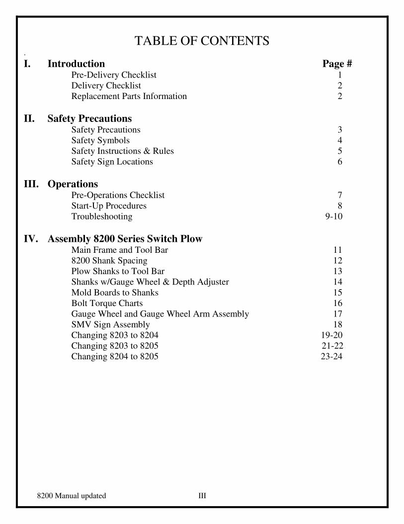
TABLE OF CONTENTS .
I. Introduction Page # Pre-Delivery Checklist 1
Delivery Checklist 2
Replacement Parts Information 2
II. Safety Precautions Safety Precautions 3
Safety Symbols 4
Safety Instructions & Rules 5
Safety Sign Locations 6
III. Operations Pre-Operations Checklist 7
Start-Up Procedures 8
Troubleshooting 9-10
IV. Assembly 8200 Series Switch Plow Main Frame and Tool Bar 11
8200 Shank Spacing 12
Plow Shanks to Tool Bar 13
Shanks w/Gauge Wheel & Depth Adjuster 14
Mold Boards to Shanks 15
Bolt Torque Charts 16
Gauge Wheel and Gauge Wheel Arm Assembly 17
SMV Sign Assembly 18
Changing 8203 to 8204 19-20
Changing 8203 to 8205 21-22
Changing 8204 to 8205 23-24
8200 Manual updated IV
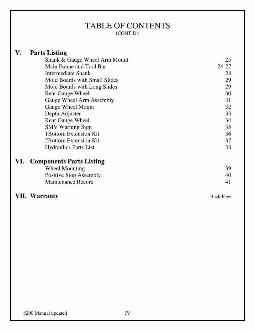
TABLE OF CONTENTS (CONT’D.)
V. Parts Listing Shank & Gauge Wheel Arm Mount 25
Main Frame and Tool Bar 26-27
Intermediate Shank 28
Mold Boards with Small Slides 29
Mold Boards with Long Slides 29
Rear Gauge Wheel 30
Gauge Wheel Arm Assembly 31
Gauge Wheel Mount 32
Depth Adjuster 33
Rear Gauge Wheel 34
SMV Warning Sign 35
1Bottom Extension Kit 36
2Bottom Extension Kit 37
Hydraulics Parts List 38
VI. Components Parts Listing
Wheel Mounting 39
Positive Stop Assembly 40
Maintenance Record 41
VII. Warranty Back Page

1
INTRODUCTION
Before operating the Switch Plow, study this manual carefully to become familiar with
the Operation and Safety Procedures. Failure to do so could result in personal injury or damage
to the equipment.
All measurements in this manual are in U.S. Standard Units.
The right and left side is determined by facing the direction of travel when in use.
The Warranty Certificate is included in this manual and supplied to owner at time of
purchase.
PRE-DELIVERY CHECKLIST
Plow should be assembled and in proper operating condition before delivery to customer.
� Plow has been assembled according to manufacturer’s instruction.
� Landslides, mold boards and all other hardware have been installed properly and
tightened to specifications.
� All moving parts have been lubricated properly and all grease fittings will take
grease.
� All functions of plow are working as designed by manufacturer.
� All safety decals are located in proper places.
� Clean and touchup any scratches in paint.
� Be sure dealer rep has fully explained proper setup operation of plow.
� Signature and date of technician performing work.
Set-up Technician Date of Service
8200 Manual updated 2
DELIVERY CHECKLIST
ADVISE CUSTOMER OF THE FOLLOWING AT THE TIME OF DELIVERY:
� Regular lubrication and maintenance extend life of equipment.
� Always follow safe and proper operating procedures.
� Point out warning decals and safety hazards.
� Keep all bolts tightened to specifications.
� Use safety and warning lights when transporting plow on public roads.
� Fill out delivery and warranty forms, and have customer sign.
� Show and explain to customer how to hitch plow to tractor, make field adjustment and operate correctly
according to operator’s manual.
Set-Up Technician Date
When ordering replacement parts, from your dealer, refer to Model No. and Serial No. of your Switch
Plow.
Serial No.:
Model No.:
8200 Manual updated 3
SAFETY PRECAUTIONS
1. Always operate plow in a careful, controlled manner.
2. Always lower plow to ground when not in use.
3. Stand clear of Switch Plow when being raised or lowered.
4. Never operate plow from side to side while someone is standing inside main frame.
5. All personnel should stand clear of Switch Plow during preparation for movement of equipment
from one location to another.
6. Always stand clear of plow when being operated from side to side.
7. Always place tool bar in center of main frame before unhitching from tractor.
8. Do not park vehicles or place objects within 10 feet of the rear of the Switch Plow.
9. Always park plow on flat, level ground before unhooking from tractor.
10.. When transporting plow, always make sure tool bar is in center position and hydraulic cylinder
hoses are connected to tractor outlets so plow cannot swing from side to side during transit.
11. Turn on flashing lights when transporting unit on highway, unless prohibited by law.
12. Never check for hydraulic leaks with hands or clothes.
13. Do not operate hydraulic systems when hydraulic leaks are present.
14. Do not operate unit close to high voltage electric lines.

8200 Manual updated 4
SAFETY SYMBOLS
RECOGNIZE SAFETY INFORMATION This is the safety symbol. When you see this, it means:
ATTENTION!
BECOME ALERT!
YOUR SAFETY IS INVOLVED!
Follow recommended precautions and procedures.
UNDERSTAND SIGNAL WORDS
A signal word –DANGER, WARNING, or
CAUTION – is used with the safety alert symbol.
DANGER indicates imminently hazardous situations that,
if not avoided, will result in serious injury, or death.
WARNING indicates potentially hazardous situations that,
if not avoided, could result in serious injury, or death.
WARNING may also be used to alert against unsafe practices. WARNING
CAUTION indicates potentially hazardous situations that,
If not avoided, may result in minor or moderate injury.
CAUTION may also be used to alert against unsafe practices. CAUTION
DANGER
FOLLOW SAFETY INSTRUCTIONS
Carefully read all safety messages in this manual and on your machine safety signs. Keep safety signs
in good condition. Remove missing or damaged safety signs. Contact LMC Bainbridge for
replacement parts.
Learn how to operate the machine and how to use controls properly. Do not let anyone operate without
instruction.
Keep your machine in proper working condition. Unauthorized modifications to the machine or
disrepair may impair safety, or the machine function.
8200 Manual updated 5
SAFETY INSTRUCTIONS AND RULES
KEEP RIDERS OFF MACHINE
Only allow the operator on the machine. Keep riders off.
Riders on machine are subject to injury such as being struck by foreign objects and
being thrown off the machine. Riders also obstruct the operator’s view resulting in the
machine being operated in an unsafe manner.
OPERATOR’S MANUAL
Do not put this operator’s manual away unread. Read the manual carefully regardless
of previous experience. Allow yourself this time, it will save time and labor later on.
IMPORTANT: Keep an extra copy of the operator’s manual in your office or in
the garage in case one gets lost.
An extra copy may be acquired from your dealer for an extra fee.
PREPARE FOR EMERGENCIES
Be prepared if fire starts.
Keep a first aid kit and fire extinguisher handy.
Keep emergency numbers for doctors, ambulance service, hospital and fire department
near your telephone.
AVOID HIGHPRESSURE FLUIDS
Escaping fluid under pressure can penetrate the skin causing serious injury. Relieve
pressure before unhooking hydraulic or other lines. Tighten all connections before
applying pressure. Keep hands and body away from pinholes and nozzles that eject
fluids under pressure. Use a piece of cardboard to search for leaks.
If any fluid is injected into the skin, a doctor familiar with this type injury must
surgically remove it within a few hours or gangrene may result.
8200 Manual updated 6
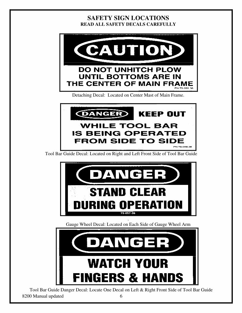
SAFETY SIGN LOCATIONS READ ALL SAFETY DECALS CAREFULLY
Detaching Decal: Located on Center Mast of Main Frame.
Tool Bar Guide Decal: Located on Right and Left Front Side of Tool Bar Guide
.
Gauge Wheel Decal: Located on Each Side of Gauge Wheel Arm
Tool Bar Guide Danger Decal: Locate One Decal on Left & Right Front Side of Tool Bar Guide
8200 Manual updated 7
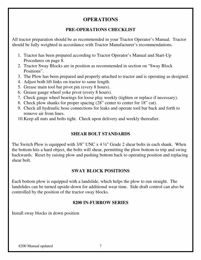
OPERATIONS
PRE-OPERATIONS CHECKLIST
All tractor preparation should be as recommended in your Tractor Operator’s Manual. Tractor
should be fully weighted in accordance with Tractor Manufacturer’s recommendations.
1. Tractor has been prepared according to Tractor Operator’s Manual and Start-Up
Procedures on page 8.
2. Tractor Sway Blocks are in position as recommended in section on “Sway Block
Positions”.
3. The Plow has been prepared and properly attached to tractor and is operating as designed.
4. Adjust both lift links on tractor to same length.
5. Grease main tool bar pivot pin (every 8 hours).
6. Grease gauge wheel yoke pivot (every 8 hours).
7. Check gauge wheel bearings for loose play weekly (tighten or replace if necessary).
8. Check plow shanks for proper spacing (28” center to center for 18” cut).
9. Check all hydraulic hose connections for leaks and operate tool bar back and forth to
remove air from lines.
10. Keep all nuts and bolts tight. Check upon delivery and weekly thereafter.
SHEAR BOLT STANDARDS
The Switch Plow is equipped with 3/8” UNC x 4 ½” Grade 2 shear bolts in each shank. When
the bottom hits a hard object, the bolts will shear, permitting the plow bottom to trip and swing
backwards. Reset by raising plow and pushing bottom back to operating position and replacing
shear bolt.
SWAY BLOCK POSITIONS
Each bottom plow is equipped with a landslide, which helps the plow to run straight. The
landslides can be turned upside-down for additional wear time. Side draft control can also be
controlled by the position of the tractor sway blocks.
8200 IN-FURROW SERIES
Install sway blocks in down position
8200 Manual updated 8
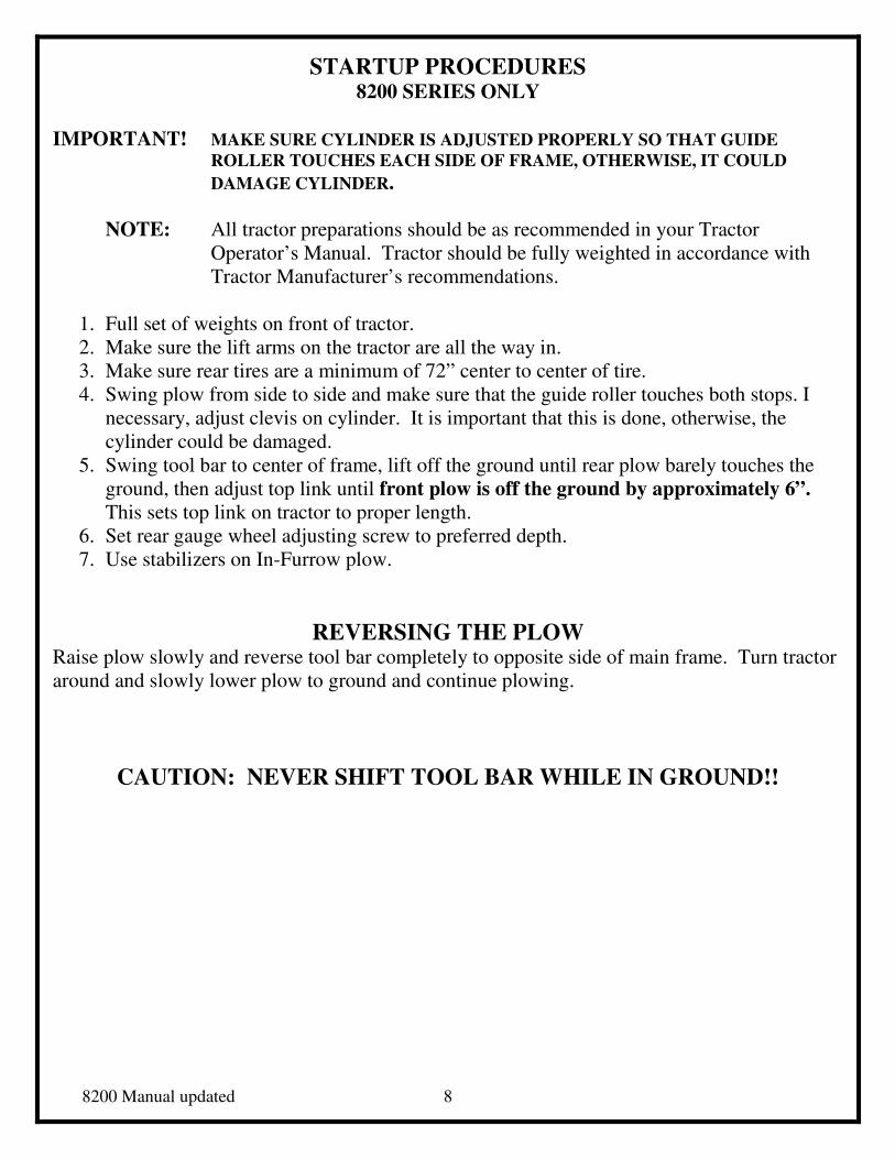
STARTUP PROCEDURES 8200 SERIES ONLY
IMPORTANT! MAKE SURE CYLINDER IS ADJUSTED PROPERLY SO THAT GUIDE
ROLLER TOUCHES EACH SIDE OF FRAME, OTHERWISE, IT COULD
DAMAGE CYLINDER.
NOTE: All tractor preparations should be as recommended in your Tractor
Operator’s Manual. Tractor should be fully weighted in accordance with
Tractor Manufacturer’s recommendations.
1. Full set of weights on front of tractor.
2. Make sure the lift arms on the tractor are all the way in.
3. Make sure rear tires are a minimum of 72” center to center of tire.
4. Swing plow from side to side and make sure that the guide roller touches both stops. I
necessary, adjust clevis on cylinder. It is important that this is done, otherwise, the
cylinder could be damaged.
5. Swing tool bar to center of frame, lift off the ground until rear plow barely touches the
ground, then adjust top link until front plow is off the ground by approximately 6”.
This sets top link on tractor to proper length.
6. Set rear gauge wheel adjusting screw to preferred depth.
7. Use stabilizers on In-Furrow plow.
REVERSING THE PLOW Raise plow slowly and reverse tool bar completely to opposite side of main frame. Turn tractor
around and slowly lower plow to ground and continue plowing.
CAUTION: NEVER SHIFT TOOL BAR WHILE IN GROUND!!

8200 Manual updated 9
TROUBLE SHOOTING PROBLEM CAUSE SOLUTIONS
Plow will not go in ground: Tractor depth control too shallow
Insufficient plow bottom suction.
Worn plow shares
Incorrect rockshaft setting.
Severe hard ground conditions
Spring trip shank mold board tilt
not set properly.
Adjust tractor setting.
Shorten center link on tractor and
extend lift arms outward.
Replace with new shares.
Adjust on tractor.
Tilt gangs forward to rear shear
bolt position.
Adjust each trip spring shank jam
nuts in to move shank and mold
board forward to take more ground.
Poor depth control: Too much load response.
Worn shares.
Adjust sensitivity lever on tractor.
Replace sensitivity lever on tractor
Plow not running straight: Improper lateral adjustment.
Plow running on nose.
Check right and left hand link for
the same dimension.
Check tractor wheel setting and tire
wear.
Check for excess landslide wear.
Adjust center link on tractor and/or
rear gauge wheel on plow.
Ridging:
Plow not properly level laterally.
Plow not level for & aft.
Front bottom cutting too wide or
too narrow.
Both right and left hand lift links
should have the same dimensions.
Adjust tractor center link and/or
rear gauge wheel adjustment.
Check for incorrect distance of
tractor from last water furrow.
8200 Manual updated 10
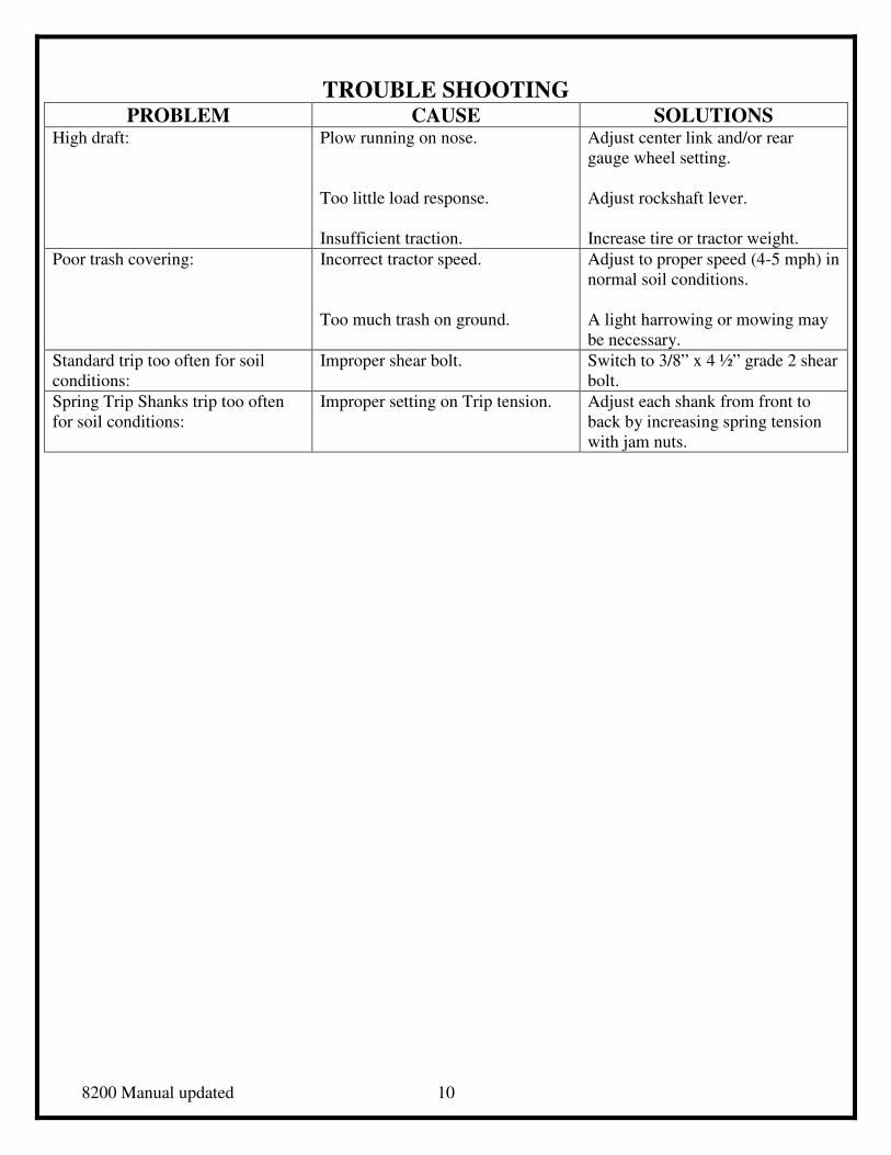
TROUBLE SHOOTING PROBLEM CAUSE SOLUTIONS
High draft: Plow running on nose.
Too little load response.
Insufficient traction.
Adjust center link and/or rear
gauge wheel setting.
Adjust rockshaft lever.
Increase tire or tractor weight.
Poor trash covering: Incorrect tractor speed.
Too much trash on ground.
Adjust to proper speed (4-5 mph) in
normal soil conditions.
A light harrowing or mowing may
be necessary.
Standard trip too often for soil
conditions:
Improper shear bolt. Switch to 3/8” x 4 ½” grade 2 shear
bolt.
Spring Trip Shanks trip too often
for soil conditions:
Improper setting on Trip tension. Adjust each shank from front to
back by increasing spring tension
with jam nuts.
8200 Manual updated 11
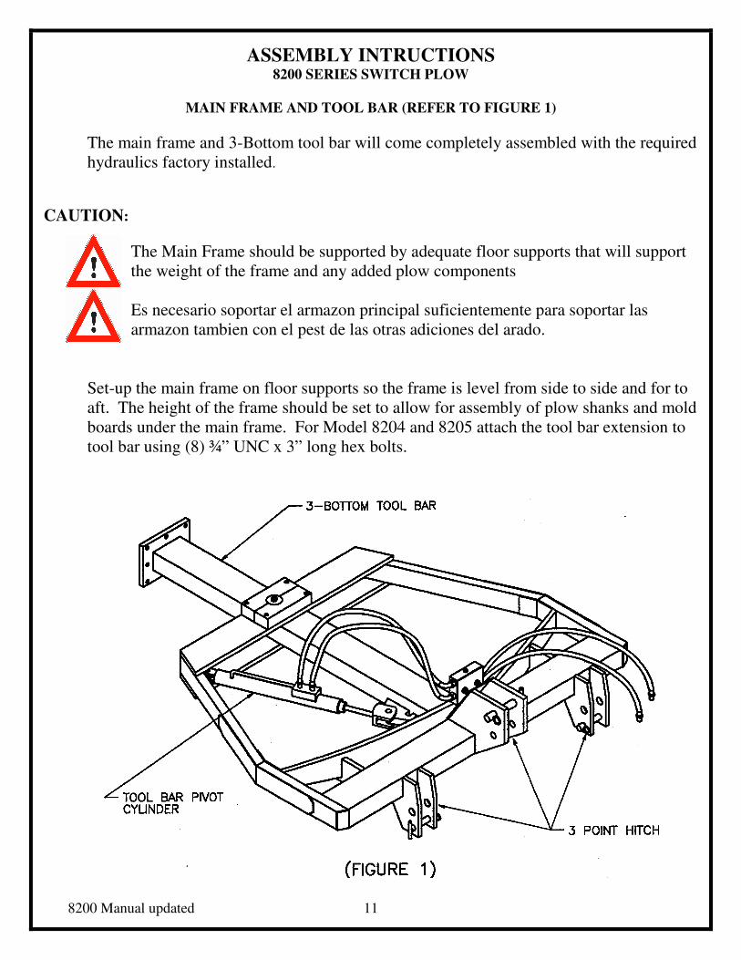
ASSEMBLY INTRUCTIONS 8200 SERIES SWITCH PLOW
MAIN FRAME AND TOOL BAR (REFER TO FIGURE 1)
The main frame and 3-Bottom tool bar will come completely assembled with the required
hydraulics factory installed.
CAUTION:
The Main Frame should be supported by adequate floor supports that will support
the weight of the frame and any added plow components
Es necesario soportar el armazon principal suficientemente para soportar las
armazon tambien con el pest de las otras adiciones del arado.
Set-up the main frame on floor supports so the frame is level from side to side and for to
aft. The height of the frame should be set to allow for assembly of plow shanks and mold
boards under the main frame. For Model 8204 and 8205 attach the tool bar extension to
tool bar using (8) ¾” UNC x 3” long hex bolts.
8200 Manual updated 12
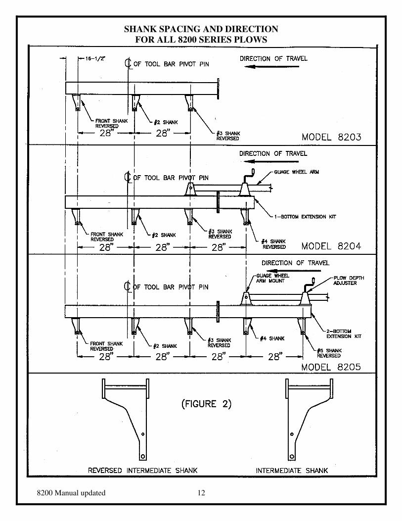
SHANK SPACING AND DIRECTION
FOR ALL 8200 SERIES PLOWS
8200 Manual updated 13
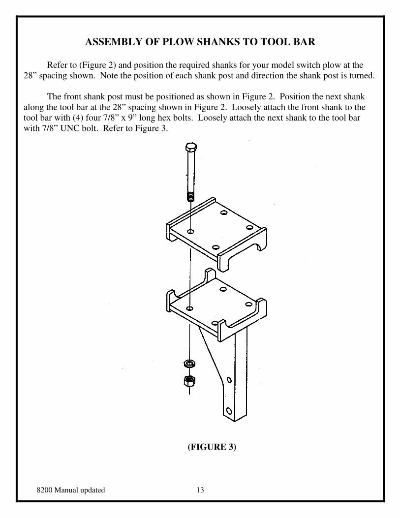
ASSEMBLY OF PLOW SHANKS TO TOOL BAR
Refer to (Figure 2) and position the required shanks for your model switch plow at the
28” spacing shown. Note the position of each shank post and direction the shank post is turned.
The front shank post must be positioned as shown in Figure 2. Position the next shank
along the tool bar at the 28” spacing shown in Figure 2. Loosely attach the front shank to the
tool bar with (4) four 7/8” x 9” long hex bolts. Loosely attach the next shank to the tool bar
with 7/8” UNC bolt. Refer to Figure 3.
(FIGURE 3)
8200 Manual updated 14
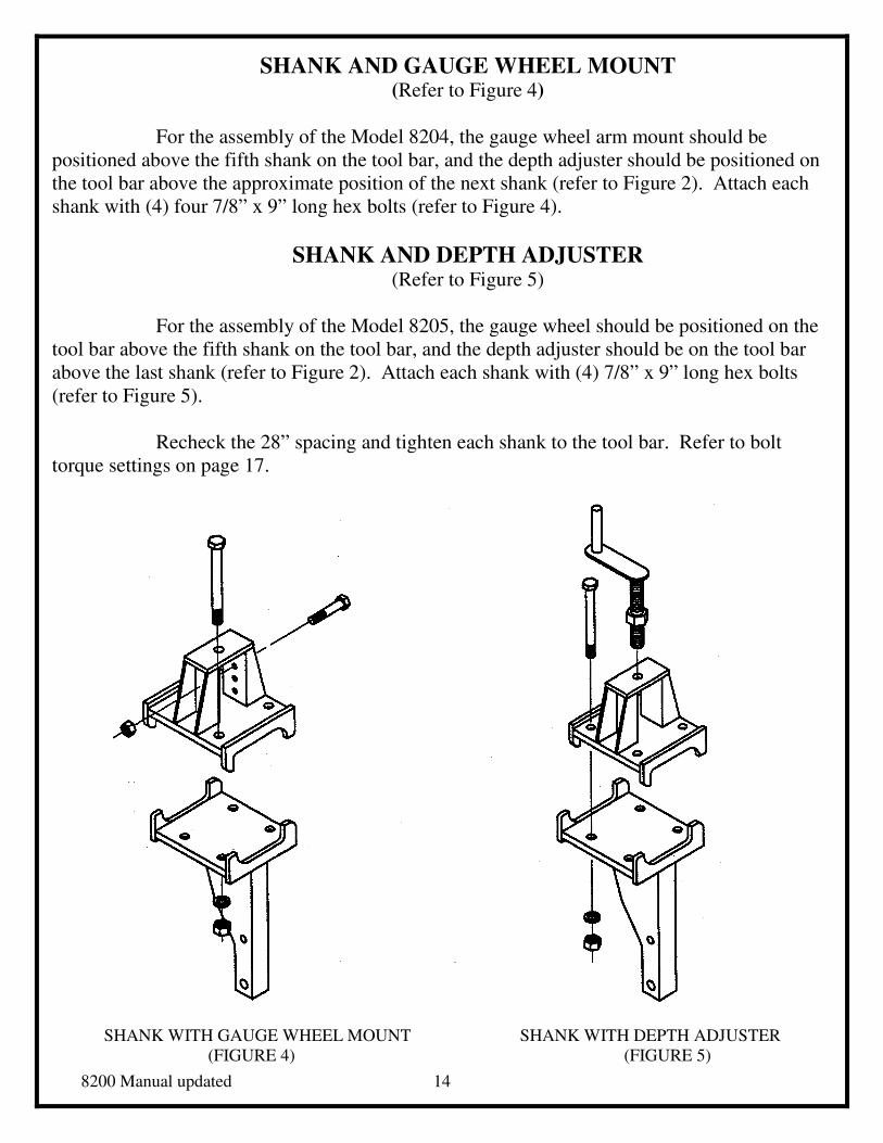
SHANK AND GAUGE WHEEL MOUNT (Refer to Figure 4)
For the assembly of the Model 8204, the gauge wheel arm mount should be
positioned above the fifth shank on the tool bar, and the depth adjuster should be positioned on
the tool bar above the approximate position of the next shank (refer to Figure 2). Attach each
shank with (4) four 7/8” x 9” long hex bolts (refer to Figure 4).
SHANK AND DEPTH ADJUSTER (Refer to Figure 5)
For the assembly of the Model 8205, the gauge wheel should be positioned on the
tool bar above the fifth shank on the tool bar, and the depth adjuster should be on the tool bar
above the last shank (refer to Figure 2). Attach each shank with (4) 7/8” x 9” long hex bolts
(refer to Figure 5).
Recheck the 28” spacing and tighten each shank to the tool bar. Refer to bolt
torque settings on page 17.
SHANK WITH GAUGE WHEEL MOUNT SHANK WITH DEPTH ADJUSTER
(FIGURE 4) (FIGURE 5)
8200 Manual updated 15
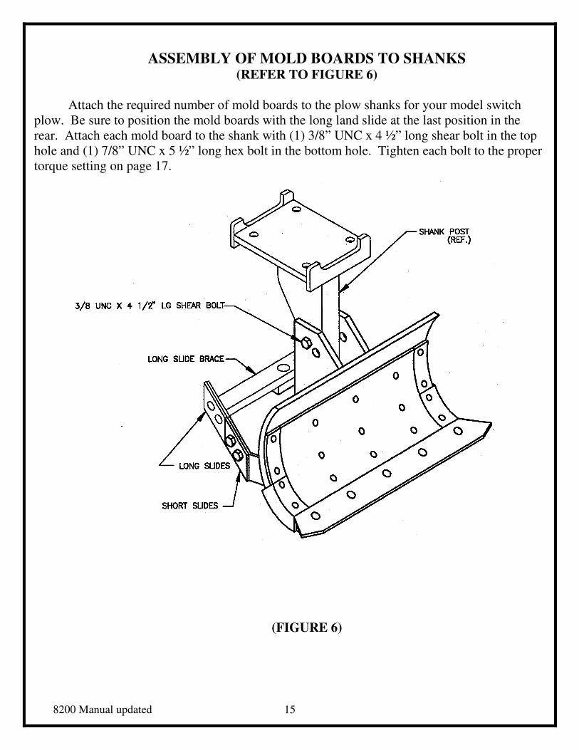
ASSEMBLY OF MOLD BOARDS TO SHANKS (REFER TO FIGURE 6)
Attach the required number of mold boards to the plow shanks for your model switch
plow. Be sure to position the mold boards with the long land slide at the last position in the
rear. Attach each mold board to the shank with (1) 3/8” UNC x 4 ½” long shear bolt in the top
hole and (1) 7/8” UNC x 5 ½” long hex bolt in the bottom hole. Tighten each bolt to the proper
torque setting on page 17.
(FIGURE 6)
8200 Manual updated 16
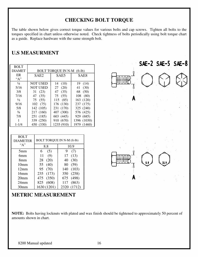
CHECKING BOLT TORQUE
The table shown below gives correct torque values for various bolts and cap screws. Tighten all bolts to the
torques specified in chart unless otherwise noted. Check tightness of bolts periodically using bolt torque chart
as a guide. Replace hardware with the same strength bolt.
U.S MEASURMENT
METRIC MEASUREMENT
NOTE: Bolts having locknuts with plated and wax finish should be tightened to approximately 50 percent of
amounts shown in chart.
BOLT TORQUE IN N-M (ft-lb)
BOLT
DIAMET
ER
“A” SAE2 SAE5 SAE8
¼ NOT USED 14 (10) 19 (14)
5/16 NOT USED 27 (20) 41 (30)
3/8 31 (23) 47 (35) 68 (50)
7/16 47 (35) 75 (55) 108 (80)
½ 75 (55) 115 (85) 163 (120)
9/16 102 (75) 176 (130) 237 (175)
5/8 142 (105) 231 (170) 325 (240)
¾ 217 (160) 407 (300) 576 (425)
7/8 251 (185) 603 (445) 929 (685)
1 339 (250) 910 (670) 1396 (1030)
1-1/4 450 (330) 1235 (910) 1979 (1460)
BOLT TORQUE IN N-M (ft-lb) BOLT
DIAMETER
“A” 8.8 10.9
5mm 6 (5) 9 (7)
6mm 11 (9) 17 (13)
8mm 28 (20) 40 (30)
10mm 55 (40) 80 (59)
12mm 95 (70) 140 (103)
16mm 235 (173) 350 (258)
20mm 475 (350) 675 (498)
24mm 825 (608) 117 (863)
30mm 1630 (1201) 2320 (1712)
8200 Manual updated 17
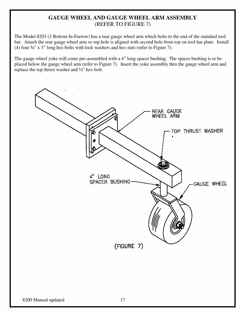
GAUGE WHEEL AND GAUGE WHEEL ARM ASSEMBLY (REFER TO FIGURE 7)
The Model 8203 (3 Bottom In-Furrow) has a rear gauge wheel arm which bolts to the end of the standard tool
bar. Attach the rear gauge wheel arm so top hole is aligned with second hole from top on tool bar plate. Install
(4) four ¾” x 3” long hex bolts with lock washers and hex nuts (refer to Figure 7).
The gauge wheel yoke will come pre-assembled with a 4” long spacer bushing. The spacer bushing is to be
placed below the gauge wheel arm (refer to Figure 7). Insert the yoke assembly thru the gauge wheel arm and
replace the top thrust washer and ½” hex bolt.
8200 Manual updated 18
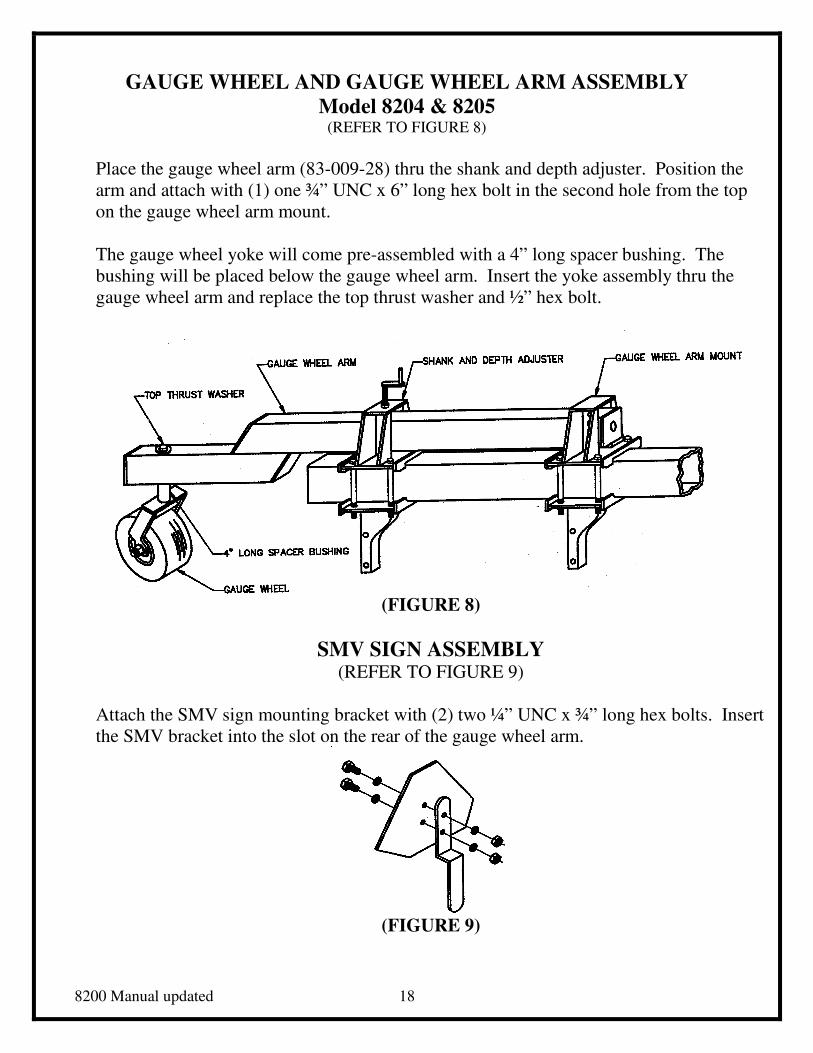
GAUGE WHEEL AND GAUGE WHEEL ARM ASSEMBLY
Model 8204 & 8205 (REFER TO FIGURE 8)
Place the gauge wheel arm (83-009-28) thru the shank and depth adjuster. Position the
arm and attach with (1) one ¾” UNC x 6” long hex bolt in the second hole from the top
on the gauge wheel arm mount.
The gauge wheel yoke will come pre-assembled with a 4” long spacer bushing. The
bushing will be placed below the gauge wheel arm. Insert the yoke assembly thru the
gauge wheel arm and replace the top thrust washer and ½” hex bolt.
(FIGURE 8)
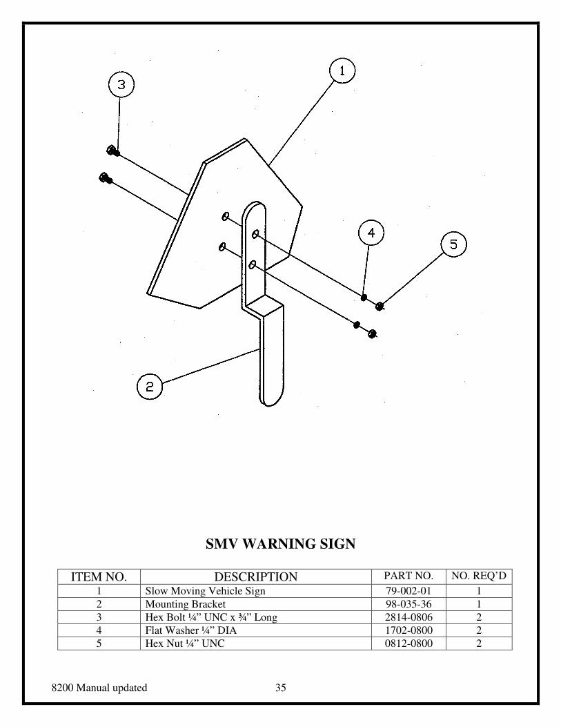
SMV SIGN ASSEMBLY (REFER TO FIGURE 9)
Attach the SMV sign mounting bracket with (2) two ¼” UNC x ¾” long hex bolts. Insert
the SMV bracket into the slot on the rear of the gauge wheel arm.
(FIGURE 9)
8200 Manual updated 19
INSTRUCTIONS FOR CHANGING MODEL 8203 TO MODEL 8204
Parts required to convert 3-Bottom Plow (Model 8203) to 4-Bottom (Model 8204):
� One Tool Bar Extension – 24”
� One Intermediate Mold Board
� One Intermediate Shank
� One Gauge Wheel Arm
� One Gauge Wheel Arm Mount
� One Depth Adjuster
� One Extension Mounting Bolt Bag
� One Shank Mounting Bolt Bag
ASSEMBLY INSTRUCTIONS
CAUTION:
The Main Frame and tool bar should be supported by adequate floor supports that will support
the weight of the frame and any additional components.
Es necesario soportar el armazon principal suficientemente para soportar las armazon tambien
con el pest de las otras adiciones del arado.
1. Remove the rear gauge wheel arm and gauge wheel from end of tool bar.
2. With the plow resting on all three (3) bottoms, attach the one bottom extension to main tool bar
with eight (8) ¾” x 3” hex, lock washers and hex nuts. Torque as specified on page 17.
3. Remove top plate from #3 bottom by removing the four (4) 7/8” x 9” bolts. Replace with gauge
wheel arm (see page 37), and tighten with four (4) 7/8” x 9” bolts (see page 21).
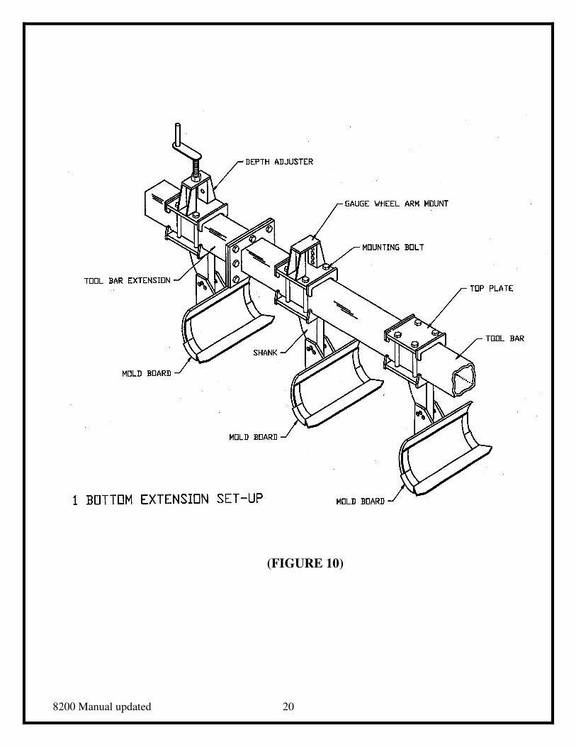
4. Attach shank post to extension (see page 13 for shank direction on 8204) with depth adjuster
using four (4) 7/8” x 9” bolts (see figure 10). Do not tighten bolts until distance between shanks
has been set. Then torque as specified on page 17.
5. Remove the mold board with long land slides from the #3 shank post and install on #4 shank
post.
6. Install new mold board with short land slides to the #3 shank post.
NOTE: Snug the 7/8” x 5 ½” bolt that mounts the mold board to the shank. DO NOT TIGHTEN
TOO TIGHT OR MOLD BOARD MAY NOT TRIP WHEN REQUIRED.
8200 Manual updated 20
(FIGURE 10)
8200 Manual updated 21
INSTRUCTIONS FOR CHANGING MODEL 8203 TO MODEL 8205
Parts required to convert 3-Bottom Plow (Model 8203) to 5-Bottom (Model 8205)
� Two Intermediate mold board units
� Two Intermediate shanks
� One 2-Bottom Tool Bar extension 52”
� One Gauge Wheel Arm
� One Rear Gauge Wheel Arm Mount
� One Depth Adjuster
� One Extension Mounting Bolt Bag
� Two Shank Mounting Bolt Bags
ASSEMBLY INSTRUCTIONS
CAUTION:
The Main Frame and tool bar should be supported by adequate floor supports that will support
the weight of the frame and any additional components.
Es necesario soportar el armazon principal suficientemente para soportar las armazon tambien
con el pest de las otras adiciones del arado.
1. Remove the rear gauge wheel arm and gauge wheel from end of tool bar.
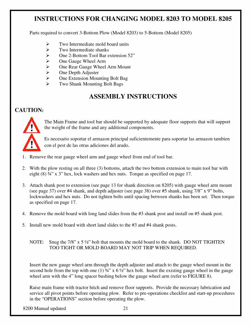
2. With the plow resting on all three (3) bottoms, attach the two bottom extension to main tool bar with
eight (8) ¾” x 3” hex, lock washers and hex nuts. Torque as specified on page 17.
3. Attach shank post to extension (see page 13 for shank direction on 8205) with gauge wheel arm mount
(see page 37) over #4 shank, and depth adjuster (see page 38) over #5 shank, using 7/8” x 9” bolts,
lockwashers and hex nuts. Do not tighten bolts until spacing between shanks has been set. Then torque
as specified on page 17.
4. Remove the mold board with long land slides from the #3 shank post and install on #5 shank post.
5. Install new mold board with short land slides to the #3 and #4 shank posts.
NOTE: Snug the 7/8” x 5 ½” bolt that mounts the mold board to the shank. DO NOT TIGHTEN
TOO TIGHT OR MOLD BOARD MAY NOT TRIP WHEN REQUIRED.
Insert the new gauge wheel arm through the depth adjuster and attach to the gauge wheel mount in the
second hole from the top with one (1) ¾” x 6 ½” hex bolt. Insert the existing gauge wheel in the gauge
wheel arm with the 4” long spacer bushing below the gauge wheel arm (refer to FIGURE 8).
Raise main frame with tractor hitch and remove floor supports. Provide the necessary lubrication and
service all pivot points before operating plow. Refer to pre-operations checklist and start-up procedures
in the “OPERATIONS” section before operating the plow.
8200 Manual updated 22
2 – Bottom Extension Set-Up
(FIGURE 11)
8200 Manual updated 23
INSTRUCTIONS FOR CHANGING MODEL 8204 TO MODEL 8205
Parts required to convert 4-Bottom Plow (Model 8204) to 5-Bottom (Model 8205)
� One Intermediate mold board unit
� One Intermediate shank
� One 2-Bottom tool bar extension – 52”
� One Top mounting plate
� One extension Mounting Bolt Bag
� One Shank Mounting Bolt Bag
ASSEMBLY INSTRUCTIONS CAUTION:
The Main Frame and Tool Bar should be supported by adequate floor supports that will support
the weight of the frame and any additional components.
Es necesario soportar el armazon principal suficientemente para soportar las armazon tambien
con el pest de las otras adiciones del arado.
1. Remove the rear gauge wheel arm and gauge wheel from end of tool bar.
2. Remove the rear mold board, shank assembly, and tool bar extension from the tool bar.
3. With the plow resting on all three (3) bottoms, attach the two bottom extension to main tool bar with
eight (8) ¾” x 3” hex, lock washers and hex nuts. Torque as specified on page 17.
4. Remove the gauge wheel arm mount from #3 by removing the four (4) 7/8” x 9” bolts. Replace with
standard top plate (see page 37), and tighten with four (4) 7/8” x 9” bolts (see page 21).
5. Attach shank post to extension (see page 13 for shank direction on 8205) with gauge wheel arm mount
in the #4 position, and depth adjuster in the #5 position, using four (4) 7/8” x 9” bolts (see figure 10).
Do not tighten bolts until distance between shanks has been set. Then torque as specified on page 17.
6. Remove the mold board with long land slides from the #4 shank post and install on #5 shank post.
7. Install new mold board with short land slides to the #4 shank post.
NOTE: Snug the 7/8” x 5 ½” bolt that mounts the mold board to the shank. DO NOT TIGHTEN
TOO TIGHT OR MOLD BOARD MAY NOT TRIP WHEN REQUIRED
Insert the new gauge wheel arm through the depth adjuster and attach to the gauge wheel mount in the
second hole from the top with one (1) ¾” x 6 ½” hex bolt. Insert the existing gauge wheel in the gauge
wheel arm with the 4” long spacer bushing below the gauge wheel arm (refer to FIGURE 8).
Raise main frame with tractor hitch and remove floor supports. Provide the necessary lubrication and
service all pivot points before operating plow. Refer to pre-operations checklist and start-up procedures
in the “OPERATIONS” section before operating the plow.
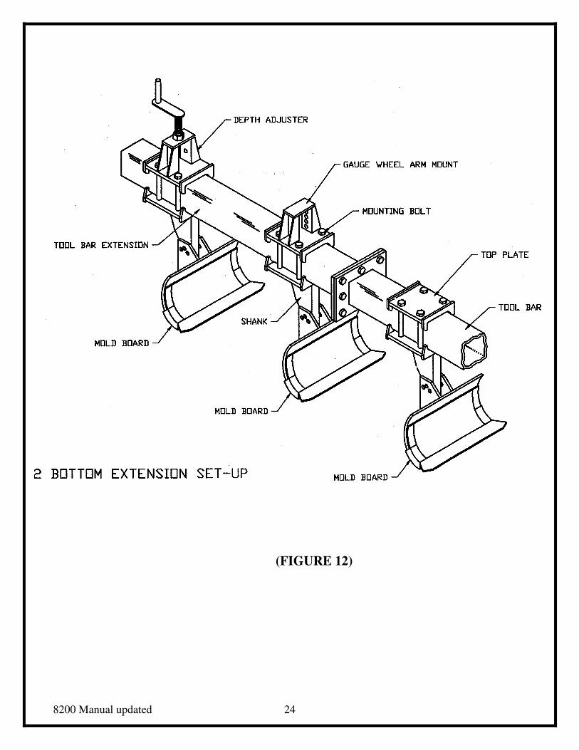
8200 Manual updated 24
(FIGURE 12)
8200 Manual updated 25
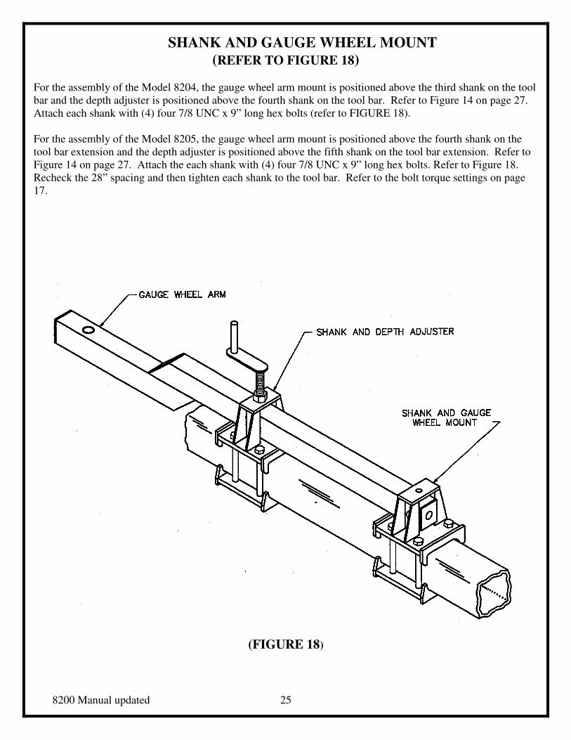
SHANK AND GAUGE WHEEL MOUNT
(REFER TO FIGURE 18)
For the assembly of the Model 8204, the gauge wheel arm mount is positioned above the third shank on the tool
bar and the depth adjuster is positioned above the fourth shank on the tool bar. Refer to Figure 14 on page 27.
Attach each shank with (4) four 7/8 UNC x 9” long hex bolts (refer to FIGURE 18).
For the assembly of the Model 8205, the gauge wheel arm mount is positioned above the fourth shank on the
tool bar extension and the depth adjuster is positioned above the fifth shank on the tool bar extension. Refer to
Figure 14 on page 27. Attach the each shank with (4) four 7/8 UNC x 9” long hex bolts. Refer to Figure 18.
Recheck the 28” spacing and then tighten each shank to the tool bar. Refer to the bolt torque settings on page
17.
(FIGURE 18)
8200 Manual updated 26
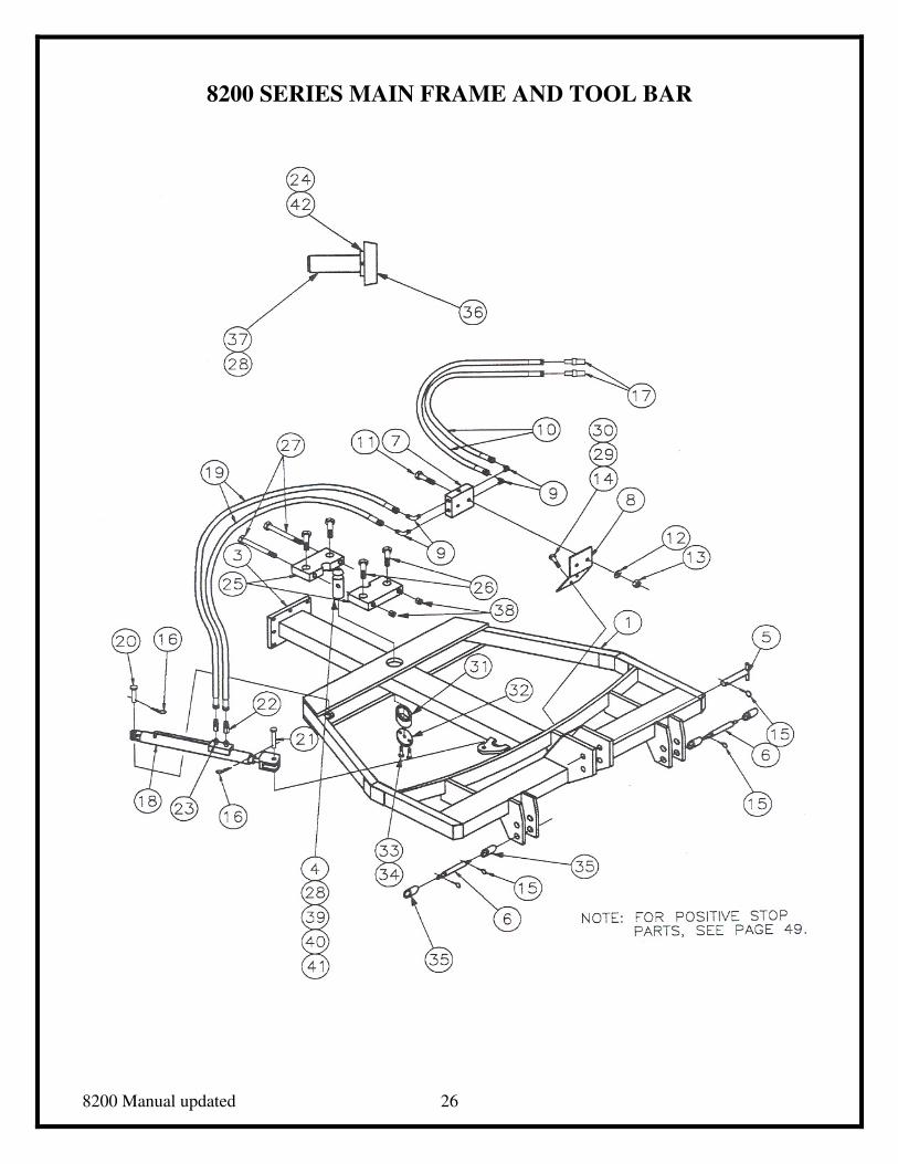
8200 SERIES MAIN FRAME AND TOOL BAR
8200 Manual updated 27
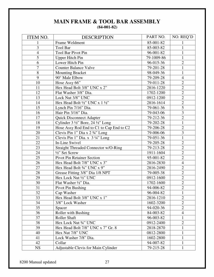
MAIN FRAME & TOOL BAR ASSEMBLY (84-001-82)
ITEM NO. DESCRIPTION PART NO. NO. REQ’D
1 Frame Weldment 85-001-82 1
3 Tool Bar 85-003-82 1
4 Tool Bar Pivot Pin 96-001-82 1
5 Upper Hitch Pin 79-1009-86 1
6 Lower Hitch Pin 96-015-36 2
7 Counter Balance Valve 79-201-28 1
8 Mounting Bracket 98-049-36 1
9 90° Male Elbow 79-209-28 4
10 Hose Assy 66” 79-011-28 2
11 Hex Head Bolt 3/8” UNC x 2” 2816-1220 2
12 Flat Washer 3/8” Dia. 1702-1200 2
13 Lock Nut 3/8” UNC 0912-1200 2
14 Hex Head Bolt ½” UNC x 1 ½” 2816-1614 2
15 Lynch Pin 7/16” Dia. 79-061-36 5
16 Hair Pin 3/16” Dia. 79-043-06 3
17 Quick Disconnect Adapter 79-212-36 2
18 Cylinder 3 ½” Bore, 24 ½” Long 79-202-28 1
19 Hose Assy Rod End to C1 to Cap End to C2 79-206-28 2
20 Clevis Pin 1” Dia x 2 ¾” Long 79-006-06 3
21 Clevis Pin 1” Dia. x 3 ¼” Long 79-051-36 1
22 In-Line Swivel 79-205-28 2
23 Straight Threaded Connector w/O-Ring 79-213-28 2
24 ½” Set Screw 1911-1604 2
25 Pivot Pin Retainer Section 95-001-82 2
26 Hex Head Bolt 7/8” UNC x 3” 2816-2830 4
27 Hex Head Bolt ¾” UNC x 9” 2816-2490 2
28 Grease Fitting 3/8” Dia 1/8 NPT 79-005-38 2
29 Hex Lock Nut ½” UNC 0912-1600 2
30 Flat Washer ½” Dia. 1702-1600 2
31 Pivot Pin Bushing 94-006-82 2
32 Cap Washer 96-004-82 1
33 Hex Head Bolt 3/8” UNC x 1” 2816-1210 2
34 3/8” Lock Washer 1602-3200 2
35 Spacer 94-020-36 2
36 Roller with Bushing 84-003-82 4
37 Roller Shaft 96-003-82 1
38 Hex Lock Nut ¾” UNC 0912-2400 2
39 Hex Head Bolt 7/8” UNC x 7” Gr. 8 2818-2870 1
40 Hex Nut 7/8” UNC 0812-2800 1
41 Lock Washer 7/8” Dia. 1602-2800 1
42 Collar 94-007-82 1
NS Adjustable Clevis for Main Cylinder 79-215-28 1
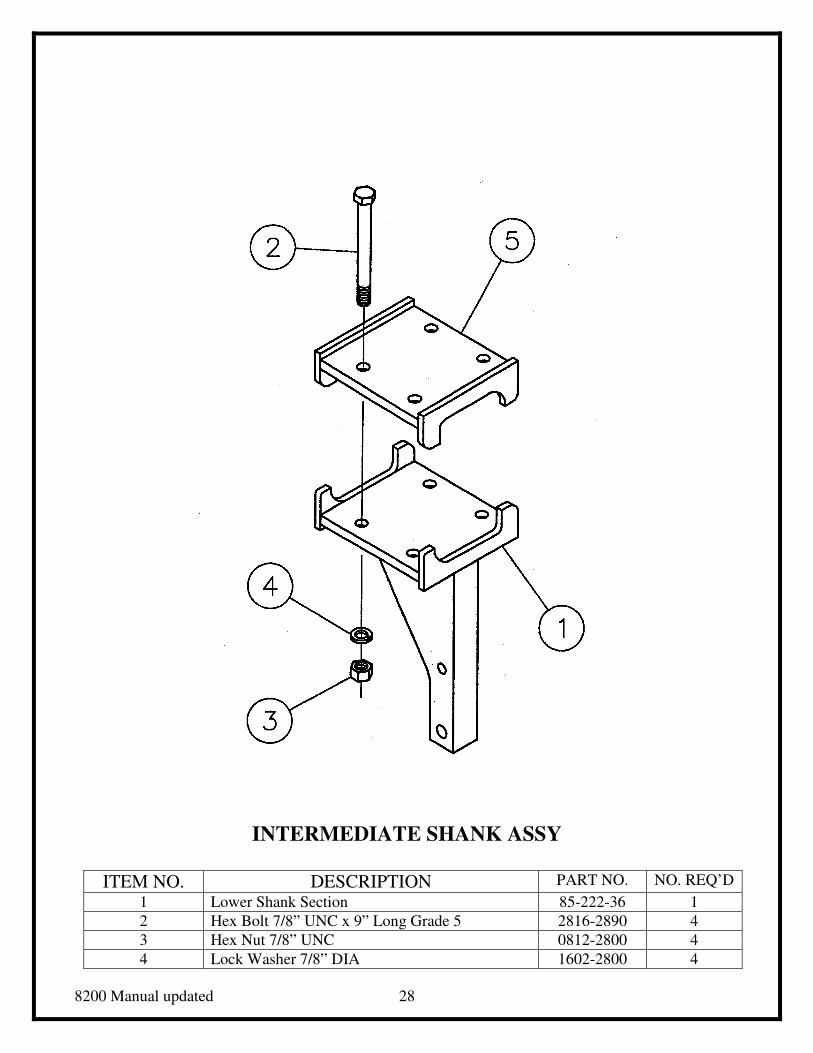
8200 Manual updated 28
INTERMEDIATE SHANK ASSY
ITEM NO. DESCRIPTION PART NO. NO. REQ’D
1 Lower Shank Section 85-222-36 1
2 Hex Bolt 7/8” UNC x 9” Long Grade 5 2816-2890 4
3 Hex Nut 7/8” UNC 0812-2800 4
4 Lock Washer 7/8” DIA 1602-2800 4
8200 Manual updated 29
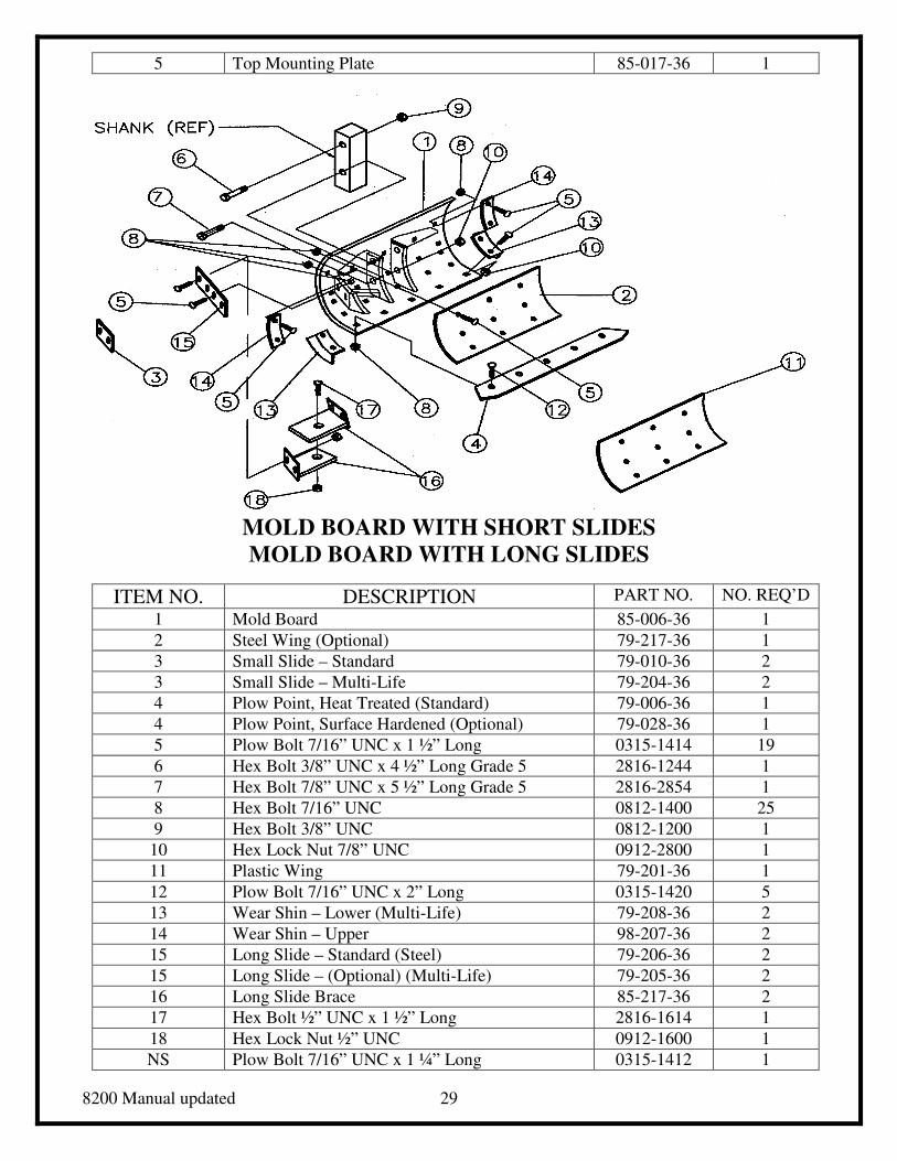
5 Top Mounting Plate 85-017-36 1
MOLD BOARD WITH SHORT SLIDES
MOLD BOARD WITH LONG SLIDES
ITEM NO. DESCRIPTION PART NO. NO. REQ’D
1 Mold Board 85-006-36 1
2 Steel Wing (Optional) 79-217-36 1
3 Small Slide – Standard 79-010-36 2
3 Small Slide – Multi-Life 79-204-36 2
4 Plow Point, Heat Treated (Standard) 79-006-36 1
4 Plow Point, Surface Hardened (Optional) 79-028-36 1
5 Plow Bolt 7/16” UNC x 1 ½” Long 0315-1414 19
6 Hex Bolt 3/8” UNC x 4 ½” Long Grade 5 2816-1244 1
7 Hex Bolt 7/8” UNC x 5 ½” Long Grade 5 2816-2854 1
8 Hex Bolt 7/16” UNC 0812-1400 25
9 Hex Bolt 3/8” UNC 0812-1200 1
10 Hex Lock Nut 7/8” UNC 0912-2800 1
11 Plastic Wing 79-201-36 1
12 Plow Bolt 7/16” UNC x 2” Long 0315-1420 5
13 Wear Shin – Lower (Multi-Life) 79-208-36 2
14 Wear Shin – Upper 98-207-36 2
15 Long Slide – Standard (Steel) 79-206-36 2
15 Long Slide – (Optional) (Multi-Life) 79-205-36 2
16 Long Slide Brace 85-217-36 2
17 Hex Bolt ½” UNC x 1 ½” Long 2816-1614 1
18 Hex Lock Nut ½” UNC 0912-1600 1
NS Plow Bolt 7/16” UNC x 1 ¼” Long 0315-1412 1
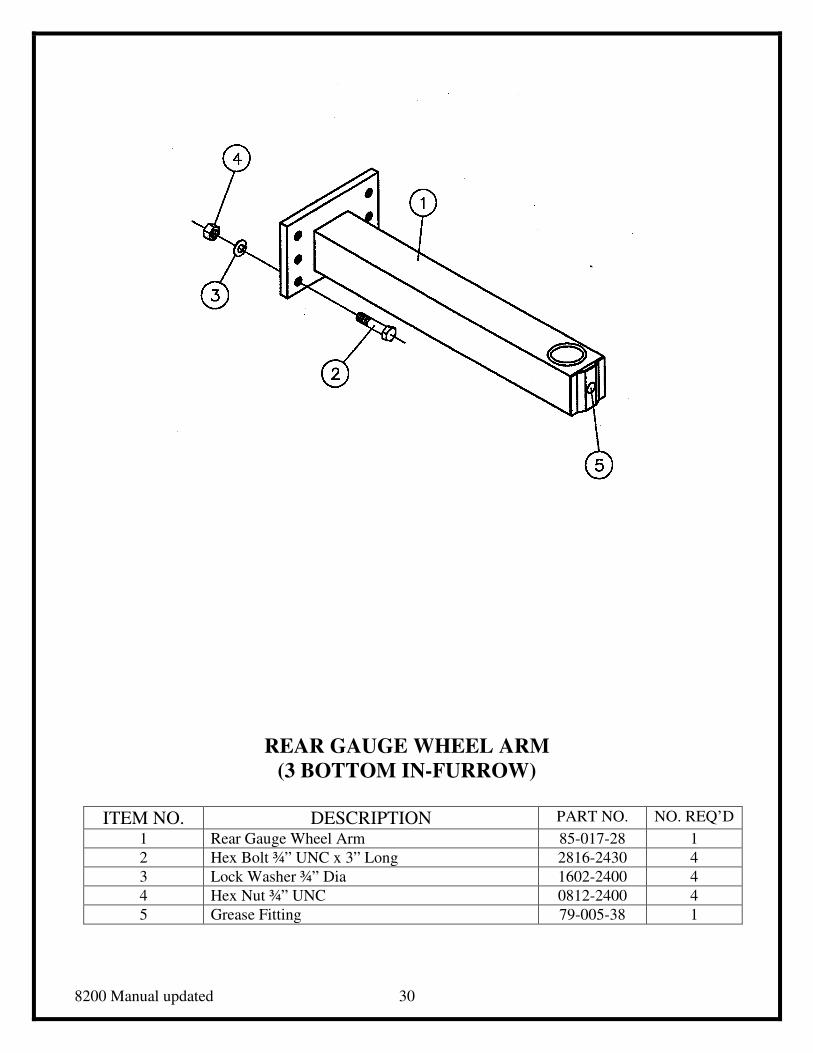
8200 Manual updated 30
REAR GAUGE WHEEL ARM
(3 BOTTOM IN-FURROW)
ITEM NO. DESCRIPTION PART NO. NO. REQ’D
1 Rear Gauge Wheel Arm 85-017-28 1
2 Hex Bolt ¾” UNC x 3” Long 2816-2430 4
3 Lock Washer ¾” Dia 1602-2400 4
4 Hex Nut ¾” UNC 0812-2400 4
5 Grease Fitting 79-005-38 1
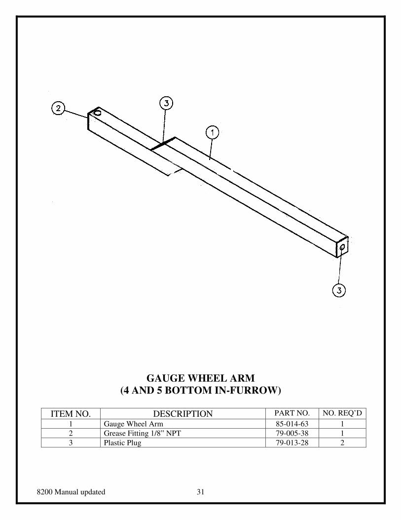
8200 Manual updated 31
GAUGE WHEEL ARM
(4 AND 5 BOTTOM IN-FURROW)
ITEM NO. DESCRIPTION PART NO. NO. REQ’D
1 Gauge Wheel Arm 85-014-63 1
2 Grease Fitting 1/8” NPT 79-005-38 1
3 Plastic Plug 79-013-28 2
8200 Manual updated 32
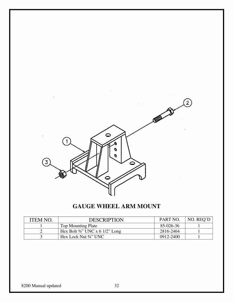
GAUGE WHEEL ARM MOUNT
ITEM NO. DESCRIPTION PART NO. NO. REQ’D
1 Top Mounting Plate 85-026-36 1
2 Hex Bolt ¾” UNC x 6 1/2” Long 2816-2464 1
3 Hex Lock Nut ¾” UNC 0912-2400 1
8200 Manual updated 33
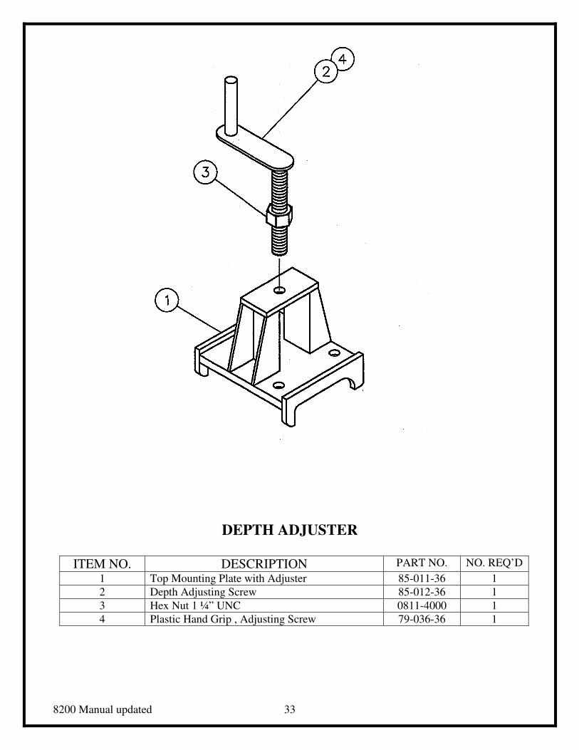
DEPTH ADJUSTER
ITEM NO. DESCRIPTION PART NO. NO. REQ’D
1 Top Mounting Plate with Adjuster 85-011-36 1
2 Depth Adjusting Screw 85-012-36 1
3 Hex Nut 1 ¼” UNC 0811-4000 1
4 Plastic Hand Grip , Adjusting Screw 79-036-36 1
8200 Manual updated 34
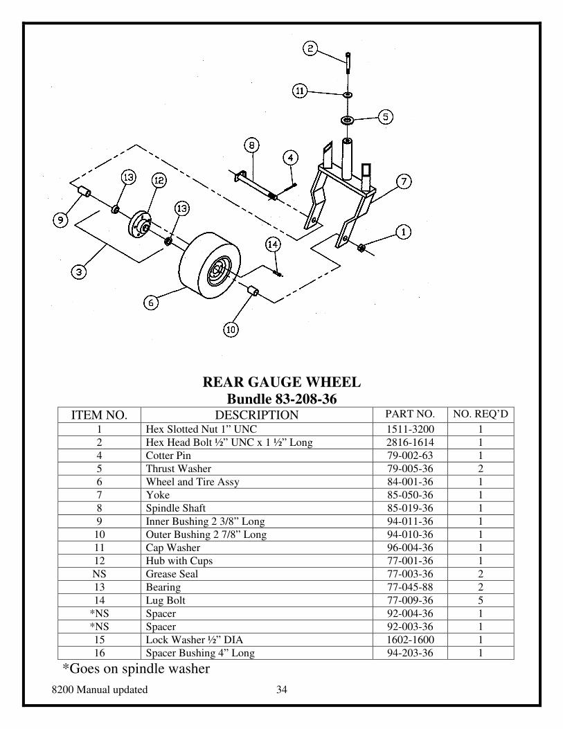
REAR GAUGE WHEEL
Bundle 83-208-36 ITEM NO. DESCRIPTION PART NO. NO. REQ’D
1 Hex Slotted Nut 1” UNC 1511-3200 1
2 Hex Head Bolt ½” UNC x 1 ½” Long 2816-1614 1
4 Cotter Pin 79-002-63 1
5 Thrust Washer 79-005-36 2
6 Wheel and Tire Assy 84-001-36 1
7 Yoke 85-050-36 1
8 Spindle Shaft 85-019-36 1
9 Inner Bushing 2 3/8” Long 94-011-36 1
10 Outer Bushing 2 7/8” Long 94-010-36 1
11 Cap Washer 96-004-36 1
12 Hub with Cups 77-001-36 1
NS Grease Seal 77-003-36 2
13 Bearing 77-045-88 2
14 Lug Bolt 77-009-36 5
*NS Spacer 92-004-36 1
*NS Spacer 92-003-36 1
15 Lock Washer ½” DIA 1602-1600 1
16 Spacer Bushing 4” Long 94-203-36 1
*Goes on spindle washer
8200 Manual updated 35
SMV WARNING SIGN
ITEM NO. DESCRIPTION PART NO. NO. REQ’D
1 Slow Moving Vehicle Sign 79-002-01 1
2 Mounting Bracket 98-035-36 1
3 Hex Bolt ¼” UNC x ¾” Long 2814-0806 2
4 Flat Washer ¼” DIA 1702-0800 2
5 Hex Nut ¼” UNC 0812-0800 2
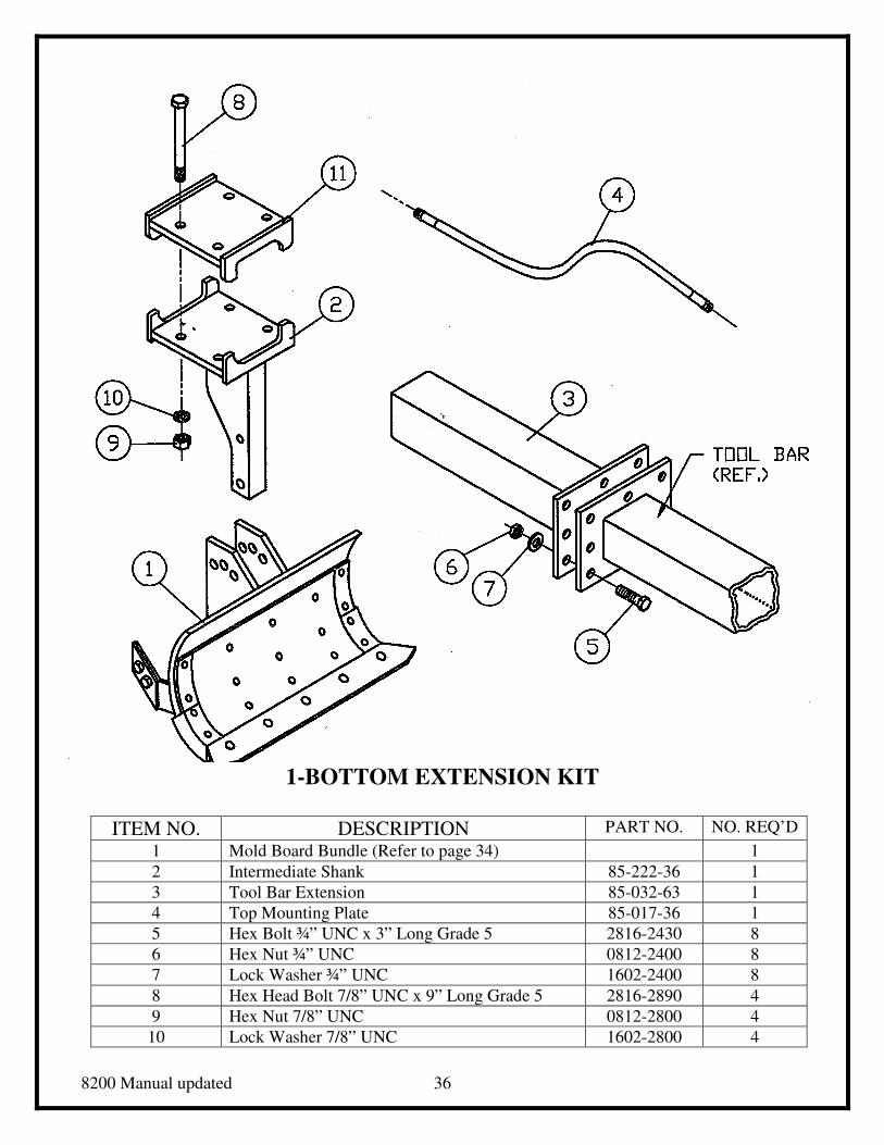
8200 Manual updated 36
1-BOTTOM EXTENSION KIT
ITEM NO. DESCRIPTION PART NO. NO. REQ’D
1 Mold Board Bundle (Refer to page 34) 1
2 Intermediate Shank 85-222-36 1
3 Tool Bar Extension 85-032-63 1
4 Top Mounting Plate 85-017-36 1
5 Hex Bolt ¾” UNC x 3” Long Grade 5 2816-2430 8
6 Hex Nut ¾” UNC 0812-2400 8
7 Lock Washer ¾” UNC 1602-2400 8
8 Hex Head Bolt 7/8” UNC x 9” Long Grade 5 2816-2890 4
9 Hex Nut 7/8” UNC 0812-2800 4
10 Lock Washer 7/8” UNC 1602-2800 4
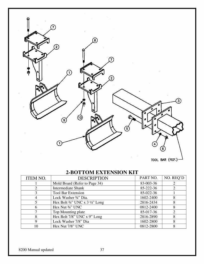
8200 Manual updated 37
2-BOTTOM EXTENSION KIT ITEM NO. DESCRIPTION PART NO. NO. REQ’D
1 Mold Board (Refer to Page 34) 83-003-36 2
2 Intermediate Shank 85-222-36 2
3 Tool Bar Extension 85-022-36 1
4 Lock Washer ¾” Dia. 1602-2400 8
5 Hex Bolt ¾” UNC x 3 ½” Long 2816-2434 8
6 Hex Nut ¾” UNC 0812-2400 8
7 Top Mounting plate 85-017-36 2
8 Hex Bolt 7/8” UNC x 9” Long 2816-2890 8
9 Lock Washer 7/8” Dia 1602-2800 8
10 Hex Nut 7/8” UNC 0812-2800 8
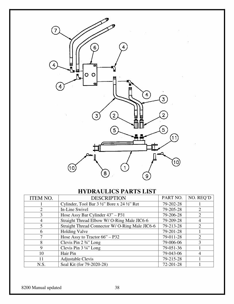
8200 Manual updated 38
HYDRAULICS PARTS LIST ITEM NO. DESCRIPTION PART NO. NO. REQ’D
1 Cylinder, Tool Bar 3 ½” Bore x 24 ½” Ret 79-202-28 1
2 In-Line Swivel 79-205-28 2
3 Hose Assy Bar Cylinder 43” – P31 79-206-28 2
4 Straight Thread Elbow W/ O-Ring Male JIC6-6 79-209-28 4
5 Straight Thread Connector W/ O-Ring Male JIC6-6 79-213-28 2
6 Holding Valve 79-201-28 1
7 Hose Assy to Tractor 66” – P32 79-011-28 2
8 Clevis Pin 2 ¾” Long 79-006-06 3
9 Clevis Pin 3 ¼” Long 79-051-36 1
10 Hair Pin 79-043-06 4
11 Adjustable Clevis 79-215-28 1
N.S. Seal Kit (for 79-2020-28) 72-201-28 1
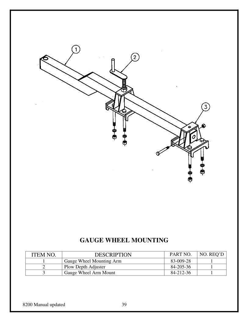
8200 Manual updated 39
GAUGE WHEEL MOUNTING
ITEM NO. DESCRIPTION PART NO. NO. REQ’D
1 Gauge Wheel Mounting Arm 83-009-28 1
2 Plow Depth Adjuster 84-205-36 1
3 Gauge Wheel Arm Mount 84-212-36 1
8200 Manual updated 40
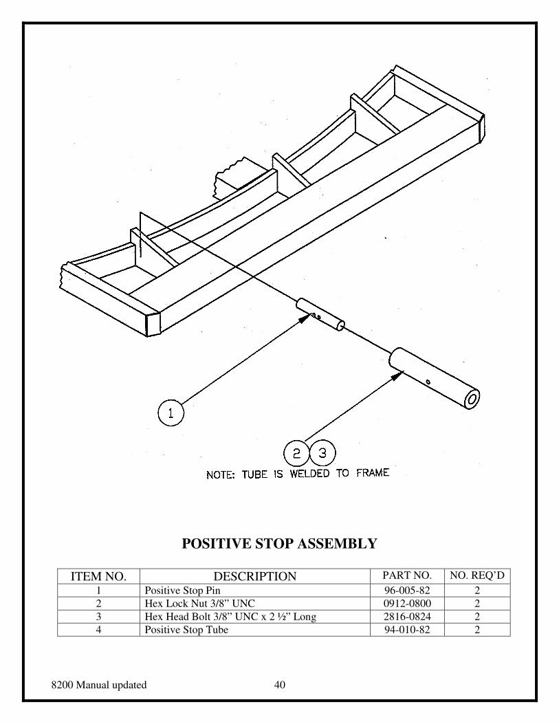
POSITIVE STOP ASSEMBLY
ITEM NO. DESCRIPTION PART NO. NO. REQ’D
1 Positive Stop Pin 96-005-82 2
2 Hex Lock Nut 3/8” UNC 0912-0800 2
3 Hex Head Bolt 3/8” UNC x 2 ½” Long 2816-0824 2
4 Positive Stop Tube 94-010-82 2
8200 Manual updated 41
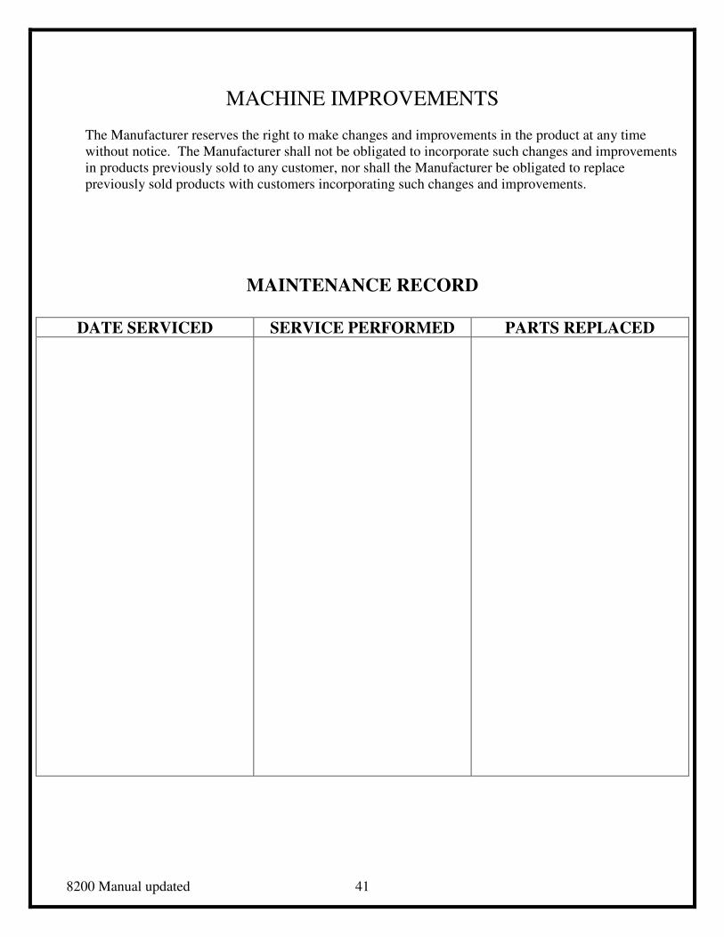
MACHINE IMPROVEMENTS
The Manufacturer reserves the right to make changes and improvements in the product at any time
without notice. The Manufacturer shall not be obligated to incorporate such changes and improvements
in products previously sold to any customer, nor shall the Manufacturer be obligated to replace
previously sold products with customers incorporating such changes and improvements.
MAINTENANCE RECORD
DATE SERVICED SERVICE PERFORMED PARTS REPLACED