Embed Size (px)
Citation preview
©2001, Mercury Marine Printed in U.S.A. 90-881986 JANUARY 2001
200OptiMaxJet Drive
Starting Model Year 2001Starting Serial Number 0E384500 for PowerheadStarting Serial Number 0E379931 for Pump Unit
Starting Model Year 2001
Starting Powerhead S/N 0E384500
200 OptiMax Jet Drive
90-881986 JANUARY 2001 Page i
Notice
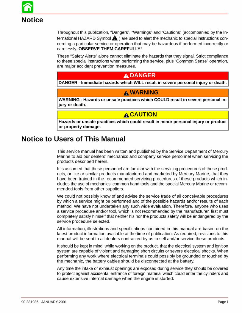
Throughout this publication, “Dangers”, “Warnings” and “Cautions” (accompanied by the In-ternational HAZARD Symbol ) are used to alert the mechanic to special instructions con-cerning a particular service or operation that may be hazardous if performed incorrectly orcarelessly. OBSERVE THEM CAREFULLY!
These “Safety Alerts” alone cannot eliminate the hazards that they signal. Strict complianceto these special instructions when performing the service, plus “Common Sense” operation,are major accident prevention measures.
DANGERDANGER - Imm ediate hazards which WILL result in severe personal injury or death.
WARNINGWARNING - Hazards or unsafe practices which COULD result in severe personal in-jury or death.
CAUTIONHazards or unsafe practices which could result in minor personal injury or productor property damage.
Notice to Users of This Manual
This service manual has been written and published by the Service Department of MercuryMarine to aid our dealers’ mechanics and company service personnel when servicing theproducts described herein.
It is assumed that these personnel are familiar with the servicing procedures of these prod-ucts, or like or similar products manufactured and marketed by Mercury Marine, that theyhave been trained in the recommended servicing procedures of these products which in-cludes the use of mechanics’ common hand tools and the special Mercury Marine or recom-mended tools from other suppliers.
We could not possibly know of and advise the service trade of all conceivable proceduresby which a service might be performed and of the possible hazards and/or results of eachmethod. We have not undertaken any such wide evaluation. Therefore, anyone who usesa service procedure and/or tool, which is not recommended by the manufacturer, first mustcompletely satisfy himself that neither his nor the products safety will be endangered by theservice procedure selected.
All information, illustrations and specifications contained in this manual are based on thelatest product information available at the time of publication. As required, revisions to thismanual will be sent to all dealers contracted by us to sell and/or service these products.
It should be kept in mind, while working on the product, that the electrical system and ignitionsystem are capable of violent and damaging short circuits or severe electrical shocks. Whenperforming any work where electrical terminals could possibly be grounded or touched bythe mechanic, the battery cables should be disconnected at the battery.
Any time the intake or exhaust openings are exposed during service they should be coveredto protect against accidental entrance of foreign material which could enter the cylinders andcause extensive internal damage when the engine is started.
Page ii 90-881986 JANUARY 2001
It is important to note, during any maintenance procedure replacement fasteners must havethe same measurements and strength as those removed. Numbers on the heads of the met-ric bolts and on the surfaces of metric nuts indicate their strength. American bolts use radiallines for this purpose, while most American nuts do not have strength markings. Mis-matched or incorrect fasteners can result in damage or malfunction, or possibly personalinjury. Therefore, fasteners removed should be saved for reuse in the same locations when-ever possible. Where the fasteners are not satisfactory for re-use, care should be taken toselect a replacement that matches the original.
Cleanliness and Care of Mercury Jet Unit
A marine power product is a combination of many machined, honed, polished and lappedsurfaces with tolerances that are measured in the ten thousands of an inch/mm. When anyproduct component is serviced, care and cleanliness are important. Throughout this manu-al, it should be understood that proper cleaning, and protection of machined surfaces andfriction areas is a part of the repair procedure. This is considered standard shop practiceeven if not specifically stated.
Whenever components are removed for service, they should be retained in order. At thetime of installation, they should be installed in the same locations and with the same matingsurfaces as when removed.
Personnel should not work on or under a powerhead which is suspended. Powerheadsshould be attached to work stands, or lowered to ground as soon as possible.
We reserve the right to make changes to this manual without prior notification.
Refer to dealer service bulletins for other pertinent information concerning the products de-scribed in this manual.
Page Numbering
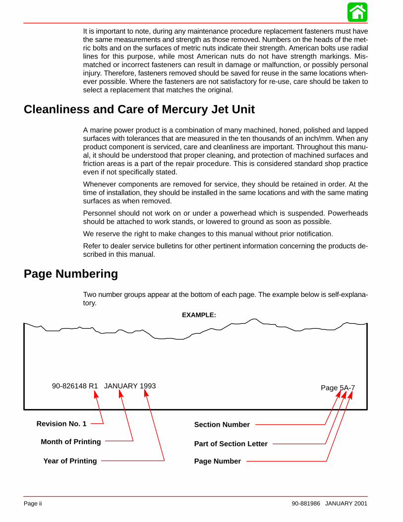
Two number groups appear at the bottom of each page. The example below is self-explana-tory.
EXAMPLE:
90-826148 R1 JANUARY 1993 Page 5A-7
Revision No. 1
Month of Printing
Year of Printing
Section Number
Part of Section Letter
Page Number
1
2
3
4
5
Important Information
Electrical
Fuel System
Powerhead
Pump Unit
6Color Diagrams
90-881986 JANUARY 2001 Page iii
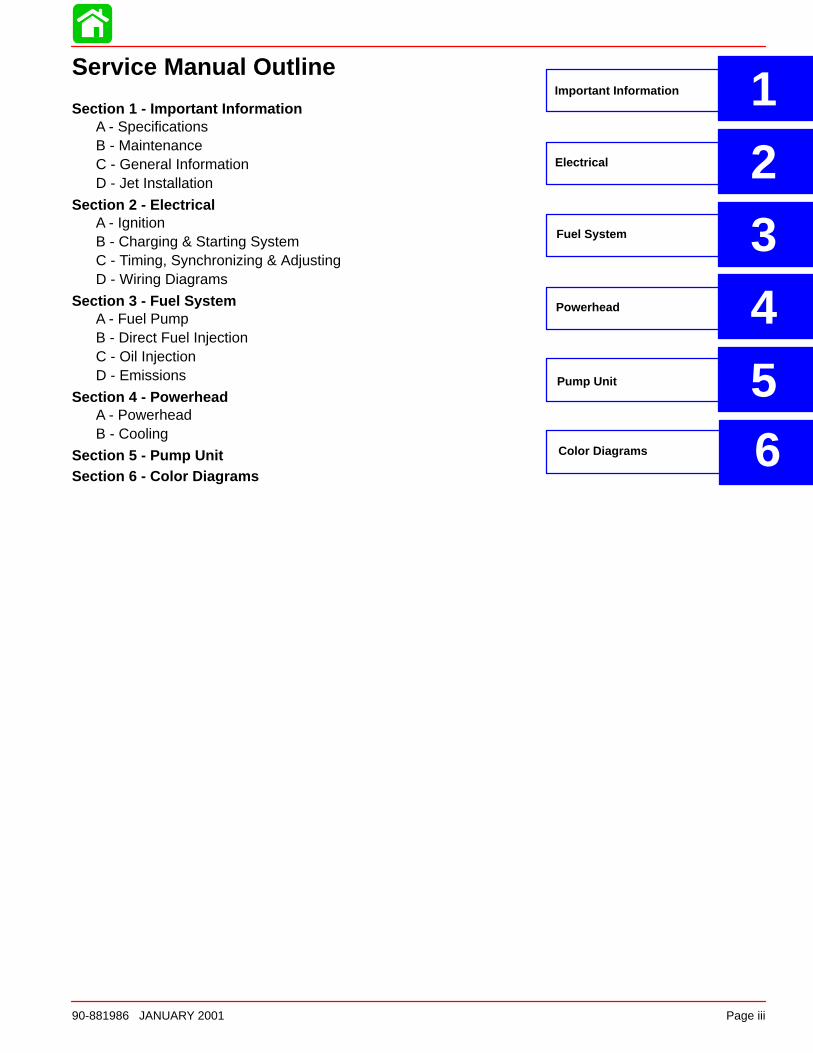
Service Manual Outline
Section 1 - Important InformationA - SpecificationsB - MaintenanceC - General InformationD - Jet Installation
Section 2 - ElectricalA - IgnitionB - Charging & Starting SystemC - Timing, Synchronizing & AdjustingD - Wiring Diagrams
Section 3 - Fuel SystemA - Fuel PumpB - Direct Fuel InjectionC - Oil InjectionD - Emissions
Section 4 - PowerheadA - PowerheadB - Cooling
Section 5 - Pump UnitSection 6 - Color Diagrams

1A
SPECIFICATIONS
90-881986 JANUARY 2001 Page 1A-1
IMPORTANT INFORMATIONSection 1A - Specifications
Table of Contents
Master Specifications 1A-2. . . . . . . . . . . . . . . . . . . . Torque Chart 1A-6. . . . . . . . . . . . . . . . . . . . . . . . .
Standard Hardware 1A-7. . . . . . . . . . . . . . . . . . . Metric Hardware 1A-7. . . . . . . . . . . . . . . . . . . . .
SPECIFICATIONS
Page 1A-2 90-881986 JANUARY 2001
Master SpecificationsModel 200 Optimax Jet Drive
HORSEPOWER(KW)
Model 200Full Throttle RPM Idle RPM (In Gear) RPM Limiter
All Models
200 (149.1)5150 - 5650900 - 1000
Refer to System Information in the Digi-tal Diagnostic Terminal (DDT) for latest
information
JET DRIVEWEIGHT
PowerheadPump Unit
257 (116.6 kg)110 (49 kg)
CYLINDERBLOCK
TypeDisplacement
V-6 Cylinder, Two Cycle, Direct Injected153 cu. in. (2508 cc) 60° Vee
STROKE Length (All Models) 2.65 in. (67.3 mm)
CYLINDERBORE
Diameter (Std)Diameter 0.015 in. OversizeTaper/Out of Round/Wear MaximumBore Type
3.501 in. (88.925 mm)3.516 in. (89.306 mm)0.003 in. (0.076 mm)
Cast Iron
CRANKSHAFT Maximum Runout 0.006 in. (0.152 mm)
PISTON Piston TypeDiameter Standard
Diameter 0.015 in. Oversize
Aluminum3.4925 in. ± .0005 in. (88.7095 mm ±
0.0127 mm)3.5075 in. ± 0.0005 in.
(89.0905 mm ± 0.0127 mm)
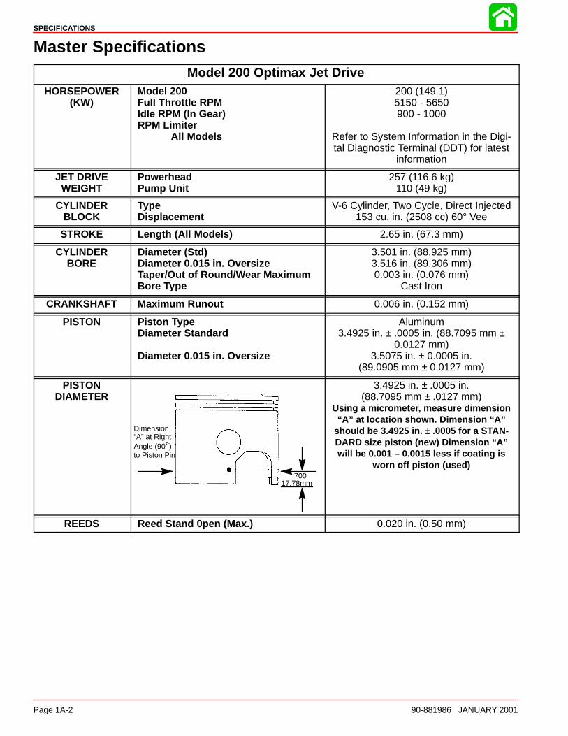
PISTONDIAMETER
Dimension“A” at RightAngle (90°)to Piston Pin
.70017.78mm
3.4925 in. ± .0005 in.(88.7095 mm ± .0127 mm)
Using a micrometer, measure dimension“A” at location shown. Dimension “A”
should be 3.4925 in. ± .0005 for a STAN-DARD size piston (new) Dimension “A”will be 0.001 – 0.0015 less if coating is
worn off piston (used)
REEDS Reed Stand 0pen (Max.) 0.020 in. (0.50 mm)
SPECIFICATIONS
90-881986 JANUARY 2001 Page 1A-3
Model 200 Optimax Jet Drive
DIRECTINJECTION
Injectors– Quantity– Injectors are Crank Angle Driven by ECM
– #2 Cylinder– #4 Cylinder– #6 Cylinder– #1 Cylinder– #3 Cylinder– #5 Cylinder
Fuel Line Pressure @ InjectorsAir PressureHigh Pressure Electric Fuel PumpAmperage DrawLow Pressure Electric Fuel PumpAmperage DrawLow Pressure Electric Fuel PumpOutputFuel Lift Electric Fuel Pump OutputFuel Lift Electric Fuel Pump Amper-age DrawFuel Injector Ohm ResistanceDirect Injector Ohm ResistanceFuel/Air Differential
6
RED/WHT + RED/BLU LeadsYEL/WHT + RED/BLU LeadsPPL/WHT + RED/BLU LeadsBRN/WHT + RED/BLU LeadsORG/WHT + RED/BLU LeadsBLU/WHT + RED/BLU Leads89 ± 2 psi (613.5 ± 13.8 kPa)79 ± 2 psi (544.0 ± 13.8 kPa)
5 – 9 Amperes
1 – 2 Amperes
6 – 9 psi (41.37 – 62.04 kPa)1 – 10 psi (6.89 – 68.94 kPa)
1 – 2 Amperes1.8 ± 0.1 Ω1.3 ± 0.3 Ω
10 psi (68.5 kPa)
FUELSYSTEM
FuelRecommended GasolineRecommended Oil
Gasoline/Oil Ratio – @ Idle
– @ WOT
Gasoline w/Oil InjectionUnleaded 87 Octane Minimum
Quicksilver TC-W3 Premium Plus 2 Cycle Outboard Oil
300 – 400:140:1
SPECIFICATIONS
Page 1A-4 90-881986 JANUARY 2001
Model 200 Optimax Jet DriveSTARTINGSYSTEM
Electric Start – All ModelsStarter Draw (Under Load)Starter Draw (No Load)Minimum Brush Length
Battery Rating
170 Amperes60 Amperes
0.25 in. (65.4 mm)1000 (Minimum) Marine Cranking Amps
750 (Minimum) Cold Cranking Amps105 (Minimum) Ampere Hours
IGNITIONSYSTEM
TypeSpark Plug TypeSpark Plug GapMaximum TimingIdle TimingThrottle Position Sensor
@ Idle@ WOT
Crank Position SensorAir Gap
Firing Order
Digital InductiveNGK PZFR5F-110.040 in. (1.0 mm)
Not Adjustable; Controlled by ECMNot Adjustable; Controlled by ECM
0.19 – 1.0 VDC3.45 – 4.63 VDC
0.025 in. – 0.040 in. (0.635 mm – 1.01 mm)
1-2-3-4-5-6
CHARGINGSYSTEM
Alternator Output (Regulated)
Brush Length
Voltage OutputRegulator Current Draw
32 - 38 Amperes @ 2000 RPM @ Battery*52 - 60 Amperes @ 2000 RPM @
AlternatorStd Exposed Length: 0.413 in. (10.5 mm)Min. Exposed Length: 0.059 in. (1.5 mm)
13.5 to 15.1 Volts0.15 mA (Ign. Switch Off)30.0 mA (Ign. Switch On)
*Amperage listed is when battery is in a discharged state. If battery is fully charged, amperage readings willbe less.
SPECIFICATIONS
90-881986 JANUARY 2001 Page 1A-5
Model 200 Optimax Jet DriveAIR
COMPRESSORType
Compressor Output
Reciprocating Piston(1 to 1 ratio with engine RPM)
@ Idle – 80 psi@ W.O.T. – 110 psi
Cylinder Block Displacement 7.07 cu. in. (116 cc)
Cylinder BoreDiameter (Standard)Taper/Out-of-Round/Wear MaximumBore Type
2.5591 in. (65.0 mm)
0.001 in. (0.025 mm)Cast Iron
Stroke Length 1.374 in. (34.9 mm)
Piston Type Aluminum
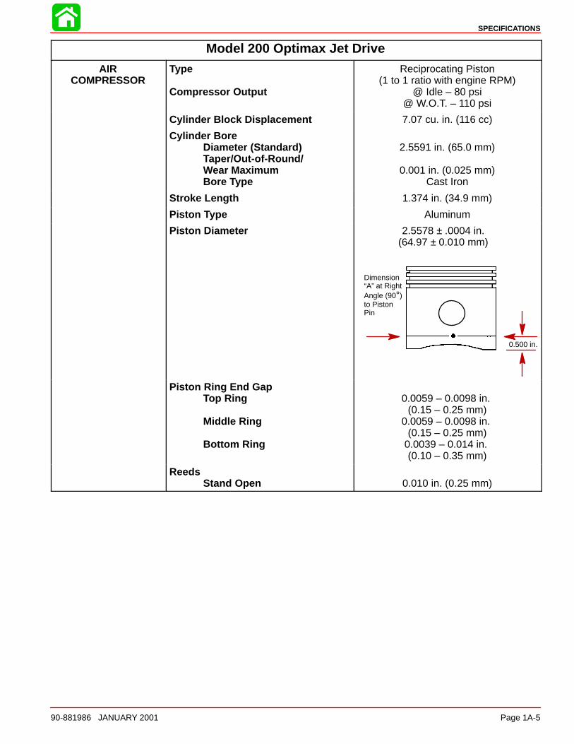
Piston Diameter 2.5578 ± .0004 in.(64.97 ± 0.010 mm)
Dimension“A” at RightAngle (90°)to PistonPin
0.500 in.
Piston Ring End GapTop Ring
Middle Ring
Bottom Ring
0.0059 – 0.0098 in. (0.15 – 0.25 mm)
0.0059 – 0.0098 in. (0.15 – 0.25 mm)
0.0039 – 0.014 in. (0.10 – 0.35 mm)
ReedsStand Open 0.010 in. (0.25 mm)
SPECIFICATIONS
Page 1A-6 90-881986 JANUARY 2001
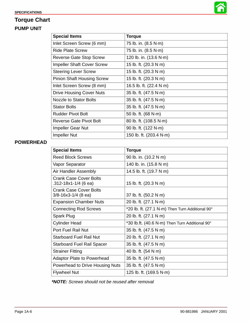
Torque ChartPUMP UNIT
Special Items Torque
Inlet Screen Screw (6 mm) 75 lb. in. (8.5 N·m)
Ride Plate Screw 75 lb. in. (8.5 N·m)
Reverse Gate Stop Screw 120 lb. in. (13.6 N·m)
Impeller Shaft Cover Screw 15 lb. ft. (20.3 N m)
Steering Lever Screw 15 lb. ft. (20.3 N m)
Pinion Shaft Housing Screw 15 lb. ft. (20.3 N m)
Inlet Screen Screw (8 mm) 16.5 lb. ft. (22.4 N m)
Drive Housing Cover Nuts 35 lb. ft. (47.5 N·m)
Nozzle to Stator Bolts 35 lb. ft. (47.5 N·m)
Stator Bolts 35 lb. ft. (47.5 N·m)
Rudder Pivot Bolt 50 lb. ft. (68 N·m)
Reverse Gate Pivot Bolt 80 lb. ft. (108.5 N·m)
Impeller Gear Nut 90 lb. ft. (122 N·m)
Impeller Nut 150 lb. ft. (203.4 N·m)
POWERHEAD
Special Items Torque
Reed Block Screws 90 lb. in. (10.2 N m)
Vapor Separator 140 lb. in. (15.8 N m)
Air Handler Assembly 14.5 lb. ft. (19.7 N m)
Crank Case Cover Bolts.312-18x1-1/4 (6 ea) 15 lb. ft. (20.3 N m)
Crank Case Cover Bolts3/8-16x3-1/4 (8 ea) 37 lb. ft. (50.2 N m)
Expansion Chamber Nuts 20 lb. ft. (27.1 N·m)
Connecting Rod Screws *20 lb. ft. (27.1 N·m) Then Turn Additional 90°
Spark Plug 20 lb. ft. (27.1 N m)
Cylinder Head *30 lb.ft. (40.6 N·m) Then Turn Additional 90°
Port Fuel Rail Nut 35 lb. ft. (47.5 N m)
Starboard Fuel Rail Nut 20 lb. ft. (27.1 N m)
Starboard Fuel Rail Spacer 35 lb. ft. (47.5 N m)
Strainer Fitting 40 lb. ft. (54 N m)
Adaptor Plate to Powerhead 35 lb. ft. (47.5 N·m)
Powerhead to Drive Housing Nuts 35 lb. ft. (47.5 N·m)
Flywheel Nut 125 lb. ft. (169.5 N·m)
*NOTE: Screws should not be reused after removal
SPECIFICATIONS
90-881986 JANUARY 2001 Page 1A-7
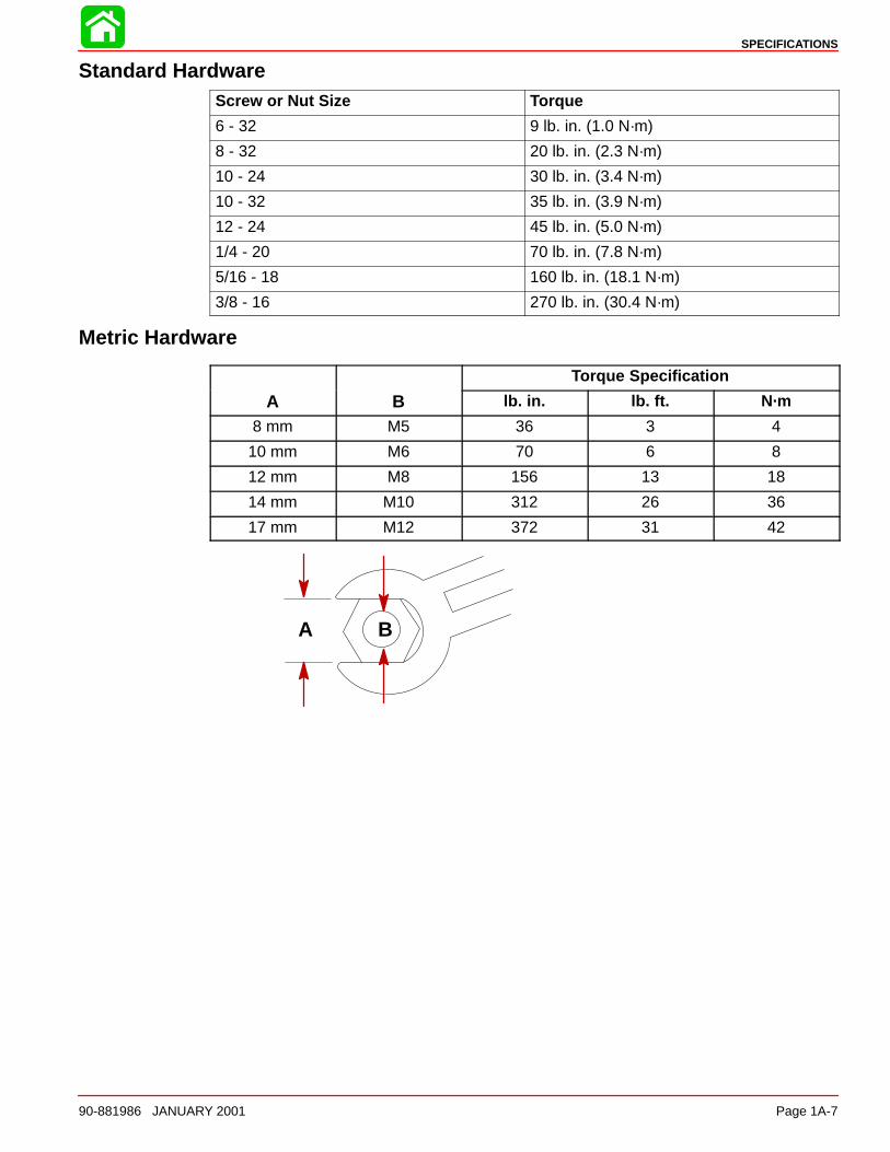
Standard HardwareScrew or Nut Size Torque
6 - 32 9 lb. in. (1.0 N·m)
8 - 32 20 lb. in. (2.3 N·m)
10 - 24 30 lb. in. (3.4 N·m)
10 - 32 35 lb. in. (3.9 N·m)
12 - 24 45 lb. in. (5.0 N·m)
1/4 - 20 70 lb. in. (7.8 N·m)
5/16 - 18 160 lb. in. (18.1 N·m)
3/8 - 16 270 lb. in. (30.4 N·m)
Metric Hardware
Torque Specification
A B lb. in. lb. ft. N·m
8 mm M5 36 3 4
10 mm M6 70 6 8
12 mm M8 156 13 18
14 mm M10 312 26 36
17 mm M12 372 31 42
A B
1B
MAINTENANCE
90-881986 JANUARY 2001 Page 1B-1
IMPORTANT INFORMATIONSection 1B - Maintenance
Table of Contents
Specifications 1B-1. . . . . . . . . . . . . . . . . . . . . . . . . . . Special Tools 1B-2. . . . . . . . . . . . . . . . . . . . . . . . . . . Quicksilver Lubricant/Sealant 1B-2. . . . . . . . . . . . . Maintenance 1B-3. . . . . . . . . . . . . . . . . . . . . . . . . . . .
Before Each Use 1B-3. . . . . . . . . . . . . . . . . . . . . After Each Use 1B-3. . . . . . . . . . . . . . . . . . . . . . . Every 10 Hours of Use or Once a Month 1B-3Every 50 Hours of Use or Once a Month 1B-3Every 100 Hours of Use or Once a Season 1B-3
Fuel System 1B-4. . . . . . . . . . . . . . . . . . . . . . . . . . . . Fuel Line Inspection 1B-4. . . . . . . . . . . . . . . . . . Water Separating Fuel Filter 1B-4. . . . . . . . . . .
Spark Plug Inspection 1B-5. . . . . . . . . . . . . . . . . . . . Battery Inspection 1B-5. . . . . . . . . . . . . . . . . . . . . . . Fuse Replacement 1B-6. . . . . . . . . . . . . . . . . . . . . . Compressor Air intake Filter 1B-6. . . . . . . . . . . . . .
Removal 1B-6. . . . . . . . . . . . . . . . . . . . . . . . . . . . Flushing Cooling System 1B-7. . . . . . . . . . . . . . . . .
Corrosion Protection 1B-7. . . . . . . . . . . . . . . . . . Out-of-Season Storage 1B-8. . . . . . . . . . . . . . . . . .
Fuel System 1B-8. . . . . . . . . . . . . . . . . . . . . . . . . Protecting Jet Pump Components 1B-9. . . . . . Battery Storage 1B-9. . . . . . . . . . . . . . . . . . . . . .
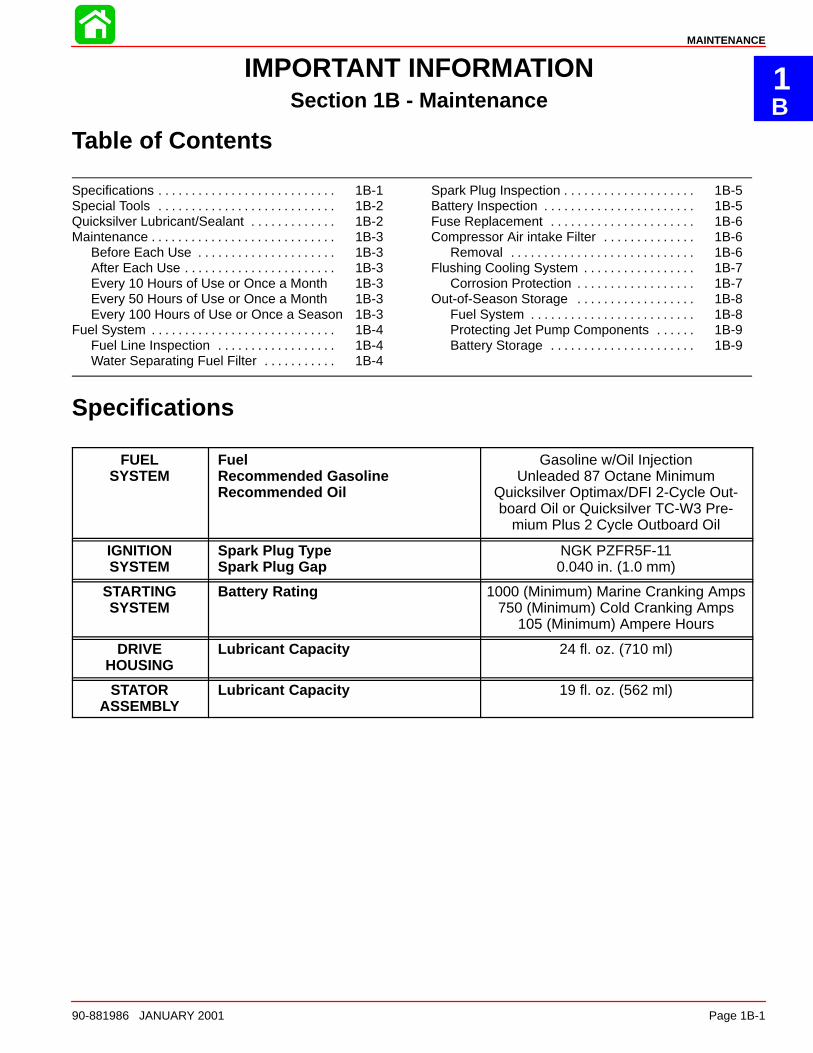
Specifications
FUELSYSTEM
FuelRecommended GasolineRecommended Oil
Gasoline w/Oil InjectionUnleaded 87 Octane Minimum
Quicksilver Optimax/DFI 2-Cycle Out-board Oil or Quicksilver TC-W3 Pre-
mium Plus 2 Cycle Outboard Oil
IGNITIONSYSTEM
Spark Plug TypeSpark Plug Gap
NGK PZFR5F-110.040 in. (1.0 mm)
STARTINGSYSTEM
Battery Rating 1000 (Minimum) Marine Cranking Amps750 (Minimum) Cold Cranking Amps
105 (Minimum) Ampere Hours
DRIVEHOUSING
Lubricant Capacity 24 fl. oz. (710 ml)
STATORASSEMBLY
Lubricant Capacity 19 fl. oz. (562 ml)
MAINTENANCE
Page 1B-2 90-881986 JANUARY 2001
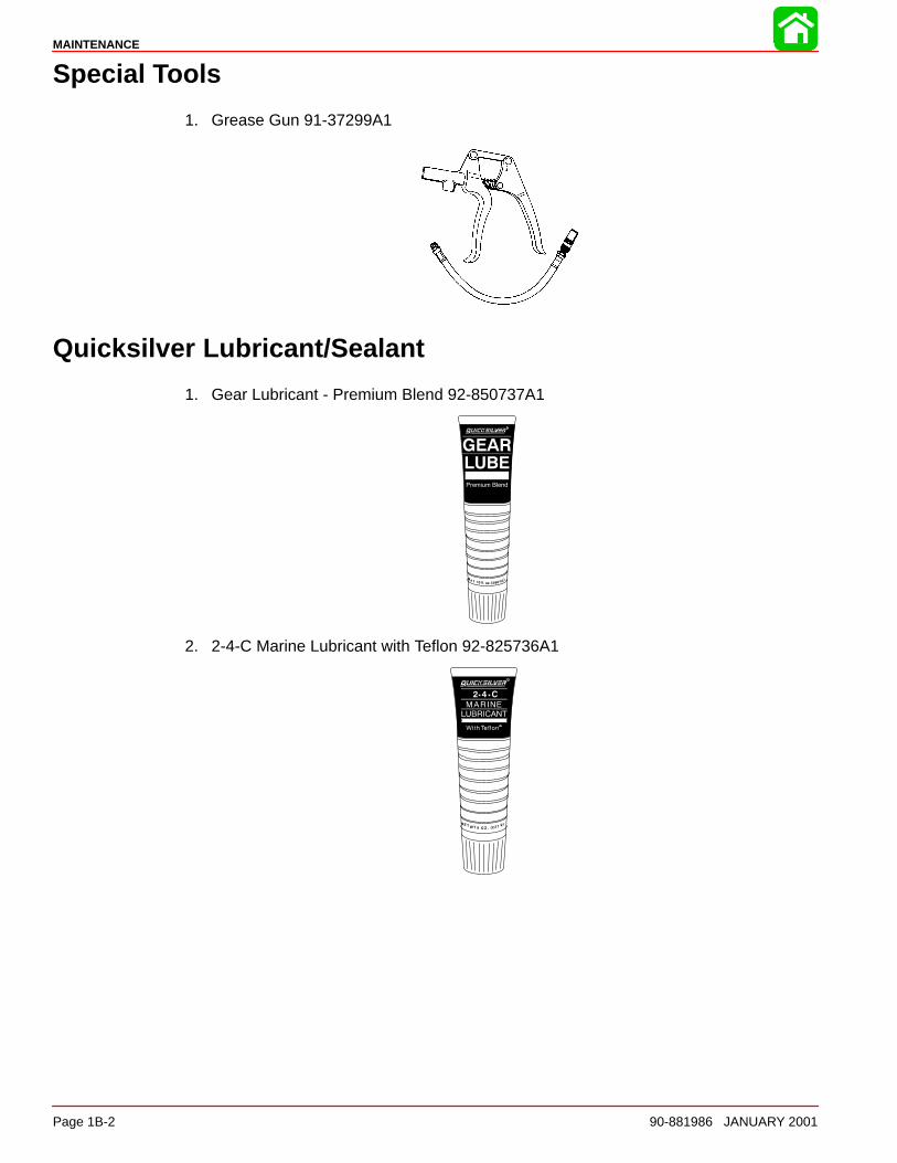
Special Tools
1. Grease Gun 91-37299A1
Quicksilver Lubricant/Sealant
1. Gear Lubricant - Premium Blend 92-850737A1
2. 2-4-C Marine Lubricant with Teflon 92-825736A1
MAINTENANCE
90-881986 JANUARY 2001 Page 1B-3
Maintenance
Before Each Use1. Check that lanyard stop switch stops the engine.
2. Visually inspect the fuel system for deterioration or leaks.
3. Check the engine compartment and use your nose to detect any fuel fumes.
4. Check throttle, shift and steering system for binding or loose components.
After Each Use1. Wash off all salt deposits with fresh water if operating in salt water.
2. Flush out the engine cooling system if operating in salt or polluted waters or sandylocations.
Every 10 Hours of Use or Once a Month1. Check bilge siphon system.
2. Inspect cable bellows: worn, rubbing, or leaking.
3. Inspect battery and connections.
4. Check tightness of bolts, nuts and other fasteners.
Every 50 Hours of Use or Once a Month1. Check level and condition of drive housing and stator lubricant.
2. Check corrosion control anodes.
3. Check tightness of bolts, nuts and other fasteners.
Every 100 Hours of Use or Once a Season1. Lubricate all lubrication points. Lubricate more frequently when used in salt water.
2. Replace spark plugs at first 100 hours or first year. After that, inspect spark plugs every100 hours or once yearly. Replace spark plugs as needed.
3. Drain and replace drive housing lubricant.
4. Drain and replace stator housing lubricant.
5. Remove impeller and lubricate impeller shaft with Quicksilver or Mercury Precision2-4-C w/Teflon to prevent impeller from seizing to the shaft.
6. Remove engine deposits with Quicksilver or Mercury Precision Power Tune EngineCleaner.
7. Replace engine fuel line filter.
MAINTENANCE
Page 1B-4 90-881986 JANUARY 2001
Fuel System
WARNINGAvoid serious injury or death from gasoline fire or explosion. Carefully follow allfuel system service instructions. Always stop the engine and DO NOT smoke or al-low open flames or sparks in the area while servicing any part of the fuel system.
Before servicing any part of the fuel system, stop engine and disconnect the battery. Drainthe fuel system completely. Use an approved container to collect and store fuel. Wipe upany spillage immediately. Material used to contain spillage must be disposed of in an ap-proved receptacle. Any fuel system service must be performed in a well ventilated area. In-spect any completed service work for sign of fuel leakage.
Fuel Line InspectionVisually inspect the fuel line for cracks, swelling, leaks, hardness, or other signs of deteriora-tion or damage. If any of these conditions is found, the fuel line must be replaced.
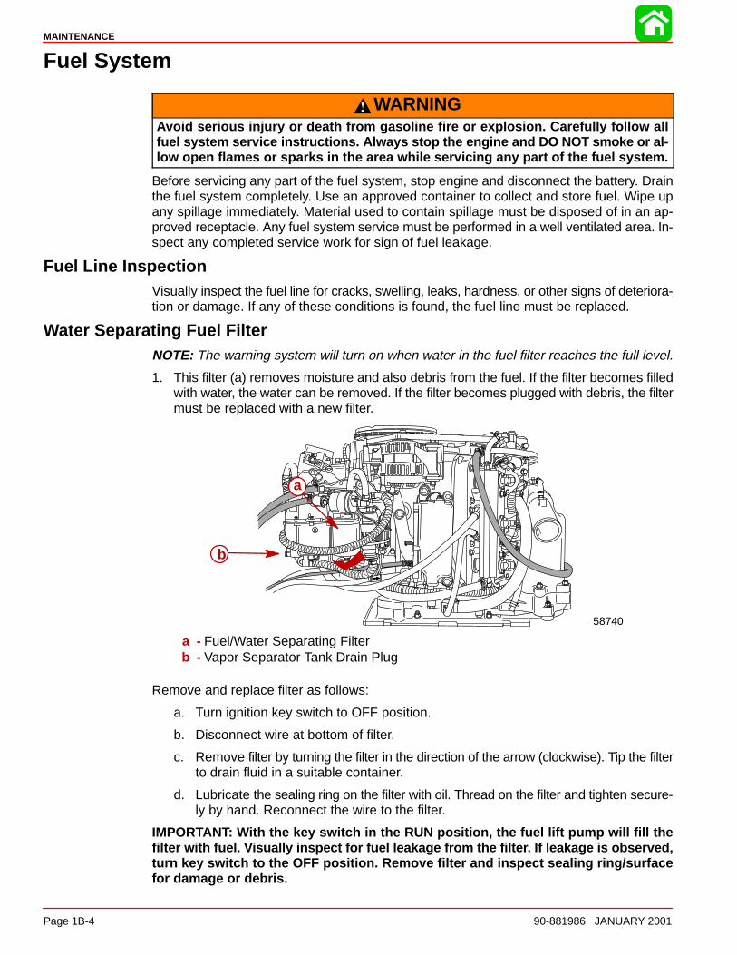
Water Separating Fuel FilterNOTE: The warning system will turn on when water in the fuel filter reaches the full level.
1. This filter (a) removes moisture and also debris from the fuel. If the filter becomes filledwith water, the water can be removed. If the filter becomes plugged with debris, the filtermust be replaced with a new filter.
58740
a
b
a - Fuel/Water Separating Filterb - Vapor Separator Tank Drain Plug
Remove and replace filter as follows:
a. Turn ignition key switch to OFF position.
b. Disconnect wire at bottom of filter.
c. Remove filter by turning the filter in the direction of the arrow (clockwise). Tip the filterto drain fluid in a suitable container.
d. Lubricate the sealing ring on the filter with oil. Thread on the filter and tighten secure-ly by hand. Reconnect the wire to the filter.
IMPORTANT: With the key switch in the RUN position, the fuel lift pump will fill thefilter with fuel. Visually inspect for fuel leakage from the filter. If leakage is observed,turn key switch to the OFF position. Remove filter and inspect sealing ring/surfacefor damage or debris.
MAINTENANCE
90-881986 JANUARY 2001 Page 1B-5
Spark Plug Inspection
Inspect spark plugs at the recommended intervals.
NOTE: On some applications it may be necessary to remove powerhead from boat to ac-cess expansion chamber and spark plugs.
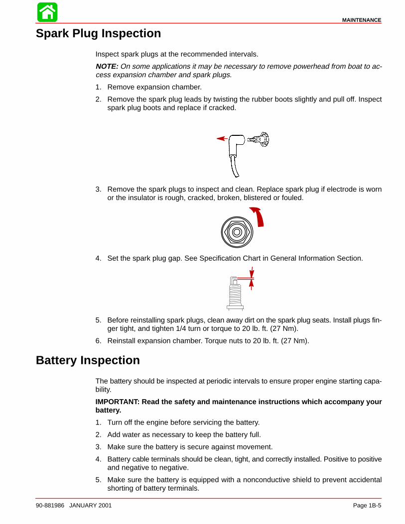
1. Remove expansion chamber.
2. Remove the spark plug leads by twisting the rubber boots slightly and pull off. Inspectspark plug boots and replace if cracked.
3. Remove the spark plugs to inspect and clean. Replace spark plug if electrode is wornor the insulator is rough, cracked, broken, blistered or fouled.
4. Set the spark plug gap. See Specification Chart in General Information Section.
5. Before reinstalling spark plugs, clean away dirt on the spark plug seats. Install plugs fin-ger tight, and tighten 1/4 turn or torque to 20 lb. ft. (27 Nm).
6. Reinstall expansion chamber. Torque nuts to 20 lb. ft. (27 Nm).
Battery Inspection
The battery should be inspected at periodic intervals to ensure proper engine starting capa-bility.
IMPORTANT: Read the safety and maintenance instructions which accompany yourbattery.
1. Turn off the engine before servicing the battery.
2. Add water as necessary to keep the battery full.
3. Make sure the battery is secure against movement.
4. Battery cable terminals should be clean, tight, and correctly installed. Positive to positiveand negative to negative.
5. Make sure the battery is equipped with a nonconductive shield to prevent accidentalshorting of battery terminals.
MAINTENANCE
Page 1B-6 90-881986 JANUARY 2001
Fuse Replacement
IMPORTANT: Always carry spare SFE 15 and 20 AMP fuses.
The electrical wiring circuits on the outboard are protected from overload by fuses in the wir-ing. If a fuse is blown, try to locate and correct the cause of the overload. If the cause is notfound, the fuse may blow again.
1. Open the fuse holder and look at the silver colored band inside the fuse. If band is bro-ken, replace the fuse. Replace fuse with a new fuse with the same rating.
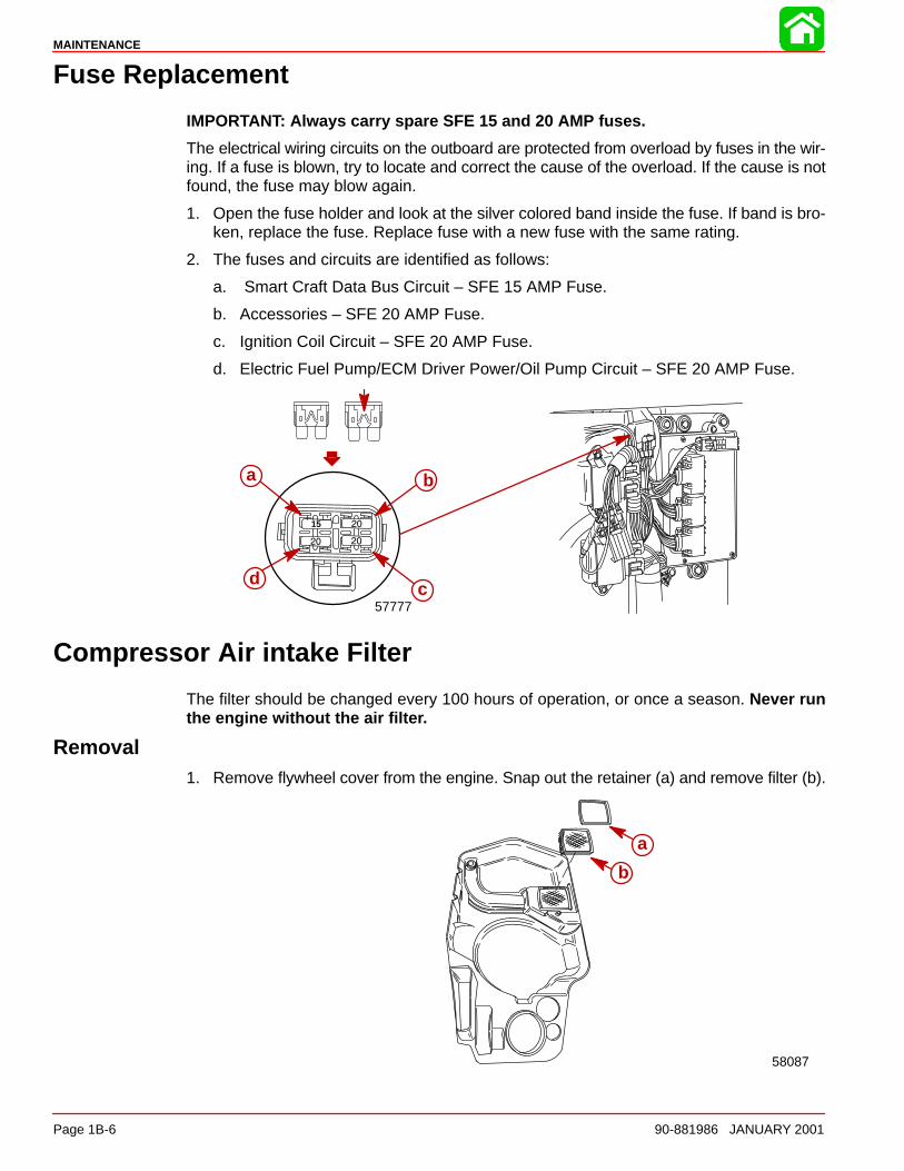
2. The fuses and circuits are identified as follows:
a. Smart Craft Data Bus Circuit – SFE 15 AMP Fuse.
b. Accessories – SFE 20 AMP Fuse.
c. Ignition Coil Circuit – SFE 20 AMP Fuse.
d. Electric Fuel Pump/ECM Driver Power/Oil Pump Circuit – SFE 20 AMP Fuse.
57777
a b
cd
15
Compressor Air intake Filter
The filter should be changed every 100 hours of operation, or once a season. Never runthe engine without the air filter.
Removal1. Remove flywheel cover from the engine. Snap out the retainer (a) and remove filter (b).
a
b
58087
MAINTENANCE
90-881986 JANUARY 2001 Page 1B-7
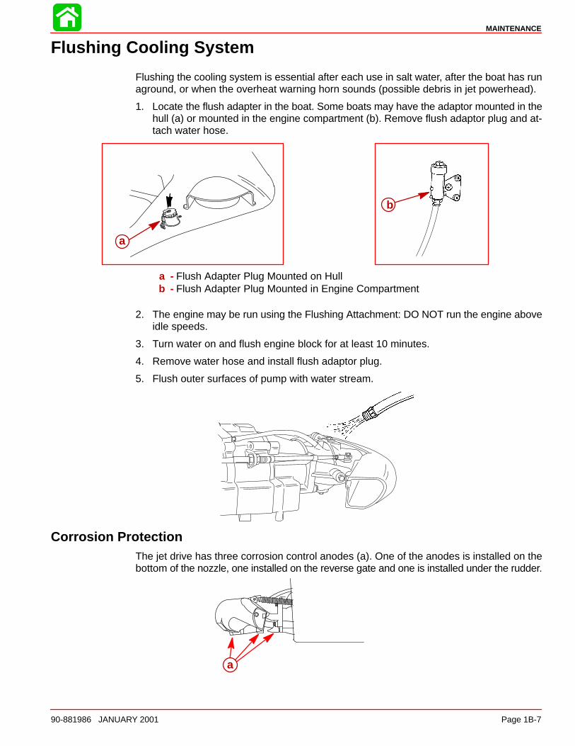
Flushing Cooling System
Flushing the cooling system is essential after each use in salt water, after the boat has runaground, or when the overheat warning horn sounds (possible debris in jet powerhead).
1. Locate the flush adapter in the boat. Some boats may have the adaptor mounted in thehull (a) or mounted in the engine compartment (b). Remove flush adaptor plug and at-tach water hose.
a
b
a - Flush Adapter Plug Mounted on Hullb - Flush Adapter Plug Mounted in Engine Compartment
2. The engine may be run using the Flushing Attachment: DO NOT run the engine aboveidle speeds.
3. Turn water on and flush engine block for at least 10 minutes.
4. Remove water hose and install flush adaptor plug.
5. Flush outer surfaces of pump with water stream.
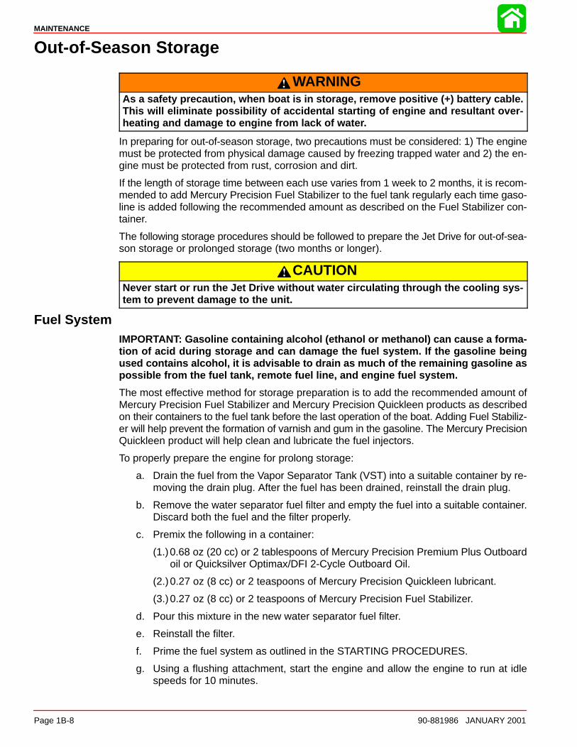
Corrosion ProtectionThe jet drive has three corrosion control anodes (a). One of the anodes is installed on thebottom of the nozzle, one installed on the reverse gate and one is installed under the rudder.
a
MAINTENANCE
Page 1B-8 90-881986 JANUARY 2001
Out-of-Season Storage
WARNINGAs a safety precaution, when boat is in storage, remove positive (+) battery cable.This will eliminate possibility of accidental starting of engine and resultant over-heating and damage to engine from lack of water.
In preparing for out-of-season storage, two precautions must be considered: 1) The enginemust be protected from physical damage caused by freezing trapped water and 2) the en-gine must be protected from rust, corrosion and dirt.
If the length of storage time between each use varies from 1 week to 2 months, it is recom-mended to add Mercury Precision Fuel Stabilizer to the fuel tank regularly each time gaso-line is added following the recommended amount as described on the Fuel Stabilizer con-tainer.
The following storage procedures should be followed to prepare the Jet Drive for out-of-sea-son storage or prolonged storage (two months or longer).
CAUTIONNever start or run the Jet Drive without water circulating through the cooling sys-tem to prevent damage to the unit.
Fuel SystemIMPORTANT: Gasoline containing alcohol (ethanol or methanol) can cause a forma-tion of acid during storage and can damage the fuel system. If the gasoline beingused contains alcohol, it is advisable to drain as much of the remaining gasoline aspossible from the fuel tank, remote fuel line, and engine fuel system.
The most effective method for storage preparation is to add the recommended amount ofMercury Precision Fuel Stabilizer and Mercury Precision Quickleen products as describedon their containers to the fuel tank before the last operation of the boat. Adding Fuel Stabiliz-er will help prevent the formation of varnish and gum in the gasoline. The Mercury PrecisionQuickleen product will help clean and lubricate the fuel injectors.
To properly prepare the engine for prolong storage:
a. Drain the fuel from the Vapor Separator Tank (VST) into a suitable container by re-moving the drain plug. After the fuel has been drained, reinstall the drain plug.
b. Remove the water separator fuel filter and empty the fuel into a suitable container.Discard both the fuel and the filter properly.
c. Premix the following in a container:
(1.)0.68 oz (20 cc) or 2 tablespoons of Mercury Precision Premium Plus Outboardoil or Quicksilver Optimax/DFI 2-Cycle Outboard Oil.
(2.)0.27 oz (8 cc) or 2 teaspoons of Mercury Precision Quickleen lubricant.
(3.)0.27 oz (8 cc) or 2 teaspoons of Mercury Precision Fuel Stabilizer.
d. Pour this mixture in the new water separator fuel filter.
e. Reinstall the filter.
f. Prime the fuel system as outlined in the STARTING PROCEDURES.
g. Using a flushing attachment, start the engine and allow the engine to run at idlespeeds for 10 minutes.
MAINTENANCE
90-881986 JANUARY 2001 Page 1B-9
h. Turn the engine off. Turn the water off if using a flushing attachment. Allow the waterto drain out of the unit completely.
i. Complete the other recommended items for storage.
Protecting Jet Pump ComponentsIMPORTANT: Check and refill housing with Quicksilver Premium Gear Lube beforestorage to protect against possible water leakage into housing which is caused byloose lubricant vent or fill plug. Inspect gaskets under lubricant vent and fill plugsreplacing any damaged gaskets before reinstalling plugs.
1. Drain and refill drive housing unit and stator assembly with Quicksilver Premium GearLube as explained in “Jet Pump ” section (see Table of Contents ).
2. Lubricate all lubrication points.
Battery Storage1. Remove battery as soon as possible and remove all grease, sulfate and dirt from top
surface.
2. Cover plates with distilled water, but not over 3/16 in. (5 mm) above perforated baffles.
3. Cover terminal bolts well with grease.
4. Store battery in a cool, dry place in a dry carton or box.
5. Remove battery from storage every 60 days. Check water level and place on charge for5 to 6 hours at 6 amperes. DO NOT fast charge.
CAUTIONA discharged battery can be damaged by freezing.
1C
GENERAL INFORMATION
90-881986 JANUARY 2001 Page 1C-1
IMPORTANT INFORMATIONSection 1C - General Information
Table of Contents
Serial Number Location 1C-1. . . . . . . . . . . . . . . . . . Conditions Affecting Performance 1C-2. . . . . . . . .
Weather 1C-2. . . . . . . . . . . . . . . . . . . . . . . . . . . . . Boat 1C-2. . . . . . . . . . . . . . . . . . . . . . . . . . . . . . . . Engine 1C-3. . . . . . . . . . . . . . . . . . . . . . . . . . . . . . Engine Compression 1C-4. . . . . . . . . . . . . . . . . . Water Pressure Check 1C-5. . . . . . . . . . . . . . . .
Following Complete Submersion 1C-5. . . . . . . . . . Salt Water Submersion 1C-5. . . . . . . . . . . . . . . .
Submerged While Running 1C-5. . . . . . . . . . . . Fresh Water Submersion 1C-5. . . . . . . . . . . . . .
Model 200 HP Front View 1C-7. . . . . . . . . . . . . . . . Model 200 HP Starboard View 1C-8. . . . . . . . . . . . Model 200 HP Port View 1C-9. . . . . . . . . . . . . . . . . Model 200 HP Aft View 1C-10. . . . . . . . . . . . . . . . . . Model 200 HP Top View 1C-11. . . . . . . . . . . . . . . . . . Mercury Jet Pump Starboard View 1C-12. . . . . . . . . Mercury Jet Pump Port View 1C-12. . . . . . . . . . . . . .
Serial Number Location
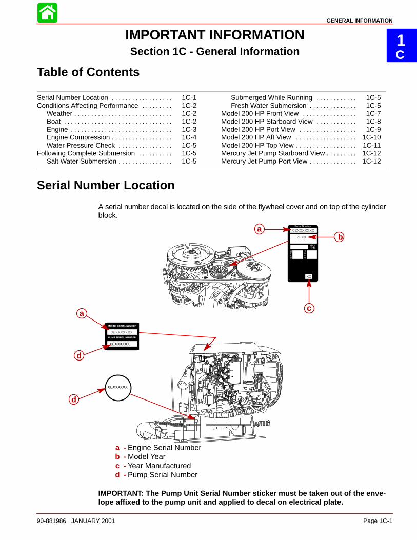
A serial number decal is located on the side of the flywheel cover and on top of the cylinderblock.
20XX
XX
OEXXXXXXX
OEXXXXXXX
ab
ca
d
d
a - Engine Serial Numberb - Model Yearc - Year Manufacturedd - Pump Serial Number
IMPORTANT: The Pump Unit Serial Number sticker must be taken out of the enve-lope affixed to the pump unit and applied to decal on electrical plate.
GENERAL INFORMATION
Page 1C-2 90-881986 JANUARY 2001
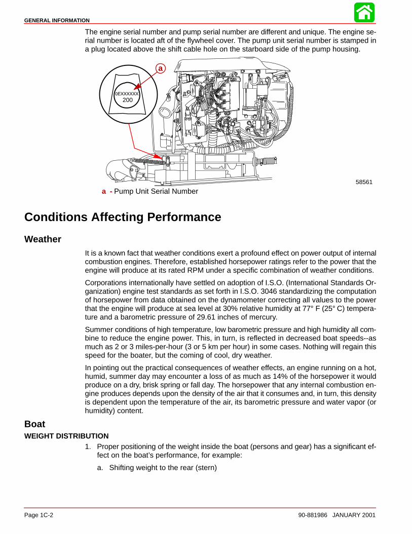
The engine serial number and pump serial number are different and unique. The engine se-rial number is located aft of the flywheel cover. The pump unit serial number is stamped ina plug located above the shift cable hole on the starboard side of the pump housing.
200
a
58561
a - Pump Unit Serial Number
Conditions Affecting Performance
WeatherIt is a known fact that weather conditions exert a profound effect on power output of internalcombustion engines. Therefore, established horsepower ratings refer to the power that theengine will produce at its rated RPM under a specific combination of weather conditions.
Corporations internationally have settled on adoption of I.S.O. (International Standards Or-ganization) engine test standards as set forth in I.S.O. 3046 standardizing the computationof horsepower from data obtained on the dynamometer correcting all values to the powerthat the engine will produce at sea level at 30% relative humidity at 77° F (25° C) tempera-ture and a barometric pressure of 29.61 inches of mercury.
Summer conditions of high temperature, low barometric pressure and high humidity all com-bine to reduce the engine power. This, in turn, is reflected in decreased boat speeds--asmuch as 2 or 3 miles-per-hour (3 or 5 km per hour) in some cases. Nothing will regain thisspeed for the boater, but the coming of cool, dry weather.
In pointing out the practical consequences of weather effects, an engine running on a hot,humid, summer day may encounter a loss of as much as 14% of the horsepower it wouldproduce on a dry, brisk spring or fall day. The horsepower that any internal combustion en-gine produces depends upon the density of the air that it consumes and, in turn, this densityis dependent upon the temperature of the air, its barometric pressure and water vapor (orhumidity) content.
BoatWEIGHT DISTRIBUTION
1. Proper positioning of the weight inside the boat (persons and gear) has a significant ef-fect on the boat’s performance, for example:
a. Shifting weight to the rear (stern)
GENERAL INFORMATION
90-881986 JANUARY 2001 Page 1C-3
(1.)Generally increases top speed.
(2.) If in excess, can cause the boat to porpoise.
(3.)Can make the bow bounce excessively in choppy water.
(4.)Will increase the danger of the following wave splashing into the boat when com-ing off plane.
b. Shifting weight to the front (bow)
(1.) Improves ease of planing off.
(2.)Generally improves rough water ride.
(3.) If excessive, can make the boat veer back-and-forth (bow steer).BOTTOM
1. Boat Bottom: For maximum speed, a boat bottom should be nearly a flat plane whereit contacts the water and particularly straight and smooth in fore-and-aft direction.
a. Hook: Exists when bottom is concave in fore-and-aft direction when viewed from theside. When boat is planing, “hook” causes more lift on bottom near transom and al-lows bow to drop, thus greatly increasing wetted surface and reducing boat speed.“Hook” frequently is caused by supporting boat too far ahead of transom while haul-ing on a trailer or during storage.
b. Rocker: The reverse of hook and much less common. “Rocker” exists if bottom isconvex in fore-and-aft direction when viewed from the side, and boat has strong ten-dency to porpoise.
c. Surface Roughness: Moss, barnacles, etc., on boat or corrosion of motor’s gearhousing increases skin friction and cause speed loss. Clean surfaces when neces-sary.
d. Jet Unit: If unit is left in the water, marine vegetation may accumulate over a periodof time. This growth MUST be removed from unit before operation, as it may clogthe water inlet holes in the gear housing and cause the engine to overheat.
WATER ABSORPTIONIt is imperative that all through hull fasteners be coated with a quality marine sealer at timeof installation. Water intrusion into the transom core and/or inner hull will result in additionalboat weight (reduced boat performance), hull decay and eventual structural failure.
CAVITATIONCavitation is caused by water vapor bubbles forming either from sharp turns or from an irreg-ularity in the impeller blade itself. These vapor bubbles flow back and collapse when strikingthe surface of the impeller blade resulting in the erosion of the impeller blade surface. If al-lowed to continue, eventual blade failure (breakage) will occur.
VENTILATIONVentilation occurs when air is drawn from the water’s surface (excessive trim out angle) orfrom the engine exhaust flow (in reverse) into the impeller blades. These air bubbles strikethe impeller blade surface and cause erosion of the blade surface. If allowed to continue,eventual blade failure (breakage) will occur.
EngineDETONATION
Detonation in a 2-cycle engine resembles the “pinging” heard in an automobile engine. Itcan be described as a “rattling” or “plinking” sound.
GENERAL INFORMATION
Page 1C-4 90-881986 JANUARY 2001
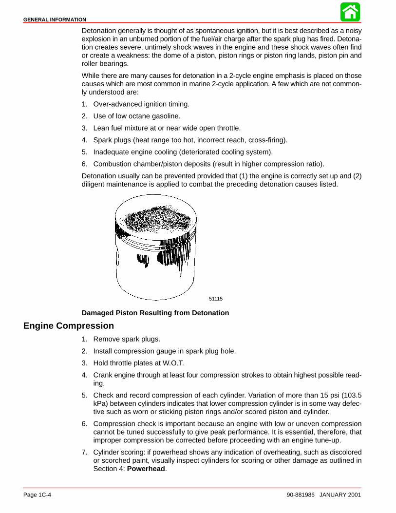
Detonation generally is thought of as spontaneous ignition, but it is best described as a noisyexplosion in an unburned portion of the fuel/air charge after the spark plug has fired. Detona-tion creates severe, untimely shock waves in the engine and these shock waves often findor create a weakness: the dome of a piston, piston rings or piston ring lands, piston pin androller bearings.
While there are many causes for detonation in a 2-cycle engine emphasis is placed on thosecauses which are most common in marine 2-cycle application. A few which are not common-ly understood are:
1. Over-advanced ignition timing.
2. Use of low octane gasoline.
3. Lean fuel mixture at or near wide open throttle.
4. Spark plugs (heat range too hot, incorrect reach, cross-firing).
5. Inadequate engine cooling (deteriorated cooling system).
6. Combustion chamber/piston deposits (result in higher compression ratio).
Detonation usually can be prevented provided that (1) the engine is correctly set up and (2)diligent maintenance is applied to combat the preceding detonation causes listed.
51115
Damaged Piston Resulting from Detonation
Engine Compression1. Remove spark plugs.
2. Install compression gauge in spark plug hole.
3. Hold throttle plates at W.O.T.
4. Crank engine through at least four compression strokes to obtain highest possible read-ing.
5. Check and record compression of each cylinder. Variation of more than 15 psi (103.5kPa) between cylinders indicates that lower compression cylinder is in some way defec-tive such as worn or sticking piston rings and/or scored piston and cylinder.
6. Compression check is important because an engine with low or uneven compressioncannot be tuned successfully to give peak performance. It is essential, therefore, thatimproper compression be corrected before proceeding with an engine tune-up.
7. Cylinder scoring: if powerhead shows any indication of overheating, such as discoloredor scorched paint, visually inspect cylinders for scoring or other damage as outlined inSection 4: Powerhead .
GENERAL INFORMATION
90-881986 JANUARY 2001 Page 1C-5
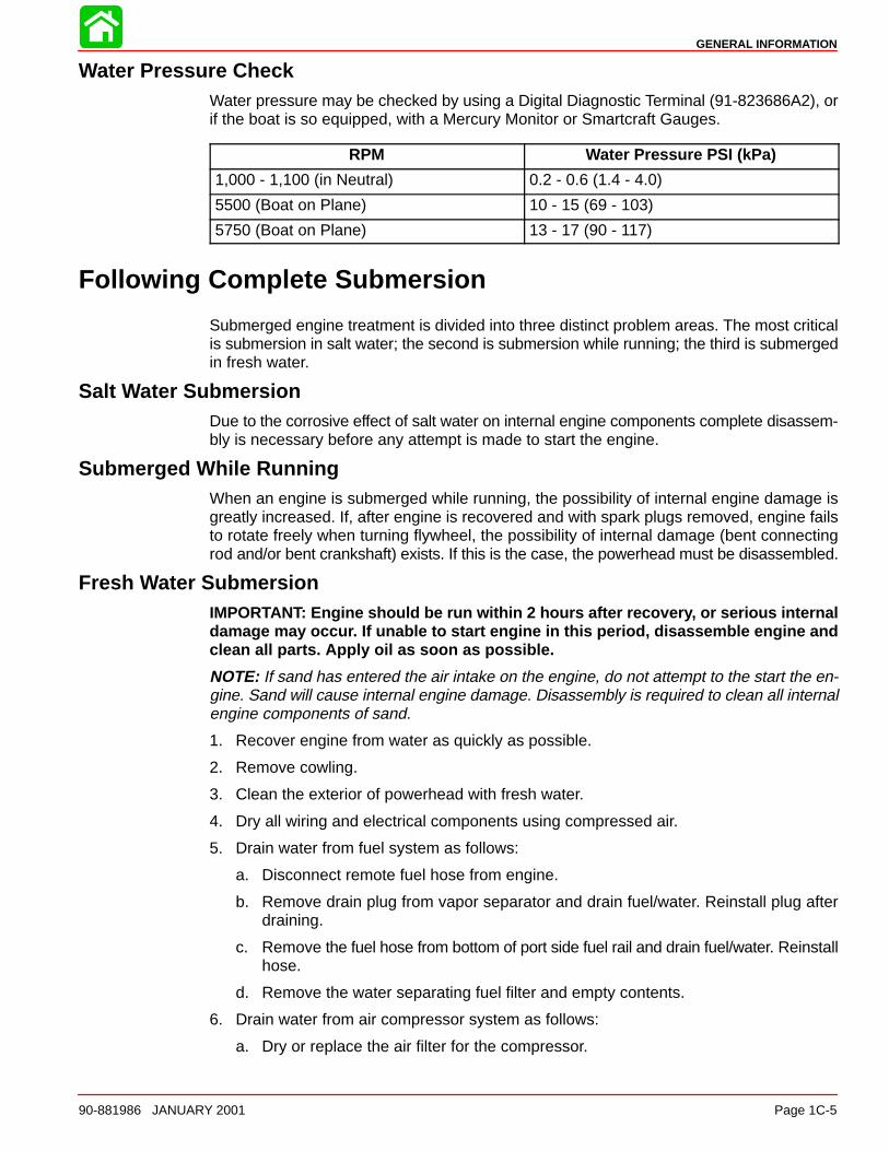
Water Pressure CheckWater pressure may be checked by using a Digital Diagnostic Terminal (91-823686A2), orif the boat is so equipped, with a Mercury Monitor or Smartcraft Gauges.
RPM Water Pressure PSI (kPa)
1,000 - 1,100 (in Neutral) 0.2 - 0.6 (1.4 - 4.0)
5500 (Boat on Plane) 10 - 15 (69 - 103)
5750 (Boat on Plane) 13 - 17 (90 - 117)
Following Complete Submersion
Submerged engine treatment is divided into three distinct problem areas. The most criticalis submersion in salt water; the second is submersion while running; the third is submergedin fresh water.
Salt Water SubmersionDue to the corrosive effect of salt water on internal engine components complete disassem-bly is necessary before any attempt is made to start the engine.
Submerged While RunningWhen an engine is submerged while running, the possibility of internal engine damage isgreatly increased. If, after engine is recovered and with spark plugs removed, engine failsto rotate freely when turning flywheel, the possibility of internal damage (bent connectingrod and/or bent crankshaft) exists. If this is the case, the powerhead must be disassembled.
Fresh Water SubmersionIMPORTANT: Engine should be run within 2 hours after recovery, or serious internaldamage may occur. If unable to start engine in this period, disassemble engine andclean all parts. Apply oil as soon as possible.
NOTE: If sand has entered the air intake on the engine, do not attempt to the start the en-gine. Sand will cause internal engine damage. Disassembly is required to clean all internalengine components of sand.
1. Recover engine from water as quickly as possible.
2. Remove cowling.
3. Clean the exterior of powerhead with fresh water.
4. Dry all wiring and electrical components using compressed air.
5. Drain water from fuel system as follows:
a. Disconnect remote fuel hose from engine.
b. Remove drain plug from vapor separator and drain fuel/water. Reinstall plug afterdraining.
c. Remove the fuel hose from bottom of port side fuel rail and drain fuel/water. Reinstallhose.
d. Remove the water separating fuel filter and empty contents.
6. Drain water from air compressor system as follows:
a. Dry or replace the air filter for the compressor.
GENERAL INFORMATION
Page 1C-6 90-881986 JANUARY 2001
b. Remove air outlet hose for the air compressor and drain water from compressor andhose. Reinstall hose.
c. Remove the air hose from bottom of port side fuel rail and drain water. Reinstallhose.
7. Drain water from engine as follows:
a. Remove throttle plate assembly (4 bolts) and sponge water/debris out of air plenum.
b. Remove spark plugs from engine.
c. Rotate flywheel manually to blow out any water from the cylinders.
d. Add approximately one ounce (30ml) of engine oil into each spark plug hole. Rotatethe flywheel manually several times to distribute the oil in the cylinders. Reinstallspark plugs.
8. Drain water from the oil injection system as follows:
a. Remove remote oil hose (black without blue stripe) from pulse fitting on starboardside of engine.
b. Drain any water from hose and reconnect.
c. If water was present in hose, check for water in the remote oil tank. Drain tank if wateris present.
9. Disassemble the engine starter motor and dry components.
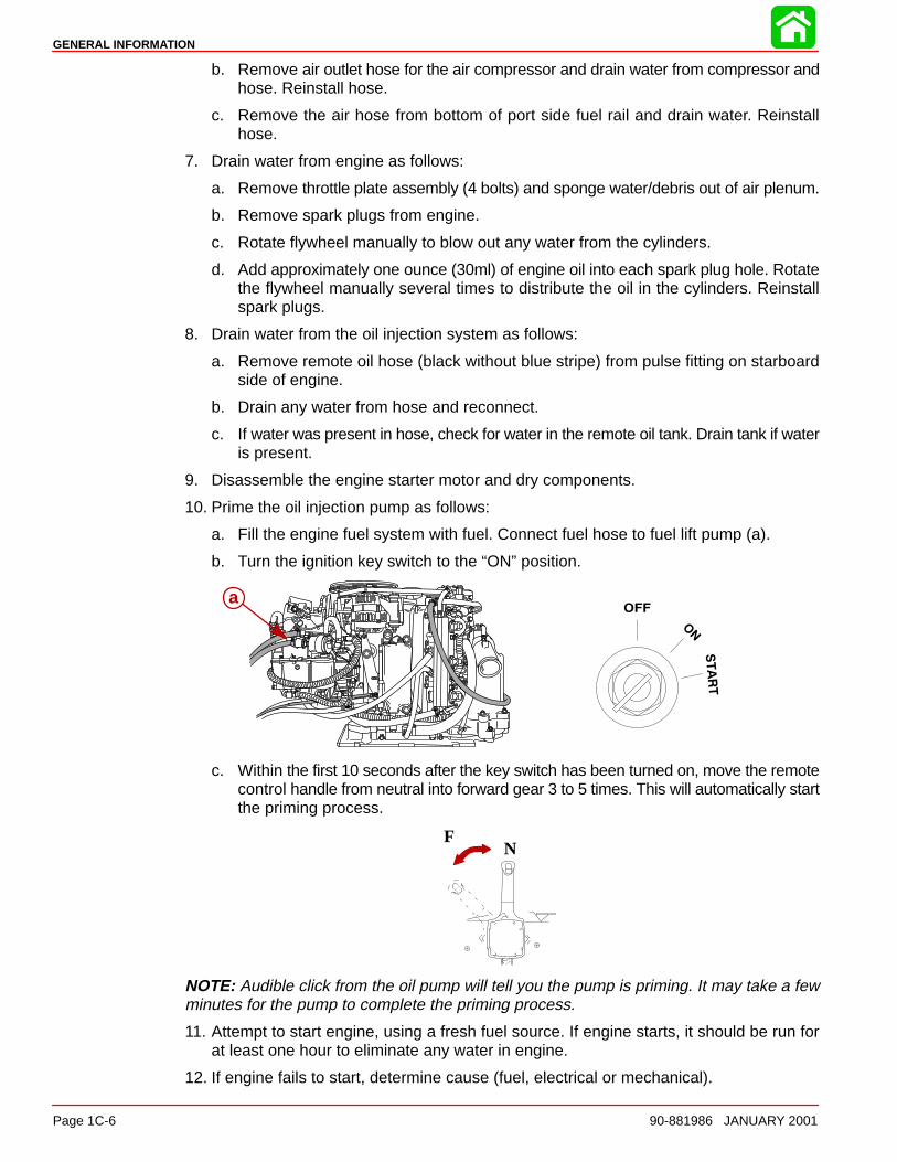
10. Prime the oil injection pump as follows:
a. Fill the engine fuel system with fuel. Connect fuel hose to fuel lift pump (a).
b. Turn the ignition key switch to the “ON” position.
a
c. Within the first 10 seconds after the key switch has been turned on, move the remotecontrol handle from neutral into forward gear 3 to 5 times. This will automatically startthe priming process.
NF
NOTE: Audible click from the oil pump will tell you the pump is priming. It may take a fewminutes for the pump to complete the priming process.
11. Attempt to start engine, using a fresh fuel source. If engine starts, it should be run forat least one hour to eliminate any water in engine.
12. If engine fails to start, determine cause (fuel, electrical or mechanical).
GENERAL INFORMATION
90-881986 JANUARY 2001 Page 1C-7
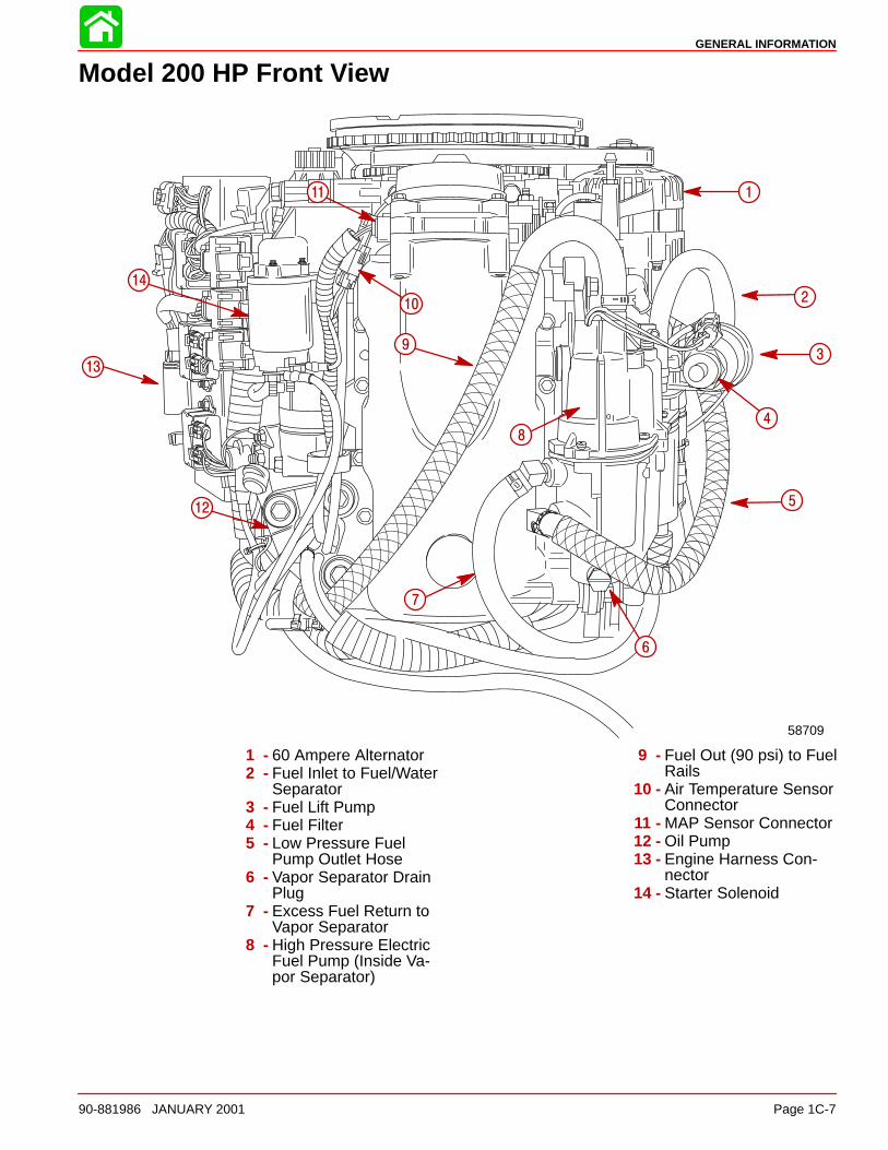
Model 200 HP Front View
58709
1
2
3
4
5
6
7
8
9
10
12
13
14
11
1 - 60 Ampere Alternator2 - Fuel Inlet to Fuel/Water
Separator3 - Fuel Lift Pump4 - Fuel Filter5 - Low Pressure Fuel
Pump Outlet Hose6 - Vapor Separator Drain
Plug7 - Excess Fuel Return to
Vapor Separator8 - High Pressure Electric
Fuel Pump (Inside Va-por Separator)
9 - Fuel Out (90 psi) to FuelRails
10 - Air Temperature SensorConnector
11 - MAP Sensor Connector12 - Oil Pump13 - Engine Harness Con-
nector14 - Starter Solenoid
GENERAL INFORMATION
Page 1C-8 90-881986 JANUARY 2001
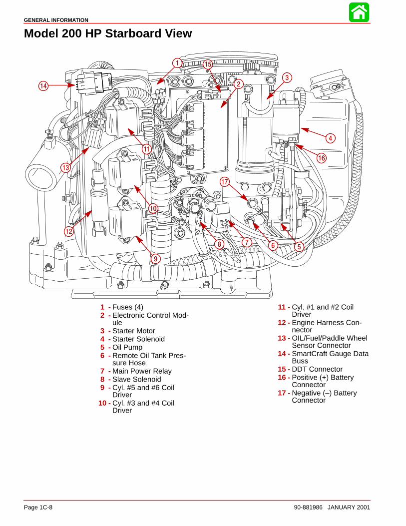
Model 200 HP Starboard View
1
23
4
5678
9
10
11
12
13
14
15
16
17
1 - Fuses (4)2 - Electronic Control Mod-
ule3 - Starter Motor4 - Starter Solenoid5 - Oil Pump6 - Remote Oil Tank Pres-
sure Hose7 - Main Power Relay8 - Slave Solenoid9 - Cyl. #5 and #6 Coil
Driver10 - Cyl. #3 and #4 Coil
Driver
11 - Cyl. #1 and #2 CoilDriver
12 - Engine Harness Con-nector
13 - OIL/Fuel/Paddle WheelSensor Connector
14 - SmartCraft Gauge DataBuss
15 - DDT Connector16 - Positive (+) Battery
Connector17 - Negative (–) Battery
Connector
GENERAL INFORMATION
90-881986 JANUARY 2001 Page 1C-9
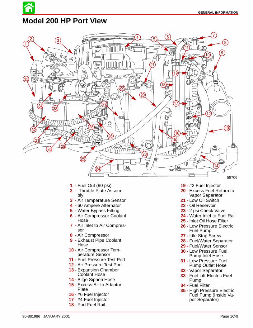
Model 200 HP Port View
58706
1
2 34 5
6 7
8
910
11
12
13
14
15
16
18
19
20
22
23
24
25
26
27
28
2930
17
31
32
3334
21
35
1 - Fuel Out (90 psi)2 - Throttle Plate Assem-
bly3 - Air Temperature Sensor4 - 60 Ampere Alternator5 - Water Bypass Fitting6 - Air Compressor Coolant
Hose7 - Air Inlet to Air Compres-
sor8 - Air Compressor9 - Exhaust Pipe Coolant
Hose10 - Air Compressor Tem-
perature Sensor11 - Fuel Pressure Test Port12 - Air Pressure Test Port13 - Expansion Chamber
Coolant Hose14 - Bilge Siphon Hose15 - Excess Air to Adaptor
Plate16 - #6 Fuel Injector17 - #4 Fuel Injector18 - Port Fuel Rail
19 - #2 Fuel Injector20 - Excess Fuel Return to
Vapor Separator21 - Low Oil Switch22 - Oil Reservoir23 - 2 psi Check Valve24 - Water Inlet to Fuel Rail25 - Inlet Oil Hose Filter26 - Low Pressure Electric
Fuel Pump27 - Idle Stop Screw28 - Fuel/Water Separator29 - Fuel/Water Sensor30 - Low Pressure Fuel
Pump Inlet Hose31 - Low Pressure Fuel
Pump Outlet Hose32 - Vapor Separator33 - Fuel Lift Electric Fuel
Pump34 - Fuel Filter35 - High Pressure Electric
Fuel Pump (Inside Va-por Separator)
GENERAL INFORMATION
Page 1C-10 90-881986 JANUARY 2001
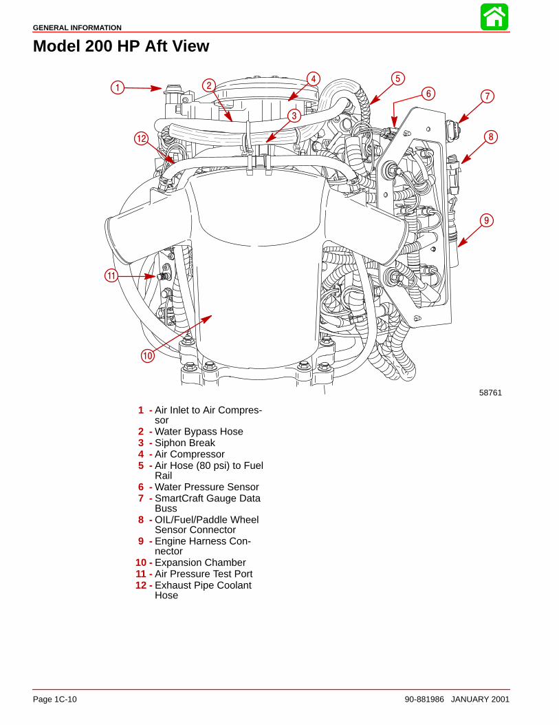
Model 200 HP Aft View
58761
1 2
3
4 5
6 7
8
9
10
11
12
1 - Air Inlet to Air Compres-sor
2 - Water Bypass Hose3 - Siphon Break4 - Air Compressor5 - Air Hose (80 psi) to Fuel
Rail6 - Water Pressure Sensor7 - SmartCraft Gauge Data
Buss8 - OIL/Fuel/Paddle Wheel
Sensor Connector9 - Engine Harness Con-
nector10 - Expansion Chamber11 - Air Pressure Test Port12 - Exhaust Pipe Coolant
Hose
GENERAL INFORMATION
90-881986 JANUARY 2001 Page 1C-11
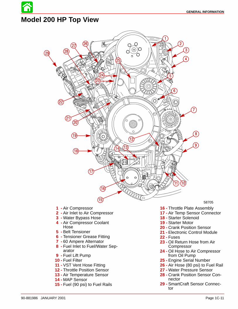
Model 200 HP Top View
58705
1
2
3
4
5
6
7
8
9
1011
12
1314
15
16
17
18
19
20
21
22
23
24
2627
2829
25
1 - Air Compressor2 - Air Inlet to Air Compressor3 - Water Bypass Hose4 - Air Compressor Coolant
Hose5 - Belt Tensioner6 - Tensioner Grease Fitting7 - 60 Ampere Alternator8 - Fuel Inlet to Fuel/Water Sep-
arator9 - Fuel Lift Pump
10 - Fuel Filter11 - VST Vent Hose Fitting12 - Throttle Position Sensor13 - Air Temperature Sensor14 - MAP Sensor15 - Fuel (90 psi) to Fuel Rails
16 - Throttle Plate Assembly17 - Air Temp Sensor Connector18 - Starter Solenoid19 - Starter Motor20 - Crank Position Sensor21 - Electronic Control Module22 - Fuses23 - Oil Return Hose from Air
Compressor24 - Oil Hose to Air Compressor
from Oil Pump25 - Engine Serial Number26 - Air Hose (80 psi) to Fuel Rail27 - Water Pressure Sensor28 - Crank Position Sensor Con-
nector29 - SmartCraft Sensor Connec-
tor
GENERAL INFORMATION
Page 1C-12 90-881986 JANUARY 2001
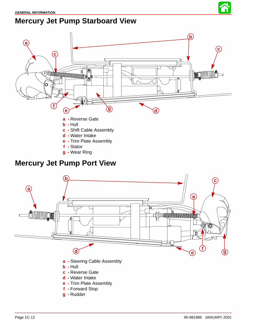
Mercury Jet Pump Starboard View
ab
c
d
c
ef g
a - Reverse Gateb - Hullc - Shift Cable Assemblyd - Water Intakee - Trim Plate Assemblyf - Statorg - Wear Ring
Mercury Jet Pump Port View
a
b c
d
a
ef g
a - Steering Cable Assemblyb - Hullc - Reverse Gated - Water Intakee - Trim Plate Assemblyf - Forward Stopg - Rudder

1D
INSTALLATION
Page 1D-190-881986 JANUARY 2001
IMPORTANT INFORMATIONSection 1D - Mercury Jet Installation
Table of Contents
General Information 1D-2. . . . . . . . . . . . . . . . . . . . . Notice to Installer 1D-2. . . . . . . . . . . . . . . . . . . . . Installation Products 1D-3. . . . . . . . . . . . . . . . . . Torque Specifications 1D-3. . . . . . . . . . . . . . . . .
Installation Requirements 1D-3. . . . . . . . . . . . . . . . Battery/Battery Cables 1D-3. . . . . . . . . . . . . . . . Boat Construction 1D-4. . . . . . . . . . . . . . . . . . . . Engine Compartment Ventilation 1D-4. . . . . . . Exhaust System 1D-5. . . . . . . . . . . . . . . . . . . . . . Fuel Delivery System 1D-5. . . . . . . . . . . . . . . . . Instrumentation 1D-6. . . . . . . . . . . . . . . . . . . . . . Wiring Diagrams 1D-7. . . . . . . . . . . . . . . . . . . . . Remote Control and Cables 1D-8. . . . . . . . . . . Steering Helm and Cable 1D-9. . . . . . . . . . . . . .
Mercury Jet Drive Hull Dimensions 1D-10. . . . . . . . Installing Jet Pump 1D-12. . . . . . . . . . . . . . . . . . . . . .
Hull Cutout 1D-12. . . . . . . . . . . . . . . . . . . . . . . . . . Steering Cable Adjustment 1D-16. . . . . . . . . . . .
Shift Cable Adjustment 1D-19. . . . . . . . . . . . . . . . Bilge Siphon Feature 1D-22. . . . . . . . . . . . . . . . . . . .
Installing Bilge Siphon 1D-22. . . . . . . . . . . . . . . . Water By-Pass System 1D-23. . . . . . . . . . . . . . . . . . .
Installation of Flushing Kit 1D-25. . . . . . . . . . . . . Operation Instructions 1D-26. . . . . . . . . . . . . . . . . Suggested Flushing Intervals 1D-27. . . . . . . . . .
Installing Powerhead 1D-28. . . . . . . . . . . . . . . . . . . . Battery Connection 1D-30. . . . . . . . . . . . . . . . . . .
Throttle Cable 1D-31. . . . . . . . . . . . . . . . . . . . . . . . . . Installation 1D-31. . . . . . . . . . . . . . . . . . . . . . . . . . .
Oil Injection Set-Up 1D-33. . . . . . . . . . . . . . . . . . . . . . Filling 1D-33. . . . . . . . . . . . . . . . . . . . . . . . . . . . . . . Priming the Oil Injection Pump 1D-34. . . . . . . . . Purging Air From the Engine Oil Tank 1D-34. . .
Trim Plate Adjustment 1D-35. . . . . . . . . . . . . . . . . . . Muffler Installation 1D-36. . . . . . . . . . . . . . . . . . . . . . . Pre-delivery Inspection 1D-37. . . . . . . . . . . . . . . . . . .
INSTALLATION
Page 1D-2 90-881986 JANUARY 2001
General Information
Notice to InstallerThroughout this publication, “Warnings” and “Cautions” (accompanied by the InternationalHazard Symbol) are used to alert the installer to special instructions concerning a particularservice or operation that may be hazardous if performed incorrectly or carelessly. –– Ob-serve Them Carefully!
These “Safety Alerts,” alone, cannot eliminate the hazards that they signal. Strict com-pliance to these special instructions when performing the service, plus “common sense” op-eration, are major accident prevention measures.
WARNINGHazards or unsafe practices which COULD result in severe personal injury or death.
CAUTIONHazards or unsafe practices which could result in minor personal injury or productor property damage.
IMPORTANT: Indicates information or instructions that are necessary for proper in-stallation and/or operation.
This installation manual has been written and published by the service department of Mer-cury Marine to aid installers when installing the products described herein.
It is assumed that these personnel are familiar with the installation procedures of these prod-ucts, or like or similar products manufactured and marketed by Mercury Marine. Also, thatthey have been trained in the recommended installation procedures of these products whichincludes the use of mechanics’ common hand tools and the special Mercury Marine or rec-ommended tools from other suppliers.
We could not possibly know of and advise the marine trade of all conceivable proceduresby which an installation might be performed and of the possible hazards and/or results ofeach method. We have not undertaken any such wide evaluation. Therefore, anyone whouses an installation procedure and/or tool, which is not recommended by the manufacturer,first must completely satisfy himself that neither his nor the product’s safety will be endan-gered by the installation procedure selected.
All information, illustrations, and specifications contained in this manual are based on thelatest product information available at time of publication. As required, revisions to this man-ual will be sent to all OEM boat companies.
INSTALLATION
Page 1D-390-881986 JANUARY 2001
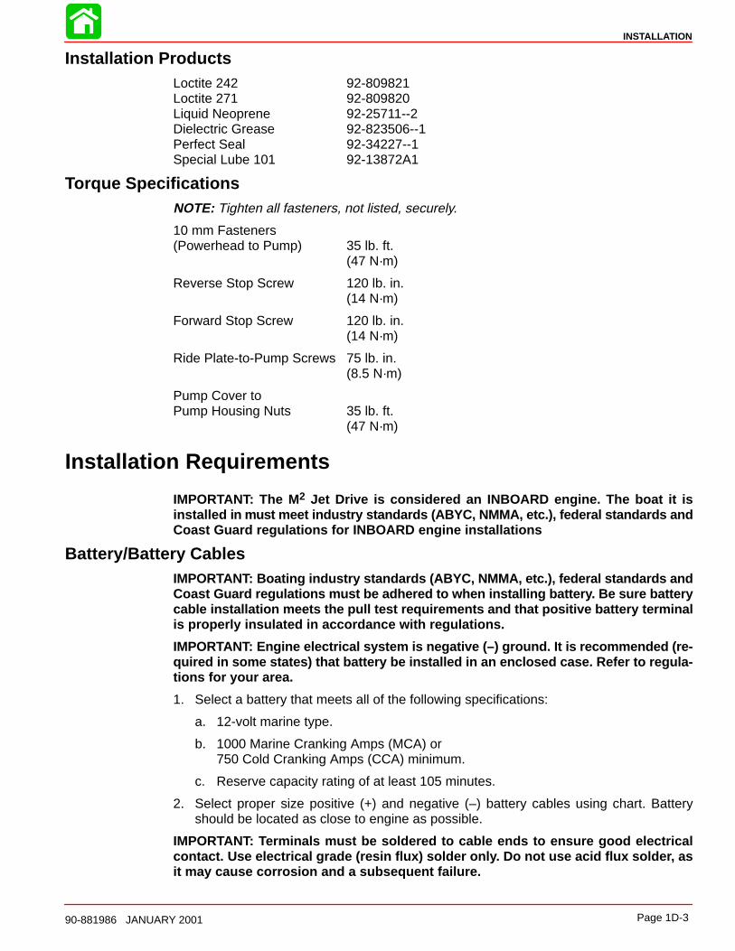
Installation ProductsLoctite 242 92-809821Loctite 271 92-809820Liquid Neoprene 92-25711--2Dielectric Grease 92-823506--1Perfect Seal 92-34227--1Special Lube 101 92-13872A1
Torque SpecificationsNOTE: Tighten all fasteners, not listed, securely.
10 mm Fasteners(Powerhead to Pump) 35 lb. ft.
(47 N·m)
Reverse Stop Screw 120 lb. in.(14 N·m)
Forward Stop Screw 120 lb. in.(14 N·m)
Ride Plate-to-Pump Screws 75 lb. in.(8.5 N·m)
Pump Cover toPump Housing Nuts 35 lb. ft.
(47 N·m)
Installation Requirements
IMPORTANT: The M 2 Jet Drive is considered an INBOARD engine. The boat it isinstalled in must m eet industry standards (ABYC, NMMA, etc.), federal standards andCoast Guard regulations for INBOARD engine installations
Battery/Battery CablesIMPORTANT: Boating industry standards (ABYC, N MMA, etc.), federal standards andCoast Guard regulations must be adhered to when installing battery. Be sure batterycable installation meets the pull test requirements and that positive battery terminalis properly insulated in accordance with regulations.
IMPORTANT: Engine electrical system is negative (–) ground. It is recommended (re-quired in some states) that battery be installed in an enclosed case. Refer to regula-tions for your area.
1. Select a battery that meets all of the following specifications:
a. 12-volt marine type.
b. 1000 Marine Cranking Amps (MCA) or750 Cold Cranking Amps (CCA) minimum.
c. Reserve capacity rating of at least 105 minutes.
2. Select proper size positive (+) and negative (–) battery cables using chart. Batteryshould be located as close to engine as possible.
IMPORTANT: Terminals must be soldered to cable ends to ensure good electricalcontact. Use electrical grade (resin flux) solder only. Do not use acid flux solder, asit may cause corrosion and a subsequent failure.

INSTALLATION
Page 1D-4 90-881986 JANUARY 2001
Cable Length Cable Gauge
Up to 3-1/2 ft.(1.1 m)
4 (25mm2)
3-1/2 - 6 ft.(1.1-1.8 m)
2 (35mm2)
6 - 7-1/2 ft.(1.8-2.3 m)
1 (50mm2)
7-1/2 - 9-1/2 ft.(2.3-2.9 m)
0 (50mm2)
9-1/2 - 12 ft.(2.9-3.7 m)
00 (70mm2)
12 - 15 ft. (3.7-4.6 m)
000 (95mm2)
15 - 19 ft. (4.6- 5.8 m)
0000 (120mm2)
Boat ConstructionIMPORTANT: All applicable U.S. Coast Guard regulations for INBOARD engines mustbe complied with, when constructing engine compartment.
Care must be exercised in the design and construction of the engine compartment. Seamsmust be located so that any rain water or splash, which may leak through the seams, is di-rected away from the engine and its air intake. Also, the passenger compartment drainagesystem should not be routed directly to the engine compartment. Water that runs on or issplashed in the carburetor cover may enter the engine and cause serious damage tointernal engine parts.
IMPORTANT: Mercury Marine will not honor any warranty claim for engine damageas a result of water entry.
Engine Compartment VentilationEngine compartment must be designed to provide a sufficient volume of air for enginebreathing and also must vent off any fumes in engine compartment in accordance withindustry standards (ABYC, NMMA, etc.), federal standards and U.S. Coast Guard regula-tions for inboard engines. Pressure differential (outside engine compartment versus insideengine compartment) should not exceed 2 in. (51mm) of water (measured with a manome-ter) at maximum air flow rate.
Engine Compartment Specifications
Model Engine Air Require-ments at Wide Open
Throttle
Physical EngineVolume*
200 Opti-max
508 ft.3/min.(0.240 m3/sec.)
1.41 ft.3(40.4 L)
* Physical engine volume is used in flotation calculations and is representative of the amountof flotation the engine provides.
For serviceability, it is recommended that an additional 6 inches minimum (152 mm) (perside) of clearance be allowed between powerhead and engine compartment walls.
INSTALLATION
Page 1D-590-881986 JANUARY 2001
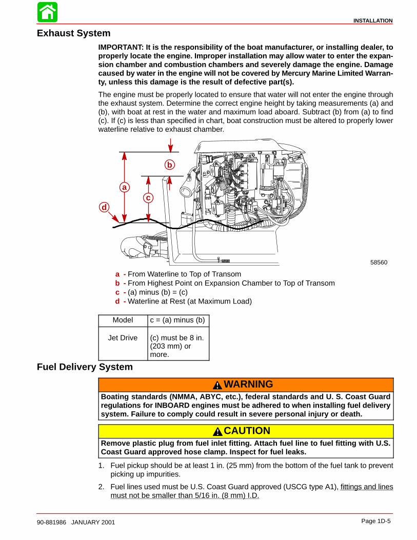
Exhaust SystemIMPORTANT: It is the responsibility of the boat manufacturer, or installing dealer, toproperly locate the engine. Improper installation may allow water to enter the expan-sion chamber and combustion chambers and severely damage the engine. Damagecaused by water in the engine will not be covered by Mercury Marine Limited W arran-ty, unless this damage is the result of defective part(s).
The engine must be properly located to ensure that water will not enter the engine throughthe exhaust system. Determine the correct engine height by taking measurements (a) and(b), with boat at rest in the water and maximum load aboard. Subtract (b) from (a) to find(c). If (c) is less than specified in chart, boat construction must be altered to properly lowerwaterline relative to exhaust chamber.
b
ca
d
58560
a - From Waterline to Top of Transomb - From Highest Point on Expansion Chamber to Top of Transomc - (a) minus (b) = (c)d - Waterline at Rest (at Maximum Load)
Model c = (a) minus (b)
Jet Drive (c) must be 8 in.(203 mm) ormore.
Fuel Delivery System
WARNINGBoating standards (NMMA, ABYC, etc.), federal standards and U. S. Coast Guardregulations for INBOARD engines must be adhered to when installing fuel deliverysystem. Failure to comply could result in severe personal injury or death.
CAUTIONRemove plastic plug from fuel inlet fitting. Attach fuel line to fuel fitting with U.S.Coast Guard approved hose clamp. Inspect for fuel leaks.
1. Fuel pickup should be at least 1 in. (25 mm) from the bottom of the fuel tank to preventpicking up impurities.
2. Fuel lines used must be U.S. Coast Guard approved (USCG type A1), fittings and linesmust not be smaller than 5/16 in. (8 mm) I.D.
INSTALLATION
Page 1D-6 90-881986 JANUARY 2001
3. On installations requiring long lines or numerous fittings, larger size lines should beused.
4. Fuel line should be installed free of stress and firmly secured to prevent vibration and/orchafing.
5. Sharp bends in fuel line should be avoided.
6. A flexible fuel line must be used to connect fuel line to engine fuel pump to absorb deflec-tion when engine is running.
7. A primer bulb is not necessary with this application. If a primer bulb is used, it must beU.S. Coast Guard approved for inboard engine installations.
8. Vapor separator must be vented to fuel tank. Vent hose must comply with U.S. CoastGuard/ABYC regulations.
Instrumentation
CAUTIONIf a fused accessory panel is to be used, it is recommended that a separate circuit(properly fused) be used from the battery to the fuse panel with sufficient wire sizeto handle the intended current load.
NOTE: The charging system on this engine is capable of producing 60 amperes maximumat the alternator and 38 amperes maximum charge @ 2000 RPM at the battery. The electri-cal load of the boat should not exceed this capacity.
We recommend the use of Quicksilver Instrumentation and Wiring Harness(es). Refer to“Quicksilver Accessories Guide” for selection.
If other than Quicksilver electrical accessories are to be used, it is good practice to usewaterproof ignition components (ignition switch, lanyard stop switch, etc.). A typical jet boatof this nature will see water splashed on these components. Therefore, precautions mustbe taken to avoid ignition failure due to shorting out of ignition components.
WARNINGSudden stopping of engine (shorting ignition components) while boat is underwaywill cause loss of steering control due to loss of thrust. This loss of steering controlmay cause property damage, personal injury or death.
A warning horn must be incorporated in the wiring harness (see wiring diagram) to alert theuser of an overheat, low oil condition or oil pump failure.
IMPORTANT: If a warning horn system is not installed by the boat manufacturer, Mer-cury Marine will not honor any warranty claims for engine damage as a result of over-heating or lack of engine oil.
Route instrumentation wiring harness back to engine, making sure that harness does notrub or get pinched. If an extension harness is required, be sure to secure connection proper-ly. Fasten harness(es) to boat at least every 18 in. (460 mm), using appropriate fasteners.
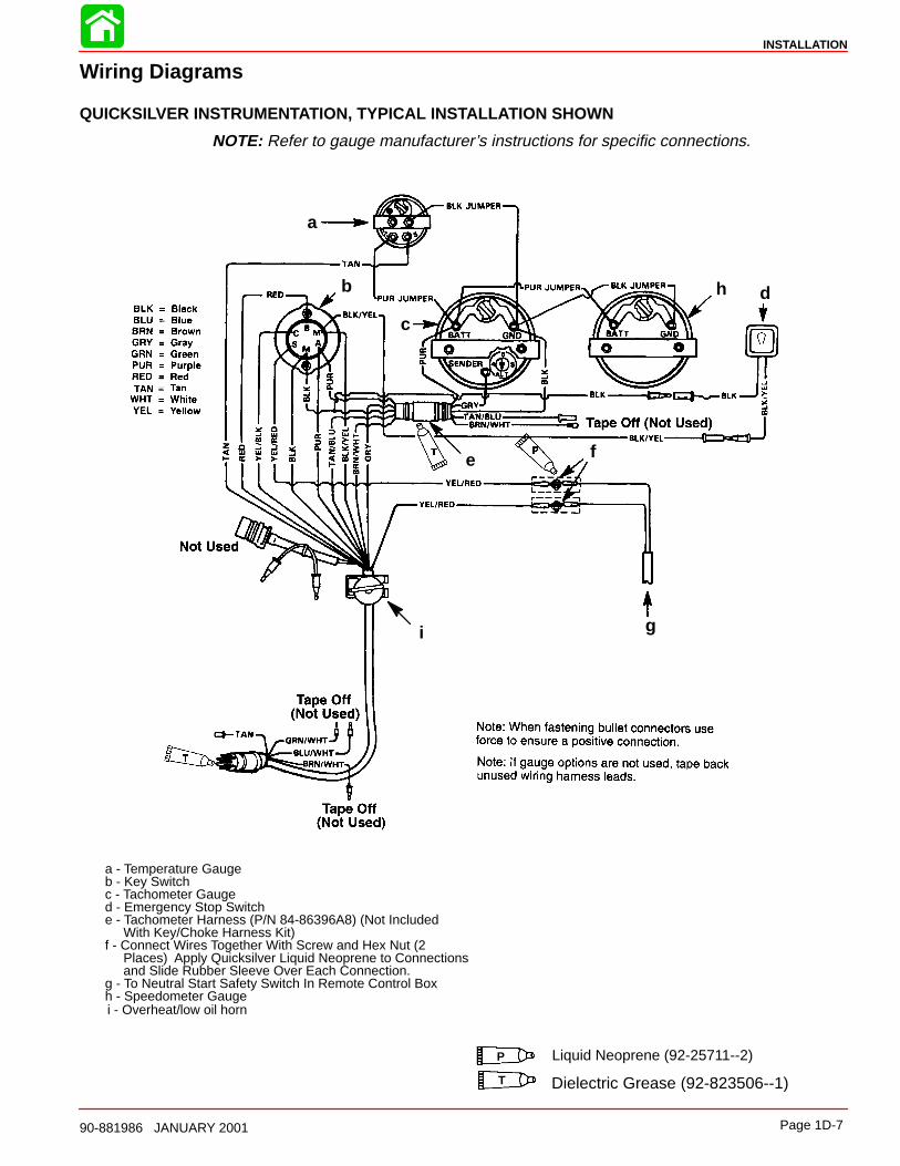
a - Temperature Gaugeb - Key Switchc - Tachometer Gauged - Emergency Stop Switche - Tachometer Harness (P/N 84-86396A8) (Not Included With Key/Choke Harness Kit)f - Connect Wires Together With Screw and Hex Nut (2 Places) Apply Quicksilver Liquid Neoprene to Connections and Slide Rubber Sleeve Over Each Connection.g - To Neutral Start Safety Switch In Remote Control Box
Liquid Neoprene (92-25711--2)
Dielectric Grease (92-823506--1)T
h - Speedometer Gaugei - Overheat/low oil horn
a
b
c
d
e f
g
h
i
P
INSTALLATION
Page 1D-790-881986 JANUARY 2001
Wiring Diagrams
QUICKSILVER INSTRUMENTATION, TYPICAL INSTALLATION SHOWN
NOTE: Refer to gauge manufacturer’s instructions for specific connections.
INSTALLATION
Page 1D-8 90-881986 JANUARY 2001
Remote Control and CablesThe remote control must provide the following required features:
• Start-in-gear protection
• Neutral rpm limit at 2,000 rpmNote: This applies to dual lever remote controls as well as single lever remote controls.
• High strength mechanism to accommodate loads transmitted to the remote control
• Shift cable travel of 3 inches 1/8 inch (76 mm 3 mm)
• Ability to use 40 series shift cable
The remote control must meet the above criteria as well as the design criteria outlined inthe ABYC manual pertaining to Mini-Jet Boats (Standard P-23).
SHIFT CABLE
The shift cable to be used MUST MEET the following criteria:
• 40-Series Cable
• 40 Series bulkhead fitting at output end
• Allow for a minimum of 3 inches (76 mm) of travel.
• A means of attaching and locking the cable to the shift cable bracket (provided).
• Cable end at pump must allow for a 1/4 inch clevis pin and cotter pin (all provided) toconnect cable to the reverse gate.
• Protected against water intrusion and/or corrosion as the cable end (at the pump) is sub-mersed in water with the boat at rest.
The shift cable end (at the pump) is submersed in water. It should be sealed against waterintrusion, protected against corrosion and be able to withstand the shift loads imparted onit by the reverse gate.
Follow shift cable adjustment procedure for proper adjustment.
THROTTLE CABLE
The throttle cable must have one end compatible with the control box. The other end musthave Mercury style connectors.
Follow throttle cable adjustment procedures for proper adjustment.
INSTALLATION
Page 1D-990-881986 JANUARY 2001
Steering Helm and CableSTEERING HELM
The steering helm must limit steering cable travel to 3.50 ± .10 inches (88.9 ± 2.5 mm).
WARNINGFailure to limit steering cable travel at the helm could pre-load the cable resultingin premature failure of a steering component causing loss of steering. This loss ofsteering could cause property damage, personal injury or death.
STEERING CABLE
The steering cable to be used MUST MEET the following criteria:
• 60 Series Steering Cable
• 60 Series bulkhead fitting at output end
• Allow for a minimum of 3.75 inches (95.3 mm) of travel.
• Cable end at pump must allow for a 5/16 in. threaded adaptor shouldered thru-bolt andlock nut to connect the cable to the steering arm.
• A means of attaching and locking the cable to the steering cable bracket (provided).
• Protected against water intrusion and/or corrosion as the cable end (at the pump) is sub-mersed in water with the boat at rest.
• The steering cable should be able to withstand the steering loads imparted on it by therudder.
A locking tab is provided by Mercury to be used with the steering cable having threads andlocknuts located 11.31 inches (287 mm) from cable end at pump with cable at center oftravel.
Follow steering cable adjustment procedure for proper adjustment.
INSTALLATION
Page 1D-10 90-881986 JANUARY 2001
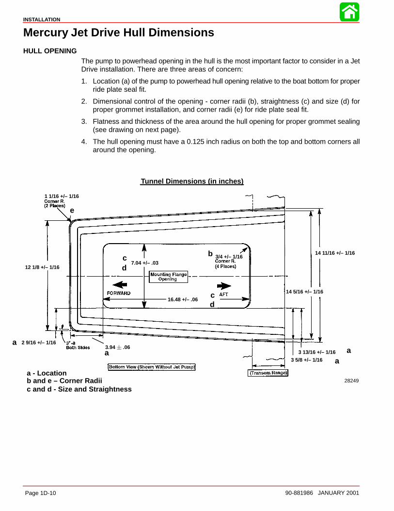
Mercury Jet Drive Hull DimensionsHULL OPENING
The pump to powerhead opening in the hull is the most important factor to consider in a JetDrive installation. There are three areas of concern:
1. Location (a) of the pump to powerhead hull opening relative to the boat bottom for properride plate seal fit.
2. Dimensional control of the opening - corner radii (b), straightness (c) and size (d) forproper grommet installation, and corner radii (e) for ride plate seal fit.
3. Flatness and thickness of the area around the hull opening for proper grommet sealing(see drawing on next page).
4. The hull opening must have a 0.125 inch radius on both the top and bottom corners allaround the opening.
1 1/16 +/– 1/16
3/4 +/– 1/167.04 +/– .03
16.48 +/– .06
14 11/16 +/– 1/16
14 5/16 +/– 1/16
2 9/16 +/– 1/16
12 1/8 +/– 1/16
3 13/16 +/– 1/16
3 5/8 +/– 1/16
b and e – Corner Radiic and d - Size and Straightness
a - Location
Tunnel Dimensions (in inches)
a
b
c
e
a
a
d
cd
28249
3.94 .06a
INSTALLATION
Page 1D-1190-881986 JANUARY 2001
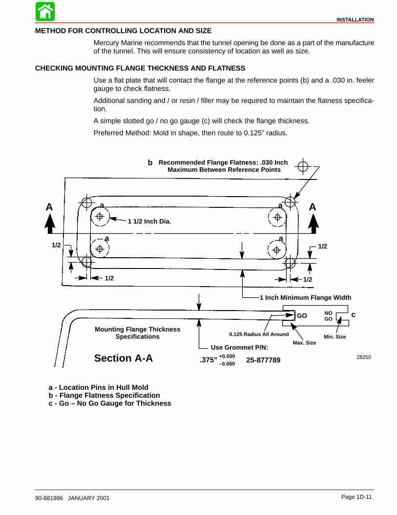
METHOD FOR CONTROLLING LOCATION AND SIZE
Mercury Marine recommends that the tunnel opening be done as a part of the manufactureof the tunnel. This will ensure consistency of location as well as size.
CHECKING MOUNTING FLANGE THICKNESS AND FLATNESS
Use a flat plate that will contact the flange at the reference points (b) and a .030 in. feelergauge to check flatness.
Additional sanding and / or resin / filler may be required to maintain the flatness specifica-tion.
A simple slotted go / no go gauge (c) will check the flange thickness.
Preferred Method: Mold in shape, then route to 0.125” radius.
Mounting Flange ThicknessSpecifications
1 Inch Minimum Flange Width
Recommended Flange Flatness: .030 Inch Maximum Between Reference Points
AA
Section A-A
1/2
1/2
1/2
1/2
1 1/2 Inch Dia.
GO NOGO
Max. SizeMin. Size
a - Location Pins in Hull Moldb - Flange Flatness Specificationc - Go – No Go Gauge for Thickness
.375”+0.000–0.060
Use Grommet P/N:
25-877789 28250
a
b
c
a a
a
0.125 Radius All Around
INSTALLATION
Page 1D-12 90-881986 JANUARY 2001
Installing Jet Pump
Hull Cutout
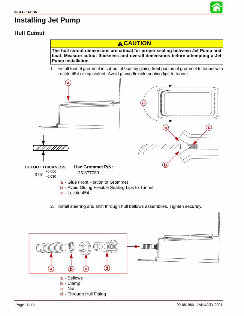
CAUTIONThe hull cutout dimensions are critical for proper sealing between Jet Pump andboat. Measure cutout thickness and overall dimensions before attempting a JetPump installation.
1. Install tunnel grommet in cut-out of boat by gluing front portion of grommet to tunnel withLoctite 454 or equivalent. Avoid gluing flexible sealing lips to tunnel.
ÀÀÀÀÀÀÀÀÀÀÀÀÀÀÀÀÀÀÀÀÀÀÀÀ
CUTOUT THICKNESS
.375”+0.050
–0.030
Use Grommet P/N:25-877789
a
a
b
b
c
a - Glue Front Portion of Grommetb - Avoid Gluing Flexible Sealing Lips to Tunnelc - Loctite 454
2. Install steering and shift through hull bellows assemblies. Tighten securely.
a b c d
a - Bellowsb - Clampc - Nutd - Through Hull Fitting
INSTALLATION
Page 1D-1390-881986 JANUARY 2001
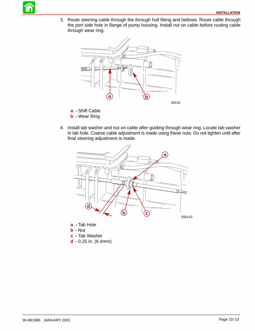
3. Route steering cable through the through hull fitting and bellows. Route cable throughthe port side hole in flange of pump housing. Install nut on cable before routing cablethrough wear ring.
58142
a b
a - Shift Cableb - Wear Ring
4. Install tab washer and nut on cable after guiding through wear ring. Locate tab washerin tab hole. Coarse cable adjustment is made using these nuts. Do not tighten until afterfinal steering adjustment is made.
558143
dc
a
b
a - Tab Holeb - Nutc - Tab Washerd - 0.25 in. (6.4mm)
INSTALLATION
Page 1D-14 90-881986 JANUARY 2001
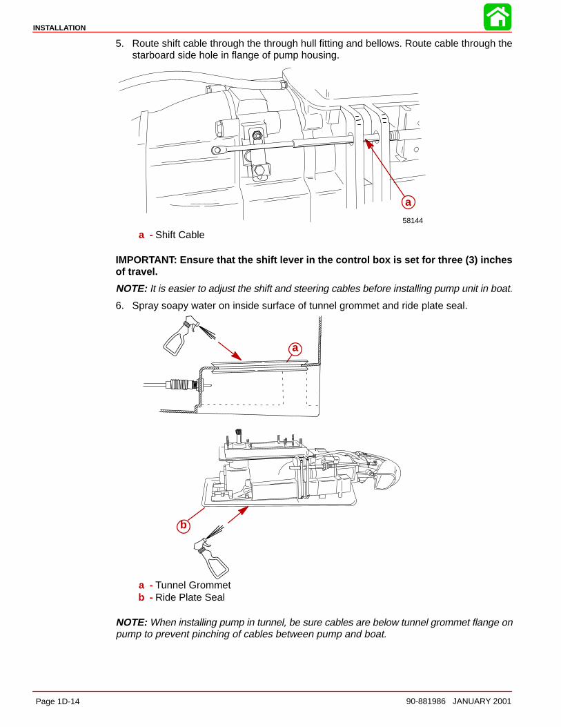
5. Route shift cable through the through hull fitting and bellows. Route cable through thestarboard side hole in flange of pump housing.
58144
a
a - Shift Cable
IMPORTANT: Ensure that the shift lever in the control box is set for three (3) inchesof travel.
NOTE: It is easier to adjust the shift and steering cables before installing pump unit in boat.
6. Spray soapy water on inside surface of tunnel grommet and ride plate seal.
a
b
a - Tunnel Grommetb - Ride Plate Seal
NOTE: When installing pump in tunnel, be sure cables are below tunnel grommet flange onpump to prevent pinching of cables between pump and boat.
INSTALLATION
Page 1D-1590-881986 JANUARY 2001
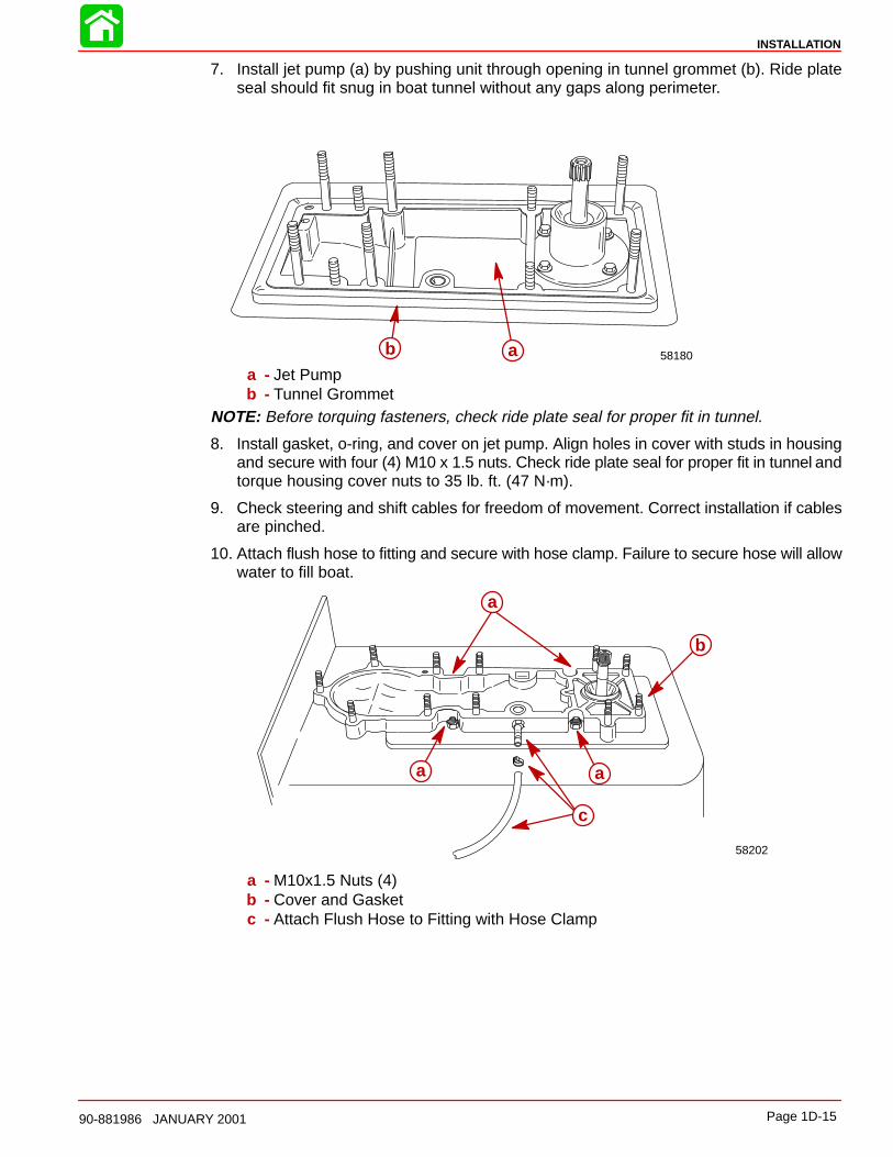
7. Install jet pump (a) by pushing unit through opening in tunnel grommet (b). Ride plateseal should fit snug in boat tunnel without any gaps along perimeter.
58180aba - Jet Pumpb - Tunnel Grommet
NOTE: Before torquing fasteners, check ride plate seal for proper fit in tunnel.
8. Install gasket, o-ring, and cover on jet pump. Align holes in cover with studs in housingand secure with four (4) M10 x 1.5 nuts. Check ride plate seal for proper fit in tunnel andtorque housing cover nuts to 35 lb. ft. (47 N·m).
9. Check steering and shift cables for freedom of movement. Correct installation if cablesare pinched.
10. Attach flush hose to fitting and secure with hose clamp. Failure to secure hose will allowwater to fill boat.
a
a
b
58202
a
c
a - M10x1.5 Nuts (4)b - Cover and Gasketc - Attach Flush Hose to Fitting with Hose Clamp
INSTALLATION
Page 1D-16 90-881986 JANUARY 2001
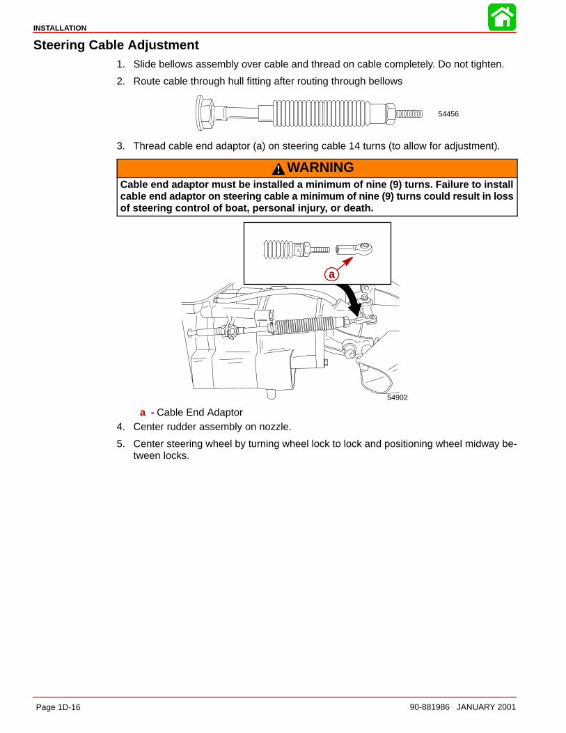
Steering Cable Adjustment1. Slide bellows assembly over cable and thread on cable completely. Do not tighten.
2. Route cable through hull fitting after routing through bellows
54456
3. Thread cable end adaptor (a) on steering cable 14 turns (to allow for adjustment).
WARNINGCable end adaptor must be installed a minimum of nine (9) turns. Failure to installcable end adaptor on steering cable a minimum of nine (9) turns could result in lossof steering control of boat, personal injury, or death.
54902
a
a - Cable End Adaptor4. Center rudder assembly on nozzle.
5. Center steering wheel by turning wheel lock to lock and positioning wheel midway be-tween locks.
INSTALLATION
Page 1D-1790-881986 JANUARY 2001
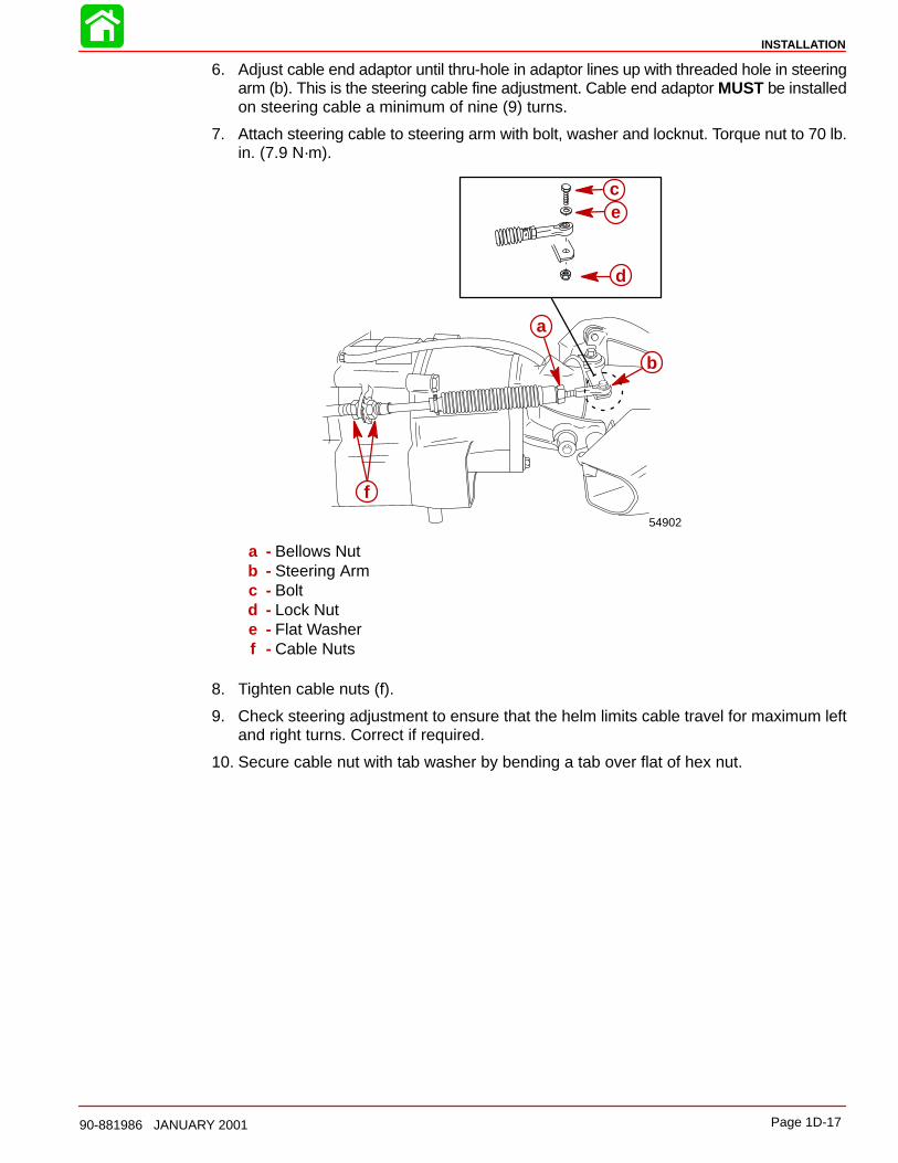
6. Adjust cable end adaptor until thru-hole in adaptor lines up with threaded hole in steeringarm (b). This is the steering cable fine adjustment. Cable end adaptor MUST be installedon steering cable a minimum of nine (9) turns.
7. Attach steering cable to steering arm with bolt, washer and locknut. Torque nut to 70 lb.in. (7.9 N·m).
54902
b
a
ce
d
f
a - Bellows Nutb - Steering Armc - Boltd - Lock Nute - Flat Washerf - Cable Nuts
8. Tighten cable nuts (f).
9. Check steering adjustment to ensure that the helm limits cable travel for maximum leftand right turns. Correct if required.
10. Secure cable nut with tab washer by bending a tab over flat of hex nut.
INSTALLATION
Page 1D-18 90-881986 JANUARY 2001
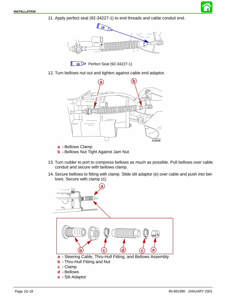
11. Apply perfect seal (92-34227-1) to end threads and cable conduit end.
19
Perfect Seal (92-34227-1)19
12. Turn bellows nut out and tighten against cable end adaptor.
54908
a b
a - Bellows Clampb - Bellows Nut Tight Against Jam Nut
13. Turn rudder to port to compress bellows as much as possible. Pull bellows over cableconduit and secure with bellows clamp.
14. Secure bellows to fitting with clamp. Slide slit adaptor (e) over cable and push into bel-lows. Secure with clamp (c).
a
b c cd ea - Steering Cable, Thru-Hull Fitting, and Bellows Assemblyb - Thru-Hull Fitting and Nutc - Clampd - Bellowse - Slit Adaptor
INSTALLATION
Page 1D-1990-881986 JANUARY 2001
Shift Cable AdjustmentIMPORTANT: The shift cable MUST BE properly adjusted. The shift cable is adjustedso that the reverse gate is not pre-loaded against either the forward or reverse stop.Pre-load in either position may cause failure of the stop and/or premature wear of theshift cable or control box components. It may also cause stiffness of the throttle con-trol.
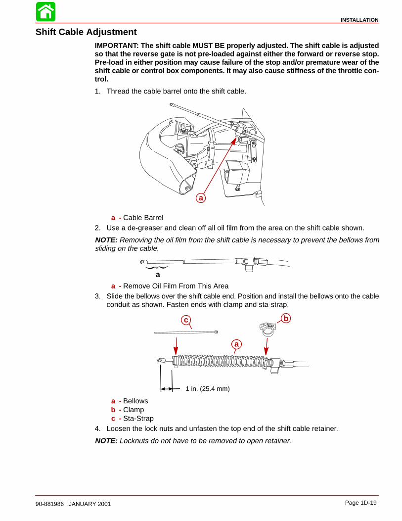
1. Thread the cable barrel onto the shift cable.
a
a - Cable Barrel2. Use a de-greaser and clean off all oil film from the area on the shift cable shown.
NOTE: Removing the oil film from the shift cable is necessary to prevent the bellows fromsliding on the cable.
aa - Remove Oil Film From This Area
3. Slide the bellows over the shift cable end. Position and install the bellows onto the cableconduit as shown. Fasten ends with clamp and sta-strap.
1 in. (25.4 mm)
a
bc
a - Bellowsb - Clampc - Sta-Strap
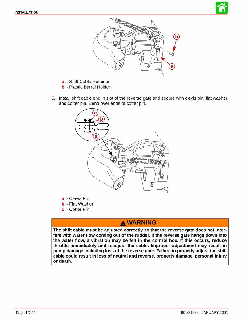
4. Loosen the lock nuts and unfasten the top end of the shift cable retainer.
NOTE: Locknuts do not have to be removed to open retainer.
INSTALLATION
Page 1D-20 90-881986 JANUARY 2001
a
b
a - Shift Cable Retainerb - Plastic Barrel Holder
5. Install shift cable end in slot of the reverse gate and secure with clevis pin, flat washer,and cotter pin. Bend over ends of cotter pin.
a
bc
a - Clevis Pinb - Flat Washerc - Cotter Pin
WARNINGThe shift cable must be adjusted correctly so that the reverse gate does not inter-fere with water flow coming out of the rudder. If the reverse gate hangs down intothe water flow, a vibration may be felt in the control box. If this occurs, reducethrottle immediately and readjust the cable. Improper adjustment may result inpump damage including loss of the reverse gate. Failure to properly adjust the shiftcable could result in loss of neutral and reverse, property damage, personal injuryor death.
INSTALLATION
Page 1D-2190-881986 JANUARY 2001
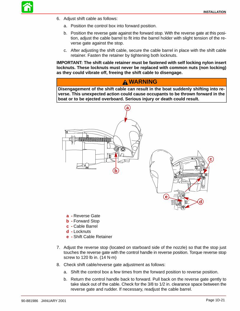
6. Adjust shift cable as follows:
a. Position the control box into forward position.
b. Position the reverse gate against the forward stop. With the reverse gate at this posi-tion, adjust the cable barrel to fit into the barrel holder with slight tension of the re-verse gate against the stop.
c. After adjusting the shift cable, secure the cable barrel in place with the shift cableretainer. Fasten the retainer by tightening both locknuts.
IMPORTANT: The shift cable retainer must be fastened with self locking nylon insertlocknuts. These locknuts must never be replaced with common nuts (non locking)as they could vibrate off, freeing the shift cable to disengage.
WARNINGDisengagement of the shift cable can result in the boat suddenly shifting into re-verse. This unexpected action could cause occupants to be thrown forward in theboat or to be ejected overboard. Serious injury or death could result.
c
de
a
b
a - Reverse Gateb - Forward Stopc - Cable Barreld - Locknutse - Shift Cable Retainer
7. Adjust the reverse stop (located on starboard side of the nozzle) so that the stop justtouches the reverse gate with the control handle in reverse position. Torque reverse stopscrew to 120 lb in. (14 N·m)
8. Check shift cable/reverse gate adjustment as follows:
a. Shift the control box a few times from the forward position to reverse position.
b. Return the control handle back to forward. Pull back on the reverse gate gently totake slack out of the cable. Check for the 3/8 to 1/2 in. clearance space between thereverse gate and rudder. If necessary, readjust the cable barrel.
INSTALLATION
Page 1D-22 90-881986 JANUARY 2001
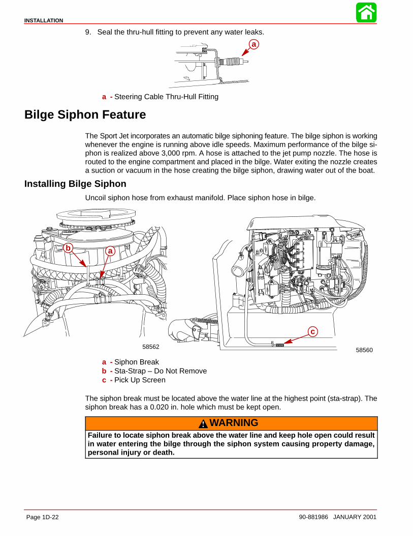
9. Seal the thru-hull fitting to prevent any water leaks.
a
a - Steering Cable Thru-Hull Fitting
Bilge Siphon Feature
The Sport Jet incorporates an automatic bilge siphoning feature. The bilge siphon is workingwhenever the engine is running above idle speeds. Maximum performance of the bilge si-phon is realized above 3,000 rpm. A hose is attached to the jet pump nozzle. The hose isrouted to the engine compartment and placed in the bilge. Water exiting the nozzle createsa suction or vacuum in the hose creating the bilge siphon, drawing water out of the boat.
Installing Bilge SiphonUncoil siphon hose from exhaust manifold. Place siphon hose in bilge.
58562
ab
c
58560
a - Siphon Breakb - Sta-Strap – Do Not Removec - Pick Up Screen
The siphon break must be located above the water line at the highest point (sta-strap). Thesiphon break has a 0.020 in. hole which must be kept open.
WARNINGFailure to locate siphon break above the water line and keep hole open could resultin water entering the bilge through the siphon system causing property damage,personal injury or death.
INSTALLATION
Page 1D-2390-881986 JANUARY 2001
Water By-Pass System
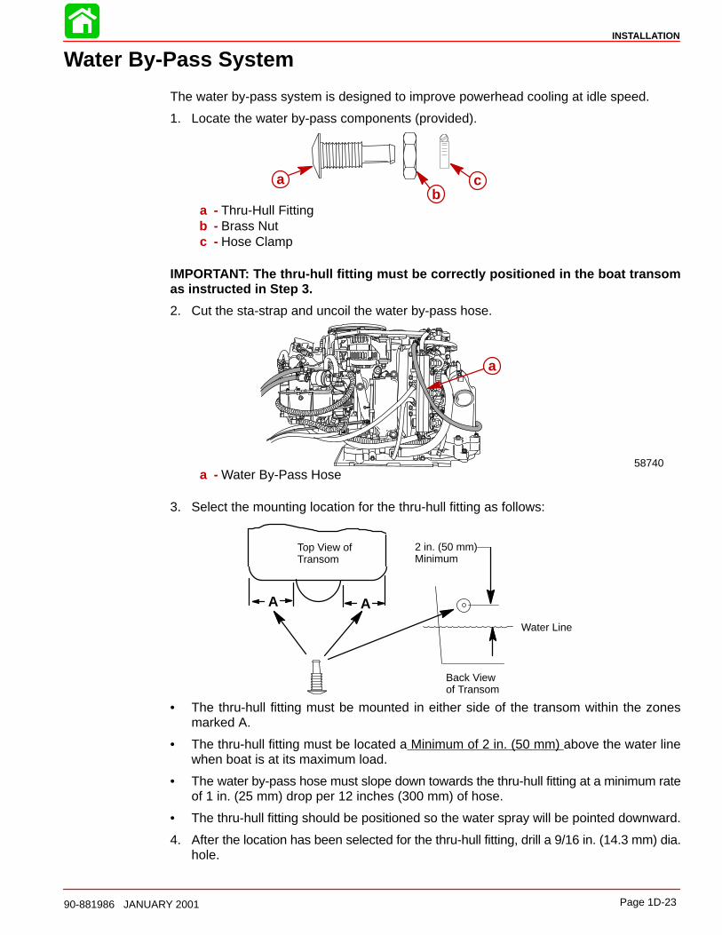
The water by-pass system is designed to improve powerhead cooling at idle speed.
1. Locate the water by-pass components (provided).
ab
c
a - Thru-Hull Fittingb - Brass Nutc - Hose Clamp
IMPORTANT: The thru-hull fitting must be correctly positioned in the boat transomas instructed in Step 3.
2. Cut the sta-strap and uncoil the water by-pass hose.
58740
a
a - Water By-Pass Hose
3. Select the mounting location for the thru-hull fitting as follows:
A
2 in. (50 mm) Minimum
Top View ofTransom
A
Back Viewof Transom
Water Line
• The thru-hull fitting must be mounted in either side of the transom within the zonesmarked A.
• The thru-hull fitting must be located a Minimum of 2 in. (50 mm) above the water linewhen boat is at its maximum load.
• The water by-pass hose must slope down towards the thru-hull fitting at a minimum rateof 1 in. (25 mm) drop per 12 inches (300 mm) of hose.
• The thru-hull fitting should be positioned so the water spray will be pointed downward.
4. After the location has been selected for the thru-hull fitting, drill a 9/16 in. (14.3 mm) dia.hole.
INSTALLATION
Page 1D-24 90-881986 JANUARY 2001
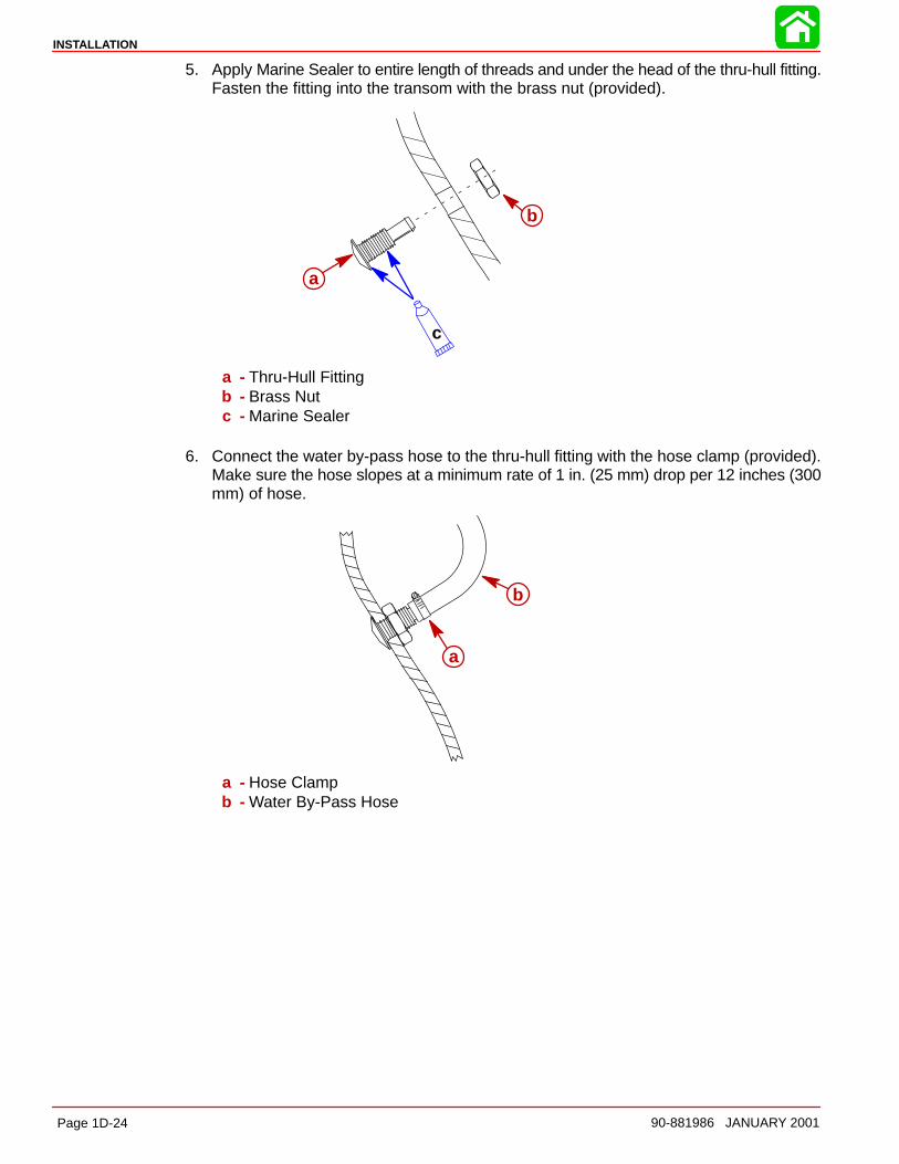
5. Apply Marine Sealer to entire length of threads and under the head of the thru-hull fitting.Fasten the fitting into the transom with the brass nut (provided).
c
a
b
a - Thru-Hull Fittingb - Brass Nutc - Marine Sealer
6. Connect the water by-pass hose to the thru-hull fitting with the hose clamp (provided).Make sure the hose slopes at a minimum rate of 1 in. (25 mm) drop per 12 inches (300mm) of hose.
a
b
a - Hose Clampb - Water By-Pass Hose
INSTALLATION
Page 1D-2590-881986 JANUARY 2001
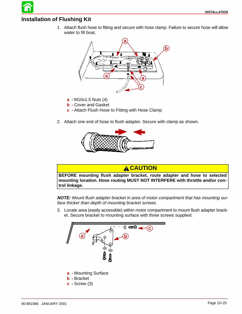
Installation of Flushing Kit1. Attach flush hose to fitting and secure with hose clamp. Failure to secure hose will allow
water to fill boat.
a
b
aa
c
a - M10x1.5 Nuts (4)b - Cover and Gasketc - Attach Flush Hose to Fitting with Hose Clamp
2. Attach one end of hose to flush adapter. Secure with clamp as shown.
CAUTIONBEFORE mounting flush adapter bracket, route adapter and hose to selectedmounting location. Hose routing MUST NOT INTERFERE with throttle and/or con-trol linkage.
NOTE: Mount flush adapter bracket in area of motor compartment that has mounting sur-face thicker than depth of mounting bracket screws.
3. Locate area (easily accessible) within motor compartment to mount flush adapter brack-et. Secure bracket to mounting surface with three screws supplied.
a b
c
a - Mounting Surfaceb - Bracketc - Screw (3)
INSTALLATION
Page 1D-26 90-881986 JANUARY 2001
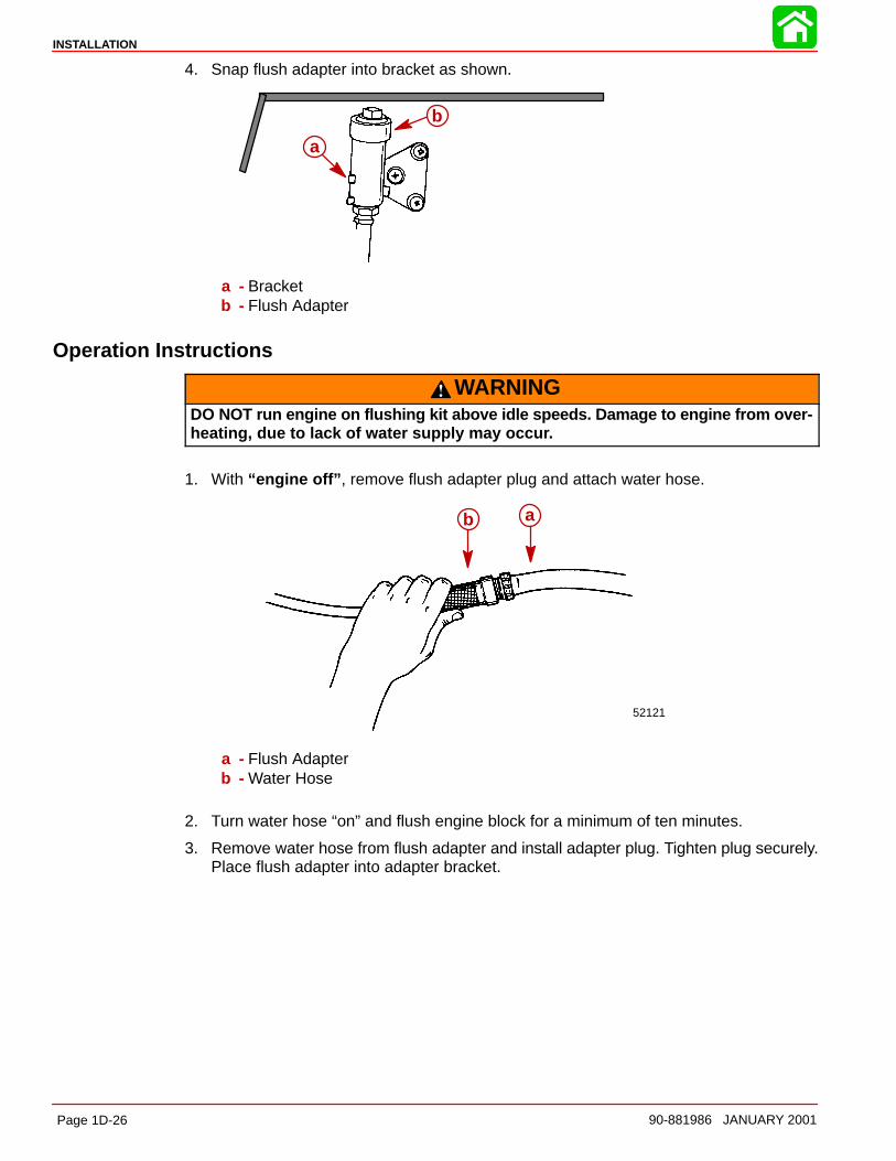
4. Snap flush adapter into bracket as shown.
a
b
a - Bracketb - Flush Adapter
Operation Instructions
WARNINGDO NOT run engine on flushing kit above idle speeds. Damage to engine from over-heating, due to lack of water supply may occur.
1. With “engine off” , remove flush adapter plug and attach water hose.
52121
ab
a - Flush Adapterb - Water Hose
2. Turn water hose “on” and flush engine block for a minimum of ten minutes.
3. Remove water hose from flush adapter and install adapter plug. Tighten plug securely.Place flush adapter into adapter bracket.
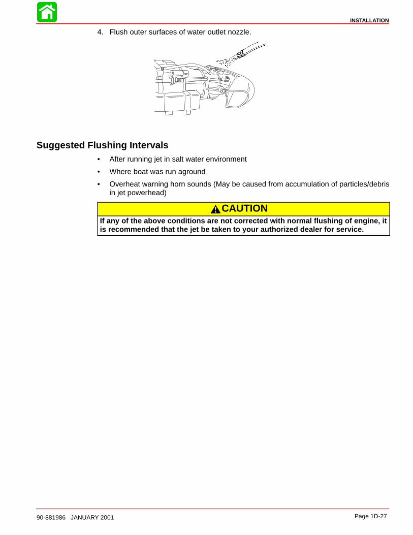
INSTALLATION
Page 1D-2790-881986 JANUARY 2001
4. Flush outer surfaces of water outlet nozzle.
Suggested Flushing Intervals• After running jet in salt water environment
• Where boat was run aground
• Overheat warning horn sounds (May be caused from accumulation of particles/debrisin jet powerhead)
CAUTIONIf any of the above conditions are not corrected with normal flushing of engine, itis recommended that the jet be taken to your authorized dealer for service.
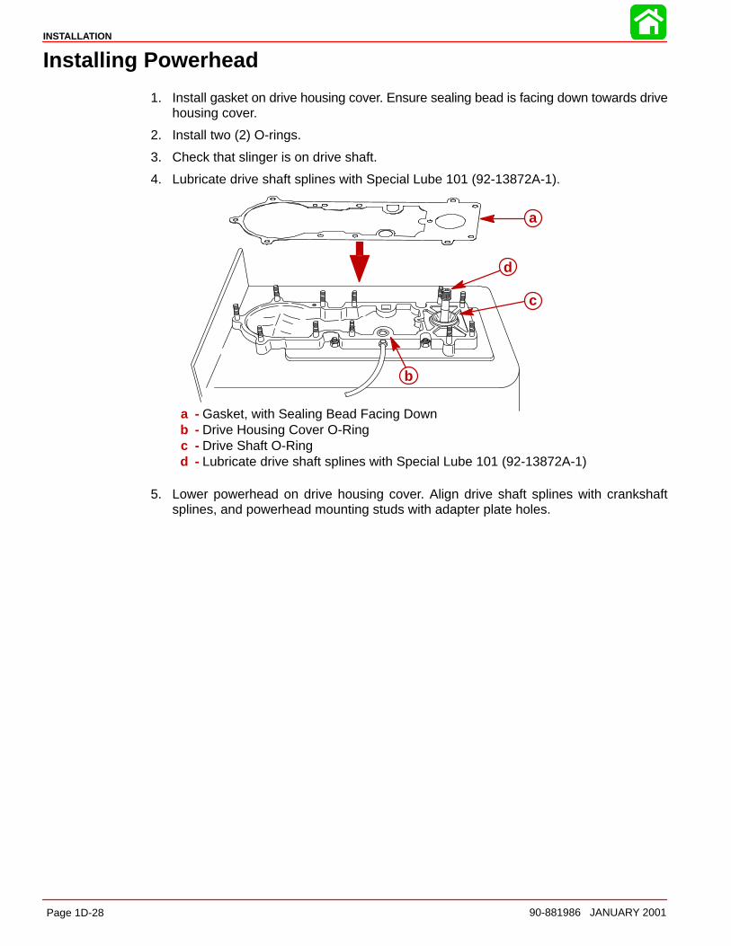
INSTALLATION
Page 1D-28 90-881986 JANUARY 2001
Installing Powerhead
1. Install gasket on drive housing cover. Ensure sealing bead is facing down towards drivehousing cover.
2. Install two (2) O-rings.
3. Check that slinger is on drive shaft.
4. Lubricate drive shaft splines with Special Lube 101 (92-13872A-1).
a
b
c
d
a - Gasket, with Sealing Bead Facing Downb - Drive Housing Cover O-Ringc - Drive Shaft O-Ringd - Lubricate drive shaft splines with Special Lube 101 (92-13872A-1)
5. Lower powerhead on drive housing cover. Align drive shaft splines with crankshaftsplines, and powerhead mounting studs with adapter plate holes.
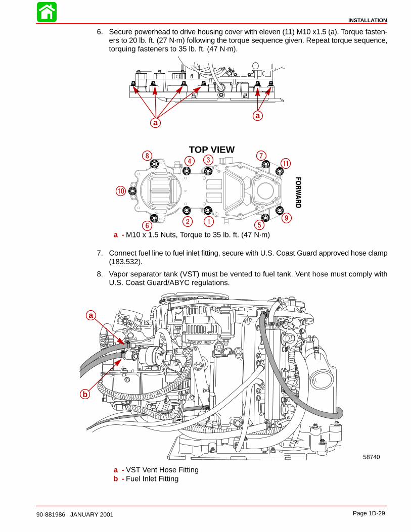
INSTALLATION
Page 1D-2990-881986 JANUARY 2001
6. Secure powerhead to drive housing cover with eleven (11) M10 x1.5 (a). Torque fasten-ers to 20 lb. ft. (27 N·m) following the torque sequence given. Repeat torque sequence,torquing fasteners to 35 lb. ft. (47 N·m).
TOP VIEW
FORWARD
aa
2 1
34
56
78
9
10
11
a - M10 x 1.5 Nuts, Torque to 35 lb. ft. (47 N·m)
7. Connect fuel line to fuel inlet fitting, secure with U.S. Coast Guard approved hose clamp(183.532).
8. Vapor separator tank (VST) must be vented to fuel tank. Vent hose must comply withU.S. Coast Guard/ABYC regulations.
b
a
58740
a - VST Vent Hose Fittingb - Fuel Inlet Fitting
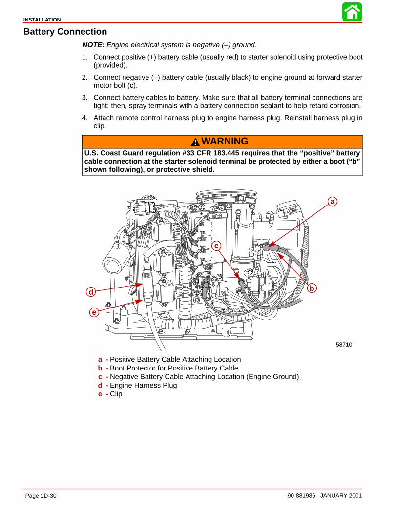
INSTALLATION
Page 1D-30 90-881986 JANUARY 2001
Battery ConnectionNOTE: Engine electrical system is negative (–) ground.
1. Connect positive (+) battery cable (usually red) to starter solenoid using protective boot(provided).
2. Connect negative (–) battery cable (usually black) to engine ground at forward startermotor bolt (c).
3. Connect battery cables to battery. Make sure that all battery terminal connections aretight; then, spray terminals with a battery connection sealant to help retard corrosion.
4. Attach remote control harness plug to engine harness plug. Reinstall harness plug inclip.
WARNINGU.S. Coast Guard regulation #33 CFR 183.445 requires that the “positive” batterycable connection at the starter solenoid terminal be protected by either a boot (“b”shown following), or protective shield.
58710
a
b
c
e
d
a - Positive Battery Cable Attaching Locationb - Boot Protector for Positive Battery Cablec - Negative Battery Cable Attaching Location (Engine Ground)d - Engine Harness Pluge - Clip
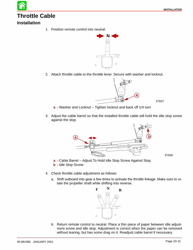
INSTALLATION
Page 1D-3190-881986 JANUARY 2001
Throttle CableInstallation
1. Position remote control into neutral.
N
2. Attach throttle cable to the throttle lever. Secure with washer and locknut.
a
57837
a - Washer and Locknut – Tighten locknut and back off 1/4 turn
3. Adjust the cable barrel so that the installed throttle cable will hold the idle stop screwagainst the stop.
a b
57838
a - Cable Barrel – Adjust To Hold Idle Stop Screw Against Stopb - Idle Stop Screw
4. Check throttle cable adjustment as follows:
a. Shift outboard into gear a few times to activate the throttle linkage. Make sure to ro-tate the propeller shaft while shifting into reverse.
N RF
b. Return remote control to neutral. Place a thin piece of paper between idle adjust-ment screw and idle stop. Adjustment is correct when the paper can be removedwithout tearing, but has some drag on it. Readjust cable barrel if necessary.
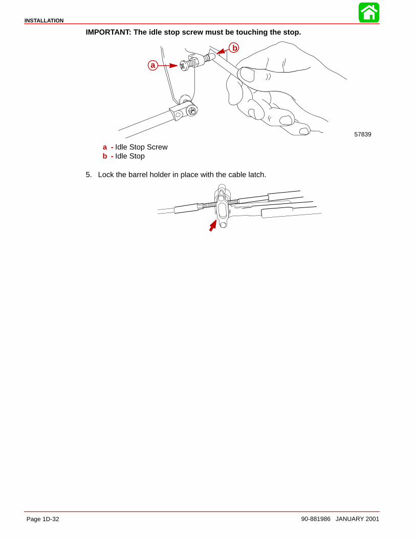
INSTALLATION
Page 1D-32 90-881986 JANUARY 2001
IMPORTANT: The idle stop screw must be touching the stop.
a
b
57839
a - Idle Stop Screwb - Idle Stop
5. Lock the barrel holder in place with the cable latch.
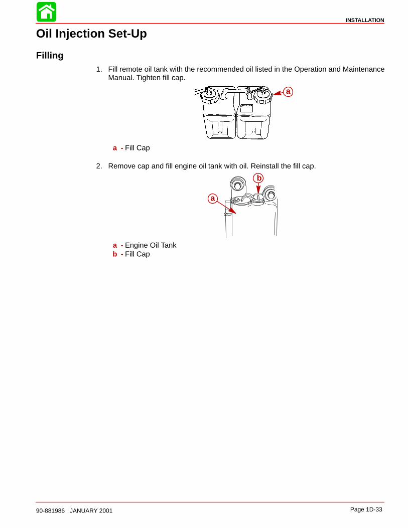
INSTALLATION
Page 1D-3390-881986 JANUARY 2001
Oil Injection Set-Up
Filling1. Fill remote oil tank with the recommended oil listed in the Operation and Maintenance
Manual. Tighten fill cap.
a
a - Fill Cap
2. Remove cap and fill engine oil tank with oil. Reinstall the fill cap.
a
b
a - Engine Oil Tankb - Fill Cap
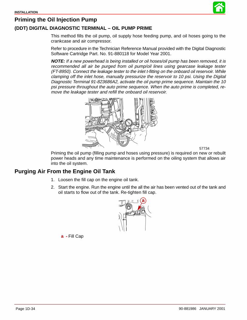
INSTALLATION
Page 1D-34 90-881986 JANUARY 2001
Priming the Oil Injection Pump(DDT) DIGITAL DIAGNOSTIC TERMINAL – OIL PUMP PRIME
This method fills the oil pump, oil supply hose feeding pump, and oil hoses going to thecrankcase and air compressor.
Refer to procedure in the Technician Reference Manual provided with the Digital DiagnosticSoftware Cartridge Part. No. 91-880118 for Model Year 2001.
NOTE: If a new powerhead is being installed or oil hoses/oil pump has been removed, it isrecommended all air be purged from oil pump/oil lines using gearcase leakage tester(FT-8950). Connect the leakage tester to the inlet t-fitting on the onboard oil reservoir. Whileclamping off the inlet hose, manually pressurize the reservoir to 10 psi. Using the DigitalDiagnostic Terminal 91-823686A2, activate the oil pump prime sequence. Maintain the 10psi pressure throughout the auto prime sequence. When the auto prime is completed, re-move the leakage tester and refill the onboard oil reservoir.
57734Priming the oil pump (filling pump and hoses using pressure) is required on new or rebuiltpower heads and any time maintenance is performed on the oiling system that allows airinto the oil system.
Purging Air From the Engine Oil Tank1. Loosen the fill cap on the engine oil tank.
2. Start the engine. Run the engine until the all the air has been vented out of the tank andoil starts to flow out of the tank. Re-tighten fill cap.
a
a - Fill Cap
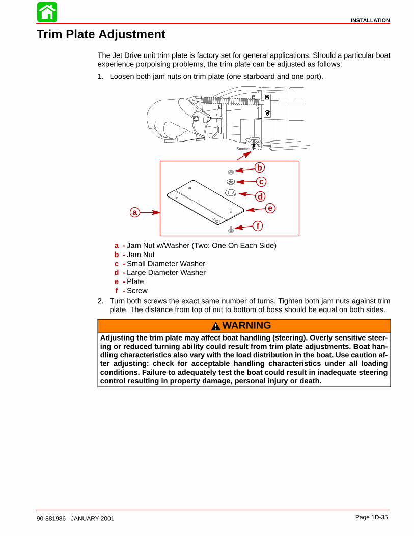
INSTALLATION
Page 1D-3590-881986 JANUARY 2001
Trim Plate Adjustment
The Jet Drive unit trim plate is factory set for general applications. Should a particular boatexperience porpoising problems, the trim plate can be adjusted as follows:
1. Loosen both jam nuts on trim plate (one starboard and one port).
a
b
c
de
f
a - Jam Nut w/Washer (Two: One On Each Side)b - Jam Nutc - Small Diameter Washerd - Large Diameter Washere - Platef - Screw
2. Turn both screws the exact same number of turns. Tighten both jam nuts against trimplate. The distance from top of nut to bottom of boss should be equal on both sides.
WARNINGAdjusting the trim plate may affect boat handling (steering). Overly sensitive steer-ing or reduced turning ability could result from trim plate adjustments. Boat han-dling characteristics also vary with the load distribution in the boat. Use caution af-ter adjusting: check for acceptable handling characteristics under all loadingconditions. Failure to adequately test the boat could result in inadequate steeringcontrol resulting in property damage, personal injury or death.
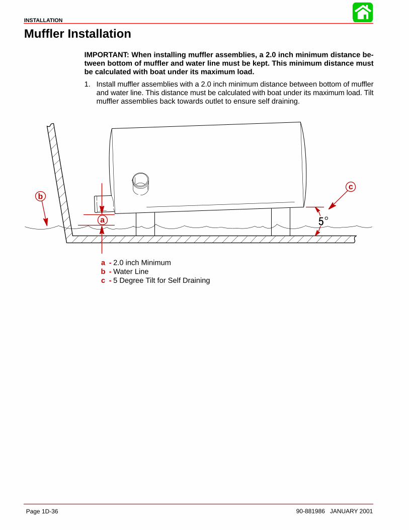
INSTALLATION
Page 1D-36 90-881986 JANUARY 2001
Muffler Installation
IMPORTANT: When installing muffler assemblies, a 2.0 inch minimum distance be-tween bottom of muffler and water line must be kept. This minimum distance mustbe calculated with boat under its maximum load.
1. Install muffler assemblies with a 2.0 inch minimum distance between bottom of mufflerand water line. This distance must be calculated with boat under its maximum load. Tiltmuffler assemblies back towards outlet to ensure self draining.
a
bc
a - 2.0 inch Minimumb - Water Linec - 5 Degree Tilt for Self Draining

INSTALLATION
Page 1D-3790-881986 JANUARY 2001
Pre-delivery Inspection
Not Check/
Applicable Adjust CHECK BEFORE RUNNING
Water hose connection/torqued
Cover plate & adaptor platefasteners torqued
Battery charged & secure
All electrical connections tight
All fuel connections tight
Throttle, shift, & steering adjustedcorrectly and fasteners torqued
Shift cable adjusted to keepreverse gate above rudder in forward w/ slack pulledout of cable and against the stop.
Carb throttle shutters open & close completely
Pump housing oil level full(See Owner’s Manual)
Oil injection reservoir full and bled
Warning system(s) operational
ON THE WATER CHECK
Starter neutral safety switchoperational
Lanyard stop switch operational
All gauges read properly
No fuel or oil leaks
No water leaks
No exhaust leaks
Ignition timing set to specs
Idle:____________RPM
Idle mixture adjusted
Forward-Neutral-Reverseoperational
Steering operational throughoutentire range
Acceleration test
WOT:___________RPM
Boat handling
POST WATER CHECK
Re-torque adapter plate fasteners
No fuel, oil, water or exhaustleaks
Re-check shift cable adjustment. Readjust as necessary
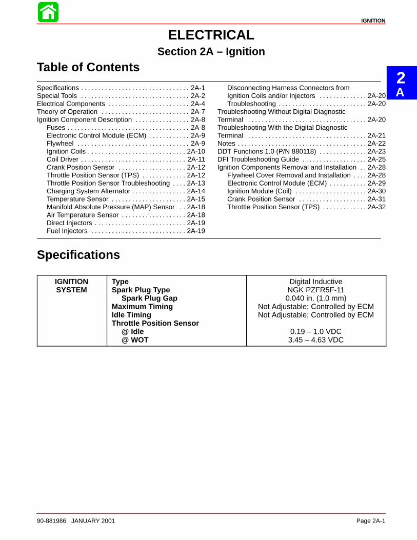
2A
IGNITION
90-881986 JANUARY 2001 Page 2A-1
ELECTRICALSection 2A – Ignition
Table of Contents
Specifications 2A-1. . . . . . . . . . . . . . . . . . . . . . . . . . . . . . . . Special Tools 2A-2. . . . . . . . . . . . . . . . . . . . . . . . . . . . . . . . Electrical Components 2A-4. . . . . . . . . . . . . . . . . . . . . . . . Theory of Operation 2A-7. . . . . . . . . . . . . . . . . . . . . . . . . . Ignition Component Description 2A-8. . . . . . . . . . . . . . . .
Fuses 2A-8. . . . . . . . . . . . . . . . . . . . . . . . . . . . . . . . . . . . Electronic Control Module (ECM) 2A-9. . . . . . . . . . . . Flywheel 2A-9. . . . . . . . . . . . . . . . . . . . . . . . . . . . . . . . . Ignition Coils 2A-10. . . . . . . . . . . . . . . . . . . . . . . . . . . . . Coil Driver 2A-11. . . . . . . . . . . . . . . . . . . . . . . . . . . . . . . Crank Position Sensor 2A-12. . . . . . . . . . . . . . . . . . . . Throttle Position Sensor (TPS) 2A-12. . . . . . . . . . . . . Throttle Position Sensor Troubleshooting 2A-13. . . . Charging System Alternator 2A-14. . . . . . . . . . . . . . . . Temperature Sensor 2A-15. . . . . . . . . . . . . . . . . . . . . . Manifold Absolute Pressure (MAP) Sensor 2A-18. . Air Temperature Sensor 2A-18. . . . . . . . . . . . . . . . . . . Direct Injectors 2A-19. . . . . . . . . . . . . . . . . . . . . . . . . . . Fuel Injectors 2A-19. . . . . . . . . . . . . . . . . . . . . . . . . . . .
Disconnecting Harness Connectors fromIgnition Coils and/or Injectors 2A-20. . . . . . . . . . . . . . Troubleshooting 2A-20. . . . . . . . . . . . . . . . . . . . . . . . . .
Troubleshooting Without Digital DiagnosticTerminal 2A-20. . . . . . . . . . . . . . . . . . . . . . . . . . . . . . . . . . . Troubleshooting With the Digital DiagnosticTerminal 2A-21. . . . . . . . . . . . . . . . . . . . . . . . . . . . . . . . . . . Notes 2A-22. . . . . . . . . . . . . . . . . . . . . . . . . . . . . . . . . . . . . . DDT Functions 1.0 (P/N 880118) 2A-23. . . . . . . . . . . . . . DFI Troubleshooting Guide 2A-25. . . . . . . . . . . . . . . . . . . Ignition Components Removal and Installation 2A-28. .
Flywheel Cover Removal and Installation 2A-28. . . . Electronic Control Module (ECM) 2A-29. . . . . . . . . . . Ignition Module (Coil) 2A-30. . . . . . . . . . . . . . . . . . . . . Crank Position Sensor 2A-31. . . . . . . . . . . . . . . . . . . . Throttle Position Sensor (TPS) 2A-32. . . . . . . . . . . . .
Specifications
IGNITIONSYSTEM
TypeSpark Plug Type
Spark Plug GapMaximum TimingIdle TimingThrottle Position Sensor
@ Idle@ WOT
Digital InductiveNGK PZFR5F-110.040 in. (1.0 mm)
Not Adjustable; Controlled by ECMNot Adjustable; Controlled by ECM
0.19 – 1.0 VDC3.45 – 4.63 VDC
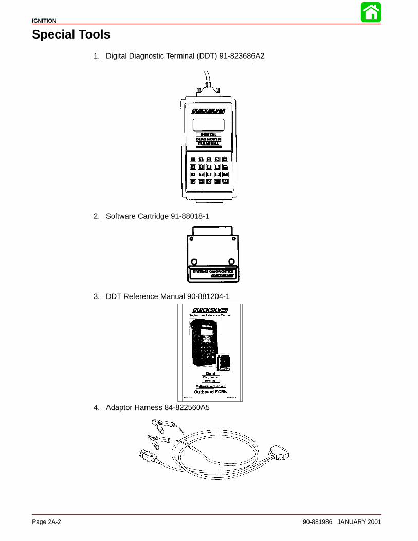
IGNITION
Page 2A-2 90-881986 JANUARY 2001
Special Tools
1. Digital Diagnostic Terminal (DDT) 91-823686A2
2. Software Cartridge 91-88018-1
3. DDT Reference Manual 90-881204-1
4. Adaptor Harness 84-822560A5
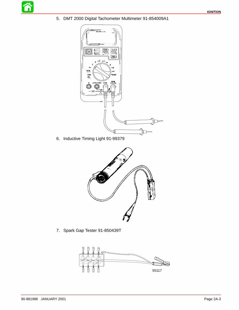
IGNITION
90-881986 JANUARY 2001 Page 2A-3
5. DMT 2000 Digital Tachometer Multimeter 91-854009A1
6. Inductive Timing Light 91-99379
7. Spark Gap Tester 91-850439T
55117
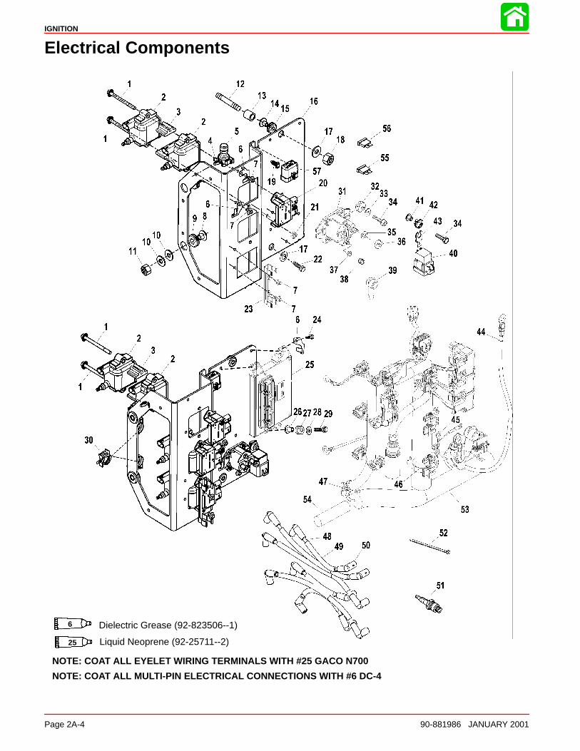
IGNITION
Page 2A-4 90-881986 JANUARY 2001
Electrical Components
NOTE: COAT ALL EYELET WIRING TERMINALS WITH #25 GACO N700
NOTE: COAT ALL MULTI-PIN ELECTRICAL CONNECTIONS WITH #6 DC-4
Dielectric Grease (92-823506--1)6
Liquid Neoprene (92-25711--2)25
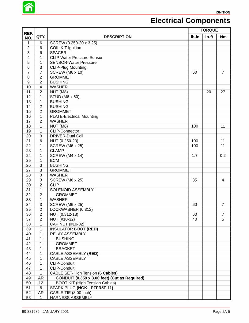
IGNITION
90-881986 JANUARY 2001 Page 2A-5
Electrical Components
REFTORQUE
REF.NO. QTY. DESCRIPTION lb-in lb-ft Nm
1 6 SCREW (0.250-20 x 3.25)2 6 COIL KIT-Ignition3 6 SPACER4 1 CLIP-Water Pressure Sensor5 1 SENSOR-Water Pressure6 3 CLIP-Plug Mounting7 7 SCREW (M6 x 10) 60 78 2 GROMMET9 2 BUSHING10 4 WASHER11 2 NUT (M8) 20 2712 1 STUD (M6 x 50)13 1 BUSHING14 2 BUSHING15 2 GROMMET16 1 PLATE-Electrical Mounting17 2 WASHER18 1 NUT (M6) 100 1119 1 CLIP-Connector20 3 DRIVER-Dual Coil21 6 NUT (0.250-20) 100 1122 1 SCREW (M6 x 25) 100 1123 1 CLAMP24 1 SCREW (M4 x 14) 1.7 0.225 1 ECM26 3 BUSHING27 3 GROMMET28 3 WASHER29 3 SCREW (M6 x 25) 35 430 2 CLIP31 1 SOLENOID ASSEMBLY32 2 GROMMET33 1 WASHER34 3 SCREW (M6 x 25) 60 735 2 LOCKWASHER (0.312)36 2 NUT (0.312-18) 60 737 2 NUT (#10-32) 40 538 1 CAP NUT (#10-32)39 1 INSULATOR BOOT (RED)40 1 RELAY ASSEMBLY41 1 BUSHING42 1 GROMMET43 1 BRACKET44 1 CABLE ASSEMBLY (RED)45 1 CABLE ASSEMBLY46 1 CLIP-Conduit47 1 CLIP-Conduit48 1 CABLE SET-High Tension (6 Cables)49 AR CONDUIT (0.359 x 3.00 feet) (Cut as Required)50 12 BOOT KIT (High Tension Cables)51 6 SPARK PLUG (NGK - PZFR5F-11)52 AR CABLE TIE (8.00 Inch)53 1 HARNESS ASSEMBLY

IGNITION
Page 2A-6 90-881986 JANUARY 2001
Electrical Components
NOTE: COAT ALL EYELET WIRING TERMINALS WITH #25 GACO N700
NOTE: COAT ALL MULTI-PIN ELECTRICAL CONNECTIONS WITH #6 DC-4
Dielectric Grease (92-823506--1)6
Liquid Neoprene (92-25711--2)25
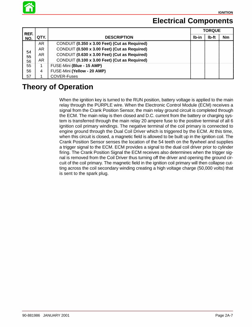
IGNITION
90-881986 JANUARY 2001 Page 2A-7
Electrical Components
REFTORQUE
REF.NO. QTY. DESCRIPTION lb-in lb-ft Nm
AR CONDUIT (0.350 x 3.00 Feet) (Cut as Required)
54AR CONDUIT (0.500 x 3.00 Feet) (Cut as Required)
5455 AR CONDUIT (0.630 x 3.00 Feet) (Cut as Required)5556 AR CONDUIT (0.100 x 3.00 Feet) (Cut as Required)55 1 FUSE-Mini (Blue - 15 AMP)56 4 FUSE-Mini (Yellow - 20 AMP)57 1 COVER-Fuses
Theory of Operation
When the ignition key is turned to the RUN position, battery voltage is applied to the mainrelay through the PURPLE wire. When the Electronic Control Module (ECM) receives asignal from the Crank Position Sensor, the main relay ground circuit is completed throughthe ECM. The main relay is then closed and D.C. current from the battery or charging sys-tem is transferred through the main relay 20 ampere fuse to the positive terminal of all 6ignition coil primary windings. The negative terminal of the coil primary is connected toengine ground through the Dual Coil Driver which is triggered by the ECM. At this time,when this circuit is closed, a magnetic field is allowed to be built up in the ignition coil. TheCrank Position Sensor senses the location of the 54 teeth on the flywheel and suppliesa trigger signal to the ECM. ECM provides a signal to the dual coil driver prior to cylinderfiring. The Crank Position Signal the ECM receives also determines when the trigger sig-nal is removed from the Coil Driver thus turning off the driver and opening the ground cir-cuit of the coil primary. The magnetic field in the ignition coil primary will then collapse cut-ting across the coil secondary winding creating a high voltage charge (50,000 volts) thatis sent to the spark plug.
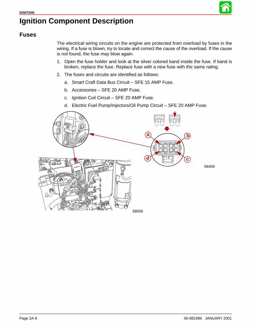
IGNITION
Page 2A-8 90-881986 JANUARY 2001
Ignition Component Description
FusesThe electrical wiring circuits on the engine are protected from overload by fuses in thewiring. If a fuse is blown, try to locate and correct the cause of the overload. If the causeis not found, the fuse may blow again.
1. Open the fuse holder and look at the silver colored band inside the fuse. If band isbroken, replace the fuse. Replace fuse with a new fuse with the same rating.
2. The fuses and circuits are identified as follows:
a. Smart Craft Data Bus Circuit – SFE 15 AMP Fuse.
b. Accessories – SFE 20 AMP Fuse.
c. Ignition Coil Circuit – SFE 20 AMP Fuse.
d. Electric Fuel Pump/Injectors/Oil Pump Circuit – SFE 20 AMP Fuse.
a
58459
d c
b
58558
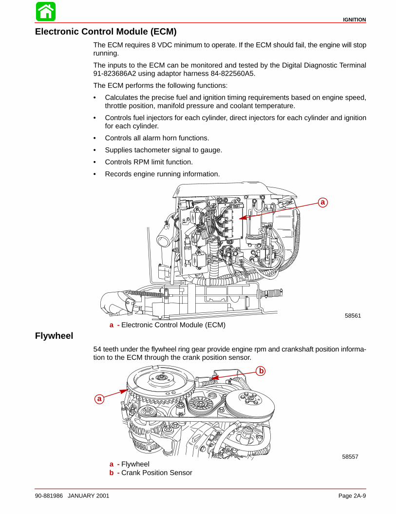
IGNITION
90-881986 JANUARY 2001 Page 2A-9
Electronic Control Module (ECM)The ECM requires 8 VDC minimum to operate. If the ECM should fail, the engine will stoprunning.
The inputs to the ECM can be monitored and tested by the Digital Diagnostic Terminal91-823686A2 using adaptor harness 84-822560A5.
The ECM performs the following functions:
• Calculates the precise fuel and ignition timing requirements based on engine speed,throttle position, manifold pressure and coolant temperature.
• Controls fuel injectors for each cylinder, direct injectors for each cylinder and ignitionfor each cylinder.
• Controls all alarm horn functions.
• Supplies tachometer signal to gauge.
• Controls RPM limit function.
• Records engine running information.
58561
a
a - Electronic Control Module (ECM)
Flywheel54 teeth under the flywheel ring gear provide engine rpm and crankshaft position informa-tion to the ECM through the crank position sensor.
58557
a
b
a - Flywheelb - Crank Position Sensor
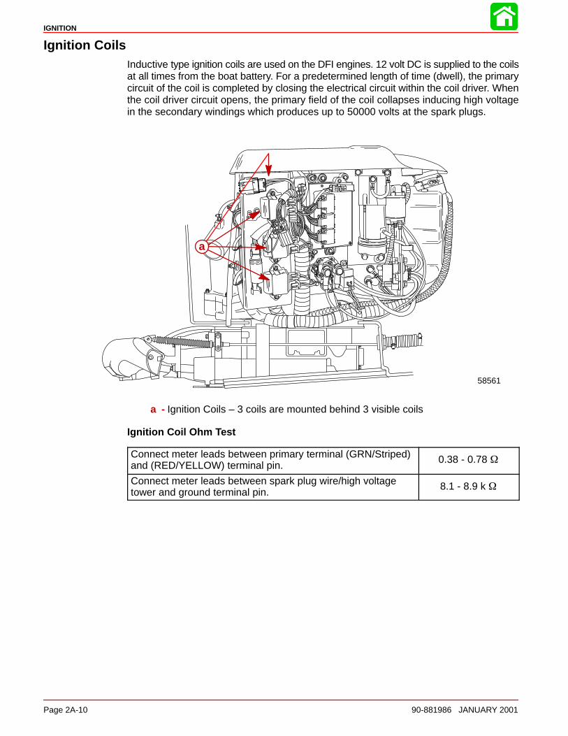
IGNITION
Page 2A-10 90-881986 JANUARY 2001
Ignition CoilsInductive type ignition coils are used on the DFI engines. 12 volt DC is supplied to the coilsat all times from the boat battery. For a predetermined length of time (dwell), the primarycircuit of the coil is completed by closing the electrical circuit within the coil driver. Whenthe coil driver circuit opens, the primary field of the coil collapses inducing high voltagein the secondary windings which produces up to 50000 volts at the spark plugs.
58561
a
a - Ignition Coils – 3 coils are mounted behind 3 visible coils
Ignition Coil Ohm Test
Connect meter leads between primary terminal (GRN/Striped)and (RED/YELLOW) terminal pin.
0.38 - 0.78
Connect meter leads between spark plug wire/high voltagetower and ground terminal pin.
8.1 - 8.9 k
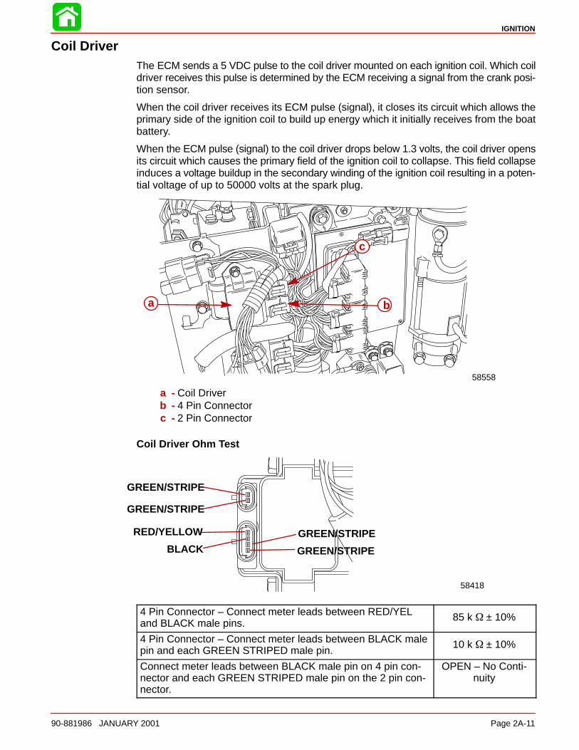
IGNITION
90-881986 JANUARY 2001 Page 2A-11
Coil DriverThe ECM sends a 5 VDC pulse to the coil driver mounted on each ignition coil. Which coildriver receives this pulse is determined by the ECM receiving a signal from the crank posi-tion sensor.
When the coil driver receives its ECM pulse (signal), it closes its circuit which allows theprimary side of the ignition coil to build up energy which it initially receives from the boatbattery.
When the ECM pulse (signal) to the coil driver drops below 1.3 volts, the coil driver opensits circuit which causes the primary field of the ignition coil to collapse. This field collapseinduces a voltage buildup in the secondary winding of the ignition coil resulting in a poten-tial voltage of up to 50000 volts at the spark plug.
58558
a b
c
a - Coil Driverb - 4 Pin Connectorc - 2 Pin Connector
Coil Driver Ohm Test
58418
GREEN/STRIPE
GREEN/STRIPE
GREEN/STRIPE
GREEN/STRIPE
RED/YELLOW
BLACK
4 Pin Connector – Connect meter leads between RED/YELand BLACK male pins.
85 k ± 10%
4 Pin Connector – Connect meter leads between BLACK malepin and each GREEN STRIPED male pin.
10 k ± 10%
Connect meter leads between BLACK male pin on 4 pin con-nector and each GREEN STRIPED male pin on the 2 pin con-nector.
OPEN – No Conti-nuity
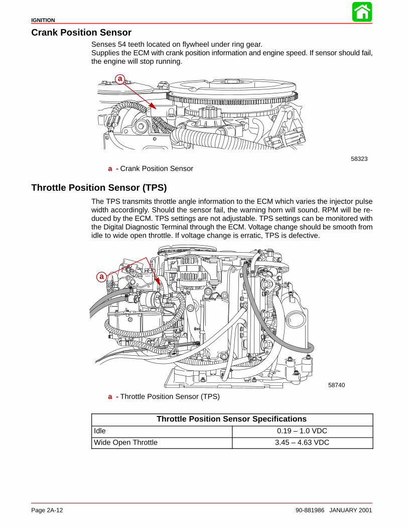
IGNITION
Page 2A-12 90-881986 JANUARY 2001
Crank Position SensorSenses 54 teeth located on flywheel under ring gear.Supplies the ECM with crank position information and engine speed. If sensor should fail,the engine will stop running.
58323
a
a - Crank Position Sensor
Throttle Position Sensor (TPS)The TPS transmits throttle angle information to the ECM which varies the injector pulsewidth accordingly. Should the sensor fail, the warning horn will sound. RPM will be re-duced by the ECM. TPS settings are not adjustable. TPS settings can be monitored withthe Digital Diagnostic Terminal through the ECM. Voltage change should be smooth fromidle to wide open throttle. If voltage change is erratic, TPS is defective.
58740
a
a - Throttle Position Sensor (TPS)
Throttle Position Sensor SpecificationsIdle 0.19 – 1.0 VDC
Wide Open Throttle 3.45 – 4.63 VDC

IGNITION
90-881986 JANUARY 2001 Page 2A-13
Throttle Position Sensor (TPS) TroubleshootingIf the throttle position sensor is out of the intended operating range when the engine isstarted, the Electronic Control Module (ECM) will sense that the Throttle Position Sensor(TPS) has failed. The warning horn will sound, check engine light will illuminate, DDT willindicate failed TPS and the engine will go into RPM reduction. When the engine is started,the throttle arm on the engine must be against the throttle stop screw. Do not move throttleor fast idle control lever forward.
• Check throttle cable adjustment. The throttle stop screw on the throttle arm must beagainst the throttle stop on the cylinder block when the engine is started. Pre-load thethrottle cable barrel 1 or 2 turns if necessary.
• Verify driver is not pushing on throttle (if foot throttle is used) or advancing the throttleonly on the control box.
• Check throttle cam to roller adjustment. If the roller is not down in the pocket/valleyarea on the cam, there is a tendency for the roller to ride up or down on the cam whichcauses the TPS link arm to push/pull on the TPS lever resulting changing values.
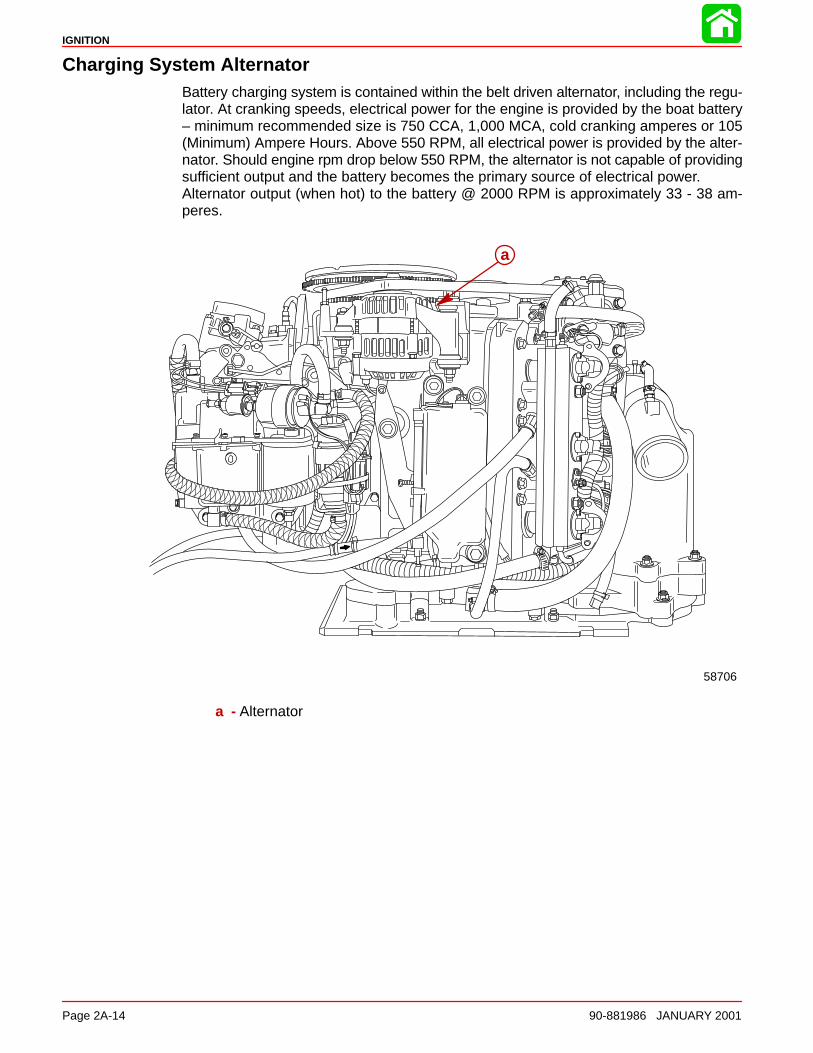
IGNITION
Page 2A-14 90-881986 JANUARY 2001
Charging System AlternatorBattery charging system is contained within the belt driven alternator, including the regu-lator. At cranking speeds, electrical power for the engine is provided by the boat battery– minimum recommended size is 750 CCA, 1,000 MCA, cold cranking amperes or 105(Minimum) Ampere Hours. Above 550 RPM, all electrical power is provided by the alter-nator. Should engine rpm drop below 550 RPM, the alternator is not capable of providingsufficient output and the battery becomes the primary source of electrical power. Alternator output (when hot) to the battery @ 2000 RPM is approximately 33 - 38 am-peres.
58706
a
a - Alternator
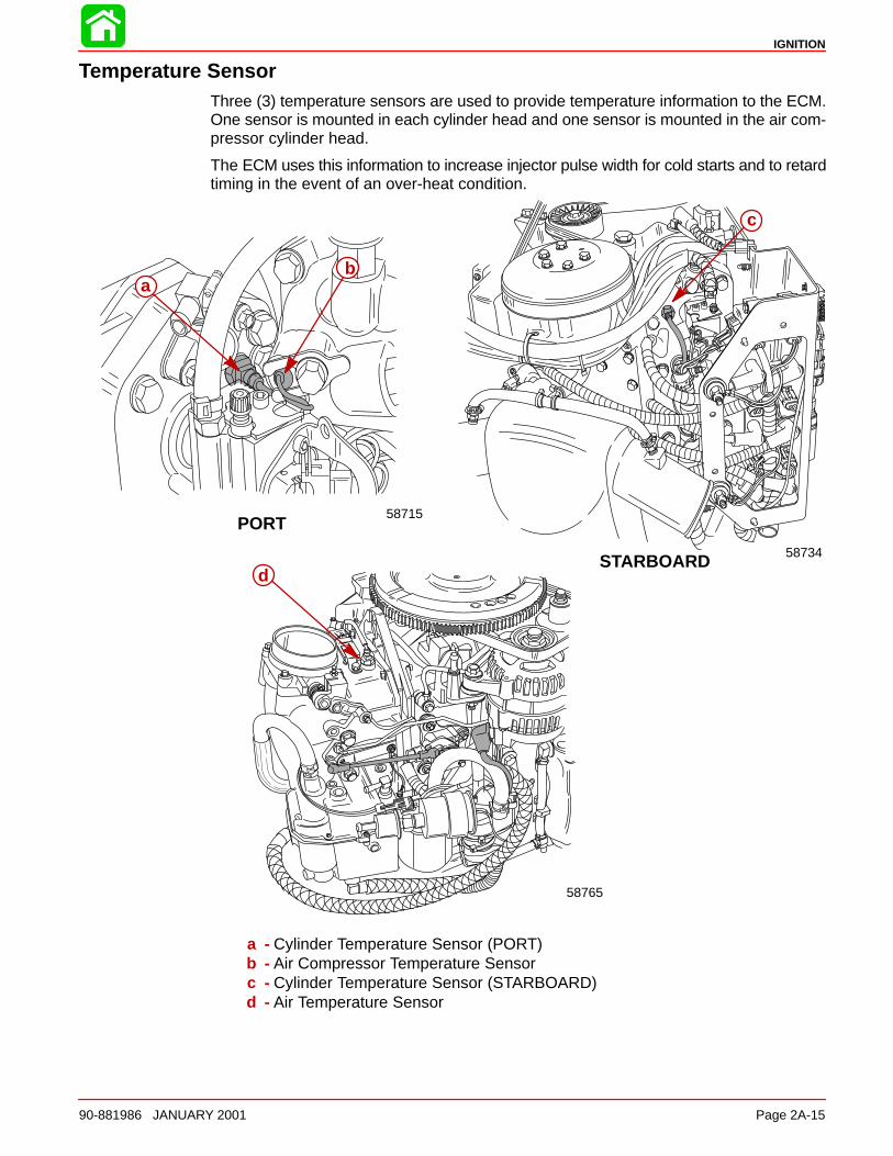
IGNITION
90-881986 JANUARY 2001 Page 2A-15
Temperature SensorThree (3) temperature sensors are used to provide temperature information to the ECM.One sensor is mounted in each cylinder head and one sensor is mounted in the air com-pressor cylinder head.
The ECM uses this information to increase injector pulse width for cold starts and to retardtiming in the event of an over-heat condition.
STARBOARD
PORT
58734
ba
c
58715
58765
d
a - Cylinder Temperature Sensor (PORT)b - Air Compressor Temperature Sensorc - Cylinder Temperature Sensor (STARBOARD)d - Air Temperature Sensor
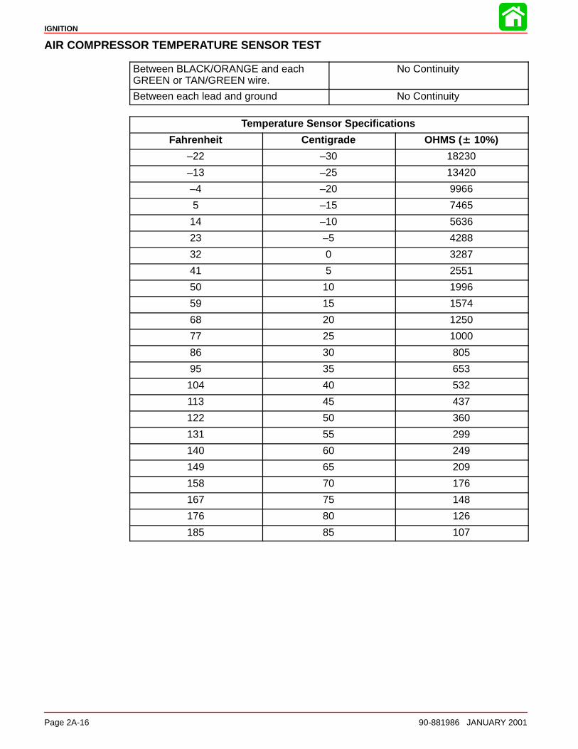
IGNITION
Page 2A-16 90-881986 JANUARY 2001
AIR COMPRESSOR TEMPERATURE SENSOR TEST
Between BLACK/ORANGE and eachGREEN or TAN/GREEN wire.
No Continuity
Between each lead and ground No Continuity
Temperature Sensor Specifications
Fahrenheit Centigrade OHMS (± 10%)
–22 –30 18230
–13 –25 13420
–4 –20 9966
5 –15 7465
14 –10 5636
23 –5 4288
32 0 3287
41 5 2551
50 10 1996
59 15 1574
68 20 1250
77 25 1000
86 30 805
95 35 653
104 40 532
113 45 437
122 50 360
131 55 299
140 60 249
149 65 209
158 70 176
167 75 148
176 80 126
185 85 107
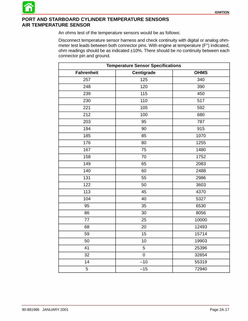
IGNITION
90-881986 JANUARY 2001 Page 2A-17
PORT AND STARBOARD CYLINDER TEMPERATURE SENSORSAIR TEMPERATURE SENSOR
An ohms test of the temperature sensors would be as follows:
Disconnect temperature sensor harness and check continuity with digital or analog ohm-meter test leads between both connector pins. With engine at temperature (F°) indicated,ohm readings should be as indicated ±10%. There should be no continuity between eachconnector pin and ground.
Temperature Sensor Specifications
Fahrenheit Centigrade OHMS
257 125 340
248 120 390
239 115 450
230 110 517
221 105 592
212 100 680
203 95 787
194 90 915
185 85 1070
176 80 1255
167 75 1480
158 70 1752
149 65 2083
140 60 2488
131 55 2986
122 50 3603
113 45 4370
104 40 5327
95 35 6530
86 30 8056
77 25 10000
68 20 12493
59 15 15714
50 10 19903
41 5 25396
32 0 32654
14 –10 55319
5 –15 72940
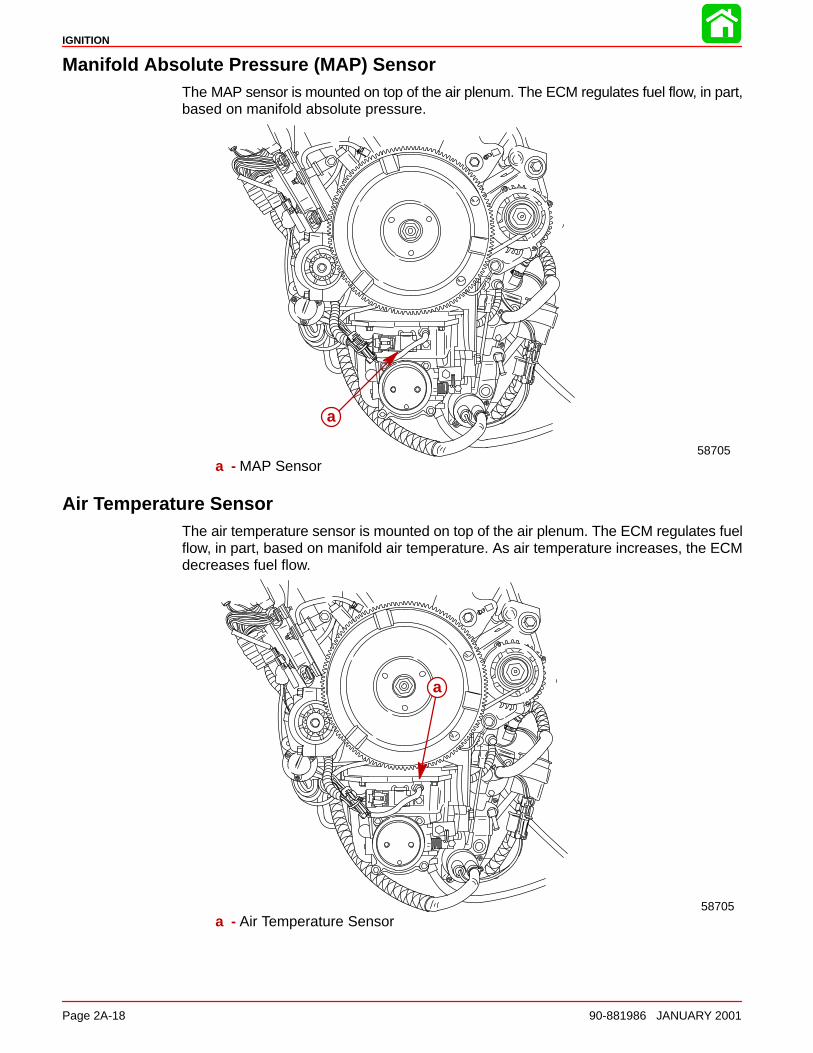
IGNITION
Page 2A-18 90-881986 JANUARY 2001
Manifold Absolute Pressure (MAP) SensorThe MAP sensor is mounted on top of the air plenum. The ECM regulates fuel flow, in part,based on manifold absolute pressure.
58705
a
a - MAP Sensor
Air Temperature SensorThe air temperature sensor is mounted on top of the air plenum. The ECM regulates fuelflow, in part, based on manifold air temperature. As air temperature increases, the ECMdecreases fuel flow.
58705
a
a - Air Temperature Sensor
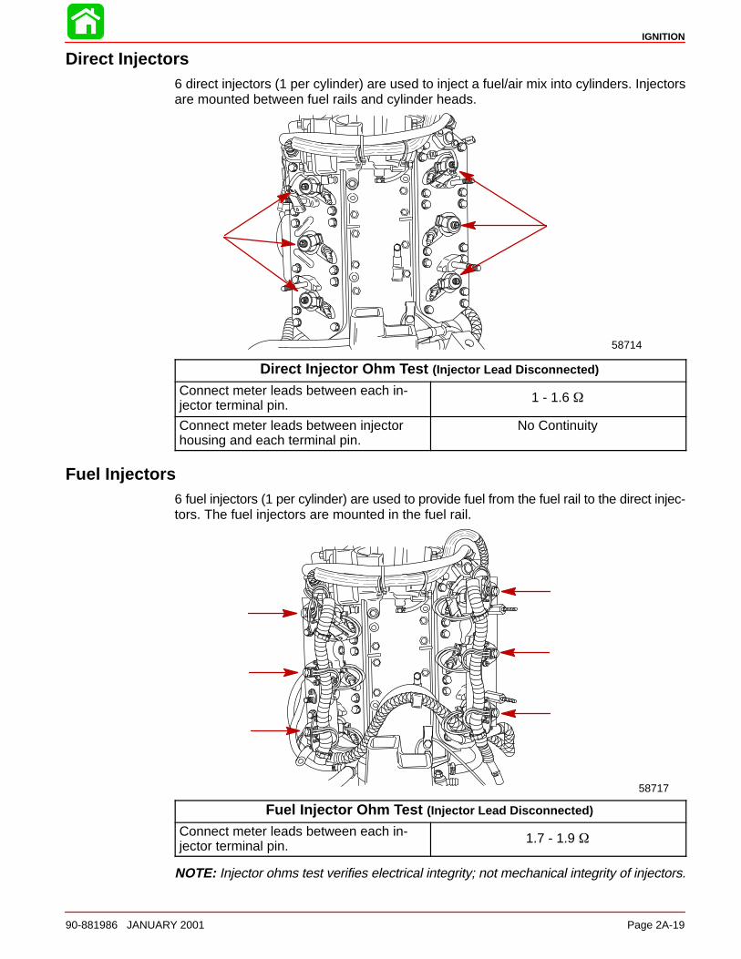
IGNITION
90-881986 JANUARY 2001 Page 2A-19
Direct Injectors6 direct injectors (1 per cylinder) are used to inject a fuel/air mix into cylinders. Injectorsare mounted between fuel rails and cylinder heads.
58714
Direct Injector Ohm Test (Injector Lead Disconnected)
Connect meter leads between each in-jector terminal pin.
1 - 1.6
Connect meter leads between injectorhousing and each terminal pin.
No Continuity
Fuel Injectors6 fuel injectors (1 per cylinder) are used to provide fuel from the fuel rail to the direct injec-tors. The fuel injectors are mounted in the fuel rail.
58717
Fuel Injector Ohm Test (Injector Lead Disconnected)
Connect meter leads between each in-jector terminal pin.
1.7 - 1.9
NOTE: Injector ohms test verifies electrical integrity; not mechanical integrity of injectors.

IGNITION
Page 2A-20 90-881986 JANUARY 2001
Disconnecting Harness Connectors from Ignition Coils and/or Injectors
54871
a
a - Wire Clip (push center down to remove)
TroubleshootingThe ECM is designed such that if a sensor fails, the ECM will compensate so that the en-gine does not go into an over-rich condition.
Disconnecting a sensor for troubleshooting purposes may have no noticeable effect.
Troubleshooting Without Digital Diagnostic Terminal
Troubleshooting without the DDT is limited to checking resistance on some of the sen-sors.
Typical failures usually do not involve the ECM. Connectors, set-up, and mechanical wearare most likely at fault.
• Verify spark plug wires are securely installed (pushed in) into the coil tower.
• The engine may not run or may not run above idle with the wrong spark plugs installed.
• Swap ignition coils to see if the problem follows the coil or stays with the particularcylinder.
NOTE: ECMs are capable of performing a cylinder misfire test to isolate problem cylin-ders. Once a suspect cylinder is located, an output load test on the ignition coil, fuel injec-tor and direct injector may be initiated through use of the DDT.
• Any sensor or connection can be disconnected and reconnected while the engine isoperating without damaging the ECM. Disconnecting the crank position sensor willstop the engine.
IMPORTANT: Any sensor that is disconnected while the engine is running will berecorded as a Fault in the ECM Fault History. Use the DDT to view and clear the faulthistory when troubleshooting/repair is completed.
• If all cylinders exhibit similar symptoms, the problem is with a sensor or harness inputto the ECM.
• If problem is speed related or intermittent, it is probably connector or contact related.Inspect connectors for corrosion, loose wires or loose pins. Secure connector seating;use dielectric compound 92-823506-1.
• Inspect the harness for obvious damage: pinched wires, chaffing.
• Secure grounds and all connections involving ring terminals (coat with Liquid Neo-prene 92-25711--3).
• Check fuel pump connections and fuel pump pressure.
• Check air compressor pressure.

IGNITION
90-881986 JANUARY 2001 Page 2A-21
Troubleshooting with the Digital Diagnostic Terminal
a
bdc
a - Digital Diagnostic Terminal (91-823686A2)b - Software Cartridge (91-880118–1)c - DDT Reference Manual (90-881204–1)d - Adapter Harness (84-822560A5)
The Quicksilver Digital Diagnostic Terminal (DDT) has been developed specifically tohelp technicians diagnose and repair Mercury Marine 2 and 4 cycle engines.
Attach the diagnostic cable to the ECM diagnostic connector and plug in the software car-tridge. You will be able to monitor sensors and ECM data values including status switches.
The ECM program can help diagnose intermittent engine problems. It will record the stateof the engine sensors and switches for a period of time and then can be played back toreview the recorded information.
Refer to the Digital Diagnostic Terminal Reference Manual for complete diagnostic proce-dures.

IGNITION
Page 2A-22 90-881986 JANUARY 2001
Notes:
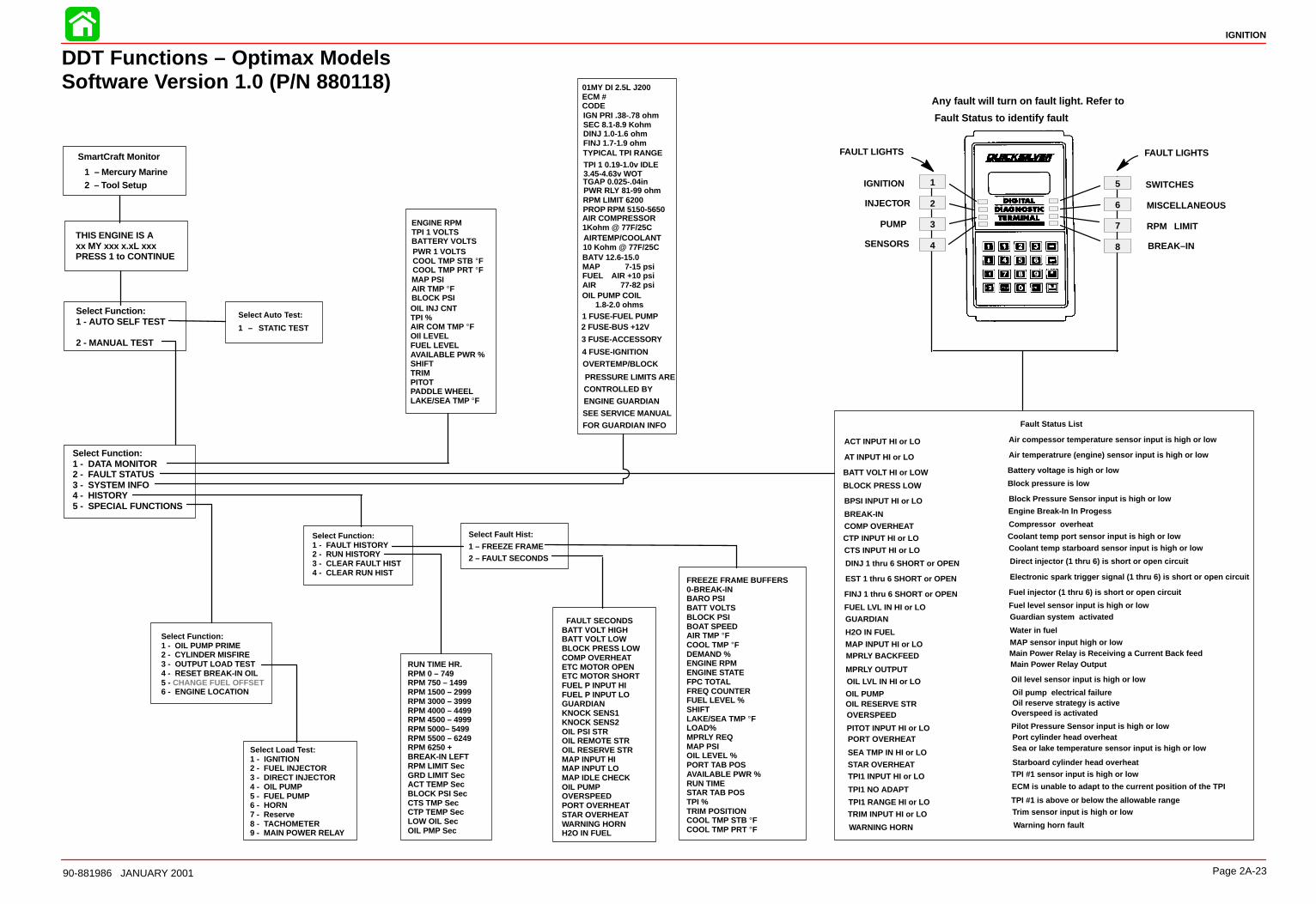
IGNITION
90-881986 JANUARY 2001 Page 2A-23
DDT Functions – Optimax ModelsSoftware Version 1.0 (P/N 880118)
IGNITION
INJECTOR
PUMP
SENSORS
SWITCHES
MISCELLANEOUS
RPM LIMIT
BREAK–IN
SmartCraft Monitor
1 – Mercury Marine2 – Tool Setup
Select Auto Test:
1 – STATIC TEST
Select Fault Hist:
1 – FREEZE FRAME2 – FAULT SECONDS
1
2
3
4
5
6
7
8
FAULT LIGHTSFAULT LIGHTS
Any fault will turn on fault light. Refer to
Fault Status to identify fault
ACT INPUT HI or LO
AT INPUT HI or LO
BATT VOLT HI or LOW
BLOCK PRESS LOW
BPSI INPUT HI or LO
BREAK-IN
COMP OVERHEAT
CTP INPUT HI or LO
CTS INPUT HI or LO
DINJ 1 thru 6 SHORT or OPEN
EST 1 thru 6 SHORT or OPEN
FINJ 1 thru 6 SHORT or OPEN
FUEL LVL IN HI or LOGUARDIAN
H2O IN FUEL
MAP INPUT HI or LO
MPRLY OUTPUT
OIL LVL IN HI or LO
OIL PUMPOIL RESERVE STROVERSPEED
PITOT INPUT HI or LOPORT OVERHEAT
SEA TMP IN HI or LO
STAR OVERHEAT
TPI1 RANGE HI or LO
TRIM INPUT HI or LO
WARNING HORN
Air compessor temperature sensor input is high or low
Air temperatrure (engine) sensor input is high or low
Battery voltage is high or low
Block pressure is low
Block Pressure Sensor input is high or low
Compressor overheat
Coolant temp port sensor input is high or lowCoolant temp starboard sensor input is high or low
Direct injector (1 thru 6) is short or open circuit
Electronic spark trigger signal (1 thru 6) is short or open circuit
Fuel injector (1 thru 6) is short or open circuit
Fuel level sensor input is high or lowGuardian system activated
Water in fuel
MAP sensor input high or low
Oil level sensor input is high or low
Oil pump electrical failureOil reserve strategy is activeOverspeed is activated
Pilot Pressure Sensor input is high or lowPort cylinder head overheatSea or lake temperature sensor input is high or low
Starboard cylinder head overheat
TPI #1 is above or below the allowable rangeTrim sensor input is high or low
Warning horn fault
MPRLY BACKFEED
TPI1 INPUT HI or LO TPI #1 sensor input is high or low
TPI1 NO ADAPT ECM is unable to adapt to the current position of the TPI
01MY DI 2.5L J200ECM # CODEIGN PRI .38-.78 ohmSEC 8.1-8.9 KohmDINJ 1.0-1.6 ohmFINJ 1.7-1.9 ohmTYPICAL TPI RANGE
TGAP 0.025-.04in
2 FUSE-BUS +12V
AIR COMPRESSOR1Kohm @ 77F/25CAIRTEMP/COOLANT10 Kohm @ 77F/25C
RPM LIMIT 6200PROP RPM 5150-5650
1 FUSE-FUEL PUMP
3 FUSE-ACCESSORY
4 FUSE-IGNITION
OIL PUMP COIL1.8-2.0 ohms
OVERTEMP/BLOCK
PRESSURE LIMITS ARE
CONTROLLED BY
ENGINE GUARDIAN
SEE SERVICE MANUAL
FOR GUARDIAN INFO
ENGINE RPMTPI 1 VOLTSBATTERY VOLTSPWR 1 VOLTSCOOL TMP STB °FCOOL TMP PRT °FMAP PSIAIR TMP °FBLOCK PSIOIL INJ CNTTPI %AIR COM TMP °FOIl LEVELFUEL LEVELAVAILABLE PWR %SHIFTTRIMPITOTPADDLE WHEELLAKE/SEA TMP °F
RUN TIME HR.RPM 0 – 749RPM 750 – 1499RPM 1500 – 2999RPM 3000 – 3999RPM 4000 – 4499RPM 4500 – 4999RPM 5000– 5499RPM 5500 – 6249RPM 6250 +BREAK-IN LEFTRPM LIMIT SecGRD LIMIT SecACT TEMP SecBLOCK PSI SecCTS TMP SecCTP TEMP SecLOW OIL SecOIL PMP Sec
Engine Break-In In Progess
Main Power Relay is Receiving a Current Back feedMain Power Relay Output
Fault Status List
Select Load Test:1 - IGNITION2 - FUEL INJECTOR3 - DIRECT INJECTOR4 - OIL PUMP5 - FUEL PUMP6 - HORN7 - Reserve8 - TACHOMETER9 - MAIN POWER RELAY
Select Function:1 - OIL PUMP PRIME2 - CYLINDER MISFIRE3 - OUTPUT LOAD TEST4 - RESET BREAK-IN OIL5 - CHANGE FUEL OFFSET6 - ENGINE LOCATION
THIS ENGINE IS Axx MY xxx x.xL xxxPRESS 1 to CONTINUE
Select Function:1 - DATA MONITOR2 - FAULT STATUS3 - SYSTEM INFO4 - HISTORY5 - SPECIAL FUNCTIONS
Select Function:1 - FAULT HISTORY2 - RUN HISTORY3 - CLEAR FAULT HIST4 - CLEAR RUN HIST
FREEZE FRAME BUFFERS0-BREAK-INBARO PSIBATT VOLTSBLOCK PSIBOAT SPEEDAIR TMP °FCOOL TMP °FDEMAND %ENGINE RPMENGINE STATEFPC TOTALFREQ COUNTERFUEL LEVEL %SHIFTLAKE/SEA TMP °FLOAD%MPRLY REQMAP PSIOIL LEVEL %PORT TAB POSAVAILABLE PWR %RUN TIMESTAR TAB POSTPI %TRIM POSITIONCOOL TMP STB °FCOOL TMP PRT °F
FAULT SECONDSBATT VOLT HIGHBATT VOLT LOWBLOCK PRESS LOWCOMP OVERHEATETC MOTOR OPENETC MOTOR SHORTFUEL P INPUT HIFUEL P INPUT LOGUARDIANKNOCK SENS1KNOCK SENS2OIL PSI STROIL REMOTE STROIL RESERVE STRMAP INPUT HIMAP INPUT LOMAP IDLE CHECKOIL PUMPOVERSPEEDPORT OVERHEATSTAR OVERHEATWARNING HORNH2O IN FUEL
Select Function:1 - AUTO SELF TEST
2 - MANUAL TEST
BATV 12.6-15.0MAP 7-15 psiFUEL AIR +10 psiAIR 77-82 psi
PWR RLY 81-99 ohm
TPI 1 0.19-1.0v IDLE3.45-4.63v WOT
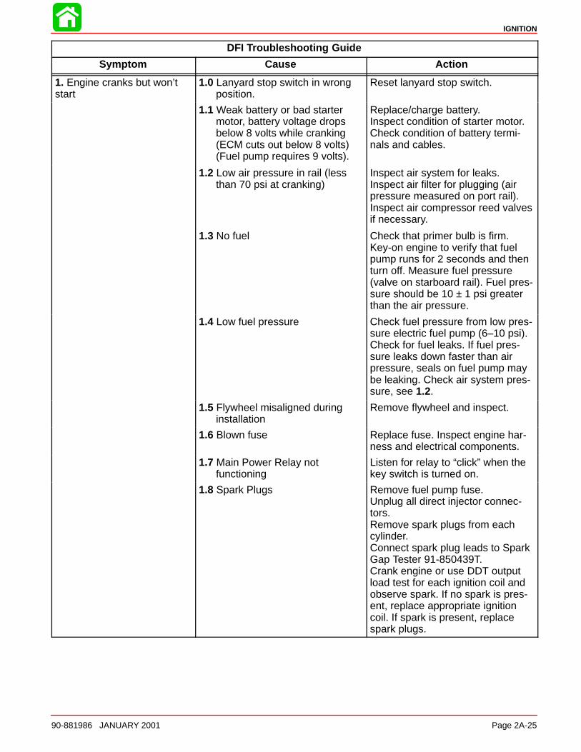
IGNITION
90-881986 JANUARY 2001 Page 2A-25
DFI Troubleshooting Guide
Symptom Cause Action
1. Engine cranks but won’tstart
1.0 Lanyard stop switch in wrong position.
Reset lanyard stop switch.
1.1 Weak battery or bad starter motor, battery voltage drops below 8 volts while cranking (ECM cuts out below 8 volts)(Fuel pump requires 9 volts).
Replace/charge battery.Inspect condition of starter motor.Check condition of battery termi-nals and cables.
1.2 Low air pressure in rail (less than 70 psi at cranking)
Inspect air system for leaks.Inspect air filter for plugging (airpressure measured on port rail).Inspect air compressor reed valvesif necessary.
1.3 No fuel Check that primer bulb is firm.Key-on engine to verify that fuelpump runs for 2 seconds and thenturn off. Measure fuel pressure(valve on starboard rail). Fuel pres-sure should be 10 ± 1 psi greaterthan the air pressure.
1.4 Low fuel pressure Check fuel pressure from low pres-sure electric fuel pump (6–10 psi).Check for fuel leaks. If fuel pres-sure leaks down faster than airpressure, seals on fuel pump maybe leaking. Check air system pres-sure, see 1.2.
1.5 Flywheel misaligned during installation
Remove flywheel and inspect.
1.6 Blown fuse Replace fuse. Inspect engine har-ness and electrical components.
1.7 Main Power Relay notfunctioning
Listen for relay to “click” when thekey switch is turned on.
1.8 Spark Plugs Remove fuel pump fuse.Unplug all direct injector connec-tors.Remove spark plugs from eachcylinder.Connect spark plug leads to SparkGap Tester 91-850439T.Crank engine or use DDT outputload test for each ignition coil andobserve spark. If no spark is pres-ent, replace appropriate ignitioncoil. If spark is present, replacespark plugs.
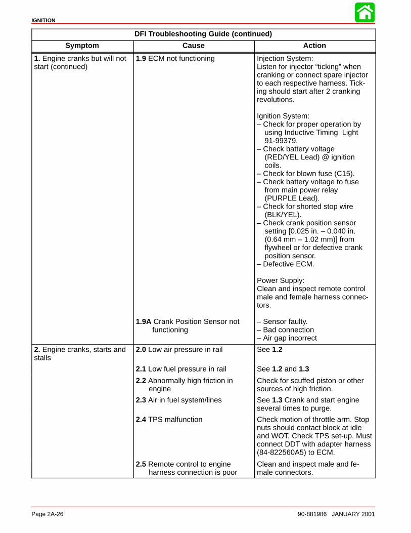
IGNITION
Page 2A-26 90-881986 JANUARY 2001
DFI Troubleshooting Guide (continued)
Symptom Cause Action
1. Engine cranks but will notstart (continued)
1.9 ECM not functioning
1.9A Crank Position Sensor not functioning
Injection System:Listen for injector “ticking” whencranking or connect spare injectorto each respective harness. Tick-ing should start after 2 crankingrevolutions.
Ignition System:– Check for proper operation by
using Inductive Timing Light91-99379.
– Check battery voltage(RED/YEL Lead) @ ignitioncoils.
– Check for blown fuse (C15).– Check battery voltage to fuse
from main power relay(PURPLE Lead).
– Check for shorted stop wire(BLK/YEL).
– Check crank position sensorsetting [0.025 in. – 0.040 in. (0.64 mm – 1.02 mm)] fromflywheel or for defective crankposition sensor.
– Defective ECM.
Power Supply:Clean and inspect remote controlmale and female harness connec-tors.
– Sensor faulty.– Bad connection– Air gap incorrect
2. Engine cranks, starts andstalls
2.0 Low air pressure in rail See 1.2
2.1 Low fuel pressure in rail See 1.2 and 1.3
2.2 Abnormally high friction inengine
Check for scuffed piston or othersources of high friction.
2.3 Air in fuel system/lines See 1.3 Crank and start engineseveral times to purge.
2.4 TPS malfunction Check motion of throttle arm. Stopnuts should contact block at idleand WOT. Check TPS set-up. Mustconnect DDT with adapter harness(84-822560A5) to ECM.
2.5 Remote control to engineharness connection is poor
Clean and inspect male and fe-male connectors.
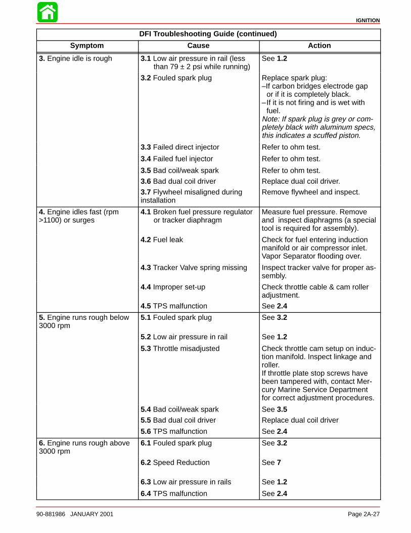
IGNITION
90-881986 JANUARY 2001 Page 2A-27
DFI Troubleshooting Guide (continued)
Symptom Cause Action
3. Engine idle is rough 3.1 Low air pressure in rail (less than 79 ± 2 psi while running)
See 1.2
3.2 Fouled spark plug Replace spark plug:–If carbon bridges electrode gap
or if it is completely black.–If it is not firing and is wet with
fuel.Note: If spark plug is grey or com-pletely black with aluminum specs,this indicates a scuffed piston.
3.3 Failed direct injector Refer to ohm test.
3.4 Failed fuel injector Refer to ohm test.
3.5 Bad coil/weak spark
3.6 Bad dual coil driver
3.7 Flywheel misaligned duringinstallation
Refer to ohm test.
Replace dual coil driver.
Remove flywheel and inspect.
4. Engine idles fast (rpm>1100) or surges
4.1 Broken fuel pressure regulator or tracker diaphragm
Measure fuel pressure. Removeand inspect diaphragms (a specialtool is required for assembly).
4.2 Fuel leak Check for fuel entering inductionmanifold or air compressor inlet.Vapor Separator flooding over.
4.3 Tracker Valve spring missing Inspect tracker valve for proper as-sembly.
4.4 Improper set-up
4.5 TPS malfunction
Check throttle cable & cam rolleradjustment.
See 2.4
5. Engine runs rough below3000 rpm
5.1 Fouled spark plug See 3.2
5.2 Low air pressure in rail See 1.2
5.3 Throttle misadjusted Check throttle cam setup on induc-tion manifold. Inspect linkage androller.If throttle plate stop screws havebeen tampered with, contact Mer-cury Marine Service Departmentfor correct adjustment procedures.
5.4 Bad coil/weak spark
5.5 Bad dual coil driver
See 3.5Replace dual coil driver
5.6 TPS malfunction See 2.4
6. Engine runs rough above3000 rpm
6.1 Fouled spark plug See 3.2
6.2 Speed Reduction See 7
6.3 Low air pressure in rails See 1.2
6.4 TPS malfunction See 2.4
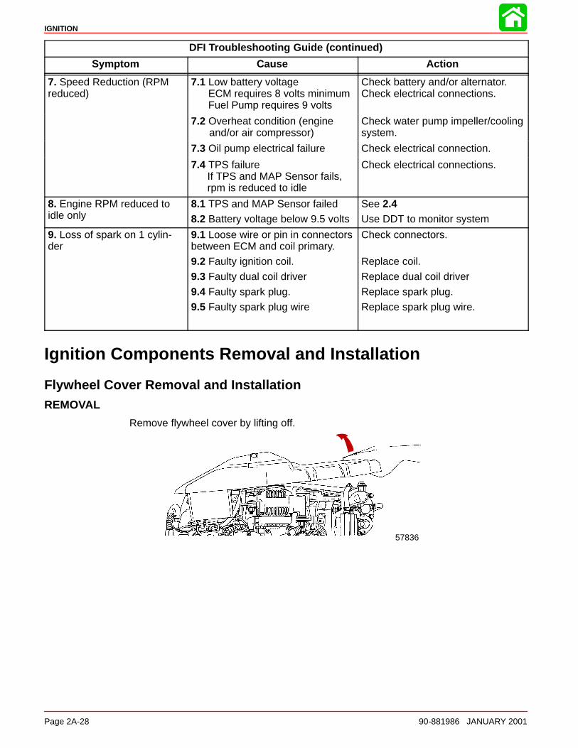
IGNITION
Page 2A-28 90-881986 JANUARY 2001
DFI Troubleshooting Guide (continued)
Symptom Cause Action
7. Speed Reduction (RPMreduced)
7.1 Low battery voltageECM requires 8 volts minimumFuel Pump requires 9 volts
Check battery and/or alternator.Check electrical connections.
7.2 Overheat condition (engineand/or air compressor)
Check water pump impeller/coolingsystem.
7.3 Oil pump electrical failure Check electrical connection.
7.4 TPS failureIf TPS and MAP Sensor fails, rpm is reduced to idle
Check electrical connections.
8. Engine RPM reduced toidle only
8.1 TPS and MAP Sensor failed
8.2 Battery voltage below 9.5 volts
See 2.4Use DDT to monitor system
9. Loss of spark on 1 cylin-der
9.1 Loose wire or pin in connectorsbetween ECM and coil primary.
9.2 Faulty ignition coil.
9.3 Faulty dual coil driver
9.4 Faulty spark plug.
9.5 Faulty spark plug wire
Check connectors.
Replace coil.
Replace dual coil driver
Replace spark plug.
Replace spark plug wire.
Ignition Components Removal and Installation
Flywheel Cover Removal and InstallationREMOVAL
Remove flywheel cover by lifting off.
57836
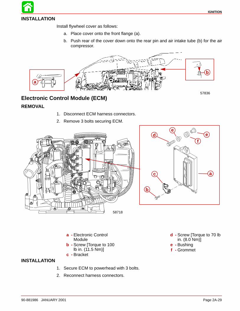
IGNITION
90-881986 JANUARY 2001 Page 2A-29
INSTALLATION
Install flywheel cover as follows:
a. Place cover onto the front flange (a).
b. Push rear of the cover down onto the rear pin and air intake tube (b) for the aircompressor.
a
b
57836
Electronic Control Module (ECM)REMOVAL
1. Disconnect ECM harness connectors.
2. Remove 3 bolts securing ECM.
a
b
f
c
de
e
58718
a - Electronic ControlModule
b - Screw [Torque to 100lb in. (11.5 Nm)]
c - Bracket
d - Screw [Torque to 70 lbin. (8.0 Nm)]
e - Bushingf - Grommet
INSTALLATION
1. Secure ECM to powerhead with 3 bolts.
2. Reconnect harness connectors.
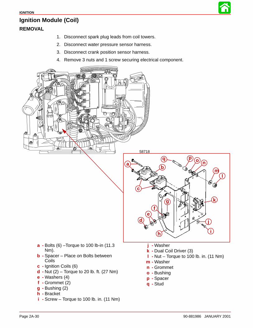
IGNITION
Page 2A-30 90-881986 JANUARY 2001
Ignition Module (Coil)REMOVAL
1. Disconnect spark plug leads from coil towers.
2. Disconnect water pressure sensor harness.
3. Disconnect crank position sensor harness.
4. Remove 3 nuts and 1 screw securing electrical component.
58718
b
c
h i
j
k
ed
f
aop
g
q
m
n
l
a - Bolts (6) –Torque to 100 lb-in (11.3Nm).
b - Spacer – Place on Bolts betweenCoils
c - Ignition Coils (6)d - Nut (2) – Torque to 20 lb. ft. (27 Nm)e - Washers (4)f - Grommet (2)g - Bushing (2)h - Bracketi - Screw – Torque to 100 lb. in. (11 Nm)
j - Washerk - Dual Coil Driver (3)l - Nut – Torque to 100 lb. in. (11 Nm)
m - Washern - Grommeto - Bushingp - Spacerq - Stud
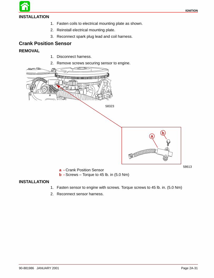
IGNITION
90-881986 JANUARY 2001 Page 2A-31
INSTALLATION
1. Fasten coils to electrical mounting plate as shown.
2. Reinstall electrical mounting plate.
3. Reconnect spark plug lead and coil harness.
Crank Position SensorREMOVAL
1. Disconnect harness.
2. Remove screws securing sensor to engine.
58323
58613
ab
a - Crank Position Sensorb - Screws – Torque to 45 lb. in (5.0 Nm)
INSTALLATION1. Fasten sensor to engine with screws. Torque screws to 45 lb. in. (5.0 Nm)
2. Reconnect sensor harness.
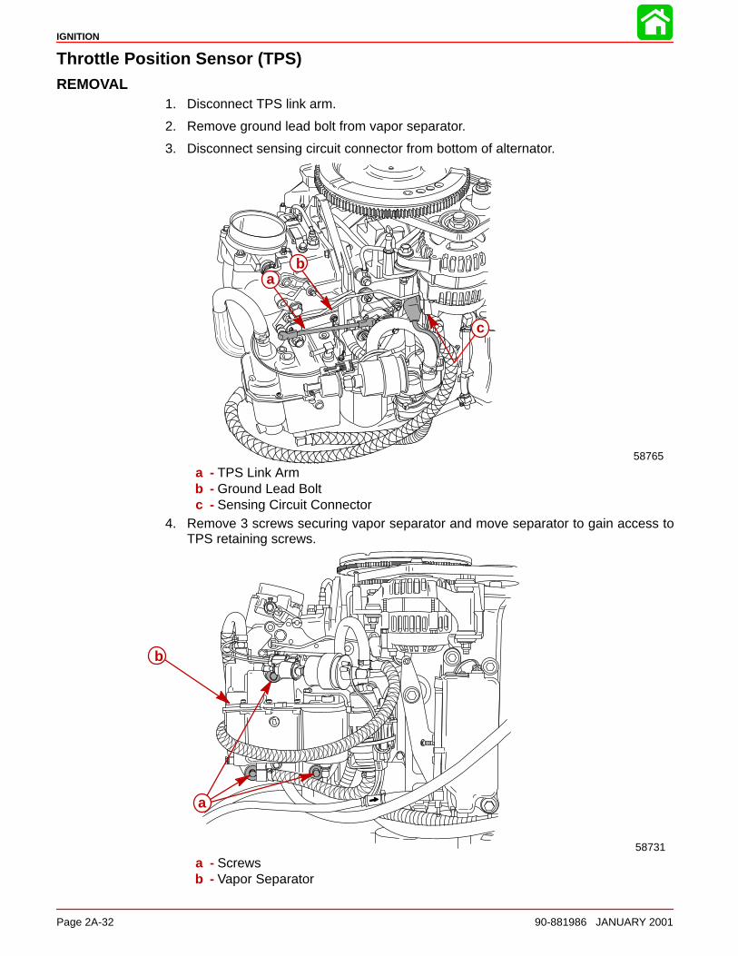
IGNITION
Page 2A-32 90-881986 JANUARY 2001
Throttle Position Sensor (TPS)REMOVAL
1. Disconnect TPS link arm.
2. Remove ground lead bolt from vapor separator.
3. Disconnect sensing circuit connector from bottom of alternator.
58765
ab
c
a - TPS Link Armb - Ground Lead Boltc - Sensing Circuit Connector
4. Remove 3 screws securing vapor separator and move separator to gain access toTPS retaining screws.
58731
a
b
a - Screwsb - Vapor Separator
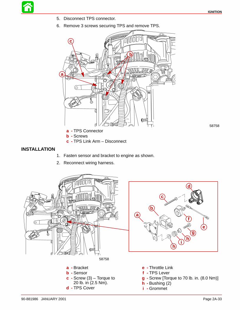
IGNITION
90-881986 JANUARY 2001 Page 2A-33
5. Disconnect TPS connector.
6. Remove 3 screws securing TPS and remove TPS.
58758
a
b
c
a - TPS Connectorb - Screwsc - TPS Link Arm – Disconnect
INSTALLATION1. Fasten sensor and bracket to engine as shown.
2. Reconnect wiring harness.
ab
c
d
e
f
gh
ih
58758
a - Bracketb - Sensorc - Screw (3) – Torque to
20 lb. in (2.5 Nm).d - TPS Cover
e - Throttle Linkf - TPS Leverg - Screw [Torque to 70 lb. in. (8.0 Nm)]h - Bushing (2)i - Grommet
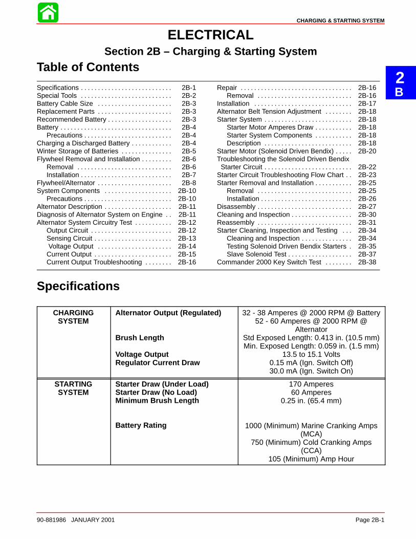
2B
CHARGING & STARTING SYSTEM
90-881986 JANUARY 2001 Page 2B-1
ELECTRICALSection 2B – Charging & Starting System
Table of Contents
Specifications 2B-1. . . . . . . . . . . . . . . . . . . . . . . . . . . Special Tools 2B-2. . . . . . . . . . . . . . . . . . . . . . . . . . . Battery Cable Size 2B-3. . . . . . . . . . . . . . . . . . . . . . Replacement Parts 2B-3. . . . . . . . . . . . . . . . . . . . . . Recommended Battery 2B-3. . . . . . . . . . . . . . . . . . . Battery 2B-4. . . . . . . . . . . . . . . . . . . . . . . . . . . . . . . . .
Precautions 2B-4. . . . . . . . . . . . . . . . . . . . . . . . . . Charging a Discharged Battery 2B-4. . . . . . . . . . . . Winter Storage of Batteries 2B-5. . . . . . . . . . . . . . . Flywheel Removal and Installation 2B-6. . . . . . . . .
Removal 2B-6. . . . . . . . . . . . . . . . . . . . . . . . . . . . Installation 2B-7. . . . . . . . . . . . . . . . . . . . . . . . . . .
Flywheel/Alternator 2B-8. . . . . . . . . . . . . . . . . . . . . . System Components 2B-10. . . . . . . . . . . . . . . . . . . .
Precautions 2B-10. . . . . . . . . . . . . . . . . . . . . . . . . . Alternator Description 2B-11. . . . . . . . . . . . . . . . . . . . Diagnosis of Alternator System on Engine 2B-11. . Alternator System Circuitry Test 2B-12. . . . . . . . . . .
Output Circuit 2B-12. . . . . . . . . . . . . . . . . . . . . . . . Sensing Circuit 2B-13. . . . . . . . . . . . . . . . . . . . . . . Voltage Output 2B-14. . . . . . . . . . . . . . . . . . . . . . Current Output 2B-15. . . . . . . . . . . . . . . . . . . . . . . Current Output Troubleshooting 2B-16. . . . . . . .
Repair 2B-16. . . . . . . . . . . . . . . . . . . . . . . . . . . . . . . . . Removal 2B-16. . . . . . . . . . . . . . . . . . . . . . . . . . . .
Installation 2B-17. . . . . . . . . . . . . . . . . . . . . . . . . . . . . Alternator Belt Tension Adjustment 2B-18. . . . . . . . Starter System 2B-18. . . . . . . . . . . . . . . . . . . . . . . . . .
Starter Motor Amperes Draw 2B-18. . . . . . . . . . . Starter System Components 2B-18. . . . . . . . . . . Description 2B-18. . . . . . . . . . . . . . . . . . . . . . . . . .
Starter Motor (Solenoid Driven Bendix) 2B-20. . . . . Troubleshooting the Solenoid Driven Bendix Starter Circuit 2B-22. . . . . . . . . . . . . . . . . . . . . . . . . . Starter Circuit Troubleshooting Flow Chart 2B-23. . Starter Removal and Installation 2B-25. . . . . . . . . . .
Removal 2B-25. . . . . . . . . . . . . . . . . . . . . . . . . . . . Installation 2B-26. . . . . . . . . . . . . . . . . . . . . . . . . . .
Disassembly 2B-27. . . . . . . . . . . . . . . . . . . . . . . . . . . . Cleaning and Inspection 2B-30. . . . . . . . . . . . . . . . . . Reassembly 2B-31. . . . . . . . . . . . . . . . . . . . . . . . . . . . Starter Cleaning, Inspection and Testing 2B-34. . .
Cleaning and Inspection 2B-34. . . . . . . . . . . . . . . Testing Solenoid Driven Bendix Starters 2B-35. Slave Solenoid Test 2B-37. . . . . . . . . . . . . . . . . . .
Commander 2000 Key Switch Test 2B-38. . . . . . . .
Specifications
CHARGINGSYSTEM
Alternator Output (Regulated)
Brush Length
Voltage OutputRegulator Current Draw
32 - 38 Amperes @ 2000 RPM @ Battery52 - 60 Amperes @ 2000 RPM @
AlternatorStd Exposed Length: 0.413 in. (10.5 mm)Min. Exposed Length: 0.059 in. (1.5 mm)
13.5 to 15.1 Volts0.15 mA (Ign. Switch Off)30.0 mA (Ign. Switch On)
STARTINGSYSTEM
Starter Draw (Under Load)Starter Draw (No Load)Minimum Brush Length
Battery Rating
170 Amperes60 Amperes
0.25 in. (65.4 mm)
1000 (Minimum) Marine Cranking Amps(MCA)
750 (Minimum) Cold Cranking Amps(CCA)
105 (Minimum) Amp Hour
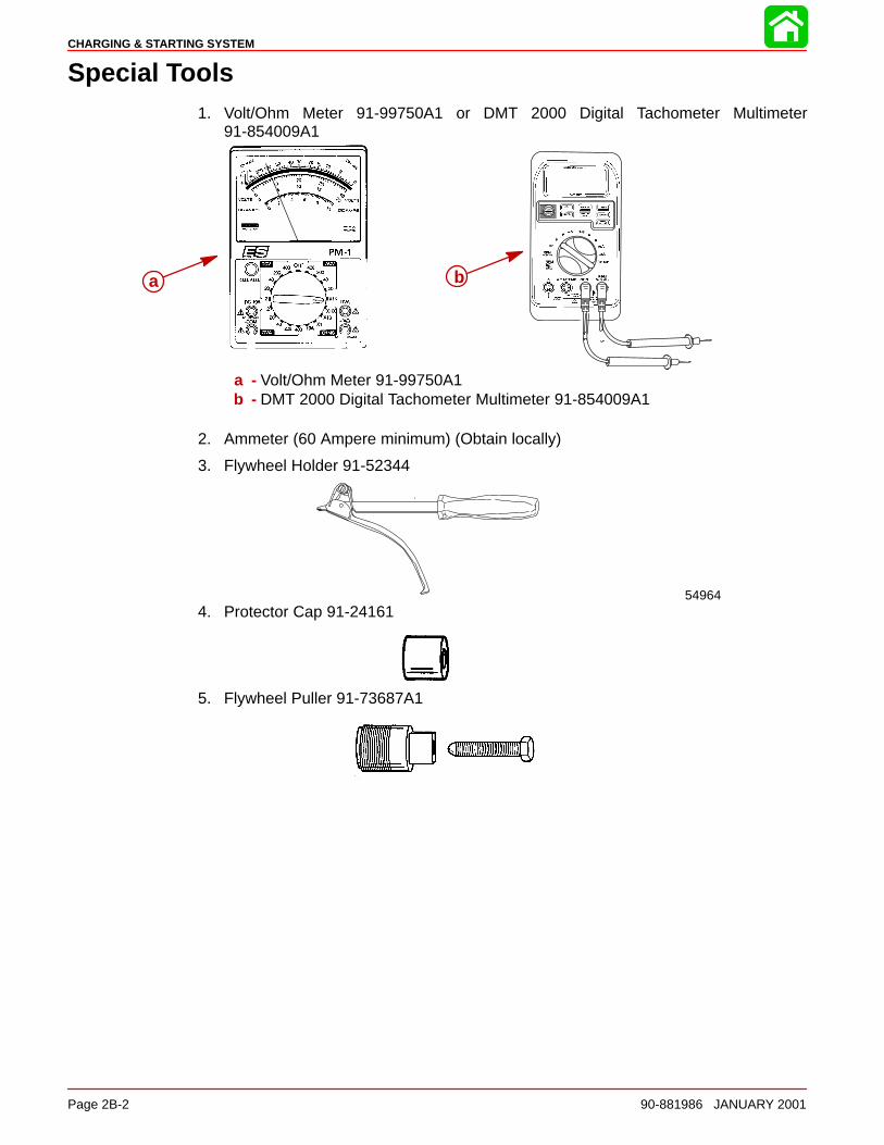
CHARGING & STARTING SYSTEM
Page 2B-2 90-881986 JANUARY 2001
Special Tools1. Volt/Ohm Meter 91-99750A1 or DMT 2000 Digital Tachometer Multimeter
91-854009A1
a b
a - Volt/Ohm Meter 91-99750A1b - DMT 2000 Digital Tachometer Multimeter 91-854009A1
2. Ammeter (60 Ampere minimum) (Obtain locally)
3. Flywheel Holder 91-52344
549644. Protector Cap 91-24161
5. Flywheel Puller 91-73687A1
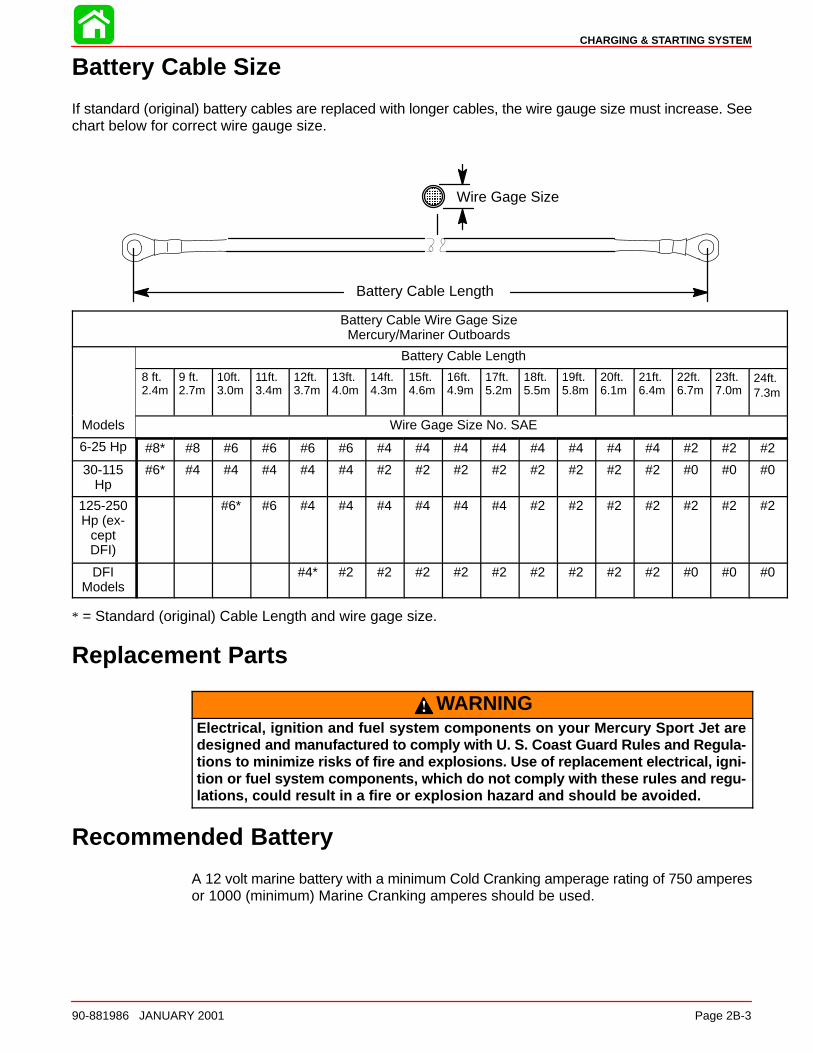
CHARGING & STARTING SYSTEM
90-881986 JANUARY 2001 Page 2B-3
Battery Cable Size
If standard (original) battery cables are replaced with longer cables, the wire gauge size must increase. Seechart below for correct wire gauge size.
Battery Cable Length
ÎÎÎÎ
Wire Gage Size
Battery Cable Wire Gage SizeMercury/Mariner Outboards
Battery Cable Length
8 ft.2.4m
9 ft.2.7m
10ft.3.0m
11ft.3.4m
12ft.3.7m
13ft.4.0m
14ft.4.3m
15ft.4.6m
16ft.4.9m
17ft.5.2m
18ft.5.5m
19ft.5.8m
20ft.6.1m
21ft.6.4m
22ft.6.7m
23ft.7.0m
24ft.7.3m
Models Wire Gage Size No. SAE
6-25 Hp #8* #8 #6 #6 #6 #6 #4 #4 #4 #4 #4 #4 #4 #4 #2 #2 #2
30-115Hp
#6* #4 #4 #4 #4 #4 #2 #2 #2 #2 #2 #2 #2 #2 #0 #0 #0
125-250Hp (ex-
ceptDFI)
#6* #6 #4 #4 #4 #4 #4 #4 #2 #2 #2 #2 #2 #2 #2
DFIModels
#4* #2 #2 #2 #2 #2 #2 #2 #2 #2 #0 #0 #0
* = Standard (original) Cable Length and wire gage size.
Replacement Parts
WARNINGElectrical, ignition and fuel system components on your Mercury Sport Jet aredesigned and manufactured to comply with U. S. Coast Guard Rules and Regula-tions to m inimize risks of fire and explosions. Use of replacement electrical, igni-tion or fuel system components, which do not comply with these rules and regu-lations, could result in a fire or explosion hazard and should be avoided.
Recommended Battery
A 12 volt marine battery with a minimum Cold Cranking amperage rating of 750 amperesor 1000 (minimum) Marine Cranking amperes should be used.
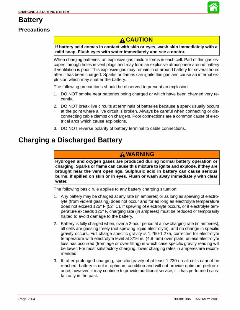
CHARGING & STARTING SYSTEM
Page 2B-4 90-881986 JANUARY 2001
BatteryPrecautions
CAUTIONIf battery acid comes in contact with skin or eyes, wash skin immediately with amild soap. Flush eyes with water immediately and see a doctor.
When charging batteries, an explosive gas mixture forms in each cell. Part of this gas es-capes through holes in vent plugs and may form an explosive atmosphere around batteryif ventilation is poor. This explosive gas may remain in or around battery for several hoursafter it has been charged. Sparks or flames can ignite this gas and cause an internal ex-plosion which may shatter the battery.
The following precautions should be observed to prevent an explosion.
1. DO NOT smoke near batteries being charged or which have been charged very re-cently.
2. DO NOT break live circuits at terminals of batteries because a spark usually occursat the point where a live circuit is broken. Always be careful when connecting or dis-connecting cable clamps on chargers. Poor connections are a common cause of elec-trical arcs which cause explosions.
3. DO NOT reverse polarity of battery terminal to cable connections.
Charging a Discharged Battery
WARNINGHydrogen and oxygen gases are produced during normal battery operation orcharging. Sparks or flame can cause this mixture to ignite and explode, if they arebrought near the vent openings. Sulphuric acid in battery can cause seriousburns, if spilled on skin or in eyes. Flush or wash away immediately with clearwater.
The following basic rule applies to any battery charging situation:
1. Any battery may be charged at any rate (in amperes) or as long as spewing of electro-lyte (from violent gassing) does not occur and for as long as electrolyte temperaturedoes not exceed 125° F (52° C). If spewing of electrolyte occurs, or if electrolyte tem-perature exceeds 125° F, charging rate (in amperes) must be reduced or temporarilyhalted to avoid damage to the battery.
2. Battery is fully charged when, over a 2-hour period at a low charging rate (in amperes),all cells are gassing freely (not spewing liquid electrolyte), and no change in specificgravity occurs. Full charge specific gravity is 1.260-1.275, corrected for electrolytetemperature with electrolyte level at 3/16 in. (4.8 mm) over plate, unless electrolyteloss has occurred (from age or over-filling) in which case specific gravity reading willbe lower. For most satisfactory charging, lower charging rates in amperes are recom-mended.
3. If, after prolonged charging, specific gravity of at least 1.230 on all cells cannot bereached, battery is not in optimum condition and will not provide optimum perform-ance; however, it may continue to provide additional service, if it has performed satis-factorily in the past.

CHARGING & STARTING SYSTEM
90-881986 JANUARY 2001 Page 2B-5
4. To check battery voltage while cranking engine with electric starting motor, place RED(+) lead of tester on POSITIVE (+) battery terminal and BLACK (–) lead of tester onNEGATIVE (–) battery terminal. If the voltage drops below 9-1/2 volts while cranking,the battery is weak and should be recharged or replaced.
Winter Storage of Batteries
Battery companies are not responsible for battery damage either in winter storage or indealer stock if the following instructions are not observed:
1. Remove battery from its installation as soon as possible and remove all grease, sul-fate and dirt from top surface by running water over top of battery. Be sure, however,that vent caps are tight beforehand, and blow off all excess water thoroughly with com-pressed air. Check water level, making sure that plates are covered.
2. When adding distilled water to battery, be extremely careful not to fill more than 3/16in. (4.8 mm) above perforated baffles inside battery. Battery solution or electrolyte ex-pands from heat caused by charging. Overfilling battery will cause electrolyte to over-flow (if filled beyond 3/16″ above baffles).
3. Grease terminal bolts well with 2-4-C Marine Lubricant and store battery in a COOL-DRY place. Remove battery from storage every 30-45 days, check water level andput on charge for 5 or 6 hours at 6 amperes. DO NOT FAST CHARGE.
4. If specific gravity drops below 1.240, check battery for reason and recharge. Whengravity reaches 1.260, discontinue charging. To check specific gravity, use a hydrom-eter, which can be purchased locally.
5. Repeat preceding charging procedure every 30-45 days, as long as battery is in stor-age, for best possible maintenance during inactive periods to ensure a good service-able battery in spring. When ready to place battery back in service, remove excessgrease from terminals (a small amount is desirable on terminals at all times), rechargeagain as necessary and reinstall battery.
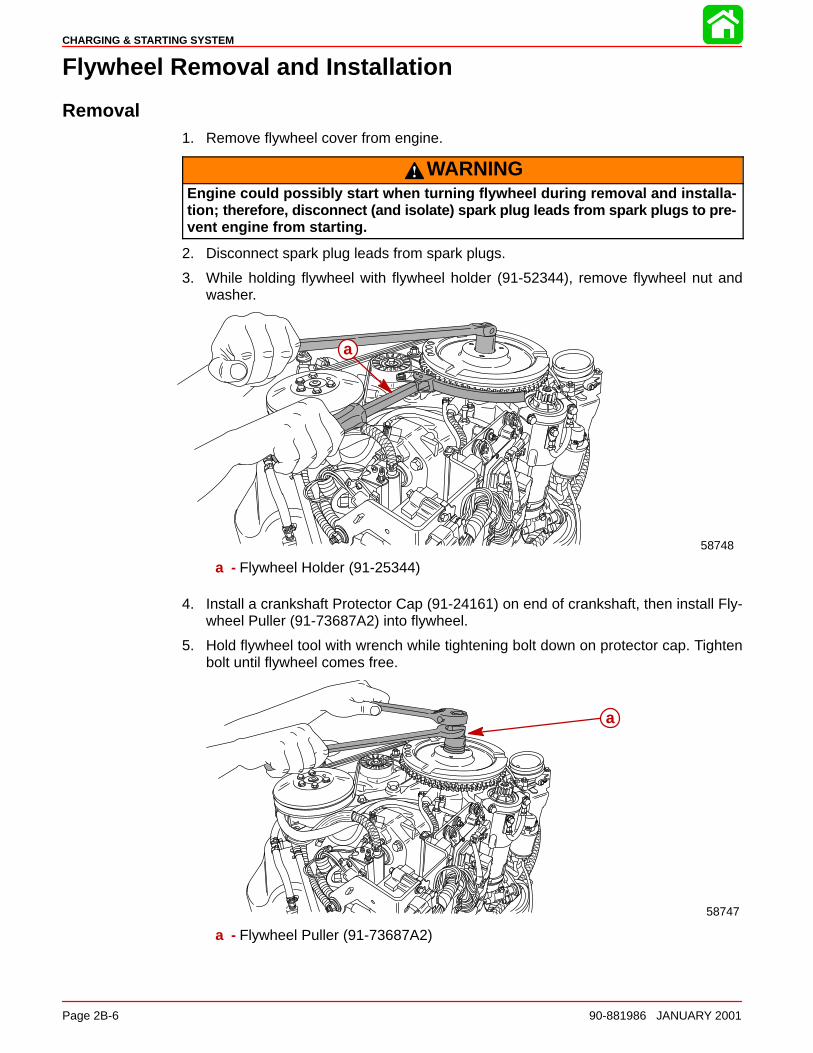
CHARGING & STARTING SYSTEM
Page 2B-6 90-881986 JANUARY 2001
Flywheel Removal and Installation
Removal1. Remove flywheel cover from engine.
WARNINGEngine could possibly start when turning flywheel during removal and installa-tion; therefore, disconnect (and isolate) spark plug leads from spark plugs to pre-vent engine from starting.
2. Disconnect spark plug leads from spark plugs.
3. While holding flywheel with flywheel holder (91-52344), remove flywheel nut andwasher.
58748
a
a - Flywheel Holder (91-25344)
4. Install a crankshaft Protector Cap (91-24161) on end of crankshaft, then install Fly-wheel Puller (91-73687A2) into flywheel.
5. Hold flywheel tool with wrench while tightening bolt down on protector cap. Tightenbolt until flywheel comes free.
58747
a
a - Flywheel Puller (91-73687A2)
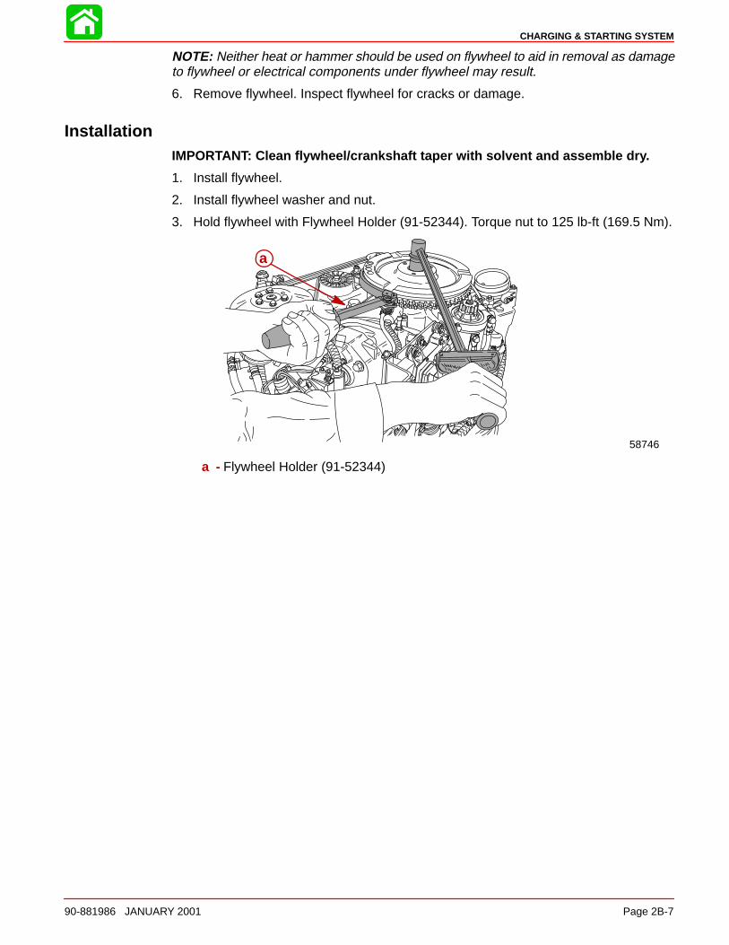
CHARGING & STARTING SYSTEM
90-881986 JANUARY 2001 Page 2B-7
NOTE: Neither heat or hammer should be used on flywheel to aid in removal as damageto flywheel or electrical components under flywheel may result.
6. Remove flywheel. Inspect flywheel for cracks or damage.
InstallationIMPORTANT: Clean flywheel/crankshaft taper with solvent and assemble dry.
1. Install flywheel.
2. Install flywheel washer and nut.
3. Hold flywheel with Flywheel Holder (91-52344). Torque nut to 125 lb-ft (169.5 Nm).
58746
a
a - Flywheel Holder (91-52344)
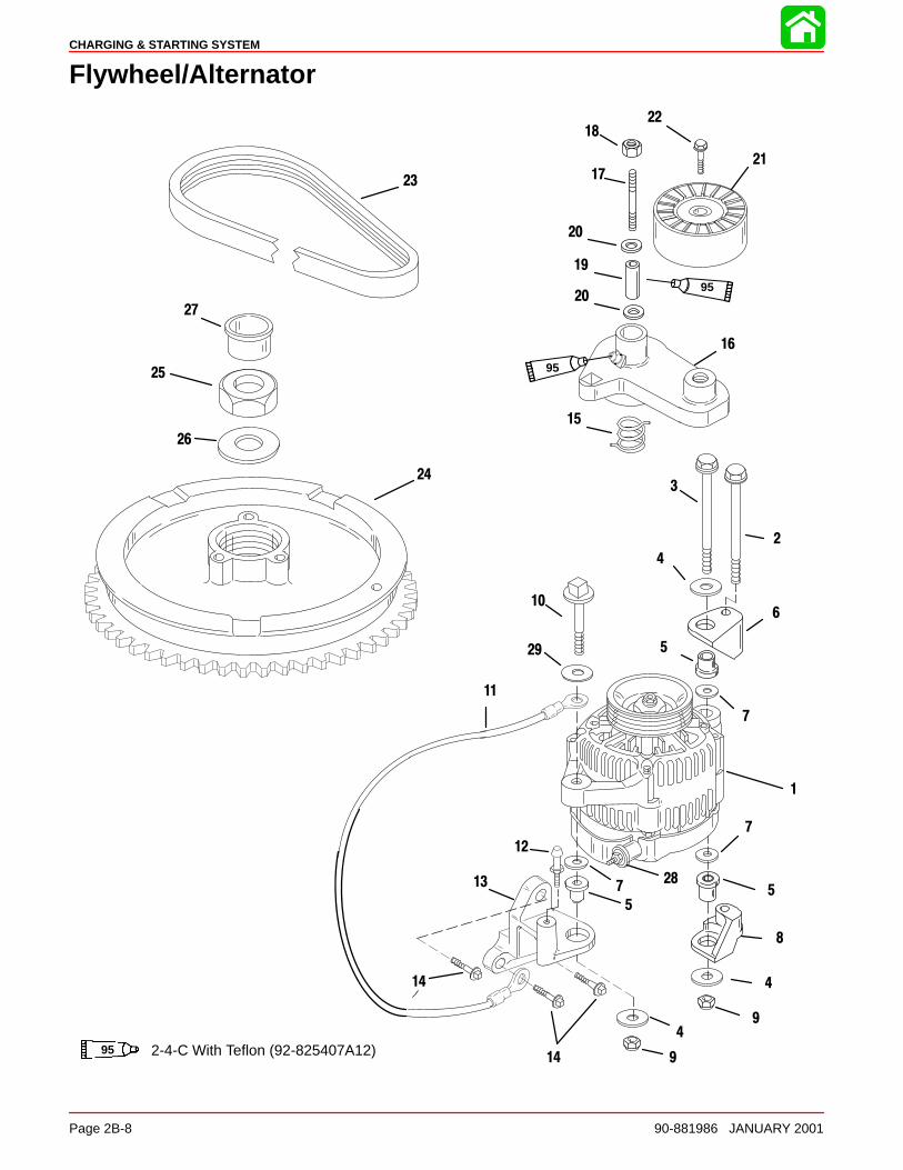
CHARGING & STARTING SYSTEM
Page 2B-8 90-881986 JANUARY 2001
Flywheel/Alternator
1
2
12
14
23
27
16
4
15
20
1721
26
3
22
19
24
18
14
5
7
8
9
10
11
13
6
5
7
7
9
4
4
20
95
95
95 2-4-C With Teflon (92-825407A12)
25
28
29
5

CHARGING & STARTING SYSTEM
90-881986 JANUARY 2001 Page 2B-9
Flywheel/Alternator
REFTORQUE
REF.NO. QTY. DESCRIPTION lb. in. lb. ft. Nm
1 1 ALTERNATOR
2 1 SCREW (M10 x 100) 40 543 1 SCREW (M10 x120) 40 544 3 WASHER5 3 MOUNT6 1 BRACKET7 3 WASHER
8 1 BRACKET9 2 NUT 25 3410 1 SCREW (M10 x 55) 25 3411 1 CABLE12 1 PIN13 1 BRACKET14 3 SCREW (5/16-18 x 1 IN.) 15.5 21
15 1 SPRING16 1 BELT TENSIONER ARM ASSY17 1 STUD (M10 x 85)18 1 NUT 15 2019 1 BUSHING20 2 WASHER21 1 PULLEY
22 1 SCREW (M10 x 35) 25 3423 1 BELT24 1 FLYWHEEL25 1 NUT (M16X1.5) 125 17026 1 WASHER27 1 PLUG28 1 NUT 110 12
29 1 WASHER
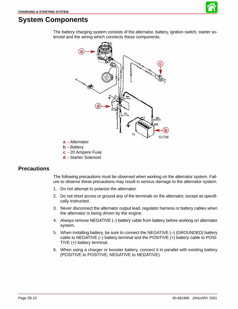
CHARGING & STARTING SYSTEM
Page 2B-10 90-881986 JANUARY 2001
System Components
The battery charging system consists of the alternator, battery, ignition switch, starter so-lenoid and the wiring which connects these components.
51708To
a
d
b
c
a
b
c
d
a - Alternatorb - Batteryc - 20 Ampere Fused - Starter Solenoid
PrecautionsThe following precautions must be observed when working on the alternator system. Fail-ure to observe these precautions may result in serious damage to the alternator system.
1. Do not attempt to polarize the alternator.
2. Do not short across or ground any of the terminals on the alternator, except as specifi-cally instructed.
3. Never disconnect the alternator output lead, regulator harness or battery cables whenthe alternator is being driven by the engine.
4. Always remove NEGATIVE (–) battery cable from battery before working on alternatorsystem.
5. When installing battery, be sure to connect the NEGATIVE (–) (GROUNDED) batterycable to NEGATIVE (–) battery terminal and the POSITIVE (+) battery cable to POSI-TIVE (+) battery terminal.
6. When using a charger or booster battery, connect it in parallel with existing battery(POSITIVE to POSITIVE; NEGATIVE to NEGATIVE).
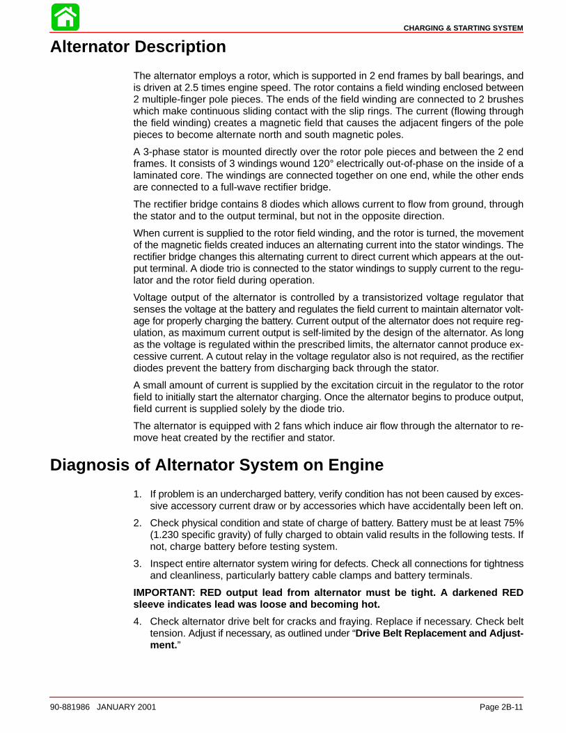
CHARGING & STARTING SYSTEM
90-881986 JANUARY 2001 Page 2B-11
Alternator Description
The alternator employs a rotor, which is supported in 2 end frames by ball bearings, andis driven at 2.5 times engine speed. The rotor contains a field winding enclosed between2 multiple-finger pole pieces. The ends of the field winding are connected to 2 brusheswhich make continuous sliding contact with the slip rings. The current (flowing throughthe field winding) creates a magnetic field that causes the adjacent fingers of the polepieces to become alternate north and south magnetic poles.
A 3-phase stator is mounted directly over the rotor pole pieces and between the 2 endframes. It consists of 3 windings wound 120° electrically out-of-phase on the inside of alaminated core. The windings are connected together on one end, while the other endsare connected to a full-wave rectifier bridge.
The rectifier bridge contains 8 diodes which allows current to flow from ground, throughthe stator and to the output terminal, but not in the opposite direction.
When current is supplied to the rotor field winding, and the rotor is turned, the movementof the magnetic fields created induces an alternating current into the stator windings. Therectifier bridge changes this alternating current to direct current which appears at the out-put terminal. A diode trio is connected to the stator windings to supply current to the regu-lator and the rotor field during operation.
Voltage output of the alternator is controlled by a transistorized voltage regulator thatsenses the voltage at the battery and regulates the field current to maintain alternator volt-age for properly charging the battery. Current output of the alternator does not require reg-ulation, as maximum current output is self-limited by the design of the alternator. As longas the voltage is regulated within the prescribed limits, the alternator cannot produce ex-cessive current. A cutout relay in the voltage regulator also is not required, as the rectifierdiodes prevent the battery from discharging back through the stator.
A small amount of current is supplied by the excitation circuit in the regulator to the rotorfield to initially start the alternator charging. Once the alternator begins to produce output,field current is supplied solely by the diode trio.
The alternator is equipped with 2 fans which induce air flow through the alternator to re-move heat created by the rectifier and stator.
Diagnosis of Alternator System on Engine
1. If problem is an undercharged battery, verify condition has not been caused by exces-sive accessory current draw or by accessories which have accidentally been left on.
2. Check physical condition and state of charge of battery. Battery must be at least 75%(1.230 specific gravity) of fully charged to obtain valid results in the following tests. Ifnot, charge battery before testing system.
3. Inspect entire alternator system wiring for defects. Check all connections for tightnessand cleanliness, particularly battery cable clamps and battery terminals.
IMPORTANT: RED output lead from alternator must be tight. A darkened REDsleeve indicates lead was loose and becoming hot.
4. Check alternator drive belt for cracks and fraying. Replace if necessary. Check belttension. Adjust if necessary, as outlined under “Drive Belt Replacement and Adjust-ment. ”
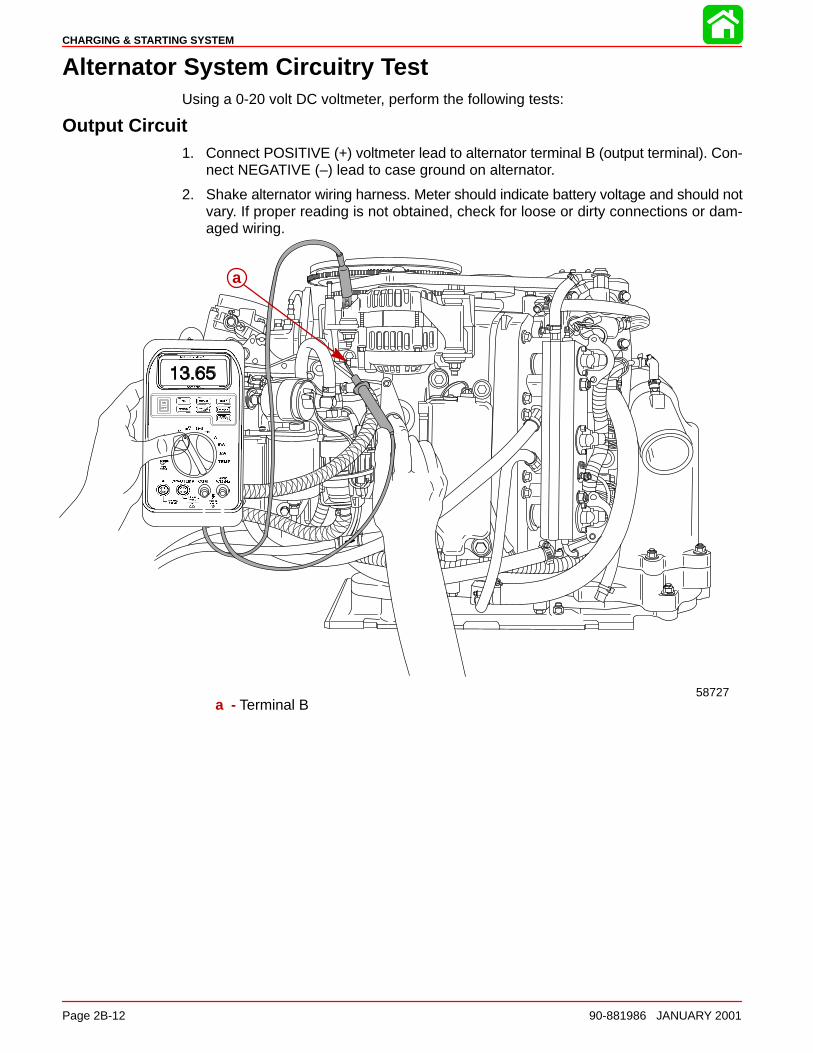
CHARGING & STARTING SYSTEM
Page 2B-12 90-881986 JANUARY 2001
Alternator System Circuitry TestUsing a 0-20 volt DC voltmeter, perform the following tests:
Output Circuit1. Connect POSITIVE (+) voltmeter lead to alternator terminal B (output terminal). Con-
nect NEGATIVE (–) lead to case ground on alternator.
2. Shake alternator wiring harness. Meter should indicate battery voltage and should notvary. If proper reading is not obtained, check for loose or dirty connections or dam-aged wiring.
58727
a
a - Terminal B
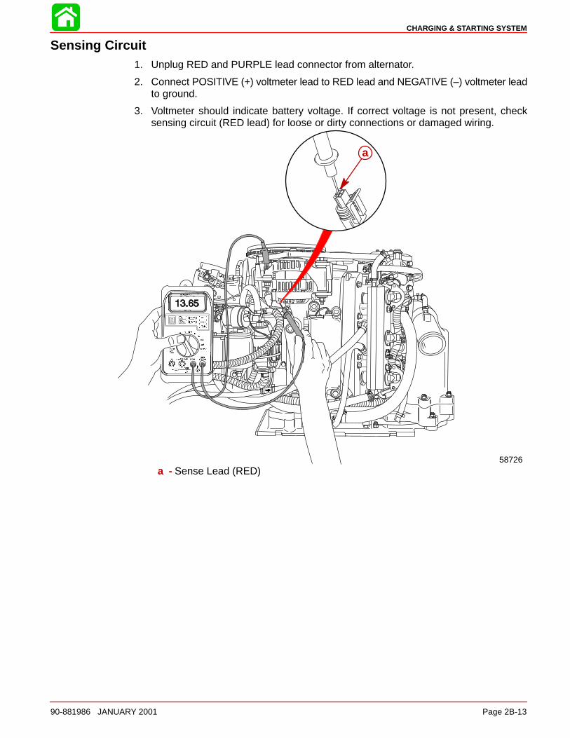
CHARGING & STARTING SYSTEM
90-881986 JANUARY 2001 Page 2B-13
Sensing Circuit1. Unplug RED and PURPLE lead connector from alternator.
2. Connect POSITIVE (+) voltmeter lead to RED lead and NEGATIVE (–) voltmeter leadto ground.
3. Voltmeter should indicate battery voltage. If correct voltage is not present, checksensing circuit (RED lead) for loose or dirty connections or damaged wiring.
58726
a
a - Sense Lead (RED)
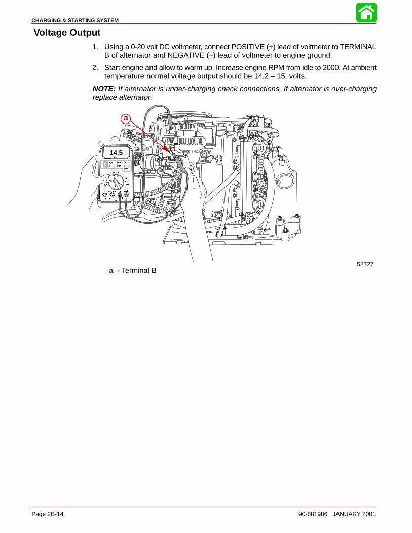
CHARGING & STARTING SYSTEM
Page 2B-14 90-881986 JANUARY 2001
Voltage Output1. Using a 0-20 volt DC voltmeter, connect POSITIVE (+) lead of voltmeter to TERMINAL
B of alternator and NEGATIVE (–) lead of voltmeter to engine ground.
2. Start engine and allow to warm up. Increase engine RPM from idle to 2000. At ambienttemperature normal voltage output should be 14.2 – 15. volts.
NOTE: If alternator is under-charging check connections. If alternator is over-chargingreplace alternator.
58727
a
14.5
a - Terminal B
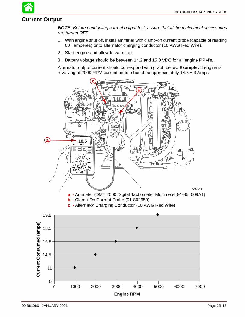
CHARGING & STARTING SYSTEM
90-881986 JANUARY 2001 Page 2B-15
Current OutputNOTE: Before conducting current output test, assure that all boat electrical accessoriesare turned OFF.
1. With engine shut off, install ammeter with clamp-on current probe (capable of reading60+ amperes) onto alternator charging conductor (10 AWG Red Wire).
2. Start engine and allow to warm up.
3. Battery voltage should be between 14.2 and 15.0 VDC for all engine RPM’s.
Alternator output current should correspond with graph below. Example: If engine is revolving at 2000 RPM current meter should be approximately 14.5 ± 3 Amps.
58729
a
b
c
18.5
a - Ammeter (DMT 2000 Digital Tachometer Multimeter 91-854009A1)b - Clamp-On Current Probe (91-802650)c - Alternator Charging Conductor (10 AWG Red Wire)
11
14.5
16.5
18.5
19.5
0
♦
♦
♦
♦
♦
1000 2000 3000 4000 5000 6000 7000
Cur
rent
Con
sum
ed (
amps
)
Engine RPM
0
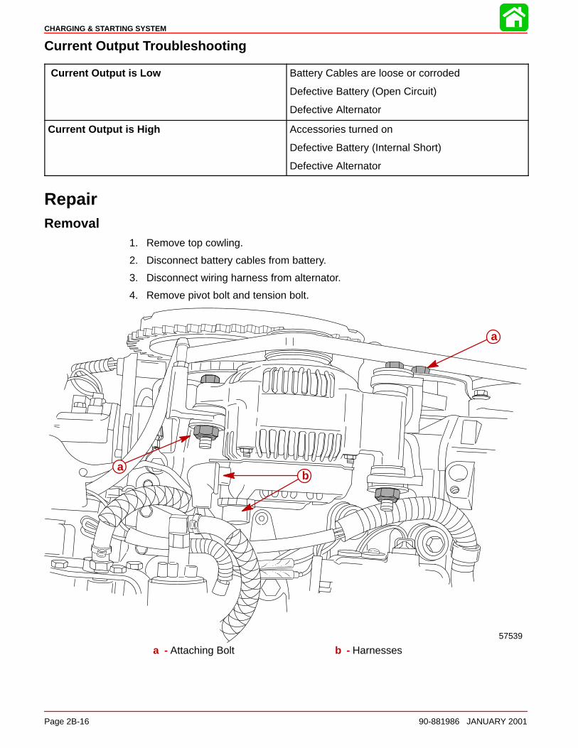
CHARGING & STARTING SYSTEM
Page 2B-16 90-881986 JANUARY 2001
Current Output Troubleshooting
Current Output is Low Battery Cables are loose or corroded
Defective Battery (Open Circuit)
Defective Alternator
Current Output is High Accessories turned on
Defective Battery (Internal Short)
Defective Alternator
RepairRemoval
1. Remove top cowling.
2. Disconnect battery cables from battery.
3. Disconnect wiring harness from alternator.
4. Remove pivot bolt and tension bolt.
ba
a
57539
a - Attaching Bolt b - Harnesses
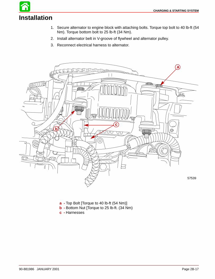
CHARGING & STARTING SYSTEM
90-881986 JANUARY 2001 Page 2B-17
Installation1. Secure alternator to engine block with attaching bolts. Torque top bolt to 40 lb-ft (54
Nm). Torque bottom bolt to 25 lb-ft (34 Nm).
2. Install alternator belt in V-groove of flywheel and alternator pulley.
3. Reconnect electrical harness to alternator.
a
bc
57539
a - Top Bolt [Torque to 40 lb-ft (54 Nm)]b - Bottom Nut [Torque to 25 lb-ft. (34 Nm)c - Harnesses
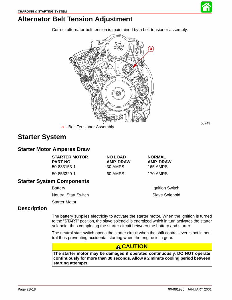
CHARGING & STARTING SYSTEM
Page 2B-18 90-881986 JANUARY 2001
Alternator Belt Tension AdjustmentCorrect alternator belt tension is maintained by a belt tensioner assembly.
58749
a
a - Belt Tensioner Assembly
Starter System
Starter Motor Amperes DrawSTARTER MOTOR NO LOAD NORMALPART NO. AMP. DRAW AMP. DRAW50-833153-1 30 AMPS 165 AMPS
50-853329-1 60 AMPS 170 AMPS
Starter System ComponentsBattery
Neutral Start Switch
Starter Motor
Ignition Switch
Slave Solenoid
DescriptionThe battery supplies electricity to activate the starter motor. When the ignition is turnedto the “START” position, the slave solenoid is energized which in turn activates the startersolenoid, thus completing the starter circuit between the battery and starter.
The neutral start switch opens the starter circuit when the shift control lever is not in neu-tral thus preventing accidental starting when the engine is in gear.
CAUTIONThe starter motor may be damaged if operated continuously. DO NOT operatecontinuously for more than 30 seconds. Allow a 2 minute cooling period betweenstarting attempts.

CHARGING & STARTING SYSTEM
90-881986 JANUARY 2001 Page 2B-19
Notes:
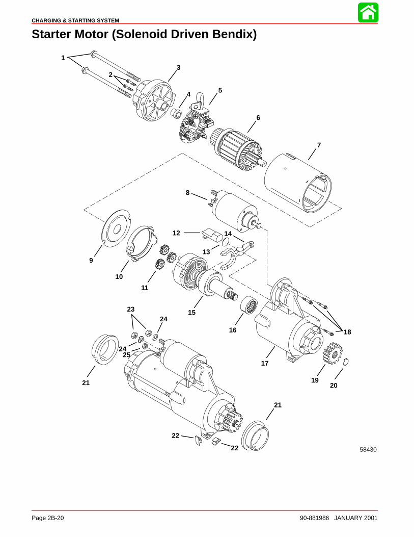
CHARGING & STARTING SYSTEM
Page 2B-20 90-881986 JANUARY 2001
Starter Motor (Solenoid Driven Bendix)
58430
1
23
4 5
6
7
8
9
10
11
12
13
14
15
16
17
18
1920
21
21
22
22
23
24
24
25
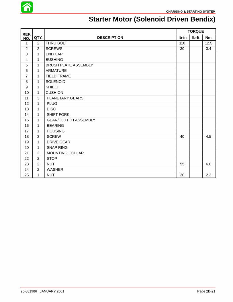
CHARGING & STARTING SYSTEM
90-881986 JANUARY 2001 Page 2B-21
Starter Motor (Solenoid Driven Bendix)
REFTORQUE
REF.NO. QTY. DESCRIPTION lb-in lb-ft Nm.
1 2 THRU BOLT 110 12.5
2 2 SCREWS 30 3.43 1 END CAP4 1 BUSHING5 1 BRUSH PLATE ASSEMBLY6 1 ARMATURE7 1 FIELD FRAME
8 1 SOLENOID9 1 SHIELD10 1 CUSHION11 3 PLANETARY GEARS12 1 PLUG13 1 DISC14 1 SHIFT FORK
15 1 GEAR/CLUTCH ASSEMBLY16 1 BEARING17 1 HOUSING18 3 SCREW 40 4.519 1 DRIVE GEAR20 1 SNAP RING21 2 MOUNTING COLLAR
22 2 STOP23 2 NUT 55 6.024 2 WASHER25 1 NUT 20 2.3
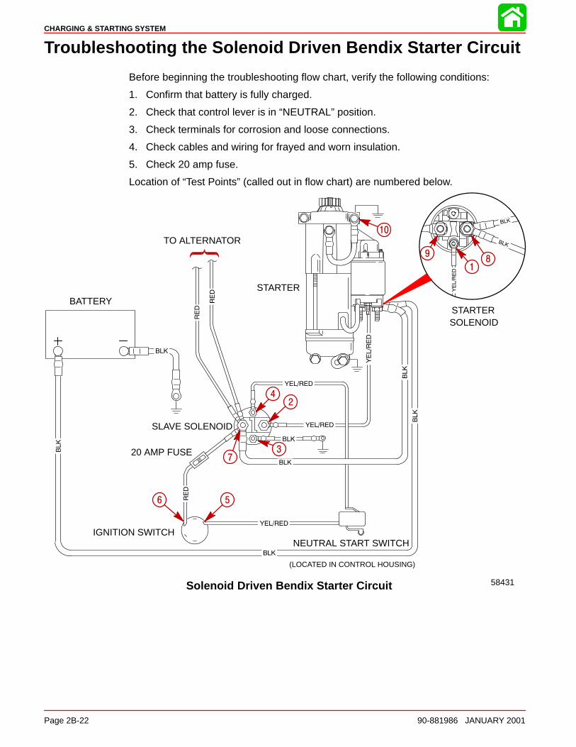
CHARGING & STARTING SYSTEM
Page 2B-22 90-881986 JANUARY 2001
Troubleshooting the Solenoid Driven Bendix Starter Circuit
Before beginning the troubleshooting flow chart, verify the following conditions:
1. Confirm that battery is fully charged.
2. Check that control lever is in “NEUTRAL” position.
3. Check terminals for corrosion and loose connections.
4. Check cables and wiring for frayed and worn insulation.
5. Check 20 amp fuse.
Location of “Test Points” (called out in flow chart) are numbered below.
Solenoid Driven Bendix Starter Circuit
BATTERY
20 AMP FUSE
(LOCATED IN CONTROL HOUSING)
58431
TO ALTERNATOR
STARTER
IGNITION SWITCHNEUTRAL START SWITCH
STARTERSOLENOID
SLAVE SOLENOID
24
1
98
37
6 5
10
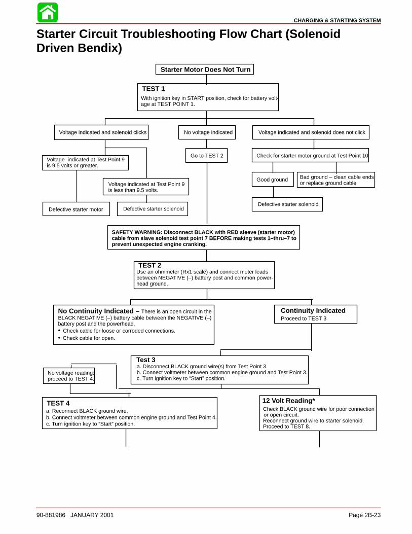
CHARGING & STARTING SYSTEM
90-881986 JANUARY 2001 Page 2B-23
Starter Circuit Troubleshooting Flow Chart (SolenoidDriven Bendix)
Starter Motor Does Not Turn
TEST 1With ignition key in START position, check for battery volt-age at TEST POINT 1.
Voltage indicated and solenoid clicks
Defective starter motor
No voltage indicated
Go to TEST 2
Voltage indicated and solenoid does not click
Defective starter solenoid
Voltage indicated at Test Point 9 is 9.5 volts or greater.
Voltage indicated at Test Point 9is less than 9.5 volts.
Defective starter solenoid
SAFETY WARNING: Disconnect BLACK with RED sleeve (starter motor)cable from slave solenoid test point 7 BEFORE making tests 1–thru–7 toprevent unexpected engine cranking.
TEST 2Use an ohmmeter (Rx1 scale) and connect meter leadsbetween NEGATIVE (–) battery post and common power-head ground.
TEST 4a. Reconnect BLACK ground wire.b. Connect voltmeter between common engine ground and Test Point 4.c. Turn ignition key to “Start” position.
12 Volt Reading*Check BLACK ground wire for poor connectionor open circuit.Reconnect ground wire to starter solenoid.Proceed to TEST 8.
No Continuity Indicated – There is an open circuit in the BLACK NEGATIVE (–) battery cable between the NEGATIVE (–) battery post and the powerhead.• Check cable for loose or corroded connections.• Check cable for open.
Continuity IndicatedProceed to TEST 3
Test 3
No voltage reading:proceed to TEST 4.
a. Disconnect BLACK ground wire(s) from Test Point 3. b. Connect voltmeter between common engine ground and Test Point 3.c. Turn ignition key to “Start” position.
Check for starter motor ground at Test Point 10
Good ground Bad ground – clean cable endsor replace ground cable
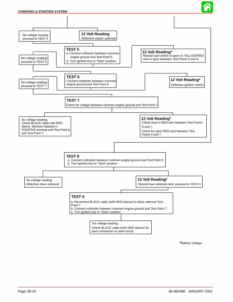
CHARGING & STARTING SYSTEM
Page 2B-24 90-881986 JANUARY 2001
TEST 8a. Connect voltmeter between common engine ground and Test Point 2.b. Turn ignition key to “Start” position.
No voltage reading:Defective slave solenoid
12 Volt Reading*Should hear solenoid click: proceed to TEST 9
TEST 9a. Reconnect BLACK cable (with RED sleeve) to slave solenoid TestPoint 7.b. Connect voltmeter between common engine ground and Test Point 7.c. Turn ignition key to “Start” position.
No voltage reading:
Check BLACK cable (with RED sleeve) forpoor connection or open circuit.
*Battery Voltage
12 Volt ReadingDefective starter solenoid
TEST 5a. Connect voltmeter between common
engine ground and Test Point 5.b. Turn ignition key to “Start” position.
12 Volt Reading*Neutral start switch is open or YELLOW/REDwire is open between Test Points 5 and 4.
TEST 6Connect voltmeter between commonengine ground and Test Point 6
12 Volt Reading*Defective ignition switch.
TEST 7Check for voltage between common engine ground and Test Point 7.
No voltage reading:Check BLACK cable with REDsleeve between battery(+)POSITIVE terminal and Test Point 8and Test Point 7.
12 Volt Reading*Check fuse in RED wire between Test Points6 and 7.Check for open RED wire between TestPoints 6 and 7.
No voltage reading:proceed to TEST 5
No voltage reading:proceed to TEST 6
No voltage reading:proceed to TEST 7
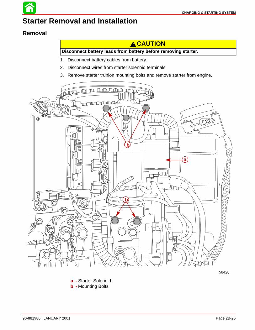
CHARGING & STARTING SYSTEM
90-881986 JANUARY 2001 Page 2B-25
Starter Removal and Installation
Removal
CAUTIONDisconnect battery leads from battery before removing starter.
1. Disconnect battery cables from battery.
2. Disconnect wires from starter solenoid terminals.
3. Remove starter trunion mounting bolts and remove starter from engine.
58428
a
b
b
a - Starter Solenoidb - Mounting Bolts
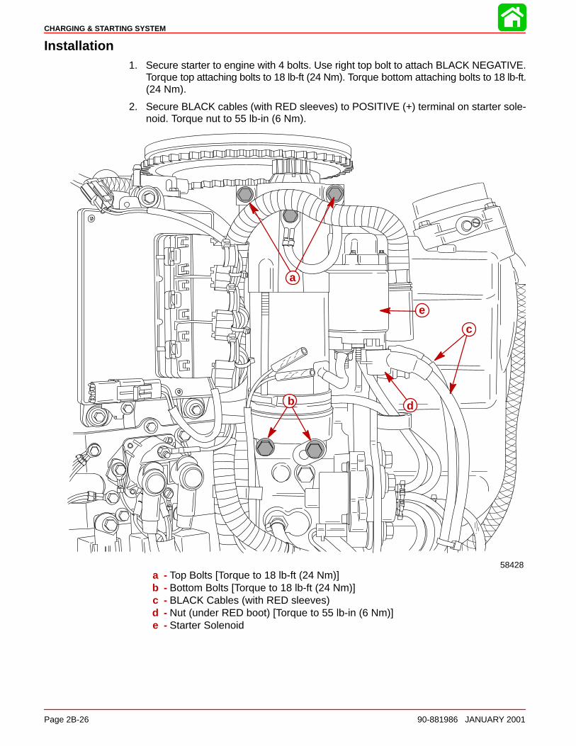
CHARGING & STARTING SYSTEM
Page 2B-26 90-881986 JANUARY 2001
Installation1. Secure starter to engine with 4 bolts. Use right top bolt to attach BLACK NEGATIVE.
Torque top attaching bolts to 18 lb-ft (24 Nm). Torque bottom attaching bolts to 18 lb-ft.(24 Nm).
2. Secure BLACK cables (with RED sleeves) to POSITIVE (+) terminal on starter sole-noid. Torque nut to 55 lb-in (6 Nm).
58428
b
c
d
e
a
a - Top Bolts [Torque to 18 lb-ft (24 Nm)]b - Bottom Bolts [Torque to 18 lb-ft (24 Nm)]c - BLACK Cables (with RED sleeves)d - Nut (under RED boot) [Torque to 55 lb-in (6 Nm)]e - Starter Solenoid
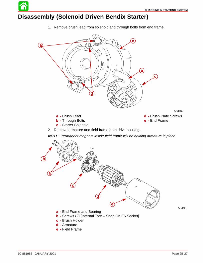
CHARGING & STARTING SYSTEM
90-881986 JANUARY 2001 Page 2B-27
Disassembly (Solenoid Driven Bendix Starter)
1. Remove brush lead from solenoid and through bolts from end frame.
58434
a
be
d
c
a - Brush Leadb - Through Boltsc - Starter Solenoid
d - Brush Plate Screwse - End Frame
2. Remove armature and field frame from drive housing.
NOTE: Permanent magnets inside field frame will be holding armature in place.
58430
b
c
d
e
a
a - End Frame and Bearingb - Screws (2) [Internal Torx – Snap On E6 Socket]c - Brush Holderd - Armaturee - Field Frame
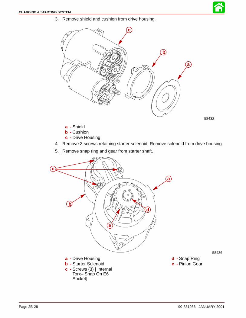
CHARGING & STARTING SYSTEM
Page 2B-28 90-881986 JANUARY 2001
3. Remove shield and cushion from drive housing.
58432
a
b
c
a - Shieldb - Cushionc - Drive Housing
4. Remove 3 screws retaining starter solenoid. Remove solenoid from drive housing.
5. Remove snap ring and gear from starter shaft.
58436
c
a
bd
e
a - Drive Housingb - Starter Solenoidc - Screws (3) [ Internal
Torx– Snap On E6Socket]
d - Snap Ringe - Pinion Gear
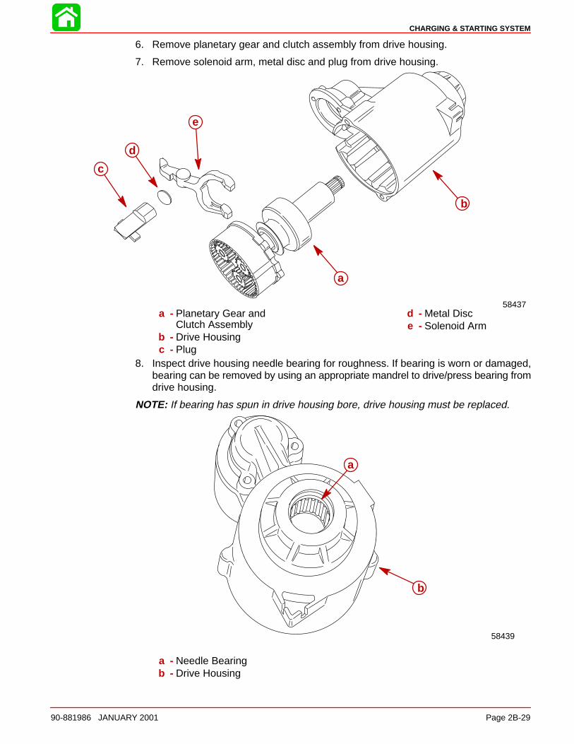
CHARGING & STARTING SYSTEM
90-881986 JANUARY 2001 Page 2B-29
6. Remove planetary gear and clutch assembly from drive housing.
7. Remove solenoid arm, metal disc and plug from drive housing.
58437
a
b
c
d
e
a - Planetary Gear andClutch Assembly
b - Drive Housingc - Plug
d - Metal Disce - Solenoid Arm
8. Inspect drive housing needle bearing for roughness. If bearing is worn or damaged,bearing can be removed by using an appropriate mandrel to drive/press bearing fromdrive housing.
NOTE: If bearing has spun in drive housing bore, drive housing must be replaced.
58439
a
b
a - Needle Bearingb - Drive Housing
CHARGING & STARTING SYSTEM
Page 2B-30 90-881986 JANUARY 2001
Cleaning and Inspection
IMPORTANT: Do not use grease dissolving solvents to clean electrical compo-nents, planetary gears or drive clutch. Solvent will damage insulation and wash thelubricant out of the clutch drive and gears. Use clean rags and compressed air toclean components.
1. Test over-running clutch action of drive. Pinion should turn freely in over-running di-rection and must not slip in cranking direction.
2. Inspect pinion teeth for wear.
3. Inspect spring for tension and drive collar for wear.
4. Check that bearings roll freely. If any roughness is felt, replace bearing.
5. Inspect planetary gear assembly. Gears must mesh easily and roll freely with no bind-ing.
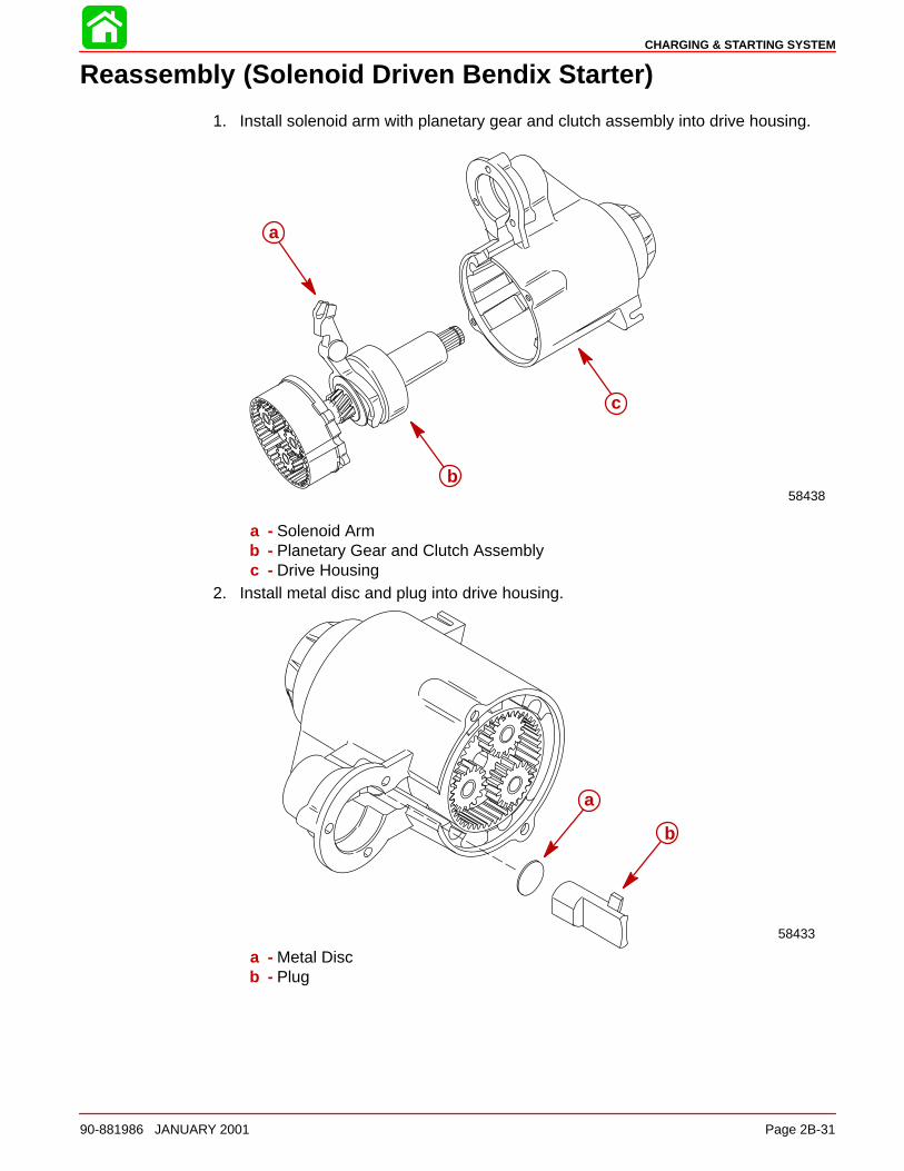
CHARGING & STARTING SYSTEM
90-881986 JANUARY 2001 Page 2B-31
Reassembly (Solenoid Driven Bendix Starter)
1. Install solenoid arm with planetary gear and clutch assembly into drive housing.
58438
a
b
c
a - Solenoid Armb - Planetary Gear and Clutch Assemblyc - Drive Housing
2. Install metal disc and plug into drive housing.
58433
a
b
a - Metal Discb - Plug
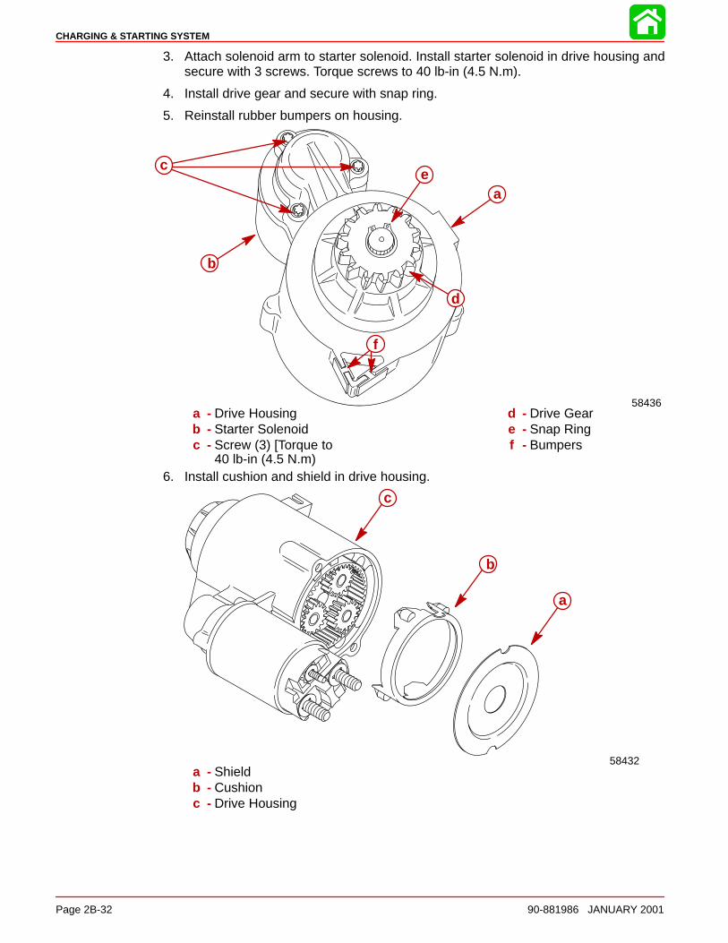
CHARGING & STARTING SYSTEM
Page 2B-32 90-881986 JANUARY 2001
3. Attach solenoid arm to starter solenoid. Install starter solenoid in drive housing andsecure with 3 screws. Torque screws to 40 lb-in (4.5 N.m).
4. Install drive gear and secure with snap ring.
5. Reinstall rubber bumpers on housing.
58436
c
a
b
e
f
d
a - Drive Housingb - Starter Solenoidc - Screw (3) [Torque to
40 lb-in (4.5 N.m)
d - Drive Geare - Snap Ringf - Bumpers
6. Install cushion and shield in drive housing.
58432
a
b
c
a - Shieldb - Cushionc - Drive Housing
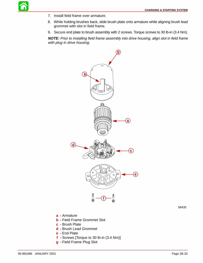
CHARGING & STARTING SYSTEM
90-881986 JANUARY 2001 Page 2B-33
7. Install field frame over armature.
8. While holding brushes back, slide brush plate onto armature while aligning brush leadgrommet with slot in field frame.
9. Secure end plate to brush assembly with 2 screws. Torque screws to 30 lb-in (3.4 Nm).
NOTE: Prior to installing field frame assembly into drive housing, align slot in field framewith plug in drive housing.
58435
a
b
cd
f
e
g
a - Armatureb - Field Frame Grommet Slotc - Brush Plated - Brush Lead Grommete - End Platef - Screws [Torque to 30 lb-in (3.4 Nm)]g - Field Frame Plug Slot
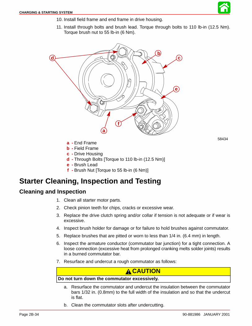
CHARGING & STARTING SYSTEM
Page 2B-34 90-881986 JANUARY 2001
10. Install field frame and end frame in drive housing.
11. Install through bolts and brush lead. Torque through bolts to 110 lb-in (12.5 Nm).Torque brush nut to 55 lb-in (6 Nm).
58434
e
db
c
fa
a - End Frameb - Field Framec - Drive Housingd - Through Bolts [Torque to 110 lb-in (12.5 Nm)]e - Brush Leadf - Brush Nut [Torque to 55 lb-in (6 Nm)]
Starter Cleaning, Inspection and TestingCleaning and Inspection
1. Clean all starter motor parts.
2. Check pinion teeth for chips, cracks or excessive wear.
3. Replace the drive clutch spring and/or collar if tension is not adequate or if wear isexcessive.
4. Inspect brush holder for damage or for failure to hold brushes against commutator.
5. Replace brushes that are pitted or worn to less than 1/4 in. (6.4 mm) in length.
6. Inspect the armature conductor (commutator bar junction) for a tight connection. Aloose connection (excessive heat from prolonged cranking melts solder joints) resultsin a burned commutator bar.
7. Resurface and undercut a rough commutator as follows:
CAUTIONDo not turn down the commutator excessively.
a. Resurface the commutator and undercut the insulation between the commutatorbars 1/32 in. (0.8mm) to the full width of the insulation and so that the undercutis flat.
b. Clean the commutator slots after undercutting.
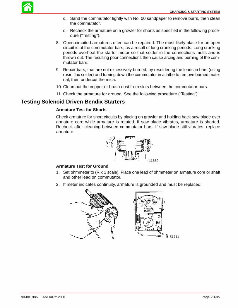
CHARGING & STARTING SYSTEM
90-881986 JANUARY 2001 Page 2B-35
c. Sand the commutator lightly with No. 00 sandpaper to remove burrs, then cleanthe commutator.
d. Recheck the armature on a growler for shorts as specified in the following proce-dure (“Testing”).
8. Open-circuited armatures often can be repaired. The most likely place for an opencircuit is at the commutator bars, as a result of long cranking periods. Long crankingperiods overheat the starter motor so that solder in the connections melts and isthrown out. The resulting poor connections then cause arcing and burning of the com-mutator bars.
9. Repair bars, that are not excessively burned, by resoldering the leads in bars (usingrosin flux solder) and turning down the commutator in a lathe to remove burned mate-rial, then undercut the mica.
10. Clean out the copper or brush dust from slots between the commutator bars.
11. Check the armature for ground. See the following procedure (“Testing”).
Testing Solenoid Driven Bendix StartersArmature Test for Shorts
Check armature for short circuits by placing on growler and holding hack saw blade overarmature core while armature is rotated. If saw blade vibrates, armature is shorted.Recheck after cleaning between commutator bars. If saw blade still vibrates, replacearmature.
11669
Armature Test for Ground1. Set ohmmeter to (R x 1 scale). Place one lead of ohmmeter on armature core or shaft
and other lead on commutator.
2. If meter indicates continuity, armature is grounded and must be replaced.
51711
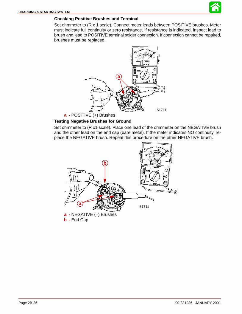
CHARGING & STARTING SYSTEM
Page 2B-36 90-881986 JANUARY 2001
Checking Positive Brushes and TerminalSet ohmmeter to (R x 1 scale). Connect meter leads between POSITIVE brushes. Metermust indicate full continuity or zero resistance. If resistance is indicated, inspect lead tobrush and lead to POSITIVE terminal solder connection. If connection cannot be repaired,brushes must be replaced.
a
51711
a
a - POSITIVE (+) BrushesTesting Negative Brushes for GroundSet ohmmeter to (R x1 scale). Place one lead of the ohmmeter on the NEGATIVE brushand the other lead on the end cap (bare metal). If the meter indicates NO continuity, re-place the NEGATIVE brush. Repeat this procedure on the other NEGATIVE brush.
b
a51711
a
b
a - NEGATIVE (–) Brushesb - End Cap
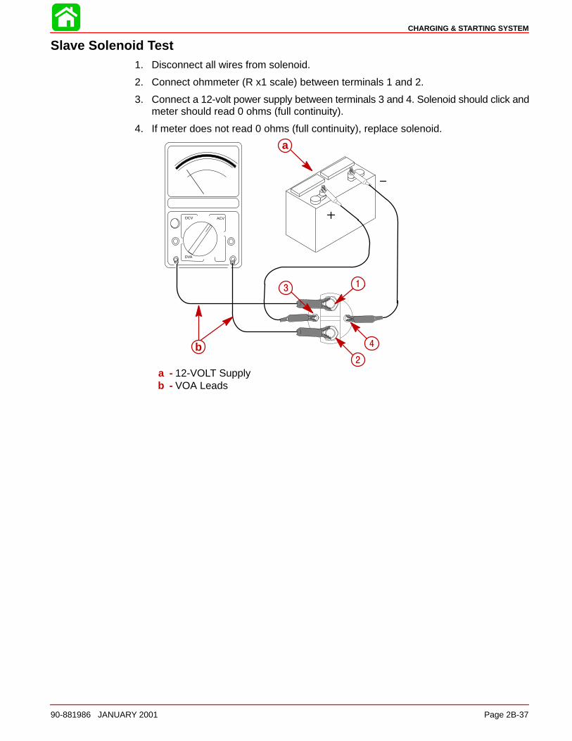
CHARGING & STARTING SYSTEM
90-881986 JANUARY 2001 Page 2B-37
Slave Solenoid Test1. Disconnect all wires from solenoid.
2. Connect ohmmeter (R x1 scale) between terminals 1 and 2.
3. Connect a 12-volt power supply between terminals 3 and 4. Solenoid should click andmeter should read 0 ohms (full continuity).
4. If meter does not read 0 ohms (full continuity), replace solenoid.
DCV ACV
DVA
a
b
1
2
3
4
a
b
1
2
3
4
a - 12-VOLT Supplyb - VOA Leads
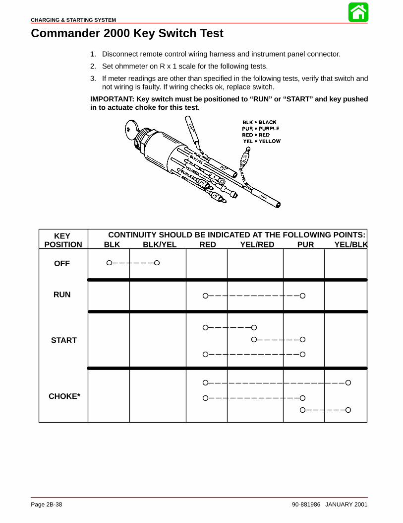
CHARGING & STARTING SYSTEM
Page 2B-38 90-881986 JANUARY 2001
Commander 2000 Key Switch Test
1. Disconnect remote control wiring harness and instrument panel connector.
2. Set ohmmeter on R x 1 scale for the following tests.
3. If meter readings are other than specified in the following tests, verify that switch andnot wiring is faulty. If wiring checks ok, replace switch.
IMPORTANT: Key switch must be positioned to “RUN” or “START” and key pushedin to actuate choke for this test.
KEYPOSITION
OFF
RUN
START
CHOKE*
CONTINUITY SHOULD BE INDICATED AT THE FOLLOWING POINTS:BLK BLK/YEL RED YEL/RED PUR YEL/BLK
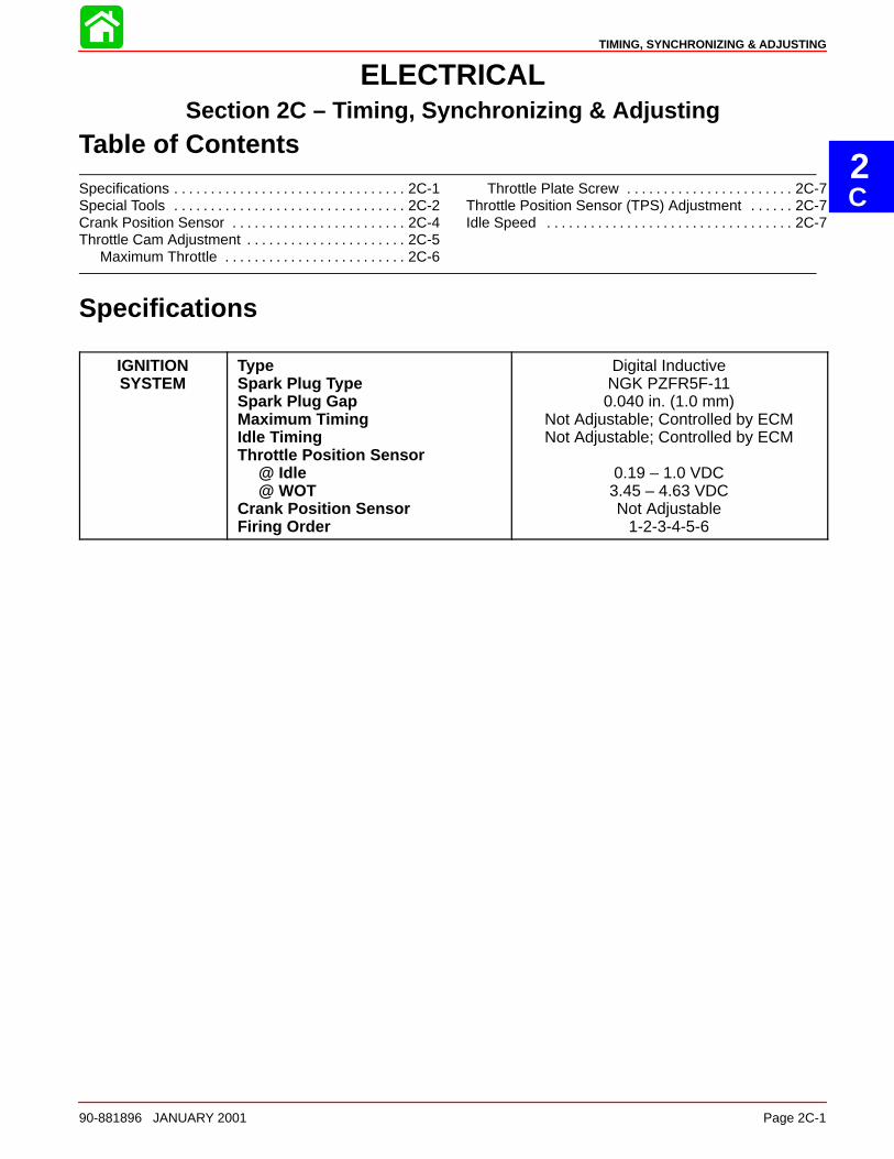
2C
TIMING, SYNCHRONIZING & ADJUSTING
90-881896 JANUARY 2001 Page 2C-1
ELECTRICALSection 2C – Timing, Synchronizing & Adjusting
Table of Contents
Specifications 2C-1. . . . . . . . . . . . . . . . . . . . . . . . . . . . . . . . Special Tools 2C-2. . . . . . . . . . . . . . . . . . . . . . . . . . . . . . . . Crank Position Sensor 2C-4. . . . . . . . . . . . . . . . . . . . . . . . Throttle Cam Adjustment 2C-5. . . . . . . . . . . . . . . . . . . . . .
Maximum Throttle 2C-6. . . . . . . . . . . . . . . . . . . . . . . . .
Throttle Plate Screw 2C-7. . . . . . . . . . . . . . . . . . . . . . . Throttle Position Sensor (TPS) Adjustment 2C-7. . . . . . Idle Speed 2C-7. . . . . . . . . . . . . . . . . . . . . . . . . . . . . . . . . .
Specifications
IGNITIONSYSTEM
TypeSpark Plug TypeSpark Plug GapMaximum TimingIdle TimingThrottle Position Sensor
@ Idle@ WOT
Crank Position SensorFiring Order
Digital InductiveNGK PZFR5F-110.040 in. (1.0 mm)
Not Adjustable; Controlled by ECMNot Adjustable; Controlled by ECM
0.19 – 1.0 VDC3.45 – 4.63 VDCNot Adjustable
1-2-3-4-5-6
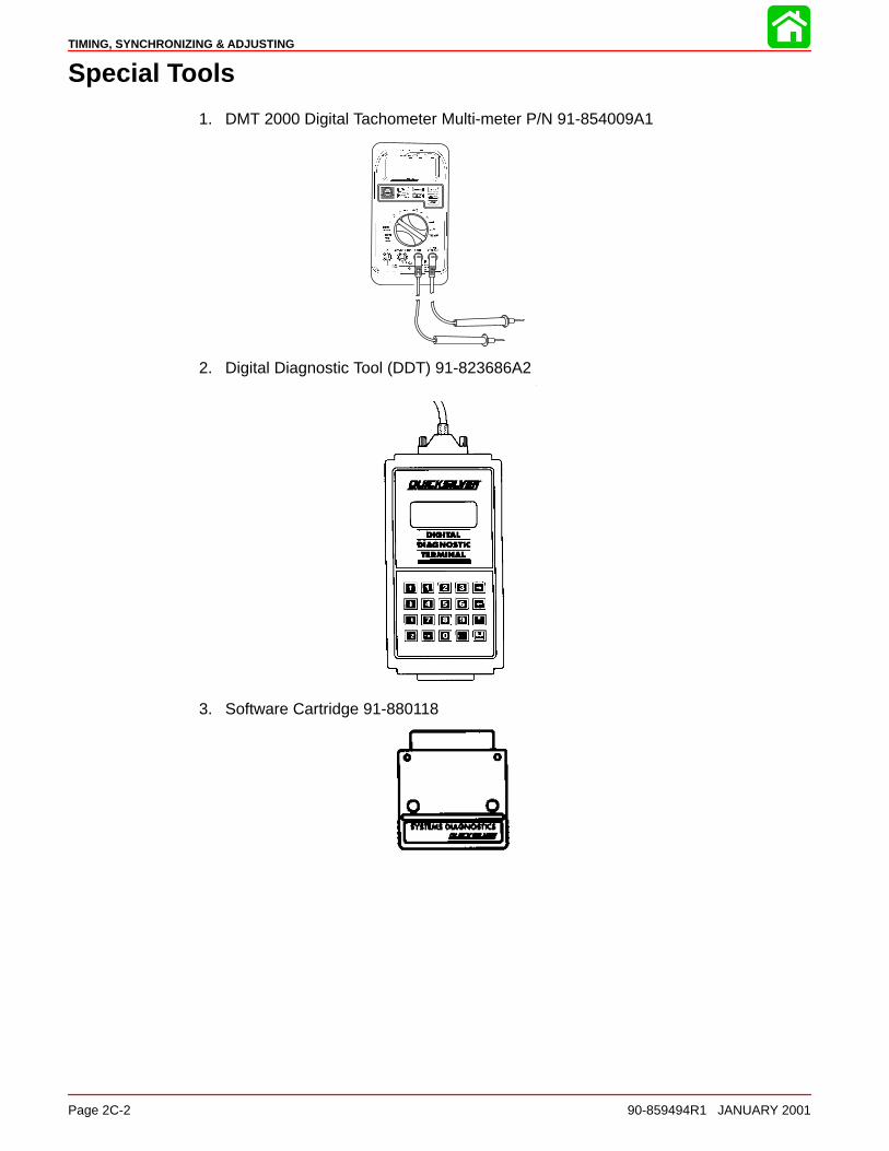
TIMING, SYNCHRONIZING & ADJUSTING
Page 2C-2 90-859494R1 JANUARY 2001
Special Tools
1. DMT 2000 Digital Tachometer Multi-meter P/N 91-854009A1
2. Digital Diagnostic Tool (DDT) 91-823686A2
3. Software Cartridge 91-880118
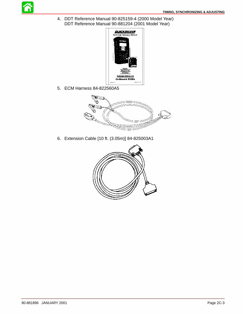
TIMING, SYNCHRONIZING & ADJUSTING
90-881896 JANUARY 2001 Page 2C-3
4. DDT Reference Manual 90-825159-4 (2000 Model Year)DDT Reference Manual 90-881204 (2001 Model Year)
5. ECM Harness 84-822560A5
6. Extension Cable [10 ft. (3.05m)] 84-825003A1
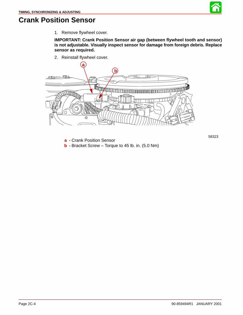
TIMING, SYNCHRONIZING & ADJUSTING
Page 2C-4 90-859494R1 JANUARY 2001
Crank Position Sensor
1. Remove flywheel cover.
IMPORTANT: Crank Position Sensor air gap (between flywheel tooth and sensor)is not adjustable. Visually inspect sensor for damage from foreign debris. Replacesensor as required.
2. Reinstall flywheel cover.
58323
ab
a - Crank Position Sensorb - Bracket Screw – Torque to 45 lb. in. (5.0 Nm)
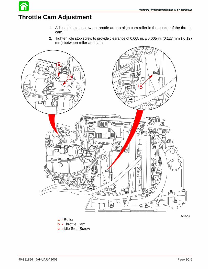
TIMING, SYNCHRONIZING & ADJUSTING
90-881896 JANUARY 2001 Page 2C-5
Throttle Cam Adjustment
1. Adjust idle stop screw on throttle arm to align cam roller in the pocket of the throttlecam.
2. Tighten idle stop screw to provide clearance of 0.005 in. ± 0.005 in. (0.127 mm ± 0.127mm) between roller and cam.
58723
a
b
c
a - Rollerb - Throttle Camc - Idle Stop Screw
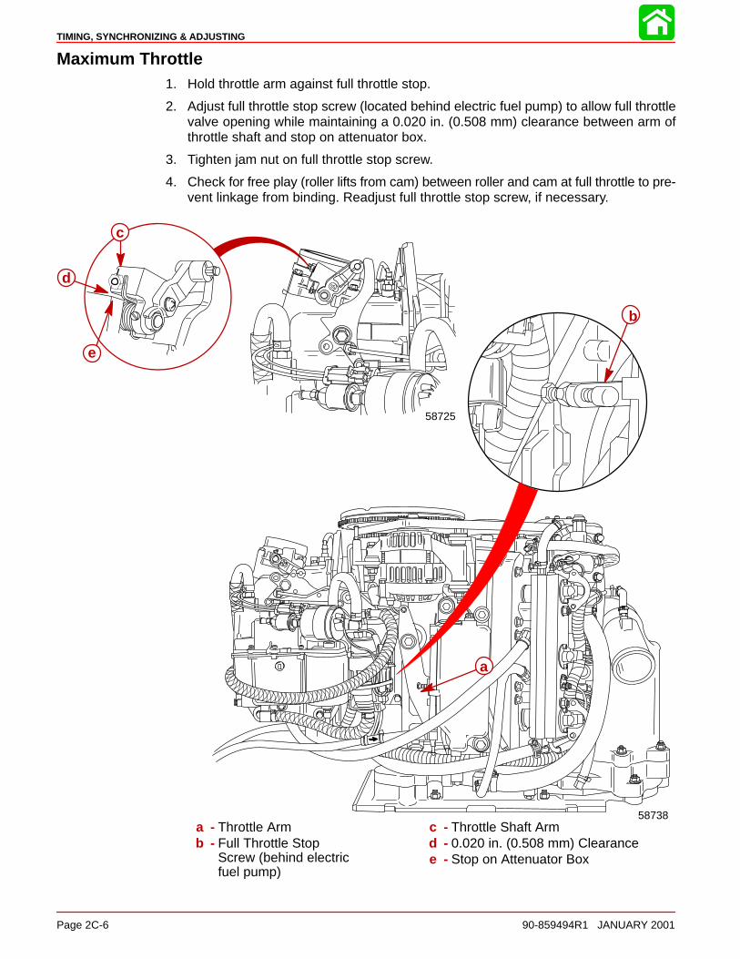
TIMING, SYNCHRONIZING & ADJUSTING
Page 2C-6 90-859494R1 JANUARY 2001
Maximum Throttle1. Hold throttle arm against full throttle stop.
2. Adjust full throttle stop screw (located behind electric fuel pump) to allow full throttlevalve opening while maintaining a 0.020 in. (0.508 mm) clearance between arm ofthrottle shaft and stop on attenuator box.
3. Tighten jam nut on full throttle stop screw.
4. Check for free play (roller lifts from cam) between roller and cam at full throttle to pre-vent linkage from binding. Readjust full throttle stop screw, if necessary.
d
e
58725
b
c
a
58738a - Throttle Armb - Full Throttle Stop
Screw (behind electricfuel pump)
c - Throttle Shaft Armd - 0.020 in. (0.508 mm) Clearancee - Stop on Attenuator Box
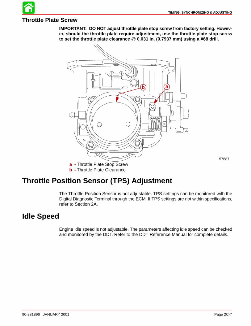
TIMING, SYNCHRONIZING & ADJUSTING
90-881896 JANUARY 2001 Page 2C-7
Throttle Plate ScrewIMPORTANT: DO NOT adjust throttle plate stop screw from factory setting. Howev-er, should the throttle plate require adjustment, use the throttle plate stop screwto set the throttle plate clearance @ 0.031 in. (0.7937 mm) using a #68 drill.
b a
57687
a - Throttle Plate Stop Screwb - Throttle Plate Clearance
Throttle Position Sensor (TPS) Adjustment
The Throttle Position Sensor is not adjustable. TPS settings can be monitored with theDigital Diagnostic Terminal through the ECM. If TPS settings are not within specifications,refer to Section 2A.
Idle Speed
Engine idle speed is not adjustable. The parameters affecting idle speed can be checkedand monitored by the DDT. Refer to the DDT Reference Manual for complete details.
2D
WIRING DIAGRAMS
90-881986 JANUARY 2001 Page 2D-1
ELECTRICALSection 2D - Wiring Diagrams
Table of Contents
200 HP OptiMax Jet Drive Wiring Diagram 2001 Model Year 2D-3. . . . . . . . . . . . . . . . . . . . . . . . .

WIRING DIAGRAMS
Page 2D-2 90-881986 JANUARY 2001
Notes:
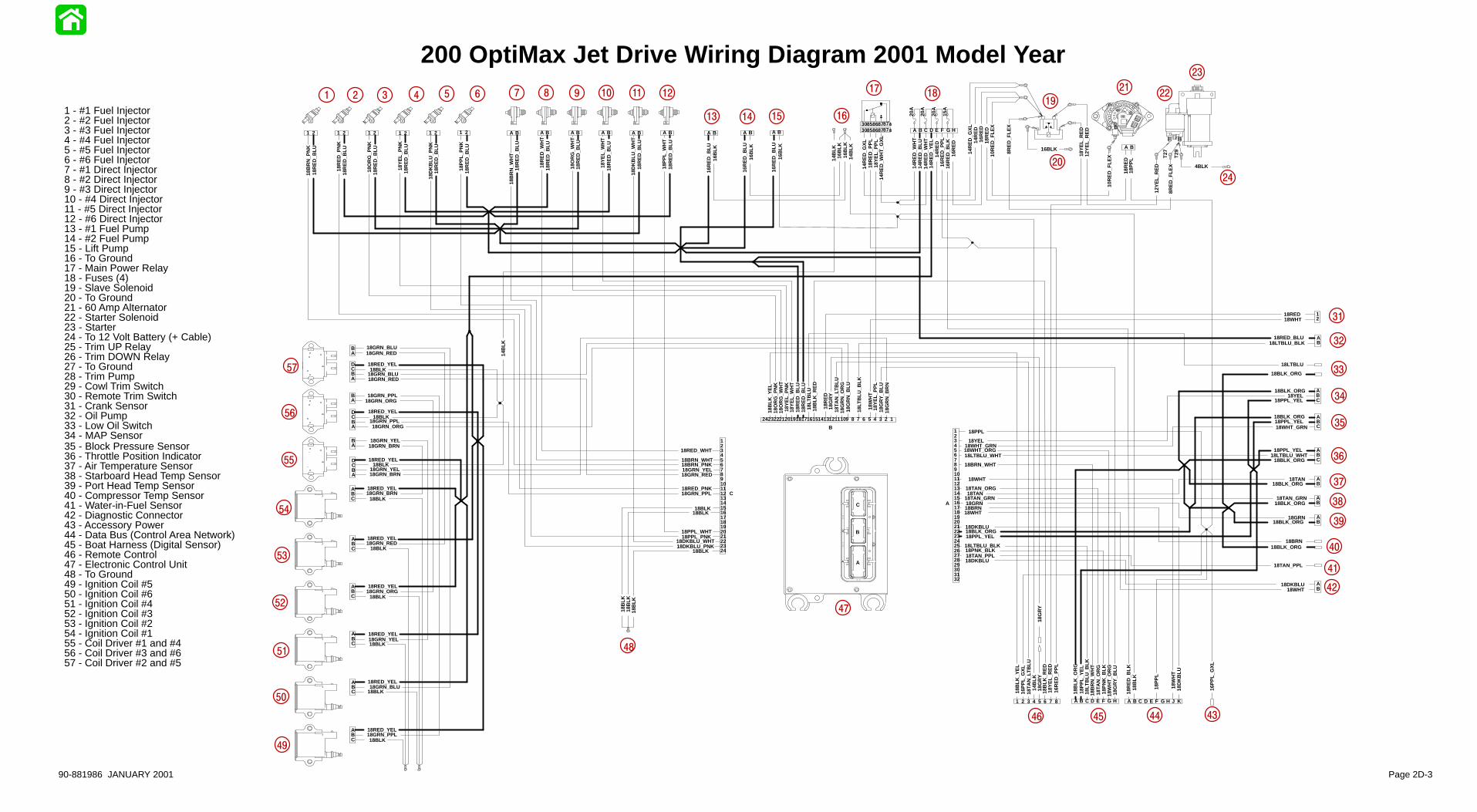
16B
LK16
RE
D_B
LU
18RED_YEL
18RED_YEL
18GRN_YEL
18RED_YEL
18GRN_PPL
18RED_YEL
18Y
EL_
PN
K
18O
RG
_PN
K
18DKBLU_PNK
18PPL_PNK
18B
RN
_WH
T
18PNK_BLK
18DKBLU
18PPL_YEL
18DKBLU
18TAN_ORG
14R
ED
_YE
L
18GRN_PPL
18GRN_YEL
18GRN_BLU
18GRN_ORG 18PPL_YEL
18BLK
18B
LK
18BLK
18BLK
18BLK
18BLK
18BLK
18BLK
18RED_YEL
18RED_YEL
18RED_YEL
18GRN_BRN
18GRN_RED
18GRN_ORG
18GRN_YEL
18GRN_BLU
18GRN_PPL
18G
RY
18BLK_ORG
18BLK_ORG
18BLK_ORG
18BLK_ORG
16P
PL_
GX
L
14B
LK
3085868787a
14R
ED
_WH
T_G
XL
16B
LK
14B
LK
16R
ED
_BLU
14R
ED
_GX
L
16R
ED
_PP
L
18R
ED
18P
PL
14R
ED
_GX
L14
RE
D
10R
ED
_FLE
X
18R
ED
_PP
L
18Y
EL_
RE
D
18Y
EL_
RE
D
16P
PL_
GX
L
14R
ED
_WH
T14
RE
D_B
LU14
RE
D_W
HT
14R
ED
16R
ED
_PP
L
16R
ED 18
RE
D
10R
ED
_FLE
X16B
LK16
RE
D_B
LU
18R
ED
_BLU
18R
ED
_BLU
18R
ED
_BLU
18GRN_RED
18GRN_BRN
18BLK
18BLK
18BLK
14B
LK
18BRN_WHT
18RED_WHT
18O
RG
_WH
T
18Y
EL_
WH
T
18DKBLU_WHT
18PPL_WHT
18BRN_PNK
18RED_PNK
18G
RN
_BR
N
18GRN_RED
18G
RN
_OR
G
18GRN_YEL
18G
RN
_BLU
18GRN_PPL
18YEL18WHT_GRN
18LTBLU_WHT
18TAN18TAN_GRN18GRN18BRN
18LT
BLU
_BLK
18TAN_PPL
18B
RN
_PN
K
18R
ED
_PN
K
18O
RG
_PN
K
18Y
EL_
PN
K
18D
KB
LU_P
NK
18P
PL_
PN
K
18TA
N_O
RG
18G
RY
_BLU
18P
NK
_BLK
18WHT
18BLK
18B
LK_R
ED
18LT
BLU
18W
HT
18R
ED
18LT
BLU
_BLK
18Y
EL_
PP
L
12Y
EL_
RE
D
18B
LK_O
RG
18R
ED
_BLU
18R
ED
_BLU
18R
ED
_BLU
18RED_BLU
18PPL_YEL
18PPL
18G
RY
_BLU
18LTBLU_WHT
18LTBLU_BLK
18DKBLU
18G
RY
18WHT
18Y
EL_
PP
L
18P
PL_
YE
L
18YEL
18WHT_GRN
18TAN
18TAN_GRN
18BRN
18TAN_PPL
18WHT_ORG
18BRN_WHT
18W
HT
_OR
G
18WHT18RED
18G
RY
18P
PL_
WH
T
18D
KB
LU_W
HT
18Y
EL_
WH
T
18O
RG
_WH
T
18R
ED
_WH
T
18B
RN
_WH
T
18GRN_BLU18GRN_RED
18GRN_ORG
18GRN_BRN
12Y
EL_
RE
D
18B
LK_Y
EL
18GRN
18TA
N_L
TB
LU
18TA
N_L
TB
LU
18LTBLU_BLK
18BLK_ORG18PPL_YEL
18R
ED
_BLU
18R
ED
_BLU
18BLK_ORG
16B
LK16
BLK
18B
LK18
BLK
18BLK
18R
ED
_BLU
18R
ED
_BLU
18R
ED
_BLU
18R
ED
_BLU
18R
ED
_BLU
18R
ED
_BLU
18RED_YEL
18RED_YEL
18BLK_ORG
18BLK_ORG
18BLK_ORG
14B
LK
18LTBLU
18W
HT
18D
KB
LU
18B
LK18
RE
D_B
LK
18P
PL
18WHT
16R
ED
_BLK
16R
ED
18B
LK_Y
EL
20A
20A
20A
15A
16BLK
8RE
D_F
LEX
8RE
D_F
LEX
4BLK
C
123456789101112131415161718192021222324
B
123456789101112131415161718192021222324
A
3231302928272625242322212019181716151413121110987654321
A BA BA BA BA BA B1 21 21 2
CBA
CBA
CBA
CBA
CBA
CBA
1 2 1 2 1 2
AB
ABC
ABC
ABC
HGFEDCBA
AB
AB
87654321
A B
A BA B A B C D E F G H
AB
ABCD
AB
ABCD
AB
ABCD
12
AB
AB
KJHGFEDCBA
3085868787aB
T27
T29
C
B
A
1 - #1 Fuel Injector2 - #2 Fuel Injector3 - #3 Fuel Injector4 - #4 Fuel Injector5 - #5 Fuel Injector6 - #6 Fuel Injector7 - #1 Direct Injector 8 - #2 Direct Injector9 - #3 Direct Injector10 - #4 Direct Injector11 - #5 Direct Injector12 - #6 Direct Injector13 - #1 Fuel Pump14 - #2 Fuel Pump15 - Lift Pump16 - To Ground17 - Main Power Relay18 - Fuses (4)19 - Slave Solenoid20 - To Ground21 - 60 Amp Alternator22 - Starter Solenoid23 - Starter24 - To 12 Volt Battery (+ Cable)25 - Trim UP Relay26 - Trim DOWN Relay27 - To Ground28 - Trim Pump29 - Cowl Trim Switch30 - Remote Trim Switch31 - Crank Sensor32 - Oil Pump33 - Low Oil Switch34 - MAP Sensor35 - Block Pressure Sensor36 - Throttle Position Indicator37 - Air Temperature Sensor38 - Starboard Head Temp Sensor39 - Port Head Temp Sensor40 - Compressor Temp Sensor41 - Water-in-Fuel Sensor42 - Diagnostic Connector43 - Accessory Power44 - Data Bus (Control Area Network)45 - Boat Harness (Digital Sensor)46 - Remote Control47 - Electronic Control Unit48 - To Ground49 - Ignition Coil #550 - Ignition Coil #651 - Ignition Coil #452 - Ignition Coil #353 - Ignition Coil #254 - Ignition Coil #155 - Coil Driver #1 and #456 - Coil Driver #3 and #657 - Coil Driver #2 and #5
200 OptiMax Jet Drive Wiring Diagram 2001 Model Year1 2 3 4 5 6 7 8 9 10 11 12
13 14 15 16
1718
19
20
2122
23
24
31
32
33
34
35
36
37
38
39
40
41
42
4546
48
49
50
51
52
53
54
55
56
57
43
47
44
A B
18B
LK_R
ED
90-881986 JANUARY 2001 Page 2D-3
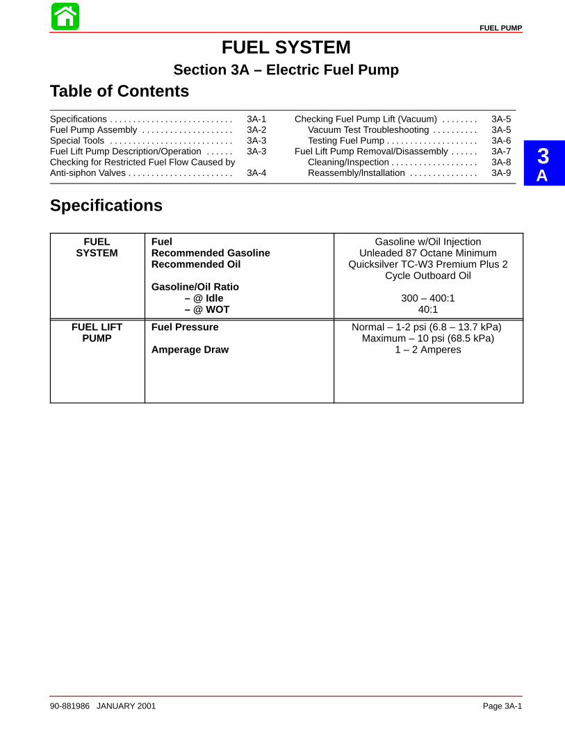
3A
FUEL PUMP
90-881986 JANUARY 2001 Page 3A-1
FUEL SYSTEMSection 3A – Electric Fuel Pump
Table of Contents
Specifications 3A-1. . . . . . . . . . . . . . . . . . . . . . . . . . . Fuel Pump Assembly 3A-2. . . . . . . . . . . . . . . . . . . . Special Tools 3A-3. . . . . . . . . . . . . . . . . . . . . . . . . . . Fuel Lift Pump Description/Operation 3A-3. . . . . . Checking for Restricted Fuel Flow Caused byAnti-siphon Valves 3A-4. . . . . . . . . . . . . . . . . . . . . . .
Checking Fuel Pump Lift (Vacuum) 3A-5. . . . . . . . Vacuum Test Troubleshooting 3A-5. . . . . . . . . . Testing Fuel Pump 3A-6. . . . . . . . . . . . . . . . . . . .
Fuel Lift Pump Removal/Disassembly 3A-7. . . . . . Cleaning/Inspection 3A-8. . . . . . . . . . . . . . . . . . . Reassembly/lnstallation 3A-9. . . . . . . . . . . . . . .
Specifications
FUELSYSTEM
FuelRecommended GasolineRecommended Oil
Gasoline/Oil Ratio – @ Idle
– @ WOT
Gasoline w/Oil InjectionUnleaded 87 Octane Minimum
Quicksilver TC-W3 Premium Plus 2Cycle Outboard Oil
300 – 400:140:1
FUEL LIFTPUMP
Fuel Pressure
Amperage Draw
Normal – 1-2 psi (6.8 – 13.7 kPa) Maximum – 10 psi (68.5 kPa)
1 – 2 Amperes
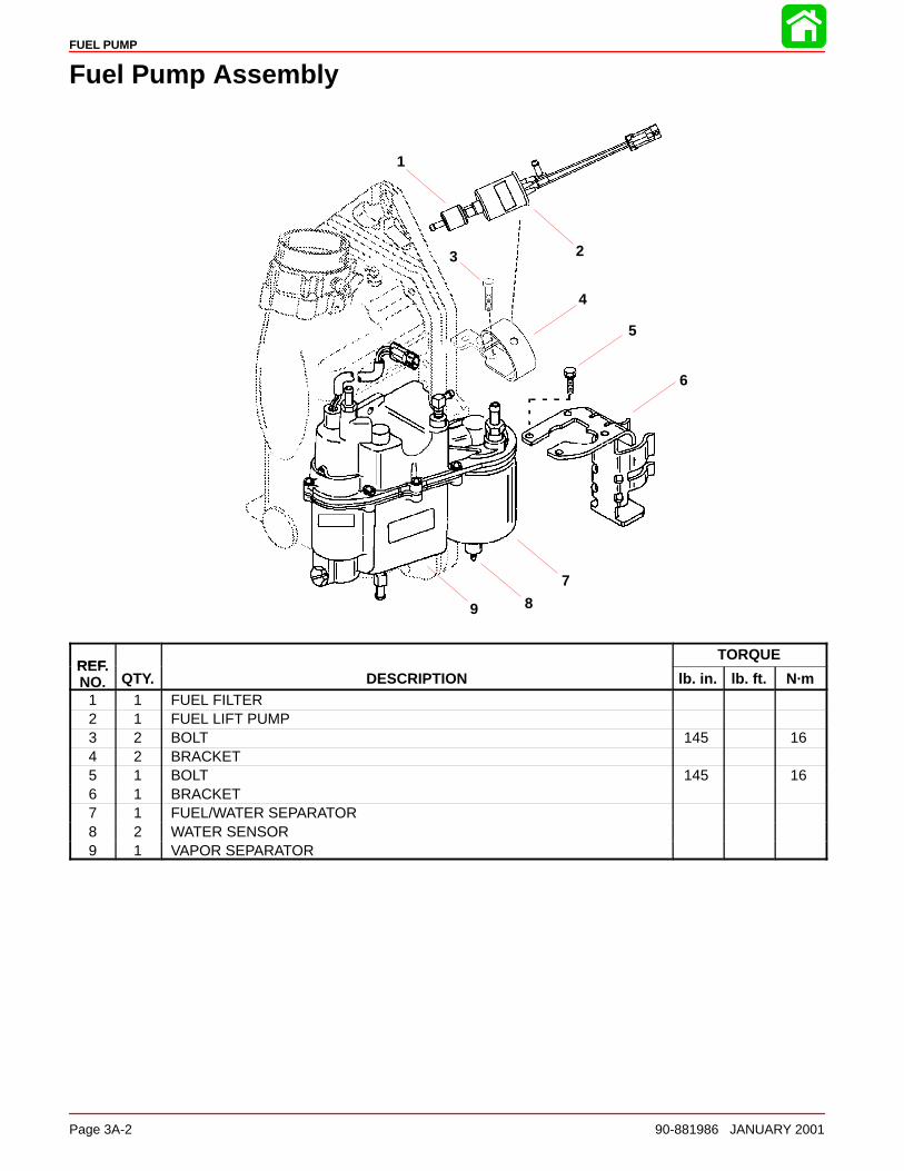
FUEL PUMP
Page 3A-2 90-881986 JANUARY 2001
Fuel Pump Assembly
1
23
4
5
6
7
89
REFTORQUE
REF.NO. QTY. DESCRIPTION lb. in. lb. ft. N·m
1 1 FUEL FILTER2 1 FUEL LIFT PUMP3 2 BOLT 145 164 2 BRACKET5 1 BOLT 145 166 1 BRACKET7 1 FUEL/WATER SEPARATOR8 2 WATER SENSOR9 1 VAPOR SEPARATOR
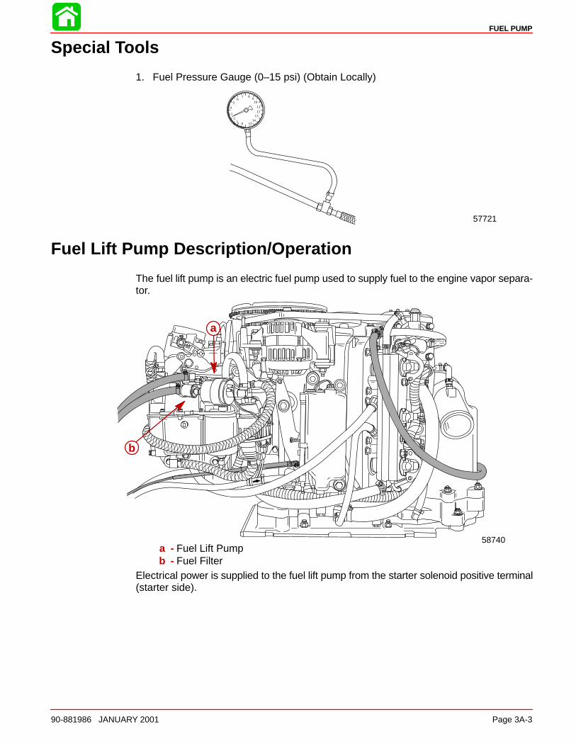
FUEL PUMP
90-881986 JANUARY 2001 Page 3A-3
Special Tools
1. Fuel Pressure Gauge (0–15 psi) (Obtain Locally)
57721
Fuel Lift Pump Description/Operation
The fuel lift pump is an electric fuel pump used to supply fuel to the engine vapor separa-tor.
58740
a
b
a - Fuel Lift Pumpb - Fuel Filter
Electrical power is supplied to the fuel lift pump from the starter solenoid positive terminal(starter side).
FUEL PUMP
Page 3A-4 90-881986 JANUARY 2001
Checking for Restricted Fuel Flow Caused by Anti-siphonValves
While anti-siphon valves may be helpful from a safety stand-point, they clog with debris,they may be too small, or they may have too heavy a spring. Summarizing, the pressuredrop across these valves can, and often does, create operational problems and/or pow-er-head damage by restricting fuel to the fuel pump and VST. Some symptoms of re-stricted (lean) fuel flow, which could be caused by use of an anti-siphon valve, are:
1 - Loss of fuel pump pressure 2 - Loss of power 3 - High speed surging 4 - Preignition/detonation (piston dome erosion)5 - Engine cuts out or hesitates upon acceleration 6 - Engine runs rough7 - Engine quits and cannot be restarted 8 - Engine will not start 9 - Vapor lock
Since any type of anti-siphon device must be located between the engine fuel inlet andfuel tank outlet, a simple method of checking [if such a device (or bad fuel) is a problemsource] is to operate the engine with a separate fuel supply which is known to be good,such as a remote fuel tank.
If, after using a separate fuel supply, it is found that the anti-siphon valve is the cause ofthe problem, there are 2 solutions to the problem; either 1) replace the anti-siphon valvewith one that has lighter spring tension or 2) replace it with a solenoid-operated fuel shutoff valve.
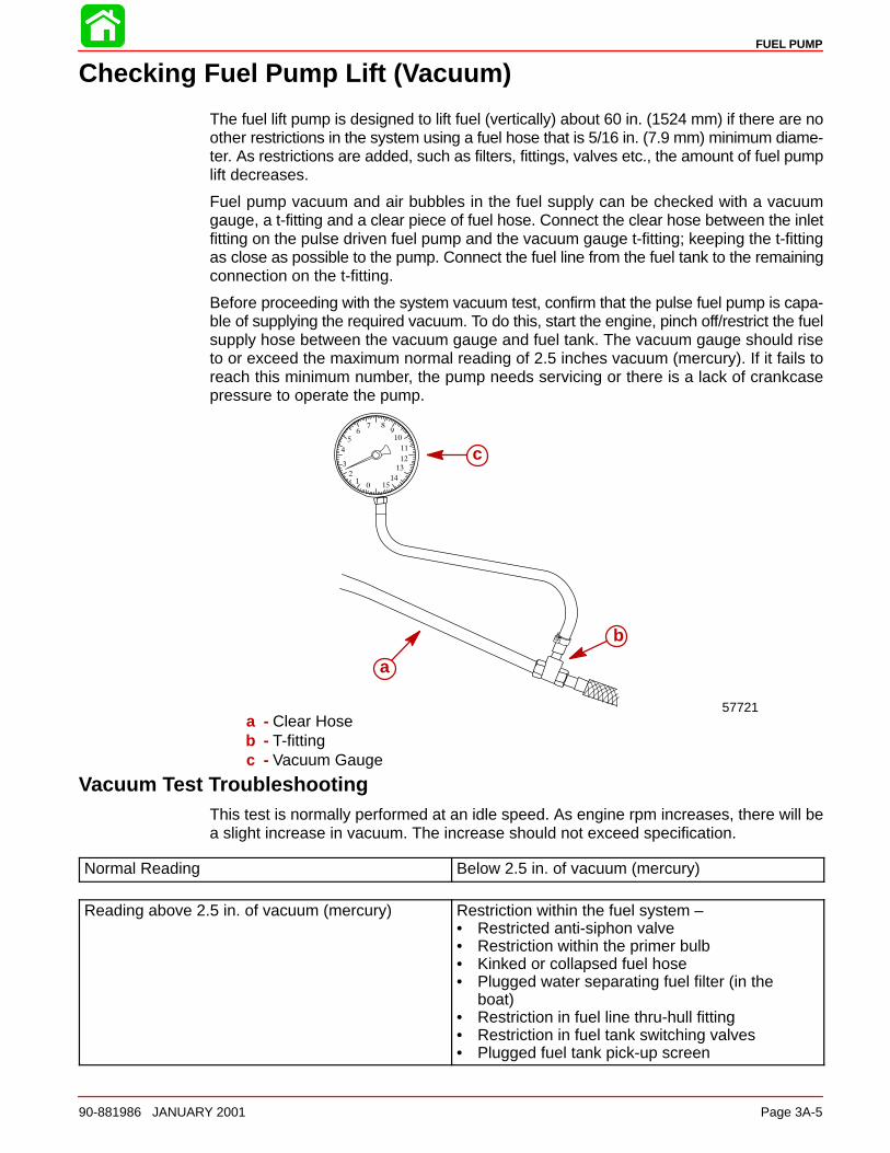
FUEL PUMP
90-881986 JANUARY 2001 Page 3A-5
Checking Fuel Pump Lift (Vacuum)
The fuel lift pump is designed to lift fuel (vertically) about 60 in. (1524 mm) if there are noother restrictions in the system using a fuel hose that is 5/16 in. (7.9 mm) minimum diame-ter. As restrictions are added, such as filters, fittings, valves etc., the amount of fuel pumplift decreases.
Fuel pump vacuum and air bubbles in the fuel supply can be checked with a vacuumgauge, a t-fitting and a clear piece of fuel hose. Connect the clear hose between the inletfitting on the pulse driven fuel pump and the vacuum gauge t-fitting; keeping the t-fittingas close as possible to the pump. Connect the fuel line from the fuel tank to the remainingconnection on the t-fitting.
Before proceeding with the system vacuum test, confirm that the pulse fuel pump is capa-ble of supplying the required vacuum. To do this, start the engine, pinch off/restrict the fuelsupply hose between the vacuum gauge and fuel tank. The vacuum gauge should riseto or exceed the maximum normal reading of 2.5 inches vacuum (mercury). If it fails toreach this minimum number, the pump needs servicing or there is a lack of crankcasepressure to operate the pump.
57721
a
c
b
a - Clear Hoseb - T-fittingc - Vacuum Gauge
Vacuum Test TroubleshootingThis test is normally performed at an idle speed. As engine rpm increases, there will bea slight increase in vacuum. The increase should not exceed specification.
Normal Reading Below 2.5 in. of vacuum (mercury)
Reading above 2.5 in. of vacuum (mercury) Restriction within the fuel system – • Restricted anti-siphon valve• Restriction within the primer bulb• Kinked or collapsed fuel hose• Plugged water separating fuel filter (in the
boat)• Restriction in fuel line thru-hull fitting• Restriction in fuel tank switching valves• Plugged fuel tank pick-up screen
FUEL PUMP
Page 3A-6 90-881986 JANUARY 2001
Testing Fuel PumpInstall clear fuel hose(s) between fuel pump and VST. Run engine, and inspect fuel pass-ing thru hose(s) for air bubbles.
Problem: Air Bubbles in Fuel LineLow fuel in tank. Fill tank with fuel.
Loose fuel line connection. Check and tighten all connectors.
Fuel pump fitting loose. Tighten fitting.
A hole or cut in fuel line. Check condition of all fuel lines and replace
Fuel Pump anchor screw(s) loose. Tighten all screws evenly and securely.
Fuel Pump filter cover anchor screw loose. Tighten screws securely.
Fuel pump filter gasket worn out. Replace gasket.
Fuel pump gasket(s) worn out. Rebuild fuel pump.
Fuel vaporizing Fuel with high reed vapor pressure (winter gradefuel) may vaporize (form bubbles) when used inhot/warm weather. Use fuel with a lower reed va-por pressure (summer grade fuel)
Problem: Lack of Fuel Pump PressureAn anti-siphon valve. See ‘‘Checking for Restricted Fuel Flow” preced-
ing.
Air in fuel line. See ‘‘Air Bubbles in Fuel Line”, above.
A dirty or clogged fuel filter. Clean or replace fuel filter.
The fuel pickup in fuel tank is clogged or dirty. Clean or replace pickup.
Worn out fuel pump diaphragm. Rebuild fuel pump.
Worn out check valve(s) in fuel pump. Rebuild fuel pump.
A leaky check valve gasket. Rebuild fuel pump.
Pulse hole(s) plugged. Remove fuel pump and clean out holes.
Hole in pulse hose. Replace pulse hose.
Loose pulse hose. Tighten connection(s).
Fuel hose internal diameter too small. Use 5/16 I.D. fuel hose.
Excessive fuel lift required. Fuel lift exceeds 2.5 in. of vacuum (mercury)
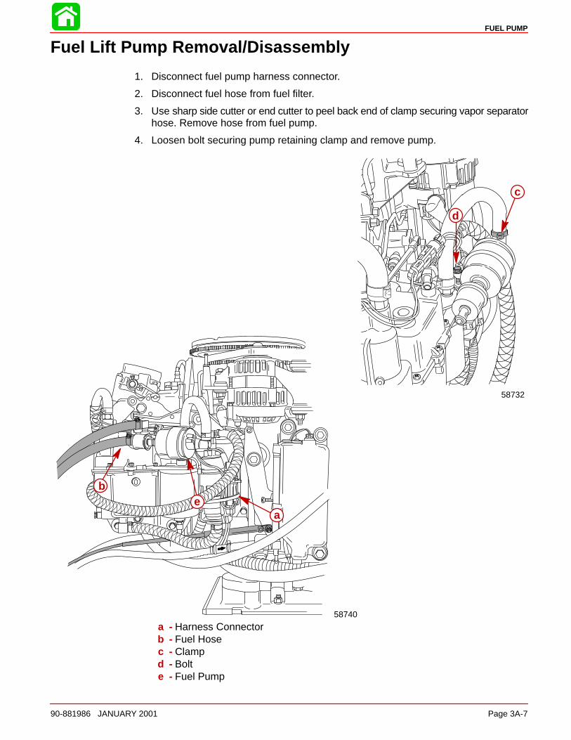
FUEL PUMP
90-881986 JANUARY 2001 Page 3A-7
Fuel Lift Pump Removal/Disassembly
1. Disconnect fuel pump harness connector.
2. Disconnect fuel hose from fuel filter.
3. Use sharp side cutter or end cutter to peel back end of clamp securing vapor separatorhose. Remove hose from fuel pump.
4. Loosen bolt securing pump retaining clamp and remove pump.
58740
58732
a
b
c
d
e
a - Harness Connectorb - Fuel Hosec - Clampd - Bolte - Fuel Pump
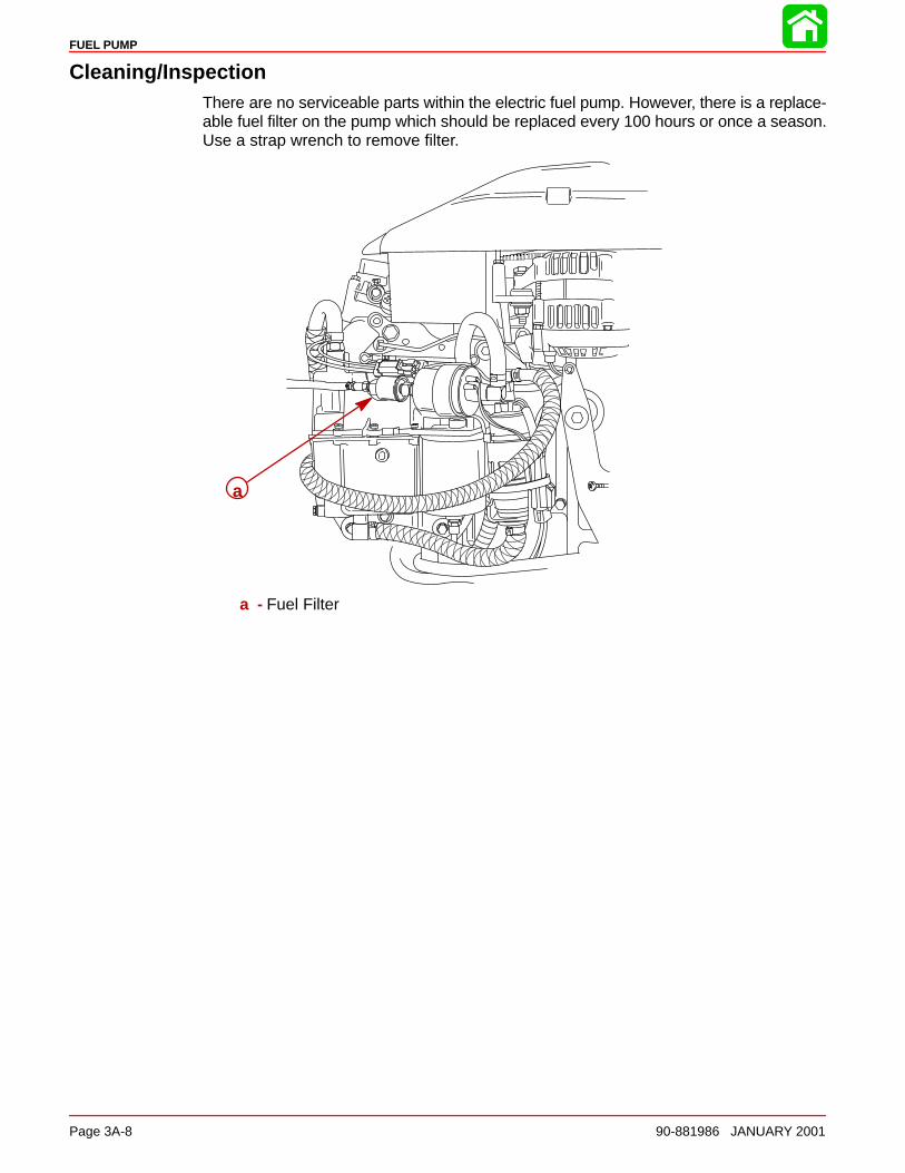
FUEL PUMP
Page 3A-8 90-881986 JANUARY 2001
Cleaning/InspectionThere are no serviceable parts within the electric fuel pump. However, there is a replace-able fuel filter on the pump which should be replaced every 100 hours or once a season.Use a strap wrench to remove filter.
a
a - Fuel Filter
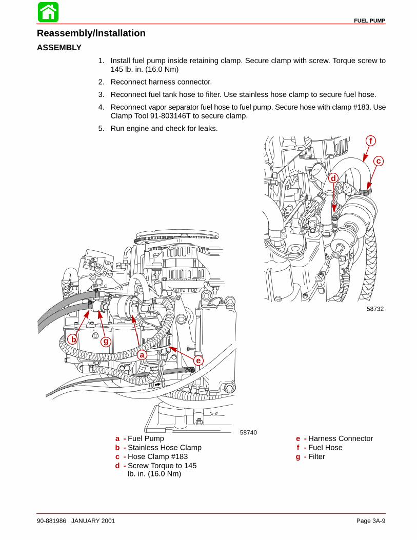
FUEL PUMP
90-881986 JANUARY 2001 Page 3A-9
Reassembly/lnstallationASSEMBLY
1. Install fuel pump inside retaining clamp. Secure clamp with screw. Torque screw to145 lb. in. (16.0 Nm)
2. Reconnect harness connector.
3. Reconnect fuel tank hose to filter. Use stainless hose clamp to secure fuel hose.
4. Reconnect vapor separator fuel hose to fuel pump. Secure hose with clamp #183. UseClamp Tool 91-803146T to secure clamp.
5. Run engine and check for leaks.
58740
58732
a
b
c
d
e
f
g
a - Fuel Pumpb - Stainless Hose Clampc - Hose Clamp #183d - Screw Torque to 145
lb. in. (16.0 Nm)
e - Harness Connectorf - Fuel Hoseg - Filter
3B
DIRECT FUEL INJECTION
90-881986 JANUARY 2001 Page 3B-1
FUEL SYSTEMSection 3B – Direct Fuel Injection
Table of Contents
Specifications 3B-2. . . . . . . . . . . . . . . . . . . . . . . . . . . Special Tools 3B-3. . . . . . . . . . . . . . . . . . . . . . . . . . . Air Handler 3B-6. . . . . . . . . . . . . . . . . . . . . . . . . . . . . Air Handler Components 3B-8. . . . . . . . . . . . . . . . . Vapor Separator Components 3B-10. . . . . . . . . . . . . Air Hoses 3B-12. . . . . . . . . . . . . . . . . . . . . . . . . . . . . . Water Hoses 3B-14. . . . . . . . . . . . . . . . . . . . . . . . . . . . Fuel Hoses 3B-16. . . . . . . . . . . . . . . . . . . . . . . . . . . . . Fuel Rails 3B-18. . . . . . . . . . . . . . . . . . . . . . . . . . . . . . Air Compressor Components 3B-20. . . . . . . . . . . . . DFI Operation 3B-22. . . . . . . . . . . . . . . . . . . . . . . . . .
Air Induction Through Crankcase 3B-22. . . . . . . Air Compressor System 3B-22. . . . . . . . . . . . . . . Fuel 3B-22. . . . . . . . . . . . . . . . . . . . . . . . . . . . . . . . Oil 3B-23. . . . . . . . . . . . . . . . . . . . . . . . . . . . . . . . . . Electrical 3B-23. . . . . . . . . . . . . . . . . . . . . . . . . . . . Operation 3B-23. . . . . . . . . . . . . . . . . . . . . . . . . . .
Testing Electric Fuel Pump Pressure Output 3B-24Low Pressure Electric Fuel Pump 3B-24. . . . . . . High Pressure Electric Fuel Pump 3B-25. . . . . .
Fuel Management Assembly Removal 3B-26. . . . . Reed Block Disassembly/Assembly 3B-29. . . . . Air Temperature Sensor Removal 3B-29. . . . . .
Air Temperature Sensor Installation 3B-30. . . . . Throttle Plate Assembly Removal 3B-30. . . . . . . Throttle Plate Assembly Installation 3B-30. . . . . Vapor Separator Disassembly 3B-30. . . . . . . . . . Vapor Separator Reassembly 3B-32. . . . . . . . . . Air Plenum Installation 3B-33. . . . . . . . . . . . . . . . Low Pressure Electric Fuel Pump Installation 3B-33. . . . . . . . . . . . . . . . . . . . . . . . . Vapor Separator Installation 3B-36. . . . . . . . . . . Fuel Rail Removal 3B-38. . . . . . . . . . . . . . . . . . . . Fuel Pressure Regulator 3B-43. . . . . . . . . . . . . . Air Pressure Regulator 3B-46. . . . . . . . . . . . . . . . Tracker Valve 3B-48. . . . . . . . . . . . . . . . . . . . . . . . Fuel Rail Cleaning 3B-50. . . . . . . . . . . . . . . . . . . . Direct Injector Removal 3B-51. . . . . . . . . . . . . . . Direct Injector Leak Test 3B-53. . . . . . . . . . . . . . . Fuel Rail and Direct Injector Installation 3B-54.
Air Compressor 3B-55. . . . . . . . . . . . . . . . . . . . . . . . . Compressor Removal 3B-56. . . . . . . . . . . . . . . . . Air Compressor Disassembly/Reassembly 3B-58. . . . . . . . . . . . Air Compressor Flow Diagram 3B-59. . . . . . . . . Air Compressor Pressure Test 3B-60. . . . . . . . .
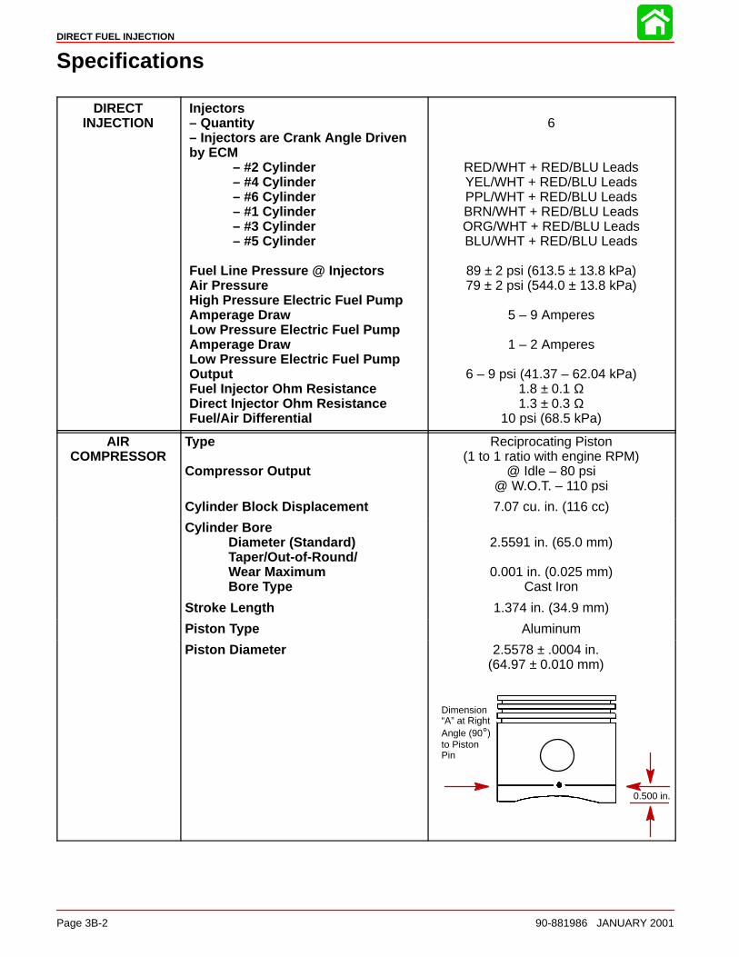
DIRECT FUEL INJECTION
Page 3B-2 90-881986 JANUARY 2001
Specifications
DIRECTINJECTION
Injectors– Quantity– Injectors are Crank Angle Driven by ECM
– #2 Cylinder– #4 Cylinder– #6 Cylinder– #1 Cylinder– #3 Cylinder– #5 Cylinder
Fuel Line Pressure @ InjectorsAir PressureHigh Pressure Electric Fuel PumpAmperage DrawLow Pressure Electric Fuel PumpAmperage DrawLow Pressure Electric Fuel PumpOutputFuel Injector Ohm ResistanceDirect Injector Ohm ResistanceFuel/Air Differential
6
RED/WHT + RED/BLU LeadsYEL/WHT + RED/BLU LeadsPPL/WHT + RED/BLU LeadsBRN/WHT + RED/BLU LeadsORG/WHT + RED/BLU LeadsBLU/WHT + RED/BLU Leads
89 ± 2 psi (613.5 ± 13.8 kPa)79 ± 2 psi (544.0 ± 13.8 kPa)
5 – 9 Amperes
1 – 2 Amperes
6 – 9 psi (41.37 – 62.04 kPa)1.8 ± 0.1 Ω1.3 ± 0.3 Ω
10 psi (68.5 kPa)
AIRCOMPRESSOR
Type
Compressor Output
Reciprocating Piston(1 to 1 ratio with engine RPM)
@ Idle – 80 psi@ W.O.T. – 110 psi
Cylinder Block Displacement 7.07 cu. in. (116 cc)
Cylinder BoreDiameter (Standard)Taper/Out-of-Round/Wear MaximumBore Type
2.5591 in. (65.0 mm)
0.001 in. (0.025 mm)Cast Iron
Stroke Length 1.374 in. (34.9 mm)
Piston Type Aluminum
Piston Diameter 2.5578 ± .0004 in.(64.97 ± 0.010 mm)
Dimension“A” at RightAngle (90°)to PistonPin
0.500 in.
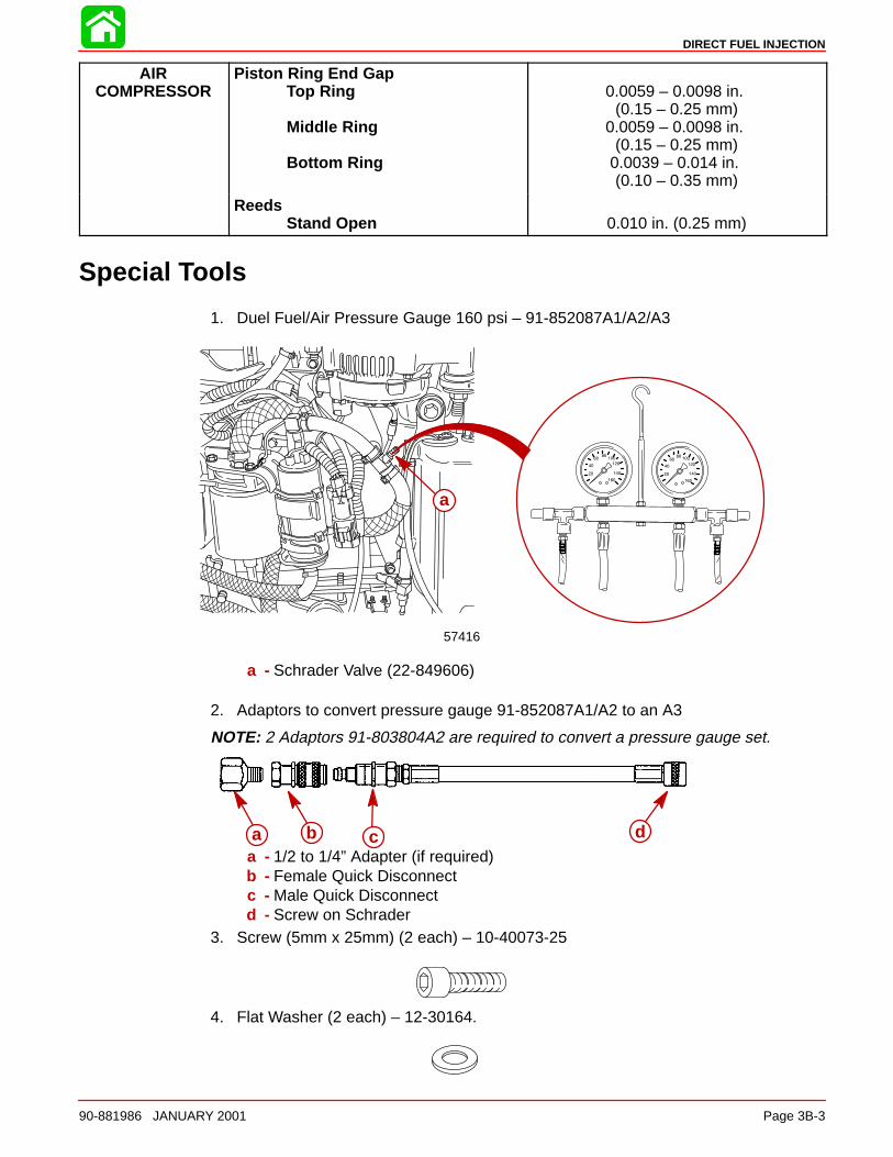
DIRECT FUEL INJECTION
90-881986 JANUARY 2001 Page 3B-3
AIRCOMPRESSOR
Piston Ring End GapTop Ring
Middle Ring
Bottom Ring
0.0059 – 0.0098 in. (0.15 – 0.25 mm)
0.0059 – 0.0098 in. (0.15 – 0.25 mm)
0.0039 – 0.014 in. (0.10 – 0.35 mm)
ReedsStand Open 0.010 in. (0.25 mm)
Special Tools
1. Duel Fuel/Air Pressure Gauge 160 psi – 91-852087A1/A2/A3
57416
a
a - Schrader Valve (22-849606)
2. Adaptors to convert pressure gauge 91-852087A1/A2 to an A3
NOTE: 2 Adaptors 91-803804A2 are required to convert a pressure gauge set.
a b c da - 1/2 to 1/4” Adapter (if required)b - Female Quick Disconnectc - Male Quick Disconnectd - Screw on Schrader
3. Screw (5mm x 25mm) (2 each) – 10-40073-25
4. Flat Washer (2 each) – 12-30164.
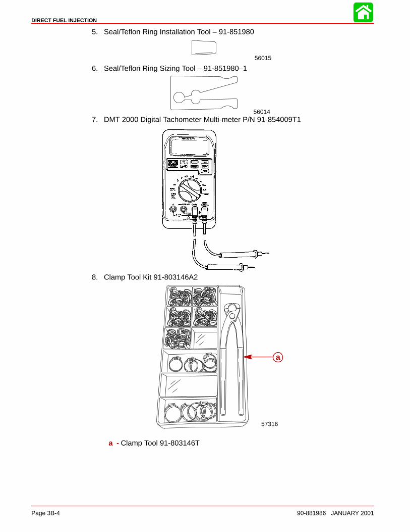
DIRECT FUEL INJECTION
Page 3B-4 90-881986 JANUARY 2001
5. Seal/Teflon Ring Installation Tool – 91-851980
56015
6. Seal/Teflon Ring Sizing Tool – 91-851980–1
560147. DMT 2000 Digital Tachometer Multi-meter P/N 91-854009T1
8. Clamp Tool Kit 91-803146A2
57316
a
a - Clamp Tool 91-803146T
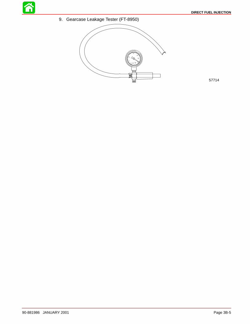
DIRECT FUEL INJECTION
90-881986 JANUARY 2001 Page 3B-5
9. Gearcase Leakage Tester (FT-8950)
57714
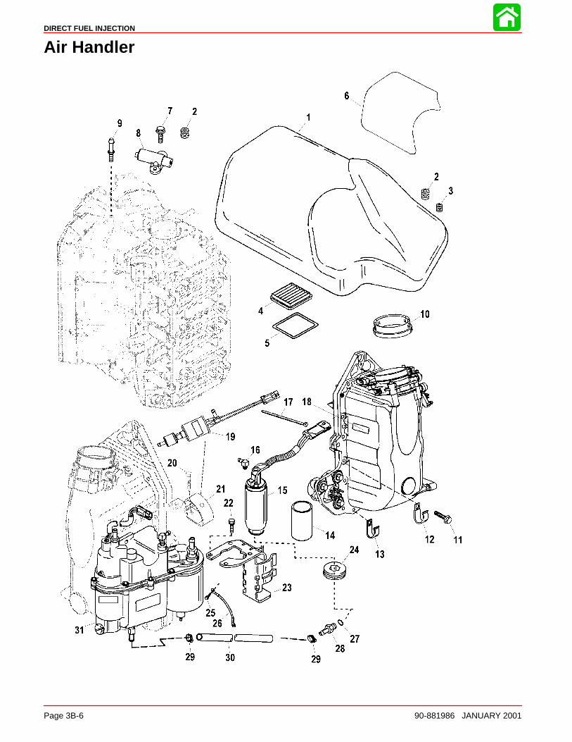
DIRECT FUEL INJECTION
Page 3B-6 90-881986 JANUARY 2001
Air Handler
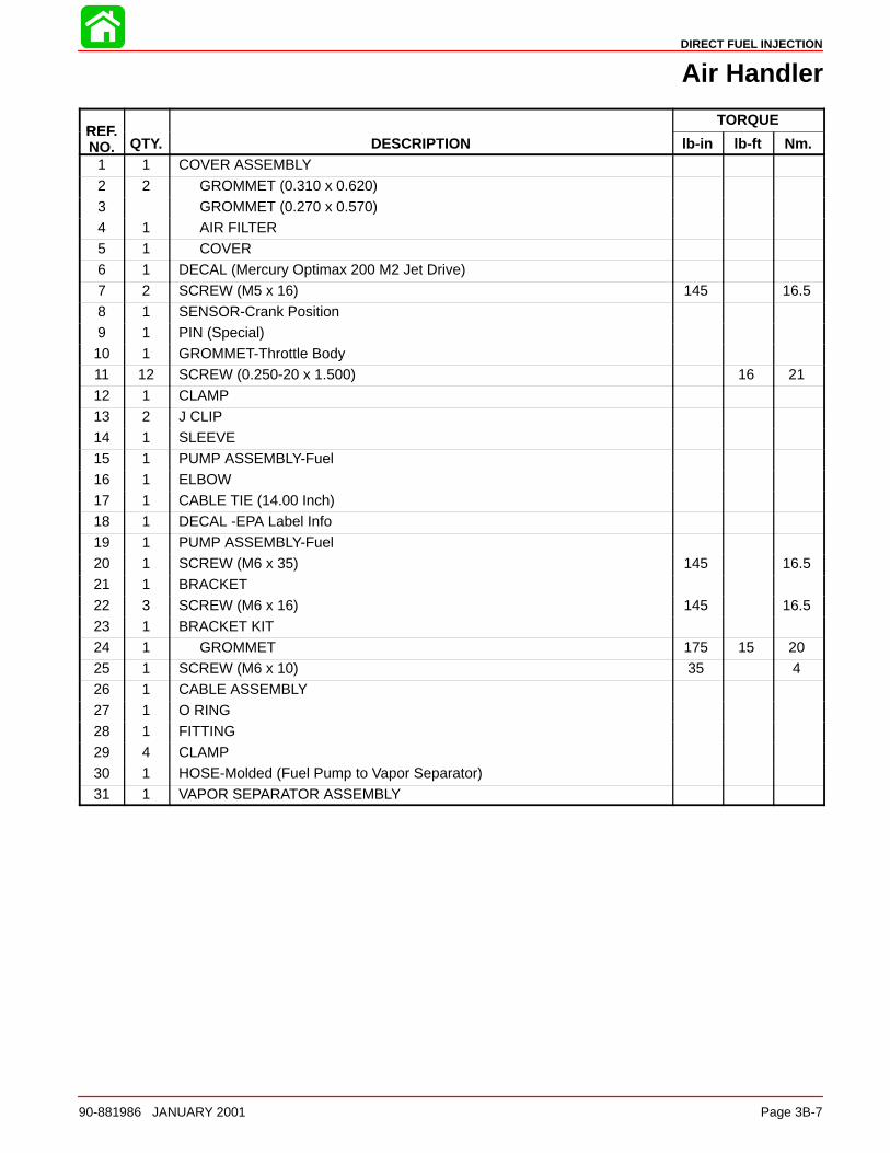
DIRECT FUEL INJECTION
90-881986 JANUARY 2001 Page 3B-7
Air Handler
REFTORQUE
REF.NO. QTY. DESCRIPTION lb-in lb-ft Nm.
1 1 COVER ASSEMBLY
2 2 GROMMET (0.310 x 0.620)3 GROMMET (0.270 x 0.570)4 1 AIR FILTER5 1 COVER6 1 DECAL (Mercury Optimax 200 M2 Jet Drive)7 2 SCREW (M5 x 16) 145 16.5
8 1 SENSOR-Crank Position9 1 PIN (Special)10 1 GROMMET-Throttle Body11 12 SCREW (0.250-20 x 1.500) 16 2112 1 CLAMP13 2 J CLIP14 1 SLEEVE
15 1 PUMP ASSEMBLY-Fuel16 1 ELBOW17 1 CABLE TIE (14.00 Inch)18 1 DECAL -EPA Label Info19 1 PUMP ASSEMBLY-Fuel20 1 SCREW (M6 x 35) 145 16.521 1 BRACKET
22 3 SCREW (M6 x 16) 145 16.523 1 BRACKET KIT24 1 GROMMET 175 15 2025 1 SCREW (M6 x 10) 35 426 1 CABLE ASSEMBLY27 1 O RING28 1 FITTING
29 4 CLAMP30 1 HOSE-Molded (Fuel Pump to Vapor Separator)31 1 VAPOR SEPARATOR ASSEMBLY
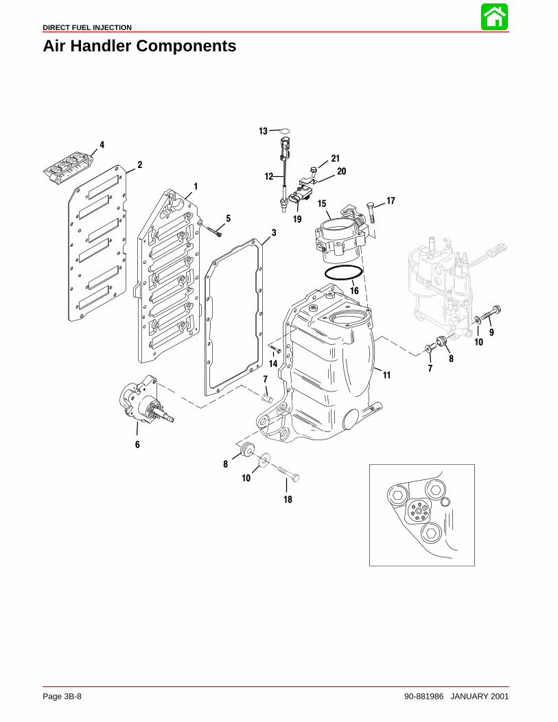
DIRECT FUEL INJECTION
Page 3B-8 90-881986 JANUARY 2001
Air Handler Components
1
12
2
3
5
6
7
8
10
11
15
16
17
9
8
714
10
18
4
13
19
20
21
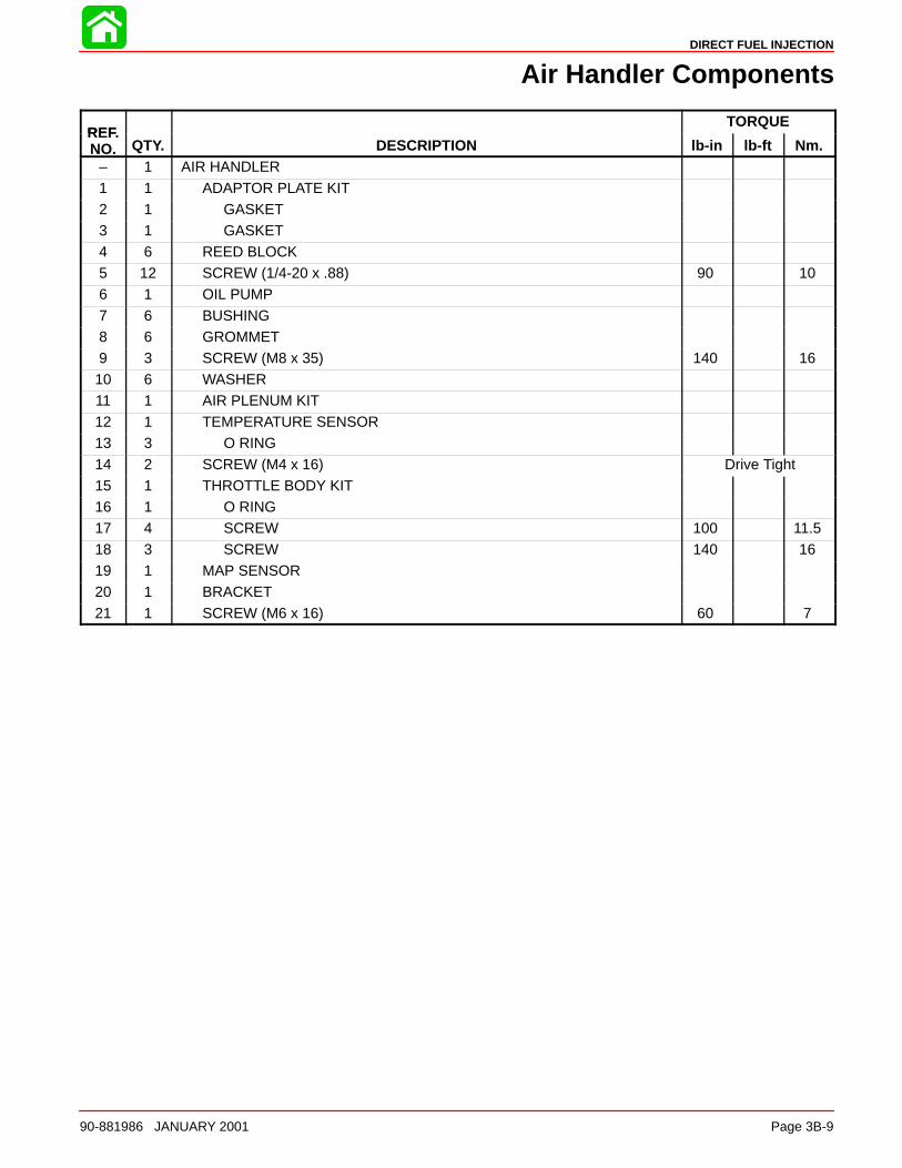
DIRECT FUEL INJECTION
90-881986 JANUARY 2001 Page 3B-9
Air Handler Components
REFTORQUE
REF.NO. QTY. DESCRIPTION lb-in lb-ft Nm.
– 1 AIR HANDLER
1 1 ADAPTOR PLATE KIT2 1 GASKET3 1 GASKET4 6 REED BLOCK 5 12 SCREW (1/4-20 x .88) 90 106 1 OIL PUMP
7 6 BUSHING8 6 GROMMET9 3 SCREW (M8 x 35) 140 1610 6 WASHER11 1 AIR PLENUM KIT12 1 TEMPERATURE SENSOR13 3 O RING
14 2 SCREW (M4 x 16) Drive Tight15 1 THROTTLE BODY KIT16 1 O RING17 4 SCREW 100 11.518 3 SCREW 140 1619 1 MAP SENSOR20 1 BRACKET
21 1 SCREW (M6 x 16) 60 7
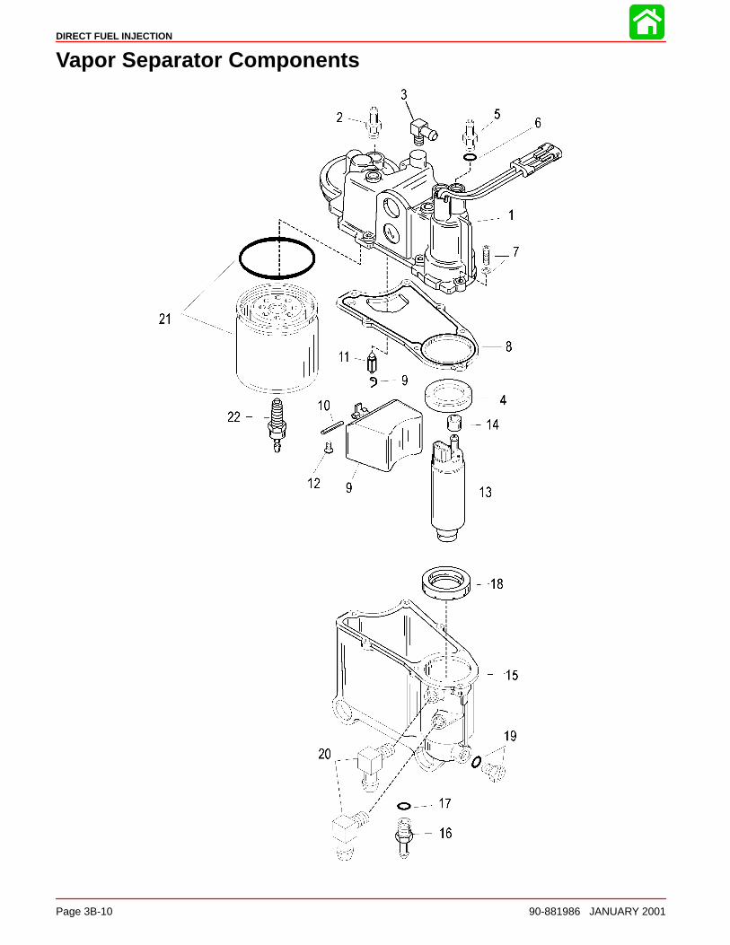
DIRECT FUEL INJECTION
Page 3B-10 90-881986 JANUARY 2001
Vapor Separator Components
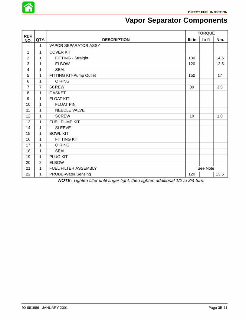
DIRECT FUEL INJECTION
90-881986 JANUARY 2001 Page 3B-11
Vapor Separator Components
REFTORQUE
REF.NO. QTY. DESCRIPTION lb-in lb-ft Nm.
– 1 VAPOR SEPARATOR ASSY
1 1 COVER KIT2 1 FITTING - Straight 130 14.53 1 ELBOW 120 13.54 1 SEAL5 1 FITTING KIT-Pump Outlet 150 176 1 O RING
7 7 SCREW 30 3.58 1 GASKET9 1 FLOAT KIT10 1 FLOAT PIN11 1 NEEDLE VALVE12 1 SCREW 10 1.0
13 1 FUEL PUMP KIT14 1 SLEEVE15 1 BOWL KIT16 1 FITTING KIT17 1 O RING18 1 SEAL19 1 PLUG KIT
20 2 ELBOW21 1 FUEL FILTER ASSEMBLY See Note22 1 PROBE-Water Sensing 120 13.5
NOTE: Tighten filter until finger tight, then tighten additional 1/2 to 3/4 turn.

DIRECT FUEL INJECTION
Page 3B-12 90-881986 JANUARY 2001
Air Hoses
1
3
6
7
1
4
2
5
98
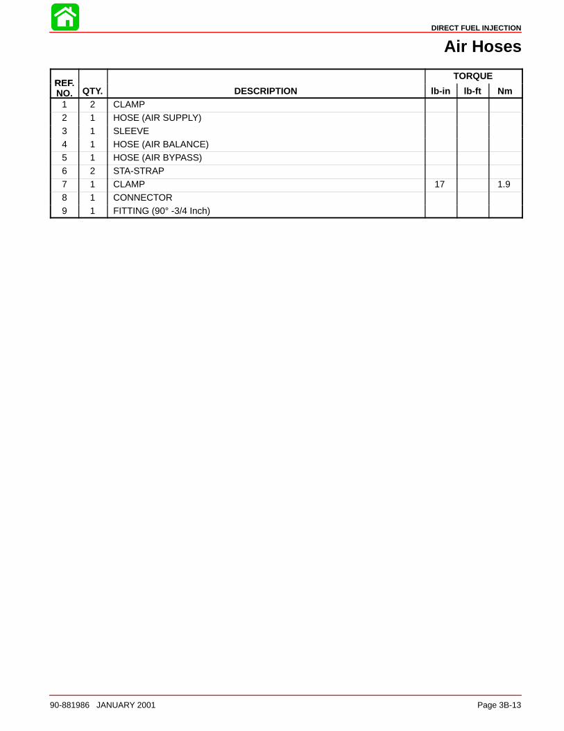
DIRECT FUEL INJECTION
90-881986 JANUARY 2001 Page 3B-13
Air Hoses
REFTORQUE
REF.NO. QTY. DESCRIPTION lb-in lb-ft Nm
1 2 CLAMP
2 1 HOSE (AIR SUPPLY)3 1 SLEEVE4 1 HOSE (AIR BALANCE)5 1 HOSE (AIR BYPASS)6 2 STA-STRAP7 1 CLAMP 17 1.9
8 1 CONNECTOR9 1 FITTING (90° -3/4 Inch)
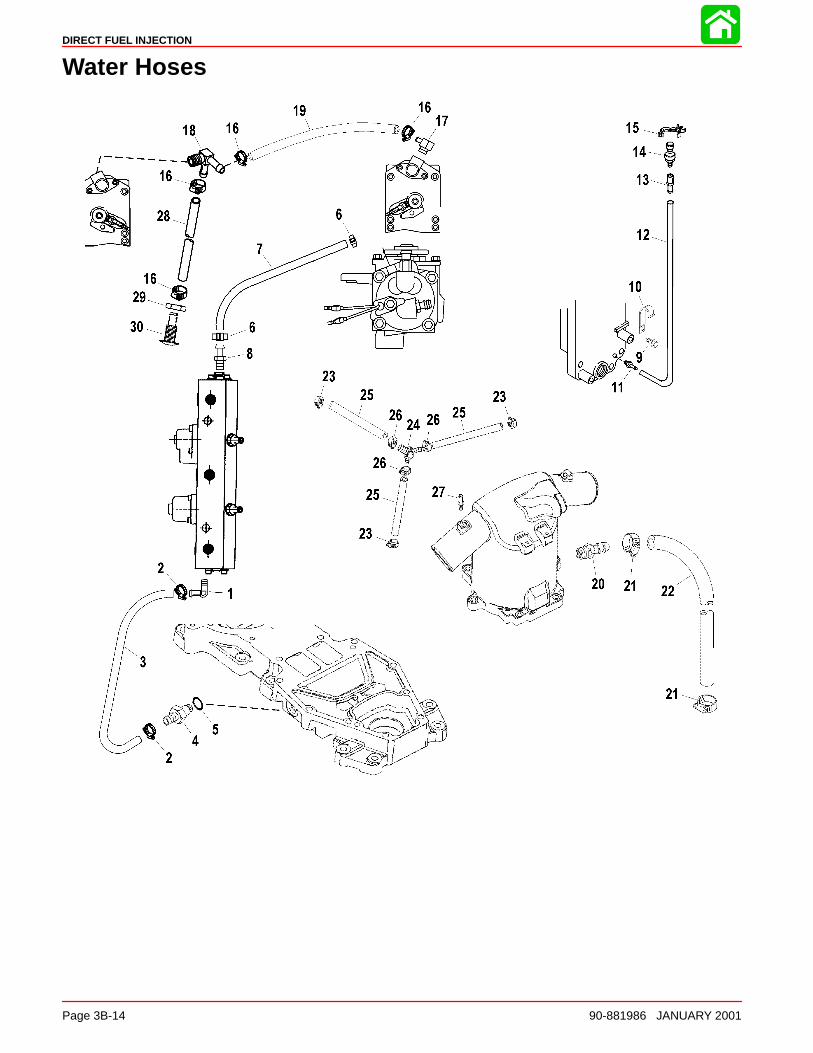
DIRECT FUEL INJECTION
Page 3B-14 90-881986 JANUARY 2001
Water Hoses
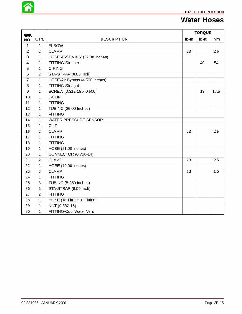
DIRECT FUEL INJECTION
90-881986 JANUARY 2001 Page 3B-15
Water Hoses
REFTORQUE
REF.NO. QTY. DESCRIPTION lb-in lb-ft Nm
1 1 ELBOW2 2 CLAMP 23 2.53 1 HOSE ASSEMBLY (32.00 Inches)4 1 FITTING-Strainer 40 545 1 O RING6 2 STA-STRAP (8.00 Inch)7 1 HOSE-Air Bypass (4.500 Inches)
8 1 FITTING-Straight9 1 SCREW (0.312-18 x 0.500) 13 17.510 1 J-CLIP11 1 FITTING12 1 TUBING (26.00 Inches)13 1 FITTING
14 1 WATER PRESSURE SENSOR15 1 CLIP16 2 CLAMP 23 2.517 1 FITTING18 1 FITTING19 1 HOSE (21.00 Inches)20 1 CONNECTOR (0.750-14)
21 2 CLAMP 23 2.522 1 HOSE (19.00 Inches)23 3 CLAMP 13 1.524 1 FITTING25 3 TUBING (5.250 Inches)26 3 STA-STRAP (8.00 Inch)27 2 FITTING
28 1 HOSE (To Thru Hull Fitting)29 1 NUT (0.562-18)30 1 FITTING-Cool Water Vent
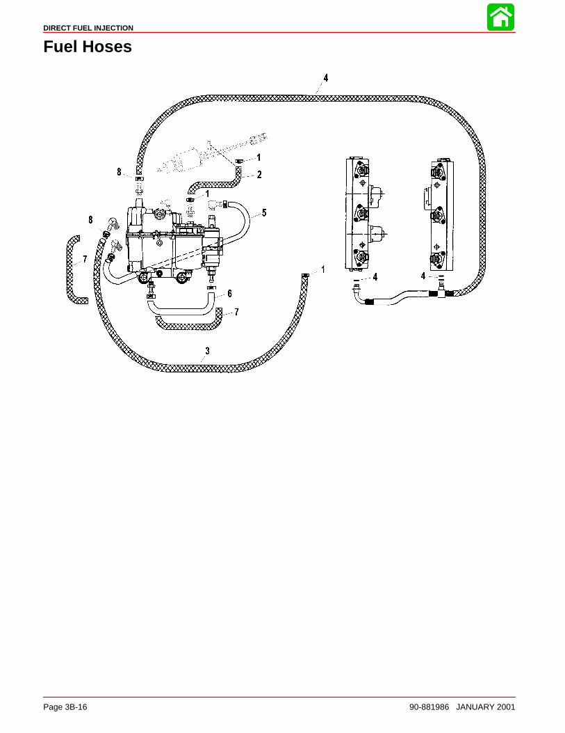
DIRECT FUEL INJECTION
Page 3B-16 90-881986 JANUARY 2001
Fuel Hoses
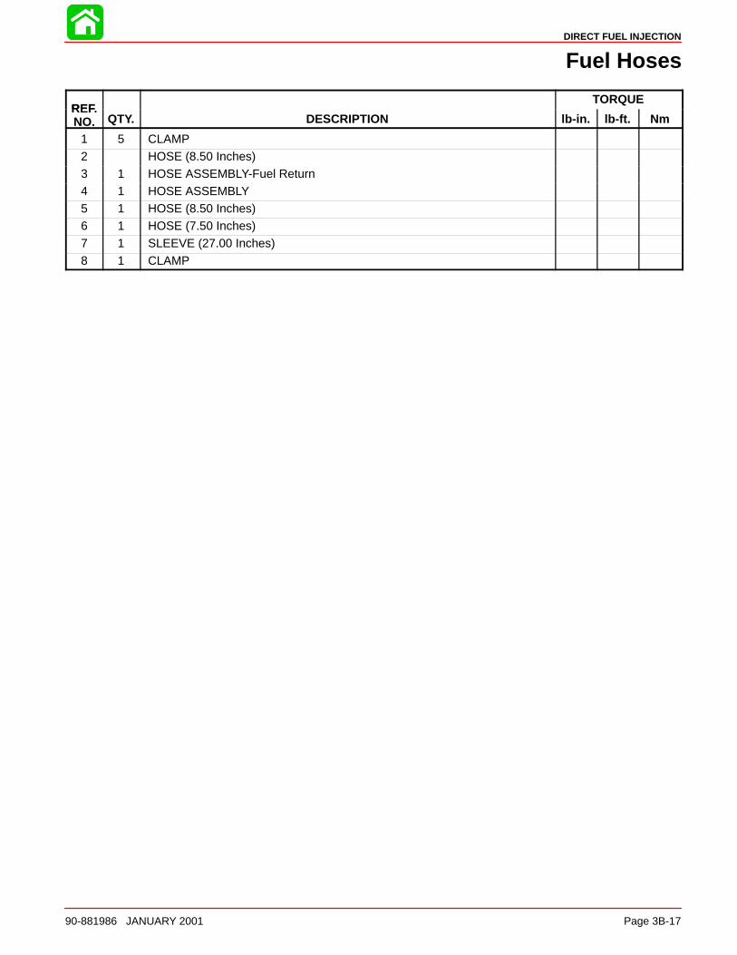
DIRECT FUEL INJECTION
90-881986 JANUARY 2001 Page 3B-17
Fuel Hoses
REFTORQUE
REF.NO. QTY. DESCRIPTION lb-in. lb-ft. Nm
1 5 CLAMP2 HOSE (8.50 Inches)3 1 HOSE ASSEMBLY-Fuel Return4 1 HOSE ASSEMBLY5 1 HOSE (8.50 Inches)6 1 HOSE (7.50 Inches)7 1 SLEEVE (27.00 Inches)
8 1 CLAMP
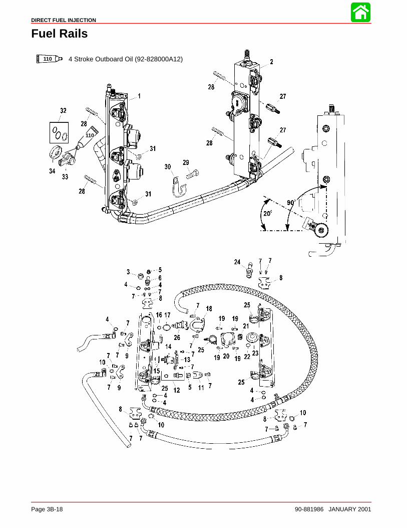
DIRECT FUEL INJECTION
Page 3B-18 90-881986 JANUARY 2001
Fuel Rails
4 Stroke Outboard Oil (92-828000A12)110
110
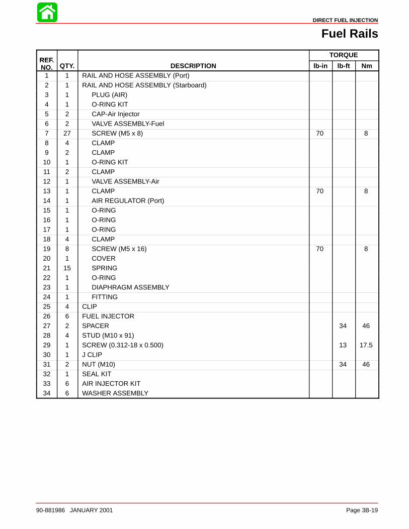
DIRECT FUEL INJECTION
90-881986 JANUARY 2001 Page 3B-19
Fuel Rails
REFTORQUE
REF.NO. QTY. DESCRIPTION lb-in lb-ft Nm
1 1 RAIL AND HOSE ASSEMBLY (Port)
2 1 RAIL AND HOSE ASSEMBLY (Starboard)3 1 PLUG (AIR)4 1 O-RING KIT5 2 CAP-Air Injector6 2 VALVE ASSEMBLY-Fuel7 27 SCREW (M5 x 8) 70 8
8 4 CLAMP9 2 CLAMP10 1 O-RING KIT11 2 CLAMP12 1 VALVE ASSEMBLY-Air13 1 CLAMP 70 814 1 AIR REGULATOR (Port)
15 1 O-RING16 1 O-RING17 1 O-RING18 4 CLAMP19 8 SCREW (M5 x 16) 70 820 1 COVER21 15 SPRING
22 1 O-RING23 1 DIAPHRAGM ASSEMBLY24 1 FITTING25 4 CLIP26 6 FUEL INJECTOR27 2 SPACER 34 4628 4 STUD (M10 x 91)
29 1 SCREW (0.312-18 x 0.500) 13 17.530 1 J CLIP31 2 NUT (M10) 34 4632 1 SEAL KIT33 6 AIR INJECTOR KIT34 6 WASHER ASSEMBLY
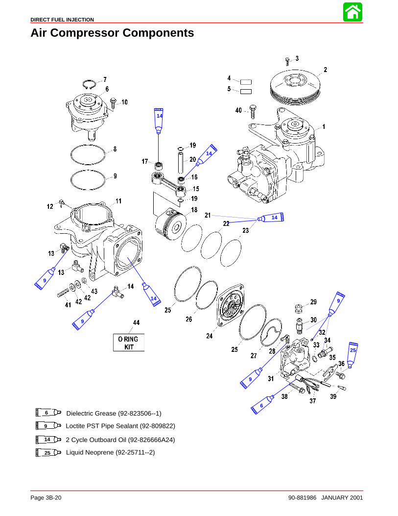
DIRECT FUEL INJECTION
Page 3B-20 90-881986 JANUARY 2001
Air Compressor Components
9
14
14
14
9
9
6
Dielectric Grease (92-823506--1)6
Loctite PST Pipe Sealant (92-809822)9
14 2 Cycle Outboard Oil (92-826666A24)
14
9
Liquid Neoprene (92-25711--2)
25
25
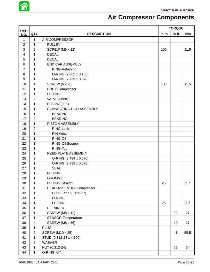
DIRECT FUEL INJECTION
90-881986 JANUARY 2001 Page 3B-21
Air Compressor Components
REFTORQUE
REF.NO. QTY. DESCRIPTION lb-in lb-ft Nm
1 1 AIR COMPRESSOR2 1 PULLEY3 5 SCREW (M6 x 12) 100 11.54 1 DECAL5 1 DECAL6 1 END CAP ASSEMBLY7 1 RING-Retaining
8 1 O-RING (2.862 x 0.103)9 1 O-RING (2.739 x 0.070)10 4 SCREW (6 x 20) 100 11.511 1 BODY-Compressor12 1 FITTING13 2 VALVE-Check
14 1 ELBOW (90° )15 1 CONNECTING ROD ASSEMBLY16 1 BEARING17 2 BEARING18 1 PISTON ASSEMBLY19 2 RING-Lock20 1 PIN-Wrist
21 1 RING-Oil22 1 RING-Oil Scraper23 1 RING-Top24 1 REED PLATE ASSEMBLY25 2 O-RING (3.489 x 0.070)26 1 O-RING (2.739 x 0.070)27 1 SEAL
28 1 FITTING29 1 GROMMET30 1 FITTING-Straight 25 2.731 1 HEAD ASSEMBLY-Compressor32 1 PLUG-Pipe (0.125-27)33 1 O-RING34 1 FITTING 25 2.7
35 1 RETAINER36 1 SCREW (M8 x 12) 20 2737 1 SENSOR-Temperature38 4 SCREW (M8 x 35) 20 2739 1 PLUG40 2 SCREW (M10 x 25) 41 55.541 1 STUD (0.312-24 x 4.190)
42 2 WASHER43 1 NUT (0.312-24) 25 3444 1 O-RING KIT
DIRECT FUEL INJECTION
Page 3B-22 90-881986 JANUARY 2001
DFI Operation
Air Induction Through CrankcaseCombustion air enters the bilge through air intakes of the boat. The air intakes on the boatdeck have hoses that route the air to bottom of bilge. This limits the exposure of salt airto the components inside the bilge.
Once inside the bilge, the air enters the plenum through the throttle shutter which is lo-cated in the plenum assembly. The air then continues through the reed valves and intothe crankcase. The throttle shutter is actuated by the throttle shaft. Mounted on a separateshaft is a throttle position sensor (TPS). This sensor tells the engine control unit (ECM)the position of the throttle.
If the TPS should fail, the warning horn will sound. Engine speed will be reduced by andthe ECM will reference the MAP sensor for fuel calibration.
Air Compressor SystemAir from inside the bilge is drawn into the compressor through the flywheel cover. This cov-er acts like a muffler to quiet compressor noise and contains a filter to prevent the inges-tion of debris into the compressor. The compressor is driven by a belt from a pulleymounted on the flywheel and is automatically self adjusted using a single idler pulley. Thisair compressor is a single cylinder unit containing a connecting rod, piston, rings, bear-ings, reed valves, and a crankshaft. The compressor is water cooled to lower the tempera-ture of the air charge and is lubricated by oil from the engine oil pump assembly. As thecompressor piston moves downward inside the cylinder, air is pulled through the filter,reed valves and into the cylinder. After the compressor piston changes direction, the in-take reeds close and the exhaust reeds open allowing compressed air into the hose lead-ing to the air/fuel rails.
The air/fuel rails contain two passages; one for fuel, the second is the air passage. Theair passage is common between all the cylinders included in the rail. A hose connects thestarboard rail air passage to the air compressor. Another hose connects the starboard airrail passage to the port air rail passage. An air pressure regulator will limit the amount ofpressure developed inside the air passages to approximately 10 psi below the pressureof the fuel inside the fuel passages (i.e. 80 psi air vs 90 psi fuel). Air exiting the pressureregulator is returned to the adaptor plate and exits thru the pump.
FuelFuel for the engine is stored in a typical fuel tank. A fuel lift pump draws fuel through thefuel line to a fuel pump assembly that pushes the fuel thru a water separating fuel filter.This filter removes any contaminates and water before the fuel reaches the vapor separa-tor. Fuel vapors are vented through a hose to the fuel tank. The electric fuel pump is differ-ent than the fuel pump that is utilized on the standard EFI engine (non DFI), and is capableof developing fuel pressures in excess of 90 psi. Fuel inside the rail must remain pressur-ized at exactly 10 psi over the air rail pressure or the ECM (map) calibrations will be incor-rect. Fuel from the vapor separator is supplied to the bottom of the starboard fuel rail. Afuel line connects the bottom of the first rail to the opposite fuel rail. Fuel is stored insidethe rail until an injector opens. A fuel pressure regulator controls pressure in the fuel rails,and allows excess fuel to return into the vapor separator. The fuel regulator not only regu-lates fuel pressure but also regulates it at approximately 10 p.s.i. higher than whateverthe air rail pressure is. The fuel regulator diaphragm is held closed with a spring that re-
DIRECT FUEL INJECTION
90-881986 JANUARY 2001 Page 3B-23
quires 10 p.s.i. to force the diaphragm off the diaphragm seat. The back side of the dia-phragm is exposed to air rail pressure. As the air rail pressure increases, the fuel pressureneeded to open the regulator will equally increase. Example: If there is 50 p.s.i. of air pres-sure on the air rail side of the diaphragm, 60 p.s.i. of fuel pressure will be required to openthe regulator. The port fuel rail is water cooled.
To equalize the pulses developed by the pumps (both air and fuel) a tracker diaphragmis installed in the starboard rail. The tracker diaphragm is positioned between the fuel andair passages. The tracker diaphragm is a rubber diaphragm which expands and retractsdepending upon which side of the diaphragm senses the pressure increase (pulse).
OilOil in this engine is not mixed with the fuel before entering the combustion chamber. Oilis stored inside a standard remote oil reservoir. Crankcase pressure will force oil from theremote oil tank into the oil reservoir on the side of the powerhead. Oil will flow from theoil reservoir into the oil pump. The oil pump is a solenoid design. It is activated by the ECMand includes 7 pistons with corresponding discharge ports. The oil pump is mounted di-rectly onto the powerhead. Each cylinder is lubricated by one of the discharge ports. Theoil is discharged into the crankcase. The seventh passage connects to the hose that leadsto the air compressor for lubrication. Excess oil from the compressor is returned to themain bearings.
The ECM will change the discharge rate of the oil pump, depending upon engine demand.The ECM will also pulse the pump on initial start up to fill the oil passages eliminating theneed to bleed the oil system. The ECM provides additional oil for break in, as determinedby its internal clock. The oil ratio varies with engine rpm and load.
ElectricalThe electrical system consists of the ECM, crank position sensor (flywheel speed & crank-shaft position), throttle position sensor (TPS), MAP sensor, engine temperature sen-sor(s), ignition coils and injectors (fuel & direct). The engine requires a battery to start (i.e.the ignition and injection will not occur if the battery is dead). The system will run off ofthe alternator.
OperationThe operation of the system happens in milliseconds (ms); exact timing is critical for en-gine performance. As the crankshaft rotates, air is drawn into the crankcase through thethrottle shutter, into the plenum and through the reed valves. As the piston nears bottom–dead–center, air from the crankcase is forced through the transfer system into the cylin-der. As the crankshaft continues to rotate the exhaust and intake ports close. With theseports closed, fuel can be injected into the cylinder. The ECM will receive a signal from thethrottle position sensor (TPS), engine temperature sensor (TS) and the crank positionsensor (flywheel speed and position sensor). With this information the ECM refers to thefuel calibration (maps) to determine when to activate (open and close) the injectors andfire the ignition coils. With the piston in the correct position, the ECM opens the fuel injec-tor, 90 psi fuel is discharged into a machined cavity inside the air chamber of the air/fuelrail. This mixes the fuel with the air charge. Next the direct injector will open, dischargingthe air/fuel mixture into the combustion chamber. The direct injector directs the mixtureat the bowl located in top of the piston. The piston’s bowl directs the air/fuel mixture intothe center of the combustion chamber. This air fuel mixture is then ignited by the sparkplug.
Compressor Notes: To aid in starting when the air rail pressure is low and before thecompressor has time to build pressure, some direct injectors are held open by the ECM.This allows the compression from inside the cylinders to pressurize the air rail faster (1or 2 strokes, or 60° of crankshaft rotation).
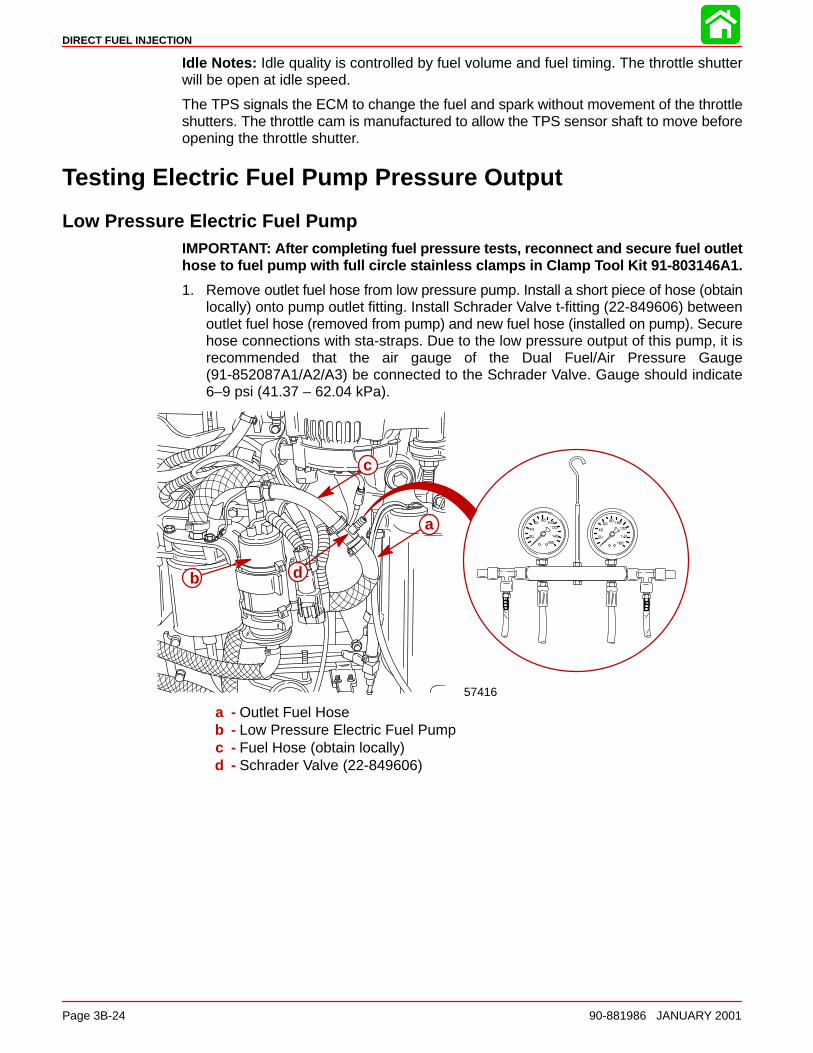
DIRECT FUEL INJECTION
Page 3B-24 90-881986 JANUARY 2001
Idle Notes: Idle quality is controlled by fuel volume and fuel timing. The throttle shutterwill be open at idle speed.
The TPS signals the ECM to change the fuel and spark without movement of the throttleshutters. The throttle cam is manufactured to allow the TPS sensor shaft to move beforeopening the throttle shutter.
Testing Electric Fuel Pump Pressure Output
Low Pressure Electric Fuel PumpIMPORTANT: After completing fuel pressure tests, reconnect and secure fuel outlethose to fuel pump with full circle stainless clamps in Clamp Tool Kit 91-803146A1.
1. Remove outlet fuel hose from low pressure pump. Install a short piece of hose (obtainlocally) onto pump outlet fitting. Install Schrader Valve t-fitting (22-849606) betweenoutlet fuel hose (removed from pump) and new fuel hose (installed on pump). Securehose connections with sta-straps. Due to the low pressure output of this pump, it isrecommended that the air gauge of the Dual Fuel/Air Pressure Gauge(91-852087A1/A2/A3) be connected to the Schrader Valve. Gauge should indicate6–9 psi (41.37 – 62.04 kPa).
57416
a
b
c
d
a - Outlet Fuel Hoseb - Low Pressure Electric Fuel Pumpc - Fuel Hose (obtain locally)d - Schrader Valve (22-849606)
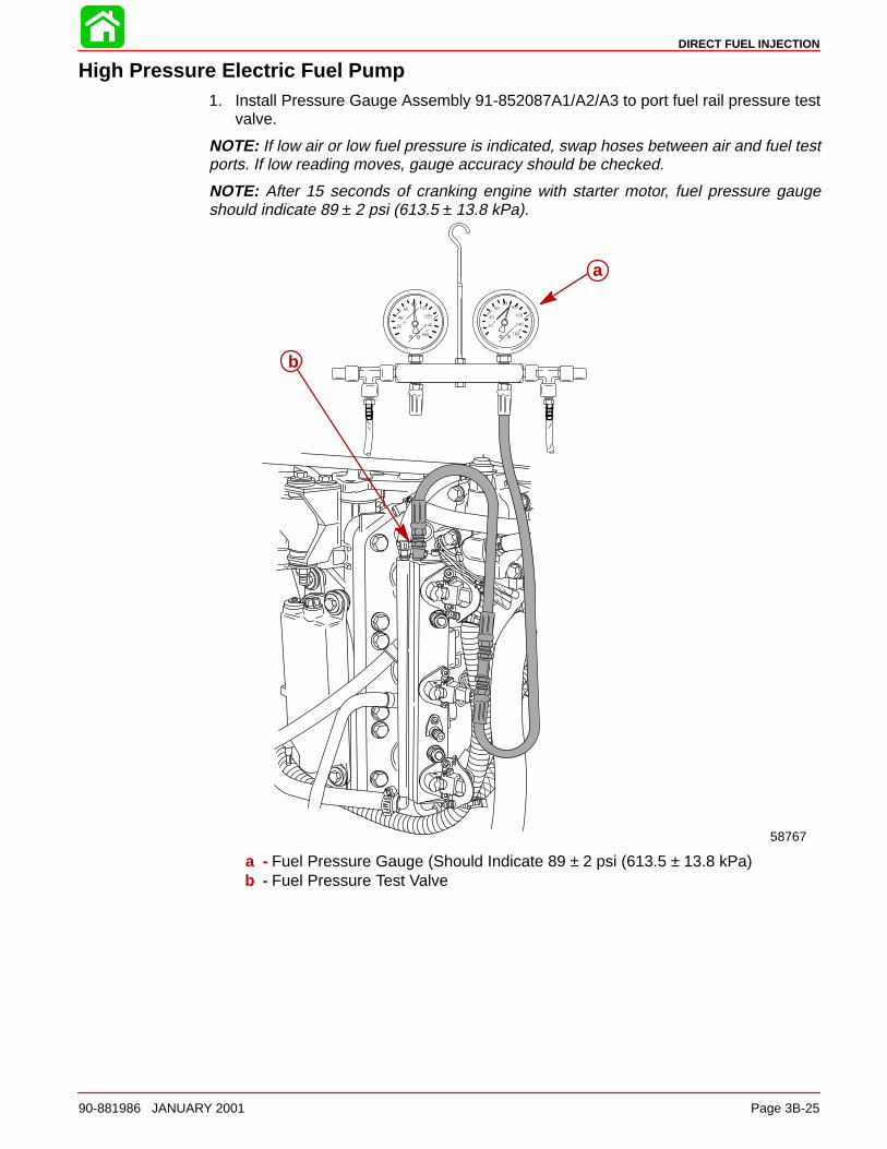
DIRECT FUEL INJECTION
90-881986 JANUARY 2001 Page 3B-25
High Pressure Electric Fuel Pump1. Install Pressure Gauge Assembly 91-852087A1/A2/A3 to port fuel rail pressure test
valve.
NOTE: If low air or low fuel pressure is indicated, swap hoses between air and fuel testports. If low reading moves, gauge accuracy should be checked.
NOTE: After 15 seconds of cranking engine with starter motor, fuel pressure gaugeshould indicate 89 ± 2 psi (613.5 ± 13.8 kPa).
58767
a
b
a - Fuel Pressure Gauge (Should Indicate 89 ± 2 psi (613.5 ± 13.8 kPa)b - Fuel Pressure Test Valve
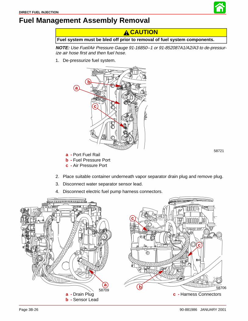
DIRECT FUEL INJECTION
Page 3B-26 90-881986 JANUARY 2001
Fuel Management Assembly Removal
CAUTIONFuel system must be bled off prior to removal of fuel system components.
NOTE: Use Fuel/Air Pressure Gauge 91-16850--1 or 91-852087A1/A2/A3 to de-pressur-ize air hose first and then fuel hose.
1. De-pressurize fuel system.
58721
b
c
a
a - Port Fuel Railb - Fuel Pressure Portc - Air Pressure Port
2. Place suitable container underneath vapor separator drain plug and remove plug.
3. Disconnect water separator sensor lead.
4. Disconnect electric fuel pump harness connectors.
a58709
b
c
c
58706
a - Drain Plugb - Sensor Lead
c - Harness Connectors
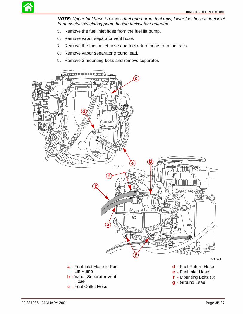
DIRECT FUEL INJECTION
90-881986 JANUARY 2001 Page 3B-27
NOTE: Upper fuel hose is excess fuel return from fuel rails; lower fuel hose is fuel inletfrom electric circulating pump beside fuel/water separator.
5. Remove the fuel inlet hose from the fuel lift pump.
6. Remove vapor separator vent hose.
7. Remove the fuel outlet hose and fuel return hose from fuel rails.
8. Remove vapor separator ground lead.
9. Remove 3 mounting bolts and remove separator.
a
b
d
e
f
f
c
58740
58709g
a - Fuel Inlet Hose to FuelLift Pump
b - Vapor Separator VentHose
c - Fuel Outlet Hose
d - Fuel Return Hosee - Fuel Inlet Hosef - Mounting Bolts (3)g - Ground Lead
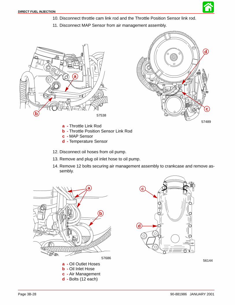
DIRECT FUEL INJECTION
Page 3B-28 90-881986 JANUARY 2001
10. Disconnect throttle cam link rod and the Throttle Position Sensor link rod.
11. Disconnect MAP Sensor from air management assembly.
57538
c
57489
a
b
d
a - Throttle Link Rodb - Throttle Position Sensor Link Rodc - MAP Sensord - Temperature Sensor
12. Disconnect oil hoses from oil pump.
13. Remove and plug oil inlet hose to oil pump.
14. Remove 12 bolts securing air management assembly to crankcase and remove as-sembly.
56144
b
ac
d
b
57686
a
a - Oil Outlet Hosesb - Oil Inlet Hosec - Air Managementd - Bolts (12 each)
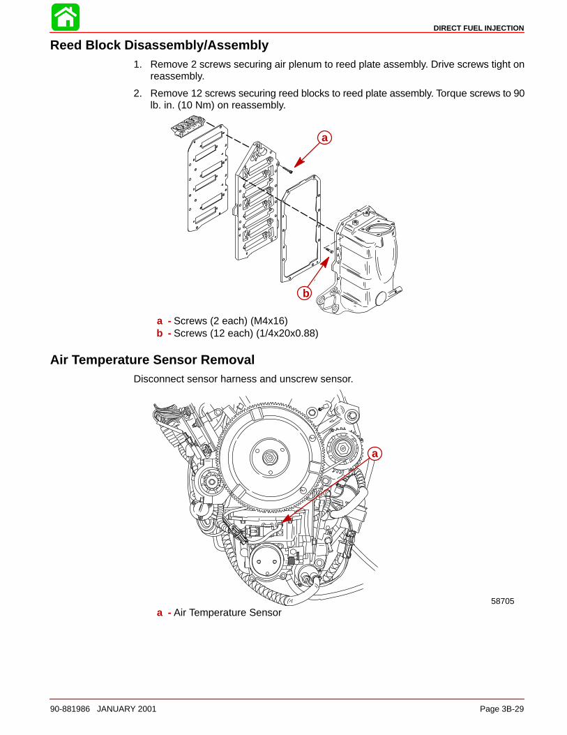
DIRECT FUEL INJECTION
90-881986 JANUARY 2001 Page 3B-29
Reed Block Disassembly/Assembly1. Remove 2 screws securing air plenum to reed plate assembly. Drive screws tight on
reassembly.
2. Remove 12 screws securing reed blocks to reed plate assembly. Torque screws to 90lb. in. (10 Nm) on reassembly.
a
b
a - Screws (2 each) (M4x16)b - Screws (12 each) (1/4x20x0.88)
Air Temperature Sensor RemovalDisconnect sensor harness and unscrew sensor.
a
58705a - Air Temperature Sensor
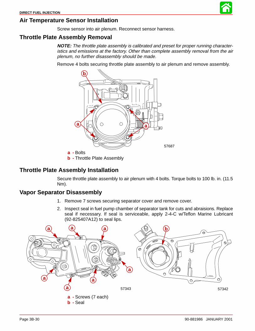
DIRECT FUEL INJECTION
Page 3B-30 90-881986 JANUARY 2001
Air Temperature Sensor InstallationScrew sensor into air plenum. Reconnect sensor harness.
Throttle Plate Assembly RemovalNOTE: The throttle plate assembly is calibrated and preset for proper running character-istics and emissions at the factory. Other than complete assembly removal from the airplenum, no further disassembly should be made.
Remove 4 bolts securing throttle plate assembly to air plenum and remove assembly.
a a
b
57687
a - Boltsb - Throttle Plate Assembly
Throttle Plate Assembly InstallationSecure throttle plate assembly to air plenum with 4 bolts. Torque bolts to 100 lb. in. (11.5Nm).
Vapor Separator Disassembly1. Remove 7 screws securing separator cover and remove cover.
2. Inspect seal in fuel pump chamber of separator tank for cuts and abraisions. Replaceseal if necessary. If seal is serviceable, apply 2-4-C w/Teflon Marine Lubricant(92-825407A12) to seal lips.
b
57342
aaa
a
a
a
a
57343
a - Screws (7 each)b - Seal
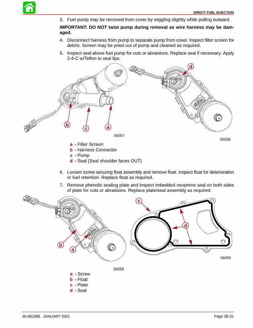
DIRECT FUEL INJECTION
90-881986 JANUARY 2001 Page 3B-31
3. Fuel pump may be removed from cover by wiggling slightly while pulling outward.
IMPORTANT: DO NOT twist pump during removal as wire harness may be dam-aged.
4. Disconnect harness from pump to separate pump from cover. Inspect filter screen fordebris. Screen may be pried out of pump and cleaned as required.
5. Inspect seal above fuel pump for cuts or abraisions. Replace seal if necessary. Apply2-4-C w/Teflon to seal lips.
5605856057
cb
cb a
d
a - Filter Screenb - Harness Connectorc - Pumpd - Seal (Seal shoulder faces OUT)
6. Loosen screw securing float assembly and remove float. Inspect float for deteriorationor fuel retention. Replace float as required.
7. Remove phenolic sealing plate and inspect imbedded neoprene seal on both sidesof plate for cuts or abraisions. Replace plate/seal assembly as required.
56059
ac
d
56058
baa
b
a - Screwb - Floatc - Plated - Seal
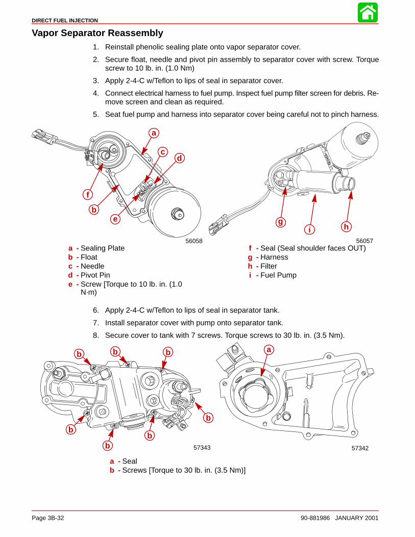
DIRECT FUEL INJECTION
Page 3B-32 90-881986 JANUARY 2001
Vapor Separator Reassembly1. Reinstall phenolic sealing plate onto vapor separator cover.
2. Secure float, needle and pivot pin assembly to separator cover with screw. Torquescrew to 10 lb. in. (1.0 Nm)
3. Apply 2-4-C w/Teflon to lips of seal in separator cover.
4. Connect electrical harness to fuel pump. Inspect fuel pump filter screen for debris. Re-move screen and clean as required.
5. Seat fuel pump and harness into separator cover being careful not to pinch harness.
56057
cag hi
56058
be
d
a
c
f
a
b
cd
e
a - Sealing Plateb - Floatc - Needled - Pivot Pine - Screw [Torque to 10 lb. in. (1.0
N·m)
f - Seal (Seal shoulder faces OUT)g - Harnessh - Filteri - Fuel Pump
6. Apply 2-4-C w/Teflon to lips of seal in separator tank.
7. Install separator cover with pump onto separator tank.
8. Secure cover to tank with 7 screws. Torque screws to 30 lb. in. (3.5 Nm).
5734257343
ab
b
bb
b
b b
a - Sealb - Screws [Torque to 30 lb. in. (3.5 Nm)]
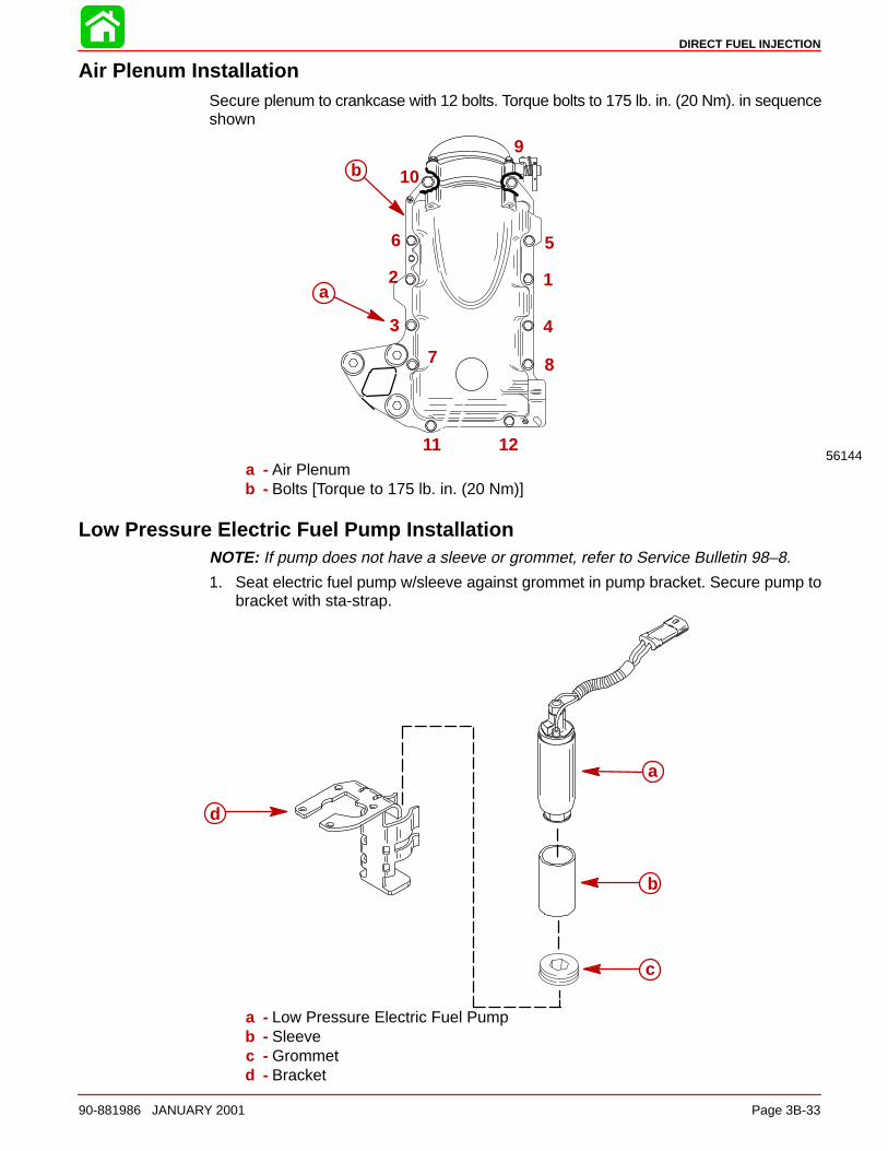
DIRECT FUEL INJECTION
90-881986 JANUARY 2001 Page 3B-33
Air Plenum InstallationSecure plenum to crankcase with 12 bolts. Torque bolts to 175 lb. in. (20 Nm). in sequenceshown
12
3 4
56
7 8
9
10
11 12
a
b
56144a - Air Plenumb - Bolts [Torque to 175 lb. in. (20 Nm)]
Low Pressure Electric Fuel Pump InstallationNOTE: If pump does not have a sleeve or grommet, refer to Service Bulletin 98–8.
1. Seat electric fuel pump w/sleeve against grommet in pump bracket. Secure pump tobracket with sta-strap.
d
a
b
c
a - Low Pressure Electric Fuel Pumpb - Sleevec - Grommetd - Bracket
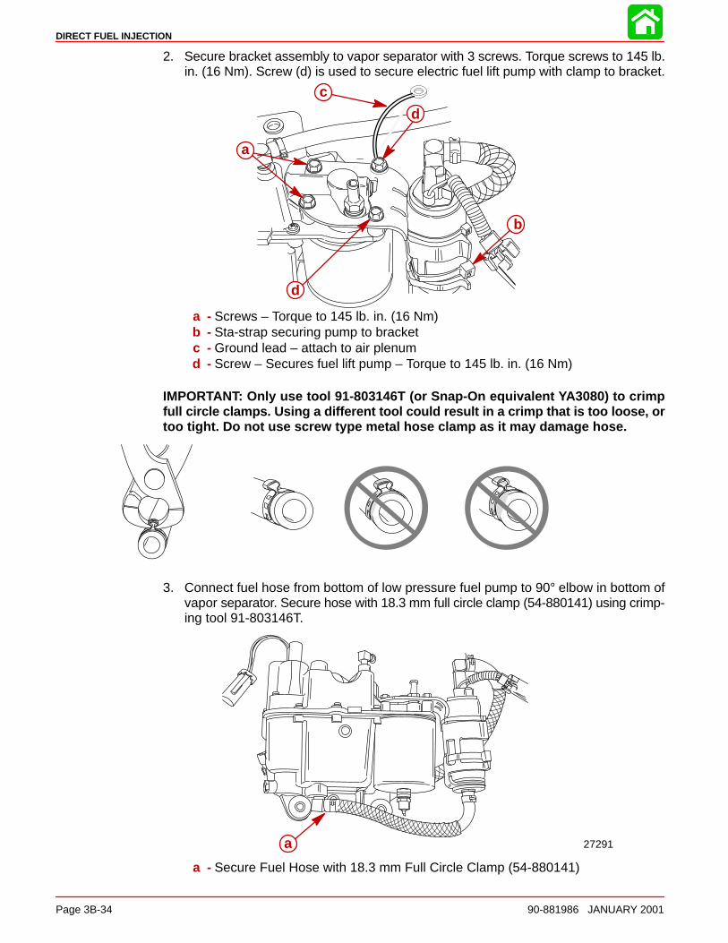
DIRECT FUEL INJECTION
Page 3B-34 90-881986 JANUARY 2001
2. Secure bracket assembly to vapor separator with 3 screws. Torque screws to 145 lb.in. (16 Nm). Screw (d) is used to secure electric fuel lift pump with clamp to bracket.
a
b
c
d
d
a - Screws – Torque to 145 lb. in. (16 Nm)b - Sta-strap securing pump to bracketc - Ground lead – attach to air plenumd - Screw – Secures fuel lift pump – Torque to 145 lb. in. (16 Nm)
IMPORTANT: Only use tool 91-803146T (or Snap-On equivalent YA3080) to crimpfull circle clamps. Using a different tool could result in a crimp that is too loose, ortoo tight. Do not use screw type metal hose clamp as it may damage hose.
3. Connect fuel hose from bottom of low pressure fuel pump to 90° elbow in bottom ofvapor separator. Secure hose with 18.3 mm full circle clamp (54-880141) using crimp-ing tool 91-803146T.
a 27291
a - Secure Fuel Hose with 18.3 mm Full Circle Clamp (54-880141)
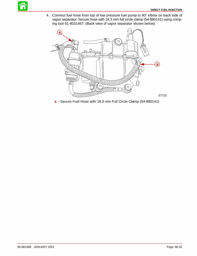
DIRECT FUEL INJECTION
90-881986 JANUARY 2001 Page 3B-35
4. Connect fuel hose from top of low pressure fuel pump to 90° elbow on back side ofvapor separator. Secure hose with 18.3 mm full circle clamp (54-880141) using crimp-ing tool 91-803146T. (Back view of vapor separator shown below)
a
57723
a
a - Secure Fuel Hose with 18.3 mm Full Circle Clamp (54-880141)
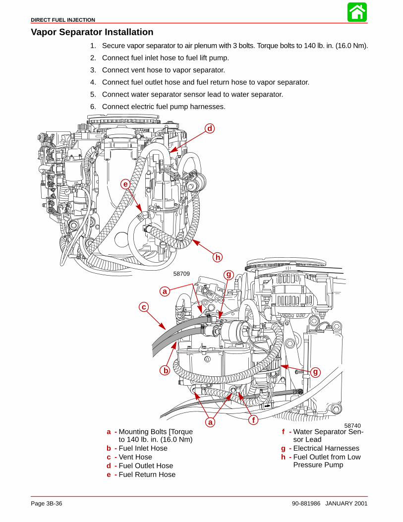
DIRECT FUEL INJECTION
Page 3B-36 90-881986 JANUARY 2001
Vapor Separator Installation1. Secure vapor separator to air plenum with 3 bolts. Torque bolts to 140 lb. in. (16.0 Nm).
2. Connect fuel inlet hose to fuel lift pump.
3. Connect vent hose to vapor separator.
4. Connect fuel outlet hose and fuel return hose to vapor separator.
5. Connect water separator sensor lead to water separator.
6. Connect electric fuel pump harnesses.
a
b
d
e
c
58740
58709
a
f
g
g
h
a - Mounting Bolts [Torqueto 140 lb. in. (16.0 Nm)
b - Fuel Inlet Hosec - Vent Hosed - Fuel Outlet Hosee - Fuel Return Hose
f - Water Separator Sen-sor Lead
g - Electrical Harnessesh - Fuel Outlet from Low
Pressure Pump
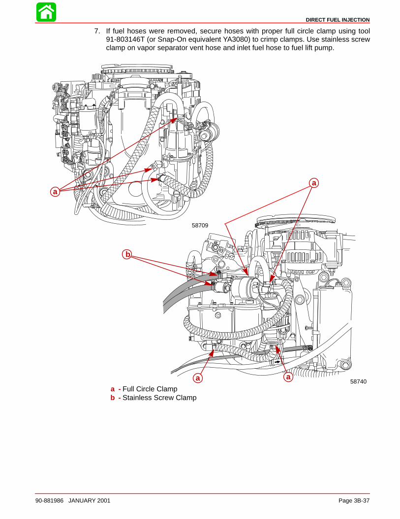
DIRECT FUEL INJECTION
90-881986 JANUARY 2001 Page 3B-37
7. If fuel hoses were removed, secure hoses with proper full circle clamp using tool91-803146T (or Snap-On equivalent YA3080) to crimp clamps. Use stainless screwclamp on vapor separator vent hose and inlet fuel hose to fuel lift pump.
58709
58740
a
a
a
a
b
a - Full Circle Clampb - Stainless Screw Clamp
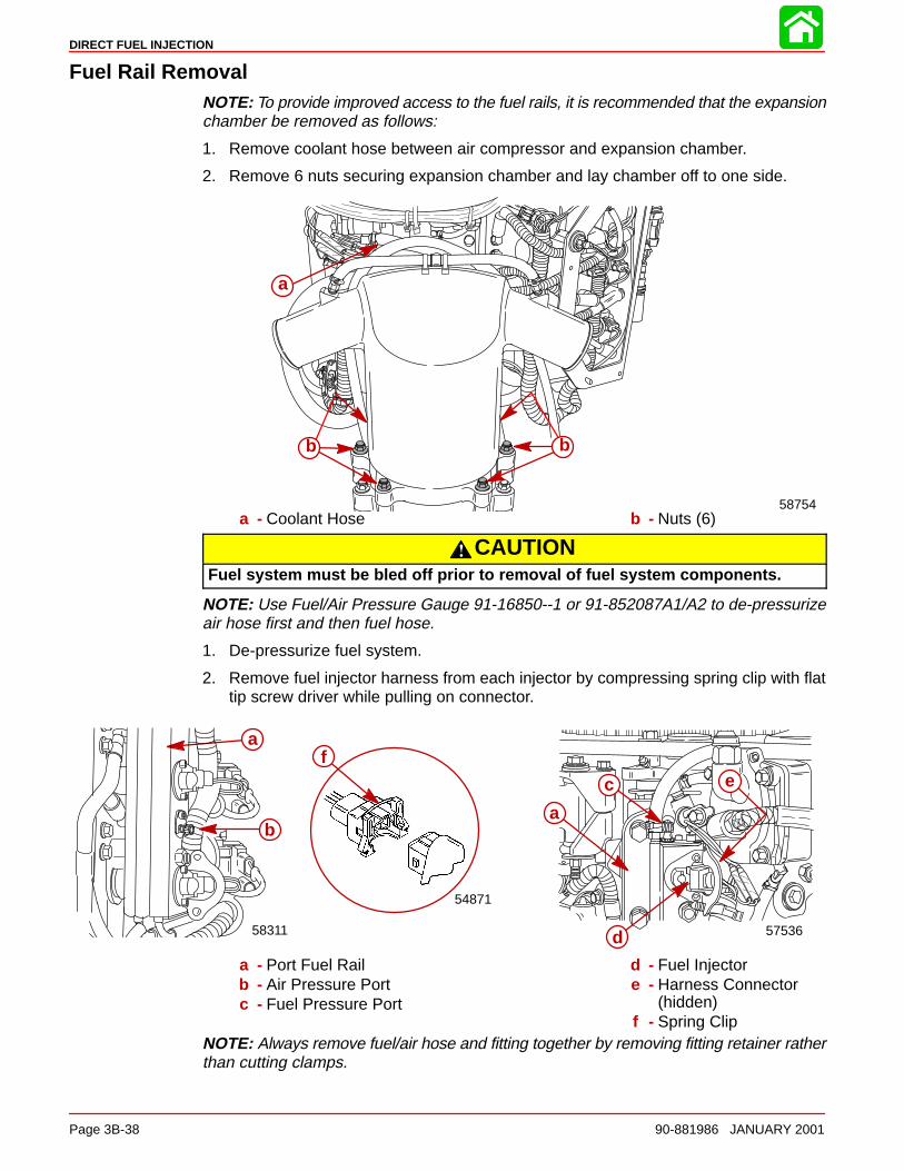
DIRECT FUEL INJECTION
Page 3B-38 90-881986 JANUARY 2001
Fuel Rail RemovalNOTE: To provide improved access to the fuel rails, it is recommended that the expansionchamber be removed as follows:
1. Remove coolant hose between air compressor and expansion chamber.
2. Remove 6 nuts securing expansion chamber and lay chamber off to one side.
58754
a
b b
a - Coolant Hose b - Nuts (6)
CAUTIONFuel system must be bled off prior to removal of fuel system components.
NOTE: Use Fuel/Air Pressure Gauge 91-16850--1 or 91-852087A1/A2 to de-pressurizeair hose first and then fuel hose.
1. De-pressurize fuel system.
2. Remove fuel injector harness from each injector by compressing spring clip with flattip screw driver while pulling on connector.
a
57536
c
d
54871
fe
a
58311
b
a - Port Fuel Railb - Air Pressure Portc - Fuel Pressure Port
d - Fuel Injectore - Harness Connector
(hidden)f - Spring Clip
NOTE: Always remove fuel/air hose and fitting together by removing fitting retainer ratherthan cutting clamps.
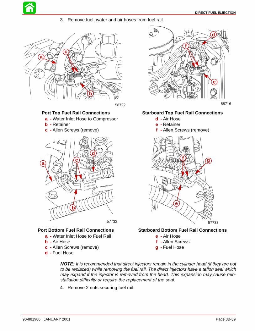
DIRECT FUEL INJECTION
90-881986 JANUARY 2001 Page 3B-39
3. Remove fuel, water and air hoses from fuel rail.
ac
b
58722 58716
f
e
d
Port Top Fuel Rail Connections Starboard Top Fuel Rail Connectionsa - Water Inlet Hose to Compressorb - Retainerc - Allen Screws (remove)
d - Air Hosee - Retainerf - Allen Screws (remove)
57732 57733
a
b
cd
f g
e
Port Bottom Fuel Rail Connections Starboard Bottom Fuel Rail Connectionsa - Water Inlet Hose to Fuel Railb - Air Hosec - Allen Screws (remove)d - Fuel Hose
e - Air Hosef - Allen Screwsg - Fuel Hose
NOTE: It is recommended that direct injectors remain in the cylinder head (if they are notto be replaced) while removing the fuel rail. The direct injectors have a teflon seal whichmay expand if the injector is removed from the head. This expansion may cause rein-stallation difficulty or require the replacement of the seal.
4. Remove 2 nuts securing fuel rail.
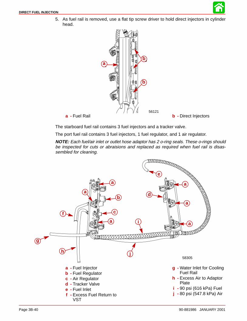
DIRECT FUEL INJECTION
Page 3B-40 90-881986 JANUARY 2001
5. As fuel rail is removed, use a flat tip screw driver to hold direct injectors in cylinderhead.
56121
ab
b
ab
b
a - Fuel Rail b - Direct Injectors
The starboard fuel rail contains 3 fuel injectors and a tracker valve.
The port fuel rail contains 3 fuel injectors, 1 fuel regulator, and 1 air regulator.
NOTE: Each fuel/air inlet or outlet hose adaptor has 2 o-ring seals. These o-rings shouldbe inspected for cuts or abraisions and replaced as required when fuel rail is disas-sembled for cleaning.
da
a
a
b
c
e
f
a
a
a
g
h
i
j58305
a - Fuel Injectorb - Fuel Regulatorc - Air Regulatord - Tracker Valvee - Fuel Inletf - Excess Fuel Return to
VST
g - Water Inlet for CoolingFuel Rail
h - Excess Air to AdaptorPlate
i - 90 psi (616 kPa) Fuelj - 80 psi (547.8 kPa) Air
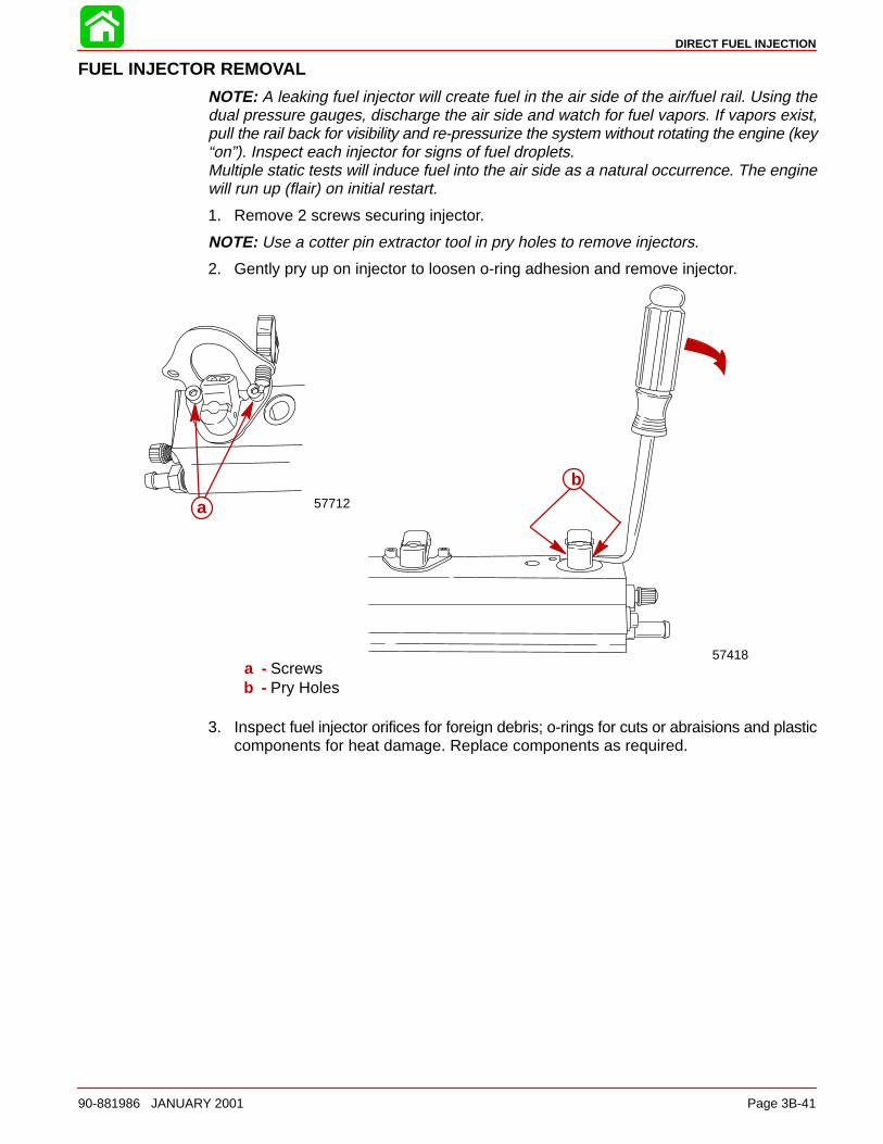
DIRECT FUEL INJECTION
90-881986 JANUARY 2001 Page 3B-41
FUEL INJECTOR REMOVAL
NOTE: A leaking fuel injector will create fuel in the air side of the air/fuel rail. Using thedual pressure gauges, discharge the air side and watch for fuel vapors. If vapors exist,pull the rail back for visibility and re-pressurize the system without rotating the engine (key“on”). Inspect each injector for signs of fuel droplets.Multiple static tests will induce fuel into the air side as a natural occurrence. The enginewill run up (flair) on initial restart.
1. Remove 2 screws securing injector.
NOTE: Use a cotter pin extractor tool in pry holes to remove injectors.
2. Gently pry up on injector to loosen o-ring adhesion and remove injector.
b
57418
a 57712
a - Screwsb - Pry Holes
3. Inspect fuel injector orifices for foreign debris; o-rings for cuts or abraisions and plasticcomponents for heat damage. Replace components as required.
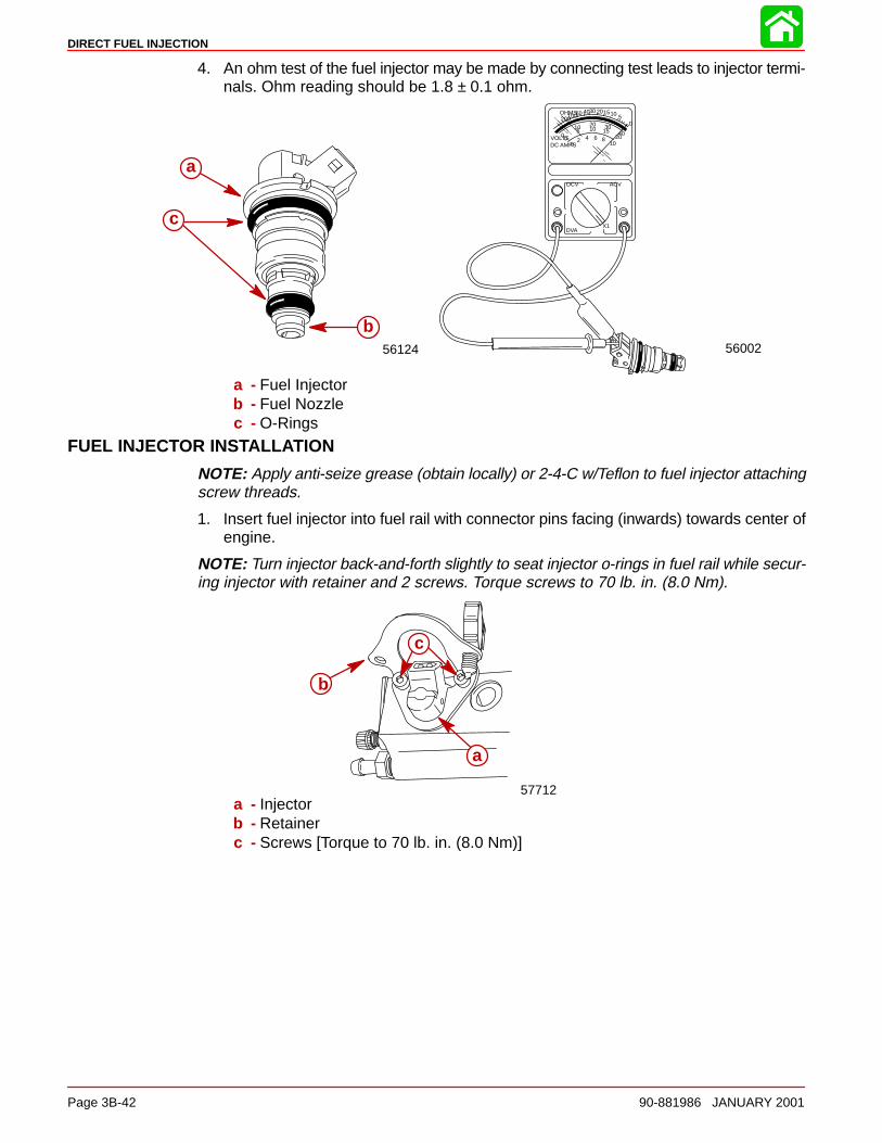
DIRECT FUEL INJECTION
Page 3B-42 90-881986 JANUARY 2001
4. An ohm test of the fuel injector may be made by connecting test leads to injector termi-nals. Ohm reading should be 1.8 ± 0.1 ohm.
VOLTSDC AMPS
OHMS
02 4 6 8
10
DCV ACV
DVA
005
10 2010 30
15 4020
05101520304060100200
X1
5600256124
a
b
c
a
b
c
a - Fuel Injectorb - Fuel Nozzlec - O-Rings
FUEL INJECTOR INSTALLATION
NOTE: Apply anti-seize grease (obtain locally) or 2-4-C w/Teflon to fuel injector attachingscrew threads.
1. Insert fuel injector into fuel rail with connector pins facing (inwards) towards center ofengine.
NOTE: Turn injector back-and-forth slightly to seat injector o-rings in fuel rail while secur-ing injector with retainer and 2 screws. Torque screws to 70 lb. in. (8.0 Nm).
57712
a
c
b
a - Injectorb - Retainerc - Screws [Torque to 70 lb. in. (8.0 Nm)]
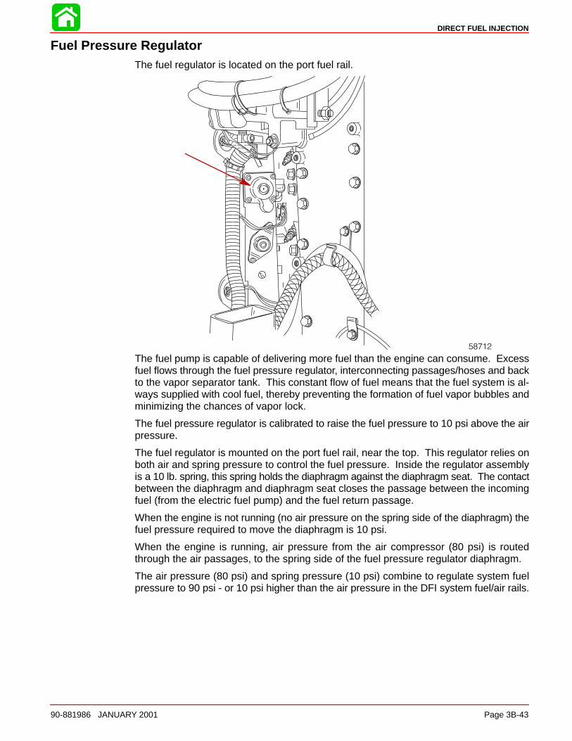
DIRECT FUEL INJECTION
90-881986 JANUARY 2001 Page 3B-43
Fuel Pressure RegulatorThe fuel regulator is located on the port fuel rail.
58712
The fuel pump is capable of delivering more fuel than the engine can consume. Excessfuel flows through the fuel pressure regulator, interconnecting passages/hoses and backto the vapor separator tank. This constant flow of fuel means that the fuel system is al-ways supplied with cool fuel, thereby preventing the formation of fuel vapor bubbles andminimizing the chances of vapor lock.
The fuel pressure regulator is calibrated to raise the fuel pressure to 10 psi above the airpressure.
The fuel regulator is mounted on the port fuel rail, near the top. This regulator relies onboth air and spring pressure to control the fuel pressure. Inside the regulator assemblyis a 10 lb. spring, this spring holds the diaphragm against the diaphragm seat. The contactbetween the diaphragm and diaphragm seat closes the passage between the incomingfuel (from the electric fuel pump) and the fuel return passage.
When the engine is not running (no air pressure on the spring side of the diaphragm) thefuel pressure required to move the diaphragm is 10 psi.
When the engine is running, air pressure from the air compressor (80 psi) is routedthrough the air passages, to the spring side of the fuel pressure regulator diaphragm.
The air pressure (80 psi) and spring pressure (10 psi) combine to regulate system fuelpressure to 90 psi - or 10 psi higher than the air pressure in the DFI system fuel/air rails.
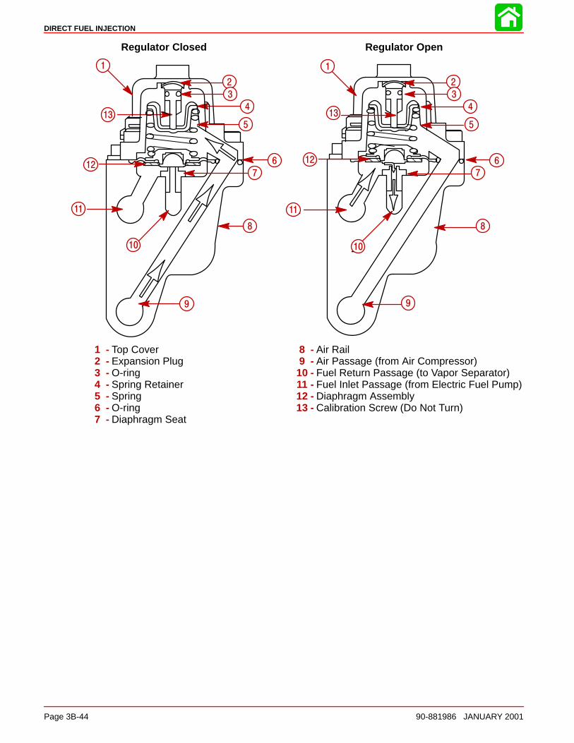
DIRECT FUEL INJECTION
Page 3B-44 90-881986 JANUARY 2001
Regulator Closed Regulator Open
ÇÇÇÇÇ ÇÇ ÇÇ
1
23
4
5
67
8
9
10
11
12
13
1
23
4
5
67
8
9
10
11
1
2
3
4
5
6
7
8
9
10
11
12
13
1
2
3
4
5
6
7
8
9
10
11
12
13
1 - Top Cover2 - Expansion Plug3 - O-ring4 - Spring Retainer5 - Spring6 - O-ring7 - Diaphragm Seat
8 - Air Rail9 - Air Passage (from Air Compressor)
10 - Fuel Return Passage (to Vapor Separator)11 - Fuel Inlet Passage (from Electric Fuel Pump)12 - Diaphragm Assembly13 - Calibration Screw (Do Not Turn)
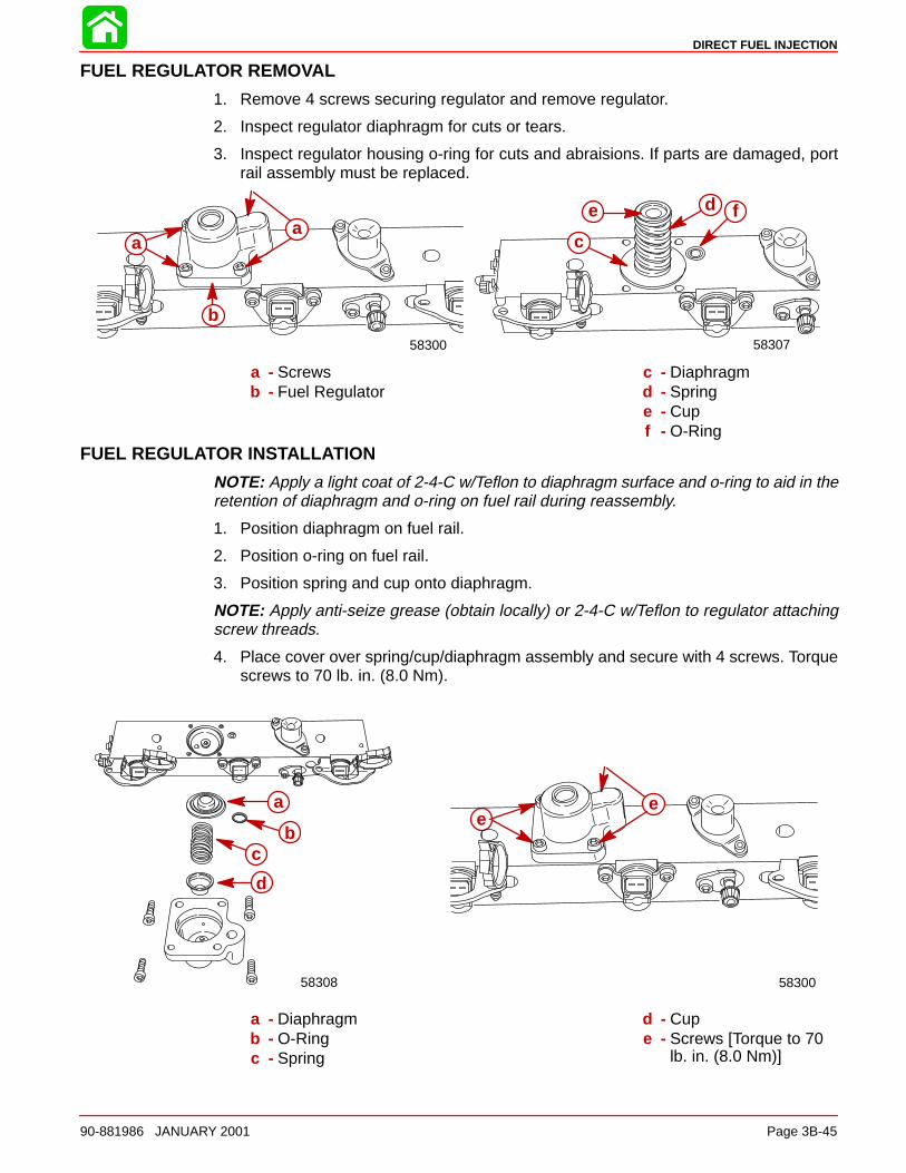
DIRECT FUEL INJECTION
90-881986 JANUARY 2001 Page 3B-45
FUEL REGULATOR REMOVAL
1. Remove 4 screws securing regulator and remove regulator.
2. Inspect regulator diaphragm for cuts or tears.
3. Inspect regulator housing o-ring for cuts and abraisions. If parts are damaged, portrail assembly must be replaced.
b
58300
aa
fd
c
e
58307
a - Screwsb - Fuel Regulator
c - Diaphragmd - Springe - Cupf - O-Ring
FUEL REGULATOR INSTALLATION
NOTE: Apply a light coat of 2-4-C w/Teflon to diaphragm surface and o-ring to aid in theretention of diaphragm and o-ring on fuel rail during reassembly.
1. Position diaphragm on fuel rail.
2. Position o-ring on fuel rail.
3. Position spring and cup onto diaphragm.
NOTE: Apply anti-seize grease (obtain locally) or 2-4-C w/Teflon to regulator attachingscrew threads.
4. Place cover over spring/cup/diaphragm assembly and secure with 4 screws. Torquescrews to 70 lb. in. (8.0 Nm).
e
58300
ea
bc
d
58308
a - Diaphragmb - O-Ringc - Spring
d - Cupe - Screws [Torque to 70
lb. in. (8.0 Nm)]
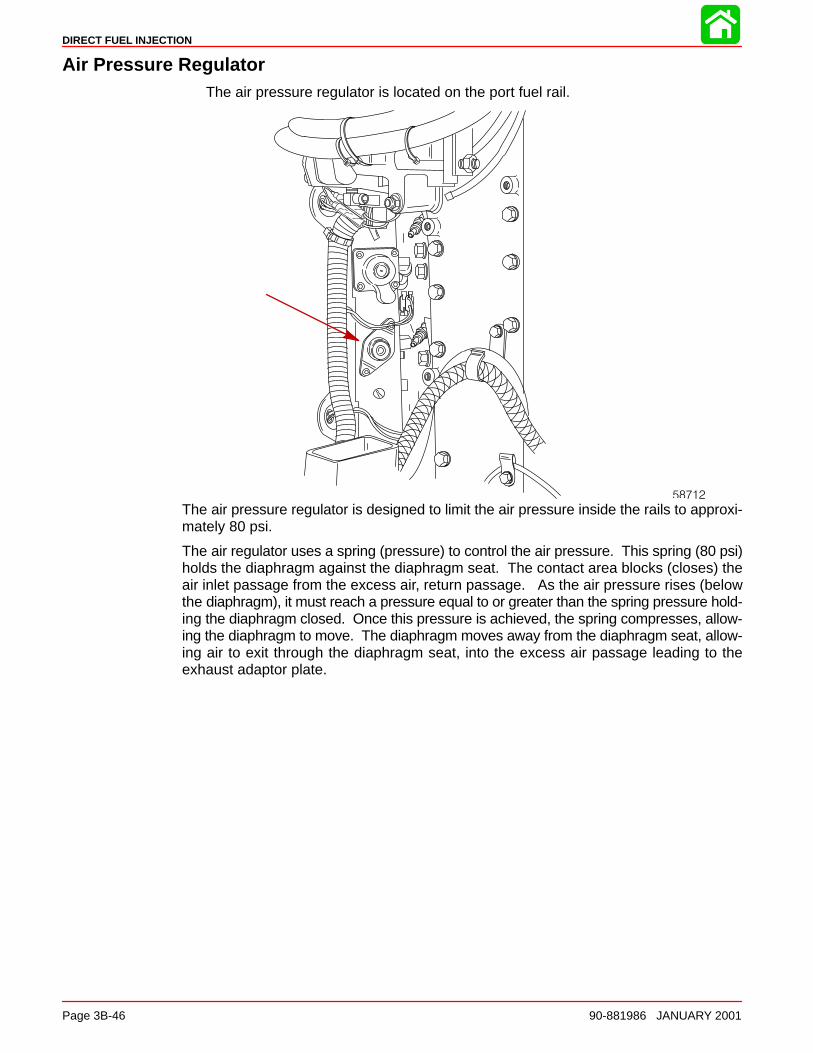
DIRECT FUEL INJECTION
Page 3B-46 90-881986 JANUARY 2001
Air Pressure RegulatorThe air pressure regulator is located on the port fuel rail.
58712
The air pressure regulator is designed to limit the air pressure inside the rails to approxi-mately 80 psi.
The air regulator uses a spring (pressure) to control the air pressure. This spring (80 psi)holds the diaphragm against the diaphragm seat. The contact area blocks (closes) theair inlet passage from the excess air, return passage. As the air pressure rises (belowthe diaphragm), it must reach a pressure equal to or greater than the spring pressure hold-ing the diaphragm closed. Once this pressure is achieved, the spring compresses, allow-ing the diaphragm to move. The diaphragm moves away from the diaphragm seat, allow-ing air to exit through the diaphragm seat, into the excess air passage leading to theexhaust adaptor plate.
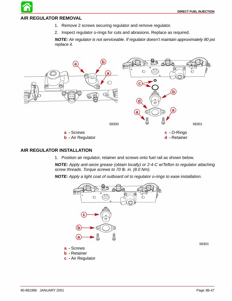
DIRECT FUEL INJECTION
90-881986 JANUARY 2001 Page 3B-47
AIR REGULATOR REMOVAL
1. Remove 2 screws securing regulator and remove regulator.
2. Inspect regulator o-rings for cuts and abrasions. Replace as required.
NOTE: Air regulator is not serviceable. If regulator doesn’t maintain approximately 80 psireplace it.
a
58300
a b
58301
b
c
a a
d
a - Screwsb - Air Regulator
c - O-Ringsd - Retainer
AIR REGULATOR INSTALLATION
1. Position air regulator, retainer and screws onto fuel rail as shown below.
NOTE: Apply anti-seize grease (obtain locally) or 2-4-C w/Teflon to regulator attachingscrew threads. Torque screws to 70 lb. in. (8.0 Nm).
NOTE: Apply a light coat of outboard oil to regulator o-rings to ease installation.
58301
a
b
c
a - Screwsb - Retainerc - Air Regulator
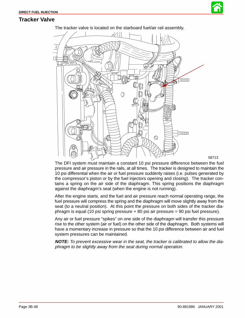
DIRECT FUEL INJECTION
Page 3B-48 90-881986 JANUARY 2001
Tracker ValveThe tracker valve is located on the starboard fuel/air rail assembly.
58713
The DFI system must maintain a constant 10 psi pressure difference between the fuelpressure and air pressure in the rails, at all times. The tracker is designed to maintain the10 psi differential when the air or fuel pressure suddenly raises (i.e. pulses generated bythe compressor’s piston or by the fuel injectors opening and closing). The tracker con-tains a spring on the air side of the diaphragm. This spring positions the diaphragmagainst the diaphragm’s seat (when the engine is not running).
After the engine starts, and the fuel and air pressure reach normal operating range, thefuel pressure will compress the spring and the diaphragm will move slightly away from theseat (to a neutral position). At this point the pressure on both sides of the tracker dia-phragm is equal (10 psi spring pressure + 80 psi air pressure = 90 psi fuel pressure).
Any air or fuel pressure “spikes” on one side of the diaphragm will transfer this pressurerise to the other system (air or fuel) on the other side of the diaphragm. Both systems willhave a momentary increase in pressure so that the 10 psi difference between air and fuelsystem pressures can be maintained.
NOTE: To prevent excessive wear in the seat, the tracker is calibrated to allow the dia-phragm to be slightly away from the seat during normal operation.
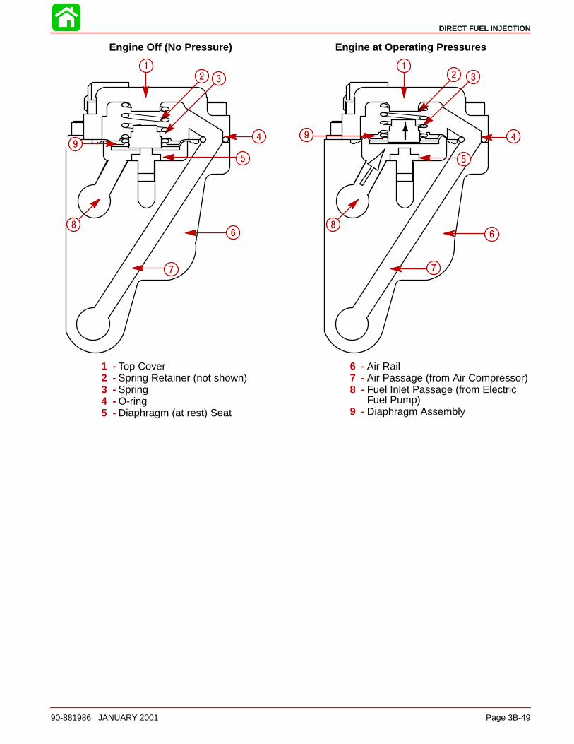
DIRECT FUEL INJECTION
90-881986 JANUARY 2001 Page 3B-49
Engine Off (No Pressure) Engine at Operating Pressures
4
5
6
7
8
5
68
9
1
2 3
4
5
6
7
8
9
12 3
4
5
6
7
8
9
1 - Top Cover2 - Spring Retainer (not shown)3 - Spring4 - O-ring5 - Diaphragm (at rest) Seat
6 - Air Rail7 - Air Passage (from Air Compressor)8 - Fuel Inlet Passage (from Electric
Fuel Pump)9 - Diaphragm Assembly
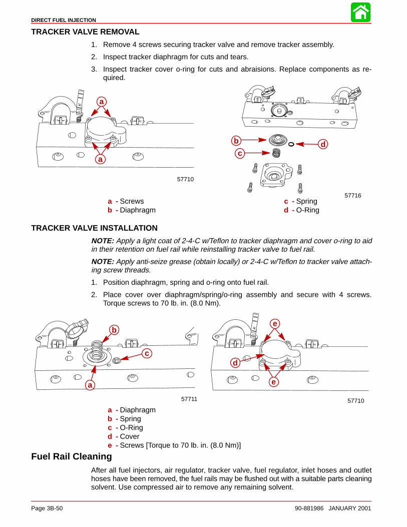
DIRECT FUEL INJECTION
Page 3B-50 90-881986 JANUARY 2001
TRACKER VALVE REMOVAL
1. Remove 4 screws securing tracker valve and remove tracker assembly.
2. Inspect tracker diaphragm for cuts and tears.
3. Inspect tracker cover o-ring for cuts and abraisions. Replace components as re-quired.
a
a
57710
57716
b
cd
a - Screwsb - Diaphragm
c - Springd - O-Ring
TRACKER VALVE INSTALLATION
NOTE: Apply a light coat of 2-4-C w/Teflon to tracker diaphragm and cover o-ring to aidin their retention on fuel rail while reinstalling tracker valve to fuel rail.
NOTE: Apply anti-seize grease (obtain locally) or 2-4-C w/Teflon to tracker valve attach-ing screw threads.
1. Position diaphragm, spring and o-ring onto fuel rail.
2. Place cover over diaphragm/spring/o-ring assembly and secure with 4 screws.Torque screws to 70 lb. in. (8.0 Nm).
be
e
d
57710
aa
c
57711
b
a - Diaphragmb - Springc - O-Ringd - Covere - Screws [Torque to 70 lb. in. (8.0 Nm)]
Fuel Rail CleaningAfter all fuel injectors, air regulator, tracker valve, fuel regulator, inlet hoses and outlethoses have been removed, the fuel rails may be flushed out with a suitable parts cleaningsolvent. Use compressed air to remove any remaining solvent.
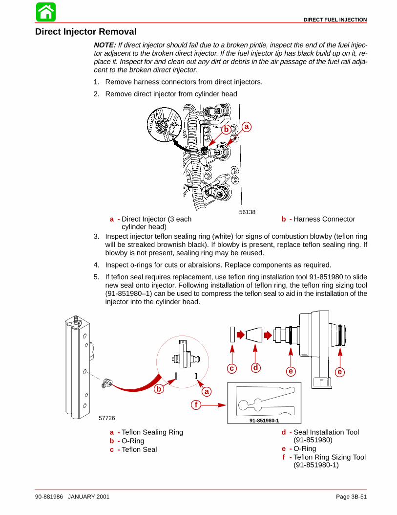
DIRECT FUEL INJECTION
90-881986 JANUARY 2001 Page 3B-51
Direct Injector RemovalNOTE: If direct injector should fail due to a broken pintle, inspect the end of the fuel injec-tor adjacent to the broken direct injector. If the fuel injector tip has black build up on it, re-place it. Inspect for and clean out any dirt or debris in the air passage of the fuel rail adja-cent to the broken direct injector.
1. Remove harness connectors from direct injectors.
2. Remove direct injector from cylinder head
56138
ab ab
a - Direct Injector (3 eachcylinder head)
b - Harness Connector
3. Inspect injector teflon sealing ring (white) for signs of combustion blowby (teflon ringwill be streaked brownish black). If blowby is present, replace teflon sealing ring. Ifblowby is not present, sealing ring may be reused.
4. Inspect o-rings for cuts or abraisions. Replace components as required.
5. If teflon seal requires replacement, use teflon ring installation tool 91-851980 to slidenew seal onto injector. Following installation of teflon ring, the teflon ring sizing tool(91-851980–1) can be used to compress the teflon seal to aid in the installation of theinjector into the cylinder head.
d
aab
c e e
91-851980-1
f
57726
a - Teflon Sealing Ringb - O-Ringc - Teflon Seal
d - Seal Installation Tool(91-851980)
e - O-Ringf - Teflon Ring Sizing Tool
(91-851980-1)
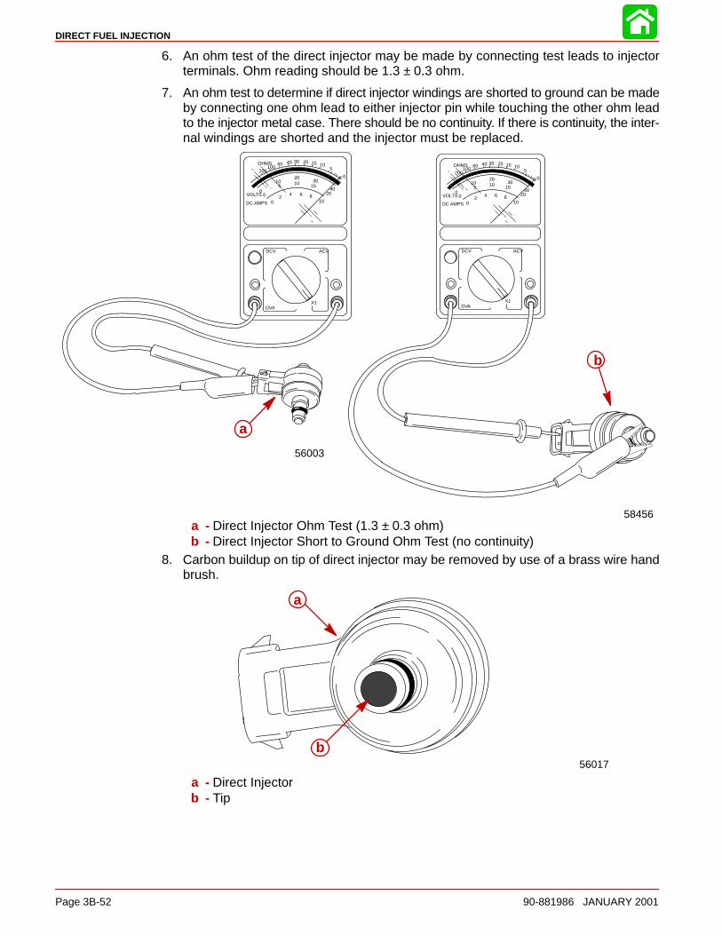
DIRECT FUEL INJECTION
Page 3B-52 90-881986 JANUARY 2001
6. An ohm test of the direct injector may be made by connecting test leads to injectorterminals. Ohm reading should be 1.3 ± 0.3 ohm.
7. An ohm test to determine if direct injector windings are shorted to ground can be madeby connecting one ohm lead to either injector pin while touching the other ohm leadto the injector metal case. There should be no continuity. If there is continuity, the inter-nal windings are shorted and the injector must be replaced.
VOLTS
DC AMPS
OHMS
02
4 6 810
DCV ACV
DVA
00
510
2010 30
1540
20
0
5101520304060
100200
X1
56003
a
VOLTS
DC AMPS
OHMS
02
4 6 810
DCV ACV
DVA
00
510
2010 30
1540
20
0
5101520304060
100200
X1
58456
b
a - Direct Injector Ohm Test (1.3 ± 0.3 ohm)b - Direct Injector Short to Ground Ohm Test (no continuity)
8. Carbon buildup on tip of direct injector may be removed by use of a brass wire handbrush.
56017
a
b
a - Direct Injectorb - Tip
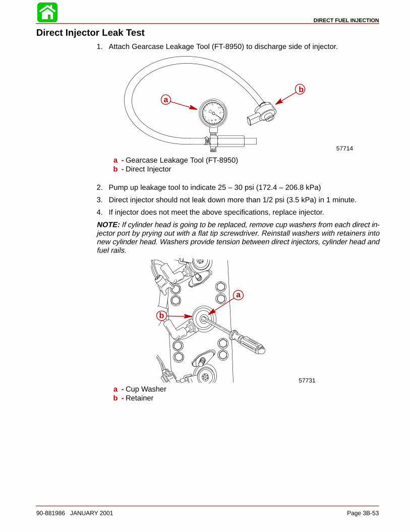
DIRECT FUEL INJECTION
90-881986 JANUARY 2001 Page 3B-53
Direct Injector Leak Test1. Attach Gearcase Leakage Tool (FT-8950) to discharge side of injector.
57714
ab
a - Gearcase Leakage Tool (FT-8950)b - Direct Injector
2. Pump up leakage tool to indicate 25 – 30 psi (172.4 – 206.8 kPa)
3. Direct injector should not leak down more than 1/2 psi (3.5 kPa) in 1 minute.
4. If injector does not meet the above specifications, replace injector.
NOTE: If cylinder head is going to be replaced, remove cup washers from each direct in-jector port by prying out with a flat tip screwdriver. Reinstall washers with retainers intonew cylinder head. Washers provide tension between direct injectors, cylinder head andfuel rails.
57731
b
a
a - Cup Washerb - Retainer
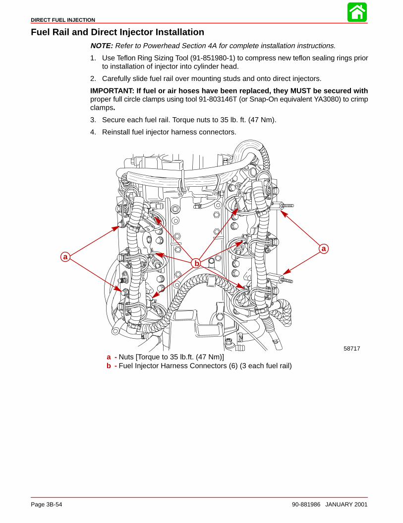
DIRECT FUEL INJECTION
Page 3B-54 90-881986 JANUARY 2001
Fuel Rail and Direct Injector InstallationNOTE: Refer to Powerhead Section 4A for complete installation instructions.
1. Use Teflon Ring Sizing Tool (91-851980-1) to compress new teflon sealing rings priorto installation of injector into cylinder head.
2. Carefully slide fuel rail over mounting studs and onto direct injectors.
IMPORTANT: If fuel or air hoses have been replaced, they MUST be secured withproper full circle clamps using tool 91-803146T (or Snap-On equivalent YA3080) to crimpclamps.
3. Secure each fuel rail. Torque nuts to 35 lb. ft. (47 Nm).
4. Reinstall fuel injector harness connectors.
58717
ba
a
a - Nuts [Torque to 35 lb.ft. (47 Nm)]b - Fuel Injector Harness Connectors (6) (3 each fuel rail)
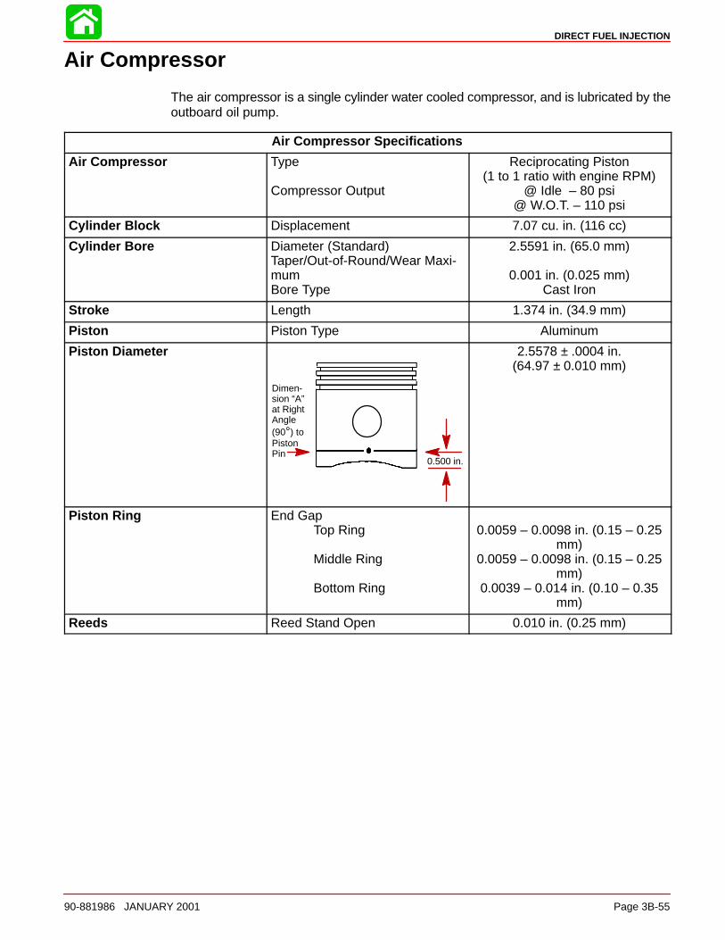
DIRECT FUEL INJECTION
90-881986 JANUARY 2001 Page 3B-55
Air Compressor
The air compressor is a single cylinder water cooled compressor, and is lubricated by theoutboard oil pump.
Air Compressor Specifications
Air Compressor Type
Compressor Output
Reciprocating Piston(1 to 1 ratio with engine RPM)
@ Idle – 80 psi@ W.O.T. – 110 psi
Cylinder Block Displacement 7.07 cu. in. (116 cc)
Cylinder Bore Diameter (Standard)Taper/Out-of-Round/Wear Maxi-mumBore Type
2.5591 in. (65.0 mm)
0.001 in. (0.025 mm)Cast Iron
Stroke Length 1.374 in. (34.9 mm)
Piston Piston Type Aluminum
Piston Diameter
Dimen-sion “A”at RightAngle(90°) toPistonPin
0.500 in.
2.5578 ± .0004 in.(64.97 ± 0.010 mm)
Piston Ring End GapTop Ring
Middle Ring
Bottom Ring
0.0059 – 0.0098 in. (0.15 – 0.25mm)
0.0059 – 0.0098 in. (0.15 – 0.25mm)
0.0039 – 0.014 in. (0.10 – 0.35mm)
Reeds Reed Stand Open 0.010 in. (0.25 mm)
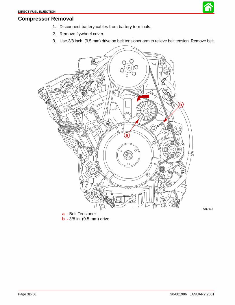
DIRECT FUEL INJECTION
Page 3B-56 90-881986 JANUARY 2001
Compressor Removal1. Disconnect battery cables from battery terminals.
2. Remove flywheel cover.
3. Use 3/8 inch (9.5 mm) drive on belt tensioner arm to relieve belt tension. Remove belt.
b
a
58749a - Belt Tensionerb - 3/8 in. (9.5 mm) drive
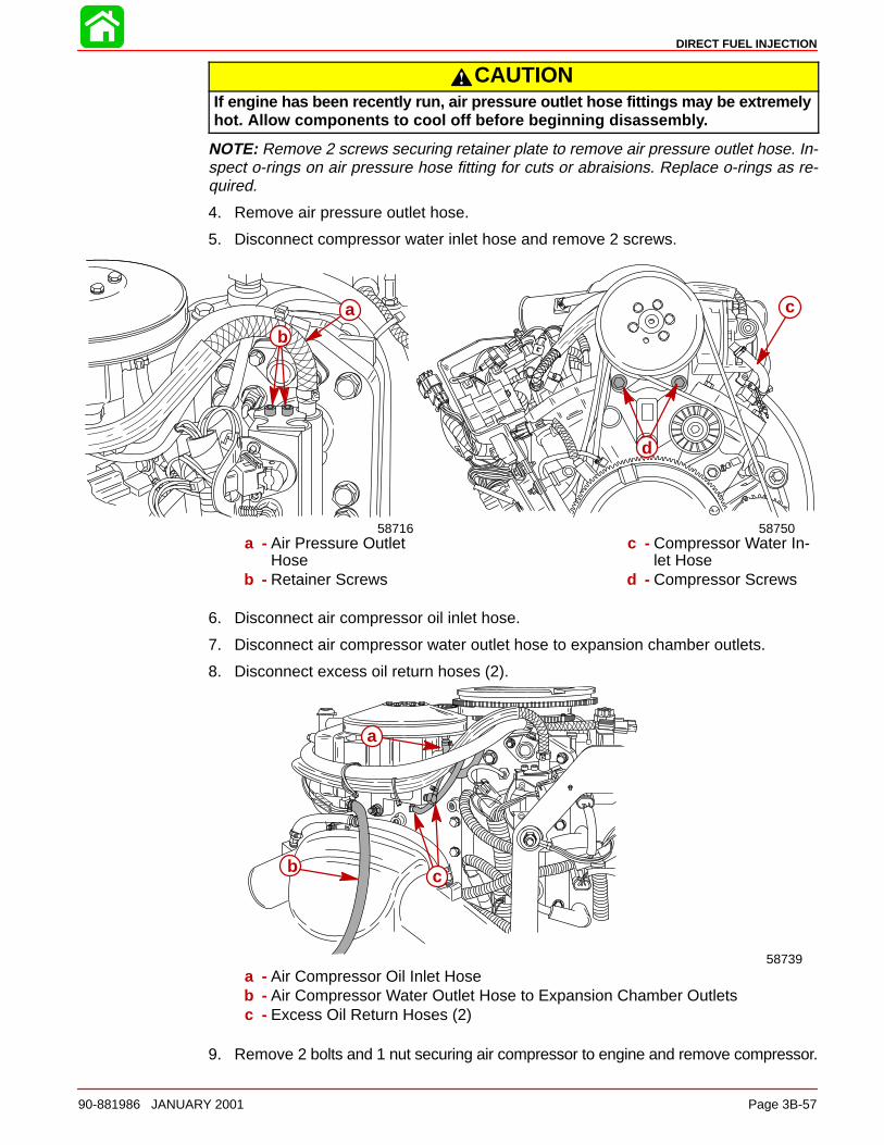
DIRECT FUEL INJECTION
90-881986 JANUARY 2001 Page 3B-57
CAUTIONIf engine has been recently run, air pressure outlet hose fittings may be extremelyhot. Allow components to cool off before beginning disassembly.
NOTE: Remove 2 screws securing retainer plate to remove air pressure outlet hose. In-spect o-rings on air pressure hose fitting for cuts or abraisions. Replace o-rings as re-quired.
4. Remove air pressure outlet hose.
5. Disconnect compressor water inlet hose and remove 2 screws.
58716
a
b
d
58750
c
a - Air Pressure OutletHose
b - Retainer Screws
c - Compressor Water In-let Hose
d - Compressor Screws
6. Disconnect air compressor oil inlet hose.
7. Disconnect air compressor water outlet hose to expansion chamber outlets.
8. Disconnect excess oil return hoses (2).
58739
cb
a
a - Air Compressor Oil Inlet Hoseb - Air Compressor Water Outlet Hose to Expansion Chamber Outletsc - Excess Oil Return Hoses (2)
9. Remove 2 bolts and 1 nut securing air compressor to engine and remove compressor.
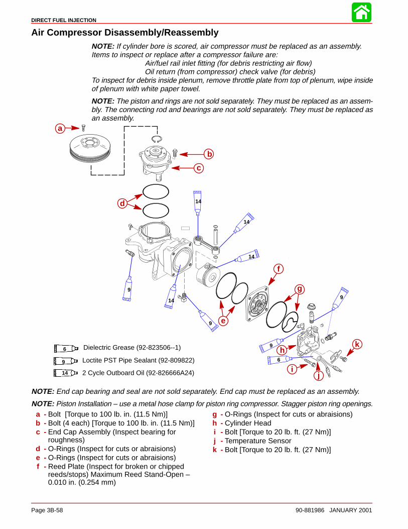
DIRECT FUEL INJECTION
Page 3B-58 90-881986 JANUARY 2001
Air Compressor Disassembly/ReassemblyNOTE: If cylinder bore is scored, air compressor must be replaced as an assembly.Items to inspect or replace after a compressor failure are:
Air/fuel rail inlet fitting (for debris restricting air flow)Oil return (from compressor) check valve (for debris)
To inspect for debris inside plenum, remove throttle plate from top of plenum, wipe insideof plenum with white paper towel.
NOTE: The piston and rings are not sold separately. They must be replaced as an assem-bly. The connecting rod and bearings are not sold separately. They must be replaced asan assembly.
ÇÇÇÇÇÇÇÇÇ
a
b
c
d
e
f
g
ij
k
9
14
9
14
14
14
9
9
6
hDielectric Grease (92-823506--1)6
Loctite PST Pipe Sealant (92-809822)9
14 2 Cycle Outboard Oil (92-826666A24)
NOTE: End cap bearing and seal are not sold separately. End cap must be replaced as an assembly.
NOTE: Piston Installation – use a metal hose clamp for piston ring compressor. Stagger piston ring openings.a - Bolt [Torque to 100 lb. in. (11.5 Nm)]b - Bolt (4 each) [Torque to 100 lb. in. (11.5 Nm)]c - End Cap Assembly (Inspect bearing for
roughness)d - O-Rings (Inspect for cuts or abraisions)e - O-Rings (Inspect for cuts or abraisions)f - Reed Plate (Inspect for broken or chipped
reeds/stops) Maximum Reed Stand-Open –0.010 in. (0.254 mm)
g - O-Rings (Inspect for cuts or abraisions)h - Cylinder Headi - Bolt [Torque to 20 lb. ft. (27 Nm)]j - Temperature Sensork - Bolt [Torque to 20 lb. ft. (27 Nm)]
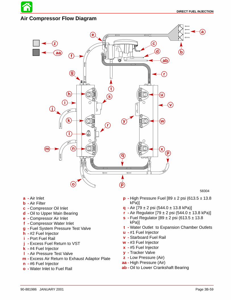
DIRECT FUEL INJECTION
90-881986 JANUARY 2001 Page 3B-59
Air Compressor Flow Diagram
ÎÎÎÎÎÎÎÎ
a
b
c
d
e
f
g
h
ij
k
l
m n
o p
q
r
s
tu
r
v
w
x
y
ab
58304
p
z
aa
a - Air Inletb - Air Filterc - Compressor Oil Inletd - Oil to Upper Main Bearinge - Compressor Air Inletf - Compressor Water Inletg - Fuel System Pressure Test Valveh - #2 Fuel Injectori - Port Fuel Railj - Excess Fuel Return to VSTk - #4 Fuel Injectorl - Air Pressure Test Valve
m - Excess Air Return to Exhaust Adaptor Platen - #6 Fuel Injectoro - Water Inlet to Fuel Rail
p - High Pressure Fuel [89 ± 2 psi (613.5 ± 13.8kPa)]
q - Air [79 ± 2 psi (544.0 ± 13.8 kPa)]r - Air Regulator [79 ± 2 psi (544.0 ± 13.8 kPa)]s - Fuel Regulator [89 ± 2 psi (613.5 ± 13.8
kPa)]t - Water Outlet to Expansion Chamber Outletsu - #1 Fuel Injectorv - Starboard Fuel Railw - #3 Fuel Injectorx - #5 Fuel Injectory - Tracker Valvez - Low Pressure (Air)
aa - High Pressure (Air)ab - Oil to Lower Crankshaft Bearing
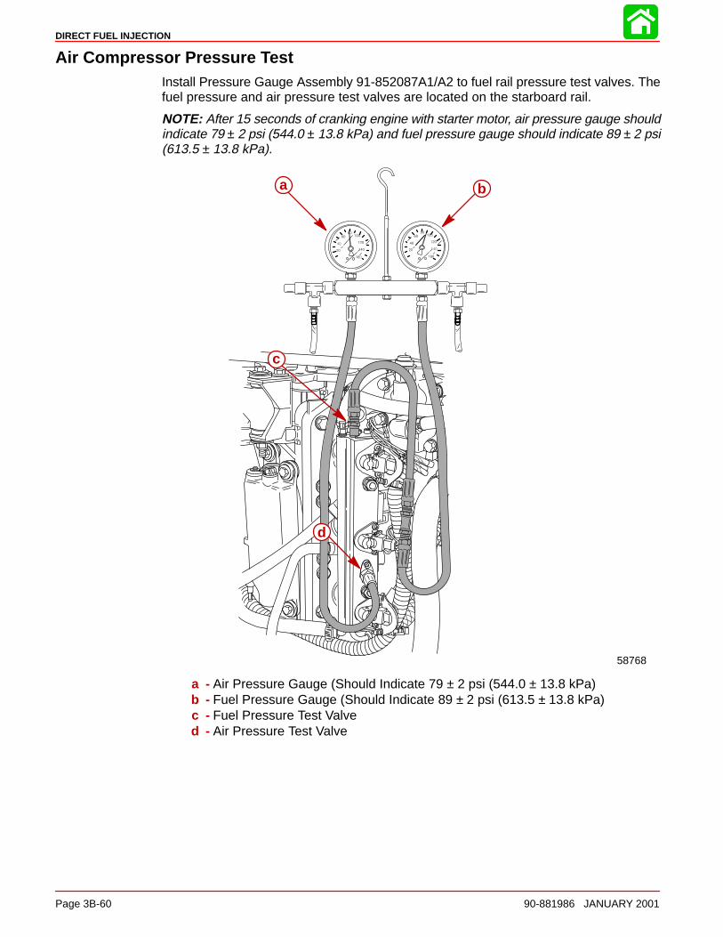
DIRECT FUEL INJECTION
Page 3B-60 90-881986 JANUARY 2001
Air Compressor Pressure TestInstall Pressure Gauge Assembly 91-852087A1/A2 to fuel rail pressure test valves. Thefuel pressure and air pressure test valves are located on the starboard rail.
NOTE: After 15 seconds of cranking engine with starter motor, air pressure gauge shouldindicate 79 ± 2 psi (544.0 ± 13.8 kPa) and fuel pressure gauge should indicate 89 ± 2 psi(613.5 ± 13.8 kPa).
ba
58768
c
d
a - Air Pressure Gauge (Should Indicate 79 ± 2 psi (544.0 ± 13.8 kPa)b - Fuel Pressure Gauge (Should Indicate 89 ± 2 psi (613.5 ± 13.8 kPa)c - Fuel Pressure Test Valved - Air Pressure Test Valve
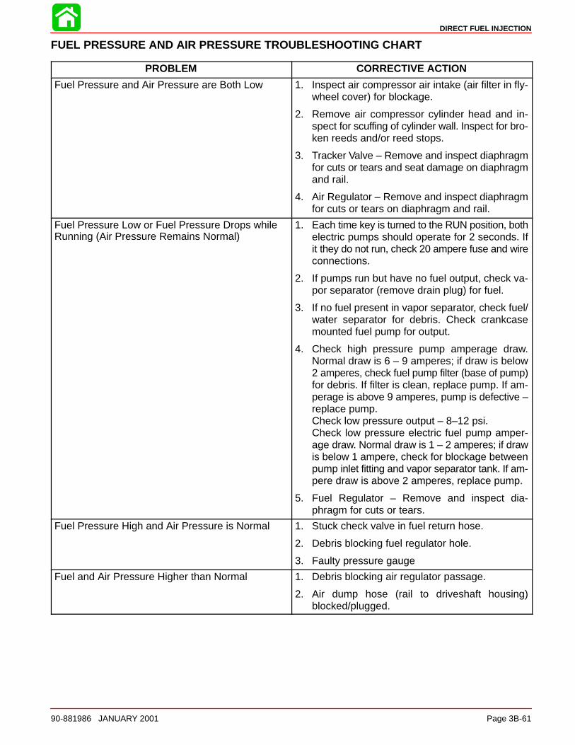
DIRECT FUEL INJECTION
90-881986 JANUARY 2001 Page 3B-61
FUEL PRESSURE AND AIR PRESSURE TROUBLESHOOTING CHART
PROBLEM CORRECTIVE ACTION
Fuel Pressure and Air Pressure are Both Low 1. Inspect air compressor air intake (air filter in fly-wheel cover) for blockage.
2. Remove air compressor cylinder head and in-spect for scuffing of cylinder wall. Inspect for bro-ken reeds and/or reed stops.
3. Tracker Valve – Remove and inspect diaphragmfor cuts or tears and seat damage on diaphragmand rail.
4. Air Regulator – Remove and inspect diaphragmfor cuts or tears on diaphragm and rail.
Fuel Pressure Low or Fuel Pressure Drops whileRunning (Air Pressure Remains Normal)
1. Each time key is turned to the RUN position, bothelectric pumps should operate for 2 seconds. Ifit they do not run, check 20 ampere fuse and wireconnections.
2. If pumps run but have no fuel output, check va-por separator (remove drain plug) for fuel.
3. If no fuel present in vapor separator, check fuel/water separator for debris. Check crankcasemounted fuel pump for output.
4. Check high pressure pump amperage draw.Normal draw is 6 – 9 amperes; if draw is below2 amperes, check fuel pump filter (base of pump)for debris. If filter is clean, replace pump. If am-perage is above 9 amperes, pump is defective –replace pump.Check low pressure output – 8–12 psi.Check low pressure electric fuel pump amper-age draw. Normal draw is 1 – 2 amperes; if drawis below 1 ampere, check for blockage betweenpump inlet fitting and vapor separator tank. If am-pere draw is above 2 amperes, replace pump.
5. Fuel Regulator – Remove and inspect dia-phragm for cuts or tears.
Fuel Pressure High and Air Pressure is Normal 1. Stuck check valve in fuel return hose.
2. Debris blocking fuel regulator hole.
3. Faulty pressure gauge
Fuel and Air Pressure Higher than Normal 1. Debris blocking air regulator passage.
2. Air dump hose (rail to driveshaft housing)blocked/plugged.
3C
OIL INJECTION
90-881986 JANUARY 2001 Page 3C-1
FUEL SYSTEMSection 3C – Oil Injection
Table of Contents
Special Tools 3C-2. . . . . . . . . . . . . . . . . . . . . . . . . . . . . . . . Oil System Operation 3C-2. . . . . . . . . . . . . . . . . . . . . . . . .
Oil Pump Output 3C-2. . . . . . . . . . . . . . . . . . . . . . . . . . Oil System – Oil Hose Installation 3C-3. . . . . . . . . . . Oil Pump Removal and Installation 3C-4. . . . . . . . . . Engine Oil Reservoir Removal and Installation 3C-5. . . . . . . . . . . . . . . . . . . . . . . . . . . . . . Priming the Oil Pump 3C-6. . . . . . . . . . . . . . . . . . . . . .
Priming Procedure – Method 1 3C-7. . . . . . . . . . . . . . Remote Oil Hose Connections 3C-8. . . . . . . . . . . . . . Filling the Oil Tanks 3C-9. . . . . . . . . . . . . . . . . . . . . . . . Purging Air From the Engine Oil Reservoir and Remote Oil Hose 3C-9. . . . . . . . . . . . . . . . . . . . . Oil Warning Systems 3C-10. . . . . . . . . . . . . . . . . . . . .
Oil System Troubleshooting 3C-12. . . . . . . . . . . . . . . . . Low Oil Warning System is Activated 3C-12. . . . . .
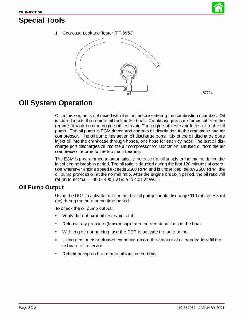
OIL INJECTION
Page 3C-2 90-881986 JANUARY 2001
Special Tools
1. Gearcase Leakage Tester (FT-8950)
57714
Oil System Operation
Oil in this engine is not mixed with the fuel before entering the combustion chamber. Oilis stored inside the remote oil tank in the boat. Crankcase pressure forces oil from theremote oil tank into the engine oil reservoir. The engine oil reservoir feeds oil to the oilpump. The oil pump is ECM driven and controls oil distribution to the crankcase and aircompressor. The oil pump has seven oil discharge ports. Six of the oil discharge portsinject oil into the crankcase through hoses, one hose for each cylinder. The last oil dis-charge port discharges oil into the air compressor for lubrication. Unused oil from the aircompressor returns to the top main bearing.
The ECM is programmed to automatically increase the oil supply to the engine during theinitial engine break-in period. The oil ratio is doubled during the first 120 minutes of opera-tion whenever engine speed exceeds 2500 RPM and is under load; below 2500 RPM theoil pump provides oil at the normal ratio. After the engine break-in period, the oil ratio willreturn to normal – 300 - 400:1 at idle to 40:1 at WOT.
Oil Pump OutputUsing the DDT to activate auto prime, the oil pump should discharge 110 ml (cc) ± 8 ml(cc) during the auto prime time period.
To check the oil pump output:
• Verify the onboard oil reservoir is full.
• Release any pressure (loosen cap) from the remote oil tank in the boat.
• With engine not running, use the DDT to activate the auto prime.
• Using a ml or cc graduated container, record the amount of oil needed to refill theonboard oil reservoir.
• Retighten cap on the remote oil tank in the boat.
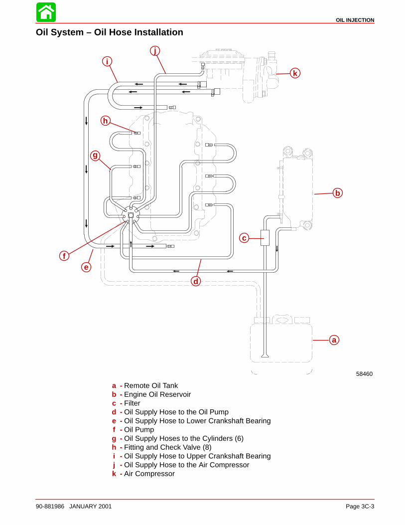
OIL INJECTION
90-881986 JANUARY 2001 Page 3C-3
Oil System – Oil Hose Installation
i
e
h
58460
j
g
f
d
c
a
bb
k
a - Remote Oil Tankb - Engine Oil Reservoirc - Filterd - Oil Supply Hose to the Oil Pumpe - Oil Supply Hose to Lower Crankshaft Bearingf - Oil Pumpg - Oil Supply Hoses to the Cylinders (6)h - Fitting and Check Valve (8)i - Oil Supply Hose to Upper Crankshaft Bearingj - Oil Supply Hose to the Air Compressork - Air Compressor
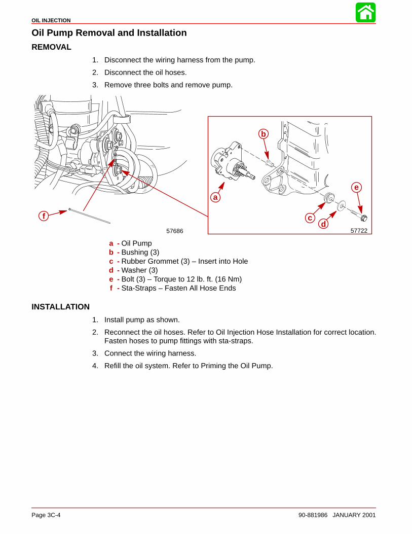
OIL INJECTION
Page 3C-4 90-881986 JANUARY 2001
Oil Pump Removal and InstallationREMOVAL
1. Disconnect the wiring harness from the pump.
2. Disconnect the oil hoses.
3. Remove three bolts and remove pump.
57686
f
57722
a
b
c
e
d
a - Oil Pumpb - Bushing (3)c - Rubber Grommet (3) – Insert into Holed - Washer (3)e - Bolt (3) – Torque to 12 lb. ft. (16 Nm)f - Sta-Straps – Fasten All Hose Ends
INSTALLATION
1. Install pump as shown.
2. Reconnect the oil hoses. Refer to Oil Injection Hose Installation for correct location.Fasten hoses to pump fittings with sta-straps.
3. Connect the wiring harness.
4. Refill the oil system. Refer to Priming the Oil Pump.
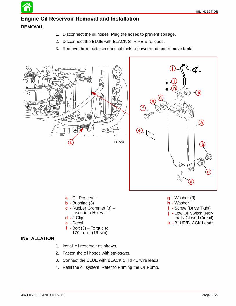
OIL INJECTION
90-881986 JANUARY 2001 Page 3C-5
Engine Oil Reservoir Removal and InstallationREMOVAL
1. Disconnect the oil hoses. Plug the hoses to prevent spillage.
2. Disconnect the BLUE with BLACK STRIPE wire leads.
3. Remove three bolts securing oil tank to powerhead and remove tank.
a
b
b
c
c
d
e
f
g
h
i
j
k 58724
a - Oil Reservoirb - Bushing (3)c - Rubber Grommet (3) –
Insert into Holesd - J-Clipe - Decalf - Bolt (3) – Torque to
170 lb. in. (19 Nm)
g - Washer (3)h - Washeri - Screw (Drive Tight)j - Low Oil Switch (Nor-
mally Closed Circuit)k - BLUE/BLACK Leads
INSTALLATION
1. Install oil reservoir as shown.
2. Fasten the oil hoses with sta-straps.
3. Connect the BLUE with BLACK STRIPE wire leads.
4. Refill the oil system. Refer to Priming the Oil Pump.
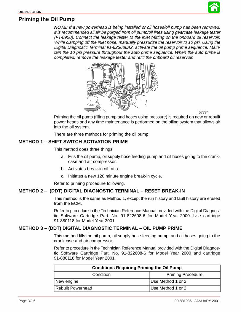
OIL INJECTION
Page 3C-6 90-881986 JANUARY 2001
Priming the Oil PumpNOTE: If a new powerhead is being installed or oil hoses/oil pump has been removed,it is recommended all air be purged from oil pump/oil lines using gearcase leakage tester(FT-8950). Connect the leakage tester to the inlet t-fitting on the onboard oil reservoir.While clamping off the inlet hose, manually pressurize the reservoir to 10 psi. Using theDigital Diagnostic Terminal 91-823686A2, activate the oil pump prime sequence. Main-tain the 10 psi pressure throughout the auto prime sequence. When the auto prime iscompleted, remove the leakage tester and refill the onboard oil reservoir.
57734Priming the oil pump (filling pump and hoses using pressure) is required on new or rebuiltpower heads and any time maintenance is performed on the oiling system that allows airinto the oil system.
There are three methods for priming the oil pump:
METHOD 1 – SHIFT SWITCH ACTIVATION PRIME
This method does three things:
a. Fills the oil pump, oil supply hose feeding pump and oil hoses going to the crank-case and air compressor.
b. Activates break-in oil ratio.
c. Initiates a new 120 minute engine break-in cycle.
Refer to priming procedure following.
METHOD 2 – (DDT) DIGITAL DIAGNOSTIC TERMINAL – RESET BREAK-IN
This method is the same as Method 1, except the run history and fault history are erasedfrom the ECM.
Refer to procedure in the Technician Reference Manual provided with the Digital Diagnos-tic Software Cartridge Part. No. 91-822608-6 for Model Year 2000. Use cartridge91-880118 for Model Year 2001.
METHOD 3 – (DDT) DIGITAL DIAGNOSTIC TERMINAL – OIL PUMP PRIME
This method fills the oil pump, oil supply hose feeding pump, and oil hoses going to thecrankcase and air compressor.
Refer to procedure in the Technician Reference Manual provided with the Digital Diagnos-tic Software Cartridge Part. No. 91-822608-6 for Model Year 2000 and cartridge91-880118 for Model Year 2001.
Conditions Requiring Priming the Oil Pump
Condition Priming Procedure
New engine Use Method 1 or 2
Rebuilt Powerhead Use Method 1 or 2
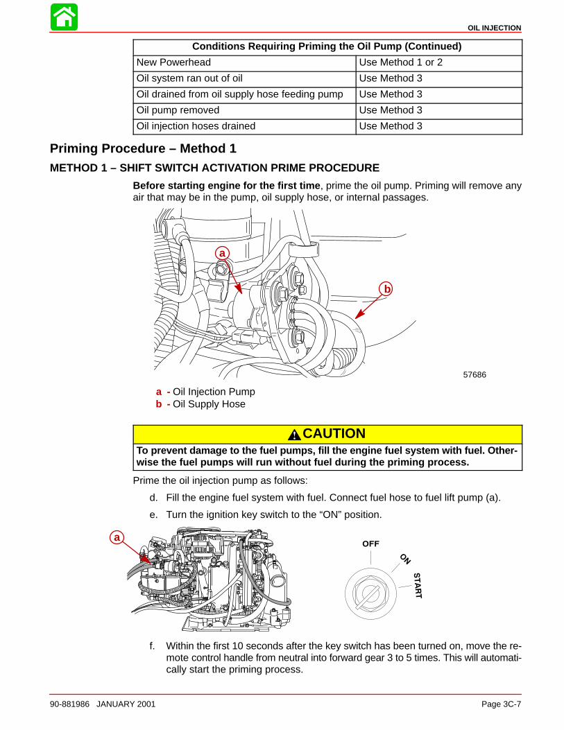
OIL INJECTION
90-881986 JANUARY 2001 Page 3C-7
Conditions Requiring Priming the Oil Pump (Continued)
New Powerhead Use Method 1 or 2
Oil system ran out of oil Use Method 3
Oil drained from oil supply hose feeding pump Use Method 3
Oil pump removed Use Method 3
Oil injection hoses drained Use Method 3
Priming Procedure – Method 1METHOD 1 – SHIFT SWITCH ACTIVATION PRIME PROCEDURE
Before starting engine for the first time , prime the oil pump. Priming will remove anyair that may be in the pump, oil supply hose, or internal passages.
57686
a
b
a - Oil Injection Pumpb - Oil Supply Hose
CAUTIONTo prevent damage to the fuel pumps, fill the engine fuel system with fuel. Other-wise the fuel pumps will run without fuel during the priming process.
Prime the oil injection pump as follows:
d. Fill the engine fuel system with fuel. Connect fuel hose to fuel lift pump (a).
e. Turn the ignition key switch to the “ON” position.
a
f. Within the first 10 seconds after the key switch has been turned on, move the re-mote control handle from neutral into forward gear 3 to 5 times. This will automati-cally start the priming process.
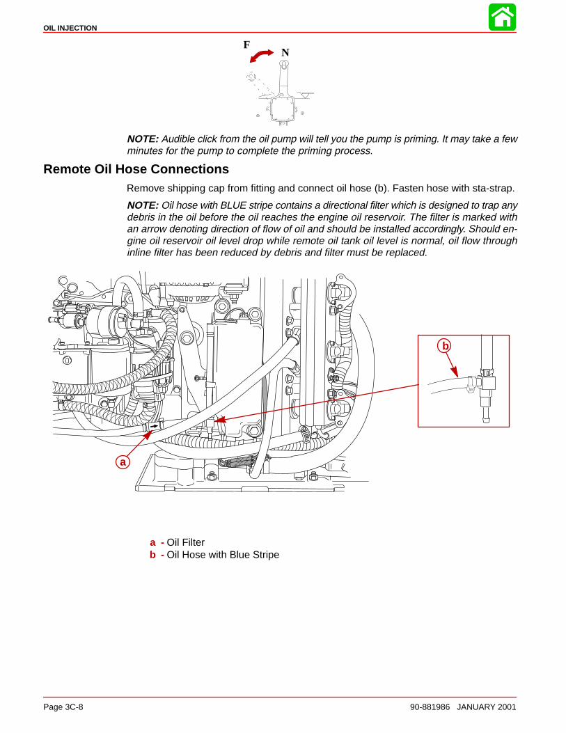
OIL INJECTION
Page 3C-8 90-881986 JANUARY 2001
NF
NOTE: Audible click from the oil pump will tell you the pump is priming. It may take a fewminutes for the pump to complete the priming process.
Remote Oil Hose ConnectionsRemove shipping cap from fitting and connect oil hose (b). Fasten hose with sta-strap.
NOTE: Oil hose with BLUE stripe contains a directional filter which is designed to trap anydebris in the oil before the oil reaches the engine oil reservoir. The filter is marked withan arrow denoting direction of flow of oil and should be installed accordingly. Should en-gine oil reservoir oil level drop while remote oil tank oil level is normal, oil flow throughinline filter has been reduced by debris and filter must be replaced.
a
b
a - Oil Filterb - Oil Hose with Blue Stripe
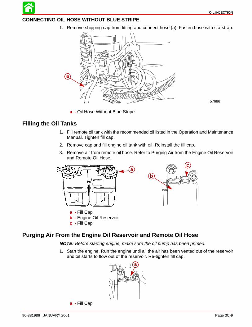
OIL INJECTION
90-881986 JANUARY 2001 Page 3C-9
CONNECTING OIL HOSE WITHOUT BLUE STRIPE
1. Remove shipping cap from fitting and connect hose (a). Fasten hose with sta-strap.
57686
a
a - Oil Hose Without Blue Stripe
Filling the Oil Tanks1. Fill remote oil tank with the recommended oil listed in the Operation and Maintenance
Manual. Tighten fill cap.
2. Remove cap and fill engine oil tank with oil. Reinstall the fill cap.
3. Remove air from remote oil hose. Refer to Purging Air from the Engine Oil Reservoirand Remote Oil Hose.
ba
ca
b
a - Fill Capb - Engine Oil Reservoirc - Fill Cap
Purging Air From the Engine Oil Reservoir and Remote Oil HoseNOTE: Before starting engine, make sure the oil pump has been primed.
1. Start the engine. Run the engine until all the air has been vented out of the reservoirand oil starts to flow out of the reservoir. Re-tighten fill cap.
a
a - Fill Cap
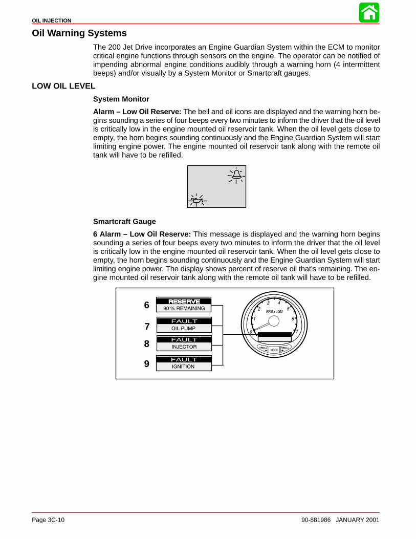
OIL INJECTION
Page 3C-10 90-881986 JANUARY 2001
Oil Warning SystemsThe 200 Jet Drive incorporates an Engine Guardian System within the ECM to monitorcritical engine functions through sensors on the engine. The operator can be notified ofimpending abnormal engine conditions audibly through a warning horn (4 intermittentbeeps) and/or visually by a System Monitor or Smartcraft gauges.
LOW OIL LEVEL
System Monitor
Alarm – Low Oil Reserve: The bell and oil icons are displayed and the warning horn be-gins sounding a series of four beeps every two minutes to inform the driver that the oil levelis critically low in the engine mounted oil reservoir tank. When the oil level gets close toempty, the horn begins sounding continuously and the Engine Guardian System will startlimiting engine power. The engine mounted oil reservoir tank along with the remote oiltank will have to be refilled.
Smartcraft Gauge
6 Alarm – Low Oil Reserve: This message is displayed and the warning horn beginssounding a series of four beeps every two minutes to inform the driver that the oil levelis critically low in the engine mounted oil reservoir tank. When the oil level gets close toempty, the horn begins sounding continuously and the Engine Guardian System will startlimiting engine power. The display shows percent of reserve oil that’s remaining. The en-gine mounted oil reservoir tank along with the remote oil tank will have to be refilled.
7
8
9
6
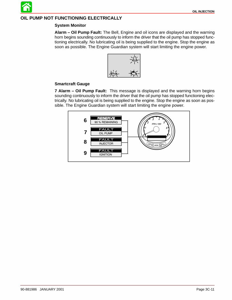
OIL INJECTION
90-881986 JANUARY 2001 Page 3C-11
OIL PUMP NOT FUNCTIONING ELECTRICALLY
System Monitor
Alarm – Oil Pump Fault: The Bell, Engine and oil icons are displayed and the warninghorn begins sounding continuously to inform the driver that the oil pump has stopped func-tioning electrically. No lubricating oil is being supplied to the engine. Stop the engine assoon as possible. The Engine Guardian system will start limiting the engine power.
Smartcraft Gauge
7 Alarm – Oil Pump Fault: This message is displayed and the warning horn beginssounding continuously to inform the driver that the oil pump has stopped functioning elec-trically. No lubricating oil is being supplied to the engine. Stop the engine as soon as pos-sible. The Engine Guardian system will start limiting the engine power.
7
8
9
6
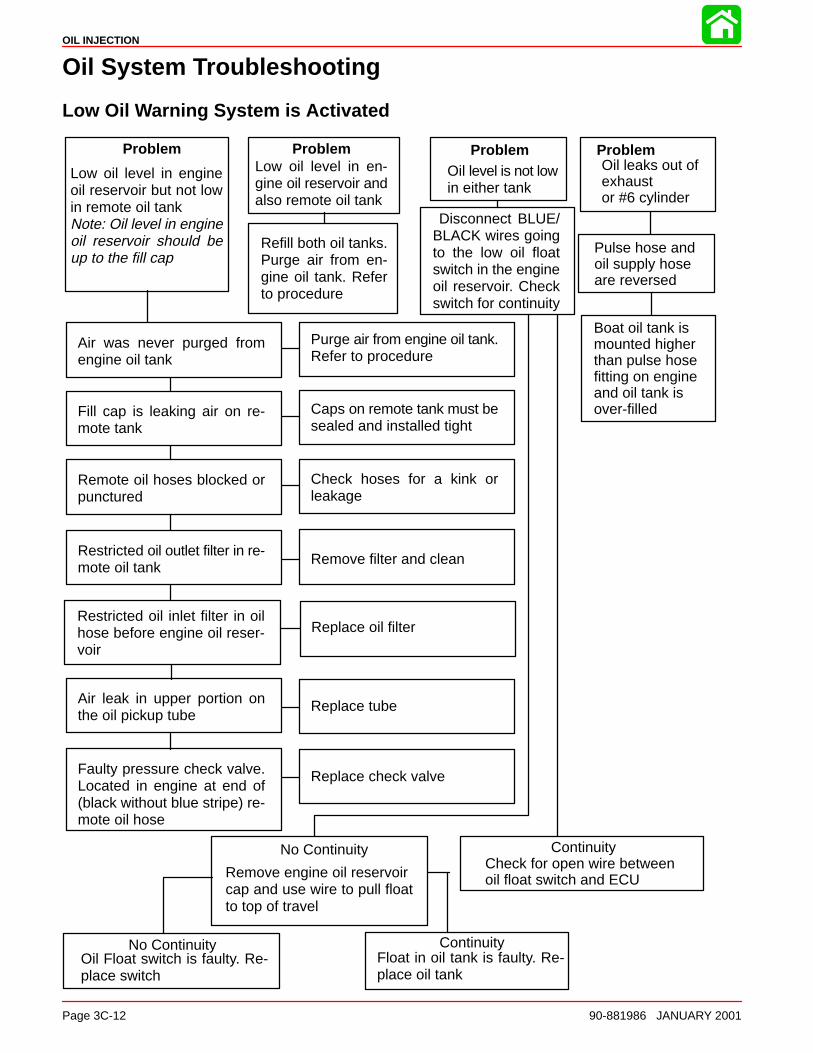
Low oil level in en-gine oil reservoir andalso remote oil tank
Low oil level in engineoil reservoir but not lowin remote oil tankNote: Oil level in engineoil reservoir should beup to the fill cap
Oil level is not lowin either tank
Refill both oil tanks.Purge air from en-gine oil tank. Referto procedure
Air was never purged fromengine oil tank
Fill cap is leaking air on re-mote tank
Remote oil hoses blocked orpunctured
Restricted oil outlet filter in re-mote oil tank
Air leak in upper portion onthe oil pickup tube
Faulty pressure check valve.Located in engine at end of(black without blue stripe) re-mote oil hose
Caps on remote tank must besealed and installed tight
Check hoses for a kink orleakage
Remove filter and clean
Replace tube
Replace check valve
Purge air from engine oil tank.Refer to procedure
Disconnect BLUE/BLACK wires goingto the low oil floatswitch in the engineoil reservoir. Checkswitch for continuity
Remove engine oil reservoircap and use wire to pull floatto top of travel
No Continuity
Oil Float switch is faulty. Re-place switch
No ContinuityFloat in oil tank is faulty. Re-place oil tank
Continuity
Problem Problem Problem ProblemOil leaks out ofexhaust or #6 cylinder
Pulse hose and oil supply hoseare reversed
Boat oil tank is mounted higher than pulse hose fitting on engineand oil tank is over-filled
ContinuityCheck for open wire between oil float switch and ECU
Restricted oil inlet filter in oilhose before engine oil reser-voir
Replace oil filter
OIL INJECTION
Page 3C-12 90-881986 JANUARY 2001
Oil System Troubleshooting
Low Oil Warning System is Activated

3D
EMISSIONS
90-881986 JANUARY 2001 Page 3D-1
FUEL SYSTEMSection 3D – Emissions
Table of Contents
Exhaust Emissions Standards 3D-1. . . . . . . . . . . . . . . . . What Are Emissions? 3D-1. . . . . . . . . . . . . . . . . . . . . . Hydrocarbons – HC 3D-1. . . . . . . . . . . . . . . . . . . . . . . . Carbon Monoxide – CO 3D-1. . . . . . . . . . . . . . . . . . . . Oxides of Nitrogen - NOx 3D-2. . . . . . . . . . . . . . . . . . . Controlling Emissions 3D-2. . . . . . . . . . . . . . . . . . . . . . Stoichiometric (14.7:1) Air/Fuel Ratio 3D-2. . . . . . . .
Outboard Hydrocarbon Emissions Reductions 3D-2. . . Stratified vs Homogenized Charge 3D-3. . . . . . . . . . . . .
Homogenized Charge 3D-3. . . . . . . . . . . . . . . . . . . . . . Stratified Charge 3D-4. . . . . . . . . . . . . . . . . . . . . . . . . .
Emissions Information 3D-4. . . . . . . . . . . . . . . . . . . . . . . . Manufacturer’s Responsibility: 3D-4. . . . . . . . . . . . . . Dealer Responsibility: 3D-5. . . . . . . . . . . . . . . . . . . . . . Owner Responsibility: 3D-5. . . . . . . . . . . . . . . . . . . . . . EPA Emission Regulations: 3D-5. . . . . . . . . . . . . . . . .
Manufacturer’s Certification Label 3D-6. . . . . . . . . . . . . . Service Replacement Certification Label 3D-7. . . . . . . .
Removal 3D-7. . . . . . . . . . . . . . . . . . . . . . . . . . . . . . . . . Date Code Identification 3D-7. . . . . . . . . . . . . . . . . . . . Installation 3D-7. . . . . . . . . . . . . . . . . . . . . . . . . . . . . . . . Decal Location: 3D-7. . . . . . . . . . . . . . . . . . . . . . . . . . .
Exhaust Emissions Standards
Through the Environmental Protection Agency (EPA), the federal government has estab-lished exhaust emissions standards for all new marine engines sold in the United States.
What Are Emissions?Emissions are what comes out of the exhaust system in the exhaust gas when the engineis running. They are formed as a result of the process of combustion or incomplete com-bustion. To understand exhaust gas emissions, remember that both air and fuel are madeof several elements. Air contains oxygen and nitrogen among other elements; gasolinecontains mainly hydrogen and carbon. These four elements combine chemically duringcombustion. If combustion were complete, the mixture of air and gasoline would result inthese emissions: water, carbon dioxide and nitrogen, which are not harmful to the environ-ment. However, combustion is not usually complete. Also, potentially harmful gases canbe formed during and after combustion.
All marine engines must reduce the emission of certain pollutants, or potentially harmfulgases, in the exhaust to conform with levels legislated by the EPA. Emissions standardsbecome more stringent each year. Standards are set primarily with regard to three emis-sions: hydrocarbons (HC), carbon monoxide (CO) and oxides of nitrogen (NOx).
Hydrocarbons – HCGasoline is a hydrocarbon fuel. The two elements of hydrogen and carbon are burnedduring combustion in combination with oxygen. But they are not totally consumed. Somepass through the combustion chamber and exit the exhaust system as unburned gasesknown as hydrocarbons.
Carbon Monoxide – COCarbon is one of the elements that make up the fuel burned in the engine along with oxy-gen during the combustion process. If the carbon in the gasoline could combine withenough oxygen (one carbon atom with two oxygen atoms), it would come out of the en-gine in the form of carbon dioxide (CO2). CO2 is a harmless gas. However, carbon oftencombines with insufficient oxygen (one carbon atom with one oxygen atom). This formscarbon monoxide, CO. Carbon monoxide is the product of incomplete combustion andis a dangerous, potentially lethal gas.

EMISSIONS
Page 3D-2 90-881986 JANUARY 2001
Oxides of Nitrogen - NOxNOx is a slightly different byproduct of combustion. Nitrogen is one of the elements thatmakes up the air going into the engine. Under extremely high temperatures it combineswith oxygen to form oxides of nitrogen (NOx). This happens in the engine’s combustionchambers when temperatures are too high. NOx itself is not harmful, but when exposedto sunlight it combines with unburned hydrocarbons to create the visible air pollutantknown as smog. Smog is a serious problem in California as well as many other heavilypopulated areas of the United States.
Controlling EmissionsThere are two principle methods of reducing emissions from a two-stroke-cycle marineengine. The first method is to control the air/fuel ratio that goes into the combustion cham-ber. The second is to control the time when this air/fuel mixture enters the combustionchamber. Timing is important, to prevent any unburned mixture from escaping out of theexhaust port.
Stoichiometric (14.7:1) Air/Fuel RatioIn the search to control pollutants and reduce exhaust emissions, engineers have discov-ered that they can be reduced effectively if a gasoline engine operates at an air/fuel ratioof 14.7:1. The technical term for this ideal ratio is stoichiometric. An air/fuel ratio of 14.7:1provides the best control of all three elements in the exhaust under almost all conditions.The HC and CO content of the exhaust gas is influenced significantly by the air/fuel ratio.At an air/fuel ratio leaner than 14.7:1, HC and CO levels are low, but with a ratio richerthan 14.7:1 they rise rapidly. It would seem that controlling HC and CO by themselvesmight not be such a difficult task; the air/fuel ratio only needs to be kept leaner than 14.7:1.However, there is also NOx to consider.
As the air/fuel ratio becomes leaner, combustion temperatures increase. Higher combus-tion temperatures raise the NOx content of the exhaust. However, enrichening the air/fuelratio to decrease combustion temperatures or reduce NOx also increases HC and CO,as well as lowering fuel economy. So the solution to controlling NOx - as well as HC andCO - is to keep the air/fuel ratio as close to 14.7:1 as possible.
Outboard Hydrocarbon Emissions Reductions
8 1/3% per Year Over 9 Model Years
0
20
40
60
80
100
120
96 97 98 99 2000 01 02 03 04 05 06 07 08
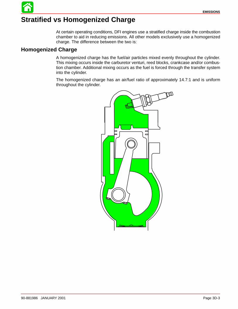
EMISSIONS
90-881986 JANUARY 2001 Page 3D-3
Stratified vs Homogenized Charge
At certain operating conditions, DFI engines use a stratified charge inside the combustionchamber to aid in reducing emissions. All other models exclusively use a homogenizedcharge. The difference between the two is:
Homogenized ChargeA homogenized charge has the fuel/air particles mixed evenly throughout the cylinder.This mixing occurs inside the carburetor venturi, reed blocks, crankcase and/or combus-tion chamber. Additional mixing occurs as the fuel is forced through the transfer systeminto the cylinder.
The homogenized charge has an air/fuel ratio of approximately 14.7:1 and is uniformthroughout the cylinder.
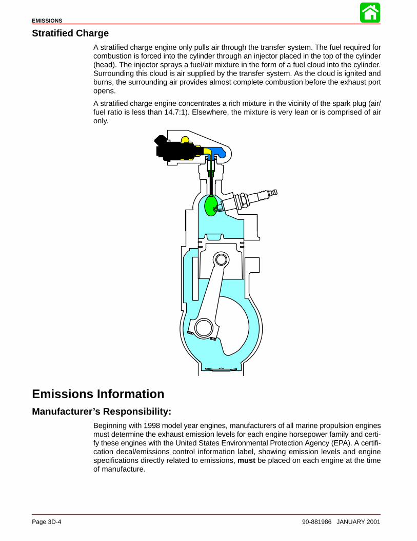
EMISSIONS
Page 3D-4 90-881986 JANUARY 2001
Stratified ChargeA stratified charge engine only pulls air through the transfer system. The fuel required forcombustion is forced into the cylinder through an injector placed in the top of the cylinder(head). The injector sprays a fuel/air mixture in the form of a fuel cloud into the cylinder.Surrounding this cloud is air supplied by the transfer system. As the cloud is ignited andburns, the surrounding air provides almost complete combustion before the exhaust portopens.
A stratified charge engine concentrates a rich mixture in the vicinity of the spark plug (air/fuel ratio is less than 14.7:1). Elsewhere, the mixture is very lean or is comprised of aironly.
Emissions InformationManufacturer’s Responsibility:
Beginning with 1998 model year engines, manufacturers of all marine propulsion enginesmust determine the exhaust emission levels for each engine horsepower family and certi-fy these engines with the United States Environmental Protection Agency (EPA). A certifi-cation decal/emissions control information label, showing emission levels and enginespecifications directly related to emissions, must be placed on each engine at the timeof manufacture.

EMISSIONS
90-881986 JANUARY 2001 Page 3D-5
Dealer Responsibility:When performing service on all 1998 and later jet drives that carry a certification, attentionmust be given to any adjustments that are made that affect emission levels.
Adjustments must be kept within published factory specifications.
Replacement or repair of any emission related component must be executed in a mannerthat maintains emission levels within the prescribed certification standards.
Dealers are not to modify the engine in any manner that would alter the horsepower orallow emission levels to exceed their predetermined factory specifications.
Exceptions include manufacturers prescribed changes, such as that for altitude adjust-ments. Also included would be factory authorized:
• Installation of performance style gear housings by Mercury Marine.
• Service replacement parts modified, changed or superceded by Mercury Marine.
Owner Responsibility:The owner/operator is required to have engine maintenance performed to maintain emis-sion levels within prescribed certification standards.
The owner/operator is not to modify the engine in any manner that would alter the horse-power or allow emissions levels to exceed their predetermined factory specifications.
Single engine exceptions may be allowed with permission from the EPA for racing andtesting.
EPA Emission Regulations:All new 1998 and later jet drives manufactured by Mercury Marine are certified to theUnited States Environmental Protection Agency as conforming to the requirements of theregulations for the control of air pollution from new outboard motors. This certification iscontingent on certain adjustments being set to factory standards. For this reason, the fac-tory procedure for servicing the product must be strictly followed and, whenever practica-ble, returned to the original intent of the design.
The responsibilities listed above are general and in no way a complete listing of the rulesand regulations pertaining to the EPA laws on exhaust emissions for marine products. Formore detailed information on this subject, you may contact the following locations:
VIA U.S. POSTAL SERVICE:Office of Mobile SourcesEngine Programs and Compliance DivisionEngine Compliance Programs Group (6403J)401 M St. NWWashington, DC 20460
VIA EXPRESS or COURIER MAIL:Office of Mobile SourcesEngine Programs and Compliance DivisionEngine Compliance Programs Group (6403J)501 3rd St. NWWashington, DC 20001
EPA INTERNET WEB SITE:http:/www.epa.gov/omswww
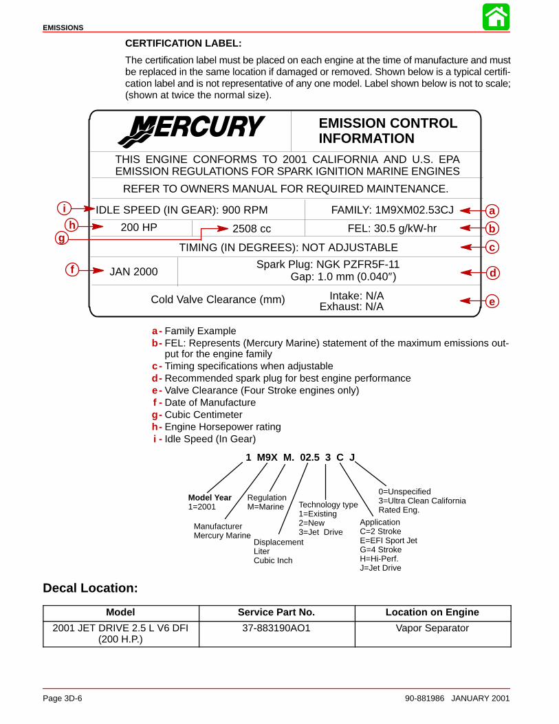
EMISSIONS
Page 3D-6 90-881986 JANUARY 2001
CERTIFICATION LABEL:
The certification label must be placed on each engine at the time of manufacture and mustbe replaced in the same location if damaged or removed. Shown below is a typical certifi-cation label and is not representative of any one model. Label shown below is not to scale;(shown at twice the normal size).
EMISSION CONTROLINFORMATION
THIS ENGINE CONFORMS TO 2001 CALIFORNIA AND U.S. EPAEMISSION REGULATIONS FOR SPARK IGNITION MARINE ENGINES
IDLE SPEED (IN GEAR): 900 RPM
TIMING (IN DEGREES): NOT ADJUSTABLE
Spark Plug: NGK PZFR5F-11Gap: 1.0 mm (0.040″)
Intake: N/A
REFER TO OWNERS MANUAL FOR REQUIRED MAINTENANCE.
FAMILY: 1M9XM02.53CJ
FEL: 30.5 g/kW-hr200 HP 2508 cc
JAN 2000
Cold Valve Clearance (mm)Exhaust: N/A
c
b
d
e
f
gh
i a
a- Family Exampleb- FEL: Represents (Mercury Marine) statement of the maximum emissions out-
put for the engine familyc - Timing specifications when adjustabled- Recommended spark plug for best engine performancee- Valve Clearance (Four Stroke engines only)f - Date of Manufactureg- Cubic Centimeterh- Engine Horsepower ratingi - Idle Speed (In Gear)
1 M9X M. 02.5 3 C J
Model Year1=2001
ManufacturerMercury Marine
RegulationM=Marine
DisplacementLiterCubic Inch
ApplicationC=2 StrokeE=EFI Sport JetG=4 StrokeH=Hi-Perf.J=Jet Drive
Technology type1=Existing2=New3=Jet Drive
0=Unspecified3=Ultra Clean CaliforniaRated Eng.
Decal Location:
Model Service Part No. Location on Engine
2001 JET DRIVE 2.5 L V6 DFI(200 H.P.)
37-883190AO1 Vapor Separator
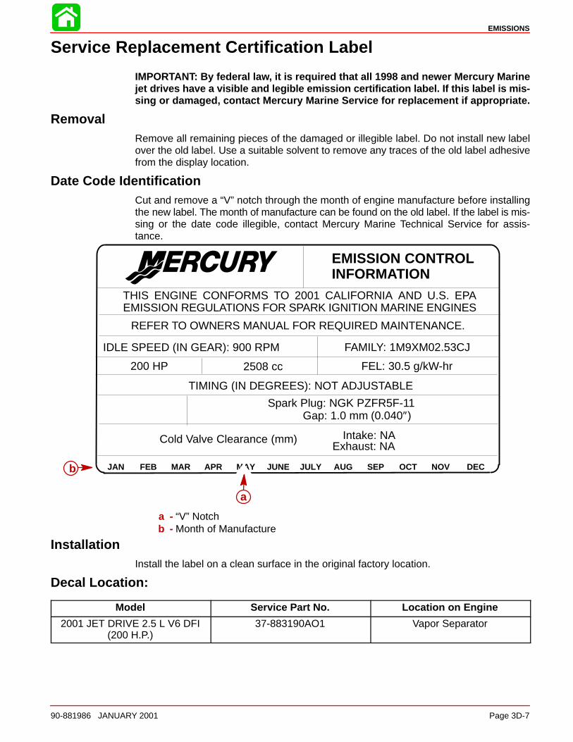
EMISSIONS
90-881986 JANUARY 2001 Page 3D-7
Service Replacement Certification Label
IMPORTANT: By federal law, it is required that all 1998 and newer Mercury Marinejet drives have a visible and legible emission certification label. If this label is mis-sing or damaged, contact Mercury Marine Service for replacement if appropriate.
RemovalRemove all remaining pieces of the damaged or illegible label. Do not install new labelover the old label. Use a suitable solvent to remove any traces of the old label adhesivefrom the display location.
Date Code IdentificationCut and remove a “V” notch through the month of engine manufacture before installingthe new label. The month of manufacture can be found on the old label. If the label is mis-sing or the date code illegible, contact Mercury Marine Technical Service for assis-tance.
EMISSION CONTROLINFORMATION
THIS ENGINE CONFORMS TO 2001 CALIFORNIA AND U.S. EPAEMISSION REGULATIONS FOR SPARK IGNITION MARINE ENGINES
IDLE SPEED (IN GEAR): 900 RPM
TIMING (IN DEGREES): NOT ADJUSTABLE
Spark Plug: NGK PZFR5F-11Gap: 1.0 mm (0.040″)
Intake: NA
REFER TO OWNERS MANUAL FOR REQUIRED MAINTENANCE.
FAMILY: 1M9XM02.53CJ
FEL: 30.5 g/kW-hr200 HP 2508 cc
Cold Valve Clearance (mm)Exhaust: NA
JAN FEB MAR APR MAY JUNE JULY AUG SEP OCT NOV DEC
a
b
a - “V” Notchb - Month of Manufacture
InstallationInstall the label on a clean surface in the original factory location.
Decal Location:
Model Service Part No. Location on Engine
2001 JET DRIVE 2.5 L V6 DFI(200 H.P.)
37-883190AO1 Vapor Separator
4A
POWERHEAD
90-881986 JANUARY 2001 Page 4A-1
POWERHEADSection 4A
Table of Contents
Powerhead Specifications 4A-2. . . . . . . . . . . . . . . . Special Tools 4A-3. . . . . . . . . . . . . . . . . . . . . . . . . . .
Powerhead Repair Stand 4A-4. . . . . . . . . . . . . . Cylinder Block Assembly 4A-6. . . . . . . . . . . . . . . . . Cylinder Block and End Caps 4A-8. . . . . . . . . . . . . Cylinder Head Assembly 4A-10. . . . . . . . . . . . . . . . . Crankshaft, Pistons and Connecting Rods 4A-12. . Expansion Chamber and Adaptor Plates 4A-14. . . Torque Sequence 4A-16. . . . . . . . . . . . . . . . . . . . . . . General Information 4A-18. . . . . . . . . . . . . . . . . . . . . Powerhead Removal from Pump Unit 4A-18. . . . . . Removing Engine Components 4A-21. . . . . . . . . . .
Removing Engine Components Individually 4A-21. . . . . . . . . . . . . . . . . . . . . . . . . Removing Engine Components as an Assembly 4A-22. . . . . . . . . . . . . . . . . . . . . . . . . .
Starboard Side Oil Hose Routing 4A-33. . . . . . . . . . Port Side Oil Hose Routing 4A-34. . . . . . . . . . . . . . . Water By-Pass Hose Routing 4A-35. . . . . . . . . . . . . Powerhead Disassembly 4A-36. . . . . . . . . . . . . . . . . Cleaning and Inspection 4A-44. . . . . . . . . . . . . . . . . .
Cylinder Block and Crankcase Cover 4A-44. . . Special Service Information 4A-44. . . . . . . . . . . . Cylinder Bores 4A-45. . . . . . . . . . . . . . . . . . . . . . .
Pistons and Piston Rings 4A-46. . . . . . . . . . . . . . Cylinder Heads and Exhaust Divider Plate 4A-48Crankshaft 4A-48. . . . . . . . . . . . . . . . . . . . . . . . . . Crankshaft (and End Cap) Bearings 4A-49. . . . End Bearing Bleed System 4A-50. . . . . . . . . . . . Connecting Rods 4A-50. . . . . . . . . . . . . . . . . . . . .
Powerhead Reassembly and Installation 4A-52. . . General 4A-52. . . . . . . . . . . . . . . . . . . . . . . . . . . . . Crankshaft Installation 4A-55. . . . . . . . . . . . . . . . Piston and Connecting Rod Reassembly 4A-57Piston and Piston Ring Combinations 4A-58. . . Piston Installation 4A-59. . . . . . . . . . . . . . . . . . . . Crankcase Cover Installation 4A-61. . . . . . . . . . . Reed Block Assembly 4A-62. . . . . . . . . . . . . . . . . Assembly of Reed Blocks to Reed Block Adaptor Plate 4A-63. . . . . . . . . . . . . . . . . . . . . . . Assembly of Exhaust Divider Plate to Block 4A-63. . . . . . . . . . . . . . . . . . . . . . . . . . . . Cylinder Head Installation 4A-64. . . . . . . . . . . . .
Reinstalling Engine Components 4A-65. . . . . . . . . . Throttle Lever/Throttle Cam Assembly 4A-66. . . . . Throttle Lever and Shift Shaft 4A-67. . . . . . . . . . . . . Powerhead Installation on Pump Unit 4A-68. . . . . . Break-ln Procedure 4A-71. . . . . . . . . . . . . . . . . . . . . .
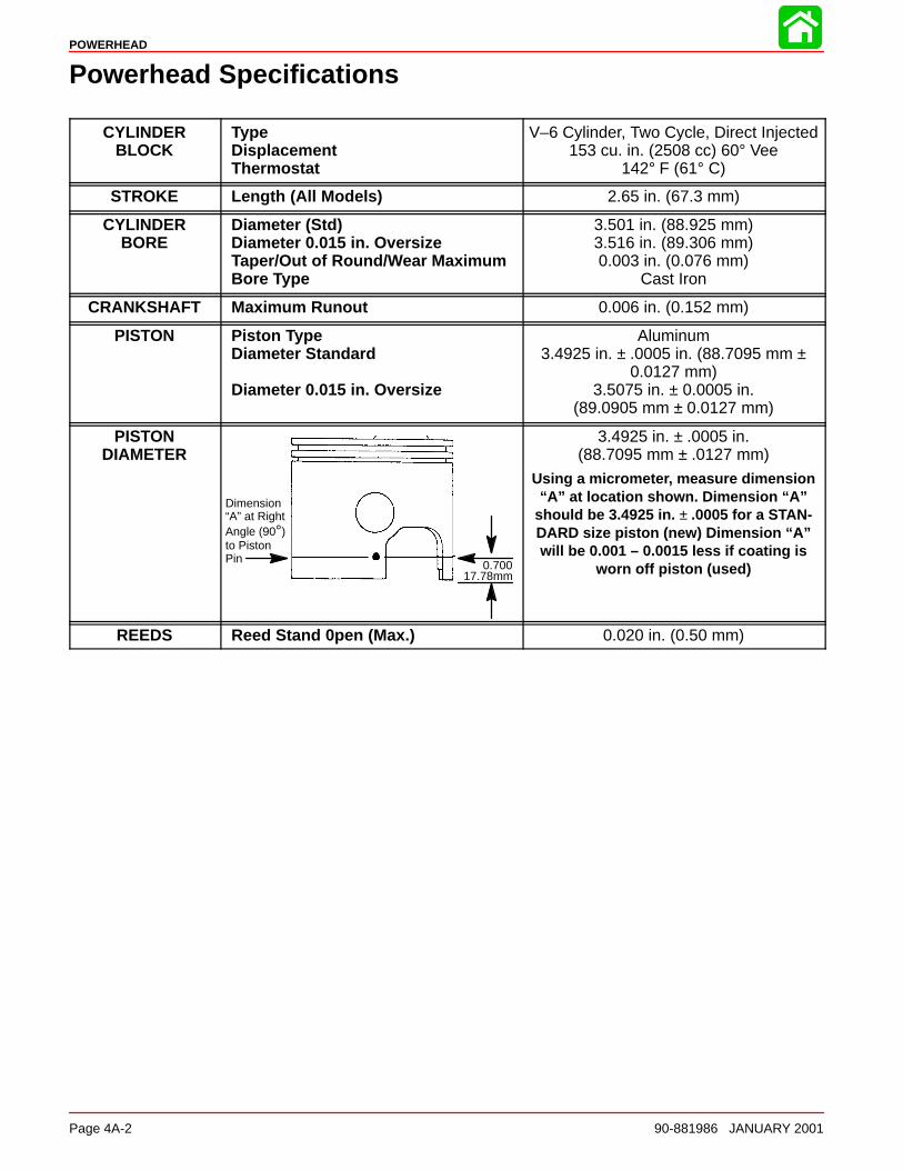
POWERHEAD
Page 4A-2 90-881986 JANUARY 2001
Powerhead Specifications
CYLINDERBLOCK
TypeDisplacementThermostat
V–6 Cylinder, Two Cycle, Direct Injected153 cu. in. (2508 cc) 60° Vee
142° F (61° C)
STROKE Length (All Models) 2.65 in. (67.3 mm)
CYLINDERBORE
Diameter (Std)Diameter 0.015 in. OversizeTaper/Out of Round/Wear MaximumBore Type
3.501 in. (88.925 mm)3.516 in. (89.306 mm)0.003 in. (0.076 mm)
Cast Iron
CRANKSHAFT Maximum Runout 0.006 in. (0.152 mm)
PISTON Piston TypeDiameter Standard
Diameter 0.015 in. Oversize
Aluminum3.4925 in. ± .0005 in. (88.7095 mm ±
0.0127 mm)3.5075 in. ± 0.0005 in.
(89.0905 mm ± 0.0127 mm)
PISTONDIAMETER
Dimension“A” at RightAngle (90°)to PistonPin 0.700
17.78mm
3.4925 in. ± .0005 in.(88.7095 mm ± .0127 mm)
Using a micrometer, measure dimension“A” at location shown. Dimension “A”
should be 3.4925 in. ± .0005 for a STAN-DARD size piston (new) Dimension “A”will be 0.001 – 0.0015 less if coating is
worn off piston (used)
REEDS Reed Stand 0pen (Max.) 0.020 in. (0.50 mm)
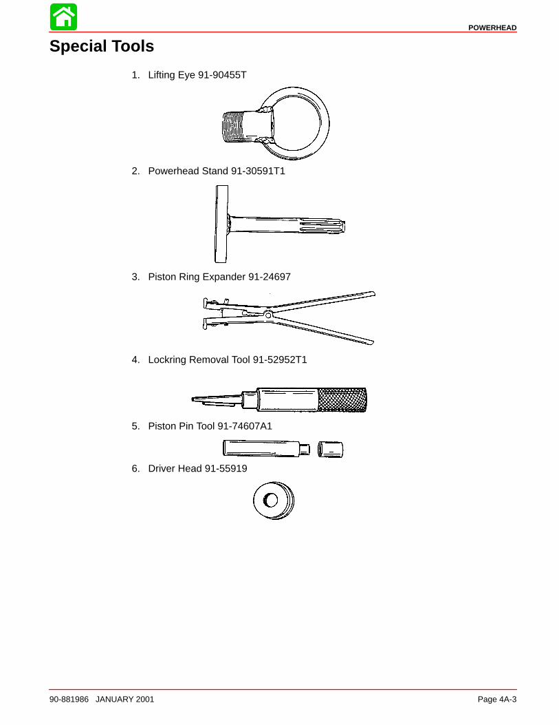
POWERHEAD
90-881986 JANUARY 2001 Page 4A-3
Special Tools
1. Lifting Eye 91-90455T
2. Powerhead Stand 91-30591T1
3. Piston Ring Expander 91-24697
4. Lockring Removal Tool 91-52952T1
5. Piston Pin Tool 91-74607A1
6. Driver Head 91-55919
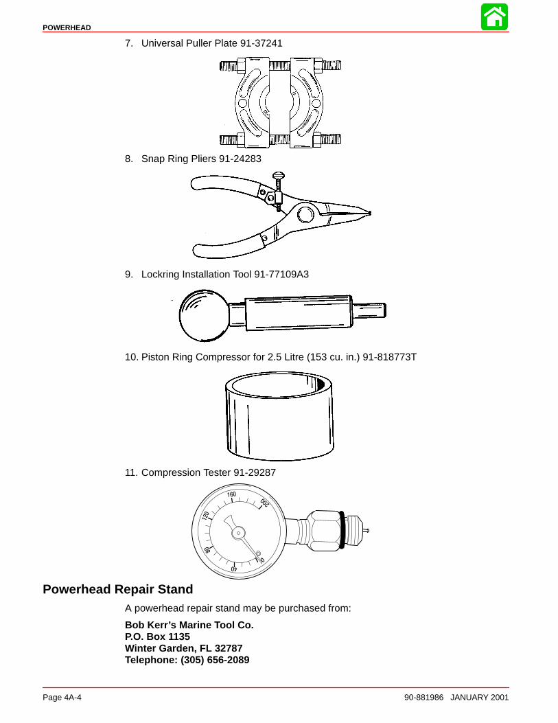
POWERHEAD
Page 4A-4 90-881986 JANUARY 2001
7. Universal Puller Plate 91-37241
8. Snap Ring Pliers 91-24283
9. Lockring Installation Tool 91-77109A3
10. Piston Ring Compressor for 2.5 Litre (153 cu. in.) 91-818773T
11. Compression Tester 91-29287
Powerhead Repair StandA powerhead repair stand may be purchased from:
Bob Kerr’s Marine Tool Co. P.O. Box 1135 Winter Garden, FL 32787 Telephone: (305) 656-2089

POWERHEAD
90-881986 JANUARY 2001 Page 4A-5
Notes:
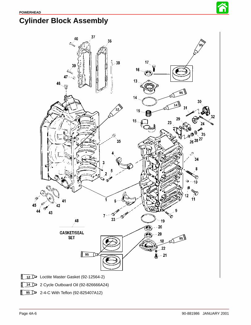
POWERHEAD
Page 4A-6 90-881986 JANUARY 2001
Cylinder Block Assembly
95
95
95
95
1412
12 Loctite Master Gasket (92-12564-2)
14 2 Cycle Outboard Oil (92-826666A24)
95 2-4-C With Teflon (92-825407A12)
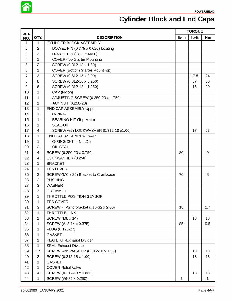
POWERHEAD
90-881986 JANUARY 2001 Page 4A-7
Cylinder Block and End Caps
REFTORQUE
REF.NO. QTY. DESCRIPTION lb-in lb-ft Nm
1 1 CYLINDER BLOCK ASSEMBLY
2 2 DOWEL PIN (0.375 x 0.620) locating3 2 DOWEL PIN (Center Main)4 1 COVER-Top Starter Mounting5 2 SCREW (0.312-18 x 1.50)6 1 COVER (Bottom Starter Mounting))7 2 SCREW (0.312-18 x 2.00) 17.5 24
8 8 SCREW (0.312-16 x 3.250) 37 509 6 SCREW (0.312-18 x 1.250) 15 2010 1 CAP (Nylon)11 1 ADJUSTING SCREW (0.250-20 x 1.750)12 1 JAM NUT (0.250-20)13 1 END CAP ASSEMBLY-Upper14 1 O-RING
15 1 BEARING KIT (Top Main)16 1 SEAL-Oil17 4 SCREW with LOCKWASHER (0.312-18 x1.00) 17 2318 1 END CAP ASSEMBLY-Lower19 1 O-RING (3-1/4 IN. I.D.)20 2 OIL SEAL21 4 SCREW (0.250-20 x 0.750) 80 9
22 4 LOCKWASHER (0.250)23 1 BRACKET24 1 TPS LEVER25 3 SCREW-(M6 x 25) Bracket to Crankcase 70 826 3 BUSHING27 3 WASHER28 3 GROMMET
29 1 THROTTLE POSITION SENSOR30 1 TPS COVER31 3 SCREW -TPS to bracket (#10-32 x 2.00) 15 1.732 1 THROTTLE LINK33 1 SCREW (M8 x 14) 13 1834 1 SCREW (#12-14 x 0.375) 85 9.535 1 PLUG (0.125-27)
36 1 GASKET37 1 PLATE KIT-Exhaust Divider38 1 SEAL-Exhaust Divider39 17 SCREW with WASHER (0.312-18 x 1.50) 13 1840 2 SCREW (0.312-18 x 1.00) 13 1841 1 GASKET
42 1 COVER-Relief Valve43 4 SCREW (0.312-18 x 0.880) 13 1844 1 SCREW (#6-32 x 0.250) 9 1

POWERHEAD
Page 4A-8 90-881986 JANUARY 2001
Cylinder Block Assembly
95
95
95
95
1412
12 Loctite Master Gasket (92-12564-2)
14 2 Cycle Outboard Oil (92-826666A24)
95 2-4-C With Teflon (92-825407A12)
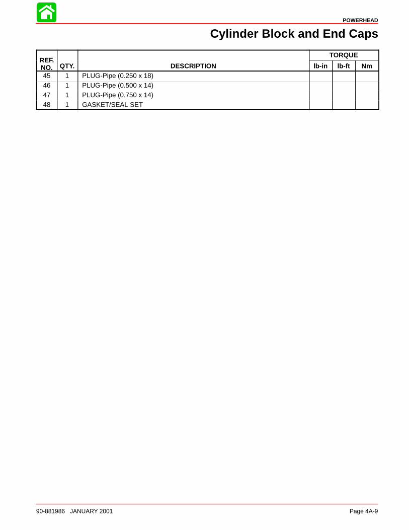
POWERHEAD
90-881986 JANUARY 2001 Page 4A-9
Cylinder Block and End Caps
REFTORQUE
REF.NO. QTY. DESCRIPTION lb-in lb-ft Nm45 1 PLUG-Pipe (0.250 x 18)
46 1 PLUG-Pipe (0.500 x 14)47 1 PLUG-Pipe (0.750 x 14)48 1 GASKET/SEAL SET
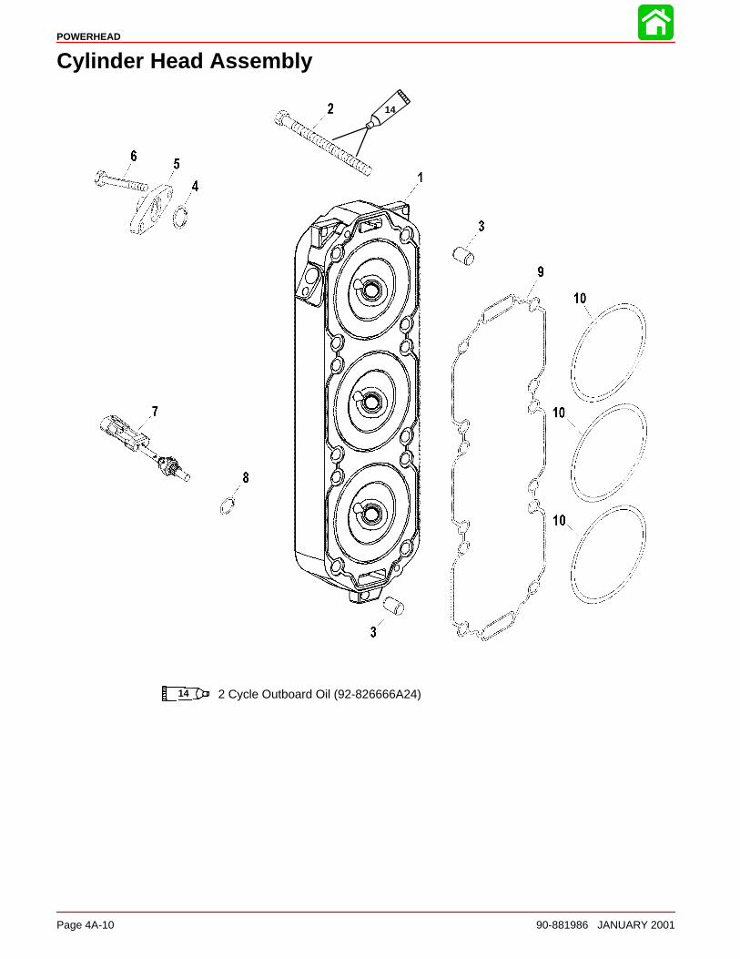
POWERHEAD
Page 4A-10 90-881986 JANUARY 2001
Cylinder Head Assembly
14 2 Cycle Outboard Oil (92-826666A24)
14
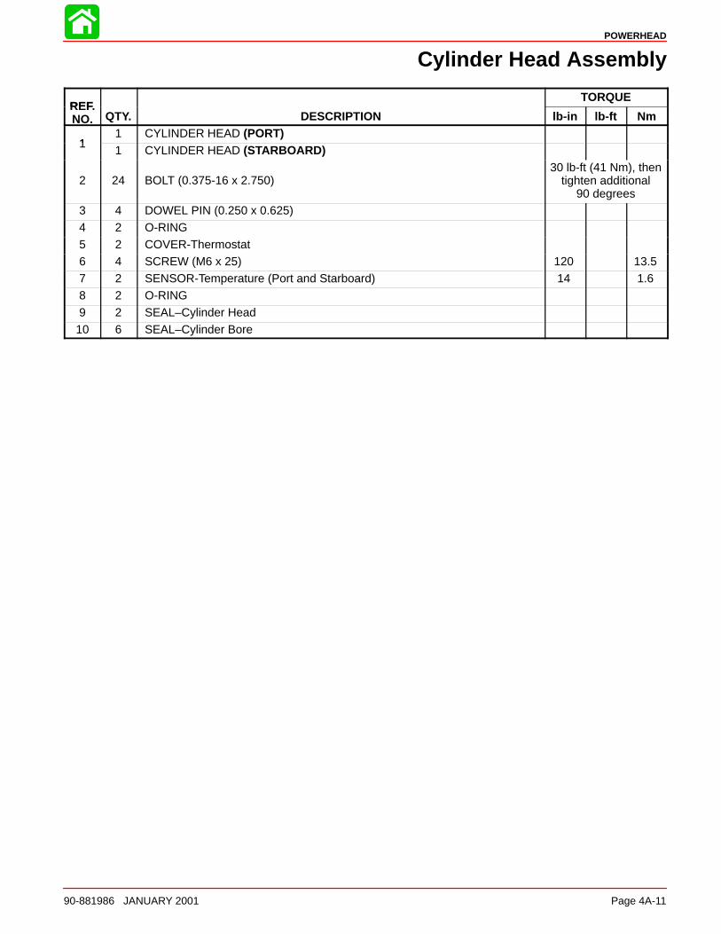
POWERHEAD
90-881986 JANUARY 2001 Page 4A-11
Cylinder Head Assembly
REFTORQUE
REF.NO. QTY. DESCRIPTION lb-in lb-ft Nm
11 CYLINDER HEAD (PORT)
11 CYLINDER HEAD (STARBOARD)
2 24 BOLT (0.375-16 x 2.750)30 lb-ft (41 Nm), then
tighten additional90 degrees
3 4 DOWEL PIN (0.250 x 0.625)4 2 O-RING5 2 COVER-Thermostat6 4 SCREW (M6 x 25) 120 13.57 2 SENSOR-Temperature (Port and Starboard) 14 1.68 2 O-RING
9 2 SEAL–Cylinder Head10 6 SEAL–Cylinder Bore
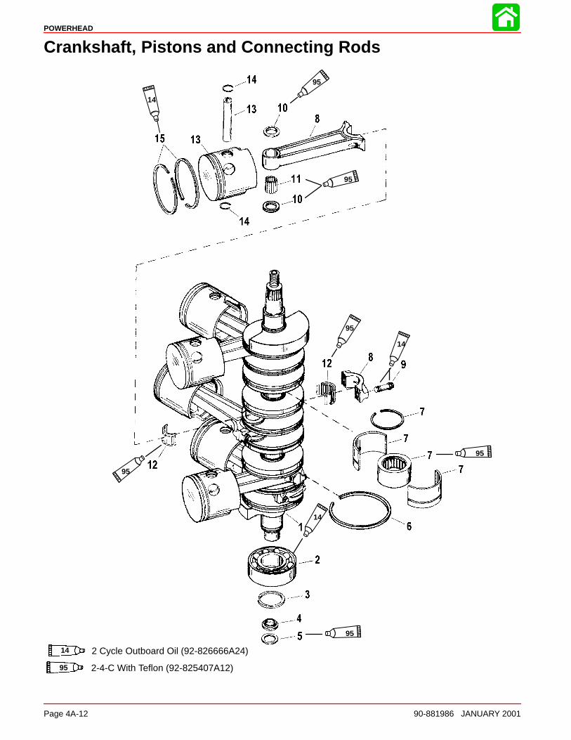
POWERHEAD
Page 4A-12 90-881986 JANUARY 2001
Crankshaft, Pistons and Connecting Rods
14
95
95
95
14
95
95
95
14
14 2 Cycle Outboard Oil (92-826666A24)
95 2-4-C With Teflon (92-825407A12)
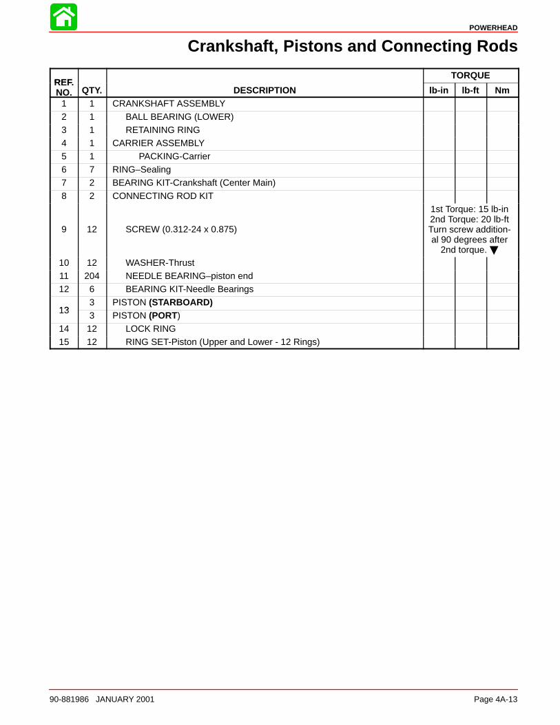
POWERHEAD
90-881986 JANUARY 2001 Page 4A-13
Crankshaft, Pistons and Connecting Rods
REFTORQUE
REF.NO. QTY. DESCRIPTION lb-in lb-ft Nm
1 1 CRANKSHAFT ASSEMBLY
2 1 BALL BEARING (LOWER)3 1 RETAINING RING4 1 CARRIER ASSEMBLY5 1 PACKING-Carrier6 7 RING–Sealing7 2 BEARING KIT-Crankshaft (Center Main)
8 2 CONNECTING ROD KIT
9 12 SCREW (0.312-24 x 0.875)
1st Torque: 15 lb-in2nd Torque: 20 lb-ftTurn screw addition-al 90 degrees after
2nd torque. 10 12 WASHER-Thrust11 204 NEEDLE BEARING–piston end12 6 BEARING KIT-Needle Bearings
133 PISTON (STARBOARD)
133 PISTON (PORT)
14 12 LOCK RING15 12 RING SET-Piston (Upper and Lower - 12 Rings)
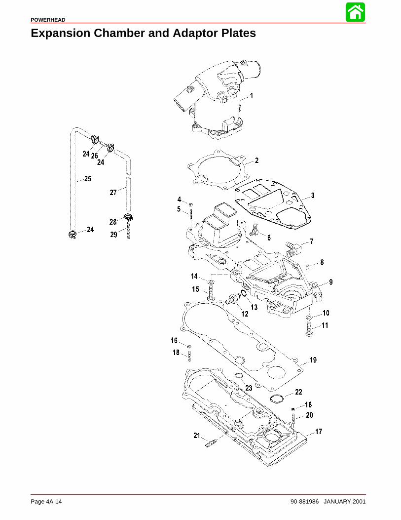
POWERHEAD
Page 4A-14 90-881986 JANUARY 2001
Expansion Chamber and Adaptor Plates
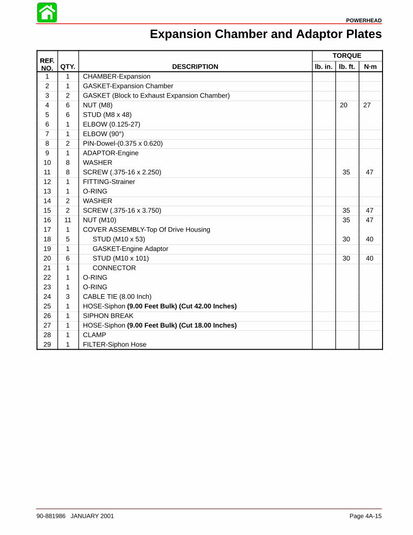
POWERHEAD
90-881986 JANUARY 2001 Page 4A-15
Expansion Chamber and Adaptor Plates
REFTORQUE
REF.NO. QTY. DESCRIPTION lb. in. lb. ft. N·m
1 1 CHAMBER-Expansion2 1 GASKET-Expansion Chamber3 2 GASKET (Block to Exhaust Expansion Chamber)4 6 NUT (M8) 20 275 6 STUD (M8 x 48)6 1 ELBOW (0.125-27)7 1 ELBOW (90°)8 2 PIN-Dowel-(0.375 x 0.620)9 1 ADAPTOR-Engine10 8 WASHER11 8 SCREW (.375-16 x 2.250) 35 4712 1 FITTING-Strainer13 1 O-RING14 2 WASHER15 2 SCREW (.375-16 x 3.750) 35 4716 11 NUT (M10) 35 4717 1 COVER ASSEMBLY-Top Of Drive Housing18 5 STUD (M10 x 53) 30 4019 1 GASKET-Engine Adaptor20 6 STUD (M10 x 101) 30 4021 1 CONNECTOR22 1 O-RING23 1 O-RING24 3 CABLE TIE (8.00 Inch)25 1 HOSE-Siphon (9.00 Feet Bulk) (Cut 42.00 Inches)26 1 SIPHON BREAK27 1 HOSE-Siphon (9.00 Feet Bulk) (Cut 18.00 Inches)28 1 CLAMP29 1 FILTER-Siphon Hose
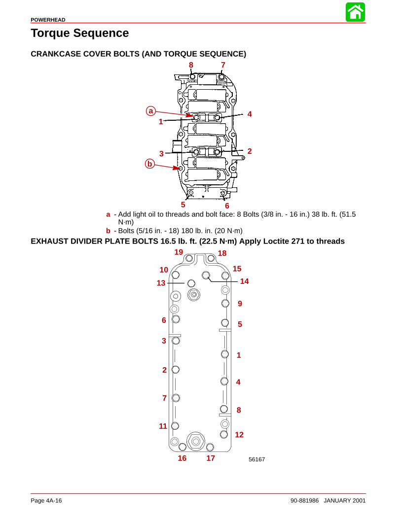
POWERHEAD
Page 4A-16 90-881986 JANUARY 2001
Torque Sequence
CRANKCASE COVER BOLTS (AND TORQUE SEQUENCE)
1
23
4
5 6
78
a
b
a - Add light oil to threads and bolt face: 8 Bolts (3/8 in. - 16 in.) 38 lb. ft. (51.5N·m)
b - Bolts (5/16 in. - 18) 180 lb. in. (20 N·m)
EXHAUST DIVIDER PLATE BOLTS 16.5 lb. ft. (22.5 N·m) Apply Loctite 271 to threads
56167
1
2
3
4
56
7
8
9
1112
13 14
15
16 17
1819
10
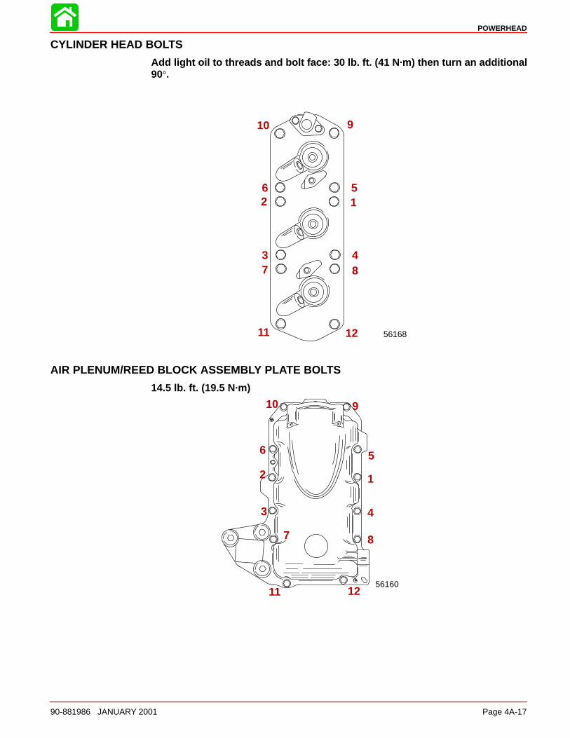
POWERHEAD
90-881986 JANUARY 2001 Page 4A-17
CYLINDER HEAD BOLTS
Add light oil to threads and bolt face: 30 lb. ft. (41 N·m) then turn an additional90°.
56168
12
3 4
56
7 8
910
11 12
AIR PLENUM/REED BLOCK ASSEMBLY PLATE BOLTS
14.5 lb. ft. (19.5 N·m)
56160
12
3 4
56
7 8
910
11 12
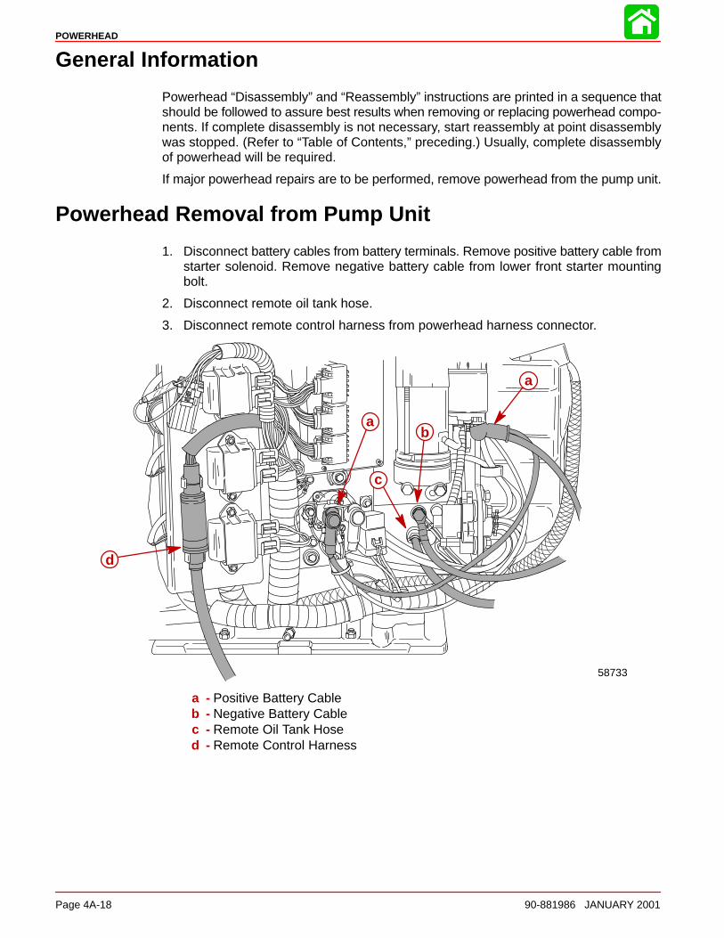
POWERHEAD
Page 4A-18 90-881986 JANUARY 2001
General Information
Powerhead “Disassembly” and “Reassembly” instructions are printed in a sequence thatshould be followed to assure best results when removing or replacing powerhead compo-nents. If complete disassembly is not necessary, start reassembly at point disassemblywas stopped. (Refer to “Table of Contents,” preceding.) Usually, complete disassemblyof powerhead will be required.
If major powerhead repairs are to be performed, remove powerhead from the pump unit.
Powerhead Removal from Pump Unit
1. Disconnect battery cables from battery terminals. Remove positive battery cable fromstarter solenoid. Remove negative battery cable from lower front starter mountingbolt.
2. Disconnect remote oil tank hose.
3. Disconnect remote control harness from powerhead harness connector.
58733
a
b
c
d
a
a - Positive Battery Cableb - Negative Battery Cablec - Remote Oil Tank Hosed - Remote Control Harness
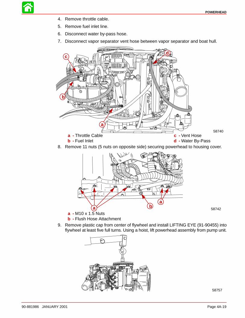
POWERHEAD
90-881986 JANUARY 2001 Page 4A-19
4. Remove throttle cable.
5. Remove fuel inlet line.
6. Disconnect water by-pass hose.
7. Disconnect vapor separator vent hose between vapor separator and boat hull.
a
b
cd
58740a - Throttle Cableb - Fuel Inlet
c - Vent Hosed - Water By-Pass
8. Remove 11 nuts (5 nuts on opposite side) securing powerhead to housing cover.
aa
b58742
a - M10 x 1.5 Nutsb - Flush Hose Attachment
9. Remove plastic cap from center of flywheel and install LIFTING EYE (91-90455) intoflywheel at least five full turns. Using a hoist, lift powerhead assembly from pump unit.
58757
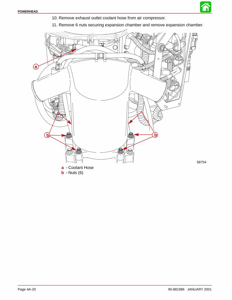
POWERHEAD
Page 4A-20 90-881986 JANUARY 2001
10. Remove exhaust outlet coolant hose from air compressor.
11. Remove 6 nuts securing expansion chamber and remove expansion chamber.
58754
a
b b
a - Coolant Hoseb - Nuts (6)
POWERHEAD
90-881986 JANUARY 2001 Page 4A-21
Removing Engine Components
NOTE: Engine components can be removed individually or in some cases as an assem-bly.
Removing Engine Components IndividuallySection 2 Starter MotorStarter Motor*Electronic Control Module*Ignition Coil*Starter SolenoidAlternatorFlywheel
Section 3Direct Fuel InjectionFuel PumpOn-Board Oil TankOil Pump
*All ignition and electrical components should remain attached to electrical plate.Plate with components can be removed as an assembly.
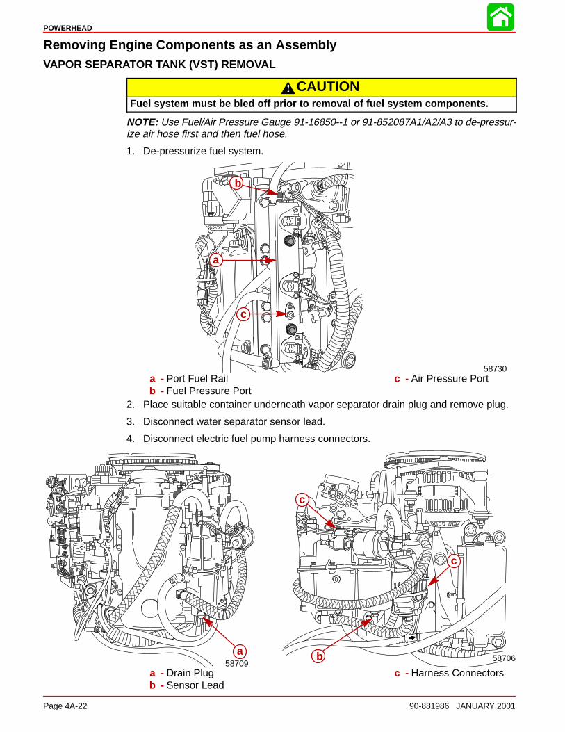
POWERHEAD
Page 4A-22 90-881986 JANUARY 2001
Removing Engine Components as an AssemblyVAPOR SEPARATOR TANK (VST) REMOVAL
CAUTIONFuel system must be bled off prior to removal of fuel system components.
NOTE: Use Fuel/Air Pressure Gauge 91-16850--1 or 91-852087A1/A2/A3 to de-pressur-ize air hose first and then fuel hose.
1. De-pressurize fuel system.
b
c
a
58730a - Port Fuel Railb - Fuel Pressure Port
c - Air Pressure Port
2. Place suitable container underneath vapor separator drain plug and remove plug.
3. Disconnect water separator sensor lead.
4. Disconnect electric fuel pump harness connectors.
a58709
b
c
c
58706
a - Drain Plugb - Sensor Lead
c - Harness Connectors

POWERHEAD
90-881986 JANUARY 2001 Page 4A-23
NOTE: Upper fuel hose is excess fuel return from fuel rails; lower fuel hose is fuel inletfrom electric circulating pump beside fuel/water separator.
5. Remove the fuel inlet hose from the fuel lift pump.
6. Remove vapor separator vent hose.
7. Remove the fuel outlet hose and fuel return hose from fuel rails.
8. Remove vapor separator ground lead.
9. Remove 3 mounting bolts and remove separator.
a
b
d
e
f
f
c
58740
58709g
a - Fuel Inlet Hose to FuelLift Pump
b - Vapor Separator VentHose
c - Fuel Outlet Hose
d - Fuel Return Hosee - Fuel Inlet Hosef - Mounting Bolts (3)g - Ground Lead
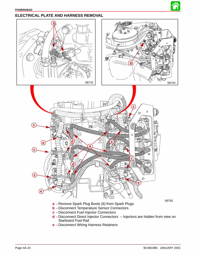
POWERHEAD
Page 4A-24 90-881986 JANUARY 2001
ELECTRICAL PLATE AND HARNESS REMOVAL
58755
5873458715
b
a
b
c
c
c
d
d
c
c
e
e
e
e
a - Remove Spark Plug Boots (6) from Spark Plugsb - Disconnect Temperature Sensor Connectorsc - Disconnect Fuel Injector Connectorsd - Disconnect Direct Injector Connectors – Injectors are hidden from view on
Starboard Fuel Raile - Disconnect Wiring Harness Retainers
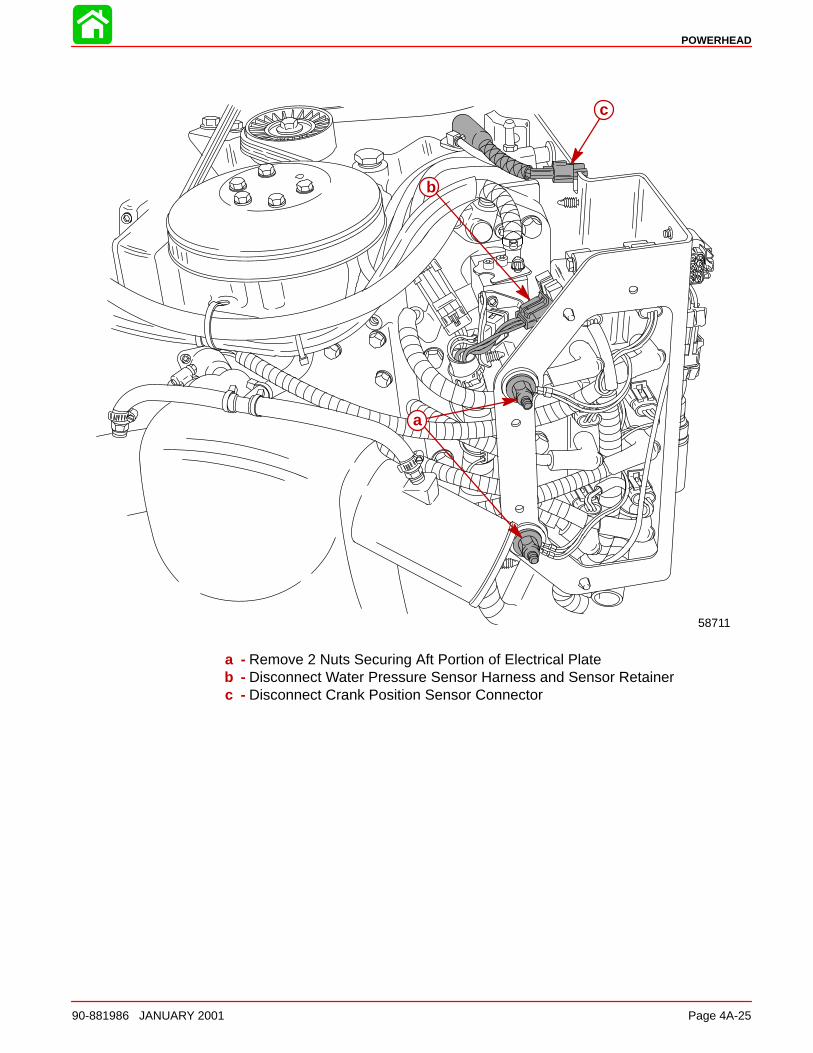
POWERHEAD
90-881986 JANUARY 2001 Page 4A-25
58711
a
b
c
a - Remove 2 Nuts Securing Aft Portion of Electrical Plateb - Disconnect Water Pressure Sensor Harness and Sensor Retainerc - Disconnect Crank Position Sensor Connector
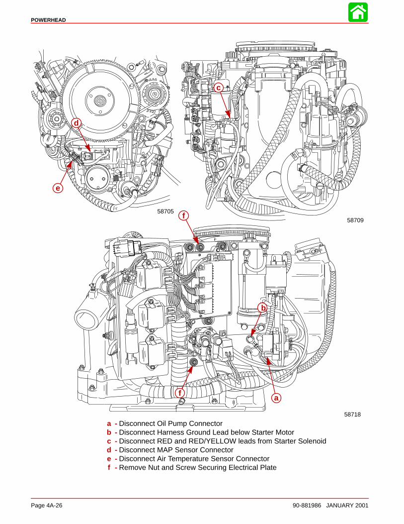
POWERHEAD
Page 4A-26 90-881986 JANUARY 2001
58718
f
f
b
c
d
a
58705
58709
e
a - Disconnect Oil Pump Connectorb - Disconnect Harness Ground Lead below Starter Motorc - Disconnect RED and RED/YELLOW leads from Starter Solenoidd - Disconnect MAP Sensor Connectore - Disconnect Air Temperature Sensor Connectorf - Remove Nut and Screw Securing Electrical Plate
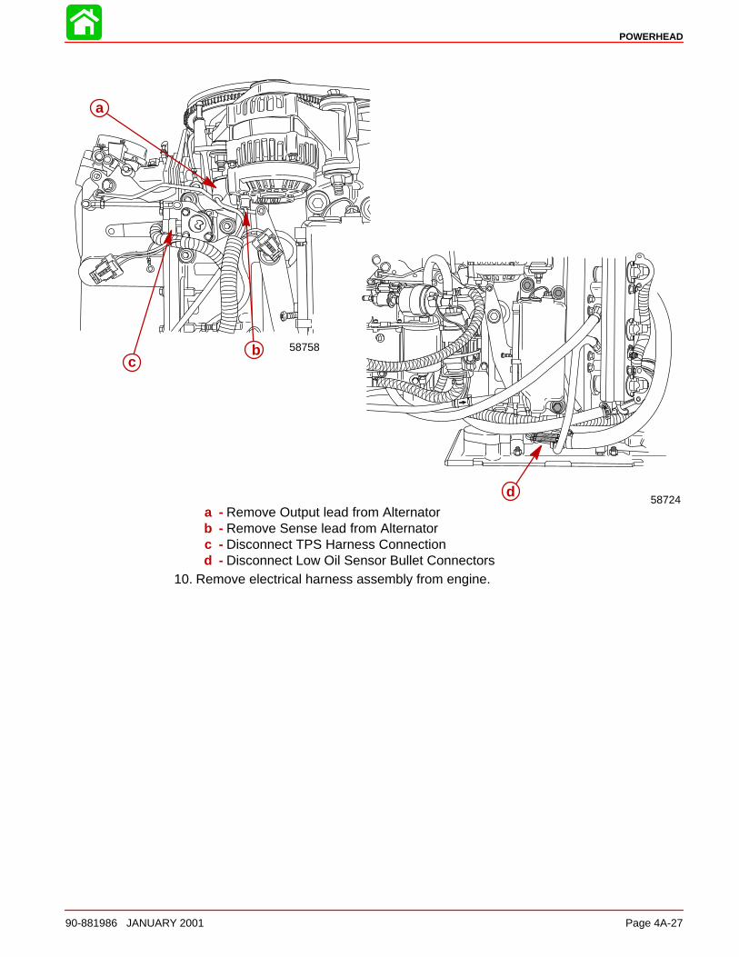
POWERHEAD
90-881986 JANUARY 2001 Page 4A-27
58758
58724
a
bc
da - Remove Output lead from Alternatorb - Remove Sense lead from Alternatorc - Disconnect TPS Harness Connectiond - Disconnect Low Oil Sensor Bullet Connectors
10. Remove electrical harness assembly from engine.
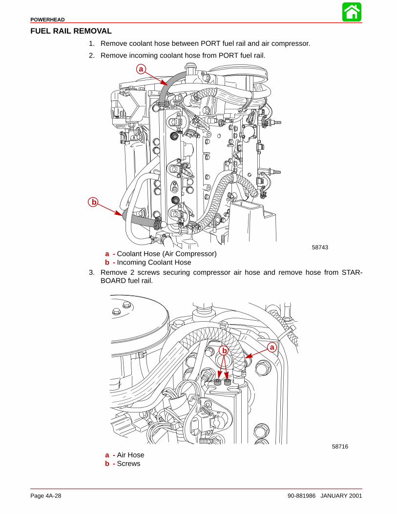
POWERHEAD
Page 4A-28 90-881986 JANUARY 2001
FUEL RAIL REMOVAL
1. Remove coolant hose between PORT fuel rail and air compressor.
2. Remove incoming coolant hose from PORT fuel rail.
58743
b
a
a - Coolant Hose (Air Compressor)b - Incoming Coolant Hose
3. Remove 2 screws securing compressor air hose and remove hose from STAR-BOARD fuel rail.
58716
ab
a - Air Hoseb - Screws
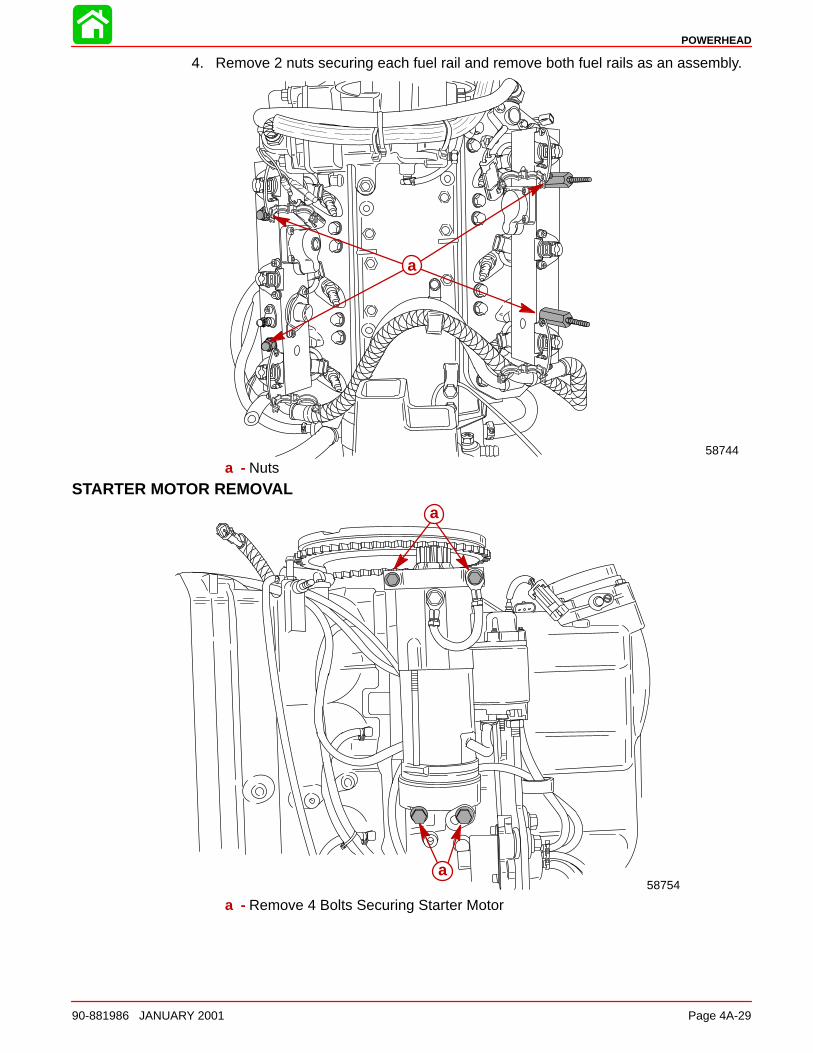
POWERHEAD
90-881986 JANUARY 2001 Page 4A-29
4. Remove 2 nuts securing each fuel rail and remove both fuel rails as an assembly.
58744
a
a - Nuts
STARTER MOTOR REMOVAL
58754a
a
a - Remove 4 Bolts Securing Starter Motor
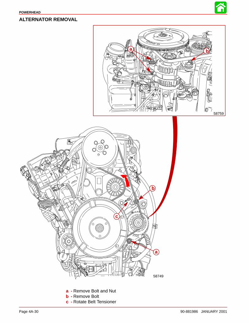
POWERHEAD
Page 4A-30 90-881986 JANUARY 2001
ALTERNATOR REMOVAL
b
a
c
58749
a b
58759
a - Remove Bolt and Nutb - Remove Boltc - Rotate Belt Tensioner
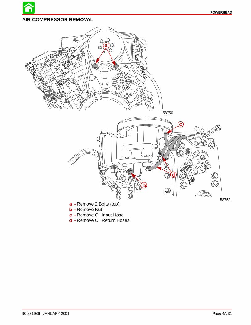
POWERHEAD
90-881986 JANUARY 2001 Page 4A-31
AIR COMPRESSOR REMOVAL
58750
a
58752
b
c
d
a - Remove 2 Bolts (top)b - Remove Nutc - Remove Oil Input Hosed - Remove Oil Return Hoses
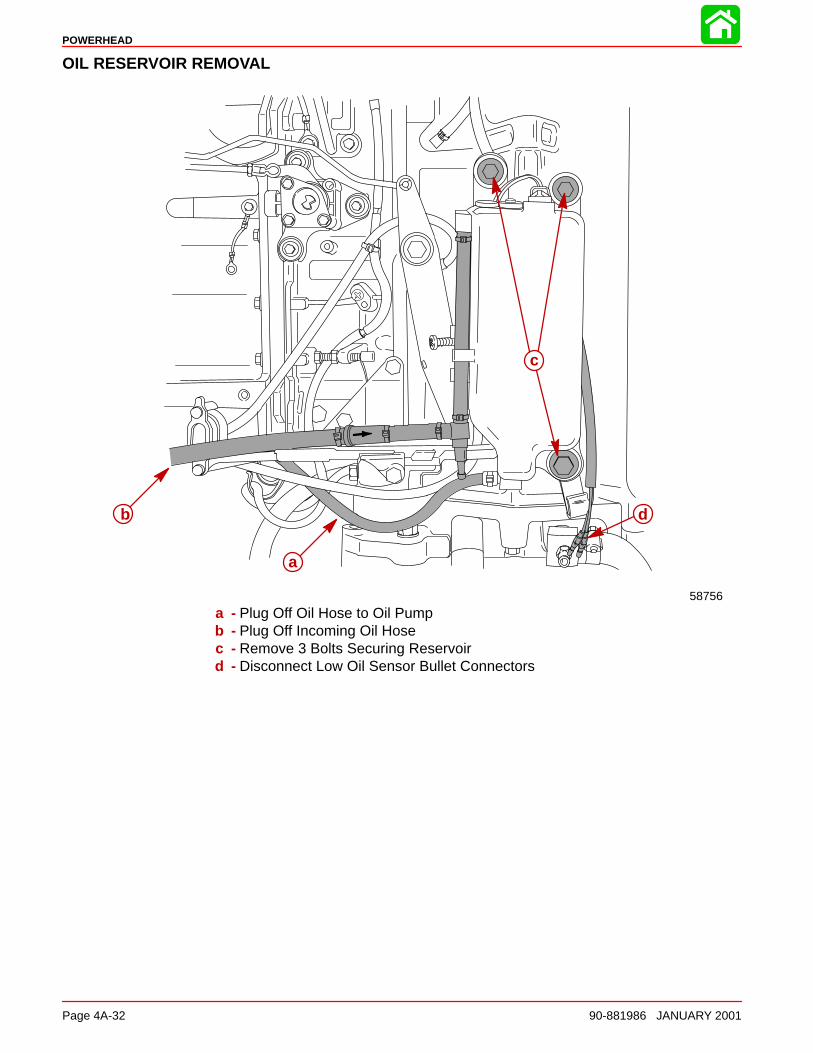
POWERHEAD
Page 4A-32 90-881986 JANUARY 2001
OIL RESERVOIR REMOVAL
b
c
d
a
58756
a - Plug Off Oil Hose to Oil Pumpb - Plug Off Incoming Oil Hosec - Remove 3 Bolts Securing Reservoird - Disconnect Low Oil Sensor Bullet Connectors
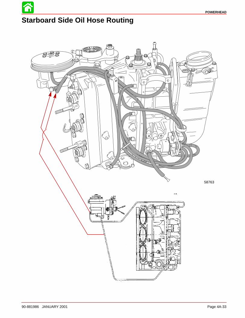
POWERHEAD
90-881986 JANUARY 2001 Page 4A-33
Starboard Side Oil Hose Routing
58763
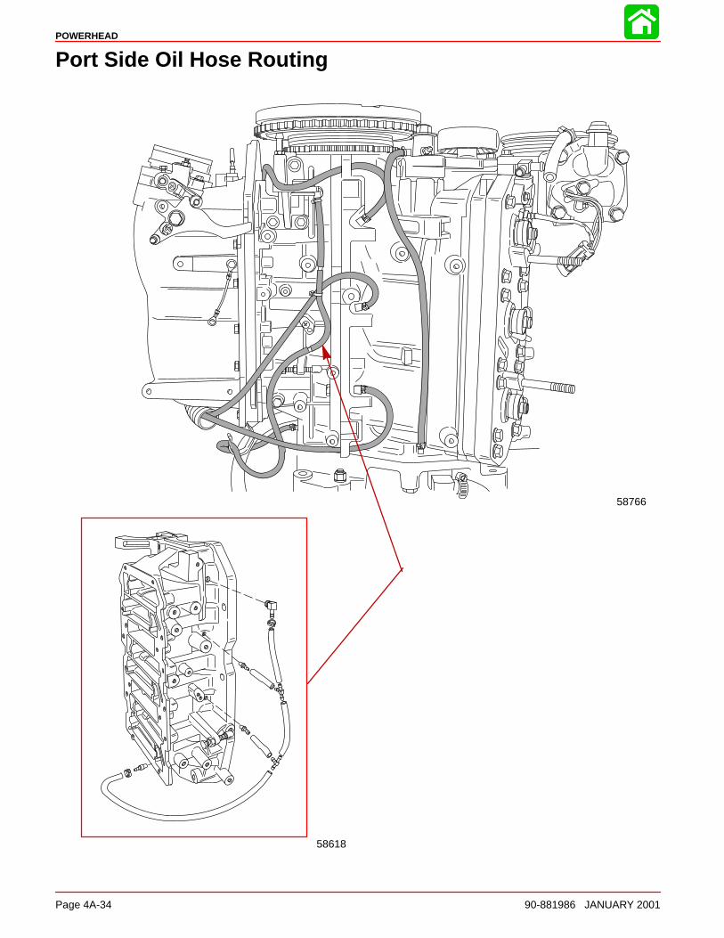
POWERHEAD
Page 4A-34 90-881986 JANUARY 2001
Port Side Oil Hose Routing
58618
58766
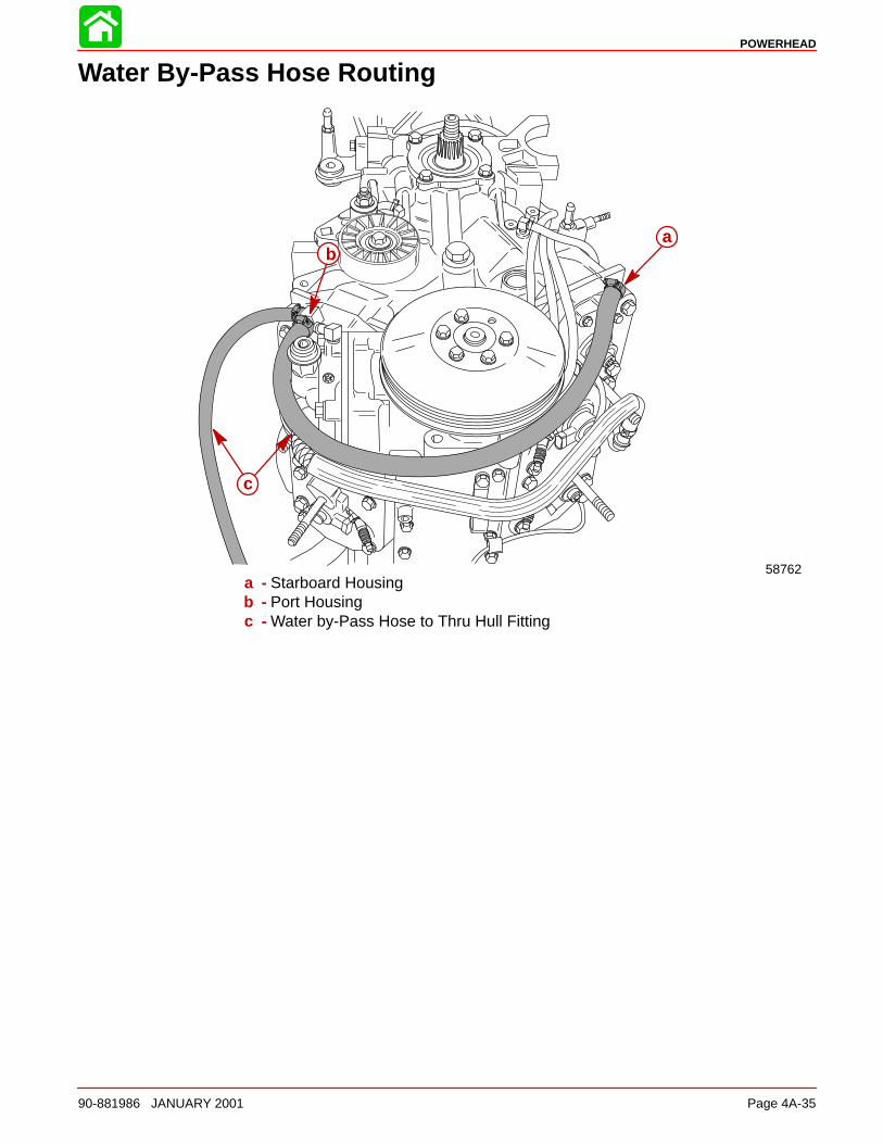
POWERHEAD
90-881986 JANUARY 2001 Page 4A-35
Water By-Pass Hose Routing
58762
c
ba
a - Starboard Housingb - Port Housingc - Water by-Pass Hose to Thru Hull Fitting
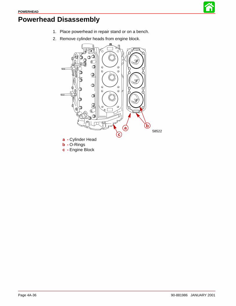
POWERHEAD
Page 4A-36 90-881986 JANUARY 2001
Powerhead Disassembly
1. Place powerhead in repair stand or on a bench.
2. Remove cylinder heads from engine block.
a58522
b
ca - Cylinder Headb - O-Ringsc - Engine Block
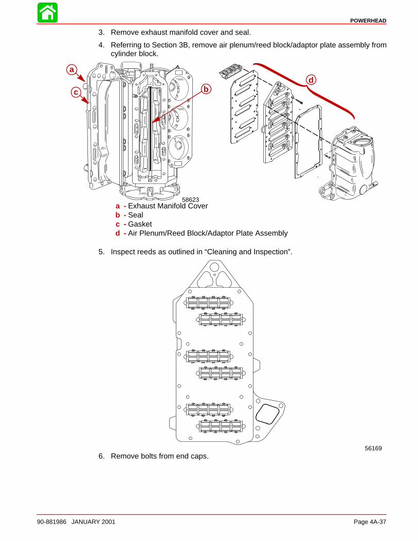
POWERHEAD
90-881986 JANUARY 2001 Page 4A-37
3. Remove exhaust manifold cover and seal.
4. Referring to Section 3B, remove air plenum/reed block/adaptor plate assembly fromcylinder block.
aad
58623
cc b
a - Exhaust Manifold Coverb - Sealc - Gasketd - Air Plenum/Reed Block/Adaptor Plate Assembly
5. Inspect reeds as outlined in “Cleaning and Inspection”.
561696. Remove bolts from end caps.
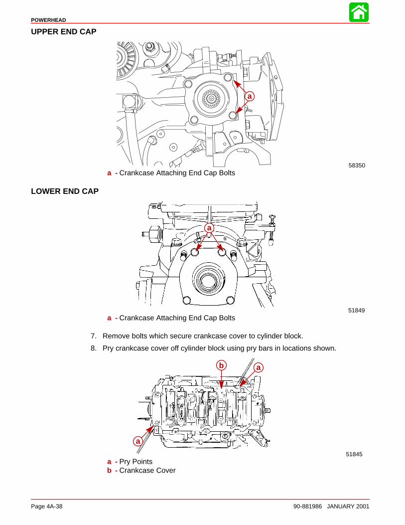
POWERHEAD
Page 4A-38 90-881986 JANUARY 2001
UPPER END CAP
a
58350a - Crankcase Attaching End Cap Bolts
LOWER END CAP
a
51849
a
a - Crankcase Attaching End Cap Bolts
7. Remove bolts which secure crankcase cover to cylinder block.
8. Pry crankcase cover off cylinder block using pry bars in locations shown.
a
b a
51845
ab
a
a - Pry Pointsb - Crankcase Cover
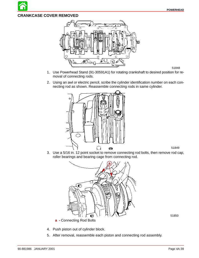
POWERHEAD
90-881986 JANUARY 2001 Page 4A-39
CRANKCASE COVER REMOVED
51848
1. Use Powerhead Stand (91-30591A1) for rotating crankshaft to desired position for re-moval of connecting rods.
2. Using an awl or electric pencil, scribe the cylinder identification number on each con-necting rod as shown. Reassemble connecting rods in same cylinder.
51849
ÄÄÄÄ
3. Use a 5/16 in. 12 point socket to remove connecting rod bolts, then remove rod cap,roller bearings and bearing cage from connecting rod.
a
51850
a
a - Connecting Rod Bolts
4. Push piston out of cylinder block.
5. After removal, reassemble each piston and connecting rod assembly.
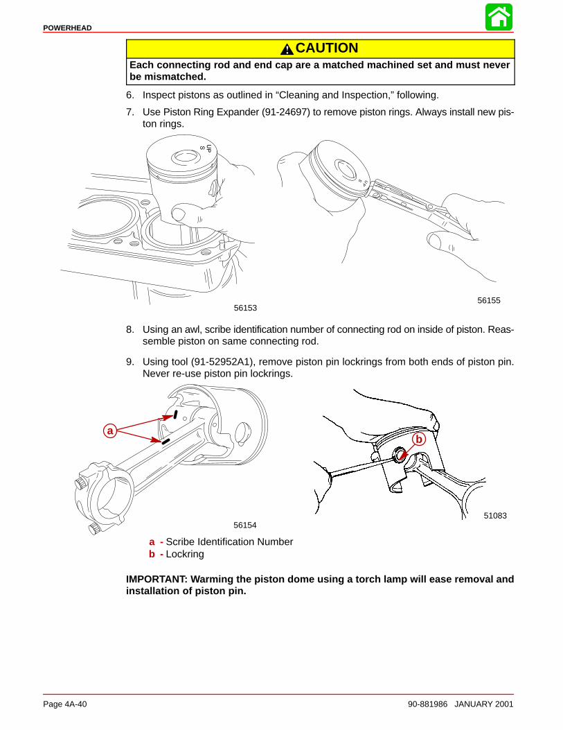
POWERHEAD
Page 4A-40 90-881986 JANUARY 2001
CAUTIONEach connecting rod and end cap are a matched machined set and must neverbe mismatched.
6. Inspect pistons as outlined in “Cleaning and Inspection,” following.
7. Use Piston Ring Expander (91-24697) to remove piston rings. Always install new pis-ton rings.
5615556153
8. Using an awl, scribe identification number of connecting rod on inside of piston. Reas-semble piston on same connecting rod.
9. Using tool (91-52952A1), remove piston pin lockrings from both ends of piston pin.Never re-use piston pin lockrings.
a
5108356154
ab
a
a - Scribe Identification Numberb - Lockring
IMPORTANT: Warming the piston dome using a torch lamp will ease removal andinstallation of piston pin.
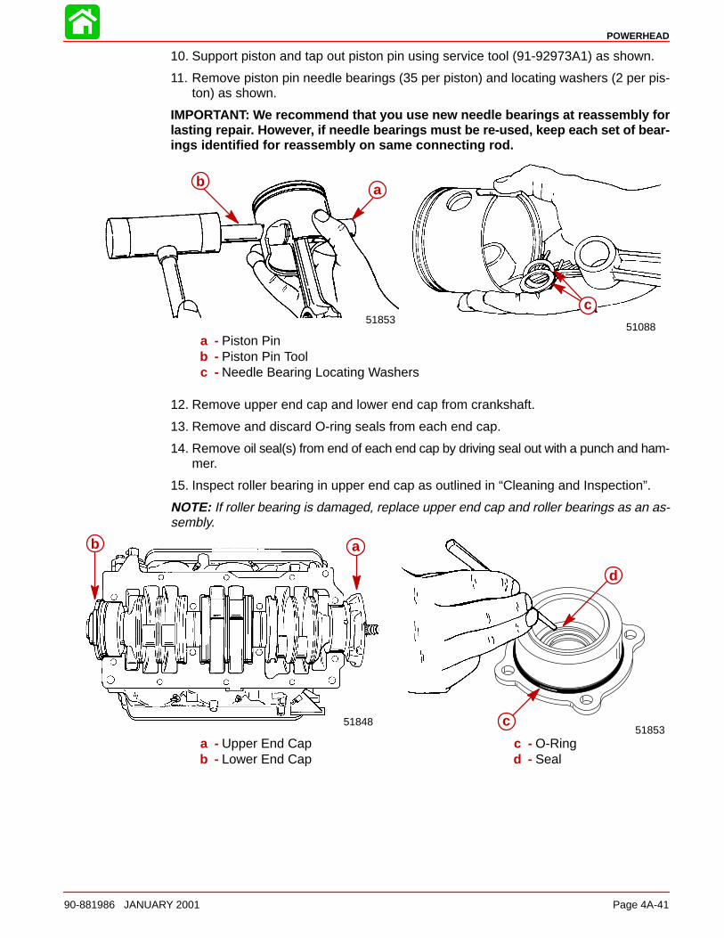
POWERHEAD
90-881986 JANUARY 2001 Page 4A-41
10. Support piston and tap out piston pin using service tool (91-92973A1) as shown.
11. Remove piston pin needle bearings (35 per piston) and locating washers (2 per pis-ton) as shown.
IMPORTANT: We recommend that you use new needle bearings at reassembly forlasting repair. However, if needle bearings must be re-used, keep each set of bear-ings identified for reassembly on same connecting rod.
a51088
a
51853
b a
c
a - Piston Pinb - Piston Pin Toolc - Needle Bearing Locating Washers
12. Remove upper end cap and lower end cap from crankshaft.
13. Remove and discard O-ring seals from each end cap.
14. Remove oil seal(s) from end of each end cap by driving seal out with a punch and ham-mer.
15. Inspect roller bearing in upper end cap as outlined in “Cleaning and Inspection”.
NOTE: If roller bearing is damaged, replace upper end cap and roller bearings as an as-sembly.
51853
ab
51848
ab
d
c
a - Upper End Capb - Lower End Cap
c - O-Ringd - Seal
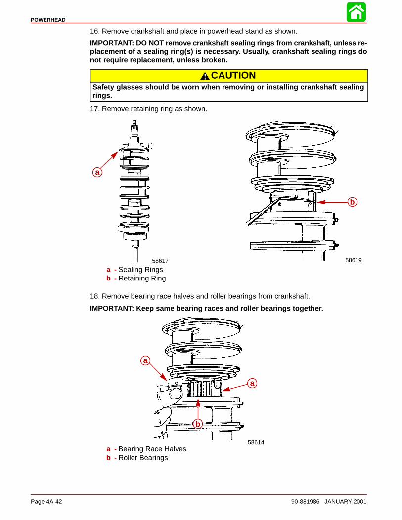
POWERHEAD
Page 4A-42 90-881986 JANUARY 2001
16. Remove crankshaft and place in powerhead stand as shown.
IMPORTANT: DO NOT remove crankshaft sealing rings from crankshaft, unless re-placement of a sealing ring(s) is necessary. Usually, crankshaft sealing rings donot require replacement, unless broken.
CAUTIONSafety glasses should be worn when removing or installing crankshaft sealingrings.
17. Remove retaining ring as shown.
a
58617
ab
58619
a - Sealing Ringsb - Retaining Ring
18. Remove bearing race halves and roller bearings from crankshaft.
IMPORTANT: Keep same bearing races and roller bearings together.
58614
aa
aa
bb
a - Bearing Race Halvesb - Roller Bearings
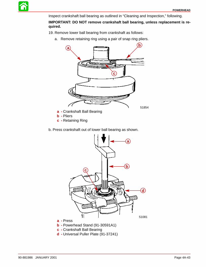
POWERHEAD
90-881986 JANUARY 2001 Page 4A-43
Inspect crankshaft ball bearing as outlined in “Cleaning and Inspection,” following.
IMPORTANT: DO NOT remove crankshaft ball bearing, unless replacement is re-quired.
19. Remove lower ball bearing from crankshaft as follows:
a. Remove retaining ring using a pair of snap ring pliers.
ab
c
ab
c
51854a - Crankshaft Ball Bearingb - Pliersc - Retaining Ring
b. Press crankshaft out of lower ball bearing as shown.
a
b
d
c
51081
bc
d
a
a - Pressb - Powerhead Stand (91-30591A1)c - Crankshaft Ball Bearingd - Universal Puller Plate (91-37241)
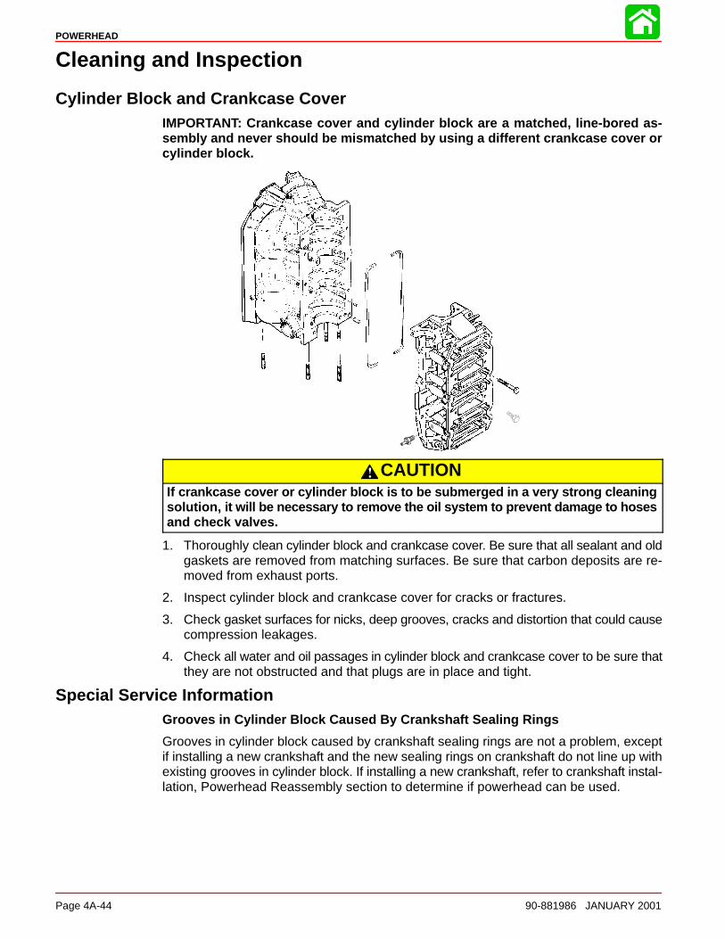
POWERHEAD
Page 4A-44 90-881986 JANUARY 2001
Cleaning and Inspection
Cylinder Block and Crankcase CoverIMPORTANT: Crankcase cover and cylinder block are a matched, line-bored as-sembly and never should be mismatched by using a different crankcase cover orcylinder block.
CAUTIONIf crankcase cover or cylinder block is to be submerged in a very strong cleaningsolution, it will be necessary to remove the oil system to prevent damage to hosesand check valves.
1. Thoroughly clean cylinder block and crankcase cover. Be sure that all sealant and oldgaskets are removed from matching surfaces. Be sure that carbon deposits are re-moved from exhaust ports.
2. Inspect cylinder block and crankcase cover for cracks or fractures.
3. Check gasket surfaces for nicks, deep grooves, cracks and distortion that could causecompression leakages.
4. Check all water and oil passages in cylinder block and crankcase cover to be sure thatthey are not obstructed and that plugs are in place and tight.
Special Service InformationGrooves in Cylinder Block Caused By Crankshaft Sealing Rings
Grooves in cylinder block caused by crankshaft sealing rings are not a problem, exceptif installing a new crankshaft and the new sealing rings on crankshaft do not line up withexisting grooves in cylinder block. If installing a new crankshaft, refer to crankshaft instal-lation, Powerhead Reassembly section to determine if powerhead can be used.
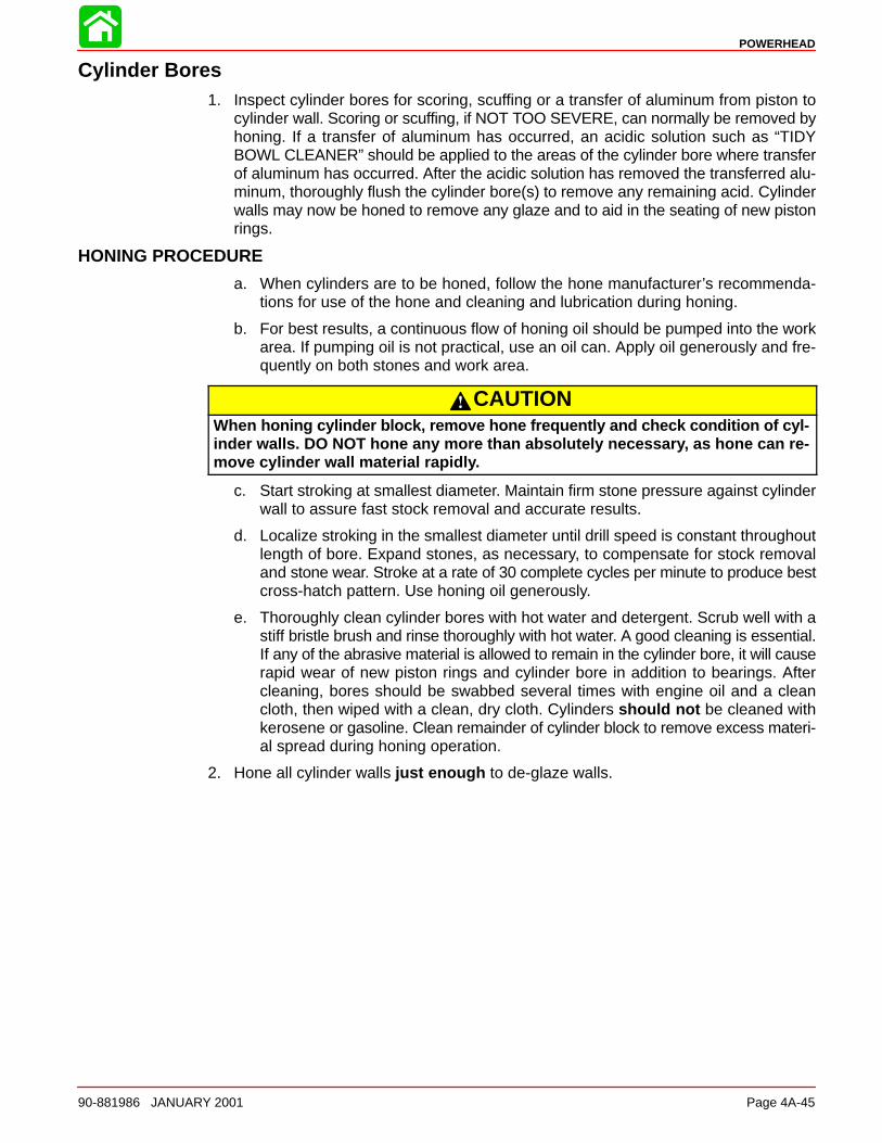
POWERHEAD
90-881986 JANUARY 2001 Page 4A-45
Cylinder Bores1. Inspect cylinder bores for scoring, scuffing or a transfer of aluminum from piston to
cylinder wall. Scoring or scuffing, if NOT TOO SEVERE, can normally be removed byhoning. If a transfer of aluminum has occurred, an acidic solution such as “TIDYBOWL CLEANER” should be applied to the areas of the cylinder bore where transferof aluminum has occurred. After the acidic solution has removed the transferred alu-minum, thoroughly flush the cylinder bore(s) to remove any remaining acid. Cylinderwalls may now be honed to remove any glaze and to aid in the seating of new pistonrings.
HONING PROCEDURE
a. When cylinders are to be honed, follow the hone manufacturer’s recommenda-tions for use of the hone and cleaning and lubrication during honing.
b. For best results, a continuous flow of honing oil should be pumped into the workarea. If pumping oil is not practical, use an oil can. Apply oil generously and fre-quently on both stones and work area.
CAUTIONWhen honing cylinder block, remove hone frequently and check condition of cyl-inder walls. DO NOT hone any more than absolutely necessary, as hone can re-move cylinder wall material rapidly.
c. Start stroking at smallest diameter. Maintain firm stone pressure against cylinderwall to assure fast stock removal and accurate results.
d. Localize stroking in the smallest diameter until drill speed is constant throughoutlength of bore. Expand stones, as necessary, to compensate for stock removaland stone wear. Stroke at a rate of 30 complete cycles per minute to produce bestcross-hatch pattern. Use honing oil generously.
e. Thoroughly clean cylinder bores with hot water and detergent. Scrub well with astiff bristle brush and rinse thoroughly with hot water. A good cleaning is essential.If any of the abrasive material is allowed to remain in the cylinder bore, it will causerapid wear of new piston rings and cylinder bore in addition to bearings. Aftercleaning, bores should be swabbed several times with engine oil and a cleancloth, then wiped with a clean, dry cloth. Cylinders should not be cleaned withkerosene or gasoline. Clean remainder of cylinder block to remove excess materi-al spread during honing operation.
2. Hone all cylinder walls just enough to de-glaze walls.
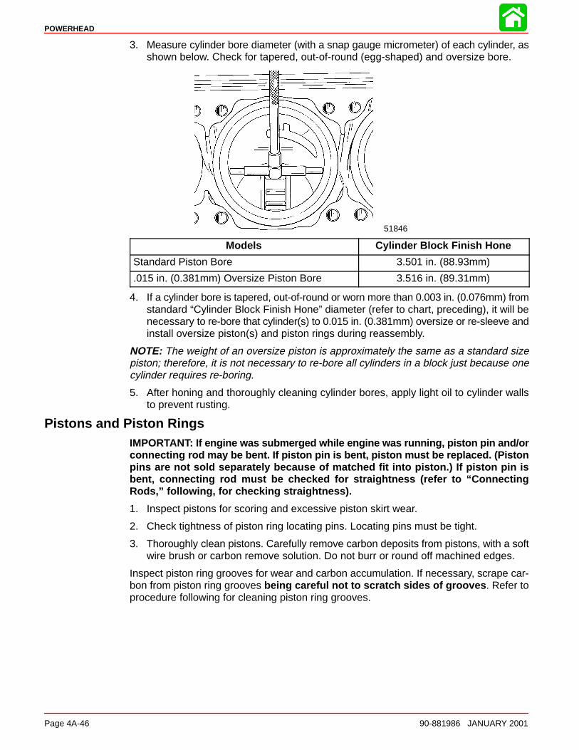
POWERHEAD
Page 4A-46 90-881986 JANUARY 2001
3. Measure cylinder bore diameter (with a snap gauge micrometer) of each cylinder, asshown below. Check for tapered, out-of-round (egg-shaped) and oversize bore.
51846
Models Cylinder Block Finish Hone
Standard Piston Bore 3.501 in. (88.93mm)
.015 in. (0.381mm) Oversize Piston Bore 3.516 in. (89.31mm)
4. If a cylinder bore is tapered, out-of-round or worn more than 0.003 in. (0.076mm) fromstandard “Cylinder Block Finish Hone” diameter (refer to chart, preceding), it will benecessary to re-bore that cylinder(s) to 0.015 in. (0.381mm) oversize or re-sleeve andinstall oversize piston(s) and piston rings during reassembly.
NOTE: The weight of an oversize piston is approximately the same as a standard sizepiston; therefore, it is not necessary to re-bore all cylinders in a block just because onecylinder requires re-boring.
5. After honing and thoroughly cleaning cylinder bores, apply light oil to cylinder wallsto prevent rusting.
Pistons and Piston RingsIMPORTANT: If engine was s ubmerged while engine was running, piston pin and/orconnecting rod may be bent. If piston pin is bent, piston must be replaced. (Pistonpins are not sold separately because of matched fit into piston.) If piston pin isbent, connecting rod must be checked for straightness (refer to “ConnectingRods,” following, for checking straightness).
1. Inspect pistons for scoring and excessive piston skirt wear.
2. Check tightness of piston ring locating pins. Locating pins must be tight.
3. Thoroughly clean pistons. Carefully remove carbon deposits from pistons, with a softwire brush or carbon remove solution. Do not burr or round off machined edges.
Inspect piston ring grooves for wear and carbon accumulation. If necessary, scrape car-bon from piston ring grooves being careful not to scratch sides of grooves . Refer toprocedure following for cleaning piston ring grooves.
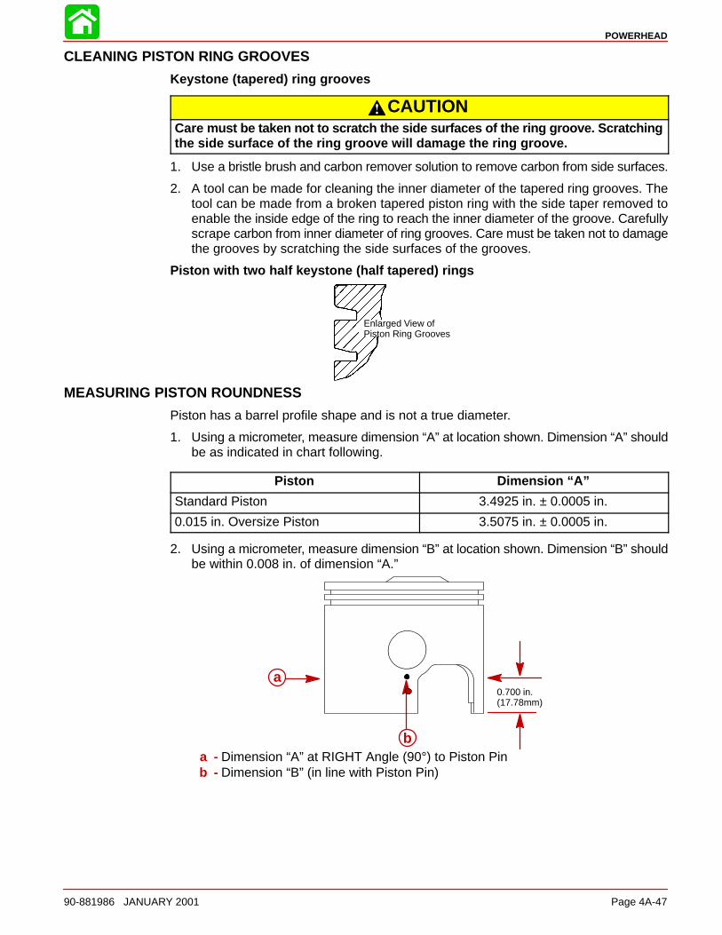
POWERHEAD
90-881986 JANUARY 2001 Page 4A-47
CLEANING PISTON RING GROOVES
Keystone (tapered) ring grooves
CAUTIONCare must be taken not to scratch the side surfaces of the ring groove. Scratchingthe side surface of the ring groove will damage the ring groove.
1. Use a bristle brush and carbon remover solution to remove carbon from side surfaces.
2. A tool can be made for cleaning the inner diameter of the tapered ring grooves. Thetool can be made from a broken tapered piston ring with the side taper removed toenable the inside edge of the ring to reach the inner diameter of the groove. Carefullyscrape carbon from inner diameter of ring grooves. Care must be taken not to damagethe grooves by scratching the side surfaces of the grooves.
Piston with two half keystone (half tapered) rings
Enlarged View ofPiston Ring Grooves
MEASURING PISTON ROUNDNESS
Piston has a barrel profile shape and is not a true diameter.
1. Using a micrometer, measure dimension “A” at location shown. Dimension “A” shouldbe as indicated in chart following.
Piston Dimension “A”
Standard Piston 3.4925 in. ± 0.0005 in.
0.015 in. Oversize Piston 3.5075 in. ± 0.0005 in.
2. Using a micrometer, measure dimension “B” at location shown. Dimension “B” shouldbe within 0.008 in. of dimension “A.”
a0.700 in.(17.78mm)
a
ba - Dimension “A” at RIGHT Angle (90°) to Piston Pinb - Dimension “B” (in line with Piston Pin)
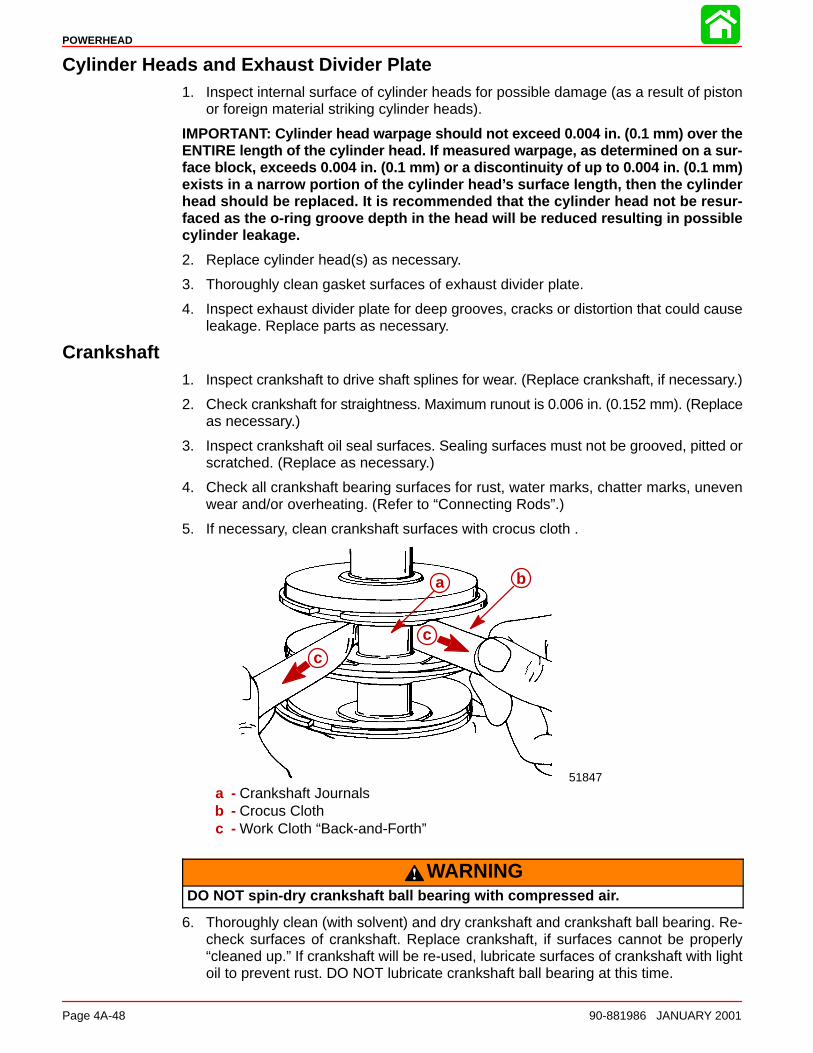
POWERHEAD
Page 4A-48 90-881986 JANUARY 2001
Cylinder Heads and Exhaust Divider Plate1. Inspect internal surface of cylinder heads for possible damage (as a result of piston
or foreign material striking cylinder heads).
IMPORTANT: Cylinder head warpage should not exceed 0.004 in. (0.1 mm) over theENTIRE length of the cylinder head. If measured warpage, as determined on a sur-face block, exceeds 0.004 in. (0.1 mm) or a discontinuity of up to 0.004 in. (0.1 mm)exists in a narrow portion of the cylinder head’s surface length, then the cylinderhead should be replaced. It is recommended that the cylinder head not be resur-faced as the o-ring groove depth in the head will be reduced resulting in possiblecylinder leakage.
2. Replace cylinder head(s) as necessary.
3. Thoroughly clean gasket surfaces of exhaust divider plate.
4. Inspect exhaust divider plate for deep grooves, cracks or distortion that could causeleakage. Replace parts as necessary.
Crankshaft1. Inspect crankshaft to drive shaft splines for wear. (Replace crankshaft, if necessary.)
2. Check crankshaft for straightness. Maximum runout is 0.006 in. (0.152 mm). (Replaceas necessary.)
3. Inspect crankshaft oil seal surfaces. Sealing surfaces must not be grooved, pitted orscratched. (Replace as necessary.)
4. Check all crankshaft bearing surfaces for rust, water marks, chatter marks, unevenwear and/or overheating. (Refer to “Connecting Rods”.)
5. If necessary, clean crankshaft surfaces with crocus cloth .
ba
cc
51847
a b
cc
a - Crankshaft Journalsb - Crocus Clothc - Work Cloth “Back-and-Forth”
WARNINGDO NOT spin-dry crankshaft ball bearing with compressed air.
6. Thoroughly clean (with solvent) and dry crankshaft and crankshaft ball bearing. Re-check surfaces of crankshaft. Replace crankshaft, if surfaces cannot be properly“cleaned up.” If crankshaft will be re-used, lubricate surfaces of crankshaft with lightoil to prevent rust. DO NOT lubricate crankshaft ball bearing at this time.
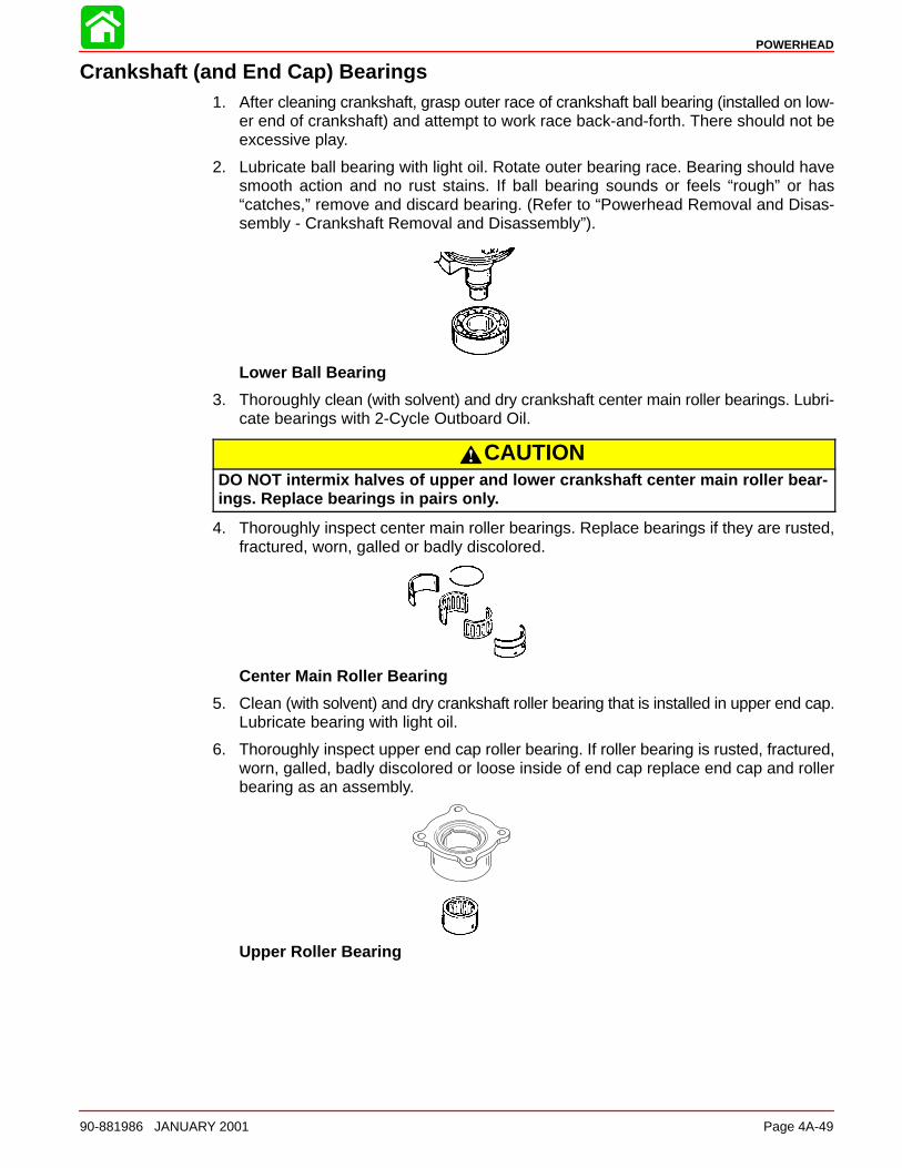
POWERHEAD
90-881986 JANUARY 2001 Page 4A-49
Crankshaft (and End Cap) Bearings1. After cleaning crankshaft, grasp outer race of crankshaft ball bearing (installed on low-
er end of crankshaft) and attempt to work race back-and-forth. There should not beexcessive play.
2. Lubricate ball bearing with light oil. Rotate outer bearing race. Bearing should havesmooth action and no rust stains. If ball bearing sounds or feels “rough” or has“catches,” remove and discard bearing. (Refer to “Powerhead Removal and Disas-sembly - Crankshaft Removal and Disassembly”).
Lower Ball Bearing
3. Thoroughly clean (with solvent) and dry crankshaft center main roller bearings. Lubri-cate bearings with 2-Cycle Outboard Oil.
CAUTIONDO NOT intermix halves of upper and lower crankshaft center main roller bear-ings. Replace bearings in pairs only.
4. Thoroughly inspect center main roller bearings. Replace bearings if they are rusted,fractured, worn, galled or badly discolored.
Center Main Roller Bearing
5. Clean (with solvent) and dry crankshaft roller bearing that is installed in upper end cap.Lubricate bearing with light oil.
6. Thoroughly inspect upper end cap roller bearing. If roller bearing is rusted, fractured,worn, galled, badly discolored or loose inside of end cap replace end cap and rollerbearing as an assembly.
Upper Roller Bearing
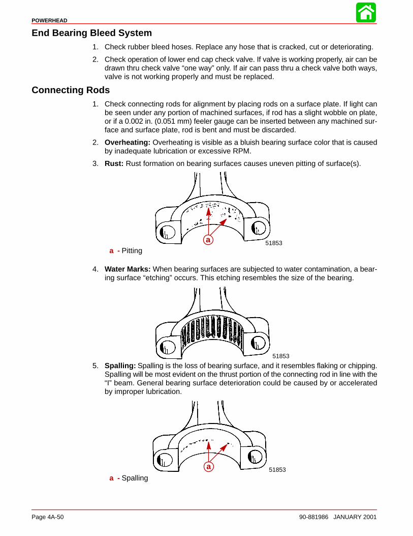
POWERHEAD
Page 4A-50 90-881986 JANUARY 2001
End Bearing Bleed System1. Check rubber bleed hoses. Replace any hose that is cracked, cut or deteriorating.
2. Check operation of lower end cap check valve. If valve is working properly, air can bedrawn thru check valve “one way” only. If air can pass thru a check valve both ways,valve is not working properly and must be replaced.
Connecting Rods1. Check connecting rods for alignment by placing rods on a surface plate. If light can
be seen under any portion of machined surfaces, if rod has a slight wobble on plate,or if a 0.002 in. (0.051 mm) feeler gauge can be inserted between any machined sur-face and surface plate, rod is bent and must be discarded.
2. Overheating: Overheating is visible as a bluish bearing surface color that is causedby inadequate lubrication or excessive RPM.
3. Rust: Rust formation on bearing surfaces causes uneven pitting of surface(s).
a 51853aa - Pitting
4. Water Marks: When bearing surfaces are subjected to water contamination, a bear-ing surface “etching” occurs. This etching resembles the size of the bearing.
51853
5. Spalling: Spalling is the loss of bearing surface, and it resembles flaking or chipping.Spalling will be most evident on the thrust portion of the connecting rod in line with the“I” beam. General bearing surface deterioration could be caused by or acceleratedby improper lubrication.
51853aaa - Spalling
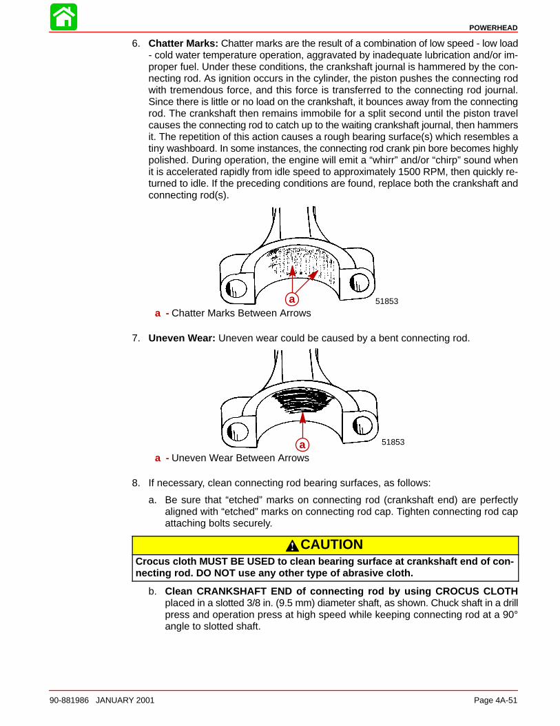
POWERHEAD
90-881986 JANUARY 2001 Page 4A-51
6. Chatter Marks: Chatter marks are the result of a combination of low speed - low load- cold water temperature operation, aggravated by inadequate lubrication and/or im-proper fuel. Under these conditions, the crankshaft journal is hammered by the con-necting rod. As ignition occurs in the cylinder, the piston pushes the connecting rodwith tremendous force, and this force is transferred to the connecting rod journal.Since there is little or no load on the crankshaft, it bounces away from the connectingrod. The crankshaft then remains immobile for a split second until the piston travelcauses the connecting rod to catch up to the waiting crankshaft journal, then hammersit. The repetition of this action causes a rough bearing surface(s) which resembles atiny washboard. In some instances, the connecting rod crank pin bore becomes highlypolished. During operation, the engine will emit a “whirr” and/or “chirp” sound whenit is accelerated rapidly from idle speed to approximately 1500 RPM, then quickly re-turned to idle. If the preceding conditions are found, replace both the crankshaft andconnecting rod(s).
a 51853aa - Chatter Marks Between Arrows
7. Uneven Wear: Uneven wear could be caused by a bent connecting rod.
a 51853aa - Uneven Wear Between Arrows
8. If necessary, clean connecting rod bearing surfaces, as follows:
a. Be sure that “etched” marks on connecting rod (crankshaft end) are perfectlyaligned with “etched” marks on connecting rod cap. Tighten connecting rod capattaching bolts securely.
CAUTIONCrocus cloth MUST BE USED to clean bearing surface at crankshaft end of con-necting rod. DO NOT use any other type of abrasive cloth.
b. Clean CRANKSHAFT END of connecting rod by using CROCUS CLOTHplaced in a slotted 3/8 in. (9.5 mm) diameter shaft, as shown. Chuck shaft in a drillpress and operation press at high speed while keeping connecting rod at a 90°angle to slotted shaft.
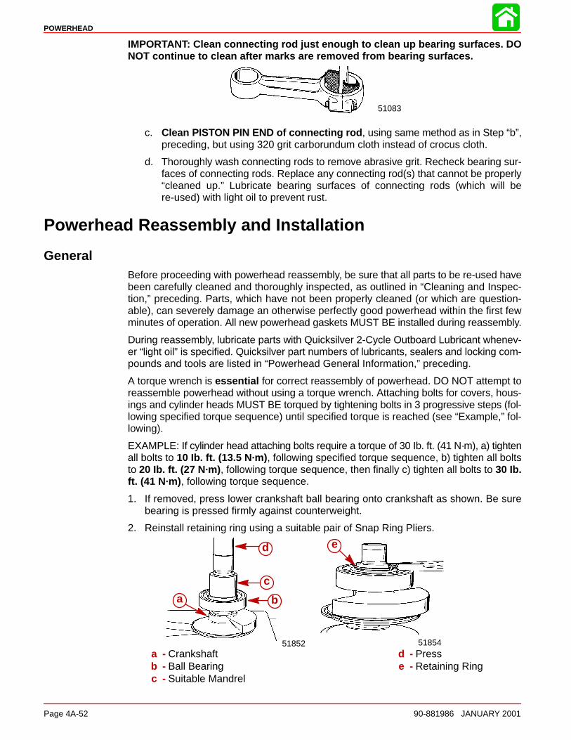
POWERHEAD
Page 4A-52 90-881986 JANUARY 2001
IMPORTANT: Clean connecting rod just enough to clean up bearing surfaces. DONOT continue to clean after marks are removed from bearing surfaces.
51083
c. Clean PISTON PIN END of connecting rod , using same method as in Step “b”,preceding, but using 320 grit carborundum cloth instead of crocus cloth.
d. Thoroughly wash connecting rods to remove abrasive grit. Recheck bearing sur-faces of connecting rods. Replace any connecting rod(s) that cannot be properly“cleaned up.” Lubricate bearing surfaces of connecting rods (which will bere-used) with light oil to prevent rust.
Powerhead Reassembly and Installation
GeneralBefore proceeding with powerhead reassembly, be sure that all parts to be re-used havebeen carefully cleaned and thoroughly inspected, as outlined in “Cleaning and Inspec-tion,” preceding. Parts, which have not been properly cleaned (or which are question-able), can severely damage an otherwise perfectly good powerhead within the first fewminutes of operation. All new powerhead gaskets MUST BE installed during reassembly.
During reassembly, lubricate parts with Quicksilver 2-Cycle Outboard Lubricant whenev-er “light oil” is specified. Quicksilver part numbers of lubricants, sealers and locking com-pounds and tools are listed in “Powerhead General Information,” preceding.
A torque wrench is essential for correct reassembly of powerhead. DO NOT attempt toreassemble powerhead without using a torque wrench. Attaching bolts for covers, hous-ings and cylinder heads MUST BE torqued by tightening bolts in 3 progressive steps (fol-lowing specified torque sequence) until specified torque is reached (see “Example,” fol-lowing).
EXAMPLE: If cylinder head attaching bolts require a torque of 30 Ib. ft. (41 N·m), a) tightenall bolts to 10 Ib. ft. (13.5 N·m) , following specified torque sequence, b) tighten all boltsto 20 Ib. ft. (27 N·m) , following torque sequence, then finally c) tighten all bolts to 30 Ib.ft. (41 N·m) , following torque sequence.
1. If removed, press lower crankshaft ball bearing onto crankshaft as shown. Be surebearing is pressed firmly against counterweight.
2. Reinstall retaining ring using a suitable pair of Snap Ring Pliers.
5185451852
e
a b
c
d
a - Crankshaftb - Ball Bearingc - Suitable Mandrel
d - Presse - Retaining Ring
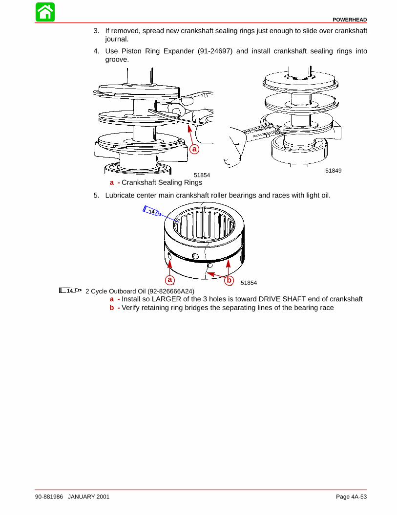
POWERHEAD
90-881986 JANUARY 2001 Page 4A-53
3. If removed, spread new crankshaft sealing rings just enough to slide over crankshaftjournal.
4. Use Piston Ring Expander (91-24697) and install crankshaft sealing rings intogroove.
5184951854
aa
a - Crankshaft Sealing Rings
5. Lubricate center main crankshaft roller bearings and races with light oil.
a b 51854a14 2 Cycle Outboard Oil (92-826666A24)
14
b
a - Install so LARGER of the 3 holes is toward DRIVE SHAFT end of crankshaftb - Verify retaining ring bridges the separating lines of the bearing race
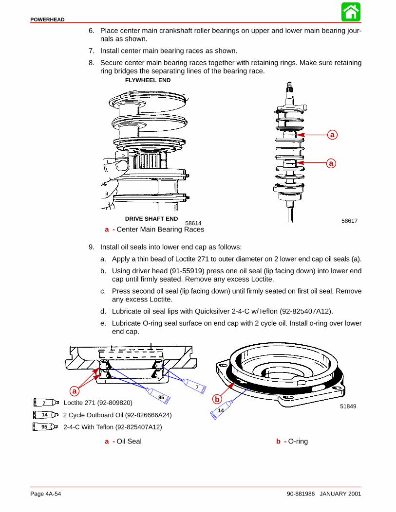
POWERHEAD
Page 4A-54 90-881986 JANUARY 2001
6. Place center main crankshaft roller bearings on upper and lower main bearing jour-nals as shown.
7. Install center main bearing races as shown.
8. Secure center main bearing races together with retaining rings. Make sure retainingring bridges the separating lines of the bearing race.
FLYWHEEL END
DRIVE SHAFT END58614
aa
a
58617
a - Center Main Bearing Races
9. Install oil seals into lower end cap as follows:
a. Apply a thin bead of Loctite 271 to outer diameter on 2 lower end cap oil seals (a).
b. Using driver head (91-55919) press one oil seal (lip facing down) into lower endcap until firmly seated. Remove any excess Loctite.
c. Press second oil seal (lip facing down) until firmly seated on first oil seal. Removeany excess Loctite.
d. Lubricate oil seal lips with Quicksilver 2-4-C w/Teflon (92-825407A12).
e. Lubricate O-ring seal surface on end cap with 2 cycle oil. Install o-ring over lowerend cap.
a51849
baa
7 Loctite 271 (92-809820)
7
14 2 Cycle Outboard Oil (92-826666A24)14
95 2-4-C With Teflon (92-825407A12)
95
a - Oil Seal b - O-ring
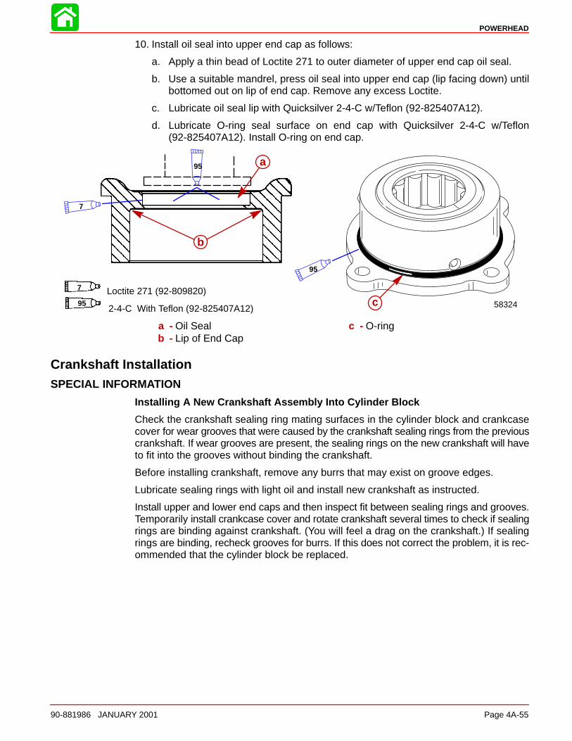
POWERHEAD
90-881986 JANUARY 2001 Page 4A-55
10. Install oil seal into upper end cap as follows:
a. Apply a thin bead of Loctite 271 to outer diameter of upper end cap oil seal.
b. Use a suitable mandrel, press oil seal into upper end cap (lip facing down) untilbottomed out on lip of end cap. Remove any excess Loctite.
c. Lubricate oil seal lip with Quicksilver 2-4-C w/Teflon (92-825407A12).
d. Lubricate O-ring seal surface on end cap with Quicksilver 2-4-C w/Teflon(92-825407A12). Install O-ring on end cap.
b
7 Loctite 271 (92-809820)95
2-4-C With Teflon (92-825407A12)
95
95
7
58324c
a
a - Oil Sealb - Lip of End Cap
c - O-ring
Crankshaft InstallationSPECIAL INFORMATION
Installing A New Crankshaft Assembly Into Cylinder Block
Check the crankshaft sealing ring mating surfaces in the cylinder block and crankcasecover for wear grooves that were caused by the crankshaft sealing rings from the previouscrankshaft. If wear grooves are present, the sealing rings on the new crankshaft will haveto fit into the grooves without binding the crankshaft.
Before installing crankshaft, remove any burrs that may exist on groove edges.
Lubricate sealing rings with light oil and install new crankshaft as instructed.
Install upper and lower end caps and then inspect fit between sealing rings and grooves.Temporarily install crankcase cover and rotate crankshaft several times to check if sealingrings are binding against crankshaft. (You will feel a drag on the crankshaft.) If sealingrings are binding, recheck grooves for burrs. If this does not correct the problem, it is rec-ommended that the cylinder block be replaced.
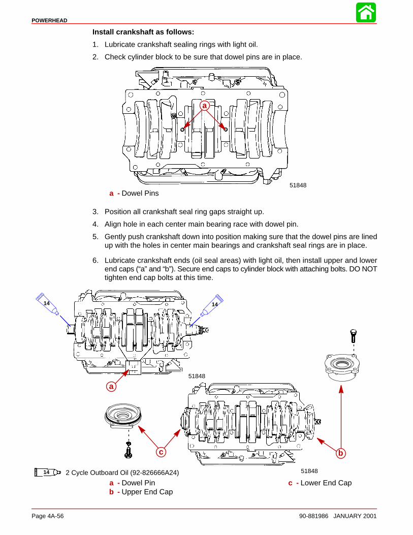
POWERHEAD
Page 4A-56 90-881986 JANUARY 2001
Install crankshaft as follows:
1. Lubricate crankshaft sealing rings with light oil.
2. Check cylinder block to be sure that dowel pins are in place.
a
51848
a
a - Dowel Pins
3. Position all crankshaft seal ring gaps straight up.
4. Align hole in each center main bearing race with dowel pin.
5. Gently push crankshaft down into position making sure that the dowel pins are linedup with the holes in center main bearings and crankshaft seal rings are in place.
6. Lubricate crankshaft ends (oil seal areas) with light oil, then install upper and lowerend caps (“a” and “b”). Secure end caps to cylinder block with attaching bolts. DO NOTtighten end cap bolts at this time.
51848
a51848
a
14 14
14 2 Cycle Outboard Oil (92-826666A24)
c b
a - Dowel Pinb - Upper End Cap
c - Lower End Cap
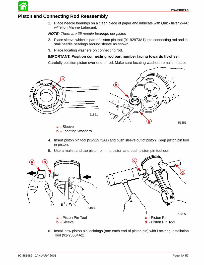
POWERHEAD
90-881986 JANUARY 2001 Page 4A-57
Piston and Connecting Rod Reassembly1. Place needle bearings on a clean piece of paper and lubricate with Quicksilver 2-4-C
w/Teflon Marine Lubricant.
NOTE: There are 35 needle bearings per piston
2. Place sleeve which is part of piston pin tool (91-92973A1) into connecting rod and in-stall needle bearings around sleeve as shown.
3. Place locating washers on connecting rod.
IMPORTANT: Position connecting rod part number facing towards flywheel.
Carefully position piston over end of rod. Make sure locating washers remain in place.
a
a 51851
b
a
51851
b
a
a - Sleeveb - Locating Washers
4. Insert piston pin tool (91-92973A1) and push sleeve out of piston. Keep piston pin toolin piston.
5. Use a mallet and tap piston pin into piston and push piston pin tool out.
a
b
51086
a b
51080
c
d
a b
a - Piston Pin Toolb - Sleeve
c - Piston Pind - Piston Pin Tool
6. Install new piston pin lockrings (one each end of piston pin) with Lockring InstallationTool (91-93004A2).
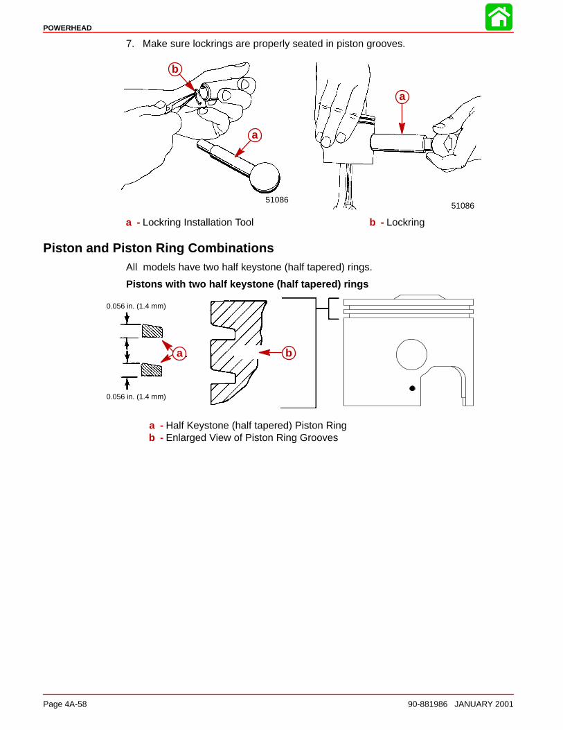
POWERHEAD
Page 4A-58 90-881986 JANUARY 2001
7. Make sure lockrings are properly seated in piston grooves.
a
51086
b
a
51086
a
a
b
a - Lockring Installation Tool b - Lockring
Piston and Piston Ring CombinationsAll models have two half keystone (half tapered) rings.
Pistons with two half keystone (half tapered) rings
0.056 in. (1.4 mm)
0.056 in. (1.4 mm)
a ba b
a - Half Keystone (half tapered) Piston Ringb - Enlarged View of Piston Ring Grooves
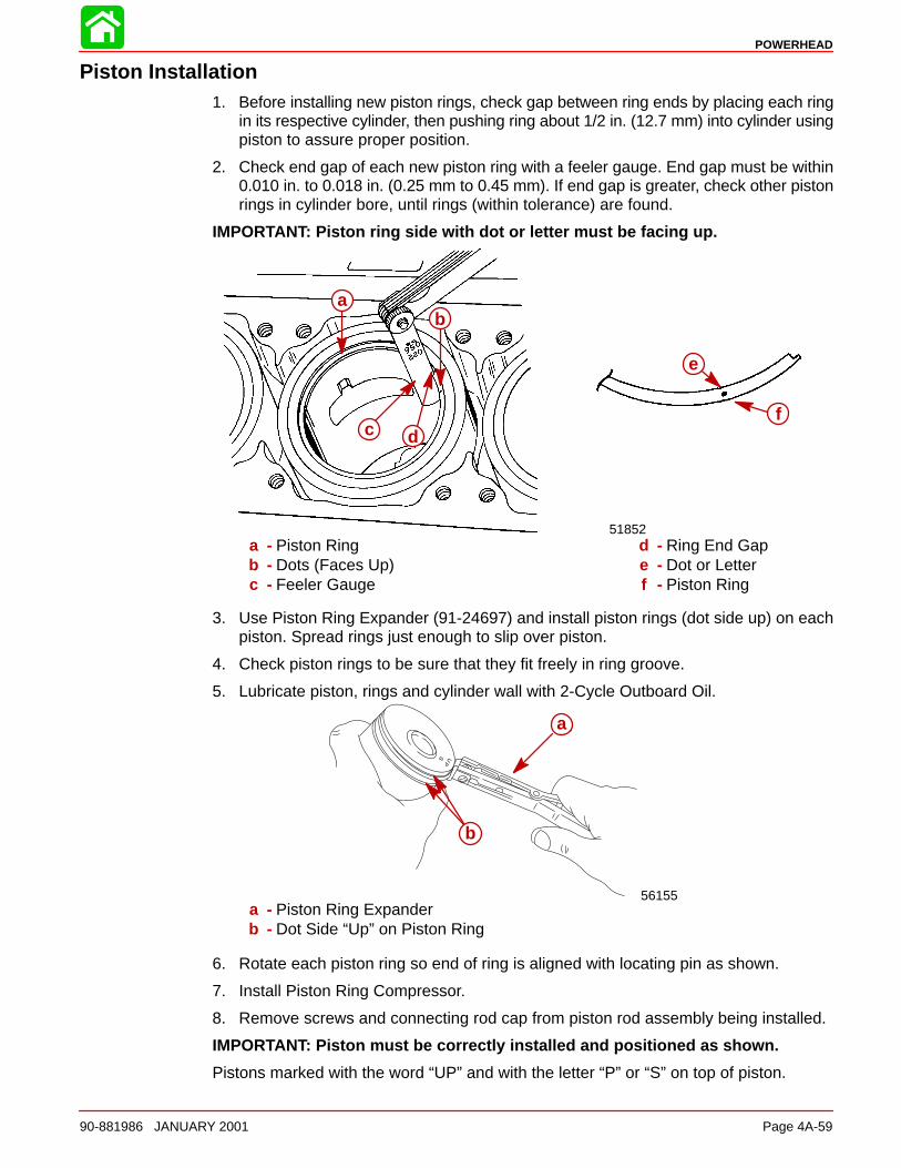
POWERHEAD
90-881986 JANUARY 2001 Page 4A-59
Piston Installation1. Before installing new piston rings, check gap between ring ends by placing each ring
in its respective cylinder, then pushing ring about 1/2 in. (12.7 mm) into cylinder usingpiston to assure proper position.
2. Check end gap of each new piston ring with a feeler gauge. End gap must be within0.010 in. to 0.018 in. (0.25 mm to 0.45 mm). If end gap is greater, check other pistonrings in cylinder bore, until rings (within tolerance) are found.
IMPORTANT: Piston ring side with dot or letter must be facing up.
a
bc d
ab
51852
ab
c d
e
f
a - Piston Ringb - Dots (Faces Up)c - Feeler Gauge
d - Ring End Gape - Dot or Letterf - Piston Ring
3. Use Piston Ring Expander (91-24697) and install piston rings (dot side up) on eachpiston. Spread rings just enough to slip over piston.
4. Check piston rings to be sure that they fit freely in ring groove.
5. Lubricate piston, rings and cylinder wall with 2-Cycle Outboard Oil.
56155
b
aa
b
a - Piston Ring Expanderb - Dot Side “Up” on Piston Ring
6. Rotate each piston ring so end of ring is aligned with locating pin as shown.
7. Install Piston Ring Compressor.
8. Remove screws and connecting rod cap from piston rod assembly being installed.
IMPORTANT: Piston must be correctly installed and positioned as shown.
Pistons marked with the word “UP” and with the letter “P” or “S” on top of piston.
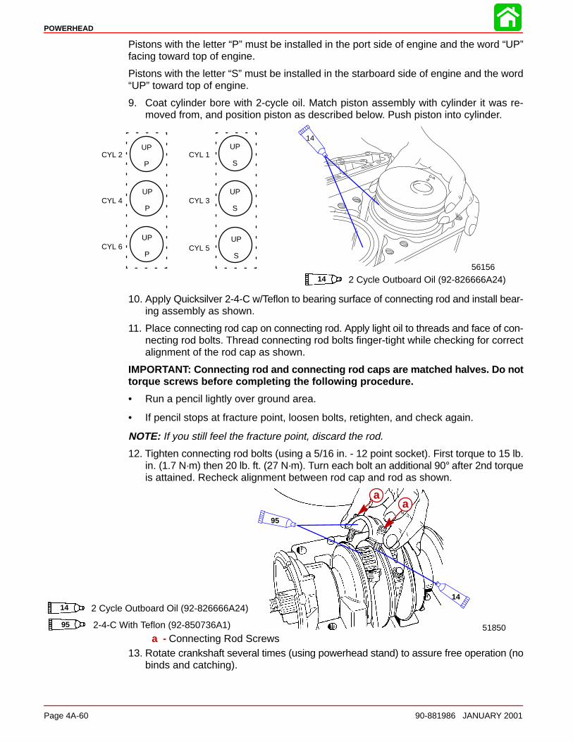
POWERHEAD
Page 4A-60 90-881986 JANUARY 2001
Pistons with the letter “P” must be installed in the port side of engine and the word “UP”facing toward top of engine.
Pistons with the letter “S” must be installed in the starboard side of engine and the word“UP” toward top of engine.
9. Coat cylinder bore with 2-cycle oil. Match piston assembly with cylinder it was re-moved from, and position piston as described below. Push piston into cylinder.
56156
CYL 2
CYL 4
CYL 6
CYL 1
CYL 3
CYL 5
UP
P
UP
P
UP
P
UP
S
UP
S
UP
S
14
14 2 Cycle Outboard Oil (92-826666A24)
10. Apply Quicksilver 2-4-C w/Teflon to bearing surface of connecting rod and install bear-ing assembly as shown.
11. Place connecting rod cap on connecting rod. Apply light oil to threads and face of con-necting rod bolts. Thread connecting rod bolts finger-tight while checking for correctalignment of the rod cap as shown.
IMPORTANT: Connecting rod and connecting rod caps are matched halves. Do nottorque screws before completing the following procedure.
• Run a pencil lightly over ground area.
• If pencil stops at fracture point, loosen bolts, retighten, and check again.
NOTE: If you still feel the fracture point, discard the rod.
12. Tighten connecting rod bolts (using a 5/16 in. - 12 point socket). First torque to 15 lb.in. (1.7 N·m) then 20 lb. ft. (27 N·m). Turn each bolt an additional 90° after 2nd torqueis attained. Recheck alignment between rod cap and rod as shown.
5185095 2-4-C With Teflon (92-850736A1)
95
14 2 Cycle Outboard Oil (92-826666A24)14
aa
a - Connecting Rod Screws13. Rotate crankshaft several times (using powerhead stand) to assure free operation (no
binds and catching).
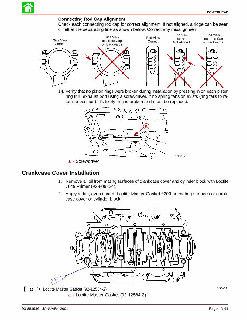
POWERHEAD
90-881986 JANUARY 2001 Page 4A-61
Connecting Rod Cap AlignmentCheck each connecting rod cap for correct alignment. If not aligned, a ridge can be seenor felt at the separating line as shown below. Correct any misalignment.
ÄÄÄ
ÄÄÄÄÄÄÄÄ
Side ViewCorrect
End ViewCorrect
Side ViewIncorrect-Capon Backwards
End ViewIncorrect-Capon Backwards
ÄÄÄÄ
End ViewIncorrect-
Not Aligned
14. Verify that no piston rings were broken during installation by pressing in on each pistonring thru exhaust port using a screwdriver. If no spring tension exists (ring fails to re-turn to position), it’s likely ring is broken and must be replaced.
51852
aa
a - Screwdriver
Crankcase Cover Installation1. Remove all oil from mating surfaces of crankcase cover and cylinder block with Loctite
7649 Primer (92-809824).
2. Apply a thin, even coat of Loctite Master Gasket #203 on mating surfaces of crank-case cover or cylinder block.
12 Loctite Master Gasket (92-12564-2) 58620
12
a - Loctite Master Gasket (92-12564-2)
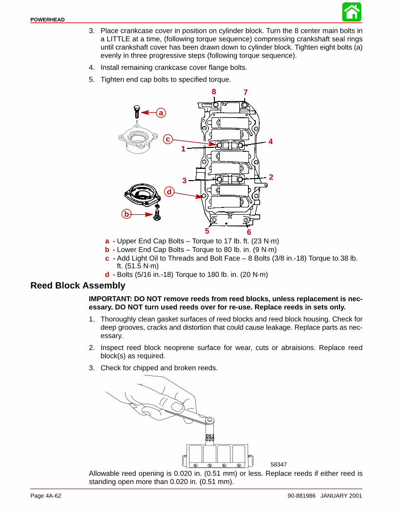
POWERHEAD
Page 4A-62 90-881986 JANUARY 2001
3. Place crankcase cover in position on cylinder block. Turn the 8 center main bolts ina LITTLE at a time, (following torque sequence) compressing crankshaft seal ringsuntil crankshaft cover has been drawn down to cylinder block. Tighten eight bolts (a)evenly in three progressive steps (following torque sequence).
4. Install remaining crankcase cover flange bolts.
5. Tighten end cap bolts to specified torque.
8 7
4
2
65
3
1
b
a
c
d
a - Upper End Cap Bolts – Torque to 17 lb. ft. (23 N·m)b - Lower End Cap Bolts – Torque to 80 lb. in. (9 N·m)c - Add Light Oil to Threads and Bolt Face – 8 Bolts (3/8 in.-18) Torque to 38 lb.
ft. (51.5 N·m)d - Bolts (5/16 in.-18) Torque to 180 lb. in. (20 N·m)
Reed Block AssemblyIMPORTANT: DO NOT remove reeds from reed blocks, unless replacement is nec-essary. DO NOT turn used reeds over for re-use. Replace reeds in sets only.
1. Thoroughly clean gasket surfaces of reed blocks and reed block housing. Check fordeep grooves, cracks and distortion that could cause leakage. Replace parts as nec-essary.
2. Inspect reed block neoprene surface for wear, cuts or abraisions. Replace reedblock(s) as required.
3. Check for chipped and broken reeds.
020051
58347
Allowable reed opening is 0.020 in. (0.51 mm) or less. Replace reeds if either reed isstanding open more than 0.020 in. (0.51 mm).
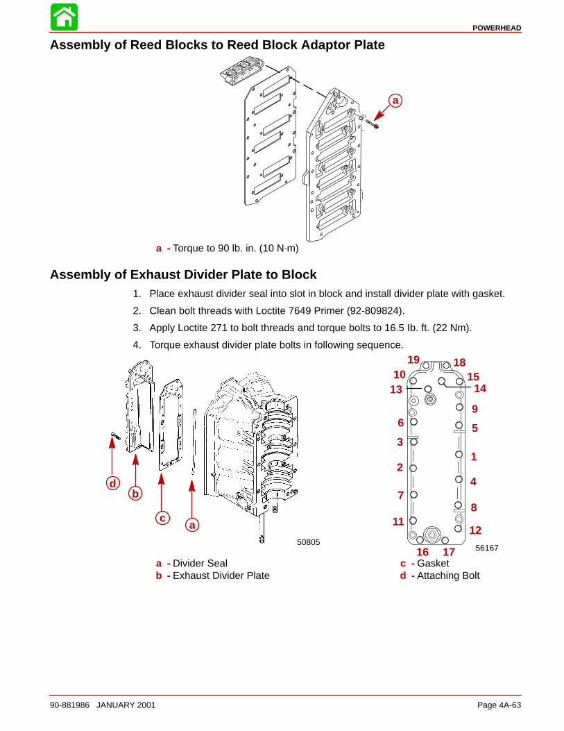
POWERHEAD
90-881986 JANUARY 2001 Page 4A-63
Assembly of Reed Blocks to Reed Block Adaptor Plate
aa
a - Torque to 90 lb. in. (10 N·m)
Assembly of Exhaust Divider Plate to Block1. Place exhaust divider seal into slot in block and install divider plate with gasket.
2. Clean bolt threads with Loctite 7649 Primer (92-809824).
3. Apply Loctite 271 to bolt threads and torque bolts to 16.5 Ib. ft. (22 Nm).
4. Torque exhaust divider plate bolts in following sequence.
56167
12
3
4
56
78
9
1112
13 1415
16 17
181910
d
ca
50805
a
b
c
d
a - Divider Sealb - Exhaust Divider Plate
c - Gasketd - Attaching Bolt
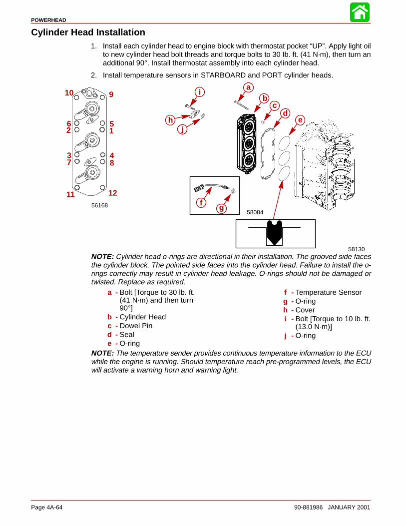
POWERHEAD
Page 4A-64 90-881986 JANUARY 2001
Cylinder Head Installation1. Install each cylinder head to engine block with thermostat pocket “UP”. Apply light oil
to new cylinder head bolt threads and torque bolts to 30 Ib. ft. (41 N·m), then turn anadditional 90°. Install thermostat assembly into each cylinder head.
2. Install temperature sensors in STARBOARD and PORT cylinder heads.
56168
12
3 4
56
7 8
910
11 12
cd
eh
ab
58130
58084
i
j
f g
NOTE: Cylinder head o-rings are directional in their installation. The grooved side facesthe cylinder block. The pointed side faces into the cylinder head. Failure to install the o-rings correctly may result in cylinder head leakage. O-rings should not be damaged ortwisted. Replace as required.
a - Bolt [Torque to 30 lb. ft.(41 N·m) and then turn90°]
b - Cylinder Headc - Dowel Pind - Seale - O-ring
f - Temperature Sensorg - O-ringh - Coveri - Bolt [Torque to 10 lb. ft.
(13.0 N·m)]j - O-ring
NOTE: The temperature sender provides continuous temperature information to the ECUwhile the engine is running. Should temperature reach pre-programmed levels, the ECUwill activate a warning horn and warning light.
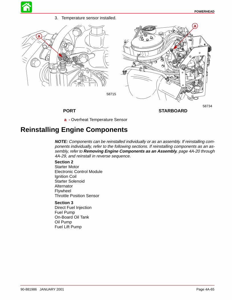
POWERHEAD
90-881986 JANUARY 2001 Page 4A-65
3. Temperature sensor installed.
STARBOARDPORT
58715
a
58734
a
a - Overheat Temperature Sensor
Reinstalling Engine Components
NOTE: Components can be reinstalled individually or as an assembly. If reinstalling com-ponents individually, refer to the following sections. If reinstalling components as an as-sembly, refer to Removing Engine Components as an Assembly , page 4A-20 through4A-29, and reinstall in reverse sequence.Section 2Starter MotorElectronic Control ModuleIgnition CoilStarter SolenoidAlternatorFlywheelThrottle Position Sensor
Section 3Direct Fuel InjectionFuel PumpOn-Board Oil TankOil PumpFuel Lift Pump
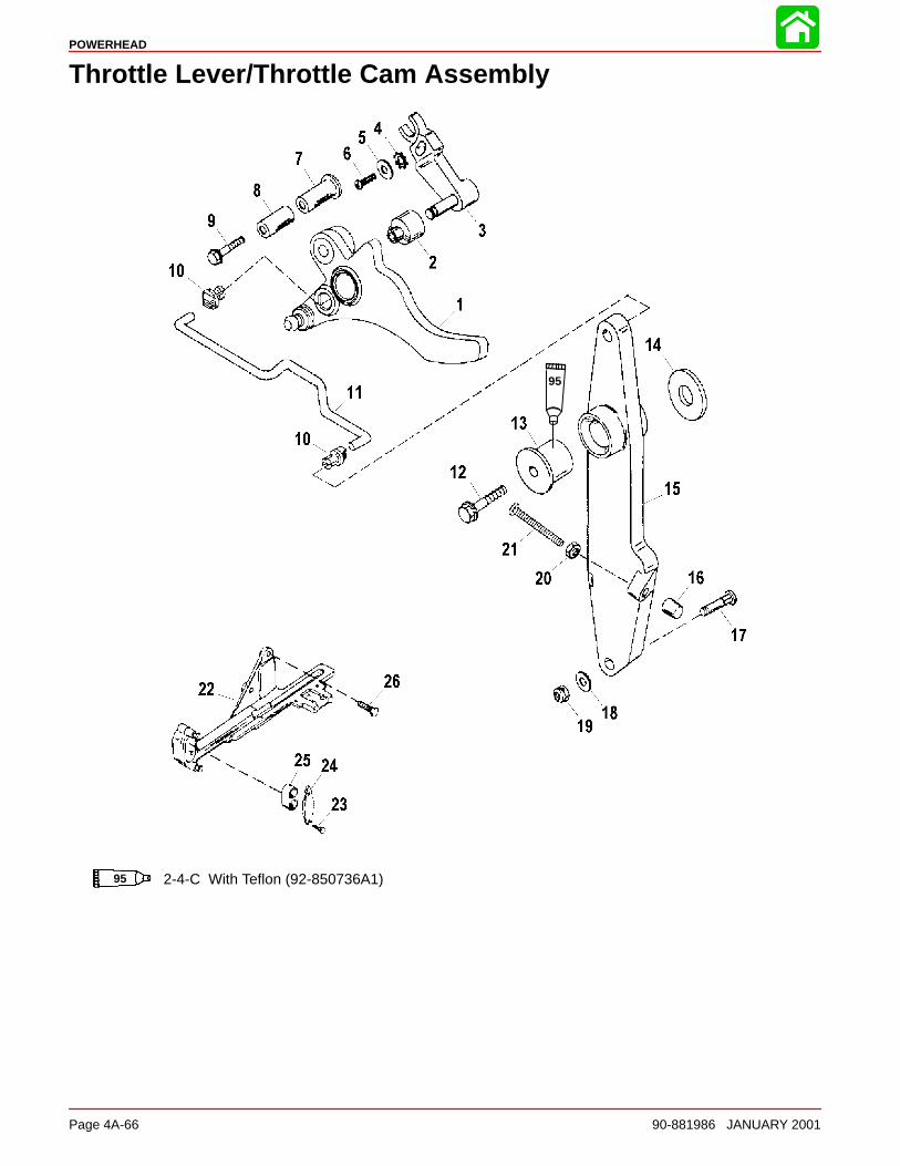
POWERHEAD
Page 4A-66 90-881986 JANUARY 2001
Throttle Lever/Throttle Cam Assembly
95 2-4-C With Teflon (92-850736A1)
95
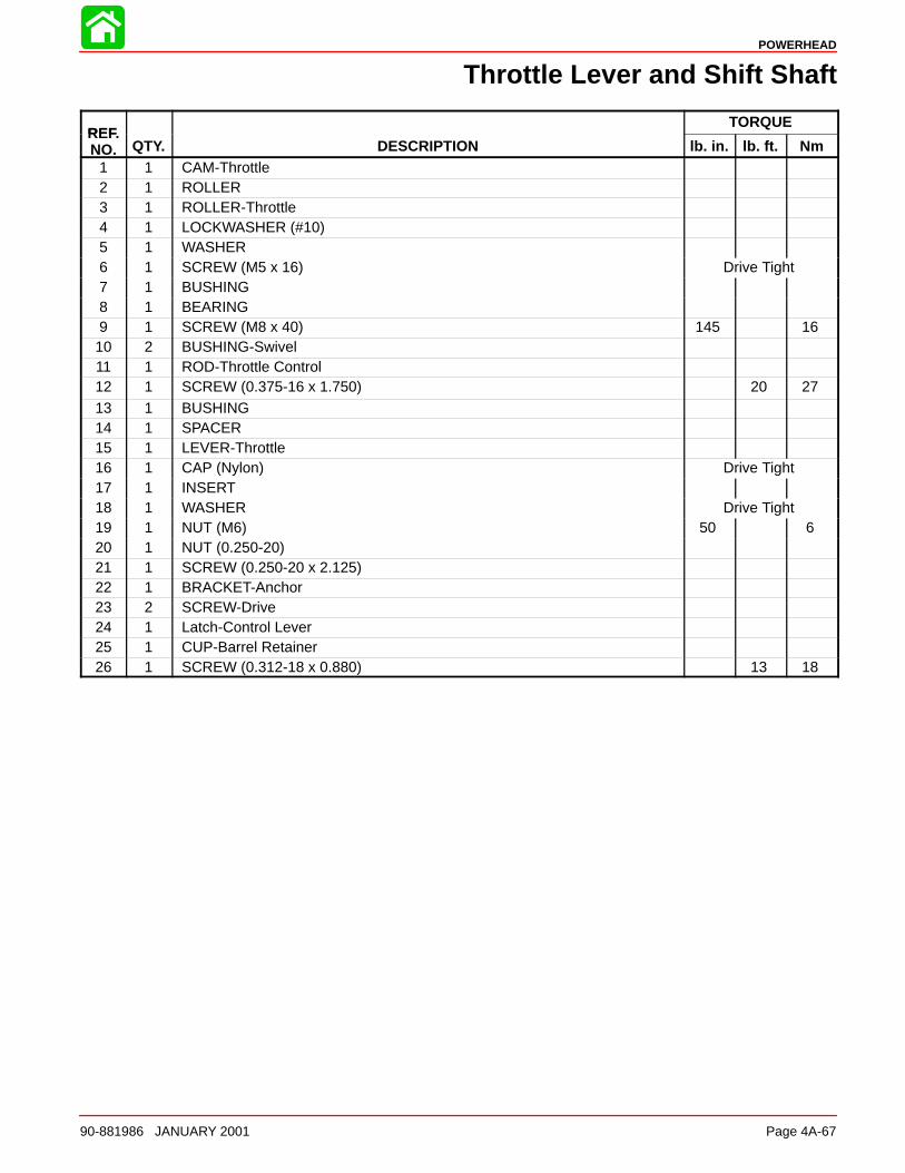
POWERHEAD
90-881986 JANUARY 2001 Page 4A-67
Throttle Lever and Shift Shaft
REFTORQUE
REF.NO. QTY. DESCRIPTION lb. in. lb. ft. Nm
1 1 CAM-Throttle2 1 ROLLER3 1 ROLLER-Throttle4 1 LOCKWASHER (#10)5 1 WASHER6 1 SCREW (M5 x 16) Drive Tight7 1 BUSHING8 1 BEARING9 1 SCREW (M8 x 40) 145 1610 2 BUSHING-Swivel11 1 ROD-Throttle Control12 1 SCREW (0.375-16 x 1.750) 20 2713 1 BUSHING14 1 SPACER15 1 LEVER-Throttle16 1 CAP (Nylon) Drive Tight17 1 INSERT18 1 WASHER Drive Tight19 1 NUT (M6) 50 620 1 NUT (0.250-20)21 1 SCREW (0.250-20 x 2.125)22 1 BRACKET-Anchor23 2 SCREW-Drive24 1 Latch-Control Lever25 1 CUP-Barrel Retainer26 1 SCREW (0.312-18 x 0.880) 13 18
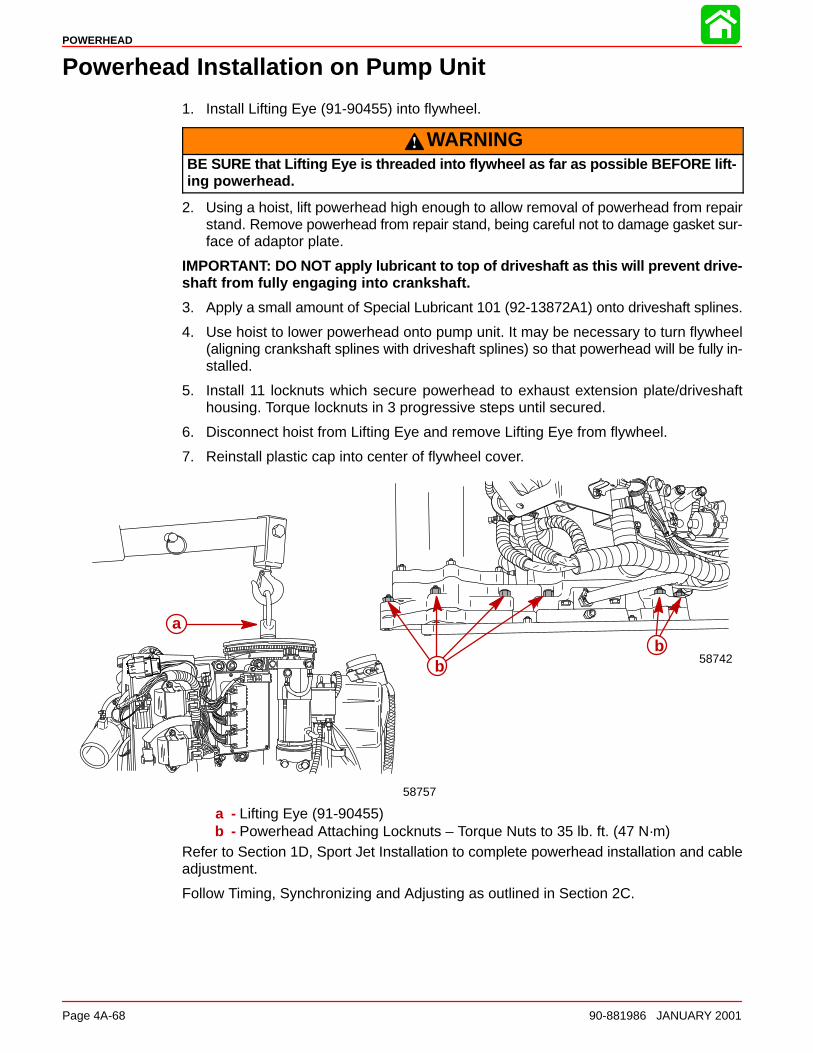
POWERHEAD
Page 4A-68 90-881986 JANUARY 2001
Powerhead Installation on Pump Unit
1. Install Lifting Eye (91-90455) into flywheel.
WARNINGBE SURE that Lifting Eye is threaded into flywheel as far as possible BEFORE lift-ing powerhead.
2. Using a hoist, lift powerhead high enough to allow removal of powerhead from repairstand. Remove powerhead from repair stand, being careful not to damage gasket sur-face of adaptor plate.
IMPORTANT: DO NOT apply lubricant to top of driveshaft as this will prevent drive-shaft from fully engaging into crankshaft.
3. Apply a small amount of Special Lubricant 101 (92-13872A1) onto driveshaft splines.
4. Use hoist to lower powerhead onto pump unit. It may be necessary to turn flywheel(aligning crankshaft splines with driveshaft splines) so that powerhead will be fully in-stalled.
5. Install 11 locknuts which secure powerhead to exhaust extension plate/driveshafthousing. Torque locknuts in 3 progressive steps until secured.
6. Disconnect hoist from Lifting Eye and remove Lifting Eye from flywheel.
7. Reinstall plastic cap into center of flywheel cover.
58742
58757
a
bb
a - Lifting Eye (91-90455)b - Powerhead Attaching Locknuts – Torque Nuts to 35 lb. ft. (47 N·m)
Refer to Section 1D, Sport Jet Installation to complete powerhead installation and cableadjustment.
Follow Timing, Synchronizing and Adjusting as outlined in Section 2C.
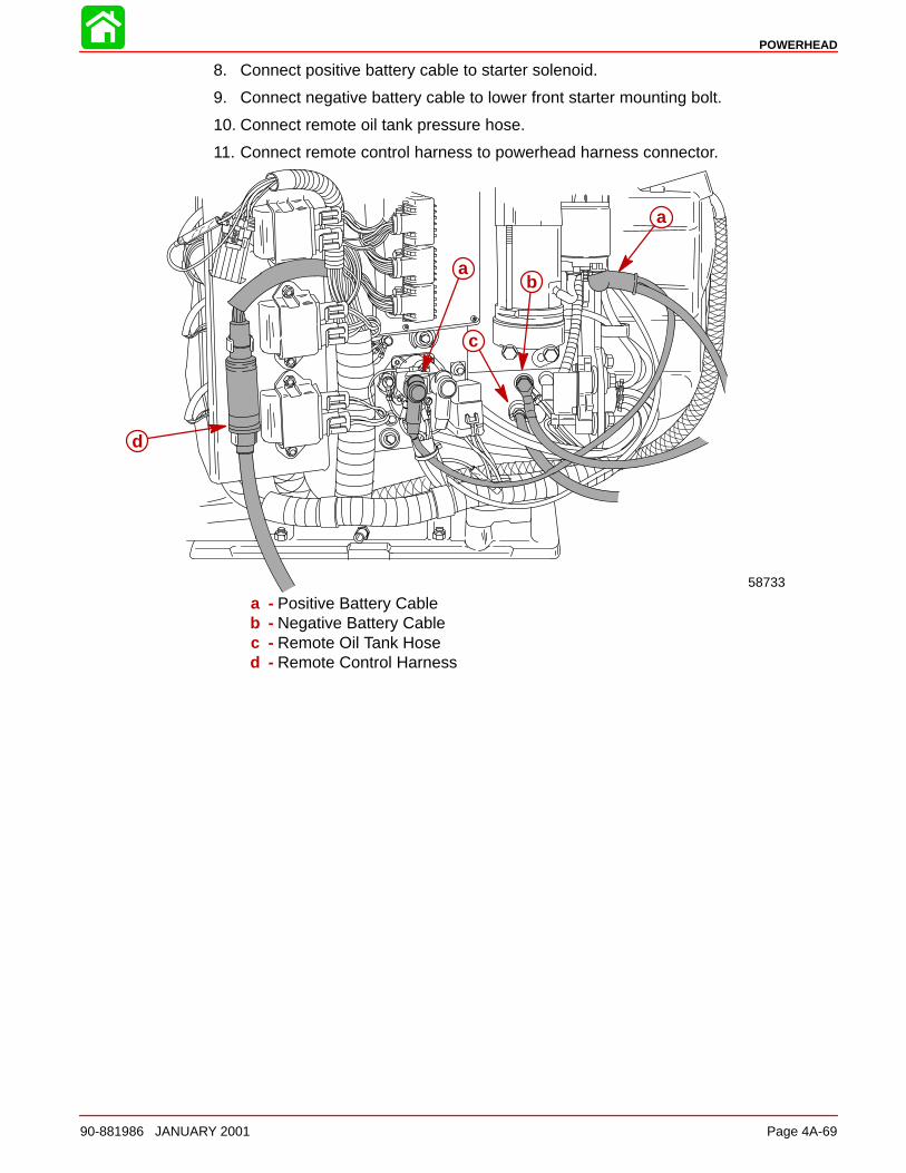
POWERHEAD
90-881986 JANUARY 2001 Page 4A-69
8. Connect positive battery cable to starter solenoid.
9. Connect negative battery cable to lower front starter mounting bolt.
10. Connect remote oil tank pressure hose.
11. Connect remote control harness to powerhead harness connector.
58733
a
b
c
d
a
a - Positive Battery Cableb - Negative Battery Cablec - Remote Oil Tank Hosed - Remote Control Harness
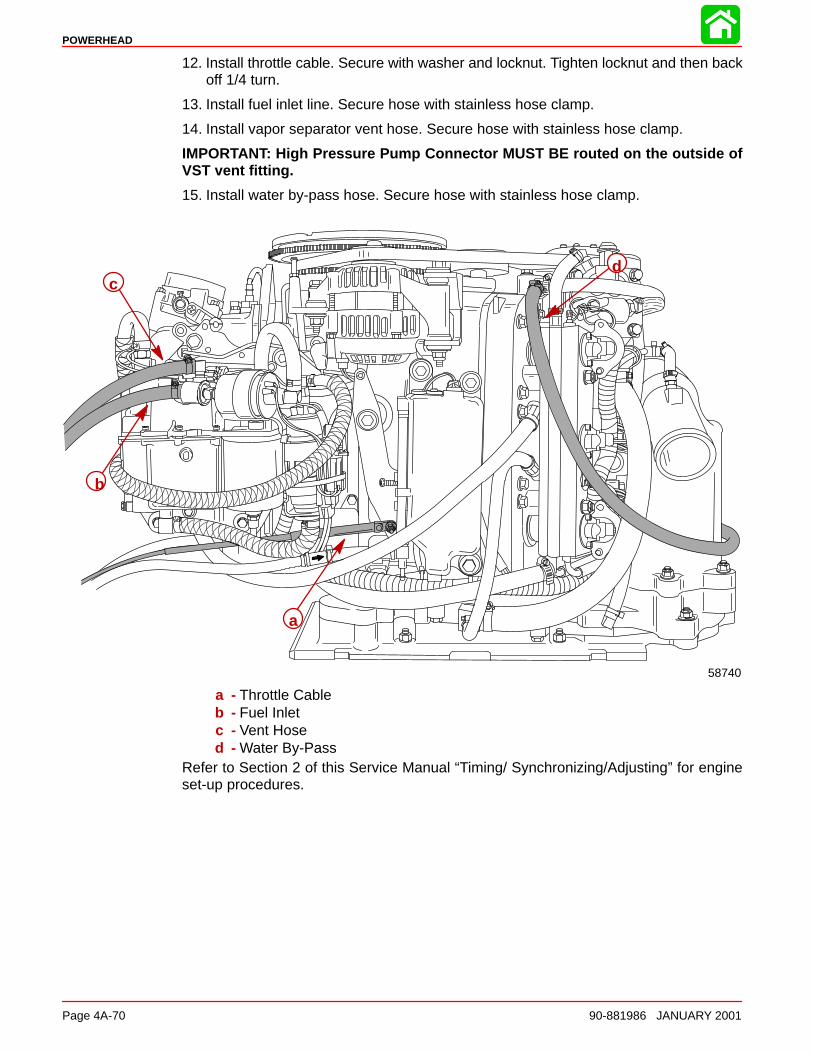
POWERHEAD
Page 4A-70 90-881986 JANUARY 2001
12. Install throttle cable. Secure with washer and locknut. Tighten locknut and then backoff 1/4 turn.
13. Install fuel inlet line. Secure hose with stainless hose clamp.
14. Install vapor separator vent hose. Secure hose with stainless hose clamp.
IMPORTANT: High Pressure Pump Connector MUST BE routed on the outside ofVST vent fitting.
15. Install water by-pass hose. Secure hose with stainless hose clamp.
a
b
cd
58740
a - Throttle Cableb - Fuel Inletc - Vent Hosed - Water By-Pass
Refer to Section 2 of this Service Manual “Timing/ Synchronizing/Adjusting” for engineset-up procedures.
POWERHEAD
90-881986 JANUARY 2001 Page 4A-71
Break-ln Procedure
CAUTIONSevere dam age to the engine can result by not complying with the Engine Break-in Procedure.
FUEL REQUIREMENTS
Do not use pre-mixed gas and oil in this engine. Use straight gasoline during enginebreak-in and after engine break-in. The ECM is programmed to signal the oil pump to pro-vide additional oil (50:1 ratio) during the first 120 minutes of operation. The ECM will moni-tor this period through its own internal clock. At the end of this period, the ECM will signalthe oil pump to go to a standard ratio of 300 – 400:1 @ idle and 40:1 @ W.O.T.
INITIATING ENGINE BREAK-IN SEQUENCE
Refer to Section 3C for proper procedures.
ENGINE BREAK-IN PROCEDURE (ALL MODELS)
First Hour
• Allow engine to warm up for 30 – 60 seconds.
• Avoid continuous operation at idle speed for more than 10 minutes.
• Run engine for the majority of the time between 3000 and 4500 rpm; approximate-ly 3/4 throttle.
• Vary engine speed; change engine speed approximately every 2 minutes.
• Short bursts of full throttle for periods up to 10 seconds are acceptable.
Next 3 Hours
• Change engine speed every 10 minutes.
4B
COOLING
90-881986 JANUARY 2001 Page 4B-1
POWERHEADSection 4B - Cooling
Table of Contents
Specifications 4B-2. . . . . . . . . . . . . . . . . . . . . . . . . . . . . . . . Water Pressure 4B-2. . . . . . . . . . . . . . . . . . . . . . . . . . . Temperature Sensor 4B-2. . . . . . . . . . . . . . . . . . . . . . .
Special Tools 4B-3. . . . . . . . . . . . . . . . . . . . . . . . . . . . . . . . Temperature Sensor 4B-4. . . . . . . . . . . . . . . . . . . . . . .
Model 200 Water Flow 4B-5. . . . . . . . . . . . . . . . . . . . . . . . Description 4B-5. . . . . . . . . . . . . . . . . . . . . . . . . . . . . . .
Model 200 Water Flow Diagram 4B-7. . . . . . . . . . . . . . . . Water Pressure Check 4B-9. . . . . . . . . . . . . . . . . . . . . . . . Problem Diagnosis 4B-9. . . . . . . . . . . . . . . . . . . . . . . . . . .
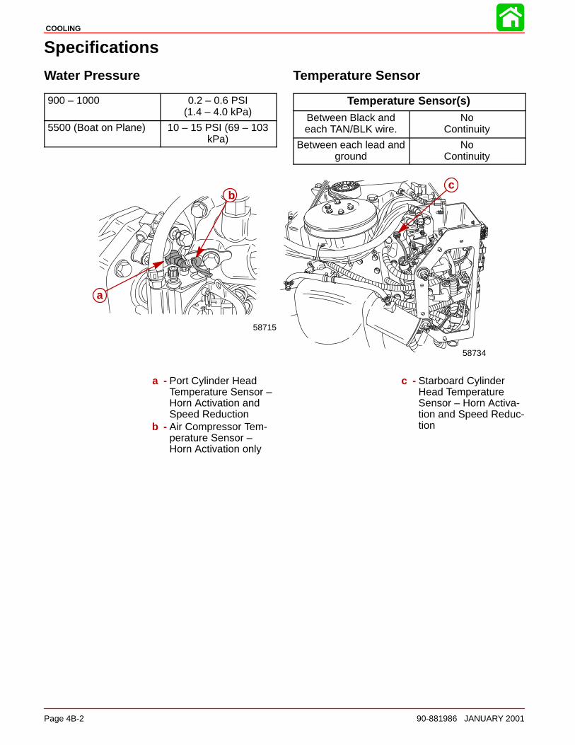
COOLING
Page 4B-2 90-881986 JANUARY 2001
Specifications
Water Pressure
900 – 1000 0.2 – 0.6 PSI(1.4 – 4.0 kPa)
5500 (Boat on Plane) 10 – 15 PSI (69 – 103kPa)
Temperature Sensor
Temperature Sensor(s)Between Black andeach TAN/BLK wire.
NoContinuity
Between each lead andground
NoContinuity
a
58715
58734
bc
a - Port Cylinder HeadTemperature Sensor –Horn Activation andSpeed Reduction
b - Air Compressor Tem-perature Sensor –Horn Activation only
c - Starboard CylinderHead TemperatureSensor – Horn Activa-tion and Speed Reduc-tion
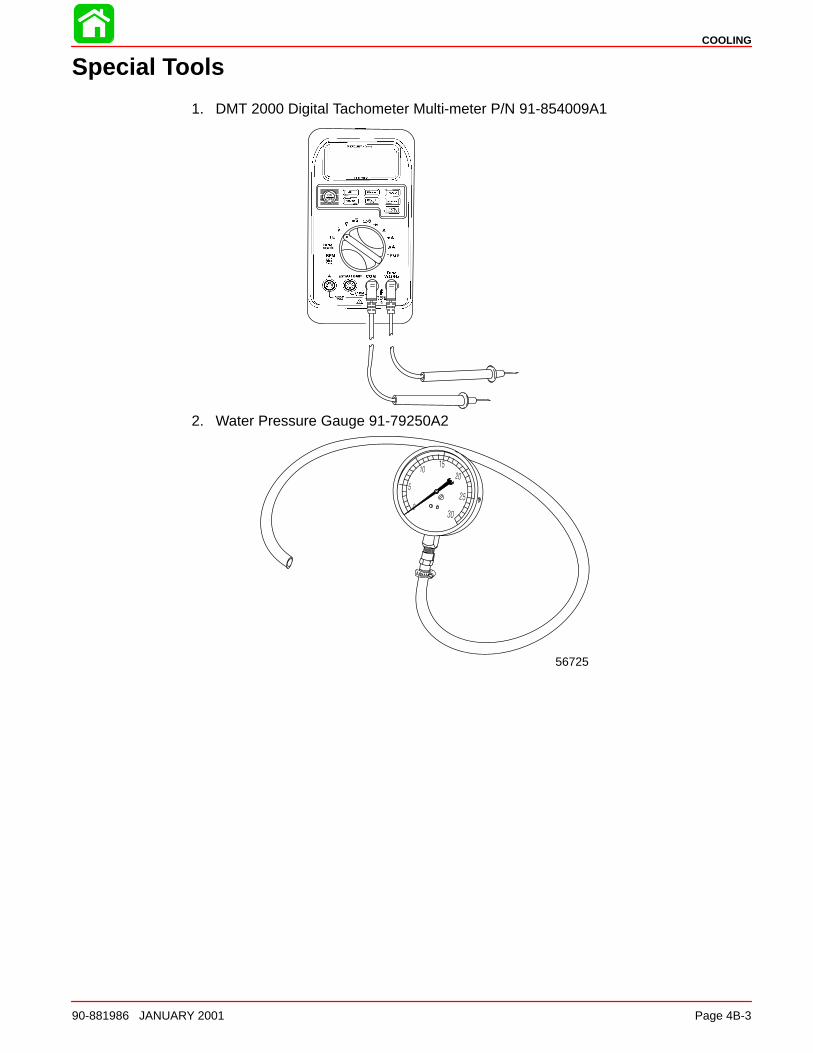
COOLING
90-881986 JANUARY 2001 Page 4B-3
Special Tools
1. DMT 2000 Digital Tachometer Multi-meter P/N 91-854009A1
2. Water Pressure Gauge 91-79250A2
56725
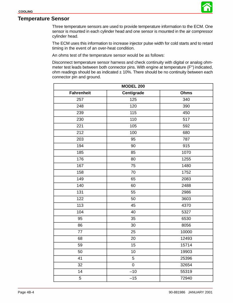
COOLING
Page 4B-4 90-881986 JANUARY 2001
Temperature SensorThree temperature sensors are used to provide temperature information to the ECM. Onesensor is mounted in each cylinder head and one sensor is mounted in the air compressorcylinder head.
The ECM uses this information to increase injector pulse width for cold starts and to retardtiming in the event of an over-heat condition.
An ohms test of the temperature sensor would be as follows:
Disconnect temperature sensor harness and check continuity with digital or analog ohm-meter test leads between both connector pins. With engine at temperature (F°) indicated,ohm readings should be as indicated ± 10%. There should be no continuity between eachconnector pin and ground.
MODEL 200
Fahrenheit Centigrade Ohms
257 125 340
248 120 390
239 115 450
230 110 517
221 105 592
212 100 680
203 95 787
194 90 915
185 85 1070
176 80 1255
167 75 1480
158 70 1752
149 65 2083
140 60 2488
131 55 2986
122 50 3603
113 45 4370
104 40 5327
95 35 6530
86 30 8056
77 25 10000
68 20 12493
59 15 15714
50 10 19903
41 5 25396
32 0 32654
14 –10 55319
5 –15 72940
COOLING
90-881986 JANUARY 2001 Page 4B-5
Model 200 Water Flow
DescriptionWater is pumped up through the adaptor plate (9) and into the powerhead by the jet pumpimpeller which is constantly turning whenever the engine is running. Water flows throughthe center of the block, around the cylinder sleeves and through the cylinder heads (1).
Water exits from the bottom of the block and into the adaptor plate (9) flowing past theexhaust runners and into the expansion chamber. The water fills the expansion chamberand exits out the top of the chamber via a hose and back into the adaptor plate where itdrains into the pump.
Water is also pumped from the starboard side of the adaptor plate to the fuel cooler (13)and then to the air compressor (12). The water exits the air compressor via a hose to at-fitting over the expansion chamber. The water is then sprayed into each exhaust pipefor cooling purposes.
To allow complete passage filling and to prevent steam pockets, all cooling passages areinterconnected. Small passages are incorporated to allow the cooling system to drain.

COOLING
Page 4B-6 90-881986 JANUARY 2001
Notes:
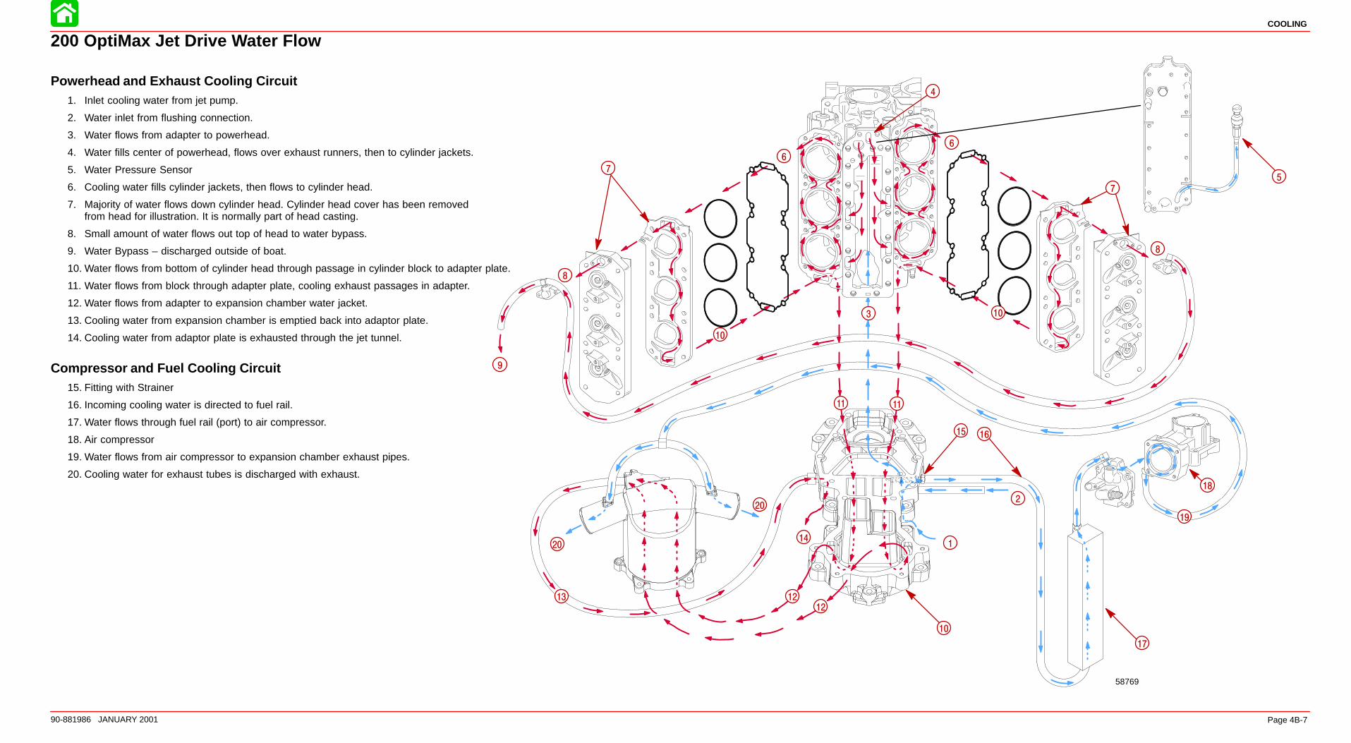
9
14
58769
2
1
20
20
16
7
10
5
17
15
3
4
6
7
8
8
10
10
11 11
12
12
13
6
18
19
COOLING
90-881986 JANUARY 2001 Page 4B-7
200 OptiMax Jet Drive Water Flow
Powerhead and Exhaust Cooling Circuit1. Inlet cooling water from jet pump.
2. Water inlet from flushing connection.
3. Water flows from adapter to powerhead.
4. Water fills center of powerhead, flows over exhaust runners, then to cylinder jackets.
5. Water Pressure Sensor
6. Cooling water fills cylinder jackets, then flows to cylinder head.
7. Majority of water flows down cylinder head. Cylinder head cover has been removedfrom head for illustration. It is normally part of head casting.
8. Small amount of water flows out top of head to water bypass.
9. Water Bypass – discharged outside of boat.
10. Water flows from bottom of cylinder head through passage in cylinder block to adapter plate.
11. Water flows from block through adapter plate, cooling exhaust passages in adapter.
12. Water flows from adapter to expansion chamber water jacket.
13. Cooling water from expansion chamber is emptied back into adaptor plate.
14. Cooling water from adaptor plate is exhausted through the jet tunnel.
Compressor and Fuel Cooling Circuit15. Fitting with Strainer
16. Incoming cooling water is directed to fuel rail.
17. Water flows through fuel rail (port) to air compressor.
18. Air compressor
19. Water flows from air compressor to expansion chamber exhaust pipes.
20. Cooling water for exhaust tubes is discharged with exhaust.
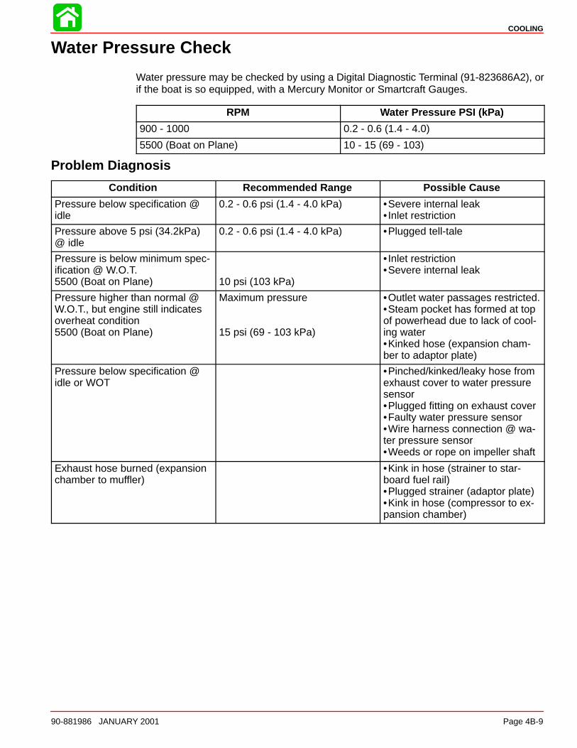
COOLING
90-881986 JANUARY 2001 Page 4B-9
Water Pressure Check
Water pressure may be checked by using a Digital Diagnostic Terminal (91-823686A2), orif the boat is so equipped, with a Mercury Monitor or Smartcraft Gauges.
RPM Water Pressure PSI (kPa)
900 - 1000 0.2 - 0.6 (1.4 - 4.0)
5500 (Boat on Plane) 10 - 15 (69 - 103)
Problem Diagnosis
Condition Recommended Range Possible Cause
Pressure below specification @idle
0.2 - 0.6 psi (1.4 - 4.0 kPa) •Severe internal leak• Inlet restriction
Pressure above 5 psi (34.2kPa)@ idle
0.2 - 0.6 psi (1.4 - 4.0 kPa) •Plugged tell-tale
Pressure is below minimum spec-ification @ W.O.T.5500 (Boat on Plane) 10 psi (103 kPa)
• Inlet restriction•Severe internal leak
Pressure higher than normal @W.O.T., but engine still indicatesoverheat condition5500 (Boat on Plane)
Maximum pressure
15 psi (69 - 103 kPa)
•Outlet water passages restricted.•Steam pocket has formed at topof powerhead due to lack of cool-ing water•Kinked hose (expansion cham-ber to adaptor plate)
Pressure below specification @idle or WOT
•Pinched/kinked/leaky hose fromexhaust cover to water pressuresensor•Plugged fitting on exhaust cover•Faulty water pressure sensor•Wire harness connection @ wa-ter pressure sensor•Weeds or rope on impeller shaft
Exhaust hose burned (expansionchamber to muffler)
•Kink in hose (strainer to star-board fuel rail)•Plugged strainer (adaptor plate)•Kink in hose (compressor to ex-pansion chamber)
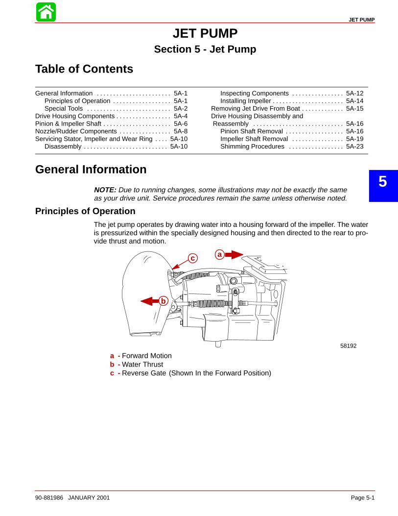
5
JET PUMP
90-881986 JANUARY 2001 Page 5-1
JET PUMPSection 5 - Jet Pump
Table of Contents
General Information 5A-1. . . . . . . . . . . . . . . . . . . . . . . Principles of Operation 5A-1. . . . . . . . . . . . . . . . . . Special Tools 5A-2. . . . . . . . . . . . . . . . . . . . . . . . . .
Drive Housing Components 5A-4. . . . . . . . . . . . . . . . . Pinion & Impeller Shaft 5A-6. . . . . . . . . . . . . . . . . . . . . Nozzle/Rudder Components 5A-8. . . . . . . . . . . . . . . . Servicing Stator, Impeller and Wear Ring 5A-10. . . .
Disassembly 5A-10. . . . . . . . . . . . . . . . . . . . . . . . . .
Inspecting Components 5A-12. . . . . . . . . . . . . . . . Installing Impeller 5A-14. . . . . . . . . . . . . . . . . . . . . .
Removing Jet Drive From Boat 5A-15. . . . . . . . . . . . . Drive Housing Disassembly and Reassembly 5A-16. . . . . . . . . . . . . . . . . . . . . . . . . . . .
Pinion Shaft Removal 5A-16. . . . . . . . . . . . . . . . . . Impeller Shaft Removal 5A-19. . . . . . . . . . . . . . . . Shimming Procedures 5A-23. . . . . . . . . . . . . . . . .
General Information
NOTE: Due to running changes, some illustrations may not be exactly the same as your drive unit. Service procedures remain the same unless otherwise noted.
Principles of OperationThe jet pump operates by drawing water into a housing forward of the impeller. The wateris pressurized within the specially designed housing and then directed to the rear to pro-vide thrust and motion.
58192
a
b
c
a - Forward Motionb - Water Thrustc - Reverse Gate (Shown In the Forward Position)
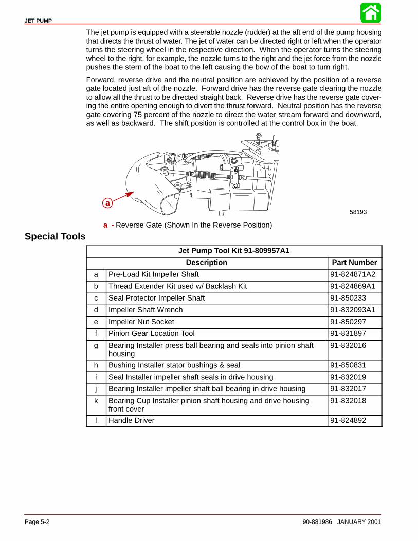
JET PUMP
Page 5-2 90-881986 JANUARY 2001
The jet pump is equipped with a steerable nozzle (rudder) at the aft end of the pump housingthat directs the thrust of water. The jet of water can be directed right or left when the operatorturns the steering wheel in the respective direction. When the operator turns the steeringwheel to the right, for example, the nozzle turns to the right and the jet force from the nozzlepushes the stern of the boat to the left causing the bow of the boat to turn right.
Forward, reverse drive and the neutral position are achieved by the position of a reversegate located just aft of the nozzle. Forward drive has the reverse gate clearing the nozzleto allow all the thrust to be directed straight back. Reverse drive has the reverse gate cover-ing the entire opening enough to divert the thrust forward. Neutral position has the reversegate covering 75 percent of the nozzle to direct the water stream forward and downward,as well as backward. The shift position is controlled at the control box in the boat.
58193a
a - Reverse Gate (Shown In the Reverse Position)
Special ToolsJet Pump Tool Kit 91-809957A1
Description Part Number
a Pre-Load Kit Impeller Shaft 91-824871A2
b Thread Extender Kit used w/ Backlash Kit 91-824869A1
c Seal Protector Impeller Shaft 91-850233
d Impeller Shaft Wrench 91-832093A1
e Impeller Nut Socket 91-850297
f Pinion Gear Location Tool 91-831897
g Bearing Installer press ball bearing and seals into pinion shafthousing
91-832016
h Bushing Installer stator bushings & seal 91-850831
i Seal Installer impeller shaft seals in drive housing 91-832019
j Bearing Installer impeller shaft ball bearing in drive housing 91-832017
k Bearing Cup Installer pinion shaft housing and drive housingfront cover
91-832018
l Handle Driver 91-824892
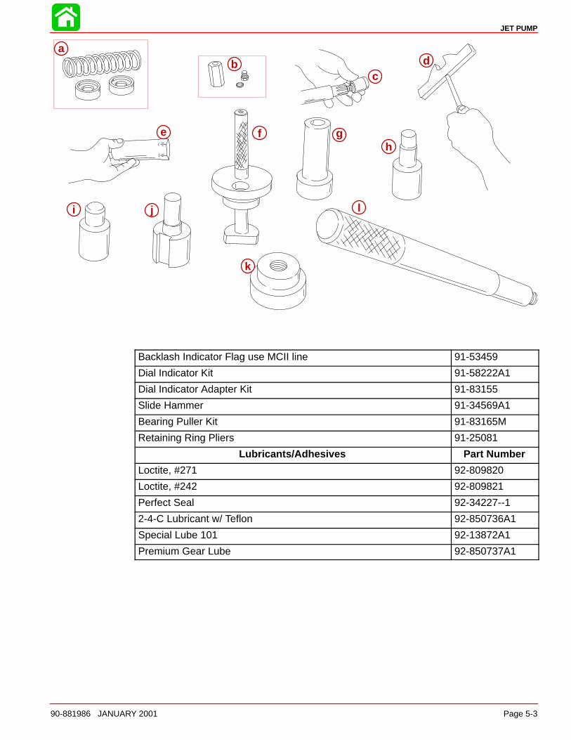
JET PUMP
90-881986 JANUARY 2001 Page 5-3
a
b d
e f gh
i j l
k
c
ab
cd
e f gh
i j
k
l
Backlash Indicator Flag use MCII line 91-53459
Dial Indicator Kit 91-58222A1
Dial Indicator Adapter Kit 91-83155
Slide Hammer 91-34569A1
Bearing Puller Kit 91-83165M
Retaining Ring Pliers 91-25081
Lubricants/Adhesives Part Number
Loctite, #271 92-809820
Loctite, #242 92-809821
Perfect Seal 92-34227--1
2-4-C Lubricant w/ Teflon 92-850736A1
Special Lube 101 92-13872A1
Premium Gear Lube 92-850737A1
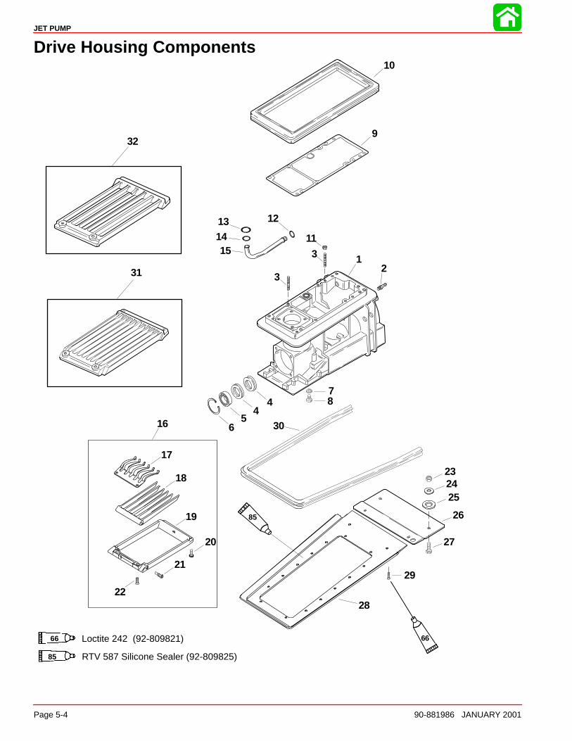
JET PUMP
Page 5-4 90-881986 JANUARY 2001
Drive Housing Components
12
48
9
10
11
12131415
16
17
18
20
21
232425
26
27
28
29
30
3
6
7
5
19
22
3
4
66 Loctite 242 (92-809821)
RTV 587 Silicone Sealer (92-809825)
66
85
85
31
32
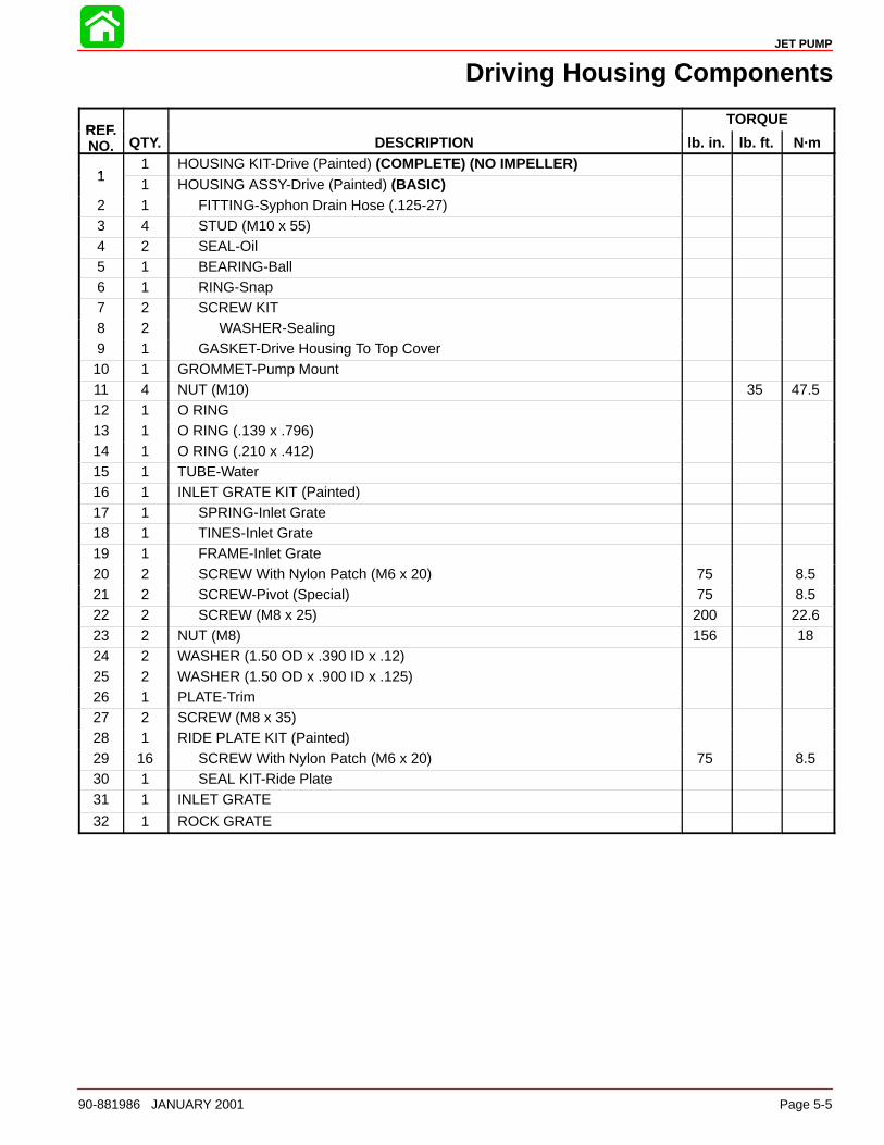
JET PUMP
90-881986 JANUARY 2001 Page 5-5
Driving Housing Components
REFTORQUE
REF.NO. QTY. DESCRIPTION lb. in. lb. ft. N·m
11 HOUSING KIT-Drive (Painted) (COMPLETE) (NO IMPELLER)
11 HOUSING ASSY-Drive (Painted) (BASIC)
2 1 FITTING-Syphon Drain Hose (.125-27)3 4 STUD (M10 x 55)4 2 SEAL-Oil5 1 BEARING-Ball6 1 RING-Snap7 2 SCREW KIT8 2 WASHER-Sealing9 1 GASKET-Drive Housing To Top Cover10 1 GROMMET-Pump Mount11 4 NUT (M10) 35 47.512 1 O RING13 1 O RING (.139 x .796)14 1 O RING (.210 x .412)15 1 TUBE-Water16 1 INLET GRATE KIT (Painted)17 1 SPRING-Inlet Grate18 1 TINES-Inlet Grate19 1 FRAME-Inlet Grate20 2 SCREW With Nylon Patch (M6 x 20) 75 8.521 2 SCREW-Pivot (Special) 75 8.522 2 SCREW (M8 x 25) 200 22.623 2 NUT (M8) 156 1824 2 WASHER (1.50 OD x .390 ID x .12)25 2 WASHER (1.50 OD x .900 ID x .125)26 1 PLATE-Trim27 2 SCREW (M8 x 35)28 1 RIDE PLATE KIT (Painted)29 16 SCREW With Nylon Patch (M6 x 20) 75 8.530 1 SEAL KIT-Ride Plate31 1 INLET GRATE
32 1 ROCK GRATE
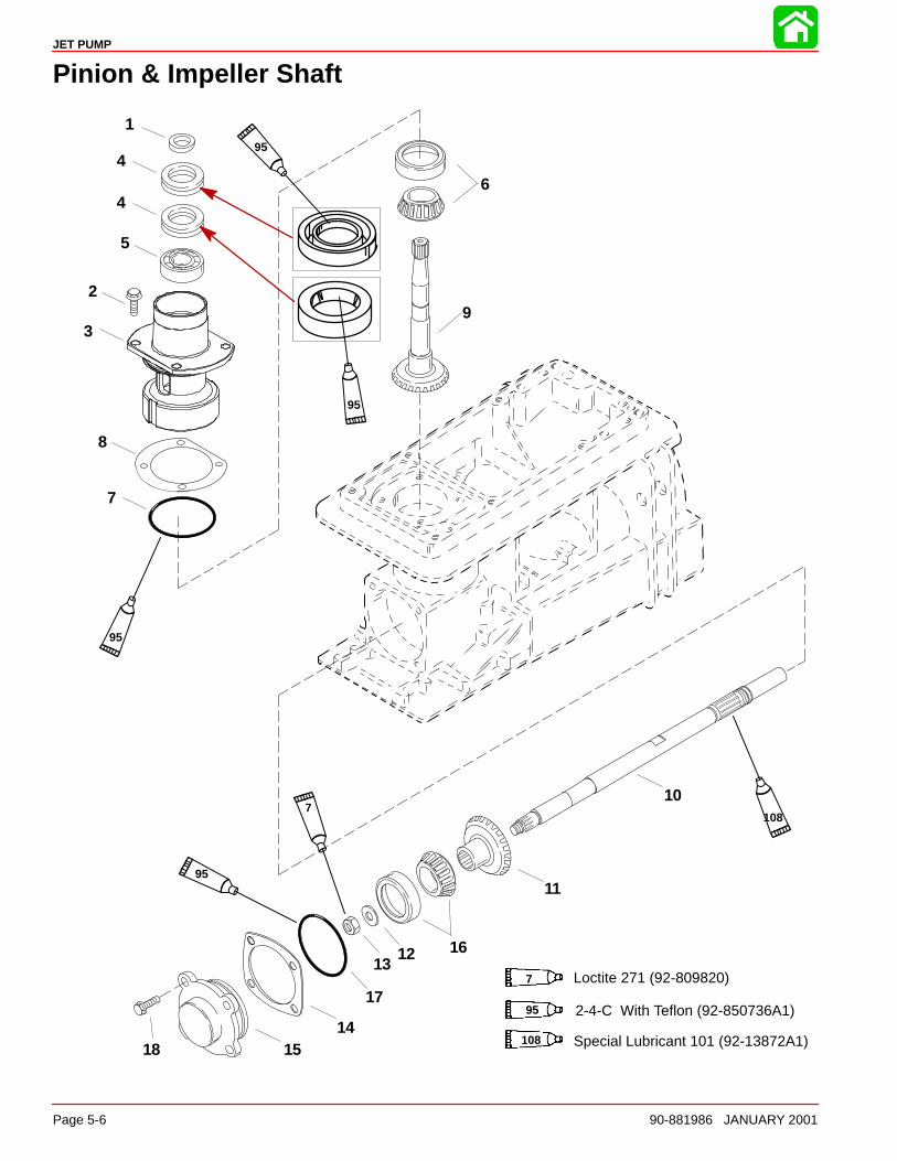
JET PUMP
Page 5-6 90-881986 JANUARY 2001
Pinion & Impeller Shaft
1
2
4
3
5
7
6
8
9
10
11
1213
1415
16
17
18
4
7 Loctite 271 (92-809820)
95 2-4-C With Teflon (92-850736A1)
108 Special Lubricant 101 (92-13872A1)
7
95
95
108
95
95
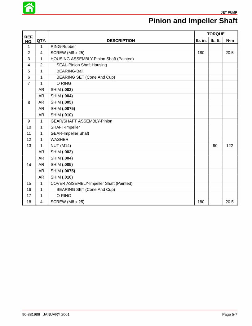
JET PUMP
90-881986 JANUARY 2001 Page 5-7
Pinion and Impeller Shaft
REFTORQUE
REF.NO. QTY. DESCRIPTION lb. in. lb. ft. N·m
1 1 RING-Rubber
2 4 SCREW (M8 x 25) 180 20.5
3 1 HOUSING ASSEMBLY-Pinion Shaft (Painted)
4 2 SEAL-Pinion Shaft Housing
5 1 BEARING-Ball
6 1 BEARING SET (Cone And Cup)
7 1 O RING
AR SHIM (.002)
AR SHIM (.004)
8 AR SHIM (.005)
AR SHIM (.0075)
AR SHIM (.010)
9 1 GEAR/SHAFT ASSEMBLY-Pinion
10 1 SHAFT-Impeller
11 1 GEAR-Impeller Shaft
12 1 WASHER
13 1 NUT (M14) 90 122
AR SHIM (.002)
AR SHIM (.004)
14 AR SHIM (.005)
AR SHIM (.0075)
AR SHIM (.010)
15 1 COVER ASSEMBLY-Impeller Shaft (Painted)
16 1 BEARING SET (Cone And Cup)
17 1 O RING
18 4 SCREW (M8 x 25) 180 20.5
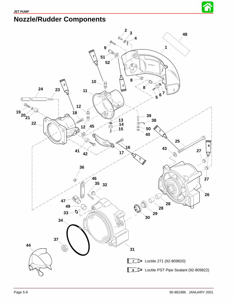
JET PUMP
Page 5-8 90-881986 JANUARY 2001
Nozzle/Rudder Components
1
23
4
5 6 7
8
9
52
11
12
131415
1617
18192021
22
2324
25
26
28
2930
32
33
34
35
36
37
3839
40
4142
43
44
45
46
47
48
810
12
2849
50
7 Loctite 271 (92-809820)
7
7
7
7
7
27
27
Loctite PST Pipe Sealant (92-809822)9
9
31
51
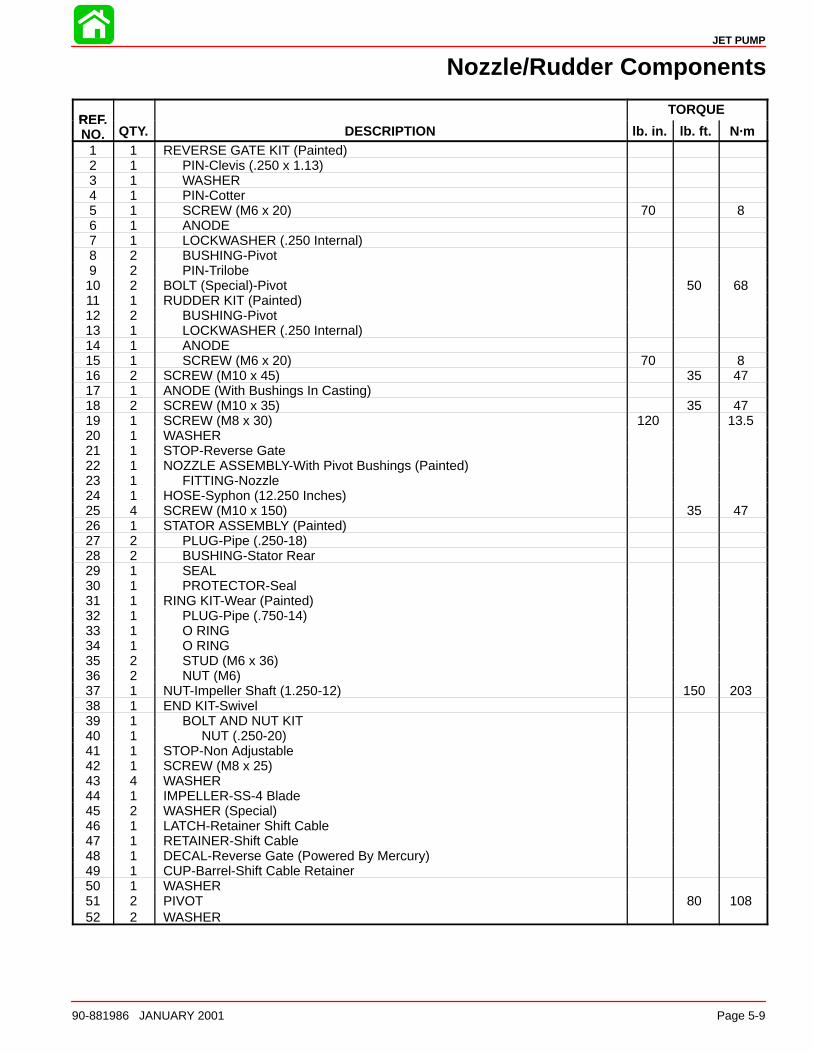
JET PUMP
90-881986 JANUARY 2001 Page 5-9
Nozzle/Rudder Components
REFTORQUE
REF.NO. QTY. DESCRIPTION lb. in. lb. ft. N·m
1 1 REVERSE GATE KIT (Painted)2 1 PIN-Clevis (.250 x 1.13)3 1 WASHER4 1 PIN-Cotter5 1 SCREW (M6 x 20) 70 86 1 ANODE7 1 LOCKWASHER (.250 Internal)8 2 BUSHING-Pivot9 2 PIN-Trilobe10 2 BOLT (Special)-Pivot 50 6811 1 RUDDER KIT (Painted)12 2 BUSHING-Pivot13 1 LOCKWASHER (.250 Internal)14 1 ANODE15 1 SCREW (M6 x 20) 70 816 2 SCREW (M10 x 45) 35 4717 1 ANODE (With Bushings In Casting)18 2 SCREW (M10 x 35) 35 4719 1 SCREW (M8 x 30) 120 13.520 1 WASHER21 1 STOP-Reverse Gate22 1 NOZZLE ASSEMBLY-With Pivot Bushings (Painted)23 1 FITTING-Nozzle24 1 HOSE-Syphon (12.250 Inches)25 4 SCREW (M10 x 150) 35 4726 1 STATOR ASSEMBLY (Painted)27 2 PLUG-Pipe (.250-18)28 2 BUSHING-Stator Rear29 1 SEAL30 1 PROTECTOR-Seal31 1 RING KIT-Wear (Painted)32 1 PLUG-Pipe (.750-14)33 1 O RING34 1 O RING35 2 STUD (M6 x 36)36 2 NUT (M6)37 1 NUT-Impeller Shaft (1.250-12) 150 20338 1 END KIT-Swivel39 1 BOLT AND NUT KIT40 1 NUT (.250-20)41 1 STOP-Non Adjustable42 1 SCREW (M8 x 25)43 4 WASHER44 1 IMPELLER-SS-4 Blade45 2 WASHER (Special)46 1 LATCH-Retainer Shift Cable47 1 RETAINER-Shift Cable48 1 DECAL-Reverse Gate (Powered By Mercury)49 1 CUP-Barrel-Shift Cable Retainer50 1 WASHER51 2 PIVOT 80 10852 2 WASHER
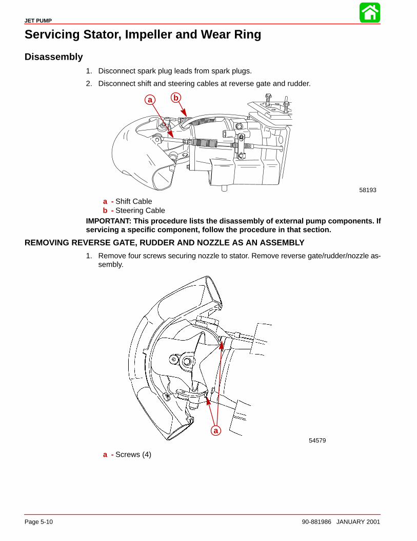
JET PUMP
Page 5-10 90-881986 JANUARY 2001
Servicing Stator, Impeller and Wear Ring
Disassembly1. Disconnect spark plug leads from spark plugs.
2. Disconnect shift and steering cables at reverse gate and rudder.
bb
58193
a
a - Shift Cableb - Steering Cable
IMPORTANT: This procedure lists the disassembly of external pump components. Ifservicing a specific component, follow the procedure in that section.
REMOVING REVERSE GATE, RUDDER AND NOZZLE AS AN ASSEMBLY
1. Remove four screws securing nozzle to stator. Remove reverse gate/rudder/nozzle as-sembly.
54579
a
a - Screws (4)
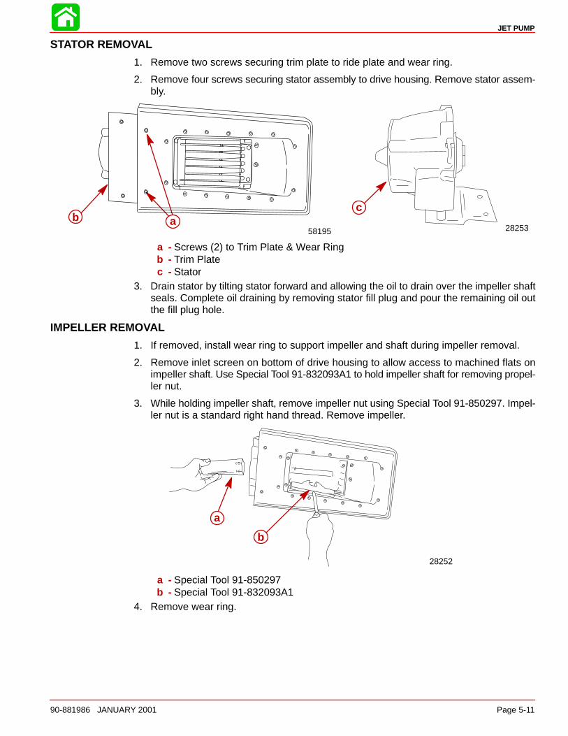
JET PUMP
90-881986 JANUARY 2001 Page 5-11
STATOR REMOVAL
1. Remove two screws securing trim plate to ride plate and wear ring.
2. Remove four screws securing stator assembly to drive housing. Remove stator assem-bly.
2825358195
cab
a - Screws (2) to Trim Plate & Wear Ringb - Trim Platec - Stator
3. Drain stator by tilting stator forward and allowing the oil to drain over the impeller shaftseals. Complete oil draining by removing stator fill plug and pour the remaining oil outthe fill plug hole.
IMPELLER REMOVAL
1. If removed, install wear ring to support impeller and shaft during impeller removal.
2. Remove inlet screen on bottom of drive housing to allow access to machined flats onimpeller shaft. Use Special Tool 91-832093A1 to hold impeller shaft for removing propel-ler nut.
3. While holding impeller shaft, remove impeller nut using Special Tool 91-850297. Impel-ler nut is a standard right hand thread. Remove impeller.
28252
a
b
a - Special Tool 91-850297b - Special Tool 91-832093A1
4. Remove wear ring.
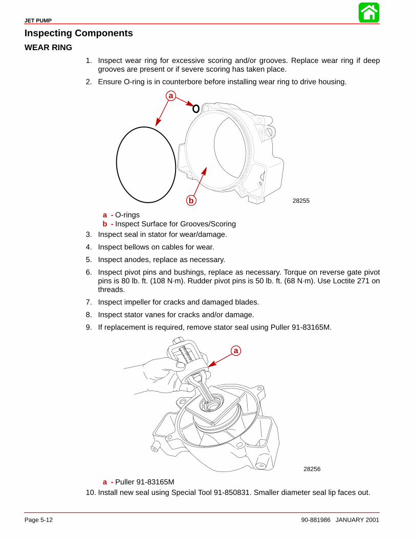
JET PUMP
Page 5-12 90-881986 JANUARY 2001
Inspecting ComponentsWEAR RING
1. Inspect wear ring for excessive scoring and/or grooves. Replace wear ring if deepgrooves are present or if severe scoring has taken place.
2. Ensure O-ring is in counterbore before installing wear ring to drive housing.
28255
a
b
a
b
a - O-ringsb - Inspect Surface for Grooves/Scoring
3. Inspect seal in stator for wear/damage.
4. Inspect bellows on cables for wear.
5. Inspect anodes, replace as necessary.
6. Inspect pivot pins and bushings, replace as necessary. Torque on reverse gate pivotpins is 80 lb. ft. (108 N·m). Rudder pivot pins is 50 lb. ft. (68 N·m). Use Loctite 271 onthreads.
7. Inspect impeller for cracks and damaged blades.
8. Inspect stator vanes for cracks and/or damage.
9. If replacement is required, remove stator seal using Puller 91-83165M.
28256
a
a - Puller 91-83165M10. Install new seal using Special Tool 91-850831. Smaller diameter seal lip faces out.
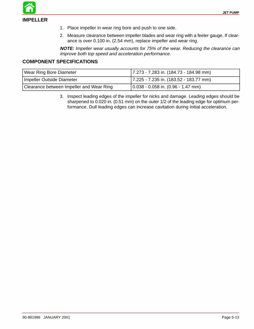
JET PUMP
90-881986 JANUARY 2001 Page 5-13
IMPELLER
1. Place impeller in wear ring bore and push to one side.
2. Measure clearance between impeller blades and wear ring with a feeler gauge. If clear-ance is over 0.100 in. (2.54 mm), replace impeller and wear ring.
NOTE: Impeller wear usually accounts for 75% of the wear. Reducing the clearance canimprove both top speed and acceleration performance.
COMPONENT SPECIFICATIONS
Wear Ring Bore Diameter 7.273 - 7.283 in. (184.73 - 184.98 mm)
Impeller Outside Diameter 7.225 - 7.235 in. (183.52 - 183.77 mm)
Clearance between Impeller and Wear Ring 0.038 - 0.058 in. (0.96 - 1.47 mm)
3. Inspect leading edges of the impeller for nicks and damage. Leading edges should besharpened to 0.020 in. (0.51 mm) on the outer 1/2 of the leading edge for optimum per-formance. Dull leading edges can increase cavitation during initial acceleration.
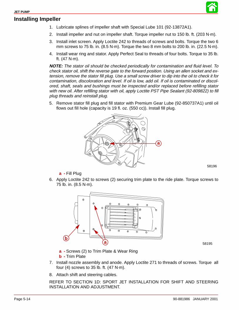
JET PUMP
Page 5-14 90-881986 JANUARY 2001
Installing Impeller1. Lubricate splines of impeller shaft with Special Lube 101 (92-13872A1).
2. Install impeller and nut on impeller shaft. Torque impeller nut to 150 lb. ft. (203 N·m).
3. Install inlet screen. Apply Loctite 242 to threads of screws and bolts. Torque the two 6mm screws to 75 lb. in. (8.5 N·m). Torque the two 8 mm bolts to 200 lb. in. (22.5 N·m).
4. Install wear ring and stator. Apply Perfect Seal to threads of four bolts. Torque to 35 lb.ft. (47 N·m).
NOTE: The stator oil should be checked periodically for contamination and fluid level. Tocheck stator oil, shift the reverse gate to the forward position. Using an allen socket and ex-tension, remove the stator fill plug. Use a small screw driver to dip into the oil to check it forcontamination, discoloration and level. If oil is low, add oil. If oil is contaminated or discol-ored, shaft, seals and bushings must be inspected and/or replaced before refilling statorwith new oil. After refilling stator with oil, apply Loctite PST Pipe Sealant (92-809822) to fillplug threads and reinstall plug.
5. Remove stator fill plug and fill stator with Premium Gear Lube (92-850737A1) until oilflows out fill hole (capacity is 19 fl. oz. (550 cc)). Install fill plug.
58196
a
a - Fill Plug6. Apply Loctite 242 to screws (2) securing trim plate to the ride plate. Torque screws to
75 lb. in. (8.5 N·m).
58195ab
a - Screws (2) to Trim Plate & Wear Ringb - Trim Plate
7. Install nozzle assembly and anode. Apply Loctite 271 to threads of screws. Torque allfour (4) screws to 35 lb. ft. (47 N·m).
8. Attach shift and steering cables.
REFER TO SECTION 1D: SPORT JET INSTALLATION FOR SHIFT AND STEERINGINSTALLATION AND ADJUSTMENT.
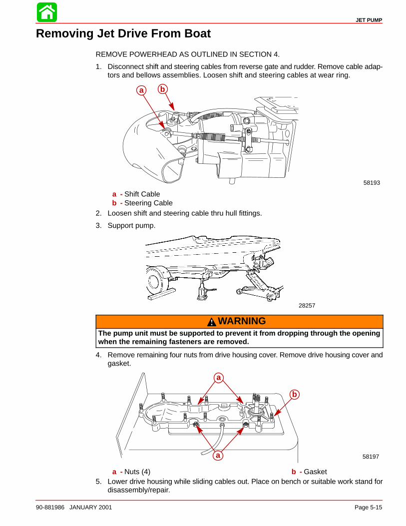
JET PUMP
90-881986 JANUARY 2001 Page 5-15
Removing Jet Drive From Boat
REMOVE POWERHEAD AS OUTLINED IN SECTION 4.
1. Disconnect shift and steering cables from reverse gate and rudder. Remove cable adap-tors and bellows assemblies. Loosen shift and steering cables at wear ring.
b
58193
a
a - Shift Cableb - Steering Cable
2. Loosen shift and steering cable thru hull fittings.
3. Support pump.
28257
WARNINGThe pump unit must be supported to prevent it from dropping through the openingwhen the remaining fasteners are removed.
4. Remove remaining four nuts from drive housing cover. Remove drive housing cover andgasket.
a
b
58197
a
a - Nuts (4) b - Gasket5. Lower drive housing while sliding cables out. Place on bench or suitable work stand for
disassembly/repair.
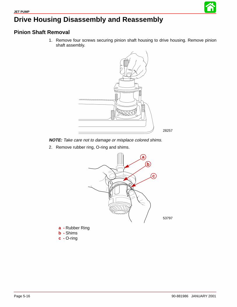
JET PUMP
Page 5-16 90-881986 JANUARY 2001
Drive Housing Disassembly and Reassembly
Pinion Shaft Removal1. Remove four screws securing pinion shaft housing to drive housing. Remove pinion
shaft assembly.
28257
NOTE: Take care not to damage or misplace colored shims.
2. Remove rubber ring, O-ring and shims.
53797
a
b
c
a - Rubber Ringb - Shimsc - O-ring
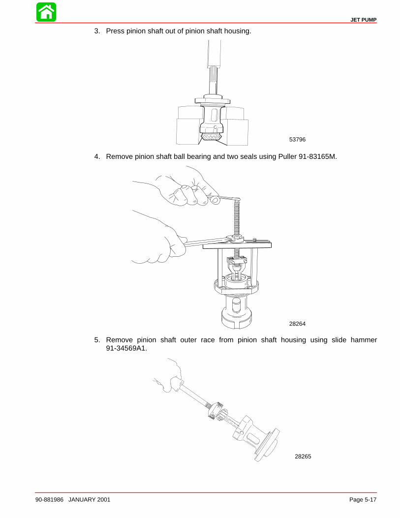
JET PUMP
90-881986 JANUARY 2001 Page 5-17
3. Press pinion shaft out of pinion shaft housing.
53796
4. Remove pinion shaft ball bearing and two seals using Puller 91-83165M.
28264
5. Remove pinion shaft outer race from pinion shaft housing using slide hammer91-34569A1.
28265
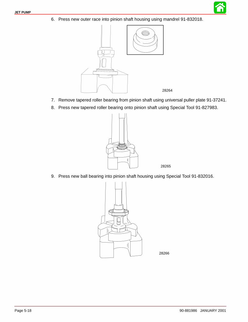
JET PUMP
Page 5-18 90-881986 JANUARY 2001
6. Press new outer race into pinion shaft housing using mandrel 91-832018.
28264
7. Remove tapered roller bearing from pinion shaft using universal puller plate 91-37241.
8. Press new tapered roller bearing onto pinion shaft using Special Tool 91-827983.
28265
9. Press new ball bearing into pinion shaft housing using Special Tool 91-832016.
28266
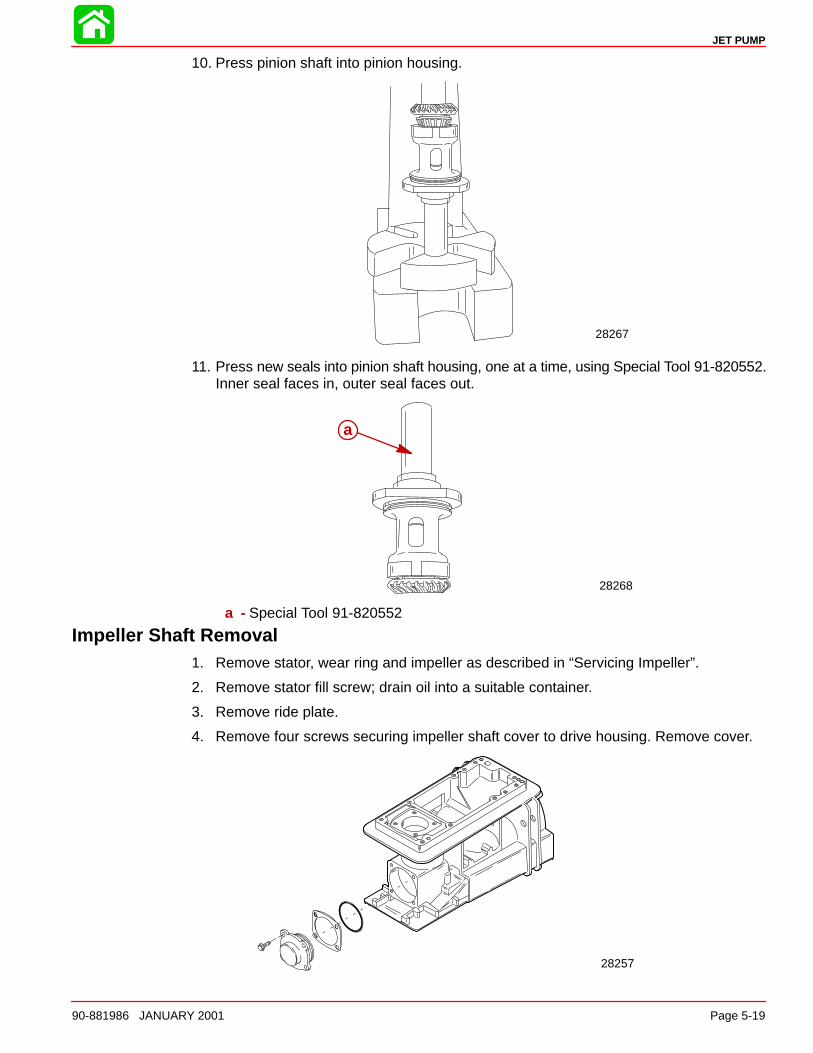
JET PUMP
90-881986 JANUARY 2001 Page 5-19
10. Press pinion shaft into pinion housing.
28267
11. Press new seals into pinion shaft housing, one at a time, using Special Tool 91-820552.Inner seal faces in, outer seal faces out.
28268
a
a - Special Tool 91-820552
Impeller Shaft Removal1. Remove stator, wear ring and impeller as described in “Servicing Impeller”.
2. Remove stator fill screw; drain oil into a suitable container.
3. Remove ride plate.
4. Remove four screws securing impeller shaft cover to drive housing. Remove cover.
28257
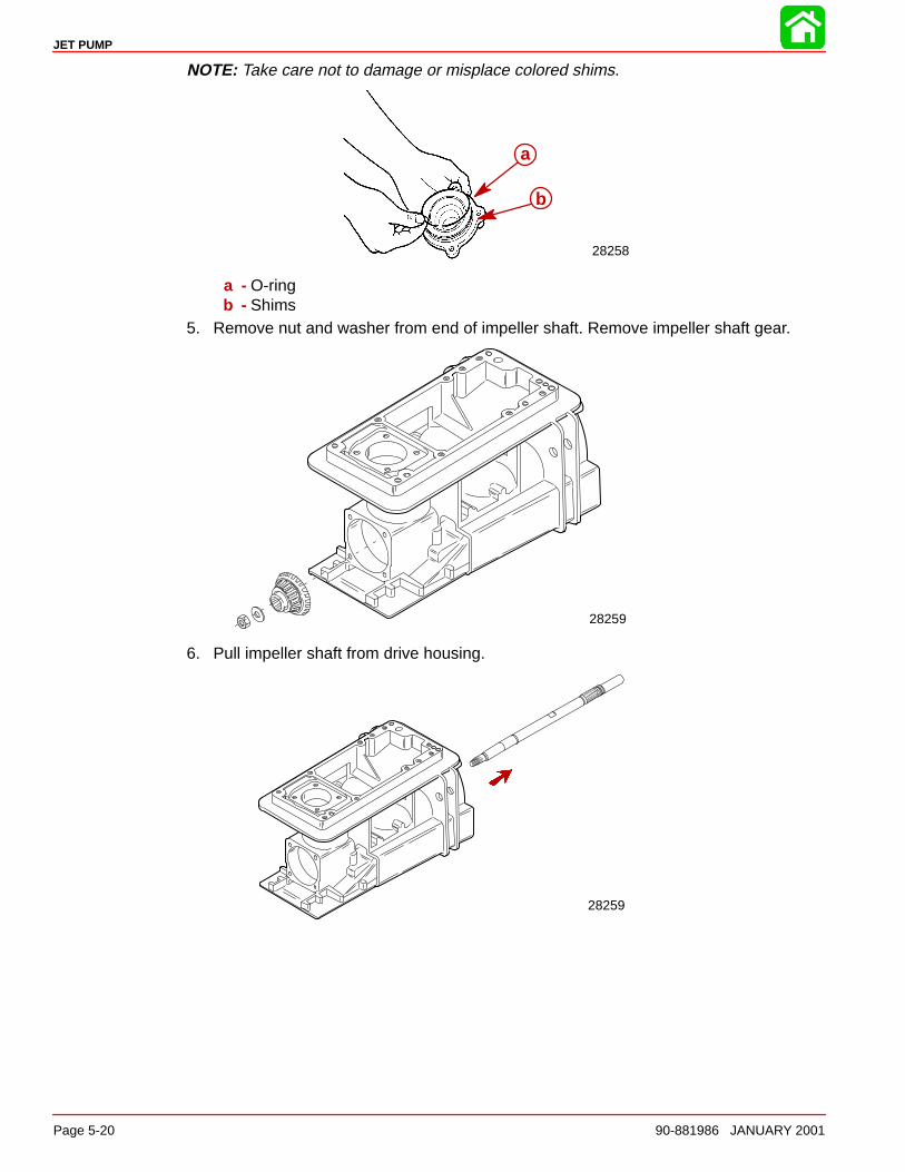
JET PUMP
Page 5-20 90-881986 JANUARY 2001
NOTE: Take care not to damage or misplace colored shims.
28258
a
b
a - O-ringb - Shims
5. Remove nut and washer from end of impeller shaft. Remove impeller shaft gear.
28259
6. Pull impeller shaft from drive housing.
28259
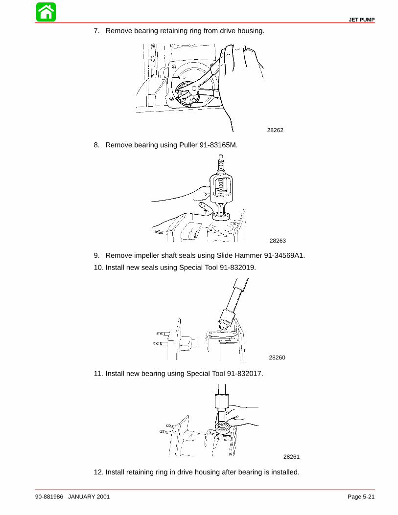
JET PUMP
90-881986 JANUARY 2001 Page 5-21
7. Remove bearing retaining ring from drive housing.
28262
8. Remove bearing using Puller 91-83165M.
28263
9. Remove impeller shaft seals using Slide Hammer 91-34569A1.
10. Install new seals using Special Tool 91-832019.
28260
11. Install new bearing using Special Tool 91-832017.
28261
12. Install retaining ring in drive housing after bearing is installed.
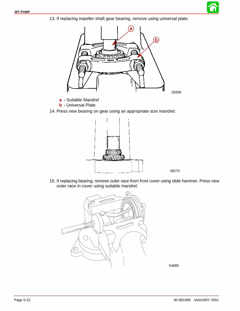
JET PUMP
Page 5-22 90-881986 JANUARY 2001
13. If replacing impeller shaft gear bearing, remove using universal plate.
28269
a
b
a - Suitable Mandrelb - Universal Plate
14. Press new bearing on gear using an appropriate size mandrel.
28270
15. If replacing bearing, remove outer race from front cover using slide hammer. Press newouter race in cover using suitable mandrel.
54985
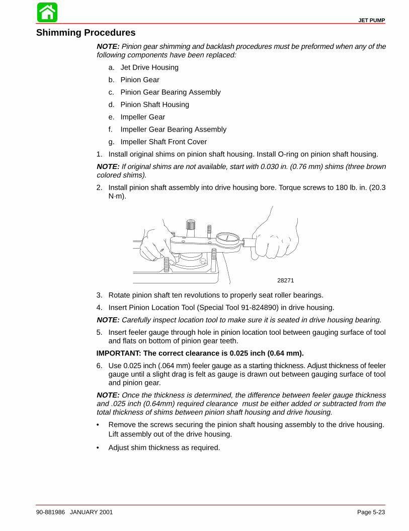
JET PUMP
90-881986 JANUARY 2001 Page 5-23
Shimming ProceduresNOTE: Pinion gear shimming and backlash procedures must be preformed when any of thefollowing components have been replaced:
a. Jet Drive Housing
b. Pinion Gear
c. Pinion Gear Bearing Assembly
d. Pinion Shaft Housing
e. Impeller Gear
f. Impeller Gear Bearing Assembly
g. Impeller Shaft Front Cover
1. Install original shims on pinion shaft housing. Install O-ring on pinion shaft housing.
NOTE: If original shims are not available, start with 0.030 in. (0.76 mm) shims (three browncolored shims).
2. Install pinion shaft assembly into drive housing bore. Torque screws to 180 lb. in. (20.3N·m).
28271
3. Rotate pinion shaft ten revolutions to properly seat roller bearings.
4. Insert Pinion Location Tool (Special Tool 91-824890) in drive housing.
NOTE: Carefully inspect location tool to make sure it is seated in drive housing bearing.
5. Insert feeler gauge through hole in pinion location tool between gauging surface of tooland flats on bottom of pinion gear teeth.
IMPORTANT: The correct clearance is 0.025 inch (0.64 mm).
6. Use 0.025 inch (.064 mm) feeler gauge as a starting thickness. Adjust thickness of feelergauge until a slight drag is felt as gauge is drawn out between gauging surface of tooland pinion gear.
NOTE: Once the thickness is determined, the difference between feeler gauge thicknessand .025 inch (0.64mm) required clearance must be either added or subtracted from thetotal thickness of shims between pinion shaft housing and drive housing.
• Remove the screws securing the pinion shaft housing assembly to the drive housing.Lift assembly out of the drive housing.
• Adjust shim thickness as required.
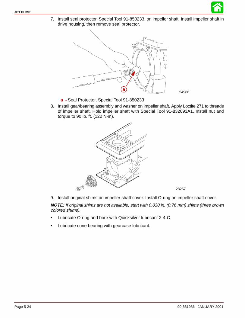
JET PUMP
Page 5-24 90-881986 JANUARY 2001
7. Install seal protector, Special Tool 91-850233, on impeller shaft. Install impeller shaft indrive housing, then remove seal protector.
54986aa
a - Seal Protector, Special Tool 91-8502338. Install gear/bearing assembly and washer on impeller shaft. Apply Loctite 271 to threads
of impeller shaft. Hold impeller shaft with Special Tool 91-832093A1. Install nut andtorque to 90 lb. ft. (122 N·m).
28257
9. Install original shims on impeller shaft cover. Install O-ring on impeller shaft cover.
NOTE: If original shims are not available, start with 0.030 in. (0.76 mm) shims (three browncolored shims).
• Lubricate O-ring and bore with Quicksilver lubricant 2-4-C.
• Lubricate cone bearing with gearcase lubricant.
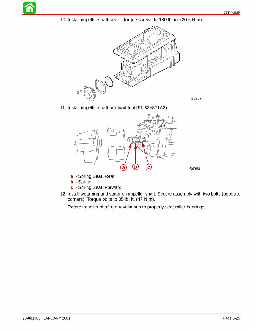
JET PUMP
90-881986 JANUARY 2001 Page 5-25
10. Install impeller shaft cover. Torque screws to 180 lb. in. (20.5 N·m).
28257
11. Install impeller shaft pre-load tool (91-824871A2).
54983a b c
a - Spring Seat, Rearb - Springc - Spring Seat, Forward
12. Install wear ring and stator on impeller shaft. Secure assembly with two bolts (oppositecorners). Torque bolts to 35 lb. ft. (47 N·m).
• Rotate impeller shaft ten revolutions to properly seat roller bearings.
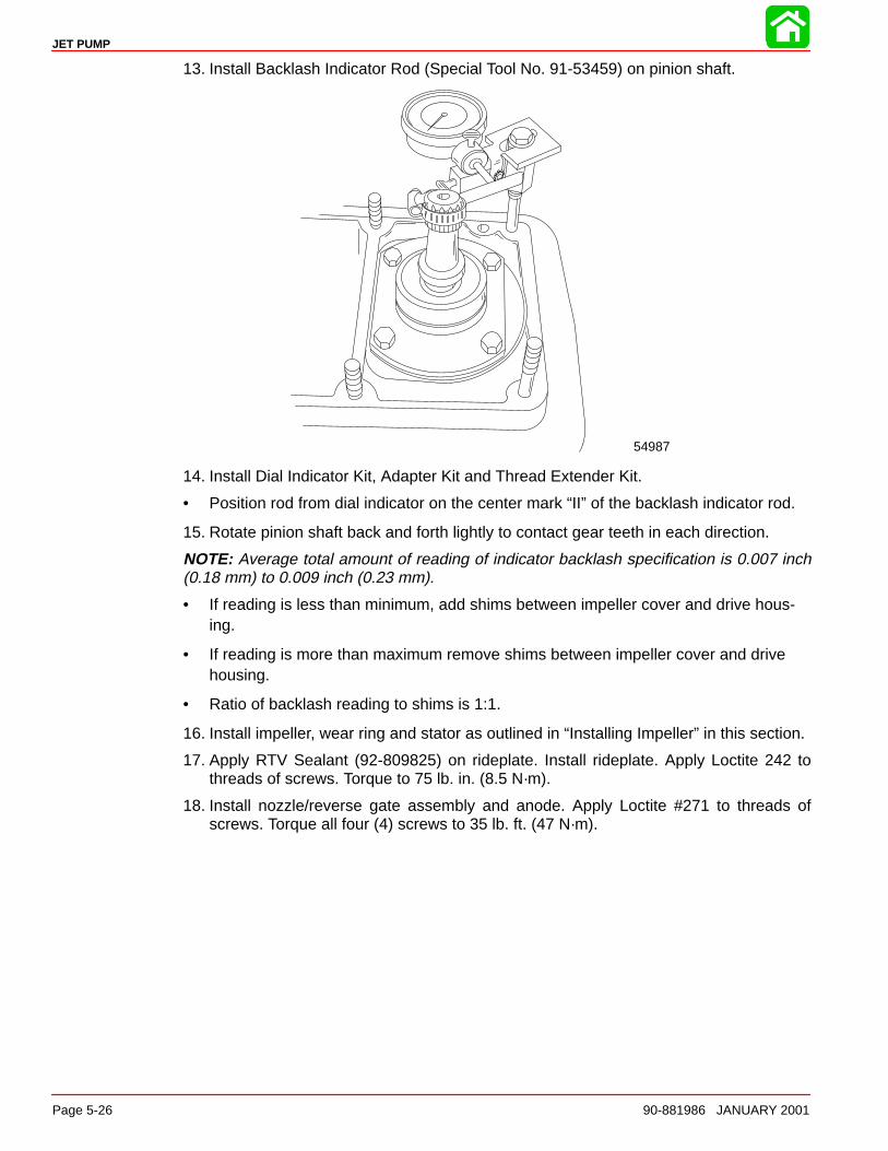
JET PUMP
Page 5-26 90-881986 JANUARY 2001
13. Install Backlash Indicator Rod (Special Tool No. 91-53459) on pinion shaft.
54987
14. Install Dial Indicator Kit, Adapter Kit and Thread Extender Kit.
• Position rod from dial indicator on the center mark “II” of the backlash indicator rod.
15. Rotate pinion shaft back and forth lightly to contact gear teeth in each direction.
NOTE: Average total amount of reading of indicator backlash specification is 0.007 inch(0.18 mm) to 0.009 inch (0.23 mm).
• If reading is less than minimum, add shims between impeller cover and drive hous-ing.
• If reading is more than maximum remove shims between impeller cover and drivehousing.
• Ratio of backlash reading to shims is 1:1.
16. Install impeller, wear ring and stator as outlined in “Installing Impeller” in this section.
17. Apply RTV Sealant (92-809825) on rideplate. Install rideplate. Apply Loctite 242 tothreads of screws. Torque to 75 lb. in. (8.5 N·m).
18. Install nozzle/reverse gate assembly and anode. Apply Loctite #271 to threads ofscrews. Torque all four (4) screws to 35 lb. ft. (47 N·m).
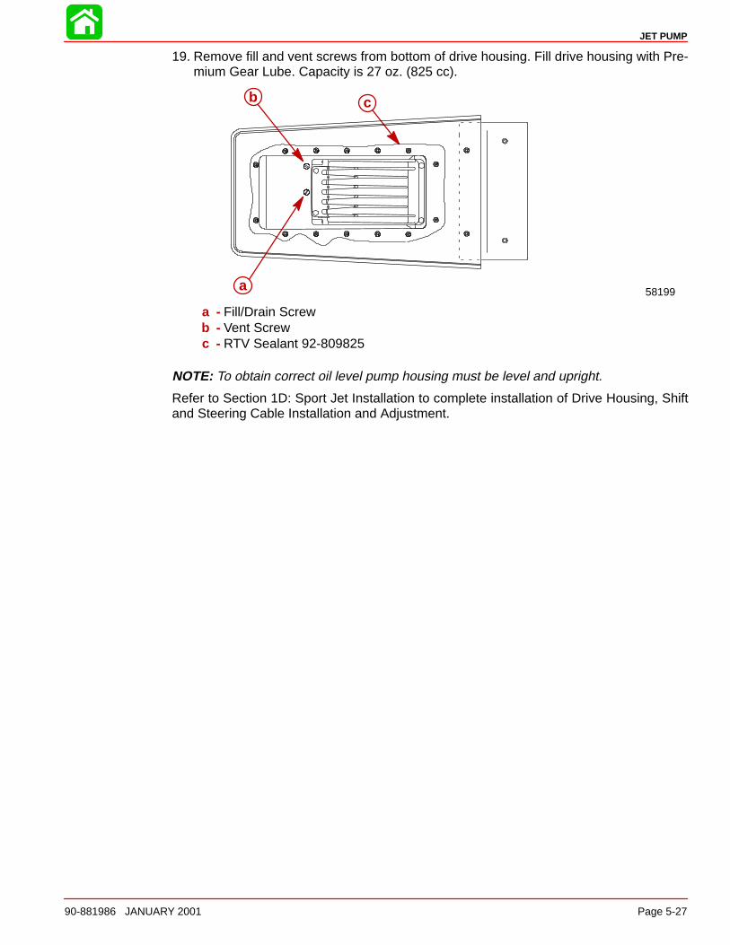
JET PUMP
90-881986 JANUARY 2001 Page 5-27
19. Remove fill and vent screws from bottom of drive housing. Fill drive housing with Pre-mium Gear Lube. Capacity is 27 oz. (825 cc).
58199
cb
a
a - Fill/Drain Screwb - Vent Screwc - RTV Sealant 92-809825
NOTE: To obtain correct oil level pump housing must be level and upright.
Refer to Section 1D: Sport Jet Installation to complete installation of Drive Housing, Shiftand Steering Cable Installation and Adjustment.
6
COLOR DIAGRAMS
90-881986 JANUARY 2001 Page 6-1
COLOR DIAGRAMSSection 6
Table of Contents
200 OptiMax Jet Drive Engine Wiring 6-3. . . . . . . . . . . . . . . . . . . . . . . . . . . . 200 OptiMax Jet Drive Typical Key Switch Wiring 6-5. . . . . . . . . . . . . . . . . . 200 OptiMax Jet Drive Typical Remote Control and Dash Wiring for Non-SmartCraft 6-7. . . . . . . . . . . . . . . . . . . . . . .
200 OptiMax Jet Drive Typical Remote Control and Dash Wiring for SmartCraft 6-9. . . . . . . . . . . . . . . . . . . . . . . . . . . . 200 OptiMax Jet Drive Fuel and Air Flow 6-11. . . . . . . . . . . . . . . . . . . . . . . . . 200 OptiMax Jet Drive Water Flow 6-13. . . . . . . . . . . . . . . . . . . . . . . . . . . . . .

JET PUMP
Page 6-2 90-881986 JANUARY 2001
Notes:
COLOR DIAGRAMS
Page 6-390-881986 January 2001
200 OPTIMAXJET DRIVE
ENGINE WIRING
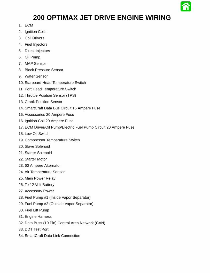
200 OPTIMAX JET DRIVE ENGINE WIRING1. ECM
2. Ignition Coils
3. Coil Drivers
4. Fuel Injectors
5. Direct Injectors
6. Oil Pump
7. MAP Sensor
8. Block Pressure Sensor
9. Water Sensor
10. Starboard Head Temperature Switch
11. Port Head Temperature Switch
12. Throttle Position Sensor (TPS)
13. Crank Position Sensor
14. SmartCraft Data Bus Circuit 15 Ampere Fuse
15. Accessories 20 Ampere Fuse
16. Ignition Coil 20 Ampere Fuse
17. ECM Driver/Oil Pump/Electric Fuel Pump Circuit 20 Ampere Fuse
18. Low Oil Switch
19. Compressor Temperature Switch
20. Slave Solenoid
21. Starter Solenoid
22. Starter Motor
23. 60 Ampere Alternator
24. Air Temperature Sensor
25. Main Power Relay
26. To 12 Volt Battery
27. Accessory Power
28. Fuel Pump #1 (Inside Vapor Separator)
29. Fuel Pump #2 (Outside Vapor Separator)
30. Fuel Lift Pump
31. Engine Harness
32. Data Buss (10 Pin) Control Area Network (CAN)
33. DDT Test Port
34. SmartCraft Data Link Connection
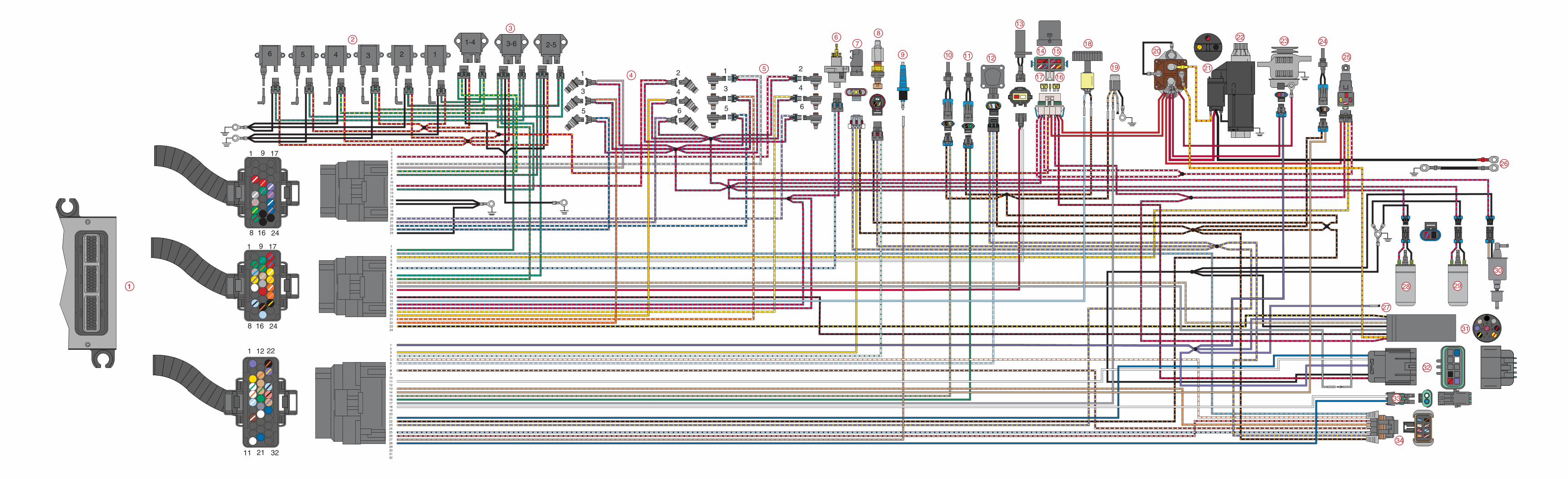
123456789101112131415161718192021222324
123456789101112131415161718192021222324
1234567891011121314151617181920212223242526272829303132
1
3
5
2
4
6
1
3
5
2
4
6
1-4 3-6 2-5135 246
1
11
12
32
1
8
9
16
17
24
1
8
9
16
17
241
23
456
78
2
3
45
67
8
9 10 11 12
13
14 15
17 16
18
25
26
2928
27
31
32
33
20
19 21
22 23 24
1
34
21
22
30

COLOR DIAGRAMS
Page 6-590-881986 January 2001
200 OPTIMAX JET DRIVETYPICAL KEY SWITCH WIRING
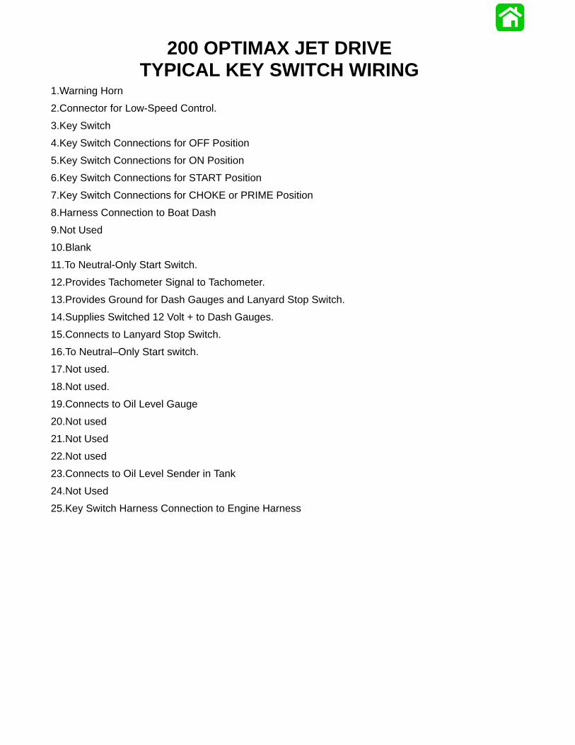
200 OPTIMAX JET DRIVETYPICAL KEY SWITCH WIRING
1.Warning Horn
2.Connector for Low-Speed Control.
3.Key Switch
4.Key Switch Connections for OFF Position
5.Key Switch Connections for ON Position
6.Key Switch Connections for START Position
7.Key Switch Connections for CHOKE or PRIME Position
8.Harness Connection to Boat Dash
9.Not Used
10.Blank
11.To Neutral-Only Start Switch.
12.Provides Tachometer Signal to Tachometer.
13.Provides Ground for Dash Gauges and Lanyard Stop Switch.
14.Supplies Switched 12 Volt + to Dash Gauges.
15.Connects to Lanyard Stop Switch.
16.To Neutral–Only Start switch.
17.Not used.
18.Not used.
19.Connects to Oil Level Gauge
20.Not used
21.Not Used
22.Not used
23.Connects to Oil Level Sender in Tank
24.Not Used
25.Key Switch Harness Connection to Engine Harness
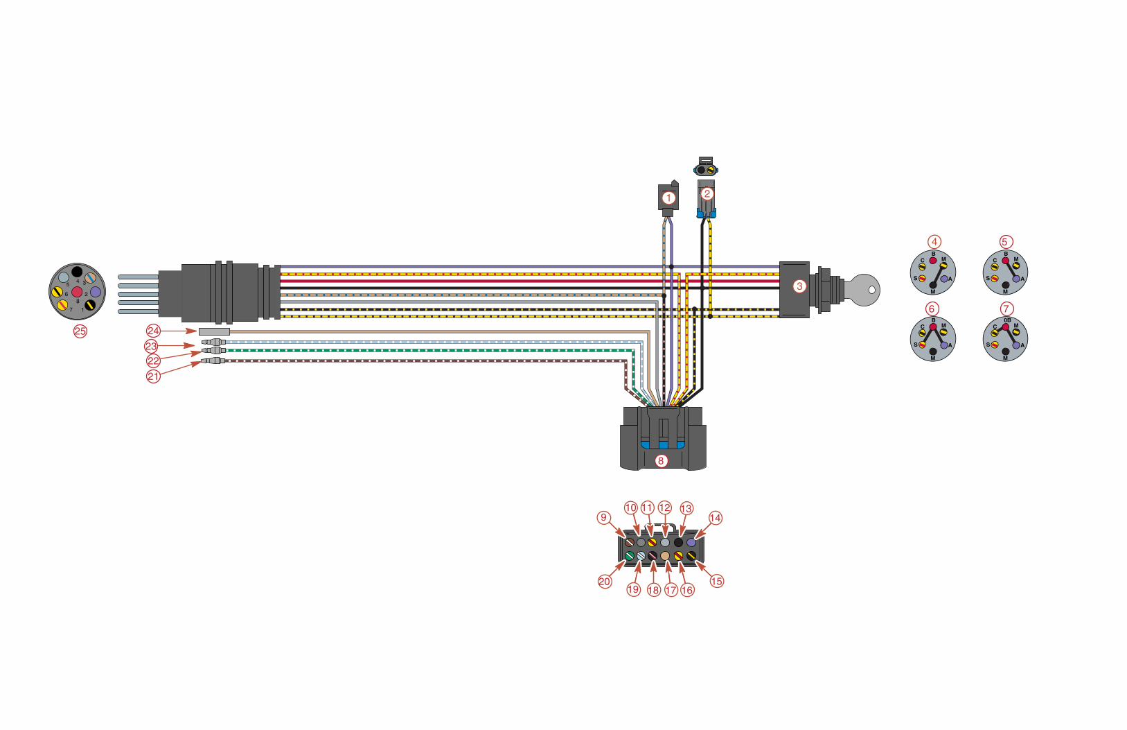
5
6 7
21
22
24
23
25 C
S
B
M
M
A
C
S
0B
M
M
A
C
S
B
M
M
A
C
S
B
M
M
A
4
1
3
8
910 11 12 13
14
1516171819
20
2
COLOR DIAGRAMS
90-881986 January 2001 Page 6-7
200 OPTIMAX JET DRIVETYPICAL REMOTE CONTROL AND DASH WIRING
NON-SMARTCRAFT
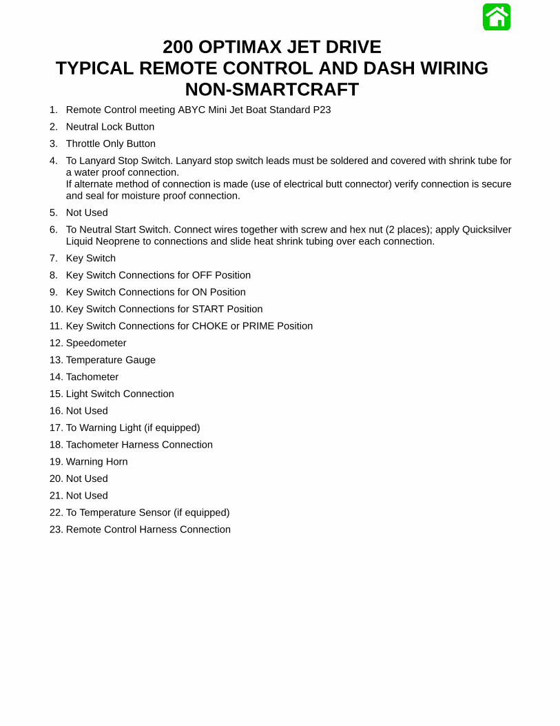
200 OPTIMAX JET DRIVETYPICAL REMOTE CONTROL AND DASH WIRING
NON-SMARTCRAFT1. Remote Control meeting ABYC Mini Jet Boat Standard P23
2. Neutral Lock Button
3. Throttle Only Button
4. To Lanyard Stop Switch. Lanyard stop switch leads must be soldered and covered with shrink tube fora water proof connection.If alternate method of connection is made (use of electrical butt connector) verify connection is secureand seal for moisture proof connection.
5. Not Used
6. To Neutral Start Switch. Connect wires together with screw and hex nut (2 places); apply QuicksilverLiquid Neoprene to connections and slide heat shrink tubing over each connection.
7. Key Switch
8. Key Switch Connections for OFF Position
9. Key Switch Connections for ON Position
10. Key Switch Connections for START Position
11. Key Switch Connections for CHOKE or PRIME Position
12. Speedometer
13. Temperature Gauge
14. Tachometer
15. Light Switch Connection
16. Not Used
17. To Warning Light (if equipped)
18. Tachometer Harness Connection
19. Warning Horn
20. Not Used
21. Not Used
22. To Temperature Sensor (if equipped)
23. Remote Control Harness Connection
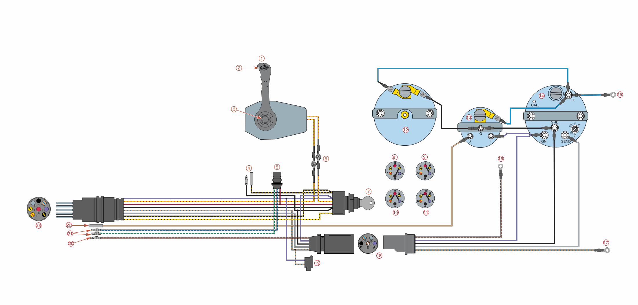
C
D E A
B
11
8 9
10
IGN.
CAL.
SEND.
GRD.
LT.
5P6P
2P
3P
8C4P
4C
6C
S I
G
1
5
6
4
3
2
13
14 15
16
18
17
19
20
21
22
C
S
B
M
M
A
C
S
0B
M
M
A
C
S
B
M
M
A
C
S
B
M
M
A
7
12
23
COLOR DIAGRAMS
Page 6-990-881986 January 2001
200 OPTIMAX JET DRIVETYPICAL REMOTE CONTROL AND DASH WIRING
WITH SMARTCRAFT
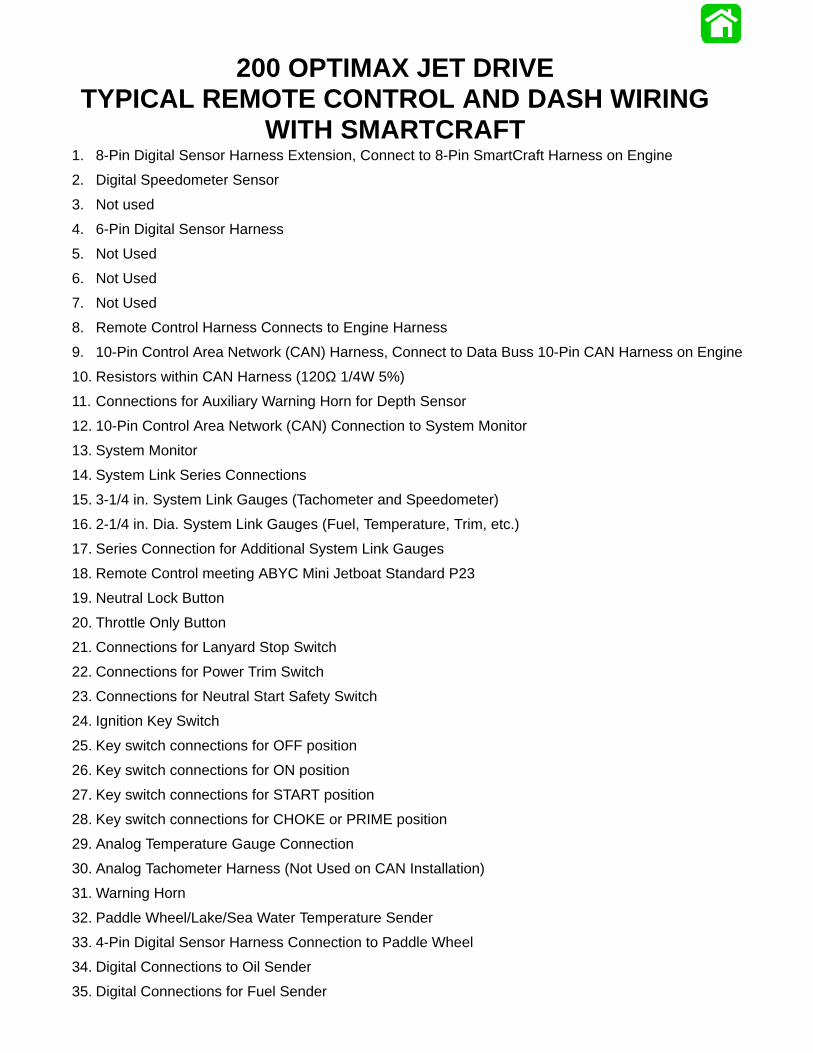
200 OPTIMAX JET DRIVETYPICAL REMOTE CONTROL AND DASH WIRING
WITH SMARTCRAFT1. 8-Pin Digital Sensor Harness Extension, Connect to 8-Pin SmartCraft Harness on Engine
2. Digital Speedometer Sensor
3. Not used
4. 6-Pin Digital Sensor Harness
5. Not Used
6. Not Used
7. Not Used
8. Remote Control Harness Connects to Engine Harness
9. 10-Pin Control Area Network (CAN) Harness, Connect to Data Buss 10-Pin CAN Harness on Engine
10. Resistors within CAN Harness (120Ω 1/4W 5%)
11. Connections for Auxiliary Warning Horn for Depth Sensor
12. 10-Pin Control Area Network (CAN) Connection to System Monitor
13. System Monitor
14. System Link Series Connections
15. 3-1/4 in. System Link Gauges (Tachometer and Speedometer)
16. 2-1/4 in. Dia. System Link Gauges (Fuel, Temperature, Trim, etc.)
17. Series Connection for Additional System Link Gauges
18. Remote Control meeting ABYC Mini Jetboat Standard P23
19. Neutral Lock Button
20. Throttle Only Button
21. Connections for Lanyard Stop Switch
22. Connections for Power Trim Switch
23. Connections for Neutral Start Safety Switch
24. Ignition Key Switch
25. Key switch connections for OFF position
26. Key switch connections for ON position
27. Key switch connections for START position
28. Key switch connections for CHOKE or PRIME position
29. Analog Temperature Gauge Connection
30. Analog Tachometer Harness (Not Used on CAN Installation)
31. Warning Horn
32. Paddle Wheel/Lake/Sea Water Temperature Sender
33. 4-Pin Digital Sensor Harness Connection to Paddle Wheel
34. Digital Connections to Oil Sender
35. Digital Connections for Fuel Sender
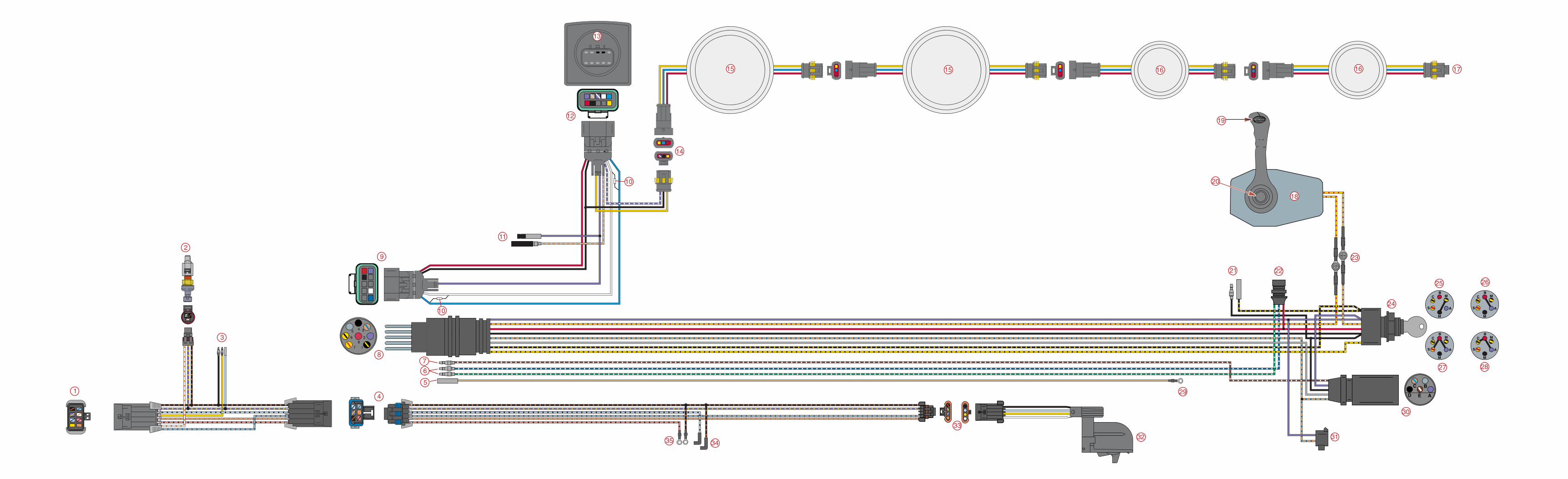
C
D E A
B
31
C
S
B
M
M
A
C
S
B
M
M
A
C
S
B
M
M
A
C
S
B
M
M
A
1
2
3
4
5
6
78
9
10
11
12
13
14
15 15 16 16 17
18
19
20
21 22
23
24
25 26
27 28
30
29
32
33
3435
10

COLOR DIAGRAMS
Page 6-1190-881986 January 2001
200 OPTIMAX JET DRIVEFUEL & AIR FLOW DIAGRAM
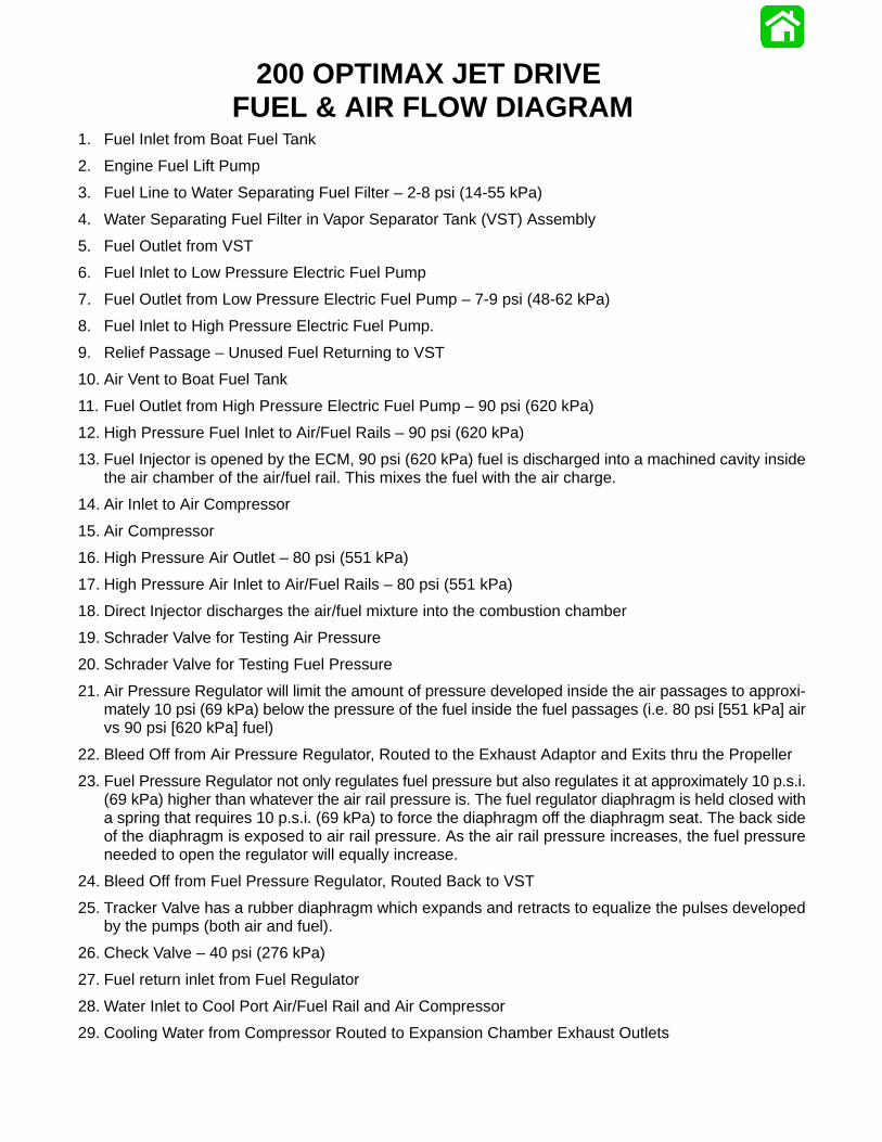
200 OPTIMAX JET DRIVE FUEL & AIR FLOW DIAGRAM
1. Fuel Inlet from Boat Fuel Tank
2. Engine Fuel Lift Pump
3. Fuel Line to Water Separating Fuel Filter – 2-8 psi (14-55 kPa)
4. Water Separating Fuel Filter in Vapor Separator Tank (VST) Assembly
5. Fuel Outlet from VST
6. Fuel Inlet to Low Pressure Electric Fuel Pump
7. Fuel Outlet from Low Pressure Electric Fuel Pump – 7-9 psi (48-62 kPa)
8. Fuel Inlet to High Pressure Electric Fuel Pump.
9. Relief Passage – Unused Fuel Returning to VST
10. Air Vent to Boat Fuel Tank
11. Fuel Outlet from High Pressure Electric Fuel Pump – 90 psi (620 kPa)
12. High Pressure Fuel Inlet to Air/Fuel Rails – 90 psi (620 kPa)
13. Fuel Injector is opened by the ECM, 90 psi (620 kPa) fuel is discharged into a machined cavity insidethe air chamber of the air/fuel rail. This mixes the fuel with the air charge.
14. Air Inlet to Air Compressor
15. Air Compressor
16. High Pressure Air Outlet – 80 psi (551 kPa)
17. High Pressure Air Inlet to Air/Fuel Rails – 80 psi (551 kPa)
18. Direct Injector discharges the air/fuel mixture into the combustion chamber
19. Schrader Valve for Testing Air Pressure
20. Schrader Valve for Testing Fuel Pressure
21. Air Pressure Regulator will limit the amount of pressure developed inside the air passages to approxi-mately 10 psi (69 kPa) below the pressure of the fuel inside the fuel passages (i.e. 80 psi [551 kPa] airvs 90 psi [620 kPa] fuel)
22. Bleed Off from Air Pressure Regulator, Routed to the Exhaust Adaptor and Exits thru the Propeller
23. Fuel Pressure Regulator not only regulates fuel pressure but also regulates it at approximately 10 p.s.i.(69 kPa) higher than whatever the air rail pressure is. The fuel regulator diaphragm is held closed witha spring that requires 10 p.s.i. (69 kPa) to force the diaphragm off the diaphragm seat. The back sideof the diaphragm is exposed to air rail pressure. As the air rail pressure increases, the fuel pressureneeded to open the regulator will equally increase.
24. Bleed Off from Fuel Pressure Regulator, Routed Back to VST
25. Tracker Valve has a rubber diaphragm which expands and retracts to equalize the pulses developedby the pumps (both air and fuel).
26. Check Valve – 40 psi (276 kPa)
27. Fuel return inlet from Fuel Regulator
28. Water Inlet to Cool Port Air/Fuel Rail and Air Compressor
29. Cooling Water from Compressor Routed to Expansion Chamber Exhaust Outlets
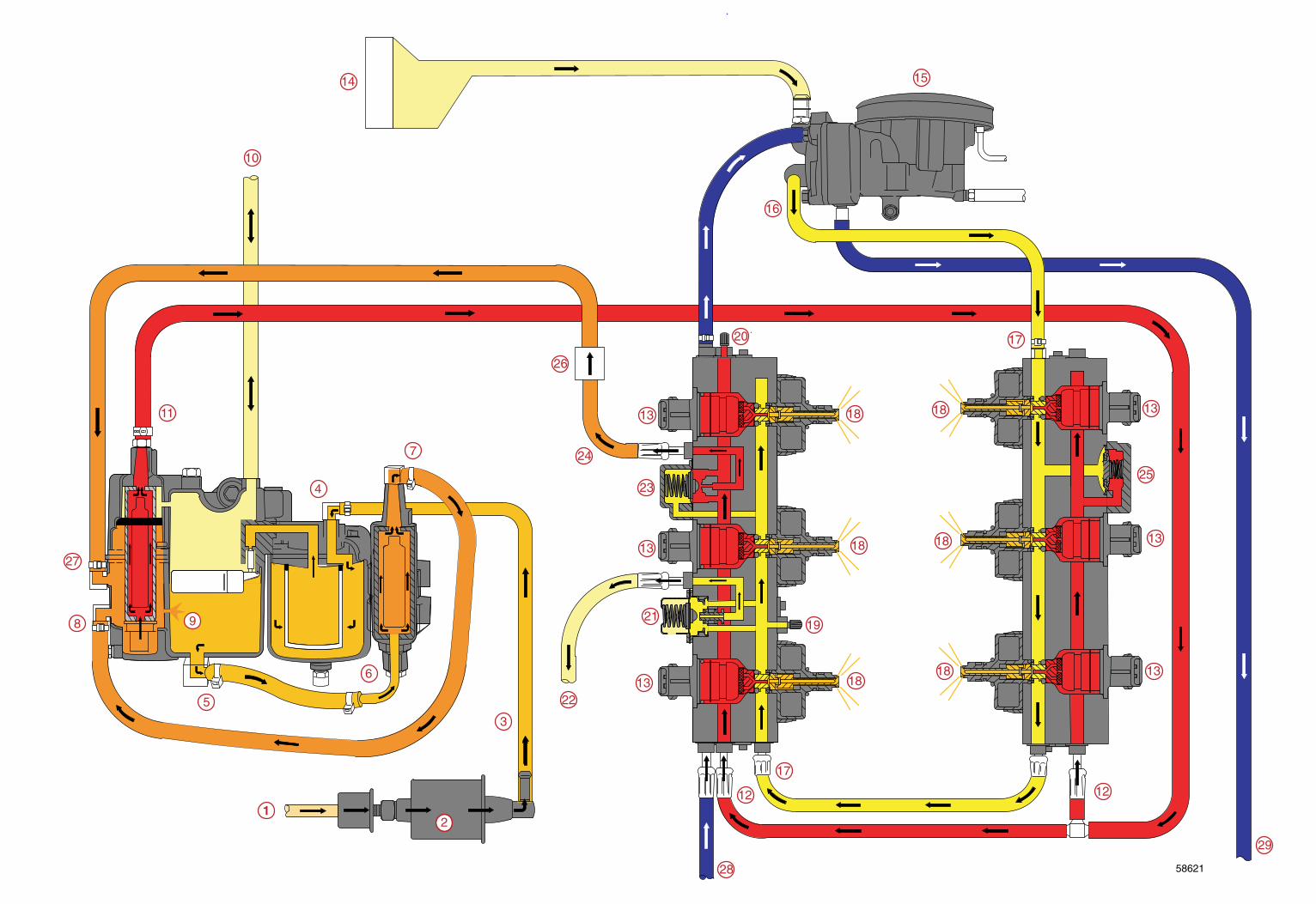
58621
1
3
4
5
6
7
8 9
10
11
12
15
16
17
18
19
20
21
22
23
24
25
26
27
12
13
13
13
13
13
13
14
17
18
18
18
1818
28
29
2
COLOR DIAGRAMS
Page 6-1390-881986 January 2001
200 OPTIMAX JET DRIVEWATER FLOW
200 OPTIMAX JET DRIVE WATER FLOWPowerhead and Exhaust Cooling Circuit
1. Inlet Cooling Water from Jet Pump.
2. Water Inlet from Flushing Connection.
3. Water Flows from Adapter Plate to Powerhead.
4. Water Fills Center of Powerhead, Flows Over Exhaust Runners, then to Cylinder Jackets
5. Water Pressure Sensor
6. Cooling Water Fills Cylinder Jackets, then flows to Cylinder Heads.
7. Majority of water flows down Cylinder Heads. Cylinder Head Cover has been removed from Head forillustration, it is normally part of Head Casting.
8. Small amount of water flows out top of Cylinder Head to Water By-Pass.
9. Water By-pass – Discharged outside of Boat.
10. Water flows from bottom of Cylinder Head through passage in Cylinder Block to Adapter Plate.
11. Water flows from Cylinder Block through Adapter Plate, Cooling Exhaust Passages.
12. Water flows from Adapter Plate to Expansion Chamber Water Jacket.
13. Cooling Water from Expansion Chamber is emptied back into Adaptor Plate.
14. Cooling Water from Adaptor Plate is exhausted through the Jet Tunnel.
Compressor and Fuel Cooling Circuit15. Fitting with Strainer
16. Incoming Cooling Water is directed to Fuel Rail.
17. Cooling Water flows through Fuel Rail (port) to Air Compressor.
18. Air Compressor
19. Cooling Water flows from Air Compressor to Expansion Chamber Exhaust Pipes.
20. Cooling Water for Exhaust Tubes is discharged with Exhaust.
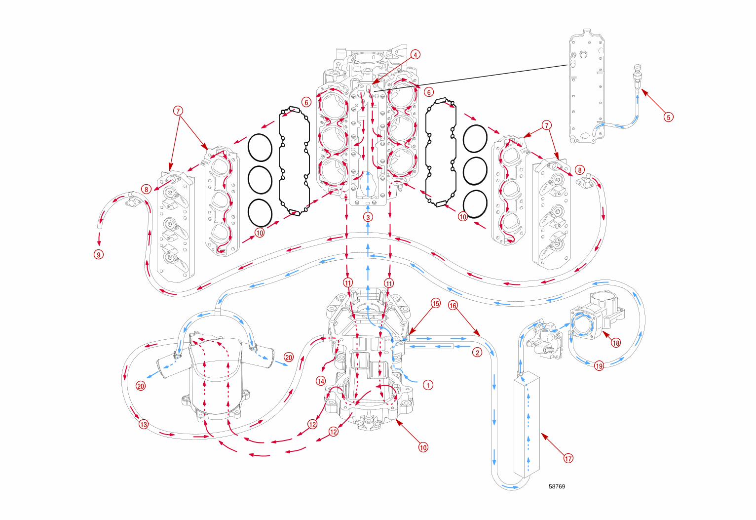
9
14
58769
2
1
20
20
16
7
10
5
17
15
3
4
6
7
8
8
10
10
11 11
12
12
13
6
18
19