Embed Size (px)
Citation preview

HEWLETT'" PACKARD
OPERATING AND SERVICE MANUAL
86222A/B
RF PLUG-IN(Including Options 002. 004. <11'111 002/(04)
SERIAL NUMBERS
This manual applies directly to FlP Model 86222Awith serial prefix 1725A and to FlP Model 86222Bwith serial prefix 1722A.
With changes described in Section VII, this manualalso applies to FlP Model 86222A prefixes 1516A,1549A, 1606A, and 1636A; and to HP Model86222B prefixes 1522A, 1552A, 1601A, 1604A,and 1628A.
For additional information about serial numbers,see INSTRUMENTS COVERED BY MANUAL inSection 1.
COPYRIGHT © HEWLETT"PACKARD COMPANY 1975, 1977
1400 FOUNTAIN GROVE PARKWAY, SANTA ROSA, CALIFORNIA, 95404 U.s"A"
MANUAL PART NO" 86222"90009
Microfiche Part No. 86222·90010 Printed; OCTOBER 1977


MANUAL CHANGES
r-r- MANUAL IDENTIFICATIDN
Model Number: 86222A/BDate Printed: October 1977Part Number: 86222·90009
This supplement contains important information for correcting manual errors and for adapting the manual toinstruments containing improvements made after the printing of the manual.
To use this supplement:
Make all ERRATA corrections
I Serial Prefix or Number -r-r-r--: Make Manual Changes Lc;
I l722A 1
1732A ],2
l74lA 1,2,3
l8]5A ],2,3,4
]832A ],2,3,4,5
] 835A, ] 902A 1,2,3,4,5,6
1905A 1,2,3,4,5,6,7
.'" 2035A ],2,3,4,5,6,7,8
Make all appropriate serial number related changes indicated in the tables below.86222A 862228
r-r- Serial Prefix or Number -t-r-r- Make Manual Changes_
1725A
] 731A 1,2
]832A, ]903A 1,2,5
L]905A ],2,5,7
~ 2035A 1,2,5,7,8i
.NEWITEM
ERRATATitle page:
Change first two paragraphs under SERIAL NUMBERS to read: This manual applies directly to lIP Model86222A with serial prefix] 636A and to lIP Model 86222B with serial prefix l628A,
With changes described in Section VII, this manual alsc applies to HP Model 86222A prefixes ]5l6A, ]529A,and l606A; and to lIP Model 86222B prefixes ]522A, ]552A, ]60]A, and ]604A,
!!>'Page ]·0, Figure r.i.Change the part number of the scale to: 86222·20029.
Page ]-4, Table ]·1:Change footnote 4 to: Use HP Mode] 432A power meter, sweep duration >]0 seconds.
Page ]·5, Table 1·2, under "Marker Output (power Output +3 to +13 dBm)":Change "Amplitude Mode: 0.5 dB" to "Amplitude Mode: >0.5 dB (internally adjustable)."
Page] ·6, Table ]·3:Change U4 (for options 002 and 002/004) to HPPart No. 86222·60055.
NOTE
Manual change supplements are revised as often as necessary to keep manuals as current and accurate as possible.Hew let.t-Packard recommends that you periodically request the latest edition of this supplement. Free copies are availablefrom all HP offices. When requesting copies quote the manual identification Information from your supplement, or the modelnumber and print date f.rom the title page of the manuaL
20 AUGUST 1980HEWLETTPACKARD
]6 Pages
Printed in U.S.A.

II
I
II
I
I
I
II
I
II
I
I
I
II
I
II
II
I
II
I
II
I

86222·90009
ERRATA [Cunt'd]
Page 1-8, Table 14:Change Power Meter and Power Sensor to Power Meter and Thermistor Mount and Model numbers to HP
432A!8478B.
Model 86222A/B
Page 24, Table 2-2:Change Power Meter and Power Sensor to PowerMeter and Thermistor Mount and Model numbers to HP
432A/8478B.
Page 2-6, Paragraph 2-28:In Figure 24, change Power Sensorto Thermistor Mount.In EQUIPMENT list, change Power Meter model number to HP 432A, change Power Sensor to Thermistor
Mount, and model number to HP 8478B.
Page 2-7, Paragraph 2-29:In EQUIPMENT list, change Power Meter model number to HP 432A, change Power Sensor to Thermistor
Mount, and model number to HP 8478B.
Page 3·7, Figure 3·3 (3 of 3)Change step 3 to:
Depress LINE pushbutton switch. to turn on mainframe. With mainframe on, LINE .' and FULL SWEEP!
START MARKER 0 pushbutton should light.
Change step 6 to:Set 8620C Markers switch f.l!) to INTEN position and 3 markers should appear on oscilloscope trace as intensified
spots. Adjust oscilloscope intensity for best contrast. Set MARKER switch f.l!) to AMPL position and markers should
appear on oscilloscope trace as a pIp. Set MARKER switch f.l!) to OFF.
Page 3·13, FIgure 3·5:Change callouts to indicate a 10 MHz to 2.4 GHz range.
Page 3·13, Figure 3·6:Change callout to 0.5 dB.
Page 3·14, Figure 3·8:In equipment setup, change PowerSensor 10 Thermistor Mount.In EQUIPMENT list, change Power Meter model number to HP 432A, change Power Sensor to Thermistor
Mount, and model uumber to HP 8478B,
Page 3-15, Figure 3-8:Change Model Number of BNC·To·Dual Banana Post adapter to read: "HP I01 I OA OR HP 1011OB(2 places).
Page 3-17, Figure 3-9:In'equipment setup, change Power Sensor to Thermstor Mount.In EQUIPMENT list, change Power Meter model number to HP 432A, change Power Sensor to Thermistor
Mount, and model number to HP 8478B.
Page 4·2, Paragraph 4-8:Change Frequency Stability Specification to:
frequency Stability:With Temperature: <;; ± 500 kHztC.With 10% Line Voltage Change: <;; ± 20 kHz.With 3 : 1 Load SWR, All Phases: <;; ± 10kHz.With 10 dB Power Levei Change: <;; ± 100 kHz.

I
I
I
I
I
I
I
I
I
I
I
I
I
I
I
I
I
I
General Information Model 86222A/B
862226 RF PLUG·IN
SCALE FOR 8620A/C86222-90029
~}~p=J========::1)
RF TEST CABLE86290-20032
RESISTIVE BARREL(86222B ONLY)
5061-1015
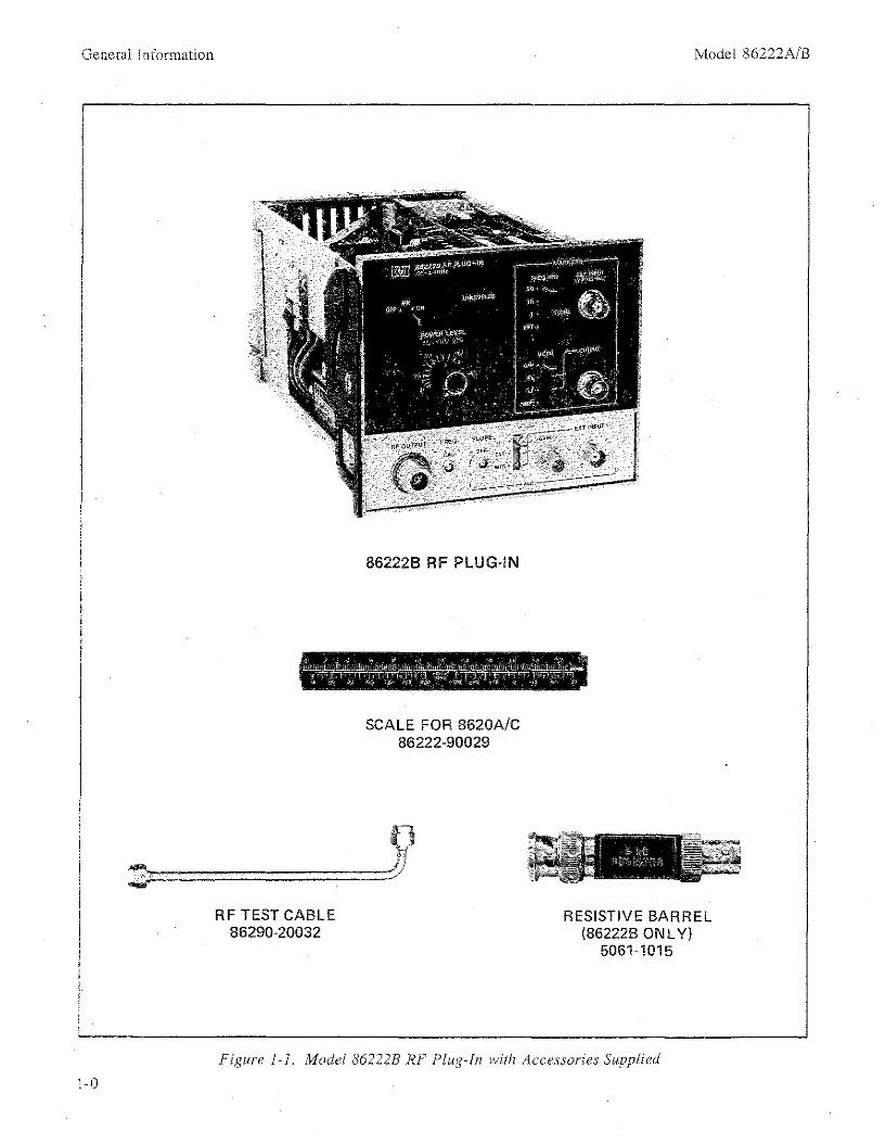
Figure i-i. Modei 86222B RF Plug-In with Accessories Supplied
1-0

I
I
I
I
I
I
I
I
I
I
I
I
I
I
I
I
I
I
I
I
I
I
I
I
I
I
I
I
I
I
I
I
Model 86222A/B
SECTION I
GENERAL INFORMATION
General Information
1-1. INTRODUCTION
1-2. This Operating and Service manual containsinformation required to install, operate, test, adjust,and service the Hewlett-Packard Model 86222A/BRF Plug-in. Fignre 1-1 shows the instrument andaccessories supplied. This section covers instrumentidentification, description, options, accessories,specifications, 'and other basic information.
1-3. Supplied with this manual is an Operating Information Supplement. The Supplement is a copyof the first three sections of the manual, andshould be kept with the instrument for use by theoperator,
1-10. Operation
1-11. BEFORE APPLYING POWER maker surethe instrument's ac input is set for the available acline voltage, that the correct fuse is installed, andthat all normal safety precautions have been taken.(See Warnings below.)
1-12. Safety Symbols
Instruction manual symbol: The apparatus will be marked with this symbol whenit is necessary for the user to refer to theinstruction manual in order to protect theapparatus against damage.
7 Indicates dangerous voltages .
..L Earth Terminal1-4. Also listed on the title page of this manual isa Microfiche part number. This number can beused to order 4 x 6-inch microfiche transparenciesof the manual. Each microfiche contains up to 60photo-duplicates of the manual pages. The microfiche package also includes the latest ManualChanges supplement as well as all pertinent ServiceNotes.
1-5. SPECIFICATIONS
1-6. Instrument specifications are listed in Table1-1. These specifications are the performance standards or limits against which the instrument istested. Table 1·2 lists supplemental characteristics.Supplemental characteristics arc not specificationsbut are typical characteristics included as additional information for the user.
I WARNING I The WARNING sign denotes ahazard. It calls attention to aprocedure, practice, or the like,which, if not correctly performedor adhered to, could result in injury or loss of life. Do not proceed beyond a WARNING signuntil the indicated conditions arefully understood and met.
The CAUTION sign denotes ahazard. It calls attention to anoperating procedure, practice, orthe like which, if not correctlyperformed or adhered to, couldresult in damage to or destruction of part or all of the equipment. Do not proceed beyond aCAUTION sign until the indicated conditions are fully understood and met.
1·7. SAFETY CONSIDERATIONS
1-8. General
1-9. This product and related documentationmust be reviewed for familiarization with safetymarkings and instructions before operation. Thisproduct has been manufactured and tested in accordance with Hewlett-Packard standards.
1-13. Service
1-14. Although this instrument has been manufactured in accordance with international safetystandards, this manual contains information, cautions, and warnings which must be followed toinsure safe operation. Service should be performedonly by qualified service personnel, and the following warnings should be observed.
1-1

General Information Model 86222A/B
SERIAL NUMBER
Figure 1-2. Typical Serial Number Plate
(cont'd)
\SU FFIX
..rPREFIX
[~~~!!?~~input is set to the voltage of the acpower source.
BEFORE SWITCHING ON THE MAINFRAME, ensure that the ac line fuse isof the required current rating and type(normal-blow, time delay, etc).
1-17. An instrument manufactured after theprinting of this manual may have a serial numberprefix that is not listed on the title page. Thisunlisted serial number prefix indicates the instrument is different from those described in this manual. The manual for this newer instrument is accompanied by a yellow Manual Changes supplement. This supplement contains "change information" that explains how to adapt the manual to thenewer instrument.
1-15. INSTRUMENTS COVERED BY MANUAL
1-16. Attached to the instrument is a serial number plate (Figure 1-2). The serial number is in twoparts. The first four digits and the letter are theserial number prefix: the last five digits are thesuffix. The prefix is the same for all identical instruments; it changes only when a change is madeto the instrument. The suffix, however, is assignedsequentially and is different for each instrument.The contents of this manual apply to instrumentswith the serial number prefix(es) listed underSERIAL NUMBERS on the title page.
If it is suspected that the protection hasbeen impaired, the instrument must bemade inoperative and be secured againstany unintended operation.
If the mainframe is to be energized viaan auto-transformer (for voltage reduction) make sure the common terminalis connected to the earthed pole of thepower source.
BEFORE SWITCHING ON THE MAINFRAME, the protective earth terminalsof the instrument must be connected tothe protective conductor of the mainspower cord. The mains plug shall onlybe inserted in a socket outlet providedwith a protective earth contact. The protective action must not be negated bythe use of an extension cord (powercord) without a protective conductor(grounding). Grounding one conductorof a two conductor outlet is not sufficient protection.
Any interruption of the protective(grounding) conductor (inside or outside the instrument) or disconnectingthe protective earth terminal couldmake this instrument dangerous.
IWARNINGS IAny maintenance or repair of theopened instrument under voltage shouldbe avoided as much as possible, but ifnecessary, should be carried out only byskilled persons who are aware of the hazard involved.
Capacitors inside the instrument maystill be charged even if the instrumenthas been disconnected from its source ofsupply.
Ensure that only fuses with the requiredrated current and of the specified type(normal blow, time delay, etc.) are usedfor replacement. The use of repairedfuses and the short-circuiting of fuseholders must be avoided.
BEFORE SWITCHING ON THE MAINFRAME, ensure that mainframe's ac
1-18. In addition to change information, the supplement may contain information for correctingerrors in the manual. To keep this manual as current and accurate as possible, Hewlett-Packard
1-2
Model 86222A/B
recommends that you periodically request thelatest Manual Changes supplement. The supplement for this manual is identified with this manual's print date and part number, both of whichappear on the manual's title page. Complimentary copies of the supplement are available fromHewlett-Packard.
1-19. For information concerning a serial number prefix that is not listed on the title page or inthe Manual Changes supplement, contact yournearest Hewlett-Packard office.
1-20. DESCRIPTION
1-21. The HI' Model 86222A/B is designed as aplug-in for the Model 8620C mainframe. The mainframe and 86222A/B RF Plug-in make up a solidstate sweep signal source with a frequency range of10 MHz to 2.4 GHz in one continuous sweep. TheModel 86222B provides intensity or amplitudecrystal markers at 1, 10, or 50 MHz intervals. Intensity markers are compatible with most CRT display units, including the HI' Model 8755A Frequency Response Test Set and HI' Model 8410BNetwork Analyzer. Front panel connectorMARKER EXT INPUT provides the capability ofgenerating markers using an external source.
1-22. The RF output of the instruments is controlled by the front panel POWER LEVEL control.Power can be leveled, externally or internally,across the band using a conventional power sampling and feedback technique. The automatic levelcontrol (ALC) switch selects the mode of levelingeither internal (INT), external (EXT), or powermeter (MTR). A front panel ALC EXT INPUT connector and ALC GAIN control are provided to usewith an external leveling loop. When the UNLEVELED light is on, it indicates that the levelingloop is open over a portion of the swept band.BNC connectors on the rear panel allow for external FM signal inputs and a IV IGHz FREQ REFoutput.
1-23. OPTIONS
1-24. Options for the Model 86222A/B RF Plugin are available to (1) include a 70-dB built-in attenuator, (2) route the RF OUTPUT connector tothe rear panel, (3) combine the 70 dB built-in attenuator and rear panel RF OUTPUT connector.
1-25. Option 002
1-26. Option 002 provides a front panel zero to70 dB step attenuator in the RF signal line. Instal-
General Information
lation information is provided in Appendix A. SeeTable 1-3 for parts required to install Option 002.
1-27. Option 004
1-28. The 86222A/B Option 004 moves the RFOUTPUT connector from the front panel to therear panel. Installation information is provided inAppendix B. Installation of the Option 004 requires the parts listed in Table 1-3.
1-29. Option 002/004
1-30. The 86222A/B Option 002/004 provides arear panel RF OUTPUT connector with a zero to70 dB step attenuator in the RF signal line. Installation information is provided in Appendix C. Installation of the Option 002/004 requires the partslisted in Table 1-3.
1-31. ACCESSORIES SUPPLIED
1-32. Figure I-I shows the HI' Model 86222A/BRF Plug-in, the dial scale (HI' Part No. 8622220029) to be mounted in the 8620AIC mainframe,the RF Test cable (HI' Part No. 86290-20032 fortesting and troubleshooting the RF section, anda Resistive Barrel (HI' Part No. 5061-1015) forsimultaneous RF BLANKING and 86222B Intensity Marker operation (supplied with 86222Bonly).
1-33. EQUIPMENT REQUIRED BUT NOTSUPPLIED
1-34. To have a complete operating sweep oscillator unit, the Model 86222A/B RF Plug-in mustbe installed in an HI' Model 8620C mainframe. HI'Model 8620A mainframes with serial prefixes1332A and below require a modification for HI'Model 8410B Network Analyzer compatibilityover multi-octave sweeps.
NOTE
All 86222A/B operation and maintenance procedures in this manual are setup using the HI' Model 8620C mainframe. The procedures also apply to the8620A mainframe, but the controls aredifferent.
1-35. EQUIPMENT AVAILABLE
1-36. Service Accessories
1-37. Service Accessories for the 86222A/B RFPlug-in are available for convenience in aligning and
1-3

General Information
Table 1·1. Specifications for 86222A/B in 8620C
SPECIFICATiONS
Model 86222A/B
FREfiUENCY'
Frequency Range:Calibrated: 10 MHz to 2.4 GHz.
Frequency Accuracy (25'C):'CWMode: 3 ,;;; ± 10 MHz.All Sweep Modes (Sweep Time> 0.1 See):~± 15 MHz.
Frequency Stability:With Temperature: ~ ± 500 kHzt C.With 10% Line Voltage Change: ,;;; ± 20 kHz.Witb 3:1 Load SWR, All Phases: ,;;; ± 10 kHz.With 10 dB Power Level Change: ,;;; ± 100 kHz.
Residual FM in 10kHz Bandwidth (FM·NORM.PLSwitch in NORM position):
CW Mode: ,;;; 5 kHz peak.
POWE R 0 UTPUT'
Power Level (For calibrated frequency range at 25'C):Maximum Leveled Power:';;' +13 dBm (20 mW).Power Level Accuracy (Internally Leveled):
,;;; ± 1 dB (Includes Flatness)
Power Variation:Internally Leveled:2 ,;;; ± 0.25 dB.Externally Leveled: 7
Crystal Detector: ,;;; ± 0.1 dB.Power Meter: 4 ,~± 0.1 dB.Option 002: ,;;; 0.33 dB ± 0.016 dB/IO dB.
Spurious Signals (below fundamental at specifiedmaximum leveled power, 25'C):'
Harmonics: > 25 dB.Non-Harmonics:
0.01'-2.3 GHz: ;;, 30 dB.2.3'-2.4 GHz: ;;, 25 dB.
Residual AM (100 kHz Bandwidth): ;;'50 dB belowmaximum power.
Equivalent Source SWR:SWR: ,;;; 1.5:1.Impedance: 50 ohms nominal.
MODULATION'
External FM:Maximum Deviations for Modulation Frequencies:
DC to 100 Hz: ± 75 MIIz.100 Hz to 1 MIIz: ± 5 MIIz.1 MIIz to 2 MIIz: ± 2 MHz.
External AM:" 5
ON/OFF Ratio: ;;, 30 dB.Symmetry: 40/60 at > + 10 dBm output power.Attenuation for +6 volt input: ;;, 30 dB.
Internal AM (At Maximum Leveled Power):1 kIlz Square-wave ON/OFF Ratio: ;;, 30 dB.RF Blanking ON/OFF Ratio: ;;, 30 dB.
MARKERS (86222B Only)" z 6
Marker Generator Accuracy (at 25'C with Power Gutput +3 to +13 dBm):
Center Frequency Accuracy: ± 5 x 10'6
Marker Frequency Range (Power Output +3 to+13 dBm):
50 and 10 MHz Markers: 10 MIIz to 2.4 GIIz.1 MHz Marker: 10 MHz to 1 GHz.
1 0 oUnless otherwise noted, all specifications are at 0 to 55 C with plug-in installed in an 8620C mainframe.
2See also the Supplernental Characteristics, Table 1·2.
3 Approach desired frequency from Iow-Irequenov end of band.
4 Use lIP Model 435A power meter. Sweep duration> 10 seconds.
5Specific requirements for compatibility with HP 8755A. ± 6V. 27.8 kHz square wave MODULATOR DRIVE output connectedto external AM input.
686222B markers will not operate when sweeping from a high frequency to a low frequency.
7Excludes coupler and detector variation.
1·4

Model 86222A/B General Information
Table 1-2. Supplemental Characteristics for 86222A/B Installed in 8620C
SUPPLEMENTAL CHARACTERISTICS
NOTE: Values in this table are not specifications but are typical characteristics included for userinformation.
FREllUENCYFrequency Accuracy in Remote Programmed Mode:
Typically ±6 MHz. -
linearity:Correlation between frequency and SWEEP 0 UT
voltage: ± 2 MHz.
Frequency Orilt:Drift ± 100 kHz per ten minutes after one hour
warm-up.
Frequency Reference Output:1 Volt/GHz i 0.01V.
POWER OUTPUT
Maximum leveled Power:Typically < +15 dBm.
Power Variation (Across any 50 MHz portion between30 MHz and 2.3 GHz):
Typically ±O.05 dR
Stability with Temperature Change:Typically ±0.02 dB(C.
Spurious Signals (dB below fundamental):Harmonics: Typically ;;>30 dB at +10 dBm.
Non-Harmonics:10 MHz to 2.3 GHz at +10 dBm:
Typically > 40 dB.2.3 to 2.4 GHz at +10 dBm:
Typically ;··35 dB.
Broadband Noise (100 kHz Bandwidth):Noise Level: -c:; -",,70 dBm.
MOOUlATION
Sensitivity:FM Mode (FM-NORM-PL switch in FM position):
Typically -20 MHz/Volt.Phase-Lock Mode (FM-NORM-PL switch in PL
position): Typically --6 MHz/Volt
External AM:Frequency Response:
Typically 150 kHz.
MARKERS (86222B Only)
External Marker Frequency Range:(Power Output +3 to +13 dBm)
-10 to 0 dBm External Input Power: 10 MHz to1.0 GHz.
-10 to +10 dBm External Input Power: 1.0 to2.4 GHz (over limited power range).
Marker Width (around center frequency with PowerOutput +3 to +13 dBm):
50 MHz Marker: ±300 kHz10 MHz Marker: ,200 kHz
1 MHz Marker: ±75 kHzExternal Marker: ±300 kHz
Temperature Stability (Power Output +3 to +13 dBm):50 MHz Marker: ~100 Hz!"C.10 MHz Marker: ±20 Hzt C.
1 MHz Marker: ±2 Hz(C.
Marker Output (Power Output +3 to +13 dBm):-n- Mode: +3 Volts.LJ Mode: --3 to v-S Volts.
Amplitude Mode: 0.5 dB.
GENERAL
Crystal Input:Approximately -10 to -100 mV for specified level
ing at maximum rated output; for use with negative polarity detectors such as HP Model 780series Directional Detectors, and HP Model 423ACrystal Detector.
Net Weight: 2.5 kg(5.5 pounds).
Shipping Weight: 4 kg (9 pounds).
Dimensions: Height 12.7 em (5 inches):Width: 14.7 em(5-13/16 inches); Depth 30.5 em (12 inches).
Options:Option 002: Zero to 70 dB attenuator.Option Q04: Rear Panel RF OUTPUT.
1-5

General Information Model 86222A/B
Table 1 3 Parts Required for 86222A/B Options-Reference
DescriptionOption Designator HP Part No.
002 Al (86222A only) 86222-60029 Front Panel Board AssemblyAl (86222B only) 86222·60020 Front Panel Board Assembly
(86222A only) 86222-00015 Panel: Front Upper(86222B only) 86222-00013 Panel: Front Upper
86222·20026 Attenuator BushingU4 08558-60003 70 dB Step Attenuator
0370-1103 Knob, PointerW8 86222·20021 RF Cable: Directional Detector to AttenuatorW13 86222-20022 RF Cable: Attenuator to RF OUTPUT
004 W8 86222-20019 RF Cable: Directional Detector to Rear PanelRFOUTPUT
0021004 Al (86222A only) 86222-60029 Front Panel Board AssemblyAl (86222B only) 86222·60020 Front Panel Board Assembly
(86222A only) 86222·00015 Panel: Front Upper(86222B only) 86222-00013 Panel: Front Upper
86222·20026 Attenuator BushingU4 08558-60003 70 dB Step Attenuator
0370·1103 Knob, PointerW8 86222-20021 RF Cable: Directional Detector to AttenuatorW13 86222·20023 RF Cable: Attenuator to Rear Panel RF OUTPUT
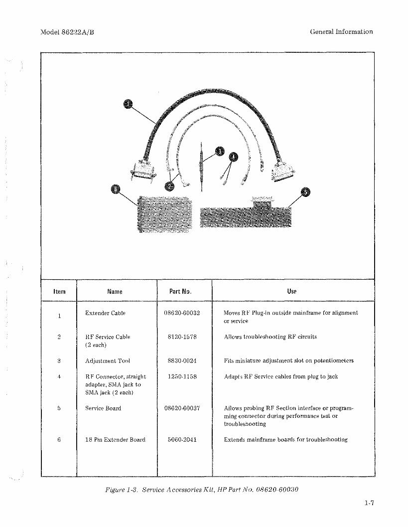
troubleshooting the mainframe and RF Plug-in.The service accessories kit contains a plug-in extender cahle, extender hoards, adjustment tool, andRF'.service cables (see Figure 1-3). The serviceaccessories kit may be obtained from HewlettPackard by ordering Service Accessories Part No.08620-60030.
1-38. Model 8755A/182C Swept AmplitudeAnalyzer and Oscilloscope
1-39. The Model 8620C/86222A/B Sweeper iscompatible with the Hewlett-Packard Model8755A Swept Amplitude Analyzer. For all sweptamplitude measurements, the 27.8 kHz squarewave modulation is applied directly the the 8620Crear-panel EXT AM connector. This eliminates theneed for an external modulator, thus providingmaximum available power to a test setup. SectionHI contains techniques and instructions for usingthe 8755A for testing and measuring microwavedevices.
also available using an HP 423A Crystal Detector.Section III contains detailed instructions for usingthe external power leveling systems.
1-42. Model 841 OB/8411 A Network Analyzer
1-43. The Model 8620C/86222A/B Sweeper provides multi-octave phase/gain measurement capability with the Hewlett-Packard Model 8410B Network Analyzer System. The combination of theModel 8410B Network Analyzer, the Model 8411AFrequency Converter, and an appropriate displayplug-in forms a phasemeter and a ratiometer fordirect phase and amplitude ratio measurement ofRF voltages. These measurements can be made onsingle frequencies and on swept frequencies from110 MHz to 2.4 GHz. The interfacing between the8410B and the 8620C/86222A/B sweeper permitsthe 8410B to phase lock over the 110 MHz to2.4 GHz range.
1-40. Power Meters and Crystal Detectors
1-41. The Hewlett-Packard Model 435A PowerMeter may be used for external leveling of theModel 86222A/B Plug-in. External leveled power is
1-44. RECOMMENDED TEST EQUIPMENT
1-45. Equipment required to maintain the Model86222A/B is listed in Table 1-4. Other equipmentmay be substituted if it meets or exceeds the critical specifications listed in the table.
1-6
Model 86222A/B General Information
Item Name Part No. Use
1 Extender Cable 08620-60032 Moves RF Plug-in outside mainframe for alignmentor service
2 RF Service Cable 8120-1578 Allows troubleshooting RF circuits(2 each)
3 Adjustment Tool 8830-0024 Fits miniature adjustment slot on potentiometers
4 RF Connector, straight 1250·1158 Adapts RF Service cables from plug to jackadapter. SMA jack toSMA jack (2 each)
5 Service Board 08620-60037 Allows probing RF Section interface or program-ming connector during performance test ortroubleshooting
6 18 Pin Extender Board 5060·2041 Extends mainframe boards for troubleshooting
Figure 1-3. Service Accessories Kit, HP Part No. 08620-600:JO
1-7

General Information
Table 1-4. Recommended Test Equipment (1 of 2)
Model 86222AjB
Instrument Critical SpecificationsRecommended
Use*Model
Sweep Oscillator 8620A is only substitution. HP 8620C P,A,T
Spectrum Analyzer Frequency Range: 10 MHz to 2.4 GHz HP 8555A/8552BI P141T
Oscilloscope with Dual- Vertical Amplifier: Dual Trace with 10: 1 probes. HP 182C/1801A! P,A,TTrace Vertical Amplifier Bandwidth: 20 MHz minimum 1820Cand 10: 1 probes Vertical Sensitivity: 5 mVIDiv
Horizontal Sweep Rate: 1 /ls!Div minimum
DC Digital Voltmeter Range: -50V to +50V HP 3490A P,A,TAccuracy: ±0.006%Input Impedance: 10 megohms minimum
Power Splitter Frequency: 10 MHz to 2.4 GHz HP 11667A PAttenuation in each arm: 6 dB
Service Boards** (See Figure 1-3) HP 08620-60037 T
Extender Cable** (See Figure 1-3) HP 08620·60032 T
Adjustment 1'001** (See Figure 1.3) HP 8830-0024 A
Crystal Detector Frequency: 10 MHz to 2.4 GHz HP 423A P, ASWR: <1.2 to 2.4 GHzPolarity: Negative
Power Meter and Power Frequency: 10 MHz to 2.4 GHz HP 435A/8482A Pl ASensor Range: +10 dBm to -20 dBm
3 dB Attenuator Attenuation: 3 dB ± 0.3 dB HP 8491A, Opt. 003 PFrequency: Dc to 2.4 GHz
10 dB Attenuator Attenuation: 10 dB ±0.5 dB HP 8491A, Opt. 010 P,A,TFrequency: Dc to 2.4 GHz
20 dB Attenuator Attenuation: 20 dB ±0.5 dB HP 8491A, Opt. 020Frequency: Dc to 2.4 GHz
BNC Tee Connectors: 1 male and 2 female HP 1250-0781 P,A,T
Swept Amplitude Analy- Frequency Range: 15 MHz to 2.4 GHz HP 8755A/182T Azer and OscilloscopeMainframe
Detectors Frequency Response: 15 MHz to 2.4 GHz HP 11664 AError: <1.3 dBImpedance: 50 ohms
* P = Performance Test; A "" Adjustments; T '" Troubleshooting
** These parts are included in Service Accessories Kit No. 08620-60030
1-8
Model 86222A/B General Information
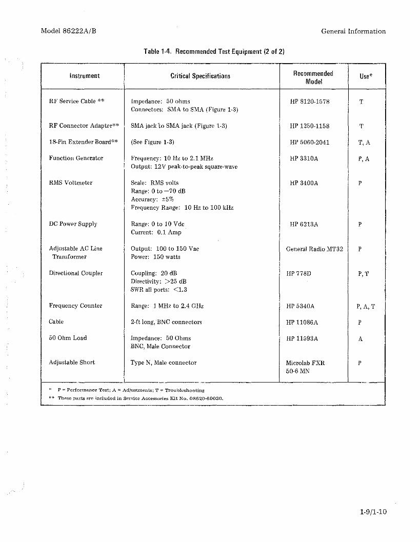
Table 1·4. Recommended TestEquipment (2 of 2)
Instrument Critical Specifications Recommended Use'Model
RF Service Cable ** Impedance: 50 ohms HP 8120·1578 TConnectors: SMA to SMA (Figure 1-3)
RF Connector Adapter** SMA jack 'to SMA jack (Figure 1-3) HP 1250-1158 T
18~Pin Extender Board** (See Figure 1·3) HP 5060-2041 T,A
Function Generator Frequency: 10 Hz to 2.1 MHz HP 3310A P,AOutput: 12V peak-to-peak square-wave
RMS Voltmeter Scale: RMS volts HP 3400A PRange: 0 to -70 dBAccuracy: ±5%Frequency Range: 10 Hz to 100 kHz
DC Power Supply Range: 0 to 10 Vdc HP 6213A PCurrent: 0.1 Amp
Adjustable AC Line Output: 100 to 150 Vac General Radio MT32 PTransformer Power: 150 watts
Directional Coupler Coupling: 20 dB HP 778D P, TDirectivity: >25 dBSWR all ports: <1. 3
Frequency Counter Range: 1 MHz to 2.4 GHz HP 5340A P,A,T
Cable 2·ft long,'BNC connectors HP 11086A P
50 Ohm Load Impedance: 50 Ohms HP 11593A AENe, Male Connector
Adjustable Short Type N, Male connector Microlab FXR P50·6 MN
* P '" Performance Test; A "" Adjustments; 'r "" Troubleshooting
** These parts arc included in Service Accessories Kit No. 08620-60030.
1-9/1·10


Model 86222AjB
SECTION IIINSTALLATION AND INCOMING INSPECTION TESTS
Installation
2-1. INSTALLATION
2-2. This section provides installation instructionsfor Model 86222AjB RF Plug-in and its accessories.It also includes information about initial inspectionand damage claims, preparation for using the RFPlug-in and packaging, storage and shipment, andincoming inspection.
table identifies the mating connector for each frontand rear panel connector on the RF Plug-in and givestheHPPartNo.and part numbers of alternate sources.
2-12. Operating Environment
2-13. Temperature. The instrument may be operated in temperatures from 00 C to +55 0 C.
2-16. Frequency Scale Installation
2-15. Altitude. The instrument may be operated ataltitudes up to 4572 meters (15,000 feet).
2·14. Humidity. The instrument may be operatedin environments with relative humidity up to 95%.However, the instrument should also be protectedfrom temperature extremes which cause condensation within the instrument.
2-3. INITIAL INSPECTION
2-4. Inspect the shipping container for damage. Ifthe shipping container or cushioning material isdamaged, it should be kept until the contents ofthe shipment have been checked for completenessand the instrument has been checked mechanicallyand electrically. The contents of the shipmentshould be as shown in Figure 1-1, and proceduresfor checking electrical operation are given in Section IV. If the contents are incomplete, if there ismechanical damage or defect, or if the RF Plug-indoes not pass the performance tests, notify thenearest Hewlett-Packard office. If the shipping container is damaged, or the cushioning material showssigns of stress, notify the carrier as well as theHewlett-Packard office. Keep the shipping materials for carrier's inspection. The HP office willarrange for repair or replacement without waitingfor claim settlement.
2-17. NOTE
If RF Plug-in is installed in mainframe,it must be removed to install frequencyscale. See RF Plug-in removal instructions in Paragraph 2-20.
To install frequency scale, proceed as follows:
2-5. PREPARATION FOR USE
2-6. Power Requirements
2-7. When the Model 86222AjB RF Plug-in isproperly installed, it obtains all power through therear interface connector from the HP Model8620AjC Sweep Oscillator mainframe.
2-8. Interconnections
2-9. For the Model 86222A/B RF Plug-in to operate, it must be plugged into an 8620A or 8620Cmainframe. Connection is made by pushing the RFPlug-in into the mainframe so that the plug-ininterface connector PI mates with the mainframeconnector.
2-10. Mating Connectors
2-11. The mating connectors for the HP Model86222A/B RF Plug-in are shown in Table 2-1. This
a. Disengage mainframe front-panel latchhandle, shown in Figure 2-1, by pushing downwardon handle while pushing inward lightly on top offront paneL
b. Swing front panel forward and down toposition shown in Figure 2-2.
c. Depress mainframe front-panel BAND select lever, shown in Figure 2-1, to rotate frequencyscale drum until desired scale position is accessible.
NOTE
The frequency scale for the 86222A/BRF Plug-in may be installed in any frequency scale drum position. If necessaryto remove a frequency scale, exert apressure OUTWARD, away from drum,on right-hand edge of scale.
d. Insert frequency scale so key (a 1j16-inchlong, 1/2 inch wide protrusion) on left end of scale
2-1

Installation Model 86222A/B
Table 2-1. Model 86222A/B Mating Connectors
ConnectorMating Connector
onInstrument Industry Identification HP Part No. Alternate Sources
J1 MARKER EXT IN- Type ENe, male connector 1250-0256 AmphenoI31-202-1021PUT (86222B only) UG-88IU
Bendix 12638-3J2 MARKER OUTPUT(86222B only) Specialty Connector 28P118-1
J4 ALC EXT INPUT
J5 FM
J6 FREQ REF
J3 RF OUTPUT Type N, male connector 1250-0882 Bendix 30481-2UG-21GIU
J3 Rear RF OUT Specialty Connector 25P117-2(Option 0021004)
DETAIL VIEW OF MAINFRAMEFRONT-PANEL LATCH HANDLE(SHOWN IN LOCKED POSITION)
BANDSELECTLEVER
2-2
FRONT-PANEL LATCH HANDLE(SHOWN IN DISENGAGED POSITION)
Figure 2-1. Installation of Frequency Scale and lIF Plug-in

Model 86222AjB
fits into notch in roller on left-hand edge of drum(see Figure 2-2).
e.
To prevent damage to frequency pointerswhen bandswitch drum is rotated, makecertain that frequency scale is firmly inplace and flush with band drum edges.
Push inward on right-hand edge of frequency scale to snap it into place on frequencyscale drum.
f. Return front panel to upright (closed)position, and, while pushing inward lightly on topof front panel, re-engage front-panel latch handleby pushing it upward to lock positions as shown inFigure 2-1, inset view.
2-18. RF Plug-in Installation and Removal
2-19. Installation. To install RF Plug-in proceed asfollows:
a. If mainframe power is ON, press mainframe LINE switch to OFF position.
Installation
b. Position latch handle located on left sideof RF Plug-in so it is perpendicular to front panel.Portion of handle with rectangular cut-out shouldbe facing forward and portion with notch shouldbe facing rear of RF Plug-in.
c. Slide RF Plug-in into mainframe towardsrear of compartment. RF Plug-in latch handle willengage a locking pin, shown in Figure 2-1, insidemainframe and exposed portion of latch handlewill start to move downward.
d. Push latch handle downward, while stillpushing inward on RF Plug-in, until latch handle isflush with front panel.
2-20. Removal. To remove RF Plug-in, proceed asfollows:
a. Push inward on top of latch handle andpull forward and up on bottom of latch handle.
b. When exposed portion of latch handle isin a position perpendicular to RF Plug-in frontpanel, it is disengaged from locking pin (Figure2-1) and RF Plug-in may be removed by pullingforward on latch handle.
BAND INDICATOR NOTCH FREOUENCYSCAlEORUM DEPRESSION
Figure 2··2. Mainframe Front Panel in Open Position
2-:3

Installation
2-21. Installation of Options
2-22. To install or remove options, refer to the installation instructions in the appendixes for theapplicable options.
2-23. MODIFICATIONS
2-24. Unmodified 8620A mainframes, which include prefixes 1332A and below, will not operatefor continuous multi-octave frequency measurements with the HP Model 8410B Network Analyzer. To modify 8620A mainframes with serial
Model 86222AjB
prefixes 1332A and below, order the 8620AMainframe Modification Kit, HP Part Number08620-60099. Service Note 8620A-6A explains themodifcation,
2-25. INCOMING INSPECTION TESTS
2-26. The following procedures test selected specifications to determine that the instrument is functioning properly for the requirements of incominginspection. The recommended test equipment islisted in Table 2-2. Equipment that meets or exceeds the critical specifications may be substituted.
Table 2-2. Recommended Test Equipment for Incoming Inspection Tests
Instrument
Sweep Oscillator
Oscilloscope with DualTrace Vertical Amplifier and 10:1 probes
Frequency Counter
Power MeterandPower Sensor
Crystal Detector
Power SplItter
10 dB Attenuator
3 dB Attenuator
Critical Specifications
8620A Is only substitution.
Vertical AmplIfier: Dual trace with 10:1 probesBandwidth: 20 MHz minimumVertical Sensitivity: 5 mV IDivHorizontal Sweep Rate: 1 j1sjDiv minimum
Range: 1 MHz to 2.4 GHz
Frequency: 10 MHz to 2.4 GHzRange: +10 dBm to -20 dBm
Frequency: 10 MHz to 2.4 GHzSWR: <1.2 to 2.4 GHzPolarity: Negative
Frequency: 10 MHz to 2.4 GHzAttenuation in each arm: 6 dB
Attenuation: 1.0 dB ± 0.5 dBFrequency: De to 2.4 GHz
Attenuation: 3 dB to.3 dBFrequency: Dc to 2.4 GHz
RecommendedModel
HP 8620C
HP 182C/1801Aj1820C
HP 5340A
HP 435A/8482A
HP 423A
HP 11667A
HP 8491A, Option 01.0
HP 8491A, Option 003
2-27. Frequency Range and Accuracy
SPECIFICATION: Frequency range: 10 MHz to 2.4 GHzFrequency accuracy (at 25'C ambient):
±10 MHz CW mode. (Approach desired CW frequency from low-frequency end ofband.)
±15 MHz All Sweep Modes (Sweep Time >0.1 sec.)
DESCRIPTION: The CW mode is checked at three frequencies across the band to determine if the RFsignal is within frequency tolerance. Start-stop sweep is then selected and the frequencyat each end-point is checked.
2-4

Model 86222A/B
INCOMING INSPECTION TESTS
2-27. Frequency Range and Accuracy (Cont'd]
SWEEP RFOSCILLATOR PLUG·IN
10dBATTENUATOR
Installation
FREQUENCY COUNTER
INI"UT
Figure 2-3. Frequency Range and Accuracy Test Setup
EQUIPMENT: SW<1ep Oscillator. .RF Plug-in . . . .Frequency Counter .10 dB Attenuator
HP 8620CHP 86222A/BHP 5340AHP 8491A, Option 010
PROCEDURE: a. Connect equipment as shown in Figure 2-3. Connect frequency counter through a10 dB attenuator to the 86222A/B RF OUTPUT connector. Press 8620C LINEswitch to the ON position.
b. Set controls as follows:
8620CSTART MARKER PointerSTOP MARKER Pointer .MODE .1 kHz SQ WV-OFF (Rear panel)
86222A/BRF ...POWER LEVELALC SwitchFM-NORM-PL .
0.02 GHz2.4 GHzMANUALOFF
ON+13 dBmINTNORM
c. Allow equipment to warm up for 30 minutes. Press 8620C CW pushbuttons. Setfrequency counter to measure frequencies from .01 GHz to 2.4 GHz.
d. Set CW pointer to .01 GHz. Frequency counter should indicate 10 MHz ±10 MHz.
e. Set CW pointer to 1.2 GHz. Frequency counter should indicate 1.2 GHz ±.01 GHz.
f. Set CW pointer to 2.4 GHz. Frequency counter should indicate 2.4 GHz ± .01 GHz.
g. Press FULL SWEEP pushbutton. Set MANUAL control fully counterclockwise. Frequency counter should indicate 20 MHz ± 15 MHz.
h. Set MANU AL control fully clockwise. Frequency counter should indicate 2.4 GHz± .015 GHz.
2-5

Installation
INCOMING INSPECTION TESTS
2-28. Power Level and Variation Test
Model 86222A/B
SPECIFICATION: Maximum Leveled Power (25"C):;;;' +13 dBm.Power Variation (at maximum leveled power): Internally Leveled: ±0.25 dB.
DESCRIPTION: Maximum leveled power is measured by a power meter. Power level variations with internalleveling are eheeked. The power variations are measured with a power meter.
SWEEP RFOSCILLATOR PLUG INnii--- - .... --i1
1_::.".__-,=" H ,00111RFOUTPUT
10 dBATTENUATOR
POWERMETER~-~
INPUT
POWERSENSOR
T
EQUIPMENT: Sweep OscillatorRF Plug-in .Power MeterPower Sensor10-dB Attenuator
Figure 2-4. Internal Leveling Test Setup
HP 8620CHP 86222A/BHP 435AHP 8482AHP 849lA, Option 010
PROCEDURE: a. Allow 30 minutes warm-up time. Set controls as follows:
8620C
START MARKER PointerSTOP MARKER Pointer.CW Pointer .MODE .RF BLANKING-OFF (Rear panel).
86222A/BRF .ALC
10 MHz2.4 GHz1.2 GHzMANUALRF BLANKING
ONINT
2-6
b. Connect equipment as shown in Figure 2-4.
c. Set 86222A/B POWER LEVEL to maximum leveled power (UN LEVELED lightout).
d. Manually tune 8620C from full CCW to full CW, slowly enough for power meterto respond. Note maximum and minimum power readings.

Model 86222A/B
INCOMING INSPECTION TESTS
2-28. Power Level and Variation Test (Cont'd)
Installation
e. Difference between maximum and minimum power readings should be ";;0.5 dBm.Minimum reading should not be lower than +3 dBm.
2-29. Internal Amplitude Modulation Test
SPECIFICATION: All tests are referenced to the 86222A/B RF OUTPUT power set to the specified maximum power of +13 dBm.
Internal AM: RF Blanking (selected by 8620C RF BLANKING-OFF switch) ON/OFFratio> 30 dB.
DESCRIPTION: Internal AM is checked for RF blanking on/off ratio. The on/off ratio is determined bypower level measurement in the RF BLANKING and OFF conditions.
RFOUTPUT
SPECTRUM ANALYZER
Figure 2-5. Internal Amplitude Modulation Test Setup
EQUIPMENT: Sweep OscillatorRF Plug-in .Power MeterPower SensorSpectrum Analyzer
HP 8620CHP 86222A/BHP 435AHP 8482AHP 8555A/8552B/141T
ONINTNORM
10 kHz20 MHz/DIV10 dB LOG
1.2 GHzDepressed (On)OFFAUTOEXT
PROCEDURE: a. Connect equipment as shown in Figure 2-5. Allow 30 minutes warm-up time.
b. Set controls as follows:Sweep Oscillator:
START MARKER Pointer ....MARKER SWEEP PushbuttonRF BLANKING-OFF (Rear Panel)MODE ..TRIGGER .
RF Plug-in:RF ...ALCFM-NORM-PL .
Spectrum Analyzer:BANDWIDTH .SCAN WIDTH .2 dB LOG-I0 dB LOG-LINEAR
2-7

Installation Model 86222A/B
INCOMING INSPECTION TESTS
2-29. Internal Amplitude Modulation Test (cont'd)
c. Adjust 86222A/B POWER LEVEL for maximum leveled power.
d. Adjust spectrum analyzer to center RF carrier on display.
e. Set LOG REF LEVEL on spectrum analyzer to top graticule line.
f. Set 8620C RF BLANKING-OFF switch to RF BLANKING and note the differencein power level (ON/OFF ratio). The ON/OFF ratio should he greater than 30 dB.
2-30. Marker Range Test (862228 Only)
SPECIFICATION: Marker Frequency Range:10 and 50 MHz Markers: 10 MHz to 2.4 GHz1 MHz Marker: 10 MHz to 1 GHz.
DESCRIPTION: Marker frequency range is determined by using an oscilloscope and crystal detector todisplay the markers.
WHQRIZINPUT
VERTINPur
OSCILLOSCOPE
Z-AXIS INPUTMARKEROUTPUT
SWEEP RFOUT OUTPUT
SWEEP RFOSCILLATOR PLUG-IN_-----i
,--- - -:l H-------------------...t9) ~ ,l
10 dBATTENUATOR
CRYSTALOE"fECTOR
Figure 2-6. Marker Range Test Setup
EQUIPMENT: Sweep OscillatorRF Plug-in . .OscilloscopeCrystal Detector10-dB Attenuator
HP 8620CHP 86222BHP 182C/1802A/1820CHP 423AHP 8491A, Option 010
PROCEDURE: a. Connect equipment as shown in Figure 2-6. Set 8620C LINE switch to ON andallow 30 minutes warm-up time.
b. Set controls as follows:
2-8

Model 86222AjB
INCOMING INSPECTION TESTS
2-30. Marker Range Test (86222B Only) (cont'd)
Installation
8620C
CW PointerLiF PointerMODE ..TRIGGERTIME-SECONDS SwitchTIME-SECONDS Vernier.RF BLANKING-OFF
86222B:RF ....POWER LEVELALC ....MARKER FREQ MHzMARKER MODEFM-NORM-PL. . . .
100 MHz160 MHzAUTOINT1 to .01Fully ClockwiseRF BLANKING
ON+13 dBmINT50J"LNORM
c. NOTE
The oscilloscope display consists of the selected Li F pointer frequencyswept symmetrically around the selected CW point of frequency. Forexample, with the CW pointer at 100 MHz and a LiF of 100 MHz, thedisplay is from 50 MHz to 150 MHz. To determine the frequencyrange of the markers, the first and last good markers should each becentered on the oscilloscope display, and either the CW pointer frequency setting read directly, or the 8620C put in CW mode and theoutput frequency read with a frequency counter.
Press 8620C LiF pushbutton and adjust LiF to display from 2 to 8 markers on oscilloscope display. Adjust oscilloscope intensity for best marker contrast.
d. Slowly adjust 8620C CW control to display from 10 MHz to 2.4 GHz and ensure50 MHz markers are present and stable over the full calibrated frequency range.
e. Set MARKER FREQ MHz switch to 10 and adjust LiF to display between 2 and 8markers on oscilloscope display.
f. Slowly adjust 8620C CW control to display from 10 MHz to 2.4 GHz and ensure10 MHz markers are present and stable over the full calibrated frequency range.
g. Set MARKER FREQ MHz switch to 1 and adjust Li F to display between 2 and 8markers on oscilloscope display.
h. Slowly adjust 8620C CW control to display from 10 MHz to 1 GHz and ensure 1 MHzmarkers are present and stable up to 1 GHz.
2-9

Installation
2-31. STORAGE AND SHIPMENT
2-32. Environment
2-33. The instrument may be stored or shipped inenvironments within the following limits:
Temperature '" --40'C to +75'CHumidity Up to 95% relativeAltitude 15240 meters (50,000 feet)
The instrument should also be protected fromtemperature extremes which cause condensationwithin the instrument.
2-34. Packaging
2-35. Original Packaging. Containers and materialsidentical to those used in factory packaging areavailable through Hewlett-Packard offices. If theinstrument is being returned to Hewlett-Packardfor servicing, attach a tag indicating the type of service required, return address, model number, andfull serial number. Also, mark the container FRAGILE to assure careful handling. In any correspondence, refer to the instrument by model numberand full serial number.
2-10
Model 86222AjB
2-36. Other Packaging. The following general instructions should be used for re-packaging withcommercially available materials:
a. Wrap instrument in heavy paper or plastic.(If shipping to Hewlett-Packard office or servicecenter, attach tag indicating type of service required, return address, model number, and fullserial number.)
b. Use strong shipping container. A doublewall carton made of 350-pound test material isadequate.
c. Use enough shock-absorbing material (3to 4-inch layer) around all sides of instrument toprovide firm cushion and prevent movement insidecontainer. Protect control panel with cardboard.
d. Seal sbipping container securely.
e. Mark sbipping container FRAGILE toassure careful handling.
f. In any correspondence, refer to instrument by model number and full serial number.

Model 86222AjB
SECTION IIIOPERATION
Operation
3-1_ INTRODUCTION
3-2. This operating section explains the functionof the controls and indicators of the Model8G222AjB RF Plug-in. It describes typical operating modes in a measurement system.
3-3. PANEL FEATURES
3-4. Front and rear panel features are describedin Figures 3-1 and 3-2. Description numbers matchthe numbers on the illustration.
3-5. OPERATOR'S CHECKS
3-G. The Operator's Checks (Figure 3-3) allowthe operator to make a quick evaluation of the instrument's main function prior to use. Thesechecks assume that the 8G222AjB RF Plug-in isinstalled in an 8620C Sweep Oscillator mainframe.The checks cover the RF Plug-in and mainframe;therefore, if the correct indications are not obtained, trouble may be in either of the units. If theRF Plug-in is suspected, follow the troubleshootingchart in Section VIII to isolate the problem.
3-7. OPERATING INSTRUCTIONS
3-8. General Operating Procedure
3-9. Figure 3-4 shows general operating procedures with the Model 8620Cj86222AjB SweepOscillator connected in a typical measurement testsetup. Many other applications are possible but arenot shown because the general operating procedureis the same.
3-10. Internal Leveling
3-11. The most convenient method of RF outputleveling is internal leveling. A portion of the RFoutput is coupled out of a direction detector, producing a de voltage proportional to the RF outputsignal. This detected de voltage is applied to theautomatic leveling control circuit (ALC). TheOperator's Checks in Figure 3-3 are performed inthe internal leveling mode.
3-12. External Crystal Detector Leveling
3-13. Power may be leveled externally using apower splitting tee (or directional coupler) andcrystal detector. This leveling system uses a powersplitting tee to sample the RF output signal and acrystal detector to produce a de voltage proportional to RF signal level. The detector voltage iscompared with an internal reference voltage, andthe difference voltage changes the output powerlevel to keep it constant at the output. Instead of apower splitting tee, a directional coupler may beused to sample the RF signal for the leveling loop.Directional couplers are usually narrow band,whereas the power splitting tee is flat over a widefrequency range. The advantage of a directionalcoupler is that it does not have a G-dB loss like thepower splitting tee, therefore a higher maximumleveled power output may be obtained. To placethe crystal detector leveling loop in operation, usethe test setup and procedures in Figure 3-8.
3-14. External Power Meter Leveling
3-15. Power leveling can be obtained with a powermeter and power splitting tee or directional coupIer as shown in Figure 3-9. A sample of the RFoutput signal is routed to a power meter to producea de voltage proportional to the RF signal level.The de voltage is applied to the 86222A/B ALCcircuits and compared with an internal referencevoltage _ A difference voltage is produced andamplified by the ALC amplifier before being applied, as modulator drive, to the Modulator-MixerUl. The modulator drive controls the output ofthe Modulator-Mixer to maintain a constant powerlevel.
3·16. External FM
3-17. The 8G222AjB RF output signal can befrequency modulated using an external modulatingsignal applied to the 86222AjB FM input connector. The external FM function provides a means ofobtaining an output frequency that varies underthe control of an external modulating signal. Apositive going voltage causes output frequency todecrease while a negative going voltage causes output frequency to increase.
3-1

Operation
3-18. Phase Lock Operation
3-19. The 86222A/B RF output (CW) signal maybe phase-locked using an external phase-lock signalapplied to the 86222A/B FM input connector. Thephase-lock function provides a means of obtaininga very stable CW frequency by transferring thefrequency stability of the reference oscillator tothe source. If the CW frequency starts to drift, thephase difference between the CW frequency andthe reference frequency (reference oscillator) is
Model 86222A/B
detected, producing a de voltage. The de voltage isa correction signal which restores the CW frequency to its previous point. Stability of this CWfrequency is determined by the stability of thereference oscillator.
3-20. OPERATOR'S MAINTENANCE
3-21. Power circuits for the Model 8G222A/B arefused in the mainframe. See the 8G20C Operatingand Service Manual for fuse replacement.
FRONT PANEL FEATURES
Figure 3-.1. Front Panel Controls, Connectors and Indicators (l 0/2)
3-2

Model 86222A/B
FRONT PANEL FEATURES
Operation
• UNLEVElEO lamp. Lights if POWER LEVEL isset too high to permit leveling over sweep rangeselected.
o RF ON-OFF switch. Turns RF power on and off.This is useful when zeroing power meter.
o MARKER FREQ MHz switch (862228 only).Selects 50, 10 or 1 MHz internal crystal markers.EXT position selects markers generated from anexternal frequency source.
o MARKER EXT INPUT 8NC connector (862228only). Input for external marker frequency source.Maximum signal input 1 volt RMS.
4) ALC GAIN control. Adjust ALC leveling amplifiergain when system is using an external levelingloop. Rotates clockwise to increase ALe loop gain .
G ALC switch. Selects INT (internal), EXT (external), or MTR (power meter) power leveling modes.
CD ALC SLOPE control. Compensates for high Irequency power losses in external RF cables by
attenuating power at lower frequencies. This compensation provides a leveled RF signal output. TheOFF position removes all compensation.
CD FREII CA L control. provides fine frequencycalibration for 86222AiB RF Plug-in.
e MARKER OUTPUT lamp (86222B only). Lightsin LrMODE when marker is coincident with RFOUTPUT frequency. Enables accurate selection ofCW frequency,
o MARKER OUTPUT BNC Connector (862228only), Output for intensity markers to Z·AXISinput of display unit.
o MARKER MODE switch (86222B only). Selectsamplitude (AMPL), negative intensity (L.I'), orpositive intentsity (IL) marker modes. Offposition switches markers off.
o ALC EXT INPUT BNC connector. Input forexternal leveling from power meter or crystaldetector" Sensitivity -10 to '--100 millivolts,
CD RF OUTPUT connector. Type-N 50-ohm RFoutput connector.
• POWER LEVEL control. Adjusts RF power output. Rotate clockwise to increase output pOWE~r.
G) latch Handle. Aids in installing and removingRF Plug-in. After installing, handle locks to holdRF' Plug-in in place.
NOTE
The front panel changes whenOption 002 or 004 is added. SeeAppendix A, B, or C for thesefront panel features.
Figure 3-1. Front Panel Controls, Connectors and Indicators (2 of 2)
3-3

Operation
REAR PANEL FEATURES
Model 86222AjB
o Interface Connector. Provides interconnectionbetween 8620C mainframe and 86222AjB RFPlug-in.
• FM-NORM-Pl switch, Operates in conjunctionwith FM input connector to provide optimum performance for either normal sweep (NORM), frequency modulation (FM), or phase lock (PL) oper-
ation. If FM or PL modes of operation are notbeing used, switch should be in NORM.
o FREll REF BNC connector. Provides approximately +1 voltjGHz frequency reference signal.
o FM BNC connector. Input connector for FMmodulation signal or phase locking error signal.
Figure 3-2. Rear Panel Controls and Connectors
3-4

Model 86222A/B
OPERATOR'S CHECKS
FRONT
Operation
REAR
Figure 3·3. Operator's Checks (1 of 3)
3-5

Operation Model 86222A/B
OPERATOR'S CHECKS
SWEEP RFOSCILLATOR PLUG·IN OSCILLOSCOPE
10 dBATTEN- CRYSTAlUATOR DETECTOR
'----....[]::JI---------<u:>-----J
EQUIPMENT:Sweep Oscillator lIP 8620C
RF Plug-in lIP 86222A/BOscilloscope " lIP l82C/180lA/1820CCrystal Detector lIP 423A10-dB Attenuator lIP 849lA, Option 010
NOTE
All procedures are written for the 8620C Sweep Oscillator. Thesesame procedures will apply to the 8620A with proper attention toto different switches.
PROCEDURE:
1. Connect equipment as shown in test setup.
2. Set controls as follows:
8620C:BAND • . . . . . . . . . . . . . . . . . . . . . . . . . . . . 0.01-2.'1 GlIzSTART MARKER pointer. " Left-hand end mark on scaleCW MARKER pointer • . Middle mark on scaleSTOP MARKER pointer • .. Right-hand end mark on scaleMARKERS. OFFMODE •.................................. AUTO
Figure 3-3. Operator's Checks (2 of 3)
3-6

Model 86222A/B
OPERATOR'S CHECKS
8620C (Cont'd):TRIGGER. . , INTTIMt~-SECONDS. . , 0.1 to 0.01TIME-SECONDS Vernier 4& ClockwiseRear Panel 1 kHz SQ WV/OFF • OFFRear Panel DISPLAY BLANKING/OFF •.. DISPLAY BLANKINGRear Panel RF BLANKING/OFF. . _.. OFF
Operation
86222A/B:RFO·············································ooPOWER LEVEL CD Fully clockwiseALCe INTSLOPE •.. - OFFRear Panel FM-NORM-PL. "'" NORMMARKERS MODE (86222B only) m OFFMARKERS FREQ MHz (86222B o;;Ty) 4) _ 50
3. Depress LINE pushbutton switch • to turn on mainframe. With mainframe on, LINE .'
START MARKER. ' and STOP MARKER. pushbuttons should light.
4. Check that the instrument is sweeping correctly. This is indicated by continuous signal
level line below zero-volt de level on oscilloscope.
5. UNLEVELED light • may be lit. If UNLEVELED light is lit, reduce output power by
86222A/B POWER LEVEL control CD counterclockwise until UNLEVELED light goes
out. This is adjustment point for maximum leveled power. Oscilloscope trace should be
leveled. (Refer to Figures 3-5 and 3-6 for typical oscilloscope display of unleveled and
leveled RF power output.
6. Set 8620C MARKERS Switch 6) to INTEN position and marker should appear on oscillo
scope trace as intensity spot. Adjust oscilloscope intensity for best contrast. Set MARKER
switch to AMPL position and marker should appear on oscilloscope trace as a pip. Set
MARKER switch to OFF.
86222B ONLY:
7. Press 8620C lIF pushbutton. and lIF and CW • pushbuttons should light. Discon
nect BNC cable from Z-AXIS OUTPUT ED and connect it to MARKER OUTPUT connec
tor CD . Set MARKERS MODE switch. to I..J and adjust lIF control 0 for
between 2 to 8 markers on oscilloscope display. Markers should appear on oscilloscope as
intensity spots. Adjust oscilloscope intensity for best contrast. Set MARKERS MODE
switch to -"- and markers should appear as dropouts on the oscilloscope trace. Set
MARKERS MODE switch to AMPL and markers should appear as pulses. Changing
MARKERS FREQ MHz switch 4) position should change marker frequency.
Figure 3-3. Operator's Checks 3 ol3)
3-7

Operation
TYPICAL SWEEP OPERATION
FRONT
Model 86222A(B
3-8
REAR
Figure 3-4. Typical Sweep Operation (I of 5)

Model 86222A/B
SWEEP RFOSCILLATOR PLUG-IN
TYPICAL SWEEP OPERATION
BLANKING
Operation
SWEPT AMPLITUDEANALYZERI
OSCILLOSCOPE
Z_AXiSINPUT
POWERSPLITTER
DEVICEUNDER TEST
DETECTOR
DETECTOR
NOTE
0.0_1111 I nn1111 ' .u.
A H MODULATORDRIV,27';"kriz
REFERENCE
The device under test may be any microwave device such as an amplifier, a broadband or narrowband f Iter, or isolator. The followingprocedure describes generally how to set up the sweeper operation.
EQUIPMENT:
Sweep Oscillator HP 8620CRF Plug-in HP 86222A/BSwept Amplitude Analyzer/Oscilloscope HP 8755A/182CDetectors (2 required) HP 11664APower Splitter HP 11667A
PROCEDURE:
1. Connect equipment as shown in test setup.
2. Set controls as follows:
8620C:BAND. . 01 - 2.4 GHzSTART MARKER pointer •........... Left-hand mark on scaleCW MARKER pointer G _.. Middle mark on scaleSTOP MARKER pointer G Right-hand end mark on scale
Figure 3-4. Typical Sweep Operation (2 of 5)
3-9

Operation
TYPICAL SWEEP OPERATION
8620C (cont'd)
MARKERS • ... . . . . . . . . . . . . . . . . . . . . . . . . . . . . . . . . . .. OFF
MODE •........................................ AUTO
TRIGGER • . INT
TIME-SECONDS G 0.1 to 0.01
TIME-SECONDS Vernier •....................... Clockwise
DlSPLAY BLANKING/OFF Rear Panel •.. DlSPLAY BLANKING
1 kHz SQ WV/OFF Rear Panel €D OFF
RF BLANKING/OFF Rear Panel Ell) OFF
86222A/B:
RF •............................................. ON
POWER LEVEL G Fully clockwise
~e···········································~SLOPE-OFF G OFF
FM-NORM-PL Rear Panel ED ............................ FM
MARKER MODE (86222B only) • OFF
MARKER FREQ MHz (86222B only) CD 50
8755A CHANNEL A:
dB/DIV (Sensitivity). . . . . . . . . . . . . . . . . . . . . . . . . . . . . . . . ... 10
DlSPLAY ... " . . . . . . . . . . . . . . . . . . . . . . . . . . . . . . . . .. Press in R
OFFSET dB +15
OFFSET OFF
Model 86222A/B
3. Depress LINE pushbutton switch. to turn on mainframe. The LINE switch and FULL
SWEEP • pushbutton should light, indicating FULL SWEEP mode is selected. In sweep
mode, a ramp sweep voltage is supplied through SWEEP OUT front panel connector • to
display equipment.
4. Adjust 86222A/B POWER LEVEL control G for desired power level on oscilloscope.
(For some measurements, such as flatness, POWER LEVEL is set so UNLEVELED lamp
• is ofL)
Figure 3-4. Typical Sweep Operation (3 of 5)
3-10

Model 86222A/B
TYPICAL SWEEP OPERATION
NOTE
Normal operation requires a sweep from low frequency to high fre
quency. However, the Model 8620C will also sweep from high to low
frequency by setting START MAR KER pointer • to high-frequency
side of sweep and setting STOP MAR KER pointer at low-frequency
side of sweep. This operation is possible only when 86222B markers are
not used.
Operation
5. For normal sweep-mode operation, set 8620C MOD}; switch • to AUTO and the sweep
signal is obtained from internal sweep oscillator. This is the only position of the MODE
switch that allows TRIGGER • and TIME G switches to operate. However, if an
external sweep source is used, set MODE switch to EXT position. The EXT SWEEP is
routed through rear-panel PROGRAMMING connector • to MODE switch EXT position.
If it is necessary to sweep band manually, set MODE to MANUAL position and adjust
MANUAL control •. In MANUAL position, a tuning voltage is supplied through SWEEP
OUT front-panel connector CD to display instrument.
6. For normal sweep operation, set 8620C TRIGGER switch • to INT position. This pro
vides automatic repetitive sweep. If a single sweep is to be viewed, press TRIGGER switch
to SINGLE position and release. Repeat this for each single sweep. TRIGGER EXT position
connects trigger input circuit to rear-panel EXT TRIGGER connector e .LINE position
allows sweep to be triggered by line frequency.
7. Set 8620C TIME-SECONDS switch G to desired range, and adjust vernier control. to
desired sweep time.
8. When operating witch the HI' 8755A, the 8620C rear-panel mSpLAY BLANKING/OFF
switch • is normally set to DISPLAY BLANKING and a hlanking pulse is supplied
through Z-AXIS/MKR/pEN LIFT output connector • to the Swept Amplitude Analyzer
Z-AXIS INPUT. For 86222B operation with the HI' 8755A, MARKER OUTPUT connector
• is normally used to supply harmonic intensity markers to the swept Amplitude Ana
lyzer Z-AXIS INPUT. Both display blanking and intensity marker operation may be used
simultaneously if the equipment is connected as shown in the partial test setup below.
NOTE
The Resistive Barrel (5061-1015) is supplied with the 86222B.
Figure 8-4. Typical Sweep Operation (4 of 5)
3-11

Operation
TYPICAL SVVEEP OPERAT!ON
Model 86222A/B
RESiSTIVEBARREL
BNC TEETOMPd?55AZ·AXtS INPUT ..
9. The MODULATION DRIVE from 8755A must be connected directly to rear-panel EXT AMconnector ED .This provides the required modulation without using an external modulator and its accompanying losses.
10. Adjust 182C Oscilloscope controls for display of reference signal. (With CHANNEL A OFFSET dB thumbwheel switches set at +15 dB, losses in the Power Splitter and 10-dB Attenuator are compensated for and reference signal should be near center graticule. This positionmay be used as a zero reference level for measurements such as insertion loss, ON/OFF ratio,and spurious signals.)
11. Press DISPLAY pushbutton. The oscilloscope display is the output of device under test.Press dB/DIV 5 or 1 as required to increase sensitivity and obtain better resolution.
12. Press DISPLAY A/R to display signal level of A in dB minus signal level of R in dB(AdS - RdS = A/R).
13. A marker is added to the sweep by selecting correct position of 8620C MARKER slideswitch •. Set MARKER slide switch to INTEN position. Marker should appear as highintensity dot on trace of display instrument by intensity modulating the Z-axis. Intensitymodulation signal is available at rear-panel Z-AXIS output •.
14. Pressing LlF pushbutton switch • lights both LlF and CW • controls. Center frequencyis selected by CW control • and indicated by location of white pointer • on top dial.Amount of deviation from selected CW frequency is set by LlF control. The LlFscale. isshort scale directly above LlF control.
86222BONLY:
15. Harmonic crystal intensity markers are selected when the MARKER MODE switch 49 is inthe~ position. They are normally used with the 8620C in the LlF mode, with a LlFselected which displays from 2 to 8 markers on the CRT screen. Harmonic marker frequencyselection is made with the MARKER FREQ MHz switch e .
Figure 3-4. Typical Sweep Operation (5 of 5)
3-12
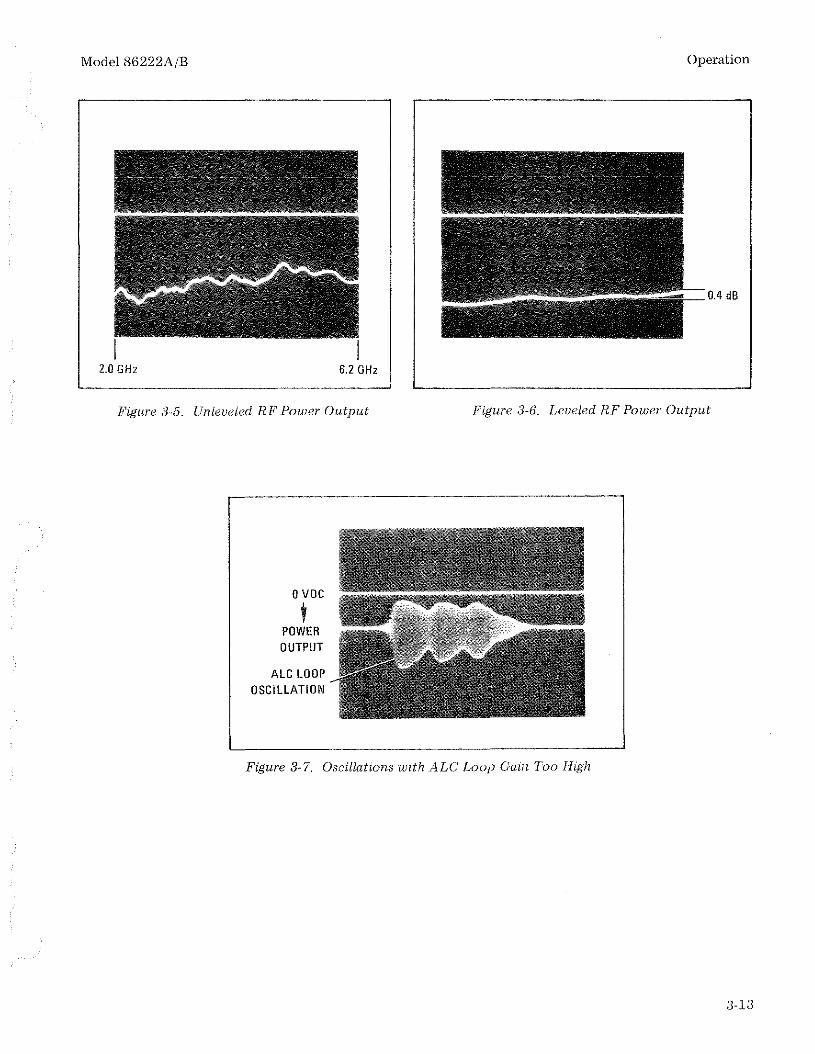
Model 86222A/B Operation
0.4 dB
2.0GHz 6.2 GHz
Figure 3-5. Unleueled RF Power Output Figure :i-(;. Leveled RF Power Output
oVOC
tPOWEROUTPUT
ALC LOOPOSCILLATION
l- . --'
Figure 3-7. Oscillations with ALe Loop Gain Too High
a.rs

Operation Model 86222A/B
EXTERNAL CRYSTAL DETECTOR LEVELING
•
POWEnMETEFl
r,···:,I,. • III ........
POWERSENSOR
10dBAfTENLJAlOR
OSCILLOSCOPFSEE
PROCEDURESTEP 1.
BNC(\ rEE
\ ...j 7jOcJB ~CRYSfAl
AnEU( Dt H:CTORUATOR
.,--_--{c J__
SWEEP RFOSCILLATOR PLUG-IN
IU:VEL"ED
I POWFJ1'- ./ ()UTPLJ~
EQUIPMENT:
Sweep Oscillator. . . . . . . . . . . . . . . . . . . . . . . . . . . . . . . . .. HP 8620CRF Plug-in HP 86222A/BOscilloscope " HP 182C/1802A/1820CPower Meter HP 435ACrystal Detector HP 423APower Splitter HP 11667A10-dB Attenuator (2 required) HP 8491A, Option 010Power Sensor HP 8482ABNC TEE HP 1250-0781
PROCEDURE:
1. NOTE
Crystal output signal must be between -10 mVdc and -100 mVdc.
Connect equipment as shown in test setup.
Figure 3-8. External Crystal Detector Leveling (l of 3)
3-14

Model 86222A/B
EXTERNAL CRYSTAL DETECTOR LEVELING
NOTE
Between 10 MHz and 50 MHz there are resonant spikes that might be ashigh as 3 dB in the envelope of the RF feedthrough to the video output.These resonances are a function of the load impedance (including cablelengths) seen by the detector. During external leveling at 10 to 50 MHz,the resonant spikes may be damped out by insertion of the circuitshown below in the test setup. The circuit may be inserted in the line tothe EXT INPUT of the RF Plug-in.
HP10110A
Operation
BNG(MITOOUAl BANANAPOST
HP 10110A
BNG TEEHP 1250-0781
-=-=-
TOEXTINPUT
2. Set controls as follows:
IL_-T-_J
I
SEE DETAil A
3.m
1000 pF
DETAil A
8620C:
START MARKER _ Left-hand end frequency selectedSTOP MARKER .. _ Right-hand end frequency selectedMARKERS _ _ __ OFFMODE AUTOTRIGGER INTTIME-SECONDS Vernier Fully clockwise1 kHz SQ WAVE/OFF Rear Panel . . . . . . .. OFFDISPLA Y BLANKING/OFF Rear Panel DISPLAY BLANKING
Figure 3-8. External Crystal Detector Leveling (2 of 3)
3-15

Operation
EXTERNAL CRYSTAL DETECTOR LEVELING
86222A/B:RF OUTPUT . . . . . . . . . . . . . . . . . . . . . . . . . .. ONPOWER LEVEL Fully clockwiseALC EXTALC GAIN Fully clockwiseFM-NORM-PL Rear Panel NORM (Normal)
Model 86222A/B
3. Press 8620C LINE pushbutton switch to turn-on mainframe. The LINE switch and FULLSWEEP pushbutton should light. indicating FULL SWEEP mode is selected.
4. Adjust ALC GAIN and POWER LEVEL controls fully clockwise for maximum RF powerOUTPUT and maximum ALC loop gain. One of the conditions shown in Figures 3-5 or 3-6should be displayed on oscllloscope. If trace is unleveled (or partially leveled) as shown inFigure 3-5 and UNLEVELED lamp is on, turn POWER LEVEL control counterclockwiseuntil trace is level (see Figure 3-6). If ALC loop is too high, oscillations may occur as shownin Figure 3-7. To remove oscillations, reduce ALC loop gain by turning ALC GAIN controlcounterclockwise.
5. To use leveled RF power output for testing external equipment, make connection at pointmarked "Leveled Power Output".
Figure 3-8. External Crystal Detector Leveling (3 of 3)
3-16

Model 86222A/B Operation
EXTERNAL POWER METER LEVELING
SWEEP RFOSCILLATOR PLUG-IN
POWERMETER
~~~;:;~~~;jJ------------jI'" •
OSCILLOSCOPE
POWERSPLITTER
POWERSENSOR
INF'UT 10d8CRYS TAL ATTEN· I LEVELW
DETECTOR UATOR POWER
'------------<C,~::n--------------_{[.=rJ__ __ AOU':'U'~
EQUIPMENT:Sweep Oscillator. . . . . . . . . . . . . . . . . . . . . . . . . . . . . . . . .. HP 8620CRF Plug-in HP 86222A/BOscilloscope HP 182C/1802A/1820CPower Meter HP 435APower Sensor HP 8482ACrystal Detector , . HP 423A10-dB Attenuator HP 8491A, Option 010Power Splitter HP 11667A
NOTE
For power meter leveling, sweep rates should be slower than 10 sec/sweep to ensure proper leveling due to the slow response of the powersensor.
PROCEDURE:
1. Connect equipment as shown in test setup.
2. Set controls as follows:
8620C:START MARKER Left-hand end frequency selectedSTOP MARKER Right-hand end frequency selectedMARKER OFFMODE AUTO
Figure 3-9. External Power Meter Leveling (1 of 2)
3-17

Operation
EXTERNAL POWER METER LEVELING
8620C (cont.'d):TRIGGER INTTIME-SECONDS 100 --10TIME-SECONDS Vernier Fully clockwise1 kHz SQ WAVE/OFF Rear Panel OFFDISPLAY BLANKING/OFF Rear Panel DISPLAY BLANKING
86222A/B:RF OUTPUT . . . . . . . . . . . . .. ONPOWER LEVEL Fully clockwiseALC MTR (Power Meter)ALC-GAIN , Fully clockwiseFM-NORM-PL Rear Panel NORM (Normal)
Model 86222A/B
3. Press 8620C LINE pushbutton switch to turn-on mainframe. The LINE switch and FULLSWEEP pushbutton should light, indicating FULL SWEEP mode is selected.
4. Select range on power meter to obtain indication near top third of meter scale.
5. Adjust 86222A/B POWER LEVEL control counterclockwise until leveling across bandoccurs as shown in Figure 3-6. If' oscillations appear on trace as shown in Figure 3-7, turnALC GAIN control counterclockwise. With proper leveling across the band, the 86222A/BUNLEVELED light should be out.
6. To use leveled RF power output for testing external equipment, make connection at pointmarked "Leveled Power Output".
Figure 3-9. External Power Meter Leveling (2 of 2)
:3-18


![g]kfn b'/;~rf/ sDkgL lnld^]* sd{rf/L ljlgodfjnL, 2061-1_ g]kfn b'/;~rf/ sDkgL lnld^]* sd{rf/L ljlgodfjnL, 2061 sDkgL P]g 2063 sf] cwLgdf /xL g]kfn b'/;~rf/ sDkgL lnld^]*sf] k|aGw-kqsf]](https://img.pdfslide.net/doc/110x75/5ecbb6f05d37ff74a70a62d2/gkfn-brf-sdkgl-lnld-sdrfl-ljlgodfjnl-2061-1-gkfn-brf-sdkgl-lnld.jpg)


![RF Generic Signals Application Plug-in Programmer Manual › manual › RF-Generic-Signals-Plug-in-Progr… · RFGSignal:CARRier[n]:DMODulation:APSK Sets or returns the APSK Modulation](https://img.pdfslide.net/doc/110x75/5f1c418e35e4bb2ee83601f3/rf-generic-signals-application-plug-in-programmer-manual-a-manual-a-rf-generic-signals-plug-in-progr.jpg)