Embed Size (px)
Citation preview
8825/8830Digital Document SystemUser Guide701P30070 June 1999

FCC Compliance in the USAWARNING: This equipment has been tested and found to comply with thelimits for a Class A computing device pursuant to Subpart J of Part 15 FCCRules.
This equipment generates, uses, and can radiate radio frequency energyand, if it is not installed and used in accordance with the instruction manual,may cause interference to radio communications. These limits are designedto provide reasonable protection against such interference when operated ina commercial environment. Operation of this equipment in a residential areais likely to cause interference, in which case the user, at his own expense,will be required to take whatever measures may be required to correct theinterference.
EME Compliance in CanadaThis digital apparatus does not exceed the Class A limits for radio noiseemissions from digital apparatus set out in the radio interference regulationsof the Canadian Department of Communications.
Conformité EEMCet appareil numérique est conforme aux limites d'émission de bruitsradioélectriques pour les appareils de classe A stipulées dans le Règlementsur le brouillage radioélectrique du Ministère des Communications duCanada.
NOTICE
Whilst every care has been taken in the preparation of thismanual, no liability will be accepted by Xerox Corporationarising out of any inaccuracies or omissions.
Xerox CorporationMultinational Customer and Service Education800 Philips RoadBuilding 845-17SWebster, NY 14580USA
All terms mentioned in this document that are known to be trademarks orservice marks have been appropriately capitalized.
Microsoft, Windows, Windows for Workgroups, Windows NT, Windows 95and Windows 98 are registered trademarks of Microsoft Corporation.NetWare and IntranetWare are trademarks of Novell.
Copyright protection claimed includes all forms and matters of copyrightablematerials and information now allowed by statutory or judicial law orhereinafter granted, including without limitation, material generated from thesoftware programs which are displayed on the screen such as styles,templates, icons, screen displays, looks, etc.
Printed in the United States of America.
© 1999 Xerox Engineering Systems. All rights reserved.
The digital box icon and the acronym XES are trademarks of XESystems,Inc.
XEROX, The Document Company, the stylized X, XXXX, and any identifyingproduct names and numbers are trademarks of XEROX corporation.
All terms mentioned in this document which are known to be trademarks orservice marks are appropriately capitalized.
Copyright 1999 by Xerox Corporation. All rights reserved.
Copyright 1999 by Xerox Engineering Systems. All rights reserved.
Xerox Engineering Systems300 Main StreetEast Rochester, N.Y. 14445
No part of this manual may be copied without prior written permission ofXerox Engineering Systems.
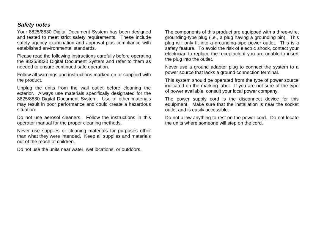
Safety notesYour 8825/8830 Digital Document System has been designedand tested to meet strict safety requirements. These includesafety agency examination and approval plus compliance withestablished environmental standards.
Please read the following instructions carefully before operatingthe 8825/8830 Digital Document System and refer to them asneeded to ensure continued safe operation.
Follow all warnings and instructions marked on or supplied withthe product.
Unplug the units from the wall outlet before cleaning theexterior. Always use materials specifically designated for the8825/8830 Digital Document System. Use of other materialsmay result in poor performance and could create a hazardoussituation.
Do not use aerosol cleaners. Follow the instructions in thisoperator manual for the proper cleaning methods.
Never use supplies or cleaning materials for purposes otherthan what they were intended. Keep all supplies and materialsout of the reach of children.
Do not use the units near water, wet locations, or outdoors.
The components of this product are equipped with a three-wire,grounding-type plug (i.e., a plug having a grounding pin). Thisplug will only fit into a grounding-type power outlet. This is asafety feature. To avoid the risk of electric shock, contact yourelectrician to replace the receptacle if you are unable to insertthe plug into the outlet.
Never use a ground adapter plug to connect the system to apower source that lacks a ground connection terminal.
This system should be operated from the type of power sourceindicated on the marking label. If you are not sure of the typeof power available, consult your local power company.
The power supply cord is the disconnect device for thisequipment. Make sure that the installation is near the socketoutlet and is easily accessible.
Do not allow anything to rest on the power cord. Do not locatethe units where someone will step on the cord.
The units should not be placed in a built-in installation unlessproper ventilation is provided.
Never push objects of any kind into the slots of the units asthey may touch dangerous voltage points or short out parts thatcould result in a risk of fire or electric shock.
Never spill liquid of any kind on the units.
Never remove any covers or guards that require a tool forremoval. There are no operator serviceable areas within thesecovers.
Never attempt any maintenance function that is not specified inthis operator manual.
Never defeat interlock switches. Machines are designed toprevent operator access to unsafe areas. Covers, guards, andinterlock switches are provided to ensure that the system willnot operate with the covers opened.
Unplug the reprographic system from the wall outlet and referservicing to qualified service personnel under the followingconditions:
• When the power cord is damaged or frayed.
• If liquid has been spilled into the product.
• If the units have been exposed to rain or water.
• If the units are producing unusual noises or odors.
• If the units or the cabinets have been damaged.
If you need additional safety information concerning the8825/8830 DDS system or XES supplied materials, you maycall:
Within the United States:
1-800-828-6571 toll free.
In other countries:
Please call your local Xerox Engineering Ssystems serviceoffice for help.
8825/8830 DDS User Guide/i
Table of Contents
Safety notes................................................................................................ iii
About this manual… 1
Getting to know the 8825/8830 DDS 1The Scanner ............................................................................................... 3
Document Handling System ................................................................... 5
DDS User Interface................................................................................. 5
Option keys and Feature keys............................................................. 6
Media Selection ............................................................................... 6
Output Format − Manual.................................................................. 7
Option keys and Feature keys (continued)...................................... 8
Output Format − Preset ................................................................... 8
Output Format -Synchro...................................................................... 8
Image Quality................................................................................... 9
Reduction & Enlargement.............................................................. 11
Navigation Keys ................................................................................ 12
Mode Key .......................................................................................... 13
Special Features keys and Numeric Keypad .................................... 14
Power On.................................................................................................. 15
Switching on the Scanner ..................................................................... 15
Warmup ................................................................................................ 15
Preparing the 8825/8830 DDS for use ..................................................... 16
Switching on the Controller and the Printer .......................................... 17
Power off .................................................................................................. 19
The Controller and the Printer .................................................................. 19
Preparing the 8825/8830 DDS for use ++ 20Loading Media and other consumable supplies ....................................... 20
Making copies 21Making a copy with the default settings.................................................... 21
Adjusting Image Quality............................................................................ 22
What is a good quality document?........................................................ 23
What is a bad quality document?.......................................................... 24
AutoIQ™ ................................................................................................... 26
Automatic adjustment of copy quality.................................................... 26
Automatic edge detection and document centering.............................. 26
Scanning strategies .................................................................................. 27
The Background Suppression feature ...................................................... 28
Preparing documents................................................................................ 29
Reducing or enlarging documents ............................................................ 30
Auto mode............................................................................................. 30
Manual mode ........................................................................................ 30
Preset mode.......................................................................................... 31
Controlling the scan .................................................................................. 32
Automatic and manual start .................................................................. 32
Direction of document return................................................................. 33
Making a copy the same size as the original document ........................... 34
Fitting the image to a fixed copy size........................................................ 35
Scanning when using the Online Folder 36
Special features and making special copies 38Printer interrupt key................................................................................... 38
Saving and recalling job data − Store/ Recall key..................................... 39
Recalling the last job ............................................................................. 39
Deleting the last job............................................................................... 40
Storing Job Templates .......................................................................... 40
Recalling Job Templates....................................................................... 42
Saving Current Parameters as Default Settings(Save Default Template) ....................................................................... 43
Deleting Job Templates ........................................................................ 44
Recalling Factory Defaults .................................................................... 45
Making Collated Copies − Sets Build key ................................................. 47
Building the set...................................................................................... 48
Adjusting the Margins − Margin Key ......................................................... 50
Justification ........................................................................................... 51
Margins ................................................................................................. 52
8825/8830 DDS User Guide/ii
Transform Key ..........................................................................................54
Mirroring ................................................................................................54
Inversion ................................................................................................55
Printing a small sample of an Image − Sample Key .................................56
Scanning to the Network (SCAN mode) 57Switching between COPY mode and SCAN mode...................................57
Understanding the READY TO SCAN screen ..........................................58
Features disabled in SCAN mode.............................................................59
Operating in SCAN mode..........................................................................59
Clearing the scanned images ...................................................................60
Managing the file system ..........................................................................61
List by Account ......................................................................................61
Deleting Images ....................................................................................61
Deleting All Images................................................................................62
Reference 63Menu functions..........................................................................................63
Menu tree ..................................................................................................64
Configuration menu...................................................................................65
Localization............................................................................................65
DDS User Interface ...............................................................................66
Beeper ...............................................................................................66
Text....................................................................................................66
Copy Options.........................................................................................67
Media Series ......................................................................................67
Custom Media Formats .....................................................................68
Custom Reduction/ Enlargement (R/E) Presets ................................69
Imaging ..............................................................................................70
Scan Options.........................................................................................70
Timers ...................................................................................................71
FEATURE Timer................................................................................71
PRINTER INTERRUPT Timer ...........................................................71
FILE DELETION Timer ......................................................................71
Adjusting a timer ................................................................................71
Scanner Control.....................................................................................72
System Information menu ........................................................................ 73
System Description............................................................................... 73
Recent Faults List..................................................................................... 74
Configuration Print.................................................................................... 74
User Accounting ....................................................................................... 74
System Administration.............................................................................. 75
The System Administration Password .................................................. 75
Password entry ..................................................................................... 75
Changing the Password − Lost Password ............................................ 76
Job accounting...................................................................................... 76
File System ........................................................................................... 76
Security settings.................................................................................... 77
Change Password ................................................................................ 77
Diagnostics ............................................................................................... 78
Scanner Diagnostics ................................................................................ 80
Stitch Alignment.................................................................................... 81
Stitch adjustment – Front to back ..................................................... 81
Stitch Alignment (continued)Stitch adjustment – Left to right ........... 82
Download Code .................................................................................... 83
Normalize Cameras .............................................................................. 84
Full System Test ................................................................................... 85
Memory Tests ....................................................................................... 86
Component Tests ................................................................................. 87
Motor Speed...................................................................................... 88
Registration ....................................................................................... 89
Input tests.......................................................................................... 90
Output Tests...................................................................................... 91
Set Machine Motor Speed .................................................................... 92
Read NVR............................................................................................. 92
Job Accounting – Setup and Administration 93
Job Accounting − overview....................................................................... 93
How usage information is collected.......................................................... 94
Setting the job accounting mode .............................................................. 96
For jobs arriving from the Scanner ....................................................... 97
8825/8830 DDS User Guide/iii
For jobs arriving from other sources..................................................... 97
Menu Tree − DDS User Interface............................................................. 98
Creating User Accounts ........................................................................... 99
Creating accounts manually.................................................................. 99
Creating accounts from a file .............................................................. 100
Preparing the file ............................................................................. 100
Loading the file ................................................................................ 100
Error messages............................................................................... 101
Resetting existing accounts.................................................................... 101
Resetting all accounts ............................................................................ 102
Deleting accounts ................................................................................... 102
Deleting some accounts ..................................................................... 102
Deleting all accounts........................................................................... 103
Obtaining reports .................................................................................... 103
Obtaining a displayed report - no password required ......................... 103
Obtaining reports - password required ............................................... 104
Displaying the usage for a single account....................................... 105
Displaying the usage for the System Account................................. 106
Writing the account data to a floppy disk ........................................ 107
Structure of the account file.................................................................... 109
Job Accounting – Submitting jobs 110Using the 8825/8830 DDS with Job Accounting..................................... 110
Submitting Jobs from the Scanner ..................................................... 110
Submitting jobs over the network........................................................ 111
Terminating use under an account ..................................................... 111
Cleaning and Maintenance − Scanner 112Cleaning the Platen Glass and the Document Hold-down Guide ....... 112
Cleaning the Document Drive Rolls.................................................... 112
Problem Solving 113System.................................................................................................... 113
The display continuously displays a clock face, and the system does notinitialize. .............................................................................................. 113
Printer ..................................................................................................... 115
Scanner................................................................................................... 115
Locate the observed symptom below.................................................. 115
The Exposure Lamp does not illuminate when youswitch on the Scanner ..................................................................... 115
The Scanner does not normalize..................................................... 115
Scanner (continued) ............................................................................... 116
The document’s lead edge enters the gap betweenthe feed tray and the drive roll area ................................................. 116
Images have gray areas caused by folds in the document ............. 116
An Error message is displayed........................................................ 116
The scanner does not position the document correctlyat the starting position before scanning........................................... 119

8825/8830 DDS User Guide/iv
Notes
8825/8830 DDS User Guide/1
About this manual…This manual contains system operating instructions for the user and thesystem administrator for the 8825/8830 DDS system, with version 4.0software loaded into the associated N5T or F5Y Controller.
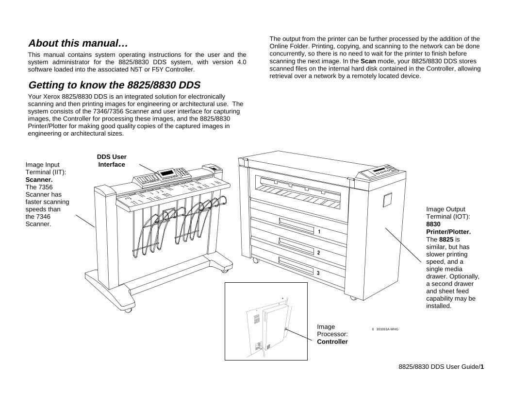
Getting to know the 8825/8830 DDSYour Xerox 8825/8830 DDS is an integrated solution for electronicallyscanning and then printing images for engineering or architectural use. Thesystem consists of the 7346/7356 Scanner and user interface for capturingimages, the Controller for processing these images, and the 8825/8830Printer/Plotter for making good quality copies of the captured images inengineering or architectural sizes.
The output from the printer can be further processed by the addition of theOnline Folder. Printing, copying, and scanning to the network can be doneconcurrently, so there is no need to wait for the printer to finish beforescanning the next image. In the Scan mode, your 8825/8830 DDS storesscanned files on the internal hard disk contained in the Controller, allowingretrieval over a network by a remotely located device.
301001A-WHG0
Image InputTerminal (IIT):Scanner.The 7356Scanner hasfaster scanningspeeds thanthe 7346Scanner.
Image OutputTerminal (IOT):8830Printer/Plotter.The 8825 issimilar, but hasslower printingspeed, and asingle mediadrawer. Optionally,a second drawerand sheet feedcapability may beinstalled.
DDS UserInterface
ImageProcessor:Controller
8825/8830 DDS User Guide/2
The 8825/8830 DDS contains AutoIQ technology from Xerox EngineeringSystems. AutoIQ enables the system to intelligently examine a sample ofthe document and to automatically make the image quality adjustments thatyield a good copy even from poor original documents. AutoIQ alsoautomatically detects the width and adjusts the centering of a scannedoriginal for most documents.On the next pages, we’ll look at each of the three components of the8825/8830 DDS system. Then, you will learn how to ensure that the8825/8830 DDS is ready to operate.
8825/8830 DDS User Guide/3
Getting to know the 8825/8830 DDS
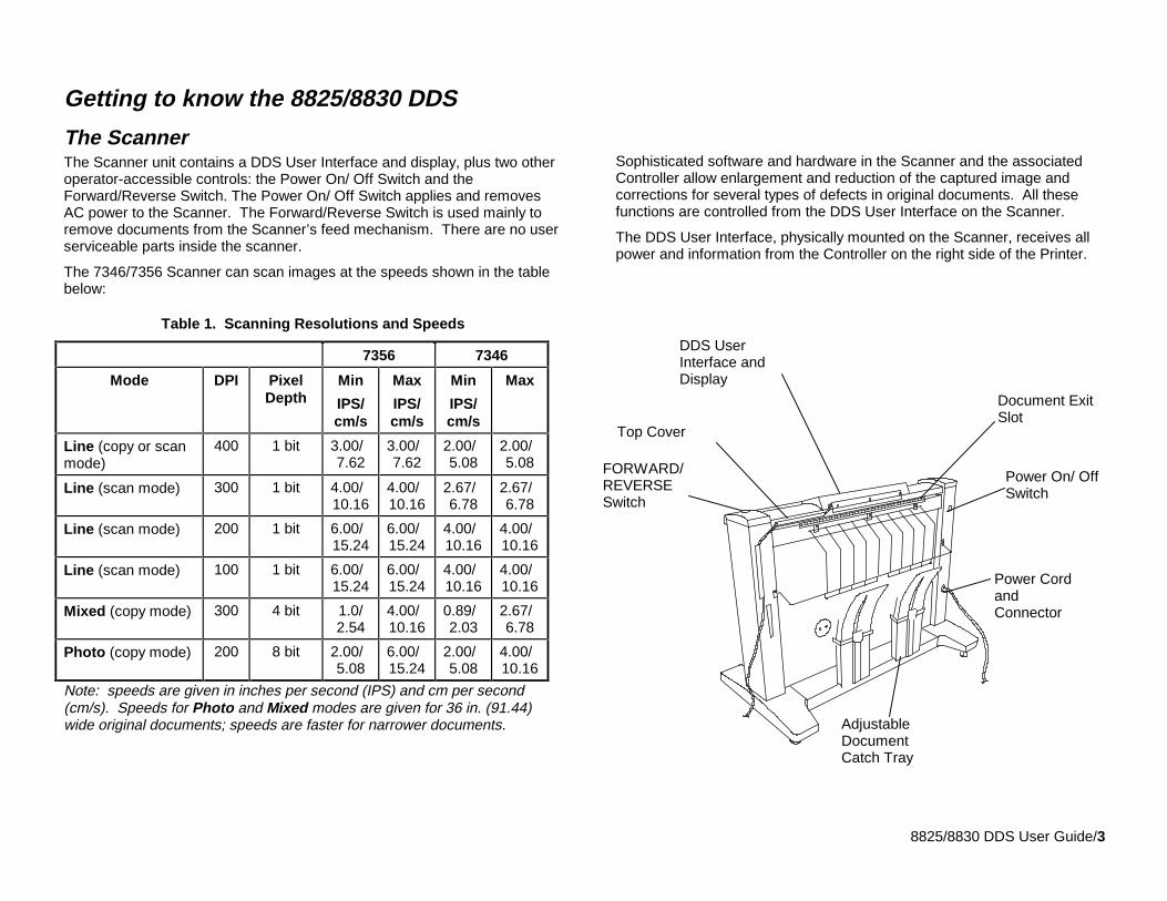
The ScannerThe Scanner unit contains a DDS User Interface and display, plus two otheroperator-accessible controls: the Power On/ Off Switch and theForward/Reverse Switch. The Power On/ Off Switch applies and removesAC power to the Scanner. The Forward/Reverse Switch is used mainly toremove documents from the Scanner’s feed mechanism. There are no userserviceable parts inside the scanner.
The 7346/7356 Scanner can scan images at the speeds shown in the tablebelow:
Table 1. Scanning Resolutions and Speeds
7356 7346
Mode DPI PixelDepth
Min
IPS/cm/s
Max
IPS/cm/s
Min
IPS/cm/s
Max
Line (copy or scanmode)
400 1 bit 3.00/7.62
3.00/7.62
2.00/5.08
2.00/5.08
Line (scan mode) 300 1 bit 4.00/10.16
4.00/10.16
2.67/6.78
2.67/6.78
Line (scan mode) 200 1 bit 6.00/15.24
6.00/15.24
4.00/10.16
4.00/10.16
Line (scan mode) 100 1 bit 6.00/15.24
6.00/15.24
4.00/10.16
4.00/10.16
Mixed (copy mode) 300 4 bit 1.0/2.54
4.00/10.16
0.89/2.03
2.67/6.78
Photo (copy mode) 200 8 bit 2.00/5.08
6.00/15.24
2.00/5.08
4.00/10.16
Note: speeds are given in inches per second (IPS) and cm per second(cm/s). Speeds for Photo and Mixed modes are given for 36 in. (91.44)wide original documents; speeds are faster for narrower documents.
Sophisticated software and hardware in the Scanner and the associatedController allow enlargement and reduction of the captured image andcorrections for several types of defects in original documents. All thesefunctions are controlled from the DDS User Interface on the Scanner.
The DDS User Interface, physically mounted on the Scanner, receives allpower and information from the Controller on the right side of the Printer.
Power On/ OffSwitch
Power CordandConnector
AdjustableDocumentCatch Tray
Document ExitSlot
Top Cover
DDS UserInterface andDisplay
FORWARD/REVERSESwitch
8825/8830 DDS User Guide/4
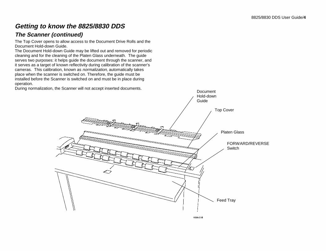
Getting to know the 8825/8830 DDSThe Scanner (continued)The Top Cover opens to allow access to the Document Drive Rolls and theDocument Hold-down Guide.The Document Hold-down Guide may be lifted out and removed for periodiccleaning and for the cleaning of the Platen Glass underneath. The guideserves two purposes: it helps guide the document through the scanner, andit serves as a target of known reflectivity during calibration of the scanner’scameras. This calibration, known as normalization, automatically takesplace when the scanner is switched on. Therefore, the guide must beinstalled before the Scanner is switched on and must be in place duringoperation.During normalization, the Scanner will not accept inserted documents.
DocumentHold-downGuide
Top Cover
Platen Glass
FORWARD/REVERSESwitch
Feed Tray
8825/8830 DDS User Guide/5
Getting to know the 8825/8830 DDSThe Scanner (continued)
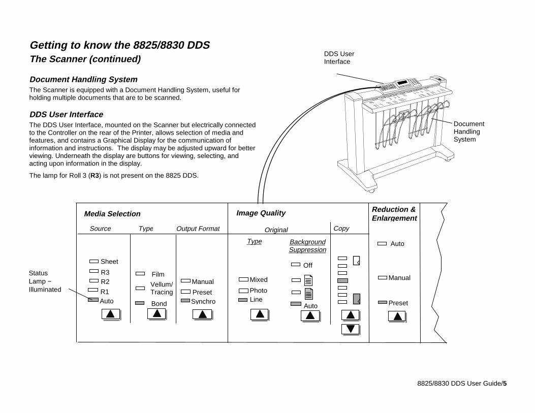
Document Handling SystemThe Scanner is equipped with a Document Handling System, useful forholding multiple documents that are to be scanned.
DDS User InterfaceThe DDS User Interface, mounted on the Scanner but electrically connectedto the Controller on the rear of the Printer, allows selection of media andfeatures, and contains a Graphical Display for the communication ofinformation and instructions. The display may be adjusted upward for betterviewing. Underneath the display are buttons for viewing, selecting, andacting upon information in the display.
The lamp for Roll 3 (R3) is not present on the 8825 DDS.
Auto
Manual
Original Copy
Image Quality Reduction &Enlargement
Preset
Type
Mixed
LinePhoto
BackgroundSuppression
Auto
OffFilm
BondAuto
R2R3
Preset
Media Selection
Source Type Output Format
Sheet
Synchro
Manual
R1Vellum/Tracing
StatusLamp −Illuminated
DDS UserInterface
DocumentHandlingSystem
8825/8830 DDS User Guide/6
Getting to know the 8825/8830 DDSThe Scanner
DDS User Interface (continued)
Option keys and Feature keys
The left half of the DDS User Interface contains the keys for selection ofoptions and is divided into three areas: Media Selection, Image Quality,and Reduction & Enlargement. Status Indicator Lamps illuminate to showwhich selections have been made.
The Features keys are found to the right of the Display. Features areenabled by pressing the corresponding feature key. If the feature has anassociated screen, then that screen will be displayed when the key ispressed. If any features are then changed from the default state, thecorresponding status lamp is illuminated next to the key.
Pressing the C/CA key on the numeric keypad twice returns all features tothe default state, and the corresponding status lamp is extinguished.
If there is no associated screen for a feature, then pressing that feature keyeither alternately switches the feature on or off, or selects one of a list ofpossible options. When a feature is enabled, the corresponding status lampis illuminated.
If the BEEP function is enabled (factory default), a beep sound will be heardwhen a key is pressed. If an improper key is pressed, a multiple beep soundwill be heard.
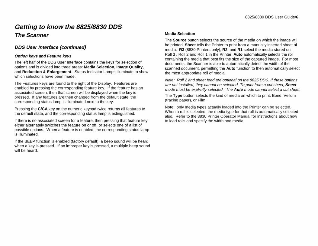
Media Selection
The Source button selects the source of the media on which the image willbe printed. Sheet tells the Printer to print from a manually inserted sheet ofmedia. R3 (8830 Printers only), R2, and R1 select the media stored onRoll 3 , Roll 2 and Roll 1 in the Printer. Auto automatically selects the rollcontaining the media that best fits the size of the captured image. For mostdocuments, the Scanner is able to automatically detect the width of thescanned document, permitting the Auto function to then automatically selectthe most appropriate roll of media.
Note: Roll 2 and sheet feed are optional on the 8825 DDS. If these optionsare not installed, they cannot be selected. To print from a cut sheet, Sheetmode must be explicitly selected. The Auto mode cannot select a cut sheet.
The Type button selects the kind of media on which to print: Bond, Vellum(tracing paper), or Film.
Note: only media types actually loaded into the Printer can be selected.When a roll is selected, the media type for that roll is automatically selectedalso. Refer to the 8830 Printer Operator Manual for instructions about howto load rolls and specify the width and media
8825/8830 DDS User Guide/7
Getting to know the 8825/8830 DDSThe Scanner
DDS User Interface (continued)Option keys and Feature keys
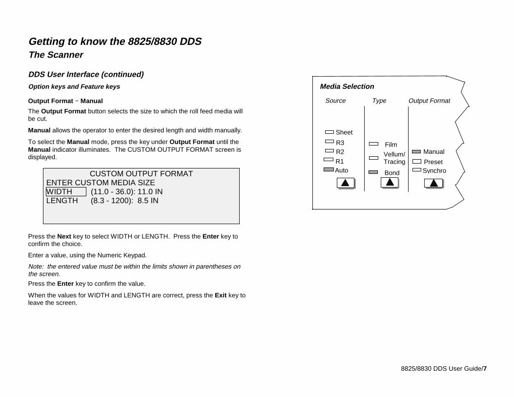
Output Format − Manual
The Output Format button selects the size to which the roll feed media willbe cut.
Manual allows the operator to enter the desired length and width manually.
To select the Manual mode, press the key under Output Format until theManual indicator illuminates. The CUSTOM OUTPUT FORMAT screen isdisplayed.
Press the Next key to select WIDTH or LENGTH. Press the Enter key toconfirm the choice.
Enter a value, using the Numeric Keypad.
Note: the entered value must be within the limits shown in parentheses onthe screen.
Press the Enter key to confirm the value.
When the values for WIDTH and LENGTH are correct, press the Exit key toleave the screen.
Film
BondAuto
R2R3
Preset
Media Selection
Source Type Output Format
Sheet
Synchro
Manual
R1Vellum/Tracing
CUSTOM OUTPUT FORMAT ENTER CUSTOM MEDIA SIZE WIDTH (11.0 - 36.0): 11.0 IN LENGTH (8.3 - 1200): 8.5 IN
8825/8830 DDS User Guide/8
Getting to know the 8825/8830 DDSThe Scanner
DDS User Interface
Option keys and Feature keys (continued)
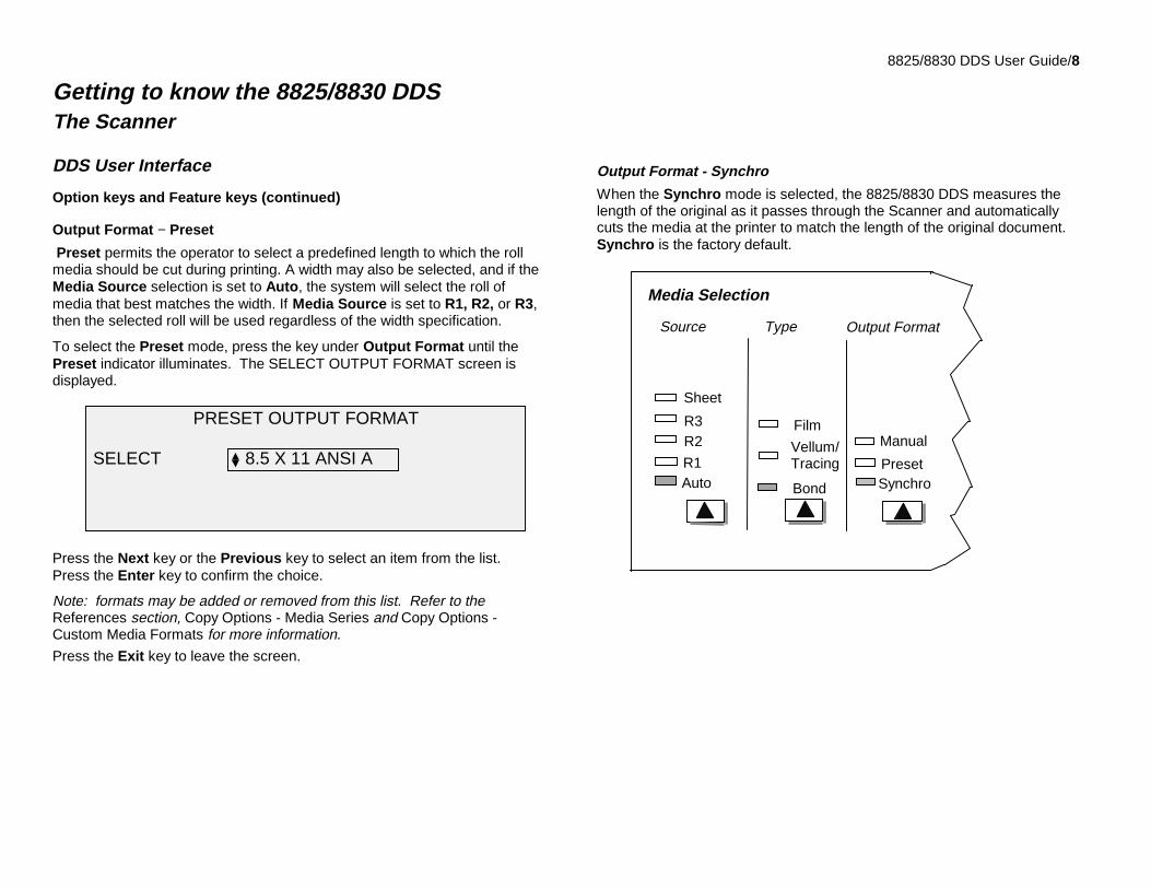
Output Format − Preset
Preset permits the operator to select a predefined length to which the rollmedia should be cut during printing. A width may also be selected, and if theMedia Source selection is set to Auto, the system will select the roll ofmedia that best matches the width. If Media Source is set to R1, R2, or R3,then the selected roll will be used regardless of the width specification.
To select the Preset mode, press the key under Output Format until thePreset indicator illuminates. The SELECT OUTPUT FORMAT screen isdisplayed.
Press the Next key or the Previous key to select an item from the list.Press the Enter key to confirm the choice.
Note: formats may be added or removed from this list. Refer to theReferences section, Copy Options - Media Series and Copy Options -Custom Media Formats for more information.
Press the Exit key to leave the screen.
Output Format - Synchro
When the Synchro mode is selected, the 8825/8830 DDS measures thelength of the original as it passes through the Scanner and automaticallycuts the media at the printer to match the length of the original document.Synchro is the factory default.
Film
BondAuto
R2R3
Preset
Media Selection
Source Type Output Format
Sheet
Synchro
Manual
R1Vellum/Tracing
PRESET OUTPUT FORMAT
SELECT 8.5 X 11 ANSI A
8825/8830 DDS User Guide/9
Getting to know the 8825/8830 DDSThe Scanner
DDS User InterfaceOption and Feature keys (continued)
Image Quality
The Image Quality portion of the DDS User Interface allows the operator tomake corrective adjustments to the image and extract the best possible copyquality from an original document.
The Type area allows selection of Mixed, Photo, or Line documents. SelectLine (factory default) for an image containing text, line art, or a mixture ofthese. Select Photo when the document contains a grayscale or colorimage, such as a photograph. Select Mixed if the document contains amixture of photographic and line images, or halftone images.
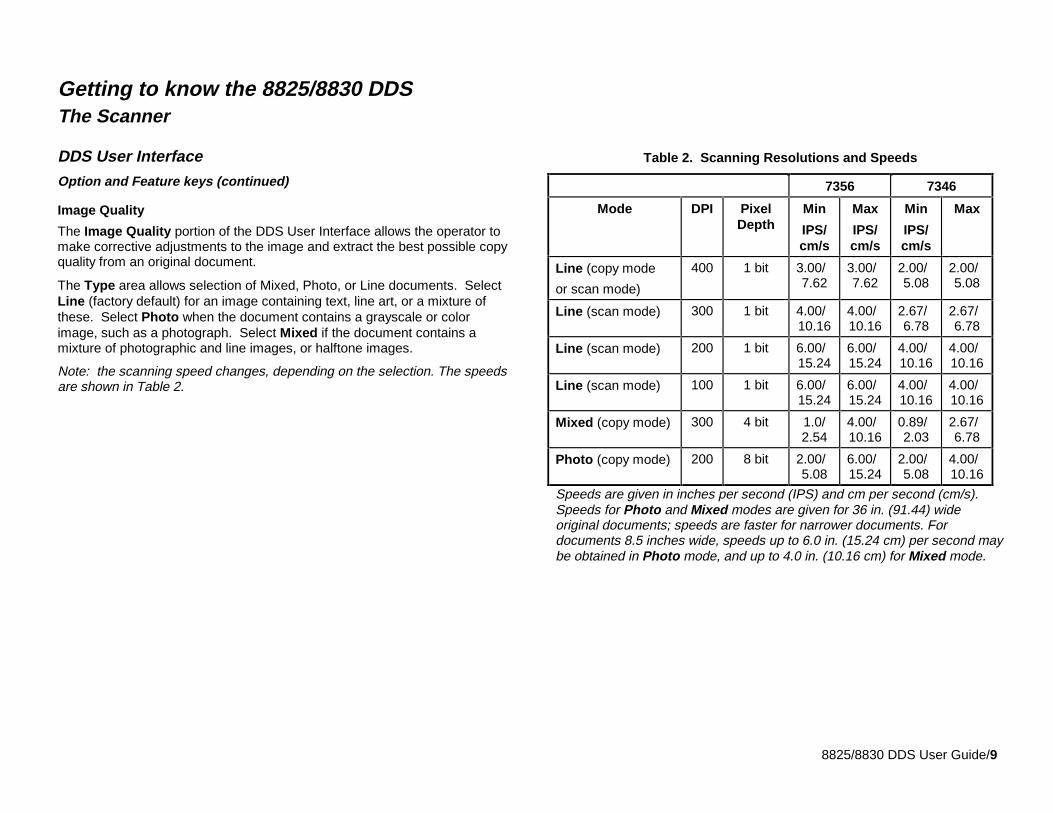
Note: the scanning speed changes, depending on the selection. The speedsare shown in Table 2.
Table 2. Scanning Resolutions and Speeds
7356 7346
Mode DPI PixelDepth
Min
IPS/cm/s
Max
IPS/cm/s
Min
IPS/cm/s
Max
Line (copy mode
or scan mode)
400 1 bit 3.00/7.62
3.00/7.62
2.00/5.08
2.00/5.08
Line (scan mode) 300 1 bit 4.00/10.16
4.00/10.16
2.67/6.78
2.67/6.78
Line (scan mode) 200 1 bit 6.00/15.24
6.00/15.24
4.00/10.16
4.00/10.16
Line (scan mode) 100 1 bit 6.00/15.24
6.00/15.24
4.00/10.16
4.00/10.16
Mixed (copy mode) 300 4 bit 1.0/2.54
4.00/10.16
0.89/2.03
2.67/6.78
Photo (copy mode) 200 8 bit 2.00/5.08
6.00/15.24
2.00/5.08
4.00/10.16
Speeds are given in inches per second (IPS) and cm per second (cm/s).Speeds for Photo and Mixed modes are given for 36 in. (91.44) wideoriginal documents; speeds are faster for narrower documents. Fordocuments 8.5 inches wide, speeds up to 6.0 in. (15.24 cm) per second maybe obtained in Photo mode, and up to 4.0 in. (10.16 cm) for Mixed mode.
8825/8830 DDS User Guide/10
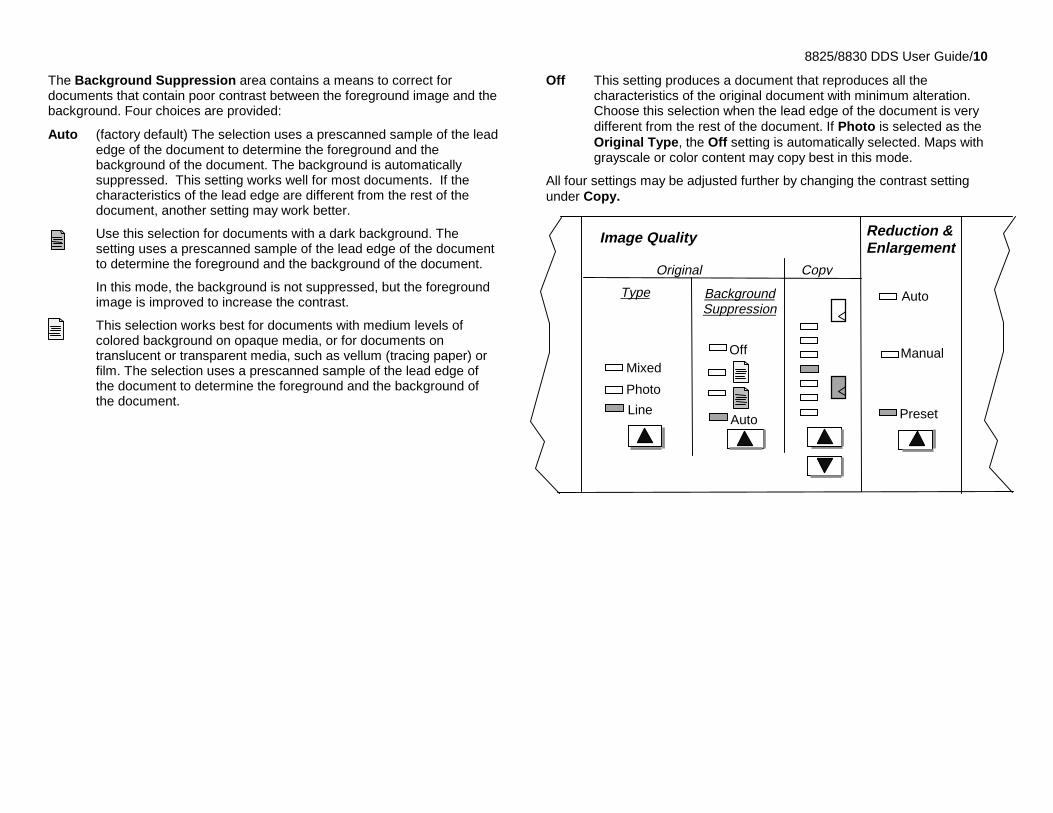
The Background Suppression area contains a means to correct fordocuments that contain poor contrast between the foreground image and thebackground. Four choices are provided:
Auto (factory default) The selection uses a prescanned sample of the leadedge of the document to determine the foreground and thebackground of the document. The background is automaticallysuppressed. This setting works well for most documents. If thecharacteristics of the lead edge are different from the rest of thedocument, another setting may work better.
Use this selection for documents with a dark background. Thesetting uses a prescanned sample of the lead edge of the documentto determine the foreground and the background of the document.
In this mode, the background is not suppressed, but the foregroundimage is improved to increase the contrast.
This selection works best for documents with medium levels ofcolored background on opaque media, or for documents ontranslucent or transparent media, such as vellum (tracing paper) orfilm. The selection uses a prescanned sample of the lead edge ofthe document to determine the foreground and the background ofthe document.
Off This setting produces a document that reproduces all thecharacteristics of the original document with minimum alteration.Choose this selection when the lead edge of the document is verydifferent from the rest of the document. If Photo is selected as theOriginal Type, the Off setting is automatically selected. Maps withgrayscale or color content may copy best in this mode.
All four settings may be adjusted further by changing the contrast settingunder Copy.
Line
Off
Auto
Manual
Original
Image Quality Reduction &Enlargement
Preset
Type
Mixed
Photo
BackgroundSuppression
Copy
Auto
8825/8830 DDS User Guide/11
Getting to know the 8825/8830 DDSThe Scanner
DDS User InterfaceOption and Feature keys (continued)
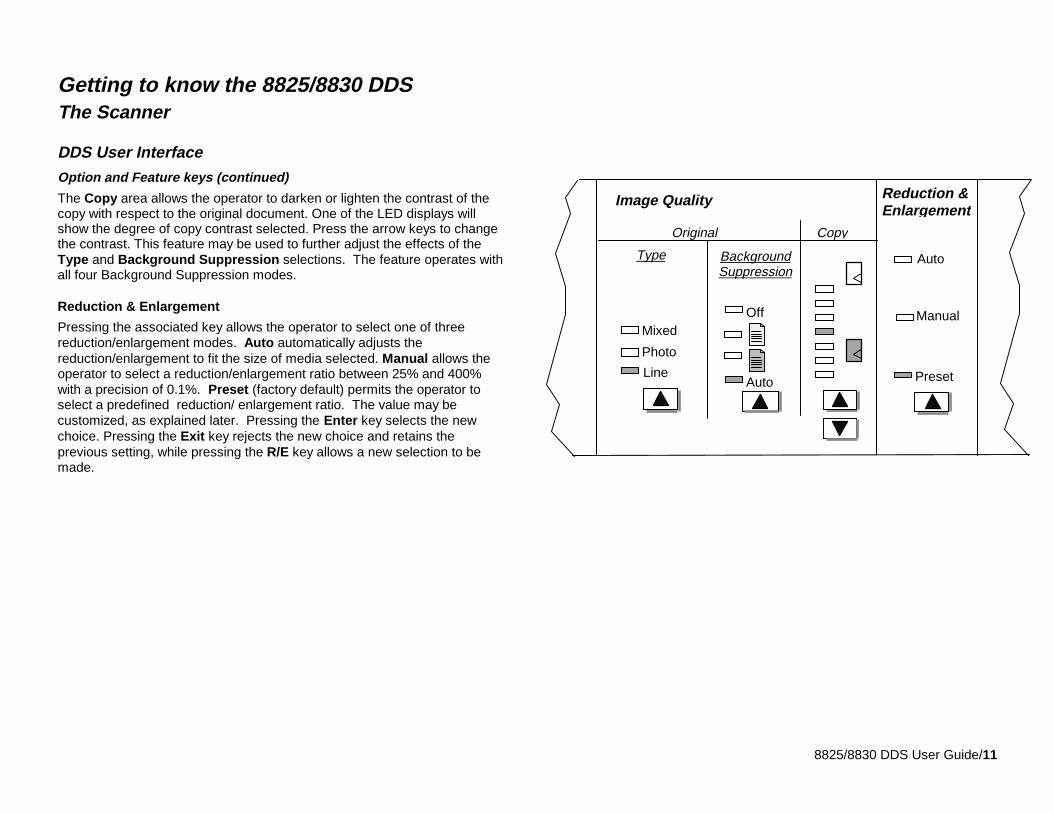
The Copy area allows the operator to darken or lighten the contrast of thecopy with respect to the original document. One of the LED displays willshow the degree of copy contrast selected. Press the arrow keys to changethe contrast. This feature may be used to further adjust the effects of theType and Background Suppression selections. The feature operates withall four Background Suppression modes.
Reduction & Enlargement
Pressing the associated key allows the operator to select one of threereduction/enlargement modes. Auto automatically adjusts thereduction/enlargement to fit the size of media selected. Manual allows theoperator to select a reduction/enlargement ratio between 25% and 400%with a precision of 0.1%. Preset (factory default) permits the operator toselect a predefined reduction/ enlargement ratio. The value may becustomized, as explained later. Pressing the Enter key selects the newchoice. Pressing the Exit key rejects the new choice and retains theprevious setting, while pressing the R/E key allows a new selection to bemade.
Line
Off
Auto
Manual
Original
Image Quality Reduction &Enlargement
Preset
Type
Mixed
Photo
BackgroundSuppression
Copy
Auto
8825/8830 DDS User Guide/12
Getting to know the 8825/8830 DDSThe Scanner
DDS User Interface (continued)
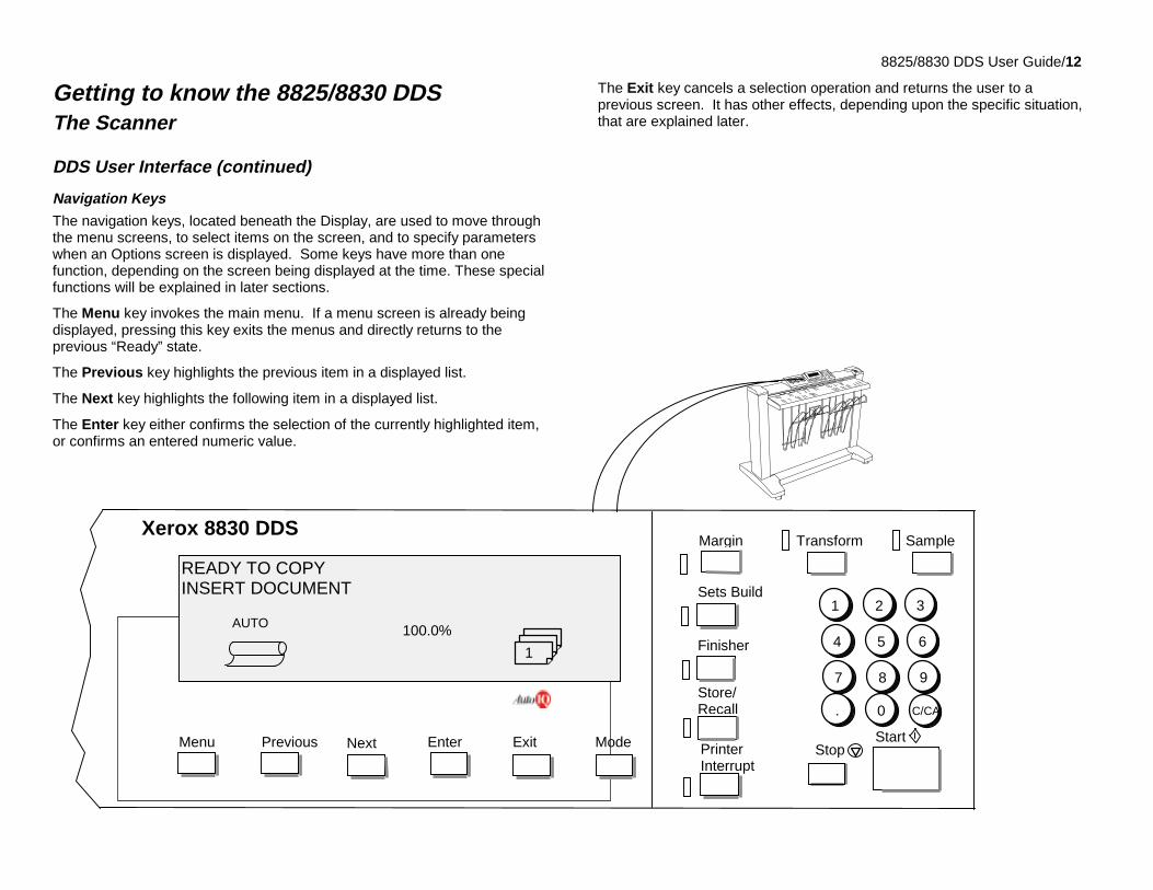
Navigation Keys
The navigation keys, located beneath the Display, are used to move throughthe menu screens, to select items on the screen, and to specify parameterswhen an Options screen is displayed. Some keys have more than onefunction, depending on the screen being displayed at the time. These specialfunctions will be explained in later sections.
The Menu key invokes the main menu. If a menu screen is already beingdisplayed, pressing this key exits the menus and directly returns to theprevious “Ready” state.
The Previous key highlights the previous item in a displayed list.
The Next key highlights the following item in a displayed list.
The Enter key either confirms the selection of the currently highlighted item,or confirms an entered numeric value.
The Exit key cancels a selection operation and returns the user to aprevious screen. It has other effects, depending upon the specific situation,that are explained later.
Xerox 8830 DDSTransform Sample
StopStart
1 2 3
4 5 6
7 8 9
. 0 C/CA
PrinterInterrupt
Store/Recall
Margin
Sets Build
Finisher
Previous Enter Exit ModeMenu Next
READY TO COPYINSERT DOCUMENT
100.0%AUTO
1
8825/8830 DDS User Guide/13
Getting to know the 8825/8830 DDSThe Scanner
DDS User Interface (continued)
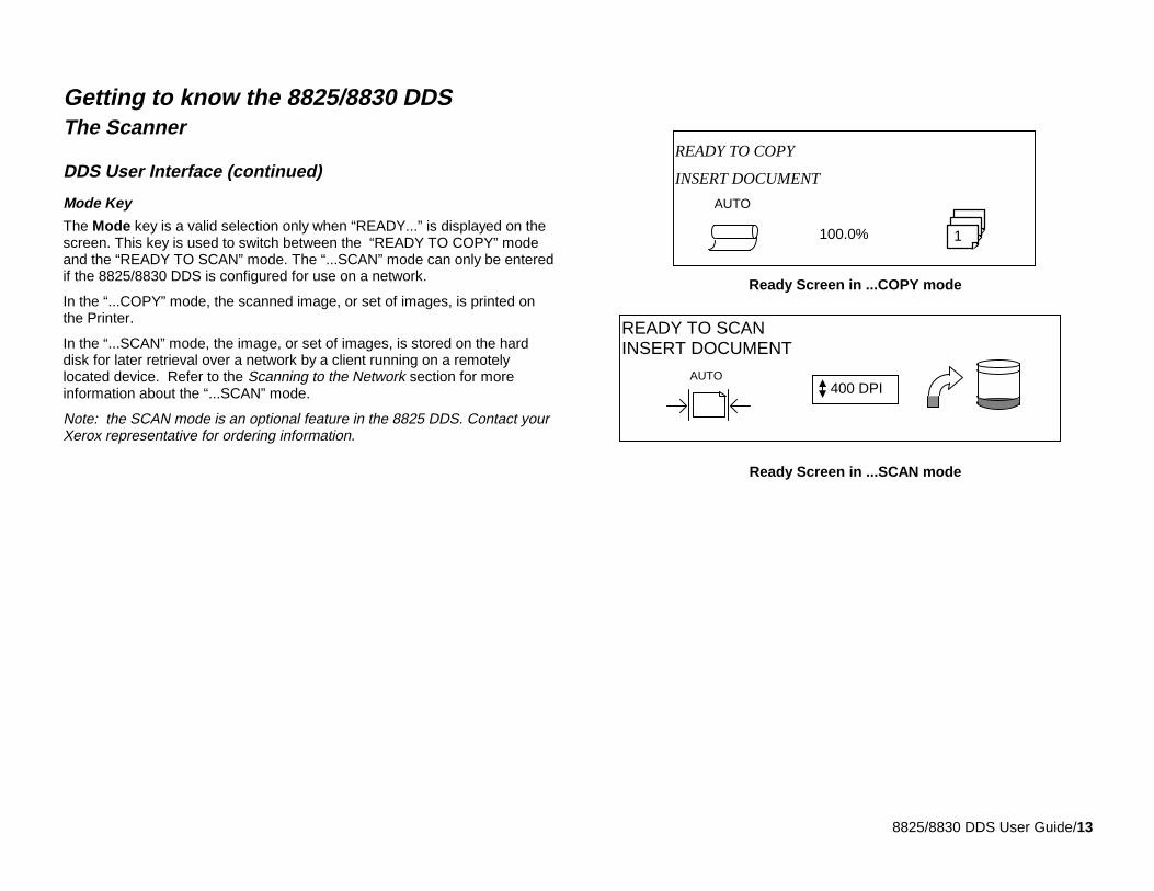
Mode Key
The Mode key is a valid selection only when “READY...” is displayed on thescreen. This key is used to switch between the “READY TO COPY” modeand the “READY TO SCAN” mode. The “...SCAN” mode can only be enteredif the 8825/8830 DDS is configured for use on a network.
In the “...COPY” mode, the scanned image, or set of images, is printed onthe Printer.
In the “...SCAN” mode, the image, or set of images, is stored on the harddisk for later retrieval over a network by a client running on a remotelylocated device. Refer to the Scanning to the Network section for moreinformation about the “...SCAN” mode.
Note: the SCAN mode is an optional feature in the 8825 DDS. Contact yourXerox representative for ordering information.
Ready Screen in ...COPY mode
Ready Screen in ...SCAN mode
READY TO COPY
INSERT DOCUMENT
100.0%
AUTO
1
READY TO SCANINSERT DOCUMENT
AUTO 400 DPI
8825/8830 DDS User Guide/14
Getting to know the 8825/8830 DDSThe Scanner
DDS User Interface (continued)
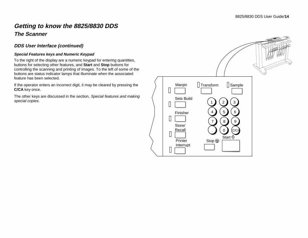
Special Features keys and Numeric Keypad
To the right of the display are a numeric keypad for entering quantities,buttons for selecting other features, and Start and Stop buttons forcontrolling the scanning and printing of images. To the left of some of thebuttons are status indicator lamps that illuminate when the associatedfeature has been selected.
If the operator enters an incorrect digit, it may be cleared by pressing theC/CA key once.
The other keys are discussed in the section, Special features and makingspecial copies.
PrinterInterrupt
SampleTransform
StopStart
1 2 3
4 5 6
7 8 9
. 0 C/CA
Store/Recall
Margin
Sets Build
Finisher
8825/8830 DDS User Guide/15
Getting to know the 8825/8830 DDS
Power OnThe components of the 8825/ 8830 DDS should be switched on in thefollowing order:
• Scanner
• Controller (circuit breaker, if so equipped)
• Printer.
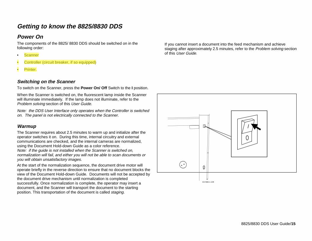
Switching on the ScannerTo switch on the Scanner, press the Power On/ Off Switch to the I position.
When the Scanner is switched on, the fluorescent lamp inside the Scannerwill illuminate immediately. If the lamp does not illuminate, refer to theProblem solving section of this User Guide.
Note: the DDS User Interface only operates when the Controller is switchedon. The panel is not electrically connected to the Scanner.
WarmupThe Scanner requires about 2.5 minutes to warm up and initialize after theoperator switches it on. During this time, internal circuitry and externalcommunications are checked, and the internal cameras are normalized,using the Document Hold-down Guide as a color reference.Note: if the guide is not installed when the Scanner is switched on,normalization will fail, and either you will not be able to scan documents oryou will obtain unsatisfactory images.At the start of the normalization sequence, the document drive motor willoperate briefly in the reverse direction to ensure that no document blocks theview of the Document Hold-down Guide. Documents will not be accepted bythe document drive mechanism until normalization is completedsuccessfully. Once normalization is complete, the operator may insert adocument, and the Scanner will transport the document to the startingposition. This transportation of the document is called staging.
If you cannot insert a document into the feed mechanism and achievestaging after approximately 2.5 minutes, refer to the Problem solving sectionof this User Guide.
8825/8830 DDS User Guide/16
Getting to know the 8825/8830 DDS(continued)
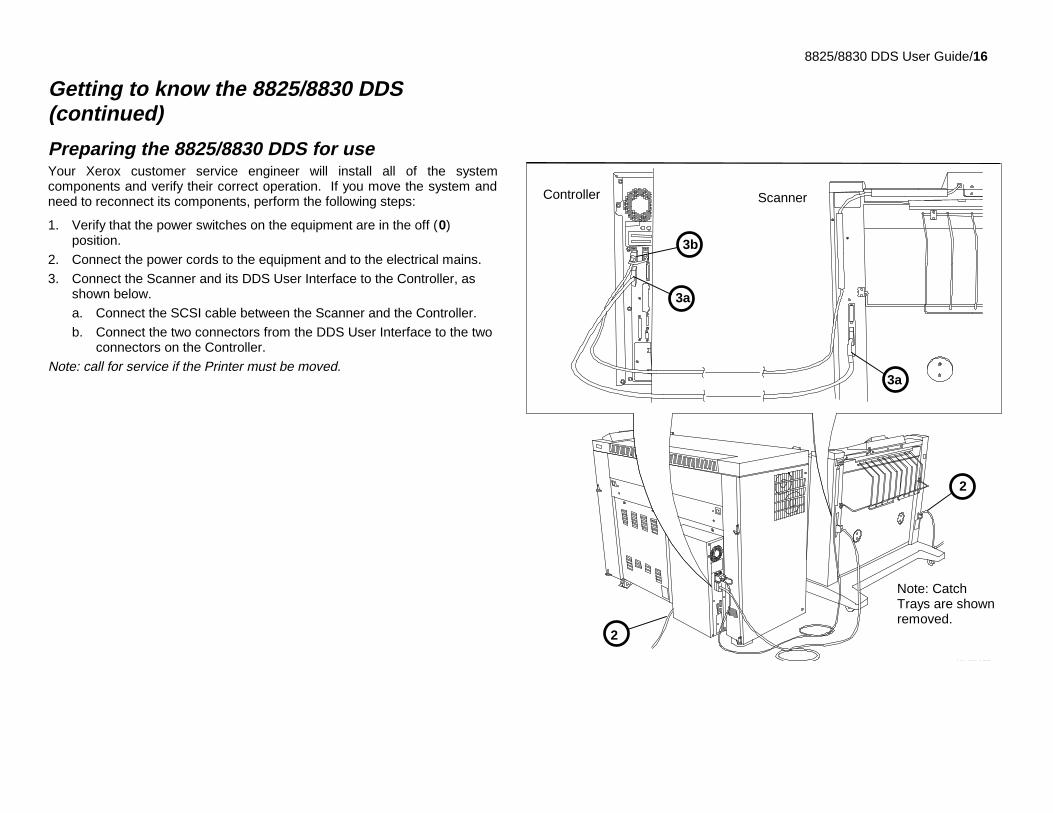
Preparing the 8825/8830 DDS for useYour Xerox customer service engineer will install all of the systemcomponents and verify their correct operation. If you move the system andneed to reconnect its components, perform the following steps:
1. Verify that the power switches on the equipment are in the off (0)position.
2. Connect the power cords to the equipment and to the electrical mains.
3. Connect the Scanner and its DDS User Interface to the Controller, asshown below.
a. Connect the SCSI cable between the Scanner and the Controller.
b. Connect the two connectors from the DDS User Interface to the twoconnectors on the Controller.
Note: call for service if the Printer must be moved.
301002A WHG0
2
3a
3a
3b
2
ScannerController
Note: CatchTrays are shownremoved.
8825/8830 DDS User Guide/17
Getting to know the 8825/8830 DDS(continued)
Power On
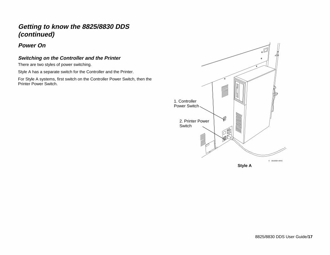
Switching on the Controller and the PrinterThere are two styles of power switching.
Style A has a separate switch for the Controller and the Printer.
For Style A systems, first switch on the Controller Power Switch, then thePrinter Power Switch.
Style A301008A-WHG0
1. ControllerPower Switch
2. Printer PowerSwitch
8825/8830 DDS User Guide/18
Getting to know the 8825/8830 DDS
Power On
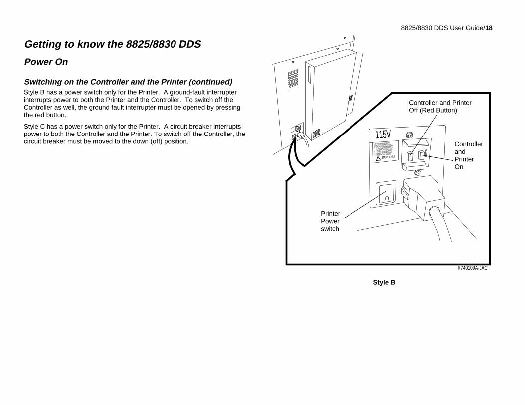
Switching on the Controller and the Printer (continued)Style B has a power switch only for the Printer. A ground-fault interrupterinterrupts power to both the Printer and the Controller. To switch off theController as well, the ground fault interrupter must be opened by pressingthe red button.
Style C has a power switch only for the Printer. A circuit breaker interruptspower to both the Controller and the Printer. To switch off the Controller, thecircuit breaker must be moved to the down (off) position.
740109A-JAC0
115V1. ERJNERHERGIJHBERFF
2. DFNETRYKFGNBKERKGH
3. WRLFN 345YRYRTMBOTP
FKGEGIHRTHKERFKGJ
FDMGNRTHGIPRTHIPE
4. FSG ETGHIGJNBMETRG
DFGNETGHRITHIEQRGL
5. NFDBKJETGITHIJRTHJ
EMERGENCY
Style B
PrinterPowerswitch
Controller and PrinterOff (Red Button)
ControllerandPrinterOn
8825/8830 DDS User Guide/19
Getting to know the 8825/8830 DDS
Power offTo switch off the Scanner, press the Power On/ Off Switch to the O position.If the Scanner is switched off, communications to the Scanner will be lost.To recover, the Printer and the Controller must also be switched off. Then,switch on the Scanner, followed by the Controller and the Printer.
The Controller and the PrinterPlease refer to the User Guide for the 8830 Printer for instructions forinstalling media and other consumable supplies as well as detailed operatinginstructions for the Printer. These instructions are applicable to the 8825printer, also.
The 8825/8830 Controller Setup Guide contains details on configuring all thesettings for the Controller.
The 8825/8830 Network Administrator’s Guide contains valuable informationabout network connectivity and help in determining network connectivitysettings.
8825/8830 DDS User Guide/20
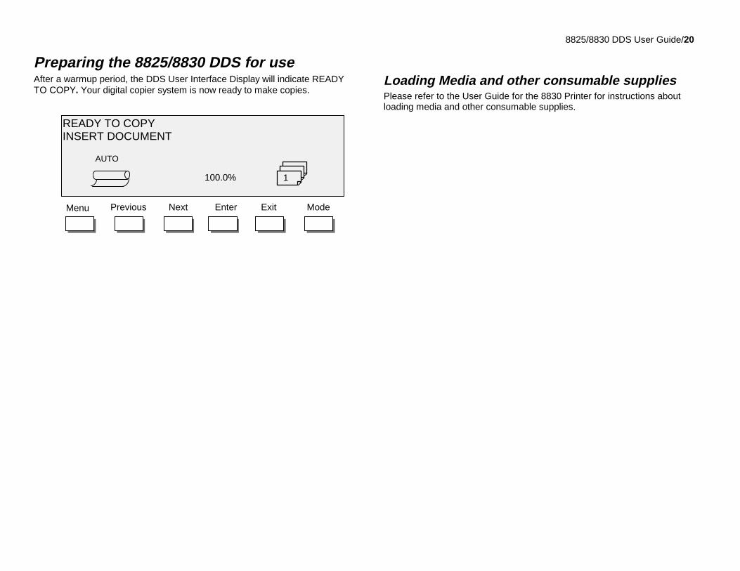
Preparing the 8825/8830 DDS for useAfter a warmup period, the DDS User Interface Display will indicate READYTO COPY. Your digital copier system is now ready to make copies.
Loading Media and other consumable suppliesPlease refer to the User Guide for the 8830 Printer for instructions aboutloading media and other consumable supplies.
EnterNext ExitPrevious ModeMenu
READY TO COPYINSERT DOCUMENT
AUTO
1100.0%
8825/8830 DDS User Guide/21
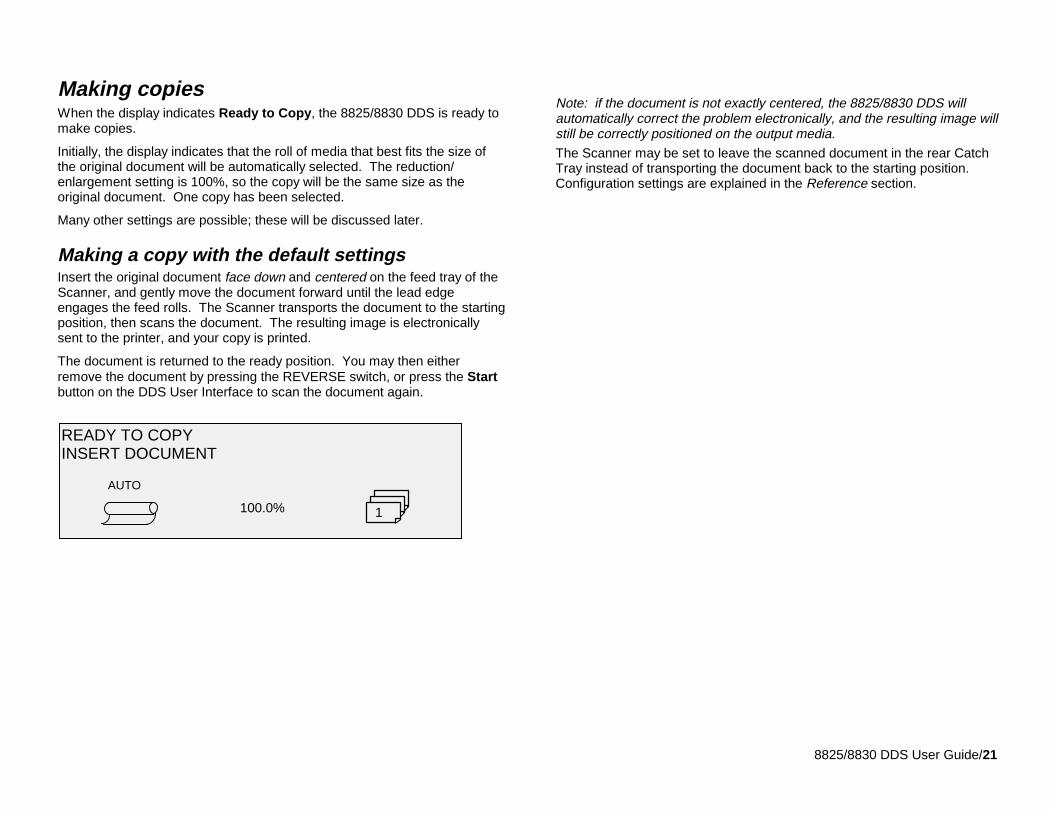
Making copiesWhen the display indicates Ready to Copy, the 8825/8830 DDS is ready tomake copies.
Initially, the display indicates that the roll of media that best fits the size ofthe original document will be automatically selected. The reduction/enlargement setting is 100%, so the copy will be the same size as theoriginal document. One copy has been selected.
Many other settings are possible; these will be discussed later.
Making a copy with the default settingsInsert the original document face down and centered on the feed tray of theScanner, and gently move the document forward until the lead edgeengages the feed rolls. The Scanner transports the document to the startingposition, then scans the document. The resulting image is electronicallysent to the printer, and your copy is printed.
The document is returned to the ready position. You may then eitherremove the document by pressing the REVERSE switch, or press the Startbutton on the DDS User Interface to scan the document again.
Note: if the document is not exactly centered, the 8825/8830 DDS willautomatically correct the problem electronically, and the resulting image willstill be correctly positioned on the output media.The Scanner may be set to leave the scanned document in the rear CatchTray instead of transporting the document back to the starting position.Configuration settings are explained in the Reference section.
READY TO COPYINSERT DOCUMENT
100.0%
AUTO
1
8825/8830 DDS User Guide/22
Making copies
Adjusting Image QualitySeveral adjustments are available to correct the image for problems in theoriginal document.
The key to effectively using the Image Quality adjustments is to first classifyyour documents as Line, Mixed, or Photo. Then, classify them according tothe characteristics of the foreground image and background.
Line documents contain lines or text against a highly contrastedbackground.
Mixed documents contain both line elements and photo elements, orhalftone images.
Photo documents are continuous-tone or grayscale images.
Note: for Photo documents, no background suppression is allowed.Background Suppression is automatically set to Off.
Set the Type setting to agree with one of the three classifications.
Next, for Line or Mixed documents, determine the background.
Is the background white, light or dark?
Are the lines or text black or colored?
Finally, determine if the document is inverted (white or light foregroundagainst dark background). If the document is inverted, refer to Specialfeatures and making special copies – Transform Key for instructions on theINVERT function.
8825/8830 DDS User Guide/23
Making copiesAdjusting Image Quality (continued)
Some documents require additional adjustments to obtain the best copyquality. Documents of good quality will usually give good copies on the firstattempt. Documents of bad quality may require more than one attempt,using different settings, to obtain the best copy quality.
• What is a good quality document? describes the characteristics ofdocuments that are easiest to scan.
• What is a bad quality document? shows several examples of problemdocuments that require more attention.
• Scanning lists the different approaches to take when scanning goodquality or bad quality documents.
• Preparing documents provides tips for getting documents ready toscan and for organizing them for efficient scanning.
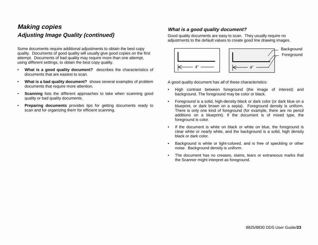
What is a good quality document?Good quality documents are easy to scan. They usually require noadjustments to the default values to create good line drawing images.
A good quality document has all of these characteristics:
• High contrast between foreground (the image of interest) andbackground. The foreground may be color or black.
• Foreground is a solid, high-density black or dark color (or dark blue on ablueprint, or dark brown on a sepia). Foreground density is uniform.There is only one kind of foreground (for example, there are no penciladditions on a blueprint). If the document is of mixed type, theforeground is color.
• If the document is white on black or white on blue, the foreground isclear white or nearly white, and the background is a solid, high densityblack or dark color.
• Background is white or light-colored, and is free of speckling or othernoise. Background density is uniform.
• The document has no creases, stains, tears or extraneous marks thatthe Scanner might interpret as foreground.
4” 4”
ForegroundBackground
8825/8830 DDS User Guide/24
Making copiesAdjusting Image Quality (continued)
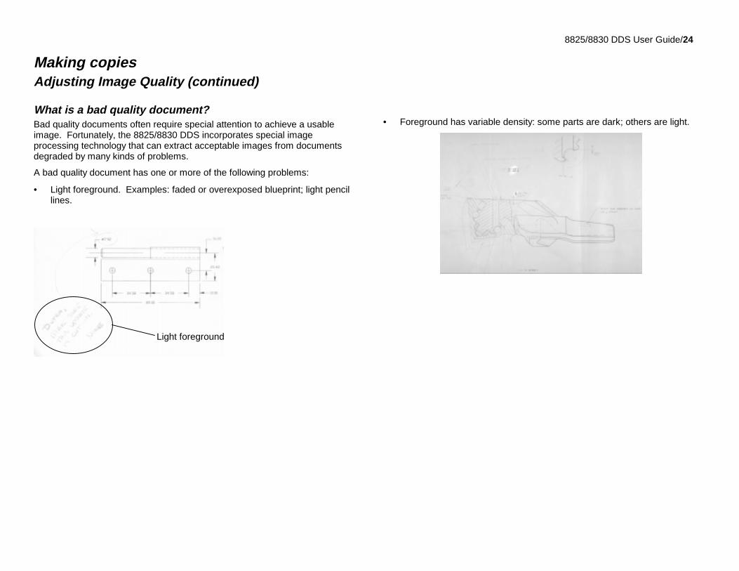
What is a bad quality document?Bad quality documents often require special attention to achieve a usableimage. Fortunately, the 8825/8830 DDS incorporates special imageprocessing technology that can extract acceptable images from documentsdegraded by many kinds of problems.
A bad quality document has one or more of the following problems:
• Light foreground. Examples: faded or overexposed blueprint; light pencillines.
• Foreground has variable density: some parts are dark; others are light.
Light foreground
8825/8830 DDS User Guide/25
Making copiesAdjusting Image Quality
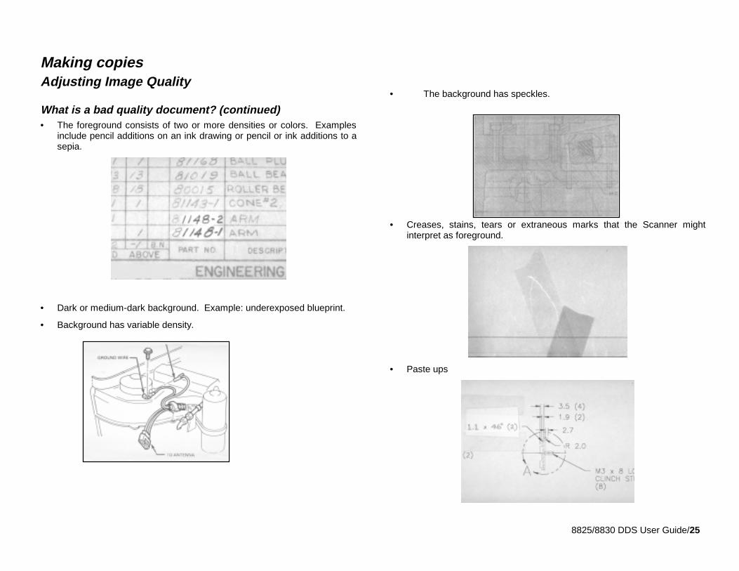
What is a bad quality document? (continued)• The foreground consists of two or more densities or colors. Examples
include pencil additions on an ink drawing or pencil or ink additions to asepia.
• Dark or medium-dark background. Example: underexposed blueprint.
• Background has variable density.
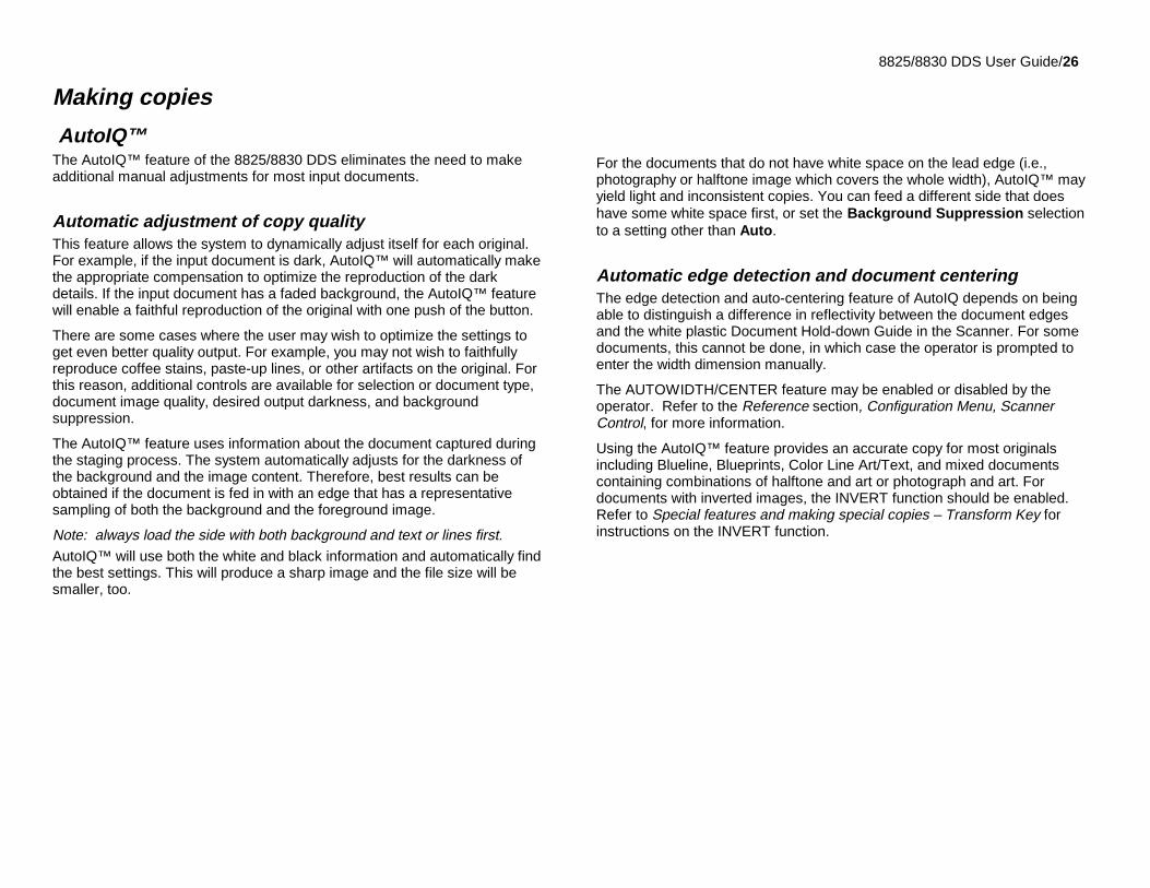
• The background has speckles.
• Creases, stains, tears or extraneous marks that the Scanner mightinterpret as foreground.
• Paste ups
8825/8830 DDS User Guide/26
Making copies
AutoIQ™The AutoIQ™ feature of the 8825/8830 DDS eliminates the need to makeadditional manual adjustments for most input documents.
Automatic adjustment of copy qualityThis feature allows the system to dynamically adjust itself for each original.For example, if the input document is dark, AutoIQ™ will automatically makethe appropriate compensation to optimize the reproduction of the darkdetails. If the input document has a faded background, the AutoIQ™ featurewill enable a faithful reproduction of the original with one push of the button.
There are some cases where the user may wish to optimize the settings toget even better quality output. For example, you may not wish to faithfullyreproduce coffee stains, paste-up lines, or other artifacts on the original. Forthis reason, additional controls are available for selection or document type,document image quality, desired output darkness, and backgroundsuppression.
The AutoIQ™ feature uses information about the document captured duringthe staging process. The system automatically adjusts for the darkness ofthe background and the image content. Therefore, best results can beobtained if the document is fed in with an edge that has a representativesampling of both the background and the foreground image.
Note: always load the side with both background and text or lines first.AutoIQ™ will use both the white and black information and automatically findthe best settings. This will produce a sharp image and the file size will besmaller, too.
For the documents that do not have white space on the lead edge (i.e.,photography or halftone image which covers the whole width), AutoIQ™ mayyield light and inconsistent copies. You can feed a different side that doeshave some white space first, or set the Background Suppression selectionto a setting other than Auto.
Automatic edge detection and document centeringThe edge detection and auto-centering feature of AutoIQ depends on beingable to distinguish a difference in reflectivity between the document edgesand the white plastic Document Hold-down Guide in the Scanner. For somedocuments, this cannot be done, in which case the operator is prompted toenter the width dimension manually.
The AUTOWIDTH/CENTER feature may be enabled or disabled by theoperator. Refer to the Reference section, Configuration Menu, ScannerControl, for more information.
Using the AutoIQ™ feature provides an accurate copy for most originalsincluding Blueline, Blueprints, Color Line Art/Text, and mixed documentscontaining combinations of halftone and art or photograph and art. Fordocuments with inverted images, the INVERT function should be enabled.Refer to Special features and making special copies – Transform Key forinstructions on the INVERT function.
8825/8830 DDS User Guide/27
Making copies
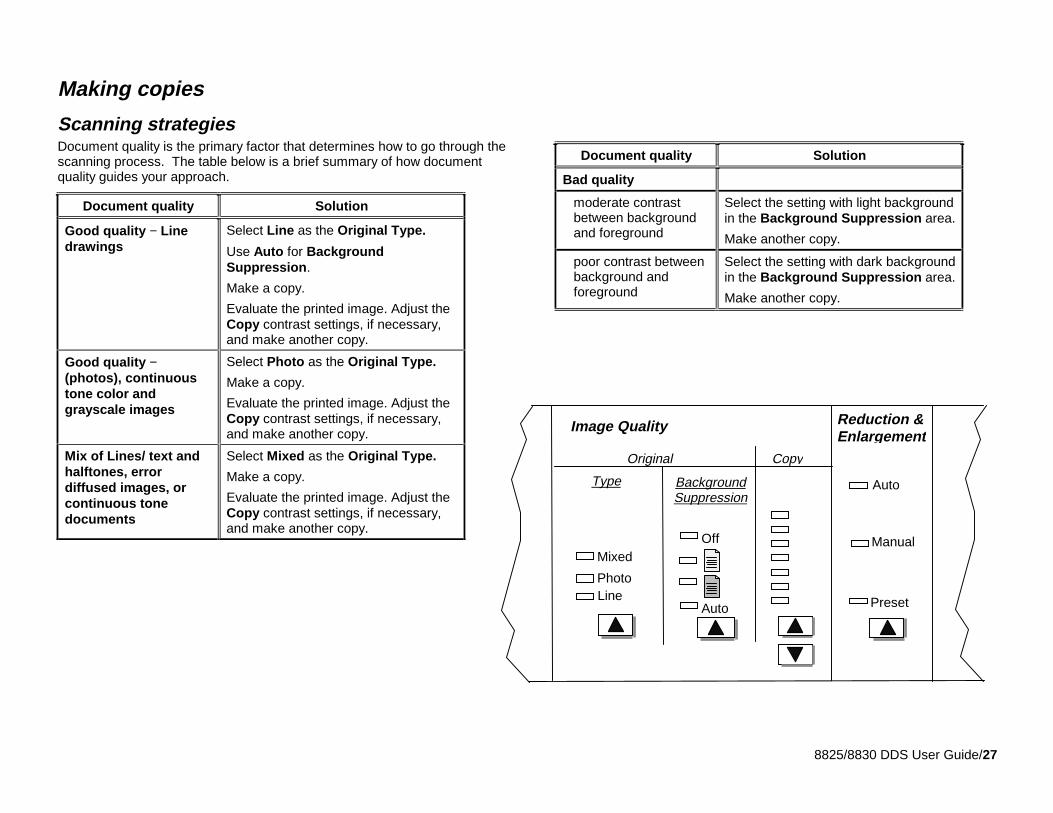
Scanning strategiesDocument quality is the primary factor that determines how to go through thescanning process. The table below is a brief summary of how documentquality guides your approach.
Document quality Solution
Good quality − Linedrawings
Select Line as the Original Type.
Use Auto for BackgroundSuppression.
Make a copy.
Evaluate the printed image. Adjust theCopy contrast settings, if necessary,and make another copy.
Good quality −(photos), continuoustone color andgrayscale images
Select Photo as the Original Type.
Make a copy.
Evaluate the printed image. Adjust theCopy contrast settings, if necessary,and make another copy.
Mix of Lines/ text andhalftones, errordiffused images, orcontinuous tonedocuments
Select Mixed as the Original Type.
Make a copy.
Evaluate the printed image. Adjust theCopy contrast settings, if necessary,and make another copy.
Document quality Solution
Bad quality
moderate contrastbetween backgroundand foreground
Select the setting with light backgroundin the Background Suppression area.
Make another copy.
poor contrast betweenbackground andforeground
Select the setting with dark backgroundin the Background Suppression area.
Make another copy.
Off
Auto
Manual
Original
Image Quality Reduction &Enlargement
Preset
Type
Mixed
LinePhoto
BackgroundSuppression
Copy
Auto
8825/8830 DDS User Guide/28
Making copies
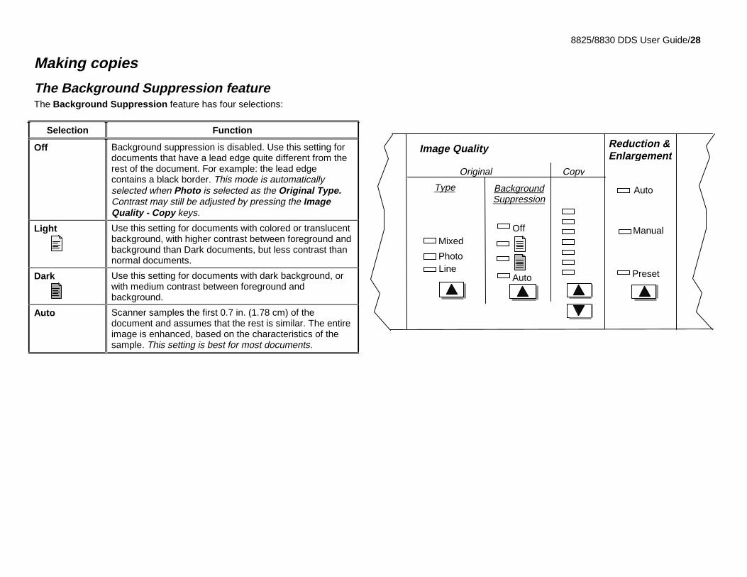
The Background Suppression featureThe Background Suppression feature has four selections:
Selection Function
Off Background suppression is disabled. Use this setting fordocuments that have a lead edge quite different from therest of the document. For example: the lead edgecontains a black border. This mode is automaticallyselected when Photo is selected as the Original Type.Contrast may still be adjusted by pressing the ImageQuality - Copy keys.
Light Use this setting for documents with colored or translucentbackground, with higher contrast between foreground andbackground than Dark documents, but less contrast thannormal documents.
Dark Use this setting for documents with dark background, orwith medium contrast between foreground andbackground.
Auto Scanner samples the first 0.7 in. (1.78 cm) of thedocument and assumes that the rest is similar. The entireimage is enhanced, based on the characteristics of thesample. This setting is best for most documents.
Off
Auto
Manual
Original
Image Quality Reduction &Enlargement
Preset
Type
Mixed
LinePhoto
BackgroundSuppression
Copy
Auto

8825/8830 DDS User Guide/29
Making copies
Preparing documents• If documents have been stored rolled up, flatten them out. They will be
much easier to handle if they have been stored flat for at least 8 hours.The longer that documents have been stored flat, the easier it will be toscan them.
• After being scanned and sent to the rear of the Scanner, rolled-updocuments may not stack reliably in the Document Catcher Assembly.
• If possible, sort the documents you are going to scan according to theseguidelines:
− First, group the documents by media type, e.g. blueprint, pencil,sepia and so forth. By scanning groups of documents that are thesame type, you will minimize the number of control changes youmake with the Image Quality controls.
− Next, divide the documents in each media type group into “good”and “bad” piles based on your evaluation of their foreground andbackground quality (see the guidelines above). That way you canscan the good quality documents first, then focus on the bad qualityones, which will require more attention.
− Finally, sort the documents by size. When using preset or customformat sizes, the number of control changes is minimized.
8825/8830 DDS User Guide/30
Making copies
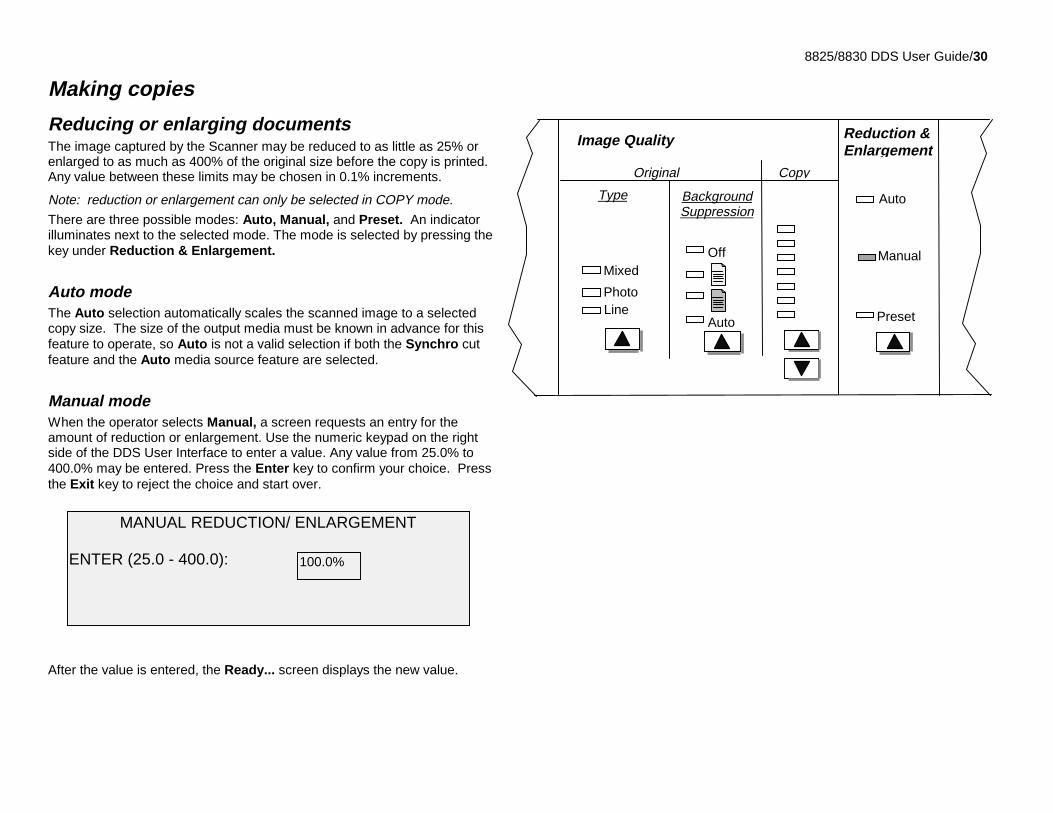
Reducing or enlarging documentsThe image captured by the Scanner may be reduced to as little as 25% orenlarged to as much as 400% of the original size before the copy is printed.Any value between these limits may be chosen in 0.1% increments.
Note: reduction or enlargement can only be selected in COPY mode.
There are three possible modes: Auto, Manual, and Preset. An indicatorilluminates next to the selected mode. The mode is selected by pressing thekey under Reduction & Enlargement.
Auto modeThe Auto selection automatically scales the scanned image to a selectedcopy size. The size of the output media must be known in advance for thisfeature to operate, so Auto is not a valid selection if both the Synchro cutfeature and the Auto media source feature are selected.
Manual modeWhen the operator selects Manual, a screen requests an entry for theamount of reduction or enlargement. Use the numeric keypad on the rightside of the DDS User Interface to enter a value. Any value from 25.0% to400.0% may be entered. Press the Enter key to confirm your choice. Pressthe Exit key to reject the choice and start over.
After the value is entered, the Ready... screen displays the new value.
Off
Auto
Manual
Original
Image Quality Reduction &Enlargement
Preset
Type
Mixed
LinePhoto
BackgroundSuppression
Copy
Auto
MANUAL REDUCTION/ ENLARGEMENT
ENTER (25.0 - 400.0): 100.0%
8825/8830 DDS User Guide/31
Making CopiesReducing or enlarging documents (continued)
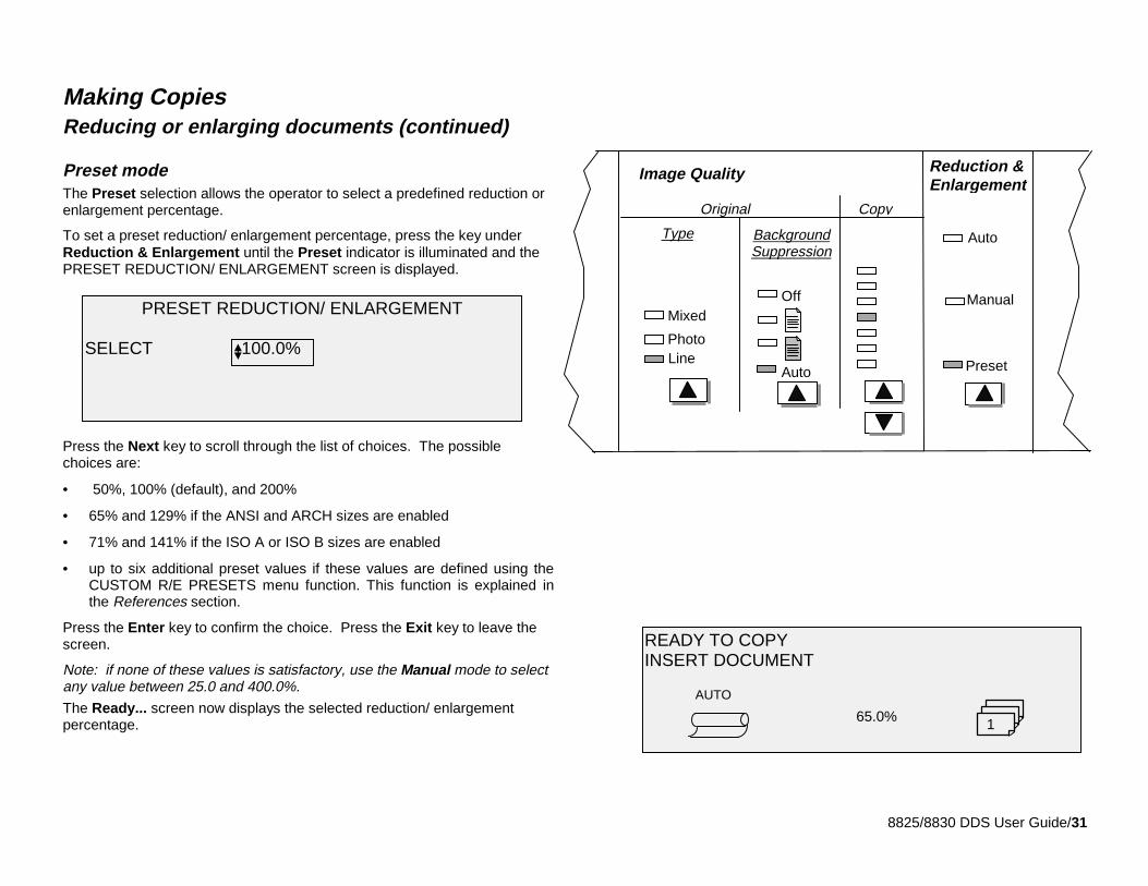
Preset modeThe Preset selection allows the operator to select a predefined reduction orenlargement percentage.
To set a preset reduction/ enlargement percentage, press the key underReduction & Enlargement until the Preset indicator is illuminated and thePRESET REDUCTION/ ENLARGEMENT screen is displayed.
Press the Next key to scroll through the list of choices. The possiblechoices are:
• 50%, 100% (default), and 200%
• 65% and 129% if the ANSI and ARCH sizes are enabled
• 71% and 141% if the ISO A or ISO B sizes are enabled
• up to six additional preset values if these values are defined using theCUSTOM R/E PRESETS menu function. This function is explained inthe References section.
Press the Enter key to confirm the choice. Press the Exit key to leave thescreen.
Note: if none of these values is satisfactory, use the Manual mode to selectany value between 25.0 and 400.0%.
The Ready... screen now displays the selected reduction/ enlargementpercentage.
READY TO COPYINSERT DOCUMENT
AUTO
165.0%
Off
Auto
Manual
Original
Image Quality Reduction &Enlargement
Preset
Type
Mixed
LinePhoto
BackgroundSuppression
Copy
Auto
PRESET REDUCTION/ ENLARGEMENT
SELECT 100.0%
8825/8830 DDS User Guide/32
Making copies
Controlling the scan
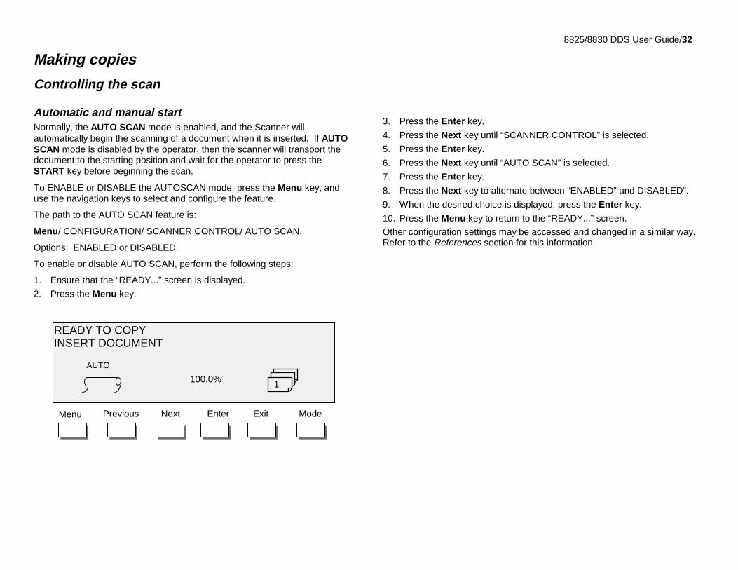
Automatic and manual startNormally, the AUTO SCAN mode is enabled, and the Scanner willautomatically begin the scanning of a document when it is inserted. If AUTOSCAN mode is disabled by the operator, then the scanner will transport thedocument to the starting position and wait for the operator to press theSTART key before beginning the scan.
To ENABLE or DISABLE the AUTOSCAN mode, press the Menu key, anduse the navigation keys to select and configure the feature.
The path to the AUTO SCAN feature is:
Menu/ CONFIGURATION/ SCANNER CONTROL/ AUTO SCAN.
Options: ENABLED or DISABLED.
To enable or disable AUTO SCAN, perform the following steps:
1. Ensure that the “READY...” screen is displayed.
2. Press the Menu key.
3. Press the Enter key.
4. Press the Next key until “SCANNER CONTROL” is selected.
5. Press the Enter key.
6. Press the Next key until “AUTO SCAN” is selected.
7. Press the Enter key.
8. Press the Next key to alternate between “ENABLED” and DISABLED”.
9. When the desired choice is displayed, press the Enter key.
10. Press the Menu key to return to the “READY...” screen.
Other configuration settings may be accessed and changed in a similar way.Refer to the References section for this information.
EnterNext ExitPrevious ModeMenu
READY TO COPYINSERT DOCUMENT
AUTO
1100.0%
8825/8830 DDS User Guide/33
Making copiesControlling the scan (continued)
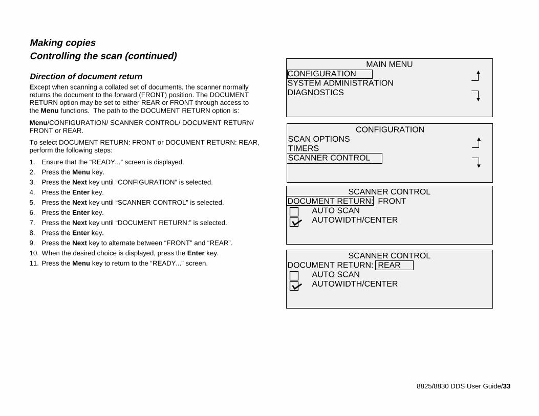
Direction of document returnExcept when scanning a collated set of documents, the scanner normallyreturns the document to the forward (FRONT) position. The DOCUMENTRETURN option may be set to either REAR or FRONT through access tothe Menu functions. The path to the DOCUMENT RETURN option is:
Menu/CONFIGURATION/ SCANNER CONTROL/ DOCUMENT RETURN/FRONT or REAR.
To select DOCUMENT RETURN: FRONT or DOCUMENT RETURN: REAR,perform the following steps:
1. Ensure that the “READY...” screen is displayed.
2. Press the Menu key.
3. Press the Next key until “CONFIGURATION” is selected.
4. Press the Enter key.
5. Press the Next key until “SCANNER CONTROL” is selected.
6. Press the Enter key.
7. Press the Next key until “DOCUMENT RETURN:” is selected.
8. Press the Enter key.
9. Press the Next key to alternate between “FRONT” and “REAR”.
10. When the desired choice is displayed, press the Enter key.
11. Press the Menu key to return to the “READY...” screen.
CONFIGURATIONSCAN OPTIONSTIMERSSCANNER CONTROL
MAIN MENUCONFIGURATIONSYSTEM ADMINISTRATIONDIAGNOSTICS
SCANNER CONTROLDOCUMENT RETURN: FRONT
AUTO SCANAUTOWIDTH/CENTER
SCANNER CONTROLDOCUMENT RETURN: REAR
AUTO SCANAUTOWIDTH/CENTER
8825/8830 DDS User Guide/34
Making copies (continued)
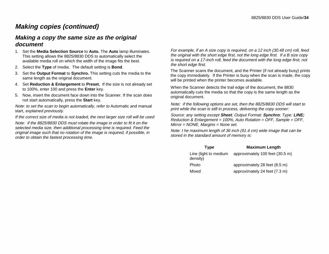
Making a copy the same size as the originaldocument1. Set the Media Selection Source to Auto. The Auto lamp illuminates.
This setting allows the 8825/8830 DDS to automatically select theavailable media roll on which the width of the image fits the best.
2. Select the Type of media. The default setting is Bond.
3. Set the Output Format to Synchro. This setting cuts the media to thesame length as the original document.
4. Set Reduction & Enlargement to Preset. If the size is not already setto 100%, enter 100 and press the Enter key.
5. Now, insert the document face down into the Scanner. If the scan doesnot start automatically, press the Start key.
Note: to set the scan to begin automatically, refer to Automatic and manualstart, explained previously.If the correct size of media is not loaded, the next larger size roll will be usedNote: if the 8825/8830 DDS must rotate the image in order to fit it on theselected media size, then additional processing time is required. Feed theoriginal image such that no rotation of the image is required, if possible, inorder to obtain the fastest processing time.
For example, if an A size copy is required, on a 12 inch (30.48 cm) roll, feedthe original with the short edge first, not the long edge first. If a B size copyis required on a 17-inch roll, feed the document with the long edge first, notthe short edge first.The Scanner scans the document, and the Printer (if not already busy) printsthe copy immediately. If the Printer is busy when the scan is made, the copywill be printed when the printer becomes available.
When the Scanner detects the trail edge of the document, the 8830automatically cuts the media so that the copy is the same length as theoriginal document.
Note: if the following options are set, then the 8825/8830 DDS will start toprint while the scan is still in process, delivering the copy sooner:
Source: any setting except Sheet; Output Format: Synchro; Type: LINE;Reduction & Enlargement = 100%, Auto Rotation = OFF, Sample = OFF,Mirror = NONE, Margins = None set.Note: t he maximum length of 36 inch (91.4 cm) wide image that can bestored in the standard amount of memory is:
Type Maximum Length
Line (light to mediumdensity)
approximately 100 feet (30.5 m)
Photo approximately 28 feet (8.5 m)
Mixed approximately 24 feet (7.3 m)
8825/8830 DDS User Guide/35
Making copies (continued)
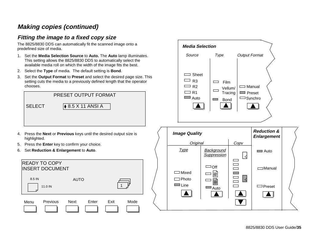
Fitting the image to a fixed copy sizeThe 8825/8830 DDS can automatically fit the scanned image onto apredefined size of media.
1. Set the Media Selection Source to Auto. The Auto lamp illuminates.This setting allows the 8825/8830 DDS to automatically select theavailable media roll on which the width of the image fits the best.
2. Select the Type of media. The default setting is Bond.
3. Set the Output Format to Preset and select the desired page size. Thissetting cuts the media to a previously defined length that the operatorchooses.
4. Press the Next or Previous keys until the desired output size ishighlighted.
5. Press the Enter key to confirm your choice.
6. Set Reduction & Enlargement to Auto.
Film
BondAuto
R2R3
Preset
Media Selection
Source Type Output Format
Sheet
Synchro
Manual
R1Vellum/TracingPRESET OUTPUT FORMAT
SELECT 8.5 X 11 ANSI A
EnterNext ExitPrevious ModeMenu
READY TO COPYINSERT DOCUMENT
AUTO
11.0 IN
8.5 IN
1 Line
Off
Auto
Manual
Original
Image Quality Reduction &Enlargement
Preset
Type
Mixed
Photo
BackgroundSuppression
Copy
Auto
8825/8830 DDS User Guide/36
Making copiesFitting the image to a fixed copy size (continued)
7. Now, insert the document face down into the Scanner. If the scan doesnot start automatically, press the Start key.
Note: to set the scan to begin automatically or by pressing the Start key,refer to Automatic and manual start, explained previously.The Scanner scans the document, and the Printer (if not already busy) printsthe copy immediately. If the Printer is busy when the scan is made, the copywill be printed when the Printer becomes available.
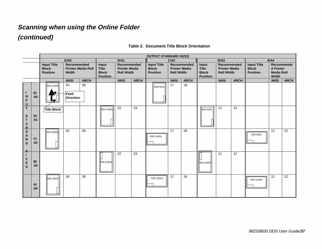
Scanning when using the Online FolderWhen using the Online Folder, the document must be inserted in the7346/7356 scanner with the title block positioned as shown in Table 3 inorder to have the title block visible after the copy is folded. To ensure thatthe correct size fold is obtained, use the paper roll width indicated in theRecommended Printer Media Roll Width column.
Documents larger than 80 inches (2.1M) can only be partially folded.
When using the Reduction and Enlargement feature, and the Online Folder,you must orient and insert the document title block in the same orientationas the resulting enlargement or reduction copy size. In addition, therecommended media should also be used.
For example: the job requires that an A (A4) be enlarged to a C (A2).
To have the title block be visible after folding, the A (A4) document must beinserted as if it were a C (A2) document. Refer to Table 1 on the next page.
Also, to ensure that the copy is folded correctly, and will not jam in the OnlineFolder, it is recommended that you only select standard reductions andenlargements (A to C, A to E, B to D, etc., A4 to A2, A4 to A0, A3 to A1,etc.). These selections are identified in Table 1 by the document icon.Those areas that are blank are not recommended because the title blockmay not be visible after the folding is complete. You may want to refer toCustom preset, Reduce/enlarge default section of this manual, and set upthe Reduction/Enlargement default to show the standard reduction andenlargement shown in Table 1. Set the reduction /enlargement to display Ato C (A4 to A2) above the buttons.
For additional folding information, refer to the Xerox Online Folder OperatorManual.
8825/8830 DDS User Guide/37
Scanning when using the Online Folder
(continued)
OUTPUT STANDARD SIZESE/A0 D/A1 C/A2 B/A3 A/A4
Input TitleBlockPosition
RecommendedPrinter Media RollWidth
InputTitleBlockPosition
RecommendedPrinter MediaRoll Width
Input TitleBlockPosition
RecommendedPrinter MediaRoll Width
InputTitleBlockPosition
RecommendedPrinter MediaRoll Width
Input TitleBlockPosition
Recommended PrinterMedia RollWidth
ANSI ARCH ANSI ARCH ANSI ARCH ANSI ARCH ANSI ARCH
E/A0
34 36 17 18
D/A1
22 24 11 12
C/A2
34 36 17 18 11 12
B/A3
22 24 11 12
A/A4
34 36 17 18 11 12
INPUT
STANDARD
SIZES
FeedDirection
Title Block
R/E=50%R/E=100%
R/E=50%R/E=100%
R/E=50%R/E=100%
R/E=200%
R/E=200% R/E=100%
R/E=400% R/E=200%R/E=100%
Table 2. Document Title Block Orientation
8825/8830 DDS User Guide/38
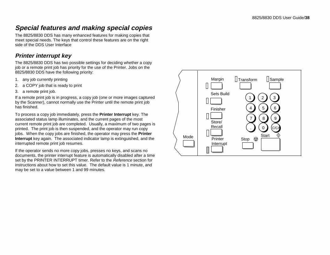
Special features and making special copiesThe 8825/8830 DDS has many enhanced features for making copies thatmeet special needs. The keys that control these features are on the rightside of the DDS User Interface
Printer interrupt keyThe 8825/8830 DDS has two possible settings for deciding whether a copyjob or a remote print job has priority for the use of the Printer. Jobs on the8825/8830 DDS have the following priority:
1. any job currently printing
2. a COPY job that is ready to print
3. a remote print job.
If a remote print job is in progress, a copy job (one or more images capturedby the Scanner), cannot normally use the Printer until the remote print jobhas finished.
To process a copy job immediately, press the Printer Interrupt key. Theassociated status lamp illuminates, and the current pages of the mostcurrent remote print job are completed. Usually, a maximum of two pages isprinted. The print job is then suspended, and the operator may run copyjobs. When the copy jobs are finished, the operator may press the PrinterInterrupt key again. The associated indicator lamp is extinguished, and theinterrupted remote print job resumes.
If the operator sends no more copy jobs, presses no keys, and scans nodocuments, the printer interrupt feature is automatically disabled after a timeset by the PRINTER INTERRUPT timer. Refer to the Reference section forinstructions about how to set this value. The default value is 1 minute, andmay be set to a value between 1 and 99 minutes.
Store/Recall
StopStartMode
1 2 3
4 5 6
7 8 9
. 0 C/CA
PrinterInterrupt
Margin
Sets Build
Finisher
SampleTransform
8825/8830 DDS User Guide/39
Special features and making special copies(continued)
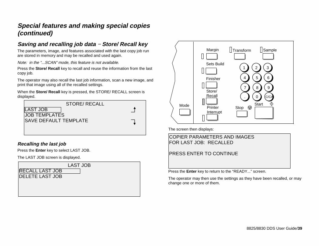
Saving and recalling job data − Store/ Recall keyThe parameters, image, and features associated with the last copy job runare stored in memory and may be recalled and used again.
Note: in the “...SCAN” mode, this feature is not available.
Press the Store/ Recall key to recall and reuse the information from the lastcopy job.
The operator may also recall the last job information, scan a new image, andprint that image using all of the recalled settings.
When the Store/ Recall key is pressed, the STORE/ RECALL screen isdisplayed.
Recalling the last jobPress the Enter key to select LAST JOB.
The LAST JOB screen is displayed.
The screen then displays:
Press the Enter key to return to the “READY...” screen.
The operator may then use the settings as they have been recalled, or maychange one or more of them.
Store/Recall
StopStartMode
1 2 3
4 5 6
7 8 9
. 0 C/CA
PrinterInterrupt
Margin
Sets Build
Finisher
SampleTransform
LAST JOBRECALL LAST JOBDELETE LAST JOB
COPIER PARAMETERS AND IMAGESFOR LAST JOB: RECALLED
PRESS ENTER TO CONTINUE
STORE/ RECALLLAST JOBJOB TEMPLATESSAVE DEFAULT TEMPLATE
8825/8830 DDS User Guide/40
Special features and making special copiesSaving and recalling job data − Store/ Recall key(continued)
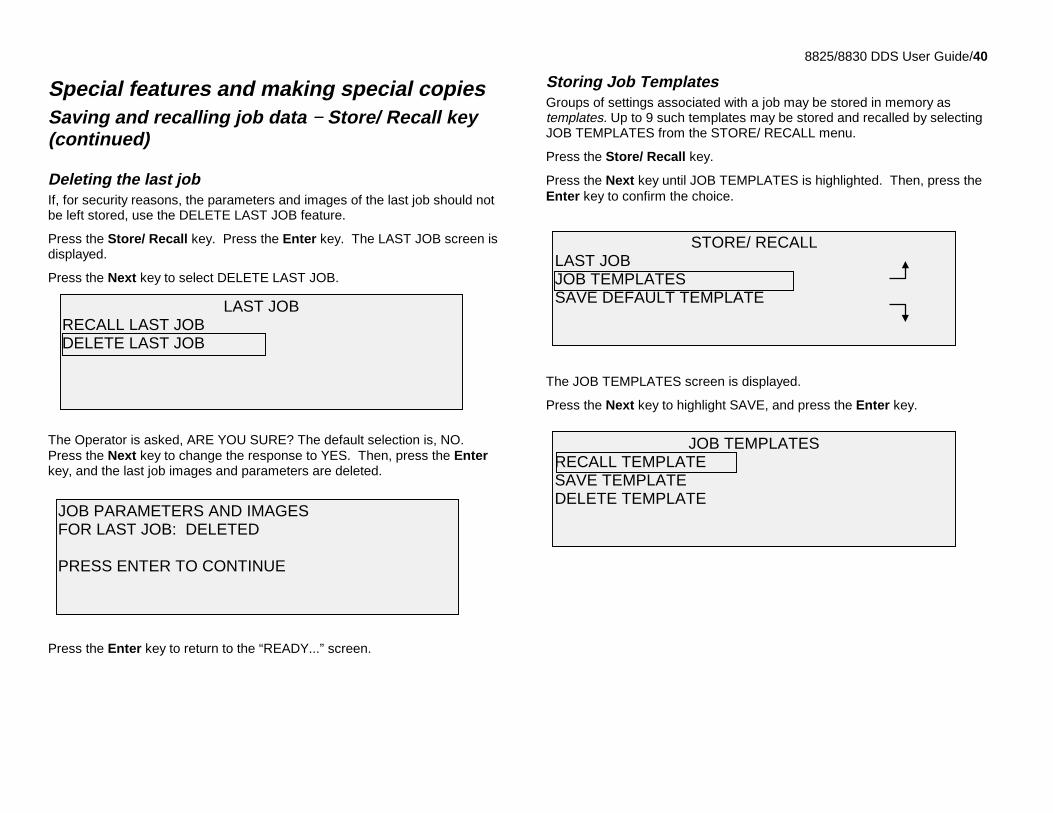
Deleting the last jobIf, for security reasons, the parameters and images of the last job should notbe left stored, use the DELETE LAST JOB feature.
Press the Store/ Recall key. Press the Enter key. The LAST JOB screen isdisplayed.
Press the Next key to select DELETE LAST JOB.
The Operator is asked, ARE YOU SURE? The default selection is, NO.Press the Next key to change the response to YES. Then, press the Enterkey, and the last job images and parameters are deleted.
Press the Enter key to return to the “READY...” screen.
Storing Job TemplatesGroups of settings associated with a job may be stored in memory astemplates. Up to 9 such templates may be stored and recalled by selectingJOB TEMPLATES from the STORE/ RECALL menu.
Press the Store/ Recall key.
Press the Next key until JOB TEMPLATES is highlighted. Then, press theEnter key to confirm the choice.
The JOB TEMPLATES screen is displayed.
Press the Next key to highlight SAVE, and press the Enter key.
JOB PARAMETERS AND IMAGESFOR LAST JOB: DELETED
PRESS ENTER TO CONTINUE
LAST JOBRECALL LAST JOBDELETE LAST JOB
JOB TEMPLATESRECALL TEMPLATESAVE TEMPLATEDELETE TEMPLATE
STORE/ RECALLLAST JOBJOB TEMPLATESSAVE DEFAULT TEMPLATE
8825/8830 DDS User Guide/41
Special features and making special copiesSaving and recalling job data − Store/ Recall key
Storing Job Templates (continued)The SAVE screen is displayed, showing the unused template locations.Locations that actually contain a template already are not displayed.
Choose an unused location, and enter its location using the numeric keypad.Press the Enter key to confirm the choice.
The settings from the current copy job are saved at the location entered; anda confirming message is displayed.
The operator may choose to replace the contents of a used location with thecurrent job settings information. If the operator chooses a location thatalready contains information, the TEMPLATE IS IN USE screen is displayed.Press the Enter key to overwrite the contents. Press the Exit key to cancelthe operation.
PARAMETERSSAVED AS TEMPLATE 3
PRESS ENTER TO CONTINUE
TEMPLATE IS IN USE:
PRESS ENTER TO OVERWRITE
SAVEUNUSED TEMPLATES: 1 2 3 4 5 6 7 8 9ENTER TEMPLATE NUMBER 3
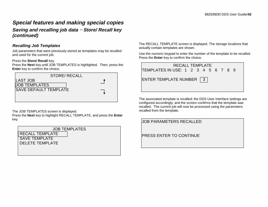
8825/8830 DDS User Guide/42
Special features and making special copiesSaving and recalling job data − Store/ Recall key(continued)
Recalling Job TemplatesJob parameters that were previously stored as templates may be recalledand used for the current job.
Press the Store/ Recall key.Press the Next key until JOB TEMPLATES is highlighted. Then, press theEnter key to confirm the choice.
The JOB TEMPLATES screen is displayed.Press the Next key to highlight RECALL TEMPLATE, and press the Enterkey.
The RECALL TEMPLATE screen is displayed. The storage locations thatactually contain templates are shown.
Use the numeric keypad to enter the number of the template to be recalled.Press the Enter key to confirm the choice.
The associated template is recalled; the DDS User Interface settings areconfigured accordingly; and the screen confirms that the template wasrecalled. The current job will now be processed using the parametersrecalled from the template.
JOB PARAMETERS RECALLED
PRESS ENTER TO CONTINUE
RECALL TEMPLATETEMPLATES IN USE: 1 2 3 4 5 6 7 8 9
ENTER TEMPLATE NUMBER 3STORE/ RECALL
LAST JOBJOB TEMPLATESSAVE DEFAULT TEMPLATE
JOB TEMPLATES RECALL TEMPLATE SAVE TEMPLATE DELETE TEMPLATE
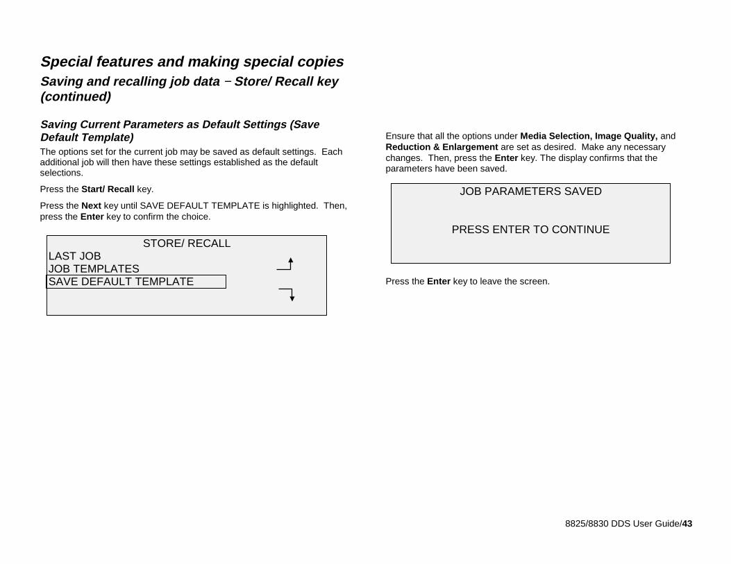
8825/8830 DDS User Guide/43
Special features and making special copiesSaving and recalling job data − Store/ Recall key(continued)
Saving Current Parameters as Default Settings (SaveDefault Template)The options set for the current job may be saved as default settings. Eachadditional job will then have these settings established as the defaultselections.
Press the Start/ Recall key.
Press the Next key until SAVE DEFAULT TEMPLATE is highlighted. Then,press the Enter key to confirm the choice.
Ensure that all the options under Media Selection, Image Quality, andReduction & Enlargement are set as desired. Make any necessarychanges. Then, press the Enter key. The display confirms that theparameters have been saved.
Press the Enter key to leave the screen.
JOB PARAMETERS SAVED
PRESS ENTER TO CONTINUESTORE/ RECALL
LAST JOBJOB TEMPLATESSAVE DEFAULT TEMPLATE
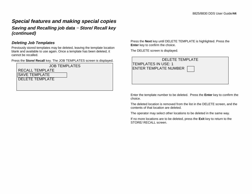
8825/8830 DDS User Guide/44
Special features and making special copiesSaving and Recalling job data − Store/ Recall key(continued)
Deleting Job TemplatesPreviously stored templates may be deleted, leaving the template locationblank and available to use again. Once a template has been deleted, itcannot be recalled.
Press the Store/ Recall key. The JOB TEMPLATES screen is displayed.
Press the Next key until DELETE TEMPLATE is highlighted. Press theEnter key to confirm the choice.
The DELETE screen is displayed.
Enter the template number to be deleted. Press the Enter key to confirm thechoice.
The deleted location is removed from the list in the DELETE screen, and thecontents of that location are deleted.
The operator may select other locations to be deleted in the same way.
If no more locations are to be deleted, press the Exit key to return to theSTORE/ RECALL screen.
DELETE TEMPLATETEMPLATES IN USE: 1ENTER TEMPLATE NUMBER
JOB TEMPLATES RECALL TEMPLATE SAVE TEMPLATE DELETE TEMPLATE
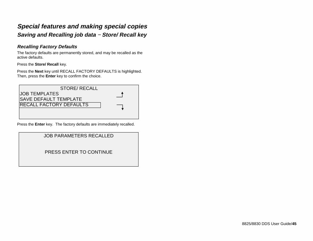
8825/8830 DDS User Guide/45
Special features and making special copiesSaving and Recalling job data − Store/ Recall key
Recalling Factory DefaultsThe factory defaults are permanently stored, and may be recalled as theactive defaults.
Press the Store/ Recall key.
Press the Next key until RECALL FACTORY DEFAULTS is highlighted.Then, press the Enter key to confirm the choice.
Press the Enter key. The factory defaults are immediately recalled.
JOB PARAMETERS RECALLED
PRESS ENTER TO CONTINUE
STORE/ RECALLJOB TEMPLATESSAVE DEFAULT TEMPLATERECALL FACTORY DEFAULTS
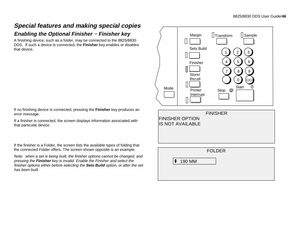
8825/8830 DDS User Guide/46
Special features and making special copiesEnabling the Optional Finisher − Finisher keyA finishing device, such as a folder, may be connected to the 8825/8830DDS. If such a device is connected, the Finisher key enables or disablesthat device.
If no finishing device is connected, pressing the Finisher key produces anerror message.
If a finisher is connected, the screen displays information associated withthat particular device.
If the finisher is a Folder, the screen lists the available types of folding thatthe connected Folder offers. The screen shown opposite is an example.
Note: when a set is being built, the finisher options cannot be changed, andpressing the Finisher key is invalid. Enable the Finisher and select thefinisher options either before selecting the Sets Build option, or after the sethas been built.
FINISHERFINISHER OPTIONIS NOT AVAILABLE
Store/Recall
StopStartMode
1 2 3
4 5 6
7 8 9
. 0 C/CA
PrinterInterrupt
Margin
Sets Build
Finisher
SampleTransform
FOLDER
190 MM
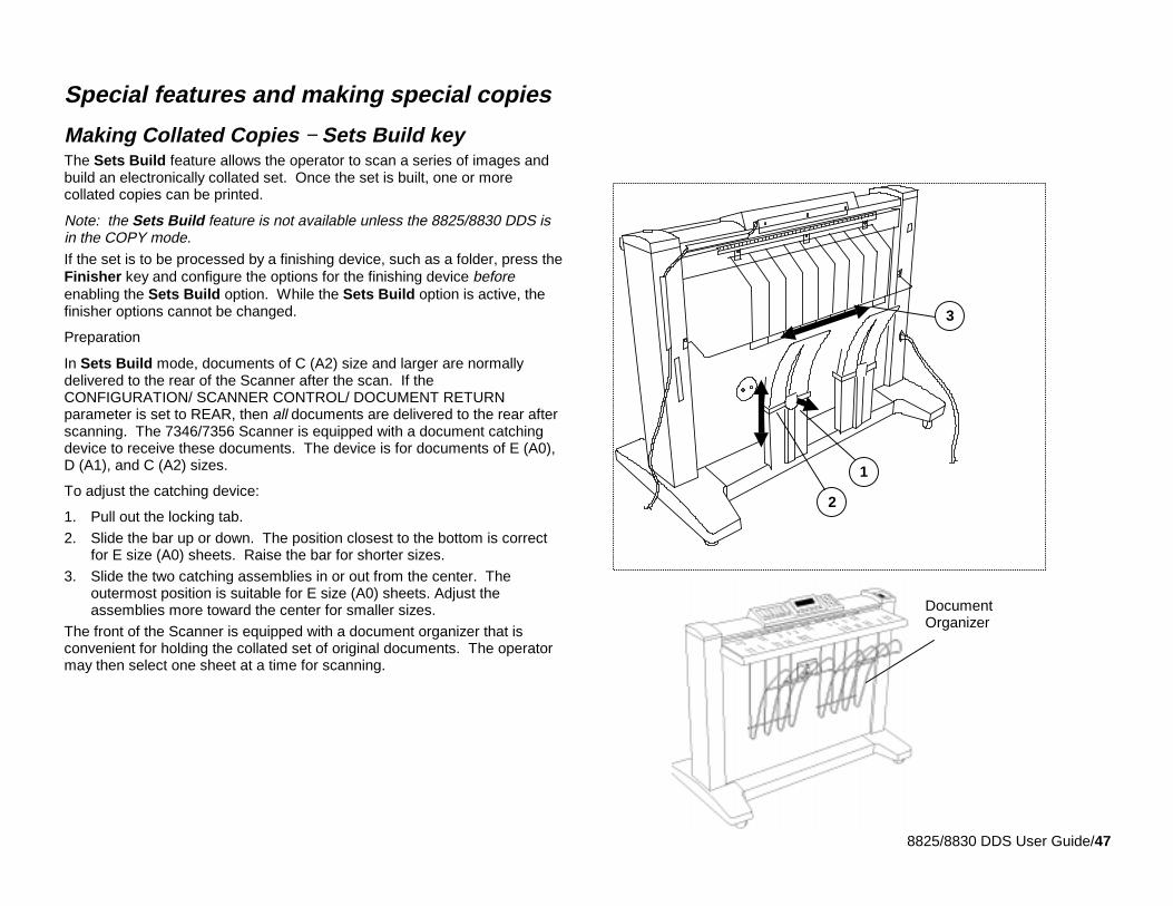
8825/8830 DDS User Guide/47
Special features and making special copies
Making Collated Copies − Sets Build keyThe Sets Build feature allows the operator to scan a series of images andbuild an electronically collated set. Once the set is built, one or morecollated copies can be printed.
Note: the Sets Build feature is not available unless the 8825/8830 DDS isin the COPY mode.If the set is to be processed by a finishing device, such as a folder, press theFinisher key and configure the options for the finishing device beforeenabling the Sets Build option. While the Sets Build option is active, thefinisher options cannot be changed.
Preparation
In Sets Build mode, documents of C (A2) size and larger are normallydelivered to the rear of the Scanner after the scan. If theCONFIGURATION/ SCANNER CONTROL/ DOCUMENT RETURNparameter is set to REAR, then all documents are delivered to the rear afterscanning. The 7346/7356 Scanner is equipped with a document catchingdevice to receive these documents. The device is for documents of E (A0),D (A1), and C (A2) sizes.
To adjust the catching device:
1. Pull out the locking tab.
2. Slide the bar up or down. The position closest to the bottom is correctfor E size (A0) sheets. Raise the bar for shorter sizes.
3. Slide the two catching assemblies in or out from the center. Theoutermost position is suitable for E size (A0) sheets. Adjust theassemblies more toward the center for smaller sizes.
The front of the Scanner is equipped with a document organizer that isconvenient for holding the collated set of original documents. The operatormay then select one sheet at a time for scanning.
1
2
3
DocumentOrganizer
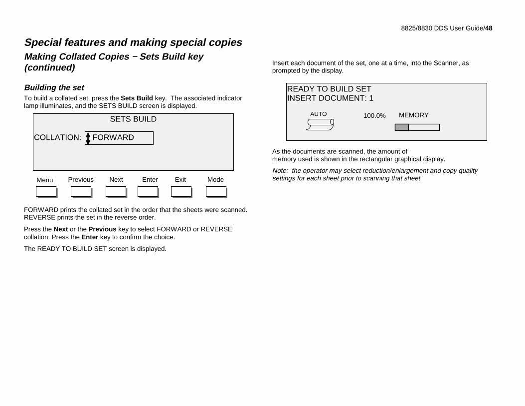
8825/8830 DDS User Guide/48
Special features and making special copiesMaking Collated Copies − Sets Build key(continued)
Building the setTo build a collated set, press the Sets Build key. The associated indicatorlamp illuminates, and the SETS BUILD screen is displayed.
FORWARD prints the collated set in the order that the sheets were scanned.REVERSE prints the set in the reverse order.
Press the Next or the Previous key to select FORWARD or REVERSEcollation. Press the Enter key to confirm the choice.
The READY TO BUILD SET screen is displayed.
Insert each document of the set, one at a time, into the Scanner, asprompted by the display.
As the documents are scanned, the amount ofmemory used is shown in the rectangular graphical display.
Note: the operator may select reduction/enlargement and copy qualitysettings for each sheet prior to scanning that sheet.
SETS BUILD
COLLATION: FORWARD
EnterNext ExitPrevious ModeMenu
READY TO BUILD SETINSERT DOCUMENT: 1
MEMORY100.0%AUTO
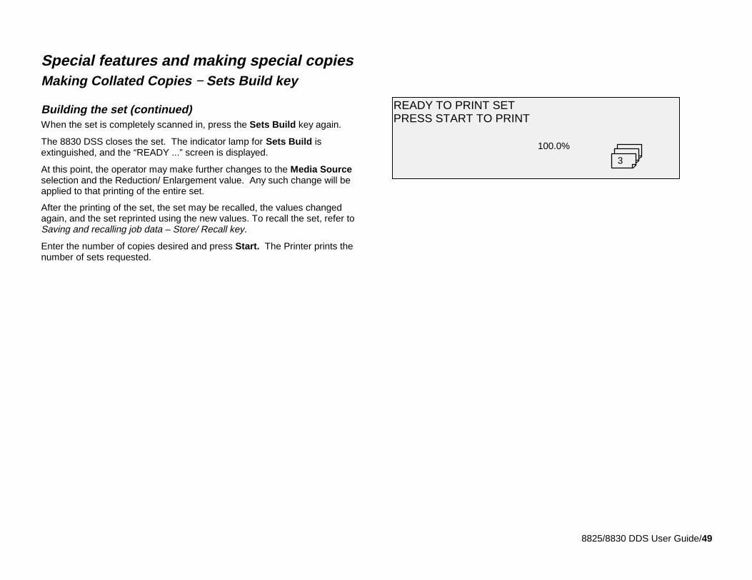
8825/8830 DDS User Guide/49
Special features and making special copiesMaking Collated Copies − Sets Build key
Building the set (continued)When the set is completely scanned in, press the Sets Build key again.
The 8830 DSS closes the set. The indicator lamp for Sets Build isextinguished, and the “READY ...” screen is displayed.
At this point, the operator may make further changes to the Media Sourceselection and the Reduction/ Enlargement value. Any such change will beapplied to that printing of the entire set.
After the printing of the set, the set may be recalled, the values changedagain, and the set reprinted using the new values. To recall the set, refer toSaving and recalling job data – Store/ Recall key.
Enter the number of copies desired and press Start. The Printer prints thenumber of sets requested.
READY TO PRINT SETPRESS START TO PRINT
100.0%
3
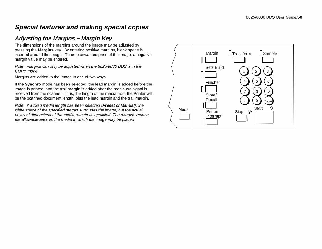
8825/8830 DDS User Guide/50
Special features and making special copies
Adjusting the Margins − Margin KeyThe dimensions of the margins around the image may be adjusted bypressing the Margins key. By entering positive margins, blank space isinserted around the image. To crop unwanted parts of the image, a negativemargin value may be entered.
Note: margins can only be adjusted when the 8825/8830 DDS is in theCOPY mode.Margins are added to the image in one of two ways.
If the Synchro mode has been selected, the lead margin is added before theimage is printed, and the trail margin is added after the media cut signal isreceived from the scanner. Thus, the length of the media from the Printer willbe the scanned document length, plus the lead margin and the trail margin.
Note: if a fixed media length has been selected (Preset or Manual), thewhite space of the specified margin surrounds the image, but the actualphysical dimensions of the media remain as specified. The margins reducethe allowable area on the media in which the image may be placed
Store/Recall
StopStartMode
1 2 3
4 5 6
7 8 9
. 0 C/CA
PrinterInterrupt
Margin
Sets Build
Finisher
SampleTransform
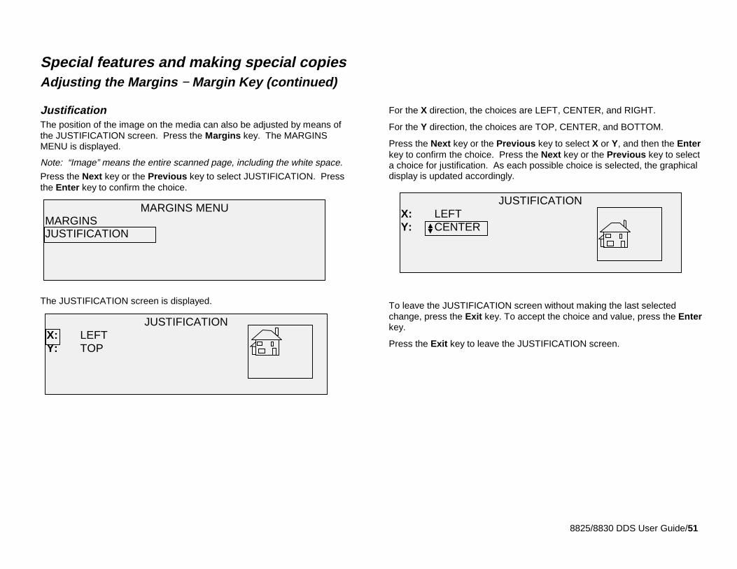
8825/8830 DDS User Guide/51
Special features and making special copiesAdjusting the Margins − Margin Key (continued)
JustificationThe position of the image on the media can also be adjusted by means ofthe JUSTIFICATION screen. Press the Margins key. The MARGINSMENU is displayed.
Note: “Image” means the entire scanned page, including the white space.
Press the Next key or the Previous key to select JUSTIFICATION. Pressthe Enter key to confirm the choice.
The JUSTIFICATION screen is displayed.
For the X direction, the choices are LEFT, CENTER, and RIGHT.
For the Y direction, the choices are TOP, CENTER, and BOTTOM.
Press the Next key or the Previous key to select X or Y, and then the Enterkey to confirm the choice. Press the Next key or the Previous key to selecta choice for justification. As each possible choice is selected, the graphicaldisplay is updated accordingly.
To leave the JUSTIFICATION screen without making the last selectedchange, press the Exit key. To accept the choice and value, press the Enterkey.
Press the Exit key to leave the JUSTIFICATION screen.
MARGINS MENUMARGINSJUSTIFICATION
JUSTIFICATIONX: LEFTY: TOP
JUSTIFICATIONX: LEFTY: CENTER
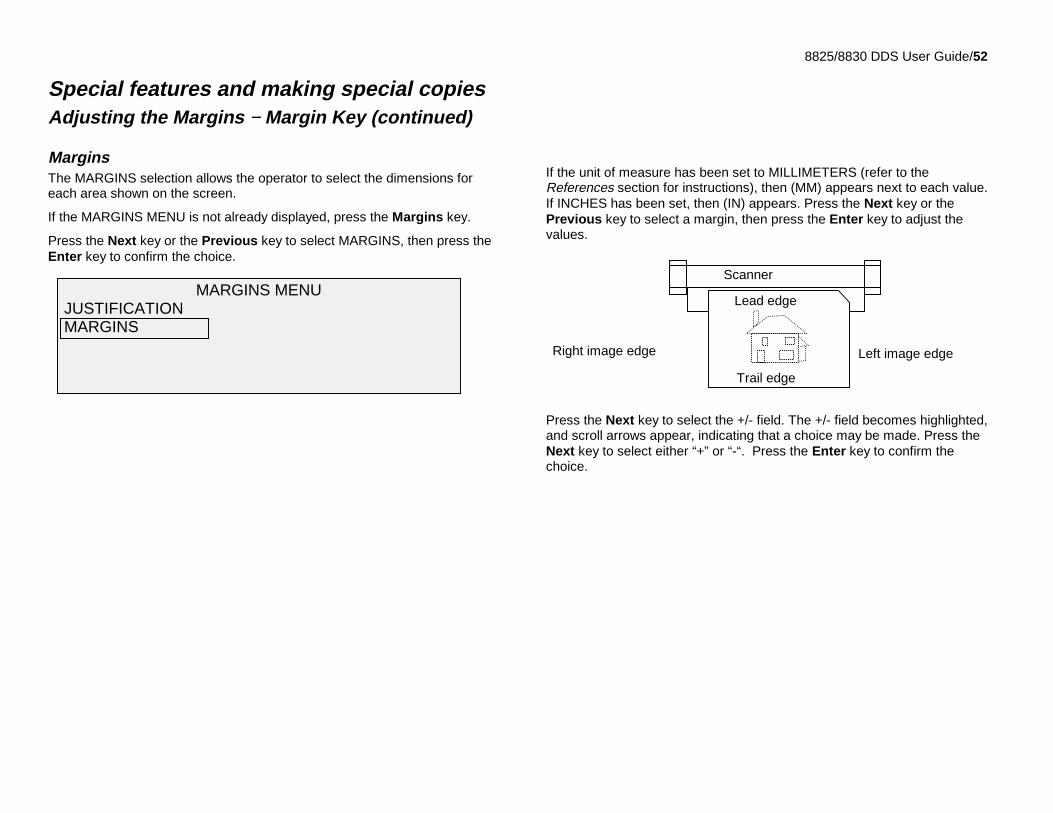
8825/8830 DDS User Guide/52
Special features and making special copiesAdjusting the Margins − Margin Key (continued)
MarginsThe MARGINS selection allows the operator to select the dimensions foreach area shown on the screen.
If the MARGINS MENU is not already displayed, press the Margins key.
Press the Next key or the Previous key to select MARGINS, then press theEnter key to confirm the choice.
If the unit of measure has been set to MILLIMETERS (refer to theReferences section for instructions), then (MM) appears next to each value.If INCHES has been set, then (IN) appears. Press the Next key or thePrevious key to select a margin, then press the Enter key to adjust thevalues.
Press the Next key to select the +/- field. The +/- field becomes highlighted,and scroll arrows appear, indicating that a choice may be made. Press theNext key to select either “+” or “-“. Press the Enter key to confirm thechoice.
MARGINS MENU JUSTIFICATION MARGINS
Scanner
Left image edgeRight image edge
Trail edge
Lead edge
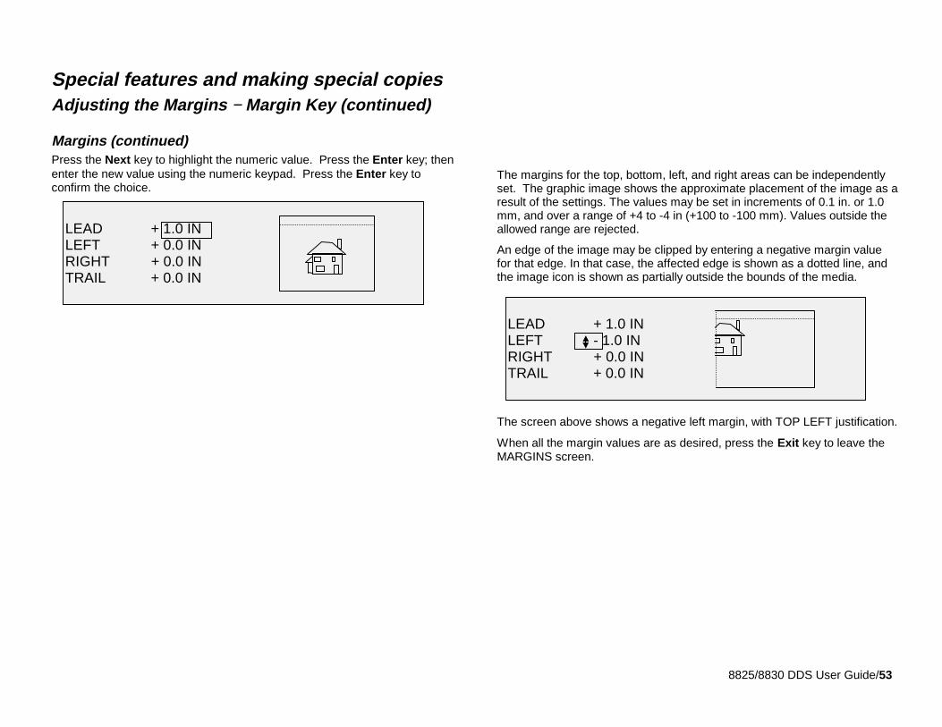
8825/8830 DDS User Guide/53
Special features and making special copiesAdjusting the Margins − Margin Key (continued)
Margins (continued)Press the Next key to highlight the numeric value. Press the Enter key; thenenter the new value using the numeric keypad. Press the Enter key toconfirm the choice.
The margins for the top, bottom, left, and right areas can be independentlyset. The graphic image shows the approximate placement of the image as aresult of the settings. The values may be set in increments of 0.1 in. or 1.0mm, and over a range of +4 to -4 in (+100 to -100 mm). Values outside theallowed range are rejected.
An edge of the image may be clipped by entering a negative margin valuefor that edge. In that case, the affected edge is shown as a dotted line, andthe image icon is shown as partially outside the bounds of the media.
The screen above shows a negative left margin, with TOP LEFT justification.
When all the margin values are as desired, press the Exit key to leave theMARGINS screen.
LEAD + 1.0 INLEFT + 0.0 INRIGHT + 0.0 INTRAIL + 0.0 IN
LEAD + 1.0 INLEFT - 1.0 INRIGHT + 0.0 INTRAIL + 0.0 IN
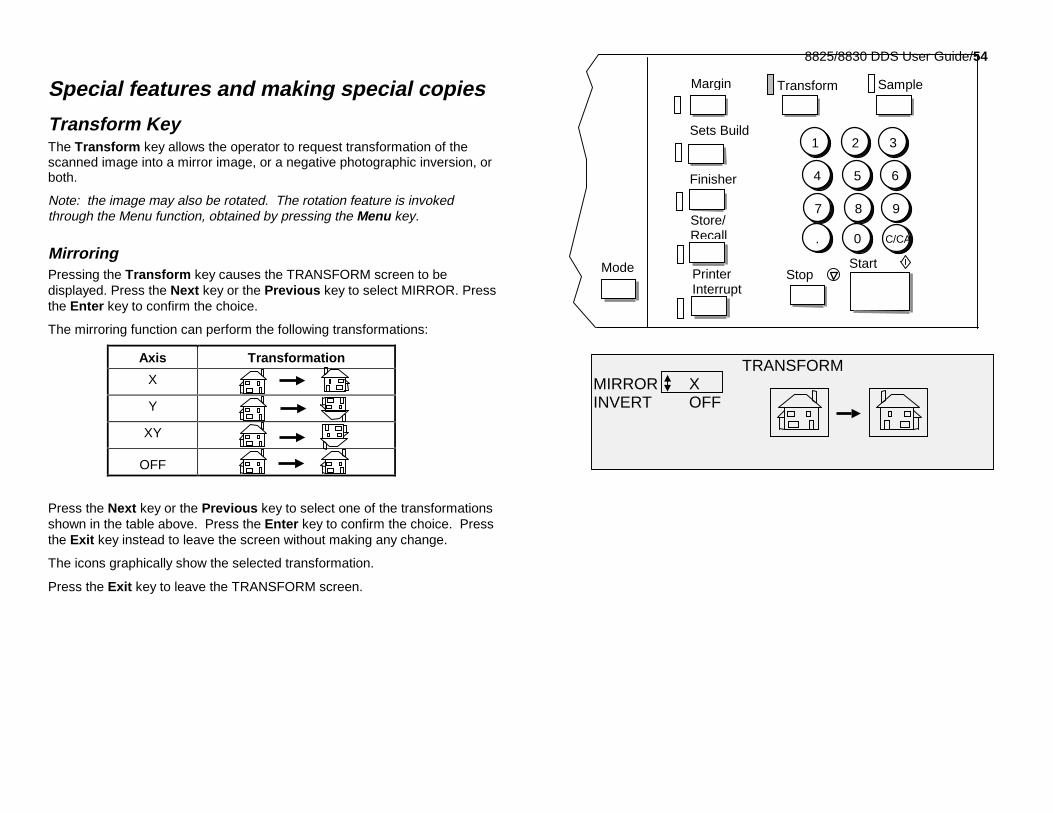
8825/8830 DDS User Guide/54
Special features and making special copies
Transform KeyThe Transform key allows the operator to request transformation of thescanned image into a mirror image, or a negative photographic inversion, orboth.
Note: the image may also be rotated. The rotation feature is invokedthrough the Menu function, obtained by pressing the Menu key.
MirroringPressing the Transform key causes the TRANSFORM screen to bedisplayed. Press the Next key or the Previous key to select MIRROR. Pressthe Enter key to confirm the choice.
The mirroring function can perform the following transformations:
Axis Transformation
X
Y
XY
OFF
Press the Next key or the Previous key to select one of the transformationsshown in the table above. Press the Enter key to confirm the choice. Pressthe Exit key instead to leave the screen without making any change.
The icons graphically show the selected transformation.
Press the Exit key to leave the TRANSFORM screen.
Store/Recall
StopStartMode
1 2 3
4 5 6
7 8 9
. 0 C/CA
PrinterInterrupt
Margin
Sets Build
Finisher
SampleTransform
TRANSFORMMIRROR XINVERT OFF
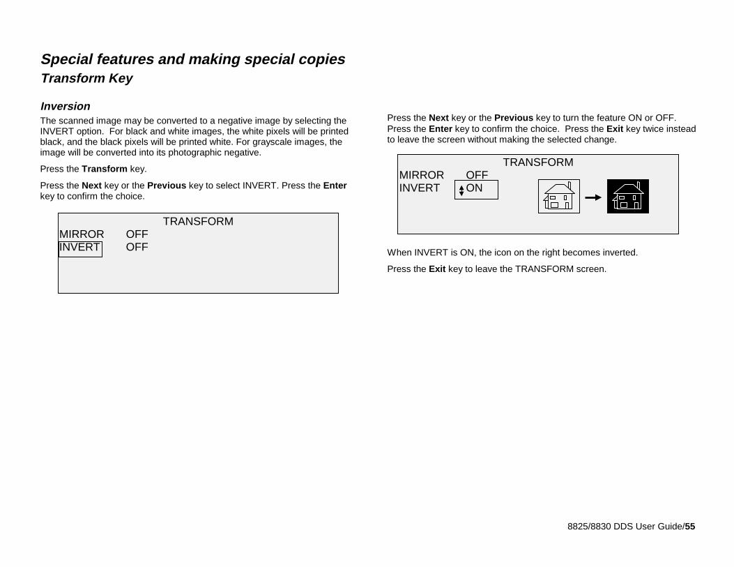
8825/8830 DDS User Guide/55
Special features and making special copiesTransform Key
InversionThe scanned image may be converted to a negative image by selecting theINVERT option. For black and white images, the white pixels will be printedblack, and the black pixels will be printed white. For grayscale images, theimage will be converted into its photographic negative.
Press the Transform key.
Press the Next key or the Previous key to select INVERT. Press the Enterkey to confirm the choice.
Press the Next key or the Previous key to turn the feature ON or OFF.Press the Enter key to confirm the choice. Press the Exit key twice insteadto leave the screen without making the selected change.
When INVERT is ON, the icon on the right becomes inverted.
Press the Exit key to leave the TRANSFORM screen.
TRANSFORMMIRROR OFFINVERT OFF
TRANSFORMMIRROR OFFINVERT ON
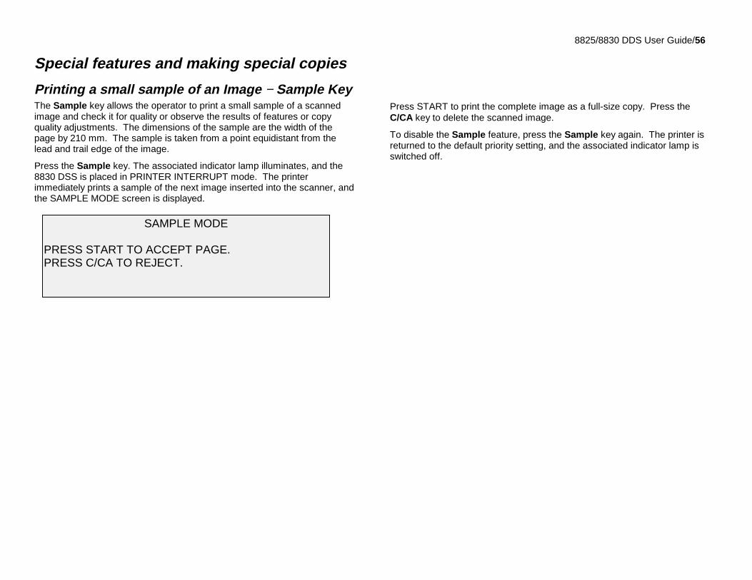
8825/8830 DDS User Guide/56
Special features and making special copies
Printing a small sample of an Image − Sample KeyThe Sample key allows the operator to print a small sample of a scannedimage and check it for quality or observe the results of features or copyquality adjustments. The dimensions of the sample are the width of thepage by 210 mm. The sample is taken from a point equidistant from thelead and trail edge of the image.
Press the Sample key. The associated indicator lamp illuminates, and the8830 DSS is placed in PRINTER INTERRUPT mode. The printerimmediately prints a sample of the next image inserted into the scanner, andthe SAMPLE MODE screen is displayed.
Press START to print the complete image as a full-size copy. Press theC/CA key to delete the scanned image.
To disable the Sample feature, press the Sample key again. The printer isreturned to the default priority setting, and the associated indicator lamp isswitched off.
SAMPLE MODE
PRESS START TO ACCEPT PAGE.PRESS C/CA TO REJECT.
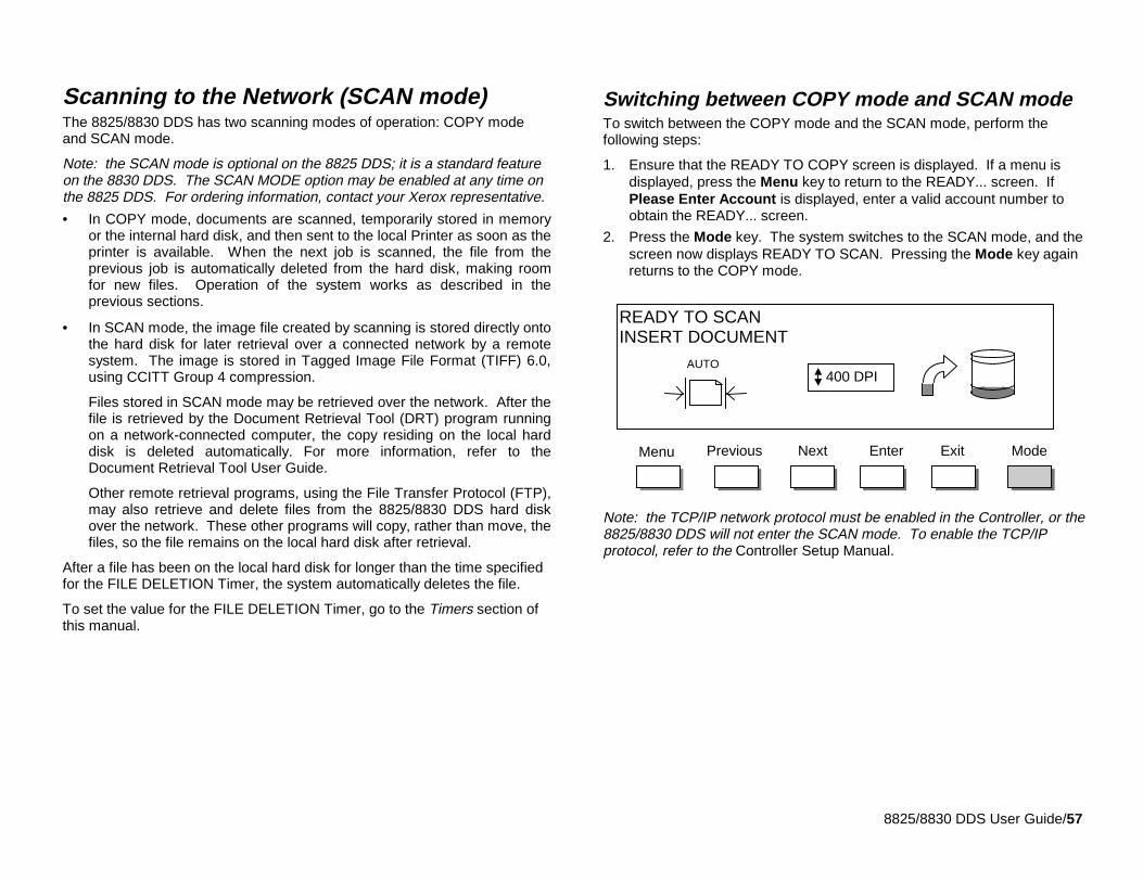
8825/8830 DDS User Guide/57
Scanning to the Network (SCAN mode)The 8825/8830 DDS has two scanning modes of operation: COPY modeand SCAN mode.
Note: the SCAN mode is optional on the 8825 DDS; it is a standard featureon the 8830 DDS. The SCAN MODE option may be enabled at any time onthe 8825 DDS. For ordering information, contact your Xerox representative.
• In COPY mode, documents are scanned, temporarily stored in memoryor the internal hard disk, and then sent to the local Printer as soon as theprinter is available. When the next job is scanned, the file from theprevious job is automatically deleted from the hard disk, making roomfor new files. Operation of the system works as described in theprevious sections.
• In SCAN mode, the image file created by scanning is stored directly ontothe hard disk for later retrieval over a connected network by a remotesystem. The image is stored in Tagged Image File Format (TIFF) 6.0,using CCITT Group 4 compression.
Files stored in SCAN mode may be retrieved over the network. After thefile is retrieved by the Document Retrieval Tool (DRT) program runningon a network-connected computer, the copy residing on the local harddisk is deleted automatically. For more information, refer to theDocument Retrieval Tool User Guide.
Other remote retrieval programs, using the File Transfer Protocol (FTP),may also retrieve and delete files from the 8825/8830 DDS hard diskover the network. These other programs will copy, rather than move, thefiles, so the file remains on the local hard disk after retrieval.
After a file has been on the local hard disk for longer than the time specifiedfor the FILE DELETION Timer, the system automatically deletes the file.
To set the value for the FILE DELETION Timer, go to the Timers section ofthis manual.
Switching between COPY mode and SCAN modeTo switch between the COPY mode and the SCAN mode, perform thefollowing steps:
1. Ensure that the READY TO COPY screen is displayed. If a menu isdisplayed, press the Menu key to return to the READY... screen. IfPlease Enter Account is displayed, enter a valid account number toobtain the READY... screen.
2. Press the Mode key. The system switches to the SCAN mode, and thescreen now displays READY TO SCAN. Pressing the Mode key againreturns to the COPY mode.
Note: the TCP/IP network protocol must be enabled in the Controller, or the8825/8830 DDS will not enter the SCAN mode. To enable the TCP/IPprotocol, refer to the Controller Setup Manual.
READY TO SCANINSERT DOCUMENT
EnterNext Exit ModeMenu
AUTO
Previous
400 DPI
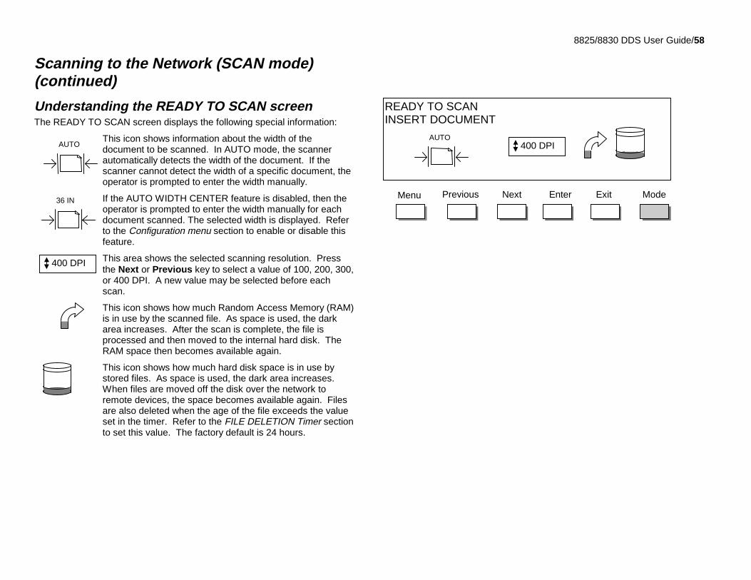
8825/8830 DDS User Guide/58
Scanning to the Network (SCAN mode)(continued)
Understanding the READY TO SCAN screenThe READY TO SCAN screen displays the following special information:
This icon shows information about the width of thedocument to be scanned. In AUTO mode, the scannerautomatically detects the width of the document. If thescanner cannot detect the width of a specific document, theoperator is prompted to enter the width manually.
If the AUTO WIDTH CENTER feature is disabled, then theoperator is prompted to enter the width manually for eachdocument scanned. The selected width is displayed. Referto the Configuration menu section to enable or disable thisfeature.
This area shows the selected scanning resolution. Pressthe Next or Previous key to select a value of 100, 200, 300,or 400 DPI. A new value may be selected before eachscan.
This icon shows how much Random Access Memory (RAM)is in use by the scanned file. As space is used, the darkarea increases. After the scan is complete, the file isprocessed and then moved to the internal hard disk. TheRAM space then becomes available again.
This icon shows how much hard disk space is in use bystored files. As space is used, the dark area increases.When files are moved off the disk over the network toremote devices, the space becomes available again. Filesare also deleted when the age of the file exceeds the valueset in the timer. Refer to the FILE DELETION Timer sectionto set this value. The factory default is 24 hours.
READY TO SCANINSERT DOCUMENT
EnterNext Exit ModeMenu Previous
AUTO 400 DPI
400 DPI
AUTO
36 IN
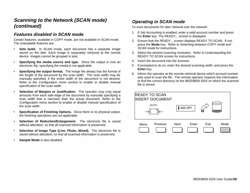
8825/8830 DDS User Guide/59
Scanning to the Network (SCAN mode)(continued)
Features disabled in SCAN modeCertain features, available in COPY mode, are not available in SCAN mode.The unavailable features are:
• Sets build. In SCAN mode, each document has a separate imagestored on the disk. Each image is separately retrieved at the remotedevice. Images cannot be grouped in sets.
• Specifying the media source and type. Since the output is now anelectronic file, specifying the media is not applicable.
• Specifying the output format. The image file always has the format ofthe length of the document by the scan width. The scan width may bemanually specified, if the entire width of the document is not desired.Refer to the Configuration menu section to enable or disable manualspecification of the scan width.
• Selection of Margins or Justification. The operator may crop equalamounts from each side edge of the document by manually specifying ascan width that is narrower than the actual document. Refer to theConfiguration menu section to enable or disable manual specification ofthe scan width.
• Specification of Finishing Options. Since there is no physical output,the finishing operations are not applicable.
• Selection of Reduction/Enlargement. The electronic file is savedwithout alteration, so that all scanned information is preserved.
• Selection of Image Type (Line, Photo, Mixed). The electronic file issaved without alteration, so that all scanned information is preserved.
• Sample Mode is also disabled.
Operating in SCAN modeTo scan documents for later retrieval over the network:
1. If Job Accounting is enabled, enter a valid account number and pressthe Enter key. The READY... screen is displayed.
2. Ensure that the READY... screen displays READY TO SCAN. If not,press the Mode key. Refer to Switching between COPY mode andSCAN mode for instructions.
3. Select the desired scanning resolution. Refer to Understanding theREADY TO SCAN screen for instructions.
4. Insert the document into the Scanner.
5. If prompted to do so, enter the desired scanning width, and press theEnter key.
6. Inform the operator at the remote retrieval device which account numberwas used to scan the file. The remote operator requires this informationto find the correct directory on the 8825/8830 DDS on which the scannedfile is stored.
READY TO SCANINSERT DOCUMENT
EnterNext Exit ModeMenu Previous
AUTO 400 DPI
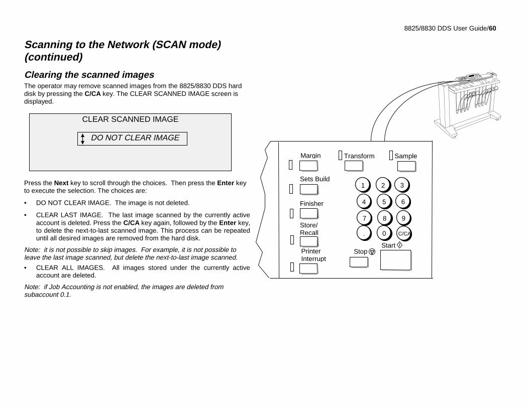
8825/8830 DDS User Guide/60
Scanning to the Network (SCAN mode)(continued)
Clearing the scanned imagesThe operator may remove scanned images from the 8825/8830 DDS harddisk by pressing the C/CA key. The CLEAR SCANNED IMAGE screen isdisplayed.
Press the Next key to scroll through the choices. Then press the Enter keyto execute the selection. The choices are:
• DO NOT CLEAR IMAGE. The image is not deleted.
• CLEAR LAST IMAGE. The last image scanned by the currently activeaccount is deleted. Press the C/CA key again, followed by the Enter key,to delete the next-to-last scanned image. This process can be repeateduntil all desired images are removed from the hard disk.
Note: it is not possible to skip images. For example, it is not possible toleave the last image scanned, but delete the next-to-last image scanned.
• CLEAR ALL IMAGES. All images stored under the currently activeaccount are deleted.
Note: if Job Accounting is not enabled, the images are deleted fromsubaccount 0.1.
PrinterInterrupt
SampleTransform
StopStart
1 2 3
4 5 6
7 8 9
. 0 C/CA
Store/Recall
Margin
Sets Build
Finisher
CLEAR SCANNED IMAGE
DO NOT CLEAR IMAGE
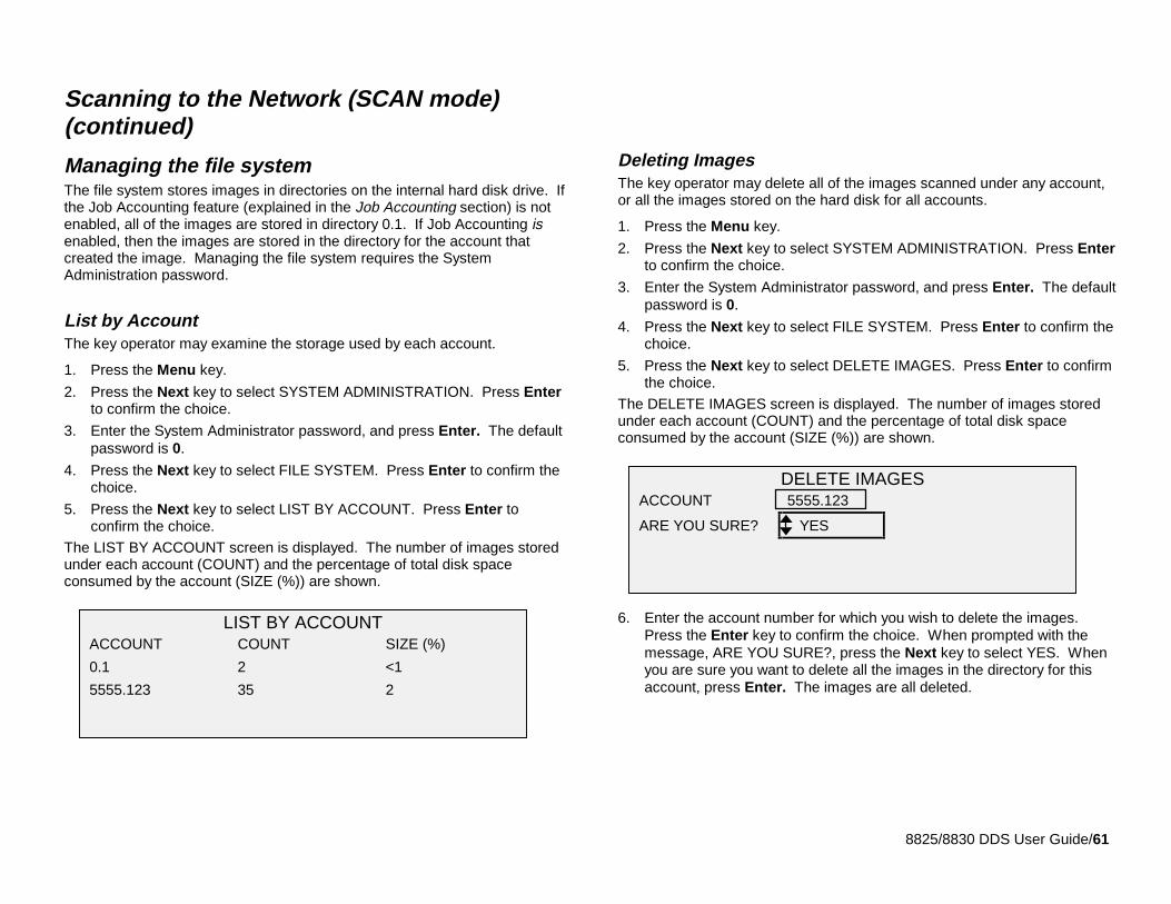
8825/8830 DDS User Guide/61
Scanning to the Network (SCAN mode)(continued)
Managing the file systemThe file system stores images in directories on the internal hard disk drive. Ifthe Job Accounting feature (explained in the Job Accounting section) is notenabled, all of the images are stored in directory 0.1. If Job Accounting isenabled, then the images are stored in the directory for the account thatcreated the image. Managing the file system requires the SystemAdministration password.
List by AccountThe key operator may examine the storage used by each account.
1. Press the Menu key.
2. Press the Next key to select SYSTEM ADMINISTRATION. Press Enterto confirm the choice.
3. Enter the System Administrator password, and press Enter. The defaultpassword is 0.
4. Press the Next key to select FILE SYSTEM. Press Enter to confirm thechoice.
5. Press the Next key to select LIST BY ACCOUNT. Press Enter toconfirm the choice.
The LIST BY ACCOUNT screen is displayed. The number of images storedunder each account (COUNT) and the percentage of total disk spaceconsumed by the account (SIZE (%)) are shown.
Deleting ImagesThe key operator may delete all of the images scanned under any account,or all the images stored on the hard disk for all accounts.
1. Press the Menu key.
2. Press the Next key to select SYSTEM ADMINISTRATION. Press Enterto confirm the choice.
3. Enter the System Administrator password, and press Enter. The defaultpassword is 0.
4. Press the Next key to select FILE SYSTEM. Press Enter to confirm thechoice.
5. Press the Next key to select DELETE IMAGES. Press Enter to confirmthe choice.
The DELETE IMAGES screen is displayed. The number of images storedunder each account (COUNT) and the percentage of total disk spaceconsumed by the account (SIZE (%)) are shown.
6. Enter the account number for which you wish to delete the images.Press the Enter key to confirm the choice. When prompted with themessage, ARE YOU SURE?, press the Next key to select YES. Whenyou are sure you want to delete all the images in the directory for thisaccount, press Enter. The images are all deleted.
LIST BY ACCOUNTACCOUNT COUNT SIZE (%)
0.1 2 <1
5555.123 35 2
DELETE IMAGESACCOUNT 5555.123
ARE YOU SURE? YES
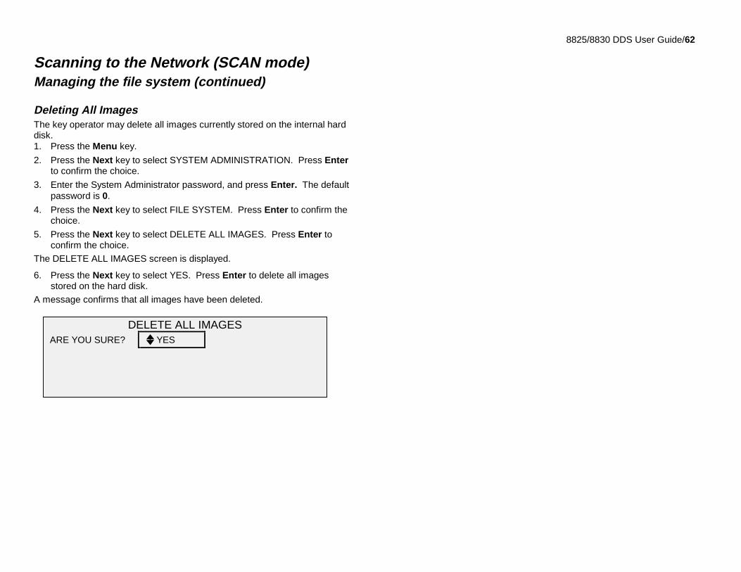
8825/8830 DDS User Guide/62
Scanning to the Network (SCAN mode)Managing the file system (continued)
Deleting All ImagesThe key operator may delete all images currently stored on the internal harddisk.1. Press the Menu key.
2. Press the Next key to select SYSTEM ADMINISTRATION. Press Enterto confirm the choice.
3. Enter the System Administrator password, and press Enter. The defaultpassword is 0.
4. Press the Next key to select FILE SYSTEM. Press Enter to confirm thechoice.
5. Press the Next key to select DELETE ALL IMAGES. Press Enter toconfirm the choice.
The DELETE ALL IMAGES screen is displayed.
6. Press the Next key to select YES. Press Enter to delete all imagesstored on the hard disk.
A message confirms that all images have been deleted.
DELETE ALL IMAGESARE YOU SURE? YES
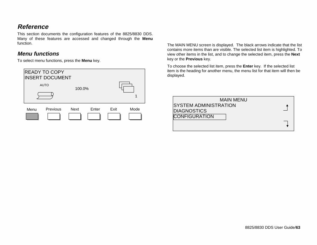
8825/8830 DDS User Guide/63
ReferenceThis section documents the configuration features of the 8825/8830 DDS.Many of these features are accessed and changed through the Menufunction.
Menu functionsTo select menu functions, press the Menu key.
The MAIN MENU screen is displayed. The black arrows indicate that the listcontains more items than are visible. The selected list item is highlighted. Toview other items in the list, and to change the selected item, press the Nextkey or the Previous key.
To choose the selected list item, press the Enter key. If the selected listitem is the heading for another menu, the menu list for that item will then bedisplayed.
EnterNext ExitPrevious ModeMenu
READY TO COPYINSERT DOCUMENT
100.0%AUTO
1MAIN MENU
SYSTEM ADMINISTRATIONDIAGNOSTICSCONFIGURATION
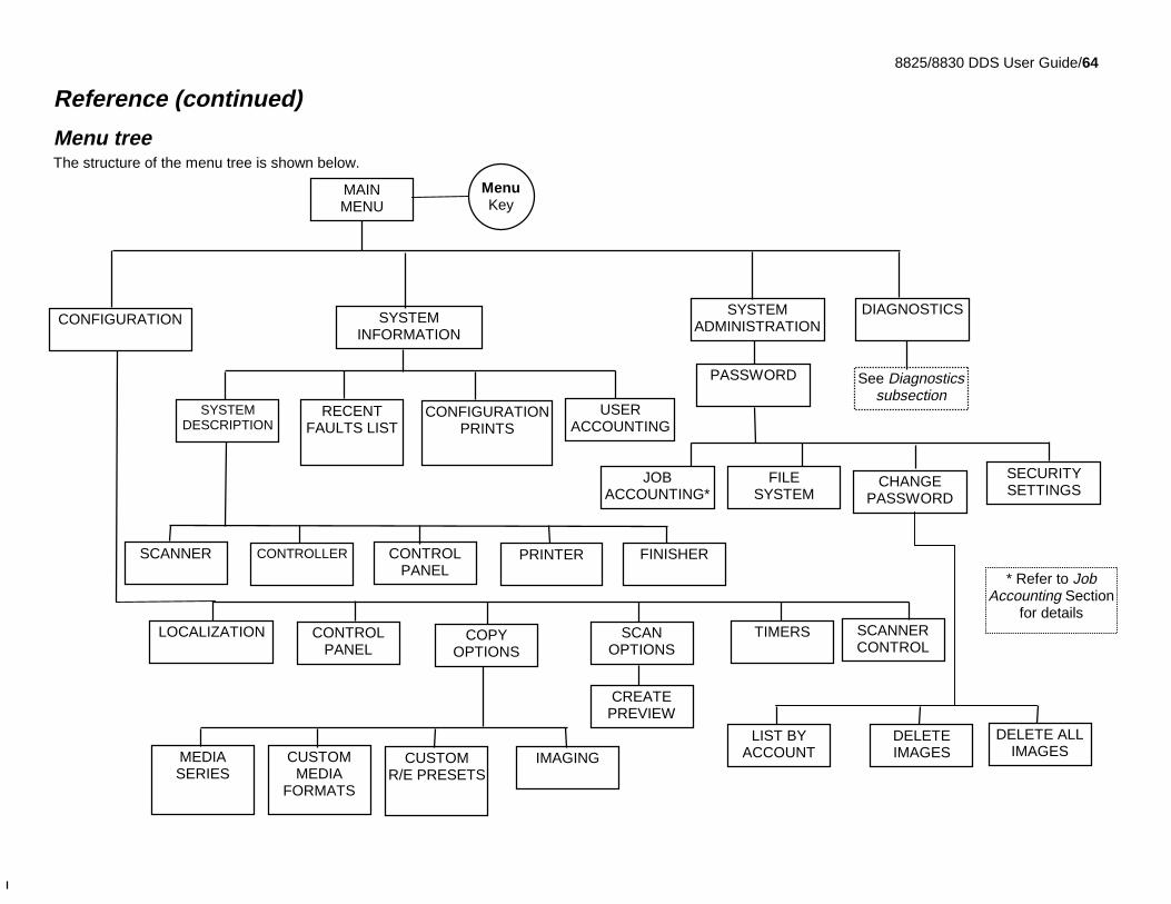
8825/8830 DDS User Guide/64
Reference (continued)
Menu treeThe structure of the menu tree is shown below.
* Refer to JobAccounting Section
for details
SECURITYSETTINGS
DELETE ALLIMAGES
See Diagnosticssubsection
CREATEPREVIEW
SCANOPTIONS
LOCALIZATION
MEDIASERIES
CUSTOMMEDIA
FORMATS
IMAGINGCUSTOMR/E PRESETS
COPYOPTIONS
SCANNERCONTROL
CONTROLPANEL
TIMERS
CHANGEPASSWORD
FILESYSTEM
JOBACCOUNTING*
MAINMENU
DIAGNOSTICSCONFIGURATION
SYSTEMADMINISTRATION
PASSWORD
SYSTEMINFORMATION
RECENTFAULTS LIST
CONFIGURATIONPRINTS
USERACCOUNTING
SYSTEMDESCRIPTION
SCANNER CONTROLLER CONTROLPANEL
PRINTER FINISHER
MenuKey
LIST BYACCOUNT
DELETEIMAGES
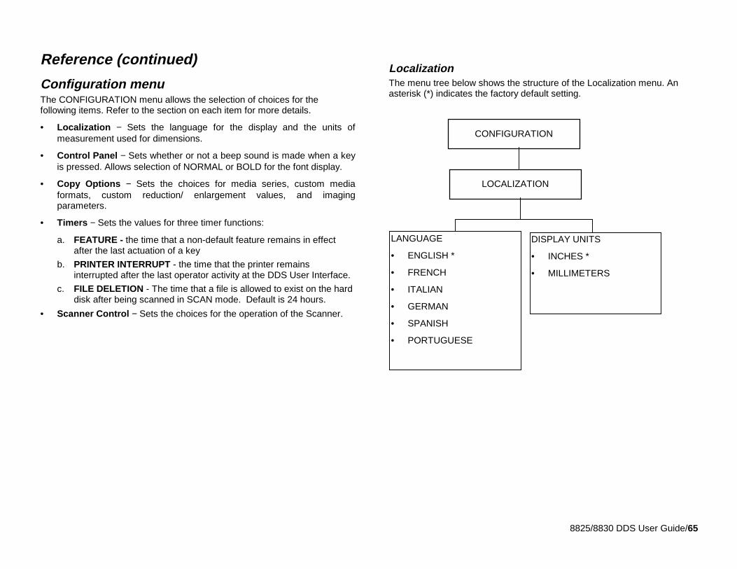
8825/8830 DDS User Guide/65
Reference (continued)
Configuration menuThe CONFIGURATION menu allows the selection of choices for thefollowing items. Refer to the section on each item for more details.
• Localization − Sets the language for the display and the units ofmeasurement used for dimensions.
• Control Panel − Sets whether or not a beep sound is made when a keyis pressed. Allows selection of NORMAL or BOLD for the font display.
• Copy Options − Sets the choices for media series, custom mediaformats, custom reduction/ enlargement values, and imagingparameters.
• Timers − Sets the values for three timer functions:
a. FEATURE - the time that a non-default feature remains in effectafter the last actuation of a key
b. PRINTER INTERRUPT - the time that the printer remainsinterrupted after the last operator activity at the DDS User Interface.
c. FILE DELETION - The time that a file is allowed to exist on the harddisk after being scanned in SCAN mode. Default is 24 hours.
• Scanner Control − Sets the choices for the operation of the Scanner.
LocalizationThe menu tree below shows the structure of the Localization menu. Anasterisk (*) indicates the factory default setting.
DISPLAY UNITS
• INCHES *
• MILLIMETERS
LANGUAGE
• ENGLISH *
• FRENCH
• ITALIAN
• GERMAN
• SPANISH
• PORTUGUESE
CONFIGURATION
LOCALIZATION
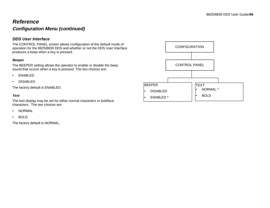
8825/8830 DDS User Guide/66
ReferenceConfiguration Menu (continued)
DDS User InterfaceThe CONTROL PANEL screen allows configuration of the default mode ofoperation for the 8825/8830 DDS and whether or not the DDS User Interfaceproduces a beep when a key is pressed.
Beeper
The BEEPER setting allows the operator to enable or disable the beepsound that occurs when a key is pressed. The two choices are:
• ENABLED
• DISABLED
The factory default is ENABLED.
Text
The text display may be set for either normal characters or boldfacecharacters. The two choices are:
• NORMAL
• BOLD
The factory default is NORMAL.
CONTROL PANEL
TEXT:• NORMAL *
• BOLD
BEEPER
• DISABLED
• ENABLED *
CONFIGURATION
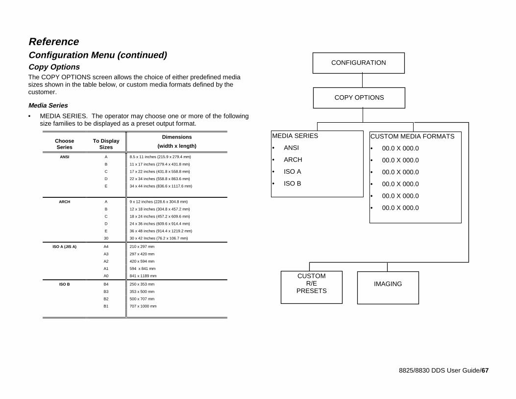
8825/8830 DDS User Guide/67
ReferenceConfiguration Menu (continued)Copy OptionsThe COPY OPTIONS screen allows the choice of either predefined mediasizes shown in the table below, or custom media formats defined by thecustomer.
Media Series
• MEDIA SERIES. The operator may choose one or more of the followingsize families to be displayed as a preset output format.
ChooseSeries
To DisplaySizes
Dimensions
(width x length)
ANSI A 8.5 x 11 inches (215.9 x 279.4 mm)
B 11 x 17 inches (279.4 x 431.8 mm)
C 17 x 22 inches (431.8 x 558.8 mm)
D 22 x 34 inches (558.8 x 863.6 mm)
E 34 x 44 inches (836.6 x 1117.6 mm)
ARCH A 9 x 12 inches (228.6 x 304.8 mm)
B 12 x 18 inches (304.8 x 457.2 mm)
C 18 x 24 inches (457.2 x 609.6 mm)
D 24 x 36 inches (609.6 x 914.4 mm)
E 36 x 48 inches (914.4 x 1219.2 mm)
30 30 x 42 Inches (76.2 x 106.7 mm)
ISO A (JIS A) A4 210 x 297 mm
A3 297 x 420 mm
A2 420 x 594 mm
A1 594 x 841 mm
A0 841 x 1189 mm
ISO B B4 250 x 353 mm
B3 353 x 500 mm
B2 500 x 707 mm
B1 707 x 1000 mm
CUSTOM MEDIA FORMATS
• 00.0 X 000.0
• 00.0 X 000.0
• 00.0 X 000.0
• 00.0 X 000.0
• 00.0 X 000.0
• 00.0 X 000.0
COPY OPTIONS
MEDIA SERIES
• ANSI
• ARCH
• ISO A
• ISO B
CONFIGURATION
IMAGINGCUSTOM
R/EPRESETS
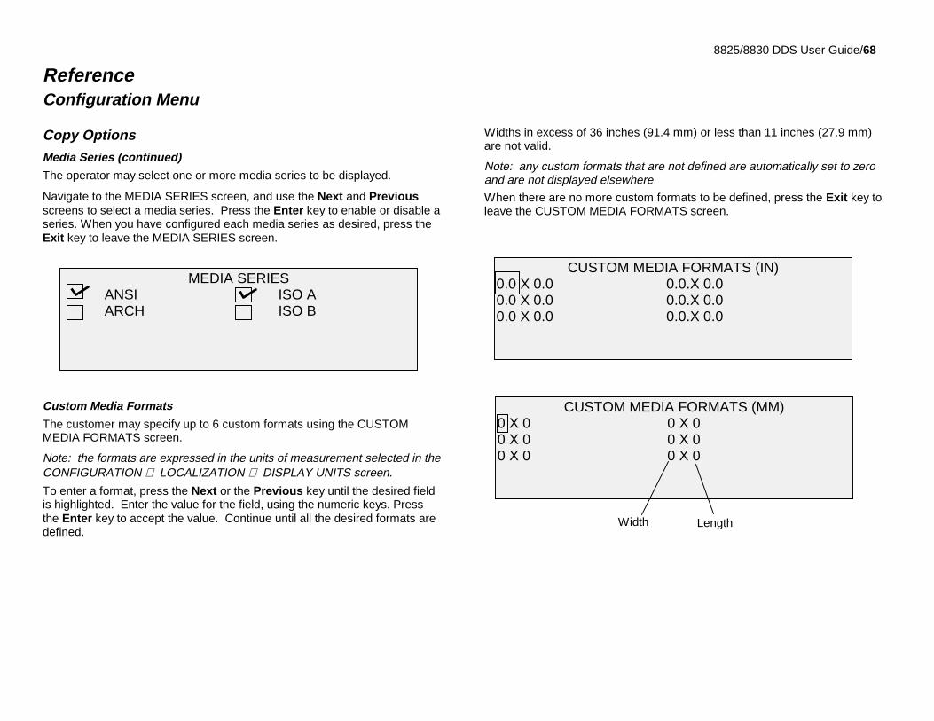
8825/8830 DDS User Guide/68
ReferenceConfiguration Menu
Copy OptionsMedia Series (continued)
The operator may select one or more media series to be displayed.
Navigate to the MEDIA SERIES screen, and use the Next and Previousscreens to select a media series. Press the Enter key to enable or disable aseries. When you have configured each media series as desired, press theExit key to leave the MEDIA SERIES screen.
Custom Media Formats
The customer may specify up to 6 custom formats using the CUSTOMMEDIA FORMATS screen.
Note: the formats are expressed in the units of measurement selected in theCONFIGURATION ⇒ LOCALIZATION ⇒ DISPLAY UNITS screen.
To enter a format, press the Next or the Previous key until the desired fieldis highlighted. Enter the value for the field, using the numeric keys. Pressthe Enter key to accept the value. Continue until all the desired formats aredefined.
Widths in excess of 36 inches (91.4 mm) or less than 11 inches (27.9 mm)are not valid.
Note: any custom formats that are not defined are automatically set to zeroand are not displayed elsewhere
When there are no more custom formats to be defined, press the Exit key toleave the CUSTOM MEDIA FORMATS screen.
MEDIA SERIESANSI ISO AARCH ISO B
CUSTOM MEDIA FORMATS (IN)0.0 X 0.0 0.0.X 0.00.0 X 0.0 0.0.X 0.00.0 X 0.0 0.0.X 0.0
CUSTOM MEDIA FORMATS (MM)0 X 0 0 X 00 X 0 0 X 00 X 0 0 X 0
LengthWidth
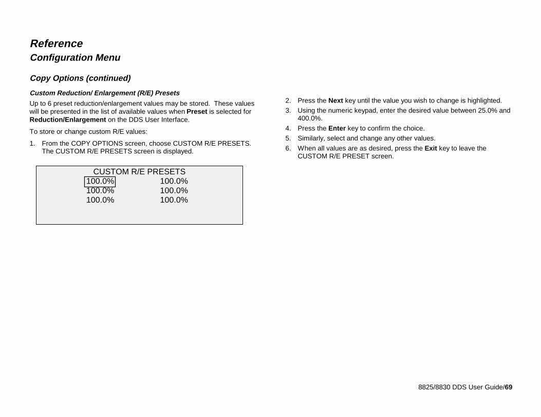
8825/8830 DDS User Guide/69
ReferenceConfiguration Menu
Copy Options (continued)
Custom Reduction/ Enlargement (R/E) Presets
Up to 6 preset reduction/enlargement values may be stored. These valueswill be presented in the list of available values when Preset is selected forReduction/Enlargement on the DDS User Interface.
To store or change custom R/E values:
1. From the COPY OPTIONS screen, choose CUSTOM R/E PRESETS.The CUSTOM R/E PRESETS screen is displayed.
2. Press the Next key until the value you wish to change is highlighted.
3. Using the numeric keypad, enter the desired value between 25.0% and400.0%.
4. Press the Enter key to confirm the choice.
5. Similarly, select and change any other values.
6. When all values are as desired, press the Exit key to leave theCUSTOM R/E PRESET screen.
CUSTOM R/E PRESETS100.0% 100.0%100.0% 100.0%100.0% 100.0%
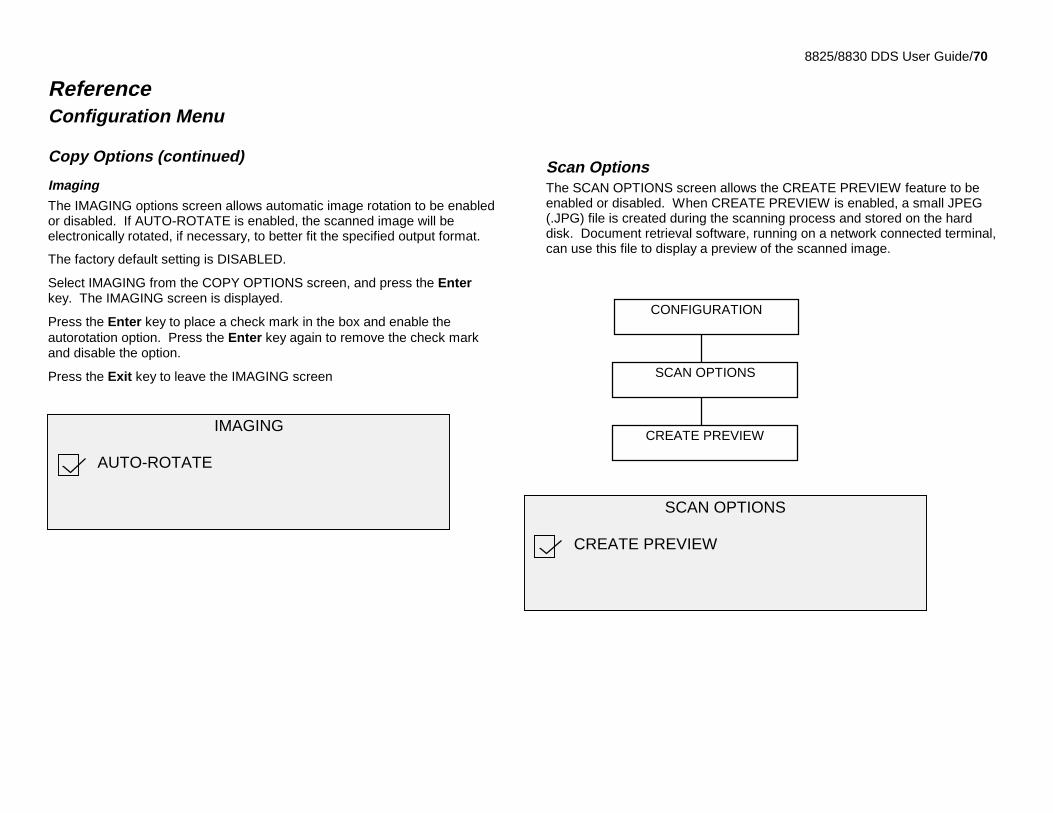
8825/8830 DDS User Guide/70
ReferenceConfiguration Menu
Copy Options (continued)
Imaging
The IMAGING options screen allows automatic image rotation to be enabledor disabled. If AUTO-ROTATE is enabled, the scanned image will beelectronically rotated, if necessary, to better fit the specified output format.
The factory default setting is DISABLED.
Select IMAGING from the COPY OPTIONS screen, and press the Enterkey. The IMAGING screen is displayed.
Press the Enter key to place a check mark in the box and enable theautorotation option. Press the Enter key again to remove the check markand disable the option.
Press the Exit key to leave the IMAGING screen
Scan OptionsThe SCAN OPTIONS screen allows the CREATE PREVIEW feature to beenabled or disabled. When CREATE PREVIEW is enabled, a small JPEG(.JPG) file is created during the scanning process and stored on the harddisk. Document retrieval software, running on a network connected terminal,can use this file to display a preview of the scanned image.
IMAGING
AUTO-ROTATE
CONFIGURATION
SCAN OPTIONS
CREATE PREVIEW
SCAN OPTIONS
CREATE PREVIEW
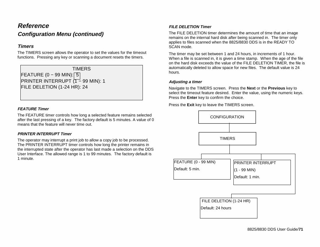
8825/8830 DDS User Guide/71
ReferenceConfiguration Menu (continued)
TimersThe TIMERS screen allows the operator to set the values for the timeoutfunctions. Pressing any key or scanning a document resets the timers.
FEATURE Timer
The FEATURE timer controls how long a selected feature remains selectedafter the last pressing of a key. The factory default is 5 minutes. A value of 0means that the feature will never time out.
PRINTER INTERRUPT Timer
The operator may interrupt a print job to allow a copy job to be processed.The PRINTER INTERRUPT timer controls how long the printer remains inthe interrupted state after the operator has last made a selection on the DDSUser Interface. The allowed range is 1 to 99 minutes. The factory default is1 minute.
FILE DELETION Timer
The FILE DELETION timer determines the amount of time that an imageremains on the internal hard disk after being scanned in. The timer onlyapplies to files scanned when the 8825/8830 DDS is in the READY TOSCAN mode.
The timer may be set between 1 and 24 hours, in increments of 1 hour.When a file is scanned in, it is given a time stamp. When the age of the fileon the hard disk exceeds the value of the FILE DELETION TIMER, the file isautomatically deleted to allow space for new files. The default value is 24hours.
Adjusting a timer
Navigate to the TIMERS screen. Press the Next or the Previous key toselect the timeout feature desired. Enter the value, using the numeric keys.Press the Enter key to confirm the choice.
Press the Exit key to leave the TIMERS screen.
TIMERSFEATURE (0 − 99 MIN): 5PRINTER INTERRUPT (1 − 99 MIN): 1FILE DELETION (1-24 HR): 24
PRINTER INTERRUPT
(1 - 99 MIN)
Default: 1 min.
FILE DELETION (1-24 HR)
Default: 24 hours
FEATURE (0 - 99 MIN)
Default: 5 min.
TIMERS
CONFIGURATION
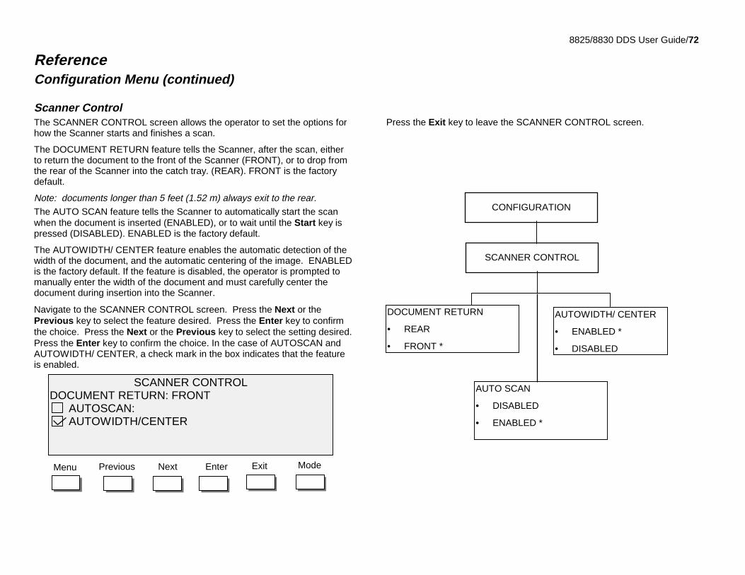
8825/8830 DDS User Guide/72
ReferenceConfiguration Menu (continued)
Scanner ControlThe SCANNER CONTROL screen allows the operator to set the options forhow the Scanner starts and finishes a scan.
The DOCUMENT RETURN feature tells the Scanner, after the scan, eitherto return the document to the front of the Scanner (FRONT), or to drop fromthe rear of the Scanner into the catch tray. (REAR). FRONT is the factorydefault.
Note: documents longer than 5 feet (1.52 m) always exit to the rear.The AUTO SCAN feature tells the Scanner to automatically start the scanwhen the document is inserted (ENABLED), or to wait until the Start key ispressed (DISABLED). ENABLED is the factory default.
The AUTOWIDTH/ CENTER feature enables the automatic detection of thewidth of the document, and the automatic centering of the image. ENABLEDis the factory default. If the feature is disabled, the operator is prompted tomanually enter the width of the document and must carefully center thedocument during insertion into the Scanner.
Navigate to the SCANNER CONTROL screen. Press the Next or thePrevious key to select the feature desired. Press the Enter key to confirmthe choice. Press the Next or the Previous key to select the setting desired.Press the Enter key to confirm the choice. In the case of AUTOSCAN andAUTOWIDTH/ CENTER, a check mark in the box indicates that the featureis enabled.
Press the Exit key to leave the SCANNER CONTROL screen.
AUTO SCAN
• DISABLED
• ENABLED *
AUTOWIDTH/ CENTER
• ENABLED *
• DISABLED
DOCUMENT RETURN
• REAR
• FRONT *
SCANNER CONTROL
CONFIGURATION
EnterNext ExitPrevious ModeMenu
SCANNER CONTROLDOCUMENT RETURN: FRONT AUTOSCAN: AUTOWIDTH/CENTER
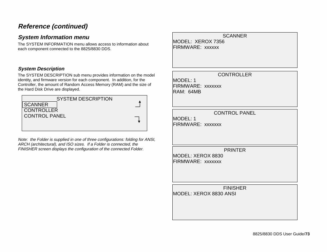
8825/8830 DDS User Guide/73
Reference (continued)
System Information menuThe SYSTEM INFORMATION menu allows access to information abouteach component connected to the 8825/8830 DDS.
System DescriptionThe SYSTEM DESCRIPTION sub menu provides information on the modelidentity, and firmware version for each component. In addition, for theController, the amount of Random Access Memory (RAM) and the size ofthe Hard Disk Drive are displayed.
Note: the Folder is supplied in one of three configurations: folding for ANSI,ARCH (architectural), and ISO sizes. If a Folder is connected, theFINISHER screen displays the configuration of the connected Folder.
SCANNERMODEL: XEROX 7356FIRMWARE: xxxxxx
FINISHERMODEL: XEROX 8830 ANSI
PRINTERMODEL: XEROX 8830FIRMWARE: xxxxxxx
CONTROL PANELMODEL: 1FIRMWARE: xxxxxxx
CONTROLLERMODEL: 1FIRMWARE: xxxxxxxRAM: 64MB
SYSTEM DESCRIPTION SCANNER CONTROLLER CONTROL PANEL
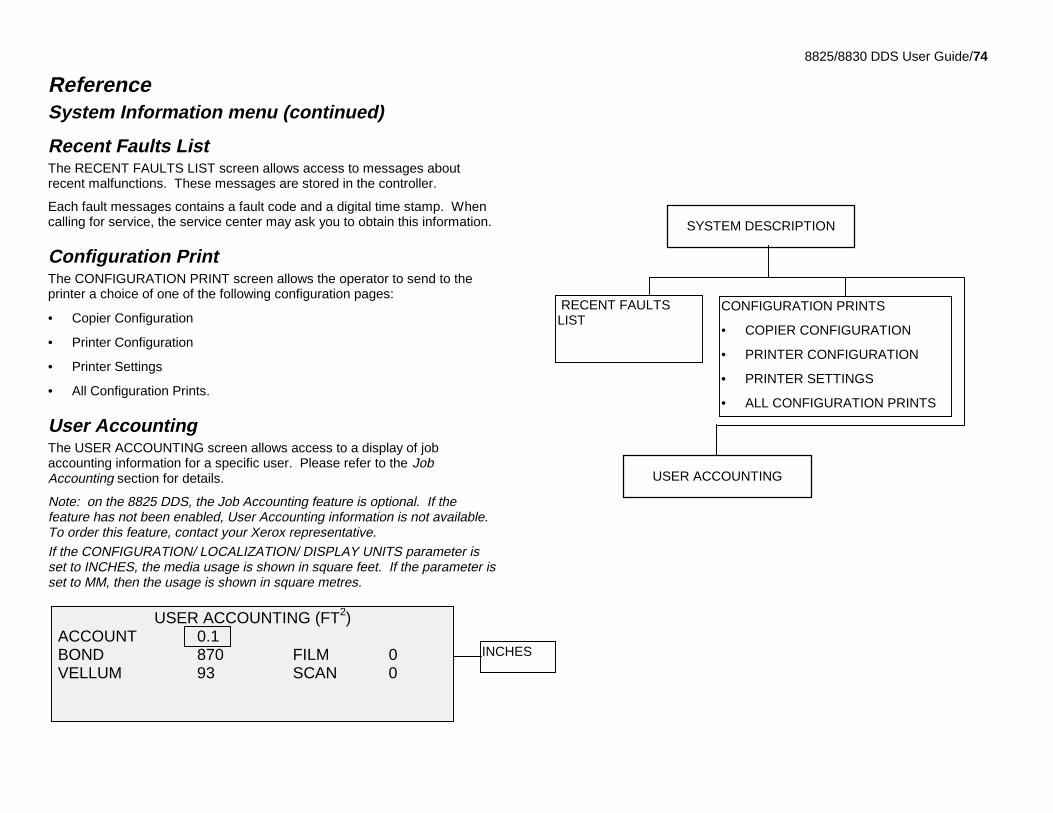
8825/8830 DDS User Guide/74
ReferenceSystem Information menu (continued)
Recent Faults ListThe RECENT FAULTS LIST screen allows access to messages aboutrecent malfunctions. These messages are stored in the controller.
Each fault messages contains a fault code and a digital time stamp. Whencalling for service, the service center may ask you to obtain this information.
Configuration PrintThe CONFIGURATION PRINT screen allows the operator to send to theprinter a choice of one of the following configuration pages:
• Copier Configuration
• Printer Configuration
• Printer Settings
• All Configuration Prints.
User AccountingThe USER ACCOUNTING screen allows access to a display of jobaccounting information for a specific user. Please refer to the JobAccounting section for details.
Note: on the 8825 DDS, the Job Accounting feature is optional. If thefeature has not been enabled, User Accounting information is not available.To order this feature, contact your Xerox representative.If the CONFIGURATION/ LOCALIZATION/ DISPLAY UNITS parameter isset to INCHES, the media usage is shown in square feet. If the parameter isset to MM, then the usage is shown in square metres.
CONFIGURATION PRINTS
• COPIER CONFIGURATION
• PRINTER CONFIGURATION
• PRINTER SETTINGS
• ALL CONFIGURATION PRINTS
RECENT FAULTSLIST
USER ACCOUNTING
SYSTEM DESCRIPTION
USER ACCOUNTING (FT2) ACCOUNT 0.1 BOND 870 FILM 0 VELLUM 93 SCAN 0
INCHES
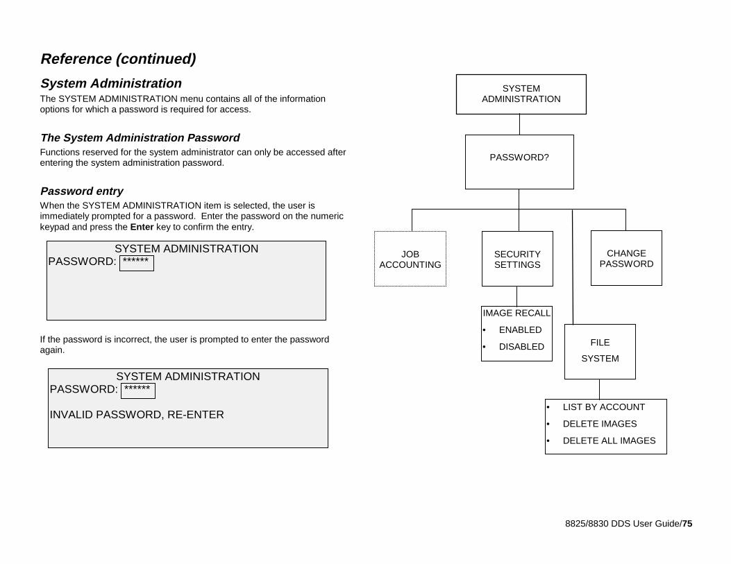
8825/8830 DDS User Guide/75
Reference (continued)
System AdministrationThe SYSTEM ADMINISTRATION menu contains all of the informationoptions for which a password is required for access.
The System Administration PasswordFunctions reserved for the system administrator can only be accessed afterentering the system administration password.
Password entryWhen the SYSTEM ADMINISTRATION item is selected, the user isimmediately prompted for a password. Enter the password on the numerickeypad and press the Enter key to confirm the entry.
If the password is incorrect, the user is prompted to enter the passwordagain.
SYSTEM ADMINISTRATIONPASSWORD: ******
SYSTEM ADMINISTRATIONPASSWORD: ******
INVALID PASSWORD, RE-ENTER
SYSTEMADMINISTRATION
PASSWORD?
IMAGE RECALL
• ENABLED
• DISABLED
CHANGEPASSWORD
SECURITYSETTINGS
JOBACCOUNTING
• LIST BY ACCOUNT
• DELETE IMAGES
• DELETE ALL IMAGES
FILE
SYSTEM
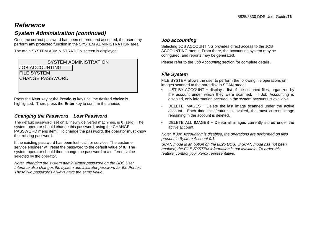
8825/8830 DDS User Guide/76
ReferenceSystem Administration (continued)Once the correct password has been entered and accepted, the user mayperform any protected function in the SYSTEM ADMINISTRATION area.
The main SYSTEM ADMINISTRATION screen is displayed:
Press the Next key or the Previous key until the desired choice ishighlighted. Then, press the Enter key to confirm the choice.
Changing the Password − Lost PasswordThe default password, set on all newly delivered machines, is 0 (zero). Thesystem operator should change this password, using the CHANGEPASSWORD menu item. To change the password, the operator must knowthe existing password.
If the existing password has been lost, call for service. The customerservice engineer will reset the password to the default value of 0. Thesystem operator should then change the password to a different valueselected by the operator.
Note: changing the system administrator password on the DDS UserInterface also changes the system administrator password for the Printer.These two passwords always have the same value.
Job accountingSelecting JOB ACCOUNTING provides direct access to the JOBACCOUNTING menu. From there, the accounting system may beconfigured, and reports may be generated.
Please refer to the Job Accounting section for complete details.
File SystemFILE SYSTEM allows the user to perform the following file operations onimages scanned to the hard disk in SCAN mode:• LIST BY ACCOUNT − display a list of the scanned files, organized by
the account under which they were scanned. If Job Accounting isdisabled, only information accrued in the system accounts is available.
• DELETE IMAGES − Delete the last image scanned under the activeaccount. Each time this feature is invoked, the most current imageremaining in the account is deleted.
• DELETE ALL IMAGES − Delete all images currently stored under theactive account.
Note: if Job Accounting is disabled, the operations are performed on filespresent in System Account 0.1.SCAN mode is an option on the 8825 DDS. If SCAN mode has not beenenabled, the FILE SYSTEM information is not available. To order thisfeature, contact your Xerox representative.
SYSTEM ADMINISTRATIONJOB ACCOUNTINGFILE SYSTEMCHANGE PASSWORD
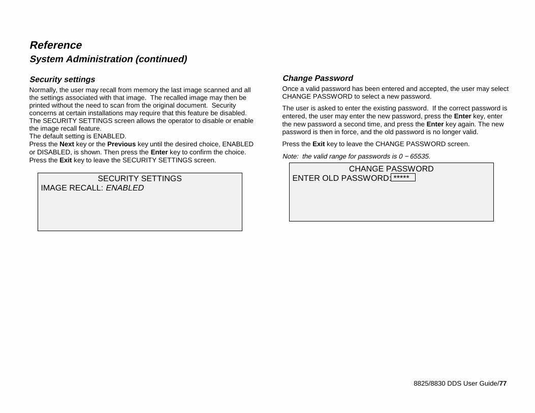
8825/8830 DDS User Guide/77
ReferenceSystem Administration (continued)
Security settingsNormally, the user may recall from memory the last image scanned and allthe settings associated with that image. The recalled image may then beprinted without the need to scan from the original document. Securityconcerns at certain installations may require that this feature be disabled.The SECURITY SETTINGS screen allows the operator to disable or enablethe image recall feature.The default setting is ENABLED.Press the Next key or the Previous key until the desired choice, ENABLEDor DISABLED, is shown. Then press the Enter key to confirm the choice.Press the Exit key to leave the SECURITY SETTINGS screen.
Change PasswordOnce a valid password has been entered and accepted, the user may selectCHANGE PASSWORD to select a new password.
The user is asked to enter the existing password. If the correct password isentered, the user may enter the new password, press the Enter key, enterthe new password a second time, and press the Enter key again. The newpassword is then in force, and the old password is no longer valid.
Press the Exit key to leave the CHANGE PASSWORD screen.
Note: the valid range for passwords is 0 − 65535.
SECURITY SETTINGS IMAGE RECALL: ENABLED
CHANGE PASSWORD ENTER OLD PASSWORD: *****
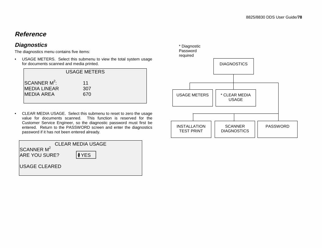
8825/8830 DDS User Guide/78
Reference
DiagnosticsThe diagnostics menu contains five items:
• USAGE METERS. Select this submenu to view the total system usagefor documents scanned and media printed.
• CLEAR MEDIA USAGE. Select this submenu to reset to zero the usagevalue for documents scanned. This function is reserved for theCustomer Service Engineer, so the diagnostic password must first beentered. Return to the PASSWORD screen and enter the diagnosticspassword if it has not been entered already.
DIAGNOSTICS
* CLEAR MEDIAUSAGE
USAGE METERS
PASSWORDINSTALLATIONTEST PRINT
SCANNERDIAGNOSTICS
* DiagnosticPasswordrequired
USAGE METERS
SCANNER M2: 11MEDIA LINEAR 307MEDIA AREA 670
CLEAR MEDIA USAGESCANNER M2
ARE YOU SURE? YES
USAGE CLEARED
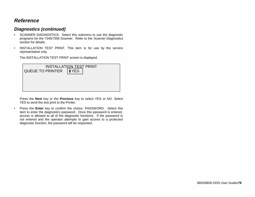
8825/8830 DDS User Guide/79
Reference
Diagnostics (continued)• SCANNER DIAGNOSTICS. Select this submenu to use the diagnostic
programs for the 7346/7356 Scanner. Refer to the Scanner Diagnosticssection for details.
• INSTALLATION TEST PRINT. This item is for use by the servicerepresentative only.
The INSTALLATION TEST PRINT screen is displayed.
Press the Next key or the Previous key to select YES or NO. SelectYES to send the test print to the Printer.
• Press the Enter key to confirm the choice. PASSWORD. Select thisitem to enter the diagnostics password. Once this password is entered,access is allowed to all of the diagnostic functions. If the password isnot entered and the operator attempts to gain access to a protecteddiagnostic function, the password will be requested.
INSTALLATION TEST PRINT QUEUE TO PRINTER YES
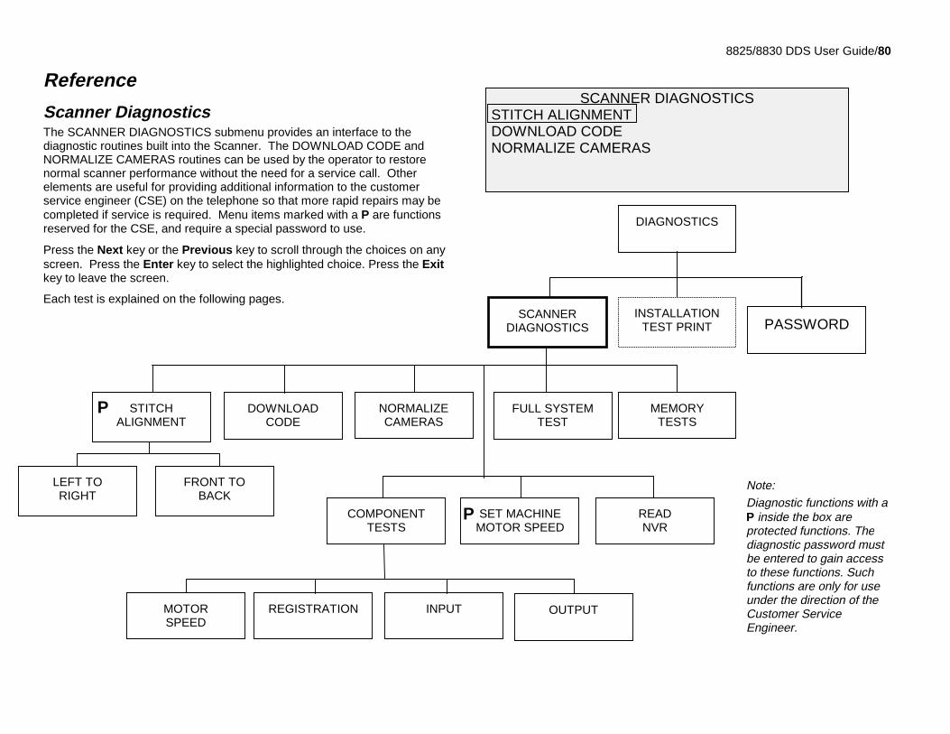
8825/8830 DDS User Guide/80
Reference
Scanner DiagnosticsThe SCANNER DIAGNOSTICS submenu provides an interface to thediagnostic routines built into the Scanner. The DOWNLOAD CODE andNORMALIZE CAMERAS routines can be used by the operator to restorenormal scanner performance without the need for a service call. Otherelements are useful for providing additional information to the customerservice engineer (CSE) on the telephone so that more rapid repairs may becompleted if service is required. Menu items marked with a P are functionsreserved for the CSE, and require a special password to use.
Press the Next key or the Previous key to scroll through the choices on anyscreen. Press the Enter key to select the highlighted choice. Press the Exitkey to leave the screen.
Each test is explained on the following pages.
SCANNER DIAGNOSTICS STITCH ALIGNMENT DOWNLOAD CODE NORMALIZE CAMERAS
SCANNERDIAGNOSTICS
READNVR
SET MACHINEMOTOR SPEED
COMPONENTTESTS
FULL SYSTEMTEST
MEMORYTESTS
PASSWORD
NORMALIZECAMERAS
DOWNLOADCODE
DIAGNOSTICS
INSTALLATIONTEST PRINT
LEFT TORIGHT
FRONT TOBACK
STITCHALIGNMENT
OUTPUTINPUTREGISTRATIONMOTORSPEED
Note:Diagnostic functions with aP inside the box areprotected functions. Thediagnostic password mustbe entered to gain accessto these functions. Suchfunctions are only for useunder the direction of theCustomer ServiceEngineer.
P
P
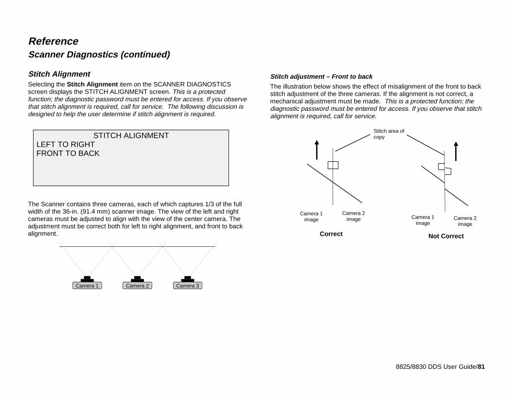
8825/8830 DDS User Guide/81
ReferenceScanner Diagnostics (continued)
Stitch AlignmentSelecting the Stitch Alignment item on the SCANNER DIAGNOSTICSscreen displays the STITCH ALIGNMENT screen. This is a protectedfunction; the diagnostic password must be entered for access. If you observethat stitch alignment is required, call for service. The following discussion isdesigned to help the user determine if stitch alignment is required.
The Scanner contains three cameras, each of which captures 1/3 of the fullwidth of the 36-in. (91.4 mm) scanner image. The view of the left and rightcameras must be adjusted to align with the view of the center camera. Theadjustment must be correct both for left to right alignment, and front to backalignment.
Stitch adjustment – Front to back
The illustration below shows the effect of misalignment of the front to backstitch adjustment of the three cameras. If the alignment is not correct, amechanical adjustment must be made. This is a protected function; thediagnostic password must be entered for access. If you observe that stitchalignment is required, call for service.
STITCH ALIGNMENT LEFT TO RIGHT FRONT TO BACK
Camera 3Camera 2Camera 1
Camera 1image
Camera 2image Camera 1
imageCamera 2
image
Stitch area ofcopy
Correct Not Correct
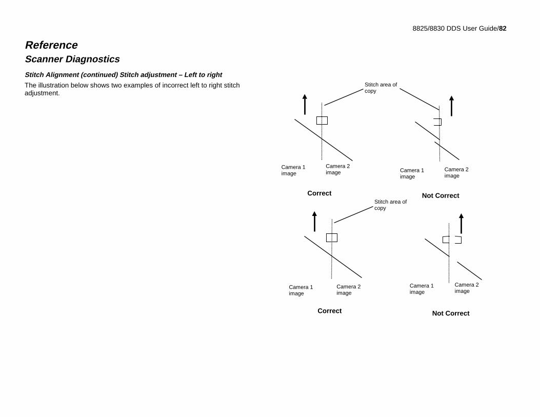
8825/8830 DDS User Guide/82
ReferenceScanner Diagnostics
Stitch Alignment (continued) Stitch adjustment – Left to right
The illustration below shows two examples of incorrect left to right stitchadjustment.
Correct Not Correct
Correct
Camera 1image
Camera 2image Camera 1
imageCamera 2image
Stitch area ofcopy
Not Correct
Camera 1image
Camera 2image
Camera 1image
Camera 2image
Stitch area ofcopy
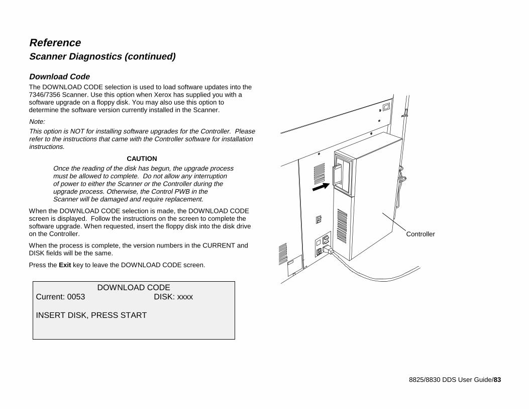
8825/8830 DDS User Guide/83
ReferenceScanner Diagnostics (continued)
Download CodeThe DOWNLOAD CODE selection is used to load software updates into the7346/7356 Scanner. Use this option when Xerox has supplied you with asoftware upgrade on a floppy disk. You may also use this option todetermine the software version currently installed in the Scanner.
Note:This option is NOT for installing software upgrades for the Controller. Pleaserefer to the instructions that came with the Controller software for installationinstructions.
CAUTIONOnce the reading of the disk has begun, the upgrade processmust be allowed to complete. Do not allow any interruptionof power to either the Scanner or the Controller during theupgrade process. Otherwise, the Control PWB in theScanner will be damaged and require replacement.
When the DOWNLOAD CODE selection is made, the DOWNLOAD CODEscreen is displayed. Follow the instructions on the screen to complete thesoftware upgrade. When requested, insert the floppy disk into the disk driveon the Controller.
When the process is complete, the version numbers in the CURRENT andDISK fields will be the same.
Press the Exit key to leave the DOWNLOAD CODE screen.
DOWNLOAD CODE Current: 0053 DISK: xxxx
INSERT DISK, PRESS START
Controller
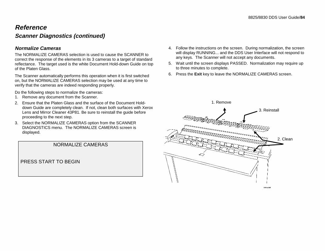
8825/8830 DDS User Guide/84
ReferenceScanner Diagnostics (continued)
Normalize CamerasThe NORMALIZE CAMERAS selection is used to cause the SCANNER tocorrect the response of the elements in its 3 cameras to a target of standardreflectance. The target used is the white Document Hold-down Guide on topof the Platen Glass.
The Scanner automatically performs this operation when it is first switchedon, but the NORMALIZE CAMERAS selection may be used at any time toverify that the cameras are indeed responding properly.
Do the following steps to normalize the cameras:1. Remove any document from the Scanner.
2. Ensure that the Platen Glass and the surface of the Document Hold-down Guide are completely clean. If not, clean both surfaces with XeroxLens and Mirror Cleaner 43P81. Be sure to reinstall the guide beforeproceeding to the next step.
3. Select the NORMALIZE CAMERAS option from the SCANNERDIAGNOSTICS menu. The NORMALIZE CAMERAS screen isdisplayed.
4. Follow the instructions on the screen. During normalization, the screenwill display RUNNING... and the DDS User Interface will not respond toany keys. The Scanner will not accept any documents.
5. Wait until the screen displays PASSED. Normalization may require upto three minutes to complete.
6. Press the Exit key to leave the NORMALIZE CAMERAS screen.
NORMALIZE CAMERAS
PRESS START TO BEGIN
3. Reinstall
1. Remove
2. Clean
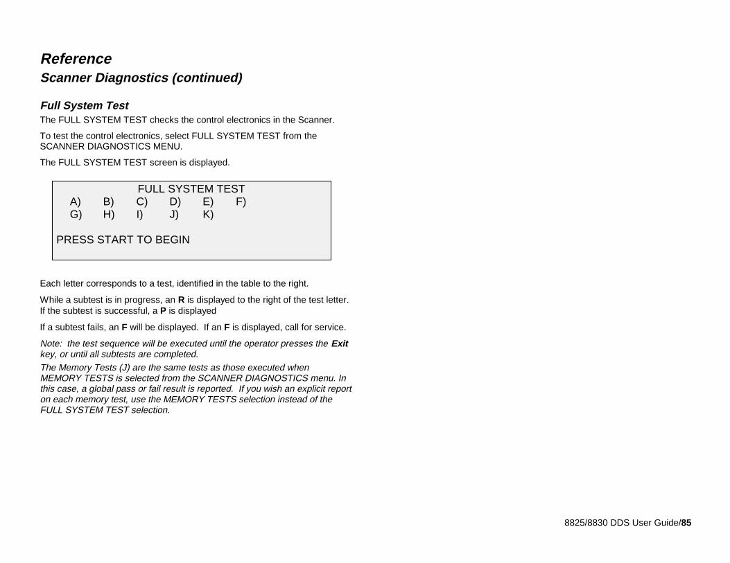
8825/8830 DDS User Guide/85
ReferenceScanner Diagnostics (continued)
Full System TestThe FULL SYSTEM TEST checks the control electronics in the Scanner.
To test the control electronics, select FULL SYSTEM TEST from theSCANNER DIAGNOSTICS MENU.
The FULL SYSTEM TEST screen is displayed.
Each letter corresponds to a test, identified in the table to the right.
While a subtest is in progress, an R is displayed to the right of the test letter.If the subtest is successful, a P is displayed
If a subtest fails, an F will be displayed. If an F is displayed, call for service.
Note: the test sequence will be executed until the operator presses the Exitkey, or until all subtests are completed.The Memory Tests (J) are the same tests as those executed whenMEMORY TESTS is selected from the SCANNER DIAGNOSTICS menu. Inthis case, a global pass or fail result is reported. If you wish an explicit reporton each memory test, use the MEMORY TESTS selection instead of theFULL SYSTEM TEST selection.
FULL SYSTEM TESTA) B) C) D) E) F)G) H) I) J) K)
PRESS START TO BEGIN
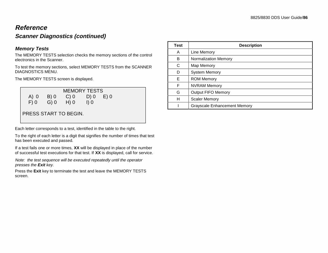
8825/8830 DDS User Guide/86
ReferenceScanner Diagnostics (continued)
Memory TestsThe MEMORY TESTS selection checks the memory sections of the controlelectronics in the Scanner.
To test the memory sections, select MEMORY TESTS from the SCANNERDIAGNOSTICS MENU.
The MEMORY TESTS screen is displayed.
Each letter corresponds to a test, identified in the table to the right.
To the right of each letter is a digit that signifies the number of times that testhas been executed and passed.
If a test fails one or more times, XX will be displayed in place of the numberof successful test executions for that test. If XX is displayed, call for service.
Note: the test sequence will be executed repeatedly until the operatorpresses the Exit key.
Press the Exit key to terminate the test and leave the MEMORY TESTSscreen.
Test Description
A Line Memory
B Normalization Memory
C Map Memory
D System Memory
E ROM Memory
F NVRAM Memory
G Output FIFO Memory
H Scaler Memory
I Grayscale Enhancement Memory
MEMORY TESTSA) 0 B) 0 C) 0 D) 0 E) 0F) 0 G) 0 H) 0 I) 0
PRESS START TO BEGIN.
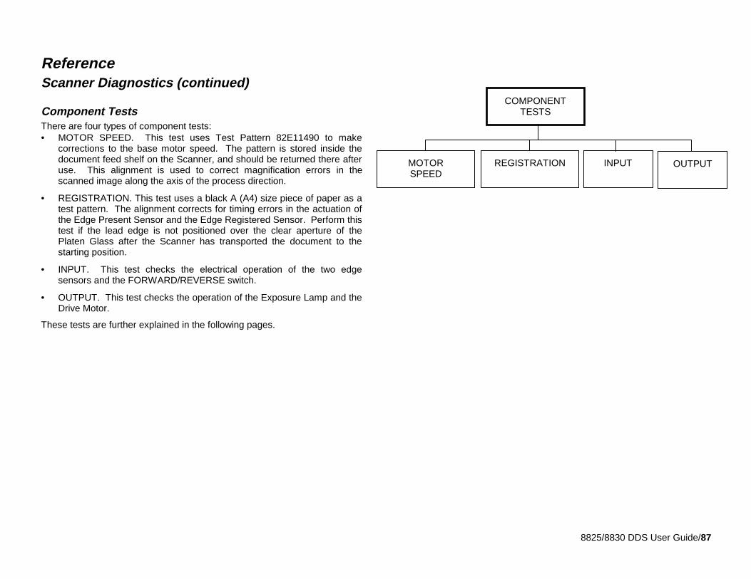
8825/8830 DDS User Guide/87
ReferenceScanner Diagnostics (continued)
Component TestsThere are four types of component tests:• MOTOR SPEED. This test uses Test Pattern 82E11490 to make
corrections to the base motor speed. The pattern is stored inside thedocument feed shelf on the Scanner, and should be returned there afteruse. This alignment is used to correct magnification errors in thescanned image along the axis of the process direction.
• REGISTRATION. This test uses a black A (A4) size piece of paper as atest pattern. The alignment corrects for timing errors in the actuation ofthe Edge Present Sensor and the Edge Registered Sensor. Perform thistest if the lead edge is not positioned over the clear aperture of thePlaten Glass after the Scanner has transported the document to thestarting position.
• INPUT. This test checks the electrical operation of the two edgesensors and the FORWARD/REVERSE switch.
• OUTPUT. This test checks the operation of the Exposure Lamp and theDrive Motor.
These tests are further explained in the following pages.
OUTPUTMOTORSPEED
COMPONENTTESTS
INPUTREGISTRATION
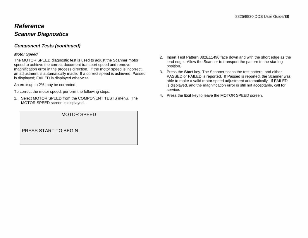
8825/8830 DDS User Guide/88
ReferenceScanner Diagnostics
Component Tests (continued)
Motor Speed
The MOTOR SPEED diagnostic test is used to adjust the Scanner motorspeed to achieve the correct document transport speed and removemagnification error in the process direction. If the motor speed is incorrect,an adjustment is automatically made. If a correct speed is achieved, Passedis displayed; FAILED is displayed otherwise.
An error up to 2% may be corrected.
To correct the motor speed, perform the following steps:
1. Select MOTOR SPEED from the COMPONENT TESTS menu. TheMOTOR SPEED screen is displayed.
2. Insert Test Pattern 082E11490 face down and with the short edge as thelead edge. Allow the Scanner to transport the pattern to the startingposition.
3. Press the Start key. The Scanner scans the test pattern, and eitherPASSED or FAILED is reported. If Passed is reported, the Scanner wasable to make a valid motor speed adjustment automatically. If FAILEDis displayed, and the magnification error is still not acceptable, call forservice.
4. Press the Exit key to leave the MOTOR SPEED screen.
MOTOR SPEED
PRESS START TO BEGIN
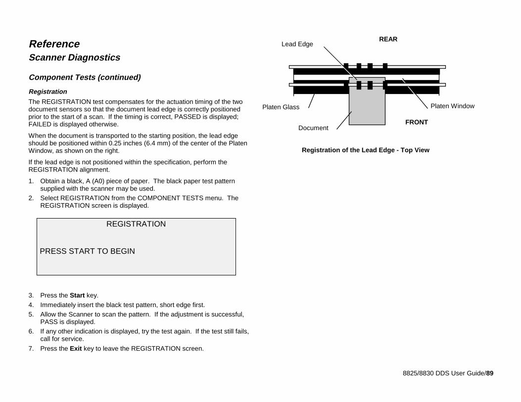
8825/8830 DDS User Guide/89
ReferenceScanner Diagnostics
Component Tests (continued)
Registration
The REGISTRATION test compensates for the actuation timing of the twodocument sensors so that the document lead edge is correctly positionedprior to the start of a scan. If the timing is correct, PASSED is displayed;FAILED is displayed otherwise.
When the document is transported to the starting position, the lead edgeshould be positioned within 0.25 inches (6.4 mm) of the center of the PlatenWindow, as shown on the right.
If the lead edge is not positioned within the specification, perform theREGISTRATION alignment.
1. Obtain a black, A (A0) piece of paper. The black paper test patternsupplied with the scanner may be used.
2. Select REGISTRATION from the COMPONENT TESTS menu. TheREGISTRATION screen is displayed.
3. Press the Start key.
4. Immediately insert the black test pattern, short edge first.
5. Allow the Scanner to scan the pattern. If the adjustment is successful,PASS is displayed.
6. If any other indication is displayed, try the test again. If the test still fails,call for service.
7. Press the Exit key to leave the REGISTRATION screen.
REGISTRATION
PRESS START TO BEGIN
Registration of the Lead Edge - Top View
FRONT
REAR
Platen Glass Platen Window
Lead Edge
Document
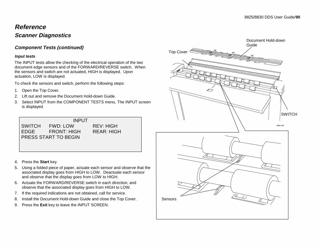
8825/8830 DDS User Guide/90
ReferenceScanner Diagnostics
Component Tests (continued)
Input tests
The INPUT tests allow the checking of the electrical operation of the twodocument edge sensors and of the FORWARD/REVERSE switch. Whenthe sensors and switch are not actuated, HIGH is displayed. Uponactuation, LOW is displayed.
To check the sensors and switch, perform the following steps:
1. Open the Top Cover.
2. Lift out and remove the Document Hold-down Guide.
3. Select INPUT from the COMPONENT TESTS menu. The INPUT screenis displayed.
4. Press the Start key.
5. Using a folded piece of paper, actuate each sensor and observe that theassociated display goes from HIGH to LOW. Deactuate each sensorand observe that the display goes from LOW to HIGH.
6. Actuate the FORWARD/REVERSE switch in each direction, andobserve that the associated display goes from HIGH to LOW.
7. If the required indications are not obtained, call for service.
8. Install the Document Hold-down Guide and close the Top Cover.
9. Press the Exit key to leave the INPUT SCREEN.
INPUT SWITCH FWD: LOW REV: HIGH EDGE FRONT: HIGH REAR: HIGH PRESS START TO BEGIN
Document Hold-downGuide
Top Cover
Sensors
SWITCH
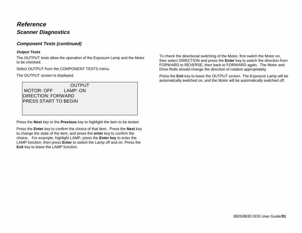
8825/8830 DDS User Guide/91
ReferenceScanner Diagnostics
Component Tests (continued)
Output Tests
The OUTPUT tests allow the operation of the Exposure Lamp and the Motorto be checked.
Select OUTPUT from the COMPONENT TESTS menu.
The OUTPUT screen is displayed.
Press the Next key or the Previous key to highlight the item to be tested.
Press the Enter key to confirm the choice of that item. Press the Next keyto change the state of the item, and press the enter key to confirm thechoice. For example, highlight LAMP, press the Enter key to enter theLAMP function, then press Enter to switch the Lamp off and on. Press theExit key to leave the LAMP function.
To check the directional switching of the Motor, first switch the Motor on,then select DIRECTION and press the Enter key to switch the direction fromFORWARD to REVERSE, then back to FORWARD again. The Motor andDrive Rolls should change the direction of rotation appropriately.
Press the Exit key to leave the OUTPUT screen. The Exposure Lamp will beautomatically switched on, and the Motor will be automatically switched off.
OUTPUT MOTOR: OFF LAMP: ONDIRECTION: FORWARDPRESS START TO BEGIN
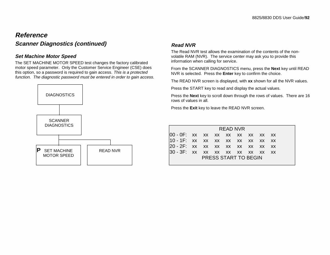
8825/8830 DDS User Guide/92
ReferenceScanner Diagnostics (continued)
Set Machine Motor SpeedThe SET MACHINE MOTOR SPEED test changes the factory calibratedmotor speed parameter. Only the Customer Service Engineer (CSE) doesthis option, so a password is required to gain access. This is a protectedfunction. The diagnostic password must be entered in order to gain access.
Read NVRThe Read NVR test allows the examination of the contents of the non-volatile RAM (NVR). The service center may ask you to provide thisinformation when calling for service.
From the SCANNER DIAGNOSTICS menu, press the Next key until READNVR is selected. Press the Enter key to confirm the choice.
The READ NVR screen is displayed, with xx shown for all the NVR values.
Press the START key to read and display the actual values.
Press the Next key to scroll down through the rows of values. There are 16rows of values in all.
Press the Exit key to leave the READ NVR screen.
READ NVR00 - 0F: xx xx xx xx xx xx xx xx10 - 1F: xx xx xx xx xx xx xx xx20 - 2F: xx xx xx xx xx xx xx xx30 - 3F: xx xx xx xx xx xx xx xx
PRESS START TO BEGIN
DIAGNOSTICS
SCANNERDIAGNOSTICS
SET MACHINEMOTOR SPEED
P READ NVR
8825/8830 DDS User Guide/93
Job Accounting – Setup and AdministrationNote: the Job Accounting feature is optional on the 8825 DDS. Contactyour sales representative for ordering information.
Job Accounting − overviewThe Job Accounting feature allows the usage of the Scanner and Printer tobe recorded in user defined account numbers. Usage is expressed as thearea (not the length) of the media scanned or used. The accounting modesfor the Scanner and the Printer can be independently set, allowing theadministrator to control access to either or both of these devices.
The job accounting mode for the scanner is controlled through the DDS UserInterface, mounted on top of the Scanner, while the accounting mode for theprinter may be set from the Printer Control Panel, or Web-based PrinterManagement Tool (PMT). Although individually set, both the Printer andScanner share a common Job Accounting database.
The Web-based PMT consists of special Web pages located in theController and accessible through either the Microsoft Internet Explorer orthe Netscape Web browsers. Version 4.0 or better is required in either casefor proper results. Other Web browsers are not supported, and may or maynot work correctly.
Job Account Administration can be performed from the Printer ControlPanel, the Web-based PMT, or the DDS User Interface on the Scanner. Forexample, an account created on the DDS User Interface can be reset ordeleted from the Printer Control Panel.
When the Scanner Job Accounting mode is set to ENABLED, userssubmitting jobs through the Scanner are required to supply a valid accountnumber before being allowed to do so. When the Printer Job Accountingmode is set to ENABLED, a valid account number must accompany any jobsubmitted to the printer. If the account number is missing or the account isinvalid, the printer will reject the job and print an error page.
Setting a Job Accounting mode to OPTIONAL allows the user to track onlythose jobs that are identified with a valid account number. In OPTIONALmode, all scan or print jobs are accepted. Usage not associated with anaccount number is tracked in a general System Account (0.3), while jobssubmitted with valid account numbers are billed to the specified account.
Setting a Job Accounting mode to DISABLED will disable the check foraccount numbers altogether. All usage is tracked in the System Total UsageAccount (0.1).
The Job Accounting feature is included in the 8830 DDS; it is an extra-costoption on the 8825 DDS. The option may be enabled at any time by sendinga special software key file to the printer. Once the feature is enabled, itremains enabled, even if you later upgrade the system software in otherways.
If you have an 8825 DDS and wish to enable Job Accounting, please contactyour XES sales representative.
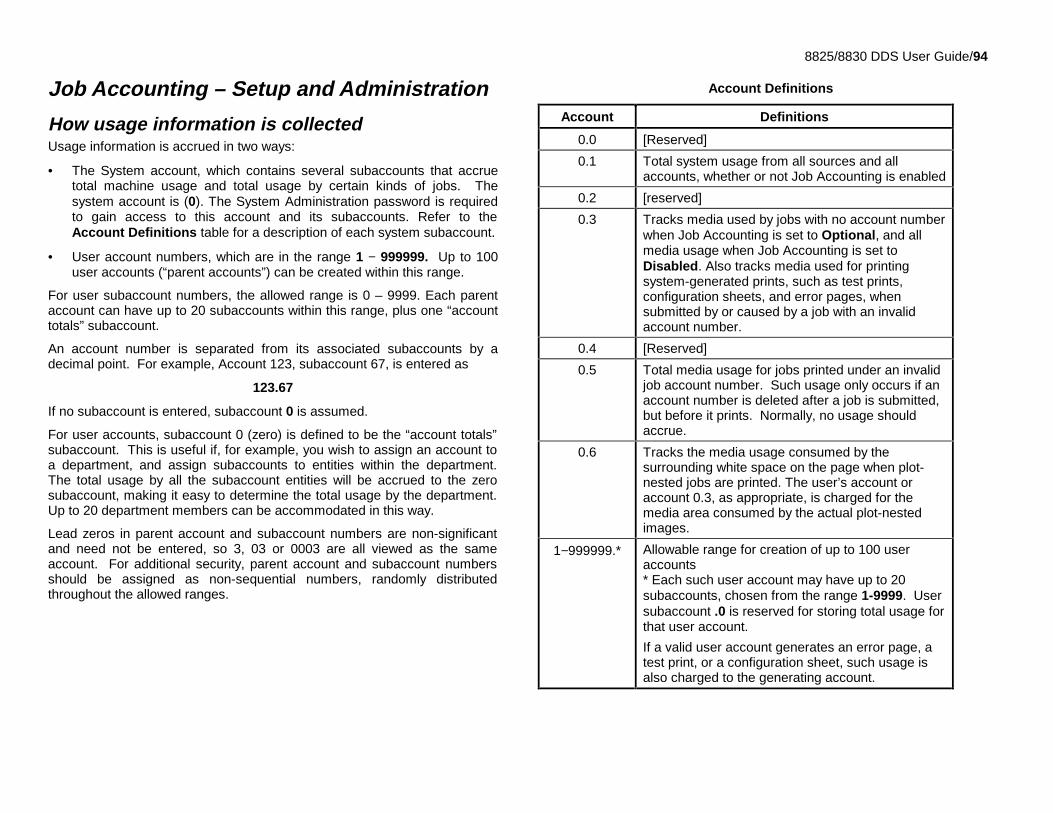
8825/8830 DDS User Guide/94
Job Accounting – Setup and Administration
How usage information is collectedUsage information is accrued in two ways:
• The System account, which contains several subaccounts that accruetotal machine usage and total usage by certain kinds of jobs. Thesystem account is (0). The System Administration password is requiredto gain access to this account and its subaccounts. Refer to theAccount Definitions table for a description of each system subaccount.
• User account numbers, which are in the range 1 − 999999. Up to 100user accounts (“parent accounts”) can be created within this range.
For user subaccount numbers, the allowed range is 0 – 9999. Each parentaccount can have up to 20 subaccounts within this range, plus one “accounttotals” subaccount.
An account number is separated from its associated subaccounts by adecimal point. For example, Account 123, subaccount 67, is entered as
123.67
If no subaccount is entered, subaccount 0 is assumed.
For user accounts, subaccount 0 (zero) is defined to be the “account totals”subaccount. This is useful if, for example, you wish to assign an account toa department, and assign subaccounts to entities within the department.The total usage by all the subaccount entities will be accrued to the zerosubaccount, making it easy to determine the total usage by the department.Up to 20 department members can be accommodated in this way.
Lead zeros in parent account and subaccount numbers are non-significantand need not be entered, so 3, 03 or 0003 are all viewed as the sameaccount. For additional security, parent account and subaccount numbersshould be assigned as non-sequential numbers, randomly distributedthroughout the allowed ranges.
Account Definitions
Account Definitions
0.0 [Reserved]
0.1 Total system usage from all sources and allaccounts, whether or not Job Accounting is enabled
0.2 [reserved]
0.3 Tracks media used by jobs with no account numberwhen Job Accounting is set to Optional, and allmedia usage when Job Accounting is set toDisabled. Also tracks media used for printingsystem-generated prints, such as test prints,configuration sheets, and error pages, whensubmitted by or caused by a job with an invalidaccount number.
0.4 [Reserved]
0.5 Total media usage for jobs printed under an invalidjob account number. Such usage only occurs if anaccount number is deleted after a job is submitted,but before it prints. Normally, no usage shouldaccrue.
0.6 Tracks the media usage consumed by thesurrounding white space on the page when plot-nested jobs are printed. The user’s account oraccount 0.3, as appropriate, is charged for themedia area consumed by the actual plot-nestedimages.
1−999999.* Allowable range for creation of up to 100 useraccounts* Each such user account may have up to 20subaccounts, chosen from the range 1-9999. Usersubaccount .0 is reserved for storing total usage forthat user account.
If a valid user account generates an error page, atest print, or a configuration sheet, such usage isalso charged to the generating account.
8825/8830 DDS User Guide/95
Job Accounting – Setup and Administration(continued)
Accounting can be used for:
• scan-to-net jobs, jobs that are scanned and stored on the internal harddisk for later retrieval over the network
• copy jobs, jobs that are scanned and then printed
• remote print jobs, jobs that are sent to the printer through one of thecommunications ports on the controller, rather than from the scanner.For details on the administration of Job Accounting for remote print jobs,refer to the Job Accounting Administrator Guide.
Under Job Accounting, each of these types of submission is accrued underthe appropriate system account as shown in the Account Definitions tableabove, and also under the account number of the submitting operator.
Users are charged for the area of media used, rather than the linear lengthused. On the display, the usage is reported in square feet if INCHES hasbeen set in the menu under CONFIGURATION/ LOCALIZATION/ DISPLAYUNITS, and in square metres if MILLIMETERS has been set. Internally, theusage figures are always stored on the internal hard disk expressed insquare decimetres. Usage figures written to a floppy disk are alsoexpressed in square decimetres.
Separate usage figures are compiled for Bond, Vellum (Tracing Paper),Film, and Scanned (scan-to-network) usage.
Plot nested jobs, that is, jobs that print multiple images arranged on a sheetof media, are charged for the calculated area that the images themselvesconsume. The surrounding white space area is charged to a special systemaccount.
Note: copy jobs cannot be plot nested.
8825/8830 DDS User Guide/96
Job Accounting – Setup and Administration(continued)
Users are charged for the area of media used, rather than the linear lengthused. On the display, the usage is reported in square feet if INCHES hasbeen set in the menu under CONFIGURATION/ LOCALIZATION/ DISPLAYUNITS, and in square metres if MILLIMETERS has been set. Internally, theusage figures are always stored on the internal hard disk expressed insquare decimetres. Usage figures written to a floppy disk are alsoexpressed in square decimetres.
Separate usage figures are compiled for Bond, Vellum (Tracing Paper),Film, and Scanned (scan-to-network) usage.
Plot nested jobs, that is, jobs that print multiple images arranged on a sheetof media, are charged for the calculated area that the images themselvesconsume. The surrounding white space area is charged to a special systemaccount.
Setting the job accounting modeNote: setting the job accounting mode from the DDS User Interface affectsjob accounting only for jobs arriving from the Scanner, that is, scan jobsand copy jobs. It has no effect on jobs arriving through one of thecommunications ports on the Controller. Such jobs are known as “remoteprint jobs.”Job accounting for remote print jobs is controlled separately through thePrinter Control Panel. Refer to the 8825/8830 Job Accounting AdministratorGuide for full details.
The job accounting mode may be set on the DDS User Interface to one ofthe following states:
• Disabled (factory default). In this mode, jobs are allowed without entry ofany job account code. Total usage of each type of media is still accruedin System Account 0.1 and in system subaccount 0.3. Total usage byscan jobs (scan-to-net) is tracked in system subaccount 0.1.
• Enabled. In this mode, copy jobs, scan jobs, and remote print jobs mustall have a valid account code entered, or the job is discarded and notprinted. The usage of each operator is tracked under that operator’saccount.subaccount number. Total usage is also accumulated in thesystem subaccounts, as shown in the Account Definitions table above.
• Optional. In this mode, operators may optionally enter a valid jobaccount.subaccount number for a job; such jobs will be tracked just asthey are when Job Accounting is enabled. Jobs without valid jobaccount numbers are accepted and printed. Their use is tracked just asif job accounting were disabled.
8825/8830 DDS User Guide/97
Job Accounting – Setup and Administration
Setting the job accounting mode (continued)Job Accounting can be separately enforced for jobs that arrive from thescanner and jobs that arrive from other sources. To enforce Job Accountingfor jobs arriving from the Scanner, enable Job Accounting from the DDSUser Interface. To enforce Job Accounting for jobs arriving from othersources, enable Job Accounting from the Printer Control Panel.
For jobs arriving from the ScannerTo set the job accounting mode for jobs that arrive from the Scanner:
1. Press the Menu key on the DDS User Interface.
2. Press the Next key until SYSTEM ADMINISTRATION is selected. Pressthe Enter key to confirm the choice.
3. Enter the system administration password, and press the Enter key.
4. Press the Next key until JOB ACCOUNTING is selected. Press theEnter key to confirm the choice.
5. Press the Next key until ACCOUNTING MODE is selected. Press theEnter key to confirm the choice.
6. Press the Next key to select the desired job accounting mode. Pressthe Enter key to confirm the choice.
For jobs arriving from other sourcesFor complete details about administering remote print job accounting, pleaserefer to the 8825/8830 Job Accounting Administrator Guide.
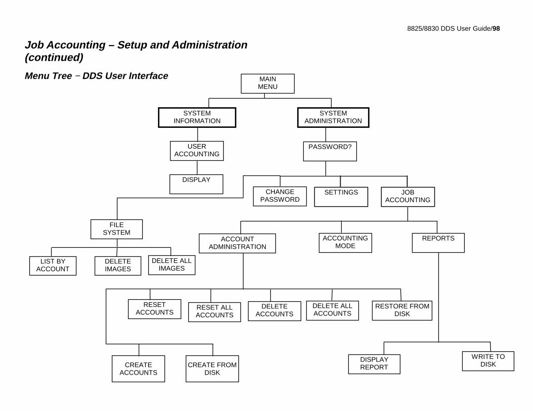
8825/8830 DDS User Guide/98
Job Accounting – Setup and Administration(continued)
Menu Tree − DDS User Interface
SYSTEMINFORMATION
SYSTEMADMINISTRATION
MAINMENU
USERACCOUNTING
DISPLAY
JOBACCOUNTING
JOBACCOUNTING
SETTINGSCHANGEPASSWORD
PASSWORD?
JOBACCOUNTING
JOBACCOUNTING
JOBACCOUNTING
ACCOUNTINGMODE
ACCOUNTADMINISTRATION
RESET ALLACCOUNTS
CREATE FROMDISK
CREATEACCOUNTS
DELETE ALLACCOUNTS
DELETEACCOUNTS
RESETACCOUNTS
REPORTS
RESTORE FROMDISK
WRITE TODISK
DISPLAYREPORT
DELETE ALLIMAGES
LIST BYACCOUNT
DELETEIMAGES
FILESYSTEM
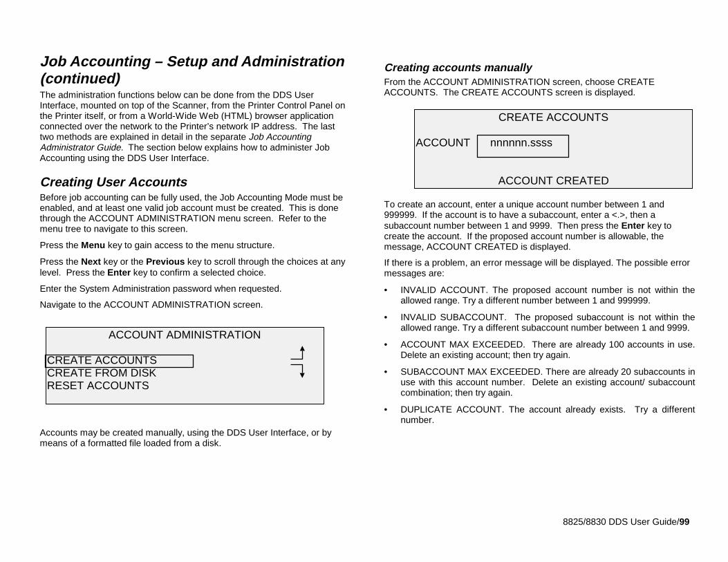
8825/8830 DDS User Guide/99
Job Accounting – Setup and Administration(continued)The administration functions below can be done from the DDS UserInterface, mounted on top of the Scanner, from the Printer Control Panel onthe Printer itself, or from a World-Wide Web (HTML) browser applicationconnected over the network to the Printer’s network IP address. The lasttwo methods are explained in detail in the separate Job AccountingAdministrator Guide. The section below explains how to administer JobAccounting using the DDS User Interface.
Creating User AccountsBefore job accounting can be fully used, the Job Accounting Mode must beenabled, and at least one valid job account must be created. This is donethrough the ACCOUNT ADMINISTRATION menu screen. Refer to themenu tree to navigate to this screen.
Press the Menu key to gain access to the menu structure.
Press the Next key or the Previous key to scroll through the choices at anylevel. Press the Enter key to confirm a selected choice.
Enter the System Administration password when requested.
Navigate to the ACCOUNT ADMINISTRATION screen.
Accounts may be created manually, using the DDS User Interface, or bymeans of a formatted file loaded from a disk.
Creating accounts manuallyFrom the ACCOUNT ADMINISTRATION screen, choose CREATEACCOUNTS. The CREATE ACCOUNTS screen is displayed.
To create an account, enter a unique account number between 1 and999999. If the account is to have a subaccount, enter a <.>, then asubaccount number between 1 and 9999. Then press the Enter key tocreate the account. If the proposed account number is allowable, themessage, ACCOUNT CREATED is displayed.
If there is a problem, an error message will be displayed. The possible errormessages are:
• INVALID ACCOUNT. The proposed account number is not within theallowed range. Try a different number between 1 and 999999.
• INVALID SUBACCOUNT. The proposed subaccount is not within theallowed range. Try a different subaccount number between 1 and 9999.
• ACCOUNT MAX EXCEEDED. There are already 100 accounts in use.Delete an existing account; then try again.
• SUBACCOUNT MAX EXCEEDED. There are already 20 subaccounts inuse with this account number. Delete an existing account/ subaccountcombination; then try again.
• DUPLICATE ACCOUNT. The account already exists. Try a differentnumber.
CREATE ACCOUNTS
ACCOUNT nnnnnn.ssss
ACCOUNT CREATED
ACCOUNT ADMINISTRATION
CREATE ACCOUNTSCREATE FROM DISKRESET ACCOUNTS
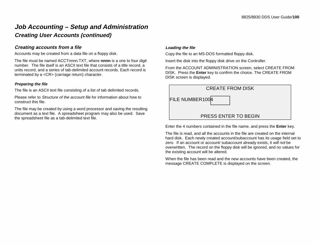
8825/8830 DDS User Guide/100
Job Accounting – Setup and AdministrationCreating User Accounts (continued)
Creating accounts from a fileAccounts may be created from a data file on a floppy disk.
The file must be named ACCTnnnn.TXT, where nnnn is a one to four digitnumber. The file itself is an ASCII text file that consists of a title record, aunits record, and a series of tab-delimited account records. Each record isterminated by a <CR> (carriage return) character.
Preparing the file
The file is an ASCII text file consisting of a list of tab delimited records.
Please refer to Structure of the account file for information about how toconstruct this file.
The file may be created by using a word processor and saving the resultingdocument as a text file. A spreadsheet program may also be used. Savethe spreadsheet file as a tab-delimited text file.
Loading the file
Copy the file to an MS-DOS formatted floppy disk.
Insert the disk into the floppy disk drive on the Controller.
From the ACCOUNT ADMINISTRATION screen, select CREATE FROMDISK. Press the Enter key to confirm the choice. The CREATE FROMDISK screen is displayed.
Enter the 4 numbers contained in the file name, and press the Enter key.
The file is read, and all the accounts in the file are created on the internalhard disk. Each newly created account/subaccount has its usage field set tozero. If an account or account/ subaccount already exists, it will not beoverwritten. The record on the floppy disk will be ignored, and no values forthe existing account will be altered.
When the file has been read and the new accounts have been created, themessage CREATE COMPLETE is displayed on the screen.
CREATE FROM DISK
FILE NUMBER1004
PRESS ENTER TO BEGIN
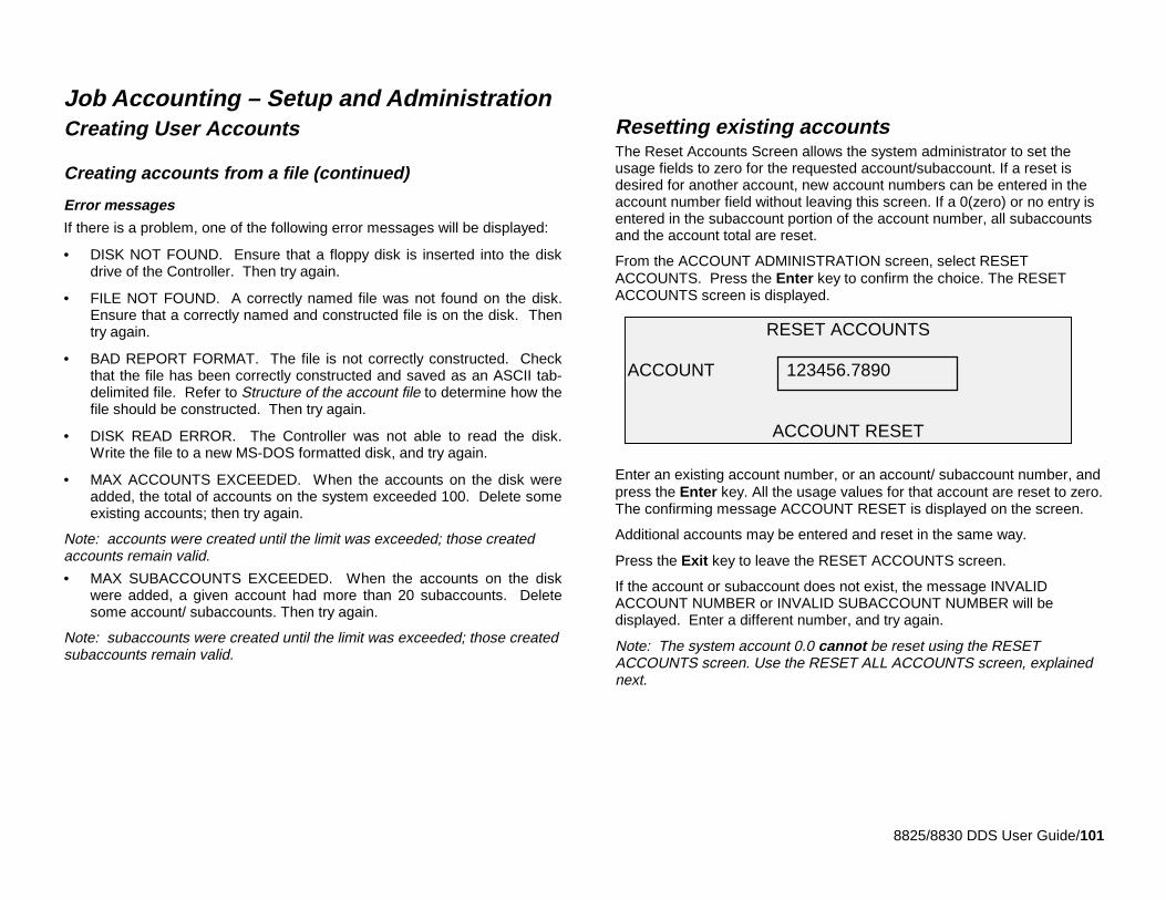
8825/8830 DDS User Guide/101
Job Accounting – Setup and AdministrationCreating User Accounts
Creating accounts from a file (continued)
Error messages
If there is a problem, one of the following error messages will be displayed:
• DISK NOT FOUND. Ensure that a floppy disk is inserted into the diskdrive of the Controller. Then try again.
• FILE NOT FOUND. A correctly named file was not found on the disk.Ensure that a correctly named and constructed file is on the disk. Thentry again.
• BAD REPORT FORMAT. The file is not correctly constructed. Checkthat the file has been correctly constructed and saved as an ASCII tab-delimited file. Refer to Structure of the account file to determine how thefile should be constructed. Then try again.
• DISK READ ERROR. The Controller was not able to read the disk.Write the file to a new MS-DOS formatted disk, and try again.
• MAX ACCOUNTS EXCEEDED. When the accounts on the disk wereadded, the total of accounts on the system exceeded 100. Delete someexisting accounts; then try again.
Note: accounts were created until the limit was exceeded; those createdaccounts remain valid.
• MAX SUBACCOUNTS EXCEEDED. When the accounts on the diskwere added, a given account had more than 20 subaccounts. Deletesome account/ subaccounts. Then try again.
Note: subaccounts were created until the limit was exceeded; those createdsubaccounts remain valid.
Resetting existing accountsThe Reset Accounts Screen allows the system administrator to set theusage fields to zero for the requested account/subaccount. If a reset isdesired for another account, new account numbers can be entered in theaccount number field without leaving this screen. If a 0(zero) or no entry isentered in the subaccount portion of the account number, all subaccountsand the account total are reset.
From the ACCOUNT ADMINISTRATION screen, select RESETACCOUNTS. Press the Enter key to confirm the choice. The RESETACCOUNTS screen is displayed.
Enter an existing account number, or an account/ subaccount number, andpress the Enter key. All the usage values for that account are reset to zero.The confirming message ACCOUNT RESET is displayed on the screen.
Additional accounts may be entered and reset in the same way.
Press the Exit key to leave the RESET ACCOUNTS screen.
If the account or subaccount does not exist, the message INVALIDACCOUNT NUMBER or INVALID SUBACCOUNT NUMBER will bedisplayed. Enter a different number, and try again.
Note: The system account 0.0 cannot be reset using the RESETACCOUNTS screen. Use the RESET ALL ACCOUNTS screen, explainednext.
RESET ACCOUNTS
ACCOUNT 123456.7890
ACCOUNT RESET
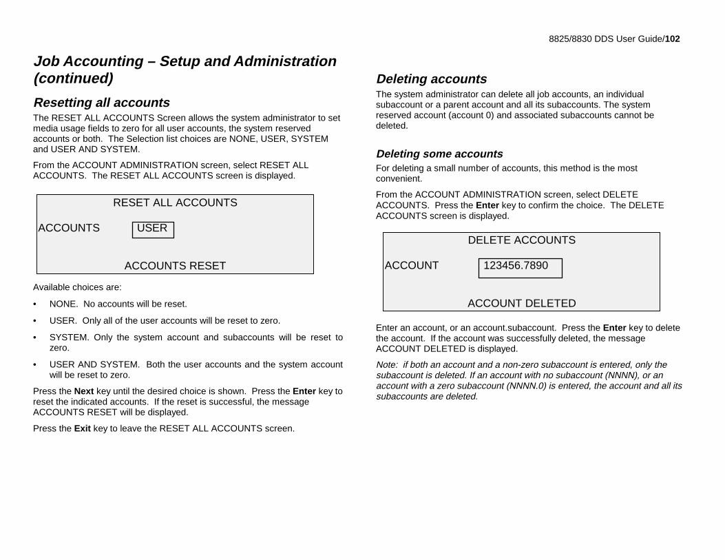
8825/8830 DDS User Guide/102
Job Accounting – Setup and Administration(continued)
Resetting all accountsThe RESET ALL ACCOUNTS Screen allows the system administrator to setmedia usage fields to zero for all user accounts, the system reservedaccounts or both. The Selection list choices are NONE, USER, SYSTEMand USER AND SYSTEM.
From the ACCOUNT ADMINISTRATION screen, select RESET ALLACCOUNTS. The RESET ALL ACCOUNTS screen is displayed.
Available choices are:
• NONE. No accounts will be reset.
• USER. Only all of the user accounts will be reset to zero.
• SYSTEM. Only the system account and subaccounts will be reset tozero.
• USER AND SYSTEM. Both the user accounts and the system accountwill be reset to zero.
Press the Next key until the desired choice is shown. Press the Enter key toreset the indicated accounts. If the reset is successful, the messageACCOUNTS RESET will be displayed.
Press the Exit key to leave the RESET ALL ACCOUNTS screen.
Deleting accountsThe system administrator can delete all job accounts, an individualsubaccount or a parent account and all its subaccounts. The systemreserved account (account 0) and associated subaccounts cannot bedeleted.
Deleting some accountsFor deleting a small number of accounts, this method is the mostconvenient.
From the ACCOUNT ADMINISTRATION screen, select DELETEACCOUNTS. Press the Enter key to confirm the choice. The DELETEACCOUNTS screen is displayed.
Enter an account, or an account.subaccount. Press the Enter key to deletethe account. If the account was successfully deleted, the messageACCOUNT DELETED is displayed.
Note: if both an account and a non-zero subaccount is entered, only thesubaccount is deleted. If an account with no subaccount (NNNN), or anaccount with a zero subaccount (NNNN.0) is entered, the account and all itssubaccounts are deleted.
DELETE ACCOUNTS
ACCOUNT 123456.7890
ACCOUNT DELETED
RESET ALL ACCOUNTS
ACCOUNTS USER
ACCOUNTS RESET
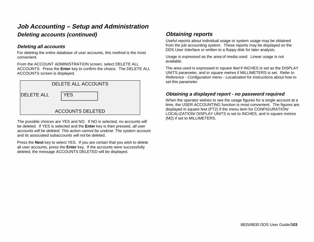
8825/8830 DDS User Guide/103
Job Accounting – Setup and AdministrationDeleting accounts (continued)
Deleting all accountsFor deleting the entire database of user accounts, this method is the mostconvenient.
From the ACCOUNT ADMINISTRATION screen, select DELETE ALLACCOUNTS. Press the Enter key to confirm the choice. The DELETE ALLACCOUNTS screen is displayed.
The possible choices are YES and NO. If NO is selected, no accounts willbe deleted. If YES is selected and the Enter key is then pressed, all useraccounts will be deleted. This action cannot be undone. The system accountand its associated subaccounts will not be deleted.
Press the Next key to select YES. If you are certain that you wish to deleteall user accounts, press the Enter key. If the accounts were successfullydeleted, the message ACCOUNTS DELETED will be displayed.
Obtaining reportsUseful reports about individual usage or system usage may be obtainedfrom the job accounting system. These reports may be displayed on theDDS User Interface or written to a floppy disk for later analysis.
Usage is expressed as the area of media used. Linear usage is notavailable.
The area used is expressed in square feet if INCHES is set as the DISPLAYUNITS parameter, and in square metres if MILLIMETERS is set. Refer toReference - Configuration menu - Localization for instructions about how toset this parameter.
Obtaining a displayed report - no password requiredWhen the operator wishes to see the usage figures for a single account at atime, the USER ACCOUNTING function is most convenient. The figures aredisplayed in square feet (FT2) if the menu item for CONFIGURATION/LOCALIZATION/ DISPLAY UNITS is set to INCHES, and in square metres(M2) if set to MILLIMETERS.
DELETE ALL ACCOUNTS
DELETE ALL YES
ACCOUNTS DELETED
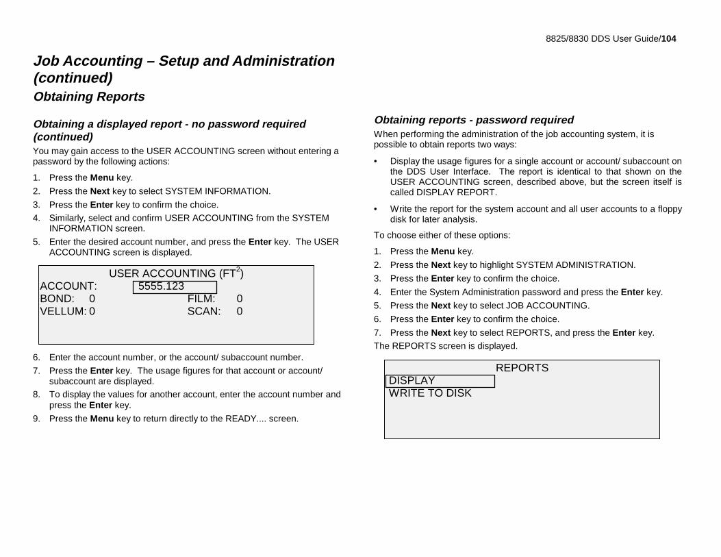
8825/8830 DDS User Guide/104
Job Accounting – Setup and Administration(continued)Obtaining Reports
Obtaining a displayed report - no password required(continued)You may gain access to the USER ACCOUNTING screen without entering apassword by the following actions:
1. Press the Menu key.
2. Press the Next key to select SYSTEM INFORMATION.
3. Press the Enter key to confirm the choice.
4. Similarly, select and confirm USER ACCOUNTING from the SYSTEMINFORMATION screen.
5. Enter the desired account number, and press the Enter key. The USERACCOUNTING screen is displayed.
6. Enter the account number, or the account/ subaccount number.
7. Press the Enter key. The usage figures for that account or account/subaccount are displayed.
8. To display the values for another account, enter the account number andpress the Enter key.
9. Press the Menu key to return directly to the READY.... screen.
Obtaining reports - password requiredWhen performing the administration of the job accounting system, it ispossible to obtain reports two ways:
• Display the usage figures for a single account or account/ subaccount onthe DDS User Interface. The report is identical to that shown on theUSER ACCOUNTING screen, described above, but the screen itself iscalled DISPLAY REPORT.
• Write the report for the system account and all user accounts to a floppydisk for later analysis.
To choose either of these options:
1. Press the Menu key.
2. Press the Next key to highlight SYSTEM ADMINISTRATION.
3. Press the Enter key to confirm the choice.
4. Enter the System Administration password and press the Enter key.
5. Press the Next key to select JOB ACCOUNTING.
6. Press the Enter key to confirm the choice.
7. Press the Next key to select REPORTS, and press the Enter key.
The REPORTS screen is displayed.
REPORTS DISPLAY WRITE TO DISK
USER ACCOUNTING (FT2)ACCOUNT: 5555.123BOND: 0 FILM: 0VELLUM: 0 SCAN: 0
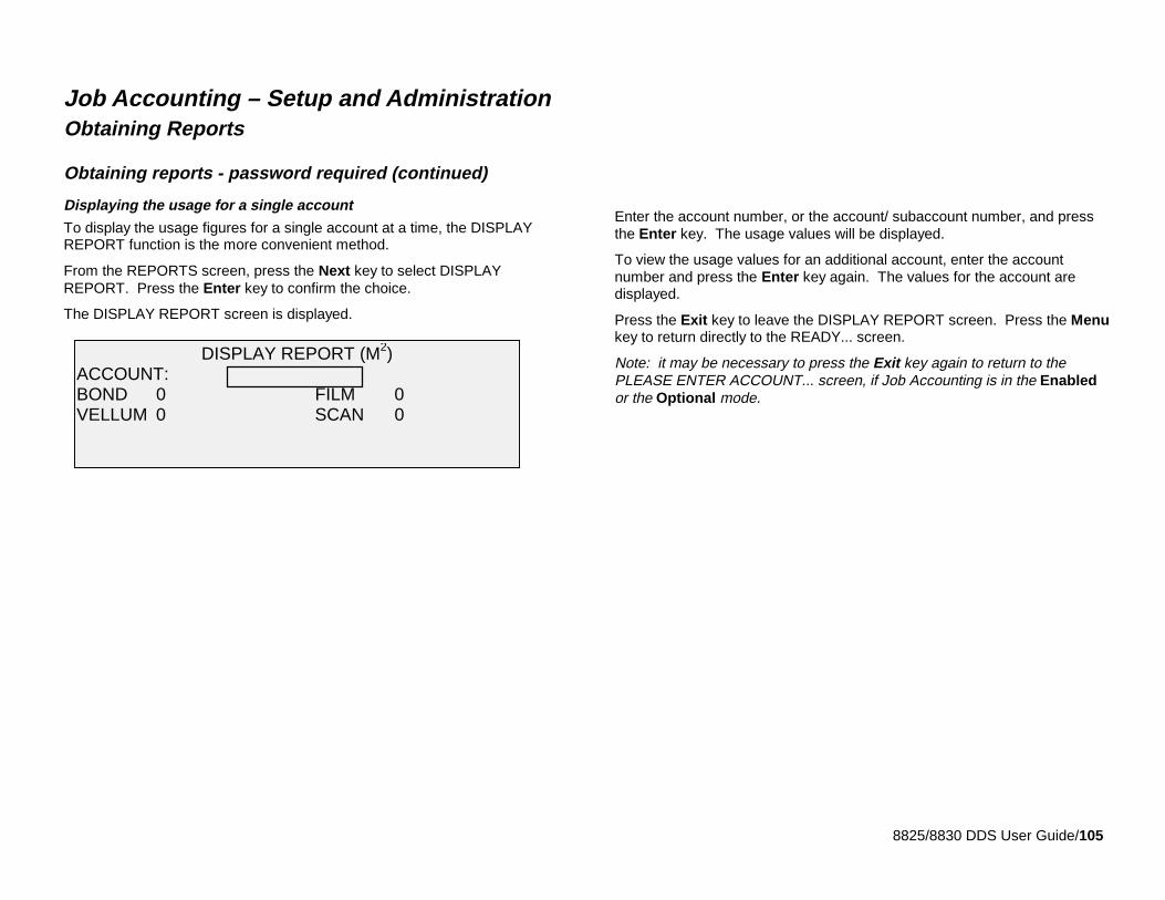
8825/8830 DDS User Guide/105
Job Accounting – Setup and AdministrationObtaining Reports
Obtaining reports - password required (continued)
Displaying the usage for a single account
To display the usage figures for a single account at a time, the DISPLAYREPORT function is the more convenient method.
From the REPORTS screen, press the Next key to select DISPLAYREPORT. Press the Enter key to confirm the choice.
The DISPLAY REPORT screen is displayed.
Enter the account number, or the account/ subaccount number, and pressthe Enter key. The usage values will be displayed.
To view the usage values for an additional account, enter the accountnumber and press the Enter key again. The values for the account aredisplayed.
Press the Exit key to leave the DISPLAY REPORT screen. Press the Menukey to return directly to the READY... screen.
Note: it may be necessary to press the Exit key again to return to thePLEASE ENTER ACCOUNT... screen, if Job Accounting is in the Enabledor the Optional mode.
DISPLAY REPORT (M2)ACCOUNT:BOND 0 FILM 0VELLUM 0 SCAN 0
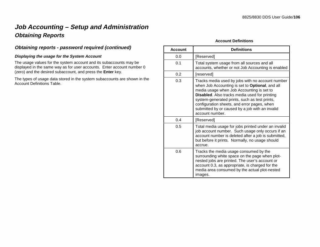
8825/8830 DDS User Guide/106
Job Accounting – Setup and AdministrationObtaining Reports
Obtaining reports - password required (continued)
Displaying the usage for the System Account
The usage values for the system account and its subaccounts may bedisplayed in the same way as for user accounts. Enter account number 0(zero) and the desired subaccount, and press the Enter key.
The types of usage data stored in the system subaccounts are shown in theAccount Definitions Table.
Account Definitions
Account Definitions
0.0 [Reserved]
0.1 Total system usage from all sources and allaccounts, whether or not Job Accounting is enabled
0.2 [reserved]
0.3 Tracks media used by jobs with no account numberwhen Job Accounting is set to Optional, and allmedia usage when Job Accounting is set toDisabled. Also tracks media used for printingsystem-generated prints, such as test prints,configuration sheets, and error pages, whensubmitted by or caused by a job with an invalidaccount number.
0.4 [Reserved]
0.5 Total media usage for jobs printed under an invalidjob account number. Such usage only occurs if anaccount number is deleted after a job is submitted,but before it prints. Normally, no usage shouldaccrue.
0.6 Tracks the media usage consumed by thesurrounding white space on the page when plot-nested jobs are printed. The user’s account oraccount 0.3, as appropriate, is charged for themedia area consumed by the actual plot-nestedimages.
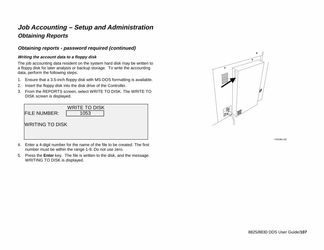
8825/8830 DDS User Guide/107
Job Accounting – Setup and AdministrationObtaining Reports
Obtaining reports - password required (continued)
Writing the account data to a floppy disk
The job accounting data resident on the system hard disk may be written toa floppy disk for later analysis or backup storage. To write the accountingdata, perform the following steps:
1. Ensure that a 3.5-inch floppy disk with MS-DOS formatting is available.
2. Insert the floppy disk into the disk drive of the Controller.
3. From the REPORTS screen, select WRITE TO DISK. The WRITE TODISK screen is displayed.
4. Enter a 4-digit number for the name of the file to be created. The firstnumber must be within the range 1-9. Do not use zero.
5. Press the Enter key. The file is written to the disk, and the messageWRITING TO DISK is displayed.
740108A-JAC0
WRITE TO DISKFILE NUMBER: 1053
WRITING TO DISK
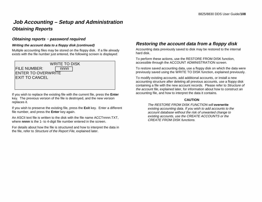
8825/8830 DDS User Guide/108
Job Accounting – Setup and AdministrationObtaining Reports
Obtaining reports − password requiredWriting the account data to a floppy disk (continued)
Multiple accounting files may be stored on the floppy disk. If a file alreadyexists with the file number just entered, the following screen is displayed:
If you wish to replace the existing file with the current file, press the Enterkey. The previous version of the file is destroyed, and the new versionreplaces it.
If you wish to preserve the existing file, press the Exit key. Enter a differentfile number, and press the Enter key again.
An ASCII text file is written to the disk with the file name ACCTnnnn.TXT,where nnnn is the 1- to 4-digit file number entered in the screen.
For details about how the file is structured and how to interpret the data inthe file, refer to Structure of the Report File, explained later.
Restoring the account data from a floppy diskAccounting data previously saved to disk may be restored to the internalhard disk.
To perform these actions, use the RESTORE FROM DISK function,accessible through the ACCOUNT ADMINISTRATION screen.
To restore saved accounting data, use a floppy disk on which the data werepreviously saved using the WRITE TO DISK function, explained previously.
To modify existing accounts, add additional accounts, or install a newaccounting structure after deleting all previous accounts, use a floppy diskcontaining a file with the new account records. Please refer to Structure ofthe account file, explained later, for information about how to construct anaccounting file, and how to interpret the data it contains.
CAUTION
The RESTORE FROM DISK FUNCTION will overwriteexisting accounting data. If you wish to add accounts to theaccount database without the risk of unwanted change toexisting accounts, use the CREATE ACCOUNTS or theCREATE FROM DISK functions.
WRITE TO DISKFILE NUMBER: nnnnENTER TO OVERWRITEEXIT TO CANCEL
8825/8830 DDS User Guide/109
Job Accounting – Setup and Administration(continued)
Structure of the account fileThe information below describes how a valid account file is constructed.This format is used when account information is written to the floppy diskusing the WRITE TO DISK function, and is also used when it is desired toinstall or modify the accounting database using the RESTORE FROM DISKor the CREATE FROM DISK functions.
A floppy disk that is DOS formatted must be used.
The file is always named ACCTnnnn.TXT, where nnnn is a 1 to 4 digitnumber assigned by the operator or the person constructing the file. Thenumber should be unique with respect to any other accounting files, so thatconfusion does not occur.
Example: ACCT1004.TXT
Multiple accounting files are permitted to exist on a single floppy disk.
The file begins with a title record, which is the product numeric name,followed by a <CR> character.
8830<CR>
The next record specifies the units of measurement used for the mediausage numbers. The choices are dm (for square decimetres) and ft (forsquare feet).
dm<CR>
Note: while all media usage data is internally stored as square decimetreson the hard disk, the units in the file may be in square decimetres or squarefeet. When this file is written to the floppy with the WRITE TO DISK function,the units will always be expressed as square decimetres.
All other records in the file are account records. Each account record hassix fields; each field is separated from the next field by a <tab> character.The record is terminated by a <CR> (carriage return) character.
The structure of the account record is:
account<TAB>subaccount<TAB>bond usage<TAB>vellum(tracing paper) usage<TAB>film usage<TAB>scan usage<CR>
For an example, a record might look like this:
523476<TAB>17<TAB>0<TAB>0<TAB>0<TAB>0<CR>
This record will create account number 523476, subaccount 17. Values forusage will all be initialized at zero. To create a parent account with nosubaccount, place a 0 (zero) in the second field.
To initialize a media usage value to other than zero, replace the 0 with thedesired value, and use the RESTORE FROM DISK function.
Note the CREATE FROM DISK function ignores the usage figures, andcreates accounts initialized to zero usage regardless of the usage values inthe record.The file may be created by using a word processor and saving the resultingfile as an ASCII text file. A spreadsheet program may also be used. Savethe spreadsheet file as a tab-delimited text file.
Accounting files saved to floppy disk may be imported into a spreadsheetprogram for analysis.
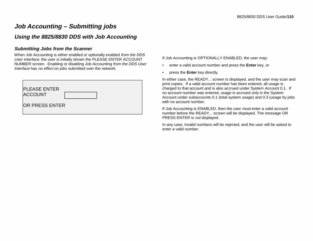
8825/8830 DDS User Guide/110
Job Accounting – Submitting jobs
Using the 8825/8830 DDS with Job Accounting
Submitting Jobs from the ScannerWhen Job Accounting is either enabled or optionally enabled from the DDSUser Interface, the user is initially shown the PLEASE ENTER ACCOUNTNUMBER screen. Enabling or disabling Job Accounting from the DDS UserInterface has no effect on jobs submitted over the network.
If Job Accounting is OPTIONALLY ENABLED, the user may:
• enter a valid account number and press the Enter key, or
• press the Enter key directly.
In either case, the READY... screen is displayed, and the user may scan andprint copies. If a valid account number has been entered, all usage ischarged to that account and is also accrued under System Account 0.1. Ifno account number was entered, usage is accrued only in the SystemAccount under subaccounts 0.1 (total system usage) and 0.3 (usage by jobswith no account number.
If Job Accounting is ENABLED, then the user must enter a valid accountnumber before the READY... screen will be displayed. The message ORPRESS ENTER is not displayed.
In any case, invalid numbers will be rejected, and the user will be asked toenter a valid number.
PLEASE ENTERACCOUNT
OR PRESS ENTER
8825/8830 DDS User Guide/111
Job Accounting – Submitting jobsUsing the 8825/8830 DDS with Job Accounting
Submitting jobs over the networkWhen Job Accounting is enabled from the Printer Control Panel, the systemexamines the incoming job for a valid account number. If none is found, thejob is rejected, and an error page is printed.
Note: the 8825/8830 print drivers and Document Submission Tool (DST)software all have a feature that allows insertion of a job accounting number.Refer to the User Guides for these software products for details.If Job Accounting is optionally enabled from the Printer Control Panel,remote print jobs will be printed whether they have a valid account numberor not. If a valid account number is present, the job will be charged to theuser account (and subaccount, if present), and also accrued to systemaccount 0.1 (total system usage). If no account number is present, the job ischarged to system account 0.1 and also to system account 0.3 (jobs with noaccount number), just the same as if job accounting were disabled.
Enabling or disabling Job Accounting from the Printer Control Panel has noeffect on jobs submitted through the Scanner.
Terminating use under an accountOnce a valid job account number has been entered, all use of the 8825/8830DDS Scanner is charged to that account. All usage continues to accrue tothat account until:
• the user presses the Exit key while either the READY... screen or a faultscreen is displayed.
• the FEATURE timer times out, due to no activity. The default value is 5minutes, but this value may be changed. Refer to FEATURE Timer inthe Reference section for information about changing the value.
When an account is no longer in use, the PLEASE ENTER ACCOUNT...screen is displayed.
Note: to avoid incorrect accounting, users should always ensure that thePLEASE ENTER ACCOUNT screen is displayed before leaving the8825/8830 DDS for the next operator. Press the Exit key to obtain thisscreen.
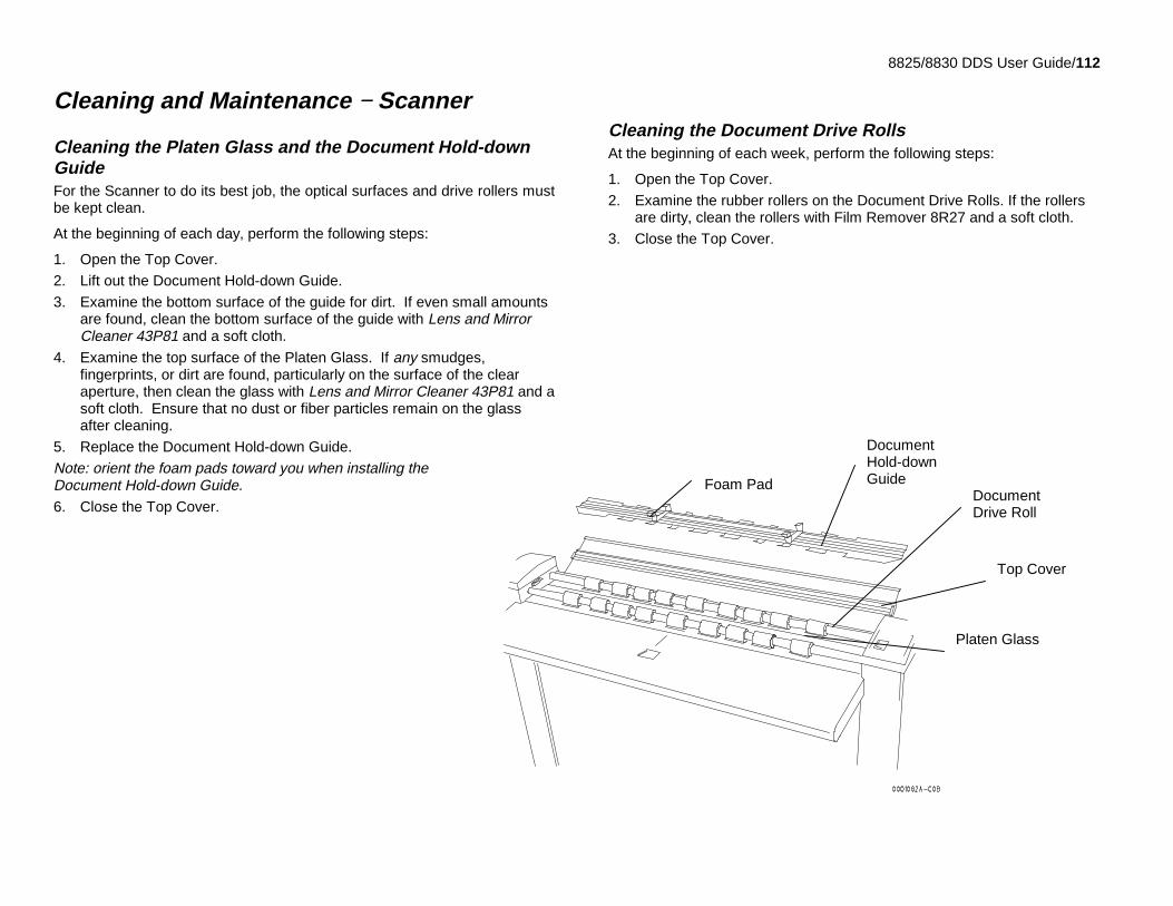
8825/8830 DDS User Guide/112
Cleaning and Maintenance − Scanner
Cleaning the Platen Glass and the Document Hold-downGuideFor the Scanner to do its best job, the optical surfaces and drive rollers mustbe kept clean.
At the beginning of each day, perform the following steps:
1. Open the Top Cover.
2. Lift out the Document Hold-down Guide.
3. Examine the bottom surface of the guide for dirt. If even small amountsare found, clean the bottom surface of the guide with Lens and MirrorCleaner 43P81 and a soft cloth.
4. Examine the top surface of the Platen Glass. If any smudges,fingerprints, or dirt are found, particularly on the surface of the clearaperture, then clean the glass with Lens and Mirror Cleaner 43P81 and asoft cloth. Ensure that no dust or fiber particles remain on the glassafter cleaning.
5. Replace the Document Hold-down Guide.
Note: orient the foam pads toward you when installing theDocument Hold-down Guide.6. Close the Top Cover.
Cleaning the Document Drive RollsAt the beginning of each week, perform the following steps:
1. Open the Top Cover.
2. Examine the rubber rollers on the Document Drive Rolls. If the rollersare dirty, clean the rollers with Film Remover 8R27 and a soft cloth.
3. Close the Top Cover.
Top Cover
DocumentDrive Roll
DocumentHold-downGuide
Platen Glass
Foam Pad
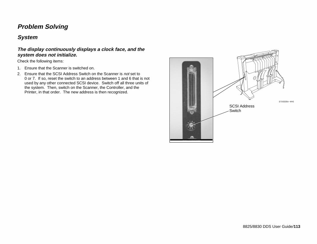
8825/8830 DDS User Guide/113
Problem Solving
System
The display continuously displays a clock face, and thesystem does not initialize.Check the following items:
1. Ensure that the Scanner is switched on.
2. Ensure that the SCSI Address Switch on the Scanner is not set to0 or 7. If so, reset the switch to an address between 1 and 6 that is notused by any other connected SCSI device. Switch off all three units ofthe system. Then, switch on the Scanner, the Controller, and thePrinter, in that order. The new address is then recognized.
SCSI AddressSwitch
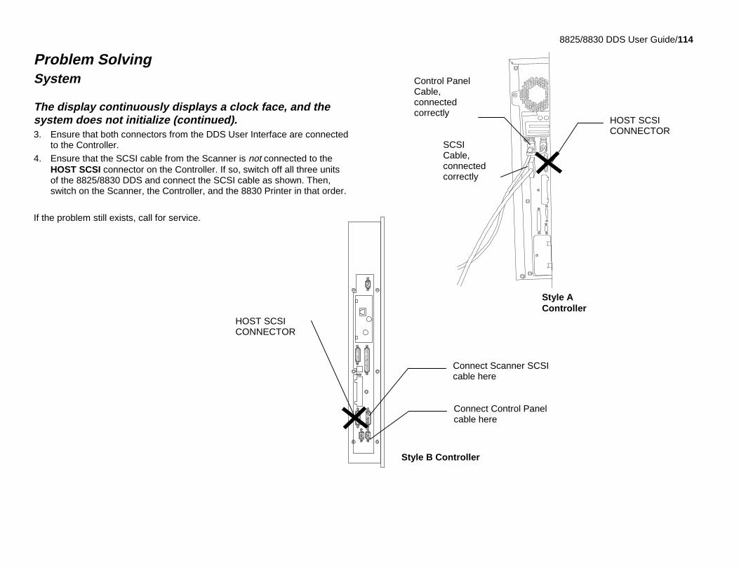
8825/8830 DDS User Guide/114
Problem SolvingSystem
The display continuously displays a clock face, and thesystem does not initialize (continued).3. Ensure that both connectors from the DDS User Interface are connected
to the Controller.
4. Ensure that the SCSI cable from the Scanner is not connected to theHOST SCSI connector on the Controller. If so, switch off all three unitsof the 8825/8830 DDS and connect the SCSI cable as shown. Then,switch on the Scanner, the Controller, and the 8830 Printer in that order.
If the problem still exists, call for service.
301010A-0
HOST SCSICONNECTOR
SCSICable,connectedcorrectly
Control PanelCable,connectedcorrectly
HOST SCSICONNECTOR
Style B Controller
Style AController
Connect Scanner SCSIcable here
Connect Control Panelcable here
8825/8830 DDS User Guide/115
Problem Solving (continued)
PrinterPlease refer to the User Guide for the 8830 Printer for help in solvingproblems in operation of the printer or difficulties with printer media.
ScannerThis problem solving section contains information that you can quickly try torestore or correct the scanner’s operation. If these procedures do notrestore normal scanner operation, please call for service.
Locate the observed symptom below.Find the symptom you are observing, and perform the steps indicated to fixthe problem.
The Exposure Lamp does not illuminate when you switch on theScanner
1. Check that the power cord is connected to the Scanner and to thecorrect power source.
2. Check that the Main Power Switch is in the on (1) position.
The Scanner does not normalize
The scanner adjusts the camera by referencing the reflectivity of theDocument Hold-down Guide. If there is dirt on the Platen Glass or the guide,some camera elements will see a level of reflectivity that is outside allowablelimits. Normalization then fails, and copy quality may not be satisfactory. Ifthis occurs:• Check that the Document Hold-down Guide is installed before the
Scanner is switched on. The Scanner will not normalize if the guide isnot installed.
• If the problem still exists, perform the procedure, Cleaning the PlatenGlass and the Document Hold-down Guide. Then:
1. Press the Menu Key on the Scanner DDS User Interface.
2. Press the Next key until the Diagnostics mode is selected.
3. Press the Enter key to enter the Diagnostics mode.
4. Enter the Key Operator password and press the Enter key.
5. Select Normalize Scanner.
• The message is displayed: The Scanner is currently Normalizing.Please wait... .
• When the Scanner successfully normalizes, the display reports that fact.Press the Exit key until the display indicates Ready to copy. Thencontinue normal operation.
• If the normalization process fails, a screen is displayed with themessage, Normalization has Failed. Press the Exit button to return tothe NORMALIZE SCANNER screen. Ensure that the Platen Glass andthe Document Hold-down Guide are truly clean, and press the Enter keyagain. If the Scanner still fails to normalize, call for service.

8825/8830 DDS User Guide/116
Problem Solving
Scanner (continued)
The document’s lead edge enters the gap between the feed tray andthe drive roll area
This problem is caused by curl in the lead edge of the document. Typically,the problem is seen in documents that are stored rolled up and not flat.Solutions:
a. Place the lead edge beyond the gap between the feed tray and thedrive roll area, and then insert the document into the feed rolls.
b. Roll up the document in the reverse direction to remove the curl,then unroll the document and feed it again.
Images have gray areas caused by folds in the document
Some relatively stiff documents with creases or folds will lift off the platenglass, causing a gray area to appear in the image at the location of the fold.Refold the document in the reverse direction so that the creases becomeflat. Then feed the document again.
An Error message is displayed.
Find the error message in the table on the next page, and perform theCorrective Action indicated. If the corrective action does not solve theproblem, call for service.
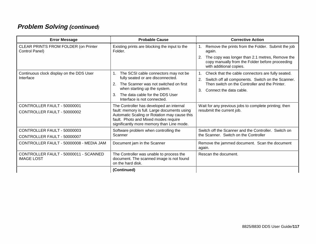
8825/8830 DDS User Guide/117
Problem Solving (continued)
Error Message Probable Cause Corrective Action
CLEAR PRINTS FROM FOLDER (on PrinterControl Panel)
Existing prints are blocking the input to theFolder.
1. Remove the prints from the Folder. Submit the jobagain.
2. The copy was longer than 2.1 metres, Remove thecopy manually from the Folder before proceedingwith additional copies.
Continuous clock display on the DDS UserInterface
1. The SCSI cable connectors may not befully seated or are disconnected.
2. The Scanner was not switched on firstwhen starting up the system.
3. The data cable for the DDS UserInterface is not connected.
1. Check that the cable connectors are fully seated.
2. Switch off all components. Switch on the Scanner.Then switch on the Controller and the Printer.
3. Connect the data cable.
CONTROLLER FAULT - 50000001
CONTROLLER FAULT - 50000002
The Controller has developed an internalfault: memory is full. Large documents usingAutomatic Scaling or Rotation may cause thisfault. Photo and Mixed modes requiresignificantly more memory than Line mode.
Wait for any previous jobs to complete printing; thenresubmit the current job.
CONTROLLER FAULT - 50000003
CONTROLLER FAULT - 50000007
Software problem when controlling theScanner
Switch off the Scanner and the Controller. Switch onthe Scanner. Switch on the Controller
CONTROLLER FAULT - 50000008 - MEDIA JAM Document jam in the Scanner Remove the jammed document. Scan the documentagain.
CONTROLLER FAULT - 50000011 - SCANNEDIMAGE LOST
The Controller was unable to process thedocument. The scanned image is not foundon the hard disk.
Rescan the document.
(Continued)
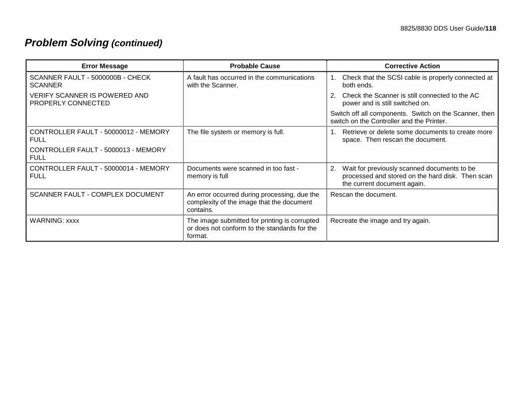
8825/8830 DDS User Guide/118
Problem Solving (continued)
Error Message Probable Cause Corrective Action
SCANNER FAULT - 5000000B - CHECKSCANNER
VERIFY SCANNER IS POWERED ANDPROPERLY CONNECTED
A fault has occurred in the communicationswith the Scanner.
1. Check that the SCSI cable is properly connected atboth ends.
2. Check the Scanner is still connected to the ACpower and is still switched on.
Switch off all components. Switch on the Scanner, thenswitch on the Controller and the Printer.
CONTROLLER FAULT - 50000012 - MEMORYFULL
CONTROLLER FAULT - 5000013 - MEMORYFULL
The file system or memory is full. 1. Retrieve or delete some documents to create morespace. Then rescan the document.
CONTROLLER FAULT - 50000014 - MEMORYFULL
Documents were scanned in too fast -memory is full
2. Wait for previously scanned documents to beprocessed and stored on the hard disk. Then scanthe current document again.
SCANNER FAULT - COMPLEX DOCUMENT An error occurred during processing, due thecomplexity of the image that the documentcontains.
Rescan the document.
WARNING: xxxx The image submitted for printing is corruptedor does not conform to the standards for theformat.
Recreate the image and try again.
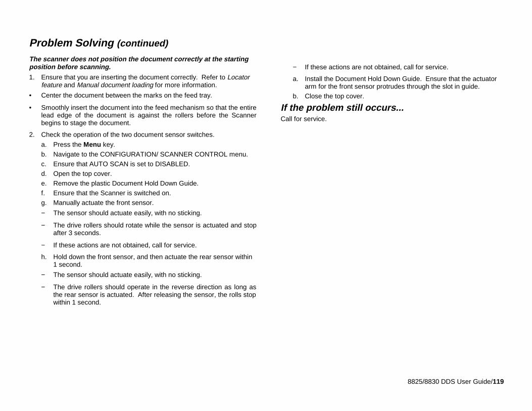
8825/8830 DDS User Guide/119
Problem Solving (continued)
The scanner does not position the document correctly at the startingposition before scanning.
1. Ensure that you are inserting the document correctly. Refer to Locatorfeature and Manual document loading for more information.
• Center the document between the marks on the feed tray.
• Smoothly insert the document into the feed mechanism so that the entirelead edge of the document is against the rollers before the Scannerbegins to stage the document.
2. Check the operation of the two document sensor switches.
a. Press the Menu key.
b. Navigate to the CONFIGURATION/ SCANNER CONTROL menu.
c. Ensure that AUTO SCAN is set to DISABLED.
d. Open the top cover.
e. Remove the plastic Document Hold Down Guide.
f. Ensure that the Scanner is switched on.
g. Manually actuate the front sensor.
− The sensor should actuate easily, with no sticking.
− The drive rollers should rotate while the sensor is actuated and stopafter 3 seconds.
− If these actions are not obtained, call for service.
h. Hold down the front sensor, and then actuate the rear sensor within1 second.
− The sensor should actuate easily, with no sticking.
− The drive rollers should operate in the reverse direction as long asthe rear sensor is actuated. After releasing the sensor, the rolls stopwithin 1 second.
− If these actions are not obtained, call for service.
a. Install the Document Hold Down Guide. Ensure that the actuatorarm for the front sensor protrudes through the slot in guide.
b. Close the top cover.
If the problem still occurs...Call for service.
8830/ 8825DDS USER GUIDE /120
Prepared by:Xerox Corporation800 Philips RoadBuilding 845-17SWebster, New York 14580-9791USA
© 1999 Xerox Engineering Systems. All rights reserved.The digital box icon and the acronym XES are trademarks of XESystems,Inc.XEROX, The Document Company, the stylized X, 7356, 7346, 8825, 8830,and any identifying product names and numbers are trademarks of XEROXCorporation.All terms mentioned in this document which are known to be trademarks orservice marks are appropriately capitalized.Copyright 1999 by Xerox Corporation. All rights reserved.Copyright 1999 by Xerox Engineering Systems. All rights reserved.
Xerox Engineering Systems300 Main StreetEast Rochester, N.Y. 14445
No part of this manual may be copied without prior written permission ofXerox Engineering Systems.Printed in the U.S.A
701P30070 6/99


![r T*square] Jlñ (llÊ2B 03-3294-8830 : TEL](https://img.pdfslide.net/doc/110x75/6169cf3f11a7b741a34b9bd4/r-tsquare-jl-ll2b-03-3294-8830-tel.jpg)