Embed Size (px)
Citation preview

Page 1
8960-PXB HSDPA DC Baseband Fading
Hong-Cheng Yang June 24, 2013
Overview This document provides detail instructions for setting up the HSDPA DC Baseband Fading system using 8960 and PXB. It is assumed that user should be familiar with PXB and 8960 basic operations and have basic understanding about fading. Below is the list of the sections which cover setting up the system, verifying the connections and performing the fading tests:
- Equipment and devices required - System Interconnections - PXB Setup - Downlink Signal quality verification (Optional) - Call establishment verification with UE - Specific fading profile setup and test - Sample SCPI scripts for the fading test
Equipment and devices required Table 1 contains all the equipment and devise required for the 8960-PXB HSPDA DC baseband
fading tests.
Products Description Quantity Visa Interface Item No
E5515E Wireless Communication Test Set 1 GPIB 1
N5106A PXB Baseband Generator and Channel Emulator
1 Visa controller 2
N5182A MXG Vector Signal Generator 1 LAN or GPIB 3
N5182A MXG Vector Signal Generator 1 LAN or GPIB 4
N9020A MXA Signal Analyzer 1 LAN or GPIB 5
TD_C205 Circulator 1 N/A 6
SHX-GF2-2 RF Splitter/Combiner 2 N/A 7,8
UE DC-HSPA test UE 1 N/A 9
Table 1 Equipment and Devices
NOTE:
- Specific FW versions are required for E5515E and N5106A to perform HSDPA DC
baseband fading. The E5515E should be running E6785I_I_01_04 or later, and N5106A
should install 2.0.0 or later.
- For the two N5182As, please ensure that they are running the same FW versions.
- The MXA is optional for the fading tests; it is used for verifying the downlink signal
quality. It should include the N9073A-1FP, N9073A-2FP and N9073A-3FP options.
Page 2
System Interconnections
Figure 1 8960-PXB HSDPA DC Baseband Fading System
Figure 1 shows the system interconnections for the 8960-PXB HSDPA DC baseband fading
system. 8960 sends the interleaved 2 channel IQ data over LVDS to PXB, PXB will deinterleave
the 2 channels, apply fading and send faded data streams to two MXGs for upconverting to RF
signals. The reason two MXG’s are used is that the frequency separation between the two
carriers is not predetermined, and may include dual bands. The MXA is used to demodulating
the RF signals from two MXGs after combiner. The UE is connected with the RF Circulator which
will route the downlink signal to UE, and UE’s RF uplink to the 8960.
All instruments (PXB, 8960, 2 MXGs and MXA) should be synchronized with 10M reference clock.
The typical 10M reference connection is below:
PXB 10M reference out -> 8960 10M reference in
8960 10M reference out -> MXG 1 10M reference in
MXG 1 10M reference out -> MXG 2 10M reference in
MXG 2 10M reference out -> MXA 10M reference in
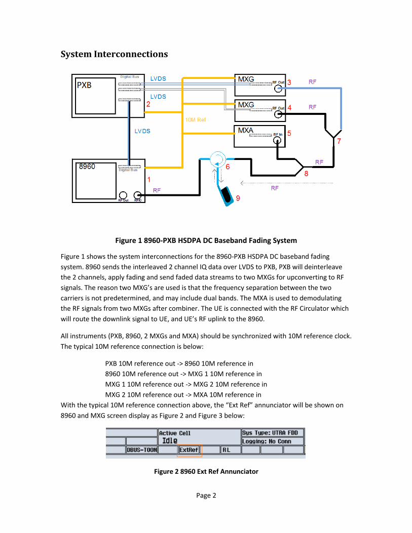
With the typical 10M reference connection above, the “Ext Ref” annunciator will be shown on
8960 and MXG screen display as Figure 2 and Figure 3 below:
Figure 2 8960 Ext Ref Annunciator
Page 3
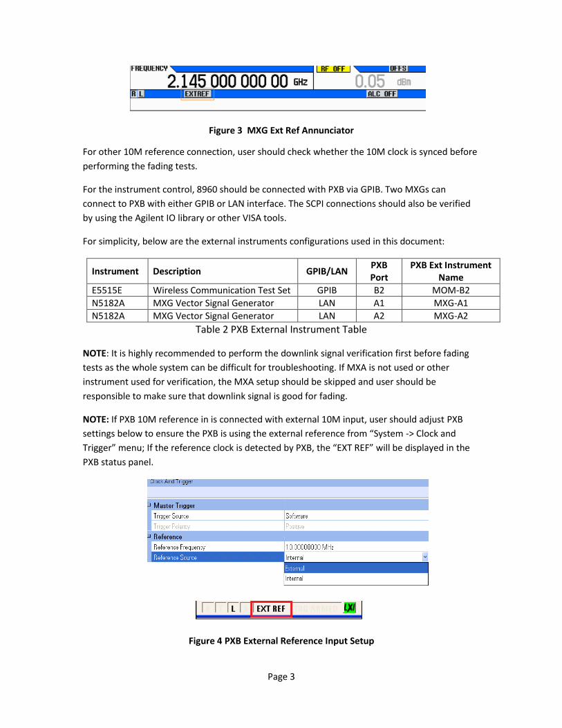
Figure 3 MXG Ext Ref Annunciator
For other 10M reference connection, user should check whether the 10M clock is synced before
performing the fading tests.
For the instrument control, 8960 should be connected with PXB via GPIB. Two MXGs can
connect to PXB with either GPIB or LAN interface. The SCPI connections should also be verified
by using the Agilent IO library or other VISA tools.
For simplicity, below are the external instruments configurations used in this document:
Instrument Description GPIB/LAN PXB Port
PXB Ext Instrument Name
E5515E Wireless Communication Test Set GPIB B2 MOM-B2
N5182A MXG Vector Signal Generator LAN A1 MXG-A1
N5182A MXG Vector Signal Generator LAN A2 MXG-A2
Table 2 PXB External Instrument Table
NOTE: It is highly recommended to perform the downlink signal verification first before fading
tests as the whole system can be difficult for troubleshooting. If MXA is not used or other
instrument used for verification, the MXA setup should be skipped and user should be
responsible to make sure that downlink signal is good for fading.
NOTE: If PXB 10M reference in is connected with external 10M input, user should adjust PXB
settings below to ensure the PXB is using the external reference from “System -> Clock and
Trigger” menu; If the reference clock is detected by PXB, the “EXT REF” will be displayed in the
PXB status panel.
Figure 4 PXB External Reference Input Setup
Page 4
PXB Setup
Follow the above system interconnection for 10M, LVDS, RF, GPIB and LAN
connections.
Power up all instruments (PXB, 8960, 2 MXGs and MXA), check the 10M reference.
Switch 8960 to “W-CDMA” application.
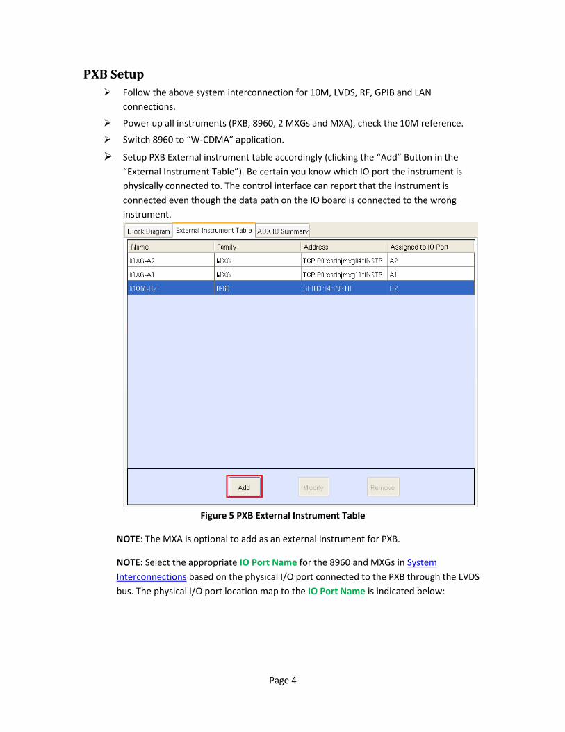
Setup PXB External instrument table accordingly (clicking the “Add” Button in the
“External Instrument Table”). Be certain you know which IO port the instrument is
physically connected to. The control interface can report that the instrument is
connected even though the data path on the IO board is connected to the wrong
instrument.
Figure 5 PXB External Instrument Table
NOTE: The MXA is optional to add as an external instrument for PXB.
NOTE: Select the appropriate IO Port Name for the 8960 and MXGs in System
Interconnections based on the physical I/O port connected to the PXB through the LVDS
bus. The physical I/O port location map to the IO Port Name is indicated below:
Page 5
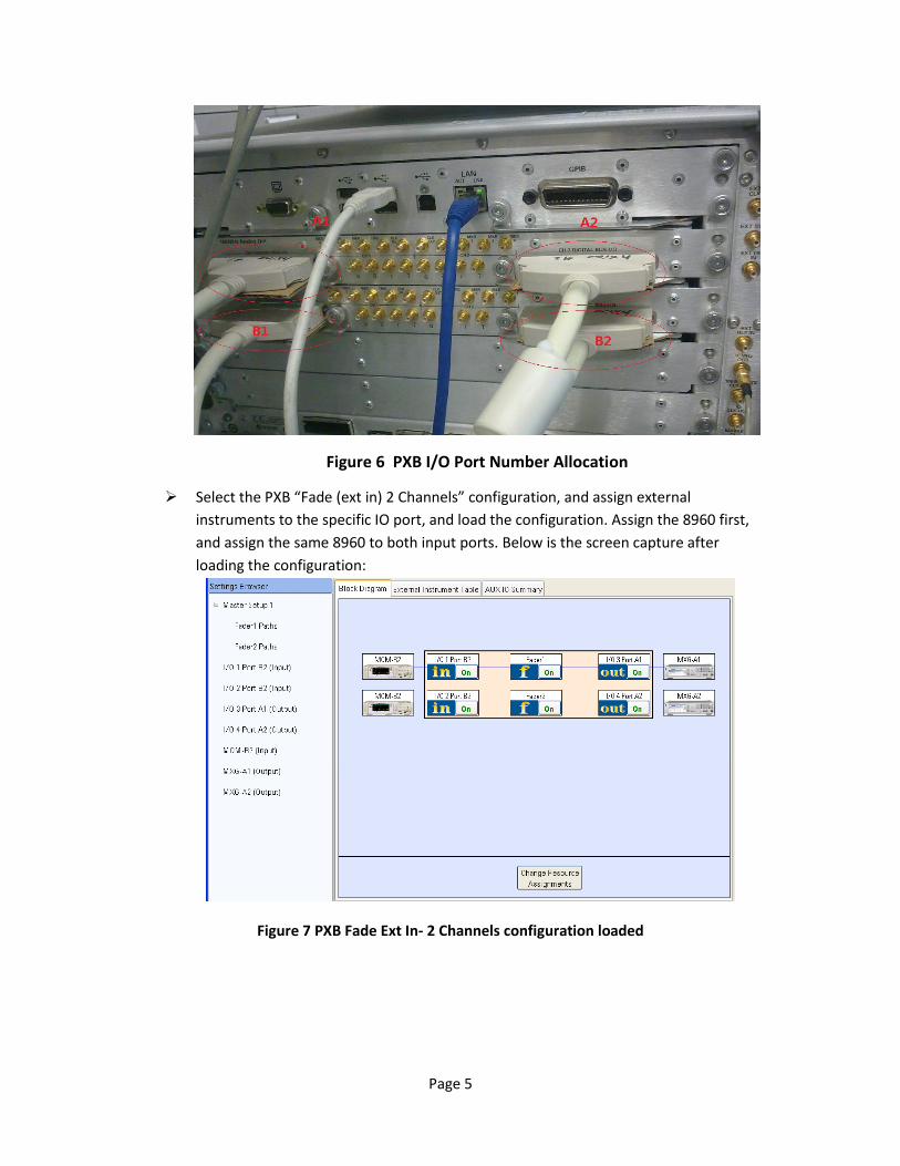
Figure 6 PXB I/O Port Number Allocation
Select the PXB “Fade (ext in) 2 Channels” configuration, and assign external
instruments to the specific IO port, and load the configuration. Assign the 8960 first,
and assign the same 8960 to both input ports. Below is the screen capture after
loading the configuration:
Figure 7 PXB Fade Ext In- 2 Channels configuration loaded
Page 6
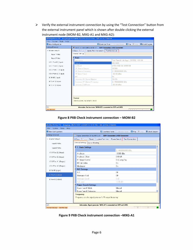
Verify the external instrument connection by using the “Test Connection” button from
the external instrument panel which is shown after double clicking the external
instrument node (MOM-B2, MXG-A1 and MXG-A2):
Figure 8 PXB Check instrument connection – MOM-B2
Figure 9 PXB Check instrument connection –MXG-A1
Page 7
NOTE: The 8960 and two MXGs should be checked to make sure that they are all
connected via SCPI and LVDS. If there are errors during the check, it means that there are
some connection problems either with SCPI or with LVDS. The connection problem
should be resolved before proceeding. Potential causes include LVDS cable, LAN cable,
GPIB cables and instrument hardware issue.
To facilitate diagnosing the LVDS connection issues, a few error messages will be
generated when there are some errors/exceptions during the coordinating the external
instruments and PXB. These errors will pop up in the GUI and also available with the
“SYSTEM:ERROR?” query.
Error ID: 107
Diagnose External Instrument Digital Interface Error: Digital cable on I/O port {0}
diagnose failed. <Specific failure information>
For <Specific failure information>, some actions may be helpful to recovery:
MXG
Signal Generator Input Setup failure : Preset or power cycle MXG LVDS alignment failure: check LVDS cable, Preset or power cycle MXG
DCM Reset failure: check LVDS cable, Preset or power cycle MXG
ARM failure: Preset or power cycle MXG/EXG
8960 (E5515E)
LVDS alignment failure: check LVDS cable, Preset or power cycle 8960
NOTE: When the instruments are moved or cables are replaced, it is highly recommended
that user should re-verify the external instrument connection before the fading tests.
Page 8
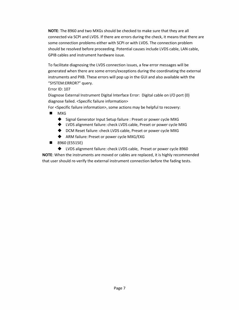
Config PXB fader with “Pass Through” for two channels
Figure 10 PXB Fader “Pass Through”
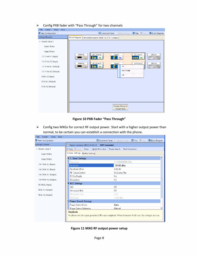
Config two MXGs for correct RF output power. Start with a higher output power than
normal, to be certain you can establish a connection with the phone.
Figure 11 MXG RF output power setup
Page 9
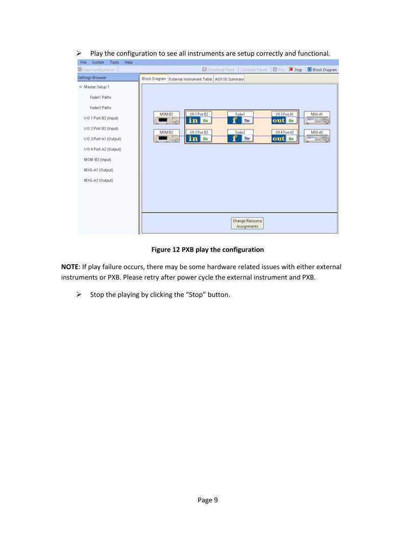
Play the configuration to see all instruments are setup correctly and functional.
Figure 12 PXB play the configuration
NOTE: If play failure occurs, there may be some hardware related issues with either external
instruments or PXB. Please retry after power cycle the external instrument and PXB.
Stop the playing by clicking the “Stop” button.
Page 10
Downlink Signal quality verification (optional) This step is optional but highly recommended. It is used to verify that the downlink signal is
good after PXB processing. 8960 is sending the HSDPA DC signal over LVDS to PXB, and MXA is
used to verify the downlink DC signal demodulation.
Config 8960 for HSDPA DC in FDD test mode:
Set Operating Mode to Cell Off [call:oper:mode off]
Set up DC-HSDPA working mode per test required. For example, using Preset Call
Configurations to setup a DC-HSDPA mode from the front panel of the 8960. Push
8960 CALL SETUP Button, select page 1 of 3 of Call Parms soft key menu and set
Call Parms -> 34.121 Preset Call Configs 6.3C:DC-HSDPA:16QAM
Set Operating Mode to FDD Test [call:oper:mode fddt]
Enable DC-HSDPA FRC H-Set 6A by selecting HSPA Parameters HSDPA
Parameters HS-DSCH Parameters FDD Test FRC Type H-Set 6A 16QAM
in page 1 of 3 of Call Parms soft key menu
Play the PXB
After the play is successful, use MXA to demodulate the downlink 2 channels using the
EVM measurement.
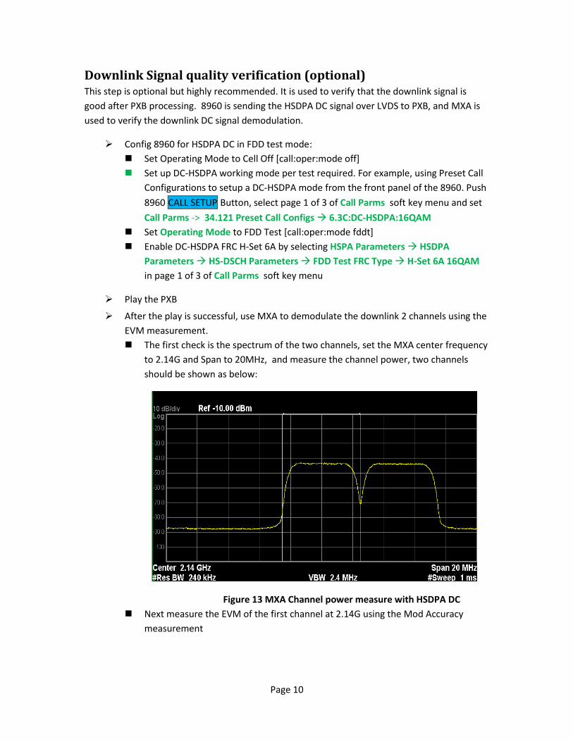
The first check is the spectrum of the two channels, set the MXA center frequency
to 2.14G and Span to 20MHz, and measure the channel power, two channels
should be shown as below:
Figure 13 MXA Channel power measure with HSDPA DC
Next measure the EVM of the first channel at 2.14G using the Mod Accuracy
measurement
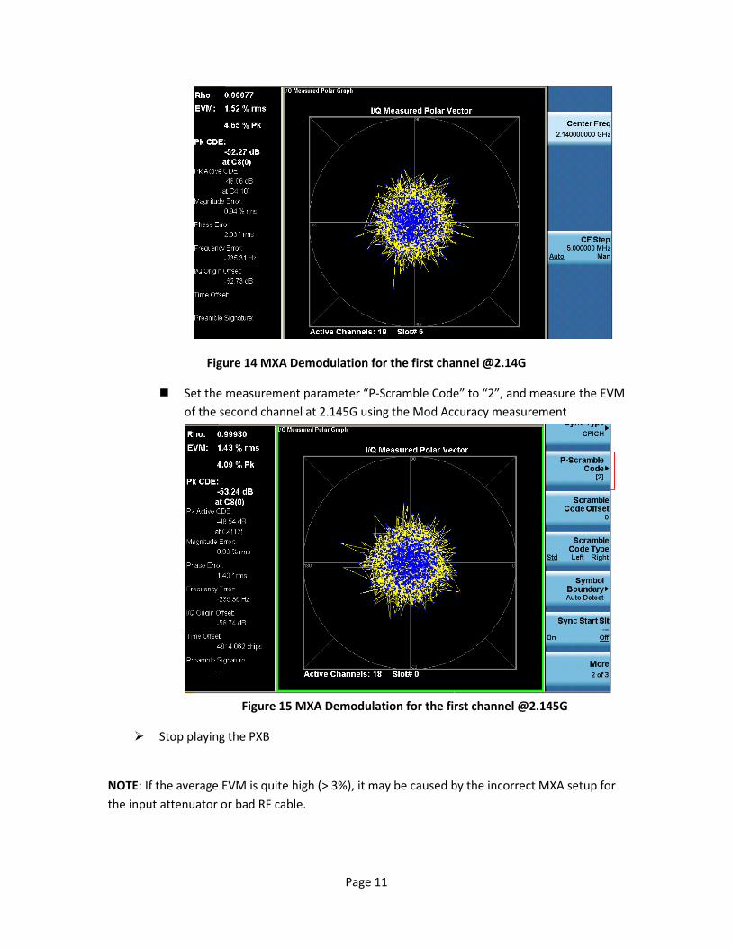
Page 11
Figure 14 MXA Demodulation for the first channel @2.14G
Set the measurement parameter “P-Scramble Code” to “2”, and measure the EVM
of the second channel at 2.145G using the Mod Accuracy measurement
Figure 15 MXA Demodulation for the first channel @2.145G
Stop playing the PXB
NOTE: If the average EVM is quite high (> 3%), it may be caused by the incorrect MXA setup for
the input attenuator or bad RF cable.
Page 12
Call establishment verification with UE
Config 8960 for HSDPA DC in active cell mode.
Set Operating Mode to Cell Off [call:oper:mode off]
Set up DC-HSDPA working mode per test required. For example, using Preset Call
Configurations to setup a DC-HSDPA mode from the front panel of the 8960. Push
8960 CALL SETUP Button, select page 1 of 3 of Call Parms soft key menu and set
Call Parms -> 34.121 Preset Call Configs 6.3C:DC-HSDPA:16QAM
Set Operating Mode to FDD Test [call:oper:mode fddt]
Enable DC-HSDPA FRC H-Set 6A by selecting HSPA Parameters HSDPA
Parameters HS-DSCH Parameters FDD Test FRC Type H-Set 6A 16QAM
in page 1 of 3 of Call Parms soft key menu
Set Operating Mode to Active Cell [call:oper:mode call]
Play the PXB
After the play is successful, use MXA to demodulate the first channel @2.14G as
detailed in the “Downlink Signal Quality Verification”. This is optional.
Configure UE
Switch on UE
Wait for UE to register
Call establishment with UE
Originate a Call[call:orig]
Wait till the call status changing to ‘Connected’
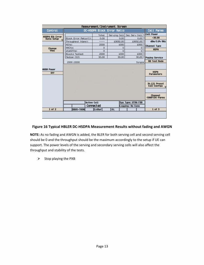
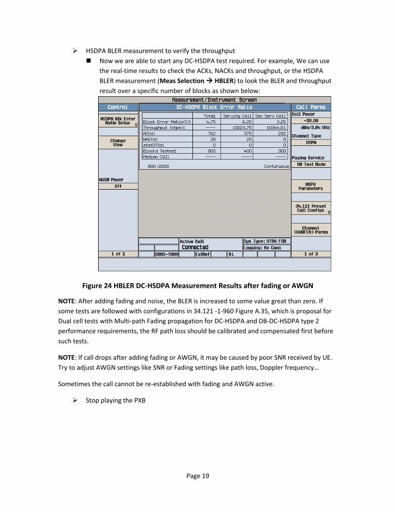
HSDPA BLER measurement to verify the throughput
Now we are able to start any DC-HSDPA test required. For example, We can use
the real-time results to check the ACKs, NACKs and throughput, or the HSDPA
BLER measurement (Meas Selection HBLER) to look the BLER and throughput
result over a specific number of blocks as shown in Figure :
Page 13
Figure 16 Typical HBLER DC-HSDPA Measurement Results without fading and AWGN
NOTE: As no fading and AWGN is added, the BLER for both serving cell and second serving cell
should be 0 and the throughput should be the maximum accordingly to the setup if UE can
support. The power levels of the serving and secondary serving cells will also affect the
throughput and stability of the tests.
Stop playing the PXB
Page 14
Specific fading profile setup and test If all above steps are all performed successfully, it means all instruments (PXB, 8960, MXG and
UE) are functional and all the cables are good. So we go ahead with the specific fading tests.
Due to the fact that the combiners and splitter are used for RF downlink and uplink, calibration
is required if some parametric fading tests are performed.
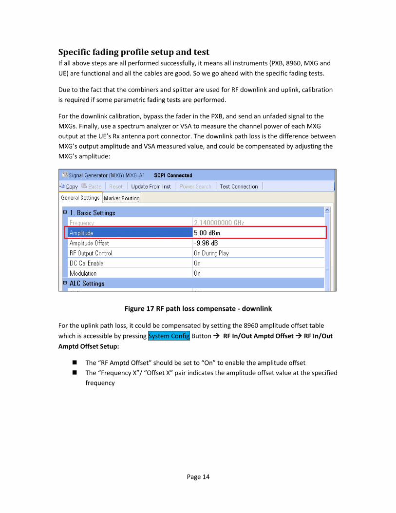
For the downlink calibration, bypass the fader in the PXB, and send an unfaded signal to the
MXGs. Finally, use a spectrum analyzer or VSA to measure the channel power of each MXG
output at the UE’s Rx antenna port connector. The downlink path loss is the difference between
MXG’s output amplitude and VSA measured value, and could be compensated by adjusting the
MXG’s amplitude:
Figure 17 RF path loss compensate - downlink
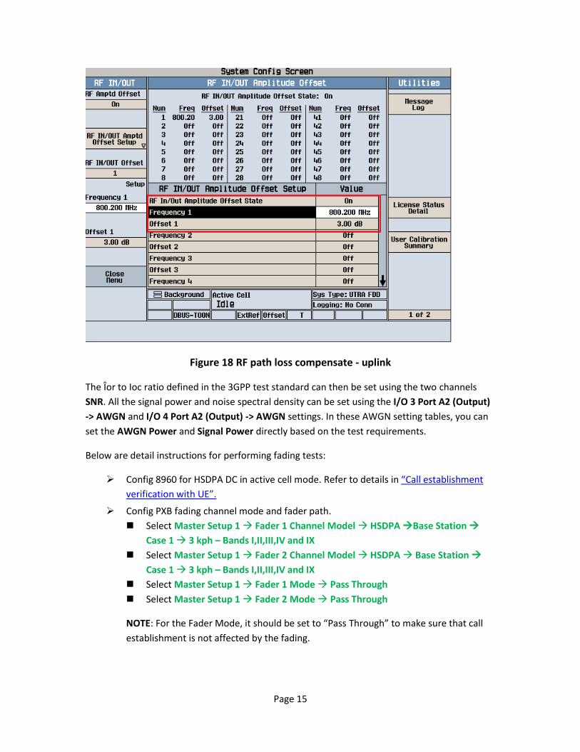
For the uplink path loss, it could be compensated by setting the 8960 amplitude offset table
which is accessible by pressing System Config Button RF In/Out Amptd Offset RF In/Out
Amptd Offset Setup:
The “RF Amptd Offset” should be set to “On” to enable the amplitude offset
The “Frequency X”/ “Offset X” pair indicates the amplitude offset value at the specified
frequency
Page 15
Figure 18 RF path loss compensate - uplink
The Îor to Ioc ratio defined in the 3GPP test standard can then be set using the two channels
SNR. All the signal power and noise spectral density can be set using the I/O 3 Port A2 (Output)
-> AWGN and I/O 4 Port A2 (Output) -> AWGN settings. In these AWGN setting tables, you can
set the AWGN Power and Signal Power directly based on the test requirements.
Below are detail instructions for performing fading tests:
Config 8960 for HSDPA DC in active cell mode. Refer to details in “Call establishment
verification with UE”.
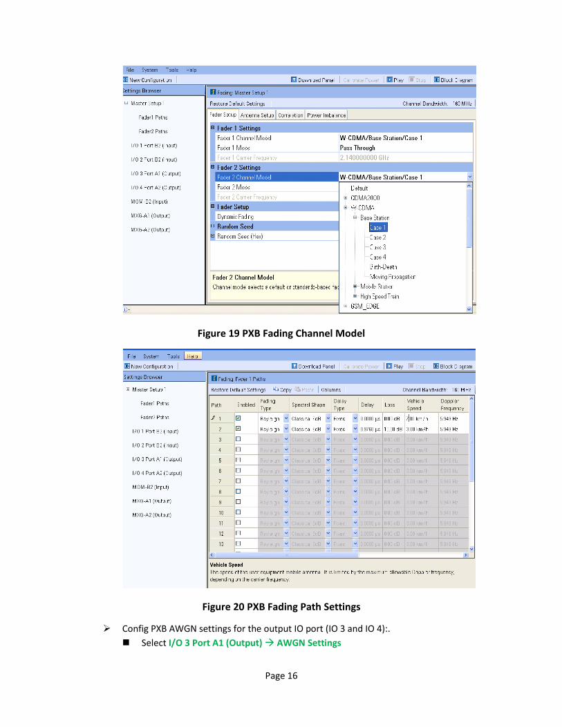
Config PXB fading channel mode and fader path.
Select Master Setup 1 Fader 1 Channel Model HSDPA Base Station
Case 1 3 kph – Bands I,II,III,IV and IX
Select Master Setup 1 Fader 2 Channel Model HSDPA Base Station
Case 1 3 kph – Bands I,II,III,IV and IX
Select Master Setup 1 Fader 1 Mode Pass Through
Select Master Setup 1 Fader 2 Mode Pass Through
NOTE: For the Fader Mode, it should be set to “Pass Through” to make sure that call
establishment is not affected by the fading.
Page 16
Figure 19 PXB Fading Channel Model
Figure 20 PXB Fading Path Settings
Config PXB AWGN settings for the output IO port (IO 3 and IO 4):.
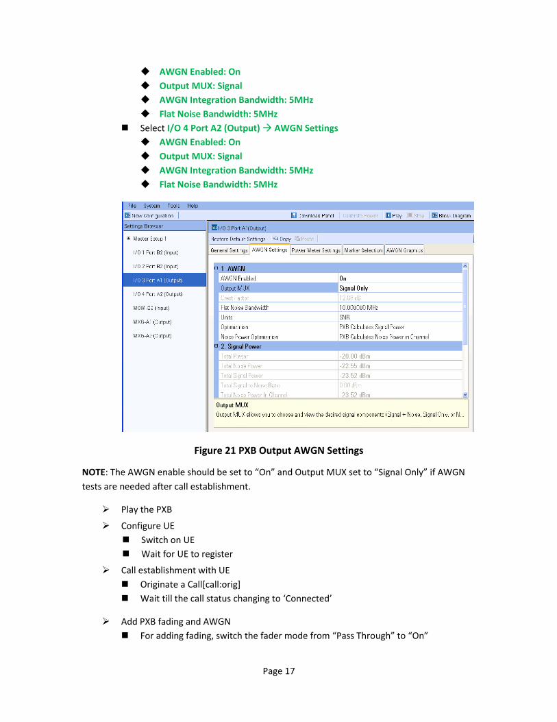
Select I/O 3 Port A1 (Output) AWGN Settings
Page 17
AWGN Enabled: On
Output MUX: Signal
AWGN Integration Bandwidth: 5MHz
Flat Noise Bandwidth: 5MHz
Select I/O 4 Port A2 (Output) AWGN Settings
AWGN Enabled: On
Output MUX: Signal
AWGN Integration Bandwidth: 5MHz
Flat Noise Bandwidth: 5MHz
Figure 21 PXB Output AWGN Settings
NOTE: The AWGN enable should be set to “On” and Output MUX set to “Signal Only” if AWGN
tests are needed after call establishment.
Play the PXB
Configure UE
Switch on UE
Wait for UE to register
Call establishment with UE
Originate a Call[call:orig]
Wait till the call status changing to ‘Connected’
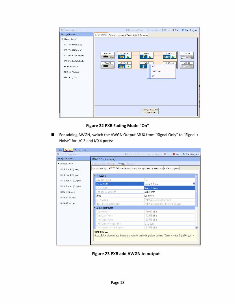
Add PXB fading and AWGN
For adding fading, switch the fader mode from “Pass Through” to “On”
Page 18
Figure 22 PXB Fading Mode “On”
For adding AWGN, switch the AWGN Output MUX from “Signal Only” to “Signal +
Noise” for I/0 3 and I/0 4 ports:
Figure 23 PXB add AWGN to output
Page 19
HSDPA BLER measurement to verify the throughput
Now we are able to start any DC-HSDPA test required. For example, We can use
the real-time results to check the ACKs, NACKs and throughput, or the HSDPA
BLER measurement (Meas Selection HBLER) to look the BLER and throughput
result over a specific number of blocks as shown below:
Figure 24 HBLER DC-HSDPA Measurement Results after fading or AWGN
NOTE: After adding fading and noise, the BLER is increased to some value great than zero. If
some tests are followed with configurations in 34.121 -1-960 Figure A.35, which is proposal for
Dual cell tests with Multi-path Fading propagation for DC-HSDPA and DB-DC-HSDPA type 2
performance requirements, the RF path loss should be calibrated and compensated first before
such tests.
NOTE: If call drops after adding fading or AWGN, it may be caused by poor SNR received by UE.
Try to adjust AWGN settings like SNR or Fading settings like path loss, Doppler frequency…
Sometimes the call cannot be re-established with fading and AWGN active.
Stop playing the PXB
Page 20
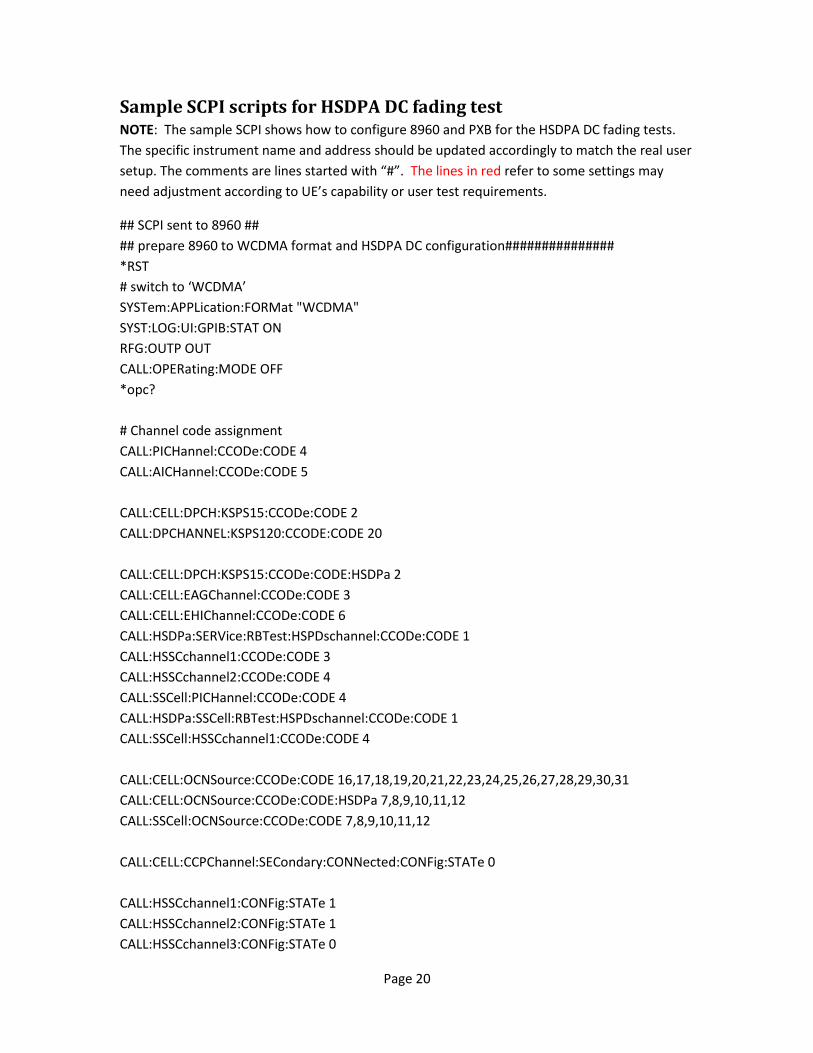
Sample SCPI scripts for HSDPA DC fading test NOTE: The sample SCPI shows how to configure 8960 and PXB for the HSDPA DC fading tests.
The specific instrument name and address should be updated accordingly to match the real user
setup. The comments are lines started with “#”. The lines in red refer to some settings may
need adjustment according to UE’s capability or user test requirements.
## SCPI sent to 8960 ##
## prepare 8960 to WCDMA format and HSDPA DC configuration###############
*RST
# switch to ‘WCDMA’
SYSTem:APPLication:FORMat "WCDMA"
SYST:LOG:UI:GPIB:STAT ON
RFG:OUTP OUT
CALL:OPERating:MODE OFF
*opc?
# Channel code assignment
CALL:PICHannel:CCODe:CODE 4
CALL:AICHannel:CCODe:CODE 5
CALL:CELL:DPCH:KSPS15:CCODe:CODE 2
CALL:DPCHANNEL:KSPS120:CCODE:CODE 20
CALL:CELL:DPCH:KSPS15:CCODe:CODE:HSDPa 2
CALL:CELL:EAGChannel:CCODe:CODE 3
CALL:CELL:EHIChannel:CCODe:CODE 6
CALL:HSDPa:SERVice:RBTest:HSPDschannel:CCODe:CODE 1
CALL:HSSCchannel1:CCODe:CODE 3
CALL:HSSCchannel2:CCODe:CODE 4
CALL:SSCell:PICHannel:CCODe:CODE 4
CALL:HSDPa:SSCell:RBTest:HSPDschannel:CCODe:CODE 1
CALL:SSCell:HSSCchannel1:CCODe:CODE 4
CALL:CELL:OCNSource:CCODe:CODE 16,17,18,19,20,21,22,23,24,25,26,27,28,29,30,31
CALL:CELL:OCNSource:CCODe:CODE:HSDPa 7,8,9,10,11,12
CALL:SSCell:OCNSource:CCODe:CODE 7,8,9,10,11,12
CALL:CELL:CCPChannel:SECondary:CONNected:CONFig:STATe 0
CALL:HSSCchannel1:CONFig:STATe 1
CALL:HSSCchannel2:CONFig:STATe 1
CALL:HSSCchannel3:CONFig:STATe 0
Page 21
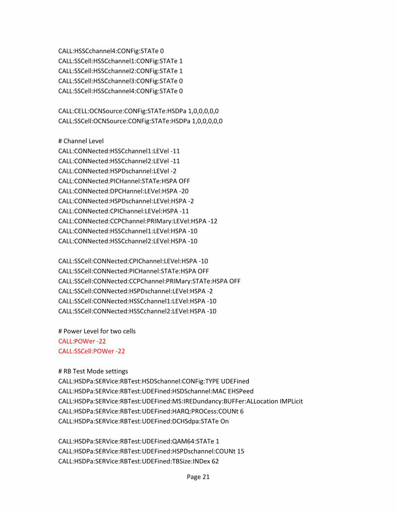
CALL:HSSCchannel4:CONFig:STATe 0
CALL:SSCell:HSSCchannel1:CONFig:STATe 1
CALL:SSCell:HSSCchannel2:CONFig:STATe 1
CALL:SSCell:HSSCchannel3:CONFig:STATe 0
CALL:SSCell:HSSCchannel4:CONFig:STATe 0
CALL:CELL:OCNSource:CONFig:STATe:HSDPa 1,0,0,0,0,0
CALL:SSCell:OCNSource:CONFig:STATe:HSDPa 1,0,0,0,0,0
# Channel Level
CALL:CONNected:HSSCchannel1:LEVel -11
CALL:CONNected:HSSCchannel2:LEVel -11
CALL:CONNected:HSPDschannel:LEVel -2
CALL:CONNected:PICHannel:STATe:HSPA OFF
CALL:CONNected:DPCHannel:LEVel:HSPA -20
CALL:CONNected:HSPDschannel:LEVel:HSPA -2
CALL:CONNected:CPIChannel:LEVel:HSPA -11
CALL:CONNected:CCPChannel:PRIMary:LEVel:HSPA -12
CALL:CONNected:HSSCchannel1:LEVel:HSPA -10
CALL:CONNected:HSSCchannel2:LEVel:HSPA -10
CALL:SSCell:CONNected:CPIChannel:LEVel:HSPA -10
CALL:SSCell:CONNected:PICHannel:STATe:HSPA OFF
CALL:SSCell:CONNected:CCPChannel:PRIMary:STATe:HSPA OFF
CALL:SSCell:CONNected:HSPDschannel:LEVel:HSPA -2
CALL:SSCell:CONNected:HSSCchannel1:LEVel:HSPA -10
CALL:SSCell:CONNected:HSSCchannel2:LEVel:HSPA -10
# Power Level for two cells
CALL:POWer -22
CALL:SSCell:POWer -22
# RB Test Mode settings
CALL:HSDPa:SERVice:RBTest:HSDSchannel:CONFig:TYPE UDEFined
CALL:HSDPa:SERVice:RBTest:UDEFined:HSDSchannel:MAC EHSPeed
CALL:HSDPa:SERVice:RBTest:UDEFined:MS:IREDundancy:BUFFer:ALLocation IMPLicit
CALL:HSDPa:SERVice:RBTest:UDEFined:HARQ:PROCess:COUNt 6
CALL:HSDPa:SERVice:RBTest:UDEFined:DCHSdpa:STATe On
CALL:HSDPa:SERVice:RBTest:UDEFined:QAM64:STATe 1
CALL:HSDPa:SERVice:RBTest:UDEFined:HSPDschannel:COUNt 15
CALL:HSDPa:SERVice:RBTest:UDEFined:TBSize:INDex 62
Page 22
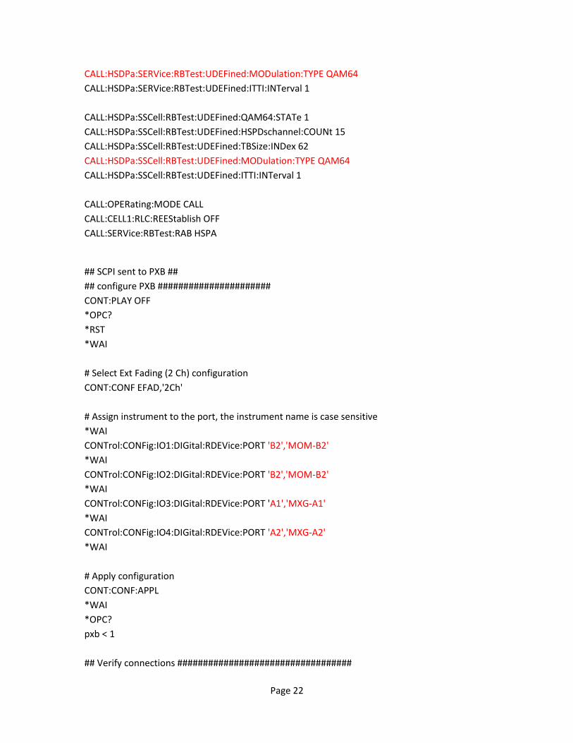
CALL:HSDPa:SERVice:RBTest:UDEFined:MODulation:TYPE QAM64
CALL:HSDPa:SERVice:RBTest:UDEFined:ITTI:INTerval 1
CALL:HSDPa:SSCell:RBTest:UDEFined:QAM64:STATe 1
CALL:HSDPa:SSCell:RBTest:UDEFined:HSPDschannel:COUNt 15
CALL:HSDPa:SSCell:RBTest:UDEFined:TBSize:INDex 62
CALL:HSDPa:SSCell:RBTest:UDEFined:MODulation:TYPE QAM64
CALL:HSDPa:SSCell:RBTest:UDEFined:ITTI:INTerval 1
CALL:OPERating:MODE CALL
CALL:CELL1:RLC:REEStablish OFF
CALL:SERVice:RBTest:RAB HSPA
## SCPI sent to PXB ##
## configure PXB ######################
CONT:PLAY OFF
*OPC?
*RST
*WAI
# Select Ext Fading (2 Ch) configuration
CONT:CONF EFAD,'2Ch'
# Assign instrument to the port, the instrument name is case sensitive
*WAI
CONTrol:CONFig:IO1:DIGital:RDEVice:PORT 'B2','MOM-B2'
*WAI
CONTrol:CONFig:IO2:DIGital:RDEVice:PORT 'B2','MOM-B2'
*WAI
CONTrol:CONFig:IO3:DIGital:RDEVice:PORT 'A1','MXG-A1'
*WAI
CONTrol:CONFig:IO4:DIGital:RDEVice:PORT 'A2','MXG-A2'
*WAI
# Apply configuration
CONT:CONF:APPL
*WAI
*OPC?
pxb < 1
## Verify connections ##################################
Page 23
## Before sending the query, set the PXB timeout to 30 seconds to avoid timeout error
## Should return "Pass" IO1 - Mom-B2; IO3 – MXG-A1 #
## IO4 – MXG-A2 #
CONTrol:CONFig:IO1:DIGital:RDEVice:DIAGnostic?
pxb < "Pass"
CONTrol:CONFig:IO3:DIGital:RDEVice:DIAGnostic?
pxb < "Pass"
CONTrol:CONFig:IO4:DIGital:RDEVice:DIAGnostic?
pxb < "Pass"
## Config PXB Fading #########################
FSIM1:FAD1:STAN:TECH HSDPA
FSIM1:FAD1:STAN:SCEN CAS1
FSIM1:FAD1:STAN:LINK BASE
FSIM1:FAD1:STAN:FBAN 1
FSIM1:FAD1:VSPeed 3
FSIM1:FAD1:MODE THR
FSIM1:FAD2:STAN:TECH HSDPA
FSIM1:FAD2:STAN:SCEN CAS1
FSIM1:FAD2:STAN:LINK BASE
FSIM1:FAD2:STAN:FBAN 1
FSIM1:FAD2:VSPeed 3
FSIM1:FAD2:MODE THR
## Config PXB AWGN ###################
CONTrol:IO3:OUTPut:AWGN:ENABle 1
CONTrol:IO3:OUTPut:AWGN:MUX SIGN
CONTrol:IO3:OUTPut:AWGN:IBANdwidth 5000000
CONTrol:IO3:OUTPut:AWGN:NBANdwidth 5000000
CONTrol:IO3:OUTPut:AWGN:OPTimization Noise
CONTrol:IO3:OUTPut:AWGN:SNR 0
CONTrol:IO3:OUTPut:AWGN:SPOWER -22
CONTrol:IO4:OUTPut:AWGN2:ENABle 1
CONTrol:IO4:OUTPut:AWGN2:MUX SIGN
CONTrol:IO4:OUTPut:AWGN2:IBANdwidth 5000000
CONTrol:IO4:OUTPut:AWGN2:NBANdwidth 5000000
CONTrol:IO4:OUTPut:AWGN2:OPTimization Noise
CONTrol:IO4:OUTPut:AWGN2:SNR 0
CONTrol:IO4:OUTPut:AWGN2:SPOWER -22
## Play configuration ###
Page 24
CONT:PLAY ON
*WAI
*OPC?
pxb < 1
# Check PXB play status
:CONTrol:PLAY:STATe?
pxb < 1
## SCPI sent to 8960 ##
## setup call connection with UE
[usr > setup call connection, then continue]
call:orig
## SCPI sent to PXB ##
## enable PXB Fading and AWGN ######################
FSIM1:FAD1:MODE ON
FSIM1:FAD2:MODE ON
CONTrol:IO3:OUTPut:AWGN:MUX SUM
CONTrol:IO4:OUTPut:AWGN2:MUX SUM
## SCPI sent to 8960 ##
## enable 8960 HBLER measurement ######################
SETup:HBLerror:COUNt 10000
SETup:HBLerror:COUNt:DCHSdpa:STATe On
SETup:HBLerror:CONTinuous OFF
INITiate:HBLerror
INITiate:DONE?
FETCh:HBLerror?
Below attachment is the sequence which can be played by Agilent Command Expert. Agilent
Command Expert is free and available at: http://www.agilent.com/find/CommandExpert.
To run the below sequence, you need to follow the instructions below:
- Setup the test system and interconnect all the devices, check 10M reference clock
- Power up all instruments (PXB, 8960, 2 MXGs)
- Setup PXB External Instrument Table according to the setup
- Run Agilent Command Expert, and load the Sequence file below
- Update the Instruments’ name, address and connections in the sequence
- Play the sequence
PXB_8960_DC_BB_Fading.iseq