Embed Size (px)
Citation preview

#8987 6” Vac-Assist Trash Pump Operation & Maintenance Manual

i
Table of Contents
SPECIFICATIONS ...................................................................................................................................... 1 HEAD CAPACITY CURVE ............................................................................................................................. 3
PREPARE PUMP FOR OPERATION ...................................................................................................... 4
PUMP PRIMING SYSTEM........................................................................................................................ 5 HOW IT WORKS............................................................................................................................................ 5 FIGURE 1 ..................................................................................................................................................... 6
Priming System-Major Mechanical Components ................................................................................... 6 Figure 2 .................................................................................................................................................. 7
PRIMING SYSTEM OPERATING INSTRUCTIONS ............................................................................ 8 MODES OF OPERATION................................................................................................................................ 8
Automatic Mode (AUTO)........................................................................................................................ 8 Off Mode (OFF) ..................................................................................................................................... 8 Manual Mode (MAN) ............................................................................................................................. 8
PUMP MAINTENANCE............................................................................................................................. 9 ENGINE........................................................................................................................................................ 9 COMPRESSOR .............................................................................................................................................. 9 SEALS.......................................................................................................................................................... 9 BEARINGS ................................................................................................................................................... 9 IMPELLER GAP ............................................................................................................................................ 9 PRIMING VALVE.......................................................................................................................................... 9 PRESSURE SWITCH .................................................................................................................................... 10 DISCHARGE CHECK VALVE....................................................................................................................... 10 BELTS-COMPRESSOR DRIVE...................................................................................................................... 10
TROUBLE SHOOTING............................................................................................................................ 12 PUMP FAILS TO PRIME............................................................................................................................... 12
General................................................................................................................................................. 12 Pump..................................................................................................................................................... 12
TROUBLE SHOOTING FLOWCHART ............................................................................................................ 14 Pump does not prime ............................................................................................................................ 14
TROUBLE SHOOTING FLOWCHART ............................................................................................................ 15 (Continued-Pump does not prime)........................................................................................................ 15
AUTOMATIC PRIMING SYSTEM FLOWCHART............................................................................................. 16 Priming system works in manual (MAN) mode but not in automatic (AUTO) mode............................ 16
FLOWCHART.............................................................................................................................................. 17 Compressor shutting off early .............................................................................................................. 17
FLOWCHART.............................................................................................................................................. 18 Compressor does not shut off ............................................................................................................... 18
TESTING PROCEDURES .............................................................................................................................. 19 #1 Clutch Test....................................................................................................................................... 19 #2 Clutch Test....................................................................................................................................... 19 #3 Eductor Vacuum Test....................................................................................................................... 20 #4 Continuity Test................................................................................................................................. 20 #5 Voltage Test ..................................................................................................................................... 20 #6 Continuity Test................................................................................................................................. 20 #7 Pressure Switch Test........................................................................................................................ 20
ii
AUTOMATIC PRIMING SYSTEM ADJUSTMENTS.......................................................................................... 21 FIGURE 3 ................................................................................................................................................... 22 EXPLODED VIEW OF PUMP ASSEMBLY...................................................................................................... 22 FIGURE 4 ................................................................................................................................................... 23
Bearing Support Cross-Section ............................................................................................................ 23 Parts List – Figure 3............................................................................................................................. 24 Parts List (cont.) – Figure 3 ................................................................................................................. 25
FIGURE 5 ................................................................................................................................................... 26 W324-001-ASSM (Priming Valve Assembly)........................................................................................ 26
FIGURE 6 ................................................................................................................................................... 27 W327-001 (Discharge Flapper Valve) ................................................................................................. 27
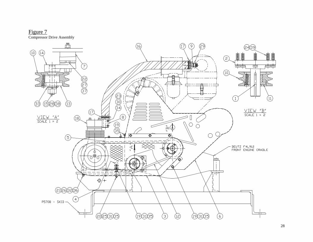
FIGURE 7 ................................................................................................................................................... 28 Compressor Drive Assembly ................................................................................................................ 28 Parts List – Figure 7............................................................................................................................. 29
FIGURE 8 ................................................................................................................................................... 30 Plumbing Layout .................................................................................................................................. 30 Parts List – Figure 8............................................................................................................................. 31
FIGURE 9 ................................................................................................................................................... 33 Electrical Box Assembly ....................................................................................................................... 33 Parts List – Figure 9............................................................................................................................. 34
FIGURE 9/1 ................................................................................................................................................ 35 SERVICE INSTRUCTIONS..................................................................................................................... 36
MECHANICAL SEAL................................................................................................................................... 36 Mechanical Seal Removal .................................................................................................................... 36 Mechanical Seal Installation ................................................................................................................ 38
RADIAL LIP SEAL REPLACEMENT.............................................................................................................. 38 FIGURE 10 ................................................................................................................................................. 39
Wear-Sleeve Installation....................................................................................................................... 39 FIGURE 11 ................................................................................................................................................. 40
Tool No. X3004..................................................................................................................................... 40 FIGURE 12 ................................................................................................................................................. 40
Tool No. X2176..................................................................................................................................... 40 FIGURE 13 ................................................................................................................................................. 41
Tool No. X3005..................................................................................................................................... 41 BEARING REPLACEMENT........................................................................................................................... 42 FIGURE 14 ................................................................................................................................................. 43
Coupling Hub ....................................................................................................................................... 43
1
Specifications Pump:
6” NPT female suction 6” NPT female discharge Maximum capacity: 1550 gpm (93,000 gph) Maximum total head: 145 feet Maximum suction lift: 28 feet Maximum spherical solids: 3”
Discharge capacity and suction lift (see HEAD CAPACITY CURVE, on page 3) Impeller-3 vane, ductile iron Volute-ductile iron, replaceable
Bearings: Double row ball bearing Single row ball bearing
Bearing Lubrication: NLGI Grade 2 high temperature, lithium complex grease
Shaft: 4340 heat-treated alloy
Seal: Single mechanical Faces: Silicon Carbide/Tungsten Carbide Elastomer: Viton Steel Parts: Type 304 stainless steel
Seal Lubrication: Synthetic ISO grade 46 oil
Discharge Check Valve: Flapper style, Buna-N elastomer
Compressor: 18 cfm @ 100 psi 1200 rpm, 5 hp 12 VDC, 4 amp, magnetic clutch
Eductor: 27” hg maximum vacuum Input pressure: 60 psi Air usage: 18 scfm Maximum flow: 10.7 scfm
Priming Valve: Float actuated shutoff in protected chamber
Control System: 12 VDC electro-mechanical relay/timer with pressure switch activation Choice of Automatic or Manual control

2
Engine:
Make/Model: DEUTZ F4L913 HP @ RPM (Max.): 80 @ 2800 HP @ RPM (Cont.): 63 @ 2300 No Load RPM: 2300
No. of Cylinders: 4 Displacement: 250 cu. in. (4,1L) Cooling System: Air Alternator: 55 Amps @ 14 VDC
Flywheel: 10” Over-center Clutch Type Bell Housing: SAE #3
Automatic Shutdowns: Low Oil Pressure, High Head Temp. & Fan Belt Breakage Standard Gauges: Oil Pressure, Temperature, Tachometer, Hour meter & Ammeter
Fuel Tank: 75 gallon capacity w/ gauge in cap Separate tank mounted in protected area of trailer (skid) Run time: Approximately 20-30 hours depending on load
Trailer: Axle: 6000 Lb. capacity, rubber torsion axle with 64 ¼” track width
Wheels: H78-15 tire; load capacity “D” (2370 lbs.); mounted on 15” rims with 6 bolt on a 5 ½” bolt circle
Fenders: Heavy duty steel fenders (8 gauge) with non-slip step pad Jacks: (3) top wind; 2000-lb. capacity Tail Lights: Sealed, rubber grommet mounted; wiring protected in trailer frame Hitch: 3” I.D. pintle eye (standard)

3
Head Capacity CurveMODEL #8987
Head Capacity Curve

4
ABS Dewatering Operation and Maintenance Manual #8900 Series 6” Vac-Assist Trash Pump
Drive Belts must be guarded while pump is operating. Read engine operation manual for starting, stopping, throttling and maintenance instructions. Read compressor operation and parts manual. Read pump safety manual. Prepare Pump for Operation
1) Level the pump assembly on solid ground. On trailer models, screw jacks down to ground. 2) Check fluid levels:
a) Engine oil (and coolant if engine is water cooled) b) Compressor oil c) Seal chamber oil (¾ up the sight level glass in the side of the bearing tube) d) Fuel
3) Connect hoses (fittings) as required to the suction and discharge ports of the pump. Support hoses/piping so that there is a maximum load on the pump ports of approximately 250 lbs. Make sure good gaskets are in place in the hose fittings. Use pipe joint compound on pipe threads to ensure tight joints. Use the strainer provided for the end of the suction hose.
4) Close drain valves (in pump case and in the bottom of the discharge check valve) and vacuum-break valve (on top of float chamber).
5) Set priming system toggle switch (inside the priming system electrical control box) to the “AUTO” position. (See PRIMING SYSTEM OPERATING INSTRUCTIONS, on page 8, for explanation of other choices for the switch position.)
6) Start the engine per the manufacturers’ instructions. Observe overall operation with the engine
idling-look for loose fittings, etc. Bring engine up to speed (2200 rpm max).
7) Priming time will depend on suction lift and length of suction hose (pipe). If the pump has not primed within five minutes, and the end of the suction line is known to be in water, shut the engine off and trouble shoot the problem (See TROUBLE SHOOTING, on page 12).
8) Adjust speed (2200 rpm max) for desired flow.
Caution: Hearing protection is recommended !
Warning: Do not run engine indoors or in a confined area where deadly exhaust fumes could accumulate
Caution: The compressor, compressor piping, eductor, and eductor exhaust will be very hot-DO NOT
!
!

5
Pump Priming System
The CH&E Series #8900 6” Trash Pumps are equipped with a vacuum assisted priming system. This system not only allows higher lifts (up to 28 feet), but it also eliminates the need for filling the pump case with water in order to prime the pump. Additionally, it automatically reprimes the pump in situations where the pump might lose its prime due to a varying water level. A special oil lubricated hard face seal will operate indefinitely without pumpage flowing through the pump. The auto-priming system and hard face seal allows longer unattended operating times.
How it works
The main components of the priming system are (see FIGURE 1, on page 6, & FIGURE 2, on page 7): 1) 18 cfm @ 100 psi compressor with 12VDC electric clutch 2) Single stage eductor “vacuum pump” 3) Priming valve to prevent water from entering the low pressure eductor line upon pump
priming and to allow the pump to operate under positive suction head (up to 20 psig) 4) Check valve in low pressure eductor line 5) Pressure switch 6) Timer (12VDC) 7) Bypass-switch for manual operation
High-pressure air (approximately 60 psig) from the compressor is directed to the eductor
inlet. The air flows through a small nozzle, which creates a low-pressure region inside the eductor housing. This low-pressure region of the eductor is connected to the pump casing via a ⅝” hose. The air inside the pump and suction line (the discharge line is blocked with a 6” flap check valve) is drawn into the eductor and blown out to atmosphere with the compressed air through the eductor exhaust. Evacuating the air out of the pump case and suction line creates a low pressure, which allows atmospheric pressure to “push” the water up the suction line into the pump, thus priming the pump. After the pump has primed, pressure in the pump case will increase to the system pressure. The pressure switch trips open with the positive pump case pressure, which signals a timer to shut down the compressor after a preset amount of time (approximately 1-3 minutes). The timer is necessary for those situations where the water level is changing (either lowering or rising) and the pump is quickly cycling between negative and positive pressure and where, without the timer, the compressor would be cycling on and off very quickly. The timer allows the compressor to run continuously through the unsteady condition until the pump reaches a steady state-either positive pressure, in which case the compressor shuts off, or negative pressure, in which case the compressor stays on until the pump primes again.
The entrance of the low pressure line of the eductor into the pump case is at the top of a priming valve, which is bolted into a large expansion chamber connected to the suction tee on the front of the pump. The large expansion chamber and priming valve prevent pumpage from being drawn into the eductor. As water rises into the expansion chamber, it also enters the float chamber around a steel baffle plate and through a filter screen to cause the float to rise which in turn moves a plug up against the entrance port of the low pressure eductor line thus effectively blocking pumpage from entering the line.
A check valve is installed in the low pressure line at the eductor to prevent back siphoning of the suction line on pump shut down and to prevent air from being drawn into the suction line during periods of pumping water and with the compressor off. Without the check valve, the low-pressure line is open to atmosphere through the eductor.
A three-position toggle switch allows the timer and pressure switch to be bypassed and the operator can control compressor operation.

6
Valve Not Shown)(Discharge CheckFemale Discharge6" NPT
Drain
6" NPT
SuctionFemale
Volute
Impeller
Priming
Screen
AssemblyValve
Valve/Flush PortVacuum Break
LinePressureHight
Exhaust
LinePressure
Low
Eductor
ValveCheck
SwitchPressure
ReliefPressure
Valve
Compressor
Screen Ringw/Baffle Plate
Float Tube
Figure 1 Priming System-Major Mechanical Components

7
Pow
er fr
omE
ngin
eC
ontr
ol B
lock
Time Delay Relay
To Compressor
10A
Fus
e
Pressure Signalfrom Pump
Pressure Switch
Compressor
Figure 2 Priming System-Major Electrical Components

8
Priming System Operating Instructions Modes of Operation
Inside the priming system electrical control box is a three position toggle switch which allows either “Automatic” or “Manual” operation of the vac-assist priming system.
Automatic Mode (AUTO) This is the “standard” mode of operation and the switch will be set in this
position from the factory. The series of events that automatically take place in priming a “dry” pump are (after the engine is started):
1. Magnetic clutch of compressor is engaged and the priming system operates as described above.
2. Pump catches prime and pressure in pump case rises to a level to activate (open) the pressure switch (3 psi set at factory, but field adjustable).
3. Timer activates and with steady pressure in the pump case, the compressor will shut off in one to three minutes (set at factory, but field adjustable). The compressor will remain off as long as pumping continues.
4. If the water level goes below the end of the suction hose or low enough that the pump is drawing in enough air to cause a loss of prime, the pressure in the pump case will go negative and the pressure switch will close which will cause the compressor to engage and start the priming cycle over again. The timer will keep the compressor on through periods of surging where the pump catches prime and quickly loses it again. Surging will occur when the water level is near the end of the suction hose. The priming system will remain activated (compressor on) until such a time as the pump catches prime and maintains a steady positive pressure on the pump.
Off Mode (OFF) With the toggle switch in the “OFF” position, the priming system is shut down
(compressor off) and will remain off until such a time as it is when the switch is put in either the “AUTO” mode or “MAN” (manual) mode. This switch position is useful if it is apparent that either the pressure switch or timer has failed to shut down the compressor after several (10-15) minutes of operation at steady state pumping with sufficient pressure in the pump case to normally activate the pressure switch (3 psig). The “OFF” position can also be used in pumping situations where there is positive suction head. Manual Mode (MAN)
With the switch in the “MAN” position, the priming system is activated (compressor on) and will remain on until such a time as when the toggle switch is put in either the “OFF” or “AUTO” position. Note that switching to the “AUTO” position will not necessarily shut the compressor off. It will shut off in the “AUTO” position if the pump is under conditions of positive pump case pressure (pumping water) and then only after the time delay period of the timer has expired (1-3 minutes). The “MAN” switch position is useful if for some reason the pressure switch and/or timer has failed to activate the system when the pump is in need of priming.
9
Pump Maintenance Engine
Refer to engine manufacturers’ manual for maintenance information.
Compressor Refer to separate manual for maintenance instructions. Oil Quantity: ¾ quart (24 oz) (.7 L) Oil Type: CH&E Part No. W115-001, ISO Grade 46 synthetic (PAO) oil, JAX SYNCOMP 46 or equivalent
Seals Check the oil level in the pump seal chamber daily. The oil level should
be ¾ up the glass of the sight gauge on the right side (when looking at the pump) of the bearing tube. Add oil through the ⅜” pipe tap in the top of the seal chamber (remove chamber breather). Oil Quantity: 1 ¼ quarts (40 oz) (1.2 L) Oil Type: C. H. & E. Part No. W115-001, ISO Grade 46 synthetic (PAO) oil, JAX SYNCOMP 46 or equivalent
Bearings The pump shaft is supported by a double-row ball bearing at the pump end
of the shaft and a single-row bearing at the engine end of the shaft. The bearings are grease lubricated.
Lubrication Interval: 500 hours or every 2 months (whichever comes first) Grease Quantity: Approximately 6 to 8 strokes of a grease gun Grease Type: NLGI Grade 2, high temperature, and lithium complex grease.
Exxon Ronex MP or equivalent.
Impeller Gap For optimum pump performance, the gap between the impeller blades and
the volute should not exceed .035”. This gap can be adjusted with the use of shims inside the threaded bore of the impeller hub. If pump performance has dropped off, check the impeller gap by use of a feeler gauge between the top of the impeller blade and the inside machined surface of the volute. Access this area through the center hole of the volute. The impeller is threaded on the shaft with a right hand thread. Remove by putting a piece of wood on the end of an impeller vane and hammering it such that the impeller is turning counterclockwise (heating the center of the impeller may be required). Set the volute to impeller gap at .015” to .030”. Check the impeller gap annually.
Priming Valve See FIGURE 1, on page 6
The priming valve is essentially a float check valve wherein as water rises in the large expansion chamber (above the suction tee on the front of the pump) a metal float, inside a tube, rises and activates (through a lever mechanism) an

10
“orifice button” that covers a seat in the port to the low pressure line of the eductor. A screen and baffle plate are attached to the bottom of the float tube to prevent trash from clogging the port to the eductor, or jamming the float mechanism. A ½” NPT flush port is provided in the cover of the priming valve to allow water to be sprayed down on the filter screen to blow off any dirt or debris that might stick to the screen and block it. Blockage of the screen and/or baffle plate is an unlikely occurrence and is dependent on the pumpage and pumping conditions (flush as conditions dictate).
Wearing parts of the priming valve such as the orifice seat, orifice button and lever pivots should be inspected on an annual basis. These parts are attached to the priming valve cover and are easily accessed by removing the cover/float assembly from the expansion chamber. Remove the low-pressure eductor hose by loosening the ½” hose swivel connector and remove the (6) 7/16” cover bolts and lift the assembly straight out. (Inspect the screen at the bottom of the float chamber at this time also.)
Pressure Switch See FIGURE 1, on page 6 and FIGURE 2, on page 7
The ½” line to the pressure switch, on top of the pump, should be inspected and cleaned on a schedule determined by the frequency of pump usage and type of pumpage. It is recommended to check the pressure switch line once a month during pump usage. Remove the (2) ½” pipe plugs from the (2) union tees in the line and clean as necessary. Access to the pipe in the base of the pressure switch is easily done by loosening the ½” swivel connector at the pressure switch and moving the line out of the way. Use care when picking any debris out of this area so as not to damage the switch.
Discharge Check Valve Inspect the flapper and seat area of the discharge check valve after each
time the pump is used. Clean the seat and flapper as necessary.
Belts-Compressor Drive Check the tension on the new compressor drive belts after 24 hours of
operation (new belts will stretch). Recheck belts every 100 hours of operation. Replace belts that show signs of checking, cracking or glazing. Replace as a matched set only.
To Check Tension: 1) Stop engine 2) Remove guard 3) Lay a straight edge on top of one belt from the compressor clutch sheave
to the top of the engine sheave. 4) Push down on one belt at the center of the span until the belt is tight. 5) Measure the distance from the straight edge to the top of the belt. This
distance should be ½” to ⅝”.
11
To Set Belt Tension: 1) Loosen belt tensioner on the bottom run of the belts. 2) Loosen the bolts securing the compressor to the mounting plate. 3) Pull back the compressor until the ½” to ⅝” dimension between a straight
edge and the top of the belt (see №’s 3-5 above) is achieved. Keep the belt alignment straight.
4) Retighten compressor-mounting bolts. 5) Push belt tensioner sheave down into the bottom run of belts and tighten in
place. 6) Recheck belt tension. 7) Replace guard.
12
Trouble Shooting Some trouble shooting suggestions for possible pump problems are
covered below. Check separate engine and compressor manuals for specific problems relating to each.
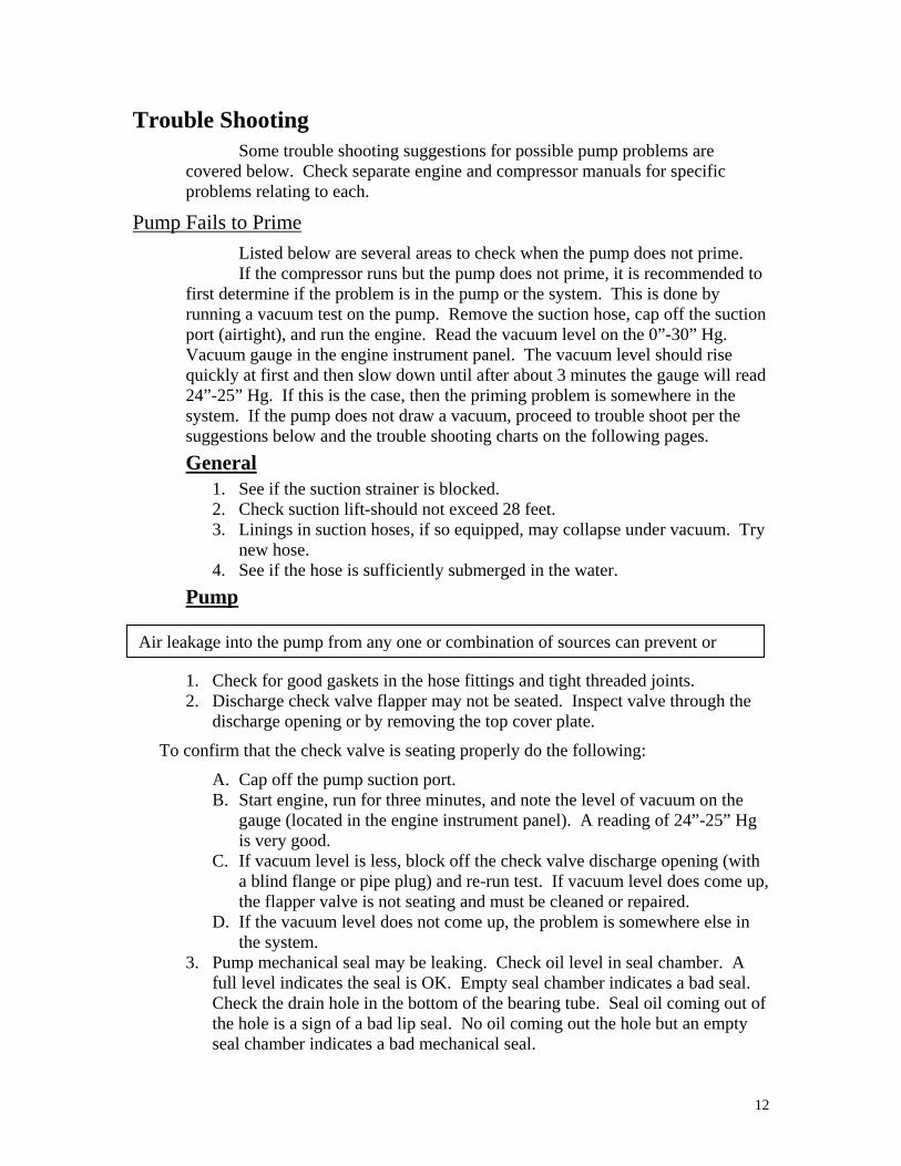
Pump Fails to Prime Listed below are several areas to check when the pump does not prime. If the compressor runs but the pump does not prime, it is recommended to
first determine if the problem is in the pump or the system. This is done by running a vacuum test on the pump. Remove the suction hose, cap off the suction port (airtight), and run the engine. Read the vacuum level on the 0”-30” Hg. Vacuum gauge in the engine instrument panel. The vacuum level should rise quickly at first and then slow down until after about 3 minutes the gauge will read 24”-25” Hg. If this is the case, then the priming problem is somewhere in the system. If the pump does not draw a vacuum, proceed to trouble shoot per the suggestions below and the trouble shooting charts on the following pages. General
1. See if the suction strainer is blocked. 2. Check suction lift-should not exceed 28 feet. 3. Linings in suction hoses, if so equipped, may collapse under vacuum. Try
new hose. 4. See if the hose is sufficiently submerged in the water.
Pump
1. Check for good gaskets in the hose fittings and tight threaded joints. 2. Discharge check valve flapper may not be seated. Inspect valve through the
discharge opening or by removing the top cover plate.
To confirm that the check valve is seating properly do the following:
A. Cap off the pump suction port. B. Start engine, run for three minutes, and note the level of vacuum on the
gauge (located in the engine instrument panel). A reading of 24”-25” Hg is very good.
C. If vacuum level is less, block off the check valve discharge opening (with a blind flange or pipe plug) and re-run test. If vacuum level does come up, the flapper valve is not seating and must be cleaned or repaired.
D. If the vacuum level does not come up, the problem is somewhere else in the system.
3. Pump mechanical seal may be leaking. Check oil level in seal chamber. A full level indicates the seal is OK. Empty seal chamber indicates a bad seal. Check the drain hole in the bottom of the bearing tube. Seal oil coming out of the hole is a sign of a bad lip seal. No oil coming out the hole but an empty seal chamber indicates a bad mechanical seal.
Air leakage into the pump from any one or combination of sources can prevent or

13
4. Check all the fasteners on the pump. Gasket joints will allow fasteners to loosen after time due to gasket set.
5. Check to see if any auxiliary valves, which may be attached to the pump, are open (vacuum break valve, drain valve, etc.)
6. Check o-ring joints (suction tee to expansion chamber, cover to case) for a good seal. O-rings should be soft and pliable. Grease lightly when replacing o-rings.

14
Trouble Shooting Flowchart Pump does not prime
PumpVacuum test
Is vacuum23"-25" Hg?
Doescompressor
run?
Is there exhaustcoming out of
eductor?
Is screen onpriming valve
plugged?
Removepriming valve
Clean offscreen
Is priming valvefloat/mechanism
stuck?Free up
Is primingvalve portblocked?
Clean off
Is the line fromeductor to priming
valve split orplugged?
Clean out orreplace line
Are the fittingsin the line
tight?Tighten them
Is the eductorlow pressureport blocked?
Clean it out
Check eductoroperation see test #3
Checksystem
Are fittingstight? Tighten them
Is line in goodcondition? Replace it
Is eductorblocked?
Is pressure reliefvalve stuck
open?
Is screen onfloat tube
broken through?
Clean the eductor& check the source
of blockage
Replace thescreen
Checkcompressor for
broken parts
Continue tomonitor eductor
for blockage
Are any partsbroken, missingor severly worn?
See compressormanual
No
YesYes
Yes
Yes
Yes
Yes
No
No
Yes
No
No
Yes
Yes
No
No
No No
Yes
No
Yes
No
Yes
Yes
No
Yes
No
Seefollowing
pageNo
No
Yes
See compressormanual
Replace valve
15
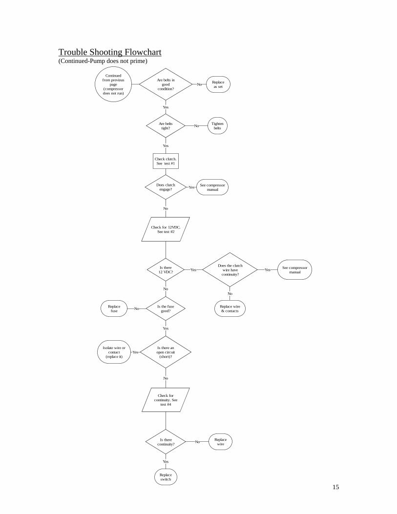
Trouble Shooting Flowchart (Continued-Pump does not prime)
Are belts ingood
condition?
Replaceas set
Are beltstight?
Tightenbelts
Check clutch.See test #1
Check for 12VDC.See test #2
Is there12 VDC?
Does the clutchwire havecontinuity?
Replace wire& contacts
See compressormanual
Is the fusegood?
Replacefuse
Check forcontinuity. See
test #4
Is therecontinuity?
Replacewire
Replaceswitch
Is there anopen circuit
(short)?
Isolate wire orcontact
(replace it)
No
No
Yes
Yes
Yes
No
No
No
Yes
Yes
Yes
No
No
Yes
Continuedfrom previous
page(compressordoes not run)
Does clutchengage?
See compressormanualYes
No

16
Automatic Priming System Flowchart Priming system works in manual (MAN) mode but not in automatic (AUTO) mode
Compressor doesn't runin "AUTO" mode at
start of priming cycle
Is line topressure switch
blocked?Clean out line
Open drain valve torelieve any positive
pressure in pump case
Does primingsystem work?
Determine thesource of positive
pressure & eliminate
Check for 12 VDC @wire contact in electrical
box. See test #5
Is there12 VDC?
Is therecontinuity?
Check forcontinuity. See
test #6
Replaceswitch
Replace wire& connectors
Yes
No
Yes
No
No
Yes
No
Yes
Bypass timer by addinga jumper between
terminal #1 & #2 on theterminal strip
Does thecompressor
run?
Replace timedelay relayYes
!Caution: Pump case could be filled with a combination of hot water & steam. Use extreme care when opening any valves
17
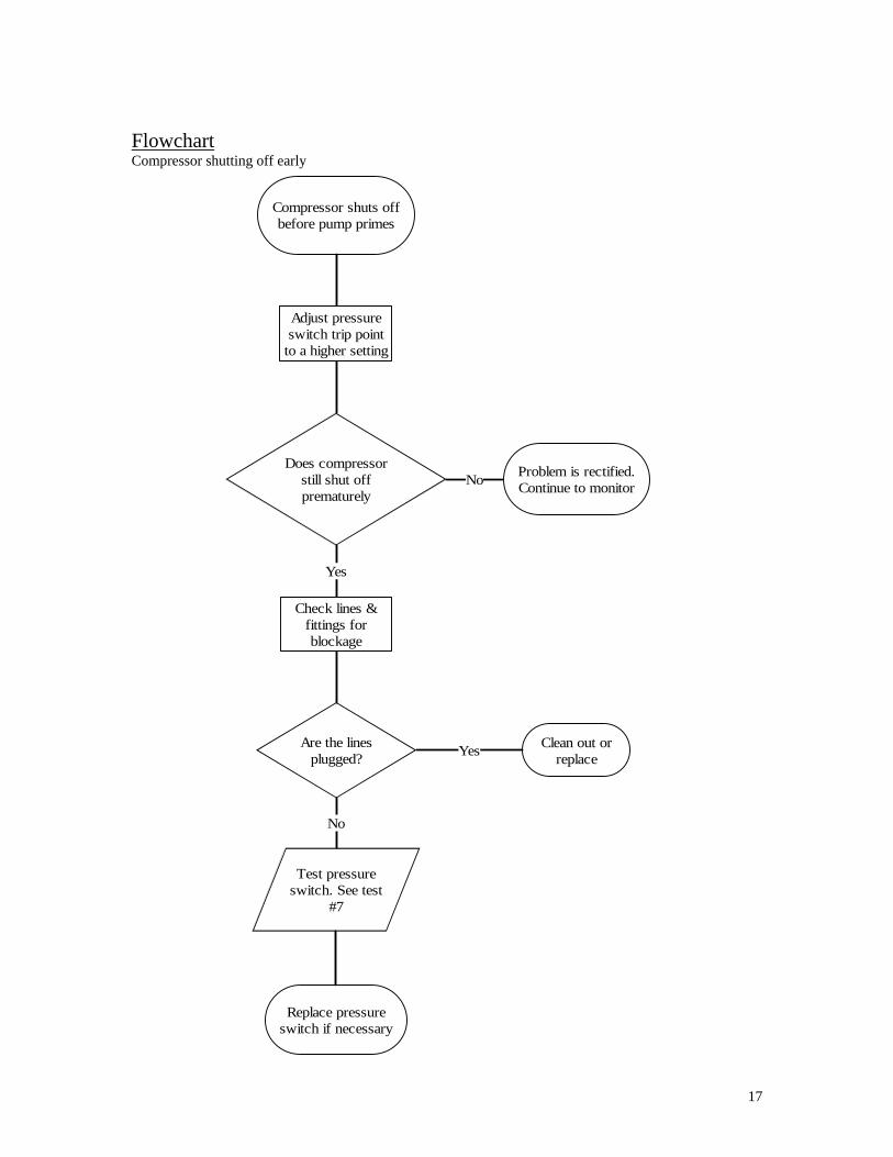
Flowchart Compressor shutting off early
Compressor shuts offbefore pump primes
Adjust pressureswitch trip point
to a higher setting
Does compressorstill shut offprematurely
Check lines &fittings forblockage
Problem is rectified.Continue to monitor
Are the linesplugged?
Clean out orreplace
Test pressureswitch. See test
#7
Replace pressureswitch if necessary
No
Yes
Yes
No
18
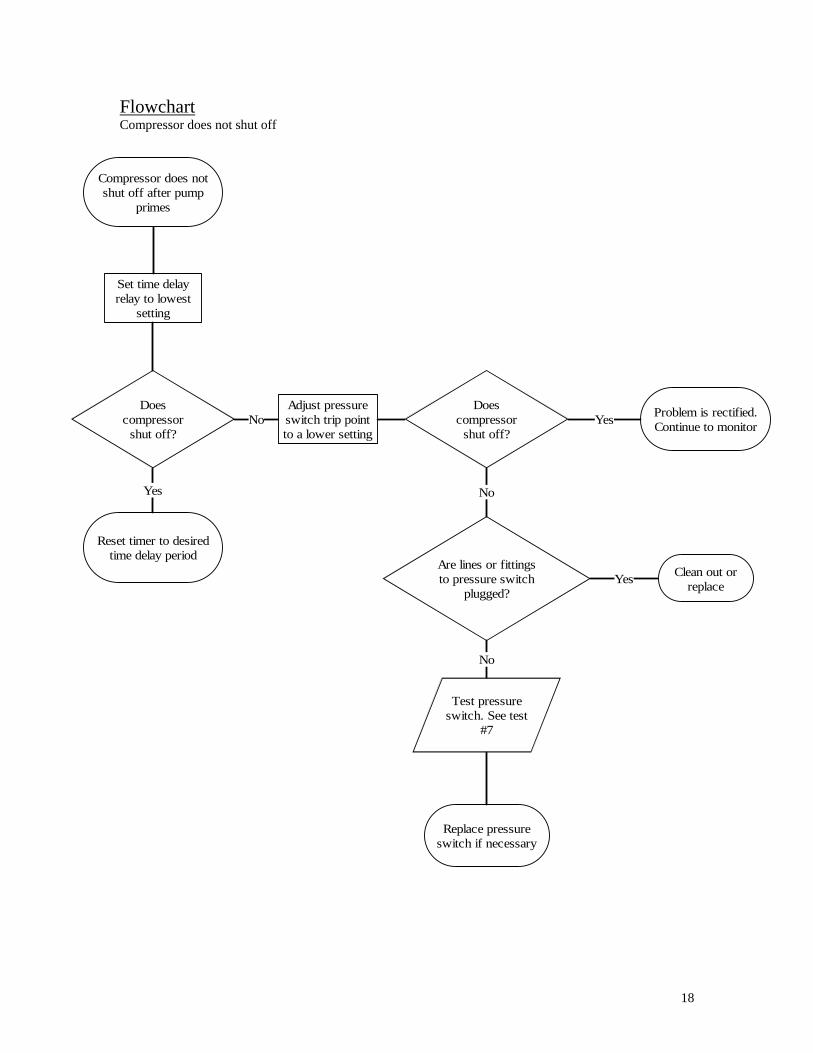
Flowchart Compressor does not shut off
Compressor does notshut off after pump
primes
Set time delayrelay to lowest
setting
Doescompressor
shut off?
Adjust pressureswitch trip pointto a lower setting
Doescompressor
shut off?
Problem is rectified.Continue to monitor
Are lines or fittingsto pressure switch
plugged?
Clean out orreplace
Test pressureswitch. See test
#7
Reset timer to desiredtime delay period
Replace pressureswitch if necessary
Yes
Yes
No
No
No
Yes
19
Testing Procedures
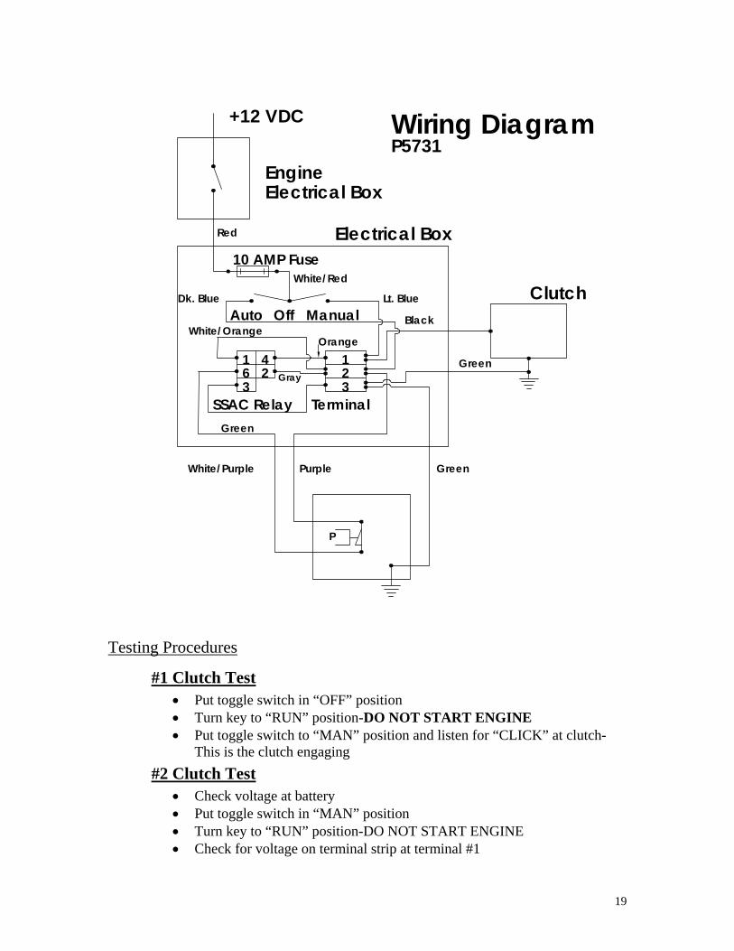
#1 Clutch Test • Put toggle switch in “OFF” position • Turn key to “RUN” position-DO NOT START ENGINE • Put toggle switch to “MAN” position and listen for “CLICK” at clutch-
This is the clutch engaging #2 Clutch Test
• Check voltage at battery • Put toggle switch in “MAN” position • Turn key to “RUN” position-DO NOT START ENGINE • Check for voltage on terminal strip at terminal #1
Manual Orange
White/Red
Terminal
Electrical Box
Electrical Box
White/Purple Purple
Green
SSAC Relay 3 6 Gray 2
4 1
3 2 1
Auto
10 AMP Fuse
White/Orange
Dk. Blue Off
Red
Engine
+12 VDC Wiring Diagram
Green
Green
Clutch Lt. Blue
Black
P5731
P
20
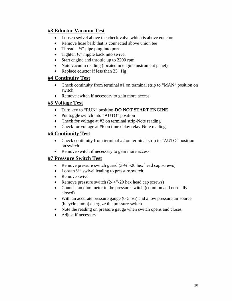
#3 Eductor Vacuum Test • Loosen swivel above the check valve which is above eductor • Remove hose barb that is connected above union tee • Thread a ½” pipe plug into port • Tighten ½” nipple back into swivel • Start engine and throttle up to 2200 rpm • Note vacuum reading (located in engine instrument panel) • Replace eductor if less than 23” Hg
#4 Continuity Test • Check continuity from terminal #1 on terminal strip to “MAN” position on
switch • Remove switch if necessary to gain more access
#5 Voltage Test • Turn key to “RUN” position-DO NOT START ENGINE • Put toggle switch into “AUTO” position • Check for voltage at #2 on terminal strip-Note reading • Check for voltage at #6 on time delay relay-Note reading
#6 Continuity Test • Check continuity from terminal #2 on terminal strip to “AUTO” position
on switch • Remove switch if necessary to gain more access
#7 Pressure Switch Test • Remove pressure switch guard (3-¼”-20 hex head cap screws) • Loosen ½” swivel leading to pressure switch • Remove swivel • Remove pressure switch (2-¼”-20 hex head cap screws) • Connect an ohm meter to the pressure switch (common and normally
closed) • With an accurate pressure gauge (0-5 psi) and a low pressure air source
(bicycle pump) energize the pressure switch • Note the reading on pressure gauge when switch opens and closes • Adjust if necessary

21
Automatic Priming System Adjustments Following are a few suggestions for fine-tuning the Automatic Priming
System to particular pumping operation requirements:
The basic operation of the Automatic Priming System is:
1. Engine starts. 2. Pump automatically primes. 3. Positive pressures in the pump case (3 psig-set at the factory but adjustable) trips
open a pressure switch. 4. Switch activates a timer to delay the shutoff of the compressor (delay set at
approximately 3 minutes at the factory) 5. Compressor shuts off. 6. Pump continues pumping until water supply level gets to the end of the suction
hose and the pump loses its prime. The pressure in the pump case falls to atmospheric or below.
7. Pressure switch closes (at about 2 to 3 psig) and activates the priming system (i.e. compressor starts).
8. Cycle repeats.
If the compressor shuts off before the pump has primed and/or does not start after loss of prime, there may be a slight positive pressure in the pump from the churning of the impeller in some amount of residual water left in the pump case creating enough vapor to make a high enough positive pressure to not allow the pressure switch to reset. Adjust the pressure switch setting up a couple psi (see pressure switch manual). Do not set the trip point too high or in low head systems the pump case pressure may not get high enough to open the switch to shut down the compressor.
If the compressor does not shut off after 5-10 minutes and the pump case pressure is known to be high enough to activate the pressure switch, do the following.
1. Set the timer to as low as it goes and retry. 2. Set pressure switch to a lower trip point (2-psi). 3. Check (test) the pressure switch.
22
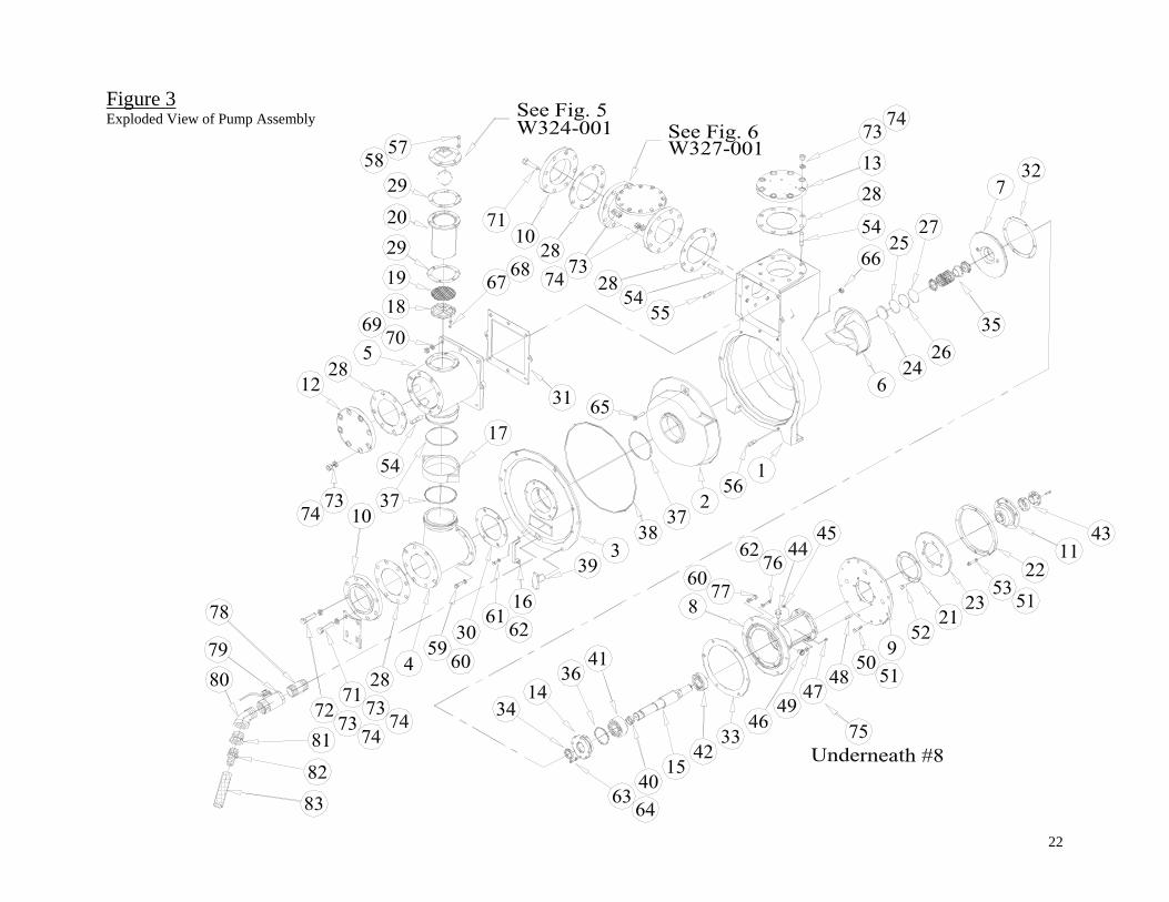
Figure 3 Exploded View of Pump Assembly

23
Figure 4 Bearing Support Cross-Section
24
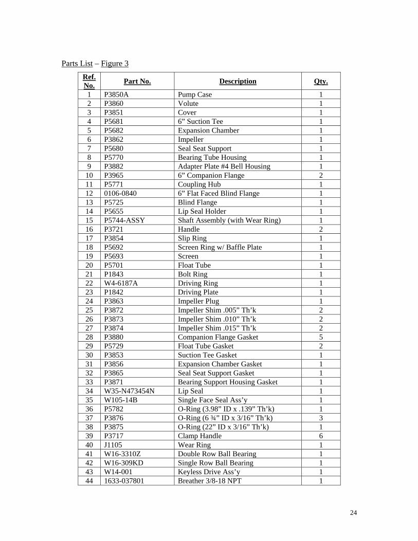
Parts List – Figure 3
Ref. No. Part No. Description Qty.
1 P3850A Pump Case 1 2 P3860 Volute 1 3 P3851 Cover 1 4 P5681 6” Suction Tee 1 5 P5682 Expansion Chamber 1 6 P3862 Impeller 1 7 P5680 Seal Seat Support 1 8 P5770 Bearing Tube Housing 1 9 P3882 Adapter Plate #4 Bell Housing 1
10 P3965 6” Companion Flange 2 11 P5771 Coupling Hub 1 12 0106-0840 6” Flat Faced Blind Flange 1 13 P5725 Blind Flange 1 14 P5655 Lip Seal Holder 1 15 P5744-ASSY Shaft Assembly (with Wear Ring) 1 16 P3721 Handle 2 17 P3854 Slip Ring 1 18 P5692 Screen Ring w/ Baffle Plate 1 19 P5693 Screen 1 20 P5701 Float Tube 1 21 P1843 Bolt Ring 1 22 W4-6187A Driving Ring 1 23 P1842 Driving Plate 1 24 P3863 Impeller Plug 1 25 P3872 Impeller Shim .005” Th’k 2 26 P3873 Impeller Shim .010” Th’k 2 27 P3874 Impeller Shim .015” Th’k 2 28 P3880 Companion Flange Gasket 5 29 P5729 Float Tube Gasket 2 30 P3853 Suction Tee Gasket 1 31 P3856 Expansion Chamber Gasket 1 32 P3865 Seal Seat Support Gasket 1 33 P3871 Bearing Support Housing Gasket 1 34 W35-N473454N Lip Seal 1 35 W105-14B Single Face Seal Ass’y 1 36 P5782 O-Ring (3.98” ID x .139” Th’k) 1 37 P3876 O-Ring (6 ¾” ID x 3/16” Th’k) 3 38 P3875 O-Ring (22” ID x 3/16” Th’k) 1 39 P3717 Clamp Handle 6 40 J1105 Wear Ring 1 41 W16-3310Z Double Row Ball Bearing 1 42 W16-309KD Single Row Ball Bearing 1 43 W14-001 Keyless Drive Ass’y 1 44 1633-037801 Breather 3/8-18 NPT 1

25
Parts List (cont.) – Figure 3 Ref. No. Part No. Description Qty.
45 W33-1/8 1/8” NPT Zerk Fitting 1 46 A2890-4 Oil Level Sight Glass 1 47 0002-1603 1/8” NPT Sq. Hd. Pipe Plug 1 48 P5607 Stud (3/8”-16 x 1 ¾” Lg.) 6 49 E6GX 3/8”-16 Hex Hd. Flange Lock Nut 6 50 GC010.10.10030Z M10 x 1.5 x 30mm Lg. Hex Hd. Screw 12 51 G620.10.100 M10 Lock Washer 20 52 P5491 ½”-13 x 1” Lg. Hex Hd. Lock Screw 6 53 GC010.10.10040Z M10 x 1.5 x 40mm Lg. Soc. Hd. Cap Screw 8 54 P3843 Stud (3/4”-10 x 3” Lg.) 24 55 P3844 Stud (5/8”-11 x 2 ¾” Lg.) 8 56 P3728 Stud (5/8”-11 x 2” Lg.) 6 57 A010.043.0150 7/16”-14 x 1 ½” Lg. Hex Hd. Cap Screw 6 58 F620.043 7/16” Lock Washer 6 59 A010.050.0150 ½”-13 x 1 ½” Lg. Hex Hd. Cap Screw 6 60 F620.050 ½” Lock Washer 12 61 A010.037.0075 3/8”-16 x ¾” Lg. Hex Hd. Cap Screw 4 62 F620.037 3/8” Lock Washer 10 63 BC070.031.0100 5/16”-18 x 1” Lg. Soc. Hd. Cap Screw 4 64 F620.031 5/16” Lock Washer 4 65 P5958 Stud, ½”-13 x 2 ½” CD1215 2 66 0813NUS ½”-13 Hydra Lock Nut 2 67 CC005.025.0087 ¼”-20 x 7/8” Lg. Hex Hd. Cap Screw (S.S.) 6 68 F620.025 ¼” Lock Washer (S.S.) 6 69 EC400.062 5/8”-11 Hex Nut 8 70 F620.062 5/8” Lock Washer 8 71 A010.075.0325 ¾”-10 x 3 ¼” Lg. Hex Hd. Cap Screw 14 72 A010.075.0350 ¾”-10 x 3 ½” Lg. Hex Hd. Cap Screw 2 73 EC400.075 ¾”-10 Hex Nut 40 74 F620.075 ¾” Lock Washer 40 75 50925K392 3/8” NPTF Hex Hd. Plug 1 76 A010.037.0150 3/8”-16 x 1 ½” Lg. Hex Hd. Cap Screw 6 77 A010.050.012 ½”-13 x 1 ¼” Lg. Hex Hd. Cap Screw 6 78 W300-1 x 2 Nipple 1” x 2” SCH40 BLK 1 79 W323-001 Valve Ball ½” NPT FXF BRZ 1 80 W302-1 x 45 Elbow ST450 x 1” CL150 BLK 1 81 W307-1 x 3/4 Reducing Bushing 1” x ¾” CL150 BLK 1 82 125HBL-12-12 Hose Barb ¾” STR MP12 Brass 1 83 W43-015-019 Hose ¾” x 1.03” x 19” LG (Water) 1

26
Figure 5 W324-001-ASSM (Priming Valve Assembly)
Ref. No. Part No. Description Qty.
2 W324-001-02 Cover 1 3 W324-001-03 Leverage Frame 1 4 W324-001-04 Seat 1 5 W324-001-05 Float 1 8 W324-001-08 Retaining Screw 2
10 W324-001-10 Float Arm 1 11 W324-001-11 Orifice Button 1 12 W324-001-12 Pivot Pin 5 13 W324-001-13 Retaining Ring 10 17 W324-001-17 Float Retainer 1 18 W324-001-18 Lock Nut 1 19 W324-001-19 Link 2 20 W324-001-20 Guide Shaft 1 21 W324-001-21 Locating Pin 1 22 W324-001-22 Orifice Button Arm 1 30 W324-001-30 Washer 2 33 W324-001-33 Clevis 1 34 W324-001-34 Lock Washer 1

27
Figure 6 W327-001 (Discharge Flapper Valve)
Ref. # Part No. Description Qty. 1 W327-001-01 Body 1 2 W327-001-02 Cover 1 3 W327-001-03 Disc 1 4 W327-001-04 Gasket 1 5 W327-001-05 7/16”-14 x 2” Lg. Hex Hd. Cap Scr. 10 6 W327-001-06 7/16”-14 x 1 ½” Lg. Hex Hd. Cap Scr. 2 7 W300-3/4 x 2 Nipple ¾” x 2 SCH40 BLK 1 8 W323-003 Valve Ball 1” NPT FXF BRZ 1
10 125HBL-12-12 Hose Barb ¾” STR MP12 Brass 1 11 W43-015-036 Hose ¾” x 1.03” x 36” LG (Water) 1
28
Figure 7 Compressor Drive Assembly
29
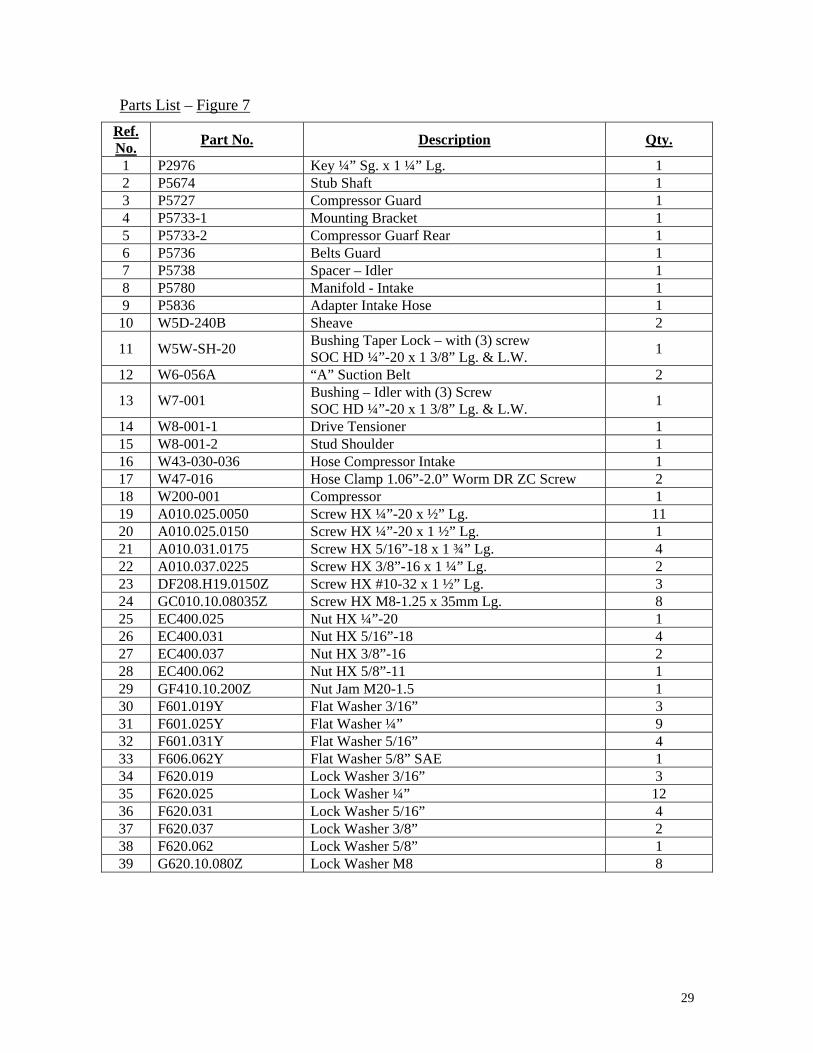
Parts List – Figure 7 Ref. No. Part No. Description Qty.
1 P2976 Key ¼” Sg. x 1 ¼” Lg. 1 2 P5674 Stub Shaft 1 3 P5727 Compressor Guard 1 4 P5733-1 Mounting Bracket 1 5 P5733-2 Compressor Guarf Rear 1 6 P5736 Belts Guard 1 7 P5738 Spacer – Idler 1 8 P5780 Manifold - Intake 1 9 P5836 Adapter Intake Hose 1
10 W5D-240B Sheave 2
11 W5W-SH-20 Bushing Taper Lock – with (3) screw SOC HD ¼”-20 x 1 3/8” Lg. & L.W. 1
12 W6-056A “A” Suction Belt 2
13 W7-001 Bushing – Idler with (3) Screw SOC HD ¼”-20 x 1 3/8” Lg. & L.W. 1
14 W8-001-1 Drive Tensioner 1 15 W8-001-2 Stud Shoulder 1 16 W43-030-036 Hose Compressor Intake 1 17 W47-016 Hose Clamp 1.06”-2.0” Worm DR ZC Screw 2 18 W200-001 Compressor 1 19 A010.025.0050 Screw HX ¼”-20 x ½” Lg. 11 20 A010.025.0150 Screw HX ¼”-20 x 1 ½” Lg. 1 21 A010.031.0175 Screw HX 5/16”-18 x 1 ¾” Lg. 4 22 A010.037.0225 Screw HX 3/8”-16 x 1 ¼” Lg. 2 23 DF208.H19.0150Z Screw HX #10-32 x 1 ½” Lg. 3 24 GC010.10.08035Z Screw HX M8-1.25 x 35mm Lg. 8 25 EC400.025 Nut HX ¼”-20 1 26 EC400.031 Nut HX 5/16”-18 4 27 EC400.037 Nut HX 3/8”-16 2 28 EC400.062 Nut HX 5/8”-11 1 29 GF410.10.200Z Nut Jam M20-1.5 1 30 F601.019Y Flat Washer 3/16” 3 31 F601.025Y Flat Washer ¼” 9 32 F601.031Y Flat Washer 5/16” 4 33 F606.062Y Flat Washer 5/8” SAE 1 34 F620.019 Lock Washer 3/16” 3 35 F620.025 Lock Washer ¼” 12 36 F620.031 Lock Washer 5/16” 4 37 F620.037 Lock Washer 3/8” 2 38 F620.062 Lock Washer 5/8” 1 39 G620.10.080Z Lock Washer M8 8

30
Figure 8 Plumbing Layout
46

31
Parts List – Figure 8
Ref. No. Part No. Description Qty.
1 W150-001 Eductor 1 2 W324-001-ASSM Priming Valve Assembly (Also see Fig. 5, p. 25) 1 3 W133-001 Pressure Switch 1 4 215PN-12 ¾” Close Nipple 1 5 216P-8 ½” Hex Nipple 2 7 0107-12-8 Pipe Adapter ¾” Male x ½” Female 1 8 0107-8-8 Pipe Adapter ½” Male x ½” Female 3 9 W323-002 Brass Ball Valve ½” Female Ports 1
10 W327-010 Brass Check Valve ¾” Female Ports 1 12 2200P-8-8 ½” x 900 Union Elbow (BRS) 2 13 2203P-8 ½” Union Tee 4 14 222P-8-4 Adapter ½” Female x ¼” Male 1 15 209P-12-8 Bushing ¾” Male x ½” Female 2 16 218P-8 ½” Hex Head Plug 2 17 20190-8-10 Series 90 Reusable Hose Fitting 2 18 125HBL-10-8 Hose Barb ⅝” Hose x ½” Male NPT 5 19 W43-010-053 Teflon Hose w/ Stainless Steel Cover 53” 20 W43-013-012 High Temperature Push-Lock Hose 12” 21 W43-012-003 Vacuum Push-Lock Hose 3” 22 W43-012-042 Vacuum Push-Lock Hose 42” 23 W47-008 Hose Clamp 1 ¼” Dia. 5 24 W47-042 Clamp Loop, 1” Dia. 1 25 W47-040 Clamp Silicon Loop, ⅝” Dia. 2 26 P5728 Pressure Switch Guard 1 27 P5729 Float Tube Gasket 2 28 P5701 Float Tube 1 29 P5692 Screen Ring w/ Baffle Plate 1 30 P5693 Screen 1 31 C620.025 ¼” Stainless Steel Lock Washer 6 32 CC005.025.0087 ¼”-20 x 7/8” Lg. Stainless Steel Hex Head Screw 6 33 F620.043 7/16” Lock Washer 6 34 A010.043.0150 7/16”-14 x 1 ½” Lg. Hex Head Screw 6 35 F620.025 ¼” Lock Washer 5 36 A010.025.0050 ¼”-20 x ½” Lg. Hex Head Screw 3 37 A010.025.0075 ¼”-20 x ¾” Lg. Hex Head Screw 2 38 215PN-8 ½” Close Nipple 2 39 209P-8-4 Bushing ½” Male x ¼” Female 2 40 W201-001 Pop Safety Valve ¼” Male @ 100 PSI 1 41 127HB-8-8 ½” Ball End Joint Adapter 3 42 125HBL-4-4 Hose Barb ¼” Hose x ¼” Male NPT 1 43 126HBL-4-2 Hose Barb ¼” Hose x 1/8” Female NPT 1 44 W43-002-036 Hose ¼” ID x ½” OD 36” 45 W73-02 Vacuum Gauge 30”-0” in Hg-2” Dial 1 46 2202P-8-8 ½” x ST900 Union Elbow (BRS) 1


33
Figure 9 Electrical Box Assembly
Electronical BoxDoor Inside view 6
12 5
To Compressor
Time Delay Relay
10A
Fus
e
31 4
9
8
7
Pow
er fr
omE
ngin
eE
lect
roni
cal B
ox
10
11
2

34
Parts List – Figure 9
Ref. No. Part No. Description Qty.
1 DC200.R25.0087Z Rd. Hd. Slotted Mach Screw ¼” – 20 x 7/8” LG. 4 2 DF200.R19.0062Z Rd. Hd. Slotted Mach Screw #10- 32 x 5/8” LG. 4 3 EC400.025 Hex. Nut ¼” - 20 FF GR2/PL 4 4 F620.025 Lock washer ¼” STD STL/PL 4 5 P5704-ASSM Electrical Panel Assemble 1 6 P5706 Electrical box 1 7 W100-001-017 ½” Dia. Flexible conduit 17” LG. 1 8 W100-001-036 ½” Dia. Flexible conduit 36” LG. 1 9 W100-001-084 ½” Dia. Flexible conduit 84” LG. 1
10 W100-017 Conduit fitting ½” Straight 2 11 W100-022 Conduit fitting ½” Elbow 90 1 12 P5731 Sticker– Wiring Diagram 1

35
Ground
3
12 4 1 INITIATE
500 TIME DELAY RELA
INPUT
MADE IN USA
4
20 200
13 14 10 100
25
400 300
3
6
7 11 19
800 DELAY ADJUSTMENTS IN SECONDS 900
1000
2 1 HP AT 125 VAC
700 600
19
16
23
15
21
32
29 2
9
Pre
ssur
e S
witc
h
OFF AUTO
5 1
MANUAL
28 27
18126
To Compressor
31 26 27
10 Fus
12
To
12 V
DP
ower
Sou
rce
10
824
33
22
30
Figure 9/1 P5704-ASSM (Electrical Panel Assembly)
PARTS LIST # Qty Description Part No. 1 1 Bypass Switch Mounting Bar P5703 2 1 Bypass Switch Label P5730 3 1 Electrical Panel P5704 4 1 Time Delay Relay W135-001 5 1 Toggle Switch W133-002 6 1 Fuse Block W134-005 7 1 Terminal Block 7527K43 8 1 Fuse 3 Ga 10 Amp W134-004 9 2 Hex-Spacer W93-8435 10 3 Ring-Terminal (#10 Stud-18 AWG) W92-151105 11 10 Ring-Terminal (#6 Stud-18 AWG) W92-151065 12 7 Push on Female Terminal -¼”, 18AWG W92-891005 13 1 Hex. Hd. Cap SCR ¼”-20 x 1½” LG. A010.025.0150 14 1 Hex Nut ¼” – 20 EC400.025 15 3 RH Slot. Mach. SCR #10-32 x 3/8” LG DF200.R19.0038Z 16 4 Hex Nut #10 – 32 EC400.019 18 1 Push on Male Terminal - ¼”, 18AWG W92-831005 19 6 RH Slot. Mach. SCR #8-32 x ½” LG DF200.F16.0050Z 20 1 Lock Washer ¼” F620.025 21 2 Hex Nut #8-32 EC400.016 22 1 18AWG Stranded (Orange) x 3½” LG W101-006OR-003.5 23 1 18AWG Stranded (White/Orange) x 4” LG W101-006WO-004.0 24 1 18AWG Stranded (Grey) x 3” LG W101-006EY- 003.0 25 1 18AWG Stranded (Green) x 4 ¾” LG W101-006G-004.8 26 1 18AWG Stranded (Black) x 72” LG W101-006B-072.0 27 2 18AWG Stranded (Green) x 72” LG W101-006G-072.0 28 1 18AWG Stranded (Violet) x 72” LG W101-006V-072.0 29 1 18AWG Stranded (White/Violet) x 72” LG W101-006WV-072.0 30 1 18AWG Stranded (Red) x 72” LG W101-006R-072.0 31 1 18AWG Stranded (White/Red) x 10½” LG W101-006WR-010.5 32 1 18AWG Stranded (Blue Dark) x 7½” LG W101-006BD-007.5 33 1 18AWG Stranded (Blue Light) x 6½” LG W101-006BL-006.5

36
Service Instructions
Mechanical Seal The impeller shaft seal is a 1 ¾” diameter spring loaded single mechanical
seal, located directly behind the impeller. The seal mating surfaces are lubricated and cooled by oil contained in a chamber in the bearing support housing which is sealed with a radial lip seal (see FIGURE 4, on page 23).
Indications that the mechanical seal may be bad are: 1. Water (pumpage) mixed with the oil and it flows out the breather vent on top
of the oil chamber or drains out the hole in the underside of the bearing support housing.
2. Pump does not prime and/or the pump does not hold a good vacuum level. (There could be other causes for this symptom but a bad seal is a possibility.)
3. Oil level in seal chamber cannot be maintained. (This could be the result of a worn out or damaged radial lip seal as well. The oil will come out the drain hole in the underside of the bearing support housing if the radial lip seal is damaged.)
Mechanical Seal Removal
Use the following steps as a guideline when removing mechanical seals:
1. Drain the pump (using the 1” ball valves).
2. Remove the suction tee (six ½”-13 x 1 ½” lg. hex head cap screws) and cover (six handles) from the pump.
3. Drain the oil from the seal chamber by removing the ¼” pipe plug in the boss on the underside of the bearing support housing.
4. Remove the volute (two ½”-13 x 2 ¼” lg. hex head cap screws) from the pump case.
5. Remove the impeller by striking the tips of the vanes with a lead mallet (or by striking a piece of wood that is held against an impeller vane tip) such that the impeller rotates in a counter-clockwise direction. (The impeller is threaded onto the impeller shaft with a standard right hand thread.) Heating the center of the impeller may be required if the impeller does not come loose by striking it “cold”.
6. Remove the seal with the seal seat support casting. Remove the seal seat support (six 3/8”-16 x 1 ½” lg. hex head cap screws) by loosening the screws which are the inner bolt circle on the large flange of the bearing support housing on the backside of the pump case. The seal seat support can be removed with the aid of a puller bar (see FIGURE 11, on page 40 or order part number X3004 from CH&E A division of ABS Pumps). Secure the puller bar to the seal seat support (two 3/8”-16 x 1” lg. hex head cap screws) using the tapped holes in the face of the seal seat support. Thread a 3/8”-16 x 2” lg. square head setscrew into the center hole of the puller bar. Put a steel spacer

37
between the setscrew and the end of the shaft to prevent damage. As the setscrew is tightened, the seal and seal seat support will come loose.
7. Remove the stationary seal seat from the seal seat support by tapping on it from the backside with a hammer and punch. Clean up the seal seat bore, in the casting, with fine emery cloth or steel wool.
38
Mechanical Seal Installation
Handle Seal with care!
(After mechanical seal installation it is a wise idea to replace the radial lip seal, since disassembly gives access to rear of seal oil chamber.)
(For installation tool see Figure FIGURE 12, on page 40 or order part X2176 from CH&E A Division of ABS PUMPS)
1. Cut a 2 ¼” to 2 3/8” diameter disc out of clean tag board or rubber (skip if X2176 is used).
2. Lubricate o-ring of the stationary seat with a rubber lubricant (P-80 from International Products Corp., Trenton, NJ).
3. With the shiny face up, place seal into the bore of the seal seat support (it will go in as far as the o-ring).
4. Place the tag board or rubber on the face (being careful not to mar face of seal).
5. Take a 2” x 2” piece of wood (don’t need if X2176 is used) and evenly press seal into the bore of the seal seat support.
6. Turn seal seat support over to check the seal is seated against the bottom of the bore.
Radial Lip Seal Replacement
Use steps 1-6 of MECHANICAL SEAL REMOVAL, on page 36 to gain access to area.
1. Remove the four 5/16”-18 x 1” lg. socket head cap screws that hold the lip seal holder in place.
2. Thread two of the screws into the tapped holes in the flange of the lip seal holder. Tighten the screws evenly (this will “push” the lip seal holder out of its seat).
3. Remove the radial lip seal from the lip seal holder by tapping on it from the backside with a hammer and punch.
4. Set the new seal on the bore with the “open” side or garter spring side of the seal up or to the outside.
5. Set a 2” pipe (2 3/8” OD) or steel plate on the seal and tap the seal until it bottoms in the bore.
6. Inspect the sleeve on the impeller shaft, where the lip seal seats. Clean it with solvent. If the sleeve is deeply grooved or heavily damaged, it will have to be replaced.
7. To remove the wear sleeve from the impeller shaft, grind an axial groove in it about 75% through the thickness (sleeve thickness is approximately .060”).
8. Split the wear sleeve the rest of the way with a hammer and cold chisel. (Do not damage the impeller shaft.)

39
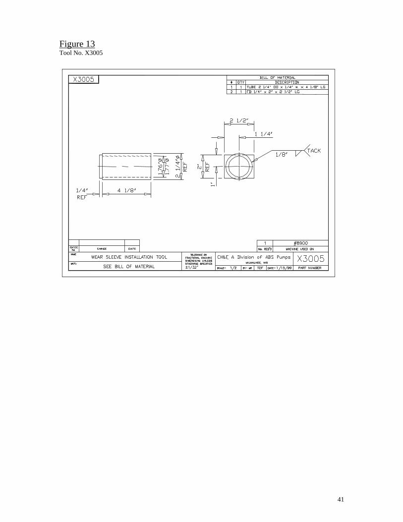
9. Install a new wear sleeve using tool X3005 (from CH&E A division of ABS Pumps) or equivalent (see FIGURE 13, on page 41). Note the position of the long chamfer on the wear sleeve on the outside diameter is towards the threaded end of the impeller shaft (see FIGURE 10, below). Either press the wear sleeve on using an arbor press or tap the sleeve in place using a hammer. The front edge of the wear sleeve must be 4 1/8” from the threaded end of the impeller shaft.
To install the lip seal holder with a new radial lip seal into the bearing support housing:
A. Tap the impeller shaft, by the threaded end, with a lead mallet to be sure the double-row ball bearing is seated against the shoulder.
B. Use rubber lubricant (P-80 or equivalent, to lubricate the o-ring on the outside diameter of the lip seal holder and the lip of the radial lip seal.
C. Thread two of the 5/16”-18 socket head cap screws into the tapped holes in the face of the lip seal holder in order to maneuver it into position.
D. Line up the holes in the lip seal holder with the tapped holes in the bearing support housing and push it into position.
E. Install the screws using blue Loc-Tite (a medium strength thread locking compound) on the threads and tighten in a crossing pattern. Torque the screws to 25-30 lb.-ft.
Figure 10 Wear-Sleeve Installation
4 1/8"
4 3/4"
P5744-ASSY
NOTE: WEAR SLEEVEJ1105 ORIENTATION
IMPELLER SHAFT

40
Figure 11 Tool No. X3004
Figure 12 Tool No. X2176
41
Figure 13 Tool No. X3005

42
Bearing Replacement 1. The pump case can be detached from the bearing support assembly while it is
still attached to the engine. Attach slings to the pump case such that it will be safely supported after it has been removed from the bearing support housing. Note that the pump case alone weighs 300 lbs. (136 Kg) and depending on the number of parts still attached (discharge check valve, expansion chamber, suction tee, etc.) could weigh as much as 800 lbs. (363 Kg). Remove the two ¾”-10 x 2 ½” lg. hex head bolts in the pump feet and the six ½”-13 x 1 ¼” lg. hex head cap screws that hold the pump case to the bearing support housing. Pull the pump case away from the bearing support housing. Be sure the pump case is properly supported.
2. Remove the impeller, mechanical seal, seal seat support and lip seal holder from the bearing support housing. (See MECHANICAL SEAL REMOVAL, on page 36)
3. Support the bearing support housing/shaft assembly with a sling and proceed to remove it from the engine by removing the twelve M10 x 1.5 x 30mm lg. hex head cap screws that attach it to the engine bell housing. Pull the bearing support housing straight back until it clears the engine.
4. To remove the drive hub/drive plate assembly from the shaft: • Relax all locking screws by at least two turns and transfer screws to all
push-off threads provided in face of inner ring. • Release connection by progressively tightening all push-off screws in a
diametrically opposite sequence except for screws adjacent to slit in inner ring, which should be tightened one after the other.
5. Pull the shaft bearing assembly out of the bearing support housing toward the threaded end of the shaft.
6. Pull the bearings off the shaft with a bearing puller. The ID of the front (double row) bearing will clear the OD of the wear sleeve used as a lip seal seat. If the sleeve has to be replaced, see the RADIAL LIP SEAL REPLACEMENT, on page 38.
7. Inspect the impeller shaft for any damage and replace if necessary.
8. Thoroughly clean all parts.
9. Press new bearings onto the shaft with the seal of the rear (single row) bearing towards the outside. Press only on the inner race of the bearing. It is not necessary to heat the bearings to install them on the impeller shaft.
10. Install the impeller shaft with bearings into the bearing support housing from the large flange end. The front (double row) bearing will stop on a step in the bearing support housing. The bearings OD is a slip fit in the bore and heavy pressure is not necessary when putting the impeller shaft into the bearing support housing.
11. See RADIAL LIP SEAL REPLACEMENT, on page 38, for lip seal holder installation.

43
Locking screw transferred to push-off thread to disengage collars prior to assembly
Impeller Shaft
12
Coupling Hub
12. Fill the bearing tube with grease (NLGI Grade 2 high temperature, lithium complex grease - Exxon Ronex MP or equivalent) through the zerk fitting on top of the bearing support housing. Also, remove the 1/8” pipe plug on top of the bearing support housing to vent the grease chamber during filling. Replace the pipe plug when grease starts coming out the hole. The chamber will be full at that point.
13. If the engine adapter plate has been removed from the bearing support housing, reattach it at this time. Use six 3/8”-16 flange hex lock nuts on the studs of the adapter plate. Torque to 16-20 lb.-ft.
14. Install the drive hub with drive plate onto the impeller shaft such that the small end of the hub butts up against the inner race of the single row bearing.
15. The following pertains to the installation of the hub locking assembly (see FIGURE 14, below).
16. The frictional torque capacity of these devices is based on lightly oiled screw, taper, shaft and bore contact areas with a coefficient of friction µ=0.12.
17. Therefore, it is important not to use Molybdenum Disulfide, e.g., Molykote, Never-Seeze or similar lubricants in any locking assembly installation.
Figure 14 Coupling Hub
A. Loosen all locking screws by a minimum of two turns and transfer at least three equally spaced screws to the clamp flange push-off threads in order to keep parts 1 and 2 spaced apart for easy insertion of locking assembly as illustrated in figure.
B. Relocate locking screws used for separating parts 1 and 2.
44
C. Tighten locking screws in several stages to 30 lb.-ft. torque using a diametrically opposite tightening sequence. This applies to all locking screws except those adjacent to slit in inner ring part 1, which should be torqued one after the other.
Note: To compensate for setting of screws adjacent to a screw just being torqued, a slightly higher torque than specified is recommended for the final pass.
D. After completing installation, check locking screws again in a clockwise or counter-clockwise sequence and make sure none of the bolts can be turned at specified torque.
It is not necessary to recheck tightening torque after equipment has been in operation.
18. See MECHANICAL SEAL INSTALLATION (on page 38) for installing seal seat support and mechanical seal.
19. Bolt the bearing support housing/shaft assembly on to the engine bell housing. Use caution not to break any teeth on the drive plate. The drive plate can be aligned with the gear teeth of the drive ring on the flywheel by inserting a screw driver through one of the holes in the adapter plate and rotate the drive plate until the gear teeth of both parts mesh properly. Tighten the twelve M10 x 1.5 x 30mm lg. hex head cap screws to 25-30 lb.-ft.
20. Lightly grease the bearing support-housing gasket and put it on the large flange of the bearing support housing.
21. Bolt the pump case to the bearing support housing with six ½”-13 x 1 ¼” lg. hex head cap screws. Torque to 25-30 lb.-ft.
22. With the pump case supported, shim under the two pump feet. There should be no gap between the bottom of the pump foot and the pump support angle, of the skid, before tightening the pump foot bolt.
Models and Specifications
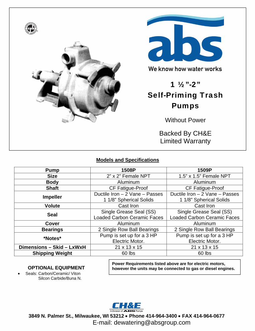
1 ½”-2” Self-Priming Trash
Pumps
Without Power
Backed By CH&E Limited Warranty
Pump 1508P 1509P Size 2” x 2” Female NPT 1.5” x 1.5” Female NPT Body Aluminum Aluminum Shaft CF Fatigue-Proof CF Fatigue-Proof
Impeller Ductile Iron – 2 Vane – Passes 1 1/8” Spherical Solids
Ductile Iron – 2 Vane – Passes 1 1/8” Spherical Solids
Volute Cast Iron Cast Iron
Seal Single Grease Seal (SS) Loaded Carbon Ceramic Faces
Single Grease Seal (SS) Loaded Carbon Ceramic Faces
Cover Aluminum Aluminum Bearings 2 Single Row Ball Bearings 2 Single Row Ball Bearings
*Notes* Pump is set up for a 3 HP Electric Motor.
Pump is set up for a 3 HP Electric Motor.
Dimensions – Skid – LxWxH 21 x 13 x 15 21 x 13 x 15 Shipping Weight 60 lbs 60 lbs
OPTIONAL EQUIPMENT • Seals: Carbon/Ceramic/ Viton
Silcon Carbide/Buna N.
Power Requirements listed above are for electric motors, however the units may be connected to gas or diesel engines.
3849 N. Palmer St., Milwaukee, WI 53212 • Phone 414-964-3400 • FAX 414-964-0677
E-mail: [email protected]

1 ½” & 2” Self-Priming Trash Pumps
3849 N. Palmer St., Milwaukee, WI 53212 • Phone 414-964-3400 • FAX 414-964-0677
E-mail: [email protected]
EASY TO MAINTAIN • Pump Housing Cover removed by
loosening four hand screws. • Replaceable Volute is positioned by
Dowel Pin. • Steel Suction Wearplate fits into volute
and sealed by “O” Ring. • Ductile Iron Two Blade No-Clog
Impeller passes 1 1/8” spherical solids.• Complete Seal Assembly can be
replaced without removing the Pump Case.
BUILT TO LAST • Aluminum Construction • Self-Lubricating Single Seal • Stainless Steel Shaft Sleeve • Ductile Iron Impeller • Cast Iron Volute • Steel Suction Wearplate
Operating and Maintenance Manual
1 ½” & 2” Self-Priming Trash Pumps
1500 Series
3489 North Palmer St
Milwaukee, WI 53212
Tel (414) 964.3400Fax (414) 964.0677
Sales (800) 236.0666
Keep this information guide or a copy of it with the pump.Contact CH&E, A Division of ABS Pumps for additional copies ifthis manual should become lost. If you have any questionsregarding operating or servicing this pump please contact CH&E,A Division of ABS Pumps at (414) 964-3400.

Operating Manual Contents:
• Model Number/Serial Number/Safety Information Pg. 1
• Safety Information (Con’t) Pg. 2
• Operating Instructions/Maintenance Requirements Pg. 3
• Maintenance Requirements (Con’t) Pg. 4
• Troubleshooting Guide Pg. 5
Serial Number / Model Number:
A nameplate listing the Model Number and Serial Number is located on each pump. The Model Number and Serial Number are necessary for ordering parts or requesting service; it is
important that you document these numbers. Record Model Number and Serial Number Here: Serial Number Model Number
Safety Information: DANGER! INDICATES AN IMMENENTLY HAZARDOUS SITUATION, FAILURE TO ABIDE BY SAFETY
PRECAUTIONS WILL RESULT IN DEATH OR SERIOUS INJURY.
Engine Power: DO NOT: Operate in an enclosed area, as exhaust fumes are lethal. DO NOT: Smoke while operating the pump. DO NOT: Smoke when refueling the engine.
DO NOT: Spill fuel when refueling. DO NOT: Refuel or operate the engine near an open flame. DO: Replace the fuel cap after refueling.
1 1500

Electric Power
DO NOT: Operate with a frayed or damaged power cord. DO NOT: Ground the pump to a gas line.
DO: Ground the pump. DO: Realize there is a potential for electrocution whenever electricity is present.
WARNING! INDICATES A POTENTIALLY HAZARDOUS SITUATION; FAILURE TO FOLLOW INSTRUCTIONS MAY RESULT IN DEATH OR SERIOUS INJURY.
Engine Power:
DO NOT: Touch hot surfaces, particularly the muffler; doing so may cause serious burns. DO NOT: Operate without the guards in place.
DO: Read and understand the engine operator manual.
Electric Power:
DO NOT: Allow water to accumulate around the pump. DO NOT: Reset a circuit breaker without first investigating the cause of the problem. DO: Install pump in accordance with the National Electrical Code and all applicable local codes.
DO: Use watertight connections. DO: Shutdown and lockout circuit breaker before performing maintenance.
Pump Safety:
DO NOT: Pump flammable liquids. DO NOT: Pump corrosive liquids. Contact local authorities for assistance. DO NOT: Remove hoses, drain plug, fill plug or any access covers if the pump has not primed in ten minutes. Water in the pump will be hot and could be under high pressure. Allow pump to cool completely before attempting maintenance. DO NOT: Operate this equipment without understanding the operating procedures.
DO NOT: Attempt to clear blockages or clean the pump while the pump is operating; rotating parts can cause serious injury. DO: Read, understand, and follow pump and operation manual procedures. DO: Be sure pump is on a firm, level surface and will not tip, roll or fall while in operation. DO: Operate only when guards are in place. DO: Anchor the end of the discharge hose to prevent possible thrashing under high flow conditions.
CAUTION! INDICATES A POTENTIALLY HAZARDOUS SITUATION, WHICH, IF NOT AVOIDED, MAY
RESULT IN PROPERTY DAMAGE.
DO NOT: Run pump against a closed discharge. DO NOT: Run the pump dry. DO: Drain the pump in freezing weather.
DO: Flush the pump with clean water after each use. DO: Store equipment properly when it is not in use.
15002

Operating Instructions:
1. Read the “Pump Safety” pamphlet in its entirety before operating the pump and observe safe pump operating procedures at all times.
2. Examine the pump carefully and read all instructions thoroughly before beginning pump operation. a. Notify the transportation company at once of any damage or loss that may have occurred during
transit. 3. Gas or Diesel Engine Pumps: Read the engine operator manual in order to understand proper
starting and stopping techniques. Always start and stop the engine in accordance with the engine manufacturer’s instructions.
4. Electric Pumps: Check for correct Shaft Rotation a. Clockwise – when looking at the fan end of the motor b. Counterclockwise – when looking at the impeller end
5. Use grease or thread sealer on threaded connections to make them airtight. a. A hose gasket must be in place with a female-coupled hose. b. Suction hose must be in good condition.
6. Make sure that the hose does not leak and that the hose lining is not loose or it will collapse under suction pressure and block the hose.
a. A hose guard should be used on the end of the suction line to prevent pumping solids too large for the pump to handle.
7. A hose or pipe can be attached to the discharge connection at the top of the pump to lead water away. a. To pump at maximum capacity, use a hose or pipe of the same size or larger than the pump
discharge. 8. Fill the pump case with water through the filler plug at the top of the flap valve housing.
a. Do not run the pump without liquid in the pump case. b. If the pump must be run for short periods of time to check the motor, fill the case with water to
keep the rotating seal lubricated. 9. All gaskets and joints must be airtight. 10. The shaft seal is self-lubricating and will handle clean or dirty water. Additional lubrication is not
required. 11. Priming time depends on the height of the vertical suction lift, the length of the hose between the pump
and the water level, and the speed of the pump. a. Maximum practical suction lift is approximately 25ft vertically from the surface of the water to the
pump suction. b. Suction lines running long, horizontal distances from the water will reduce capacity due to the
increased loss of friction. c. Fastest priming and greatest capacity are achieved at low suction lifts. d. For optimum performance, locate the pump close to water. e. The pump primes faster at higher speeds.
Maintenance Requirements:
• Keep the suction hose connection airtight.
Check the suction hose for leaks and/or a loose lining frequently. • Check all of the bolts on the pump frequently, keeping them drawn up tightly. • Replace “O” Rings after long periods of disuse as they will become dry and lose resiliency. • If the impeller and/or volute are badly worn, they should be replaced to regain the best pump
performance. • Check the impeller gap annually; it should be set at .015” to .030”. • Flush out the pump after each use. • Drain the pump after each use. • Block the suction and discharge openings before storing the pump.
3 1500