Embed Size (px)
Citation preview
Boris Glezer, Optimized Turbine Solutions, San Diego, USA
“Turbine Cooling and Transient Tip Clearance Control:Development Experience”
)8th Israeli Symposium on Jet Engine and Gas Turbine
Technion, Haifa, November 19, 2009
SUBJECTS OF DISCUSSIONIntroduction: Design Constraints for Engine Hot
Section Components
1. Engine Cooling Requirements, Cooling Techniques and Means of Reducing Associated Performance Penalties
2. Engine Transient Thermal Behavior and Turbine Blade Tip Clearance Control
3. Uncertainty of Numerical Predictions and Experimental Validation Practices
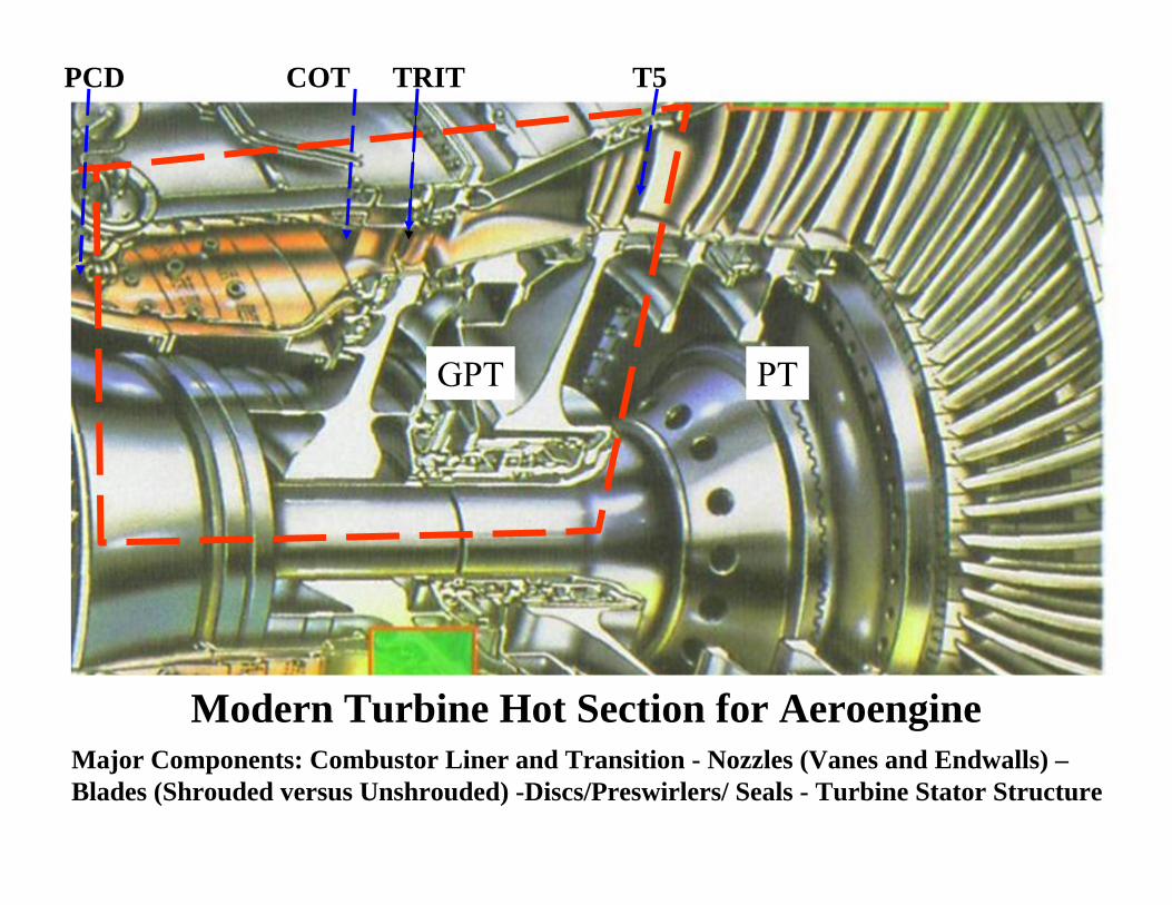
Modern Turbine Hot Section for Aeroengine
PCD COT TRIT T5
GPT PT
Major Components: Combustor Liner and Transition - Nozzles (Vanes and Endwalls) –Blades (Shrouded versus Unshrouded) -Discs/Preswirlers/ Seals - Turbine Stator Structure
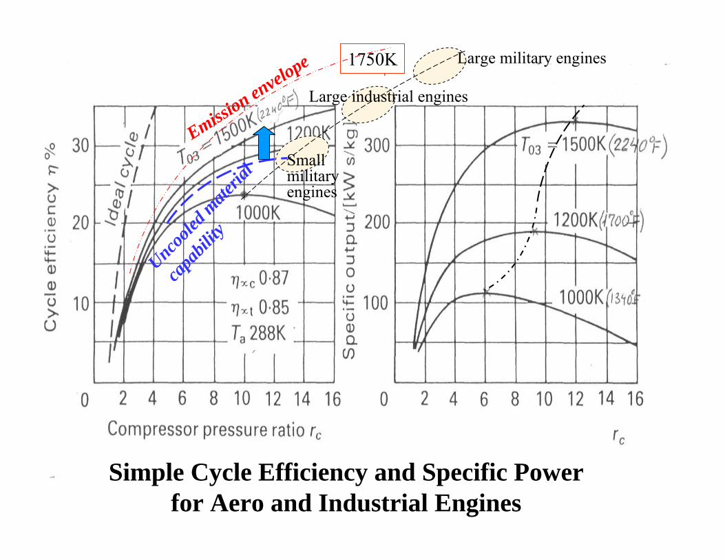
Simple Cycle Efficiency and Specific Power for Aero and Industrial Engines
Emission envelope 1750K Large military engines
Large industrial engines
Smallmilitaryengines
Uncoole
d mate
rial
capa
bility
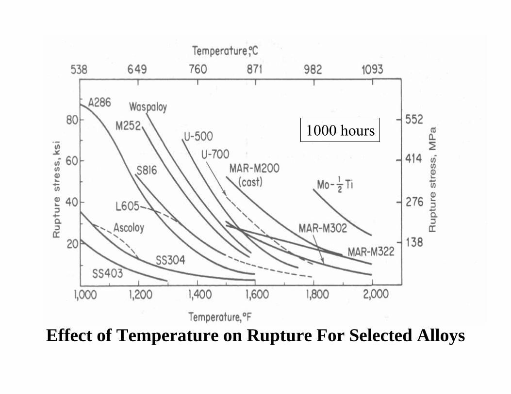
Effect of Temperature on Rupture For Selected Alloys
1000 hours
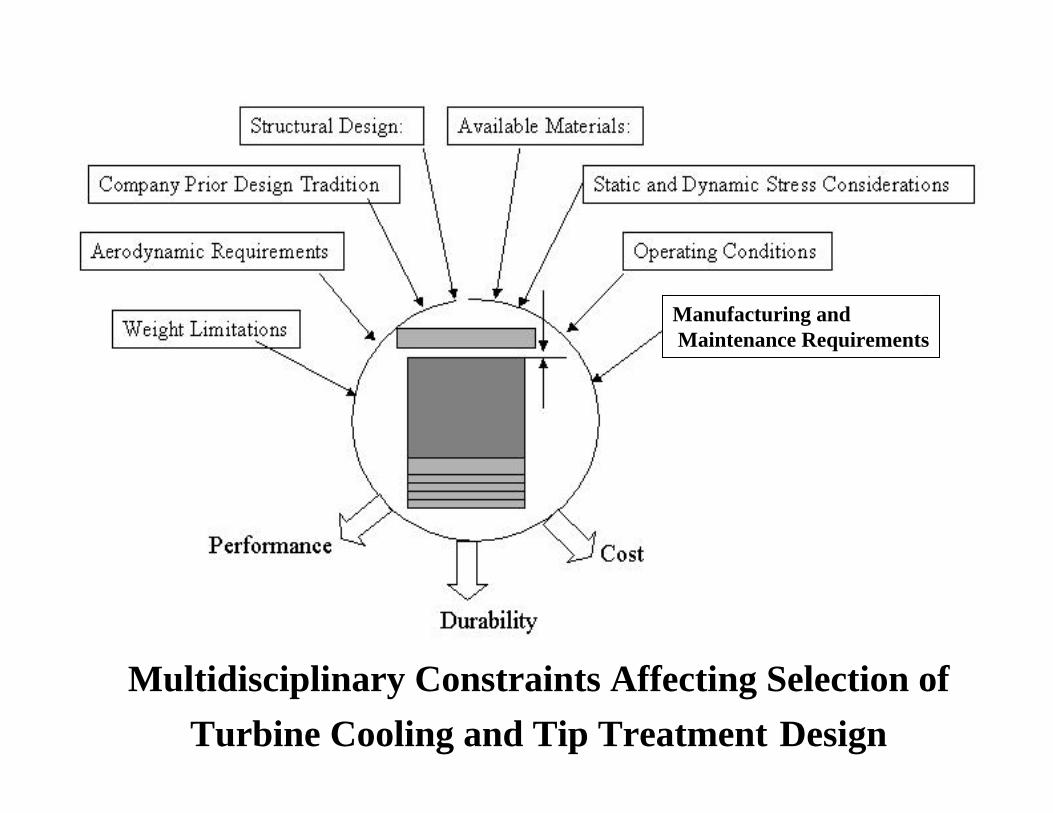
Multidisciplinary Constraints Affecting Selection of Turbine Cooling and Tip Treatment Design
Manufacturing andMaintenance Requirements
1. ENGINE COOLING REQUIREMENTS, COOLING TECHNIQUES AND MEANS
OF REDUCING PERFORMANCE PENALTIES
Hot Side
Hot Side
Hot Side
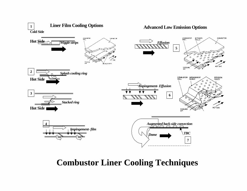
Liner Film Cooling Options
Wiggle-strips
Splash cooling ring
Stacked ring
Effusion
Impingement- Effusion
Impingement- film
Cold Side
Augmented back-side convection
TBC
Advanced Low Emission Options
Dome
Figure 4. Combustor Liner Cooling Techniques
1
2
3
4
5
6
7
Combustor Liner Cooling Techniques
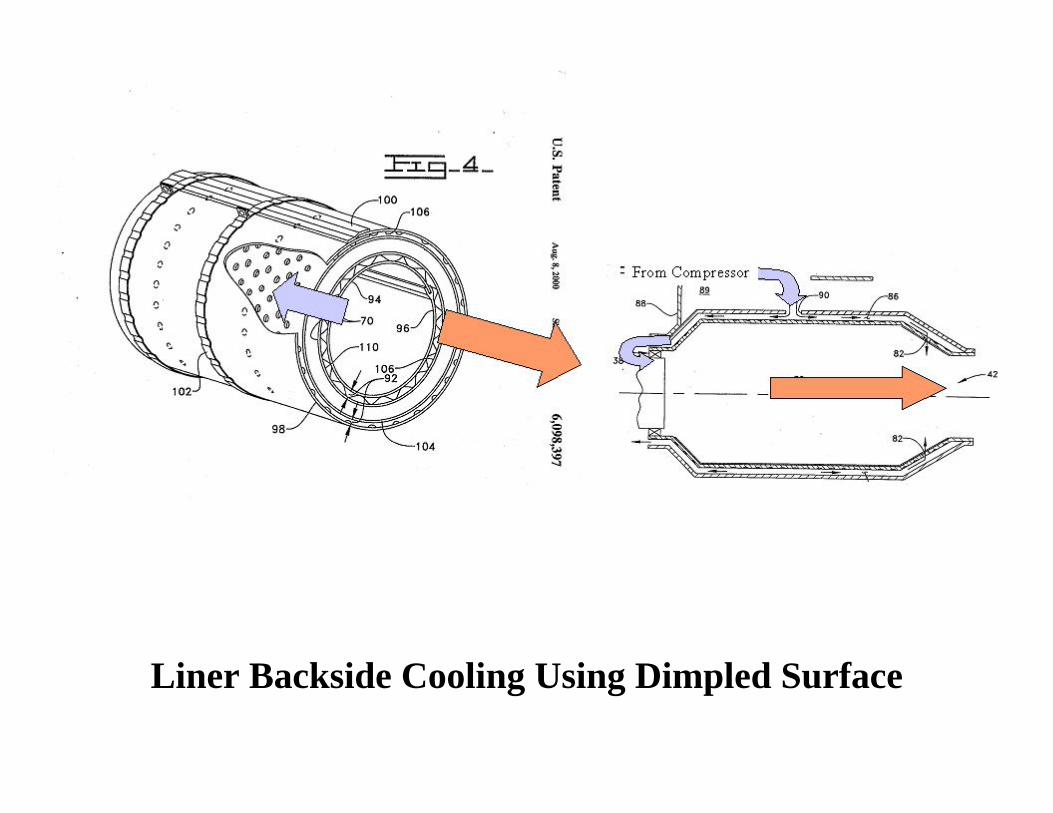
Liner Backside Cooling Using Dimpled Surface
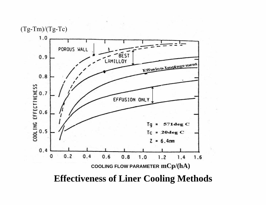
Effectiveness of Liner Cooling MethodsCOOLING FLOW PARAMETER mCp/(hA)
(Tg-Tm)/(Tg-Tc)
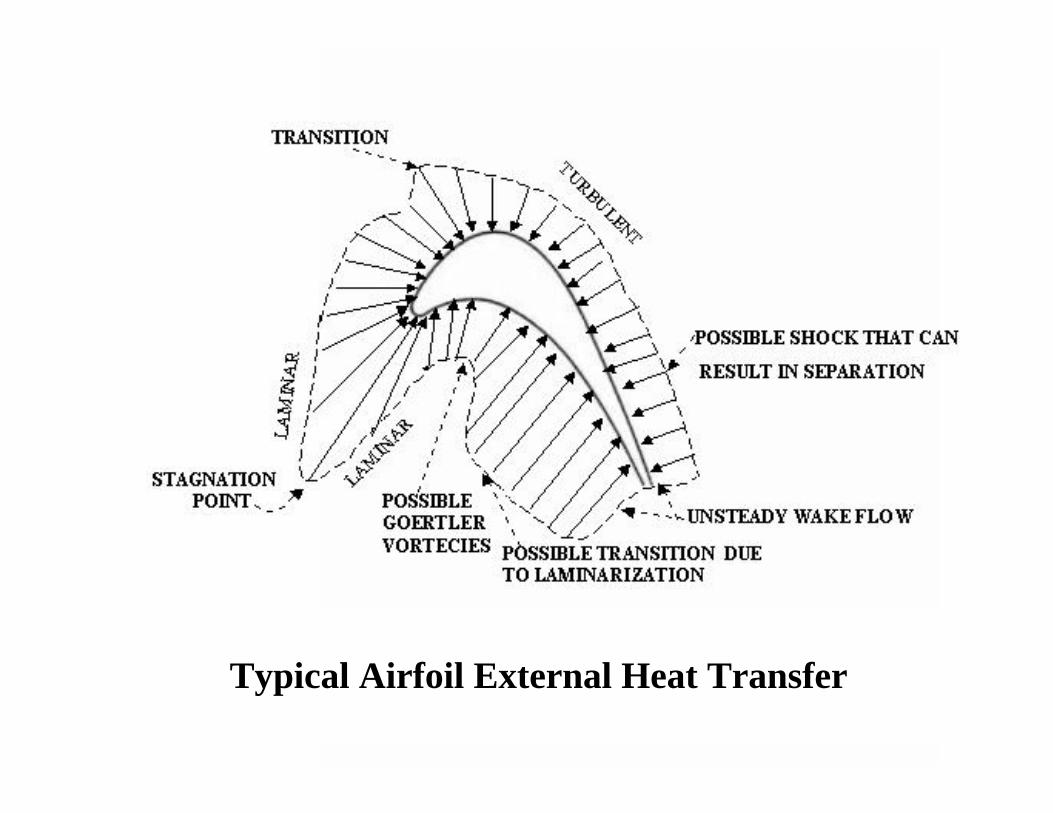
Typical Airfoil External Heat Transfer
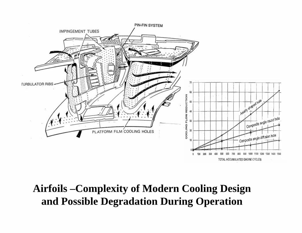
Airfoils –Complexity of Modern Cooling Design and Possible Degradation During Operation
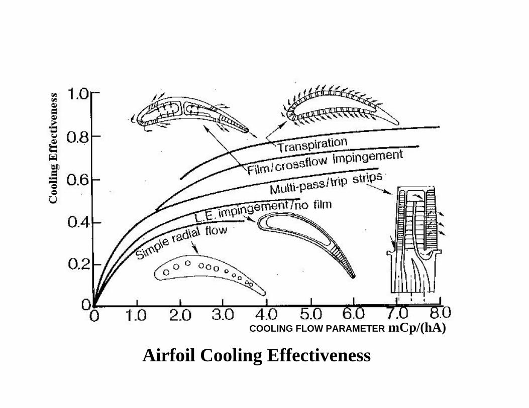
Airfoil Cooling EffectivenessCOOLING FLOW PARAMETER mCp/(hA)
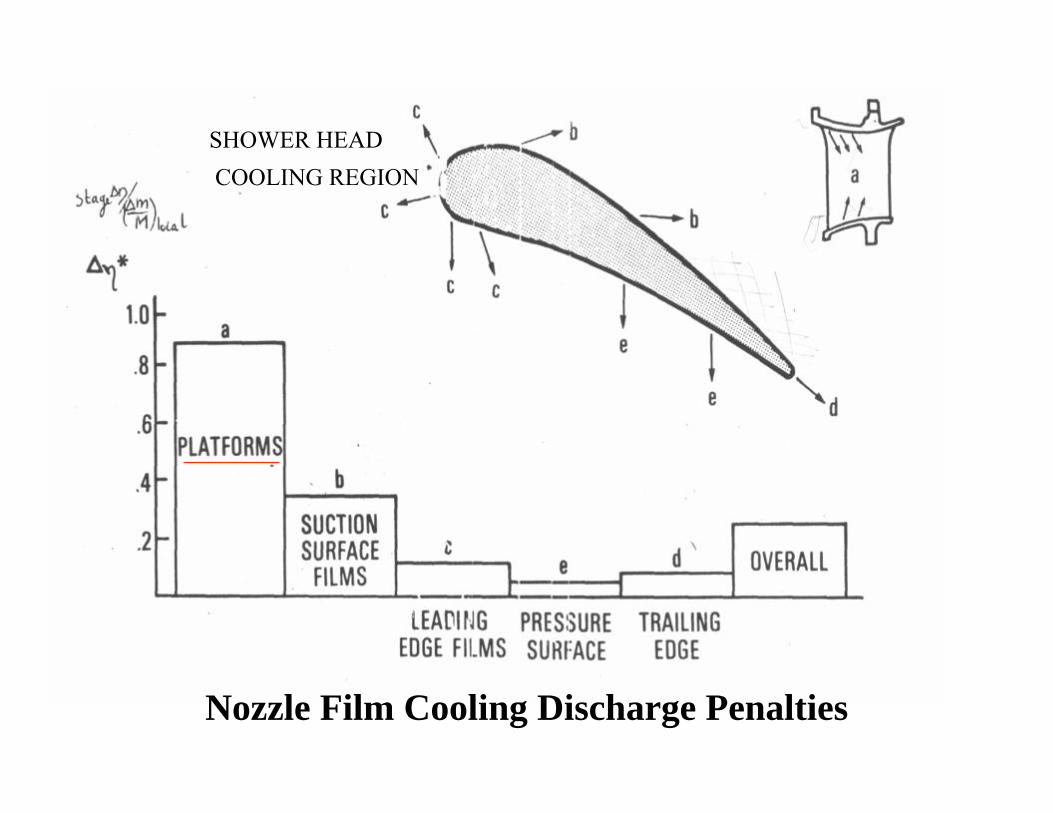
Nozzle Film Cooling Discharge Penalties
SHOWER HEADCOOLING REGION
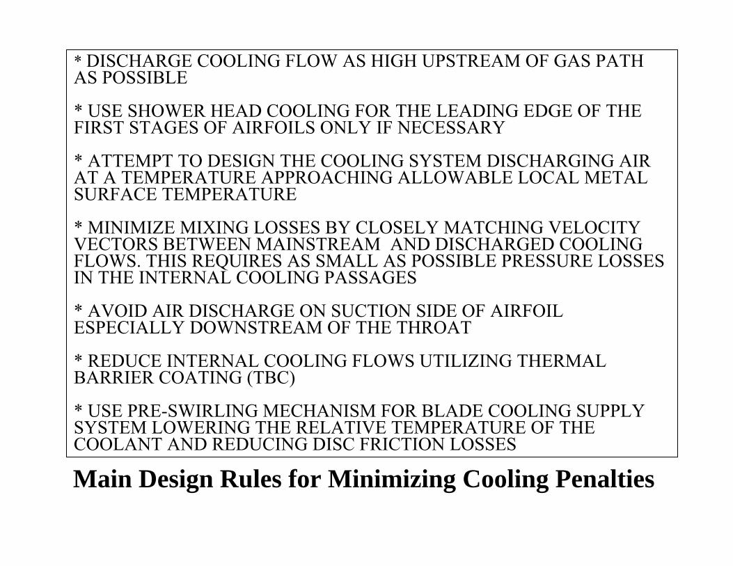
Main Design Rules for Minimizing Cooling Penalties
* DISCHARGE COOLING FLOW AS HIGH UPSTREAM OF GAS PATH AS POSSIBLE
* USE SHOWER HEAD COOLING FOR THE LEADING EDGE OF THE FIRST STAGES OF AIRFOILS ONLY IF NECESSARY
* ATTEMPT TO DESIGN THE COOLING SYSTEM DISCHARGING AIR AT A TEMPERATURE APPROACHING ALLOWABLE LOCAL METAL SURFACE TEMPERATURE
* MINIMIZE MIXING LOSSES BY CLOSELY MATCHING VELOCITY VECTORS BETWEEN MAINSTREAM AND DISCHARGED COOLING FLOWS. THIS REQUIRES AS SMALL AS POSSIBLE PRESSURE LOSSES IN THE INTERNAL COOLING PASSAGES
* AVOID AIR DISCHARGE ON SUCTION SIDE OF AIRFOIL ESPECIALLY DOWNSTREAM OF THE THROAT
* REDUCE INTERNAL COOLING FLOWS UTILIZING THERMAL BARRIER COATING (TBC)
* USE PRE-SWIRLING MECHANISM FOR BLADE COOLING SUPPLY SYSTEM LOWERING THE RELATIVE TEMPERATURE OF THE COOLANT AND REDUCING DISC FRICTION LOSSES
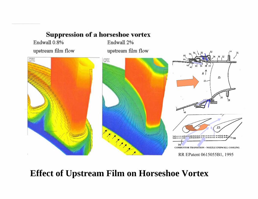
Effect of Upstream Film on Horseshoe Vortex
COMBUSTOR TRANSITION – NOZZLE ENDWALL COOLING
RR EPatent 0615055B1, 1995
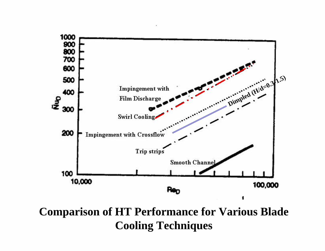
Comparison of HT Performance for Various Blade Cooling Techniques
Dimpled (H/d=0.3-1.5)
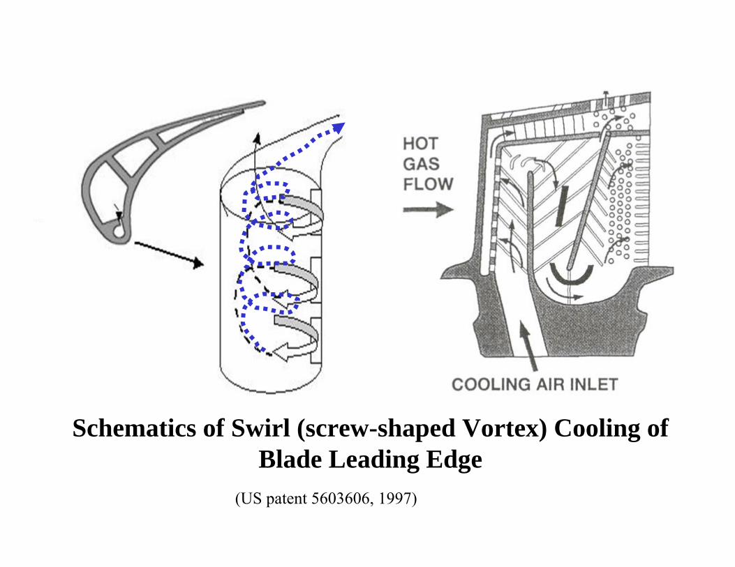
Schematics of Swirl (screw-shaped Vortex) Cooling of Blade Leading Edge
(US patent 5603606, 1997)
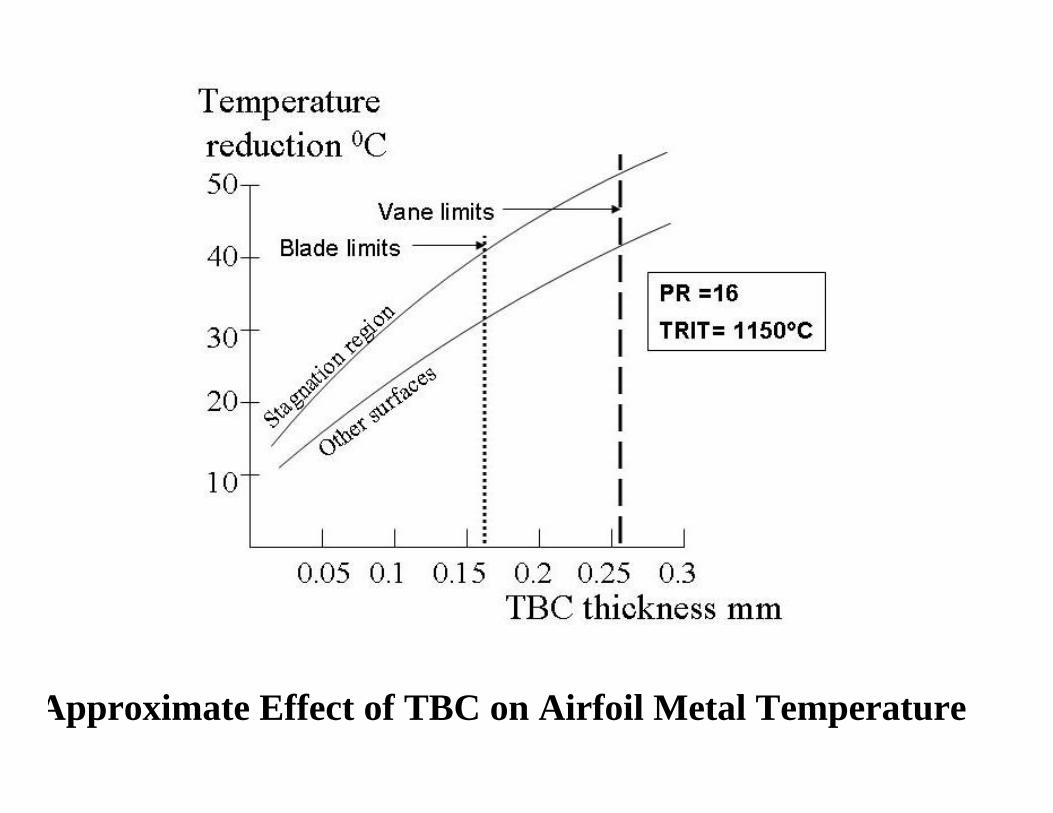
Approximate Effect of TBC on Airfoil Metal Temperature
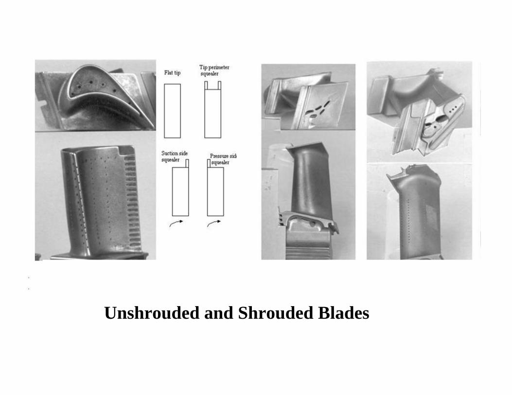
Unshrouded and Shrouded Blades
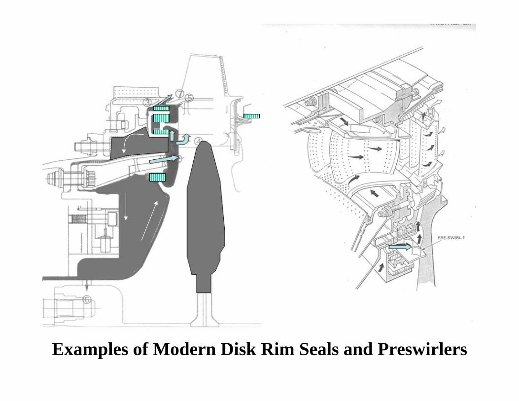
Examples of Modern Disk Rim Seals and Preswirlers
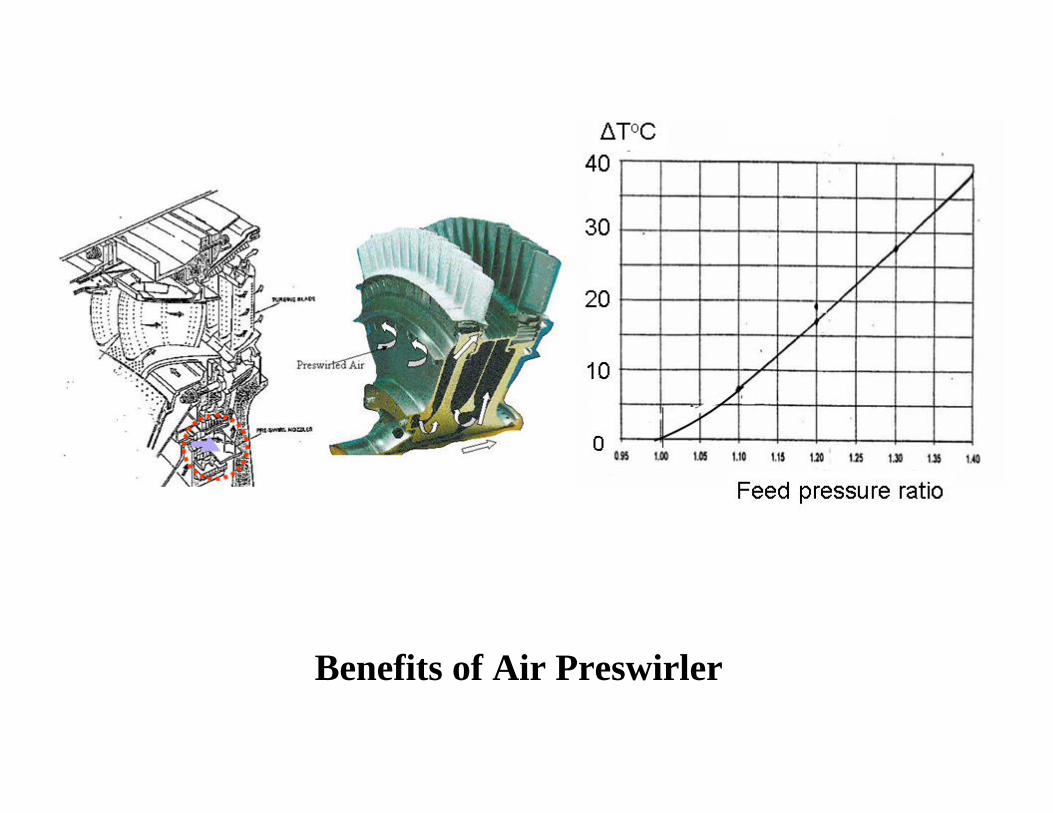
Benefits of Air Preswirler
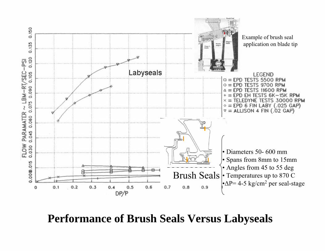
Performance of Brush Seals Versus Labyseals
• Diameters 50- 600 mm• Spans from 8mm to 15mm• Angles from 45 to 55 deg• Temperatures up to 870 C •ΔP= 4-5 kg/cm2 per seal-stage
Brush Seals
Example of brush sealapplication on blade tip
2. ENGINE TRANSIENT THERMAL BEHAVIOR AND
TURBINE BLADE TIP CLEARANCE CONTROL
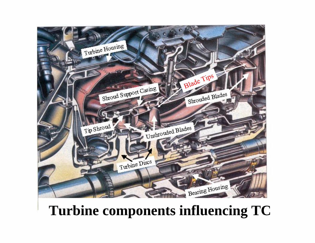
Turbine components influencing TC
Blade Tips
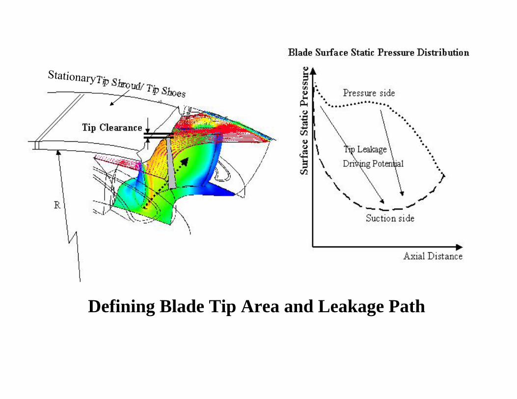
A good summary of OTL flow is provided by Denton & Cumpsty (1987) and Denton (1993)Morphis & Bindon (1988) and Yaras et al. (1991a & b); Denton (1993) Loss Generation Moore & Moore (1986) Passage Secondary Flows Sieverding (1985) and a more completedescription is given in Gregory-Smith (1997).Modeling: Sjolander & Cao (1994)
Stationary
Defining Blade Tip Area and Leakage Path
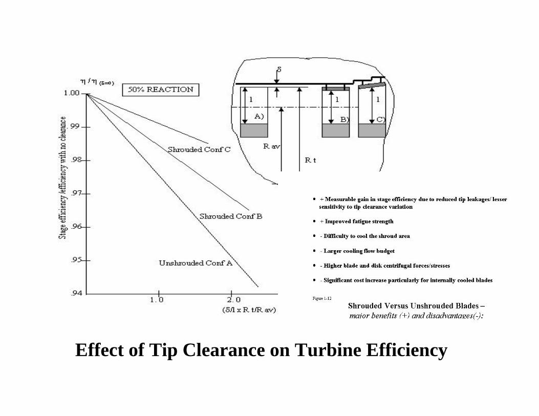
Effect of Tip Clearance on Turbine Efficiency
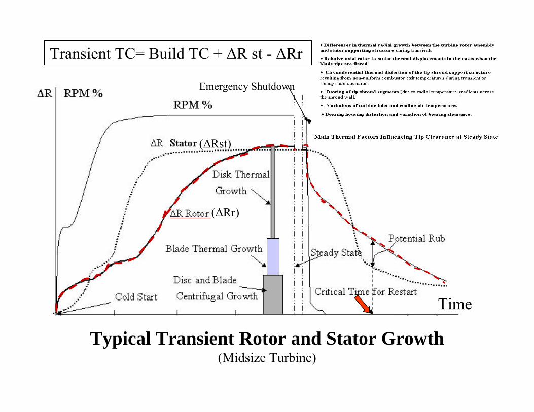
Typical Transient Rotor and Stator Growth(Midsize Turbine)
Emergency Shutdown
Time
Transient TC= Build TC + ΔR st - ΔRr
(ΔRr)
(ΔRst)
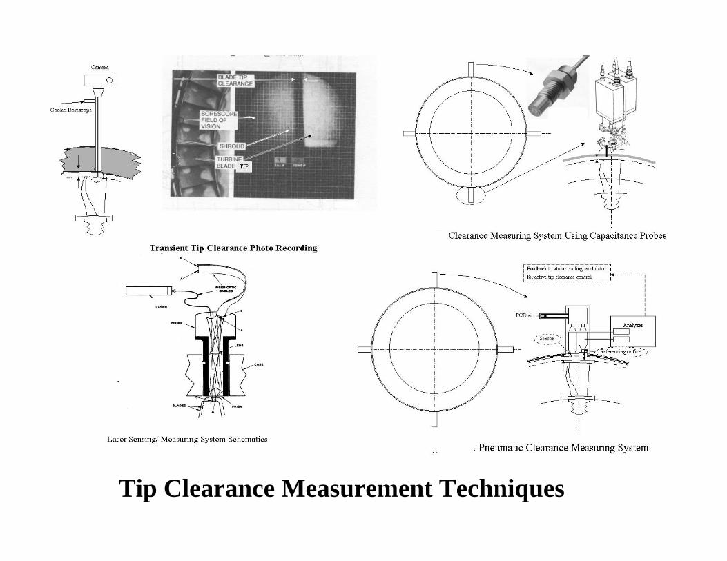
Tip Clearance Measurement Techniques
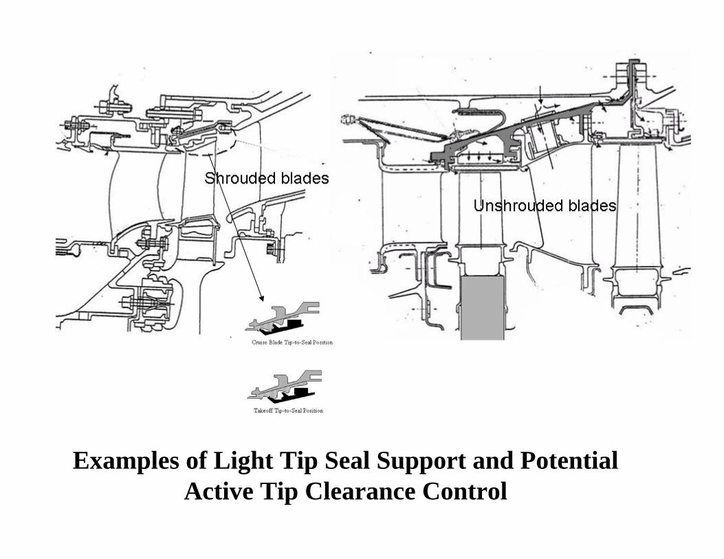
Examples of Light Tip Seal Support and Potential Active Tip Clearance Control
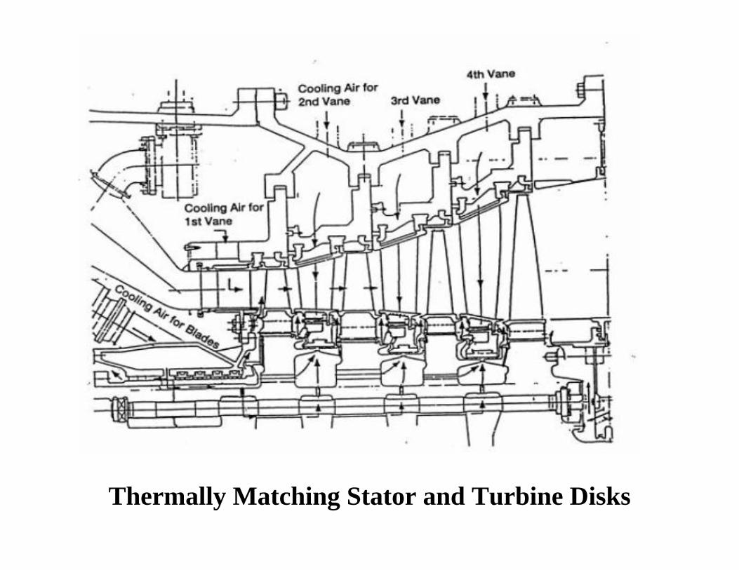
Thermally Matching Stator and Turbine Disks
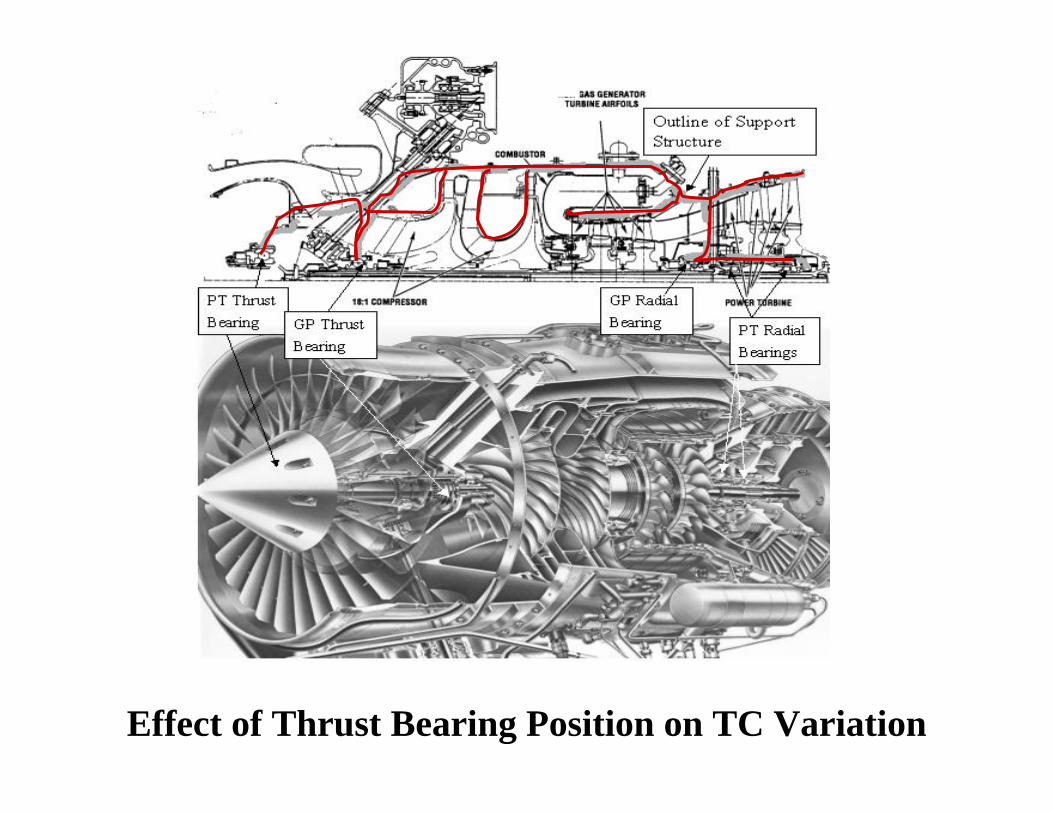
Effect of Thrust Bearing Position on TC Variation
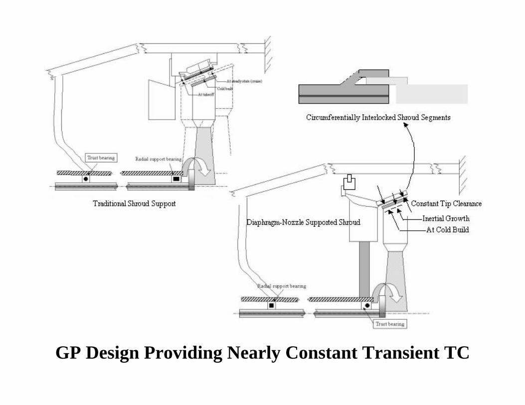
GP Design Providing Nearly Constant Transient TC
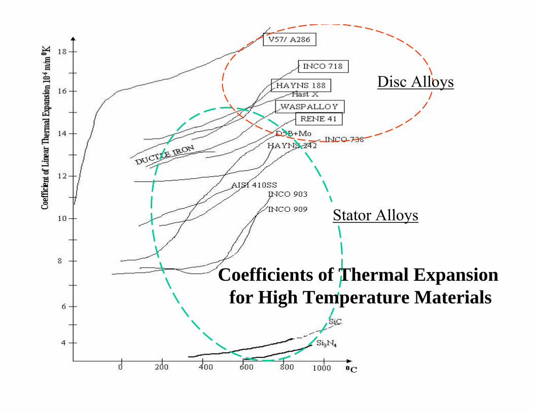
Coefficients of Thermal Expansionfor High Temperature Materials
Stator Alloys
Disc Alloys
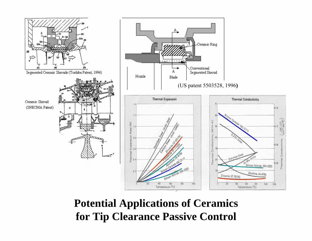
Potential Applications of Ceramics for Tip Clearance Passive Control
(US patent 5503528, 1996)
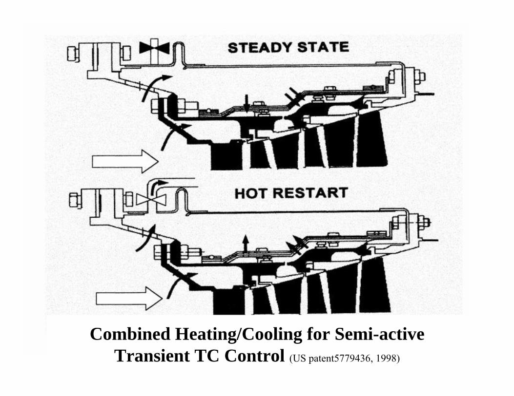
Combined Heating/Cooling for Semi-active Transient TC Control (US patent5779436, 1998)
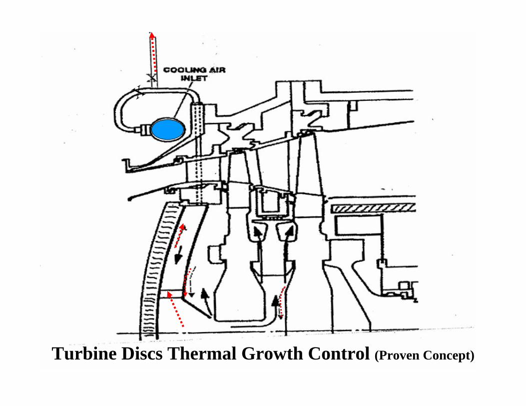
Turbine Discs Thermal Growth Control (Proven Concept)
X

3. UNCERTAINTY OF ANALYTICAL PREDICTIONS AND EXPERIMENTAL
VALIDATION PRACTICES
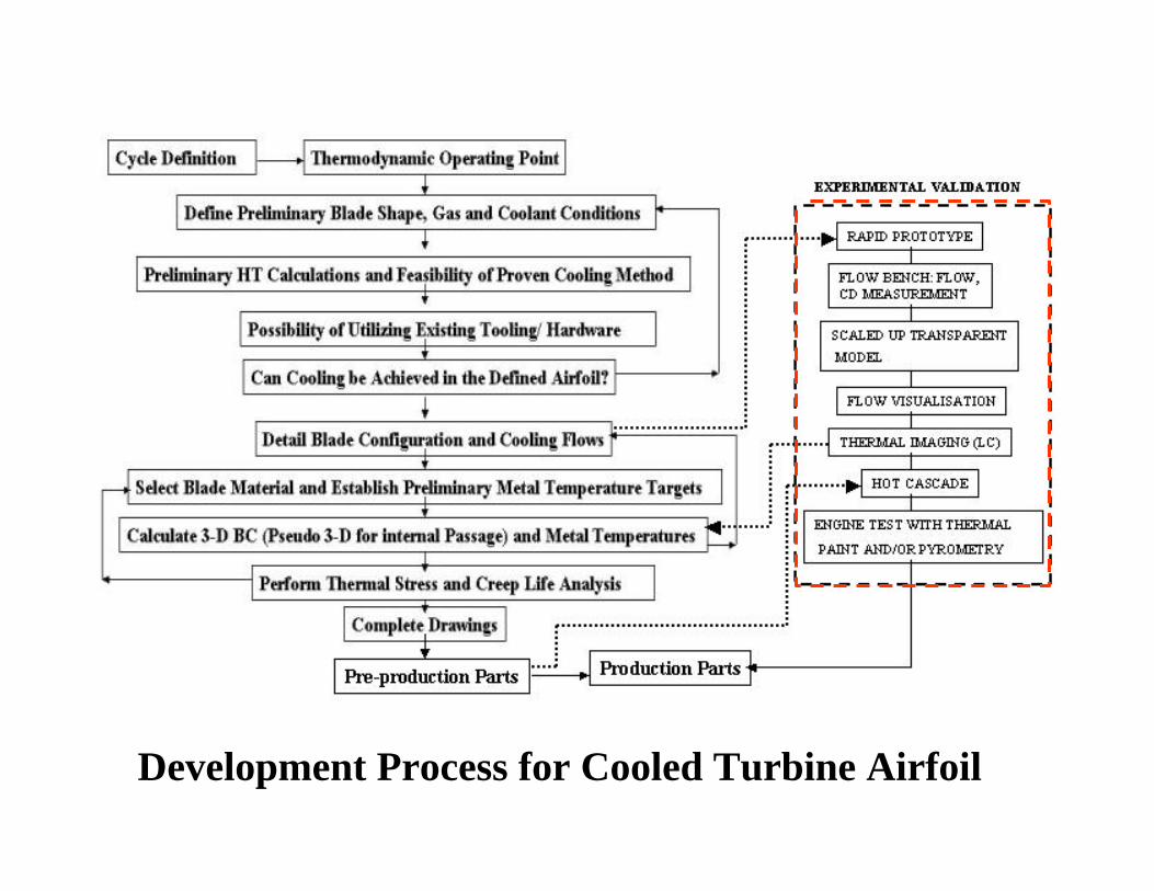
Development Process for Cooled Turbine Airfoil
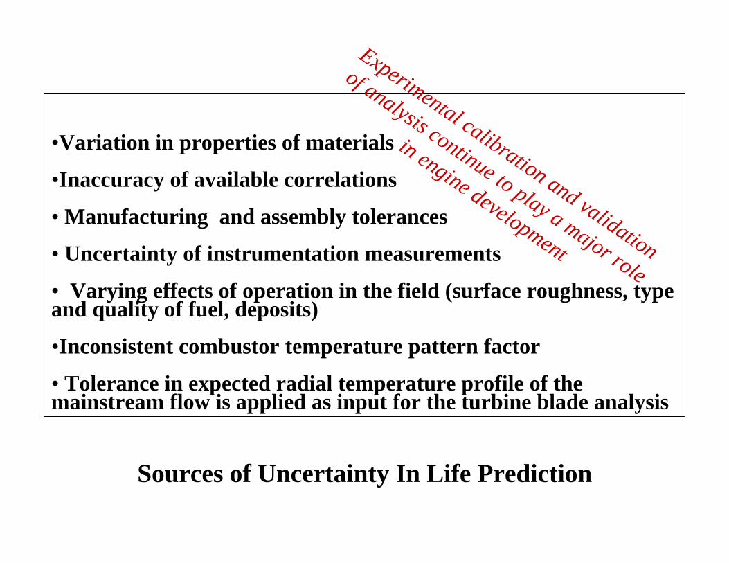
Sources of Uncertainty In Life Prediction
•Variation in properties of materials
•Inaccuracy of available correlations
• Manufacturing and assembly tolerances
• Uncertainty of instrumentation measurements
• Varying effects of operation in the field (surface roughness, type and quality of fuel, deposits)
•Inconsistent combustor temperature pattern factor
• Tolerance in expected radial temperature profile of the mainstream flow is applied as input for the turbine blade analysis
Experimental calibration and validation
of analysis continue to play a major role
in engine development
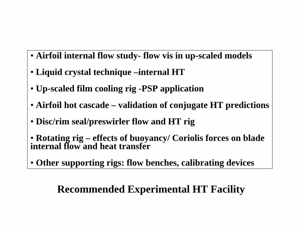
Recommended Experimental HT Facility
• Airfoil internal flow study- flow vis in up-scaled models
• Liquid crystal technique –internal HT
• Up-scaled film cooling rig -PSP application
• Airfoil hot cascade – validation of conjugate HT predictions
• Disc/rim seal/preswirler flow and HT rig
• Rotating rig – effects of buoyancy/ Coriolis forces on blade internal flow and heat transfer
• Other supporting rigs: flow benches, calibrating devices
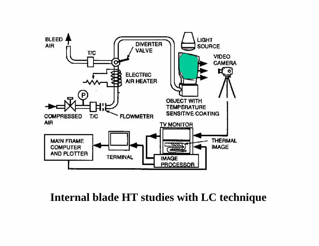
Internal blade HT studies with LC technique
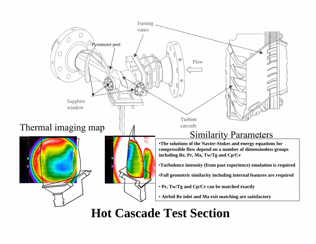
Hot Cascade Test Section
Pyrometer port
*>520.0°F
*<430.0°F
430.0
440.0
450.0
460.0
470.0
480.0
490.0
500.0
510.0
520.0*>520.0°F
*<430.0°F
430.0
440.0
450.0
460.0
470.0
480.0
490.0
500.0
510.0
520.0
Thermal imaging map•The solutions of the Navier-Stokes and energy equations for compressible flow depend on a number of dimensionless groups including Re, Pr, Ma, Tw/Tg and Cp/Cv
•Turbulence intensity (from past experience) emulation is required
•Full geometric similarity including internal features are required
• Pr, Tw/Tg and Cp/Cv can be matched exactly
• Airfoil Re inlet and Ma exit matching are satisfactory
Similarity Parameters
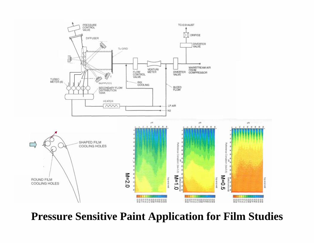
Pressure Sensitive Paint Application for Film Studies
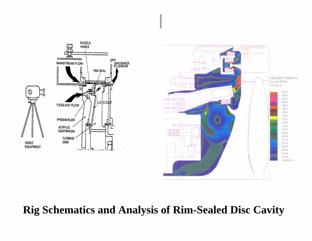
Rig Schematics and Analysis of Rim-Sealed Disc Cavity
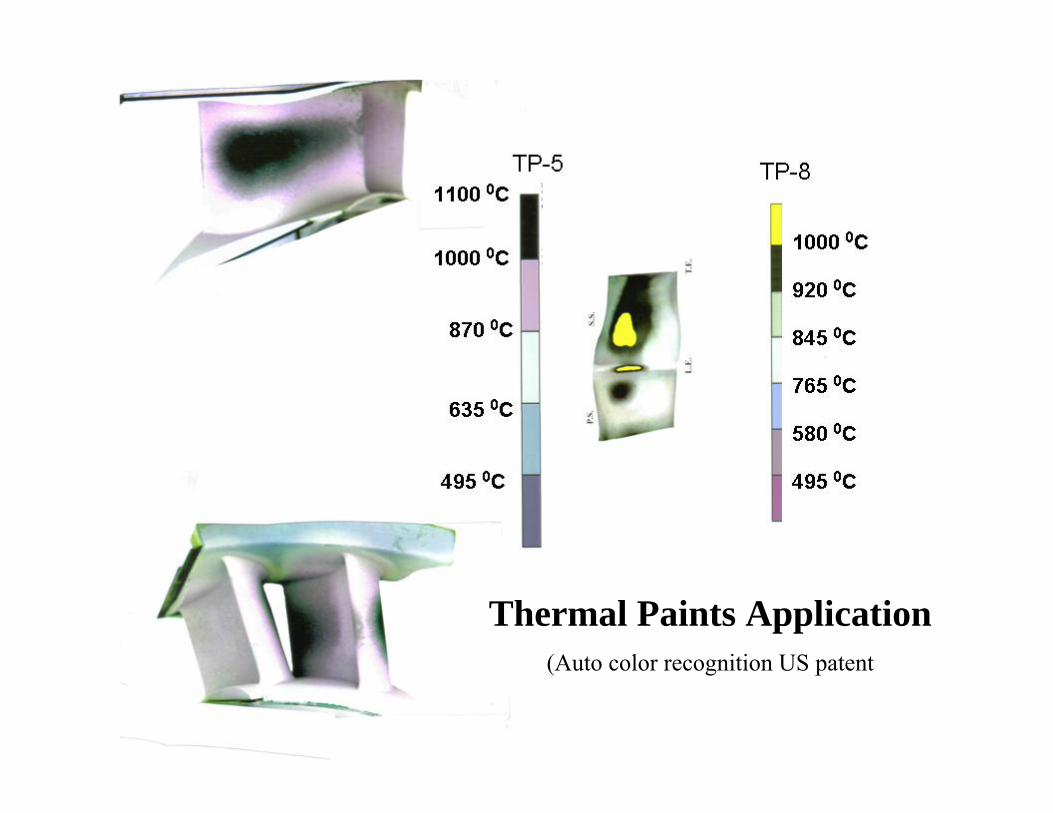
Thermal Paints Application(Auto color recognition US patent
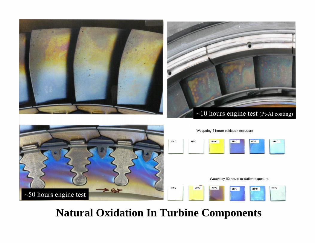
~50 hours engine test
~10 hours engine test (Pt-Al coating)
Natural Oxidation In Turbine Components
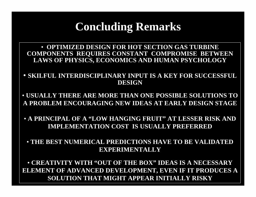
Concluding Remarks• OPTIMIZED DESIGN FOR HOT SECTION GAS TURBINE
COMPONENTS REQUIRES CONSTANT COMPROMISE BETWEEN LAWS OF PHYSICS, ECONOMICS AND HUMAN PSYCHOLOGY
• SKILFUL INTERDISCIPLINARY INPUT IS A KEY FOR SUCCESSFUL DESIGN
• USUALLY THERE ARE MORE THAN ONE POSSIBLE SOLUTIONS TO A PROBLEM ENCOURAGING NEW IDEAS AT EARLY DESIGN STAGE
• A PRINCIPAL OF A “LOW HANGING FRUIT” AT LESSER RISK AND IMPLEMENTATION COST IS USUALLY PREFERRED
• THE BEST NUMERICAL PREDICTIONS HAVE TO BE VALIDATED EXPERIMENTALLY
• CREATIVITY WITH “OUT OF THE BOX” IDEAS IS A NECESSARY ELEMENT OF ADVANCED DEVELOPMENT, EVEN IF IT PRODUCES A
SOLUTION THAT MIGHT APPEAR INITIALLY RISKY