Embed Size (px)
Citation preview

8U SuperBladereg
Userrsquos ManualRevision 12a
5 MP and 10 DP Blade System
20 DP Blade System
8U SuperBlade Userrsquos Manual
ii
The information in this Userrsquos Manual has been carefully reviewed and is believed to be accurate The vendor assumes no responsibility for any inaccuracies that may be contained in this document makes no commitment to update or to keep current the information in this manual or to notify any person or organization of the updates Please Note For the most up-to-date version of this manual please see our web site at wwwsupermicrocom
Super Micro Computer Inc (Supermicro) reserves the right to make changes to the product described in this manual at any time and without notice This product including software and documentation is the property of Supermicro andor its licensors and is supplied only under a license Any use or reproduction of this product is not allowed except as expressly permitted by the terms of said license
IN NO EVENT WILL SUPERMICRO BE LIABLE FOR DIRECT INDIRECT SPECIAL INCIDENTAL SPECULATIVE OR CONSEQUENTIAL DAMAGES ARISING FROM THE USE OR INABILITY TO USE THIS PRODUCT OR DOCUMENTATION EVEN IF ADVISED OF THE POSSIBILITY OF SUCH DAMAGES IN PARTICULAR SUPERMICRO SHALL NOT HAVE LIABILITY FOR ANY HARDWARE SOFTWARE OR DATA STORED OR USED WITH THE PRODUCT INCLUDING THE COSTS OF REPAIRING REPLACING INTEGRATING INSTALLING OR RECOVERING SUCH HARDWARE SOFTWARE OR DATA
Any disputes arising between manufacturer and customer shall be governed by the laws of Santa Clara County in the State of California USA The State of California County of Santa Clara shall be the exclusive venue for the resolution of any such disputes Super Micros total liability for all claims will not exceed the price paid for the hardware product
FCC Statement This equipment has been tested and found to comply with the limits for a Class A digital device pursuant to Part 15 of the FCC Rules These limits are designed to provide reasonable protection against harmful interference when the equipment is operated in a commercial environment This equipment generates uses and can radiate radio frequency energy and if not installed and used in accordance with the manufacturerrsquos instruction manual may cause harmful interference with radio communications Operation of this equipment in a residential area is likely to cause harmful interference in which case you will be required to correct the interference at your own expense
California Best Management Practices Regulations for Perchlorate Materials This Perchlorate warning applies only to products containing CR (Manganese Dioxide) Lithium coin cells Perchlorate Material-special handling may apply See wwwdtsccagovhazardouswasteperchlorate for further details
WARNING HANDLING OF LEAD SOLDER MATERIALS USED IN THIS PRODUCT MAY EXPOSE YOU TO LEAD A CHEMICAL KNOWN TO THE STATE OF CALIFORNIA TO CAUSE BIRTH DEFECTS AND OTHER REPRODUCTIVE HARM
Manual Revision 12a
Release Date October 24 2018
Unless you request and receive written permission from Super Micro Computer Inc you may not copy any part of this document
Information in this document is subject to change without notice Other products and companies referred to herein are trademarks or registered trademarks of their respective companies or mark holders
Copyright copy 2018 by Super Micro Computer IncAll rights reservedPrinted in the United States of America
Preface
About this Manual
This manual is written for professional system integrators Information Technology professionals service personnel and technicians It provides information for the installation and use of Supermicros 8U SuperBlade system Installation and maintenance should be performed by experienced professionals only
Manual Organization
Chapter 1 Introduction
The first chapter provides a checklist of the main components included with the blade system and describes the main features of the mainboard and enclosure A quick start procedure is also provided for your use
Chapter 2 System Safety
You should familiarize yourself with this chapter for a general overview of safety precautions that should be followed when installing and servicing the 8U SuperBlade
Chapter 3 Setup and Installation
Refer here for details on installing the 8U SuperBlade system into a rack
Chapter 4 System Modules
This chapter covers modules in the 8U SuperBlade system as well as the CMM module and configuring double-wide bays
Chapter 5 Power Supply Modules
This chapter covers the system power supplies and their installation
Appendix A System Specifications
This appendix provides a summary of system specifications
i
8U SuperBlade Userrsquos Manual
Notes
ii
Table of Contents
Chapter 1 Introduction 1-1
1-1 Overview 1-1
1-2 Quick Start Setup 1-1
1-3 Software Mode Selection 1-2
1-4 Product Checklist of Typical Components 1-3
1-5 Blade Enclosure Features 1-6
Power 1-7Middle Plane 1-7LEDs 1-7Enclosure Cooling1-7
1-6 Power Supply Features 1-8
Power Supply Modules 1-9Power Cord 1-9Power Supply Failure 1-9
1-7 Special Design Features1-9
Operating System Support 1-9Remote Management 1-9Computing DensityPower 1-10High-Efficiency Power Supplies 1-10
1-8 Returning Merchandise for Service1-10
1-9 Contacting Supermicro1-11
Chapter 2 Standardized Warning Statements2-1
2-1 About Standardized Warning Statements 2-1
Warning Definition2-1Installation Instructions 2-3Circuit Breaker 2-4Power Disconnection Warning 2-5Equipment Installation 2-6Restricted Area 2-7Battery Handling 2-9Redundant Power Supplies 2-10Backplane Voltage 2-11Comply with Local and National Electrical Codes2-12Product Disposal2-13Hot Swap Fan Warning 2-14
i
8U SuperBlade Userrsquos Manual
Power Cable and AC Adapter 2-15
Chapter 3 Setup and Installation 3-1
3-1 Overview 3-1
3-2 Unpacking the System 3-1
Choosing a Setup Location 3-1Rack Precautions 3-2Server Precautions 3-2Rack Mounting Considerations 3-2
Ambient Operating Temperature 3-2Reduced Airflow 3-2Mechanical Loading 3-2Circuit Overloading 3-3Reliable Ground 3-3
Installing the System Into a Rack 3-3Rack Mounting Hardware 3-3Installation 3-4
Chapter 4 System Modules 4-1
4-1 Chassis Management Module 4-4
Module Redundancy 4-6Determining MasterSlave Modules Status 4-6CMM Module Installation 4-6Configuring the CMM 4-7CMM Functions 4-9
Remote KVM over IP 4-10Remote Storage (Virtual Media)4-10Serial Over LAN (SOL)4-10Monitoring Functions4-10Power Consumption Management4-10
USB Ports and Reset Button 4-11USB Ports 4-12Reset Button 4-12
Firmware 4-12Web-based Management Utility 4-12
Supported Browsers4-13Network ConnectionLogin 4-13Address Defaults4-13Home Page 4-14
ii
Chapter 5 Power Supply Modules 5-1
5-1 Power Supply Modules 5-1
BPP Batteries 5-3Power Supply Failure 5-5Installing a Power Supply 5-5Removing a Power Supply 5-5
5-2 Redundant Power Supplies 5-5
5-3 Power Supply Fans 5-7
Appendix A System Specifications A-1
A-1 Enclosure Specifications A-1
A-2 Environmental SpecificationsA-2
A-3 Address DefaultsA-2
A-4 Power Supply Power Calculations A-3
iii
8U SuperBlade Userrsquos Manual
iv
List of Figures
Figure 3-1 Positioning the Enclosure Template 3-4Figure 3-2 Securing the Rails to the Rack 3-4Figure 3-3 Sliding the Enclosure into the Rack 3-5Figure 3-4 Attaching the Optional Handles 3-5Figure 3-5 Enclosure Installed into Rack 3-6Figure 4-1 8U 820C Enclosure with 100G Switch Rear View 4-1Figure 4-2 8U 820J Enclosure with 2x25Gand 2x10G Switches Rear View4-2Figure 4-3 8U 820L Enclosure with 2x10G Switches Rear View 4-3Figure 4-4 Chassis Management Module MBM-CMM-FIO 4-4Figure 4-5 Chassis Management Module MBM-CMM-001 4-5Figure 4-6 Choose Internal Protocol 4-8Figure 4-7 Manually Configure the IP Address 4-8Figure 4-8 Changing Settings 4-9Figure 4-9 USB Ports on CMM 4-11Figure 4-10 Home Page4-14Figure 5-1 PWS-2K21A-BR Power Supply 5-2Figure 5-2 PWS-1K20B-BR Battery Backup Power (BPP) Module 5-3Figure 5-3 Power Supply Status 5-6
i
8U SuperBlade Userrsquos Manual
Notes
ii
List of Tables
Table 1-1 Networking Module Solutions1-4Table 1-1 Networking Module Solutions 1-4Table 1-2 8U SuperBlade Enclosures 1-6Table 1-3 Number of Network Modules that May Be Installed in each Enclosure1-6Table 1-4 Enclosure Models and Power Supply Combinations 1-8Table 4-1 Typical 8U Blade System Module Configuration Rear View 4-2Table 4-2 Typical 8U Blade System Module Configuration Rear View 4-3Table 4-3 MBM-CMM-FIO Module Interface4-4Table 4-4 MBM-CMM-FIO Module Features4-5Table 4-5 MBM-CMM-001 Module Interface4-5Table 4-6 MBM-CMM-001 Module Features4-6Table 4-7 CMM Reset Settings 4-12Table 4-8 Address Defaults4-13Table 5-1 Amperage Draw Specifications for the PWS-2K21A-BR Power Supply 5-1Table 5-2 PWS-2K21A-BR Power Supply Features 5-2Table 5-3 PWS-1K20B-BR Battery Backup Power (BPP) Module Specifications 5-4Table 5-4 PWS-1K20B-BR BPP Module Estimated Runtime 5-4Table 5-5 Chassis Compatible with the BPP 5-4Table A-1 8U Enclosure Specification Features A-1Table A-2 Environmental Specification FeaturesA-2Table A-3 Address Defaults A-2Table A-4 Power Supply Power Calculations (PWS-2K21A-BR)A-3Table A-5 Power Supply Power Calculations (PWS-1K20B-BR)A-3
i
8U SuperBlade Userrsquos Manual
ii
Chapter 1 Introduction
Chapter 1Introduction
1-1 OverviewThe 8U SuperBlade is a compact self-contained server that connects to a pre-cabled enclosure that provides power cooling management and networking functions One enclosure can hold up to either ten or twenty blade servers depending upon the blade enclosure This new generation of the 8U SuperBlade enclosure is designed to deliver a much higher system density and to incorporate many latest technologies to satisfy the increasing demands of modern technology and higher computing power
In this manual ldquoblade systemrdquo refers to the entire system (including the enclosure and blades servers) ldquobladerdquo or ldquoblade serverrdquo refers to a single blade module and ldquoblade enclosurerdquo is the unit that the blades power supplies and modules are housed in
Each blade server is optimized to fit into either a specific ten-blade or twenty-blade enclosure
Please refer to our web site for information on operating systems that have been certified for use with the 8U SuperBlade (wwwsupermicrocomproductssuperblade)
1-2 Quick Start SetupThis section covers how to quickly get your new 8U SuperBlade system up and running Follow the procedure below to quickly setup your 8U SuperBlade system
1 Unpack the components of your 8U SuperBlade system and check the packing list for damaged or missing components
2 Select a setup location for your system See Choosing a Setup Location on page 3-1 for details
3 Mount the 8U SuperBlade chassis in your server rack See Installing the System Into a Rack on page 3-3 for details
4 Install the power supply modules into the rear of the 8U SuperBlade chassis See Installing a Power Supply on page 5-5 for details
5 Install the CMM module and any switch modules into the rear of the 8U SuperBlade chassis
a For the CMM module see CMM Module Installation on page 4-6 for details
b For the InfiniBand and Ethernet modules see the 8U SuperBlade Network Modules Userrsquos Manual for details
c Attach keyboard mouse and video connections to your CMM module
d Attach network connections for your InfiniBand or Ethernet modules See the 8U SuperBlade Network Modules Userrsquos Manual for details
1-1
8U SuperBlade Userrsquos Manual
6 Setup your blade modules for use by doing the following
a Open the module case lids of each blade module Refer to the blade module userrsquos manual for details
b Install memory into each module Refer to the blade module userrsquos manual for details
c Close the module case lids when you have installed your memory for each blade module Refer to the blade module userrsquos manual for details
d Install the hard disk drives into each module Refer to the blade module userrsquos manual for details
e Install your blade modules into your 8U SuperBlade chassis Refer to the blade module userrsquos manual for details
7 Connect the power cords for your 8U SuperBlade systemrsquos power supply and plug them into your power source ONLY after you have installed and secured all system components
8 Power up your 8U SuperBlade system Check to be sure all components are operating right and are not showing any fault LEDs or alarms in their operation
9 Install your selected operating system for each blade module Refer to the blade module userrsquos manual for details
10 Download a BIOS update for each of your blade modules from the Supermicro website
1-3 Software Mode SelectionUsing the Web-based Management Utility you can specify your 8U SuperBlade system to use a quiet mode for quieter operation and lower fan speed See Section 4-1 Chassis Management Module on page 4-4 for further details
1-2
Chapter 1 Introduction
1-4 Product Checklist of Typical Componentsbull Blade Enclosure (x1) SBE-820CCBJJB 822820D 820L 622 and 422 (8U 10
full-height 2-socket or 20 half-height blades 4-socket)
bull Blade Unit (minimum of 2 10 or 20 maximum) See the Supermicro website (httpwwwsupermicrocomproductssuperblade) for a complete list of blades that can be mounted in your system Some examples are listed below
20 Blade
bull Dual socket (SP) ndash SBI-4129P-C2NT3N (205W)
10 Blade
bull 4 Way ndash SBI-8149R-C4NT8N
bull Power Supplies (up to 8) PWS-2K21A
bull KVM Cable (x1) CBL-0218L
Optional components include
bull InfiniBandreg Switch Module SBM-IBS-E3616
bull Omni-Pathtrade Switch Module SBM-OPA-C4020
bull CMM Module (x1) MBM-CMM-FIO or MBM-CMM-001
bull Blade IPMI Add-on Card AOC-SB410-001 (front control board with KVM connector)
bull Mezzanine Cards (required for operation with the InfiniBand Switch) AOC-IBH-X4ED-P (100-Gbps InfiniBand card) AOM-B-4M-100 (M2 card) AOM-B3108-H8-B11 (SAS3 card) AOM-SB1-SATA31-P (SATA3 card) AOC-OPA-WFR (OPA card)
bull Ethernet Switches MBM-XEM-001 (Broadcom 10-Gbps) MBM-XEM-002 (Intel 10-Gbps) MBM-GEM-001 (Intel 1-Gbps) MBM-GEM-004 (Broadcom 1-Gbps)
bull Fan Modules PWS-DF006-2F PWS-DF006-2F
Additional modules will periodically become available Please refer to httpwwwsupermicrocomproductssuperblade for the most current list of modules available for the 8U SuperBlade
Blade systems install into standard racks Up to five 8U blade systems may be installed into a 19 industry standard 42U rack
Warning It is highly recommended that you do not discard or throw away any parts for the system delivered to you since some parts might be required for later reconfigurations of the system at a later date
1-3
8U SuperBlade Userrsquos Manual
For some details on the combinations and types of networking modules available see Table 1-1 below See the SuperBlade Network Modules User Manual for full details on available modules for the SuperBlade system
Table 1-1 Networking Module Solutions
8U Enclosure Model
Model Speed Protocol 820C(B) 820J(B) 820L(B) Notes
SBM-IBH-E3616 100GInfiniBand
EDRUp to 1 -
20x 100G EDR InfiniBand downlinks 16x 100G EDR InfiniBand uplinks 72Tbps PHY 100G opticalcopper QSFP28
SBM-OPA-C4020 100GIntel
Omni-PathUp to 1 -
20x 100G EDR InfiniBand downlinks 24x 100G EDR InfiniBand uplinks 1USB Port 96Tbps PHY 100G opticalcopper QSFP28
SBM-25G-100 25G Ethernet - Up to 2
20x 25G Ethernet downlinks 4x 100G40G Ethernet uplinks (each can split to 4x 25G uplinks w optional fan-out cables 1x Gigabit Ethernet uplink 1 console portPHY 100G40G opticalcopper QSFP28 Gigabit Ethernet copper RJ45
MBM-XEM-001 10G Ethernet Up to 2 Up to 4
56x 10G25G1G Ethernet downloads 4x 40G Ethernet uplinks 1 console port 1 USB port
PHY 960G40G opticalcopper QSFP+
1-4
Chapter 1 Introduction
MBM-XEM-002 10G Ethernet Up to 2 Up to 4 Up to 2
56x 10G25G1G Ethernet downlinks 2x 40G Ethernet QSFP+ or 1x 40G and 4x 10G Ethernet uplinks 1 console port 1 USB port
PHY 1280G40G opticalcopper QSFP+ Optional 10G Ethernet opticalcopper SFP+
MBM-GEM-001 1G Ethernet Up to 2 Up to 4 Up to 2
56x 25G1G Ethernet downlinks 1 Gigabit Ethernet 2x 40G Ethernet or 8x 10G Ethernet uplinks 1 console port 1 USB port
PHY 442G40G opticalcopper QSFP+ 10G opticalcopper SFP+ Gigabit Ethernet copper RJ45
MBM-GEM-004 1G Ethernet Up to 2 Up to 4 Up to 2
40x 1G Ethernet downlinks 8x 1G Ethernet RJ45 and optional 4x 10G Ethernet Uplinks 1 console port
PHY 176G Optional 10G opticalcopper SFP+ Gigabit Ethernet copper RJ45
Table 1-1 Networking Module Solutions (Continued)
8U Enclosure Model
Model Speed Protocol 820C(B) 820J(B) 820L(B) Notes
1-5
8U SuperBlade Userrsquos Manual
1-5 Blade Enclosure FeaturesSupermicros blade enclosures are designed to house from 10 to 20 blade units Each accommodates up to eight power supplies The enclosure mid-plane allows the blade units to share power cooling and networking Table 1-2 below describes the various enclosures their components and modules Table 1-3 shows the number of each module that may be installed in the various enclosure models
Please check the Supermicro website for the latest module and enclosure installation information at httpwwwsupermicrocomserversbladenetworkingmatrixcfm for further details
The following sections provide a general outline of the main features for all blade server enclosures
Table 1-2 8U SuperBlade Enclosures
Enclosure Model
Blade Module Capacity
Power Supply Options
Intel Blade Options
AMD Blade Options
ModuleOptions
SBE-820C-82220-node 2-socket blades (half-height)
or
10-node 4-socket blades (full-height)
2200W (x8)
SBI-4129P-T3NC2N
NA
SBM-IBS-E3616 SBM-OPA-C4020
MBM-XEM-001MBM-XEM-002MBM-GEM-001MBM-GEM-004
MBM-CMM-FIOMBM-CMM-001
SBE-820C-622 2200W (x6)
SBE-820C-422 2200W (x4)
SBE-820L-820 2200W (x8)
Table 1-3 Number of Network Modules that May Be Installed in each Enclosure
Name (SKU) SBE-820L SBE-820C SBE-820J
Max CMM Modules supported 1 1 1
1G Ethernet Switch(MBM-GEM-001) 2 2 2
100G InfiniBand Switch (SBM-IBS-E3616) 1 1
100G Omni-Path Switch (SBM-OBA-C4020) 1
Broadcom 10G Switch (MBM-XEM-001) 2 2 2
Intel 10G Switch (MBM-XEM-002) 2 2 2
Broadcom 1G Switch (MBM-GEM-004) 2 2 2
25G Switch (SBM-25G-100) 2 2
1-6
Chapter 1 Introduction
Power
The typical blade enclosure features a 2200W power system composed of four six or eight power supply modules An alternate configuration (and required for a full 10 or 20-blade system) features a total of four power supply modules for redundancy This power redundancy feature allows you to replace the failing power module while the backup module takes over to keep the system running You must have either two four or eight power supply modules installed in the blade enclosure (eight is recommended in a full system)
The Chassis Management Module assumes the worst case (maximum) power for any model of blade prior to applying power If the power supplies cannot supply that amount of the required power for the given load on the power supplies then the CMM will not allow that unit to power up After a blade is powered up the bladersquos BIOS calculates the actual power load required by the blade based upon the installed devices and informs the CMM of its requirements The CMM then adjusts the remaining supply of power for additional blades based upon the actual delta of the total power minus the amount of power being used by the blades that are powered on
Middle Plane
The middle plane connects the various capabilities of the blades such as the various speed switch(es) to Network Interface Controller(s) the Chassis Management Module (CMM) to the USB devices and the InfiniBand Switch to the Host Channel Adapters These devices all connect to the middle plane through high density connectors that provide both signals and power This type of configuration reduces the amount of system cabling and simplifies the task of setting up the system It provides an alternative signals route to support redundant power CMM network and IPMI functions
NOTE Signaling information can NOT be physically routed from one blade to another
LEDs
Two LEDs are located at the right top of the enclosure above the last or right most blade The left LED provides Power Status information and the right LED is the Fault LED
Enclosure Cooling
The cooling for the entire blade system is provided by the fans in the power supply modules or optional fans that can be installed in place of a power supply If a power supply fails its fans will continue to operate to provide continuous cooling For this reason a failed power supply should remain installed in the enclosure until a replacement unit is ready
NOTE Fans are controlled by Auto Mode or User Mode (User Mode from level 1 to 10)
WARNING The fans are very noisy at full speed and it is recommended that they not be run at full speed when in use in an office or near populated workstations
1-7
8U SuperBlade Userrsquos Manual
For the SBE-820C enclosures three additional cooling fan modules each with two cooling fans are in the rear of the enclosure Also additional fan modules are available for substitution of power supply slots in the enclosure
NOTE In order to prevent air flow leaks that would reduce cooling efficiency in the blade systemrsquos enclosure install dummy blades to close off any blade slots that do not have active blade modules installed in them
For overheat problems check that there are no obstructions (such as poorly routed cables) check that all fans are operating normally and make sure the ambient room temperature is not too warm (refer to Section A-2 Environmental Specifications on page A-2 for the maximum operating temperature) You can also use either of the blade management software utilities to increase the fan speed and maximize system cooling
In the event of a power overload you will have to add additional power supply modules to take up the load Otherwise you will not be able to power up all the blade modules The blade BIOS plus CMM firmware calculates the load to determine if the power supplies can adequately handle the total system configuration
1-6 Power Supply FeaturesThe 8U SuperBlade enclosure comes standard with one CMM module and up to eight power supplies Information on the power supplies is summarized below See Section 4-1 Chassis Management Module on page 4-4 for details on the CMM module and Chapter 5 for details on the power supplies
If you install only four power supplies in the enclosure they should be installed in the lower rather than the upper power bays The reason for this counter-intuitive installation is that the power supplies in the lower bays provide increased airflow across the memory modules within each blade module See the table below for details on the power supplies for the different models of enclosures
Table 1-4 Enclosure Models and Power Supply Combinations
Enclosure Model Power Supplies and Fan Combinations
820CJ-822 8x hot-swappable 2200W Titanium Level (96 efficiency)
820CJ-622 6x hot-swappable 2200W Titanium Level (96 efficiency) + 2 fans
820CJ-422 4x hot-swappable 2200W Titanium Level (96 efficiency) + 4 fans
820CJ-820D 8x hot-swappable 2000W DC PWS
820CB-422 4x hot-swappable 2200W + 4x 1200W BBP modules
820JB-422 4x hot-swappable 2200W + 4x 1200W BBP modules
820L-820 8x hot-swappable 2000W DC PWS
1-8
Chapter 1 Introduction
Power Supply Modules
Each power supply module has its own power cord Eight modules are required when the full complement of blade units are installed into an enclosure An LED on the back of a power supply will be red when AC power is present and green when the power is on
Supermicros high-efficiency blade system power supplies deliver continuous redundant power up to 96 peak efficiency Each power supply module includes a management module that monitors the power supplies and the power enclosure
See Chapter 5 for specifications and details on the power supplies available for the SuperBlade system
Power Cord
Each power supply module has a C-14 type socket for AC power and the power cord must have a C-13 type connector to connect to the power supply
Refer to Appendix A for poweramperage calculation tablesRefer to the supermicro web site for further details on power cords
Power Supply Failure
If a power supply or a fan in a power supply fails the system management software will notify you of the situation In either case you will need to replace the power supply module with another identical one Please note that if a power supply fails its fans will continue to operate to provide system cooling For this reason a failed power supply should remain installed in the enclosure until a replacement unit is ready
See Chapter 5 for the procedure on replacing power supplies
1-7 Special Design FeaturesSupermicros 8U SuperBlade offers special design features some of which no other blade server can duplicate These features give you extraordinary flexibility in configuring a blade system for your own particular needs
Operating System Support
Please check with the SMC web page for certified OS at httpswwwsupermicrocomsupportresourcesOSOS_Certification_Intelcfm
Remote Management
The Chassis Management Module (CMM) can manage the whole enclosure and any individual blade module by switching around to it
NOTE Some Blade modules already have onboard BMC
An additional feature for the SBE-822 enclosures is an extra IPMI and Com port in card (part FPB-FP820B-IPMI) that attaches to the left carry handle of the enclosure This allows you a connection in the front of the enclosure for connection to the system
1-9
8U SuperBlade Userrsquos Manual
Computing DensityPower
Dual and quad core processors are supported in the blade module systems Each 8U SuperBlade mainboard supports two or four processors and up to 2 TB of main memory This translates to a maximum potential of up to 40 processors and 61 TB of memory per 8U enclosure or 200 processors and 307 TB of memory for a 42U rack
High-Efficiency Power Supplies
A reliable source of power is critical in server systems and even more so in a blade system where up to fourteen systems (blades) share the same power source 8U SuperBlade power supplies have been designed to operate at up to 96 peak efficiency and provide redundancy Using high-efficiency power supplies results in a measurable reduction in wasted energy consumption and generated heat
1-8 Returning Merchandise for ServiceA receipt or copy of your invoice marked with the date of purchase is required before any warranty service will be rendered You can obtain service by calling your vendor for a Returned Merchandise Authorization (RMA) number When returning to the manufacturer the RMA number should be prominently displayed on the outside of the shipping carton and mailed prepaid or hand-carried Shipping and handling charges will be applied for all orders that must be mailed when service is complete
This warranty only covers normal consumer use and does not cover damages incurred in shipping or from failure due to the alteration misuse abuse or improper maintenance of products
During the warranty period contact your distributor first for any product problems
For faster service RMA authorizations may be requested online at
httpwww supermicrocomsupportrma
1-10
Chapter 1 Introduction
1-9 Contacting Supermicro
Headquarters
Address Super Micro Computer Inc
980 Rock Ave
San Jose CA 95131 USA
Tel +1 (408) 503-8000
Fax +1 (408) 503-8008
Emailmarketingsupermicrocom (General Information)
supportsupermicrocom (Technical Support)
Website wwwsupermicrocom
Europe
Address Super Micro Computer BV
Het Sterrenbeeld 28 5215 ML
lsquos-Hertogenbosch The Netherlands
Tel +31 (0) 73-6400390
Fax +31 (0) 73-6416525
salessupermicronl (General Information)
supportsupermicronl (Technical Support)
rmasupermicronl (Customer Support)
Asia-Pacific
Address Super Micro Computer Inc
3F No 150 Jian 1st Rd
Zhonghe Dist New Taipei City 23511
Taiwan (ROC)
Tel +886-(2) 8226-3990
Fax +886-(2) 8226-3992
Website wwwsupermicrocomtw
Technical Support
Email supportsupermicrocomtw
1-11
8U SuperBlade Userrsquos Manual
1-12
Chapter 2 Standardized Warning Statements
Chapter 2Standardized Warning Statements
2-1 About Standardized Warning StatementsThe following statements are industry standard warnings provided to warn the user of situations which have the potential for bodily injury Should you have questions or experience difficulty contact Supermicros Technical Support department for assistance Only certified technicians should attempt to install or configure components
Read this appendix in its entirety before installing or configuring components in the Supermicro chassis
These warnings may also be found on our web site at httpwwwsupermicrocomaboutpoliciessafety_informationcfm
Warning Definition
Warning
This warning symbol means danger You are in a situation that could cause bodily injury Before you work on any equipment be aware of the hazards
involved with electrical circuitry and be familiar with standard practices for preventing accidents
警告の定義
この警告サインは危険を意味します
人身事故につながる可能性がありますのでいずれの機器でも動作させる前に
電気回路に含まれる危険性に注意して標準的な事故防止策に精通して下さい
此警告符号代表危险
您正处于可能受到严重伤害的工作环境中在您使用设备开始工作之前必须充分意识到
触电的危险并熟练掌握防止事故发生的标准工作程序请根据每项警告结尾的声明号码
找到此设备的安全性警告说明的翻译文本
此警告符號代表危險
您正處於可能身體可能會受損傷的工作環境中在您使用任何設備之前請注意觸電的危
險並且要熟悉預防事故發生的標準工作程序請依照每一注意事項後的號碼找到相關的
翻譯說明內容
2-1
8U SuperBlade Userrsquos Manual
Warnung
WICHTIGE SICHERHEITSHINWEISE
Dieses Warnsymbol bedeutet Gefahr Sie befinden sich in einer Situation die zu Verletzungen fuumlhren kann Machen Sie sich vor der Arbeit mit Geraumlten mit den Gefahren elektrischer Schaltungen und den uumlblichen Verfahren zur Vorbeugung vor Unfaumlllen vertraut Suchen Sie mit der am Ende jeder Warnung angegebenen Anweisungsnummer nach der jeweiligen Uumlbersetzung in den uumlbersetzten Sicherheitshinweisen die zusammen mit diesem Geraumlt ausgeliefert wurden
BEWAHREN SIE DIESE HINWEISE GUT AUF
INSTRUCCIONES IMPORTANTES DE SEGURIDAD
Este siacutembolo de aviso indica peligro Existe riesgo para su integridad fiacutesica Antes de manipular cualquier equipo considere los riesgos de la corriente eleacutectrica y familiariacutecese con los procedimientos estaacutendar de prevencioacuten de accidentes Al final de cada advertencia encontraraacute el nuacutemero que le ayudaraacute a encontrar el texto traducido en el apartado de traducciones que acompantildea a este dispositivo
GUARDE ESTAS INSTRUCCIONES
IMPORTANTES INFORMATIONS DE SEacuteCURITEacute
Ce symbole davertissement indique un danger Vous vous trouvez dans une situation pouvant entraicircner des blessures ou des dommages corporels Avant de travailler sur un eacutequipement soyez conscient des dangers lieacutes aux circuits eacutelectriques et familiarisez-vous avec les proceacutedures couramment utiliseacutees pour eacuteviter les accidents Pour prendre connaissance des traductions des avertissements figurant dans les consignes de seacutecuriteacute traduites qui accompagnent cet appareil reacutefeacuterez-vous au numeacutero de linstruction situeacute agrave la fin de chaque avertissement
CONSERVEZ CES INFORMATIONS
안전을 위한 주의사항
경고
זהרהאהצהרות תקנוןן
חבלה זהרות על פי תקני התעשייה על מנת להזהיר את המשתמש מפני אהצהרות הבאות הן קשר עם מחלקת תמיכה יש ליצורתקלות בבעיה כלשהי יפיזית אפשרית במידה ויש שאלות או ה
רכיבים האת טכנית של סופרמיקרו טכנאים מוסמכים בלבד רשאים להתקין או להגדיר
את הנספח במלואו לפני התקנת או הגדרת הרכיבים במארזי סופרמיקרו יש לקרוא
جسدیة اصابة تتسبب في حالة یمكن أن انك في خطر یعني ھذا الرمز تحذیر الدوائر بالمخاطر الناجمة عن ن على علمكمعدات تعمل على أي قبل أن
الكھربائیةحوادثأي وقوعمنع ل الوقائیة ساتبالممار ن على درایةوك
ترجمتھا للعثور كل تحذیر في نھایة المنصوص البیان استخدم رقم
2-2
Chapter 2 Standardized Warning Statements
이 경고 기호는 위험이 있음을 알려 줍니다 작업자의 신체에 부상을 야기 할 수 있는
상태에 있게 됩니다 모든 장비에 대한 작업을 수행하기 전에 전기회로와 관련된 위험
요소들을 확인하시고 사전에 사고를 방지할 수 있도록 표준 작업절차를 준수해 주시기
바랍니다
해당 번역문을 찾기 위해 각 경고의 마지막 부분에 제공된 경고문 번호를 참조하십시오
BELANGRIJKE VEILIGHEIDSINSTRUCTIES
Dit waarschuwings symbool betekent gevaar U verkeert in een situatie die lichamelijk letsel kan veroorzaken Voordat u aan enige apparatuur gaat werken dient u zich bewust te zijn van de bij een elektrische installatie betrokken risicos en dient u op de hoogte te zijn van de standaard procedures om ongelukken te voorkomen Gebruik de nummers aan het eind van elke waarschuwing om deze te herleiden naar de desbetreffende locatie
BEWAAR DEZE INSTRUCTIES
Installation Instructions
Warning
Read the installation instructions before connecting the system to the power source
設置手順書
システムを電源に接続する前に設置手順書をお読み下さい
警告
将此系统连接电源前 请先阅读安装说明
警告
將系統與電源連接前請先閱讀安裝說明
Warnung
Vor dem Anschlieszligen des Systems an die Stromquelle die Installationsanweisungen lesen
iexclAdvertencia
Lea las instrucciones de instalacioacuten antes de conectar el sistema a la red de alimentacioacuten
Attention
Avant de brancher le systegraveme sur la source dalimentation consulter les directives dinstallation
מתחאת הוראות התקנה לפני חיבור המערכת למקור יש לקרוא
2-3
8U SuperBlade Userrsquos Manual
시스템을 전원에 연결하기 전에 설치 안내를 읽어주십시오
Waarschuwing
Raadpleeg de installatie-instructies voordat u het systeem op de voedingsbron aansluit
Circuit Breaker
Warning
This product relies on the buildings installation for short-circuit (overcurrent) protection Ensure that the protective device is rated not greater than 250 V
20 A
サーキットブレーカー
この製品は短絡(過電流)保護装置がある建物での設置を前提としています
保護装置の定格が 250 V20 A を超えないことを確認下さい
警告
此产品的短路(过载电流)保护由建筑物的供电系统提供确保短路保护设备的额定电流
不大于 250V20A
警告
此產品的短路 ( 過載電流 )保護由建築物的供電系統提供 確保短路保護設備的額定電流不大於 250V20A
Warnung
Dieses Produkt ist darauf angewiesen dass im Gebaumlude ein Kurzschluss- bzw Uumlberstromschutz installiert ist Stellen Sie sicher dass der Nennwert der Schutzvorrichtung nicht mehr als 250 V 20 A betraumlgt
iexclAdvertencia
Este equipo utiliza el sistema de proteccioacuten contra cortocircuitos (o sobrecorrientes) del edificio Aseguacuterese de que el dispositivo de proteccioacuten no sea superior a 250 V 20 A
Attention
Pour ce qui est de la protection contre les courts-circuits (surtension) ce produit deacutepend de linstallation eacutelectrique du local Veacuterifiez que le courant nominal du dispositif de protection nest pas supeacuterieur agrave 250 V 20 A
مصدر للطاقة النظام إلى قبل توصیل تركیباقر إرشادات ال
קצר חשמלי יש לוודא כי המותקנת במבנים למניעת ההגנמוצר זה מסתמך על V 20 A 250-הוא לא יותר מהחשמלי המכשיר המגן מפני הקצר
2-4
Chapter 2 Standardized Warning Statements
경고
이 제품은 전원의 단락 (과전류 )방지에 대해서 전적으로 건물의 관련 설비에 의존합니
다 보호장치의 정격이 반드시 250V( 볼트 ) 20A( 암페어 )를 초과하지 않도록 해야
합니다
Waarschuwing
Dit product is afhankelijk van de kortsluitbeveiliging (overspanning) van uw electrische installatie Controleer of het beveiligde aparaat niet groter gedimensioneerd is dan 220V 20A
Power Disconnection Warning
Warning
The system must be disconnected from all sources of power and the power cord removed from the power supply module(s) before accessing the chassis
interior to install or remove system components
電源切断の警告
システムコンポーネントの取り付けまたは取り外しのためにシャーシー内部にアクセ
スするには
システムの電源はすべてのソースから切断され電源コードは電源モジュールから取り
外す必要があります
警告
在你打开机箱并安装或移除内部器件前 必须将系统完全断电 并移除电源线
警告
在您打開機殼安裝或移除內部元件前必須將系統完全斷電並移除電源線
Warnung
Das System muss von allen Quellen der Energie und vom Netzanschlusskabel getrennt sein das von den SpgVersorgungsteilmodulen entfernt wird bevor es auf den Chassisinnenraum zuruumlckgreift um Systemsbestandteile anzubringen oder zu entfernen
في التي تم تثبیتھا من الدوائرالقصیرة الحمایة معدات یعتمد على ھذا المنتج المبنى
20A 250V أكثر من لیس وقائيال الجھاز تقییم أن تأكد من
2-5
8U SuperBlade Userrsquos Manual
iexclAdvertencia
El sistema debe ser disconnected de todas las fuentes de energiacutea y del cable eleacutectrico quitado de los moacutedulos de fuente de alimentacioacuten antes de tener acceso el interior del chasis para instalar o para quitar componentes de sistema
Attention
Le systegraveme doit ecirctre deacutebrancheacute de toutes les sources de puissance ainsi que de son cordon dalimentation secteur avant dacceacuteder agrave linteacuterieur du chassis pour installer ou enlever des composants de systeacuteme
경고
시스템에 부품들을 장착하거나 제거하기 위해서는 섀시 내부에 접근하기 전에 반드시
전원 공급장치로부터 연결되어있는 모든 전원과 전기코드를 분리해주어야 합니다
Waarschuwing
Voordat u toegang neemt tot het binnenwerk van de behuizing voor het installeren of verwijderen van systeem onderdelen dient u alle spanningsbronnen en alle stroomkabels aangesloten op de voeding(en) van de behuizing te verwijderen
Equipment Installation
Warning
Only trained and qualified personnel should be allowed to install replace or service this equipment
機器の設置
トレーニングを受け認定された人だけがこの装置の設置交換またはサービスを許可されています
警告
只有经过培训且具有资格的人员才能进行此设备的安装更换和维修
警告
只有經過受訓且具資格人員才可安裝更換與維修此設備
אזהרה מפני ניתוק חשמליי
אזהרהאת כבל החשמלי מהספק ויש להסיר יש לנתק את המערכת מכל מקורות החשמל
רכיבים תאו הסר תלפני גישה לחלק הפנימי של המארז לצורך התקנ
امداد وحدة من سلك الكھرباء وإزالة الطاقة مصادرمن جمیع النظام یجب فصل قبل الطاقة
الجھاز مكونات لتثبیت أو إزالة لھیكلل المناطق الداخلیة الوصول إلى
2-6
Chapter 2 Standardized Warning Statements
Warnung
Das Installieren Ersetzen oder Bedienen dieser Ausruumlstung sollte nur geschultem qualifiziertem Personal gestattet werden
iexclAdvertencia
Solamente el personal calificado debe instalar reemplazar o utilizar este equipo
Attention
Il est vivement recommandeacute de confier linstallation le remplacement et la maintenance de ces eacutequipements agrave des personnels qualifieacutes et expeacuterimenteacutes
경고
훈련을 받고 공인된 기술자만이 이 장비의 설치 교체 또는 서비스를 수행할 수 있습니
다
Waarschuwing
Deze apparatuur mag alleen worden geiumlnstalleerd vervangen of hersteld door geschoold en gekwalificeerd personeel
Restricted Area
Warning
This unit is intended for installation in restricted access areas A restricted access area can be accessed only through the use of a special tool lock and
key or other means of security (This warning does not apply to workstations)
アクセス制限区域
このユニットはアクセス制限区域に設置されることを想定しています
アクセス制限区域は特別なツール鍵と錠前その他のセキュリティの手段を用いてのみ出入りが可能です
警告
此部件应安装在限制进出的场所限制进出的场所指只能通过使用特殊工具锁和钥匙或
其它安全手段进出的场所
警告
此裝置僅限安裝於進出管制區域進出管制區域係指僅能以特殊工具鎖頭及鑰匙或其
他安全方式才能進入的區域
אזהרה הציוד או לתת שירות עבור הציוד אי להתקין להחליף אתצוות מוסמך בלבד רש
ھذا الجھاز خدمة أو استبداللتركیب و والمدربین للموظفین المؤھلین فقط یجب أن یسمح
2-7
8U SuperBlade Userrsquos Manual
Warnung
Diese Einheit ist zur Installation in Bereichen mit beschraumlnktem Zutritt vorgesehen Der Zutritt zu derartigen Bereichen ist nur mit einem Spezialwerkzeug Schloss und Schluumlssel oder einer sonstigen Sicherheitsvorkehrung moumlglich
iexclAdvertencia
Esta unidad ha sido disentildeada para instalacioacuten en aacutereas de acceso restringido Soacutelo puede obtenerse acceso a una de estas aacutereas mediante la utilizacioacuten de una herramienta especial cerradura con llave u otro medio de seguridad
Attention
Cet appareil doit ecirctre installeacutee dans des zones daccegraves reacuteserveacutes Laccegraves agrave une zone daccegraves reacuteserveacute nest possible quen utilisant un outil speacutecial un meacutecanisme de verrouillage et une cleacute ou tout autre moyen de seacutecuriteacute
경고
이 장치는 접근이 제한된 구역에 설치하도록 되어있습니다 특수도구 잠금 장치 및 키
또는 기타 보안 수단을 통해서만 접근 제한 구역에 들어갈 수 있습니다
Waarschuwing
Dit apparaat is bedoeld voor installatie in gebieden met een beperkte toegang Toegang tot dergelijke gebieden kunnen alleen verkregen worden door gebruik te maken van speciaal gereedschap slot en sleutel of andere veiligheidsmaatregelen
אזור עם גישה מוגבלתת
אזהרהיש להתקין את היחידה באזורים שיש בהם הגבלת גישה הגישה ניתנת בעזרת
כלי אבטחה בלבד (מפתח מנעול וכד)
تم محظورة مناطق لتركیبھا في ھذه الوحدة تخصیصأداة خاصة من خالل استخدام فقط محظورة منطقة ول إلىیمكن الوص
ألمانوسیلة أخرى لال أي أو قفل ومفتاح
2-8
Chapter 2 Standardized Warning Statements
Battery Handling
Warning
There is the danger of explosion if the battery is replaced incorrectly Replace the battery only with the same or equivalent type recommended by the
manufacturer Dispose of used batteries according to the manufacturers instructions
電池の取り扱い
電池交換が正しく行われなかった場合破裂の危険性があります 交換する電池はメーカーが推奨する型または同等のものを使用下さい 使用済電池は製造元の指示に従って処分して下さい
警告
电池更换不当会有爆炸危险请只使用同类电池或制造商推荐的功能相当的电池更换原有
电池请按制造商的说明处理废旧电池
警告
電池更換不當會有爆炸危險請使用製造商建議之相同或功能相當的電池更換原有電池請按照製造商的說明指示處理廢棄舊電池
Warnung
Bei Einsetzen einer falschen Batterie besteht Explosionsgefahr Ersetzen Sie die Batterie nur durch den gleichen oder vom Hersteller empfohlenen Batterietyp Entsorgen Sie die benutzten Batterien nach den Anweisungen des Herstellers
Attention
Danger dexplosion si la pile nest pas remplaceacutee correctement Ne la remplacer que par une pile de type semblable ou eacutequivalent recommandeacutee par le fabricant Jeter les piles usageacutees conformeacutement aux instructions du fabricant
iexclAdvertencia
Existe peligro de explosioacuten si la bateriacutea se reemplaza de manera incorrecta Reemplazar la bateriacutea exclusivamente con el mismo tipo o el equivalente recomendado por el fabricante Desechar las bateriacuteas gastadas seguacuten las instrucciones del fabricante
경고
אזהרהיש להחליף של הסוללה במידה והוחלפה בדרך לא תקינה פיצוץקיימת סכנת
צתיצרן מומלחברת התואם מ את הסוללה בסוג
לפי הוראות היצרן יש לבצע המשומשות סילוק הסוללותفعلیك بطریقة غیر صحیحة البطاریة انفجار في حالة استبدال من ھناك خطر
استبدال البطاریةبھ الشركة المصنعة أوصتكما أو ما یعادلھا بنفس النوع فقط
تعلیمات الشركة الصانعةالمستعملة وفقا ل تخلص من البطاریات
2-9
8U SuperBlade Userrsquos Manual
배터리가 올바르게 교체되지 않으면 폭발의 위험이 있습니다 기존 배터리와 동일하거
나 제조사에서 권장하는 동등한 종류의 배터리로만 교체해야 합니다 제조사의 안내에
따라 사용된 배터리를 처리하여 주십시오
Waarschuwing
Er is ontploffingsgevaar indien de batterij verkeerd vervangen wordt Vervang de batterij slechts met hetzelfde of een equivalent type die door de fabrikant aanbevolen wordt Gebruikte batterijen dienen overeenkomstig fabrieksvoorschriften afgevoerd te worden
Redundant Power Supplies
Warning
This unit might have more than one power supply connection All connections must be removed to de-energize the unit
冗長電源装置
このユニットは複数の電源装置が接続されている場合があります
ユニットの電源を切るためにはすべての接続を取り外さなければなりません
警告
此部件连接的电源可能不止一个必须将所有电源断开才能停止给该部件供电
警告
此裝置連接的電源可能不只一個必須切斷所有電源才能停止對該裝置的供電
Warnung
Dieses Geraumlt kann mehr als eine Stromzufuhr haben Um sicherzustellen dass der Einheit kein trom zugefuumlhrt wird muumlssen alle Verbindungen entfernt werden
iexclAdvertencia
Puede que esta unidad tenga maacutes de una conexioacuten para fuentes de alimentacioacuten Para cortar por completo el suministro de energiacutea deben desconectarse todas las conexiones
Attention
Cette uniteacute peut avoir plus dune connexion dalimentation Pour supprimer toute tension et tout courant eacutelectrique de luniteacute toutes les connexions dalimentation doivent ecirctre deacutebrancheacutees
אם קיים יותר מספק אחדד
אזהרהכל החיבורים על מנת לרוקן יש להסיר את ליחדה יש יותר מחיבור אחד של ספק
דהיאת היח
2-10
Chapter 2 Standardized Warning Statements
경고
이 장치에는 한 개 이상의 전원 공급 단자가 연결되어 있을 수 있습니다 이 장치에 전
원을 차단하기 위해서는 모든 연결 단자를 제거해야만 합니다
Waarschuwing
Deze eenheid kan meer dan eacuteeacuten stroomtoevoeraansluiting bevatten Alle aansluitingen dienen verwijderd te worden om het apparaat stroomloos te maken
Backplane Voltage
Warning
Hazardous voltage or energy is present on the backplane when the system is operating Use caution when servicing
バックプレーンの電圧
システムの稼働中は危険な電圧または電力がバックプレーン上にかかっています
修理する際には注意ください
警告
当系统正在进行时背板上有很危险的电压或能量进行维修时务必小心
警告
當系統正在進行時背板上有危險的電壓或能量進行維修時務必小心
Warnung
Wenn das System in Betrieb ist treten auf der Ruumlckwandplatine gefaumlhrliche Spannungen oder Energien auf Vorsicht bei der Wartung
iexclAdvertencia
Cuando el sistema estaacute en funcionamiento el voltaje del plano trasero es peligroso Tenga cuidado cuando lo revise
Attention
Lorsque le systegraveme est en fonctionnement des tensions eacutelectriques circulent sur le fond de panier Prendre des preacutecautions lors de la maintenance
امداد الطاقة بوحدات عدة اتصاالت جھازال یكون لھذا قد
الكھرباء عن وحدةال لعزل كافة االتصاالت یجب إزالة
מתח בפנל האחוריי
הרהאזקיימת סכנת מתח בפנל האחורי בזמן תפעול המערכת יש להיזהר במהלך
העבודה
2-11
8U SuperBlade Userrsquos Manual
경고
시스템이 동작 중일 때 후면판 (Backplane) 에는 위험한 전압이나 에너지가 발생 합니
다 서비스 작업 시 주의하십시오
Waarschuwing
Een gevaarlijke spanning of energie is aanwezig op de backplane wanneer het systeem in gebruik is Voorzichtigheid is geboden tijdens het onderhoud
Comply with Local and National Electrical Codes
Warning
Installation of the equipment must comply with local and national electrical codes
地方および国の電気規格に準拠
機器の取り付けはその地方および国の電気規格に準拠する必要があります
警告
设备安装必须符合本地与本国电气法规
警告
設備安裝必須符合本地與本國電氣法規
Warnung
Die Installation der Geraumlte muss den Sicherheitsstandards entsprechen
iexclAdvertencia
La instalacion del equipo debe cumplir con las normas de electricidad locales y nacionales
Attention
Leacutequipement doit ecirctre installeacute conformeacutement aux normes eacutelectriques nationales et locales
اللوحة أوالطاقة الموجودة على التیار الكھربائي من خطر ھناك
ھذا الجھاز خدمة كن حذرا عند یعمل النظامعندما یكون
תיאום חוקי החשמל הארצי
אזהרההציוד חייבת להיות תואמת לחוקי החשמל המקומיים והארציים התקנת
المتعلقة المحلیة والوطنیةقوانین یجب أن یمتثل لل الكھربائیة تركیب المعدات بالكھرباء
2-12
Chapter 2 Standardized Warning Statements
경고
현 지역 및 국가의 전기 규정에 따라 장비를 설치해야 합니다
Waarschuwing
Bij installatie van de apparatuur moet worden voldaan aan de lokale en nationale elektriciteitsvoorschriften
Product Disposal
Warning
Ultimate disposal of this product should be handled according to all national laws and regulations
製品の廃棄
この製品を廃棄処分する場合国の関係する全ての法律条例に従い処理する必要があります
警告
本产品的废弃处理应根据所有国家的法律和规章进行
警告
本產品的廢棄處理應根據所有國家的法律和規章進行
Warnung
Die Entsorgung dieses Produkts sollte gemaumlszlig allen Bestimmungen und Gesetzen des Landes erfolgen
iexclAdvertencia
Al deshacerse por completo de este producto debe seguir todas las leyes y reglamentos nacionales
Attention
La mise au rebut ou le recyclage de ce produit sont geacuteneacuteralement soumis agrave des lois etou directives de respect de lenvironnement Renseignez-vous aupregraves de lorganisme compeacutetent
סילוק המוצרר
אזהרהחוקי המדינהסילוק סופי של מוצר זה חייב להיות בהתאם להנחיות ו
القوانین واللوائح الوطنیةجمیع وفقا ل ینبغي التعامل معھ ھذا المنتج من التخلص النھائي عند
2-13
8U SuperBlade Userrsquos Manual
경고
이 제품은 해당 국가의 관련 법규 및 규정에 따라 폐기되어야 합니다
Waarschuwing
De uiteindelijke verwijdering van dit product dient te geschieden in overeenstemming met alle nationale wetten en reglementen
Hot Swap Fan Warning
Warning
The fans might still be turning when you remove the fan assembly from the chassis Keep fingers screwdrivers and other objects away from the
openings in the fan assemblys housing
ファンホットスワップの警告
シャーシから冷却ファン装置を取り外した際ファンがまだ回転している可能性があります ファンの開口部に指ドライバーおよびその他のものを近づけないで下さい
警告
当您从机架移除风扇装置风扇可能仍在转动小心不要将手指螺丝起子和其他物品太
靠近风扇
警告
當您從機架移除風扇裝置風扇可能仍在轉動小心不要將手指螺絲起子和其他物品太靠近風扇
Warnung
Die Luumlfter drehen sich u U noch wenn die Luumlfterbaugruppe aus dem Chassis genommen wird Halten Sie Finger Schraubendreher und andere Gegenstaumlnde von den Oumlffnungen des Luumlftergehaumluses entfernt
iexclAdvertencia
Los ventiladores podran dar vuelta cuando usted quite ell montaje del ventilador del chasis Mandtenga los dedos los destornilladores y todos los objetos lejos de las aberturas del ventilador
Attention
Il est possible que les ventilateurs soient toujours en rotation lorsque vous retirerez le bloc ventilateur du chacircssis Prenez garde agrave ce que doigts tournevis et autres objets soient eacuteloigneacutes du logement du bloc ventilateur
אזהרההמאוורר מהמארז יתכן והמאווררים עדיין עובדים יש כאשר מסירים את חלקי
מרחק בטוח את האצבעות וכלי עבודה שונים מהפתחים בתוך המאווררללהרחיק
2-14
Chapter 2 Standardized Warning Statements
경고
섀시로부터 팬 조립품을 제거할 때 팬은 여전히 회전하고 있을 수 있습니다 팬 조림품
외관의 열려있는 부분들로부터 손가락 및 스크류드라이버 다른 물체들이 가까이 하지
않도록 배치해 주십시오
Waarschuwing
Het is mogelijk dat de ventilator nog draait tijdens het verwijderen van het ventilatorsamenstel uit het chassis Houd uw vingers schroevendraaiers en eventuele andere voorwerpen uit de buurt van de openingen in de ventilatorbehuizing
Power Cable and AC Adapter
Warning
When installing the product use the provided or designated connection cables power cables and AC adaptors Using any other cables and adaptors
could cause a malfunction or a fire Electrical Appliance and Material Safety Law prohibits the use of UL or CSA -certified cables (that have ULCSA shown on the code) for any other electrical devices than products designated by Supermicro only
電源コードと ACアダプター
製品を設置する場合提供または指定された接続ケーブル電源コードと ACアダプターを使用下さい 他のケーブルやアダプタを使用すると故障や火災の原因になることがあります 電気用品安全法はULまたは CSA 認定のケーブル (ULCSE マークがコードに表記 ) を Supermicro が指定する製品以外に使用することを禁止しています
警告
安装此产品时请使用本身提供的或指定的连接线电源线和电源适配器使用其它线材或
适配器可能会引起故障或火灾除了 Supermicro 所指定的产品 电气用品和材料安全法
律规定禁止使用未经 UL 或 CSA 认证的线材( 线材上会显示 ULCSA 符号 )
警告
安裝此產品時 請使用本身提供的或指定的連接線 電源線和電源適配器 使用其它線材或適配器可能會引起故障或火災除了 Supermicro 所指定的產品 電氣用品和材料安
全法律規定禁止使用未經 UL 或 CSA 認證的線材( 線材上會顯示 ULCSA 符號 )
إبقاء یجب من الھیكل المروحة كتلة تدورعند إزالة ال تزال أن المراوح من الممكنمفكات البراغيو األصابع
المروحة كتلة في الفتحات عن بعیدا وغیرھا من األشیاء
2-15
8U SuperBlade Userrsquos Manual
Warnung
Bei der Installation des Produkts die zur Verfuumlgung gestellten oder benannt Anschlusskabel Stromkabel und Netzteile Verwendung anderer Kabel und Adapter kann zu einer Fehlfunktion oder ein Brand entstehen Elektrische Geraumlte und Material Safety Law verbietet die Verwendung von UL-oder CSA-zertifizierte Kabel UL oder CSA auf der Code fuumlr alle anderen elektrischen Geraumlte als Produkte von Supermicro nur bezeichnet gezeigt haben
iexclAdvertencia
Al instalar el producto utilice los cables de conexioacuten previstos o designados los cables y adaptadores de CA La utilizacioacuten de otros cables y adaptadores podriacutea ocasionar un mal funcionamiento o un incendio Aparatos Eleacutectricos y la Ley de Seguridad del Material prohiacutebe el uso de UL o CSA cables certificados que tienen UL o CSA se muestra en el coacutedigo de otros dispositivos eleacutectricos que los productos designados por Supermicro solamente
Attention
Lors de linstallation du produit utilisez les bables de connection fournis ou deacutesigneacute Lutilisation dautres cables et adaptateurs peut provoquer un dysfonctionnement ou un incendie Appareils eacutelectromeacutenagers et de loi sur la seacutecuriteacute Mateacuteriel interdit lutilisation de UL ou CSA cacircbles certifieacutes qui ont UL ou CSA indiqueacute sur le code pour tous les autres appareils eacutelectriques que les produits deacutesigneacutes par Supermicro seulement
ACי מחשמליים ומתאא
אזהרהאשר ACכאשר מתקינים את המוצר יש להשתמש בכבלים ספקים ומתאמים
נועדו וסופקו לשם כך שימוש בכל כבל או מתאם אחר יכול לגרום לתקלה או יחות קיים איסור קצר חשמלי על פי חוקי שימוש במכשירי חשמל וחוקי בט
(כשאר מופיע עליהם קוד של CSA -או ב UL -להשתמש בכבלים המוסמכים בULCSA( שלא צוין על ידי סופרקמיקרו בלבדעבור כל מוצר חשמלי אחר
الكابالت الكھربائیة كابالت التوصیلو الجھاز یجب استخدام عند تركیبالتیار المتردد ومحوالت
أو حریق حدوث عطل في یتسبب أخرى ومحوالت كابالت استخدام أي أن التيمع المنتج تم توفیرھا لك
UL أو CSA الكابالت یحظر استخدام السالمة قانون ومواد األجھزة الكھربائیة معتمدة من قبل
Supermicro ألي من قبل المعینة المنتجات غیر كھربائیة أخرى أجھزة
(ULCSA عالمةالتي تحمل )
2-16
Chapter 2 Standardized Warning Statements
경고
제품을 설치할 때에는 제공되거나 지정된 연결케이블과 전원케이블 AC 어댑터를 사용
해야 합니다 그 밖의 다른 케이블들이나 어댑터들은 고장 또는 화재의 원인이 될 수 있
습니다 전기용품안전법 (Electrical Appliance and Material Safety Law) 은 슈퍼마
이크로에서 지정한 제품들 외에는 그 밖의 다른 전기 장치들을 위한 UL또는 CSA에서
인증한 케이블 (전선 위에 ULCSA가 표시 )들의 사용을 금지합니다
Waarschuwing
Bij het installeren van het product gebruik de meegeleverde of aangewezen kabels stroomkabels en adapters Het gebruik van andere kabels en adapters kan leiden tot een storing of een brand Elektrisch apparaat en veiligheidsinformatiebladen wet verbiedt het gebruik van UL of CSA gecertificeerde kabels die UL of CSA die op de code voor andere elektrische apparaten dan de producten die door Supermicro alleen
2-17
8U SuperBlade Userrsquos Manual
Notes
2-18
Chapter 3 Setup and Installation
Chapter 3Setup and Installation
3-1 OverviewThis chapter provides a quick setup procedure for your 8U SuperBlade Following these steps in the order given should enable you to have the system operational within a minimum amount of time This quick setup assumes that the processor(s) and memory have already been installed If not please turn to Chapter 4 for details on installing specific components
3-2 Unpacking the SystemYou should inspect the box the 8U SuperBlade was shipped in and note if it was damaged in any way If the server itself shows damage you should file a damage claim with the carrier who delivered it
Decide on a suitable location for the rack unit that will hold the 8U SuperBlade It should be situated in a clean dust-free area that is well ventilated Avoid areas where heat electrical noise and electromagnetic fields are generated You will also need it placed near a grounded power outlet Read the Rack Precautions and Server Precautions in the next section
The box the 8U SuperBlade was shipped in should include two sets of rail assemblies two handles and the mounting screws you will need to install the system into the rack Follow the steps in the order given to complete the installation process in a minimum amount of time Please read this section in its entirety before you begin the installation procedure outlined in the sections that follow
Choosing a Setup Location
The following are important considerations for choosing a setup location
bull Leave enough clearance in front of the rack to enable you to remove the blade units (~25 inches)
bull Leave approximately 30 inches of clearance behind or to the rear of the rack to allow for sufficient airflow and ease in servicing as well as clearance for electrical power connections
bull This product is intended for installation only in a Restricted Access Location (dedicated equipment rooms service closets and the like) This is because the 8U SuperBlade enclosure does not provide any physical security measures
bull This product is not suitable for use with visual display work place devices according to sect2 of the German Ordinance for Work with Visual Display Units
WARNING Please read the following important Warnings and Precautions
3-1
8U SuperBlade Userrsquos Manual
Rack Precautions
The following are important precautions concerning rack setup
bull The enclosure unit is heavy and requires at least two people to lift it
bull Ensure that the leveling jacks on the bottom of the rack are fully extended to the floor with the full weight of the rack resting on them
bull In single rack installation stabilizers should be attached to the rack
bull In multiple rack installations the racks frames should be grounded to the same earth ground as the electrical source for the power supplies by means of a grounding strap
Server Precautions
The following are important precautions concerning server setup
bull Review the electrical and general safety precautions in Chapter 2
bull Determine the placement of each component in the rack before you install the rails
bull Install the heaviest server components on the bottom of the rack first and then work up
bull Use a regulating uninterrupted power supply (UPS) to protect the server from power surges voltage spikes and to keep your system operating in case of a power failure
bull Allow the hot plug hard drives and power supply units to cool before touching them
bull Always keep the racks front door and all panels and components on the servers closed when not servicing to maintain proper cooling
Rack Mounting Considerations
Below are listed important considerations for rack mounting
Ambient Operating Temperature
If installed in a closed or multi-unit rack assembly the ambient operating temperature of the rack environment may be greater than the ambient temperature of the room Therefore consideration should be given to installing the equipment in an environment compatible with the manufacturerrsquos maximum rated ambient temperature Refer to Appendix E for operating temperature specifications
Reduced Airflow
Equipment should be mounted into a rack so that the amount of airflow required for safe operation is not compromised
Mechanical Loading
Equipment should be mounted into a rack so that a hazardous condition does not arise due to uneven mechanical loading
3-2
Chapter 3 Setup and Installation
Circuit Overloading
Consideration should be given to the connection of the equipment to the power supply circuitry and the effect that any possible overloading of circuits might have on over-current protection and power supply wiring Appropriate consideration of equipment nameplate ratings should be used when addressing this concern See the power calculation tables in Appendix A
Reliable Ground
A reliable ground must be maintained at all times To ensure this the rack itself should be grounded Particular attention should be given to power supply connections other than the direct connections to the branch circuit (such as the use of power strips and so on)
NOTE It is recommended that you seek the advice and assistance of a licensed electrician that can advise you on best practices for ensuring that the electrical supply and the rack are joined to a Common Bonding Network
Professional documents on grounding techniques include
bull ANSITIA-942 ndash Telecommunications Infrastructure Standard for Data Centers
bull J-STD-607-A-2002 ndash Commercial Building Grounding (Earthing) and Bonding Requirements for Telecommunications
bull IEEE Std 1100trade-2005 (IEEE Emerald Book) ndash IEEE Recommended Practice for Powering and Grounding Electronic Equipment
Installing the System Into a Rack
This section provides information on installing the 8U SuperBlade into a rack There are a variety of rack units on the market meaning the procedure may differ slightly Refer to the Enclosure Template that was included with the system for help
Rack Mounting Hardware
The following is a list of rack mounting hardware you will need for rack setup and installation
bull Two rail assemblies (one for each side of the enclosure)
bull Two handles
bull Four roundhead screws for fastening the enclosure ears to the rack
bull Eight flathead screws and washers for mounting the rails to the rack
3-3
8U SuperBlade Userrsquos Manual
Installation
Use the procedure below for installing an enclosure in a rack
Installing an enclosure
1 Decide where you want to place the blade enclosure into the rack (see Rack Mounting Considerations in the previous section)
2 Position the Enclosure Template at the front of the enclosure to determine the locations of the screws for the enclosure rails (see Figure 3-1)
Figure 3-1 Positioning the Enclosure Template
3 The two enclosure rail sections are screwed together to keep them immobile during shipping Release these screws just enough to allow the rails to slide apart Note the arrow on the rail which indicates the end that attaches to the front of the rack
4 Slide the rails apart far enough to match the depth of the rack Position the rails with the template and secure the front of each to the front of the rack with two flathead screws then secure the back of each rail to the rear of the rack with two flathead screws (see Figure 3-2) Note that the rails are leftright specific and very heavy
Figure 3-2 Securing the Rails to the Rack
5 (Optional step) Add the front left and right handles to the enclosure using five screws to secure each handle Install a thumbscrew through the bottom hole of each handle (see Figure 3-4)
3-4
Chapter 3 Setup and Installation
NOTE These handles are optional and need only be installed when mounting the system into a short rack When mounting into a deep rack they are unnecessary and regular screws should be used instead of thumbscrews
Be aware that these handles are not to be used for lifting the system they are only to be used to slide the system within the rack
6 With one person on either side (see the descriptive label on the side of the enclosure) lift the enclosure and slide it into the installed rails
WARNING Be sure that the enclosure is empty of all blades power supplies switches and management modules BEFORE lifting These should be installed AFTER the enclosure is mounted in the rack Injury and damage may occur if components are not removed from the rack prior to installation
7 After pushing the enclosure all the way into the rack use two roundhead screws on each side of the server to lock it into place
Figure 3-4 Attaching the Optional Handles
Figure 3-3 Sliding the Enclosure into the Rack
810 Enclosure 820 Enclosure
3-5
8U SuperBlade Userrsquos Manual
8 The enclosure is now securely installed in the rack (see Figure 3-5)
Figure 3-5 Enclosure Installed into Rack
3-6
Chapter 4 System Modules
Chapter 4System Modules
In addition to the blade units your blade system comes equipped with one or more system modules The modules fit into the rear of the enclosure into bays above andor below the power supplies This chapter describes the various blade modules that may be part of your blade system Module configurations can be customized you can install two of the same type module for redundancy purposes or you may omit a module altogether (except for the CMM which is a required module) Figure 4-1 shows a typical module configuration in a blade system See Chapter 5 for information on power supply modules
WARNING All module bays must be populated either with a module or a dummy module cover to maintain proper airflow
Figure 4-1 8U 820C Enclosure with 100G Switch Rear View
1 1
3
2
4 44
5 5 5 5
5555
4-1
8U SuperBlade Userrsquos Manual
Figure 4-2 8U 820J Enclosure with 2x25Gand 2x10G Switches Rear View
NOTE When setting up a bay the single wide bay is for 10G25G switches while the triple wide bay uses 100G switches for the 8U SuperBlade system
Table 4-1 Typical 8U Blade System Module Configuration Rear View
Item Description
1These bays can hold any of the following 1Gb Ethernet Switch Module or a 10Gb Ethernet Switch Module
2 CMM (Chassis Management Module) (x1 standard or x2 optional per enclosure)
3 These bays can hold a 25G Ethernet Switch
4 Dual System Fan Modules
5 2200W Power Supplies (x4 required x4 optional depending upon system requirements)
3 32
4 44
5 5 5 5
5555
2 11
4-2
Chapter 4 System Modules
Figure 4-3 8U 820L Enclosure with 2x10G Switches Rear View
Table 4-2 Typical 8U Blade System Module Configuration Rear View
Item Description
1These bays can hold any of the following 1Gb Ethernet Switch Module or a 10Gb Ethernet Switch Module
2 CMM (Chassis Management Module) (x1 standard or x2 optional per enclosure)
3 Dual System Fan Modules
4 2200W Power Supplies (x4 required x4 optional depending upon system requirements)
3 33
4 4 4 4
4444
2 11
4-3
8U SuperBlade Userrsquos Manual
4-1 Chassis Management ModuleThe Chassis Management Module (CMM) (Figure 4-4) is a required module in a blade system This ldquocommandrdquo module communicates with the blade units the power supplies and the blade switches Used in conjunction with the Web Interface or IPMI View management software the CMM provides administrator control over individual blade units power supplies cooling fans and networking switches and monitors onboard temperatures power status voltage levels and fan speeds The standard CMM module for the 8U SuperBlade system is the MBM-CMM-FIO or MBM-CMM-001
NOTE Using the MBM-CMM-FIO in the enclosure allows the use of the two front mounted RJ45 ports on the enclosure however using the MBM-CMM-001 does not allow these ports to function
The CMM provides a dedicated local and remote KVM (keyboardvideomouse) connection over an out of band TCPIP Ethernet network during any server state (functioning blue-screen powered down BIOS and so on) It also supports Virtual Media (VM) redirection for CD floppy and USB mass storage devices and configures such information as the switch IP addresses A summary of CMM features is shown in Table 4-4
Figure 4-4 Chassis Management Module MBM-CMM-FIO
Table 4-3 MBM-CMM-FIO Module Interface
Item Description
1 Power LED
2 Fault LED
3 Information LED
4 USB Ports
5 IPMI Port
6 Ethernet Ports
7 Reset Button
8 Module Release Handle
2
3
1
7 4 6
5
4-4
Chapter 4 System Modules
Figure 4-5 Chassis Management Module MBM-CMM-001
Table 4-4 MBM-CMM-FIO Module Features
Feature Description
Management Capabilities Can manage 10 to 20 blade units network modules and 8 power supplies
PortsTwo Ethernet ports one IPMI Ethernet port and two USB ports (for debug only)
Basic Functions SupportedRemote KVM remote storage Serial-over-LAN (SOL) blade monitoring and control
System Management System management interface provided via dedicated LAN
Power Consumption Approximately 20W
Operating System Firmware (upgradable)
Table 4-5 MBM-CMM-001 Module Interface
Item Description
1 Power LED
2 Fault LED
3 Information LED
4 USB Ports
5 Ethernet Ports
6 Serial Port
7 Reset Button
8 Module Release Handle
2
3
1
7 4 5
8
6
4-5
8U SuperBlade Userrsquos Manual
Module Redundancy
A blade system must have one CMM and may have two for redundancy is offered only on a specific enclosure model which has the hardware capability to incorporate two CMMs on one backplane Since the CMM uses its own processor all monitoring and control functions are carried out regardless of the operation or power status of the blade units CMM modules can only be installed in the upper andor lower right module bays
Determining MasterSlave Modules Status
When a blade system has two CMM modules they are assigned a masterslave status This is done automatically with the default primary CMM specified for per each enclosure while there will be no redundant in certain enclosures
If the master CMM is powered down or removed (or is being reset by its user) the second (slave) CMM module will then immediately be assigned as the master The redundant CMM mode is only offered on specific chassis models The slave uses the previous master IP config in case of a fail over
NOTE The Slave CMM keeps the same logstatus as the Master CMM and uses the previous master IP config
CMM Module Installation
Use this procedure to install the MBM-CMM-FIO or MBM-CMM-001 CMM module to the 8U SuperBlade chassis Make sure the cover to the module has been installed before proceeding Follow the anti-static precautions described in Chapter 2
Installing the Module
1 Remove the dummy cover from the bay you want to place the module in
2 Place the modules release handle in the open position
3 Slide the module into the module bay until it stops
4 Push the release handle to the closed position
Table 4-6 MBM-CMM-001 Module Features
Feature Description
Management Capabilities Can manage 10 to 20 blade units network modules and 8 power supplies
Ports Two Ethernet ports one serial port and two USB ports (for debug only)
Basic Functions SupportedRemote KVM remote storage Serial-over-LAN (SOL) blade monitoring and control switch PWS monitor thermal redundant based on specific enclosure model
System ManagementSystem management interface provided via dedicated LAN switch PWS monitor thermal and is redundant based on the specific enclosure model
Power Consumption Approximately 20W
Operating System Firmware (upgradeable)
4-6
Chapter 4 System Modules
5 After the module has been installed and the handle locked it will turn on and a POST test will run to verify it is working properly
Removing the Module
1 Pull out the release handle to the open position
2 Pull the module out of the bay
3 Replace immediately with another module or with a dummy module cover to maintain airflow integrity
Configuring the CMM
To accessconfigure the CMM you first have to configure the IP settings of the CMM depending on you network environment The below procedure for this configuration just serves as a reference for getting the CMM setup If your system has Linux OS please follow similar instructions to get the CMM setup
The CMM access topology is as follows
DHCP Access
1 Connect a network cable to the CMM module
2 The system should boot into the default Fail Over mode The DHCP mode will appear on the CLI mode screen
3 If the system fail over and CLI is not active it will proceed to the next default IP of CMM at https192168100100
4 If the CMM cannot enter the default IP then an RJ45USB cable can be connected from the CMMs RJ45 Ethernet LAN Port to the Desktop Host using the USB Port in Serial Port mode with a speed set at 115200 The DHCP IP can be manually set at the same subnet-mask for gateway access at 19216810010001
Default IP Access
1 Connect network cable to the network port at CMM
2 At system Prompt https192168100100
Requirements are
bull Computer system with LAN (RJ45) port
bull RJ -45 Ethernet cable
The default IP of the CMM is https192168100100 Configure the Computer system (connected through Ethernet-LAN to the CMM) to the same address range (for example https192168100101) The default mode is the Fail Over mode If the DHCP fails then the CMM will automatically default to the IP address of the CMM
Configuring the CMM in Windows OS
1 Go to START CONTROL PANEL NETWORK CONNECTIONS
2 Right-click on LAN to view properties
4-7
8U SuperBlade Userrsquos Manual
3 Choose ldquoInternet Protocol (TCPIP)rdquo under the GENERAL tab and click on PROPERTIES (see Figure 4-6)
4 Manually configure the IP address of the computer system to be in the same address range as the CMM (see Figure 4-7)
Example
bull IP address https192168100101
bull Subnet Mask 2552552550
bull Default Gateway 1921681001
5 Once the IP address for the computer system is configured the CMM can be accessed through the web browser by entering the default IP address 192168100100 of the CMM into the browserrsquos address bar
Figure 4-6 Choose Internal Protocol
Figure 4-7 Manually Configure the IP Address
4-8
Chapter 4 System Modules
6 Now the IP address subnet mask and default gateway of the CMM can be changed according to the network environment (see Figure 4-8) Please refer to the Web-based Management Utility Userrsquos Manual for more information
WARNING Dont change any other setting unless you are familiar with it
NOTE The above screens are examples for purposes of demonstrating this procedure The screens you actually view may or may not appear the same as those shown above
CMM Functions
The following sections describe local functions and remote functions of the CMM With only minor exceptions all of the remote functions can be performed by one of three mechanisms web-based access to the CMM module access to the CMM using IPMIview a client tool implemented in Java or via IPMItool commands (DOS commands or shell scripted commands)
When the web based browser is used the CMM acts as a web server requiring a higher bandwidth connection to the CMM If there are any bandwidth constraints IPMI will provide a superior experience Additionally since graphical updates are provided by client-side Java IPMIview can also be a superior user experience
IPMItool on the other hand can provide the ability to issue similaridentical commands to many 8U SuperBlade enclosuresCMMrsquos to manage all of them in a similar way
Figure 4-8 Changing Settings
4-9
8U SuperBlade Userrsquos Manual
Remote KVM over IP
Remote KVM over IP is independent from local KVM (although local KVM can operate in parallel with Remote KVM) Remote KVM encrypts all communication between the remote user and the CMM
To Use Remote KVM over IP is initiated with the management software (IPMI View or Web-based utility) Attach the LAN cable to the LAN port on the CMM module then refer to Web-based Management Utility on page 4-12 to login and use either utility
Remote Storage (Virtual Media)
The Remote Storage function allows the user to connect to a remote storage device (such as a floppy hard disk or USB storage device) and access the device as if it were local This can be used not only to read and write to remote storage devices but to load an operating system from a remote drive
Serial Over LAN (SOL)
Serial Over LAN allows you to redirect the input and output of a serial port via IPMI in order to manage blade modules from a remote location
To Use Serial Over LAN can be activated via the Web-based Management utility See the Web-based Management Utility Userrsquos Manual for the procedure to initiate SOL
Monitoring Functions
Used in conjunction with IPMI or the Web-based Management utility the CMM module can monitor and provide information on the hardware health of the blade modules and the system as a whole In addition to the monitoring functions you can remotely power on power off or reboot a system
Health information includes
bull Temperature levels
bull Fan speeds
bull Voltage levels
bull Power status
Power Consumption Management
The CMM modulersquos firmware can also control all power onoff activity in the whole blade system This is done by using the Power button onboard BMC or from any other use of remote management software
Once a blade module is installed in the enclosure the installed CMM immediately receives information on the rated Max Power Consumption value of the new blade module The CMM then calculates whether there is enough power for this new blade module by comparing the Max Power Consumption value of the new blade module with the calculated Remaining Power value of the system
4-10
Chapter 4 System Modules
If there is enough power the CMM will power on the blade However if there is not enough power in the blade system then the new blade module is not powered on and the front panel LED on the enclosure will blink
After the blade is powered on the CMM then collects the actual power consumption of this individual blade and updates the calculated Remaining Power value for the system
The CMM also reserves power for all the networking and chassis management modules installed on the system
WARNING One CMM module must be running to control the power systems and prevent overloading
USB Ports and Reset Button
The USB Ports and Reset Button on the CMM are described below
Figure 4-9 USB Ports on CMM
USB PortsMBM-CMM-FIO Reset Button
USB PortsMBM-CMM-001 Reset Button
4-11
8U SuperBlade Userrsquos Manual
USB Ports
The USB ports on both CMM modules are shown in Figure 4-9 They are only used for debugging purposes and not for communication with your system
Reset Button
The Reset button located on the front of the CMM module is used to reset the following software settings to their defaults
To reset the CMM to factory defaults press and hold the Reset button for five seconds
Firmware
The firmware for the CMM switch resides in the module This firmware can be updated with the web-based management utility
Within the utility go to the MAINTENANCE gt UPDATE FIRMWARE screen in the Web-based Management Utility Here you can enter the name of the firmware you want to update or click on BROWSE to select the firmware file Finish by clicking the UPLOAD button
NOTE This process is not reversible once the firmware is updated so proceed with caution It might take a few minutes to complete this procedure
Web-based Management Utility
System management may be performed with either of three software packages IPMIview SMCIPMItool or a Web-based Management Utility Any of these utilities are designed to provide an administrator with a comprehensive set of functions and monitored data to keep tabs on the system and perform management activities
The Web-based Management Utility is a web-based interface that consolidates and simplifies system management for Supermicro 8U SuperBlade systems The Web-based Management Utility aggregates and displays data from the CMM module
The Web-based Management Utility provides the following key management features
bull Enables IT administrators to view in-depth hardware configuration and status information using a single intuitive interface
bull Provides an OS-independent remote graphical console
Table 4-7 CMM Reset Settings
Software Setting Default
User Name and Password Reset to ADMIN and ADMIN (case sensitive)
IP Address Reset to https192168100100
Gateway Address Reset to 0000
Subnet Mask Reset to 2552552550
4-12
Chapter 4 System Modules
bull Allows remote users to map local media (floppy removable disks and hard drives) or ISO images on a shared network drive to a blade server
Supported Browsers
The following browsers have been tested for use with the Web-based Management Utility It is recommended that you use the most current revision of the browser you choose The minimum browser revisions supported by the Web-based Management Utility are shown below
bull Internet Explorer 7
bull Firefox 2007
bull Netscape 903b
Network ConnectionLogin
To log into the Web-based Management Utility
1 Launch a web browser
2 In the address field of the browser enter the IP address that you assigned to the system and hit the ltENTERgt key
3 When the browser makes contact with Supermicrorsquos Chassis Management Module enter your username and password then click LOGIN
4 The WEB-BASED MANAGEMENT UTILITY HOME PAGE will then display as shown in Figure 4-10
Address Defaults
Table 4-8 shows the default addresses that are initially set for the CMM Afterwards you can change these values within the program (see the Web-based Management Utility Userrsquos Manual M for more details)
Table 4-8 Address Defaults
Default Description
Default IP Address https192168100100a
a Note The web address must be entered as https192168100100 in the web browser Entering only http gives you instead an address error
Default Gateway Address 0000
Default Subnet Mask 2552552550
Default username ADMIN
Default password ADMIN
4-13
8U SuperBlade Userrsquos Manual
Home Page
Figure 4-10 displays the WEB-BASED MANAGEMENT UTILITY HOME PAGE and its controls
Figure 4-10 Home Page
NOTE For more information on the Web-based Management Utility and a description of its controls see the Superblade Web-based Management Utility Userrsquos Manual for more details
4-14
Chapter 5 Power Supply Modules
Chapter 5Power Supply Modules
The 8U SuperBlade enclosure comes standard with one CMM module (see the Chapter 4 for details on the CMM module) and either two or four power supplies See Appendix A for summary specification details on the power supplies available to the 8U SuperBlade enclosure
5-1 Power Supply ModulesThe minimum amount of modules required to power the system depends upon the full complement of blade units installed into an enclosure and the type of switches installed in the enclosure An LED on the back of a power supply will be green when AC power is present and amber color when it fails
When installing only a few power supplies in the enclosure they should be installed first in the lower rather than the upper power bays This is to provide increased airflow across the memory modules within each blade module
The 2200W power supply modules require a 100-240V AC input and a C14 socket which requires a power cord with a C13 connector
Supermicros high-efficiency blade system power supplies deliver continuous redundant power up to 96 peak efficiency Each power supply module includes a management module that monitors the power supplies and the power enclosure
The features of these power supplies are shown below
Table 5-1 Amperage Draw Specifications for the PWS-2K21A-BR Power Supply
Watts Low Volts High Volts Low Amps High Amps
1200W 100 127 11 14
1980W 220 230 98 10
2090W 230 240 98 10
1800W 200 220 95 10
2200W (ULcUL only) 220 240 11 12
2090W (ULcUL only) 180 220 11 14
5-1
8U SuperBlade Userrsquos Manual
Figure 5-1 PWS-2K21A-BR Power Supply
Table 5-2 PWS-2K21A-BR Power Supply Features
Feature Description
Output 2200W2090W1980W1800W1200W
Type Redundant Module (N+1N+N)
+12V18333A (2200W) 17417A (2090W) 165A (1980W) 150A (1800W) or 100A (1200W)
+12VSB 2A
PFC Yes
Peak Efficiency 96+ (Titanium Level)
Input AC Range100-127V (1200W) 200-220V (1800W) 220-230V (1980W) 230-240V (2090W) 200-220V (2090W for UL amp cUL) or 220-240V (2200W for UL amp cUL)
Operating ConditionsTemp 0 to 50 C
Humidity 5 to 95 RH
Fan Type 80x80mm counter rotating fan
Dimensions (LxWxH) 2453 x 1065 x 84mm
5-2
Chapter 5 Power Supply Modules
BPP Batteries
BBP Batteries like all rechargeable batteries are consumable components that eventually their capacity and performance decline as they age Regular maintenance by charge and discharge cycles is recommended to maintain the effectiveness of the BBP batteries At least one charge and discharge cycle for every 30 days is recommended The BBP maintenance scheduler can be enabled and configured through the CMM
When the BBP function is disabled through the CMM the battery will discharge until the minimum energy state is reached While the battery function is disabled regular BBP maintenance cannot be performed since the battery energy remains at the lowest state and will not re-charge As a result the battery capacity and performance will decline at a faster pace andor cause the battery to no longer operate The battery will remain the minimum charge until the BBP function is again re-enabled through CMM The user should use the disabling BBP function with caution knowing that the possible outcome of degraded battery performance or not operational battery
Figure 5-2 PWS-1K20B-BR Battery Backup Power (BPP) Module
5-3
8U SuperBlade Userrsquos Manual
Under typical conditions the above is the estimated runtime for the BPP modules The runtime can be extended by adding additional BPP modules to a system
Table 5-3 PWS-1K20B-BR Battery Backup Power (BPP) Module Specifications
Feature Description
Total Output Power 1200W
Input 112 to 129VDC
Output 12V 12VSB
Form Factor MicroBlade
Dimensions 2453 x 1065 x 84-mm
Battery Cell Capacity 68Whr
Redundant N+1 N+N
I2C Remote Monitoring FRUSmart Battery I2C
+12V Output 100A
12VSB Output 25A
Efficiency Online mode battery power consumption less than 5W
Discharge Duration 1200W for 35 Seconds
Cell Chemistry Lithium-Ion
Cooling Internal 80 x 80-mm colling fan
Operating Temperature 5degC - 50degC
Table 5-4 PWS-1K20B-BR BPP Module Estimated Runtime
Power Load Installed BPP Modules Discharge Duration
1000W 4 180 Seconds
2000W 4 120 Seconds
3000W 4 60 Seconds
4000W 4 35 Seconds
4800W 4 35 Seconds
Table 5-5 Chassis Compatible with the BPP
Model Output Power Capacity SBE-820CB-422 SBE-820JB-422
PWS-1K208-BR 1200W 68Whour Up to 4 Up to 4
5-4
Chapter 5 Power Supply Modules
Power Supply Failure
If a power supply or a fan in a power supply fails the system management software will notify you of the situation In either case you will need to replace the power supply module with another identical one
NOTE Refer to wwwsupermicroproductssuperblade for possible updates on part numbers
Installing a Power Supply
1 Insert a replacement unit into the empty power bay with the handle to the left
WARNING This leftright orientation depends on the power supplyrsquos top or bottom location If you inadvertently put a power supply upside down in the lower slots it can be VERY difficult to remove the power supply
2 Push unit all the way in until it is firmly seated
3 Push the handle back into the closed position until it clicks into the locked position
4 Move the locking clip away from the socket and reconnect the power cord
Removing a Power Supply
First make sure the power supply has been shut down You can remove power from a power unit via your system management software
1 Remove the power cord from the power supply unit
2 Release the locking clip to unlock the power supply module
3 Pull out the handle and remove the unit the two-piece handle locks into the closed position To release the handle squeeze together the two metal plates of the handle with your thumb and fingers and then pull out
5-2 Redundant Power SuppliesEach blade enclosure can hold up to four power supplies Installing all four power supplies may provide you with redundant power ndash depending upon the number of blades in the enclosure the model and power level of the power supplies installed and the power load from modules in your system In most blade enclosure systems power supplies may be redundant and therefore provide backup in case of power supply failure The configuration for power redundancy is created using the IPMIView application tool for the system
For purposes of denoting the amount of redundancy a server system has N main power supplies to support the whole system working with a ldquo+rdquo number after the N denoting the number of redundant power supplies Hence if there is one power supply for redundancy in a system that has the feature of ldquoredundant powerrdquo the total of power supplies for that server system is denoted as N+1
5-5
8U SuperBlade Userrsquos Manual
For example suppose a 10-blade system has four 2200 Watt Power Supply Units (PSU) for a total power supply of 8800 Watts The maximum power usage of each blade is 375 Watts for a total power demand of 3750 Watts to run the whole system So in this example there are effectively two redundant power supplies (N+1) over what is needed to power the blades in the system
In the IPMIView tool you can set the priority (default CPU power usage) of each blade first before any PSU fails (0-gtshut down 50-gtthrottling 100-gtRunning) See Figure 5-3 below for an example
Therefore the following redundancies apply to your system when as an example 2200W power supplies fail
bull If one PSU fails then you have 6600 Watts available The CMM will detect the remaining power left for the whole system But because the total blade power usage is only 3750 Watts every blade can still work properly
bull If 2 PSUs fail then only 4400 Watts are left available to support the blade power usage The system can still support all ten blades running in it
bull If 3 PSUs fail then the remaining 2200 Watts available cannot support the whole system Therefore the CMM will start to shut down or throttle down the load in order to keep blades running based upon the priority settings that were made for each blade using the IPMIView application until the load is enough to power the remaining blade modules
Figure 5-3 Power Supply Status
5-6
Chapter 5 Power Supply Modules
5-3 Power Supply FansEach power supply unit has two to four rear fans These fans are not hot-swappable If one fails the power supply will continue to operate but you should replace the power supply unit at the earliest opportunity If two or more fans fail the power supply unit will shut down and the LED on the back will turn amber
5-7
8U SuperBlade Userrsquos Manual
5-8
Appendix ASystem Specifications
A-1 Enclosure Specifications
NOTE Up to 8x (N+1 or N+N redundant) 2200W Titanium certified (96 efficiency) AC power supplies or 2000W DC power supplies battery back-up option on SBE-820CE-422 PDU specs and requirements for rack
Table A-1 8U Enclosure Specification Features
EnclosureSBE-820C-822622 rack mount blade enclosures
Dimensions (WxHxD) 122 x 176 x 29 in (3098 x 447 x 7366 mm)
Blade Module SupportUp to either 10 full-height 4-socket or 20 half-height 2 socket hot-plug blade modules
System CoolingThree twin-PWM fan modules in the rear chassis In addition up to four (4) optional cooling fan modules can be used in place of four power supplies can be mounted in an enclosure
Power Supplies (modules required varies)
Rated Output Power 2200W (Part PWS-2K21-BR C-20 type socket) power supplies
Rated Output Voltages +12V (183A) +12Vsb (2A) for 2200W +12V (174A) +12Vsb (2A) for 2090W +12V (165A) +12Vsb (2A) for 1980W +12V (150A) +12Vsb (2A) for 1800W +12V (100A) +12Vsb (2A) for 1200W
Power Supply Model Numbers
bull PWS-2K21A-BR (for the SBE-820C-822 enclosure)
bull PWS-DF006-2F (for the SBE-820C-622 enclosure)
bull PWS-DF005-2F (for the SBE-820C-42 enclosure)
System Input Requirements
AC Input Voltage 220~240V AC auto-range for 2200W 230~240V AC auto-range for 2090W 220~230V AC auto-range for 1980W 200~220V AC auto-range for 1800W 100-127V AC auto-range for 1200W
Rated Input Current 12A-11A for 2200W 14-11A for 2090W 10-98A for 1980W 10-95A for 1800W 14-11A for 1200W
Rated Input Frequency 50 to 60 Hz
Thermal Range
Supermicrorsquos new 8U SuperBlade Enclosure has a wide thermal support range to incorporate a significant range of CPU TDP this can range from 85W 105W 125W 130W 140W 150W 155W 165W and 205W
A special heatsink is required for the gold CPU with TDP ranging from 165W-200W Extra wide heatsinks are required for the 205W platinum CPU
For further details please check with thermal specifications and advisory for conditional thermal support of 15-32deg degree ambient and 10-35deg degree ambient temperatures The 8U system will not support 5-45deg degree ambient temperatures
A-1
8U SuperBlade Userrsquos Manual
A-2 Environmental Specifications
A-3 Address Defaults
Table A-2 Environmental Specification Features
Operating Environment
Operating Temperature 10ordm to 35ordm C (50ordm to 95ordm F)
Non-operating Temperature -40ordm to 70ordm C (-40ordm to 158ordm F)
Operating Relative Humidity 8 to 90 (non-condensing)
Non-operating Relative Humidity 5 to 95 (non-condensing)
Regulatory Compliance
Electromagnetic Emissions
FCC Class A EN 55022 Class A EN 61000-3-2-3-3 CISPR 22 Class A
Electromagnetic Immunity
EN 55024CISPR 24 (EN 61000-4-2 EN 61000-4-3 EN 61000-4-4 EN 61000-4-5 EN 61000-4-6 EN 61000-4-8 EN 61000-4-11)
Safety
EN 60950IEC 60950-Compliant UL Listed (USA) CUL Listed (Canada) TUV Certified (Germany) CE Marking (Europe)
California Best Management Practices Regulations for Perchlorate Materials This Perchlorate warning applies only to products containing CR (Manganese Dioxide) Lithium coin cells ldquoPerchlorate Material-special handling may apply See wwwdtsccagovhazardouswasteperchlorate for details
Table A-3 Address Defaults
CMM Module
IP Address 192168100100
Gateway Address 0000
Subnet Mask 2552552550
User Name and Password ADMIN and ADMIN (case sensitive)
GbE Switch
IP Address 192168100102
Gateway Address 1921681001
Subnet Mask 2552552550
A-2
A-4 Power Supply Power Calculations
Table A-4 Power Supply Power Calculations (PWS-2K21A-BR)
Calculation Value
Watts 2200
Volts (HighLow) 240220
Amps (HighLow) 1211
Efficiency (High) 96
Power Factor (High) 98
10 Reserve (High) 15
10 Reserve (Low) 13
Amps (Total) 11240 volts
Table A-5 Power Supply Power Calculations (PWS-1K20B-BR)
Calculation Value
Watts 1200
Volts (HighLow)DC Output 12V 12Vsb
DC Input 112 to 129Vdc
Amps (HighLow)+12V Output 100A
12Vsb Output 2A
Efficiency (High) 94
Power Factor (High) 98
10 Reserve (High) 15
10 Reserve (Low) 13
A-3
8U SuperBlade Userrsquos Manual
Notes
A-4
Disclaimer
The products sold by Supermicro are not intended for and will not be used in life support systems medical equipment nuclear facilities or systems aircraft aircraft devices aircraftemergency communication devices or other critical systems whose failure to perform be reasonably expected to result in significant injury or loss of life or catastrophic property damage Accordingly 8U SuperBlade disclaims any and all liability and should buyer use or sell such products for use in such ultra-hazardous applications it does so entirely at its own risk Furthermore buyer agrees to fully indemnify defend and hold Supermicro harmless for and against any and all claims demands actions litigation and proceedings of any kind arising out of or related to such ultra-hazardous use or sale
8U SuperBlade Userrsquos Manual

8U SuperBlade Userrsquos Manual
ii
The information in this Userrsquos Manual has been carefully reviewed and is believed to be accurate The vendor assumes no responsibility for any inaccuracies that may be contained in this document makes no commitment to update or to keep current the information in this manual or to notify any person or organization of the updates Please Note For the most up-to-date version of this manual please see our web site at wwwsupermicrocom
Super Micro Computer Inc (Supermicro) reserves the right to make changes to the product described in this manual at any time and without notice This product including software and documentation is the property of Supermicro andor its licensors and is supplied only under a license Any use or reproduction of this product is not allowed except as expressly permitted by the terms of said license
IN NO EVENT WILL SUPERMICRO BE LIABLE FOR DIRECT INDIRECT SPECIAL INCIDENTAL SPECULATIVE OR CONSEQUENTIAL DAMAGES ARISING FROM THE USE OR INABILITY TO USE THIS PRODUCT OR DOCUMENTATION EVEN IF ADVISED OF THE POSSIBILITY OF SUCH DAMAGES IN PARTICULAR SUPERMICRO SHALL NOT HAVE LIABILITY FOR ANY HARDWARE SOFTWARE OR DATA STORED OR USED WITH THE PRODUCT INCLUDING THE COSTS OF REPAIRING REPLACING INTEGRATING INSTALLING OR RECOVERING SUCH HARDWARE SOFTWARE OR DATA
Any disputes arising between manufacturer and customer shall be governed by the laws of Santa Clara County in the State of California USA The State of California County of Santa Clara shall be the exclusive venue for the resolution of any such disputes Super Micros total liability for all claims will not exceed the price paid for the hardware product
FCC Statement This equipment has been tested and found to comply with the limits for a Class A digital device pursuant to Part 15 of the FCC Rules These limits are designed to provide reasonable protection against harmful interference when the equipment is operated in a commercial environment This equipment generates uses and can radiate radio frequency energy and if not installed and used in accordance with the manufacturerrsquos instruction manual may cause harmful interference with radio communications Operation of this equipment in a residential area is likely to cause harmful interference in which case you will be required to correct the interference at your own expense
California Best Management Practices Regulations for Perchlorate Materials This Perchlorate warning applies only to products containing CR (Manganese Dioxide) Lithium coin cells Perchlorate Material-special handling may apply See wwwdtsccagovhazardouswasteperchlorate for further details
WARNING HANDLING OF LEAD SOLDER MATERIALS USED IN THIS PRODUCT MAY EXPOSE YOU TO LEAD A CHEMICAL KNOWN TO THE STATE OF CALIFORNIA TO CAUSE BIRTH DEFECTS AND OTHER REPRODUCTIVE HARM
Manual Revision 12a
Release Date October 24 2018
Unless you request and receive written permission from Super Micro Computer Inc you may not copy any part of this document
Information in this document is subject to change without notice Other products and companies referred to herein are trademarks or registered trademarks of their respective companies or mark holders
Copyright copy 2018 by Super Micro Computer IncAll rights reservedPrinted in the United States of America
Preface
About this Manual
This manual is written for professional system integrators Information Technology professionals service personnel and technicians It provides information for the installation and use of Supermicros 8U SuperBlade system Installation and maintenance should be performed by experienced professionals only
Manual Organization
Chapter 1 Introduction
The first chapter provides a checklist of the main components included with the blade system and describes the main features of the mainboard and enclosure A quick start procedure is also provided for your use
Chapter 2 System Safety
You should familiarize yourself with this chapter for a general overview of safety precautions that should be followed when installing and servicing the 8U SuperBlade
Chapter 3 Setup and Installation
Refer here for details on installing the 8U SuperBlade system into a rack
Chapter 4 System Modules
This chapter covers modules in the 8U SuperBlade system as well as the CMM module and configuring double-wide bays
Chapter 5 Power Supply Modules
This chapter covers the system power supplies and their installation
Appendix A System Specifications
This appendix provides a summary of system specifications
i
8U SuperBlade Userrsquos Manual
Notes
ii
Table of Contents
Chapter 1 Introduction 1-1
1-1 Overview 1-1
1-2 Quick Start Setup 1-1
1-3 Software Mode Selection 1-2
1-4 Product Checklist of Typical Components 1-3
1-5 Blade Enclosure Features 1-6
Power 1-7Middle Plane 1-7LEDs 1-7Enclosure Cooling1-7
1-6 Power Supply Features 1-8
Power Supply Modules 1-9Power Cord 1-9Power Supply Failure 1-9
1-7 Special Design Features1-9
Operating System Support 1-9Remote Management 1-9Computing DensityPower 1-10High-Efficiency Power Supplies 1-10
1-8 Returning Merchandise for Service1-10
1-9 Contacting Supermicro1-11
Chapter 2 Standardized Warning Statements2-1
2-1 About Standardized Warning Statements 2-1
Warning Definition2-1Installation Instructions 2-3Circuit Breaker 2-4Power Disconnection Warning 2-5Equipment Installation 2-6Restricted Area 2-7Battery Handling 2-9Redundant Power Supplies 2-10Backplane Voltage 2-11Comply with Local and National Electrical Codes2-12Product Disposal2-13Hot Swap Fan Warning 2-14
i
8U SuperBlade Userrsquos Manual
Power Cable and AC Adapter 2-15
Chapter 3 Setup and Installation 3-1
3-1 Overview 3-1
3-2 Unpacking the System 3-1
Choosing a Setup Location 3-1Rack Precautions 3-2Server Precautions 3-2Rack Mounting Considerations 3-2
Ambient Operating Temperature 3-2Reduced Airflow 3-2Mechanical Loading 3-2Circuit Overloading 3-3Reliable Ground 3-3
Installing the System Into a Rack 3-3Rack Mounting Hardware 3-3Installation 3-4
Chapter 4 System Modules 4-1
4-1 Chassis Management Module 4-4
Module Redundancy 4-6Determining MasterSlave Modules Status 4-6CMM Module Installation 4-6Configuring the CMM 4-7CMM Functions 4-9
Remote KVM over IP 4-10Remote Storage (Virtual Media)4-10Serial Over LAN (SOL)4-10Monitoring Functions4-10Power Consumption Management4-10
USB Ports and Reset Button 4-11USB Ports 4-12Reset Button 4-12
Firmware 4-12Web-based Management Utility 4-12
Supported Browsers4-13Network ConnectionLogin 4-13Address Defaults4-13Home Page 4-14
ii
Chapter 5 Power Supply Modules 5-1
5-1 Power Supply Modules 5-1
BPP Batteries 5-3Power Supply Failure 5-5Installing a Power Supply 5-5Removing a Power Supply 5-5
5-2 Redundant Power Supplies 5-5
5-3 Power Supply Fans 5-7
Appendix A System Specifications A-1
A-1 Enclosure Specifications A-1
A-2 Environmental SpecificationsA-2
A-3 Address DefaultsA-2
A-4 Power Supply Power Calculations A-3
iii
8U SuperBlade Userrsquos Manual
iv
List of Figures
Figure 3-1 Positioning the Enclosure Template 3-4Figure 3-2 Securing the Rails to the Rack 3-4Figure 3-3 Sliding the Enclosure into the Rack 3-5Figure 3-4 Attaching the Optional Handles 3-5Figure 3-5 Enclosure Installed into Rack 3-6Figure 4-1 8U 820C Enclosure with 100G Switch Rear View 4-1Figure 4-2 8U 820J Enclosure with 2x25Gand 2x10G Switches Rear View4-2Figure 4-3 8U 820L Enclosure with 2x10G Switches Rear View 4-3Figure 4-4 Chassis Management Module MBM-CMM-FIO 4-4Figure 4-5 Chassis Management Module MBM-CMM-001 4-5Figure 4-6 Choose Internal Protocol 4-8Figure 4-7 Manually Configure the IP Address 4-8Figure 4-8 Changing Settings 4-9Figure 4-9 USB Ports on CMM 4-11Figure 4-10 Home Page4-14Figure 5-1 PWS-2K21A-BR Power Supply 5-2Figure 5-2 PWS-1K20B-BR Battery Backup Power (BPP) Module 5-3Figure 5-3 Power Supply Status 5-6
i
8U SuperBlade Userrsquos Manual
Notes
ii
List of Tables
Table 1-1 Networking Module Solutions1-4Table 1-1 Networking Module Solutions 1-4Table 1-2 8U SuperBlade Enclosures 1-6Table 1-3 Number of Network Modules that May Be Installed in each Enclosure1-6Table 1-4 Enclosure Models and Power Supply Combinations 1-8Table 4-1 Typical 8U Blade System Module Configuration Rear View 4-2Table 4-2 Typical 8U Blade System Module Configuration Rear View 4-3Table 4-3 MBM-CMM-FIO Module Interface4-4Table 4-4 MBM-CMM-FIO Module Features4-5Table 4-5 MBM-CMM-001 Module Interface4-5Table 4-6 MBM-CMM-001 Module Features4-6Table 4-7 CMM Reset Settings 4-12Table 4-8 Address Defaults4-13Table 5-1 Amperage Draw Specifications for the PWS-2K21A-BR Power Supply 5-1Table 5-2 PWS-2K21A-BR Power Supply Features 5-2Table 5-3 PWS-1K20B-BR Battery Backup Power (BPP) Module Specifications 5-4Table 5-4 PWS-1K20B-BR BPP Module Estimated Runtime 5-4Table 5-5 Chassis Compatible with the BPP 5-4Table A-1 8U Enclosure Specification Features A-1Table A-2 Environmental Specification FeaturesA-2Table A-3 Address Defaults A-2Table A-4 Power Supply Power Calculations (PWS-2K21A-BR)A-3Table A-5 Power Supply Power Calculations (PWS-1K20B-BR)A-3
i
8U SuperBlade Userrsquos Manual
ii
Chapter 1 Introduction
Chapter 1Introduction
1-1 OverviewThe 8U SuperBlade is a compact self-contained server that connects to a pre-cabled enclosure that provides power cooling management and networking functions One enclosure can hold up to either ten or twenty blade servers depending upon the blade enclosure This new generation of the 8U SuperBlade enclosure is designed to deliver a much higher system density and to incorporate many latest technologies to satisfy the increasing demands of modern technology and higher computing power
In this manual ldquoblade systemrdquo refers to the entire system (including the enclosure and blades servers) ldquobladerdquo or ldquoblade serverrdquo refers to a single blade module and ldquoblade enclosurerdquo is the unit that the blades power supplies and modules are housed in
Each blade server is optimized to fit into either a specific ten-blade or twenty-blade enclosure
Please refer to our web site for information on operating systems that have been certified for use with the 8U SuperBlade (wwwsupermicrocomproductssuperblade)
1-2 Quick Start SetupThis section covers how to quickly get your new 8U SuperBlade system up and running Follow the procedure below to quickly setup your 8U SuperBlade system
1 Unpack the components of your 8U SuperBlade system and check the packing list for damaged or missing components
2 Select a setup location for your system See Choosing a Setup Location on page 3-1 for details
3 Mount the 8U SuperBlade chassis in your server rack See Installing the System Into a Rack on page 3-3 for details
4 Install the power supply modules into the rear of the 8U SuperBlade chassis See Installing a Power Supply on page 5-5 for details
5 Install the CMM module and any switch modules into the rear of the 8U SuperBlade chassis
a For the CMM module see CMM Module Installation on page 4-6 for details
b For the InfiniBand and Ethernet modules see the 8U SuperBlade Network Modules Userrsquos Manual for details
c Attach keyboard mouse and video connections to your CMM module
d Attach network connections for your InfiniBand or Ethernet modules See the 8U SuperBlade Network Modules Userrsquos Manual for details
1-1
8U SuperBlade Userrsquos Manual
6 Setup your blade modules for use by doing the following
a Open the module case lids of each blade module Refer to the blade module userrsquos manual for details
b Install memory into each module Refer to the blade module userrsquos manual for details
c Close the module case lids when you have installed your memory for each blade module Refer to the blade module userrsquos manual for details
d Install the hard disk drives into each module Refer to the blade module userrsquos manual for details
e Install your blade modules into your 8U SuperBlade chassis Refer to the blade module userrsquos manual for details
7 Connect the power cords for your 8U SuperBlade systemrsquos power supply and plug them into your power source ONLY after you have installed and secured all system components
8 Power up your 8U SuperBlade system Check to be sure all components are operating right and are not showing any fault LEDs or alarms in their operation
9 Install your selected operating system for each blade module Refer to the blade module userrsquos manual for details
10 Download a BIOS update for each of your blade modules from the Supermicro website
1-3 Software Mode SelectionUsing the Web-based Management Utility you can specify your 8U SuperBlade system to use a quiet mode for quieter operation and lower fan speed See Section 4-1 Chassis Management Module on page 4-4 for further details
1-2
Chapter 1 Introduction
1-4 Product Checklist of Typical Componentsbull Blade Enclosure (x1) SBE-820CCBJJB 822820D 820L 622 and 422 (8U 10
full-height 2-socket or 20 half-height blades 4-socket)
bull Blade Unit (minimum of 2 10 or 20 maximum) See the Supermicro website (httpwwwsupermicrocomproductssuperblade) for a complete list of blades that can be mounted in your system Some examples are listed below
20 Blade
bull Dual socket (SP) ndash SBI-4129P-C2NT3N (205W)
10 Blade
bull 4 Way ndash SBI-8149R-C4NT8N
bull Power Supplies (up to 8) PWS-2K21A
bull KVM Cable (x1) CBL-0218L
Optional components include
bull InfiniBandreg Switch Module SBM-IBS-E3616
bull Omni-Pathtrade Switch Module SBM-OPA-C4020
bull CMM Module (x1) MBM-CMM-FIO or MBM-CMM-001
bull Blade IPMI Add-on Card AOC-SB410-001 (front control board with KVM connector)
bull Mezzanine Cards (required for operation with the InfiniBand Switch) AOC-IBH-X4ED-P (100-Gbps InfiniBand card) AOM-B-4M-100 (M2 card) AOM-B3108-H8-B11 (SAS3 card) AOM-SB1-SATA31-P (SATA3 card) AOC-OPA-WFR (OPA card)
bull Ethernet Switches MBM-XEM-001 (Broadcom 10-Gbps) MBM-XEM-002 (Intel 10-Gbps) MBM-GEM-001 (Intel 1-Gbps) MBM-GEM-004 (Broadcom 1-Gbps)
bull Fan Modules PWS-DF006-2F PWS-DF006-2F
Additional modules will periodically become available Please refer to httpwwwsupermicrocomproductssuperblade for the most current list of modules available for the 8U SuperBlade
Blade systems install into standard racks Up to five 8U blade systems may be installed into a 19 industry standard 42U rack
Warning It is highly recommended that you do not discard or throw away any parts for the system delivered to you since some parts might be required for later reconfigurations of the system at a later date
1-3
8U SuperBlade Userrsquos Manual
For some details on the combinations and types of networking modules available see Table 1-1 below See the SuperBlade Network Modules User Manual for full details on available modules for the SuperBlade system
Table 1-1 Networking Module Solutions
8U Enclosure Model
Model Speed Protocol 820C(B) 820J(B) 820L(B) Notes
SBM-IBH-E3616 100GInfiniBand
EDRUp to 1 -
20x 100G EDR InfiniBand downlinks 16x 100G EDR InfiniBand uplinks 72Tbps PHY 100G opticalcopper QSFP28
SBM-OPA-C4020 100GIntel
Omni-PathUp to 1 -
20x 100G EDR InfiniBand downlinks 24x 100G EDR InfiniBand uplinks 1USB Port 96Tbps PHY 100G opticalcopper QSFP28
SBM-25G-100 25G Ethernet - Up to 2
20x 25G Ethernet downlinks 4x 100G40G Ethernet uplinks (each can split to 4x 25G uplinks w optional fan-out cables 1x Gigabit Ethernet uplink 1 console portPHY 100G40G opticalcopper QSFP28 Gigabit Ethernet copper RJ45
MBM-XEM-001 10G Ethernet Up to 2 Up to 4
56x 10G25G1G Ethernet downloads 4x 40G Ethernet uplinks 1 console port 1 USB port
PHY 960G40G opticalcopper QSFP+
1-4
Chapter 1 Introduction
MBM-XEM-002 10G Ethernet Up to 2 Up to 4 Up to 2
56x 10G25G1G Ethernet downlinks 2x 40G Ethernet QSFP+ or 1x 40G and 4x 10G Ethernet uplinks 1 console port 1 USB port
PHY 1280G40G opticalcopper QSFP+ Optional 10G Ethernet opticalcopper SFP+
MBM-GEM-001 1G Ethernet Up to 2 Up to 4 Up to 2
56x 25G1G Ethernet downlinks 1 Gigabit Ethernet 2x 40G Ethernet or 8x 10G Ethernet uplinks 1 console port 1 USB port
PHY 442G40G opticalcopper QSFP+ 10G opticalcopper SFP+ Gigabit Ethernet copper RJ45
MBM-GEM-004 1G Ethernet Up to 2 Up to 4 Up to 2
40x 1G Ethernet downlinks 8x 1G Ethernet RJ45 and optional 4x 10G Ethernet Uplinks 1 console port
PHY 176G Optional 10G opticalcopper SFP+ Gigabit Ethernet copper RJ45
Table 1-1 Networking Module Solutions (Continued)
8U Enclosure Model
Model Speed Protocol 820C(B) 820J(B) 820L(B) Notes
1-5
8U SuperBlade Userrsquos Manual
1-5 Blade Enclosure FeaturesSupermicros blade enclosures are designed to house from 10 to 20 blade units Each accommodates up to eight power supplies The enclosure mid-plane allows the blade units to share power cooling and networking Table 1-2 below describes the various enclosures their components and modules Table 1-3 shows the number of each module that may be installed in the various enclosure models
Please check the Supermicro website for the latest module and enclosure installation information at httpwwwsupermicrocomserversbladenetworkingmatrixcfm for further details
The following sections provide a general outline of the main features for all blade server enclosures
Table 1-2 8U SuperBlade Enclosures
Enclosure Model
Blade Module Capacity
Power Supply Options
Intel Blade Options
AMD Blade Options
ModuleOptions
SBE-820C-82220-node 2-socket blades (half-height)
or
10-node 4-socket blades (full-height)
2200W (x8)
SBI-4129P-T3NC2N
NA
SBM-IBS-E3616 SBM-OPA-C4020
MBM-XEM-001MBM-XEM-002MBM-GEM-001MBM-GEM-004
MBM-CMM-FIOMBM-CMM-001
SBE-820C-622 2200W (x6)
SBE-820C-422 2200W (x4)
SBE-820L-820 2200W (x8)
Table 1-3 Number of Network Modules that May Be Installed in each Enclosure
Name (SKU) SBE-820L SBE-820C SBE-820J
Max CMM Modules supported 1 1 1
1G Ethernet Switch(MBM-GEM-001) 2 2 2
100G InfiniBand Switch (SBM-IBS-E3616) 1 1
100G Omni-Path Switch (SBM-OBA-C4020) 1
Broadcom 10G Switch (MBM-XEM-001) 2 2 2
Intel 10G Switch (MBM-XEM-002) 2 2 2
Broadcom 1G Switch (MBM-GEM-004) 2 2 2
25G Switch (SBM-25G-100) 2 2
1-6
Chapter 1 Introduction
Power
The typical blade enclosure features a 2200W power system composed of four six or eight power supply modules An alternate configuration (and required for a full 10 or 20-blade system) features a total of four power supply modules for redundancy This power redundancy feature allows you to replace the failing power module while the backup module takes over to keep the system running You must have either two four or eight power supply modules installed in the blade enclosure (eight is recommended in a full system)
The Chassis Management Module assumes the worst case (maximum) power for any model of blade prior to applying power If the power supplies cannot supply that amount of the required power for the given load on the power supplies then the CMM will not allow that unit to power up After a blade is powered up the bladersquos BIOS calculates the actual power load required by the blade based upon the installed devices and informs the CMM of its requirements The CMM then adjusts the remaining supply of power for additional blades based upon the actual delta of the total power minus the amount of power being used by the blades that are powered on
Middle Plane
The middle plane connects the various capabilities of the blades such as the various speed switch(es) to Network Interface Controller(s) the Chassis Management Module (CMM) to the USB devices and the InfiniBand Switch to the Host Channel Adapters These devices all connect to the middle plane through high density connectors that provide both signals and power This type of configuration reduces the amount of system cabling and simplifies the task of setting up the system It provides an alternative signals route to support redundant power CMM network and IPMI functions
NOTE Signaling information can NOT be physically routed from one blade to another
LEDs
Two LEDs are located at the right top of the enclosure above the last or right most blade The left LED provides Power Status information and the right LED is the Fault LED
Enclosure Cooling
The cooling for the entire blade system is provided by the fans in the power supply modules or optional fans that can be installed in place of a power supply If a power supply fails its fans will continue to operate to provide continuous cooling For this reason a failed power supply should remain installed in the enclosure until a replacement unit is ready
NOTE Fans are controlled by Auto Mode or User Mode (User Mode from level 1 to 10)
WARNING The fans are very noisy at full speed and it is recommended that they not be run at full speed when in use in an office or near populated workstations
1-7
8U SuperBlade Userrsquos Manual
For the SBE-820C enclosures three additional cooling fan modules each with two cooling fans are in the rear of the enclosure Also additional fan modules are available for substitution of power supply slots in the enclosure
NOTE In order to prevent air flow leaks that would reduce cooling efficiency in the blade systemrsquos enclosure install dummy blades to close off any blade slots that do not have active blade modules installed in them
For overheat problems check that there are no obstructions (such as poorly routed cables) check that all fans are operating normally and make sure the ambient room temperature is not too warm (refer to Section A-2 Environmental Specifications on page A-2 for the maximum operating temperature) You can also use either of the blade management software utilities to increase the fan speed and maximize system cooling
In the event of a power overload you will have to add additional power supply modules to take up the load Otherwise you will not be able to power up all the blade modules The blade BIOS plus CMM firmware calculates the load to determine if the power supplies can adequately handle the total system configuration
1-6 Power Supply FeaturesThe 8U SuperBlade enclosure comes standard with one CMM module and up to eight power supplies Information on the power supplies is summarized below See Section 4-1 Chassis Management Module on page 4-4 for details on the CMM module and Chapter 5 for details on the power supplies
If you install only four power supplies in the enclosure they should be installed in the lower rather than the upper power bays The reason for this counter-intuitive installation is that the power supplies in the lower bays provide increased airflow across the memory modules within each blade module See the table below for details on the power supplies for the different models of enclosures
Table 1-4 Enclosure Models and Power Supply Combinations
Enclosure Model Power Supplies and Fan Combinations
820CJ-822 8x hot-swappable 2200W Titanium Level (96 efficiency)
820CJ-622 6x hot-swappable 2200W Titanium Level (96 efficiency) + 2 fans
820CJ-422 4x hot-swappable 2200W Titanium Level (96 efficiency) + 4 fans
820CJ-820D 8x hot-swappable 2000W DC PWS
820CB-422 4x hot-swappable 2200W + 4x 1200W BBP modules
820JB-422 4x hot-swappable 2200W + 4x 1200W BBP modules
820L-820 8x hot-swappable 2000W DC PWS
1-8
Chapter 1 Introduction
Power Supply Modules
Each power supply module has its own power cord Eight modules are required when the full complement of blade units are installed into an enclosure An LED on the back of a power supply will be red when AC power is present and green when the power is on
Supermicros high-efficiency blade system power supplies deliver continuous redundant power up to 96 peak efficiency Each power supply module includes a management module that monitors the power supplies and the power enclosure
See Chapter 5 for specifications and details on the power supplies available for the SuperBlade system
Power Cord
Each power supply module has a C-14 type socket for AC power and the power cord must have a C-13 type connector to connect to the power supply
Refer to Appendix A for poweramperage calculation tablesRefer to the supermicro web site for further details on power cords
Power Supply Failure
If a power supply or a fan in a power supply fails the system management software will notify you of the situation In either case you will need to replace the power supply module with another identical one Please note that if a power supply fails its fans will continue to operate to provide system cooling For this reason a failed power supply should remain installed in the enclosure until a replacement unit is ready
See Chapter 5 for the procedure on replacing power supplies
1-7 Special Design FeaturesSupermicros 8U SuperBlade offers special design features some of which no other blade server can duplicate These features give you extraordinary flexibility in configuring a blade system for your own particular needs
Operating System Support
Please check with the SMC web page for certified OS at httpswwwsupermicrocomsupportresourcesOSOS_Certification_Intelcfm
Remote Management
The Chassis Management Module (CMM) can manage the whole enclosure and any individual blade module by switching around to it
NOTE Some Blade modules already have onboard BMC
An additional feature for the SBE-822 enclosures is an extra IPMI and Com port in card (part FPB-FP820B-IPMI) that attaches to the left carry handle of the enclosure This allows you a connection in the front of the enclosure for connection to the system
1-9
8U SuperBlade Userrsquos Manual
Computing DensityPower
Dual and quad core processors are supported in the blade module systems Each 8U SuperBlade mainboard supports two or four processors and up to 2 TB of main memory This translates to a maximum potential of up to 40 processors and 61 TB of memory per 8U enclosure or 200 processors and 307 TB of memory for a 42U rack
High-Efficiency Power Supplies
A reliable source of power is critical in server systems and even more so in a blade system where up to fourteen systems (blades) share the same power source 8U SuperBlade power supplies have been designed to operate at up to 96 peak efficiency and provide redundancy Using high-efficiency power supplies results in a measurable reduction in wasted energy consumption and generated heat
1-8 Returning Merchandise for ServiceA receipt or copy of your invoice marked with the date of purchase is required before any warranty service will be rendered You can obtain service by calling your vendor for a Returned Merchandise Authorization (RMA) number When returning to the manufacturer the RMA number should be prominently displayed on the outside of the shipping carton and mailed prepaid or hand-carried Shipping and handling charges will be applied for all orders that must be mailed when service is complete
This warranty only covers normal consumer use and does not cover damages incurred in shipping or from failure due to the alteration misuse abuse or improper maintenance of products
During the warranty period contact your distributor first for any product problems
For faster service RMA authorizations may be requested online at
httpwww supermicrocomsupportrma
1-10
Chapter 1 Introduction
1-9 Contacting Supermicro
Headquarters
Address Super Micro Computer Inc
980 Rock Ave
San Jose CA 95131 USA
Tel +1 (408) 503-8000
Fax +1 (408) 503-8008
Emailmarketingsupermicrocom (General Information)
supportsupermicrocom (Technical Support)
Website wwwsupermicrocom
Europe
Address Super Micro Computer BV
Het Sterrenbeeld 28 5215 ML
lsquos-Hertogenbosch The Netherlands
Tel +31 (0) 73-6400390
Fax +31 (0) 73-6416525
salessupermicronl (General Information)
supportsupermicronl (Technical Support)
rmasupermicronl (Customer Support)
Asia-Pacific
Address Super Micro Computer Inc
3F No 150 Jian 1st Rd
Zhonghe Dist New Taipei City 23511
Taiwan (ROC)
Tel +886-(2) 8226-3990
Fax +886-(2) 8226-3992
Website wwwsupermicrocomtw
Technical Support
Email supportsupermicrocomtw
1-11
8U SuperBlade Userrsquos Manual
1-12
Chapter 2 Standardized Warning Statements
Chapter 2Standardized Warning Statements
2-1 About Standardized Warning StatementsThe following statements are industry standard warnings provided to warn the user of situations which have the potential for bodily injury Should you have questions or experience difficulty contact Supermicros Technical Support department for assistance Only certified technicians should attempt to install or configure components
Read this appendix in its entirety before installing or configuring components in the Supermicro chassis
These warnings may also be found on our web site at httpwwwsupermicrocomaboutpoliciessafety_informationcfm
Warning Definition
Warning
This warning symbol means danger You are in a situation that could cause bodily injury Before you work on any equipment be aware of the hazards
involved with electrical circuitry and be familiar with standard practices for preventing accidents
警告の定義
この警告サインは危険を意味します
人身事故につながる可能性がありますのでいずれの機器でも動作させる前に
電気回路に含まれる危険性に注意して標準的な事故防止策に精通して下さい
此警告符号代表危险
您正处于可能受到严重伤害的工作环境中在您使用设备开始工作之前必须充分意识到
触电的危险并熟练掌握防止事故发生的标准工作程序请根据每项警告结尾的声明号码
找到此设备的安全性警告说明的翻译文本
此警告符號代表危險
您正處於可能身體可能會受損傷的工作環境中在您使用任何設備之前請注意觸電的危
險並且要熟悉預防事故發生的標準工作程序請依照每一注意事項後的號碼找到相關的
翻譯說明內容
2-1
8U SuperBlade Userrsquos Manual
Warnung
WICHTIGE SICHERHEITSHINWEISE
Dieses Warnsymbol bedeutet Gefahr Sie befinden sich in einer Situation die zu Verletzungen fuumlhren kann Machen Sie sich vor der Arbeit mit Geraumlten mit den Gefahren elektrischer Schaltungen und den uumlblichen Verfahren zur Vorbeugung vor Unfaumlllen vertraut Suchen Sie mit der am Ende jeder Warnung angegebenen Anweisungsnummer nach der jeweiligen Uumlbersetzung in den uumlbersetzten Sicherheitshinweisen die zusammen mit diesem Geraumlt ausgeliefert wurden
BEWAHREN SIE DIESE HINWEISE GUT AUF
INSTRUCCIONES IMPORTANTES DE SEGURIDAD
Este siacutembolo de aviso indica peligro Existe riesgo para su integridad fiacutesica Antes de manipular cualquier equipo considere los riesgos de la corriente eleacutectrica y familiariacutecese con los procedimientos estaacutendar de prevencioacuten de accidentes Al final de cada advertencia encontraraacute el nuacutemero que le ayudaraacute a encontrar el texto traducido en el apartado de traducciones que acompantildea a este dispositivo
GUARDE ESTAS INSTRUCCIONES
IMPORTANTES INFORMATIONS DE SEacuteCURITEacute
Ce symbole davertissement indique un danger Vous vous trouvez dans une situation pouvant entraicircner des blessures ou des dommages corporels Avant de travailler sur un eacutequipement soyez conscient des dangers lieacutes aux circuits eacutelectriques et familiarisez-vous avec les proceacutedures couramment utiliseacutees pour eacuteviter les accidents Pour prendre connaissance des traductions des avertissements figurant dans les consignes de seacutecuriteacute traduites qui accompagnent cet appareil reacutefeacuterez-vous au numeacutero de linstruction situeacute agrave la fin de chaque avertissement
CONSERVEZ CES INFORMATIONS
안전을 위한 주의사항
경고
זהרהאהצהרות תקנוןן
חבלה זהרות על פי תקני התעשייה על מנת להזהיר את המשתמש מפני אהצהרות הבאות הן קשר עם מחלקת תמיכה יש ליצורתקלות בבעיה כלשהי יפיזית אפשרית במידה ויש שאלות או ה
רכיבים האת טכנית של סופרמיקרו טכנאים מוסמכים בלבד רשאים להתקין או להגדיר
את הנספח במלואו לפני התקנת או הגדרת הרכיבים במארזי סופרמיקרו יש לקרוא
جسدیة اصابة تتسبب في حالة یمكن أن انك في خطر یعني ھذا الرمز تحذیر الدوائر بالمخاطر الناجمة عن ن على علمكمعدات تعمل على أي قبل أن
الكھربائیةحوادثأي وقوعمنع ل الوقائیة ساتبالممار ن على درایةوك
ترجمتھا للعثور كل تحذیر في نھایة المنصوص البیان استخدم رقم
2-2
Chapter 2 Standardized Warning Statements
이 경고 기호는 위험이 있음을 알려 줍니다 작업자의 신체에 부상을 야기 할 수 있는
상태에 있게 됩니다 모든 장비에 대한 작업을 수행하기 전에 전기회로와 관련된 위험
요소들을 확인하시고 사전에 사고를 방지할 수 있도록 표준 작업절차를 준수해 주시기
바랍니다
해당 번역문을 찾기 위해 각 경고의 마지막 부분에 제공된 경고문 번호를 참조하십시오
BELANGRIJKE VEILIGHEIDSINSTRUCTIES
Dit waarschuwings symbool betekent gevaar U verkeert in een situatie die lichamelijk letsel kan veroorzaken Voordat u aan enige apparatuur gaat werken dient u zich bewust te zijn van de bij een elektrische installatie betrokken risicos en dient u op de hoogte te zijn van de standaard procedures om ongelukken te voorkomen Gebruik de nummers aan het eind van elke waarschuwing om deze te herleiden naar de desbetreffende locatie
BEWAAR DEZE INSTRUCTIES
Installation Instructions
Warning
Read the installation instructions before connecting the system to the power source
設置手順書
システムを電源に接続する前に設置手順書をお読み下さい
警告
将此系统连接电源前 请先阅读安装说明
警告
將系統與電源連接前請先閱讀安裝說明
Warnung
Vor dem Anschlieszligen des Systems an die Stromquelle die Installationsanweisungen lesen
iexclAdvertencia
Lea las instrucciones de instalacioacuten antes de conectar el sistema a la red de alimentacioacuten
Attention
Avant de brancher le systegraveme sur la source dalimentation consulter les directives dinstallation
מתחאת הוראות התקנה לפני חיבור המערכת למקור יש לקרוא
2-3
8U SuperBlade Userrsquos Manual
시스템을 전원에 연결하기 전에 설치 안내를 읽어주십시오
Waarschuwing
Raadpleeg de installatie-instructies voordat u het systeem op de voedingsbron aansluit
Circuit Breaker
Warning
This product relies on the buildings installation for short-circuit (overcurrent) protection Ensure that the protective device is rated not greater than 250 V
20 A
サーキットブレーカー
この製品は短絡(過電流)保護装置がある建物での設置を前提としています
保護装置の定格が 250 V20 A を超えないことを確認下さい
警告
此产品的短路(过载电流)保护由建筑物的供电系统提供确保短路保护设备的额定电流
不大于 250V20A
警告
此產品的短路 ( 過載電流 )保護由建築物的供電系統提供 確保短路保護設備的額定電流不大於 250V20A
Warnung
Dieses Produkt ist darauf angewiesen dass im Gebaumlude ein Kurzschluss- bzw Uumlberstromschutz installiert ist Stellen Sie sicher dass der Nennwert der Schutzvorrichtung nicht mehr als 250 V 20 A betraumlgt
iexclAdvertencia
Este equipo utiliza el sistema de proteccioacuten contra cortocircuitos (o sobrecorrientes) del edificio Aseguacuterese de que el dispositivo de proteccioacuten no sea superior a 250 V 20 A
Attention
Pour ce qui est de la protection contre les courts-circuits (surtension) ce produit deacutepend de linstallation eacutelectrique du local Veacuterifiez que le courant nominal du dispositif de protection nest pas supeacuterieur agrave 250 V 20 A
مصدر للطاقة النظام إلى قبل توصیل تركیباقر إرشادات ال
קצר חשמלי יש לוודא כי המותקנת במבנים למניעת ההגנמוצר זה מסתמך על V 20 A 250-הוא לא יותר מהחשמלי המכשיר המגן מפני הקצר
2-4
Chapter 2 Standardized Warning Statements
경고
이 제품은 전원의 단락 (과전류 )방지에 대해서 전적으로 건물의 관련 설비에 의존합니
다 보호장치의 정격이 반드시 250V( 볼트 ) 20A( 암페어 )를 초과하지 않도록 해야
합니다
Waarschuwing
Dit product is afhankelijk van de kortsluitbeveiliging (overspanning) van uw electrische installatie Controleer of het beveiligde aparaat niet groter gedimensioneerd is dan 220V 20A
Power Disconnection Warning
Warning
The system must be disconnected from all sources of power and the power cord removed from the power supply module(s) before accessing the chassis
interior to install or remove system components
電源切断の警告
システムコンポーネントの取り付けまたは取り外しのためにシャーシー内部にアクセ
スするには
システムの電源はすべてのソースから切断され電源コードは電源モジュールから取り
外す必要があります
警告
在你打开机箱并安装或移除内部器件前 必须将系统完全断电 并移除电源线
警告
在您打開機殼安裝或移除內部元件前必須將系統完全斷電並移除電源線
Warnung
Das System muss von allen Quellen der Energie und vom Netzanschlusskabel getrennt sein das von den SpgVersorgungsteilmodulen entfernt wird bevor es auf den Chassisinnenraum zuruumlckgreift um Systemsbestandteile anzubringen oder zu entfernen
في التي تم تثبیتھا من الدوائرالقصیرة الحمایة معدات یعتمد على ھذا المنتج المبنى
20A 250V أكثر من لیس وقائيال الجھاز تقییم أن تأكد من
2-5
8U SuperBlade Userrsquos Manual
iexclAdvertencia
El sistema debe ser disconnected de todas las fuentes de energiacutea y del cable eleacutectrico quitado de los moacutedulos de fuente de alimentacioacuten antes de tener acceso el interior del chasis para instalar o para quitar componentes de sistema
Attention
Le systegraveme doit ecirctre deacutebrancheacute de toutes les sources de puissance ainsi que de son cordon dalimentation secteur avant dacceacuteder agrave linteacuterieur du chassis pour installer ou enlever des composants de systeacuteme
경고
시스템에 부품들을 장착하거나 제거하기 위해서는 섀시 내부에 접근하기 전에 반드시
전원 공급장치로부터 연결되어있는 모든 전원과 전기코드를 분리해주어야 합니다
Waarschuwing
Voordat u toegang neemt tot het binnenwerk van de behuizing voor het installeren of verwijderen van systeem onderdelen dient u alle spanningsbronnen en alle stroomkabels aangesloten op de voeding(en) van de behuizing te verwijderen
Equipment Installation
Warning
Only trained and qualified personnel should be allowed to install replace or service this equipment
機器の設置
トレーニングを受け認定された人だけがこの装置の設置交換またはサービスを許可されています
警告
只有经过培训且具有资格的人员才能进行此设备的安装更换和维修
警告
只有經過受訓且具資格人員才可安裝更換與維修此設備
אזהרה מפני ניתוק חשמליי
אזהרהאת כבל החשמלי מהספק ויש להסיר יש לנתק את המערכת מכל מקורות החשמל
רכיבים תאו הסר תלפני גישה לחלק הפנימי של המארז לצורך התקנ
امداد وحدة من سلك الكھرباء وإزالة الطاقة مصادرمن جمیع النظام یجب فصل قبل الطاقة
الجھاز مكونات لتثبیت أو إزالة لھیكلل المناطق الداخلیة الوصول إلى
2-6
Chapter 2 Standardized Warning Statements
Warnung
Das Installieren Ersetzen oder Bedienen dieser Ausruumlstung sollte nur geschultem qualifiziertem Personal gestattet werden
iexclAdvertencia
Solamente el personal calificado debe instalar reemplazar o utilizar este equipo
Attention
Il est vivement recommandeacute de confier linstallation le remplacement et la maintenance de ces eacutequipements agrave des personnels qualifieacutes et expeacuterimenteacutes
경고
훈련을 받고 공인된 기술자만이 이 장비의 설치 교체 또는 서비스를 수행할 수 있습니
다
Waarschuwing
Deze apparatuur mag alleen worden geiumlnstalleerd vervangen of hersteld door geschoold en gekwalificeerd personeel
Restricted Area
Warning
This unit is intended for installation in restricted access areas A restricted access area can be accessed only through the use of a special tool lock and
key or other means of security (This warning does not apply to workstations)
アクセス制限区域
このユニットはアクセス制限区域に設置されることを想定しています
アクセス制限区域は特別なツール鍵と錠前その他のセキュリティの手段を用いてのみ出入りが可能です
警告
此部件应安装在限制进出的场所限制进出的场所指只能通过使用特殊工具锁和钥匙或
其它安全手段进出的场所
警告
此裝置僅限安裝於進出管制區域進出管制區域係指僅能以特殊工具鎖頭及鑰匙或其
他安全方式才能進入的區域
אזהרה הציוד או לתת שירות עבור הציוד אי להתקין להחליף אתצוות מוסמך בלבד רש
ھذا الجھاز خدمة أو استبداللتركیب و والمدربین للموظفین المؤھلین فقط یجب أن یسمح
2-7
8U SuperBlade Userrsquos Manual
Warnung
Diese Einheit ist zur Installation in Bereichen mit beschraumlnktem Zutritt vorgesehen Der Zutritt zu derartigen Bereichen ist nur mit einem Spezialwerkzeug Schloss und Schluumlssel oder einer sonstigen Sicherheitsvorkehrung moumlglich
iexclAdvertencia
Esta unidad ha sido disentildeada para instalacioacuten en aacutereas de acceso restringido Soacutelo puede obtenerse acceso a una de estas aacutereas mediante la utilizacioacuten de una herramienta especial cerradura con llave u otro medio de seguridad
Attention
Cet appareil doit ecirctre installeacutee dans des zones daccegraves reacuteserveacutes Laccegraves agrave une zone daccegraves reacuteserveacute nest possible quen utilisant un outil speacutecial un meacutecanisme de verrouillage et une cleacute ou tout autre moyen de seacutecuriteacute
경고
이 장치는 접근이 제한된 구역에 설치하도록 되어있습니다 특수도구 잠금 장치 및 키
또는 기타 보안 수단을 통해서만 접근 제한 구역에 들어갈 수 있습니다
Waarschuwing
Dit apparaat is bedoeld voor installatie in gebieden met een beperkte toegang Toegang tot dergelijke gebieden kunnen alleen verkregen worden door gebruik te maken van speciaal gereedschap slot en sleutel of andere veiligheidsmaatregelen
אזור עם גישה מוגבלתת
אזהרהיש להתקין את היחידה באזורים שיש בהם הגבלת גישה הגישה ניתנת בעזרת
כלי אבטחה בלבד (מפתח מנעול וכד)
تم محظورة مناطق لتركیبھا في ھذه الوحدة تخصیصأداة خاصة من خالل استخدام فقط محظورة منطقة ول إلىیمكن الوص
ألمانوسیلة أخرى لال أي أو قفل ومفتاح
2-8
Chapter 2 Standardized Warning Statements
Battery Handling
Warning
There is the danger of explosion if the battery is replaced incorrectly Replace the battery only with the same or equivalent type recommended by the
manufacturer Dispose of used batteries according to the manufacturers instructions
電池の取り扱い
電池交換が正しく行われなかった場合破裂の危険性があります 交換する電池はメーカーが推奨する型または同等のものを使用下さい 使用済電池は製造元の指示に従って処分して下さい
警告
电池更换不当会有爆炸危险请只使用同类电池或制造商推荐的功能相当的电池更换原有
电池请按制造商的说明处理废旧电池
警告
電池更換不當會有爆炸危險請使用製造商建議之相同或功能相當的電池更換原有電池請按照製造商的說明指示處理廢棄舊電池
Warnung
Bei Einsetzen einer falschen Batterie besteht Explosionsgefahr Ersetzen Sie die Batterie nur durch den gleichen oder vom Hersteller empfohlenen Batterietyp Entsorgen Sie die benutzten Batterien nach den Anweisungen des Herstellers
Attention
Danger dexplosion si la pile nest pas remplaceacutee correctement Ne la remplacer que par une pile de type semblable ou eacutequivalent recommandeacutee par le fabricant Jeter les piles usageacutees conformeacutement aux instructions du fabricant
iexclAdvertencia
Existe peligro de explosioacuten si la bateriacutea se reemplaza de manera incorrecta Reemplazar la bateriacutea exclusivamente con el mismo tipo o el equivalente recomendado por el fabricante Desechar las bateriacuteas gastadas seguacuten las instrucciones del fabricante
경고
אזהרהיש להחליף של הסוללה במידה והוחלפה בדרך לא תקינה פיצוץקיימת סכנת
צתיצרן מומלחברת התואם מ את הסוללה בסוג
לפי הוראות היצרן יש לבצע המשומשות סילוק הסוללותفعلیك بطریقة غیر صحیحة البطاریة انفجار في حالة استبدال من ھناك خطر
استبدال البطاریةبھ الشركة المصنعة أوصتكما أو ما یعادلھا بنفس النوع فقط
تعلیمات الشركة الصانعةالمستعملة وفقا ل تخلص من البطاریات
2-9
8U SuperBlade Userrsquos Manual
배터리가 올바르게 교체되지 않으면 폭발의 위험이 있습니다 기존 배터리와 동일하거
나 제조사에서 권장하는 동등한 종류의 배터리로만 교체해야 합니다 제조사의 안내에
따라 사용된 배터리를 처리하여 주십시오
Waarschuwing
Er is ontploffingsgevaar indien de batterij verkeerd vervangen wordt Vervang de batterij slechts met hetzelfde of een equivalent type die door de fabrikant aanbevolen wordt Gebruikte batterijen dienen overeenkomstig fabrieksvoorschriften afgevoerd te worden
Redundant Power Supplies
Warning
This unit might have more than one power supply connection All connections must be removed to de-energize the unit
冗長電源装置
このユニットは複数の電源装置が接続されている場合があります
ユニットの電源を切るためにはすべての接続を取り外さなければなりません
警告
此部件连接的电源可能不止一个必须将所有电源断开才能停止给该部件供电
警告
此裝置連接的電源可能不只一個必須切斷所有電源才能停止對該裝置的供電
Warnung
Dieses Geraumlt kann mehr als eine Stromzufuhr haben Um sicherzustellen dass der Einheit kein trom zugefuumlhrt wird muumlssen alle Verbindungen entfernt werden
iexclAdvertencia
Puede que esta unidad tenga maacutes de una conexioacuten para fuentes de alimentacioacuten Para cortar por completo el suministro de energiacutea deben desconectarse todas las conexiones
Attention
Cette uniteacute peut avoir plus dune connexion dalimentation Pour supprimer toute tension et tout courant eacutelectrique de luniteacute toutes les connexions dalimentation doivent ecirctre deacutebrancheacutees
אם קיים יותר מספק אחדד
אזהרהכל החיבורים על מנת לרוקן יש להסיר את ליחדה יש יותר מחיבור אחד של ספק
דהיאת היח
2-10
Chapter 2 Standardized Warning Statements
경고
이 장치에는 한 개 이상의 전원 공급 단자가 연결되어 있을 수 있습니다 이 장치에 전
원을 차단하기 위해서는 모든 연결 단자를 제거해야만 합니다
Waarschuwing
Deze eenheid kan meer dan eacuteeacuten stroomtoevoeraansluiting bevatten Alle aansluitingen dienen verwijderd te worden om het apparaat stroomloos te maken
Backplane Voltage
Warning
Hazardous voltage or energy is present on the backplane when the system is operating Use caution when servicing
バックプレーンの電圧
システムの稼働中は危険な電圧または電力がバックプレーン上にかかっています
修理する際には注意ください
警告
当系统正在进行时背板上有很危险的电压或能量进行维修时务必小心
警告
當系統正在進行時背板上有危險的電壓或能量進行維修時務必小心
Warnung
Wenn das System in Betrieb ist treten auf der Ruumlckwandplatine gefaumlhrliche Spannungen oder Energien auf Vorsicht bei der Wartung
iexclAdvertencia
Cuando el sistema estaacute en funcionamiento el voltaje del plano trasero es peligroso Tenga cuidado cuando lo revise
Attention
Lorsque le systegraveme est en fonctionnement des tensions eacutelectriques circulent sur le fond de panier Prendre des preacutecautions lors de la maintenance
امداد الطاقة بوحدات عدة اتصاالت جھازال یكون لھذا قد
الكھرباء عن وحدةال لعزل كافة االتصاالت یجب إزالة
מתח בפנל האחוריי
הרהאזקיימת סכנת מתח בפנל האחורי בזמן תפעול המערכת יש להיזהר במהלך
העבודה
2-11
8U SuperBlade Userrsquos Manual
경고
시스템이 동작 중일 때 후면판 (Backplane) 에는 위험한 전압이나 에너지가 발생 합니
다 서비스 작업 시 주의하십시오
Waarschuwing
Een gevaarlijke spanning of energie is aanwezig op de backplane wanneer het systeem in gebruik is Voorzichtigheid is geboden tijdens het onderhoud
Comply with Local and National Electrical Codes
Warning
Installation of the equipment must comply with local and national electrical codes
地方および国の電気規格に準拠
機器の取り付けはその地方および国の電気規格に準拠する必要があります
警告
设备安装必须符合本地与本国电气法规
警告
設備安裝必須符合本地與本國電氣法規
Warnung
Die Installation der Geraumlte muss den Sicherheitsstandards entsprechen
iexclAdvertencia
La instalacion del equipo debe cumplir con las normas de electricidad locales y nacionales
Attention
Leacutequipement doit ecirctre installeacute conformeacutement aux normes eacutelectriques nationales et locales
اللوحة أوالطاقة الموجودة على التیار الكھربائي من خطر ھناك
ھذا الجھاز خدمة كن حذرا عند یعمل النظامعندما یكون
תיאום חוקי החשמל הארצי
אזהרההציוד חייבת להיות תואמת לחוקי החשמל המקומיים והארציים התקנת
المتعلقة المحلیة والوطنیةقوانین یجب أن یمتثل لل الكھربائیة تركیب المعدات بالكھرباء
2-12
Chapter 2 Standardized Warning Statements
경고
현 지역 및 국가의 전기 규정에 따라 장비를 설치해야 합니다
Waarschuwing
Bij installatie van de apparatuur moet worden voldaan aan de lokale en nationale elektriciteitsvoorschriften
Product Disposal
Warning
Ultimate disposal of this product should be handled according to all national laws and regulations
製品の廃棄
この製品を廃棄処分する場合国の関係する全ての法律条例に従い処理する必要があります
警告
本产品的废弃处理应根据所有国家的法律和规章进行
警告
本產品的廢棄處理應根據所有國家的法律和規章進行
Warnung
Die Entsorgung dieses Produkts sollte gemaumlszlig allen Bestimmungen und Gesetzen des Landes erfolgen
iexclAdvertencia
Al deshacerse por completo de este producto debe seguir todas las leyes y reglamentos nacionales
Attention
La mise au rebut ou le recyclage de ce produit sont geacuteneacuteralement soumis agrave des lois etou directives de respect de lenvironnement Renseignez-vous aupregraves de lorganisme compeacutetent
סילוק המוצרר
אזהרהחוקי המדינהסילוק סופי של מוצר זה חייב להיות בהתאם להנחיות ו
القوانین واللوائح الوطنیةجمیع وفقا ل ینبغي التعامل معھ ھذا المنتج من التخلص النھائي عند
2-13
8U SuperBlade Userrsquos Manual
경고
이 제품은 해당 국가의 관련 법규 및 규정에 따라 폐기되어야 합니다
Waarschuwing
De uiteindelijke verwijdering van dit product dient te geschieden in overeenstemming met alle nationale wetten en reglementen
Hot Swap Fan Warning
Warning
The fans might still be turning when you remove the fan assembly from the chassis Keep fingers screwdrivers and other objects away from the
openings in the fan assemblys housing
ファンホットスワップの警告
シャーシから冷却ファン装置を取り外した際ファンがまだ回転している可能性があります ファンの開口部に指ドライバーおよびその他のものを近づけないで下さい
警告
当您从机架移除风扇装置风扇可能仍在转动小心不要将手指螺丝起子和其他物品太
靠近风扇
警告
當您從機架移除風扇裝置風扇可能仍在轉動小心不要將手指螺絲起子和其他物品太靠近風扇
Warnung
Die Luumlfter drehen sich u U noch wenn die Luumlfterbaugruppe aus dem Chassis genommen wird Halten Sie Finger Schraubendreher und andere Gegenstaumlnde von den Oumlffnungen des Luumlftergehaumluses entfernt
iexclAdvertencia
Los ventiladores podran dar vuelta cuando usted quite ell montaje del ventilador del chasis Mandtenga los dedos los destornilladores y todos los objetos lejos de las aberturas del ventilador
Attention
Il est possible que les ventilateurs soient toujours en rotation lorsque vous retirerez le bloc ventilateur du chacircssis Prenez garde agrave ce que doigts tournevis et autres objets soient eacuteloigneacutes du logement du bloc ventilateur
אזהרההמאוורר מהמארז יתכן והמאווררים עדיין עובדים יש כאשר מסירים את חלקי
מרחק בטוח את האצבעות וכלי עבודה שונים מהפתחים בתוך המאווררללהרחיק
2-14
Chapter 2 Standardized Warning Statements
경고
섀시로부터 팬 조립품을 제거할 때 팬은 여전히 회전하고 있을 수 있습니다 팬 조림품
외관의 열려있는 부분들로부터 손가락 및 스크류드라이버 다른 물체들이 가까이 하지
않도록 배치해 주십시오
Waarschuwing
Het is mogelijk dat de ventilator nog draait tijdens het verwijderen van het ventilatorsamenstel uit het chassis Houd uw vingers schroevendraaiers en eventuele andere voorwerpen uit de buurt van de openingen in de ventilatorbehuizing
Power Cable and AC Adapter
Warning
When installing the product use the provided or designated connection cables power cables and AC adaptors Using any other cables and adaptors
could cause a malfunction or a fire Electrical Appliance and Material Safety Law prohibits the use of UL or CSA -certified cables (that have ULCSA shown on the code) for any other electrical devices than products designated by Supermicro only
電源コードと ACアダプター
製品を設置する場合提供または指定された接続ケーブル電源コードと ACアダプターを使用下さい 他のケーブルやアダプタを使用すると故障や火災の原因になることがあります 電気用品安全法はULまたは CSA 認定のケーブル (ULCSE マークがコードに表記 ) を Supermicro が指定する製品以外に使用することを禁止しています
警告
安装此产品时请使用本身提供的或指定的连接线电源线和电源适配器使用其它线材或
适配器可能会引起故障或火灾除了 Supermicro 所指定的产品 电气用品和材料安全法
律规定禁止使用未经 UL 或 CSA 认证的线材( 线材上会显示 ULCSA 符号 )
警告
安裝此產品時 請使用本身提供的或指定的連接線 電源線和電源適配器 使用其它線材或適配器可能會引起故障或火災除了 Supermicro 所指定的產品 電氣用品和材料安
全法律規定禁止使用未經 UL 或 CSA 認證的線材( 線材上會顯示 ULCSA 符號 )
إبقاء یجب من الھیكل المروحة كتلة تدورعند إزالة ال تزال أن المراوح من الممكنمفكات البراغيو األصابع
المروحة كتلة في الفتحات عن بعیدا وغیرھا من األشیاء
2-15
8U SuperBlade Userrsquos Manual
Warnung
Bei der Installation des Produkts die zur Verfuumlgung gestellten oder benannt Anschlusskabel Stromkabel und Netzteile Verwendung anderer Kabel und Adapter kann zu einer Fehlfunktion oder ein Brand entstehen Elektrische Geraumlte und Material Safety Law verbietet die Verwendung von UL-oder CSA-zertifizierte Kabel UL oder CSA auf der Code fuumlr alle anderen elektrischen Geraumlte als Produkte von Supermicro nur bezeichnet gezeigt haben
iexclAdvertencia
Al instalar el producto utilice los cables de conexioacuten previstos o designados los cables y adaptadores de CA La utilizacioacuten de otros cables y adaptadores podriacutea ocasionar un mal funcionamiento o un incendio Aparatos Eleacutectricos y la Ley de Seguridad del Material prohiacutebe el uso de UL o CSA cables certificados que tienen UL o CSA se muestra en el coacutedigo de otros dispositivos eleacutectricos que los productos designados por Supermicro solamente
Attention
Lors de linstallation du produit utilisez les bables de connection fournis ou deacutesigneacute Lutilisation dautres cables et adaptateurs peut provoquer un dysfonctionnement ou un incendie Appareils eacutelectromeacutenagers et de loi sur la seacutecuriteacute Mateacuteriel interdit lutilisation de UL ou CSA cacircbles certifieacutes qui ont UL ou CSA indiqueacute sur le code pour tous les autres appareils eacutelectriques que les produits deacutesigneacutes par Supermicro seulement
ACי מחשמליים ומתאא
אזהרהאשר ACכאשר מתקינים את המוצר יש להשתמש בכבלים ספקים ומתאמים
נועדו וסופקו לשם כך שימוש בכל כבל או מתאם אחר יכול לגרום לתקלה או יחות קיים איסור קצר חשמלי על פי חוקי שימוש במכשירי חשמל וחוקי בט
(כשאר מופיע עליהם קוד של CSA -או ב UL -להשתמש בכבלים המוסמכים בULCSA( שלא צוין על ידי סופרקמיקרו בלבדעבור כל מוצר חשמלי אחר
الكابالت الكھربائیة كابالت التوصیلو الجھاز یجب استخدام عند تركیبالتیار المتردد ومحوالت
أو حریق حدوث عطل في یتسبب أخرى ومحوالت كابالت استخدام أي أن التيمع المنتج تم توفیرھا لك
UL أو CSA الكابالت یحظر استخدام السالمة قانون ومواد األجھزة الكھربائیة معتمدة من قبل
Supermicro ألي من قبل المعینة المنتجات غیر كھربائیة أخرى أجھزة
(ULCSA عالمةالتي تحمل )
2-16
Chapter 2 Standardized Warning Statements
경고
제품을 설치할 때에는 제공되거나 지정된 연결케이블과 전원케이블 AC 어댑터를 사용
해야 합니다 그 밖의 다른 케이블들이나 어댑터들은 고장 또는 화재의 원인이 될 수 있
습니다 전기용품안전법 (Electrical Appliance and Material Safety Law) 은 슈퍼마
이크로에서 지정한 제품들 외에는 그 밖의 다른 전기 장치들을 위한 UL또는 CSA에서
인증한 케이블 (전선 위에 ULCSA가 표시 )들의 사용을 금지합니다
Waarschuwing
Bij het installeren van het product gebruik de meegeleverde of aangewezen kabels stroomkabels en adapters Het gebruik van andere kabels en adapters kan leiden tot een storing of een brand Elektrisch apparaat en veiligheidsinformatiebladen wet verbiedt het gebruik van UL of CSA gecertificeerde kabels die UL of CSA die op de code voor andere elektrische apparaten dan de producten die door Supermicro alleen
2-17
8U SuperBlade Userrsquos Manual
Notes
2-18
Chapter 3 Setup and Installation
Chapter 3Setup and Installation
3-1 OverviewThis chapter provides a quick setup procedure for your 8U SuperBlade Following these steps in the order given should enable you to have the system operational within a minimum amount of time This quick setup assumes that the processor(s) and memory have already been installed If not please turn to Chapter 4 for details on installing specific components
3-2 Unpacking the SystemYou should inspect the box the 8U SuperBlade was shipped in and note if it was damaged in any way If the server itself shows damage you should file a damage claim with the carrier who delivered it
Decide on a suitable location for the rack unit that will hold the 8U SuperBlade It should be situated in a clean dust-free area that is well ventilated Avoid areas where heat electrical noise and electromagnetic fields are generated You will also need it placed near a grounded power outlet Read the Rack Precautions and Server Precautions in the next section
The box the 8U SuperBlade was shipped in should include two sets of rail assemblies two handles and the mounting screws you will need to install the system into the rack Follow the steps in the order given to complete the installation process in a minimum amount of time Please read this section in its entirety before you begin the installation procedure outlined in the sections that follow
Choosing a Setup Location
The following are important considerations for choosing a setup location
bull Leave enough clearance in front of the rack to enable you to remove the blade units (~25 inches)
bull Leave approximately 30 inches of clearance behind or to the rear of the rack to allow for sufficient airflow and ease in servicing as well as clearance for electrical power connections
bull This product is intended for installation only in a Restricted Access Location (dedicated equipment rooms service closets and the like) This is because the 8U SuperBlade enclosure does not provide any physical security measures
bull This product is not suitable for use with visual display work place devices according to sect2 of the German Ordinance for Work with Visual Display Units
WARNING Please read the following important Warnings and Precautions
3-1
8U SuperBlade Userrsquos Manual
Rack Precautions
The following are important precautions concerning rack setup
bull The enclosure unit is heavy and requires at least two people to lift it
bull Ensure that the leveling jacks on the bottom of the rack are fully extended to the floor with the full weight of the rack resting on them
bull In single rack installation stabilizers should be attached to the rack
bull In multiple rack installations the racks frames should be grounded to the same earth ground as the electrical source for the power supplies by means of a grounding strap
Server Precautions
The following are important precautions concerning server setup
bull Review the electrical and general safety precautions in Chapter 2
bull Determine the placement of each component in the rack before you install the rails
bull Install the heaviest server components on the bottom of the rack first and then work up
bull Use a regulating uninterrupted power supply (UPS) to protect the server from power surges voltage spikes and to keep your system operating in case of a power failure
bull Allow the hot plug hard drives and power supply units to cool before touching them
bull Always keep the racks front door and all panels and components on the servers closed when not servicing to maintain proper cooling
Rack Mounting Considerations
Below are listed important considerations for rack mounting
Ambient Operating Temperature
If installed in a closed or multi-unit rack assembly the ambient operating temperature of the rack environment may be greater than the ambient temperature of the room Therefore consideration should be given to installing the equipment in an environment compatible with the manufacturerrsquos maximum rated ambient temperature Refer to Appendix E for operating temperature specifications
Reduced Airflow
Equipment should be mounted into a rack so that the amount of airflow required for safe operation is not compromised
Mechanical Loading
Equipment should be mounted into a rack so that a hazardous condition does not arise due to uneven mechanical loading
3-2
Chapter 3 Setup and Installation
Circuit Overloading
Consideration should be given to the connection of the equipment to the power supply circuitry and the effect that any possible overloading of circuits might have on over-current protection and power supply wiring Appropriate consideration of equipment nameplate ratings should be used when addressing this concern See the power calculation tables in Appendix A
Reliable Ground
A reliable ground must be maintained at all times To ensure this the rack itself should be grounded Particular attention should be given to power supply connections other than the direct connections to the branch circuit (such as the use of power strips and so on)
NOTE It is recommended that you seek the advice and assistance of a licensed electrician that can advise you on best practices for ensuring that the electrical supply and the rack are joined to a Common Bonding Network
Professional documents on grounding techniques include
bull ANSITIA-942 ndash Telecommunications Infrastructure Standard for Data Centers
bull J-STD-607-A-2002 ndash Commercial Building Grounding (Earthing) and Bonding Requirements for Telecommunications
bull IEEE Std 1100trade-2005 (IEEE Emerald Book) ndash IEEE Recommended Practice for Powering and Grounding Electronic Equipment
Installing the System Into a Rack
This section provides information on installing the 8U SuperBlade into a rack There are a variety of rack units on the market meaning the procedure may differ slightly Refer to the Enclosure Template that was included with the system for help
Rack Mounting Hardware
The following is a list of rack mounting hardware you will need for rack setup and installation
bull Two rail assemblies (one for each side of the enclosure)
bull Two handles
bull Four roundhead screws for fastening the enclosure ears to the rack
bull Eight flathead screws and washers for mounting the rails to the rack
3-3
8U SuperBlade Userrsquos Manual
Installation
Use the procedure below for installing an enclosure in a rack
Installing an enclosure
1 Decide where you want to place the blade enclosure into the rack (see Rack Mounting Considerations in the previous section)
2 Position the Enclosure Template at the front of the enclosure to determine the locations of the screws for the enclosure rails (see Figure 3-1)
Figure 3-1 Positioning the Enclosure Template
3 The two enclosure rail sections are screwed together to keep them immobile during shipping Release these screws just enough to allow the rails to slide apart Note the arrow on the rail which indicates the end that attaches to the front of the rack
4 Slide the rails apart far enough to match the depth of the rack Position the rails with the template and secure the front of each to the front of the rack with two flathead screws then secure the back of each rail to the rear of the rack with two flathead screws (see Figure 3-2) Note that the rails are leftright specific and very heavy
Figure 3-2 Securing the Rails to the Rack
5 (Optional step) Add the front left and right handles to the enclosure using five screws to secure each handle Install a thumbscrew through the bottom hole of each handle (see Figure 3-4)
3-4
Chapter 3 Setup and Installation
NOTE These handles are optional and need only be installed when mounting the system into a short rack When mounting into a deep rack they are unnecessary and regular screws should be used instead of thumbscrews
Be aware that these handles are not to be used for lifting the system they are only to be used to slide the system within the rack
6 With one person on either side (see the descriptive label on the side of the enclosure) lift the enclosure and slide it into the installed rails
WARNING Be sure that the enclosure is empty of all blades power supplies switches and management modules BEFORE lifting These should be installed AFTER the enclosure is mounted in the rack Injury and damage may occur if components are not removed from the rack prior to installation
7 After pushing the enclosure all the way into the rack use two roundhead screws on each side of the server to lock it into place
Figure 3-4 Attaching the Optional Handles
Figure 3-3 Sliding the Enclosure into the Rack
810 Enclosure 820 Enclosure
3-5
8U SuperBlade Userrsquos Manual
8 The enclosure is now securely installed in the rack (see Figure 3-5)
Figure 3-5 Enclosure Installed into Rack
3-6
Chapter 4 System Modules
Chapter 4System Modules
In addition to the blade units your blade system comes equipped with one or more system modules The modules fit into the rear of the enclosure into bays above andor below the power supplies This chapter describes the various blade modules that may be part of your blade system Module configurations can be customized you can install two of the same type module for redundancy purposes or you may omit a module altogether (except for the CMM which is a required module) Figure 4-1 shows a typical module configuration in a blade system See Chapter 5 for information on power supply modules
WARNING All module bays must be populated either with a module or a dummy module cover to maintain proper airflow
Figure 4-1 8U 820C Enclosure with 100G Switch Rear View
1 1
3
2
4 44
5 5 5 5
5555
4-1
8U SuperBlade Userrsquos Manual
Figure 4-2 8U 820J Enclosure with 2x25Gand 2x10G Switches Rear View
NOTE When setting up a bay the single wide bay is for 10G25G switches while the triple wide bay uses 100G switches for the 8U SuperBlade system
Table 4-1 Typical 8U Blade System Module Configuration Rear View
Item Description
1These bays can hold any of the following 1Gb Ethernet Switch Module or a 10Gb Ethernet Switch Module
2 CMM (Chassis Management Module) (x1 standard or x2 optional per enclosure)
3 These bays can hold a 25G Ethernet Switch
4 Dual System Fan Modules
5 2200W Power Supplies (x4 required x4 optional depending upon system requirements)
3 32
4 44
5 5 5 5
5555
2 11
4-2
Chapter 4 System Modules
Figure 4-3 8U 820L Enclosure with 2x10G Switches Rear View
Table 4-2 Typical 8U Blade System Module Configuration Rear View
Item Description
1These bays can hold any of the following 1Gb Ethernet Switch Module or a 10Gb Ethernet Switch Module
2 CMM (Chassis Management Module) (x1 standard or x2 optional per enclosure)
3 Dual System Fan Modules
4 2200W Power Supplies (x4 required x4 optional depending upon system requirements)
3 33
4 4 4 4
4444
2 11
4-3
8U SuperBlade Userrsquos Manual
4-1 Chassis Management ModuleThe Chassis Management Module (CMM) (Figure 4-4) is a required module in a blade system This ldquocommandrdquo module communicates with the blade units the power supplies and the blade switches Used in conjunction with the Web Interface or IPMI View management software the CMM provides administrator control over individual blade units power supplies cooling fans and networking switches and monitors onboard temperatures power status voltage levels and fan speeds The standard CMM module for the 8U SuperBlade system is the MBM-CMM-FIO or MBM-CMM-001
NOTE Using the MBM-CMM-FIO in the enclosure allows the use of the two front mounted RJ45 ports on the enclosure however using the MBM-CMM-001 does not allow these ports to function
The CMM provides a dedicated local and remote KVM (keyboardvideomouse) connection over an out of band TCPIP Ethernet network during any server state (functioning blue-screen powered down BIOS and so on) It also supports Virtual Media (VM) redirection for CD floppy and USB mass storage devices and configures such information as the switch IP addresses A summary of CMM features is shown in Table 4-4
Figure 4-4 Chassis Management Module MBM-CMM-FIO
Table 4-3 MBM-CMM-FIO Module Interface
Item Description
1 Power LED
2 Fault LED
3 Information LED
4 USB Ports
5 IPMI Port
6 Ethernet Ports
7 Reset Button
8 Module Release Handle
2
3
1
7 4 6
5
4-4
Chapter 4 System Modules
Figure 4-5 Chassis Management Module MBM-CMM-001
Table 4-4 MBM-CMM-FIO Module Features
Feature Description
Management Capabilities Can manage 10 to 20 blade units network modules and 8 power supplies
PortsTwo Ethernet ports one IPMI Ethernet port and two USB ports (for debug only)
Basic Functions SupportedRemote KVM remote storage Serial-over-LAN (SOL) blade monitoring and control
System Management System management interface provided via dedicated LAN
Power Consumption Approximately 20W
Operating System Firmware (upgradable)
Table 4-5 MBM-CMM-001 Module Interface
Item Description
1 Power LED
2 Fault LED
3 Information LED
4 USB Ports
5 Ethernet Ports
6 Serial Port
7 Reset Button
8 Module Release Handle
2
3
1
7 4 5
8
6
4-5
8U SuperBlade Userrsquos Manual
Module Redundancy
A blade system must have one CMM and may have two for redundancy is offered only on a specific enclosure model which has the hardware capability to incorporate two CMMs on one backplane Since the CMM uses its own processor all monitoring and control functions are carried out regardless of the operation or power status of the blade units CMM modules can only be installed in the upper andor lower right module bays
Determining MasterSlave Modules Status
When a blade system has two CMM modules they are assigned a masterslave status This is done automatically with the default primary CMM specified for per each enclosure while there will be no redundant in certain enclosures
If the master CMM is powered down or removed (or is being reset by its user) the second (slave) CMM module will then immediately be assigned as the master The redundant CMM mode is only offered on specific chassis models The slave uses the previous master IP config in case of a fail over
NOTE The Slave CMM keeps the same logstatus as the Master CMM and uses the previous master IP config
CMM Module Installation
Use this procedure to install the MBM-CMM-FIO or MBM-CMM-001 CMM module to the 8U SuperBlade chassis Make sure the cover to the module has been installed before proceeding Follow the anti-static precautions described in Chapter 2
Installing the Module
1 Remove the dummy cover from the bay you want to place the module in
2 Place the modules release handle in the open position
3 Slide the module into the module bay until it stops
4 Push the release handle to the closed position
Table 4-6 MBM-CMM-001 Module Features
Feature Description
Management Capabilities Can manage 10 to 20 blade units network modules and 8 power supplies
Ports Two Ethernet ports one serial port and two USB ports (for debug only)
Basic Functions SupportedRemote KVM remote storage Serial-over-LAN (SOL) blade monitoring and control switch PWS monitor thermal redundant based on specific enclosure model
System ManagementSystem management interface provided via dedicated LAN switch PWS monitor thermal and is redundant based on the specific enclosure model
Power Consumption Approximately 20W
Operating System Firmware (upgradeable)
4-6
Chapter 4 System Modules
5 After the module has been installed and the handle locked it will turn on and a POST test will run to verify it is working properly
Removing the Module
1 Pull out the release handle to the open position
2 Pull the module out of the bay
3 Replace immediately with another module or with a dummy module cover to maintain airflow integrity
Configuring the CMM
To accessconfigure the CMM you first have to configure the IP settings of the CMM depending on you network environment The below procedure for this configuration just serves as a reference for getting the CMM setup If your system has Linux OS please follow similar instructions to get the CMM setup
The CMM access topology is as follows
DHCP Access
1 Connect a network cable to the CMM module
2 The system should boot into the default Fail Over mode The DHCP mode will appear on the CLI mode screen
3 If the system fail over and CLI is not active it will proceed to the next default IP of CMM at https192168100100
4 If the CMM cannot enter the default IP then an RJ45USB cable can be connected from the CMMs RJ45 Ethernet LAN Port to the Desktop Host using the USB Port in Serial Port mode with a speed set at 115200 The DHCP IP can be manually set at the same subnet-mask for gateway access at 19216810010001
Default IP Access
1 Connect network cable to the network port at CMM
2 At system Prompt https192168100100
Requirements are
bull Computer system with LAN (RJ45) port
bull RJ -45 Ethernet cable
The default IP of the CMM is https192168100100 Configure the Computer system (connected through Ethernet-LAN to the CMM) to the same address range (for example https192168100101) The default mode is the Fail Over mode If the DHCP fails then the CMM will automatically default to the IP address of the CMM
Configuring the CMM in Windows OS
1 Go to START CONTROL PANEL NETWORK CONNECTIONS
2 Right-click on LAN to view properties
4-7
8U SuperBlade Userrsquos Manual
3 Choose ldquoInternet Protocol (TCPIP)rdquo under the GENERAL tab and click on PROPERTIES (see Figure 4-6)
4 Manually configure the IP address of the computer system to be in the same address range as the CMM (see Figure 4-7)
Example
bull IP address https192168100101
bull Subnet Mask 2552552550
bull Default Gateway 1921681001
5 Once the IP address for the computer system is configured the CMM can be accessed through the web browser by entering the default IP address 192168100100 of the CMM into the browserrsquos address bar
Figure 4-6 Choose Internal Protocol
Figure 4-7 Manually Configure the IP Address
4-8
Chapter 4 System Modules
6 Now the IP address subnet mask and default gateway of the CMM can be changed according to the network environment (see Figure 4-8) Please refer to the Web-based Management Utility Userrsquos Manual for more information
WARNING Dont change any other setting unless you are familiar with it
NOTE The above screens are examples for purposes of demonstrating this procedure The screens you actually view may or may not appear the same as those shown above
CMM Functions
The following sections describe local functions and remote functions of the CMM With only minor exceptions all of the remote functions can be performed by one of three mechanisms web-based access to the CMM module access to the CMM using IPMIview a client tool implemented in Java or via IPMItool commands (DOS commands or shell scripted commands)
When the web based browser is used the CMM acts as a web server requiring a higher bandwidth connection to the CMM If there are any bandwidth constraints IPMI will provide a superior experience Additionally since graphical updates are provided by client-side Java IPMIview can also be a superior user experience
IPMItool on the other hand can provide the ability to issue similaridentical commands to many 8U SuperBlade enclosuresCMMrsquos to manage all of them in a similar way
Figure 4-8 Changing Settings
4-9
8U SuperBlade Userrsquos Manual
Remote KVM over IP
Remote KVM over IP is independent from local KVM (although local KVM can operate in parallel with Remote KVM) Remote KVM encrypts all communication between the remote user and the CMM
To Use Remote KVM over IP is initiated with the management software (IPMI View or Web-based utility) Attach the LAN cable to the LAN port on the CMM module then refer to Web-based Management Utility on page 4-12 to login and use either utility
Remote Storage (Virtual Media)
The Remote Storage function allows the user to connect to a remote storage device (such as a floppy hard disk or USB storage device) and access the device as if it were local This can be used not only to read and write to remote storage devices but to load an operating system from a remote drive
Serial Over LAN (SOL)
Serial Over LAN allows you to redirect the input and output of a serial port via IPMI in order to manage blade modules from a remote location
To Use Serial Over LAN can be activated via the Web-based Management utility See the Web-based Management Utility Userrsquos Manual for the procedure to initiate SOL
Monitoring Functions
Used in conjunction with IPMI or the Web-based Management utility the CMM module can monitor and provide information on the hardware health of the blade modules and the system as a whole In addition to the monitoring functions you can remotely power on power off or reboot a system
Health information includes
bull Temperature levels
bull Fan speeds
bull Voltage levels
bull Power status
Power Consumption Management
The CMM modulersquos firmware can also control all power onoff activity in the whole blade system This is done by using the Power button onboard BMC or from any other use of remote management software
Once a blade module is installed in the enclosure the installed CMM immediately receives information on the rated Max Power Consumption value of the new blade module The CMM then calculates whether there is enough power for this new blade module by comparing the Max Power Consumption value of the new blade module with the calculated Remaining Power value of the system
4-10
Chapter 4 System Modules
If there is enough power the CMM will power on the blade However if there is not enough power in the blade system then the new blade module is not powered on and the front panel LED on the enclosure will blink
After the blade is powered on the CMM then collects the actual power consumption of this individual blade and updates the calculated Remaining Power value for the system
The CMM also reserves power for all the networking and chassis management modules installed on the system
WARNING One CMM module must be running to control the power systems and prevent overloading
USB Ports and Reset Button
The USB Ports and Reset Button on the CMM are described below
Figure 4-9 USB Ports on CMM
USB PortsMBM-CMM-FIO Reset Button
USB PortsMBM-CMM-001 Reset Button
4-11
8U SuperBlade Userrsquos Manual
USB Ports
The USB ports on both CMM modules are shown in Figure 4-9 They are only used for debugging purposes and not for communication with your system
Reset Button
The Reset button located on the front of the CMM module is used to reset the following software settings to their defaults
To reset the CMM to factory defaults press and hold the Reset button for five seconds
Firmware
The firmware for the CMM switch resides in the module This firmware can be updated with the web-based management utility
Within the utility go to the MAINTENANCE gt UPDATE FIRMWARE screen in the Web-based Management Utility Here you can enter the name of the firmware you want to update or click on BROWSE to select the firmware file Finish by clicking the UPLOAD button
NOTE This process is not reversible once the firmware is updated so proceed with caution It might take a few minutes to complete this procedure
Web-based Management Utility
System management may be performed with either of three software packages IPMIview SMCIPMItool or a Web-based Management Utility Any of these utilities are designed to provide an administrator with a comprehensive set of functions and monitored data to keep tabs on the system and perform management activities
The Web-based Management Utility is a web-based interface that consolidates and simplifies system management for Supermicro 8U SuperBlade systems The Web-based Management Utility aggregates and displays data from the CMM module
The Web-based Management Utility provides the following key management features
bull Enables IT administrators to view in-depth hardware configuration and status information using a single intuitive interface
bull Provides an OS-independent remote graphical console
Table 4-7 CMM Reset Settings
Software Setting Default
User Name and Password Reset to ADMIN and ADMIN (case sensitive)
IP Address Reset to https192168100100
Gateway Address Reset to 0000
Subnet Mask Reset to 2552552550
4-12
Chapter 4 System Modules
bull Allows remote users to map local media (floppy removable disks and hard drives) or ISO images on a shared network drive to a blade server
Supported Browsers
The following browsers have been tested for use with the Web-based Management Utility It is recommended that you use the most current revision of the browser you choose The minimum browser revisions supported by the Web-based Management Utility are shown below
bull Internet Explorer 7
bull Firefox 2007
bull Netscape 903b
Network ConnectionLogin
To log into the Web-based Management Utility
1 Launch a web browser
2 In the address field of the browser enter the IP address that you assigned to the system and hit the ltENTERgt key
3 When the browser makes contact with Supermicrorsquos Chassis Management Module enter your username and password then click LOGIN
4 The WEB-BASED MANAGEMENT UTILITY HOME PAGE will then display as shown in Figure 4-10
Address Defaults
Table 4-8 shows the default addresses that are initially set for the CMM Afterwards you can change these values within the program (see the Web-based Management Utility Userrsquos Manual M for more details)
Table 4-8 Address Defaults
Default Description
Default IP Address https192168100100a
a Note The web address must be entered as https192168100100 in the web browser Entering only http gives you instead an address error
Default Gateway Address 0000
Default Subnet Mask 2552552550
Default username ADMIN
Default password ADMIN
4-13
8U SuperBlade Userrsquos Manual
Home Page
Figure 4-10 displays the WEB-BASED MANAGEMENT UTILITY HOME PAGE and its controls
Figure 4-10 Home Page
NOTE For more information on the Web-based Management Utility and a description of its controls see the Superblade Web-based Management Utility Userrsquos Manual for more details
4-14
Chapter 5 Power Supply Modules
Chapter 5Power Supply Modules
The 8U SuperBlade enclosure comes standard with one CMM module (see the Chapter 4 for details on the CMM module) and either two or four power supplies See Appendix A for summary specification details on the power supplies available to the 8U SuperBlade enclosure
5-1 Power Supply ModulesThe minimum amount of modules required to power the system depends upon the full complement of blade units installed into an enclosure and the type of switches installed in the enclosure An LED on the back of a power supply will be green when AC power is present and amber color when it fails
When installing only a few power supplies in the enclosure they should be installed first in the lower rather than the upper power bays This is to provide increased airflow across the memory modules within each blade module
The 2200W power supply modules require a 100-240V AC input and a C14 socket which requires a power cord with a C13 connector
Supermicros high-efficiency blade system power supplies deliver continuous redundant power up to 96 peak efficiency Each power supply module includes a management module that monitors the power supplies and the power enclosure
The features of these power supplies are shown below
Table 5-1 Amperage Draw Specifications for the PWS-2K21A-BR Power Supply
Watts Low Volts High Volts Low Amps High Amps
1200W 100 127 11 14
1980W 220 230 98 10
2090W 230 240 98 10
1800W 200 220 95 10
2200W (ULcUL only) 220 240 11 12
2090W (ULcUL only) 180 220 11 14
5-1
8U SuperBlade Userrsquos Manual
Figure 5-1 PWS-2K21A-BR Power Supply
Table 5-2 PWS-2K21A-BR Power Supply Features
Feature Description
Output 2200W2090W1980W1800W1200W
Type Redundant Module (N+1N+N)
+12V18333A (2200W) 17417A (2090W) 165A (1980W) 150A (1800W) or 100A (1200W)
+12VSB 2A
PFC Yes
Peak Efficiency 96+ (Titanium Level)
Input AC Range100-127V (1200W) 200-220V (1800W) 220-230V (1980W) 230-240V (2090W) 200-220V (2090W for UL amp cUL) or 220-240V (2200W for UL amp cUL)
Operating ConditionsTemp 0 to 50 C
Humidity 5 to 95 RH
Fan Type 80x80mm counter rotating fan
Dimensions (LxWxH) 2453 x 1065 x 84mm
5-2
Chapter 5 Power Supply Modules
BPP Batteries
BBP Batteries like all rechargeable batteries are consumable components that eventually their capacity and performance decline as they age Regular maintenance by charge and discharge cycles is recommended to maintain the effectiveness of the BBP batteries At least one charge and discharge cycle for every 30 days is recommended The BBP maintenance scheduler can be enabled and configured through the CMM
When the BBP function is disabled through the CMM the battery will discharge until the minimum energy state is reached While the battery function is disabled regular BBP maintenance cannot be performed since the battery energy remains at the lowest state and will not re-charge As a result the battery capacity and performance will decline at a faster pace andor cause the battery to no longer operate The battery will remain the minimum charge until the BBP function is again re-enabled through CMM The user should use the disabling BBP function with caution knowing that the possible outcome of degraded battery performance or not operational battery
Figure 5-2 PWS-1K20B-BR Battery Backup Power (BPP) Module
5-3
8U SuperBlade Userrsquos Manual
Under typical conditions the above is the estimated runtime for the BPP modules The runtime can be extended by adding additional BPP modules to a system
Table 5-3 PWS-1K20B-BR Battery Backup Power (BPP) Module Specifications
Feature Description
Total Output Power 1200W
Input 112 to 129VDC
Output 12V 12VSB
Form Factor MicroBlade
Dimensions 2453 x 1065 x 84-mm
Battery Cell Capacity 68Whr
Redundant N+1 N+N
I2C Remote Monitoring FRUSmart Battery I2C
+12V Output 100A
12VSB Output 25A
Efficiency Online mode battery power consumption less than 5W
Discharge Duration 1200W for 35 Seconds
Cell Chemistry Lithium-Ion
Cooling Internal 80 x 80-mm colling fan
Operating Temperature 5degC - 50degC
Table 5-4 PWS-1K20B-BR BPP Module Estimated Runtime
Power Load Installed BPP Modules Discharge Duration
1000W 4 180 Seconds
2000W 4 120 Seconds
3000W 4 60 Seconds
4000W 4 35 Seconds
4800W 4 35 Seconds
Table 5-5 Chassis Compatible with the BPP
Model Output Power Capacity SBE-820CB-422 SBE-820JB-422
PWS-1K208-BR 1200W 68Whour Up to 4 Up to 4
5-4
Chapter 5 Power Supply Modules
Power Supply Failure
If a power supply or a fan in a power supply fails the system management software will notify you of the situation In either case you will need to replace the power supply module with another identical one
NOTE Refer to wwwsupermicroproductssuperblade for possible updates on part numbers
Installing a Power Supply
1 Insert a replacement unit into the empty power bay with the handle to the left
WARNING This leftright orientation depends on the power supplyrsquos top or bottom location If you inadvertently put a power supply upside down in the lower slots it can be VERY difficult to remove the power supply
2 Push unit all the way in until it is firmly seated
3 Push the handle back into the closed position until it clicks into the locked position
4 Move the locking clip away from the socket and reconnect the power cord
Removing a Power Supply
First make sure the power supply has been shut down You can remove power from a power unit via your system management software
1 Remove the power cord from the power supply unit
2 Release the locking clip to unlock the power supply module
3 Pull out the handle and remove the unit the two-piece handle locks into the closed position To release the handle squeeze together the two metal plates of the handle with your thumb and fingers and then pull out
5-2 Redundant Power SuppliesEach blade enclosure can hold up to four power supplies Installing all four power supplies may provide you with redundant power ndash depending upon the number of blades in the enclosure the model and power level of the power supplies installed and the power load from modules in your system In most blade enclosure systems power supplies may be redundant and therefore provide backup in case of power supply failure The configuration for power redundancy is created using the IPMIView application tool for the system
For purposes of denoting the amount of redundancy a server system has N main power supplies to support the whole system working with a ldquo+rdquo number after the N denoting the number of redundant power supplies Hence if there is one power supply for redundancy in a system that has the feature of ldquoredundant powerrdquo the total of power supplies for that server system is denoted as N+1
5-5
8U SuperBlade Userrsquos Manual
For example suppose a 10-blade system has four 2200 Watt Power Supply Units (PSU) for a total power supply of 8800 Watts The maximum power usage of each blade is 375 Watts for a total power demand of 3750 Watts to run the whole system So in this example there are effectively two redundant power supplies (N+1) over what is needed to power the blades in the system
In the IPMIView tool you can set the priority (default CPU power usage) of each blade first before any PSU fails (0-gtshut down 50-gtthrottling 100-gtRunning) See Figure 5-3 below for an example
Therefore the following redundancies apply to your system when as an example 2200W power supplies fail
bull If one PSU fails then you have 6600 Watts available The CMM will detect the remaining power left for the whole system But because the total blade power usage is only 3750 Watts every blade can still work properly
bull If 2 PSUs fail then only 4400 Watts are left available to support the blade power usage The system can still support all ten blades running in it
bull If 3 PSUs fail then the remaining 2200 Watts available cannot support the whole system Therefore the CMM will start to shut down or throttle down the load in order to keep blades running based upon the priority settings that were made for each blade using the IPMIView application until the load is enough to power the remaining blade modules
Figure 5-3 Power Supply Status
5-6
Chapter 5 Power Supply Modules
5-3 Power Supply FansEach power supply unit has two to four rear fans These fans are not hot-swappable If one fails the power supply will continue to operate but you should replace the power supply unit at the earliest opportunity If two or more fans fail the power supply unit will shut down and the LED on the back will turn amber
5-7
8U SuperBlade Userrsquos Manual
5-8
Appendix ASystem Specifications
A-1 Enclosure Specifications
NOTE Up to 8x (N+1 or N+N redundant) 2200W Titanium certified (96 efficiency) AC power supplies or 2000W DC power supplies battery back-up option on SBE-820CE-422 PDU specs and requirements for rack
Table A-1 8U Enclosure Specification Features
EnclosureSBE-820C-822622 rack mount blade enclosures
Dimensions (WxHxD) 122 x 176 x 29 in (3098 x 447 x 7366 mm)
Blade Module SupportUp to either 10 full-height 4-socket or 20 half-height 2 socket hot-plug blade modules
System CoolingThree twin-PWM fan modules in the rear chassis In addition up to four (4) optional cooling fan modules can be used in place of four power supplies can be mounted in an enclosure
Power Supplies (modules required varies)
Rated Output Power 2200W (Part PWS-2K21-BR C-20 type socket) power supplies
Rated Output Voltages +12V (183A) +12Vsb (2A) for 2200W +12V (174A) +12Vsb (2A) for 2090W +12V (165A) +12Vsb (2A) for 1980W +12V (150A) +12Vsb (2A) for 1800W +12V (100A) +12Vsb (2A) for 1200W
Power Supply Model Numbers
bull PWS-2K21A-BR (for the SBE-820C-822 enclosure)
bull PWS-DF006-2F (for the SBE-820C-622 enclosure)
bull PWS-DF005-2F (for the SBE-820C-42 enclosure)
System Input Requirements
AC Input Voltage 220~240V AC auto-range for 2200W 230~240V AC auto-range for 2090W 220~230V AC auto-range for 1980W 200~220V AC auto-range for 1800W 100-127V AC auto-range for 1200W
Rated Input Current 12A-11A for 2200W 14-11A for 2090W 10-98A for 1980W 10-95A for 1800W 14-11A for 1200W
Rated Input Frequency 50 to 60 Hz
Thermal Range
Supermicrorsquos new 8U SuperBlade Enclosure has a wide thermal support range to incorporate a significant range of CPU TDP this can range from 85W 105W 125W 130W 140W 150W 155W 165W and 205W
A special heatsink is required for the gold CPU with TDP ranging from 165W-200W Extra wide heatsinks are required for the 205W platinum CPU
For further details please check with thermal specifications and advisory for conditional thermal support of 15-32deg degree ambient and 10-35deg degree ambient temperatures The 8U system will not support 5-45deg degree ambient temperatures
A-1
8U SuperBlade Userrsquos Manual
A-2 Environmental Specifications
A-3 Address Defaults
Table A-2 Environmental Specification Features
Operating Environment
Operating Temperature 10ordm to 35ordm C (50ordm to 95ordm F)
Non-operating Temperature -40ordm to 70ordm C (-40ordm to 158ordm F)
Operating Relative Humidity 8 to 90 (non-condensing)
Non-operating Relative Humidity 5 to 95 (non-condensing)
Regulatory Compliance
Electromagnetic Emissions
FCC Class A EN 55022 Class A EN 61000-3-2-3-3 CISPR 22 Class A
Electromagnetic Immunity
EN 55024CISPR 24 (EN 61000-4-2 EN 61000-4-3 EN 61000-4-4 EN 61000-4-5 EN 61000-4-6 EN 61000-4-8 EN 61000-4-11)
Safety
EN 60950IEC 60950-Compliant UL Listed (USA) CUL Listed (Canada) TUV Certified (Germany) CE Marking (Europe)
California Best Management Practices Regulations for Perchlorate Materials This Perchlorate warning applies only to products containing CR (Manganese Dioxide) Lithium coin cells ldquoPerchlorate Material-special handling may apply See wwwdtsccagovhazardouswasteperchlorate for details
Table A-3 Address Defaults
CMM Module
IP Address 192168100100
Gateway Address 0000
Subnet Mask 2552552550
User Name and Password ADMIN and ADMIN (case sensitive)
GbE Switch
IP Address 192168100102
Gateway Address 1921681001
Subnet Mask 2552552550
A-2
A-4 Power Supply Power Calculations
Table A-4 Power Supply Power Calculations (PWS-2K21A-BR)
Calculation Value
Watts 2200
Volts (HighLow) 240220
Amps (HighLow) 1211
Efficiency (High) 96
Power Factor (High) 98
10 Reserve (High) 15
10 Reserve (Low) 13
Amps (Total) 11240 volts
Table A-5 Power Supply Power Calculations (PWS-1K20B-BR)
Calculation Value
Watts 1200
Volts (HighLow)DC Output 12V 12Vsb
DC Input 112 to 129Vdc
Amps (HighLow)+12V Output 100A
12Vsb Output 2A
Efficiency (High) 94
Power Factor (High) 98
10 Reserve (High) 15
10 Reserve (Low) 13
A-3
8U SuperBlade Userrsquos Manual
Notes
A-4
Disclaimer
The products sold by Supermicro are not intended for and will not be used in life support systems medical equipment nuclear facilities or systems aircraft aircraft devices aircraftemergency communication devices or other critical systems whose failure to perform be reasonably expected to result in significant injury or loss of life or catastrophic property damage Accordingly 8U SuperBlade disclaims any and all liability and should buyer use or sell such products for use in such ultra-hazardous applications it does so entirely at its own risk Furthermore buyer agrees to fully indemnify defend and hold Supermicro harmless for and against any and all claims demands actions litigation and proceedings of any kind arising out of or related to such ultra-hazardous use or sale
8U SuperBlade Userrsquos Manual

8U SuperBlade Userrsquos Manual
Notes
ii
Table of Contents
Chapter 1 Introduction 1-1
1-1 Overview 1-1
1-2 Quick Start Setup 1-1
1-3 Software Mode Selection 1-2
1-4 Product Checklist of Typical Components 1-3
1-5 Blade Enclosure Features 1-6
Power 1-7Middle Plane 1-7LEDs 1-7Enclosure Cooling1-7
1-6 Power Supply Features 1-8
Power Supply Modules 1-9Power Cord 1-9Power Supply Failure 1-9
1-7 Special Design Features1-9
Operating System Support 1-9Remote Management 1-9Computing DensityPower 1-10High-Efficiency Power Supplies 1-10
1-8 Returning Merchandise for Service1-10
1-9 Contacting Supermicro1-11
Chapter 2 Standardized Warning Statements2-1
2-1 About Standardized Warning Statements 2-1
Warning Definition2-1Installation Instructions 2-3Circuit Breaker 2-4Power Disconnection Warning 2-5Equipment Installation 2-6Restricted Area 2-7Battery Handling 2-9Redundant Power Supplies 2-10Backplane Voltage 2-11Comply with Local and National Electrical Codes2-12Product Disposal2-13Hot Swap Fan Warning 2-14
i
8U SuperBlade Userrsquos Manual
Power Cable and AC Adapter 2-15
Chapter 3 Setup and Installation 3-1
3-1 Overview 3-1
3-2 Unpacking the System 3-1
Choosing a Setup Location 3-1Rack Precautions 3-2Server Precautions 3-2Rack Mounting Considerations 3-2
Ambient Operating Temperature 3-2Reduced Airflow 3-2Mechanical Loading 3-2Circuit Overloading 3-3Reliable Ground 3-3
Installing the System Into a Rack 3-3Rack Mounting Hardware 3-3Installation 3-4
Chapter 4 System Modules 4-1
4-1 Chassis Management Module 4-4
Module Redundancy 4-6Determining MasterSlave Modules Status 4-6CMM Module Installation 4-6Configuring the CMM 4-7CMM Functions 4-9
Remote KVM over IP 4-10Remote Storage (Virtual Media)4-10Serial Over LAN (SOL)4-10Monitoring Functions4-10Power Consumption Management4-10
USB Ports and Reset Button 4-11USB Ports 4-12Reset Button 4-12
Firmware 4-12Web-based Management Utility 4-12
Supported Browsers4-13Network ConnectionLogin 4-13Address Defaults4-13Home Page 4-14
ii
Chapter 5 Power Supply Modules 5-1
5-1 Power Supply Modules 5-1
BPP Batteries 5-3Power Supply Failure 5-5Installing a Power Supply 5-5Removing a Power Supply 5-5
5-2 Redundant Power Supplies 5-5
5-3 Power Supply Fans 5-7
Appendix A System Specifications A-1
A-1 Enclosure Specifications A-1
A-2 Environmental SpecificationsA-2
A-3 Address DefaultsA-2
A-4 Power Supply Power Calculations A-3
iii
8U SuperBlade Userrsquos Manual
iv
List of Figures
Figure 3-1 Positioning the Enclosure Template 3-4Figure 3-2 Securing the Rails to the Rack 3-4Figure 3-3 Sliding the Enclosure into the Rack 3-5Figure 3-4 Attaching the Optional Handles 3-5Figure 3-5 Enclosure Installed into Rack 3-6Figure 4-1 8U 820C Enclosure with 100G Switch Rear View 4-1Figure 4-2 8U 820J Enclosure with 2x25Gand 2x10G Switches Rear View4-2Figure 4-3 8U 820L Enclosure with 2x10G Switches Rear View 4-3Figure 4-4 Chassis Management Module MBM-CMM-FIO 4-4Figure 4-5 Chassis Management Module MBM-CMM-001 4-5Figure 4-6 Choose Internal Protocol 4-8Figure 4-7 Manually Configure the IP Address 4-8Figure 4-8 Changing Settings 4-9Figure 4-9 USB Ports on CMM 4-11Figure 4-10 Home Page4-14Figure 5-1 PWS-2K21A-BR Power Supply 5-2Figure 5-2 PWS-1K20B-BR Battery Backup Power (BPP) Module 5-3Figure 5-3 Power Supply Status 5-6
i
8U SuperBlade Userrsquos Manual
Notes
ii
List of Tables
Table 1-1 Networking Module Solutions1-4Table 1-1 Networking Module Solutions 1-4Table 1-2 8U SuperBlade Enclosures 1-6Table 1-3 Number of Network Modules that May Be Installed in each Enclosure1-6Table 1-4 Enclosure Models and Power Supply Combinations 1-8Table 4-1 Typical 8U Blade System Module Configuration Rear View 4-2Table 4-2 Typical 8U Blade System Module Configuration Rear View 4-3Table 4-3 MBM-CMM-FIO Module Interface4-4Table 4-4 MBM-CMM-FIO Module Features4-5Table 4-5 MBM-CMM-001 Module Interface4-5Table 4-6 MBM-CMM-001 Module Features4-6Table 4-7 CMM Reset Settings 4-12Table 4-8 Address Defaults4-13Table 5-1 Amperage Draw Specifications for the PWS-2K21A-BR Power Supply 5-1Table 5-2 PWS-2K21A-BR Power Supply Features 5-2Table 5-3 PWS-1K20B-BR Battery Backup Power (BPP) Module Specifications 5-4Table 5-4 PWS-1K20B-BR BPP Module Estimated Runtime 5-4Table 5-5 Chassis Compatible with the BPP 5-4Table A-1 8U Enclosure Specification Features A-1Table A-2 Environmental Specification FeaturesA-2Table A-3 Address Defaults A-2Table A-4 Power Supply Power Calculations (PWS-2K21A-BR)A-3Table A-5 Power Supply Power Calculations (PWS-1K20B-BR)A-3
i
8U SuperBlade Userrsquos Manual
ii
Chapter 1 Introduction
Chapter 1Introduction
1-1 OverviewThe 8U SuperBlade is a compact self-contained server that connects to a pre-cabled enclosure that provides power cooling management and networking functions One enclosure can hold up to either ten or twenty blade servers depending upon the blade enclosure This new generation of the 8U SuperBlade enclosure is designed to deliver a much higher system density and to incorporate many latest technologies to satisfy the increasing demands of modern technology and higher computing power
In this manual ldquoblade systemrdquo refers to the entire system (including the enclosure and blades servers) ldquobladerdquo or ldquoblade serverrdquo refers to a single blade module and ldquoblade enclosurerdquo is the unit that the blades power supplies and modules are housed in
Each blade server is optimized to fit into either a specific ten-blade or twenty-blade enclosure
Please refer to our web site for information on operating systems that have been certified for use with the 8U SuperBlade (wwwsupermicrocomproductssuperblade)
1-2 Quick Start SetupThis section covers how to quickly get your new 8U SuperBlade system up and running Follow the procedure below to quickly setup your 8U SuperBlade system
1 Unpack the components of your 8U SuperBlade system and check the packing list for damaged or missing components
2 Select a setup location for your system See Choosing a Setup Location on page 3-1 for details
3 Mount the 8U SuperBlade chassis in your server rack See Installing the System Into a Rack on page 3-3 for details
4 Install the power supply modules into the rear of the 8U SuperBlade chassis See Installing a Power Supply on page 5-5 for details
5 Install the CMM module and any switch modules into the rear of the 8U SuperBlade chassis
a For the CMM module see CMM Module Installation on page 4-6 for details
b For the InfiniBand and Ethernet modules see the 8U SuperBlade Network Modules Userrsquos Manual for details
c Attach keyboard mouse and video connections to your CMM module
d Attach network connections for your InfiniBand or Ethernet modules See the 8U SuperBlade Network Modules Userrsquos Manual for details
1-1
8U SuperBlade Userrsquos Manual
6 Setup your blade modules for use by doing the following
a Open the module case lids of each blade module Refer to the blade module userrsquos manual for details
b Install memory into each module Refer to the blade module userrsquos manual for details
c Close the module case lids when you have installed your memory for each blade module Refer to the blade module userrsquos manual for details
d Install the hard disk drives into each module Refer to the blade module userrsquos manual for details
e Install your blade modules into your 8U SuperBlade chassis Refer to the blade module userrsquos manual for details
7 Connect the power cords for your 8U SuperBlade systemrsquos power supply and plug them into your power source ONLY after you have installed and secured all system components
8 Power up your 8U SuperBlade system Check to be sure all components are operating right and are not showing any fault LEDs or alarms in their operation
9 Install your selected operating system for each blade module Refer to the blade module userrsquos manual for details
10 Download a BIOS update for each of your blade modules from the Supermicro website
1-3 Software Mode SelectionUsing the Web-based Management Utility you can specify your 8U SuperBlade system to use a quiet mode for quieter operation and lower fan speed See Section 4-1 Chassis Management Module on page 4-4 for further details
1-2
Chapter 1 Introduction
1-4 Product Checklist of Typical Componentsbull Blade Enclosure (x1) SBE-820CCBJJB 822820D 820L 622 and 422 (8U 10
full-height 2-socket or 20 half-height blades 4-socket)
bull Blade Unit (minimum of 2 10 or 20 maximum) See the Supermicro website (httpwwwsupermicrocomproductssuperblade) for a complete list of blades that can be mounted in your system Some examples are listed below
20 Blade
bull Dual socket (SP) ndash SBI-4129P-C2NT3N (205W)
10 Blade
bull 4 Way ndash SBI-8149R-C4NT8N
bull Power Supplies (up to 8) PWS-2K21A
bull KVM Cable (x1) CBL-0218L
Optional components include
bull InfiniBandreg Switch Module SBM-IBS-E3616
bull Omni-Pathtrade Switch Module SBM-OPA-C4020
bull CMM Module (x1) MBM-CMM-FIO or MBM-CMM-001
bull Blade IPMI Add-on Card AOC-SB410-001 (front control board with KVM connector)
bull Mezzanine Cards (required for operation with the InfiniBand Switch) AOC-IBH-X4ED-P (100-Gbps InfiniBand card) AOM-B-4M-100 (M2 card) AOM-B3108-H8-B11 (SAS3 card) AOM-SB1-SATA31-P (SATA3 card) AOC-OPA-WFR (OPA card)
bull Ethernet Switches MBM-XEM-001 (Broadcom 10-Gbps) MBM-XEM-002 (Intel 10-Gbps) MBM-GEM-001 (Intel 1-Gbps) MBM-GEM-004 (Broadcom 1-Gbps)
bull Fan Modules PWS-DF006-2F PWS-DF006-2F
Additional modules will periodically become available Please refer to httpwwwsupermicrocomproductssuperblade for the most current list of modules available for the 8U SuperBlade
Blade systems install into standard racks Up to five 8U blade systems may be installed into a 19 industry standard 42U rack
Warning It is highly recommended that you do not discard or throw away any parts for the system delivered to you since some parts might be required for later reconfigurations of the system at a later date
1-3
8U SuperBlade Userrsquos Manual
For some details on the combinations and types of networking modules available see Table 1-1 below See the SuperBlade Network Modules User Manual for full details on available modules for the SuperBlade system
Table 1-1 Networking Module Solutions
8U Enclosure Model
Model Speed Protocol 820C(B) 820J(B) 820L(B) Notes
SBM-IBH-E3616 100GInfiniBand
EDRUp to 1 -
20x 100G EDR InfiniBand downlinks 16x 100G EDR InfiniBand uplinks 72Tbps PHY 100G opticalcopper QSFP28
SBM-OPA-C4020 100GIntel
Omni-PathUp to 1 -
20x 100G EDR InfiniBand downlinks 24x 100G EDR InfiniBand uplinks 1USB Port 96Tbps PHY 100G opticalcopper QSFP28
SBM-25G-100 25G Ethernet - Up to 2
20x 25G Ethernet downlinks 4x 100G40G Ethernet uplinks (each can split to 4x 25G uplinks w optional fan-out cables 1x Gigabit Ethernet uplink 1 console portPHY 100G40G opticalcopper QSFP28 Gigabit Ethernet copper RJ45
MBM-XEM-001 10G Ethernet Up to 2 Up to 4
56x 10G25G1G Ethernet downloads 4x 40G Ethernet uplinks 1 console port 1 USB port
PHY 960G40G opticalcopper QSFP+
1-4
Chapter 1 Introduction
MBM-XEM-002 10G Ethernet Up to 2 Up to 4 Up to 2
56x 10G25G1G Ethernet downlinks 2x 40G Ethernet QSFP+ or 1x 40G and 4x 10G Ethernet uplinks 1 console port 1 USB port
PHY 1280G40G opticalcopper QSFP+ Optional 10G Ethernet opticalcopper SFP+
MBM-GEM-001 1G Ethernet Up to 2 Up to 4 Up to 2
56x 25G1G Ethernet downlinks 1 Gigabit Ethernet 2x 40G Ethernet or 8x 10G Ethernet uplinks 1 console port 1 USB port
PHY 442G40G opticalcopper QSFP+ 10G opticalcopper SFP+ Gigabit Ethernet copper RJ45
MBM-GEM-004 1G Ethernet Up to 2 Up to 4 Up to 2
40x 1G Ethernet downlinks 8x 1G Ethernet RJ45 and optional 4x 10G Ethernet Uplinks 1 console port
PHY 176G Optional 10G opticalcopper SFP+ Gigabit Ethernet copper RJ45
Table 1-1 Networking Module Solutions (Continued)
8U Enclosure Model
Model Speed Protocol 820C(B) 820J(B) 820L(B) Notes
1-5
8U SuperBlade Userrsquos Manual
1-5 Blade Enclosure FeaturesSupermicros blade enclosures are designed to house from 10 to 20 blade units Each accommodates up to eight power supplies The enclosure mid-plane allows the blade units to share power cooling and networking Table 1-2 below describes the various enclosures their components and modules Table 1-3 shows the number of each module that may be installed in the various enclosure models
Please check the Supermicro website for the latest module and enclosure installation information at httpwwwsupermicrocomserversbladenetworkingmatrixcfm for further details
The following sections provide a general outline of the main features for all blade server enclosures
Table 1-2 8U SuperBlade Enclosures
Enclosure Model
Blade Module Capacity
Power Supply Options
Intel Blade Options
AMD Blade Options
ModuleOptions
SBE-820C-82220-node 2-socket blades (half-height)
or
10-node 4-socket blades (full-height)
2200W (x8)
SBI-4129P-T3NC2N
NA
SBM-IBS-E3616 SBM-OPA-C4020
MBM-XEM-001MBM-XEM-002MBM-GEM-001MBM-GEM-004
MBM-CMM-FIOMBM-CMM-001
SBE-820C-622 2200W (x6)
SBE-820C-422 2200W (x4)
SBE-820L-820 2200W (x8)
Table 1-3 Number of Network Modules that May Be Installed in each Enclosure
Name (SKU) SBE-820L SBE-820C SBE-820J
Max CMM Modules supported 1 1 1
1G Ethernet Switch(MBM-GEM-001) 2 2 2
100G InfiniBand Switch (SBM-IBS-E3616) 1 1
100G Omni-Path Switch (SBM-OBA-C4020) 1
Broadcom 10G Switch (MBM-XEM-001) 2 2 2
Intel 10G Switch (MBM-XEM-002) 2 2 2
Broadcom 1G Switch (MBM-GEM-004) 2 2 2
25G Switch (SBM-25G-100) 2 2
1-6
Chapter 1 Introduction
Power
The typical blade enclosure features a 2200W power system composed of four six or eight power supply modules An alternate configuration (and required for a full 10 or 20-blade system) features a total of four power supply modules for redundancy This power redundancy feature allows you to replace the failing power module while the backup module takes over to keep the system running You must have either two four or eight power supply modules installed in the blade enclosure (eight is recommended in a full system)
The Chassis Management Module assumes the worst case (maximum) power for any model of blade prior to applying power If the power supplies cannot supply that amount of the required power for the given load on the power supplies then the CMM will not allow that unit to power up After a blade is powered up the bladersquos BIOS calculates the actual power load required by the blade based upon the installed devices and informs the CMM of its requirements The CMM then adjusts the remaining supply of power for additional blades based upon the actual delta of the total power minus the amount of power being used by the blades that are powered on
Middle Plane
The middle plane connects the various capabilities of the blades such as the various speed switch(es) to Network Interface Controller(s) the Chassis Management Module (CMM) to the USB devices and the InfiniBand Switch to the Host Channel Adapters These devices all connect to the middle plane through high density connectors that provide both signals and power This type of configuration reduces the amount of system cabling and simplifies the task of setting up the system It provides an alternative signals route to support redundant power CMM network and IPMI functions
NOTE Signaling information can NOT be physically routed from one blade to another
LEDs
Two LEDs are located at the right top of the enclosure above the last or right most blade The left LED provides Power Status information and the right LED is the Fault LED
Enclosure Cooling
The cooling for the entire blade system is provided by the fans in the power supply modules or optional fans that can be installed in place of a power supply If a power supply fails its fans will continue to operate to provide continuous cooling For this reason a failed power supply should remain installed in the enclosure until a replacement unit is ready
NOTE Fans are controlled by Auto Mode or User Mode (User Mode from level 1 to 10)
WARNING The fans are very noisy at full speed and it is recommended that they not be run at full speed when in use in an office or near populated workstations
1-7
8U SuperBlade Userrsquos Manual
For the SBE-820C enclosures three additional cooling fan modules each with two cooling fans are in the rear of the enclosure Also additional fan modules are available for substitution of power supply slots in the enclosure
NOTE In order to prevent air flow leaks that would reduce cooling efficiency in the blade systemrsquos enclosure install dummy blades to close off any blade slots that do not have active blade modules installed in them
For overheat problems check that there are no obstructions (such as poorly routed cables) check that all fans are operating normally and make sure the ambient room temperature is not too warm (refer to Section A-2 Environmental Specifications on page A-2 for the maximum operating temperature) You can also use either of the blade management software utilities to increase the fan speed and maximize system cooling
In the event of a power overload you will have to add additional power supply modules to take up the load Otherwise you will not be able to power up all the blade modules The blade BIOS plus CMM firmware calculates the load to determine if the power supplies can adequately handle the total system configuration
1-6 Power Supply FeaturesThe 8U SuperBlade enclosure comes standard with one CMM module and up to eight power supplies Information on the power supplies is summarized below See Section 4-1 Chassis Management Module on page 4-4 for details on the CMM module and Chapter 5 for details on the power supplies
If you install only four power supplies in the enclosure they should be installed in the lower rather than the upper power bays The reason for this counter-intuitive installation is that the power supplies in the lower bays provide increased airflow across the memory modules within each blade module See the table below for details on the power supplies for the different models of enclosures
Table 1-4 Enclosure Models and Power Supply Combinations
Enclosure Model Power Supplies and Fan Combinations
820CJ-822 8x hot-swappable 2200W Titanium Level (96 efficiency)
820CJ-622 6x hot-swappable 2200W Titanium Level (96 efficiency) + 2 fans
820CJ-422 4x hot-swappable 2200W Titanium Level (96 efficiency) + 4 fans
820CJ-820D 8x hot-swappable 2000W DC PWS
820CB-422 4x hot-swappable 2200W + 4x 1200W BBP modules
820JB-422 4x hot-swappable 2200W + 4x 1200W BBP modules
820L-820 8x hot-swappable 2000W DC PWS
1-8
Chapter 1 Introduction
Power Supply Modules
Each power supply module has its own power cord Eight modules are required when the full complement of blade units are installed into an enclosure An LED on the back of a power supply will be red when AC power is present and green when the power is on
Supermicros high-efficiency blade system power supplies deliver continuous redundant power up to 96 peak efficiency Each power supply module includes a management module that monitors the power supplies and the power enclosure
See Chapter 5 for specifications and details on the power supplies available for the SuperBlade system
Power Cord
Each power supply module has a C-14 type socket for AC power and the power cord must have a C-13 type connector to connect to the power supply
Refer to Appendix A for poweramperage calculation tablesRefer to the supermicro web site for further details on power cords
Power Supply Failure
If a power supply or a fan in a power supply fails the system management software will notify you of the situation In either case you will need to replace the power supply module with another identical one Please note that if a power supply fails its fans will continue to operate to provide system cooling For this reason a failed power supply should remain installed in the enclosure until a replacement unit is ready
See Chapter 5 for the procedure on replacing power supplies
1-7 Special Design FeaturesSupermicros 8U SuperBlade offers special design features some of which no other blade server can duplicate These features give you extraordinary flexibility in configuring a blade system for your own particular needs
Operating System Support
Please check with the SMC web page for certified OS at httpswwwsupermicrocomsupportresourcesOSOS_Certification_Intelcfm
Remote Management
The Chassis Management Module (CMM) can manage the whole enclosure and any individual blade module by switching around to it
NOTE Some Blade modules already have onboard BMC
An additional feature for the SBE-822 enclosures is an extra IPMI and Com port in card (part FPB-FP820B-IPMI) that attaches to the left carry handle of the enclosure This allows you a connection in the front of the enclosure for connection to the system
1-9
8U SuperBlade Userrsquos Manual
Computing DensityPower
Dual and quad core processors are supported in the blade module systems Each 8U SuperBlade mainboard supports two or four processors and up to 2 TB of main memory This translates to a maximum potential of up to 40 processors and 61 TB of memory per 8U enclosure or 200 processors and 307 TB of memory for a 42U rack
High-Efficiency Power Supplies
A reliable source of power is critical in server systems and even more so in a blade system where up to fourteen systems (blades) share the same power source 8U SuperBlade power supplies have been designed to operate at up to 96 peak efficiency and provide redundancy Using high-efficiency power supplies results in a measurable reduction in wasted energy consumption and generated heat
1-8 Returning Merchandise for ServiceA receipt or copy of your invoice marked with the date of purchase is required before any warranty service will be rendered You can obtain service by calling your vendor for a Returned Merchandise Authorization (RMA) number When returning to the manufacturer the RMA number should be prominently displayed on the outside of the shipping carton and mailed prepaid or hand-carried Shipping and handling charges will be applied for all orders that must be mailed when service is complete
This warranty only covers normal consumer use and does not cover damages incurred in shipping or from failure due to the alteration misuse abuse or improper maintenance of products
During the warranty period contact your distributor first for any product problems
For faster service RMA authorizations may be requested online at
httpwww supermicrocomsupportrma
1-10
Chapter 1 Introduction
1-9 Contacting Supermicro
Headquarters
Address Super Micro Computer Inc
980 Rock Ave
San Jose CA 95131 USA
Tel +1 (408) 503-8000
Fax +1 (408) 503-8008
Emailmarketingsupermicrocom (General Information)
supportsupermicrocom (Technical Support)
Website wwwsupermicrocom
Europe
Address Super Micro Computer BV
Het Sterrenbeeld 28 5215 ML
lsquos-Hertogenbosch The Netherlands
Tel +31 (0) 73-6400390
Fax +31 (0) 73-6416525
salessupermicronl (General Information)
supportsupermicronl (Technical Support)
rmasupermicronl (Customer Support)
Asia-Pacific
Address Super Micro Computer Inc
3F No 150 Jian 1st Rd
Zhonghe Dist New Taipei City 23511
Taiwan (ROC)
Tel +886-(2) 8226-3990
Fax +886-(2) 8226-3992
Website wwwsupermicrocomtw
Technical Support
Email supportsupermicrocomtw
1-11
8U SuperBlade Userrsquos Manual
1-12
Chapter 2 Standardized Warning Statements
Chapter 2Standardized Warning Statements
2-1 About Standardized Warning StatementsThe following statements are industry standard warnings provided to warn the user of situations which have the potential for bodily injury Should you have questions or experience difficulty contact Supermicros Technical Support department for assistance Only certified technicians should attempt to install or configure components
Read this appendix in its entirety before installing or configuring components in the Supermicro chassis
These warnings may also be found on our web site at httpwwwsupermicrocomaboutpoliciessafety_informationcfm
Warning Definition
Warning
This warning symbol means danger You are in a situation that could cause bodily injury Before you work on any equipment be aware of the hazards
involved with electrical circuitry and be familiar with standard practices for preventing accidents
警告の定義
この警告サインは危険を意味します
人身事故につながる可能性がありますのでいずれの機器でも動作させる前に
電気回路に含まれる危険性に注意して標準的な事故防止策に精通して下さい
此警告符号代表危险
您正处于可能受到严重伤害的工作环境中在您使用设备开始工作之前必须充分意识到
触电的危险并熟练掌握防止事故发生的标准工作程序请根据每项警告结尾的声明号码
找到此设备的安全性警告说明的翻译文本
此警告符號代表危險
您正處於可能身體可能會受損傷的工作環境中在您使用任何設備之前請注意觸電的危
險並且要熟悉預防事故發生的標準工作程序請依照每一注意事項後的號碼找到相關的
翻譯說明內容
2-1
8U SuperBlade Userrsquos Manual
Warnung
WICHTIGE SICHERHEITSHINWEISE
Dieses Warnsymbol bedeutet Gefahr Sie befinden sich in einer Situation die zu Verletzungen fuumlhren kann Machen Sie sich vor der Arbeit mit Geraumlten mit den Gefahren elektrischer Schaltungen und den uumlblichen Verfahren zur Vorbeugung vor Unfaumlllen vertraut Suchen Sie mit der am Ende jeder Warnung angegebenen Anweisungsnummer nach der jeweiligen Uumlbersetzung in den uumlbersetzten Sicherheitshinweisen die zusammen mit diesem Geraumlt ausgeliefert wurden
BEWAHREN SIE DIESE HINWEISE GUT AUF
INSTRUCCIONES IMPORTANTES DE SEGURIDAD
Este siacutembolo de aviso indica peligro Existe riesgo para su integridad fiacutesica Antes de manipular cualquier equipo considere los riesgos de la corriente eleacutectrica y familiariacutecese con los procedimientos estaacutendar de prevencioacuten de accidentes Al final de cada advertencia encontraraacute el nuacutemero que le ayudaraacute a encontrar el texto traducido en el apartado de traducciones que acompantildea a este dispositivo
GUARDE ESTAS INSTRUCCIONES
IMPORTANTES INFORMATIONS DE SEacuteCURITEacute
Ce symbole davertissement indique un danger Vous vous trouvez dans une situation pouvant entraicircner des blessures ou des dommages corporels Avant de travailler sur un eacutequipement soyez conscient des dangers lieacutes aux circuits eacutelectriques et familiarisez-vous avec les proceacutedures couramment utiliseacutees pour eacuteviter les accidents Pour prendre connaissance des traductions des avertissements figurant dans les consignes de seacutecuriteacute traduites qui accompagnent cet appareil reacutefeacuterez-vous au numeacutero de linstruction situeacute agrave la fin de chaque avertissement
CONSERVEZ CES INFORMATIONS
안전을 위한 주의사항
경고
זהרהאהצהרות תקנוןן
חבלה זהרות על פי תקני התעשייה על מנת להזהיר את המשתמש מפני אהצהרות הבאות הן קשר עם מחלקת תמיכה יש ליצורתקלות בבעיה כלשהי יפיזית אפשרית במידה ויש שאלות או ה
רכיבים האת טכנית של סופרמיקרו טכנאים מוסמכים בלבד רשאים להתקין או להגדיר
את הנספח במלואו לפני התקנת או הגדרת הרכיבים במארזי סופרמיקרו יש לקרוא
جسدیة اصابة تتسبب في حالة یمكن أن انك في خطر یعني ھذا الرمز تحذیر الدوائر بالمخاطر الناجمة عن ن على علمكمعدات تعمل على أي قبل أن
الكھربائیةحوادثأي وقوعمنع ل الوقائیة ساتبالممار ن على درایةوك
ترجمتھا للعثور كل تحذیر في نھایة المنصوص البیان استخدم رقم
2-2
Chapter 2 Standardized Warning Statements
이 경고 기호는 위험이 있음을 알려 줍니다 작업자의 신체에 부상을 야기 할 수 있는
상태에 있게 됩니다 모든 장비에 대한 작업을 수행하기 전에 전기회로와 관련된 위험
요소들을 확인하시고 사전에 사고를 방지할 수 있도록 표준 작업절차를 준수해 주시기
바랍니다
해당 번역문을 찾기 위해 각 경고의 마지막 부분에 제공된 경고문 번호를 참조하십시오
BELANGRIJKE VEILIGHEIDSINSTRUCTIES
Dit waarschuwings symbool betekent gevaar U verkeert in een situatie die lichamelijk letsel kan veroorzaken Voordat u aan enige apparatuur gaat werken dient u zich bewust te zijn van de bij een elektrische installatie betrokken risicos en dient u op de hoogte te zijn van de standaard procedures om ongelukken te voorkomen Gebruik de nummers aan het eind van elke waarschuwing om deze te herleiden naar de desbetreffende locatie
BEWAAR DEZE INSTRUCTIES
Installation Instructions
Warning
Read the installation instructions before connecting the system to the power source
設置手順書
システムを電源に接続する前に設置手順書をお読み下さい
警告
将此系统连接电源前 请先阅读安装说明
警告
將系統與電源連接前請先閱讀安裝說明
Warnung
Vor dem Anschlieszligen des Systems an die Stromquelle die Installationsanweisungen lesen
iexclAdvertencia
Lea las instrucciones de instalacioacuten antes de conectar el sistema a la red de alimentacioacuten
Attention
Avant de brancher le systegraveme sur la source dalimentation consulter les directives dinstallation
מתחאת הוראות התקנה לפני חיבור המערכת למקור יש לקרוא
2-3
8U SuperBlade Userrsquos Manual
시스템을 전원에 연결하기 전에 설치 안내를 읽어주십시오
Waarschuwing
Raadpleeg de installatie-instructies voordat u het systeem op de voedingsbron aansluit
Circuit Breaker
Warning
This product relies on the buildings installation for short-circuit (overcurrent) protection Ensure that the protective device is rated not greater than 250 V
20 A
サーキットブレーカー
この製品は短絡(過電流)保護装置がある建物での設置を前提としています
保護装置の定格が 250 V20 A を超えないことを確認下さい
警告
此产品的短路(过载电流)保护由建筑物的供电系统提供确保短路保护设备的额定电流
不大于 250V20A
警告
此產品的短路 ( 過載電流 )保護由建築物的供電系統提供 確保短路保護設備的額定電流不大於 250V20A
Warnung
Dieses Produkt ist darauf angewiesen dass im Gebaumlude ein Kurzschluss- bzw Uumlberstromschutz installiert ist Stellen Sie sicher dass der Nennwert der Schutzvorrichtung nicht mehr als 250 V 20 A betraumlgt
iexclAdvertencia
Este equipo utiliza el sistema de proteccioacuten contra cortocircuitos (o sobrecorrientes) del edificio Aseguacuterese de que el dispositivo de proteccioacuten no sea superior a 250 V 20 A
Attention
Pour ce qui est de la protection contre les courts-circuits (surtension) ce produit deacutepend de linstallation eacutelectrique du local Veacuterifiez que le courant nominal du dispositif de protection nest pas supeacuterieur agrave 250 V 20 A
مصدر للطاقة النظام إلى قبل توصیل تركیباقر إرشادات ال
קצר חשמלי יש לוודא כי המותקנת במבנים למניעת ההגנמוצר זה מסתמך על V 20 A 250-הוא לא יותר מהחשמלי המכשיר המגן מפני הקצר
2-4
Chapter 2 Standardized Warning Statements
경고
이 제품은 전원의 단락 (과전류 )방지에 대해서 전적으로 건물의 관련 설비에 의존합니
다 보호장치의 정격이 반드시 250V( 볼트 ) 20A( 암페어 )를 초과하지 않도록 해야
합니다
Waarschuwing
Dit product is afhankelijk van de kortsluitbeveiliging (overspanning) van uw electrische installatie Controleer of het beveiligde aparaat niet groter gedimensioneerd is dan 220V 20A
Power Disconnection Warning
Warning
The system must be disconnected from all sources of power and the power cord removed from the power supply module(s) before accessing the chassis
interior to install or remove system components
電源切断の警告
システムコンポーネントの取り付けまたは取り外しのためにシャーシー内部にアクセ
スするには
システムの電源はすべてのソースから切断され電源コードは電源モジュールから取り
外す必要があります
警告
在你打开机箱并安装或移除内部器件前 必须将系统完全断电 并移除电源线
警告
在您打開機殼安裝或移除內部元件前必須將系統完全斷電並移除電源線
Warnung
Das System muss von allen Quellen der Energie und vom Netzanschlusskabel getrennt sein das von den SpgVersorgungsteilmodulen entfernt wird bevor es auf den Chassisinnenraum zuruumlckgreift um Systemsbestandteile anzubringen oder zu entfernen
في التي تم تثبیتھا من الدوائرالقصیرة الحمایة معدات یعتمد على ھذا المنتج المبنى
20A 250V أكثر من لیس وقائيال الجھاز تقییم أن تأكد من
2-5
8U SuperBlade Userrsquos Manual
iexclAdvertencia
El sistema debe ser disconnected de todas las fuentes de energiacutea y del cable eleacutectrico quitado de los moacutedulos de fuente de alimentacioacuten antes de tener acceso el interior del chasis para instalar o para quitar componentes de sistema
Attention
Le systegraveme doit ecirctre deacutebrancheacute de toutes les sources de puissance ainsi que de son cordon dalimentation secteur avant dacceacuteder agrave linteacuterieur du chassis pour installer ou enlever des composants de systeacuteme
경고
시스템에 부품들을 장착하거나 제거하기 위해서는 섀시 내부에 접근하기 전에 반드시
전원 공급장치로부터 연결되어있는 모든 전원과 전기코드를 분리해주어야 합니다
Waarschuwing
Voordat u toegang neemt tot het binnenwerk van de behuizing voor het installeren of verwijderen van systeem onderdelen dient u alle spanningsbronnen en alle stroomkabels aangesloten op de voeding(en) van de behuizing te verwijderen
Equipment Installation
Warning
Only trained and qualified personnel should be allowed to install replace or service this equipment
機器の設置
トレーニングを受け認定された人だけがこの装置の設置交換またはサービスを許可されています
警告
只有经过培训且具有资格的人员才能进行此设备的安装更换和维修
警告
只有經過受訓且具資格人員才可安裝更換與維修此設備
אזהרה מפני ניתוק חשמליי
אזהרהאת כבל החשמלי מהספק ויש להסיר יש לנתק את המערכת מכל מקורות החשמל
רכיבים תאו הסר תלפני גישה לחלק הפנימי של המארז לצורך התקנ
امداد وحدة من سلك الكھرباء وإزالة الطاقة مصادرمن جمیع النظام یجب فصل قبل الطاقة
الجھاز مكونات لتثبیت أو إزالة لھیكلل المناطق الداخلیة الوصول إلى
2-6
Chapter 2 Standardized Warning Statements
Warnung
Das Installieren Ersetzen oder Bedienen dieser Ausruumlstung sollte nur geschultem qualifiziertem Personal gestattet werden
iexclAdvertencia
Solamente el personal calificado debe instalar reemplazar o utilizar este equipo
Attention
Il est vivement recommandeacute de confier linstallation le remplacement et la maintenance de ces eacutequipements agrave des personnels qualifieacutes et expeacuterimenteacutes
경고
훈련을 받고 공인된 기술자만이 이 장비의 설치 교체 또는 서비스를 수행할 수 있습니
다
Waarschuwing
Deze apparatuur mag alleen worden geiumlnstalleerd vervangen of hersteld door geschoold en gekwalificeerd personeel
Restricted Area
Warning
This unit is intended for installation in restricted access areas A restricted access area can be accessed only through the use of a special tool lock and
key or other means of security (This warning does not apply to workstations)
アクセス制限区域
このユニットはアクセス制限区域に設置されることを想定しています
アクセス制限区域は特別なツール鍵と錠前その他のセキュリティの手段を用いてのみ出入りが可能です
警告
此部件应安装在限制进出的场所限制进出的场所指只能通过使用特殊工具锁和钥匙或
其它安全手段进出的场所
警告
此裝置僅限安裝於進出管制區域進出管制區域係指僅能以特殊工具鎖頭及鑰匙或其
他安全方式才能進入的區域
אזהרה הציוד או לתת שירות עבור הציוד אי להתקין להחליף אתצוות מוסמך בלבד רש
ھذا الجھاز خدمة أو استبداللتركیب و والمدربین للموظفین المؤھلین فقط یجب أن یسمح
2-7
8U SuperBlade Userrsquos Manual
Warnung
Diese Einheit ist zur Installation in Bereichen mit beschraumlnktem Zutritt vorgesehen Der Zutritt zu derartigen Bereichen ist nur mit einem Spezialwerkzeug Schloss und Schluumlssel oder einer sonstigen Sicherheitsvorkehrung moumlglich
iexclAdvertencia
Esta unidad ha sido disentildeada para instalacioacuten en aacutereas de acceso restringido Soacutelo puede obtenerse acceso a una de estas aacutereas mediante la utilizacioacuten de una herramienta especial cerradura con llave u otro medio de seguridad
Attention
Cet appareil doit ecirctre installeacutee dans des zones daccegraves reacuteserveacutes Laccegraves agrave une zone daccegraves reacuteserveacute nest possible quen utilisant un outil speacutecial un meacutecanisme de verrouillage et une cleacute ou tout autre moyen de seacutecuriteacute
경고
이 장치는 접근이 제한된 구역에 설치하도록 되어있습니다 특수도구 잠금 장치 및 키
또는 기타 보안 수단을 통해서만 접근 제한 구역에 들어갈 수 있습니다
Waarschuwing
Dit apparaat is bedoeld voor installatie in gebieden met een beperkte toegang Toegang tot dergelijke gebieden kunnen alleen verkregen worden door gebruik te maken van speciaal gereedschap slot en sleutel of andere veiligheidsmaatregelen
אזור עם גישה מוגבלתת
אזהרהיש להתקין את היחידה באזורים שיש בהם הגבלת גישה הגישה ניתנת בעזרת
כלי אבטחה בלבד (מפתח מנעול וכד)
تم محظورة مناطق لتركیبھا في ھذه الوحدة تخصیصأداة خاصة من خالل استخدام فقط محظورة منطقة ول إلىیمكن الوص
ألمانوسیلة أخرى لال أي أو قفل ومفتاح
2-8
Chapter 2 Standardized Warning Statements
Battery Handling
Warning
There is the danger of explosion if the battery is replaced incorrectly Replace the battery only with the same or equivalent type recommended by the
manufacturer Dispose of used batteries according to the manufacturers instructions
電池の取り扱い
電池交換が正しく行われなかった場合破裂の危険性があります 交換する電池はメーカーが推奨する型または同等のものを使用下さい 使用済電池は製造元の指示に従って処分して下さい
警告
电池更换不当会有爆炸危险请只使用同类电池或制造商推荐的功能相当的电池更换原有
电池请按制造商的说明处理废旧电池
警告
電池更換不當會有爆炸危險請使用製造商建議之相同或功能相當的電池更換原有電池請按照製造商的說明指示處理廢棄舊電池
Warnung
Bei Einsetzen einer falschen Batterie besteht Explosionsgefahr Ersetzen Sie die Batterie nur durch den gleichen oder vom Hersteller empfohlenen Batterietyp Entsorgen Sie die benutzten Batterien nach den Anweisungen des Herstellers
Attention
Danger dexplosion si la pile nest pas remplaceacutee correctement Ne la remplacer que par une pile de type semblable ou eacutequivalent recommandeacutee par le fabricant Jeter les piles usageacutees conformeacutement aux instructions du fabricant
iexclAdvertencia
Existe peligro de explosioacuten si la bateriacutea se reemplaza de manera incorrecta Reemplazar la bateriacutea exclusivamente con el mismo tipo o el equivalente recomendado por el fabricante Desechar las bateriacuteas gastadas seguacuten las instrucciones del fabricante
경고
אזהרהיש להחליף של הסוללה במידה והוחלפה בדרך לא תקינה פיצוץקיימת סכנת
צתיצרן מומלחברת התואם מ את הסוללה בסוג
לפי הוראות היצרן יש לבצע המשומשות סילוק הסוללותفعلیك بطریقة غیر صحیحة البطاریة انفجار في حالة استبدال من ھناك خطر
استبدال البطاریةبھ الشركة المصنعة أوصتكما أو ما یعادلھا بنفس النوع فقط
تعلیمات الشركة الصانعةالمستعملة وفقا ل تخلص من البطاریات
2-9
8U SuperBlade Userrsquos Manual
배터리가 올바르게 교체되지 않으면 폭발의 위험이 있습니다 기존 배터리와 동일하거
나 제조사에서 권장하는 동등한 종류의 배터리로만 교체해야 합니다 제조사의 안내에
따라 사용된 배터리를 처리하여 주십시오
Waarschuwing
Er is ontploffingsgevaar indien de batterij verkeerd vervangen wordt Vervang de batterij slechts met hetzelfde of een equivalent type die door de fabrikant aanbevolen wordt Gebruikte batterijen dienen overeenkomstig fabrieksvoorschriften afgevoerd te worden
Redundant Power Supplies
Warning
This unit might have more than one power supply connection All connections must be removed to de-energize the unit
冗長電源装置
このユニットは複数の電源装置が接続されている場合があります
ユニットの電源を切るためにはすべての接続を取り外さなければなりません
警告
此部件连接的电源可能不止一个必须将所有电源断开才能停止给该部件供电
警告
此裝置連接的電源可能不只一個必須切斷所有電源才能停止對該裝置的供電
Warnung
Dieses Geraumlt kann mehr als eine Stromzufuhr haben Um sicherzustellen dass der Einheit kein trom zugefuumlhrt wird muumlssen alle Verbindungen entfernt werden
iexclAdvertencia
Puede que esta unidad tenga maacutes de una conexioacuten para fuentes de alimentacioacuten Para cortar por completo el suministro de energiacutea deben desconectarse todas las conexiones
Attention
Cette uniteacute peut avoir plus dune connexion dalimentation Pour supprimer toute tension et tout courant eacutelectrique de luniteacute toutes les connexions dalimentation doivent ecirctre deacutebrancheacutees
אם קיים יותר מספק אחדד
אזהרהכל החיבורים על מנת לרוקן יש להסיר את ליחדה יש יותר מחיבור אחד של ספק
דהיאת היח
2-10
Chapter 2 Standardized Warning Statements
경고
이 장치에는 한 개 이상의 전원 공급 단자가 연결되어 있을 수 있습니다 이 장치에 전
원을 차단하기 위해서는 모든 연결 단자를 제거해야만 합니다
Waarschuwing
Deze eenheid kan meer dan eacuteeacuten stroomtoevoeraansluiting bevatten Alle aansluitingen dienen verwijderd te worden om het apparaat stroomloos te maken
Backplane Voltage
Warning
Hazardous voltage or energy is present on the backplane when the system is operating Use caution when servicing
バックプレーンの電圧
システムの稼働中は危険な電圧または電力がバックプレーン上にかかっています
修理する際には注意ください
警告
当系统正在进行时背板上有很危险的电压或能量进行维修时务必小心
警告
當系統正在進行時背板上有危險的電壓或能量進行維修時務必小心
Warnung
Wenn das System in Betrieb ist treten auf der Ruumlckwandplatine gefaumlhrliche Spannungen oder Energien auf Vorsicht bei der Wartung
iexclAdvertencia
Cuando el sistema estaacute en funcionamiento el voltaje del plano trasero es peligroso Tenga cuidado cuando lo revise
Attention
Lorsque le systegraveme est en fonctionnement des tensions eacutelectriques circulent sur le fond de panier Prendre des preacutecautions lors de la maintenance
امداد الطاقة بوحدات عدة اتصاالت جھازال یكون لھذا قد
الكھرباء عن وحدةال لعزل كافة االتصاالت یجب إزالة
מתח בפנל האחוריי
הרהאזקיימת סכנת מתח בפנל האחורי בזמן תפעול המערכת יש להיזהר במהלך
העבודה
2-11
8U SuperBlade Userrsquos Manual
경고
시스템이 동작 중일 때 후면판 (Backplane) 에는 위험한 전압이나 에너지가 발생 합니
다 서비스 작업 시 주의하십시오
Waarschuwing
Een gevaarlijke spanning of energie is aanwezig op de backplane wanneer het systeem in gebruik is Voorzichtigheid is geboden tijdens het onderhoud
Comply with Local and National Electrical Codes
Warning
Installation of the equipment must comply with local and national electrical codes
地方および国の電気規格に準拠
機器の取り付けはその地方および国の電気規格に準拠する必要があります
警告
设备安装必须符合本地与本国电气法规
警告
設備安裝必須符合本地與本國電氣法規
Warnung
Die Installation der Geraumlte muss den Sicherheitsstandards entsprechen
iexclAdvertencia
La instalacion del equipo debe cumplir con las normas de electricidad locales y nacionales
Attention
Leacutequipement doit ecirctre installeacute conformeacutement aux normes eacutelectriques nationales et locales
اللوحة أوالطاقة الموجودة على التیار الكھربائي من خطر ھناك
ھذا الجھاز خدمة كن حذرا عند یعمل النظامعندما یكون
תיאום חוקי החשמל הארצי
אזהרההציוד חייבת להיות תואמת לחוקי החשמל המקומיים והארציים התקנת
المتعلقة المحلیة والوطنیةقوانین یجب أن یمتثل لل الكھربائیة تركیب المعدات بالكھرباء
2-12
Chapter 2 Standardized Warning Statements
경고
현 지역 및 국가의 전기 규정에 따라 장비를 설치해야 합니다
Waarschuwing
Bij installatie van de apparatuur moet worden voldaan aan de lokale en nationale elektriciteitsvoorschriften
Product Disposal
Warning
Ultimate disposal of this product should be handled according to all national laws and regulations
製品の廃棄
この製品を廃棄処分する場合国の関係する全ての法律条例に従い処理する必要があります
警告
本产品的废弃处理应根据所有国家的法律和规章进行
警告
本產品的廢棄處理應根據所有國家的法律和規章進行
Warnung
Die Entsorgung dieses Produkts sollte gemaumlszlig allen Bestimmungen und Gesetzen des Landes erfolgen
iexclAdvertencia
Al deshacerse por completo de este producto debe seguir todas las leyes y reglamentos nacionales
Attention
La mise au rebut ou le recyclage de ce produit sont geacuteneacuteralement soumis agrave des lois etou directives de respect de lenvironnement Renseignez-vous aupregraves de lorganisme compeacutetent
סילוק המוצרר
אזהרהחוקי המדינהסילוק סופי של מוצר זה חייב להיות בהתאם להנחיות ו
القوانین واللوائح الوطنیةجمیع وفقا ل ینبغي التعامل معھ ھذا المنتج من التخلص النھائي عند
2-13
8U SuperBlade Userrsquos Manual
경고
이 제품은 해당 국가의 관련 법규 및 규정에 따라 폐기되어야 합니다
Waarschuwing
De uiteindelijke verwijdering van dit product dient te geschieden in overeenstemming met alle nationale wetten en reglementen
Hot Swap Fan Warning
Warning
The fans might still be turning when you remove the fan assembly from the chassis Keep fingers screwdrivers and other objects away from the
openings in the fan assemblys housing
ファンホットスワップの警告
シャーシから冷却ファン装置を取り外した際ファンがまだ回転している可能性があります ファンの開口部に指ドライバーおよびその他のものを近づけないで下さい
警告
当您从机架移除风扇装置风扇可能仍在转动小心不要将手指螺丝起子和其他物品太
靠近风扇
警告
當您從機架移除風扇裝置風扇可能仍在轉動小心不要將手指螺絲起子和其他物品太靠近風扇
Warnung
Die Luumlfter drehen sich u U noch wenn die Luumlfterbaugruppe aus dem Chassis genommen wird Halten Sie Finger Schraubendreher und andere Gegenstaumlnde von den Oumlffnungen des Luumlftergehaumluses entfernt
iexclAdvertencia
Los ventiladores podran dar vuelta cuando usted quite ell montaje del ventilador del chasis Mandtenga los dedos los destornilladores y todos los objetos lejos de las aberturas del ventilador
Attention
Il est possible que les ventilateurs soient toujours en rotation lorsque vous retirerez le bloc ventilateur du chacircssis Prenez garde agrave ce que doigts tournevis et autres objets soient eacuteloigneacutes du logement du bloc ventilateur
אזהרההמאוורר מהמארז יתכן והמאווררים עדיין עובדים יש כאשר מסירים את חלקי
מרחק בטוח את האצבעות וכלי עבודה שונים מהפתחים בתוך המאווררללהרחיק
2-14
Chapter 2 Standardized Warning Statements
경고
섀시로부터 팬 조립품을 제거할 때 팬은 여전히 회전하고 있을 수 있습니다 팬 조림품
외관의 열려있는 부분들로부터 손가락 및 스크류드라이버 다른 물체들이 가까이 하지
않도록 배치해 주십시오
Waarschuwing
Het is mogelijk dat de ventilator nog draait tijdens het verwijderen van het ventilatorsamenstel uit het chassis Houd uw vingers schroevendraaiers en eventuele andere voorwerpen uit de buurt van de openingen in de ventilatorbehuizing
Power Cable and AC Adapter
Warning
When installing the product use the provided or designated connection cables power cables and AC adaptors Using any other cables and adaptors
could cause a malfunction or a fire Electrical Appliance and Material Safety Law prohibits the use of UL or CSA -certified cables (that have ULCSA shown on the code) for any other electrical devices than products designated by Supermicro only
電源コードと ACアダプター
製品を設置する場合提供または指定された接続ケーブル電源コードと ACアダプターを使用下さい 他のケーブルやアダプタを使用すると故障や火災の原因になることがあります 電気用品安全法はULまたは CSA 認定のケーブル (ULCSE マークがコードに表記 ) を Supermicro が指定する製品以外に使用することを禁止しています
警告
安装此产品时请使用本身提供的或指定的连接线电源线和电源适配器使用其它线材或
适配器可能会引起故障或火灾除了 Supermicro 所指定的产品 电气用品和材料安全法
律规定禁止使用未经 UL 或 CSA 认证的线材( 线材上会显示 ULCSA 符号 )
警告
安裝此產品時 請使用本身提供的或指定的連接線 電源線和電源適配器 使用其它線材或適配器可能會引起故障或火災除了 Supermicro 所指定的產品 電氣用品和材料安
全法律規定禁止使用未經 UL 或 CSA 認證的線材( 線材上會顯示 ULCSA 符號 )
إبقاء یجب من الھیكل المروحة كتلة تدورعند إزالة ال تزال أن المراوح من الممكنمفكات البراغيو األصابع
المروحة كتلة في الفتحات عن بعیدا وغیرھا من األشیاء
2-15
8U SuperBlade Userrsquos Manual
Warnung
Bei der Installation des Produkts die zur Verfuumlgung gestellten oder benannt Anschlusskabel Stromkabel und Netzteile Verwendung anderer Kabel und Adapter kann zu einer Fehlfunktion oder ein Brand entstehen Elektrische Geraumlte und Material Safety Law verbietet die Verwendung von UL-oder CSA-zertifizierte Kabel UL oder CSA auf der Code fuumlr alle anderen elektrischen Geraumlte als Produkte von Supermicro nur bezeichnet gezeigt haben
iexclAdvertencia
Al instalar el producto utilice los cables de conexioacuten previstos o designados los cables y adaptadores de CA La utilizacioacuten de otros cables y adaptadores podriacutea ocasionar un mal funcionamiento o un incendio Aparatos Eleacutectricos y la Ley de Seguridad del Material prohiacutebe el uso de UL o CSA cables certificados que tienen UL o CSA se muestra en el coacutedigo de otros dispositivos eleacutectricos que los productos designados por Supermicro solamente
Attention
Lors de linstallation du produit utilisez les bables de connection fournis ou deacutesigneacute Lutilisation dautres cables et adaptateurs peut provoquer un dysfonctionnement ou un incendie Appareils eacutelectromeacutenagers et de loi sur la seacutecuriteacute Mateacuteriel interdit lutilisation de UL ou CSA cacircbles certifieacutes qui ont UL ou CSA indiqueacute sur le code pour tous les autres appareils eacutelectriques que les produits deacutesigneacutes par Supermicro seulement
ACי מחשמליים ומתאא
אזהרהאשר ACכאשר מתקינים את המוצר יש להשתמש בכבלים ספקים ומתאמים
נועדו וסופקו לשם כך שימוש בכל כבל או מתאם אחר יכול לגרום לתקלה או יחות קיים איסור קצר חשמלי על פי חוקי שימוש במכשירי חשמל וחוקי בט
(כשאר מופיע עליהם קוד של CSA -או ב UL -להשתמש בכבלים המוסמכים בULCSA( שלא צוין על ידי סופרקמיקרו בלבדעבור כל מוצר חשמלי אחר
الكابالت الكھربائیة كابالت التوصیلو الجھاز یجب استخدام عند تركیبالتیار المتردد ومحوالت
أو حریق حدوث عطل في یتسبب أخرى ومحوالت كابالت استخدام أي أن التيمع المنتج تم توفیرھا لك
UL أو CSA الكابالت یحظر استخدام السالمة قانون ومواد األجھزة الكھربائیة معتمدة من قبل
Supermicro ألي من قبل المعینة المنتجات غیر كھربائیة أخرى أجھزة
(ULCSA عالمةالتي تحمل )
2-16
Chapter 2 Standardized Warning Statements
경고
제품을 설치할 때에는 제공되거나 지정된 연결케이블과 전원케이블 AC 어댑터를 사용
해야 합니다 그 밖의 다른 케이블들이나 어댑터들은 고장 또는 화재의 원인이 될 수 있
습니다 전기용품안전법 (Electrical Appliance and Material Safety Law) 은 슈퍼마
이크로에서 지정한 제품들 외에는 그 밖의 다른 전기 장치들을 위한 UL또는 CSA에서
인증한 케이블 (전선 위에 ULCSA가 표시 )들의 사용을 금지합니다
Waarschuwing
Bij het installeren van het product gebruik de meegeleverde of aangewezen kabels stroomkabels en adapters Het gebruik van andere kabels en adapters kan leiden tot een storing of een brand Elektrisch apparaat en veiligheidsinformatiebladen wet verbiedt het gebruik van UL of CSA gecertificeerde kabels die UL of CSA die op de code voor andere elektrische apparaten dan de producten die door Supermicro alleen
2-17
8U SuperBlade Userrsquos Manual
Notes
2-18
Chapter 3 Setup and Installation
Chapter 3Setup and Installation
3-1 OverviewThis chapter provides a quick setup procedure for your 8U SuperBlade Following these steps in the order given should enable you to have the system operational within a minimum amount of time This quick setup assumes that the processor(s) and memory have already been installed If not please turn to Chapter 4 for details on installing specific components
3-2 Unpacking the SystemYou should inspect the box the 8U SuperBlade was shipped in and note if it was damaged in any way If the server itself shows damage you should file a damage claim with the carrier who delivered it
Decide on a suitable location for the rack unit that will hold the 8U SuperBlade It should be situated in a clean dust-free area that is well ventilated Avoid areas where heat electrical noise and electromagnetic fields are generated You will also need it placed near a grounded power outlet Read the Rack Precautions and Server Precautions in the next section
The box the 8U SuperBlade was shipped in should include two sets of rail assemblies two handles and the mounting screws you will need to install the system into the rack Follow the steps in the order given to complete the installation process in a minimum amount of time Please read this section in its entirety before you begin the installation procedure outlined in the sections that follow
Choosing a Setup Location
The following are important considerations for choosing a setup location
bull Leave enough clearance in front of the rack to enable you to remove the blade units (~25 inches)
bull Leave approximately 30 inches of clearance behind or to the rear of the rack to allow for sufficient airflow and ease in servicing as well as clearance for electrical power connections
bull This product is intended for installation only in a Restricted Access Location (dedicated equipment rooms service closets and the like) This is because the 8U SuperBlade enclosure does not provide any physical security measures
bull This product is not suitable for use with visual display work place devices according to sect2 of the German Ordinance for Work with Visual Display Units
WARNING Please read the following important Warnings and Precautions
3-1
8U SuperBlade Userrsquos Manual
Rack Precautions
The following are important precautions concerning rack setup
bull The enclosure unit is heavy and requires at least two people to lift it
bull Ensure that the leveling jacks on the bottom of the rack are fully extended to the floor with the full weight of the rack resting on them
bull In single rack installation stabilizers should be attached to the rack
bull In multiple rack installations the racks frames should be grounded to the same earth ground as the electrical source for the power supplies by means of a grounding strap
Server Precautions
The following are important precautions concerning server setup
bull Review the electrical and general safety precautions in Chapter 2
bull Determine the placement of each component in the rack before you install the rails
bull Install the heaviest server components on the bottom of the rack first and then work up
bull Use a regulating uninterrupted power supply (UPS) to protect the server from power surges voltage spikes and to keep your system operating in case of a power failure
bull Allow the hot plug hard drives and power supply units to cool before touching them
bull Always keep the racks front door and all panels and components on the servers closed when not servicing to maintain proper cooling
Rack Mounting Considerations
Below are listed important considerations for rack mounting
Ambient Operating Temperature
If installed in a closed or multi-unit rack assembly the ambient operating temperature of the rack environment may be greater than the ambient temperature of the room Therefore consideration should be given to installing the equipment in an environment compatible with the manufacturerrsquos maximum rated ambient temperature Refer to Appendix E for operating temperature specifications
Reduced Airflow
Equipment should be mounted into a rack so that the amount of airflow required for safe operation is not compromised
Mechanical Loading
Equipment should be mounted into a rack so that a hazardous condition does not arise due to uneven mechanical loading
3-2
Chapter 3 Setup and Installation
Circuit Overloading
Consideration should be given to the connection of the equipment to the power supply circuitry and the effect that any possible overloading of circuits might have on over-current protection and power supply wiring Appropriate consideration of equipment nameplate ratings should be used when addressing this concern See the power calculation tables in Appendix A
Reliable Ground
A reliable ground must be maintained at all times To ensure this the rack itself should be grounded Particular attention should be given to power supply connections other than the direct connections to the branch circuit (such as the use of power strips and so on)
NOTE It is recommended that you seek the advice and assistance of a licensed electrician that can advise you on best practices for ensuring that the electrical supply and the rack are joined to a Common Bonding Network
Professional documents on grounding techniques include
bull ANSITIA-942 ndash Telecommunications Infrastructure Standard for Data Centers
bull J-STD-607-A-2002 ndash Commercial Building Grounding (Earthing) and Bonding Requirements for Telecommunications
bull IEEE Std 1100trade-2005 (IEEE Emerald Book) ndash IEEE Recommended Practice for Powering and Grounding Electronic Equipment
Installing the System Into a Rack
This section provides information on installing the 8U SuperBlade into a rack There are a variety of rack units on the market meaning the procedure may differ slightly Refer to the Enclosure Template that was included with the system for help
Rack Mounting Hardware
The following is a list of rack mounting hardware you will need for rack setup and installation
bull Two rail assemblies (one for each side of the enclosure)
bull Two handles
bull Four roundhead screws for fastening the enclosure ears to the rack
bull Eight flathead screws and washers for mounting the rails to the rack
3-3
8U SuperBlade Userrsquos Manual
Installation
Use the procedure below for installing an enclosure in a rack
Installing an enclosure
1 Decide where you want to place the blade enclosure into the rack (see Rack Mounting Considerations in the previous section)
2 Position the Enclosure Template at the front of the enclosure to determine the locations of the screws for the enclosure rails (see Figure 3-1)
Figure 3-1 Positioning the Enclosure Template
3 The two enclosure rail sections are screwed together to keep them immobile during shipping Release these screws just enough to allow the rails to slide apart Note the arrow on the rail which indicates the end that attaches to the front of the rack
4 Slide the rails apart far enough to match the depth of the rack Position the rails with the template and secure the front of each to the front of the rack with two flathead screws then secure the back of each rail to the rear of the rack with two flathead screws (see Figure 3-2) Note that the rails are leftright specific and very heavy
Figure 3-2 Securing the Rails to the Rack
5 (Optional step) Add the front left and right handles to the enclosure using five screws to secure each handle Install a thumbscrew through the bottom hole of each handle (see Figure 3-4)
3-4
Chapter 3 Setup and Installation
NOTE These handles are optional and need only be installed when mounting the system into a short rack When mounting into a deep rack they are unnecessary and regular screws should be used instead of thumbscrews
Be aware that these handles are not to be used for lifting the system they are only to be used to slide the system within the rack
6 With one person on either side (see the descriptive label on the side of the enclosure) lift the enclosure and slide it into the installed rails
WARNING Be sure that the enclosure is empty of all blades power supplies switches and management modules BEFORE lifting These should be installed AFTER the enclosure is mounted in the rack Injury and damage may occur if components are not removed from the rack prior to installation
7 After pushing the enclosure all the way into the rack use two roundhead screws on each side of the server to lock it into place
Figure 3-4 Attaching the Optional Handles
Figure 3-3 Sliding the Enclosure into the Rack
810 Enclosure 820 Enclosure
3-5
8U SuperBlade Userrsquos Manual
8 The enclosure is now securely installed in the rack (see Figure 3-5)
Figure 3-5 Enclosure Installed into Rack
3-6
Chapter 4 System Modules
Chapter 4System Modules
In addition to the blade units your blade system comes equipped with one or more system modules The modules fit into the rear of the enclosure into bays above andor below the power supplies This chapter describes the various blade modules that may be part of your blade system Module configurations can be customized you can install two of the same type module for redundancy purposes or you may omit a module altogether (except for the CMM which is a required module) Figure 4-1 shows a typical module configuration in a blade system See Chapter 5 for information on power supply modules
WARNING All module bays must be populated either with a module or a dummy module cover to maintain proper airflow
Figure 4-1 8U 820C Enclosure with 100G Switch Rear View
1 1
3
2
4 44
5 5 5 5
5555
4-1
8U SuperBlade Userrsquos Manual
Figure 4-2 8U 820J Enclosure with 2x25Gand 2x10G Switches Rear View
NOTE When setting up a bay the single wide bay is for 10G25G switches while the triple wide bay uses 100G switches for the 8U SuperBlade system
Table 4-1 Typical 8U Blade System Module Configuration Rear View
Item Description
1These bays can hold any of the following 1Gb Ethernet Switch Module or a 10Gb Ethernet Switch Module
2 CMM (Chassis Management Module) (x1 standard or x2 optional per enclosure)
3 These bays can hold a 25G Ethernet Switch
4 Dual System Fan Modules
5 2200W Power Supplies (x4 required x4 optional depending upon system requirements)
3 32
4 44
5 5 5 5
5555
2 11
4-2
Chapter 4 System Modules
Figure 4-3 8U 820L Enclosure with 2x10G Switches Rear View
Table 4-2 Typical 8U Blade System Module Configuration Rear View
Item Description
1These bays can hold any of the following 1Gb Ethernet Switch Module or a 10Gb Ethernet Switch Module
2 CMM (Chassis Management Module) (x1 standard or x2 optional per enclosure)
3 Dual System Fan Modules
4 2200W Power Supplies (x4 required x4 optional depending upon system requirements)
3 33
4 4 4 4
4444
2 11
4-3
8U SuperBlade Userrsquos Manual
4-1 Chassis Management ModuleThe Chassis Management Module (CMM) (Figure 4-4) is a required module in a blade system This ldquocommandrdquo module communicates with the blade units the power supplies and the blade switches Used in conjunction with the Web Interface or IPMI View management software the CMM provides administrator control over individual blade units power supplies cooling fans and networking switches and monitors onboard temperatures power status voltage levels and fan speeds The standard CMM module for the 8U SuperBlade system is the MBM-CMM-FIO or MBM-CMM-001
NOTE Using the MBM-CMM-FIO in the enclosure allows the use of the two front mounted RJ45 ports on the enclosure however using the MBM-CMM-001 does not allow these ports to function
The CMM provides a dedicated local and remote KVM (keyboardvideomouse) connection over an out of band TCPIP Ethernet network during any server state (functioning blue-screen powered down BIOS and so on) It also supports Virtual Media (VM) redirection for CD floppy and USB mass storage devices and configures such information as the switch IP addresses A summary of CMM features is shown in Table 4-4
Figure 4-4 Chassis Management Module MBM-CMM-FIO
Table 4-3 MBM-CMM-FIO Module Interface
Item Description
1 Power LED
2 Fault LED
3 Information LED
4 USB Ports
5 IPMI Port
6 Ethernet Ports
7 Reset Button
8 Module Release Handle
2
3
1
7 4 6
5
4-4
Chapter 4 System Modules
Figure 4-5 Chassis Management Module MBM-CMM-001
Table 4-4 MBM-CMM-FIO Module Features
Feature Description
Management Capabilities Can manage 10 to 20 blade units network modules and 8 power supplies
PortsTwo Ethernet ports one IPMI Ethernet port and two USB ports (for debug only)
Basic Functions SupportedRemote KVM remote storage Serial-over-LAN (SOL) blade monitoring and control
System Management System management interface provided via dedicated LAN
Power Consumption Approximately 20W
Operating System Firmware (upgradable)
Table 4-5 MBM-CMM-001 Module Interface
Item Description
1 Power LED
2 Fault LED
3 Information LED
4 USB Ports
5 Ethernet Ports
6 Serial Port
7 Reset Button
8 Module Release Handle
2
3
1
7 4 5
8
6
4-5
8U SuperBlade Userrsquos Manual
Module Redundancy
A blade system must have one CMM and may have two for redundancy is offered only on a specific enclosure model which has the hardware capability to incorporate two CMMs on one backplane Since the CMM uses its own processor all monitoring and control functions are carried out regardless of the operation or power status of the blade units CMM modules can only be installed in the upper andor lower right module bays
Determining MasterSlave Modules Status
When a blade system has two CMM modules they are assigned a masterslave status This is done automatically with the default primary CMM specified for per each enclosure while there will be no redundant in certain enclosures
If the master CMM is powered down or removed (or is being reset by its user) the second (slave) CMM module will then immediately be assigned as the master The redundant CMM mode is only offered on specific chassis models The slave uses the previous master IP config in case of a fail over
NOTE The Slave CMM keeps the same logstatus as the Master CMM and uses the previous master IP config
CMM Module Installation
Use this procedure to install the MBM-CMM-FIO or MBM-CMM-001 CMM module to the 8U SuperBlade chassis Make sure the cover to the module has been installed before proceeding Follow the anti-static precautions described in Chapter 2
Installing the Module
1 Remove the dummy cover from the bay you want to place the module in
2 Place the modules release handle in the open position
3 Slide the module into the module bay until it stops
4 Push the release handle to the closed position
Table 4-6 MBM-CMM-001 Module Features
Feature Description
Management Capabilities Can manage 10 to 20 blade units network modules and 8 power supplies
Ports Two Ethernet ports one serial port and two USB ports (for debug only)
Basic Functions SupportedRemote KVM remote storage Serial-over-LAN (SOL) blade monitoring and control switch PWS monitor thermal redundant based on specific enclosure model
System ManagementSystem management interface provided via dedicated LAN switch PWS monitor thermal and is redundant based on the specific enclosure model
Power Consumption Approximately 20W
Operating System Firmware (upgradeable)
4-6
Chapter 4 System Modules
5 After the module has been installed and the handle locked it will turn on and a POST test will run to verify it is working properly
Removing the Module
1 Pull out the release handle to the open position
2 Pull the module out of the bay
3 Replace immediately with another module or with a dummy module cover to maintain airflow integrity
Configuring the CMM
To accessconfigure the CMM you first have to configure the IP settings of the CMM depending on you network environment The below procedure for this configuration just serves as a reference for getting the CMM setup If your system has Linux OS please follow similar instructions to get the CMM setup
The CMM access topology is as follows
DHCP Access
1 Connect a network cable to the CMM module
2 The system should boot into the default Fail Over mode The DHCP mode will appear on the CLI mode screen
3 If the system fail over and CLI is not active it will proceed to the next default IP of CMM at https192168100100
4 If the CMM cannot enter the default IP then an RJ45USB cable can be connected from the CMMs RJ45 Ethernet LAN Port to the Desktop Host using the USB Port in Serial Port mode with a speed set at 115200 The DHCP IP can be manually set at the same subnet-mask for gateway access at 19216810010001
Default IP Access
1 Connect network cable to the network port at CMM
2 At system Prompt https192168100100
Requirements are
bull Computer system with LAN (RJ45) port
bull RJ -45 Ethernet cable
The default IP of the CMM is https192168100100 Configure the Computer system (connected through Ethernet-LAN to the CMM) to the same address range (for example https192168100101) The default mode is the Fail Over mode If the DHCP fails then the CMM will automatically default to the IP address of the CMM
Configuring the CMM in Windows OS
1 Go to START CONTROL PANEL NETWORK CONNECTIONS
2 Right-click on LAN to view properties
4-7
8U SuperBlade Userrsquos Manual
3 Choose ldquoInternet Protocol (TCPIP)rdquo under the GENERAL tab and click on PROPERTIES (see Figure 4-6)
4 Manually configure the IP address of the computer system to be in the same address range as the CMM (see Figure 4-7)
Example
bull IP address https192168100101
bull Subnet Mask 2552552550
bull Default Gateway 1921681001
5 Once the IP address for the computer system is configured the CMM can be accessed through the web browser by entering the default IP address 192168100100 of the CMM into the browserrsquos address bar
Figure 4-6 Choose Internal Protocol
Figure 4-7 Manually Configure the IP Address
4-8
Chapter 4 System Modules
6 Now the IP address subnet mask and default gateway of the CMM can be changed according to the network environment (see Figure 4-8) Please refer to the Web-based Management Utility Userrsquos Manual for more information
WARNING Dont change any other setting unless you are familiar with it
NOTE The above screens are examples for purposes of demonstrating this procedure The screens you actually view may or may not appear the same as those shown above
CMM Functions
The following sections describe local functions and remote functions of the CMM With only minor exceptions all of the remote functions can be performed by one of three mechanisms web-based access to the CMM module access to the CMM using IPMIview a client tool implemented in Java or via IPMItool commands (DOS commands or shell scripted commands)
When the web based browser is used the CMM acts as a web server requiring a higher bandwidth connection to the CMM If there are any bandwidth constraints IPMI will provide a superior experience Additionally since graphical updates are provided by client-side Java IPMIview can also be a superior user experience
IPMItool on the other hand can provide the ability to issue similaridentical commands to many 8U SuperBlade enclosuresCMMrsquos to manage all of them in a similar way
Figure 4-8 Changing Settings
4-9
8U SuperBlade Userrsquos Manual
Remote KVM over IP
Remote KVM over IP is independent from local KVM (although local KVM can operate in parallel with Remote KVM) Remote KVM encrypts all communication between the remote user and the CMM
To Use Remote KVM over IP is initiated with the management software (IPMI View or Web-based utility) Attach the LAN cable to the LAN port on the CMM module then refer to Web-based Management Utility on page 4-12 to login and use either utility
Remote Storage (Virtual Media)
The Remote Storage function allows the user to connect to a remote storage device (such as a floppy hard disk or USB storage device) and access the device as if it were local This can be used not only to read and write to remote storage devices but to load an operating system from a remote drive
Serial Over LAN (SOL)
Serial Over LAN allows you to redirect the input and output of a serial port via IPMI in order to manage blade modules from a remote location
To Use Serial Over LAN can be activated via the Web-based Management utility See the Web-based Management Utility Userrsquos Manual for the procedure to initiate SOL
Monitoring Functions
Used in conjunction with IPMI or the Web-based Management utility the CMM module can monitor and provide information on the hardware health of the blade modules and the system as a whole In addition to the monitoring functions you can remotely power on power off or reboot a system
Health information includes
bull Temperature levels
bull Fan speeds
bull Voltage levels
bull Power status
Power Consumption Management
The CMM modulersquos firmware can also control all power onoff activity in the whole blade system This is done by using the Power button onboard BMC or from any other use of remote management software
Once a blade module is installed in the enclosure the installed CMM immediately receives information on the rated Max Power Consumption value of the new blade module The CMM then calculates whether there is enough power for this new blade module by comparing the Max Power Consumption value of the new blade module with the calculated Remaining Power value of the system
4-10
Chapter 4 System Modules
If there is enough power the CMM will power on the blade However if there is not enough power in the blade system then the new blade module is not powered on and the front panel LED on the enclosure will blink
After the blade is powered on the CMM then collects the actual power consumption of this individual blade and updates the calculated Remaining Power value for the system
The CMM also reserves power for all the networking and chassis management modules installed on the system
WARNING One CMM module must be running to control the power systems and prevent overloading
USB Ports and Reset Button
The USB Ports and Reset Button on the CMM are described below
Figure 4-9 USB Ports on CMM
USB PortsMBM-CMM-FIO Reset Button
USB PortsMBM-CMM-001 Reset Button
4-11
8U SuperBlade Userrsquos Manual
USB Ports
The USB ports on both CMM modules are shown in Figure 4-9 They are only used for debugging purposes and not for communication with your system
Reset Button
The Reset button located on the front of the CMM module is used to reset the following software settings to their defaults
To reset the CMM to factory defaults press and hold the Reset button for five seconds
Firmware
The firmware for the CMM switch resides in the module This firmware can be updated with the web-based management utility
Within the utility go to the MAINTENANCE gt UPDATE FIRMWARE screen in the Web-based Management Utility Here you can enter the name of the firmware you want to update or click on BROWSE to select the firmware file Finish by clicking the UPLOAD button
NOTE This process is not reversible once the firmware is updated so proceed with caution It might take a few minutes to complete this procedure
Web-based Management Utility
System management may be performed with either of three software packages IPMIview SMCIPMItool or a Web-based Management Utility Any of these utilities are designed to provide an administrator with a comprehensive set of functions and monitored data to keep tabs on the system and perform management activities
The Web-based Management Utility is a web-based interface that consolidates and simplifies system management for Supermicro 8U SuperBlade systems The Web-based Management Utility aggregates and displays data from the CMM module
The Web-based Management Utility provides the following key management features
bull Enables IT administrators to view in-depth hardware configuration and status information using a single intuitive interface
bull Provides an OS-independent remote graphical console
Table 4-7 CMM Reset Settings
Software Setting Default
User Name and Password Reset to ADMIN and ADMIN (case sensitive)
IP Address Reset to https192168100100
Gateway Address Reset to 0000
Subnet Mask Reset to 2552552550
4-12
Chapter 4 System Modules
bull Allows remote users to map local media (floppy removable disks and hard drives) or ISO images on a shared network drive to a blade server
Supported Browsers
The following browsers have been tested for use with the Web-based Management Utility It is recommended that you use the most current revision of the browser you choose The minimum browser revisions supported by the Web-based Management Utility are shown below
bull Internet Explorer 7
bull Firefox 2007
bull Netscape 903b
Network ConnectionLogin
To log into the Web-based Management Utility
1 Launch a web browser
2 In the address field of the browser enter the IP address that you assigned to the system and hit the ltENTERgt key
3 When the browser makes contact with Supermicrorsquos Chassis Management Module enter your username and password then click LOGIN
4 The WEB-BASED MANAGEMENT UTILITY HOME PAGE will then display as shown in Figure 4-10
Address Defaults
Table 4-8 shows the default addresses that are initially set for the CMM Afterwards you can change these values within the program (see the Web-based Management Utility Userrsquos Manual M for more details)
Table 4-8 Address Defaults
Default Description
Default IP Address https192168100100a
a Note The web address must be entered as https192168100100 in the web browser Entering only http gives you instead an address error
Default Gateway Address 0000
Default Subnet Mask 2552552550
Default username ADMIN
Default password ADMIN
4-13
8U SuperBlade Userrsquos Manual
Home Page
Figure 4-10 displays the WEB-BASED MANAGEMENT UTILITY HOME PAGE and its controls
Figure 4-10 Home Page
NOTE For more information on the Web-based Management Utility and a description of its controls see the Superblade Web-based Management Utility Userrsquos Manual for more details
4-14
Chapter 5 Power Supply Modules
Chapter 5Power Supply Modules
The 8U SuperBlade enclosure comes standard with one CMM module (see the Chapter 4 for details on the CMM module) and either two or four power supplies See Appendix A for summary specification details on the power supplies available to the 8U SuperBlade enclosure
5-1 Power Supply ModulesThe minimum amount of modules required to power the system depends upon the full complement of blade units installed into an enclosure and the type of switches installed in the enclosure An LED on the back of a power supply will be green when AC power is present and amber color when it fails
When installing only a few power supplies in the enclosure they should be installed first in the lower rather than the upper power bays This is to provide increased airflow across the memory modules within each blade module
The 2200W power supply modules require a 100-240V AC input and a C14 socket which requires a power cord with a C13 connector
Supermicros high-efficiency blade system power supplies deliver continuous redundant power up to 96 peak efficiency Each power supply module includes a management module that monitors the power supplies and the power enclosure
The features of these power supplies are shown below
Table 5-1 Amperage Draw Specifications for the PWS-2K21A-BR Power Supply
Watts Low Volts High Volts Low Amps High Amps
1200W 100 127 11 14
1980W 220 230 98 10
2090W 230 240 98 10
1800W 200 220 95 10
2200W (ULcUL only) 220 240 11 12
2090W (ULcUL only) 180 220 11 14
5-1
8U SuperBlade Userrsquos Manual
Figure 5-1 PWS-2K21A-BR Power Supply
Table 5-2 PWS-2K21A-BR Power Supply Features
Feature Description
Output 2200W2090W1980W1800W1200W
Type Redundant Module (N+1N+N)
+12V18333A (2200W) 17417A (2090W) 165A (1980W) 150A (1800W) or 100A (1200W)
+12VSB 2A
PFC Yes
Peak Efficiency 96+ (Titanium Level)
Input AC Range100-127V (1200W) 200-220V (1800W) 220-230V (1980W) 230-240V (2090W) 200-220V (2090W for UL amp cUL) or 220-240V (2200W for UL amp cUL)
Operating ConditionsTemp 0 to 50 C
Humidity 5 to 95 RH
Fan Type 80x80mm counter rotating fan
Dimensions (LxWxH) 2453 x 1065 x 84mm
5-2
Chapter 5 Power Supply Modules
BPP Batteries
BBP Batteries like all rechargeable batteries are consumable components that eventually their capacity and performance decline as they age Regular maintenance by charge and discharge cycles is recommended to maintain the effectiveness of the BBP batteries At least one charge and discharge cycle for every 30 days is recommended The BBP maintenance scheduler can be enabled and configured through the CMM
When the BBP function is disabled through the CMM the battery will discharge until the minimum energy state is reached While the battery function is disabled regular BBP maintenance cannot be performed since the battery energy remains at the lowest state and will not re-charge As a result the battery capacity and performance will decline at a faster pace andor cause the battery to no longer operate The battery will remain the minimum charge until the BBP function is again re-enabled through CMM The user should use the disabling BBP function with caution knowing that the possible outcome of degraded battery performance or not operational battery
Figure 5-2 PWS-1K20B-BR Battery Backup Power (BPP) Module
5-3
8U SuperBlade Userrsquos Manual
Under typical conditions the above is the estimated runtime for the BPP modules The runtime can be extended by adding additional BPP modules to a system
Table 5-3 PWS-1K20B-BR Battery Backup Power (BPP) Module Specifications
Feature Description
Total Output Power 1200W
Input 112 to 129VDC
Output 12V 12VSB
Form Factor MicroBlade
Dimensions 2453 x 1065 x 84-mm
Battery Cell Capacity 68Whr
Redundant N+1 N+N
I2C Remote Monitoring FRUSmart Battery I2C
+12V Output 100A
12VSB Output 25A
Efficiency Online mode battery power consumption less than 5W
Discharge Duration 1200W for 35 Seconds
Cell Chemistry Lithium-Ion
Cooling Internal 80 x 80-mm colling fan
Operating Temperature 5degC - 50degC
Table 5-4 PWS-1K20B-BR BPP Module Estimated Runtime
Power Load Installed BPP Modules Discharge Duration
1000W 4 180 Seconds
2000W 4 120 Seconds
3000W 4 60 Seconds
4000W 4 35 Seconds
4800W 4 35 Seconds
Table 5-5 Chassis Compatible with the BPP
Model Output Power Capacity SBE-820CB-422 SBE-820JB-422
PWS-1K208-BR 1200W 68Whour Up to 4 Up to 4
5-4
Chapter 5 Power Supply Modules
Power Supply Failure
If a power supply or a fan in a power supply fails the system management software will notify you of the situation In either case you will need to replace the power supply module with another identical one
NOTE Refer to wwwsupermicroproductssuperblade for possible updates on part numbers
Installing a Power Supply
1 Insert a replacement unit into the empty power bay with the handle to the left
WARNING This leftright orientation depends on the power supplyrsquos top or bottom location If you inadvertently put a power supply upside down in the lower slots it can be VERY difficult to remove the power supply
2 Push unit all the way in until it is firmly seated
3 Push the handle back into the closed position until it clicks into the locked position
4 Move the locking clip away from the socket and reconnect the power cord
Removing a Power Supply
First make sure the power supply has been shut down You can remove power from a power unit via your system management software
1 Remove the power cord from the power supply unit
2 Release the locking clip to unlock the power supply module
3 Pull out the handle and remove the unit the two-piece handle locks into the closed position To release the handle squeeze together the two metal plates of the handle with your thumb and fingers and then pull out
5-2 Redundant Power SuppliesEach blade enclosure can hold up to four power supplies Installing all four power supplies may provide you with redundant power ndash depending upon the number of blades in the enclosure the model and power level of the power supplies installed and the power load from modules in your system In most blade enclosure systems power supplies may be redundant and therefore provide backup in case of power supply failure The configuration for power redundancy is created using the IPMIView application tool for the system
For purposes of denoting the amount of redundancy a server system has N main power supplies to support the whole system working with a ldquo+rdquo number after the N denoting the number of redundant power supplies Hence if there is one power supply for redundancy in a system that has the feature of ldquoredundant powerrdquo the total of power supplies for that server system is denoted as N+1
5-5
8U SuperBlade Userrsquos Manual
For example suppose a 10-blade system has four 2200 Watt Power Supply Units (PSU) for a total power supply of 8800 Watts The maximum power usage of each blade is 375 Watts for a total power demand of 3750 Watts to run the whole system So in this example there are effectively two redundant power supplies (N+1) over what is needed to power the blades in the system
In the IPMIView tool you can set the priority (default CPU power usage) of each blade first before any PSU fails (0-gtshut down 50-gtthrottling 100-gtRunning) See Figure 5-3 below for an example
Therefore the following redundancies apply to your system when as an example 2200W power supplies fail
bull If one PSU fails then you have 6600 Watts available The CMM will detect the remaining power left for the whole system But because the total blade power usage is only 3750 Watts every blade can still work properly
bull If 2 PSUs fail then only 4400 Watts are left available to support the blade power usage The system can still support all ten blades running in it
bull If 3 PSUs fail then the remaining 2200 Watts available cannot support the whole system Therefore the CMM will start to shut down or throttle down the load in order to keep blades running based upon the priority settings that were made for each blade using the IPMIView application until the load is enough to power the remaining blade modules
Figure 5-3 Power Supply Status
5-6
Chapter 5 Power Supply Modules
5-3 Power Supply FansEach power supply unit has two to four rear fans These fans are not hot-swappable If one fails the power supply will continue to operate but you should replace the power supply unit at the earliest opportunity If two or more fans fail the power supply unit will shut down and the LED on the back will turn amber
5-7
8U SuperBlade Userrsquos Manual
5-8
Appendix ASystem Specifications
A-1 Enclosure Specifications
NOTE Up to 8x (N+1 or N+N redundant) 2200W Titanium certified (96 efficiency) AC power supplies or 2000W DC power supplies battery back-up option on SBE-820CE-422 PDU specs and requirements for rack
Table A-1 8U Enclosure Specification Features
EnclosureSBE-820C-822622 rack mount blade enclosures
Dimensions (WxHxD) 122 x 176 x 29 in (3098 x 447 x 7366 mm)
Blade Module SupportUp to either 10 full-height 4-socket or 20 half-height 2 socket hot-plug blade modules
System CoolingThree twin-PWM fan modules in the rear chassis In addition up to four (4) optional cooling fan modules can be used in place of four power supplies can be mounted in an enclosure
Power Supplies (modules required varies)
Rated Output Power 2200W (Part PWS-2K21-BR C-20 type socket) power supplies
Rated Output Voltages +12V (183A) +12Vsb (2A) for 2200W +12V (174A) +12Vsb (2A) for 2090W +12V (165A) +12Vsb (2A) for 1980W +12V (150A) +12Vsb (2A) for 1800W +12V (100A) +12Vsb (2A) for 1200W
Power Supply Model Numbers
bull PWS-2K21A-BR (for the SBE-820C-822 enclosure)
bull PWS-DF006-2F (for the SBE-820C-622 enclosure)
bull PWS-DF005-2F (for the SBE-820C-42 enclosure)
System Input Requirements
AC Input Voltage 220~240V AC auto-range for 2200W 230~240V AC auto-range for 2090W 220~230V AC auto-range for 1980W 200~220V AC auto-range for 1800W 100-127V AC auto-range for 1200W
Rated Input Current 12A-11A for 2200W 14-11A for 2090W 10-98A for 1980W 10-95A for 1800W 14-11A for 1200W
Rated Input Frequency 50 to 60 Hz
Thermal Range
Supermicrorsquos new 8U SuperBlade Enclosure has a wide thermal support range to incorporate a significant range of CPU TDP this can range from 85W 105W 125W 130W 140W 150W 155W 165W and 205W
A special heatsink is required for the gold CPU with TDP ranging from 165W-200W Extra wide heatsinks are required for the 205W platinum CPU
For further details please check with thermal specifications and advisory for conditional thermal support of 15-32deg degree ambient and 10-35deg degree ambient temperatures The 8U system will not support 5-45deg degree ambient temperatures
A-1
8U SuperBlade Userrsquos Manual
A-2 Environmental Specifications
A-3 Address Defaults
Table A-2 Environmental Specification Features
Operating Environment
Operating Temperature 10ordm to 35ordm C (50ordm to 95ordm F)
Non-operating Temperature -40ordm to 70ordm C (-40ordm to 158ordm F)
Operating Relative Humidity 8 to 90 (non-condensing)
Non-operating Relative Humidity 5 to 95 (non-condensing)
Regulatory Compliance
Electromagnetic Emissions
FCC Class A EN 55022 Class A EN 61000-3-2-3-3 CISPR 22 Class A
Electromagnetic Immunity
EN 55024CISPR 24 (EN 61000-4-2 EN 61000-4-3 EN 61000-4-4 EN 61000-4-5 EN 61000-4-6 EN 61000-4-8 EN 61000-4-11)
Safety
EN 60950IEC 60950-Compliant UL Listed (USA) CUL Listed (Canada) TUV Certified (Germany) CE Marking (Europe)
California Best Management Practices Regulations for Perchlorate Materials This Perchlorate warning applies only to products containing CR (Manganese Dioxide) Lithium coin cells ldquoPerchlorate Material-special handling may apply See wwwdtsccagovhazardouswasteperchlorate for details
Table A-3 Address Defaults
CMM Module
IP Address 192168100100
Gateway Address 0000
Subnet Mask 2552552550
User Name and Password ADMIN and ADMIN (case sensitive)
GbE Switch
IP Address 192168100102
Gateway Address 1921681001
Subnet Mask 2552552550
A-2
A-4 Power Supply Power Calculations
Table A-4 Power Supply Power Calculations (PWS-2K21A-BR)
Calculation Value
Watts 2200
Volts (HighLow) 240220
Amps (HighLow) 1211
Efficiency (High) 96
Power Factor (High) 98
10 Reserve (High) 15
10 Reserve (Low) 13
Amps (Total) 11240 volts
Table A-5 Power Supply Power Calculations (PWS-1K20B-BR)
Calculation Value
Watts 1200
Volts (HighLow)DC Output 12V 12Vsb
DC Input 112 to 129Vdc
Amps (HighLow)+12V Output 100A
12Vsb Output 2A
Efficiency (High) 94
Power Factor (High) 98
10 Reserve (High) 15
10 Reserve (Low) 13
A-3
8U SuperBlade Userrsquos Manual
Notes
A-4
Disclaimer
The products sold by Supermicro are not intended for and will not be used in life support systems medical equipment nuclear facilities or systems aircraft aircraft devices aircraftemergency communication devices or other critical systems whose failure to perform be reasonably expected to result in significant injury or loss of life or catastrophic property damage Accordingly 8U SuperBlade disclaims any and all liability and should buyer use or sell such products for use in such ultra-hazardous applications it does so entirely at its own risk Furthermore buyer agrees to fully indemnify defend and hold Supermicro harmless for and against any and all claims demands actions litigation and proceedings of any kind arising out of or related to such ultra-hazardous use or sale
8U SuperBlade Userrsquos Manual

8U SuperBlade Userrsquos Manual
Power Cable and AC Adapter 2-15
Chapter 3 Setup and Installation 3-1
3-1 Overview 3-1
3-2 Unpacking the System 3-1
Choosing a Setup Location 3-1Rack Precautions 3-2Server Precautions 3-2Rack Mounting Considerations 3-2
Ambient Operating Temperature 3-2Reduced Airflow 3-2Mechanical Loading 3-2Circuit Overloading 3-3Reliable Ground 3-3
Installing the System Into a Rack 3-3Rack Mounting Hardware 3-3Installation 3-4
Chapter 4 System Modules 4-1
4-1 Chassis Management Module 4-4
Module Redundancy 4-6Determining MasterSlave Modules Status 4-6CMM Module Installation 4-6Configuring the CMM 4-7CMM Functions 4-9
Remote KVM over IP 4-10Remote Storage (Virtual Media)4-10Serial Over LAN (SOL)4-10Monitoring Functions4-10Power Consumption Management4-10
USB Ports and Reset Button 4-11USB Ports 4-12Reset Button 4-12
Firmware 4-12Web-based Management Utility 4-12
Supported Browsers4-13Network ConnectionLogin 4-13Address Defaults4-13Home Page 4-14
ii
Chapter 5 Power Supply Modules 5-1
5-1 Power Supply Modules 5-1
BPP Batteries 5-3Power Supply Failure 5-5Installing a Power Supply 5-5Removing a Power Supply 5-5
5-2 Redundant Power Supplies 5-5
5-3 Power Supply Fans 5-7
Appendix A System Specifications A-1
A-1 Enclosure Specifications A-1
A-2 Environmental SpecificationsA-2
A-3 Address DefaultsA-2
A-4 Power Supply Power Calculations A-3
iii
8U SuperBlade Userrsquos Manual
iv
List of Figures
Figure 3-1 Positioning the Enclosure Template 3-4Figure 3-2 Securing the Rails to the Rack 3-4Figure 3-3 Sliding the Enclosure into the Rack 3-5Figure 3-4 Attaching the Optional Handles 3-5Figure 3-5 Enclosure Installed into Rack 3-6Figure 4-1 8U 820C Enclosure with 100G Switch Rear View 4-1Figure 4-2 8U 820J Enclosure with 2x25Gand 2x10G Switches Rear View4-2Figure 4-3 8U 820L Enclosure with 2x10G Switches Rear View 4-3Figure 4-4 Chassis Management Module MBM-CMM-FIO 4-4Figure 4-5 Chassis Management Module MBM-CMM-001 4-5Figure 4-6 Choose Internal Protocol 4-8Figure 4-7 Manually Configure the IP Address 4-8Figure 4-8 Changing Settings 4-9Figure 4-9 USB Ports on CMM 4-11Figure 4-10 Home Page4-14Figure 5-1 PWS-2K21A-BR Power Supply 5-2Figure 5-2 PWS-1K20B-BR Battery Backup Power (BPP) Module 5-3Figure 5-3 Power Supply Status 5-6
i
8U SuperBlade Userrsquos Manual
Notes
ii
List of Tables
Table 1-1 Networking Module Solutions1-4Table 1-1 Networking Module Solutions 1-4Table 1-2 8U SuperBlade Enclosures 1-6Table 1-3 Number of Network Modules that May Be Installed in each Enclosure1-6Table 1-4 Enclosure Models and Power Supply Combinations 1-8Table 4-1 Typical 8U Blade System Module Configuration Rear View 4-2Table 4-2 Typical 8U Blade System Module Configuration Rear View 4-3Table 4-3 MBM-CMM-FIO Module Interface4-4Table 4-4 MBM-CMM-FIO Module Features4-5Table 4-5 MBM-CMM-001 Module Interface4-5Table 4-6 MBM-CMM-001 Module Features4-6Table 4-7 CMM Reset Settings 4-12Table 4-8 Address Defaults4-13Table 5-1 Amperage Draw Specifications for the PWS-2K21A-BR Power Supply 5-1Table 5-2 PWS-2K21A-BR Power Supply Features 5-2Table 5-3 PWS-1K20B-BR Battery Backup Power (BPP) Module Specifications 5-4Table 5-4 PWS-1K20B-BR BPP Module Estimated Runtime 5-4Table 5-5 Chassis Compatible with the BPP 5-4Table A-1 8U Enclosure Specification Features A-1Table A-2 Environmental Specification FeaturesA-2Table A-3 Address Defaults A-2Table A-4 Power Supply Power Calculations (PWS-2K21A-BR)A-3Table A-5 Power Supply Power Calculations (PWS-1K20B-BR)A-3
i
8U SuperBlade Userrsquos Manual
ii
Chapter 1 Introduction
Chapter 1Introduction
1-1 OverviewThe 8U SuperBlade is a compact self-contained server that connects to a pre-cabled enclosure that provides power cooling management and networking functions One enclosure can hold up to either ten or twenty blade servers depending upon the blade enclosure This new generation of the 8U SuperBlade enclosure is designed to deliver a much higher system density and to incorporate many latest technologies to satisfy the increasing demands of modern technology and higher computing power
In this manual ldquoblade systemrdquo refers to the entire system (including the enclosure and blades servers) ldquobladerdquo or ldquoblade serverrdquo refers to a single blade module and ldquoblade enclosurerdquo is the unit that the blades power supplies and modules are housed in
Each blade server is optimized to fit into either a specific ten-blade or twenty-blade enclosure
Please refer to our web site for information on operating systems that have been certified for use with the 8U SuperBlade (wwwsupermicrocomproductssuperblade)
1-2 Quick Start SetupThis section covers how to quickly get your new 8U SuperBlade system up and running Follow the procedure below to quickly setup your 8U SuperBlade system
1 Unpack the components of your 8U SuperBlade system and check the packing list for damaged or missing components
2 Select a setup location for your system See Choosing a Setup Location on page 3-1 for details
3 Mount the 8U SuperBlade chassis in your server rack See Installing the System Into a Rack on page 3-3 for details
4 Install the power supply modules into the rear of the 8U SuperBlade chassis See Installing a Power Supply on page 5-5 for details
5 Install the CMM module and any switch modules into the rear of the 8U SuperBlade chassis
a For the CMM module see CMM Module Installation on page 4-6 for details
b For the InfiniBand and Ethernet modules see the 8U SuperBlade Network Modules Userrsquos Manual for details
c Attach keyboard mouse and video connections to your CMM module
d Attach network connections for your InfiniBand or Ethernet modules See the 8U SuperBlade Network Modules Userrsquos Manual for details
1-1
8U SuperBlade Userrsquos Manual
6 Setup your blade modules for use by doing the following
a Open the module case lids of each blade module Refer to the blade module userrsquos manual for details
b Install memory into each module Refer to the blade module userrsquos manual for details
c Close the module case lids when you have installed your memory for each blade module Refer to the blade module userrsquos manual for details
d Install the hard disk drives into each module Refer to the blade module userrsquos manual for details
e Install your blade modules into your 8U SuperBlade chassis Refer to the blade module userrsquos manual for details
7 Connect the power cords for your 8U SuperBlade systemrsquos power supply and plug them into your power source ONLY after you have installed and secured all system components
8 Power up your 8U SuperBlade system Check to be sure all components are operating right and are not showing any fault LEDs or alarms in their operation
9 Install your selected operating system for each blade module Refer to the blade module userrsquos manual for details
10 Download a BIOS update for each of your blade modules from the Supermicro website
1-3 Software Mode SelectionUsing the Web-based Management Utility you can specify your 8U SuperBlade system to use a quiet mode for quieter operation and lower fan speed See Section 4-1 Chassis Management Module on page 4-4 for further details
1-2
Chapter 1 Introduction
1-4 Product Checklist of Typical Componentsbull Blade Enclosure (x1) SBE-820CCBJJB 822820D 820L 622 and 422 (8U 10
full-height 2-socket or 20 half-height blades 4-socket)
bull Blade Unit (minimum of 2 10 or 20 maximum) See the Supermicro website (httpwwwsupermicrocomproductssuperblade) for a complete list of blades that can be mounted in your system Some examples are listed below
20 Blade
bull Dual socket (SP) ndash SBI-4129P-C2NT3N (205W)
10 Blade
bull 4 Way ndash SBI-8149R-C4NT8N
bull Power Supplies (up to 8) PWS-2K21A
bull KVM Cable (x1) CBL-0218L
Optional components include
bull InfiniBandreg Switch Module SBM-IBS-E3616
bull Omni-Pathtrade Switch Module SBM-OPA-C4020
bull CMM Module (x1) MBM-CMM-FIO or MBM-CMM-001
bull Blade IPMI Add-on Card AOC-SB410-001 (front control board with KVM connector)
bull Mezzanine Cards (required for operation with the InfiniBand Switch) AOC-IBH-X4ED-P (100-Gbps InfiniBand card) AOM-B-4M-100 (M2 card) AOM-B3108-H8-B11 (SAS3 card) AOM-SB1-SATA31-P (SATA3 card) AOC-OPA-WFR (OPA card)
bull Ethernet Switches MBM-XEM-001 (Broadcom 10-Gbps) MBM-XEM-002 (Intel 10-Gbps) MBM-GEM-001 (Intel 1-Gbps) MBM-GEM-004 (Broadcom 1-Gbps)
bull Fan Modules PWS-DF006-2F PWS-DF006-2F
Additional modules will periodically become available Please refer to httpwwwsupermicrocomproductssuperblade for the most current list of modules available for the 8U SuperBlade
Blade systems install into standard racks Up to five 8U blade systems may be installed into a 19 industry standard 42U rack
Warning It is highly recommended that you do not discard or throw away any parts for the system delivered to you since some parts might be required for later reconfigurations of the system at a later date
1-3
8U SuperBlade Userrsquos Manual
For some details on the combinations and types of networking modules available see Table 1-1 below See the SuperBlade Network Modules User Manual for full details on available modules for the SuperBlade system
Table 1-1 Networking Module Solutions
8U Enclosure Model
Model Speed Protocol 820C(B) 820J(B) 820L(B) Notes
SBM-IBH-E3616 100GInfiniBand
EDRUp to 1 -
20x 100G EDR InfiniBand downlinks 16x 100G EDR InfiniBand uplinks 72Tbps PHY 100G opticalcopper QSFP28
SBM-OPA-C4020 100GIntel
Omni-PathUp to 1 -
20x 100G EDR InfiniBand downlinks 24x 100G EDR InfiniBand uplinks 1USB Port 96Tbps PHY 100G opticalcopper QSFP28
SBM-25G-100 25G Ethernet - Up to 2
20x 25G Ethernet downlinks 4x 100G40G Ethernet uplinks (each can split to 4x 25G uplinks w optional fan-out cables 1x Gigabit Ethernet uplink 1 console portPHY 100G40G opticalcopper QSFP28 Gigabit Ethernet copper RJ45
MBM-XEM-001 10G Ethernet Up to 2 Up to 4
56x 10G25G1G Ethernet downloads 4x 40G Ethernet uplinks 1 console port 1 USB port
PHY 960G40G opticalcopper QSFP+
1-4
Chapter 1 Introduction
MBM-XEM-002 10G Ethernet Up to 2 Up to 4 Up to 2
56x 10G25G1G Ethernet downlinks 2x 40G Ethernet QSFP+ or 1x 40G and 4x 10G Ethernet uplinks 1 console port 1 USB port
PHY 1280G40G opticalcopper QSFP+ Optional 10G Ethernet opticalcopper SFP+
MBM-GEM-001 1G Ethernet Up to 2 Up to 4 Up to 2
56x 25G1G Ethernet downlinks 1 Gigabit Ethernet 2x 40G Ethernet or 8x 10G Ethernet uplinks 1 console port 1 USB port
PHY 442G40G opticalcopper QSFP+ 10G opticalcopper SFP+ Gigabit Ethernet copper RJ45
MBM-GEM-004 1G Ethernet Up to 2 Up to 4 Up to 2
40x 1G Ethernet downlinks 8x 1G Ethernet RJ45 and optional 4x 10G Ethernet Uplinks 1 console port
PHY 176G Optional 10G opticalcopper SFP+ Gigabit Ethernet copper RJ45
Table 1-1 Networking Module Solutions (Continued)
8U Enclosure Model
Model Speed Protocol 820C(B) 820J(B) 820L(B) Notes
1-5
8U SuperBlade Userrsquos Manual
1-5 Blade Enclosure FeaturesSupermicros blade enclosures are designed to house from 10 to 20 blade units Each accommodates up to eight power supplies The enclosure mid-plane allows the blade units to share power cooling and networking Table 1-2 below describes the various enclosures their components and modules Table 1-3 shows the number of each module that may be installed in the various enclosure models
Please check the Supermicro website for the latest module and enclosure installation information at httpwwwsupermicrocomserversbladenetworkingmatrixcfm for further details
The following sections provide a general outline of the main features for all blade server enclosures
Table 1-2 8U SuperBlade Enclosures
Enclosure Model
Blade Module Capacity
Power Supply Options
Intel Blade Options
AMD Blade Options
ModuleOptions
SBE-820C-82220-node 2-socket blades (half-height)
or
10-node 4-socket blades (full-height)
2200W (x8)
SBI-4129P-T3NC2N
NA
SBM-IBS-E3616 SBM-OPA-C4020
MBM-XEM-001MBM-XEM-002MBM-GEM-001MBM-GEM-004
MBM-CMM-FIOMBM-CMM-001
SBE-820C-622 2200W (x6)
SBE-820C-422 2200W (x4)
SBE-820L-820 2200W (x8)
Table 1-3 Number of Network Modules that May Be Installed in each Enclosure
Name (SKU) SBE-820L SBE-820C SBE-820J
Max CMM Modules supported 1 1 1
1G Ethernet Switch(MBM-GEM-001) 2 2 2
100G InfiniBand Switch (SBM-IBS-E3616) 1 1
100G Omni-Path Switch (SBM-OBA-C4020) 1
Broadcom 10G Switch (MBM-XEM-001) 2 2 2
Intel 10G Switch (MBM-XEM-002) 2 2 2
Broadcom 1G Switch (MBM-GEM-004) 2 2 2
25G Switch (SBM-25G-100) 2 2
1-6
Chapter 1 Introduction
Power
The typical blade enclosure features a 2200W power system composed of four six or eight power supply modules An alternate configuration (and required for a full 10 or 20-blade system) features a total of four power supply modules for redundancy This power redundancy feature allows you to replace the failing power module while the backup module takes over to keep the system running You must have either two four or eight power supply modules installed in the blade enclosure (eight is recommended in a full system)
The Chassis Management Module assumes the worst case (maximum) power for any model of blade prior to applying power If the power supplies cannot supply that amount of the required power for the given load on the power supplies then the CMM will not allow that unit to power up After a blade is powered up the bladersquos BIOS calculates the actual power load required by the blade based upon the installed devices and informs the CMM of its requirements The CMM then adjusts the remaining supply of power for additional blades based upon the actual delta of the total power minus the amount of power being used by the blades that are powered on
Middle Plane
The middle plane connects the various capabilities of the blades such as the various speed switch(es) to Network Interface Controller(s) the Chassis Management Module (CMM) to the USB devices and the InfiniBand Switch to the Host Channel Adapters These devices all connect to the middle plane through high density connectors that provide both signals and power This type of configuration reduces the amount of system cabling and simplifies the task of setting up the system It provides an alternative signals route to support redundant power CMM network and IPMI functions
NOTE Signaling information can NOT be physically routed from one blade to another
LEDs
Two LEDs are located at the right top of the enclosure above the last or right most blade The left LED provides Power Status information and the right LED is the Fault LED
Enclosure Cooling
The cooling for the entire blade system is provided by the fans in the power supply modules or optional fans that can be installed in place of a power supply If a power supply fails its fans will continue to operate to provide continuous cooling For this reason a failed power supply should remain installed in the enclosure until a replacement unit is ready
NOTE Fans are controlled by Auto Mode or User Mode (User Mode from level 1 to 10)
WARNING The fans are very noisy at full speed and it is recommended that they not be run at full speed when in use in an office or near populated workstations
1-7
8U SuperBlade Userrsquos Manual
For the SBE-820C enclosures three additional cooling fan modules each with two cooling fans are in the rear of the enclosure Also additional fan modules are available for substitution of power supply slots in the enclosure
NOTE In order to prevent air flow leaks that would reduce cooling efficiency in the blade systemrsquos enclosure install dummy blades to close off any blade slots that do not have active blade modules installed in them
For overheat problems check that there are no obstructions (such as poorly routed cables) check that all fans are operating normally and make sure the ambient room temperature is not too warm (refer to Section A-2 Environmental Specifications on page A-2 for the maximum operating temperature) You can also use either of the blade management software utilities to increase the fan speed and maximize system cooling
In the event of a power overload you will have to add additional power supply modules to take up the load Otherwise you will not be able to power up all the blade modules The blade BIOS plus CMM firmware calculates the load to determine if the power supplies can adequately handle the total system configuration
1-6 Power Supply FeaturesThe 8U SuperBlade enclosure comes standard with one CMM module and up to eight power supplies Information on the power supplies is summarized below See Section 4-1 Chassis Management Module on page 4-4 for details on the CMM module and Chapter 5 for details on the power supplies
If you install only four power supplies in the enclosure they should be installed in the lower rather than the upper power bays The reason for this counter-intuitive installation is that the power supplies in the lower bays provide increased airflow across the memory modules within each blade module See the table below for details on the power supplies for the different models of enclosures
Table 1-4 Enclosure Models and Power Supply Combinations
Enclosure Model Power Supplies and Fan Combinations
820CJ-822 8x hot-swappable 2200W Titanium Level (96 efficiency)
820CJ-622 6x hot-swappable 2200W Titanium Level (96 efficiency) + 2 fans
820CJ-422 4x hot-swappable 2200W Titanium Level (96 efficiency) + 4 fans
820CJ-820D 8x hot-swappable 2000W DC PWS
820CB-422 4x hot-swappable 2200W + 4x 1200W BBP modules
820JB-422 4x hot-swappable 2200W + 4x 1200W BBP modules
820L-820 8x hot-swappable 2000W DC PWS
1-8
Chapter 1 Introduction
Power Supply Modules
Each power supply module has its own power cord Eight modules are required when the full complement of blade units are installed into an enclosure An LED on the back of a power supply will be red when AC power is present and green when the power is on
Supermicros high-efficiency blade system power supplies deliver continuous redundant power up to 96 peak efficiency Each power supply module includes a management module that monitors the power supplies and the power enclosure
See Chapter 5 for specifications and details on the power supplies available for the SuperBlade system
Power Cord
Each power supply module has a C-14 type socket for AC power and the power cord must have a C-13 type connector to connect to the power supply
Refer to Appendix A for poweramperage calculation tablesRefer to the supermicro web site for further details on power cords
Power Supply Failure
If a power supply or a fan in a power supply fails the system management software will notify you of the situation In either case you will need to replace the power supply module with another identical one Please note that if a power supply fails its fans will continue to operate to provide system cooling For this reason a failed power supply should remain installed in the enclosure until a replacement unit is ready
See Chapter 5 for the procedure on replacing power supplies
1-7 Special Design FeaturesSupermicros 8U SuperBlade offers special design features some of which no other blade server can duplicate These features give you extraordinary flexibility in configuring a blade system for your own particular needs
Operating System Support
Please check with the SMC web page for certified OS at httpswwwsupermicrocomsupportresourcesOSOS_Certification_Intelcfm
Remote Management
The Chassis Management Module (CMM) can manage the whole enclosure and any individual blade module by switching around to it
NOTE Some Blade modules already have onboard BMC
An additional feature for the SBE-822 enclosures is an extra IPMI and Com port in card (part FPB-FP820B-IPMI) that attaches to the left carry handle of the enclosure This allows you a connection in the front of the enclosure for connection to the system
1-9
8U SuperBlade Userrsquos Manual
Computing DensityPower
Dual and quad core processors are supported in the blade module systems Each 8U SuperBlade mainboard supports two or four processors and up to 2 TB of main memory This translates to a maximum potential of up to 40 processors and 61 TB of memory per 8U enclosure or 200 processors and 307 TB of memory for a 42U rack
High-Efficiency Power Supplies
A reliable source of power is critical in server systems and even more so in a blade system where up to fourteen systems (blades) share the same power source 8U SuperBlade power supplies have been designed to operate at up to 96 peak efficiency and provide redundancy Using high-efficiency power supplies results in a measurable reduction in wasted energy consumption and generated heat
1-8 Returning Merchandise for ServiceA receipt or copy of your invoice marked with the date of purchase is required before any warranty service will be rendered You can obtain service by calling your vendor for a Returned Merchandise Authorization (RMA) number When returning to the manufacturer the RMA number should be prominently displayed on the outside of the shipping carton and mailed prepaid or hand-carried Shipping and handling charges will be applied for all orders that must be mailed when service is complete
This warranty only covers normal consumer use and does not cover damages incurred in shipping or from failure due to the alteration misuse abuse or improper maintenance of products
During the warranty period contact your distributor first for any product problems
For faster service RMA authorizations may be requested online at
httpwww supermicrocomsupportrma
1-10
Chapter 1 Introduction
1-9 Contacting Supermicro
Headquarters
Address Super Micro Computer Inc
980 Rock Ave
San Jose CA 95131 USA
Tel +1 (408) 503-8000
Fax +1 (408) 503-8008
Emailmarketingsupermicrocom (General Information)
supportsupermicrocom (Technical Support)
Website wwwsupermicrocom
Europe
Address Super Micro Computer BV
Het Sterrenbeeld 28 5215 ML
lsquos-Hertogenbosch The Netherlands
Tel +31 (0) 73-6400390
Fax +31 (0) 73-6416525
salessupermicronl (General Information)
supportsupermicronl (Technical Support)
rmasupermicronl (Customer Support)
Asia-Pacific
Address Super Micro Computer Inc
3F No 150 Jian 1st Rd
Zhonghe Dist New Taipei City 23511
Taiwan (ROC)
Tel +886-(2) 8226-3990
Fax +886-(2) 8226-3992
Website wwwsupermicrocomtw
Technical Support
Email supportsupermicrocomtw
1-11
8U SuperBlade Userrsquos Manual
1-12
Chapter 2 Standardized Warning Statements
Chapter 2Standardized Warning Statements
2-1 About Standardized Warning StatementsThe following statements are industry standard warnings provided to warn the user of situations which have the potential for bodily injury Should you have questions or experience difficulty contact Supermicros Technical Support department for assistance Only certified technicians should attempt to install or configure components
Read this appendix in its entirety before installing or configuring components in the Supermicro chassis
These warnings may also be found on our web site at httpwwwsupermicrocomaboutpoliciessafety_informationcfm
Warning Definition
Warning
This warning symbol means danger You are in a situation that could cause bodily injury Before you work on any equipment be aware of the hazards
involved with electrical circuitry and be familiar with standard practices for preventing accidents
警告の定義
この警告サインは危険を意味します
人身事故につながる可能性がありますのでいずれの機器でも動作させる前に
電気回路に含まれる危険性に注意して標準的な事故防止策に精通して下さい
此警告符号代表危险
您正处于可能受到严重伤害的工作环境中在您使用设备开始工作之前必须充分意识到
触电的危险并熟练掌握防止事故发生的标准工作程序请根据每项警告结尾的声明号码
找到此设备的安全性警告说明的翻译文本
此警告符號代表危險
您正處於可能身體可能會受損傷的工作環境中在您使用任何設備之前請注意觸電的危
險並且要熟悉預防事故發生的標準工作程序請依照每一注意事項後的號碼找到相關的
翻譯說明內容
2-1
8U SuperBlade Userrsquos Manual
Warnung
WICHTIGE SICHERHEITSHINWEISE
Dieses Warnsymbol bedeutet Gefahr Sie befinden sich in einer Situation die zu Verletzungen fuumlhren kann Machen Sie sich vor der Arbeit mit Geraumlten mit den Gefahren elektrischer Schaltungen und den uumlblichen Verfahren zur Vorbeugung vor Unfaumlllen vertraut Suchen Sie mit der am Ende jeder Warnung angegebenen Anweisungsnummer nach der jeweiligen Uumlbersetzung in den uumlbersetzten Sicherheitshinweisen die zusammen mit diesem Geraumlt ausgeliefert wurden
BEWAHREN SIE DIESE HINWEISE GUT AUF
INSTRUCCIONES IMPORTANTES DE SEGURIDAD
Este siacutembolo de aviso indica peligro Existe riesgo para su integridad fiacutesica Antes de manipular cualquier equipo considere los riesgos de la corriente eleacutectrica y familiariacutecese con los procedimientos estaacutendar de prevencioacuten de accidentes Al final de cada advertencia encontraraacute el nuacutemero que le ayudaraacute a encontrar el texto traducido en el apartado de traducciones que acompantildea a este dispositivo
GUARDE ESTAS INSTRUCCIONES
IMPORTANTES INFORMATIONS DE SEacuteCURITEacute
Ce symbole davertissement indique un danger Vous vous trouvez dans une situation pouvant entraicircner des blessures ou des dommages corporels Avant de travailler sur un eacutequipement soyez conscient des dangers lieacutes aux circuits eacutelectriques et familiarisez-vous avec les proceacutedures couramment utiliseacutees pour eacuteviter les accidents Pour prendre connaissance des traductions des avertissements figurant dans les consignes de seacutecuriteacute traduites qui accompagnent cet appareil reacutefeacuterez-vous au numeacutero de linstruction situeacute agrave la fin de chaque avertissement
CONSERVEZ CES INFORMATIONS
안전을 위한 주의사항
경고
זהרהאהצהרות תקנוןן
חבלה זהרות על פי תקני התעשייה על מנת להזהיר את המשתמש מפני אהצהרות הבאות הן קשר עם מחלקת תמיכה יש ליצורתקלות בבעיה כלשהי יפיזית אפשרית במידה ויש שאלות או ה
רכיבים האת טכנית של סופרמיקרו טכנאים מוסמכים בלבד רשאים להתקין או להגדיר
את הנספח במלואו לפני התקנת או הגדרת הרכיבים במארזי סופרמיקרו יש לקרוא
جسدیة اصابة تتسبب في حالة یمكن أن انك في خطر یعني ھذا الرمز تحذیر الدوائر بالمخاطر الناجمة عن ن على علمكمعدات تعمل على أي قبل أن
الكھربائیةحوادثأي وقوعمنع ل الوقائیة ساتبالممار ن على درایةوك
ترجمتھا للعثور كل تحذیر في نھایة المنصوص البیان استخدم رقم
2-2
Chapter 2 Standardized Warning Statements
이 경고 기호는 위험이 있음을 알려 줍니다 작업자의 신체에 부상을 야기 할 수 있는
상태에 있게 됩니다 모든 장비에 대한 작업을 수행하기 전에 전기회로와 관련된 위험
요소들을 확인하시고 사전에 사고를 방지할 수 있도록 표준 작업절차를 준수해 주시기
바랍니다
해당 번역문을 찾기 위해 각 경고의 마지막 부분에 제공된 경고문 번호를 참조하십시오
BELANGRIJKE VEILIGHEIDSINSTRUCTIES
Dit waarschuwings symbool betekent gevaar U verkeert in een situatie die lichamelijk letsel kan veroorzaken Voordat u aan enige apparatuur gaat werken dient u zich bewust te zijn van de bij een elektrische installatie betrokken risicos en dient u op de hoogte te zijn van de standaard procedures om ongelukken te voorkomen Gebruik de nummers aan het eind van elke waarschuwing om deze te herleiden naar de desbetreffende locatie
BEWAAR DEZE INSTRUCTIES
Installation Instructions
Warning
Read the installation instructions before connecting the system to the power source
設置手順書
システムを電源に接続する前に設置手順書をお読み下さい
警告
将此系统连接电源前 请先阅读安装说明
警告
將系統與電源連接前請先閱讀安裝說明
Warnung
Vor dem Anschlieszligen des Systems an die Stromquelle die Installationsanweisungen lesen
iexclAdvertencia
Lea las instrucciones de instalacioacuten antes de conectar el sistema a la red de alimentacioacuten
Attention
Avant de brancher le systegraveme sur la source dalimentation consulter les directives dinstallation
מתחאת הוראות התקנה לפני חיבור המערכת למקור יש לקרוא
2-3
8U SuperBlade Userrsquos Manual
시스템을 전원에 연결하기 전에 설치 안내를 읽어주십시오
Waarschuwing
Raadpleeg de installatie-instructies voordat u het systeem op de voedingsbron aansluit
Circuit Breaker
Warning
This product relies on the buildings installation for short-circuit (overcurrent) protection Ensure that the protective device is rated not greater than 250 V
20 A
サーキットブレーカー
この製品は短絡(過電流)保護装置がある建物での設置を前提としています
保護装置の定格が 250 V20 A を超えないことを確認下さい
警告
此产品的短路(过载电流)保护由建筑物的供电系统提供确保短路保护设备的额定电流
不大于 250V20A
警告
此產品的短路 ( 過載電流 )保護由建築物的供電系統提供 確保短路保護設備的額定電流不大於 250V20A
Warnung
Dieses Produkt ist darauf angewiesen dass im Gebaumlude ein Kurzschluss- bzw Uumlberstromschutz installiert ist Stellen Sie sicher dass der Nennwert der Schutzvorrichtung nicht mehr als 250 V 20 A betraumlgt
iexclAdvertencia
Este equipo utiliza el sistema de proteccioacuten contra cortocircuitos (o sobrecorrientes) del edificio Aseguacuterese de que el dispositivo de proteccioacuten no sea superior a 250 V 20 A
Attention
Pour ce qui est de la protection contre les courts-circuits (surtension) ce produit deacutepend de linstallation eacutelectrique du local Veacuterifiez que le courant nominal du dispositif de protection nest pas supeacuterieur agrave 250 V 20 A
مصدر للطاقة النظام إلى قبل توصیل تركیباقر إرشادات ال
קצר חשמלי יש לוודא כי המותקנת במבנים למניעת ההגנמוצר זה מסתמך על V 20 A 250-הוא לא יותר מהחשמלי המכשיר המגן מפני הקצר
2-4
Chapter 2 Standardized Warning Statements
경고
이 제품은 전원의 단락 (과전류 )방지에 대해서 전적으로 건물의 관련 설비에 의존합니
다 보호장치의 정격이 반드시 250V( 볼트 ) 20A( 암페어 )를 초과하지 않도록 해야
합니다
Waarschuwing
Dit product is afhankelijk van de kortsluitbeveiliging (overspanning) van uw electrische installatie Controleer of het beveiligde aparaat niet groter gedimensioneerd is dan 220V 20A
Power Disconnection Warning
Warning
The system must be disconnected from all sources of power and the power cord removed from the power supply module(s) before accessing the chassis
interior to install or remove system components
電源切断の警告
システムコンポーネントの取り付けまたは取り外しのためにシャーシー内部にアクセ
スするには
システムの電源はすべてのソースから切断され電源コードは電源モジュールから取り
外す必要があります
警告
在你打开机箱并安装或移除内部器件前 必须将系统完全断电 并移除电源线
警告
在您打開機殼安裝或移除內部元件前必須將系統完全斷電並移除電源線
Warnung
Das System muss von allen Quellen der Energie und vom Netzanschlusskabel getrennt sein das von den SpgVersorgungsteilmodulen entfernt wird bevor es auf den Chassisinnenraum zuruumlckgreift um Systemsbestandteile anzubringen oder zu entfernen
في التي تم تثبیتھا من الدوائرالقصیرة الحمایة معدات یعتمد على ھذا المنتج المبنى
20A 250V أكثر من لیس وقائيال الجھاز تقییم أن تأكد من
2-5
8U SuperBlade Userrsquos Manual
iexclAdvertencia
El sistema debe ser disconnected de todas las fuentes de energiacutea y del cable eleacutectrico quitado de los moacutedulos de fuente de alimentacioacuten antes de tener acceso el interior del chasis para instalar o para quitar componentes de sistema
Attention
Le systegraveme doit ecirctre deacutebrancheacute de toutes les sources de puissance ainsi que de son cordon dalimentation secteur avant dacceacuteder agrave linteacuterieur du chassis pour installer ou enlever des composants de systeacuteme
경고
시스템에 부품들을 장착하거나 제거하기 위해서는 섀시 내부에 접근하기 전에 반드시
전원 공급장치로부터 연결되어있는 모든 전원과 전기코드를 분리해주어야 합니다
Waarschuwing
Voordat u toegang neemt tot het binnenwerk van de behuizing voor het installeren of verwijderen van systeem onderdelen dient u alle spanningsbronnen en alle stroomkabels aangesloten op de voeding(en) van de behuizing te verwijderen
Equipment Installation
Warning
Only trained and qualified personnel should be allowed to install replace or service this equipment
機器の設置
トレーニングを受け認定された人だけがこの装置の設置交換またはサービスを許可されています
警告
只有经过培训且具有资格的人员才能进行此设备的安装更换和维修
警告
只有經過受訓且具資格人員才可安裝更換與維修此設備
אזהרה מפני ניתוק חשמליי
אזהרהאת כבל החשמלי מהספק ויש להסיר יש לנתק את המערכת מכל מקורות החשמל
רכיבים תאו הסר תלפני גישה לחלק הפנימי של המארז לצורך התקנ
امداد وحدة من سلك الكھرباء وإزالة الطاقة مصادرمن جمیع النظام یجب فصل قبل الطاقة
الجھاز مكونات لتثبیت أو إزالة لھیكلل المناطق الداخلیة الوصول إلى
2-6
Chapter 2 Standardized Warning Statements
Warnung
Das Installieren Ersetzen oder Bedienen dieser Ausruumlstung sollte nur geschultem qualifiziertem Personal gestattet werden
iexclAdvertencia
Solamente el personal calificado debe instalar reemplazar o utilizar este equipo
Attention
Il est vivement recommandeacute de confier linstallation le remplacement et la maintenance de ces eacutequipements agrave des personnels qualifieacutes et expeacuterimenteacutes
경고
훈련을 받고 공인된 기술자만이 이 장비의 설치 교체 또는 서비스를 수행할 수 있습니
다
Waarschuwing
Deze apparatuur mag alleen worden geiumlnstalleerd vervangen of hersteld door geschoold en gekwalificeerd personeel
Restricted Area
Warning
This unit is intended for installation in restricted access areas A restricted access area can be accessed only through the use of a special tool lock and
key or other means of security (This warning does not apply to workstations)
アクセス制限区域
このユニットはアクセス制限区域に設置されることを想定しています
アクセス制限区域は特別なツール鍵と錠前その他のセキュリティの手段を用いてのみ出入りが可能です
警告
此部件应安装在限制进出的场所限制进出的场所指只能通过使用特殊工具锁和钥匙或
其它安全手段进出的场所
警告
此裝置僅限安裝於進出管制區域進出管制區域係指僅能以特殊工具鎖頭及鑰匙或其
他安全方式才能進入的區域
אזהרה הציוד או לתת שירות עבור הציוד אי להתקין להחליף אתצוות מוסמך בלבד רש
ھذا الجھاز خدمة أو استبداللتركیب و والمدربین للموظفین المؤھلین فقط یجب أن یسمح
2-7
8U SuperBlade Userrsquos Manual
Warnung
Diese Einheit ist zur Installation in Bereichen mit beschraumlnktem Zutritt vorgesehen Der Zutritt zu derartigen Bereichen ist nur mit einem Spezialwerkzeug Schloss und Schluumlssel oder einer sonstigen Sicherheitsvorkehrung moumlglich
iexclAdvertencia
Esta unidad ha sido disentildeada para instalacioacuten en aacutereas de acceso restringido Soacutelo puede obtenerse acceso a una de estas aacutereas mediante la utilizacioacuten de una herramienta especial cerradura con llave u otro medio de seguridad
Attention
Cet appareil doit ecirctre installeacutee dans des zones daccegraves reacuteserveacutes Laccegraves agrave une zone daccegraves reacuteserveacute nest possible quen utilisant un outil speacutecial un meacutecanisme de verrouillage et une cleacute ou tout autre moyen de seacutecuriteacute
경고
이 장치는 접근이 제한된 구역에 설치하도록 되어있습니다 특수도구 잠금 장치 및 키
또는 기타 보안 수단을 통해서만 접근 제한 구역에 들어갈 수 있습니다
Waarschuwing
Dit apparaat is bedoeld voor installatie in gebieden met een beperkte toegang Toegang tot dergelijke gebieden kunnen alleen verkregen worden door gebruik te maken van speciaal gereedschap slot en sleutel of andere veiligheidsmaatregelen
אזור עם גישה מוגבלתת
אזהרהיש להתקין את היחידה באזורים שיש בהם הגבלת גישה הגישה ניתנת בעזרת
כלי אבטחה בלבד (מפתח מנעול וכד)
تم محظورة مناطق لتركیبھا في ھذه الوحدة تخصیصأداة خاصة من خالل استخدام فقط محظورة منطقة ول إلىیمكن الوص
ألمانوسیلة أخرى لال أي أو قفل ومفتاح
2-8
Chapter 2 Standardized Warning Statements
Battery Handling
Warning
There is the danger of explosion if the battery is replaced incorrectly Replace the battery only with the same or equivalent type recommended by the
manufacturer Dispose of used batteries according to the manufacturers instructions
電池の取り扱い
電池交換が正しく行われなかった場合破裂の危険性があります 交換する電池はメーカーが推奨する型または同等のものを使用下さい 使用済電池は製造元の指示に従って処分して下さい
警告
电池更换不当会有爆炸危险请只使用同类电池或制造商推荐的功能相当的电池更换原有
电池请按制造商的说明处理废旧电池
警告
電池更換不當會有爆炸危險請使用製造商建議之相同或功能相當的電池更換原有電池請按照製造商的說明指示處理廢棄舊電池
Warnung
Bei Einsetzen einer falschen Batterie besteht Explosionsgefahr Ersetzen Sie die Batterie nur durch den gleichen oder vom Hersteller empfohlenen Batterietyp Entsorgen Sie die benutzten Batterien nach den Anweisungen des Herstellers
Attention
Danger dexplosion si la pile nest pas remplaceacutee correctement Ne la remplacer que par une pile de type semblable ou eacutequivalent recommandeacutee par le fabricant Jeter les piles usageacutees conformeacutement aux instructions du fabricant
iexclAdvertencia
Existe peligro de explosioacuten si la bateriacutea se reemplaza de manera incorrecta Reemplazar la bateriacutea exclusivamente con el mismo tipo o el equivalente recomendado por el fabricante Desechar las bateriacuteas gastadas seguacuten las instrucciones del fabricante
경고
אזהרהיש להחליף של הסוללה במידה והוחלפה בדרך לא תקינה פיצוץקיימת סכנת
צתיצרן מומלחברת התואם מ את הסוללה בסוג
לפי הוראות היצרן יש לבצע המשומשות סילוק הסוללותفعلیك بطریقة غیر صحیحة البطاریة انفجار في حالة استبدال من ھناك خطر
استبدال البطاریةبھ الشركة المصنعة أوصتكما أو ما یعادلھا بنفس النوع فقط
تعلیمات الشركة الصانعةالمستعملة وفقا ل تخلص من البطاریات
2-9
8U SuperBlade Userrsquos Manual
배터리가 올바르게 교체되지 않으면 폭발의 위험이 있습니다 기존 배터리와 동일하거
나 제조사에서 권장하는 동등한 종류의 배터리로만 교체해야 합니다 제조사의 안내에
따라 사용된 배터리를 처리하여 주십시오
Waarschuwing
Er is ontploffingsgevaar indien de batterij verkeerd vervangen wordt Vervang de batterij slechts met hetzelfde of een equivalent type die door de fabrikant aanbevolen wordt Gebruikte batterijen dienen overeenkomstig fabrieksvoorschriften afgevoerd te worden
Redundant Power Supplies
Warning
This unit might have more than one power supply connection All connections must be removed to de-energize the unit
冗長電源装置
このユニットは複数の電源装置が接続されている場合があります
ユニットの電源を切るためにはすべての接続を取り外さなければなりません
警告
此部件连接的电源可能不止一个必须将所有电源断开才能停止给该部件供电
警告
此裝置連接的電源可能不只一個必須切斷所有電源才能停止對該裝置的供電
Warnung
Dieses Geraumlt kann mehr als eine Stromzufuhr haben Um sicherzustellen dass der Einheit kein trom zugefuumlhrt wird muumlssen alle Verbindungen entfernt werden
iexclAdvertencia
Puede que esta unidad tenga maacutes de una conexioacuten para fuentes de alimentacioacuten Para cortar por completo el suministro de energiacutea deben desconectarse todas las conexiones
Attention
Cette uniteacute peut avoir plus dune connexion dalimentation Pour supprimer toute tension et tout courant eacutelectrique de luniteacute toutes les connexions dalimentation doivent ecirctre deacutebrancheacutees
אם קיים יותר מספק אחדד
אזהרהכל החיבורים על מנת לרוקן יש להסיר את ליחדה יש יותר מחיבור אחד של ספק
דהיאת היח
2-10
Chapter 2 Standardized Warning Statements
경고
이 장치에는 한 개 이상의 전원 공급 단자가 연결되어 있을 수 있습니다 이 장치에 전
원을 차단하기 위해서는 모든 연결 단자를 제거해야만 합니다
Waarschuwing
Deze eenheid kan meer dan eacuteeacuten stroomtoevoeraansluiting bevatten Alle aansluitingen dienen verwijderd te worden om het apparaat stroomloos te maken
Backplane Voltage
Warning
Hazardous voltage or energy is present on the backplane when the system is operating Use caution when servicing
バックプレーンの電圧
システムの稼働中は危険な電圧または電力がバックプレーン上にかかっています
修理する際には注意ください
警告
当系统正在进行时背板上有很危险的电压或能量进行维修时务必小心
警告
當系統正在進行時背板上有危險的電壓或能量進行維修時務必小心
Warnung
Wenn das System in Betrieb ist treten auf der Ruumlckwandplatine gefaumlhrliche Spannungen oder Energien auf Vorsicht bei der Wartung
iexclAdvertencia
Cuando el sistema estaacute en funcionamiento el voltaje del plano trasero es peligroso Tenga cuidado cuando lo revise
Attention
Lorsque le systegraveme est en fonctionnement des tensions eacutelectriques circulent sur le fond de panier Prendre des preacutecautions lors de la maintenance
امداد الطاقة بوحدات عدة اتصاالت جھازال یكون لھذا قد
الكھرباء عن وحدةال لعزل كافة االتصاالت یجب إزالة
מתח בפנל האחוריי
הרהאזקיימת סכנת מתח בפנל האחורי בזמן תפעול המערכת יש להיזהר במהלך
העבודה
2-11
8U SuperBlade Userrsquos Manual
경고
시스템이 동작 중일 때 후면판 (Backplane) 에는 위험한 전압이나 에너지가 발생 합니
다 서비스 작업 시 주의하십시오
Waarschuwing
Een gevaarlijke spanning of energie is aanwezig op de backplane wanneer het systeem in gebruik is Voorzichtigheid is geboden tijdens het onderhoud
Comply with Local and National Electrical Codes
Warning
Installation of the equipment must comply with local and national electrical codes
地方および国の電気規格に準拠
機器の取り付けはその地方および国の電気規格に準拠する必要があります
警告
设备安装必须符合本地与本国电气法规
警告
設備安裝必須符合本地與本國電氣法規
Warnung
Die Installation der Geraumlte muss den Sicherheitsstandards entsprechen
iexclAdvertencia
La instalacion del equipo debe cumplir con las normas de electricidad locales y nacionales
Attention
Leacutequipement doit ecirctre installeacute conformeacutement aux normes eacutelectriques nationales et locales
اللوحة أوالطاقة الموجودة على التیار الكھربائي من خطر ھناك
ھذا الجھاز خدمة كن حذرا عند یعمل النظامعندما یكون
תיאום חוקי החשמל הארצי
אזהרההציוד חייבת להיות תואמת לחוקי החשמל המקומיים והארציים התקנת
المتعلقة المحلیة والوطنیةقوانین یجب أن یمتثل لل الكھربائیة تركیب المعدات بالكھرباء
2-12
Chapter 2 Standardized Warning Statements
경고
현 지역 및 국가의 전기 규정에 따라 장비를 설치해야 합니다
Waarschuwing
Bij installatie van de apparatuur moet worden voldaan aan de lokale en nationale elektriciteitsvoorschriften
Product Disposal
Warning
Ultimate disposal of this product should be handled according to all national laws and regulations
製品の廃棄
この製品を廃棄処分する場合国の関係する全ての法律条例に従い処理する必要があります
警告
本产品的废弃处理应根据所有国家的法律和规章进行
警告
本產品的廢棄處理應根據所有國家的法律和規章進行
Warnung
Die Entsorgung dieses Produkts sollte gemaumlszlig allen Bestimmungen und Gesetzen des Landes erfolgen
iexclAdvertencia
Al deshacerse por completo de este producto debe seguir todas las leyes y reglamentos nacionales
Attention
La mise au rebut ou le recyclage de ce produit sont geacuteneacuteralement soumis agrave des lois etou directives de respect de lenvironnement Renseignez-vous aupregraves de lorganisme compeacutetent
סילוק המוצרר
אזהרהחוקי המדינהסילוק סופי של מוצר זה חייב להיות בהתאם להנחיות ו
القوانین واللوائح الوطنیةجمیع وفقا ل ینبغي التعامل معھ ھذا المنتج من التخلص النھائي عند
2-13
8U SuperBlade Userrsquos Manual
경고
이 제품은 해당 국가의 관련 법규 및 규정에 따라 폐기되어야 합니다
Waarschuwing
De uiteindelijke verwijdering van dit product dient te geschieden in overeenstemming met alle nationale wetten en reglementen
Hot Swap Fan Warning
Warning
The fans might still be turning when you remove the fan assembly from the chassis Keep fingers screwdrivers and other objects away from the
openings in the fan assemblys housing
ファンホットスワップの警告
シャーシから冷却ファン装置を取り外した際ファンがまだ回転している可能性があります ファンの開口部に指ドライバーおよびその他のものを近づけないで下さい
警告
当您从机架移除风扇装置风扇可能仍在转动小心不要将手指螺丝起子和其他物品太
靠近风扇
警告
當您從機架移除風扇裝置風扇可能仍在轉動小心不要將手指螺絲起子和其他物品太靠近風扇
Warnung
Die Luumlfter drehen sich u U noch wenn die Luumlfterbaugruppe aus dem Chassis genommen wird Halten Sie Finger Schraubendreher und andere Gegenstaumlnde von den Oumlffnungen des Luumlftergehaumluses entfernt
iexclAdvertencia
Los ventiladores podran dar vuelta cuando usted quite ell montaje del ventilador del chasis Mandtenga los dedos los destornilladores y todos los objetos lejos de las aberturas del ventilador
Attention
Il est possible que les ventilateurs soient toujours en rotation lorsque vous retirerez le bloc ventilateur du chacircssis Prenez garde agrave ce que doigts tournevis et autres objets soient eacuteloigneacutes du logement du bloc ventilateur
אזהרההמאוורר מהמארז יתכן והמאווררים עדיין עובדים יש כאשר מסירים את חלקי
מרחק בטוח את האצבעות וכלי עבודה שונים מהפתחים בתוך המאווררללהרחיק
2-14
Chapter 2 Standardized Warning Statements
경고
섀시로부터 팬 조립품을 제거할 때 팬은 여전히 회전하고 있을 수 있습니다 팬 조림품
외관의 열려있는 부분들로부터 손가락 및 스크류드라이버 다른 물체들이 가까이 하지
않도록 배치해 주십시오
Waarschuwing
Het is mogelijk dat de ventilator nog draait tijdens het verwijderen van het ventilatorsamenstel uit het chassis Houd uw vingers schroevendraaiers en eventuele andere voorwerpen uit de buurt van de openingen in de ventilatorbehuizing
Power Cable and AC Adapter
Warning
When installing the product use the provided or designated connection cables power cables and AC adaptors Using any other cables and adaptors
could cause a malfunction or a fire Electrical Appliance and Material Safety Law prohibits the use of UL or CSA -certified cables (that have ULCSA shown on the code) for any other electrical devices than products designated by Supermicro only
電源コードと ACアダプター
製品を設置する場合提供または指定された接続ケーブル電源コードと ACアダプターを使用下さい 他のケーブルやアダプタを使用すると故障や火災の原因になることがあります 電気用品安全法はULまたは CSA 認定のケーブル (ULCSE マークがコードに表記 ) を Supermicro が指定する製品以外に使用することを禁止しています
警告
安装此产品时请使用本身提供的或指定的连接线电源线和电源适配器使用其它线材或
适配器可能会引起故障或火灾除了 Supermicro 所指定的产品 电气用品和材料安全法
律规定禁止使用未经 UL 或 CSA 认证的线材( 线材上会显示 ULCSA 符号 )
警告
安裝此產品時 請使用本身提供的或指定的連接線 電源線和電源適配器 使用其它線材或適配器可能會引起故障或火災除了 Supermicro 所指定的產品 電氣用品和材料安
全法律規定禁止使用未經 UL 或 CSA 認證的線材( 線材上會顯示 ULCSA 符號 )
إبقاء یجب من الھیكل المروحة كتلة تدورعند إزالة ال تزال أن المراوح من الممكنمفكات البراغيو األصابع
المروحة كتلة في الفتحات عن بعیدا وغیرھا من األشیاء
2-15
8U SuperBlade Userrsquos Manual
Warnung
Bei der Installation des Produkts die zur Verfuumlgung gestellten oder benannt Anschlusskabel Stromkabel und Netzteile Verwendung anderer Kabel und Adapter kann zu einer Fehlfunktion oder ein Brand entstehen Elektrische Geraumlte und Material Safety Law verbietet die Verwendung von UL-oder CSA-zertifizierte Kabel UL oder CSA auf der Code fuumlr alle anderen elektrischen Geraumlte als Produkte von Supermicro nur bezeichnet gezeigt haben
iexclAdvertencia
Al instalar el producto utilice los cables de conexioacuten previstos o designados los cables y adaptadores de CA La utilizacioacuten de otros cables y adaptadores podriacutea ocasionar un mal funcionamiento o un incendio Aparatos Eleacutectricos y la Ley de Seguridad del Material prohiacutebe el uso de UL o CSA cables certificados que tienen UL o CSA se muestra en el coacutedigo de otros dispositivos eleacutectricos que los productos designados por Supermicro solamente
Attention
Lors de linstallation du produit utilisez les bables de connection fournis ou deacutesigneacute Lutilisation dautres cables et adaptateurs peut provoquer un dysfonctionnement ou un incendie Appareils eacutelectromeacutenagers et de loi sur la seacutecuriteacute Mateacuteriel interdit lutilisation de UL ou CSA cacircbles certifieacutes qui ont UL ou CSA indiqueacute sur le code pour tous les autres appareils eacutelectriques que les produits deacutesigneacutes par Supermicro seulement
ACי מחשמליים ומתאא
אזהרהאשר ACכאשר מתקינים את המוצר יש להשתמש בכבלים ספקים ומתאמים
נועדו וסופקו לשם כך שימוש בכל כבל או מתאם אחר יכול לגרום לתקלה או יחות קיים איסור קצר חשמלי על פי חוקי שימוש במכשירי חשמל וחוקי בט
(כשאר מופיע עליהם קוד של CSA -או ב UL -להשתמש בכבלים המוסמכים בULCSA( שלא צוין על ידי סופרקמיקרו בלבדעבור כל מוצר חשמלי אחר
الكابالت الكھربائیة كابالت التوصیلو الجھاز یجب استخدام عند تركیبالتیار المتردد ومحوالت
أو حریق حدوث عطل في یتسبب أخرى ومحوالت كابالت استخدام أي أن التيمع المنتج تم توفیرھا لك
UL أو CSA الكابالت یحظر استخدام السالمة قانون ومواد األجھزة الكھربائیة معتمدة من قبل
Supermicro ألي من قبل المعینة المنتجات غیر كھربائیة أخرى أجھزة
(ULCSA عالمةالتي تحمل )
2-16
Chapter 2 Standardized Warning Statements
경고
제품을 설치할 때에는 제공되거나 지정된 연결케이블과 전원케이블 AC 어댑터를 사용
해야 합니다 그 밖의 다른 케이블들이나 어댑터들은 고장 또는 화재의 원인이 될 수 있
습니다 전기용품안전법 (Electrical Appliance and Material Safety Law) 은 슈퍼마
이크로에서 지정한 제품들 외에는 그 밖의 다른 전기 장치들을 위한 UL또는 CSA에서
인증한 케이블 (전선 위에 ULCSA가 표시 )들의 사용을 금지합니다
Waarschuwing
Bij het installeren van het product gebruik de meegeleverde of aangewezen kabels stroomkabels en adapters Het gebruik van andere kabels en adapters kan leiden tot een storing of een brand Elektrisch apparaat en veiligheidsinformatiebladen wet verbiedt het gebruik van UL of CSA gecertificeerde kabels die UL of CSA die op de code voor andere elektrische apparaten dan de producten die door Supermicro alleen
2-17
8U SuperBlade Userrsquos Manual
Notes
2-18
Chapter 3 Setup and Installation
Chapter 3Setup and Installation
3-1 OverviewThis chapter provides a quick setup procedure for your 8U SuperBlade Following these steps in the order given should enable you to have the system operational within a minimum amount of time This quick setup assumes that the processor(s) and memory have already been installed If not please turn to Chapter 4 for details on installing specific components
3-2 Unpacking the SystemYou should inspect the box the 8U SuperBlade was shipped in and note if it was damaged in any way If the server itself shows damage you should file a damage claim with the carrier who delivered it
Decide on a suitable location for the rack unit that will hold the 8U SuperBlade It should be situated in a clean dust-free area that is well ventilated Avoid areas where heat electrical noise and electromagnetic fields are generated You will also need it placed near a grounded power outlet Read the Rack Precautions and Server Precautions in the next section
The box the 8U SuperBlade was shipped in should include two sets of rail assemblies two handles and the mounting screws you will need to install the system into the rack Follow the steps in the order given to complete the installation process in a minimum amount of time Please read this section in its entirety before you begin the installation procedure outlined in the sections that follow
Choosing a Setup Location
The following are important considerations for choosing a setup location
bull Leave enough clearance in front of the rack to enable you to remove the blade units (~25 inches)
bull Leave approximately 30 inches of clearance behind or to the rear of the rack to allow for sufficient airflow and ease in servicing as well as clearance for electrical power connections
bull This product is intended for installation only in a Restricted Access Location (dedicated equipment rooms service closets and the like) This is because the 8U SuperBlade enclosure does not provide any physical security measures
bull This product is not suitable for use with visual display work place devices according to sect2 of the German Ordinance for Work with Visual Display Units
WARNING Please read the following important Warnings and Precautions
3-1
8U SuperBlade Userrsquos Manual
Rack Precautions
The following are important precautions concerning rack setup
bull The enclosure unit is heavy and requires at least two people to lift it
bull Ensure that the leveling jacks on the bottom of the rack are fully extended to the floor with the full weight of the rack resting on them
bull In single rack installation stabilizers should be attached to the rack
bull In multiple rack installations the racks frames should be grounded to the same earth ground as the electrical source for the power supplies by means of a grounding strap
Server Precautions
The following are important precautions concerning server setup
bull Review the electrical and general safety precautions in Chapter 2
bull Determine the placement of each component in the rack before you install the rails
bull Install the heaviest server components on the bottom of the rack first and then work up
bull Use a regulating uninterrupted power supply (UPS) to protect the server from power surges voltage spikes and to keep your system operating in case of a power failure
bull Allow the hot plug hard drives and power supply units to cool before touching them
bull Always keep the racks front door and all panels and components on the servers closed when not servicing to maintain proper cooling
Rack Mounting Considerations
Below are listed important considerations for rack mounting
Ambient Operating Temperature
If installed in a closed or multi-unit rack assembly the ambient operating temperature of the rack environment may be greater than the ambient temperature of the room Therefore consideration should be given to installing the equipment in an environment compatible with the manufacturerrsquos maximum rated ambient temperature Refer to Appendix E for operating temperature specifications
Reduced Airflow
Equipment should be mounted into a rack so that the amount of airflow required for safe operation is not compromised
Mechanical Loading
Equipment should be mounted into a rack so that a hazardous condition does not arise due to uneven mechanical loading
3-2
Chapter 3 Setup and Installation
Circuit Overloading
Consideration should be given to the connection of the equipment to the power supply circuitry and the effect that any possible overloading of circuits might have on over-current protection and power supply wiring Appropriate consideration of equipment nameplate ratings should be used when addressing this concern See the power calculation tables in Appendix A
Reliable Ground
A reliable ground must be maintained at all times To ensure this the rack itself should be grounded Particular attention should be given to power supply connections other than the direct connections to the branch circuit (such as the use of power strips and so on)
NOTE It is recommended that you seek the advice and assistance of a licensed electrician that can advise you on best practices for ensuring that the electrical supply and the rack are joined to a Common Bonding Network
Professional documents on grounding techniques include
bull ANSITIA-942 ndash Telecommunications Infrastructure Standard for Data Centers
bull J-STD-607-A-2002 ndash Commercial Building Grounding (Earthing) and Bonding Requirements for Telecommunications
bull IEEE Std 1100trade-2005 (IEEE Emerald Book) ndash IEEE Recommended Practice for Powering and Grounding Electronic Equipment
Installing the System Into a Rack
This section provides information on installing the 8U SuperBlade into a rack There are a variety of rack units on the market meaning the procedure may differ slightly Refer to the Enclosure Template that was included with the system for help
Rack Mounting Hardware
The following is a list of rack mounting hardware you will need for rack setup and installation
bull Two rail assemblies (one for each side of the enclosure)
bull Two handles
bull Four roundhead screws for fastening the enclosure ears to the rack
bull Eight flathead screws and washers for mounting the rails to the rack
3-3
8U SuperBlade Userrsquos Manual
Installation
Use the procedure below for installing an enclosure in a rack
Installing an enclosure
1 Decide where you want to place the blade enclosure into the rack (see Rack Mounting Considerations in the previous section)
2 Position the Enclosure Template at the front of the enclosure to determine the locations of the screws for the enclosure rails (see Figure 3-1)
Figure 3-1 Positioning the Enclosure Template
3 The two enclosure rail sections are screwed together to keep them immobile during shipping Release these screws just enough to allow the rails to slide apart Note the arrow on the rail which indicates the end that attaches to the front of the rack
4 Slide the rails apart far enough to match the depth of the rack Position the rails with the template and secure the front of each to the front of the rack with two flathead screws then secure the back of each rail to the rear of the rack with two flathead screws (see Figure 3-2) Note that the rails are leftright specific and very heavy
Figure 3-2 Securing the Rails to the Rack
5 (Optional step) Add the front left and right handles to the enclosure using five screws to secure each handle Install a thumbscrew through the bottom hole of each handle (see Figure 3-4)
3-4
Chapter 3 Setup and Installation
NOTE These handles are optional and need only be installed when mounting the system into a short rack When mounting into a deep rack they are unnecessary and regular screws should be used instead of thumbscrews
Be aware that these handles are not to be used for lifting the system they are only to be used to slide the system within the rack
6 With one person on either side (see the descriptive label on the side of the enclosure) lift the enclosure and slide it into the installed rails
WARNING Be sure that the enclosure is empty of all blades power supplies switches and management modules BEFORE lifting These should be installed AFTER the enclosure is mounted in the rack Injury and damage may occur if components are not removed from the rack prior to installation
7 After pushing the enclosure all the way into the rack use two roundhead screws on each side of the server to lock it into place
Figure 3-4 Attaching the Optional Handles
Figure 3-3 Sliding the Enclosure into the Rack
810 Enclosure 820 Enclosure
3-5
8U SuperBlade Userrsquos Manual
8 The enclosure is now securely installed in the rack (see Figure 3-5)
Figure 3-5 Enclosure Installed into Rack
3-6
Chapter 4 System Modules
Chapter 4System Modules
In addition to the blade units your blade system comes equipped with one or more system modules The modules fit into the rear of the enclosure into bays above andor below the power supplies This chapter describes the various blade modules that may be part of your blade system Module configurations can be customized you can install two of the same type module for redundancy purposes or you may omit a module altogether (except for the CMM which is a required module) Figure 4-1 shows a typical module configuration in a blade system See Chapter 5 for information on power supply modules
WARNING All module bays must be populated either with a module or a dummy module cover to maintain proper airflow
Figure 4-1 8U 820C Enclosure with 100G Switch Rear View
1 1
3
2
4 44
5 5 5 5
5555
4-1
8U SuperBlade Userrsquos Manual
Figure 4-2 8U 820J Enclosure with 2x25Gand 2x10G Switches Rear View
NOTE When setting up a bay the single wide bay is for 10G25G switches while the triple wide bay uses 100G switches for the 8U SuperBlade system
Table 4-1 Typical 8U Blade System Module Configuration Rear View
Item Description
1These bays can hold any of the following 1Gb Ethernet Switch Module or a 10Gb Ethernet Switch Module
2 CMM (Chassis Management Module) (x1 standard or x2 optional per enclosure)
3 These bays can hold a 25G Ethernet Switch
4 Dual System Fan Modules
5 2200W Power Supplies (x4 required x4 optional depending upon system requirements)
3 32
4 44
5 5 5 5
5555
2 11
4-2
Chapter 4 System Modules
Figure 4-3 8U 820L Enclosure with 2x10G Switches Rear View
Table 4-2 Typical 8U Blade System Module Configuration Rear View
Item Description
1These bays can hold any of the following 1Gb Ethernet Switch Module or a 10Gb Ethernet Switch Module
2 CMM (Chassis Management Module) (x1 standard or x2 optional per enclosure)
3 Dual System Fan Modules
4 2200W Power Supplies (x4 required x4 optional depending upon system requirements)
3 33
4 4 4 4
4444
2 11
4-3
8U SuperBlade Userrsquos Manual
4-1 Chassis Management ModuleThe Chassis Management Module (CMM) (Figure 4-4) is a required module in a blade system This ldquocommandrdquo module communicates with the blade units the power supplies and the blade switches Used in conjunction with the Web Interface or IPMI View management software the CMM provides administrator control over individual blade units power supplies cooling fans and networking switches and monitors onboard temperatures power status voltage levels and fan speeds The standard CMM module for the 8U SuperBlade system is the MBM-CMM-FIO or MBM-CMM-001
NOTE Using the MBM-CMM-FIO in the enclosure allows the use of the two front mounted RJ45 ports on the enclosure however using the MBM-CMM-001 does not allow these ports to function
The CMM provides a dedicated local and remote KVM (keyboardvideomouse) connection over an out of band TCPIP Ethernet network during any server state (functioning blue-screen powered down BIOS and so on) It also supports Virtual Media (VM) redirection for CD floppy and USB mass storage devices and configures such information as the switch IP addresses A summary of CMM features is shown in Table 4-4
Figure 4-4 Chassis Management Module MBM-CMM-FIO
Table 4-3 MBM-CMM-FIO Module Interface
Item Description
1 Power LED
2 Fault LED
3 Information LED
4 USB Ports
5 IPMI Port
6 Ethernet Ports
7 Reset Button
8 Module Release Handle
2
3
1
7 4 6
5
4-4
Chapter 4 System Modules
Figure 4-5 Chassis Management Module MBM-CMM-001
Table 4-4 MBM-CMM-FIO Module Features
Feature Description
Management Capabilities Can manage 10 to 20 blade units network modules and 8 power supplies
PortsTwo Ethernet ports one IPMI Ethernet port and two USB ports (for debug only)
Basic Functions SupportedRemote KVM remote storage Serial-over-LAN (SOL) blade monitoring and control
System Management System management interface provided via dedicated LAN
Power Consumption Approximately 20W
Operating System Firmware (upgradable)
Table 4-5 MBM-CMM-001 Module Interface
Item Description
1 Power LED
2 Fault LED
3 Information LED
4 USB Ports
5 Ethernet Ports
6 Serial Port
7 Reset Button
8 Module Release Handle
2
3
1
7 4 5
8
6
4-5
8U SuperBlade Userrsquos Manual
Module Redundancy
A blade system must have one CMM and may have two for redundancy is offered only on a specific enclosure model which has the hardware capability to incorporate two CMMs on one backplane Since the CMM uses its own processor all monitoring and control functions are carried out regardless of the operation or power status of the blade units CMM modules can only be installed in the upper andor lower right module bays
Determining MasterSlave Modules Status
When a blade system has two CMM modules they are assigned a masterslave status This is done automatically with the default primary CMM specified for per each enclosure while there will be no redundant in certain enclosures
If the master CMM is powered down or removed (or is being reset by its user) the second (slave) CMM module will then immediately be assigned as the master The redundant CMM mode is only offered on specific chassis models The slave uses the previous master IP config in case of a fail over
NOTE The Slave CMM keeps the same logstatus as the Master CMM and uses the previous master IP config
CMM Module Installation
Use this procedure to install the MBM-CMM-FIO or MBM-CMM-001 CMM module to the 8U SuperBlade chassis Make sure the cover to the module has been installed before proceeding Follow the anti-static precautions described in Chapter 2
Installing the Module
1 Remove the dummy cover from the bay you want to place the module in
2 Place the modules release handle in the open position
3 Slide the module into the module bay until it stops
4 Push the release handle to the closed position
Table 4-6 MBM-CMM-001 Module Features
Feature Description
Management Capabilities Can manage 10 to 20 blade units network modules and 8 power supplies
Ports Two Ethernet ports one serial port and two USB ports (for debug only)
Basic Functions SupportedRemote KVM remote storage Serial-over-LAN (SOL) blade monitoring and control switch PWS monitor thermal redundant based on specific enclosure model
System ManagementSystem management interface provided via dedicated LAN switch PWS monitor thermal and is redundant based on the specific enclosure model
Power Consumption Approximately 20W
Operating System Firmware (upgradeable)
4-6
Chapter 4 System Modules
5 After the module has been installed and the handle locked it will turn on and a POST test will run to verify it is working properly
Removing the Module
1 Pull out the release handle to the open position
2 Pull the module out of the bay
3 Replace immediately with another module or with a dummy module cover to maintain airflow integrity
Configuring the CMM
To accessconfigure the CMM you first have to configure the IP settings of the CMM depending on you network environment The below procedure for this configuration just serves as a reference for getting the CMM setup If your system has Linux OS please follow similar instructions to get the CMM setup
The CMM access topology is as follows
DHCP Access
1 Connect a network cable to the CMM module
2 The system should boot into the default Fail Over mode The DHCP mode will appear on the CLI mode screen
3 If the system fail over and CLI is not active it will proceed to the next default IP of CMM at https192168100100
4 If the CMM cannot enter the default IP then an RJ45USB cable can be connected from the CMMs RJ45 Ethernet LAN Port to the Desktop Host using the USB Port in Serial Port mode with a speed set at 115200 The DHCP IP can be manually set at the same subnet-mask for gateway access at 19216810010001
Default IP Access
1 Connect network cable to the network port at CMM
2 At system Prompt https192168100100
Requirements are
bull Computer system with LAN (RJ45) port
bull RJ -45 Ethernet cable
The default IP of the CMM is https192168100100 Configure the Computer system (connected through Ethernet-LAN to the CMM) to the same address range (for example https192168100101) The default mode is the Fail Over mode If the DHCP fails then the CMM will automatically default to the IP address of the CMM
Configuring the CMM in Windows OS
1 Go to START CONTROL PANEL NETWORK CONNECTIONS
2 Right-click on LAN to view properties
4-7
8U SuperBlade Userrsquos Manual
3 Choose ldquoInternet Protocol (TCPIP)rdquo under the GENERAL tab and click on PROPERTIES (see Figure 4-6)
4 Manually configure the IP address of the computer system to be in the same address range as the CMM (see Figure 4-7)
Example
bull IP address https192168100101
bull Subnet Mask 2552552550
bull Default Gateway 1921681001
5 Once the IP address for the computer system is configured the CMM can be accessed through the web browser by entering the default IP address 192168100100 of the CMM into the browserrsquos address bar
Figure 4-6 Choose Internal Protocol
Figure 4-7 Manually Configure the IP Address
4-8
Chapter 4 System Modules
6 Now the IP address subnet mask and default gateway of the CMM can be changed according to the network environment (see Figure 4-8) Please refer to the Web-based Management Utility Userrsquos Manual for more information
WARNING Dont change any other setting unless you are familiar with it
NOTE The above screens are examples for purposes of demonstrating this procedure The screens you actually view may or may not appear the same as those shown above
CMM Functions
The following sections describe local functions and remote functions of the CMM With only minor exceptions all of the remote functions can be performed by one of three mechanisms web-based access to the CMM module access to the CMM using IPMIview a client tool implemented in Java or via IPMItool commands (DOS commands or shell scripted commands)
When the web based browser is used the CMM acts as a web server requiring a higher bandwidth connection to the CMM If there are any bandwidth constraints IPMI will provide a superior experience Additionally since graphical updates are provided by client-side Java IPMIview can also be a superior user experience
IPMItool on the other hand can provide the ability to issue similaridentical commands to many 8U SuperBlade enclosuresCMMrsquos to manage all of them in a similar way
Figure 4-8 Changing Settings
4-9
8U SuperBlade Userrsquos Manual
Remote KVM over IP
Remote KVM over IP is independent from local KVM (although local KVM can operate in parallel with Remote KVM) Remote KVM encrypts all communication between the remote user and the CMM
To Use Remote KVM over IP is initiated with the management software (IPMI View or Web-based utility) Attach the LAN cable to the LAN port on the CMM module then refer to Web-based Management Utility on page 4-12 to login and use either utility
Remote Storage (Virtual Media)
The Remote Storage function allows the user to connect to a remote storage device (such as a floppy hard disk or USB storage device) and access the device as if it were local This can be used not only to read and write to remote storage devices but to load an operating system from a remote drive
Serial Over LAN (SOL)
Serial Over LAN allows you to redirect the input and output of a serial port via IPMI in order to manage blade modules from a remote location
To Use Serial Over LAN can be activated via the Web-based Management utility See the Web-based Management Utility Userrsquos Manual for the procedure to initiate SOL
Monitoring Functions
Used in conjunction with IPMI or the Web-based Management utility the CMM module can monitor and provide information on the hardware health of the blade modules and the system as a whole In addition to the monitoring functions you can remotely power on power off or reboot a system
Health information includes
bull Temperature levels
bull Fan speeds
bull Voltage levels
bull Power status
Power Consumption Management
The CMM modulersquos firmware can also control all power onoff activity in the whole blade system This is done by using the Power button onboard BMC or from any other use of remote management software
Once a blade module is installed in the enclosure the installed CMM immediately receives information on the rated Max Power Consumption value of the new blade module The CMM then calculates whether there is enough power for this new blade module by comparing the Max Power Consumption value of the new blade module with the calculated Remaining Power value of the system
4-10
Chapter 4 System Modules
If there is enough power the CMM will power on the blade However if there is not enough power in the blade system then the new blade module is not powered on and the front panel LED on the enclosure will blink
After the blade is powered on the CMM then collects the actual power consumption of this individual blade and updates the calculated Remaining Power value for the system
The CMM also reserves power for all the networking and chassis management modules installed on the system
WARNING One CMM module must be running to control the power systems and prevent overloading
USB Ports and Reset Button
The USB Ports and Reset Button on the CMM are described below
Figure 4-9 USB Ports on CMM
USB PortsMBM-CMM-FIO Reset Button
USB PortsMBM-CMM-001 Reset Button
4-11
8U SuperBlade Userrsquos Manual
USB Ports
The USB ports on both CMM modules are shown in Figure 4-9 They are only used for debugging purposes and not for communication with your system
Reset Button
The Reset button located on the front of the CMM module is used to reset the following software settings to their defaults
To reset the CMM to factory defaults press and hold the Reset button for five seconds
Firmware
The firmware for the CMM switch resides in the module This firmware can be updated with the web-based management utility
Within the utility go to the MAINTENANCE gt UPDATE FIRMWARE screen in the Web-based Management Utility Here you can enter the name of the firmware you want to update or click on BROWSE to select the firmware file Finish by clicking the UPLOAD button
NOTE This process is not reversible once the firmware is updated so proceed with caution It might take a few minutes to complete this procedure
Web-based Management Utility
System management may be performed with either of three software packages IPMIview SMCIPMItool or a Web-based Management Utility Any of these utilities are designed to provide an administrator with a comprehensive set of functions and monitored data to keep tabs on the system and perform management activities
The Web-based Management Utility is a web-based interface that consolidates and simplifies system management for Supermicro 8U SuperBlade systems The Web-based Management Utility aggregates and displays data from the CMM module
The Web-based Management Utility provides the following key management features
bull Enables IT administrators to view in-depth hardware configuration and status information using a single intuitive interface
bull Provides an OS-independent remote graphical console
Table 4-7 CMM Reset Settings
Software Setting Default
User Name and Password Reset to ADMIN and ADMIN (case sensitive)
IP Address Reset to https192168100100
Gateway Address Reset to 0000
Subnet Mask Reset to 2552552550
4-12
Chapter 4 System Modules
bull Allows remote users to map local media (floppy removable disks and hard drives) or ISO images on a shared network drive to a blade server
Supported Browsers
The following browsers have been tested for use with the Web-based Management Utility It is recommended that you use the most current revision of the browser you choose The minimum browser revisions supported by the Web-based Management Utility are shown below
bull Internet Explorer 7
bull Firefox 2007
bull Netscape 903b
Network ConnectionLogin
To log into the Web-based Management Utility
1 Launch a web browser
2 In the address field of the browser enter the IP address that you assigned to the system and hit the ltENTERgt key
3 When the browser makes contact with Supermicrorsquos Chassis Management Module enter your username and password then click LOGIN
4 The WEB-BASED MANAGEMENT UTILITY HOME PAGE will then display as shown in Figure 4-10
Address Defaults
Table 4-8 shows the default addresses that are initially set for the CMM Afterwards you can change these values within the program (see the Web-based Management Utility Userrsquos Manual M for more details)
Table 4-8 Address Defaults
Default Description
Default IP Address https192168100100a
a Note The web address must be entered as https192168100100 in the web browser Entering only http gives you instead an address error
Default Gateway Address 0000
Default Subnet Mask 2552552550
Default username ADMIN
Default password ADMIN
4-13
8U SuperBlade Userrsquos Manual
Home Page
Figure 4-10 displays the WEB-BASED MANAGEMENT UTILITY HOME PAGE and its controls
Figure 4-10 Home Page
NOTE For more information on the Web-based Management Utility and a description of its controls see the Superblade Web-based Management Utility Userrsquos Manual for more details
4-14
Chapter 5 Power Supply Modules
Chapter 5Power Supply Modules
The 8U SuperBlade enclosure comes standard with one CMM module (see the Chapter 4 for details on the CMM module) and either two or four power supplies See Appendix A for summary specification details on the power supplies available to the 8U SuperBlade enclosure
5-1 Power Supply ModulesThe minimum amount of modules required to power the system depends upon the full complement of blade units installed into an enclosure and the type of switches installed in the enclosure An LED on the back of a power supply will be green when AC power is present and amber color when it fails
When installing only a few power supplies in the enclosure they should be installed first in the lower rather than the upper power bays This is to provide increased airflow across the memory modules within each blade module
The 2200W power supply modules require a 100-240V AC input and a C14 socket which requires a power cord with a C13 connector
Supermicros high-efficiency blade system power supplies deliver continuous redundant power up to 96 peak efficiency Each power supply module includes a management module that monitors the power supplies and the power enclosure
The features of these power supplies are shown below
Table 5-1 Amperage Draw Specifications for the PWS-2K21A-BR Power Supply
Watts Low Volts High Volts Low Amps High Amps
1200W 100 127 11 14
1980W 220 230 98 10
2090W 230 240 98 10
1800W 200 220 95 10
2200W (ULcUL only) 220 240 11 12
2090W (ULcUL only) 180 220 11 14
5-1
8U SuperBlade Userrsquos Manual
Figure 5-1 PWS-2K21A-BR Power Supply
Table 5-2 PWS-2K21A-BR Power Supply Features
Feature Description
Output 2200W2090W1980W1800W1200W
Type Redundant Module (N+1N+N)
+12V18333A (2200W) 17417A (2090W) 165A (1980W) 150A (1800W) or 100A (1200W)
+12VSB 2A
PFC Yes
Peak Efficiency 96+ (Titanium Level)
Input AC Range100-127V (1200W) 200-220V (1800W) 220-230V (1980W) 230-240V (2090W) 200-220V (2090W for UL amp cUL) or 220-240V (2200W for UL amp cUL)
Operating ConditionsTemp 0 to 50 C
Humidity 5 to 95 RH
Fan Type 80x80mm counter rotating fan
Dimensions (LxWxH) 2453 x 1065 x 84mm
5-2
Chapter 5 Power Supply Modules
BPP Batteries
BBP Batteries like all rechargeable batteries are consumable components that eventually their capacity and performance decline as they age Regular maintenance by charge and discharge cycles is recommended to maintain the effectiveness of the BBP batteries At least one charge and discharge cycle for every 30 days is recommended The BBP maintenance scheduler can be enabled and configured through the CMM
When the BBP function is disabled through the CMM the battery will discharge until the minimum energy state is reached While the battery function is disabled regular BBP maintenance cannot be performed since the battery energy remains at the lowest state and will not re-charge As a result the battery capacity and performance will decline at a faster pace andor cause the battery to no longer operate The battery will remain the minimum charge until the BBP function is again re-enabled through CMM The user should use the disabling BBP function with caution knowing that the possible outcome of degraded battery performance or not operational battery
Figure 5-2 PWS-1K20B-BR Battery Backup Power (BPP) Module
5-3
8U SuperBlade Userrsquos Manual
Under typical conditions the above is the estimated runtime for the BPP modules The runtime can be extended by adding additional BPP modules to a system
Table 5-3 PWS-1K20B-BR Battery Backup Power (BPP) Module Specifications
Feature Description
Total Output Power 1200W
Input 112 to 129VDC
Output 12V 12VSB
Form Factor MicroBlade
Dimensions 2453 x 1065 x 84-mm
Battery Cell Capacity 68Whr
Redundant N+1 N+N
I2C Remote Monitoring FRUSmart Battery I2C
+12V Output 100A
12VSB Output 25A
Efficiency Online mode battery power consumption less than 5W
Discharge Duration 1200W for 35 Seconds
Cell Chemistry Lithium-Ion
Cooling Internal 80 x 80-mm colling fan
Operating Temperature 5degC - 50degC
Table 5-4 PWS-1K20B-BR BPP Module Estimated Runtime
Power Load Installed BPP Modules Discharge Duration
1000W 4 180 Seconds
2000W 4 120 Seconds
3000W 4 60 Seconds
4000W 4 35 Seconds
4800W 4 35 Seconds
Table 5-5 Chassis Compatible with the BPP
Model Output Power Capacity SBE-820CB-422 SBE-820JB-422
PWS-1K208-BR 1200W 68Whour Up to 4 Up to 4
5-4
Chapter 5 Power Supply Modules
Power Supply Failure
If a power supply or a fan in a power supply fails the system management software will notify you of the situation In either case you will need to replace the power supply module with another identical one
NOTE Refer to wwwsupermicroproductssuperblade for possible updates on part numbers
Installing a Power Supply
1 Insert a replacement unit into the empty power bay with the handle to the left
WARNING This leftright orientation depends on the power supplyrsquos top or bottom location If you inadvertently put a power supply upside down in the lower slots it can be VERY difficult to remove the power supply
2 Push unit all the way in until it is firmly seated
3 Push the handle back into the closed position until it clicks into the locked position
4 Move the locking clip away from the socket and reconnect the power cord
Removing a Power Supply
First make sure the power supply has been shut down You can remove power from a power unit via your system management software
1 Remove the power cord from the power supply unit
2 Release the locking clip to unlock the power supply module
3 Pull out the handle and remove the unit the two-piece handle locks into the closed position To release the handle squeeze together the two metal plates of the handle with your thumb and fingers and then pull out
5-2 Redundant Power SuppliesEach blade enclosure can hold up to four power supplies Installing all four power supplies may provide you with redundant power ndash depending upon the number of blades in the enclosure the model and power level of the power supplies installed and the power load from modules in your system In most blade enclosure systems power supplies may be redundant and therefore provide backup in case of power supply failure The configuration for power redundancy is created using the IPMIView application tool for the system
For purposes of denoting the amount of redundancy a server system has N main power supplies to support the whole system working with a ldquo+rdquo number after the N denoting the number of redundant power supplies Hence if there is one power supply for redundancy in a system that has the feature of ldquoredundant powerrdquo the total of power supplies for that server system is denoted as N+1
5-5
8U SuperBlade Userrsquos Manual
For example suppose a 10-blade system has four 2200 Watt Power Supply Units (PSU) for a total power supply of 8800 Watts The maximum power usage of each blade is 375 Watts for a total power demand of 3750 Watts to run the whole system So in this example there are effectively two redundant power supplies (N+1) over what is needed to power the blades in the system
In the IPMIView tool you can set the priority (default CPU power usage) of each blade first before any PSU fails (0-gtshut down 50-gtthrottling 100-gtRunning) See Figure 5-3 below for an example
Therefore the following redundancies apply to your system when as an example 2200W power supplies fail
bull If one PSU fails then you have 6600 Watts available The CMM will detect the remaining power left for the whole system But because the total blade power usage is only 3750 Watts every blade can still work properly
bull If 2 PSUs fail then only 4400 Watts are left available to support the blade power usage The system can still support all ten blades running in it
bull If 3 PSUs fail then the remaining 2200 Watts available cannot support the whole system Therefore the CMM will start to shut down or throttle down the load in order to keep blades running based upon the priority settings that were made for each blade using the IPMIView application until the load is enough to power the remaining blade modules
Figure 5-3 Power Supply Status
5-6
Chapter 5 Power Supply Modules
5-3 Power Supply FansEach power supply unit has two to four rear fans These fans are not hot-swappable If one fails the power supply will continue to operate but you should replace the power supply unit at the earliest opportunity If two or more fans fail the power supply unit will shut down and the LED on the back will turn amber
5-7
8U SuperBlade Userrsquos Manual
5-8
Appendix ASystem Specifications
A-1 Enclosure Specifications
NOTE Up to 8x (N+1 or N+N redundant) 2200W Titanium certified (96 efficiency) AC power supplies or 2000W DC power supplies battery back-up option on SBE-820CE-422 PDU specs and requirements for rack
Table A-1 8U Enclosure Specification Features
EnclosureSBE-820C-822622 rack mount blade enclosures
Dimensions (WxHxD) 122 x 176 x 29 in (3098 x 447 x 7366 mm)
Blade Module SupportUp to either 10 full-height 4-socket or 20 half-height 2 socket hot-plug blade modules
System CoolingThree twin-PWM fan modules in the rear chassis In addition up to four (4) optional cooling fan modules can be used in place of four power supplies can be mounted in an enclosure
Power Supplies (modules required varies)
Rated Output Power 2200W (Part PWS-2K21-BR C-20 type socket) power supplies
Rated Output Voltages +12V (183A) +12Vsb (2A) for 2200W +12V (174A) +12Vsb (2A) for 2090W +12V (165A) +12Vsb (2A) for 1980W +12V (150A) +12Vsb (2A) for 1800W +12V (100A) +12Vsb (2A) for 1200W
Power Supply Model Numbers
bull PWS-2K21A-BR (for the SBE-820C-822 enclosure)
bull PWS-DF006-2F (for the SBE-820C-622 enclosure)
bull PWS-DF005-2F (for the SBE-820C-42 enclosure)
System Input Requirements
AC Input Voltage 220~240V AC auto-range for 2200W 230~240V AC auto-range for 2090W 220~230V AC auto-range for 1980W 200~220V AC auto-range for 1800W 100-127V AC auto-range for 1200W
Rated Input Current 12A-11A for 2200W 14-11A for 2090W 10-98A for 1980W 10-95A for 1800W 14-11A for 1200W
Rated Input Frequency 50 to 60 Hz
Thermal Range
Supermicrorsquos new 8U SuperBlade Enclosure has a wide thermal support range to incorporate a significant range of CPU TDP this can range from 85W 105W 125W 130W 140W 150W 155W 165W and 205W
A special heatsink is required for the gold CPU with TDP ranging from 165W-200W Extra wide heatsinks are required for the 205W platinum CPU
For further details please check with thermal specifications and advisory for conditional thermal support of 15-32deg degree ambient and 10-35deg degree ambient temperatures The 8U system will not support 5-45deg degree ambient temperatures
A-1
8U SuperBlade Userrsquos Manual
A-2 Environmental Specifications
A-3 Address Defaults
Table A-2 Environmental Specification Features
Operating Environment
Operating Temperature 10ordm to 35ordm C (50ordm to 95ordm F)
Non-operating Temperature -40ordm to 70ordm C (-40ordm to 158ordm F)
Operating Relative Humidity 8 to 90 (non-condensing)
Non-operating Relative Humidity 5 to 95 (non-condensing)
Regulatory Compliance
Electromagnetic Emissions
FCC Class A EN 55022 Class A EN 61000-3-2-3-3 CISPR 22 Class A
Electromagnetic Immunity
EN 55024CISPR 24 (EN 61000-4-2 EN 61000-4-3 EN 61000-4-4 EN 61000-4-5 EN 61000-4-6 EN 61000-4-8 EN 61000-4-11)
Safety
EN 60950IEC 60950-Compliant UL Listed (USA) CUL Listed (Canada) TUV Certified (Germany) CE Marking (Europe)
California Best Management Practices Regulations for Perchlorate Materials This Perchlorate warning applies only to products containing CR (Manganese Dioxide) Lithium coin cells ldquoPerchlorate Material-special handling may apply See wwwdtsccagovhazardouswasteperchlorate for details
Table A-3 Address Defaults
CMM Module
IP Address 192168100100
Gateway Address 0000
Subnet Mask 2552552550
User Name and Password ADMIN and ADMIN (case sensitive)
GbE Switch
IP Address 192168100102
Gateway Address 1921681001
Subnet Mask 2552552550
A-2
A-4 Power Supply Power Calculations
Table A-4 Power Supply Power Calculations (PWS-2K21A-BR)
Calculation Value
Watts 2200
Volts (HighLow) 240220
Amps (HighLow) 1211
Efficiency (High) 96
Power Factor (High) 98
10 Reserve (High) 15
10 Reserve (Low) 13
Amps (Total) 11240 volts
Table A-5 Power Supply Power Calculations (PWS-1K20B-BR)
Calculation Value
Watts 1200
Volts (HighLow)DC Output 12V 12Vsb
DC Input 112 to 129Vdc
Amps (HighLow)+12V Output 100A
12Vsb Output 2A
Efficiency (High) 94
Power Factor (High) 98
10 Reserve (High) 15
10 Reserve (Low) 13
A-3
8U SuperBlade Userrsquos Manual
Notes
A-4
Disclaimer
The products sold by Supermicro are not intended for and will not be used in life support systems medical equipment nuclear facilities or systems aircraft aircraft devices aircraftemergency communication devices or other critical systems whose failure to perform be reasonably expected to result in significant injury or loss of life or catastrophic property damage Accordingly 8U SuperBlade disclaims any and all liability and should buyer use or sell such products for use in such ultra-hazardous applications it does so entirely at its own risk Furthermore buyer agrees to fully indemnify defend and hold Supermicro harmless for and against any and all claims demands actions litigation and proceedings of any kind arising out of or related to such ultra-hazardous use or sale
8U SuperBlade Userrsquos Manual

8U SuperBlade Userrsquos Manual
iv
List of Figures
Figure 3-1 Positioning the Enclosure Template 3-4Figure 3-2 Securing the Rails to the Rack 3-4Figure 3-3 Sliding the Enclosure into the Rack 3-5Figure 3-4 Attaching the Optional Handles 3-5Figure 3-5 Enclosure Installed into Rack 3-6Figure 4-1 8U 820C Enclosure with 100G Switch Rear View 4-1Figure 4-2 8U 820J Enclosure with 2x25Gand 2x10G Switches Rear View4-2Figure 4-3 8U 820L Enclosure with 2x10G Switches Rear View 4-3Figure 4-4 Chassis Management Module MBM-CMM-FIO 4-4Figure 4-5 Chassis Management Module MBM-CMM-001 4-5Figure 4-6 Choose Internal Protocol 4-8Figure 4-7 Manually Configure the IP Address 4-8Figure 4-8 Changing Settings 4-9Figure 4-9 USB Ports on CMM 4-11Figure 4-10 Home Page4-14Figure 5-1 PWS-2K21A-BR Power Supply 5-2Figure 5-2 PWS-1K20B-BR Battery Backup Power (BPP) Module 5-3Figure 5-3 Power Supply Status 5-6
i
8U SuperBlade Userrsquos Manual
Notes
ii
List of Tables
Table 1-1 Networking Module Solutions1-4Table 1-1 Networking Module Solutions 1-4Table 1-2 8U SuperBlade Enclosures 1-6Table 1-3 Number of Network Modules that May Be Installed in each Enclosure1-6Table 1-4 Enclosure Models and Power Supply Combinations 1-8Table 4-1 Typical 8U Blade System Module Configuration Rear View 4-2Table 4-2 Typical 8U Blade System Module Configuration Rear View 4-3Table 4-3 MBM-CMM-FIO Module Interface4-4Table 4-4 MBM-CMM-FIO Module Features4-5Table 4-5 MBM-CMM-001 Module Interface4-5Table 4-6 MBM-CMM-001 Module Features4-6Table 4-7 CMM Reset Settings 4-12Table 4-8 Address Defaults4-13Table 5-1 Amperage Draw Specifications for the PWS-2K21A-BR Power Supply 5-1Table 5-2 PWS-2K21A-BR Power Supply Features 5-2Table 5-3 PWS-1K20B-BR Battery Backup Power (BPP) Module Specifications 5-4Table 5-4 PWS-1K20B-BR BPP Module Estimated Runtime 5-4Table 5-5 Chassis Compatible with the BPP 5-4Table A-1 8U Enclosure Specification Features A-1Table A-2 Environmental Specification FeaturesA-2Table A-3 Address Defaults A-2Table A-4 Power Supply Power Calculations (PWS-2K21A-BR)A-3Table A-5 Power Supply Power Calculations (PWS-1K20B-BR)A-3
i
8U SuperBlade Userrsquos Manual
ii
Chapter 1 Introduction
Chapter 1Introduction
1-1 OverviewThe 8U SuperBlade is a compact self-contained server that connects to a pre-cabled enclosure that provides power cooling management and networking functions One enclosure can hold up to either ten or twenty blade servers depending upon the blade enclosure This new generation of the 8U SuperBlade enclosure is designed to deliver a much higher system density and to incorporate many latest technologies to satisfy the increasing demands of modern technology and higher computing power
In this manual ldquoblade systemrdquo refers to the entire system (including the enclosure and blades servers) ldquobladerdquo or ldquoblade serverrdquo refers to a single blade module and ldquoblade enclosurerdquo is the unit that the blades power supplies and modules are housed in
Each blade server is optimized to fit into either a specific ten-blade or twenty-blade enclosure
Please refer to our web site for information on operating systems that have been certified for use with the 8U SuperBlade (wwwsupermicrocomproductssuperblade)
1-2 Quick Start SetupThis section covers how to quickly get your new 8U SuperBlade system up and running Follow the procedure below to quickly setup your 8U SuperBlade system
1 Unpack the components of your 8U SuperBlade system and check the packing list for damaged or missing components
2 Select a setup location for your system See Choosing a Setup Location on page 3-1 for details
3 Mount the 8U SuperBlade chassis in your server rack See Installing the System Into a Rack on page 3-3 for details
4 Install the power supply modules into the rear of the 8U SuperBlade chassis See Installing a Power Supply on page 5-5 for details
5 Install the CMM module and any switch modules into the rear of the 8U SuperBlade chassis
a For the CMM module see CMM Module Installation on page 4-6 for details
b For the InfiniBand and Ethernet modules see the 8U SuperBlade Network Modules Userrsquos Manual for details
c Attach keyboard mouse and video connections to your CMM module
d Attach network connections for your InfiniBand or Ethernet modules See the 8U SuperBlade Network Modules Userrsquos Manual for details
1-1
8U SuperBlade Userrsquos Manual
6 Setup your blade modules for use by doing the following
a Open the module case lids of each blade module Refer to the blade module userrsquos manual for details
b Install memory into each module Refer to the blade module userrsquos manual for details
c Close the module case lids when you have installed your memory for each blade module Refer to the blade module userrsquos manual for details
d Install the hard disk drives into each module Refer to the blade module userrsquos manual for details
e Install your blade modules into your 8U SuperBlade chassis Refer to the blade module userrsquos manual for details
7 Connect the power cords for your 8U SuperBlade systemrsquos power supply and plug them into your power source ONLY after you have installed and secured all system components
8 Power up your 8U SuperBlade system Check to be sure all components are operating right and are not showing any fault LEDs or alarms in their operation
9 Install your selected operating system for each blade module Refer to the blade module userrsquos manual for details
10 Download a BIOS update for each of your blade modules from the Supermicro website
1-3 Software Mode SelectionUsing the Web-based Management Utility you can specify your 8U SuperBlade system to use a quiet mode for quieter operation and lower fan speed See Section 4-1 Chassis Management Module on page 4-4 for further details
1-2
Chapter 1 Introduction
1-4 Product Checklist of Typical Componentsbull Blade Enclosure (x1) SBE-820CCBJJB 822820D 820L 622 and 422 (8U 10
full-height 2-socket or 20 half-height blades 4-socket)
bull Blade Unit (minimum of 2 10 or 20 maximum) See the Supermicro website (httpwwwsupermicrocomproductssuperblade) for a complete list of blades that can be mounted in your system Some examples are listed below
20 Blade
bull Dual socket (SP) ndash SBI-4129P-C2NT3N (205W)
10 Blade
bull 4 Way ndash SBI-8149R-C4NT8N
bull Power Supplies (up to 8) PWS-2K21A
bull KVM Cable (x1) CBL-0218L
Optional components include
bull InfiniBandreg Switch Module SBM-IBS-E3616
bull Omni-Pathtrade Switch Module SBM-OPA-C4020
bull CMM Module (x1) MBM-CMM-FIO or MBM-CMM-001
bull Blade IPMI Add-on Card AOC-SB410-001 (front control board with KVM connector)
bull Mezzanine Cards (required for operation with the InfiniBand Switch) AOC-IBH-X4ED-P (100-Gbps InfiniBand card) AOM-B-4M-100 (M2 card) AOM-B3108-H8-B11 (SAS3 card) AOM-SB1-SATA31-P (SATA3 card) AOC-OPA-WFR (OPA card)
bull Ethernet Switches MBM-XEM-001 (Broadcom 10-Gbps) MBM-XEM-002 (Intel 10-Gbps) MBM-GEM-001 (Intel 1-Gbps) MBM-GEM-004 (Broadcom 1-Gbps)
bull Fan Modules PWS-DF006-2F PWS-DF006-2F
Additional modules will periodically become available Please refer to httpwwwsupermicrocomproductssuperblade for the most current list of modules available for the 8U SuperBlade
Blade systems install into standard racks Up to five 8U blade systems may be installed into a 19 industry standard 42U rack
Warning It is highly recommended that you do not discard or throw away any parts for the system delivered to you since some parts might be required for later reconfigurations of the system at a later date
1-3
8U SuperBlade Userrsquos Manual
For some details on the combinations and types of networking modules available see Table 1-1 below See the SuperBlade Network Modules User Manual for full details on available modules for the SuperBlade system
Table 1-1 Networking Module Solutions
8U Enclosure Model
Model Speed Protocol 820C(B) 820J(B) 820L(B) Notes
SBM-IBH-E3616 100GInfiniBand
EDRUp to 1 -
20x 100G EDR InfiniBand downlinks 16x 100G EDR InfiniBand uplinks 72Tbps PHY 100G opticalcopper QSFP28
SBM-OPA-C4020 100GIntel
Omni-PathUp to 1 -
20x 100G EDR InfiniBand downlinks 24x 100G EDR InfiniBand uplinks 1USB Port 96Tbps PHY 100G opticalcopper QSFP28
SBM-25G-100 25G Ethernet - Up to 2
20x 25G Ethernet downlinks 4x 100G40G Ethernet uplinks (each can split to 4x 25G uplinks w optional fan-out cables 1x Gigabit Ethernet uplink 1 console portPHY 100G40G opticalcopper QSFP28 Gigabit Ethernet copper RJ45
MBM-XEM-001 10G Ethernet Up to 2 Up to 4
56x 10G25G1G Ethernet downloads 4x 40G Ethernet uplinks 1 console port 1 USB port
PHY 960G40G opticalcopper QSFP+
1-4
Chapter 1 Introduction
MBM-XEM-002 10G Ethernet Up to 2 Up to 4 Up to 2
56x 10G25G1G Ethernet downlinks 2x 40G Ethernet QSFP+ or 1x 40G and 4x 10G Ethernet uplinks 1 console port 1 USB port
PHY 1280G40G opticalcopper QSFP+ Optional 10G Ethernet opticalcopper SFP+
MBM-GEM-001 1G Ethernet Up to 2 Up to 4 Up to 2
56x 25G1G Ethernet downlinks 1 Gigabit Ethernet 2x 40G Ethernet or 8x 10G Ethernet uplinks 1 console port 1 USB port
PHY 442G40G opticalcopper QSFP+ 10G opticalcopper SFP+ Gigabit Ethernet copper RJ45
MBM-GEM-004 1G Ethernet Up to 2 Up to 4 Up to 2
40x 1G Ethernet downlinks 8x 1G Ethernet RJ45 and optional 4x 10G Ethernet Uplinks 1 console port
PHY 176G Optional 10G opticalcopper SFP+ Gigabit Ethernet copper RJ45
Table 1-1 Networking Module Solutions (Continued)
8U Enclosure Model
Model Speed Protocol 820C(B) 820J(B) 820L(B) Notes
1-5
8U SuperBlade Userrsquos Manual
1-5 Blade Enclosure FeaturesSupermicros blade enclosures are designed to house from 10 to 20 blade units Each accommodates up to eight power supplies The enclosure mid-plane allows the blade units to share power cooling and networking Table 1-2 below describes the various enclosures their components and modules Table 1-3 shows the number of each module that may be installed in the various enclosure models
Please check the Supermicro website for the latest module and enclosure installation information at httpwwwsupermicrocomserversbladenetworkingmatrixcfm for further details
The following sections provide a general outline of the main features for all blade server enclosures
Table 1-2 8U SuperBlade Enclosures
Enclosure Model
Blade Module Capacity
Power Supply Options
Intel Blade Options
AMD Blade Options
ModuleOptions
SBE-820C-82220-node 2-socket blades (half-height)
or
10-node 4-socket blades (full-height)
2200W (x8)
SBI-4129P-T3NC2N
NA
SBM-IBS-E3616 SBM-OPA-C4020
MBM-XEM-001MBM-XEM-002MBM-GEM-001MBM-GEM-004
MBM-CMM-FIOMBM-CMM-001
SBE-820C-622 2200W (x6)
SBE-820C-422 2200W (x4)
SBE-820L-820 2200W (x8)
Table 1-3 Number of Network Modules that May Be Installed in each Enclosure
Name (SKU) SBE-820L SBE-820C SBE-820J
Max CMM Modules supported 1 1 1
1G Ethernet Switch(MBM-GEM-001) 2 2 2
100G InfiniBand Switch (SBM-IBS-E3616) 1 1
100G Omni-Path Switch (SBM-OBA-C4020) 1
Broadcom 10G Switch (MBM-XEM-001) 2 2 2
Intel 10G Switch (MBM-XEM-002) 2 2 2
Broadcom 1G Switch (MBM-GEM-004) 2 2 2
25G Switch (SBM-25G-100) 2 2
1-6
Chapter 1 Introduction
Power
The typical blade enclosure features a 2200W power system composed of four six or eight power supply modules An alternate configuration (and required for a full 10 or 20-blade system) features a total of four power supply modules for redundancy This power redundancy feature allows you to replace the failing power module while the backup module takes over to keep the system running You must have either two four or eight power supply modules installed in the blade enclosure (eight is recommended in a full system)
The Chassis Management Module assumes the worst case (maximum) power for any model of blade prior to applying power If the power supplies cannot supply that amount of the required power for the given load on the power supplies then the CMM will not allow that unit to power up After a blade is powered up the bladersquos BIOS calculates the actual power load required by the blade based upon the installed devices and informs the CMM of its requirements The CMM then adjusts the remaining supply of power for additional blades based upon the actual delta of the total power minus the amount of power being used by the blades that are powered on
Middle Plane
The middle plane connects the various capabilities of the blades such as the various speed switch(es) to Network Interface Controller(s) the Chassis Management Module (CMM) to the USB devices and the InfiniBand Switch to the Host Channel Adapters These devices all connect to the middle plane through high density connectors that provide both signals and power This type of configuration reduces the amount of system cabling and simplifies the task of setting up the system It provides an alternative signals route to support redundant power CMM network and IPMI functions
NOTE Signaling information can NOT be physically routed from one blade to another
LEDs
Two LEDs are located at the right top of the enclosure above the last or right most blade The left LED provides Power Status information and the right LED is the Fault LED
Enclosure Cooling
The cooling for the entire blade system is provided by the fans in the power supply modules or optional fans that can be installed in place of a power supply If a power supply fails its fans will continue to operate to provide continuous cooling For this reason a failed power supply should remain installed in the enclosure until a replacement unit is ready
NOTE Fans are controlled by Auto Mode or User Mode (User Mode from level 1 to 10)
WARNING The fans are very noisy at full speed and it is recommended that they not be run at full speed when in use in an office or near populated workstations
1-7
8U SuperBlade Userrsquos Manual
For the SBE-820C enclosures three additional cooling fan modules each with two cooling fans are in the rear of the enclosure Also additional fan modules are available for substitution of power supply slots in the enclosure
NOTE In order to prevent air flow leaks that would reduce cooling efficiency in the blade systemrsquos enclosure install dummy blades to close off any blade slots that do not have active blade modules installed in them
For overheat problems check that there are no obstructions (such as poorly routed cables) check that all fans are operating normally and make sure the ambient room temperature is not too warm (refer to Section A-2 Environmental Specifications on page A-2 for the maximum operating temperature) You can also use either of the blade management software utilities to increase the fan speed and maximize system cooling
In the event of a power overload you will have to add additional power supply modules to take up the load Otherwise you will not be able to power up all the blade modules The blade BIOS plus CMM firmware calculates the load to determine if the power supplies can adequately handle the total system configuration
1-6 Power Supply FeaturesThe 8U SuperBlade enclosure comes standard with one CMM module and up to eight power supplies Information on the power supplies is summarized below See Section 4-1 Chassis Management Module on page 4-4 for details on the CMM module and Chapter 5 for details on the power supplies
If you install only four power supplies in the enclosure they should be installed in the lower rather than the upper power bays The reason for this counter-intuitive installation is that the power supplies in the lower bays provide increased airflow across the memory modules within each blade module See the table below for details on the power supplies for the different models of enclosures
Table 1-4 Enclosure Models and Power Supply Combinations
Enclosure Model Power Supplies and Fan Combinations
820CJ-822 8x hot-swappable 2200W Titanium Level (96 efficiency)
820CJ-622 6x hot-swappable 2200W Titanium Level (96 efficiency) + 2 fans
820CJ-422 4x hot-swappable 2200W Titanium Level (96 efficiency) + 4 fans
820CJ-820D 8x hot-swappable 2000W DC PWS
820CB-422 4x hot-swappable 2200W + 4x 1200W BBP modules
820JB-422 4x hot-swappable 2200W + 4x 1200W BBP modules
820L-820 8x hot-swappable 2000W DC PWS
1-8
Chapter 1 Introduction
Power Supply Modules
Each power supply module has its own power cord Eight modules are required when the full complement of blade units are installed into an enclosure An LED on the back of a power supply will be red when AC power is present and green when the power is on
Supermicros high-efficiency blade system power supplies deliver continuous redundant power up to 96 peak efficiency Each power supply module includes a management module that monitors the power supplies and the power enclosure
See Chapter 5 for specifications and details on the power supplies available for the SuperBlade system
Power Cord
Each power supply module has a C-14 type socket for AC power and the power cord must have a C-13 type connector to connect to the power supply
Refer to Appendix A for poweramperage calculation tablesRefer to the supermicro web site for further details on power cords
Power Supply Failure
If a power supply or a fan in a power supply fails the system management software will notify you of the situation In either case you will need to replace the power supply module with another identical one Please note that if a power supply fails its fans will continue to operate to provide system cooling For this reason a failed power supply should remain installed in the enclosure until a replacement unit is ready
See Chapter 5 for the procedure on replacing power supplies
1-7 Special Design FeaturesSupermicros 8U SuperBlade offers special design features some of which no other blade server can duplicate These features give you extraordinary flexibility in configuring a blade system for your own particular needs
Operating System Support
Please check with the SMC web page for certified OS at httpswwwsupermicrocomsupportresourcesOSOS_Certification_Intelcfm
Remote Management
The Chassis Management Module (CMM) can manage the whole enclosure and any individual blade module by switching around to it
NOTE Some Blade modules already have onboard BMC
An additional feature for the SBE-822 enclosures is an extra IPMI and Com port in card (part FPB-FP820B-IPMI) that attaches to the left carry handle of the enclosure This allows you a connection in the front of the enclosure for connection to the system
1-9
8U SuperBlade Userrsquos Manual
Computing DensityPower
Dual and quad core processors are supported in the blade module systems Each 8U SuperBlade mainboard supports two or four processors and up to 2 TB of main memory This translates to a maximum potential of up to 40 processors and 61 TB of memory per 8U enclosure or 200 processors and 307 TB of memory for a 42U rack
High-Efficiency Power Supplies
A reliable source of power is critical in server systems and even more so in a blade system where up to fourteen systems (blades) share the same power source 8U SuperBlade power supplies have been designed to operate at up to 96 peak efficiency and provide redundancy Using high-efficiency power supplies results in a measurable reduction in wasted energy consumption and generated heat
1-8 Returning Merchandise for ServiceA receipt or copy of your invoice marked with the date of purchase is required before any warranty service will be rendered You can obtain service by calling your vendor for a Returned Merchandise Authorization (RMA) number When returning to the manufacturer the RMA number should be prominently displayed on the outside of the shipping carton and mailed prepaid or hand-carried Shipping and handling charges will be applied for all orders that must be mailed when service is complete
This warranty only covers normal consumer use and does not cover damages incurred in shipping or from failure due to the alteration misuse abuse or improper maintenance of products
During the warranty period contact your distributor first for any product problems
For faster service RMA authorizations may be requested online at
httpwww supermicrocomsupportrma
1-10
Chapter 1 Introduction
1-9 Contacting Supermicro
Headquarters
Address Super Micro Computer Inc
980 Rock Ave
San Jose CA 95131 USA
Tel +1 (408) 503-8000
Fax +1 (408) 503-8008
Emailmarketingsupermicrocom (General Information)
supportsupermicrocom (Technical Support)
Website wwwsupermicrocom
Europe
Address Super Micro Computer BV
Het Sterrenbeeld 28 5215 ML
lsquos-Hertogenbosch The Netherlands
Tel +31 (0) 73-6400390
Fax +31 (0) 73-6416525
salessupermicronl (General Information)
supportsupermicronl (Technical Support)
rmasupermicronl (Customer Support)
Asia-Pacific
Address Super Micro Computer Inc
3F No 150 Jian 1st Rd
Zhonghe Dist New Taipei City 23511
Taiwan (ROC)
Tel +886-(2) 8226-3990
Fax +886-(2) 8226-3992
Website wwwsupermicrocomtw
Technical Support
Email supportsupermicrocomtw
1-11
8U SuperBlade Userrsquos Manual
1-12
Chapter 2 Standardized Warning Statements
Chapter 2Standardized Warning Statements
2-1 About Standardized Warning StatementsThe following statements are industry standard warnings provided to warn the user of situations which have the potential for bodily injury Should you have questions or experience difficulty contact Supermicros Technical Support department for assistance Only certified technicians should attempt to install or configure components
Read this appendix in its entirety before installing or configuring components in the Supermicro chassis
These warnings may also be found on our web site at httpwwwsupermicrocomaboutpoliciessafety_informationcfm
Warning Definition
Warning
This warning symbol means danger You are in a situation that could cause bodily injury Before you work on any equipment be aware of the hazards
involved with electrical circuitry and be familiar with standard practices for preventing accidents
警告の定義
この警告サインは危険を意味します
人身事故につながる可能性がありますのでいずれの機器でも動作させる前に
電気回路に含まれる危険性に注意して標準的な事故防止策に精通して下さい
此警告符号代表危险
您正处于可能受到严重伤害的工作环境中在您使用设备开始工作之前必须充分意识到
触电的危险并熟练掌握防止事故发生的标准工作程序请根据每项警告结尾的声明号码
找到此设备的安全性警告说明的翻译文本
此警告符號代表危險
您正處於可能身體可能會受損傷的工作環境中在您使用任何設備之前請注意觸電的危
險並且要熟悉預防事故發生的標準工作程序請依照每一注意事項後的號碼找到相關的
翻譯說明內容
2-1
8U SuperBlade Userrsquos Manual
Warnung
WICHTIGE SICHERHEITSHINWEISE
Dieses Warnsymbol bedeutet Gefahr Sie befinden sich in einer Situation die zu Verletzungen fuumlhren kann Machen Sie sich vor der Arbeit mit Geraumlten mit den Gefahren elektrischer Schaltungen und den uumlblichen Verfahren zur Vorbeugung vor Unfaumlllen vertraut Suchen Sie mit der am Ende jeder Warnung angegebenen Anweisungsnummer nach der jeweiligen Uumlbersetzung in den uumlbersetzten Sicherheitshinweisen die zusammen mit diesem Geraumlt ausgeliefert wurden
BEWAHREN SIE DIESE HINWEISE GUT AUF
INSTRUCCIONES IMPORTANTES DE SEGURIDAD
Este siacutembolo de aviso indica peligro Existe riesgo para su integridad fiacutesica Antes de manipular cualquier equipo considere los riesgos de la corriente eleacutectrica y familiariacutecese con los procedimientos estaacutendar de prevencioacuten de accidentes Al final de cada advertencia encontraraacute el nuacutemero que le ayudaraacute a encontrar el texto traducido en el apartado de traducciones que acompantildea a este dispositivo
GUARDE ESTAS INSTRUCCIONES
IMPORTANTES INFORMATIONS DE SEacuteCURITEacute
Ce symbole davertissement indique un danger Vous vous trouvez dans une situation pouvant entraicircner des blessures ou des dommages corporels Avant de travailler sur un eacutequipement soyez conscient des dangers lieacutes aux circuits eacutelectriques et familiarisez-vous avec les proceacutedures couramment utiliseacutees pour eacuteviter les accidents Pour prendre connaissance des traductions des avertissements figurant dans les consignes de seacutecuriteacute traduites qui accompagnent cet appareil reacutefeacuterez-vous au numeacutero de linstruction situeacute agrave la fin de chaque avertissement
CONSERVEZ CES INFORMATIONS
안전을 위한 주의사항
경고
זהרהאהצהרות תקנוןן
חבלה זהרות על פי תקני התעשייה על מנת להזהיר את המשתמש מפני אהצהרות הבאות הן קשר עם מחלקת תמיכה יש ליצורתקלות בבעיה כלשהי יפיזית אפשרית במידה ויש שאלות או ה
רכיבים האת טכנית של סופרמיקרו טכנאים מוסמכים בלבד רשאים להתקין או להגדיר
את הנספח במלואו לפני התקנת או הגדרת הרכיבים במארזי סופרמיקרו יש לקרוא
جسدیة اصابة تتسبب في حالة یمكن أن انك في خطر یعني ھذا الرمز تحذیر الدوائر بالمخاطر الناجمة عن ن على علمكمعدات تعمل على أي قبل أن
الكھربائیةحوادثأي وقوعمنع ل الوقائیة ساتبالممار ن على درایةوك
ترجمتھا للعثور كل تحذیر في نھایة المنصوص البیان استخدم رقم
2-2
Chapter 2 Standardized Warning Statements
이 경고 기호는 위험이 있음을 알려 줍니다 작업자의 신체에 부상을 야기 할 수 있는
상태에 있게 됩니다 모든 장비에 대한 작업을 수행하기 전에 전기회로와 관련된 위험
요소들을 확인하시고 사전에 사고를 방지할 수 있도록 표준 작업절차를 준수해 주시기
바랍니다
해당 번역문을 찾기 위해 각 경고의 마지막 부분에 제공된 경고문 번호를 참조하십시오
BELANGRIJKE VEILIGHEIDSINSTRUCTIES
Dit waarschuwings symbool betekent gevaar U verkeert in een situatie die lichamelijk letsel kan veroorzaken Voordat u aan enige apparatuur gaat werken dient u zich bewust te zijn van de bij een elektrische installatie betrokken risicos en dient u op de hoogte te zijn van de standaard procedures om ongelukken te voorkomen Gebruik de nummers aan het eind van elke waarschuwing om deze te herleiden naar de desbetreffende locatie
BEWAAR DEZE INSTRUCTIES
Installation Instructions
Warning
Read the installation instructions before connecting the system to the power source
設置手順書
システムを電源に接続する前に設置手順書をお読み下さい
警告
将此系统连接电源前 请先阅读安装说明
警告
將系統與電源連接前請先閱讀安裝說明
Warnung
Vor dem Anschlieszligen des Systems an die Stromquelle die Installationsanweisungen lesen
iexclAdvertencia
Lea las instrucciones de instalacioacuten antes de conectar el sistema a la red de alimentacioacuten
Attention
Avant de brancher le systegraveme sur la source dalimentation consulter les directives dinstallation
מתחאת הוראות התקנה לפני חיבור המערכת למקור יש לקרוא
2-3
8U SuperBlade Userrsquos Manual
시스템을 전원에 연결하기 전에 설치 안내를 읽어주십시오
Waarschuwing
Raadpleeg de installatie-instructies voordat u het systeem op de voedingsbron aansluit
Circuit Breaker
Warning
This product relies on the buildings installation for short-circuit (overcurrent) protection Ensure that the protective device is rated not greater than 250 V
20 A
サーキットブレーカー
この製品は短絡(過電流)保護装置がある建物での設置を前提としています
保護装置の定格が 250 V20 A を超えないことを確認下さい
警告
此产品的短路(过载电流)保护由建筑物的供电系统提供确保短路保护设备的额定电流
不大于 250V20A
警告
此產品的短路 ( 過載電流 )保護由建築物的供電系統提供 確保短路保護設備的額定電流不大於 250V20A
Warnung
Dieses Produkt ist darauf angewiesen dass im Gebaumlude ein Kurzschluss- bzw Uumlberstromschutz installiert ist Stellen Sie sicher dass der Nennwert der Schutzvorrichtung nicht mehr als 250 V 20 A betraumlgt
iexclAdvertencia
Este equipo utiliza el sistema de proteccioacuten contra cortocircuitos (o sobrecorrientes) del edificio Aseguacuterese de que el dispositivo de proteccioacuten no sea superior a 250 V 20 A
Attention
Pour ce qui est de la protection contre les courts-circuits (surtension) ce produit deacutepend de linstallation eacutelectrique du local Veacuterifiez que le courant nominal du dispositif de protection nest pas supeacuterieur agrave 250 V 20 A
مصدر للطاقة النظام إلى قبل توصیل تركیباقر إرشادات ال
קצר חשמלי יש לוודא כי המותקנת במבנים למניעת ההגנמוצר זה מסתמך על V 20 A 250-הוא לא יותר מהחשמלי המכשיר המגן מפני הקצר
2-4
Chapter 2 Standardized Warning Statements
경고
이 제품은 전원의 단락 (과전류 )방지에 대해서 전적으로 건물의 관련 설비에 의존합니
다 보호장치의 정격이 반드시 250V( 볼트 ) 20A( 암페어 )를 초과하지 않도록 해야
합니다
Waarschuwing
Dit product is afhankelijk van de kortsluitbeveiliging (overspanning) van uw electrische installatie Controleer of het beveiligde aparaat niet groter gedimensioneerd is dan 220V 20A
Power Disconnection Warning
Warning
The system must be disconnected from all sources of power and the power cord removed from the power supply module(s) before accessing the chassis
interior to install or remove system components
電源切断の警告
システムコンポーネントの取り付けまたは取り外しのためにシャーシー内部にアクセ
スするには
システムの電源はすべてのソースから切断され電源コードは電源モジュールから取り
外す必要があります
警告
在你打开机箱并安装或移除内部器件前 必须将系统完全断电 并移除电源线
警告
在您打開機殼安裝或移除內部元件前必須將系統完全斷電並移除電源線
Warnung
Das System muss von allen Quellen der Energie und vom Netzanschlusskabel getrennt sein das von den SpgVersorgungsteilmodulen entfernt wird bevor es auf den Chassisinnenraum zuruumlckgreift um Systemsbestandteile anzubringen oder zu entfernen
في التي تم تثبیتھا من الدوائرالقصیرة الحمایة معدات یعتمد على ھذا المنتج المبنى
20A 250V أكثر من لیس وقائيال الجھاز تقییم أن تأكد من
2-5
8U SuperBlade Userrsquos Manual
iexclAdvertencia
El sistema debe ser disconnected de todas las fuentes de energiacutea y del cable eleacutectrico quitado de los moacutedulos de fuente de alimentacioacuten antes de tener acceso el interior del chasis para instalar o para quitar componentes de sistema
Attention
Le systegraveme doit ecirctre deacutebrancheacute de toutes les sources de puissance ainsi que de son cordon dalimentation secteur avant dacceacuteder agrave linteacuterieur du chassis pour installer ou enlever des composants de systeacuteme
경고
시스템에 부품들을 장착하거나 제거하기 위해서는 섀시 내부에 접근하기 전에 반드시
전원 공급장치로부터 연결되어있는 모든 전원과 전기코드를 분리해주어야 합니다
Waarschuwing
Voordat u toegang neemt tot het binnenwerk van de behuizing voor het installeren of verwijderen van systeem onderdelen dient u alle spanningsbronnen en alle stroomkabels aangesloten op de voeding(en) van de behuizing te verwijderen
Equipment Installation
Warning
Only trained and qualified personnel should be allowed to install replace or service this equipment
機器の設置
トレーニングを受け認定された人だけがこの装置の設置交換またはサービスを許可されています
警告
只有经过培训且具有资格的人员才能进行此设备的安装更换和维修
警告
只有經過受訓且具資格人員才可安裝更換與維修此設備
אזהרה מפני ניתוק חשמליי
אזהרהאת כבל החשמלי מהספק ויש להסיר יש לנתק את המערכת מכל מקורות החשמל
רכיבים תאו הסר תלפני גישה לחלק הפנימי של המארז לצורך התקנ
امداد وحدة من سلك الكھرباء وإزالة الطاقة مصادرمن جمیع النظام یجب فصل قبل الطاقة
الجھاز مكونات لتثبیت أو إزالة لھیكلل المناطق الداخلیة الوصول إلى
2-6
Chapter 2 Standardized Warning Statements
Warnung
Das Installieren Ersetzen oder Bedienen dieser Ausruumlstung sollte nur geschultem qualifiziertem Personal gestattet werden
iexclAdvertencia
Solamente el personal calificado debe instalar reemplazar o utilizar este equipo
Attention
Il est vivement recommandeacute de confier linstallation le remplacement et la maintenance de ces eacutequipements agrave des personnels qualifieacutes et expeacuterimenteacutes
경고
훈련을 받고 공인된 기술자만이 이 장비의 설치 교체 또는 서비스를 수행할 수 있습니
다
Waarschuwing
Deze apparatuur mag alleen worden geiumlnstalleerd vervangen of hersteld door geschoold en gekwalificeerd personeel
Restricted Area
Warning
This unit is intended for installation in restricted access areas A restricted access area can be accessed only through the use of a special tool lock and
key or other means of security (This warning does not apply to workstations)
アクセス制限区域
このユニットはアクセス制限区域に設置されることを想定しています
アクセス制限区域は特別なツール鍵と錠前その他のセキュリティの手段を用いてのみ出入りが可能です
警告
此部件应安装在限制进出的场所限制进出的场所指只能通过使用特殊工具锁和钥匙或
其它安全手段进出的场所
警告
此裝置僅限安裝於進出管制區域進出管制區域係指僅能以特殊工具鎖頭及鑰匙或其
他安全方式才能進入的區域
אזהרה הציוד או לתת שירות עבור הציוד אי להתקין להחליף אתצוות מוסמך בלבד רש
ھذا الجھاز خدمة أو استبداللتركیب و والمدربین للموظفین المؤھلین فقط یجب أن یسمح
2-7
8U SuperBlade Userrsquos Manual
Warnung
Diese Einheit ist zur Installation in Bereichen mit beschraumlnktem Zutritt vorgesehen Der Zutritt zu derartigen Bereichen ist nur mit einem Spezialwerkzeug Schloss und Schluumlssel oder einer sonstigen Sicherheitsvorkehrung moumlglich
iexclAdvertencia
Esta unidad ha sido disentildeada para instalacioacuten en aacutereas de acceso restringido Soacutelo puede obtenerse acceso a una de estas aacutereas mediante la utilizacioacuten de una herramienta especial cerradura con llave u otro medio de seguridad
Attention
Cet appareil doit ecirctre installeacutee dans des zones daccegraves reacuteserveacutes Laccegraves agrave une zone daccegraves reacuteserveacute nest possible quen utilisant un outil speacutecial un meacutecanisme de verrouillage et une cleacute ou tout autre moyen de seacutecuriteacute
경고
이 장치는 접근이 제한된 구역에 설치하도록 되어있습니다 특수도구 잠금 장치 및 키
또는 기타 보안 수단을 통해서만 접근 제한 구역에 들어갈 수 있습니다
Waarschuwing
Dit apparaat is bedoeld voor installatie in gebieden met een beperkte toegang Toegang tot dergelijke gebieden kunnen alleen verkregen worden door gebruik te maken van speciaal gereedschap slot en sleutel of andere veiligheidsmaatregelen
אזור עם גישה מוגבלתת
אזהרהיש להתקין את היחידה באזורים שיש בהם הגבלת גישה הגישה ניתנת בעזרת
כלי אבטחה בלבד (מפתח מנעול וכד)
تم محظورة مناطق لتركیبھا في ھذه الوحدة تخصیصأداة خاصة من خالل استخدام فقط محظورة منطقة ول إلىیمكن الوص
ألمانوسیلة أخرى لال أي أو قفل ومفتاح
2-8
Chapter 2 Standardized Warning Statements
Battery Handling
Warning
There is the danger of explosion if the battery is replaced incorrectly Replace the battery only with the same or equivalent type recommended by the
manufacturer Dispose of used batteries according to the manufacturers instructions
電池の取り扱い
電池交換が正しく行われなかった場合破裂の危険性があります 交換する電池はメーカーが推奨する型または同等のものを使用下さい 使用済電池は製造元の指示に従って処分して下さい
警告
电池更换不当会有爆炸危险请只使用同类电池或制造商推荐的功能相当的电池更换原有
电池请按制造商的说明处理废旧电池
警告
電池更換不當會有爆炸危險請使用製造商建議之相同或功能相當的電池更換原有電池請按照製造商的說明指示處理廢棄舊電池
Warnung
Bei Einsetzen einer falschen Batterie besteht Explosionsgefahr Ersetzen Sie die Batterie nur durch den gleichen oder vom Hersteller empfohlenen Batterietyp Entsorgen Sie die benutzten Batterien nach den Anweisungen des Herstellers
Attention
Danger dexplosion si la pile nest pas remplaceacutee correctement Ne la remplacer que par une pile de type semblable ou eacutequivalent recommandeacutee par le fabricant Jeter les piles usageacutees conformeacutement aux instructions du fabricant
iexclAdvertencia
Existe peligro de explosioacuten si la bateriacutea se reemplaza de manera incorrecta Reemplazar la bateriacutea exclusivamente con el mismo tipo o el equivalente recomendado por el fabricante Desechar las bateriacuteas gastadas seguacuten las instrucciones del fabricante
경고
אזהרהיש להחליף של הסוללה במידה והוחלפה בדרך לא תקינה פיצוץקיימת סכנת
צתיצרן מומלחברת התואם מ את הסוללה בסוג
לפי הוראות היצרן יש לבצע המשומשות סילוק הסוללותفعلیك بطریقة غیر صحیحة البطاریة انفجار في حالة استبدال من ھناك خطر
استبدال البطاریةبھ الشركة المصنعة أوصتكما أو ما یعادلھا بنفس النوع فقط
تعلیمات الشركة الصانعةالمستعملة وفقا ل تخلص من البطاریات
2-9
8U SuperBlade Userrsquos Manual
배터리가 올바르게 교체되지 않으면 폭발의 위험이 있습니다 기존 배터리와 동일하거
나 제조사에서 권장하는 동등한 종류의 배터리로만 교체해야 합니다 제조사의 안내에
따라 사용된 배터리를 처리하여 주십시오
Waarschuwing
Er is ontploffingsgevaar indien de batterij verkeerd vervangen wordt Vervang de batterij slechts met hetzelfde of een equivalent type die door de fabrikant aanbevolen wordt Gebruikte batterijen dienen overeenkomstig fabrieksvoorschriften afgevoerd te worden
Redundant Power Supplies
Warning
This unit might have more than one power supply connection All connections must be removed to de-energize the unit
冗長電源装置
このユニットは複数の電源装置が接続されている場合があります
ユニットの電源を切るためにはすべての接続を取り外さなければなりません
警告
此部件连接的电源可能不止一个必须将所有电源断开才能停止给该部件供电
警告
此裝置連接的電源可能不只一個必須切斷所有電源才能停止對該裝置的供電
Warnung
Dieses Geraumlt kann mehr als eine Stromzufuhr haben Um sicherzustellen dass der Einheit kein trom zugefuumlhrt wird muumlssen alle Verbindungen entfernt werden
iexclAdvertencia
Puede que esta unidad tenga maacutes de una conexioacuten para fuentes de alimentacioacuten Para cortar por completo el suministro de energiacutea deben desconectarse todas las conexiones
Attention
Cette uniteacute peut avoir plus dune connexion dalimentation Pour supprimer toute tension et tout courant eacutelectrique de luniteacute toutes les connexions dalimentation doivent ecirctre deacutebrancheacutees
אם קיים יותר מספק אחדד
אזהרהכל החיבורים על מנת לרוקן יש להסיר את ליחדה יש יותר מחיבור אחד של ספק
דהיאת היח
2-10
Chapter 2 Standardized Warning Statements
경고
이 장치에는 한 개 이상의 전원 공급 단자가 연결되어 있을 수 있습니다 이 장치에 전
원을 차단하기 위해서는 모든 연결 단자를 제거해야만 합니다
Waarschuwing
Deze eenheid kan meer dan eacuteeacuten stroomtoevoeraansluiting bevatten Alle aansluitingen dienen verwijderd te worden om het apparaat stroomloos te maken
Backplane Voltage
Warning
Hazardous voltage or energy is present on the backplane when the system is operating Use caution when servicing
バックプレーンの電圧
システムの稼働中は危険な電圧または電力がバックプレーン上にかかっています
修理する際には注意ください
警告
当系统正在进行时背板上有很危险的电压或能量进行维修时务必小心
警告
當系統正在進行時背板上有危險的電壓或能量進行維修時務必小心
Warnung
Wenn das System in Betrieb ist treten auf der Ruumlckwandplatine gefaumlhrliche Spannungen oder Energien auf Vorsicht bei der Wartung
iexclAdvertencia
Cuando el sistema estaacute en funcionamiento el voltaje del plano trasero es peligroso Tenga cuidado cuando lo revise
Attention
Lorsque le systegraveme est en fonctionnement des tensions eacutelectriques circulent sur le fond de panier Prendre des preacutecautions lors de la maintenance
امداد الطاقة بوحدات عدة اتصاالت جھازال یكون لھذا قد
الكھرباء عن وحدةال لعزل كافة االتصاالت یجب إزالة
מתח בפנל האחוריי
הרהאזקיימת סכנת מתח בפנל האחורי בזמן תפעול המערכת יש להיזהר במהלך
העבודה
2-11
8U SuperBlade Userrsquos Manual
경고
시스템이 동작 중일 때 후면판 (Backplane) 에는 위험한 전압이나 에너지가 발생 합니
다 서비스 작업 시 주의하십시오
Waarschuwing
Een gevaarlijke spanning of energie is aanwezig op de backplane wanneer het systeem in gebruik is Voorzichtigheid is geboden tijdens het onderhoud
Comply with Local and National Electrical Codes
Warning
Installation of the equipment must comply with local and national electrical codes
地方および国の電気規格に準拠
機器の取り付けはその地方および国の電気規格に準拠する必要があります
警告
设备安装必须符合本地与本国电气法规
警告
設備安裝必須符合本地與本國電氣法規
Warnung
Die Installation der Geraumlte muss den Sicherheitsstandards entsprechen
iexclAdvertencia
La instalacion del equipo debe cumplir con las normas de electricidad locales y nacionales
Attention
Leacutequipement doit ecirctre installeacute conformeacutement aux normes eacutelectriques nationales et locales
اللوحة أوالطاقة الموجودة على التیار الكھربائي من خطر ھناك
ھذا الجھاز خدمة كن حذرا عند یعمل النظامعندما یكون
תיאום חוקי החשמל הארצי
אזהרההציוד חייבת להיות תואמת לחוקי החשמל המקומיים והארציים התקנת
المتعلقة المحلیة والوطنیةقوانین یجب أن یمتثل لل الكھربائیة تركیب المعدات بالكھرباء
2-12
Chapter 2 Standardized Warning Statements
경고
현 지역 및 국가의 전기 규정에 따라 장비를 설치해야 합니다
Waarschuwing
Bij installatie van de apparatuur moet worden voldaan aan de lokale en nationale elektriciteitsvoorschriften
Product Disposal
Warning
Ultimate disposal of this product should be handled according to all national laws and regulations
製品の廃棄
この製品を廃棄処分する場合国の関係する全ての法律条例に従い処理する必要があります
警告
本产品的废弃处理应根据所有国家的法律和规章进行
警告
本產品的廢棄處理應根據所有國家的法律和規章進行
Warnung
Die Entsorgung dieses Produkts sollte gemaumlszlig allen Bestimmungen und Gesetzen des Landes erfolgen
iexclAdvertencia
Al deshacerse por completo de este producto debe seguir todas las leyes y reglamentos nacionales
Attention
La mise au rebut ou le recyclage de ce produit sont geacuteneacuteralement soumis agrave des lois etou directives de respect de lenvironnement Renseignez-vous aupregraves de lorganisme compeacutetent
סילוק המוצרר
אזהרהחוקי המדינהסילוק סופי של מוצר זה חייב להיות בהתאם להנחיות ו
القوانین واللوائح الوطنیةجمیع وفقا ل ینبغي التعامل معھ ھذا المنتج من التخلص النھائي عند
2-13
8U SuperBlade Userrsquos Manual
경고
이 제품은 해당 국가의 관련 법규 및 규정에 따라 폐기되어야 합니다
Waarschuwing
De uiteindelijke verwijdering van dit product dient te geschieden in overeenstemming met alle nationale wetten en reglementen
Hot Swap Fan Warning
Warning
The fans might still be turning when you remove the fan assembly from the chassis Keep fingers screwdrivers and other objects away from the
openings in the fan assemblys housing
ファンホットスワップの警告
シャーシから冷却ファン装置を取り外した際ファンがまだ回転している可能性があります ファンの開口部に指ドライバーおよびその他のものを近づけないで下さい
警告
当您从机架移除风扇装置风扇可能仍在转动小心不要将手指螺丝起子和其他物品太
靠近风扇
警告
當您從機架移除風扇裝置風扇可能仍在轉動小心不要將手指螺絲起子和其他物品太靠近風扇
Warnung
Die Luumlfter drehen sich u U noch wenn die Luumlfterbaugruppe aus dem Chassis genommen wird Halten Sie Finger Schraubendreher und andere Gegenstaumlnde von den Oumlffnungen des Luumlftergehaumluses entfernt
iexclAdvertencia
Los ventiladores podran dar vuelta cuando usted quite ell montaje del ventilador del chasis Mandtenga los dedos los destornilladores y todos los objetos lejos de las aberturas del ventilador
Attention
Il est possible que les ventilateurs soient toujours en rotation lorsque vous retirerez le bloc ventilateur du chacircssis Prenez garde agrave ce que doigts tournevis et autres objets soient eacuteloigneacutes du logement du bloc ventilateur
אזהרההמאוורר מהמארז יתכן והמאווררים עדיין עובדים יש כאשר מסירים את חלקי
מרחק בטוח את האצבעות וכלי עבודה שונים מהפתחים בתוך המאווררללהרחיק
2-14
Chapter 2 Standardized Warning Statements
경고
섀시로부터 팬 조립품을 제거할 때 팬은 여전히 회전하고 있을 수 있습니다 팬 조림품
외관의 열려있는 부분들로부터 손가락 및 스크류드라이버 다른 물체들이 가까이 하지
않도록 배치해 주십시오
Waarschuwing
Het is mogelijk dat de ventilator nog draait tijdens het verwijderen van het ventilatorsamenstel uit het chassis Houd uw vingers schroevendraaiers en eventuele andere voorwerpen uit de buurt van de openingen in de ventilatorbehuizing
Power Cable and AC Adapter
Warning
When installing the product use the provided or designated connection cables power cables and AC adaptors Using any other cables and adaptors
could cause a malfunction or a fire Electrical Appliance and Material Safety Law prohibits the use of UL or CSA -certified cables (that have ULCSA shown on the code) for any other electrical devices than products designated by Supermicro only
電源コードと ACアダプター
製品を設置する場合提供または指定された接続ケーブル電源コードと ACアダプターを使用下さい 他のケーブルやアダプタを使用すると故障や火災の原因になることがあります 電気用品安全法はULまたは CSA 認定のケーブル (ULCSE マークがコードに表記 ) を Supermicro が指定する製品以外に使用することを禁止しています
警告
安装此产品时请使用本身提供的或指定的连接线电源线和电源适配器使用其它线材或
适配器可能会引起故障或火灾除了 Supermicro 所指定的产品 电气用品和材料安全法
律规定禁止使用未经 UL 或 CSA 认证的线材( 线材上会显示 ULCSA 符号 )
警告
安裝此產品時 請使用本身提供的或指定的連接線 電源線和電源適配器 使用其它線材或適配器可能會引起故障或火災除了 Supermicro 所指定的產品 電氣用品和材料安
全法律規定禁止使用未經 UL 或 CSA 認證的線材( 線材上會顯示 ULCSA 符號 )
إبقاء یجب من الھیكل المروحة كتلة تدورعند إزالة ال تزال أن المراوح من الممكنمفكات البراغيو األصابع
المروحة كتلة في الفتحات عن بعیدا وغیرھا من األشیاء
2-15
8U SuperBlade Userrsquos Manual
Warnung
Bei der Installation des Produkts die zur Verfuumlgung gestellten oder benannt Anschlusskabel Stromkabel und Netzteile Verwendung anderer Kabel und Adapter kann zu einer Fehlfunktion oder ein Brand entstehen Elektrische Geraumlte und Material Safety Law verbietet die Verwendung von UL-oder CSA-zertifizierte Kabel UL oder CSA auf der Code fuumlr alle anderen elektrischen Geraumlte als Produkte von Supermicro nur bezeichnet gezeigt haben
iexclAdvertencia
Al instalar el producto utilice los cables de conexioacuten previstos o designados los cables y adaptadores de CA La utilizacioacuten de otros cables y adaptadores podriacutea ocasionar un mal funcionamiento o un incendio Aparatos Eleacutectricos y la Ley de Seguridad del Material prohiacutebe el uso de UL o CSA cables certificados que tienen UL o CSA se muestra en el coacutedigo de otros dispositivos eleacutectricos que los productos designados por Supermicro solamente
Attention
Lors de linstallation du produit utilisez les bables de connection fournis ou deacutesigneacute Lutilisation dautres cables et adaptateurs peut provoquer un dysfonctionnement ou un incendie Appareils eacutelectromeacutenagers et de loi sur la seacutecuriteacute Mateacuteriel interdit lutilisation de UL ou CSA cacircbles certifieacutes qui ont UL ou CSA indiqueacute sur le code pour tous les autres appareils eacutelectriques que les produits deacutesigneacutes par Supermicro seulement
ACי מחשמליים ומתאא
אזהרהאשר ACכאשר מתקינים את המוצר יש להשתמש בכבלים ספקים ומתאמים
נועדו וסופקו לשם כך שימוש בכל כבל או מתאם אחר יכול לגרום לתקלה או יחות קיים איסור קצר חשמלי על פי חוקי שימוש במכשירי חשמל וחוקי בט
(כשאר מופיע עליהם קוד של CSA -או ב UL -להשתמש בכבלים המוסמכים בULCSA( שלא צוין על ידי סופרקמיקרו בלבדעבור כל מוצר חשמלי אחר
الكابالت الكھربائیة كابالت التوصیلو الجھاز یجب استخدام عند تركیبالتیار المتردد ومحوالت
أو حریق حدوث عطل في یتسبب أخرى ومحوالت كابالت استخدام أي أن التيمع المنتج تم توفیرھا لك
UL أو CSA الكابالت یحظر استخدام السالمة قانون ومواد األجھزة الكھربائیة معتمدة من قبل
Supermicro ألي من قبل المعینة المنتجات غیر كھربائیة أخرى أجھزة
(ULCSA عالمةالتي تحمل )
2-16
Chapter 2 Standardized Warning Statements
경고
제품을 설치할 때에는 제공되거나 지정된 연결케이블과 전원케이블 AC 어댑터를 사용
해야 합니다 그 밖의 다른 케이블들이나 어댑터들은 고장 또는 화재의 원인이 될 수 있
습니다 전기용품안전법 (Electrical Appliance and Material Safety Law) 은 슈퍼마
이크로에서 지정한 제품들 외에는 그 밖의 다른 전기 장치들을 위한 UL또는 CSA에서
인증한 케이블 (전선 위에 ULCSA가 표시 )들의 사용을 금지합니다
Waarschuwing
Bij het installeren van het product gebruik de meegeleverde of aangewezen kabels stroomkabels en adapters Het gebruik van andere kabels en adapters kan leiden tot een storing of een brand Elektrisch apparaat en veiligheidsinformatiebladen wet verbiedt het gebruik van UL of CSA gecertificeerde kabels die UL of CSA die op de code voor andere elektrische apparaten dan de producten die door Supermicro alleen
2-17
8U SuperBlade Userrsquos Manual
Notes
2-18
Chapter 3 Setup and Installation
Chapter 3Setup and Installation
3-1 OverviewThis chapter provides a quick setup procedure for your 8U SuperBlade Following these steps in the order given should enable you to have the system operational within a minimum amount of time This quick setup assumes that the processor(s) and memory have already been installed If not please turn to Chapter 4 for details on installing specific components
3-2 Unpacking the SystemYou should inspect the box the 8U SuperBlade was shipped in and note if it was damaged in any way If the server itself shows damage you should file a damage claim with the carrier who delivered it
Decide on a suitable location for the rack unit that will hold the 8U SuperBlade It should be situated in a clean dust-free area that is well ventilated Avoid areas where heat electrical noise and electromagnetic fields are generated You will also need it placed near a grounded power outlet Read the Rack Precautions and Server Precautions in the next section
The box the 8U SuperBlade was shipped in should include two sets of rail assemblies two handles and the mounting screws you will need to install the system into the rack Follow the steps in the order given to complete the installation process in a minimum amount of time Please read this section in its entirety before you begin the installation procedure outlined in the sections that follow
Choosing a Setup Location
The following are important considerations for choosing a setup location
bull Leave enough clearance in front of the rack to enable you to remove the blade units (~25 inches)
bull Leave approximately 30 inches of clearance behind or to the rear of the rack to allow for sufficient airflow and ease in servicing as well as clearance for electrical power connections
bull This product is intended for installation only in a Restricted Access Location (dedicated equipment rooms service closets and the like) This is because the 8U SuperBlade enclosure does not provide any physical security measures
bull This product is not suitable for use with visual display work place devices according to sect2 of the German Ordinance for Work with Visual Display Units
WARNING Please read the following important Warnings and Precautions
3-1
8U SuperBlade Userrsquos Manual
Rack Precautions
The following are important precautions concerning rack setup
bull The enclosure unit is heavy and requires at least two people to lift it
bull Ensure that the leveling jacks on the bottom of the rack are fully extended to the floor with the full weight of the rack resting on them
bull In single rack installation stabilizers should be attached to the rack
bull In multiple rack installations the racks frames should be grounded to the same earth ground as the electrical source for the power supplies by means of a grounding strap
Server Precautions
The following are important precautions concerning server setup
bull Review the electrical and general safety precautions in Chapter 2
bull Determine the placement of each component in the rack before you install the rails
bull Install the heaviest server components on the bottom of the rack first and then work up
bull Use a regulating uninterrupted power supply (UPS) to protect the server from power surges voltage spikes and to keep your system operating in case of a power failure
bull Allow the hot plug hard drives and power supply units to cool before touching them
bull Always keep the racks front door and all panels and components on the servers closed when not servicing to maintain proper cooling
Rack Mounting Considerations
Below are listed important considerations for rack mounting
Ambient Operating Temperature
If installed in a closed or multi-unit rack assembly the ambient operating temperature of the rack environment may be greater than the ambient temperature of the room Therefore consideration should be given to installing the equipment in an environment compatible with the manufacturerrsquos maximum rated ambient temperature Refer to Appendix E for operating temperature specifications
Reduced Airflow
Equipment should be mounted into a rack so that the amount of airflow required for safe operation is not compromised
Mechanical Loading
Equipment should be mounted into a rack so that a hazardous condition does not arise due to uneven mechanical loading
3-2
Chapter 3 Setup and Installation
Circuit Overloading
Consideration should be given to the connection of the equipment to the power supply circuitry and the effect that any possible overloading of circuits might have on over-current protection and power supply wiring Appropriate consideration of equipment nameplate ratings should be used when addressing this concern See the power calculation tables in Appendix A
Reliable Ground
A reliable ground must be maintained at all times To ensure this the rack itself should be grounded Particular attention should be given to power supply connections other than the direct connections to the branch circuit (such as the use of power strips and so on)
NOTE It is recommended that you seek the advice and assistance of a licensed electrician that can advise you on best practices for ensuring that the electrical supply and the rack are joined to a Common Bonding Network
Professional documents on grounding techniques include
bull ANSITIA-942 ndash Telecommunications Infrastructure Standard for Data Centers
bull J-STD-607-A-2002 ndash Commercial Building Grounding (Earthing) and Bonding Requirements for Telecommunications
bull IEEE Std 1100trade-2005 (IEEE Emerald Book) ndash IEEE Recommended Practice for Powering and Grounding Electronic Equipment
Installing the System Into a Rack
This section provides information on installing the 8U SuperBlade into a rack There are a variety of rack units on the market meaning the procedure may differ slightly Refer to the Enclosure Template that was included with the system for help
Rack Mounting Hardware
The following is a list of rack mounting hardware you will need for rack setup and installation
bull Two rail assemblies (one for each side of the enclosure)
bull Two handles
bull Four roundhead screws for fastening the enclosure ears to the rack
bull Eight flathead screws and washers for mounting the rails to the rack
3-3
8U SuperBlade Userrsquos Manual
Installation
Use the procedure below for installing an enclosure in a rack
Installing an enclosure
1 Decide where you want to place the blade enclosure into the rack (see Rack Mounting Considerations in the previous section)
2 Position the Enclosure Template at the front of the enclosure to determine the locations of the screws for the enclosure rails (see Figure 3-1)
Figure 3-1 Positioning the Enclosure Template
3 The two enclosure rail sections are screwed together to keep them immobile during shipping Release these screws just enough to allow the rails to slide apart Note the arrow on the rail which indicates the end that attaches to the front of the rack
4 Slide the rails apart far enough to match the depth of the rack Position the rails with the template and secure the front of each to the front of the rack with two flathead screws then secure the back of each rail to the rear of the rack with two flathead screws (see Figure 3-2) Note that the rails are leftright specific and very heavy
Figure 3-2 Securing the Rails to the Rack
5 (Optional step) Add the front left and right handles to the enclosure using five screws to secure each handle Install a thumbscrew through the bottom hole of each handle (see Figure 3-4)
3-4
Chapter 3 Setup and Installation
NOTE These handles are optional and need only be installed when mounting the system into a short rack When mounting into a deep rack they are unnecessary and regular screws should be used instead of thumbscrews
Be aware that these handles are not to be used for lifting the system they are only to be used to slide the system within the rack
6 With one person on either side (see the descriptive label on the side of the enclosure) lift the enclosure and slide it into the installed rails
WARNING Be sure that the enclosure is empty of all blades power supplies switches and management modules BEFORE lifting These should be installed AFTER the enclosure is mounted in the rack Injury and damage may occur if components are not removed from the rack prior to installation
7 After pushing the enclosure all the way into the rack use two roundhead screws on each side of the server to lock it into place
Figure 3-4 Attaching the Optional Handles
Figure 3-3 Sliding the Enclosure into the Rack
810 Enclosure 820 Enclosure
3-5
8U SuperBlade Userrsquos Manual
8 The enclosure is now securely installed in the rack (see Figure 3-5)
Figure 3-5 Enclosure Installed into Rack
3-6
Chapter 4 System Modules
Chapter 4System Modules
In addition to the blade units your blade system comes equipped with one or more system modules The modules fit into the rear of the enclosure into bays above andor below the power supplies This chapter describes the various blade modules that may be part of your blade system Module configurations can be customized you can install two of the same type module for redundancy purposes or you may omit a module altogether (except for the CMM which is a required module) Figure 4-1 shows a typical module configuration in a blade system See Chapter 5 for information on power supply modules
WARNING All module bays must be populated either with a module or a dummy module cover to maintain proper airflow
Figure 4-1 8U 820C Enclosure with 100G Switch Rear View
1 1
3
2
4 44
5 5 5 5
5555
4-1
8U SuperBlade Userrsquos Manual
Figure 4-2 8U 820J Enclosure with 2x25Gand 2x10G Switches Rear View
NOTE When setting up a bay the single wide bay is for 10G25G switches while the triple wide bay uses 100G switches for the 8U SuperBlade system
Table 4-1 Typical 8U Blade System Module Configuration Rear View
Item Description
1These bays can hold any of the following 1Gb Ethernet Switch Module or a 10Gb Ethernet Switch Module
2 CMM (Chassis Management Module) (x1 standard or x2 optional per enclosure)
3 These bays can hold a 25G Ethernet Switch
4 Dual System Fan Modules
5 2200W Power Supplies (x4 required x4 optional depending upon system requirements)
3 32
4 44
5 5 5 5
5555
2 11
4-2
Chapter 4 System Modules
Figure 4-3 8U 820L Enclosure with 2x10G Switches Rear View
Table 4-2 Typical 8U Blade System Module Configuration Rear View
Item Description
1These bays can hold any of the following 1Gb Ethernet Switch Module or a 10Gb Ethernet Switch Module
2 CMM (Chassis Management Module) (x1 standard or x2 optional per enclosure)
3 Dual System Fan Modules
4 2200W Power Supplies (x4 required x4 optional depending upon system requirements)
3 33
4 4 4 4
4444
2 11
4-3
8U SuperBlade Userrsquos Manual
4-1 Chassis Management ModuleThe Chassis Management Module (CMM) (Figure 4-4) is a required module in a blade system This ldquocommandrdquo module communicates with the blade units the power supplies and the blade switches Used in conjunction with the Web Interface or IPMI View management software the CMM provides administrator control over individual blade units power supplies cooling fans and networking switches and monitors onboard temperatures power status voltage levels and fan speeds The standard CMM module for the 8U SuperBlade system is the MBM-CMM-FIO or MBM-CMM-001
NOTE Using the MBM-CMM-FIO in the enclosure allows the use of the two front mounted RJ45 ports on the enclosure however using the MBM-CMM-001 does not allow these ports to function
The CMM provides a dedicated local and remote KVM (keyboardvideomouse) connection over an out of band TCPIP Ethernet network during any server state (functioning blue-screen powered down BIOS and so on) It also supports Virtual Media (VM) redirection for CD floppy and USB mass storage devices and configures such information as the switch IP addresses A summary of CMM features is shown in Table 4-4
Figure 4-4 Chassis Management Module MBM-CMM-FIO
Table 4-3 MBM-CMM-FIO Module Interface
Item Description
1 Power LED
2 Fault LED
3 Information LED
4 USB Ports
5 IPMI Port
6 Ethernet Ports
7 Reset Button
8 Module Release Handle
2
3
1
7 4 6
5
4-4
Chapter 4 System Modules
Figure 4-5 Chassis Management Module MBM-CMM-001
Table 4-4 MBM-CMM-FIO Module Features
Feature Description
Management Capabilities Can manage 10 to 20 blade units network modules and 8 power supplies
PortsTwo Ethernet ports one IPMI Ethernet port and two USB ports (for debug only)
Basic Functions SupportedRemote KVM remote storage Serial-over-LAN (SOL) blade monitoring and control
System Management System management interface provided via dedicated LAN
Power Consumption Approximately 20W
Operating System Firmware (upgradable)
Table 4-5 MBM-CMM-001 Module Interface
Item Description
1 Power LED
2 Fault LED
3 Information LED
4 USB Ports
5 Ethernet Ports
6 Serial Port
7 Reset Button
8 Module Release Handle
2
3
1
7 4 5
8
6
4-5
8U SuperBlade Userrsquos Manual
Module Redundancy
A blade system must have one CMM and may have two for redundancy is offered only on a specific enclosure model which has the hardware capability to incorporate two CMMs on one backplane Since the CMM uses its own processor all monitoring and control functions are carried out regardless of the operation or power status of the blade units CMM modules can only be installed in the upper andor lower right module bays
Determining MasterSlave Modules Status
When a blade system has two CMM modules they are assigned a masterslave status This is done automatically with the default primary CMM specified for per each enclosure while there will be no redundant in certain enclosures
If the master CMM is powered down or removed (or is being reset by its user) the second (slave) CMM module will then immediately be assigned as the master The redundant CMM mode is only offered on specific chassis models The slave uses the previous master IP config in case of a fail over
NOTE The Slave CMM keeps the same logstatus as the Master CMM and uses the previous master IP config
CMM Module Installation
Use this procedure to install the MBM-CMM-FIO or MBM-CMM-001 CMM module to the 8U SuperBlade chassis Make sure the cover to the module has been installed before proceeding Follow the anti-static precautions described in Chapter 2
Installing the Module
1 Remove the dummy cover from the bay you want to place the module in
2 Place the modules release handle in the open position
3 Slide the module into the module bay until it stops
4 Push the release handle to the closed position
Table 4-6 MBM-CMM-001 Module Features
Feature Description
Management Capabilities Can manage 10 to 20 blade units network modules and 8 power supplies
Ports Two Ethernet ports one serial port and two USB ports (for debug only)
Basic Functions SupportedRemote KVM remote storage Serial-over-LAN (SOL) blade monitoring and control switch PWS monitor thermal redundant based on specific enclosure model
System ManagementSystem management interface provided via dedicated LAN switch PWS monitor thermal and is redundant based on the specific enclosure model
Power Consumption Approximately 20W
Operating System Firmware (upgradeable)
4-6
Chapter 4 System Modules
5 After the module has been installed and the handle locked it will turn on and a POST test will run to verify it is working properly
Removing the Module
1 Pull out the release handle to the open position
2 Pull the module out of the bay
3 Replace immediately with another module or with a dummy module cover to maintain airflow integrity
Configuring the CMM
To accessconfigure the CMM you first have to configure the IP settings of the CMM depending on you network environment The below procedure for this configuration just serves as a reference for getting the CMM setup If your system has Linux OS please follow similar instructions to get the CMM setup
The CMM access topology is as follows
DHCP Access
1 Connect a network cable to the CMM module
2 The system should boot into the default Fail Over mode The DHCP mode will appear on the CLI mode screen
3 If the system fail over and CLI is not active it will proceed to the next default IP of CMM at https192168100100
4 If the CMM cannot enter the default IP then an RJ45USB cable can be connected from the CMMs RJ45 Ethernet LAN Port to the Desktop Host using the USB Port in Serial Port mode with a speed set at 115200 The DHCP IP can be manually set at the same subnet-mask for gateway access at 19216810010001
Default IP Access
1 Connect network cable to the network port at CMM
2 At system Prompt https192168100100
Requirements are
bull Computer system with LAN (RJ45) port
bull RJ -45 Ethernet cable
The default IP of the CMM is https192168100100 Configure the Computer system (connected through Ethernet-LAN to the CMM) to the same address range (for example https192168100101) The default mode is the Fail Over mode If the DHCP fails then the CMM will automatically default to the IP address of the CMM
Configuring the CMM in Windows OS
1 Go to START CONTROL PANEL NETWORK CONNECTIONS
2 Right-click on LAN to view properties
4-7
8U SuperBlade Userrsquos Manual
3 Choose ldquoInternet Protocol (TCPIP)rdquo under the GENERAL tab and click on PROPERTIES (see Figure 4-6)
4 Manually configure the IP address of the computer system to be in the same address range as the CMM (see Figure 4-7)
Example
bull IP address https192168100101
bull Subnet Mask 2552552550
bull Default Gateway 1921681001
5 Once the IP address for the computer system is configured the CMM can be accessed through the web browser by entering the default IP address 192168100100 of the CMM into the browserrsquos address bar
Figure 4-6 Choose Internal Protocol
Figure 4-7 Manually Configure the IP Address
4-8
Chapter 4 System Modules
6 Now the IP address subnet mask and default gateway of the CMM can be changed according to the network environment (see Figure 4-8) Please refer to the Web-based Management Utility Userrsquos Manual for more information
WARNING Dont change any other setting unless you are familiar with it
NOTE The above screens are examples for purposes of demonstrating this procedure The screens you actually view may or may not appear the same as those shown above
CMM Functions
The following sections describe local functions and remote functions of the CMM With only minor exceptions all of the remote functions can be performed by one of three mechanisms web-based access to the CMM module access to the CMM using IPMIview a client tool implemented in Java or via IPMItool commands (DOS commands or shell scripted commands)
When the web based browser is used the CMM acts as a web server requiring a higher bandwidth connection to the CMM If there are any bandwidth constraints IPMI will provide a superior experience Additionally since graphical updates are provided by client-side Java IPMIview can also be a superior user experience
IPMItool on the other hand can provide the ability to issue similaridentical commands to many 8U SuperBlade enclosuresCMMrsquos to manage all of them in a similar way
Figure 4-8 Changing Settings
4-9
8U SuperBlade Userrsquos Manual
Remote KVM over IP
Remote KVM over IP is independent from local KVM (although local KVM can operate in parallel with Remote KVM) Remote KVM encrypts all communication between the remote user and the CMM
To Use Remote KVM over IP is initiated with the management software (IPMI View or Web-based utility) Attach the LAN cable to the LAN port on the CMM module then refer to Web-based Management Utility on page 4-12 to login and use either utility
Remote Storage (Virtual Media)
The Remote Storage function allows the user to connect to a remote storage device (such as a floppy hard disk or USB storage device) and access the device as if it were local This can be used not only to read and write to remote storage devices but to load an operating system from a remote drive
Serial Over LAN (SOL)
Serial Over LAN allows you to redirect the input and output of a serial port via IPMI in order to manage blade modules from a remote location
To Use Serial Over LAN can be activated via the Web-based Management utility See the Web-based Management Utility Userrsquos Manual for the procedure to initiate SOL
Monitoring Functions
Used in conjunction with IPMI or the Web-based Management utility the CMM module can monitor and provide information on the hardware health of the blade modules and the system as a whole In addition to the monitoring functions you can remotely power on power off or reboot a system
Health information includes
bull Temperature levels
bull Fan speeds
bull Voltage levels
bull Power status
Power Consumption Management
The CMM modulersquos firmware can also control all power onoff activity in the whole blade system This is done by using the Power button onboard BMC or from any other use of remote management software
Once a blade module is installed in the enclosure the installed CMM immediately receives information on the rated Max Power Consumption value of the new blade module The CMM then calculates whether there is enough power for this new blade module by comparing the Max Power Consumption value of the new blade module with the calculated Remaining Power value of the system
4-10
Chapter 4 System Modules
If there is enough power the CMM will power on the blade However if there is not enough power in the blade system then the new blade module is not powered on and the front panel LED on the enclosure will blink
After the blade is powered on the CMM then collects the actual power consumption of this individual blade and updates the calculated Remaining Power value for the system
The CMM also reserves power for all the networking and chassis management modules installed on the system
WARNING One CMM module must be running to control the power systems and prevent overloading
USB Ports and Reset Button
The USB Ports and Reset Button on the CMM are described below
Figure 4-9 USB Ports on CMM
USB PortsMBM-CMM-FIO Reset Button
USB PortsMBM-CMM-001 Reset Button
4-11
8U SuperBlade Userrsquos Manual
USB Ports
The USB ports on both CMM modules are shown in Figure 4-9 They are only used for debugging purposes and not for communication with your system
Reset Button
The Reset button located on the front of the CMM module is used to reset the following software settings to their defaults
To reset the CMM to factory defaults press and hold the Reset button for five seconds
Firmware
The firmware for the CMM switch resides in the module This firmware can be updated with the web-based management utility
Within the utility go to the MAINTENANCE gt UPDATE FIRMWARE screen in the Web-based Management Utility Here you can enter the name of the firmware you want to update or click on BROWSE to select the firmware file Finish by clicking the UPLOAD button
NOTE This process is not reversible once the firmware is updated so proceed with caution It might take a few minutes to complete this procedure
Web-based Management Utility
System management may be performed with either of three software packages IPMIview SMCIPMItool or a Web-based Management Utility Any of these utilities are designed to provide an administrator with a comprehensive set of functions and monitored data to keep tabs on the system and perform management activities
The Web-based Management Utility is a web-based interface that consolidates and simplifies system management for Supermicro 8U SuperBlade systems The Web-based Management Utility aggregates and displays data from the CMM module
The Web-based Management Utility provides the following key management features
bull Enables IT administrators to view in-depth hardware configuration and status information using a single intuitive interface
bull Provides an OS-independent remote graphical console
Table 4-7 CMM Reset Settings
Software Setting Default
User Name and Password Reset to ADMIN and ADMIN (case sensitive)
IP Address Reset to https192168100100
Gateway Address Reset to 0000
Subnet Mask Reset to 2552552550
4-12
Chapter 4 System Modules
bull Allows remote users to map local media (floppy removable disks and hard drives) or ISO images on a shared network drive to a blade server
Supported Browsers
The following browsers have been tested for use with the Web-based Management Utility It is recommended that you use the most current revision of the browser you choose The minimum browser revisions supported by the Web-based Management Utility are shown below
bull Internet Explorer 7
bull Firefox 2007
bull Netscape 903b
Network ConnectionLogin
To log into the Web-based Management Utility
1 Launch a web browser
2 In the address field of the browser enter the IP address that you assigned to the system and hit the ltENTERgt key
3 When the browser makes contact with Supermicrorsquos Chassis Management Module enter your username and password then click LOGIN
4 The WEB-BASED MANAGEMENT UTILITY HOME PAGE will then display as shown in Figure 4-10
Address Defaults
Table 4-8 shows the default addresses that are initially set for the CMM Afterwards you can change these values within the program (see the Web-based Management Utility Userrsquos Manual M for more details)
Table 4-8 Address Defaults
Default Description
Default IP Address https192168100100a
a Note The web address must be entered as https192168100100 in the web browser Entering only http gives you instead an address error
Default Gateway Address 0000
Default Subnet Mask 2552552550
Default username ADMIN
Default password ADMIN
4-13
8U SuperBlade Userrsquos Manual
Home Page
Figure 4-10 displays the WEB-BASED MANAGEMENT UTILITY HOME PAGE and its controls
Figure 4-10 Home Page
NOTE For more information on the Web-based Management Utility and a description of its controls see the Superblade Web-based Management Utility Userrsquos Manual for more details
4-14
Chapter 5 Power Supply Modules
Chapter 5Power Supply Modules
The 8U SuperBlade enclosure comes standard with one CMM module (see the Chapter 4 for details on the CMM module) and either two or four power supplies See Appendix A for summary specification details on the power supplies available to the 8U SuperBlade enclosure
5-1 Power Supply ModulesThe minimum amount of modules required to power the system depends upon the full complement of blade units installed into an enclosure and the type of switches installed in the enclosure An LED on the back of a power supply will be green when AC power is present and amber color when it fails
When installing only a few power supplies in the enclosure they should be installed first in the lower rather than the upper power bays This is to provide increased airflow across the memory modules within each blade module
The 2200W power supply modules require a 100-240V AC input and a C14 socket which requires a power cord with a C13 connector
Supermicros high-efficiency blade system power supplies deliver continuous redundant power up to 96 peak efficiency Each power supply module includes a management module that monitors the power supplies and the power enclosure
The features of these power supplies are shown below
Table 5-1 Amperage Draw Specifications for the PWS-2K21A-BR Power Supply
Watts Low Volts High Volts Low Amps High Amps
1200W 100 127 11 14
1980W 220 230 98 10
2090W 230 240 98 10
1800W 200 220 95 10
2200W (ULcUL only) 220 240 11 12
2090W (ULcUL only) 180 220 11 14
5-1
8U SuperBlade Userrsquos Manual
Figure 5-1 PWS-2K21A-BR Power Supply
Table 5-2 PWS-2K21A-BR Power Supply Features
Feature Description
Output 2200W2090W1980W1800W1200W
Type Redundant Module (N+1N+N)
+12V18333A (2200W) 17417A (2090W) 165A (1980W) 150A (1800W) or 100A (1200W)
+12VSB 2A
PFC Yes
Peak Efficiency 96+ (Titanium Level)
Input AC Range100-127V (1200W) 200-220V (1800W) 220-230V (1980W) 230-240V (2090W) 200-220V (2090W for UL amp cUL) or 220-240V (2200W for UL amp cUL)
Operating ConditionsTemp 0 to 50 C
Humidity 5 to 95 RH
Fan Type 80x80mm counter rotating fan
Dimensions (LxWxH) 2453 x 1065 x 84mm
5-2
Chapter 5 Power Supply Modules
BPP Batteries
BBP Batteries like all rechargeable batteries are consumable components that eventually their capacity and performance decline as they age Regular maintenance by charge and discharge cycles is recommended to maintain the effectiveness of the BBP batteries At least one charge and discharge cycle for every 30 days is recommended The BBP maintenance scheduler can be enabled and configured through the CMM
When the BBP function is disabled through the CMM the battery will discharge until the minimum energy state is reached While the battery function is disabled regular BBP maintenance cannot be performed since the battery energy remains at the lowest state and will not re-charge As a result the battery capacity and performance will decline at a faster pace andor cause the battery to no longer operate The battery will remain the minimum charge until the BBP function is again re-enabled through CMM The user should use the disabling BBP function with caution knowing that the possible outcome of degraded battery performance or not operational battery
Figure 5-2 PWS-1K20B-BR Battery Backup Power (BPP) Module
5-3
8U SuperBlade Userrsquos Manual
Under typical conditions the above is the estimated runtime for the BPP modules The runtime can be extended by adding additional BPP modules to a system
Table 5-3 PWS-1K20B-BR Battery Backup Power (BPP) Module Specifications
Feature Description
Total Output Power 1200W
Input 112 to 129VDC
Output 12V 12VSB
Form Factor MicroBlade
Dimensions 2453 x 1065 x 84-mm
Battery Cell Capacity 68Whr
Redundant N+1 N+N
I2C Remote Monitoring FRUSmart Battery I2C
+12V Output 100A
12VSB Output 25A
Efficiency Online mode battery power consumption less than 5W
Discharge Duration 1200W for 35 Seconds
Cell Chemistry Lithium-Ion
Cooling Internal 80 x 80-mm colling fan
Operating Temperature 5degC - 50degC
Table 5-4 PWS-1K20B-BR BPP Module Estimated Runtime
Power Load Installed BPP Modules Discharge Duration
1000W 4 180 Seconds
2000W 4 120 Seconds
3000W 4 60 Seconds
4000W 4 35 Seconds
4800W 4 35 Seconds
Table 5-5 Chassis Compatible with the BPP
Model Output Power Capacity SBE-820CB-422 SBE-820JB-422
PWS-1K208-BR 1200W 68Whour Up to 4 Up to 4
5-4
Chapter 5 Power Supply Modules
Power Supply Failure
If a power supply or a fan in a power supply fails the system management software will notify you of the situation In either case you will need to replace the power supply module with another identical one
NOTE Refer to wwwsupermicroproductssuperblade for possible updates on part numbers
Installing a Power Supply
1 Insert a replacement unit into the empty power bay with the handle to the left
WARNING This leftright orientation depends on the power supplyrsquos top or bottom location If you inadvertently put a power supply upside down in the lower slots it can be VERY difficult to remove the power supply
2 Push unit all the way in until it is firmly seated
3 Push the handle back into the closed position until it clicks into the locked position
4 Move the locking clip away from the socket and reconnect the power cord
Removing a Power Supply
First make sure the power supply has been shut down You can remove power from a power unit via your system management software
1 Remove the power cord from the power supply unit
2 Release the locking clip to unlock the power supply module
3 Pull out the handle and remove the unit the two-piece handle locks into the closed position To release the handle squeeze together the two metal plates of the handle with your thumb and fingers and then pull out
5-2 Redundant Power SuppliesEach blade enclosure can hold up to four power supplies Installing all four power supplies may provide you with redundant power ndash depending upon the number of blades in the enclosure the model and power level of the power supplies installed and the power load from modules in your system In most blade enclosure systems power supplies may be redundant and therefore provide backup in case of power supply failure The configuration for power redundancy is created using the IPMIView application tool for the system
For purposes of denoting the amount of redundancy a server system has N main power supplies to support the whole system working with a ldquo+rdquo number after the N denoting the number of redundant power supplies Hence if there is one power supply for redundancy in a system that has the feature of ldquoredundant powerrdquo the total of power supplies for that server system is denoted as N+1
5-5
8U SuperBlade Userrsquos Manual
For example suppose a 10-blade system has four 2200 Watt Power Supply Units (PSU) for a total power supply of 8800 Watts The maximum power usage of each blade is 375 Watts for a total power demand of 3750 Watts to run the whole system So in this example there are effectively two redundant power supplies (N+1) over what is needed to power the blades in the system
In the IPMIView tool you can set the priority (default CPU power usage) of each blade first before any PSU fails (0-gtshut down 50-gtthrottling 100-gtRunning) See Figure 5-3 below for an example
Therefore the following redundancies apply to your system when as an example 2200W power supplies fail
bull If one PSU fails then you have 6600 Watts available The CMM will detect the remaining power left for the whole system But because the total blade power usage is only 3750 Watts every blade can still work properly
bull If 2 PSUs fail then only 4400 Watts are left available to support the blade power usage The system can still support all ten blades running in it
bull If 3 PSUs fail then the remaining 2200 Watts available cannot support the whole system Therefore the CMM will start to shut down or throttle down the load in order to keep blades running based upon the priority settings that were made for each blade using the IPMIView application until the load is enough to power the remaining blade modules
Figure 5-3 Power Supply Status
5-6
Chapter 5 Power Supply Modules
5-3 Power Supply FansEach power supply unit has two to four rear fans These fans are not hot-swappable If one fails the power supply will continue to operate but you should replace the power supply unit at the earliest opportunity If two or more fans fail the power supply unit will shut down and the LED on the back will turn amber
5-7
8U SuperBlade Userrsquos Manual
5-8
Appendix ASystem Specifications
A-1 Enclosure Specifications
NOTE Up to 8x (N+1 or N+N redundant) 2200W Titanium certified (96 efficiency) AC power supplies or 2000W DC power supplies battery back-up option on SBE-820CE-422 PDU specs and requirements for rack
Table A-1 8U Enclosure Specification Features
EnclosureSBE-820C-822622 rack mount blade enclosures
Dimensions (WxHxD) 122 x 176 x 29 in (3098 x 447 x 7366 mm)
Blade Module SupportUp to either 10 full-height 4-socket or 20 half-height 2 socket hot-plug blade modules
System CoolingThree twin-PWM fan modules in the rear chassis In addition up to four (4) optional cooling fan modules can be used in place of four power supplies can be mounted in an enclosure
Power Supplies (modules required varies)
Rated Output Power 2200W (Part PWS-2K21-BR C-20 type socket) power supplies
Rated Output Voltages +12V (183A) +12Vsb (2A) for 2200W +12V (174A) +12Vsb (2A) for 2090W +12V (165A) +12Vsb (2A) for 1980W +12V (150A) +12Vsb (2A) for 1800W +12V (100A) +12Vsb (2A) for 1200W
Power Supply Model Numbers
bull PWS-2K21A-BR (for the SBE-820C-822 enclosure)
bull PWS-DF006-2F (for the SBE-820C-622 enclosure)
bull PWS-DF005-2F (for the SBE-820C-42 enclosure)
System Input Requirements
AC Input Voltage 220~240V AC auto-range for 2200W 230~240V AC auto-range for 2090W 220~230V AC auto-range for 1980W 200~220V AC auto-range for 1800W 100-127V AC auto-range for 1200W
Rated Input Current 12A-11A for 2200W 14-11A for 2090W 10-98A for 1980W 10-95A for 1800W 14-11A for 1200W
Rated Input Frequency 50 to 60 Hz
Thermal Range
Supermicrorsquos new 8U SuperBlade Enclosure has a wide thermal support range to incorporate a significant range of CPU TDP this can range from 85W 105W 125W 130W 140W 150W 155W 165W and 205W
A special heatsink is required for the gold CPU with TDP ranging from 165W-200W Extra wide heatsinks are required for the 205W platinum CPU
For further details please check with thermal specifications and advisory for conditional thermal support of 15-32deg degree ambient and 10-35deg degree ambient temperatures The 8U system will not support 5-45deg degree ambient temperatures
A-1
8U SuperBlade Userrsquos Manual
A-2 Environmental Specifications
A-3 Address Defaults
Table A-2 Environmental Specification Features
Operating Environment
Operating Temperature 10ordm to 35ordm C (50ordm to 95ordm F)
Non-operating Temperature -40ordm to 70ordm C (-40ordm to 158ordm F)
Operating Relative Humidity 8 to 90 (non-condensing)
Non-operating Relative Humidity 5 to 95 (non-condensing)
Regulatory Compliance
Electromagnetic Emissions
FCC Class A EN 55022 Class A EN 61000-3-2-3-3 CISPR 22 Class A
Electromagnetic Immunity
EN 55024CISPR 24 (EN 61000-4-2 EN 61000-4-3 EN 61000-4-4 EN 61000-4-5 EN 61000-4-6 EN 61000-4-8 EN 61000-4-11)
Safety
EN 60950IEC 60950-Compliant UL Listed (USA) CUL Listed (Canada) TUV Certified (Germany) CE Marking (Europe)
California Best Management Practices Regulations for Perchlorate Materials This Perchlorate warning applies only to products containing CR (Manganese Dioxide) Lithium coin cells ldquoPerchlorate Material-special handling may apply See wwwdtsccagovhazardouswasteperchlorate for details
Table A-3 Address Defaults
CMM Module
IP Address 192168100100
Gateway Address 0000
Subnet Mask 2552552550
User Name and Password ADMIN and ADMIN (case sensitive)
GbE Switch
IP Address 192168100102
Gateway Address 1921681001
Subnet Mask 2552552550
A-2
A-4 Power Supply Power Calculations
Table A-4 Power Supply Power Calculations (PWS-2K21A-BR)
Calculation Value
Watts 2200
Volts (HighLow) 240220
Amps (HighLow) 1211
Efficiency (High) 96
Power Factor (High) 98
10 Reserve (High) 15
10 Reserve (Low) 13
Amps (Total) 11240 volts
Table A-5 Power Supply Power Calculations (PWS-1K20B-BR)
Calculation Value
Watts 1200
Volts (HighLow)DC Output 12V 12Vsb
DC Input 112 to 129Vdc
Amps (HighLow)+12V Output 100A
12Vsb Output 2A
Efficiency (High) 94
Power Factor (High) 98
10 Reserve (High) 15
10 Reserve (Low) 13
A-3
8U SuperBlade Userrsquos Manual
Notes
A-4
Disclaimer
The products sold by Supermicro are not intended for and will not be used in life support systems medical equipment nuclear facilities or systems aircraft aircraft devices aircraftemergency communication devices or other critical systems whose failure to perform be reasonably expected to result in significant injury or loss of life or catastrophic property damage Accordingly 8U SuperBlade disclaims any and all liability and should buyer use or sell such products for use in such ultra-hazardous applications it does so entirely at its own risk Furthermore buyer agrees to fully indemnify defend and hold Supermicro harmless for and against any and all claims demands actions litigation and proceedings of any kind arising out of or related to such ultra-hazardous use or sale
8U SuperBlade Userrsquos Manual

8U SuperBlade Userrsquos Manual
Notes
ii
List of Tables
Table 1-1 Networking Module Solutions1-4Table 1-1 Networking Module Solutions 1-4Table 1-2 8U SuperBlade Enclosures 1-6Table 1-3 Number of Network Modules that May Be Installed in each Enclosure1-6Table 1-4 Enclosure Models and Power Supply Combinations 1-8Table 4-1 Typical 8U Blade System Module Configuration Rear View 4-2Table 4-2 Typical 8U Blade System Module Configuration Rear View 4-3Table 4-3 MBM-CMM-FIO Module Interface4-4Table 4-4 MBM-CMM-FIO Module Features4-5Table 4-5 MBM-CMM-001 Module Interface4-5Table 4-6 MBM-CMM-001 Module Features4-6Table 4-7 CMM Reset Settings 4-12Table 4-8 Address Defaults4-13Table 5-1 Amperage Draw Specifications for the PWS-2K21A-BR Power Supply 5-1Table 5-2 PWS-2K21A-BR Power Supply Features 5-2Table 5-3 PWS-1K20B-BR Battery Backup Power (BPP) Module Specifications 5-4Table 5-4 PWS-1K20B-BR BPP Module Estimated Runtime 5-4Table 5-5 Chassis Compatible with the BPP 5-4Table A-1 8U Enclosure Specification Features A-1Table A-2 Environmental Specification FeaturesA-2Table A-3 Address Defaults A-2Table A-4 Power Supply Power Calculations (PWS-2K21A-BR)A-3Table A-5 Power Supply Power Calculations (PWS-1K20B-BR)A-3
i
8U SuperBlade Userrsquos Manual
ii
Chapter 1 Introduction
Chapter 1Introduction
1-1 OverviewThe 8U SuperBlade is a compact self-contained server that connects to a pre-cabled enclosure that provides power cooling management and networking functions One enclosure can hold up to either ten or twenty blade servers depending upon the blade enclosure This new generation of the 8U SuperBlade enclosure is designed to deliver a much higher system density and to incorporate many latest technologies to satisfy the increasing demands of modern technology and higher computing power
In this manual ldquoblade systemrdquo refers to the entire system (including the enclosure and blades servers) ldquobladerdquo or ldquoblade serverrdquo refers to a single blade module and ldquoblade enclosurerdquo is the unit that the blades power supplies and modules are housed in
Each blade server is optimized to fit into either a specific ten-blade or twenty-blade enclosure
Please refer to our web site for information on operating systems that have been certified for use with the 8U SuperBlade (wwwsupermicrocomproductssuperblade)
1-2 Quick Start SetupThis section covers how to quickly get your new 8U SuperBlade system up and running Follow the procedure below to quickly setup your 8U SuperBlade system
1 Unpack the components of your 8U SuperBlade system and check the packing list for damaged or missing components
2 Select a setup location for your system See Choosing a Setup Location on page 3-1 for details
3 Mount the 8U SuperBlade chassis in your server rack See Installing the System Into a Rack on page 3-3 for details
4 Install the power supply modules into the rear of the 8U SuperBlade chassis See Installing a Power Supply on page 5-5 for details
5 Install the CMM module and any switch modules into the rear of the 8U SuperBlade chassis
a For the CMM module see CMM Module Installation on page 4-6 for details
b For the InfiniBand and Ethernet modules see the 8U SuperBlade Network Modules Userrsquos Manual for details
c Attach keyboard mouse and video connections to your CMM module
d Attach network connections for your InfiniBand or Ethernet modules See the 8U SuperBlade Network Modules Userrsquos Manual for details
1-1
8U SuperBlade Userrsquos Manual
6 Setup your blade modules for use by doing the following
a Open the module case lids of each blade module Refer to the blade module userrsquos manual for details
b Install memory into each module Refer to the blade module userrsquos manual for details
c Close the module case lids when you have installed your memory for each blade module Refer to the blade module userrsquos manual for details
d Install the hard disk drives into each module Refer to the blade module userrsquos manual for details
e Install your blade modules into your 8U SuperBlade chassis Refer to the blade module userrsquos manual for details
7 Connect the power cords for your 8U SuperBlade systemrsquos power supply and plug them into your power source ONLY after you have installed and secured all system components
8 Power up your 8U SuperBlade system Check to be sure all components are operating right and are not showing any fault LEDs or alarms in their operation
9 Install your selected operating system for each blade module Refer to the blade module userrsquos manual for details
10 Download a BIOS update for each of your blade modules from the Supermicro website
1-3 Software Mode SelectionUsing the Web-based Management Utility you can specify your 8U SuperBlade system to use a quiet mode for quieter operation and lower fan speed See Section 4-1 Chassis Management Module on page 4-4 for further details
1-2
Chapter 1 Introduction
1-4 Product Checklist of Typical Componentsbull Blade Enclosure (x1) SBE-820CCBJJB 822820D 820L 622 and 422 (8U 10
full-height 2-socket or 20 half-height blades 4-socket)
bull Blade Unit (minimum of 2 10 or 20 maximum) See the Supermicro website (httpwwwsupermicrocomproductssuperblade) for a complete list of blades that can be mounted in your system Some examples are listed below
20 Blade
bull Dual socket (SP) ndash SBI-4129P-C2NT3N (205W)
10 Blade
bull 4 Way ndash SBI-8149R-C4NT8N
bull Power Supplies (up to 8) PWS-2K21A
bull KVM Cable (x1) CBL-0218L
Optional components include
bull InfiniBandreg Switch Module SBM-IBS-E3616
bull Omni-Pathtrade Switch Module SBM-OPA-C4020
bull CMM Module (x1) MBM-CMM-FIO or MBM-CMM-001
bull Blade IPMI Add-on Card AOC-SB410-001 (front control board with KVM connector)
bull Mezzanine Cards (required for operation with the InfiniBand Switch) AOC-IBH-X4ED-P (100-Gbps InfiniBand card) AOM-B-4M-100 (M2 card) AOM-B3108-H8-B11 (SAS3 card) AOM-SB1-SATA31-P (SATA3 card) AOC-OPA-WFR (OPA card)
bull Ethernet Switches MBM-XEM-001 (Broadcom 10-Gbps) MBM-XEM-002 (Intel 10-Gbps) MBM-GEM-001 (Intel 1-Gbps) MBM-GEM-004 (Broadcom 1-Gbps)
bull Fan Modules PWS-DF006-2F PWS-DF006-2F
Additional modules will periodically become available Please refer to httpwwwsupermicrocomproductssuperblade for the most current list of modules available for the 8U SuperBlade
Blade systems install into standard racks Up to five 8U blade systems may be installed into a 19 industry standard 42U rack
Warning It is highly recommended that you do not discard or throw away any parts for the system delivered to you since some parts might be required for later reconfigurations of the system at a later date
1-3
8U SuperBlade Userrsquos Manual
For some details on the combinations and types of networking modules available see Table 1-1 below See the SuperBlade Network Modules User Manual for full details on available modules for the SuperBlade system
Table 1-1 Networking Module Solutions
8U Enclosure Model
Model Speed Protocol 820C(B) 820J(B) 820L(B) Notes
SBM-IBH-E3616 100GInfiniBand
EDRUp to 1 -
20x 100G EDR InfiniBand downlinks 16x 100G EDR InfiniBand uplinks 72Tbps PHY 100G opticalcopper QSFP28
SBM-OPA-C4020 100GIntel
Omni-PathUp to 1 -
20x 100G EDR InfiniBand downlinks 24x 100G EDR InfiniBand uplinks 1USB Port 96Tbps PHY 100G opticalcopper QSFP28
SBM-25G-100 25G Ethernet - Up to 2
20x 25G Ethernet downlinks 4x 100G40G Ethernet uplinks (each can split to 4x 25G uplinks w optional fan-out cables 1x Gigabit Ethernet uplink 1 console portPHY 100G40G opticalcopper QSFP28 Gigabit Ethernet copper RJ45
MBM-XEM-001 10G Ethernet Up to 2 Up to 4
56x 10G25G1G Ethernet downloads 4x 40G Ethernet uplinks 1 console port 1 USB port
PHY 960G40G opticalcopper QSFP+
1-4
Chapter 1 Introduction
MBM-XEM-002 10G Ethernet Up to 2 Up to 4 Up to 2
56x 10G25G1G Ethernet downlinks 2x 40G Ethernet QSFP+ or 1x 40G and 4x 10G Ethernet uplinks 1 console port 1 USB port
PHY 1280G40G opticalcopper QSFP+ Optional 10G Ethernet opticalcopper SFP+
MBM-GEM-001 1G Ethernet Up to 2 Up to 4 Up to 2
56x 25G1G Ethernet downlinks 1 Gigabit Ethernet 2x 40G Ethernet or 8x 10G Ethernet uplinks 1 console port 1 USB port
PHY 442G40G opticalcopper QSFP+ 10G opticalcopper SFP+ Gigabit Ethernet copper RJ45
MBM-GEM-004 1G Ethernet Up to 2 Up to 4 Up to 2
40x 1G Ethernet downlinks 8x 1G Ethernet RJ45 and optional 4x 10G Ethernet Uplinks 1 console port
PHY 176G Optional 10G opticalcopper SFP+ Gigabit Ethernet copper RJ45
Table 1-1 Networking Module Solutions (Continued)
8U Enclosure Model
Model Speed Protocol 820C(B) 820J(B) 820L(B) Notes
1-5
8U SuperBlade Userrsquos Manual
1-5 Blade Enclosure FeaturesSupermicros blade enclosures are designed to house from 10 to 20 blade units Each accommodates up to eight power supplies The enclosure mid-plane allows the blade units to share power cooling and networking Table 1-2 below describes the various enclosures their components and modules Table 1-3 shows the number of each module that may be installed in the various enclosure models
Please check the Supermicro website for the latest module and enclosure installation information at httpwwwsupermicrocomserversbladenetworkingmatrixcfm for further details
The following sections provide a general outline of the main features for all blade server enclosures
Table 1-2 8U SuperBlade Enclosures
Enclosure Model
Blade Module Capacity
Power Supply Options
Intel Blade Options
AMD Blade Options
ModuleOptions
SBE-820C-82220-node 2-socket blades (half-height)
or
10-node 4-socket blades (full-height)
2200W (x8)
SBI-4129P-T3NC2N
NA
SBM-IBS-E3616 SBM-OPA-C4020
MBM-XEM-001MBM-XEM-002MBM-GEM-001MBM-GEM-004
MBM-CMM-FIOMBM-CMM-001
SBE-820C-622 2200W (x6)
SBE-820C-422 2200W (x4)
SBE-820L-820 2200W (x8)
Table 1-3 Number of Network Modules that May Be Installed in each Enclosure
Name (SKU) SBE-820L SBE-820C SBE-820J
Max CMM Modules supported 1 1 1
1G Ethernet Switch(MBM-GEM-001) 2 2 2
100G InfiniBand Switch (SBM-IBS-E3616) 1 1
100G Omni-Path Switch (SBM-OBA-C4020) 1
Broadcom 10G Switch (MBM-XEM-001) 2 2 2
Intel 10G Switch (MBM-XEM-002) 2 2 2
Broadcom 1G Switch (MBM-GEM-004) 2 2 2
25G Switch (SBM-25G-100) 2 2
1-6
Chapter 1 Introduction
Power
The typical blade enclosure features a 2200W power system composed of four six or eight power supply modules An alternate configuration (and required for a full 10 or 20-blade system) features a total of four power supply modules for redundancy This power redundancy feature allows you to replace the failing power module while the backup module takes over to keep the system running You must have either two four or eight power supply modules installed in the blade enclosure (eight is recommended in a full system)
The Chassis Management Module assumes the worst case (maximum) power for any model of blade prior to applying power If the power supplies cannot supply that amount of the required power for the given load on the power supplies then the CMM will not allow that unit to power up After a blade is powered up the bladersquos BIOS calculates the actual power load required by the blade based upon the installed devices and informs the CMM of its requirements The CMM then adjusts the remaining supply of power for additional blades based upon the actual delta of the total power minus the amount of power being used by the blades that are powered on
Middle Plane
The middle plane connects the various capabilities of the blades such as the various speed switch(es) to Network Interface Controller(s) the Chassis Management Module (CMM) to the USB devices and the InfiniBand Switch to the Host Channel Adapters These devices all connect to the middle plane through high density connectors that provide both signals and power This type of configuration reduces the amount of system cabling and simplifies the task of setting up the system It provides an alternative signals route to support redundant power CMM network and IPMI functions
NOTE Signaling information can NOT be physically routed from one blade to another
LEDs
Two LEDs are located at the right top of the enclosure above the last or right most blade The left LED provides Power Status information and the right LED is the Fault LED
Enclosure Cooling
The cooling for the entire blade system is provided by the fans in the power supply modules or optional fans that can be installed in place of a power supply If a power supply fails its fans will continue to operate to provide continuous cooling For this reason a failed power supply should remain installed in the enclosure until a replacement unit is ready
NOTE Fans are controlled by Auto Mode or User Mode (User Mode from level 1 to 10)
WARNING The fans are very noisy at full speed and it is recommended that they not be run at full speed when in use in an office or near populated workstations
1-7
8U SuperBlade Userrsquos Manual
For the SBE-820C enclosures three additional cooling fan modules each with two cooling fans are in the rear of the enclosure Also additional fan modules are available for substitution of power supply slots in the enclosure
NOTE In order to prevent air flow leaks that would reduce cooling efficiency in the blade systemrsquos enclosure install dummy blades to close off any blade slots that do not have active blade modules installed in them
For overheat problems check that there are no obstructions (such as poorly routed cables) check that all fans are operating normally and make sure the ambient room temperature is not too warm (refer to Section A-2 Environmental Specifications on page A-2 for the maximum operating temperature) You can also use either of the blade management software utilities to increase the fan speed and maximize system cooling
In the event of a power overload you will have to add additional power supply modules to take up the load Otherwise you will not be able to power up all the blade modules The blade BIOS plus CMM firmware calculates the load to determine if the power supplies can adequately handle the total system configuration
1-6 Power Supply FeaturesThe 8U SuperBlade enclosure comes standard with one CMM module and up to eight power supplies Information on the power supplies is summarized below See Section 4-1 Chassis Management Module on page 4-4 for details on the CMM module and Chapter 5 for details on the power supplies
If you install only four power supplies in the enclosure they should be installed in the lower rather than the upper power bays The reason for this counter-intuitive installation is that the power supplies in the lower bays provide increased airflow across the memory modules within each blade module See the table below for details on the power supplies for the different models of enclosures
Table 1-4 Enclosure Models and Power Supply Combinations
Enclosure Model Power Supplies and Fan Combinations
820CJ-822 8x hot-swappable 2200W Titanium Level (96 efficiency)
820CJ-622 6x hot-swappable 2200W Titanium Level (96 efficiency) + 2 fans
820CJ-422 4x hot-swappable 2200W Titanium Level (96 efficiency) + 4 fans
820CJ-820D 8x hot-swappable 2000W DC PWS
820CB-422 4x hot-swappable 2200W + 4x 1200W BBP modules
820JB-422 4x hot-swappable 2200W + 4x 1200W BBP modules
820L-820 8x hot-swappable 2000W DC PWS
1-8
Chapter 1 Introduction
Power Supply Modules
Each power supply module has its own power cord Eight modules are required when the full complement of blade units are installed into an enclosure An LED on the back of a power supply will be red when AC power is present and green when the power is on
Supermicros high-efficiency blade system power supplies deliver continuous redundant power up to 96 peak efficiency Each power supply module includes a management module that monitors the power supplies and the power enclosure
See Chapter 5 for specifications and details on the power supplies available for the SuperBlade system
Power Cord
Each power supply module has a C-14 type socket for AC power and the power cord must have a C-13 type connector to connect to the power supply
Refer to Appendix A for poweramperage calculation tablesRefer to the supermicro web site for further details on power cords
Power Supply Failure
If a power supply or a fan in a power supply fails the system management software will notify you of the situation In either case you will need to replace the power supply module with another identical one Please note that if a power supply fails its fans will continue to operate to provide system cooling For this reason a failed power supply should remain installed in the enclosure until a replacement unit is ready
See Chapter 5 for the procedure on replacing power supplies
1-7 Special Design FeaturesSupermicros 8U SuperBlade offers special design features some of which no other blade server can duplicate These features give you extraordinary flexibility in configuring a blade system for your own particular needs
Operating System Support
Please check with the SMC web page for certified OS at httpswwwsupermicrocomsupportresourcesOSOS_Certification_Intelcfm
Remote Management
The Chassis Management Module (CMM) can manage the whole enclosure and any individual blade module by switching around to it
NOTE Some Blade modules already have onboard BMC
An additional feature for the SBE-822 enclosures is an extra IPMI and Com port in card (part FPB-FP820B-IPMI) that attaches to the left carry handle of the enclosure This allows you a connection in the front of the enclosure for connection to the system
1-9
8U SuperBlade Userrsquos Manual
Computing DensityPower
Dual and quad core processors are supported in the blade module systems Each 8U SuperBlade mainboard supports two or four processors and up to 2 TB of main memory This translates to a maximum potential of up to 40 processors and 61 TB of memory per 8U enclosure or 200 processors and 307 TB of memory for a 42U rack
High-Efficiency Power Supplies
A reliable source of power is critical in server systems and even more so in a blade system where up to fourteen systems (blades) share the same power source 8U SuperBlade power supplies have been designed to operate at up to 96 peak efficiency and provide redundancy Using high-efficiency power supplies results in a measurable reduction in wasted energy consumption and generated heat
1-8 Returning Merchandise for ServiceA receipt or copy of your invoice marked with the date of purchase is required before any warranty service will be rendered You can obtain service by calling your vendor for a Returned Merchandise Authorization (RMA) number When returning to the manufacturer the RMA number should be prominently displayed on the outside of the shipping carton and mailed prepaid or hand-carried Shipping and handling charges will be applied for all orders that must be mailed when service is complete
This warranty only covers normal consumer use and does not cover damages incurred in shipping or from failure due to the alteration misuse abuse or improper maintenance of products
During the warranty period contact your distributor first for any product problems
For faster service RMA authorizations may be requested online at
httpwww supermicrocomsupportrma
1-10
Chapter 1 Introduction
1-9 Contacting Supermicro
Headquarters
Address Super Micro Computer Inc
980 Rock Ave
San Jose CA 95131 USA
Tel +1 (408) 503-8000
Fax +1 (408) 503-8008
Emailmarketingsupermicrocom (General Information)
supportsupermicrocom (Technical Support)
Website wwwsupermicrocom
Europe
Address Super Micro Computer BV
Het Sterrenbeeld 28 5215 ML
lsquos-Hertogenbosch The Netherlands
Tel +31 (0) 73-6400390
Fax +31 (0) 73-6416525
salessupermicronl (General Information)
supportsupermicronl (Technical Support)
rmasupermicronl (Customer Support)
Asia-Pacific
Address Super Micro Computer Inc
3F No 150 Jian 1st Rd
Zhonghe Dist New Taipei City 23511
Taiwan (ROC)
Tel +886-(2) 8226-3990
Fax +886-(2) 8226-3992
Website wwwsupermicrocomtw
Technical Support
Email supportsupermicrocomtw
1-11
8U SuperBlade Userrsquos Manual
1-12
Chapter 2 Standardized Warning Statements
Chapter 2Standardized Warning Statements
2-1 About Standardized Warning StatementsThe following statements are industry standard warnings provided to warn the user of situations which have the potential for bodily injury Should you have questions or experience difficulty contact Supermicros Technical Support department for assistance Only certified technicians should attempt to install or configure components
Read this appendix in its entirety before installing or configuring components in the Supermicro chassis
These warnings may also be found on our web site at httpwwwsupermicrocomaboutpoliciessafety_informationcfm
Warning Definition
Warning
This warning symbol means danger You are in a situation that could cause bodily injury Before you work on any equipment be aware of the hazards
involved with electrical circuitry and be familiar with standard practices for preventing accidents
警告の定義
この警告サインは危険を意味します
人身事故につながる可能性がありますのでいずれの機器でも動作させる前に
電気回路に含まれる危険性に注意して標準的な事故防止策に精通して下さい
此警告符号代表危险
您正处于可能受到严重伤害的工作环境中在您使用设备开始工作之前必须充分意识到
触电的危险并熟练掌握防止事故发生的标准工作程序请根据每项警告结尾的声明号码
找到此设备的安全性警告说明的翻译文本
此警告符號代表危險
您正處於可能身體可能會受損傷的工作環境中在您使用任何設備之前請注意觸電的危
險並且要熟悉預防事故發生的標準工作程序請依照每一注意事項後的號碼找到相關的
翻譯說明內容
2-1
8U SuperBlade Userrsquos Manual
Warnung
WICHTIGE SICHERHEITSHINWEISE
Dieses Warnsymbol bedeutet Gefahr Sie befinden sich in einer Situation die zu Verletzungen fuumlhren kann Machen Sie sich vor der Arbeit mit Geraumlten mit den Gefahren elektrischer Schaltungen und den uumlblichen Verfahren zur Vorbeugung vor Unfaumlllen vertraut Suchen Sie mit der am Ende jeder Warnung angegebenen Anweisungsnummer nach der jeweiligen Uumlbersetzung in den uumlbersetzten Sicherheitshinweisen die zusammen mit diesem Geraumlt ausgeliefert wurden
BEWAHREN SIE DIESE HINWEISE GUT AUF
INSTRUCCIONES IMPORTANTES DE SEGURIDAD
Este siacutembolo de aviso indica peligro Existe riesgo para su integridad fiacutesica Antes de manipular cualquier equipo considere los riesgos de la corriente eleacutectrica y familiariacutecese con los procedimientos estaacutendar de prevencioacuten de accidentes Al final de cada advertencia encontraraacute el nuacutemero que le ayudaraacute a encontrar el texto traducido en el apartado de traducciones que acompantildea a este dispositivo
GUARDE ESTAS INSTRUCCIONES
IMPORTANTES INFORMATIONS DE SEacuteCURITEacute
Ce symbole davertissement indique un danger Vous vous trouvez dans une situation pouvant entraicircner des blessures ou des dommages corporels Avant de travailler sur un eacutequipement soyez conscient des dangers lieacutes aux circuits eacutelectriques et familiarisez-vous avec les proceacutedures couramment utiliseacutees pour eacuteviter les accidents Pour prendre connaissance des traductions des avertissements figurant dans les consignes de seacutecuriteacute traduites qui accompagnent cet appareil reacutefeacuterez-vous au numeacutero de linstruction situeacute agrave la fin de chaque avertissement
CONSERVEZ CES INFORMATIONS
안전을 위한 주의사항
경고
זהרהאהצהרות תקנוןן
חבלה זהרות על פי תקני התעשייה על מנת להזהיר את המשתמש מפני אהצהרות הבאות הן קשר עם מחלקת תמיכה יש ליצורתקלות בבעיה כלשהי יפיזית אפשרית במידה ויש שאלות או ה
רכיבים האת טכנית של סופרמיקרו טכנאים מוסמכים בלבד רשאים להתקין או להגדיר
את הנספח במלואו לפני התקנת או הגדרת הרכיבים במארזי סופרמיקרו יש לקרוא
جسدیة اصابة تتسبب في حالة یمكن أن انك في خطر یعني ھذا الرمز تحذیر الدوائر بالمخاطر الناجمة عن ن على علمكمعدات تعمل على أي قبل أن
الكھربائیةحوادثأي وقوعمنع ل الوقائیة ساتبالممار ن على درایةوك
ترجمتھا للعثور كل تحذیر في نھایة المنصوص البیان استخدم رقم
2-2
Chapter 2 Standardized Warning Statements
이 경고 기호는 위험이 있음을 알려 줍니다 작업자의 신체에 부상을 야기 할 수 있는
상태에 있게 됩니다 모든 장비에 대한 작업을 수행하기 전에 전기회로와 관련된 위험
요소들을 확인하시고 사전에 사고를 방지할 수 있도록 표준 작업절차를 준수해 주시기
바랍니다
해당 번역문을 찾기 위해 각 경고의 마지막 부분에 제공된 경고문 번호를 참조하십시오
BELANGRIJKE VEILIGHEIDSINSTRUCTIES
Dit waarschuwings symbool betekent gevaar U verkeert in een situatie die lichamelijk letsel kan veroorzaken Voordat u aan enige apparatuur gaat werken dient u zich bewust te zijn van de bij een elektrische installatie betrokken risicos en dient u op de hoogte te zijn van de standaard procedures om ongelukken te voorkomen Gebruik de nummers aan het eind van elke waarschuwing om deze te herleiden naar de desbetreffende locatie
BEWAAR DEZE INSTRUCTIES
Installation Instructions
Warning
Read the installation instructions before connecting the system to the power source
設置手順書
システムを電源に接続する前に設置手順書をお読み下さい
警告
将此系统连接电源前 请先阅读安装说明
警告
將系統與電源連接前請先閱讀安裝說明
Warnung
Vor dem Anschlieszligen des Systems an die Stromquelle die Installationsanweisungen lesen
iexclAdvertencia
Lea las instrucciones de instalacioacuten antes de conectar el sistema a la red de alimentacioacuten
Attention
Avant de brancher le systegraveme sur la source dalimentation consulter les directives dinstallation
מתחאת הוראות התקנה לפני חיבור המערכת למקור יש לקרוא
2-3
8U SuperBlade Userrsquos Manual
시스템을 전원에 연결하기 전에 설치 안내를 읽어주십시오
Waarschuwing
Raadpleeg de installatie-instructies voordat u het systeem op de voedingsbron aansluit
Circuit Breaker
Warning
This product relies on the buildings installation for short-circuit (overcurrent) protection Ensure that the protective device is rated not greater than 250 V
20 A
サーキットブレーカー
この製品は短絡(過電流)保護装置がある建物での設置を前提としています
保護装置の定格が 250 V20 A を超えないことを確認下さい
警告
此产品的短路(过载电流)保护由建筑物的供电系统提供确保短路保护设备的额定电流
不大于 250V20A
警告
此產品的短路 ( 過載電流 )保護由建築物的供電系統提供 確保短路保護設備的額定電流不大於 250V20A
Warnung
Dieses Produkt ist darauf angewiesen dass im Gebaumlude ein Kurzschluss- bzw Uumlberstromschutz installiert ist Stellen Sie sicher dass der Nennwert der Schutzvorrichtung nicht mehr als 250 V 20 A betraumlgt
iexclAdvertencia
Este equipo utiliza el sistema de proteccioacuten contra cortocircuitos (o sobrecorrientes) del edificio Aseguacuterese de que el dispositivo de proteccioacuten no sea superior a 250 V 20 A
Attention
Pour ce qui est de la protection contre les courts-circuits (surtension) ce produit deacutepend de linstallation eacutelectrique du local Veacuterifiez que le courant nominal du dispositif de protection nest pas supeacuterieur agrave 250 V 20 A
مصدر للطاقة النظام إلى قبل توصیل تركیباقر إرشادات ال
קצר חשמלי יש לוודא כי המותקנת במבנים למניעת ההגנמוצר זה מסתמך על V 20 A 250-הוא לא יותר מהחשמלי המכשיר המגן מפני הקצר
2-4
Chapter 2 Standardized Warning Statements
경고
이 제품은 전원의 단락 (과전류 )방지에 대해서 전적으로 건물의 관련 설비에 의존합니
다 보호장치의 정격이 반드시 250V( 볼트 ) 20A( 암페어 )를 초과하지 않도록 해야
합니다
Waarschuwing
Dit product is afhankelijk van de kortsluitbeveiliging (overspanning) van uw electrische installatie Controleer of het beveiligde aparaat niet groter gedimensioneerd is dan 220V 20A
Power Disconnection Warning
Warning
The system must be disconnected from all sources of power and the power cord removed from the power supply module(s) before accessing the chassis
interior to install or remove system components
電源切断の警告
システムコンポーネントの取り付けまたは取り外しのためにシャーシー内部にアクセ
スするには
システムの電源はすべてのソースから切断され電源コードは電源モジュールから取り
外す必要があります
警告
在你打开机箱并安装或移除内部器件前 必须将系统完全断电 并移除电源线
警告
在您打開機殼安裝或移除內部元件前必須將系統完全斷電並移除電源線
Warnung
Das System muss von allen Quellen der Energie und vom Netzanschlusskabel getrennt sein das von den SpgVersorgungsteilmodulen entfernt wird bevor es auf den Chassisinnenraum zuruumlckgreift um Systemsbestandteile anzubringen oder zu entfernen
في التي تم تثبیتھا من الدوائرالقصیرة الحمایة معدات یعتمد على ھذا المنتج المبنى
20A 250V أكثر من لیس وقائيال الجھاز تقییم أن تأكد من
2-5
8U SuperBlade Userrsquos Manual
iexclAdvertencia
El sistema debe ser disconnected de todas las fuentes de energiacutea y del cable eleacutectrico quitado de los moacutedulos de fuente de alimentacioacuten antes de tener acceso el interior del chasis para instalar o para quitar componentes de sistema
Attention
Le systegraveme doit ecirctre deacutebrancheacute de toutes les sources de puissance ainsi que de son cordon dalimentation secteur avant dacceacuteder agrave linteacuterieur du chassis pour installer ou enlever des composants de systeacuteme
경고
시스템에 부품들을 장착하거나 제거하기 위해서는 섀시 내부에 접근하기 전에 반드시
전원 공급장치로부터 연결되어있는 모든 전원과 전기코드를 분리해주어야 합니다
Waarschuwing
Voordat u toegang neemt tot het binnenwerk van de behuizing voor het installeren of verwijderen van systeem onderdelen dient u alle spanningsbronnen en alle stroomkabels aangesloten op de voeding(en) van de behuizing te verwijderen
Equipment Installation
Warning
Only trained and qualified personnel should be allowed to install replace or service this equipment
機器の設置
トレーニングを受け認定された人だけがこの装置の設置交換またはサービスを許可されています
警告
只有经过培训且具有资格的人员才能进行此设备的安装更换和维修
警告
只有經過受訓且具資格人員才可安裝更換與維修此設備
אזהרה מפני ניתוק חשמליי
אזהרהאת כבל החשמלי מהספק ויש להסיר יש לנתק את המערכת מכל מקורות החשמל
רכיבים תאו הסר תלפני גישה לחלק הפנימי של המארז לצורך התקנ
امداد وحدة من سلك الكھرباء وإزالة الطاقة مصادرمن جمیع النظام یجب فصل قبل الطاقة
الجھاز مكونات لتثبیت أو إزالة لھیكلل المناطق الداخلیة الوصول إلى
2-6
Chapter 2 Standardized Warning Statements
Warnung
Das Installieren Ersetzen oder Bedienen dieser Ausruumlstung sollte nur geschultem qualifiziertem Personal gestattet werden
iexclAdvertencia
Solamente el personal calificado debe instalar reemplazar o utilizar este equipo
Attention
Il est vivement recommandeacute de confier linstallation le remplacement et la maintenance de ces eacutequipements agrave des personnels qualifieacutes et expeacuterimenteacutes
경고
훈련을 받고 공인된 기술자만이 이 장비의 설치 교체 또는 서비스를 수행할 수 있습니
다
Waarschuwing
Deze apparatuur mag alleen worden geiumlnstalleerd vervangen of hersteld door geschoold en gekwalificeerd personeel
Restricted Area
Warning
This unit is intended for installation in restricted access areas A restricted access area can be accessed only through the use of a special tool lock and
key or other means of security (This warning does not apply to workstations)
アクセス制限区域
このユニットはアクセス制限区域に設置されることを想定しています
アクセス制限区域は特別なツール鍵と錠前その他のセキュリティの手段を用いてのみ出入りが可能です
警告
此部件应安装在限制进出的场所限制进出的场所指只能通过使用特殊工具锁和钥匙或
其它安全手段进出的场所
警告
此裝置僅限安裝於進出管制區域進出管制區域係指僅能以特殊工具鎖頭及鑰匙或其
他安全方式才能進入的區域
אזהרה הציוד או לתת שירות עבור הציוד אי להתקין להחליף אתצוות מוסמך בלבד רש
ھذا الجھاز خدمة أو استبداللتركیب و والمدربین للموظفین المؤھلین فقط یجب أن یسمح
2-7
8U SuperBlade Userrsquos Manual
Warnung
Diese Einheit ist zur Installation in Bereichen mit beschraumlnktem Zutritt vorgesehen Der Zutritt zu derartigen Bereichen ist nur mit einem Spezialwerkzeug Schloss und Schluumlssel oder einer sonstigen Sicherheitsvorkehrung moumlglich
iexclAdvertencia
Esta unidad ha sido disentildeada para instalacioacuten en aacutereas de acceso restringido Soacutelo puede obtenerse acceso a una de estas aacutereas mediante la utilizacioacuten de una herramienta especial cerradura con llave u otro medio de seguridad
Attention
Cet appareil doit ecirctre installeacutee dans des zones daccegraves reacuteserveacutes Laccegraves agrave une zone daccegraves reacuteserveacute nest possible quen utilisant un outil speacutecial un meacutecanisme de verrouillage et une cleacute ou tout autre moyen de seacutecuriteacute
경고
이 장치는 접근이 제한된 구역에 설치하도록 되어있습니다 특수도구 잠금 장치 및 키
또는 기타 보안 수단을 통해서만 접근 제한 구역에 들어갈 수 있습니다
Waarschuwing
Dit apparaat is bedoeld voor installatie in gebieden met een beperkte toegang Toegang tot dergelijke gebieden kunnen alleen verkregen worden door gebruik te maken van speciaal gereedschap slot en sleutel of andere veiligheidsmaatregelen
אזור עם גישה מוגבלתת
אזהרהיש להתקין את היחידה באזורים שיש בהם הגבלת גישה הגישה ניתנת בעזרת
כלי אבטחה בלבד (מפתח מנעול וכד)
تم محظورة مناطق لتركیبھا في ھذه الوحدة تخصیصأداة خاصة من خالل استخدام فقط محظورة منطقة ول إلىیمكن الوص
ألمانوسیلة أخرى لال أي أو قفل ومفتاح
2-8
Chapter 2 Standardized Warning Statements
Battery Handling
Warning
There is the danger of explosion if the battery is replaced incorrectly Replace the battery only with the same or equivalent type recommended by the
manufacturer Dispose of used batteries according to the manufacturers instructions
電池の取り扱い
電池交換が正しく行われなかった場合破裂の危険性があります 交換する電池はメーカーが推奨する型または同等のものを使用下さい 使用済電池は製造元の指示に従って処分して下さい
警告
电池更换不当会有爆炸危险请只使用同类电池或制造商推荐的功能相当的电池更换原有
电池请按制造商的说明处理废旧电池
警告
電池更換不當會有爆炸危險請使用製造商建議之相同或功能相當的電池更換原有電池請按照製造商的說明指示處理廢棄舊電池
Warnung
Bei Einsetzen einer falschen Batterie besteht Explosionsgefahr Ersetzen Sie die Batterie nur durch den gleichen oder vom Hersteller empfohlenen Batterietyp Entsorgen Sie die benutzten Batterien nach den Anweisungen des Herstellers
Attention
Danger dexplosion si la pile nest pas remplaceacutee correctement Ne la remplacer que par une pile de type semblable ou eacutequivalent recommandeacutee par le fabricant Jeter les piles usageacutees conformeacutement aux instructions du fabricant
iexclAdvertencia
Existe peligro de explosioacuten si la bateriacutea se reemplaza de manera incorrecta Reemplazar la bateriacutea exclusivamente con el mismo tipo o el equivalente recomendado por el fabricante Desechar las bateriacuteas gastadas seguacuten las instrucciones del fabricante
경고
אזהרהיש להחליף של הסוללה במידה והוחלפה בדרך לא תקינה פיצוץקיימת סכנת
צתיצרן מומלחברת התואם מ את הסוללה בסוג
לפי הוראות היצרן יש לבצע המשומשות סילוק הסוללותفعلیك بطریقة غیر صحیحة البطاریة انفجار في حالة استبدال من ھناك خطر
استبدال البطاریةبھ الشركة المصنعة أوصتكما أو ما یعادلھا بنفس النوع فقط
تعلیمات الشركة الصانعةالمستعملة وفقا ل تخلص من البطاریات
2-9
8U SuperBlade Userrsquos Manual
배터리가 올바르게 교체되지 않으면 폭발의 위험이 있습니다 기존 배터리와 동일하거
나 제조사에서 권장하는 동등한 종류의 배터리로만 교체해야 합니다 제조사의 안내에
따라 사용된 배터리를 처리하여 주십시오
Waarschuwing
Er is ontploffingsgevaar indien de batterij verkeerd vervangen wordt Vervang de batterij slechts met hetzelfde of een equivalent type die door de fabrikant aanbevolen wordt Gebruikte batterijen dienen overeenkomstig fabrieksvoorschriften afgevoerd te worden
Redundant Power Supplies
Warning
This unit might have more than one power supply connection All connections must be removed to de-energize the unit
冗長電源装置
このユニットは複数の電源装置が接続されている場合があります
ユニットの電源を切るためにはすべての接続を取り外さなければなりません
警告
此部件连接的电源可能不止一个必须将所有电源断开才能停止给该部件供电
警告
此裝置連接的電源可能不只一個必須切斷所有電源才能停止對該裝置的供電
Warnung
Dieses Geraumlt kann mehr als eine Stromzufuhr haben Um sicherzustellen dass der Einheit kein trom zugefuumlhrt wird muumlssen alle Verbindungen entfernt werden
iexclAdvertencia
Puede que esta unidad tenga maacutes de una conexioacuten para fuentes de alimentacioacuten Para cortar por completo el suministro de energiacutea deben desconectarse todas las conexiones
Attention
Cette uniteacute peut avoir plus dune connexion dalimentation Pour supprimer toute tension et tout courant eacutelectrique de luniteacute toutes les connexions dalimentation doivent ecirctre deacutebrancheacutees
אם קיים יותר מספק אחדד
אזהרהכל החיבורים על מנת לרוקן יש להסיר את ליחדה יש יותר מחיבור אחד של ספק
דהיאת היח
2-10
Chapter 2 Standardized Warning Statements
경고
이 장치에는 한 개 이상의 전원 공급 단자가 연결되어 있을 수 있습니다 이 장치에 전
원을 차단하기 위해서는 모든 연결 단자를 제거해야만 합니다
Waarschuwing
Deze eenheid kan meer dan eacuteeacuten stroomtoevoeraansluiting bevatten Alle aansluitingen dienen verwijderd te worden om het apparaat stroomloos te maken
Backplane Voltage
Warning
Hazardous voltage or energy is present on the backplane when the system is operating Use caution when servicing
バックプレーンの電圧
システムの稼働中は危険な電圧または電力がバックプレーン上にかかっています
修理する際には注意ください
警告
当系统正在进行时背板上有很危险的电压或能量进行维修时务必小心
警告
當系統正在進行時背板上有危險的電壓或能量進行維修時務必小心
Warnung
Wenn das System in Betrieb ist treten auf der Ruumlckwandplatine gefaumlhrliche Spannungen oder Energien auf Vorsicht bei der Wartung
iexclAdvertencia
Cuando el sistema estaacute en funcionamiento el voltaje del plano trasero es peligroso Tenga cuidado cuando lo revise
Attention
Lorsque le systegraveme est en fonctionnement des tensions eacutelectriques circulent sur le fond de panier Prendre des preacutecautions lors de la maintenance
امداد الطاقة بوحدات عدة اتصاالت جھازال یكون لھذا قد
الكھرباء عن وحدةال لعزل كافة االتصاالت یجب إزالة
מתח בפנל האחוריי
הרהאזקיימת סכנת מתח בפנל האחורי בזמן תפעול המערכת יש להיזהר במהלך
העבודה
2-11
8U SuperBlade Userrsquos Manual
경고
시스템이 동작 중일 때 후면판 (Backplane) 에는 위험한 전압이나 에너지가 발생 합니
다 서비스 작업 시 주의하십시오
Waarschuwing
Een gevaarlijke spanning of energie is aanwezig op de backplane wanneer het systeem in gebruik is Voorzichtigheid is geboden tijdens het onderhoud
Comply with Local and National Electrical Codes
Warning
Installation of the equipment must comply with local and national electrical codes
地方および国の電気規格に準拠
機器の取り付けはその地方および国の電気規格に準拠する必要があります
警告
设备安装必须符合本地与本国电气法规
警告
設備安裝必須符合本地與本國電氣法規
Warnung
Die Installation der Geraumlte muss den Sicherheitsstandards entsprechen
iexclAdvertencia
La instalacion del equipo debe cumplir con las normas de electricidad locales y nacionales
Attention
Leacutequipement doit ecirctre installeacute conformeacutement aux normes eacutelectriques nationales et locales
اللوحة أوالطاقة الموجودة على التیار الكھربائي من خطر ھناك
ھذا الجھاز خدمة كن حذرا عند یعمل النظامعندما یكون
תיאום חוקי החשמל הארצי
אזהרההציוד חייבת להיות תואמת לחוקי החשמל המקומיים והארציים התקנת
المتعلقة المحلیة والوطنیةقوانین یجب أن یمتثل لل الكھربائیة تركیب المعدات بالكھرباء
2-12
Chapter 2 Standardized Warning Statements
경고
현 지역 및 국가의 전기 규정에 따라 장비를 설치해야 합니다
Waarschuwing
Bij installatie van de apparatuur moet worden voldaan aan de lokale en nationale elektriciteitsvoorschriften
Product Disposal
Warning
Ultimate disposal of this product should be handled according to all national laws and regulations
製品の廃棄
この製品を廃棄処分する場合国の関係する全ての法律条例に従い処理する必要があります
警告
本产品的废弃处理应根据所有国家的法律和规章进行
警告
本產品的廢棄處理應根據所有國家的法律和規章進行
Warnung
Die Entsorgung dieses Produkts sollte gemaumlszlig allen Bestimmungen und Gesetzen des Landes erfolgen
iexclAdvertencia
Al deshacerse por completo de este producto debe seguir todas las leyes y reglamentos nacionales
Attention
La mise au rebut ou le recyclage de ce produit sont geacuteneacuteralement soumis agrave des lois etou directives de respect de lenvironnement Renseignez-vous aupregraves de lorganisme compeacutetent
סילוק המוצרר
אזהרהחוקי המדינהסילוק סופי של מוצר זה חייב להיות בהתאם להנחיות ו
القوانین واللوائح الوطنیةجمیع وفقا ل ینبغي التعامل معھ ھذا المنتج من التخلص النھائي عند
2-13
8U SuperBlade Userrsquos Manual
경고
이 제품은 해당 국가의 관련 법규 및 규정에 따라 폐기되어야 합니다
Waarschuwing
De uiteindelijke verwijdering van dit product dient te geschieden in overeenstemming met alle nationale wetten en reglementen
Hot Swap Fan Warning
Warning
The fans might still be turning when you remove the fan assembly from the chassis Keep fingers screwdrivers and other objects away from the
openings in the fan assemblys housing
ファンホットスワップの警告
シャーシから冷却ファン装置を取り外した際ファンがまだ回転している可能性があります ファンの開口部に指ドライバーおよびその他のものを近づけないで下さい
警告
当您从机架移除风扇装置风扇可能仍在转动小心不要将手指螺丝起子和其他物品太
靠近风扇
警告
當您從機架移除風扇裝置風扇可能仍在轉動小心不要將手指螺絲起子和其他物品太靠近風扇
Warnung
Die Luumlfter drehen sich u U noch wenn die Luumlfterbaugruppe aus dem Chassis genommen wird Halten Sie Finger Schraubendreher und andere Gegenstaumlnde von den Oumlffnungen des Luumlftergehaumluses entfernt
iexclAdvertencia
Los ventiladores podran dar vuelta cuando usted quite ell montaje del ventilador del chasis Mandtenga los dedos los destornilladores y todos los objetos lejos de las aberturas del ventilador
Attention
Il est possible que les ventilateurs soient toujours en rotation lorsque vous retirerez le bloc ventilateur du chacircssis Prenez garde agrave ce que doigts tournevis et autres objets soient eacuteloigneacutes du logement du bloc ventilateur
אזהרההמאוורר מהמארז יתכן והמאווררים עדיין עובדים יש כאשר מסירים את חלקי
מרחק בטוח את האצבעות וכלי עבודה שונים מהפתחים בתוך המאווררללהרחיק
2-14
Chapter 2 Standardized Warning Statements
경고
섀시로부터 팬 조립품을 제거할 때 팬은 여전히 회전하고 있을 수 있습니다 팬 조림품
외관의 열려있는 부분들로부터 손가락 및 스크류드라이버 다른 물체들이 가까이 하지
않도록 배치해 주십시오
Waarschuwing
Het is mogelijk dat de ventilator nog draait tijdens het verwijderen van het ventilatorsamenstel uit het chassis Houd uw vingers schroevendraaiers en eventuele andere voorwerpen uit de buurt van de openingen in de ventilatorbehuizing
Power Cable and AC Adapter
Warning
When installing the product use the provided or designated connection cables power cables and AC adaptors Using any other cables and adaptors
could cause a malfunction or a fire Electrical Appliance and Material Safety Law prohibits the use of UL or CSA -certified cables (that have ULCSA shown on the code) for any other electrical devices than products designated by Supermicro only
電源コードと ACアダプター
製品を設置する場合提供または指定された接続ケーブル電源コードと ACアダプターを使用下さい 他のケーブルやアダプタを使用すると故障や火災の原因になることがあります 電気用品安全法はULまたは CSA 認定のケーブル (ULCSE マークがコードに表記 ) を Supermicro が指定する製品以外に使用することを禁止しています
警告
安装此产品时请使用本身提供的或指定的连接线电源线和电源适配器使用其它线材或
适配器可能会引起故障或火灾除了 Supermicro 所指定的产品 电气用品和材料安全法
律规定禁止使用未经 UL 或 CSA 认证的线材( 线材上会显示 ULCSA 符号 )
警告
安裝此產品時 請使用本身提供的或指定的連接線 電源線和電源適配器 使用其它線材或適配器可能會引起故障或火災除了 Supermicro 所指定的產品 電氣用品和材料安
全法律規定禁止使用未經 UL 或 CSA 認證的線材( 線材上會顯示 ULCSA 符號 )
إبقاء یجب من الھیكل المروحة كتلة تدورعند إزالة ال تزال أن المراوح من الممكنمفكات البراغيو األصابع
المروحة كتلة في الفتحات عن بعیدا وغیرھا من األشیاء
2-15
8U SuperBlade Userrsquos Manual
Warnung
Bei der Installation des Produkts die zur Verfuumlgung gestellten oder benannt Anschlusskabel Stromkabel und Netzteile Verwendung anderer Kabel und Adapter kann zu einer Fehlfunktion oder ein Brand entstehen Elektrische Geraumlte und Material Safety Law verbietet die Verwendung von UL-oder CSA-zertifizierte Kabel UL oder CSA auf der Code fuumlr alle anderen elektrischen Geraumlte als Produkte von Supermicro nur bezeichnet gezeigt haben
iexclAdvertencia
Al instalar el producto utilice los cables de conexioacuten previstos o designados los cables y adaptadores de CA La utilizacioacuten de otros cables y adaptadores podriacutea ocasionar un mal funcionamiento o un incendio Aparatos Eleacutectricos y la Ley de Seguridad del Material prohiacutebe el uso de UL o CSA cables certificados que tienen UL o CSA se muestra en el coacutedigo de otros dispositivos eleacutectricos que los productos designados por Supermicro solamente
Attention
Lors de linstallation du produit utilisez les bables de connection fournis ou deacutesigneacute Lutilisation dautres cables et adaptateurs peut provoquer un dysfonctionnement ou un incendie Appareils eacutelectromeacutenagers et de loi sur la seacutecuriteacute Mateacuteriel interdit lutilisation de UL ou CSA cacircbles certifieacutes qui ont UL ou CSA indiqueacute sur le code pour tous les autres appareils eacutelectriques que les produits deacutesigneacutes par Supermicro seulement
ACי מחשמליים ומתאא
אזהרהאשר ACכאשר מתקינים את המוצר יש להשתמש בכבלים ספקים ומתאמים
נועדו וסופקו לשם כך שימוש בכל כבל או מתאם אחר יכול לגרום לתקלה או יחות קיים איסור קצר חשמלי על פי חוקי שימוש במכשירי חשמל וחוקי בט
(כשאר מופיע עליהם קוד של CSA -או ב UL -להשתמש בכבלים המוסמכים בULCSA( שלא צוין על ידי סופרקמיקרו בלבדעבור כל מוצר חשמלי אחר
الكابالت الكھربائیة كابالت التوصیلو الجھاز یجب استخدام عند تركیبالتیار المتردد ومحوالت
أو حریق حدوث عطل في یتسبب أخرى ومحوالت كابالت استخدام أي أن التيمع المنتج تم توفیرھا لك
UL أو CSA الكابالت یحظر استخدام السالمة قانون ومواد األجھزة الكھربائیة معتمدة من قبل
Supermicro ألي من قبل المعینة المنتجات غیر كھربائیة أخرى أجھزة
(ULCSA عالمةالتي تحمل )
2-16
Chapter 2 Standardized Warning Statements
경고
제품을 설치할 때에는 제공되거나 지정된 연결케이블과 전원케이블 AC 어댑터를 사용
해야 합니다 그 밖의 다른 케이블들이나 어댑터들은 고장 또는 화재의 원인이 될 수 있
습니다 전기용품안전법 (Electrical Appliance and Material Safety Law) 은 슈퍼마
이크로에서 지정한 제품들 외에는 그 밖의 다른 전기 장치들을 위한 UL또는 CSA에서
인증한 케이블 (전선 위에 ULCSA가 표시 )들의 사용을 금지합니다
Waarschuwing
Bij het installeren van het product gebruik de meegeleverde of aangewezen kabels stroomkabels en adapters Het gebruik van andere kabels en adapters kan leiden tot een storing of een brand Elektrisch apparaat en veiligheidsinformatiebladen wet verbiedt het gebruik van UL of CSA gecertificeerde kabels die UL of CSA die op de code voor andere elektrische apparaten dan de producten die door Supermicro alleen
2-17
8U SuperBlade Userrsquos Manual
Notes
2-18
Chapter 3 Setup and Installation
Chapter 3Setup and Installation
3-1 OverviewThis chapter provides a quick setup procedure for your 8U SuperBlade Following these steps in the order given should enable you to have the system operational within a minimum amount of time This quick setup assumes that the processor(s) and memory have already been installed If not please turn to Chapter 4 for details on installing specific components
3-2 Unpacking the SystemYou should inspect the box the 8U SuperBlade was shipped in and note if it was damaged in any way If the server itself shows damage you should file a damage claim with the carrier who delivered it
Decide on a suitable location for the rack unit that will hold the 8U SuperBlade It should be situated in a clean dust-free area that is well ventilated Avoid areas where heat electrical noise and electromagnetic fields are generated You will also need it placed near a grounded power outlet Read the Rack Precautions and Server Precautions in the next section
The box the 8U SuperBlade was shipped in should include two sets of rail assemblies two handles and the mounting screws you will need to install the system into the rack Follow the steps in the order given to complete the installation process in a minimum amount of time Please read this section in its entirety before you begin the installation procedure outlined in the sections that follow
Choosing a Setup Location
The following are important considerations for choosing a setup location
bull Leave enough clearance in front of the rack to enable you to remove the blade units (~25 inches)
bull Leave approximately 30 inches of clearance behind or to the rear of the rack to allow for sufficient airflow and ease in servicing as well as clearance for electrical power connections
bull This product is intended for installation only in a Restricted Access Location (dedicated equipment rooms service closets and the like) This is because the 8U SuperBlade enclosure does not provide any physical security measures
bull This product is not suitable for use with visual display work place devices according to sect2 of the German Ordinance for Work with Visual Display Units
WARNING Please read the following important Warnings and Precautions
3-1
8U SuperBlade Userrsquos Manual
Rack Precautions
The following are important precautions concerning rack setup
bull The enclosure unit is heavy and requires at least two people to lift it
bull Ensure that the leveling jacks on the bottom of the rack are fully extended to the floor with the full weight of the rack resting on them
bull In single rack installation stabilizers should be attached to the rack
bull In multiple rack installations the racks frames should be grounded to the same earth ground as the electrical source for the power supplies by means of a grounding strap
Server Precautions
The following are important precautions concerning server setup
bull Review the electrical and general safety precautions in Chapter 2
bull Determine the placement of each component in the rack before you install the rails
bull Install the heaviest server components on the bottom of the rack first and then work up
bull Use a regulating uninterrupted power supply (UPS) to protect the server from power surges voltage spikes and to keep your system operating in case of a power failure
bull Allow the hot plug hard drives and power supply units to cool before touching them
bull Always keep the racks front door and all panels and components on the servers closed when not servicing to maintain proper cooling
Rack Mounting Considerations
Below are listed important considerations for rack mounting
Ambient Operating Temperature
If installed in a closed or multi-unit rack assembly the ambient operating temperature of the rack environment may be greater than the ambient temperature of the room Therefore consideration should be given to installing the equipment in an environment compatible with the manufacturerrsquos maximum rated ambient temperature Refer to Appendix E for operating temperature specifications
Reduced Airflow
Equipment should be mounted into a rack so that the amount of airflow required for safe operation is not compromised
Mechanical Loading
Equipment should be mounted into a rack so that a hazardous condition does not arise due to uneven mechanical loading
3-2
Chapter 3 Setup and Installation
Circuit Overloading
Consideration should be given to the connection of the equipment to the power supply circuitry and the effect that any possible overloading of circuits might have on over-current protection and power supply wiring Appropriate consideration of equipment nameplate ratings should be used when addressing this concern See the power calculation tables in Appendix A
Reliable Ground
A reliable ground must be maintained at all times To ensure this the rack itself should be grounded Particular attention should be given to power supply connections other than the direct connections to the branch circuit (such as the use of power strips and so on)
NOTE It is recommended that you seek the advice and assistance of a licensed electrician that can advise you on best practices for ensuring that the electrical supply and the rack are joined to a Common Bonding Network
Professional documents on grounding techniques include
bull ANSITIA-942 ndash Telecommunications Infrastructure Standard for Data Centers
bull J-STD-607-A-2002 ndash Commercial Building Grounding (Earthing) and Bonding Requirements for Telecommunications
bull IEEE Std 1100trade-2005 (IEEE Emerald Book) ndash IEEE Recommended Practice for Powering and Grounding Electronic Equipment
Installing the System Into a Rack
This section provides information on installing the 8U SuperBlade into a rack There are a variety of rack units on the market meaning the procedure may differ slightly Refer to the Enclosure Template that was included with the system for help
Rack Mounting Hardware
The following is a list of rack mounting hardware you will need for rack setup and installation
bull Two rail assemblies (one for each side of the enclosure)
bull Two handles
bull Four roundhead screws for fastening the enclosure ears to the rack
bull Eight flathead screws and washers for mounting the rails to the rack
3-3
8U SuperBlade Userrsquos Manual
Installation
Use the procedure below for installing an enclosure in a rack
Installing an enclosure
1 Decide where you want to place the blade enclosure into the rack (see Rack Mounting Considerations in the previous section)
2 Position the Enclosure Template at the front of the enclosure to determine the locations of the screws for the enclosure rails (see Figure 3-1)
Figure 3-1 Positioning the Enclosure Template
3 The two enclosure rail sections are screwed together to keep them immobile during shipping Release these screws just enough to allow the rails to slide apart Note the arrow on the rail which indicates the end that attaches to the front of the rack
4 Slide the rails apart far enough to match the depth of the rack Position the rails with the template and secure the front of each to the front of the rack with two flathead screws then secure the back of each rail to the rear of the rack with two flathead screws (see Figure 3-2) Note that the rails are leftright specific and very heavy
Figure 3-2 Securing the Rails to the Rack
5 (Optional step) Add the front left and right handles to the enclosure using five screws to secure each handle Install a thumbscrew through the bottom hole of each handle (see Figure 3-4)
3-4
Chapter 3 Setup and Installation
NOTE These handles are optional and need only be installed when mounting the system into a short rack When mounting into a deep rack they are unnecessary and regular screws should be used instead of thumbscrews
Be aware that these handles are not to be used for lifting the system they are only to be used to slide the system within the rack
6 With one person on either side (see the descriptive label on the side of the enclosure) lift the enclosure and slide it into the installed rails
WARNING Be sure that the enclosure is empty of all blades power supplies switches and management modules BEFORE lifting These should be installed AFTER the enclosure is mounted in the rack Injury and damage may occur if components are not removed from the rack prior to installation
7 After pushing the enclosure all the way into the rack use two roundhead screws on each side of the server to lock it into place
Figure 3-4 Attaching the Optional Handles
Figure 3-3 Sliding the Enclosure into the Rack
810 Enclosure 820 Enclosure
3-5
8U SuperBlade Userrsquos Manual
8 The enclosure is now securely installed in the rack (see Figure 3-5)
Figure 3-5 Enclosure Installed into Rack
3-6
Chapter 4 System Modules
Chapter 4System Modules
In addition to the blade units your blade system comes equipped with one or more system modules The modules fit into the rear of the enclosure into bays above andor below the power supplies This chapter describes the various blade modules that may be part of your blade system Module configurations can be customized you can install two of the same type module for redundancy purposes or you may omit a module altogether (except for the CMM which is a required module) Figure 4-1 shows a typical module configuration in a blade system See Chapter 5 for information on power supply modules
WARNING All module bays must be populated either with a module or a dummy module cover to maintain proper airflow
Figure 4-1 8U 820C Enclosure with 100G Switch Rear View
1 1
3
2
4 44
5 5 5 5
5555
4-1
8U SuperBlade Userrsquos Manual
Figure 4-2 8U 820J Enclosure with 2x25Gand 2x10G Switches Rear View
NOTE When setting up a bay the single wide bay is for 10G25G switches while the triple wide bay uses 100G switches for the 8U SuperBlade system
Table 4-1 Typical 8U Blade System Module Configuration Rear View
Item Description
1These bays can hold any of the following 1Gb Ethernet Switch Module or a 10Gb Ethernet Switch Module
2 CMM (Chassis Management Module) (x1 standard or x2 optional per enclosure)
3 These bays can hold a 25G Ethernet Switch
4 Dual System Fan Modules
5 2200W Power Supplies (x4 required x4 optional depending upon system requirements)
3 32
4 44
5 5 5 5
5555
2 11
4-2
Chapter 4 System Modules
Figure 4-3 8U 820L Enclosure with 2x10G Switches Rear View
Table 4-2 Typical 8U Blade System Module Configuration Rear View
Item Description
1These bays can hold any of the following 1Gb Ethernet Switch Module or a 10Gb Ethernet Switch Module
2 CMM (Chassis Management Module) (x1 standard or x2 optional per enclosure)
3 Dual System Fan Modules
4 2200W Power Supplies (x4 required x4 optional depending upon system requirements)
3 33
4 4 4 4
4444
2 11
4-3
8U SuperBlade Userrsquos Manual
4-1 Chassis Management ModuleThe Chassis Management Module (CMM) (Figure 4-4) is a required module in a blade system This ldquocommandrdquo module communicates with the blade units the power supplies and the blade switches Used in conjunction with the Web Interface or IPMI View management software the CMM provides administrator control over individual blade units power supplies cooling fans and networking switches and monitors onboard temperatures power status voltage levels and fan speeds The standard CMM module for the 8U SuperBlade system is the MBM-CMM-FIO or MBM-CMM-001
NOTE Using the MBM-CMM-FIO in the enclosure allows the use of the two front mounted RJ45 ports on the enclosure however using the MBM-CMM-001 does not allow these ports to function
The CMM provides a dedicated local and remote KVM (keyboardvideomouse) connection over an out of band TCPIP Ethernet network during any server state (functioning blue-screen powered down BIOS and so on) It also supports Virtual Media (VM) redirection for CD floppy and USB mass storage devices and configures such information as the switch IP addresses A summary of CMM features is shown in Table 4-4
Figure 4-4 Chassis Management Module MBM-CMM-FIO
Table 4-3 MBM-CMM-FIO Module Interface
Item Description
1 Power LED
2 Fault LED
3 Information LED
4 USB Ports
5 IPMI Port
6 Ethernet Ports
7 Reset Button
8 Module Release Handle
2
3
1
7 4 6
5
4-4
Chapter 4 System Modules
Figure 4-5 Chassis Management Module MBM-CMM-001
Table 4-4 MBM-CMM-FIO Module Features
Feature Description
Management Capabilities Can manage 10 to 20 blade units network modules and 8 power supplies
PortsTwo Ethernet ports one IPMI Ethernet port and two USB ports (for debug only)
Basic Functions SupportedRemote KVM remote storage Serial-over-LAN (SOL) blade monitoring and control
System Management System management interface provided via dedicated LAN
Power Consumption Approximately 20W
Operating System Firmware (upgradable)
Table 4-5 MBM-CMM-001 Module Interface
Item Description
1 Power LED
2 Fault LED
3 Information LED
4 USB Ports
5 Ethernet Ports
6 Serial Port
7 Reset Button
8 Module Release Handle
2
3
1
7 4 5
8
6
4-5
8U SuperBlade Userrsquos Manual
Module Redundancy
A blade system must have one CMM and may have two for redundancy is offered only on a specific enclosure model which has the hardware capability to incorporate two CMMs on one backplane Since the CMM uses its own processor all monitoring and control functions are carried out regardless of the operation or power status of the blade units CMM modules can only be installed in the upper andor lower right module bays
Determining MasterSlave Modules Status
When a blade system has two CMM modules they are assigned a masterslave status This is done automatically with the default primary CMM specified for per each enclosure while there will be no redundant in certain enclosures
If the master CMM is powered down or removed (or is being reset by its user) the second (slave) CMM module will then immediately be assigned as the master The redundant CMM mode is only offered on specific chassis models The slave uses the previous master IP config in case of a fail over
NOTE The Slave CMM keeps the same logstatus as the Master CMM and uses the previous master IP config
CMM Module Installation
Use this procedure to install the MBM-CMM-FIO or MBM-CMM-001 CMM module to the 8U SuperBlade chassis Make sure the cover to the module has been installed before proceeding Follow the anti-static precautions described in Chapter 2
Installing the Module
1 Remove the dummy cover from the bay you want to place the module in
2 Place the modules release handle in the open position
3 Slide the module into the module bay until it stops
4 Push the release handle to the closed position
Table 4-6 MBM-CMM-001 Module Features
Feature Description
Management Capabilities Can manage 10 to 20 blade units network modules and 8 power supplies
Ports Two Ethernet ports one serial port and two USB ports (for debug only)
Basic Functions SupportedRemote KVM remote storage Serial-over-LAN (SOL) blade monitoring and control switch PWS monitor thermal redundant based on specific enclosure model
System ManagementSystem management interface provided via dedicated LAN switch PWS monitor thermal and is redundant based on the specific enclosure model
Power Consumption Approximately 20W
Operating System Firmware (upgradeable)
4-6
Chapter 4 System Modules
5 After the module has been installed and the handle locked it will turn on and a POST test will run to verify it is working properly
Removing the Module
1 Pull out the release handle to the open position
2 Pull the module out of the bay
3 Replace immediately with another module or with a dummy module cover to maintain airflow integrity
Configuring the CMM
To accessconfigure the CMM you first have to configure the IP settings of the CMM depending on you network environment The below procedure for this configuration just serves as a reference for getting the CMM setup If your system has Linux OS please follow similar instructions to get the CMM setup
The CMM access topology is as follows
DHCP Access
1 Connect a network cable to the CMM module
2 The system should boot into the default Fail Over mode The DHCP mode will appear on the CLI mode screen
3 If the system fail over and CLI is not active it will proceed to the next default IP of CMM at https192168100100
4 If the CMM cannot enter the default IP then an RJ45USB cable can be connected from the CMMs RJ45 Ethernet LAN Port to the Desktop Host using the USB Port in Serial Port mode with a speed set at 115200 The DHCP IP can be manually set at the same subnet-mask for gateway access at 19216810010001
Default IP Access
1 Connect network cable to the network port at CMM
2 At system Prompt https192168100100
Requirements are
bull Computer system with LAN (RJ45) port
bull RJ -45 Ethernet cable
The default IP of the CMM is https192168100100 Configure the Computer system (connected through Ethernet-LAN to the CMM) to the same address range (for example https192168100101) The default mode is the Fail Over mode If the DHCP fails then the CMM will automatically default to the IP address of the CMM
Configuring the CMM in Windows OS
1 Go to START CONTROL PANEL NETWORK CONNECTIONS
2 Right-click on LAN to view properties
4-7
8U SuperBlade Userrsquos Manual
3 Choose ldquoInternet Protocol (TCPIP)rdquo under the GENERAL tab and click on PROPERTIES (see Figure 4-6)
4 Manually configure the IP address of the computer system to be in the same address range as the CMM (see Figure 4-7)
Example
bull IP address https192168100101
bull Subnet Mask 2552552550
bull Default Gateway 1921681001
5 Once the IP address for the computer system is configured the CMM can be accessed through the web browser by entering the default IP address 192168100100 of the CMM into the browserrsquos address bar
Figure 4-6 Choose Internal Protocol
Figure 4-7 Manually Configure the IP Address
4-8
Chapter 4 System Modules
6 Now the IP address subnet mask and default gateway of the CMM can be changed according to the network environment (see Figure 4-8) Please refer to the Web-based Management Utility Userrsquos Manual for more information
WARNING Dont change any other setting unless you are familiar with it
NOTE The above screens are examples for purposes of demonstrating this procedure The screens you actually view may or may not appear the same as those shown above
CMM Functions
The following sections describe local functions and remote functions of the CMM With only minor exceptions all of the remote functions can be performed by one of three mechanisms web-based access to the CMM module access to the CMM using IPMIview a client tool implemented in Java or via IPMItool commands (DOS commands or shell scripted commands)
When the web based browser is used the CMM acts as a web server requiring a higher bandwidth connection to the CMM If there are any bandwidth constraints IPMI will provide a superior experience Additionally since graphical updates are provided by client-side Java IPMIview can also be a superior user experience
IPMItool on the other hand can provide the ability to issue similaridentical commands to many 8U SuperBlade enclosuresCMMrsquos to manage all of them in a similar way
Figure 4-8 Changing Settings
4-9
8U SuperBlade Userrsquos Manual
Remote KVM over IP
Remote KVM over IP is independent from local KVM (although local KVM can operate in parallel with Remote KVM) Remote KVM encrypts all communication between the remote user and the CMM
To Use Remote KVM over IP is initiated with the management software (IPMI View or Web-based utility) Attach the LAN cable to the LAN port on the CMM module then refer to Web-based Management Utility on page 4-12 to login and use either utility
Remote Storage (Virtual Media)
The Remote Storage function allows the user to connect to a remote storage device (such as a floppy hard disk or USB storage device) and access the device as if it were local This can be used not only to read and write to remote storage devices but to load an operating system from a remote drive
Serial Over LAN (SOL)
Serial Over LAN allows you to redirect the input and output of a serial port via IPMI in order to manage blade modules from a remote location
To Use Serial Over LAN can be activated via the Web-based Management utility See the Web-based Management Utility Userrsquos Manual for the procedure to initiate SOL
Monitoring Functions
Used in conjunction with IPMI or the Web-based Management utility the CMM module can monitor and provide information on the hardware health of the blade modules and the system as a whole In addition to the monitoring functions you can remotely power on power off or reboot a system
Health information includes
bull Temperature levels
bull Fan speeds
bull Voltage levels
bull Power status
Power Consumption Management
The CMM modulersquos firmware can also control all power onoff activity in the whole blade system This is done by using the Power button onboard BMC or from any other use of remote management software
Once a blade module is installed in the enclosure the installed CMM immediately receives information on the rated Max Power Consumption value of the new blade module The CMM then calculates whether there is enough power for this new blade module by comparing the Max Power Consumption value of the new blade module with the calculated Remaining Power value of the system
4-10
Chapter 4 System Modules
If there is enough power the CMM will power on the blade However if there is not enough power in the blade system then the new blade module is not powered on and the front panel LED on the enclosure will blink
After the blade is powered on the CMM then collects the actual power consumption of this individual blade and updates the calculated Remaining Power value for the system
The CMM also reserves power for all the networking and chassis management modules installed on the system
WARNING One CMM module must be running to control the power systems and prevent overloading
USB Ports and Reset Button
The USB Ports and Reset Button on the CMM are described below
Figure 4-9 USB Ports on CMM
USB PortsMBM-CMM-FIO Reset Button
USB PortsMBM-CMM-001 Reset Button
4-11
8U SuperBlade Userrsquos Manual
USB Ports
The USB ports on both CMM modules are shown in Figure 4-9 They are only used for debugging purposes and not for communication with your system
Reset Button
The Reset button located on the front of the CMM module is used to reset the following software settings to their defaults
To reset the CMM to factory defaults press and hold the Reset button for five seconds
Firmware
The firmware for the CMM switch resides in the module This firmware can be updated with the web-based management utility
Within the utility go to the MAINTENANCE gt UPDATE FIRMWARE screen in the Web-based Management Utility Here you can enter the name of the firmware you want to update or click on BROWSE to select the firmware file Finish by clicking the UPLOAD button
NOTE This process is not reversible once the firmware is updated so proceed with caution It might take a few minutes to complete this procedure
Web-based Management Utility
System management may be performed with either of three software packages IPMIview SMCIPMItool or a Web-based Management Utility Any of these utilities are designed to provide an administrator with a comprehensive set of functions and monitored data to keep tabs on the system and perform management activities
The Web-based Management Utility is a web-based interface that consolidates and simplifies system management for Supermicro 8U SuperBlade systems The Web-based Management Utility aggregates and displays data from the CMM module
The Web-based Management Utility provides the following key management features
bull Enables IT administrators to view in-depth hardware configuration and status information using a single intuitive interface
bull Provides an OS-independent remote graphical console
Table 4-7 CMM Reset Settings
Software Setting Default
User Name and Password Reset to ADMIN and ADMIN (case sensitive)
IP Address Reset to https192168100100
Gateway Address Reset to 0000
Subnet Mask Reset to 2552552550
4-12
Chapter 4 System Modules
bull Allows remote users to map local media (floppy removable disks and hard drives) or ISO images on a shared network drive to a blade server
Supported Browsers
The following browsers have been tested for use with the Web-based Management Utility It is recommended that you use the most current revision of the browser you choose The minimum browser revisions supported by the Web-based Management Utility are shown below
bull Internet Explorer 7
bull Firefox 2007
bull Netscape 903b
Network ConnectionLogin
To log into the Web-based Management Utility
1 Launch a web browser
2 In the address field of the browser enter the IP address that you assigned to the system and hit the ltENTERgt key
3 When the browser makes contact with Supermicrorsquos Chassis Management Module enter your username and password then click LOGIN
4 The WEB-BASED MANAGEMENT UTILITY HOME PAGE will then display as shown in Figure 4-10
Address Defaults
Table 4-8 shows the default addresses that are initially set for the CMM Afterwards you can change these values within the program (see the Web-based Management Utility Userrsquos Manual M for more details)
Table 4-8 Address Defaults
Default Description
Default IP Address https192168100100a
a Note The web address must be entered as https192168100100 in the web browser Entering only http gives you instead an address error
Default Gateway Address 0000
Default Subnet Mask 2552552550
Default username ADMIN
Default password ADMIN
4-13
8U SuperBlade Userrsquos Manual
Home Page
Figure 4-10 displays the WEB-BASED MANAGEMENT UTILITY HOME PAGE and its controls
Figure 4-10 Home Page
NOTE For more information on the Web-based Management Utility and a description of its controls see the Superblade Web-based Management Utility Userrsquos Manual for more details
4-14
Chapter 5 Power Supply Modules
Chapter 5Power Supply Modules
The 8U SuperBlade enclosure comes standard with one CMM module (see the Chapter 4 for details on the CMM module) and either two or four power supplies See Appendix A for summary specification details on the power supplies available to the 8U SuperBlade enclosure
5-1 Power Supply ModulesThe minimum amount of modules required to power the system depends upon the full complement of blade units installed into an enclosure and the type of switches installed in the enclosure An LED on the back of a power supply will be green when AC power is present and amber color when it fails
When installing only a few power supplies in the enclosure they should be installed first in the lower rather than the upper power bays This is to provide increased airflow across the memory modules within each blade module
The 2200W power supply modules require a 100-240V AC input and a C14 socket which requires a power cord with a C13 connector
Supermicros high-efficiency blade system power supplies deliver continuous redundant power up to 96 peak efficiency Each power supply module includes a management module that monitors the power supplies and the power enclosure
The features of these power supplies are shown below
Table 5-1 Amperage Draw Specifications for the PWS-2K21A-BR Power Supply
Watts Low Volts High Volts Low Amps High Amps
1200W 100 127 11 14
1980W 220 230 98 10
2090W 230 240 98 10
1800W 200 220 95 10
2200W (ULcUL only) 220 240 11 12
2090W (ULcUL only) 180 220 11 14
5-1
8U SuperBlade Userrsquos Manual
Figure 5-1 PWS-2K21A-BR Power Supply
Table 5-2 PWS-2K21A-BR Power Supply Features
Feature Description
Output 2200W2090W1980W1800W1200W
Type Redundant Module (N+1N+N)
+12V18333A (2200W) 17417A (2090W) 165A (1980W) 150A (1800W) or 100A (1200W)
+12VSB 2A
PFC Yes
Peak Efficiency 96+ (Titanium Level)
Input AC Range100-127V (1200W) 200-220V (1800W) 220-230V (1980W) 230-240V (2090W) 200-220V (2090W for UL amp cUL) or 220-240V (2200W for UL amp cUL)
Operating ConditionsTemp 0 to 50 C
Humidity 5 to 95 RH
Fan Type 80x80mm counter rotating fan
Dimensions (LxWxH) 2453 x 1065 x 84mm
5-2
Chapter 5 Power Supply Modules
BPP Batteries
BBP Batteries like all rechargeable batteries are consumable components that eventually their capacity and performance decline as they age Regular maintenance by charge and discharge cycles is recommended to maintain the effectiveness of the BBP batteries At least one charge and discharge cycle for every 30 days is recommended The BBP maintenance scheduler can be enabled and configured through the CMM
When the BBP function is disabled through the CMM the battery will discharge until the minimum energy state is reached While the battery function is disabled regular BBP maintenance cannot be performed since the battery energy remains at the lowest state and will not re-charge As a result the battery capacity and performance will decline at a faster pace andor cause the battery to no longer operate The battery will remain the minimum charge until the BBP function is again re-enabled through CMM The user should use the disabling BBP function with caution knowing that the possible outcome of degraded battery performance or not operational battery
Figure 5-2 PWS-1K20B-BR Battery Backup Power (BPP) Module
5-3
8U SuperBlade Userrsquos Manual
Under typical conditions the above is the estimated runtime for the BPP modules The runtime can be extended by adding additional BPP modules to a system
Table 5-3 PWS-1K20B-BR Battery Backup Power (BPP) Module Specifications
Feature Description
Total Output Power 1200W
Input 112 to 129VDC
Output 12V 12VSB
Form Factor MicroBlade
Dimensions 2453 x 1065 x 84-mm
Battery Cell Capacity 68Whr
Redundant N+1 N+N
I2C Remote Monitoring FRUSmart Battery I2C
+12V Output 100A
12VSB Output 25A
Efficiency Online mode battery power consumption less than 5W
Discharge Duration 1200W for 35 Seconds
Cell Chemistry Lithium-Ion
Cooling Internal 80 x 80-mm colling fan
Operating Temperature 5degC - 50degC
Table 5-4 PWS-1K20B-BR BPP Module Estimated Runtime
Power Load Installed BPP Modules Discharge Duration
1000W 4 180 Seconds
2000W 4 120 Seconds
3000W 4 60 Seconds
4000W 4 35 Seconds
4800W 4 35 Seconds
Table 5-5 Chassis Compatible with the BPP
Model Output Power Capacity SBE-820CB-422 SBE-820JB-422
PWS-1K208-BR 1200W 68Whour Up to 4 Up to 4
5-4
Chapter 5 Power Supply Modules
Power Supply Failure
If a power supply or a fan in a power supply fails the system management software will notify you of the situation In either case you will need to replace the power supply module with another identical one
NOTE Refer to wwwsupermicroproductssuperblade for possible updates on part numbers
Installing a Power Supply
1 Insert a replacement unit into the empty power bay with the handle to the left
WARNING This leftright orientation depends on the power supplyrsquos top or bottom location If you inadvertently put a power supply upside down in the lower slots it can be VERY difficult to remove the power supply
2 Push unit all the way in until it is firmly seated
3 Push the handle back into the closed position until it clicks into the locked position
4 Move the locking clip away from the socket and reconnect the power cord
Removing a Power Supply
First make sure the power supply has been shut down You can remove power from a power unit via your system management software
1 Remove the power cord from the power supply unit
2 Release the locking clip to unlock the power supply module
3 Pull out the handle and remove the unit the two-piece handle locks into the closed position To release the handle squeeze together the two metal plates of the handle with your thumb and fingers and then pull out
5-2 Redundant Power SuppliesEach blade enclosure can hold up to four power supplies Installing all four power supplies may provide you with redundant power ndash depending upon the number of blades in the enclosure the model and power level of the power supplies installed and the power load from modules in your system In most blade enclosure systems power supplies may be redundant and therefore provide backup in case of power supply failure The configuration for power redundancy is created using the IPMIView application tool for the system
For purposes of denoting the amount of redundancy a server system has N main power supplies to support the whole system working with a ldquo+rdquo number after the N denoting the number of redundant power supplies Hence if there is one power supply for redundancy in a system that has the feature of ldquoredundant powerrdquo the total of power supplies for that server system is denoted as N+1
5-5
8U SuperBlade Userrsquos Manual
For example suppose a 10-blade system has four 2200 Watt Power Supply Units (PSU) for a total power supply of 8800 Watts The maximum power usage of each blade is 375 Watts for a total power demand of 3750 Watts to run the whole system So in this example there are effectively two redundant power supplies (N+1) over what is needed to power the blades in the system
In the IPMIView tool you can set the priority (default CPU power usage) of each blade first before any PSU fails (0-gtshut down 50-gtthrottling 100-gtRunning) See Figure 5-3 below for an example
Therefore the following redundancies apply to your system when as an example 2200W power supplies fail
bull If one PSU fails then you have 6600 Watts available The CMM will detect the remaining power left for the whole system But because the total blade power usage is only 3750 Watts every blade can still work properly
bull If 2 PSUs fail then only 4400 Watts are left available to support the blade power usage The system can still support all ten blades running in it
bull If 3 PSUs fail then the remaining 2200 Watts available cannot support the whole system Therefore the CMM will start to shut down or throttle down the load in order to keep blades running based upon the priority settings that were made for each blade using the IPMIView application until the load is enough to power the remaining blade modules
Figure 5-3 Power Supply Status
5-6
Chapter 5 Power Supply Modules
5-3 Power Supply FansEach power supply unit has two to four rear fans These fans are not hot-swappable If one fails the power supply will continue to operate but you should replace the power supply unit at the earliest opportunity If two or more fans fail the power supply unit will shut down and the LED on the back will turn amber
5-7
8U SuperBlade Userrsquos Manual
5-8
Appendix ASystem Specifications
A-1 Enclosure Specifications
NOTE Up to 8x (N+1 or N+N redundant) 2200W Titanium certified (96 efficiency) AC power supplies or 2000W DC power supplies battery back-up option on SBE-820CE-422 PDU specs and requirements for rack
Table A-1 8U Enclosure Specification Features
EnclosureSBE-820C-822622 rack mount blade enclosures
Dimensions (WxHxD) 122 x 176 x 29 in (3098 x 447 x 7366 mm)
Blade Module SupportUp to either 10 full-height 4-socket or 20 half-height 2 socket hot-plug blade modules
System CoolingThree twin-PWM fan modules in the rear chassis In addition up to four (4) optional cooling fan modules can be used in place of four power supplies can be mounted in an enclosure
Power Supplies (modules required varies)
Rated Output Power 2200W (Part PWS-2K21-BR C-20 type socket) power supplies
Rated Output Voltages +12V (183A) +12Vsb (2A) for 2200W +12V (174A) +12Vsb (2A) for 2090W +12V (165A) +12Vsb (2A) for 1980W +12V (150A) +12Vsb (2A) for 1800W +12V (100A) +12Vsb (2A) for 1200W
Power Supply Model Numbers
bull PWS-2K21A-BR (for the SBE-820C-822 enclosure)
bull PWS-DF006-2F (for the SBE-820C-622 enclosure)
bull PWS-DF005-2F (for the SBE-820C-42 enclosure)
System Input Requirements
AC Input Voltage 220~240V AC auto-range for 2200W 230~240V AC auto-range for 2090W 220~230V AC auto-range for 1980W 200~220V AC auto-range for 1800W 100-127V AC auto-range for 1200W
Rated Input Current 12A-11A for 2200W 14-11A for 2090W 10-98A for 1980W 10-95A for 1800W 14-11A for 1200W
Rated Input Frequency 50 to 60 Hz
Thermal Range
Supermicrorsquos new 8U SuperBlade Enclosure has a wide thermal support range to incorporate a significant range of CPU TDP this can range from 85W 105W 125W 130W 140W 150W 155W 165W and 205W
A special heatsink is required for the gold CPU with TDP ranging from 165W-200W Extra wide heatsinks are required for the 205W platinum CPU
For further details please check with thermal specifications and advisory for conditional thermal support of 15-32deg degree ambient and 10-35deg degree ambient temperatures The 8U system will not support 5-45deg degree ambient temperatures
A-1
8U SuperBlade Userrsquos Manual
A-2 Environmental Specifications
A-3 Address Defaults
Table A-2 Environmental Specification Features
Operating Environment
Operating Temperature 10ordm to 35ordm C (50ordm to 95ordm F)
Non-operating Temperature -40ordm to 70ordm C (-40ordm to 158ordm F)
Operating Relative Humidity 8 to 90 (non-condensing)
Non-operating Relative Humidity 5 to 95 (non-condensing)
Regulatory Compliance
Electromagnetic Emissions
FCC Class A EN 55022 Class A EN 61000-3-2-3-3 CISPR 22 Class A
Electromagnetic Immunity
EN 55024CISPR 24 (EN 61000-4-2 EN 61000-4-3 EN 61000-4-4 EN 61000-4-5 EN 61000-4-6 EN 61000-4-8 EN 61000-4-11)
Safety
EN 60950IEC 60950-Compliant UL Listed (USA) CUL Listed (Canada) TUV Certified (Germany) CE Marking (Europe)
California Best Management Practices Regulations for Perchlorate Materials This Perchlorate warning applies only to products containing CR (Manganese Dioxide) Lithium coin cells ldquoPerchlorate Material-special handling may apply See wwwdtsccagovhazardouswasteperchlorate for details
Table A-3 Address Defaults
CMM Module
IP Address 192168100100
Gateway Address 0000
Subnet Mask 2552552550
User Name and Password ADMIN and ADMIN (case sensitive)
GbE Switch
IP Address 192168100102
Gateway Address 1921681001
Subnet Mask 2552552550
A-2
A-4 Power Supply Power Calculations
Table A-4 Power Supply Power Calculations (PWS-2K21A-BR)
Calculation Value
Watts 2200
Volts (HighLow) 240220
Amps (HighLow) 1211
Efficiency (High) 96
Power Factor (High) 98
10 Reserve (High) 15
10 Reserve (Low) 13
Amps (Total) 11240 volts
Table A-5 Power Supply Power Calculations (PWS-1K20B-BR)
Calculation Value
Watts 1200
Volts (HighLow)DC Output 12V 12Vsb
DC Input 112 to 129Vdc
Amps (HighLow)+12V Output 100A
12Vsb Output 2A
Efficiency (High) 94
Power Factor (High) 98
10 Reserve (High) 15
10 Reserve (Low) 13
A-3
8U SuperBlade Userrsquos Manual
Notes
A-4
Disclaimer
The products sold by Supermicro are not intended for and will not be used in life support systems medical equipment nuclear facilities or systems aircraft aircraft devices aircraftemergency communication devices or other critical systems whose failure to perform be reasonably expected to result in significant injury or loss of life or catastrophic property damage Accordingly 8U SuperBlade disclaims any and all liability and should buyer use or sell such products for use in such ultra-hazardous applications it does so entirely at its own risk Furthermore buyer agrees to fully indemnify defend and hold Supermicro harmless for and against any and all claims demands actions litigation and proceedings of any kind arising out of or related to such ultra-hazardous use or sale
8U SuperBlade Userrsquos Manual

8U SuperBlade Userrsquos Manual
ii
Chapter 1 Introduction
Chapter 1Introduction
1-1 OverviewThe 8U SuperBlade is a compact self-contained server that connects to a pre-cabled enclosure that provides power cooling management and networking functions One enclosure can hold up to either ten or twenty blade servers depending upon the blade enclosure This new generation of the 8U SuperBlade enclosure is designed to deliver a much higher system density and to incorporate many latest technologies to satisfy the increasing demands of modern technology and higher computing power
In this manual ldquoblade systemrdquo refers to the entire system (including the enclosure and blades servers) ldquobladerdquo or ldquoblade serverrdquo refers to a single blade module and ldquoblade enclosurerdquo is the unit that the blades power supplies and modules are housed in
Each blade server is optimized to fit into either a specific ten-blade or twenty-blade enclosure
Please refer to our web site for information on operating systems that have been certified for use with the 8U SuperBlade (wwwsupermicrocomproductssuperblade)
1-2 Quick Start SetupThis section covers how to quickly get your new 8U SuperBlade system up and running Follow the procedure below to quickly setup your 8U SuperBlade system
1 Unpack the components of your 8U SuperBlade system and check the packing list for damaged or missing components
2 Select a setup location for your system See Choosing a Setup Location on page 3-1 for details
3 Mount the 8U SuperBlade chassis in your server rack See Installing the System Into a Rack on page 3-3 for details
4 Install the power supply modules into the rear of the 8U SuperBlade chassis See Installing a Power Supply on page 5-5 for details
5 Install the CMM module and any switch modules into the rear of the 8U SuperBlade chassis
a For the CMM module see CMM Module Installation on page 4-6 for details
b For the InfiniBand and Ethernet modules see the 8U SuperBlade Network Modules Userrsquos Manual for details
c Attach keyboard mouse and video connections to your CMM module
d Attach network connections for your InfiniBand or Ethernet modules See the 8U SuperBlade Network Modules Userrsquos Manual for details
1-1
8U SuperBlade Userrsquos Manual
6 Setup your blade modules for use by doing the following
a Open the module case lids of each blade module Refer to the blade module userrsquos manual for details
b Install memory into each module Refer to the blade module userrsquos manual for details
c Close the module case lids when you have installed your memory for each blade module Refer to the blade module userrsquos manual for details
d Install the hard disk drives into each module Refer to the blade module userrsquos manual for details
e Install your blade modules into your 8U SuperBlade chassis Refer to the blade module userrsquos manual for details
7 Connect the power cords for your 8U SuperBlade systemrsquos power supply and plug them into your power source ONLY after you have installed and secured all system components
8 Power up your 8U SuperBlade system Check to be sure all components are operating right and are not showing any fault LEDs or alarms in their operation
9 Install your selected operating system for each blade module Refer to the blade module userrsquos manual for details
10 Download a BIOS update for each of your blade modules from the Supermicro website
1-3 Software Mode SelectionUsing the Web-based Management Utility you can specify your 8U SuperBlade system to use a quiet mode for quieter operation and lower fan speed See Section 4-1 Chassis Management Module on page 4-4 for further details
1-2
Chapter 1 Introduction
1-4 Product Checklist of Typical Componentsbull Blade Enclosure (x1) SBE-820CCBJJB 822820D 820L 622 and 422 (8U 10
full-height 2-socket or 20 half-height blades 4-socket)
bull Blade Unit (minimum of 2 10 or 20 maximum) See the Supermicro website (httpwwwsupermicrocomproductssuperblade) for a complete list of blades that can be mounted in your system Some examples are listed below
20 Blade
bull Dual socket (SP) ndash SBI-4129P-C2NT3N (205W)
10 Blade
bull 4 Way ndash SBI-8149R-C4NT8N
bull Power Supplies (up to 8) PWS-2K21A
bull KVM Cable (x1) CBL-0218L
Optional components include
bull InfiniBandreg Switch Module SBM-IBS-E3616
bull Omni-Pathtrade Switch Module SBM-OPA-C4020
bull CMM Module (x1) MBM-CMM-FIO or MBM-CMM-001
bull Blade IPMI Add-on Card AOC-SB410-001 (front control board with KVM connector)
bull Mezzanine Cards (required for operation with the InfiniBand Switch) AOC-IBH-X4ED-P (100-Gbps InfiniBand card) AOM-B-4M-100 (M2 card) AOM-B3108-H8-B11 (SAS3 card) AOM-SB1-SATA31-P (SATA3 card) AOC-OPA-WFR (OPA card)
bull Ethernet Switches MBM-XEM-001 (Broadcom 10-Gbps) MBM-XEM-002 (Intel 10-Gbps) MBM-GEM-001 (Intel 1-Gbps) MBM-GEM-004 (Broadcom 1-Gbps)
bull Fan Modules PWS-DF006-2F PWS-DF006-2F
Additional modules will periodically become available Please refer to httpwwwsupermicrocomproductssuperblade for the most current list of modules available for the 8U SuperBlade
Blade systems install into standard racks Up to five 8U blade systems may be installed into a 19 industry standard 42U rack
Warning It is highly recommended that you do not discard or throw away any parts for the system delivered to you since some parts might be required for later reconfigurations of the system at a later date
1-3
8U SuperBlade Userrsquos Manual
For some details on the combinations and types of networking modules available see Table 1-1 below See the SuperBlade Network Modules User Manual for full details on available modules for the SuperBlade system
Table 1-1 Networking Module Solutions
8U Enclosure Model
Model Speed Protocol 820C(B) 820J(B) 820L(B) Notes
SBM-IBH-E3616 100GInfiniBand
EDRUp to 1 -
20x 100G EDR InfiniBand downlinks 16x 100G EDR InfiniBand uplinks 72Tbps PHY 100G opticalcopper QSFP28
SBM-OPA-C4020 100GIntel
Omni-PathUp to 1 -
20x 100G EDR InfiniBand downlinks 24x 100G EDR InfiniBand uplinks 1USB Port 96Tbps PHY 100G opticalcopper QSFP28
SBM-25G-100 25G Ethernet - Up to 2
20x 25G Ethernet downlinks 4x 100G40G Ethernet uplinks (each can split to 4x 25G uplinks w optional fan-out cables 1x Gigabit Ethernet uplink 1 console portPHY 100G40G opticalcopper QSFP28 Gigabit Ethernet copper RJ45
MBM-XEM-001 10G Ethernet Up to 2 Up to 4
56x 10G25G1G Ethernet downloads 4x 40G Ethernet uplinks 1 console port 1 USB port
PHY 960G40G opticalcopper QSFP+
1-4
Chapter 1 Introduction
MBM-XEM-002 10G Ethernet Up to 2 Up to 4 Up to 2
56x 10G25G1G Ethernet downlinks 2x 40G Ethernet QSFP+ or 1x 40G and 4x 10G Ethernet uplinks 1 console port 1 USB port
PHY 1280G40G opticalcopper QSFP+ Optional 10G Ethernet opticalcopper SFP+
MBM-GEM-001 1G Ethernet Up to 2 Up to 4 Up to 2
56x 25G1G Ethernet downlinks 1 Gigabit Ethernet 2x 40G Ethernet or 8x 10G Ethernet uplinks 1 console port 1 USB port
PHY 442G40G opticalcopper QSFP+ 10G opticalcopper SFP+ Gigabit Ethernet copper RJ45
MBM-GEM-004 1G Ethernet Up to 2 Up to 4 Up to 2
40x 1G Ethernet downlinks 8x 1G Ethernet RJ45 and optional 4x 10G Ethernet Uplinks 1 console port
PHY 176G Optional 10G opticalcopper SFP+ Gigabit Ethernet copper RJ45
Table 1-1 Networking Module Solutions (Continued)
8U Enclosure Model
Model Speed Protocol 820C(B) 820J(B) 820L(B) Notes
1-5
8U SuperBlade Userrsquos Manual
1-5 Blade Enclosure FeaturesSupermicros blade enclosures are designed to house from 10 to 20 blade units Each accommodates up to eight power supplies The enclosure mid-plane allows the blade units to share power cooling and networking Table 1-2 below describes the various enclosures their components and modules Table 1-3 shows the number of each module that may be installed in the various enclosure models
Please check the Supermicro website for the latest module and enclosure installation information at httpwwwsupermicrocomserversbladenetworkingmatrixcfm for further details
The following sections provide a general outline of the main features for all blade server enclosures
Table 1-2 8U SuperBlade Enclosures
Enclosure Model
Blade Module Capacity
Power Supply Options
Intel Blade Options
AMD Blade Options
ModuleOptions
SBE-820C-82220-node 2-socket blades (half-height)
or
10-node 4-socket blades (full-height)
2200W (x8)
SBI-4129P-T3NC2N
NA
SBM-IBS-E3616 SBM-OPA-C4020
MBM-XEM-001MBM-XEM-002MBM-GEM-001MBM-GEM-004
MBM-CMM-FIOMBM-CMM-001
SBE-820C-622 2200W (x6)
SBE-820C-422 2200W (x4)
SBE-820L-820 2200W (x8)
Table 1-3 Number of Network Modules that May Be Installed in each Enclosure
Name (SKU) SBE-820L SBE-820C SBE-820J
Max CMM Modules supported 1 1 1
1G Ethernet Switch(MBM-GEM-001) 2 2 2
100G InfiniBand Switch (SBM-IBS-E3616) 1 1
100G Omni-Path Switch (SBM-OBA-C4020) 1
Broadcom 10G Switch (MBM-XEM-001) 2 2 2
Intel 10G Switch (MBM-XEM-002) 2 2 2
Broadcom 1G Switch (MBM-GEM-004) 2 2 2
25G Switch (SBM-25G-100) 2 2
1-6
Chapter 1 Introduction
Power
The typical blade enclosure features a 2200W power system composed of four six or eight power supply modules An alternate configuration (and required for a full 10 or 20-blade system) features a total of four power supply modules for redundancy This power redundancy feature allows you to replace the failing power module while the backup module takes over to keep the system running You must have either two four or eight power supply modules installed in the blade enclosure (eight is recommended in a full system)
The Chassis Management Module assumes the worst case (maximum) power for any model of blade prior to applying power If the power supplies cannot supply that amount of the required power for the given load on the power supplies then the CMM will not allow that unit to power up After a blade is powered up the bladersquos BIOS calculates the actual power load required by the blade based upon the installed devices and informs the CMM of its requirements The CMM then adjusts the remaining supply of power for additional blades based upon the actual delta of the total power minus the amount of power being used by the blades that are powered on
Middle Plane
The middle plane connects the various capabilities of the blades such as the various speed switch(es) to Network Interface Controller(s) the Chassis Management Module (CMM) to the USB devices and the InfiniBand Switch to the Host Channel Adapters These devices all connect to the middle plane through high density connectors that provide both signals and power This type of configuration reduces the amount of system cabling and simplifies the task of setting up the system It provides an alternative signals route to support redundant power CMM network and IPMI functions
NOTE Signaling information can NOT be physically routed from one blade to another
LEDs
Two LEDs are located at the right top of the enclosure above the last or right most blade The left LED provides Power Status information and the right LED is the Fault LED
Enclosure Cooling
The cooling for the entire blade system is provided by the fans in the power supply modules or optional fans that can be installed in place of a power supply If a power supply fails its fans will continue to operate to provide continuous cooling For this reason a failed power supply should remain installed in the enclosure until a replacement unit is ready
NOTE Fans are controlled by Auto Mode or User Mode (User Mode from level 1 to 10)
WARNING The fans are very noisy at full speed and it is recommended that they not be run at full speed when in use in an office or near populated workstations
1-7
8U SuperBlade Userrsquos Manual
For the SBE-820C enclosures three additional cooling fan modules each with two cooling fans are in the rear of the enclosure Also additional fan modules are available for substitution of power supply slots in the enclosure
NOTE In order to prevent air flow leaks that would reduce cooling efficiency in the blade systemrsquos enclosure install dummy blades to close off any blade slots that do not have active blade modules installed in them
For overheat problems check that there are no obstructions (such as poorly routed cables) check that all fans are operating normally and make sure the ambient room temperature is not too warm (refer to Section A-2 Environmental Specifications on page A-2 for the maximum operating temperature) You can also use either of the blade management software utilities to increase the fan speed and maximize system cooling
In the event of a power overload you will have to add additional power supply modules to take up the load Otherwise you will not be able to power up all the blade modules The blade BIOS plus CMM firmware calculates the load to determine if the power supplies can adequately handle the total system configuration
1-6 Power Supply FeaturesThe 8U SuperBlade enclosure comes standard with one CMM module and up to eight power supplies Information on the power supplies is summarized below See Section 4-1 Chassis Management Module on page 4-4 for details on the CMM module and Chapter 5 for details on the power supplies
If you install only four power supplies in the enclosure they should be installed in the lower rather than the upper power bays The reason for this counter-intuitive installation is that the power supplies in the lower bays provide increased airflow across the memory modules within each blade module See the table below for details on the power supplies for the different models of enclosures
Table 1-4 Enclosure Models and Power Supply Combinations
Enclosure Model Power Supplies and Fan Combinations
820CJ-822 8x hot-swappable 2200W Titanium Level (96 efficiency)
820CJ-622 6x hot-swappable 2200W Titanium Level (96 efficiency) + 2 fans
820CJ-422 4x hot-swappable 2200W Titanium Level (96 efficiency) + 4 fans
820CJ-820D 8x hot-swappable 2000W DC PWS
820CB-422 4x hot-swappable 2200W + 4x 1200W BBP modules
820JB-422 4x hot-swappable 2200W + 4x 1200W BBP modules
820L-820 8x hot-swappable 2000W DC PWS
1-8
Chapter 1 Introduction
Power Supply Modules
Each power supply module has its own power cord Eight modules are required when the full complement of blade units are installed into an enclosure An LED on the back of a power supply will be red when AC power is present and green when the power is on
Supermicros high-efficiency blade system power supplies deliver continuous redundant power up to 96 peak efficiency Each power supply module includes a management module that monitors the power supplies and the power enclosure
See Chapter 5 for specifications and details on the power supplies available for the SuperBlade system
Power Cord
Each power supply module has a C-14 type socket for AC power and the power cord must have a C-13 type connector to connect to the power supply
Refer to Appendix A for poweramperage calculation tablesRefer to the supermicro web site for further details on power cords
Power Supply Failure
If a power supply or a fan in a power supply fails the system management software will notify you of the situation In either case you will need to replace the power supply module with another identical one Please note that if a power supply fails its fans will continue to operate to provide system cooling For this reason a failed power supply should remain installed in the enclosure until a replacement unit is ready
See Chapter 5 for the procedure on replacing power supplies
1-7 Special Design FeaturesSupermicros 8U SuperBlade offers special design features some of which no other blade server can duplicate These features give you extraordinary flexibility in configuring a blade system for your own particular needs
Operating System Support
Please check with the SMC web page for certified OS at httpswwwsupermicrocomsupportresourcesOSOS_Certification_Intelcfm
Remote Management
The Chassis Management Module (CMM) can manage the whole enclosure and any individual blade module by switching around to it
NOTE Some Blade modules already have onboard BMC
An additional feature for the SBE-822 enclosures is an extra IPMI and Com port in card (part FPB-FP820B-IPMI) that attaches to the left carry handle of the enclosure This allows you a connection in the front of the enclosure for connection to the system
1-9
8U SuperBlade Userrsquos Manual
Computing DensityPower
Dual and quad core processors are supported in the blade module systems Each 8U SuperBlade mainboard supports two or four processors and up to 2 TB of main memory This translates to a maximum potential of up to 40 processors and 61 TB of memory per 8U enclosure or 200 processors and 307 TB of memory for a 42U rack
High-Efficiency Power Supplies
A reliable source of power is critical in server systems and even more so in a blade system where up to fourteen systems (blades) share the same power source 8U SuperBlade power supplies have been designed to operate at up to 96 peak efficiency and provide redundancy Using high-efficiency power supplies results in a measurable reduction in wasted energy consumption and generated heat
1-8 Returning Merchandise for ServiceA receipt or copy of your invoice marked with the date of purchase is required before any warranty service will be rendered You can obtain service by calling your vendor for a Returned Merchandise Authorization (RMA) number When returning to the manufacturer the RMA number should be prominently displayed on the outside of the shipping carton and mailed prepaid or hand-carried Shipping and handling charges will be applied for all orders that must be mailed when service is complete
This warranty only covers normal consumer use and does not cover damages incurred in shipping or from failure due to the alteration misuse abuse or improper maintenance of products
During the warranty period contact your distributor first for any product problems
For faster service RMA authorizations may be requested online at
httpwww supermicrocomsupportrma
1-10
Chapter 1 Introduction
1-9 Contacting Supermicro
Headquarters
Address Super Micro Computer Inc
980 Rock Ave
San Jose CA 95131 USA
Tel +1 (408) 503-8000
Fax +1 (408) 503-8008
Emailmarketingsupermicrocom (General Information)
supportsupermicrocom (Technical Support)
Website wwwsupermicrocom
Europe
Address Super Micro Computer BV
Het Sterrenbeeld 28 5215 ML
lsquos-Hertogenbosch The Netherlands
Tel +31 (0) 73-6400390
Fax +31 (0) 73-6416525
salessupermicronl (General Information)
supportsupermicronl (Technical Support)
rmasupermicronl (Customer Support)
Asia-Pacific
Address Super Micro Computer Inc
3F No 150 Jian 1st Rd
Zhonghe Dist New Taipei City 23511
Taiwan (ROC)
Tel +886-(2) 8226-3990
Fax +886-(2) 8226-3992
Website wwwsupermicrocomtw
Technical Support
Email supportsupermicrocomtw
1-11
8U SuperBlade Userrsquos Manual
1-12
Chapter 2 Standardized Warning Statements
Chapter 2Standardized Warning Statements
2-1 About Standardized Warning StatementsThe following statements are industry standard warnings provided to warn the user of situations which have the potential for bodily injury Should you have questions or experience difficulty contact Supermicros Technical Support department for assistance Only certified technicians should attempt to install or configure components
Read this appendix in its entirety before installing or configuring components in the Supermicro chassis
These warnings may also be found on our web site at httpwwwsupermicrocomaboutpoliciessafety_informationcfm
Warning Definition
Warning
This warning symbol means danger You are in a situation that could cause bodily injury Before you work on any equipment be aware of the hazards
involved with electrical circuitry and be familiar with standard practices for preventing accidents
警告の定義
この警告サインは危険を意味します
人身事故につながる可能性がありますのでいずれの機器でも動作させる前に
電気回路に含まれる危険性に注意して標準的な事故防止策に精通して下さい
此警告符号代表危险
您正处于可能受到严重伤害的工作环境中在您使用设备开始工作之前必须充分意识到
触电的危险并熟练掌握防止事故发生的标准工作程序请根据每项警告结尾的声明号码
找到此设备的安全性警告说明的翻译文本
此警告符號代表危險
您正處於可能身體可能會受損傷的工作環境中在您使用任何設備之前請注意觸電的危
險並且要熟悉預防事故發生的標準工作程序請依照每一注意事項後的號碼找到相關的
翻譯說明內容
2-1
8U SuperBlade Userrsquos Manual
Warnung
WICHTIGE SICHERHEITSHINWEISE
Dieses Warnsymbol bedeutet Gefahr Sie befinden sich in einer Situation die zu Verletzungen fuumlhren kann Machen Sie sich vor der Arbeit mit Geraumlten mit den Gefahren elektrischer Schaltungen und den uumlblichen Verfahren zur Vorbeugung vor Unfaumlllen vertraut Suchen Sie mit der am Ende jeder Warnung angegebenen Anweisungsnummer nach der jeweiligen Uumlbersetzung in den uumlbersetzten Sicherheitshinweisen die zusammen mit diesem Geraumlt ausgeliefert wurden
BEWAHREN SIE DIESE HINWEISE GUT AUF
INSTRUCCIONES IMPORTANTES DE SEGURIDAD
Este siacutembolo de aviso indica peligro Existe riesgo para su integridad fiacutesica Antes de manipular cualquier equipo considere los riesgos de la corriente eleacutectrica y familiariacutecese con los procedimientos estaacutendar de prevencioacuten de accidentes Al final de cada advertencia encontraraacute el nuacutemero que le ayudaraacute a encontrar el texto traducido en el apartado de traducciones que acompantildea a este dispositivo
GUARDE ESTAS INSTRUCCIONES
IMPORTANTES INFORMATIONS DE SEacuteCURITEacute
Ce symbole davertissement indique un danger Vous vous trouvez dans une situation pouvant entraicircner des blessures ou des dommages corporels Avant de travailler sur un eacutequipement soyez conscient des dangers lieacutes aux circuits eacutelectriques et familiarisez-vous avec les proceacutedures couramment utiliseacutees pour eacuteviter les accidents Pour prendre connaissance des traductions des avertissements figurant dans les consignes de seacutecuriteacute traduites qui accompagnent cet appareil reacutefeacuterez-vous au numeacutero de linstruction situeacute agrave la fin de chaque avertissement
CONSERVEZ CES INFORMATIONS
안전을 위한 주의사항
경고
זהרהאהצהרות תקנוןן
חבלה זהרות על פי תקני התעשייה על מנת להזהיר את המשתמש מפני אהצהרות הבאות הן קשר עם מחלקת תמיכה יש ליצורתקלות בבעיה כלשהי יפיזית אפשרית במידה ויש שאלות או ה
רכיבים האת טכנית של סופרמיקרו טכנאים מוסמכים בלבד רשאים להתקין או להגדיר
את הנספח במלואו לפני התקנת או הגדרת הרכיבים במארזי סופרמיקרו יש לקרוא
جسدیة اصابة تتسبب في حالة یمكن أن انك في خطر یعني ھذا الرمز تحذیر الدوائر بالمخاطر الناجمة عن ن على علمكمعدات تعمل على أي قبل أن
الكھربائیةحوادثأي وقوعمنع ل الوقائیة ساتبالممار ن على درایةوك
ترجمتھا للعثور كل تحذیر في نھایة المنصوص البیان استخدم رقم
2-2
Chapter 2 Standardized Warning Statements
이 경고 기호는 위험이 있음을 알려 줍니다 작업자의 신체에 부상을 야기 할 수 있는
상태에 있게 됩니다 모든 장비에 대한 작업을 수행하기 전에 전기회로와 관련된 위험
요소들을 확인하시고 사전에 사고를 방지할 수 있도록 표준 작업절차를 준수해 주시기
바랍니다
해당 번역문을 찾기 위해 각 경고의 마지막 부분에 제공된 경고문 번호를 참조하십시오
BELANGRIJKE VEILIGHEIDSINSTRUCTIES
Dit waarschuwings symbool betekent gevaar U verkeert in een situatie die lichamelijk letsel kan veroorzaken Voordat u aan enige apparatuur gaat werken dient u zich bewust te zijn van de bij een elektrische installatie betrokken risicos en dient u op de hoogte te zijn van de standaard procedures om ongelukken te voorkomen Gebruik de nummers aan het eind van elke waarschuwing om deze te herleiden naar de desbetreffende locatie
BEWAAR DEZE INSTRUCTIES
Installation Instructions
Warning
Read the installation instructions before connecting the system to the power source
設置手順書
システムを電源に接続する前に設置手順書をお読み下さい
警告
将此系统连接电源前 请先阅读安装说明
警告
將系統與電源連接前請先閱讀安裝說明
Warnung
Vor dem Anschlieszligen des Systems an die Stromquelle die Installationsanweisungen lesen
iexclAdvertencia
Lea las instrucciones de instalacioacuten antes de conectar el sistema a la red de alimentacioacuten
Attention
Avant de brancher le systegraveme sur la source dalimentation consulter les directives dinstallation
מתחאת הוראות התקנה לפני חיבור המערכת למקור יש לקרוא
2-3
8U SuperBlade Userrsquos Manual
시스템을 전원에 연결하기 전에 설치 안내를 읽어주십시오
Waarschuwing
Raadpleeg de installatie-instructies voordat u het systeem op de voedingsbron aansluit
Circuit Breaker
Warning
This product relies on the buildings installation for short-circuit (overcurrent) protection Ensure that the protective device is rated not greater than 250 V
20 A
サーキットブレーカー
この製品は短絡(過電流)保護装置がある建物での設置を前提としています
保護装置の定格が 250 V20 A を超えないことを確認下さい
警告
此产品的短路(过载电流)保护由建筑物的供电系统提供确保短路保护设备的额定电流
不大于 250V20A
警告
此產品的短路 ( 過載電流 )保護由建築物的供電系統提供 確保短路保護設備的額定電流不大於 250V20A
Warnung
Dieses Produkt ist darauf angewiesen dass im Gebaumlude ein Kurzschluss- bzw Uumlberstromschutz installiert ist Stellen Sie sicher dass der Nennwert der Schutzvorrichtung nicht mehr als 250 V 20 A betraumlgt
iexclAdvertencia
Este equipo utiliza el sistema de proteccioacuten contra cortocircuitos (o sobrecorrientes) del edificio Aseguacuterese de que el dispositivo de proteccioacuten no sea superior a 250 V 20 A
Attention
Pour ce qui est de la protection contre les courts-circuits (surtension) ce produit deacutepend de linstallation eacutelectrique du local Veacuterifiez que le courant nominal du dispositif de protection nest pas supeacuterieur agrave 250 V 20 A
مصدر للطاقة النظام إلى قبل توصیل تركیباقر إرشادات ال
קצר חשמלי יש לוודא כי המותקנת במבנים למניעת ההגנמוצר זה מסתמך על V 20 A 250-הוא לא יותר מהחשמלי המכשיר המגן מפני הקצר
2-4
Chapter 2 Standardized Warning Statements
경고
이 제품은 전원의 단락 (과전류 )방지에 대해서 전적으로 건물의 관련 설비에 의존합니
다 보호장치의 정격이 반드시 250V( 볼트 ) 20A( 암페어 )를 초과하지 않도록 해야
합니다
Waarschuwing
Dit product is afhankelijk van de kortsluitbeveiliging (overspanning) van uw electrische installatie Controleer of het beveiligde aparaat niet groter gedimensioneerd is dan 220V 20A
Power Disconnection Warning
Warning
The system must be disconnected from all sources of power and the power cord removed from the power supply module(s) before accessing the chassis
interior to install or remove system components
電源切断の警告
システムコンポーネントの取り付けまたは取り外しのためにシャーシー内部にアクセ
スするには
システムの電源はすべてのソースから切断され電源コードは電源モジュールから取り
外す必要があります
警告
在你打开机箱并安装或移除内部器件前 必须将系统完全断电 并移除电源线
警告
在您打開機殼安裝或移除內部元件前必須將系統完全斷電並移除電源線
Warnung
Das System muss von allen Quellen der Energie und vom Netzanschlusskabel getrennt sein das von den SpgVersorgungsteilmodulen entfernt wird bevor es auf den Chassisinnenraum zuruumlckgreift um Systemsbestandteile anzubringen oder zu entfernen
في التي تم تثبیتھا من الدوائرالقصیرة الحمایة معدات یعتمد على ھذا المنتج المبنى
20A 250V أكثر من لیس وقائيال الجھاز تقییم أن تأكد من
2-5
8U SuperBlade Userrsquos Manual
iexclAdvertencia
El sistema debe ser disconnected de todas las fuentes de energiacutea y del cable eleacutectrico quitado de los moacutedulos de fuente de alimentacioacuten antes de tener acceso el interior del chasis para instalar o para quitar componentes de sistema
Attention
Le systegraveme doit ecirctre deacutebrancheacute de toutes les sources de puissance ainsi que de son cordon dalimentation secteur avant dacceacuteder agrave linteacuterieur du chassis pour installer ou enlever des composants de systeacuteme
경고
시스템에 부품들을 장착하거나 제거하기 위해서는 섀시 내부에 접근하기 전에 반드시
전원 공급장치로부터 연결되어있는 모든 전원과 전기코드를 분리해주어야 합니다
Waarschuwing
Voordat u toegang neemt tot het binnenwerk van de behuizing voor het installeren of verwijderen van systeem onderdelen dient u alle spanningsbronnen en alle stroomkabels aangesloten op de voeding(en) van de behuizing te verwijderen
Equipment Installation
Warning
Only trained and qualified personnel should be allowed to install replace or service this equipment
機器の設置
トレーニングを受け認定された人だけがこの装置の設置交換またはサービスを許可されています
警告
只有经过培训且具有资格的人员才能进行此设备的安装更换和维修
警告
只有經過受訓且具資格人員才可安裝更換與維修此設備
אזהרה מפני ניתוק חשמליי
אזהרהאת כבל החשמלי מהספק ויש להסיר יש לנתק את המערכת מכל מקורות החשמל
רכיבים תאו הסר תלפני גישה לחלק הפנימי של המארז לצורך התקנ
امداد وحدة من سلك الكھرباء وإزالة الطاقة مصادرمن جمیع النظام یجب فصل قبل الطاقة
الجھاز مكونات لتثبیت أو إزالة لھیكلل المناطق الداخلیة الوصول إلى
2-6
Chapter 2 Standardized Warning Statements
Warnung
Das Installieren Ersetzen oder Bedienen dieser Ausruumlstung sollte nur geschultem qualifiziertem Personal gestattet werden
iexclAdvertencia
Solamente el personal calificado debe instalar reemplazar o utilizar este equipo
Attention
Il est vivement recommandeacute de confier linstallation le remplacement et la maintenance de ces eacutequipements agrave des personnels qualifieacutes et expeacuterimenteacutes
경고
훈련을 받고 공인된 기술자만이 이 장비의 설치 교체 또는 서비스를 수행할 수 있습니
다
Waarschuwing
Deze apparatuur mag alleen worden geiumlnstalleerd vervangen of hersteld door geschoold en gekwalificeerd personeel
Restricted Area
Warning
This unit is intended for installation in restricted access areas A restricted access area can be accessed only through the use of a special tool lock and
key or other means of security (This warning does not apply to workstations)
アクセス制限区域
このユニットはアクセス制限区域に設置されることを想定しています
アクセス制限区域は特別なツール鍵と錠前その他のセキュリティの手段を用いてのみ出入りが可能です
警告
此部件应安装在限制进出的场所限制进出的场所指只能通过使用特殊工具锁和钥匙或
其它安全手段进出的场所
警告
此裝置僅限安裝於進出管制區域進出管制區域係指僅能以特殊工具鎖頭及鑰匙或其
他安全方式才能進入的區域
אזהרה הציוד או לתת שירות עבור הציוד אי להתקין להחליף אתצוות מוסמך בלבד רש
ھذا الجھاز خدمة أو استبداللتركیب و والمدربین للموظفین المؤھلین فقط یجب أن یسمح
2-7
8U SuperBlade Userrsquos Manual
Warnung
Diese Einheit ist zur Installation in Bereichen mit beschraumlnktem Zutritt vorgesehen Der Zutritt zu derartigen Bereichen ist nur mit einem Spezialwerkzeug Schloss und Schluumlssel oder einer sonstigen Sicherheitsvorkehrung moumlglich
iexclAdvertencia
Esta unidad ha sido disentildeada para instalacioacuten en aacutereas de acceso restringido Soacutelo puede obtenerse acceso a una de estas aacutereas mediante la utilizacioacuten de una herramienta especial cerradura con llave u otro medio de seguridad
Attention
Cet appareil doit ecirctre installeacutee dans des zones daccegraves reacuteserveacutes Laccegraves agrave une zone daccegraves reacuteserveacute nest possible quen utilisant un outil speacutecial un meacutecanisme de verrouillage et une cleacute ou tout autre moyen de seacutecuriteacute
경고
이 장치는 접근이 제한된 구역에 설치하도록 되어있습니다 특수도구 잠금 장치 및 키
또는 기타 보안 수단을 통해서만 접근 제한 구역에 들어갈 수 있습니다
Waarschuwing
Dit apparaat is bedoeld voor installatie in gebieden met een beperkte toegang Toegang tot dergelijke gebieden kunnen alleen verkregen worden door gebruik te maken van speciaal gereedschap slot en sleutel of andere veiligheidsmaatregelen
אזור עם גישה מוגבלתת
אזהרהיש להתקין את היחידה באזורים שיש בהם הגבלת גישה הגישה ניתנת בעזרת
כלי אבטחה בלבד (מפתח מנעול וכד)
تم محظورة مناطق لتركیبھا في ھذه الوحدة تخصیصأداة خاصة من خالل استخدام فقط محظورة منطقة ول إلىیمكن الوص
ألمانوسیلة أخرى لال أي أو قفل ومفتاح
2-8
Chapter 2 Standardized Warning Statements
Battery Handling
Warning
There is the danger of explosion if the battery is replaced incorrectly Replace the battery only with the same or equivalent type recommended by the
manufacturer Dispose of used batteries according to the manufacturers instructions
電池の取り扱い
電池交換が正しく行われなかった場合破裂の危険性があります 交換する電池はメーカーが推奨する型または同等のものを使用下さい 使用済電池は製造元の指示に従って処分して下さい
警告
电池更换不当会有爆炸危险请只使用同类电池或制造商推荐的功能相当的电池更换原有
电池请按制造商的说明处理废旧电池
警告
電池更換不當會有爆炸危險請使用製造商建議之相同或功能相當的電池更換原有電池請按照製造商的說明指示處理廢棄舊電池
Warnung
Bei Einsetzen einer falschen Batterie besteht Explosionsgefahr Ersetzen Sie die Batterie nur durch den gleichen oder vom Hersteller empfohlenen Batterietyp Entsorgen Sie die benutzten Batterien nach den Anweisungen des Herstellers
Attention
Danger dexplosion si la pile nest pas remplaceacutee correctement Ne la remplacer que par une pile de type semblable ou eacutequivalent recommandeacutee par le fabricant Jeter les piles usageacutees conformeacutement aux instructions du fabricant
iexclAdvertencia
Existe peligro de explosioacuten si la bateriacutea se reemplaza de manera incorrecta Reemplazar la bateriacutea exclusivamente con el mismo tipo o el equivalente recomendado por el fabricante Desechar las bateriacuteas gastadas seguacuten las instrucciones del fabricante
경고
אזהרהיש להחליף של הסוללה במידה והוחלפה בדרך לא תקינה פיצוץקיימת סכנת
צתיצרן מומלחברת התואם מ את הסוללה בסוג
לפי הוראות היצרן יש לבצע המשומשות סילוק הסוללותفعلیك بطریقة غیر صحیحة البطاریة انفجار في حالة استبدال من ھناك خطر
استبدال البطاریةبھ الشركة المصنعة أوصتكما أو ما یعادلھا بنفس النوع فقط
تعلیمات الشركة الصانعةالمستعملة وفقا ل تخلص من البطاریات
2-9
8U SuperBlade Userrsquos Manual
배터리가 올바르게 교체되지 않으면 폭발의 위험이 있습니다 기존 배터리와 동일하거
나 제조사에서 권장하는 동등한 종류의 배터리로만 교체해야 합니다 제조사의 안내에
따라 사용된 배터리를 처리하여 주십시오
Waarschuwing
Er is ontploffingsgevaar indien de batterij verkeerd vervangen wordt Vervang de batterij slechts met hetzelfde of een equivalent type die door de fabrikant aanbevolen wordt Gebruikte batterijen dienen overeenkomstig fabrieksvoorschriften afgevoerd te worden
Redundant Power Supplies
Warning
This unit might have more than one power supply connection All connections must be removed to de-energize the unit
冗長電源装置
このユニットは複数の電源装置が接続されている場合があります
ユニットの電源を切るためにはすべての接続を取り外さなければなりません
警告
此部件连接的电源可能不止一个必须将所有电源断开才能停止给该部件供电
警告
此裝置連接的電源可能不只一個必須切斷所有電源才能停止對該裝置的供電
Warnung
Dieses Geraumlt kann mehr als eine Stromzufuhr haben Um sicherzustellen dass der Einheit kein trom zugefuumlhrt wird muumlssen alle Verbindungen entfernt werden
iexclAdvertencia
Puede que esta unidad tenga maacutes de una conexioacuten para fuentes de alimentacioacuten Para cortar por completo el suministro de energiacutea deben desconectarse todas las conexiones
Attention
Cette uniteacute peut avoir plus dune connexion dalimentation Pour supprimer toute tension et tout courant eacutelectrique de luniteacute toutes les connexions dalimentation doivent ecirctre deacutebrancheacutees
אם קיים יותר מספק אחדד
אזהרהכל החיבורים על מנת לרוקן יש להסיר את ליחדה יש יותר מחיבור אחד של ספק
דהיאת היח
2-10
Chapter 2 Standardized Warning Statements
경고
이 장치에는 한 개 이상의 전원 공급 단자가 연결되어 있을 수 있습니다 이 장치에 전
원을 차단하기 위해서는 모든 연결 단자를 제거해야만 합니다
Waarschuwing
Deze eenheid kan meer dan eacuteeacuten stroomtoevoeraansluiting bevatten Alle aansluitingen dienen verwijderd te worden om het apparaat stroomloos te maken
Backplane Voltage
Warning
Hazardous voltage or energy is present on the backplane when the system is operating Use caution when servicing
バックプレーンの電圧
システムの稼働中は危険な電圧または電力がバックプレーン上にかかっています
修理する際には注意ください
警告
当系统正在进行时背板上有很危险的电压或能量进行维修时务必小心
警告
當系統正在進行時背板上有危險的電壓或能量進行維修時務必小心
Warnung
Wenn das System in Betrieb ist treten auf der Ruumlckwandplatine gefaumlhrliche Spannungen oder Energien auf Vorsicht bei der Wartung
iexclAdvertencia
Cuando el sistema estaacute en funcionamiento el voltaje del plano trasero es peligroso Tenga cuidado cuando lo revise
Attention
Lorsque le systegraveme est en fonctionnement des tensions eacutelectriques circulent sur le fond de panier Prendre des preacutecautions lors de la maintenance
امداد الطاقة بوحدات عدة اتصاالت جھازال یكون لھذا قد
الكھرباء عن وحدةال لعزل كافة االتصاالت یجب إزالة
מתח בפנל האחוריי
הרהאזקיימת סכנת מתח בפנל האחורי בזמן תפעול המערכת יש להיזהר במהלך
העבודה
2-11
8U SuperBlade Userrsquos Manual
경고
시스템이 동작 중일 때 후면판 (Backplane) 에는 위험한 전압이나 에너지가 발생 합니
다 서비스 작업 시 주의하십시오
Waarschuwing
Een gevaarlijke spanning of energie is aanwezig op de backplane wanneer het systeem in gebruik is Voorzichtigheid is geboden tijdens het onderhoud
Comply with Local and National Electrical Codes
Warning
Installation of the equipment must comply with local and national electrical codes
地方および国の電気規格に準拠
機器の取り付けはその地方および国の電気規格に準拠する必要があります
警告
设备安装必须符合本地与本国电气法规
警告
設備安裝必須符合本地與本國電氣法規
Warnung
Die Installation der Geraumlte muss den Sicherheitsstandards entsprechen
iexclAdvertencia
La instalacion del equipo debe cumplir con las normas de electricidad locales y nacionales
Attention
Leacutequipement doit ecirctre installeacute conformeacutement aux normes eacutelectriques nationales et locales
اللوحة أوالطاقة الموجودة على التیار الكھربائي من خطر ھناك
ھذا الجھاز خدمة كن حذرا عند یعمل النظامعندما یكون
תיאום חוקי החשמל הארצי
אזהרההציוד חייבת להיות תואמת לחוקי החשמל המקומיים והארציים התקנת
المتعلقة المحلیة والوطنیةقوانین یجب أن یمتثل لل الكھربائیة تركیب المعدات بالكھرباء
2-12
Chapter 2 Standardized Warning Statements
경고
현 지역 및 국가의 전기 규정에 따라 장비를 설치해야 합니다
Waarschuwing
Bij installatie van de apparatuur moet worden voldaan aan de lokale en nationale elektriciteitsvoorschriften
Product Disposal
Warning
Ultimate disposal of this product should be handled according to all national laws and regulations
製品の廃棄
この製品を廃棄処分する場合国の関係する全ての法律条例に従い処理する必要があります
警告
本产品的废弃处理应根据所有国家的法律和规章进行
警告
本產品的廢棄處理應根據所有國家的法律和規章進行
Warnung
Die Entsorgung dieses Produkts sollte gemaumlszlig allen Bestimmungen und Gesetzen des Landes erfolgen
iexclAdvertencia
Al deshacerse por completo de este producto debe seguir todas las leyes y reglamentos nacionales
Attention
La mise au rebut ou le recyclage de ce produit sont geacuteneacuteralement soumis agrave des lois etou directives de respect de lenvironnement Renseignez-vous aupregraves de lorganisme compeacutetent
סילוק המוצרר
אזהרהחוקי המדינהסילוק סופי של מוצר זה חייב להיות בהתאם להנחיות ו
القوانین واللوائح الوطنیةجمیع وفقا ل ینبغي التعامل معھ ھذا المنتج من التخلص النھائي عند
2-13
8U SuperBlade Userrsquos Manual
경고
이 제품은 해당 국가의 관련 법규 및 규정에 따라 폐기되어야 합니다
Waarschuwing
De uiteindelijke verwijdering van dit product dient te geschieden in overeenstemming met alle nationale wetten en reglementen
Hot Swap Fan Warning
Warning
The fans might still be turning when you remove the fan assembly from the chassis Keep fingers screwdrivers and other objects away from the
openings in the fan assemblys housing
ファンホットスワップの警告
シャーシから冷却ファン装置を取り外した際ファンがまだ回転している可能性があります ファンの開口部に指ドライバーおよびその他のものを近づけないで下さい
警告
当您从机架移除风扇装置风扇可能仍在转动小心不要将手指螺丝起子和其他物品太
靠近风扇
警告
當您從機架移除風扇裝置風扇可能仍在轉動小心不要將手指螺絲起子和其他物品太靠近風扇
Warnung
Die Luumlfter drehen sich u U noch wenn die Luumlfterbaugruppe aus dem Chassis genommen wird Halten Sie Finger Schraubendreher und andere Gegenstaumlnde von den Oumlffnungen des Luumlftergehaumluses entfernt
iexclAdvertencia
Los ventiladores podran dar vuelta cuando usted quite ell montaje del ventilador del chasis Mandtenga los dedos los destornilladores y todos los objetos lejos de las aberturas del ventilador
Attention
Il est possible que les ventilateurs soient toujours en rotation lorsque vous retirerez le bloc ventilateur du chacircssis Prenez garde agrave ce que doigts tournevis et autres objets soient eacuteloigneacutes du logement du bloc ventilateur
אזהרההמאוורר מהמארז יתכן והמאווררים עדיין עובדים יש כאשר מסירים את חלקי
מרחק בטוח את האצבעות וכלי עבודה שונים מהפתחים בתוך המאווררללהרחיק
2-14
Chapter 2 Standardized Warning Statements
경고
섀시로부터 팬 조립품을 제거할 때 팬은 여전히 회전하고 있을 수 있습니다 팬 조림품
외관의 열려있는 부분들로부터 손가락 및 스크류드라이버 다른 물체들이 가까이 하지
않도록 배치해 주십시오
Waarschuwing
Het is mogelijk dat de ventilator nog draait tijdens het verwijderen van het ventilatorsamenstel uit het chassis Houd uw vingers schroevendraaiers en eventuele andere voorwerpen uit de buurt van de openingen in de ventilatorbehuizing
Power Cable and AC Adapter
Warning
When installing the product use the provided or designated connection cables power cables and AC adaptors Using any other cables and adaptors
could cause a malfunction or a fire Electrical Appliance and Material Safety Law prohibits the use of UL or CSA -certified cables (that have ULCSA shown on the code) for any other electrical devices than products designated by Supermicro only
電源コードと ACアダプター
製品を設置する場合提供または指定された接続ケーブル電源コードと ACアダプターを使用下さい 他のケーブルやアダプタを使用すると故障や火災の原因になることがあります 電気用品安全法はULまたは CSA 認定のケーブル (ULCSE マークがコードに表記 ) を Supermicro が指定する製品以外に使用することを禁止しています
警告
安装此产品时请使用本身提供的或指定的连接线电源线和电源适配器使用其它线材或
适配器可能会引起故障或火灾除了 Supermicro 所指定的产品 电气用品和材料安全法
律规定禁止使用未经 UL 或 CSA 认证的线材( 线材上会显示 ULCSA 符号 )
警告
安裝此產品時 請使用本身提供的或指定的連接線 電源線和電源適配器 使用其它線材或適配器可能會引起故障或火災除了 Supermicro 所指定的產品 電氣用品和材料安
全法律規定禁止使用未經 UL 或 CSA 認證的線材( 線材上會顯示 ULCSA 符號 )
إبقاء یجب من الھیكل المروحة كتلة تدورعند إزالة ال تزال أن المراوح من الممكنمفكات البراغيو األصابع
المروحة كتلة في الفتحات عن بعیدا وغیرھا من األشیاء
2-15
8U SuperBlade Userrsquos Manual
Warnung
Bei der Installation des Produkts die zur Verfuumlgung gestellten oder benannt Anschlusskabel Stromkabel und Netzteile Verwendung anderer Kabel und Adapter kann zu einer Fehlfunktion oder ein Brand entstehen Elektrische Geraumlte und Material Safety Law verbietet die Verwendung von UL-oder CSA-zertifizierte Kabel UL oder CSA auf der Code fuumlr alle anderen elektrischen Geraumlte als Produkte von Supermicro nur bezeichnet gezeigt haben
iexclAdvertencia
Al instalar el producto utilice los cables de conexioacuten previstos o designados los cables y adaptadores de CA La utilizacioacuten de otros cables y adaptadores podriacutea ocasionar un mal funcionamiento o un incendio Aparatos Eleacutectricos y la Ley de Seguridad del Material prohiacutebe el uso de UL o CSA cables certificados que tienen UL o CSA se muestra en el coacutedigo de otros dispositivos eleacutectricos que los productos designados por Supermicro solamente
Attention
Lors de linstallation du produit utilisez les bables de connection fournis ou deacutesigneacute Lutilisation dautres cables et adaptateurs peut provoquer un dysfonctionnement ou un incendie Appareils eacutelectromeacutenagers et de loi sur la seacutecuriteacute Mateacuteriel interdit lutilisation de UL ou CSA cacircbles certifieacutes qui ont UL ou CSA indiqueacute sur le code pour tous les autres appareils eacutelectriques que les produits deacutesigneacutes par Supermicro seulement
ACי מחשמליים ומתאא
אזהרהאשר ACכאשר מתקינים את המוצר יש להשתמש בכבלים ספקים ומתאמים
נועדו וסופקו לשם כך שימוש בכל כבל או מתאם אחר יכול לגרום לתקלה או יחות קיים איסור קצר חשמלי על פי חוקי שימוש במכשירי חשמל וחוקי בט
(כשאר מופיע עליהם קוד של CSA -או ב UL -להשתמש בכבלים המוסמכים בULCSA( שלא צוין על ידי סופרקמיקרו בלבדעבור כל מוצר חשמלי אחר
الكابالت الكھربائیة كابالت التوصیلو الجھاز یجب استخدام عند تركیبالتیار المتردد ومحوالت
أو حریق حدوث عطل في یتسبب أخرى ومحوالت كابالت استخدام أي أن التيمع المنتج تم توفیرھا لك
UL أو CSA الكابالت یحظر استخدام السالمة قانون ومواد األجھزة الكھربائیة معتمدة من قبل
Supermicro ألي من قبل المعینة المنتجات غیر كھربائیة أخرى أجھزة
(ULCSA عالمةالتي تحمل )
2-16
Chapter 2 Standardized Warning Statements
경고
제품을 설치할 때에는 제공되거나 지정된 연결케이블과 전원케이블 AC 어댑터를 사용
해야 합니다 그 밖의 다른 케이블들이나 어댑터들은 고장 또는 화재의 원인이 될 수 있
습니다 전기용품안전법 (Electrical Appliance and Material Safety Law) 은 슈퍼마
이크로에서 지정한 제품들 외에는 그 밖의 다른 전기 장치들을 위한 UL또는 CSA에서
인증한 케이블 (전선 위에 ULCSA가 표시 )들의 사용을 금지합니다
Waarschuwing
Bij het installeren van het product gebruik de meegeleverde of aangewezen kabels stroomkabels en adapters Het gebruik van andere kabels en adapters kan leiden tot een storing of een brand Elektrisch apparaat en veiligheidsinformatiebladen wet verbiedt het gebruik van UL of CSA gecertificeerde kabels die UL of CSA die op de code voor andere elektrische apparaten dan de producten die door Supermicro alleen
2-17
8U SuperBlade Userrsquos Manual
Notes
2-18
Chapter 3 Setup and Installation
Chapter 3Setup and Installation
3-1 OverviewThis chapter provides a quick setup procedure for your 8U SuperBlade Following these steps in the order given should enable you to have the system operational within a minimum amount of time This quick setup assumes that the processor(s) and memory have already been installed If not please turn to Chapter 4 for details on installing specific components
3-2 Unpacking the SystemYou should inspect the box the 8U SuperBlade was shipped in and note if it was damaged in any way If the server itself shows damage you should file a damage claim with the carrier who delivered it
Decide on a suitable location for the rack unit that will hold the 8U SuperBlade It should be situated in a clean dust-free area that is well ventilated Avoid areas where heat electrical noise and electromagnetic fields are generated You will also need it placed near a grounded power outlet Read the Rack Precautions and Server Precautions in the next section
The box the 8U SuperBlade was shipped in should include two sets of rail assemblies two handles and the mounting screws you will need to install the system into the rack Follow the steps in the order given to complete the installation process in a minimum amount of time Please read this section in its entirety before you begin the installation procedure outlined in the sections that follow
Choosing a Setup Location
The following are important considerations for choosing a setup location
bull Leave enough clearance in front of the rack to enable you to remove the blade units (~25 inches)
bull Leave approximately 30 inches of clearance behind or to the rear of the rack to allow for sufficient airflow and ease in servicing as well as clearance for electrical power connections
bull This product is intended for installation only in a Restricted Access Location (dedicated equipment rooms service closets and the like) This is because the 8U SuperBlade enclosure does not provide any physical security measures
bull This product is not suitable for use with visual display work place devices according to sect2 of the German Ordinance for Work with Visual Display Units
WARNING Please read the following important Warnings and Precautions
3-1
8U SuperBlade Userrsquos Manual
Rack Precautions
The following are important precautions concerning rack setup
bull The enclosure unit is heavy and requires at least two people to lift it
bull Ensure that the leveling jacks on the bottom of the rack are fully extended to the floor with the full weight of the rack resting on them
bull In single rack installation stabilizers should be attached to the rack
bull In multiple rack installations the racks frames should be grounded to the same earth ground as the electrical source for the power supplies by means of a grounding strap
Server Precautions
The following are important precautions concerning server setup
bull Review the electrical and general safety precautions in Chapter 2
bull Determine the placement of each component in the rack before you install the rails
bull Install the heaviest server components on the bottom of the rack first and then work up
bull Use a regulating uninterrupted power supply (UPS) to protect the server from power surges voltage spikes and to keep your system operating in case of a power failure
bull Allow the hot plug hard drives and power supply units to cool before touching them
bull Always keep the racks front door and all panels and components on the servers closed when not servicing to maintain proper cooling
Rack Mounting Considerations
Below are listed important considerations for rack mounting
Ambient Operating Temperature
If installed in a closed or multi-unit rack assembly the ambient operating temperature of the rack environment may be greater than the ambient temperature of the room Therefore consideration should be given to installing the equipment in an environment compatible with the manufacturerrsquos maximum rated ambient temperature Refer to Appendix E for operating temperature specifications
Reduced Airflow
Equipment should be mounted into a rack so that the amount of airflow required for safe operation is not compromised
Mechanical Loading
Equipment should be mounted into a rack so that a hazardous condition does not arise due to uneven mechanical loading
3-2
Chapter 3 Setup and Installation
Circuit Overloading
Consideration should be given to the connection of the equipment to the power supply circuitry and the effect that any possible overloading of circuits might have on over-current protection and power supply wiring Appropriate consideration of equipment nameplate ratings should be used when addressing this concern See the power calculation tables in Appendix A
Reliable Ground
A reliable ground must be maintained at all times To ensure this the rack itself should be grounded Particular attention should be given to power supply connections other than the direct connections to the branch circuit (such as the use of power strips and so on)
NOTE It is recommended that you seek the advice and assistance of a licensed electrician that can advise you on best practices for ensuring that the electrical supply and the rack are joined to a Common Bonding Network
Professional documents on grounding techniques include
bull ANSITIA-942 ndash Telecommunications Infrastructure Standard for Data Centers
bull J-STD-607-A-2002 ndash Commercial Building Grounding (Earthing) and Bonding Requirements for Telecommunications
bull IEEE Std 1100trade-2005 (IEEE Emerald Book) ndash IEEE Recommended Practice for Powering and Grounding Electronic Equipment
Installing the System Into a Rack
This section provides information on installing the 8U SuperBlade into a rack There are a variety of rack units on the market meaning the procedure may differ slightly Refer to the Enclosure Template that was included with the system for help
Rack Mounting Hardware
The following is a list of rack mounting hardware you will need for rack setup and installation
bull Two rail assemblies (one for each side of the enclosure)
bull Two handles
bull Four roundhead screws for fastening the enclosure ears to the rack
bull Eight flathead screws and washers for mounting the rails to the rack
3-3
8U SuperBlade Userrsquos Manual
Installation
Use the procedure below for installing an enclosure in a rack
Installing an enclosure
1 Decide where you want to place the blade enclosure into the rack (see Rack Mounting Considerations in the previous section)
2 Position the Enclosure Template at the front of the enclosure to determine the locations of the screws for the enclosure rails (see Figure 3-1)
Figure 3-1 Positioning the Enclosure Template
3 The two enclosure rail sections are screwed together to keep them immobile during shipping Release these screws just enough to allow the rails to slide apart Note the arrow on the rail which indicates the end that attaches to the front of the rack
4 Slide the rails apart far enough to match the depth of the rack Position the rails with the template and secure the front of each to the front of the rack with two flathead screws then secure the back of each rail to the rear of the rack with two flathead screws (see Figure 3-2) Note that the rails are leftright specific and very heavy
Figure 3-2 Securing the Rails to the Rack
5 (Optional step) Add the front left and right handles to the enclosure using five screws to secure each handle Install a thumbscrew through the bottom hole of each handle (see Figure 3-4)
3-4
Chapter 3 Setup and Installation
NOTE These handles are optional and need only be installed when mounting the system into a short rack When mounting into a deep rack they are unnecessary and regular screws should be used instead of thumbscrews
Be aware that these handles are not to be used for lifting the system they are only to be used to slide the system within the rack
6 With one person on either side (see the descriptive label on the side of the enclosure) lift the enclosure and slide it into the installed rails
WARNING Be sure that the enclosure is empty of all blades power supplies switches and management modules BEFORE lifting These should be installed AFTER the enclosure is mounted in the rack Injury and damage may occur if components are not removed from the rack prior to installation
7 After pushing the enclosure all the way into the rack use two roundhead screws on each side of the server to lock it into place
Figure 3-4 Attaching the Optional Handles
Figure 3-3 Sliding the Enclosure into the Rack
810 Enclosure 820 Enclosure
3-5
8U SuperBlade Userrsquos Manual
8 The enclosure is now securely installed in the rack (see Figure 3-5)
Figure 3-5 Enclosure Installed into Rack
3-6
Chapter 4 System Modules
Chapter 4System Modules
In addition to the blade units your blade system comes equipped with one or more system modules The modules fit into the rear of the enclosure into bays above andor below the power supplies This chapter describes the various blade modules that may be part of your blade system Module configurations can be customized you can install two of the same type module for redundancy purposes or you may omit a module altogether (except for the CMM which is a required module) Figure 4-1 shows a typical module configuration in a blade system See Chapter 5 for information on power supply modules
WARNING All module bays must be populated either with a module or a dummy module cover to maintain proper airflow
Figure 4-1 8U 820C Enclosure with 100G Switch Rear View
1 1
3
2
4 44
5 5 5 5
5555
4-1
8U SuperBlade Userrsquos Manual
Figure 4-2 8U 820J Enclosure with 2x25Gand 2x10G Switches Rear View
NOTE When setting up a bay the single wide bay is for 10G25G switches while the triple wide bay uses 100G switches for the 8U SuperBlade system
Table 4-1 Typical 8U Blade System Module Configuration Rear View
Item Description
1These bays can hold any of the following 1Gb Ethernet Switch Module or a 10Gb Ethernet Switch Module
2 CMM (Chassis Management Module) (x1 standard or x2 optional per enclosure)
3 These bays can hold a 25G Ethernet Switch
4 Dual System Fan Modules
5 2200W Power Supplies (x4 required x4 optional depending upon system requirements)
3 32
4 44
5 5 5 5
5555
2 11
4-2
Chapter 4 System Modules
Figure 4-3 8U 820L Enclosure with 2x10G Switches Rear View
Table 4-2 Typical 8U Blade System Module Configuration Rear View
Item Description
1These bays can hold any of the following 1Gb Ethernet Switch Module or a 10Gb Ethernet Switch Module
2 CMM (Chassis Management Module) (x1 standard or x2 optional per enclosure)
3 Dual System Fan Modules
4 2200W Power Supplies (x4 required x4 optional depending upon system requirements)
3 33
4 4 4 4
4444
2 11
4-3
8U SuperBlade Userrsquos Manual
4-1 Chassis Management ModuleThe Chassis Management Module (CMM) (Figure 4-4) is a required module in a blade system This ldquocommandrdquo module communicates with the blade units the power supplies and the blade switches Used in conjunction with the Web Interface or IPMI View management software the CMM provides administrator control over individual blade units power supplies cooling fans and networking switches and monitors onboard temperatures power status voltage levels and fan speeds The standard CMM module for the 8U SuperBlade system is the MBM-CMM-FIO or MBM-CMM-001
NOTE Using the MBM-CMM-FIO in the enclosure allows the use of the two front mounted RJ45 ports on the enclosure however using the MBM-CMM-001 does not allow these ports to function
The CMM provides a dedicated local and remote KVM (keyboardvideomouse) connection over an out of band TCPIP Ethernet network during any server state (functioning blue-screen powered down BIOS and so on) It also supports Virtual Media (VM) redirection for CD floppy and USB mass storage devices and configures such information as the switch IP addresses A summary of CMM features is shown in Table 4-4
Figure 4-4 Chassis Management Module MBM-CMM-FIO
Table 4-3 MBM-CMM-FIO Module Interface
Item Description
1 Power LED
2 Fault LED
3 Information LED
4 USB Ports
5 IPMI Port
6 Ethernet Ports
7 Reset Button
8 Module Release Handle
2
3
1
7 4 6
5
4-4
Chapter 4 System Modules
Figure 4-5 Chassis Management Module MBM-CMM-001
Table 4-4 MBM-CMM-FIO Module Features
Feature Description
Management Capabilities Can manage 10 to 20 blade units network modules and 8 power supplies
PortsTwo Ethernet ports one IPMI Ethernet port and two USB ports (for debug only)
Basic Functions SupportedRemote KVM remote storage Serial-over-LAN (SOL) blade monitoring and control
System Management System management interface provided via dedicated LAN
Power Consumption Approximately 20W
Operating System Firmware (upgradable)
Table 4-5 MBM-CMM-001 Module Interface
Item Description
1 Power LED
2 Fault LED
3 Information LED
4 USB Ports
5 Ethernet Ports
6 Serial Port
7 Reset Button
8 Module Release Handle
2
3
1
7 4 5
8
6
4-5
8U SuperBlade Userrsquos Manual
Module Redundancy
A blade system must have one CMM and may have two for redundancy is offered only on a specific enclosure model which has the hardware capability to incorporate two CMMs on one backplane Since the CMM uses its own processor all monitoring and control functions are carried out regardless of the operation or power status of the blade units CMM modules can only be installed in the upper andor lower right module bays
Determining MasterSlave Modules Status
When a blade system has two CMM modules they are assigned a masterslave status This is done automatically with the default primary CMM specified for per each enclosure while there will be no redundant in certain enclosures
If the master CMM is powered down or removed (or is being reset by its user) the second (slave) CMM module will then immediately be assigned as the master The redundant CMM mode is only offered on specific chassis models The slave uses the previous master IP config in case of a fail over
NOTE The Slave CMM keeps the same logstatus as the Master CMM and uses the previous master IP config
CMM Module Installation
Use this procedure to install the MBM-CMM-FIO or MBM-CMM-001 CMM module to the 8U SuperBlade chassis Make sure the cover to the module has been installed before proceeding Follow the anti-static precautions described in Chapter 2
Installing the Module
1 Remove the dummy cover from the bay you want to place the module in
2 Place the modules release handle in the open position
3 Slide the module into the module bay until it stops
4 Push the release handle to the closed position
Table 4-6 MBM-CMM-001 Module Features
Feature Description
Management Capabilities Can manage 10 to 20 blade units network modules and 8 power supplies
Ports Two Ethernet ports one serial port and two USB ports (for debug only)
Basic Functions SupportedRemote KVM remote storage Serial-over-LAN (SOL) blade monitoring and control switch PWS monitor thermal redundant based on specific enclosure model
System ManagementSystem management interface provided via dedicated LAN switch PWS monitor thermal and is redundant based on the specific enclosure model
Power Consumption Approximately 20W
Operating System Firmware (upgradeable)
4-6
Chapter 4 System Modules
5 After the module has been installed and the handle locked it will turn on and a POST test will run to verify it is working properly
Removing the Module
1 Pull out the release handle to the open position
2 Pull the module out of the bay
3 Replace immediately with another module or with a dummy module cover to maintain airflow integrity
Configuring the CMM
To accessconfigure the CMM you first have to configure the IP settings of the CMM depending on you network environment The below procedure for this configuration just serves as a reference for getting the CMM setup If your system has Linux OS please follow similar instructions to get the CMM setup
The CMM access topology is as follows
DHCP Access
1 Connect a network cable to the CMM module
2 The system should boot into the default Fail Over mode The DHCP mode will appear on the CLI mode screen
3 If the system fail over and CLI is not active it will proceed to the next default IP of CMM at https192168100100
4 If the CMM cannot enter the default IP then an RJ45USB cable can be connected from the CMMs RJ45 Ethernet LAN Port to the Desktop Host using the USB Port in Serial Port mode with a speed set at 115200 The DHCP IP can be manually set at the same subnet-mask for gateway access at 19216810010001
Default IP Access
1 Connect network cable to the network port at CMM
2 At system Prompt https192168100100
Requirements are
bull Computer system with LAN (RJ45) port
bull RJ -45 Ethernet cable
The default IP of the CMM is https192168100100 Configure the Computer system (connected through Ethernet-LAN to the CMM) to the same address range (for example https192168100101) The default mode is the Fail Over mode If the DHCP fails then the CMM will automatically default to the IP address of the CMM
Configuring the CMM in Windows OS
1 Go to START CONTROL PANEL NETWORK CONNECTIONS
2 Right-click on LAN to view properties
4-7
8U SuperBlade Userrsquos Manual
3 Choose ldquoInternet Protocol (TCPIP)rdquo under the GENERAL tab and click on PROPERTIES (see Figure 4-6)
4 Manually configure the IP address of the computer system to be in the same address range as the CMM (see Figure 4-7)
Example
bull IP address https192168100101
bull Subnet Mask 2552552550
bull Default Gateway 1921681001
5 Once the IP address for the computer system is configured the CMM can be accessed through the web browser by entering the default IP address 192168100100 of the CMM into the browserrsquos address bar
Figure 4-6 Choose Internal Protocol
Figure 4-7 Manually Configure the IP Address
4-8
Chapter 4 System Modules
6 Now the IP address subnet mask and default gateway of the CMM can be changed according to the network environment (see Figure 4-8) Please refer to the Web-based Management Utility Userrsquos Manual for more information
WARNING Dont change any other setting unless you are familiar with it
NOTE The above screens are examples for purposes of demonstrating this procedure The screens you actually view may or may not appear the same as those shown above
CMM Functions
The following sections describe local functions and remote functions of the CMM With only minor exceptions all of the remote functions can be performed by one of three mechanisms web-based access to the CMM module access to the CMM using IPMIview a client tool implemented in Java or via IPMItool commands (DOS commands or shell scripted commands)
When the web based browser is used the CMM acts as a web server requiring a higher bandwidth connection to the CMM If there are any bandwidth constraints IPMI will provide a superior experience Additionally since graphical updates are provided by client-side Java IPMIview can also be a superior user experience
IPMItool on the other hand can provide the ability to issue similaridentical commands to many 8U SuperBlade enclosuresCMMrsquos to manage all of them in a similar way
Figure 4-8 Changing Settings
4-9
8U SuperBlade Userrsquos Manual
Remote KVM over IP
Remote KVM over IP is independent from local KVM (although local KVM can operate in parallel with Remote KVM) Remote KVM encrypts all communication between the remote user and the CMM
To Use Remote KVM over IP is initiated with the management software (IPMI View or Web-based utility) Attach the LAN cable to the LAN port on the CMM module then refer to Web-based Management Utility on page 4-12 to login and use either utility
Remote Storage (Virtual Media)
The Remote Storage function allows the user to connect to a remote storage device (such as a floppy hard disk or USB storage device) and access the device as if it were local This can be used not only to read and write to remote storage devices but to load an operating system from a remote drive
Serial Over LAN (SOL)
Serial Over LAN allows you to redirect the input and output of a serial port via IPMI in order to manage blade modules from a remote location
To Use Serial Over LAN can be activated via the Web-based Management utility See the Web-based Management Utility Userrsquos Manual for the procedure to initiate SOL
Monitoring Functions
Used in conjunction with IPMI or the Web-based Management utility the CMM module can monitor and provide information on the hardware health of the blade modules and the system as a whole In addition to the monitoring functions you can remotely power on power off or reboot a system
Health information includes
bull Temperature levels
bull Fan speeds
bull Voltage levels
bull Power status
Power Consumption Management
The CMM modulersquos firmware can also control all power onoff activity in the whole blade system This is done by using the Power button onboard BMC or from any other use of remote management software
Once a blade module is installed in the enclosure the installed CMM immediately receives information on the rated Max Power Consumption value of the new blade module The CMM then calculates whether there is enough power for this new blade module by comparing the Max Power Consumption value of the new blade module with the calculated Remaining Power value of the system
4-10
Chapter 4 System Modules
If there is enough power the CMM will power on the blade However if there is not enough power in the blade system then the new blade module is not powered on and the front panel LED on the enclosure will blink
After the blade is powered on the CMM then collects the actual power consumption of this individual blade and updates the calculated Remaining Power value for the system
The CMM also reserves power for all the networking and chassis management modules installed on the system
WARNING One CMM module must be running to control the power systems and prevent overloading
USB Ports and Reset Button
The USB Ports and Reset Button on the CMM are described below
Figure 4-9 USB Ports on CMM
USB PortsMBM-CMM-FIO Reset Button
USB PortsMBM-CMM-001 Reset Button
4-11
8U SuperBlade Userrsquos Manual
USB Ports
The USB ports on both CMM modules are shown in Figure 4-9 They are only used for debugging purposes and not for communication with your system
Reset Button
The Reset button located on the front of the CMM module is used to reset the following software settings to their defaults
To reset the CMM to factory defaults press and hold the Reset button for five seconds
Firmware
The firmware for the CMM switch resides in the module This firmware can be updated with the web-based management utility
Within the utility go to the MAINTENANCE gt UPDATE FIRMWARE screen in the Web-based Management Utility Here you can enter the name of the firmware you want to update or click on BROWSE to select the firmware file Finish by clicking the UPLOAD button
NOTE This process is not reversible once the firmware is updated so proceed with caution It might take a few minutes to complete this procedure
Web-based Management Utility
System management may be performed with either of three software packages IPMIview SMCIPMItool or a Web-based Management Utility Any of these utilities are designed to provide an administrator with a comprehensive set of functions and monitored data to keep tabs on the system and perform management activities
The Web-based Management Utility is a web-based interface that consolidates and simplifies system management for Supermicro 8U SuperBlade systems The Web-based Management Utility aggregates and displays data from the CMM module
The Web-based Management Utility provides the following key management features
bull Enables IT administrators to view in-depth hardware configuration and status information using a single intuitive interface
bull Provides an OS-independent remote graphical console
Table 4-7 CMM Reset Settings
Software Setting Default
User Name and Password Reset to ADMIN and ADMIN (case sensitive)
IP Address Reset to https192168100100
Gateway Address Reset to 0000
Subnet Mask Reset to 2552552550
4-12
Chapter 4 System Modules
bull Allows remote users to map local media (floppy removable disks and hard drives) or ISO images on a shared network drive to a blade server
Supported Browsers
The following browsers have been tested for use with the Web-based Management Utility It is recommended that you use the most current revision of the browser you choose The minimum browser revisions supported by the Web-based Management Utility are shown below
bull Internet Explorer 7
bull Firefox 2007
bull Netscape 903b
Network ConnectionLogin
To log into the Web-based Management Utility
1 Launch a web browser
2 In the address field of the browser enter the IP address that you assigned to the system and hit the ltENTERgt key
3 When the browser makes contact with Supermicrorsquos Chassis Management Module enter your username and password then click LOGIN
4 The WEB-BASED MANAGEMENT UTILITY HOME PAGE will then display as shown in Figure 4-10
Address Defaults
Table 4-8 shows the default addresses that are initially set for the CMM Afterwards you can change these values within the program (see the Web-based Management Utility Userrsquos Manual M for more details)
Table 4-8 Address Defaults
Default Description
Default IP Address https192168100100a
a Note The web address must be entered as https192168100100 in the web browser Entering only http gives you instead an address error
Default Gateway Address 0000
Default Subnet Mask 2552552550
Default username ADMIN
Default password ADMIN
4-13
8U SuperBlade Userrsquos Manual
Home Page
Figure 4-10 displays the WEB-BASED MANAGEMENT UTILITY HOME PAGE and its controls
Figure 4-10 Home Page
NOTE For more information on the Web-based Management Utility and a description of its controls see the Superblade Web-based Management Utility Userrsquos Manual for more details
4-14
Chapter 5 Power Supply Modules
Chapter 5Power Supply Modules
The 8U SuperBlade enclosure comes standard with one CMM module (see the Chapter 4 for details on the CMM module) and either two or four power supplies See Appendix A for summary specification details on the power supplies available to the 8U SuperBlade enclosure
5-1 Power Supply ModulesThe minimum amount of modules required to power the system depends upon the full complement of blade units installed into an enclosure and the type of switches installed in the enclosure An LED on the back of a power supply will be green when AC power is present and amber color when it fails
When installing only a few power supplies in the enclosure they should be installed first in the lower rather than the upper power bays This is to provide increased airflow across the memory modules within each blade module
The 2200W power supply modules require a 100-240V AC input and a C14 socket which requires a power cord with a C13 connector
Supermicros high-efficiency blade system power supplies deliver continuous redundant power up to 96 peak efficiency Each power supply module includes a management module that monitors the power supplies and the power enclosure
The features of these power supplies are shown below
Table 5-1 Amperage Draw Specifications for the PWS-2K21A-BR Power Supply
Watts Low Volts High Volts Low Amps High Amps
1200W 100 127 11 14
1980W 220 230 98 10
2090W 230 240 98 10
1800W 200 220 95 10
2200W (ULcUL only) 220 240 11 12
2090W (ULcUL only) 180 220 11 14
5-1
8U SuperBlade Userrsquos Manual
Figure 5-1 PWS-2K21A-BR Power Supply
Table 5-2 PWS-2K21A-BR Power Supply Features
Feature Description
Output 2200W2090W1980W1800W1200W
Type Redundant Module (N+1N+N)
+12V18333A (2200W) 17417A (2090W) 165A (1980W) 150A (1800W) or 100A (1200W)
+12VSB 2A
PFC Yes
Peak Efficiency 96+ (Titanium Level)
Input AC Range100-127V (1200W) 200-220V (1800W) 220-230V (1980W) 230-240V (2090W) 200-220V (2090W for UL amp cUL) or 220-240V (2200W for UL amp cUL)
Operating ConditionsTemp 0 to 50 C
Humidity 5 to 95 RH
Fan Type 80x80mm counter rotating fan
Dimensions (LxWxH) 2453 x 1065 x 84mm
5-2
Chapter 5 Power Supply Modules
BPP Batteries
BBP Batteries like all rechargeable batteries are consumable components that eventually their capacity and performance decline as they age Regular maintenance by charge and discharge cycles is recommended to maintain the effectiveness of the BBP batteries At least one charge and discharge cycle for every 30 days is recommended The BBP maintenance scheduler can be enabled and configured through the CMM
When the BBP function is disabled through the CMM the battery will discharge until the minimum energy state is reached While the battery function is disabled regular BBP maintenance cannot be performed since the battery energy remains at the lowest state and will not re-charge As a result the battery capacity and performance will decline at a faster pace andor cause the battery to no longer operate The battery will remain the minimum charge until the BBP function is again re-enabled through CMM The user should use the disabling BBP function with caution knowing that the possible outcome of degraded battery performance or not operational battery
Figure 5-2 PWS-1K20B-BR Battery Backup Power (BPP) Module
5-3
8U SuperBlade Userrsquos Manual
Under typical conditions the above is the estimated runtime for the BPP modules The runtime can be extended by adding additional BPP modules to a system
Table 5-3 PWS-1K20B-BR Battery Backup Power (BPP) Module Specifications
Feature Description
Total Output Power 1200W
Input 112 to 129VDC
Output 12V 12VSB
Form Factor MicroBlade
Dimensions 2453 x 1065 x 84-mm
Battery Cell Capacity 68Whr
Redundant N+1 N+N
I2C Remote Monitoring FRUSmart Battery I2C
+12V Output 100A
12VSB Output 25A
Efficiency Online mode battery power consumption less than 5W
Discharge Duration 1200W for 35 Seconds
Cell Chemistry Lithium-Ion
Cooling Internal 80 x 80-mm colling fan
Operating Temperature 5degC - 50degC
Table 5-4 PWS-1K20B-BR BPP Module Estimated Runtime
Power Load Installed BPP Modules Discharge Duration
1000W 4 180 Seconds
2000W 4 120 Seconds
3000W 4 60 Seconds
4000W 4 35 Seconds
4800W 4 35 Seconds
Table 5-5 Chassis Compatible with the BPP
Model Output Power Capacity SBE-820CB-422 SBE-820JB-422
PWS-1K208-BR 1200W 68Whour Up to 4 Up to 4
5-4
Chapter 5 Power Supply Modules
Power Supply Failure
If a power supply or a fan in a power supply fails the system management software will notify you of the situation In either case you will need to replace the power supply module with another identical one
NOTE Refer to wwwsupermicroproductssuperblade for possible updates on part numbers
Installing a Power Supply
1 Insert a replacement unit into the empty power bay with the handle to the left
WARNING This leftright orientation depends on the power supplyrsquos top or bottom location If you inadvertently put a power supply upside down in the lower slots it can be VERY difficult to remove the power supply
2 Push unit all the way in until it is firmly seated
3 Push the handle back into the closed position until it clicks into the locked position
4 Move the locking clip away from the socket and reconnect the power cord
Removing a Power Supply
First make sure the power supply has been shut down You can remove power from a power unit via your system management software
1 Remove the power cord from the power supply unit
2 Release the locking clip to unlock the power supply module
3 Pull out the handle and remove the unit the two-piece handle locks into the closed position To release the handle squeeze together the two metal plates of the handle with your thumb and fingers and then pull out
5-2 Redundant Power SuppliesEach blade enclosure can hold up to four power supplies Installing all four power supplies may provide you with redundant power ndash depending upon the number of blades in the enclosure the model and power level of the power supplies installed and the power load from modules in your system In most blade enclosure systems power supplies may be redundant and therefore provide backup in case of power supply failure The configuration for power redundancy is created using the IPMIView application tool for the system
For purposes of denoting the amount of redundancy a server system has N main power supplies to support the whole system working with a ldquo+rdquo number after the N denoting the number of redundant power supplies Hence if there is one power supply for redundancy in a system that has the feature of ldquoredundant powerrdquo the total of power supplies for that server system is denoted as N+1
5-5
8U SuperBlade Userrsquos Manual
For example suppose a 10-blade system has four 2200 Watt Power Supply Units (PSU) for a total power supply of 8800 Watts The maximum power usage of each blade is 375 Watts for a total power demand of 3750 Watts to run the whole system So in this example there are effectively two redundant power supplies (N+1) over what is needed to power the blades in the system
In the IPMIView tool you can set the priority (default CPU power usage) of each blade first before any PSU fails (0-gtshut down 50-gtthrottling 100-gtRunning) See Figure 5-3 below for an example
Therefore the following redundancies apply to your system when as an example 2200W power supplies fail
bull If one PSU fails then you have 6600 Watts available The CMM will detect the remaining power left for the whole system But because the total blade power usage is only 3750 Watts every blade can still work properly
bull If 2 PSUs fail then only 4400 Watts are left available to support the blade power usage The system can still support all ten blades running in it
bull If 3 PSUs fail then the remaining 2200 Watts available cannot support the whole system Therefore the CMM will start to shut down or throttle down the load in order to keep blades running based upon the priority settings that were made for each blade using the IPMIView application until the load is enough to power the remaining blade modules
Figure 5-3 Power Supply Status
5-6
Chapter 5 Power Supply Modules
5-3 Power Supply FansEach power supply unit has two to four rear fans These fans are not hot-swappable If one fails the power supply will continue to operate but you should replace the power supply unit at the earliest opportunity If two or more fans fail the power supply unit will shut down and the LED on the back will turn amber
5-7
8U SuperBlade Userrsquos Manual
5-8
Appendix ASystem Specifications
A-1 Enclosure Specifications
NOTE Up to 8x (N+1 or N+N redundant) 2200W Titanium certified (96 efficiency) AC power supplies or 2000W DC power supplies battery back-up option on SBE-820CE-422 PDU specs and requirements for rack
Table A-1 8U Enclosure Specification Features
EnclosureSBE-820C-822622 rack mount blade enclosures
Dimensions (WxHxD) 122 x 176 x 29 in (3098 x 447 x 7366 mm)
Blade Module SupportUp to either 10 full-height 4-socket or 20 half-height 2 socket hot-plug blade modules
System CoolingThree twin-PWM fan modules in the rear chassis In addition up to four (4) optional cooling fan modules can be used in place of four power supplies can be mounted in an enclosure
Power Supplies (modules required varies)
Rated Output Power 2200W (Part PWS-2K21-BR C-20 type socket) power supplies
Rated Output Voltages +12V (183A) +12Vsb (2A) for 2200W +12V (174A) +12Vsb (2A) for 2090W +12V (165A) +12Vsb (2A) for 1980W +12V (150A) +12Vsb (2A) for 1800W +12V (100A) +12Vsb (2A) for 1200W
Power Supply Model Numbers
bull PWS-2K21A-BR (for the SBE-820C-822 enclosure)
bull PWS-DF006-2F (for the SBE-820C-622 enclosure)
bull PWS-DF005-2F (for the SBE-820C-42 enclosure)
System Input Requirements
AC Input Voltage 220~240V AC auto-range for 2200W 230~240V AC auto-range for 2090W 220~230V AC auto-range for 1980W 200~220V AC auto-range for 1800W 100-127V AC auto-range for 1200W
Rated Input Current 12A-11A for 2200W 14-11A for 2090W 10-98A for 1980W 10-95A for 1800W 14-11A for 1200W
Rated Input Frequency 50 to 60 Hz
Thermal Range
Supermicrorsquos new 8U SuperBlade Enclosure has a wide thermal support range to incorporate a significant range of CPU TDP this can range from 85W 105W 125W 130W 140W 150W 155W 165W and 205W
A special heatsink is required for the gold CPU with TDP ranging from 165W-200W Extra wide heatsinks are required for the 205W platinum CPU
For further details please check with thermal specifications and advisory for conditional thermal support of 15-32deg degree ambient and 10-35deg degree ambient temperatures The 8U system will not support 5-45deg degree ambient temperatures
A-1
8U SuperBlade Userrsquos Manual
A-2 Environmental Specifications
A-3 Address Defaults
Table A-2 Environmental Specification Features
Operating Environment
Operating Temperature 10ordm to 35ordm C (50ordm to 95ordm F)
Non-operating Temperature -40ordm to 70ordm C (-40ordm to 158ordm F)
Operating Relative Humidity 8 to 90 (non-condensing)
Non-operating Relative Humidity 5 to 95 (non-condensing)
Regulatory Compliance
Electromagnetic Emissions
FCC Class A EN 55022 Class A EN 61000-3-2-3-3 CISPR 22 Class A
Electromagnetic Immunity
EN 55024CISPR 24 (EN 61000-4-2 EN 61000-4-3 EN 61000-4-4 EN 61000-4-5 EN 61000-4-6 EN 61000-4-8 EN 61000-4-11)
Safety
EN 60950IEC 60950-Compliant UL Listed (USA) CUL Listed (Canada) TUV Certified (Germany) CE Marking (Europe)
California Best Management Practices Regulations for Perchlorate Materials This Perchlorate warning applies only to products containing CR (Manganese Dioxide) Lithium coin cells ldquoPerchlorate Material-special handling may apply See wwwdtsccagovhazardouswasteperchlorate for details
Table A-3 Address Defaults
CMM Module
IP Address 192168100100
Gateway Address 0000
Subnet Mask 2552552550
User Name and Password ADMIN and ADMIN (case sensitive)
GbE Switch
IP Address 192168100102
Gateway Address 1921681001
Subnet Mask 2552552550
A-2
A-4 Power Supply Power Calculations
Table A-4 Power Supply Power Calculations (PWS-2K21A-BR)
Calculation Value
Watts 2200
Volts (HighLow) 240220
Amps (HighLow) 1211
Efficiency (High) 96
Power Factor (High) 98
10 Reserve (High) 15
10 Reserve (Low) 13
Amps (Total) 11240 volts
Table A-5 Power Supply Power Calculations (PWS-1K20B-BR)
Calculation Value
Watts 1200
Volts (HighLow)DC Output 12V 12Vsb
DC Input 112 to 129Vdc
Amps (HighLow)+12V Output 100A
12Vsb Output 2A
Efficiency (High) 94
Power Factor (High) 98
10 Reserve (High) 15
10 Reserve (Low) 13
A-3
8U SuperBlade Userrsquos Manual
Notes
A-4
Disclaimer
The products sold by Supermicro are not intended for and will not be used in life support systems medical equipment nuclear facilities or systems aircraft aircraft devices aircraftemergency communication devices or other critical systems whose failure to perform be reasonably expected to result in significant injury or loss of life or catastrophic property damage Accordingly 8U SuperBlade disclaims any and all liability and should buyer use or sell such products for use in such ultra-hazardous applications it does so entirely at its own risk Furthermore buyer agrees to fully indemnify defend and hold Supermicro harmless for and against any and all claims demands actions litigation and proceedings of any kind arising out of or related to such ultra-hazardous use or sale
8U SuperBlade Userrsquos Manual

Chapter 1 Introduction
Chapter 1Introduction
1-1 OverviewThe 8U SuperBlade is a compact self-contained server that connects to a pre-cabled enclosure that provides power cooling management and networking functions One enclosure can hold up to either ten or twenty blade servers depending upon the blade enclosure This new generation of the 8U SuperBlade enclosure is designed to deliver a much higher system density and to incorporate many latest technologies to satisfy the increasing demands of modern technology and higher computing power
In this manual ldquoblade systemrdquo refers to the entire system (including the enclosure and blades servers) ldquobladerdquo or ldquoblade serverrdquo refers to a single blade module and ldquoblade enclosurerdquo is the unit that the blades power supplies and modules are housed in
Each blade server is optimized to fit into either a specific ten-blade or twenty-blade enclosure
Please refer to our web site for information on operating systems that have been certified for use with the 8U SuperBlade (wwwsupermicrocomproductssuperblade)
1-2 Quick Start SetupThis section covers how to quickly get your new 8U SuperBlade system up and running Follow the procedure below to quickly setup your 8U SuperBlade system
1 Unpack the components of your 8U SuperBlade system and check the packing list for damaged or missing components
2 Select a setup location for your system See Choosing a Setup Location on page 3-1 for details
3 Mount the 8U SuperBlade chassis in your server rack See Installing the System Into a Rack on page 3-3 for details
4 Install the power supply modules into the rear of the 8U SuperBlade chassis See Installing a Power Supply on page 5-5 for details
5 Install the CMM module and any switch modules into the rear of the 8U SuperBlade chassis
a For the CMM module see CMM Module Installation on page 4-6 for details
b For the InfiniBand and Ethernet modules see the 8U SuperBlade Network Modules Userrsquos Manual for details
c Attach keyboard mouse and video connections to your CMM module
d Attach network connections for your InfiniBand or Ethernet modules See the 8U SuperBlade Network Modules Userrsquos Manual for details
1-1
8U SuperBlade Userrsquos Manual
6 Setup your blade modules for use by doing the following
a Open the module case lids of each blade module Refer to the blade module userrsquos manual for details
b Install memory into each module Refer to the blade module userrsquos manual for details
c Close the module case lids when you have installed your memory for each blade module Refer to the blade module userrsquos manual for details
d Install the hard disk drives into each module Refer to the blade module userrsquos manual for details
e Install your blade modules into your 8U SuperBlade chassis Refer to the blade module userrsquos manual for details
7 Connect the power cords for your 8U SuperBlade systemrsquos power supply and plug them into your power source ONLY after you have installed and secured all system components
8 Power up your 8U SuperBlade system Check to be sure all components are operating right and are not showing any fault LEDs or alarms in their operation
9 Install your selected operating system for each blade module Refer to the blade module userrsquos manual for details
10 Download a BIOS update for each of your blade modules from the Supermicro website
1-3 Software Mode SelectionUsing the Web-based Management Utility you can specify your 8U SuperBlade system to use a quiet mode for quieter operation and lower fan speed See Section 4-1 Chassis Management Module on page 4-4 for further details
1-2
Chapter 1 Introduction
1-4 Product Checklist of Typical Componentsbull Blade Enclosure (x1) SBE-820CCBJJB 822820D 820L 622 and 422 (8U 10
full-height 2-socket or 20 half-height blades 4-socket)
bull Blade Unit (minimum of 2 10 or 20 maximum) See the Supermicro website (httpwwwsupermicrocomproductssuperblade) for a complete list of blades that can be mounted in your system Some examples are listed below
20 Blade
bull Dual socket (SP) ndash SBI-4129P-C2NT3N (205W)
10 Blade
bull 4 Way ndash SBI-8149R-C4NT8N
bull Power Supplies (up to 8) PWS-2K21A
bull KVM Cable (x1) CBL-0218L
Optional components include
bull InfiniBandreg Switch Module SBM-IBS-E3616
bull Omni-Pathtrade Switch Module SBM-OPA-C4020
bull CMM Module (x1) MBM-CMM-FIO or MBM-CMM-001
bull Blade IPMI Add-on Card AOC-SB410-001 (front control board with KVM connector)
bull Mezzanine Cards (required for operation with the InfiniBand Switch) AOC-IBH-X4ED-P (100-Gbps InfiniBand card) AOM-B-4M-100 (M2 card) AOM-B3108-H8-B11 (SAS3 card) AOM-SB1-SATA31-P (SATA3 card) AOC-OPA-WFR (OPA card)
bull Ethernet Switches MBM-XEM-001 (Broadcom 10-Gbps) MBM-XEM-002 (Intel 10-Gbps) MBM-GEM-001 (Intel 1-Gbps) MBM-GEM-004 (Broadcom 1-Gbps)
bull Fan Modules PWS-DF006-2F PWS-DF006-2F
Additional modules will periodically become available Please refer to httpwwwsupermicrocomproductssuperblade for the most current list of modules available for the 8U SuperBlade
Blade systems install into standard racks Up to five 8U blade systems may be installed into a 19 industry standard 42U rack
Warning It is highly recommended that you do not discard or throw away any parts for the system delivered to you since some parts might be required for later reconfigurations of the system at a later date
1-3
8U SuperBlade Userrsquos Manual
For some details on the combinations and types of networking modules available see Table 1-1 below See the SuperBlade Network Modules User Manual for full details on available modules for the SuperBlade system
Table 1-1 Networking Module Solutions
8U Enclosure Model
Model Speed Protocol 820C(B) 820J(B) 820L(B) Notes
SBM-IBH-E3616 100GInfiniBand
EDRUp to 1 -
20x 100G EDR InfiniBand downlinks 16x 100G EDR InfiniBand uplinks 72Tbps PHY 100G opticalcopper QSFP28
SBM-OPA-C4020 100GIntel
Omni-PathUp to 1 -
20x 100G EDR InfiniBand downlinks 24x 100G EDR InfiniBand uplinks 1USB Port 96Tbps PHY 100G opticalcopper QSFP28
SBM-25G-100 25G Ethernet - Up to 2
20x 25G Ethernet downlinks 4x 100G40G Ethernet uplinks (each can split to 4x 25G uplinks w optional fan-out cables 1x Gigabit Ethernet uplink 1 console portPHY 100G40G opticalcopper QSFP28 Gigabit Ethernet copper RJ45
MBM-XEM-001 10G Ethernet Up to 2 Up to 4
56x 10G25G1G Ethernet downloads 4x 40G Ethernet uplinks 1 console port 1 USB port
PHY 960G40G opticalcopper QSFP+
1-4
Chapter 1 Introduction
MBM-XEM-002 10G Ethernet Up to 2 Up to 4 Up to 2
56x 10G25G1G Ethernet downlinks 2x 40G Ethernet QSFP+ or 1x 40G and 4x 10G Ethernet uplinks 1 console port 1 USB port
PHY 1280G40G opticalcopper QSFP+ Optional 10G Ethernet opticalcopper SFP+
MBM-GEM-001 1G Ethernet Up to 2 Up to 4 Up to 2
56x 25G1G Ethernet downlinks 1 Gigabit Ethernet 2x 40G Ethernet or 8x 10G Ethernet uplinks 1 console port 1 USB port
PHY 442G40G opticalcopper QSFP+ 10G opticalcopper SFP+ Gigabit Ethernet copper RJ45
MBM-GEM-004 1G Ethernet Up to 2 Up to 4 Up to 2
40x 1G Ethernet downlinks 8x 1G Ethernet RJ45 and optional 4x 10G Ethernet Uplinks 1 console port
PHY 176G Optional 10G opticalcopper SFP+ Gigabit Ethernet copper RJ45
Table 1-1 Networking Module Solutions (Continued)
8U Enclosure Model
Model Speed Protocol 820C(B) 820J(B) 820L(B) Notes
1-5
8U SuperBlade Userrsquos Manual
1-5 Blade Enclosure FeaturesSupermicros blade enclosures are designed to house from 10 to 20 blade units Each accommodates up to eight power supplies The enclosure mid-plane allows the blade units to share power cooling and networking Table 1-2 below describes the various enclosures their components and modules Table 1-3 shows the number of each module that may be installed in the various enclosure models
Please check the Supermicro website for the latest module and enclosure installation information at httpwwwsupermicrocomserversbladenetworkingmatrixcfm for further details
The following sections provide a general outline of the main features for all blade server enclosures
Table 1-2 8U SuperBlade Enclosures
Enclosure Model
Blade Module Capacity
Power Supply Options
Intel Blade Options
AMD Blade Options
ModuleOptions
SBE-820C-82220-node 2-socket blades (half-height)
or
10-node 4-socket blades (full-height)
2200W (x8)
SBI-4129P-T3NC2N
NA
SBM-IBS-E3616 SBM-OPA-C4020
MBM-XEM-001MBM-XEM-002MBM-GEM-001MBM-GEM-004
MBM-CMM-FIOMBM-CMM-001
SBE-820C-622 2200W (x6)
SBE-820C-422 2200W (x4)
SBE-820L-820 2200W (x8)
Table 1-3 Number of Network Modules that May Be Installed in each Enclosure
Name (SKU) SBE-820L SBE-820C SBE-820J
Max CMM Modules supported 1 1 1
1G Ethernet Switch(MBM-GEM-001) 2 2 2
100G InfiniBand Switch (SBM-IBS-E3616) 1 1
100G Omni-Path Switch (SBM-OBA-C4020) 1
Broadcom 10G Switch (MBM-XEM-001) 2 2 2
Intel 10G Switch (MBM-XEM-002) 2 2 2
Broadcom 1G Switch (MBM-GEM-004) 2 2 2
25G Switch (SBM-25G-100) 2 2
1-6
Chapter 1 Introduction
Power
The typical blade enclosure features a 2200W power system composed of four six or eight power supply modules An alternate configuration (and required for a full 10 or 20-blade system) features a total of four power supply modules for redundancy This power redundancy feature allows you to replace the failing power module while the backup module takes over to keep the system running You must have either two four or eight power supply modules installed in the blade enclosure (eight is recommended in a full system)
The Chassis Management Module assumes the worst case (maximum) power for any model of blade prior to applying power If the power supplies cannot supply that amount of the required power for the given load on the power supplies then the CMM will not allow that unit to power up After a blade is powered up the bladersquos BIOS calculates the actual power load required by the blade based upon the installed devices and informs the CMM of its requirements The CMM then adjusts the remaining supply of power for additional blades based upon the actual delta of the total power minus the amount of power being used by the blades that are powered on
Middle Plane
The middle plane connects the various capabilities of the blades such as the various speed switch(es) to Network Interface Controller(s) the Chassis Management Module (CMM) to the USB devices and the InfiniBand Switch to the Host Channel Adapters These devices all connect to the middle plane through high density connectors that provide both signals and power This type of configuration reduces the amount of system cabling and simplifies the task of setting up the system It provides an alternative signals route to support redundant power CMM network and IPMI functions
NOTE Signaling information can NOT be physically routed from one blade to another
LEDs
Two LEDs are located at the right top of the enclosure above the last or right most blade The left LED provides Power Status information and the right LED is the Fault LED
Enclosure Cooling
The cooling for the entire blade system is provided by the fans in the power supply modules or optional fans that can be installed in place of a power supply If a power supply fails its fans will continue to operate to provide continuous cooling For this reason a failed power supply should remain installed in the enclosure until a replacement unit is ready
NOTE Fans are controlled by Auto Mode or User Mode (User Mode from level 1 to 10)
WARNING The fans are very noisy at full speed and it is recommended that they not be run at full speed when in use in an office or near populated workstations
1-7
8U SuperBlade Userrsquos Manual
For the SBE-820C enclosures three additional cooling fan modules each with two cooling fans are in the rear of the enclosure Also additional fan modules are available for substitution of power supply slots in the enclosure
NOTE In order to prevent air flow leaks that would reduce cooling efficiency in the blade systemrsquos enclosure install dummy blades to close off any blade slots that do not have active blade modules installed in them
For overheat problems check that there are no obstructions (such as poorly routed cables) check that all fans are operating normally and make sure the ambient room temperature is not too warm (refer to Section A-2 Environmental Specifications on page A-2 for the maximum operating temperature) You can also use either of the blade management software utilities to increase the fan speed and maximize system cooling
In the event of a power overload you will have to add additional power supply modules to take up the load Otherwise you will not be able to power up all the blade modules The blade BIOS plus CMM firmware calculates the load to determine if the power supplies can adequately handle the total system configuration
1-6 Power Supply FeaturesThe 8U SuperBlade enclosure comes standard with one CMM module and up to eight power supplies Information on the power supplies is summarized below See Section 4-1 Chassis Management Module on page 4-4 for details on the CMM module and Chapter 5 for details on the power supplies
If you install only four power supplies in the enclosure they should be installed in the lower rather than the upper power bays The reason for this counter-intuitive installation is that the power supplies in the lower bays provide increased airflow across the memory modules within each blade module See the table below for details on the power supplies for the different models of enclosures
Table 1-4 Enclosure Models and Power Supply Combinations
Enclosure Model Power Supplies and Fan Combinations
820CJ-822 8x hot-swappable 2200W Titanium Level (96 efficiency)
820CJ-622 6x hot-swappable 2200W Titanium Level (96 efficiency) + 2 fans
820CJ-422 4x hot-swappable 2200W Titanium Level (96 efficiency) + 4 fans
820CJ-820D 8x hot-swappable 2000W DC PWS
820CB-422 4x hot-swappable 2200W + 4x 1200W BBP modules
820JB-422 4x hot-swappable 2200W + 4x 1200W BBP modules
820L-820 8x hot-swappable 2000W DC PWS
1-8
Chapter 1 Introduction
Power Supply Modules
Each power supply module has its own power cord Eight modules are required when the full complement of blade units are installed into an enclosure An LED on the back of a power supply will be red when AC power is present and green when the power is on
Supermicros high-efficiency blade system power supplies deliver continuous redundant power up to 96 peak efficiency Each power supply module includes a management module that monitors the power supplies and the power enclosure
See Chapter 5 for specifications and details on the power supplies available for the SuperBlade system
Power Cord
Each power supply module has a C-14 type socket for AC power and the power cord must have a C-13 type connector to connect to the power supply
Refer to Appendix A for poweramperage calculation tablesRefer to the supermicro web site for further details on power cords
Power Supply Failure
If a power supply or a fan in a power supply fails the system management software will notify you of the situation In either case you will need to replace the power supply module with another identical one Please note that if a power supply fails its fans will continue to operate to provide system cooling For this reason a failed power supply should remain installed in the enclosure until a replacement unit is ready
See Chapter 5 for the procedure on replacing power supplies
1-7 Special Design FeaturesSupermicros 8U SuperBlade offers special design features some of which no other blade server can duplicate These features give you extraordinary flexibility in configuring a blade system for your own particular needs
Operating System Support
Please check with the SMC web page for certified OS at httpswwwsupermicrocomsupportresourcesOSOS_Certification_Intelcfm
Remote Management
The Chassis Management Module (CMM) can manage the whole enclosure and any individual blade module by switching around to it
NOTE Some Blade modules already have onboard BMC
An additional feature for the SBE-822 enclosures is an extra IPMI and Com port in card (part FPB-FP820B-IPMI) that attaches to the left carry handle of the enclosure This allows you a connection in the front of the enclosure for connection to the system
1-9
8U SuperBlade Userrsquos Manual
Computing DensityPower
Dual and quad core processors are supported in the blade module systems Each 8U SuperBlade mainboard supports two or four processors and up to 2 TB of main memory This translates to a maximum potential of up to 40 processors and 61 TB of memory per 8U enclosure or 200 processors and 307 TB of memory for a 42U rack
High-Efficiency Power Supplies
A reliable source of power is critical in server systems and even more so in a blade system where up to fourteen systems (blades) share the same power source 8U SuperBlade power supplies have been designed to operate at up to 96 peak efficiency and provide redundancy Using high-efficiency power supplies results in a measurable reduction in wasted energy consumption and generated heat
1-8 Returning Merchandise for ServiceA receipt or copy of your invoice marked with the date of purchase is required before any warranty service will be rendered You can obtain service by calling your vendor for a Returned Merchandise Authorization (RMA) number When returning to the manufacturer the RMA number should be prominently displayed on the outside of the shipping carton and mailed prepaid or hand-carried Shipping and handling charges will be applied for all orders that must be mailed when service is complete
This warranty only covers normal consumer use and does not cover damages incurred in shipping or from failure due to the alteration misuse abuse or improper maintenance of products
During the warranty period contact your distributor first for any product problems
For faster service RMA authorizations may be requested online at
httpwww supermicrocomsupportrma
1-10
Chapter 1 Introduction
1-9 Contacting Supermicro
Headquarters
Address Super Micro Computer Inc
980 Rock Ave
San Jose CA 95131 USA
Tel +1 (408) 503-8000
Fax +1 (408) 503-8008
Emailmarketingsupermicrocom (General Information)
supportsupermicrocom (Technical Support)
Website wwwsupermicrocom
Europe
Address Super Micro Computer BV
Het Sterrenbeeld 28 5215 ML
lsquos-Hertogenbosch The Netherlands
Tel +31 (0) 73-6400390
Fax +31 (0) 73-6416525
salessupermicronl (General Information)
supportsupermicronl (Technical Support)
rmasupermicronl (Customer Support)
Asia-Pacific
Address Super Micro Computer Inc
3F No 150 Jian 1st Rd
Zhonghe Dist New Taipei City 23511
Taiwan (ROC)
Tel +886-(2) 8226-3990
Fax +886-(2) 8226-3992
Website wwwsupermicrocomtw
Technical Support
Email supportsupermicrocomtw
1-11
8U SuperBlade Userrsquos Manual
1-12
Chapter 2 Standardized Warning Statements
Chapter 2Standardized Warning Statements
2-1 About Standardized Warning StatementsThe following statements are industry standard warnings provided to warn the user of situations which have the potential for bodily injury Should you have questions or experience difficulty contact Supermicros Technical Support department for assistance Only certified technicians should attempt to install or configure components
Read this appendix in its entirety before installing or configuring components in the Supermicro chassis
These warnings may also be found on our web site at httpwwwsupermicrocomaboutpoliciessafety_informationcfm
Warning Definition
Warning
This warning symbol means danger You are in a situation that could cause bodily injury Before you work on any equipment be aware of the hazards
involved with electrical circuitry and be familiar with standard practices for preventing accidents
警告の定義
この警告サインは危険を意味します
人身事故につながる可能性がありますのでいずれの機器でも動作させる前に
電気回路に含まれる危険性に注意して標準的な事故防止策に精通して下さい
此警告符号代表危险
您正处于可能受到严重伤害的工作环境中在您使用设备开始工作之前必须充分意识到
触电的危险并熟练掌握防止事故发生的标准工作程序请根据每项警告结尾的声明号码
找到此设备的安全性警告说明的翻译文本
此警告符號代表危險
您正處於可能身體可能會受損傷的工作環境中在您使用任何設備之前請注意觸電的危
險並且要熟悉預防事故發生的標準工作程序請依照每一注意事項後的號碼找到相關的
翻譯說明內容
2-1
8U SuperBlade Userrsquos Manual
Warnung
WICHTIGE SICHERHEITSHINWEISE
Dieses Warnsymbol bedeutet Gefahr Sie befinden sich in einer Situation die zu Verletzungen fuumlhren kann Machen Sie sich vor der Arbeit mit Geraumlten mit den Gefahren elektrischer Schaltungen und den uumlblichen Verfahren zur Vorbeugung vor Unfaumlllen vertraut Suchen Sie mit der am Ende jeder Warnung angegebenen Anweisungsnummer nach der jeweiligen Uumlbersetzung in den uumlbersetzten Sicherheitshinweisen die zusammen mit diesem Geraumlt ausgeliefert wurden
BEWAHREN SIE DIESE HINWEISE GUT AUF
INSTRUCCIONES IMPORTANTES DE SEGURIDAD
Este siacutembolo de aviso indica peligro Existe riesgo para su integridad fiacutesica Antes de manipular cualquier equipo considere los riesgos de la corriente eleacutectrica y familiariacutecese con los procedimientos estaacutendar de prevencioacuten de accidentes Al final de cada advertencia encontraraacute el nuacutemero que le ayudaraacute a encontrar el texto traducido en el apartado de traducciones que acompantildea a este dispositivo
GUARDE ESTAS INSTRUCCIONES
IMPORTANTES INFORMATIONS DE SEacuteCURITEacute
Ce symbole davertissement indique un danger Vous vous trouvez dans une situation pouvant entraicircner des blessures ou des dommages corporels Avant de travailler sur un eacutequipement soyez conscient des dangers lieacutes aux circuits eacutelectriques et familiarisez-vous avec les proceacutedures couramment utiliseacutees pour eacuteviter les accidents Pour prendre connaissance des traductions des avertissements figurant dans les consignes de seacutecuriteacute traduites qui accompagnent cet appareil reacutefeacuterez-vous au numeacutero de linstruction situeacute agrave la fin de chaque avertissement
CONSERVEZ CES INFORMATIONS
안전을 위한 주의사항
경고
זהרהאהצהרות תקנוןן
חבלה זהרות על פי תקני התעשייה על מנת להזהיר את המשתמש מפני אהצהרות הבאות הן קשר עם מחלקת תמיכה יש ליצורתקלות בבעיה כלשהי יפיזית אפשרית במידה ויש שאלות או ה
רכיבים האת טכנית של סופרמיקרו טכנאים מוסמכים בלבד רשאים להתקין או להגדיר
את הנספח במלואו לפני התקנת או הגדרת הרכיבים במארזי סופרמיקרו יש לקרוא
جسدیة اصابة تتسبب في حالة یمكن أن انك في خطر یعني ھذا الرمز تحذیر الدوائر بالمخاطر الناجمة عن ن على علمكمعدات تعمل على أي قبل أن
الكھربائیةحوادثأي وقوعمنع ل الوقائیة ساتبالممار ن على درایةوك
ترجمتھا للعثور كل تحذیر في نھایة المنصوص البیان استخدم رقم
2-2
Chapter 2 Standardized Warning Statements
이 경고 기호는 위험이 있음을 알려 줍니다 작업자의 신체에 부상을 야기 할 수 있는
상태에 있게 됩니다 모든 장비에 대한 작업을 수행하기 전에 전기회로와 관련된 위험
요소들을 확인하시고 사전에 사고를 방지할 수 있도록 표준 작업절차를 준수해 주시기
바랍니다
해당 번역문을 찾기 위해 각 경고의 마지막 부분에 제공된 경고문 번호를 참조하십시오
BELANGRIJKE VEILIGHEIDSINSTRUCTIES
Dit waarschuwings symbool betekent gevaar U verkeert in een situatie die lichamelijk letsel kan veroorzaken Voordat u aan enige apparatuur gaat werken dient u zich bewust te zijn van de bij een elektrische installatie betrokken risicos en dient u op de hoogte te zijn van de standaard procedures om ongelukken te voorkomen Gebruik de nummers aan het eind van elke waarschuwing om deze te herleiden naar de desbetreffende locatie
BEWAAR DEZE INSTRUCTIES
Installation Instructions
Warning
Read the installation instructions before connecting the system to the power source
設置手順書
システムを電源に接続する前に設置手順書をお読み下さい
警告
将此系统连接电源前 请先阅读安装说明
警告
將系統與電源連接前請先閱讀安裝說明
Warnung
Vor dem Anschlieszligen des Systems an die Stromquelle die Installationsanweisungen lesen
iexclAdvertencia
Lea las instrucciones de instalacioacuten antes de conectar el sistema a la red de alimentacioacuten
Attention
Avant de brancher le systegraveme sur la source dalimentation consulter les directives dinstallation
מתחאת הוראות התקנה לפני חיבור המערכת למקור יש לקרוא
2-3
8U SuperBlade Userrsquos Manual
시스템을 전원에 연결하기 전에 설치 안내를 읽어주십시오
Waarschuwing
Raadpleeg de installatie-instructies voordat u het systeem op de voedingsbron aansluit
Circuit Breaker
Warning
This product relies on the buildings installation for short-circuit (overcurrent) protection Ensure that the protective device is rated not greater than 250 V
20 A
サーキットブレーカー
この製品は短絡(過電流)保護装置がある建物での設置を前提としています
保護装置の定格が 250 V20 A を超えないことを確認下さい
警告
此产品的短路(过载电流)保护由建筑物的供电系统提供确保短路保护设备的额定电流
不大于 250V20A
警告
此產品的短路 ( 過載電流 )保護由建築物的供電系統提供 確保短路保護設備的額定電流不大於 250V20A
Warnung
Dieses Produkt ist darauf angewiesen dass im Gebaumlude ein Kurzschluss- bzw Uumlberstromschutz installiert ist Stellen Sie sicher dass der Nennwert der Schutzvorrichtung nicht mehr als 250 V 20 A betraumlgt
iexclAdvertencia
Este equipo utiliza el sistema de proteccioacuten contra cortocircuitos (o sobrecorrientes) del edificio Aseguacuterese de que el dispositivo de proteccioacuten no sea superior a 250 V 20 A
Attention
Pour ce qui est de la protection contre les courts-circuits (surtension) ce produit deacutepend de linstallation eacutelectrique du local Veacuterifiez que le courant nominal du dispositif de protection nest pas supeacuterieur agrave 250 V 20 A
مصدر للطاقة النظام إلى قبل توصیل تركیباقر إرشادات ال
קצר חשמלי יש לוודא כי המותקנת במבנים למניעת ההגנמוצר זה מסתמך על V 20 A 250-הוא לא יותר מהחשמלי המכשיר המגן מפני הקצר
2-4
Chapter 2 Standardized Warning Statements
경고
이 제품은 전원의 단락 (과전류 )방지에 대해서 전적으로 건물의 관련 설비에 의존합니
다 보호장치의 정격이 반드시 250V( 볼트 ) 20A( 암페어 )를 초과하지 않도록 해야
합니다
Waarschuwing
Dit product is afhankelijk van de kortsluitbeveiliging (overspanning) van uw electrische installatie Controleer of het beveiligde aparaat niet groter gedimensioneerd is dan 220V 20A
Power Disconnection Warning
Warning
The system must be disconnected from all sources of power and the power cord removed from the power supply module(s) before accessing the chassis
interior to install or remove system components
電源切断の警告
システムコンポーネントの取り付けまたは取り外しのためにシャーシー内部にアクセ
スするには
システムの電源はすべてのソースから切断され電源コードは電源モジュールから取り
外す必要があります
警告
在你打开机箱并安装或移除内部器件前 必须将系统完全断电 并移除电源线
警告
在您打開機殼安裝或移除內部元件前必須將系統完全斷電並移除電源線
Warnung
Das System muss von allen Quellen der Energie und vom Netzanschlusskabel getrennt sein das von den SpgVersorgungsteilmodulen entfernt wird bevor es auf den Chassisinnenraum zuruumlckgreift um Systemsbestandteile anzubringen oder zu entfernen
في التي تم تثبیتھا من الدوائرالقصیرة الحمایة معدات یعتمد على ھذا المنتج المبنى
20A 250V أكثر من لیس وقائيال الجھاز تقییم أن تأكد من
2-5
8U SuperBlade Userrsquos Manual
iexclAdvertencia
El sistema debe ser disconnected de todas las fuentes de energiacutea y del cable eleacutectrico quitado de los moacutedulos de fuente de alimentacioacuten antes de tener acceso el interior del chasis para instalar o para quitar componentes de sistema
Attention
Le systegraveme doit ecirctre deacutebrancheacute de toutes les sources de puissance ainsi que de son cordon dalimentation secteur avant dacceacuteder agrave linteacuterieur du chassis pour installer ou enlever des composants de systeacuteme
경고
시스템에 부품들을 장착하거나 제거하기 위해서는 섀시 내부에 접근하기 전에 반드시
전원 공급장치로부터 연결되어있는 모든 전원과 전기코드를 분리해주어야 합니다
Waarschuwing
Voordat u toegang neemt tot het binnenwerk van de behuizing voor het installeren of verwijderen van systeem onderdelen dient u alle spanningsbronnen en alle stroomkabels aangesloten op de voeding(en) van de behuizing te verwijderen
Equipment Installation
Warning
Only trained and qualified personnel should be allowed to install replace or service this equipment
機器の設置
トレーニングを受け認定された人だけがこの装置の設置交換またはサービスを許可されています
警告
只有经过培训且具有资格的人员才能进行此设备的安装更换和维修
警告
只有經過受訓且具資格人員才可安裝更換與維修此設備
אזהרה מפני ניתוק חשמליי
אזהרהאת כבל החשמלי מהספק ויש להסיר יש לנתק את המערכת מכל מקורות החשמל
רכיבים תאו הסר תלפני גישה לחלק הפנימי של המארז לצורך התקנ
امداد وحدة من سلك الكھرباء وإزالة الطاقة مصادرمن جمیع النظام یجب فصل قبل الطاقة
الجھاز مكونات لتثبیت أو إزالة لھیكلل المناطق الداخلیة الوصول إلى
2-6
Chapter 2 Standardized Warning Statements
Warnung
Das Installieren Ersetzen oder Bedienen dieser Ausruumlstung sollte nur geschultem qualifiziertem Personal gestattet werden
iexclAdvertencia
Solamente el personal calificado debe instalar reemplazar o utilizar este equipo
Attention
Il est vivement recommandeacute de confier linstallation le remplacement et la maintenance de ces eacutequipements agrave des personnels qualifieacutes et expeacuterimenteacutes
경고
훈련을 받고 공인된 기술자만이 이 장비의 설치 교체 또는 서비스를 수행할 수 있습니
다
Waarschuwing
Deze apparatuur mag alleen worden geiumlnstalleerd vervangen of hersteld door geschoold en gekwalificeerd personeel
Restricted Area
Warning
This unit is intended for installation in restricted access areas A restricted access area can be accessed only through the use of a special tool lock and
key or other means of security (This warning does not apply to workstations)
アクセス制限区域
このユニットはアクセス制限区域に設置されることを想定しています
アクセス制限区域は特別なツール鍵と錠前その他のセキュリティの手段を用いてのみ出入りが可能です
警告
此部件应安装在限制进出的场所限制进出的场所指只能通过使用特殊工具锁和钥匙或
其它安全手段进出的场所
警告
此裝置僅限安裝於進出管制區域進出管制區域係指僅能以特殊工具鎖頭及鑰匙或其
他安全方式才能進入的區域
אזהרה הציוד או לתת שירות עבור הציוד אי להתקין להחליף אתצוות מוסמך בלבד רש
ھذا الجھاز خدمة أو استبداللتركیب و والمدربین للموظفین المؤھلین فقط یجب أن یسمح
2-7
8U SuperBlade Userrsquos Manual
Warnung
Diese Einheit ist zur Installation in Bereichen mit beschraumlnktem Zutritt vorgesehen Der Zutritt zu derartigen Bereichen ist nur mit einem Spezialwerkzeug Schloss und Schluumlssel oder einer sonstigen Sicherheitsvorkehrung moumlglich
iexclAdvertencia
Esta unidad ha sido disentildeada para instalacioacuten en aacutereas de acceso restringido Soacutelo puede obtenerse acceso a una de estas aacutereas mediante la utilizacioacuten de una herramienta especial cerradura con llave u otro medio de seguridad
Attention
Cet appareil doit ecirctre installeacutee dans des zones daccegraves reacuteserveacutes Laccegraves agrave une zone daccegraves reacuteserveacute nest possible quen utilisant un outil speacutecial un meacutecanisme de verrouillage et une cleacute ou tout autre moyen de seacutecuriteacute
경고
이 장치는 접근이 제한된 구역에 설치하도록 되어있습니다 특수도구 잠금 장치 및 키
또는 기타 보안 수단을 통해서만 접근 제한 구역에 들어갈 수 있습니다
Waarschuwing
Dit apparaat is bedoeld voor installatie in gebieden met een beperkte toegang Toegang tot dergelijke gebieden kunnen alleen verkregen worden door gebruik te maken van speciaal gereedschap slot en sleutel of andere veiligheidsmaatregelen
אזור עם גישה מוגבלתת
אזהרהיש להתקין את היחידה באזורים שיש בהם הגבלת גישה הגישה ניתנת בעזרת
כלי אבטחה בלבד (מפתח מנעול וכד)
تم محظورة مناطق لتركیبھا في ھذه الوحدة تخصیصأداة خاصة من خالل استخدام فقط محظورة منطقة ول إلىیمكن الوص
ألمانوسیلة أخرى لال أي أو قفل ومفتاح
2-8
Chapter 2 Standardized Warning Statements
Battery Handling
Warning
There is the danger of explosion if the battery is replaced incorrectly Replace the battery only with the same or equivalent type recommended by the
manufacturer Dispose of used batteries according to the manufacturers instructions
電池の取り扱い
電池交換が正しく行われなかった場合破裂の危険性があります 交換する電池はメーカーが推奨する型または同等のものを使用下さい 使用済電池は製造元の指示に従って処分して下さい
警告
电池更换不当会有爆炸危险请只使用同类电池或制造商推荐的功能相当的电池更换原有
电池请按制造商的说明处理废旧电池
警告
電池更換不當會有爆炸危險請使用製造商建議之相同或功能相當的電池更換原有電池請按照製造商的說明指示處理廢棄舊電池
Warnung
Bei Einsetzen einer falschen Batterie besteht Explosionsgefahr Ersetzen Sie die Batterie nur durch den gleichen oder vom Hersteller empfohlenen Batterietyp Entsorgen Sie die benutzten Batterien nach den Anweisungen des Herstellers
Attention
Danger dexplosion si la pile nest pas remplaceacutee correctement Ne la remplacer que par une pile de type semblable ou eacutequivalent recommandeacutee par le fabricant Jeter les piles usageacutees conformeacutement aux instructions du fabricant
iexclAdvertencia
Existe peligro de explosioacuten si la bateriacutea se reemplaza de manera incorrecta Reemplazar la bateriacutea exclusivamente con el mismo tipo o el equivalente recomendado por el fabricante Desechar las bateriacuteas gastadas seguacuten las instrucciones del fabricante
경고
אזהרהיש להחליף של הסוללה במידה והוחלפה בדרך לא תקינה פיצוץקיימת סכנת
צתיצרן מומלחברת התואם מ את הסוללה בסוג
לפי הוראות היצרן יש לבצע המשומשות סילוק הסוללותفعلیك بطریقة غیر صحیحة البطاریة انفجار في حالة استبدال من ھناك خطر
استبدال البطاریةبھ الشركة المصنعة أوصتكما أو ما یعادلھا بنفس النوع فقط
تعلیمات الشركة الصانعةالمستعملة وفقا ل تخلص من البطاریات
2-9
8U SuperBlade Userrsquos Manual
배터리가 올바르게 교체되지 않으면 폭발의 위험이 있습니다 기존 배터리와 동일하거
나 제조사에서 권장하는 동등한 종류의 배터리로만 교체해야 합니다 제조사의 안내에
따라 사용된 배터리를 처리하여 주십시오
Waarschuwing
Er is ontploffingsgevaar indien de batterij verkeerd vervangen wordt Vervang de batterij slechts met hetzelfde of een equivalent type die door de fabrikant aanbevolen wordt Gebruikte batterijen dienen overeenkomstig fabrieksvoorschriften afgevoerd te worden
Redundant Power Supplies
Warning
This unit might have more than one power supply connection All connections must be removed to de-energize the unit
冗長電源装置
このユニットは複数の電源装置が接続されている場合があります
ユニットの電源を切るためにはすべての接続を取り外さなければなりません
警告
此部件连接的电源可能不止一个必须将所有电源断开才能停止给该部件供电
警告
此裝置連接的電源可能不只一個必須切斷所有電源才能停止對該裝置的供電
Warnung
Dieses Geraumlt kann mehr als eine Stromzufuhr haben Um sicherzustellen dass der Einheit kein trom zugefuumlhrt wird muumlssen alle Verbindungen entfernt werden
iexclAdvertencia
Puede que esta unidad tenga maacutes de una conexioacuten para fuentes de alimentacioacuten Para cortar por completo el suministro de energiacutea deben desconectarse todas las conexiones
Attention
Cette uniteacute peut avoir plus dune connexion dalimentation Pour supprimer toute tension et tout courant eacutelectrique de luniteacute toutes les connexions dalimentation doivent ecirctre deacutebrancheacutees
אם קיים יותר מספק אחדד
אזהרהכל החיבורים על מנת לרוקן יש להסיר את ליחדה יש יותר מחיבור אחד של ספק
דהיאת היח
2-10
Chapter 2 Standardized Warning Statements
경고
이 장치에는 한 개 이상의 전원 공급 단자가 연결되어 있을 수 있습니다 이 장치에 전
원을 차단하기 위해서는 모든 연결 단자를 제거해야만 합니다
Waarschuwing
Deze eenheid kan meer dan eacuteeacuten stroomtoevoeraansluiting bevatten Alle aansluitingen dienen verwijderd te worden om het apparaat stroomloos te maken
Backplane Voltage
Warning
Hazardous voltage or energy is present on the backplane when the system is operating Use caution when servicing
バックプレーンの電圧
システムの稼働中は危険な電圧または電力がバックプレーン上にかかっています
修理する際には注意ください
警告
当系统正在进行时背板上有很危险的电压或能量进行维修时务必小心
警告
當系統正在進行時背板上有危險的電壓或能量進行維修時務必小心
Warnung
Wenn das System in Betrieb ist treten auf der Ruumlckwandplatine gefaumlhrliche Spannungen oder Energien auf Vorsicht bei der Wartung
iexclAdvertencia
Cuando el sistema estaacute en funcionamiento el voltaje del plano trasero es peligroso Tenga cuidado cuando lo revise
Attention
Lorsque le systegraveme est en fonctionnement des tensions eacutelectriques circulent sur le fond de panier Prendre des preacutecautions lors de la maintenance
امداد الطاقة بوحدات عدة اتصاالت جھازال یكون لھذا قد
الكھرباء عن وحدةال لعزل كافة االتصاالت یجب إزالة
מתח בפנל האחוריי
הרהאזקיימת סכנת מתח בפנל האחורי בזמן תפעול המערכת יש להיזהר במהלך
העבודה
2-11
8U SuperBlade Userrsquos Manual
경고
시스템이 동작 중일 때 후면판 (Backplane) 에는 위험한 전압이나 에너지가 발생 합니
다 서비스 작업 시 주의하십시오
Waarschuwing
Een gevaarlijke spanning of energie is aanwezig op de backplane wanneer het systeem in gebruik is Voorzichtigheid is geboden tijdens het onderhoud
Comply with Local and National Electrical Codes
Warning
Installation of the equipment must comply with local and national electrical codes
地方および国の電気規格に準拠
機器の取り付けはその地方および国の電気規格に準拠する必要があります
警告
设备安装必须符合本地与本国电气法规
警告
設備安裝必須符合本地與本國電氣法規
Warnung
Die Installation der Geraumlte muss den Sicherheitsstandards entsprechen
iexclAdvertencia
La instalacion del equipo debe cumplir con las normas de electricidad locales y nacionales
Attention
Leacutequipement doit ecirctre installeacute conformeacutement aux normes eacutelectriques nationales et locales
اللوحة أوالطاقة الموجودة على التیار الكھربائي من خطر ھناك
ھذا الجھاز خدمة كن حذرا عند یعمل النظامعندما یكون
תיאום חוקי החשמל הארצי
אזהרההציוד חייבת להיות תואמת לחוקי החשמל המקומיים והארציים התקנת
المتعلقة المحلیة والوطنیةقوانین یجب أن یمتثل لل الكھربائیة تركیب المعدات بالكھرباء
2-12
Chapter 2 Standardized Warning Statements
경고
현 지역 및 국가의 전기 규정에 따라 장비를 설치해야 합니다
Waarschuwing
Bij installatie van de apparatuur moet worden voldaan aan de lokale en nationale elektriciteitsvoorschriften
Product Disposal
Warning
Ultimate disposal of this product should be handled according to all national laws and regulations
製品の廃棄
この製品を廃棄処分する場合国の関係する全ての法律条例に従い処理する必要があります
警告
本产品的废弃处理应根据所有国家的法律和规章进行
警告
本產品的廢棄處理應根據所有國家的法律和規章進行
Warnung
Die Entsorgung dieses Produkts sollte gemaumlszlig allen Bestimmungen und Gesetzen des Landes erfolgen
iexclAdvertencia
Al deshacerse por completo de este producto debe seguir todas las leyes y reglamentos nacionales
Attention
La mise au rebut ou le recyclage de ce produit sont geacuteneacuteralement soumis agrave des lois etou directives de respect de lenvironnement Renseignez-vous aupregraves de lorganisme compeacutetent
סילוק המוצרר
אזהרהחוקי המדינהסילוק סופי של מוצר זה חייב להיות בהתאם להנחיות ו
القوانین واللوائح الوطنیةجمیع وفقا ل ینبغي التعامل معھ ھذا المنتج من التخلص النھائي عند
2-13
8U SuperBlade Userrsquos Manual
경고
이 제품은 해당 국가의 관련 법규 및 규정에 따라 폐기되어야 합니다
Waarschuwing
De uiteindelijke verwijdering van dit product dient te geschieden in overeenstemming met alle nationale wetten en reglementen
Hot Swap Fan Warning
Warning
The fans might still be turning when you remove the fan assembly from the chassis Keep fingers screwdrivers and other objects away from the
openings in the fan assemblys housing
ファンホットスワップの警告
シャーシから冷却ファン装置を取り外した際ファンがまだ回転している可能性があります ファンの開口部に指ドライバーおよびその他のものを近づけないで下さい
警告
当您从机架移除风扇装置风扇可能仍在转动小心不要将手指螺丝起子和其他物品太
靠近风扇
警告
當您從機架移除風扇裝置風扇可能仍在轉動小心不要將手指螺絲起子和其他物品太靠近風扇
Warnung
Die Luumlfter drehen sich u U noch wenn die Luumlfterbaugruppe aus dem Chassis genommen wird Halten Sie Finger Schraubendreher und andere Gegenstaumlnde von den Oumlffnungen des Luumlftergehaumluses entfernt
iexclAdvertencia
Los ventiladores podran dar vuelta cuando usted quite ell montaje del ventilador del chasis Mandtenga los dedos los destornilladores y todos los objetos lejos de las aberturas del ventilador
Attention
Il est possible que les ventilateurs soient toujours en rotation lorsque vous retirerez le bloc ventilateur du chacircssis Prenez garde agrave ce que doigts tournevis et autres objets soient eacuteloigneacutes du logement du bloc ventilateur
אזהרההמאוורר מהמארז יתכן והמאווררים עדיין עובדים יש כאשר מסירים את חלקי
מרחק בטוח את האצבעות וכלי עבודה שונים מהפתחים בתוך המאווררללהרחיק
2-14
Chapter 2 Standardized Warning Statements
경고
섀시로부터 팬 조립품을 제거할 때 팬은 여전히 회전하고 있을 수 있습니다 팬 조림품
외관의 열려있는 부분들로부터 손가락 및 스크류드라이버 다른 물체들이 가까이 하지
않도록 배치해 주십시오
Waarschuwing
Het is mogelijk dat de ventilator nog draait tijdens het verwijderen van het ventilatorsamenstel uit het chassis Houd uw vingers schroevendraaiers en eventuele andere voorwerpen uit de buurt van de openingen in de ventilatorbehuizing
Power Cable and AC Adapter
Warning
When installing the product use the provided or designated connection cables power cables and AC adaptors Using any other cables and adaptors
could cause a malfunction or a fire Electrical Appliance and Material Safety Law prohibits the use of UL or CSA -certified cables (that have ULCSA shown on the code) for any other electrical devices than products designated by Supermicro only
電源コードと ACアダプター
製品を設置する場合提供または指定された接続ケーブル電源コードと ACアダプターを使用下さい 他のケーブルやアダプタを使用すると故障や火災の原因になることがあります 電気用品安全法はULまたは CSA 認定のケーブル (ULCSE マークがコードに表記 ) を Supermicro が指定する製品以外に使用することを禁止しています
警告
安装此产品时请使用本身提供的或指定的连接线电源线和电源适配器使用其它线材或
适配器可能会引起故障或火灾除了 Supermicro 所指定的产品 电气用品和材料安全法
律规定禁止使用未经 UL 或 CSA 认证的线材( 线材上会显示 ULCSA 符号 )
警告
安裝此產品時 請使用本身提供的或指定的連接線 電源線和電源適配器 使用其它線材或適配器可能會引起故障或火災除了 Supermicro 所指定的產品 電氣用品和材料安
全法律規定禁止使用未經 UL 或 CSA 認證的線材( 線材上會顯示 ULCSA 符號 )
إبقاء یجب من الھیكل المروحة كتلة تدورعند إزالة ال تزال أن المراوح من الممكنمفكات البراغيو األصابع
المروحة كتلة في الفتحات عن بعیدا وغیرھا من األشیاء
2-15
8U SuperBlade Userrsquos Manual
Warnung
Bei der Installation des Produkts die zur Verfuumlgung gestellten oder benannt Anschlusskabel Stromkabel und Netzteile Verwendung anderer Kabel und Adapter kann zu einer Fehlfunktion oder ein Brand entstehen Elektrische Geraumlte und Material Safety Law verbietet die Verwendung von UL-oder CSA-zertifizierte Kabel UL oder CSA auf der Code fuumlr alle anderen elektrischen Geraumlte als Produkte von Supermicro nur bezeichnet gezeigt haben
iexclAdvertencia
Al instalar el producto utilice los cables de conexioacuten previstos o designados los cables y adaptadores de CA La utilizacioacuten de otros cables y adaptadores podriacutea ocasionar un mal funcionamiento o un incendio Aparatos Eleacutectricos y la Ley de Seguridad del Material prohiacutebe el uso de UL o CSA cables certificados que tienen UL o CSA se muestra en el coacutedigo de otros dispositivos eleacutectricos que los productos designados por Supermicro solamente
Attention
Lors de linstallation du produit utilisez les bables de connection fournis ou deacutesigneacute Lutilisation dautres cables et adaptateurs peut provoquer un dysfonctionnement ou un incendie Appareils eacutelectromeacutenagers et de loi sur la seacutecuriteacute Mateacuteriel interdit lutilisation de UL ou CSA cacircbles certifieacutes qui ont UL ou CSA indiqueacute sur le code pour tous les autres appareils eacutelectriques que les produits deacutesigneacutes par Supermicro seulement
ACי מחשמליים ומתאא
אזהרהאשר ACכאשר מתקינים את המוצר יש להשתמש בכבלים ספקים ומתאמים
נועדו וסופקו לשם כך שימוש בכל כבל או מתאם אחר יכול לגרום לתקלה או יחות קיים איסור קצר חשמלי על פי חוקי שימוש במכשירי חשמל וחוקי בט
(כשאר מופיע עליהם קוד של CSA -או ב UL -להשתמש בכבלים המוסמכים בULCSA( שלא צוין על ידי סופרקמיקרו בלבדעבור כל מוצר חשמלי אחר
الكابالت الكھربائیة كابالت التوصیلو الجھاز یجب استخدام عند تركیبالتیار المتردد ومحوالت
أو حریق حدوث عطل في یتسبب أخرى ومحوالت كابالت استخدام أي أن التيمع المنتج تم توفیرھا لك
UL أو CSA الكابالت یحظر استخدام السالمة قانون ومواد األجھزة الكھربائیة معتمدة من قبل
Supermicro ألي من قبل المعینة المنتجات غیر كھربائیة أخرى أجھزة
(ULCSA عالمةالتي تحمل )
2-16
Chapter 2 Standardized Warning Statements
경고
제품을 설치할 때에는 제공되거나 지정된 연결케이블과 전원케이블 AC 어댑터를 사용
해야 합니다 그 밖의 다른 케이블들이나 어댑터들은 고장 또는 화재의 원인이 될 수 있
습니다 전기용품안전법 (Electrical Appliance and Material Safety Law) 은 슈퍼마
이크로에서 지정한 제품들 외에는 그 밖의 다른 전기 장치들을 위한 UL또는 CSA에서
인증한 케이블 (전선 위에 ULCSA가 표시 )들의 사용을 금지합니다
Waarschuwing
Bij het installeren van het product gebruik de meegeleverde of aangewezen kabels stroomkabels en adapters Het gebruik van andere kabels en adapters kan leiden tot een storing of een brand Elektrisch apparaat en veiligheidsinformatiebladen wet verbiedt het gebruik van UL of CSA gecertificeerde kabels die UL of CSA die op de code voor andere elektrische apparaten dan de producten die door Supermicro alleen
2-17
8U SuperBlade Userrsquos Manual
Notes
2-18
Chapter 3 Setup and Installation
Chapter 3Setup and Installation
3-1 OverviewThis chapter provides a quick setup procedure for your 8U SuperBlade Following these steps in the order given should enable you to have the system operational within a minimum amount of time This quick setup assumes that the processor(s) and memory have already been installed If not please turn to Chapter 4 for details on installing specific components
3-2 Unpacking the SystemYou should inspect the box the 8U SuperBlade was shipped in and note if it was damaged in any way If the server itself shows damage you should file a damage claim with the carrier who delivered it
Decide on a suitable location for the rack unit that will hold the 8U SuperBlade It should be situated in a clean dust-free area that is well ventilated Avoid areas where heat electrical noise and electromagnetic fields are generated You will also need it placed near a grounded power outlet Read the Rack Precautions and Server Precautions in the next section
The box the 8U SuperBlade was shipped in should include two sets of rail assemblies two handles and the mounting screws you will need to install the system into the rack Follow the steps in the order given to complete the installation process in a minimum amount of time Please read this section in its entirety before you begin the installation procedure outlined in the sections that follow
Choosing a Setup Location
The following are important considerations for choosing a setup location
bull Leave enough clearance in front of the rack to enable you to remove the blade units (~25 inches)
bull Leave approximately 30 inches of clearance behind or to the rear of the rack to allow for sufficient airflow and ease in servicing as well as clearance for electrical power connections
bull This product is intended for installation only in a Restricted Access Location (dedicated equipment rooms service closets and the like) This is because the 8U SuperBlade enclosure does not provide any physical security measures
bull This product is not suitable for use with visual display work place devices according to sect2 of the German Ordinance for Work with Visual Display Units
WARNING Please read the following important Warnings and Precautions
3-1
8U SuperBlade Userrsquos Manual
Rack Precautions
The following are important precautions concerning rack setup
bull The enclosure unit is heavy and requires at least two people to lift it
bull Ensure that the leveling jacks on the bottom of the rack are fully extended to the floor with the full weight of the rack resting on them
bull In single rack installation stabilizers should be attached to the rack
bull In multiple rack installations the racks frames should be grounded to the same earth ground as the electrical source for the power supplies by means of a grounding strap
Server Precautions
The following are important precautions concerning server setup
bull Review the electrical and general safety precautions in Chapter 2
bull Determine the placement of each component in the rack before you install the rails
bull Install the heaviest server components on the bottom of the rack first and then work up
bull Use a regulating uninterrupted power supply (UPS) to protect the server from power surges voltage spikes and to keep your system operating in case of a power failure
bull Allow the hot plug hard drives and power supply units to cool before touching them
bull Always keep the racks front door and all panels and components on the servers closed when not servicing to maintain proper cooling
Rack Mounting Considerations
Below are listed important considerations for rack mounting
Ambient Operating Temperature
If installed in a closed or multi-unit rack assembly the ambient operating temperature of the rack environment may be greater than the ambient temperature of the room Therefore consideration should be given to installing the equipment in an environment compatible with the manufacturerrsquos maximum rated ambient temperature Refer to Appendix E for operating temperature specifications
Reduced Airflow
Equipment should be mounted into a rack so that the amount of airflow required for safe operation is not compromised
Mechanical Loading
Equipment should be mounted into a rack so that a hazardous condition does not arise due to uneven mechanical loading
3-2
Chapter 3 Setup and Installation
Circuit Overloading
Consideration should be given to the connection of the equipment to the power supply circuitry and the effect that any possible overloading of circuits might have on over-current protection and power supply wiring Appropriate consideration of equipment nameplate ratings should be used when addressing this concern See the power calculation tables in Appendix A
Reliable Ground
A reliable ground must be maintained at all times To ensure this the rack itself should be grounded Particular attention should be given to power supply connections other than the direct connections to the branch circuit (such as the use of power strips and so on)
NOTE It is recommended that you seek the advice and assistance of a licensed electrician that can advise you on best practices for ensuring that the electrical supply and the rack are joined to a Common Bonding Network
Professional documents on grounding techniques include
bull ANSITIA-942 ndash Telecommunications Infrastructure Standard for Data Centers
bull J-STD-607-A-2002 ndash Commercial Building Grounding (Earthing) and Bonding Requirements for Telecommunications
bull IEEE Std 1100trade-2005 (IEEE Emerald Book) ndash IEEE Recommended Practice for Powering and Grounding Electronic Equipment
Installing the System Into a Rack
This section provides information on installing the 8U SuperBlade into a rack There are a variety of rack units on the market meaning the procedure may differ slightly Refer to the Enclosure Template that was included with the system for help
Rack Mounting Hardware
The following is a list of rack mounting hardware you will need for rack setup and installation
bull Two rail assemblies (one for each side of the enclosure)
bull Two handles
bull Four roundhead screws for fastening the enclosure ears to the rack
bull Eight flathead screws and washers for mounting the rails to the rack
3-3
8U SuperBlade Userrsquos Manual
Installation
Use the procedure below for installing an enclosure in a rack
Installing an enclosure
1 Decide where you want to place the blade enclosure into the rack (see Rack Mounting Considerations in the previous section)
2 Position the Enclosure Template at the front of the enclosure to determine the locations of the screws for the enclosure rails (see Figure 3-1)
Figure 3-1 Positioning the Enclosure Template
3 The two enclosure rail sections are screwed together to keep them immobile during shipping Release these screws just enough to allow the rails to slide apart Note the arrow on the rail which indicates the end that attaches to the front of the rack
4 Slide the rails apart far enough to match the depth of the rack Position the rails with the template and secure the front of each to the front of the rack with two flathead screws then secure the back of each rail to the rear of the rack with two flathead screws (see Figure 3-2) Note that the rails are leftright specific and very heavy
Figure 3-2 Securing the Rails to the Rack
5 (Optional step) Add the front left and right handles to the enclosure using five screws to secure each handle Install a thumbscrew through the bottom hole of each handle (see Figure 3-4)
3-4
Chapter 3 Setup and Installation
NOTE These handles are optional and need only be installed when mounting the system into a short rack When mounting into a deep rack they are unnecessary and regular screws should be used instead of thumbscrews
Be aware that these handles are not to be used for lifting the system they are only to be used to slide the system within the rack
6 With one person on either side (see the descriptive label on the side of the enclosure) lift the enclosure and slide it into the installed rails
WARNING Be sure that the enclosure is empty of all blades power supplies switches and management modules BEFORE lifting These should be installed AFTER the enclosure is mounted in the rack Injury and damage may occur if components are not removed from the rack prior to installation
7 After pushing the enclosure all the way into the rack use two roundhead screws on each side of the server to lock it into place
Figure 3-4 Attaching the Optional Handles
Figure 3-3 Sliding the Enclosure into the Rack
810 Enclosure 820 Enclosure
3-5
8U SuperBlade Userrsquos Manual
8 The enclosure is now securely installed in the rack (see Figure 3-5)
Figure 3-5 Enclosure Installed into Rack
3-6
Chapter 4 System Modules
Chapter 4System Modules
In addition to the blade units your blade system comes equipped with one or more system modules The modules fit into the rear of the enclosure into bays above andor below the power supplies This chapter describes the various blade modules that may be part of your blade system Module configurations can be customized you can install two of the same type module for redundancy purposes or you may omit a module altogether (except for the CMM which is a required module) Figure 4-1 shows a typical module configuration in a blade system See Chapter 5 for information on power supply modules
WARNING All module bays must be populated either with a module or a dummy module cover to maintain proper airflow
Figure 4-1 8U 820C Enclosure with 100G Switch Rear View
1 1
3
2
4 44
5 5 5 5
5555
4-1
8U SuperBlade Userrsquos Manual
Figure 4-2 8U 820J Enclosure with 2x25Gand 2x10G Switches Rear View
NOTE When setting up a bay the single wide bay is for 10G25G switches while the triple wide bay uses 100G switches for the 8U SuperBlade system
Table 4-1 Typical 8U Blade System Module Configuration Rear View
Item Description
1These bays can hold any of the following 1Gb Ethernet Switch Module or a 10Gb Ethernet Switch Module
2 CMM (Chassis Management Module) (x1 standard or x2 optional per enclosure)
3 These bays can hold a 25G Ethernet Switch
4 Dual System Fan Modules
5 2200W Power Supplies (x4 required x4 optional depending upon system requirements)
3 32
4 44
5 5 5 5
5555
2 11
4-2
Chapter 4 System Modules
Figure 4-3 8U 820L Enclosure with 2x10G Switches Rear View
Table 4-2 Typical 8U Blade System Module Configuration Rear View
Item Description
1These bays can hold any of the following 1Gb Ethernet Switch Module or a 10Gb Ethernet Switch Module
2 CMM (Chassis Management Module) (x1 standard or x2 optional per enclosure)
3 Dual System Fan Modules
4 2200W Power Supplies (x4 required x4 optional depending upon system requirements)
3 33
4 4 4 4
4444
2 11
4-3
8U SuperBlade Userrsquos Manual
4-1 Chassis Management ModuleThe Chassis Management Module (CMM) (Figure 4-4) is a required module in a blade system This ldquocommandrdquo module communicates with the blade units the power supplies and the blade switches Used in conjunction with the Web Interface or IPMI View management software the CMM provides administrator control over individual blade units power supplies cooling fans and networking switches and monitors onboard temperatures power status voltage levels and fan speeds The standard CMM module for the 8U SuperBlade system is the MBM-CMM-FIO or MBM-CMM-001
NOTE Using the MBM-CMM-FIO in the enclosure allows the use of the two front mounted RJ45 ports on the enclosure however using the MBM-CMM-001 does not allow these ports to function
The CMM provides a dedicated local and remote KVM (keyboardvideomouse) connection over an out of band TCPIP Ethernet network during any server state (functioning blue-screen powered down BIOS and so on) It also supports Virtual Media (VM) redirection for CD floppy and USB mass storage devices and configures such information as the switch IP addresses A summary of CMM features is shown in Table 4-4
Figure 4-4 Chassis Management Module MBM-CMM-FIO
Table 4-3 MBM-CMM-FIO Module Interface
Item Description
1 Power LED
2 Fault LED
3 Information LED
4 USB Ports
5 IPMI Port
6 Ethernet Ports
7 Reset Button
8 Module Release Handle
2
3
1
7 4 6
5
4-4
Chapter 4 System Modules
Figure 4-5 Chassis Management Module MBM-CMM-001
Table 4-4 MBM-CMM-FIO Module Features
Feature Description
Management Capabilities Can manage 10 to 20 blade units network modules and 8 power supplies
PortsTwo Ethernet ports one IPMI Ethernet port and two USB ports (for debug only)
Basic Functions SupportedRemote KVM remote storage Serial-over-LAN (SOL) blade monitoring and control
System Management System management interface provided via dedicated LAN
Power Consumption Approximately 20W
Operating System Firmware (upgradable)
Table 4-5 MBM-CMM-001 Module Interface
Item Description
1 Power LED
2 Fault LED
3 Information LED
4 USB Ports
5 Ethernet Ports
6 Serial Port
7 Reset Button
8 Module Release Handle
2
3
1
7 4 5
8
6
4-5
8U SuperBlade Userrsquos Manual
Module Redundancy
A blade system must have one CMM and may have two for redundancy is offered only on a specific enclosure model which has the hardware capability to incorporate two CMMs on one backplane Since the CMM uses its own processor all monitoring and control functions are carried out regardless of the operation or power status of the blade units CMM modules can only be installed in the upper andor lower right module bays
Determining MasterSlave Modules Status
When a blade system has two CMM modules they are assigned a masterslave status This is done automatically with the default primary CMM specified for per each enclosure while there will be no redundant in certain enclosures
If the master CMM is powered down or removed (or is being reset by its user) the second (slave) CMM module will then immediately be assigned as the master The redundant CMM mode is only offered on specific chassis models The slave uses the previous master IP config in case of a fail over
NOTE The Slave CMM keeps the same logstatus as the Master CMM and uses the previous master IP config
CMM Module Installation
Use this procedure to install the MBM-CMM-FIO or MBM-CMM-001 CMM module to the 8U SuperBlade chassis Make sure the cover to the module has been installed before proceeding Follow the anti-static precautions described in Chapter 2
Installing the Module
1 Remove the dummy cover from the bay you want to place the module in
2 Place the modules release handle in the open position
3 Slide the module into the module bay until it stops
4 Push the release handle to the closed position
Table 4-6 MBM-CMM-001 Module Features
Feature Description
Management Capabilities Can manage 10 to 20 blade units network modules and 8 power supplies
Ports Two Ethernet ports one serial port and two USB ports (for debug only)
Basic Functions SupportedRemote KVM remote storage Serial-over-LAN (SOL) blade monitoring and control switch PWS monitor thermal redundant based on specific enclosure model
System ManagementSystem management interface provided via dedicated LAN switch PWS monitor thermal and is redundant based on the specific enclosure model
Power Consumption Approximately 20W
Operating System Firmware (upgradeable)
4-6
Chapter 4 System Modules
5 After the module has been installed and the handle locked it will turn on and a POST test will run to verify it is working properly
Removing the Module
1 Pull out the release handle to the open position
2 Pull the module out of the bay
3 Replace immediately with another module or with a dummy module cover to maintain airflow integrity
Configuring the CMM
To accessconfigure the CMM you first have to configure the IP settings of the CMM depending on you network environment The below procedure for this configuration just serves as a reference for getting the CMM setup If your system has Linux OS please follow similar instructions to get the CMM setup
The CMM access topology is as follows
DHCP Access
1 Connect a network cable to the CMM module
2 The system should boot into the default Fail Over mode The DHCP mode will appear on the CLI mode screen
3 If the system fail over and CLI is not active it will proceed to the next default IP of CMM at https192168100100
4 If the CMM cannot enter the default IP then an RJ45USB cable can be connected from the CMMs RJ45 Ethernet LAN Port to the Desktop Host using the USB Port in Serial Port mode with a speed set at 115200 The DHCP IP can be manually set at the same subnet-mask for gateway access at 19216810010001
Default IP Access
1 Connect network cable to the network port at CMM
2 At system Prompt https192168100100
Requirements are
bull Computer system with LAN (RJ45) port
bull RJ -45 Ethernet cable
The default IP of the CMM is https192168100100 Configure the Computer system (connected through Ethernet-LAN to the CMM) to the same address range (for example https192168100101) The default mode is the Fail Over mode If the DHCP fails then the CMM will automatically default to the IP address of the CMM
Configuring the CMM in Windows OS
1 Go to START CONTROL PANEL NETWORK CONNECTIONS
2 Right-click on LAN to view properties
4-7
8U SuperBlade Userrsquos Manual
3 Choose ldquoInternet Protocol (TCPIP)rdquo under the GENERAL tab and click on PROPERTIES (see Figure 4-6)
4 Manually configure the IP address of the computer system to be in the same address range as the CMM (see Figure 4-7)
Example
bull IP address https192168100101
bull Subnet Mask 2552552550
bull Default Gateway 1921681001
5 Once the IP address for the computer system is configured the CMM can be accessed through the web browser by entering the default IP address 192168100100 of the CMM into the browserrsquos address bar
Figure 4-6 Choose Internal Protocol
Figure 4-7 Manually Configure the IP Address
4-8
Chapter 4 System Modules
6 Now the IP address subnet mask and default gateway of the CMM can be changed according to the network environment (see Figure 4-8) Please refer to the Web-based Management Utility Userrsquos Manual for more information
WARNING Dont change any other setting unless you are familiar with it
NOTE The above screens are examples for purposes of demonstrating this procedure The screens you actually view may or may not appear the same as those shown above
CMM Functions
The following sections describe local functions and remote functions of the CMM With only minor exceptions all of the remote functions can be performed by one of three mechanisms web-based access to the CMM module access to the CMM using IPMIview a client tool implemented in Java or via IPMItool commands (DOS commands or shell scripted commands)
When the web based browser is used the CMM acts as a web server requiring a higher bandwidth connection to the CMM If there are any bandwidth constraints IPMI will provide a superior experience Additionally since graphical updates are provided by client-side Java IPMIview can also be a superior user experience
IPMItool on the other hand can provide the ability to issue similaridentical commands to many 8U SuperBlade enclosuresCMMrsquos to manage all of them in a similar way
Figure 4-8 Changing Settings
4-9
8U SuperBlade Userrsquos Manual
Remote KVM over IP
Remote KVM over IP is independent from local KVM (although local KVM can operate in parallel with Remote KVM) Remote KVM encrypts all communication between the remote user and the CMM
To Use Remote KVM over IP is initiated with the management software (IPMI View or Web-based utility) Attach the LAN cable to the LAN port on the CMM module then refer to Web-based Management Utility on page 4-12 to login and use either utility
Remote Storage (Virtual Media)
The Remote Storage function allows the user to connect to a remote storage device (such as a floppy hard disk or USB storage device) and access the device as if it were local This can be used not only to read and write to remote storage devices but to load an operating system from a remote drive
Serial Over LAN (SOL)
Serial Over LAN allows you to redirect the input and output of a serial port via IPMI in order to manage blade modules from a remote location
To Use Serial Over LAN can be activated via the Web-based Management utility See the Web-based Management Utility Userrsquos Manual for the procedure to initiate SOL
Monitoring Functions
Used in conjunction with IPMI or the Web-based Management utility the CMM module can monitor and provide information on the hardware health of the blade modules and the system as a whole In addition to the monitoring functions you can remotely power on power off or reboot a system
Health information includes
bull Temperature levels
bull Fan speeds
bull Voltage levels
bull Power status
Power Consumption Management
The CMM modulersquos firmware can also control all power onoff activity in the whole blade system This is done by using the Power button onboard BMC or from any other use of remote management software
Once a blade module is installed in the enclosure the installed CMM immediately receives information on the rated Max Power Consumption value of the new blade module The CMM then calculates whether there is enough power for this new blade module by comparing the Max Power Consumption value of the new blade module with the calculated Remaining Power value of the system
4-10
Chapter 4 System Modules
If there is enough power the CMM will power on the blade However if there is not enough power in the blade system then the new blade module is not powered on and the front panel LED on the enclosure will blink
After the blade is powered on the CMM then collects the actual power consumption of this individual blade and updates the calculated Remaining Power value for the system
The CMM also reserves power for all the networking and chassis management modules installed on the system
WARNING One CMM module must be running to control the power systems and prevent overloading
USB Ports and Reset Button
The USB Ports and Reset Button on the CMM are described below
Figure 4-9 USB Ports on CMM
USB PortsMBM-CMM-FIO Reset Button
USB PortsMBM-CMM-001 Reset Button
4-11
8U SuperBlade Userrsquos Manual
USB Ports
The USB ports on both CMM modules are shown in Figure 4-9 They are only used for debugging purposes and not for communication with your system
Reset Button
The Reset button located on the front of the CMM module is used to reset the following software settings to their defaults
To reset the CMM to factory defaults press and hold the Reset button for five seconds
Firmware
The firmware for the CMM switch resides in the module This firmware can be updated with the web-based management utility
Within the utility go to the MAINTENANCE gt UPDATE FIRMWARE screen in the Web-based Management Utility Here you can enter the name of the firmware you want to update or click on BROWSE to select the firmware file Finish by clicking the UPLOAD button
NOTE This process is not reversible once the firmware is updated so proceed with caution It might take a few minutes to complete this procedure
Web-based Management Utility
System management may be performed with either of three software packages IPMIview SMCIPMItool or a Web-based Management Utility Any of these utilities are designed to provide an administrator with a comprehensive set of functions and monitored data to keep tabs on the system and perform management activities
The Web-based Management Utility is a web-based interface that consolidates and simplifies system management for Supermicro 8U SuperBlade systems The Web-based Management Utility aggregates and displays data from the CMM module
The Web-based Management Utility provides the following key management features
bull Enables IT administrators to view in-depth hardware configuration and status information using a single intuitive interface
bull Provides an OS-independent remote graphical console
Table 4-7 CMM Reset Settings
Software Setting Default
User Name and Password Reset to ADMIN and ADMIN (case sensitive)
IP Address Reset to https192168100100
Gateway Address Reset to 0000
Subnet Mask Reset to 2552552550
4-12
Chapter 4 System Modules
bull Allows remote users to map local media (floppy removable disks and hard drives) or ISO images on a shared network drive to a blade server
Supported Browsers
The following browsers have been tested for use with the Web-based Management Utility It is recommended that you use the most current revision of the browser you choose The minimum browser revisions supported by the Web-based Management Utility are shown below
bull Internet Explorer 7
bull Firefox 2007
bull Netscape 903b
Network ConnectionLogin
To log into the Web-based Management Utility
1 Launch a web browser
2 In the address field of the browser enter the IP address that you assigned to the system and hit the ltENTERgt key
3 When the browser makes contact with Supermicrorsquos Chassis Management Module enter your username and password then click LOGIN
4 The WEB-BASED MANAGEMENT UTILITY HOME PAGE will then display as shown in Figure 4-10
Address Defaults
Table 4-8 shows the default addresses that are initially set for the CMM Afterwards you can change these values within the program (see the Web-based Management Utility Userrsquos Manual M for more details)
Table 4-8 Address Defaults
Default Description
Default IP Address https192168100100a
a Note The web address must be entered as https192168100100 in the web browser Entering only http gives you instead an address error
Default Gateway Address 0000
Default Subnet Mask 2552552550
Default username ADMIN
Default password ADMIN
4-13
8U SuperBlade Userrsquos Manual
Home Page
Figure 4-10 displays the WEB-BASED MANAGEMENT UTILITY HOME PAGE and its controls
Figure 4-10 Home Page
NOTE For more information on the Web-based Management Utility and a description of its controls see the Superblade Web-based Management Utility Userrsquos Manual for more details
4-14
Chapter 5 Power Supply Modules
Chapter 5Power Supply Modules
The 8U SuperBlade enclosure comes standard with one CMM module (see the Chapter 4 for details on the CMM module) and either two or four power supplies See Appendix A for summary specification details on the power supplies available to the 8U SuperBlade enclosure
5-1 Power Supply ModulesThe minimum amount of modules required to power the system depends upon the full complement of blade units installed into an enclosure and the type of switches installed in the enclosure An LED on the back of a power supply will be green when AC power is present and amber color when it fails
When installing only a few power supplies in the enclosure they should be installed first in the lower rather than the upper power bays This is to provide increased airflow across the memory modules within each blade module
The 2200W power supply modules require a 100-240V AC input and a C14 socket which requires a power cord with a C13 connector
Supermicros high-efficiency blade system power supplies deliver continuous redundant power up to 96 peak efficiency Each power supply module includes a management module that monitors the power supplies and the power enclosure
The features of these power supplies are shown below
Table 5-1 Amperage Draw Specifications for the PWS-2K21A-BR Power Supply
Watts Low Volts High Volts Low Amps High Amps
1200W 100 127 11 14
1980W 220 230 98 10
2090W 230 240 98 10
1800W 200 220 95 10
2200W (ULcUL only) 220 240 11 12
2090W (ULcUL only) 180 220 11 14
5-1
8U SuperBlade Userrsquos Manual
Figure 5-1 PWS-2K21A-BR Power Supply
Table 5-2 PWS-2K21A-BR Power Supply Features
Feature Description
Output 2200W2090W1980W1800W1200W
Type Redundant Module (N+1N+N)
+12V18333A (2200W) 17417A (2090W) 165A (1980W) 150A (1800W) or 100A (1200W)
+12VSB 2A
PFC Yes
Peak Efficiency 96+ (Titanium Level)
Input AC Range100-127V (1200W) 200-220V (1800W) 220-230V (1980W) 230-240V (2090W) 200-220V (2090W for UL amp cUL) or 220-240V (2200W for UL amp cUL)
Operating ConditionsTemp 0 to 50 C
Humidity 5 to 95 RH
Fan Type 80x80mm counter rotating fan
Dimensions (LxWxH) 2453 x 1065 x 84mm
5-2
Chapter 5 Power Supply Modules
BPP Batteries
BBP Batteries like all rechargeable batteries are consumable components that eventually their capacity and performance decline as they age Regular maintenance by charge and discharge cycles is recommended to maintain the effectiveness of the BBP batteries At least one charge and discharge cycle for every 30 days is recommended The BBP maintenance scheduler can be enabled and configured through the CMM
When the BBP function is disabled through the CMM the battery will discharge until the minimum energy state is reached While the battery function is disabled regular BBP maintenance cannot be performed since the battery energy remains at the lowest state and will not re-charge As a result the battery capacity and performance will decline at a faster pace andor cause the battery to no longer operate The battery will remain the minimum charge until the BBP function is again re-enabled through CMM The user should use the disabling BBP function with caution knowing that the possible outcome of degraded battery performance or not operational battery
Figure 5-2 PWS-1K20B-BR Battery Backup Power (BPP) Module
5-3
8U SuperBlade Userrsquos Manual
Under typical conditions the above is the estimated runtime for the BPP modules The runtime can be extended by adding additional BPP modules to a system
Table 5-3 PWS-1K20B-BR Battery Backup Power (BPP) Module Specifications
Feature Description
Total Output Power 1200W
Input 112 to 129VDC
Output 12V 12VSB
Form Factor MicroBlade
Dimensions 2453 x 1065 x 84-mm
Battery Cell Capacity 68Whr
Redundant N+1 N+N
I2C Remote Monitoring FRUSmart Battery I2C
+12V Output 100A
12VSB Output 25A
Efficiency Online mode battery power consumption less than 5W
Discharge Duration 1200W for 35 Seconds
Cell Chemistry Lithium-Ion
Cooling Internal 80 x 80-mm colling fan
Operating Temperature 5degC - 50degC
Table 5-4 PWS-1K20B-BR BPP Module Estimated Runtime
Power Load Installed BPP Modules Discharge Duration
1000W 4 180 Seconds
2000W 4 120 Seconds
3000W 4 60 Seconds
4000W 4 35 Seconds
4800W 4 35 Seconds
Table 5-5 Chassis Compatible with the BPP
Model Output Power Capacity SBE-820CB-422 SBE-820JB-422
PWS-1K208-BR 1200W 68Whour Up to 4 Up to 4
5-4
Chapter 5 Power Supply Modules
Power Supply Failure
If a power supply or a fan in a power supply fails the system management software will notify you of the situation In either case you will need to replace the power supply module with another identical one
NOTE Refer to wwwsupermicroproductssuperblade for possible updates on part numbers
Installing a Power Supply
1 Insert a replacement unit into the empty power bay with the handle to the left
WARNING This leftright orientation depends on the power supplyrsquos top or bottom location If you inadvertently put a power supply upside down in the lower slots it can be VERY difficult to remove the power supply
2 Push unit all the way in until it is firmly seated
3 Push the handle back into the closed position until it clicks into the locked position
4 Move the locking clip away from the socket and reconnect the power cord
Removing a Power Supply
First make sure the power supply has been shut down You can remove power from a power unit via your system management software
1 Remove the power cord from the power supply unit
2 Release the locking clip to unlock the power supply module
3 Pull out the handle and remove the unit the two-piece handle locks into the closed position To release the handle squeeze together the two metal plates of the handle with your thumb and fingers and then pull out
5-2 Redundant Power SuppliesEach blade enclosure can hold up to four power supplies Installing all four power supplies may provide you with redundant power ndash depending upon the number of blades in the enclosure the model and power level of the power supplies installed and the power load from modules in your system In most blade enclosure systems power supplies may be redundant and therefore provide backup in case of power supply failure The configuration for power redundancy is created using the IPMIView application tool for the system
For purposes of denoting the amount of redundancy a server system has N main power supplies to support the whole system working with a ldquo+rdquo number after the N denoting the number of redundant power supplies Hence if there is one power supply for redundancy in a system that has the feature of ldquoredundant powerrdquo the total of power supplies for that server system is denoted as N+1
5-5
8U SuperBlade Userrsquos Manual
For example suppose a 10-blade system has four 2200 Watt Power Supply Units (PSU) for a total power supply of 8800 Watts The maximum power usage of each blade is 375 Watts for a total power demand of 3750 Watts to run the whole system So in this example there are effectively two redundant power supplies (N+1) over what is needed to power the blades in the system
In the IPMIView tool you can set the priority (default CPU power usage) of each blade first before any PSU fails (0-gtshut down 50-gtthrottling 100-gtRunning) See Figure 5-3 below for an example
Therefore the following redundancies apply to your system when as an example 2200W power supplies fail
bull If one PSU fails then you have 6600 Watts available The CMM will detect the remaining power left for the whole system But because the total blade power usage is only 3750 Watts every blade can still work properly
bull If 2 PSUs fail then only 4400 Watts are left available to support the blade power usage The system can still support all ten blades running in it
bull If 3 PSUs fail then the remaining 2200 Watts available cannot support the whole system Therefore the CMM will start to shut down or throttle down the load in order to keep blades running based upon the priority settings that were made for each blade using the IPMIView application until the load is enough to power the remaining blade modules
Figure 5-3 Power Supply Status
5-6
Chapter 5 Power Supply Modules
5-3 Power Supply FansEach power supply unit has two to four rear fans These fans are not hot-swappable If one fails the power supply will continue to operate but you should replace the power supply unit at the earliest opportunity If two or more fans fail the power supply unit will shut down and the LED on the back will turn amber
5-7
8U SuperBlade Userrsquos Manual
5-8
Appendix ASystem Specifications
A-1 Enclosure Specifications
NOTE Up to 8x (N+1 or N+N redundant) 2200W Titanium certified (96 efficiency) AC power supplies or 2000W DC power supplies battery back-up option on SBE-820CE-422 PDU specs and requirements for rack
Table A-1 8U Enclosure Specification Features
EnclosureSBE-820C-822622 rack mount blade enclosures
Dimensions (WxHxD) 122 x 176 x 29 in (3098 x 447 x 7366 mm)
Blade Module SupportUp to either 10 full-height 4-socket or 20 half-height 2 socket hot-plug blade modules
System CoolingThree twin-PWM fan modules in the rear chassis In addition up to four (4) optional cooling fan modules can be used in place of four power supplies can be mounted in an enclosure
Power Supplies (modules required varies)
Rated Output Power 2200W (Part PWS-2K21-BR C-20 type socket) power supplies
Rated Output Voltages +12V (183A) +12Vsb (2A) for 2200W +12V (174A) +12Vsb (2A) for 2090W +12V (165A) +12Vsb (2A) for 1980W +12V (150A) +12Vsb (2A) for 1800W +12V (100A) +12Vsb (2A) for 1200W
Power Supply Model Numbers
bull PWS-2K21A-BR (for the SBE-820C-822 enclosure)
bull PWS-DF006-2F (for the SBE-820C-622 enclosure)
bull PWS-DF005-2F (for the SBE-820C-42 enclosure)
System Input Requirements
AC Input Voltage 220~240V AC auto-range for 2200W 230~240V AC auto-range for 2090W 220~230V AC auto-range for 1980W 200~220V AC auto-range for 1800W 100-127V AC auto-range for 1200W
Rated Input Current 12A-11A for 2200W 14-11A for 2090W 10-98A for 1980W 10-95A for 1800W 14-11A for 1200W
Rated Input Frequency 50 to 60 Hz
Thermal Range
Supermicrorsquos new 8U SuperBlade Enclosure has a wide thermal support range to incorporate a significant range of CPU TDP this can range from 85W 105W 125W 130W 140W 150W 155W 165W and 205W
A special heatsink is required for the gold CPU with TDP ranging from 165W-200W Extra wide heatsinks are required for the 205W platinum CPU
For further details please check with thermal specifications and advisory for conditional thermal support of 15-32deg degree ambient and 10-35deg degree ambient temperatures The 8U system will not support 5-45deg degree ambient temperatures
A-1
8U SuperBlade Userrsquos Manual
A-2 Environmental Specifications
A-3 Address Defaults
Table A-2 Environmental Specification Features
Operating Environment
Operating Temperature 10ordm to 35ordm C (50ordm to 95ordm F)
Non-operating Temperature -40ordm to 70ordm C (-40ordm to 158ordm F)
Operating Relative Humidity 8 to 90 (non-condensing)
Non-operating Relative Humidity 5 to 95 (non-condensing)
Regulatory Compliance
Electromagnetic Emissions
FCC Class A EN 55022 Class A EN 61000-3-2-3-3 CISPR 22 Class A
Electromagnetic Immunity
EN 55024CISPR 24 (EN 61000-4-2 EN 61000-4-3 EN 61000-4-4 EN 61000-4-5 EN 61000-4-6 EN 61000-4-8 EN 61000-4-11)
Safety
EN 60950IEC 60950-Compliant UL Listed (USA) CUL Listed (Canada) TUV Certified (Germany) CE Marking (Europe)
California Best Management Practices Regulations for Perchlorate Materials This Perchlorate warning applies only to products containing CR (Manganese Dioxide) Lithium coin cells ldquoPerchlorate Material-special handling may apply See wwwdtsccagovhazardouswasteperchlorate for details
Table A-3 Address Defaults
CMM Module
IP Address 192168100100
Gateway Address 0000
Subnet Mask 2552552550
User Name and Password ADMIN and ADMIN (case sensitive)
GbE Switch
IP Address 192168100102
Gateway Address 1921681001
Subnet Mask 2552552550
A-2
A-4 Power Supply Power Calculations
Table A-4 Power Supply Power Calculations (PWS-2K21A-BR)
Calculation Value
Watts 2200
Volts (HighLow) 240220
Amps (HighLow) 1211
Efficiency (High) 96
Power Factor (High) 98
10 Reserve (High) 15
10 Reserve (Low) 13
Amps (Total) 11240 volts
Table A-5 Power Supply Power Calculations (PWS-1K20B-BR)
Calculation Value
Watts 1200
Volts (HighLow)DC Output 12V 12Vsb
DC Input 112 to 129Vdc
Amps (HighLow)+12V Output 100A
12Vsb Output 2A
Efficiency (High) 94
Power Factor (High) 98
10 Reserve (High) 15
10 Reserve (Low) 13
A-3
8U SuperBlade Userrsquos Manual
Notes
A-4
Disclaimer
The products sold by Supermicro are not intended for and will not be used in life support systems medical equipment nuclear facilities or systems aircraft aircraft devices aircraftemergency communication devices or other critical systems whose failure to perform be reasonably expected to result in significant injury or loss of life or catastrophic property damage Accordingly 8U SuperBlade disclaims any and all liability and should buyer use or sell such products for use in such ultra-hazardous applications it does so entirely at its own risk Furthermore buyer agrees to fully indemnify defend and hold Supermicro harmless for and against any and all claims demands actions litigation and proceedings of any kind arising out of or related to such ultra-hazardous use or sale
8U SuperBlade Userrsquos Manual

8U SuperBlade Userrsquos Manual
6 Setup your blade modules for use by doing the following
a Open the module case lids of each blade module Refer to the blade module userrsquos manual for details
b Install memory into each module Refer to the blade module userrsquos manual for details
c Close the module case lids when you have installed your memory for each blade module Refer to the blade module userrsquos manual for details
d Install the hard disk drives into each module Refer to the blade module userrsquos manual for details
e Install your blade modules into your 8U SuperBlade chassis Refer to the blade module userrsquos manual for details
7 Connect the power cords for your 8U SuperBlade systemrsquos power supply and plug them into your power source ONLY after you have installed and secured all system components
8 Power up your 8U SuperBlade system Check to be sure all components are operating right and are not showing any fault LEDs or alarms in their operation
9 Install your selected operating system for each blade module Refer to the blade module userrsquos manual for details
10 Download a BIOS update for each of your blade modules from the Supermicro website
1-3 Software Mode SelectionUsing the Web-based Management Utility you can specify your 8U SuperBlade system to use a quiet mode for quieter operation and lower fan speed See Section 4-1 Chassis Management Module on page 4-4 for further details
1-2
Chapter 1 Introduction
1-4 Product Checklist of Typical Componentsbull Blade Enclosure (x1) SBE-820CCBJJB 822820D 820L 622 and 422 (8U 10
full-height 2-socket or 20 half-height blades 4-socket)
bull Blade Unit (minimum of 2 10 or 20 maximum) See the Supermicro website (httpwwwsupermicrocomproductssuperblade) for a complete list of blades that can be mounted in your system Some examples are listed below
20 Blade
bull Dual socket (SP) ndash SBI-4129P-C2NT3N (205W)
10 Blade
bull 4 Way ndash SBI-8149R-C4NT8N
bull Power Supplies (up to 8) PWS-2K21A
bull KVM Cable (x1) CBL-0218L
Optional components include
bull InfiniBandreg Switch Module SBM-IBS-E3616
bull Omni-Pathtrade Switch Module SBM-OPA-C4020
bull CMM Module (x1) MBM-CMM-FIO or MBM-CMM-001
bull Blade IPMI Add-on Card AOC-SB410-001 (front control board with KVM connector)
bull Mezzanine Cards (required for operation with the InfiniBand Switch) AOC-IBH-X4ED-P (100-Gbps InfiniBand card) AOM-B-4M-100 (M2 card) AOM-B3108-H8-B11 (SAS3 card) AOM-SB1-SATA31-P (SATA3 card) AOC-OPA-WFR (OPA card)
bull Ethernet Switches MBM-XEM-001 (Broadcom 10-Gbps) MBM-XEM-002 (Intel 10-Gbps) MBM-GEM-001 (Intel 1-Gbps) MBM-GEM-004 (Broadcom 1-Gbps)
bull Fan Modules PWS-DF006-2F PWS-DF006-2F
Additional modules will periodically become available Please refer to httpwwwsupermicrocomproductssuperblade for the most current list of modules available for the 8U SuperBlade
Blade systems install into standard racks Up to five 8U blade systems may be installed into a 19 industry standard 42U rack
Warning It is highly recommended that you do not discard or throw away any parts for the system delivered to you since some parts might be required for later reconfigurations of the system at a later date
1-3
8U SuperBlade Userrsquos Manual
For some details on the combinations and types of networking modules available see Table 1-1 below See the SuperBlade Network Modules User Manual for full details on available modules for the SuperBlade system
Table 1-1 Networking Module Solutions
8U Enclosure Model
Model Speed Protocol 820C(B) 820J(B) 820L(B) Notes
SBM-IBH-E3616 100GInfiniBand
EDRUp to 1 -
20x 100G EDR InfiniBand downlinks 16x 100G EDR InfiniBand uplinks 72Tbps PHY 100G opticalcopper QSFP28
SBM-OPA-C4020 100GIntel
Omni-PathUp to 1 -
20x 100G EDR InfiniBand downlinks 24x 100G EDR InfiniBand uplinks 1USB Port 96Tbps PHY 100G opticalcopper QSFP28
SBM-25G-100 25G Ethernet - Up to 2
20x 25G Ethernet downlinks 4x 100G40G Ethernet uplinks (each can split to 4x 25G uplinks w optional fan-out cables 1x Gigabit Ethernet uplink 1 console portPHY 100G40G opticalcopper QSFP28 Gigabit Ethernet copper RJ45
MBM-XEM-001 10G Ethernet Up to 2 Up to 4
56x 10G25G1G Ethernet downloads 4x 40G Ethernet uplinks 1 console port 1 USB port
PHY 960G40G opticalcopper QSFP+
1-4
Chapter 1 Introduction
MBM-XEM-002 10G Ethernet Up to 2 Up to 4 Up to 2
56x 10G25G1G Ethernet downlinks 2x 40G Ethernet QSFP+ or 1x 40G and 4x 10G Ethernet uplinks 1 console port 1 USB port
PHY 1280G40G opticalcopper QSFP+ Optional 10G Ethernet opticalcopper SFP+
MBM-GEM-001 1G Ethernet Up to 2 Up to 4 Up to 2
56x 25G1G Ethernet downlinks 1 Gigabit Ethernet 2x 40G Ethernet or 8x 10G Ethernet uplinks 1 console port 1 USB port
PHY 442G40G opticalcopper QSFP+ 10G opticalcopper SFP+ Gigabit Ethernet copper RJ45
MBM-GEM-004 1G Ethernet Up to 2 Up to 4 Up to 2
40x 1G Ethernet downlinks 8x 1G Ethernet RJ45 and optional 4x 10G Ethernet Uplinks 1 console port
PHY 176G Optional 10G opticalcopper SFP+ Gigabit Ethernet copper RJ45
Table 1-1 Networking Module Solutions (Continued)
8U Enclosure Model
Model Speed Protocol 820C(B) 820J(B) 820L(B) Notes
1-5
8U SuperBlade Userrsquos Manual
1-5 Blade Enclosure FeaturesSupermicros blade enclosures are designed to house from 10 to 20 blade units Each accommodates up to eight power supplies The enclosure mid-plane allows the blade units to share power cooling and networking Table 1-2 below describes the various enclosures their components and modules Table 1-3 shows the number of each module that may be installed in the various enclosure models
Please check the Supermicro website for the latest module and enclosure installation information at httpwwwsupermicrocomserversbladenetworkingmatrixcfm for further details
The following sections provide a general outline of the main features for all blade server enclosures
Table 1-2 8U SuperBlade Enclosures
Enclosure Model
Blade Module Capacity
Power Supply Options
Intel Blade Options
AMD Blade Options
ModuleOptions
SBE-820C-82220-node 2-socket blades (half-height)
or
10-node 4-socket blades (full-height)
2200W (x8)
SBI-4129P-T3NC2N
NA
SBM-IBS-E3616 SBM-OPA-C4020
MBM-XEM-001MBM-XEM-002MBM-GEM-001MBM-GEM-004
MBM-CMM-FIOMBM-CMM-001
SBE-820C-622 2200W (x6)
SBE-820C-422 2200W (x4)
SBE-820L-820 2200W (x8)
Table 1-3 Number of Network Modules that May Be Installed in each Enclosure
Name (SKU) SBE-820L SBE-820C SBE-820J
Max CMM Modules supported 1 1 1
1G Ethernet Switch(MBM-GEM-001) 2 2 2
100G InfiniBand Switch (SBM-IBS-E3616) 1 1
100G Omni-Path Switch (SBM-OBA-C4020) 1
Broadcom 10G Switch (MBM-XEM-001) 2 2 2
Intel 10G Switch (MBM-XEM-002) 2 2 2
Broadcom 1G Switch (MBM-GEM-004) 2 2 2
25G Switch (SBM-25G-100) 2 2
1-6
Chapter 1 Introduction
Power
The typical blade enclosure features a 2200W power system composed of four six or eight power supply modules An alternate configuration (and required for a full 10 or 20-blade system) features a total of four power supply modules for redundancy This power redundancy feature allows you to replace the failing power module while the backup module takes over to keep the system running You must have either two four or eight power supply modules installed in the blade enclosure (eight is recommended in a full system)
The Chassis Management Module assumes the worst case (maximum) power for any model of blade prior to applying power If the power supplies cannot supply that amount of the required power for the given load on the power supplies then the CMM will not allow that unit to power up After a blade is powered up the bladersquos BIOS calculates the actual power load required by the blade based upon the installed devices and informs the CMM of its requirements The CMM then adjusts the remaining supply of power for additional blades based upon the actual delta of the total power minus the amount of power being used by the blades that are powered on
Middle Plane
The middle plane connects the various capabilities of the blades such as the various speed switch(es) to Network Interface Controller(s) the Chassis Management Module (CMM) to the USB devices and the InfiniBand Switch to the Host Channel Adapters These devices all connect to the middle plane through high density connectors that provide both signals and power This type of configuration reduces the amount of system cabling and simplifies the task of setting up the system It provides an alternative signals route to support redundant power CMM network and IPMI functions
NOTE Signaling information can NOT be physically routed from one blade to another
LEDs
Two LEDs are located at the right top of the enclosure above the last or right most blade The left LED provides Power Status information and the right LED is the Fault LED
Enclosure Cooling
The cooling for the entire blade system is provided by the fans in the power supply modules or optional fans that can be installed in place of a power supply If a power supply fails its fans will continue to operate to provide continuous cooling For this reason a failed power supply should remain installed in the enclosure until a replacement unit is ready
NOTE Fans are controlled by Auto Mode or User Mode (User Mode from level 1 to 10)
WARNING The fans are very noisy at full speed and it is recommended that they not be run at full speed when in use in an office or near populated workstations
1-7
8U SuperBlade Userrsquos Manual
For the SBE-820C enclosures three additional cooling fan modules each with two cooling fans are in the rear of the enclosure Also additional fan modules are available for substitution of power supply slots in the enclosure
NOTE In order to prevent air flow leaks that would reduce cooling efficiency in the blade systemrsquos enclosure install dummy blades to close off any blade slots that do not have active blade modules installed in them
For overheat problems check that there are no obstructions (such as poorly routed cables) check that all fans are operating normally and make sure the ambient room temperature is not too warm (refer to Section A-2 Environmental Specifications on page A-2 for the maximum operating temperature) You can also use either of the blade management software utilities to increase the fan speed and maximize system cooling
In the event of a power overload you will have to add additional power supply modules to take up the load Otherwise you will not be able to power up all the blade modules The blade BIOS plus CMM firmware calculates the load to determine if the power supplies can adequately handle the total system configuration
1-6 Power Supply FeaturesThe 8U SuperBlade enclosure comes standard with one CMM module and up to eight power supplies Information on the power supplies is summarized below See Section 4-1 Chassis Management Module on page 4-4 for details on the CMM module and Chapter 5 for details on the power supplies
If you install only four power supplies in the enclosure they should be installed in the lower rather than the upper power bays The reason for this counter-intuitive installation is that the power supplies in the lower bays provide increased airflow across the memory modules within each blade module See the table below for details on the power supplies for the different models of enclosures
Table 1-4 Enclosure Models and Power Supply Combinations
Enclosure Model Power Supplies and Fan Combinations
820CJ-822 8x hot-swappable 2200W Titanium Level (96 efficiency)
820CJ-622 6x hot-swappable 2200W Titanium Level (96 efficiency) + 2 fans
820CJ-422 4x hot-swappable 2200W Titanium Level (96 efficiency) + 4 fans
820CJ-820D 8x hot-swappable 2000W DC PWS
820CB-422 4x hot-swappable 2200W + 4x 1200W BBP modules
820JB-422 4x hot-swappable 2200W + 4x 1200W BBP modules
820L-820 8x hot-swappable 2000W DC PWS
1-8
Chapter 1 Introduction
Power Supply Modules
Each power supply module has its own power cord Eight modules are required when the full complement of blade units are installed into an enclosure An LED on the back of a power supply will be red when AC power is present and green when the power is on
Supermicros high-efficiency blade system power supplies deliver continuous redundant power up to 96 peak efficiency Each power supply module includes a management module that monitors the power supplies and the power enclosure
See Chapter 5 for specifications and details on the power supplies available for the SuperBlade system
Power Cord
Each power supply module has a C-14 type socket for AC power and the power cord must have a C-13 type connector to connect to the power supply
Refer to Appendix A for poweramperage calculation tablesRefer to the supermicro web site for further details on power cords
Power Supply Failure
If a power supply or a fan in a power supply fails the system management software will notify you of the situation In either case you will need to replace the power supply module with another identical one Please note that if a power supply fails its fans will continue to operate to provide system cooling For this reason a failed power supply should remain installed in the enclosure until a replacement unit is ready
See Chapter 5 for the procedure on replacing power supplies
1-7 Special Design FeaturesSupermicros 8U SuperBlade offers special design features some of which no other blade server can duplicate These features give you extraordinary flexibility in configuring a blade system for your own particular needs
Operating System Support
Please check with the SMC web page for certified OS at httpswwwsupermicrocomsupportresourcesOSOS_Certification_Intelcfm
Remote Management
The Chassis Management Module (CMM) can manage the whole enclosure and any individual blade module by switching around to it
NOTE Some Blade modules already have onboard BMC
An additional feature for the SBE-822 enclosures is an extra IPMI and Com port in card (part FPB-FP820B-IPMI) that attaches to the left carry handle of the enclosure This allows you a connection in the front of the enclosure for connection to the system
1-9
8U SuperBlade Userrsquos Manual
Computing DensityPower
Dual and quad core processors are supported in the blade module systems Each 8U SuperBlade mainboard supports two or four processors and up to 2 TB of main memory This translates to a maximum potential of up to 40 processors and 61 TB of memory per 8U enclosure or 200 processors and 307 TB of memory for a 42U rack
High-Efficiency Power Supplies
A reliable source of power is critical in server systems and even more so in a blade system where up to fourteen systems (blades) share the same power source 8U SuperBlade power supplies have been designed to operate at up to 96 peak efficiency and provide redundancy Using high-efficiency power supplies results in a measurable reduction in wasted energy consumption and generated heat
1-8 Returning Merchandise for ServiceA receipt or copy of your invoice marked with the date of purchase is required before any warranty service will be rendered You can obtain service by calling your vendor for a Returned Merchandise Authorization (RMA) number When returning to the manufacturer the RMA number should be prominently displayed on the outside of the shipping carton and mailed prepaid or hand-carried Shipping and handling charges will be applied for all orders that must be mailed when service is complete
This warranty only covers normal consumer use and does not cover damages incurred in shipping or from failure due to the alteration misuse abuse or improper maintenance of products
During the warranty period contact your distributor first for any product problems
For faster service RMA authorizations may be requested online at
httpwww supermicrocomsupportrma
1-10
Chapter 1 Introduction
1-9 Contacting Supermicro
Headquarters
Address Super Micro Computer Inc
980 Rock Ave
San Jose CA 95131 USA
Tel +1 (408) 503-8000
Fax +1 (408) 503-8008
Emailmarketingsupermicrocom (General Information)
supportsupermicrocom (Technical Support)
Website wwwsupermicrocom
Europe
Address Super Micro Computer BV
Het Sterrenbeeld 28 5215 ML
lsquos-Hertogenbosch The Netherlands
Tel +31 (0) 73-6400390
Fax +31 (0) 73-6416525
salessupermicronl (General Information)
supportsupermicronl (Technical Support)
rmasupermicronl (Customer Support)
Asia-Pacific
Address Super Micro Computer Inc
3F No 150 Jian 1st Rd
Zhonghe Dist New Taipei City 23511
Taiwan (ROC)
Tel +886-(2) 8226-3990
Fax +886-(2) 8226-3992
Website wwwsupermicrocomtw
Technical Support
Email supportsupermicrocomtw
1-11
8U SuperBlade Userrsquos Manual
1-12
Chapter 2 Standardized Warning Statements
Chapter 2Standardized Warning Statements
2-1 About Standardized Warning StatementsThe following statements are industry standard warnings provided to warn the user of situations which have the potential for bodily injury Should you have questions or experience difficulty contact Supermicros Technical Support department for assistance Only certified technicians should attempt to install or configure components
Read this appendix in its entirety before installing or configuring components in the Supermicro chassis
These warnings may also be found on our web site at httpwwwsupermicrocomaboutpoliciessafety_informationcfm
Warning Definition
Warning
This warning symbol means danger You are in a situation that could cause bodily injury Before you work on any equipment be aware of the hazards
involved with electrical circuitry and be familiar with standard practices for preventing accidents
警告の定義
この警告サインは危険を意味します
人身事故につながる可能性がありますのでいずれの機器でも動作させる前に
電気回路に含まれる危険性に注意して標準的な事故防止策に精通して下さい
此警告符号代表危险
您正处于可能受到严重伤害的工作环境中在您使用设备开始工作之前必须充分意识到
触电的危险并熟练掌握防止事故发生的标准工作程序请根据每项警告结尾的声明号码
找到此设备的安全性警告说明的翻译文本
此警告符號代表危險
您正處於可能身體可能會受損傷的工作環境中在您使用任何設備之前請注意觸電的危
險並且要熟悉預防事故發生的標準工作程序請依照每一注意事項後的號碼找到相關的
翻譯說明內容
2-1
8U SuperBlade Userrsquos Manual
Warnung
WICHTIGE SICHERHEITSHINWEISE
Dieses Warnsymbol bedeutet Gefahr Sie befinden sich in einer Situation die zu Verletzungen fuumlhren kann Machen Sie sich vor der Arbeit mit Geraumlten mit den Gefahren elektrischer Schaltungen und den uumlblichen Verfahren zur Vorbeugung vor Unfaumlllen vertraut Suchen Sie mit der am Ende jeder Warnung angegebenen Anweisungsnummer nach der jeweiligen Uumlbersetzung in den uumlbersetzten Sicherheitshinweisen die zusammen mit diesem Geraumlt ausgeliefert wurden
BEWAHREN SIE DIESE HINWEISE GUT AUF
INSTRUCCIONES IMPORTANTES DE SEGURIDAD
Este siacutembolo de aviso indica peligro Existe riesgo para su integridad fiacutesica Antes de manipular cualquier equipo considere los riesgos de la corriente eleacutectrica y familiariacutecese con los procedimientos estaacutendar de prevencioacuten de accidentes Al final de cada advertencia encontraraacute el nuacutemero que le ayudaraacute a encontrar el texto traducido en el apartado de traducciones que acompantildea a este dispositivo
GUARDE ESTAS INSTRUCCIONES
IMPORTANTES INFORMATIONS DE SEacuteCURITEacute
Ce symbole davertissement indique un danger Vous vous trouvez dans une situation pouvant entraicircner des blessures ou des dommages corporels Avant de travailler sur un eacutequipement soyez conscient des dangers lieacutes aux circuits eacutelectriques et familiarisez-vous avec les proceacutedures couramment utiliseacutees pour eacuteviter les accidents Pour prendre connaissance des traductions des avertissements figurant dans les consignes de seacutecuriteacute traduites qui accompagnent cet appareil reacutefeacuterez-vous au numeacutero de linstruction situeacute agrave la fin de chaque avertissement
CONSERVEZ CES INFORMATIONS
안전을 위한 주의사항
경고
זהרהאהצהרות תקנוןן
חבלה זהרות על פי תקני התעשייה על מנת להזהיר את המשתמש מפני אהצהרות הבאות הן קשר עם מחלקת תמיכה יש ליצורתקלות בבעיה כלשהי יפיזית אפשרית במידה ויש שאלות או ה
רכיבים האת טכנית של סופרמיקרו טכנאים מוסמכים בלבד רשאים להתקין או להגדיר
את הנספח במלואו לפני התקנת או הגדרת הרכיבים במארזי סופרמיקרו יש לקרוא
جسدیة اصابة تتسبب في حالة یمكن أن انك في خطر یعني ھذا الرمز تحذیر الدوائر بالمخاطر الناجمة عن ن على علمكمعدات تعمل على أي قبل أن
الكھربائیةحوادثأي وقوعمنع ل الوقائیة ساتبالممار ن على درایةوك
ترجمتھا للعثور كل تحذیر في نھایة المنصوص البیان استخدم رقم
2-2
Chapter 2 Standardized Warning Statements
이 경고 기호는 위험이 있음을 알려 줍니다 작업자의 신체에 부상을 야기 할 수 있는
상태에 있게 됩니다 모든 장비에 대한 작업을 수행하기 전에 전기회로와 관련된 위험
요소들을 확인하시고 사전에 사고를 방지할 수 있도록 표준 작업절차를 준수해 주시기
바랍니다
해당 번역문을 찾기 위해 각 경고의 마지막 부분에 제공된 경고문 번호를 참조하십시오
BELANGRIJKE VEILIGHEIDSINSTRUCTIES
Dit waarschuwings symbool betekent gevaar U verkeert in een situatie die lichamelijk letsel kan veroorzaken Voordat u aan enige apparatuur gaat werken dient u zich bewust te zijn van de bij een elektrische installatie betrokken risicos en dient u op de hoogte te zijn van de standaard procedures om ongelukken te voorkomen Gebruik de nummers aan het eind van elke waarschuwing om deze te herleiden naar de desbetreffende locatie
BEWAAR DEZE INSTRUCTIES
Installation Instructions
Warning
Read the installation instructions before connecting the system to the power source
設置手順書
システムを電源に接続する前に設置手順書をお読み下さい
警告
将此系统连接电源前 请先阅读安装说明
警告
將系統與電源連接前請先閱讀安裝說明
Warnung
Vor dem Anschlieszligen des Systems an die Stromquelle die Installationsanweisungen lesen
iexclAdvertencia
Lea las instrucciones de instalacioacuten antes de conectar el sistema a la red de alimentacioacuten
Attention
Avant de brancher le systegraveme sur la source dalimentation consulter les directives dinstallation
מתחאת הוראות התקנה לפני חיבור המערכת למקור יש לקרוא
2-3
8U SuperBlade Userrsquos Manual
시스템을 전원에 연결하기 전에 설치 안내를 읽어주십시오
Waarschuwing
Raadpleeg de installatie-instructies voordat u het systeem op de voedingsbron aansluit
Circuit Breaker
Warning
This product relies on the buildings installation for short-circuit (overcurrent) protection Ensure that the protective device is rated not greater than 250 V
20 A
サーキットブレーカー
この製品は短絡(過電流)保護装置がある建物での設置を前提としています
保護装置の定格が 250 V20 A を超えないことを確認下さい
警告
此产品的短路(过载电流)保护由建筑物的供电系统提供确保短路保护设备的额定电流
不大于 250V20A
警告
此產品的短路 ( 過載電流 )保護由建築物的供電系統提供 確保短路保護設備的額定電流不大於 250V20A
Warnung
Dieses Produkt ist darauf angewiesen dass im Gebaumlude ein Kurzschluss- bzw Uumlberstromschutz installiert ist Stellen Sie sicher dass der Nennwert der Schutzvorrichtung nicht mehr als 250 V 20 A betraumlgt
iexclAdvertencia
Este equipo utiliza el sistema de proteccioacuten contra cortocircuitos (o sobrecorrientes) del edificio Aseguacuterese de que el dispositivo de proteccioacuten no sea superior a 250 V 20 A
Attention
Pour ce qui est de la protection contre les courts-circuits (surtension) ce produit deacutepend de linstallation eacutelectrique du local Veacuterifiez que le courant nominal du dispositif de protection nest pas supeacuterieur agrave 250 V 20 A
مصدر للطاقة النظام إلى قبل توصیل تركیباقر إرشادات ال
קצר חשמלי יש לוודא כי המותקנת במבנים למניעת ההגנמוצר זה מסתמך על V 20 A 250-הוא לא יותר מהחשמלי המכשיר המגן מפני הקצר
2-4
Chapter 2 Standardized Warning Statements
경고
이 제품은 전원의 단락 (과전류 )방지에 대해서 전적으로 건물의 관련 설비에 의존합니
다 보호장치의 정격이 반드시 250V( 볼트 ) 20A( 암페어 )를 초과하지 않도록 해야
합니다
Waarschuwing
Dit product is afhankelijk van de kortsluitbeveiliging (overspanning) van uw electrische installatie Controleer of het beveiligde aparaat niet groter gedimensioneerd is dan 220V 20A
Power Disconnection Warning
Warning
The system must be disconnected from all sources of power and the power cord removed from the power supply module(s) before accessing the chassis
interior to install or remove system components
電源切断の警告
システムコンポーネントの取り付けまたは取り外しのためにシャーシー内部にアクセ
スするには
システムの電源はすべてのソースから切断され電源コードは電源モジュールから取り
外す必要があります
警告
在你打开机箱并安装或移除内部器件前 必须将系统完全断电 并移除电源线
警告
在您打開機殼安裝或移除內部元件前必須將系統完全斷電並移除電源線
Warnung
Das System muss von allen Quellen der Energie und vom Netzanschlusskabel getrennt sein das von den SpgVersorgungsteilmodulen entfernt wird bevor es auf den Chassisinnenraum zuruumlckgreift um Systemsbestandteile anzubringen oder zu entfernen
في التي تم تثبیتھا من الدوائرالقصیرة الحمایة معدات یعتمد على ھذا المنتج المبنى
20A 250V أكثر من لیس وقائيال الجھاز تقییم أن تأكد من
2-5
8U SuperBlade Userrsquos Manual
iexclAdvertencia
El sistema debe ser disconnected de todas las fuentes de energiacutea y del cable eleacutectrico quitado de los moacutedulos de fuente de alimentacioacuten antes de tener acceso el interior del chasis para instalar o para quitar componentes de sistema
Attention
Le systegraveme doit ecirctre deacutebrancheacute de toutes les sources de puissance ainsi que de son cordon dalimentation secteur avant dacceacuteder agrave linteacuterieur du chassis pour installer ou enlever des composants de systeacuteme
경고
시스템에 부품들을 장착하거나 제거하기 위해서는 섀시 내부에 접근하기 전에 반드시
전원 공급장치로부터 연결되어있는 모든 전원과 전기코드를 분리해주어야 합니다
Waarschuwing
Voordat u toegang neemt tot het binnenwerk van de behuizing voor het installeren of verwijderen van systeem onderdelen dient u alle spanningsbronnen en alle stroomkabels aangesloten op de voeding(en) van de behuizing te verwijderen
Equipment Installation
Warning
Only trained and qualified personnel should be allowed to install replace or service this equipment
機器の設置
トレーニングを受け認定された人だけがこの装置の設置交換またはサービスを許可されています
警告
只有经过培训且具有资格的人员才能进行此设备的安装更换和维修
警告
只有經過受訓且具資格人員才可安裝更換與維修此設備
אזהרה מפני ניתוק חשמליי
אזהרהאת כבל החשמלי מהספק ויש להסיר יש לנתק את המערכת מכל מקורות החשמל
רכיבים תאו הסר תלפני גישה לחלק הפנימי של המארז לצורך התקנ
امداد وحدة من سلك الكھرباء وإزالة الطاقة مصادرمن جمیع النظام یجب فصل قبل الطاقة
الجھاز مكونات لتثبیت أو إزالة لھیكلل المناطق الداخلیة الوصول إلى
2-6
Chapter 2 Standardized Warning Statements
Warnung
Das Installieren Ersetzen oder Bedienen dieser Ausruumlstung sollte nur geschultem qualifiziertem Personal gestattet werden
iexclAdvertencia
Solamente el personal calificado debe instalar reemplazar o utilizar este equipo
Attention
Il est vivement recommandeacute de confier linstallation le remplacement et la maintenance de ces eacutequipements agrave des personnels qualifieacutes et expeacuterimenteacutes
경고
훈련을 받고 공인된 기술자만이 이 장비의 설치 교체 또는 서비스를 수행할 수 있습니
다
Waarschuwing
Deze apparatuur mag alleen worden geiumlnstalleerd vervangen of hersteld door geschoold en gekwalificeerd personeel
Restricted Area
Warning
This unit is intended for installation in restricted access areas A restricted access area can be accessed only through the use of a special tool lock and
key or other means of security (This warning does not apply to workstations)
アクセス制限区域
このユニットはアクセス制限区域に設置されることを想定しています
アクセス制限区域は特別なツール鍵と錠前その他のセキュリティの手段を用いてのみ出入りが可能です
警告
此部件应安装在限制进出的场所限制进出的场所指只能通过使用特殊工具锁和钥匙或
其它安全手段进出的场所
警告
此裝置僅限安裝於進出管制區域進出管制區域係指僅能以特殊工具鎖頭及鑰匙或其
他安全方式才能進入的區域
אזהרה הציוד או לתת שירות עבור הציוד אי להתקין להחליף אתצוות מוסמך בלבד רש
ھذا الجھاز خدمة أو استبداللتركیب و والمدربین للموظفین المؤھلین فقط یجب أن یسمح
2-7
8U SuperBlade Userrsquos Manual
Warnung
Diese Einheit ist zur Installation in Bereichen mit beschraumlnktem Zutritt vorgesehen Der Zutritt zu derartigen Bereichen ist nur mit einem Spezialwerkzeug Schloss und Schluumlssel oder einer sonstigen Sicherheitsvorkehrung moumlglich
iexclAdvertencia
Esta unidad ha sido disentildeada para instalacioacuten en aacutereas de acceso restringido Soacutelo puede obtenerse acceso a una de estas aacutereas mediante la utilizacioacuten de una herramienta especial cerradura con llave u otro medio de seguridad
Attention
Cet appareil doit ecirctre installeacutee dans des zones daccegraves reacuteserveacutes Laccegraves agrave une zone daccegraves reacuteserveacute nest possible quen utilisant un outil speacutecial un meacutecanisme de verrouillage et une cleacute ou tout autre moyen de seacutecuriteacute
경고
이 장치는 접근이 제한된 구역에 설치하도록 되어있습니다 특수도구 잠금 장치 및 키
또는 기타 보안 수단을 통해서만 접근 제한 구역에 들어갈 수 있습니다
Waarschuwing
Dit apparaat is bedoeld voor installatie in gebieden met een beperkte toegang Toegang tot dergelijke gebieden kunnen alleen verkregen worden door gebruik te maken van speciaal gereedschap slot en sleutel of andere veiligheidsmaatregelen
אזור עם גישה מוגבלתת
אזהרהיש להתקין את היחידה באזורים שיש בהם הגבלת גישה הגישה ניתנת בעזרת
כלי אבטחה בלבד (מפתח מנעול וכד)
تم محظورة مناطق لتركیبھا في ھذه الوحدة تخصیصأداة خاصة من خالل استخدام فقط محظورة منطقة ول إلىیمكن الوص
ألمانوسیلة أخرى لال أي أو قفل ومفتاح
2-8
Chapter 2 Standardized Warning Statements
Battery Handling
Warning
There is the danger of explosion if the battery is replaced incorrectly Replace the battery only with the same or equivalent type recommended by the
manufacturer Dispose of used batteries according to the manufacturers instructions
電池の取り扱い
電池交換が正しく行われなかった場合破裂の危険性があります 交換する電池はメーカーが推奨する型または同等のものを使用下さい 使用済電池は製造元の指示に従って処分して下さい
警告
电池更换不当会有爆炸危险请只使用同类电池或制造商推荐的功能相当的电池更换原有
电池请按制造商的说明处理废旧电池
警告
電池更換不當會有爆炸危險請使用製造商建議之相同或功能相當的電池更換原有電池請按照製造商的說明指示處理廢棄舊電池
Warnung
Bei Einsetzen einer falschen Batterie besteht Explosionsgefahr Ersetzen Sie die Batterie nur durch den gleichen oder vom Hersteller empfohlenen Batterietyp Entsorgen Sie die benutzten Batterien nach den Anweisungen des Herstellers
Attention
Danger dexplosion si la pile nest pas remplaceacutee correctement Ne la remplacer que par une pile de type semblable ou eacutequivalent recommandeacutee par le fabricant Jeter les piles usageacutees conformeacutement aux instructions du fabricant
iexclAdvertencia
Existe peligro de explosioacuten si la bateriacutea se reemplaza de manera incorrecta Reemplazar la bateriacutea exclusivamente con el mismo tipo o el equivalente recomendado por el fabricante Desechar las bateriacuteas gastadas seguacuten las instrucciones del fabricante
경고
אזהרהיש להחליף של הסוללה במידה והוחלפה בדרך לא תקינה פיצוץקיימת סכנת
צתיצרן מומלחברת התואם מ את הסוללה בסוג
לפי הוראות היצרן יש לבצע המשומשות סילוק הסוללותفعلیك بطریقة غیر صحیحة البطاریة انفجار في حالة استبدال من ھناك خطر
استبدال البطاریةبھ الشركة المصنعة أوصتكما أو ما یعادلھا بنفس النوع فقط
تعلیمات الشركة الصانعةالمستعملة وفقا ل تخلص من البطاریات
2-9
8U SuperBlade Userrsquos Manual
배터리가 올바르게 교체되지 않으면 폭발의 위험이 있습니다 기존 배터리와 동일하거
나 제조사에서 권장하는 동등한 종류의 배터리로만 교체해야 합니다 제조사의 안내에
따라 사용된 배터리를 처리하여 주십시오
Waarschuwing
Er is ontploffingsgevaar indien de batterij verkeerd vervangen wordt Vervang de batterij slechts met hetzelfde of een equivalent type die door de fabrikant aanbevolen wordt Gebruikte batterijen dienen overeenkomstig fabrieksvoorschriften afgevoerd te worden
Redundant Power Supplies
Warning
This unit might have more than one power supply connection All connections must be removed to de-energize the unit
冗長電源装置
このユニットは複数の電源装置が接続されている場合があります
ユニットの電源を切るためにはすべての接続を取り外さなければなりません
警告
此部件连接的电源可能不止一个必须将所有电源断开才能停止给该部件供电
警告
此裝置連接的電源可能不只一個必須切斷所有電源才能停止對該裝置的供電
Warnung
Dieses Geraumlt kann mehr als eine Stromzufuhr haben Um sicherzustellen dass der Einheit kein trom zugefuumlhrt wird muumlssen alle Verbindungen entfernt werden
iexclAdvertencia
Puede que esta unidad tenga maacutes de una conexioacuten para fuentes de alimentacioacuten Para cortar por completo el suministro de energiacutea deben desconectarse todas las conexiones
Attention
Cette uniteacute peut avoir plus dune connexion dalimentation Pour supprimer toute tension et tout courant eacutelectrique de luniteacute toutes les connexions dalimentation doivent ecirctre deacutebrancheacutees
אם קיים יותר מספק אחדד
אזהרהכל החיבורים על מנת לרוקן יש להסיר את ליחדה יש יותר מחיבור אחד של ספק
דהיאת היח
2-10
Chapter 2 Standardized Warning Statements
경고
이 장치에는 한 개 이상의 전원 공급 단자가 연결되어 있을 수 있습니다 이 장치에 전
원을 차단하기 위해서는 모든 연결 단자를 제거해야만 합니다
Waarschuwing
Deze eenheid kan meer dan eacuteeacuten stroomtoevoeraansluiting bevatten Alle aansluitingen dienen verwijderd te worden om het apparaat stroomloos te maken
Backplane Voltage
Warning
Hazardous voltage or energy is present on the backplane when the system is operating Use caution when servicing
バックプレーンの電圧
システムの稼働中は危険な電圧または電力がバックプレーン上にかかっています
修理する際には注意ください
警告
当系统正在进行时背板上有很危险的电压或能量进行维修时务必小心
警告
當系統正在進行時背板上有危險的電壓或能量進行維修時務必小心
Warnung
Wenn das System in Betrieb ist treten auf der Ruumlckwandplatine gefaumlhrliche Spannungen oder Energien auf Vorsicht bei der Wartung
iexclAdvertencia
Cuando el sistema estaacute en funcionamiento el voltaje del plano trasero es peligroso Tenga cuidado cuando lo revise
Attention
Lorsque le systegraveme est en fonctionnement des tensions eacutelectriques circulent sur le fond de panier Prendre des preacutecautions lors de la maintenance
امداد الطاقة بوحدات عدة اتصاالت جھازال یكون لھذا قد
الكھرباء عن وحدةال لعزل كافة االتصاالت یجب إزالة
מתח בפנל האחוריי
הרהאזקיימת סכנת מתח בפנל האחורי בזמן תפעול המערכת יש להיזהר במהלך
העבודה
2-11
8U SuperBlade Userrsquos Manual
경고
시스템이 동작 중일 때 후면판 (Backplane) 에는 위험한 전압이나 에너지가 발생 합니
다 서비스 작업 시 주의하십시오
Waarschuwing
Een gevaarlijke spanning of energie is aanwezig op de backplane wanneer het systeem in gebruik is Voorzichtigheid is geboden tijdens het onderhoud
Comply with Local and National Electrical Codes
Warning
Installation of the equipment must comply with local and national electrical codes
地方および国の電気規格に準拠
機器の取り付けはその地方および国の電気規格に準拠する必要があります
警告
设备安装必须符合本地与本国电气法规
警告
設備安裝必須符合本地與本國電氣法規
Warnung
Die Installation der Geraumlte muss den Sicherheitsstandards entsprechen
iexclAdvertencia
La instalacion del equipo debe cumplir con las normas de electricidad locales y nacionales
Attention
Leacutequipement doit ecirctre installeacute conformeacutement aux normes eacutelectriques nationales et locales
اللوحة أوالطاقة الموجودة على التیار الكھربائي من خطر ھناك
ھذا الجھاز خدمة كن حذرا عند یعمل النظامعندما یكون
תיאום חוקי החשמל הארצי
אזהרההציוד חייבת להיות תואמת לחוקי החשמל המקומיים והארציים התקנת
المتعلقة المحلیة والوطنیةقوانین یجب أن یمتثل لل الكھربائیة تركیب المعدات بالكھرباء
2-12
Chapter 2 Standardized Warning Statements
경고
현 지역 및 국가의 전기 규정에 따라 장비를 설치해야 합니다
Waarschuwing
Bij installatie van de apparatuur moet worden voldaan aan de lokale en nationale elektriciteitsvoorschriften
Product Disposal
Warning
Ultimate disposal of this product should be handled according to all national laws and regulations
製品の廃棄
この製品を廃棄処分する場合国の関係する全ての法律条例に従い処理する必要があります
警告
本产品的废弃处理应根据所有国家的法律和规章进行
警告
本產品的廢棄處理應根據所有國家的法律和規章進行
Warnung
Die Entsorgung dieses Produkts sollte gemaumlszlig allen Bestimmungen und Gesetzen des Landes erfolgen
iexclAdvertencia
Al deshacerse por completo de este producto debe seguir todas las leyes y reglamentos nacionales
Attention
La mise au rebut ou le recyclage de ce produit sont geacuteneacuteralement soumis agrave des lois etou directives de respect de lenvironnement Renseignez-vous aupregraves de lorganisme compeacutetent
סילוק המוצרר
אזהרהחוקי המדינהסילוק סופי של מוצר זה חייב להיות בהתאם להנחיות ו
القوانین واللوائح الوطنیةجمیع وفقا ل ینبغي التعامل معھ ھذا المنتج من التخلص النھائي عند
2-13
8U SuperBlade Userrsquos Manual
경고
이 제품은 해당 국가의 관련 법규 및 규정에 따라 폐기되어야 합니다
Waarschuwing
De uiteindelijke verwijdering van dit product dient te geschieden in overeenstemming met alle nationale wetten en reglementen
Hot Swap Fan Warning
Warning
The fans might still be turning when you remove the fan assembly from the chassis Keep fingers screwdrivers and other objects away from the
openings in the fan assemblys housing
ファンホットスワップの警告
シャーシから冷却ファン装置を取り外した際ファンがまだ回転している可能性があります ファンの開口部に指ドライバーおよびその他のものを近づけないで下さい
警告
当您从机架移除风扇装置风扇可能仍在转动小心不要将手指螺丝起子和其他物品太
靠近风扇
警告
當您從機架移除風扇裝置風扇可能仍在轉動小心不要將手指螺絲起子和其他物品太靠近風扇
Warnung
Die Luumlfter drehen sich u U noch wenn die Luumlfterbaugruppe aus dem Chassis genommen wird Halten Sie Finger Schraubendreher und andere Gegenstaumlnde von den Oumlffnungen des Luumlftergehaumluses entfernt
iexclAdvertencia
Los ventiladores podran dar vuelta cuando usted quite ell montaje del ventilador del chasis Mandtenga los dedos los destornilladores y todos los objetos lejos de las aberturas del ventilador
Attention
Il est possible que les ventilateurs soient toujours en rotation lorsque vous retirerez le bloc ventilateur du chacircssis Prenez garde agrave ce que doigts tournevis et autres objets soient eacuteloigneacutes du logement du bloc ventilateur
אזהרההמאוורר מהמארז יתכן והמאווררים עדיין עובדים יש כאשר מסירים את חלקי
מרחק בטוח את האצבעות וכלי עבודה שונים מהפתחים בתוך המאווררללהרחיק
2-14
Chapter 2 Standardized Warning Statements
경고
섀시로부터 팬 조립품을 제거할 때 팬은 여전히 회전하고 있을 수 있습니다 팬 조림품
외관의 열려있는 부분들로부터 손가락 및 스크류드라이버 다른 물체들이 가까이 하지
않도록 배치해 주십시오
Waarschuwing
Het is mogelijk dat de ventilator nog draait tijdens het verwijderen van het ventilatorsamenstel uit het chassis Houd uw vingers schroevendraaiers en eventuele andere voorwerpen uit de buurt van de openingen in de ventilatorbehuizing
Power Cable and AC Adapter
Warning
When installing the product use the provided or designated connection cables power cables and AC adaptors Using any other cables and adaptors
could cause a malfunction or a fire Electrical Appliance and Material Safety Law prohibits the use of UL or CSA -certified cables (that have ULCSA shown on the code) for any other electrical devices than products designated by Supermicro only
電源コードと ACアダプター
製品を設置する場合提供または指定された接続ケーブル電源コードと ACアダプターを使用下さい 他のケーブルやアダプタを使用すると故障や火災の原因になることがあります 電気用品安全法はULまたは CSA 認定のケーブル (ULCSE マークがコードに表記 ) を Supermicro が指定する製品以外に使用することを禁止しています
警告
安装此产品时请使用本身提供的或指定的连接线电源线和电源适配器使用其它线材或
适配器可能会引起故障或火灾除了 Supermicro 所指定的产品 电气用品和材料安全法
律规定禁止使用未经 UL 或 CSA 认证的线材( 线材上会显示 ULCSA 符号 )
警告
安裝此產品時 請使用本身提供的或指定的連接線 電源線和電源適配器 使用其它線材或適配器可能會引起故障或火災除了 Supermicro 所指定的產品 電氣用品和材料安
全法律規定禁止使用未經 UL 或 CSA 認證的線材( 線材上會顯示 ULCSA 符號 )
إبقاء یجب من الھیكل المروحة كتلة تدورعند إزالة ال تزال أن المراوح من الممكنمفكات البراغيو األصابع
المروحة كتلة في الفتحات عن بعیدا وغیرھا من األشیاء
2-15
8U SuperBlade Userrsquos Manual
Warnung
Bei der Installation des Produkts die zur Verfuumlgung gestellten oder benannt Anschlusskabel Stromkabel und Netzteile Verwendung anderer Kabel und Adapter kann zu einer Fehlfunktion oder ein Brand entstehen Elektrische Geraumlte und Material Safety Law verbietet die Verwendung von UL-oder CSA-zertifizierte Kabel UL oder CSA auf der Code fuumlr alle anderen elektrischen Geraumlte als Produkte von Supermicro nur bezeichnet gezeigt haben
iexclAdvertencia
Al instalar el producto utilice los cables de conexioacuten previstos o designados los cables y adaptadores de CA La utilizacioacuten de otros cables y adaptadores podriacutea ocasionar un mal funcionamiento o un incendio Aparatos Eleacutectricos y la Ley de Seguridad del Material prohiacutebe el uso de UL o CSA cables certificados que tienen UL o CSA se muestra en el coacutedigo de otros dispositivos eleacutectricos que los productos designados por Supermicro solamente
Attention
Lors de linstallation du produit utilisez les bables de connection fournis ou deacutesigneacute Lutilisation dautres cables et adaptateurs peut provoquer un dysfonctionnement ou un incendie Appareils eacutelectromeacutenagers et de loi sur la seacutecuriteacute Mateacuteriel interdit lutilisation de UL ou CSA cacircbles certifieacutes qui ont UL ou CSA indiqueacute sur le code pour tous les autres appareils eacutelectriques que les produits deacutesigneacutes par Supermicro seulement
ACי מחשמליים ומתאא
אזהרהאשר ACכאשר מתקינים את המוצר יש להשתמש בכבלים ספקים ומתאמים
נועדו וסופקו לשם כך שימוש בכל כבל או מתאם אחר יכול לגרום לתקלה או יחות קיים איסור קצר חשמלי על פי חוקי שימוש במכשירי חשמל וחוקי בט
(כשאר מופיע עליהם קוד של CSA -או ב UL -להשתמש בכבלים המוסמכים בULCSA( שלא צוין על ידי סופרקמיקרו בלבדעבור כל מוצר חשמלי אחר
الكابالت الكھربائیة كابالت التوصیلو الجھاز یجب استخدام عند تركیبالتیار المتردد ومحوالت
أو حریق حدوث عطل في یتسبب أخرى ومحوالت كابالت استخدام أي أن التيمع المنتج تم توفیرھا لك
UL أو CSA الكابالت یحظر استخدام السالمة قانون ومواد األجھزة الكھربائیة معتمدة من قبل
Supermicro ألي من قبل المعینة المنتجات غیر كھربائیة أخرى أجھزة
(ULCSA عالمةالتي تحمل )
2-16
Chapter 2 Standardized Warning Statements
경고
제품을 설치할 때에는 제공되거나 지정된 연결케이블과 전원케이블 AC 어댑터를 사용
해야 합니다 그 밖의 다른 케이블들이나 어댑터들은 고장 또는 화재의 원인이 될 수 있
습니다 전기용품안전법 (Electrical Appliance and Material Safety Law) 은 슈퍼마
이크로에서 지정한 제품들 외에는 그 밖의 다른 전기 장치들을 위한 UL또는 CSA에서
인증한 케이블 (전선 위에 ULCSA가 표시 )들의 사용을 금지합니다
Waarschuwing
Bij het installeren van het product gebruik de meegeleverde of aangewezen kabels stroomkabels en adapters Het gebruik van andere kabels en adapters kan leiden tot een storing of een brand Elektrisch apparaat en veiligheidsinformatiebladen wet verbiedt het gebruik van UL of CSA gecertificeerde kabels die UL of CSA die op de code voor andere elektrische apparaten dan de producten die door Supermicro alleen
2-17
8U SuperBlade Userrsquos Manual
Notes
2-18
Chapter 3 Setup and Installation
Chapter 3Setup and Installation
3-1 OverviewThis chapter provides a quick setup procedure for your 8U SuperBlade Following these steps in the order given should enable you to have the system operational within a minimum amount of time This quick setup assumes that the processor(s) and memory have already been installed If not please turn to Chapter 4 for details on installing specific components
3-2 Unpacking the SystemYou should inspect the box the 8U SuperBlade was shipped in and note if it was damaged in any way If the server itself shows damage you should file a damage claim with the carrier who delivered it
Decide on a suitable location for the rack unit that will hold the 8U SuperBlade It should be situated in a clean dust-free area that is well ventilated Avoid areas where heat electrical noise and electromagnetic fields are generated You will also need it placed near a grounded power outlet Read the Rack Precautions and Server Precautions in the next section
The box the 8U SuperBlade was shipped in should include two sets of rail assemblies two handles and the mounting screws you will need to install the system into the rack Follow the steps in the order given to complete the installation process in a minimum amount of time Please read this section in its entirety before you begin the installation procedure outlined in the sections that follow
Choosing a Setup Location
The following are important considerations for choosing a setup location
bull Leave enough clearance in front of the rack to enable you to remove the blade units (~25 inches)
bull Leave approximately 30 inches of clearance behind or to the rear of the rack to allow for sufficient airflow and ease in servicing as well as clearance for electrical power connections
bull This product is intended for installation only in a Restricted Access Location (dedicated equipment rooms service closets and the like) This is because the 8U SuperBlade enclosure does not provide any physical security measures
bull This product is not suitable for use with visual display work place devices according to sect2 of the German Ordinance for Work with Visual Display Units
WARNING Please read the following important Warnings and Precautions
3-1
8U SuperBlade Userrsquos Manual
Rack Precautions
The following are important precautions concerning rack setup
bull The enclosure unit is heavy and requires at least two people to lift it
bull Ensure that the leveling jacks on the bottom of the rack are fully extended to the floor with the full weight of the rack resting on them
bull In single rack installation stabilizers should be attached to the rack
bull In multiple rack installations the racks frames should be grounded to the same earth ground as the electrical source for the power supplies by means of a grounding strap
Server Precautions
The following are important precautions concerning server setup
bull Review the electrical and general safety precautions in Chapter 2
bull Determine the placement of each component in the rack before you install the rails
bull Install the heaviest server components on the bottom of the rack first and then work up
bull Use a regulating uninterrupted power supply (UPS) to protect the server from power surges voltage spikes and to keep your system operating in case of a power failure
bull Allow the hot plug hard drives and power supply units to cool before touching them
bull Always keep the racks front door and all panels and components on the servers closed when not servicing to maintain proper cooling
Rack Mounting Considerations
Below are listed important considerations for rack mounting
Ambient Operating Temperature
If installed in a closed or multi-unit rack assembly the ambient operating temperature of the rack environment may be greater than the ambient temperature of the room Therefore consideration should be given to installing the equipment in an environment compatible with the manufacturerrsquos maximum rated ambient temperature Refer to Appendix E for operating temperature specifications
Reduced Airflow
Equipment should be mounted into a rack so that the amount of airflow required for safe operation is not compromised
Mechanical Loading
Equipment should be mounted into a rack so that a hazardous condition does not arise due to uneven mechanical loading
3-2
Chapter 3 Setup and Installation
Circuit Overloading
Consideration should be given to the connection of the equipment to the power supply circuitry and the effect that any possible overloading of circuits might have on over-current protection and power supply wiring Appropriate consideration of equipment nameplate ratings should be used when addressing this concern See the power calculation tables in Appendix A
Reliable Ground
A reliable ground must be maintained at all times To ensure this the rack itself should be grounded Particular attention should be given to power supply connections other than the direct connections to the branch circuit (such as the use of power strips and so on)
NOTE It is recommended that you seek the advice and assistance of a licensed electrician that can advise you on best practices for ensuring that the electrical supply and the rack are joined to a Common Bonding Network
Professional documents on grounding techniques include
bull ANSITIA-942 ndash Telecommunications Infrastructure Standard for Data Centers
bull J-STD-607-A-2002 ndash Commercial Building Grounding (Earthing) and Bonding Requirements for Telecommunications
bull IEEE Std 1100trade-2005 (IEEE Emerald Book) ndash IEEE Recommended Practice for Powering and Grounding Electronic Equipment
Installing the System Into a Rack
This section provides information on installing the 8U SuperBlade into a rack There are a variety of rack units on the market meaning the procedure may differ slightly Refer to the Enclosure Template that was included with the system for help
Rack Mounting Hardware
The following is a list of rack mounting hardware you will need for rack setup and installation
bull Two rail assemblies (one for each side of the enclosure)
bull Two handles
bull Four roundhead screws for fastening the enclosure ears to the rack
bull Eight flathead screws and washers for mounting the rails to the rack
3-3
8U SuperBlade Userrsquos Manual
Installation
Use the procedure below for installing an enclosure in a rack
Installing an enclosure
1 Decide where you want to place the blade enclosure into the rack (see Rack Mounting Considerations in the previous section)
2 Position the Enclosure Template at the front of the enclosure to determine the locations of the screws for the enclosure rails (see Figure 3-1)
Figure 3-1 Positioning the Enclosure Template
3 The two enclosure rail sections are screwed together to keep them immobile during shipping Release these screws just enough to allow the rails to slide apart Note the arrow on the rail which indicates the end that attaches to the front of the rack
4 Slide the rails apart far enough to match the depth of the rack Position the rails with the template and secure the front of each to the front of the rack with two flathead screws then secure the back of each rail to the rear of the rack with two flathead screws (see Figure 3-2) Note that the rails are leftright specific and very heavy
Figure 3-2 Securing the Rails to the Rack
5 (Optional step) Add the front left and right handles to the enclosure using five screws to secure each handle Install a thumbscrew through the bottom hole of each handle (see Figure 3-4)
3-4
Chapter 3 Setup and Installation
NOTE These handles are optional and need only be installed when mounting the system into a short rack When mounting into a deep rack they are unnecessary and regular screws should be used instead of thumbscrews
Be aware that these handles are not to be used for lifting the system they are only to be used to slide the system within the rack
6 With one person on either side (see the descriptive label on the side of the enclosure) lift the enclosure and slide it into the installed rails
WARNING Be sure that the enclosure is empty of all blades power supplies switches and management modules BEFORE lifting These should be installed AFTER the enclosure is mounted in the rack Injury and damage may occur if components are not removed from the rack prior to installation
7 After pushing the enclosure all the way into the rack use two roundhead screws on each side of the server to lock it into place
Figure 3-4 Attaching the Optional Handles
Figure 3-3 Sliding the Enclosure into the Rack
810 Enclosure 820 Enclosure
3-5
8U SuperBlade Userrsquos Manual
8 The enclosure is now securely installed in the rack (see Figure 3-5)
Figure 3-5 Enclosure Installed into Rack
3-6
Chapter 4 System Modules
Chapter 4System Modules
In addition to the blade units your blade system comes equipped with one or more system modules The modules fit into the rear of the enclosure into bays above andor below the power supplies This chapter describes the various blade modules that may be part of your blade system Module configurations can be customized you can install two of the same type module for redundancy purposes or you may omit a module altogether (except for the CMM which is a required module) Figure 4-1 shows a typical module configuration in a blade system See Chapter 5 for information on power supply modules
WARNING All module bays must be populated either with a module or a dummy module cover to maintain proper airflow
Figure 4-1 8U 820C Enclosure with 100G Switch Rear View
1 1
3
2
4 44
5 5 5 5
5555
4-1
8U SuperBlade Userrsquos Manual
Figure 4-2 8U 820J Enclosure with 2x25Gand 2x10G Switches Rear View
NOTE When setting up a bay the single wide bay is for 10G25G switches while the triple wide bay uses 100G switches for the 8U SuperBlade system
Table 4-1 Typical 8U Blade System Module Configuration Rear View
Item Description
1These bays can hold any of the following 1Gb Ethernet Switch Module or a 10Gb Ethernet Switch Module
2 CMM (Chassis Management Module) (x1 standard or x2 optional per enclosure)
3 These bays can hold a 25G Ethernet Switch
4 Dual System Fan Modules
5 2200W Power Supplies (x4 required x4 optional depending upon system requirements)
3 32
4 44
5 5 5 5
5555
2 11
4-2
Chapter 4 System Modules
Figure 4-3 8U 820L Enclosure with 2x10G Switches Rear View
Table 4-2 Typical 8U Blade System Module Configuration Rear View
Item Description
1These bays can hold any of the following 1Gb Ethernet Switch Module or a 10Gb Ethernet Switch Module
2 CMM (Chassis Management Module) (x1 standard or x2 optional per enclosure)
3 Dual System Fan Modules
4 2200W Power Supplies (x4 required x4 optional depending upon system requirements)
3 33
4 4 4 4
4444
2 11
4-3
8U SuperBlade Userrsquos Manual
4-1 Chassis Management ModuleThe Chassis Management Module (CMM) (Figure 4-4) is a required module in a blade system This ldquocommandrdquo module communicates with the blade units the power supplies and the blade switches Used in conjunction with the Web Interface or IPMI View management software the CMM provides administrator control over individual blade units power supplies cooling fans and networking switches and monitors onboard temperatures power status voltage levels and fan speeds The standard CMM module for the 8U SuperBlade system is the MBM-CMM-FIO or MBM-CMM-001
NOTE Using the MBM-CMM-FIO in the enclosure allows the use of the two front mounted RJ45 ports on the enclosure however using the MBM-CMM-001 does not allow these ports to function
The CMM provides a dedicated local and remote KVM (keyboardvideomouse) connection over an out of band TCPIP Ethernet network during any server state (functioning blue-screen powered down BIOS and so on) It also supports Virtual Media (VM) redirection for CD floppy and USB mass storage devices and configures such information as the switch IP addresses A summary of CMM features is shown in Table 4-4
Figure 4-4 Chassis Management Module MBM-CMM-FIO
Table 4-3 MBM-CMM-FIO Module Interface
Item Description
1 Power LED
2 Fault LED
3 Information LED
4 USB Ports
5 IPMI Port
6 Ethernet Ports
7 Reset Button
8 Module Release Handle
2
3
1
7 4 6
5
4-4
Chapter 4 System Modules
Figure 4-5 Chassis Management Module MBM-CMM-001
Table 4-4 MBM-CMM-FIO Module Features
Feature Description
Management Capabilities Can manage 10 to 20 blade units network modules and 8 power supplies
PortsTwo Ethernet ports one IPMI Ethernet port and two USB ports (for debug only)
Basic Functions SupportedRemote KVM remote storage Serial-over-LAN (SOL) blade monitoring and control
System Management System management interface provided via dedicated LAN
Power Consumption Approximately 20W
Operating System Firmware (upgradable)
Table 4-5 MBM-CMM-001 Module Interface
Item Description
1 Power LED
2 Fault LED
3 Information LED
4 USB Ports
5 Ethernet Ports
6 Serial Port
7 Reset Button
8 Module Release Handle
2
3
1
7 4 5
8
6
4-5
8U SuperBlade Userrsquos Manual
Module Redundancy
A blade system must have one CMM and may have two for redundancy is offered only on a specific enclosure model which has the hardware capability to incorporate two CMMs on one backplane Since the CMM uses its own processor all monitoring and control functions are carried out regardless of the operation or power status of the blade units CMM modules can only be installed in the upper andor lower right module bays
Determining MasterSlave Modules Status
When a blade system has two CMM modules they are assigned a masterslave status This is done automatically with the default primary CMM specified for per each enclosure while there will be no redundant in certain enclosures
If the master CMM is powered down or removed (or is being reset by its user) the second (slave) CMM module will then immediately be assigned as the master The redundant CMM mode is only offered on specific chassis models The slave uses the previous master IP config in case of a fail over
NOTE The Slave CMM keeps the same logstatus as the Master CMM and uses the previous master IP config
CMM Module Installation
Use this procedure to install the MBM-CMM-FIO or MBM-CMM-001 CMM module to the 8U SuperBlade chassis Make sure the cover to the module has been installed before proceeding Follow the anti-static precautions described in Chapter 2
Installing the Module
1 Remove the dummy cover from the bay you want to place the module in
2 Place the modules release handle in the open position
3 Slide the module into the module bay until it stops
4 Push the release handle to the closed position
Table 4-6 MBM-CMM-001 Module Features
Feature Description
Management Capabilities Can manage 10 to 20 blade units network modules and 8 power supplies
Ports Two Ethernet ports one serial port and two USB ports (for debug only)
Basic Functions SupportedRemote KVM remote storage Serial-over-LAN (SOL) blade monitoring and control switch PWS monitor thermal redundant based on specific enclosure model
System ManagementSystem management interface provided via dedicated LAN switch PWS monitor thermal and is redundant based on the specific enclosure model
Power Consumption Approximately 20W
Operating System Firmware (upgradeable)
4-6
Chapter 4 System Modules
5 After the module has been installed and the handle locked it will turn on and a POST test will run to verify it is working properly
Removing the Module
1 Pull out the release handle to the open position
2 Pull the module out of the bay
3 Replace immediately with another module or with a dummy module cover to maintain airflow integrity
Configuring the CMM
To accessconfigure the CMM you first have to configure the IP settings of the CMM depending on you network environment The below procedure for this configuration just serves as a reference for getting the CMM setup If your system has Linux OS please follow similar instructions to get the CMM setup
The CMM access topology is as follows
DHCP Access
1 Connect a network cable to the CMM module
2 The system should boot into the default Fail Over mode The DHCP mode will appear on the CLI mode screen
3 If the system fail over and CLI is not active it will proceed to the next default IP of CMM at https192168100100
4 If the CMM cannot enter the default IP then an RJ45USB cable can be connected from the CMMs RJ45 Ethernet LAN Port to the Desktop Host using the USB Port in Serial Port mode with a speed set at 115200 The DHCP IP can be manually set at the same subnet-mask for gateway access at 19216810010001
Default IP Access
1 Connect network cable to the network port at CMM
2 At system Prompt https192168100100
Requirements are
bull Computer system with LAN (RJ45) port
bull RJ -45 Ethernet cable
The default IP of the CMM is https192168100100 Configure the Computer system (connected through Ethernet-LAN to the CMM) to the same address range (for example https192168100101) The default mode is the Fail Over mode If the DHCP fails then the CMM will automatically default to the IP address of the CMM
Configuring the CMM in Windows OS
1 Go to START CONTROL PANEL NETWORK CONNECTIONS
2 Right-click on LAN to view properties
4-7
8U SuperBlade Userrsquos Manual
3 Choose ldquoInternet Protocol (TCPIP)rdquo under the GENERAL tab and click on PROPERTIES (see Figure 4-6)
4 Manually configure the IP address of the computer system to be in the same address range as the CMM (see Figure 4-7)
Example
bull IP address https192168100101
bull Subnet Mask 2552552550
bull Default Gateway 1921681001
5 Once the IP address for the computer system is configured the CMM can be accessed through the web browser by entering the default IP address 192168100100 of the CMM into the browserrsquos address bar
Figure 4-6 Choose Internal Protocol
Figure 4-7 Manually Configure the IP Address
4-8
Chapter 4 System Modules
6 Now the IP address subnet mask and default gateway of the CMM can be changed according to the network environment (see Figure 4-8) Please refer to the Web-based Management Utility Userrsquos Manual for more information
WARNING Dont change any other setting unless you are familiar with it
NOTE The above screens are examples for purposes of demonstrating this procedure The screens you actually view may or may not appear the same as those shown above
CMM Functions
The following sections describe local functions and remote functions of the CMM With only minor exceptions all of the remote functions can be performed by one of three mechanisms web-based access to the CMM module access to the CMM using IPMIview a client tool implemented in Java or via IPMItool commands (DOS commands or shell scripted commands)
When the web based browser is used the CMM acts as a web server requiring a higher bandwidth connection to the CMM If there are any bandwidth constraints IPMI will provide a superior experience Additionally since graphical updates are provided by client-side Java IPMIview can also be a superior user experience
IPMItool on the other hand can provide the ability to issue similaridentical commands to many 8U SuperBlade enclosuresCMMrsquos to manage all of them in a similar way
Figure 4-8 Changing Settings
4-9
8U SuperBlade Userrsquos Manual
Remote KVM over IP
Remote KVM over IP is independent from local KVM (although local KVM can operate in parallel with Remote KVM) Remote KVM encrypts all communication between the remote user and the CMM
To Use Remote KVM over IP is initiated with the management software (IPMI View or Web-based utility) Attach the LAN cable to the LAN port on the CMM module then refer to Web-based Management Utility on page 4-12 to login and use either utility
Remote Storage (Virtual Media)
The Remote Storage function allows the user to connect to a remote storage device (such as a floppy hard disk or USB storage device) and access the device as if it were local This can be used not only to read and write to remote storage devices but to load an operating system from a remote drive
Serial Over LAN (SOL)
Serial Over LAN allows you to redirect the input and output of a serial port via IPMI in order to manage blade modules from a remote location
To Use Serial Over LAN can be activated via the Web-based Management utility See the Web-based Management Utility Userrsquos Manual for the procedure to initiate SOL
Monitoring Functions
Used in conjunction with IPMI or the Web-based Management utility the CMM module can monitor and provide information on the hardware health of the blade modules and the system as a whole In addition to the monitoring functions you can remotely power on power off or reboot a system
Health information includes
bull Temperature levels
bull Fan speeds
bull Voltage levels
bull Power status
Power Consumption Management
The CMM modulersquos firmware can also control all power onoff activity in the whole blade system This is done by using the Power button onboard BMC or from any other use of remote management software
Once a blade module is installed in the enclosure the installed CMM immediately receives information on the rated Max Power Consumption value of the new blade module The CMM then calculates whether there is enough power for this new blade module by comparing the Max Power Consumption value of the new blade module with the calculated Remaining Power value of the system
4-10
Chapter 4 System Modules
If there is enough power the CMM will power on the blade However if there is not enough power in the blade system then the new blade module is not powered on and the front panel LED on the enclosure will blink
After the blade is powered on the CMM then collects the actual power consumption of this individual blade and updates the calculated Remaining Power value for the system
The CMM also reserves power for all the networking and chassis management modules installed on the system
WARNING One CMM module must be running to control the power systems and prevent overloading
USB Ports and Reset Button
The USB Ports and Reset Button on the CMM are described below
Figure 4-9 USB Ports on CMM
USB PortsMBM-CMM-FIO Reset Button
USB PortsMBM-CMM-001 Reset Button
4-11
8U SuperBlade Userrsquos Manual
USB Ports
The USB ports on both CMM modules are shown in Figure 4-9 They are only used for debugging purposes and not for communication with your system
Reset Button
The Reset button located on the front of the CMM module is used to reset the following software settings to their defaults
To reset the CMM to factory defaults press and hold the Reset button for five seconds
Firmware
The firmware for the CMM switch resides in the module This firmware can be updated with the web-based management utility
Within the utility go to the MAINTENANCE gt UPDATE FIRMWARE screen in the Web-based Management Utility Here you can enter the name of the firmware you want to update or click on BROWSE to select the firmware file Finish by clicking the UPLOAD button
NOTE This process is not reversible once the firmware is updated so proceed with caution It might take a few minutes to complete this procedure
Web-based Management Utility
System management may be performed with either of three software packages IPMIview SMCIPMItool or a Web-based Management Utility Any of these utilities are designed to provide an administrator with a comprehensive set of functions and monitored data to keep tabs on the system and perform management activities
The Web-based Management Utility is a web-based interface that consolidates and simplifies system management for Supermicro 8U SuperBlade systems The Web-based Management Utility aggregates and displays data from the CMM module
The Web-based Management Utility provides the following key management features
bull Enables IT administrators to view in-depth hardware configuration and status information using a single intuitive interface
bull Provides an OS-independent remote graphical console
Table 4-7 CMM Reset Settings
Software Setting Default
User Name and Password Reset to ADMIN and ADMIN (case sensitive)
IP Address Reset to https192168100100
Gateway Address Reset to 0000
Subnet Mask Reset to 2552552550
4-12
Chapter 4 System Modules
bull Allows remote users to map local media (floppy removable disks and hard drives) or ISO images on a shared network drive to a blade server
Supported Browsers
The following browsers have been tested for use with the Web-based Management Utility It is recommended that you use the most current revision of the browser you choose The minimum browser revisions supported by the Web-based Management Utility are shown below
bull Internet Explorer 7
bull Firefox 2007
bull Netscape 903b
Network ConnectionLogin
To log into the Web-based Management Utility
1 Launch a web browser
2 In the address field of the browser enter the IP address that you assigned to the system and hit the ltENTERgt key
3 When the browser makes contact with Supermicrorsquos Chassis Management Module enter your username and password then click LOGIN
4 The WEB-BASED MANAGEMENT UTILITY HOME PAGE will then display as shown in Figure 4-10
Address Defaults
Table 4-8 shows the default addresses that are initially set for the CMM Afterwards you can change these values within the program (see the Web-based Management Utility Userrsquos Manual M for more details)
Table 4-8 Address Defaults
Default Description
Default IP Address https192168100100a
a Note The web address must be entered as https192168100100 in the web browser Entering only http gives you instead an address error
Default Gateway Address 0000
Default Subnet Mask 2552552550
Default username ADMIN
Default password ADMIN
4-13
8U SuperBlade Userrsquos Manual
Home Page
Figure 4-10 displays the WEB-BASED MANAGEMENT UTILITY HOME PAGE and its controls
Figure 4-10 Home Page
NOTE For more information on the Web-based Management Utility and a description of its controls see the Superblade Web-based Management Utility Userrsquos Manual for more details
4-14
Chapter 5 Power Supply Modules
Chapter 5Power Supply Modules
The 8U SuperBlade enclosure comes standard with one CMM module (see the Chapter 4 for details on the CMM module) and either two or four power supplies See Appendix A for summary specification details on the power supplies available to the 8U SuperBlade enclosure
5-1 Power Supply ModulesThe minimum amount of modules required to power the system depends upon the full complement of blade units installed into an enclosure and the type of switches installed in the enclosure An LED on the back of a power supply will be green when AC power is present and amber color when it fails
When installing only a few power supplies in the enclosure they should be installed first in the lower rather than the upper power bays This is to provide increased airflow across the memory modules within each blade module
The 2200W power supply modules require a 100-240V AC input and a C14 socket which requires a power cord with a C13 connector
Supermicros high-efficiency blade system power supplies deliver continuous redundant power up to 96 peak efficiency Each power supply module includes a management module that monitors the power supplies and the power enclosure
The features of these power supplies are shown below
Table 5-1 Amperage Draw Specifications for the PWS-2K21A-BR Power Supply
Watts Low Volts High Volts Low Amps High Amps
1200W 100 127 11 14
1980W 220 230 98 10
2090W 230 240 98 10
1800W 200 220 95 10
2200W (ULcUL only) 220 240 11 12
2090W (ULcUL only) 180 220 11 14
5-1
8U SuperBlade Userrsquos Manual
Figure 5-1 PWS-2K21A-BR Power Supply
Table 5-2 PWS-2K21A-BR Power Supply Features
Feature Description
Output 2200W2090W1980W1800W1200W
Type Redundant Module (N+1N+N)
+12V18333A (2200W) 17417A (2090W) 165A (1980W) 150A (1800W) or 100A (1200W)
+12VSB 2A
PFC Yes
Peak Efficiency 96+ (Titanium Level)
Input AC Range100-127V (1200W) 200-220V (1800W) 220-230V (1980W) 230-240V (2090W) 200-220V (2090W for UL amp cUL) or 220-240V (2200W for UL amp cUL)
Operating ConditionsTemp 0 to 50 C
Humidity 5 to 95 RH
Fan Type 80x80mm counter rotating fan
Dimensions (LxWxH) 2453 x 1065 x 84mm
5-2
Chapter 5 Power Supply Modules
BPP Batteries
BBP Batteries like all rechargeable batteries are consumable components that eventually their capacity and performance decline as they age Regular maintenance by charge and discharge cycles is recommended to maintain the effectiveness of the BBP batteries At least one charge and discharge cycle for every 30 days is recommended The BBP maintenance scheduler can be enabled and configured through the CMM
When the BBP function is disabled through the CMM the battery will discharge until the minimum energy state is reached While the battery function is disabled regular BBP maintenance cannot be performed since the battery energy remains at the lowest state and will not re-charge As a result the battery capacity and performance will decline at a faster pace andor cause the battery to no longer operate The battery will remain the minimum charge until the BBP function is again re-enabled through CMM The user should use the disabling BBP function with caution knowing that the possible outcome of degraded battery performance or not operational battery
Figure 5-2 PWS-1K20B-BR Battery Backup Power (BPP) Module
5-3
8U SuperBlade Userrsquos Manual
Under typical conditions the above is the estimated runtime for the BPP modules The runtime can be extended by adding additional BPP modules to a system
Table 5-3 PWS-1K20B-BR Battery Backup Power (BPP) Module Specifications
Feature Description
Total Output Power 1200W
Input 112 to 129VDC
Output 12V 12VSB
Form Factor MicroBlade
Dimensions 2453 x 1065 x 84-mm
Battery Cell Capacity 68Whr
Redundant N+1 N+N
I2C Remote Monitoring FRUSmart Battery I2C
+12V Output 100A
12VSB Output 25A
Efficiency Online mode battery power consumption less than 5W
Discharge Duration 1200W for 35 Seconds
Cell Chemistry Lithium-Ion
Cooling Internal 80 x 80-mm colling fan
Operating Temperature 5degC - 50degC
Table 5-4 PWS-1K20B-BR BPP Module Estimated Runtime
Power Load Installed BPP Modules Discharge Duration
1000W 4 180 Seconds
2000W 4 120 Seconds
3000W 4 60 Seconds
4000W 4 35 Seconds
4800W 4 35 Seconds
Table 5-5 Chassis Compatible with the BPP
Model Output Power Capacity SBE-820CB-422 SBE-820JB-422
PWS-1K208-BR 1200W 68Whour Up to 4 Up to 4
5-4
Chapter 5 Power Supply Modules
Power Supply Failure
If a power supply or a fan in a power supply fails the system management software will notify you of the situation In either case you will need to replace the power supply module with another identical one
NOTE Refer to wwwsupermicroproductssuperblade for possible updates on part numbers
Installing a Power Supply
1 Insert a replacement unit into the empty power bay with the handle to the left
WARNING This leftright orientation depends on the power supplyrsquos top or bottom location If you inadvertently put a power supply upside down in the lower slots it can be VERY difficult to remove the power supply
2 Push unit all the way in until it is firmly seated
3 Push the handle back into the closed position until it clicks into the locked position
4 Move the locking clip away from the socket and reconnect the power cord
Removing a Power Supply
First make sure the power supply has been shut down You can remove power from a power unit via your system management software
1 Remove the power cord from the power supply unit
2 Release the locking clip to unlock the power supply module
3 Pull out the handle and remove the unit the two-piece handle locks into the closed position To release the handle squeeze together the two metal plates of the handle with your thumb and fingers and then pull out
5-2 Redundant Power SuppliesEach blade enclosure can hold up to four power supplies Installing all four power supplies may provide you with redundant power ndash depending upon the number of blades in the enclosure the model and power level of the power supplies installed and the power load from modules in your system In most blade enclosure systems power supplies may be redundant and therefore provide backup in case of power supply failure The configuration for power redundancy is created using the IPMIView application tool for the system
For purposes of denoting the amount of redundancy a server system has N main power supplies to support the whole system working with a ldquo+rdquo number after the N denoting the number of redundant power supplies Hence if there is one power supply for redundancy in a system that has the feature of ldquoredundant powerrdquo the total of power supplies for that server system is denoted as N+1
5-5
8U SuperBlade Userrsquos Manual
For example suppose a 10-blade system has four 2200 Watt Power Supply Units (PSU) for a total power supply of 8800 Watts The maximum power usage of each blade is 375 Watts for a total power demand of 3750 Watts to run the whole system So in this example there are effectively two redundant power supplies (N+1) over what is needed to power the blades in the system
In the IPMIView tool you can set the priority (default CPU power usage) of each blade first before any PSU fails (0-gtshut down 50-gtthrottling 100-gtRunning) See Figure 5-3 below for an example
Therefore the following redundancies apply to your system when as an example 2200W power supplies fail
bull If one PSU fails then you have 6600 Watts available The CMM will detect the remaining power left for the whole system But because the total blade power usage is only 3750 Watts every blade can still work properly
bull If 2 PSUs fail then only 4400 Watts are left available to support the blade power usage The system can still support all ten blades running in it
bull If 3 PSUs fail then the remaining 2200 Watts available cannot support the whole system Therefore the CMM will start to shut down or throttle down the load in order to keep blades running based upon the priority settings that were made for each blade using the IPMIView application until the load is enough to power the remaining blade modules
Figure 5-3 Power Supply Status
5-6
Chapter 5 Power Supply Modules
5-3 Power Supply FansEach power supply unit has two to four rear fans These fans are not hot-swappable If one fails the power supply will continue to operate but you should replace the power supply unit at the earliest opportunity If two or more fans fail the power supply unit will shut down and the LED on the back will turn amber
5-7
8U SuperBlade Userrsquos Manual
5-8
Appendix ASystem Specifications
A-1 Enclosure Specifications
NOTE Up to 8x (N+1 or N+N redundant) 2200W Titanium certified (96 efficiency) AC power supplies or 2000W DC power supplies battery back-up option on SBE-820CE-422 PDU specs and requirements for rack
Table A-1 8U Enclosure Specification Features
EnclosureSBE-820C-822622 rack mount blade enclosures
Dimensions (WxHxD) 122 x 176 x 29 in (3098 x 447 x 7366 mm)
Blade Module SupportUp to either 10 full-height 4-socket or 20 half-height 2 socket hot-plug blade modules
System CoolingThree twin-PWM fan modules in the rear chassis In addition up to four (4) optional cooling fan modules can be used in place of four power supplies can be mounted in an enclosure
Power Supplies (modules required varies)
Rated Output Power 2200W (Part PWS-2K21-BR C-20 type socket) power supplies
Rated Output Voltages +12V (183A) +12Vsb (2A) for 2200W +12V (174A) +12Vsb (2A) for 2090W +12V (165A) +12Vsb (2A) for 1980W +12V (150A) +12Vsb (2A) for 1800W +12V (100A) +12Vsb (2A) for 1200W
Power Supply Model Numbers
bull PWS-2K21A-BR (for the SBE-820C-822 enclosure)
bull PWS-DF006-2F (for the SBE-820C-622 enclosure)
bull PWS-DF005-2F (for the SBE-820C-42 enclosure)
System Input Requirements
AC Input Voltage 220~240V AC auto-range for 2200W 230~240V AC auto-range for 2090W 220~230V AC auto-range for 1980W 200~220V AC auto-range for 1800W 100-127V AC auto-range for 1200W
Rated Input Current 12A-11A for 2200W 14-11A for 2090W 10-98A for 1980W 10-95A for 1800W 14-11A for 1200W
Rated Input Frequency 50 to 60 Hz
Thermal Range
Supermicrorsquos new 8U SuperBlade Enclosure has a wide thermal support range to incorporate a significant range of CPU TDP this can range from 85W 105W 125W 130W 140W 150W 155W 165W and 205W
A special heatsink is required for the gold CPU with TDP ranging from 165W-200W Extra wide heatsinks are required for the 205W platinum CPU
For further details please check with thermal specifications and advisory for conditional thermal support of 15-32deg degree ambient and 10-35deg degree ambient temperatures The 8U system will not support 5-45deg degree ambient temperatures
A-1
8U SuperBlade Userrsquos Manual
A-2 Environmental Specifications
A-3 Address Defaults
Table A-2 Environmental Specification Features
Operating Environment
Operating Temperature 10ordm to 35ordm C (50ordm to 95ordm F)
Non-operating Temperature -40ordm to 70ordm C (-40ordm to 158ordm F)
Operating Relative Humidity 8 to 90 (non-condensing)
Non-operating Relative Humidity 5 to 95 (non-condensing)
Regulatory Compliance
Electromagnetic Emissions
FCC Class A EN 55022 Class A EN 61000-3-2-3-3 CISPR 22 Class A
Electromagnetic Immunity
EN 55024CISPR 24 (EN 61000-4-2 EN 61000-4-3 EN 61000-4-4 EN 61000-4-5 EN 61000-4-6 EN 61000-4-8 EN 61000-4-11)
Safety
EN 60950IEC 60950-Compliant UL Listed (USA) CUL Listed (Canada) TUV Certified (Germany) CE Marking (Europe)
California Best Management Practices Regulations for Perchlorate Materials This Perchlorate warning applies only to products containing CR (Manganese Dioxide) Lithium coin cells ldquoPerchlorate Material-special handling may apply See wwwdtsccagovhazardouswasteperchlorate for details
Table A-3 Address Defaults
CMM Module
IP Address 192168100100
Gateway Address 0000
Subnet Mask 2552552550
User Name and Password ADMIN and ADMIN (case sensitive)
GbE Switch
IP Address 192168100102
Gateway Address 1921681001
Subnet Mask 2552552550
A-2
A-4 Power Supply Power Calculations
Table A-4 Power Supply Power Calculations (PWS-2K21A-BR)
Calculation Value
Watts 2200
Volts (HighLow) 240220
Amps (HighLow) 1211
Efficiency (High) 96
Power Factor (High) 98
10 Reserve (High) 15
10 Reserve (Low) 13
Amps (Total) 11240 volts
Table A-5 Power Supply Power Calculations (PWS-1K20B-BR)
Calculation Value
Watts 1200
Volts (HighLow)DC Output 12V 12Vsb
DC Input 112 to 129Vdc
Amps (HighLow)+12V Output 100A
12Vsb Output 2A
Efficiency (High) 94
Power Factor (High) 98
10 Reserve (High) 15
10 Reserve (Low) 13
A-3
8U SuperBlade Userrsquos Manual
Notes
A-4
Disclaimer
The products sold by Supermicro are not intended for and will not be used in life support systems medical equipment nuclear facilities or systems aircraft aircraft devices aircraftemergency communication devices or other critical systems whose failure to perform be reasonably expected to result in significant injury or loss of life or catastrophic property damage Accordingly 8U SuperBlade disclaims any and all liability and should buyer use or sell such products for use in such ultra-hazardous applications it does so entirely at its own risk Furthermore buyer agrees to fully indemnify defend and hold Supermicro harmless for and against any and all claims demands actions litigation and proceedings of any kind arising out of or related to such ultra-hazardous use or sale
8U SuperBlade Userrsquos Manual

Chapter 1 Introduction
1-4 Product Checklist of Typical Componentsbull Blade Enclosure (x1) SBE-820CCBJJB 822820D 820L 622 and 422 (8U 10
full-height 2-socket or 20 half-height blades 4-socket)
bull Blade Unit (minimum of 2 10 or 20 maximum) See the Supermicro website (httpwwwsupermicrocomproductssuperblade) for a complete list of blades that can be mounted in your system Some examples are listed below
20 Blade
bull Dual socket (SP) ndash SBI-4129P-C2NT3N (205W)
10 Blade
bull 4 Way ndash SBI-8149R-C4NT8N
bull Power Supplies (up to 8) PWS-2K21A
bull KVM Cable (x1) CBL-0218L
Optional components include
bull InfiniBandreg Switch Module SBM-IBS-E3616
bull Omni-Pathtrade Switch Module SBM-OPA-C4020
bull CMM Module (x1) MBM-CMM-FIO or MBM-CMM-001
bull Blade IPMI Add-on Card AOC-SB410-001 (front control board with KVM connector)
bull Mezzanine Cards (required for operation with the InfiniBand Switch) AOC-IBH-X4ED-P (100-Gbps InfiniBand card) AOM-B-4M-100 (M2 card) AOM-B3108-H8-B11 (SAS3 card) AOM-SB1-SATA31-P (SATA3 card) AOC-OPA-WFR (OPA card)
bull Ethernet Switches MBM-XEM-001 (Broadcom 10-Gbps) MBM-XEM-002 (Intel 10-Gbps) MBM-GEM-001 (Intel 1-Gbps) MBM-GEM-004 (Broadcom 1-Gbps)
bull Fan Modules PWS-DF006-2F PWS-DF006-2F
Additional modules will periodically become available Please refer to httpwwwsupermicrocomproductssuperblade for the most current list of modules available for the 8U SuperBlade
Blade systems install into standard racks Up to five 8U blade systems may be installed into a 19 industry standard 42U rack
Warning It is highly recommended that you do not discard or throw away any parts for the system delivered to you since some parts might be required for later reconfigurations of the system at a later date
1-3
8U SuperBlade Userrsquos Manual
For some details on the combinations and types of networking modules available see Table 1-1 below See the SuperBlade Network Modules User Manual for full details on available modules for the SuperBlade system
Table 1-1 Networking Module Solutions
8U Enclosure Model
Model Speed Protocol 820C(B) 820J(B) 820L(B) Notes
SBM-IBH-E3616 100GInfiniBand
EDRUp to 1 -
20x 100G EDR InfiniBand downlinks 16x 100G EDR InfiniBand uplinks 72Tbps PHY 100G opticalcopper QSFP28
SBM-OPA-C4020 100GIntel
Omni-PathUp to 1 -
20x 100G EDR InfiniBand downlinks 24x 100G EDR InfiniBand uplinks 1USB Port 96Tbps PHY 100G opticalcopper QSFP28
SBM-25G-100 25G Ethernet - Up to 2
20x 25G Ethernet downlinks 4x 100G40G Ethernet uplinks (each can split to 4x 25G uplinks w optional fan-out cables 1x Gigabit Ethernet uplink 1 console portPHY 100G40G opticalcopper QSFP28 Gigabit Ethernet copper RJ45
MBM-XEM-001 10G Ethernet Up to 2 Up to 4
56x 10G25G1G Ethernet downloads 4x 40G Ethernet uplinks 1 console port 1 USB port
PHY 960G40G opticalcopper QSFP+
1-4
Chapter 1 Introduction
MBM-XEM-002 10G Ethernet Up to 2 Up to 4 Up to 2
56x 10G25G1G Ethernet downlinks 2x 40G Ethernet QSFP+ or 1x 40G and 4x 10G Ethernet uplinks 1 console port 1 USB port
PHY 1280G40G opticalcopper QSFP+ Optional 10G Ethernet opticalcopper SFP+
MBM-GEM-001 1G Ethernet Up to 2 Up to 4 Up to 2
56x 25G1G Ethernet downlinks 1 Gigabit Ethernet 2x 40G Ethernet or 8x 10G Ethernet uplinks 1 console port 1 USB port
PHY 442G40G opticalcopper QSFP+ 10G opticalcopper SFP+ Gigabit Ethernet copper RJ45
MBM-GEM-004 1G Ethernet Up to 2 Up to 4 Up to 2
40x 1G Ethernet downlinks 8x 1G Ethernet RJ45 and optional 4x 10G Ethernet Uplinks 1 console port
PHY 176G Optional 10G opticalcopper SFP+ Gigabit Ethernet copper RJ45
Table 1-1 Networking Module Solutions (Continued)
8U Enclosure Model
Model Speed Protocol 820C(B) 820J(B) 820L(B) Notes
1-5
8U SuperBlade Userrsquos Manual
1-5 Blade Enclosure FeaturesSupermicros blade enclosures are designed to house from 10 to 20 blade units Each accommodates up to eight power supplies The enclosure mid-plane allows the blade units to share power cooling and networking Table 1-2 below describes the various enclosures their components and modules Table 1-3 shows the number of each module that may be installed in the various enclosure models
Please check the Supermicro website for the latest module and enclosure installation information at httpwwwsupermicrocomserversbladenetworkingmatrixcfm for further details
The following sections provide a general outline of the main features for all blade server enclosures
Table 1-2 8U SuperBlade Enclosures
Enclosure Model
Blade Module Capacity
Power Supply Options
Intel Blade Options
AMD Blade Options
ModuleOptions
SBE-820C-82220-node 2-socket blades (half-height)
or
10-node 4-socket blades (full-height)
2200W (x8)
SBI-4129P-T3NC2N
NA
SBM-IBS-E3616 SBM-OPA-C4020
MBM-XEM-001MBM-XEM-002MBM-GEM-001MBM-GEM-004
MBM-CMM-FIOMBM-CMM-001
SBE-820C-622 2200W (x6)
SBE-820C-422 2200W (x4)
SBE-820L-820 2200W (x8)
Table 1-3 Number of Network Modules that May Be Installed in each Enclosure
Name (SKU) SBE-820L SBE-820C SBE-820J
Max CMM Modules supported 1 1 1
1G Ethernet Switch(MBM-GEM-001) 2 2 2
100G InfiniBand Switch (SBM-IBS-E3616) 1 1
100G Omni-Path Switch (SBM-OBA-C4020) 1
Broadcom 10G Switch (MBM-XEM-001) 2 2 2
Intel 10G Switch (MBM-XEM-002) 2 2 2
Broadcom 1G Switch (MBM-GEM-004) 2 2 2
25G Switch (SBM-25G-100) 2 2
1-6
Chapter 1 Introduction
Power
The typical blade enclosure features a 2200W power system composed of four six or eight power supply modules An alternate configuration (and required for a full 10 or 20-blade system) features a total of four power supply modules for redundancy This power redundancy feature allows you to replace the failing power module while the backup module takes over to keep the system running You must have either two four or eight power supply modules installed in the blade enclosure (eight is recommended in a full system)
The Chassis Management Module assumes the worst case (maximum) power for any model of blade prior to applying power If the power supplies cannot supply that amount of the required power for the given load on the power supplies then the CMM will not allow that unit to power up After a blade is powered up the bladersquos BIOS calculates the actual power load required by the blade based upon the installed devices and informs the CMM of its requirements The CMM then adjusts the remaining supply of power for additional blades based upon the actual delta of the total power minus the amount of power being used by the blades that are powered on
Middle Plane
The middle plane connects the various capabilities of the blades such as the various speed switch(es) to Network Interface Controller(s) the Chassis Management Module (CMM) to the USB devices and the InfiniBand Switch to the Host Channel Adapters These devices all connect to the middle plane through high density connectors that provide both signals and power This type of configuration reduces the amount of system cabling and simplifies the task of setting up the system It provides an alternative signals route to support redundant power CMM network and IPMI functions
NOTE Signaling information can NOT be physically routed from one blade to another
LEDs
Two LEDs are located at the right top of the enclosure above the last or right most blade The left LED provides Power Status information and the right LED is the Fault LED
Enclosure Cooling
The cooling for the entire blade system is provided by the fans in the power supply modules or optional fans that can be installed in place of a power supply If a power supply fails its fans will continue to operate to provide continuous cooling For this reason a failed power supply should remain installed in the enclosure until a replacement unit is ready
NOTE Fans are controlled by Auto Mode or User Mode (User Mode from level 1 to 10)
WARNING The fans are very noisy at full speed and it is recommended that they not be run at full speed when in use in an office or near populated workstations
1-7
8U SuperBlade Userrsquos Manual
For the SBE-820C enclosures three additional cooling fan modules each with two cooling fans are in the rear of the enclosure Also additional fan modules are available for substitution of power supply slots in the enclosure
NOTE In order to prevent air flow leaks that would reduce cooling efficiency in the blade systemrsquos enclosure install dummy blades to close off any blade slots that do not have active blade modules installed in them
For overheat problems check that there are no obstructions (such as poorly routed cables) check that all fans are operating normally and make sure the ambient room temperature is not too warm (refer to Section A-2 Environmental Specifications on page A-2 for the maximum operating temperature) You can also use either of the blade management software utilities to increase the fan speed and maximize system cooling
In the event of a power overload you will have to add additional power supply modules to take up the load Otherwise you will not be able to power up all the blade modules The blade BIOS plus CMM firmware calculates the load to determine if the power supplies can adequately handle the total system configuration
1-6 Power Supply FeaturesThe 8U SuperBlade enclosure comes standard with one CMM module and up to eight power supplies Information on the power supplies is summarized below See Section 4-1 Chassis Management Module on page 4-4 for details on the CMM module and Chapter 5 for details on the power supplies
If you install only four power supplies in the enclosure they should be installed in the lower rather than the upper power bays The reason for this counter-intuitive installation is that the power supplies in the lower bays provide increased airflow across the memory modules within each blade module See the table below for details on the power supplies for the different models of enclosures
Table 1-4 Enclosure Models and Power Supply Combinations
Enclosure Model Power Supplies and Fan Combinations
820CJ-822 8x hot-swappable 2200W Titanium Level (96 efficiency)
820CJ-622 6x hot-swappable 2200W Titanium Level (96 efficiency) + 2 fans
820CJ-422 4x hot-swappable 2200W Titanium Level (96 efficiency) + 4 fans
820CJ-820D 8x hot-swappable 2000W DC PWS
820CB-422 4x hot-swappable 2200W + 4x 1200W BBP modules
820JB-422 4x hot-swappable 2200W + 4x 1200W BBP modules
820L-820 8x hot-swappable 2000W DC PWS
1-8
Chapter 1 Introduction
Power Supply Modules
Each power supply module has its own power cord Eight modules are required when the full complement of blade units are installed into an enclosure An LED on the back of a power supply will be red when AC power is present and green when the power is on
Supermicros high-efficiency blade system power supplies deliver continuous redundant power up to 96 peak efficiency Each power supply module includes a management module that monitors the power supplies and the power enclosure
See Chapter 5 for specifications and details on the power supplies available for the SuperBlade system
Power Cord
Each power supply module has a C-14 type socket for AC power and the power cord must have a C-13 type connector to connect to the power supply
Refer to Appendix A for poweramperage calculation tablesRefer to the supermicro web site for further details on power cords
Power Supply Failure
If a power supply or a fan in a power supply fails the system management software will notify you of the situation In either case you will need to replace the power supply module with another identical one Please note that if a power supply fails its fans will continue to operate to provide system cooling For this reason a failed power supply should remain installed in the enclosure until a replacement unit is ready
See Chapter 5 for the procedure on replacing power supplies
1-7 Special Design FeaturesSupermicros 8U SuperBlade offers special design features some of which no other blade server can duplicate These features give you extraordinary flexibility in configuring a blade system for your own particular needs
Operating System Support
Please check with the SMC web page for certified OS at httpswwwsupermicrocomsupportresourcesOSOS_Certification_Intelcfm
Remote Management
The Chassis Management Module (CMM) can manage the whole enclosure and any individual blade module by switching around to it
NOTE Some Blade modules already have onboard BMC
An additional feature for the SBE-822 enclosures is an extra IPMI and Com port in card (part FPB-FP820B-IPMI) that attaches to the left carry handle of the enclosure This allows you a connection in the front of the enclosure for connection to the system
1-9
8U SuperBlade Userrsquos Manual
Computing DensityPower
Dual and quad core processors are supported in the blade module systems Each 8U SuperBlade mainboard supports two or four processors and up to 2 TB of main memory This translates to a maximum potential of up to 40 processors and 61 TB of memory per 8U enclosure or 200 processors and 307 TB of memory for a 42U rack
High-Efficiency Power Supplies
A reliable source of power is critical in server systems and even more so in a blade system where up to fourteen systems (blades) share the same power source 8U SuperBlade power supplies have been designed to operate at up to 96 peak efficiency and provide redundancy Using high-efficiency power supplies results in a measurable reduction in wasted energy consumption and generated heat
1-8 Returning Merchandise for ServiceA receipt or copy of your invoice marked with the date of purchase is required before any warranty service will be rendered You can obtain service by calling your vendor for a Returned Merchandise Authorization (RMA) number When returning to the manufacturer the RMA number should be prominently displayed on the outside of the shipping carton and mailed prepaid or hand-carried Shipping and handling charges will be applied for all orders that must be mailed when service is complete
This warranty only covers normal consumer use and does not cover damages incurred in shipping or from failure due to the alteration misuse abuse or improper maintenance of products
During the warranty period contact your distributor first for any product problems
For faster service RMA authorizations may be requested online at
httpwww supermicrocomsupportrma
1-10
Chapter 1 Introduction
1-9 Contacting Supermicro
Headquarters
Address Super Micro Computer Inc
980 Rock Ave
San Jose CA 95131 USA
Tel +1 (408) 503-8000
Fax +1 (408) 503-8008
Emailmarketingsupermicrocom (General Information)
supportsupermicrocom (Technical Support)
Website wwwsupermicrocom
Europe
Address Super Micro Computer BV
Het Sterrenbeeld 28 5215 ML
lsquos-Hertogenbosch The Netherlands
Tel +31 (0) 73-6400390
Fax +31 (0) 73-6416525
salessupermicronl (General Information)
supportsupermicronl (Technical Support)
rmasupermicronl (Customer Support)
Asia-Pacific
Address Super Micro Computer Inc
3F No 150 Jian 1st Rd
Zhonghe Dist New Taipei City 23511
Taiwan (ROC)
Tel +886-(2) 8226-3990
Fax +886-(2) 8226-3992
Website wwwsupermicrocomtw
Technical Support
Email supportsupermicrocomtw
1-11
8U SuperBlade Userrsquos Manual
1-12
Chapter 2 Standardized Warning Statements
Chapter 2Standardized Warning Statements
2-1 About Standardized Warning StatementsThe following statements are industry standard warnings provided to warn the user of situations which have the potential for bodily injury Should you have questions or experience difficulty contact Supermicros Technical Support department for assistance Only certified technicians should attempt to install or configure components
Read this appendix in its entirety before installing or configuring components in the Supermicro chassis
These warnings may also be found on our web site at httpwwwsupermicrocomaboutpoliciessafety_informationcfm
Warning Definition
Warning
This warning symbol means danger You are in a situation that could cause bodily injury Before you work on any equipment be aware of the hazards
involved with electrical circuitry and be familiar with standard practices for preventing accidents
警告の定義
この警告サインは危険を意味します
人身事故につながる可能性がありますのでいずれの機器でも動作させる前に
電気回路に含まれる危険性に注意して標準的な事故防止策に精通して下さい
此警告符号代表危险
您正处于可能受到严重伤害的工作环境中在您使用设备开始工作之前必须充分意识到
触电的危险并熟练掌握防止事故发生的标准工作程序请根据每项警告结尾的声明号码
找到此设备的安全性警告说明的翻译文本
此警告符號代表危險
您正處於可能身體可能會受損傷的工作環境中在您使用任何設備之前請注意觸電的危
險並且要熟悉預防事故發生的標準工作程序請依照每一注意事項後的號碼找到相關的
翻譯說明內容
2-1
8U SuperBlade Userrsquos Manual
Warnung
WICHTIGE SICHERHEITSHINWEISE
Dieses Warnsymbol bedeutet Gefahr Sie befinden sich in einer Situation die zu Verletzungen fuumlhren kann Machen Sie sich vor der Arbeit mit Geraumlten mit den Gefahren elektrischer Schaltungen und den uumlblichen Verfahren zur Vorbeugung vor Unfaumlllen vertraut Suchen Sie mit der am Ende jeder Warnung angegebenen Anweisungsnummer nach der jeweiligen Uumlbersetzung in den uumlbersetzten Sicherheitshinweisen die zusammen mit diesem Geraumlt ausgeliefert wurden
BEWAHREN SIE DIESE HINWEISE GUT AUF
INSTRUCCIONES IMPORTANTES DE SEGURIDAD
Este siacutembolo de aviso indica peligro Existe riesgo para su integridad fiacutesica Antes de manipular cualquier equipo considere los riesgos de la corriente eleacutectrica y familiariacutecese con los procedimientos estaacutendar de prevencioacuten de accidentes Al final de cada advertencia encontraraacute el nuacutemero que le ayudaraacute a encontrar el texto traducido en el apartado de traducciones que acompantildea a este dispositivo
GUARDE ESTAS INSTRUCCIONES
IMPORTANTES INFORMATIONS DE SEacuteCURITEacute
Ce symbole davertissement indique un danger Vous vous trouvez dans une situation pouvant entraicircner des blessures ou des dommages corporels Avant de travailler sur un eacutequipement soyez conscient des dangers lieacutes aux circuits eacutelectriques et familiarisez-vous avec les proceacutedures couramment utiliseacutees pour eacuteviter les accidents Pour prendre connaissance des traductions des avertissements figurant dans les consignes de seacutecuriteacute traduites qui accompagnent cet appareil reacutefeacuterez-vous au numeacutero de linstruction situeacute agrave la fin de chaque avertissement
CONSERVEZ CES INFORMATIONS
안전을 위한 주의사항
경고
זהרהאהצהרות תקנוןן
חבלה זהרות על פי תקני התעשייה על מנת להזהיר את המשתמש מפני אהצהרות הבאות הן קשר עם מחלקת תמיכה יש ליצורתקלות בבעיה כלשהי יפיזית אפשרית במידה ויש שאלות או ה
רכיבים האת טכנית של סופרמיקרו טכנאים מוסמכים בלבד רשאים להתקין או להגדיר
את הנספח במלואו לפני התקנת או הגדרת הרכיבים במארזי סופרמיקרו יש לקרוא
جسدیة اصابة تتسبب في حالة یمكن أن انك في خطر یعني ھذا الرمز تحذیر الدوائر بالمخاطر الناجمة عن ن على علمكمعدات تعمل على أي قبل أن
الكھربائیةحوادثأي وقوعمنع ل الوقائیة ساتبالممار ن على درایةوك
ترجمتھا للعثور كل تحذیر في نھایة المنصوص البیان استخدم رقم
2-2
Chapter 2 Standardized Warning Statements
이 경고 기호는 위험이 있음을 알려 줍니다 작업자의 신체에 부상을 야기 할 수 있는
상태에 있게 됩니다 모든 장비에 대한 작업을 수행하기 전에 전기회로와 관련된 위험
요소들을 확인하시고 사전에 사고를 방지할 수 있도록 표준 작업절차를 준수해 주시기
바랍니다
해당 번역문을 찾기 위해 각 경고의 마지막 부분에 제공된 경고문 번호를 참조하십시오
BELANGRIJKE VEILIGHEIDSINSTRUCTIES
Dit waarschuwings symbool betekent gevaar U verkeert in een situatie die lichamelijk letsel kan veroorzaken Voordat u aan enige apparatuur gaat werken dient u zich bewust te zijn van de bij een elektrische installatie betrokken risicos en dient u op de hoogte te zijn van de standaard procedures om ongelukken te voorkomen Gebruik de nummers aan het eind van elke waarschuwing om deze te herleiden naar de desbetreffende locatie
BEWAAR DEZE INSTRUCTIES
Installation Instructions
Warning
Read the installation instructions before connecting the system to the power source
設置手順書
システムを電源に接続する前に設置手順書をお読み下さい
警告
将此系统连接电源前 请先阅读安装说明
警告
將系統與電源連接前請先閱讀安裝說明
Warnung
Vor dem Anschlieszligen des Systems an die Stromquelle die Installationsanweisungen lesen
iexclAdvertencia
Lea las instrucciones de instalacioacuten antes de conectar el sistema a la red de alimentacioacuten
Attention
Avant de brancher le systegraveme sur la source dalimentation consulter les directives dinstallation
מתחאת הוראות התקנה לפני חיבור המערכת למקור יש לקרוא
2-3
8U SuperBlade Userrsquos Manual
시스템을 전원에 연결하기 전에 설치 안내를 읽어주십시오
Waarschuwing
Raadpleeg de installatie-instructies voordat u het systeem op de voedingsbron aansluit
Circuit Breaker
Warning
This product relies on the buildings installation for short-circuit (overcurrent) protection Ensure that the protective device is rated not greater than 250 V
20 A
サーキットブレーカー
この製品は短絡(過電流)保護装置がある建物での設置を前提としています
保護装置の定格が 250 V20 A を超えないことを確認下さい
警告
此产品的短路(过载电流)保护由建筑物的供电系统提供确保短路保护设备的额定电流
不大于 250V20A
警告
此產品的短路 ( 過載電流 )保護由建築物的供電系統提供 確保短路保護設備的額定電流不大於 250V20A
Warnung
Dieses Produkt ist darauf angewiesen dass im Gebaumlude ein Kurzschluss- bzw Uumlberstromschutz installiert ist Stellen Sie sicher dass der Nennwert der Schutzvorrichtung nicht mehr als 250 V 20 A betraumlgt
iexclAdvertencia
Este equipo utiliza el sistema de proteccioacuten contra cortocircuitos (o sobrecorrientes) del edificio Aseguacuterese de que el dispositivo de proteccioacuten no sea superior a 250 V 20 A
Attention
Pour ce qui est de la protection contre les courts-circuits (surtension) ce produit deacutepend de linstallation eacutelectrique du local Veacuterifiez que le courant nominal du dispositif de protection nest pas supeacuterieur agrave 250 V 20 A
مصدر للطاقة النظام إلى قبل توصیل تركیباقر إرشادات ال
קצר חשמלי יש לוודא כי המותקנת במבנים למניעת ההגנמוצר זה מסתמך על V 20 A 250-הוא לא יותר מהחשמלי המכשיר המגן מפני הקצר
2-4
Chapter 2 Standardized Warning Statements
경고
이 제품은 전원의 단락 (과전류 )방지에 대해서 전적으로 건물의 관련 설비에 의존합니
다 보호장치의 정격이 반드시 250V( 볼트 ) 20A( 암페어 )를 초과하지 않도록 해야
합니다
Waarschuwing
Dit product is afhankelijk van de kortsluitbeveiliging (overspanning) van uw electrische installatie Controleer of het beveiligde aparaat niet groter gedimensioneerd is dan 220V 20A
Power Disconnection Warning
Warning
The system must be disconnected from all sources of power and the power cord removed from the power supply module(s) before accessing the chassis
interior to install or remove system components
電源切断の警告
システムコンポーネントの取り付けまたは取り外しのためにシャーシー内部にアクセ
スするには
システムの電源はすべてのソースから切断され電源コードは電源モジュールから取り
外す必要があります
警告
在你打开机箱并安装或移除内部器件前 必须将系统完全断电 并移除电源线
警告
在您打開機殼安裝或移除內部元件前必須將系統完全斷電並移除電源線
Warnung
Das System muss von allen Quellen der Energie und vom Netzanschlusskabel getrennt sein das von den SpgVersorgungsteilmodulen entfernt wird bevor es auf den Chassisinnenraum zuruumlckgreift um Systemsbestandteile anzubringen oder zu entfernen
في التي تم تثبیتھا من الدوائرالقصیرة الحمایة معدات یعتمد على ھذا المنتج المبنى
20A 250V أكثر من لیس وقائيال الجھاز تقییم أن تأكد من
2-5
8U SuperBlade Userrsquos Manual
iexclAdvertencia
El sistema debe ser disconnected de todas las fuentes de energiacutea y del cable eleacutectrico quitado de los moacutedulos de fuente de alimentacioacuten antes de tener acceso el interior del chasis para instalar o para quitar componentes de sistema
Attention
Le systegraveme doit ecirctre deacutebrancheacute de toutes les sources de puissance ainsi que de son cordon dalimentation secteur avant dacceacuteder agrave linteacuterieur du chassis pour installer ou enlever des composants de systeacuteme
경고
시스템에 부품들을 장착하거나 제거하기 위해서는 섀시 내부에 접근하기 전에 반드시
전원 공급장치로부터 연결되어있는 모든 전원과 전기코드를 분리해주어야 합니다
Waarschuwing
Voordat u toegang neemt tot het binnenwerk van de behuizing voor het installeren of verwijderen van systeem onderdelen dient u alle spanningsbronnen en alle stroomkabels aangesloten op de voeding(en) van de behuizing te verwijderen
Equipment Installation
Warning
Only trained and qualified personnel should be allowed to install replace or service this equipment
機器の設置
トレーニングを受け認定された人だけがこの装置の設置交換またはサービスを許可されています
警告
只有经过培训且具有资格的人员才能进行此设备的安装更换和维修
警告
只有經過受訓且具資格人員才可安裝更換與維修此設備
אזהרה מפני ניתוק חשמליי
אזהרהאת כבל החשמלי מהספק ויש להסיר יש לנתק את המערכת מכל מקורות החשמל
רכיבים תאו הסר תלפני גישה לחלק הפנימי של המארז לצורך התקנ
امداد وحدة من سلك الكھرباء وإزالة الطاقة مصادرمن جمیع النظام یجب فصل قبل الطاقة
الجھاز مكونات لتثبیت أو إزالة لھیكلل المناطق الداخلیة الوصول إلى
2-6
Chapter 2 Standardized Warning Statements
Warnung
Das Installieren Ersetzen oder Bedienen dieser Ausruumlstung sollte nur geschultem qualifiziertem Personal gestattet werden
iexclAdvertencia
Solamente el personal calificado debe instalar reemplazar o utilizar este equipo
Attention
Il est vivement recommandeacute de confier linstallation le remplacement et la maintenance de ces eacutequipements agrave des personnels qualifieacutes et expeacuterimenteacutes
경고
훈련을 받고 공인된 기술자만이 이 장비의 설치 교체 또는 서비스를 수행할 수 있습니
다
Waarschuwing
Deze apparatuur mag alleen worden geiumlnstalleerd vervangen of hersteld door geschoold en gekwalificeerd personeel
Restricted Area
Warning
This unit is intended for installation in restricted access areas A restricted access area can be accessed only through the use of a special tool lock and
key or other means of security (This warning does not apply to workstations)
アクセス制限区域
このユニットはアクセス制限区域に設置されることを想定しています
アクセス制限区域は特別なツール鍵と錠前その他のセキュリティの手段を用いてのみ出入りが可能です
警告
此部件应安装在限制进出的场所限制进出的场所指只能通过使用特殊工具锁和钥匙或
其它安全手段进出的场所
警告
此裝置僅限安裝於進出管制區域進出管制區域係指僅能以特殊工具鎖頭及鑰匙或其
他安全方式才能進入的區域
אזהרה הציוד או לתת שירות עבור הציוד אי להתקין להחליף אתצוות מוסמך בלבד רש
ھذا الجھاز خدمة أو استبداللتركیب و والمدربین للموظفین المؤھلین فقط یجب أن یسمح
2-7
8U SuperBlade Userrsquos Manual
Warnung
Diese Einheit ist zur Installation in Bereichen mit beschraumlnktem Zutritt vorgesehen Der Zutritt zu derartigen Bereichen ist nur mit einem Spezialwerkzeug Schloss und Schluumlssel oder einer sonstigen Sicherheitsvorkehrung moumlglich
iexclAdvertencia
Esta unidad ha sido disentildeada para instalacioacuten en aacutereas de acceso restringido Soacutelo puede obtenerse acceso a una de estas aacutereas mediante la utilizacioacuten de una herramienta especial cerradura con llave u otro medio de seguridad
Attention
Cet appareil doit ecirctre installeacutee dans des zones daccegraves reacuteserveacutes Laccegraves agrave une zone daccegraves reacuteserveacute nest possible quen utilisant un outil speacutecial un meacutecanisme de verrouillage et une cleacute ou tout autre moyen de seacutecuriteacute
경고
이 장치는 접근이 제한된 구역에 설치하도록 되어있습니다 특수도구 잠금 장치 및 키
또는 기타 보안 수단을 통해서만 접근 제한 구역에 들어갈 수 있습니다
Waarschuwing
Dit apparaat is bedoeld voor installatie in gebieden met een beperkte toegang Toegang tot dergelijke gebieden kunnen alleen verkregen worden door gebruik te maken van speciaal gereedschap slot en sleutel of andere veiligheidsmaatregelen
אזור עם גישה מוגבלתת
אזהרהיש להתקין את היחידה באזורים שיש בהם הגבלת גישה הגישה ניתנת בעזרת
כלי אבטחה בלבד (מפתח מנעול וכד)
تم محظورة مناطق لتركیبھا في ھذه الوحدة تخصیصأداة خاصة من خالل استخدام فقط محظورة منطقة ول إلىیمكن الوص
ألمانوسیلة أخرى لال أي أو قفل ومفتاح
2-8
Chapter 2 Standardized Warning Statements
Battery Handling
Warning
There is the danger of explosion if the battery is replaced incorrectly Replace the battery only with the same or equivalent type recommended by the
manufacturer Dispose of used batteries according to the manufacturers instructions
電池の取り扱い
電池交換が正しく行われなかった場合破裂の危険性があります 交換する電池はメーカーが推奨する型または同等のものを使用下さい 使用済電池は製造元の指示に従って処分して下さい
警告
电池更换不当会有爆炸危险请只使用同类电池或制造商推荐的功能相当的电池更换原有
电池请按制造商的说明处理废旧电池
警告
電池更換不當會有爆炸危險請使用製造商建議之相同或功能相當的電池更換原有電池請按照製造商的說明指示處理廢棄舊電池
Warnung
Bei Einsetzen einer falschen Batterie besteht Explosionsgefahr Ersetzen Sie die Batterie nur durch den gleichen oder vom Hersteller empfohlenen Batterietyp Entsorgen Sie die benutzten Batterien nach den Anweisungen des Herstellers
Attention
Danger dexplosion si la pile nest pas remplaceacutee correctement Ne la remplacer que par une pile de type semblable ou eacutequivalent recommandeacutee par le fabricant Jeter les piles usageacutees conformeacutement aux instructions du fabricant
iexclAdvertencia
Existe peligro de explosioacuten si la bateriacutea se reemplaza de manera incorrecta Reemplazar la bateriacutea exclusivamente con el mismo tipo o el equivalente recomendado por el fabricante Desechar las bateriacuteas gastadas seguacuten las instrucciones del fabricante
경고
אזהרהיש להחליף של הסוללה במידה והוחלפה בדרך לא תקינה פיצוץקיימת סכנת
צתיצרן מומלחברת התואם מ את הסוללה בסוג
לפי הוראות היצרן יש לבצע המשומשות סילוק הסוללותفعلیك بطریقة غیر صحیحة البطاریة انفجار في حالة استبدال من ھناك خطر
استبدال البطاریةبھ الشركة المصنعة أوصتكما أو ما یعادلھا بنفس النوع فقط
تعلیمات الشركة الصانعةالمستعملة وفقا ل تخلص من البطاریات
2-9
8U SuperBlade Userrsquos Manual
배터리가 올바르게 교체되지 않으면 폭발의 위험이 있습니다 기존 배터리와 동일하거
나 제조사에서 권장하는 동등한 종류의 배터리로만 교체해야 합니다 제조사의 안내에
따라 사용된 배터리를 처리하여 주십시오
Waarschuwing
Er is ontploffingsgevaar indien de batterij verkeerd vervangen wordt Vervang de batterij slechts met hetzelfde of een equivalent type die door de fabrikant aanbevolen wordt Gebruikte batterijen dienen overeenkomstig fabrieksvoorschriften afgevoerd te worden
Redundant Power Supplies
Warning
This unit might have more than one power supply connection All connections must be removed to de-energize the unit
冗長電源装置
このユニットは複数の電源装置が接続されている場合があります
ユニットの電源を切るためにはすべての接続を取り外さなければなりません
警告
此部件连接的电源可能不止一个必须将所有电源断开才能停止给该部件供电
警告
此裝置連接的電源可能不只一個必須切斷所有電源才能停止對該裝置的供電
Warnung
Dieses Geraumlt kann mehr als eine Stromzufuhr haben Um sicherzustellen dass der Einheit kein trom zugefuumlhrt wird muumlssen alle Verbindungen entfernt werden
iexclAdvertencia
Puede que esta unidad tenga maacutes de una conexioacuten para fuentes de alimentacioacuten Para cortar por completo el suministro de energiacutea deben desconectarse todas las conexiones
Attention
Cette uniteacute peut avoir plus dune connexion dalimentation Pour supprimer toute tension et tout courant eacutelectrique de luniteacute toutes les connexions dalimentation doivent ecirctre deacutebrancheacutees
אם קיים יותר מספק אחדד
אזהרהכל החיבורים על מנת לרוקן יש להסיר את ליחדה יש יותר מחיבור אחד של ספק
דהיאת היח
2-10
Chapter 2 Standardized Warning Statements
경고
이 장치에는 한 개 이상의 전원 공급 단자가 연결되어 있을 수 있습니다 이 장치에 전
원을 차단하기 위해서는 모든 연결 단자를 제거해야만 합니다
Waarschuwing
Deze eenheid kan meer dan eacuteeacuten stroomtoevoeraansluiting bevatten Alle aansluitingen dienen verwijderd te worden om het apparaat stroomloos te maken
Backplane Voltage
Warning
Hazardous voltage or energy is present on the backplane when the system is operating Use caution when servicing
バックプレーンの電圧
システムの稼働中は危険な電圧または電力がバックプレーン上にかかっています
修理する際には注意ください
警告
当系统正在进行时背板上有很危险的电压或能量进行维修时务必小心
警告
當系統正在進行時背板上有危險的電壓或能量進行維修時務必小心
Warnung
Wenn das System in Betrieb ist treten auf der Ruumlckwandplatine gefaumlhrliche Spannungen oder Energien auf Vorsicht bei der Wartung
iexclAdvertencia
Cuando el sistema estaacute en funcionamiento el voltaje del plano trasero es peligroso Tenga cuidado cuando lo revise
Attention
Lorsque le systegraveme est en fonctionnement des tensions eacutelectriques circulent sur le fond de panier Prendre des preacutecautions lors de la maintenance
امداد الطاقة بوحدات عدة اتصاالت جھازال یكون لھذا قد
الكھرباء عن وحدةال لعزل كافة االتصاالت یجب إزالة
מתח בפנל האחוריי
הרהאזקיימת סכנת מתח בפנל האחורי בזמן תפעול המערכת יש להיזהר במהלך
העבודה
2-11
8U SuperBlade Userrsquos Manual
경고
시스템이 동작 중일 때 후면판 (Backplane) 에는 위험한 전압이나 에너지가 발생 합니
다 서비스 작업 시 주의하십시오
Waarschuwing
Een gevaarlijke spanning of energie is aanwezig op de backplane wanneer het systeem in gebruik is Voorzichtigheid is geboden tijdens het onderhoud
Comply with Local and National Electrical Codes
Warning
Installation of the equipment must comply with local and national electrical codes
地方および国の電気規格に準拠
機器の取り付けはその地方および国の電気規格に準拠する必要があります
警告
设备安装必须符合本地与本国电气法规
警告
設備安裝必須符合本地與本國電氣法規
Warnung
Die Installation der Geraumlte muss den Sicherheitsstandards entsprechen
iexclAdvertencia
La instalacion del equipo debe cumplir con las normas de electricidad locales y nacionales
Attention
Leacutequipement doit ecirctre installeacute conformeacutement aux normes eacutelectriques nationales et locales
اللوحة أوالطاقة الموجودة على التیار الكھربائي من خطر ھناك
ھذا الجھاز خدمة كن حذرا عند یعمل النظامعندما یكون
תיאום חוקי החשמל הארצי
אזהרההציוד חייבת להיות תואמת לחוקי החשמל המקומיים והארציים התקנת
المتعلقة المحلیة والوطنیةقوانین یجب أن یمتثل لل الكھربائیة تركیب المعدات بالكھرباء
2-12
Chapter 2 Standardized Warning Statements
경고
현 지역 및 국가의 전기 규정에 따라 장비를 설치해야 합니다
Waarschuwing
Bij installatie van de apparatuur moet worden voldaan aan de lokale en nationale elektriciteitsvoorschriften
Product Disposal
Warning
Ultimate disposal of this product should be handled according to all national laws and regulations
製品の廃棄
この製品を廃棄処分する場合国の関係する全ての法律条例に従い処理する必要があります
警告
本产品的废弃处理应根据所有国家的法律和规章进行
警告
本產品的廢棄處理應根據所有國家的法律和規章進行
Warnung
Die Entsorgung dieses Produkts sollte gemaumlszlig allen Bestimmungen und Gesetzen des Landes erfolgen
iexclAdvertencia
Al deshacerse por completo de este producto debe seguir todas las leyes y reglamentos nacionales
Attention
La mise au rebut ou le recyclage de ce produit sont geacuteneacuteralement soumis agrave des lois etou directives de respect de lenvironnement Renseignez-vous aupregraves de lorganisme compeacutetent
סילוק המוצרר
אזהרהחוקי המדינהסילוק סופי של מוצר זה חייב להיות בהתאם להנחיות ו
القوانین واللوائح الوطنیةجمیع وفقا ل ینبغي التعامل معھ ھذا المنتج من التخلص النھائي عند
2-13
8U SuperBlade Userrsquos Manual
경고
이 제품은 해당 국가의 관련 법규 및 규정에 따라 폐기되어야 합니다
Waarschuwing
De uiteindelijke verwijdering van dit product dient te geschieden in overeenstemming met alle nationale wetten en reglementen
Hot Swap Fan Warning
Warning
The fans might still be turning when you remove the fan assembly from the chassis Keep fingers screwdrivers and other objects away from the
openings in the fan assemblys housing
ファンホットスワップの警告
シャーシから冷却ファン装置を取り外した際ファンがまだ回転している可能性があります ファンの開口部に指ドライバーおよびその他のものを近づけないで下さい
警告
当您从机架移除风扇装置风扇可能仍在转动小心不要将手指螺丝起子和其他物品太
靠近风扇
警告
當您從機架移除風扇裝置風扇可能仍在轉動小心不要將手指螺絲起子和其他物品太靠近風扇
Warnung
Die Luumlfter drehen sich u U noch wenn die Luumlfterbaugruppe aus dem Chassis genommen wird Halten Sie Finger Schraubendreher und andere Gegenstaumlnde von den Oumlffnungen des Luumlftergehaumluses entfernt
iexclAdvertencia
Los ventiladores podran dar vuelta cuando usted quite ell montaje del ventilador del chasis Mandtenga los dedos los destornilladores y todos los objetos lejos de las aberturas del ventilador
Attention
Il est possible que les ventilateurs soient toujours en rotation lorsque vous retirerez le bloc ventilateur du chacircssis Prenez garde agrave ce que doigts tournevis et autres objets soient eacuteloigneacutes du logement du bloc ventilateur
אזהרההמאוורר מהמארז יתכן והמאווררים עדיין עובדים יש כאשר מסירים את חלקי
מרחק בטוח את האצבעות וכלי עבודה שונים מהפתחים בתוך המאווררללהרחיק
2-14
Chapter 2 Standardized Warning Statements
경고
섀시로부터 팬 조립품을 제거할 때 팬은 여전히 회전하고 있을 수 있습니다 팬 조림품
외관의 열려있는 부분들로부터 손가락 및 스크류드라이버 다른 물체들이 가까이 하지
않도록 배치해 주십시오
Waarschuwing
Het is mogelijk dat de ventilator nog draait tijdens het verwijderen van het ventilatorsamenstel uit het chassis Houd uw vingers schroevendraaiers en eventuele andere voorwerpen uit de buurt van de openingen in de ventilatorbehuizing
Power Cable and AC Adapter
Warning
When installing the product use the provided or designated connection cables power cables and AC adaptors Using any other cables and adaptors
could cause a malfunction or a fire Electrical Appliance and Material Safety Law prohibits the use of UL or CSA -certified cables (that have ULCSA shown on the code) for any other electrical devices than products designated by Supermicro only
電源コードと ACアダプター
製品を設置する場合提供または指定された接続ケーブル電源コードと ACアダプターを使用下さい 他のケーブルやアダプタを使用すると故障や火災の原因になることがあります 電気用品安全法はULまたは CSA 認定のケーブル (ULCSE マークがコードに表記 ) を Supermicro が指定する製品以外に使用することを禁止しています
警告
安装此产品时请使用本身提供的或指定的连接线电源线和电源适配器使用其它线材或
适配器可能会引起故障或火灾除了 Supermicro 所指定的产品 电气用品和材料安全法
律规定禁止使用未经 UL 或 CSA 认证的线材( 线材上会显示 ULCSA 符号 )
警告
安裝此產品時 請使用本身提供的或指定的連接線 電源線和電源適配器 使用其它線材或適配器可能會引起故障或火災除了 Supermicro 所指定的產品 電氣用品和材料安
全法律規定禁止使用未經 UL 或 CSA 認證的線材( 線材上會顯示 ULCSA 符號 )
إبقاء یجب من الھیكل المروحة كتلة تدورعند إزالة ال تزال أن المراوح من الممكنمفكات البراغيو األصابع
المروحة كتلة في الفتحات عن بعیدا وغیرھا من األشیاء
2-15
8U SuperBlade Userrsquos Manual
Warnung
Bei der Installation des Produkts die zur Verfuumlgung gestellten oder benannt Anschlusskabel Stromkabel und Netzteile Verwendung anderer Kabel und Adapter kann zu einer Fehlfunktion oder ein Brand entstehen Elektrische Geraumlte und Material Safety Law verbietet die Verwendung von UL-oder CSA-zertifizierte Kabel UL oder CSA auf der Code fuumlr alle anderen elektrischen Geraumlte als Produkte von Supermicro nur bezeichnet gezeigt haben
iexclAdvertencia
Al instalar el producto utilice los cables de conexioacuten previstos o designados los cables y adaptadores de CA La utilizacioacuten de otros cables y adaptadores podriacutea ocasionar un mal funcionamiento o un incendio Aparatos Eleacutectricos y la Ley de Seguridad del Material prohiacutebe el uso de UL o CSA cables certificados que tienen UL o CSA se muestra en el coacutedigo de otros dispositivos eleacutectricos que los productos designados por Supermicro solamente
Attention
Lors de linstallation du produit utilisez les bables de connection fournis ou deacutesigneacute Lutilisation dautres cables et adaptateurs peut provoquer un dysfonctionnement ou un incendie Appareils eacutelectromeacutenagers et de loi sur la seacutecuriteacute Mateacuteriel interdit lutilisation de UL ou CSA cacircbles certifieacutes qui ont UL ou CSA indiqueacute sur le code pour tous les autres appareils eacutelectriques que les produits deacutesigneacutes par Supermicro seulement
ACי מחשמליים ומתאא
אזהרהאשר ACכאשר מתקינים את המוצר יש להשתמש בכבלים ספקים ומתאמים
נועדו וסופקו לשם כך שימוש בכל כבל או מתאם אחר יכול לגרום לתקלה או יחות קיים איסור קצר חשמלי על פי חוקי שימוש במכשירי חשמל וחוקי בט
(כשאר מופיע עליהם קוד של CSA -או ב UL -להשתמש בכבלים המוסמכים בULCSA( שלא צוין על ידי סופרקמיקרו בלבדעבור כל מוצר חשמלי אחר
الكابالت الكھربائیة كابالت التوصیلو الجھاز یجب استخدام عند تركیبالتیار المتردد ومحوالت
أو حریق حدوث عطل في یتسبب أخرى ومحوالت كابالت استخدام أي أن التيمع المنتج تم توفیرھا لك
UL أو CSA الكابالت یحظر استخدام السالمة قانون ومواد األجھزة الكھربائیة معتمدة من قبل
Supermicro ألي من قبل المعینة المنتجات غیر كھربائیة أخرى أجھزة
(ULCSA عالمةالتي تحمل )
2-16
Chapter 2 Standardized Warning Statements
경고
제품을 설치할 때에는 제공되거나 지정된 연결케이블과 전원케이블 AC 어댑터를 사용
해야 합니다 그 밖의 다른 케이블들이나 어댑터들은 고장 또는 화재의 원인이 될 수 있
습니다 전기용품안전법 (Electrical Appliance and Material Safety Law) 은 슈퍼마
이크로에서 지정한 제품들 외에는 그 밖의 다른 전기 장치들을 위한 UL또는 CSA에서
인증한 케이블 (전선 위에 ULCSA가 표시 )들의 사용을 금지합니다
Waarschuwing
Bij het installeren van het product gebruik de meegeleverde of aangewezen kabels stroomkabels en adapters Het gebruik van andere kabels en adapters kan leiden tot een storing of een brand Elektrisch apparaat en veiligheidsinformatiebladen wet verbiedt het gebruik van UL of CSA gecertificeerde kabels die UL of CSA die op de code voor andere elektrische apparaten dan de producten die door Supermicro alleen
2-17
8U SuperBlade Userrsquos Manual
Notes
2-18
Chapter 3 Setup and Installation
Chapter 3Setup and Installation
3-1 OverviewThis chapter provides a quick setup procedure for your 8U SuperBlade Following these steps in the order given should enable you to have the system operational within a minimum amount of time This quick setup assumes that the processor(s) and memory have already been installed If not please turn to Chapter 4 for details on installing specific components
3-2 Unpacking the SystemYou should inspect the box the 8U SuperBlade was shipped in and note if it was damaged in any way If the server itself shows damage you should file a damage claim with the carrier who delivered it
Decide on a suitable location for the rack unit that will hold the 8U SuperBlade It should be situated in a clean dust-free area that is well ventilated Avoid areas where heat electrical noise and electromagnetic fields are generated You will also need it placed near a grounded power outlet Read the Rack Precautions and Server Precautions in the next section
The box the 8U SuperBlade was shipped in should include two sets of rail assemblies two handles and the mounting screws you will need to install the system into the rack Follow the steps in the order given to complete the installation process in a minimum amount of time Please read this section in its entirety before you begin the installation procedure outlined in the sections that follow
Choosing a Setup Location
The following are important considerations for choosing a setup location
bull Leave enough clearance in front of the rack to enable you to remove the blade units (~25 inches)
bull Leave approximately 30 inches of clearance behind or to the rear of the rack to allow for sufficient airflow and ease in servicing as well as clearance for electrical power connections
bull This product is intended for installation only in a Restricted Access Location (dedicated equipment rooms service closets and the like) This is because the 8U SuperBlade enclosure does not provide any physical security measures
bull This product is not suitable for use with visual display work place devices according to sect2 of the German Ordinance for Work with Visual Display Units
WARNING Please read the following important Warnings and Precautions
3-1
8U SuperBlade Userrsquos Manual
Rack Precautions
The following are important precautions concerning rack setup
bull The enclosure unit is heavy and requires at least two people to lift it
bull Ensure that the leveling jacks on the bottom of the rack are fully extended to the floor with the full weight of the rack resting on them
bull In single rack installation stabilizers should be attached to the rack
bull In multiple rack installations the racks frames should be grounded to the same earth ground as the electrical source for the power supplies by means of a grounding strap
Server Precautions
The following are important precautions concerning server setup
bull Review the electrical and general safety precautions in Chapter 2
bull Determine the placement of each component in the rack before you install the rails
bull Install the heaviest server components on the bottom of the rack first and then work up
bull Use a regulating uninterrupted power supply (UPS) to protect the server from power surges voltage spikes and to keep your system operating in case of a power failure
bull Allow the hot plug hard drives and power supply units to cool before touching them
bull Always keep the racks front door and all panels and components on the servers closed when not servicing to maintain proper cooling
Rack Mounting Considerations
Below are listed important considerations for rack mounting
Ambient Operating Temperature
If installed in a closed or multi-unit rack assembly the ambient operating temperature of the rack environment may be greater than the ambient temperature of the room Therefore consideration should be given to installing the equipment in an environment compatible with the manufacturerrsquos maximum rated ambient temperature Refer to Appendix E for operating temperature specifications
Reduced Airflow
Equipment should be mounted into a rack so that the amount of airflow required for safe operation is not compromised
Mechanical Loading
Equipment should be mounted into a rack so that a hazardous condition does not arise due to uneven mechanical loading
3-2
Chapter 3 Setup and Installation
Circuit Overloading
Consideration should be given to the connection of the equipment to the power supply circuitry and the effect that any possible overloading of circuits might have on over-current protection and power supply wiring Appropriate consideration of equipment nameplate ratings should be used when addressing this concern See the power calculation tables in Appendix A
Reliable Ground
A reliable ground must be maintained at all times To ensure this the rack itself should be grounded Particular attention should be given to power supply connections other than the direct connections to the branch circuit (such as the use of power strips and so on)
NOTE It is recommended that you seek the advice and assistance of a licensed electrician that can advise you on best practices for ensuring that the electrical supply and the rack are joined to a Common Bonding Network
Professional documents on grounding techniques include
bull ANSITIA-942 ndash Telecommunications Infrastructure Standard for Data Centers
bull J-STD-607-A-2002 ndash Commercial Building Grounding (Earthing) and Bonding Requirements for Telecommunications
bull IEEE Std 1100trade-2005 (IEEE Emerald Book) ndash IEEE Recommended Practice for Powering and Grounding Electronic Equipment
Installing the System Into a Rack
This section provides information on installing the 8U SuperBlade into a rack There are a variety of rack units on the market meaning the procedure may differ slightly Refer to the Enclosure Template that was included with the system for help
Rack Mounting Hardware
The following is a list of rack mounting hardware you will need for rack setup and installation
bull Two rail assemblies (one for each side of the enclosure)
bull Two handles
bull Four roundhead screws for fastening the enclosure ears to the rack
bull Eight flathead screws and washers for mounting the rails to the rack
3-3
8U SuperBlade Userrsquos Manual
Installation
Use the procedure below for installing an enclosure in a rack
Installing an enclosure
1 Decide where you want to place the blade enclosure into the rack (see Rack Mounting Considerations in the previous section)
2 Position the Enclosure Template at the front of the enclosure to determine the locations of the screws for the enclosure rails (see Figure 3-1)
Figure 3-1 Positioning the Enclosure Template
3 The two enclosure rail sections are screwed together to keep them immobile during shipping Release these screws just enough to allow the rails to slide apart Note the arrow on the rail which indicates the end that attaches to the front of the rack
4 Slide the rails apart far enough to match the depth of the rack Position the rails with the template and secure the front of each to the front of the rack with two flathead screws then secure the back of each rail to the rear of the rack with two flathead screws (see Figure 3-2) Note that the rails are leftright specific and very heavy
Figure 3-2 Securing the Rails to the Rack
5 (Optional step) Add the front left and right handles to the enclosure using five screws to secure each handle Install a thumbscrew through the bottom hole of each handle (see Figure 3-4)
3-4
Chapter 3 Setup and Installation
NOTE These handles are optional and need only be installed when mounting the system into a short rack When mounting into a deep rack they are unnecessary and regular screws should be used instead of thumbscrews
Be aware that these handles are not to be used for lifting the system they are only to be used to slide the system within the rack
6 With one person on either side (see the descriptive label on the side of the enclosure) lift the enclosure and slide it into the installed rails
WARNING Be sure that the enclosure is empty of all blades power supplies switches and management modules BEFORE lifting These should be installed AFTER the enclosure is mounted in the rack Injury and damage may occur if components are not removed from the rack prior to installation
7 After pushing the enclosure all the way into the rack use two roundhead screws on each side of the server to lock it into place
Figure 3-4 Attaching the Optional Handles
Figure 3-3 Sliding the Enclosure into the Rack
810 Enclosure 820 Enclosure
3-5
8U SuperBlade Userrsquos Manual
8 The enclosure is now securely installed in the rack (see Figure 3-5)
Figure 3-5 Enclosure Installed into Rack
3-6
Chapter 4 System Modules
Chapter 4System Modules
In addition to the blade units your blade system comes equipped with one or more system modules The modules fit into the rear of the enclosure into bays above andor below the power supplies This chapter describes the various blade modules that may be part of your blade system Module configurations can be customized you can install two of the same type module for redundancy purposes or you may omit a module altogether (except for the CMM which is a required module) Figure 4-1 shows a typical module configuration in a blade system See Chapter 5 for information on power supply modules
WARNING All module bays must be populated either with a module or a dummy module cover to maintain proper airflow
Figure 4-1 8U 820C Enclosure with 100G Switch Rear View
1 1
3
2
4 44
5 5 5 5
5555
4-1
8U SuperBlade Userrsquos Manual
Figure 4-2 8U 820J Enclosure with 2x25Gand 2x10G Switches Rear View
NOTE When setting up a bay the single wide bay is for 10G25G switches while the triple wide bay uses 100G switches for the 8U SuperBlade system
Table 4-1 Typical 8U Blade System Module Configuration Rear View
Item Description
1These bays can hold any of the following 1Gb Ethernet Switch Module or a 10Gb Ethernet Switch Module
2 CMM (Chassis Management Module) (x1 standard or x2 optional per enclosure)
3 These bays can hold a 25G Ethernet Switch
4 Dual System Fan Modules
5 2200W Power Supplies (x4 required x4 optional depending upon system requirements)
3 32
4 44
5 5 5 5
5555
2 11
4-2
Chapter 4 System Modules
Figure 4-3 8U 820L Enclosure with 2x10G Switches Rear View
Table 4-2 Typical 8U Blade System Module Configuration Rear View
Item Description
1These bays can hold any of the following 1Gb Ethernet Switch Module or a 10Gb Ethernet Switch Module
2 CMM (Chassis Management Module) (x1 standard or x2 optional per enclosure)
3 Dual System Fan Modules
4 2200W Power Supplies (x4 required x4 optional depending upon system requirements)
3 33
4 4 4 4
4444
2 11
4-3
8U SuperBlade Userrsquos Manual
4-1 Chassis Management ModuleThe Chassis Management Module (CMM) (Figure 4-4) is a required module in a blade system This ldquocommandrdquo module communicates with the blade units the power supplies and the blade switches Used in conjunction with the Web Interface or IPMI View management software the CMM provides administrator control over individual blade units power supplies cooling fans and networking switches and monitors onboard temperatures power status voltage levels and fan speeds The standard CMM module for the 8U SuperBlade system is the MBM-CMM-FIO or MBM-CMM-001
NOTE Using the MBM-CMM-FIO in the enclosure allows the use of the two front mounted RJ45 ports on the enclosure however using the MBM-CMM-001 does not allow these ports to function
The CMM provides a dedicated local and remote KVM (keyboardvideomouse) connection over an out of band TCPIP Ethernet network during any server state (functioning blue-screen powered down BIOS and so on) It also supports Virtual Media (VM) redirection for CD floppy and USB mass storage devices and configures such information as the switch IP addresses A summary of CMM features is shown in Table 4-4
Figure 4-4 Chassis Management Module MBM-CMM-FIO
Table 4-3 MBM-CMM-FIO Module Interface
Item Description
1 Power LED
2 Fault LED
3 Information LED
4 USB Ports
5 IPMI Port
6 Ethernet Ports
7 Reset Button
8 Module Release Handle
2
3
1
7 4 6
5
4-4
Chapter 4 System Modules
Figure 4-5 Chassis Management Module MBM-CMM-001
Table 4-4 MBM-CMM-FIO Module Features
Feature Description
Management Capabilities Can manage 10 to 20 blade units network modules and 8 power supplies
PortsTwo Ethernet ports one IPMI Ethernet port and two USB ports (for debug only)
Basic Functions SupportedRemote KVM remote storage Serial-over-LAN (SOL) blade monitoring and control
System Management System management interface provided via dedicated LAN
Power Consumption Approximately 20W
Operating System Firmware (upgradable)
Table 4-5 MBM-CMM-001 Module Interface
Item Description
1 Power LED
2 Fault LED
3 Information LED
4 USB Ports
5 Ethernet Ports
6 Serial Port
7 Reset Button
8 Module Release Handle
2
3
1
7 4 5
8
6
4-5
8U SuperBlade Userrsquos Manual
Module Redundancy
A blade system must have one CMM and may have two for redundancy is offered only on a specific enclosure model which has the hardware capability to incorporate two CMMs on one backplane Since the CMM uses its own processor all monitoring and control functions are carried out regardless of the operation or power status of the blade units CMM modules can only be installed in the upper andor lower right module bays
Determining MasterSlave Modules Status
When a blade system has two CMM modules they are assigned a masterslave status This is done automatically with the default primary CMM specified for per each enclosure while there will be no redundant in certain enclosures
If the master CMM is powered down or removed (or is being reset by its user) the second (slave) CMM module will then immediately be assigned as the master The redundant CMM mode is only offered on specific chassis models The slave uses the previous master IP config in case of a fail over
NOTE The Slave CMM keeps the same logstatus as the Master CMM and uses the previous master IP config
CMM Module Installation
Use this procedure to install the MBM-CMM-FIO or MBM-CMM-001 CMM module to the 8U SuperBlade chassis Make sure the cover to the module has been installed before proceeding Follow the anti-static precautions described in Chapter 2
Installing the Module
1 Remove the dummy cover from the bay you want to place the module in
2 Place the modules release handle in the open position
3 Slide the module into the module bay until it stops
4 Push the release handle to the closed position
Table 4-6 MBM-CMM-001 Module Features
Feature Description
Management Capabilities Can manage 10 to 20 blade units network modules and 8 power supplies
Ports Two Ethernet ports one serial port and two USB ports (for debug only)
Basic Functions SupportedRemote KVM remote storage Serial-over-LAN (SOL) blade monitoring and control switch PWS monitor thermal redundant based on specific enclosure model
System ManagementSystem management interface provided via dedicated LAN switch PWS monitor thermal and is redundant based on the specific enclosure model
Power Consumption Approximately 20W
Operating System Firmware (upgradeable)
4-6
Chapter 4 System Modules
5 After the module has been installed and the handle locked it will turn on and a POST test will run to verify it is working properly
Removing the Module
1 Pull out the release handle to the open position
2 Pull the module out of the bay
3 Replace immediately with another module or with a dummy module cover to maintain airflow integrity
Configuring the CMM
To accessconfigure the CMM you first have to configure the IP settings of the CMM depending on you network environment The below procedure for this configuration just serves as a reference for getting the CMM setup If your system has Linux OS please follow similar instructions to get the CMM setup
The CMM access topology is as follows
DHCP Access
1 Connect a network cable to the CMM module
2 The system should boot into the default Fail Over mode The DHCP mode will appear on the CLI mode screen
3 If the system fail over and CLI is not active it will proceed to the next default IP of CMM at https192168100100
4 If the CMM cannot enter the default IP then an RJ45USB cable can be connected from the CMMs RJ45 Ethernet LAN Port to the Desktop Host using the USB Port in Serial Port mode with a speed set at 115200 The DHCP IP can be manually set at the same subnet-mask for gateway access at 19216810010001
Default IP Access
1 Connect network cable to the network port at CMM
2 At system Prompt https192168100100
Requirements are
bull Computer system with LAN (RJ45) port
bull RJ -45 Ethernet cable
The default IP of the CMM is https192168100100 Configure the Computer system (connected through Ethernet-LAN to the CMM) to the same address range (for example https192168100101) The default mode is the Fail Over mode If the DHCP fails then the CMM will automatically default to the IP address of the CMM
Configuring the CMM in Windows OS
1 Go to START CONTROL PANEL NETWORK CONNECTIONS
2 Right-click on LAN to view properties
4-7
8U SuperBlade Userrsquos Manual
3 Choose ldquoInternet Protocol (TCPIP)rdquo under the GENERAL tab and click on PROPERTIES (see Figure 4-6)
4 Manually configure the IP address of the computer system to be in the same address range as the CMM (see Figure 4-7)
Example
bull IP address https192168100101
bull Subnet Mask 2552552550
bull Default Gateway 1921681001
5 Once the IP address for the computer system is configured the CMM can be accessed through the web browser by entering the default IP address 192168100100 of the CMM into the browserrsquos address bar
Figure 4-6 Choose Internal Protocol
Figure 4-7 Manually Configure the IP Address
4-8
Chapter 4 System Modules
6 Now the IP address subnet mask and default gateway of the CMM can be changed according to the network environment (see Figure 4-8) Please refer to the Web-based Management Utility Userrsquos Manual for more information
WARNING Dont change any other setting unless you are familiar with it
NOTE The above screens are examples for purposes of demonstrating this procedure The screens you actually view may or may not appear the same as those shown above
CMM Functions
The following sections describe local functions and remote functions of the CMM With only minor exceptions all of the remote functions can be performed by one of three mechanisms web-based access to the CMM module access to the CMM using IPMIview a client tool implemented in Java or via IPMItool commands (DOS commands or shell scripted commands)
When the web based browser is used the CMM acts as a web server requiring a higher bandwidth connection to the CMM If there are any bandwidth constraints IPMI will provide a superior experience Additionally since graphical updates are provided by client-side Java IPMIview can also be a superior user experience
IPMItool on the other hand can provide the ability to issue similaridentical commands to many 8U SuperBlade enclosuresCMMrsquos to manage all of them in a similar way
Figure 4-8 Changing Settings
4-9
8U SuperBlade Userrsquos Manual
Remote KVM over IP
Remote KVM over IP is independent from local KVM (although local KVM can operate in parallel with Remote KVM) Remote KVM encrypts all communication between the remote user and the CMM
To Use Remote KVM over IP is initiated with the management software (IPMI View or Web-based utility) Attach the LAN cable to the LAN port on the CMM module then refer to Web-based Management Utility on page 4-12 to login and use either utility
Remote Storage (Virtual Media)
The Remote Storage function allows the user to connect to a remote storage device (such as a floppy hard disk or USB storage device) and access the device as if it were local This can be used not only to read and write to remote storage devices but to load an operating system from a remote drive
Serial Over LAN (SOL)
Serial Over LAN allows you to redirect the input and output of a serial port via IPMI in order to manage blade modules from a remote location
To Use Serial Over LAN can be activated via the Web-based Management utility See the Web-based Management Utility Userrsquos Manual for the procedure to initiate SOL
Monitoring Functions
Used in conjunction with IPMI or the Web-based Management utility the CMM module can monitor and provide information on the hardware health of the blade modules and the system as a whole In addition to the monitoring functions you can remotely power on power off or reboot a system
Health information includes
bull Temperature levels
bull Fan speeds
bull Voltage levels
bull Power status
Power Consumption Management
The CMM modulersquos firmware can also control all power onoff activity in the whole blade system This is done by using the Power button onboard BMC or from any other use of remote management software
Once a blade module is installed in the enclosure the installed CMM immediately receives information on the rated Max Power Consumption value of the new blade module The CMM then calculates whether there is enough power for this new blade module by comparing the Max Power Consumption value of the new blade module with the calculated Remaining Power value of the system
4-10
Chapter 4 System Modules
If there is enough power the CMM will power on the blade However if there is not enough power in the blade system then the new blade module is not powered on and the front panel LED on the enclosure will blink
After the blade is powered on the CMM then collects the actual power consumption of this individual blade and updates the calculated Remaining Power value for the system
The CMM also reserves power for all the networking and chassis management modules installed on the system
WARNING One CMM module must be running to control the power systems and prevent overloading
USB Ports and Reset Button
The USB Ports and Reset Button on the CMM are described below
Figure 4-9 USB Ports on CMM
USB PortsMBM-CMM-FIO Reset Button
USB PortsMBM-CMM-001 Reset Button
4-11
8U SuperBlade Userrsquos Manual
USB Ports
The USB ports on both CMM modules are shown in Figure 4-9 They are only used for debugging purposes and not for communication with your system
Reset Button
The Reset button located on the front of the CMM module is used to reset the following software settings to their defaults
To reset the CMM to factory defaults press and hold the Reset button for five seconds
Firmware
The firmware for the CMM switch resides in the module This firmware can be updated with the web-based management utility
Within the utility go to the MAINTENANCE gt UPDATE FIRMWARE screen in the Web-based Management Utility Here you can enter the name of the firmware you want to update or click on BROWSE to select the firmware file Finish by clicking the UPLOAD button
NOTE This process is not reversible once the firmware is updated so proceed with caution It might take a few minutes to complete this procedure
Web-based Management Utility
System management may be performed with either of three software packages IPMIview SMCIPMItool or a Web-based Management Utility Any of these utilities are designed to provide an administrator with a comprehensive set of functions and monitored data to keep tabs on the system and perform management activities
The Web-based Management Utility is a web-based interface that consolidates and simplifies system management for Supermicro 8U SuperBlade systems The Web-based Management Utility aggregates and displays data from the CMM module
The Web-based Management Utility provides the following key management features
bull Enables IT administrators to view in-depth hardware configuration and status information using a single intuitive interface
bull Provides an OS-independent remote graphical console
Table 4-7 CMM Reset Settings
Software Setting Default
User Name and Password Reset to ADMIN and ADMIN (case sensitive)
IP Address Reset to https192168100100
Gateway Address Reset to 0000
Subnet Mask Reset to 2552552550
4-12
Chapter 4 System Modules
bull Allows remote users to map local media (floppy removable disks and hard drives) or ISO images on a shared network drive to a blade server
Supported Browsers
The following browsers have been tested for use with the Web-based Management Utility It is recommended that you use the most current revision of the browser you choose The minimum browser revisions supported by the Web-based Management Utility are shown below
bull Internet Explorer 7
bull Firefox 2007
bull Netscape 903b
Network ConnectionLogin
To log into the Web-based Management Utility
1 Launch a web browser
2 In the address field of the browser enter the IP address that you assigned to the system and hit the ltENTERgt key
3 When the browser makes contact with Supermicrorsquos Chassis Management Module enter your username and password then click LOGIN
4 The WEB-BASED MANAGEMENT UTILITY HOME PAGE will then display as shown in Figure 4-10
Address Defaults
Table 4-8 shows the default addresses that are initially set for the CMM Afterwards you can change these values within the program (see the Web-based Management Utility Userrsquos Manual M for more details)
Table 4-8 Address Defaults
Default Description
Default IP Address https192168100100a
a Note The web address must be entered as https192168100100 in the web browser Entering only http gives you instead an address error
Default Gateway Address 0000
Default Subnet Mask 2552552550
Default username ADMIN
Default password ADMIN
4-13
8U SuperBlade Userrsquos Manual
Home Page
Figure 4-10 displays the WEB-BASED MANAGEMENT UTILITY HOME PAGE and its controls
Figure 4-10 Home Page
NOTE For more information on the Web-based Management Utility and a description of its controls see the Superblade Web-based Management Utility Userrsquos Manual for more details
4-14
Chapter 5 Power Supply Modules
Chapter 5Power Supply Modules
The 8U SuperBlade enclosure comes standard with one CMM module (see the Chapter 4 for details on the CMM module) and either two or four power supplies See Appendix A for summary specification details on the power supplies available to the 8U SuperBlade enclosure
5-1 Power Supply ModulesThe minimum amount of modules required to power the system depends upon the full complement of blade units installed into an enclosure and the type of switches installed in the enclosure An LED on the back of a power supply will be green when AC power is present and amber color when it fails
When installing only a few power supplies in the enclosure they should be installed first in the lower rather than the upper power bays This is to provide increased airflow across the memory modules within each blade module
The 2200W power supply modules require a 100-240V AC input and a C14 socket which requires a power cord with a C13 connector
Supermicros high-efficiency blade system power supplies deliver continuous redundant power up to 96 peak efficiency Each power supply module includes a management module that monitors the power supplies and the power enclosure
The features of these power supplies are shown below
Table 5-1 Amperage Draw Specifications for the PWS-2K21A-BR Power Supply
Watts Low Volts High Volts Low Amps High Amps
1200W 100 127 11 14
1980W 220 230 98 10
2090W 230 240 98 10
1800W 200 220 95 10
2200W (ULcUL only) 220 240 11 12
2090W (ULcUL only) 180 220 11 14
5-1
8U SuperBlade Userrsquos Manual
Figure 5-1 PWS-2K21A-BR Power Supply
Table 5-2 PWS-2K21A-BR Power Supply Features
Feature Description
Output 2200W2090W1980W1800W1200W
Type Redundant Module (N+1N+N)
+12V18333A (2200W) 17417A (2090W) 165A (1980W) 150A (1800W) or 100A (1200W)
+12VSB 2A
PFC Yes
Peak Efficiency 96+ (Titanium Level)
Input AC Range100-127V (1200W) 200-220V (1800W) 220-230V (1980W) 230-240V (2090W) 200-220V (2090W for UL amp cUL) or 220-240V (2200W for UL amp cUL)
Operating ConditionsTemp 0 to 50 C
Humidity 5 to 95 RH
Fan Type 80x80mm counter rotating fan
Dimensions (LxWxH) 2453 x 1065 x 84mm
5-2
Chapter 5 Power Supply Modules
BPP Batteries
BBP Batteries like all rechargeable batteries are consumable components that eventually their capacity and performance decline as they age Regular maintenance by charge and discharge cycles is recommended to maintain the effectiveness of the BBP batteries At least one charge and discharge cycle for every 30 days is recommended The BBP maintenance scheduler can be enabled and configured through the CMM
When the BBP function is disabled through the CMM the battery will discharge until the minimum energy state is reached While the battery function is disabled regular BBP maintenance cannot be performed since the battery energy remains at the lowest state and will not re-charge As a result the battery capacity and performance will decline at a faster pace andor cause the battery to no longer operate The battery will remain the minimum charge until the BBP function is again re-enabled through CMM The user should use the disabling BBP function with caution knowing that the possible outcome of degraded battery performance or not operational battery
Figure 5-2 PWS-1K20B-BR Battery Backup Power (BPP) Module
5-3
8U SuperBlade Userrsquos Manual
Under typical conditions the above is the estimated runtime for the BPP modules The runtime can be extended by adding additional BPP modules to a system
Table 5-3 PWS-1K20B-BR Battery Backup Power (BPP) Module Specifications
Feature Description
Total Output Power 1200W
Input 112 to 129VDC
Output 12V 12VSB
Form Factor MicroBlade
Dimensions 2453 x 1065 x 84-mm
Battery Cell Capacity 68Whr
Redundant N+1 N+N
I2C Remote Monitoring FRUSmart Battery I2C
+12V Output 100A
12VSB Output 25A
Efficiency Online mode battery power consumption less than 5W
Discharge Duration 1200W for 35 Seconds
Cell Chemistry Lithium-Ion
Cooling Internal 80 x 80-mm colling fan
Operating Temperature 5degC - 50degC
Table 5-4 PWS-1K20B-BR BPP Module Estimated Runtime
Power Load Installed BPP Modules Discharge Duration
1000W 4 180 Seconds
2000W 4 120 Seconds
3000W 4 60 Seconds
4000W 4 35 Seconds
4800W 4 35 Seconds
Table 5-5 Chassis Compatible with the BPP
Model Output Power Capacity SBE-820CB-422 SBE-820JB-422
PWS-1K208-BR 1200W 68Whour Up to 4 Up to 4
5-4
Chapter 5 Power Supply Modules
Power Supply Failure
If a power supply or a fan in a power supply fails the system management software will notify you of the situation In either case you will need to replace the power supply module with another identical one
NOTE Refer to wwwsupermicroproductssuperblade for possible updates on part numbers
Installing a Power Supply
1 Insert a replacement unit into the empty power bay with the handle to the left
WARNING This leftright orientation depends on the power supplyrsquos top or bottom location If you inadvertently put a power supply upside down in the lower slots it can be VERY difficult to remove the power supply
2 Push unit all the way in until it is firmly seated
3 Push the handle back into the closed position until it clicks into the locked position
4 Move the locking clip away from the socket and reconnect the power cord
Removing a Power Supply
First make sure the power supply has been shut down You can remove power from a power unit via your system management software
1 Remove the power cord from the power supply unit
2 Release the locking clip to unlock the power supply module
3 Pull out the handle and remove the unit the two-piece handle locks into the closed position To release the handle squeeze together the two metal plates of the handle with your thumb and fingers and then pull out
5-2 Redundant Power SuppliesEach blade enclosure can hold up to four power supplies Installing all four power supplies may provide you with redundant power ndash depending upon the number of blades in the enclosure the model and power level of the power supplies installed and the power load from modules in your system In most blade enclosure systems power supplies may be redundant and therefore provide backup in case of power supply failure The configuration for power redundancy is created using the IPMIView application tool for the system
For purposes of denoting the amount of redundancy a server system has N main power supplies to support the whole system working with a ldquo+rdquo number after the N denoting the number of redundant power supplies Hence if there is one power supply for redundancy in a system that has the feature of ldquoredundant powerrdquo the total of power supplies for that server system is denoted as N+1
5-5
8U SuperBlade Userrsquos Manual
For example suppose a 10-blade system has four 2200 Watt Power Supply Units (PSU) for a total power supply of 8800 Watts The maximum power usage of each blade is 375 Watts for a total power demand of 3750 Watts to run the whole system So in this example there are effectively two redundant power supplies (N+1) over what is needed to power the blades in the system
In the IPMIView tool you can set the priority (default CPU power usage) of each blade first before any PSU fails (0-gtshut down 50-gtthrottling 100-gtRunning) See Figure 5-3 below for an example
Therefore the following redundancies apply to your system when as an example 2200W power supplies fail
bull If one PSU fails then you have 6600 Watts available The CMM will detect the remaining power left for the whole system But because the total blade power usage is only 3750 Watts every blade can still work properly
bull If 2 PSUs fail then only 4400 Watts are left available to support the blade power usage The system can still support all ten blades running in it
bull If 3 PSUs fail then the remaining 2200 Watts available cannot support the whole system Therefore the CMM will start to shut down or throttle down the load in order to keep blades running based upon the priority settings that were made for each blade using the IPMIView application until the load is enough to power the remaining blade modules
Figure 5-3 Power Supply Status
5-6
Chapter 5 Power Supply Modules
5-3 Power Supply FansEach power supply unit has two to four rear fans These fans are not hot-swappable If one fails the power supply will continue to operate but you should replace the power supply unit at the earliest opportunity If two or more fans fail the power supply unit will shut down and the LED on the back will turn amber
5-7
8U SuperBlade Userrsquos Manual
5-8
Appendix ASystem Specifications
A-1 Enclosure Specifications
NOTE Up to 8x (N+1 or N+N redundant) 2200W Titanium certified (96 efficiency) AC power supplies or 2000W DC power supplies battery back-up option on SBE-820CE-422 PDU specs and requirements for rack
Table A-1 8U Enclosure Specification Features
EnclosureSBE-820C-822622 rack mount blade enclosures
Dimensions (WxHxD) 122 x 176 x 29 in (3098 x 447 x 7366 mm)
Blade Module SupportUp to either 10 full-height 4-socket or 20 half-height 2 socket hot-plug blade modules
System CoolingThree twin-PWM fan modules in the rear chassis In addition up to four (4) optional cooling fan modules can be used in place of four power supplies can be mounted in an enclosure
Power Supplies (modules required varies)
Rated Output Power 2200W (Part PWS-2K21-BR C-20 type socket) power supplies
Rated Output Voltages +12V (183A) +12Vsb (2A) for 2200W +12V (174A) +12Vsb (2A) for 2090W +12V (165A) +12Vsb (2A) for 1980W +12V (150A) +12Vsb (2A) for 1800W +12V (100A) +12Vsb (2A) for 1200W
Power Supply Model Numbers
bull PWS-2K21A-BR (for the SBE-820C-822 enclosure)
bull PWS-DF006-2F (for the SBE-820C-622 enclosure)
bull PWS-DF005-2F (for the SBE-820C-42 enclosure)
System Input Requirements
AC Input Voltage 220~240V AC auto-range for 2200W 230~240V AC auto-range for 2090W 220~230V AC auto-range for 1980W 200~220V AC auto-range for 1800W 100-127V AC auto-range for 1200W
Rated Input Current 12A-11A for 2200W 14-11A for 2090W 10-98A for 1980W 10-95A for 1800W 14-11A for 1200W
Rated Input Frequency 50 to 60 Hz
Thermal Range
Supermicrorsquos new 8U SuperBlade Enclosure has a wide thermal support range to incorporate a significant range of CPU TDP this can range from 85W 105W 125W 130W 140W 150W 155W 165W and 205W
A special heatsink is required for the gold CPU with TDP ranging from 165W-200W Extra wide heatsinks are required for the 205W platinum CPU
For further details please check with thermal specifications and advisory for conditional thermal support of 15-32deg degree ambient and 10-35deg degree ambient temperatures The 8U system will not support 5-45deg degree ambient temperatures
A-1
8U SuperBlade Userrsquos Manual
A-2 Environmental Specifications
A-3 Address Defaults
Table A-2 Environmental Specification Features
Operating Environment
Operating Temperature 10ordm to 35ordm C (50ordm to 95ordm F)
Non-operating Temperature -40ordm to 70ordm C (-40ordm to 158ordm F)
Operating Relative Humidity 8 to 90 (non-condensing)
Non-operating Relative Humidity 5 to 95 (non-condensing)
Regulatory Compliance
Electromagnetic Emissions
FCC Class A EN 55022 Class A EN 61000-3-2-3-3 CISPR 22 Class A
Electromagnetic Immunity
EN 55024CISPR 24 (EN 61000-4-2 EN 61000-4-3 EN 61000-4-4 EN 61000-4-5 EN 61000-4-6 EN 61000-4-8 EN 61000-4-11)
Safety
EN 60950IEC 60950-Compliant UL Listed (USA) CUL Listed (Canada) TUV Certified (Germany) CE Marking (Europe)
California Best Management Practices Regulations for Perchlorate Materials This Perchlorate warning applies only to products containing CR (Manganese Dioxide) Lithium coin cells ldquoPerchlorate Material-special handling may apply See wwwdtsccagovhazardouswasteperchlorate for details
Table A-3 Address Defaults
CMM Module
IP Address 192168100100
Gateway Address 0000
Subnet Mask 2552552550
User Name and Password ADMIN and ADMIN (case sensitive)
GbE Switch
IP Address 192168100102
Gateway Address 1921681001
Subnet Mask 2552552550
A-2
A-4 Power Supply Power Calculations
Table A-4 Power Supply Power Calculations (PWS-2K21A-BR)
Calculation Value
Watts 2200
Volts (HighLow) 240220
Amps (HighLow) 1211
Efficiency (High) 96
Power Factor (High) 98
10 Reserve (High) 15
10 Reserve (Low) 13
Amps (Total) 11240 volts
Table A-5 Power Supply Power Calculations (PWS-1K20B-BR)
Calculation Value
Watts 1200
Volts (HighLow)DC Output 12V 12Vsb
DC Input 112 to 129Vdc
Amps (HighLow)+12V Output 100A
12Vsb Output 2A
Efficiency (High) 94
Power Factor (High) 98
10 Reserve (High) 15
10 Reserve (Low) 13
A-3
8U SuperBlade Userrsquos Manual
Notes
A-4
Disclaimer
The products sold by Supermicro are not intended for and will not be used in life support systems medical equipment nuclear facilities or systems aircraft aircraft devices aircraftemergency communication devices or other critical systems whose failure to perform be reasonably expected to result in significant injury or loss of life or catastrophic property damage Accordingly 8U SuperBlade disclaims any and all liability and should buyer use or sell such products for use in such ultra-hazardous applications it does so entirely at its own risk Furthermore buyer agrees to fully indemnify defend and hold Supermicro harmless for and against any and all claims demands actions litigation and proceedings of any kind arising out of or related to such ultra-hazardous use or sale
8U SuperBlade Userrsquos Manual

8U SuperBlade Userrsquos Manual
For some details on the combinations and types of networking modules available see Table 1-1 below See the SuperBlade Network Modules User Manual for full details on available modules for the SuperBlade system
Table 1-1 Networking Module Solutions
8U Enclosure Model
Model Speed Protocol 820C(B) 820J(B) 820L(B) Notes
SBM-IBH-E3616 100GInfiniBand
EDRUp to 1 -
20x 100G EDR InfiniBand downlinks 16x 100G EDR InfiniBand uplinks 72Tbps PHY 100G opticalcopper QSFP28
SBM-OPA-C4020 100GIntel
Omni-PathUp to 1 -
20x 100G EDR InfiniBand downlinks 24x 100G EDR InfiniBand uplinks 1USB Port 96Tbps PHY 100G opticalcopper QSFP28
SBM-25G-100 25G Ethernet - Up to 2
20x 25G Ethernet downlinks 4x 100G40G Ethernet uplinks (each can split to 4x 25G uplinks w optional fan-out cables 1x Gigabit Ethernet uplink 1 console portPHY 100G40G opticalcopper QSFP28 Gigabit Ethernet copper RJ45
MBM-XEM-001 10G Ethernet Up to 2 Up to 4
56x 10G25G1G Ethernet downloads 4x 40G Ethernet uplinks 1 console port 1 USB port
PHY 960G40G opticalcopper QSFP+
1-4
Chapter 1 Introduction
MBM-XEM-002 10G Ethernet Up to 2 Up to 4 Up to 2
56x 10G25G1G Ethernet downlinks 2x 40G Ethernet QSFP+ or 1x 40G and 4x 10G Ethernet uplinks 1 console port 1 USB port
PHY 1280G40G opticalcopper QSFP+ Optional 10G Ethernet opticalcopper SFP+
MBM-GEM-001 1G Ethernet Up to 2 Up to 4 Up to 2
56x 25G1G Ethernet downlinks 1 Gigabit Ethernet 2x 40G Ethernet or 8x 10G Ethernet uplinks 1 console port 1 USB port
PHY 442G40G opticalcopper QSFP+ 10G opticalcopper SFP+ Gigabit Ethernet copper RJ45
MBM-GEM-004 1G Ethernet Up to 2 Up to 4 Up to 2
40x 1G Ethernet downlinks 8x 1G Ethernet RJ45 and optional 4x 10G Ethernet Uplinks 1 console port
PHY 176G Optional 10G opticalcopper SFP+ Gigabit Ethernet copper RJ45
Table 1-1 Networking Module Solutions (Continued)
8U Enclosure Model
Model Speed Protocol 820C(B) 820J(B) 820L(B) Notes
1-5
8U SuperBlade Userrsquos Manual
1-5 Blade Enclosure FeaturesSupermicros blade enclosures are designed to house from 10 to 20 blade units Each accommodates up to eight power supplies The enclosure mid-plane allows the blade units to share power cooling and networking Table 1-2 below describes the various enclosures their components and modules Table 1-3 shows the number of each module that may be installed in the various enclosure models
Please check the Supermicro website for the latest module and enclosure installation information at httpwwwsupermicrocomserversbladenetworkingmatrixcfm for further details
The following sections provide a general outline of the main features for all blade server enclosures
Table 1-2 8U SuperBlade Enclosures
Enclosure Model
Blade Module Capacity
Power Supply Options
Intel Blade Options
AMD Blade Options
ModuleOptions
SBE-820C-82220-node 2-socket blades (half-height)
or
10-node 4-socket blades (full-height)
2200W (x8)
SBI-4129P-T3NC2N
NA
SBM-IBS-E3616 SBM-OPA-C4020
MBM-XEM-001MBM-XEM-002MBM-GEM-001MBM-GEM-004
MBM-CMM-FIOMBM-CMM-001
SBE-820C-622 2200W (x6)
SBE-820C-422 2200W (x4)
SBE-820L-820 2200W (x8)
Table 1-3 Number of Network Modules that May Be Installed in each Enclosure
Name (SKU) SBE-820L SBE-820C SBE-820J
Max CMM Modules supported 1 1 1
1G Ethernet Switch(MBM-GEM-001) 2 2 2
100G InfiniBand Switch (SBM-IBS-E3616) 1 1
100G Omni-Path Switch (SBM-OBA-C4020) 1
Broadcom 10G Switch (MBM-XEM-001) 2 2 2
Intel 10G Switch (MBM-XEM-002) 2 2 2
Broadcom 1G Switch (MBM-GEM-004) 2 2 2
25G Switch (SBM-25G-100) 2 2
1-6
Chapter 1 Introduction
Power
The typical blade enclosure features a 2200W power system composed of four six or eight power supply modules An alternate configuration (and required for a full 10 or 20-blade system) features a total of four power supply modules for redundancy This power redundancy feature allows you to replace the failing power module while the backup module takes over to keep the system running You must have either two four or eight power supply modules installed in the blade enclosure (eight is recommended in a full system)
The Chassis Management Module assumes the worst case (maximum) power for any model of blade prior to applying power If the power supplies cannot supply that amount of the required power for the given load on the power supplies then the CMM will not allow that unit to power up After a blade is powered up the bladersquos BIOS calculates the actual power load required by the blade based upon the installed devices and informs the CMM of its requirements The CMM then adjusts the remaining supply of power for additional blades based upon the actual delta of the total power minus the amount of power being used by the blades that are powered on
Middle Plane
The middle plane connects the various capabilities of the blades such as the various speed switch(es) to Network Interface Controller(s) the Chassis Management Module (CMM) to the USB devices and the InfiniBand Switch to the Host Channel Adapters These devices all connect to the middle plane through high density connectors that provide both signals and power This type of configuration reduces the amount of system cabling and simplifies the task of setting up the system It provides an alternative signals route to support redundant power CMM network and IPMI functions
NOTE Signaling information can NOT be physically routed from one blade to another
LEDs
Two LEDs are located at the right top of the enclosure above the last or right most blade The left LED provides Power Status information and the right LED is the Fault LED
Enclosure Cooling
The cooling for the entire blade system is provided by the fans in the power supply modules or optional fans that can be installed in place of a power supply If a power supply fails its fans will continue to operate to provide continuous cooling For this reason a failed power supply should remain installed in the enclosure until a replacement unit is ready
NOTE Fans are controlled by Auto Mode or User Mode (User Mode from level 1 to 10)
WARNING The fans are very noisy at full speed and it is recommended that they not be run at full speed when in use in an office or near populated workstations
1-7
8U SuperBlade Userrsquos Manual
For the SBE-820C enclosures three additional cooling fan modules each with two cooling fans are in the rear of the enclosure Also additional fan modules are available for substitution of power supply slots in the enclosure
NOTE In order to prevent air flow leaks that would reduce cooling efficiency in the blade systemrsquos enclosure install dummy blades to close off any blade slots that do not have active blade modules installed in them
For overheat problems check that there are no obstructions (such as poorly routed cables) check that all fans are operating normally and make sure the ambient room temperature is not too warm (refer to Section A-2 Environmental Specifications on page A-2 for the maximum operating temperature) You can also use either of the blade management software utilities to increase the fan speed and maximize system cooling
In the event of a power overload you will have to add additional power supply modules to take up the load Otherwise you will not be able to power up all the blade modules The blade BIOS plus CMM firmware calculates the load to determine if the power supplies can adequately handle the total system configuration
1-6 Power Supply FeaturesThe 8U SuperBlade enclosure comes standard with one CMM module and up to eight power supplies Information on the power supplies is summarized below See Section 4-1 Chassis Management Module on page 4-4 for details on the CMM module and Chapter 5 for details on the power supplies
If you install only four power supplies in the enclosure they should be installed in the lower rather than the upper power bays The reason for this counter-intuitive installation is that the power supplies in the lower bays provide increased airflow across the memory modules within each blade module See the table below for details on the power supplies for the different models of enclosures
Table 1-4 Enclosure Models and Power Supply Combinations
Enclosure Model Power Supplies and Fan Combinations
820CJ-822 8x hot-swappable 2200W Titanium Level (96 efficiency)
820CJ-622 6x hot-swappable 2200W Titanium Level (96 efficiency) + 2 fans
820CJ-422 4x hot-swappable 2200W Titanium Level (96 efficiency) + 4 fans
820CJ-820D 8x hot-swappable 2000W DC PWS
820CB-422 4x hot-swappable 2200W + 4x 1200W BBP modules
820JB-422 4x hot-swappable 2200W + 4x 1200W BBP modules
820L-820 8x hot-swappable 2000W DC PWS
1-8
Chapter 1 Introduction
Power Supply Modules
Each power supply module has its own power cord Eight modules are required when the full complement of blade units are installed into an enclosure An LED on the back of a power supply will be red when AC power is present and green when the power is on
Supermicros high-efficiency blade system power supplies deliver continuous redundant power up to 96 peak efficiency Each power supply module includes a management module that monitors the power supplies and the power enclosure
See Chapter 5 for specifications and details on the power supplies available for the SuperBlade system
Power Cord
Each power supply module has a C-14 type socket for AC power and the power cord must have a C-13 type connector to connect to the power supply
Refer to Appendix A for poweramperage calculation tablesRefer to the supermicro web site for further details on power cords
Power Supply Failure
If a power supply or a fan in a power supply fails the system management software will notify you of the situation In either case you will need to replace the power supply module with another identical one Please note that if a power supply fails its fans will continue to operate to provide system cooling For this reason a failed power supply should remain installed in the enclosure until a replacement unit is ready
See Chapter 5 for the procedure on replacing power supplies
1-7 Special Design FeaturesSupermicros 8U SuperBlade offers special design features some of which no other blade server can duplicate These features give you extraordinary flexibility in configuring a blade system for your own particular needs
Operating System Support
Please check with the SMC web page for certified OS at httpswwwsupermicrocomsupportresourcesOSOS_Certification_Intelcfm
Remote Management
The Chassis Management Module (CMM) can manage the whole enclosure and any individual blade module by switching around to it
NOTE Some Blade modules already have onboard BMC
An additional feature for the SBE-822 enclosures is an extra IPMI and Com port in card (part FPB-FP820B-IPMI) that attaches to the left carry handle of the enclosure This allows you a connection in the front of the enclosure for connection to the system
1-9
8U SuperBlade Userrsquos Manual
Computing DensityPower
Dual and quad core processors are supported in the blade module systems Each 8U SuperBlade mainboard supports two or four processors and up to 2 TB of main memory This translates to a maximum potential of up to 40 processors and 61 TB of memory per 8U enclosure or 200 processors and 307 TB of memory for a 42U rack
High-Efficiency Power Supplies
A reliable source of power is critical in server systems and even more so in a blade system where up to fourteen systems (blades) share the same power source 8U SuperBlade power supplies have been designed to operate at up to 96 peak efficiency and provide redundancy Using high-efficiency power supplies results in a measurable reduction in wasted energy consumption and generated heat
1-8 Returning Merchandise for ServiceA receipt or copy of your invoice marked with the date of purchase is required before any warranty service will be rendered You can obtain service by calling your vendor for a Returned Merchandise Authorization (RMA) number When returning to the manufacturer the RMA number should be prominently displayed on the outside of the shipping carton and mailed prepaid or hand-carried Shipping and handling charges will be applied for all orders that must be mailed when service is complete
This warranty only covers normal consumer use and does not cover damages incurred in shipping or from failure due to the alteration misuse abuse or improper maintenance of products
During the warranty period contact your distributor first for any product problems
For faster service RMA authorizations may be requested online at
httpwww supermicrocomsupportrma
1-10
Chapter 1 Introduction
1-9 Contacting Supermicro
Headquarters
Address Super Micro Computer Inc
980 Rock Ave
San Jose CA 95131 USA
Tel +1 (408) 503-8000
Fax +1 (408) 503-8008
Emailmarketingsupermicrocom (General Information)
supportsupermicrocom (Technical Support)
Website wwwsupermicrocom
Europe
Address Super Micro Computer BV
Het Sterrenbeeld 28 5215 ML
lsquos-Hertogenbosch The Netherlands
Tel +31 (0) 73-6400390
Fax +31 (0) 73-6416525
salessupermicronl (General Information)
supportsupermicronl (Technical Support)
rmasupermicronl (Customer Support)
Asia-Pacific
Address Super Micro Computer Inc
3F No 150 Jian 1st Rd
Zhonghe Dist New Taipei City 23511
Taiwan (ROC)
Tel +886-(2) 8226-3990
Fax +886-(2) 8226-3992
Website wwwsupermicrocomtw
Technical Support
Email supportsupermicrocomtw
1-11
8U SuperBlade Userrsquos Manual
1-12
Chapter 2 Standardized Warning Statements
Chapter 2Standardized Warning Statements
2-1 About Standardized Warning StatementsThe following statements are industry standard warnings provided to warn the user of situations which have the potential for bodily injury Should you have questions or experience difficulty contact Supermicros Technical Support department for assistance Only certified technicians should attempt to install or configure components
Read this appendix in its entirety before installing or configuring components in the Supermicro chassis
These warnings may also be found on our web site at httpwwwsupermicrocomaboutpoliciessafety_informationcfm
Warning Definition
Warning
This warning symbol means danger You are in a situation that could cause bodily injury Before you work on any equipment be aware of the hazards
involved with electrical circuitry and be familiar with standard practices for preventing accidents
警告の定義
この警告サインは危険を意味します
人身事故につながる可能性がありますのでいずれの機器でも動作させる前に
電気回路に含まれる危険性に注意して標準的な事故防止策に精通して下さい
此警告符号代表危险
您正处于可能受到严重伤害的工作环境中在您使用设备开始工作之前必须充分意识到
触电的危险并熟练掌握防止事故发生的标准工作程序请根据每项警告结尾的声明号码
找到此设备的安全性警告说明的翻译文本
此警告符號代表危險
您正處於可能身體可能會受損傷的工作環境中在您使用任何設備之前請注意觸電的危
險並且要熟悉預防事故發生的標準工作程序請依照每一注意事項後的號碼找到相關的
翻譯說明內容
2-1
8U SuperBlade Userrsquos Manual
Warnung
WICHTIGE SICHERHEITSHINWEISE
Dieses Warnsymbol bedeutet Gefahr Sie befinden sich in einer Situation die zu Verletzungen fuumlhren kann Machen Sie sich vor der Arbeit mit Geraumlten mit den Gefahren elektrischer Schaltungen und den uumlblichen Verfahren zur Vorbeugung vor Unfaumlllen vertraut Suchen Sie mit der am Ende jeder Warnung angegebenen Anweisungsnummer nach der jeweiligen Uumlbersetzung in den uumlbersetzten Sicherheitshinweisen die zusammen mit diesem Geraumlt ausgeliefert wurden
BEWAHREN SIE DIESE HINWEISE GUT AUF
INSTRUCCIONES IMPORTANTES DE SEGURIDAD
Este siacutembolo de aviso indica peligro Existe riesgo para su integridad fiacutesica Antes de manipular cualquier equipo considere los riesgos de la corriente eleacutectrica y familiariacutecese con los procedimientos estaacutendar de prevencioacuten de accidentes Al final de cada advertencia encontraraacute el nuacutemero que le ayudaraacute a encontrar el texto traducido en el apartado de traducciones que acompantildea a este dispositivo
GUARDE ESTAS INSTRUCCIONES
IMPORTANTES INFORMATIONS DE SEacuteCURITEacute
Ce symbole davertissement indique un danger Vous vous trouvez dans une situation pouvant entraicircner des blessures ou des dommages corporels Avant de travailler sur un eacutequipement soyez conscient des dangers lieacutes aux circuits eacutelectriques et familiarisez-vous avec les proceacutedures couramment utiliseacutees pour eacuteviter les accidents Pour prendre connaissance des traductions des avertissements figurant dans les consignes de seacutecuriteacute traduites qui accompagnent cet appareil reacutefeacuterez-vous au numeacutero de linstruction situeacute agrave la fin de chaque avertissement
CONSERVEZ CES INFORMATIONS
안전을 위한 주의사항
경고
זהרהאהצהרות תקנוןן
חבלה זהרות על פי תקני התעשייה על מנת להזהיר את המשתמש מפני אהצהרות הבאות הן קשר עם מחלקת תמיכה יש ליצורתקלות בבעיה כלשהי יפיזית אפשרית במידה ויש שאלות או ה
רכיבים האת טכנית של סופרמיקרו טכנאים מוסמכים בלבד רשאים להתקין או להגדיר
את הנספח במלואו לפני התקנת או הגדרת הרכיבים במארזי סופרמיקרו יש לקרוא
جسدیة اصابة تتسبب في حالة یمكن أن انك في خطر یعني ھذا الرمز تحذیر الدوائر بالمخاطر الناجمة عن ن على علمكمعدات تعمل على أي قبل أن
الكھربائیةحوادثأي وقوعمنع ل الوقائیة ساتبالممار ن على درایةوك
ترجمتھا للعثور كل تحذیر في نھایة المنصوص البیان استخدم رقم
2-2
Chapter 2 Standardized Warning Statements
이 경고 기호는 위험이 있음을 알려 줍니다 작업자의 신체에 부상을 야기 할 수 있는
상태에 있게 됩니다 모든 장비에 대한 작업을 수행하기 전에 전기회로와 관련된 위험
요소들을 확인하시고 사전에 사고를 방지할 수 있도록 표준 작업절차를 준수해 주시기
바랍니다
해당 번역문을 찾기 위해 각 경고의 마지막 부분에 제공된 경고문 번호를 참조하십시오
BELANGRIJKE VEILIGHEIDSINSTRUCTIES
Dit waarschuwings symbool betekent gevaar U verkeert in een situatie die lichamelijk letsel kan veroorzaken Voordat u aan enige apparatuur gaat werken dient u zich bewust te zijn van de bij een elektrische installatie betrokken risicos en dient u op de hoogte te zijn van de standaard procedures om ongelukken te voorkomen Gebruik de nummers aan het eind van elke waarschuwing om deze te herleiden naar de desbetreffende locatie
BEWAAR DEZE INSTRUCTIES
Installation Instructions
Warning
Read the installation instructions before connecting the system to the power source
設置手順書
システムを電源に接続する前に設置手順書をお読み下さい
警告
将此系统连接电源前 请先阅读安装说明
警告
將系統與電源連接前請先閱讀安裝說明
Warnung
Vor dem Anschlieszligen des Systems an die Stromquelle die Installationsanweisungen lesen
iexclAdvertencia
Lea las instrucciones de instalacioacuten antes de conectar el sistema a la red de alimentacioacuten
Attention
Avant de brancher le systegraveme sur la source dalimentation consulter les directives dinstallation
מתחאת הוראות התקנה לפני חיבור המערכת למקור יש לקרוא
2-3
8U SuperBlade Userrsquos Manual
시스템을 전원에 연결하기 전에 설치 안내를 읽어주십시오
Waarschuwing
Raadpleeg de installatie-instructies voordat u het systeem op de voedingsbron aansluit
Circuit Breaker
Warning
This product relies on the buildings installation for short-circuit (overcurrent) protection Ensure that the protective device is rated not greater than 250 V
20 A
サーキットブレーカー
この製品は短絡(過電流)保護装置がある建物での設置を前提としています
保護装置の定格が 250 V20 A を超えないことを確認下さい
警告
此产品的短路(过载电流)保护由建筑物的供电系统提供确保短路保护设备的额定电流
不大于 250V20A
警告
此產品的短路 ( 過載電流 )保護由建築物的供電系統提供 確保短路保護設備的額定電流不大於 250V20A
Warnung
Dieses Produkt ist darauf angewiesen dass im Gebaumlude ein Kurzschluss- bzw Uumlberstromschutz installiert ist Stellen Sie sicher dass der Nennwert der Schutzvorrichtung nicht mehr als 250 V 20 A betraumlgt
iexclAdvertencia
Este equipo utiliza el sistema de proteccioacuten contra cortocircuitos (o sobrecorrientes) del edificio Aseguacuterese de que el dispositivo de proteccioacuten no sea superior a 250 V 20 A
Attention
Pour ce qui est de la protection contre les courts-circuits (surtension) ce produit deacutepend de linstallation eacutelectrique du local Veacuterifiez que le courant nominal du dispositif de protection nest pas supeacuterieur agrave 250 V 20 A
مصدر للطاقة النظام إلى قبل توصیل تركیباقر إرشادات ال
קצר חשמלי יש לוודא כי המותקנת במבנים למניעת ההגנמוצר זה מסתמך על V 20 A 250-הוא לא יותר מהחשמלי המכשיר המגן מפני הקצר
2-4
Chapter 2 Standardized Warning Statements
경고
이 제품은 전원의 단락 (과전류 )방지에 대해서 전적으로 건물의 관련 설비에 의존합니
다 보호장치의 정격이 반드시 250V( 볼트 ) 20A( 암페어 )를 초과하지 않도록 해야
합니다
Waarschuwing
Dit product is afhankelijk van de kortsluitbeveiliging (overspanning) van uw electrische installatie Controleer of het beveiligde aparaat niet groter gedimensioneerd is dan 220V 20A
Power Disconnection Warning
Warning
The system must be disconnected from all sources of power and the power cord removed from the power supply module(s) before accessing the chassis
interior to install or remove system components
電源切断の警告
システムコンポーネントの取り付けまたは取り外しのためにシャーシー内部にアクセ
スするには
システムの電源はすべてのソースから切断され電源コードは電源モジュールから取り
外す必要があります
警告
在你打开机箱并安装或移除内部器件前 必须将系统完全断电 并移除电源线
警告
在您打開機殼安裝或移除內部元件前必須將系統完全斷電並移除電源線
Warnung
Das System muss von allen Quellen der Energie und vom Netzanschlusskabel getrennt sein das von den SpgVersorgungsteilmodulen entfernt wird bevor es auf den Chassisinnenraum zuruumlckgreift um Systemsbestandteile anzubringen oder zu entfernen
في التي تم تثبیتھا من الدوائرالقصیرة الحمایة معدات یعتمد على ھذا المنتج المبنى
20A 250V أكثر من لیس وقائيال الجھاز تقییم أن تأكد من
2-5
8U SuperBlade Userrsquos Manual
iexclAdvertencia
El sistema debe ser disconnected de todas las fuentes de energiacutea y del cable eleacutectrico quitado de los moacutedulos de fuente de alimentacioacuten antes de tener acceso el interior del chasis para instalar o para quitar componentes de sistema
Attention
Le systegraveme doit ecirctre deacutebrancheacute de toutes les sources de puissance ainsi que de son cordon dalimentation secteur avant dacceacuteder agrave linteacuterieur du chassis pour installer ou enlever des composants de systeacuteme
경고
시스템에 부품들을 장착하거나 제거하기 위해서는 섀시 내부에 접근하기 전에 반드시
전원 공급장치로부터 연결되어있는 모든 전원과 전기코드를 분리해주어야 합니다
Waarschuwing
Voordat u toegang neemt tot het binnenwerk van de behuizing voor het installeren of verwijderen van systeem onderdelen dient u alle spanningsbronnen en alle stroomkabels aangesloten op de voeding(en) van de behuizing te verwijderen
Equipment Installation
Warning
Only trained and qualified personnel should be allowed to install replace or service this equipment
機器の設置
トレーニングを受け認定された人だけがこの装置の設置交換またはサービスを許可されています
警告
只有经过培训且具有资格的人员才能进行此设备的安装更换和维修
警告
只有經過受訓且具資格人員才可安裝更換與維修此設備
אזהרה מפני ניתוק חשמליי
אזהרהאת כבל החשמלי מהספק ויש להסיר יש לנתק את המערכת מכל מקורות החשמל
רכיבים תאו הסר תלפני גישה לחלק הפנימי של המארז לצורך התקנ
امداد وحدة من سلك الكھرباء وإزالة الطاقة مصادرمن جمیع النظام یجب فصل قبل الطاقة
الجھاز مكونات لتثبیت أو إزالة لھیكلل المناطق الداخلیة الوصول إلى
2-6
Chapter 2 Standardized Warning Statements
Warnung
Das Installieren Ersetzen oder Bedienen dieser Ausruumlstung sollte nur geschultem qualifiziertem Personal gestattet werden
iexclAdvertencia
Solamente el personal calificado debe instalar reemplazar o utilizar este equipo
Attention
Il est vivement recommandeacute de confier linstallation le remplacement et la maintenance de ces eacutequipements agrave des personnels qualifieacutes et expeacuterimenteacutes
경고
훈련을 받고 공인된 기술자만이 이 장비의 설치 교체 또는 서비스를 수행할 수 있습니
다
Waarschuwing
Deze apparatuur mag alleen worden geiumlnstalleerd vervangen of hersteld door geschoold en gekwalificeerd personeel
Restricted Area
Warning
This unit is intended for installation in restricted access areas A restricted access area can be accessed only through the use of a special tool lock and
key or other means of security (This warning does not apply to workstations)
アクセス制限区域
このユニットはアクセス制限区域に設置されることを想定しています
アクセス制限区域は特別なツール鍵と錠前その他のセキュリティの手段を用いてのみ出入りが可能です
警告
此部件应安装在限制进出的场所限制进出的场所指只能通过使用特殊工具锁和钥匙或
其它安全手段进出的场所
警告
此裝置僅限安裝於進出管制區域進出管制區域係指僅能以特殊工具鎖頭及鑰匙或其
他安全方式才能進入的區域
אזהרה הציוד או לתת שירות עבור הציוד אי להתקין להחליף אתצוות מוסמך בלבד רש
ھذا الجھاز خدمة أو استبداللتركیب و والمدربین للموظفین المؤھلین فقط یجب أن یسمح
2-7
8U SuperBlade Userrsquos Manual
Warnung
Diese Einheit ist zur Installation in Bereichen mit beschraumlnktem Zutritt vorgesehen Der Zutritt zu derartigen Bereichen ist nur mit einem Spezialwerkzeug Schloss und Schluumlssel oder einer sonstigen Sicherheitsvorkehrung moumlglich
iexclAdvertencia
Esta unidad ha sido disentildeada para instalacioacuten en aacutereas de acceso restringido Soacutelo puede obtenerse acceso a una de estas aacutereas mediante la utilizacioacuten de una herramienta especial cerradura con llave u otro medio de seguridad
Attention
Cet appareil doit ecirctre installeacutee dans des zones daccegraves reacuteserveacutes Laccegraves agrave une zone daccegraves reacuteserveacute nest possible quen utilisant un outil speacutecial un meacutecanisme de verrouillage et une cleacute ou tout autre moyen de seacutecuriteacute
경고
이 장치는 접근이 제한된 구역에 설치하도록 되어있습니다 특수도구 잠금 장치 및 키
또는 기타 보안 수단을 통해서만 접근 제한 구역에 들어갈 수 있습니다
Waarschuwing
Dit apparaat is bedoeld voor installatie in gebieden met een beperkte toegang Toegang tot dergelijke gebieden kunnen alleen verkregen worden door gebruik te maken van speciaal gereedschap slot en sleutel of andere veiligheidsmaatregelen
אזור עם גישה מוגבלתת
אזהרהיש להתקין את היחידה באזורים שיש בהם הגבלת גישה הגישה ניתנת בעזרת
כלי אבטחה בלבד (מפתח מנעול וכד)
تم محظورة مناطق لتركیبھا في ھذه الوحدة تخصیصأداة خاصة من خالل استخدام فقط محظورة منطقة ول إلىیمكن الوص
ألمانوسیلة أخرى لال أي أو قفل ومفتاح
2-8
Chapter 2 Standardized Warning Statements
Battery Handling
Warning
There is the danger of explosion if the battery is replaced incorrectly Replace the battery only with the same or equivalent type recommended by the
manufacturer Dispose of used batteries according to the manufacturers instructions
電池の取り扱い
電池交換が正しく行われなかった場合破裂の危険性があります 交換する電池はメーカーが推奨する型または同等のものを使用下さい 使用済電池は製造元の指示に従って処分して下さい
警告
电池更换不当会有爆炸危险请只使用同类电池或制造商推荐的功能相当的电池更换原有
电池请按制造商的说明处理废旧电池
警告
電池更換不當會有爆炸危險請使用製造商建議之相同或功能相當的電池更換原有電池請按照製造商的說明指示處理廢棄舊電池
Warnung
Bei Einsetzen einer falschen Batterie besteht Explosionsgefahr Ersetzen Sie die Batterie nur durch den gleichen oder vom Hersteller empfohlenen Batterietyp Entsorgen Sie die benutzten Batterien nach den Anweisungen des Herstellers
Attention
Danger dexplosion si la pile nest pas remplaceacutee correctement Ne la remplacer que par une pile de type semblable ou eacutequivalent recommandeacutee par le fabricant Jeter les piles usageacutees conformeacutement aux instructions du fabricant
iexclAdvertencia
Existe peligro de explosioacuten si la bateriacutea se reemplaza de manera incorrecta Reemplazar la bateriacutea exclusivamente con el mismo tipo o el equivalente recomendado por el fabricante Desechar las bateriacuteas gastadas seguacuten las instrucciones del fabricante
경고
אזהרהיש להחליף של הסוללה במידה והוחלפה בדרך לא תקינה פיצוץקיימת סכנת
צתיצרן מומלחברת התואם מ את הסוללה בסוג
לפי הוראות היצרן יש לבצע המשומשות סילוק הסוללותفعلیك بطریقة غیر صحیحة البطاریة انفجار في حالة استبدال من ھناك خطر
استبدال البطاریةبھ الشركة المصنعة أوصتكما أو ما یعادلھا بنفس النوع فقط
تعلیمات الشركة الصانعةالمستعملة وفقا ل تخلص من البطاریات
2-9
8U SuperBlade Userrsquos Manual
배터리가 올바르게 교체되지 않으면 폭발의 위험이 있습니다 기존 배터리와 동일하거
나 제조사에서 권장하는 동등한 종류의 배터리로만 교체해야 합니다 제조사의 안내에
따라 사용된 배터리를 처리하여 주십시오
Waarschuwing
Er is ontploffingsgevaar indien de batterij verkeerd vervangen wordt Vervang de batterij slechts met hetzelfde of een equivalent type die door de fabrikant aanbevolen wordt Gebruikte batterijen dienen overeenkomstig fabrieksvoorschriften afgevoerd te worden
Redundant Power Supplies
Warning
This unit might have more than one power supply connection All connections must be removed to de-energize the unit
冗長電源装置
このユニットは複数の電源装置が接続されている場合があります
ユニットの電源を切るためにはすべての接続を取り外さなければなりません
警告
此部件连接的电源可能不止一个必须将所有电源断开才能停止给该部件供电
警告
此裝置連接的電源可能不只一個必須切斷所有電源才能停止對該裝置的供電
Warnung
Dieses Geraumlt kann mehr als eine Stromzufuhr haben Um sicherzustellen dass der Einheit kein trom zugefuumlhrt wird muumlssen alle Verbindungen entfernt werden
iexclAdvertencia
Puede que esta unidad tenga maacutes de una conexioacuten para fuentes de alimentacioacuten Para cortar por completo el suministro de energiacutea deben desconectarse todas las conexiones
Attention
Cette uniteacute peut avoir plus dune connexion dalimentation Pour supprimer toute tension et tout courant eacutelectrique de luniteacute toutes les connexions dalimentation doivent ecirctre deacutebrancheacutees
אם קיים יותר מספק אחדד
אזהרהכל החיבורים על מנת לרוקן יש להסיר את ליחדה יש יותר מחיבור אחד של ספק
דהיאת היח
2-10
Chapter 2 Standardized Warning Statements
경고
이 장치에는 한 개 이상의 전원 공급 단자가 연결되어 있을 수 있습니다 이 장치에 전
원을 차단하기 위해서는 모든 연결 단자를 제거해야만 합니다
Waarschuwing
Deze eenheid kan meer dan eacuteeacuten stroomtoevoeraansluiting bevatten Alle aansluitingen dienen verwijderd te worden om het apparaat stroomloos te maken
Backplane Voltage
Warning
Hazardous voltage or energy is present on the backplane when the system is operating Use caution when servicing
バックプレーンの電圧
システムの稼働中は危険な電圧または電力がバックプレーン上にかかっています
修理する際には注意ください
警告
当系统正在进行时背板上有很危险的电压或能量进行维修时务必小心
警告
當系統正在進行時背板上有危險的電壓或能量進行維修時務必小心
Warnung
Wenn das System in Betrieb ist treten auf der Ruumlckwandplatine gefaumlhrliche Spannungen oder Energien auf Vorsicht bei der Wartung
iexclAdvertencia
Cuando el sistema estaacute en funcionamiento el voltaje del plano trasero es peligroso Tenga cuidado cuando lo revise
Attention
Lorsque le systegraveme est en fonctionnement des tensions eacutelectriques circulent sur le fond de panier Prendre des preacutecautions lors de la maintenance
امداد الطاقة بوحدات عدة اتصاالت جھازال یكون لھذا قد
الكھرباء عن وحدةال لعزل كافة االتصاالت یجب إزالة
מתח בפנל האחוריי
הרהאזקיימת סכנת מתח בפנל האחורי בזמן תפעול המערכת יש להיזהר במהלך
העבודה
2-11
8U SuperBlade Userrsquos Manual
경고
시스템이 동작 중일 때 후면판 (Backplane) 에는 위험한 전압이나 에너지가 발생 합니
다 서비스 작업 시 주의하십시오
Waarschuwing
Een gevaarlijke spanning of energie is aanwezig op de backplane wanneer het systeem in gebruik is Voorzichtigheid is geboden tijdens het onderhoud
Comply with Local and National Electrical Codes
Warning
Installation of the equipment must comply with local and national electrical codes
地方および国の電気規格に準拠
機器の取り付けはその地方および国の電気規格に準拠する必要があります
警告
设备安装必须符合本地与本国电气法规
警告
設備安裝必須符合本地與本國電氣法規
Warnung
Die Installation der Geraumlte muss den Sicherheitsstandards entsprechen
iexclAdvertencia
La instalacion del equipo debe cumplir con las normas de electricidad locales y nacionales
Attention
Leacutequipement doit ecirctre installeacute conformeacutement aux normes eacutelectriques nationales et locales
اللوحة أوالطاقة الموجودة على التیار الكھربائي من خطر ھناك
ھذا الجھاز خدمة كن حذرا عند یعمل النظامعندما یكون
תיאום חוקי החשמל הארצי
אזהרההציוד חייבת להיות תואמת לחוקי החשמל המקומיים והארציים התקנת
المتعلقة المحلیة والوطنیةقوانین یجب أن یمتثل لل الكھربائیة تركیب المعدات بالكھرباء
2-12
Chapter 2 Standardized Warning Statements
경고
현 지역 및 국가의 전기 규정에 따라 장비를 설치해야 합니다
Waarschuwing
Bij installatie van de apparatuur moet worden voldaan aan de lokale en nationale elektriciteitsvoorschriften
Product Disposal
Warning
Ultimate disposal of this product should be handled according to all national laws and regulations
製品の廃棄
この製品を廃棄処分する場合国の関係する全ての法律条例に従い処理する必要があります
警告
本产品的废弃处理应根据所有国家的法律和规章进行
警告
本產品的廢棄處理應根據所有國家的法律和規章進行
Warnung
Die Entsorgung dieses Produkts sollte gemaumlszlig allen Bestimmungen und Gesetzen des Landes erfolgen
iexclAdvertencia
Al deshacerse por completo de este producto debe seguir todas las leyes y reglamentos nacionales
Attention
La mise au rebut ou le recyclage de ce produit sont geacuteneacuteralement soumis agrave des lois etou directives de respect de lenvironnement Renseignez-vous aupregraves de lorganisme compeacutetent
סילוק המוצרר
אזהרהחוקי המדינהסילוק סופי של מוצר זה חייב להיות בהתאם להנחיות ו
القوانین واللوائح الوطنیةجمیع وفقا ل ینبغي التعامل معھ ھذا المنتج من التخلص النھائي عند
2-13
8U SuperBlade Userrsquos Manual
경고
이 제품은 해당 국가의 관련 법규 및 규정에 따라 폐기되어야 합니다
Waarschuwing
De uiteindelijke verwijdering van dit product dient te geschieden in overeenstemming met alle nationale wetten en reglementen
Hot Swap Fan Warning
Warning
The fans might still be turning when you remove the fan assembly from the chassis Keep fingers screwdrivers and other objects away from the
openings in the fan assemblys housing
ファンホットスワップの警告
シャーシから冷却ファン装置を取り外した際ファンがまだ回転している可能性があります ファンの開口部に指ドライバーおよびその他のものを近づけないで下さい
警告
当您从机架移除风扇装置风扇可能仍在转动小心不要将手指螺丝起子和其他物品太
靠近风扇
警告
當您從機架移除風扇裝置風扇可能仍在轉動小心不要將手指螺絲起子和其他物品太靠近風扇
Warnung
Die Luumlfter drehen sich u U noch wenn die Luumlfterbaugruppe aus dem Chassis genommen wird Halten Sie Finger Schraubendreher und andere Gegenstaumlnde von den Oumlffnungen des Luumlftergehaumluses entfernt
iexclAdvertencia
Los ventiladores podran dar vuelta cuando usted quite ell montaje del ventilador del chasis Mandtenga los dedos los destornilladores y todos los objetos lejos de las aberturas del ventilador
Attention
Il est possible que les ventilateurs soient toujours en rotation lorsque vous retirerez le bloc ventilateur du chacircssis Prenez garde agrave ce que doigts tournevis et autres objets soient eacuteloigneacutes du logement du bloc ventilateur
אזהרההמאוורר מהמארז יתכן והמאווררים עדיין עובדים יש כאשר מסירים את חלקי
מרחק בטוח את האצבעות וכלי עבודה שונים מהפתחים בתוך המאווררללהרחיק
2-14
Chapter 2 Standardized Warning Statements
경고
섀시로부터 팬 조립품을 제거할 때 팬은 여전히 회전하고 있을 수 있습니다 팬 조림품
외관의 열려있는 부분들로부터 손가락 및 스크류드라이버 다른 물체들이 가까이 하지
않도록 배치해 주십시오
Waarschuwing
Het is mogelijk dat de ventilator nog draait tijdens het verwijderen van het ventilatorsamenstel uit het chassis Houd uw vingers schroevendraaiers en eventuele andere voorwerpen uit de buurt van de openingen in de ventilatorbehuizing
Power Cable and AC Adapter
Warning
When installing the product use the provided or designated connection cables power cables and AC adaptors Using any other cables and adaptors
could cause a malfunction or a fire Electrical Appliance and Material Safety Law prohibits the use of UL or CSA -certified cables (that have ULCSA shown on the code) for any other electrical devices than products designated by Supermicro only
電源コードと ACアダプター
製品を設置する場合提供または指定された接続ケーブル電源コードと ACアダプターを使用下さい 他のケーブルやアダプタを使用すると故障や火災の原因になることがあります 電気用品安全法はULまたは CSA 認定のケーブル (ULCSE マークがコードに表記 ) を Supermicro が指定する製品以外に使用することを禁止しています
警告
安装此产品时请使用本身提供的或指定的连接线电源线和电源适配器使用其它线材或
适配器可能会引起故障或火灾除了 Supermicro 所指定的产品 电气用品和材料安全法
律规定禁止使用未经 UL 或 CSA 认证的线材( 线材上会显示 ULCSA 符号 )
警告
安裝此產品時 請使用本身提供的或指定的連接線 電源線和電源適配器 使用其它線材或適配器可能會引起故障或火災除了 Supermicro 所指定的產品 電氣用品和材料安
全法律規定禁止使用未經 UL 或 CSA 認證的線材( 線材上會顯示 ULCSA 符號 )
إبقاء یجب من الھیكل المروحة كتلة تدورعند إزالة ال تزال أن المراوح من الممكنمفكات البراغيو األصابع
المروحة كتلة في الفتحات عن بعیدا وغیرھا من األشیاء
2-15
8U SuperBlade Userrsquos Manual
Warnung
Bei der Installation des Produkts die zur Verfuumlgung gestellten oder benannt Anschlusskabel Stromkabel und Netzteile Verwendung anderer Kabel und Adapter kann zu einer Fehlfunktion oder ein Brand entstehen Elektrische Geraumlte und Material Safety Law verbietet die Verwendung von UL-oder CSA-zertifizierte Kabel UL oder CSA auf der Code fuumlr alle anderen elektrischen Geraumlte als Produkte von Supermicro nur bezeichnet gezeigt haben
iexclAdvertencia
Al instalar el producto utilice los cables de conexioacuten previstos o designados los cables y adaptadores de CA La utilizacioacuten de otros cables y adaptadores podriacutea ocasionar un mal funcionamiento o un incendio Aparatos Eleacutectricos y la Ley de Seguridad del Material prohiacutebe el uso de UL o CSA cables certificados que tienen UL o CSA se muestra en el coacutedigo de otros dispositivos eleacutectricos que los productos designados por Supermicro solamente
Attention
Lors de linstallation du produit utilisez les bables de connection fournis ou deacutesigneacute Lutilisation dautres cables et adaptateurs peut provoquer un dysfonctionnement ou un incendie Appareils eacutelectromeacutenagers et de loi sur la seacutecuriteacute Mateacuteriel interdit lutilisation de UL ou CSA cacircbles certifieacutes qui ont UL ou CSA indiqueacute sur le code pour tous les autres appareils eacutelectriques que les produits deacutesigneacutes par Supermicro seulement
ACי מחשמליים ומתאא
אזהרהאשר ACכאשר מתקינים את המוצר יש להשתמש בכבלים ספקים ומתאמים
נועדו וסופקו לשם כך שימוש בכל כבל או מתאם אחר יכול לגרום לתקלה או יחות קיים איסור קצר חשמלי על פי חוקי שימוש במכשירי חשמל וחוקי בט
(כשאר מופיע עליהם קוד של CSA -או ב UL -להשתמש בכבלים המוסמכים בULCSA( שלא צוין על ידי סופרקמיקרו בלבדעבור כל מוצר חשמלי אחר
الكابالت الكھربائیة كابالت التوصیلو الجھاز یجب استخدام عند تركیبالتیار المتردد ومحوالت
أو حریق حدوث عطل في یتسبب أخرى ومحوالت كابالت استخدام أي أن التيمع المنتج تم توفیرھا لك
UL أو CSA الكابالت یحظر استخدام السالمة قانون ومواد األجھزة الكھربائیة معتمدة من قبل
Supermicro ألي من قبل المعینة المنتجات غیر كھربائیة أخرى أجھزة
(ULCSA عالمةالتي تحمل )
2-16
Chapter 2 Standardized Warning Statements
경고
제품을 설치할 때에는 제공되거나 지정된 연결케이블과 전원케이블 AC 어댑터를 사용
해야 합니다 그 밖의 다른 케이블들이나 어댑터들은 고장 또는 화재의 원인이 될 수 있
습니다 전기용품안전법 (Electrical Appliance and Material Safety Law) 은 슈퍼마
이크로에서 지정한 제품들 외에는 그 밖의 다른 전기 장치들을 위한 UL또는 CSA에서
인증한 케이블 (전선 위에 ULCSA가 표시 )들의 사용을 금지합니다
Waarschuwing
Bij het installeren van het product gebruik de meegeleverde of aangewezen kabels stroomkabels en adapters Het gebruik van andere kabels en adapters kan leiden tot een storing of een brand Elektrisch apparaat en veiligheidsinformatiebladen wet verbiedt het gebruik van UL of CSA gecertificeerde kabels die UL of CSA die op de code voor andere elektrische apparaten dan de producten die door Supermicro alleen
2-17
8U SuperBlade Userrsquos Manual
Notes
2-18
Chapter 3 Setup and Installation
Chapter 3Setup and Installation
3-1 OverviewThis chapter provides a quick setup procedure for your 8U SuperBlade Following these steps in the order given should enable you to have the system operational within a minimum amount of time This quick setup assumes that the processor(s) and memory have already been installed If not please turn to Chapter 4 for details on installing specific components
3-2 Unpacking the SystemYou should inspect the box the 8U SuperBlade was shipped in and note if it was damaged in any way If the server itself shows damage you should file a damage claim with the carrier who delivered it
Decide on a suitable location for the rack unit that will hold the 8U SuperBlade It should be situated in a clean dust-free area that is well ventilated Avoid areas where heat electrical noise and electromagnetic fields are generated You will also need it placed near a grounded power outlet Read the Rack Precautions and Server Precautions in the next section
The box the 8U SuperBlade was shipped in should include two sets of rail assemblies two handles and the mounting screws you will need to install the system into the rack Follow the steps in the order given to complete the installation process in a minimum amount of time Please read this section in its entirety before you begin the installation procedure outlined in the sections that follow
Choosing a Setup Location
The following are important considerations for choosing a setup location
bull Leave enough clearance in front of the rack to enable you to remove the blade units (~25 inches)
bull Leave approximately 30 inches of clearance behind or to the rear of the rack to allow for sufficient airflow and ease in servicing as well as clearance for electrical power connections
bull This product is intended for installation only in a Restricted Access Location (dedicated equipment rooms service closets and the like) This is because the 8U SuperBlade enclosure does not provide any physical security measures
bull This product is not suitable for use with visual display work place devices according to sect2 of the German Ordinance for Work with Visual Display Units
WARNING Please read the following important Warnings and Precautions
3-1
8U SuperBlade Userrsquos Manual
Rack Precautions
The following are important precautions concerning rack setup
bull The enclosure unit is heavy and requires at least two people to lift it
bull Ensure that the leveling jacks on the bottom of the rack are fully extended to the floor with the full weight of the rack resting on them
bull In single rack installation stabilizers should be attached to the rack
bull In multiple rack installations the racks frames should be grounded to the same earth ground as the electrical source for the power supplies by means of a grounding strap
Server Precautions
The following are important precautions concerning server setup
bull Review the electrical and general safety precautions in Chapter 2
bull Determine the placement of each component in the rack before you install the rails
bull Install the heaviest server components on the bottom of the rack first and then work up
bull Use a regulating uninterrupted power supply (UPS) to protect the server from power surges voltage spikes and to keep your system operating in case of a power failure
bull Allow the hot plug hard drives and power supply units to cool before touching them
bull Always keep the racks front door and all panels and components on the servers closed when not servicing to maintain proper cooling
Rack Mounting Considerations
Below are listed important considerations for rack mounting
Ambient Operating Temperature
If installed in a closed or multi-unit rack assembly the ambient operating temperature of the rack environment may be greater than the ambient temperature of the room Therefore consideration should be given to installing the equipment in an environment compatible with the manufacturerrsquos maximum rated ambient temperature Refer to Appendix E for operating temperature specifications
Reduced Airflow
Equipment should be mounted into a rack so that the amount of airflow required for safe operation is not compromised
Mechanical Loading
Equipment should be mounted into a rack so that a hazardous condition does not arise due to uneven mechanical loading
3-2
Chapter 3 Setup and Installation
Circuit Overloading
Consideration should be given to the connection of the equipment to the power supply circuitry and the effect that any possible overloading of circuits might have on over-current protection and power supply wiring Appropriate consideration of equipment nameplate ratings should be used when addressing this concern See the power calculation tables in Appendix A
Reliable Ground
A reliable ground must be maintained at all times To ensure this the rack itself should be grounded Particular attention should be given to power supply connections other than the direct connections to the branch circuit (such as the use of power strips and so on)
NOTE It is recommended that you seek the advice and assistance of a licensed electrician that can advise you on best practices for ensuring that the electrical supply and the rack are joined to a Common Bonding Network
Professional documents on grounding techniques include
bull ANSITIA-942 ndash Telecommunications Infrastructure Standard for Data Centers
bull J-STD-607-A-2002 ndash Commercial Building Grounding (Earthing) and Bonding Requirements for Telecommunications
bull IEEE Std 1100trade-2005 (IEEE Emerald Book) ndash IEEE Recommended Practice for Powering and Grounding Electronic Equipment
Installing the System Into a Rack
This section provides information on installing the 8U SuperBlade into a rack There are a variety of rack units on the market meaning the procedure may differ slightly Refer to the Enclosure Template that was included with the system for help
Rack Mounting Hardware
The following is a list of rack mounting hardware you will need for rack setup and installation
bull Two rail assemblies (one for each side of the enclosure)
bull Two handles
bull Four roundhead screws for fastening the enclosure ears to the rack
bull Eight flathead screws and washers for mounting the rails to the rack
3-3
8U SuperBlade Userrsquos Manual
Installation
Use the procedure below for installing an enclosure in a rack
Installing an enclosure
1 Decide where you want to place the blade enclosure into the rack (see Rack Mounting Considerations in the previous section)
2 Position the Enclosure Template at the front of the enclosure to determine the locations of the screws for the enclosure rails (see Figure 3-1)
Figure 3-1 Positioning the Enclosure Template
3 The two enclosure rail sections are screwed together to keep them immobile during shipping Release these screws just enough to allow the rails to slide apart Note the arrow on the rail which indicates the end that attaches to the front of the rack
4 Slide the rails apart far enough to match the depth of the rack Position the rails with the template and secure the front of each to the front of the rack with two flathead screws then secure the back of each rail to the rear of the rack with two flathead screws (see Figure 3-2) Note that the rails are leftright specific and very heavy
Figure 3-2 Securing the Rails to the Rack
5 (Optional step) Add the front left and right handles to the enclosure using five screws to secure each handle Install a thumbscrew through the bottom hole of each handle (see Figure 3-4)
3-4
Chapter 3 Setup and Installation
NOTE These handles are optional and need only be installed when mounting the system into a short rack When mounting into a deep rack they are unnecessary and regular screws should be used instead of thumbscrews
Be aware that these handles are not to be used for lifting the system they are only to be used to slide the system within the rack
6 With one person on either side (see the descriptive label on the side of the enclosure) lift the enclosure and slide it into the installed rails
WARNING Be sure that the enclosure is empty of all blades power supplies switches and management modules BEFORE lifting These should be installed AFTER the enclosure is mounted in the rack Injury and damage may occur if components are not removed from the rack prior to installation
7 After pushing the enclosure all the way into the rack use two roundhead screws on each side of the server to lock it into place
Figure 3-4 Attaching the Optional Handles
Figure 3-3 Sliding the Enclosure into the Rack
810 Enclosure 820 Enclosure
3-5
8U SuperBlade Userrsquos Manual
8 The enclosure is now securely installed in the rack (see Figure 3-5)
Figure 3-5 Enclosure Installed into Rack
3-6
Chapter 4 System Modules
Chapter 4System Modules
In addition to the blade units your blade system comes equipped with one or more system modules The modules fit into the rear of the enclosure into bays above andor below the power supplies This chapter describes the various blade modules that may be part of your blade system Module configurations can be customized you can install two of the same type module for redundancy purposes or you may omit a module altogether (except for the CMM which is a required module) Figure 4-1 shows a typical module configuration in a blade system See Chapter 5 for information on power supply modules
WARNING All module bays must be populated either with a module or a dummy module cover to maintain proper airflow
Figure 4-1 8U 820C Enclosure with 100G Switch Rear View
1 1
3
2
4 44
5 5 5 5
5555
4-1
8U SuperBlade Userrsquos Manual
Figure 4-2 8U 820J Enclosure with 2x25Gand 2x10G Switches Rear View
NOTE When setting up a bay the single wide bay is for 10G25G switches while the triple wide bay uses 100G switches for the 8U SuperBlade system
Table 4-1 Typical 8U Blade System Module Configuration Rear View
Item Description
1These bays can hold any of the following 1Gb Ethernet Switch Module or a 10Gb Ethernet Switch Module
2 CMM (Chassis Management Module) (x1 standard or x2 optional per enclosure)
3 These bays can hold a 25G Ethernet Switch
4 Dual System Fan Modules
5 2200W Power Supplies (x4 required x4 optional depending upon system requirements)
3 32
4 44
5 5 5 5
5555
2 11
4-2
Chapter 4 System Modules
Figure 4-3 8U 820L Enclosure with 2x10G Switches Rear View
Table 4-2 Typical 8U Blade System Module Configuration Rear View
Item Description
1These bays can hold any of the following 1Gb Ethernet Switch Module or a 10Gb Ethernet Switch Module
2 CMM (Chassis Management Module) (x1 standard or x2 optional per enclosure)
3 Dual System Fan Modules
4 2200W Power Supplies (x4 required x4 optional depending upon system requirements)
3 33
4 4 4 4
4444
2 11
4-3
8U SuperBlade Userrsquos Manual
4-1 Chassis Management ModuleThe Chassis Management Module (CMM) (Figure 4-4) is a required module in a blade system This ldquocommandrdquo module communicates with the blade units the power supplies and the blade switches Used in conjunction with the Web Interface or IPMI View management software the CMM provides administrator control over individual blade units power supplies cooling fans and networking switches and monitors onboard temperatures power status voltage levels and fan speeds The standard CMM module for the 8U SuperBlade system is the MBM-CMM-FIO or MBM-CMM-001
NOTE Using the MBM-CMM-FIO in the enclosure allows the use of the two front mounted RJ45 ports on the enclosure however using the MBM-CMM-001 does not allow these ports to function
The CMM provides a dedicated local and remote KVM (keyboardvideomouse) connection over an out of band TCPIP Ethernet network during any server state (functioning blue-screen powered down BIOS and so on) It also supports Virtual Media (VM) redirection for CD floppy and USB mass storage devices and configures such information as the switch IP addresses A summary of CMM features is shown in Table 4-4
Figure 4-4 Chassis Management Module MBM-CMM-FIO
Table 4-3 MBM-CMM-FIO Module Interface
Item Description
1 Power LED
2 Fault LED
3 Information LED
4 USB Ports
5 IPMI Port
6 Ethernet Ports
7 Reset Button
8 Module Release Handle
2
3
1
7 4 6
5
4-4
Chapter 4 System Modules
Figure 4-5 Chassis Management Module MBM-CMM-001
Table 4-4 MBM-CMM-FIO Module Features
Feature Description
Management Capabilities Can manage 10 to 20 blade units network modules and 8 power supplies
PortsTwo Ethernet ports one IPMI Ethernet port and two USB ports (for debug only)
Basic Functions SupportedRemote KVM remote storage Serial-over-LAN (SOL) blade monitoring and control
System Management System management interface provided via dedicated LAN
Power Consumption Approximately 20W
Operating System Firmware (upgradable)
Table 4-5 MBM-CMM-001 Module Interface
Item Description
1 Power LED
2 Fault LED
3 Information LED
4 USB Ports
5 Ethernet Ports
6 Serial Port
7 Reset Button
8 Module Release Handle
2
3
1
7 4 5
8
6
4-5
8U SuperBlade Userrsquos Manual
Module Redundancy
A blade system must have one CMM and may have two for redundancy is offered only on a specific enclosure model which has the hardware capability to incorporate two CMMs on one backplane Since the CMM uses its own processor all monitoring and control functions are carried out regardless of the operation or power status of the blade units CMM modules can only be installed in the upper andor lower right module bays
Determining MasterSlave Modules Status
When a blade system has two CMM modules they are assigned a masterslave status This is done automatically with the default primary CMM specified for per each enclosure while there will be no redundant in certain enclosures
If the master CMM is powered down or removed (or is being reset by its user) the second (slave) CMM module will then immediately be assigned as the master The redundant CMM mode is only offered on specific chassis models The slave uses the previous master IP config in case of a fail over
NOTE The Slave CMM keeps the same logstatus as the Master CMM and uses the previous master IP config
CMM Module Installation
Use this procedure to install the MBM-CMM-FIO or MBM-CMM-001 CMM module to the 8U SuperBlade chassis Make sure the cover to the module has been installed before proceeding Follow the anti-static precautions described in Chapter 2
Installing the Module
1 Remove the dummy cover from the bay you want to place the module in
2 Place the modules release handle in the open position
3 Slide the module into the module bay until it stops
4 Push the release handle to the closed position
Table 4-6 MBM-CMM-001 Module Features
Feature Description
Management Capabilities Can manage 10 to 20 blade units network modules and 8 power supplies
Ports Two Ethernet ports one serial port and two USB ports (for debug only)
Basic Functions SupportedRemote KVM remote storage Serial-over-LAN (SOL) blade monitoring and control switch PWS monitor thermal redundant based on specific enclosure model
System ManagementSystem management interface provided via dedicated LAN switch PWS monitor thermal and is redundant based on the specific enclosure model
Power Consumption Approximately 20W
Operating System Firmware (upgradeable)
4-6
Chapter 4 System Modules
5 After the module has been installed and the handle locked it will turn on and a POST test will run to verify it is working properly
Removing the Module
1 Pull out the release handle to the open position
2 Pull the module out of the bay
3 Replace immediately with another module or with a dummy module cover to maintain airflow integrity
Configuring the CMM
To accessconfigure the CMM you first have to configure the IP settings of the CMM depending on you network environment The below procedure for this configuration just serves as a reference for getting the CMM setup If your system has Linux OS please follow similar instructions to get the CMM setup
The CMM access topology is as follows
DHCP Access
1 Connect a network cable to the CMM module
2 The system should boot into the default Fail Over mode The DHCP mode will appear on the CLI mode screen
3 If the system fail over and CLI is not active it will proceed to the next default IP of CMM at https192168100100
4 If the CMM cannot enter the default IP then an RJ45USB cable can be connected from the CMMs RJ45 Ethernet LAN Port to the Desktop Host using the USB Port in Serial Port mode with a speed set at 115200 The DHCP IP can be manually set at the same subnet-mask for gateway access at 19216810010001
Default IP Access
1 Connect network cable to the network port at CMM
2 At system Prompt https192168100100
Requirements are
bull Computer system with LAN (RJ45) port
bull RJ -45 Ethernet cable
The default IP of the CMM is https192168100100 Configure the Computer system (connected through Ethernet-LAN to the CMM) to the same address range (for example https192168100101) The default mode is the Fail Over mode If the DHCP fails then the CMM will automatically default to the IP address of the CMM
Configuring the CMM in Windows OS
1 Go to START CONTROL PANEL NETWORK CONNECTIONS
2 Right-click on LAN to view properties
4-7
8U SuperBlade Userrsquos Manual
3 Choose ldquoInternet Protocol (TCPIP)rdquo under the GENERAL tab and click on PROPERTIES (see Figure 4-6)
4 Manually configure the IP address of the computer system to be in the same address range as the CMM (see Figure 4-7)
Example
bull IP address https192168100101
bull Subnet Mask 2552552550
bull Default Gateway 1921681001
5 Once the IP address for the computer system is configured the CMM can be accessed through the web browser by entering the default IP address 192168100100 of the CMM into the browserrsquos address bar
Figure 4-6 Choose Internal Protocol
Figure 4-7 Manually Configure the IP Address
4-8
Chapter 4 System Modules
6 Now the IP address subnet mask and default gateway of the CMM can be changed according to the network environment (see Figure 4-8) Please refer to the Web-based Management Utility Userrsquos Manual for more information
WARNING Dont change any other setting unless you are familiar with it
NOTE The above screens are examples for purposes of demonstrating this procedure The screens you actually view may or may not appear the same as those shown above
CMM Functions
The following sections describe local functions and remote functions of the CMM With only minor exceptions all of the remote functions can be performed by one of three mechanisms web-based access to the CMM module access to the CMM using IPMIview a client tool implemented in Java or via IPMItool commands (DOS commands or shell scripted commands)
When the web based browser is used the CMM acts as a web server requiring a higher bandwidth connection to the CMM If there are any bandwidth constraints IPMI will provide a superior experience Additionally since graphical updates are provided by client-side Java IPMIview can also be a superior user experience
IPMItool on the other hand can provide the ability to issue similaridentical commands to many 8U SuperBlade enclosuresCMMrsquos to manage all of them in a similar way
Figure 4-8 Changing Settings
4-9
8U SuperBlade Userrsquos Manual
Remote KVM over IP
Remote KVM over IP is independent from local KVM (although local KVM can operate in parallel with Remote KVM) Remote KVM encrypts all communication between the remote user and the CMM
To Use Remote KVM over IP is initiated with the management software (IPMI View or Web-based utility) Attach the LAN cable to the LAN port on the CMM module then refer to Web-based Management Utility on page 4-12 to login and use either utility
Remote Storage (Virtual Media)
The Remote Storage function allows the user to connect to a remote storage device (such as a floppy hard disk or USB storage device) and access the device as if it were local This can be used not only to read and write to remote storage devices but to load an operating system from a remote drive
Serial Over LAN (SOL)
Serial Over LAN allows you to redirect the input and output of a serial port via IPMI in order to manage blade modules from a remote location
To Use Serial Over LAN can be activated via the Web-based Management utility See the Web-based Management Utility Userrsquos Manual for the procedure to initiate SOL
Monitoring Functions
Used in conjunction with IPMI or the Web-based Management utility the CMM module can monitor and provide information on the hardware health of the blade modules and the system as a whole In addition to the monitoring functions you can remotely power on power off or reboot a system
Health information includes
bull Temperature levels
bull Fan speeds
bull Voltage levels
bull Power status
Power Consumption Management
The CMM modulersquos firmware can also control all power onoff activity in the whole blade system This is done by using the Power button onboard BMC or from any other use of remote management software
Once a blade module is installed in the enclosure the installed CMM immediately receives information on the rated Max Power Consumption value of the new blade module The CMM then calculates whether there is enough power for this new blade module by comparing the Max Power Consumption value of the new blade module with the calculated Remaining Power value of the system
4-10
Chapter 4 System Modules
If there is enough power the CMM will power on the blade However if there is not enough power in the blade system then the new blade module is not powered on and the front panel LED on the enclosure will blink
After the blade is powered on the CMM then collects the actual power consumption of this individual blade and updates the calculated Remaining Power value for the system
The CMM also reserves power for all the networking and chassis management modules installed on the system
WARNING One CMM module must be running to control the power systems and prevent overloading
USB Ports and Reset Button
The USB Ports and Reset Button on the CMM are described below
Figure 4-9 USB Ports on CMM
USB PortsMBM-CMM-FIO Reset Button
USB PortsMBM-CMM-001 Reset Button
4-11
8U SuperBlade Userrsquos Manual
USB Ports
The USB ports on both CMM modules are shown in Figure 4-9 They are only used for debugging purposes and not for communication with your system
Reset Button
The Reset button located on the front of the CMM module is used to reset the following software settings to their defaults
To reset the CMM to factory defaults press and hold the Reset button for five seconds
Firmware
The firmware for the CMM switch resides in the module This firmware can be updated with the web-based management utility
Within the utility go to the MAINTENANCE gt UPDATE FIRMWARE screen in the Web-based Management Utility Here you can enter the name of the firmware you want to update or click on BROWSE to select the firmware file Finish by clicking the UPLOAD button
NOTE This process is not reversible once the firmware is updated so proceed with caution It might take a few minutes to complete this procedure
Web-based Management Utility
System management may be performed with either of three software packages IPMIview SMCIPMItool or a Web-based Management Utility Any of these utilities are designed to provide an administrator with a comprehensive set of functions and monitored data to keep tabs on the system and perform management activities
The Web-based Management Utility is a web-based interface that consolidates and simplifies system management for Supermicro 8U SuperBlade systems The Web-based Management Utility aggregates and displays data from the CMM module
The Web-based Management Utility provides the following key management features
bull Enables IT administrators to view in-depth hardware configuration and status information using a single intuitive interface
bull Provides an OS-independent remote graphical console
Table 4-7 CMM Reset Settings
Software Setting Default
User Name and Password Reset to ADMIN and ADMIN (case sensitive)
IP Address Reset to https192168100100
Gateway Address Reset to 0000
Subnet Mask Reset to 2552552550
4-12
Chapter 4 System Modules
bull Allows remote users to map local media (floppy removable disks and hard drives) or ISO images on a shared network drive to a blade server
Supported Browsers
The following browsers have been tested for use with the Web-based Management Utility It is recommended that you use the most current revision of the browser you choose The minimum browser revisions supported by the Web-based Management Utility are shown below
bull Internet Explorer 7
bull Firefox 2007
bull Netscape 903b
Network ConnectionLogin
To log into the Web-based Management Utility
1 Launch a web browser
2 In the address field of the browser enter the IP address that you assigned to the system and hit the ltENTERgt key
3 When the browser makes contact with Supermicrorsquos Chassis Management Module enter your username and password then click LOGIN
4 The WEB-BASED MANAGEMENT UTILITY HOME PAGE will then display as shown in Figure 4-10
Address Defaults
Table 4-8 shows the default addresses that are initially set for the CMM Afterwards you can change these values within the program (see the Web-based Management Utility Userrsquos Manual M for more details)
Table 4-8 Address Defaults
Default Description
Default IP Address https192168100100a
a Note The web address must be entered as https192168100100 in the web browser Entering only http gives you instead an address error
Default Gateway Address 0000
Default Subnet Mask 2552552550
Default username ADMIN
Default password ADMIN
4-13
8U SuperBlade Userrsquos Manual
Home Page
Figure 4-10 displays the WEB-BASED MANAGEMENT UTILITY HOME PAGE and its controls
Figure 4-10 Home Page
NOTE For more information on the Web-based Management Utility and a description of its controls see the Superblade Web-based Management Utility Userrsquos Manual for more details
4-14
Chapter 5 Power Supply Modules
Chapter 5Power Supply Modules
The 8U SuperBlade enclosure comes standard with one CMM module (see the Chapter 4 for details on the CMM module) and either two or four power supplies See Appendix A for summary specification details on the power supplies available to the 8U SuperBlade enclosure
5-1 Power Supply ModulesThe minimum amount of modules required to power the system depends upon the full complement of blade units installed into an enclosure and the type of switches installed in the enclosure An LED on the back of a power supply will be green when AC power is present and amber color when it fails
When installing only a few power supplies in the enclosure they should be installed first in the lower rather than the upper power bays This is to provide increased airflow across the memory modules within each blade module
The 2200W power supply modules require a 100-240V AC input and a C14 socket which requires a power cord with a C13 connector
Supermicros high-efficiency blade system power supplies deliver continuous redundant power up to 96 peak efficiency Each power supply module includes a management module that monitors the power supplies and the power enclosure
The features of these power supplies are shown below
Table 5-1 Amperage Draw Specifications for the PWS-2K21A-BR Power Supply
Watts Low Volts High Volts Low Amps High Amps
1200W 100 127 11 14
1980W 220 230 98 10
2090W 230 240 98 10
1800W 200 220 95 10
2200W (ULcUL only) 220 240 11 12
2090W (ULcUL only) 180 220 11 14
5-1
8U SuperBlade Userrsquos Manual
Figure 5-1 PWS-2K21A-BR Power Supply
Table 5-2 PWS-2K21A-BR Power Supply Features
Feature Description
Output 2200W2090W1980W1800W1200W
Type Redundant Module (N+1N+N)
+12V18333A (2200W) 17417A (2090W) 165A (1980W) 150A (1800W) or 100A (1200W)
+12VSB 2A
PFC Yes
Peak Efficiency 96+ (Titanium Level)
Input AC Range100-127V (1200W) 200-220V (1800W) 220-230V (1980W) 230-240V (2090W) 200-220V (2090W for UL amp cUL) or 220-240V (2200W for UL amp cUL)
Operating ConditionsTemp 0 to 50 C
Humidity 5 to 95 RH
Fan Type 80x80mm counter rotating fan
Dimensions (LxWxH) 2453 x 1065 x 84mm
5-2
Chapter 5 Power Supply Modules
BPP Batteries
BBP Batteries like all rechargeable batteries are consumable components that eventually their capacity and performance decline as they age Regular maintenance by charge and discharge cycles is recommended to maintain the effectiveness of the BBP batteries At least one charge and discharge cycle for every 30 days is recommended The BBP maintenance scheduler can be enabled and configured through the CMM
When the BBP function is disabled through the CMM the battery will discharge until the minimum energy state is reached While the battery function is disabled regular BBP maintenance cannot be performed since the battery energy remains at the lowest state and will not re-charge As a result the battery capacity and performance will decline at a faster pace andor cause the battery to no longer operate The battery will remain the minimum charge until the BBP function is again re-enabled through CMM The user should use the disabling BBP function with caution knowing that the possible outcome of degraded battery performance or not operational battery
Figure 5-2 PWS-1K20B-BR Battery Backup Power (BPP) Module
5-3
8U SuperBlade Userrsquos Manual
Under typical conditions the above is the estimated runtime for the BPP modules The runtime can be extended by adding additional BPP modules to a system
Table 5-3 PWS-1K20B-BR Battery Backup Power (BPP) Module Specifications
Feature Description
Total Output Power 1200W
Input 112 to 129VDC
Output 12V 12VSB
Form Factor MicroBlade
Dimensions 2453 x 1065 x 84-mm
Battery Cell Capacity 68Whr
Redundant N+1 N+N
I2C Remote Monitoring FRUSmart Battery I2C
+12V Output 100A
12VSB Output 25A
Efficiency Online mode battery power consumption less than 5W
Discharge Duration 1200W for 35 Seconds
Cell Chemistry Lithium-Ion
Cooling Internal 80 x 80-mm colling fan
Operating Temperature 5degC - 50degC
Table 5-4 PWS-1K20B-BR BPP Module Estimated Runtime
Power Load Installed BPP Modules Discharge Duration
1000W 4 180 Seconds
2000W 4 120 Seconds
3000W 4 60 Seconds
4000W 4 35 Seconds
4800W 4 35 Seconds
Table 5-5 Chassis Compatible with the BPP
Model Output Power Capacity SBE-820CB-422 SBE-820JB-422
PWS-1K208-BR 1200W 68Whour Up to 4 Up to 4
5-4
Chapter 5 Power Supply Modules
Power Supply Failure
If a power supply or a fan in a power supply fails the system management software will notify you of the situation In either case you will need to replace the power supply module with another identical one
NOTE Refer to wwwsupermicroproductssuperblade for possible updates on part numbers
Installing a Power Supply
1 Insert a replacement unit into the empty power bay with the handle to the left
WARNING This leftright orientation depends on the power supplyrsquos top or bottom location If you inadvertently put a power supply upside down in the lower slots it can be VERY difficult to remove the power supply
2 Push unit all the way in until it is firmly seated
3 Push the handle back into the closed position until it clicks into the locked position
4 Move the locking clip away from the socket and reconnect the power cord
Removing a Power Supply
First make sure the power supply has been shut down You can remove power from a power unit via your system management software
1 Remove the power cord from the power supply unit
2 Release the locking clip to unlock the power supply module
3 Pull out the handle and remove the unit the two-piece handle locks into the closed position To release the handle squeeze together the two metal plates of the handle with your thumb and fingers and then pull out
5-2 Redundant Power SuppliesEach blade enclosure can hold up to four power supplies Installing all four power supplies may provide you with redundant power ndash depending upon the number of blades in the enclosure the model and power level of the power supplies installed and the power load from modules in your system In most blade enclosure systems power supplies may be redundant and therefore provide backup in case of power supply failure The configuration for power redundancy is created using the IPMIView application tool for the system
For purposes of denoting the amount of redundancy a server system has N main power supplies to support the whole system working with a ldquo+rdquo number after the N denoting the number of redundant power supplies Hence if there is one power supply for redundancy in a system that has the feature of ldquoredundant powerrdquo the total of power supplies for that server system is denoted as N+1
5-5
8U SuperBlade Userrsquos Manual
For example suppose a 10-blade system has four 2200 Watt Power Supply Units (PSU) for a total power supply of 8800 Watts The maximum power usage of each blade is 375 Watts for a total power demand of 3750 Watts to run the whole system So in this example there are effectively two redundant power supplies (N+1) over what is needed to power the blades in the system
In the IPMIView tool you can set the priority (default CPU power usage) of each blade first before any PSU fails (0-gtshut down 50-gtthrottling 100-gtRunning) See Figure 5-3 below for an example
Therefore the following redundancies apply to your system when as an example 2200W power supplies fail
bull If one PSU fails then you have 6600 Watts available The CMM will detect the remaining power left for the whole system But because the total blade power usage is only 3750 Watts every blade can still work properly
bull If 2 PSUs fail then only 4400 Watts are left available to support the blade power usage The system can still support all ten blades running in it
bull If 3 PSUs fail then the remaining 2200 Watts available cannot support the whole system Therefore the CMM will start to shut down or throttle down the load in order to keep blades running based upon the priority settings that were made for each blade using the IPMIView application until the load is enough to power the remaining blade modules
Figure 5-3 Power Supply Status
5-6
Chapter 5 Power Supply Modules
5-3 Power Supply FansEach power supply unit has two to four rear fans These fans are not hot-swappable If one fails the power supply will continue to operate but you should replace the power supply unit at the earliest opportunity If two or more fans fail the power supply unit will shut down and the LED on the back will turn amber
5-7
8U SuperBlade Userrsquos Manual
5-8
Appendix ASystem Specifications
A-1 Enclosure Specifications
NOTE Up to 8x (N+1 or N+N redundant) 2200W Titanium certified (96 efficiency) AC power supplies or 2000W DC power supplies battery back-up option on SBE-820CE-422 PDU specs and requirements for rack
Table A-1 8U Enclosure Specification Features
EnclosureSBE-820C-822622 rack mount blade enclosures
Dimensions (WxHxD) 122 x 176 x 29 in (3098 x 447 x 7366 mm)
Blade Module SupportUp to either 10 full-height 4-socket or 20 half-height 2 socket hot-plug blade modules
System CoolingThree twin-PWM fan modules in the rear chassis In addition up to four (4) optional cooling fan modules can be used in place of four power supplies can be mounted in an enclosure
Power Supplies (modules required varies)
Rated Output Power 2200W (Part PWS-2K21-BR C-20 type socket) power supplies
Rated Output Voltages +12V (183A) +12Vsb (2A) for 2200W +12V (174A) +12Vsb (2A) for 2090W +12V (165A) +12Vsb (2A) for 1980W +12V (150A) +12Vsb (2A) for 1800W +12V (100A) +12Vsb (2A) for 1200W
Power Supply Model Numbers
bull PWS-2K21A-BR (for the SBE-820C-822 enclosure)
bull PWS-DF006-2F (for the SBE-820C-622 enclosure)
bull PWS-DF005-2F (for the SBE-820C-42 enclosure)
System Input Requirements
AC Input Voltage 220~240V AC auto-range for 2200W 230~240V AC auto-range for 2090W 220~230V AC auto-range for 1980W 200~220V AC auto-range for 1800W 100-127V AC auto-range for 1200W
Rated Input Current 12A-11A for 2200W 14-11A for 2090W 10-98A for 1980W 10-95A for 1800W 14-11A for 1200W
Rated Input Frequency 50 to 60 Hz
Thermal Range
Supermicrorsquos new 8U SuperBlade Enclosure has a wide thermal support range to incorporate a significant range of CPU TDP this can range from 85W 105W 125W 130W 140W 150W 155W 165W and 205W
A special heatsink is required for the gold CPU with TDP ranging from 165W-200W Extra wide heatsinks are required for the 205W platinum CPU
For further details please check with thermal specifications and advisory for conditional thermal support of 15-32deg degree ambient and 10-35deg degree ambient temperatures The 8U system will not support 5-45deg degree ambient temperatures
A-1
8U SuperBlade Userrsquos Manual
A-2 Environmental Specifications
A-3 Address Defaults
Table A-2 Environmental Specification Features
Operating Environment
Operating Temperature 10ordm to 35ordm C (50ordm to 95ordm F)
Non-operating Temperature -40ordm to 70ordm C (-40ordm to 158ordm F)
Operating Relative Humidity 8 to 90 (non-condensing)
Non-operating Relative Humidity 5 to 95 (non-condensing)
Regulatory Compliance
Electromagnetic Emissions
FCC Class A EN 55022 Class A EN 61000-3-2-3-3 CISPR 22 Class A
Electromagnetic Immunity
EN 55024CISPR 24 (EN 61000-4-2 EN 61000-4-3 EN 61000-4-4 EN 61000-4-5 EN 61000-4-6 EN 61000-4-8 EN 61000-4-11)
Safety
EN 60950IEC 60950-Compliant UL Listed (USA) CUL Listed (Canada) TUV Certified (Germany) CE Marking (Europe)
California Best Management Practices Regulations for Perchlorate Materials This Perchlorate warning applies only to products containing CR (Manganese Dioxide) Lithium coin cells ldquoPerchlorate Material-special handling may apply See wwwdtsccagovhazardouswasteperchlorate for details
Table A-3 Address Defaults
CMM Module
IP Address 192168100100
Gateway Address 0000
Subnet Mask 2552552550
User Name and Password ADMIN and ADMIN (case sensitive)
GbE Switch
IP Address 192168100102
Gateway Address 1921681001
Subnet Mask 2552552550
A-2
A-4 Power Supply Power Calculations
Table A-4 Power Supply Power Calculations (PWS-2K21A-BR)
Calculation Value
Watts 2200
Volts (HighLow) 240220
Amps (HighLow) 1211
Efficiency (High) 96
Power Factor (High) 98
10 Reserve (High) 15
10 Reserve (Low) 13
Amps (Total) 11240 volts
Table A-5 Power Supply Power Calculations (PWS-1K20B-BR)
Calculation Value
Watts 1200
Volts (HighLow)DC Output 12V 12Vsb
DC Input 112 to 129Vdc
Amps (HighLow)+12V Output 100A
12Vsb Output 2A
Efficiency (High) 94
Power Factor (High) 98
10 Reserve (High) 15
10 Reserve (Low) 13
A-3
8U SuperBlade Userrsquos Manual
Notes
A-4
Disclaimer
The products sold by Supermicro are not intended for and will not be used in life support systems medical equipment nuclear facilities or systems aircraft aircraft devices aircraftemergency communication devices or other critical systems whose failure to perform be reasonably expected to result in significant injury or loss of life or catastrophic property damage Accordingly 8U SuperBlade disclaims any and all liability and should buyer use or sell such products for use in such ultra-hazardous applications it does so entirely at its own risk Furthermore buyer agrees to fully indemnify defend and hold Supermicro harmless for and against any and all claims demands actions litigation and proceedings of any kind arising out of or related to such ultra-hazardous use or sale
8U SuperBlade Userrsquos Manual

Chapter 1 Introduction
MBM-XEM-002 10G Ethernet Up to 2 Up to 4 Up to 2
56x 10G25G1G Ethernet downlinks 2x 40G Ethernet QSFP+ or 1x 40G and 4x 10G Ethernet uplinks 1 console port 1 USB port
PHY 1280G40G opticalcopper QSFP+ Optional 10G Ethernet opticalcopper SFP+
MBM-GEM-001 1G Ethernet Up to 2 Up to 4 Up to 2
56x 25G1G Ethernet downlinks 1 Gigabit Ethernet 2x 40G Ethernet or 8x 10G Ethernet uplinks 1 console port 1 USB port
PHY 442G40G opticalcopper QSFP+ 10G opticalcopper SFP+ Gigabit Ethernet copper RJ45
MBM-GEM-004 1G Ethernet Up to 2 Up to 4 Up to 2
40x 1G Ethernet downlinks 8x 1G Ethernet RJ45 and optional 4x 10G Ethernet Uplinks 1 console port
PHY 176G Optional 10G opticalcopper SFP+ Gigabit Ethernet copper RJ45
Table 1-1 Networking Module Solutions (Continued)
8U Enclosure Model
Model Speed Protocol 820C(B) 820J(B) 820L(B) Notes
1-5
8U SuperBlade Userrsquos Manual
1-5 Blade Enclosure FeaturesSupermicros blade enclosures are designed to house from 10 to 20 blade units Each accommodates up to eight power supplies The enclosure mid-plane allows the blade units to share power cooling and networking Table 1-2 below describes the various enclosures their components and modules Table 1-3 shows the number of each module that may be installed in the various enclosure models
Please check the Supermicro website for the latest module and enclosure installation information at httpwwwsupermicrocomserversbladenetworkingmatrixcfm for further details
The following sections provide a general outline of the main features for all blade server enclosures
Table 1-2 8U SuperBlade Enclosures
Enclosure Model
Blade Module Capacity
Power Supply Options
Intel Blade Options
AMD Blade Options
ModuleOptions
SBE-820C-82220-node 2-socket blades (half-height)
or
10-node 4-socket blades (full-height)
2200W (x8)
SBI-4129P-T3NC2N
NA
SBM-IBS-E3616 SBM-OPA-C4020
MBM-XEM-001MBM-XEM-002MBM-GEM-001MBM-GEM-004
MBM-CMM-FIOMBM-CMM-001
SBE-820C-622 2200W (x6)
SBE-820C-422 2200W (x4)
SBE-820L-820 2200W (x8)
Table 1-3 Number of Network Modules that May Be Installed in each Enclosure
Name (SKU) SBE-820L SBE-820C SBE-820J
Max CMM Modules supported 1 1 1
1G Ethernet Switch(MBM-GEM-001) 2 2 2
100G InfiniBand Switch (SBM-IBS-E3616) 1 1
100G Omni-Path Switch (SBM-OBA-C4020) 1
Broadcom 10G Switch (MBM-XEM-001) 2 2 2
Intel 10G Switch (MBM-XEM-002) 2 2 2
Broadcom 1G Switch (MBM-GEM-004) 2 2 2
25G Switch (SBM-25G-100) 2 2
1-6
Chapter 1 Introduction
Power
The typical blade enclosure features a 2200W power system composed of four six or eight power supply modules An alternate configuration (and required for a full 10 or 20-blade system) features a total of four power supply modules for redundancy This power redundancy feature allows you to replace the failing power module while the backup module takes over to keep the system running You must have either two four or eight power supply modules installed in the blade enclosure (eight is recommended in a full system)
The Chassis Management Module assumes the worst case (maximum) power for any model of blade prior to applying power If the power supplies cannot supply that amount of the required power for the given load on the power supplies then the CMM will not allow that unit to power up After a blade is powered up the bladersquos BIOS calculates the actual power load required by the blade based upon the installed devices and informs the CMM of its requirements The CMM then adjusts the remaining supply of power for additional blades based upon the actual delta of the total power minus the amount of power being used by the blades that are powered on
Middle Plane
The middle plane connects the various capabilities of the blades such as the various speed switch(es) to Network Interface Controller(s) the Chassis Management Module (CMM) to the USB devices and the InfiniBand Switch to the Host Channel Adapters These devices all connect to the middle plane through high density connectors that provide both signals and power This type of configuration reduces the amount of system cabling and simplifies the task of setting up the system It provides an alternative signals route to support redundant power CMM network and IPMI functions
NOTE Signaling information can NOT be physically routed from one blade to another
LEDs
Two LEDs are located at the right top of the enclosure above the last or right most blade The left LED provides Power Status information and the right LED is the Fault LED
Enclosure Cooling
The cooling for the entire blade system is provided by the fans in the power supply modules or optional fans that can be installed in place of a power supply If a power supply fails its fans will continue to operate to provide continuous cooling For this reason a failed power supply should remain installed in the enclosure until a replacement unit is ready
NOTE Fans are controlled by Auto Mode or User Mode (User Mode from level 1 to 10)
WARNING The fans are very noisy at full speed and it is recommended that they not be run at full speed when in use in an office or near populated workstations
1-7
8U SuperBlade Userrsquos Manual
For the SBE-820C enclosures three additional cooling fan modules each with two cooling fans are in the rear of the enclosure Also additional fan modules are available for substitution of power supply slots in the enclosure
NOTE In order to prevent air flow leaks that would reduce cooling efficiency in the blade systemrsquos enclosure install dummy blades to close off any blade slots that do not have active blade modules installed in them
For overheat problems check that there are no obstructions (such as poorly routed cables) check that all fans are operating normally and make sure the ambient room temperature is not too warm (refer to Section A-2 Environmental Specifications on page A-2 for the maximum operating temperature) You can also use either of the blade management software utilities to increase the fan speed and maximize system cooling
In the event of a power overload you will have to add additional power supply modules to take up the load Otherwise you will not be able to power up all the blade modules The blade BIOS plus CMM firmware calculates the load to determine if the power supplies can adequately handle the total system configuration
1-6 Power Supply FeaturesThe 8U SuperBlade enclosure comes standard with one CMM module and up to eight power supplies Information on the power supplies is summarized below See Section 4-1 Chassis Management Module on page 4-4 for details on the CMM module and Chapter 5 for details on the power supplies
If you install only four power supplies in the enclosure they should be installed in the lower rather than the upper power bays The reason for this counter-intuitive installation is that the power supplies in the lower bays provide increased airflow across the memory modules within each blade module See the table below for details on the power supplies for the different models of enclosures
Table 1-4 Enclosure Models and Power Supply Combinations
Enclosure Model Power Supplies and Fan Combinations
820CJ-822 8x hot-swappable 2200W Titanium Level (96 efficiency)
820CJ-622 6x hot-swappable 2200W Titanium Level (96 efficiency) + 2 fans
820CJ-422 4x hot-swappable 2200W Titanium Level (96 efficiency) + 4 fans
820CJ-820D 8x hot-swappable 2000W DC PWS
820CB-422 4x hot-swappable 2200W + 4x 1200W BBP modules
820JB-422 4x hot-swappable 2200W + 4x 1200W BBP modules
820L-820 8x hot-swappable 2000W DC PWS
1-8
Chapter 1 Introduction
Power Supply Modules
Each power supply module has its own power cord Eight modules are required when the full complement of blade units are installed into an enclosure An LED on the back of a power supply will be red when AC power is present and green when the power is on
Supermicros high-efficiency blade system power supplies deliver continuous redundant power up to 96 peak efficiency Each power supply module includes a management module that monitors the power supplies and the power enclosure
See Chapter 5 for specifications and details on the power supplies available for the SuperBlade system
Power Cord
Each power supply module has a C-14 type socket for AC power and the power cord must have a C-13 type connector to connect to the power supply
Refer to Appendix A for poweramperage calculation tablesRefer to the supermicro web site for further details on power cords
Power Supply Failure
If a power supply or a fan in a power supply fails the system management software will notify you of the situation In either case you will need to replace the power supply module with another identical one Please note that if a power supply fails its fans will continue to operate to provide system cooling For this reason a failed power supply should remain installed in the enclosure until a replacement unit is ready
See Chapter 5 for the procedure on replacing power supplies
1-7 Special Design FeaturesSupermicros 8U SuperBlade offers special design features some of which no other blade server can duplicate These features give you extraordinary flexibility in configuring a blade system for your own particular needs
Operating System Support
Please check with the SMC web page for certified OS at httpswwwsupermicrocomsupportresourcesOSOS_Certification_Intelcfm
Remote Management
The Chassis Management Module (CMM) can manage the whole enclosure and any individual blade module by switching around to it
NOTE Some Blade modules already have onboard BMC
An additional feature for the SBE-822 enclosures is an extra IPMI and Com port in card (part FPB-FP820B-IPMI) that attaches to the left carry handle of the enclosure This allows you a connection in the front of the enclosure for connection to the system
1-9
8U SuperBlade Userrsquos Manual
Computing DensityPower
Dual and quad core processors are supported in the blade module systems Each 8U SuperBlade mainboard supports two or four processors and up to 2 TB of main memory This translates to a maximum potential of up to 40 processors and 61 TB of memory per 8U enclosure or 200 processors and 307 TB of memory for a 42U rack
High-Efficiency Power Supplies
A reliable source of power is critical in server systems and even more so in a blade system where up to fourteen systems (blades) share the same power source 8U SuperBlade power supplies have been designed to operate at up to 96 peak efficiency and provide redundancy Using high-efficiency power supplies results in a measurable reduction in wasted energy consumption and generated heat
1-8 Returning Merchandise for ServiceA receipt or copy of your invoice marked with the date of purchase is required before any warranty service will be rendered You can obtain service by calling your vendor for a Returned Merchandise Authorization (RMA) number When returning to the manufacturer the RMA number should be prominently displayed on the outside of the shipping carton and mailed prepaid or hand-carried Shipping and handling charges will be applied for all orders that must be mailed when service is complete
This warranty only covers normal consumer use and does not cover damages incurred in shipping or from failure due to the alteration misuse abuse or improper maintenance of products
During the warranty period contact your distributor first for any product problems
For faster service RMA authorizations may be requested online at
httpwww supermicrocomsupportrma
1-10
Chapter 1 Introduction
1-9 Contacting Supermicro
Headquarters
Address Super Micro Computer Inc
980 Rock Ave
San Jose CA 95131 USA
Tel +1 (408) 503-8000
Fax +1 (408) 503-8008
Emailmarketingsupermicrocom (General Information)
supportsupermicrocom (Technical Support)
Website wwwsupermicrocom
Europe
Address Super Micro Computer BV
Het Sterrenbeeld 28 5215 ML
lsquos-Hertogenbosch The Netherlands
Tel +31 (0) 73-6400390
Fax +31 (0) 73-6416525
salessupermicronl (General Information)
supportsupermicronl (Technical Support)
rmasupermicronl (Customer Support)
Asia-Pacific
Address Super Micro Computer Inc
3F No 150 Jian 1st Rd
Zhonghe Dist New Taipei City 23511
Taiwan (ROC)
Tel +886-(2) 8226-3990
Fax +886-(2) 8226-3992
Website wwwsupermicrocomtw
Technical Support
Email supportsupermicrocomtw
1-11
8U SuperBlade Userrsquos Manual
1-12
Chapter 2 Standardized Warning Statements
Chapter 2Standardized Warning Statements
2-1 About Standardized Warning StatementsThe following statements are industry standard warnings provided to warn the user of situations which have the potential for bodily injury Should you have questions or experience difficulty contact Supermicros Technical Support department for assistance Only certified technicians should attempt to install or configure components
Read this appendix in its entirety before installing or configuring components in the Supermicro chassis
These warnings may also be found on our web site at httpwwwsupermicrocomaboutpoliciessafety_informationcfm
Warning Definition
Warning
This warning symbol means danger You are in a situation that could cause bodily injury Before you work on any equipment be aware of the hazards
involved with electrical circuitry and be familiar with standard practices for preventing accidents
警告の定義
この警告サインは危険を意味します
人身事故につながる可能性がありますのでいずれの機器でも動作させる前に
電気回路に含まれる危険性に注意して標準的な事故防止策に精通して下さい
此警告符号代表危险
您正处于可能受到严重伤害的工作环境中在您使用设备开始工作之前必须充分意识到
触电的危险并熟练掌握防止事故发生的标准工作程序请根据每项警告结尾的声明号码
找到此设备的安全性警告说明的翻译文本
此警告符號代表危險
您正處於可能身體可能會受損傷的工作環境中在您使用任何設備之前請注意觸電的危
險並且要熟悉預防事故發生的標準工作程序請依照每一注意事項後的號碼找到相關的
翻譯說明內容
2-1
8U SuperBlade Userrsquos Manual
Warnung
WICHTIGE SICHERHEITSHINWEISE
Dieses Warnsymbol bedeutet Gefahr Sie befinden sich in einer Situation die zu Verletzungen fuumlhren kann Machen Sie sich vor der Arbeit mit Geraumlten mit den Gefahren elektrischer Schaltungen und den uumlblichen Verfahren zur Vorbeugung vor Unfaumlllen vertraut Suchen Sie mit der am Ende jeder Warnung angegebenen Anweisungsnummer nach der jeweiligen Uumlbersetzung in den uumlbersetzten Sicherheitshinweisen die zusammen mit diesem Geraumlt ausgeliefert wurden
BEWAHREN SIE DIESE HINWEISE GUT AUF
INSTRUCCIONES IMPORTANTES DE SEGURIDAD
Este siacutembolo de aviso indica peligro Existe riesgo para su integridad fiacutesica Antes de manipular cualquier equipo considere los riesgos de la corriente eleacutectrica y familiariacutecese con los procedimientos estaacutendar de prevencioacuten de accidentes Al final de cada advertencia encontraraacute el nuacutemero que le ayudaraacute a encontrar el texto traducido en el apartado de traducciones que acompantildea a este dispositivo
GUARDE ESTAS INSTRUCCIONES
IMPORTANTES INFORMATIONS DE SEacuteCURITEacute
Ce symbole davertissement indique un danger Vous vous trouvez dans une situation pouvant entraicircner des blessures ou des dommages corporels Avant de travailler sur un eacutequipement soyez conscient des dangers lieacutes aux circuits eacutelectriques et familiarisez-vous avec les proceacutedures couramment utiliseacutees pour eacuteviter les accidents Pour prendre connaissance des traductions des avertissements figurant dans les consignes de seacutecuriteacute traduites qui accompagnent cet appareil reacutefeacuterez-vous au numeacutero de linstruction situeacute agrave la fin de chaque avertissement
CONSERVEZ CES INFORMATIONS
안전을 위한 주의사항
경고
זהרהאהצהרות תקנוןן
חבלה זהרות על פי תקני התעשייה על מנת להזהיר את המשתמש מפני אהצהרות הבאות הן קשר עם מחלקת תמיכה יש ליצורתקלות בבעיה כלשהי יפיזית אפשרית במידה ויש שאלות או ה
רכיבים האת טכנית של סופרמיקרו טכנאים מוסמכים בלבד רשאים להתקין או להגדיר
את הנספח במלואו לפני התקנת או הגדרת הרכיבים במארזי סופרמיקרו יש לקרוא
جسدیة اصابة تتسبب في حالة یمكن أن انك في خطر یعني ھذا الرمز تحذیر الدوائر بالمخاطر الناجمة عن ن على علمكمعدات تعمل على أي قبل أن
الكھربائیةحوادثأي وقوعمنع ل الوقائیة ساتبالممار ن على درایةوك
ترجمتھا للعثور كل تحذیر في نھایة المنصوص البیان استخدم رقم
2-2
Chapter 2 Standardized Warning Statements
이 경고 기호는 위험이 있음을 알려 줍니다 작업자의 신체에 부상을 야기 할 수 있는
상태에 있게 됩니다 모든 장비에 대한 작업을 수행하기 전에 전기회로와 관련된 위험
요소들을 확인하시고 사전에 사고를 방지할 수 있도록 표준 작업절차를 준수해 주시기
바랍니다
해당 번역문을 찾기 위해 각 경고의 마지막 부분에 제공된 경고문 번호를 참조하십시오
BELANGRIJKE VEILIGHEIDSINSTRUCTIES
Dit waarschuwings symbool betekent gevaar U verkeert in een situatie die lichamelijk letsel kan veroorzaken Voordat u aan enige apparatuur gaat werken dient u zich bewust te zijn van de bij een elektrische installatie betrokken risicos en dient u op de hoogte te zijn van de standaard procedures om ongelukken te voorkomen Gebruik de nummers aan het eind van elke waarschuwing om deze te herleiden naar de desbetreffende locatie
BEWAAR DEZE INSTRUCTIES
Installation Instructions
Warning
Read the installation instructions before connecting the system to the power source
設置手順書
システムを電源に接続する前に設置手順書をお読み下さい
警告
将此系统连接电源前 请先阅读安装说明
警告
將系統與電源連接前請先閱讀安裝說明
Warnung
Vor dem Anschlieszligen des Systems an die Stromquelle die Installationsanweisungen lesen
iexclAdvertencia
Lea las instrucciones de instalacioacuten antes de conectar el sistema a la red de alimentacioacuten
Attention
Avant de brancher le systegraveme sur la source dalimentation consulter les directives dinstallation
מתחאת הוראות התקנה לפני חיבור המערכת למקור יש לקרוא
2-3
8U SuperBlade Userrsquos Manual
시스템을 전원에 연결하기 전에 설치 안내를 읽어주십시오
Waarschuwing
Raadpleeg de installatie-instructies voordat u het systeem op de voedingsbron aansluit
Circuit Breaker
Warning
This product relies on the buildings installation for short-circuit (overcurrent) protection Ensure that the protective device is rated not greater than 250 V
20 A
サーキットブレーカー
この製品は短絡(過電流)保護装置がある建物での設置を前提としています
保護装置の定格が 250 V20 A を超えないことを確認下さい
警告
此产品的短路(过载电流)保护由建筑物的供电系统提供确保短路保护设备的额定电流
不大于 250V20A
警告
此產品的短路 ( 過載電流 )保護由建築物的供電系統提供 確保短路保護設備的額定電流不大於 250V20A
Warnung
Dieses Produkt ist darauf angewiesen dass im Gebaumlude ein Kurzschluss- bzw Uumlberstromschutz installiert ist Stellen Sie sicher dass der Nennwert der Schutzvorrichtung nicht mehr als 250 V 20 A betraumlgt
iexclAdvertencia
Este equipo utiliza el sistema de proteccioacuten contra cortocircuitos (o sobrecorrientes) del edificio Aseguacuterese de que el dispositivo de proteccioacuten no sea superior a 250 V 20 A
Attention
Pour ce qui est de la protection contre les courts-circuits (surtension) ce produit deacutepend de linstallation eacutelectrique du local Veacuterifiez que le courant nominal du dispositif de protection nest pas supeacuterieur agrave 250 V 20 A
مصدر للطاقة النظام إلى قبل توصیل تركیباقر إرشادات ال
קצר חשמלי יש לוודא כי המותקנת במבנים למניעת ההגנמוצר זה מסתמך על V 20 A 250-הוא לא יותר מהחשמלי המכשיר המגן מפני הקצר
2-4
Chapter 2 Standardized Warning Statements
경고
이 제품은 전원의 단락 (과전류 )방지에 대해서 전적으로 건물의 관련 설비에 의존합니
다 보호장치의 정격이 반드시 250V( 볼트 ) 20A( 암페어 )를 초과하지 않도록 해야
합니다
Waarschuwing
Dit product is afhankelijk van de kortsluitbeveiliging (overspanning) van uw electrische installatie Controleer of het beveiligde aparaat niet groter gedimensioneerd is dan 220V 20A
Power Disconnection Warning
Warning
The system must be disconnected from all sources of power and the power cord removed from the power supply module(s) before accessing the chassis
interior to install or remove system components
電源切断の警告
システムコンポーネントの取り付けまたは取り外しのためにシャーシー内部にアクセ
スするには
システムの電源はすべてのソースから切断され電源コードは電源モジュールから取り
外す必要があります
警告
在你打开机箱并安装或移除内部器件前 必须将系统完全断电 并移除电源线
警告
在您打開機殼安裝或移除內部元件前必須將系統完全斷電並移除電源線
Warnung
Das System muss von allen Quellen der Energie und vom Netzanschlusskabel getrennt sein das von den SpgVersorgungsteilmodulen entfernt wird bevor es auf den Chassisinnenraum zuruumlckgreift um Systemsbestandteile anzubringen oder zu entfernen
في التي تم تثبیتھا من الدوائرالقصیرة الحمایة معدات یعتمد على ھذا المنتج المبنى
20A 250V أكثر من لیس وقائيال الجھاز تقییم أن تأكد من
2-5
8U SuperBlade Userrsquos Manual
iexclAdvertencia
El sistema debe ser disconnected de todas las fuentes de energiacutea y del cable eleacutectrico quitado de los moacutedulos de fuente de alimentacioacuten antes de tener acceso el interior del chasis para instalar o para quitar componentes de sistema
Attention
Le systegraveme doit ecirctre deacutebrancheacute de toutes les sources de puissance ainsi que de son cordon dalimentation secteur avant dacceacuteder agrave linteacuterieur du chassis pour installer ou enlever des composants de systeacuteme
경고
시스템에 부품들을 장착하거나 제거하기 위해서는 섀시 내부에 접근하기 전에 반드시
전원 공급장치로부터 연결되어있는 모든 전원과 전기코드를 분리해주어야 합니다
Waarschuwing
Voordat u toegang neemt tot het binnenwerk van de behuizing voor het installeren of verwijderen van systeem onderdelen dient u alle spanningsbronnen en alle stroomkabels aangesloten op de voeding(en) van de behuizing te verwijderen
Equipment Installation
Warning
Only trained and qualified personnel should be allowed to install replace or service this equipment
機器の設置
トレーニングを受け認定された人だけがこの装置の設置交換またはサービスを許可されています
警告
只有经过培训且具有资格的人员才能进行此设备的安装更换和维修
警告
只有經過受訓且具資格人員才可安裝更換與維修此設備
אזהרה מפני ניתוק חשמליי
אזהרהאת כבל החשמלי מהספק ויש להסיר יש לנתק את המערכת מכל מקורות החשמל
רכיבים תאו הסר תלפני גישה לחלק הפנימי של המארז לצורך התקנ
امداد وحدة من سلك الكھرباء وإزالة الطاقة مصادرمن جمیع النظام یجب فصل قبل الطاقة
الجھاز مكونات لتثبیت أو إزالة لھیكلل المناطق الداخلیة الوصول إلى
2-6
Chapter 2 Standardized Warning Statements
Warnung
Das Installieren Ersetzen oder Bedienen dieser Ausruumlstung sollte nur geschultem qualifiziertem Personal gestattet werden
iexclAdvertencia
Solamente el personal calificado debe instalar reemplazar o utilizar este equipo
Attention
Il est vivement recommandeacute de confier linstallation le remplacement et la maintenance de ces eacutequipements agrave des personnels qualifieacutes et expeacuterimenteacutes
경고
훈련을 받고 공인된 기술자만이 이 장비의 설치 교체 또는 서비스를 수행할 수 있습니
다
Waarschuwing
Deze apparatuur mag alleen worden geiumlnstalleerd vervangen of hersteld door geschoold en gekwalificeerd personeel
Restricted Area
Warning
This unit is intended for installation in restricted access areas A restricted access area can be accessed only through the use of a special tool lock and
key or other means of security (This warning does not apply to workstations)
アクセス制限区域
このユニットはアクセス制限区域に設置されることを想定しています
アクセス制限区域は特別なツール鍵と錠前その他のセキュリティの手段を用いてのみ出入りが可能です
警告
此部件应安装在限制进出的场所限制进出的场所指只能通过使用特殊工具锁和钥匙或
其它安全手段进出的场所
警告
此裝置僅限安裝於進出管制區域進出管制區域係指僅能以特殊工具鎖頭及鑰匙或其
他安全方式才能進入的區域
אזהרה הציוד או לתת שירות עבור הציוד אי להתקין להחליף אתצוות מוסמך בלבד רש
ھذا الجھاز خدمة أو استبداللتركیب و والمدربین للموظفین المؤھلین فقط یجب أن یسمح
2-7
8U SuperBlade Userrsquos Manual
Warnung
Diese Einheit ist zur Installation in Bereichen mit beschraumlnktem Zutritt vorgesehen Der Zutritt zu derartigen Bereichen ist nur mit einem Spezialwerkzeug Schloss und Schluumlssel oder einer sonstigen Sicherheitsvorkehrung moumlglich
iexclAdvertencia
Esta unidad ha sido disentildeada para instalacioacuten en aacutereas de acceso restringido Soacutelo puede obtenerse acceso a una de estas aacutereas mediante la utilizacioacuten de una herramienta especial cerradura con llave u otro medio de seguridad
Attention
Cet appareil doit ecirctre installeacutee dans des zones daccegraves reacuteserveacutes Laccegraves agrave une zone daccegraves reacuteserveacute nest possible quen utilisant un outil speacutecial un meacutecanisme de verrouillage et une cleacute ou tout autre moyen de seacutecuriteacute
경고
이 장치는 접근이 제한된 구역에 설치하도록 되어있습니다 특수도구 잠금 장치 및 키
또는 기타 보안 수단을 통해서만 접근 제한 구역에 들어갈 수 있습니다
Waarschuwing
Dit apparaat is bedoeld voor installatie in gebieden met een beperkte toegang Toegang tot dergelijke gebieden kunnen alleen verkregen worden door gebruik te maken van speciaal gereedschap slot en sleutel of andere veiligheidsmaatregelen
אזור עם גישה מוגבלתת
אזהרהיש להתקין את היחידה באזורים שיש בהם הגבלת גישה הגישה ניתנת בעזרת
כלי אבטחה בלבד (מפתח מנעול וכד)
تم محظورة مناطق لتركیبھا في ھذه الوحدة تخصیصأداة خاصة من خالل استخدام فقط محظورة منطقة ول إلىیمكن الوص
ألمانوسیلة أخرى لال أي أو قفل ومفتاح
2-8
Chapter 2 Standardized Warning Statements
Battery Handling
Warning
There is the danger of explosion if the battery is replaced incorrectly Replace the battery only with the same or equivalent type recommended by the
manufacturer Dispose of used batteries according to the manufacturers instructions
電池の取り扱い
電池交換が正しく行われなかった場合破裂の危険性があります 交換する電池はメーカーが推奨する型または同等のものを使用下さい 使用済電池は製造元の指示に従って処分して下さい
警告
电池更换不当会有爆炸危险请只使用同类电池或制造商推荐的功能相当的电池更换原有
电池请按制造商的说明处理废旧电池
警告
電池更換不當會有爆炸危險請使用製造商建議之相同或功能相當的電池更換原有電池請按照製造商的說明指示處理廢棄舊電池
Warnung
Bei Einsetzen einer falschen Batterie besteht Explosionsgefahr Ersetzen Sie die Batterie nur durch den gleichen oder vom Hersteller empfohlenen Batterietyp Entsorgen Sie die benutzten Batterien nach den Anweisungen des Herstellers
Attention
Danger dexplosion si la pile nest pas remplaceacutee correctement Ne la remplacer que par une pile de type semblable ou eacutequivalent recommandeacutee par le fabricant Jeter les piles usageacutees conformeacutement aux instructions du fabricant
iexclAdvertencia
Existe peligro de explosioacuten si la bateriacutea se reemplaza de manera incorrecta Reemplazar la bateriacutea exclusivamente con el mismo tipo o el equivalente recomendado por el fabricante Desechar las bateriacuteas gastadas seguacuten las instrucciones del fabricante
경고
אזהרהיש להחליף של הסוללה במידה והוחלפה בדרך לא תקינה פיצוץקיימת סכנת
צתיצרן מומלחברת התואם מ את הסוללה בסוג
לפי הוראות היצרן יש לבצע המשומשות סילוק הסוללותفعلیك بطریقة غیر صحیحة البطاریة انفجار في حالة استبدال من ھناك خطر
استبدال البطاریةبھ الشركة المصنعة أوصتكما أو ما یعادلھا بنفس النوع فقط
تعلیمات الشركة الصانعةالمستعملة وفقا ل تخلص من البطاریات
2-9
8U SuperBlade Userrsquos Manual
배터리가 올바르게 교체되지 않으면 폭발의 위험이 있습니다 기존 배터리와 동일하거
나 제조사에서 권장하는 동등한 종류의 배터리로만 교체해야 합니다 제조사의 안내에
따라 사용된 배터리를 처리하여 주십시오
Waarschuwing
Er is ontploffingsgevaar indien de batterij verkeerd vervangen wordt Vervang de batterij slechts met hetzelfde of een equivalent type die door de fabrikant aanbevolen wordt Gebruikte batterijen dienen overeenkomstig fabrieksvoorschriften afgevoerd te worden
Redundant Power Supplies
Warning
This unit might have more than one power supply connection All connections must be removed to de-energize the unit
冗長電源装置
このユニットは複数の電源装置が接続されている場合があります
ユニットの電源を切るためにはすべての接続を取り外さなければなりません
警告
此部件连接的电源可能不止一个必须将所有电源断开才能停止给该部件供电
警告
此裝置連接的電源可能不只一個必須切斷所有電源才能停止對該裝置的供電
Warnung
Dieses Geraumlt kann mehr als eine Stromzufuhr haben Um sicherzustellen dass der Einheit kein trom zugefuumlhrt wird muumlssen alle Verbindungen entfernt werden
iexclAdvertencia
Puede que esta unidad tenga maacutes de una conexioacuten para fuentes de alimentacioacuten Para cortar por completo el suministro de energiacutea deben desconectarse todas las conexiones
Attention
Cette uniteacute peut avoir plus dune connexion dalimentation Pour supprimer toute tension et tout courant eacutelectrique de luniteacute toutes les connexions dalimentation doivent ecirctre deacutebrancheacutees
אם קיים יותר מספק אחדד
אזהרהכל החיבורים על מנת לרוקן יש להסיר את ליחדה יש יותר מחיבור אחד של ספק
דהיאת היח
2-10
Chapter 2 Standardized Warning Statements
경고
이 장치에는 한 개 이상의 전원 공급 단자가 연결되어 있을 수 있습니다 이 장치에 전
원을 차단하기 위해서는 모든 연결 단자를 제거해야만 합니다
Waarschuwing
Deze eenheid kan meer dan eacuteeacuten stroomtoevoeraansluiting bevatten Alle aansluitingen dienen verwijderd te worden om het apparaat stroomloos te maken
Backplane Voltage
Warning
Hazardous voltage or energy is present on the backplane when the system is operating Use caution when servicing
バックプレーンの電圧
システムの稼働中は危険な電圧または電力がバックプレーン上にかかっています
修理する際には注意ください
警告
当系统正在进行时背板上有很危险的电压或能量进行维修时务必小心
警告
當系統正在進行時背板上有危險的電壓或能量進行維修時務必小心
Warnung
Wenn das System in Betrieb ist treten auf der Ruumlckwandplatine gefaumlhrliche Spannungen oder Energien auf Vorsicht bei der Wartung
iexclAdvertencia
Cuando el sistema estaacute en funcionamiento el voltaje del plano trasero es peligroso Tenga cuidado cuando lo revise
Attention
Lorsque le systegraveme est en fonctionnement des tensions eacutelectriques circulent sur le fond de panier Prendre des preacutecautions lors de la maintenance
امداد الطاقة بوحدات عدة اتصاالت جھازال یكون لھذا قد
الكھرباء عن وحدةال لعزل كافة االتصاالت یجب إزالة
מתח בפנל האחוריי
הרהאזקיימת סכנת מתח בפנל האחורי בזמן תפעול המערכת יש להיזהר במהלך
העבודה
2-11
8U SuperBlade Userrsquos Manual
경고
시스템이 동작 중일 때 후면판 (Backplane) 에는 위험한 전압이나 에너지가 발생 합니
다 서비스 작업 시 주의하십시오
Waarschuwing
Een gevaarlijke spanning of energie is aanwezig op de backplane wanneer het systeem in gebruik is Voorzichtigheid is geboden tijdens het onderhoud
Comply with Local and National Electrical Codes
Warning
Installation of the equipment must comply with local and national electrical codes
地方および国の電気規格に準拠
機器の取り付けはその地方および国の電気規格に準拠する必要があります
警告
设备安装必须符合本地与本国电气法规
警告
設備安裝必須符合本地與本國電氣法規
Warnung
Die Installation der Geraumlte muss den Sicherheitsstandards entsprechen
iexclAdvertencia
La instalacion del equipo debe cumplir con las normas de electricidad locales y nacionales
Attention
Leacutequipement doit ecirctre installeacute conformeacutement aux normes eacutelectriques nationales et locales
اللوحة أوالطاقة الموجودة على التیار الكھربائي من خطر ھناك
ھذا الجھاز خدمة كن حذرا عند یعمل النظامعندما یكون
תיאום חוקי החשמל הארצי
אזהרההציוד חייבת להיות תואמת לחוקי החשמל המקומיים והארציים התקנת
المتعلقة المحلیة والوطنیةقوانین یجب أن یمتثل لل الكھربائیة تركیب المعدات بالكھرباء
2-12
Chapter 2 Standardized Warning Statements
경고
현 지역 및 국가의 전기 규정에 따라 장비를 설치해야 합니다
Waarschuwing
Bij installatie van de apparatuur moet worden voldaan aan de lokale en nationale elektriciteitsvoorschriften
Product Disposal
Warning
Ultimate disposal of this product should be handled according to all national laws and regulations
製品の廃棄
この製品を廃棄処分する場合国の関係する全ての法律条例に従い処理する必要があります
警告
本产品的废弃处理应根据所有国家的法律和规章进行
警告
本產品的廢棄處理應根據所有國家的法律和規章進行
Warnung
Die Entsorgung dieses Produkts sollte gemaumlszlig allen Bestimmungen und Gesetzen des Landes erfolgen
iexclAdvertencia
Al deshacerse por completo de este producto debe seguir todas las leyes y reglamentos nacionales
Attention
La mise au rebut ou le recyclage de ce produit sont geacuteneacuteralement soumis agrave des lois etou directives de respect de lenvironnement Renseignez-vous aupregraves de lorganisme compeacutetent
סילוק המוצרר
אזהרהחוקי המדינהסילוק סופי של מוצר זה חייב להיות בהתאם להנחיות ו
القوانین واللوائح الوطنیةجمیع وفقا ل ینبغي التعامل معھ ھذا المنتج من التخلص النھائي عند
2-13
8U SuperBlade Userrsquos Manual
경고
이 제품은 해당 국가의 관련 법규 및 규정에 따라 폐기되어야 합니다
Waarschuwing
De uiteindelijke verwijdering van dit product dient te geschieden in overeenstemming met alle nationale wetten en reglementen
Hot Swap Fan Warning
Warning
The fans might still be turning when you remove the fan assembly from the chassis Keep fingers screwdrivers and other objects away from the
openings in the fan assemblys housing
ファンホットスワップの警告
シャーシから冷却ファン装置を取り外した際ファンがまだ回転している可能性があります ファンの開口部に指ドライバーおよびその他のものを近づけないで下さい
警告
当您从机架移除风扇装置风扇可能仍在转动小心不要将手指螺丝起子和其他物品太
靠近风扇
警告
當您從機架移除風扇裝置風扇可能仍在轉動小心不要將手指螺絲起子和其他物品太靠近風扇
Warnung
Die Luumlfter drehen sich u U noch wenn die Luumlfterbaugruppe aus dem Chassis genommen wird Halten Sie Finger Schraubendreher und andere Gegenstaumlnde von den Oumlffnungen des Luumlftergehaumluses entfernt
iexclAdvertencia
Los ventiladores podran dar vuelta cuando usted quite ell montaje del ventilador del chasis Mandtenga los dedos los destornilladores y todos los objetos lejos de las aberturas del ventilador
Attention
Il est possible que les ventilateurs soient toujours en rotation lorsque vous retirerez le bloc ventilateur du chacircssis Prenez garde agrave ce que doigts tournevis et autres objets soient eacuteloigneacutes du logement du bloc ventilateur
אזהרההמאוורר מהמארז יתכן והמאווררים עדיין עובדים יש כאשר מסירים את חלקי
מרחק בטוח את האצבעות וכלי עבודה שונים מהפתחים בתוך המאווררללהרחיק
2-14
Chapter 2 Standardized Warning Statements
경고
섀시로부터 팬 조립품을 제거할 때 팬은 여전히 회전하고 있을 수 있습니다 팬 조림품
외관의 열려있는 부분들로부터 손가락 및 스크류드라이버 다른 물체들이 가까이 하지
않도록 배치해 주십시오
Waarschuwing
Het is mogelijk dat de ventilator nog draait tijdens het verwijderen van het ventilatorsamenstel uit het chassis Houd uw vingers schroevendraaiers en eventuele andere voorwerpen uit de buurt van de openingen in de ventilatorbehuizing
Power Cable and AC Adapter
Warning
When installing the product use the provided or designated connection cables power cables and AC adaptors Using any other cables and adaptors
could cause a malfunction or a fire Electrical Appliance and Material Safety Law prohibits the use of UL or CSA -certified cables (that have ULCSA shown on the code) for any other electrical devices than products designated by Supermicro only
電源コードと ACアダプター
製品を設置する場合提供または指定された接続ケーブル電源コードと ACアダプターを使用下さい 他のケーブルやアダプタを使用すると故障や火災の原因になることがあります 電気用品安全法はULまたは CSA 認定のケーブル (ULCSE マークがコードに表記 ) を Supermicro が指定する製品以外に使用することを禁止しています
警告
安装此产品时请使用本身提供的或指定的连接线电源线和电源适配器使用其它线材或
适配器可能会引起故障或火灾除了 Supermicro 所指定的产品 电气用品和材料安全法
律规定禁止使用未经 UL 或 CSA 认证的线材( 线材上会显示 ULCSA 符号 )
警告
安裝此產品時 請使用本身提供的或指定的連接線 電源線和電源適配器 使用其它線材或適配器可能會引起故障或火災除了 Supermicro 所指定的產品 電氣用品和材料安
全法律規定禁止使用未經 UL 或 CSA 認證的線材( 線材上會顯示 ULCSA 符號 )
إبقاء یجب من الھیكل المروحة كتلة تدورعند إزالة ال تزال أن المراوح من الممكنمفكات البراغيو األصابع
المروحة كتلة في الفتحات عن بعیدا وغیرھا من األشیاء
2-15
8U SuperBlade Userrsquos Manual
Warnung
Bei der Installation des Produkts die zur Verfuumlgung gestellten oder benannt Anschlusskabel Stromkabel und Netzteile Verwendung anderer Kabel und Adapter kann zu einer Fehlfunktion oder ein Brand entstehen Elektrische Geraumlte und Material Safety Law verbietet die Verwendung von UL-oder CSA-zertifizierte Kabel UL oder CSA auf der Code fuumlr alle anderen elektrischen Geraumlte als Produkte von Supermicro nur bezeichnet gezeigt haben
iexclAdvertencia
Al instalar el producto utilice los cables de conexioacuten previstos o designados los cables y adaptadores de CA La utilizacioacuten de otros cables y adaptadores podriacutea ocasionar un mal funcionamiento o un incendio Aparatos Eleacutectricos y la Ley de Seguridad del Material prohiacutebe el uso de UL o CSA cables certificados que tienen UL o CSA se muestra en el coacutedigo de otros dispositivos eleacutectricos que los productos designados por Supermicro solamente
Attention
Lors de linstallation du produit utilisez les bables de connection fournis ou deacutesigneacute Lutilisation dautres cables et adaptateurs peut provoquer un dysfonctionnement ou un incendie Appareils eacutelectromeacutenagers et de loi sur la seacutecuriteacute Mateacuteriel interdit lutilisation de UL ou CSA cacircbles certifieacutes qui ont UL ou CSA indiqueacute sur le code pour tous les autres appareils eacutelectriques que les produits deacutesigneacutes par Supermicro seulement
ACי מחשמליים ומתאא
אזהרהאשר ACכאשר מתקינים את המוצר יש להשתמש בכבלים ספקים ומתאמים
נועדו וסופקו לשם כך שימוש בכל כבל או מתאם אחר יכול לגרום לתקלה או יחות קיים איסור קצר חשמלי על פי חוקי שימוש במכשירי חשמל וחוקי בט
(כשאר מופיע עליהם קוד של CSA -או ב UL -להשתמש בכבלים המוסמכים בULCSA( שלא צוין על ידי סופרקמיקרו בלבדעבור כל מוצר חשמלי אחר
الكابالت الكھربائیة كابالت التوصیلو الجھاز یجب استخدام عند تركیبالتیار المتردد ومحوالت
أو حریق حدوث عطل في یتسبب أخرى ومحوالت كابالت استخدام أي أن التيمع المنتج تم توفیرھا لك
UL أو CSA الكابالت یحظر استخدام السالمة قانون ومواد األجھزة الكھربائیة معتمدة من قبل
Supermicro ألي من قبل المعینة المنتجات غیر كھربائیة أخرى أجھزة
(ULCSA عالمةالتي تحمل )
2-16
Chapter 2 Standardized Warning Statements
경고
제품을 설치할 때에는 제공되거나 지정된 연결케이블과 전원케이블 AC 어댑터를 사용
해야 합니다 그 밖의 다른 케이블들이나 어댑터들은 고장 또는 화재의 원인이 될 수 있
습니다 전기용품안전법 (Electrical Appliance and Material Safety Law) 은 슈퍼마
이크로에서 지정한 제품들 외에는 그 밖의 다른 전기 장치들을 위한 UL또는 CSA에서
인증한 케이블 (전선 위에 ULCSA가 표시 )들의 사용을 금지합니다
Waarschuwing
Bij het installeren van het product gebruik de meegeleverde of aangewezen kabels stroomkabels en adapters Het gebruik van andere kabels en adapters kan leiden tot een storing of een brand Elektrisch apparaat en veiligheidsinformatiebladen wet verbiedt het gebruik van UL of CSA gecertificeerde kabels die UL of CSA die op de code voor andere elektrische apparaten dan de producten die door Supermicro alleen
2-17
8U SuperBlade Userrsquos Manual
Notes
2-18
Chapter 3 Setup and Installation
Chapter 3Setup and Installation
3-1 OverviewThis chapter provides a quick setup procedure for your 8U SuperBlade Following these steps in the order given should enable you to have the system operational within a minimum amount of time This quick setup assumes that the processor(s) and memory have already been installed If not please turn to Chapter 4 for details on installing specific components
3-2 Unpacking the SystemYou should inspect the box the 8U SuperBlade was shipped in and note if it was damaged in any way If the server itself shows damage you should file a damage claim with the carrier who delivered it
Decide on a suitable location for the rack unit that will hold the 8U SuperBlade It should be situated in a clean dust-free area that is well ventilated Avoid areas where heat electrical noise and electromagnetic fields are generated You will also need it placed near a grounded power outlet Read the Rack Precautions and Server Precautions in the next section
The box the 8U SuperBlade was shipped in should include two sets of rail assemblies two handles and the mounting screws you will need to install the system into the rack Follow the steps in the order given to complete the installation process in a minimum amount of time Please read this section in its entirety before you begin the installation procedure outlined in the sections that follow
Choosing a Setup Location
The following are important considerations for choosing a setup location
bull Leave enough clearance in front of the rack to enable you to remove the blade units (~25 inches)
bull Leave approximately 30 inches of clearance behind or to the rear of the rack to allow for sufficient airflow and ease in servicing as well as clearance for electrical power connections
bull This product is intended for installation only in a Restricted Access Location (dedicated equipment rooms service closets and the like) This is because the 8U SuperBlade enclosure does not provide any physical security measures
bull This product is not suitable for use with visual display work place devices according to sect2 of the German Ordinance for Work with Visual Display Units
WARNING Please read the following important Warnings and Precautions
3-1
8U SuperBlade Userrsquos Manual
Rack Precautions
The following are important precautions concerning rack setup
bull The enclosure unit is heavy and requires at least two people to lift it
bull Ensure that the leveling jacks on the bottom of the rack are fully extended to the floor with the full weight of the rack resting on them
bull In single rack installation stabilizers should be attached to the rack
bull In multiple rack installations the racks frames should be grounded to the same earth ground as the electrical source for the power supplies by means of a grounding strap
Server Precautions
The following are important precautions concerning server setup
bull Review the electrical and general safety precautions in Chapter 2
bull Determine the placement of each component in the rack before you install the rails
bull Install the heaviest server components on the bottom of the rack first and then work up
bull Use a regulating uninterrupted power supply (UPS) to protect the server from power surges voltage spikes and to keep your system operating in case of a power failure
bull Allow the hot plug hard drives and power supply units to cool before touching them
bull Always keep the racks front door and all panels and components on the servers closed when not servicing to maintain proper cooling
Rack Mounting Considerations
Below are listed important considerations for rack mounting
Ambient Operating Temperature
If installed in a closed or multi-unit rack assembly the ambient operating temperature of the rack environment may be greater than the ambient temperature of the room Therefore consideration should be given to installing the equipment in an environment compatible with the manufacturerrsquos maximum rated ambient temperature Refer to Appendix E for operating temperature specifications
Reduced Airflow
Equipment should be mounted into a rack so that the amount of airflow required for safe operation is not compromised
Mechanical Loading
Equipment should be mounted into a rack so that a hazardous condition does not arise due to uneven mechanical loading
3-2
Chapter 3 Setup and Installation
Circuit Overloading
Consideration should be given to the connection of the equipment to the power supply circuitry and the effect that any possible overloading of circuits might have on over-current protection and power supply wiring Appropriate consideration of equipment nameplate ratings should be used when addressing this concern See the power calculation tables in Appendix A
Reliable Ground
A reliable ground must be maintained at all times To ensure this the rack itself should be grounded Particular attention should be given to power supply connections other than the direct connections to the branch circuit (such as the use of power strips and so on)
NOTE It is recommended that you seek the advice and assistance of a licensed electrician that can advise you on best practices for ensuring that the electrical supply and the rack are joined to a Common Bonding Network
Professional documents on grounding techniques include
bull ANSITIA-942 ndash Telecommunications Infrastructure Standard for Data Centers
bull J-STD-607-A-2002 ndash Commercial Building Grounding (Earthing) and Bonding Requirements for Telecommunications
bull IEEE Std 1100trade-2005 (IEEE Emerald Book) ndash IEEE Recommended Practice for Powering and Grounding Electronic Equipment
Installing the System Into a Rack
This section provides information on installing the 8U SuperBlade into a rack There are a variety of rack units on the market meaning the procedure may differ slightly Refer to the Enclosure Template that was included with the system for help
Rack Mounting Hardware
The following is a list of rack mounting hardware you will need for rack setup and installation
bull Two rail assemblies (one for each side of the enclosure)
bull Two handles
bull Four roundhead screws for fastening the enclosure ears to the rack
bull Eight flathead screws and washers for mounting the rails to the rack
3-3
8U SuperBlade Userrsquos Manual
Installation
Use the procedure below for installing an enclosure in a rack
Installing an enclosure
1 Decide where you want to place the blade enclosure into the rack (see Rack Mounting Considerations in the previous section)
2 Position the Enclosure Template at the front of the enclosure to determine the locations of the screws for the enclosure rails (see Figure 3-1)
Figure 3-1 Positioning the Enclosure Template
3 The two enclosure rail sections are screwed together to keep them immobile during shipping Release these screws just enough to allow the rails to slide apart Note the arrow on the rail which indicates the end that attaches to the front of the rack
4 Slide the rails apart far enough to match the depth of the rack Position the rails with the template and secure the front of each to the front of the rack with two flathead screws then secure the back of each rail to the rear of the rack with two flathead screws (see Figure 3-2) Note that the rails are leftright specific and very heavy
Figure 3-2 Securing the Rails to the Rack
5 (Optional step) Add the front left and right handles to the enclosure using five screws to secure each handle Install a thumbscrew through the bottom hole of each handle (see Figure 3-4)
3-4
Chapter 3 Setup and Installation
NOTE These handles are optional and need only be installed when mounting the system into a short rack When mounting into a deep rack they are unnecessary and regular screws should be used instead of thumbscrews
Be aware that these handles are not to be used for lifting the system they are only to be used to slide the system within the rack
6 With one person on either side (see the descriptive label on the side of the enclosure) lift the enclosure and slide it into the installed rails
WARNING Be sure that the enclosure is empty of all blades power supplies switches and management modules BEFORE lifting These should be installed AFTER the enclosure is mounted in the rack Injury and damage may occur if components are not removed from the rack prior to installation
7 After pushing the enclosure all the way into the rack use two roundhead screws on each side of the server to lock it into place
Figure 3-4 Attaching the Optional Handles
Figure 3-3 Sliding the Enclosure into the Rack
810 Enclosure 820 Enclosure
3-5
8U SuperBlade Userrsquos Manual
8 The enclosure is now securely installed in the rack (see Figure 3-5)
Figure 3-5 Enclosure Installed into Rack
3-6
Chapter 4 System Modules
Chapter 4System Modules
In addition to the blade units your blade system comes equipped with one or more system modules The modules fit into the rear of the enclosure into bays above andor below the power supplies This chapter describes the various blade modules that may be part of your blade system Module configurations can be customized you can install two of the same type module for redundancy purposes or you may omit a module altogether (except for the CMM which is a required module) Figure 4-1 shows a typical module configuration in a blade system See Chapter 5 for information on power supply modules
WARNING All module bays must be populated either with a module or a dummy module cover to maintain proper airflow
Figure 4-1 8U 820C Enclosure with 100G Switch Rear View
1 1
3
2
4 44
5 5 5 5
5555
4-1
8U SuperBlade Userrsquos Manual
Figure 4-2 8U 820J Enclosure with 2x25Gand 2x10G Switches Rear View
NOTE When setting up a bay the single wide bay is for 10G25G switches while the triple wide bay uses 100G switches for the 8U SuperBlade system
Table 4-1 Typical 8U Blade System Module Configuration Rear View
Item Description
1These bays can hold any of the following 1Gb Ethernet Switch Module or a 10Gb Ethernet Switch Module
2 CMM (Chassis Management Module) (x1 standard or x2 optional per enclosure)
3 These bays can hold a 25G Ethernet Switch
4 Dual System Fan Modules
5 2200W Power Supplies (x4 required x4 optional depending upon system requirements)
3 32
4 44
5 5 5 5
5555
2 11
4-2
Chapter 4 System Modules
Figure 4-3 8U 820L Enclosure with 2x10G Switches Rear View
Table 4-2 Typical 8U Blade System Module Configuration Rear View
Item Description
1These bays can hold any of the following 1Gb Ethernet Switch Module or a 10Gb Ethernet Switch Module
2 CMM (Chassis Management Module) (x1 standard or x2 optional per enclosure)
3 Dual System Fan Modules
4 2200W Power Supplies (x4 required x4 optional depending upon system requirements)
3 33
4 4 4 4
4444
2 11
4-3
8U SuperBlade Userrsquos Manual
4-1 Chassis Management ModuleThe Chassis Management Module (CMM) (Figure 4-4) is a required module in a blade system This ldquocommandrdquo module communicates with the blade units the power supplies and the blade switches Used in conjunction with the Web Interface or IPMI View management software the CMM provides administrator control over individual blade units power supplies cooling fans and networking switches and monitors onboard temperatures power status voltage levels and fan speeds The standard CMM module for the 8U SuperBlade system is the MBM-CMM-FIO or MBM-CMM-001
NOTE Using the MBM-CMM-FIO in the enclosure allows the use of the two front mounted RJ45 ports on the enclosure however using the MBM-CMM-001 does not allow these ports to function
The CMM provides a dedicated local and remote KVM (keyboardvideomouse) connection over an out of band TCPIP Ethernet network during any server state (functioning blue-screen powered down BIOS and so on) It also supports Virtual Media (VM) redirection for CD floppy and USB mass storage devices and configures such information as the switch IP addresses A summary of CMM features is shown in Table 4-4
Figure 4-4 Chassis Management Module MBM-CMM-FIO
Table 4-3 MBM-CMM-FIO Module Interface
Item Description
1 Power LED
2 Fault LED
3 Information LED
4 USB Ports
5 IPMI Port
6 Ethernet Ports
7 Reset Button
8 Module Release Handle
2
3
1
7 4 6
5
4-4
Chapter 4 System Modules
Figure 4-5 Chassis Management Module MBM-CMM-001
Table 4-4 MBM-CMM-FIO Module Features
Feature Description
Management Capabilities Can manage 10 to 20 blade units network modules and 8 power supplies
PortsTwo Ethernet ports one IPMI Ethernet port and two USB ports (for debug only)
Basic Functions SupportedRemote KVM remote storage Serial-over-LAN (SOL) blade monitoring and control
System Management System management interface provided via dedicated LAN
Power Consumption Approximately 20W
Operating System Firmware (upgradable)
Table 4-5 MBM-CMM-001 Module Interface
Item Description
1 Power LED
2 Fault LED
3 Information LED
4 USB Ports
5 Ethernet Ports
6 Serial Port
7 Reset Button
8 Module Release Handle
2
3
1
7 4 5
8
6
4-5
8U SuperBlade Userrsquos Manual
Module Redundancy
A blade system must have one CMM and may have two for redundancy is offered only on a specific enclosure model which has the hardware capability to incorporate two CMMs on one backplane Since the CMM uses its own processor all monitoring and control functions are carried out regardless of the operation or power status of the blade units CMM modules can only be installed in the upper andor lower right module bays
Determining MasterSlave Modules Status
When a blade system has two CMM modules they are assigned a masterslave status This is done automatically with the default primary CMM specified for per each enclosure while there will be no redundant in certain enclosures
If the master CMM is powered down or removed (or is being reset by its user) the second (slave) CMM module will then immediately be assigned as the master The redundant CMM mode is only offered on specific chassis models The slave uses the previous master IP config in case of a fail over
NOTE The Slave CMM keeps the same logstatus as the Master CMM and uses the previous master IP config
CMM Module Installation
Use this procedure to install the MBM-CMM-FIO or MBM-CMM-001 CMM module to the 8U SuperBlade chassis Make sure the cover to the module has been installed before proceeding Follow the anti-static precautions described in Chapter 2
Installing the Module
1 Remove the dummy cover from the bay you want to place the module in
2 Place the modules release handle in the open position
3 Slide the module into the module bay until it stops
4 Push the release handle to the closed position
Table 4-6 MBM-CMM-001 Module Features
Feature Description
Management Capabilities Can manage 10 to 20 blade units network modules and 8 power supplies
Ports Two Ethernet ports one serial port and two USB ports (for debug only)
Basic Functions SupportedRemote KVM remote storage Serial-over-LAN (SOL) blade monitoring and control switch PWS monitor thermal redundant based on specific enclosure model
System ManagementSystem management interface provided via dedicated LAN switch PWS monitor thermal and is redundant based on the specific enclosure model
Power Consumption Approximately 20W
Operating System Firmware (upgradeable)
4-6
Chapter 4 System Modules
5 After the module has been installed and the handle locked it will turn on and a POST test will run to verify it is working properly
Removing the Module
1 Pull out the release handle to the open position
2 Pull the module out of the bay
3 Replace immediately with another module or with a dummy module cover to maintain airflow integrity
Configuring the CMM
To accessconfigure the CMM you first have to configure the IP settings of the CMM depending on you network environment The below procedure for this configuration just serves as a reference for getting the CMM setup If your system has Linux OS please follow similar instructions to get the CMM setup
The CMM access topology is as follows
DHCP Access
1 Connect a network cable to the CMM module
2 The system should boot into the default Fail Over mode The DHCP mode will appear on the CLI mode screen
3 If the system fail over and CLI is not active it will proceed to the next default IP of CMM at https192168100100
4 If the CMM cannot enter the default IP then an RJ45USB cable can be connected from the CMMs RJ45 Ethernet LAN Port to the Desktop Host using the USB Port in Serial Port mode with a speed set at 115200 The DHCP IP can be manually set at the same subnet-mask for gateway access at 19216810010001
Default IP Access
1 Connect network cable to the network port at CMM
2 At system Prompt https192168100100
Requirements are
bull Computer system with LAN (RJ45) port
bull RJ -45 Ethernet cable
The default IP of the CMM is https192168100100 Configure the Computer system (connected through Ethernet-LAN to the CMM) to the same address range (for example https192168100101) The default mode is the Fail Over mode If the DHCP fails then the CMM will automatically default to the IP address of the CMM
Configuring the CMM in Windows OS
1 Go to START CONTROL PANEL NETWORK CONNECTIONS
2 Right-click on LAN to view properties
4-7
8U SuperBlade Userrsquos Manual
3 Choose ldquoInternet Protocol (TCPIP)rdquo under the GENERAL tab and click on PROPERTIES (see Figure 4-6)
4 Manually configure the IP address of the computer system to be in the same address range as the CMM (see Figure 4-7)
Example
bull IP address https192168100101
bull Subnet Mask 2552552550
bull Default Gateway 1921681001
5 Once the IP address for the computer system is configured the CMM can be accessed through the web browser by entering the default IP address 192168100100 of the CMM into the browserrsquos address bar
Figure 4-6 Choose Internal Protocol
Figure 4-7 Manually Configure the IP Address
4-8
Chapter 4 System Modules
6 Now the IP address subnet mask and default gateway of the CMM can be changed according to the network environment (see Figure 4-8) Please refer to the Web-based Management Utility Userrsquos Manual for more information
WARNING Dont change any other setting unless you are familiar with it
NOTE The above screens are examples for purposes of demonstrating this procedure The screens you actually view may or may not appear the same as those shown above
CMM Functions
The following sections describe local functions and remote functions of the CMM With only minor exceptions all of the remote functions can be performed by one of three mechanisms web-based access to the CMM module access to the CMM using IPMIview a client tool implemented in Java or via IPMItool commands (DOS commands or shell scripted commands)
When the web based browser is used the CMM acts as a web server requiring a higher bandwidth connection to the CMM If there are any bandwidth constraints IPMI will provide a superior experience Additionally since graphical updates are provided by client-side Java IPMIview can also be a superior user experience
IPMItool on the other hand can provide the ability to issue similaridentical commands to many 8U SuperBlade enclosuresCMMrsquos to manage all of them in a similar way
Figure 4-8 Changing Settings
4-9
8U SuperBlade Userrsquos Manual
Remote KVM over IP
Remote KVM over IP is independent from local KVM (although local KVM can operate in parallel with Remote KVM) Remote KVM encrypts all communication between the remote user and the CMM
To Use Remote KVM over IP is initiated with the management software (IPMI View or Web-based utility) Attach the LAN cable to the LAN port on the CMM module then refer to Web-based Management Utility on page 4-12 to login and use either utility
Remote Storage (Virtual Media)
The Remote Storage function allows the user to connect to a remote storage device (such as a floppy hard disk or USB storage device) and access the device as if it were local This can be used not only to read and write to remote storage devices but to load an operating system from a remote drive
Serial Over LAN (SOL)
Serial Over LAN allows you to redirect the input and output of a serial port via IPMI in order to manage blade modules from a remote location
To Use Serial Over LAN can be activated via the Web-based Management utility See the Web-based Management Utility Userrsquos Manual for the procedure to initiate SOL
Monitoring Functions
Used in conjunction with IPMI or the Web-based Management utility the CMM module can monitor and provide information on the hardware health of the blade modules and the system as a whole In addition to the monitoring functions you can remotely power on power off or reboot a system
Health information includes
bull Temperature levels
bull Fan speeds
bull Voltage levels
bull Power status
Power Consumption Management
The CMM modulersquos firmware can also control all power onoff activity in the whole blade system This is done by using the Power button onboard BMC or from any other use of remote management software
Once a blade module is installed in the enclosure the installed CMM immediately receives information on the rated Max Power Consumption value of the new blade module The CMM then calculates whether there is enough power for this new blade module by comparing the Max Power Consumption value of the new blade module with the calculated Remaining Power value of the system
4-10
Chapter 4 System Modules
If there is enough power the CMM will power on the blade However if there is not enough power in the blade system then the new blade module is not powered on and the front panel LED on the enclosure will blink
After the blade is powered on the CMM then collects the actual power consumption of this individual blade and updates the calculated Remaining Power value for the system
The CMM also reserves power for all the networking and chassis management modules installed on the system
WARNING One CMM module must be running to control the power systems and prevent overloading
USB Ports and Reset Button
The USB Ports and Reset Button on the CMM are described below
Figure 4-9 USB Ports on CMM
USB PortsMBM-CMM-FIO Reset Button
USB PortsMBM-CMM-001 Reset Button
4-11
8U SuperBlade Userrsquos Manual
USB Ports
The USB ports on both CMM modules are shown in Figure 4-9 They are only used for debugging purposes and not for communication with your system
Reset Button
The Reset button located on the front of the CMM module is used to reset the following software settings to their defaults
To reset the CMM to factory defaults press and hold the Reset button for five seconds
Firmware
The firmware for the CMM switch resides in the module This firmware can be updated with the web-based management utility
Within the utility go to the MAINTENANCE gt UPDATE FIRMWARE screen in the Web-based Management Utility Here you can enter the name of the firmware you want to update or click on BROWSE to select the firmware file Finish by clicking the UPLOAD button
NOTE This process is not reversible once the firmware is updated so proceed with caution It might take a few minutes to complete this procedure
Web-based Management Utility
System management may be performed with either of three software packages IPMIview SMCIPMItool or a Web-based Management Utility Any of these utilities are designed to provide an administrator with a comprehensive set of functions and monitored data to keep tabs on the system and perform management activities
The Web-based Management Utility is a web-based interface that consolidates and simplifies system management for Supermicro 8U SuperBlade systems The Web-based Management Utility aggregates and displays data from the CMM module
The Web-based Management Utility provides the following key management features
bull Enables IT administrators to view in-depth hardware configuration and status information using a single intuitive interface
bull Provides an OS-independent remote graphical console
Table 4-7 CMM Reset Settings
Software Setting Default
User Name and Password Reset to ADMIN and ADMIN (case sensitive)
IP Address Reset to https192168100100
Gateway Address Reset to 0000
Subnet Mask Reset to 2552552550
4-12
Chapter 4 System Modules
bull Allows remote users to map local media (floppy removable disks and hard drives) or ISO images on a shared network drive to a blade server
Supported Browsers
The following browsers have been tested for use with the Web-based Management Utility It is recommended that you use the most current revision of the browser you choose The minimum browser revisions supported by the Web-based Management Utility are shown below
bull Internet Explorer 7
bull Firefox 2007
bull Netscape 903b
Network ConnectionLogin
To log into the Web-based Management Utility
1 Launch a web browser
2 In the address field of the browser enter the IP address that you assigned to the system and hit the ltENTERgt key
3 When the browser makes contact with Supermicrorsquos Chassis Management Module enter your username and password then click LOGIN
4 The WEB-BASED MANAGEMENT UTILITY HOME PAGE will then display as shown in Figure 4-10
Address Defaults
Table 4-8 shows the default addresses that are initially set for the CMM Afterwards you can change these values within the program (see the Web-based Management Utility Userrsquos Manual M for more details)
Table 4-8 Address Defaults
Default Description
Default IP Address https192168100100a
a Note The web address must be entered as https192168100100 in the web browser Entering only http gives you instead an address error
Default Gateway Address 0000
Default Subnet Mask 2552552550
Default username ADMIN
Default password ADMIN
4-13
8U SuperBlade Userrsquos Manual
Home Page
Figure 4-10 displays the WEB-BASED MANAGEMENT UTILITY HOME PAGE and its controls
Figure 4-10 Home Page
NOTE For more information on the Web-based Management Utility and a description of its controls see the Superblade Web-based Management Utility Userrsquos Manual for more details
4-14
Chapter 5 Power Supply Modules
Chapter 5Power Supply Modules
The 8U SuperBlade enclosure comes standard with one CMM module (see the Chapter 4 for details on the CMM module) and either two or four power supplies See Appendix A for summary specification details on the power supplies available to the 8U SuperBlade enclosure
5-1 Power Supply ModulesThe minimum amount of modules required to power the system depends upon the full complement of blade units installed into an enclosure and the type of switches installed in the enclosure An LED on the back of a power supply will be green when AC power is present and amber color when it fails
When installing only a few power supplies in the enclosure they should be installed first in the lower rather than the upper power bays This is to provide increased airflow across the memory modules within each blade module
The 2200W power supply modules require a 100-240V AC input and a C14 socket which requires a power cord with a C13 connector
Supermicros high-efficiency blade system power supplies deliver continuous redundant power up to 96 peak efficiency Each power supply module includes a management module that monitors the power supplies and the power enclosure
The features of these power supplies are shown below
Table 5-1 Amperage Draw Specifications for the PWS-2K21A-BR Power Supply
Watts Low Volts High Volts Low Amps High Amps
1200W 100 127 11 14
1980W 220 230 98 10
2090W 230 240 98 10
1800W 200 220 95 10
2200W (ULcUL only) 220 240 11 12
2090W (ULcUL only) 180 220 11 14
5-1
8U SuperBlade Userrsquos Manual
Figure 5-1 PWS-2K21A-BR Power Supply
Table 5-2 PWS-2K21A-BR Power Supply Features
Feature Description
Output 2200W2090W1980W1800W1200W
Type Redundant Module (N+1N+N)
+12V18333A (2200W) 17417A (2090W) 165A (1980W) 150A (1800W) or 100A (1200W)
+12VSB 2A
PFC Yes
Peak Efficiency 96+ (Titanium Level)
Input AC Range100-127V (1200W) 200-220V (1800W) 220-230V (1980W) 230-240V (2090W) 200-220V (2090W for UL amp cUL) or 220-240V (2200W for UL amp cUL)
Operating ConditionsTemp 0 to 50 C
Humidity 5 to 95 RH
Fan Type 80x80mm counter rotating fan
Dimensions (LxWxH) 2453 x 1065 x 84mm
5-2
Chapter 5 Power Supply Modules
BPP Batteries
BBP Batteries like all rechargeable batteries are consumable components that eventually their capacity and performance decline as they age Regular maintenance by charge and discharge cycles is recommended to maintain the effectiveness of the BBP batteries At least one charge and discharge cycle for every 30 days is recommended The BBP maintenance scheduler can be enabled and configured through the CMM
When the BBP function is disabled through the CMM the battery will discharge until the minimum energy state is reached While the battery function is disabled regular BBP maintenance cannot be performed since the battery energy remains at the lowest state and will not re-charge As a result the battery capacity and performance will decline at a faster pace andor cause the battery to no longer operate The battery will remain the minimum charge until the BBP function is again re-enabled through CMM The user should use the disabling BBP function with caution knowing that the possible outcome of degraded battery performance or not operational battery
Figure 5-2 PWS-1K20B-BR Battery Backup Power (BPP) Module
5-3
8U SuperBlade Userrsquos Manual
Under typical conditions the above is the estimated runtime for the BPP modules The runtime can be extended by adding additional BPP modules to a system
Table 5-3 PWS-1K20B-BR Battery Backup Power (BPP) Module Specifications
Feature Description
Total Output Power 1200W
Input 112 to 129VDC
Output 12V 12VSB
Form Factor MicroBlade
Dimensions 2453 x 1065 x 84-mm
Battery Cell Capacity 68Whr
Redundant N+1 N+N
I2C Remote Monitoring FRUSmart Battery I2C
+12V Output 100A
12VSB Output 25A
Efficiency Online mode battery power consumption less than 5W
Discharge Duration 1200W for 35 Seconds
Cell Chemistry Lithium-Ion
Cooling Internal 80 x 80-mm colling fan
Operating Temperature 5degC - 50degC
Table 5-4 PWS-1K20B-BR BPP Module Estimated Runtime
Power Load Installed BPP Modules Discharge Duration
1000W 4 180 Seconds
2000W 4 120 Seconds
3000W 4 60 Seconds
4000W 4 35 Seconds
4800W 4 35 Seconds
Table 5-5 Chassis Compatible with the BPP
Model Output Power Capacity SBE-820CB-422 SBE-820JB-422
PWS-1K208-BR 1200W 68Whour Up to 4 Up to 4
5-4
Chapter 5 Power Supply Modules
Power Supply Failure
If a power supply or a fan in a power supply fails the system management software will notify you of the situation In either case you will need to replace the power supply module with another identical one
NOTE Refer to wwwsupermicroproductssuperblade for possible updates on part numbers
Installing a Power Supply
1 Insert a replacement unit into the empty power bay with the handle to the left
WARNING This leftright orientation depends on the power supplyrsquos top or bottom location If you inadvertently put a power supply upside down in the lower slots it can be VERY difficult to remove the power supply
2 Push unit all the way in until it is firmly seated
3 Push the handle back into the closed position until it clicks into the locked position
4 Move the locking clip away from the socket and reconnect the power cord
Removing a Power Supply
First make sure the power supply has been shut down You can remove power from a power unit via your system management software
1 Remove the power cord from the power supply unit
2 Release the locking clip to unlock the power supply module
3 Pull out the handle and remove the unit the two-piece handle locks into the closed position To release the handle squeeze together the two metal plates of the handle with your thumb and fingers and then pull out
5-2 Redundant Power SuppliesEach blade enclosure can hold up to four power supplies Installing all four power supplies may provide you with redundant power ndash depending upon the number of blades in the enclosure the model and power level of the power supplies installed and the power load from modules in your system In most blade enclosure systems power supplies may be redundant and therefore provide backup in case of power supply failure The configuration for power redundancy is created using the IPMIView application tool for the system
For purposes of denoting the amount of redundancy a server system has N main power supplies to support the whole system working with a ldquo+rdquo number after the N denoting the number of redundant power supplies Hence if there is one power supply for redundancy in a system that has the feature of ldquoredundant powerrdquo the total of power supplies for that server system is denoted as N+1
5-5
8U SuperBlade Userrsquos Manual
For example suppose a 10-blade system has four 2200 Watt Power Supply Units (PSU) for a total power supply of 8800 Watts The maximum power usage of each blade is 375 Watts for a total power demand of 3750 Watts to run the whole system So in this example there are effectively two redundant power supplies (N+1) over what is needed to power the blades in the system
In the IPMIView tool you can set the priority (default CPU power usage) of each blade first before any PSU fails (0-gtshut down 50-gtthrottling 100-gtRunning) See Figure 5-3 below for an example
Therefore the following redundancies apply to your system when as an example 2200W power supplies fail
bull If one PSU fails then you have 6600 Watts available The CMM will detect the remaining power left for the whole system But because the total blade power usage is only 3750 Watts every blade can still work properly
bull If 2 PSUs fail then only 4400 Watts are left available to support the blade power usage The system can still support all ten blades running in it
bull If 3 PSUs fail then the remaining 2200 Watts available cannot support the whole system Therefore the CMM will start to shut down or throttle down the load in order to keep blades running based upon the priority settings that were made for each blade using the IPMIView application until the load is enough to power the remaining blade modules
Figure 5-3 Power Supply Status
5-6
Chapter 5 Power Supply Modules
5-3 Power Supply FansEach power supply unit has two to four rear fans These fans are not hot-swappable If one fails the power supply will continue to operate but you should replace the power supply unit at the earliest opportunity If two or more fans fail the power supply unit will shut down and the LED on the back will turn amber
5-7
8U SuperBlade Userrsquos Manual
5-8
Appendix ASystem Specifications
A-1 Enclosure Specifications
NOTE Up to 8x (N+1 or N+N redundant) 2200W Titanium certified (96 efficiency) AC power supplies or 2000W DC power supplies battery back-up option on SBE-820CE-422 PDU specs and requirements for rack
Table A-1 8U Enclosure Specification Features
EnclosureSBE-820C-822622 rack mount blade enclosures
Dimensions (WxHxD) 122 x 176 x 29 in (3098 x 447 x 7366 mm)
Blade Module SupportUp to either 10 full-height 4-socket or 20 half-height 2 socket hot-plug blade modules
System CoolingThree twin-PWM fan modules in the rear chassis In addition up to four (4) optional cooling fan modules can be used in place of four power supplies can be mounted in an enclosure
Power Supplies (modules required varies)
Rated Output Power 2200W (Part PWS-2K21-BR C-20 type socket) power supplies
Rated Output Voltages +12V (183A) +12Vsb (2A) for 2200W +12V (174A) +12Vsb (2A) for 2090W +12V (165A) +12Vsb (2A) for 1980W +12V (150A) +12Vsb (2A) for 1800W +12V (100A) +12Vsb (2A) for 1200W
Power Supply Model Numbers
bull PWS-2K21A-BR (for the SBE-820C-822 enclosure)
bull PWS-DF006-2F (for the SBE-820C-622 enclosure)
bull PWS-DF005-2F (for the SBE-820C-42 enclosure)
System Input Requirements
AC Input Voltage 220~240V AC auto-range for 2200W 230~240V AC auto-range for 2090W 220~230V AC auto-range for 1980W 200~220V AC auto-range for 1800W 100-127V AC auto-range for 1200W
Rated Input Current 12A-11A for 2200W 14-11A for 2090W 10-98A for 1980W 10-95A for 1800W 14-11A for 1200W
Rated Input Frequency 50 to 60 Hz
Thermal Range
Supermicrorsquos new 8U SuperBlade Enclosure has a wide thermal support range to incorporate a significant range of CPU TDP this can range from 85W 105W 125W 130W 140W 150W 155W 165W and 205W
A special heatsink is required for the gold CPU with TDP ranging from 165W-200W Extra wide heatsinks are required for the 205W platinum CPU
For further details please check with thermal specifications and advisory for conditional thermal support of 15-32deg degree ambient and 10-35deg degree ambient temperatures The 8U system will not support 5-45deg degree ambient temperatures
A-1
8U SuperBlade Userrsquos Manual
A-2 Environmental Specifications
A-3 Address Defaults
Table A-2 Environmental Specification Features
Operating Environment
Operating Temperature 10ordm to 35ordm C (50ordm to 95ordm F)
Non-operating Temperature -40ordm to 70ordm C (-40ordm to 158ordm F)
Operating Relative Humidity 8 to 90 (non-condensing)
Non-operating Relative Humidity 5 to 95 (non-condensing)
Regulatory Compliance
Electromagnetic Emissions
FCC Class A EN 55022 Class A EN 61000-3-2-3-3 CISPR 22 Class A
Electromagnetic Immunity
EN 55024CISPR 24 (EN 61000-4-2 EN 61000-4-3 EN 61000-4-4 EN 61000-4-5 EN 61000-4-6 EN 61000-4-8 EN 61000-4-11)
Safety
EN 60950IEC 60950-Compliant UL Listed (USA) CUL Listed (Canada) TUV Certified (Germany) CE Marking (Europe)
California Best Management Practices Regulations for Perchlorate Materials This Perchlorate warning applies only to products containing CR (Manganese Dioxide) Lithium coin cells ldquoPerchlorate Material-special handling may apply See wwwdtsccagovhazardouswasteperchlorate for details
Table A-3 Address Defaults
CMM Module
IP Address 192168100100
Gateway Address 0000
Subnet Mask 2552552550
User Name and Password ADMIN and ADMIN (case sensitive)
GbE Switch
IP Address 192168100102
Gateway Address 1921681001
Subnet Mask 2552552550
A-2
A-4 Power Supply Power Calculations
Table A-4 Power Supply Power Calculations (PWS-2K21A-BR)
Calculation Value
Watts 2200
Volts (HighLow) 240220
Amps (HighLow) 1211
Efficiency (High) 96
Power Factor (High) 98
10 Reserve (High) 15
10 Reserve (Low) 13
Amps (Total) 11240 volts
Table A-5 Power Supply Power Calculations (PWS-1K20B-BR)
Calculation Value
Watts 1200
Volts (HighLow)DC Output 12V 12Vsb
DC Input 112 to 129Vdc
Amps (HighLow)+12V Output 100A
12Vsb Output 2A
Efficiency (High) 94
Power Factor (High) 98
10 Reserve (High) 15
10 Reserve (Low) 13
A-3
8U SuperBlade Userrsquos Manual
Notes
A-4
Disclaimer
The products sold by Supermicro are not intended for and will not be used in life support systems medical equipment nuclear facilities or systems aircraft aircraft devices aircraftemergency communication devices or other critical systems whose failure to perform be reasonably expected to result in significant injury or loss of life or catastrophic property damage Accordingly 8U SuperBlade disclaims any and all liability and should buyer use or sell such products for use in such ultra-hazardous applications it does so entirely at its own risk Furthermore buyer agrees to fully indemnify defend and hold Supermicro harmless for and against any and all claims demands actions litigation and proceedings of any kind arising out of or related to such ultra-hazardous use or sale
8U SuperBlade Userrsquos Manual

8U SuperBlade Userrsquos Manual
1-5 Blade Enclosure FeaturesSupermicros blade enclosures are designed to house from 10 to 20 blade units Each accommodates up to eight power supplies The enclosure mid-plane allows the blade units to share power cooling and networking Table 1-2 below describes the various enclosures their components and modules Table 1-3 shows the number of each module that may be installed in the various enclosure models
Please check the Supermicro website for the latest module and enclosure installation information at httpwwwsupermicrocomserversbladenetworkingmatrixcfm for further details
The following sections provide a general outline of the main features for all blade server enclosures
Table 1-2 8U SuperBlade Enclosures
Enclosure Model
Blade Module Capacity
Power Supply Options
Intel Blade Options
AMD Blade Options
ModuleOptions
SBE-820C-82220-node 2-socket blades (half-height)
or
10-node 4-socket blades (full-height)
2200W (x8)
SBI-4129P-T3NC2N
NA
SBM-IBS-E3616 SBM-OPA-C4020
MBM-XEM-001MBM-XEM-002MBM-GEM-001MBM-GEM-004
MBM-CMM-FIOMBM-CMM-001
SBE-820C-622 2200W (x6)
SBE-820C-422 2200W (x4)
SBE-820L-820 2200W (x8)
Table 1-3 Number of Network Modules that May Be Installed in each Enclosure
Name (SKU) SBE-820L SBE-820C SBE-820J
Max CMM Modules supported 1 1 1
1G Ethernet Switch(MBM-GEM-001) 2 2 2
100G InfiniBand Switch (SBM-IBS-E3616) 1 1
100G Omni-Path Switch (SBM-OBA-C4020) 1
Broadcom 10G Switch (MBM-XEM-001) 2 2 2
Intel 10G Switch (MBM-XEM-002) 2 2 2
Broadcom 1G Switch (MBM-GEM-004) 2 2 2
25G Switch (SBM-25G-100) 2 2
1-6
Chapter 1 Introduction
Power
The typical blade enclosure features a 2200W power system composed of four six or eight power supply modules An alternate configuration (and required for a full 10 or 20-blade system) features a total of four power supply modules for redundancy This power redundancy feature allows you to replace the failing power module while the backup module takes over to keep the system running You must have either two four or eight power supply modules installed in the blade enclosure (eight is recommended in a full system)
The Chassis Management Module assumes the worst case (maximum) power for any model of blade prior to applying power If the power supplies cannot supply that amount of the required power for the given load on the power supplies then the CMM will not allow that unit to power up After a blade is powered up the bladersquos BIOS calculates the actual power load required by the blade based upon the installed devices and informs the CMM of its requirements The CMM then adjusts the remaining supply of power for additional blades based upon the actual delta of the total power minus the amount of power being used by the blades that are powered on
Middle Plane
The middle plane connects the various capabilities of the blades such as the various speed switch(es) to Network Interface Controller(s) the Chassis Management Module (CMM) to the USB devices and the InfiniBand Switch to the Host Channel Adapters These devices all connect to the middle plane through high density connectors that provide both signals and power This type of configuration reduces the amount of system cabling and simplifies the task of setting up the system It provides an alternative signals route to support redundant power CMM network and IPMI functions
NOTE Signaling information can NOT be physically routed from one blade to another
LEDs
Two LEDs are located at the right top of the enclosure above the last or right most blade The left LED provides Power Status information and the right LED is the Fault LED
Enclosure Cooling
The cooling for the entire blade system is provided by the fans in the power supply modules or optional fans that can be installed in place of a power supply If a power supply fails its fans will continue to operate to provide continuous cooling For this reason a failed power supply should remain installed in the enclosure until a replacement unit is ready
NOTE Fans are controlled by Auto Mode or User Mode (User Mode from level 1 to 10)
WARNING The fans are very noisy at full speed and it is recommended that they not be run at full speed when in use in an office or near populated workstations
1-7
8U SuperBlade Userrsquos Manual
For the SBE-820C enclosures three additional cooling fan modules each with two cooling fans are in the rear of the enclosure Also additional fan modules are available for substitution of power supply slots in the enclosure
NOTE In order to prevent air flow leaks that would reduce cooling efficiency in the blade systemrsquos enclosure install dummy blades to close off any blade slots that do not have active blade modules installed in them
For overheat problems check that there are no obstructions (such as poorly routed cables) check that all fans are operating normally and make sure the ambient room temperature is not too warm (refer to Section A-2 Environmental Specifications on page A-2 for the maximum operating temperature) You can also use either of the blade management software utilities to increase the fan speed and maximize system cooling
In the event of a power overload you will have to add additional power supply modules to take up the load Otherwise you will not be able to power up all the blade modules The blade BIOS plus CMM firmware calculates the load to determine if the power supplies can adequately handle the total system configuration
1-6 Power Supply FeaturesThe 8U SuperBlade enclosure comes standard with one CMM module and up to eight power supplies Information on the power supplies is summarized below See Section 4-1 Chassis Management Module on page 4-4 for details on the CMM module and Chapter 5 for details on the power supplies
If you install only four power supplies in the enclosure they should be installed in the lower rather than the upper power bays The reason for this counter-intuitive installation is that the power supplies in the lower bays provide increased airflow across the memory modules within each blade module See the table below for details on the power supplies for the different models of enclosures
Table 1-4 Enclosure Models and Power Supply Combinations
Enclosure Model Power Supplies and Fan Combinations
820CJ-822 8x hot-swappable 2200W Titanium Level (96 efficiency)
820CJ-622 6x hot-swappable 2200W Titanium Level (96 efficiency) + 2 fans
820CJ-422 4x hot-swappable 2200W Titanium Level (96 efficiency) + 4 fans
820CJ-820D 8x hot-swappable 2000W DC PWS
820CB-422 4x hot-swappable 2200W + 4x 1200W BBP modules
820JB-422 4x hot-swappable 2200W + 4x 1200W BBP modules
820L-820 8x hot-swappable 2000W DC PWS
1-8
Chapter 1 Introduction
Power Supply Modules
Each power supply module has its own power cord Eight modules are required when the full complement of blade units are installed into an enclosure An LED on the back of a power supply will be red when AC power is present and green when the power is on
Supermicros high-efficiency blade system power supplies deliver continuous redundant power up to 96 peak efficiency Each power supply module includes a management module that monitors the power supplies and the power enclosure
See Chapter 5 for specifications and details on the power supplies available for the SuperBlade system
Power Cord
Each power supply module has a C-14 type socket for AC power and the power cord must have a C-13 type connector to connect to the power supply
Refer to Appendix A for poweramperage calculation tablesRefer to the supermicro web site for further details on power cords
Power Supply Failure
If a power supply or a fan in a power supply fails the system management software will notify you of the situation In either case you will need to replace the power supply module with another identical one Please note that if a power supply fails its fans will continue to operate to provide system cooling For this reason a failed power supply should remain installed in the enclosure until a replacement unit is ready
See Chapter 5 for the procedure on replacing power supplies
1-7 Special Design FeaturesSupermicros 8U SuperBlade offers special design features some of which no other blade server can duplicate These features give you extraordinary flexibility in configuring a blade system for your own particular needs
Operating System Support
Please check with the SMC web page for certified OS at httpswwwsupermicrocomsupportresourcesOSOS_Certification_Intelcfm
Remote Management
The Chassis Management Module (CMM) can manage the whole enclosure and any individual blade module by switching around to it
NOTE Some Blade modules already have onboard BMC
An additional feature for the SBE-822 enclosures is an extra IPMI and Com port in card (part FPB-FP820B-IPMI) that attaches to the left carry handle of the enclosure This allows you a connection in the front of the enclosure for connection to the system
1-9
8U SuperBlade Userrsquos Manual
Computing DensityPower
Dual and quad core processors are supported in the blade module systems Each 8U SuperBlade mainboard supports two or four processors and up to 2 TB of main memory This translates to a maximum potential of up to 40 processors and 61 TB of memory per 8U enclosure or 200 processors and 307 TB of memory for a 42U rack
High-Efficiency Power Supplies
A reliable source of power is critical in server systems and even more so in a blade system where up to fourteen systems (blades) share the same power source 8U SuperBlade power supplies have been designed to operate at up to 96 peak efficiency and provide redundancy Using high-efficiency power supplies results in a measurable reduction in wasted energy consumption and generated heat
1-8 Returning Merchandise for ServiceA receipt or copy of your invoice marked with the date of purchase is required before any warranty service will be rendered You can obtain service by calling your vendor for a Returned Merchandise Authorization (RMA) number When returning to the manufacturer the RMA number should be prominently displayed on the outside of the shipping carton and mailed prepaid or hand-carried Shipping and handling charges will be applied for all orders that must be mailed when service is complete
This warranty only covers normal consumer use and does not cover damages incurred in shipping or from failure due to the alteration misuse abuse or improper maintenance of products
During the warranty period contact your distributor first for any product problems
For faster service RMA authorizations may be requested online at
httpwww supermicrocomsupportrma
1-10
Chapter 1 Introduction
1-9 Contacting Supermicro
Headquarters
Address Super Micro Computer Inc
980 Rock Ave
San Jose CA 95131 USA
Tel +1 (408) 503-8000
Fax +1 (408) 503-8008
Emailmarketingsupermicrocom (General Information)
supportsupermicrocom (Technical Support)
Website wwwsupermicrocom
Europe
Address Super Micro Computer BV
Het Sterrenbeeld 28 5215 ML
lsquos-Hertogenbosch The Netherlands
Tel +31 (0) 73-6400390
Fax +31 (0) 73-6416525
salessupermicronl (General Information)
supportsupermicronl (Technical Support)
rmasupermicronl (Customer Support)
Asia-Pacific
Address Super Micro Computer Inc
3F No 150 Jian 1st Rd
Zhonghe Dist New Taipei City 23511
Taiwan (ROC)
Tel +886-(2) 8226-3990
Fax +886-(2) 8226-3992
Website wwwsupermicrocomtw
Technical Support
Email supportsupermicrocomtw
1-11
8U SuperBlade Userrsquos Manual
1-12
Chapter 2 Standardized Warning Statements
Chapter 2Standardized Warning Statements
2-1 About Standardized Warning StatementsThe following statements are industry standard warnings provided to warn the user of situations which have the potential for bodily injury Should you have questions or experience difficulty contact Supermicros Technical Support department for assistance Only certified technicians should attempt to install or configure components
Read this appendix in its entirety before installing or configuring components in the Supermicro chassis
These warnings may also be found on our web site at httpwwwsupermicrocomaboutpoliciessafety_informationcfm
Warning Definition
Warning
This warning symbol means danger You are in a situation that could cause bodily injury Before you work on any equipment be aware of the hazards
involved with electrical circuitry and be familiar with standard practices for preventing accidents
警告の定義
この警告サインは危険を意味します
人身事故につながる可能性がありますのでいずれの機器でも動作させる前に
電気回路に含まれる危険性に注意して標準的な事故防止策に精通して下さい
此警告符号代表危险
您正处于可能受到严重伤害的工作环境中在您使用设备开始工作之前必须充分意识到
触电的危险并熟练掌握防止事故发生的标准工作程序请根据每项警告结尾的声明号码
找到此设备的安全性警告说明的翻译文本
此警告符號代表危險
您正處於可能身體可能會受損傷的工作環境中在您使用任何設備之前請注意觸電的危
險並且要熟悉預防事故發生的標準工作程序請依照每一注意事項後的號碼找到相關的
翻譯說明內容
2-1
8U SuperBlade Userrsquos Manual
Warnung
WICHTIGE SICHERHEITSHINWEISE
Dieses Warnsymbol bedeutet Gefahr Sie befinden sich in einer Situation die zu Verletzungen fuumlhren kann Machen Sie sich vor der Arbeit mit Geraumlten mit den Gefahren elektrischer Schaltungen und den uumlblichen Verfahren zur Vorbeugung vor Unfaumlllen vertraut Suchen Sie mit der am Ende jeder Warnung angegebenen Anweisungsnummer nach der jeweiligen Uumlbersetzung in den uumlbersetzten Sicherheitshinweisen die zusammen mit diesem Geraumlt ausgeliefert wurden
BEWAHREN SIE DIESE HINWEISE GUT AUF
INSTRUCCIONES IMPORTANTES DE SEGURIDAD
Este siacutembolo de aviso indica peligro Existe riesgo para su integridad fiacutesica Antes de manipular cualquier equipo considere los riesgos de la corriente eleacutectrica y familiariacutecese con los procedimientos estaacutendar de prevencioacuten de accidentes Al final de cada advertencia encontraraacute el nuacutemero que le ayudaraacute a encontrar el texto traducido en el apartado de traducciones que acompantildea a este dispositivo
GUARDE ESTAS INSTRUCCIONES
IMPORTANTES INFORMATIONS DE SEacuteCURITEacute
Ce symbole davertissement indique un danger Vous vous trouvez dans une situation pouvant entraicircner des blessures ou des dommages corporels Avant de travailler sur un eacutequipement soyez conscient des dangers lieacutes aux circuits eacutelectriques et familiarisez-vous avec les proceacutedures couramment utiliseacutees pour eacuteviter les accidents Pour prendre connaissance des traductions des avertissements figurant dans les consignes de seacutecuriteacute traduites qui accompagnent cet appareil reacutefeacuterez-vous au numeacutero de linstruction situeacute agrave la fin de chaque avertissement
CONSERVEZ CES INFORMATIONS
안전을 위한 주의사항
경고
זהרהאהצהרות תקנוןן
חבלה זהרות על פי תקני התעשייה על מנת להזהיר את המשתמש מפני אהצהרות הבאות הן קשר עם מחלקת תמיכה יש ליצורתקלות בבעיה כלשהי יפיזית אפשרית במידה ויש שאלות או ה
רכיבים האת טכנית של סופרמיקרו טכנאים מוסמכים בלבד רשאים להתקין או להגדיר
את הנספח במלואו לפני התקנת או הגדרת הרכיבים במארזי סופרמיקרו יש לקרוא
جسدیة اصابة تتسبب في حالة یمكن أن انك في خطر یعني ھذا الرمز تحذیر الدوائر بالمخاطر الناجمة عن ن على علمكمعدات تعمل على أي قبل أن
الكھربائیةحوادثأي وقوعمنع ل الوقائیة ساتبالممار ن على درایةوك
ترجمتھا للعثور كل تحذیر في نھایة المنصوص البیان استخدم رقم
2-2
Chapter 2 Standardized Warning Statements
이 경고 기호는 위험이 있음을 알려 줍니다 작업자의 신체에 부상을 야기 할 수 있는
상태에 있게 됩니다 모든 장비에 대한 작업을 수행하기 전에 전기회로와 관련된 위험
요소들을 확인하시고 사전에 사고를 방지할 수 있도록 표준 작업절차를 준수해 주시기
바랍니다
해당 번역문을 찾기 위해 각 경고의 마지막 부분에 제공된 경고문 번호를 참조하십시오
BELANGRIJKE VEILIGHEIDSINSTRUCTIES
Dit waarschuwings symbool betekent gevaar U verkeert in een situatie die lichamelijk letsel kan veroorzaken Voordat u aan enige apparatuur gaat werken dient u zich bewust te zijn van de bij een elektrische installatie betrokken risicos en dient u op de hoogte te zijn van de standaard procedures om ongelukken te voorkomen Gebruik de nummers aan het eind van elke waarschuwing om deze te herleiden naar de desbetreffende locatie
BEWAAR DEZE INSTRUCTIES
Installation Instructions
Warning
Read the installation instructions before connecting the system to the power source
設置手順書
システムを電源に接続する前に設置手順書をお読み下さい
警告
将此系统连接电源前 请先阅读安装说明
警告
將系統與電源連接前請先閱讀安裝說明
Warnung
Vor dem Anschlieszligen des Systems an die Stromquelle die Installationsanweisungen lesen
iexclAdvertencia
Lea las instrucciones de instalacioacuten antes de conectar el sistema a la red de alimentacioacuten
Attention
Avant de brancher le systegraveme sur la source dalimentation consulter les directives dinstallation
מתחאת הוראות התקנה לפני חיבור המערכת למקור יש לקרוא
2-3
8U SuperBlade Userrsquos Manual
시스템을 전원에 연결하기 전에 설치 안내를 읽어주십시오
Waarschuwing
Raadpleeg de installatie-instructies voordat u het systeem op de voedingsbron aansluit
Circuit Breaker
Warning
This product relies on the buildings installation for short-circuit (overcurrent) protection Ensure that the protective device is rated not greater than 250 V
20 A
サーキットブレーカー
この製品は短絡(過電流)保護装置がある建物での設置を前提としています
保護装置の定格が 250 V20 A を超えないことを確認下さい
警告
此产品的短路(过载电流)保护由建筑物的供电系统提供确保短路保护设备的额定电流
不大于 250V20A
警告
此產品的短路 ( 過載電流 )保護由建築物的供電系統提供 確保短路保護設備的額定電流不大於 250V20A
Warnung
Dieses Produkt ist darauf angewiesen dass im Gebaumlude ein Kurzschluss- bzw Uumlberstromschutz installiert ist Stellen Sie sicher dass der Nennwert der Schutzvorrichtung nicht mehr als 250 V 20 A betraumlgt
iexclAdvertencia
Este equipo utiliza el sistema de proteccioacuten contra cortocircuitos (o sobrecorrientes) del edificio Aseguacuterese de que el dispositivo de proteccioacuten no sea superior a 250 V 20 A
Attention
Pour ce qui est de la protection contre les courts-circuits (surtension) ce produit deacutepend de linstallation eacutelectrique du local Veacuterifiez que le courant nominal du dispositif de protection nest pas supeacuterieur agrave 250 V 20 A
مصدر للطاقة النظام إلى قبل توصیل تركیباقر إرشادات ال
קצר חשמלי יש לוודא כי המותקנת במבנים למניעת ההגנמוצר זה מסתמך על V 20 A 250-הוא לא יותר מהחשמלי המכשיר המגן מפני הקצר
2-4
Chapter 2 Standardized Warning Statements
경고
이 제품은 전원의 단락 (과전류 )방지에 대해서 전적으로 건물의 관련 설비에 의존합니
다 보호장치의 정격이 반드시 250V( 볼트 ) 20A( 암페어 )를 초과하지 않도록 해야
합니다
Waarschuwing
Dit product is afhankelijk van de kortsluitbeveiliging (overspanning) van uw electrische installatie Controleer of het beveiligde aparaat niet groter gedimensioneerd is dan 220V 20A
Power Disconnection Warning
Warning
The system must be disconnected from all sources of power and the power cord removed from the power supply module(s) before accessing the chassis
interior to install or remove system components
電源切断の警告
システムコンポーネントの取り付けまたは取り外しのためにシャーシー内部にアクセ
スするには
システムの電源はすべてのソースから切断され電源コードは電源モジュールから取り
外す必要があります
警告
在你打开机箱并安装或移除内部器件前 必须将系统完全断电 并移除电源线
警告
在您打開機殼安裝或移除內部元件前必須將系統完全斷電並移除電源線
Warnung
Das System muss von allen Quellen der Energie und vom Netzanschlusskabel getrennt sein das von den SpgVersorgungsteilmodulen entfernt wird bevor es auf den Chassisinnenraum zuruumlckgreift um Systemsbestandteile anzubringen oder zu entfernen
في التي تم تثبیتھا من الدوائرالقصیرة الحمایة معدات یعتمد على ھذا المنتج المبنى
20A 250V أكثر من لیس وقائيال الجھاز تقییم أن تأكد من
2-5
8U SuperBlade Userrsquos Manual
iexclAdvertencia
El sistema debe ser disconnected de todas las fuentes de energiacutea y del cable eleacutectrico quitado de los moacutedulos de fuente de alimentacioacuten antes de tener acceso el interior del chasis para instalar o para quitar componentes de sistema
Attention
Le systegraveme doit ecirctre deacutebrancheacute de toutes les sources de puissance ainsi que de son cordon dalimentation secteur avant dacceacuteder agrave linteacuterieur du chassis pour installer ou enlever des composants de systeacuteme
경고
시스템에 부품들을 장착하거나 제거하기 위해서는 섀시 내부에 접근하기 전에 반드시
전원 공급장치로부터 연결되어있는 모든 전원과 전기코드를 분리해주어야 합니다
Waarschuwing
Voordat u toegang neemt tot het binnenwerk van de behuizing voor het installeren of verwijderen van systeem onderdelen dient u alle spanningsbronnen en alle stroomkabels aangesloten op de voeding(en) van de behuizing te verwijderen
Equipment Installation
Warning
Only trained and qualified personnel should be allowed to install replace or service this equipment
機器の設置
トレーニングを受け認定された人だけがこの装置の設置交換またはサービスを許可されています
警告
只有经过培训且具有资格的人员才能进行此设备的安装更换和维修
警告
只有經過受訓且具資格人員才可安裝更換與維修此設備
אזהרה מפני ניתוק חשמליי
אזהרהאת כבל החשמלי מהספק ויש להסיר יש לנתק את המערכת מכל מקורות החשמל
רכיבים תאו הסר תלפני גישה לחלק הפנימי של המארז לצורך התקנ
امداد وحدة من سلك الكھرباء وإزالة الطاقة مصادرمن جمیع النظام یجب فصل قبل الطاقة
الجھاز مكونات لتثبیت أو إزالة لھیكلل المناطق الداخلیة الوصول إلى
2-6
Chapter 2 Standardized Warning Statements
Warnung
Das Installieren Ersetzen oder Bedienen dieser Ausruumlstung sollte nur geschultem qualifiziertem Personal gestattet werden
iexclAdvertencia
Solamente el personal calificado debe instalar reemplazar o utilizar este equipo
Attention
Il est vivement recommandeacute de confier linstallation le remplacement et la maintenance de ces eacutequipements agrave des personnels qualifieacutes et expeacuterimenteacutes
경고
훈련을 받고 공인된 기술자만이 이 장비의 설치 교체 또는 서비스를 수행할 수 있습니
다
Waarschuwing
Deze apparatuur mag alleen worden geiumlnstalleerd vervangen of hersteld door geschoold en gekwalificeerd personeel
Restricted Area
Warning
This unit is intended for installation in restricted access areas A restricted access area can be accessed only through the use of a special tool lock and
key or other means of security (This warning does not apply to workstations)
アクセス制限区域
このユニットはアクセス制限区域に設置されることを想定しています
アクセス制限区域は特別なツール鍵と錠前その他のセキュリティの手段を用いてのみ出入りが可能です
警告
此部件应安装在限制进出的场所限制进出的场所指只能通过使用特殊工具锁和钥匙或
其它安全手段进出的场所
警告
此裝置僅限安裝於進出管制區域進出管制區域係指僅能以特殊工具鎖頭及鑰匙或其
他安全方式才能進入的區域
אזהרה הציוד או לתת שירות עבור הציוד אי להתקין להחליף אתצוות מוסמך בלבד רש
ھذا الجھاز خدمة أو استبداللتركیب و والمدربین للموظفین المؤھلین فقط یجب أن یسمح
2-7
8U SuperBlade Userrsquos Manual
Warnung
Diese Einheit ist zur Installation in Bereichen mit beschraumlnktem Zutritt vorgesehen Der Zutritt zu derartigen Bereichen ist nur mit einem Spezialwerkzeug Schloss und Schluumlssel oder einer sonstigen Sicherheitsvorkehrung moumlglich
iexclAdvertencia
Esta unidad ha sido disentildeada para instalacioacuten en aacutereas de acceso restringido Soacutelo puede obtenerse acceso a una de estas aacutereas mediante la utilizacioacuten de una herramienta especial cerradura con llave u otro medio de seguridad
Attention
Cet appareil doit ecirctre installeacutee dans des zones daccegraves reacuteserveacutes Laccegraves agrave une zone daccegraves reacuteserveacute nest possible quen utilisant un outil speacutecial un meacutecanisme de verrouillage et une cleacute ou tout autre moyen de seacutecuriteacute
경고
이 장치는 접근이 제한된 구역에 설치하도록 되어있습니다 특수도구 잠금 장치 및 키
또는 기타 보안 수단을 통해서만 접근 제한 구역에 들어갈 수 있습니다
Waarschuwing
Dit apparaat is bedoeld voor installatie in gebieden met een beperkte toegang Toegang tot dergelijke gebieden kunnen alleen verkregen worden door gebruik te maken van speciaal gereedschap slot en sleutel of andere veiligheidsmaatregelen
אזור עם גישה מוגבלתת
אזהרהיש להתקין את היחידה באזורים שיש בהם הגבלת גישה הגישה ניתנת בעזרת
כלי אבטחה בלבד (מפתח מנעול וכד)
تم محظورة مناطق لتركیبھا في ھذه الوحدة تخصیصأداة خاصة من خالل استخدام فقط محظورة منطقة ول إلىیمكن الوص
ألمانوسیلة أخرى لال أي أو قفل ومفتاح
2-8
Chapter 2 Standardized Warning Statements
Battery Handling
Warning
There is the danger of explosion if the battery is replaced incorrectly Replace the battery only with the same or equivalent type recommended by the
manufacturer Dispose of used batteries according to the manufacturers instructions
電池の取り扱い
電池交換が正しく行われなかった場合破裂の危険性があります 交換する電池はメーカーが推奨する型または同等のものを使用下さい 使用済電池は製造元の指示に従って処分して下さい
警告
电池更换不当会有爆炸危险请只使用同类电池或制造商推荐的功能相当的电池更换原有
电池请按制造商的说明处理废旧电池
警告
電池更換不當會有爆炸危險請使用製造商建議之相同或功能相當的電池更換原有電池請按照製造商的說明指示處理廢棄舊電池
Warnung
Bei Einsetzen einer falschen Batterie besteht Explosionsgefahr Ersetzen Sie die Batterie nur durch den gleichen oder vom Hersteller empfohlenen Batterietyp Entsorgen Sie die benutzten Batterien nach den Anweisungen des Herstellers
Attention
Danger dexplosion si la pile nest pas remplaceacutee correctement Ne la remplacer que par une pile de type semblable ou eacutequivalent recommandeacutee par le fabricant Jeter les piles usageacutees conformeacutement aux instructions du fabricant
iexclAdvertencia
Existe peligro de explosioacuten si la bateriacutea se reemplaza de manera incorrecta Reemplazar la bateriacutea exclusivamente con el mismo tipo o el equivalente recomendado por el fabricante Desechar las bateriacuteas gastadas seguacuten las instrucciones del fabricante
경고
אזהרהיש להחליף של הסוללה במידה והוחלפה בדרך לא תקינה פיצוץקיימת סכנת
צתיצרן מומלחברת התואם מ את הסוללה בסוג
לפי הוראות היצרן יש לבצע המשומשות סילוק הסוללותفعلیك بطریقة غیر صحیحة البطاریة انفجار في حالة استبدال من ھناك خطر
استبدال البطاریةبھ الشركة المصنعة أوصتكما أو ما یعادلھا بنفس النوع فقط
تعلیمات الشركة الصانعةالمستعملة وفقا ل تخلص من البطاریات
2-9
8U SuperBlade Userrsquos Manual
배터리가 올바르게 교체되지 않으면 폭발의 위험이 있습니다 기존 배터리와 동일하거
나 제조사에서 권장하는 동등한 종류의 배터리로만 교체해야 합니다 제조사의 안내에
따라 사용된 배터리를 처리하여 주십시오
Waarschuwing
Er is ontploffingsgevaar indien de batterij verkeerd vervangen wordt Vervang de batterij slechts met hetzelfde of een equivalent type die door de fabrikant aanbevolen wordt Gebruikte batterijen dienen overeenkomstig fabrieksvoorschriften afgevoerd te worden
Redundant Power Supplies
Warning
This unit might have more than one power supply connection All connections must be removed to de-energize the unit
冗長電源装置
このユニットは複数の電源装置が接続されている場合があります
ユニットの電源を切るためにはすべての接続を取り外さなければなりません
警告
此部件连接的电源可能不止一个必须将所有电源断开才能停止给该部件供电
警告
此裝置連接的電源可能不只一個必須切斷所有電源才能停止對該裝置的供電
Warnung
Dieses Geraumlt kann mehr als eine Stromzufuhr haben Um sicherzustellen dass der Einheit kein trom zugefuumlhrt wird muumlssen alle Verbindungen entfernt werden
iexclAdvertencia
Puede que esta unidad tenga maacutes de una conexioacuten para fuentes de alimentacioacuten Para cortar por completo el suministro de energiacutea deben desconectarse todas las conexiones
Attention
Cette uniteacute peut avoir plus dune connexion dalimentation Pour supprimer toute tension et tout courant eacutelectrique de luniteacute toutes les connexions dalimentation doivent ecirctre deacutebrancheacutees
אם קיים יותר מספק אחדד
אזהרהכל החיבורים על מנת לרוקן יש להסיר את ליחדה יש יותר מחיבור אחד של ספק
דהיאת היח
2-10
Chapter 2 Standardized Warning Statements
경고
이 장치에는 한 개 이상의 전원 공급 단자가 연결되어 있을 수 있습니다 이 장치에 전
원을 차단하기 위해서는 모든 연결 단자를 제거해야만 합니다
Waarschuwing
Deze eenheid kan meer dan eacuteeacuten stroomtoevoeraansluiting bevatten Alle aansluitingen dienen verwijderd te worden om het apparaat stroomloos te maken
Backplane Voltage
Warning
Hazardous voltage or energy is present on the backplane when the system is operating Use caution when servicing
バックプレーンの電圧
システムの稼働中は危険な電圧または電力がバックプレーン上にかかっています
修理する際には注意ください
警告
当系统正在进行时背板上有很危险的电压或能量进行维修时务必小心
警告
當系統正在進行時背板上有危險的電壓或能量進行維修時務必小心
Warnung
Wenn das System in Betrieb ist treten auf der Ruumlckwandplatine gefaumlhrliche Spannungen oder Energien auf Vorsicht bei der Wartung
iexclAdvertencia
Cuando el sistema estaacute en funcionamiento el voltaje del plano trasero es peligroso Tenga cuidado cuando lo revise
Attention
Lorsque le systegraveme est en fonctionnement des tensions eacutelectriques circulent sur le fond de panier Prendre des preacutecautions lors de la maintenance
امداد الطاقة بوحدات عدة اتصاالت جھازال یكون لھذا قد
الكھرباء عن وحدةال لعزل كافة االتصاالت یجب إزالة
מתח בפנל האחוריי
הרהאזקיימת סכנת מתח בפנל האחורי בזמן תפעול המערכת יש להיזהר במהלך
העבודה
2-11
8U SuperBlade Userrsquos Manual
경고
시스템이 동작 중일 때 후면판 (Backplane) 에는 위험한 전압이나 에너지가 발생 합니
다 서비스 작업 시 주의하십시오
Waarschuwing
Een gevaarlijke spanning of energie is aanwezig op de backplane wanneer het systeem in gebruik is Voorzichtigheid is geboden tijdens het onderhoud
Comply with Local and National Electrical Codes
Warning
Installation of the equipment must comply with local and national electrical codes
地方および国の電気規格に準拠
機器の取り付けはその地方および国の電気規格に準拠する必要があります
警告
设备安装必须符合本地与本国电气法规
警告
設備安裝必須符合本地與本國電氣法規
Warnung
Die Installation der Geraumlte muss den Sicherheitsstandards entsprechen
iexclAdvertencia
La instalacion del equipo debe cumplir con las normas de electricidad locales y nacionales
Attention
Leacutequipement doit ecirctre installeacute conformeacutement aux normes eacutelectriques nationales et locales
اللوحة أوالطاقة الموجودة على التیار الكھربائي من خطر ھناك
ھذا الجھاز خدمة كن حذرا عند یعمل النظامعندما یكون
תיאום חוקי החשמל הארצי
אזהרההציוד חייבת להיות תואמת לחוקי החשמל המקומיים והארציים התקנת
المتعلقة المحلیة والوطنیةقوانین یجب أن یمتثل لل الكھربائیة تركیب المعدات بالكھرباء
2-12
Chapter 2 Standardized Warning Statements
경고
현 지역 및 국가의 전기 규정에 따라 장비를 설치해야 합니다
Waarschuwing
Bij installatie van de apparatuur moet worden voldaan aan de lokale en nationale elektriciteitsvoorschriften
Product Disposal
Warning
Ultimate disposal of this product should be handled according to all national laws and regulations
製品の廃棄
この製品を廃棄処分する場合国の関係する全ての法律条例に従い処理する必要があります
警告
本产品的废弃处理应根据所有国家的法律和规章进行
警告
本產品的廢棄處理應根據所有國家的法律和規章進行
Warnung
Die Entsorgung dieses Produkts sollte gemaumlszlig allen Bestimmungen und Gesetzen des Landes erfolgen
iexclAdvertencia
Al deshacerse por completo de este producto debe seguir todas las leyes y reglamentos nacionales
Attention
La mise au rebut ou le recyclage de ce produit sont geacuteneacuteralement soumis agrave des lois etou directives de respect de lenvironnement Renseignez-vous aupregraves de lorganisme compeacutetent
סילוק המוצרר
אזהרהחוקי המדינהסילוק סופי של מוצר זה חייב להיות בהתאם להנחיות ו
القوانین واللوائح الوطنیةجمیع وفقا ل ینبغي التعامل معھ ھذا المنتج من التخلص النھائي عند
2-13
8U SuperBlade Userrsquos Manual
경고
이 제품은 해당 국가의 관련 법규 및 규정에 따라 폐기되어야 합니다
Waarschuwing
De uiteindelijke verwijdering van dit product dient te geschieden in overeenstemming met alle nationale wetten en reglementen
Hot Swap Fan Warning
Warning
The fans might still be turning when you remove the fan assembly from the chassis Keep fingers screwdrivers and other objects away from the
openings in the fan assemblys housing
ファンホットスワップの警告
シャーシから冷却ファン装置を取り外した際ファンがまだ回転している可能性があります ファンの開口部に指ドライバーおよびその他のものを近づけないで下さい
警告
当您从机架移除风扇装置风扇可能仍在转动小心不要将手指螺丝起子和其他物品太
靠近风扇
警告
當您從機架移除風扇裝置風扇可能仍在轉動小心不要將手指螺絲起子和其他物品太靠近風扇
Warnung
Die Luumlfter drehen sich u U noch wenn die Luumlfterbaugruppe aus dem Chassis genommen wird Halten Sie Finger Schraubendreher und andere Gegenstaumlnde von den Oumlffnungen des Luumlftergehaumluses entfernt
iexclAdvertencia
Los ventiladores podran dar vuelta cuando usted quite ell montaje del ventilador del chasis Mandtenga los dedos los destornilladores y todos los objetos lejos de las aberturas del ventilador
Attention
Il est possible que les ventilateurs soient toujours en rotation lorsque vous retirerez le bloc ventilateur du chacircssis Prenez garde agrave ce que doigts tournevis et autres objets soient eacuteloigneacutes du logement du bloc ventilateur
אזהרההמאוורר מהמארז יתכן והמאווררים עדיין עובדים יש כאשר מסירים את חלקי
מרחק בטוח את האצבעות וכלי עבודה שונים מהפתחים בתוך המאווררללהרחיק
2-14
Chapter 2 Standardized Warning Statements
경고
섀시로부터 팬 조립품을 제거할 때 팬은 여전히 회전하고 있을 수 있습니다 팬 조림품
외관의 열려있는 부분들로부터 손가락 및 스크류드라이버 다른 물체들이 가까이 하지
않도록 배치해 주십시오
Waarschuwing
Het is mogelijk dat de ventilator nog draait tijdens het verwijderen van het ventilatorsamenstel uit het chassis Houd uw vingers schroevendraaiers en eventuele andere voorwerpen uit de buurt van de openingen in de ventilatorbehuizing
Power Cable and AC Adapter
Warning
When installing the product use the provided or designated connection cables power cables and AC adaptors Using any other cables and adaptors
could cause a malfunction or a fire Electrical Appliance and Material Safety Law prohibits the use of UL or CSA -certified cables (that have ULCSA shown on the code) for any other electrical devices than products designated by Supermicro only
電源コードと ACアダプター
製品を設置する場合提供または指定された接続ケーブル電源コードと ACアダプターを使用下さい 他のケーブルやアダプタを使用すると故障や火災の原因になることがあります 電気用品安全法はULまたは CSA 認定のケーブル (ULCSE マークがコードに表記 ) を Supermicro が指定する製品以外に使用することを禁止しています
警告
安装此产品时请使用本身提供的或指定的连接线电源线和电源适配器使用其它线材或
适配器可能会引起故障或火灾除了 Supermicro 所指定的产品 电气用品和材料安全法
律规定禁止使用未经 UL 或 CSA 认证的线材( 线材上会显示 ULCSA 符号 )
警告
安裝此產品時 請使用本身提供的或指定的連接線 電源線和電源適配器 使用其它線材或適配器可能會引起故障或火災除了 Supermicro 所指定的產品 電氣用品和材料安
全法律規定禁止使用未經 UL 或 CSA 認證的線材( 線材上會顯示 ULCSA 符號 )
إبقاء یجب من الھیكل المروحة كتلة تدورعند إزالة ال تزال أن المراوح من الممكنمفكات البراغيو األصابع
المروحة كتلة في الفتحات عن بعیدا وغیرھا من األشیاء
2-15
8U SuperBlade Userrsquos Manual
Warnung
Bei der Installation des Produkts die zur Verfuumlgung gestellten oder benannt Anschlusskabel Stromkabel und Netzteile Verwendung anderer Kabel und Adapter kann zu einer Fehlfunktion oder ein Brand entstehen Elektrische Geraumlte und Material Safety Law verbietet die Verwendung von UL-oder CSA-zertifizierte Kabel UL oder CSA auf der Code fuumlr alle anderen elektrischen Geraumlte als Produkte von Supermicro nur bezeichnet gezeigt haben
iexclAdvertencia
Al instalar el producto utilice los cables de conexioacuten previstos o designados los cables y adaptadores de CA La utilizacioacuten de otros cables y adaptadores podriacutea ocasionar un mal funcionamiento o un incendio Aparatos Eleacutectricos y la Ley de Seguridad del Material prohiacutebe el uso de UL o CSA cables certificados que tienen UL o CSA se muestra en el coacutedigo de otros dispositivos eleacutectricos que los productos designados por Supermicro solamente
Attention
Lors de linstallation du produit utilisez les bables de connection fournis ou deacutesigneacute Lutilisation dautres cables et adaptateurs peut provoquer un dysfonctionnement ou un incendie Appareils eacutelectromeacutenagers et de loi sur la seacutecuriteacute Mateacuteriel interdit lutilisation de UL ou CSA cacircbles certifieacutes qui ont UL ou CSA indiqueacute sur le code pour tous les autres appareils eacutelectriques que les produits deacutesigneacutes par Supermicro seulement
ACי מחשמליים ומתאא
אזהרהאשר ACכאשר מתקינים את המוצר יש להשתמש בכבלים ספקים ומתאמים
נועדו וסופקו לשם כך שימוש בכל כבל או מתאם אחר יכול לגרום לתקלה או יחות קיים איסור קצר חשמלי על פי חוקי שימוש במכשירי חשמל וחוקי בט
(כשאר מופיע עליהם קוד של CSA -או ב UL -להשתמש בכבלים המוסמכים בULCSA( שלא צוין על ידי סופרקמיקרו בלבדעבור כל מוצר חשמלי אחר
الكابالت الكھربائیة كابالت التوصیلو الجھاز یجب استخدام عند تركیبالتیار المتردد ومحوالت
أو حریق حدوث عطل في یتسبب أخرى ومحوالت كابالت استخدام أي أن التيمع المنتج تم توفیرھا لك
UL أو CSA الكابالت یحظر استخدام السالمة قانون ومواد األجھزة الكھربائیة معتمدة من قبل
Supermicro ألي من قبل المعینة المنتجات غیر كھربائیة أخرى أجھزة
(ULCSA عالمةالتي تحمل )
2-16
Chapter 2 Standardized Warning Statements
경고
제품을 설치할 때에는 제공되거나 지정된 연결케이블과 전원케이블 AC 어댑터를 사용
해야 합니다 그 밖의 다른 케이블들이나 어댑터들은 고장 또는 화재의 원인이 될 수 있
습니다 전기용품안전법 (Electrical Appliance and Material Safety Law) 은 슈퍼마
이크로에서 지정한 제품들 외에는 그 밖의 다른 전기 장치들을 위한 UL또는 CSA에서
인증한 케이블 (전선 위에 ULCSA가 표시 )들의 사용을 금지합니다
Waarschuwing
Bij het installeren van het product gebruik de meegeleverde of aangewezen kabels stroomkabels en adapters Het gebruik van andere kabels en adapters kan leiden tot een storing of een brand Elektrisch apparaat en veiligheidsinformatiebladen wet verbiedt het gebruik van UL of CSA gecertificeerde kabels die UL of CSA die op de code voor andere elektrische apparaten dan de producten die door Supermicro alleen
2-17
8U SuperBlade Userrsquos Manual
Notes
2-18
Chapter 3 Setup and Installation
Chapter 3Setup and Installation
3-1 OverviewThis chapter provides a quick setup procedure for your 8U SuperBlade Following these steps in the order given should enable you to have the system operational within a minimum amount of time This quick setup assumes that the processor(s) and memory have already been installed If not please turn to Chapter 4 for details on installing specific components
3-2 Unpacking the SystemYou should inspect the box the 8U SuperBlade was shipped in and note if it was damaged in any way If the server itself shows damage you should file a damage claim with the carrier who delivered it
Decide on a suitable location for the rack unit that will hold the 8U SuperBlade It should be situated in a clean dust-free area that is well ventilated Avoid areas where heat electrical noise and electromagnetic fields are generated You will also need it placed near a grounded power outlet Read the Rack Precautions and Server Precautions in the next section
The box the 8U SuperBlade was shipped in should include two sets of rail assemblies two handles and the mounting screws you will need to install the system into the rack Follow the steps in the order given to complete the installation process in a minimum amount of time Please read this section in its entirety before you begin the installation procedure outlined in the sections that follow
Choosing a Setup Location
The following are important considerations for choosing a setup location
bull Leave enough clearance in front of the rack to enable you to remove the blade units (~25 inches)
bull Leave approximately 30 inches of clearance behind or to the rear of the rack to allow for sufficient airflow and ease in servicing as well as clearance for electrical power connections
bull This product is intended for installation only in a Restricted Access Location (dedicated equipment rooms service closets and the like) This is because the 8U SuperBlade enclosure does not provide any physical security measures
bull This product is not suitable for use with visual display work place devices according to sect2 of the German Ordinance for Work with Visual Display Units
WARNING Please read the following important Warnings and Precautions
3-1
8U SuperBlade Userrsquos Manual
Rack Precautions
The following are important precautions concerning rack setup
bull The enclosure unit is heavy and requires at least two people to lift it
bull Ensure that the leveling jacks on the bottom of the rack are fully extended to the floor with the full weight of the rack resting on them
bull In single rack installation stabilizers should be attached to the rack
bull In multiple rack installations the racks frames should be grounded to the same earth ground as the electrical source for the power supplies by means of a grounding strap
Server Precautions
The following are important precautions concerning server setup
bull Review the electrical and general safety precautions in Chapter 2
bull Determine the placement of each component in the rack before you install the rails
bull Install the heaviest server components on the bottom of the rack first and then work up
bull Use a regulating uninterrupted power supply (UPS) to protect the server from power surges voltage spikes and to keep your system operating in case of a power failure
bull Allow the hot plug hard drives and power supply units to cool before touching them
bull Always keep the racks front door and all panels and components on the servers closed when not servicing to maintain proper cooling
Rack Mounting Considerations
Below are listed important considerations for rack mounting
Ambient Operating Temperature
If installed in a closed or multi-unit rack assembly the ambient operating temperature of the rack environment may be greater than the ambient temperature of the room Therefore consideration should be given to installing the equipment in an environment compatible with the manufacturerrsquos maximum rated ambient temperature Refer to Appendix E for operating temperature specifications
Reduced Airflow
Equipment should be mounted into a rack so that the amount of airflow required for safe operation is not compromised
Mechanical Loading
Equipment should be mounted into a rack so that a hazardous condition does not arise due to uneven mechanical loading
3-2
Chapter 3 Setup and Installation
Circuit Overloading
Consideration should be given to the connection of the equipment to the power supply circuitry and the effect that any possible overloading of circuits might have on over-current protection and power supply wiring Appropriate consideration of equipment nameplate ratings should be used when addressing this concern See the power calculation tables in Appendix A
Reliable Ground
A reliable ground must be maintained at all times To ensure this the rack itself should be grounded Particular attention should be given to power supply connections other than the direct connections to the branch circuit (such as the use of power strips and so on)
NOTE It is recommended that you seek the advice and assistance of a licensed electrician that can advise you on best practices for ensuring that the electrical supply and the rack are joined to a Common Bonding Network
Professional documents on grounding techniques include
bull ANSITIA-942 ndash Telecommunications Infrastructure Standard for Data Centers
bull J-STD-607-A-2002 ndash Commercial Building Grounding (Earthing) and Bonding Requirements for Telecommunications
bull IEEE Std 1100trade-2005 (IEEE Emerald Book) ndash IEEE Recommended Practice for Powering and Grounding Electronic Equipment
Installing the System Into a Rack
This section provides information on installing the 8U SuperBlade into a rack There are a variety of rack units on the market meaning the procedure may differ slightly Refer to the Enclosure Template that was included with the system for help
Rack Mounting Hardware
The following is a list of rack mounting hardware you will need for rack setup and installation
bull Two rail assemblies (one for each side of the enclosure)
bull Two handles
bull Four roundhead screws for fastening the enclosure ears to the rack
bull Eight flathead screws and washers for mounting the rails to the rack
3-3
8U SuperBlade Userrsquos Manual
Installation
Use the procedure below for installing an enclosure in a rack
Installing an enclosure
1 Decide where you want to place the blade enclosure into the rack (see Rack Mounting Considerations in the previous section)
2 Position the Enclosure Template at the front of the enclosure to determine the locations of the screws for the enclosure rails (see Figure 3-1)
Figure 3-1 Positioning the Enclosure Template
3 The two enclosure rail sections are screwed together to keep them immobile during shipping Release these screws just enough to allow the rails to slide apart Note the arrow on the rail which indicates the end that attaches to the front of the rack
4 Slide the rails apart far enough to match the depth of the rack Position the rails with the template and secure the front of each to the front of the rack with two flathead screws then secure the back of each rail to the rear of the rack with two flathead screws (see Figure 3-2) Note that the rails are leftright specific and very heavy
Figure 3-2 Securing the Rails to the Rack
5 (Optional step) Add the front left and right handles to the enclosure using five screws to secure each handle Install a thumbscrew through the bottom hole of each handle (see Figure 3-4)
3-4
Chapter 3 Setup and Installation
NOTE These handles are optional and need only be installed when mounting the system into a short rack When mounting into a deep rack they are unnecessary and regular screws should be used instead of thumbscrews
Be aware that these handles are not to be used for lifting the system they are only to be used to slide the system within the rack
6 With one person on either side (see the descriptive label on the side of the enclosure) lift the enclosure and slide it into the installed rails
WARNING Be sure that the enclosure is empty of all blades power supplies switches and management modules BEFORE lifting These should be installed AFTER the enclosure is mounted in the rack Injury and damage may occur if components are not removed from the rack prior to installation
7 After pushing the enclosure all the way into the rack use two roundhead screws on each side of the server to lock it into place
Figure 3-4 Attaching the Optional Handles
Figure 3-3 Sliding the Enclosure into the Rack
810 Enclosure 820 Enclosure
3-5
8U SuperBlade Userrsquos Manual
8 The enclosure is now securely installed in the rack (see Figure 3-5)
Figure 3-5 Enclosure Installed into Rack
3-6
Chapter 4 System Modules
Chapter 4System Modules
In addition to the blade units your blade system comes equipped with one or more system modules The modules fit into the rear of the enclosure into bays above andor below the power supplies This chapter describes the various blade modules that may be part of your blade system Module configurations can be customized you can install two of the same type module for redundancy purposes or you may omit a module altogether (except for the CMM which is a required module) Figure 4-1 shows a typical module configuration in a blade system See Chapter 5 for information on power supply modules
WARNING All module bays must be populated either with a module or a dummy module cover to maintain proper airflow
Figure 4-1 8U 820C Enclosure with 100G Switch Rear View
1 1
3
2
4 44
5 5 5 5
5555
4-1
8U SuperBlade Userrsquos Manual
Figure 4-2 8U 820J Enclosure with 2x25Gand 2x10G Switches Rear View
NOTE When setting up a bay the single wide bay is for 10G25G switches while the triple wide bay uses 100G switches for the 8U SuperBlade system
Table 4-1 Typical 8U Blade System Module Configuration Rear View
Item Description
1These bays can hold any of the following 1Gb Ethernet Switch Module or a 10Gb Ethernet Switch Module
2 CMM (Chassis Management Module) (x1 standard or x2 optional per enclosure)
3 These bays can hold a 25G Ethernet Switch
4 Dual System Fan Modules
5 2200W Power Supplies (x4 required x4 optional depending upon system requirements)
3 32
4 44
5 5 5 5
5555
2 11
4-2
Chapter 4 System Modules
Figure 4-3 8U 820L Enclosure with 2x10G Switches Rear View
Table 4-2 Typical 8U Blade System Module Configuration Rear View
Item Description
1These bays can hold any of the following 1Gb Ethernet Switch Module or a 10Gb Ethernet Switch Module
2 CMM (Chassis Management Module) (x1 standard or x2 optional per enclosure)
3 Dual System Fan Modules
4 2200W Power Supplies (x4 required x4 optional depending upon system requirements)
3 33
4 4 4 4
4444
2 11
4-3
8U SuperBlade Userrsquos Manual
4-1 Chassis Management ModuleThe Chassis Management Module (CMM) (Figure 4-4) is a required module in a blade system This ldquocommandrdquo module communicates with the blade units the power supplies and the blade switches Used in conjunction with the Web Interface or IPMI View management software the CMM provides administrator control over individual blade units power supplies cooling fans and networking switches and monitors onboard temperatures power status voltage levels and fan speeds The standard CMM module for the 8U SuperBlade system is the MBM-CMM-FIO or MBM-CMM-001
NOTE Using the MBM-CMM-FIO in the enclosure allows the use of the two front mounted RJ45 ports on the enclosure however using the MBM-CMM-001 does not allow these ports to function
The CMM provides a dedicated local and remote KVM (keyboardvideomouse) connection over an out of band TCPIP Ethernet network during any server state (functioning blue-screen powered down BIOS and so on) It also supports Virtual Media (VM) redirection for CD floppy and USB mass storage devices and configures such information as the switch IP addresses A summary of CMM features is shown in Table 4-4
Figure 4-4 Chassis Management Module MBM-CMM-FIO
Table 4-3 MBM-CMM-FIO Module Interface
Item Description
1 Power LED
2 Fault LED
3 Information LED
4 USB Ports
5 IPMI Port
6 Ethernet Ports
7 Reset Button
8 Module Release Handle
2
3
1
7 4 6
5
4-4
Chapter 4 System Modules
Figure 4-5 Chassis Management Module MBM-CMM-001
Table 4-4 MBM-CMM-FIO Module Features
Feature Description
Management Capabilities Can manage 10 to 20 blade units network modules and 8 power supplies
PortsTwo Ethernet ports one IPMI Ethernet port and two USB ports (for debug only)
Basic Functions SupportedRemote KVM remote storage Serial-over-LAN (SOL) blade monitoring and control
System Management System management interface provided via dedicated LAN
Power Consumption Approximately 20W
Operating System Firmware (upgradable)
Table 4-5 MBM-CMM-001 Module Interface
Item Description
1 Power LED
2 Fault LED
3 Information LED
4 USB Ports
5 Ethernet Ports
6 Serial Port
7 Reset Button
8 Module Release Handle
2
3
1
7 4 5
8
6
4-5
8U SuperBlade Userrsquos Manual
Module Redundancy
A blade system must have one CMM and may have two for redundancy is offered only on a specific enclosure model which has the hardware capability to incorporate two CMMs on one backplane Since the CMM uses its own processor all monitoring and control functions are carried out regardless of the operation or power status of the blade units CMM modules can only be installed in the upper andor lower right module bays
Determining MasterSlave Modules Status
When a blade system has two CMM modules they are assigned a masterslave status This is done automatically with the default primary CMM specified for per each enclosure while there will be no redundant in certain enclosures
If the master CMM is powered down or removed (or is being reset by its user) the second (slave) CMM module will then immediately be assigned as the master The redundant CMM mode is only offered on specific chassis models The slave uses the previous master IP config in case of a fail over
NOTE The Slave CMM keeps the same logstatus as the Master CMM and uses the previous master IP config
CMM Module Installation
Use this procedure to install the MBM-CMM-FIO or MBM-CMM-001 CMM module to the 8U SuperBlade chassis Make sure the cover to the module has been installed before proceeding Follow the anti-static precautions described in Chapter 2
Installing the Module
1 Remove the dummy cover from the bay you want to place the module in
2 Place the modules release handle in the open position
3 Slide the module into the module bay until it stops
4 Push the release handle to the closed position
Table 4-6 MBM-CMM-001 Module Features
Feature Description
Management Capabilities Can manage 10 to 20 blade units network modules and 8 power supplies
Ports Two Ethernet ports one serial port and two USB ports (for debug only)
Basic Functions SupportedRemote KVM remote storage Serial-over-LAN (SOL) blade monitoring and control switch PWS monitor thermal redundant based on specific enclosure model
System ManagementSystem management interface provided via dedicated LAN switch PWS monitor thermal and is redundant based on the specific enclosure model
Power Consumption Approximately 20W
Operating System Firmware (upgradeable)
4-6
Chapter 4 System Modules
5 After the module has been installed and the handle locked it will turn on and a POST test will run to verify it is working properly
Removing the Module
1 Pull out the release handle to the open position
2 Pull the module out of the bay
3 Replace immediately with another module or with a dummy module cover to maintain airflow integrity
Configuring the CMM
To accessconfigure the CMM you first have to configure the IP settings of the CMM depending on you network environment The below procedure for this configuration just serves as a reference for getting the CMM setup If your system has Linux OS please follow similar instructions to get the CMM setup
The CMM access topology is as follows
DHCP Access
1 Connect a network cable to the CMM module
2 The system should boot into the default Fail Over mode The DHCP mode will appear on the CLI mode screen
3 If the system fail over and CLI is not active it will proceed to the next default IP of CMM at https192168100100
4 If the CMM cannot enter the default IP then an RJ45USB cable can be connected from the CMMs RJ45 Ethernet LAN Port to the Desktop Host using the USB Port in Serial Port mode with a speed set at 115200 The DHCP IP can be manually set at the same subnet-mask for gateway access at 19216810010001
Default IP Access
1 Connect network cable to the network port at CMM
2 At system Prompt https192168100100
Requirements are
bull Computer system with LAN (RJ45) port
bull RJ -45 Ethernet cable
The default IP of the CMM is https192168100100 Configure the Computer system (connected through Ethernet-LAN to the CMM) to the same address range (for example https192168100101) The default mode is the Fail Over mode If the DHCP fails then the CMM will automatically default to the IP address of the CMM
Configuring the CMM in Windows OS
1 Go to START CONTROL PANEL NETWORK CONNECTIONS
2 Right-click on LAN to view properties
4-7
8U SuperBlade Userrsquos Manual
3 Choose ldquoInternet Protocol (TCPIP)rdquo under the GENERAL tab and click on PROPERTIES (see Figure 4-6)
4 Manually configure the IP address of the computer system to be in the same address range as the CMM (see Figure 4-7)
Example
bull IP address https192168100101
bull Subnet Mask 2552552550
bull Default Gateway 1921681001
5 Once the IP address for the computer system is configured the CMM can be accessed through the web browser by entering the default IP address 192168100100 of the CMM into the browserrsquos address bar
Figure 4-6 Choose Internal Protocol
Figure 4-7 Manually Configure the IP Address
4-8
Chapter 4 System Modules
6 Now the IP address subnet mask and default gateway of the CMM can be changed according to the network environment (see Figure 4-8) Please refer to the Web-based Management Utility Userrsquos Manual for more information
WARNING Dont change any other setting unless you are familiar with it
NOTE The above screens are examples for purposes of demonstrating this procedure The screens you actually view may or may not appear the same as those shown above
CMM Functions
The following sections describe local functions and remote functions of the CMM With only minor exceptions all of the remote functions can be performed by one of three mechanisms web-based access to the CMM module access to the CMM using IPMIview a client tool implemented in Java or via IPMItool commands (DOS commands or shell scripted commands)
When the web based browser is used the CMM acts as a web server requiring a higher bandwidth connection to the CMM If there are any bandwidth constraints IPMI will provide a superior experience Additionally since graphical updates are provided by client-side Java IPMIview can also be a superior user experience
IPMItool on the other hand can provide the ability to issue similaridentical commands to many 8U SuperBlade enclosuresCMMrsquos to manage all of them in a similar way
Figure 4-8 Changing Settings
4-9
8U SuperBlade Userrsquos Manual
Remote KVM over IP
Remote KVM over IP is independent from local KVM (although local KVM can operate in parallel with Remote KVM) Remote KVM encrypts all communication between the remote user and the CMM
To Use Remote KVM over IP is initiated with the management software (IPMI View or Web-based utility) Attach the LAN cable to the LAN port on the CMM module then refer to Web-based Management Utility on page 4-12 to login and use either utility
Remote Storage (Virtual Media)
The Remote Storage function allows the user to connect to a remote storage device (such as a floppy hard disk or USB storage device) and access the device as if it were local This can be used not only to read and write to remote storage devices but to load an operating system from a remote drive
Serial Over LAN (SOL)
Serial Over LAN allows you to redirect the input and output of a serial port via IPMI in order to manage blade modules from a remote location
To Use Serial Over LAN can be activated via the Web-based Management utility See the Web-based Management Utility Userrsquos Manual for the procedure to initiate SOL
Monitoring Functions
Used in conjunction with IPMI or the Web-based Management utility the CMM module can monitor and provide information on the hardware health of the blade modules and the system as a whole In addition to the monitoring functions you can remotely power on power off or reboot a system
Health information includes
bull Temperature levels
bull Fan speeds
bull Voltage levels
bull Power status
Power Consumption Management
The CMM modulersquos firmware can also control all power onoff activity in the whole blade system This is done by using the Power button onboard BMC or from any other use of remote management software
Once a blade module is installed in the enclosure the installed CMM immediately receives information on the rated Max Power Consumption value of the new blade module The CMM then calculates whether there is enough power for this new blade module by comparing the Max Power Consumption value of the new blade module with the calculated Remaining Power value of the system
4-10
Chapter 4 System Modules
If there is enough power the CMM will power on the blade However if there is not enough power in the blade system then the new blade module is not powered on and the front panel LED on the enclosure will blink
After the blade is powered on the CMM then collects the actual power consumption of this individual blade and updates the calculated Remaining Power value for the system
The CMM also reserves power for all the networking and chassis management modules installed on the system
WARNING One CMM module must be running to control the power systems and prevent overloading
USB Ports and Reset Button
The USB Ports and Reset Button on the CMM are described below
Figure 4-9 USB Ports on CMM
USB PortsMBM-CMM-FIO Reset Button
USB PortsMBM-CMM-001 Reset Button
4-11
8U SuperBlade Userrsquos Manual
USB Ports
The USB ports on both CMM modules are shown in Figure 4-9 They are only used for debugging purposes and not for communication with your system
Reset Button
The Reset button located on the front of the CMM module is used to reset the following software settings to their defaults
To reset the CMM to factory defaults press and hold the Reset button for five seconds
Firmware
The firmware for the CMM switch resides in the module This firmware can be updated with the web-based management utility
Within the utility go to the MAINTENANCE gt UPDATE FIRMWARE screen in the Web-based Management Utility Here you can enter the name of the firmware you want to update or click on BROWSE to select the firmware file Finish by clicking the UPLOAD button
NOTE This process is not reversible once the firmware is updated so proceed with caution It might take a few minutes to complete this procedure
Web-based Management Utility
System management may be performed with either of three software packages IPMIview SMCIPMItool or a Web-based Management Utility Any of these utilities are designed to provide an administrator with a comprehensive set of functions and monitored data to keep tabs on the system and perform management activities
The Web-based Management Utility is a web-based interface that consolidates and simplifies system management for Supermicro 8U SuperBlade systems The Web-based Management Utility aggregates and displays data from the CMM module
The Web-based Management Utility provides the following key management features
bull Enables IT administrators to view in-depth hardware configuration and status information using a single intuitive interface
bull Provides an OS-independent remote graphical console
Table 4-7 CMM Reset Settings
Software Setting Default
User Name and Password Reset to ADMIN and ADMIN (case sensitive)
IP Address Reset to https192168100100
Gateway Address Reset to 0000
Subnet Mask Reset to 2552552550
4-12
Chapter 4 System Modules
bull Allows remote users to map local media (floppy removable disks and hard drives) or ISO images on a shared network drive to a blade server
Supported Browsers
The following browsers have been tested for use with the Web-based Management Utility It is recommended that you use the most current revision of the browser you choose The minimum browser revisions supported by the Web-based Management Utility are shown below
bull Internet Explorer 7
bull Firefox 2007
bull Netscape 903b
Network ConnectionLogin
To log into the Web-based Management Utility
1 Launch a web browser
2 In the address field of the browser enter the IP address that you assigned to the system and hit the ltENTERgt key
3 When the browser makes contact with Supermicrorsquos Chassis Management Module enter your username and password then click LOGIN
4 The WEB-BASED MANAGEMENT UTILITY HOME PAGE will then display as shown in Figure 4-10
Address Defaults
Table 4-8 shows the default addresses that are initially set for the CMM Afterwards you can change these values within the program (see the Web-based Management Utility Userrsquos Manual M for more details)
Table 4-8 Address Defaults
Default Description
Default IP Address https192168100100a
a Note The web address must be entered as https192168100100 in the web browser Entering only http gives you instead an address error
Default Gateway Address 0000
Default Subnet Mask 2552552550
Default username ADMIN
Default password ADMIN
4-13
8U SuperBlade Userrsquos Manual
Home Page
Figure 4-10 displays the WEB-BASED MANAGEMENT UTILITY HOME PAGE and its controls
Figure 4-10 Home Page
NOTE For more information on the Web-based Management Utility and a description of its controls see the Superblade Web-based Management Utility Userrsquos Manual for more details
4-14
Chapter 5 Power Supply Modules
Chapter 5Power Supply Modules
The 8U SuperBlade enclosure comes standard with one CMM module (see the Chapter 4 for details on the CMM module) and either two or four power supplies See Appendix A for summary specification details on the power supplies available to the 8U SuperBlade enclosure
5-1 Power Supply ModulesThe minimum amount of modules required to power the system depends upon the full complement of blade units installed into an enclosure and the type of switches installed in the enclosure An LED on the back of a power supply will be green when AC power is present and amber color when it fails
When installing only a few power supplies in the enclosure they should be installed first in the lower rather than the upper power bays This is to provide increased airflow across the memory modules within each blade module
The 2200W power supply modules require a 100-240V AC input and a C14 socket which requires a power cord with a C13 connector
Supermicros high-efficiency blade system power supplies deliver continuous redundant power up to 96 peak efficiency Each power supply module includes a management module that monitors the power supplies and the power enclosure
The features of these power supplies are shown below
Table 5-1 Amperage Draw Specifications for the PWS-2K21A-BR Power Supply
Watts Low Volts High Volts Low Amps High Amps
1200W 100 127 11 14
1980W 220 230 98 10
2090W 230 240 98 10
1800W 200 220 95 10
2200W (ULcUL only) 220 240 11 12
2090W (ULcUL only) 180 220 11 14
5-1
8U SuperBlade Userrsquos Manual
Figure 5-1 PWS-2K21A-BR Power Supply
Table 5-2 PWS-2K21A-BR Power Supply Features
Feature Description
Output 2200W2090W1980W1800W1200W
Type Redundant Module (N+1N+N)
+12V18333A (2200W) 17417A (2090W) 165A (1980W) 150A (1800W) or 100A (1200W)
+12VSB 2A
PFC Yes
Peak Efficiency 96+ (Titanium Level)
Input AC Range100-127V (1200W) 200-220V (1800W) 220-230V (1980W) 230-240V (2090W) 200-220V (2090W for UL amp cUL) or 220-240V (2200W for UL amp cUL)
Operating ConditionsTemp 0 to 50 C
Humidity 5 to 95 RH
Fan Type 80x80mm counter rotating fan
Dimensions (LxWxH) 2453 x 1065 x 84mm
5-2
Chapter 5 Power Supply Modules
BPP Batteries
BBP Batteries like all rechargeable batteries are consumable components that eventually their capacity and performance decline as they age Regular maintenance by charge and discharge cycles is recommended to maintain the effectiveness of the BBP batteries At least one charge and discharge cycle for every 30 days is recommended The BBP maintenance scheduler can be enabled and configured through the CMM
When the BBP function is disabled through the CMM the battery will discharge until the minimum energy state is reached While the battery function is disabled regular BBP maintenance cannot be performed since the battery energy remains at the lowest state and will not re-charge As a result the battery capacity and performance will decline at a faster pace andor cause the battery to no longer operate The battery will remain the minimum charge until the BBP function is again re-enabled through CMM The user should use the disabling BBP function with caution knowing that the possible outcome of degraded battery performance or not operational battery
Figure 5-2 PWS-1K20B-BR Battery Backup Power (BPP) Module
5-3
8U SuperBlade Userrsquos Manual
Under typical conditions the above is the estimated runtime for the BPP modules The runtime can be extended by adding additional BPP modules to a system
Table 5-3 PWS-1K20B-BR Battery Backup Power (BPP) Module Specifications
Feature Description
Total Output Power 1200W
Input 112 to 129VDC
Output 12V 12VSB
Form Factor MicroBlade
Dimensions 2453 x 1065 x 84-mm
Battery Cell Capacity 68Whr
Redundant N+1 N+N
I2C Remote Monitoring FRUSmart Battery I2C
+12V Output 100A
12VSB Output 25A
Efficiency Online mode battery power consumption less than 5W
Discharge Duration 1200W for 35 Seconds
Cell Chemistry Lithium-Ion
Cooling Internal 80 x 80-mm colling fan
Operating Temperature 5degC - 50degC
Table 5-4 PWS-1K20B-BR BPP Module Estimated Runtime
Power Load Installed BPP Modules Discharge Duration
1000W 4 180 Seconds
2000W 4 120 Seconds
3000W 4 60 Seconds
4000W 4 35 Seconds
4800W 4 35 Seconds
Table 5-5 Chassis Compatible with the BPP
Model Output Power Capacity SBE-820CB-422 SBE-820JB-422
PWS-1K208-BR 1200W 68Whour Up to 4 Up to 4
5-4
Chapter 5 Power Supply Modules
Power Supply Failure
If a power supply or a fan in a power supply fails the system management software will notify you of the situation In either case you will need to replace the power supply module with another identical one
NOTE Refer to wwwsupermicroproductssuperblade for possible updates on part numbers
Installing a Power Supply
1 Insert a replacement unit into the empty power bay with the handle to the left
WARNING This leftright orientation depends on the power supplyrsquos top or bottom location If you inadvertently put a power supply upside down in the lower slots it can be VERY difficult to remove the power supply
2 Push unit all the way in until it is firmly seated
3 Push the handle back into the closed position until it clicks into the locked position
4 Move the locking clip away from the socket and reconnect the power cord
Removing a Power Supply
First make sure the power supply has been shut down You can remove power from a power unit via your system management software
1 Remove the power cord from the power supply unit
2 Release the locking clip to unlock the power supply module
3 Pull out the handle and remove the unit the two-piece handle locks into the closed position To release the handle squeeze together the two metal plates of the handle with your thumb and fingers and then pull out
5-2 Redundant Power SuppliesEach blade enclosure can hold up to four power supplies Installing all four power supplies may provide you with redundant power ndash depending upon the number of blades in the enclosure the model and power level of the power supplies installed and the power load from modules in your system In most blade enclosure systems power supplies may be redundant and therefore provide backup in case of power supply failure The configuration for power redundancy is created using the IPMIView application tool for the system
For purposes of denoting the amount of redundancy a server system has N main power supplies to support the whole system working with a ldquo+rdquo number after the N denoting the number of redundant power supplies Hence if there is one power supply for redundancy in a system that has the feature of ldquoredundant powerrdquo the total of power supplies for that server system is denoted as N+1
5-5
8U SuperBlade Userrsquos Manual
For example suppose a 10-blade system has four 2200 Watt Power Supply Units (PSU) for a total power supply of 8800 Watts The maximum power usage of each blade is 375 Watts for a total power demand of 3750 Watts to run the whole system So in this example there are effectively two redundant power supplies (N+1) over what is needed to power the blades in the system
In the IPMIView tool you can set the priority (default CPU power usage) of each blade first before any PSU fails (0-gtshut down 50-gtthrottling 100-gtRunning) See Figure 5-3 below for an example
Therefore the following redundancies apply to your system when as an example 2200W power supplies fail
bull If one PSU fails then you have 6600 Watts available The CMM will detect the remaining power left for the whole system But because the total blade power usage is only 3750 Watts every blade can still work properly
bull If 2 PSUs fail then only 4400 Watts are left available to support the blade power usage The system can still support all ten blades running in it
bull If 3 PSUs fail then the remaining 2200 Watts available cannot support the whole system Therefore the CMM will start to shut down or throttle down the load in order to keep blades running based upon the priority settings that were made for each blade using the IPMIView application until the load is enough to power the remaining blade modules
Figure 5-3 Power Supply Status
5-6
Chapter 5 Power Supply Modules
5-3 Power Supply FansEach power supply unit has two to four rear fans These fans are not hot-swappable If one fails the power supply will continue to operate but you should replace the power supply unit at the earliest opportunity If two or more fans fail the power supply unit will shut down and the LED on the back will turn amber
5-7
8U SuperBlade Userrsquos Manual
5-8
Appendix ASystem Specifications
A-1 Enclosure Specifications
NOTE Up to 8x (N+1 or N+N redundant) 2200W Titanium certified (96 efficiency) AC power supplies or 2000W DC power supplies battery back-up option on SBE-820CE-422 PDU specs and requirements for rack
Table A-1 8U Enclosure Specification Features
EnclosureSBE-820C-822622 rack mount blade enclosures
Dimensions (WxHxD) 122 x 176 x 29 in (3098 x 447 x 7366 mm)
Blade Module SupportUp to either 10 full-height 4-socket or 20 half-height 2 socket hot-plug blade modules
System CoolingThree twin-PWM fan modules in the rear chassis In addition up to four (4) optional cooling fan modules can be used in place of four power supplies can be mounted in an enclosure
Power Supplies (modules required varies)
Rated Output Power 2200W (Part PWS-2K21-BR C-20 type socket) power supplies
Rated Output Voltages +12V (183A) +12Vsb (2A) for 2200W +12V (174A) +12Vsb (2A) for 2090W +12V (165A) +12Vsb (2A) for 1980W +12V (150A) +12Vsb (2A) for 1800W +12V (100A) +12Vsb (2A) for 1200W
Power Supply Model Numbers
bull PWS-2K21A-BR (for the SBE-820C-822 enclosure)
bull PWS-DF006-2F (for the SBE-820C-622 enclosure)
bull PWS-DF005-2F (for the SBE-820C-42 enclosure)
System Input Requirements
AC Input Voltage 220~240V AC auto-range for 2200W 230~240V AC auto-range for 2090W 220~230V AC auto-range for 1980W 200~220V AC auto-range for 1800W 100-127V AC auto-range for 1200W
Rated Input Current 12A-11A for 2200W 14-11A for 2090W 10-98A for 1980W 10-95A for 1800W 14-11A for 1200W
Rated Input Frequency 50 to 60 Hz
Thermal Range
Supermicrorsquos new 8U SuperBlade Enclosure has a wide thermal support range to incorporate a significant range of CPU TDP this can range from 85W 105W 125W 130W 140W 150W 155W 165W and 205W
A special heatsink is required for the gold CPU with TDP ranging from 165W-200W Extra wide heatsinks are required for the 205W platinum CPU
For further details please check with thermal specifications and advisory for conditional thermal support of 15-32deg degree ambient and 10-35deg degree ambient temperatures The 8U system will not support 5-45deg degree ambient temperatures
A-1
8U SuperBlade Userrsquos Manual
A-2 Environmental Specifications
A-3 Address Defaults
Table A-2 Environmental Specification Features
Operating Environment
Operating Temperature 10ordm to 35ordm C (50ordm to 95ordm F)
Non-operating Temperature -40ordm to 70ordm C (-40ordm to 158ordm F)
Operating Relative Humidity 8 to 90 (non-condensing)
Non-operating Relative Humidity 5 to 95 (non-condensing)
Regulatory Compliance
Electromagnetic Emissions
FCC Class A EN 55022 Class A EN 61000-3-2-3-3 CISPR 22 Class A
Electromagnetic Immunity
EN 55024CISPR 24 (EN 61000-4-2 EN 61000-4-3 EN 61000-4-4 EN 61000-4-5 EN 61000-4-6 EN 61000-4-8 EN 61000-4-11)
Safety
EN 60950IEC 60950-Compliant UL Listed (USA) CUL Listed (Canada) TUV Certified (Germany) CE Marking (Europe)
California Best Management Practices Regulations for Perchlorate Materials This Perchlorate warning applies only to products containing CR (Manganese Dioxide) Lithium coin cells ldquoPerchlorate Material-special handling may apply See wwwdtsccagovhazardouswasteperchlorate for details
Table A-3 Address Defaults
CMM Module
IP Address 192168100100
Gateway Address 0000
Subnet Mask 2552552550
User Name and Password ADMIN and ADMIN (case sensitive)
GbE Switch
IP Address 192168100102
Gateway Address 1921681001
Subnet Mask 2552552550
A-2
A-4 Power Supply Power Calculations
Table A-4 Power Supply Power Calculations (PWS-2K21A-BR)
Calculation Value
Watts 2200
Volts (HighLow) 240220
Amps (HighLow) 1211
Efficiency (High) 96
Power Factor (High) 98
10 Reserve (High) 15
10 Reserve (Low) 13
Amps (Total) 11240 volts
Table A-5 Power Supply Power Calculations (PWS-1K20B-BR)
Calculation Value
Watts 1200
Volts (HighLow)DC Output 12V 12Vsb
DC Input 112 to 129Vdc
Amps (HighLow)+12V Output 100A
12Vsb Output 2A
Efficiency (High) 94
Power Factor (High) 98
10 Reserve (High) 15
10 Reserve (Low) 13
A-3
8U SuperBlade Userrsquos Manual
Notes
A-4
Disclaimer
The products sold by Supermicro are not intended for and will not be used in life support systems medical equipment nuclear facilities or systems aircraft aircraft devices aircraftemergency communication devices or other critical systems whose failure to perform be reasonably expected to result in significant injury or loss of life or catastrophic property damage Accordingly 8U SuperBlade disclaims any and all liability and should buyer use or sell such products for use in such ultra-hazardous applications it does so entirely at its own risk Furthermore buyer agrees to fully indemnify defend and hold Supermicro harmless for and against any and all claims demands actions litigation and proceedings of any kind arising out of or related to such ultra-hazardous use or sale
8U SuperBlade Userrsquos Manual

Chapter 1 Introduction
Power
The typical blade enclosure features a 2200W power system composed of four six or eight power supply modules An alternate configuration (and required for a full 10 or 20-blade system) features a total of four power supply modules for redundancy This power redundancy feature allows you to replace the failing power module while the backup module takes over to keep the system running You must have either two four or eight power supply modules installed in the blade enclosure (eight is recommended in a full system)
The Chassis Management Module assumes the worst case (maximum) power for any model of blade prior to applying power If the power supplies cannot supply that amount of the required power for the given load on the power supplies then the CMM will not allow that unit to power up After a blade is powered up the bladersquos BIOS calculates the actual power load required by the blade based upon the installed devices and informs the CMM of its requirements The CMM then adjusts the remaining supply of power for additional blades based upon the actual delta of the total power minus the amount of power being used by the blades that are powered on
Middle Plane
The middle plane connects the various capabilities of the blades such as the various speed switch(es) to Network Interface Controller(s) the Chassis Management Module (CMM) to the USB devices and the InfiniBand Switch to the Host Channel Adapters These devices all connect to the middle plane through high density connectors that provide both signals and power This type of configuration reduces the amount of system cabling and simplifies the task of setting up the system It provides an alternative signals route to support redundant power CMM network and IPMI functions
NOTE Signaling information can NOT be physically routed from one blade to another
LEDs
Two LEDs are located at the right top of the enclosure above the last or right most blade The left LED provides Power Status information and the right LED is the Fault LED
Enclosure Cooling
The cooling for the entire blade system is provided by the fans in the power supply modules or optional fans that can be installed in place of a power supply If a power supply fails its fans will continue to operate to provide continuous cooling For this reason a failed power supply should remain installed in the enclosure until a replacement unit is ready
NOTE Fans are controlled by Auto Mode or User Mode (User Mode from level 1 to 10)
WARNING The fans are very noisy at full speed and it is recommended that they not be run at full speed when in use in an office or near populated workstations
1-7
8U SuperBlade Userrsquos Manual
For the SBE-820C enclosures three additional cooling fan modules each with two cooling fans are in the rear of the enclosure Also additional fan modules are available for substitution of power supply slots in the enclosure
NOTE In order to prevent air flow leaks that would reduce cooling efficiency in the blade systemrsquos enclosure install dummy blades to close off any blade slots that do not have active blade modules installed in them
For overheat problems check that there are no obstructions (such as poorly routed cables) check that all fans are operating normally and make sure the ambient room temperature is not too warm (refer to Section A-2 Environmental Specifications on page A-2 for the maximum operating temperature) You can also use either of the blade management software utilities to increase the fan speed and maximize system cooling
In the event of a power overload you will have to add additional power supply modules to take up the load Otherwise you will not be able to power up all the blade modules The blade BIOS plus CMM firmware calculates the load to determine if the power supplies can adequately handle the total system configuration
1-6 Power Supply FeaturesThe 8U SuperBlade enclosure comes standard with one CMM module and up to eight power supplies Information on the power supplies is summarized below See Section 4-1 Chassis Management Module on page 4-4 for details on the CMM module and Chapter 5 for details on the power supplies
If you install only four power supplies in the enclosure they should be installed in the lower rather than the upper power bays The reason for this counter-intuitive installation is that the power supplies in the lower bays provide increased airflow across the memory modules within each blade module See the table below for details on the power supplies for the different models of enclosures
Table 1-4 Enclosure Models and Power Supply Combinations
Enclosure Model Power Supplies and Fan Combinations
820CJ-822 8x hot-swappable 2200W Titanium Level (96 efficiency)
820CJ-622 6x hot-swappable 2200W Titanium Level (96 efficiency) + 2 fans
820CJ-422 4x hot-swappable 2200W Titanium Level (96 efficiency) + 4 fans
820CJ-820D 8x hot-swappable 2000W DC PWS
820CB-422 4x hot-swappable 2200W + 4x 1200W BBP modules
820JB-422 4x hot-swappable 2200W + 4x 1200W BBP modules
820L-820 8x hot-swappable 2000W DC PWS
1-8
Chapter 1 Introduction
Power Supply Modules
Each power supply module has its own power cord Eight modules are required when the full complement of blade units are installed into an enclosure An LED on the back of a power supply will be red when AC power is present and green when the power is on
Supermicros high-efficiency blade system power supplies deliver continuous redundant power up to 96 peak efficiency Each power supply module includes a management module that monitors the power supplies and the power enclosure
See Chapter 5 for specifications and details on the power supplies available for the SuperBlade system
Power Cord
Each power supply module has a C-14 type socket for AC power and the power cord must have a C-13 type connector to connect to the power supply
Refer to Appendix A for poweramperage calculation tablesRefer to the supermicro web site for further details on power cords
Power Supply Failure
If a power supply or a fan in a power supply fails the system management software will notify you of the situation In either case you will need to replace the power supply module with another identical one Please note that if a power supply fails its fans will continue to operate to provide system cooling For this reason a failed power supply should remain installed in the enclosure until a replacement unit is ready
See Chapter 5 for the procedure on replacing power supplies
1-7 Special Design FeaturesSupermicros 8U SuperBlade offers special design features some of which no other blade server can duplicate These features give you extraordinary flexibility in configuring a blade system for your own particular needs
Operating System Support
Please check with the SMC web page for certified OS at httpswwwsupermicrocomsupportresourcesOSOS_Certification_Intelcfm
Remote Management
The Chassis Management Module (CMM) can manage the whole enclosure and any individual blade module by switching around to it
NOTE Some Blade modules already have onboard BMC
An additional feature for the SBE-822 enclosures is an extra IPMI and Com port in card (part FPB-FP820B-IPMI) that attaches to the left carry handle of the enclosure This allows you a connection in the front of the enclosure for connection to the system
1-9
8U SuperBlade Userrsquos Manual
Computing DensityPower
Dual and quad core processors are supported in the blade module systems Each 8U SuperBlade mainboard supports two or four processors and up to 2 TB of main memory This translates to a maximum potential of up to 40 processors and 61 TB of memory per 8U enclosure or 200 processors and 307 TB of memory for a 42U rack
High-Efficiency Power Supplies
A reliable source of power is critical in server systems and even more so in a blade system where up to fourteen systems (blades) share the same power source 8U SuperBlade power supplies have been designed to operate at up to 96 peak efficiency and provide redundancy Using high-efficiency power supplies results in a measurable reduction in wasted energy consumption and generated heat
1-8 Returning Merchandise for ServiceA receipt or copy of your invoice marked with the date of purchase is required before any warranty service will be rendered You can obtain service by calling your vendor for a Returned Merchandise Authorization (RMA) number When returning to the manufacturer the RMA number should be prominently displayed on the outside of the shipping carton and mailed prepaid or hand-carried Shipping and handling charges will be applied for all orders that must be mailed when service is complete
This warranty only covers normal consumer use and does not cover damages incurred in shipping or from failure due to the alteration misuse abuse or improper maintenance of products
During the warranty period contact your distributor first for any product problems
For faster service RMA authorizations may be requested online at
httpwww supermicrocomsupportrma
1-10
Chapter 1 Introduction
1-9 Contacting Supermicro
Headquarters
Address Super Micro Computer Inc
980 Rock Ave
San Jose CA 95131 USA
Tel +1 (408) 503-8000
Fax +1 (408) 503-8008
Emailmarketingsupermicrocom (General Information)
supportsupermicrocom (Technical Support)
Website wwwsupermicrocom
Europe
Address Super Micro Computer BV
Het Sterrenbeeld 28 5215 ML
lsquos-Hertogenbosch The Netherlands
Tel +31 (0) 73-6400390
Fax +31 (0) 73-6416525
salessupermicronl (General Information)
supportsupermicronl (Technical Support)
rmasupermicronl (Customer Support)
Asia-Pacific
Address Super Micro Computer Inc
3F No 150 Jian 1st Rd
Zhonghe Dist New Taipei City 23511
Taiwan (ROC)
Tel +886-(2) 8226-3990
Fax +886-(2) 8226-3992
Website wwwsupermicrocomtw
Technical Support
Email supportsupermicrocomtw
1-11
8U SuperBlade Userrsquos Manual
1-12
Chapter 2 Standardized Warning Statements
Chapter 2Standardized Warning Statements
2-1 About Standardized Warning StatementsThe following statements are industry standard warnings provided to warn the user of situations which have the potential for bodily injury Should you have questions or experience difficulty contact Supermicros Technical Support department for assistance Only certified technicians should attempt to install or configure components
Read this appendix in its entirety before installing or configuring components in the Supermicro chassis
These warnings may also be found on our web site at httpwwwsupermicrocomaboutpoliciessafety_informationcfm
Warning Definition
Warning
This warning symbol means danger You are in a situation that could cause bodily injury Before you work on any equipment be aware of the hazards
involved with electrical circuitry and be familiar with standard practices for preventing accidents
警告の定義
この警告サインは危険を意味します
人身事故につながる可能性がありますのでいずれの機器でも動作させる前に
電気回路に含まれる危険性に注意して標準的な事故防止策に精通して下さい
此警告符号代表危险
您正处于可能受到严重伤害的工作环境中在您使用设备开始工作之前必须充分意识到
触电的危险并熟练掌握防止事故发生的标准工作程序请根据每项警告结尾的声明号码
找到此设备的安全性警告说明的翻译文本
此警告符號代表危險
您正處於可能身體可能會受損傷的工作環境中在您使用任何設備之前請注意觸電的危
險並且要熟悉預防事故發生的標準工作程序請依照每一注意事項後的號碼找到相關的
翻譯說明內容
2-1
8U SuperBlade Userrsquos Manual
Warnung
WICHTIGE SICHERHEITSHINWEISE
Dieses Warnsymbol bedeutet Gefahr Sie befinden sich in einer Situation die zu Verletzungen fuumlhren kann Machen Sie sich vor der Arbeit mit Geraumlten mit den Gefahren elektrischer Schaltungen und den uumlblichen Verfahren zur Vorbeugung vor Unfaumlllen vertraut Suchen Sie mit der am Ende jeder Warnung angegebenen Anweisungsnummer nach der jeweiligen Uumlbersetzung in den uumlbersetzten Sicherheitshinweisen die zusammen mit diesem Geraumlt ausgeliefert wurden
BEWAHREN SIE DIESE HINWEISE GUT AUF
INSTRUCCIONES IMPORTANTES DE SEGURIDAD
Este siacutembolo de aviso indica peligro Existe riesgo para su integridad fiacutesica Antes de manipular cualquier equipo considere los riesgos de la corriente eleacutectrica y familiariacutecese con los procedimientos estaacutendar de prevencioacuten de accidentes Al final de cada advertencia encontraraacute el nuacutemero que le ayudaraacute a encontrar el texto traducido en el apartado de traducciones que acompantildea a este dispositivo
GUARDE ESTAS INSTRUCCIONES
IMPORTANTES INFORMATIONS DE SEacuteCURITEacute
Ce symbole davertissement indique un danger Vous vous trouvez dans une situation pouvant entraicircner des blessures ou des dommages corporels Avant de travailler sur un eacutequipement soyez conscient des dangers lieacutes aux circuits eacutelectriques et familiarisez-vous avec les proceacutedures couramment utiliseacutees pour eacuteviter les accidents Pour prendre connaissance des traductions des avertissements figurant dans les consignes de seacutecuriteacute traduites qui accompagnent cet appareil reacutefeacuterez-vous au numeacutero de linstruction situeacute agrave la fin de chaque avertissement
CONSERVEZ CES INFORMATIONS
안전을 위한 주의사항
경고
זהרהאהצהרות תקנוןן
חבלה זהרות על פי תקני התעשייה על מנת להזהיר את המשתמש מפני אהצהרות הבאות הן קשר עם מחלקת תמיכה יש ליצורתקלות בבעיה כלשהי יפיזית אפשרית במידה ויש שאלות או ה
רכיבים האת טכנית של סופרמיקרו טכנאים מוסמכים בלבד רשאים להתקין או להגדיר
את הנספח במלואו לפני התקנת או הגדרת הרכיבים במארזי סופרמיקרו יש לקרוא
جسدیة اصابة تتسبب في حالة یمكن أن انك في خطر یعني ھذا الرمز تحذیر الدوائر بالمخاطر الناجمة عن ن على علمكمعدات تعمل على أي قبل أن
الكھربائیةحوادثأي وقوعمنع ل الوقائیة ساتبالممار ن على درایةوك
ترجمتھا للعثور كل تحذیر في نھایة المنصوص البیان استخدم رقم
2-2
Chapter 2 Standardized Warning Statements
이 경고 기호는 위험이 있음을 알려 줍니다 작업자의 신체에 부상을 야기 할 수 있는
상태에 있게 됩니다 모든 장비에 대한 작업을 수행하기 전에 전기회로와 관련된 위험
요소들을 확인하시고 사전에 사고를 방지할 수 있도록 표준 작업절차를 준수해 주시기
바랍니다
해당 번역문을 찾기 위해 각 경고의 마지막 부분에 제공된 경고문 번호를 참조하십시오
BELANGRIJKE VEILIGHEIDSINSTRUCTIES
Dit waarschuwings symbool betekent gevaar U verkeert in een situatie die lichamelijk letsel kan veroorzaken Voordat u aan enige apparatuur gaat werken dient u zich bewust te zijn van de bij een elektrische installatie betrokken risicos en dient u op de hoogte te zijn van de standaard procedures om ongelukken te voorkomen Gebruik de nummers aan het eind van elke waarschuwing om deze te herleiden naar de desbetreffende locatie
BEWAAR DEZE INSTRUCTIES
Installation Instructions
Warning
Read the installation instructions before connecting the system to the power source
設置手順書
システムを電源に接続する前に設置手順書をお読み下さい
警告
将此系统连接电源前 请先阅读安装说明
警告
將系統與電源連接前請先閱讀安裝說明
Warnung
Vor dem Anschlieszligen des Systems an die Stromquelle die Installationsanweisungen lesen
iexclAdvertencia
Lea las instrucciones de instalacioacuten antes de conectar el sistema a la red de alimentacioacuten
Attention
Avant de brancher le systegraveme sur la source dalimentation consulter les directives dinstallation
מתחאת הוראות התקנה לפני חיבור המערכת למקור יש לקרוא
2-3
8U SuperBlade Userrsquos Manual
시스템을 전원에 연결하기 전에 설치 안내를 읽어주십시오
Waarschuwing
Raadpleeg de installatie-instructies voordat u het systeem op de voedingsbron aansluit
Circuit Breaker
Warning
This product relies on the buildings installation for short-circuit (overcurrent) protection Ensure that the protective device is rated not greater than 250 V
20 A
サーキットブレーカー
この製品は短絡(過電流)保護装置がある建物での設置を前提としています
保護装置の定格が 250 V20 A を超えないことを確認下さい
警告
此产品的短路(过载电流)保护由建筑物的供电系统提供确保短路保护设备的额定电流
不大于 250V20A
警告
此產品的短路 ( 過載電流 )保護由建築物的供電系統提供 確保短路保護設備的額定電流不大於 250V20A
Warnung
Dieses Produkt ist darauf angewiesen dass im Gebaumlude ein Kurzschluss- bzw Uumlberstromschutz installiert ist Stellen Sie sicher dass der Nennwert der Schutzvorrichtung nicht mehr als 250 V 20 A betraumlgt
iexclAdvertencia
Este equipo utiliza el sistema de proteccioacuten contra cortocircuitos (o sobrecorrientes) del edificio Aseguacuterese de que el dispositivo de proteccioacuten no sea superior a 250 V 20 A
Attention
Pour ce qui est de la protection contre les courts-circuits (surtension) ce produit deacutepend de linstallation eacutelectrique du local Veacuterifiez que le courant nominal du dispositif de protection nest pas supeacuterieur agrave 250 V 20 A
مصدر للطاقة النظام إلى قبل توصیل تركیباقر إرشادات ال
קצר חשמלי יש לוודא כי המותקנת במבנים למניעת ההגנמוצר זה מסתמך על V 20 A 250-הוא לא יותר מהחשמלי המכשיר המגן מפני הקצר
2-4
Chapter 2 Standardized Warning Statements
경고
이 제품은 전원의 단락 (과전류 )방지에 대해서 전적으로 건물의 관련 설비에 의존합니
다 보호장치의 정격이 반드시 250V( 볼트 ) 20A( 암페어 )를 초과하지 않도록 해야
합니다
Waarschuwing
Dit product is afhankelijk van de kortsluitbeveiliging (overspanning) van uw electrische installatie Controleer of het beveiligde aparaat niet groter gedimensioneerd is dan 220V 20A
Power Disconnection Warning
Warning
The system must be disconnected from all sources of power and the power cord removed from the power supply module(s) before accessing the chassis
interior to install or remove system components
電源切断の警告
システムコンポーネントの取り付けまたは取り外しのためにシャーシー内部にアクセ
スするには
システムの電源はすべてのソースから切断され電源コードは電源モジュールから取り
外す必要があります
警告
在你打开机箱并安装或移除内部器件前 必须将系统完全断电 并移除电源线
警告
在您打開機殼安裝或移除內部元件前必須將系統完全斷電並移除電源線
Warnung
Das System muss von allen Quellen der Energie und vom Netzanschlusskabel getrennt sein das von den SpgVersorgungsteilmodulen entfernt wird bevor es auf den Chassisinnenraum zuruumlckgreift um Systemsbestandteile anzubringen oder zu entfernen
في التي تم تثبیتھا من الدوائرالقصیرة الحمایة معدات یعتمد على ھذا المنتج المبنى
20A 250V أكثر من لیس وقائيال الجھاز تقییم أن تأكد من
2-5
8U SuperBlade Userrsquos Manual
iexclAdvertencia
El sistema debe ser disconnected de todas las fuentes de energiacutea y del cable eleacutectrico quitado de los moacutedulos de fuente de alimentacioacuten antes de tener acceso el interior del chasis para instalar o para quitar componentes de sistema
Attention
Le systegraveme doit ecirctre deacutebrancheacute de toutes les sources de puissance ainsi que de son cordon dalimentation secteur avant dacceacuteder agrave linteacuterieur du chassis pour installer ou enlever des composants de systeacuteme
경고
시스템에 부품들을 장착하거나 제거하기 위해서는 섀시 내부에 접근하기 전에 반드시
전원 공급장치로부터 연결되어있는 모든 전원과 전기코드를 분리해주어야 합니다
Waarschuwing
Voordat u toegang neemt tot het binnenwerk van de behuizing voor het installeren of verwijderen van systeem onderdelen dient u alle spanningsbronnen en alle stroomkabels aangesloten op de voeding(en) van de behuizing te verwijderen
Equipment Installation
Warning
Only trained and qualified personnel should be allowed to install replace or service this equipment
機器の設置
トレーニングを受け認定された人だけがこの装置の設置交換またはサービスを許可されています
警告
只有经过培训且具有资格的人员才能进行此设备的安装更换和维修
警告
只有經過受訓且具資格人員才可安裝更換與維修此設備
אזהרה מפני ניתוק חשמליי
אזהרהאת כבל החשמלי מהספק ויש להסיר יש לנתק את המערכת מכל מקורות החשמל
רכיבים תאו הסר תלפני גישה לחלק הפנימי של המארז לצורך התקנ
امداد وحدة من سلك الكھرباء وإزالة الطاقة مصادرمن جمیع النظام یجب فصل قبل الطاقة
الجھاز مكونات لتثبیت أو إزالة لھیكلل المناطق الداخلیة الوصول إلى
2-6
Chapter 2 Standardized Warning Statements
Warnung
Das Installieren Ersetzen oder Bedienen dieser Ausruumlstung sollte nur geschultem qualifiziertem Personal gestattet werden
iexclAdvertencia
Solamente el personal calificado debe instalar reemplazar o utilizar este equipo
Attention
Il est vivement recommandeacute de confier linstallation le remplacement et la maintenance de ces eacutequipements agrave des personnels qualifieacutes et expeacuterimenteacutes
경고
훈련을 받고 공인된 기술자만이 이 장비의 설치 교체 또는 서비스를 수행할 수 있습니
다
Waarschuwing
Deze apparatuur mag alleen worden geiumlnstalleerd vervangen of hersteld door geschoold en gekwalificeerd personeel
Restricted Area
Warning
This unit is intended for installation in restricted access areas A restricted access area can be accessed only through the use of a special tool lock and
key or other means of security (This warning does not apply to workstations)
アクセス制限区域
このユニットはアクセス制限区域に設置されることを想定しています
アクセス制限区域は特別なツール鍵と錠前その他のセキュリティの手段を用いてのみ出入りが可能です
警告
此部件应安装在限制进出的场所限制进出的场所指只能通过使用特殊工具锁和钥匙或
其它安全手段进出的场所
警告
此裝置僅限安裝於進出管制區域進出管制區域係指僅能以特殊工具鎖頭及鑰匙或其
他安全方式才能進入的區域
אזהרה הציוד או לתת שירות עבור הציוד אי להתקין להחליף אתצוות מוסמך בלבד רש
ھذا الجھاز خدمة أو استبداللتركیب و والمدربین للموظفین المؤھلین فقط یجب أن یسمح
2-7
8U SuperBlade Userrsquos Manual
Warnung
Diese Einheit ist zur Installation in Bereichen mit beschraumlnktem Zutritt vorgesehen Der Zutritt zu derartigen Bereichen ist nur mit einem Spezialwerkzeug Schloss und Schluumlssel oder einer sonstigen Sicherheitsvorkehrung moumlglich
iexclAdvertencia
Esta unidad ha sido disentildeada para instalacioacuten en aacutereas de acceso restringido Soacutelo puede obtenerse acceso a una de estas aacutereas mediante la utilizacioacuten de una herramienta especial cerradura con llave u otro medio de seguridad
Attention
Cet appareil doit ecirctre installeacutee dans des zones daccegraves reacuteserveacutes Laccegraves agrave une zone daccegraves reacuteserveacute nest possible quen utilisant un outil speacutecial un meacutecanisme de verrouillage et une cleacute ou tout autre moyen de seacutecuriteacute
경고
이 장치는 접근이 제한된 구역에 설치하도록 되어있습니다 특수도구 잠금 장치 및 키
또는 기타 보안 수단을 통해서만 접근 제한 구역에 들어갈 수 있습니다
Waarschuwing
Dit apparaat is bedoeld voor installatie in gebieden met een beperkte toegang Toegang tot dergelijke gebieden kunnen alleen verkregen worden door gebruik te maken van speciaal gereedschap slot en sleutel of andere veiligheidsmaatregelen
אזור עם גישה מוגבלתת
אזהרהיש להתקין את היחידה באזורים שיש בהם הגבלת גישה הגישה ניתנת בעזרת
כלי אבטחה בלבד (מפתח מנעול וכד)
تم محظورة مناطق لتركیبھا في ھذه الوحدة تخصیصأداة خاصة من خالل استخدام فقط محظورة منطقة ول إلىیمكن الوص
ألمانوسیلة أخرى لال أي أو قفل ومفتاح
2-8
Chapter 2 Standardized Warning Statements
Battery Handling
Warning
There is the danger of explosion if the battery is replaced incorrectly Replace the battery only with the same or equivalent type recommended by the
manufacturer Dispose of used batteries according to the manufacturers instructions
電池の取り扱い
電池交換が正しく行われなかった場合破裂の危険性があります 交換する電池はメーカーが推奨する型または同等のものを使用下さい 使用済電池は製造元の指示に従って処分して下さい
警告
电池更换不当会有爆炸危险请只使用同类电池或制造商推荐的功能相当的电池更换原有
电池请按制造商的说明处理废旧电池
警告
電池更換不當會有爆炸危險請使用製造商建議之相同或功能相當的電池更換原有電池請按照製造商的說明指示處理廢棄舊電池
Warnung
Bei Einsetzen einer falschen Batterie besteht Explosionsgefahr Ersetzen Sie die Batterie nur durch den gleichen oder vom Hersteller empfohlenen Batterietyp Entsorgen Sie die benutzten Batterien nach den Anweisungen des Herstellers
Attention
Danger dexplosion si la pile nest pas remplaceacutee correctement Ne la remplacer que par une pile de type semblable ou eacutequivalent recommandeacutee par le fabricant Jeter les piles usageacutees conformeacutement aux instructions du fabricant
iexclAdvertencia
Existe peligro de explosioacuten si la bateriacutea se reemplaza de manera incorrecta Reemplazar la bateriacutea exclusivamente con el mismo tipo o el equivalente recomendado por el fabricante Desechar las bateriacuteas gastadas seguacuten las instrucciones del fabricante
경고
אזהרהיש להחליף של הסוללה במידה והוחלפה בדרך לא תקינה פיצוץקיימת סכנת
צתיצרן מומלחברת התואם מ את הסוללה בסוג
לפי הוראות היצרן יש לבצע המשומשות סילוק הסוללותفعلیك بطریقة غیر صحیحة البطاریة انفجار في حالة استبدال من ھناك خطر
استبدال البطاریةبھ الشركة المصنعة أوصتكما أو ما یعادلھا بنفس النوع فقط
تعلیمات الشركة الصانعةالمستعملة وفقا ل تخلص من البطاریات
2-9
8U SuperBlade Userrsquos Manual
배터리가 올바르게 교체되지 않으면 폭발의 위험이 있습니다 기존 배터리와 동일하거
나 제조사에서 권장하는 동등한 종류의 배터리로만 교체해야 합니다 제조사의 안내에
따라 사용된 배터리를 처리하여 주십시오
Waarschuwing
Er is ontploffingsgevaar indien de batterij verkeerd vervangen wordt Vervang de batterij slechts met hetzelfde of een equivalent type die door de fabrikant aanbevolen wordt Gebruikte batterijen dienen overeenkomstig fabrieksvoorschriften afgevoerd te worden
Redundant Power Supplies
Warning
This unit might have more than one power supply connection All connections must be removed to de-energize the unit
冗長電源装置
このユニットは複数の電源装置が接続されている場合があります
ユニットの電源を切るためにはすべての接続を取り外さなければなりません
警告
此部件连接的电源可能不止一个必须将所有电源断开才能停止给该部件供电
警告
此裝置連接的電源可能不只一個必須切斷所有電源才能停止對該裝置的供電
Warnung
Dieses Geraumlt kann mehr als eine Stromzufuhr haben Um sicherzustellen dass der Einheit kein trom zugefuumlhrt wird muumlssen alle Verbindungen entfernt werden
iexclAdvertencia
Puede que esta unidad tenga maacutes de una conexioacuten para fuentes de alimentacioacuten Para cortar por completo el suministro de energiacutea deben desconectarse todas las conexiones
Attention
Cette uniteacute peut avoir plus dune connexion dalimentation Pour supprimer toute tension et tout courant eacutelectrique de luniteacute toutes les connexions dalimentation doivent ecirctre deacutebrancheacutees
אם קיים יותר מספק אחדד
אזהרהכל החיבורים על מנת לרוקן יש להסיר את ליחדה יש יותר מחיבור אחד של ספק
דהיאת היח
2-10
Chapter 2 Standardized Warning Statements
경고
이 장치에는 한 개 이상의 전원 공급 단자가 연결되어 있을 수 있습니다 이 장치에 전
원을 차단하기 위해서는 모든 연결 단자를 제거해야만 합니다
Waarschuwing
Deze eenheid kan meer dan eacuteeacuten stroomtoevoeraansluiting bevatten Alle aansluitingen dienen verwijderd te worden om het apparaat stroomloos te maken
Backplane Voltage
Warning
Hazardous voltage or energy is present on the backplane when the system is operating Use caution when servicing
バックプレーンの電圧
システムの稼働中は危険な電圧または電力がバックプレーン上にかかっています
修理する際には注意ください
警告
当系统正在进行时背板上有很危险的电压或能量进行维修时务必小心
警告
當系統正在進行時背板上有危險的電壓或能量進行維修時務必小心
Warnung
Wenn das System in Betrieb ist treten auf der Ruumlckwandplatine gefaumlhrliche Spannungen oder Energien auf Vorsicht bei der Wartung
iexclAdvertencia
Cuando el sistema estaacute en funcionamiento el voltaje del plano trasero es peligroso Tenga cuidado cuando lo revise
Attention
Lorsque le systegraveme est en fonctionnement des tensions eacutelectriques circulent sur le fond de panier Prendre des preacutecautions lors de la maintenance
امداد الطاقة بوحدات عدة اتصاالت جھازال یكون لھذا قد
الكھرباء عن وحدةال لعزل كافة االتصاالت یجب إزالة
מתח בפנל האחוריי
הרהאזקיימת סכנת מתח בפנל האחורי בזמן תפעול המערכת יש להיזהר במהלך
העבודה
2-11
8U SuperBlade Userrsquos Manual
경고
시스템이 동작 중일 때 후면판 (Backplane) 에는 위험한 전압이나 에너지가 발생 합니
다 서비스 작업 시 주의하십시오
Waarschuwing
Een gevaarlijke spanning of energie is aanwezig op de backplane wanneer het systeem in gebruik is Voorzichtigheid is geboden tijdens het onderhoud
Comply with Local and National Electrical Codes
Warning
Installation of the equipment must comply with local and national electrical codes
地方および国の電気規格に準拠
機器の取り付けはその地方および国の電気規格に準拠する必要があります
警告
设备安装必须符合本地与本国电气法规
警告
設備安裝必須符合本地與本國電氣法規
Warnung
Die Installation der Geraumlte muss den Sicherheitsstandards entsprechen
iexclAdvertencia
La instalacion del equipo debe cumplir con las normas de electricidad locales y nacionales
Attention
Leacutequipement doit ecirctre installeacute conformeacutement aux normes eacutelectriques nationales et locales
اللوحة أوالطاقة الموجودة على التیار الكھربائي من خطر ھناك
ھذا الجھاز خدمة كن حذرا عند یعمل النظامعندما یكون
תיאום חוקי החשמל הארצי
אזהרההציוד חייבת להיות תואמת לחוקי החשמל המקומיים והארציים התקנת
المتعلقة المحلیة والوطنیةقوانین یجب أن یمتثل لل الكھربائیة تركیب المعدات بالكھرباء
2-12
Chapter 2 Standardized Warning Statements
경고
현 지역 및 국가의 전기 규정에 따라 장비를 설치해야 합니다
Waarschuwing
Bij installatie van de apparatuur moet worden voldaan aan de lokale en nationale elektriciteitsvoorschriften
Product Disposal
Warning
Ultimate disposal of this product should be handled according to all national laws and regulations
製品の廃棄
この製品を廃棄処分する場合国の関係する全ての法律条例に従い処理する必要があります
警告
本产品的废弃处理应根据所有国家的法律和规章进行
警告
本產品的廢棄處理應根據所有國家的法律和規章進行
Warnung
Die Entsorgung dieses Produkts sollte gemaumlszlig allen Bestimmungen und Gesetzen des Landes erfolgen
iexclAdvertencia
Al deshacerse por completo de este producto debe seguir todas las leyes y reglamentos nacionales
Attention
La mise au rebut ou le recyclage de ce produit sont geacuteneacuteralement soumis agrave des lois etou directives de respect de lenvironnement Renseignez-vous aupregraves de lorganisme compeacutetent
סילוק המוצרר
אזהרהחוקי המדינהסילוק סופי של מוצר זה חייב להיות בהתאם להנחיות ו
القوانین واللوائح الوطنیةجمیع وفقا ل ینبغي التعامل معھ ھذا المنتج من التخلص النھائي عند
2-13
8U SuperBlade Userrsquos Manual
경고
이 제품은 해당 국가의 관련 법규 및 규정에 따라 폐기되어야 합니다
Waarschuwing
De uiteindelijke verwijdering van dit product dient te geschieden in overeenstemming met alle nationale wetten en reglementen
Hot Swap Fan Warning
Warning
The fans might still be turning when you remove the fan assembly from the chassis Keep fingers screwdrivers and other objects away from the
openings in the fan assemblys housing
ファンホットスワップの警告
シャーシから冷却ファン装置を取り外した際ファンがまだ回転している可能性があります ファンの開口部に指ドライバーおよびその他のものを近づけないで下さい
警告
当您从机架移除风扇装置风扇可能仍在转动小心不要将手指螺丝起子和其他物品太
靠近风扇
警告
當您從機架移除風扇裝置風扇可能仍在轉動小心不要將手指螺絲起子和其他物品太靠近風扇
Warnung
Die Luumlfter drehen sich u U noch wenn die Luumlfterbaugruppe aus dem Chassis genommen wird Halten Sie Finger Schraubendreher und andere Gegenstaumlnde von den Oumlffnungen des Luumlftergehaumluses entfernt
iexclAdvertencia
Los ventiladores podran dar vuelta cuando usted quite ell montaje del ventilador del chasis Mandtenga los dedos los destornilladores y todos los objetos lejos de las aberturas del ventilador
Attention
Il est possible que les ventilateurs soient toujours en rotation lorsque vous retirerez le bloc ventilateur du chacircssis Prenez garde agrave ce que doigts tournevis et autres objets soient eacuteloigneacutes du logement du bloc ventilateur
אזהרההמאוורר מהמארז יתכן והמאווררים עדיין עובדים יש כאשר מסירים את חלקי
מרחק בטוח את האצבעות וכלי עבודה שונים מהפתחים בתוך המאווררללהרחיק
2-14
Chapter 2 Standardized Warning Statements
경고
섀시로부터 팬 조립품을 제거할 때 팬은 여전히 회전하고 있을 수 있습니다 팬 조림품
외관의 열려있는 부분들로부터 손가락 및 스크류드라이버 다른 물체들이 가까이 하지
않도록 배치해 주십시오
Waarschuwing
Het is mogelijk dat de ventilator nog draait tijdens het verwijderen van het ventilatorsamenstel uit het chassis Houd uw vingers schroevendraaiers en eventuele andere voorwerpen uit de buurt van de openingen in de ventilatorbehuizing
Power Cable and AC Adapter
Warning
When installing the product use the provided or designated connection cables power cables and AC adaptors Using any other cables and adaptors
could cause a malfunction or a fire Electrical Appliance and Material Safety Law prohibits the use of UL or CSA -certified cables (that have ULCSA shown on the code) for any other electrical devices than products designated by Supermicro only
電源コードと ACアダプター
製品を設置する場合提供または指定された接続ケーブル電源コードと ACアダプターを使用下さい 他のケーブルやアダプタを使用すると故障や火災の原因になることがあります 電気用品安全法はULまたは CSA 認定のケーブル (ULCSE マークがコードに表記 ) を Supermicro が指定する製品以外に使用することを禁止しています
警告
安装此产品时请使用本身提供的或指定的连接线电源线和电源适配器使用其它线材或
适配器可能会引起故障或火灾除了 Supermicro 所指定的产品 电气用品和材料安全法
律规定禁止使用未经 UL 或 CSA 认证的线材( 线材上会显示 ULCSA 符号 )
警告
安裝此產品時 請使用本身提供的或指定的連接線 電源線和電源適配器 使用其它線材或適配器可能會引起故障或火災除了 Supermicro 所指定的產品 電氣用品和材料安
全法律規定禁止使用未經 UL 或 CSA 認證的線材( 線材上會顯示 ULCSA 符號 )
إبقاء یجب من الھیكل المروحة كتلة تدورعند إزالة ال تزال أن المراوح من الممكنمفكات البراغيو األصابع
المروحة كتلة في الفتحات عن بعیدا وغیرھا من األشیاء
2-15
8U SuperBlade Userrsquos Manual
Warnung
Bei der Installation des Produkts die zur Verfuumlgung gestellten oder benannt Anschlusskabel Stromkabel und Netzteile Verwendung anderer Kabel und Adapter kann zu einer Fehlfunktion oder ein Brand entstehen Elektrische Geraumlte und Material Safety Law verbietet die Verwendung von UL-oder CSA-zertifizierte Kabel UL oder CSA auf der Code fuumlr alle anderen elektrischen Geraumlte als Produkte von Supermicro nur bezeichnet gezeigt haben
iexclAdvertencia
Al instalar el producto utilice los cables de conexioacuten previstos o designados los cables y adaptadores de CA La utilizacioacuten de otros cables y adaptadores podriacutea ocasionar un mal funcionamiento o un incendio Aparatos Eleacutectricos y la Ley de Seguridad del Material prohiacutebe el uso de UL o CSA cables certificados que tienen UL o CSA se muestra en el coacutedigo de otros dispositivos eleacutectricos que los productos designados por Supermicro solamente
Attention
Lors de linstallation du produit utilisez les bables de connection fournis ou deacutesigneacute Lutilisation dautres cables et adaptateurs peut provoquer un dysfonctionnement ou un incendie Appareils eacutelectromeacutenagers et de loi sur la seacutecuriteacute Mateacuteriel interdit lutilisation de UL ou CSA cacircbles certifieacutes qui ont UL ou CSA indiqueacute sur le code pour tous les autres appareils eacutelectriques que les produits deacutesigneacutes par Supermicro seulement
ACי מחשמליים ומתאא
אזהרהאשר ACכאשר מתקינים את המוצר יש להשתמש בכבלים ספקים ומתאמים
נועדו וסופקו לשם כך שימוש בכל כבל או מתאם אחר יכול לגרום לתקלה או יחות קיים איסור קצר חשמלי על פי חוקי שימוש במכשירי חשמל וחוקי בט
(כשאר מופיע עליהם קוד של CSA -או ב UL -להשתמש בכבלים המוסמכים בULCSA( שלא צוין על ידי סופרקמיקרו בלבדעבור כל מוצר חשמלי אחר
الكابالت الكھربائیة كابالت التوصیلو الجھاز یجب استخدام عند تركیبالتیار المتردد ومحوالت
أو حریق حدوث عطل في یتسبب أخرى ومحوالت كابالت استخدام أي أن التيمع المنتج تم توفیرھا لك
UL أو CSA الكابالت یحظر استخدام السالمة قانون ومواد األجھزة الكھربائیة معتمدة من قبل
Supermicro ألي من قبل المعینة المنتجات غیر كھربائیة أخرى أجھزة
(ULCSA عالمةالتي تحمل )
2-16
Chapter 2 Standardized Warning Statements
경고
제품을 설치할 때에는 제공되거나 지정된 연결케이블과 전원케이블 AC 어댑터를 사용
해야 합니다 그 밖의 다른 케이블들이나 어댑터들은 고장 또는 화재의 원인이 될 수 있
습니다 전기용품안전법 (Electrical Appliance and Material Safety Law) 은 슈퍼마
이크로에서 지정한 제품들 외에는 그 밖의 다른 전기 장치들을 위한 UL또는 CSA에서
인증한 케이블 (전선 위에 ULCSA가 표시 )들의 사용을 금지합니다
Waarschuwing
Bij het installeren van het product gebruik de meegeleverde of aangewezen kabels stroomkabels en adapters Het gebruik van andere kabels en adapters kan leiden tot een storing of een brand Elektrisch apparaat en veiligheidsinformatiebladen wet verbiedt het gebruik van UL of CSA gecertificeerde kabels die UL of CSA die op de code voor andere elektrische apparaten dan de producten die door Supermicro alleen
2-17
8U SuperBlade Userrsquos Manual
Notes
2-18
Chapter 3 Setup and Installation
Chapter 3Setup and Installation
3-1 OverviewThis chapter provides a quick setup procedure for your 8U SuperBlade Following these steps in the order given should enable you to have the system operational within a minimum amount of time This quick setup assumes that the processor(s) and memory have already been installed If not please turn to Chapter 4 for details on installing specific components
3-2 Unpacking the SystemYou should inspect the box the 8U SuperBlade was shipped in and note if it was damaged in any way If the server itself shows damage you should file a damage claim with the carrier who delivered it
Decide on a suitable location for the rack unit that will hold the 8U SuperBlade It should be situated in a clean dust-free area that is well ventilated Avoid areas where heat electrical noise and electromagnetic fields are generated You will also need it placed near a grounded power outlet Read the Rack Precautions and Server Precautions in the next section
The box the 8U SuperBlade was shipped in should include two sets of rail assemblies two handles and the mounting screws you will need to install the system into the rack Follow the steps in the order given to complete the installation process in a minimum amount of time Please read this section in its entirety before you begin the installation procedure outlined in the sections that follow
Choosing a Setup Location
The following are important considerations for choosing a setup location
bull Leave enough clearance in front of the rack to enable you to remove the blade units (~25 inches)
bull Leave approximately 30 inches of clearance behind or to the rear of the rack to allow for sufficient airflow and ease in servicing as well as clearance for electrical power connections
bull This product is intended for installation only in a Restricted Access Location (dedicated equipment rooms service closets and the like) This is because the 8U SuperBlade enclosure does not provide any physical security measures
bull This product is not suitable for use with visual display work place devices according to sect2 of the German Ordinance for Work with Visual Display Units
WARNING Please read the following important Warnings and Precautions
3-1
8U SuperBlade Userrsquos Manual
Rack Precautions
The following are important precautions concerning rack setup
bull The enclosure unit is heavy and requires at least two people to lift it
bull Ensure that the leveling jacks on the bottom of the rack are fully extended to the floor with the full weight of the rack resting on them
bull In single rack installation stabilizers should be attached to the rack
bull In multiple rack installations the racks frames should be grounded to the same earth ground as the electrical source for the power supplies by means of a grounding strap
Server Precautions
The following are important precautions concerning server setup
bull Review the electrical and general safety precautions in Chapter 2
bull Determine the placement of each component in the rack before you install the rails
bull Install the heaviest server components on the bottom of the rack first and then work up
bull Use a regulating uninterrupted power supply (UPS) to protect the server from power surges voltage spikes and to keep your system operating in case of a power failure
bull Allow the hot plug hard drives and power supply units to cool before touching them
bull Always keep the racks front door and all panels and components on the servers closed when not servicing to maintain proper cooling
Rack Mounting Considerations
Below are listed important considerations for rack mounting
Ambient Operating Temperature
If installed in a closed or multi-unit rack assembly the ambient operating temperature of the rack environment may be greater than the ambient temperature of the room Therefore consideration should be given to installing the equipment in an environment compatible with the manufacturerrsquos maximum rated ambient temperature Refer to Appendix E for operating temperature specifications
Reduced Airflow
Equipment should be mounted into a rack so that the amount of airflow required for safe operation is not compromised
Mechanical Loading
Equipment should be mounted into a rack so that a hazardous condition does not arise due to uneven mechanical loading
3-2
Chapter 3 Setup and Installation
Circuit Overloading
Consideration should be given to the connection of the equipment to the power supply circuitry and the effect that any possible overloading of circuits might have on over-current protection and power supply wiring Appropriate consideration of equipment nameplate ratings should be used when addressing this concern See the power calculation tables in Appendix A
Reliable Ground
A reliable ground must be maintained at all times To ensure this the rack itself should be grounded Particular attention should be given to power supply connections other than the direct connections to the branch circuit (such as the use of power strips and so on)
NOTE It is recommended that you seek the advice and assistance of a licensed electrician that can advise you on best practices for ensuring that the electrical supply and the rack are joined to a Common Bonding Network
Professional documents on grounding techniques include
bull ANSITIA-942 ndash Telecommunications Infrastructure Standard for Data Centers
bull J-STD-607-A-2002 ndash Commercial Building Grounding (Earthing) and Bonding Requirements for Telecommunications
bull IEEE Std 1100trade-2005 (IEEE Emerald Book) ndash IEEE Recommended Practice for Powering and Grounding Electronic Equipment
Installing the System Into a Rack
This section provides information on installing the 8U SuperBlade into a rack There are a variety of rack units on the market meaning the procedure may differ slightly Refer to the Enclosure Template that was included with the system for help
Rack Mounting Hardware
The following is a list of rack mounting hardware you will need for rack setup and installation
bull Two rail assemblies (one for each side of the enclosure)
bull Two handles
bull Four roundhead screws for fastening the enclosure ears to the rack
bull Eight flathead screws and washers for mounting the rails to the rack
3-3
8U SuperBlade Userrsquos Manual
Installation
Use the procedure below for installing an enclosure in a rack
Installing an enclosure
1 Decide where you want to place the blade enclosure into the rack (see Rack Mounting Considerations in the previous section)
2 Position the Enclosure Template at the front of the enclosure to determine the locations of the screws for the enclosure rails (see Figure 3-1)
Figure 3-1 Positioning the Enclosure Template
3 The two enclosure rail sections are screwed together to keep them immobile during shipping Release these screws just enough to allow the rails to slide apart Note the arrow on the rail which indicates the end that attaches to the front of the rack
4 Slide the rails apart far enough to match the depth of the rack Position the rails with the template and secure the front of each to the front of the rack with two flathead screws then secure the back of each rail to the rear of the rack with two flathead screws (see Figure 3-2) Note that the rails are leftright specific and very heavy
Figure 3-2 Securing the Rails to the Rack
5 (Optional step) Add the front left and right handles to the enclosure using five screws to secure each handle Install a thumbscrew through the bottom hole of each handle (see Figure 3-4)
3-4
Chapter 3 Setup and Installation
NOTE These handles are optional and need only be installed when mounting the system into a short rack When mounting into a deep rack they are unnecessary and regular screws should be used instead of thumbscrews
Be aware that these handles are not to be used for lifting the system they are only to be used to slide the system within the rack
6 With one person on either side (see the descriptive label on the side of the enclosure) lift the enclosure and slide it into the installed rails
WARNING Be sure that the enclosure is empty of all blades power supplies switches and management modules BEFORE lifting These should be installed AFTER the enclosure is mounted in the rack Injury and damage may occur if components are not removed from the rack prior to installation
7 After pushing the enclosure all the way into the rack use two roundhead screws on each side of the server to lock it into place
Figure 3-4 Attaching the Optional Handles
Figure 3-3 Sliding the Enclosure into the Rack
810 Enclosure 820 Enclosure
3-5
8U SuperBlade Userrsquos Manual
8 The enclosure is now securely installed in the rack (see Figure 3-5)
Figure 3-5 Enclosure Installed into Rack
3-6
Chapter 4 System Modules
Chapter 4System Modules
In addition to the blade units your blade system comes equipped with one or more system modules The modules fit into the rear of the enclosure into bays above andor below the power supplies This chapter describes the various blade modules that may be part of your blade system Module configurations can be customized you can install two of the same type module for redundancy purposes or you may omit a module altogether (except for the CMM which is a required module) Figure 4-1 shows a typical module configuration in a blade system See Chapter 5 for information on power supply modules
WARNING All module bays must be populated either with a module or a dummy module cover to maintain proper airflow
Figure 4-1 8U 820C Enclosure with 100G Switch Rear View
1 1
3
2
4 44
5 5 5 5
5555
4-1
8U SuperBlade Userrsquos Manual
Figure 4-2 8U 820J Enclosure with 2x25Gand 2x10G Switches Rear View
NOTE When setting up a bay the single wide bay is for 10G25G switches while the triple wide bay uses 100G switches for the 8U SuperBlade system
Table 4-1 Typical 8U Blade System Module Configuration Rear View
Item Description
1These bays can hold any of the following 1Gb Ethernet Switch Module or a 10Gb Ethernet Switch Module
2 CMM (Chassis Management Module) (x1 standard or x2 optional per enclosure)
3 These bays can hold a 25G Ethernet Switch
4 Dual System Fan Modules
5 2200W Power Supplies (x4 required x4 optional depending upon system requirements)
3 32
4 44
5 5 5 5
5555
2 11
4-2
Chapter 4 System Modules
Figure 4-3 8U 820L Enclosure with 2x10G Switches Rear View
Table 4-2 Typical 8U Blade System Module Configuration Rear View
Item Description
1These bays can hold any of the following 1Gb Ethernet Switch Module or a 10Gb Ethernet Switch Module
2 CMM (Chassis Management Module) (x1 standard or x2 optional per enclosure)
3 Dual System Fan Modules
4 2200W Power Supplies (x4 required x4 optional depending upon system requirements)
3 33
4 4 4 4
4444
2 11
4-3
8U SuperBlade Userrsquos Manual
4-1 Chassis Management ModuleThe Chassis Management Module (CMM) (Figure 4-4) is a required module in a blade system This ldquocommandrdquo module communicates with the blade units the power supplies and the blade switches Used in conjunction with the Web Interface or IPMI View management software the CMM provides administrator control over individual blade units power supplies cooling fans and networking switches and monitors onboard temperatures power status voltage levels and fan speeds The standard CMM module for the 8U SuperBlade system is the MBM-CMM-FIO or MBM-CMM-001
NOTE Using the MBM-CMM-FIO in the enclosure allows the use of the two front mounted RJ45 ports on the enclosure however using the MBM-CMM-001 does not allow these ports to function
The CMM provides a dedicated local and remote KVM (keyboardvideomouse) connection over an out of band TCPIP Ethernet network during any server state (functioning blue-screen powered down BIOS and so on) It also supports Virtual Media (VM) redirection for CD floppy and USB mass storage devices and configures such information as the switch IP addresses A summary of CMM features is shown in Table 4-4
Figure 4-4 Chassis Management Module MBM-CMM-FIO
Table 4-3 MBM-CMM-FIO Module Interface
Item Description
1 Power LED
2 Fault LED
3 Information LED
4 USB Ports
5 IPMI Port
6 Ethernet Ports
7 Reset Button
8 Module Release Handle
2
3
1
7 4 6
5
4-4
Chapter 4 System Modules
Figure 4-5 Chassis Management Module MBM-CMM-001
Table 4-4 MBM-CMM-FIO Module Features
Feature Description
Management Capabilities Can manage 10 to 20 blade units network modules and 8 power supplies
PortsTwo Ethernet ports one IPMI Ethernet port and two USB ports (for debug only)
Basic Functions SupportedRemote KVM remote storage Serial-over-LAN (SOL) blade monitoring and control
System Management System management interface provided via dedicated LAN
Power Consumption Approximately 20W
Operating System Firmware (upgradable)
Table 4-5 MBM-CMM-001 Module Interface
Item Description
1 Power LED
2 Fault LED
3 Information LED
4 USB Ports
5 Ethernet Ports
6 Serial Port
7 Reset Button
8 Module Release Handle
2
3
1
7 4 5
8
6
4-5
8U SuperBlade Userrsquos Manual
Module Redundancy
A blade system must have one CMM and may have two for redundancy is offered only on a specific enclosure model which has the hardware capability to incorporate two CMMs on one backplane Since the CMM uses its own processor all monitoring and control functions are carried out regardless of the operation or power status of the blade units CMM modules can only be installed in the upper andor lower right module bays
Determining MasterSlave Modules Status
When a blade system has two CMM modules they are assigned a masterslave status This is done automatically with the default primary CMM specified for per each enclosure while there will be no redundant in certain enclosures
If the master CMM is powered down or removed (or is being reset by its user) the second (slave) CMM module will then immediately be assigned as the master The redundant CMM mode is only offered on specific chassis models The slave uses the previous master IP config in case of a fail over
NOTE The Slave CMM keeps the same logstatus as the Master CMM and uses the previous master IP config
CMM Module Installation
Use this procedure to install the MBM-CMM-FIO or MBM-CMM-001 CMM module to the 8U SuperBlade chassis Make sure the cover to the module has been installed before proceeding Follow the anti-static precautions described in Chapter 2
Installing the Module
1 Remove the dummy cover from the bay you want to place the module in
2 Place the modules release handle in the open position
3 Slide the module into the module bay until it stops
4 Push the release handle to the closed position
Table 4-6 MBM-CMM-001 Module Features
Feature Description
Management Capabilities Can manage 10 to 20 blade units network modules and 8 power supplies
Ports Two Ethernet ports one serial port and two USB ports (for debug only)
Basic Functions SupportedRemote KVM remote storage Serial-over-LAN (SOL) blade monitoring and control switch PWS monitor thermal redundant based on specific enclosure model
System ManagementSystem management interface provided via dedicated LAN switch PWS monitor thermal and is redundant based on the specific enclosure model
Power Consumption Approximately 20W
Operating System Firmware (upgradeable)
4-6
Chapter 4 System Modules
5 After the module has been installed and the handle locked it will turn on and a POST test will run to verify it is working properly
Removing the Module
1 Pull out the release handle to the open position
2 Pull the module out of the bay
3 Replace immediately with another module or with a dummy module cover to maintain airflow integrity
Configuring the CMM
To accessconfigure the CMM you first have to configure the IP settings of the CMM depending on you network environment The below procedure for this configuration just serves as a reference for getting the CMM setup If your system has Linux OS please follow similar instructions to get the CMM setup
The CMM access topology is as follows
DHCP Access
1 Connect a network cable to the CMM module
2 The system should boot into the default Fail Over mode The DHCP mode will appear on the CLI mode screen
3 If the system fail over and CLI is not active it will proceed to the next default IP of CMM at https192168100100
4 If the CMM cannot enter the default IP then an RJ45USB cable can be connected from the CMMs RJ45 Ethernet LAN Port to the Desktop Host using the USB Port in Serial Port mode with a speed set at 115200 The DHCP IP can be manually set at the same subnet-mask for gateway access at 19216810010001
Default IP Access
1 Connect network cable to the network port at CMM
2 At system Prompt https192168100100
Requirements are
bull Computer system with LAN (RJ45) port
bull RJ -45 Ethernet cable
The default IP of the CMM is https192168100100 Configure the Computer system (connected through Ethernet-LAN to the CMM) to the same address range (for example https192168100101) The default mode is the Fail Over mode If the DHCP fails then the CMM will automatically default to the IP address of the CMM
Configuring the CMM in Windows OS
1 Go to START CONTROL PANEL NETWORK CONNECTIONS
2 Right-click on LAN to view properties
4-7
8U SuperBlade Userrsquos Manual
3 Choose ldquoInternet Protocol (TCPIP)rdquo under the GENERAL tab and click on PROPERTIES (see Figure 4-6)
4 Manually configure the IP address of the computer system to be in the same address range as the CMM (see Figure 4-7)
Example
bull IP address https192168100101
bull Subnet Mask 2552552550
bull Default Gateway 1921681001
5 Once the IP address for the computer system is configured the CMM can be accessed through the web browser by entering the default IP address 192168100100 of the CMM into the browserrsquos address bar
Figure 4-6 Choose Internal Protocol
Figure 4-7 Manually Configure the IP Address
4-8
Chapter 4 System Modules
6 Now the IP address subnet mask and default gateway of the CMM can be changed according to the network environment (see Figure 4-8) Please refer to the Web-based Management Utility Userrsquos Manual for more information
WARNING Dont change any other setting unless you are familiar with it
NOTE The above screens are examples for purposes of demonstrating this procedure The screens you actually view may or may not appear the same as those shown above
CMM Functions
The following sections describe local functions and remote functions of the CMM With only minor exceptions all of the remote functions can be performed by one of three mechanisms web-based access to the CMM module access to the CMM using IPMIview a client tool implemented in Java or via IPMItool commands (DOS commands or shell scripted commands)
When the web based browser is used the CMM acts as a web server requiring a higher bandwidth connection to the CMM If there are any bandwidth constraints IPMI will provide a superior experience Additionally since graphical updates are provided by client-side Java IPMIview can also be a superior user experience
IPMItool on the other hand can provide the ability to issue similaridentical commands to many 8U SuperBlade enclosuresCMMrsquos to manage all of them in a similar way
Figure 4-8 Changing Settings
4-9
8U SuperBlade Userrsquos Manual
Remote KVM over IP
Remote KVM over IP is independent from local KVM (although local KVM can operate in parallel with Remote KVM) Remote KVM encrypts all communication between the remote user and the CMM
To Use Remote KVM over IP is initiated with the management software (IPMI View or Web-based utility) Attach the LAN cable to the LAN port on the CMM module then refer to Web-based Management Utility on page 4-12 to login and use either utility
Remote Storage (Virtual Media)
The Remote Storage function allows the user to connect to a remote storage device (such as a floppy hard disk or USB storage device) and access the device as if it were local This can be used not only to read and write to remote storage devices but to load an operating system from a remote drive
Serial Over LAN (SOL)
Serial Over LAN allows you to redirect the input and output of a serial port via IPMI in order to manage blade modules from a remote location
To Use Serial Over LAN can be activated via the Web-based Management utility See the Web-based Management Utility Userrsquos Manual for the procedure to initiate SOL
Monitoring Functions
Used in conjunction with IPMI or the Web-based Management utility the CMM module can monitor and provide information on the hardware health of the blade modules and the system as a whole In addition to the monitoring functions you can remotely power on power off or reboot a system
Health information includes
bull Temperature levels
bull Fan speeds
bull Voltage levels
bull Power status
Power Consumption Management
The CMM modulersquos firmware can also control all power onoff activity in the whole blade system This is done by using the Power button onboard BMC or from any other use of remote management software
Once a blade module is installed in the enclosure the installed CMM immediately receives information on the rated Max Power Consumption value of the new blade module The CMM then calculates whether there is enough power for this new blade module by comparing the Max Power Consumption value of the new blade module with the calculated Remaining Power value of the system
4-10
Chapter 4 System Modules
If there is enough power the CMM will power on the blade However if there is not enough power in the blade system then the new blade module is not powered on and the front panel LED on the enclosure will blink
After the blade is powered on the CMM then collects the actual power consumption of this individual blade and updates the calculated Remaining Power value for the system
The CMM also reserves power for all the networking and chassis management modules installed on the system
WARNING One CMM module must be running to control the power systems and prevent overloading
USB Ports and Reset Button
The USB Ports and Reset Button on the CMM are described below
Figure 4-9 USB Ports on CMM
USB PortsMBM-CMM-FIO Reset Button
USB PortsMBM-CMM-001 Reset Button
4-11
8U SuperBlade Userrsquos Manual
USB Ports
The USB ports on both CMM modules are shown in Figure 4-9 They are only used for debugging purposes and not for communication with your system
Reset Button
The Reset button located on the front of the CMM module is used to reset the following software settings to their defaults
To reset the CMM to factory defaults press and hold the Reset button for five seconds
Firmware
The firmware for the CMM switch resides in the module This firmware can be updated with the web-based management utility
Within the utility go to the MAINTENANCE gt UPDATE FIRMWARE screen in the Web-based Management Utility Here you can enter the name of the firmware you want to update or click on BROWSE to select the firmware file Finish by clicking the UPLOAD button
NOTE This process is not reversible once the firmware is updated so proceed with caution It might take a few minutes to complete this procedure
Web-based Management Utility
System management may be performed with either of three software packages IPMIview SMCIPMItool or a Web-based Management Utility Any of these utilities are designed to provide an administrator with a comprehensive set of functions and monitored data to keep tabs on the system and perform management activities
The Web-based Management Utility is a web-based interface that consolidates and simplifies system management for Supermicro 8U SuperBlade systems The Web-based Management Utility aggregates and displays data from the CMM module
The Web-based Management Utility provides the following key management features
bull Enables IT administrators to view in-depth hardware configuration and status information using a single intuitive interface
bull Provides an OS-independent remote graphical console
Table 4-7 CMM Reset Settings
Software Setting Default
User Name and Password Reset to ADMIN and ADMIN (case sensitive)
IP Address Reset to https192168100100
Gateway Address Reset to 0000
Subnet Mask Reset to 2552552550
4-12
Chapter 4 System Modules
bull Allows remote users to map local media (floppy removable disks and hard drives) or ISO images on a shared network drive to a blade server
Supported Browsers
The following browsers have been tested for use with the Web-based Management Utility It is recommended that you use the most current revision of the browser you choose The minimum browser revisions supported by the Web-based Management Utility are shown below
bull Internet Explorer 7
bull Firefox 2007
bull Netscape 903b
Network ConnectionLogin
To log into the Web-based Management Utility
1 Launch a web browser
2 In the address field of the browser enter the IP address that you assigned to the system and hit the ltENTERgt key
3 When the browser makes contact with Supermicrorsquos Chassis Management Module enter your username and password then click LOGIN
4 The WEB-BASED MANAGEMENT UTILITY HOME PAGE will then display as shown in Figure 4-10
Address Defaults
Table 4-8 shows the default addresses that are initially set for the CMM Afterwards you can change these values within the program (see the Web-based Management Utility Userrsquos Manual M for more details)
Table 4-8 Address Defaults
Default Description
Default IP Address https192168100100a
a Note The web address must be entered as https192168100100 in the web browser Entering only http gives you instead an address error
Default Gateway Address 0000
Default Subnet Mask 2552552550
Default username ADMIN
Default password ADMIN
4-13
8U SuperBlade Userrsquos Manual
Home Page
Figure 4-10 displays the WEB-BASED MANAGEMENT UTILITY HOME PAGE and its controls
Figure 4-10 Home Page
NOTE For more information on the Web-based Management Utility and a description of its controls see the Superblade Web-based Management Utility Userrsquos Manual for more details
4-14
Chapter 5 Power Supply Modules
Chapter 5Power Supply Modules
The 8U SuperBlade enclosure comes standard with one CMM module (see the Chapter 4 for details on the CMM module) and either two or four power supplies See Appendix A for summary specification details on the power supplies available to the 8U SuperBlade enclosure
5-1 Power Supply ModulesThe minimum amount of modules required to power the system depends upon the full complement of blade units installed into an enclosure and the type of switches installed in the enclosure An LED on the back of a power supply will be green when AC power is present and amber color when it fails
When installing only a few power supplies in the enclosure they should be installed first in the lower rather than the upper power bays This is to provide increased airflow across the memory modules within each blade module
The 2200W power supply modules require a 100-240V AC input and a C14 socket which requires a power cord with a C13 connector
Supermicros high-efficiency blade system power supplies deliver continuous redundant power up to 96 peak efficiency Each power supply module includes a management module that monitors the power supplies and the power enclosure
The features of these power supplies are shown below
Table 5-1 Amperage Draw Specifications for the PWS-2K21A-BR Power Supply
Watts Low Volts High Volts Low Amps High Amps
1200W 100 127 11 14
1980W 220 230 98 10
2090W 230 240 98 10
1800W 200 220 95 10
2200W (ULcUL only) 220 240 11 12
2090W (ULcUL only) 180 220 11 14
5-1
8U SuperBlade Userrsquos Manual
Figure 5-1 PWS-2K21A-BR Power Supply
Table 5-2 PWS-2K21A-BR Power Supply Features
Feature Description
Output 2200W2090W1980W1800W1200W
Type Redundant Module (N+1N+N)
+12V18333A (2200W) 17417A (2090W) 165A (1980W) 150A (1800W) or 100A (1200W)
+12VSB 2A
PFC Yes
Peak Efficiency 96+ (Titanium Level)
Input AC Range100-127V (1200W) 200-220V (1800W) 220-230V (1980W) 230-240V (2090W) 200-220V (2090W for UL amp cUL) or 220-240V (2200W for UL amp cUL)
Operating ConditionsTemp 0 to 50 C
Humidity 5 to 95 RH
Fan Type 80x80mm counter rotating fan
Dimensions (LxWxH) 2453 x 1065 x 84mm
5-2
Chapter 5 Power Supply Modules
BPP Batteries
BBP Batteries like all rechargeable batteries are consumable components that eventually their capacity and performance decline as they age Regular maintenance by charge and discharge cycles is recommended to maintain the effectiveness of the BBP batteries At least one charge and discharge cycle for every 30 days is recommended The BBP maintenance scheduler can be enabled and configured through the CMM
When the BBP function is disabled through the CMM the battery will discharge until the minimum energy state is reached While the battery function is disabled regular BBP maintenance cannot be performed since the battery energy remains at the lowest state and will not re-charge As a result the battery capacity and performance will decline at a faster pace andor cause the battery to no longer operate The battery will remain the minimum charge until the BBP function is again re-enabled through CMM The user should use the disabling BBP function with caution knowing that the possible outcome of degraded battery performance or not operational battery
Figure 5-2 PWS-1K20B-BR Battery Backup Power (BPP) Module
5-3
8U SuperBlade Userrsquos Manual
Under typical conditions the above is the estimated runtime for the BPP modules The runtime can be extended by adding additional BPP modules to a system
Table 5-3 PWS-1K20B-BR Battery Backup Power (BPP) Module Specifications
Feature Description
Total Output Power 1200W
Input 112 to 129VDC
Output 12V 12VSB
Form Factor MicroBlade
Dimensions 2453 x 1065 x 84-mm
Battery Cell Capacity 68Whr
Redundant N+1 N+N
I2C Remote Monitoring FRUSmart Battery I2C
+12V Output 100A
12VSB Output 25A
Efficiency Online mode battery power consumption less than 5W
Discharge Duration 1200W for 35 Seconds
Cell Chemistry Lithium-Ion
Cooling Internal 80 x 80-mm colling fan
Operating Temperature 5degC - 50degC
Table 5-4 PWS-1K20B-BR BPP Module Estimated Runtime
Power Load Installed BPP Modules Discharge Duration
1000W 4 180 Seconds
2000W 4 120 Seconds
3000W 4 60 Seconds
4000W 4 35 Seconds
4800W 4 35 Seconds
Table 5-5 Chassis Compatible with the BPP
Model Output Power Capacity SBE-820CB-422 SBE-820JB-422
PWS-1K208-BR 1200W 68Whour Up to 4 Up to 4
5-4
Chapter 5 Power Supply Modules
Power Supply Failure
If a power supply or a fan in a power supply fails the system management software will notify you of the situation In either case you will need to replace the power supply module with another identical one
NOTE Refer to wwwsupermicroproductssuperblade for possible updates on part numbers
Installing a Power Supply
1 Insert a replacement unit into the empty power bay with the handle to the left
WARNING This leftright orientation depends on the power supplyrsquos top or bottom location If you inadvertently put a power supply upside down in the lower slots it can be VERY difficult to remove the power supply
2 Push unit all the way in until it is firmly seated
3 Push the handle back into the closed position until it clicks into the locked position
4 Move the locking clip away from the socket and reconnect the power cord
Removing a Power Supply
First make sure the power supply has been shut down You can remove power from a power unit via your system management software
1 Remove the power cord from the power supply unit
2 Release the locking clip to unlock the power supply module
3 Pull out the handle and remove the unit the two-piece handle locks into the closed position To release the handle squeeze together the two metal plates of the handle with your thumb and fingers and then pull out
5-2 Redundant Power SuppliesEach blade enclosure can hold up to four power supplies Installing all four power supplies may provide you with redundant power ndash depending upon the number of blades in the enclosure the model and power level of the power supplies installed and the power load from modules in your system In most blade enclosure systems power supplies may be redundant and therefore provide backup in case of power supply failure The configuration for power redundancy is created using the IPMIView application tool for the system
For purposes of denoting the amount of redundancy a server system has N main power supplies to support the whole system working with a ldquo+rdquo number after the N denoting the number of redundant power supplies Hence if there is one power supply for redundancy in a system that has the feature of ldquoredundant powerrdquo the total of power supplies for that server system is denoted as N+1
5-5
8U SuperBlade Userrsquos Manual
For example suppose a 10-blade system has four 2200 Watt Power Supply Units (PSU) for a total power supply of 8800 Watts The maximum power usage of each blade is 375 Watts for a total power demand of 3750 Watts to run the whole system So in this example there are effectively two redundant power supplies (N+1) over what is needed to power the blades in the system
In the IPMIView tool you can set the priority (default CPU power usage) of each blade first before any PSU fails (0-gtshut down 50-gtthrottling 100-gtRunning) See Figure 5-3 below for an example
Therefore the following redundancies apply to your system when as an example 2200W power supplies fail
bull If one PSU fails then you have 6600 Watts available The CMM will detect the remaining power left for the whole system But because the total blade power usage is only 3750 Watts every blade can still work properly
bull If 2 PSUs fail then only 4400 Watts are left available to support the blade power usage The system can still support all ten blades running in it
bull If 3 PSUs fail then the remaining 2200 Watts available cannot support the whole system Therefore the CMM will start to shut down or throttle down the load in order to keep blades running based upon the priority settings that were made for each blade using the IPMIView application until the load is enough to power the remaining blade modules
Figure 5-3 Power Supply Status
5-6
Chapter 5 Power Supply Modules
5-3 Power Supply FansEach power supply unit has two to four rear fans These fans are not hot-swappable If one fails the power supply will continue to operate but you should replace the power supply unit at the earliest opportunity If two or more fans fail the power supply unit will shut down and the LED on the back will turn amber
5-7
8U SuperBlade Userrsquos Manual
5-8
Appendix ASystem Specifications
A-1 Enclosure Specifications
NOTE Up to 8x (N+1 or N+N redundant) 2200W Titanium certified (96 efficiency) AC power supplies or 2000W DC power supplies battery back-up option on SBE-820CE-422 PDU specs and requirements for rack
Table A-1 8U Enclosure Specification Features
EnclosureSBE-820C-822622 rack mount blade enclosures
Dimensions (WxHxD) 122 x 176 x 29 in (3098 x 447 x 7366 mm)
Blade Module SupportUp to either 10 full-height 4-socket or 20 half-height 2 socket hot-plug blade modules
System CoolingThree twin-PWM fan modules in the rear chassis In addition up to four (4) optional cooling fan modules can be used in place of four power supplies can be mounted in an enclosure
Power Supplies (modules required varies)
Rated Output Power 2200W (Part PWS-2K21-BR C-20 type socket) power supplies
Rated Output Voltages +12V (183A) +12Vsb (2A) for 2200W +12V (174A) +12Vsb (2A) for 2090W +12V (165A) +12Vsb (2A) for 1980W +12V (150A) +12Vsb (2A) for 1800W +12V (100A) +12Vsb (2A) for 1200W
Power Supply Model Numbers
bull PWS-2K21A-BR (for the SBE-820C-822 enclosure)
bull PWS-DF006-2F (for the SBE-820C-622 enclosure)
bull PWS-DF005-2F (for the SBE-820C-42 enclosure)
System Input Requirements
AC Input Voltage 220~240V AC auto-range for 2200W 230~240V AC auto-range for 2090W 220~230V AC auto-range for 1980W 200~220V AC auto-range for 1800W 100-127V AC auto-range for 1200W
Rated Input Current 12A-11A for 2200W 14-11A for 2090W 10-98A for 1980W 10-95A for 1800W 14-11A for 1200W
Rated Input Frequency 50 to 60 Hz
Thermal Range
Supermicrorsquos new 8U SuperBlade Enclosure has a wide thermal support range to incorporate a significant range of CPU TDP this can range from 85W 105W 125W 130W 140W 150W 155W 165W and 205W
A special heatsink is required for the gold CPU with TDP ranging from 165W-200W Extra wide heatsinks are required for the 205W platinum CPU
For further details please check with thermal specifications and advisory for conditional thermal support of 15-32deg degree ambient and 10-35deg degree ambient temperatures The 8U system will not support 5-45deg degree ambient temperatures
A-1
8U SuperBlade Userrsquos Manual
A-2 Environmental Specifications
A-3 Address Defaults
Table A-2 Environmental Specification Features
Operating Environment
Operating Temperature 10ordm to 35ordm C (50ordm to 95ordm F)
Non-operating Temperature -40ordm to 70ordm C (-40ordm to 158ordm F)
Operating Relative Humidity 8 to 90 (non-condensing)
Non-operating Relative Humidity 5 to 95 (non-condensing)
Regulatory Compliance
Electromagnetic Emissions
FCC Class A EN 55022 Class A EN 61000-3-2-3-3 CISPR 22 Class A
Electromagnetic Immunity
EN 55024CISPR 24 (EN 61000-4-2 EN 61000-4-3 EN 61000-4-4 EN 61000-4-5 EN 61000-4-6 EN 61000-4-8 EN 61000-4-11)
Safety
EN 60950IEC 60950-Compliant UL Listed (USA) CUL Listed (Canada) TUV Certified (Germany) CE Marking (Europe)
California Best Management Practices Regulations for Perchlorate Materials This Perchlorate warning applies only to products containing CR (Manganese Dioxide) Lithium coin cells ldquoPerchlorate Material-special handling may apply See wwwdtsccagovhazardouswasteperchlorate for details
Table A-3 Address Defaults
CMM Module
IP Address 192168100100
Gateway Address 0000
Subnet Mask 2552552550
User Name and Password ADMIN and ADMIN (case sensitive)
GbE Switch
IP Address 192168100102
Gateway Address 1921681001
Subnet Mask 2552552550
A-2
A-4 Power Supply Power Calculations
Table A-4 Power Supply Power Calculations (PWS-2K21A-BR)
Calculation Value
Watts 2200
Volts (HighLow) 240220
Amps (HighLow) 1211
Efficiency (High) 96
Power Factor (High) 98
10 Reserve (High) 15
10 Reserve (Low) 13
Amps (Total) 11240 volts
Table A-5 Power Supply Power Calculations (PWS-1K20B-BR)
Calculation Value
Watts 1200
Volts (HighLow)DC Output 12V 12Vsb
DC Input 112 to 129Vdc
Amps (HighLow)+12V Output 100A
12Vsb Output 2A
Efficiency (High) 94
Power Factor (High) 98
10 Reserve (High) 15
10 Reserve (Low) 13
A-3
8U SuperBlade Userrsquos Manual
Notes
A-4
Disclaimer
The products sold by Supermicro are not intended for and will not be used in life support systems medical equipment nuclear facilities or systems aircraft aircraft devices aircraftemergency communication devices or other critical systems whose failure to perform be reasonably expected to result in significant injury or loss of life or catastrophic property damage Accordingly 8U SuperBlade disclaims any and all liability and should buyer use or sell such products for use in such ultra-hazardous applications it does so entirely at its own risk Furthermore buyer agrees to fully indemnify defend and hold Supermicro harmless for and against any and all claims demands actions litigation and proceedings of any kind arising out of or related to such ultra-hazardous use or sale
8U SuperBlade Userrsquos Manual

8U SuperBlade Userrsquos Manual
For the SBE-820C enclosures three additional cooling fan modules each with two cooling fans are in the rear of the enclosure Also additional fan modules are available for substitution of power supply slots in the enclosure
NOTE In order to prevent air flow leaks that would reduce cooling efficiency in the blade systemrsquos enclosure install dummy blades to close off any blade slots that do not have active blade modules installed in them
For overheat problems check that there are no obstructions (such as poorly routed cables) check that all fans are operating normally and make sure the ambient room temperature is not too warm (refer to Section A-2 Environmental Specifications on page A-2 for the maximum operating temperature) You can also use either of the blade management software utilities to increase the fan speed and maximize system cooling
In the event of a power overload you will have to add additional power supply modules to take up the load Otherwise you will not be able to power up all the blade modules The blade BIOS plus CMM firmware calculates the load to determine if the power supplies can adequately handle the total system configuration
1-6 Power Supply FeaturesThe 8U SuperBlade enclosure comes standard with one CMM module and up to eight power supplies Information on the power supplies is summarized below See Section 4-1 Chassis Management Module on page 4-4 for details on the CMM module and Chapter 5 for details on the power supplies
If you install only four power supplies in the enclosure they should be installed in the lower rather than the upper power bays The reason for this counter-intuitive installation is that the power supplies in the lower bays provide increased airflow across the memory modules within each blade module See the table below for details on the power supplies for the different models of enclosures
Table 1-4 Enclosure Models and Power Supply Combinations
Enclosure Model Power Supplies and Fan Combinations
820CJ-822 8x hot-swappable 2200W Titanium Level (96 efficiency)
820CJ-622 6x hot-swappable 2200W Titanium Level (96 efficiency) + 2 fans
820CJ-422 4x hot-swappable 2200W Titanium Level (96 efficiency) + 4 fans
820CJ-820D 8x hot-swappable 2000W DC PWS
820CB-422 4x hot-swappable 2200W + 4x 1200W BBP modules
820JB-422 4x hot-swappable 2200W + 4x 1200W BBP modules
820L-820 8x hot-swappable 2000W DC PWS
1-8
Chapter 1 Introduction
Power Supply Modules
Each power supply module has its own power cord Eight modules are required when the full complement of blade units are installed into an enclosure An LED on the back of a power supply will be red when AC power is present and green when the power is on
Supermicros high-efficiency blade system power supplies deliver continuous redundant power up to 96 peak efficiency Each power supply module includes a management module that monitors the power supplies and the power enclosure
See Chapter 5 for specifications and details on the power supplies available for the SuperBlade system
Power Cord
Each power supply module has a C-14 type socket for AC power and the power cord must have a C-13 type connector to connect to the power supply
Refer to Appendix A for poweramperage calculation tablesRefer to the supermicro web site for further details on power cords
Power Supply Failure
If a power supply or a fan in a power supply fails the system management software will notify you of the situation In either case you will need to replace the power supply module with another identical one Please note that if a power supply fails its fans will continue to operate to provide system cooling For this reason a failed power supply should remain installed in the enclosure until a replacement unit is ready
See Chapter 5 for the procedure on replacing power supplies
1-7 Special Design FeaturesSupermicros 8U SuperBlade offers special design features some of which no other blade server can duplicate These features give you extraordinary flexibility in configuring a blade system for your own particular needs
Operating System Support
Please check with the SMC web page for certified OS at httpswwwsupermicrocomsupportresourcesOSOS_Certification_Intelcfm
Remote Management
The Chassis Management Module (CMM) can manage the whole enclosure and any individual blade module by switching around to it
NOTE Some Blade modules already have onboard BMC
An additional feature for the SBE-822 enclosures is an extra IPMI and Com port in card (part FPB-FP820B-IPMI) that attaches to the left carry handle of the enclosure This allows you a connection in the front of the enclosure for connection to the system
1-9
8U SuperBlade Userrsquos Manual
Computing DensityPower
Dual and quad core processors are supported in the blade module systems Each 8U SuperBlade mainboard supports two or four processors and up to 2 TB of main memory This translates to a maximum potential of up to 40 processors and 61 TB of memory per 8U enclosure or 200 processors and 307 TB of memory for a 42U rack
High-Efficiency Power Supplies
A reliable source of power is critical in server systems and even more so in a blade system where up to fourteen systems (blades) share the same power source 8U SuperBlade power supplies have been designed to operate at up to 96 peak efficiency and provide redundancy Using high-efficiency power supplies results in a measurable reduction in wasted energy consumption and generated heat
1-8 Returning Merchandise for ServiceA receipt or copy of your invoice marked with the date of purchase is required before any warranty service will be rendered You can obtain service by calling your vendor for a Returned Merchandise Authorization (RMA) number When returning to the manufacturer the RMA number should be prominently displayed on the outside of the shipping carton and mailed prepaid or hand-carried Shipping and handling charges will be applied for all orders that must be mailed when service is complete
This warranty only covers normal consumer use and does not cover damages incurred in shipping or from failure due to the alteration misuse abuse or improper maintenance of products
During the warranty period contact your distributor first for any product problems
For faster service RMA authorizations may be requested online at
httpwww supermicrocomsupportrma
1-10
Chapter 1 Introduction
1-9 Contacting Supermicro
Headquarters
Address Super Micro Computer Inc
980 Rock Ave
San Jose CA 95131 USA
Tel +1 (408) 503-8000
Fax +1 (408) 503-8008
Emailmarketingsupermicrocom (General Information)
supportsupermicrocom (Technical Support)
Website wwwsupermicrocom
Europe
Address Super Micro Computer BV
Het Sterrenbeeld 28 5215 ML
lsquos-Hertogenbosch The Netherlands
Tel +31 (0) 73-6400390
Fax +31 (0) 73-6416525
salessupermicronl (General Information)
supportsupermicronl (Technical Support)
rmasupermicronl (Customer Support)
Asia-Pacific
Address Super Micro Computer Inc
3F No 150 Jian 1st Rd
Zhonghe Dist New Taipei City 23511
Taiwan (ROC)
Tel +886-(2) 8226-3990
Fax +886-(2) 8226-3992
Website wwwsupermicrocomtw
Technical Support
Email supportsupermicrocomtw
1-11
8U SuperBlade Userrsquos Manual
1-12
Chapter 2 Standardized Warning Statements
Chapter 2Standardized Warning Statements
2-1 About Standardized Warning StatementsThe following statements are industry standard warnings provided to warn the user of situations which have the potential for bodily injury Should you have questions or experience difficulty contact Supermicros Technical Support department for assistance Only certified technicians should attempt to install or configure components
Read this appendix in its entirety before installing or configuring components in the Supermicro chassis
These warnings may also be found on our web site at httpwwwsupermicrocomaboutpoliciessafety_informationcfm
Warning Definition
Warning
This warning symbol means danger You are in a situation that could cause bodily injury Before you work on any equipment be aware of the hazards
involved with electrical circuitry and be familiar with standard practices for preventing accidents
警告の定義
この警告サインは危険を意味します
人身事故につながる可能性がありますのでいずれの機器でも動作させる前に
電気回路に含まれる危険性に注意して標準的な事故防止策に精通して下さい
此警告符号代表危险
您正处于可能受到严重伤害的工作环境中在您使用设备开始工作之前必须充分意识到
触电的危险并熟练掌握防止事故发生的标准工作程序请根据每项警告结尾的声明号码
找到此设备的安全性警告说明的翻译文本
此警告符號代表危險
您正處於可能身體可能會受損傷的工作環境中在您使用任何設備之前請注意觸電的危
險並且要熟悉預防事故發生的標準工作程序請依照每一注意事項後的號碼找到相關的
翻譯說明內容
2-1
8U SuperBlade Userrsquos Manual
Warnung
WICHTIGE SICHERHEITSHINWEISE
Dieses Warnsymbol bedeutet Gefahr Sie befinden sich in einer Situation die zu Verletzungen fuumlhren kann Machen Sie sich vor der Arbeit mit Geraumlten mit den Gefahren elektrischer Schaltungen und den uumlblichen Verfahren zur Vorbeugung vor Unfaumlllen vertraut Suchen Sie mit der am Ende jeder Warnung angegebenen Anweisungsnummer nach der jeweiligen Uumlbersetzung in den uumlbersetzten Sicherheitshinweisen die zusammen mit diesem Geraumlt ausgeliefert wurden
BEWAHREN SIE DIESE HINWEISE GUT AUF
INSTRUCCIONES IMPORTANTES DE SEGURIDAD
Este siacutembolo de aviso indica peligro Existe riesgo para su integridad fiacutesica Antes de manipular cualquier equipo considere los riesgos de la corriente eleacutectrica y familiariacutecese con los procedimientos estaacutendar de prevencioacuten de accidentes Al final de cada advertencia encontraraacute el nuacutemero que le ayudaraacute a encontrar el texto traducido en el apartado de traducciones que acompantildea a este dispositivo
GUARDE ESTAS INSTRUCCIONES
IMPORTANTES INFORMATIONS DE SEacuteCURITEacute
Ce symbole davertissement indique un danger Vous vous trouvez dans une situation pouvant entraicircner des blessures ou des dommages corporels Avant de travailler sur un eacutequipement soyez conscient des dangers lieacutes aux circuits eacutelectriques et familiarisez-vous avec les proceacutedures couramment utiliseacutees pour eacuteviter les accidents Pour prendre connaissance des traductions des avertissements figurant dans les consignes de seacutecuriteacute traduites qui accompagnent cet appareil reacutefeacuterez-vous au numeacutero de linstruction situeacute agrave la fin de chaque avertissement
CONSERVEZ CES INFORMATIONS
안전을 위한 주의사항
경고
זהרהאהצהרות תקנוןן
חבלה זהרות על פי תקני התעשייה על מנת להזהיר את המשתמש מפני אהצהרות הבאות הן קשר עם מחלקת תמיכה יש ליצורתקלות בבעיה כלשהי יפיזית אפשרית במידה ויש שאלות או ה
רכיבים האת טכנית של סופרמיקרו טכנאים מוסמכים בלבד רשאים להתקין או להגדיר
את הנספח במלואו לפני התקנת או הגדרת הרכיבים במארזי סופרמיקרו יש לקרוא
جسدیة اصابة تتسبب في حالة یمكن أن انك في خطر یعني ھذا الرمز تحذیر الدوائر بالمخاطر الناجمة عن ن على علمكمعدات تعمل على أي قبل أن
الكھربائیةحوادثأي وقوعمنع ل الوقائیة ساتبالممار ن على درایةوك
ترجمتھا للعثور كل تحذیر في نھایة المنصوص البیان استخدم رقم
2-2
Chapter 2 Standardized Warning Statements
이 경고 기호는 위험이 있음을 알려 줍니다 작업자의 신체에 부상을 야기 할 수 있는
상태에 있게 됩니다 모든 장비에 대한 작업을 수행하기 전에 전기회로와 관련된 위험
요소들을 확인하시고 사전에 사고를 방지할 수 있도록 표준 작업절차를 준수해 주시기
바랍니다
해당 번역문을 찾기 위해 각 경고의 마지막 부분에 제공된 경고문 번호를 참조하십시오
BELANGRIJKE VEILIGHEIDSINSTRUCTIES
Dit waarschuwings symbool betekent gevaar U verkeert in een situatie die lichamelijk letsel kan veroorzaken Voordat u aan enige apparatuur gaat werken dient u zich bewust te zijn van de bij een elektrische installatie betrokken risicos en dient u op de hoogte te zijn van de standaard procedures om ongelukken te voorkomen Gebruik de nummers aan het eind van elke waarschuwing om deze te herleiden naar de desbetreffende locatie
BEWAAR DEZE INSTRUCTIES
Installation Instructions
Warning
Read the installation instructions before connecting the system to the power source
設置手順書
システムを電源に接続する前に設置手順書をお読み下さい
警告
将此系统连接电源前 请先阅读安装说明
警告
將系統與電源連接前請先閱讀安裝說明
Warnung
Vor dem Anschlieszligen des Systems an die Stromquelle die Installationsanweisungen lesen
iexclAdvertencia
Lea las instrucciones de instalacioacuten antes de conectar el sistema a la red de alimentacioacuten
Attention
Avant de brancher le systegraveme sur la source dalimentation consulter les directives dinstallation
מתחאת הוראות התקנה לפני חיבור המערכת למקור יש לקרוא
2-3
8U SuperBlade Userrsquos Manual
시스템을 전원에 연결하기 전에 설치 안내를 읽어주십시오
Waarschuwing
Raadpleeg de installatie-instructies voordat u het systeem op de voedingsbron aansluit
Circuit Breaker
Warning
This product relies on the buildings installation for short-circuit (overcurrent) protection Ensure that the protective device is rated not greater than 250 V
20 A
サーキットブレーカー
この製品は短絡(過電流)保護装置がある建物での設置を前提としています
保護装置の定格が 250 V20 A を超えないことを確認下さい
警告
此产品的短路(过载电流)保护由建筑物的供电系统提供确保短路保护设备的额定电流
不大于 250V20A
警告
此產品的短路 ( 過載電流 )保護由建築物的供電系統提供 確保短路保護設備的額定電流不大於 250V20A
Warnung
Dieses Produkt ist darauf angewiesen dass im Gebaumlude ein Kurzschluss- bzw Uumlberstromschutz installiert ist Stellen Sie sicher dass der Nennwert der Schutzvorrichtung nicht mehr als 250 V 20 A betraumlgt
iexclAdvertencia
Este equipo utiliza el sistema de proteccioacuten contra cortocircuitos (o sobrecorrientes) del edificio Aseguacuterese de que el dispositivo de proteccioacuten no sea superior a 250 V 20 A
Attention
Pour ce qui est de la protection contre les courts-circuits (surtension) ce produit deacutepend de linstallation eacutelectrique du local Veacuterifiez que le courant nominal du dispositif de protection nest pas supeacuterieur agrave 250 V 20 A
مصدر للطاقة النظام إلى قبل توصیل تركیباقر إرشادات ال
קצר חשמלי יש לוודא כי המותקנת במבנים למניעת ההגנמוצר זה מסתמך על V 20 A 250-הוא לא יותר מהחשמלי המכשיר המגן מפני הקצר
2-4
Chapter 2 Standardized Warning Statements
경고
이 제품은 전원의 단락 (과전류 )방지에 대해서 전적으로 건물의 관련 설비에 의존합니
다 보호장치의 정격이 반드시 250V( 볼트 ) 20A( 암페어 )를 초과하지 않도록 해야
합니다
Waarschuwing
Dit product is afhankelijk van de kortsluitbeveiliging (overspanning) van uw electrische installatie Controleer of het beveiligde aparaat niet groter gedimensioneerd is dan 220V 20A
Power Disconnection Warning
Warning
The system must be disconnected from all sources of power and the power cord removed from the power supply module(s) before accessing the chassis
interior to install or remove system components
電源切断の警告
システムコンポーネントの取り付けまたは取り外しのためにシャーシー内部にアクセ
スするには
システムの電源はすべてのソースから切断され電源コードは電源モジュールから取り
外す必要があります
警告
在你打开机箱并安装或移除内部器件前 必须将系统完全断电 并移除电源线
警告
在您打開機殼安裝或移除內部元件前必須將系統完全斷電並移除電源線
Warnung
Das System muss von allen Quellen der Energie und vom Netzanschlusskabel getrennt sein das von den SpgVersorgungsteilmodulen entfernt wird bevor es auf den Chassisinnenraum zuruumlckgreift um Systemsbestandteile anzubringen oder zu entfernen
في التي تم تثبیتھا من الدوائرالقصیرة الحمایة معدات یعتمد على ھذا المنتج المبنى
20A 250V أكثر من لیس وقائيال الجھاز تقییم أن تأكد من
2-5
8U SuperBlade Userrsquos Manual
iexclAdvertencia
El sistema debe ser disconnected de todas las fuentes de energiacutea y del cable eleacutectrico quitado de los moacutedulos de fuente de alimentacioacuten antes de tener acceso el interior del chasis para instalar o para quitar componentes de sistema
Attention
Le systegraveme doit ecirctre deacutebrancheacute de toutes les sources de puissance ainsi que de son cordon dalimentation secteur avant dacceacuteder agrave linteacuterieur du chassis pour installer ou enlever des composants de systeacuteme
경고
시스템에 부품들을 장착하거나 제거하기 위해서는 섀시 내부에 접근하기 전에 반드시
전원 공급장치로부터 연결되어있는 모든 전원과 전기코드를 분리해주어야 합니다
Waarschuwing
Voordat u toegang neemt tot het binnenwerk van de behuizing voor het installeren of verwijderen van systeem onderdelen dient u alle spanningsbronnen en alle stroomkabels aangesloten op de voeding(en) van de behuizing te verwijderen
Equipment Installation
Warning
Only trained and qualified personnel should be allowed to install replace or service this equipment
機器の設置
トレーニングを受け認定された人だけがこの装置の設置交換またはサービスを許可されています
警告
只有经过培训且具有资格的人员才能进行此设备的安装更换和维修
警告
只有經過受訓且具資格人員才可安裝更換與維修此設備
אזהרה מפני ניתוק חשמליי
אזהרהאת כבל החשמלי מהספק ויש להסיר יש לנתק את המערכת מכל מקורות החשמל
רכיבים תאו הסר תלפני גישה לחלק הפנימי של המארז לצורך התקנ
امداد وحدة من سلك الكھرباء وإزالة الطاقة مصادرمن جمیع النظام یجب فصل قبل الطاقة
الجھاز مكونات لتثبیت أو إزالة لھیكلل المناطق الداخلیة الوصول إلى
2-6
Chapter 2 Standardized Warning Statements
Warnung
Das Installieren Ersetzen oder Bedienen dieser Ausruumlstung sollte nur geschultem qualifiziertem Personal gestattet werden
iexclAdvertencia
Solamente el personal calificado debe instalar reemplazar o utilizar este equipo
Attention
Il est vivement recommandeacute de confier linstallation le remplacement et la maintenance de ces eacutequipements agrave des personnels qualifieacutes et expeacuterimenteacutes
경고
훈련을 받고 공인된 기술자만이 이 장비의 설치 교체 또는 서비스를 수행할 수 있습니
다
Waarschuwing
Deze apparatuur mag alleen worden geiumlnstalleerd vervangen of hersteld door geschoold en gekwalificeerd personeel
Restricted Area
Warning
This unit is intended for installation in restricted access areas A restricted access area can be accessed only through the use of a special tool lock and
key or other means of security (This warning does not apply to workstations)
アクセス制限区域
このユニットはアクセス制限区域に設置されることを想定しています
アクセス制限区域は特別なツール鍵と錠前その他のセキュリティの手段を用いてのみ出入りが可能です
警告
此部件应安装在限制进出的场所限制进出的场所指只能通过使用特殊工具锁和钥匙或
其它安全手段进出的场所
警告
此裝置僅限安裝於進出管制區域進出管制區域係指僅能以特殊工具鎖頭及鑰匙或其
他安全方式才能進入的區域
אזהרה הציוד או לתת שירות עבור הציוד אי להתקין להחליף אתצוות מוסמך בלבד רש
ھذا الجھاز خدمة أو استبداللتركیب و والمدربین للموظفین المؤھلین فقط یجب أن یسمح
2-7
8U SuperBlade Userrsquos Manual
Warnung
Diese Einheit ist zur Installation in Bereichen mit beschraumlnktem Zutritt vorgesehen Der Zutritt zu derartigen Bereichen ist nur mit einem Spezialwerkzeug Schloss und Schluumlssel oder einer sonstigen Sicherheitsvorkehrung moumlglich
iexclAdvertencia
Esta unidad ha sido disentildeada para instalacioacuten en aacutereas de acceso restringido Soacutelo puede obtenerse acceso a una de estas aacutereas mediante la utilizacioacuten de una herramienta especial cerradura con llave u otro medio de seguridad
Attention
Cet appareil doit ecirctre installeacutee dans des zones daccegraves reacuteserveacutes Laccegraves agrave une zone daccegraves reacuteserveacute nest possible quen utilisant un outil speacutecial un meacutecanisme de verrouillage et une cleacute ou tout autre moyen de seacutecuriteacute
경고
이 장치는 접근이 제한된 구역에 설치하도록 되어있습니다 특수도구 잠금 장치 및 키
또는 기타 보안 수단을 통해서만 접근 제한 구역에 들어갈 수 있습니다
Waarschuwing
Dit apparaat is bedoeld voor installatie in gebieden met een beperkte toegang Toegang tot dergelijke gebieden kunnen alleen verkregen worden door gebruik te maken van speciaal gereedschap slot en sleutel of andere veiligheidsmaatregelen
אזור עם גישה מוגבלתת
אזהרהיש להתקין את היחידה באזורים שיש בהם הגבלת גישה הגישה ניתנת בעזרת
כלי אבטחה בלבד (מפתח מנעול וכד)
تم محظورة مناطق لتركیبھا في ھذه الوحدة تخصیصأداة خاصة من خالل استخدام فقط محظورة منطقة ول إلىیمكن الوص
ألمانوسیلة أخرى لال أي أو قفل ومفتاح
2-8
Chapter 2 Standardized Warning Statements
Battery Handling
Warning
There is the danger of explosion if the battery is replaced incorrectly Replace the battery only with the same or equivalent type recommended by the
manufacturer Dispose of used batteries according to the manufacturers instructions
電池の取り扱い
電池交換が正しく行われなかった場合破裂の危険性があります 交換する電池はメーカーが推奨する型または同等のものを使用下さい 使用済電池は製造元の指示に従って処分して下さい
警告
电池更换不当会有爆炸危险请只使用同类电池或制造商推荐的功能相当的电池更换原有
电池请按制造商的说明处理废旧电池
警告
電池更換不當會有爆炸危險請使用製造商建議之相同或功能相當的電池更換原有電池請按照製造商的說明指示處理廢棄舊電池
Warnung
Bei Einsetzen einer falschen Batterie besteht Explosionsgefahr Ersetzen Sie die Batterie nur durch den gleichen oder vom Hersteller empfohlenen Batterietyp Entsorgen Sie die benutzten Batterien nach den Anweisungen des Herstellers
Attention
Danger dexplosion si la pile nest pas remplaceacutee correctement Ne la remplacer que par une pile de type semblable ou eacutequivalent recommandeacutee par le fabricant Jeter les piles usageacutees conformeacutement aux instructions du fabricant
iexclAdvertencia
Existe peligro de explosioacuten si la bateriacutea se reemplaza de manera incorrecta Reemplazar la bateriacutea exclusivamente con el mismo tipo o el equivalente recomendado por el fabricante Desechar las bateriacuteas gastadas seguacuten las instrucciones del fabricante
경고
אזהרהיש להחליף של הסוללה במידה והוחלפה בדרך לא תקינה פיצוץקיימת סכנת
צתיצרן מומלחברת התואם מ את הסוללה בסוג
לפי הוראות היצרן יש לבצע המשומשות סילוק הסוללותفعلیك بطریقة غیر صحیحة البطاریة انفجار في حالة استبدال من ھناك خطر
استبدال البطاریةبھ الشركة المصنعة أوصتكما أو ما یعادلھا بنفس النوع فقط
تعلیمات الشركة الصانعةالمستعملة وفقا ل تخلص من البطاریات
2-9
8U SuperBlade Userrsquos Manual
배터리가 올바르게 교체되지 않으면 폭발의 위험이 있습니다 기존 배터리와 동일하거
나 제조사에서 권장하는 동등한 종류의 배터리로만 교체해야 합니다 제조사의 안내에
따라 사용된 배터리를 처리하여 주십시오
Waarschuwing
Er is ontploffingsgevaar indien de batterij verkeerd vervangen wordt Vervang de batterij slechts met hetzelfde of een equivalent type die door de fabrikant aanbevolen wordt Gebruikte batterijen dienen overeenkomstig fabrieksvoorschriften afgevoerd te worden
Redundant Power Supplies
Warning
This unit might have more than one power supply connection All connections must be removed to de-energize the unit
冗長電源装置
このユニットは複数の電源装置が接続されている場合があります
ユニットの電源を切るためにはすべての接続を取り外さなければなりません
警告
此部件连接的电源可能不止一个必须将所有电源断开才能停止给该部件供电
警告
此裝置連接的電源可能不只一個必須切斷所有電源才能停止對該裝置的供電
Warnung
Dieses Geraumlt kann mehr als eine Stromzufuhr haben Um sicherzustellen dass der Einheit kein trom zugefuumlhrt wird muumlssen alle Verbindungen entfernt werden
iexclAdvertencia
Puede que esta unidad tenga maacutes de una conexioacuten para fuentes de alimentacioacuten Para cortar por completo el suministro de energiacutea deben desconectarse todas las conexiones
Attention
Cette uniteacute peut avoir plus dune connexion dalimentation Pour supprimer toute tension et tout courant eacutelectrique de luniteacute toutes les connexions dalimentation doivent ecirctre deacutebrancheacutees
אם קיים יותר מספק אחדד
אזהרהכל החיבורים על מנת לרוקן יש להסיר את ליחדה יש יותר מחיבור אחד של ספק
דהיאת היח
2-10
Chapter 2 Standardized Warning Statements
경고
이 장치에는 한 개 이상의 전원 공급 단자가 연결되어 있을 수 있습니다 이 장치에 전
원을 차단하기 위해서는 모든 연결 단자를 제거해야만 합니다
Waarschuwing
Deze eenheid kan meer dan eacuteeacuten stroomtoevoeraansluiting bevatten Alle aansluitingen dienen verwijderd te worden om het apparaat stroomloos te maken
Backplane Voltage
Warning
Hazardous voltage or energy is present on the backplane when the system is operating Use caution when servicing
バックプレーンの電圧
システムの稼働中は危険な電圧または電力がバックプレーン上にかかっています
修理する際には注意ください
警告
当系统正在进行时背板上有很危险的电压或能量进行维修时务必小心
警告
當系統正在進行時背板上有危險的電壓或能量進行維修時務必小心
Warnung
Wenn das System in Betrieb ist treten auf der Ruumlckwandplatine gefaumlhrliche Spannungen oder Energien auf Vorsicht bei der Wartung
iexclAdvertencia
Cuando el sistema estaacute en funcionamiento el voltaje del plano trasero es peligroso Tenga cuidado cuando lo revise
Attention
Lorsque le systegraveme est en fonctionnement des tensions eacutelectriques circulent sur le fond de panier Prendre des preacutecautions lors de la maintenance
امداد الطاقة بوحدات عدة اتصاالت جھازال یكون لھذا قد
الكھرباء عن وحدةال لعزل كافة االتصاالت یجب إزالة
מתח בפנל האחוריי
הרהאזקיימת סכנת מתח בפנל האחורי בזמן תפעול המערכת יש להיזהר במהלך
העבודה
2-11
8U SuperBlade Userrsquos Manual
경고
시스템이 동작 중일 때 후면판 (Backplane) 에는 위험한 전압이나 에너지가 발생 합니
다 서비스 작업 시 주의하십시오
Waarschuwing
Een gevaarlijke spanning of energie is aanwezig op de backplane wanneer het systeem in gebruik is Voorzichtigheid is geboden tijdens het onderhoud
Comply with Local and National Electrical Codes
Warning
Installation of the equipment must comply with local and national electrical codes
地方および国の電気規格に準拠
機器の取り付けはその地方および国の電気規格に準拠する必要があります
警告
设备安装必须符合本地与本国电气法规
警告
設備安裝必須符合本地與本國電氣法規
Warnung
Die Installation der Geraumlte muss den Sicherheitsstandards entsprechen
iexclAdvertencia
La instalacion del equipo debe cumplir con las normas de electricidad locales y nacionales
Attention
Leacutequipement doit ecirctre installeacute conformeacutement aux normes eacutelectriques nationales et locales
اللوحة أوالطاقة الموجودة على التیار الكھربائي من خطر ھناك
ھذا الجھاز خدمة كن حذرا عند یعمل النظامعندما یكون
תיאום חוקי החשמל הארצי
אזהרההציוד חייבת להיות תואמת לחוקי החשמל המקומיים והארציים התקנת
المتعلقة المحلیة والوطنیةقوانین یجب أن یمتثل لل الكھربائیة تركیب المعدات بالكھرباء
2-12
Chapter 2 Standardized Warning Statements
경고
현 지역 및 국가의 전기 규정에 따라 장비를 설치해야 합니다
Waarschuwing
Bij installatie van de apparatuur moet worden voldaan aan de lokale en nationale elektriciteitsvoorschriften
Product Disposal
Warning
Ultimate disposal of this product should be handled according to all national laws and regulations
製品の廃棄
この製品を廃棄処分する場合国の関係する全ての法律条例に従い処理する必要があります
警告
本产品的废弃处理应根据所有国家的法律和规章进行
警告
本產品的廢棄處理應根據所有國家的法律和規章進行
Warnung
Die Entsorgung dieses Produkts sollte gemaumlszlig allen Bestimmungen und Gesetzen des Landes erfolgen
iexclAdvertencia
Al deshacerse por completo de este producto debe seguir todas las leyes y reglamentos nacionales
Attention
La mise au rebut ou le recyclage de ce produit sont geacuteneacuteralement soumis agrave des lois etou directives de respect de lenvironnement Renseignez-vous aupregraves de lorganisme compeacutetent
סילוק המוצרר
אזהרהחוקי המדינהסילוק סופי של מוצר זה חייב להיות בהתאם להנחיות ו
القوانین واللوائح الوطنیةجمیع وفقا ل ینبغي التعامل معھ ھذا المنتج من التخلص النھائي عند
2-13
8U SuperBlade Userrsquos Manual
경고
이 제품은 해당 국가의 관련 법규 및 규정에 따라 폐기되어야 합니다
Waarschuwing
De uiteindelijke verwijdering van dit product dient te geschieden in overeenstemming met alle nationale wetten en reglementen
Hot Swap Fan Warning
Warning
The fans might still be turning when you remove the fan assembly from the chassis Keep fingers screwdrivers and other objects away from the
openings in the fan assemblys housing
ファンホットスワップの警告
シャーシから冷却ファン装置を取り外した際ファンがまだ回転している可能性があります ファンの開口部に指ドライバーおよびその他のものを近づけないで下さい
警告
当您从机架移除风扇装置风扇可能仍在转动小心不要将手指螺丝起子和其他物品太
靠近风扇
警告
當您從機架移除風扇裝置風扇可能仍在轉動小心不要將手指螺絲起子和其他物品太靠近風扇
Warnung
Die Luumlfter drehen sich u U noch wenn die Luumlfterbaugruppe aus dem Chassis genommen wird Halten Sie Finger Schraubendreher und andere Gegenstaumlnde von den Oumlffnungen des Luumlftergehaumluses entfernt
iexclAdvertencia
Los ventiladores podran dar vuelta cuando usted quite ell montaje del ventilador del chasis Mandtenga los dedos los destornilladores y todos los objetos lejos de las aberturas del ventilador
Attention
Il est possible que les ventilateurs soient toujours en rotation lorsque vous retirerez le bloc ventilateur du chacircssis Prenez garde agrave ce que doigts tournevis et autres objets soient eacuteloigneacutes du logement du bloc ventilateur
אזהרההמאוורר מהמארז יתכן והמאווררים עדיין עובדים יש כאשר מסירים את חלקי
מרחק בטוח את האצבעות וכלי עבודה שונים מהפתחים בתוך המאווררללהרחיק
2-14
Chapter 2 Standardized Warning Statements
경고
섀시로부터 팬 조립품을 제거할 때 팬은 여전히 회전하고 있을 수 있습니다 팬 조림품
외관의 열려있는 부분들로부터 손가락 및 스크류드라이버 다른 물체들이 가까이 하지
않도록 배치해 주십시오
Waarschuwing
Het is mogelijk dat de ventilator nog draait tijdens het verwijderen van het ventilatorsamenstel uit het chassis Houd uw vingers schroevendraaiers en eventuele andere voorwerpen uit de buurt van de openingen in de ventilatorbehuizing
Power Cable and AC Adapter
Warning
When installing the product use the provided or designated connection cables power cables and AC adaptors Using any other cables and adaptors
could cause a malfunction or a fire Electrical Appliance and Material Safety Law prohibits the use of UL or CSA -certified cables (that have ULCSA shown on the code) for any other electrical devices than products designated by Supermicro only
電源コードと ACアダプター
製品を設置する場合提供または指定された接続ケーブル電源コードと ACアダプターを使用下さい 他のケーブルやアダプタを使用すると故障や火災の原因になることがあります 電気用品安全法はULまたは CSA 認定のケーブル (ULCSE マークがコードに表記 ) を Supermicro が指定する製品以外に使用することを禁止しています
警告
安装此产品时请使用本身提供的或指定的连接线电源线和电源适配器使用其它线材或
适配器可能会引起故障或火灾除了 Supermicro 所指定的产品 电气用品和材料安全法
律规定禁止使用未经 UL 或 CSA 认证的线材( 线材上会显示 ULCSA 符号 )
警告
安裝此產品時 請使用本身提供的或指定的連接線 電源線和電源適配器 使用其它線材或適配器可能會引起故障或火災除了 Supermicro 所指定的產品 電氣用品和材料安
全法律規定禁止使用未經 UL 或 CSA 認證的線材( 線材上會顯示 ULCSA 符號 )
إبقاء یجب من الھیكل المروحة كتلة تدورعند إزالة ال تزال أن المراوح من الممكنمفكات البراغيو األصابع
المروحة كتلة في الفتحات عن بعیدا وغیرھا من األشیاء
2-15
8U SuperBlade Userrsquos Manual
Warnung
Bei der Installation des Produkts die zur Verfuumlgung gestellten oder benannt Anschlusskabel Stromkabel und Netzteile Verwendung anderer Kabel und Adapter kann zu einer Fehlfunktion oder ein Brand entstehen Elektrische Geraumlte und Material Safety Law verbietet die Verwendung von UL-oder CSA-zertifizierte Kabel UL oder CSA auf der Code fuumlr alle anderen elektrischen Geraumlte als Produkte von Supermicro nur bezeichnet gezeigt haben
iexclAdvertencia
Al instalar el producto utilice los cables de conexioacuten previstos o designados los cables y adaptadores de CA La utilizacioacuten de otros cables y adaptadores podriacutea ocasionar un mal funcionamiento o un incendio Aparatos Eleacutectricos y la Ley de Seguridad del Material prohiacutebe el uso de UL o CSA cables certificados que tienen UL o CSA se muestra en el coacutedigo de otros dispositivos eleacutectricos que los productos designados por Supermicro solamente
Attention
Lors de linstallation du produit utilisez les bables de connection fournis ou deacutesigneacute Lutilisation dautres cables et adaptateurs peut provoquer un dysfonctionnement ou un incendie Appareils eacutelectromeacutenagers et de loi sur la seacutecuriteacute Mateacuteriel interdit lutilisation de UL ou CSA cacircbles certifieacutes qui ont UL ou CSA indiqueacute sur le code pour tous les autres appareils eacutelectriques que les produits deacutesigneacutes par Supermicro seulement
ACי מחשמליים ומתאא
אזהרהאשר ACכאשר מתקינים את המוצר יש להשתמש בכבלים ספקים ומתאמים
נועדו וסופקו לשם כך שימוש בכל כבל או מתאם אחר יכול לגרום לתקלה או יחות קיים איסור קצר חשמלי על פי חוקי שימוש במכשירי חשמל וחוקי בט
(כשאר מופיע עליהם קוד של CSA -או ב UL -להשתמש בכבלים המוסמכים בULCSA( שלא צוין על ידי סופרקמיקרו בלבדעבור כל מוצר חשמלי אחר
الكابالت الكھربائیة كابالت التوصیلو الجھاز یجب استخدام عند تركیبالتیار المتردد ومحوالت
أو حریق حدوث عطل في یتسبب أخرى ومحوالت كابالت استخدام أي أن التيمع المنتج تم توفیرھا لك
UL أو CSA الكابالت یحظر استخدام السالمة قانون ومواد األجھزة الكھربائیة معتمدة من قبل
Supermicro ألي من قبل المعینة المنتجات غیر كھربائیة أخرى أجھزة
(ULCSA عالمةالتي تحمل )
2-16
Chapter 2 Standardized Warning Statements
경고
제품을 설치할 때에는 제공되거나 지정된 연결케이블과 전원케이블 AC 어댑터를 사용
해야 합니다 그 밖의 다른 케이블들이나 어댑터들은 고장 또는 화재의 원인이 될 수 있
습니다 전기용품안전법 (Electrical Appliance and Material Safety Law) 은 슈퍼마
이크로에서 지정한 제품들 외에는 그 밖의 다른 전기 장치들을 위한 UL또는 CSA에서
인증한 케이블 (전선 위에 ULCSA가 표시 )들의 사용을 금지합니다
Waarschuwing
Bij het installeren van het product gebruik de meegeleverde of aangewezen kabels stroomkabels en adapters Het gebruik van andere kabels en adapters kan leiden tot een storing of een brand Elektrisch apparaat en veiligheidsinformatiebladen wet verbiedt het gebruik van UL of CSA gecertificeerde kabels die UL of CSA die op de code voor andere elektrische apparaten dan de producten die door Supermicro alleen
2-17
8U SuperBlade Userrsquos Manual
Notes
2-18
Chapter 3 Setup and Installation
Chapter 3Setup and Installation
3-1 OverviewThis chapter provides a quick setup procedure for your 8U SuperBlade Following these steps in the order given should enable you to have the system operational within a minimum amount of time This quick setup assumes that the processor(s) and memory have already been installed If not please turn to Chapter 4 for details on installing specific components
3-2 Unpacking the SystemYou should inspect the box the 8U SuperBlade was shipped in and note if it was damaged in any way If the server itself shows damage you should file a damage claim with the carrier who delivered it
Decide on a suitable location for the rack unit that will hold the 8U SuperBlade It should be situated in a clean dust-free area that is well ventilated Avoid areas where heat electrical noise and electromagnetic fields are generated You will also need it placed near a grounded power outlet Read the Rack Precautions and Server Precautions in the next section
The box the 8U SuperBlade was shipped in should include two sets of rail assemblies two handles and the mounting screws you will need to install the system into the rack Follow the steps in the order given to complete the installation process in a minimum amount of time Please read this section in its entirety before you begin the installation procedure outlined in the sections that follow
Choosing a Setup Location
The following are important considerations for choosing a setup location
bull Leave enough clearance in front of the rack to enable you to remove the blade units (~25 inches)
bull Leave approximately 30 inches of clearance behind or to the rear of the rack to allow for sufficient airflow and ease in servicing as well as clearance for electrical power connections
bull This product is intended for installation only in a Restricted Access Location (dedicated equipment rooms service closets and the like) This is because the 8U SuperBlade enclosure does not provide any physical security measures
bull This product is not suitable for use with visual display work place devices according to sect2 of the German Ordinance for Work with Visual Display Units
WARNING Please read the following important Warnings and Precautions
3-1
8U SuperBlade Userrsquos Manual
Rack Precautions
The following are important precautions concerning rack setup
bull The enclosure unit is heavy and requires at least two people to lift it
bull Ensure that the leveling jacks on the bottom of the rack are fully extended to the floor with the full weight of the rack resting on them
bull In single rack installation stabilizers should be attached to the rack
bull In multiple rack installations the racks frames should be grounded to the same earth ground as the electrical source for the power supplies by means of a grounding strap
Server Precautions
The following are important precautions concerning server setup
bull Review the electrical and general safety precautions in Chapter 2
bull Determine the placement of each component in the rack before you install the rails
bull Install the heaviest server components on the bottom of the rack first and then work up
bull Use a regulating uninterrupted power supply (UPS) to protect the server from power surges voltage spikes and to keep your system operating in case of a power failure
bull Allow the hot plug hard drives and power supply units to cool before touching them
bull Always keep the racks front door and all panels and components on the servers closed when not servicing to maintain proper cooling
Rack Mounting Considerations
Below are listed important considerations for rack mounting
Ambient Operating Temperature
If installed in a closed or multi-unit rack assembly the ambient operating temperature of the rack environment may be greater than the ambient temperature of the room Therefore consideration should be given to installing the equipment in an environment compatible with the manufacturerrsquos maximum rated ambient temperature Refer to Appendix E for operating temperature specifications
Reduced Airflow
Equipment should be mounted into a rack so that the amount of airflow required for safe operation is not compromised
Mechanical Loading
Equipment should be mounted into a rack so that a hazardous condition does not arise due to uneven mechanical loading
3-2
Chapter 3 Setup and Installation
Circuit Overloading
Consideration should be given to the connection of the equipment to the power supply circuitry and the effect that any possible overloading of circuits might have on over-current protection and power supply wiring Appropriate consideration of equipment nameplate ratings should be used when addressing this concern See the power calculation tables in Appendix A
Reliable Ground
A reliable ground must be maintained at all times To ensure this the rack itself should be grounded Particular attention should be given to power supply connections other than the direct connections to the branch circuit (such as the use of power strips and so on)
NOTE It is recommended that you seek the advice and assistance of a licensed electrician that can advise you on best practices for ensuring that the electrical supply and the rack are joined to a Common Bonding Network
Professional documents on grounding techniques include
bull ANSITIA-942 ndash Telecommunications Infrastructure Standard for Data Centers
bull J-STD-607-A-2002 ndash Commercial Building Grounding (Earthing) and Bonding Requirements for Telecommunications
bull IEEE Std 1100trade-2005 (IEEE Emerald Book) ndash IEEE Recommended Practice for Powering and Grounding Electronic Equipment
Installing the System Into a Rack
This section provides information on installing the 8U SuperBlade into a rack There are a variety of rack units on the market meaning the procedure may differ slightly Refer to the Enclosure Template that was included with the system for help
Rack Mounting Hardware
The following is a list of rack mounting hardware you will need for rack setup and installation
bull Two rail assemblies (one for each side of the enclosure)
bull Two handles
bull Four roundhead screws for fastening the enclosure ears to the rack
bull Eight flathead screws and washers for mounting the rails to the rack
3-3
8U SuperBlade Userrsquos Manual
Installation
Use the procedure below for installing an enclosure in a rack
Installing an enclosure
1 Decide where you want to place the blade enclosure into the rack (see Rack Mounting Considerations in the previous section)
2 Position the Enclosure Template at the front of the enclosure to determine the locations of the screws for the enclosure rails (see Figure 3-1)
Figure 3-1 Positioning the Enclosure Template
3 The two enclosure rail sections are screwed together to keep them immobile during shipping Release these screws just enough to allow the rails to slide apart Note the arrow on the rail which indicates the end that attaches to the front of the rack
4 Slide the rails apart far enough to match the depth of the rack Position the rails with the template and secure the front of each to the front of the rack with two flathead screws then secure the back of each rail to the rear of the rack with two flathead screws (see Figure 3-2) Note that the rails are leftright specific and very heavy
Figure 3-2 Securing the Rails to the Rack
5 (Optional step) Add the front left and right handles to the enclosure using five screws to secure each handle Install a thumbscrew through the bottom hole of each handle (see Figure 3-4)
3-4
Chapter 3 Setup and Installation
NOTE These handles are optional and need only be installed when mounting the system into a short rack When mounting into a deep rack they are unnecessary and regular screws should be used instead of thumbscrews
Be aware that these handles are not to be used for lifting the system they are only to be used to slide the system within the rack
6 With one person on either side (see the descriptive label on the side of the enclosure) lift the enclosure and slide it into the installed rails
WARNING Be sure that the enclosure is empty of all blades power supplies switches and management modules BEFORE lifting These should be installed AFTER the enclosure is mounted in the rack Injury and damage may occur if components are not removed from the rack prior to installation
7 After pushing the enclosure all the way into the rack use two roundhead screws on each side of the server to lock it into place
Figure 3-4 Attaching the Optional Handles
Figure 3-3 Sliding the Enclosure into the Rack
810 Enclosure 820 Enclosure
3-5
8U SuperBlade Userrsquos Manual
8 The enclosure is now securely installed in the rack (see Figure 3-5)
Figure 3-5 Enclosure Installed into Rack
3-6
Chapter 4 System Modules
Chapter 4System Modules
In addition to the blade units your blade system comes equipped with one or more system modules The modules fit into the rear of the enclosure into bays above andor below the power supplies This chapter describes the various blade modules that may be part of your blade system Module configurations can be customized you can install two of the same type module for redundancy purposes or you may omit a module altogether (except for the CMM which is a required module) Figure 4-1 shows a typical module configuration in a blade system See Chapter 5 for information on power supply modules
WARNING All module bays must be populated either with a module or a dummy module cover to maintain proper airflow
Figure 4-1 8U 820C Enclosure with 100G Switch Rear View
1 1
3
2
4 44
5 5 5 5
5555
4-1
8U SuperBlade Userrsquos Manual
Figure 4-2 8U 820J Enclosure with 2x25Gand 2x10G Switches Rear View
NOTE When setting up a bay the single wide bay is for 10G25G switches while the triple wide bay uses 100G switches for the 8U SuperBlade system
Table 4-1 Typical 8U Blade System Module Configuration Rear View
Item Description
1These bays can hold any of the following 1Gb Ethernet Switch Module or a 10Gb Ethernet Switch Module
2 CMM (Chassis Management Module) (x1 standard or x2 optional per enclosure)
3 These bays can hold a 25G Ethernet Switch
4 Dual System Fan Modules
5 2200W Power Supplies (x4 required x4 optional depending upon system requirements)
3 32
4 44
5 5 5 5
5555
2 11
4-2
Chapter 4 System Modules
Figure 4-3 8U 820L Enclosure with 2x10G Switches Rear View
Table 4-2 Typical 8U Blade System Module Configuration Rear View
Item Description
1These bays can hold any of the following 1Gb Ethernet Switch Module or a 10Gb Ethernet Switch Module
2 CMM (Chassis Management Module) (x1 standard or x2 optional per enclosure)
3 Dual System Fan Modules
4 2200W Power Supplies (x4 required x4 optional depending upon system requirements)
3 33
4 4 4 4
4444
2 11
4-3
8U SuperBlade Userrsquos Manual
4-1 Chassis Management ModuleThe Chassis Management Module (CMM) (Figure 4-4) is a required module in a blade system This ldquocommandrdquo module communicates with the blade units the power supplies and the blade switches Used in conjunction with the Web Interface or IPMI View management software the CMM provides administrator control over individual blade units power supplies cooling fans and networking switches and monitors onboard temperatures power status voltage levels and fan speeds The standard CMM module for the 8U SuperBlade system is the MBM-CMM-FIO or MBM-CMM-001
NOTE Using the MBM-CMM-FIO in the enclosure allows the use of the two front mounted RJ45 ports on the enclosure however using the MBM-CMM-001 does not allow these ports to function
The CMM provides a dedicated local and remote KVM (keyboardvideomouse) connection over an out of band TCPIP Ethernet network during any server state (functioning blue-screen powered down BIOS and so on) It also supports Virtual Media (VM) redirection for CD floppy and USB mass storage devices and configures such information as the switch IP addresses A summary of CMM features is shown in Table 4-4
Figure 4-4 Chassis Management Module MBM-CMM-FIO
Table 4-3 MBM-CMM-FIO Module Interface
Item Description
1 Power LED
2 Fault LED
3 Information LED
4 USB Ports
5 IPMI Port
6 Ethernet Ports
7 Reset Button
8 Module Release Handle
2
3
1
7 4 6
5
4-4
Chapter 4 System Modules
Figure 4-5 Chassis Management Module MBM-CMM-001
Table 4-4 MBM-CMM-FIO Module Features
Feature Description
Management Capabilities Can manage 10 to 20 blade units network modules and 8 power supplies
PortsTwo Ethernet ports one IPMI Ethernet port and two USB ports (for debug only)
Basic Functions SupportedRemote KVM remote storage Serial-over-LAN (SOL) blade monitoring and control
System Management System management interface provided via dedicated LAN
Power Consumption Approximately 20W
Operating System Firmware (upgradable)
Table 4-5 MBM-CMM-001 Module Interface
Item Description
1 Power LED
2 Fault LED
3 Information LED
4 USB Ports
5 Ethernet Ports
6 Serial Port
7 Reset Button
8 Module Release Handle
2
3
1
7 4 5
8
6
4-5
8U SuperBlade Userrsquos Manual
Module Redundancy
A blade system must have one CMM and may have two for redundancy is offered only on a specific enclosure model which has the hardware capability to incorporate two CMMs on one backplane Since the CMM uses its own processor all monitoring and control functions are carried out regardless of the operation or power status of the blade units CMM modules can only be installed in the upper andor lower right module bays
Determining MasterSlave Modules Status
When a blade system has two CMM modules they are assigned a masterslave status This is done automatically with the default primary CMM specified for per each enclosure while there will be no redundant in certain enclosures
If the master CMM is powered down or removed (or is being reset by its user) the second (slave) CMM module will then immediately be assigned as the master The redundant CMM mode is only offered on specific chassis models The slave uses the previous master IP config in case of a fail over
NOTE The Slave CMM keeps the same logstatus as the Master CMM and uses the previous master IP config
CMM Module Installation
Use this procedure to install the MBM-CMM-FIO or MBM-CMM-001 CMM module to the 8U SuperBlade chassis Make sure the cover to the module has been installed before proceeding Follow the anti-static precautions described in Chapter 2
Installing the Module
1 Remove the dummy cover from the bay you want to place the module in
2 Place the modules release handle in the open position
3 Slide the module into the module bay until it stops
4 Push the release handle to the closed position
Table 4-6 MBM-CMM-001 Module Features
Feature Description
Management Capabilities Can manage 10 to 20 blade units network modules and 8 power supplies
Ports Two Ethernet ports one serial port and two USB ports (for debug only)
Basic Functions SupportedRemote KVM remote storage Serial-over-LAN (SOL) blade monitoring and control switch PWS monitor thermal redundant based on specific enclosure model
System ManagementSystem management interface provided via dedicated LAN switch PWS monitor thermal and is redundant based on the specific enclosure model
Power Consumption Approximately 20W
Operating System Firmware (upgradeable)
4-6
Chapter 4 System Modules
5 After the module has been installed and the handle locked it will turn on and a POST test will run to verify it is working properly
Removing the Module
1 Pull out the release handle to the open position
2 Pull the module out of the bay
3 Replace immediately with another module or with a dummy module cover to maintain airflow integrity
Configuring the CMM
To accessconfigure the CMM you first have to configure the IP settings of the CMM depending on you network environment The below procedure for this configuration just serves as a reference for getting the CMM setup If your system has Linux OS please follow similar instructions to get the CMM setup
The CMM access topology is as follows
DHCP Access
1 Connect a network cable to the CMM module
2 The system should boot into the default Fail Over mode The DHCP mode will appear on the CLI mode screen
3 If the system fail over and CLI is not active it will proceed to the next default IP of CMM at https192168100100
4 If the CMM cannot enter the default IP then an RJ45USB cable can be connected from the CMMs RJ45 Ethernet LAN Port to the Desktop Host using the USB Port in Serial Port mode with a speed set at 115200 The DHCP IP can be manually set at the same subnet-mask for gateway access at 19216810010001
Default IP Access
1 Connect network cable to the network port at CMM
2 At system Prompt https192168100100
Requirements are
bull Computer system with LAN (RJ45) port
bull RJ -45 Ethernet cable
The default IP of the CMM is https192168100100 Configure the Computer system (connected through Ethernet-LAN to the CMM) to the same address range (for example https192168100101) The default mode is the Fail Over mode If the DHCP fails then the CMM will automatically default to the IP address of the CMM
Configuring the CMM in Windows OS
1 Go to START CONTROL PANEL NETWORK CONNECTIONS
2 Right-click on LAN to view properties
4-7
8U SuperBlade Userrsquos Manual
3 Choose ldquoInternet Protocol (TCPIP)rdquo under the GENERAL tab and click on PROPERTIES (see Figure 4-6)
4 Manually configure the IP address of the computer system to be in the same address range as the CMM (see Figure 4-7)
Example
bull IP address https192168100101
bull Subnet Mask 2552552550
bull Default Gateway 1921681001
5 Once the IP address for the computer system is configured the CMM can be accessed through the web browser by entering the default IP address 192168100100 of the CMM into the browserrsquos address bar
Figure 4-6 Choose Internal Protocol
Figure 4-7 Manually Configure the IP Address
4-8
Chapter 4 System Modules
6 Now the IP address subnet mask and default gateway of the CMM can be changed according to the network environment (see Figure 4-8) Please refer to the Web-based Management Utility Userrsquos Manual for more information
WARNING Dont change any other setting unless you are familiar with it
NOTE The above screens are examples for purposes of demonstrating this procedure The screens you actually view may or may not appear the same as those shown above
CMM Functions
The following sections describe local functions and remote functions of the CMM With only minor exceptions all of the remote functions can be performed by one of three mechanisms web-based access to the CMM module access to the CMM using IPMIview a client tool implemented in Java or via IPMItool commands (DOS commands or shell scripted commands)
When the web based browser is used the CMM acts as a web server requiring a higher bandwidth connection to the CMM If there are any bandwidth constraints IPMI will provide a superior experience Additionally since graphical updates are provided by client-side Java IPMIview can also be a superior user experience
IPMItool on the other hand can provide the ability to issue similaridentical commands to many 8U SuperBlade enclosuresCMMrsquos to manage all of them in a similar way
Figure 4-8 Changing Settings
4-9
8U SuperBlade Userrsquos Manual
Remote KVM over IP
Remote KVM over IP is independent from local KVM (although local KVM can operate in parallel with Remote KVM) Remote KVM encrypts all communication between the remote user and the CMM
To Use Remote KVM over IP is initiated with the management software (IPMI View or Web-based utility) Attach the LAN cable to the LAN port on the CMM module then refer to Web-based Management Utility on page 4-12 to login and use either utility
Remote Storage (Virtual Media)
The Remote Storage function allows the user to connect to a remote storage device (such as a floppy hard disk or USB storage device) and access the device as if it were local This can be used not only to read and write to remote storage devices but to load an operating system from a remote drive
Serial Over LAN (SOL)
Serial Over LAN allows you to redirect the input and output of a serial port via IPMI in order to manage blade modules from a remote location
To Use Serial Over LAN can be activated via the Web-based Management utility See the Web-based Management Utility Userrsquos Manual for the procedure to initiate SOL
Monitoring Functions
Used in conjunction with IPMI or the Web-based Management utility the CMM module can monitor and provide information on the hardware health of the blade modules and the system as a whole In addition to the monitoring functions you can remotely power on power off or reboot a system
Health information includes
bull Temperature levels
bull Fan speeds
bull Voltage levels
bull Power status
Power Consumption Management
The CMM modulersquos firmware can also control all power onoff activity in the whole blade system This is done by using the Power button onboard BMC or from any other use of remote management software
Once a blade module is installed in the enclosure the installed CMM immediately receives information on the rated Max Power Consumption value of the new blade module The CMM then calculates whether there is enough power for this new blade module by comparing the Max Power Consumption value of the new blade module with the calculated Remaining Power value of the system
4-10
Chapter 4 System Modules
If there is enough power the CMM will power on the blade However if there is not enough power in the blade system then the new blade module is not powered on and the front panel LED on the enclosure will blink
After the blade is powered on the CMM then collects the actual power consumption of this individual blade and updates the calculated Remaining Power value for the system
The CMM also reserves power for all the networking and chassis management modules installed on the system
WARNING One CMM module must be running to control the power systems and prevent overloading
USB Ports and Reset Button
The USB Ports and Reset Button on the CMM are described below
Figure 4-9 USB Ports on CMM
USB PortsMBM-CMM-FIO Reset Button
USB PortsMBM-CMM-001 Reset Button
4-11
8U SuperBlade Userrsquos Manual
USB Ports
The USB ports on both CMM modules are shown in Figure 4-9 They are only used for debugging purposes and not for communication with your system
Reset Button
The Reset button located on the front of the CMM module is used to reset the following software settings to their defaults
To reset the CMM to factory defaults press and hold the Reset button for five seconds
Firmware
The firmware for the CMM switch resides in the module This firmware can be updated with the web-based management utility
Within the utility go to the MAINTENANCE gt UPDATE FIRMWARE screen in the Web-based Management Utility Here you can enter the name of the firmware you want to update or click on BROWSE to select the firmware file Finish by clicking the UPLOAD button
NOTE This process is not reversible once the firmware is updated so proceed with caution It might take a few minutes to complete this procedure
Web-based Management Utility
System management may be performed with either of three software packages IPMIview SMCIPMItool or a Web-based Management Utility Any of these utilities are designed to provide an administrator with a comprehensive set of functions and monitored data to keep tabs on the system and perform management activities
The Web-based Management Utility is a web-based interface that consolidates and simplifies system management for Supermicro 8U SuperBlade systems The Web-based Management Utility aggregates and displays data from the CMM module
The Web-based Management Utility provides the following key management features
bull Enables IT administrators to view in-depth hardware configuration and status information using a single intuitive interface
bull Provides an OS-independent remote graphical console
Table 4-7 CMM Reset Settings
Software Setting Default
User Name and Password Reset to ADMIN and ADMIN (case sensitive)
IP Address Reset to https192168100100
Gateway Address Reset to 0000
Subnet Mask Reset to 2552552550
4-12
Chapter 4 System Modules
bull Allows remote users to map local media (floppy removable disks and hard drives) or ISO images on a shared network drive to a blade server
Supported Browsers
The following browsers have been tested for use with the Web-based Management Utility It is recommended that you use the most current revision of the browser you choose The minimum browser revisions supported by the Web-based Management Utility are shown below
bull Internet Explorer 7
bull Firefox 2007
bull Netscape 903b
Network ConnectionLogin
To log into the Web-based Management Utility
1 Launch a web browser
2 In the address field of the browser enter the IP address that you assigned to the system and hit the ltENTERgt key
3 When the browser makes contact with Supermicrorsquos Chassis Management Module enter your username and password then click LOGIN
4 The WEB-BASED MANAGEMENT UTILITY HOME PAGE will then display as shown in Figure 4-10
Address Defaults
Table 4-8 shows the default addresses that are initially set for the CMM Afterwards you can change these values within the program (see the Web-based Management Utility Userrsquos Manual M for more details)
Table 4-8 Address Defaults
Default Description
Default IP Address https192168100100a
a Note The web address must be entered as https192168100100 in the web browser Entering only http gives you instead an address error
Default Gateway Address 0000
Default Subnet Mask 2552552550
Default username ADMIN
Default password ADMIN
4-13
8U SuperBlade Userrsquos Manual
Home Page
Figure 4-10 displays the WEB-BASED MANAGEMENT UTILITY HOME PAGE and its controls
Figure 4-10 Home Page
NOTE For more information on the Web-based Management Utility and a description of its controls see the Superblade Web-based Management Utility Userrsquos Manual for more details
4-14
Chapter 5 Power Supply Modules
Chapter 5Power Supply Modules
The 8U SuperBlade enclosure comes standard with one CMM module (see the Chapter 4 for details on the CMM module) and either two or four power supplies See Appendix A for summary specification details on the power supplies available to the 8U SuperBlade enclosure
5-1 Power Supply ModulesThe minimum amount of modules required to power the system depends upon the full complement of blade units installed into an enclosure and the type of switches installed in the enclosure An LED on the back of a power supply will be green when AC power is present and amber color when it fails
When installing only a few power supplies in the enclosure they should be installed first in the lower rather than the upper power bays This is to provide increased airflow across the memory modules within each blade module
The 2200W power supply modules require a 100-240V AC input and a C14 socket which requires a power cord with a C13 connector
Supermicros high-efficiency blade system power supplies deliver continuous redundant power up to 96 peak efficiency Each power supply module includes a management module that monitors the power supplies and the power enclosure
The features of these power supplies are shown below
Table 5-1 Amperage Draw Specifications for the PWS-2K21A-BR Power Supply
Watts Low Volts High Volts Low Amps High Amps
1200W 100 127 11 14
1980W 220 230 98 10
2090W 230 240 98 10
1800W 200 220 95 10
2200W (ULcUL only) 220 240 11 12
2090W (ULcUL only) 180 220 11 14
5-1
8U SuperBlade Userrsquos Manual
Figure 5-1 PWS-2K21A-BR Power Supply
Table 5-2 PWS-2K21A-BR Power Supply Features
Feature Description
Output 2200W2090W1980W1800W1200W
Type Redundant Module (N+1N+N)
+12V18333A (2200W) 17417A (2090W) 165A (1980W) 150A (1800W) or 100A (1200W)
+12VSB 2A
PFC Yes
Peak Efficiency 96+ (Titanium Level)
Input AC Range100-127V (1200W) 200-220V (1800W) 220-230V (1980W) 230-240V (2090W) 200-220V (2090W for UL amp cUL) or 220-240V (2200W for UL amp cUL)
Operating ConditionsTemp 0 to 50 C
Humidity 5 to 95 RH
Fan Type 80x80mm counter rotating fan
Dimensions (LxWxH) 2453 x 1065 x 84mm
5-2
Chapter 5 Power Supply Modules
BPP Batteries
BBP Batteries like all rechargeable batteries are consumable components that eventually their capacity and performance decline as they age Regular maintenance by charge and discharge cycles is recommended to maintain the effectiveness of the BBP batteries At least one charge and discharge cycle for every 30 days is recommended The BBP maintenance scheduler can be enabled and configured through the CMM
When the BBP function is disabled through the CMM the battery will discharge until the minimum energy state is reached While the battery function is disabled regular BBP maintenance cannot be performed since the battery energy remains at the lowest state and will not re-charge As a result the battery capacity and performance will decline at a faster pace andor cause the battery to no longer operate The battery will remain the minimum charge until the BBP function is again re-enabled through CMM The user should use the disabling BBP function with caution knowing that the possible outcome of degraded battery performance or not operational battery
Figure 5-2 PWS-1K20B-BR Battery Backup Power (BPP) Module
5-3
8U SuperBlade Userrsquos Manual
Under typical conditions the above is the estimated runtime for the BPP modules The runtime can be extended by adding additional BPP modules to a system
Table 5-3 PWS-1K20B-BR Battery Backup Power (BPP) Module Specifications
Feature Description
Total Output Power 1200W
Input 112 to 129VDC
Output 12V 12VSB
Form Factor MicroBlade
Dimensions 2453 x 1065 x 84-mm
Battery Cell Capacity 68Whr
Redundant N+1 N+N
I2C Remote Monitoring FRUSmart Battery I2C
+12V Output 100A
12VSB Output 25A
Efficiency Online mode battery power consumption less than 5W
Discharge Duration 1200W for 35 Seconds
Cell Chemistry Lithium-Ion
Cooling Internal 80 x 80-mm colling fan
Operating Temperature 5degC - 50degC
Table 5-4 PWS-1K20B-BR BPP Module Estimated Runtime
Power Load Installed BPP Modules Discharge Duration
1000W 4 180 Seconds
2000W 4 120 Seconds
3000W 4 60 Seconds
4000W 4 35 Seconds
4800W 4 35 Seconds
Table 5-5 Chassis Compatible with the BPP
Model Output Power Capacity SBE-820CB-422 SBE-820JB-422
PWS-1K208-BR 1200W 68Whour Up to 4 Up to 4
5-4
Chapter 5 Power Supply Modules
Power Supply Failure
If a power supply or a fan in a power supply fails the system management software will notify you of the situation In either case you will need to replace the power supply module with another identical one
NOTE Refer to wwwsupermicroproductssuperblade for possible updates on part numbers
Installing a Power Supply
1 Insert a replacement unit into the empty power bay with the handle to the left
WARNING This leftright orientation depends on the power supplyrsquos top or bottom location If you inadvertently put a power supply upside down in the lower slots it can be VERY difficult to remove the power supply
2 Push unit all the way in until it is firmly seated
3 Push the handle back into the closed position until it clicks into the locked position
4 Move the locking clip away from the socket and reconnect the power cord
Removing a Power Supply
First make sure the power supply has been shut down You can remove power from a power unit via your system management software
1 Remove the power cord from the power supply unit
2 Release the locking clip to unlock the power supply module
3 Pull out the handle and remove the unit the two-piece handle locks into the closed position To release the handle squeeze together the two metal plates of the handle with your thumb and fingers and then pull out
5-2 Redundant Power SuppliesEach blade enclosure can hold up to four power supplies Installing all four power supplies may provide you with redundant power ndash depending upon the number of blades in the enclosure the model and power level of the power supplies installed and the power load from modules in your system In most blade enclosure systems power supplies may be redundant and therefore provide backup in case of power supply failure The configuration for power redundancy is created using the IPMIView application tool for the system
For purposes of denoting the amount of redundancy a server system has N main power supplies to support the whole system working with a ldquo+rdquo number after the N denoting the number of redundant power supplies Hence if there is one power supply for redundancy in a system that has the feature of ldquoredundant powerrdquo the total of power supplies for that server system is denoted as N+1
5-5
8U SuperBlade Userrsquos Manual
For example suppose a 10-blade system has four 2200 Watt Power Supply Units (PSU) for a total power supply of 8800 Watts The maximum power usage of each blade is 375 Watts for a total power demand of 3750 Watts to run the whole system So in this example there are effectively two redundant power supplies (N+1) over what is needed to power the blades in the system
In the IPMIView tool you can set the priority (default CPU power usage) of each blade first before any PSU fails (0-gtshut down 50-gtthrottling 100-gtRunning) See Figure 5-3 below for an example
Therefore the following redundancies apply to your system when as an example 2200W power supplies fail
bull If one PSU fails then you have 6600 Watts available The CMM will detect the remaining power left for the whole system But because the total blade power usage is only 3750 Watts every blade can still work properly
bull If 2 PSUs fail then only 4400 Watts are left available to support the blade power usage The system can still support all ten blades running in it
bull If 3 PSUs fail then the remaining 2200 Watts available cannot support the whole system Therefore the CMM will start to shut down or throttle down the load in order to keep blades running based upon the priority settings that were made for each blade using the IPMIView application until the load is enough to power the remaining blade modules
Figure 5-3 Power Supply Status
5-6
Chapter 5 Power Supply Modules
5-3 Power Supply FansEach power supply unit has two to four rear fans These fans are not hot-swappable If one fails the power supply will continue to operate but you should replace the power supply unit at the earliest opportunity If two or more fans fail the power supply unit will shut down and the LED on the back will turn amber
5-7
8U SuperBlade Userrsquos Manual
5-8
Appendix ASystem Specifications
A-1 Enclosure Specifications
NOTE Up to 8x (N+1 or N+N redundant) 2200W Titanium certified (96 efficiency) AC power supplies or 2000W DC power supplies battery back-up option on SBE-820CE-422 PDU specs and requirements for rack
Table A-1 8U Enclosure Specification Features
EnclosureSBE-820C-822622 rack mount blade enclosures
Dimensions (WxHxD) 122 x 176 x 29 in (3098 x 447 x 7366 mm)
Blade Module SupportUp to either 10 full-height 4-socket or 20 half-height 2 socket hot-plug blade modules
System CoolingThree twin-PWM fan modules in the rear chassis In addition up to four (4) optional cooling fan modules can be used in place of four power supplies can be mounted in an enclosure
Power Supplies (modules required varies)
Rated Output Power 2200W (Part PWS-2K21-BR C-20 type socket) power supplies
Rated Output Voltages +12V (183A) +12Vsb (2A) for 2200W +12V (174A) +12Vsb (2A) for 2090W +12V (165A) +12Vsb (2A) for 1980W +12V (150A) +12Vsb (2A) for 1800W +12V (100A) +12Vsb (2A) for 1200W
Power Supply Model Numbers
bull PWS-2K21A-BR (for the SBE-820C-822 enclosure)
bull PWS-DF006-2F (for the SBE-820C-622 enclosure)
bull PWS-DF005-2F (for the SBE-820C-42 enclosure)
System Input Requirements
AC Input Voltage 220~240V AC auto-range for 2200W 230~240V AC auto-range for 2090W 220~230V AC auto-range for 1980W 200~220V AC auto-range for 1800W 100-127V AC auto-range for 1200W
Rated Input Current 12A-11A for 2200W 14-11A for 2090W 10-98A for 1980W 10-95A for 1800W 14-11A for 1200W
Rated Input Frequency 50 to 60 Hz
Thermal Range
Supermicrorsquos new 8U SuperBlade Enclosure has a wide thermal support range to incorporate a significant range of CPU TDP this can range from 85W 105W 125W 130W 140W 150W 155W 165W and 205W
A special heatsink is required for the gold CPU with TDP ranging from 165W-200W Extra wide heatsinks are required for the 205W platinum CPU
For further details please check with thermal specifications and advisory for conditional thermal support of 15-32deg degree ambient and 10-35deg degree ambient temperatures The 8U system will not support 5-45deg degree ambient temperatures
A-1
8U SuperBlade Userrsquos Manual
A-2 Environmental Specifications
A-3 Address Defaults
Table A-2 Environmental Specification Features
Operating Environment
Operating Temperature 10ordm to 35ordm C (50ordm to 95ordm F)
Non-operating Temperature -40ordm to 70ordm C (-40ordm to 158ordm F)
Operating Relative Humidity 8 to 90 (non-condensing)
Non-operating Relative Humidity 5 to 95 (non-condensing)
Regulatory Compliance
Electromagnetic Emissions
FCC Class A EN 55022 Class A EN 61000-3-2-3-3 CISPR 22 Class A
Electromagnetic Immunity
EN 55024CISPR 24 (EN 61000-4-2 EN 61000-4-3 EN 61000-4-4 EN 61000-4-5 EN 61000-4-6 EN 61000-4-8 EN 61000-4-11)
Safety
EN 60950IEC 60950-Compliant UL Listed (USA) CUL Listed (Canada) TUV Certified (Germany) CE Marking (Europe)
California Best Management Practices Regulations for Perchlorate Materials This Perchlorate warning applies only to products containing CR (Manganese Dioxide) Lithium coin cells ldquoPerchlorate Material-special handling may apply See wwwdtsccagovhazardouswasteperchlorate for details
Table A-3 Address Defaults
CMM Module
IP Address 192168100100
Gateway Address 0000
Subnet Mask 2552552550
User Name and Password ADMIN and ADMIN (case sensitive)
GbE Switch
IP Address 192168100102
Gateway Address 1921681001
Subnet Mask 2552552550
A-2
A-4 Power Supply Power Calculations
Table A-4 Power Supply Power Calculations (PWS-2K21A-BR)
Calculation Value
Watts 2200
Volts (HighLow) 240220
Amps (HighLow) 1211
Efficiency (High) 96
Power Factor (High) 98
10 Reserve (High) 15
10 Reserve (Low) 13
Amps (Total) 11240 volts
Table A-5 Power Supply Power Calculations (PWS-1K20B-BR)
Calculation Value
Watts 1200
Volts (HighLow)DC Output 12V 12Vsb
DC Input 112 to 129Vdc
Amps (HighLow)+12V Output 100A
12Vsb Output 2A
Efficiency (High) 94
Power Factor (High) 98
10 Reserve (High) 15
10 Reserve (Low) 13
A-3
8U SuperBlade Userrsquos Manual
Notes
A-4
Disclaimer
The products sold by Supermicro are not intended for and will not be used in life support systems medical equipment nuclear facilities or systems aircraft aircraft devices aircraftemergency communication devices or other critical systems whose failure to perform be reasonably expected to result in significant injury or loss of life or catastrophic property damage Accordingly 8U SuperBlade disclaims any and all liability and should buyer use or sell such products for use in such ultra-hazardous applications it does so entirely at its own risk Furthermore buyer agrees to fully indemnify defend and hold Supermicro harmless for and against any and all claims demands actions litigation and proceedings of any kind arising out of or related to such ultra-hazardous use or sale
8U SuperBlade Userrsquos Manual

Chapter 1 Introduction
Power Supply Modules
Each power supply module has its own power cord Eight modules are required when the full complement of blade units are installed into an enclosure An LED on the back of a power supply will be red when AC power is present and green when the power is on
Supermicros high-efficiency blade system power supplies deliver continuous redundant power up to 96 peak efficiency Each power supply module includes a management module that monitors the power supplies and the power enclosure
See Chapter 5 for specifications and details on the power supplies available for the SuperBlade system
Power Cord
Each power supply module has a C-14 type socket for AC power and the power cord must have a C-13 type connector to connect to the power supply
Refer to Appendix A for poweramperage calculation tablesRefer to the supermicro web site for further details on power cords
Power Supply Failure
If a power supply or a fan in a power supply fails the system management software will notify you of the situation In either case you will need to replace the power supply module with another identical one Please note that if a power supply fails its fans will continue to operate to provide system cooling For this reason a failed power supply should remain installed in the enclosure until a replacement unit is ready
See Chapter 5 for the procedure on replacing power supplies
1-7 Special Design FeaturesSupermicros 8U SuperBlade offers special design features some of which no other blade server can duplicate These features give you extraordinary flexibility in configuring a blade system for your own particular needs
Operating System Support
Please check with the SMC web page for certified OS at httpswwwsupermicrocomsupportresourcesOSOS_Certification_Intelcfm
Remote Management
The Chassis Management Module (CMM) can manage the whole enclosure and any individual blade module by switching around to it
NOTE Some Blade modules already have onboard BMC
An additional feature for the SBE-822 enclosures is an extra IPMI and Com port in card (part FPB-FP820B-IPMI) that attaches to the left carry handle of the enclosure This allows you a connection in the front of the enclosure for connection to the system
1-9
8U SuperBlade Userrsquos Manual
Computing DensityPower
Dual and quad core processors are supported in the blade module systems Each 8U SuperBlade mainboard supports two or four processors and up to 2 TB of main memory This translates to a maximum potential of up to 40 processors and 61 TB of memory per 8U enclosure or 200 processors and 307 TB of memory for a 42U rack
High-Efficiency Power Supplies
A reliable source of power is critical in server systems and even more so in a blade system where up to fourteen systems (blades) share the same power source 8U SuperBlade power supplies have been designed to operate at up to 96 peak efficiency and provide redundancy Using high-efficiency power supplies results in a measurable reduction in wasted energy consumption and generated heat
1-8 Returning Merchandise for ServiceA receipt or copy of your invoice marked with the date of purchase is required before any warranty service will be rendered You can obtain service by calling your vendor for a Returned Merchandise Authorization (RMA) number When returning to the manufacturer the RMA number should be prominently displayed on the outside of the shipping carton and mailed prepaid or hand-carried Shipping and handling charges will be applied for all orders that must be mailed when service is complete
This warranty only covers normal consumer use and does not cover damages incurred in shipping or from failure due to the alteration misuse abuse or improper maintenance of products
During the warranty period contact your distributor first for any product problems
For faster service RMA authorizations may be requested online at
httpwww supermicrocomsupportrma
1-10
Chapter 1 Introduction
1-9 Contacting Supermicro
Headquarters
Address Super Micro Computer Inc
980 Rock Ave
San Jose CA 95131 USA
Tel +1 (408) 503-8000
Fax +1 (408) 503-8008
Emailmarketingsupermicrocom (General Information)
supportsupermicrocom (Technical Support)
Website wwwsupermicrocom
Europe
Address Super Micro Computer BV
Het Sterrenbeeld 28 5215 ML
lsquos-Hertogenbosch The Netherlands
Tel +31 (0) 73-6400390
Fax +31 (0) 73-6416525
salessupermicronl (General Information)
supportsupermicronl (Technical Support)
rmasupermicronl (Customer Support)
Asia-Pacific
Address Super Micro Computer Inc
3F No 150 Jian 1st Rd
Zhonghe Dist New Taipei City 23511
Taiwan (ROC)
Tel +886-(2) 8226-3990
Fax +886-(2) 8226-3992
Website wwwsupermicrocomtw
Technical Support
Email supportsupermicrocomtw
1-11
8U SuperBlade Userrsquos Manual
1-12
Chapter 2 Standardized Warning Statements
Chapter 2Standardized Warning Statements
2-1 About Standardized Warning StatementsThe following statements are industry standard warnings provided to warn the user of situations which have the potential for bodily injury Should you have questions or experience difficulty contact Supermicros Technical Support department for assistance Only certified technicians should attempt to install or configure components
Read this appendix in its entirety before installing or configuring components in the Supermicro chassis
These warnings may also be found on our web site at httpwwwsupermicrocomaboutpoliciessafety_informationcfm
Warning Definition
Warning
This warning symbol means danger You are in a situation that could cause bodily injury Before you work on any equipment be aware of the hazards
involved with electrical circuitry and be familiar with standard practices for preventing accidents
警告の定義
この警告サインは危険を意味します
人身事故につながる可能性がありますのでいずれの機器でも動作させる前に
電気回路に含まれる危険性に注意して標準的な事故防止策に精通して下さい
此警告符号代表危险
您正处于可能受到严重伤害的工作环境中在您使用设备开始工作之前必须充分意识到
触电的危险并熟练掌握防止事故发生的标准工作程序请根据每项警告结尾的声明号码
找到此设备的安全性警告说明的翻译文本
此警告符號代表危險
您正處於可能身體可能會受損傷的工作環境中在您使用任何設備之前請注意觸電的危
險並且要熟悉預防事故發生的標準工作程序請依照每一注意事項後的號碼找到相關的
翻譯說明內容
2-1
8U SuperBlade Userrsquos Manual
Warnung
WICHTIGE SICHERHEITSHINWEISE
Dieses Warnsymbol bedeutet Gefahr Sie befinden sich in einer Situation die zu Verletzungen fuumlhren kann Machen Sie sich vor der Arbeit mit Geraumlten mit den Gefahren elektrischer Schaltungen und den uumlblichen Verfahren zur Vorbeugung vor Unfaumlllen vertraut Suchen Sie mit der am Ende jeder Warnung angegebenen Anweisungsnummer nach der jeweiligen Uumlbersetzung in den uumlbersetzten Sicherheitshinweisen die zusammen mit diesem Geraumlt ausgeliefert wurden
BEWAHREN SIE DIESE HINWEISE GUT AUF
INSTRUCCIONES IMPORTANTES DE SEGURIDAD
Este siacutembolo de aviso indica peligro Existe riesgo para su integridad fiacutesica Antes de manipular cualquier equipo considere los riesgos de la corriente eleacutectrica y familiariacutecese con los procedimientos estaacutendar de prevencioacuten de accidentes Al final de cada advertencia encontraraacute el nuacutemero que le ayudaraacute a encontrar el texto traducido en el apartado de traducciones que acompantildea a este dispositivo
GUARDE ESTAS INSTRUCCIONES
IMPORTANTES INFORMATIONS DE SEacuteCURITEacute
Ce symbole davertissement indique un danger Vous vous trouvez dans une situation pouvant entraicircner des blessures ou des dommages corporels Avant de travailler sur un eacutequipement soyez conscient des dangers lieacutes aux circuits eacutelectriques et familiarisez-vous avec les proceacutedures couramment utiliseacutees pour eacuteviter les accidents Pour prendre connaissance des traductions des avertissements figurant dans les consignes de seacutecuriteacute traduites qui accompagnent cet appareil reacutefeacuterez-vous au numeacutero de linstruction situeacute agrave la fin de chaque avertissement
CONSERVEZ CES INFORMATIONS
안전을 위한 주의사항
경고
זהרהאהצהרות תקנוןן
חבלה זהרות על פי תקני התעשייה על מנת להזהיר את המשתמש מפני אהצהרות הבאות הן קשר עם מחלקת תמיכה יש ליצורתקלות בבעיה כלשהי יפיזית אפשרית במידה ויש שאלות או ה
רכיבים האת טכנית של סופרמיקרו טכנאים מוסמכים בלבד רשאים להתקין או להגדיר
את הנספח במלואו לפני התקנת או הגדרת הרכיבים במארזי סופרמיקרו יש לקרוא
جسدیة اصابة تتسبب في حالة یمكن أن انك في خطر یعني ھذا الرمز تحذیر الدوائر بالمخاطر الناجمة عن ن على علمكمعدات تعمل على أي قبل أن
الكھربائیةحوادثأي وقوعمنع ل الوقائیة ساتبالممار ن على درایةوك
ترجمتھا للعثور كل تحذیر في نھایة المنصوص البیان استخدم رقم
2-2
Chapter 2 Standardized Warning Statements
이 경고 기호는 위험이 있음을 알려 줍니다 작업자의 신체에 부상을 야기 할 수 있는
상태에 있게 됩니다 모든 장비에 대한 작업을 수행하기 전에 전기회로와 관련된 위험
요소들을 확인하시고 사전에 사고를 방지할 수 있도록 표준 작업절차를 준수해 주시기
바랍니다
해당 번역문을 찾기 위해 각 경고의 마지막 부분에 제공된 경고문 번호를 참조하십시오
BELANGRIJKE VEILIGHEIDSINSTRUCTIES
Dit waarschuwings symbool betekent gevaar U verkeert in een situatie die lichamelijk letsel kan veroorzaken Voordat u aan enige apparatuur gaat werken dient u zich bewust te zijn van de bij een elektrische installatie betrokken risicos en dient u op de hoogte te zijn van de standaard procedures om ongelukken te voorkomen Gebruik de nummers aan het eind van elke waarschuwing om deze te herleiden naar de desbetreffende locatie
BEWAAR DEZE INSTRUCTIES
Installation Instructions
Warning
Read the installation instructions before connecting the system to the power source
設置手順書
システムを電源に接続する前に設置手順書をお読み下さい
警告
将此系统连接电源前 请先阅读安装说明
警告
將系統與電源連接前請先閱讀安裝說明
Warnung
Vor dem Anschlieszligen des Systems an die Stromquelle die Installationsanweisungen lesen
iexclAdvertencia
Lea las instrucciones de instalacioacuten antes de conectar el sistema a la red de alimentacioacuten
Attention
Avant de brancher le systegraveme sur la source dalimentation consulter les directives dinstallation
מתחאת הוראות התקנה לפני חיבור המערכת למקור יש לקרוא
2-3
8U SuperBlade Userrsquos Manual
시스템을 전원에 연결하기 전에 설치 안내를 읽어주십시오
Waarschuwing
Raadpleeg de installatie-instructies voordat u het systeem op de voedingsbron aansluit
Circuit Breaker
Warning
This product relies on the buildings installation for short-circuit (overcurrent) protection Ensure that the protective device is rated not greater than 250 V
20 A
サーキットブレーカー
この製品は短絡(過電流)保護装置がある建物での設置を前提としています
保護装置の定格が 250 V20 A を超えないことを確認下さい
警告
此产品的短路(过载电流)保护由建筑物的供电系统提供确保短路保护设备的额定电流
不大于 250V20A
警告
此產品的短路 ( 過載電流 )保護由建築物的供電系統提供 確保短路保護設備的額定電流不大於 250V20A
Warnung
Dieses Produkt ist darauf angewiesen dass im Gebaumlude ein Kurzschluss- bzw Uumlberstromschutz installiert ist Stellen Sie sicher dass der Nennwert der Schutzvorrichtung nicht mehr als 250 V 20 A betraumlgt
iexclAdvertencia
Este equipo utiliza el sistema de proteccioacuten contra cortocircuitos (o sobrecorrientes) del edificio Aseguacuterese de que el dispositivo de proteccioacuten no sea superior a 250 V 20 A
Attention
Pour ce qui est de la protection contre les courts-circuits (surtension) ce produit deacutepend de linstallation eacutelectrique du local Veacuterifiez que le courant nominal du dispositif de protection nest pas supeacuterieur agrave 250 V 20 A
مصدر للطاقة النظام إلى قبل توصیل تركیباقر إرشادات ال
קצר חשמלי יש לוודא כי המותקנת במבנים למניעת ההגנמוצר זה מסתמך על V 20 A 250-הוא לא יותר מהחשמלי המכשיר המגן מפני הקצר
2-4
Chapter 2 Standardized Warning Statements
경고
이 제품은 전원의 단락 (과전류 )방지에 대해서 전적으로 건물의 관련 설비에 의존합니
다 보호장치의 정격이 반드시 250V( 볼트 ) 20A( 암페어 )를 초과하지 않도록 해야
합니다
Waarschuwing
Dit product is afhankelijk van de kortsluitbeveiliging (overspanning) van uw electrische installatie Controleer of het beveiligde aparaat niet groter gedimensioneerd is dan 220V 20A
Power Disconnection Warning
Warning
The system must be disconnected from all sources of power and the power cord removed from the power supply module(s) before accessing the chassis
interior to install or remove system components
電源切断の警告
システムコンポーネントの取り付けまたは取り外しのためにシャーシー内部にアクセ
スするには
システムの電源はすべてのソースから切断され電源コードは電源モジュールから取り
外す必要があります
警告
在你打开机箱并安装或移除内部器件前 必须将系统完全断电 并移除电源线
警告
在您打開機殼安裝或移除內部元件前必須將系統完全斷電並移除電源線
Warnung
Das System muss von allen Quellen der Energie und vom Netzanschlusskabel getrennt sein das von den SpgVersorgungsteilmodulen entfernt wird bevor es auf den Chassisinnenraum zuruumlckgreift um Systemsbestandteile anzubringen oder zu entfernen
في التي تم تثبیتھا من الدوائرالقصیرة الحمایة معدات یعتمد على ھذا المنتج المبنى
20A 250V أكثر من لیس وقائيال الجھاز تقییم أن تأكد من
2-5
8U SuperBlade Userrsquos Manual
iexclAdvertencia
El sistema debe ser disconnected de todas las fuentes de energiacutea y del cable eleacutectrico quitado de los moacutedulos de fuente de alimentacioacuten antes de tener acceso el interior del chasis para instalar o para quitar componentes de sistema
Attention
Le systegraveme doit ecirctre deacutebrancheacute de toutes les sources de puissance ainsi que de son cordon dalimentation secteur avant dacceacuteder agrave linteacuterieur du chassis pour installer ou enlever des composants de systeacuteme
경고
시스템에 부품들을 장착하거나 제거하기 위해서는 섀시 내부에 접근하기 전에 반드시
전원 공급장치로부터 연결되어있는 모든 전원과 전기코드를 분리해주어야 합니다
Waarschuwing
Voordat u toegang neemt tot het binnenwerk van de behuizing voor het installeren of verwijderen van systeem onderdelen dient u alle spanningsbronnen en alle stroomkabels aangesloten op de voeding(en) van de behuizing te verwijderen
Equipment Installation
Warning
Only trained and qualified personnel should be allowed to install replace or service this equipment
機器の設置
トレーニングを受け認定された人だけがこの装置の設置交換またはサービスを許可されています
警告
只有经过培训且具有资格的人员才能进行此设备的安装更换和维修
警告
只有經過受訓且具資格人員才可安裝更換與維修此設備
אזהרה מפני ניתוק חשמליי
אזהרהאת כבל החשמלי מהספק ויש להסיר יש לנתק את המערכת מכל מקורות החשמל
רכיבים תאו הסר תלפני גישה לחלק הפנימי של המארז לצורך התקנ
امداد وحدة من سلك الكھرباء وإزالة الطاقة مصادرمن جمیع النظام یجب فصل قبل الطاقة
الجھاز مكونات لتثبیت أو إزالة لھیكلل المناطق الداخلیة الوصول إلى
2-6
Chapter 2 Standardized Warning Statements
Warnung
Das Installieren Ersetzen oder Bedienen dieser Ausruumlstung sollte nur geschultem qualifiziertem Personal gestattet werden
iexclAdvertencia
Solamente el personal calificado debe instalar reemplazar o utilizar este equipo
Attention
Il est vivement recommandeacute de confier linstallation le remplacement et la maintenance de ces eacutequipements agrave des personnels qualifieacutes et expeacuterimenteacutes
경고
훈련을 받고 공인된 기술자만이 이 장비의 설치 교체 또는 서비스를 수행할 수 있습니
다
Waarschuwing
Deze apparatuur mag alleen worden geiumlnstalleerd vervangen of hersteld door geschoold en gekwalificeerd personeel
Restricted Area
Warning
This unit is intended for installation in restricted access areas A restricted access area can be accessed only through the use of a special tool lock and
key or other means of security (This warning does not apply to workstations)
アクセス制限区域
このユニットはアクセス制限区域に設置されることを想定しています
アクセス制限区域は特別なツール鍵と錠前その他のセキュリティの手段を用いてのみ出入りが可能です
警告
此部件应安装在限制进出的场所限制进出的场所指只能通过使用特殊工具锁和钥匙或
其它安全手段进出的场所
警告
此裝置僅限安裝於進出管制區域進出管制區域係指僅能以特殊工具鎖頭及鑰匙或其
他安全方式才能進入的區域
אזהרה הציוד או לתת שירות עבור הציוד אי להתקין להחליף אתצוות מוסמך בלבד רש
ھذا الجھاز خدمة أو استبداللتركیب و والمدربین للموظفین المؤھلین فقط یجب أن یسمح
2-7
8U SuperBlade Userrsquos Manual
Warnung
Diese Einheit ist zur Installation in Bereichen mit beschraumlnktem Zutritt vorgesehen Der Zutritt zu derartigen Bereichen ist nur mit einem Spezialwerkzeug Schloss und Schluumlssel oder einer sonstigen Sicherheitsvorkehrung moumlglich
iexclAdvertencia
Esta unidad ha sido disentildeada para instalacioacuten en aacutereas de acceso restringido Soacutelo puede obtenerse acceso a una de estas aacutereas mediante la utilizacioacuten de una herramienta especial cerradura con llave u otro medio de seguridad
Attention
Cet appareil doit ecirctre installeacutee dans des zones daccegraves reacuteserveacutes Laccegraves agrave une zone daccegraves reacuteserveacute nest possible quen utilisant un outil speacutecial un meacutecanisme de verrouillage et une cleacute ou tout autre moyen de seacutecuriteacute
경고
이 장치는 접근이 제한된 구역에 설치하도록 되어있습니다 특수도구 잠금 장치 및 키
또는 기타 보안 수단을 통해서만 접근 제한 구역에 들어갈 수 있습니다
Waarschuwing
Dit apparaat is bedoeld voor installatie in gebieden met een beperkte toegang Toegang tot dergelijke gebieden kunnen alleen verkregen worden door gebruik te maken van speciaal gereedschap slot en sleutel of andere veiligheidsmaatregelen
אזור עם גישה מוגבלתת
אזהרהיש להתקין את היחידה באזורים שיש בהם הגבלת גישה הגישה ניתנת בעזרת
כלי אבטחה בלבד (מפתח מנעול וכד)
تم محظورة مناطق لتركیبھا في ھذه الوحدة تخصیصأداة خاصة من خالل استخدام فقط محظورة منطقة ول إلىیمكن الوص
ألمانوسیلة أخرى لال أي أو قفل ومفتاح
2-8
Chapter 2 Standardized Warning Statements
Battery Handling
Warning
There is the danger of explosion if the battery is replaced incorrectly Replace the battery only with the same or equivalent type recommended by the
manufacturer Dispose of used batteries according to the manufacturers instructions
電池の取り扱い
電池交換が正しく行われなかった場合破裂の危険性があります 交換する電池はメーカーが推奨する型または同等のものを使用下さい 使用済電池は製造元の指示に従って処分して下さい
警告
电池更换不当会有爆炸危险请只使用同类电池或制造商推荐的功能相当的电池更换原有
电池请按制造商的说明处理废旧电池
警告
電池更換不當會有爆炸危險請使用製造商建議之相同或功能相當的電池更換原有電池請按照製造商的說明指示處理廢棄舊電池
Warnung
Bei Einsetzen einer falschen Batterie besteht Explosionsgefahr Ersetzen Sie die Batterie nur durch den gleichen oder vom Hersteller empfohlenen Batterietyp Entsorgen Sie die benutzten Batterien nach den Anweisungen des Herstellers
Attention
Danger dexplosion si la pile nest pas remplaceacutee correctement Ne la remplacer que par une pile de type semblable ou eacutequivalent recommandeacutee par le fabricant Jeter les piles usageacutees conformeacutement aux instructions du fabricant
iexclAdvertencia
Existe peligro de explosioacuten si la bateriacutea se reemplaza de manera incorrecta Reemplazar la bateriacutea exclusivamente con el mismo tipo o el equivalente recomendado por el fabricante Desechar las bateriacuteas gastadas seguacuten las instrucciones del fabricante
경고
אזהרהיש להחליף של הסוללה במידה והוחלפה בדרך לא תקינה פיצוץקיימת סכנת
צתיצרן מומלחברת התואם מ את הסוללה בסוג
לפי הוראות היצרן יש לבצע המשומשות סילוק הסוללותفعلیك بطریقة غیر صحیحة البطاریة انفجار في حالة استبدال من ھناك خطر
استبدال البطاریةبھ الشركة المصنعة أوصتكما أو ما یعادلھا بنفس النوع فقط
تعلیمات الشركة الصانعةالمستعملة وفقا ل تخلص من البطاریات
2-9
8U SuperBlade Userrsquos Manual
배터리가 올바르게 교체되지 않으면 폭발의 위험이 있습니다 기존 배터리와 동일하거
나 제조사에서 권장하는 동등한 종류의 배터리로만 교체해야 합니다 제조사의 안내에
따라 사용된 배터리를 처리하여 주십시오
Waarschuwing
Er is ontploffingsgevaar indien de batterij verkeerd vervangen wordt Vervang de batterij slechts met hetzelfde of een equivalent type die door de fabrikant aanbevolen wordt Gebruikte batterijen dienen overeenkomstig fabrieksvoorschriften afgevoerd te worden
Redundant Power Supplies
Warning
This unit might have more than one power supply connection All connections must be removed to de-energize the unit
冗長電源装置
このユニットは複数の電源装置が接続されている場合があります
ユニットの電源を切るためにはすべての接続を取り外さなければなりません
警告
此部件连接的电源可能不止一个必须将所有电源断开才能停止给该部件供电
警告
此裝置連接的電源可能不只一個必須切斷所有電源才能停止對該裝置的供電
Warnung
Dieses Geraumlt kann mehr als eine Stromzufuhr haben Um sicherzustellen dass der Einheit kein trom zugefuumlhrt wird muumlssen alle Verbindungen entfernt werden
iexclAdvertencia
Puede que esta unidad tenga maacutes de una conexioacuten para fuentes de alimentacioacuten Para cortar por completo el suministro de energiacutea deben desconectarse todas las conexiones
Attention
Cette uniteacute peut avoir plus dune connexion dalimentation Pour supprimer toute tension et tout courant eacutelectrique de luniteacute toutes les connexions dalimentation doivent ecirctre deacutebrancheacutees
אם קיים יותר מספק אחדד
אזהרהכל החיבורים על מנת לרוקן יש להסיר את ליחדה יש יותר מחיבור אחד של ספק
דהיאת היח
2-10
Chapter 2 Standardized Warning Statements
경고
이 장치에는 한 개 이상의 전원 공급 단자가 연결되어 있을 수 있습니다 이 장치에 전
원을 차단하기 위해서는 모든 연결 단자를 제거해야만 합니다
Waarschuwing
Deze eenheid kan meer dan eacuteeacuten stroomtoevoeraansluiting bevatten Alle aansluitingen dienen verwijderd te worden om het apparaat stroomloos te maken
Backplane Voltage
Warning
Hazardous voltage or energy is present on the backplane when the system is operating Use caution when servicing
バックプレーンの電圧
システムの稼働中は危険な電圧または電力がバックプレーン上にかかっています
修理する際には注意ください
警告
当系统正在进行时背板上有很危险的电压或能量进行维修时务必小心
警告
當系統正在進行時背板上有危險的電壓或能量進行維修時務必小心
Warnung
Wenn das System in Betrieb ist treten auf der Ruumlckwandplatine gefaumlhrliche Spannungen oder Energien auf Vorsicht bei der Wartung
iexclAdvertencia
Cuando el sistema estaacute en funcionamiento el voltaje del plano trasero es peligroso Tenga cuidado cuando lo revise
Attention
Lorsque le systegraveme est en fonctionnement des tensions eacutelectriques circulent sur le fond de panier Prendre des preacutecautions lors de la maintenance
امداد الطاقة بوحدات عدة اتصاالت جھازال یكون لھذا قد
الكھرباء عن وحدةال لعزل كافة االتصاالت یجب إزالة
מתח בפנל האחוריי
הרהאזקיימת סכנת מתח בפנל האחורי בזמן תפעול המערכת יש להיזהר במהלך
העבודה
2-11
8U SuperBlade Userrsquos Manual
경고
시스템이 동작 중일 때 후면판 (Backplane) 에는 위험한 전압이나 에너지가 발생 합니
다 서비스 작업 시 주의하십시오
Waarschuwing
Een gevaarlijke spanning of energie is aanwezig op de backplane wanneer het systeem in gebruik is Voorzichtigheid is geboden tijdens het onderhoud
Comply with Local and National Electrical Codes
Warning
Installation of the equipment must comply with local and national electrical codes
地方および国の電気規格に準拠
機器の取り付けはその地方および国の電気規格に準拠する必要があります
警告
设备安装必须符合本地与本国电气法规
警告
設備安裝必須符合本地與本國電氣法規
Warnung
Die Installation der Geraumlte muss den Sicherheitsstandards entsprechen
iexclAdvertencia
La instalacion del equipo debe cumplir con las normas de electricidad locales y nacionales
Attention
Leacutequipement doit ecirctre installeacute conformeacutement aux normes eacutelectriques nationales et locales
اللوحة أوالطاقة الموجودة على التیار الكھربائي من خطر ھناك
ھذا الجھاز خدمة كن حذرا عند یعمل النظامعندما یكون
תיאום חוקי החשמל הארצי
אזהרההציוד חייבת להיות תואמת לחוקי החשמל המקומיים והארציים התקנת
المتعلقة المحلیة والوطنیةقوانین یجب أن یمتثل لل الكھربائیة تركیب المعدات بالكھرباء
2-12
Chapter 2 Standardized Warning Statements
경고
현 지역 및 국가의 전기 규정에 따라 장비를 설치해야 합니다
Waarschuwing
Bij installatie van de apparatuur moet worden voldaan aan de lokale en nationale elektriciteitsvoorschriften
Product Disposal
Warning
Ultimate disposal of this product should be handled according to all national laws and regulations
製品の廃棄
この製品を廃棄処分する場合国の関係する全ての法律条例に従い処理する必要があります
警告
本产品的废弃处理应根据所有国家的法律和规章进行
警告
本產品的廢棄處理應根據所有國家的法律和規章進行
Warnung
Die Entsorgung dieses Produkts sollte gemaumlszlig allen Bestimmungen und Gesetzen des Landes erfolgen
iexclAdvertencia
Al deshacerse por completo de este producto debe seguir todas las leyes y reglamentos nacionales
Attention
La mise au rebut ou le recyclage de ce produit sont geacuteneacuteralement soumis agrave des lois etou directives de respect de lenvironnement Renseignez-vous aupregraves de lorganisme compeacutetent
סילוק המוצרר
אזהרהחוקי המדינהסילוק סופי של מוצר זה חייב להיות בהתאם להנחיות ו
القوانین واللوائح الوطنیةجمیع وفقا ل ینبغي التعامل معھ ھذا المنتج من التخلص النھائي عند
2-13
8U SuperBlade Userrsquos Manual
경고
이 제품은 해당 국가의 관련 법규 및 규정에 따라 폐기되어야 합니다
Waarschuwing
De uiteindelijke verwijdering van dit product dient te geschieden in overeenstemming met alle nationale wetten en reglementen
Hot Swap Fan Warning
Warning
The fans might still be turning when you remove the fan assembly from the chassis Keep fingers screwdrivers and other objects away from the
openings in the fan assemblys housing
ファンホットスワップの警告
シャーシから冷却ファン装置を取り外した際ファンがまだ回転している可能性があります ファンの開口部に指ドライバーおよびその他のものを近づけないで下さい
警告
当您从机架移除风扇装置风扇可能仍在转动小心不要将手指螺丝起子和其他物品太
靠近风扇
警告
當您從機架移除風扇裝置風扇可能仍在轉動小心不要將手指螺絲起子和其他物品太靠近風扇
Warnung
Die Luumlfter drehen sich u U noch wenn die Luumlfterbaugruppe aus dem Chassis genommen wird Halten Sie Finger Schraubendreher und andere Gegenstaumlnde von den Oumlffnungen des Luumlftergehaumluses entfernt
iexclAdvertencia
Los ventiladores podran dar vuelta cuando usted quite ell montaje del ventilador del chasis Mandtenga los dedos los destornilladores y todos los objetos lejos de las aberturas del ventilador
Attention
Il est possible que les ventilateurs soient toujours en rotation lorsque vous retirerez le bloc ventilateur du chacircssis Prenez garde agrave ce que doigts tournevis et autres objets soient eacuteloigneacutes du logement du bloc ventilateur
אזהרההמאוורר מהמארז יתכן והמאווררים עדיין עובדים יש כאשר מסירים את חלקי
מרחק בטוח את האצבעות וכלי עבודה שונים מהפתחים בתוך המאווררללהרחיק
2-14
Chapter 2 Standardized Warning Statements
경고
섀시로부터 팬 조립품을 제거할 때 팬은 여전히 회전하고 있을 수 있습니다 팬 조림품
외관의 열려있는 부분들로부터 손가락 및 스크류드라이버 다른 물체들이 가까이 하지
않도록 배치해 주십시오
Waarschuwing
Het is mogelijk dat de ventilator nog draait tijdens het verwijderen van het ventilatorsamenstel uit het chassis Houd uw vingers schroevendraaiers en eventuele andere voorwerpen uit de buurt van de openingen in de ventilatorbehuizing
Power Cable and AC Adapter
Warning
When installing the product use the provided or designated connection cables power cables and AC adaptors Using any other cables and adaptors
could cause a malfunction or a fire Electrical Appliance and Material Safety Law prohibits the use of UL or CSA -certified cables (that have ULCSA shown on the code) for any other electrical devices than products designated by Supermicro only
電源コードと ACアダプター
製品を設置する場合提供または指定された接続ケーブル電源コードと ACアダプターを使用下さい 他のケーブルやアダプタを使用すると故障や火災の原因になることがあります 電気用品安全法はULまたは CSA 認定のケーブル (ULCSE マークがコードに表記 ) を Supermicro が指定する製品以外に使用することを禁止しています
警告
安装此产品时请使用本身提供的或指定的连接线电源线和电源适配器使用其它线材或
适配器可能会引起故障或火灾除了 Supermicro 所指定的产品 电气用品和材料安全法
律规定禁止使用未经 UL 或 CSA 认证的线材( 线材上会显示 ULCSA 符号 )
警告
安裝此產品時 請使用本身提供的或指定的連接線 電源線和電源適配器 使用其它線材或適配器可能會引起故障或火災除了 Supermicro 所指定的產品 電氣用品和材料安
全法律規定禁止使用未經 UL 或 CSA 認證的線材( 線材上會顯示 ULCSA 符號 )
إبقاء یجب من الھیكل المروحة كتلة تدورعند إزالة ال تزال أن المراوح من الممكنمفكات البراغيو األصابع
المروحة كتلة في الفتحات عن بعیدا وغیرھا من األشیاء
2-15
8U SuperBlade Userrsquos Manual
Warnung
Bei der Installation des Produkts die zur Verfuumlgung gestellten oder benannt Anschlusskabel Stromkabel und Netzteile Verwendung anderer Kabel und Adapter kann zu einer Fehlfunktion oder ein Brand entstehen Elektrische Geraumlte und Material Safety Law verbietet die Verwendung von UL-oder CSA-zertifizierte Kabel UL oder CSA auf der Code fuumlr alle anderen elektrischen Geraumlte als Produkte von Supermicro nur bezeichnet gezeigt haben
iexclAdvertencia
Al instalar el producto utilice los cables de conexioacuten previstos o designados los cables y adaptadores de CA La utilizacioacuten de otros cables y adaptadores podriacutea ocasionar un mal funcionamiento o un incendio Aparatos Eleacutectricos y la Ley de Seguridad del Material prohiacutebe el uso de UL o CSA cables certificados que tienen UL o CSA se muestra en el coacutedigo de otros dispositivos eleacutectricos que los productos designados por Supermicro solamente
Attention
Lors de linstallation du produit utilisez les bables de connection fournis ou deacutesigneacute Lutilisation dautres cables et adaptateurs peut provoquer un dysfonctionnement ou un incendie Appareils eacutelectromeacutenagers et de loi sur la seacutecuriteacute Mateacuteriel interdit lutilisation de UL ou CSA cacircbles certifieacutes qui ont UL ou CSA indiqueacute sur le code pour tous les autres appareils eacutelectriques que les produits deacutesigneacutes par Supermicro seulement
ACי מחשמליים ומתאא
אזהרהאשר ACכאשר מתקינים את המוצר יש להשתמש בכבלים ספקים ומתאמים
נועדו וסופקו לשם כך שימוש בכל כבל או מתאם אחר יכול לגרום לתקלה או יחות קיים איסור קצר חשמלי על פי חוקי שימוש במכשירי חשמל וחוקי בט
(כשאר מופיע עליהם קוד של CSA -או ב UL -להשתמש בכבלים המוסמכים בULCSA( שלא צוין על ידי סופרקמיקרו בלבדעבור כל מוצר חשמלי אחר
الكابالت الكھربائیة كابالت التوصیلو الجھاز یجب استخدام عند تركیبالتیار المتردد ومحوالت
أو حریق حدوث عطل في یتسبب أخرى ومحوالت كابالت استخدام أي أن التيمع المنتج تم توفیرھا لك
UL أو CSA الكابالت یحظر استخدام السالمة قانون ومواد األجھزة الكھربائیة معتمدة من قبل
Supermicro ألي من قبل المعینة المنتجات غیر كھربائیة أخرى أجھزة
(ULCSA عالمةالتي تحمل )
2-16
Chapter 2 Standardized Warning Statements
경고
제품을 설치할 때에는 제공되거나 지정된 연결케이블과 전원케이블 AC 어댑터를 사용
해야 합니다 그 밖의 다른 케이블들이나 어댑터들은 고장 또는 화재의 원인이 될 수 있
습니다 전기용품안전법 (Electrical Appliance and Material Safety Law) 은 슈퍼마
이크로에서 지정한 제품들 외에는 그 밖의 다른 전기 장치들을 위한 UL또는 CSA에서
인증한 케이블 (전선 위에 ULCSA가 표시 )들의 사용을 금지합니다
Waarschuwing
Bij het installeren van het product gebruik de meegeleverde of aangewezen kabels stroomkabels en adapters Het gebruik van andere kabels en adapters kan leiden tot een storing of een brand Elektrisch apparaat en veiligheidsinformatiebladen wet verbiedt het gebruik van UL of CSA gecertificeerde kabels die UL of CSA die op de code voor andere elektrische apparaten dan de producten die door Supermicro alleen
2-17
8U SuperBlade Userrsquos Manual
Notes
2-18
Chapter 3 Setup and Installation
Chapter 3Setup and Installation
3-1 OverviewThis chapter provides a quick setup procedure for your 8U SuperBlade Following these steps in the order given should enable you to have the system operational within a minimum amount of time This quick setup assumes that the processor(s) and memory have already been installed If not please turn to Chapter 4 for details on installing specific components
3-2 Unpacking the SystemYou should inspect the box the 8U SuperBlade was shipped in and note if it was damaged in any way If the server itself shows damage you should file a damage claim with the carrier who delivered it
Decide on a suitable location for the rack unit that will hold the 8U SuperBlade It should be situated in a clean dust-free area that is well ventilated Avoid areas where heat electrical noise and electromagnetic fields are generated You will also need it placed near a grounded power outlet Read the Rack Precautions and Server Precautions in the next section
The box the 8U SuperBlade was shipped in should include two sets of rail assemblies two handles and the mounting screws you will need to install the system into the rack Follow the steps in the order given to complete the installation process in a minimum amount of time Please read this section in its entirety before you begin the installation procedure outlined in the sections that follow
Choosing a Setup Location
The following are important considerations for choosing a setup location
bull Leave enough clearance in front of the rack to enable you to remove the blade units (~25 inches)
bull Leave approximately 30 inches of clearance behind or to the rear of the rack to allow for sufficient airflow and ease in servicing as well as clearance for electrical power connections
bull This product is intended for installation only in a Restricted Access Location (dedicated equipment rooms service closets and the like) This is because the 8U SuperBlade enclosure does not provide any physical security measures
bull This product is not suitable for use with visual display work place devices according to sect2 of the German Ordinance for Work with Visual Display Units
WARNING Please read the following important Warnings and Precautions
3-1
8U SuperBlade Userrsquos Manual
Rack Precautions
The following are important precautions concerning rack setup
bull The enclosure unit is heavy and requires at least two people to lift it
bull Ensure that the leveling jacks on the bottom of the rack are fully extended to the floor with the full weight of the rack resting on them
bull In single rack installation stabilizers should be attached to the rack
bull In multiple rack installations the racks frames should be grounded to the same earth ground as the electrical source for the power supplies by means of a grounding strap
Server Precautions
The following are important precautions concerning server setup
bull Review the electrical and general safety precautions in Chapter 2
bull Determine the placement of each component in the rack before you install the rails
bull Install the heaviest server components on the bottom of the rack first and then work up
bull Use a regulating uninterrupted power supply (UPS) to protect the server from power surges voltage spikes and to keep your system operating in case of a power failure
bull Allow the hot plug hard drives and power supply units to cool before touching them
bull Always keep the racks front door and all panels and components on the servers closed when not servicing to maintain proper cooling
Rack Mounting Considerations
Below are listed important considerations for rack mounting
Ambient Operating Temperature
If installed in a closed or multi-unit rack assembly the ambient operating temperature of the rack environment may be greater than the ambient temperature of the room Therefore consideration should be given to installing the equipment in an environment compatible with the manufacturerrsquos maximum rated ambient temperature Refer to Appendix E for operating temperature specifications
Reduced Airflow
Equipment should be mounted into a rack so that the amount of airflow required for safe operation is not compromised
Mechanical Loading
Equipment should be mounted into a rack so that a hazardous condition does not arise due to uneven mechanical loading
3-2
Chapter 3 Setup and Installation
Circuit Overloading
Consideration should be given to the connection of the equipment to the power supply circuitry and the effect that any possible overloading of circuits might have on over-current protection and power supply wiring Appropriate consideration of equipment nameplate ratings should be used when addressing this concern See the power calculation tables in Appendix A
Reliable Ground
A reliable ground must be maintained at all times To ensure this the rack itself should be grounded Particular attention should be given to power supply connections other than the direct connections to the branch circuit (such as the use of power strips and so on)
NOTE It is recommended that you seek the advice and assistance of a licensed electrician that can advise you on best practices for ensuring that the electrical supply and the rack are joined to a Common Bonding Network
Professional documents on grounding techniques include
bull ANSITIA-942 ndash Telecommunications Infrastructure Standard for Data Centers
bull J-STD-607-A-2002 ndash Commercial Building Grounding (Earthing) and Bonding Requirements for Telecommunications
bull IEEE Std 1100trade-2005 (IEEE Emerald Book) ndash IEEE Recommended Practice for Powering and Grounding Electronic Equipment
Installing the System Into a Rack
This section provides information on installing the 8U SuperBlade into a rack There are a variety of rack units on the market meaning the procedure may differ slightly Refer to the Enclosure Template that was included with the system for help
Rack Mounting Hardware
The following is a list of rack mounting hardware you will need for rack setup and installation
bull Two rail assemblies (one for each side of the enclosure)
bull Two handles
bull Four roundhead screws for fastening the enclosure ears to the rack
bull Eight flathead screws and washers for mounting the rails to the rack
3-3
8U SuperBlade Userrsquos Manual
Installation
Use the procedure below for installing an enclosure in a rack
Installing an enclosure
1 Decide where you want to place the blade enclosure into the rack (see Rack Mounting Considerations in the previous section)
2 Position the Enclosure Template at the front of the enclosure to determine the locations of the screws for the enclosure rails (see Figure 3-1)
Figure 3-1 Positioning the Enclosure Template
3 The two enclosure rail sections are screwed together to keep them immobile during shipping Release these screws just enough to allow the rails to slide apart Note the arrow on the rail which indicates the end that attaches to the front of the rack
4 Slide the rails apart far enough to match the depth of the rack Position the rails with the template and secure the front of each to the front of the rack with two flathead screws then secure the back of each rail to the rear of the rack with two flathead screws (see Figure 3-2) Note that the rails are leftright specific and very heavy
Figure 3-2 Securing the Rails to the Rack
5 (Optional step) Add the front left and right handles to the enclosure using five screws to secure each handle Install a thumbscrew through the bottom hole of each handle (see Figure 3-4)
3-4
Chapter 3 Setup and Installation
NOTE These handles are optional and need only be installed when mounting the system into a short rack When mounting into a deep rack they are unnecessary and regular screws should be used instead of thumbscrews
Be aware that these handles are not to be used for lifting the system they are only to be used to slide the system within the rack
6 With one person on either side (see the descriptive label on the side of the enclosure) lift the enclosure and slide it into the installed rails
WARNING Be sure that the enclosure is empty of all blades power supplies switches and management modules BEFORE lifting These should be installed AFTER the enclosure is mounted in the rack Injury and damage may occur if components are not removed from the rack prior to installation
7 After pushing the enclosure all the way into the rack use two roundhead screws on each side of the server to lock it into place
Figure 3-4 Attaching the Optional Handles
Figure 3-3 Sliding the Enclosure into the Rack
810 Enclosure 820 Enclosure
3-5
8U SuperBlade Userrsquos Manual
8 The enclosure is now securely installed in the rack (see Figure 3-5)
Figure 3-5 Enclosure Installed into Rack
3-6
Chapter 4 System Modules
Chapter 4System Modules
In addition to the blade units your blade system comes equipped with one or more system modules The modules fit into the rear of the enclosure into bays above andor below the power supplies This chapter describes the various blade modules that may be part of your blade system Module configurations can be customized you can install two of the same type module for redundancy purposes or you may omit a module altogether (except for the CMM which is a required module) Figure 4-1 shows a typical module configuration in a blade system See Chapter 5 for information on power supply modules
WARNING All module bays must be populated either with a module or a dummy module cover to maintain proper airflow
Figure 4-1 8U 820C Enclosure with 100G Switch Rear View
1 1
3
2
4 44
5 5 5 5
5555
4-1
8U SuperBlade Userrsquos Manual
Figure 4-2 8U 820J Enclosure with 2x25Gand 2x10G Switches Rear View
NOTE When setting up a bay the single wide bay is for 10G25G switches while the triple wide bay uses 100G switches for the 8U SuperBlade system
Table 4-1 Typical 8U Blade System Module Configuration Rear View
Item Description
1These bays can hold any of the following 1Gb Ethernet Switch Module or a 10Gb Ethernet Switch Module
2 CMM (Chassis Management Module) (x1 standard or x2 optional per enclosure)
3 These bays can hold a 25G Ethernet Switch
4 Dual System Fan Modules
5 2200W Power Supplies (x4 required x4 optional depending upon system requirements)
3 32
4 44
5 5 5 5
5555
2 11
4-2
Chapter 4 System Modules
Figure 4-3 8U 820L Enclosure with 2x10G Switches Rear View
Table 4-2 Typical 8U Blade System Module Configuration Rear View
Item Description
1These bays can hold any of the following 1Gb Ethernet Switch Module or a 10Gb Ethernet Switch Module
2 CMM (Chassis Management Module) (x1 standard or x2 optional per enclosure)
3 Dual System Fan Modules
4 2200W Power Supplies (x4 required x4 optional depending upon system requirements)
3 33
4 4 4 4
4444
2 11
4-3
8U SuperBlade Userrsquos Manual
4-1 Chassis Management ModuleThe Chassis Management Module (CMM) (Figure 4-4) is a required module in a blade system This ldquocommandrdquo module communicates with the blade units the power supplies and the blade switches Used in conjunction with the Web Interface or IPMI View management software the CMM provides administrator control over individual blade units power supplies cooling fans and networking switches and monitors onboard temperatures power status voltage levels and fan speeds The standard CMM module for the 8U SuperBlade system is the MBM-CMM-FIO or MBM-CMM-001
NOTE Using the MBM-CMM-FIO in the enclosure allows the use of the two front mounted RJ45 ports on the enclosure however using the MBM-CMM-001 does not allow these ports to function
The CMM provides a dedicated local and remote KVM (keyboardvideomouse) connection over an out of band TCPIP Ethernet network during any server state (functioning blue-screen powered down BIOS and so on) It also supports Virtual Media (VM) redirection for CD floppy and USB mass storage devices and configures such information as the switch IP addresses A summary of CMM features is shown in Table 4-4
Figure 4-4 Chassis Management Module MBM-CMM-FIO
Table 4-3 MBM-CMM-FIO Module Interface
Item Description
1 Power LED
2 Fault LED
3 Information LED
4 USB Ports
5 IPMI Port
6 Ethernet Ports
7 Reset Button
8 Module Release Handle
2
3
1
7 4 6
5
4-4
Chapter 4 System Modules
Figure 4-5 Chassis Management Module MBM-CMM-001
Table 4-4 MBM-CMM-FIO Module Features
Feature Description
Management Capabilities Can manage 10 to 20 blade units network modules and 8 power supplies
PortsTwo Ethernet ports one IPMI Ethernet port and two USB ports (for debug only)
Basic Functions SupportedRemote KVM remote storage Serial-over-LAN (SOL) blade monitoring and control
System Management System management interface provided via dedicated LAN
Power Consumption Approximately 20W
Operating System Firmware (upgradable)
Table 4-5 MBM-CMM-001 Module Interface
Item Description
1 Power LED
2 Fault LED
3 Information LED
4 USB Ports
5 Ethernet Ports
6 Serial Port
7 Reset Button
8 Module Release Handle
2
3
1
7 4 5
8
6
4-5
8U SuperBlade Userrsquos Manual
Module Redundancy
A blade system must have one CMM and may have two for redundancy is offered only on a specific enclosure model which has the hardware capability to incorporate two CMMs on one backplane Since the CMM uses its own processor all monitoring and control functions are carried out regardless of the operation or power status of the blade units CMM modules can only be installed in the upper andor lower right module bays
Determining MasterSlave Modules Status
When a blade system has two CMM modules they are assigned a masterslave status This is done automatically with the default primary CMM specified for per each enclosure while there will be no redundant in certain enclosures
If the master CMM is powered down or removed (or is being reset by its user) the second (slave) CMM module will then immediately be assigned as the master The redundant CMM mode is only offered on specific chassis models The slave uses the previous master IP config in case of a fail over
NOTE The Slave CMM keeps the same logstatus as the Master CMM and uses the previous master IP config
CMM Module Installation
Use this procedure to install the MBM-CMM-FIO or MBM-CMM-001 CMM module to the 8U SuperBlade chassis Make sure the cover to the module has been installed before proceeding Follow the anti-static precautions described in Chapter 2
Installing the Module
1 Remove the dummy cover from the bay you want to place the module in
2 Place the modules release handle in the open position
3 Slide the module into the module bay until it stops
4 Push the release handle to the closed position
Table 4-6 MBM-CMM-001 Module Features
Feature Description
Management Capabilities Can manage 10 to 20 blade units network modules and 8 power supplies
Ports Two Ethernet ports one serial port and two USB ports (for debug only)
Basic Functions SupportedRemote KVM remote storage Serial-over-LAN (SOL) blade monitoring and control switch PWS monitor thermal redundant based on specific enclosure model
System ManagementSystem management interface provided via dedicated LAN switch PWS monitor thermal and is redundant based on the specific enclosure model
Power Consumption Approximately 20W
Operating System Firmware (upgradeable)
4-6
Chapter 4 System Modules
5 After the module has been installed and the handle locked it will turn on and a POST test will run to verify it is working properly
Removing the Module
1 Pull out the release handle to the open position
2 Pull the module out of the bay
3 Replace immediately with another module or with a dummy module cover to maintain airflow integrity
Configuring the CMM
To accessconfigure the CMM you first have to configure the IP settings of the CMM depending on you network environment The below procedure for this configuration just serves as a reference for getting the CMM setup If your system has Linux OS please follow similar instructions to get the CMM setup
The CMM access topology is as follows
DHCP Access
1 Connect a network cable to the CMM module
2 The system should boot into the default Fail Over mode The DHCP mode will appear on the CLI mode screen
3 If the system fail over and CLI is not active it will proceed to the next default IP of CMM at https192168100100
4 If the CMM cannot enter the default IP then an RJ45USB cable can be connected from the CMMs RJ45 Ethernet LAN Port to the Desktop Host using the USB Port in Serial Port mode with a speed set at 115200 The DHCP IP can be manually set at the same subnet-mask for gateway access at 19216810010001
Default IP Access
1 Connect network cable to the network port at CMM
2 At system Prompt https192168100100
Requirements are
bull Computer system with LAN (RJ45) port
bull RJ -45 Ethernet cable
The default IP of the CMM is https192168100100 Configure the Computer system (connected through Ethernet-LAN to the CMM) to the same address range (for example https192168100101) The default mode is the Fail Over mode If the DHCP fails then the CMM will automatically default to the IP address of the CMM
Configuring the CMM in Windows OS
1 Go to START CONTROL PANEL NETWORK CONNECTIONS
2 Right-click on LAN to view properties
4-7
8U SuperBlade Userrsquos Manual
3 Choose ldquoInternet Protocol (TCPIP)rdquo under the GENERAL tab and click on PROPERTIES (see Figure 4-6)
4 Manually configure the IP address of the computer system to be in the same address range as the CMM (see Figure 4-7)
Example
bull IP address https192168100101
bull Subnet Mask 2552552550
bull Default Gateway 1921681001
5 Once the IP address for the computer system is configured the CMM can be accessed through the web browser by entering the default IP address 192168100100 of the CMM into the browserrsquos address bar
Figure 4-6 Choose Internal Protocol
Figure 4-7 Manually Configure the IP Address
4-8
Chapter 4 System Modules
6 Now the IP address subnet mask and default gateway of the CMM can be changed according to the network environment (see Figure 4-8) Please refer to the Web-based Management Utility Userrsquos Manual for more information
WARNING Dont change any other setting unless you are familiar with it
NOTE The above screens are examples for purposes of demonstrating this procedure The screens you actually view may or may not appear the same as those shown above
CMM Functions
The following sections describe local functions and remote functions of the CMM With only minor exceptions all of the remote functions can be performed by one of three mechanisms web-based access to the CMM module access to the CMM using IPMIview a client tool implemented in Java or via IPMItool commands (DOS commands or shell scripted commands)
When the web based browser is used the CMM acts as a web server requiring a higher bandwidth connection to the CMM If there are any bandwidth constraints IPMI will provide a superior experience Additionally since graphical updates are provided by client-side Java IPMIview can also be a superior user experience
IPMItool on the other hand can provide the ability to issue similaridentical commands to many 8U SuperBlade enclosuresCMMrsquos to manage all of them in a similar way
Figure 4-8 Changing Settings
4-9
8U SuperBlade Userrsquos Manual
Remote KVM over IP
Remote KVM over IP is independent from local KVM (although local KVM can operate in parallel with Remote KVM) Remote KVM encrypts all communication between the remote user and the CMM
To Use Remote KVM over IP is initiated with the management software (IPMI View or Web-based utility) Attach the LAN cable to the LAN port on the CMM module then refer to Web-based Management Utility on page 4-12 to login and use either utility
Remote Storage (Virtual Media)
The Remote Storage function allows the user to connect to a remote storage device (such as a floppy hard disk or USB storage device) and access the device as if it were local This can be used not only to read and write to remote storage devices but to load an operating system from a remote drive
Serial Over LAN (SOL)
Serial Over LAN allows you to redirect the input and output of a serial port via IPMI in order to manage blade modules from a remote location
To Use Serial Over LAN can be activated via the Web-based Management utility See the Web-based Management Utility Userrsquos Manual for the procedure to initiate SOL
Monitoring Functions
Used in conjunction with IPMI or the Web-based Management utility the CMM module can monitor and provide information on the hardware health of the blade modules and the system as a whole In addition to the monitoring functions you can remotely power on power off or reboot a system
Health information includes
bull Temperature levels
bull Fan speeds
bull Voltage levels
bull Power status
Power Consumption Management
The CMM modulersquos firmware can also control all power onoff activity in the whole blade system This is done by using the Power button onboard BMC or from any other use of remote management software
Once a blade module is installed in the enclosure the installed CMM immediately receives information on the rated Max Power Consumption value of the new blade module The CMM then calculates whether there is enough power for this new blade module by comparing the Max Power Consumption value of the new blade module with the calculated Remaining Power value of the system
4-10
Chapter 4 System Modules
If there is enough power the CMM will power on the blade However if there is not enough power in the blade system then the new blade module is not powered on and the front panel LED on the enclosure will blink
After the blade is powered on the CMM then collects the actual power consumption of this individual blade and updates the calculated Remaining Power value for the system
The CMM also reserves power for all the networking and chassis management modules installed on the system
WARNING One CMM module must be running to control the power systems and prevent overloading
USB Ports and Reset Button
The USB Ports and Reset Button on the CMM are described below
Figure 4-9 USB Ports on CMM
USB PortsMBM-CMM-FIO Reset Button
USB PortsMBM-CMM-001 Reset Button
4-11
8U SuperBlade Userrsquos Manual
USB Ports
The USB ports on both CMM modules are shown in Figure 4-9 They are only used for debugging purposes and not for communication with your system
Reset Button
The Reset button located on the front of the CMM module is used to reset the following software settings to their defaults
To reset the CMM to factory defaults press and hold the Reset button for five seconds
Firmware
The firmware for the CMM switch resides in the module This firmware can be updated with the web-based management utility
Within the utility go to the MAINTENANCE gt UPDATE FIRMWARE screen in the Web-based Management Utility Here you can enter the name of the firmware you want to update or click on BROWSE to select the firmware file Finish by clicking the UPLOAD button
NOTE This process is not reversible once the firmware is updated so proceed with caution It might take a few minutes to complete this procedure
Web-based Management Utility
System management may be performed with either of three software packages IPMIview SMCIPMItool or a Web-based Management Utility Any of these utilities are designed to provide an administrator with a comprehensive set of functions and monitored data to keep tabs on the system and perform management activities
The Web-based Management Utility is a web-based interface that consolidates and simplifies system management for Supermicro 8U SuperBlade systems The Web-based Management Utility aggregates and displays data from the CMM module
The Web-based Management Utility provides the following key management features
bull Enables IT administrators to view in-depth hardware configuration and status information using a single intuitive interface
bull Provides an OS-independent remote graphical console
Table 4-7 CMM Reset Settings
Software Setting Default
User Name and Password Reset to ADMIN and ADMIN (case sensitive)
IP Address Reset to https192168100100
Gateway Address Reset to 0000
Subnet Mask Reset to 2552552550
4-12
Chapter 4 System Modules
bull Allows remote users to map local media (floppy removable disks and hard drives) or ISO images on a shared network drive to a blade server
Supported Browsers
The following browsers have been tested for use with the Web-based Management Utility It is recommended that you use the most current revision of the browser you choose The minimum browser revisions supported by the Web-based Management Utility are shown below
bull Internet Explorer 7
bull Firefox 2007
bull Netscape 903b
Network ConnectionLogin
To log into the Web-based Management Utility
1 Launch a web browser
2 In the address field of the browser enter the IP address that you assigned to the system and hit the ltENTERgt key
3 When the browser makes contact with Supermicrorsquos Chassis Management Module enter your username and password then click LOGIN
4 The WEB-BASED MANAGEMENT UTILITY HOME PAGE will then display as shown in Figure 4-10
Address Defaults
Table 4-8 shows the default addresses that are initially set for the CMM Afterwards you can change these values within the program (see the Web-based Management Utility Userrsquos Manual M for more details)
Table 4-8 Address Defaults
Default Description
Default IP Address https192168100100a
a Note The web address must be entered as https192168100100 in the web browser Entering only http gives you instead an address error
Default Gateway Address 0000
Default Subnet Mask 2552552550
Default username ADMIN
Default password ADMIN
4-13
8U SuperBlade Userrsquos Manual
Home Page
Figure 4-10 displays the WEB-BASED MANAGEMENT UTILITY HOME PAGE and its controls
Figure 4-10 Home Page
NOTE For more information on the Web-based Management Utility and a description of its controls see the Superblade Web-based Management Utility Userrsquos Manual for more details
4-14
Chapter 5 Power Supply Modules
Chapter 5Power Supply Modules
The 8U SuperBlade enclosure comes standard with one CMM module (see the Chapter 4 for details on the CMM module) and either two or four power supplies See Appendix A for summary specification details on the power supplies available to the 8U SuperBlade enclosure
5-1 Power Supply ModulesThe minimum amount of modules required to power the system depends upon the full complement of blade units installed into an enclosure and the type of switches installed in the enclosure An LED on the back of a power supply will be green when AC power is present and amber color when it fails
When installing only a few power supplies in the enclosure they should be installed first in the lower rather than the upper power bays This is to provide increased airflow across the memory modules within each blade module
The 2200W power supply modules require a 100-240V AC input and a C14 socket which requires a power cord with a C13 connector
Supermicros high-efficiency blade system power supplies deliver continuous redundant power up to 96 peak efficiency Each power supply module includes a management module that monitors the power supplies and the power enclosure
The features of these power supplies are shown below
Table 5-1 Amperage Draw Specifications for the PWS-2K21A-BR Power Supply
Watts Low Volts High Volts Low Amps High Amps
1200W 100 127 11 14
1980W 220 230 98 10
2090W 230 240 98 10
1800W 200 220 95 10
2200W (ULcUL only) 220 240 11 12
2090W (ULcUL only) 180 220 11 14
5-1
8U SuperBlade Userrsquos Manual
Figure 5-1 PWS-2K21A-BR Power Supply
Table 5-2 PWS-2K21A-BR Power Supply Features
Feature Description
Output 2200W2090W1980W1800W1200W
Type Redundant Module (N+1N+N)
+12V18333A (2200W) 17417A (2090W) 165A (1980W) 150A (1800W) or 100A (1200W)
+12VSB 2A
PFC Yes
Peak Efficiency 96+ (Titanium Level)
Input AC Range100-127V (1200W) 200-220V (1800W) 220-230V (1980W) 230-240V (2090W) 200-220V (2090W for UL amp cUL) or 220-240V (2200W for UL amp cUL)
Operating ConditionsTemp 0 to 50 C
Humidity 5 to 95 RH
Fan Type 80x80mm counter rotating fan
Dimensions (LxWxH) 2453 x 1065 x 84mm
5-2
Chapter 5 Power Supply Modules
BPP Batteries
BBP Batteries like all rechargeable batteries are consumable components that eventually their capacity and performance decline as they age Regular maintenance by charge and discharge cycles is recommended to maintain the effectiveness of the BBP batteries At least one charge and discharge cycle for every 30 days is recommended The BBP maintenance scheduler can be enabled and configured through the CMM
When the BBP function is disabled through the CMM the battery will discharge until the minimum energy state is reached While the battery function is disabled regular BBP maintenance cannot be performed since the battery energy remains at the lowest state and will not re-charge As a result the battery capacity and performance will decline at a faster pace andor cause the battery to no longer operate The battery will remain the minimum charge until the BBP function is again re-enabled through CMM The user should use the disabling BBP function with caution knowing that the possible outcome of degraded battery performance or not operational battery
Figure 5-2 PWS-1K20B-BR Battery Backup Power (BPP) Module
5-3
8U SuperBlade Userrsquos Manual
Under typical conditions the above is the estimated runtime for the BPP modules The runtime can be extended by adding additional BPP modules to a system
Table 5-3 PWS-1K20B-BR Battery Backup Power (BPP) Module Specifications
Feature Description
Total Output Power 1200W
Input 112 to 129VDC
Output 12V 12VSB
Form Factor MicroBlade
Dimensions 2453 x 1065 x 84-mm
Battery Cell Capacity 68Whr
Redundant N+1 N+N
I2C Remote Monitoring FRUSmart Battery I2C
+12V Output 100A
12VSB Output 25A
Efficiency Online mode battery power consumption less than 5W
Discharge Duration 1200W for 35 Seconds
Cell Chemistry Lithium-Ion
Cooling Internal 80 x 80-mm colling fan
Operating Temperature 5degC - 50degC
Table 5-4 PWS-1K20B-BR BPP Module Estimated Runtime
Power Load Installed BPP Modules Discharge Duration
1000W 4 180 Seconds
2000W 4 120 Seconds
3000W 4 60 Seconds
4000W 4 35 Seconds
4800W 4 35 Seconds
Table 5-5 Chassis Compatible with the BPP
Model Output Power Capacity SBE-820CB-422 SBE-820JB-422
PWS-1K208-BR 1200W 68Whour Up to 4 Up to 4
5-4
Chapter 5 Power Supply Modules
Power Supply Failure
If a power supply or a fan in a power supply fails the system management software will notify you of the situation In either case you will need to replace the power supply module with another identical one
NOTE Refer to wwwsupermicroproductssuperblade for possible updates on part numbers
Installing a Power Supply
1 Insert a replacement unit into the empty power bay with the handle to the left
WARNING This leftright orientation depends on the power supplyrsquos top or bottom location If you inadvertently put a power supply upside down in the lower slots it can be VERY difficult to remove the power supply
2 Push unit all the way in until it is firmly seated
3 Push the handle back into the closed position until it clicks into the locked position
4 Move the locking clip away from the socket and reconnect the power cord
Removing a Power Supply
First make sure the power supply has been shut down You can remove power from a power unit via your system management software
1 Remove the power cord from the power supply unit
2 Release the locking clip to unlock the power supply module
3 Pull out the handle and remove the unit the two-piece handle locks into the closed position To release the handle squeeze together the two metal plates of the handle with your thumb and fingers and then pull out
5-2 Redundant Power SuppliesEach blade enclosure can hold up to four power supplies Installing all four power supplies may provide you with redundant power ndash depending upon the number of blades in the enclosure the model and power level of the power supplies installed and the power load from modules in your system In most blade enclosure systems power supplies may be redundant and therefore provide backup in case of power supply failure The configuration for power redundancy is created using the IPMIView application tool for the system
For purposes of denoting the amount of redundancy a server system has N main power supplies to support the whole system working with a ldquo+rdquo number after the N denoting the number of redundant power supplies Hence if there is one power supply for redundancy in a system that has the feature of ldquoredundant powerrdquo the total of power supplies for that server system is denoted as N+1
5-5
8U SuperBlade Userrsquos Manual
For example suppose a 10-blade system has four 2200 Watt Power Supply Units (PSU) for a total power supply of 8800 Watts The maximum power usage of each blade is 375 Watts for a total power demand of 3750 Watts to run the whole system So in this example there are effectively two redundant power supplies (N+1) over what is needed to power the blades in the system
In the IPMIView tool you can set the priority (default CPU power usage) of each blade first before any PSU fails (0-gtshut down 50-gtthrottling 100-gtRunning) See Figure 5-3 below for an example
Therefore the following redundancies apply to your system when as an example 2200W power supplies fail
bull If one PSU fails then you have 6600 Watts available The CMM will detect the remaining power left for the whole system But because the total blade power usage is only 3750 Watts every blade can still work properly
bull If 2 PSUs fail then only 4400 Watts are left available to support the blade power usage The system can still support all ten blades running in it
bull If 3 PSUs fail then the remaining 2200 Watts available cannot support the whole system Therefore the CMM will start to shut down or throttle down the load in order to keep blades running based upon the priority settings that were made for each blade using the IPMIView application until the load is enough to power the remaining blade modules
Figure 5-3 Power Supply Status
5-6
Chapter 5 Power Supply Modules
5-3 Power Supply FansEach power supply unit has two to four rear fans These fans are not hot-swappable If one fails the power supply will continue to operate but you should replace the power supply unit at the earliest opportunity If two or more fans fail the power supply unit will shut down and the LED on the back will turn amber
5-7
8U SuperBlade Userrsquos Manual
5-8
Appendix ASystem Specifications
A-1 Enclosure Specifications
NOTE Up to 8x (N+1 or N+N redundant) 2200W Titanium certified (96 efficiency) AC power supplies or 2000W DC power supplies battery back-up option on SBE-820CE-422 PDU specs and requirements for rack
Table A-1 8U Enclosure Specification Features
EnclosureSBE-820C-822622 rack mount blade enclosures
Dimensions (WxHxD) 122 x 176 x 29 in (3098 x 447 x 7366 mm)
Blade Module SupportUp to either 10 full-height 4-socket or 20 half-height 2 socket hot-plug blade modules
System CoolingThree twin-PWM fan modules in the rear chassis In addition up to four (4) optional cooling fan modules can be used in place of four power supplies can be mounted in an enclosure
Power Supplies (modules required varies)
Rated Output Power 2200W (Part PWS-2K21-BR C-20 type socket) power supplies
Rated Output Voltages +12V (183A) +12Vsb (2A) for 2200W +12V (174A) +12Vsb (2A) for 2090W +12V (165A) +12Vsb (2A) for 1980W +12V (150A) +12Vsb (2A) for 1800W +12V (100A) +12Vsb (2A) for 1200W
Power Supply Model Numbers
bull PWS-2K21A-BR (for the SBE-820C-822 enclosure)
bull PWS-DF006-2F (for the SBE-820C-622 enclosure)
bull PWS-DF005-2F (for the SBE-820C-42 enclosure)
System Input Requirements
AC Input Voltage 220~240V AC auto-range for 2200W 230~240V AC auto-range for 2090W 220~230V AC auto-range for 1980W 200~220V AC auto-range for 1800W 100-127V AC auto-range for 1200W
Rated Input Current 12A-11A for 2200W 14-11A for 2090W 10-98A for 1980W 10-95A for 1800W 14-11A for 1200W
Rated Input Frequency 50 to 60 Hz
Thermal Range
Supermicrorsquos new 8U SuperBlade Enclosure has a wide thermal support range to incorporate a significant range of CPU TDP this can range from 85W 105W 125W 130W 140W 150W 155W 165W and 205W
A special heatsink is required for the gold CPU with TDP ranging from 165W-200W Extra wide heatsinks are required for the 205W platinum CPU
For further details please check with thermal specifications and advisory for conditional thermal support of 15-32deg degree ambient and 10-35deg degree ambient temperatures The 8U system will not support 5-45deg degree ambient temperatures
A-1
8U SuperBlade Userrsquos Manual
A-2 Environmental Specifications
A-3 Address Defaults
Table A-2 Environmental Specification Features
Operating Environment
Operating Temperature 10ordm to 35ordm C (50ordm to 95ordm F)
Non-operating Temperature -40ordm to 70ordm C (-40ordm to 158ordm F)
Operating Relative Humidity 8 to 90 (non-condensing)
Non-operating Relative Humidity 5 to 95 (non-condensing)
Regulatory Compliance
Electromagnetic Emissions
FCC Class A EN 55022 Class A EN 61000-3-2-3-3 CISPR 22 Class A
Electromagnetic Immunity
EN 55024CISPR 24 (EN 61000-4-2 EN 61000-4-3 EN 61000-4-4 EN 61000-4-5 EN 61000-4-6 EN 61000-4-8 EN 61000-4-11)
Safety
EN 60950IEC 60950-Compliant UL Listed (USA) CUL Listed (Canada) TUV Certified (Germany) CE Marking (Europe)
California Best Management Practices Regulations for Perchlorate Materials This Perchlorate warning applies only to products containing CR (Manganese Dioxide) Lithium coin cells ldquoPerchlorate Material-special handling may apply See wwwdtsccagovhazardouswasteperchlorate for details
Table A-3 Address Defaults
CMM Module
IP Address 192168100100
Gateway Address 0000
Subnet Mask 2552552550
User Name and Password ADMIN and ADMIN (case sensitive)
GbE Switch
IP Address 192168100102
Gateway Address 1921681001
Subnet Mask 2552552550
A-2
A-4 Power Supply Power Calculations
Table A-4 Power Supply Power Calculations (PWS-2K21A-BR)
Calculation Value
Watts 2200
Volts (HighLow) 240220
Amps (HighLow) 1211
Efficiency (High) 96
Power Factor (High) 98
10 Reserve (High) 15
10 Reserve (Low) 13
Amps (Total) 11240 volts
Table A-5 Power Supply Power Calculations (PWS-1K20B-BR)
Calculation Value
Watts 1200
Volts (HighLow)DC Output 12V 12Vsb
DC Input 112 to 129Vdc
Amps (HighLow)+12V Output 100A
12Vsb Output 2A
Efficiency (High) 94
Power Factor (High) 98
10 Reserve (High) 15
10 Reserve (Low) 13
A-3
8U SuperBlade Userrsquos Manual
Notes
A-4
Disclaimer
The products sold by Supermicro are not intended for and will not be used in life support systems medical equipment nuclear facilities or systems aircraft aircraft devices aircraftemergency communication devices or other critical systems whose failure to perform be reasonably expected to result in significant injury or loss of life or catastrophic property damage Accordingly 8U SuperBlade disclaims any and all liability and should buyer use or sell such products for use in such ultra-hazardous applications it does so entirely at its own risk Furthermore buyer agrees to fully indemnify defend and hold Supermicro harmless for and against any and all claims demands actions litigation and proceedings of any kind arising out of or related to such ultra-hazardous use or sale
8U SuperBlade Userrsquos Manual

8U SuperBlade Userrsquos Manual
Computing DensityPower
Dual and quad core processors are supported in the blade module systems Each 8U SuperBlade mainboard supports two or four processors and up to 2 TB of main memory This translates to a maximum potential of up to 40 processors and 61 TB of memory per 8U enclosure or 200 processors and 307 TB of memory for a 42U rack
High-Efficiency Power Supplies
A reliable source of power is critical in server systems and even more so in a blade system where up to fourteen systems (blades) share the same power source 8U SuperBlade power supplies have been designed to operate at up to 96 peak efficiency and provide redundancy Using high-efficiency power supplies results in a measurable reduction in wasted energy consumption and generated heat
1-8 Returning Merchandise for ServiceA receipt or copy of your invoice marked with the date of purchase is required before any warranty service will be rendered You can obtain service by calling your vendor for a Returned Merchandise Authorization (RMA) number When returning to the manufacturer the RMA number should be prominently displayed on the outside of the shipping carton and mailed prepaid or hand-carried Shipping and handling charges will be applied for all orders that must be mailed when service is complete
This warranty only covers normal consumer use and does not cover damages incurred in shipping or from failure due to the alteration misuse abuse or improper maintenance of products
During the warranty period contact your distributor first for any product problems
For faster service RMA authorizations may be requested online at
httpwww supermicrocomsupportrma
1-10
Chapter 1 Introduction
1-9 Contacting Supermicro
Headquarters
Address Super Micro Computer Inc
980 Rock Ave
San Jose CA 95131 USA
Tel +1 (408) 503-8000
Fax +1 (408) 503-8008
Emailmarketingsupermicrocom (General Information)
supportsupermicrocom (Technical Support)
Website wwwsupermicrocom
Europe
Address Super Micro Computer BV
Het Sterrenbeeld 28 5215 ML
lsquos-Hertogenbosch The Netherlands
Tel +31 (0) 73-6400390
Fax +31 (0) 73-6416525
salessupermicronl (General Information)
supportsupermicronl (Technical Support)
rmasupermicronl (Customer Support)
Asia-Pacific
Address Super Micro Computer Inc
3F No 150 Jian 1st Rd
Zhonghe Dist New Taipei City 23511
Taiwan (ROC)
Tel +886-(2) 8226-3990
Fax +886-(2) 8226-3992
Website wwwsupermicrocomtw
Technical Support
Email supportsupermicrocomtw
1-11
8U SuperBlade Userrsquos Manual
1-12
Chapter 2 Standardized Warning Statements
Chapter 2Standardized Warning Statements
2-1 About Standardized Warning StatementsThe following statements are industry standard warnings provided to warn the user of situations which have the potential for bodily injury Should you have questions or experience difficulty contact Supermicros Technical Support department for assistance Only certified technicians should attempt to install or configure components
Read this appendix in its entirety before installing or configuring components in the Supermicro chassis
These warnings may also be found on our web site at httpwwwsupermicrocomaboutpoliciessafety_informationcfm
Warning Definition
Warning
This warning symbol means danger You are in a situation that could cause bodily injury Before you work on any equipment be aware of the hazards
involved with electrical circuitry and be familiar with standard practices for preventing accidents
警告の定義
この警告サインは危険を意味します
人身事故につながる可能性がありますのでいずれの機器でも動作させる前に
電気回路に含まれる危険性に注意して標準的な事故防止策に精通して下さい
此警告符号代表危险
您正处于可能受到严重伤害的工作环境中在您使用设备开始工作之前必须充分意识到
触电的危险并熟练掌握防止事故发生的标准工作程序请根据每项警告结尾的声明号码
找到此设备的安全性警告说明的翻译文本
此警告符號代表危險
您正處於可能身體可能會受損傷的工作環境中在您使用任何設備之前請注意觸電的危
險並且要熟悉預防事故發生的標準工作程序請依照每一注意事項後的號碼找到相關的
翻譯說明內容
2-1
8U SuperBlade Userrsquos Manual
Warnung
WICHTIGE SICHERHEITSHINWEISE
Dieses Warnsymbol bedeutet Gefahr Sie befinden sich in einer Situation die zu Verletzungen fuumlhren kann Machen Sie sich vor der Arbeit mit Geraumlten mit den Gefahren elektrischer Schaltungen und den uumlblichen Verfahren zur Vorbeugung vor Unfaumlllen vertraut Suchen Sie mit der am Ende jeder Warnung angegebenen Anweisungsnummer nach der jeweiligen Uumlbersetzung in den uumlbersetzten Sicherheitshinweisen die zusammen mit diesem Geraumlt ausgeliefert wurden
BEWAHREN SIE DIESE HINWEISE GUT AUF
INSTRUCCIONES IMPORTANTES DE SEGURIDAD
Este siacutembolo de aviso indica peligro Existe riesgo para su integridad fiacutesica Antes de manipular cualquier equipo considere los riesgos de la corriente eleacutectrica y familiariacutecese con los procedimientos estaacutendar de prevencioacuten de accidentes Al final de cada advertencia encontraraacute el nuacutemero que le ayudaraacute a encontrar el texto traducido en el apartado de traducciones que acompantildea a este dispositivo
GUARDE ESTAS INSTRUCCIONES
IMPORTANTES INFORMATIONS DE SEacuteCURITEacute
Ce symbole davertissement indique un danger Vous vous trouvez dans une situation pouvant entraicircner des blessures ou des dommages corporels Avant de travailler sur un eacutequipement soyez conscient des dangers lieacutes aux circuits eacutelectriques et familiarisez-vous avec les proceacutedures couramment utiliseacutees pour eacuteviter les accidents Pour prendre connaissance des traductions des avertissements figurant dans les consignes de seacutecuriteacute traduites qui accompagnent cet appareil reacutefeacuterez-vous au numeacutero de linstruction situeacute agrave la fin de chaque avertissement
CONSERVEZ CES INFORMATIONS
안전을 위한 주의사항
경고
זהרהאהצהרות תקנוןן
חבלה זהרות על פי תקני התעשייה על מנת להזהיר את המשתמש מפני אהצהרות הבאות הן קשר עם מחלקת תמיכה יש ליצורתקלות בבעיה כלשהי יפיזית אפשרית במידה ויש שאלות או ה
רכיבים האת טכנית של סופרמיקרו טכנאים מוסמכים בלבד רשאים להתקין או להגדיר
את הנספח במלואו לפני התקנת או הגדרת הרכיבים במארזי סופרמיקרו יש לקרוא
جسدیة اصابة تتسبب في حالة یمكن أن انك في خطر یعني ھذا الرمز تحذیر الدوائر بالمخاطر الناجمة عن ن على علمكمعدات تعمل على أي قبل أن
الكھربائیةحوادثأي وقوعمنع ل الوقائیة ساتبالممار ن على درایةوك
ترجمتھا للعثور كل تحذیر في نھایة المنصوص البیان استخدم رقم
2-2
Chapter 2 Standardized Warning Statements
이 경고 기호는 위험이 있음을 알려 줍니다 작업자의 신체에 부상을 야기 할 수 있는
상태에 있게 됩니다 모든 장비에 대한 작업을 수행하기 전에 전기회로와 관련된 위험
요소들을 확인하시고 사전에 사고를 방지할 수 있도록 표준 작업절차를 준수해 주시기
바랍니다
해당 번역문을 찾기 위해 각 경고의 마지막 부분에 제공된 경고문 번호를 참조하십시오
BELANGRIJKE VEILIGHEIDSINSTRUCTIES
Dit waarschuwings symbool betekent gevaar U verkeert in een situatie die lichamelijk letsel kan veroorzaken Voordat u aan enige apparatuur gaat werken dient u zich bewust te zijn van de bij een elektrische installatie betrokken risicos en dient u op de hoogte te zijn van de standaard procedures om ongelukken te voorkomen Gebruik de nummers aan het eind van elke waarschuwing om deze te herleiden naar de desbetreffende locatie
BEWAAR DEZE INSTRUCTIES
Installation Instructions
Warning
Read the installation instructions before connecting the system to the power source
設置手順書
システムを電源に接続する前に設置手順書をお読み下さい
警告
将此系统连接电源前 请先阅读安装说明
警告
將系統與電源連接前請先閱讀安裝說明
Warnung
Vor dem Anschlieszligen des Systems an die Stromquelle die Installationsanweisungen lesen
iexclAdvertencia
Lea las instrucciones de instalacioacuten antes de conectar el sistema a la red de alimentacioacuten
Attention
Avant de brancher le systegraveme sur la source dalimentation consulter les directives dinstallation
מתחאת הוראות התקנה לפני חיבור המערכת למקור יש לקרוא
2-3
8U SuperBlade Userrsquos Manual
시스템을 전원에 연결하기 전에 설치 안내를 읽어주십시오
Waarschuwing
Raadpleeg de installatie-instructies voordat u het systeem op de voedingsbron aansluit
Circuit Breaker
Warning
This product relies on the buildings installation for short-circuit (overcurrent) protection Ensure that the protective device is rated not greater than 250 V
20 A
サーキットブレーカー
この製品は短絡(過電流)保護装置がある建物での設置を前提としています
保護装置の定格が 250 V20 A を超えないことを確認下さい
警告
此产品的短路(过载电流)保护由建筑物的供电系统提供确保短路保护设备的额定电流
不大于 250V20A
警告
此產品的短路 ( 過載電流 )保護由建築物的供電系統提供 確保短路保護設備的額定電流不大於 250V20A
Warnung
Dieses Produkt ist darauf angewiesen dass im Gebaumlude ein Kurzschluss- bzw Uumlberstromschutz installiert ist Stellen Sie sicher dass der Nennwert der Schutzvorrichtung nicht mehr als 250 V 20 A betraumlgt
iexclAdvertencia
Este equipo utiliza el sistema de proteccioacuten contra cortocircuitos (o sobrecorrientes) del edificio Aseguacuterese de que el dispositivo de proteccioacuten no sea superior a 250 V 20 A
Attention
Pour ce qui est de la protection contre les courts-circuits (surtension) ce produit deacutepend de linstallation eacutelectrique du local Veacuterifiez que le courant nominal du dispositif de protection nest pas supeacuterieur agrave 250 V 20 A
مصدر للطاقة النظام إلى قبل توصیل تركیباقر إرشادات ال
קצר חשמלי יש לוודא כי המותקנת במבנים למניעת ההגנמוצר זה מסתמך על V 20 A 250-הוא לא יותר מהחשמלי המכשיר המגן מפני הקצר
2-4
Chapter 2 Standardized Warning Statements
경고
이 제품은 전원의 단락 (과전류 )방지에 대해서 전적으로 건물의 관련 설비에 의존합니
다 보호장치의 정격이 반드시 250V( 볼트 ) 20A( 암페어 )를 초과하지 않도록 해야
합니다
Waarschuwing
Dit product is afhankelijk van de kortsluitbeveiliging (overspanning) van uw electrische installatie Controleer of het beveiligde aparaat niet groter gedimensioneerd is dan 220V 20A
Power Disconnection Warning
Warning
The system must be disconnected from all sources of power and the power cord removed from the power supply module(s) before accessing the chassis
interior to install or remove system components
電源切断の警告
システムコンポーネントの取り付けまたは取り外しのためにシャーシー内部にアクセ
スするには
システムの電源はすべてのソースから切断され電源コードは電源モジュールから取り
外す必要があります
警告
在你打开机箱并安装或移除内部器件前 必须将系统完全断电 并移除电源线
警告
在您打開機殼安裝或移除內部元件前必須將系統完全斷電並移除電源線
Warnung
Das System muss von allen Quellen der Energie und vom Netzanschlusskabel getrennt sein das von den SpgVersorgungsteilmodulen entfernt wird bevor es auf den Chassisinnenraum zuruumlckgreift um Systemsbestandteile anzubringen oder zu entfernen
في التي تم تثبیتھا من الدوائرالقصیرة الحمایة معدات یعتمد على ھذا المنتج المبنى
20A 250V أكثر من لیس وقائيال الجھاز تقییم أن تأكد من
2-5
8U SuperBlade Userrsquos Manual
iexclAdvertencia
El sistema debe ser disconnected de todas las fuentes de energiacutea y del cable eleacutectrico quitado de los moacutedulos de fuente de alimentacioacuten antes de tener acceso el interior del chasis para instalar o para quitar componentes de sistema
Attention
Le systegraveme doit ecirctre deacutebrancheacute de toutes les sources de puissance ainsi que de son cordon dalimentation secteur avant dacceacuteder agrave linteacuterieur du chassis pour installer ou enlever des composants de systeacuteme
경고
시스템에 부품들을 장착하거나 제거하기 위해서는 섀시 내부에 접근하기 전에 반드시
전원 공급장치로부터 연결되어있는 모든 전원과 전기코드를 분리해주어야 합니다
Waarschuwing
Voordat u toegang neemt tot het binnenwerk van de behuizing voor het installeren of verwijderen van systeem onderdelen dient u alle spanningsbronnen en alle stroomkabels aangesloten op de voeding(en) van de behuizing te verwijderen
Equipment Installation
Warning
Only trained and qualified personnel should be allowed to install replace or service this equipment
機器の設置
トレーニングを受け認定された人だけがこの装置の設置交換またはサービスを許可されています
警告
只有经过培训且具有资格的人员才能进行此设备的安装更换和维修
警告
只有經過受訓且具資格人員才可安裝更換與維修此設備
אזהרה מפני ניתוק חשמליי
אזהרהאת כבל החשמלי מהספק ויש להסיר יש לנתק את המערכת מכל מקורות החשמל
רכיבים תאו הסר תלפני גישה לחלק הפנימי של המארז לצורך התקנ
امداد وحدة من سلك الكھرباء وإزالة الطاقة مصادرمن جمیع النظام یجب فصل قبل الطاقة
الجھاز مكونات لتثبیت أو إزالة لھیكلل المناطق الداخلیة الوصول إلى
2-6
Chapter 2 Standardized Warning Statements
Warnung
Das Installieren Ersetzen oder Bedienen dieser Ausruumlstung sollte nur geschultem qualifiziertem Personal gestattet werden
iexclAdvertencia
Solamente el personal calificado debe instalar reemplazar o utilizar este equipo
Attention
Il est vivement recommandeacute de confier linstallation le remplacement et la maintenance de ces eacutequipements agrave des personnels qualifieacutes et expeacuterimenteacutes
경고
훈련을 받고 공인된 기술자만이 이 장비의 설치 교체 또는 서비스를 수행할 수 있습니
다
Waarschuwing
Deze apparatuur mag alleen worden geiumlnstalleerd vervangen of hersteld door geschoold en gekwalificeerd personeel
Restricted Area
Warning
This unit is intended for installation in restricted access areas A restricted access area can be accessed only through the use of a special tool lock and
key or other means of security (This warning does not apply to workstations)
アクセス制限区域
このユニットはアクセス制限区域に設置されることを想定しています
アクセス制限区域は特別なツール鍵と錠前その他のセキュリティの手段を用いてのみ出入りが可能です
警告
此部件应安装在限制进出的场所限制进出的场所指只能通过使用特殊工具锁和钥匙或
其它安全手段进出的场所
警告
此裝置僅限安裝於進出管制區域進出管制區域係指僅能以特殊工具鎖頭及鑰匙或其
他安全方式才能進入的區域
אזהרה הציוד או לתת שירות עבור הציוד אי להתקין להחליף אתצוות מוסמך בלבד רש
ھذا الجھاز خدمة أو استبداللتركیب و والمدربین للموظفین المؤھلین فقط یجب أن یسمح
2-7
8U SuperBlade Userrsquos Manual
Warnung
Diese Einheit ist zur Installation in Bereichen mit beschraumlnktem Zutritt vorgesehen Der Zutritt zu derartigen Bereichen ist nur mit einem Spezialwerkzeug Schloss und Schluumlssel oder einer sonstigen Sicherheitsvorkehrung moumlglich
iexclAdvertencia
Esta unidad ha sido disentildeada para instalacioacuten en aacutereas de acceso restringido Soacutelo puede obtenerse acceso a una de estas aacutereas mediante la utilizacioacuten de una herramienta especial cerradura con llave u otro medio de seguridad
Attention
Cet appareil doit ecirctre installeacutee dans des zones daccegraves reacuteserveacutes Laccegraves agrave une zone daccegraves reacuteserveacute nest possible quen utilisant un outil speacutecial un meacutecanisme de verrouillage et une cleacute ou tout autre moyen de seacutecuriteacute
경고
이 장치는 접근이 제한된 구역에 설치하도록 되어있습니다 특수도구 잠금 장치 및 키
또는 기타 보안 수단을 통해서만 접근 제한 구역에 들어갈 수 있습니다
Waarschuwing
Dit apparaat is bedoeld voor installatie in gebieden met een beperkte toegang Toegang tot dergelijke gebieden kunnen alleen verkregen worden door gebruik te maken van speciaal gereedschap slot en sleutel of andere veiligheidsmaatregelen
אזור עם גישה מוגבלתת
אזהרהיש להתקין את היחידה באזורים שיש בהם הגבלת גישה הגישה ניתנת בעזרת
כלי אבטחה בלבד (מפתח מנעול וכד)
تم محظورة مناطق لتركیبھا في ھذه الوحدة تخصیصأداة خاصة من خالل استخدام فقط محظورة منطقة ول إلىیمكن الوص
ألمانوسیلة أخرى لال أي أو قفل ومفتاح
2-8
Chapter 2 Standardized Warning Statements
Battery Handling
Warning
There is the danger of explosion if the battery is replaced incorrectly Replace the battery only with the same or equivalent type recommended by the
manufacturer Dispose of used batteries according to the manufacturers instructions
電池の取り扱い
電池交換が正しく行われなかった場合破裂の危険性があります 交換する電池はメーカーが推奨する型または同等のものを使用下さい 使用済電池は製造元の指示に従って処分して下さい
警告
电池更换不当会有爆炸危险请只使用同类电池或制造商推荐的功能相当的电池更换原有
电池请按制造商的说明处理废旧电池
警告
電池更換不當會有爆炸危險請使用製造商建議之相同或功能相當的電池更換原有電池請按照製造商的說明指示處理廢棄舊電池
Warnung
Bei Einsetzen einer falschen Batterie besteht Explosionsgefahr Ersetzen Sie die Batterie nur durch den gleichen oder vom Hersteller empfohlenen Batterietyp Entsorgen Sie die benutzten Batterien nach den Anweisungen des Herstellers
Attention
Danger dexplosion si la pile nest pas remplaceacutee correctement Ne la remplacer que par une pile de type semblable ou eacutequivalent recommandeacutee par le fabricant Jeter les piles usageacutees conformeacutement aux instructions du fabricant
iexclAdvertencia
Existe peligro de explosioacuten si la bateriacutea se reemplaza de manera incorrecta Reemplazar la bateriacutea exclusivamente con el mismo tipo o el equivalente recomendado por el fabricante Desechar las bateriacuteas gastadas seguacuten las instrucciones del fabricante
경고
אזהרהיש להחליף של הסוללה במידה והוחלפה בדרך לא תקינה פיצוץקיימת סכנת
צתיצרן מומלחברת התואם מ את הסוללה בסוג
לפי הוראות היצרן יש לבצע המשומשות סילוק הסוללותفعلیك بطریقة غیر صحیحة البطاریة انفجار في حالة استبدال من ھناك خطر
استبدال البطاریةبھ الشركة المصنعة أوصتكما أو ما یعادلھا بنفس النوع فقط
تعلیمات الشركة الصانعةالمستعملة وفقا ل تخلص من البطاریات
2-9
8U SuperBlade Userrsquos Manual
배터리가 올바르게 교체되지 않으면 폭발의 위험이 있습니다 기존 배터리와 동일하거
나 제조사에서 권장하는 동등한 종류의 배터리로만 교체해야 합니다 제조사의 안내에
따라 사용된 배터리를 처리하여 주십시오
Waarschuwing
Er is ontploffingsgevaar indien de batterij verkeerd vervangen wordt Vervang de batterij slechts met hetzelfde of een equivalent type die door de fabrikant aanbevolen wordt Gebruikte batterijen dienen overeenkomstig fabrieksvoorschriften afgevoerd te worden
Redundant Power Supplies
Warning
This unit might have more than one power supply connection All connections must be removed to de-energize the unit
冗長電源装置
このユニットは複数の電源装置が接続されている場合があります
ユニットの電源を切るためにはすべての接続を取り外さなければなりません
警告
此部件连接的电源可能不止一个必须将所有电源断开才能停止给该部件供电
警告
此裝置連接的電源可能不只一個必須切斷所有電源才能停止對該裝置的供電
Warnung
Dieses Geraumlt kann mehr als eine Stromzufuhr haben Um sicherzustellen dass der Einheit kein trom zugefuumlhrt wird muumlssen alle Verbindungen entfernt werden
iexclAdvertencia
Puede que esta unidad tenga maacutes de una conexioacuten para fuentes de alimentacioacuten Para cortar por completo el suministro de energiacutea deben desconectarse todas las conexiones
Attention
Cette uniteacute peut avoir plus dune connexion dalimentation Pour supprimer toute tension et tout courant eacutelectrique de luniteacute toutes les connexions dalimentation doivent ecirctre deacutebrancheacutees
אם קיים יותר מספק אחדד
אזהרהכל החיבורים על מנת לרוקן יש להסיר את ליחדה יש יותר מחיבור אחד של ספק
דהיאת היח
2-10
Chapter 2 Standardized Warning Statements
경고
이 장치에는 한 개 이상의 전원 공급 단자가 연결되어 있을 수 있습니다 이 장치에 전
원을 차단하기 위해서는 모든 연결 단자를 제거해야만 합니다
Waarschuwing
Deze eenheid kan meer dan eacuteeacuten stroomtoevoeraansluiting bevatten Alle aansluitingen dienen verwijderd te worden om het apparaat stroomloos te maken
Backplane Voltage
Warning
Hazardous voltage or energy is present on the backplane when the system is operating Use caution when servicing
バックプレーンの電圧
システムの稼働中は危険な電圧または電力がバックプレーン上にかかっています
修理する際には注意ください
警告
当系统正在进行时背板上有很危险的电压或能量进行维修时务必小心
警告
當系統正在進行時背板上有危險的電壓或能量進行維修時務必小心
Warnung
Wenn das System in Betrieb ist treten auf der Ruumlckwandplatine gefaumlhrliche Spannungen oder Energien auf Vorsicht bei der Wartung
iexclAdvertencia
Cuando el sistema estaacute en funcionamiento el voltaje del plano trasero es peligroso Tenga cuidado cuando lo revise
Attention
Lorsque le systegraveme est en fonctionnement des tensions eacutelectriques circulent sur le fond de panier Prendre des preacutecautions lors de la maintenance
امداد الطاقة بوحدات عدة اتصاالت جھازال یكون لھذا قد
الكھرباء عن وحدةال لعزل كافة االتصاالت یجب إزالة
מתח בפנל האחוריי
הרהאזקיימת סכנת מתח בפנל האחורי בזמן תפעול המערכת יש להיזהר במהלך
העבודה
2-11
8U SuperBlade Userrsquos Manual
경고
시스템이 동작 중일 때 후면판 (Backplane) 에는 위험한 전압이나 에너지가 발생 합니
다 서비스 작업 시 주의하십시오
Waarschuwing
Een gevaarlijke spanning of energie is aanwezig op de backplane wanneer het systeem in gebruik is Voorzichtigheid is geboden tijdens het onderhoud
Comply with Local and National Electrical Codes
Warning
Installation of the equipment must comply with local and national electrical codes
地方および国の電気規格に準拠
機器の取り付けはその地方および国の電気規格に準拠する必要があります
警告
设备安装必须符合本地与本国电气法规
警告
設備安裝必須符合本地與本國電氣法規
Warnung
Die Installation der Geraumlte muss den Sicherheitsstandards entsprechen
iexclAdvertencia
La instalacion del equipo debe cumplir con las normas de electricidad locales y nacionales
Attention
Leacutequipement doit ecirctre installeacute conformeacutement aux normes eacutelectriques nationales et locales
اللوحة أوالطاقة الموجودة على التیار الكھربائي من خطر ھناك
ھذا الجھاز خدمة كن حذرا عند یعمل النظامعندما یكون
תיאום חוקי החשמל הארצי
אזהרההציוד חייבת להיות תואמת לחוקי החשמל המקומיים והארציים התקנת
المتعلقة المحلیة والوطنیةقوانین یجب أن یمتثل لل الكھربائیة تركیب المعدات بالكھرباء
2-12
Chapter 2 Standardized Warning Statements
경고
현 지역 및 국가의 전기 규정에 따라 장비를 설치해야 합니다
Waarschuwing
Bij installatie van de apparatuur moet worden voldaan aan de lokale en nationale elektriciteitsvoorschriften
Product Disposal
Warning
Ultimate disposal of this product should be handled according to all national laws and regulations
製品の廃棄
この製品を廃棄処分する場合国の関係する全ての法律条例に従い処理する必要があります
警告
本产品的废弃处理应根据所有国家的法律和规章进行
警告
本產品的廢棄處理應根據所有國家的法律和規章進行
Warnung
Die Entsorgung dieses Produkts sollte gemaumlszlig allen Bestimmungen und Gesetzen des Landes erfolgen
iexclAdvertencia
Al deshacerse por completo de este producto debe seguir todas las leyes y reglamentos nacionales
Attention
La mise au rebut ou le recyclage de ce produit sont geacuteneacuteralement soumis agrave des lois etou directives de respect de lenvironnement Renseignez-vous aupregraves de lorganisme compeacutetent
סילוק המוצרר
אזהרהחוקי המדינהסילוק סופי של מוצר זה חייב להיות בהתאם להנחיות ו
القوانین واللوائح الوطنیةجمیع وفقا ل ینبغي التعامل معھ ھذا المنتج من التخلص النھائي عند
2-13
8U SuperBlade Userrsquos Manual
경고
이 제품은 해당 국가의 관련 법규 및 규정에 따라 폐기되어야 합니다
Waarschuwing
De uiteindelijke verwijdering van dit product dient te geschieden in overeenstemming met alle nationale wetten en reglementen
Hot Swap Fan Warning
Warning
The fans might still be turning when you remove the fan assembly from the chassis Keep fingers screwdrivers and other objects away from the
openings in the fan assemblys housing
ファンホットスワップの警告
シャーシから冷却ファン装置を取り外した際ファンがまだ回転している可能性があります ファンの開口部に指ドライバーおよびその他のものを近づけないで下さい
警告
当您从机架移除风扇装置风扇可能仍在转动小心不要将手指螺丝起子和其他物品太
靠近风扇
警告
當您從機架移除風扇裝置風扇可能仍在轉動小心不要將手指螺絲起子和其他物品太靠近風扇
Warnung
Die Luumlfter drehen sich u U noch wenn die Luumlfterbaugruppe aus dem Chassis genommen wird Halten Sie Finger Schraubendreher und andere Gegenstaumlnde von den Oumlffnungen des Luumlftergehaumluses entfernt
iexclAdvertencia
Los ventiladores podran dar vuelta cuando usted quite ell montaje del ventilador del chasis Mandtenga los dedos los destornilladores y todos los objetos lejos de las aberturas del ventilador
Attention
Il est possible que les ventilateurs soient toujours en rotation lorsque vous retirerez le bloc ventilateur du chacircssis Prenez garde agrave ce que doigts tournevis et autres objets soient eacuteloigneacutes du logement du bloc ventilateur
אזהרההמאוורר מהמארז יתכן והמאווררים עדיין עובדים יש כאשר מסירים את חלקי
מרחק בטוח את האצבעות וכלי עבודה שונים מהפתחים בתוך המאווררללהרחיק
2-14
Chapter 2 Standardized Warning Statements
경고
섀시로부터 팬 조립품을 제거할 때 팬은 여전히 회전하고 있을 수 있습니다 팬 조림품
외관의 열려있는 부분들로부터 손가락 및 스크류드라이버 다른 물체들이 가까이 하지
않도록 배치해 주십시오
Waarschuwing
Het is mogelijk dat de ventilator nog draait tijdens het verwijderen van het ventilatorsamenstel uit het chassis Houd uw vingers schroevendraaiers en eventuele andere voorwerpen uit de buurt van de openingen in de ventilatorbehuizing
Power Cable and AC Adapter
Warning
When installing the product use the provided or designated connection cables power cables and AC adaptors Using any other cables and adaptors
could cause a malfunction or a fire Electrical Appliance and Material Safety Law prohibits the use of UL or CSA -certified cables (that have ULCSA shown on the code) for any other electrical devices than products designated by Supermicro only
電源コードと ACアダプター
製品を設置する場合提供または指定された接続ケーブル電源コードと ACアダプターを使用下さい 他のケーブルやアダプタを使用すると故障や火災の原因になることがあります 電気用品安全法はULまたは CSA 認定のケーブル (ULCSE マークがコードに表記 ) を Supermicro が指定する製品以外に使用することを禁止しています
警告
安装此产品时请使用本身提供的或指定的连接线电源线和电源适配器使用其它线材或
适配器可能会引起故障或火灾除了 Supermicro 所指定的产品 电气用品和材料安全法
律规定禁止使用未经 UL 或 CSA 认证的线材( 线材上会显示 ULCSA 符号 )
警告
安裝此產品時 請使用本身提供的或指定的連接線 電源線和電源適配器 使用其它線材或適配器可能會引起故障或火災除了 Supermicro 所指定的產品 電氣用品和材料安
全法律規定禁止使用未經 UL 或 CSA 認證的線材( 線材上會顯示 ULCSA 符號 )
إبقاء یجب من الھیكل المروحة كتلة تدورعند إزالة ال تزال أن المراوح من الممكنمفكات البراغيو األصابع
المروحة كتلة في الفتحات عن بعیدا وغیرھا من األشیاء
2-15
8U SuperBlade Userrsquos Manual
Warnung
Bei der Installation des Produkts die zur Verfuumlgung gestellten oder benannt Anschlusskabel Stromkabel und Netzteile Verwendung anderer Kabel und Adapter kann zu einer Fehlfunktion oder ein Brand entstehen Elektrische Geraumlte und Material Safety Law verbietet die Verwendung von UL-oder CSA-zertifizierte Kabel UL oder CSA auf der Code fuumlr alle anderen elektrischen Geraumlte als Produkte von Supermicro nur bezeichnet gezeigt haben
iexclAdvertencia
Al instalar el producto utilice los cables de conexioacuten previstos o designados los cables y adaptadores de CA La utilizacioacuten de otros cables y adaptadores podriacutea ocasionar un mal funcionamiento o un incendio Aparatos Eleacutectricos y la Ley de Seguridad del Material prohiacutebe el uso de UL o CSA cables certificados que tienen UL o CSA se muestra en el coacutedigo de otros dispositivos eleacutectricos que los productos designados por Supermicro solamente
Attention
Lors de linstallation du produit utilisez les bables de connection fournis ou deacutesigneacute Lutilisation dautres cables et adaptateurs peut provoquer un dysfonctionnement ou un incendie Appareils eacutelectromeacutenagers et de loi sur la seacutecuriteacute Mateacuteriel interdit lutilisation de UL ou CSA cacircbles certifieacutes qui ont UL ou CSA indiqueacute sur le code pour tous les autres appareils eacutelectriques que les produits deacutesigneacutes par Supermicro seulement
ACי מחשמליים ומתאא
אזהרהאשר ACכאשר מתקינים את המוצר יש להשתמש בכבלים ספקים ומתאמים
נועדו וסופקו לשם כך שימוש בכל כבל או מתאם אחר יכול לגרום לתקלה או יחות קיים איסור קצר חשמלי על פי חוקי שימוש במכשירי חשמל וחוקי בט
(כשאר מופיע עליהם קוד של CSA -או ב UL -להשתמש בכבלים המוסמכים בULCSA( שלא צוין על ידי סופרקמיקרו בלבדעבור כל מוצר חשמלי אחר
الكابالت الكھربائیة كابالت التوصیلو الجھاز یجب استخدام عند تركیبالتیار المتردد ومحوالت
أو حریق حدوث عطل في یتسبب أخرى ومحوالت كابالت استخدام أي أن التيمع المنتج تم توفیرھا لك
UL أو CSA الكابالت یحظر استخدام السالمة قانون ومواد األجھزة الكھربائیة معتمدة من قبل
Supermicro ألي من قبل المعینة المنتجات غیر كھربائیة أخرى أجھزة
(ULCSA عالمةالتي تحمل )
2-16
Chapter 2 Standardized Warning Statements
경고
제품을 설치할 때에는 제공되거나 지정된 연결케이블과 전원케이블 AC 어댑터를 사용
해야 합니다 그 밖의 다른 케이블들이나 어댑터들은 고장 또는 화재의 원인이 될 수 있
습니다 전기용품안전법 (Electrical Appliance and Material Safety Law) 은 슈퍼마
이크로에서 지정한 제품들 외에는 그 밖의 다른 전기 장치들을 위한 UL또는 CSA에서
인증한 케이블 (전선 위에 ULCSA가 표시 )들의 사용을 금지합니다
Waarschuwing
Bij het installeren van het product gebruik de meegeleverde of aangewezen kabels stroomkabels en adapters Het gebruik van andere kabels en adapters kan leiden tot een storing of een brand Elektrisch apparaat en veiligheidsinformatiebladen wet verbiedt het gebruik van UL of CSA gecertificeerde kabels die UL of CSA die op de code voor andere elektrische apparaten dan de producten die door Supermicro alleen
2-17
8U SuperBlade Userrsquos Manual
Notes
2-18
Chapter 3 Setup and Installation
Chapter 3Setup and Installation
3-1 OverviewThis chapter provides a quick setup procedure for your 8U SuperBlade Following these steps in the order given should enable you to have the system operational within a minimum amount of time This quick setup assumes that the processor(s) and memory have already been installed If not please turn to Chapter 4 for details on installing specific components
3-2 Unpacking the SystemYou should inspect the box the 8U SuperBlade was shipped in and note if it was damaged in any way If the server itself shows damage you should file a damage claim with the carrier who delivered it
Decide on a suitable location for the rack unit that will hold the 8U SuperBlade It should be situated in a clean dust-free area that is well ventilated Avoid areas where heat electrical noise and electromagnetic fields are generated You will also need it placed near a grounded power outlet Read the Rack Precautions and Server Precautions in the next section
The box the 8U SuperBlade was shipped in should include two sets of rail assemblies two handles and the mounting screws you will need to install the system into the rack Follow the steps in the order given to complete the installation process in a minimum amount of time Please read this section in its entirety before you begin the installation procedure outlined in the sections that follow
Choosing a Setup Location
The following are important considerations for choosing a setup location
bull Leave enough clearance in front of the rack to enable you to remove the blade units (~25 inches)
bull Leave approximately 30 inches of clearance behind or to the rear of the rack to allow for sufficient airflow and ease in servicing as well as clearance for electrical power connections
bull This product is intended for installation only in a Restricted Access Location (dedicated equipment rooms service closets and the like) This is because the 8U SuperBlade enclosure does not provide any physical security measures
bull This product is not suitable for use with visual display work place devices according to sect2 of the German Ordinance for Work with Visual Display Units
WARNING Please read the following important Warnings and Precautions
3-1
8U SuperBlade Userrsquos Manual
Rack Precautions
The following are important precautions concerning rack setup
bull The enclosure unit is heavy and requires at least two people to lift it
bull Ensure that the leveling jacks on the bottom of the rack are fully extended to the floor with the full weight of the rack resting on them
bull In single rack installation stabilizers should be attached to the rack
bull In multiple rack installations the racks frames should be grounded to the same earth ground as the electrical source for the power supplies by means of a grounding strap
Server Precautions
The following are important precautions concerning server setup
bull Review the electrical and general safety precautions in Chapter 2
bull Determine the placement of each component in the rack before you install the rails
bull Install the heaviest server components on the bottom of the rack first and then work up
bull Use a regulating uninterrupted power supply (UPS) to protect the server from power surges voltage spikes and to keep your system operating in case of a power failure
bull Allow the hot plug hard drives and power supply units to cool before touching them
bull Always keep the racks front door and all panels and components on the servers closed when not servicing to maintain proper cooling
Rack Mounting Considerations
Below are listed important considerations for rack mounting
Ambient Operating Temperature
If installed in a closed or multi-unit rack assembly the ambient operating temperature of the rack environment may be greater than the ambient temperature of the room Therefore consideration should be given to installing the equipment in an environment compatible with the manufacturerrsquos maximum rated ambient temperature Refer to Appendix E for operating temperature specifications
Reduced Airflow
Equipment should be mounted into a rack so that the amount of airflow required for safe operation is not compromised
Mechanical Loading
Equipment should be mounted into a rack so that a hazardous condition does not arise due to uneven mechanical loading
3-2
Chapter 3 Setup and Installation
Circuit Overloading
Consideration should be given to the connection of the equipment to the power supply circuitry and the effect that any possible overloading of circuits might have on over-current protection and power supply wiring Appropriate consideration of equipment nameplate ratings should be used when addressing this concern See the power calculation tables in Appendix A
Reliable Ground
A reliable ground must be maintained at all times To ensure this the rack itself should be grounded Particular attention should be given to power supply connections other than the direct connections to the branch circuit (such as the use of power strips and so on)
NOTE It is recommended that you seek the advice and assistance of a licensed electrician that can advise you on best practices for ensuring that the electrical supply and the rack are joined to a Common Bonding Network
Professional documents on grounding techniques include
bull ANSITIA-942 ndash Telecommunications Infrastructure Standard for Data Centers
bull J-STD-607-A-2002 ndash Commercial Building Grounding (Earthing) and Bonding Requirements for Telecommunications
bull IEEE Std 1100trade-2005 (IEEE Emerald Book) ndash IEEE Recommended Practice for Powering and Grounding Electronic Equipment
Installing the System Into a Rack
This section provides information on installing the 8U SuperBlade into a rack There are a variety of rack units on the market meaning the procedure may differ slightly Refer to the Enclosure Template that was included with the system for help
Rack Mounting Hardware
The following is a list of rack mounting hardware you will need for rack setup and installation
bull Two rail assemblies (one for each side of the enclosure)
bull Two handles
bull Four roundhead screws for fastening the enclosure ears to the rack
bull Eight flathead screws and washers for mounting the rails to the rack
3-3
8U SuperBlade Userrsquos Manual
Installation
Use the procedure below for installing an enclosure in a rack
Installing an enclosure
1 Decide where you want to place the blade enclosure into the rack (see Rack Mounting Considerations in the previous section)
2 Position the Enclosure Template at the front of the enclosure to determine the locations of the screws for the enclosure rails (see Figure 3-1)
Figure 3-1 Positioning the Enclosure Template
3 The two enclosure rail sections are screwed together to keep them immobile during shipping Release these screws just enough to allow the rails to slide apart Note the arrow on the rail which indicates the end that attaches to the front of the rack
4 Slide the rails apart far enough to match the depth of the rack Position the rails with the template and secure the front of each to the front of the rack with two flathead screws then secure the back of each rail to the rear of the rack with two flathead screws (see Figure 3-2) Note that the rails are leftright specific and very heavy
Figure 3-2 Securing the Rails to the Rack
5 (Optional step) Add the front left and right handles to the enclosure using five screws to secure each handle Install a thumbscrew through the bottom hole of each handle (see Figure 3-4)
3-4
Chapter 3 Setup and Installation
NOTE These handles are optional and need only be installed when mounting the system into a short rack When mounting into a deep rack they are unnecessary and regular screws should be used instead of thumbscrews
Be aware that these handles are not to be used for lifting the system they are only to be used to slide the system within the rack
6 With one person on either side (see the descriptive label on the side of the enclosure) lift the enclosure and slide it into the installed rails
WARNING Be sure that the enclosure is empty of all blades power supplies switches and management modules BEFORE lifting These should be installed AFTER the enclosure is mounted in the rack Injury and damage may occur if components are not removed from the rack prior to installation
7 After pushing the enclosure all the way into the rack use two roundhead screws on each side of the server to lock it into place
Figure 3-4 Attaching the Optional Handles
Figure 3-3 Sliding the Enclosure into the Rack
810 Enclosure 820 Enclosure
3-5
8U SuperBlade Userrsquos Manual
8 The enclosure is now securely installed in the rack (see Figure 3-5)
Figure 3-5 Enclosure Installed into Rack
3-6
Chapter 4 System Modules
Chapter 4System Modules
In addition to the blade units your blade system comes equipped with one or more system modules The modules fit into the rear of the enclosure into bays above andor below the power supplies This chapter describes the various blade modules that may be part of your blade system Module configurations can be customized you can install two of the same type module for redundancy purposes or you may omit a module altogether (except for the CMM which is a required module) Figure 4-1 shows a typical module configuration in a blade system See Chapter 5 for information on power supply modules
WARNING All module bays must be populated either with a module or a dummy module cover to maintain proper airflow
Figure 4-1 8U 820C Enclosure with 100G Switch Rear View
1 1
3
2
4 44
5 5 5 5
5555
4-1
8U SuperBlade Userrsquos Manual
Figure 4-2 8U 820J Enclosure with 2x25Gand 2x10G Switches Rear View
NOTE When setting up a bay the single wide bay is for 10G25G switches while the triple wide bay uses 100G switches for the 8U SuperBlade system
Table 4-1 Typical 8U Blade System Module Configuration Rear View
Item Description
1These bays can hold any of the following 1Gb Ethernet Switch Module or a 10Gb Ethernet Switch Module
2 CMM (Chassis Management Module) (x1 standard or x2 optional per enclosure)
3 These bays can hold a 25G Ethernet Switch
4 Dual System Fan Modules
5 2200W Power Supplies (x4 required x4 optional depending upon system requirements)
3 32
4 44
5 5 5 5
5555
2 11
4-2
Chapter 4 System Modules
Figure 4-3 8U 820L Enclosure with 2x10G Switches Rear View
Table 4-2 Typical 8U Blade System Module Configuration Rear View
Item Description
1These bays can hold any of the following 1Gb Ethernet Switch Module or a 10Gb Ethernet Switch Module
2 CMM (Chassis Management Module) (x1 standard or x2 optional per enclosure)
3 Dual System Fan Modules
4 2200W Power Supplies (x4 required x4 optional depending upon system requirements)
3 33
4 4 4 4
4444
2 11
4-3
8U SuperBlade Userrsquos Manual
4-1 Chassis Management ModuleThe Chassis Management Module (CMM) (Figure 4-4) is a required module in a blade system This ldquocommandrdquo module communicates with the blade units the power supplies and the blade switches Used in conjunction with the Web Interface or IPMI View management software the CMM provides administrator control over individual blade units power supplies cooling fans and networking switches and monitors onboard temperatures power status voltage levels and fan speeds The standard CMM module for the 8U SuperBlade system is the MBM-CMM-FIO or MBM-CMM-001
NOTE Using the MBM-CMM-FIO in the enclosure allows the use of the two front mounted RJ45 ports on the enclosure however using the MBM-CMM-001 does not allow these ports to function
The CMM provides a dedicated local and remote KVM (keyboardvideomouse) connection over an out of band TCPIP Ethernet network during any server state (functioning blue-screen powered down BIOS and so on) It also supports Virtual Media (VM) redirection for CD floppy and USB mass storage devices and configures such information as the switch IP addresses A summary of CMM features is shown in Table 4-4
Figure 4-4 Chassis Management Module MBM-CMM-FIO
Table 4-3 MBM-CMM-FIO Module Interface
Item Description
1 Power LED
2 Fault LED
3 Information LED
4 USB Ports
5 IPMI Port
6 Ethernet Ports
7 Reset Button
8 Module Release Handle
2
3
1
7 4 6
5
4-4
Chapter 4 System Modules
Figure 4-5 Chassis Management Module MBM-CMM-001
Table 4-4 MBM-CMM-FIO Module Features
Feature Description
Management Capabilities Can manage 10 to 20 blade units network modules and 8 power supplies
PortsTwo Ethernet ports one IPMI Ethernet port and two USB ports (for debug only)
Basic Functions SupportedRemote KVM remote storage Serial-over-LAN (SOL) blade monitoring and control
System Management System management interface provided via dedicated LAN
Power Consumption Approximately 20W
Operating System Firmware (upgradable)
Table 4-5 MBM-CMM-001 Module Interface
Item Description
1 Power LED
2 Fault LED
3 Information LED
4 USB Ports
5 Ethernet Ports
6 Serial Port
7 Reset Button
8 Module Release Handle
2
3
1
7 4 5
8
6
4-5
8U SuperBlade Userrsquos Manual
Module Redundancy
A blade system must have one CMM and may have two for redundancy is offered only on a specific enclosure model which has the hardware capability to incorporate two CMMs on one backplane Since the CMM uses its own processor all monitoring and control functions are carried out regardless of the operation or power status of the blade units CMM modules can only be installed in the upper andor lower right module bays
Determining MasterSlave Modules Status
When a blade system has two CMM modules they are assigned a masterslave status This is done automatically with the default primary CMM specified for per each enclosure while there will be no redundant in certain enclosures
If the master CMM is powered down or removed (or is being reset by its user) the second (slave) CMM module will then immediately be assigned as the master The redundant CMM mode is only offered on specific chassis models The slave uses the previous master IP config in case of a fail over
NOTE The Slave CMM keeps the same logstatus as the Master CMM and uses the previous master IP config
CMM Module Installation
Use this procedure to install the MBM-CMM-FIO or MBM-CMM-001 CMM module to the 8U SuperBlade chassis Make sure the cover to the module has been installed before proceeding Follow the anti-static precautions described in Chapter 2
Installing the Module
1 Remove the dummy cover from the bay you want to place the module in
2 Place the modules release handle in the open position
3 Slide the module into the module bay until it stops
4 Push the release handle to the closed position
Table 4-6 MBM-CMM-001 Module Features
Feature Description
Management Capabilities Can manage 10 to 20 blade units network modules and 8 power supplies
Ports Two Ethernet ports one serial port and two USB ports (for debug only)
Basic Functions SupportedRemote KVM remote storage Serial-over-LAN (SOL) blade monitoring and control switch PWS monitor thermal redundant based on specific enclosure model
System ManagementSystem management interface provided via dedicated LAN switch PWS monitor thermal and is redundant based on the specific enclosure model
Power Consumption Approximately 20W
Operating System Firmware (upgradeable)
4-6
Chapter 4 System Modules
5 After the module has been installed and the handle locked it will turn on and a POST test will run to verify it is working properly
Removing the Module
1 Pull out the release handle to the open position
2 Pull the module out of the bay
3 Replace immediately with another module or with a dummy module cover to maintain airflow integrity
Configuring the CMM
To accessconfigure the CMM you first have to configure the IP settings of the CMM depending on you network environment The below procedure for this configuration just serves as a reference for getting the CMM setup If your system has Linux OS please follow similar instructions to get the CMM setup
The CMM access topology is as follows
DHCP Access
1 Connect a network cable to the CMM module
2 The system should boot into the default Fail Over mode The DHCP mode will appear on the CLI mode screen
3 If the system fail over and CLI is not active it will proceed to the next default IP of CMM at https192168100100
4 If the CMM cannot enter the default IP then an RJ45USB cable can be connected from the CMMs RJ45 Ethernet LAN Port to the Desktop Host using the USB Port in Serial Port mode with a speed set at 115200 The DHCP IP can be manually set at the same subnet-mask for gateway access at 19216810010001
Default IP Access
1 Connect network cable to the network port at CMM
2 At system Prompt https192168100100
Requirements are
bull Computer system with LAN (RJ45) port
bull RJ -45 Ethernet cable
The default IP of the CMM is https192168100100 Configure the Computer system (connected through Ethernet-LAN to the CMM) to the same address range (for example https192168100101) The default mode is the Fail Over mode If the DHCP fails then the CMM will automatically default to the IP address of the CMM
Configuring the CMM in Windows OS
1 Go to START CONTROL PANEL NETWORK CONNECTIONS
2 Right-click on LAN to view properties
4-7
8U SuperBlade Userrsquos Manual
3 Choose ldquoInternet Protocol (TCPIP)rdquo under the GENERAL tab and click on PROPERTIES (see Figure 4-6)
4 Manually configure the IP address of the computer system to be in the same address range as the CMM (see Figure 4-7)
Example
bull IP address https192168100101
bull Subnet Mask 2552552550
bull Default Gateway 1921681001
5 Once the IP address for the computer system is configured the CMM can be accessed through the web browser by entering the default IP address 192168100100 of the CMM into the browserrsquos address bar
Figure 4-6 Choose Internal Protocol
Figure 4-7 Manually Configure the IP Address
4-8
Chapter 4 System Modules
6 Now the IP address subnet mask and default gateway of the CMM can be changed according to the network environment (see Figure 4-8) Please refer to the Web-based Management Utility Userrsquos Manual for more information
WARNING Dont change any other setting unless you are familiar with it
NOTE The above screens are examples for purposes of demonstrating this procedure The screens you actually view may or may not appear the same as those shown above
CMM Functions
The following sections describe local functions and remote functions of the CMM With only minor exceptions all of the remote functions can be performed by one of three mechanisms web-based access to the CMM module access to the CMM using IPMIview a client tool implemented in Java or via IPMItool commands (DOS commands or shell scripted commands)
When the web based browser is used the CMM acts as a web server requiring a higher bandwidth connection to the CMM If there are any bandwidth constraints IPMI will provide a superior experience Additionally since graphical updates are provided by client-side Java IPMIview can also be a superior user experience
IPMItool on the other hand can provide the ability to issue similaridentical commands to many 8U SuperBlade enclosuresCMMrsquos to manage all of them in a similar way
Figure 4-8 Changing Settings
4-9
8U SuperBlade Userrsquos Manual
Remote KVM over IP
Remote KVM over IP is independent from local KVM (although local KVM can operate in parallel with Remote KVM) Remote KVM encrypts all communication between the remote user and the CMM
To Use Remote KVM over IP is initiated with the management software (IPMI View or Web-based utility) Attach the LAN cable to the LAN port on the CMM module then refer to Web-based Management Utility on page 4-12 to login and use either utility
Remote Storage (Virtual Media)
The Remote Storage function allows the user to connect to a remote storage device (such as a floppy hard disk or USB storage device) and access the device as if it were local This can be used not only to read and write to remote storage devices but to load an operating system from a remote drive
Serial Over LAN (SOL)
Serial Over LAN allows you to redirect the input and output of a serial port via IPMI in order to manage blade modules from a remote location
To Use Serial Over LAN can be activated via the Web-based Management utility See the Web-based Management Utility Userrsquos Manual for the procedure to initiate SOL
Monitoring Functions
Used in conjunction with IPMI or the Web-based Management utility the CMM module can monitor and provide information on the hardware health of the blade modules and the system as a whole In addition to the monitoring functions you can remotely power on power off or reboot a system
Health information includes
bull Temperature levels
bull Fan speeds
bull Voltage levels
bull Power status
Power Consumption Management
The CMM modulersquos firmware can also control all power onoff activity in the whole blade system This is done by using the Power button onboard BMC or from any other use of remote management software
Once a blade module is installed in the enclosure the installed CMM immediately receives information on the rated Max Power Consumption value of the new blade module The CMM then calculates whether there is enough power for this new blade module by comparing the Max Power Consumption value of the new blade module with the calculated Remaining Power value of the system
4-10
Chapter 4 System Modules
If there is enough power the CMM will power on the blade However if there is not enough power in the blade system then the new blade module is not powered on and the front panel LED on the enclosure will blink
After the blade is powered on the CMM then collects the actual power consumption of this individual blade and updates the calculated Remaining Power value for the system
The CMM also reserves power for all the networking and chassis management modules installed on the system
WARNING One CMM module must be running to control the power systems and prevent overloading
USB Ports and Reset Button
The USB Ports and Reset Button on the CMM are described below
Figure 4-9 USB Ports on CMM
USB PortsMBM-CMM-FIO Reset Button
USB PortsMBM-CMM-001 Reset Button
4-11
8U SuperBlade Userrsquos Manual
USB Ports
The USB ports on both CMM modules are shown in Figure 4-9 They are only used for debugging purposes and not for communication with your system
Reset Button
The Reset button located on the front of the CMM module is used to reset the following software settings to their defaults
To reset the CMM to factory defaults press and hold the Reset button for five seconds
Firmware
The firmware for the CMM switch resides in the module This firmware can be updated with the web-based management utility
Within the utility go to the MAINTENANCE gt UPDATE FIRMWARE screen in the Web-based Management Utility Here you can enter the name of the firmware you want to update or click on BROWSE to select the firmware file Finish by clicking the UPLOAD button
NOTE This process is not reversible once the firmware is updated so proceed with caution It might take a few minutes to complete this procedure
Web-based Management Utility
System management may be performed with either of three software packages IPMIview SMCIPMItool or a Web-based Management Utility Any of these utilities are designed to provide an administrator with a comprehensive set of functions and monitored data to keep tabs on the system and perform management activities
The Web-based Management Utility is a web-based interface that consolidates and simplifies system management for Supermicro 8U SuperBlade systems The Web-based Management Utility aggregates and displays data from the CMM module
The Web-based Management Utility provides the following key management features
bull Enables IT administrators to view in-depth hardware configuration and status information using a single intuitive interface
bull Provides an OS-independent remote graphical console
Table 4-7 CMM Reset Settings
Software Setting Default
User Name and Password Reset to ADMIN and ADMIN (case sensitive)
IP Address Reset to https192168100100
Gateway Address Reset to 0000
Subnet Mask Reset to 2552552550
4-12
Chapter 4 System Modules
bull Allows remote users to map local media (floppy removable disks and hard drives) or ISO images on a shared network drive to a blade server
Supported Browsers
The following browsers have been tested for use with the Web-based Management Utility It is recommended that you use the most current revision of the browser you choose The minimum browser revisions supported by the Web-based Management Utility are shown below
bull Internet Explorer 7
bull Firefox 2007
bull Netscape 903b
Network ConnectionLogin
To log into the Web-based Management Utility
1 Launch a web browser
2 In the address field of the browser enter the IP address that you assigned to the system and hit the ltENTERgt key
3 When the browser makes contact with Supermicrorsquos Chassis Management Module enter your username and password then click LOGIN
4 The WEB-BASED MANAGEMENT UTILITY HOME PAGE will then display as shown in Figure 4-10
Address Defaults
Table 4-8 shows the default addresses that are initially set for the CMM Afterwards you can change these values within the program (see the Web-based Management Utility Userrsquos Manual M for more details)
Table 4-8 Address Defaults
Default Description
Default IP Address https192168100100a
a Note The web address must be entered as https192168100100 in the web browser Entering only http gives you instead an address error
Default Gateway Address 0000
Default Subnet Mask 2552552550
Default username ADMIN
Default password ADMIN
4-13
8U SuperBlade Userrsquos Manual
Home Page
Figure 4-10 displays the WEB-BASED MANAGEMENT UTILITY HOME PAGE and its controls
Figure 4-10 Home Page
NOTE For more information on the Web-based Management Utility and a description of its controls see the Superblade Web-based Management Utility Userrsquos Manual for more details
4-14
Chapter 5 Power Supply Modules
Chapter 5Power Supply Modules
The 8U SuperBlade enclosure comes standard with one CMM module (see the Chapter 4 for details on the CMM module) and either two or four power supplies See Appendix A for summary specification details on the power supplies available to the 8U SuperBlade enclosure
5-1 Power Supply ModulesThe minimum amount of modules required to power the system depends upon the full complement of blade units installed into an enclosure and the type of switches installed in the enclosure An LED on the back of a power supply will be green when AC power is present and amber color when it fails
When installing only a few power supplies in the enclosure they should be installed first in the lower rather than the upper power bays This is to provide increased airflow across the memory modules within each blade module
The 2200W power supply modules require a 100-240V AC input and a C14 socket which requires a power cord with a C13 connector
Supermicros high-efficiency blade system power supplies deliver continuous redundant power up to 96 peak efficiency Each power supply module includes a management module that monitors the power supplies and the power enclosure
The features of these power supplies are shown below
Table 5-1 Amperage Draw Specifications for the PWS-2K21A-BR Power Supply
Watts Low Volts High Volts Low Amps High Amps
1200W 100 127 11 14
1980W 220 230 98 10
2090W 230 240 98 10
1800W 200 220 95 10
2200W (ULcUL only) 220 240 11 12
2090W (ULcUL only) 180 220 11 14
5-1
8U SuperBlade Userrsquos Manual
Figure 5-1 PWS-2K21A-BR Power Supply
Table 5-2 PWS-2K21A-BR Power Supply Features
Feature Description
Output 2200W2090W1980W1800W1200W
Type Redundant Module (N+1N+N)
+12V18333A (2200W) 17417A (2090W) 165A (1980W) 150A (1800W) or 100A (1200W)
+12VSB 2A
PFC Yes
Peak Efficiency 96+ (Titanium Level)
Input AC Range100-127V (1200W) 200-220V (1800W) 220-230V (1980W) 230-240V (2090W) 200-220V (2090W for UL amp cUL) or 220-240V (2200W for UL amp cUL)
Operating ConditionsTemp 0 to 50 C
Humidity 5 to 95 RH
Fan Type 80x80mm counter rotating fan
Dimensions (LxWxH) 2453 x 1065 x 84mm
5-2
Chapter 5 Power Supply Modules
BPP Batteries
BBP Batteries like all rechargeable batteries are consumable components that eventually their capacity and performance decline as they age Regular maintenance by charge and discharge cycles is recommended to maintain the effectiveness of the BBP batteries At least one charge and discharge cycle for every 30 days is recommended The BBP maintenance scheduler can be enabled and configured through the CMM
When the BBP function is disabled through the CMM the battery will discharge until the minimum energy state is reached While the battery function is disabled regular BBP maintenance cannot be performed since the battery energy remains at the lowest state and will not re-charge As a result the battery capacity and performance will decline at a faster pace andor cause the battery to no longer operate The battery will remain the minimum charge until the BBP function is again re-enabled through CMM The user should use the disabling BBP function with caution knowing that the possible outcome of degraded battery performance or not operational battery
Figure 5-2 PWS-1K20B-BR Battery Backup Power (BPP) Module
5-3
8U SuperBlade Userrsquos Manual
Under typical conditions the above is the estimated runtime for the BPP modules The runtime can be extended by adding additional BPP modules to a system
Table 5-3 PWS-1K20B-BR Battery Backup Power (BPP) Module Specifications
Feature Description
Total Output Power 1200W
Input 112 to 129VDC
Output 12V 12VSB
Form Factor MicroBlade
Dimensions 2453 x 1065 x 84-mm
Battery Cell Capacity 68Whr
Redundant N+1 N+N
I2C Remote Monitoring FRUSmart Battery I2C
+12V Output 100A
12VSB Output 25A
Efficiency Online mode battery power consumption less than 5W
Discharge Duration 1200W for 35 Seconds
Cell Chemistry Lithium-Ion
Cooling Internal 80 x 80-mm colling fan
Operating Temperature 5degC - 50degC
Table 5-4 PWS-1K20B-BR BPP Module Estimated Runtime
Power Load Installed BPP Modules Discharge Duration
1000W 4 180 Seconds
2000W 4 120 Seconds
3000W 4 60 Seconds
4000W 4 35 Seconds
4800W 4 35 Seconds
Table 5-5 Chassis Compatible with the BPP
Model Output Power Capacity SBE-820CB-422 SBE-820JB-422
PWS-1K208-BR 1200W 68Whour Up to 4 Up to 4
5-4
Chapter 5 Power Supply Modules
Power Supply Failure
If a power supply or a fan in a power supply fails the system management software will notify you of the situation In either case you will need to replace the power supply module with another identical one
NOTE Refer to wwwsupermicroproductssuperblade for possible updates on part numbers
Installing a Power Supply
1 Insert a replacement unit into the empty power bay with the handle to the left
WARNING This leftright orientation depends on the power supplyrsquos top or bottom location If you inadvertently put a power supply upside down in the lower slots it can be VERY difficult to remove the power supply
2 Push unit all the way in until it is firmly seated
3 Push the handle back into the closed position until it clicks into the locked position
4 Move the locking clip away from the socket and reconnect the power cord
Removing a Power Supply
First make sure the power supply has been shut down You can remove power from a power unit via your system management software
1 Remove the power cord from the power supply unit
2 Release the locking clip to unlock the power supply module
3 Pull out the handle and remove the unit the two-piece handle locks into the closed position To release the handle squeeze together the two metal plates of the handle with your thumb and fingers and then pull out
5-2 Redundant Power SuppliesEach blade enclosure can hold up to four power supplies Installing all four power supplies may provide you with redundant power ndash depending upon the number of blades in the enclosure the model and power level of the power supplies installed and the power load from modules in your system In most blade enclosure systems power supplies may be redundant and therefore provide backup in case of power supply failure The configuration for power redundancy is created using the IPMIView application tool for the system
For purposes of denoting the amount of redundancy a server system has N main power supplies to support the whole system working with a ldquo+rdquo number after the N denoting the number of redundant power supplies Hence if there is one power supply for redundancy in a system that has the feature of ldquoredundant powerrdquo the total of power supplies for that server system is denoted as N+1
5-5
8U SuperBlade Userrsquos Manual
For example suppose a 10-blade system has four 2200 Watt Power Supply Units (PSU) for a total power supply of 8800 Watts The maximum power usage of each blade is 375 Watts for a total power demand of 3750 Watts to run the whole system So in this example there are effectively two redundant power supplies (N+1) over what is needed to power the blades in the system
In the IPMIView tool you can set the priority (default CPU power usage) of each blade first before any PSU fails (0-gtshut down 50-gtthrottling 100-gtRunning) See Figure 5-3 below for an example
Therefore the following redundancies apply to your system when as an example 2200W power supplies fail
bull If one PSU fails then you have 6600 Watts available The CMM will detect the remaining power left for the whole system But because the total blade power usage is only 3750 Watts every blade can still work properly
bull If 2 PSUs fail then only 4400 Watts are left available to support the blade power usage The system can still support all ten blades running in it
bull If 3 PSUs fail then the remaining 2200 Watts available cannot support the whole system Therefore the CMM will start to shut down or throttle down the load in order to keep blades running based upon the priority settings that were made for each blade using the IPMIView application until the load is enough to power the remaining blade modules
Figure 5-3 Power Supply Status
5-6
Chapter 5 Power Supply Modules
5-3 Power Supply FansEach power supply unit has two to four rear fans These fans are not hot-swappable If one fails the power supply will continue to operate but you should replace the power supply unit at the earliest opportunity If two or more fans fail the power supply unit will shut down and the LED on the back will turn amber
5-7
8U SuperBlade Userrsquos Manual
5-8
Appendix ASystem Specifications
A-1 Enclosure Specifications
NOTE Up to 8x (N+1 or N+N redundant) 2200W Titanium certified (96 efficiency) AC power supplies or 2000W DC power supplies battery back-up option on SBE-820CE-422 PDU specs and requirements for rack
Table A-1 8U Enclosure Specification Features
EnclosureSBE-820C-822622 rack mount blade enclosures
Dimensions (WxHxD) 122 x 176 x 29 in (3098 x 447 x 7366 mm)
Blade Module SupportUp to either 10 full-height 4-socket or 20 half-height 2 socket hot-plug blade modules
System CoolingThree twin-PWM fan modules in the rear chassis In addition up to four (4) optional cooling fan modules can be used in place of four power supplies can be mounted in an enclosure
Power Supplies (modules required varies)
Rated Output Power 2200W (Part PWS-2K21-BR C-20 type socket) power supplies
Rated Output Voltages +12V (183A) +12Vsb (2A) for 2200W +12V (174A) +12Vsb (2A) for 2090W +12V (165A) +12Vsb (2A) for 1980W +12V (150A) +12Vsb (2A) for 1800W +12V (100A) +12Vsb (2A) for 1200W
Power Supply Model Numbers
bull PWS-2K21A-BR (for the SBE-820C-822 enclosure)
bull PWS-DF006-2F (for the SBE-820C-622 enclosure)
bull PWS-DF005-2F (for the SBE-820C-42 enclosure)
System Input Requirements
AC Input Voltage 220~240V AC auto-range for 2200W 230~240V AC auto-range for 2090W 220~230V AC auto-range for 1980W 200~220V AC auto-range for 1800W 100-127V AC auto-range for 1200W
Rated Input Current 12A-11A for 2200W 14-11A for 2090W 10-98A for 1980W 10-95A for 1800W 14-11A for 1200W
Rated Input Frequency 50 to 60 Hz
Thermal Range
Supermicrorsquos new 8U SuperBlade Enclosure has a wide thermal support range to incorporate a significant range of CPU TDP this can range from 85W 105W 125W 130W 140W 150W 155W 165W and 205W
A special heatsink is required for the gold CPU with TDP ranging from 165W-200W Extra wide heatsinks are required for the 205W platinum CPU
For further details please check with thermal specifications and advisory for conditional thermal support of 15-32deg degree ambient and 10-35deg degree ambient temperatures The 8U system will not support 5-45deg degree ambient temperatures
A-1
8U SuperBlade Userrsquos Manual
A-2 Environmental Specifications
A-3 Address Defaults
Table A-2 Environmental Specification Features
Operating Environment
Operating Temperature 10ordm to 35ordm C (50ordm to 95ordm F)
Non-operating Temperature -40ordm to 70ordm C (-40ordm to 158ordm F)
Operating Relative Humidity 8 to 90 (non-condensing)
Non-operating Relative Humidity 5 to 95 (non-condensing)
Regulatory Compliance
Electromagnetic Emissions
FCC Class A EN 55022 Class A EN 61000-3-2-3-3 CISPR 22 Class A
Electromagnetic Immunity
EN 55024CISPR 24 (EN 61000-4-2 EN 61000-4-3 EN 61000-4-4 EN 61000-4-5 EN 61000-4-6 EN 61000-4-8 EN 61000-4-11)
Safety
EN 60950IEC 60950-Compliant UL Listed (USA) CUL Listed (Canada) TUV Certified (Germany) CE Marking (Europe)
California Best Management Practices Regulations for Perchlorate Materials This Perchlorate warning applies only to products containing CR (Manganese Dioxide) Lithium coin cells ldquoPerchlorate Material-special handling may apply See wwwdtsccagovhazardouswasteperchlorate for details
Table A-3 Address Defaults
CMM Module
IP Address 192168100100
Gateway Address 0000
Subnet Mask 2552552550
User Name and Password ADMIN and ADMIN (case sensitive)
GbE Switch
IP Address 192168100102
Gateway Address 1921681001
Subnet Mask 2552552550
A-2
A-4 Power Supply Power Calculations
Table A-4 Power Supply Power Calculations (PWS-2K21A-BR)
Calculation Value
Watts 2200
Volts (HighLow) 240220
Amps (HighLow) 1211
Efficiency (High) 96
Power Factor (High) 98
10 Reserve (High) 15
10 Reserve (Low) 13
Amps (Total) 11240 volts
Table A-5 Power Supply Power Calculations (PWS-1K20B-BR)
Calculation Value
Watts 1200
Volts (HighLow)DC Output 12V 12Vsb
DC Input 112 to 129Vdc
Amps (HighLow)+12V Output 100A
12Vsb Output 2A
Efficiency (High) 94
Power Factor (High) 98
10 Reserve (High) 15
10 Reserve (Low) 13
A-3
8U SuperBlade Userrsquos Manual
Notes
A-4
Disclaimer
The products sold by Supermicro are not intended for and will not be used in life support systems medical equipment nuclear facilities or systems aircraft aircraft devices aircraftemergency communication devices or other critical systems whose failure to perform be reasonably expected to result in significant injury or loss of life or catastrophic property damage Accordingly 8U SuperBlade disclaims any and all liability and should buyer use or sell such products for use in such ultra-hazardous applications it does so entirely at its own risk Furthermore buyer agrees to fully indemnify defend and hold Supermicro harmless for and against any and all claims demands actions litigation and proceedings of any kind arising out of or related to such ultra-hazardous use or sale
8U SuperBlade Userrsquos Manual

8U SuperBlade Userrsquos Manual
1-12
Chapter 2 Standardized Warning Statements
Chapter 2Standardized Warning Statements
2-1 About Standardized Warning StatementsThe following statements are industry standard warnings provided to warn the user of situations which have the potential for bodily injury Should you have questions or experience difficulty contact Supermicros Technical Support department for assistance Only certified technicians should attempt to install or configure components
Read this appendix in its entirety before installing or configuring components in the Supermicro chassis
These warnings may also be found on our web site at httpwwwsupermicrocomaboutpoliciessafety_informationcfm
Warning Definition
Warning
This warning symbol means danger You are in a situation that could cause bodily injury Before you work on any equipment be aware of the hazards
involved with electrical circuitry and be familiar with standard practices for preventing accidents
警告の定義
この警告サインは危険を意味します
人身事故につながる可能性がありますのでいずれの機器でも動作させる前に
電気回路に含まれる危険性に注意して標準的な事故防止策に精通して下さい
此警告符号代表危险
您正处于可能受到严重伤害的工作环境中在您使用设备开始工作之前必须充分意识到
触电的危险并熟练掌握防止事故发生的标准工作程序请根据每项警告结尾的声明号码
找到此设备的安全性警告说明的翻译文本
此警告符號代表危險
您正處於可能身體可能會受損傷的工作環境中在您使用任何設備之前請注意觸電的危
險並且要熟悉預防事故發生的標準工作程序請依照每一注意事項後的號碼找到相關的
翻譯說明內容
2-1
8U SuperBlade Userrsquos Manual
Warnung
WICHTIGE SICHERHEITSHINWEISE
Dieses Warnsymbol bedeutet Gefahr Sie befinden sich in einer Situation die zu Verletzungen fuumlhren kann Machen Sie sich vor der Arbeit mit Geraumlten mit den Gefahren elektrischer Schaltungen und den uumlblichen Verfahren zur Vorbeugung vor Unfaumlllen vertraut Suchen Sie mit der am Ende jeder Warnung angegebenen Anweisungsnummer nach der jeweiligen Uumlbersetzung in den uumlbersetzten Sicherheitshinweisen die zusammen mit diesem Geraumlt ausgeliefert wurden
BEWAHREN SIE DIESE HINWEISE GUT AUF
INSTRUCCIONES IMPORTANTES DE SEGURIDAD
Este siacutembolo de aviso indica peligro Existe riesgo para su integridad fiacutesica Antes de manipular cualquier equipo considere los riesgos de la corriente eleacutectrica y familiariacutecese con los procedimientos estaacutendar de prevencioacuten de accidentes Al final de cada advertencia encontraraacute el nuacutemero que le ayudaraacute a encontrar el texto traducido en el apartado de traducciones que acompantildea a este dispositivo
GUARDE ESTAS INSTRUCCIONES
IMPORTANTES INFORMATIONS DE SEacuteCURITEacute
Ce symbole davertissement indique un danger Vous vous trouvez dans une situation pouvant entraicircner des blessures ou des dommages corporels Avant de travailler sur un eacutequipement soyez conscient des dangers lieacutes aux circuits eacutelectriques et familiarisez-vous avec les proceacutedures couramment utiliseacutees pour eacuteviter les accidents Pour prendre connaissance des traductions des avertissements figurant dans les consignes de seacutecuriteacute traduites qui accompagnent cet appareil reacutefeacuterez-vous au numeacutero de linstruction situeacute agrave la fin de chaque avertissement
CONSERVEZ CES INFORMATIONS
안전을 위한 주의사항
경고
זהרהאהצהרות תקנוןן
חבלה זהרות על פי תקני התעשייה על מנת להזהיר את המשתמש מפני אהצהרות הבאות הן קשר עם מחלקת תמיכה יש ליצורתקלות בבעיה כלשהי יפיזית אפשרית במידה ויש שאלות או ה
רכיבים האת טכנית של סופרמיקרו טכנאים מוסמכים בלבד רשאים להתקין או להגדיר
את הנספח במלואו לפני התקנת או הגדרת הרכיבים במארזי סופרמיקרו יש לקרוא
جسدیة اصابة تتسبب في حالة یمكن أن انك في خطر یعني ھذا الرمز تحذیر الدوائر بالمخاطر الناجمة عن ن على علمكمعدات تعمل على أي قبل أن
الكھربائیةحوادثأي وقوعمنع ل الوقائیة ساتبالممار ن على درایةوك
ترجمتھا للعثور كل تحذیر في نھایة المنصوص البیان استخدم رقم
2-2
Chapter 2 Standardized Warning Statements
이 경고 기호는 위험이 있음을 알려 줍니다 작업자의 신체에 부상을 야기 할 수 있는
상태에 있게 됩니다 모든 장비에 대한 작업을 수행하기 전에 전기회로와 관련된 위험
요소들을 확인하시고 사전에 사고를 방지할 수 있도록 표준 작업절차를 준수해 주시기
바랍니다
해당 번역문을 찾기 위해 각 경고의 마지막 부분에 제공된 경고문 번호를 참조하십시오
BELANGRIJKE VEILIGHEIDSINSTRUCTIES
Dit waarschuwings symbool betekent gevaar U verkeert in een situatie die lichamelijk letsel kan veroorzaken Voordat u aan enige apparatuur gaat werken dient u zich bewust te zijn van de bij een elektrische installatie betrokken risicos en dient u op de hoogte te zijn van de standaard procedures om ongelukken te voorkomen Gebruik de nummers aan het eind van elke waarschuwing om deze te herleiden naar de desbetreffende locatie
BEWAAR DEZE INSTRUCTIES
Installation Instructions
Warning
Read the installation instructions before connecting the system to the power source
設置手順書
システムを電源に接続する前に設置手順書をお読み下さい
警告
将此系统连接电源前 请先阅读安装说明
警告
將系統與電源連接前請先閱讀安裝說明
Warnung
Vor dem Anschlieszligen des Systems an die Stromquelle die Installationsanweisungen lesen
iexclAdvertencia
Lea las instrucciones de instalacioacuten antes de conectar el sistema a la red de alimentacioacuten
Attention
Avant de brancher le systegraveme sur la source dalimentation consulter les directives dinstallation
מתחאת הוראות התקנה לפני חיבור המערכת למקור יש לקרוא
2-3
8U SuperBlade Userrsquos Manual
시스템을 전원에 연결하기 전에 설치 안내를 읽어주십시오
Waarschuwing
Raadpleeg de installatie-instructies voordat u het systeem op de voedingsbron aansluit
Circuit Breaker
Warning
This product relies on the buildings installation for short-circuit (overcurrent) protection Ensure that the protective device is rated not greater than 250 V
20 A
サーキットブレーカー
この製品は短絡(過電流)保護装置がある建物での設置を前提としています
保護装置の定格が 250 V20 A を超えないことを確認下さい
警告
此产品的短路(过载电流)保护由建筑物的供电系统提供确保短路保护设备的额定电流
不大于 250V20A
警告
此產品的短路 ( 過載電流 )保護由建築物的供電系統提供 確保短路保護設備的額定電流不大於 250V20A
Warnung
Dieses Produkt ist darauf angewiesen dass im Gebaumlude ein Kurzschluss- bzw Uumlberstromschutz installiert ist Stellen Sie sicher dass der Nennwert der Schutzvorrichtung nicht mehr als 250 V 20 A betraumlgt
iexclAdvertencia
Este equipo utiliza el sistema de proteccioacuten contra cortocircuitos (o sobrecorrientes) del edificio Aseguacuterese de que el dispositivo de proteccioacuten no sea superior a 250 V 20 A
Attention
Pour ce qui est de la protection contre les courts-circuits (surtension) ce produit deacutepend de linstallation eacutelectrique du local Veacuterifiez que le courant nominal du dispositif de protection nest pas supeacuterieur agrave 250 V 20 A
مصدر للطاقة النظام إلى قبل توصیل تركیباقر إرشادات ال
קצר חשמלי יש לוודא כי המותקנת במבנים למניעת ההגנמוצר זה מסתמך על V 20 A 250-הוא לא יותר מהחשמלי המכשיר המגן מפני הקצר
2-4
Chapter 2 Standardized Warning Statements
경고
이 제품은 전원의 단락 (과전류 )방지에 대해서 전적으로 건물의 관련 설비에 의존합니
다 보호장치의 정격이 반드시 250V( 볼트 ) 20A( 암페어 )를 초과하지 않도록 해야
합니다
Waarschuwing
Dit product is afhankelijk van de kortsluitbeveiliging (overspanning) van uw electrische installatie Controleer of het beveiligde aparaat niet groter gedimensioneerd is dan 220V 20A
Power Disconnection Warning
Warning
The system must be disconnected from all sources of power and the power cord removed from the power supply module(s) before accessing the chassis
interior to install or remove system components
電源切断の警告
システムコンポーネントの取り付けまたは取り外しのためにシャーシー内部にアクセ
スするには
システムの電源はすべてのソースから切断され電源コードは電源モジュールから取り
外す必要があります
警告
在你打开机箱并安装或移除内部器件前 必须将系统完全断电 并移除电源线
警告
在您打開機殼安裝或移除內部元件前必須將系統完全斷電並移除電源線
Warnung
Das System muss von allen Quellen der Energie und vom Netzanschlusskabel getrennt sein das von den SpgVersorgungsteilmodulen entfernt wird bevor es auf den Chassisinnenraum zuruumlckgreift um Systemsbestandteile anzubringen oder zu entfernen
في التي تم تثبیتھا من الدوائرالقصیرة الحمایة معدات یعتمد على ھذا المنتج المبنى
20A 250V أكثر من لیس وقائيال الجھاز تقییم أن تأكد من
2-5
8U SuperBlade Userrsquos Manual
iexclAdvertencia
El sistema debe ser disconnected de todas las fuentes de energiacutea y del cable eleacutectrico quitado de los moacutedulos de fuente de alimentacioacuten antes de tener acceso el interior del chasis para instalar o para quitar componentes de sistema
Attention
Le systegraveme doit ecirctre deacutebrancheacute de toutes les sources de puissance ainsi que de son cordon dalimentation secteur avant dacceacuteder agrave linteacuterieur du chassis pour installer ou enlever des composants de systeacuteme
경고
시스템에 부품들을 장착하거나 제거하기 위해서는 섀시 내부에 접근하기 전에 반드시
전원 공급장치로부터 연결되어있는 모든 전원과 전기코드를 분리해주어야 합니다
Waarschuwing
Voordat u toegang neemt tot het binnenwerk van de behuizing voor het installeren of verwijderen van systeem onderdelen dient u alle spanningsbronnen en alle stroomkabels aangesloten op de voeding(en) van de behuizing te verwijderen
Equipment Installation
Warning
Only trained and qualified personnel should be allowed to install replace or service this equipment
機器の設置
トレーニングを受け認定された人だけがこの装置の設置交換またはサービスを許可されています
警告
只有经过培训且具有资格的人员才能进行此设备的安装更换和维修
警告
只有經過受訓且具資格人員才可安裝更換與維修此設備
אזהרה מפני ניתוק חשמליי
אזהרהאת כבל החשמלי מהספק ויש להסיר יש לנתק את המערכת מכל מקורות החשמל
רכיבים תאו הסר תלפני גישה לחלק הפנימי של המארז לצורך התקנ
امداد وحدة من سلك الكھرباء وإزالة الطاقة مصادرمن جمیع النظام یجب فصل قبل الطاقة
الجھاز مكونات لتثبیت أو إزالة لھیكلل المناطق الداخلیة الوصول إلى
2-6
Chapter 2 Standardized Warning Statements
Warnung
Das Installieren Ersetzen oder Bedienen dieser Ausruumlstung sollte nur geschultem qualifiziertem Personal gestattet werden
iexclAdvertencia
Solamente el personal calificado debe instalar reemplazar o utilizar este equipo
Attention
Il est vivement recommandeacute de confier linstallation le remplacement et la maintenance de ces eacutequipements agrave des personnels qualifieacutes et expeacuterimenteacutes
경고
훈련을 받고 공인된 기술자만이 이 장비의 설치 교체 또는 서비스를 수행할 수 있습니
다
Waarschuwing
Deze apparatuur mag alleen worden geiumlnstalleerd vervangen of hersteld door geschoold en gekwalificeerd personeel
Restricted Area
Warning
This unit is intended for installation in restricted access areas A restricted access area can be accessed only through the use of a special tool lock and
key or other means of security (This warning does not apply to workstations)
アクセス制限区域
このユニットはアクセス制限区域に設置されることを想定しています
アクセス制限区域は特別なツール鍵と錠前その他のセキュリティの手段を用いてのみ出入りが可能です
警告
此部件应安装在限制进出的场所限制进出的场所指只能通过使用特殊工具锁和钥匙或
其它安全手段进出的场所
警告
此裝置僅限安裝於進出管制區域進出管制區域係指僅能以特殊工具鎖頭及鑰匙或其
他安全方式才能進入的區域
אזהרה הציוד או לתת שירות עבור הציוד אי להתקין להחליף אתצוות מוסמך בלבד רש
ھذا الجھاز خدمة أو استبداللتركیب و والمدربین للموظفین المؤھلین فقط یجب أن یسمح
2-7
8U SuperBlade Userrsquos Manual
Warnung
Diese Einheit ist zur Installation in Bereichen mit beschraumlnktem Zutritt vorgesehen Der Zutritt zu derartigen Bereichen ist nur mit einem Spezialwerkzeug Schloss und Schluumlssel oder einer sonstigen Sicherheitsvorkehrung moumlglich
iexclAdvertencia
Esta unidad ha sido disentildeada para instalacioacuten en aacutereas de acceso restringido Soacutelo puede obtenerse acceso a una de estas aacutereas mediante la utilizacioacuten de una herramienta especial cerradura con llave u otro medio de seguridad
Attention
Cet appareil doit ecirctre installeacutee dans des zones daccegraves reacuteserveacutes Laccegraves agrave une zone daccegraves reacuteserveacute nest possible quen utilisant un outil speacutecial un meacutecanisme de verrouillage et une cleacute ou tout autre moyen de seacutecuriteacute
경고
이 장치는 접근이 제한된 구역에 설치하도록 되어있습니다 특수도구 잠금 장치 및 키
또는 기타 보안 수단을 통해서만 접근 제한 구역에 들어갈 수 있습니다
Waarschuwing
Dit apparaat is bedoeld voor installatie in gebieden met een beperkte toegang Toegang tot dergelijke gebieden kunnen alleen verkregen worden door gebruik te maken van speciaal gereedschap slot en sleutel of andere veiligheidsmaatregelen
אזור עם גישה מוגבלתת
אזהרהיש להתקין את היחידה באזורים שיש בהם הגבלת גישה הגישה ניתנת בעזרת
כלי אבטחה בלבד (מפתח מנעול וכד)
تم محظورة مناطق لتركیبھا في ھذه الوحدة تخصیصأداة خاصة من خالل استخدام فقط محظورة منطقة ول إلىیمكن الوص
ألمانوسیلة أخرى لال أي أو قفل ومفتاح
2-8
Chapter 2 Standardized Warning Statements
Battery Handling
Warning
There is the danger of explosion if the battery is replaced incorrectly Replace the battery only with the same or equivalent type recommended by the
manufacturer Dispose of used batteries according to the manufacturers instructions
電池の取り扱い
電池交換が正しく行われなかった場合破裂の危険性があります 交換する電池はメーカーが推奨する型または同等のものを使用下さい 使用済電池は製造元の指示に従って処分して下さい
警告
电池更换不当会有爆炸危险请只使用同类电池或制造商推荐的功能相当的电池更换原有
电池请按制造商的说明处理废旧电池
警告
電池更換不當會有爆炸危險請使用製造商建議之相同或功能相當的電池更換原有電池請按照製造商的說明指示處理廢棄舊電池
Warnung
Bei Einsetzen einer falschen Batterie besteht Explosionsgefahr Ersetzen Sie die Batterie nur durch den gleichen oder vom Hersteller empfohlenen Batterietyp Entsorgen Sie die benutzten Batterien nach den Anweisungen des Herstellers
Attention
Danger dexplosion si la pile nest pas remplaceacutee correctement Ne la remplacer que par une pile de type semblable ou eacutequivalent recommandeacutee par le fabricant Jeter les piles usageacutees conformeacutement aux instructions du fabricant
iexclAdvertencia
Existe peligro de explosioacuten si la bateriacutea se reemplaza de manera incorrecta Reemplazar la bateriacutea exclusivamente con el mismo tipo o el equivalente recomendado por el fabricante Desechar las bateriacuteas gastadas seguacuten las instrucciones del fabricante
경고
אזהרהיש להחליף של הסוללה במידה והוחלפה בדרך לא תקינה פיצוץקיימת סכנת
צתיצרן מומלחברת התואם מ את הסוללה בסוג
לפי הוראות היצרן יש לבצע המשומשות סילוק הסוללותفعلیك بطریقة غیر صحیحة البطاریة انفجار في حالة استبدال من ھناك خطر
استبدال البطاریةبھ الشركة المصنعة أوصتكما أو ما یعادلھا بنفس النوع فقط
تعلیمات الشركة الصانعةالمستعملة وفقا ل تخلص من البطاریات
2-9
8U SuperBlade Userrsquos Manual
배터리가 올바르게 교체되지 않으면 폭발의 위험이 있습니다 기존 배터리와 동일하거
나 제조사에서 권장하는 동등한 종류의 배터리로만 교체해야 합니다 제조사의 안내에
따라 사용된 배터리를 처리하여 주십시오
Waarschuwing
Er is ontploffingsgevaar indien de batterij verkeerd vervangen wordt Vervang de batterij slechts met hetzelfde of een equivalent type die door de fabrikant aanbevolen wordt Gebruikte batterijen dienen overeenkomstig fabrieksvoorschriften afgevoerd te worden
Redundant Power Supplies
Warning
This unit might have more than one power supply connection All connections must be removed to de-energize the unit
冗長電源装置
このユニットは複数の電源装置が接続されている場合があります
ユニットの電源を切るためにはすべての接続を取り外さなければなりません
警告
此部件连接的电源可能不止一个必须将所有电源断开才能停止给该部件供电
警告
此裝置連接的電源可能不只一個必須切斷所有電源才能停止對該裝置的供電
Warnung
Dieses Geraumlt kann mehr als eine Stromzufuhr haben Um sicherzustellen dass der Einheit kein trom zugefuumlhrt wird muumlssen alle Verbindungen entfernt werden
iexclAdvertencia
Puede que esta unidad tenga maacutes de una conexioacuten para fuentes de alimentacioacuten Para cortar por completo el suministro de energiacutea deben desconectarse todas las conexiones
Attention
Cette uniteacute peut avoir plus dune connexion dalimentation Pour supprimer toute tension et tout courant eacutelectrique de luniteacute toutes les connexions dalimentation doivent ecirctre deacutebrancheacutees
אם קיים יותר מספק אחדד
אזהרהכל החיבורים על מנת לרוקן יש להסיר את ליחדה יש יותר מחיבור אחד של ספק
דהיאת היח
2-10
Chapter 2 Standardized Warning Statements
경고
이 장치에는 한 개 이상의 전원 공급 단자가 연결되어 있을 수 있습니다 이 장치에 전
원을 차단하기 위해서는 모든 연결 단자를 제거해야만 합니다
Waarschuwing
Deze eenheid kan meer dan eacuteeacuten stroomtoevoeraansluiting bevatten Alle aansluitingen dienen verwijderd te worden om het apparaat stroomloos te maken
Backplane Voltage
Warning
Hazardous voltage or energy is present on the backplane when the system is operating Use caution when servicing
バックプレーンの電圧
システムの稼働中は危険な電圧または電力がバックプレーン上にかかっています
修理する際には注意ください
警告
当系统正在进行时背板上有很危险的电压或能量进行维修时务必小心
警告
當系統正在進行時背板上有危險的電壓或能量進行維修時務必小心
Warnung
Wenn das System in Betrieb ist treten auf der Ruumlckwandplatine gefaumlhrliche Spannungen oder Energien auf Vorsicht bei der Wartung
iexclAdvertencia
Cuando el sistema estaacute en funcionamiento el voltaje del plano trasero es peligroso Tenga cuidado cuando lo revise
Attention
Lorsque le systegraveme est en fonctionnement des tensions eacutelectriques circulent sur le fond de panier Prendre des preacutecautions lors de la maintenance
امداد الطاقة بوحدات عدة اتصاالت جھازال یكون لھذا قد
الكھرباء عن وحدةال لعزل كافة االتصاالت یجب إزالة
מתח בפנל האחוריי
הרהאזקיימת סכנת מתח בפנל האחורי בזמן תפעול המערכת יש להיזהר במהלך
העבודה
2-11
8U SuperBlade Userrsquos Manual
경고
시스템이 동작 중일 때 후면판 (Backplane) 에는 위험한 전압이나 에너지가 발생 합니
다 서비스 작업 시 주의하십시오
Waarschuwing
Een gevaarlijke spanning of energie is aanwezig op de backplane wanneer het systeem in gebruik is Voorzichtigheid is geboden tijdens het onderhoud
Comply with Local and National Electrical Codes
Warning
Installation of the equipment must comply with local and national electrical codes
地方および国の電気規格に準拠
機器の取り付けはその地方および国の電気規格に準拠する必要があります
警告
设备安装必须符合本地与本国电气法规
警告
設備安裝必須符合本地與本國電氣法規
Warnung
Die Installation der Geraumlte muss den Sicherheitsstandards entsprechen
iexclAdvertencia
La instalacion del equipo debe cumplir con las normas de electricidad locales y nacionales
Attention
Leacutequipement doit ecirctre installeacute conformeacutement aux normes eacutelectriques nationales et locales
اللوحة أوالطاقة الموجودة على التیار الكھربائي من خطر ھناك
ھذا الجھاز خدمة كن حذرا عند یعمل النظامعندما یكون
תיאום חוקי החשמל הארצי
אזהרההציוד חייבת להיות תואמת לחוקי החשמל המקומיים והארציים התקנת
المتعلقة المحلیة والوطنیةقوانین یجب أن یمتثل لل الكھربائیة تركیب المعدات بالكھرباء
2-12
Chapter 2 Standardized Warning Statements
경고
현 지역 및 국가의 전기 규정에 따라 장비를 설치해야 합니다
Waarschuwing
Bij installatie van de apparatuur moet worden voldaan aan de lokale en nationale elektriciteitsvoorschriften
Product Disposal
Warning
Ultimate disposal of this product should be handled according to all national laws and regulations
製品の廃棄
この製品を廃棄処分する場合国の関係する全ての法律条例に従い処理する必要があります
警告
本产品的废弃处理应根据所有国家的法律和规章进行
警告
本產品的廢棄處理應根據所有國家的法律和規章進行
Warnung
Die Entsorgung dieses Produkts sollte gemaumlszlig allen Bestimmungen und Gesetzen des Landes erfolgen
iexclAdvertencia
Al deshacerse por completo de este producto debe seguir todas las leyes y reglamentos nacionales
Attention
La mise au rebut ou le recyclage de ce produit sont geacuteneacuteralement soumis agrave des lois etou directives de respect de lenvironnement Renseignez-vous aupregraves de lorganisme compeacutetent
סילוק המוצרר
אזהרהחוקי המדינהסילוק סופי של מוצר זה חייב להיות בהתאם להנחיות ו
القوانین واللوائح الوطنیةجمیع وفقا ل ینبغي التعامل معھ ھذا المنتج من التخلص النھائي عند
2-13
8U SuperBlade Userrsquos Manual
경고
이 제품은 해당 국가의 관련 법규 및 규정에 따라 폐기되어야 합니다
Waarschuwing
De uiteindelijke verwijdering van dit product dient te geschieden in overeenstemming met alle nationale wetten en reglementen
Hot Swap Fan Warning
Warning
The fans might still be turning when you remove the fan assembly from the chassis Keep fingers screwdrivers and other objects away from the
openings in the fan assemblys housing
ファンホットスワップの警告
シャーシから冷却ファン装置を取り外した際ファンがまだ回転している可能性があります ファンの開口部に指ドライバーおよびその他のものを近づけないで下さい
警告
当您从机架移除风扇装置风扇可能仍在转动小心不要将手指螺丝起子和其他物品太
靠近风扇
警告
當您從機架移除風扇裝置風扇可能仍在轉動小心不要將手指螺絲起子和其他物品太靠近風扇
Warnung
Die Luumlfter drehen sich u U noch wenn die Luumlfterbaugruppe aus dem Chassis genommen wird Halten Sie Finger Schraubendreher und andere Gegenstaumlnde von den Oumlffnungen des Luumlftergehaumluses entfernt
iexclAdvertencia
Los ventiladores podran dar vuelta cuando usted quite ell montaje del ventilador del chasis Mandtenga los dedos los destornilladores y todos los objetos lejos de las aberturas del ventilador
Attention
Il est possible que les ventilateurs soient toujours en rotation lorsque vous retirerez le bloc ventilateur du chacircssis Prenez garde agrave ce que doigts tournevis et autres objets soient eacuteloigneacutes du logement du bloc ventilateur
אזהרההמאוורר מהמארז יתכן והמאווררים עדיין עובדים יש כאשר מסירים את חלקי
מרחק בטוח את האצבעות וכלי עבודה שונים מהפתחים בתוך המאווררללהרחיק
2-14
Chapter 2 Standardized Warning Statements
경고
섀시로부터 팬 조립품을 제거할 때 팬은 여전히 회전하고 있을 수 있습니다 팬 조림품
외관의 열려있는 부분들로부터 손가락 및 스크류드라이버 다른 물체들이 가까이 하지
않도록 배치해 주십시오
Waarschuwing
Het is mogelijk dat de ventilator nog draait tijdens het verwijderen van het ventilatorsamenstel uit het chassis Houd uw vingers schroevendraaiers en eventuele andere voorwerpen uit de buurt van de openingen in de ventilatorbehuizing
Power Cable and AC Adapter
Warning
When installing the product use the provided or designated connection cables power cables and AC adaptors Using any other cables and adaptors
could cause a malfunction or a fire Electrical Appliance and Material Safety Law prohibits the use of UL or CSA -certified cables (that have ULCSA shown on the code) for any other electrical devices than products designated by Supermicro only
電源コードと ACアダプター
製品を設置する場合提供または指定された接続ケーブル電源コードと ACアダプターを使用下さい 他のケーブルやアダプタを使用すると故障や火災の原因になることがあります 電気用品安全法はULまたは CSA 認定のケーブル (ULCSE マークがコードに表記 ) を Supermicro が指定する製品以外に使用することを禁止しています
警告
安装此产品时请使用本身提供的或指定的连接线电源线和电源适配器使用其它线材或
适配器可能会引起故障或火灾除了 Supermicro 所指定的产品 电气用品和材料安全法
律规定禁止使用未经 UL 或 CSA 认证的线材( 线材上会显示 ULCSA 符号 )
警告
安裝此產品時 請使用本身提供的或指定的連接線 電源線和電源適配器 使用其它線材或適配器可能會引起故障或火災除了 Supermicro 所指定的產品 電氣用品和材料安
全法律規定禁止使用未經 UL 或 CSA 認證的線材( 線材上會顯示 ULCSA 符號 )
إبقاء یجب من الھیكل المروحة كتلة تدورعند إزالة ال تزال أن المراوح من الممكنمفكات البراغيو األصابع
المروحة كتلة في الفتحات عن بعیدا وغیرھا من األشیاء
2-15
8U SuperBlade Userrsquos Manual
Warnung
Bei der Installation des Produkts die zur Verfuumlgung gestellten oder benannt Anschlusskabel Stromkabel und Netzteile Verwendung anderer Kabel und Adapter kann zu einer Fehlfunktion oder ein Brand entstehen Elektrische Geraumlte und Material Safety Law verbietet die Verwendung von UL-oder CSA-zertifizierte Kabel UL oder CSA auf der Code fuumlr alle anderen elektrischen Geraumlte als Produkte von Supermicro nur bezeichnet gezeigt haben
iexclAdvertencia
Al instalar el producto utilice los cables de conexioacuten previstos o designados los cables y adaptadores de CA La utilizacioacuten de otros cables y adaptadores podriacutea ocasionar un mal funcionamiento o un incendio Aparatos Eleacutectricos y la Ley de Seguridad del Material prohiacutebe el uso de UL o CSA cables certificados que tienen UL o CSA se muestra en el coacutedigo de otros dispositivos eleacutectricos que los productos designados por Supermicro solamente
Attention
Lors de linstallation du produit utilisez les bables de connection fournis ou deacutesigneacute Lutilisation dautres cables et adaptateurs peut provoquer un dysfonctionnement ou un incendie Appareils eacutelectromeacutenagers et de loi sur la seacutecuriteacute Mateacuteriel interdit lutilisation de UL ou CSA cacircbles certifieacutes qui ont UL ou CSA indiqueacute sur le code pour tous les autres appareils eacutelectriques que les produits deacutesigneacutes par Supermicro seulement
ACי מחשמליים ומתאא
אזהרהאשר ACכאשר מתקינים את המוצר יש להשתמש בכבלים ספקים ומתאמים
נועדו וסופקו לשם כך שימוש בכל כבל או מתאם אחר יכול לגרום לתקלה או יחות קיים איסור קצר חשמלי על פי חוקי שימוש במכשירי חשמל וחוקי בט
(כשאר מופיע עליהם קוד של CSA -או ב UL -להשתמש בכבלים המוסמכים בULCSA( שלא צוין על ידי סופרקמיקרו בלבדעבור כל מוצר חשמלי אחר
الكابالت الكھربائیة كابالت التوصیلو الجھاز یجب استخدام عند تركیبالتیار المتردد ومحوالت
أو حریق حدوث عطل في یتسبب أخرى ومحوالت كابالت استخدام أي أن التيمع المنتج تم توفیرھا لك
UL أو CSA الكابالت یحظر استخدام السالمة قانون ومواد األجھزة الكھربائیة معتمدة من قبل
Supermicro ألي من قبل المعینة المنتجات غیر كھربائیة أخرى أجھزة
(ULCSA عالمةالتي تحمل )
2-16
Chapter 2 Standardized Warning Statements
경고
제품을 설치할 때에는 제공되거나 지정된 연결케이블과 전원케이블 AC 어댑터를 사용
해야 합니다 그 밖의 다른 케이블들이나 어댑터들은 고장 또는 화재의 원인이 될 수 있
습니다 전기용품안전법 (Electrical Appliance and Material Safety Law) 은 슈퍼마
이크로에서 지정한 제품들 외에는 그 밖의 다른 전기 장치들을 위한 UL또는 CSA에서
인증한 케이블 (전선 위에 ULCSA가 표시 )들의 사용을 금지합니다
Waarschuwing
Bij het installeren van het product gebruik de meegeleverde of aangewezen kabels stroomkabels en adapters Het gebruik van andere kabels en adapters kan leiden tot een storing of een brand Elektrisch apparaat en veiligheidsinformatiebladen wet verbiedt het gebruik van UL of CSA gecertificeerde kabels die UL of CSA die op de code voor andere elektrische apparaten dan de producten die door Supermicro alleen
2-17
8U SuperBlade Userrsquos Manual
Notes
2-18
Chapter 3 Setup and Installation
Chapter 3Setup and Installation
3-1 OverviewThis chapter provides a quick setup procedure for your 8U SuperBlade Following these steps in the order given should enable you to have the system operational within a minimum amount of time This quick setup assumes that the processor(s) and memory have already been installed If not please turn to Chapter 4 for details on installing specific components
3-2 Unpacking the SystemYou should inspect the box the 8U SuperBlade was shipped in and note if it was damaged in any way If the server itself shows damage you should file a damage claim with the carrier who delivered it
Decide on a suitable location for the rack unit that will hold the 8U SuperBlade It should be situated in a clean dust-free area that is well ventilated Avoid areas where heat electrical noise and electromagnetic fields are generated You will also need it placed near a grounded power outlet Read the Rack Precautions and Server Precautions in the next section
The box the 8U SuperBlade was shipped in should include two sets of rail assemblies two handles and the mounting screws you will need to install the system into the rack Follow the steps in the order given to complete the installation process in a minimum amount of time Please read this section in its entirety before you begin the installation procedure outlined in the sections that follow
Choosing a Setup Location
The following are important considerations for choosing a setup location
bull Leave enough clearance in front of the rack to enable you to remove the blade units (~25 inches)
bull Leave approximately 30 inches of clearance behind or to the rear of the rack to allow for sufficient airflow and ease in servicing as well as clearance for electrical power connections
bull This product is intended for installation only in a Restricted Access Location (dedicated equipment rooms service closets and the like) This is because the 8U SuperBlade enclosure does not provide any physical security measures
bull This product is not suitable for use with visual display work place devices according to sect2 of the German Ordinance for Work with Visual Display Units
WARNING Please read the following important Warnings and Precautions
3-1
8U SuperBlade Userrsquos Manual
Rack Precautions
The following are important precautions concerning rack setup
bull The enclosure unit is heavy and requires at least two people to lift it
bull Ensure that the leveling jacks on the bottom of the rack are fully extended to the floor with the full weight of the rack resting on them
bull In single rack installation stabilizers should be attached to the rack
bull In multiple rack installations the racks frames should be grounded to the same earth ground as the electrical source for the power supplies by means of a grounding strap
Server Precautions
The following are important precautions concerning server setup
bull Review the electrical and general safety precautions in Chapter 2
bull Determine the placement of each component in the rack before you install the rails
bull Install the heaviest server components on the bottom of the rack first and then work up
bull Use a regulating uninterrupted power supply (UPS) to protect the server from power surges voltage spikes and to keep your system operating in case of a power failure
bull Allow the hot plug hard drives and power supply units to cool before touching them
bull Always keep the racks front door and all panels and components on the servers closed when not servicing to maintain proper cooling
Rack Mounting Considerations
Below are listed important considerations for rack mounting
Ambient Operating Temperature
If installed in a closed or multi-unit rack assembly the ambient operating temperature of the rack environment may be greater than the ambient temperature of the room Therefore consideration should be given to installing the equipment in an environment compatible with the manufacturerrsquos maximum rated ambient temperature Refer to Appendix E for operating temperature specifications
Reduced Airflow
Equipment should be mounted into a rack so that the amount of airflow required for safe operation is not compromised
Mechanical Loading
Equipment should be mounted into a rack so that a hazardous condition does not arise due to uneven mechanical loading
3-2
Chapter 3 Setup and Installation
Circuit Overloading
Consideration should be given to the connection of the equipment to the power supply circuitry and the effect that any possible overloading of circuits might have on over-current protection and power supply wiring Appropriate consideration of equipment nameplate ratings should be used when addressing this concern See the power calculation tables in Appendix A
Reliable Ground
A reliable ground must be maintained at all times To ensure this the rack itself should be grounded Particular attention should be given to power supply connections other than the direct connections to the branch circuit (such as the use of power strips and so on)
NOTE It is recommended that you seek the advice and assistance of a licensed electrician that can advise you on best practices for ensuring that the electrical supply and the rack are joined to a Common Bonding Network
Professional documents on grounding techniques include
bull ANSITIA-942 ndash Telecommunications Infrastructure Standard for Data Centers
bull J-STD-607-A-2002 ndash Commercial Building Grounding (Earthing) and Bonding Requirements for Telecommunications
bull IEEE Std 1100trade-2005 (IEEE Emerald Book) ndash IEEE Recommended Practice for Powering and Grounding Electronic Equipment
Installing the System Into a Rack
This section provides information on installing the 8U SuperBlade into a rack There are a variety of rack units on the market meaning the procedure may differ slightly Refer to the Enclosure Template that was included with the system for help
Rack Mounting Hardware
The following is a list of rack mounting hardware you will need for rack setup and installation
bull Two rail assemblies (one for each side of the enclosure)
bull Two handles
bull Four roundhead screws for fastening the enclosure ears to the rack
bull Eight flathead screws and washers for mounting the rails to the rack
3-3
8U SuperBlade Userrsquos Manual
Installation
Use the procedure below for installing an enclosure in a rack
Installing an enclosure
1 Decide where you want to place the blade enclosure into the rack (see Rack Mounting Considerations in the previous section)
2 Position the Enclosure Template at the front of the enclosure to determine the locations of the screws for the enclosure rails (see Figure 3-1)
Figure 3-1 Positioning the Enclosure Template
3 The two enclosure rail sections are screwed together to keep them immobile during shipping Release these screws just enough to allow the rails to slide apart Note the arrow on the rail which indicates the end that attaches to the front of the rack
4 Slide the rails apart far enough to match the depth of the rack Position the rails with the template and secure the front of each to the front of the rack with two flathead screws then secure the back of each rail to the rear of the rack with two flathead screws (see Figure 3-2) Note that the rails are leftright specific and very heavy
Figure 3-2 Securing the Rails to the Rack
5 (Optional step) Add the front left and right handles to the enclosure using five screws to secure each handle Install a thumbscrew through the bottom hole of each handle (see Figure 3-4)
3-4
Chapter 3 Setup and Installation
NOTE These handles are optional and need only be installed when mounting the system into a short rack When mounting into a deep rack they are unnecessary and regular screws should be used instead of thumbscrews
Be aware that these handles are not to be used for lifting the system they are only to be used to slide the system within the rack
6 With one person on either side (see the descriptive label on the side of the enclosure) lift the enclosure and slide it into the installed rails
WARNING Be sure that the enclosure is empty of all blades power supplies switches and management modules BEFORE lifting These should be installed AFTER the enclosure is mounted in the rack Injury and damage may occur if components are not removed from the rack prior to installation
7 After pushing the enclosure all the way into the rack use two roundhead screws on each side of the server to lock it into place
Figure 3-4 Attaching the Optional Handles
Figure 3-3 Sliding the Enclosure into the Rack
810 Enclosure 820 Enclosure
3-5
8U SuperBlade Userrsquos Manual
8 The enclosure is now securely installed in the rack (see Figure 3-5)
Figure 3-5 Enclosure Installed into Rack
3-6
Chapter 4 System Modules
Chapter 4System Modules
In addition to the blade units your blade system comes equipped with one or more system modules The modules fit into the rear of the enclosure into bays above andor below the power supplies This chapter describes the various blade modules that may be part of your blade system Module configurations can be customized you can install two of the same type module for redundancy purposes or you may omit a module altogether (except for the CMM which is a required module) Figure 4-1 shows a typical module configuration in a blade system See Chapter 5 for information on power supply modules
WARNING All module bays must be populated either with a module or a dummy module cover to maintain proper airflow
Figure 4-1 8U 820C Enclosure with 100G Switch Rear View
1 1
3
2
4 44
5 5 5 5
5555
4-1
8U SuperBlade Userrsquos Manual
Figure 4-2 8U 820J Enclosure with 2x25Gand 2x10G Switches Rear View
NOTE When setting up a bay the single wide bay is for 10G25G switches while the triple wide bay uses 100G switches for the 8U SuperBlade system
Table 4-1 Typical 8U Blade System Module Configuration Rear View
Item Description
1These bays can hold any of the following 1Gb Ethernet Switch Module or a 10Gb Ethernet Switch Module
2 CMM (Chassis Management Module) (x1 standard or x2 optional per enclosure)
3 These bays can hold a 25G Ethernet Switch
4 Dual System Fan Modules
5 2200W Power Supplies (x4 required x4 optional depending upon system requirements)
3 32
4 44
5 5 5 5
5555
2 11
4-2
Chapter 4 System Modules
Figure 4-3 8U 820L Enclosure with 2x10G Switches Rear View
Table 4-2 Typical 8U Blade System Module Configuration Rear View
Item Description
1These bays can hold any of the following 1Gb Ethernet Switch Module or a 10Gb Ethernet Switch Module
2 CMM (Chassis Management Module) (x1 standard or x2 optional per enclosure)
3 Dual System Fan Modules
4 2200W Power Supplies (x4 required x4 optional depending upon system requirements)
3 33
4 4 4 4
4444
2 11
4-3
8U SuperBlade Userrsquos Manual
4-1 Chassis Management ModuleThe Chassis Management Module (CMM) (Figure 4-4) is a required module in a blade system This ldquocommandrdquo module communicates with the blade units the power supplies and the blade switches Used in conjunction with the Web Interface or IPMI View management software the CMM provides administrator control over individual blade units power supplies cooling fans and networking switches and monitors onboard temperatures power status voltage levels and fan speeds The standard CMM module for the 8U SuperBlade system is the MBM-CMM-FIO or MBM-CMM-001
NOTE Using the MBM-CMM-FIO in the enclosure allows the use of the two front mounted RJ45 ports on the enclosure however using the MBM-CMM-001 does not allow these ports to function
The CMM provides a dedicated local and remote KVM (keyboardvideomouse) connection over an out of band TCPIP Ethernet network during any server state (functioning blue-screen powered down BIOS and so on) It also supports Virtual Media (VM) redirection for CD floppy and USB mass storage devices and configures such information as the switch IP addresses A summary of CMM features is shown in Table 4-4
Figure 4-4 Chassis Management Module MBM-CMM-FIO
Table 4-3 MBM-CMM-FIO Module Interface
Item Description
1 Power LED
2 Fault LED
3 Information LED
4 USB Ports
5 IPMI Port
6 Ethernet Ports
7 Reset Button
8 Module Release Handle
2
3
1
7 4 6
5
4-4
Chapter 4 System Modules
Figure 4-5 Chassis Management Module MBM-CMM-001
Table 4-4 MBM-CMM-FIO Module Features
Feature Description
Management Capabilities Can manage 10 to 20 blade units network modules and 8 power supplies
PortsTwo Ethernet ports one IPMI Ethernet port and two USB ports (for debug only)
Basic Functions SupportedRemote KVM remote storage Serial-over-LAN (SOL) blade monitoring and control
System Management System management interface provided via dedicated LAN
Power Consumption Approximately 20W
Operating System Firmware (upgradable)
Table 4-5 MBM-CMM-001 Module Interface
Item Description
1 Power LED
2 Fault LED
3 Information LED
4 USB Ports
5 Ethernet Ports
6 Serial Port
7 Reset Button
8 Module Release Handle
2
3
1
7 4 5
8
6
4-5
8U SuperBlade Userrsquos Manual
Module Redundancy
A blade system must have one CMM and may have two for redundancy is offered only on a specific enclosure model which has the hardware capability to incorporate two CMMs on one backplane Since the CMM uses its own processor all monitoring and control functions are carried out regardless of the operation or power status of the blade units CMM modules can only be installed in the upper andor lower right module bays
Determining MasterSlave Modules Status
When a blade system has two CMM modules they are assigned a masterslave status This is done automatically with the default primary CMM specified for per each enclosure while there will be no redundant in certain enclosures
If the master CMM is powered down or removed (or is being reset by its user) the second (slave) CMM module will then immediately be assigned as the master The redundant CMM mode is only offered on specific chassis models The slave uses the previous master IP config in case of a fail over
NOTE The Slave CMM keeps the same logstatus as the Master CMM and uses the previous master IP config
CMM Module Installation
Use this procedure to install the MBM-CMM-FIO or MBM-CMM-001 CMM module to the 8U SuperBlade chassis Make sure the cover to the module has been installed before proceeding Follow the anti-static precautions described in Chapter 2
Installing the Module
1 Remove the dummy cover from the bay you want to place the module in
2 Place the modules release handle in the open position
3 Slide the module into the module bay until it stops
4 Push the release handle to the closed position
Table 4-6 MBM-CMM-001 Module Features
Feature Description
Management Capabilities Can manage 10 to 20 blade units network modules and 8 power supplies
Ports Two Ethernet ports one serial port and two USB ports (for debug only)
Basic Functions SupportedRemote KVM remote storage Serial-over-LAN (SOL) blade monitoring and control switch PWS monitor thermal redundant based on specific enclosure model
System ManagementSystem management interface provided via dedicated LAN switch PWS monitor thermal and is redundant based on the specific enclosure model
Power Consumption Approximately 20W
Operating System Firmware (upgradeable)
4-6
Chapter 4 System Modules
5 After the module has been installed and the handle locked it will turn on and a POST test will run to verify it is working properly
Removing the Module
1 Pull out the release handle to the open position
2 Pull the module out of the bay
3 Replace immediately with another module or with a dummy module cover to maintain airflow integrity
Configuring the CMM
To accessconfigure the CMM you first have to configure the IP settings of the CMM depending on you network environment The below procedure for this configuration just serves as a reference for getting the CMM setup If your system has Linux OS please follow similar instructions to get the CMM setup
The CMM access topology is as follows
DHCP Access
1 Connect a network cable to the CMM module
2 The system should boot into the default Fail Over mode The DHCP mode will appear on the CLI mode screen
3 If the system fail over and CLI is not active it will proceed to the next default IP of CMM at https192168100100
4 If the CMM cannot enter the default IP then an RJ45USB cable can be connected from the CMMs RJ45 Ethernet LAN Port to the Desktop Host using the USB Port in Serial Port mode with a speed set at 115200 The DHCP IP can be manually set at the same subnet-mask for gateway access at 19216810010001
Default IP Access
1 Connect network cable to the network port at CMM
2 At system Prompt https192168100100
Requirements are
bull Computer system with LAN (RJ45) port
bull RJ -45 Ethernet cable
The default IP of the CMM is https192168100100 Configure the Computer system (connected through Ethernet-LAN to the CMM) to the same address range (for example https192168100101) The default mode is the Fail Over mode If the DHCP fails then the CMM will automatically default to the IP address of the CMM
Configuring the CMM in Windows OS
1 Go to START CONTROL PANEL NETWORK CONNECTIONS
2 Right-click on LAN to view properties
4-7
8U SuperBlade Userrsquos Manual
3 Choose ldquoInternet Protocol (TCPIP)rdquo under the GENERAL tab and click on PROPERTIES (see Figure 4-6)
4 Manually configure the IP address of the computer system to be in the same address range as the CMM (see Figure 4-7)
Example
bull IP address https192168100101
bull Subnet Mask 2552552550
bull Default Gateway 1921681001
5 Once the IP address for the computer system is configured the CMM can be accessed through the web browser by entering the default IP address 192168100100 of the CMM into the browserrsquos address bar
Figure 4-6 Choose Internal Protocol
Figure 4-7 Manually Configure the IP Address
4-8
Chapter 4 System Modules
6 Now the IP address subnet mask and default gateway of the CMM can be changed according to the network environment (see Figure 4-8) Please refer to the Web-based Management Utility Userrsquos Manual for more information
WARNING Dont change any other setting unless you are familiar with it
NOTE The above screens are examples for purposes of demonstrating this procedure The screens you actually view may or may not appear the same as those shown above
CMM Functions
The following sections describe local functions and remote functions of the CMM With only minor exceptions all of the remote functions can be performed by one of three mechanisms web-based access to the CMM module access to the CMM using IPMIview a client tool implemented in Java or via IPMItool commands (DOS commands or shell scripted commands)
When the web based browser is used the CMM acts as a web server requiring a higher bandwidth connection to the CMM If there are any bandwidth constraints IPMI will provide a superior experience Additionally since graphical updates are provided by client-side Java IPMIview can also be a superior user experience
IPMItool on the other hand can provide the ability to issue similaridentical commands to many 8U SuperBlade enclosuresCMMrsquos to manage all of them in a similar way
Figure 4-8 Changing Settings
4-9
8U SuperBlade Userrsquos Manual
Remote KVM over IP
Remote KVM over IP is independent from local KVM (although local KVM can operate in parallel with Remote KVM) Remote KVM encrypts all communication between the remote user and the CMM
To Use Remote KVM over IP is initiated with the management software (IPMI View or Web-based utility) Attach the LAN cable to the LAN port on the CMM module then refer to Web-based Management Utility on page 4-12 to login and use either utility
Remote Storage (Virtual Media)
The Remote Storage function allows the user to connect to a remote storage device (such as a floppy hard disk or USB storage device) and access the device as if it were local This can be used not only to read and write to remote storage devices but to load an operating system from a remote drive
Serial Over LAN (SOL)
Serial Over LAN allows you to redirect the input and output of a serial port via IPMI in order to manage blade modules from a remote location
To Use Serial Over LAN can be activated via the Web-based Management utility See the Web-based Management Utility Userrsquos Manual for the procedure to initiate SOL
Monitoring Functions
Used in conjunction with IPMI or the Web-based Management utility the CMM module can monitor and provide information on the hardware health of the blade modules and the system as a whole In addition to the monitoring functions you can remotely power on power off or reboot a system
Health information includes
bull Temperature levels
bull Fan speeds
bull Voltage levels
bull Power status
Power Consumption Management
The CMM modulersquos firmware can also control all power onoff activity in the whole blade system This is done by using the Power button onboard BMC or from any other use of remote management software
Once a blade module is installed in the enclosure the installed CMM immediately receives information on the rated Max Power Consumption value of the new blade module The CMM then calculates whether there is enough power for this new blade module by comparing the Max Power Consumption value of the new blade module with the calculated Remaining Power value of the system
4-10
Chapter 4 System Modules
If there is enough power the CMM will power on the blade However if there is not enough power in the blade system then the new blade module is not powered on and the front panel LED on the enclosure will blink
After the blade is powered on the CMM then collects the actual power consumption of this individual blade and updates the calculated Remaining Power value for the system
The CMM also reserves power for all the networking and chassis management modules installed on the system
WARNING One CMM module must be running to control the power systems and prevent overloading
USB Ports and Reset Button
The USB Ports and Reset Button on the CMM are described below
Figure 4-9 USB Ports on CMM
USB PortsMBM-CMM-FIO Reset Button
USB PortsMBM-CMM-001 Reset Button
4-11
8U SuperBlade Userrsquos Manual
USB Ports
The USB ports on both CMM modules are shown in Figure 4-9 They are only used for debugging purposes and not for communication with your system
Reset Button
The Reset button located on the front of the CMM module is used to reset the following software settings to their defaults
To reset the CMM to factory defaults press and hold the Reset button for five seconds
Firmware
The firmware for the CMM switch resides in the module This firmware can be updated with the web-based management utility
Within the utility go to the MAINTENANCE gt UPDATE FIRMWARE screen in the Web-based Management Utility Here you can enter the name of the firmware you want to update or click on BROWSE to select the firmware file Finish by clicking the UPLOAD button
NOTE This process is not reversible once the firmware is updated so proceed with caution It might take a few minutes to complete this procedure
Web-based Management Utility
System management may be performed with either of three software packages IPMIview SMCIPMItool or a Web-based Management Utility Any of these utilities are designed to provide an administrator with a comprehensive set of functions and monitored data to keep tabs on the system and perform management activities
The Web-based Management Utility is a web-based interface that consolidates and simplifies system management for Supermicro 8U SuperBlade systems The Web-based Management Utility aggregates and displays data from the CMM module
The Web-based Management Utility provides the following key management features
bull Enables IT administrators to view in-depth hardware configuration and status information using a single intuitive interface
bull Provides an OS-independent remote graphical console
Table 4-7 CMM Reset Settings
Software Setting Default
User Name and Password Reset to ADMIN and ADMIN (case sensitive)
IP Address Reset to https192168100100
Gateway Address Reset to 0000
Subnet Mask Reset to 2552552550
4-12
Chapter 4 System Modules
bull Allows remote users to map local media (floppy removable disks and hard drives) or ISO images on a shared network drive to a blade server
Supported Browsers
The following browsers have been tested for use with the Web-based Management Utility It is recommended that you use the most current revision of the browser you choose The minimum browser revisions supported by the Web-based Management Utility are shown below
bull Internet Explorer 7
bull Firefox 2007
bull Netscape 903b
Network ConnectionLogin
To log into the Web-based Management Utility
1 Launch a web browser
2 In the address field of the browser enter the IP address that you assigned to the system and hit the ltENTERgt key
3 When the browser makes contact with Supermicrorsquos Chassis Management Module enter your username and password then click LOGIN
4 The WEB-BASED MANAGEMENT UTILITY HOME PAGE will then display as shown in Figure 4-10
Address Defaults
Table 4-8 shows the default addresses that are initially set for the CMM Afterwards you can change these values within the program (see the Web-based Management Utility Userrsquos Manual M for more details)
Table 4-8 Address Defaults
Default Description
Default IP Address https192168100100a
a Note The web address must be entered as https192168100100 in the web browser Entering only http gives you instead an address error
Default Gateway Address 0000
Default Subnet Mask 2552552550
Default username ADMIN
Default password ADMIN
4-13
8U SuperBlade Userrsquos Manual
Home Page
Figure 4-10 displays the WEB-BASED MANAGEMENT UTILITY HOME PAGE and its controls
Figure 4-10 Home Page
NOTE For more information on the Web-based Management Utility and a description of its controls see the Superblade Web-based Management Utility Userrsquos Manual for more details
4-14
Chapter 5 Power Supply Modules
Chapter 5Power Supply Modules
The 8U SuperBlade enclosure comes standard with one CMM module (see the Chapter 4 for details on the CMM module) and either two or four power supplies See Appendix A for summary specification details on the power supplies available to the 8U SuperBlade enclosure
5-1 Power Supply ModulesThe minimum amount of modules required to power the system depends upon the full complement of blade units installed into an enclosure and the type of switches installed in the enclosure An LED on the back of a power supply will be green when AC power is present and amber color when it fails
When installing only a few power supplies in the enclosure they should be installed first in the lower rather than the upper power bays This is to provide increased airflow across the memory modules within each blade module
The 2200W power supply modules require a 100-240V AC input and a C14 socket which requires a power cord with a C13 connector
Supermicros high-efficiency blade system power supplies deliver continuous redundant power up to 96 peak efficiency Each power supply module includes a management module that monitors the power supplies and the power enclosure
The features of these power supplies are shown below
Table 5-1 Amperage Draw Specifications for the PWS-2K21A-BR Power Supply
Watts Low Volts High Volts Low Amps High Amps
1200W 100 127 11 14
1980W 220 230 98 10
2090W 230 240 98 10
1800W 200 220 95 10
2200W (ULcUL only) 220 240 11 12
2090W (ULcUL only) 180 220 11 14
5-1
8U SuperBlade Userrsquos Manual
Figure 5-1 PWS-2K21A-BR Power Supply
Table 5-2 PWS-2K21A-BR Power Supply Features
Feature Description
Output 2200W2090W1980W1800W1200W
Type Redundant Module (N+1N+N)
+12V18333A (2200W) 17417A (2090W) 165A (1980W) 150A (1800W) or 100A (1200W)
+12VSB 2A
PFC Yes
Peak Efficiency 96+ (Titanium Level)
Input AC Range100-127V (1200W) 200-220V (1800W) 220-230V (1980W) 230-240V (2090W) 200-220V (2090W for UL amp cUL) or 220-240V (2200W for UL amp cUL)
Operating ConditionsTemp 0 to 50 C
Humidity 5 to 95 RH
Fan Type 80x80mm counter rotating fan
Dimensions (LxWxH) 2453 x 1065 x 84mm
5-2
Chapter 5 Power Supply Modules
BPP Batteries
BBP Batteries like all rechargeable batteries are consumable components that eventually their capacity and performance decline as they age Regular maintenance by charge and discharge cycles is recommended to maintain the effectiveness of the BBP batteries At least one charge and discharge cycle for every 30 days is recommended The BBP maintenance scheduler can be enabled and configured through the CMM
When the BBP function is disabled through the CMM the battery will discharge until the minimum energy state is reached While the battery function is disabled regular BBP maintenance cannot be performed since the battery energy remains at the lowest state and will not re-charge As a result the battery capacity and performance will decline at a faster pace andor cause the battery to no longer operate The battery will remain the minimum charge until the BBP function is again re-enabled through CMM The user should use the disabling BBP function with caution knowing that the possible outcome of degraded battery performance or not operational battery
Figure 5-2 PWS-1K20B-BR Battery Backup Power (BPP) Module
5-3
8U SuperBlade Userrsquos Manual
Under typical conditions the above is the estimated runtime for the BPP modules The runtime can be extended by adding additional BPP modules to a system
Table 5-3 PWS-1K20B-BR Battery Backup Power (BPP) Module Specifications
Feature Description
Total Output Power 1200W
Input 112 to 129VDC
Output 12V 12VSB
Form Factor MicroBlade
Dimensions 2453 x 1065 x 84-mm
Battery Cell Capacity 68Whr
Redundant N+1 N+N
I2C Remote Monitoring FRUSmart Battery I2C
+12V Output 100A
12VSB Output 25A
Efficiency Online mode battery power consumption less than 5W
Discharge Duration 1200W for 35 Seconds
Cell Chemistry Lithium-Ion
Cooling Internal 80 x 80-mm colling fan
Operating Temperature 5degC - 50degC
Table 5-4 PWS-1K20B-BR BPP Module Estimated Runtime
Power Load Installed BPP Modules Discharge Duration
1000W 4 180 Seconds
2000W 4 120 Seconds
3000W 4 60 Seconds
4000W 4 35 Seconds
4800W 4 35 Seconds
Table 5-5 Chassis Compatible with the BPP
Model Output Power Capacity SBE-820CB-422 SBE-820JB-422
PWS-1K208-BR 1200W 68Whour Up to 4 Up to 4
5-4
Chapter 5 Power Supply Modules
Power Supply Failure
If a power supply or a fan in a power supply fails the system management software will notify you of the situation In either case you will need to replace the power supply module with another identical one
NOTE Refer to wwwsupermicroproductssuperblade for possible updates on part numbers
Installing a Power Supply
1 Insert a replacement unit into the empty power bay with the handle to the left
WARNING This leftright orientation depends on the power supplyrsquos top or bottom location If you inadvertently put a power supply upside down in the lower slots it can be VERY difficult to remove the power supply
2 Push unit all the way in until it is firmly seated
3 Push the handle back into the closed position until it clicks into the locked position
4 Move the locking clip away from the socket and reconnect the power cord
Removing a Power Supply
First make sure the power supply has been shut down You can remove power from a power unit via your system management software
1 Remove the power cord from the power supply unit
2 Release the locking clip to unlock the power supply module
3 Pull out the handle and remove the unit the two-piece handle locks into the closed position To release the handle squeeze together the two metal plates of the handle with your thumb and fingers and then pull out
5-2 Redundant Power SuppliesEach blade enclosure can hold up to four power supplies Installing all four power supplies may provide you with redundant power ndash depending upon the number of blades in the enclosure the model and power level of the power supplies installed and the power load from modules in your system In most blade enclosure systems power supplies may be redundant and therefore provide backup in case of power supply failure The configuration for power redundancy is created using the IPMIView application tool for the system
For purposes of denoting the amount of redundancy a server system has N main power supplies to support the whole system working with a ldquo+rdquo number after the N denoting the number of redundant power supplies Hence if there is one power supply for redundancy in a system that has the feature of ldquoredundant powerrdquo the total of power supplies for that server system is denoted as N+1
5-5
8U SuperBlade Userrsquos Manual
For example suppose a 10-blade system has four 2200 Watt Power Supply Units (PSU) for a total power supply of 8800 Watts The maximum power usage of each blade is 375 Watts for a total power demand of 3750 Watts to run the whole system So in this example there are effectively two redundant power supplies (N+1) over what is needed to power the blades in the system
In the IPMIView tool you can set the priority (default CPU power usage) of each blade first before any PSU fails (0-gtshut down 50-gtthrottling 100-gtRunning) See Figure 5-3 below for an example
Therefore the following redundancies apply to your system when as an example 2200W power supplies fail
bull If one PSU fails then you have 6600 Watts available The CMM will detect the remaining power left for the whole system But because the total blade power usage is only 3750 Watts every blade can still work properly
bull If 2 PSUs fail then only 4400 Watts are left available to support the blade power usage The system can still support all ten blades running in it
bull If 3 PSUs fail then the remaining 2200 Watts available cannot support the whole system Therefore the CMM will start to shut down or throttle down the load in order to keep blades running based upon the priority settings that were made for each blade using the IPMIView application until the load is enough to power the remaining blade modules
Figure 5-3 Power Supply Status
5-6
Chapter 5 Power Supply Modules
5-3 Power Supply FansEach power supply unit has two to four rear fans These fans are not hot-swappable If one fails the power supply will continue to operate but you should replace the power supply unit at the earliest opportunity If two or more fans fail the power supply unit will shut down and the LED on the back will turn amber
5-7
8U SuperBlade Userrsquos Manual
5-8
Appendix ASystem Specifications
A-1 Enclosure Specifications
NOTE Up to 8x (N+1 or N+N redundant) 2200W Titanium certified (96 efficiency) AC power supplies or 2000W DC power supplies battery back-up option on SBE-820CE-422 PDU specs and requirements for rack
Table A-1 8U Enclosure Specification Features
EnclosureSBE-820C-822622 rack mount blade enclosures
Dimensions (WxHxD) 122 x 176 x 29 in (3098 x 447 x 7366 mm)
Blade Module SupportUp to either 10 full-height 4-socket or 20 half-height 2 socket hot-plug blade modules
System CoolingThree twin-PWM fan modules in the rear chassis In addition up to four (4) optional cooling fan modules can be used in place of four power supplies can be mounted in an enclosure
Power Supplies (modules required varies)
Rated Output Power 2200W (Part PWS-2K21-BR C-20 type socket) power supplies
Rated Output Voltages +12V (183A) +12Vsb (2A) for 2200W +12V (174A) +12Vsb (2A) for 2090W +12V (165A) +12Vsb (2A) for 1980W +12V (150A) +12Vsb (2A) for 1800W +12V (100A) +12Vsb (2A) for 1200W
Power Supply Model Numbers
bull PWS-2K21A-BR (for the SBE-820C-822 enclosure)
bull PWS-DF006-2F (for the SBE-820C-622 enclosure)
bull PWS-DF005-2F (for the SBE-820C-42 enclosure)
System Input Requirements
AC Input Voltage 220~240V AC auto-range for 2200W 230~240V AC auto-range for 2090W 220~230V AC auto-range for 1980W 200~220V AC auto-range for 1800W 100-127V AC auto-range for 1200W
Rated Input Current 12A-11A for 2200W 14-11A for 2090W 10-98A for 1980W 10-95A for 1800W 14-11A for 1200W
Rated Input Frequency 50 to 60 Hz
Thermal Range
Supermicrorsquos new 8U SuperBlade Enclosure has a wide thermal support range to incorporate a significant range of CPU TDP this can range from 85W 105W 125W 130W 140W 150W 155W 165W and 205W
A special heatsink is required for the gold CPU with TDP ranging from 165W-200W Extra wide heatsinks are required for the 205W platinum CPU
For further details please check with thermal specifications and advisory for conditional thermal support of 15-32deg degree ambient and 10-35deg degree ambient temperatures The 8U system will not support 5-45deg degree ambient temperatures
A-1
8U SuperBlade Userrsquos Manual
A-2 Environmental Specifications
A-3 Address Defaults
Table A-2 Environmental Specification Features
Operating Environment
Operating Temperature 10ordm to 35ordm C (50ordm to 95ordm F)
Non-operating Temperature -40ordm to 70ordm C (-40ordm to 158ordm F)
Operating Relative Humidity 8 to 90 (non-condensing)
Non-operating Relative Humidity 5 to 95 (non-condensing)
Regulatory Compliance
Electromagnetic Emissions
FCC Class A EN 55022 Class A EN 61000-3-2-3-3 CISPR 22 Class A
Electromagnetic Immunity
EN 55024CISPR 24 (EN 61000-4-2 EN 61000-4-3 EN 61000-4-4 EN 61000-4-5 EN 61000-4-6 EN 61000-4-8 EN 61000-4-11)
Safety
EN 60950IEC 60950-Compliant UL Listed (USA) CUL Listed (Canada) TUV Certified (Germany) CE Marking (Europe)
California Best Management Practices Regulations for Perchlorate Materials This Perchlorate warning applies only to products containing CR (Manganese Dioxide) Lithium coin cells ldquoPerchlorate Material-special handling may apply See wwwdtsccagovhazardouswasteperchlorate for details
Table A-3 Address Defaults
CMM Module
IP Address 192168100100
Gateway Address 0000
Subnet Mask 2552552550
User Name and Password ADMIN and ADMIN (case sensitive)
GbE Switch
IP Address 192168100102
Gateway Address 1921681001
Subnet Mask 2552552550
A-2
A-4 Power Supply Power Calculations
Table A-4 Power Supply Power Calculations (PWS-2K21A-BR)
Calculation Value
Watts 2200
Volts (HighLow) 240220
Amps (HighLow) 1211
Efficiency (High) 96
Power Factor (High) 98
10 Reserve (High) 15
10 Reserve (Low) 13
Amps (Total) 11240 volts
Table A-5 Power Supply Power Calculations (PWS-1K20B-BR)
Calculation Value
Watts 1200
Volts (HighLow)DC Output 12V 12Vsb
DC Input 112 to 129Vdc
Amps (HighLow)+12V Output 100A
12Vsb Output 2A
Efficiency (High) 94
Power Factor (High) 98
10 Reserve (High) 15
10 Reserve (Low) 13
A-3
8U SuperBlade Userrsquos Manual
Notes
A-4
Disclaimer
The products sold by Supermicro are not intended for and will not be used in life support systems medical equipment nuclear facilities or systems aircraft aircraft devices aircraftemergency communication devices or other critical systems whose failure to perform be reasonably expected to result in significant injury or loss of life or catastrophic property damage Accordingly 8U SuperBlade disclaims any and all liability and should buyer use or sell such products for use in such ultra-hazardous applications it does so entirely at its own risk Furthermore buyer agrees to fully indemnify defend and hold Supermicro harmless for and against any and all claims demands actions litigation and proceedings of any kind arising out of or related to such ultra-hazardous use or sale
8U SuperBlade Userrsquos Manual

Chapter 2 Standardized Warning Statements
Chapter 2Standardized Warning Statements
2-1 About Standardized Warning StatementsThe following statements are industry standard warnings provided to warn the user of situations which have the potential for bodily injury Should you have questions or experience difficulty contact Supermicros Technical Support department for assistance Only certified technicians should attempt to install or configure components
Read this appendix in its entirety before installing or configuring components in the Supermicro chassis
These warnings may also be found on our web site at httpwwwsupermicrocomaboutpoliciessafety_informationcfm
Warning Definition
Warning
This warning symbol means danger You are in a situation that could cause bodily injury Before you work on any equipment be aware of the hazards
involved with electrical circuitry and be familiar with standard practices for preventing accidents
警告の定義
この警告サインは危険を意味します
人身事故につながる可能性がありますのでいずれの機器でも動作させる前に
電気回路に含まれる危険性に注意して標準的な事故防止策に精通して下さい
此警告符号代表危险
您正处于可能受到严重伤害的工作环境中在您使用设备开始工作之前必须充分意识到
触电的危险并熟练掌握防止事故发生的标准工作程序请根据每项警告结尾的声明号码
找到此设备的安全性警告说明的翻译文本
此警告符號代表危險
您正處於可能身體可能會受損傷的工作環境中在您使用任何設備之前請注意觸電的危
險並且要熟悉預防事故發生的標準工作程序請依照每一注意事項後的號碼找到相關的
翻譯說明內容
2-1
8U SuperBlade Userrsquos Manual
Warnung
WICHTIGE SICHERHEITSHINWEISE
Dieses Warnsymbol bedeutet Gefahr Sie befinden sich in einer Situation die zu Verletzungen fuumlhren kann Machen Sie sich vor der Arbeit mit Geraumlten mit den Gefahren elektrischer Schaltungen und den uumlblichen Verfahren zur Vorbeugung vor Unfaumlllen vertraut Suchen Sie mit der am Ende jeder Warnung angegebenen Anweisungsnummer nach der jeweiligen Uumlbersetzung in den uumlbersetzten Sicherheitshinweisen die zusammen mit diesem Geraumlt ausgeliefert wurden
BEWAHREN SIE DIESE HINWEISE GUT AUF
INSTRUCCIONES IMPORTANTES DE SEGURIDAD
Este siacutembolo de aviso indica peligro Existe riesgo para su integridad fiacutesica Antes de manipular cualquier equipo considere los riesgos de la corriente eleacutectrica y familiariacutecese con los procedimientos estaacutendar de prevencioacuten de accidentes Al final de cada advertencia encontraraacute el nuacutemero que le ayudaraacute a encontrar el texto traducido en el apartado de traducciones que acompantildea a este dispositivo
GUARDE ESTAS INSTRUCCIONES
IMPORTANTES INFORMATIONS DE SEacuteCURITEacute
Ce symbole davertissement indique un danger Vous vous trouvez dans une situation pouvant entraicircner des blessures ou des dommages corporels Avant de travailler sur un eacutequipement soyez conscient des dangers lieacutes aux circuits eacutelectriques et familiarisez-vous avec les proceacutedures couramment utiliseacutees pour eacuteviter les accidents Pour prendre connaissance des traductions des avertissements figurant dans les consignes de seacutecuriteacute traduites qui accompagnent cet appareil reacutefeacuterez-vous au numeacutero de linstruction situeacute agrave la fin de chaque avertissement
CONSERVEZ CES INFORMATIONS
안전을 위한 주의사항
경고
זהרהאהצהרות תקנוןן
חבלה זהרות על פי תקני התעשייה על מנת להזהיר את המשתמש מפני אהצהרות הבאות הן קשר עם מחלקת תמיכה יש ליצורתקלות בבעיה כלשהי יפיזית אפשרית במידה ויש שאלות או ה
רכיבים האת טכנית של סופרמיקרו טכנאים מוסמכים בלבד רשאים להתקין או להגדיר
את הנספח במלואו לפני התקנת או הגדרת הרכיבים במארזי סופרמיקרו יש לקרוא
جسدیة اصابة تتسبب في حالة یمكن أن انك في خطر یعني ھذا الرمز تحذیر الدوائر بالمخاطر الناجمة عن ن على علمكمعدات تعمل على أي قبل أن
الكھربائیةحوادثأي وقوعمنع ل الوقائیة ساتبالممار ن على درایةوك
ترجمتھا للعثور كل تحذیر في نھایة المنصوص البیان استخدم رقم
2-2
Chapter 2 Standardized Warning Statements
이 경고 기호는 위험이 있음을 알려 줍니다 작업자의 신체에 부상을 야기 할 수 있는
상태에 있게 됩니다 모든 장비에 대한 작업을 수행하기 전에 전기회로와 관련된 위험
요소들을 확인하시고 사전에 사고를 방지할 수 있도록 표준 작업절차를 준수해 주시기
바랍니다
해당 번역문을 찾기 위해 각 경고의 마지막 부분에 제공된 경고문 번호를 참조하십시오
BELANGRIJKE VEILIGHEIDSINSTRUCTIES
Dit waarschuwings symbool betekent gevaar U verkeert in een situatie die lichamelijk letsel kan veroorzaken Voordat u aan enige apparatuur gaat werken dient u zich bewust te zijn van de bij een elektrische installatie betrokken risicos en dient u op de hoogte te zijn van de standaard procedures om ongelukken te voorkomen Gebruik de nummers aan het eind van elke waarschuwing om deze te herleiden naar de desbetreffende locatie
BEWAAR DEZE INSTRUCTIES
Installation Instructions
Warning
Read the installation instructions before connecting the system to the power source
設置手順書
システムを電源に接続する前に設置手順書をお読み下さい
警告
将此系统连接电源前 请先阅读安装说明
警告
將系統與電源連接前請先閱讀安裝說明
Warnung
Vor dem Anschlieszligen des Systems an die Stromquelle die Installationsanweisungen lesen
iexclAdvertencia
Lea las instrucciones de instalacioacuten antes de conectar el sistema a la red de alimentacioacuten
Attention
Avant de brancher le systegraveme sur la source dalimentation consulter les directives dinstallation
מתחאת הוראות התקנה לפני חיבור המערכת למקור יש לקרוא
2-3
8U SuperBlade Userrsquos Manual
시스템을 전원에 연결하기 전에 설치 안내를 읽어주십시오
Waarschuwing
Raadpleeg de installatie-instructies voordat u het systeem op de voedingsbron aansluit
Circuit Breaker
Warning
This product relies on the buildings installation for short-circuit (overcurrent) protection Ensure that the protective device is rated not greater than 250 V
20 A
サーキットブレーカー
この製品は短絡(過電流)保護装置がある建物での設置を前提としています
保護装置の定格が 250 V20 A を超えないことを確認下さい
警告
此产品的短路(过载电流)保护由建筑物的供电系统提供确保短路保护设备的额定电流
不大于 250V20A
警告
此產品的短路 ( 過載電流 )保護由建築物的供電系統提供 確保短路保護設備的額定電流不大於 250V20A
Warnung
Dieses Produkt ist darauf angewiesen dass im Gebaumlude ein Kurzschluss- bzw Uumlberstromschutz installiert ist Stellen Sie sicher dass der Nennwert der Schutzvorrichtung nicht mehr als 250 V 20 A betraumlgt
iexclAdvertencia
Este equipo utiliza el sistema de proteccioacuten contra cortocircuitos (o sobrecorrientes) del edificio Aseguacuterese de que el dispositivo de proteccioacuten no sea superior a 250 V 20 A
Attention
Pour ce qui est de la protection contre les courts-circuits (surtension) ce produit deacutepend de linstallation eacutelectrique du local Veacuterifiez que le courant nominal du dispositif de protection nest pas supeacuterieur agrave 250 V 20 A
مصدر للطاقة النظام إلى قبل توصیل تركیباقر إرشادات ال
קצר חשמלי יש לוודא כי המותקנת במבנים למניעת ההגנמוצר זה מסתמך על V 20 A 250-הוא לא יותר מהחשמלי המכשיר המגן מפני הקצר
2-4
Chapter 2 Standardized Warning Statements
경고
이 제품은 전원의 단락 (과전류 )방지에 대해서 전적으로 건물의 관련 설비에 의존합니
다 보호장치의 정격이 반드시 250V( 볼트 ) 20A( 암페어 )를 초과하지 않도록 해야
합니다
Waarschuwing
Dit product is afhankelijk van de kortsluitbeveiliging (overspanning) van uw electrische installatie Controleer of het beveiligde aparaat niet groter gedimensioneerd is dan 220V 20A
Power Disconnection Warning
Warning
The system must be disconnected from all sources of power and the power cord removed from the power supply module(s) before accessing the chassis
interior to install or remove system components
電源切断の警告
システムコンポーネントの取り付けまたは取り外しのためにシャーシー内部にアクセ
スするには
システムの電源はすべてのソースから切断され電源コードは電源モジュールから取り
外す必要があります
警告
在你打开机箱并安装或移除内部器件前 必须将系统完全断电 并移除电源线
警告
在您打開機殼安裝或移除內部元件前必須將系統完全斷電並移除電源線
Warnung
Das System muss von allen Quellen der Energie und vom Netzanschlusskabel getrennt sein das von den SpgVersorgungsteilmodulen entfernt wird bevor es auf den Chassisinnenraum zuruumlckgreift um Systemsbestandteile anzubringen oder zu entfernen
في التي تم تثبیتھا من الدوائرالقصیرة الحمایة معدات یعتمد على ھذا المنتج المبنى
20A 250V أكثر من لیس وقائيال الجھاز تقییم أن تأكد من
2-5
8U SuperBlade Userrsquos Manual
iexclAdvertencia
El sistema debe ser disconnected de todas las fuentes de energiacutea y del cable eleacutectrico quitado de los moacutedulos de fuente de alimentacioacuten antes de tener acceso el interior del chasis para instalar o para quitar componentes de sistema
Attention
Le systegraveme doit ecirctre deacutebrancheacute de toutes les sources de puissance ainsi que de son cordon dalimentation secteur avant dacceacuteder agrave linteacuterieur du chassis pour installer ou enlever des composants de systeacuteme
경고
시스템에 부품들을 장착하거나 제거하기 위해서는 섀시 내부에 접근하기 전에 반드시
전원 공급장치로부터 연결되어있는 모든 전원과 전기코드를 분리해주어야 합니다
Waarschuwing
Voordat u toegang neemt tot het binnenwerk van de behuizing voor het installeren of verwijderen van systeem onderdelen dient u alle spanningsbronnen en alle stroomkabels aangesloten op de voeding(en) van de behuizing te verwijderen
Equipment Installation
Warning
Only trained and qualified personnel should be allowed to install replace or service this equipment
機器の設置
トレーニングを受け認定された人だけがこの装置の設置交換またはサービスを許可されています
警告
只有经过培训且具有资格的人员才能进行此设备的安装更换和维修
警告
只有經過受訓且具資格人員才可安裝更換與維修此設備
אזהרה מפני ניתוק חשמליי
אזהרהאת כבל החשמלי מהספק ויש להסיר יש לנתק את המערכת מכל מקורות החשמל
רכיבים תאו הסר תלפני גישה לחלק הפנימי של המארז לצורך התקנ
امداد وحدة من سلك الكھرباء وإزالة الطاقة مصادرمن جمیع النظام یجب فصل قبل الطاقة
الجھاز مكونات لتثبیت أو إزالة لھیكلل المناطق الداخلیة الوصول إلى
2-6
Chapter 2 Standardized Warning Statements
Warnung
Das Installieren Ersetzen oder Bedienen dieser Ausruumlstung sollte nur geschultem qualifiziertem Personal gestattet werden
iexclAdvertencia
Solamente el personal calificado debe instalar reemplazar o utilizar este equipo
Attention
Il est vivement recommandeacute de confier linstallation le remplacement et la maintenance de ces eacutequipements agrave des personnels qualifieacutes et expeacuterimenteacutes
경고
훈련을 받고 공인된 기술자만이 이 장비의 설치 교체 또는 서비스를 수행할 수 있습니
다
Waarschuwing
Deze apparatuur mag alleen worden geiumlnstalleerd vervangen of hersteld door geschoold en gekwalificeerd personeel
Restricted Area
Warning
This unit is intended for installation in restricted access areas A restricted access area can be accessed only through the use of a special tool lock and
key or other means of security (This warning does not apply to workstations)
アクセス制限区域
このユニットはアクセス制限区域に設置されることを想定しています
アクセス制限区域は特別なツール鍵と錠前その他のセキュリティの手段を用いてのみ出入りが可能です
警告
此部件应安装在限制进出的场所限制进出的场所指只能通过使用特殊工具锁和钥匙或
其它安全手段进出的场所
警告
此裝置僅限安裝於進出管制區域進出管制區域係指僅能以特殊工具鎖頭及鑰匙或其
他安全方式才能進入的區域
אזהרה הציוד או לתת שירות עבור הציוד אי להתקין להחליף אתצוות מוסמך בלבד רש
ھذا الجھاز خدمة أو استبداللتركیب و والمدربین للموظفین المؤھلین فقط یجب أن یسمح
2-7
8U SuperBlade Userrsquos Manual
Warnung
Diese Einheit ist zur Installation in Bereichen mit beschraumlnktem Zutritt vorgesehen Der Zutritt zu derartigen Bereichen ist nur mit einem Spezialwerkzeug Schloss und Schluumlssel oder einer sonstigen Sicherheitsvorkehrung moumlglich
iexclAdvertencia
Esta unidad ha sido disentildeada para instalacioacuten en aacutereas de acceso restringido Soacutelo puede obtenerse acceso a una de estas aacutereas mediante la utilizacioacuten de una herramienta especial cerradura con llave u otro medio de seguridad
Attention
Cet appareil doit ecirctre installeacutee dans des zones daccegraves reacuteserveacutes Laccegraves agrave une zone daccegraves reacuteserveacute nest possible quen utilisant un outil speacutecial un meacutecanisme de verrouillage et une cleacute ou tout autre moyen de seacutecuriteacute
경고
이 장치는 접근이 제한된 구역에 설치하도록 되어있습니다 특수도구 잠금 장치 및 키
또는 기타 보안 수단을 통해서만 접근 제한 구역에 들어갈 수 있습니다
Waarschuwing
Dit apparaat is bedoeld voor installatie in gebieden met een beperkte toegang Toegang tot dergelijke gebieden kunnen alleen verkregen worden door gebruik te maken van speciaal gereedschap slot en sleutel of andere veiligheidsmaatregelen
אזור עם גישה מוגבלתת
אזהרהיש להתקין את היחידה באזורים שיש בהם הגבלת גישה הגישה ניתנת בעזרת
כלי אבטחה בלבד (מפתח מנעול וכד)
تم محظورة مناطق لتركیبھا في ھذه الوحدة تخصیصأداة خاصة من خالل استخدام فقط محظورة منطقة ول إلىیمكن الوص
ألمانوسیلة أخرى لال أي أو قفل ومفتاح
2-8
Chapter 2 Standardized Warning Statements
Battery Handling
Warning
There is the danger of explosion if the battery is replaced incorrectly Replace the battery only with the same or equivalent type recommended by the
manufacturer Dispose of used batteries according to the manufacturers instructions
電池の取り扱い
電池交換が正しく行われなかった場合破裂の危険性があります 交換する電池はメーカーが推奨する型または同等のものを使用下さい 使用済電池は製造元の指示に従って処分して下さい
警告
电池更换不当会有爆炸危险请只使用同类电池或制造商推荐的功能相当的电池更换原有
电池请按制造商的说明处理废旧电池
警告
電池更換不當會有爆炸危險請使用製造商建議之相同或功能相當的電池更換原有電池請按照製造商的說明指示處理廢棄舊電池
Warnung
Bei Einsetzen einer falschen Batterie besteht Explosionsgefahr Ersetzen Sie die Batterie nur durch den gleichen oder vom Hersteller empfohlenen Batterietyp Entsorgen Sie die benutzten Batterien nach den Anweisungen des Herstellers
Attention
Danger dexplosion si la pile nest pas remplaceacutee correctement Ne la remplacer que par une pile de type semblable ou eacutequivalent recommandeacutee par le fabricant Jeter les piles usageacutees conformeacutement aux instructions du fabricant
iexclAdvertencia
Existe peligro de explosioacuten si la bateriacutea se reemplaza de manera incorrecta Reemplazar la bateriacutea exclusivamente con el mismo tipo o el equivalente recomendado por el fabricante Desechar las bateriacuteas gastadas seguacuten las instrucciones del fabricante
경고
אזהרהיש להחליף של הסוללה במידה והוחלפה בדרך לא תקינה פיצוץקיימת סכנת
צתיצרן מומלחברת התואם מ את הסוללה בסוג
לפי הוראות היצרן יש לבצע המשומשות סילוק הסוללותفعلیك بطریقة غیر صحیحة البطاریة انفجار في حالة استبدال من ھناك خطر
استبدال البطاریةبھ الشركة المصنعة أوصتكما أو ما یعادلھا بنفس النوع فقط
تعلیمات الشركة الصانعةالمستعملة وفقا ل تخلص من البطاریات
2-9
8U SuperBlade Userrsquos Manual
배터리가 올바르게 교체되지 않으면 폭발의 위험이 있습니다 기존 배터리와 동일하거
나 제조사에서 권장하는 동등한 종류의 배터리로만 교체해야 합니다 제조사의 안내에
따라 사용된 배터리를 처리하여 주십시오
Waarschuwing
Er is ontploffingsgevaar indien de batterij verkeerd vervangen wordt Vervang de batterij slechts met hetzelfde of een equivalent type die door de fabrikant aanbevolen wordt Gebruikte batterijen dienen overeenkomstig fabrieksvoorschriften afgevoerd te worden
Redundant Power Supplies
Warning
This unit might have more than one power supply connection All connections must be removed to de-energize the unit
冗長電源装置
このユニットは複数の電源装置が接続されている場合があります
ユニットの電源を切るためにはすべての接続を取り外さなければなりません
警告
此部件连接的电源可能不止一个必须将所有电源断开才能停止给该部件供电
警告
此裝置連接的電源可能不只一個必須切斷所有電源才能停止對該裝置的供電
Warnung
Dieses Geraumlt kann mehr als eine Stromzufuhr haben Um sicherzustellen dass der Einheit kein trom zugefuumlhrt wird muumlssen alle Verbindungen entfernt werden
iexclAdvertencia
Puede que esta unidad tenga maacutes de una conexioacuten para fuentes de alimentacioacuten Para cortar por completo el suministro de energiacutea deben desconectarse todas las conexiones
Attention
Cette uniteacute peut avoir plus dune connexion dalimentation Pour supprimer toute tension et tout courant eacutelectrique de luniteacute toutes les connexions dalimentation doivent ecirctre deacutebrancheacutees
אם קיים יותר מספק אחדד
אזהרהכל החיבורים על מנת לרוקן יש להסיר את ליחדה יש יותר מחיבור אחד של ספק
דהיאת היח
2-10
Chapter 2 Standardized Warning Statements
경고
이 장치에는 한 개 이상의 전원 공급 단자가 연결되어 있을 수 있습니다 이 장치에 전
원을 차단하기 위해서는 모든 연결 단자를 제거해야만 합니다
Waarschuwing
Deze eenheid kan meer dan eacuteeacuten stroomtoevoeraansluiting bevatten Alle aansluitingen dienen verwijderd te worden om het apparaat stroomloos te maken
Backplane Voltage
Warning
Hazardous voltage or energy is present on the backplane when the system is operating Use caution when servicing
バックプレーンの電圧
システムの稼働中は危険な電圧または電力がバックプレーン上にかかっています
修理する際には注意ください
警告
当系统正在进行时背板上有很危险的电压或能量进行维修时务必小心
警告
當系統正在進行時背板上有危險的電壓或能量進行維修時務必小心
Warnung
Wenn das System in Betrieb ist treten auf der Ruumlckwandplatine gefaumlhrliche Spannungen oder Energien auf Vorsicht bei der Wartung
iexclAdvertencia
Cuando el sistema estaacute en funcionamiento el voltaje del plano trasero es peligroso Tenga cuidado cuando lo revise
Attention
Lorsque le systegraveme est en fonctionnement des tensions eacutelectriques circulent sur le fond de panier Prendre des preacutecautions lors de la maintenance
امداد الطاقة بوحدات عدة اتصاالت جھازال یكون لھذا قد
الكھرباء عن وحدةال لعزل كافة االتصاالت یجب إزالة
מתח בפנל האחוריי
הרהאזקיימת סכנת מתח בפנל האחורי בזמן תפעול המערכת יש להיזהר במהלך
העבודה
2-11
8U SuperBlade Userrsquos Manual
경고
시스템이 동작 중일 때 후면판 (Backplane) 에는 위험한 전압이나 에너지가 발생 합니
다 서비스 작업 시 주의하십시오
Waarschuwing
Een gevaarlijke spanning of energie is aanwezig op de backplane wanneer het systeem in gebruik is Voorzichtigheid is geboden tijdens het onderhoud
Comply with Local and National Electrical Codes
Warning
Installation of the equipment must comply with local and national electrical codes
地方および国の電気規格に準拠
機器の取り付けはその地方および国の電気規格に準拠する必要があります
警告
设备安装必须符合本地与本国电气法规
警告
設備安裝必須符合本地與本國電氣法規
Warnung
Die Installation der Geraumlte muss den Sicherheitsstandards entsprechen
iexclAdvertencia
La instalacion del equipo debe cumplir con las normas de electricidad locales y nacionales
Attention
Leacutequipement doit ecirctre installeacute conformeacutement aux normes eacutelectriques nationales et locales
اللوحة أوالطاقة الموجودة على التیار الكھربائي من خطر ھناك
ھذا الجھاز خدمة كن حذرا عند یعمل النظامعندما یكون
תיאום חוקי החשמל הארצי
אזהרההציוד חייבת להיות תואמת לחוקי החשמל המקומיים והארציים התקנת
المتعلقة المحلیة والوطنیةقوانین یجب أن یمتثل لل الكھربائیة تركیب المعدات بالكھرباء
2-12
Chapter 2 Standardized Warning Statements
경고
현 지역 및 국가의 전기 규정에 따라 장비를 설치해야 합니다
Waarschuwing
Bij installatie van de apparatuur moet worden voldaan aan de lokale en nationale elektriciteitsvoorschriften
Product Disposal
Warning
Ultimate disposal of this product should be handled according to all national laws and regulations
製品の廃棄
この製品を廃棄処分する場合国の関係する全ての法律条例に従い処理する必要があります
警告
本产品的废弃处理应根据所有国家的法律和规章进行
警告
本產品的廢棄處理應根據所有國家的法律和規章進行
Warnung
Die Entsorgung dieses Produkts sollte gemaumlszlig allen Bestimmungen und Gesetzen des Landes erfolgen
iexclAdvertencia
Al deshacerse por completo de este producto debe seguir todas las leyes y reglamentos nacionales
Attention
La mise au rebut ou le recyclage de ce produit sont geacuteneacuteralement soumis agrave des lois etou directives de respect de lenvironnement Renseignez-vous aupregraves de lorganisme compeacutetent
סילוק המוצרר
אזהרהחוקי המדינהסילוק סופי של מוצר זה חייב להיות בהתאם להנחיות ו
القوانین واللوائح الوطنیةجمیع وفقا ل ینبغي التعامل معھ ھذا المنتج من التخلص النھائي عند
2-13
8U SuperBlade Userrsquos Manual
경고
이 제품은 해당 국가의 관련 법규 및 규정에 따라 폐기되어야 합니다
Waarschuwing
De uiteindelijke verwijdering van dit product dient te geschieden in overeenstemming met alle nationale wetten en reglementen
Hot Swap Fan Warning
Warning
The fans might still be turning when you remove the fan assembly from the chassis Keep fingers screwdrivers and other objects away from the
openings in the fan assemblys housing
ファンホットスワップの警告
シャーシから冷却ファン装置を取り外した際ファンがまだ回転している可能性があります ファンの開口部に指ドライバーおよびその他のものを近づけないで下さい
警告
当您从机架移除风扇装置风扇可能仍在转动小心不要将手指螺丝起子和其他物品太
靠近风扇
警告
當您從機架移除風扇裝置風扇可能仍在轉動小心不要將手指螺絲起子和其他物品太靠近風扇
Warnung
Die Luumlfter drehen sich u U noch wenn die Luumlfterbaugruppe aus dem Chassis genommen wird Halten Sie Finger Schraubendreher und andere Gegenstaumlnde von den Oumlffnungen des Luumlftergehaumluses entfernt
iexclAdvertencia
Los ventiladores podran dar vuelta cuando usted quite ell montaje del ventilador del chasis Mandtenga los dedos los destornilladores y todos los objetos lejos de las aberturas del ventilador
Attention
Il est possible que les ventilateurs soient toujours en rotation lorsque vous retirerez le bloc ventilateur du chacircssis Prenez garde agrave ce que doigts tournevis et autres objets soient eacuteloigneacutes du logement du bloc ventilateur
אזהרההמאוורר מהמארז יתכן והמאווררים עדיין עובדים יש כאשר מסירים את חלקי
מרחק בטוח את האצבעות וכלי עבודה שונים מהפתחים בתוך המאווררללהרחיק
2-14
Chapter 2 Standardized Warning Statements
경고
섀시로부터 팬 조립품을 제거할 때 팬은 여전히 회전하고 있을 수 있습니다 팬 조림품
외관의 열려있는 부분들로부터 손가락 및 스크류드라이버 다른 물체들이 가까이 하지
않도록 배치해 주십시오
Waarschuwing
Het is mogelijk dat de ventilator nog draait tijdens het verwijderen van het ventilatorsamenstel uit het chassis Houd uw vingers schroevendraaiers en eventuele andere voorwerpen uit de buurt van de openingen in de ventilatorbehuizing
Power Cable and AC Adapter
Warning
When installing the product use the provided or designated connection cables power cables and AC adaptors Using any other cables and adaptors
could cause a malfunction or a fire Electrical Appliance and Material Safety Law prohibits the use of UL or CSA -certified cables (that have ULCSA shown on the code) for any other electrical devices than products designated by Supermicro only
電源コードと ACアダプター
製品を設置する場合提供または指定された接続ケーブル電源コードと ACアダプターを使用下さい 他のケーブルやアダプタを使用すると故障や火災の原因になることがあります 電気用品安全法はULまたは CSA 認定のケーブル (ULCSE マークがコードに表記 ) を Supermicro が指定する製品以外に使用することを禁止しています
警告
安装此产品时请使用本身提供的或指定的连接线电源线和电源适配器使用其它线材或
适配器可能会引起故障或火灾除了 Supermicro 所指定的产品 电气用品和材料安全法
律规定禁止使用未经 UL 或 CSA 认证的线材( 线材上会显示 ULCSA 符号 )
警告
安裝此產品時 請使用本身提供的或指定的連接線 電源線和電源適配器 使用其它線材或適配器可能會引起故障或火災除了 Supermicro 所指定的產品 電氣用品和材料安
全法律規定禁止使用未經 UL 或 CSA 認證的線材( 線材上會顯示 ULCSA 符號 )
إبقاء یجب من الھیكل المروحة كتلة تدورعند إزالة ال تزال أن المراوح من الممكنمفكات البراغيو األصابع
المروحة كتلة في الفتحات عن بعیدا وغیرھا من األشیاء
2-15
8U SuperBlade Userrsquos Manual
Warnung
Bei der Installation des Produkts die zur Verfuumlgung gestellten oder benannt Anschlusskabel Stromkabel und Netzteile Verwendung anderer Kabel und Adapter kann zu einer Fehlfunktion oder ein Brand entstehen Elektrische Geraumlte und Material Safety Law verbietet die Verwendung von UL-oder CSA-zertifizierte Kabel UL oder CSA auf der Code fuumlr alle anderen elektrischen Geraumlte als Produkte von Supermicro nur bezeichnet gezeigt haben
iexclAdvertencia
Al instalar el producto utilice los cables de conexioacuten previstos o designados los cables y adaptadores de CA La utilizacioacuten de otros cables y adaptadores podriacutea ocasionar un mal funcionamiento o un incendio Aparatos Eleacutectricos y la Ley de Seguridad del Material prohiacutebe el uso de UL o CSA cables certificados que tienen UL o CSA se muestra en el coacutedigo de otros dispositivos eleacutectricos que los productos designados por Supermicro solamente
Attention
Lors de linstallation du produit utilisez les bables de connection fournis ou deacutesigneacute Lutilisation dautres cables et adaptateurs peut provoquer un dysfonctionnement ou un incendie Appareils eacutelectromeacutenagers et de loi sur la seacutecuriteacute Mateacuteriel interdit lutilisation de UL ou CSA cacircbles certifieacutes qui ont UL ou CSA indiqueacute sur le code pour tous les autres appareils eacutelectriques que les produits deacutesigneacutes par Supermicro seulement
ACי מחשמליים ומתאא
אזהרהאשר ACכאשר מתקינים את המוצר יש להשתמש בכבלים ספקים ומתאמים
נועדו וסופקו לשם כך שימוש בכל כבל או מתאם אחר יכול לגרום לתקלה או יחות קיים איסור קצר חשמלי על פי חוקי שימוש במכשירי חשמל וחוקי בט
(כשאר מופיע עליהם קוד של CSA -או ב UL -להשתמש בכבלים המוסמכים בULCSA( שלא צוין על ידי סופרקמיקרו בלבדעבור כל מוצר חשמלי אחר
الكابالت الكھربائیة كابالت التوصیلو الجھاز یجب استخدام عند تركیبالتیار المتردد ومحوالت
أو حریق حدوث عطل في یتسبب أخرى ومحوالت كابالت استخدام أي أن التيمع المنتج تم توفیرھا لك
UL أو CSA الكابالت یحظر استخدام السالمة قانون ومواد األجھزة الكھربائیة معتمدة من قبل
Supermicro ألي من قبل المعینة المنتجات غیر كھربائیة أخرى أجھزة
(ULCSA عالمةالتي تحمل )
2-16
Chapter 2 Standardized Warning Statements
경고
제품을 설치할 때에는 제공되거나 지정된 연결케이블과 전원케이블 AC 어댑터를 사용
해야 합니다 그 밖의 다른 케이블들이나 어댑터들은 고장 또는 화재의 원인이 될 수 있
습니다 전기용품안전법 (Electrical Appliance and Material Safety Law) 은 슈퍼마
이크로에서 지정한 제품들 외에는 그 밖의 다른 전기 장치들을 위한 UL또는 CSA에서
인증한 케이블 (전선 위에 ULCSA가 표시 )들의 사용을 금지합니다
Waarschuwing
Bij het installeren van het product gebruik de meegeleverde of aangewezen kabels stroomkabels en adapters Het gebruik van andere kabels en adapters kan leiden tot een storing of een brand Elektrisch apparaat en veiligheidsinformatiebladen wet verbiedt het gebruik van UL of CSA gecertificeerde kabels die UL of CSA die op de code voor andere elektrische apparaten dan de producten die door Supermicro alleen
2-17
8U SuperBlade Userrsquos Manual
Notes
2-18
Chapter 3 Setup and Installation
Chapter 3Setup and Installation
3-1 OverviewThis chapter provides a quick setup procedure for your 8U SuperBlade Following these steps in the order given should enable you to have the system operational within a minimum amount of time This quick setup assumes that the processor(s) and memory have already been installed If not please turn to Chapter 4 for details on installing specific components
3-2 Unpacking the SystemYou should inspect the box the 8U SuperBlade was shipped in and note if it was damaged in any way If the server itself shows damage you should file a damage claim with the carrier who delivered it
Decide on a suitable location for the rack unit that will hold the 8U SuperBlade It should be situated in a clean dust-free area that is well ventilated Avoid areas where heat electrical noise and electromagnetic fields are generated You will also need it placed near a grounded power outlet Read the Rack Precautions and Server Precautions in the next section
The box the 8U SuperBlade was shipped in should include two sets of rail assemblies two handles and the mounting screws you will need to install the system into the rack Follow the steps in the order given to complete the installation process in a minimum amount of time Please read this section in its entirety before you begin the installation procedure outlined in the sections that follow
Choosing a Setup Location
The following are important considerations for choosing a setup location
bull Leave enough clearance in front of the rack to enable you to remove the blade units (~25 inches)
bull Leave approximately 30 inches of clearance behind or to the rear of the rack to allow for sufficient airflow and ease in servicing as well as clearance for electrical power connections
bull This product is intended for installation only in a Restricted Access Location (dedicated equipment rooms service closets and the like) This is because the 8U SuperBlade enclosure does not provide any physical security measures
bull This product is not suitable for use with visual display work place devices according to sect2 of the German Ordinance for Work with Visual Display Units
WARNING Please read the following important Warnings and Precautions
3-1
8U SuperBlade Userrsquos Manual
Rack Precautions
The following are important precautions concerning rack setup
bull The enclosure unit is heavy and requires at least two people to lift it
bull Ensure that the leveling jacks on the bottom of the rack are fully extended to the floor with the full weight of the rack resting on them
bull In single rack installation stabilizers should be attached to the rack
bull In multiple rack installations the racks frames should be grounded to the same earth ground as the electrical source for the power supplies by means of a grounding strap
Server Precautions
The following are important precautions concerning server setup
bull Review the electrical and general safety precautions in Chapter 2
bull Determine the placement of each component in the rack before you install the rails
bull Install the heaviest server components on the bottom of the rack first and then work up
bull Use a regulating uninterrupted power supply (UPS) to protect the server from power surges voltage spikes and to keep your system operating in case of a power failure
bull Allow the hot plug hard drives and power supply units to cool before touching them
bull Always keep the racks front door and all panels and components on the servers closed when not servicing to maintain proper cooling
Rack Mounting Considerations
Below are listed important considerations for rack mounting
Ambient Operating Temperature
If installed in a closed or multi-unit rack assembly the ambient operating temperature of the rack environment may be greater than the ambient temperature of the room Therefore consideration should be given to installing the equipment in an environment compatible with the manufacturerrsquos maximum rated ambient temperature Refer to Appendix E for operating temperature specifications
Reduced Airflow
Equipment should be mounted into a rack so that the amount of airflow required for safe operation is not compromised
Mechanical Loading
Equipment should be mounted into a rack so that a hazardous condition does not arise due to uneven mechanical loading
3-2
Chapter 3 Setup and Installation
Circuit Overloading
Consideration should be given to the connection of the equipment to the power supply circuitry and the effect that any possible overloading of circuits might have on over-current protection and power supply wiring Appropriate consideration of equipment nameplate ratings should be used when addressing this concern See the power calculation tables in Appendix A
Reliable Ground
A reliable ground must be maintained at all times To ensure this the rack itself should be grounded Particular attention should be given to power supply connections other than the direct connections to the branch circuit (such as the use of power strips and so on)
NOTE It is recommended that you seek the advice and assistance of a licensed electrician that can advise you on best practices for ensuring that the electrical supply and the rack are joined to a Common Bonding Network
Professional documents on grounding techniques include
bull ANSITIA-942 ndash Telecommunications Infrastructure Standard for Data Centers
bull J-STD-607-A-2002 ndash Commercial Building Grounding (Earthing) and Bonding Requirements for Telecommunications
bull IEEE Std 1100trade-2005 (IEEE Emerald Book) ndash IEEE Recommended Practice for Powering and Grounding Electronic Equipment
Installing the System Into a Rack
This section provides information on installing the 8U SuperBlade into a rack There are a variety of rack units on the market meaning the procedure may differ slightly Refer to the Enclosure Template that was included with the system for help
Rack Mounting Hardware
The following is a list of rack mounting hardware you will need for rack setup and installation
bull Two rail assemblies (one for each side of the enclosure)
bull Two handles
bull Four roundhead screws for fastening the enclosure ears to the rack
bull Eight flathead screws and washers for mounting the rails to the rack
3-3
8U SuperBlade Userrsquos Manual
Installation
Use the procedure below for installing an enclosure in a rack
Installing an enclosure
1 Decide where you want to place the blade enclosure into the rack (see Rack Mounting Considerations in the previous section)
2 Position the Enclosure Template at the front of the enclosure to determine the locations of the screws for the enclosure rails (see Figure 3-1)
Figure 3-1 Positioning the Enclosure Template
3 The two enclosure rail sections are screwed together to keep them immobile during shipping Release these screws just enough to allow the rails to slide apart Note the arrow on the rail which indicates the end that attaches to the front of the rack
4 Slide the rails apart far enough to match the depth of the rack Position the rails with the template and secure the front of each to the front of the rack with two flathead screws then secure the back of each rail to the rear of the rack with two flathead screws (see Figure 3-2) Note that the rails are leftright specific and very heavy
Figure 3-2 Securing the Rails to the Rack
5 (Optional step) Add the front left and right handles to the enclosure using five screws to secure each handle Install a thumbscrew through the bottom hole of each handle (see Figure 3-4)
3-4
Chapter 3 Setup and Installation
NOTE These handles are optional and need only be installed when mounting the system into a short rack When mounting into a deep rack they are unnecessary and regular screws should be used instead of thumbscrews
Be aware that these handles are not to be used for lifting the system they are only to be used to slide the system within the rack
6 With one person on either side (see the descriptive label on the side of the enclosure) lift the enclosure and slide it into the installed rails
WARNING Be sure that the enclosure is empty of all blades power supplies switches and management modules BEFORE lifting These should be installed AFTER the enclosure is mounted in the rack Injury and damage may occur if components are not removed from the rack prior to installation
7 After pushing the enclosure all the way into the rack use two roundhead screws on each side of the server to lock it into place
Figure 3-4 Attaching the Optional Handles
Figure 3-3 Sliding the Enclosure into the Rack
810 Enclosure 820 Enclosure
3-5
8U SuperBlade Userrsquos Manual
8 The enclosure is now securely installed in the rack (see Figure 3-5)
Figure 3-5 Enclosure Installed into Rack
3-6
Chapter 4 System Modules
Chapter 4System Modules
In addition to the blade units your blade system comes equipped with one or more system modules The modules fit into the rear of the enclosure into bays above andor below the power supplies This chapter describes the various blade modules that may be part of your blade system Module configurations can be customized you can install two of the same type module for redundancy purposes or you may omit a module altogether (except for the CMM which is a required module) Figure 4-1 shows a typical module configuration in a blade system See Chapter 5 for information on power supply modules
WARNING All module bays must be populated either with a module or a dummy module cover to maintain proper airflow
Figure 4-1 8U 820C Enclosure with 100G Switch Rear View
1 1
3
2
4 44
5 5 5 5
5555
4-1
8U SuperBlade Userrsquos Manual
Figure 4-2 8U 820J Enclosure with 2x25Gand 2x10G Switches Rear View
NOTE When setting up a bay the single wide bay is for 10G25G switches while the triple wide bay uses 100G switches for the 8U SuperBlade system
Table 4-1 Typical 8U Blade System Module Configuration Rear View
Item Description
1These bays can hold any of the following 1Gb Ethernet Switch Module or a 10Gb Ethernet Switch Module
2 CMM (Chassis Management Module) (x1 standard or x2 optional per enclosure)
3 These bays can hold a 25G Ethernet Switch
4 Dual System Fan Modules
5 2200W Power Supplies (x4 required x4 optional depending upon system requirements)
3 32
4 44
5 5 5 5
5555
2 11
4-2
Chapter 4 System Modules
Figure 4-3 8U 820L Enclosure with 2x10G Switches Rear View
Table 4-2 Typical 8U Blade System Module Configuration Rear View
Item Description
1These bays can hold any of the following 1Gb Ethernet Switch Module or a 10Gb Ethernet Switch Module
2 CMM (Chassis Management Module) (x1 standard or x2 optional per enclosure)
3 Dual System Fan Modules
4 2200W Power Supplies (x4 required x4 optional depending upon system requirements)
3 33
4 4 4 4
4444
2 11
4-3
8U SuperBlade Userrsquos Manual
4-1 Chassis Management ModuleThe Chassis Management Module (CMM) (Figure 4-4) is a required module in a blade system This ldquocommandrdquo module communicates with the blade units the power supplies and the blade switches Used in conjunction with the Web Interface or IPMI View management software the CMM provides administrator control over individual blade units power supplies cooling fans and networking switches and monitors onboard temperatures power status voltage levels and fan speeds The standard CMM module for the 8U SuperBlade system is the MBM-CMM-FIO or MBM-CMM-001
NOTE Using the MBM-CMM-FIO in the enclosure allows the use of the two front mounted RJ45 ports on the enclosure however using the MBM-CMM-001 does not allow these ports to function
The CMM provides a dedicated local and remote KVM (keyboardvideomouse) connection over an out of band TCPIP Ethernet network during any server state (functioning blue-screen powered down BIOS and so on) It also supports Virtual Media (VM) redirection for CD floppy and USB mass storage devices and configures such information as the switch IP addresses A summary of CMM features is shown in Table 4-4
Figure 4-4 Chassis Management Module MBM-CMM-FIO
Table 4-3 MBM-CMM-FIO Module Interface
Item Description
1 Power LED
2 Fault LED
3 Information LED
4 USB Ports
5 IPMI Port
6 Ethernet Ports
7 Reset Button
8 Module Release Handle
2
3
1
7 4 6
5
4-4
Chapter 4 System Modules
Figure 4-5 Chassis Management Module MBM-CMM-001
Table 4-4 MBM-CMM-FIO Module Features
Feature Description
Management Capabilities Can manage 10 to 20 blade units network modules and 8 power supplies
PortsTwo Ethernet ports one IPMI Ethernet port and two USB ports (for debug only)
Basic Functions SupportedRemote KVM remote storage Serial-over-LAN (SOL) blade monitoring and control
System Management System management interface provided via dedicated LAN
Power Consumption Approximately 20W
Operating System Firmware (upgradable)
Table 4-5 MBM-CMM-001 Module Interface
Item Description
1 Power LED
2 Fault LED
3 Information LED
4 USB Ports
5 Ethernet Ports
6 Serial Port
7 Reset Button
8 Module Release Handle
2
3
1
7 4 5
8
6
4-5
8U SuperBlade Userrsquos Manual
Module Redundancy
A blade system must have one CMM and may have two for redundancy is offered only on a specific enclosure model which has the hardware capability to incorporate two CMMs on one backplane Since the CMM uses its own processor all monitoring and control functions are carried out regardless of the operation or power status of the blade units CMM modules can only be installed in the upper andor lower right module bays
Determining MasterSlave Modules Status
When a blade system has two CMM modules they are assigned a masterslave status This is done automatically with the default primary CMM specified for per each enclosure while there will be no redundant in certain enclosures
If the master CMM is powered down or removed (or is being reset by its user) the second (slave) CMM module will then immediately be assigned as the master The redundant CMM mode is only offered on specific chassis models The slave uses the previous master IP config in case of a fail over
NOTE The Slave CMM keeps the same logstatus as the Master CMM and uses the previous master IP config
CMM Module Installation
Use this procedure to install the MBM-CMM-FIO or MBM-CMM-001 CMM module to the 8U SuperBlade chassis Make sure the cover to the module has been installed before proceeding Follow the anti-static precautions described in Chapter 2
Installing the Module
1 Remove the dummy cover from the bay you want to place the module in
2 Place the modules release handle in the open position
3 Slide the module into the module bay until it stops
4 Push the release handle to the closed position
Table 4-6 MBM-CMM-001 Module Features
Feature Description
Management Capabilities Can manage 10 to 20 blade units network modules and 8 power supplies
Ports Two Ethernet ports one serial port and two USB ports (for debug only)
Basic Functions SupportedRemote KVM remote storage Serial-over-LAN (SOL) blade monitoring and control switch PWS monitor thermal redundant based on specific enclosure model
System ManagementSystem management interface provided via dedicated LAN switch PWS monitor thermal and is redundant based on the specific enclosure model
Power Consumption Approximately 20W
Operating System Firmware (upgradeable)
4-6
Chapter 4 System Modules
5 After the module has been installed and the handle locked it will turn on and a POST test will run to verify it is working properly
Removing the Module
1 Pull out the release handle to the open position
2 Pull the module out of the bay
3 Replace immediately with another module or with a dummy module cover to maintain airflow integrity
Configuring the CMM
To accessconfigure the CMM you first have to configure the IP settings of the CMM depending on you network environment The below procedure for this configuration just serves as a reference for getting the CMM setup If your system has Linux OS please follow similar instructions to get the CMM setup
The CMM access topology is as follows
DHCP Access
1 Connect a network cable to the CMM module
2 The system should boot into the default Fail Over mode The DHCP mode will appear on the CLI mode screen
3 If the system fail over and CLI is not active it will proceed to the next default IP of CMM at https192168100100
4 If the CMM cannot enter the default IP then an RJ45USB cable can be connected from the CMMs RJ45 Ethernet LAN Port to the Desktop Host using the USB Port in Serial Port mode with a speed set at 115200 The DHCP IP can be manually set at the same subnet-mask for gateway access at 19216810010001
Default IP Access
1 Connect network cable to the network port at CMM
2 At system Prompt https192168100100
Requirements are
bull Computer system with LAN (RJ45) port
bull RJ -45 Ethernet cable
The default IP of the CMM is https192168100100 Configure the Computer system (connected through Ethernet-LAN to the CMM) to the same address range (for example https192168100101) The default mode is the Fail Over mode If the DHCP fails then the CMM will automatically default to the IP address of the CMM
Configuring the CMM in Windows OS
1 Go to START CONTROL PANEL NETWORK CONNECTIONS
2 Right-click on LAN to view properties
4-7
8U SuperBlade Userrsquos Manual
3 Choose ldquoInternet Protocol (TCPIP)rdquo under the GENERAL tab and click on PROPERTIES (see Figure 4-6)
4 Manually configure the IP address of the computer system to be in the same address range as the CMM (see Figure 4-7)
Example
bull IP address https192168100101
bull Subnet Mask 2552552550
bull Default Gateway 1921681001
5 Once the IP address for the computer system is configured the CMM can be accessed through the web browser by entering the default IP address 192168100100 of the CMM into the browserrsquos address bar
Figure 4-6 Choose Internal Protocol
Figure 4-7 Manually Configure the IP Address
4-8
Chapter 4 System Modules
6 Now the IP address subnet mask and default gateway of the CMM can be changed according to the network environment (see Figure 4-8) Please refer to the Web-based Management Utility Userrsquos Manual for more information
WARNING Dont change any other setting unless you are familiar with it
NOTE The above screens are examples for purposes of demonstrating this procedure The screens you actually view may or may not appear the same as those shown above
CMM Functions
The following sections describe local functions and remote functions of the CMM With only minor exceptions all of the remote functions can be performed by one of three mechanisms web-based access to the CMM module access to the CMM using IPMIview a client tool implemented in Java or via IPMItool commands (DOS commands or shell scripted commands)
When the web based browser is used the CMM acts as a web server requiring a higher bandwidth connection to the CMM If there are any bandwidth constraints IPMI will provide a superior experience Additionally since graphical updates are provided by client-side Java IPMIview can also be a superior user experience
IPMItool on the other hand can provide the ability to issue similaridentical commands to many 8U SuperBlade enclosuresCMMrsquos to manage all of them in a similar way
Figure 4-8 Changing Settings
4-9
8U SuperBlade Userrsquos Manual
Remote KVM over IP
Remote KVM over IP is independent from local KVM (although local KVM can operate in parallel with Remote KVM) Remote KVM encrypts all communication between the remote user and the CMM
To Use Remote KVM over IP is initiated with the management software (IPMI View or Web-based utility) Attach the LAN cable to the LAN port on the CMM module then refer to Web-based Management Utility on page 4-12 to login and use either utility
Remote Storage (Virtual Media)
The Remote Storage function allows the user to connect to a remote storage device (such as a floppy hard disk or USB storage device) and access the device as if it were local This can be used not only to read and write to remote storage devices but to load an operating system from a remote drive
Serial Over LAN (SOL)
Serial Over LAN allows you to redirect the input and output of a serial port via IPMI in order to manage blade modules from a remote location
To Use Serial Over LAN can be activated via the Web-based Management utility See the Web-based Management Utility Userrsquos Manual for the procedure to initiate SOL
Monitoring Functions
Used in conjunction with IPMI or the Web-based Management utility the CMM module can monitor and provide information on the hardware health of the blade modules and the system as a whole In addition to the monitoring functions you can remotely power on power off or reboot a system
Health information includes
bull Temperature levels
bull Fan speeds
bull Voltage levels
bull Power status
Power Consumption Management
The CMM modulersquos firmware can also control all power onoff activity in the whole blade system This is done by using the Power button onboard BMC or from any other use of remote management software
Once a blade module is installed in the enclosure the installed CMM immediately receives information on the rated Max Power Consumption value of the new blade module The CMM then calculates whether there is enough power for this new blade module by comparing the Max Power Consumption value of the new blade module with the calculated Remaining Power value of the system
4-10
Chapter 4 System Modules
If there is enough power the CMM will power on the blade However if there is not enough power in the blade system then the new blade module is not powered on and the front panel LED on the enclosure will blink
After the blade is powered on the CMM then collects the actual power consumption of this individual blade and updates the calculated Remaining Power value for the system
The CMM also reserves power for all the networking and chassis management modules installed on the system
WARNING One CMM module must be running to control the power systems and prevent overloading
USB Ports and Reset Button
The USB Ports and Reset Button on the CMM are described below
Figure 4-9 USB Ports on CMM
USB PortsMBM-CMM-FIO Reset Button
USB PortsMBM-CMM-001 Reset Button
4-11
8U SuperBlade Userrsquos Manual
USB Ports
The USB ports on both CMM modules are shown in Figure 4-9 They are only used for debugging purposes and not for communication with your system
Reset Button
The Reset button located on the front of the CMM module is used to reset the following software settings to their defaults
To reset the CMM to factory defaults press and hold the Reset button for five seconds
Firmware
The firmware for the CMM switch resides in the module This firmware can be updated with the web-based management utility
Within the utility go to the MAINTENANCE gt UPDATE FIRMWARE screen in the Web-based Management Utility Here you can enter the name of the firmware you want to update or click on BROWSE to select the firmware file Finish by clicking the UPLOAD button
NOTE This process is not reversible once the firmware is updated so proceed with caution It might take a few minutes to complete this procedure
Web-based Management Utility
System management may be performed with either of three software packages IPMIview SMCIPMItool or a Web-based Management Utility Any of these utilities are designed to provide an administrator with a comprehensive set of functions and monitored data to keep tabs on the system and perform management activities
The Web-based Management Utility is a web-based interface that consolidates and simplifies system management for Supermicro 8U SuperBlade systems The Web-based Management Utility aggregates and displays data from the CMM module
The Web-based Management Utility provides the following key management features
bull Enables IT administrators to view in-depth hardware configuration and status information using a single intuitive interface
bull Provides an OS-independent remote graphical console
Table 4-7 CMM Reset Settings
Software Setting Default
User Name and Password Reset to ADMIN and ADMIN (case sensitive)
IP Address Reset to https192168100100
Gateway Address Reset to 0000
Subnet Mask Reset to 2552552550
4-12
Chapter 4 System Modules
bull Allows remote users to map local media (floppy removable disks and hard drives) or ISO images on a shared network drive to a blade server
Supported Browsers
The following browsers have been tested for use with the Web-based Management Utility It is recommended that you use the most current revision of the browser you choose The minimum browser revisions supported by the Web-based Management Utility are shown below
bull Internet Explorer 7
bull Firefox 2007
bull Netscape 903b
Network ConnectionLogin
To log into the Web-based Management Utility
1 Launch a web browser
2 In the address field of the browser enter the IP address that you assigned to the system and hit the ltENTERgt key
3 When the browser makes contact with Supermicrorsquos Chassis Management Module enter your username and password then click LOGIN
4 The WEB-BASED MANAGEMENT UTILITY HOME PAGE will then display as shown in Figure 4-10
Address Defaults
Table 4-8 shows the default addresses that are initially set for the CMM Afterwards you can change these values within the program (see the Web-based Management Utility Userrsquos Manual M for more details)
Table 4-8 Address Defaults
Default Description
Default IP Address https192168100100a
a Note The web address must be entered as https192168100100 in the web browser Entering only http gives you instead an address error
Default Gateway Address 0000
Default Subnet Mask 2552552550
Default username ADMIN
Default password ADMIN
4-13
8U SuperBlade Userrsquos Manual
Home Page
Figure 4-10 displays the WEB-BASED MANAGEMENT UTILITY HOME PAGE and its controls
Figure 4-10 Home Page
NOTE For more information on the Web-based Management Utility and a description of its controls see the Superblade Web-based Management Utility Userrsquos Manual for more details
4-14
Chapter 5 Power Supply Modules
Chapter 5Power Supply Modules
The 8U SuperBlade enclosure comes standard with one CMM module (see the Chapter 4 for details on the CMM module) and either two or four power supplies See Appendix A for summary specification details on the power supplies available to the 8U SuperBlade enclosure
5-1 Power Supply ModulesThe minimum amount of modules required to power the system depends upon the full complement of blade units installed into an enclosure and the type of switches installed in the enclosure An LED on the back of a power supply will be green when AC power is present and amber color when it fails
When installing only a few power supplies in the enclosure they should be installed first in the lower rather than the upper power bays This is to provide increased airflow across the memory modules within each blade module
The 2200W power supply modules require a 100-240V AC input and a C14 socket which requires a power cord with a C13 connector
Supermicros high-efficiency blade system power supplies deliver continuous redundant power up to 96 peak efficiency Each power supply module includes a management module that monitors the power supplies and the power enclosure
The features of these power supplies are shown below
Table 5-1 Amperage Draw Specifications for the PWS-2K21A-BR Power Supply
Watts Low Volts High Volts Low Amps High Amps
1200W 100 127 11 14
1980W 220 230 98 10
2090W 230 240 98 10
1800W 200 220 95 10
2200W (ULcUL only) 220 240 11 12
2090W (ULcUL only) 180 220 11 14
5-1
8U SuperBlade Userrsquos Manual
Figure 5-1 PWS-2K21A-BR Power Supply
Table 5-2 PWS-2K21A-BR Power Supply Features
Feature Description
Output 2200W2090W1980W1800W1200W
Type Redundant Module (N+1N+N)
+12V18333A (2200W) 17417A (2090W) 165A (1980W) 150A (1800W) or 100A (1200W)
+12VSB 2A
PFC Yes
Peak Efficiency 96+ (Titanium Level)
Input AC Range100-127V (1200W) 200-220V (1800W) 220-230V (1980W) 230-240V (2090W) 200-220V (2090W for UL amp cUL) or 220-240V (2200W for UL amp cUL)
Operating ConditionsTemp 0 to 50 C
Humidity 5 to 95 RH
Fan Type 80x80mm counter rotating fan
Dimensions (LxWxH) 2453 x 1065 x 84mm
5-2
Chapter 5 Power Supply Modules
BPP Batteries
BBP Batteries like all rechargeable batteries are consumable components that eventually their capacity and performance decline as they age Regular maintenance by charge and discharge cycles is recommended to maintain the effectiveness of the BBP batteries At least one charge and discharge cycle for every 30 days is recommended The BBP maintenance scheduler can be enabled and configured through the CMM
When the BBP function is disabled through the CMM the battery will discharge until the minimum energy state is reached While the battery function is disabled regular BBP maintenance cannot be performed since the battery energy remains at the lowest state and will not re-charge As a result the battery capacity and performance will decline at a faster pace andor cause the battery to no longer operate The battery will remain the minimum charge until the BBP function is again re-enabled through CMM The user should use the disabling BBP function with caution knowing that the possible outcome of degraded battery performance or not operational battery
Figure 5-2 PWS-1K20B-BR Battery Backup Power (BPP) Module
5-3
8U SuperBlade Userrsquos Manual
Under typical conditions the above is the estimated runtime for the BPP modules The runtime can be extended by adding additional BPP modules to a system
Table 5-3 PWS-1K20B-BR Battery Backup Power (BPP) Module Specifications
Feature Description
Total Output Power 1200W
Input 112 to 129VDC
Output 12V 12VSB
Form Factor MicroBlade
Dimensions 2453 x 1065 x 84-mm
Battery Cell Capacity 68Whr
Redundant N+1 N+N
I2C Remote Monitoring FRUSmart Battery I2C
+12V Output 100A
12VSB Output 25A
Efficiency Online mode battery power consumption less than 5W
Discharge Duration 1200W for 35 Seconds
Cell Chemistry Lithium-Ion
Cooling Internal 80 x 80-mm colling fan
Operating Temperature 5degC - 50degC
Table 5-4 PWS-1K20B-BR BPP Module Estimated Runtime
Power Load Installed BPP Modules Discharge Duration
1000W 4 180 Seconds
2000W 4 120 Seconds
3000W 4 60 Seconds
4000W 4 35 Seconds
4800W 4 35 Seconds
Table 5-5 Chassis Compatible with the BPP
Model Output Power Capacity SBE-820CB-422 SBE-820JB-422
PWS-1K208-BR 1200W 68Whour Up to 4 Up to 4
5-4
Chapter 5 Power Supply Modules
Power Supply Failure
If a power supply or a fan in a power supply fails the system management software will notify you of the situation In either case you will need to replace the power supply module with another identical one
NOTE Refer to wwwsupermicroproductssuperblade for possible updates on part numbers
Installing a Power Supply
1 Insert a replacement unit into the empty power bay with the handle to the left
WARNING This leftright orientation depends on the power supplyrsquos top or bottom location If you inadvertently put a power supply upside down in the lower slots it can be VERY difficult to remove the power supply
2 Push unit all the way in until it is firmly seated
3 Push the handle back into the closed position until it clicks into the locked position
4 Move the locking clip away from the socket and reconnect the power cord
Removing a Power Supply
First make sure the power supply has been shut down You can remove power from a power unit via your system management software
1 Remove the power cord from the power supply unit
2 Release the locking clip to unlock the power supply module
3 Pull out the handle and remove the unit the two-piece handle locks into the closed position To release the handle squeeze together the two metal plates of the handle with your thumb and fingers and then pull out
5-2 Redundant Power SuppliesEach blade enclosure can hold up to four power supplies Installing all four power supplies may provide you with redundant power ndash depending upon the number of blades in the enclosure the model and power level of the power supplies installed and the power load from modules in your system In most blade enclosure systems power supplies may be redundant and therefore provide backup in case of power supply failure The configuration for power redundancy is created using the IPMIView application tool for the system
For purposes of denoting the amount of redundancy a server system has N main power supplies to support the whole system working with a ldquo+rdquo number after the N denoting the number of redundant power supplies Hence if there is one power supply for redundancy in a system that has the feature of ldquoredundant powerrdquo the total of power supplies for that server system is denoted as N+1
5-5
8U SuperBlade Userrsquos Manual
For example suppose a 10-blade system has four 2200 Watt Power Supply Units (PSU) for a total power supply of 8800 Watts The maximum power usage of each blade is 375 Watts for a total power demand of 3750 Watts to run the whole system So in this example there are effectively two redundant power supplies (N+1) over what is needed to power the blades in the system
In the IPMIView tool you can set the priority (default CPU power usage) of each blade first before any PSU fails (0-gtshut down 50-gtthrottling 100-gtRunning) See Figure 5-3 below for an example
Therefore the following redundancies apply to your system when as an example 2200W power supplies fail
bull If one PSU fails then you have 6600 Watts available The CMM will detect the remaining power left for the whole system But because the total blade power usage is only 3750 Watts every blade can still work properly
bull If 2 PSUs fail then only 4400 Watts are left available to support the blade power usage The system can still support all ten blades running in it
bull If 3 PSUs fail then the remaining 2200 Watts available cannot support the whole system Therefore the CMM will start to shut down or throttle down the load in order to keep blades running based upon the priority settings that were made for each blade using the IPMIView application until the load is enough to power the remaining blade modules
Figure 5-3 Power Supply Status
5-6
Chapter 5 Power Supply Modules
5-3 Power Supply FansEach power supply unit has two to four rear fans These fans are not hot-swappable If one fails the power supply will continue to operate but you should replace the power supply unit at the earliest opportunity If two or more fans fail the power supply unit will shut down and the LED on the back will turn amber
5-7
8U SuperBlade Userrsquos Manual
5-8
Appendix ASystem Specifications
A-1 Enclosure Specifications
NOTE Up to 8x (N+1 or N+N redundant) 2200W Titanium certified (96 efficiency) AC power supplies or 2000W DC power supplies battery back-up option on SBE-820CE-422 PDU specs and requirements for rack
Table A-1 8U Enclosure Specification Features
EnclosureSBE-820C-822622 rack mount blade enclosures
Dimensions (WxHxD) 122 x 176 x 29 in (3098 x 447 x 7366 mm)
Blade Module SupportUp to either 10 full-height 4-socket or 20 half-height 2 socket hot-plug blade modules
System CoolingThree twin-PWM fan modules in the rear chassis In addition up to four (4) optional cooling fan modules can be used in place of four power supplies can be mounted in an enclosure
Power Supplies (modules required varies)
Rated Output Power 2200W (Part PWS-2K21-BR C-20 type socket) power supplies
Rated Output Voltages +12V (183A) +12Vsb (2A) for 2200W +12V (174A) +12Vsb (2A) for 2090W +12V (165A) +12Vsb (2A) for 1980W +12V (150A) +12Vsb (2A) for 1800W +12V (100A) +12Vsb (2A) for 1200W
Power Supply Model Numbers
bull PWS-2K21A-BR (for the SBE-820C-822 enclosure)
bull PWS-DF006-2F (for the SBE-820C-622 enclosure)
bull PWS-DF005-2F (for the SBE-820C-42 enclosure)
System Input Requirements
AC Input Voltage 220~240V AC auto-range for 2200W 230~240V AC auto-range for 2090W 220~230V AC auto-range for 1980W 200~220V AC auto-range for 1800W 100-127V AC auto-range for 1200W
Rated Input Current 12A-11A for 2200W 14-11A for 2090W 10-98A for 1980W 10-95A for 1800W 14-11A for 1200W
Rated Input Frequency 50 to 60 Hz
Thermal Range
Supermicrorsquos new 8U SuperBlade Enclosure has a wide thermal support range to incorporate a significant range of CPU TDP this can range from 85W 105W 125W 130W 140W 150W 155W 165W and 205W
A special heatsink is required for the gold CPU with TDP ranging from 165W-200W Extra wide heatsinks are required for the 205W platinum CPU
For further details please check with thermal specifications and advisory for conditional thermal support of 15-32deg degree ambient and 10-35deg degree ambient temperatures The 8U system will not support 5-45deg degree ambient temperatures
A-1
8U SuperBlade Userrsquos Manual
A-2 Environmental Specifications
A-3 Address Defaults
Table A-2 Environmental Specification Features
Operating Environment
Operating Temperature 10ordm to 35ordm C (50ordm to 95ordm F)
Non-operating Temperature -40ordm to 70ordm C (-40ordm to 158ordm F)
Operating Relative Humidity 8 to 90 (non-condensing)
Non-operating Relative Humidity 5 to 95 (non-condensing)
Regulatory Compliance
Electromagnetic Emissions
FCC Class A EN 55022 Class A EN 61000-3-2-3-3 CISPR 22 Class A
Electromagnetic Immunity
EN 55024CISPR 24 (EN 61000-4-2 EN 61000-4-3 EN 61000-4-4 EN 61000-4-5 EN 61000-4-6 EN 61000-4-8 EN 61000-4-11)
Safety
EN 60950IEC 60950-Compliant UL Listed (USA) CUL Listed (Canada) TUV Certified (Germany) CE Marking (Europe)
California Best Management Practices Regulations for Perchlorate Materials This Perchlorate warning applies only to products containing CR (Manganese Dioxide) Lithium coin cells ldquoPerchlorate Material-special handling may apply See wwwdtsccagovhazardouswasteperchlorate for details
Table A-3 Address Defaults
CMM Module
IP Address 192168100100
Gateway Address 0000
Subnet Mask 2552552550
User Name and Password ADMIN and ADMIN (case sensitive)
GbE Switch
IP Address 192168100102
Gateway Address 1921681001
Subnet Mask 2552552550
A-2
A-4 Power Supply Power Calculations
Table A-4 Power Supply Power Calculations (PWS-2K21A-BR)
Calculation Value
Watts 2200
Volts (HighLow) 240220
Amps (HighLow) 1211
Efficiency (High) 96
Power Factor (High) 98
10 Reserve (High) 15
10 Reserve (Low) 13
Amps (Total) 11240 volts
Table A-5 Power Supply Power Calculations (PWS-1K20B-BR)
Calculation Value
Watts 1200
Volts (HighLow)DC Output 12V 12Vsb
DC Input 112 to 129Vdc
Amps (HighLow)+12V Output 100A
12Vsb Output 2A
Efficiency (High) 94
Power Factor (High) 98
10 Reserve (High) 15
10 Reserve (Low) 13
A-3
8U SuperBlade Userrsquos Manual
Notes
A-4
Disclaimer
The products sold by Supermicro are not intended for and will not be used in life support systems medical equipment nuclear facilities or systems aircraft aircraft devices aircraftemergency communication devices or other critical systems whose failure to perform be reasonably expected to result in significant injury or loss of life or catastrophic property damage Accordingly 8U SuperBlade disclaims any and all liability and should buyer use or sell such products for use in such ultra-hazardous applications it does so entirely at its own risk Furthermore buyer agrees to fully indemnify defend and hold Supermicro harmless for and against any and all claims demands actions litigation and proceedings of any kind arising out of or related to such ultra-hazardous use or sale
8U SuperBlade Userrsquos Manual
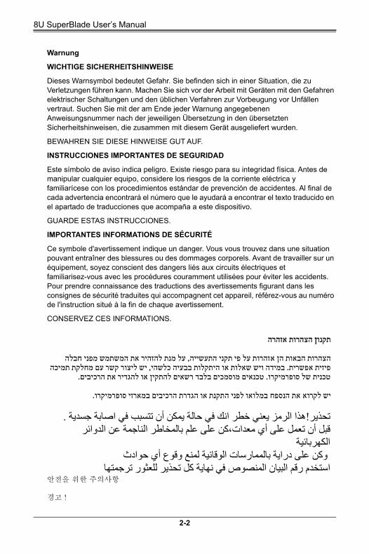
8U SuperBlade Userrsquos Manual
Warnung
WICHTIGE SICHERHEITSHINWEISE
Dieses Warnsymbol bedeutet Gefahr Sie befinden sich in einer Situation die zu Verletzungen fuumlhren kann Machen Sie sich vor der Arbeit mit Geraumlten mit den Gefahren elektrischer Schaltungen und den uumlblichen Verfahren zur Vorbeugung vor Unfaumlllen vertraut Suchen Sie mit der am Ende jeder Warnung angegebenen Anweisungsnummer nach der jeweiligen Uumlbersetzung in den uumlbersetzten Sicherheitshinweisen die zusammen mit diesem Geraumlt ausgeliefert wurden
BEWAHREN SIE DIESE HINWEISE GUT AUF
INSTRUCCIONES IMPORTANTES DE SEGURIDAD
Este siacutembolo de aviso indica peligro Existe riesgo para su integridad fiacutesica Antes de manipular cualquier equipo considere los riesgos de la corriente eleacutectrica y familiariacutecese con los procedimientos estaacutendar de prevencioacuten de accidentes Al final de cada advertencia encontraraacute el nuacutemero que le ayudaraacute a encontrar el texto traducido en el apartado de traducciones que acompantildea a este dispositivo
GUARDE ESTAS INSTRUCCIONES
IMPORTANTES INFORMATIONS DE SEacuteCURITEacute
Ce symbole davertissement indique un danger Vous vous trouvez dans une situation pouvant entraicircner des blessures ou des dommages corporels Avant de travailler sur un eacutequipement soyez conscient des dangers lieacutes aux circuits eacutelectriques et familiarisez-vous avec les proceacutedures couramment utiliseacutees pour eacuteviter les accidents Pour prendre connaissance des traductions des avertissements figurant dans les consignes de seacutecuriteacute traduites qui accompagnent cet appareil reacutefeacuterez-vous au numeacutero de linstruction situeacute agrave la fin de chaque avertissement
CONSERVEZ CES INFORMATIONS
안전을 위한 주의사항
경고
זהרהאהצהרות תקנוןן
חבלה זהרות על פי תקני התעשייה על מנת להזהיר את המשתמש מפני אהצהרות הבאות הן קשר עם מחלקת תמיכה יש ליצורתקלות בבעיה כלשהי יפיזית אפשרית במידה ויש שאלות או ה
רכיבים האת טכנית של סופרמיקרו טכנאים מוסמכים בלבד רשאים להתקין או להגדיר
את הנספח במלואו לפני התקנת או הגדרת הרכיבים במארזי סופרמיקרו יש לקרוא
جسدیة اصابة تتسبب في حالة یمكن أن انك في خطر یعني ھذا الرمز تحذیر الدوائر بالمخاطر الناجمة عن ن على علمكمعدات تعمل على أي قبل أن
الكھربائیةحوادثأي وقوعمنع ل الوقائیة ساتبالممار ن على درایةوك
ترجمتھا للعثور كل تحذیر في نھایة المنصوص البیان استخدم رقم
2-2
Chapter 2 Standardized Warning Statements
이 경고 기호는 위험이 있음을 알려 줍니다 작업자의 신체에 부상을 야기 할 수 있는
상태에 있게 됩니다 모든 장비에 대한 작업을 수행하기 전에 전기회로와 관련된 위험
요소들을 확인하시고 사전에 사고를 방지할 수 있도록 표준 작업절차를 준수해 주시기
바랍니다
해당 번역문을 찾기 위해 각 경고의 마지막 부분에 제공된 경고문 번호를 참조하십시오
BELANGRIJKE VEILIGHEIDSINSTRUCTIES
Dit waarschuwings symbool betekent gevaar U verkeert in een situatie die lichamelijk letsel kan veroorzaken Voordat u aan enige apparatuur gaat werken dient u zich bewust te zijn van de bij een elektrische installatie betrokken risicos en dient u op de hoogte te zijn van de standaard procedures om ongelukken te voorkomen Gebruik de nummers aan het eind van elke waarschuwing om deze te herleiden naar de desbetreffende locatie
BEWAAR DEZE INSTRUCTIES
Installation Instructions
Warning
Read the installation instructions before connecting the system to the power source
設置手順書
システムを電源に接続する前に設置手順書をお読み下さい
警告
将此系统连接电源前 请先阅读安装说明
警告
將系統與電源連接前請先閱讀安裝說明
Warnung
Vor dem Anschlieszligen des Systems an die Stromquelle die Installationsanweisungen lesen
iexclAdvertencia
Lea las instrucciones de instalacioacuten antes de conectar el sistema a la red de alimentacioacuten
Attention
Avant de brancher le systegraveme sur la source dalimentation consulter les directives dinstallation
מתחאת הוראות התקנה לפני חיבור המערכת למקור יש לקרוא
2-3
8U SuperBlade Userrsquos Manual
시스템을 전원에 연결하기 전에 설치 안내를 읽어주십시오
Waarschuwing
Raadpleeg de installatie-instructies voordat u het systeem op de voedingsbron aansluit
Circuit Breaker
Warning
This product relies on the buildings installation for short-circuit (overcurrent) protection Ensure that the protective device is rated not greater than 250 V
20 A
サーキットブレーカー
この製品は短絡(過電流)保護装置がある建物での設置を前提としています
保護装置の定格が 250 V20 A を超えないことを確認下さい
警告
此产品的短路(过载电流)保护由建筑物的供电系统提供确保短路保护设备的额定电流
不大于 250V20A
警告
此產品的短路 ( 過載電流 )保護由建築物的供電系統提供 確保短路保護設備的額定電流不大於 250V20A
Warnung
Dieses Produkt ist darauf angewiesen dass im Gebaumlude ein Kurzschluss- bzw Uumlberstromschutz installiert ist Stellen Sie sicher dass der Nennwert der Schutzvorrichtung nicht mehr als 250 V 20 A betraumlgt
iexclAdvertencia
Este equipo utiliza el sistema de proteccioacuten contra cortocircuitos (o sobrecorrientes) del edificio Aseguacuterese de que el dispositivo de proteccioacuten no sea superior a 250 V 20 A
Attention
Pour ce qui est de la protection contre les courts-circuits (surtension) ce produit deacutepend de linstallation eacutelectrique du local Veacuterifiez que le courant nominal du dispositif de protection nest pas supeacuterieur agrave 250 V 20 A
مصدر للطاقة النظام إلى قبل توصیل تركیباقر إرشادات ال
קצר חשמלי יש לוודא כי המותקנת במבנים למניעת ההגנמוצר זה מסתמך על V 20 A 250-הוא לא יותר מהחשמלי המכשיר המגן מפני הקצר
2-4
Chapter 2 Standardized Warning Statements
경고
이 제품은 전원의 단락 (과전류 )방지에 대해서 전적으로 건물의 관련 설비에 의존합니
다 보호장치의 정격이 반드시 250V( 볼트 ) 20A( 암페어 )를 초과하지 않도록 해야
합니다
Waarschuwing
Dit product is afhankelijk van de kortsluitbeveiliging (overspanning) van uw electrische installatie Controleer of het beveiligde aparaat niet groter gedimensioneerd is dan 220V 20A
Power Disconnection Warning
Warning
The system must be disconnected from all sources of power and the power cord removed from the power supply module(s) before accessing the chassis
interior to install or remove system components
電源切断の警告
システムコンポーネントの取り付けまたは取り外しのためにシャーシー内部にアクセ
スするには
システムの電源はすべてのソースから切断され電源コードは電源モジュールから取り
外す必要があります
警告
在你打开机箱并安装或移除内部器件前 必须将系统完全断电 并移除电源线
警告
在您打開機殼安裝或移除內部元件前必須將系統完全斷電並移除電源線
Warnung
Das System muss von allen Quellen der Energie und vom Netzanschlusskabel getrennt sein das von den SpgVersorgungsteilmodulen entfernt wird bevor es auf den Chassisinnenraum zuruumlckgreift um Systemsbestandteile anzubringen oder zu entfernen
في التي تم تثبیتھا من الدوائرالقصیرة الحمایة معدات یعتمد على ھذا المنتج المبنى
20A 250V أكثر من لیس وقائيال الجھاز تقییم أن تأكد من
2-5
8U SuperBlade Userrsquos Manual
iexclAdvertencia
El sistema debe ser disconnected de todas las fuentes de energiacutea y del cable eleacutectrico quitado de los moacutedulos de fuente de alimentacioacuten antes de tener acceso el interior del chasis para instalar o para quitar componentes de sistema
Attention
Le systegraveme doit ecirctre deacutebrancheacute de toutes les sources de puissance ainsi que de son cordon dalimentation secteur avant dacceacuteder agrave linteacuterieur du chassis pour installer ou enlever des composants de systeacuteme
경고
시스템에 부품들을 장착하거나 제거하기 위해서는 섀시 내부에 접근하기 전에 반드시
전원 공급장치로부터 연결되어있는 모든 전원과 전기코드를 분리해주어야 합니다
Waarschuwing
Voordat u toegang neemt tot het binnenwerk van de behuizing voor het installeren of verwijderen van systeem onderdelen dient u alle spanningsbronnen en alle stroomkabels aangesloten op de voeding(en) van de behuizing te verwijderen
Equipment Installation
Warning
Only trained and qualified personnel should be allowed to install replace or service this equipment
機器の設置
トレーニングを受け認定された人だけがこの装置の設置交換またはサービスを許可されています
警告
只有经过培训且具有资格的人员才能进行此设备的安装更换和维修
警告
只有經過受訓且具資格人員才可安裝更換與維修此設備
אזהרה מפני ניתוק חשמליי
אזהרהאת כבל החשמלי מהספק ויש להסיר יש לנתק את המערכת מכל מקורות החשמל
רכיבים תאו הסר תלפני גישה לחלק הפנימי של המארז לצורך התקנ
امداد وحدة من سلك الكھرباء وإزالة الطاقة مصادرمن جمیع النظام یجب فصل قبل الطاقة
الجھاز مكونات لتثبیت أو إزالة لھیكلل المناطق الداخلیة الوصول إلى
2-6
Chapter 2 Standardized Warning Statements
Warnung
Das Installieren Ersetzen oder Bedienen dieser Ausruumlstung sollte nur geschultem qualifiziertem Personal gestattet werden
iexclAdvertencia
Solamente el personal calificado debe instalar reemplazar o utilizar este equipo
Attention
Il est vivement recommandeacute de confier linstallation le remplacement et la maintenance de ces eacutequipements agrave des personnels qualifieacutes et expeacuterimenteacutes
경고
훈련을 받고 공인된 기술자만이 이 장비의 설치 교체 또는 서비스를 수행할 수 있습니
다
Waarschuwing
Deze apparatuur mag alleen worden geiumlnstalleerd vervangen of hersteld door geschoold en gekwalificeerd personeel
Restricted Area
Warning
This unit is intended for installation in restricted access areas A restricted access area can be accessed only through the use of a special tool lock and
key or other means of security (This warning does not apply to workstations)
アクセス制限区域
このユニットはアクセス制限区域に設置されることを想定しています
アクセス制限区域は特別なツール鍵と錠前その他のセキュリティの手段を用いてのみ出入りが可能です
警告
此部件应安装在限制进出的场所限制进出的场所指只能通过使用特殊工具锁和钥匙或
其它安全手段进出的场所
警告
此裝置僅限安裝於進出管制區域進出管制區域係指僅能以特殊工具鎖頭及鑰匙或其
他安全方式才能進入的區域
אזהרה הציוד או לתת שירות עבור הציוד אי להתקין להחליף אתצוות מוסמך בלבד רש
ھذا الجھاز خدمة أو استبداللتركیب و والمدربین للموظفین المؤھلین فقط یجب أن یسمح
2-7
8U SuperBlade Userrsquos Manual
Warnung
Diese Einheit ist zur Installation in Bereichen mit beschraumlnktem Zutritt vorgesehen Der Zutritt zu derartigen Bereichen ist nur mit einem Spezialwerkzeug Schloss und Schluumlssel oder einer sonstigen Sicherheitsvorkehrung moumlglich
iexclAdvertencia
Esta unidad ha sido disentildeada para instalacioacuten en aacutereas de acceso restringido Soacutelo puede obtenerse acceso a una de estas aacutereas mediante la utilizacioacuten de una herramienta especial cerradura con llave u otro medio de seguridad
Attention
Cet appareil doit ecirctre installeacutee dans des zones daccegraves reacuteserveacutes Laccegraves agrave une zone daccegraves reacuteserveacute nest possible quen utilisant un outil speacutecial un meacutecanisme de verrouillage et une cleacute ou tout autre moyen de seacutecuriteacute
경고
이 장치는 접근이 제한된 구역에 설치하도록 되어있습니다 특수도구 잠금 장치 및 키
또는 기타 보안 수단을 통해서만 접근 제한 구역에 들어갈 수 있습니다
Waarschuwing
Dit apparaat is bedoeld voor installatie in gebieden met een beperkte toegang Toegang tot dergelijke gebieden kunnen alleen verkregen worden door gebruik te maken van speciaal gereedschap slot en sleutel of andere veiligheidsmaatregelen
אזור עם גישה מוגבלתת
אזהרהיש להתקין את היחידה באזורים שיש בהם הגבלת גישה הגישה ניתנת בעזרת
כלי אבטחה בלבד (מפתח מנעול וכד)
تم محظورة مناطق لتركیبھا في ھذه الوحدة تخصیصأداة خاصة من خالل استخدام فقط محظورة منطقة ول إلىیمكن الوص
ألمانوسیلة أخرى لال أي أو قفل ومفتاح
2-8
Chapter 2 Standardized Warning Statements
Battery Handling
Warning
There is the danger of explosion if the battery is replaced incorrectly Replace the battery only with the same or equivalent type recommended by the
manufacturer Dispose of used batteries according to the manufacturers instructions
電池の取り扱い
電池交換が正しく行われなかった場合破裂の危険性があります 交換する電池はメーカーが推奨する型または同等のものを使用下さい 使用済電池は製造元の指示に従って処分して下さい
警告
电池更换不当会有爆炸危险请只使用同类电池或制造商推荐的功能相当的电池更换原有
电池请按制造商的说明处理废旧电池
警告
電池更換不當會有爆炸危險請使用製造商建議之相同或功能相當的電池更換原有電池請按照製造商的說明指示處理廢棄舊電池
Warnung
Bei Einsetzen einer falschen Batterie besteht Explosionsgefahr Ersetzen Sie die Batterie nur durch den gleichen oder vom Hersteller empfohlenen Batterietyp Entsorgen Sie die benutzten Batterien nach den Anweisungen des Herstellers
Attention
Danger dexplosion si la pile nest pas remplaceacutee correctement Ne la remplacer que par une pile de type semblable ou eacutequivalent recommandeacutee par le fabricant Jeter les piles usageacutees conformeacutement aux instructions du fabricant
iexclAdvertencia
Existe peligro de explosioacuten si la bateriacutea se reemplaza de manera incorrecta Reemplazar la bateriacutea exclusivamente con el mismo tipo o el equivalente recomendado por el fabricante Desechar las bateriacuteas gastadas seguacuten las instrucciones del fabricante
경고
אזהרהיש להחליף של הסוללה במידה והוחלפה בדרך לא תקינה פיצוץקיימת סכנת
צתיצרן מומלחברת התואם מ את הסוללה בסוג
לפי הוראות היצרן יש לבצע המשומשות סילוק הסוללותفعلیك بطریقة غیر صحیحة البطاریة انفجار في حالة استبدال من ھناك خطر
استبدال البطاریةبھ الشركة المصنعة أوصتكما أو ما یعادلھا بنفس النوع فقط
تعلیمات الشركة الصانعةالمستعملة وفقا ل تخلص من البطاریات
2-9
8U SuperBlade Userrsquos Manual
배터리가 올바르게 교체되지 않으면 폭발의 위험이 있습니다 기존 배터리와 동일하거
나 제조사에서 권장하는 동등한 종류의 배터리로만 교체해야 합니다 제조사의 안내에
따라 사용된 배터리를 처리하여 주십시오
Waarschuwing
Er is ontploffingsgevaar indien de batterij verkeerd vervangen wordt Vervang de batterij slechts met hetzelfde of een equivalent type die door de fabrikant aanbevolen wordt Gebruikte batterijen dienen overeenkomstig fabrieksvoorschriften afgevoerd te worden
Redundant Power Supplies
Warning
This unit might have more than one power supply connection All connections must be removed to de-energize the unit
冗長電源装置
このユニットは複数の電源装置が接続されている場合があります
ユニットの電源を切るためにはすべての接続を取り外さなければなりません
警告
此部件连接的电源可能不止一个必须将所有电源断开才能停止给该部件供电
警告
此裝置連接的電源可能不只一個必須切斷所有電源才能停止對該裝置的供電
Warnung
Dieses Geraumlt kann mehr als eine Stromzufuhr haben Um sicherzustellen dass der Einheit kein trom zugefuumlhrt wird muumlssen alle Verbindungen entfernt werden
iexclAdvertencia
Puede que esta unidad tenga maacutes de una conexioacuten para fuentes de alimentacioacuten Para cortar por completo el suministro de energiacutea deben desconectarse todas las conexiones
Attention
Cette uniteacute peut avoir plus dune connexion dalimentation Pour supprimer toute tension et tout courant eacutelectrique de luniteacute toutes les connexions dalimentation doivent ecirctre deacutebrancheacutees
אם קיים יותר מספק אחדד
אזהרהכל החיבורים על מנת לרוקן יש להסיר את ליחדה יש יותר מחיבור אחד של ספק
דהיאת היח
2-10
Chapter 2 Standardized Warning Statements
경고
이 장치에는 한 개 이상의 전원 공급 단자가 연결되어 있을 수 있습니다 이 장치에 전
원을 차단하기 위해서는 모든 연결 단자를 제거해야만 합니다
Waarschuwing
Deze eenheid kan meer dan eacuteeacuten stroomtoevoeraansluiting bevatten Alle aansluitingen dienen verwijderd te worden om het apparaat stroomloos te maken
Backplane Voltage
Warning
Hazardous voltage or energy is present on the backplane when the system is operating Use caution when servicing
バックプレーンの電圧
システムの稼働中は危険な電圧または電力がバックプレーン上にかかっています
修理する際には注意ください
警告
当系统正在进行时背板上有很危险的电压或能量进行维修时务必小心
警告
當系統正在進行時背板上有危險的電壓或能量進行維修時務必小心
Warnung
Wenn das System in Betrieb ist treten auf der Ruumlckwandplatine gefaumlhrliche Spannungen oder Energien auf Vorsicht bei der Wartung
iexclAdvertencia
Cuando el sistema estaacute en funcionamiento el voltaje del plano trasero es peligroso Tenga cuidado cuando lo revise
Attention
Lorsque le systegraveme est en fonctionnement des tensions eacutelectriques circulent sur le fond de panier Prendre des preacutecautions lors de la maintenance
امداد الطاقة بوحدات عدة اتصاالت جھازال یكون لھذا قد
الكھرباء عن وحدةال لعزل كافة االتصاالت یجب إزالة
מתח בפנל האחוריי
הרהאזקיימת סכנת מתח בפנל האחורי בזמן תפעול המערכת יש להיזהר במהלך
העבודה
2-11
8U SuperBlade Userrsquos Manual
경고
시스템이 동작 중일 때 후면판 (Backplane) 에는 위험한 전압이나 에너지가 발생 합니
다 서비스 작업 시 주의하십시오
Waarschuwing
Een gevaarlijke spanning of energie is aanwezig op de backplane wanneer het systeem in gebruik is Voorzichtigheid is geboden tijdens het onderhoud
Comply with Local and National Electrical Codes
Warning
Installation of the equipment must comply with local and national electrical codes
地方および国の電気規格に準拠
機器の取り付けはその地方および国の電気規格に準拠する必要があります
警告
设备安装必须符合本地与本国电气法规
警告
設備安裝必須符合本地與本國電氣法規
Warnung
Die Installation der Geraumlte muss den Sicherheitsstandards entsprechen
iexclAdvertencia
La instalacion del equipo debe cumplir con las normas de electricidad locales y nacionales
Attention
Leacutequipement doit ecirctre installeacute conformeacutement aux normes eacutelectriques nationales et locales
اللوحة أوالطاقة الموجودة على التیار الكھربائي من خطر ھناك
ھذا الجھاز خدمة كن حذرا عند یعمل النظامعندما یكون
תיאום חוקי החשמל הארצי
אזהרההציוד חייבת להיות תואמת לחוקי החשמל המקומיים והארציים התקנת
المتعلقة المحلیة والوطنیةقوانین یجب أن یمتثل لل الكھربائیة تركیب المعدات بالكھرباء
2-12
Chapter 2 Standardized Warning Statements
경고
현 지역 및 국가의 전기 규정에 따라 장비를 설치해야 합니다
Waarschuwing
Bij installatie van de apparatuur moet worden voldaan aan de lokale en nationale elektriciteitsvoorschriften
Product Disposal
Warning
Ultimate disposal of this product should be handled according to all national laws and regulations
製品の廃棄
この製品を廃棄処分する場合国の関係する全ての法律条例に従い処理する必要があります
警告
本产品的废弃处理应根据所有国家的法律和规章进行
警告
本產品的廢棄處理應根據所有國家的法律和規章進行
Warnung
Die Entsorgung dieses Produkts sollte gemaumlszlig allen Bestimmungen und Gesetzen des Landes erfolgen
iexclAdvertencia
Al deshacerse por completo de este producto debe seguir todas las leyes y reglamentos nacionales
Attention
La mise au rebut ou le recyclage de ce produit sont geacuteneacuteralement soumis agrave des lois etou directives de respect de lenvironnement Renseignez-vous aupregraves de lorganisme compeacutetent
סילוק המוצרר
אזהרהחוקי המדינהסילוק סופי של מוצר זה חייב להיות בהתאם להנחיות ו
القوانین واللوائح الوطنیةجمیع وفقا ل ینبغي التعامل معھ ھذا المنتج من التخلص النھائي عند
2-13
8U SuperBlade Userrsquos Manual
경고
이 제품은 해당 국가의 관련 법규 및 규정에 따라 폐기되어야 합니다
Waarschuwing
De uiteindelijke verwijdering van dit product dient te geschieden in overeenstemming met alle nationale wetten en reglementen
Hot Swap Fan Warning
Warning
The fans might still be turning when you remove the fan assembly from the chassis Keep fingers screwdrivers and other objects away from the
openings in the fan assemblys housing
ファンホットスワップの警告
シャーシから冷却ファン装置を取り外した際ファンがまだ回転している可能性があります ファンの開口部に指ドライバーおよびその他のものを近づけないで下さい
警告
当您从机架移除风扇装置风扇可能仍在转动小心不要将手指螺丝起子和其他物品太
靠近风扇
警告
當您從機架移除風扇裝置風扇可能仍在轉動小心不要將手指螺絲起子和其他物品太靠近風扇
Warnung
Die Luumlfter drehen sich u U noch wenn die Luumlfterbaugruppe aus dem Chassis genommen wird Halten Sie Finger Schraubendreher und andere Gegenstaumlnde von den Oumlffnungen des Luumlftergehaumluses entfernt
iexclAdvertencia
Los ventiladores podran dar vuelta cuando usted quite ell montaje del ventilador del chasis Mandtenga los dedos los destornilladores y todos los objetos lejos de las aberturas del ventilador
Attention
Il est possible que les ventilateurs soient toujours en rotation lorsque vous retirerez le bloc ventilateur du chacircssis Prenez garde agrave ce que doigts tournevis et autres objets soient eacuteloigneacutes du logement du bloc ventilateur
אזהרההמאוורר מהמארז יתכן והמאווררים עדיין עובדים יש כאשר מסירים את חלקי
מרחק בטוח את האצבעות וכלי עבודה שונים מהפתחים בתוך המאווררללהרחיק
2-14
Chapter 2 Standardized Warning Statements
경고
섀시로부터 팬 조립품을 제거할 때 팬은 여전히 회전하고 있을 수 있습니다 팬 조림품
외관의 열려있는 부분들로부터 손가락 및 스크류드라이버 다른 물체들이 가까이 하지
않도록 배치해 주십시오
Waarschuwing
Het is mogelijk dat de ventilator nog draait tijdens het verwijderen van het ventilatorsamenstel uit het chassis Houd uw vingers schroevendraaiers en eventuele andere voorwerpen uit de buurt van de openingen in de ventilatorbehuizing
Power Cable and AC Adapter
Warning
When installing the product use the provided or designated connection cables power cables and AC adaptors Using any other cables and adaptors
could cause a malfunction or a fire Electrical Appliance and Material Safety Law prohibits the use of UL or CSA -certified cables (that have ULCSA shown on the code) for any other electrical devices than products designated by Supermicro only
電源コードと ACアダプター
製品を設置する場合提供または指定された接続ケーブル電源コードと ACアダプターを使用下さい 他のケーブルやアダプタを使用すると故障や火災の原因になることがあります 電気用品安全法はULまたは CSA 認定のケーブル (ULCSE マークがコードに表記 ) を Supermicro が指定する製品以外に使用することを禁止しています
警告
安装此产品时请使用本身提供的或指定的连接线电源线和电源适配器使用其它线材或
适配器可能会引起故障或火灾除了 Supermicro 所指定的产品 电气用品和材料安全法
律规定禁止使用未经 UL 或 CSA 认证的线材( 线材上会显示 ULCSA 符号 )
警告
安裝此產品時 請使用本身提供的或指定的連接線 電源線和電源適配器 使用其它線材或適配器可能會引起故障或火災除了 Supermicro 所指定的產品 電氣用品和材料安
全法律規定禁止使用未經 UL 或 CSA 認證的線材( 線材上會顯示 ULCSA 符號 )
إبقاء یجب من الھیكل المروحة كتلة تدورعند إزالة ال تزال أن المراوح من الممكنمفكات البراغيو األصابع
المروحة كتلة في الفتحات عن بعیدا وغیرھا من األشیاء
2-15
8U SuperBlade Userrsquos Manual
Warnung
Bei der Installation des Produkts die zur Verfuumlgung gestellten oder benannt Anschlusskabel Stromkabel und Netzteile Verwendung anderer Kabel und Adapter kann zu einer Fehlfunktion oder ein Brand entstehen Elektrische Geraumlte und Material Safety Law verbietet die Verwendung von UL-oder CSA-zertifizierte Kabel UL oder CSA auf der Code fuumlr alle anderen elektrischen Geraumlte als Produkte von Supermicro nur bezeichnet gezeigt haben
iexclAdvertencia
Al instalar el producto utilice los cables de conexioacuten previstos o designados los cables y adaptadores de CA La utilizacioacuten de otros cables y adaptadores podriacutea ocasionar un mal funcionamiento o un incendio Aparatos Eleacutectricos y la Ley de Seguridad del Material prohiacutebe el uso de UL o CSA cables certificados que tienen UL o CSA se muestra en el coacutedigo de otros dispositivos eleacutectricos que los productos designados por Supermicro solamente
Attention
Lors de linstallation du produit utilisez les bables de connection fournis ou deacutesigneacute Lutilisation dautres cables et adaptateurs peut provoquer un dysfonctionnement ou un incendie Appareils eacutelectromeacutenagers et de loi sur la seacutecuriteacute Mateacuteriel interdit lutilisation de UL ou CSA cacircbles certifieacutes qui ont UL ou CSA indiqueacute sur le code pour tous les autres appareils eacutelectriques que les produits deacutesigneacutes par Supermicro seulement
ACי מחשמליים ומתאא
אזהרהאשר ACכאשר מתקינים את המוצר יש להשתמש בכבלים ספקים ומתאמים
נועדו וסופקו לשם כך שימוש בכל כבל או מתאם אחר יכול לגרום לתקלה או יחות קיים איסור קצר חשמלי על פי חוקי שימוש במכשירי חשמל וחוקי בט
(כשאר מופיע עליהם קוד של CSA -או ב UL -להשתמש בכבלים המוסמכים בULCSA( שלא צוין על ידי סופרקמיקרו בלבדעבור כל מוצר חשמלי אחר
الكابالت الكھربائیة كابالت التوصیلو الجھاز یجب استخدام عند تركیبالتیار المتردد ومحوالت
أو حریق حدوث عطل في یتسبب أخرى ومحوالت كابالت استخدام أي أن التيمع المنتج تم توفیرھا لك
UL أو CSA الكابالت یحظر استخدام السالمة قانون ومواد األجھزة الكھربائیة معتمدة من قبل
Supermicro ألي من قبل المعینة المنتجات غیر كھربائیة أخرى أجھزة
(ULCSA عالمةالتي تحمل )
2-16
Chapter 2 Standardized Warning Statements
경고
제품을 설치할 때에는 제공되거나 지정된 연결케이블과 전원케이블 AC 어댑터를 사용
해야 합니다 그 밖의 다른 케이블들이나 어댑터들은 고장 또는 화재의 원인이 될 수 있
습니다 전기용품안전법 (Electrical Appliance and Material Safety Law) 은 슈퍼마
이크로에서 지정한 제품들 외에는 그 밖의 다른 전기 장치들을 위한 UL또는 CSA에서
인증한 케이블 (전선 위에 ULCSA가 표시 )들의 사용을 금지합니다
Waarschuwing
Bij het installeren van het product gebruik de meegeleverde of aangewezen kabels stroomkabels en adapters Het gebruik van andere kabels en adapters kan leiden tot een storing of een brand Elektrisch apparaat en veiligheidsinformatiebladen wet verbiedt het gebruik van UL of CSA gecertificeerde kabels die UL of CSA die op de code voor andere elektrische apparaten dan de producten die door Supermicro alleen
2-17
8U SuperBlade Userrsquos Manual
Notes
2-18
Chapter 3 Setup and Installation
Chapter 3Setup and Installation
3-1 OverviewThis chapter provides a quick setup procedure for your 8U SuperBlade Following these steps in the order given should enable you to have the system operational within a minimum amount of time This quick setup assumes that the processor(s) and memory have already been installed If not please turn to Chapter 4 for details on installing specific components
3-2 Unpacking the SystemYou should inspect the box the 8U SuperBlade was shipped in and note if it was damaged in any way If the server itself shows damage you should file a damage claim with the carrier who delivered it
Decide on a suitable location for the rack unit that will hold the 8U SuperBlade It should be situated in a clean dust-free area that is well ventilated Avoid areas where heat electrical noise and electromagnetic fields are generated You will also need it placed near a grounded power outlet Read the Rack Precautions and Server Precautions in the next section
The box the 8U SuperBlade was shipped in should include two sets of rail assemblies two handles and the mounting screws you will need to install the system into the rack Follow the steps in the order given to complete the installation process in a minimum amount of time Please read this section in its entirety before you begin the installation procedure outlined in the sections that follow
Choosing a Setup Location
The following are important considerations for choosing a setup location
bull Leave enough clearance in front of the rack to enable you to remove the blade units (~25 inches)
bull Leave approximately 30 inches of clearance behind or to the rear of the rack to allow for sufficient airflow and ease in servicing as well as clearance for electrical power connections
bull This product is intended for installation only in a Restricted Access Location (dedicated equipment rooms service closets and the like) This is because the 8U SuperBlade enclosure does not provide any physical security measures
bull This product is not suitable for use with visual display work place devices according to sect2 of the German Ordinance for Work with Visual Display Units
WARNING Please read the following important Warnings and Precautions
3-1
8U SuperBlade Userrsquos Manual
Rack Precautions
The following are important precautions concerning rack setup
bull The enclosure unit is heavy and requires at least two people to lift it
bull Ensure that the leveling jacks on the bottom of the rack are fully extended to the floor with the full weight of the rack resting on them
bull In single rack installation stabilizers should be attached to the rack
bull In multiple rack installations the racks frames should be grounded to the same earth ground as the electrical source for the power supplies by means of a grounding strap
Server Precautions
The following are important precautions concerning server setup
bull Review the electrical and general safety precautions in Chapter 2
bull Determine the placement of each component in the rack before you install the rails
bull Install the heaviest server components on the bottom of the rack first and then work up
bull Use a regulating uninterrupted power supply (UPS) to protect the server from power surges voltage spikes and to keep your system operating in case of a power failure
bull Allow the hot plug hard drives and power supply units to cool before touching them
bull Always keep the racks front door and all panels and components on the servers closed when not servicing to maintain proper cooling
Rack Mounting Considerations
Below are listed important considerations for rack mounting
Ambient Operating Temperature
If installed in a closed or multi-unit rack assembly the ambient operating temperature of the rack environment may be greater than the ambient temperature of the room Therefore consideration should be given to installing the equipment in an environment compatible with the manufacturerrsquos maximum rated ambient temperature Refer to Appendix E for operating temperature specifications
Reduced Airflow
Equipment should be mounted into a rack so that the amount of airflow required for safe operation is not compromised
Mechanical Loading
Equipment should be mounted into a rack so that a hazardous condition does not arise due to uneven mechanical loading
3-2
Chapter 3 Setup and Installation
Circuit Overloading
Consideration should be given to the connection of the equipment to the power supply circuitry and the effect that any possible overloading of circuits might have on over-current protection and power supply wiring Appropriate consideration of equipment nameplate ratings should be used when addressing this concern See the power calculation tables in Appendix A
Reliable Ground
A reliable ground must be maintained at all times To ensure this the rack itself should be grounded Particular attention should be given to power supply connections other than the direct connections to the branch circuit (such as the use of power strips and so on)
NOTE It is recommended that you seek the advice and assistance of a licensed electrician that can advise you on best practices for ensuring that the electrical supply and the rack are joined to a Common Bonding Network
Professional documents on grounding techniques include
bull ANSITIA-942 ndash Telecommunications Infrastructure Standard for Data Centers
bull J-STD-607-A-2002 ndash Commercial Building Grounding (Earthing) and Bonding Requirements for Telecommunications
bull IEEE Std 1100trade-2005 (IEEE Emerald Book) ndash IEEE Recommended Practice for Powering and Grounding Electronic Equipment
Installing the System Into a Rack
This section provides information on installing the 8U SuperBlade into a rack There are a variety of rack units on the market meaning the procedure may differ slightly Refer to the Enclosure Template that was included with the system for help
Rack Mounting Hardware
The following is a list of rack mounting hardware you will need for rack setup and installation
bull Two rail assemblies (one for each side of the enclosure)
bull Two handles
bull Four roundhead screws for fastening the enclosure ears to the rack
bull Eight flathead screws and washers for mounting the rails to the rack
3-3
8U SuperBlade Userrsquos Manual
Installation
Use the procedure below for installing an enclosure in a rack
Installing an enclosure
1 Decide where you want to place the blade enclosure into the rack (see Rack Mounting Considerations in the previous section)
2 Position the Enclosure Template at the front of the enclosure to determine the locations of the screws for the enclosure rails (see Figure 3-1)
Figure 3-1 Positioning the Enclosure Template
3 The two enclosure rail sections are screwed together to keep them immobile during shipping Release these screws just enough to allow the rails to slide apart Note the arrow on the rail which indicates the end that attaches to the front of the rack
4 Slide the rails apart far enough to match the depth of the rack Position the rails with the template and secure the front of each to the front of the rack with two flathead screws then secure the back of each rail to the rear of the rack with two flathead screws (see Figure 3-2) Note that the rails are leftright specific and very heavy
Figure 3-2 Securing the Rails to the Rack
5 (Optional step) Add the front left and right handles to the enclosure using five screws to secure each handle Install a thumbscrew through the bottom hole of each handle (see Figure 3-4)
3-4
Chapter 3 Setup and Installation
NOTE These handles are optional and need only be installed when mounting the system into a short rack When mounting into a deep rack they are unnecessary and regular screws should be used instead of thumbscrews
Be aware that these handles are not to be used for lifting the system they are only to be used to slide the system within the rack
6 With one person on either side (see the descriptive label on the side of the enclosure) lift the enclosure and slide it into the installed rails
WARNING Be sure that the enclosure is empty of all blades power supplies switches and management modules BEFORE lifting These should be installed AFTER the enclosure is mounted in the rack Injury and damage may occur if components are not removed from the rack prior to installation
7 After pushing the enclosure all the way into the rack use two roundhead screws on each side of the server to lock it into place
Figure 3-4 Attaching the Optional Handles
Figure 3-3 Sliding the Enclosure into the Rack
810 Enclosure 820 Enclosure
3-5
8U SuperBlade Userrsquos Manual
8 The enclosure is now securely installed in the rack (see Figure 3-5)
Figure 3-5 Enclosure Installed into Rack
3-6
Chapter 4 System Modules
Chapter 4System Modules
In addition to the blade units your blade system comes equipped with one or more system modules The modules fit into the rear of the enclosure into bays above andor below the power supplies This chapter describes the various blade modules that may be part of your blade system Module configurations can be customized you can install two of the same type module for redundancy purposes or you may omit a module altogether (except for the CMM which is a required module) Figure 4-1 shows a typical module configuration in a blade system See Chapter 5 for information on power supply modules
WARNING All module bays must be populated either with a module or a dummy module cover to maintain proper airflow
Figure 4-1 8U 820C Enclosure with 100G Switch Rear View
1 1
3
2
4 44
5 5 5 5
5555
4-1
8U SuperBlade Userrsquos Manual
Figure 4-2 8U 820J Enclosure with 2x25Gand 2x10G Switches Rear View
NOTE When setting up a bay the single wide bay is for 10G25G switches while the triple wide bay uses 100G switches for the 8U SuperBlade system
Table 4-1 Typical 8U Blade System Module Configuration Rear View
Item Description
1These bays can hold any of the following 1Gb Ethernet Switch Module or a 10Gb Ethernet Switch Module
2 CMM (Chassis Management Module) (x1 standard or x2 optional per enclosure)
3 These bays can hold a 25G Ethernet Switch
4 Dual System Fan Modules
5 2200W Power Supplies (x4 required x4 optional depending upon system requirements)
3 32
4 44
5 5 5 5
5555
2 11
4-2
Chapter 4 System Modules
Figure 4-3 8U 820L Enclosure with 2x10G Switches Rear View
Table 4-2 Typical 8U Blade System Module Configuration Rear View
Item Description
1These bays can hold any of the following 1Gb Ethernet Switch Module or a 10Gb Ethernet Switch Module
2 CMM (Chassis Management Module) (x1 standard or x2 optional per enclosure)
3 Dual System Fan Modules
4 2200W Power Supplies (x4 required x4 optional depending upon system requirements)
3 33
4 4 4 4
4444
2 11
4-3
8U SuperBlade Userrsquos Manual
4-1 Chassis Management ModuleThe Chassis Management Module (CMM) (Figure 4-4) is a required module in a blade system This ldquocommandrdquo module communicates with the blade units the power supplies and the blade switches Used in conjunction with the Web Interface or IPMI View management software the CMM provides administrator control over individual blade units power supplies cooling fans and networking switches and monitors onboard temperatures power status voltage levels and fan speeds The standard CMM module for the 8U SuperBlade system is the MBM-CMM-FIO or MBM-CMM-001
NOTE Using the MBM-CMM-FIO in the enclosure allows the use of the two front mounted RJ45 ports on the enclosure however using the MBM-CMM-001 does not allow these ports to function
The CMM provides a dedicated local and remote KVM (keyboardvideomouse) connection over an out of band TCPIP Ethernet network during any server state (functioning blue-screen powered down BIOS and so on) It also supports Virtual Media (VM) redirection for CD floppy and USB mass storage devices and configures such information as the switch IP addresses A summary of CMM features is shown in Table 4-4
Figure 4-4 Chassis Management Module MBM-CMM-FIO
Table 4-3 MBM-CMM-FIO Module Interface
Item Description
1 Power LED
2 Fault LED
3 Information LED
4 USB Ports
5 IPMI Port
6 Ethernet Ports
7 Reset Button
8 Module Release Handle
2
3
1
7 4 6
5
4-4
Chapter 4 System Modules
Figure 4-5 Chassis Management Module MBM-CMM-001
Table 4-4 MBM-CMM-FIO Module Features
Feature Description
Management Capabilities Can manage 10 to 20 blade units network modules and 8 power supplies
PortsTwo Ethernet ports one IPMI Ethernet port and two USB ports (for debug only)
Basic Functions SupportedRemote KVM remote storage Serial-over-LAN (SOL) blade monitoring and control
System Management System management interface provided via dedicated LAN
Power Consumption Approximately 20W
Operating System Firmware (upgradable)
Table 4-5 MBM-CMM-001 Module Interface
Item Description
1 Power LED
2 Fault LED
3 Information LED
4 USB Ports
5 Ethernet Ports
6 Serial Port
7 Reset Button
8 Module Release Handle
2
3
1
7 4 5
8
6
4-5
8U SuperBlade Userrsquos Manual
Module Redundancy
A blade system must have one CMM and may have two for redundancy is offered only on a specific enclosure model which has the hardware capability to incorporate two CMMs on one backplane Since the CMM uses its own processor all monitoring and control functions are carried out regardless of the operation or power status of the blade units CMM modules can only be installed in the upper andor lower right module bays
Determining MasterSlave Modules Status
When a blade system has two CMM modules they are assigned a masterslave status This is done automatically with the default primary CMM specified for per each enclosure while there will be no redundant in certain enclosures
If the master CMM is powered down or removed (or is being reset by its user) the second (slave) CMM module will then immediately be assigned as the master The redundant CMM mode is only offered on specific chassis models The slave uses the previous master IP config in case of a fail over
NOTE The Slave CMM keeps the same logstatus as the Master CMM and uses the previous master IP config
CMM Module Installation
Use this procedure to install the MBM-CMM-FIO or MBM-CMM-001 CMM module to the 8U SuperBlade chassis Make sure the cover to the module has been installed before proceeding Follow the anti-static precautions described in Chapter 2
Installing the Module
1 Remove the dummy cover from the bay you want to place the module in
2 Place the modules release handle in the open position
3 Slide the module into the module bay until it stops
4 Push the release handle to the closed position
Table 4-6 MBM-CMM-001 Module Features
Feature Description
Management Capabilities Can manage 10 to 20 blade units network modules and 8 power supplies
Ports Two Ethernet ports one serial port and two USB ports (for debug only)
Basic Functions SupportedRemote KVM remote storage Serial-over-LAN (SOL) blade monitoring and control switch PWS monitor thermal redundant based on specific enclosure model
System ManagementSystem management interface provided via dedicated LAN switch PWS monitor thermal and is redundant based on the specific enclosure model
Power Consumption Approximately 20W
Operating System Firmware (upgradeable)
4-6
Chapter 4 System Modules
5 After the module has been installed and the handle locked it will turn on and a POST test will run to verify it is working properly
Removing the Module
1 Pull out the release handle to the open position
2 Pull the module out of the bay
3 Replace immediately with another module or with a dummy module cover to maintain airflow integrity
Configuring the CMM
To accessconfigure the CMM you first have to configure the IP settings of the CMM depending on you network environment The below procedure for this configuration just serves as a reference for getting the CMM setup If your system has Linux OS please follow similar instructions to get the CMM setup
The CMM access topology is as follows
DHCP Access
1 Connect a network cable to the CMM module
2 The system should boot into the default Fail Over mode The DHCP mode will appear on the CLI mode screen
3 If the system fail over and CLI is not active it will proceed to the next default IP of CMM at https192168100100
4 If the CMM cannot enter the default IP then an RJ45USB cable can be connected from the CMMs RJ45 Ethernet LAN Port to the Desktop Host using the USB Port in Serial Port mode with a speed set at 115200 The DHCP IP can be manually set at the same subnet-mask for gateway access at 19216810010001
Default IP Access
1 Connect network cable to the network port at CMM
2 At system Prompt https192168100100
Requirements are
bull Computer system with LAN (RJ45) port
bull RJ -45 Ethernet cable
The default IP of the CMM is https192168100100 Configure the Computer system (connected through Ethernet-LAN to the CMM) to the same address range (for example https192168100101) The default mode is the Fail Over mode If the DHCP fails then the CMM will automatically default to the IP address of the CMM
Configuring the CMM in Windows OS
1 Go to START CONTROL PANEL NETWORK CONNECTIONS
2 Right-click on LAN to view properties
4-7
8U SuperBlade Userrsquos Manual
3 Choose ldquoInternet Protocol (TCPIP)rdquo under the GENERAL tab and click on PROPERTIES (see Figure 4-6)
4 Manually configure the IP address of the computer system to be in the same address range as the CMM (see Figure 4-7)
Example
bull IP address https192168100101
bull Subnet Mask 2552552550
bull Default Gateway 1921681001
5 Once the IP address for the computer system is configured the CMM can be accessed through the web browser by entering the default IP address 192168100100 of the CMM into the browserrsquos address bar
Figure 4-6 Choose Internal Protocol
Figure 4-7 Manually Configure the IP Address
4-8
Chapter 4 System Modules
6 Now the IP address subnet mask and default gateway of the CMM can be changed according to the network environment (see Figure 4-8) Please refer to the Web-based Management Utility Userrsquos Manual for more information
WARNING Dont change any other setting unless you are familiar with it
NOTE The above screens are examples for purposes of demonstrating this procedure The screens you actually view may or may not appear the same as those shown above
CMM Functions
The following sections describe local functions and remote functions of the CMM With only minor exceptions all of the remote functions can be performed by one of three mechanisms web-based access to the CMM module access to the CMM using IPMIview a client tool implemented in Java or via IPMItool commands (DOS commands or shell scripted commands)
When the web based browser is used the CMM acts as a web server requiring a higher bandwidth connection to the CMM If there are any bandwidth constraints IPMI will provide a superior experience Additionally since graphical updates are provided by client-side Java IPMIview can also be a superior user experience
IPMItool on the other hand can provide the ability to issue similaridentical commands to many 8U SuperBlade enclosuresCMMrsquos to manage all of them in a similar way
Figure 4-8 Changing Settings
4-9
8U SuperBlade Userrsquos Manual
Remote KVM over IP
Remote KVM over IP is independent from local KVM (although local KVM can operate in parallel with Remote KVM) Remote KVM encrypts all communication between the remote user and the CMM
To Use Remote KVM over IP is initiated with the management software (IPMI View or Web-based utility) Attach the LAN cable to the LAN port on the CMM module then refer to Web-based Management Utility on page 4-12 to login and use either utility
Remote Storage (Virtual Media)
The Remote Storage function allows the user to connect to a remote storage device (such as a floppy hard disk or USB storage device) and access the device as if it were local This can be used not only to read and write to remote storage devices but to load an operating system from a remote drive
Serial Over LAN (SOL)
Serial Over LAN allows you to redirect the input and output of a serial port via IPMI in order to manage blade modules from a remote location
To Use Serial Over LAN can be activated via the Web-based Management utility See the Web-based Management Utility Userrsquos Manual for the procedure to initiate SOL
Monitoring Functions
Used in conjunction with IPMI or the Web-based Management utility the CMM module can monitor and provide information on the hardware health of the blade modules and the system as a whole In addition to the monitoring functions you can remotely power on power off or reboot a system
Health information includes
bull Temperature levels
bull Fan speeds
bull Voltage levels
bull Power status
Power Consumption Management
The CMM modulersquos firmware can also control all power onoff activity in the whole blade system This is done by using the Power button onboard BMC or from any other use of remote management software
Once a blade module is installed in the enclosure the installed CMM immediately receives information on the rated Max Power Consumption value of the new blade module The CMM then calculates whether there is enough power for this new blade module by comparing the Max Power Consumption value of the new blade module with the calculated Remaining Power value of the system
4-10
Chapter 4 System Modules
If there is enough power the CMM will power on the blade However if there is not enough power in the blade system then the new blade module is not powered on and the front panel LED on the enclosure will blink
After the blade is powered on the CMM then collects the actual power consumption of this individual blade and updates the calculated Remaining Power value for the system
The CMM also reserves power for all the networking and chassis management modules installed on the system
WARNING One CMM module must be running to control the power systems and prevent overloading
USB Ports and Reset Button
The USB Ports and Reset Button on the CMM are described below
Figure 4-9 USB Ports on CMM
USB PortsMBM-CMM-FIO Reset Button
USB PortsMBM-CMM-001 Reset Button
4-11
8U SuperBlade Userrsquos Manual
USB Ports
The USB ports on both CMM modules are shown in Figure 4-9 They are only used for debugging purposes and not for communication with your system
Reset Button
The Reset button located on the front of the CMM module is used to reset the following software settings to their defaults
To reset the CMM to factory defaults press and hold the Reset button for five seconds
Firmware
The firmware for the CMM switch resides in the module This firmware can be updated with the web-based management utility
Within the utility go to the MAINTENANCE gt UPDATE FIRMWARE screen in the Web-based Management Utility Here you can enter the name of the firmware you want to update or click on BROWSE to select the firmware file Finish by clicking the UPLOAD button
NOTE This process is not reversible once the firmware is updated so proceed with caution It might take a few minutes to complete this procedure
Web-based Management Utility
System management may be performed with either of three software packages IPMIview SMCIPMItool or a Web-based Management Utility Any of these utilities are designed to provide an administrator with a comprehensive set of functions and monitored data to keep tabs on the system and perform management activities
The Web-based Management Utility is a web-based interface that consolidates and simplifies system management for Supermicro 8U SuperBlade systems The Web-based Management Utility aggregates and displays data from the CMM module
The Web-based Management Utility provides the following key management features
bull Enables IT administrators to view in-depth hardware configuration and status information using a single intuitive interface
bull Provides an OS-independent remote graphical console
Table 4-7 CMM Reset Settings
Software Setting Default
User Name and Password Reset to ADMIN and ADMIN (case sensitive)
IP Address Reset to https192168100100
Gateway Address Reset to 0000
Subnet Mask Reset to 2552552550
4-12
Chapter 4 System Modules
bull Allows remote users to map local media (floppy removable disks and hard drives) or ISO images on a shared network drive to a blade server
Supported Browsers
The following browsers have been tested for use with the Web-based Management Utility It is recommended that you use the most current revision of the browser you choose The minimum browser revisions supported by the Web-based Management Utility are shown below
bull Internet Explorer 7
bull Firefox 2007
bull Netscape 903b
Network ConnectionLogin
To log into the Web-based Management Utility
1 Launch a web browser
2 In the address field of the browser enter the IP address that you assigned to the system and hit the ltENTERgt key
3 When the browser makes contact with Supermicrorsquos Chassis Management Module enter your username and password then click LOGIN
4 The WEB-BASED MANAGEMENT UTILITY HOME PAGE will then display as shown in Figure 4-10
Address Defaults
Table 4-8 shows the default addresses that are initially set for the CMM Afterwards you can change these values within the program (see the Web-based Management Utility Userrsquos Manual M for more details)
Table 4-8 Address Defaults
Default Description
Default IP Address https192168100100a
a Note The web address must be entered as https192168100100 in the web browser Entering only http gives you instead an address error
Default Gateway Address 0000
Default Subnet Mask 2552552550
Default username ADMIN
Default password ADMIN
4-13
8U SuperBlade Userrsquos Manual
Home Page
Figure 4-10 displays the WEB-BASED MANAGEMENT UTILITY HOME PAGE and its controls
Figure 4-10 Home Page
NOTE For more information on the Web-based Management Utility and a description of its controls see the Superblade Web-based Management Utility Userrsquos Manual for more details
4-14
Chapter 5 Power Supply Modules
Chapter 5Power Supply Modules
The 8U SuperBlade enclosure comes standard with one CMM module (see the Chapter 4 for details on the CMM module) and either two or four power supplies See Appendix A for summary specification details on the power supplies available to the 8U SuperBlade enclosure
5-1 Power Supply ModulesThe minimum amount of modules required to power the system depends upon the full complement of blade units installed into an enclosure and the type of switches installed in the enclosure An LED on the back of a power supply will be green when AC power is present and amber color when it fails
When installing only a few power supplies in the enclosure they should be installed first in the lower rather than the upper power bays This is to provide increased airflow across the memory modules within each blade module
The 2200W power supply modules require a 100-240V AC input and a C14 socket which requires a power cord with a C13 connector
Supermicros high-efficiency blade system power supplies deliver continuous redundant power up to 96 peak efficiency Each power supply module includes a management module that monitors the power supplies and the power enclosure
The features of these power supplies are shown below
Table 5-1 Amperage Draw Specifications for the PWS-2K21A-BR Power Supply
Watts Low Volts High Volts Low Amps High Amps
1200W 100 127 11 14
1980W 220 230 98 10
2090W 230 240 98 10
1800W 200 220 95 10
2200W (ULcUL only) 220 240 11 12
2090W (ULcUL only) 180 220 11 14
5-1
8U SuperBlade Userrsquos Manual
Figure 5-1 PWS-2K21A-BR Power Supply
Table 5-2 PWS-2K21A-BR Power Supply Features
Feature Description
Output 2200W2090W1980W1800W1200W
Type Redundant Module (N+1N+N)
+12V18333A (2200W) 17417A (2090W) 165A (1980W) 150A (1800W) or 100A (1200W)
+12VSB 2A
PFC Yes
Peak Efficiency 96+ (Titanium Level)
Input AC Range100-127V (1200W) 200-220V (1800W) 220-230V (1980W) 230-240V (2090W) 200-220V (2090W for UL amp cUL) or 220-240V (2200W for UL amp cUL)
Operating ConditionsTemp 0 to 50 C
Humidity 5 to 95 RH
Fan Type 80x80mm counter rotating fan
Dimensions (LxWxH) 2453 x 1065 x 84mm
5-2
Chapter 5 Power Supply Modules
BPP Batteries
BBP Batteries like all rechargeable batteries are consumable components that eventually their capacity and performance decline as they age Regular maintenance by charge and discharge cycles is recommended to maintain the effectiveness of the BBP batteries At least one charge and discharge cycle for every 30 days is recommended The BBP maintenance scheduler can be enabled and configured through the CMM
When the BBP function is disabled through the CMM the battery will discharge until the minimum energy state is reached While the battery function is disabled regular BBP maintenance cannot be performed since the battery energy remains at the lowest state and will not re-charge As a result the battery capacity and performance will decline at a faster pace andor cause the battery to no longer operate The battery will remain the minimum charge until the BBP function is again re-enabled through CMM The user should use the disabling BBP function with caution knowing that the possible outcome of degraded battery performance or not operational battery
Figure 5-2 PWS-1K20B-BR Battery Backup Power (BPP) Module
5-3
8U SuperBlade Userrsquos Manual
Under typical conditions the above is the estimated runtime for the BPP modules The runtime can be extended by adding additional BPP modules to a system
Table 5-3 PWS-1K20B-BR Battery Backup Power (BPP) Module Specifications
Feature Description
Total Output Power 1200W
Input 112 to 129VDC
Output 12V 12VSB
Form Factor MicroBlade
Dimensions 2453 x 1065 x 84-mm
Battery Cell Capacity 68Whr
Redundant N+1 N+N
I2C Remote Monitoring FRUSmart Battery I2C
+12V Output 100A
12VSB Output 25A
Efficiency Online mode battery power consumption less than 5W
Discharge Duration 1200W for 35 Seconds
Cell Chemistry Lithium-Ion
Cooling Internal 80 x 80-mm colling fan
Operating Temperature 5degC - 50degC
Table 5-4 PWS-1K20B-BR BPP Module Estimated Runtime
Power Load Installed BPP Modules Discharge Duration
1000W 4 180 Seconds
2000W 4 120 Seconds
3000W 4 60 Seconds
4000W 4 35 Seconds
4800W 4 35 Seconds
Table 5-5 Chassis Compatible with the BPP
Model Output Power Capacity SBE-820CB-422 SBE-820JB-422
PWS-1K208-BR 1200W 68Whour Up to 4 Up to 4
5-4
Chapter 5 Power Supply Modules
Power Supply Failure
If a power supply or a fan in a power supply fails the system management software will notify you of the situation In either case you will need to replace the power supply module with another identical one
NOTE Refer to wwwsupermicroproductssuperblade for possible updates on part numbers
Installing a Power Supply
1 Insert a replacement unit into the empty power bay with the handle to the left
WARNING This leftright orientation depends on the power supplyrsquos top or bottom location If you inadvertently put a power supply upside down in the lower slots it can be VERY difficult to remove the power supply
2 Push unit all the way in until it is firmly seated
3 Push the handle back into the closed position until it clicks into the locked position
4 Move the locking clip away from the socket and reconnect the power cord
Removing a Power Supply
First make sure the power supply has been shut down You can remove power from a power unit via your system management software
1 Remove the power cord from the power supply unit
2 Release the locking clip to unlock the power supply module
3 Pull out the handle and remove the unit the two-piece handle locks into the closed position To release the handle squeeze together the two metal plates of the handle with your thumb and fingers and then pull out
5-2 Redundant Power SuppliesEach blade enclosure can hold up to four power supplies Installing all four power supplies may provide you with redundant power ndash depending upon the number of blades in the enclosure the model and power level of the power supplies installed and the power load from modules in your system In most blade enclosure systems power supplies may be redundant and therefore provide backup in case of power supply failure The configuration for power redundancy is created using the IPMIView application tool for the system
For purposes of denoting the amount of redundancy a server system has N main power supplies to support the whole system working with a ldquo+rdquo number after the N denoting the number of redundant power supplies Hence if there is one power supply for redundancy in a system that has the feature of ldquoredundant powerrdquo the total of power supplies for that server system is denoted as N+1
5-5
8U SuperBlade Userrsquos Manual
For example suppose a 10-blade system has four 2200 Watt Power Supply Units (PSU) for a total power supply of 8800 Watts The maximum power usage of each blade is 375 Watts for a total power demand of 3750 Watts to run the whole system So in this example there are effectively two redundant power supplies (N+1) over what is needed to power the blades in the system
In the IPMIView tool you can set the priority (default CPU power usage) of each blade first before any PSU fails (0-gtshut down 50-gtthrottling 100-gtRunning) See Figure 5-3 below for an example
Therefore the following redundancies apply to your system when as an example 2200W power supplies fail
bull If one PSU fails then you have 6600 Watts available The CMM will detect the remaining power left for the whole system But because the total blade power usage is only 3750 Watts every blade can still work properly
bull If 2 PSUs fail then only 4400 Watts are left available to support the blade power usage The system can still support all ten blades running in it
bull If 3 PSUs fail then the remaining 2200 Watts available cannot support the whole system Therefore the CMM will start to shut down or throttle down the load in order to keep blades running based upon the priority settings that were made for each blade using the IPMIView application until the load is enough to power the remaining blade modules
Figure 5-3 Power Supply Status
5-6
Chapter 5 Power Supply Modules
5-3 Power Supply FansEach power supply unit has two to four rear fans These fans are not hot-swappable If one fails the power supply will continue to operate but you should replace the power supply unit at the earliest opportunity If two or more fans fail the power supply unit will shut down and the LED on the back will turn amber
5-7
8U SuperBlade Userrsquos Manual
5-8
Appendix ASystem Specifications
A-1 Enclosure Specifications
NOTE Up to 8x (N+1 or N+N redundant) 2200W Titanium certified (96 efficiency) AC power supplies or 2000W DC power supplies battery back-up option on SBE-820CE-422 PDU specs and requirements for rack
Table A-1 8U Enclosure Specification Features
EnclosureSBE-820C-822622 rack mount blade enclosures
Dimensions (WxHxD) 122 x 176 x 29 in (3098 x 447 x 7366 mm)
Blade Module SupportUp to either 10 full-height 4-socket or 20 half-height 2 socket hot-plug blade modules
System CoolingThree twin-PWM fan modules in the rear chassis In addition up to four (4) optional cooling fan modules can be used in place of four power supplies can be mounted in an enclosure
Power Supplies (modules required varies)
Rated Output Power 2200W (Part PWS-2K21-BR C-20 type socket) power supplies
Rated Output Voltages +12V (183A) +12Vsb (2A) for 2200W +12V (174A) +12Vsb (2A) for 2090W +12V (165A) +12Vsb (2A) for 1980W +12V (150A) +12Vsb (2A) for 1800W +12V (100A) +12Vsb (2A) for 1200W
Power Supply Model Numbers
bull PWS-2K21A-BR (for the SBE-820C-822 enclosure)
bull PWS-DF006-2F (for the SBE-820C-622 enclosure)
bull PWS-DF005-2F (for the SBE-820C-42 enclosure)
System Input Requirements
AC Input Voltage 220~240V AC auto-range for 2200W 230~240V AC auto-range for 2090W 220~230V AC auto-range for 1980W 200~220V AC auto-range for 1800W 100-127V AC auto-range for 1200W
Rated Input Current 12A-11A for 2200W 14-11A for 2090W 10-98A for 1980W 10-95A for 1800W 14-11A for 1200W
Rated Input Frequency 50 to 60 Hz
Thermal Range
Supermicrorsquos new 8U SuperBlade Enclosure has a wide thermal support range to incorporate a significant range of CPU TDP this can range from 85W 105W 125W 130W 140W 150W 155W 165W and 205W
A special heatsink is required for the gold CPU with TDP ranging from 165W-200W Extra wide heatsinks are required for the 205W platinum CPU
For further details please check with thermal specifications and advisory for conditional thermal support of 15-32deg degree ambient and 10-35deg degree ambient temperatures The 8U system will not support 5-45deg degree ambient temperatures
A-1
8U SuperBlade Userrsquos Manual
A-2 Environmental Specifications
A-3 Address Defaults
Table A-2 Environmental Specification Features
Operating Environment
Operating Temperature 10ordm to 35ordm C (50ordm to 95ordm F)
Non-operating Temperature -40ordm to 70ordm C (-40ordm to 158ordm F)
Operating Relative Humidity 8 to 90 (non-condensing)
Non-operating Relative Humidity 5 to 95 (non-condensing)
Regulatory Compliance
Electromagnetic Emissions
FCC Class A EN 55022 Class A EN 61000-3-2-3-3 CISPR 22 Class A
Electromagnetic Immunity
EN 55024CISPR 24 (EN 61000-4-2 EN 61000-4-3 EN 61000-4-4 EN 61000-4-5 EN 61000-4-6 EN 61000-4-8 EN 61000-4-11)
Safety
EN 60950IEC 60950-Compliant UL Listed (USA) CUL Listed (Canada) TUV Certified (Germany) CE Marking (Europe)
California Best Management Practices Regulations for Perchlorate Materials This Perchlorate warning applies only to products containing CR (Manganese Dioxide) Lithium coin cells ldquoPerchlorate Material-special handling may apply See wwwdtsccagovhazardouswasteperchlorate for details
Table A-3 Address Defaults
CMM Module
IP Address 192168100100
Gateway Address 0000
Subnet Mask 2552552550
User Name and Password ADMIN and ADMIN (case sensitive)
GbE Switch
IP Address 192168100102
Gateway Address 1921681001
Subnet Mask 2552552550
A-2
A-4 Power Supply Power Calculations
Table A-4 Power Supply Power Calculations (PWS-2K21A-BR)
Calculation Value
Watts 2200
Volts (HighLow) 240220
Amps (HighLow) 1211
Efficiency (High) 96
Power Factor (High) 98
10 Reserve (High) 15
10 Reserve (Low) 13
Amps (Total) 11240 volts
Table A-5 Power Supply Power Calculations (PWS-1K20B-BR)
Calculation Value
Watts 1200
Volts (HighLow)DC Output 12V 12Vsb
DC Input 112 to 129Vdc
Amps (HighLow)+12V Output 100A
12Vsb Output 2A
Efficiency (High) 94
Power Factor (High) 98
10 Reserve (High) 15
10 Reserve (Low) 13
A-3
8U SuperBlade Userrsquos Manual
Notes
A-4
Disclaimer
The products sold by Supermicro are not intended for and will not be used in life support systems medical equipment nuclear facilities or systems aircraft aircraft devices aircraftemergency communication devices or other critical systems whose failure to perform be reasonably expected to result in significant injury or loss of life or catastrophic property damage Accordingly 8U SuperBlade disclaims any and all liability and should buyer use or sell such products for use in such ultra-hazardous applications it does so entirely at its own risk Furthermore buyer agrees to fully indemnify defend and hold Supermicro harmless for and against any and all claims demands actions litigation and proceedings of any kind arising out of or related to such ultra-hazardous use or sale
8U SuperBlade Userrsquos Manual

Chapter 2 Standardized Warning Statements
이 경고 기호는 위험이 있음을 알려 줍니다 작업자의 신체에 부상을 야기 할 수 있는
상태에 있게 됩니다 모든 장비에 대한 작업을 수행하기 전에 전기회로와 관련된 위험
요소들을 확인하시고 사전에 사고를 방지할 수 있도록 표준 작업절차를 준수해 주시기
바랍니다
해당 번역문을 찾기 위해 각 경고의 마지막 부분에 제공된 경고문 번호를 참조하십시오
BELANGRIJKE VEILIGHEIDSINSTRUCTIES
Dit waarschuwings symbool betekent gevaar U verkeert in een situatie die lichamelijk letsel kan veroorzaken Voordat u aan enige apparatuur gaat werken dient u zich bewust te zijn van de bij een elektrische installatie betrokken risicos en dient u op de hoogte te zijn van de standaard procedures om ongelukken te voorkomen Gebruik de nummers aan het eind van elke waarschuwing om deze te herleiden naar de desbetreffende locatie
BEWAAR DEZE INSTRUCTIES
Installation Instructions
Warning
Read the installation instructions before connecting the system to the power source
設置手順書
システムを電源に接続する前に設置手順書をお読み下さい
警告
将此系统连接电源前 请先阅读安装说明
警告
將系統與電源連接前請先閱讀安裝說明
Warnung
Vor dem Anschlieszligen des Systems an die Stromquelle die Installationsanweisungen lesen
iexclAdvertencia
Lea las instrucciones de instalacioacuten antes de conectar el sistema a la red de alimentacioacuten
Attention
Avant de brancher le systegraveme sur la source dalimentation consulter les directives dinstallation
מתחאת הוראות התקנה לפני חיבור המערכת למקור יש לקרוא
2-3
8U SuperBlade Userrsquos Manual
시스템을 전원에 연결하기 전에 설치 안내를 읽어주십시오
Waarschuwing
Raadpleeg de installatie-instructies voordat u het systeem op de voedingsbron aansluit
Circuit Breaker
Warning
This product relies on the buildings installation for short-circuit (overcurrent) protection Ensure that the protective device is rated not greater than 250 V
20 A
サーキットブレーカー
この製品は短絡(過電流)保護装置がある建物での設置を前提としています
保護装置の定格が 250 V20 A を超えないことを確認下さい
警告
此产品的短路(过载电流)保护由建筑物的供电系统提供确保短路保护设备的额定电流
不大于 250V20A
警告
此產品的短路 ( 過載電流 )保護由建築物的供電系統提供 確保短路保護設備的額定電流不大於 250V20A
Warnung
Dieses Produkt ist darauf angewiesen dass im Gebaumlude ein Kurzschluss- bzw Uumlberstromschutz installiert ist Stellen Sie sicher dass der Nennwert der Schutzvorrichtung nicht mehr als 250 V 20 A betraumlgt
iexclAdvertencia
Este equipo utiliza el sistema de proteccioacuten contra cortocircuitos (o sobrecorrientes) del edificio Aseguacuterese de que el dispositivo de proteccioacuten no sea superior a 250 V 20 A
Attention
Pour ce qui est de la protection contre les courts-circuits (surtension) ce produit deacutepend de linstallation eacutelectrique du local Veacuterifiez que le courant nominal du dispositif de protection nest pas supeacuterieur agrave 250 V 20 A
مصدر للطاقة النظام إلى قبل توصیل تركیباقر إرشادات ال
קצר חשמלי יש לוודא כי המותקנת במבנים למניעת ההגנמוצר זה מסתמך על V 20 A 250-הוא לא יותר מהחשמלי המכשיר המגן מפני הקצר
2-4
Chapter 2 Standardized Warning Statements
경고
이 제품은 전원의 단락 (과전류 )방지에 대해서 전적으로 건물의 관련 설비에 의존합니
다 보호장치의 정격이 반드시 250V( 볼트 ) 20A( 암페어 )를 초과하지 않도록 해야
합니다
Waarschuwing
Dit product is afhankelijk van de kortsluitbeveiliging (overspanning) van uw electrische installatie Controleer of het beveiligde aparaat niet groter gedimensioneerd is dan 220V 20A
Power Disconnection Warning
Warning
The system must be disconnected from all sources of power and the power cord removed from the power supply module(s) before accessing the chassis
interior to install or remove system components
電源切断の警告
システムコンポーネントの取り付けまたは取り外しのためにシャーシー内部にアクセ
スするには
システムの電源はすべてのソースから切断され電源コードは電源モジュールから取り
外す必要があります
警告
在你打开机箱并安装或移除内部器件前 必须将系统完全断电 并移除电源线
警告
在您打開機殼安裝或移除內部元件前必須將系統完全斷電並移除電源線
Warnung
Das System muss von allen Quellen der Energie und vom Netzanschlusskabel getrennt sein das von den SpgVersorgungsteilmodulen entfernt wird bevor es auf den Chassisinnenraum zuruumlckgreift um Systemsbestandteile anzubringen oder zu entfernen
في التي تم تثبیتھا من الدوائرالقصیرة الحمایة معدات یعتمد على ھذا المنتج المبنى
20A 250V أكثر من لیس وقائيال الجھاز تقییم أن تأكد من
2-5
8U SuperBlade Userrsquos Manual
iexclAdvertencia
El sistema debe ser disconnected de todas las fuentes de energiacutea y del cable eleacutectrico quitado de los moacutedulos de fuente de alimentacioacuten antes de tener acceso el interior del chasis para instalar o para quitar componentes de sistema
Attention
Le systegraveme doit ecirctre deacutebrancheacute de toutes les sources de puissance ainsi que de son cordon dalimentation secteur avant dacceacuteder agrave linteacuterieur du chassis pour installer ou enlever des composants de systeacuteme
경고
시스템에 부품들을 장착하거나 제거하기 위해서는 섀시 내부에 접근하기 전에 반드시
전원 공급장치로부터 연결되어있는 모든 전원과 전기코드를 분리해주어야 합니다
Waarschuwing
Voordat u toegang neemt tot het binnenwerk van de behuizing voor het installeren of verwijderen van systeem onderdelen dient u alle spanningsbronnen en alle stroomkabels aangesloten op de voeding(en) van de behuizing te verwijderen
Equipment Installation
Warning
Only trained and qualified personnel should be allowed to install replace or service this equipment
機器の設置
トレーニングを受け認定された人だけがこの装置の設置交換またはサービスを許可されています
警告
只有经过培训且具有资格的人员才能进行此设备的安装更换和维修
警告
只有經過受訓且具資格人員才可安裝更換與維修此設備
אזהרה מפני ניתוק חשמליי
אזהרהאת כבל החשמלי מהספק ויש להסיר יש לנתק את המערכת מכל מקורות החשמל
רכיבים תאו הסר תלפני גישה לחלק הפנימי של המארז לצורך התקנ
امداد وحدة من سلك الكھرباء وإزالة الطاقة مصادرمن جمیع النظام یجب فصل قبل الطاقة
الجھاز مكونات لتثبیت أو إزالة لھیكلل المناطق الداخلیة الوصول إلى
2-6
Chapter 2 Standardized Warning Statements
Warnung
Das Installieren Ersetzen oder Bedienen dieser Ausruumlstung sollte nur geschultem qualifiziertem Personal gestattet werden
iexclAdvertencia
Solamente el personal calificado debe instalar reemplazar o utilizar este equipo
Attention
Il est vivement recommandeacute de confier linstallation le remplacement et la maintenance de ces eacutequipements agrave des personnels qualifieacutes et expeacuterimenteacutes
경고
훈련을 받고 공인된 기술자만이 이 장비의 설치 교체 또는 서비스를 수행할 수 있습니
다
Waarschuwing
Deze apparatuur mag alleen worden geiumlnstalleerd vervangen of hersteld door geschoold en gekwalificeerd personeel
Restricted Area
Warning
This unit is intended for installation in restricted access areas A restricted access area can be accessed only through the use of a special tool lock and
key or other means of security (This warning does not apply to workstations)
アクセス制限区域
このユニットはアクセス制限区域に設置されることを想定しています
アクセス制限区域は特別なツール鍵と錠前その他のセキュリティの手段を用いてのみ出入りが可能です
警告
此部件应安装在限制进出的场所限制进出的场所指只能通过使用特殊工具锁和钥匙或
其它安全手段进出的场所
警告
此裝置僅限安裝於進出管制區域進出管制區域係指僅能以特殊工具鎖頭及鑰匙或其
他安全方式才能進入的區域
אזהרה הציוד או לתת שירות עבור הציוד אי להתקין להחליף אתצוות מוסמך בלבד רש
ھذا الجھاز خدمة أو استبداللتركیب و والمدربین للموظفین المؤھلین فقط یجب أن یسمح
2-7
8U SuperBlade Userrsquos Manual
Warnung
Diese Einheit ist zur Installation in Bereichen mit beschraumlnktem Zutritt vorgesehen Der Zutritt zu derartigen Bereichen ist nur mit einem Spezialwerkzeug Schloss und Schluumlssel oder einer sonstigen Sicherheitsvorkehrung moumlglich
iexclAdvertencia
Esta unidad ha sido disentildeada para instalacioacuten en aacutereas de acceso restringido Soacutelo puede obtenerse acceso a una de estas aacutereas mediante la utilizacioacuten de una herramienta especial cerradura con llave u otro medio de seguridad
Attention
Cet appareil doit ecirctre installeacutee dans des zones daccegraves reacuteserveacutes Laccegraves agrave une zone daccegraves reacuteserveacute nest possible quen utilisant un outil speacutecial un meacutecanisme de verrouillage et une cleacute ou tout autre moyen de seacutecuriteacute
경고
이 장치는 접근이 제한된 구역에 설치하도록 되어있습니다 특수도구 잠금 장치 및 키
또는 기타 보안 수단을 통해서만 접근 제한 구역에 들어갈 수 있습니다
Waarschuwing
Dit apparaat is bedoeld voor installatie in gebieden met een beperkte toegang Toegang tot dergelijke gebieden kunnen alleen verkregen worden door gebruik te maken van speciaal gereedschap slot en sleutel of andere veiligheidsmaatregelen
אזור עם גישה מוגבלתת
אזהרהיש להתקין את היחידה באזורים שיש בהם הגבלת גישה הגישה ניתנת בעזרת
כלי אבטחה בלבד (מפתח מנעול וכד)
تم محظورة مناطق لتركیبھا في ھذه الوحدة تخصیصأداة خاصة من خالل استخدام فقط محظورة منطقة ول إلىیمكن الوص
ألمانوسیلة أخرى لال أي أو قفل ومفتاح
2-8
Chapter 2 Standardized Warning Statements
Battery Handling
Warning
There is the danger of explosion if the battery is replaced incorrectly Replace the battery only with the same or equivalent type recommended by the
manufacturer Dispose of used batteries according to the manufacturers instructions
電池の取り扱い
電池交換が正しく行われなかった場合破裂の危険性があります 交換する電池はメーカーが推奨する型または同等のものを使用下さい 使用済電池は製造元の指示に従って処分して下さい
警告
电池更换不当会有爆炸危险请只使用同类电池或制造商推荐的功能相当的电池更换原有
电池请按制造商的说明处理废旧电池
警告
電池更換不當會有爆炸危險請使用製造商建議之相同或功能相當的電池更換原有電池請按照製造商的說明指示處理廢棄舊電池
Warnung
Bei Einsetzen einer falschen Batterie besteht Explosionsgefahr Ersetzen Sie die Batterie nur durch den gleichen oder vom Hersteller empfohlenen Batterietyp Entsorgen Sie die benutzten Batterien nach den Anweisungen des Herstellers
Attention
Danger dexplosion si la pile nest pas remplaceacutee correctement Ne la remplacer que par une pile de type semblable ou eacutequivalent recommandeacutee par le fabricant Jeter les piles usageacutees conformeacutement aux instructions du fabricant
iexclAdvertencia
Existe peligro de explosioacuten si la bateriacutea se reemplaza de manera incorrecta Reemplazar la bateriacutea exclusivamente con el mismo tipo o el equivalente recomendado por el fabricante Desechar las bateriacuteas gastadas seguacuten las instrucciones del fabricante
경고
אזהרהיש להחליף של הסוללה במידה והוחלפה בדרך לא תקינה פיצוץקיימת סכנת
צתיצרן מומלחברת התואם מ את הסוללה בסוג
לפי הוראות היצרן יש לבצע המשומשות סילוק הסוללותفعلیك بطریقة غیر صحیحة البطاریة انفجار في حالة استبدال من ھناك خطر
استبدال البطاریةبھ الشركة المصنعة أوصتكما أو ما یعادلھا بنفس النوع فقط
تعلیمات الشركة الصانعةالمستعملة وفقا ل تخلص من البطاریات
2-9
8U SuperBlade Userrsquos Manual
배터리가 올바르게 교체되지 않으면 폭발의 위험이 있습니다 기존 배터리와 동일하거
나 제조사에서 권장하는 동등한 종류의 배터리로만 교체해야 합니다 제조사의 안내에
따라 사용된 배터리를 처리하여 주십시오
Waarschuwing
Er is ontploffingsgevaar indien de batterij verkeerd vervangen wordt Vervang de batterij slechts met hetzelfde of een equivalent type die door de fabrikant aanbevolen wordt Gebruikte batterijen dienen overeenkomstig fabrieksvoorschriften afgevoerd te worden
Redundant Power Supplies
Warning
This unit might have more than one power supply connection All connections must be removed to de-energize the unit
冗長電源装置
このユニットは複数の電源装置が接続されている場合があります
ユニットの電源を切るためにはすべての接続を取り外さなければなりません
警告
此部件连接的电源可能不止一个必须将所有电源断开才能停止给该部件供电
警告
此裝置連接的電源可能不只一個必須切斷所有電源才能停止對該裝置的供電
Warnung
Dieses Geraumlt kann mehr als eine Stromzufuhr haben Um sicherzustellen dass der Einheit kein trom zugefuumlhrt wird muumlssen alle Verbindungen entfernt werden
iexclAdvertencia
Puede que esta unidad tenga maacutes de una conexioacuten para fuentes de alimentacioacuten Para cortar por completo el suministro de energiacutea deben desconectarse todas las conexiones
Attention
Cette uniteacute peut avoir plus dune connexion dalimentation Pour supprimer toute tension et tout courant eacutelectrique de luniteacute toutes les connexions dalimentation doivent ecirctre deacutebrancheacutees
אם קיים יותר מספק אחדד
אזהרהכל החיבורים על מנת לרוקן יש להסיר את ליחדה יש יותר מחיבור אחד של ספק
דהיאת היח
2-10
Chapter 2 Standardized Warning Statements
경고
이 장치에는 한 개 이상의 전원 공급 단자가 연결되어 있을 수 있습니다 이 장치에 전
원을 차단하기 위해서는 모든 연결 단자를 제거해야만 합니다
Waarschuwing
Deze eenheid kan meer dan eacuteeacuten stroomtoevoeraansluiting bevatten Alle aansluitingen dienen verwijderd te worden om het apparaat stroomloos te maken
Backplane Voltage
Warning
Hazardous voltage or energy is present on the backplane when the system is operating Use caution when servicing
バックプレーンの電圧
システムの稼働中は危険な電圧または電力がバックプレーン上にかかっています
修理する際には注意ください
警告
当系统正在进行时背板上有很危险的电压或能量进行维修时务必小心
警告
當系統正在進行時背板上有危險的電壓或能量進行維修時務必小心
Warnung
Wenn das System in Betrieb ist treten auf der Ruumlckwandplatine gefaumlhrliche Spannungen oder Energien auf Vorsicht bei der Wartung
iexclAdvertencia
Cuando el sistema estaacute en funcionamiento el voltaje del plano trasero es peligroso Tenga cuidado cuando lo revise
Attention
Lorsque le systegraveme est en fonctionnement des tensions eacutelectriques circulent sur le fond de panier Prendre des preacutecautions lors de la maintenance
امداد الطاقة بوحدات عدة اتصاالت جھازال یكون لھذا قد
الكھرباء عن وحدةال لعزل كافة االتصاالت یجب إزالة
מתח בפנל האחוריי
הרהאזקיימת סכנת מתח בפנל האחורי בזמן תפעול המערכת יש להיזהר במהלך
העבודה
2-11
8U SuperBlade Userrsquos Manual
경고
시스템이 동작 중일 때 후면판 (Backplane) 에는 위험한 전압이나 에너지가 발생 합니
다 서비스 작업 시 주의하십시오
Waarschuwing
Een gevaarlijke spanning of energie is aanwezig op de backplane wanneer het systeem in gebruik is Voorzichtigheid is geboden tijdens het onderhoud
Comply with Local and National Electrical Codes
Warning
Installation of the equipment must comply with local and national electrical codes
地方および国の電気規格に準拠
機器の取り付けはその地方および国の電気規格に準拠する必要があります
警告
设备安装必须符合本地与本国电气法规
警告
設備安裝必須符合本地與本國電氣法規
Warnung
Die Installation der Geraumlte muss den Sicherheitsstandards entsprechen
iexclAdvertencia
La instalacion del equipo debe cumplir con las normas de electricidad locales y nacionales
Attention
Leacutequipement doit ecirctre installeacute conformeacutement aux normes eacutelectriques nationales et locales
اللوحة أوالطاقة الموجودة على التیار الكھربائي من خطر ھناك
ھذا الجھاز خدمة كن حذرا عند یعمل النظامعندما یكون
תיאום חוקי החשמל הארצי
אזהרההציוד חייבת להיות תואמת לחוקי החשמל המקומיים והארציים התקנת
المتعلقة المحلیة والوطنیةقوانین یجب أن یمتثل لل الكھربائیة تركیب المعدات بالكھرباء
2-12
Chapter 2 Standardized Warning Statements
경고
현 지역 및 국가의 전기 규정에 따라 장비를 설치해야 합니다
Waarschuwing
Bij installatie van de apparatuur moet worden voldaan aan de lokale en nationale elektriciteitsvoorschriften
Product Disposal
Warning
Ultimate disposal of this product should be handled according to all national laws and regulations
製品の廃棄
この製品を廃棄処分する場合国の関係する全ての法律条例に従い処理する必要があります
警告
本产品的废弃处理应根据所有国家的法律和规章进行
警告
本產品的廢棄處理應根據所有國家的法律和規章進行
Warnung
Die Entsorgung dieses Produkts sollte gemaumlszlig allen Bestimmungen und Gesetzen des Landes erfolgen
iexclAdvertencia
Al deshacerse por completo de este producto debe seguir todas las leyes y reglamentos nacionales
Attention
La mise au rebut ou le recyclage de ce produit sont geacuteneacuteralement soumis agrave des lois etou directives de respect de lenvironnement Renseignez-vous aupregraves de lorganisme compeacutetent
סילוק המוצרר
אזהרהחוקי המדינהסילוק סופי של מוצר זה חייב להיות בהתאם להנחיות ו
القوانین واللوائح الوطنیةجمیع وفقا ل ینبغي التعامل معھ ھذا المنتج من التخلص النھائي عند
2-13
8U SuperBlade Userrsquos Manual
경고
이 제품은 해당 국가의 관련 법규 및 규정에 따라 폐기되어야 합니다
Waarschuwing
De uiteindelijke verwijdering van dit product dient te geschieden in overeenstemming met alle nationale wetten en reglementen
Hot Swap Fan Warning
Warning
The fans might still be turning when you remove the fan assembly from the chassis Keep fingers screwdrivers and other objects away from the
openings in the fan assemblys housing
ファンホットスワップの警告
シャーシから冷却ファン装置を取り外した際ファンがまだ回転している可能性があります ファンの開口部に指ドライバーおよびその他のものを近づけないで下さい
警告
当您从机架移除风扇装置风扇可能仍在转动小心不要将手指螺丝起子和其他物品太
靠近风扇
警告
當您從機架移除風扇裝置風扇可能仍在轉動小心不要將手指螺絲起子和其他物品太靠近風扇
Warnung
Die Luumlfter drehen sich u U noch wenn die Luumlfterbaugruppe aus dem Chassis genommen wird Halten Sie Finger Schraubendreher und andere Gegenstaumlnde von den Oumlffnungen des Luumlftergehaumluses entfernt
iexclAdvertencia
Los ventiladores podran dar vuelta cuando usted quite ell montaje del ventilador del chasis Mandtenga los dedos los destornilladores y todos los objetos lejos de las aberturas del ventilador
Attention
Il est possible que les ventilateurs soient toujours en rotation lorsque vous retirerez le bloc ventilateur du chacircssis Prenez garde agrave ce que doigts tournevis et autres objets soient eacuteloigneacutes du logement du bloc ventilateur
אזהרההמאוורר מהמארז יתכן והמאווררים עדיין עובדים יש כאשר מסירים את חלקי
מרחק בטוח את האצבעות וכלי עבודה שונים מהפתחים בתוך המאווררללהרחיק
2-14
Chapter 2 Standardized Warning Statements
경고
섀시로부터 팬 조립품을 제거할 때 팬은 여전히 회전하고 있을 수 있습니다 팬 조림품
외관의 열려있는 부분들로부터 손가락 및 스크류드라이버 다른 물체들이 가까이 하지
않도록 배치해 주십시오
Waarschuwing
Het is mogelijk dat de ventilator nog draait tijdens het verwijderen van het ventilatorsamenstel uit het chassis Houd uw vingers schroevendraaiers en eventuele andere voorwerpen uit de buurt van de openingen in de ventilatorbehuizing
Power Cable and AC Adapter
Warning
When installing the product use the provided or designated connection cables power cables and AC adaptors Using any other cables and adaptors
could cause a malfunction or a fire Electrical Appliance and Material Safety Law prohibits the use of UL or CSA -certified cables (that have ULCSA shown on the code) for any other electrical devices than products designated by Supermicro only
電源コードと ACアダプター
製品を設置する場合提供または指定された接続ケーブル電源コードと ACアダプターを使用下さい 他のケーブルやアダプタを使用すると故障や火災の原因になることがあります 電気用品安全法はULまたは CSA 認定のケーブル (ULCSE マークがコードに表記 ) を Supermicro が指定する製品以外に使用することを禁止しています
警告
安装此产品时请使用本身提供的或指定的连接线电源线和电源适配器使用其它线材或
适配器可能会引起故障或火灾除了 Supermicro 所指定的产品 电气用品和材料安全法
律规定禁止使用未经 UL 或 CSA 认证的线材( 线材上会显示 ULCSA 符号 )
警告
安裝此產品時 請使用本身提供的或指定的連接線 電源線和電源適配器 使用其它線材或適配器可能會引起故障或火災除了 Supermicro 所指定的產品 電氣用品和材料安
全法律規定禁止使用未經 UL 或 CSA 認證的線材( 線材上會顯示 ULCSA 符號 )
إبقاء یجب من الھیكل المروحة كتلة تدورعند إزالة ال تزال أن المراوح من الممكنمفكات البراغيو األصابع
المروحة كتلة في الفتحات عن بعیدا وغیرھا من األشیاء
2-15
8U SuperBlade Userrsquos Manual
Warnung
Bei der Installation des Produkts die zur Verfuumlgung gestellten oder benannt Anschlusskabel Stromkabel und Netzteile Verwendung anderer Kabel und Adapter kann zu einer Fehlfunktion oder ein Brand entstehen Elektrische Geraumlte und Material Safety Law verbietet die Verwendung von UL-oder CSA-zertifizierte Kabel UL oder CSA auf der Code fuumlr alle anderen elektrischen Geraumlte als Produkte von Supermicro nur bezeichnet gezeigt haben
iexclAdvertencia
Al instalar el producto utilice los cables de conexioacuten previstos o designados los cables y adaptadores de CA La utilizacioacuten de otros cables y adaptadores podriacutea ocasionar un mal funcionamiento o un incendio Aparatos Eleacutectricos y la Ley de Seguridad del Material prohiacutebe el uso de UL o CSA cables certificados que tienen UL o CSA se muestra en el coacutedigo de otros dispositivos eleacutectricos que los productos designados por Supermicro solamente
Attention
Lors de linstallation du produit utilisez les bables de connection fournis ou deacutesigneacute Lutilisation dautres cables et adaptateurs peut provoquer un dysfonctionnement ou un incendie Appareils eacutelectromeacutenagers et de loi sur la seacutecuriteacute Mateacuteriel interdit lutilisation de UL ou CSA cacircbles certifieacutes qui ont UL ou CSA indiqueacute sur le code pour tous les autres appareils eacutelectriques que les produits deacutesigneacutes par Supermicro seulement
ACי מחשמליים ומתאא
אזהרהאשר ACכאשר מתקינים את המוצר יש להשתמש בכבלים ספקים ומתאמים
נועדו וסופקו לשם כך שימוש בכל כבל או מתאם אחר יכול לגרום לתקלה או יחות קיים איסור קצר חשמלי על פי חוקי שימוש במכשירי חשמל וחוקי בט
(כשאר מופיע עליהם קוד של CSA -או ב UL -להשתמש בכבלים המוסמכים בULCSA( שלא צוין על ידי סופרקמיקרו בלבדעבור כל מוצר חשמלי אחר
الكابالت الكھربائیة كابالت التوصیلو الجھاز یجب استخدام عند تركیبالتیار المتردد ومحوالت
أو حریق حدوث عطل في یتسبب أخرى ومحوالت كابالت استخدام أي أن التيمع المنتج تم توفیرھا لك
UL أو CSA الكابالت یحظر استخدام السالمة قانون ومواد األجھزة الكھربائیة معتمدة من قبل
Supermicro ألي من قبل المعینة المنتجات غیر كھربائیة أخرى أجھزة
(ULCSA عالمةالتي تحمل )
2-16
Chapter 2 Standardized Warning Statements
경고
제품을 설치할 때에는 제공되거나 지정된 연결케이블과 전원케이블 AC 어댑터를 사용
해야 합니다 그 밖의 다른 케이블들이나 어댑터들은 고장 또는 화재의 원인이 될 수 있
습니다 전기용품안전법 (Electrical Appliance and Material Safety Law) 은 슈퍼마
이크로에서 지정한 제품들 외에는 그 밖의 다른 전기 장치들을 위한 UL또는 CSA에서
인증한 케이블 (전선 위에 ULCSA가 표시 )들의 사용을 금지합니다
Waarschuwing
Bij het installeren van het product gebruik de meegeleverde of aangewezen kabels stroomkabels en adapters Het gebruik van andere kabels en adapters kan leiden tot een storing of een brand Elektrisch apparaat en veiligheidsinformatiebladen wet verbiedt het gebruik van UL of CSA gecertificeerde kabels die UL of CSA die op de code voor andere elektrische apparaten dan de producten die door Supermicro alleen
2-17
8U SuperBlade Userrsquos Manual
Notes
2-18
Chapter 3 Setup and Installation
Chapter 3Setup and Installation
3-1 OverviewThis chapter provides a quick setup procedure for your 8U SuperBlade Following these steps in the order given should enable you to have the system operational within a minimum amount of time This quick setup assumes that the processor(s) and memory have already been installed If not please turn to Chapter 4 for details on installing specific components
3-2 Unpacking the SystemYou should inspect the box the 8U SuperBlade was shipped in and note if it was damaged in any way If the server itself shows damage you should file a damage claim with the carrier who delivered it
Decide on a suitable location for the rack unit that will hold the 8U SuperBlade It should be situated in a clean dust-free area that is well ventilated Avoid areas where heat electrical noise and electromagnetic fields are generated You will also need it placed near a grounded power outlet Read the Rack Precautions and Server Precautions in the next section
The box the 8U SuperBlade was shipped in should include two sets of rail assemblies two handles and the mounting screws you will need to install the system into the rack Follow the steps in the order given to complete the installation process in a minimum amount of time Please read this section in its entirety before you begin the installation procedure outlined in the sections that follow
Choosing a Setup Location
The following are important considerations for choosing a setup location
bull Leave enough clearance in front of the rack to enable you to remove the blade units (~25 inches)
bull Leave approximately 30 inches of clearance behind or to the rear of the rack to allow for sufficient airflow and ease in servicing as well as clearance for electrical power connections
bull This product is intended for installation only in a Restricted Access Location (dedicated equipment rooms service closets and the like) This is because the 8U SuperBlade enclosure does not provide any physical security measures
bull This product is not suitable for use with visual display work place devices according to sect2 of the German Ordinance for Work with Visual Display Units
WARNING Please read the following important Warnings and Precautions
3-1
8U SuperBlade Userrsquos Manual
Rack Precautions
The following are important precautions concerning rack setup
bull The enclosure unit is heavy and requires at least two people to lift it
bull Ensure that the leveling jacks on the bottom of the rack are fully extended to the floor with the full weight of the rack resting on them
bull In single rack installation stabilizers should be attached to the rack
bull In multiple rack installations the racks frames should be grounded to the same earth ground as the electrical source for the power supplies by means of a grounding strap
Server Precautions
The following are important precautions concerning server setup
bull Review the electrical and general safety precautions in Chapter 2
bull Determine the placement of each component in the rack before you install the rails
bull Install the heaviest server components on the bottom of the rack first and then work up
bull Use a regulating uninterrupted power supply (UPS) to protect the server from power surges voltage spikes and to keep your system operating in case of a power failure
bull Allow the hot plug hard drives and power supply units to cool before touching them
bull Always keep the racks front door and all panels and components on the servers closed when not servicing to maintain proper cooling
Rack Mounting Considerations
Below are listed important considerations for rack mounting
Ambient Operating Temperature
If installed in a closed or multi-unit rack assembly the ambient operating temperature of the rack environment may be greater than the ambient temperature of the room Therefore consideration should be given to installing the equipment in an environment compatible with the manufacturerrsquos maximum rated ambient temperature Refer to Appendix E for operating temperature specifications
Reduced Airflow
Equipment should be mounted into a rack so that the amount of airflow required for safe operation is not compromised
Mechanical Loading
Equipment should be mounted into a rack so that a hazardous condition does not arise due to uneven mechanical loading
3-2
Chapter 3 Setup and Installation
Circuit Overloading
Consideration should be given to the connection of the equipment to the power supply circuitry and the effect that any possible overloading of circuits might have on over-current protection and power supply wiring Appropriate consideration of equipment nameplate ratings should be used when addressing this concern See the power calculation tables in Appendix A
Reliable Ground
A reliable ground must be maintained at all times To ensure this the rack itself should be grounded Particular attention should be given to power supply connections other than the direct connections to the branch circuit (such as the use of power strips and so on)
NOTE It is recommended that you seek the advice and assistance of a licensed electrician that can advise you on best practices for ensuring that the electrical supply and the rack are joined to a Common Bonding Network
Professional documents on grounding techniques include
bull ANSITIA-942 ndash Telecommunications Infrastructure Standard for Data Centers
bull J-STD-607-A-2002 ndash Commercial Building Grounding (Earthing) and Bonding Requirements for Telecommunications
bull IEEE Std 1100trade-2005 (IEEE Emerald Book) ndash IEEE Recommended Practice for Powering and Grounding Electronic Equipment
Installing the System Into a Rack
This section provides information on installing the 8U SuperBlade into a rack There are a variety of rack units on the market meaning the procedure may differ slightly Refer to the Enclosure Template that was included with the system for help
Rack Mounting Hardware
The following is a list of rack mounting hardware you will need for rack setup and installation
bull Two rail assemblies (one for each side of the enclosure)
bull Two handles
bull Four roundhead screws for fastening the enclosure ears to the rack
bull Eight flathead screws and washers for mounting the rails to the rack
3-3
8U SuperBlade Userrsquos Manual
Installation
Use the procedure below for installing an enclosure in a rack
Installing an enclosure
1 Decide where you want to place the blade enclosure into the rack (see Rack Mounting Considerations in the previous section)
2 Position the Enclosure Template at the front of the enclosure to determine the locations of the screws for the enclosure rails (see Figure 3-1)
Figure 3-1 Positioning the Enclosure Template
3 The two enclosure rail sections are screwed together to keep them immobile during shipping Release these screws just enough to allow the rails to slide apart Note the arrow on the rail which indicates the end that attaches to the front of the rack
4 Slide the rails apart far enough to match the depth of the rack Position the rails with the template and secure the front of each to the front of the rack with two flathead screws then secure the back of each rail to the rear of the rack with two flathead screws (see Figure 3-2) Note that the rails are leftright specific and very heavy
Figure 3-2 Securing the Rails to the Rack
5 (Optional step) Add the front left and right handles to the enclosure using five screws to secure each handle Install a thumbscrew through the bottom hole of each handle (see Figure 3-4)
3-4
Chapter 3 Setup and Installation
NOTE These handles are optional and need only be installed when mounting the system into a short rack When mounting into a deep rack they are unnecessary and regular screws should be used instead of thumbscrews
Be aware that these handles are not to be used for lifting the system they are only to be used to slide the system within the rack
6 With one person on either side (see the descriptive label on the side of the enclosure) lift the enclosure and slide it into the installed rails
WARNING Be sure that the enclosure is empty of all blades power supplies switches and management modules BEFORE lifting These should be installed AFTER the enclosure is mounted in the rack Injury and damage may occur if components are not removed from the rack prior to installation
7 After pushing the enclosure all the way into the rack use two roundhead screws on each side of the server to lock it into place
Figure 3-4 Attaching the Optional Handles
Figure 3-3 Sliding the Enclosure into the Rack
810 Enclosure 820 Enclosure
3-5
8U SuperBlade Userrsquos Manual
8 The enclosure is now securely installed in the rack (see Figure 3-5)
Figure 3-5 Enclosure Installed into Rack
3-6
Chapter 4 System Modules
Chapter 4System Modules
In addition to the blade units your blade system comes equipped with one or more system modules The modules fit into the rear of the enclosure into bays above andor below the power supplies This chapter describes the various blade modules that may be part of your blade system Module configurations can be customized you can install two of the same type module for redundancy purposes or you may omit a module altogether (except for the CMM which is a required module) Figure 4-1 shows a typical module configuration in a blade system See Chapter 5 for information on power supply modules
WARNING All module bays must be populated either with a module or a dummy module cover to maintain proper airflow
Figure 4-1 8U 820C Enclosure with 100G Switch Rear View
1 1
3
2
4 44
5 5 5 5
5555
4-1
8U SuperBlade Userrsquos Manual
Figure 4-2 8U 820J Enclosure with 2x25Gand 2x10G Switches Rear View
NOTE When setting up a bay the single wide bay is for 10G25G switches while the triple wide bay uses 100G switches for the 8U SuperBlade system
Table 4-1 Typical 8U Blade System Module Configuration Rear View
Item Description
1These bays can hold any of the following 1Gb Ethernet Switch Module or a 10Gb Ethernet Switch Module
2 CMM (Chassis Management Module) (x1 standard or x2 optional per enclosure)
3 These bays can hold a 25G Ethernet Switch
4 Dual System Fan Modules
5 2200W Power Supplies (x4 required x4 optional depending upon system requirements)
3 32
4 44
5 5 5 5
5555
2 11
4-2
Chapter 4 System Modules
Figure 4-3 8U 820L Enclosure with 2x10G Switches Rear View
Table 4-2 Typical 8U Blade System Module Configuration Rear View
Item Description
1These bays can hold any of the following 1Gb Ethernet Switch Module or a 10Gb Ethernet Switch Module
2 CMM (Chassis Management Module) (x1 standard or x2 optional per enclosure)
3 Dual System Fan Modules
4 2200W Power Supplies (x4 required x4 optional depending upon system requirements)
3 33
4 4 4 4
4444
2 11
4-3
8U SuperBlade Userrsquos Manual
4-1 Chassis Management ModuleThe Chassis Management Module (CMM) (Figure 4-4) is a required module in a blade system This ldquocommandrdquo module communicates with the blade units the power supplies and the blade switches Used in conjunction with the Web Interface or IPMI View management software the CMM provides administrator control over individual blade units power supplies cooling fans and networking switches and monitors onboard temperatures power status voltage levels and fan speeds The standard CMM module for the 8U SuperBlade system is the MBM-CMM-FIO or MBM-CMM-001
NOTE Using the MBM-CMM-FIO in the enclosure allows the use of the two front mounted RJ45 ports on the enclosure however using the MBM-CMM-001 does not allow these ports to function
The CMM provides a dedicated local and remote KVM (keyboardvideomouse) connection over an out of band TCPIP Ethernet network during any server state (functioning blue-screen powered down BIOS and so on) It also supports Virtual Media (VM) redirection for CD floppy and USB mass storage devices and configures such information as the switch IP addresses A summary of CMM features is shown in Table 4-4
Figure 4-4 Chassis Management Module MBM-CMM-FIO
Table 4-3 MBM-CMM-FIO Module Interface
Item Description
1 Power LED
2 Fault LED
3 Information LED
4 USB Ports
5 IPMI Port
6 Ethernet Ports
7 Reset Button
8 Module Release Handle
2
3
1
7 4 6
5
4-4
Chapter 4 System Modules
Figure 4-5 Chassis Management Module MBM-CMM-001
Table 4-4 MBM-CMM-FIO Module Features
Feature Description
Management Capabilities Can manage 10 to 20 blade units network modules and 8 power supplies
PortsTwo Ethernet ports one IPMI Ethernet port and two USB ports (for debug only)
Basic Functions SupportedRemote KVM remote storage Serial-over-LAN (SOL) blade monitoring and control
System Management System management interface provided via dedicated LAN
Power Consumption Approximately 20W
Operating System Firmware (upgradable)
Table 4-5 MBM-CMM-001 Module Interface
Item Description
1 Power LED
2 Fault LED
3 Information LED
4 USB Ports
5 Ethernet Ports
6 Serial Port
7 Reset Button
8 Module Release Handle
2
3
1
7 4 5
8
6
4-5
8U SuperBlade Userrsquos Manual
Module Redundancy
A blade system must have one CMM and may have two for redundancy is offered only on a specific enclosure model which has the hardware capability to incorporate two CMMs on one backplane Since the CMM uses its own processor all monitoring and control functions are carried out regardless of the operation or power status of the blade units CMM modules can only be installed in the upper andor lower right module bays
Determining MasterSlave Modules Status
When a blade system has two CMM modules they are assigned a masterslave status This is done automatically with the default primary CMM specified for per each enclosure while there will be no redundant in certain enclosures
If the master CMM is powered down or removed (or is being reset by its user) the second (slave) CMM module will then immediately be assigned as the master The redundant CMM mode is only offered on specific chassis models The slave uses the previous master IP config in case of a fail over
NOTE The Slave CMM keeps the same logstatus as the Master CMM and uses the previous master IP config
CMM Module Installation
Use this procedure to install the MBM-CMM-FIO or MBM-CMM-001 CMM module to the 8U SuperBlade chassis Make sure the cover to the module has been installed before proceeding Follow the anti-static precautions described in Chapter 2
Installing the Module
1 Remove the dummy cover from the bay you want to place the module in
2 Place the modules release handle in the open position
3 Slide the module into the module bay until it stops
4 Push the release handle to the closed position
Table 4-6 MBM-CMM-001 Module Features
Feature Description
Management Capabilities Can manage 10 to 20 blade units network modules and 8 power supplies
Ports Two Ethernet ports one serial port and two USB ports (for debug only)
Basic Functions SupportedRemote KVM remote storage Serial-over-LAN (SOL) blade monitoring and control switch PWS monitor thermal redundant based on specific enclosure model
System ManagementSystem management interface provided via dedicated LAN switch PWS monitor thermal and is redundant based on the specific enclosure model
Power Consumption Approximately 20W
Operating System Firmware (upgradeable)
4-6
Chapter 4 System Modules
5 After the module has been installed and the handle locked it will turn on and a POST test will run to verify it is working properly
Removing the Module
1 Pull out the release handle to the open position
2 Pull the module out of the bay
3 Replace immediately with another module or with a dummy module cover to maintain airflow integrity
Configuring the CMM
To accessconfigure the CMM you first have to configure the IP settings of the CMM depending on you network environment The below procedure for this configuration just serves as a reference for getting the CMM setup If your system has Linux OS please follow similar instructions to get the CMM setup
The CMM access topology is as follows
DHCP Access
1 Connect a network cable to the CMM module
2 The system should boot into the default Fail Over mode The DHCP mode will appear on the CLI mode screen
3 If the system fail over and CLI is not active it will proceed to the next default IP of CMM at https192168100100
4 If the CMM cannot enter the default IP then an RJ45USB cable can be connected from the CMMs RJ45 Ethernet LAN Port to the Desktop Host using the USB Port in Serial Port mode with a speed set at 115200 The DHCP IP can be manually set at the same subnet-mask for gateway access at 19216810010001
Default IP Access
1 Connect network cable to the network port at CMM
2 At system Prompt https192168100100
Requirements are
bull Computer system with LAN (RJ45) port
bull RJ -45 Ethernet cable
The default IP of the CMM is https192168100100 Configure the Computer system (connected through Ethernet-LAN to the CMM) to the same address range (for example https192168100101) The default mode is the Fail Over mode If the DHCP fails then the CMM will automatically default to the IP address of the CMM
Configuring the CMM in Windows OS
1 Go to START CONTROL PANEL NETWORK CONNECTIONS
2 Right-click on LAN to view properties
4-7
8U SuperBlade Userrsquos Manual
3 Choose ldquoInternet Protocol (TCPIP)rdquo under the GENERAL tab and click on PROPERTIES (see Figure 4-6)
4 Manually configure the IP address of the computer system to be in the same address range as the CMM (see Figure 4-7)
Example
bull IP address https192168100101
bull Subnet Mask 2552552550
bull Default Gateway 1921681001
5 Once the IP address for the computer system is configured the CMM can be accessed through the web browser by entering the default IP address 192168100100 of the CMM into the browserrsquos address bar
Figure 4-6 Choose Internal Protocol
Figure 4-7 Manually Configure the IP Address
4-8
Chapter 4 System Modules
6 Now the IP address subnet mask and default gateway of the CMM can be changed according to the network environment (see Figure 4-8) Please refer to the Web-based Management Utility Userrsquos Manual for more information
WARNING Dont change any other setting unless you are familiar with it
NOTE The above screens are examples for purposes of demonstrating this procedure The screens you actually view may or may not appear the same as those shown above
CMM Functions
The following sections describe local functions and remote functions of the CMM With only minor exceptions all of the remote functions can be performed by one of three mechanisms web-based access to the CMM module access to the CMM using IPMIview a client tool implemented in Java or via IPMItool commands (DOS commands or shell scripted commands)
When the web based browser is used the CMM acts as a web server requiring a higher bandwidth connection to the CMM If there are any bandwidth constraints IPMI will provide a superior experience Additionally since graphical updates are provided by client-side Java IPMIview can also be a superior user experience
IPMItool on the other hand can provide the ability to issue similaridentical commands to many 8U SuperBlade enclosuresCMMrsquos to manage all of them in a similar way
Figure 4-8 Changing Settings
4-9
8U SuperBlade Userrsquos Manual
Remote KVM over IP
Remote KVM over IP is independent from local KVM (although local KVM can operate in parallel with Remote KVM) Remote KVM encrypts all communication between the remote user and the CMM
To Use Remote KVM over IP is initiated with the management software (IPMI View or Web-based utility) Attach the LAN cable to the LAN port on the CMM module then refer to Web-based Management Utility on page 4-12 to login and use either utility
Remote Storage (Virtual Media)
The Remote Storage function allows the user to connect to a remote storage device (such as a floppy hard disk or USB storage device) and access the device as if it were local This can be used not only to read and write to remote storage devices but to load an operating system from a remote drive
Serial Over LAN (SOL)
Serial Over LAN allows you to redirect the input and output of a serial port via IPMI in order to manage blade modules from a remote location
To Use Serial Over LAN can be activated via the Web-based Management utility See the Web-based Management Utility Userrsquos Manual for the procedure to initiate SOL
Monitoring Functions
Used in conjunction with IPMI or the Web-based Management utility the CMM module can monitor and provide information on the hardware health of the blade modules and the system as a whole In addition to the monitoring functions you can remotely power on power off or reboot a system
Health information includes
bull Temperature levels
bull Fan speeds
bull Voltage levels
bull Power status
Power Consumption Management
The CMM modulersquos firmware can also control all power onoff activity in the whole blade system This is done by using the Power button onboard BMC or from any other use of remote management software
Once a blade module is installed in the enclosure the installed CMM immediately receives information on the rated Max Power Consumption value of the new blade module The CMM then calculates whether there is enough power for this new blade module by comparing the Max Power Consumption value of the new blade module with the calculated Remaining Power value of the system
4-10
Chapter 4 System Modules
If there is enough power the CMM will power on the blade However if there is not enough power in the blade system then the new blade module is not powered on and the front panel LED on the enclosure will blink
After the blade is powered on the CMM then collects the actual power consumption of this individual blade and updates the calculated Remaining Power value for the system
The CMM also reserves power for all the networking and chassis management modules installed on the system
WARNING One CMM module must be running to control the power systems and prevent overloading
USB Ports and Reset Button
The USB Ports and Reset Button on the CMM are described below
Figure 4-9 USB Ports on CMM
USB PortsMBM-CMM-FIO Reset Button
USB PortsMBM-CMM-001 Reset Button
4-11
8U SuperBlade Userrsquos Manual
USB Ports
The USB ports on both CMM modules are shown in Figure 4-9 They are only used for debugging purposes and not for communication with your system
Reset Button
The Reset button located on the front of the CMM module is used to reset the following software settings to their defaults
To reset the CMM to factory defaults press and hold the Reset button for five seconds
Firmware
The firmware for the CMM switch resides in the module This firmware can be updated with the web-based management utility
Within the utility go to the MAINTENANCE gt UPDATE FIRMWARE screen in the Web-based Management Utility Here you can enter the name of the firmware you want to update or click on BROWSE to select the firmware file Finish by clicking the UPLOAD button
NOTE This process is not reversible once the firmware is updated so proceed with caution It might take a few minutes to complete this procedure
Web-based Management Utility
System management may be performed with either of three software packages IPMIview SMCIPMItool or a Web-based Management Utility Any of these utilities are designed to provide an administrator with a comprehensive set of functions and monitored data to keep tabs on the system and perform management activities
The Web-based Management Utility is a web-based interface that consolidates and simplifies system management for Supermicro 8U SuperBlade systems The Web-based Management Utility aggregates and displays data from the CMM module
The Web-based Management Utility provides the following key management features
bull Enables IT administrators to view in-depth hardware configuration and status information using a single intuitive interface
bull Provides an OS-independent remote graphical console
Table 4-7 CMM Reset Settings
Software Setting Default
User Name and Password Reset to ADMIN and ADMIN (case sensitive)
IP Address Reset to https192168100100
Gateway Address Reset to 0000
Subnet Mask Reset to 2552552550
4-12
Chapter 4 System Modules
bull Allows remote users to map local media (floppy removable disks and hard drives) or ISO images on a shared network drive to a blade server
Supported Browsers
The following browsers have been tested for use with the Web-based Management Utility It is recommended that you use the most current revision of the browser you choose The minimum browser revisions supported by the Web-based Management Utility are shown below
bull Internet Explorer 7
bull Firefox 2007
bull Netscape 903b
Network ConnectionLogin
To log into the Web-based Management Utility
1 Launch a web browser
2 In the address field of the browser enter the IP address that you assigned to the system and hit the ltENTERgt key
3 When the browser makes contact with Supermicrorsquos Chassis Management Module enter your username and password then click LOGIN
4 The WEB-BASED MANAGEMENT UTILITY HOME PAGE will then display as shown in Figure 4-10
Address Defaults
Table 4-8 shows the default addresses that are initially set for the CMM Afterwards you can change these values within the program (see the Web-based Management Utility Userrsquos Manual M for more details)
Table 4-8 Address Defaults
Default Description
Default IP Address https192168100100a
a Note The web address must be entered as https192168100100 in the web browser Entering only http gives you instead an address error
Default Gateway Address 0000
Default Subnet Mask 2552552550
Default username ADMIN
Default password ADMIN
4-13
8U SuperBlade Userrsquos Manual
Home Page
Figure 4-10 displays the WEB-BASED MANAGEMENT UTILITY HOME PAGE and its controls
Figure 4-10 Home Page
NOTE For more information on the Web-based Management Utility and a description of its controls see the Superblade Web-based Management Utility Userrsquos Manual for more details
4-14
Chapter 5 Power Supply Modules
Chapter 5Power Supply Modules
The 8U SuperBlade enclosure comes standard with one CMM module (see the Chapter 4 for details on the CMM module) and either two or four power supplies See Appendix A for summary specification details on the power supplies available to the 8U SuperBlade enclosure
5-1 Power Supply ModulesThe minimum amount of modules required to power the system depends upon the full complement of blade units installed into an enclosure and the type of switches installed in the enclosure An LED on the back of a power supply will be green when AC power is present and amber color when it fails
When installing only a few power supplies in the enclosure they should be installed first in the lower rather than the upper power bays This is to provide increased airflow across the memory modules within each blade module
The 2200W power supply modules require a 100-240V AC input and a C14 socket which requires a power cord with a C13 connector
Supermicros high-efficiency blade system power supplies deliver continuous redundant power up to 96 peak efficiency Each power supply module includes a management module that monitors the power supplies and the power enclosure
The features of these power supplies are shown below
Table 5-1 Amperage Draw Specifications for the PWS-2K21A-BR Power Supply
Watts Low Volts High Volts Low Amps High Amps
1200W 100 127 11 14
1980W 220 230 98 10
2090W 230 240 98 10
1800W 200 220 95 10
2200W (ULcUL only) 220 240 11 12
2090W (ULcUL only) 180 220 11 14
5-1
8U SuperBlade Userrsquos Manual
Figure 5-1 PWS-2K21A-BR Power Supply
Table 5-2 PWS-2K21A-BR Power Supply Features
Feature Description
Output 2200W2090W1980W1800W1200W
Type Redundant Module (N+1N+N)
+12V18333A (2200W) 17417A (2090W) 165A (1980W) 150A (1800W) or 100A (1200W)
+12VSB 2A
PFC Yes
Peak Efficiency 96+ (Titanium Level)
Input AC Range100-127V (1200W) 200-220V (1800W) 220-230V (1980W) 230-240V (2090W) 200-220V (2090W for UL amp cUL) or 220-240V (2200W for UL amp cUL)
Operating ConditionsTemp 0 to 50 C
Humidity 5 to 95 RH
Fan Type 80x80mm counter rotating fan
Dimensions (LxWxH) 2453 x 1065 x 84mm
5-2
Chapter 5 Power Supply Modules
BPP Batteries
BBP Batteries like all rechargeable batteries are consumable components that eventually their capacity and performance decline as they age Regular maintenance by charge and discharge cycles is recommended to maintain the effectiveness of the BBP batteries At least one charge and discharge cycle for every 30 days is recommended The BBP maintenance scheduler can be enabled and configured through the CMM
When the BBP function is disabled through the CMM the battery will discharge until the minimum energy state is reached While the battery function is disabled regular BBP maintenance cannot be performed since the battery energy remains at the lowest state and will not re-charge As a result the battery capacity and performance will decline at a faster pace andor cause the battery to no longer operate The battery will remain the minimum charge until the BBP function is again re-enabled through CMM The user should use the disabling BBP function with caution knowing that the possible outcome of degraded battery performance or not operational battery
Figure 5-2 PWS-1K20B-BR Battery Backup Power (BPP) Module
5-3
8U SuperBlade Userrsquos Manual
Under typical conditions the above is the estimated runtime for the BPP modules The runtime can be extended by adding additional BPP modules to a system
Table 5-3 PWS-1K20B-BR Battery Backup Power (BPP) Module Specifications
Feature Description
Total Output Power 1200W
Input 112 to 129VDC
Output 12V 12VSB
Form Factor MicroBlade
Dimensions 2453 x 1065 x 84-mm
Battery Cell Capacity 68Whr
Redundant N+1 N+N
I2C Remote Monitoring FRUSmart Battery I2C
+12V Output 100A
12VSB Output 25A
Efficiency Online mode battery power consumption less than 5W
Discharge Duration 1200W for 35 Seconds
Cell Chemistry Lithium-Ion
Cooling Internal 80 x 80-mm colling fan
Operating Temperature 5degC - 50degC
Table 5-4 PWS-1K20B-BR BPP Module Estimated Runtime
Power Load Installed BPP Modules Discharge Duration
1000W 4 180 Seconds
2000W 4 120 Seconds
3000W 4 60 Seconds
4000W 4 35 Seconds
4800W 4 35 Seconds
Table 5-5 Chassis Compatible with the BPP
Model Output Power Capacity SBE-820CB-422 SBE-820JB-422
PWS-1K208-BR 1200W 68Whour Up to 4 Up to 4
5-4
Chapter 5 Power Supply Modules
Power Supply Failure
If a power supply or a fan in a power supply fails the system management software will notify you of the situation In either case you will need to replace the power supply module with another identical one
NOTE Refer to wwwsupermicroproductssuperblade for possible updates on part numbers
Installing a Power Supply
1 Insert a replacement unit into the empty power bay with the handle to the left
WARNING This leftright orientation depends on the power supplyrsquos top or bottom location If you inadvertently put a power supply upside down in the lower slots it can be VERY difficult to remove the power supply
2 Push unit all the way in until it is firmly seated
3 Push the handle back into the closed position until it clicks into the locked position
4 Move the locking clip away from the socket and reconnect the power cord
Removing a Power Supply
First make sure the power supply has been shut down You can remove power from a power unit via your system management software
1 Remove the power cord from the power supply unit
2 Release the locking clip to unlock the power supply module
3 Pull out the handle and remove the unit the two-piece handle locks into the closed position To release the handle squeeze together the two metal plates of the handle with your thumb and fingers and then pull out
5-2 Redundant Power SuppliesEach blade enclosure can hold up to four power supplies Installing all four power supplies may provide you with redundant power ndash depending upon the number of blades in the enclosure the model and power level of the power supplies installed and the power load from modules in your system In most blade enclosure systems power supplies may be redundant and therefore provide backup in case of power supply failure The configuration for power redundancy is created using the IPMIView application tool for the system
For purposes of denoting the amount of redundancy a server system has N main power supplies to support the whole system working with a ldquo+rdquo number after the N denoting the number of redundant power supplies Hence if there is one power supply for redundancy in a system that has the feature of ldquoredundant powerrdquo the total of power supplies for that server system is denoted as N+1
5-5
8U SuperBlade Userrsquos Manual
For example suppose a 10-blade system has four 2200 Watt Power Supply Units (PSU) for a total power supply of 8800 Watts The maximum power usage of each blade is 375 Watts for a total power demand of 3750 Watts to run the whole system So in this example there are effectively two redundant power supplies (N+1) over what is needed to power the blades in the system
In the IPMIView tool you can set the priority (default CPU power usage) of each blade first before any PSU fails (0-gtshut down 50-gtthrottling 100-gtRunning) See Figure 5-3 below for an example
Therefore the following redundancies apply to your system when as an example 2200W power supplies fail
bull If one PSU fails then you have 6600 Watts available The CMM will detect the remaining power left for the whole system But because the total blade power usage is only 3750 Watts every blade can still work properly
bull If 2 PSUs fail then only 4400 Watts are left available to support the blade power usage The system can still support all ten blades running in it
bull If 3 PSUs fail then the remaining 2200 Watts available cannot support the whole system Therefore the CMM will start to shut down or throttle down the load in order to keep blades running based upon the priority settings that were made for each blade using the IPMIView application until the load is enough to power the remaining blade modules
Figure 5-3 Power Supply Status
5-6
Chapter 5 Power Supply Modules
5-3 Power Supply FansEach power supply unit has two to four rear fans These fans are not hot-swappable If one fails the power supply will continue to operate but you should replace the power supply unit at the earliest opportunity If two or more fans fail the power supply unit will shut down and the LED on the back will turn amber
5-7
8U SuperBlade Userrsquos Manual
5-8
Appendix ASystem Specifications
A-1 Enclosure Specifications
NOTE Up to 8x (N+1 or N+N redundant) 2200W Titanium certified (96 efficiency) AC power supplies or 2000W DC power supplies battery back-up option on SBE-820CE-422 PDU specs and requirements for rack
Table A-1 8U Enclosure Specification Features
EnclosureSBE-820C-822622 rack mount blade enclosures
Dimensions (WxHxD) 122 x 176 x 29 in (3098 x 447 x 7366 mm)
Blade Module SupportUp to either 10 full-height 4-socket or 20 half-height 2 socket hot-plug blade modules
System CoolingThree twin-PWM fan modules in the rear chassis In addition up to four (4) optional cooling fan modules can be used in place of four power supplies can be mounted in an enclosure
Power Supplies (modules required varies)
Rated Output Power 2200W (Part PWS-2K21-BR C-20 type socket) power supplies
Rated Output Voltages +12V (183A) +12Vsb (2A) for 2200W +12V (174A) +12Vsb (2A) for 2090W +12V (165A) +12Vsb (2A) for 1980W +12V (150A) +12Vsb (2A) for 1800W +12V (100A) +12Vsb (2A) for 1200W
Power Supply Model Numbers
bull PWS-2K21A-BR (for the SBE-820C-822 enclosure)
bull PWS-DF006-2F (for the SBE-820C-622 enclosure)
bull PWS-DF005-2F (for the SBE-820C-42 enclosure)
System Input Requirements
AC Input Voltage 220~240V AC auto-range for 2200W 230~240V AC auto-range for 2090W 220~230V AC auto-range for 1980W 200~220V AC auto-range for 1800W 100-127V AC auto-range for 1200W
Rated Input Current 12A-11A for 2200W 14-11A for 2090W 10-98A for 1980W 10-95A for 1800W 14-11A for 1200W
Rated Input Frequency 50 to 60 Hz
Thermal Range
Supermicrorsquos new 8U SuperBlade Enclosure has a wide thermal support range to incorporate a significant range of CPU TDP this can range from 85W 105W 125W 130W 140W 150W 155W 165W and 205W
A special heatsink is required for the gold CPU with TDP ranging from 165W-200W Extra wide heatsinks are required for the 205W platinum CPU
For further details please check with thermal specifications and advisory for conditional thermal support of 15-32deg degree ambient and 10-35deg degree ambient temperatures The 8U system will not support 5-45deg degree ambient temperatures
A-1
8U SuperBlade Userrsquos Manual
A-2 Environmental Specifications
A-3 Address Defaults
Table A-2 Environmental Specification Features
Operating Environment
Operating Temperature 10ordm to 35ordm C (50ordm to 95ordm F)
Non-operating Temperature -40ordm to 70ordm C (-40ordm to 158ordm F)
Operating Relative Humidity 8 to 90 (non-condensing)
Non-operating Relative Humidity 5 to 95 (non-condensing)
Regulatory Compliance
Electromagnetic Emissions
FCC Class A EN 55022 Class A EN 61000-3-2-3-3 CISPR 22 Class A
Electromagnetic Immunity
EN 55024CISPR 24 (EN 61000-4-2 EN 61000-4-3 EN 61000-4-4 EN 61000-4-5 EN 61000-4-6 EN 61000-4-8 EN 61000-4-11)
Safety
EN 60950IEC 60950-Compliant UL Listed (USA) CUL Listed (Canada) TUV Certified (Germany) CE Marking (Europe)
California Best Management Practices Regulations for Perchlorate Materials This Perchlorate warning applies only to products containing CR (Manganese Dioxide) Lithium coin cells ldquoPerchlorate Material-special handling may apply See wwwdtsccagovhazardouswasteperchlorate for details
Table A-3 Address Defaults
CMM Module
IP Address 192168100100
Gateway Address 0000
Subnet Mask 2552552550
User Name and Password ADMIN and ADMIN (case sensitive)
GbE Switch
IP Address 192168100102
Gateway Address 1921681001
Subnet Mask 2552552550
A-2
A-4 Power Supply Power Calculations
Table A-4 Power Supply Power Calculations (PWS-2K21A-BR)
Calculation Value
Watts 2200
Volts (HighLow) 240220
Amps (HighLow) 1211
Efficiency (High) 96
Power Factor (High) 98
10 Reserve (High) 15
10 Reserve (Low) 13
Amps (Total) 11240 volts
Table A-5 Power Supply Power Calculations (PWS-1K20B-BR)
Calculation Value
Watts 1200
Volts (HighLow)DC Output 12V 12Vsb
DC Input 112 to 129Vdc
Amps (HighLow)+12V Output 100A
12Vsb Output 2A
Efficiency (High) 94
Power Factor (High) 98
10 Reserve (High) 15
10 Reserve (Low) 13
A-3
8U SuperBlade Userrsquos Manual
Notes
A-4
Disclaimer
The products sold by Supermicro are not intended for and will not be used in life support systems medical equipment nuclear facilities or systems aircraft aircraft devices aircraftemergency communication devices or other critical systems whose failure to perform be reasonably expected to result in significant injury or loss of life or catastrophic property damage Accordingly 8U SuperBlade disclaims any and all liability and should buyer use or sell such products for use in such ultra-hazardous applications it does so entirely at its own risk Furthermore buyer agrees to fully indemnify defend and hold Supermicro harmless for and against any and all claims demands actions litigation and proceedings of any kind arising out of or related to such ultra-hazardous use or sale
8U SuperBlade Userrsquos Manual

8U SuperBlade Userrsquos Manual
시스템을 전원에 연결하기 전에 설치 안내를 읽어주십시오
Waarschuwing
Raadpleeg de installatie-instructies voordat u het systeem op de voedingsbron aansluit
Circuit Breaker
Warning
This product relies on the buildings installation for short-circuit (overcurrent) protection Ensure that the protective device is rated not greater than 250 V
20 A
サーキットブレーカー
この製品は短絡(過電流)保護装置がある建物での設置を前提としています
保護装置の定格が 250 V20 A を超えないことを確認下さい
警告
此产品的短路(过载电流)保护由建筑物的供电系统提供确保短路保护设备的额定电流
不大于 250V20A
警告
此產品的短路 ( 過載電流 )保護由建築物的供電系統提供 確保短路保護設備的額定電流不大於 250V20A
Warnung
Dieses Produkt ist darauf angewiesen dass im Gebaumlude ein Kurzschluss- bzw Uumlberstromschutz installiert ist Stellen Sie sicher dass der Nennwert der Schutzvorrichtung nicht mehr als 250 V 20 A betraumlgt
iexclAdvertencia
Este equipo utiliza el sistema de proteccioacuten contra cortocircuitos (o sobrecorrientes) del edificio Aseguacuterese de que el dispositivo de proteccioacuten no sea superior a 250 V 20 A
Attention
Pour ce qui est de la protection contre les courts-circuits (surtension) ce produit deacutepend de linstallation eacutelectrique du local Veacuterifiez que le courant nominal du dispositif de protection nest pas supeacuterieur agrave 250 V 20 A
مصدر للطاقة النظام إلى قبل توصیل تركیباقر إرشادات ال
קצר חשמלי יש לוודא כי המותקנת במבנים למניעת ההגנמוצר זה מסתמך על V 20 A 250-הוא לא יותר מהחשמלי המכשיר המגן מפני הקצר
2-4
Chapter 2 Standardized Warning Statements
경고
이 제품은 전원의 단락 (과전류 )방지에 대해서 전적으로 건물의 관련 설비에 의존합니
다 보호장치의 정격이 반드시 250V( 볼트 ) 20A( 암페어 )를 초과하지 않도록 해야
합니다
Waarschuwing
Dit product is afhankelijk van de kortsluitbeveiliging (overspanning) van uw electrische installatie Controleer of het beveiligde aparaat niet groter gedimensioneerd is dan 220V 20A
Power Disconnection Warning
Warning
The system must be disconnected from all sources of power and the power cord removed from the power supply module(s) before accessing the chassis
interior to install or remove system components
電源切断の警告
システムコンポーネントの取り付けまたは取り外しのためにシャーシー内部にアクセ
スするには
システムの電源はすべてのソースから切断され電源コードは電源モジュールから取り
外す必要があります
警告
在你打开机箱并安装或移除内部器件前 必须将系统完全断电 并移除电源线
警告
在您打開機殼安裝或移除內部元件前必須將系統完全斷電並移除電源線
Warnung
Das System muss von allen Quellen der Energie und vom Netzanschlusskabel getrennt sein das von den SpgVersorgungsteilmodulen entfernt wird bevor es auf den Chassisinnenraum zuruumlckgreift um Systemsbestandteile anzubringen oder zu entfernen
في التي تم تثبیتھا من الدوائرالقصیرة الحمایة معدات یعتمد على ھذا المنتج المبنى
20A 250V أكثر من لیس وقائيال الجھاز تقییم أن تأكد من
2-5
8U SuperBlade Userrsquos Manual
iexclAdvertencia
El sistema debe ser disconnected de todas las fuentes de energiacutea y del cable eleacutectrico quitado de los moacutedulos de fuente de alimentacioacuten antes de tener acceso el interior del chasis para instalar o para quitar componentes de sistema
Attention
Le systegraveme doit ecirctre deacutebrancheacute de toutes les sources de puissance ainsi que de son cordon dalimentation secteur avant dacceacuteder agrave linteacuterieur du chassis pour installer ou enlever des composants de systeacuteme
경고
시스템에 부품들을 장착하거나 제거하기 위해서는 섀시 내부에 접근하기 전에 반드시
전원 공급장치로부터 연결되어있는 모든 전원과 전기코드를 분리해주어야 합니다
Waarschuwing
Voordat u toegang neemt tot het binnenwerk van de behuizing voor het installeren of verwijderen van systeem onderdelen dient u alle spanningsbronnen en alle stroomkabels aangesloten op de voeding(en) van de behuizing te verwijderen
Equipment Installation
Warning
Only trained and qualified personnel should be allowed to install replace or service this equipment
機器の設置
トレーニングを受け認定された人だけがこの装置の設置交換またはサービスを許可されています
警告
只有经过培训且具有资格的人员才能进行此设备的安装更换和维修
警告
只有經過受訓且具資格人員才可安裝更換與維修此設備
אזהרה מפני ניתוק חשמליי
אזהרהאת כבל החשמלי מהספק ויש להסיר יש לנתק את המערכת מכל מקורות החשמל
רכיבים תאו הסר תלפני גישה לחלק הפנימי של המארז לצורך התקנ
امداد وحدة من سلك الكھرباء وإزالة الطاقة مصادرمن جمیع النظام یجب فصل قبل الطاقة
الجھاز مكونات لتثبیت أو إزالة لھیكلل المناطق الداخلیة الوصول إلى
2-6
Chapter 2 Standardized Warning Statements
Warnung
Das Installieren Ersetzen oder Bedienen dieser Ausruumlstung sollte nur geschultem qualifiziertem Personal gestattet werden
iexclAdvertencia
Solamente el personal calificado debe instalar reemplazar o utilizar este equipo
Attention
Il est vivement recommandeacute de confier linstallation le remplacement et la maintenance de ces eacutequipements agrave des personnels qualifieacutes et expeacuterimenteacutes
경고
훈련을 받고 공인된 기술자만이 이 장비의 설치 교체 또는 서비스를 수행할 수 있습니
다
Waarschuwing
Deze apparatuur mag alleen worden geiumlnstalleerd vervangen of hersteld door geschoold en gekwalificeerd personeel
Restricted Area
Warning
This unit is intended for installation in restricted access areas A restricted access area can be accessed only through the use of a special tool lock and
key or other means of security (This warning does not apply to workstations)
アクセス制限区域
このユニットはアクセス制限区域に設置されることを想定しています
アクセス制限区域は特別なツール鍵と錠前その他のセキュリティの手段を用いてのみ出入りが可能です
警告
此部件应安装在限制进出的场所限制进出的场所指只能通过使用特殊工具锁和钥匙或
其它安全手段进出的场所
警告
此裝置僅限安裝於進出管制區域進出管制區域係指僅能以特殊工具鎖頭及鑰匙或其
他安全方式才能進入的區域
אזהרה הציוד או לתת שירות עבור הציוד אי להתקין להחליף אתצוות מוסמך בלבד רש
ھذا الجھاز خدمة أو استبداللتركیب و والمدربین للموظفین المؤھلین فقط یجب أن یسمح
2-7
8U SuperBlade Userrsquos Manual
Warnung
Diese Einheit ist zur Installation in Bereichen mit beschraumlnktem Zutritt vorgesehen Der Zutritt zu derartigen Bereichen ist nur mit einem Spezialwerkzeug Schloss und Schluumlssel oder einer sonstigen Sicherheitsvorkehrung moumlglich
iexclAdvertencia
Esta unidad ha sido disentildeada para instalacioacuten en aacutereas de acceso restringido Soacutelo puede obtenerse acceso a una de estas aacutereas mediante la utilizacioacuten de una herramienta especial cerradura con llave u otro medio de seguridad
Attention
Cet appareil doit ecirctre installeacutee dans des zones daccegraves reacuteserveacutes Laccegraves agrave une zone daccegraves reacuteserveacute nest possible quen utilisant un outil speacutecial un meacutecanisme de verrouillage et une cleacute ou tout autre moyen de seacutecuriteacute
경고
이 장치는 접근이 제한된 구역에 설치하도록 되어있습니다 특수도구 잠금 장치 및 키
또는 기타 보안 수단을 통해서만 접근 제한 구역에 들어갈 수 있습니다
Waarschuwing
Dit apparaat is bedoeld voor installatie in gebieden met een beperkte toegang Toegang tot dergelijke gebieden kunnen alleen verkregen worden door gebruik te maken van speciaal gereedschap slot en sleutel of andere veiligheidsmaatregelen
אזור עם גישה מוגבלתת
אזהרהיש להתקין את היחידה באזורים שיש בהם הגבלת גישה הגישה ניתנת בעזרת
כלי אבטחה בלבד (מפתח מנעול וכד)
تم محظورة مناطق لتركیبھا في ھذه الوحدة تخصیصأداة خاصة من خالل استخدام فقط محظورة منطقة ول إلىیمكن الوص
ألمانوسیلة أخرى لال أي أو قفل ومفتاح
2-8
Chapter 2 Standardized Warning Statements
Battery Handling
Warning
There is the danger of explosion if the battery is replaced incorrectly Replace the battery only with the same or equivalent type recommended by the
manufacturer Dispose of used batteries according to the manufacturers instructions
電池の取り扱い
電池交換が正しく行われなかった場合破裂の危険性があります 交換する電池はメーカーが推奨する型または同等のものを使用下さい 使用済電池は製造元の指示に従って処分して下さい
警告
电池更换不当会有爆炸危险请只使用同类电池或制造商推荐的功能相当的电池更换原有
电池请按制造商的说明处理废旧电池
警告
電池更換不當會有爆炸危險請使用製造商建議之相同或功能相當的電池更換原有電池請按照製造商的說明指示處理廢棄舊電池
Warnung
Bei Einsetzen einer falschen Batterie besteht Explosionsgefahr Ersetzen Sie die Batterie nur durch den gleichen oder vom Hersteller empfohlenen Batterietyp Entsorgen Sie die benutzten Batterien nach den Anweisungen des Herstellers
Attention
Danger dexplosion si la pile nest pas remplaceacutee correctement Ne la remplacer que par une pile de type semblable ou eacutequivalent recommandeacutee par le fabricant Jeter les piles usageacutees conformeacutement aux instructions du fabricant
iexclAdvertencia
Existe peligro de explosioacuten si la bateriacutea se reemplaza de manera incorrecta Reemplazar la bateriacutea exclusivamente con el mismo tipo o el equivalente recomendado por el fabricante Desechar las bateriacuteas gastadas seguacuten las instrucciones del fabricante
경고
אזהרהיש להחליף של הסוללה במידה והוחלפה בדרך לא תקינה פיצוץקיימת סכנת
צתיצרן מומלחברת התואם מ את הסוללה בסוג
לפי הוראות היצרן יש לבצע המשומשות סילוק הסוללותفعلیك بطریقة غیر صحیحة البطاریة انفجار في حالة استبدال من ھناك خطر
استبدال البطاریةبھ الشركة المصنعة أوصتكما أو ما یعادلھا بنفس النوع فقط
تعلیمات الشركة الصانعةالمستعملة وفقا ل تخلص من البطاریات
2-9
8U SuperBlade Userrsquos Manual
배터리가 올바르게 교체되지 않으면 폭발의 위험이 있습니다 기존 배터리와 동일하거
나 제조사에서 권장하는 동등한 종류의 배터리로만 교체해야 합니다 제조사의 안내에
따라 사용된 배터리를 처리하여 주십시오
Waarschuwing
Er is ontploffingsgevaar indien de batterij verkeerd vervangen wordt Vervang de batterij slechts met hetzelfde of een equivalent type die door de fabrikant aanbevolen wordt Gebruikte batterijen dienen overeenkomstig fabrieksvoorschriften afgevoerd te worden
Redundant Power Supplies
Warning
This unit might have more than one power supply connection All connections must be removed to de-energize the unit
冗長電源装置
このユニットは複数の電源装置が接続されている場合があります
ユニットの電源を切るためにはすべての接続を取り外さなければなりません
警告
此部件连接的电源可能不止一个必须将所有电源断开才能停止给该部件供电
警告
此裝置連接的電源可能不只一個必須切斷所有電源才能停止對該裝置的供電
Warnung
Dieses Geraumlt kann mehr als eine Stromzufuhr haben Um sicherzustellen dass der Einheit kein trom zugefuumlhrt wird muumlssen alle Verbindungen entfernt werden
iexclAdvertencia
Puede que esta unidad tenga maacutes de una conexioacuten para fuentes de alimentacioacuten Para cortar por completo el suministro de energiacutea deben desconectarse todas las conexiones
Attention
Cette uniteacute peut avoir plus dune connexion dalimentation Pour supprimer toute tension et tout courant eacutelectrique de luniteacute toutes les connexions dalimentation doivent ecirctre deacutebrancheacutees
אם קיים יותר מספק אחדד
אזהרהכל החיבורים על מנת לרוקן יש להסיר את ליחדה יש יותר מחיבור אחד של ספק
דהיאת היח
2-10
Chapter 2 Standardized Warning Statements
경고
이 장치에는 한 개 이상의 전원 공급 단자가 연결되어 있을 수 있습니다 이 장치에 전
원을 차단하기 위해서는 모든 연결 단자를 제거해야만 합니다
Waarschuwing
Deze eenheid kan meer dan eacuteeacuten stroomtoevoeraansluiting bevatten Alle aansluitingen dienen verwijderd te worden om het apparaat stroomloos te maken
Backplane Voltage
Warning
Hazardous voltage or energy is present on the backplane when the system is operating Use caution when servicing
バックプレーンの電圧
システムの稼働中は危険な電圧または電力がバックプレーン上にかかっています
修理する際には注意ください
警告
当系统正在进行时背板上有很危险的电压或能量进行维修时务必小心
警告
當系統正在進行時背板上有危險的電壓或能量進行維修時務必小心
Warnung
Wenn das System in Betrieb ist treten auf der Ruumlckwandplatine gefaumlhrliche Spannungen oder Energien auf Vorsicht bei der Wartung
iexclAdvertencia
Cuando el sistema estaacute en funcionamiento el voltaje del plano trasero es peligroso Tenga cuidado cuando lo revise
Attention
Lorsque le systegraveme est en fonctionnement des tensions eacutelectriques circulent sur le fond de panier Prendre des preacutecautions lors de la maintenance
امداد الطاقة بوحدات عدة اتصاالت جھازال یكون لھذا قد
الكھرباء عن وحدةال لعزل كافة االتصاالت یجب إزالة
מתח בפנל האחוריי
הרהאזקיימת סכנת מתח בפנל האחורי בזמן תפעול המערכת יש להיזהר במהלך
העבודה
2-11
8U SuperBlade Userrsquos Manual
경고
시스템이 동작 중일 때 후면판 (Backplane) 에는 위험한 전압이나 에너지가 발생 합니
다 서비스 작업 시 주의하십시오
Waarschuwing
Een gevaarlijke spanning of energie is aanwezig op de backplane wanneer het systeem in gebruik is Voorzichtigheid is geboden tijdens het onderhoud
Comply with Local and National Electrical Codes
Warning
Installation of the equipment must comply with local and national electrical codes
地方および国の電気規格に準拠
機器の取り付けはその地方および国の電気規格に準拠する必要があります
警告
设备安装必须符合本地与本国电气法规
警告
設備安裝必須符合本地與本國電氣法規
Warnung
Die Installation der Geraumlte muss den Sicherheitsstandards entsprechen
iexclAdvertencia
La instalacion del equipo debe cumplir con las normas de electricidad locales y nacionales
Attention
Leacutequipement doit ecirctre installeacute conformeacutement aux normes eacutelectriques nationales et locales
اللوحة أوالطاقة الموجودة على التیار الكھربائي من خطر ھناك
ھذا الجھاز خدمة كن حذرا عند یعمل النظامعندما یكون
תיאום חוקי החשמל הארצי
אזהרההציוד חייבת להיות תואמת לחוקי החשמל המקומיים והארציים התקנת
المتعلقة المحلیة والوطنیةقوانین یجب أن یمتثل لل الكھربائیة تركیب المعدات بالكھرباء
2-12
Chapter 2 Standardized Warning Statements
경고
현 지역 및 국가의 전기 규정에 따라 장비를 설치해야 합니다
Waarschuwing
Bij installatie van de apparatuur moet worden voldaan aan de lokale en nationale elektriciteitsvoorschriften
Product Disposal
Warning
Ultimate disposal of this product should be handled according to all national laws and regulations
製品の廃棄
この製品を廃棄処分する場合国の関係する全ての法律条例に従い処理する必要があります
警告
本产品的废弃处理应根据所有国家的法律和规章进行
警告
本產品的廢棄處理應根據所有國家的法律和規章進行
Warnung
Die Entsorgung dieses Produkts sollte gemaumlszlig allen Bestimmungen und Gesetzen des Landes erfolgen
iexclAdvertencia
Al deshacerse por completo de este producto debe seguir todas las leyes y reglamentos nacionales
Attention
La mise au rebut ou le recyclage de ce produit sont geacuteneacuteralement soumis agrave des lois etou directives de respect de lenvironnement Renseignez-vous aupregraves de lorganisme compeacutetent
סילוק המוצרר
אזהרהחוקי המדינהסילוק סופי של מוצר זה חייב להיות בהתאם להנחיות ו
القوانین واللوائح الوطنیةجمیع وفقا ل ینبغي التعامل معھ ھذا المنتج من التخلص النھائي عند
2-13
8U SuperBlade Userrsquos Manual
경고
이 제품은 해당 국가의 관련 법규 및 규정에 따라 폐기되어야 합니다
Waarschuwing
De uiteindelijke verwijdering van dit product dient te geschieden in overeenstemming met alle nationale wetten en reglementen
Hot Swap Fan Warning
Warning
The fans might still be turning when you remove the fan assembly from the chassis Keep fingers screwdrivers and other objects away from the
openings in the fan assemblys housing
ファンホットスワップの警告
シャーシから冷却ファン装置を取り外した際ファンがまだ回転している可能性があります ファンの開口部に指ドライバーおよびその他のものを近づけないで下さい
警告
当您从机架移除风扇装置风扇可能仍在转动小心不要将手指螺丝起子和其他物品太
靠近风扇
警告
當您從機架移除風扇裝置風扇可能仍在轉動小心不要將手指螺絲起子和其他物品太靠近風扇
Warnung
Die Luumlfter drehen sich u U noch wenn die Luumlfterbaugruppe aus dem Chassis genommen wird Halten Sie Finger Schraubendreher und andere Gegenstaumlnde von den Oumlffnungen des Luumlftergehaumluses entfernt
iexclAdvertencia
Los ventiladores podran dar vuelta cuando usted quite ell montaje del ventilador del chasis Mandtenga los dedos los destornilladores y todos los objetos lejos de las aberturas del ventilador
Attention
Il est possible que les ventilateurs soient toujours en rotation lorsque vous retirerez le bloc ventilateur du chacircssis Prenez garde agrave ce que doigts tournevis et autres objets soient eacuteloigneacutes du logement du bloc ventilateur
אזהרההמאוורר מהמארז יתכן והמאווררים עדיין עובדים יש כאשר מסירים את חלקי
מרחק בטוח את האצבעות וכלי עבודה שונים מהפתחים בתוך המאווררללהרחיק
2-14
Chapter 2 Standardized Warning Statements
경고
섀시로부터 팬 조립품을 제거할 때 팬은 여전히 회전하고 있을 수 있습니다 팬 조림품
외관의 열려있는 부분들로부터 손가락 및 스크류드라이버 다른 물체들이 가까이 하지
않도록 배치해 주십시오
Waarschuwing
Het is mogelijk dat de ventilator nog draait tijdens het verwijderen van het ventilatorsamenstel uit het chassis Houd uw vingers schroevendraaiers en eventuele andere voorwerpen uit de buurt van de openingen in de ventilatorbehuizing
Power Cable and AC Adapter
Warning
When installing the product use the provided or designated connection cables power cables and AC adaptors Using any other cables and adaptors
could cause a malfunction or a fire Electrical Appliance and Material Safety Law prohibits the use of UL or CSA -certified cables (that have ULCSA shown on the code) for any other electrical devices than products designated by Supermicro only
電源コードと ACアダプター
製品を設置する場合提供または指定された接続ケーブル電源コードと ACアダプターを使用下さい 他のケーブルやアダプタを使用すると故障や火災の原因になることがあります 電気用品安全法はULまたは CSA 認定のケーブル (ULCSE マークがコードに表記 ) を Supermicro が指定する製品以外に使用することを禁止しています
警告
安装此产品时请使用本身提供的或指定的连接线电源线和电源适配器使用其它线材或
适配器可能会引起故障或火灾除了 Supermicro 所指定的产品 电气用品和材料安全法
律规定禁止使用未经 UL 或 CSA 认证的线材( 线材上会显示 ULCSA 符号 )
警告
安裝此產品時 請使用本身提供的或指定的連接線 電源線和電源適配器 使用其它線材或適配器可能會引起故障或火災除了 Supermicro 所指定的產品 電氣用品和材料安
全法律規定禁止使用未經 UL 或 CSA 認證的線材( 線材上會顯示 ULCSA 符號 )
إبقاء یجب من الھیكل المروحة كتلة تدورعند إزالة ال تزال أن المراوح من الممكنمفكات البراغيو األصابع
المروحة كتلة في الفتحات عن بعیدا وغیرھا من األشیاء
2-15
8U SuperBlade Userrsquos Manual
Warnung
Bei der Installation des Produkts die zur Verfuumlgung gestellten oder benannt Anschlusskabel Stromkabel und Netzteile Verwendung anderer Kabel und Adapter kann zu einer Fehlfunktion oder ein Brand entstehen Elektrische Geraumlte und Material Safety Law verbietet die Verwendung von UL-oder CSA-zertifizierte Kabel UL oder CSA auf der Code fuumlr alle anderen elektrischen Geraumlte als Produkte von Supermicro nur bezeichnet gezeigt haben
iexclAdvertencia
Al instalar el producto utilice los cables de conexioacuten previstos o designados los cables y adaptadores de CA La utilizacioacuten de otros cables y adaptadores podriacutea ocasionar un mal funcionamiento o un incendio Aparatos Eleacutectricos y la Ley de Seguridad del Material prohiacutebe el uso de UL o CSA cables certificados que tienen UL o CSA se muestra en el coacutedigo de otros dispositivos eleacutectricos que los productos designados por Supermicro solamente
Attention
Lors de linstallation du produit utilisez les bables de connection fournis ou deacutesigneacute Lutilisation dautres cables et adaptateurs peut provoquer un dysfonctionnement ou un incendie Appareils eacutelectromeacutenagers et de loi sur la seacutecuriteacute Mateacuteriel interdit lutilisation de UL ou CSA cacircbles certifieacutes qui ont UL ou CSA indiqueacute sur le code pour tous les autres appareils eacutelectriques que les produits deacutesigneacutes par Supermicro seulement
ACי מחשמליים ומתאא
אזהרהאשר ACכאשר מתקינים את המוצר יש להשתמש בכבלים ספקים ומתאמים
נועדו וסופקו לשם כך שימוש בכל כבל או מתאם אחר יכול לגרום לתקלה או יחות קיים איסור קצר חשמלי על פי חוקי שימוש במכשירי חשמל וחוקי בט
(כשאר מופיע עליהם קוד של CSA -או ב UL -להשתמש בכבלים המוסמכים בULCSA( שלא צוין על ידי סופרקמיקרו בלבדעבור כל מוצר חשמלי אחר
الكابالت الكھربائیة كابالت التوصیلو الجھاز یجب استخدام عند تركیبالتیار المتردد ومحوالت
أو حریق حدوث عطل في یتسبب أخرى ومحوالت كابالت استخدام أي أن التيمع المنتج تم توفیرھا لك
UL أو CSA الكابالت یحظر استخدام السالمة قانون ومواد األجھزة الكھربائیة معتمدة من قبل
Supermicro ألي من قبل المعینة المنتجات غیر كھربائیة أخرى أجھزة
(ULCSA عالمةالتي تحمل )
2-16
Chapter 2 Standardized Warning Statements
경고
제품을 설치할 때에는 제공되거나 지정된 연결케이블과 전원케이블 AC 어댑터를 사용
해야 합니다 그 밖의 다른 케이블들이나 어댑터들은 고장 또는 화재의 원인이 될 수 있
습니다 전기용품안전법 (Electrical Appliance and Material Safety Law) 은 슈퍼마
이크로에서 지정한 제품들 외에는 그 밖의 다른 전기 장치들을 위한 UL또는 CSA에서
인증한 케이블 (전선 위에 ULCSA가 표시 )들의 사용을 금지합니다
Waarschuwing
Bij het installeren van het product gebruik de meegeleverde of aangewezen kabels stroomkabels en adapters Het gebruik van andere kabels en adapters kan leiden tot een storing of een brand Elektrisch apparaat en veiligheidsinformatiebladen wet verbiedt het gebruik van UL of CSA gecertificeerde kabels die UL of CSA die op de code voor andere elektrische apparaten dan de producten die door Supermicro alleen
2-17
8U SuperBlade Userrsquos Manual
Notes
2-18
Chapter 3 Setup and Installation
Chapter 3Setup and Installation
3-1 OverviewThis chapter provides a quick setup procedure for your 8U SuperBlade Following these steps in the order given should enable you to have the system operational within a minimum amount of time This quick setup assumes that the processor(s) and memory have already been installed If not please turn to Chapter 4 for details on installing specific components
3-2 Unpacking the SystemYou should inspect the box the 8U SuperBlade was shipped in and note if it was damaged in any way If the server itself shows damage you should file a damage claim with the carrier who delivered it
Decide on a suitable location for the rack unit that will hold the 8U SuperBlade It should be situated in a clean dust-free area that is well ventilated Avoid areas where heat electrical noise and electromagnetic fields are generated You will also need it placed near a grounded power outlet Read the Rack Precautions and Server Precautions in the next section
The box the 8U SuperBlade was shipped in should include two sets of rail assemblies two handles and the mounting screws you will need to install the system into the rack Follow the steps in the order given to complete the installation process in a minimum amount of time Please read this section in its entirety before you begin the installation procedure outlined in the sections that follow
Choosing a Setup Location
The following are important considerations for choosing a setup location
bull Leave enough clearance in front of the rack to enable you to remove the blade units (~25 inches)
bull Leave approximately 30 inches of clearance behind or to the rear of the rack to allow for sufficient airflow and ease in servicing as well as clearance for electrical power connections
bull This product is intended for installation only in a Restricted Access Location (dedicated equipment rooms service closets and the like) This is because the 8U SuperBlade enclosure does not provide any physical security measures
bull This product is not suitable for use with visual display work place devices according to sect2 of the German Ordinance for Work with Visual Display Units
WARNING Please read the following important Warnings and Precautions
3-1
8U SuperBlade Userrsquos Manual
Rack Precautions
The following are important precautions concerning rack setup
bull The enclosure unit is heavy and requires at least two people to lift it
bull Ensure that the leveling jacks on the bottom of the rack are fully extended to the floor with the full weight of the rack resting on them
bull In single rack installation stabilizers should be attached to the rack
bull In multiple rack installations the racks frames should be grounded to the same earth ground as the electrical source for the power supplies by means of a grounding strap
Server Precautions
The following are important precautions concerning server setup
bull Review the electrical and general safety precautions in Chapter 2
bull Determine the placement of each component in the rack before you install the rails
bull Install the heaviest server components on the bottom of the rack first and then work up
bull Use a regulating uninterrupted power supply (UPS) to protect the server from power surges voltage spikes and to keep your system operating in case of a power failure
bull Allow the hot plug hard drives and power supply units to cool before touching them
bull Always keep the racks front door and all panels and components on the servers closed when not servicing to maintain proper cooling
Rack Mounting Considerations
Below are listed important considerations for rack mounting
Ambient Operating Temperature
If installed in a closed or multi-unit rack assembly the ambient operating temperature of the rack environment may be greater than the ambient temperature of the room Therefore consideration should be given to installing the equipment in an environment compatible with the manufacturerrsquos maximum rated ambient temperature Refer to Appendix E for operating temperature specifications
Reduced Airflow
Equipment should be mounted into a rack so that the amount of airflow required for safe operation is not compromised
Mechanical Loading
Equipment should be mounted into a rack so that a hazardous condition does not arise due to uneven mechanical loading
3-2
Chapter 3 Setup and Installation
Circuit Overloading
Consideration should be given to the connection of the equipment to the power supply circuitry and the effect that any possible overloading of circuits might have on over-current protection and power supply wiring Appropriate consideration of equipment nameplate ratings should be used when addressing this concern See the power calculation tables in Appendix A
Reliable Ground
A reliable ground must be maintained at all times To ensure this the rack itself should be grounded Particular attention should be given to power supply connections other than the direct connections to the branch circuit (such as the use of power strips and so on)
NOTE It is recommended that you seek the advice and assistance of a licensed electrician that can advise you on best practices for ensuring that the electrical supply and the rack are joined to a Common Bonding Network
Professional documents on grounding techniques include
bull ANSITIA-942 ndash Telecommunications Infrastructure Standard for Data Centers
bull J-STD-607-A-2002 ndash Commercial Building Grounding (Earthing) and Bonding Requirements for Telecommunications
bull IEEE Std 1100trade-2005 (IEEE Emerald Book) ndash IEEE Recommended Practice for Powering and Grounding Electronic Equipment
Installing the System Into a Rack
This section provides information on installing the 8U SuperBlade into a rack There are a variety of rack units on the market meaning the procedure may differ slightly Refer to the Enclosure Template that was included with the system for help
Rack Mounting Hardware
The following is a list of rack mounting hardware you will need for rack setup and installation
bull Two rail assemblies (one for each side of the enclosure)
bull Two handles
bull Four roundhead screws for fastening the enclosure ears to the rack
bull Eight flathead screws and washers for mounting the rails to the rack
3-3
8U SuperBlade Userrsquos Manual
Installation
Use the procedure below for installing an enclosure in a rack
Installing an enclosure
1 Decide where you want to place the blade enclosure into the rack (see Rack Mounting Considerations in the previous section)
2 Position the Enclosure Template at the front of the enclosure to determine the locations of the screws for the enclosure rails (see Figure 3-1)
Figure 3-1 Positioning the Enclosure Template
3 The two enclosure rail sections are screwed together to keep them immobile during shipping Release these screws just enough to allow the rails to slide apart Note the arrow on the rail which indicates the end that attaches to the front of the rack
4 Slide the rails apart far enough to match the depth of the rack Position the rails with the template and secure the front of each to the front of the rack with two flathead screws then secure the back of each rail to the rear of the rack with two flathead screws (see Figure 3-2) Note that the rails are leftright specific and very heavy
Figure 3-2 Securing the Rails to the Rack
5 (Optional step) Add the front left and right handles to the enclosure using five screws to secure each handle Install a thumbscrew through the bottom hole of each handle (see Figure 3-4)
3-4
Chapter 3 Setup and Installation
NOTE These handles are optional and need only be installed when mounting the system into a short rack When mounting into a deep rack they are unnecessary and regular screws should be used instead of thumbscrews
Be aware that these handles are not to be used for lifting the system they are only to be used to slide the system within the rack
6 With one person on either side (see the descriptive label on the side of the enclosure) lift the enclosure and slide it into the installed rails
WARNING Be sure that the enclosure is empty of all blades power supplies switches and management modules BEFORE lifting These should be installed AFTER the enclosure is mounted in the rack Injury and damage may occur if components are not removed from the rack prior to installation
7 After pushing the enclosure all the way into the rack use two roundhead screws on each side of the server to lock it into place
Figure 3-4 Attaching the Optional Handles
Figure 3-3 Sliding the Enclosure into the Rack
810 Enclosure 820 Enclosure
3-5
8U SuperBlade Userrsquos Manual
8 The enclosure is now securely installed in the rack (see Figure 3-5)
Figure 3-5 Enclosure Installed into Rack
3-6
Chapter 4 System Modules
Chapter 4System Modules
In addition to the blade units your blade system comes equipped with one or more system modules The modules fit into the rear of the enclosure into bays above andor below the power supplies This chapter describes the various blade modules that may be part of your blade system Module configurations can be customized you can install two of the same type module for redundancy purposes or you may omit a module altogether (except for the CMM which is a required module) Figure 4-1 shows a typical module configuration in a blade system See Chapter 5 for information on power supply modules
WARNING All module bays must be populated either with a module or a dummy module cover to maintain proper airflow
Figure 4-1 8U 820C Enclosure with 100G Switch Rear View
1 1
3
2
4 44
5 5 5 5
5555
4-1
8U SuperBlade Userrsquos Manual
Figure 4-2 8U 820J Enclosure with 2x25Gand 2x10G Switches Rear View
NOTE When setting up a bay the single wide bay is for 10G25G switches while the triple wide bay uses 100G switches for the 8U SuperBlade system
Table 4-1 Typical 8U Blade System Module Configuration Rear View
Item Description
1These bays can hold any of the following 1Gb Ethernet Switch Module or a 10Gb Ethernet Switch Module
2 CMM (Chassis Management Module) (x1 standard or x2 optional per enclosure)
3 These bays can hold a 25G Ethernet Switch
4 Dual System Fan Modules
5 2200W Power Supplies (x4 required x4 optional depending upon system requirements)
3 32
4 44
5 5 5 5
5555
2 11
4-2
Chapter 4 System Modules
Figure 4-3 8U 820L Enclosure with 2x10G Switches Rear View
Table 4-2 Typical 8U Blade System Module Configuration Rear View
Item Description
1These bays can hold any of the following 1Gb Ethernet Switch Module or a 10Gb Ethernet Switch Module
2 CMM (Chassis Management Module) (x1 standard or x2 optional per enclosure)
3 Dual System Fan Modules
4 2200W Power Supplies (x4 required x4 optional depending upon system requirements)
3 33
4 4 4 4
4444
2 11
4-3
8U SuperBlade Userrsquos Manual
4-1 Chassis Management ModuleThe Chassis Management Module (CMM) (Figure 4-4) is a required module in a blade system This ldquocommandrdquo module communicates with the blade units the power supplies and the blade switches Used in conjunction with the Web Interface or IPMI View management software the CMM provides administrator control over individual blade units power supplies cooling fans and networking switches and monitors onboard temperatures power status voltage levels and fan speeds The standard CMM module for the 8U SuperBlade system is the MBM-CMM-FIO or MBM-CMM-001
NOTE Using the MBM-CMM-FIO in the enclosure allows the use of the two front mounted RJ45 ports on the enclosure however using the MBM-CMM-001 does not allow these ports to function
The CMM provides a dedicated local and remote KVM (keyboardvideomouse) connection over an out of band TCPIP Ethernet network during any server state (functioning blue-screen powered down BIOS and so on) It also supports Virtual Media (VM) redirection for CD floppy and USB mass storage devices and configures such information as the switch IP addresses A summary of CMM features is shown in Table 4-4
Figure 4-4 Chassis Management Module MBM-CMM-FIO
Table 4-3 MBM-CMM-FIO Module Interface
Item Description
1 Power LED
2 Fault LED
3 Information LED
4 USB Ports
5 IPMI Port
6 Ethernet Ports
7 Reset Button
8 Module Release Handle
2
3
1
7 4 6
5
4-4
Chapter 4 System Modules
Figure 4-5 Chassis Management Module MBM-CMM-001
Table 4-4 MBM-CMM-FIO Module Features
Feature Description
Management Capabilities Can manage 10 to 20 blade units network modules and 8 power supplies
PortsTwo Ethernet ports one IPMI Ethernet port and two USB ports (for debug only)
Basic Functions SupportedRemote KVM remote storage Serial-over-LAN (SOL) blade monitoring and control
System Management System management interface provided via dedicated LAN
Power Consumption Approximately 20W
Operating System Firmware (upgradable)
Table 4-5 MBM-CMM-001 Module Interface
Item Description
1 Power LED
2 Fault LED
3 Information LED
4 USB Ports
5 Ethernet Ports
6 Serial Port
7 Reset Button
8 Module Release Handle
2
3
1
7 4 5
8
6
4-5
8U SuperBlade Userrsquos Manual
Module Redundancy
A blade system must have one CMM and may have two for redundancy is offered only on a specific enclosure model which has the hardware capability to incorporate two CMMs on one backplane Since the CMM uses its own processor all monitoring and control functions are carried out regardless of the operation or power status of the blade units CMM modules can only be installed in the upper andor lower right module bays
Determining MasterSlave Modules Status
When a blade system has two CMM modules they are assigned a masterslave status This is done automatically with the default primary CMM specified for per each enclosure while there will be no redundant in certain enclosures
If the master CMM is powered down or removed (or is being reset by its user) the second (slave) CMM module will then immediately be assigned as the master The redundant CMM mode is only offered on specific chassis models The slave uses the previous master IP config in case of a fail over
NOTE The Slave CMM keeps the same logstatus as the Master CMM and uses the previous master IP config
CMM Module Installation
Use this procedure to install the MBM-CMM-FIO or MBM-CMM-001 CMM module to the 8U SuperBlade chassis Make sure the cover to the module has been installed before proceeding Follow the anti-static precautions described in Chapter 2
Installing the Module
1 Remove the dummy cover from the bay you want to place the module in
2 Place the modules release handle in the open position
3 Slide the module into the module bay until it stops
4 Push the release handle to the closed position
Table 4-6 MBM-CMM-001 Module Features
Feature Description
Management Capabilities Can manage 10 to 20 blade units network modules and 8 power supplies
Ports Two Ethernet ports one serial port and two USB ports (for debug only)
Basic Functions SupportedRemote KVM remote storage Serial-over-LAN (SOL) blade monitoring and control switch PWS monitor thermal redundant based on specific enclosure model
System ManagementSystem management interface provided via dedicated LAN switch PWS monitor thermal and is redundant based on the specific enclosure model
Power Consumption Approximately 20W
Operating System Firmware (upgradeable)
4-6
Chapter 4 System Modules
5 After the module has been installed and the handle locked it will turn on and a POST test will run to verify it is working properly
Removing the Module
1 Pull out the release handle to the open position
2 Pull the module out of the bay
3 Replace immediately with another module or with a dummy module cover to maintain airflow integrity
Configuring the CMM
To accessconfigure the CMM you first have to configure the IP settings of the CMM depending on you network environment The below procedure for this configuration just serves as a reference for getting the CMM setup If your system has Linux OS please follow similar instructions to get the CMM setup
The CMM access topology is as follows
DHCP Access
1 Connect a network cable to the CMM module
2 The system should boot into the default Fail Over mode The DHCP mode will appear on the CLI mode screen
3 If the system fail over and CLI is not active it will proceed to the next default IP of CMM at https192168100100
4 If the CMM cannot enter the default IP then an RJ45USB cable can be connected from the CMMs RJ45 Ethernet LAN Port to the Desktop Host using the USB Port in Serial Port mode with a speed set at 115200 The DHCP IP can be manually set at the same subnet-mask for gateway access at 19216810010001
Default IP Access
1 Connect network cable to the network port at CMM
2 At system Prompt https192168100100
Requirements are
bull Computer system with LAN (RJ45) port
bull RJ -45 Ethernet cable
The default IP of the CMM is https192168100100 Configure the Computer system (connected through Ethernet-LAN to the CMM) to the same address range (for example https192168100101) The default mode is the Fail Over mode If the DHCP fails then the CMM will automatically default to the IP address of the CMM
Configuring the CMM in Windows OS
1 Go to START CONTROL PANEL NETWORK CONNECTIONS
2 Right-click on LAN to view properties
4-7
8U SuperBlade Userrsquos Manual
3 Choose ldquoInternet Protocol (TCPIP)rdquo under the GENERAL tab and click on PROPERTIES (see Figure 4-6)
4 Manually configure the IP address of the computer system to be in the same address range as the CMM (see Figure 4-7)
Example
bull IP address https192168100101
bull Subnet Mask 2552552550
bull Default Gateway 1921681001
5 Once the IP address for the computer system is configured the CMM can be accessed through the web browser by entering the default IP address 192168100100 of the CMM into the browserrsquos address bar
Figure 4-6 Choose Internal Protocol
Figure 4-7 Manually Configure the IP Address
4-8
Chapter 4 System Modules
6 Now the IP address subnet mask and default gateway of the CMM can be changed according to the network environment (see Figure 4-8) Please refer to the Web-based Management Utility Userrsquos Manual for more information
WARNING Dont change any other setting unless you are familiar with it
NOTE The above screens are examples for purposes of demonstrating this procedure The screens you actually view may or may not appear the same as those shown above
CMM Functions
The following sections describe local functions and remote functions of the CMM With only minor exceptions all of the remote functions can be performed by one of three mechanisms web-based access to the CMM module access to the CMM using IPMIview a client tool implemented in Java or via IPMItool commands (DOS commands or shell scripted commands)
When the web based browser is used the CMM acts as a web server requiring a higher bandwidth connection to the CMM If there are any bandwidth constraints IPMI will provide a superior experience Additionally since graphical updates are provided by client-side Java IPMIview can also be a superior user experience
IPMItool on the other hand can provide the ability to issue similaridentical commands to many 8U SuperBlade enclosuresCMMrsquos to manage all of them in a similar way
Figure 4-8 Changing Settings
4-9
8U SuperBlade Userrsquos Manual
Remote KVM over IP
Remote KVM over IP is independent from local KVM (although local KVM can operate in parallel with Remote KVM) Remote KVM encrypts all communication between the remote user and the CMM
To Use Remote KVM over IP is initiated with the management software (IPMI View or Web-based utility) Attach the LAN cable to the LAN port on the CMM module then refer to Web-based Management Utility on page 4-12 to login and use either utility
Remote Storage (Virtual Media)
The Remote Storage function allows the user to connect to a remote storage device (such as a floppy hard disk or USB storage device) and access the device as if it were local This can be used not only to read and write to remote storage devices but to load an operating system from a remote drive
Serial Over LAN (SOL)
Serial Over LAN allows you to redirect the input and output of a serial port via IPMI in order to manage blade modules from a remote location
To Use Serial Over LAN can be activated via the Web-based Management utility See the Web-based Management Utility Userrsquos Manual for the procedure to initiate SOL
Monitoring Functions
Used in conjunction with IPMI or the Web-based Management utility the CMM module can monitor and provide information on the hardware health of the blade modules and the system as a whole In addition to the monitoring functions you can remotely power on power off or reboot a system
Health information includes
bull Temperature levels
bull Fan speeds
bull Voltage levels
bull Power status
Power Consumption Management
The CMM modulersquos firmware can also control all power onoff activity in the whole blade system This is done by using the Power button onboard BMC or from any other use of remote management software
Once a blade module is installed in the enclosure the installed CMM immediately receives information on the rated Max Power Consumption value of the new blade module The CMM then calculates whether there is enough power for this new blade module by comparing the Max Power Consumption value of the new blade module with the calculated Remaining Power value of the system
4-10
Chapter 4 System Modules
If there is enough power the CMM will power on the blade However if there is not enough power in the blade system then the new blade module is not powered on and the front panel LED on the enclosure will blink
After the blade is powered on the CMM then collects the actual power consumption of this individual blade and updates the calculated Remaining Power value for the system
The CMM also reserves power for all the networking and chassis management modules installed on the system
WARNING One CMM module must be running to control the power systems and prevent overloading
USB Ports and Reset Button
The USB Ports and Reset Button on the CMM are described below
Figure 4-9 USB Ports on CMM
USB PortsMBM-CMM-FIO Reset Button
USB PortsMBM-CMM-001 Reset Button
4-11
8U SuperBlade Userrsquos Manual
USB Ports
The USB ports on both CMM modules are shown in Figure 4-9 They are only used for debugging purposes and not for communication with your system
Reset Button
The Reset button located on the front of the CMM module is used to reset the following software settings to their defaults
To reset the CMM to factory defaults press and hold the Reset button for five seconds
Firmware
The firmware for the CMM switch resides in the module This firmware can be updated with the web-based management utility
Within the utility go to the MAINTENANCE gt UPDATE FIRMWARE screen in the Web-based Management Utility Here you can enter the name of the firmware you want to update or click on BROWSE to select the firmware file Finish by clicking the UPLOAD button
NOTE This process is not reversible once the firmware is updated so proceed with caution It might take a few minutes to complete this procedure
Web-based Management Utility
System management may be performed with either of three software packages IPMIview SMCIPMItool or a Web-based Management Utility Any of these utilities are designed to provide an administrator with a comprehensive set of functions and monitored data to keep tabs on the system and perform management activities
The Web-based Management Utility is a web-based interface that consolidates and simplifies system management for Supermicro 8U SuperBlade systems The Web-based Management Utility aggregates and displays data from the CMM module
The Web-based Management Utility provides the following key management features
bull Enables IT administrators to view in-depth hardware configuration and status information using a single intuitive interface
bull Provides an OS-independent remote graphical console
Table 4-7 CMM Reset Settings
Software Setting Default
User Name and Password Reset to ADMIN and ADMIN (case sensitive)
IP Address Reset to https192168100100
Gateway Address Reset to 0000
Subnet Mask Reset to 2552552550
4-12
Chapter 4 System Modules
bull Allows remote users to map local media (floppy removable disks and hard drives) or ISO images on a shared network drive to a blade server
Supported Browsers
The following browsers have been tested for use with the Web-based Management Utility It is recommended that you use the most current revision of the browser you choose The minimum browser revisions supported by the Web-based Management Utility are shown below
bull Internet Explorer 7
bull Firefox 2007
bull Netscape 903b
Network ConnectionLogin
To log into the Web-based Management Utility
1 Launch a web browser
2 In the address field of the browser enter the IP address that you assigned to the system and hit the ltENTERgt key
3 When the browser makes contact with Supermicrorsquos Chassis Management Module enter your username and password then click LOGIN
4 The WEB-BASED MANAGEMENT UTILITY HOME PAGE will then display as shown in Figure 4-10
Address Defaults
Table 4-8 shows the default addresses that are initially set for the CMM Afterwards you can change these values within the program (see the Web-based Management Utility Userrsquos Manual M for more details)
Table 4-8 Address Defaults
Default Description
Default IP Address https192168100100a
a Note The web address must be entered as https192168100100 in the web browser Entering only http gives you instead an address error
Default Gateway Address 0000
Default Subnet Mask 2552552550
Default username ADMIN
Default password ADMIN
4-13
8U SuperBlade Userrsquos Manual
Home Page
Figure 4-10 displays the WEB-BASED MANAGEMENT UTILITY HOME PAGE and its controls
Figure 4-10 Home Page
NOTE For more information on the Web-based Management Utility and a description of its controls see the Superblade Web-based Management Utility Userrsquos Manual for more details
4-14
Chapter 5 Power Supply Modules
Chapter 5Power Supply Modules
The 8U SuperBlade enclosure comes standard with one CMM module (see the Chapter 4 for details on the CMM module) and either two or four power supplies See Appendix A for summary specification details on the power supplies available to the 8U SuperBlade enclosure
5-1 Power Supply ModulesThe minimum amount of modules required to power the system depends upon the full complement of blade units installed into an enclosure and the type of switches installed in the enclosure An LED on the back of a power supply will be green when AC power is present and amber color when it fails
When installing only a few power supplies in the enclosure they should be installed first in the lower rather than the upper power bays This is to provide increased airflow across the memory modules within each blade module
The 2200W power supply modules require a 100-240V AC input and a C14 socket which requires a power cord with a C13 connector
Supermicros high-efficiency blade system power supplies deliver continuous redundant power up to 96 peak efficiency Each power supply module includes a management module that monitors the power supplies and the power enclosure
The features of these power supplies are shown below
Table 5-1 Amperage Draw Specifications for the PWS-2K21A-BR Power Supply
Watts Low Volts High Volts Low Amps High Amps
1200W 100 127 11 14
1980W 220 230 98 10
2090W 230 240 98 10
1800W 200 220 95 10
2200W (ULcUL only) 220 240 11 12
2090W (ULcUL only) 180 220 11 14
5-1
8U SuperBlade Userrsquos Manual
Figure 5-1 PWS-2K21A-BR Power Supply
Table 5-2 PWS-2K21A-BR Power Supply Features
Feature Description
Output 2200W2090W1980W1800W1200W
Type Redundant Module (N+1N+N)
+12V18333A (2200W) 17417A (2090W) 165A (1980W) 150A (1800W) or 100A (1200W)
+12VSB 2A
PFC Yes
Peak Efficiency 96+ (Titanium Level)
Input AC Range100-127V (1200W) 200-220V (1800W) 220-230V (1980W) 230-240V (2090W) 200-220V (2090W for UL amp cUL) or 220-240V (2200W for UL amp cUL)
Operating ConditionsTemp 0 to 50 C
Humidity 5 to 95 RH
Fan Type 80x80mm counter rotating fan
Dimensions (LxWxH) 2453 x 1065 x 84mm
5-2
Chapter 5 Power Supply Modules
BPP Batteries
BBP Batteries like all rechargeable batteries are consumable components that eventually their capacity and performance decline as they age Regular maintenance by charge and discharge cycles is recommended to maintain the effectiveness of the BBP batteries At least one charge and discharge cycle for every 30 days is recommended The BBP maintenance scheduler can be enabled and configured through the CMM
When the BBP function is disabled through the CMM the battery will discharge until the minimum energy state is reached While the battery function is disabled regular BBP maintenance cannot be performed since the battery energy remains at the lowest state and will not re-charge As a result the battery capacity and performance will decline at a faster pace andor cause the battery to no longer operate The battery will remain the minimum charge until the BBP function is again re-enabled through CMM The user should use the disabling BBP function with caution knowing that the possible outcome of degraded battery performance or not operational battery
Figure 5-2 PWS-1K20B-BR Battery Backup Power (BPP) Module
5-3
8U SuperBlade Userrsquos Manual
Under typical conditions the above is the estimated runtime for the BPP modules The runtime can be extended by adding additional BPP modules to a system
Table 5-3 PWS-1K20B-BR Battery Backup Power (BPP) Module Specifications
Feature Description
Total Output Power 1200W
Input 112 to 129VDC
Output 12V 12VSB
Form Factor MicroBlade
Dimensions 2453 x 1065 x 84-mm
Battery Cell Capacity 68Whr
Redundant N+1 N+N
I2C Remote Monitoring FRUSmart Battery I2C
+12V Output 100A
12VSB Output 25A
Efficiency Online mode battery power consumption less than 5W
Discharge Duration 1200W for 35 Seconds
Cell Chemistry Lithium-Ion
Cooling Internal 80 x 80-mm colling fan
Operating Temperature 5degC - 50degC
Table 5-4 PWS-1K20B-BR BPP Module Estimated Runtime
Power Load Installed BPP Modules Discharge Duration
1000W 4 180 Seconds
2000W 4 120 Seconds
3000W 4 60 Seconds
4000W 4 35 Seconds
4800W 4 35 Seconds
Table 5-5 Chassis Compatible with the BPP
Model Output Power Capacity SBE-820CB-422 SBE-820JB-422
PWS-1K208-BR 1200W 68Whour Up to 4 Up to 4
5-4
Chapter 5 Power Supply Modules
Power Supply Failure
If a power supply or a fan in a power supply fails the system management software will notify you of the situation In either case you will need to replace the power supply module with another identical one
NOTE Refer to wwwsupermicroproductssuperblade for possible updates on part numbers
Installing a Power Supply
1 Insert a replacement unit into the empty power bay with the handle to the left
WARNING This leftright orientation depends on the power supplyrsquos top or bottom location If you inadvertently put a power supply upside down in the lower slots it can be VERY difficult to remove the power supply
2 Push unit all the way in until it is firmly seated
3 Push the handle back into the closed position until it clicks into the locked position
4 Move the locking clip away from the socket and reconnect the power cord
Removing a Power Supply
First make sure the power supply has been shut down You can remove power from a power unit via your system management software
1 Remove the power cord from the power supply unit
2 Release the locking clip to unlock the power supply module
3 Pull out the handle and remove the unit the two-piece handle locks into the closed position To release the handle squeeze together the two metal plates of the handle with your thumb and fingers and then pull out
5-2 Redundant Power SuppliesEach blade enclosure can hold up to four power supplies Installing all four power supplies may provide you with redundant power ndash depending upon the number of blades in the enclosure the model and power level of the power supplies installed and the power load from modules in your system In most blade enclosure systems power supplies may be redundant and therefore provide backup in case of power supply failure The configuration for power redundancy is created using the IPMIView application tool for the system
For purposes of denoting the amount of redundancy a server system has N main power supplies to support the whole system working with a ldquo+rdquo number after the N denoting the number of redundant power supplies Hence if there is one power supply for redundancy in a system that has the feature of ldquoredundant powerrdquo the total of power supplies for that server system is denoted as N+1
5-5
8U SuperBlade Userrsquos Manual
For example suppose a 10-blade system has four 2200 Watt Power Supply Units (PSU) for a total power supply of 8800 Watts The maximum power usage of each blade is 375 Watts for a total power demand of 3750 Watts to run the whole system So in this example there are effectively two redundant power supplies (N+1) over what is needed to power the blades in the system
In the IPMIView tool you can set the priority (default CPU power usage) of each blade first before any PSU fails (0-gtshut down 50-gtthrottling 100-gtRunning) See Figure 5-3 below for an example
Therefore the following redundancies apply to your system when as an example 2200W power supplies fail
bull If one PSU fails then you have 6600 Watts available The CMM will detect the remaining power left for the whole system But because the total blade power usage is only 3750 Watts every blade can still work properly
bull If 2 PSUs fail then only 4400 Watts are left available to support the blade power usage The system can still support all ten blades running in it
bull If 3 PSUs fail then the remaining 2200 Watts available cannot support the whole system Therefore the CMM will start to shut down or throttle down the load in order to keep blades running based upon the priority settings that were made for each blade using the IPMIView application until the load is enough to power the remaining blade modules
Figure 5-3 Power Supply Status
5-6
Chapter 5 Power Supply Modules
5-3 Power Supply FansEach power supply unit has two to four rear fans These fans are not hot-swappable If one fails the power supply will continue to operate but you should replace the power supply unit at the earliest opportunity If two or more fans fail the power supply unit will shut down and the LED on the back will turn amber
5-7
8U SuperBlade Userrsquos Manual
5-8
Appendix ASystem Specifications
A-1 Enclosure Specifications
NOTE Up to 8x (N+1 or N+N redundant) 2200W Titanium certified (96 efficiency) AC power supplies or 2000W DC power supplies battery back-up option on SBE-820CE-422 PDU specs and requirements for rack
Table A-1 8U Enclosure Specification Features
EnclosureSBE-820C-822622 rack mount blade enclosures
Dimensions (WxHxD) 122 x 176 x 29 in (3098 x 447 x 7366 mm)
Blade Module SupportUp to either 10 full-height 4-socket or 20 half-height 2 socket hot-plug blade modules
System CoolingThree twin-PWM fan modules in the rear chassis In addition up to four (4) optional cooling fan modules can be used in place of four power supplies can be mounted in an enclosure
Power Supplies (modules required varies)
Rated Output Power 2200W (Part PWS-2K21-BR C-20 type socket) power supplies
Rated Output Voltages +12V (183A) +12Vsb (2A) for 2200W +12V (174A) +12Vsb (2A) for 2090W +12V (165A) +12Vsb (2A) for 1980W +12V (150A) +12Vsb (2A) for 1800W +12V (100A) +12Vsb (2A) for 1200W
Power Supply Model Numbers
bull PWS-2K21A-BR (for the SBE-820C-822 enclosure)
bull PWS-DF006-2F (for the SBE-820C-622 enclosure)
bull PWS-DF005-2F (for the SBE-820C-42 enclosure)
System Input Requirements
AC Input Voltage 220~240V AC auto-range for 2200W 230~240V AC auto-range for 2090W 220~230V AC auto-range for 1980W 200~220V AC auto-range for 1800W 100-127V AC auto-range for 1200W
Rated Input Current 12A-11A for 2200W 14-11A for 2090W 10-98A for 1980W 10-95A for 1800W 14-11A for 1200W
Rated Input Frequency 50 to 60 Hz
Thermal Range
Supermicrorsquos new 8U SuperBlade Enclosure has a wide thermal support range to incorporate a significant range of CPU TDP this can range from 85W 105W 125W 130W 140W 150W 155W 165W and 205W
A special heatsink is required for the gold CPU with TDP ranging from 165W-200W Extra wide heatsinks are required for the 205W platinum CPU
For further details please check with thermal specifications and advisory for conditional thermal support of 15-32deg degree ambient and 10-35deg degree ambient temperatures The 8U system will not support 5-45deg degree ambient temperatures
A-1
8U SuperBlade Userrsquos Manual
A-2 Environmental Specifications
A-3 Address Defaults
Table A-2 Environmental Specification Features
Operating Environment
Operating Temperature 10ordm to 35ordm C (50ordm to 95ordm F)
Non-operating Temperature -40ordm to 70ordm C (-40ordm to 158ordm F)
Operating Relative Humidity 8 to 90 (non-condensing)
Non-operating Relative Humidity 5 to 95 (non-condensing)
Regulatory Compliance
Electromagnetic Emissions
FCC Class A EN 55022 Class A EN 61000-3-2-3-3 CISPR 22 Class A
Electromagnetic Immunity
EN 55024CISPR 24 (EN 61000-4-2 EN 61000-4-3 EN 61000-4-4 EN 61000-4-5 EN 61000-4-6 EN 61000-4-8 EN 61000-4-11)
Safety
EN 60950IEC 60950-Compliant UL Listed (USA) CUL Listed (Canada) TUV Certified (Germany) CE Marking (Europe)
California Best Management Practices Regulations for Perchlorate Materials This Perchlorate warning applies only to products containing CR (Manganese Dioxide) Lithium coin cells ldquoPerchlorate Material-special handling may apply See wwwdtsccagovhazardouswasteperchlorate for details
Table A-3 Address Defaults
CMM Module
IP Address 192168100100
Gateway Address 0000
Subnet Mask 2552552550
User Name and Password ADMIN and ADMIN (case sensitive)
GbE Switch
IP Address 192168100102
Gateway Address 1921681001
Subnet Mask 2552552550
A-2
A-4 Power Supply Power Calculations
Table A-4 Power Supply Power Calculations (PWS-2K21A-BR)
Calculation Value
Watts 2200
Volts (HighLow) 240220
Amps (HighLow) 1211
Efficiency (High) 96
Power Factor (High) 98
10 Reserve (High) 15
10 Reserve (Low) 13
Amps (Total) 11240 volts
Table A-5 Power Supply Power Calculations (PWS-1K20B-BR)
Calculation Value
Watts 1200
Volts (HighLow)DC Output 12V 12Vsb
DC Input 112 to 129Vdc
Amps (HighLow)+12V Output 100A
12Vsb Output 2A
Efficiency (High) 94
Power Factor (High) 98
10 Reserve (High) 15
10 Reserve (Low) 13
A-3
8U SuperBlade Userrsquos Manual
Notes
A-4
Disclaimer
The products sold by Supermicro are not intended for and will not be used in life support systems medical equipment nuclear facilities or systems aircraft aircraft devices aircraftemergency communication devices or other critical systems whose failure to perform be reasonably expected to result in significant injury or loss of life or catastrophic property damage Accordingly 8U SuperBlade disclaims any and all liability and should buyer use or sell such products for use in such ultra-hazardous applications it does so entirely at its own risk Furthermore buyer agrees to fully indemnify defend and hold Supermicro harmless for and against any and all claims demands actions litigation and proceedings of any kind arising out of or related to such ultra-hazardous use or sale
8U SuperBlade Userrsquos Manual

Chapter 2 Standardized Warning Statements
경고
이 제품은 전원의 단락 (과전류 )방지에 대해서 전적으로 건물의 관련 설비에 의존합니
다 보호장치의 정격이 반드시 250V( 볼트 ) 20A( 암페어 )를 초과하지 않도록 해야
합니다
Waarschuwing
Dit product is afhankelijk van de kortsluitbeveiliging (overspanning) van uw electrische installatie Controleer of het beveiligde aparaat niet groter gedimensioneerd is dan 220V 20A
Power Disconnection Warning
Warning
The system must be disconnected from all sources of power and the power cord removed from the power supply module(s) before accessing the chassis
interior to install or remove system components
電源切断の警告
システムコンポーネントの取り付けまたは取り外しのためにシャーシー内部にアクセ
スするには
システムの電源はすべてのソースから切断され電源コードは電源モジュールから取り
外す必要があります
警告
在你打开机箱并安装或移除内部器件前 必须将系统完全断电 并移除电源线
警告
在您打開機殼安裝或移除內部元件前必須將系統完全斷電並移除電源線
Warnung
Das System muss von allen Quellen der Energie und vom Netzanschlusskabel getrennt sein das von den SpgVersorgungsteilmodulen entfernt wird bevor es auf den Chassisinnenraum zuruumlckgreift um Systemsbestandteile anzubringen oder zu entfernen
في التي تم تثبیتھا من الدوائرالقصیرة الحمایة معدات یعتمد على ھذا المنتج المبنى
20A 250V أكثر من لیس وقائيال الجھاز تقییم أن تأكد من
2-5
8U SuperBlade Userrsquos Manual
iexclAdvertencia
El sistema debe ser disconnected de todas las fuentes de energiacutea y del cable eleacutectrico quitado de los moacutedulos de fuente de alimentacioacuten antes de tener acceso el interior del chasis para instalar o para quitar componentes de sistema
Attention
Le systegraveme doit ecirctre deacutebrancheacute de toutes les sources de puissance ainsi que de son cordon dalimentation secteur avant dacceacuteder agrave linteacuterieur du chassis pour installer ou enlever des composants de systeacuteme
경고
시스템에 부품들을 장착하거나 제거하기 위해서는 섀시 내부에 접근하기 전에 반드시
전원 공급장치로부터 연결되어있는 모든 전원과 전기코드를 분리해주어야 합니다
Waarschuwing
Voordat u toegang neemt tot het binnenwerk van de behuizing voor het installeren of verwijderen van systeem onderdelen dient u alle spanningsbronnen en alle stroomkabels aangesloten op de voeding(en) van de behuizing te verwijderen
Equipment Installation
Warning
Only trained and qualified personnel should be allowed to install replace or service this equipment
機器の設置
トレーニングを受け認定された人だけがこの装置の設置交換またはサービスを許可されています
警告
只有经过培训且具有资格的人员才能进行此设备的安装更换和维修
警告
只有經過受訓且具資格人員才可安裝更換與維修此設備
אזהרה מפני ניתוק חשמליי
אזהרהאת כבל החשמלי מהספק ויש להסיר יש לנתק את המערכת מכל מקורות החשמל
רכיבים תאו הסר תלפני גישה לחלק הפנימי של המארז לצורך התקנ
امداد وحدة من سلك الكھرباء وإزالة الطاقة مصادرمن جمیع النظام یجب فصل قبل الطاقة
الجھاز مكونات لتثبیت أو إزالة لھیكلل المناطق الداخلیة الوصول إلى
2-6
Chapter 2 Standardized Warning Statements
Warnung
Das Installieren Ersetzen oder Bedienen dieser Ausruumlstung sollte nur geschultem qualifiziertem Personal gestattet werden
iexclAdvertencia
Solamente el personal calificado debe instalar reemplazar o utilizar este equipo
Attention
Il est vivement recommandeacute de confier linstallation le remplacement et la maintenance de ces eacutequipements agrave des personnels qualifieacutes et expeacuterimenteacutes
경고
훈련을 받고 공인된 기술자만이 이 장비의 설치 교체 또는 서비스를 수행할 수 있습니
다
Waarschuwing
Deze apparatuur mag alleen worden geiumlnstalleerd vervangen of hersteld door geschoold en gekwalificeerd personeel
Restricted Area
Warning
This unit is intended for installation in restricted access areas A restricted access area can be accessed only through the use of a special tool lock and
key or other means of security (This warning does not apply to workstations)
アクセス制限区域
このユニットはアクセス制限区域に設置されることを想定しています
アクセス制限区域は特別なツール鍵と錠前その他のセキュリティの手段を用いてのみ出入りが可能です
警告
此部件应安装在限制进出的场所限制进出的场所指只能通过使用特殊工具锁和钥匙或
其它安全手段进出的场所
警告
此裝置僅限安裝於進出管制區域進出管制區域係指僅能以特殊工具鎖頭及鑰匙或其
他安全方式才能進入的區域
אזהרה הציוד או לתת שירות עבור הציוד אי להתקין להחליף אתצוות מוסמך בלבד רש
ھذا الجھاز خدمة أو استبداللتركیب و والمدربین للموظفین المؤھلین فقط یجب أن یسمح
2-7
8U SuperBlade Userrsquos Manual
Warnung
Diese Einheit ist zur Installation in Bereichen mit beschraumlnktem Zutritt vorgesehen Der Zutritt zu derartigen Bereichen ist nur mit einem Spezialwerkzeug Schloss und Schluumlssel oder einer sonstigen Sicherheitsvorkehrung moumlglich
iexclAdvertencia
Esta unidad ha sido disentildeada para instalacioacuten en aacutereas de acceso restringido Soacutelo puede obtenerse acceso a una de estas aacutereas mediante la utilizacioacuten de una herramienta especial cerradura con llave u otro medio de seguridad
Attention
Cet appareil doit ecirctre installeacutee dans des zones daccegraves reacuteserveacutes Laccegraves agrave une zone daccegraves reacuteserveacute nest possible quen utilisant un outil speacutecial un meacutecanisme de verrouillage et une cleacute ou tout autre moyen de seacutecuriteacute
경고
이 장치는 접근이 제한된 구역에 설치하도록 되어있습니다 특수도구 잠금 장치 및 키
또는 기타 보안 수단을 통해서만 접근 제한 구역에 들어갈 수 있습니다
Waarschuwing
Dit apparaat is bedoeld voor installatie in gebieden met een beperkte toegang Toegang tot dergelijke gebieden kunnen alleen verkregen worden door gebruik te maken van speciaal gereedschap slot en sleutel of andere veiligheidsmaatregelen
אזור עם גישה מוגבלתת
אזהרהיש להתקין את היחידה באזורים שיש בהם הגבלת גישה הגישה ניתנת בעזרת
כלי אבטחה בלבד (מפתח מנעול וכד)
تم محظورة مناطق لتركیبھا في ھذه الوحدة تخصیصأداة خاصة من خالل استخدام فقط محظورة منطقة ول إلىیمكن الوص
ألمانوسیلة أخرى لال أي أو قفل ومفتاح
2-8
Chapter 2 Standardized Warning Statements
Battery Handling
Warning
There is the danger of explosion if the battery is replaced incorrectly Replace the battery only with the same or equivalent type recommended by the
manufacturer Dispose of used batteries according to the manufacturers instructions
電池の取り扱い
電池交換が正しく行われなかった場合破裂の危険性があります 交換する電池はメーカーが推奨する型または同等のものを使用下さい 使用済電池は製造元の指示に従って処分して下さい
警告
电池更换不当会有爆炸危险请只使用同类电池或制造商推荐的功能相当的电池更换原有
电池请按制造商的说明处理废旧电池
警告
電池更換不當會有爆炸危險請使用製造商建議之相同或功能相當的電池更換原有電池請按照製造商的說明指示處理廢棄舊電池
Warnung
Bei Einsetzen einer falschen Batterie besteht Explosionsgefahr Ersetzen Sie die Batterie nur durch den gleichen oder vom Hersteller empfohlenen Batterietyp Entsorgen Sie die benutzten Batterien nach den Anweisungen des Herstellers
Attention
Danger dexplosion si la pile nest pas remplaceacutee correctement Ne la remplacer que par une pile de type semblable ou eacutequivalent recommandeacutee par le fabricant Jeter les piles usageacutees conformeacutement aux instructions du fabricant
iexclAdvertencia
Existe peligro de explosioacuten si la bateriacutea se reemplaza de manera incorrecta Reemplazar la bateriacutea exclusivamente con el mismo tipo o el equivalente recomendado por el fabricante Desechar las bateriacuteas gastadas seguacuten las instrucciones del fabricante
경고
אזהרהיש להחליף של הסוללה במידה והוחלפה בדרך לא תקינה פיצוץקיימת סכנת
צתיצרן מומלחברת התואם מ את הסוללה בסוג
לפי הוראות היצרן יש לבצע המשומשות סילוק הסוללותفعلیك بطریقة غیر صحیحة البطاریة انفجار في حالة استبدال من ھناك خطر
استبدال البطاریةبھ الشركة المصنعة أوصتكما أو ما یعادلھا بنفس النوع فقط
تعلیمات الشركة الصانعةالمستعملة وفقا ل تخلص من البطاریات
2-9
8U SuperBlade Userrsquos Manual
배터리가 올바르게 교체되지 않으면 폭발의 위험이 있습니다 기존 배터리와 동일하거
나 제조사에서 권장하는 동등한 종류의 배터리로만 교체해야 합니다 제조사의 안내에
따라 사용된 배터리를 처리하여 주십시오
Waarschuwing
Er is ontploffingsgevaar indien de batterij verkeerd vervangen wordt Vervang de batterij slechts met hetzelfde of een equivalent type die door de fabrikant aanbevolen wordt Gebruikte batterijen dienen overeenkomstig fabrieksvoorschriften afgevoerd te worden
Redundant Power Supplies
Warning
This unit might have more than one power supply connection All connections must be removed to de-energize the unit
冗長電源装置
このユニットは複数の電源装置が接続されている場合があります
ユニットの電源を切るためにはすべての接続を取り外さなければなりません
警告
此部件连接的电源可能不止一个必须将所有电源断开才能停止给该部件供电
警告
此裝置連接的電源可能不只一個必須切斷所有電源才能停止對該裝置的供電
Warnung
Dieses Geraumlt kann mehr als eine Stromzufuhr haben Um sicherzustellen dass der Einheit kein trom zugefuumlhrt wird muumlssen alle Verbindungen entfernt werden
iexclAdvertencia
Puede que esta unidad tenga maacutes de una conexioacuten para fuentes de alimentacioacuten Para cortar por completo el suministro de energiacutea deben desconectarse todas las conexiones
Attention
Cette uniteacute peut avoir plus dune connexion dalimentation Pour supprimer toute tension et tout courant eacutelectrique de luniteacute toutes les connexions dalimentation doivent ecirctre deacutebrancheacutees
אם קיים יותר מספק אחדד
אזהרהכל החיבורים על מנת לרוקן יש להסיר את ליחדה יש יותר מחיבור אחד של ספק
דהיאת היח
2-10
Chapter 2 Standardized Warning Statements
경고
이 장치에는 한 개 이상의 전원 공급 단자가 연결되어 있을 수 있습니다 이 장치에 전
원을 차단하기 위해서는 모든 연결 단자를 제거해야만 합니다
Waarschuwing
Deze eenheid kan meer dan eacuteeacuten stroomtoevoeraansluiting bevatten Alle aansluitingen dienen verwijderd te worden om het apparaat stroomloos te maken
Backplane Voltage
Warning
Hazardous voltage or energy is present on the backplane when the system is operating Use caution when servicing
バックプレーンの電圧
システムの稼働中は危険な電圧または電力がバックプレーン上にかかっています
修理する際には注意ください
警告
当系统正在进行时背板上有很危险的电压或能量进行维修时务必小心
警告
當系統正在進行時背板上有危險的電壓或能量進行維修時務必小心
Warnung
Wenn das System in Betrieb ist treten auf der Ruumlckwandplatine gefaumlhrliche Spannungen oder Energien auf Vorsicht bei der Wartung
iexclAdvertencia
Cuando el sistema estaacute en funcionamiento el voltaje del plano trasero es peligroso Tenga cuidado cuando lo revise
Attention
Lorsque le systegraveme est en fonctionnement des tensions eacutelectriques circulent sur le fond de panier Prendre des preacutecautions lors de la maintenance
امداد الطاقة بوحدات عدة اتصاالت جھازال یكون لھذا قد
الكھرباء عن وحدةال لعزل كافة االتصاالت یجب إزالة
מתח בפנל האחוריי
הרהאזקיימת סכנת מתח בפנל האחורי בזמן תפעול המערכת יש להיזהר במהלך
העבודה
2-11
8U SuperBlade Userrsquos Manual
경고
시스템이 동작 중일 때 후면판 (Backplane) 에는 위험한 전압이나 에너지가 발생 합니
다 서비스 작업 시 주의하십시오
Waarschuwing
Een gevaarlijke spanning of energie is aanwezig op de backplane wanneer het systeem in gebruik is Voorzichtigheid is geboden tijdens het onderhoud
Comply with Local and National Electrical Codes
Warning
Installation of the equipment must comply with local and national electrical codes
地方および国の電気規格に準拠
機器の取り付けはその地方および国の電気規格に準拠する必要があります
警告
设备安装必须符合本地与本国电气法规
警告
設備安裝必須符合本地與本國電氣法規
Warnung
Die Installation der Geraumlte muss den Sicherheitsstandards entsprechen
iexclAdvertencia
La instalacion del equipo debe cumplir con las normas de electricidad locales y nacionales
Attention
Leacutequipement doit ecirctre installeacute conformeacutement aux normes eacutelectriques nationales et locales
اللوحة أوالطاقة الموجودة على التیار الكھربائي من خطر ھناك
ھذا الجھاز خدمة كن حذرا عند یعمل النظامعندما یكون
תיאום חוקי החשמל הארצי
אזהרההציוד חייבת להיות תואמת לחוקי החשמל המקומיים והארציים התקנת
المتعلقة المحلیة والوطنیةقوانین یجب أن یمتثل لل الكھربائیة تركیب المعدات بالكھرباء
2-12
Chapter 2 Standardized Warning Statements
경고
현 지역 및 국가의 전기 규정에 따라 장비를 설치해야 합니다
Waarschuwing
Bij installatie van de apparatuur moet worden voldaan aan de lokale en nationale elektriciteitsvoorschriften
Product Disposal
Warning
Ultimate disposal of this product should be handled according to all national laws and regulations
製品の廃棄
この製品を廃棄処分する場合国の関係する全ての法律条例に従い処理する必要があります
警告
本产品的废弃处理应根据所有国家的法律和规章进行
警告
本產品的廢棄處理應根據所有國家的法律和規章進行
Warnung
Die Entsorgung dieses Produkts sollte gemaumlszlig allen Bestimmungen und Gesetzen des Landes erfolgen
iexclAdvertencia
Al deshacerse por completo de este producto debe seguir todas las leyes y reglamentos nacionales
Attention
La mise au rebut ou le recyclage de ce produit sont geacuteneacuteralement soumis agrave des lois etou directives de respect de lenvironnement Renseignez-vous aupregraves de lorganisme compeacutetent
סילוק המוצרר
אזהרהחוקי המדינהסילוק סופי של מוצר זה חייב להיות בהתאם להנחיות ו
القوانین واللوائح الوطنیةجمیع وفقا ل ینبغي التعامل معھ ھذا المنتج من التخلص النھائي عند
2-13
8U SuperBlade Userrsquos Manual
경고
이 제품은 해당 국가의 관련 법규 및 규정에 따라 폐기되어야 합니다
Waarschuwing
De uiteindelijke verwijdering van dit product dient te geschieden in overeenstemming met alle nationale wetten en reglementen
Hot Swap Fan Warning
Warning
The fans might still be turning when you remove the fan assembly from the chassis Keep fingers screwdrivers and other objects away from the
openings in the fan assemblys housing
ファンホットスワップの警告
シャーシから冷却ファン装置を取り外した際ファンがまだ回転している可能性があります ファンの開口部に指ドライバーおよびその他のものを近づけないで下さい
警告
当您从机架移除风扇装置风扇可能仍在转动小心不要将手指螺丝起子和其他物品太
靠近风扇
警告
當您從機架移除風扇裝置風扇可能仍在轉動小心不要將手指螺絲起子和其他物品太靠近風扇
Warnung
Die Luumlfter drehen sich u U noch wenn die Luumlfterbaugruppe aus dem Chassis genommen wird Halten Sie Finger Schraubendreher und andere Gegenstaumlnde von den Oumlffnungen des Luumlftergehaumluses entfernt
iexclAdvertencia
Los ventiladores podran dar vuelta cuando usted quite ell montaje del ventilador del chasis Mandtenga los dedos los destornilladores y todos los objetos lejos de las aberturas del ventilador
Attention
Il est possible que les ventilateurs soient toujours en rotation lorsque vous retirerez le bloc ventilateur du chacircssis Prenez garde agrave ce que doigts tournevis et autres objets soient eacuteloigneacutes du logement du bloc ventilateur
אזהרההמאוורר מהמארז יתכן והמאווררים עדיין עובדים יש כאשר מסירים את חלקי
מרחק בטוח את האצבעות וכלי עבודה שונים מהפתחים בתוך המאווררללהרחיק
2-14
Chapter 2 Standardized Warning Statements
경고
섀시로부터 팬 조립품을 제거할 때 팬은 여전히 회전하고 있을 수 있습니다 팬 조림품
외관의 열려있는 부분들로부터 손가락 및 스크류드라이버 다른 물체들이 가까이 하지
않도록 배치해 주십시오
Waarschuwing
Het is mogelijk dat de ventilator nog draait tijdens het verwijderen van het ventilatorsamenstel uit het chassis Houd uw vingers schroevendraaiers en eventuele andere voorwerpen uit de buurt van de openingen in de ventilatorbehuizing
Power Cable and AC Adapter
Warning
When installing the product use the provided or designated connection cables power cables and AC adaptors Using any other cables and adaptors
could cause a malfunction or a fire Electrical Appliance and Material Safety Law prohibits the use of UL or CSA -certified cables (that have ULCSA shown on the code) for any other electrical devices than products designated by Supermicro only
電源コードと ACアダプター
製品を設置する場合提供または指定された接続ケーブル電源コードと ACアダプターを使用下さい 他のケーブルやアダプタを使用すると故障や火災の原因になることがあります 電気用品安全法はULまたは CSA 認定のケーブル (ULCSE マークがコードに表記 ) を Supermicro が指定する製品以外に使用することを禁止しています
警告
安装此产品时请使用本身提供的或指定的连接线电源线和电源适配器使用其它线材或
适配器可能会引起故障或火灾除了 Supermicro 所指定的产品 电气用品和材料安全法
律规定禁止使用未经 UL 或 CSA 认证的线材( 线材上会显示 ULCSA 符号 )
警告
安裝此產品時 請使用本身提供的或指定的連接線 電源線和電源適配器 使用其它線材或適配器可能會引起故障或火災除了 Supermicro 所指定的產品 電氣用品和材料安
全法律規定禁止使用未經 UL 或 CSA 認證的線材( 線材上會顯示 ULCSA 符號 )
إبقاء یجب من الھیكل المروحة كتلة تدورعند إزالة ال تزال أن المراوح من الممكنمفكات البراغيو األصابع
المروحة كتلة في الفتحات عن بعیدا وغیرھا من األشیاء
2-15
8U SuperBlade Userrsquos Manual
Warnung
Bei der Installation des Produkts die zur Verfuumlgung gestellten oder benannt Anschlusskabel Stromkabel und Netzteile Verwendung anderer Kabel und Adapter kann zu einer Fehlfunktion oder ein Brand entstehen Elektrische Geraumlte und Material Safety Law verbietet die Verwendung von UL-oder CSA-zertifizierte Kabel UL oder CSA auf der Code fuumlr alle anderen elektrischen Geraumlte als Produkte von Supermicro nur bezeichnet gezeigt haben
iexclAdvertencia
Al instalar el producto utilice los cables de conexioacuten previstos o designados los cables y adaptadores de CA La utilizacioacuten de otros cables y adaptadores podriacutea ocasionar un mal funcionamiento o un incendio Aparatos Eleacutectricos y la Ley de Seguridad del Material prohiacutebe el uso de UL o CSA cables certificados que tienen UL o CSA se muestra en el coacutedigo de otros dispositivos eleacutectricos que los productos designados por Supermicro solamente
Attention
Lors de linstallation du produit utilisez les bables de connection fournis ou deacutesigneacute Lutilisation dautres cables et adaptateurs peut provoquer un dysfonctionnement ou un incendie Appareils eacutelectromeacutenagers et de loi sur la seacutecuriteacute Mateacuteriel interdit lutilisation de UL ou CSA cacircbles certifieacutes qui ont UL ou CSA indiqueacute sur le code pour tous les autres appareils eacutelectriques que les produits deacutesigneacutes par Supermicro seulement
ACי מחשמליים ומתאא
אזהרהאשר ACכאשר מתקינים את המוצר יש להשתמש בכבלים ספקים ומתאמים
נועדו וסופקו לשם כך שימוש בכל כבל או מתאם אחר יכול לגרום לתקלה או יחות קיים איסור קצר חשמלי על פי חוקי שימוש במכשירי חשמל וחוקי בט
(כשאר מופיע עליהם קוד של CSA -או ב UL -להשתמש בכבלים המוסמכים בULCSA( שלא צוין על ידי סופרקמיקרו בלבדעבור כל מוצר חשמלי אחר
الكابالت الكھربائیة كابالت التوصیلو الجھاز یجب استخدام عند تركیبالتیار المتردد ومحوالت
أو حریق حدوث عطل في یتسبب أخرى ومحوالت كابالت استخدام أي أن التيمع المنتج تم توفیرھا لك
UL أو CSA الكابالت یحظر استخدام السالمة قانون ومواد األجھزة الكھربائیة معتمدة من قبل
Supermicro ألي من قبل المعینة المنتجات غیر كھربائیة أخرى أجھزة
(ULCSA عالمةالتي تحمل )
2-16
Chapter 2 Standardized Warning Statements
경고
제품을 설치할 때에는 제공되거나 지정된 연결케이블과 전원케이블 AC 어댑터를 사용
해야 합니다 그 밖의 다른 케이블들이나 어댑터들은 고장 또는 화재의 원인이 될 수 있
습니다 전기용품안전법 (Electrical Appliance and Material Safety Law) 은 슈퍼마
이크로에서 지정한 제품들 외에는 그 밖의 다른 전기 장치들을 위한 UL또는 CSA에서
인증한 케이블 (전선 위에 ULCSA가 표시 )들의 사용을 금지합니다
Waarschuwing
Bij het installeren van het product gebruik de meegeleverde of aangewezen kabels stroomkabels en adapters Het gebruik van andere kabels en adapters kan leiden tot een storing of een brand Elektrisch apparaat en veiligheidsinformatiebladen wet verbiedt het gebruik van UL of CSA gecertificeerde kabels die UL of CSA die op de code voor andere elektrische apparaten dan de producten die door Supermicro alleen
2-17
8U SuperBlade Userrsquos Manual
Notes
2-18
Chapter 3 Setup and Installation
Chapter 3Setup and Installation
3-1 OverviewThis chapter provides a quick setup procedure for your 8U SuperBlade Following these steps in the order given should enable you to have the system operational within a minimum amount of time This quick setup assumes that the processor(s) and memory have already been installed If not please turn to Chapter 4 for details on installing specific components
3-2 Unpacking the SystemYou should inspect the box the 8U SuperBlade was shipped in and note if it was damaged in any way If the server itself shows damage you should file a damage claim with the carrier who delivered it
Decide on a suitable location for the rack unit that will hold the 8U SuperBlade It should be situated in a clean dust-free area that is well ventilated Avoid areas where heat electrical noise and electromagnetic fields are generated You will also need it placed near a grounded power outlet Read the Rack Precautions and Server Precautions in the next section
The box the 8U SuperBlade was shipped in should include two sets of rail assemblies two handles and the mounting screws you will need to install the system into the rack Follow the steps in the order given to complete the installation process in a minimum amount of time Please read this section in its entirety before you begin the installation procedure outlined in the sections that follow
Choosing a Setup Location
The following are important considerations for choosing a setup location
bull Leave enough clearance in front of the rack to enable you to remove the blade units (~25 inches)
bull Leave approximately 30 inches of clearance behind or to the rear of the rack to allow for sufficient airflow and ease in servicing as well as clearance for electrical power connections
bull This product is intended for installation only in a Restricted Access Location (dedicated equipment rooms service closets and the like) This is because the 8U SuperBlade enclosure does not provide any physical security measures
bull This product is not suitable for use with visual display work place devices according to sect2 of the German Ordinance for Work with Visual Display Units
WARNING Please read the following important Warnings and Precautions
3-1
8U SuperBlade Userrsquos Manual
Rack Precautions
The following are important precautions concerning rack setup
bull The enclosure unit is heavy and requires at least two people to lift it
bull Ensure that the leveling jacks on the bottom of the rack are fully extended to the floor with the full weight of the rack resting on them
bull In single rack installation stabilizers should be attached to the rack
bull In multiple rack installations the racks frames should be grounded to the same earth ground as the electrical source for the power supplies by means of a grounding strap
Server Precautions
The following are important precautions concerning server setup
bull Review the electrical and general safety precautions in Chapter 2
bull Determine the placement of each component in the rack before you install the rails
bull Install the heaviest server components on the bottom of the rack first and then work up
bull Use a regulating uninterrupted power supply (UPS) to protect the server from power surges voltage spikes and to keep your system operating in case of a power failure
bull Allow the hot plug hard drives and power supply units to cool before touching them
bull Always keep the racks front door and all panels and components on the servers closed when not servicing to maintain proper cooling
Rack Mounting Considerations
Below are listed important considerations for rack mounting
Ambient Operating Temperature
If installed in a closed or multi-unit rack assembly the ambient operating temperature of the rack environment may be greater than the ambient temperature of the room Therefore consideration should be given to installing the equipment in an environment compatible with the manufacturerrsquos maximum rated ambient temperature Refer to Appendix E for operating temperature specifications
Reduced Airflow
Equipment should be mounted into a rack so that the amount of airflow required for safe operation is not compromised
Mechanical Loading
Equipment should be mounted into a rack so that a hazardous condition does not arise due to uneven mechanical loading
3-2
Chapter 3 Setup and Installation
Circuit Overloading
Consideration should be given to the connection of the equipment to the power supply circuitry and the effect that any possible overloading of circuits might have on over-current protection and power supply wiring Appropriate consideration of equipment nameplate ratings should be used when addressing this concern See the power calculation tables in Appendix A
Reliable Ground
A reliable ground must be maintained at all times To ensure this the rack itself should be grounded Particular attention should be given to power supply connections other than the direct connections to the branch circuit (such as the use of power strips and so on)
NOTE It is recommended that you seek the advice and assistance of a licensed electrician that can advise you on best practices for ensuring that the electrical supply and the rack are joined to a Common Bonding Network
Professional documents on grounding techniques include
bull ANSITIA-942 ndash Telecommunications Infrastructure Standard for Data Centers
bull J-STD-607-A-2002 ndash Commercial Building Grounding (Earthing) and Bonding Requirements for Telecommunications
bull IEEE Std 1100trade-2005 (IEEE Emerald Book) ndash IEEE Recommended Practice for Powering and Grounding Electronic Equipment
Installing the System Into a Rack
This section provides information on installing the 8U SuperBlade into a rack There are a variety of rack units on the market meaning the procedure may differ slightly Refer to the Enclosure Template that was included with the system for help
Rack Mounting Hardware
The following is a list of rack mounting hardware you will need for rack setup and installation
bull Two rail assemblies (one for each side of the enclosure)
bull Two handles
bull Four roundhead screws for fastening the enclosure ears to the rack
bull Eight flathead screws and washers for mounting the rails to the rack
3-3
8U SuperBlade Userrsquos Manual
Installation
Use the procedure below for installing an enclosure in a rack
Installing an enclosure
1 Decide where you want to place the blade enclosure into the rack (see Rack Mounting Considerations in the previous section)
2 Position the Enclosure Template at the front of the enclosure to determine the locations of the screws for the enclosure rails (see Figure 3-1)
Figure 3-1 Positioning the Enclosure Template
3 The two enclosure rail sections are screwed together to keep them immobile during shipping Release these screws just enough to allow the rails to slide apart Note the arrow on the rail which indicates the end that attaches to the front of the rack
4 Slide the rails apart far enough to match the depth of the rack Position the rails with the template and secure the front of each to the front of the rack with two flathead screws then secure the back of each rail to the rear of the rack with two flathead screws (see Figure 3-2) Note that the rails are leftright specific and very heavy
Figure 3-2 Securing the Rails to the Rack
5 (Optional step) Add the front left and right handles to the enclosure using five screws to secure each handle Install a thumbscrew through the bottom hole of each handle (see Figure 3-4)
3-4
Chapter 3 Setup and Installation
NOTE These handles are optional and need only be installed when mounting the system into a short rack When mounting into a deep rack they are unnecessary and regular screws should be used instead of thumbscrews
Be aware that these handles are not to be used for lifting the system they are only to be used to slide the system within the rack
6 With one person on either side (see the descriptive label on the side of the enclosure) lift the enclosure and slide it into the installed rails
WARNING Be sure that the enclosure is empty of all blades power supplies switches and management modules BEFORE lifting These should be installed AFTER the enclosure is mounted in the rack Injury and damage may occur if components are not removed from the rack prior to installation
7 After pushing the enclosure all the way into the rack use two roundhead screws on each side of the server to lock it into place
Figure 3-4 Attaching the Optional Handles
Figure 3-3 Sliding the Enclosure into the Rack
810 Enclosure 820 Enclosure
3-5
8U SuperBlade Userrsquos Manual
8 The enclosure is now securely installed in the rack (see Figure 3-5)
Figure 3-5 Enclosure Installed into Rack
3-6
Chapter 4 System Modules
Chapter 4System Modules
In addition to the blade units your blade system comes equipped with one or more system modules The modules fit into the rear of the enclosure into bays above andor below the power supplies This chapter describes the various blade modules that may be part of your blade system Module configurations can be customized you can install two of the same type module for redundancy purposes or you may omit a module altogether (except for the CMM which is a required module) Figure 4-1 shows a typical module configuration in a blade system See Chapter 5 for information on power supply modules
WARNING All module bays must be populated either with a module or a dummy module cover to maintain proper airflow
Figure 4-1 8U 820C Enclosure with 100G Switch Rear View
1 1
3
2
4 44
5 5 5 5
5555
4-1
8U SuperBlade Userrsquos Manual
Figure 4-2 8U 820J Enclosure with 2x25Gand 2x10G Switches Rear View
NOTE When setting up a bay the single wide bay is for 10G25G switches while the triple wide bay uses 100G switches for the 8U SuperBlade system
Table 4-1 Typical 8U Blade System Module Configuration Rear View
Item Description
1These bays can hold any of the following 1Gb Ethernet Switch Module or a 10Gb Ethernet Switch Module
2 CMM (Chassis Management Module) (x1 standard or x2 optional per enclosure)
3 These bays can hold a 25G Ethernet Switch
4 Dual System Fan Modules
5 2200W Power Supplies (x4 required x4 optional depending upon system requirements)
3 32
4 44
5 5 5 5
5555
2 11
4-2
Chapter 4 System Modules
Figure 4-3 8U 820L Enclosure with 2x10G Switches Rear View
Table 4-2 Typical 8U Blade System Module Configuration Rear View
Item Description
1These bays can hold any of the following 1Gb Ethernet Switch Module or a 10Gb Ethernet Switch Module
2 CMM (Chassis Management Module) (x1 standard or x2 optional per enclosure)
3 Dual System Fan Modules
4 2200W Power Supplies (x4 required x4 optional depending upon system requirements)
3 33
4 4 4 4
4444
2 11
4-3
8U SuperBlade Userrsquos Manual
4-1 Chassis Management ModuleThe Chassis Management Module (CMM) (Figure 4-4) is a required module in a blade system This ldquocommandrdquo module communicates with the blade units the power supplies and the blade switches Used in conjunction with the Web Interface or IPMI View management software the CMM provides administrator control over individual blade units power supplies cooling fans and networking switches and monitors onboard temperatures power status voltage levels and fan speeds The standard CMM module for the 8U SuperBlade system is the MBM-CMM-FIO or MBM-CMM-001
NOTE Using the MBM-CMM-FIO in the enclosure allows the use of the two front mounted RJ45 ports on the enclosure however using the MBM-CMM-001 does not allow these ports to function
The CMM provides a dedicated local and remote KVM (keyboardvideomouse) connection over an out of band TCPIP Ethernet network during any server state (functioning blue-screen powered down BIOS and so on) It also supports Virtual Media (VM) redirection for CD floppy and USB mass storage devices and configures such information as the switch IP addresses A summary of CMM features is shown in Table 4-4
Figure 4-4 Chassis Management Module MBM-CMM-FIO
Table 4-3 MBM-CMM-FIO Module Interface
Item Description
1 Power LED
2 Fault LED
3 Information LED
4 USB Ports
5 IPMI Port
6 Ethernet Ports
7 Reset Button
8 Module Release Handle
2
3
1
7 4 6
5
4-4
Chapter 4 System Modules
Figure 4-5 Chassis Management Module MBM-CMM-001
Table 4-4 MBM-CMM-FIO Module Features
Feature Description
Management Capabilities Can manage 10 to 20 blade units network modules and 8 power supplies
PortsTwo Ethernet ports one IPMI Ethernet port and two USB ports (for debug only)
Basic Functions SupportedRemote KVM remote storage Serial-over-LAN (SOL) blade monitoring and control
System Management System management interface provided via dedicated LAN
Power Consumption Approximately 20W
Operating System Firmware (upgradable)
Table 4-5 MBM-CMM-001 Module Interface
Item Description
1 Power LED
2 Fault LED
3 Information LED
4 USB Ports
5 Ethernet Ports
6 Serial Port
7 Reset Button
8 Module Release Handle
2
3
1
7 4 5
8
6
4-5
8U SuperBlade Userrsquos Manual
Module Redundancy
A blade system must have one CMM and may have two for redundancy is offered only on a specific enclosure model which has the hardware capability to incorporate two CMMs on one backplane Since the CMM uses its own processor all monitoring and control functions are carried out regardless of the operation or power status of the blade units CMM modules can only be installed in the upper andor lower right module bays
Determining MasterSlave Modules Status
When a blade system has two CMM modules they are assigned a masterslave status This is done automatically with the default primary CMM specified for per each enclosure while there will be no redundant in certain enclosures
If the master CMM is powered down or removed (or is being reset by its user) the second (slave) CMM module will then immediately be assigned as the master The redundant CMM mode is only offered on specific chassis models The slave uses the previous master IP config in case of a fail over
NOTE The Slave CMM keeps the same logstatus as the Master CMM and uses the previous master IP config
CMM Module Installation
Use this procedure to install the MBM-CMM-FIO or MBM-CMM-001 CMM module to the 8U SuperBlade chassis Make sure the cover to the module has been installed before proceeding Follow the anti-static precautions described in Chapter 2
Installing the Module
1 Remove the dummy cover from the bay you want to place the module in
2 Place the modules release handle in the open position
3 Slide the module into the module bay until it stops
4 Push the release handle to the closed position
Table 4-6 MBM-CMM-001 Module Features
Feature Description
Management Capabilities Can manage 10 to 20 blade units network modules and 8 power supplies
Ports Two Ethernet ports one serial port and two USB ports (for debug only)
Basic Functions SupportedRemote KVM remote storage Serial-over-LAN (SOL) blade monitoring and control switch PWS monitor thermal redundant based on specific enclosure model
System ManagementSystem management interface provided via dedicated LAN switch PWS monitor thermal and is redundant based on the specific enclosure model
Power Consumption Approximately 20W
Operating System Firmware (upgradeable)
4-6
Chapter 4 System Modules
5 After the module has been installed and the handle locked it will turn on and a POST test will run to verify it is working properly
Removing the Module
1 Pull out the release handle to the open position
2 Pull the module out of the bay
3 Replace immediately with another module or with a dummy module cover to maintain airflow integrity
Configuring the CMM
To accessconfigure the CMM you first have to configure the IP settings of the CMM depending on you network environment The below procedure for this configuration just serves as a reference for getting the CMM setup If your system has Linux OS please follow similar instructions to get the CMM setup
The CMM access topology is as follows
DHCP Access
1 Connect a network cable to the CMM module
2 The system should boot into the default Fail Over mode The DHCP mode will appear on the CLI mode screen
3 If the system fail over and CLI is not active it will proceed to the next default IP of CMM at https192168100100
4 If the CMM cannot enter the default IP then an RJ45USB cable can be connected from the CMMs RJ45 Ethernet LAN Port to the Desktop Host using the USB Port in Serial Port mode with a speed set at 115200 The DHCP IP can be manually set at the same subnet-mask for gateway access at 19216810010001
Default IP Access
1 Connect network cable to the network port at CMM
2 At system Prompt https192168100100
Requirements are
bull Computer system with LAN (RJ45) port
bull RJ -45 Ethernet cable
The default IP of the CMM is https192168100100 Configure the Computer system (connected through Ethernet-LAN to the CMM) to the same address range (for example https192168100101) The default mode is the Fail Over mode If the DHCP fails then the CMM will automatically default to the IP address of the CMM
Configuring the CMM in Windows OS
1 Go to START CONTROL PANEL NETWORK CONNECTIONS
2 Right-click on LAN to view properties
4-7
8U SuperBlade Userrsquos Manual
3 Choose ldquoInternet Protocol (TCPIP)rdquo under the GENERAL tab and click on PROPERTIES (see Figure 4-6)
4 Manually configure the IP address of the computer system to be in the same address range as the CMM (see Figure 4-7)
Example
bull IP address https192168100101
bull Subnet Mask 2552552550
bull Default Gateway 1921681001
5 Once the IP address for the computer system is configured the CMM can be accessed through the web browser by entering the default IP address 192168100100 of the CMM into the browserrsquos address bar
Figure 4-6 Choose Internal Protocol
Figure 4-7 Manually Configure the IP Address
4-8
Chapter 4 System Modules
6 Now the IP address subnet mask and default gateway of the CMM can be changed according to the network environment (see Figure 4-8) Please refer to the Web-based Management Utility Userrsquos Manual for more information
WARNING Dont change any other setting unless you are familiar with it
NOTE The above screens are examples for purposes of demonstrating this procedure The screens you actually view may or may not appear the same as those shown above
CMM Functions
The following sections describe local functions and remote functions of the CMM With only minor exceptions all of the remote functions can be performed by one of three mechanisms web-based access to the CMM module access to the CMM using IPMIview a client tool implemented in Java or via IPMItool commands (DOS commands or shell scripted commands)
When the web based browser is used the CMM acts as a web server requiring a higher bandwidth connection to the CMM If there are any bandwidth constraints IPMI will provide a superior experience Additionally since graphical updates are provided by client-side Java IPMIview can also be a superior user experience
IPMItool on the other hand can provide the ability to issue similaridentical commands to many 8U SuperBlade enclosuresCMMrsquos to manage all of them in a similar way
Figure 4-8 Changing Settings
4-9
8U SuperBlade Userrsquos Manual
Remote KVM over IP
Remote KVM over IP is independent from local KVM (although local KVM can operate in parallel with Remote KVM) Remote KVM encrypts all communication between the remote user and the CMM
To Use Remote KVM over IP is initiated with the management software (IPMI View or Web-based utility) Attach the LAN cable to the LAN port on the CMM module then refer to Web-based Management Utility on page 4-12 to login and use either utility
Remote Storage (Virtual Media)
The Remote Storage function allows the user to connect to a remote storage device (such as a floppy hard disk or USB storage device) and access the device as if it were local This can be used not only to read and write to remote storage devices but to load an operating system from a remote drive
Serial Over LAN (SOL)
Serial Over LAN allows you to redirect the input and output of a serial port via IPMI in order to manage blade modules from a remote location
To Use Serial Over LAN can be activated via the Web-based Management utility See the Web-based Management Utility Userrsquos Manual for the procedure to initiate SOL
Monitoring Functions
Used in conjunction with IPMI or the Web-based Management utility the CMM module can monitor and provide information on the hardware health of the blade modules and the system as a whole In addition to the monitoring functions you can remotely power on power off or reboot a system
Health information includes
bull Temperature levels
bull Fan speeds
bull Voltage levels
bull Power status
Power Consumption Management
The CMM modulersquos firmware can also control all power onoff activity in the whole blade system This is done by using the Power button onboard BMC or from any other use of remote management software
Once a blade module is installed in the enclosure the installed CMM immediately receives information on the rated Max Power Consumption value of the new blade module The CMM then calculates whether there is enough power for this new blade module by comparing the Max Power Consumption value of the new blade module with the calculated Remaining Power value of the system
4-10
Chapter 4 System Modules
If there is enough power the CMM will power on the blade However if there is not enough power in the blade system then the new blade module is not powered on and the front panel LED on the enclosure will blink
After the blade is powered on the CMM then collects the actual power consumption of this individual blade and updates the calculated Remaining Power value for the system
The CMM also reserves power for all the networking and chassis management modules installed on the system
WARNING One CMM module must be running to control the power systems and prevent overloading
USB Ports and Reset Button
The USB Ports and Reset Button on the CMM are described below
Figure 4-9 USB Ports on CMM
USB PortsMBM-CMM-FIO Reset Button
USB PortsMBM-CMM-001 Reset Button
4-11
8U SuperBlade Userrsquos Manual
USB Ports
The USB ports on both CMM modules are shown in Figure 4-9 They are only used for debugging purposes and not for communication with your system
Reset Button
The Reset button located on the front of the CMM module is used to reset the following software settings to their defaults
To reset the CMM to factory defaults press and hold the Reset button for five seconds
Firmware
The firmware for the CMM switch resides in the module This firmware can be updated with the web-based management utility
Within the utility go to the MAINTENANCE gt UPDATE FIRMWARE screen in the Web-based Management Utility Here you can enter the name of the firmware you want to update or click on BROWSE to select the firmware file Finish by clicking the UPLOAD button
NOTE This process is not reversible once the firmware is updated so proceed with caution It might take a few minutes to complete this procedure
Web-based Management Utility
System management may be performed with either of three software packages IPMIview SMCIPMItool or a Web-based Management Utility Any of these utilities are designed to provide an administrator with a comprehensive set of functions and monitored data to keep tabs on the system and perform management activities
The Web-based Management Utility is a web-based interface that consolidates and simplifies system management for Supermicro 8U SuperBlade systems The Web-based Management Utility aggregates and displays data from the CMM module
The Web-based Management Utility provides the following key management features
bull Enables IT administrators to view in-depth hardware configuration and status information using a single intuitive interface
bull Provides an OS-independent remote graphical console
Table 4-7 CMM Reset Settings
Software Setting Default
User Name and Password Reset to ADMIN and ADMIN (case sensitive)
IP Address Reset to https192168100100
Gateway Address Reset to 0000
Subnet Mask Reset to 2552552550
4-12
Chapter 4 System Modules
bull Allows remote users to map local media (floppy removable disks and hard drives) or ISO images on a shared network drive to a blade server
Supported Browsers
The following browsers have been tested for use with the Web-based Management Utility It is recommended that you use the most current revision of the browser you choose The minimum browser revisions supported by the Web-based Management Utility are shown below
bull Internet Explorer 7
bull Firefox 2007
bull Netscape 903b
Network ConnectionLogin
To log into the Web-based Management Utility
1 Launch a web browser
2 In the address field of the browser enter the IP address that you assigned to the system and hit the ltENTERgt key
3 When the browser makes contact with Supermicrorsquos Chassis Management Module enter your username and password then click LOGIN
4 The WEB-BASED MANAGEMENT UTILITY HOME PAGE will then display as shown in Figure 4-10
Address Defaults
Table 4-8 shows the default addresses that are initially set for the CMM Afterwards you can change these values within the program (see the Web-based Management Utility Userrsquos Manual M for more details)
Table 4-8 Address Defaults
Default Description
Default IP Address https192168100100a
a Note The web address must be entered as https192168100100 in the web browser Entering only http gives you instead an address error
Default Gateway Address 0000
Default Subnet Mask 2552552550
Default username ADMIN
Default password ADMIN
4-13
8U SuperBlade Userrsquos Manual
Home Page
Figure 4-10 displays the WEB-BASED MANAGEMENT UTILITY HOME PAGE and its controls
Figure 4-10 Home Page
NOTE For more information on the Web-based Management Utility and a description of its controls see the Superblade Web-based Management Utility Userrsquos Manual for more details
4-14
Chapter 5 Power Supply Modules
Chapter 5Power Supply Modules
The 8U SuperBlade enclosure comes standard with one CMM module (see the Chapter 4 for details on the CMM module) and either two or four power supplies See Appendix A for summary specification details on the power supplies available to the 8U SuperBlade enclosure
5-1 Power Supply ModulesThe minimum amount of modules required to power the system depends upon the full complement of blade units installed into an enclosure and the type of switches installed in the enclosure An LED on the back of a power supply will be green when AC power is present and amber color when it fails
When installing only a few power supplies in the enclosure they should be installed first in the lower rather than the upper power bays This is to provide increased airflow across the memory modules within each blade module
The 2200W power supply modules require a 100-240V AC input and a C14 socket which requires a power cord with a C13 connector
Supermicros high-efficiency blade system power supplies deliver continuous redundant power up to 96 peak efficiency Each power supply module includes a management module that monitors the power supplies and the power enclosure
The features of these power supplies are shown below
Table 5-1 Amperage Draw Specifications for the PWS-2K21A-BR Power Supply
Watts Low Volts High Volts Low Amps High Amps
1200W 100 127 11 14
1980W 220 230 98 10
2090W 230 240 98 10
1800W 200 220 95 10
2200W (ULcUL only) 220 240 11 12
2090W (ULcUL only) 180 220 11 14
5-1
8U SuperBlade Userrsquos Manual
Figure 5-1 PWS-2K21A-BR Power Supply
Table 5-2 PWS-2K21A-BR Power Supply Features
Feature Description
Output 2200W2090W1980W1800W1200W
Type Redundant Module (N+1N+N)
+12V18333A (2200W) 17417A (2090W) 165A (1980W) 150A (1800W) or 100A (1200W)
+12VSB 2A
PFC Yes
Peak Efficiency 96+ (Titanium Level)
Input AC Range100-127V (1200W) 200-220V (1800W) 220-230V (1980W) 230-240V (2090W) 200-220V (2090W for UL amp cUL) or 220-240V (2200W for UL amp cUL)
Operating ConditionsTemp 0 to 50 C
Humidity 5 to 95 RH
Fan Type 80x80mm counter rotating fan
Dimensions (LxWxH) 2453 x 1065 x 84mm
5-2
Chapter 5 Power Supply Modules
BPP Batteries
BBP Batteries like all rechargeable batteries are consumable components that eventually their capacity and performance decline as they age Regular maintenance by charge and discharge cycles is recommended to maintain the effectiveness of the BBP batteries At least one charge and discharge cycle for every 30 days is recommended The BBP maintenance scheduler can be enabled and configured through the CMM
When the BBP function is disabled through the CMM the battery will discharge until the minimum energy state is reached While the battery function is disabled regular BBP maintenance cannot be performed since the battery energy remains at the lowest state and will not re-charge As a result the battery capacity and performance will decline at a faster pace andor cause the battery to no longer operate The battery will remain the minimum charge until the BBP function is again re-enabled through CMM The user should use the disabling BBP function with caution knowing that the possible outcome of degraded battery performance or not operational battery
Figure 5-2 PWS-1K20B-BR Battery Backup Power (BPP) Module
5-3
8U SuperBlade Userrsquos Manual
Under typical conditions the above is the estimated runtime for the BPP modules The runtime can be extended by adding additional BPP modules to a system
Table 5-3 PWS-1K20B-BR Battery Backup Power (BPP) Module Specifications
Feature Description
Total Output Power 1200W
Input 112 to 129VDC
Output 12V 12VSB
Form Factor MicroBlade
Dimensions 2453 x 1065 x 84-mm
Battery Cell Capacity 68Whr
Redundant N+1 N+N
I2C Remote Monitoring FRUSmart Battery I2C
+12V Output 100A
12VSB Output 25A
Efficiency Online mode battery power consumption less than 5W
Discharge Duration 1200W for 35 Seconds
Cell Chemistry Lithium-Ion
Cooling Internal 80 x 80-mm colling fan
Operating Temperature 5degC - 50degC
Table 5-4 PWS-1K20B-BR BPP Module Estimated Runtime
Power Load Installed BPP Modules Discharge Duration
1000W 4 180 Seconds
2000W 4 120 Seconds
3000W 4 60 Seconds
4000W 4 35 Seconds
4800W 4 35 Seconds
Table 5-5 Chassis Compatible with the BPP
Model Output Power Capacity SBE-820CB-422 SBE-820JB-422
PWS-1K208-BR 1200W 68Whour Up to 4 Up to 4
5-4
Chapter 5 Power Supply Modules
Power Supply Failure
If a power supply or a fan in a power supply fails the system management software will notify you of the situation In either case you will need to replace the power supply module with another identical one
NOTE Refer to wwwsupermicroproductssuperblade for possible updates on part numbers
Installing a Power Supply
1 Insert a replacement unit into the empty power bay with the handle to the left
WARNING This leftright orientation depends on the power supplyrsquos top or bottom location If you inadvertently put a power supply upside down in the lower slots it can be VERY difficult to remove the power supply
2 Push unit all the way in until it is firmly seated
3 Push the handle back into the closed position until it clicks into the locked position
4 Move the locking clip away from the socket and reconnect the power cord
Removing a Power Supply
First make sure the power supply has been shut down You can remove power from a power unit via your system management software
1 Remove the power cord from the power supply unit
2 Release the locking clip to unlock the power supply module
3 Pull out the handle and remove the unit the two-piece handle locks into the closed position To release the handle squeeze together the two metal plates of the handle with your thumb and fingers and then pull out
5-2 Redundant Power SuppliesEach blade enclosure can hold up to four power supplies Installing all four power supplies may provide you with redundant power ndash depending upon the number of blades in the enclosure the model and power level of the power supplies installed and the power load from modules in your system In most blade enclosure systems power supplies may be redundant and therefore provide backup in case of power supply failure The configuration for power redundancy is created using the IPMIView application tool for the system
For purposes of denoting the amount of redundancy a server system has N main power supplies to support the whole system working with a ldquo+rdquo number after the N denoting the number of redundant power supplies Hence if there is one power supply for redundancy in a system that has the feature of ldquoredundant powerrdquo the total of power supplies for that server system is denoted as N+1
5-5
8U SuperBlade Userrsquos Manual
For example suppose a 10-blade system has four 2200 Watt Power Supply Units (PSU) for a total power supply of 8800 Watts The maximum power usage of each blade is 375 Watts for a total power demand of 3750 Watts to run the whole system So in this example there are effectively two redundant power supplies (N+1) over what is needed to power the blades in the system
In the IPMIView tool you can set the priority (default CPU power usage) of each blade first before any PSU fails (0-gtshut down 50-gtthrottling 100-gtRunning) See Figure 5-3 below for an example
Therefore the following redundancies apply to your system when as an example 2200W power supplies fail
bull If one PSU fails then you have 6600 Watts available The CMM will detect the remaining power left for the whole system But because the total blade power usage is only 3750 Watts every blade can still work properly
bull If 2 PSUs fail then only 4400 Watts are left available to support the blade power usage The system can still support all ten blades running in it
bull If 3 PSUs fail then the remaining 2200 Watts available cannot support the whole system Therefore the CMM will start to shut down or throttle down the load in order to keep blades running based upon the priority settings that were made for each blade using the IPMIView application until the load is enough to power the remaining blade modules
Figure 5-3 Power Supply Status
5-6
Chapter 5 Power Supply Modules
5-3 Power Supply FansEach power supply unit has two to four rear fans These fans are not hot-swappable If one fails the power supply will continue to operate but you should replace the power supply unit at the earliest opportunity If two or more fans fail the power supply unit will shut down and the LED on the back will turn amber
5-7
8U SuperBlade Userrsquos Manual
5-8
Appendix ASystem Specifications
A-1 Enclosure Specifications
NOTE Up to 8x (N+1 or N+N redundant) 2200W Titanium certified (96 efficiency) AC power supplies or 2000W DC power supplies battery back-up option on SBE-820CE-422 PDU specs and requirements for rack
Table A-1 8U Enclosure Specification Features
EnclosureSBE-820C-822622 rack mount blade enclosures
Dimensions (WxHxD) 122 x 176 x 29 in (3098 x 447 x 7366 mm)
Blade Module SupportUp to either 10 full-height 4-socket or 20 half-height 2 socket hot-plug blade modules
System CoolingThree twin-PWM fan modules in the rear chassis In addition up to four (4) optional cooling fan modules can be used in place of four power supplies can be mounted in an enclosure
Power Supplies (modules required varies)
Rated Output Power 2200W (Part PWS-2K21-BR C-20 type socket) power supplies
Rated Output Voltages +12V (183A) +12Vsb (2A) for 2200W +12V (174A) +12Vsb (2A) for 2090W +12V (165A) +12Vsb (2A) for 1980W +12V (150A) +12Vsb (2A) for 1800W +12V (100A) +12Vsb (2A) for 1200W
Power Supply Model Numbers
bull PWS-2K21A-BR (for the SBE-820C-822 enclosure)
bull PWS-DF006-2F (for the SBE-820C-622 enclosure)
bull PWS-DF005-2F (for the SBE-820C-42 enclosure)
System Input Requirements
AC Input Voltage 220~240V AC auto-range for 2200W 230~240V AC auto-range for 2090W 220~230V AC auto-range for 1980W 200~220V AC auto-range for 1800W 100-127V AC auto-range for 1200W
Rated Input Current 12A-11A for 2200W 14-11A for 2090W 10-98A for 1980W 10-95A for 1800W 14-11A for 1200W
Rated Input Frequency 50 to 60 Hz
Thermal Range
Supermicrorsquos new 8U SuperBlade Enclosure has a wide thermal support range to incorporate a significant range of CPU TDP this can range from 85W 105W 125W 130W 140W 150W 155W 165W and 205W
A special heatsink is required for the gold CPU with TDP ranging from 165W-200W Extra wide heatsinks are required for the 205W platinum CPU
For further details please check with thermal specifications and advisory for conditional thermal support of 15-32deg degree ambient and 10-35deg degree ambient temperatures The 8U system will not support 5-45deg degree ambient temperatures
A-1
8U SuperBlade Userrsquos Manual
A-2 Environmental Specifications
A-3 Address Defaults
Table A-2 Environmental Specification Features
Operating Environment
Operating Temperature 10ordm to 35ordm C (50ordm to 95ordm F)
Non-operating Temperature -40ordm to 70ordm C (-40ordm to 158ordm F)
Operating Relative Humidity 8 to 90 (non-condensing)
Non-operating Relative Humidity 5 to 95 (non-condensing)
Regulatory Compliance
Electromagnetic Emissions
FCC Class A EN 55022 Class A EN 61000-3-2-3-3 CISPR 22 Class A
Electromagnetic Immunity
EN 55024CISPR 24 (EN 61000-4-2 EN 61000-4-3 EN 61000-4-4 EN 61000-4-5 EN 61000-4-6 EN 61000-4-8 EN 61000-4-11)
Safety
EN 60950IEC 60950-Compliant UL Listed (USA) CUL Listed (Canada) TUV Certified (Germany) CE Marking (Europe)
California Best Management Practices Regulations for Perchlorate Materials This Perchlorate warning applies only to products containing CR (Manganese Dioxide) Lithium coin cells ldquoPerchlorate Material-special handling may apply See wwwdtsccagovhazardouswasteperchlorate for details
Table A-3 Address Defaults
CMM Module
IP Address 192168100100
Gateway Address 0000
Subnet Mask 2552552550
User Name and Password ADMIN and ADMIN (case sensitive)
GbE Switch
IP Address 192168100102
Gateway Address 1921681001
Subnet Mask 2552552550
A-2
A-4 Power Supply Power Calculations
Table A-4 Power Supply Power Calculations (PWS-2K21A-BR)
Calculation Value
Watts 2200
Volts (HighLow) 240220
Amps (HighLow) 1211
Efficiency (High) 96
Power Factor (High) 98
10 Reserve (High) 15
10 Reserve (Low) 13
Amps (Total) 11240 volts
Table A-5 Power Supply Power Calculations (PWS-1K20B-BR)
Calculation Value
Watts 1200
Volts (HighLow)DC Output 12V 12Vsb
DC Input 112 to 129Vdc
Amps (HighLow)+12V Output 100A
12Vsb Output 2A
Efficiency (High) 94
Power Factor (High) 98
10 Reserve (High) 15
10 Reserve (Low) 13
A-3
8U SuperBlade Userrsquos Manual
Notes
A-4
Disclaimer
The products sold by Supermicro are not intended for and will not be used in life support systems medical equipment nuclear facilities or systems aircraft aircraft devices aircraftemergency communication devices or other critical systems whose failure to perform be reasonably expected to result in significant injury or loss of life or catastrophic property damage Accordingly 8U SuperBlade disclaims any and all liability and should buyer use or sell such products for use in such ultra-hazardous applications it does so entirely at its own risk Furthermore buyer agrees to fully indemnify defend and hold Supermicro harmless for and against any and all claims demands actions litigation and proceedings of any kind arising out of or related to such ultra-hazardous use or sale
8U SuperBlade Userrsquos Manual

8U SuperBlade Userrsquos Manual
iexclAdvertencia
El sistema debe ser disconnected de todas las fuentes de energiacutea y del cable eleacutectrico quitado de los moacutedulos de fuente de alimentacioacuten antes de tener acceso el interior del chasis para instalar o para quitar componentes de sistema
Attention
Le systegraveme doit ecirctre deacutebrancheacute de toutes les sources de puissance ainsi que de son cordon dalimentation secteur avant dacceacuteder agrave linteacuterieur du chassis pour installer ou enlever des composants de systeacuteme
경고
시스템에 부품들을 장착하거나 제거하기 위해서는 섀시 내부에 접근하기 전에 반드시
전원 공급장치로부터 연결되어있는 모든 전원과 전기코드를 분리해주어야 합니다
Waarschuwing
Voordat u toegang neemt tot het binnenwerk van de behuizing voor het installeren of verwijderen van systeem onderdelen dient u alle spanningsbronnen en alle stroomkabels aangesloten op de voeding(en) van de behuizing te verwijderen
Equipment Installation
Warning
Only trained and qualified personnel should be allowed to install replace or service this equipment
機器の設置
トレーニングを受け認定された人だけがこの装置の設置交換またはサービスを許可されています
警告
只有经过培训且具有资格的人员才能进行此设备的安装更换和维修
警告
只有經過受訓且具資格人員才可安裝更換與維修此設備
אזהרה מפני ניתוק חשמליי
אזהרהאת כבל החשמלי מהספק ויש להסיר יש לנתק את המערכת מכל מקורות החשמל
רכיבים תאו הסר תלפני גישה לחלק הפנימי של המארז לצורך התקנ
امداد وحدة من سلك الكھرباء وإزالة الطاقة مصادرمن جمیع النظام یجب فصل قبل الطاقة
الجھاز مكونات لتثبیت أو إزالة لھیكلل المناطق الداخلیة الوصول إلى
2-6
Chapter 2 Standardized Warning Statements
Warnung
Das Installieren Ersetzen oder Bedienen dieser Ausruumlstung sollte nur geschultem qualifiziertem Personal gestattet werden
iexclAdvertencia
Solamente el personal calificado debe instalar reemplazar o utilizar este equipo
Attention
Il est vivement recommandeacute de confier linstallation le remplacement et la maintenance de ces eacutequipements agrave des personnels qualifieacutes et expeacuterimenteacutes
경고
훈련을 받고 공인된 기술자만이 이 장비의 설치 교체 또는 서비스를 수행할 수 있습니
다
Waarschuwing
Deze apparatuur mag alleen worden geiumlnstalleerd vervangen of hersteld door geschoold en gekwalificeerd personeel
Restricted Area
Warning
This unit is intended for installation in restricted access areas A restricted access area can be accessed only through the use of a special tool lock and
key or other means of security (This warning does not apply to workstations)
アクセス制限区域
このユニットはアクセス制限区域に設置されることを想定しています
アクセス制限区域は特別なツール鍵と錠前その他のセキュリティの手段を用いてのみ出入りが可能です
警告
此部件应安装在限制进出的场所限制进出的场所指只能通过使用特殊工具锁和钥匙或
其它安全手段进出的场所
警告
此裝置僅限安裝於進出管制區域進出管制區域係指僅能以特殊工具鎖頭及鑰匙或其
他安全方式才能進入的區域
אזהרה הציוד או לתת שירות עבור הציוד אי להתקין להחליף אתצוות מוסמך בלבד רש
ھذا الجھاز خدمة أو استبداللتركیب و والمدربین للموظفین المؤھلین فقط یجب أن یسمح
2-7
8U SuperBlade Userrsquos Manual
Warnung
Diese Einheit ist zur Installation in Bereichen mit beschraumlnktem Zutritt vorgesehen Der Zutritt zu derartigen Bereichen ist nur mit einem Spezialwerkzeug Schloss und Schluumlssel oder einer sonstigen Sicherheitsvorkehrung moumlglich
iexclAdvertencia
Esta unidad ha sido disentildeada para instalacioacuten en aacutereas de acceso restringido Soacutelo puede obtenerse acceso a una de estas aacutereas mediante la utilizacioacuten de una herramienta especial cerradura con llave u otro medio de seguridad
Attention
Cet appareil doit ecirctre installeacutee dans des zones daccegraves reacuteserveacutes Laccegraves agrave une zone daccegraves reacuteserveacute nest possible quen utilisant un outil speacutecial un meacutecanisme de verrouillage et une cleacute ou tout autre moyen de seacutecuriteacute
경고
이 장치는 접근이 제한된 구역에 설치하도록 되어있습니다 특수도구 잠금 장치 및 키
또는 기타 보안 수단을 통해서만 접근 제한 구역에 들어갈 수 있습니다
Waarschuwing
Dit apparaat is bedoeld voor installatie in gebieden met een beperkte toegang Toegang tot dergelijke gebieden kunnen alleen verkregen worden door gebruik te maken van speciaal gereedschap slot en sleutel of andere veiligheidsmaatregelen
אזור עם גישה מוגבלתת
אזהרהיש להתקין את היחידה באזורים שיש בהם הגבלת גישה הגישה ניתנת בעזרת
כלי אבטחה בלבד (מפתח מנעול וכד)
تم محظورة مناطق لتركیبھا في ھذه الوحدة تخصیصأداة خاصة من خالل استخدام فقط محظورة منطقة ول إلىیمكن الوص
ألمانوسیلة أخرى لال أي أو قفل ومفتاح
2-8
Chapter 2 Standardized Warning Statements
Battery Handling
Warning
There is the danger of explosion if the battery is replaced incorrectly Replace the battery only with the same or equivalent type recommended by the
manufacturer Dispose of used batteries according to the manufacturers instructions
電池の取り扱い
電池交換が正しく行われなかった場合破裂の危険性があります 交換する電池はメーカーが推奨する型または同等のものを使用下さい 使用済電池は製造元の指示に従って処分して下さい
警告
电池更换不当会有爆炸危险请只使用同类电池或制造商推荐的功能相当的电池更换原有
电池请按制造商的说明处理废旧电池
警告
電池更換不當會有爆炸危險請使用製造商建議之相同或功能相當的電池更換原有電池請按照製造商的說明指示處理廢棄舊電池
Warnung
Bei Einsetzen einer falschen Batterie besteht Explosionsgefahr Ersetzen Sie die Batterie nur durch den gleichen oder vom Hersteller empfohlenen Batterietyp Entsorgen Sie die benutzten Batterien nach den Anweisungen des Herstellers
Attention
Danger dexplosion si la pile nest pas remplaceacutee correctement Ne la remplacer que par une pile de type semblable ou eacutequivalent recommandeacutee par le fabricant Jeter les piles usageacutees conformeacutement aux instructions du fabricant
iexclAdvertencia
Existe peligro de explosioacuten si la bateriacutea se reemplaza de manera incorrecta Reemplazar la bateriacutea exclusivamente con el mismo tipo o el equivalente recomendado por el fabricante Desechar las bateriacuteas gastadas seguacuten las instrucciones del fabricante
경고
אזהרהיש להחליף של הסוללה במידה והוחלפה בדרך לא תקינה פיצוץקיימת סכנת
צתיצרן מומלחברת התואם מ את הסוללה בסוג
לפי הוראות היצרן יש לבצע המשומשות סילוק הסוללותفعلیك بطریقة غیر صحیحة البطاریة انفجار في حالة استبدال من ھناك خطر
استبدال البطاریةبھ الشركة المصنعة أوصتكما أو ما یعادلھا بنفس النوع فقط
تعلیمات الشركة الصانعةالمستعملة وفقا ل تخلص من البطاریات
2-9
8U SuperBlade Userrsquos Manual
배터리가 올바르게 교체되지 않으면 폭발의 위험이 있습니다 기존 배터리와 동일하거
나 제조사에서 권장하는 동등한 종류의 배터리로만 교체해야 합니다 제조사의 안내에
따라 사용된 배터리를 처리하여 주십시오
Waarschuwing
Er is ontploffingsgevaar indien de batterij verkeerd vervangen wordt Vervang de batterij slechts met hetzelfde of een equivalent type die door de fabrikant aanbevolen wordt Gebruikte batterijen dienen overeenkomstig fabrieksvoorschriften afgevoerd te worden
Redundant Power Supplies
Warning
This unit might have more than one power supply connection All connections must be removed to de-energize the unit
冗長電源装置
このユニットは複数の電源装置が接続されている場合があります
ユニットの電源を切るためにはすべての接続を取り外さなければなりません
警告
此部件连接的电源可能不止一个必须将所有电源断开才能停止给该部件供电
警告
此裝置連接的電源可能不只一個必須切斷所有電源才能停止對該裝置的供電
Warnung
Dieses Geraumlt kann mehr als eine Stromzufuhr haben Um sicherzustellen dass der Einheit kein trom zugefuumlhrt wird muumlssen alle Verbindungen entfernt werden
iexclAdvertencia
Puede que esta unidad tenga maacutes de una conexioacuten para fuentes de alimentacioacuten Para cortar por completo el suministro de energiacutea deben desconectarse todas las conexiones
Attention
Cette uniteacute peut avoir plus dune connexion dalimentation Pour supprimer toute tension et tout courant eacutelectrique de luniteacute toutes les connexions dalimentation doivent ecirctre deacutebrancheacutees
אם קיים יותר מספק אחדד
אזהרהכל החיבורים על מנת לרוקן יש להסיר את ליחדה יש יותר מחיבור אחד של ספק
דהיאת היח
2-10
Chapter 2 Standardized Warning Statements
경고
이 장치에는 한 개 이상의 전원 공급 단자가 연결되어 있을 수 있습니다 이 장치에 전
원을 차단하기 위해서는 모든 연결 단자를 제거해야만 합니다
Waarschuwing
Deze eenheid kan meer dan eacuteeacuten stroomtoevoeraansluiting bevatten Alle aansluitingen dienen verwijderd te worden om het apparaat stroomloos te maken
Backplane Voltage
Warning
Hazardous voltage or energy is present on the backplane when the system is operating Use caution when servicing
バックプレーンの電圧
システムの稼働中は危険な電圧または電力がバックプレーン上にかかっています
修理する際には注意ください
警告
当系统正在进行时背板上有很危险的电压或能量进行维修时务必小心
警告
當系統正在進行時背板上有危險的電壓或能量進行維修時務必小心
Warnung
Wenn das System in Betrieb ist treten auf der Ruumlckwandplatine gefaumlhrliche Spannungen oder Energien auf Vorsicht bei der Wartung
iexclAdvertencia
Cuando el sistema estaacute en funcionamiento el voltaje del plano trasero es peligroso Tenga cuidado cuando lo revise
Attention
Lorsque le systegraveme est en fonctionnement des tensions eacutelectriques circulent sur le fond de panier Prendre des preacutecautions lors de la maintenance
امداد الطاقة بوحدات عدة اتصاالت جھازال یكون لھذا قد
الكھرباء عن وحدةال لعزل كافة االتصاالت یجب إزالة
מתח בפנל האחוריי
הרהאזקיימת סכנת מתח בפנל האחורי בזמן תפעול המערכת יש להיזהר במהלך
העבודה
2-11
8U SuperBlade Userrsquos Manual
경고
시스템이 동작 중일 때 후면판 (Backplane) 에는 위험한 전압이나 에너지가 발생 합니
다 서비스 작업 시 주의하십시오
Waarschuwing
Een gevaarlijke spanning of energie is aanwezig op de backplane wanneer het systeem in gebruik is Voorzichtigheid is geboden tijdens het onderhoud
Comply with Local and National Electrical Codes
Warning
Installation of the equipment must comply with local and national electrical codes
地方および国の電気規格に準拠
機器の取り付けはその地方および国の電気規格に準拠する必要があります
警告
设备安装必须符合本地与本国电气法规
警告
設備安裝必須符合本地與本國電氣法規
Warnung
Die Installation der Geraumlte muss den Sicherheitsstandards entsprechen
iexclAdvertencia
La instalacion del equipo debe cumplir con las normas de electricidad locales y nacionales
Attention
Leacutequipement doit ecirctre installeacute conformeacutement aux normes eacutelectriques nationales et locales
اللوحة أوالطاقة الموجودة على التیار الكھربائي من خطر ھناك
ھذا الجھاز خدمة كن حذرا عند یعمل النظامعندما یكون
תיאום חוקי החשמל הארצי
אזהרההציוד חייבת להיות תואמת לחוקי החשמל המקומיים והארציים התקנת
المتعلقة المحلیة والوطنیةقوانین یجب أن یمتثل لل الكھربائیة تركیب المعدات بالكھرباء
2-12
Chapter 2 Standardized Warning Statements
경고
현 지역 및 국가의 전기 규정에 따라 장비를 설치해야 합니다
Waarschuwing
Bij installatie van de apparatuur moet worden voldaan aan de lokale en nationale elektriciteitsvoorschriften
Product Disposal
Warning
Ultimate disposal of this product should be handled according to all national laws and regulations
製品の廃棄
この製品を廃棄処分する場合国の関係する全ての法律条例に従い処理する必要があります
警告
本产品的废弃处理应根据所有国家的法律和规章进行
警告
本產品的廢棄處理應根據所有國家的法律和規章進行
Warnung
Die Entsorgung dieses Produkts sollte gemaumlszlig allen Bestimmungen und Gesetzen des Landes erfolgen
iexclAdvertencia
Al deshacerse por completo de este producto debe seguir todas las leyes y reglamentos nacionales
Attention
La mise au rebut ou le recyclage de ce produit sont geacuteneacuteralement soumis agrave des lois etou directives de respect de lenvironnement Renseignez-vous aupregraves de lorganisme compeacutetent
סילוק המוצרר
אזהרהחוקי המדינהסילוק סופי של מוצר זה חייב להיות בהתאם להנחיות ו
القوانین واللوائح الوطنیةجمیع وفقا ل ینبغي التعامل معھ ھذا المنتج من التخلص النھائي عند
2-13
8U SuperBlade Userrsquos Manual
경고
이 제품은 해당 국가의 관련 법규 및 규정에 따라 폐기되어야 합니다
Waarschuwing
De uiteindelijke verwijdering van dit product dient te geschieden in overeenstemming met alle nationale wetten en reglementen
Hot Swap Fan Warning
Warning
The fans might still be turning when you remove the fan assembly from the chassis Keep fingers screwdrivers and other objects away from the
openings in the fan assemblys housing
ファンホットスワップの警告
シャーシから冷却ファン装置を取り外した際ファンがまだ回転している可能性があります ファンの開口部に指ドライバーおよびその他のものを近づけないで下さい
警告
当您从机架移除风扇装置风扇可能仍在转动小心不要将手指螺丝起子和其他物品太
靠近风扇
警告
當您從機架移除風扇裝置風扇可能仍在轉動小心不要將手指螺絲起子和其他物品太靠近風扇
Warnung
Die Luumlfter drehen sich u U noch wenn die Luumlfterbaugruppe aus dem Chassis genommen wird Halten Sie Finger Schraubendreher und andere Gegenstaumlnde von den Oumlffnungen des Luumlftergehaumluses entfernt
iexclAdvertencia
Los ventiladores podran dar vuelta cuando usted quite ell montaje del ventilador del chasis Mandtenga los dedos los destornilladores y todos los objetos lejos de las aberturas del ventilador
Attention
Il est possible que les ventilateurs soient toujours en rotation lorsque vous retirerez le bloc ventilateur du chacircssis Prenez garde agrave ce que doigts tournevis et autres objets soient eacuteloigneacutes du logement du bloc ventilateur
אזהרההמאוורר מהמארז יתכן והמאווררים עדיין עובדים יש כאשר מסירים את חלקי
מרחק בטוח את האצבעות וכלי עבודה שונים מהפתחים בתוך המאווררללהרחיק
2-14
Chapter 2 Standardized Warning Statements
경고
섀시로부터 팬 조립품을 제거할 때 팬은 여전히 회전하고 있을 수 있습니다 팬 조림품
외관의 열려있는 부분들로부터 손가락 및 스크류드라이버 다른 물체들이 가까이 하지
않도록 배치해 주십시오
Waarschuwing
Het is mogelijk dat de ventilator nog draait tijdens het verwijderen van het ventilatorsamenstel uit het chassis Houd uw vingers schroevendraaiers en eventuele andere voorwerpen uit de buurt van de openingen in de ventilatorbehuizing
Power Cable and AC Adapter
Warning
When installing the product use the provided or designated connection cables power cables and AC adaptors Using any other cables and adaptors
could cause a malfunction or a fire Electrical Appliance and Material Safety Law prohibits the use of UL or CSA -certified cables (that have ULCSA shown on the code) for any other electrical devices than products designated by Supermicro only
電源コードと ACアダプター
製品を設置する場合提供または指定された接続ケーブル電源コードと ACアダプターを使用下さい 他のケーブルやアダプタを使用すると故障や火災の原因になることがあります 電気用品安全法はULまたは CSA 認定のケーブル (ULCSE マークがコードに表記 ) を Supermicro が指定する製品以外に使用することを禁止しています
警告
安装此产品时请使用本身提供的或指定的连接线电源线和电源适配器使用其它线材或
适配器可能会引起故障或火灾除了 Supermicro 所指定的产品 电气用品和材料安全法
律规定禁止使用未经 UL 或 CSA 认证的线材( 线材上会显示 ULCSA 符号 )
警告
安裝此產品時 請使用本身提供的或指定的連接線 電源線和電源適配器 使用其它線材或適配器可能會引起故障或火災除了 Supermicro 所指定的產品 電氣用品和材料安
全法律規定禁止使用未經 UL 或 CSA 認證的線材( 線材上會顯示 ULCSA 符號 )
إبقاء یجب من الھیكل المروحة كتلة تدورعند إزالة ال تزال أن المراوح من الممكنمفكات البراغيو األصابع
المروحة كتلة في الفتحات عن بعیدا وغیرھا من األشیاء
2-15
8U SuperBlade Userrsquos Manual
Warnung
Bei der Installation des Produkts die zur Verfuumlgung gestellten oder benannt Anschlusskabel Stromkabel und Netzteile Verwendung anderer Kabel und Adapter kann zu einer Fehlfunktion oder ein Brand entstehen Elektrische Geraumlte und Material Safety Law verbietet die Verwendung von UL-oder CSA-zertifizierte Kabel UL oder CSA auf der Code fuumlr alle anderen elektrischen Geraumlte als Produkte von Supermicro nur bezeichnet gezeigt haben
iexclAdvertencia
Al instalar el producto utilice los cables de conexioacuten previstos o designados los cables y adaptadores de CA La utilizacioacuten de otros cables y adaptadores podriacutea ocasionar un mal funcionamiento o un incendio Aparatos Eleacutectricos y la Ley de Seguridad del Material prohiacutebe el uso de UL o CSA cables certificados que tienen UL o CSA se muestra en el coacutedigo de otros dispositivos eleacutectricos que los productos designados por Supermicro solamente
Attention
Lors de linstallation du produit utilisez les bables de connection fournis ou deacutesigneacute Lutilisation dautres cables et adaptateurs peut provoquer un dysfonctionnement ou un incendie Appareils eacutelectromeacutenagers et de loi sur la seacutecuriteacute Mateacuteriel interdit lutilisation de UL ou CSA cacircbles certifieacutes qui ont UL ou CSA indiqueacute sur le code pour tous les autres appareils eacutelectriques que les produits deacutesigneacutes par Supermicro seulement
ACי מחשמליים ומתאא
אזהרהאשר ACכאשר מתקינים את המוצר יש להשתמש בכבלים ספקים ומתאמים
נועדו וסופקו לשם כך שימוש בכל כבל או מתאם אחר יכול לגרום לתקלה או יחות קיים איסור קצר חשמלי על פי חוקי שימוש במכשירי חשמל וחוקי בט
(כשאר מופיע עליהם קוד של CSA -או ב UL -להשתמש בכבלים המוסמכים בULCSA( שלא צוין על ידי סופרקמיקרו בלבדעבור כל מוצר חשמלי אחר
الكابالت الكھربائیة كابالت التوصیلو الجھاز یجب استخدام عند تركیبالتیار المتردد ومحوالت
أو حریق حدوث عطل في یتسبب أخرى ومحوالت كابالت استخدام أي أن التيمع المنتج تم توفیرھا لك
UL أو CSA الكابالت یحظر استخدام السالمة قانون ومواد األجھزة الكھربائیة معتمدة من قبل
Supermicro ألي من قبل المعینة المنتجات غیر كھربائیة أخرى أجھزة
(ULCSA عالمةالتي تحمل )
2-16
Chapter 2 Standardized Warning Statements
경고
제품을 설치할 때에는 제공되거나 지정된 연결케이블과 전원케이블 AC 어댑터를 사용
해야 합니다 그 밖의 다른 케이블들이나 어댑터들은 고장 또는 화재의 원인이 될 수 있
습니다 전기용품안전법 (Electrical Appliance and Material Safety Law) 은 슈퍼마
이크로에서 지정한 제품들 외에는 그 밖의 다른 전기 장치들을 위한 UL또는 CSA에서
인증한 케이블 (전선 위에 ULCSA가 표시 )들의 사용을 금지합니다
Waarschuwing
Bij het installeren van het product gebruik de meegeleverde of aangewezen kabels stroomkabels en adapters Het gebruik van andere kabels en adapters kan leiden tot een storing of een brand Elektrisch apparaat en veiligheidsinformatiebladen wet verbiedt het gebruik van UL of CSA gecertificeerde kabels die UL of CSA die op de code voor andere elektrische apparaten dan de producten die door Supermicro alleen
2-17
8U SuperBlade Userrsquos Manual
Notes
2-18
Chapter 3 Setup and Installation
Chapter 3Setup and Installation
3-1 OverviewThis chapter provides a quick setup procedure for your 8U SuperBlade Following these steps in the order given should enable you to have the system operational within a minimum amount of time This quick setup assumes that the processor(s) and memory have already been installed If not please turn to Chapter 4 for details on installing specific components
3-2 Unpacking the SystemYou should inspect the box the 8U SuperBlade was shipped in and note if it was damaged in any way If the server itself shows damage you should file a damage claim with the carrier who delivered it
Decide on a suitable location for the rack unit that will hold the 8U SuperBlade It should be situated in a clean dust-free area that is well ventilated Avoid areas where heat electrical noise and electromagnetic fields are generated You will also need it placed near a grounded power outlet Read the Rack Precautions and Server Precautions in the next section
The box the 8U SuperBlade was shipped in should include two sets of rail assemblies two handles and the mounting screws you will need to install the system into the rack Follow the steps in the order given to complete the installation process in a minimum amount of time Please read this section in its entirety before you begin the installation procedure outlined in the sections that follow
Choosing a Setup Location
The following are important considerations for choosing a setup location
bull Leave enough clearance in front of the rack to enable you to remove the blade units (~25 inches)
bull Leave approximately 30 inches of clearance behind or to the rear of the rack to allow for sufficient airflow and ease in servicing as well as clearance for electrical power connections
bull This product is intended for installation only in a Restricted Access Location (dedicated equipment rooms service closets and the like) This is because the 8U SuperBlade enclosure does not provide any physical security measures
bull This product is not suitable for use with visual display work place devices according to sect2 of the German Ordinance for Work with Visual Display Units
WARNING Please read the following important Warnings and Precautions
3-1
8U SuperBlade Userrsquos Manual
Rack Precautions
The following are important precautions concerning rack setup
bull The enclosure unit is heavy and requires at least two people to lift it
bull Ensure that the leveling jacks on the bottom of the rack are fully extended to the floor with the full weight of the rack resting on them
bull In single rack installation stabilizers should be attached to the rack
bull In multiple rack installations the racks frames should be grounded to the same earth ground as the electrical source for the power supplies by means of a grounding strap
Server Precautions
The following are important precautions concerning server setup
bull Review the electrical and general safety precautions in Chapter 2
bull Determine the placement of each component in the rack before you install the rails
bull Install the heaviest server components on the bottom of the rack first and then work up
bull Use a regulating uninterrupted power supply (UPS) to protect the server from power surges voltage spikes and to keep your system operating in case of a power failure
bull Allow the hot plug hard drives and power supply units to cool before touching them
bull Always keep the racks front door and all panels and components on the servers closed when not servicing to maintain proper cooling
Rack Mounting Considerations
Below are listed important considerations for rack mounting
Ambient Operating Temperature
If installed in a closed or multi-unit rack assembly the ambient operating temperature of the rack environment may be greater than the ambient temperature of the room Therefore consideration should be given to installing the equipment in an environment compatible with the manufacturerrsquos maximum rated ambient temperature Refer to Appendix E for operating temperature specifications
Reduced Airflow
Equipment should be mounted into a rack so that the amount of airflow required for safe operation is not compromised
Mechanical Loading
Equipment should be mounted into a rack so that a hazardous condition does not arise due to uneven mechanical loading
3-2
Chapter 3 Setup and Installation
Circuit Overloading
Consideration should be given to the connection of the equipment to the power supply circuitry and the effect that any possible overloading of circuits might have on over-current protection and power supply wiring Appropriate consideration of equipment nameplate ratings should be used when addressing this concern See the power calculation tables in Appendix A
Reliable Ground
A reliable ground must be maintained at all times To ensure this the rack itself should be grounded Particular attention should be given to power supply connections other than the direct connections to the branch circuit (such as the use of power strips and so on)
NOTE It is recommended that you seek the advice and assistance of a licensed electrician that can advise you on best practices for ensuring that the electrical supply and the rack are joined to a Common Bonding Network
Professional documents on grounding techniques include
bull ANSITIA-942 ndash Telecommunications Infrastructure Standard for Data Centers
bull J-STD-607-A-2002 ndash Commercial Building Grounding (Earthing) and Bonding Requirements for Telecommunications
bull IEEE Std 1100trade-2005 (IEEE Emerald Book) ndash IEEE Recommended Practice for Powering and Grounding Electronic Equipment
Installing the System Into a Rack
This section provides information on installing the 8U SuperBlade into a rack There are a variety of rack units on the market meaning the procedure may differ slightly Refer to the Enclosure Template that was included with the system for help
Rack Mounting Hardware
The following is a list of rack mounting hardware you will need for rack setup and installation
bull Two rail assemblies (one for each side of the enclosure)
bull Two handles
bull Four roundhead screws for fastening the enclosure ears to the rack
bull Eight flathead screws and washers for mounting the rails to the rack
3-3
8U SuperBlade Userrsquos Manual
Installation
Use the procedure below for installing an enclosure in a rack
Installing an enclosure
1 Decide where you want to place the blade enclosure into the rack (see Rack Mounting Considerations in the previous section)
2 Position the Enclosure Template at the front of the enclosure to determine the locations of the screws for the enclosure rails (see Figure 3-1)
Figure 3-1 Positioning the Enclosure Template
3 The two enclosure rail sections are screwed together to keep them immobile during shipping Release these screws just enough to allow the rails to slide apart Note the arrow on the rail which indicates the end that attaches to the front of the rack
4 Slide the rails apart far enough to match the depth of the rack Position the rails with the template and secure the front of each to the front of the rack with two flathead screws then secure the back of each rail to the rear of the rack with two flathead screws (see Figure 3-2) Note that the rails are leftright specific and very heavy
Figure 3-2 Securing the Rails to the Rack
5 (Optional step) Add the front left and right handles to the enclosure using five screws to secure each handle Install a thumbscrew through the bottom hole of each handle (see Figure 3-4)
3-4
Chapter 3 Setup and Installation
NOTE These handles are optional and need only be installed when mounting the system into a short rack When mounting into a deep rack they are unnecessary and regular screws should be used instead of thumbscrews
Be aware that these handles are not to be used for lifting the system they are only to be used to slide the system within the rack
6 With one person on either side (see the descriptive label on the side of the enclosure) lift the enclosure and slide it into the installed rails
WARNING Be sure that the enclosure is empty of all blades power supplies switches and management modules BEFORE lifting These should be installed AFTER the enclosure is mounted in the rack Injury and damage may occur if components are not removed from the rack prior to installation
7 After pushing the enclosure all the way into the rack use two roundhead screws on each side of the server to lock it into place
Figure 3-4 Attaching the Optional Handles
Figure 3-3 Sliding the Enclosure into the Rack
810 Enclosure 820 Enclosure
3-5
8U SuperBlade Userrsquos Manual
8 The enclosure is now securely installed in the rack (see Figure 3-5)
Figure 3-5 Enclosure Installed into Rack
3-6
Chapter 4 System Modules
Chapter 4System Modules
In addition to the blade units your blade system comes equipped with one or more system modules The modules fit into the rear of the enclosure into bays above andor below the power supplies This chapter describes the various blade modules that may be part of your blade system Module configurations can be customized you can install two of the same type module for redundancy purposes or you may omit a module altogether (except for the CMM which is a required module) Figure 4-1 shows a typical module configuration in a blade system See Chapter 5 for information on power supply modules
WARNING All module bays must be populated either with a module or a dummy module cover to maintain proper airflow
Figure 4-1 8U 820C Enclosure with 100G Switch Rear View
1 1
3
2
4 44
5 5 5 5
5555
4-1
8U SuperBlade Userrsquos Manual
Figure 4-2 8U 820J Enclosure with 2x25Gand 2x10G Switches Rear View
NOTE When setting up a bay the single wide bay is for 10G25G switches while the triple wide bay uses 100G switches for the 8U SuperBlade system
Table 4-1 Typical 8U Blade System Module Configuration Rear View
Item Description
1These bays can hold any of the following 1Gb Ethernet Switch Module or a 10Gb Ethernet Switch Module
2 CMM (Chassis Management Module) (x1 standard or x2 optional per enclosure)
3 These bays can hold a 25G Ethernet Switch
4 Dual System Fan Modules
5 2200W Power Supplies (x4 required x4 optional depending upon system requirements)
3 32
4 44
5 5 5 5
5555
2 11
4-2
Chapter 4 System Modules
Figure 4-3 8U 820L Enclosure with 2x10G Switches Rear View
Table 4-2 Typical 8U Blade System Module Configuration Rear View
Item Description
1These bays can hold any of the following 1Gb Ethernet Switch Module or a 10Gb Ethernet Switch Module
2 CMM (Chassis Management Module) (x1 standard or x2 optional per enclosure)
3 Dual System Fan Modules
4 2200W Power Supplies (x4 required x4 optional depending upon system requirements)
3 33
4 4 4 4
4444
2 11
4-3
8U SuperBlade Userrsquos Manual
4-1 Chassis Management ModuleThe Chassis Management Module (CMM) (Figure 4-4) is a required module in a blade system This ldquocommandrdquo module communicates with the blade units the power supplies and the blade switches Used in conjunction with the Web Interface or IPMI View management software the CMM provides administrator control over individual blade units power supplies cooling fans and networking switches and monitors onboard temperatures power status voltage levels and fan speeds The standard CMM module for the 8U SuperBlade system is the MBM-CMM-FIO or MBM-CMM-001
NOTE Using the MBM-CMM-FIO in the enclosure allows the use of the two front mounted RJ45 ports on the enclosure however using the MBM-CMM-001 does not allow these ports to function
The CMM provides a dedicated local and remote KVM (keyboardvideomouse) connection over an out of band TCPIP Ethernet network during any server state (functioning blue-screen powered down BIOS and so on) It also supports Virtual Media (VM) redirection for CD floppy and USB mass storage devices and configures such information as the switch IP addresses A summary of CMM features is shown in Table 4-4
Figure 4-4 Chassis Management Module MBM-CMM-FIO
Table 4-3 MBM-CMM-FIO Module Interface
Item Description
1 Power LED
2 Fault LED
3 Information LED
4 USB Ports
5 IPMI Port
6 Ethernet Ports
7 Reset Button
8 Module Release Handle
2
3
1
7 4 6
5
4-4
Chapter 4 System Modules
Figure 4-5 Chassis Management Module MBM-CMM-001
Table 4-4 MBM-CMM-FIO Module Features
Feature Description
Management Capabilities Can manage 10 to 20 blade units network modules and 8 power supplies
PortsTwo Ethernet ports one IPMI Ethernet port and two USB ports (for debug only)
Basic Functions SupportedRemote KVM remote storage Serial-over-LAN (SOL) blade monitoring and control
System Management System management interface provided via dedicated LAN
Power Consumption Approximately 20W
Operating System Firmware (upgradable)
Table 4-5 MBM-CMM-001 Module Interface
Item Description
1 Power LED
2 Fault LED
3 Information LED
4 USB Ports
5 Ethernet Ports
6 Serial Port
7 Reset Button
8 Module Release Handle
2
3
1
7 4 5
8
6
4-5
8U SuperBlade Userrsquos Manual
Module Redundancy
A blade system must have one CMM and may have two for redundancy is offered only on a specific enclosure model which has the hardware capability to incorporate two CMMs on one backplane Since the CMM uses its own processor all monitoring and control functions are carried out regardless of the operation or power status of the blade units CMM modules can only be installed in the upper andor lower right module bays
Determining MasterSlave Modules Status
When a blade system has two CMM modules they are assigned a masterslave status This is done automatically with the default primary CMM specified for per each enclosure while there will be no redundant in certain enclosures
If the master CMM is powered down or removed (or is being reset by its user) the second (slave) CMM module will then immediately be assigned as the master The redundant CMM mode is only offered on specific chassis models The slave uses the previous master IP config in case of a fail over
NOTE The Slave CMM keeps the same logstatus as the Master CMM and uses the previous master IP config
CMM Module Installation
Use this procedure to install the MBM-CMM-FIO or MBM-CMM-001 CMM module to the 8U SuperBlade chassis Make sure the cover to the module has been installed before proceeding Follow the anti-static precautions described in Chapter 2
Installing the Module
1 Remove the dummy cover from the bay you want to place the module in
2 Place the modules release handle in the open position
3 Slide the module into the module bay until it stops
4 Push the release handle to the closed position
Table 4-6 MBM-CMM-001 Module Features
Feature Description
Management Capabilities Can manage 10 to 20 blade units network modules and 8 power supplies
Ports Two Ethernet ports one serial port and two USB ports (for debug only)
Basic Functions SupportedRemote KVM remote storage Serial-over-LAN (SOL) blade monitoring and control switch PWS monitor thermal redundant based on specific enclosure model
System ManagementSystem management interface provided via dedicated LAN switch PWS monitor thermal and is redundant based on the specific enclosure model
Power Consumption Approximately 20W
Operating System Firmware (upgradeable)
4-6
Chapter 4 System Modules
5 After the module has been installed and the handle locked it will turn on and a POST test will run to verify it is working properly
Removing the Module
1 Pull out the release handle to the open position
2 Pull the module out of the bay
3 Replace immediately with another module or with a dummy module cover to maintain airflow integrity
Configuring the CMM
To accessconfigure the CMM you first have to configure the IP settings of the CMM depending on you network environment The below procedure for this configuration just serves as a reference for getting the CMM setup If your system has Linux OS please follow similar instructions to get the CMM setup
The CMM access topology is as follows
DHCP Access
1 Connect a network cable to the CMM module
2 The system should boot into the default Fail Over mode The DHCP mode will appear on the CLI mode screen
3 If the system fail over and CLI is not active it will proceed to the next default IP of CMM at https192168100100
4 If the CMM cannot enter the default IP then an RJ45USB cable can be connected from the CMMs RJ45 Ethernet LAN Port to the Desktop Host using the USB Port in Serial Port mode with a speed set at 115200 The DHCP IP can be manually set at the same subnet-mask for gateway access at 19216810010001
Default IP Access
1 Connect network cable to the network port at CMM
2 At system Prompt https192168100100
Requirements are
bull Computer system with LAN (RJ45) port
bull RJ -45 Ethernet cable
The default IP of the CMM is https192168100100 Configure the Computer system (connected through Ethernet-LAN to the CMM) to the same address range (for example https192168100101) The default mode is the Fail Over mode If the DHCP fails then the CMM will automatically default to the IP address of the CMM
Configuring the CMM in Windows OS
1 Go to START CONTROL PANEL NETWORK CONNECTIONS
2 Right-click on LAN to view properties
4-7
8U SuperBlade Userrsquos Manual
3 Choose ldquoInternet Protocol (TCPIP)rdquo under the GENERAL tab and click on PROPERTIES (see Figure 4-6)
4 Manually configure the IP address of the computer system to be in the same address range as the CMM (see Figure 4-7)
Example
bull IP address https192168100101
bull Subnet Mask 2552552550
bull Default Gateway 1921681001
5 Once the IP address for the computer system is configured the CMM can be accessed through the web browser by entering the default IP address 192168100100 of the CMM into the browserrsquos address bar
Figure 4-6 Choose Internal Protocol
Figure 4-7 Manually Configure the IP Address
4-8
Chapter 4 System Modules
6 Now the IP address subnet mask and default gateway of the CMM can be changed according to the network environment (see Figure 4-8) Please refer to the Web-based Management Utility Userrsquos Manual for more information
WARNING Dont change any other setting unless you are familiar with it
NOTE The above screens are examples for purposes of demonstrating this procedure The screens you actually view may or may not appear the same as those shown above
CMM Functions
The following sections describe local functions and remote functions of the CMM With only minor exceptions all of the remote functions can be performed by one of three mechanisms web-based access to the CMM module access to the CMM using IPMIview a client tool implemented in Java or via IPMItool commands (DOS commands or shell scripted commands)
When the web based browser is used the CMM acts as a web server requiring a higher bandwidth connection to the CMM If there are any bandwidth constraints IPMI will provide a superior experience Additionally since graphical updates are provided by client-side Java IPMIview can also be a superior user experience
IPMItool on the other hand can provide the ability to issue similaridentical commands to many 8U SuperBlade enclosuresCMMrsquos to manage all of them in a similar way
Figure 4-8 Changing Settings
4-9
8U SuperBlade Userrsquos Manual
Remote KVM over IP
Remote KVM over IP is independent from local KVM (although local KVM can operate in parallel with Remote KVM) Remote KVM encrypts all communication between the remote user and the CMM
To Use Remote KVM over IP is initiated with the management software (IPMI View or Web-based utility) Attach the LAN cable to the LAN port on the CMM module then refer to Web-based Management Utility on page 4-12 to login and use either utility
Remote Storage (Virtual Media)
The Remote Storage function allows the user to connect to a remote storage device (such as a floppy hard disk or USB storage device) and access the device as if it were local This can be used not only to read and write to remote storage devices but to load an operating system from a remote drive
Serial Over LAN (SOL)
Serial Over LAN allows you to redirect the input and output of a serial port via IPMI in order to manage blade modules from a remote location
To Use Serial Over LAN can be activated via the Web-based Management utility See the Web-based Management Utility Userrsquos Manual for the procedure to initiate SOL
Monitoring Functions
Used in conjunction with IPMI or the Web-based Management utility the CMM module can monitor and provide information on the hardware health of the blade modules and the system as a whole In addition to the monitoring functions you can remotely power on power off or reboot a system
Health information includes
bull Temperature levels
bull Fan speeds
bull Voltage levels
bull Power status
Power Consumption Management
The CMM modulersquos firmware can also control all power onoff activity in the whole blade system This is done by using the Power button onboard BMC or from any other use of remote management software
Once a blade module is installed in the enclosure the installed CMM immediately receives information on the rated Max Power Consumption value of the new blade module The CMM then calculates whether there is enough power for this new blade module by comparing the Max Power Consumption value of the new blade module with the calculated Remaining Power value of the system
4-10
Chapter 4 System Modules
If there is enough power the CMM will power on the blade However if there is not enough power in the blade system then the new blade module is not powered on and the front panel LED on the enclosure will blink
After the blade is powered on the CMM then collects the actual power consumption of this individual blade and updates the calculated Remaining Power value for the system
The CMM also reserves power for all the networking and chassis management modules installed on the system
WARNING One CMM module must be running to control the power systems and prevent overloading
USB Ports and Reset Button
The USB Ports and Reset Button on the CMM are described below
Figure 4-9 USB Ports on CMM
USB PortsMBM-CMM-FIO Reset Button
USB PortsMBM-CMM-001 Reset Button
4-11
8U SuperBlade Userrsquos Manual
USB Ports
The USB ports on both CMM modules are shown in Figure 4-9 They are only used for debugging purposes and not for communication with your system
Reset Button
The Reset button located on the front of the CMM module is used to reset the following software settings to their defaults
To reset the CMM to factory defaults press and hold the Reset button for five seconds
Firmware
The firmware for the CMM switch resides in the module This firmware can be updated with the web-based management utility
Within the utility go to the MAINTENANCE gt UPDATE FIRMWARE screen in the Web-based Management Utility Here you can enter the name of the firmware you want to update or click on BROWSE to select the firmware file Finish by clicking the UPLOAD button
NOTE This process is not reversible once the firmware is updated so proceed with caution It might take a few minutes to complete this procedure
Web-based Management Utility
System management may be performed with either of three software packages IPMIview SMCIPMItool or a Web-based Management Utility Any of these utilities are designed to provide an administrator with a comprehensive set of functions and monitored data to keep tabs on the system and perform management activities
The Web-based Management Utility is a web-based interface that consolidates and simplifies system management for Supermicro 8U SuperBlade systems The Web-based Management Utility aggregates and displays data from the CMM module
The Web-based Management Utility provides the following key management features
bull Enables IT administrators to view in-depth hardware configuration and status information using a single intuitive interface
bull Provides an OS-independent remote graphical console
Table 4-7 CMM Reset Settings
Software Setting Default
User Name and Password Reset to ADMIN and ADMIN (case sensitive)
IP Address Reset to https192168100100
Gateway Address Reset to 0000
Subnet Mask Reset to 2552552550
4-12
Chapter 4 System Modules
bull Allows remote users to map local media (floppy removable disks and hard drives) or ISO images on a shared network drive to a blade server
Supported Browsers
The following browsers have been tested for use with the Web-based Management Utility It is recommended that you use the most current revision of the browser you choose The minimum browser revisions supported by the Web-based Management Utility are shown below
bull Internet Explorer 7
bull Firefox 2007
bull Netscape 903b
Network ConnectionLogin
To log into the Web-based Management Utility
1 Launch a web browser
2 In the address field of the browser enter the IP address that you assigned to the system and hit the ltENTERgt key
3 When the browser makes contact with Supermicrorsquos Chassis Management Module enter your username and password then click LOGIN
4 The WEB-BASED MANAGEMENT UTILITY HOME PAGE will then display as shown in Figure 4-10
Address Defaults
Table 4-8 shows the default addresses that are initially set for the CMM Afterwards you can change these values within the program (see the Web-based Management Utility Userrsquos Manual M for more details)
Table 4-8 Address Defaults
Default Description
Default IP Address https192168100100a
a Note The web address must be entered as https192168100100 in the web browser Entering only http gives you instead an address error
Default Gateway Address 0000
Default Subnet Mask 2552552550
Default username ADMIN
Default password ADMIN
4-13
8U SuperBlade Userrsquos Manual
Home Page
Figure 4-10 displays the WEB-BASED MANAGEMENT UTILITY HOME PAGE and its controls
Figure 4-10 Home Page
NOTE For more information on the Web-based Management Utility and a description of its controls see the Superblade Web-based Management Utility Userrsquos Manual for more details
4-14
Chapter 5 Power Supply Modules
Chapter 5Power Supply Modules
The 8U SuperBlade enclosure comes standard with one CMM module (see the Chapter 4 for details on the CMM module) and either two or four power supplies See Appendix A for summary specification details on the power supplies available to the 8U SuperBlade enclosure
5-1 Power Supply ModulesThe minimum amount of modules required to power the system depends upon the full complement of blade units installed into an enclosure and the type of switches installed in the enclosure An LED on the back of a power supply will be green when AC power is present and amber color when it fails
When installing only a few power supplies in the enclosure they should be installed first in the lower rather than the upper power bays This is to provide increased airflow across the memory modules within each blade module
The 2200W power supply modules require a 100-240V AC input and a C14 socket which requires a power cord with a C13 connector
Supermicros high-efficiency blade system power supplies deliver continuous redundant power up to 96 peak efficiency Each power supply module includes a management module that monitors the power supplies and the power enclosure
The features of these power supplies are shown below
Table 5-1 Amperage Draw Specifications for the PWS-2K21A-BR Power Supply
Watts Low Volts High Volts Low Amps High Amps
1200W 100 127 11 14
1980W 220 230 98 10
2090W 230 240 98 10
1800W 200 220 95 10
2200W (ULcUL only) 220 240 11 12
2090W (ULcUL only) 180 220 11 14
5-1
8U SuperBlade Userrsquos Manual
Figure 5-1 PWS-2K21A-BR Power Supply
Table 5-2 PWS-2K21A-BR Power Supply Features
Feature Description
Output 2200W2090W1980W1800W1200W
Type Redundant Module (N+1N+N)
+12V18333A (2200W) 17417A (2090W) 165A (1980W) 150A (1800W) or 100A (1200W)
+12VSB 2A
PFC Yes
Peak Efficiency 96+ (Titanium Level)
Input AC Range100-127V (1200W) 200-220V (1800W) 220-230V (1980W) 230-240V (2090W) 200-220V (2090W for UL amp cUL) or 220-240V (2200W for UL amp cUL)
Operating ConditionsTemp 0 to 50 C
Humidity 5 to 95 RH
Fan Type 80x80mm counter rotating fan
Dimensions (LxWxH) 2453 x 1065 x 84mm
5-2
Chapter 5 Power Supply Modules
BPP Batteries
BBP Batteries like all rechargeable batteries are consumable components that eventually their capacity and performance decline as they age Regular maintenance by charge and discharge cycles is recommended to maintain the effectiveness of the BBP batteries At least one charge and discharge cycle for every 30 days is recommended The BBP maintenance scheduler can be enabled and configured through the CMM
When the BBP function is disabled through the CMM the battery will discharge until the minimum energy state is reached While the battery function is disabled regular BBP maintenance cannot be performed since the battery energy remains at the lowest state and will not re-charge As a result the battery capacity and performance will decline at a faster pace andor cause the battery to no longer operate The battery will remain the minimum charge until the BBP function is again re-enabled through CMM The user should use the disabling BBP function with caution knowing that the possible outcome of degraded battery performance or not operational battery
Figure 5-2 PWS-1K20B-BR Battery Backup Power (BPP) Module
5-3
8U SuperBlade Userrsquos Manual
Under typical conditions the above is the estimated runtime for the BPP modules The runtime can be extended by adding additional BPP modules to a system
Table 5-3 PWS-1K20B-BR Battery Backup Power (BPP) Module Specifications
Feature Description
Total Output Power 1200W
Input 112 to 129VDC
Output 12V 12VSB
Form Factor MicroBlade
Dimensions 2453 x 1065 x 84-mm
Battery Cell Capacity 68Whr
Redundant N+1 N+N
I2C Remote Monitoring FRUSmart Battery I2C
+12V Output 100A
12VSB Output 25A
Efficiency Online mode battery power consumption less than 5W
Discharge Duration 1200W for 35 Seconds
Cell Chemistry Lithium-Ion
Cooling Internal 80 x 80-mm colling fan
Operating Temperature 5degC - 50degC
Table 5-4 PWS-1K20B-BR BPP Module Estimated Runtime
Power Load Installed BPP Modules Discharge Duration
1000W 4 180 Seconds
2000W 4 120 Seconds
3000W 4 60 Seconds
4000W 4 35 Seconds
4800W 4 35 Seconds
Table 5-5 Chassis Compatible with the BPP
Model Output Power Capacity SBE-820CB-422 SBE-820JB-422
PWS-1K208-BR 1200W 68Whour Up to 4 Up to 4
5-4
Chapter 5 Power Supply Modules
Power Supply Failure
If a power supply or a fan in a power supply fails the system management software will notify you of the situation In either case you will need to replace the power supply module with another identical one
NOTE Refer to wwwsupermicroproductssuperblade for possible updates on part numbers
Installing a Power Supply
1 Insert a replacement unit into the empty power bay with the handle to the left
WARNING This leftright orientation depends on the power supplyrsquos top or bottom location If you inadvertently put a power supply upside down in the lower slots it can be VERY difficult to remove the power supply
2 Push unit all the way in until it is firmly seated
3 Push the handle back into the closed position until it clicks into the locked position
4 Move the locking clip away from the socket and reconnect the power cord
Removing a Power Supply
First make sure the power supply has been shut down You can remove power from a power unit via your system management software
1 Remove the power cord from the power supply unit
2 Release the locking clip to unlock the power supply module
3 Pull out the handle and remove the unit the two-piece handle locks into the closed position To release the handle squeeze together the two metal plates of the handle with your thumb and fingers and then pull out
5-2 Redundant Power SuppliesEach blade enclosure can hold up to four power supplies Installing all four power supplies may provide you with redundant power ndash depending upon the number of blades in the enclosure the model and power level of the power supplies installed and the power load from modules in your system In most blade enclosure systems power supplies may be redundant and therefore provide backup in case of power supply failure The configuration for power redundancy is created using the IPMIView application tool for the system
For purposes of denoting the amount of redundancy a server system has N main power supplies to support the whole system working with a ldquo+rdquo number after the N denoting the number of redundant power supplies Hence if there is one power supply for redundancy in a system that has the feature of ldquoredundant powerrdquo the total of power supplies for that server system is denoted as N+1
5-5
8U SuperBlade Userrsquos Manual
For example suppose a 10-blade system has four 2200 Watt Power Supply Units (PSU) for a total power supply of 8800 Watts The maximum power usage of each blade is 375 Watts for a total power demand of 3750 Watts to run the whole system So in this example there are effectively two redundant power supplies (N+1) over what is needed to power the blades in the system
In the IPMIView tool you can set the priority (default CPU power usage) of each blade first before any PSU fails (0-gtshut down 50-gtthrottling 100-gtRunning) See Figure 5-3 below for an example
Therefore the following redundancies apply to your system when as an example 2200W power supplies fail
bull If one PSU fails then you have 6600 Watts available The CMM will detect the remaining power left for the whole system But because the total blade power usage is only 3750 Watts every blade can still work properly
bull If 2 PSUs fail then only 4400 Watts are left available to support the blade power usage The system can still support all ten blades running in it
bull If 3 PSUs fail then the remaining 2200 Watts available cannot support the whole system Therefore the CMM will start to shut down or throttle down the load in order to keep blades running based upon the priority settings that were made for each blade using the IPMIView application until the load is enough to power the remaining blade modules
Figure 5-3 Power Supply Status
5-6
Chapter 5 Power Supply Modules
5-3 Power Supply FansEach power supply unit has two to four rear fans These fans are not hot-swappable If one fails the power supply will continue to operate but you should replace the power supply unit at the earliest opportunity If two or more fans fail the power supply unit will shut down and the LED on the back will turn amber
5-7
8U SuperBlade Userrsquos Manual
5-8
Appendix ASystem Specifications
A-1 Enclosure Specifications
NOTE Up to 8x (N+1 or N+N redundant) 2200W Titanium certified (96 efficiency) AC power supplies or 2000W DC power supplies battery back-up option on SBE-820CE-422 PDU specs and requirements for rack
Table A-1 8U Enclosure Specification Features
EnclosureSBE-820C-822622 rack mount blade enclosures
Dimensions (WxHxD) 122 x 176 x 29 in (3098 x 447 x 7366 mm)
Blade Module SupportUp to either 10 full-height 4-socket or 20 half-height 2 socket hot-plug blade modules
System CoolingThree twin-PWM fan modules in the rear chassis In addition up to four (4) optional cooling fan modules can be used in place of four power supplies can be mounted in an enclosure
Power Supplies (modules required varies)
Rated Output Power 2200W (Part PWS-2K21-BR C-20 type socket) power supplies
Rated Output Voltages +12V (183A) +12Vsb (2A) for 2200W +12V (174A) +12Vsb (2A) for 2090W +12V (165A) +12Vsb (2A) for 1980W +12V (150A) +12Vsb (2A) for 1800W +12V (100A) +12Vsb (2A) for 1200W
Power Supply Model Numbers
bull PWS-2K21A-BR (for the SBE-820C-822 enclosure)
bull PWS-DF006-2F (for the SBE-820C-622 enclosure)
bull PWS-DF005-2F (for the SBE-820C-42 enclosure)
System Input Requirements
AC Input Voltage 220~240V AC auto-range for 2200W 230~240V AC auto-range for 2090W 220~230V AC auto-range for 1980W 200~220V AC auto-range for 1800W 100-127V AC auto-range for 1200W
Rated Input Current 12A-11A for 2200W 14-11A for 2090W 10-98A for 1980W 10-95A for 1800W 14-11A for 1200W
Rated Input Frequency 50 to 60 Hz
Thermal Range
Supermicrorsquos new 8U SuperBlade Enclosure has a wide thermal support range to incorporate a significant range of CPU TDP this can range from 85W 105W 125W 130W 140W 150W 155W 165W and 205W
A special heatsink is required for the gold CPU with TDP ranging from 165W-200W Extra wide heatsinks are required for the 205W platinum CPU
For further details please check with thermal specifications and advisory for conditional thermal support of 15-32deg degree ambient and 10-35deg degree ambient temperatures The 8U system will not support 5-45deg degree ambient temperatures
A-1
8U SuperBlade Userrsquos Manual
A-2 Environmental Specifications
A-3 Address Defaults
Table A-2 Environmental Specification Features
Operating Environment
Operating Temperature 10ordm to 35ordm C (50ordm to 95ordm F)
Non-operating Temperature -40ordm to 70ordm C (-40ordm to 158ordm F)
Operating Relative Humidity 8 to 90 (non-condensing)
Non-operating Relative Humidity 5 to 95 (non-condensing)
Regulatory Compliance
Electromagnetic Emissions
FCC Class A EN 55022 Class A EN 61000-3-2-3-3 CISPR 22 Class A
Electromagnetic Immunity
EN 55024CISPR 24 (EN 61000-4-2 EN 61000-4-3 EN 61000-4-4 EN 61000-4-5 EN 61000-4-6 EN 61000-4-8 EN 61000-4-11)
Safety
EN 60950IEC 60950-Compliant UL Listed (USA) CUL Listed (Canada) TUV Certified (Germany) CE Marking (Europe)
California Best Management Practices Regulations for Perchlorate Materials This Perchlorate warning applies only to products containing CR (Manganese Dioxide) Lithium coin cells ldquoPerchlorate Material-special handling may apply See wwwdtsccagovhazardouswasteperchlorate for details
Table A-3 Address Defaults
CMM Module
IP Address 192168100100
Gateway Address 0000
Subnet Mask 2552552550
User Name and Password ADMIN and ADMIN (case sensitive)
GbE Switch
IP Address 192168100102
Gateway Address 1921681001
Subnet Mask 2552552550
A-2
A-4 Power Supply Power Calculations
Table A-4 Power Supply Power Calculations (PWS-2K21A-BR)
Calculation Value
Watts 2200
Volts (HighLow) 240220
Amps (HighLow) 1211
Efficiency (High) 96
Power Factor (High) 98
10 Reserve (High) 15
10 Reserve (Low) 13
Amps (Total) 11240 volts
Table A-5 Power Supply Power Calculations (PWS-1K20B-BR)
Calculation Value
Watts 1200
Volts (HighLow)DC Output 12V 12Vsb
DC Input 112 to 129Vdc
Amps (HighLow)+12V Output 100A
12Vsb Output 2A
Efficiency (High) 94
Power Factor (High) 98
10 Reserve (High) 15
10 Reserve (Low) 13
A-3
8U SuperBlade Userrsquos Manual
Notes
A-4
Disclaimer
The products sold by Supermicro are not intended for and will not be used in life support systems medical equipment nuclear facilities or systems aircraft aircraft devices aircraftemergency communication devices or other critical systems whose failure to perform be reasonably expected to result in significant injury or loss of life or catastrophic property damage Accordingly 8U SuperBlade disclaims any and all liability and should buyer use or sell such products for use in such ultra-hazardous applications it does so entirely at its own risk Furthermore buyer agrees to fully indemnify defend and hold Supermicro harmless for and against any and all claims demands actions litigation and proceedings of any kind arising out of or related to such ultra-hazardous use or sale
8U SuperBlade Userrsquos Manual

Chapter 2 Standardized Warning Statements
Warnung
Das Installieren Ersetzen oder Bedienen dieser Ausruumlstung sollte nur geschultem qualifiziertem Personal gestattet werden
iexclAdvertencia
Solamente el personal calificado debe instalar reemplazar o utilizar este equipo
Attention
Il est vivement recommandeacute de confier linstallation le remplacement et la maintenance de ces eacutequipements agrave des personnels qualifieacutes et expeacuterimenteacutes
경고
훈련을 받고 공인된 기술자만이 이 장비의 설치 교체 또는 서비스를 수행할 수 있습니
다
Waarschuwing
Deze apparatuur mag alleen worden geiumlnstalleerd vervangen of hersteld door geschoold en gekwalificeerd personeel
Restricted Area
Warning
This unit is intended for installation in restricted access areas A restricted access area can be accessed only through the use of a special tool lock and
key or other means of security (This warning does not apply to workstations)
アクセス制限区域
このユニットはアクセス制限区域に設置されることを想定しています
アクセス制限区域は特別なツール鍵と錠前その他のセキュリティの手段を用いてのみ出入りが可能です
警告
此部件应安装在限制进出的场所限制进出的场所指只能通过使用特殊工具锁和钥匙或
其它安全手段进出的场所
警告
此裝置僅限安裝於進出管制區域進出管制區域係指僅能以特殊工具鎖頭及鑰匙或其
他安全方式才能進入的區域
אזהרה הציוד או לתת שירות עבור הציוד אי להתקין להחליף אתצוות מוסמך בלבד רש
ھذا الجھاز خدمة أو استبداللتركیب و والمدربین للموظفین المؤھلین فقط یجب أن یسمح
2-7
8U SuperBlade Userrsquos Manual
Warnung
Diese Einheit ist zur Installation in Bereichen mit beschraumlnktem Zutritt vorgesehen Der Zutritt zu derartigen Bereichen ist nur mit einem Spezialwerkzeug Schloss und Schluumlssel oder einer sonstigen Sicherheitsvorkehrung moumlglich
iexclAdvertencia
Esta unidad ha sido disentildeada para instalacioacuten en aacutereas de acceso restringido Soacutelo puede obtenerse acceso a una de estas aacutereas mediante la utilizacioacuten de una herramienta especial cerradura con llave u otro medio de seguridad
Attention
Cet appareil doit ecirctre installeacutee dans des zones daccegraves reacuteserveacutes Laccegraves agrave une zone daccegraves reacuteserveacute nest possible quen utilisant un outil speacutecial un meacutecanisme de verrouillage et une cleacute ou tout autre moyen de seacutecuriteacute
경고
이 장치는 접근이 제한된 구역에 설치하도록 되어있습니다 특수도구 잠금 장치 및 키
또는 기타 보안 수단을 통해서만 접근 제한 구역에 들어갈 수 있습니다
Waarschuwing
Dit apparaat is bedoeld voor installatie in gebieden met een beperkte toegang Toegang tot dergelijke gebieden kunnen alleen verkregen worden door gebruik te maken van speciaal gereedschap slot en sleutel of andere veiligheidsmaatregelen
אזור עם גישה מוגבלתת
אזהרהיש להתקין את היחידה באזורים שיש בהם הגבלת גישה הגישה ניתנת בעזרת
כלי אבטחה בלבד (מפתח מנעול וכד)
تم محظورة مناطق لتركیبھا في ھذه الوحدة تخصیصأداة خاصة من خالل استخدام فقط محظورة منطقة ول إلىیمكن الوص
ألمانوسیلة أخرى لال أي أو قفل ومفتاح
2-8
Chapter 2 Standardized Warning Statements
Battery Handling
Warning
There is the danger of explosion if the battery is replaced incorrectly Replace the battery only with the same or equivalent type recommended by the
manufacturer Dispose of used batteries according to the manufacturers instructions
電池の取り扱い
電池交換が正しく行われなかった場合破裂の危険性があります 交換する電池はメーカーが推奨する型または同等のものを使用下さい 使用済電池は製造元の指示に従って処分して下さい
警告
电池更换不当会有爆炸危险请只使用同类电池或制造商推荐的功能相当的电池更换原有
电池请按制造商的说明处理废旧电池
警告
電池更換不當會有爆炸危險請使用製造商建議之相同或功能相當的電池更換原有電池請按照製造商的說明指示處理廢棄舊電池
Warnung
Bei Einsetzen einer falschen Batterie besteht Explosionsgefahr Ersetzen Sie die Batterie nur durch den gleichen oder vom Hersteller empfohlenen Batterietyp Entsorgen Sie die benutzten Batterien nach den Anweisungen des Herstellers
Attention
Danger dexplosion si la pile nest pas remplaceacutee correctement Ne la remplacer que par une pile de type semblable ou eacutequivalent recommandeacutee par le fabricant Jeter les piles usageacutees conformeacutement aux instructions du fabricant
iexclAdvertencia
Existe peligro de explosioacuten si la bateriacutea se reemplaza de manera incorrecta Reemplazar la bateriacutea exclusivamente con el mismo tipo o el equivalente recomendado por el fabricante Desechar las bateriacuteas gastadas seguacuten las instrucciones del fabricante
경고
אזהרהיש להחליף של הסוללה במידה והוחלפה בדרך לא תקינה פיצוץקיימת סכנת
צתיצרן מומלחברת התואם מ את הסוללה בסוג
לפי הוראות היצרן יש לבצע המשומשות סילוק הסוללותفعلیك بطریقة غیر صحیحة البطاریة انفجار في حالة استبدال من ھناك خطر
استبدال البطاریةبھ الشركة المصنعة أوصتكما أو ما یعادلھا بنفس النوع فقط
تعلیمات الشركة الصانعةالمستعملة وفقا ل تخلص من البطاریات
2-9
8U SuperBlade Userrsquos Manual
배터리가 올바르게 교체되지 않으면 폭발의 위험이 있습니다 기존 배터리와 동일하거
나 제조사에서 권장하는 동등한 종류의 배터리로만 교체해야 합니다 제조사의 안내에
따라 사용된 배터리를 처리하여 주십시오
Waarschuwing
Er is ontploffingsgevaar indien de batterij verkeerd vervangen wordt Vervang de batterij slechts met hetzelfde of een equivalent type die door de fabrikant aanbevolen wordt Gebruikte batterijen dienen overeenkomstig fabrieksvoorschriften afgevoerd te worden
Redundant Power Supplies
Warning
This unit might have more than one power supply connection All connections must be removed to de-energize the unit
冗長電源装置
このユニットは複数の電源装置が接続されている場合があります
ユニットの電源を切るためにはすべての接続を取り外さなければなりません
警告
此部件连接的电源可能不止一个必须将所有电源断开才能停止给该部件供电
警告
此裝置連接的電源可能不只一個必須切斷所有電源才能停止對該裝置的供電
Warnung
Dieses Geraumlt kann mehr als eine Stromzufuhr haben Um sicherzustellen dass der Einheit kein trom zugefuumlhrt wird muumlssen alle Verbindungen entfernt werden
iexclAdvertencia
Puede que esta unidad tenga maacutes de una conexioacuten para fuentes de alimentacioacuten Para cortar por completo el suministro de energiacutea deben desconectarse todas las conexiones
Attention
Cette uniteacute peut avoir plus dune connexion dalimentation Pour supprimer toute tension et tout courant eacutelectrique de luniteacute toutes les connexions dalimentation doivent ecirctre deacutebrancheacutees
אם קיים יותר מספק אחדד
אזהרהכל החיבורים על מנת לרוקן יש להסיר את ליחדה יש יותר מחיבור אחד של ספק
דהיאת היח
2-10
Chapter 2 Standardized Warning Statements
경고
이 장치에는 한 개 이상의 전원 공급 단자가 연결되어 있을 수 있습니다 이 장치에 전
원을 차단하기 위해서는 모든 연결 단자를 제거해야만 합니다
Waarschuwing
Deze eenheid kan meer dan eacuteeacuten stroomtoevoeraansluiting bevatten Alle aansluitingen dienen verwijderd te worden om het apparaat stroomloos te maken
Backplane Voltage
Warning
Hazardous voltage or energy is present on the backplane when the system is operating Use caution when servicing
バックプレーンの電圧
システムの稼働中は危険な電圧または電力がバックプレーン上にかかっています
修理する際には注意ください
警告
当系统正在进行时背板上有很危险的电压或能量进行维修时务必小心
警告
當系統正在進行時背板上有危險的電壓或能量進行維修時務必小心
Warnung
Wenn das System in Betrieb ist treten auf der Ruumlckwandplatine gefaumlhrliche Spannungen oder Energien auf Vorsicht bei der Wartung
iexclAdvertencia
Cuando el sistema estaacute en funcionamiento el voltaje del plano trasero es peligroso Tenga cuidado cuando lo revise
Attention
Lorsque le systegraveme est en fonctionnement des tensions eacutelectriques circulent sur le fond de panier Prendre des preacutecautions lors de la maintenance
امداد الطاقة بوحدات عدة اتصاالت جھازال یكون لھذا قد
الكھرباء عن وحدةال لعزل كافة االتصاالت یجب إزالة
מתח בפנל האחוריי
הרהאזקיימת סכנת מתח בפנל האחורי בזמן תפעול המערכת יש להיזהר במהלך
העבודה
2-11
8U SuperBlade Userrsquos Manual
경고
시스템이 동작 중일 때 후면판 (Backplane) 에는 위험한 전압이나 에너지가 발생 합니
다 서비스 작업 시 주의하십시오
Waarschuwing
Een gevaarlijke spanning of energie is aanwezig op de backplane wanneer het systeem in gebruik is Voorzichtigheid is geboden tijdens het onderhoud
Comply with Local and National Electrical Codes
Warning
Installation of the equipment must comply with local and national electrical codes
地方および国の電気規格に準拠
機器の取り付けはその地方および国の電気規格に準拠する必要があります
警告
设备安装必须符合本地与本国电气法规
警告
設備安裝必須符合本地與本國電氣法規
Warnung
Die Installation der Geraumlte muss den Sicherheitsstandards entsprechen
iexclAdvertencia
La instalacion del equipo debe cumplir con las normas de electricidad locales y nacionales
Attention
Leacutequipement doit ecirctre installeacute conformeacutement aux normes eacutelectriques nationales et locales
اللوحة أوالطاقة الموجودة على التیار الكھربائي من خطر ھناك
ھذا الجھاز خدمة كن حذرا عند یعمل النظامعندما یكون
תיאום חוקי החשמל הארצי
אזהרההציוד חייבת להיות תואמת לחוקי החשמל המקומיים והארציים התקנת
المتعلقة المحلیة والوطنیةقوانین یجب أن یمتثل لل الكھربائیة تركیب المعدات بالكھرباء
2-12
Chapter 2 Standardized Warning Statements
경고
현 지역 및 국가의 전기 규정에 따라 장비를 설치해야 합니다
Waarschuwing
Bij installatie van de apparatuur moet worden voldaan aan de lokale en nationale elektriciteitsvoorschriften
Product Disposal
Warning
Ultimate disposal of this product should be handled according to all national laws and regulations
製品の廃棄
この製品を廃棄処分する場合国の関係する全ての法律条例に従い処理する必要があります
警告
本产品的废弃处理应根据所有国家的法律和规章进行
警告
本產品的廢棄處理應根據所有國家的法律和規章進行
Warnung
Die Entsorgung dieses Produkts sollte gemaumlszlig allen Bestimmungen und Gesetzen des Landes erfolgen
iexclAdvertencia
Al deshacerse por completo de este producto debe seguir todas las leyes y reglamentos nacionales
Attention
La mise au rebut ou le recyclage de ce produit sont geacuteneacuteralement soumis agrave des lois etou directives de respect de lenvironnement Renseignez-vous aupregraves de lorganisme compeacutetent
סילוק המוצרר
אזהרהחוקי המדינהסילוק סופי של מוצר זה חייב להיות בהתאם להנחיות ו
القوانین واللوائح الوطنیةجمیع وفقا ل ینبغي التعامل معھ ھذا المنتج من التخلص النھائي عند
2-13
8U SuperBlade Userrsquos Manual
경고
이 제품은 해당 국가의 관련 법규 및 규정에 따라 폐기되어야 합니다
Waarschuwing
De uiteindelijke verwijdering van dit product dient te geschieden in overeenstemming met alle nationale wetten en reglementen
Hot Swap Fan Warning
Warning
The fans might still be turning when you remove the fan assembly from the chassis Keep fingers screwdrivers and other objects away from the
openings in the fan assemblys housing
ファンホットスワップの警告
シャーシから冷却ファン装置を取り外した際ファンがまだ回転している可能性があります ファンの開口部に指ドライバーおよびその他のものを近づけないで下さい
警告
当您从机架移除风扇装置风扇可能仍在转动小心不要将手指螺丝起子和其他物品太
靠近风扇
警告
當您從機架移除風扇裝置風扇可能仍在轉動小心不要將手指螺絲起子和其他物品太靠近風扇
Warnung
Die Luumlfter drehen sich u U noch wenn die Luumlfterbaugruppe aus dem Chassis genommen wird Halten Sie Finger Schraubendreher und andere Gegenstaumlnde von den Oumlffnungen des Luumlftergehaumluses entfernt
iexclAdvertencia
Los ventiladores podran dar vuelta cuando usted quite ell montaje del ventilador del chasis Mandtenga los dedos los destornilladores y todos los objetos lejos de las aberturas del ventilador
Attention
Il est possible que les ventilateurs soient toujours en rotation lorsque vous retirerez le bloc ventilateur du chacircssis Prenez garde agrave ce que doigts tournevis et autres objets soient eacuteloigneacutes du logement du bloc ventilateur
אזהרההמאוורר מהמארז יתכן והמאווררים עדיין עובדים יש כאשר מסירים את חלקי
מרחק בטוח את האצבעות וכלי עבודה שונים מהפתחים בתוך המאווררללהרחיק
2-14
Chapter 2 Standardized Warning Statements
경고
섀시로부터 팬 조립품을 제거할 때 팬은 여전히 회전하고 있을 수 있습니다 팬 조림품
외관의 열려있는 부분들로부터 손가락 및 스크류드라이버 다른 물체들이 가까이 하지
않도록 배치해 주십시오
Waarschuwing
Het is mogelijk dat de ventilator nog draait tijdens het verwijderen van het ventilatorsamenstel uit het chassis Houd uw vingers schroevendraaiers en eventuele andere voorwerpen uit de buurt van de openingen in de ventilatorbehuizing
Power Cable and AC Adapter
Warning
When installing the product use the provided or designated connection cables power cables and AC adaptors Using any other cables and adaptors
could cause a malfunction or a fire Electrical Appliance and Material Safety Law prohibits the use of UL or CSA -certified cables (that have ULCSA shown on the code) for any other electrical devices than products designated by Supermicro only
電源コードと ACアダプター
製品を設置する場合提供または指定された接続ケーブル電源コードと ACアダプターを使用下さい 他のケーブルやアダプタを使用すると故障や火災の原因になることがあります 電気用品安全法はULまたは CSA 認定のケーブル (ULCSE マークがコードに表記 ) を Supermicro が指定する製品以外に使用することを禁止しています
警告
安装此产品时请使用本身提供的或指定的连接线电源线和电源适配器使用其它线材或
适配器可能会引起故障或火灾除了 Supermicro 所指定的产品 电气用品和材料安全法
律规定禁止使用未经 UL 或 CSA 认证的线材( 线材上会显示 ULCSA 符号 )
警告
安裝此產品時 請使用本身提供的或指定的連接線 電源線和電源適配器 使用其它線材或適配器可能會引起故障或火災除了 Supermicro 所指定的產品 電氣用品和材料安
全法律規定禁止使用未經 UL 或 CSA 認證的線材( 線材上會顯示 ULCSA 符號 )
إبقاء یجب من الھیكل المروحة كتلة تدورعند إزالة ال تزال أن المراوح من الممكنمفكات البراغيو األصابع
المروحة كتلة في الفتحات عن بعیدا وغیرھا من األشیاء
2-15
8U SuperBlade Userrsquos Manual
Warnung
Bei der Installation des Produkts die zur Verfuumlgung gestellten oder benannt Anschlusskabel Stromkabel und Netzteile Verwendung anderer Kabel und Adapter kann zu einer Fehlfunktion oder ein Brand entstehen Elektrische Geraumlte und Material Safety Law verbietet die Verwendung von UL-oder CSA-zertifizierte Kabel UL oder CSA auf der Code fuumlr alle anderen elektrischen Geraumlte als Produkte von Supermicro nur bezeichnet gezeigt haben
iexclAdvertencia
Al instalar el producto utilice los cables de conexioacuten previstos o designados los cables y adaptadores de CA La utilizacioacuten de otros cables y adaptadores podriacutea ocasionar un mal funcionamiento o un incendio Aparatos Eleacutectricos y la Ley de Seguridad del Material prohiacutebe el uso de UL o CSA cables certificados que tienen UL o CSA se muestra en el coacutedigo de otros dispositivos eleacutectricos que los productos designados por Supermicro solamente
Attention
Lors de linstallation du produit utilisez les bables de connection fournis ou deacutesigneacute Lutilisation dautres cables et adaptateurs peut provoquer un dysfonctionnement ou un incendie Appareils eacutelectromeacutenagers et de loi sur la seacutecuriteacute Mateacuteriel interdit lutilisation de UL ou CSA cacircbles certifieacutes qui ont UL ou CSA indiqueacute sur le code pour tous les autres appareils eacutelectriques que les produits deacutesigneacutes par Supermicro seulement
ACי מחשמליים ומתאא
אזהרהאשר ACכאשר מתקינים את המוצר יש להשתמש בכבלים ספקים ומתאמים
נועדו וסופקו לשם כך שימוש בכל כבל או מתאם אחר יכול לגרום לתקלה או יחות קיים איסור קצר חשמלי על פי חוקי שימוש במכשירי חשמל וחוקי בט
(כשאר מופיע עליהם קוד של CSA -או ב UL -להשתמש בכבלים המוסמכים בULCSA( שלא צוין על ידי סופרקמיקרו בלבדעבור כל מוצר חשמלי אחר
الكابالت الكھربائیة كابالت التوصیلو الجھاز یجب استخدام عند تركیبالتیار المتردد ومحوالت
أو حریق حدوث عطل في یتسبب أخرى ومحوالت كابالت استخدام أي أن التيمع المنتج تم توفیرھا لك
UL أو CSA الكابالت یحظر استخدام السالمة قانون ومواد األجھزة الكھربائیة معتمدة من قبل
Supermicro ألي من قبل المعینة المنتجات غیر كھربائیة أخرى أجھزة
(ULCSA عالمةالتي تحمل )
2-16
Chapter 2 Standardized Warning Statements
경고
제품을 설치할 때에는 제공되거나 지정된 연결케이블과 전원케이블 AC 어댑터를 사용
해야 합니다 그 밖의 다른 케이블들이나 어댑터들은 고장 또는 화재의 원인이 될 수 있
습니다 전기용품안전법 (Electrical Appliance and Material Safety Law) 은 슈퍼마
이크로에서 지정한 제품들 외에는 그 밖의 다른 전기 장치들을 위한 UL또는 CSA에서
인증한 케이블 (전선 위에 ULCSA가 표시 )들의 사용을 금지합니다
Waarschuwing
Bij het installeren van het product gebruik de meegeleverde of aangewezen kabels stroomkabels en adapters Het gebruik van andere kabels en adapters kan leiden tot een storing of een brand Elektrisch apparaat en veiligheidsinformatiebladen wet verbiedt het gebruik van UL of CSA gecertificeerde kabels die UL of CSA die op de code voor andere elektrische apparaten dan de producten die door Supermicro alleen
2-17
8U SuperBlade Userrsquos Manual
Notes
2-18
Chapter 3 Setup and Installation
Chapter 3Setup and Installation
3-1 OverviewThis chapter provides a quick setup procedure for your 8U SuperBlade Following these steps in the order given should enable you to have the system operational within a minimum amount of time This quick setup assumes that the processor(s) and memory have already been installed If not please turn to Chapter 4 for details on installing specific components
3-2 Unpacking the SystemYou should inspect the box the 8U SuperBlade was shipped in and note if it was damaged in any way If the server itself shows damage you should file a damage claim with the carrier who delivered it
Decide on a suitable location for the rack unit that will hold the 8U SuperBlade It should be situated in a clean dust-free area that is well ventilated Avoid areas where heat electrical noise and electromagnetic fields are generated You will also need it placed near a grounded power outlet Read the Rack Precautions and Server Precautions in the next section
The box the 8U SuperBlade was shipped in should include two sets of rail assemblies two handles and the mounting screws you will need to install the system into the rack Follow the steps in the order given to complete the installation process in a minimum amount of time Please read this section in its entirety before you begin the installation procedure outlined in the sections that follow
Choosing a Setup Location
The following are important considerations for choosing a setup location
bull Leave enough clearance in front of the rack to enable you to remove the blade units (~25 inches)
bull Leave approximately 30 inches of clearance behind or to the rear of the rack to allow for sufficient airflow and ease in servicing as well as clearance for electrical power connections
bull This product is intended for installation only in a Restricted Access Location (dedicated equipment rooms service closets and the like) This is because the 8U SuperBlade enclosure does not provide any physical security measures
bull This product is not suitable for use with visual display work place devices according to sect2 of the German Ordinance for Work with Visual Display Units
WARNING Please read the following important Warnings and Precautions
3-1
8U SuperBlade Userrsquos Manual
Rack Precautions
The following are important precautions concerning rack setup
bull The enclosure unit is heavy and requires at least two people to lift it
bull Ensure that the leveling jacks on the bottom of the rack are fully extended to the floor with the full weight of the rack resting on them
bull In single rack installation stabilizers should be attached to the rack
bull In multiple rack installations the racks frames should be grounded to the same earth ground as the electrical source for the power supplies by means of a grounding strap
Server Precautions
The following are important precautions concerning server setup
bull Review the electrical and general safety precautions in Chapter 2
bull Determine the placement of each component in the rack before you install the rails
bull Install the heaviest server components on the bottom of the rack first and then work up
bull Use a regulating uninterrupted power supply (UPS) to protect the server from power surges voltage spikes and to keep your system operating in case of a power failure
bull Allow the hot plug hard drives and power supply units to cool before touching them
bull Always keep the racks front door and all panels and components on the servers closed when not servicing to maintain proper cooling
Rack Mounting Considerations
Below are listed important considerations for rack mounting
Ambient Operating Temperature
If installed in a closed or multi-unit rack assembly the ambient operating temperature of the rack environment may be greater than the ambient temperature of the room Therefore consideration should be given to installing the equipment in an environment compatible with the manufacturerrsquos maximum rated ambient temperature Refer to Appendix E for operating temperature specifications
Reduced Airflow
Equipment should be mounted into a rack so that the amount of airflow required for safe operation is not compromised
Mechanical Loading
Equipment should be mounted into a rack so that a hazardous condition does not arise due to uneven mechanical loading
3-2
Chapter 3 Setup and Installation
Circuit Overloading
Consideration should be given to the connection of the equipment to the power supply circuitry and the effect that any possible overloading of circuits might have on over-current protection and power supply wiring Appropriate consideration of equipment nameplate ratings should be used when addressing this concern See the power calculation tables in Appendix A
Reliable Ground
A reliable ground must be maintained at all times To ensure this the rack itself should be grounded Particular attention should be given to power supply connections other than the direct connections to the branch circuit (such as the use of power strips and so on)
NOTE It is recommended that you seek the advice and assistance of a licensed electrician that can advise you on best practices for ensuring that the electrical supply and the rack are joined to a Common Bonding Network
Professional documents on grounding techniques include
bull ANSITIA-942 ndash Telecommunications Infrastructure Standard for Data Centers
bull J-STD-607-A-2002 ndash Commercial Building Grounding (Earthing) and Bonding Requirements for Telecommunications
bull IEEE Std 1100trade-2005 (IEEE Emerald Book) ndash IEEE Recommended Practice for Powering and Grounding Electronic Equipment
Installing the System Into a Rack
This section provides information on installing the 8U SuperBlade into a rack There are a variety of rack units on the market meaning the procedure may differ slightly Refer to the Enclosure Template that was included with the system for help
Rack Mounting Hardware
The following is a list of rack mounting hardware you will need for rack setup and installation
bull Two rail assemblies (one for each side of the enclosure)
bull Two handles
bull Four roundhead screws for fastening the enclosure ears to the rack
bull Eight flathead screws and washers for mounting the rails to the rack
3-3
8U SuperBlade Userrsquos Manual
Installation
Use the procedure below for installing an enclosure in a rack
Installing an enclosure
1 Decide where you want to place the blade enclosure into the rack (see Rack Mounting Considerations in the previous section)
2 Position the Enclosure Template at the front of the enclosure to determine the locations of the screws for the enclosure rails (see Figure 3-1)
Figure 3-1 Positioning the Enclosure Template
3 The two enclosure rail sections are screwed together to keep them immobile during shipping Release these screws just enough to allow the rails to slide apart Note the arrow on the rail which indicates the end that attaches to the front of the rack
4 Slide the rails apart far enough to match the depth of the rack Position the rails with the template and secure the front of each to the front of the rack with two flathead screws then secure the back of each rail to the rear of the rack with two flathead screws (see Figure 3-2) Note that the rails are leftright specific and very heavy
Figure 3-2 Securing the Rails to the Rack
5 (Optional step) Add the front left and right handles to the enclosure using five screws to secure each handle Install a thumbscrew through the bottom hole of each handle (see Figure 3-4)
3-4
Chapter 3 Setup and Installation
NOTE These handles are optional and need only be installed when mounting the system into a short rack When mounting into a deep rack they are unnecessary and regular screws should be used instead of thumbscrews
Be aware that these handles are not to be used for lifting the system they are only to be used to slide the system within the rack
6 With one person on either side (see the descriptive label on the side of the enclosure) lift the enclosure and slide it into the installed rails
WARNING Be sure that the enclosure is empty of all blades power supplies switches and management modules BEFORE lifting These should be installed AFTER the enclosure is mounted in the rack Injury and damage may occur if components are not removed from the rack prior to installation
7 After pushing the enclosure all the way into the rack use two roundhead screws on each side of the server to lock it into place
Figure 3-4 Attaching the Optional Handles
Figure 3-3 Sliding the Enclosure into the Rack
810 Enclosure 820 Enclosure
3-5
8U SuperBlade Userrsquos Manual
8 The enclosure is now securely installed in the rack (see Figure 3-5)
Figure 3-5 Enclosure Installed into Rack
3-6
Chapter 4 System Modules
Chapter 4System Modules
In addition to the blade units your blade system comes equipped with one or more system modules The modules fit into the rear of the enclosure into bays above andor below the power supplies This chapter describes the various blade modules that may be part of your blade system Module configurations can be customized you can install two of the same type module for redundancy purposes or you may omit a module altogether (except for the CMM which is a required module) Figure 4-1 shows a typical module configuration in a blade system See Chapter 5 for information on power supply modules
WARNING All module bays must be populated either with a module or a dummy module cover to maintain proper airflow
Figure 4-1 8U 820C Enclosure with 100G Switch Rear View
1 1
3
2
4 44
5 5 5 5
5555
4-1
8U SuperBlade Userrsquos Manual
Figure 4-2 8U 820J Enclosure with 2x25Gand 2x10G Switches Rear View
NOTE When setting up a bay the single wide bay is for 10G25G switches while the triple wide bay uses 100G switches for the 8U SuperBlade system
Table 4-1 Typical 8U Blade System Module Configuration Rear View
Item Description
1These bays can hold any of the following 1Gb Ethernet Switch Module or a 10Gb Ethernet Switch Module
2 CMM (Chassis Management Module) (x1 standard or x2 optional per enclosure)
3 These bays can hold a 25G Ethernet Switch
4 Dual System Fan Modules
5 2200W Power Supplies (x4 required x4 optional depending upon system requirements)
3 32
4 44
5 5 5 5
5555
2 11
4-2
Chapter 4 System Modules
Figure 4-3 8U 820L Enclosure with 2x10G Switches Rear View
Table 4-2 Typical 8U Blade System Module Configuration Rear View
Item Description
1These bays can hold any of the following 1Gb Ethernet Switch Module or a 10Gb Ethernet Switch Module
2 CMM (Chassis Management Module) (x1 standard or x2 optional per enclosure)
3 Dual System Fan Modules
4 2200W Power Supplies (x4 required x4 optional depending upon system requirements)
3 33
4 4 4 4
4444
2 11
4-3
8U SuperBlade Userrsquos Manual
4-1 Chassis Management ModuleThe Chassis Management Module (CMM) (Figure 4-4) is a required module in a blade system This ldquocommandrdquo module communicates with the blade units the power supplies and the blade switches Used in conjunction with the Web Interface or IPMI View management software the CMM provides administrator control over individual blade units power supplies cooling fans and networking switches and monitors onboard temperatures power status voltage levels and fan speeds The standard CMM module for the 8U SuperBlade system is the MBM-CMM-FIO or MBM-CMM-001
NOTE Using the MBM-CMM-FIO in the enclosure allows the use of the two front mounted RJ45 ports on the enclosure however using the MBM-CMM-001 does not allow these ports to function
The CMM provides a dedicated local and remote KVM (keyboardvideomouse) connection over an out of band TCPIP Ethernet network during any server state (functioning blue-screen powered down BIOS and so on) It also supports Virtual Media (VM) redirection for CD floppy and USB mass storage devices and configures such information as the switch IP addresses A summary of CMM features is shown in Table 4-4
Figure 4-4 Chassis Management Module MBM-CMM-FIO
Table 4-3 MBM-CMM-FIO Module Interface
Item Description
1 Power LED
2 Fault LED
3 Information LED
4 USB Ports
5 IPMI Port
6 Ethernet Ports
7 Reset Button
8 Module Release Handle
2
3
1
7 4 6
5
4-4
Chapter 4 System Modules
Figure 4-5 Chassis Management Module MBM-CMM-001
Table 4-4 MBM-CMM-FIO Module Features
Feature Description
Management Capabilities Can manage 10 to 20 blade units network modules and 8 power supplies
PortsTwo Ethernet ports one IPMI Ethernet port and two USB ports (for debug only)
Basic Functions SupportedRemote KVM remote storage Serial-over-LAN (SOL) blade monitoring and control
System Management System management interface provided via dedicated LAN
Power Consumption Approximately 20W
Operating System Firmware (upgradable)
Table 4-5 MBM-CMM-001 Module Interface
Item Description
1 Power LED
2 Fault LED
3 Information LED
4 USB Ports
5 Ethernet Ports
6 Serial Port
7 Reset Button
8 Module Release Handle
2
3
1
7 4 5
8
6
4-5
8U SuperBlade Userrsquos Manual
Module Redundancy
A blade system must have one CMM and may have two for redundancy is offered only on a specific enclosure model which has the hardware capability to incorporate two CMMs on one backplane Since the CMM uses its own processor all monitoring and control functions are carried out regardless of the operation or power status of the blade units CMM modules can only be installed in the upper andor lower right module bays
Determining MasterSlave Modules Status
When a blade system has two CMM modules they are assigned a masterslave status This is done automatically with the default primary CMM specified for per each enclosure while there will be no redundant in certain enclosures
If the master CMM is powered down or removed (or is being reset by its user) the second (slave) CMM module will then immediately be assigned as the master The redundant CMM mode is only offered on specific chassis models The slave uses the previous master IP config in case of a fail over
NOTE The Slave CMM keeps the same logstatus as the Master CMM and uses the previous master IP config
CMM Module Installation
Use this procedure to install the MBM-CMM-FIO or MBM-CMM-001 CMM module to the 8U SuperBlade chassis Make sure the cover to the module has been installed before proceeding Follow the anti-static precautions described in Chapter 2
Installing the Module
1 Remove the dummy cover from the bay you want to place the module in
2 Place the modules release handle in the open position
3 Slide the module into the module bay until it stops
4 Push the release handle to the closed position
Table 4-6 MBM-CMM-001 Module Features
Feature Description
Management Capabilities Can manage 10 to 20 blade units network modules and 8 power supplies
Ports Two Ethernet ports one serial port and two USB ports (for debug only)
Basic Functions SupportedRemote KVM remote storage Serial-over-LAN (SOL) blade monitoring and control switch PWS monitor thermal redundant based on specific enclosure model
System ManagementSystem management interface provided via dedicated LAN switch PWS monitor thermal and is redundant based on the specific enclosure model
Power Consumption Approximately 20W
Operating System Firmware (upgradeable)
4-6
Chapter 4 System Modules
5 After the module has been installed and the handle locked it will turn on and a POST test will run to verify it is working properly
Removing the Module
1 Pull out the release handle to the open position
2 Pull the module out of the bay
3 Replace immediately with another module or with a dummy module cover to maintain airflow integrity
Configuring the CMM
To accessconfigure the CMM you first have to configure the IP settings of the CMM depending on you network environment The below procedure for this configuration just serves as a reference for getting the CMM setup If your system has Linux OS please follow similar instructions to get the CMM setup
The CMM access topology is as follows
DHCP Access
1 Connect a network cable to the CMM module
2 The system should boot into the default Fail Over mode The DHCP mode will appear on the CLI mode screen
3 If the system fail over and CLI is not active it will proceed to the next default IP of CMM at https192168100100
4 If the CMM cannot enter the default IP then an RJ45USB cable can be connected from the CMMs RJ45 Ethernet LAN Port to the Desktop Host using the USB Port in Serial Port mode with a speed set at 115200 The DHCP IP can be manually set at the same subnet-mask for gateway access at 19216810010001
Default IP Access
1 Connect network cable to the network port at CMM
2 At system Prompt https192168100100
Requirements are
bull Computer system with LAN (RJ45) port
bull RJ -45 Ethernet cable
The default IP of the CMM is https192168100100 Configure the Computer system (connected through Ethernet-LAN to the CMM) to the same address range (for example https192168100101) The default mode is the Fail Over mode If the DHCP fails then the CMM will automatically default to the IP address of the CMM
Configuring the CMM in Windows OS
1 Go to START CONTROL PANEL NETWORK CONNECTIONS
2 Right-click on LAN to view properties
4-7
8U SuperBlade Userrsquos Manual
3 Choose ldquoInternet Protocol (TCPIP)rdquo under the GENERAL tab and click on PROPERTIES (see Figure 4-6)
4 Manually configure the IP address of the computer system to be in the same address range as the CMM (see Figure 4-7)
Example
bull IP address https192168100101
bull Subnet Mask 2552552550
bull Default Gateway 1921681001
5 Once the IP address for the computer system is configured the CMM can be accessed through the web browser by entering the default IP address 192168100100 of the CMM into the browserrsquos address bar
Figure 4-6 Choose Internal Protocol
Figure 4-7 Manually Configure the IP Address
4-8
Chapter 4 System Modules
6 Now the IP address subnet mask and default gateway of the CMM can be changed according to the network environment (see Figure 4-8) Please refer to the Web-based Management Utility Userrsquos Manual for more information
WARNING Dont change any other setting unless you are familiar with it
NOTE The above screens are examples for purposes of demonstrating this procedure The screens you actually view may or may not appear the same as those shown above
CMM Functions
The following sections describe local functions and remote functions of the CMM With only minor exceptions all of the remote functions can be performed by one of three mechanisms web-based access to the CMM module access to the CMM using IPMIview a client tool implemented in Java or via IPMItool commands (DOS commands or shell scripted commands)
When the web based browser is used the CMM acts as a web server requiring a higher bandwidth connection to the CMM If there are any bandwidth constraints IPMI will provide a superior experience Additionally since graphical updates are provided by client-side Java IPMIview can also be a superior user experience
IPMItool on the other hand can provide the ability to issue similaridentical commands to many 8U SuperBlade enclosuresCMMrsquos to manage all of them in a similar way
Figure 4-8 Changing Settings
4-9
8U SuperBlade Userrsquos Manual
Remote KVM over IP
Remote KVM over IP is independent from local KVM (although local KVM can operate in parallel with Remote KVM) Remote KVM encrypts all communication between the remote user and the CMM
To Use Remote KVM over IP is initiated with the management software (IPMI View or Web-based utility) Attach the LAN cable to the LAN port on the CMM module then refer to Web-based Management Utility on page 4-12 to login and use either utility
Remote Storage (Virtual Media)
The Remote Storage function allows the user to connect to a remote storage device (such as a floppy hard disk or USB storage device) and access the device as if it were local This can be used not only to read and write to remote storage devices but to load an operating system from a remote drive
Serial Over LAN (SOL)
Serial Over LAN allows you to redirect the input and output of a serial port via IPMI in order to manage blade modules from a remote location
To Use Serial Over LAN can be activated via the Web-based Management utility See the Web-based Management Utility Userrsquos Manual for the procedure to initiate SOL
Monitoring Functions
Used in conjunction with IPMI or the Web-based Management utility the CMM module can monitor and provide information on the hardware health of the blade modules and the system as a whole In addition to the monitoring functions you can remotely power on power off or reboot a system
Health information includes
bull Temperature levels
bull Fan speeds
bull Voltage levels
bull Power status
Power Consumption Management
The CMM modulersquos firmware can also control all power onoff activity in the whole blade system This is done by using the Power button onboard BMC or from any other use of remote management software
Once a blade module is installed in the enclosure the installed CMM immediately receives information on the rated Max Power Consumption value of the new blade module The CMM then calculates whether there is enough power for this new blade module by comparing the Max Power Consumption value of the new blade module with the calculated Remaining Power value of the system
4-10
Chapter 4 System Modules
If there is enough power the CMM will power on the blade However if there is not enough power in the blade system then the new blade module is not powered on and the front panel LED on the enclosure will blink
After the blade is powered on the CMM then collects the actual power consumption of this individual blade and updates the calculated Remaining Power value for the system
The CMM also reserves power for all the networking and chassis management modules installed on the system
WARNING One CMM module must be running to control the power systems and prevent overloading
USB Ports and Reset Button
The USB Ports and Reset Button on the CMM are described below
Figure 4-9 USB Ports on CMM
USB PortsMBM-CMM-FIO Reset Button
USB PortsMBM-CMM-001 Reset Button
4-11
8U SuperBlade Userrsquos Manual
USB Ports
The USB ports on both CMM modules are shown in Figure 4-9 They are only used for debugging purposes and not for communication with your system
Reset Button
The Reset button located on the front of the CMM module is used to reset the following software settings to their defaults
To reset the CMM to factory defaults press and hold the Reset button for five seconds
Firmware
The firmware for the CMM switch resides in the module This firmware can be updated with the web-based management utility
Within the utility go to the MAINTENANCE gt UPDATE FIRMWARE screen in the Web-based Management Utility Here you can enter the name of the firmware you want to update or click on BROWSE to select the firmware file Finish by clicking the UPLOAD button
NOTE This process is not reversible once the firmware is updated so proceed with caution It might take a few minutes to complete this procedure
Web-based Management Utility
System management may be performed with either of three software packages IPMIview SMCIPMItool or a Web-based Management Utility Any of these utilities are designed to provide an administrator with a comprehensive set of functions and monitored data to keep tabs on the system and perform management activities
The Web-based Management Utility is a web-based interface that consolidates and simplifies system management for Supermicro 8U SuperBlade systems The Web-based Management Utility aggregates and displays data from the CMM module
The Web-based Management Utility provides the following key management features
bull Enables IT administrators to view in-depth hardware configuration and status information using a single intuitive interface
bull Provides an OS-independent remote graphical console
Table 4-7 CMM Reset Settings
Software Setting Default
User Name and Password Reset to ADMIN and ADMIN (case sensitive)
IP Address Reset to https192168100100
Gateway Address Reset to 0000
Subnet Mask Reset to 2552552550
4-12
Chapter 4 System Modules
bull Allows remote users to map local media (floppy removable disks and hard drives) or ISO images on a shared network drive to a blade server
Supported Browsers
The following browsers have been tested for use with the Web-based Management Utility It is recommended that you use the most current revision of the browser you choose The minimum browser revisions supported by the Web-based Management Utility are shown below
bull Internet Explorer 7
bull Firefox 2007
bull Netscape 903b
Network ConnectionLogin
To log into the Web-based Management Utility
1 Launch a web browser
2 In the address field of the browser enter the IP address that you assigned to the system and hit the ltENTERgt key
3 When the browser makes contact with Supermicrorsquos Chassis Management Module enter your username and password then click LOGIN
4 The WEB-BASED MANAGEMENT UTILITY HOME PAGE will then display as shown in Figure 4-10
Address Defaults
Table 4-8 shows the default addresses that are initially set for the CMM Afterwards you can change these values within the program (see the Web-based Management Utility Userrsquos Manual M for more details)
Table 4-8 Address Defaults
Default Description
Default IP Address https192168100100a
a Note The web address must be entered as https192168100100 in the web browser Entering only http gives you instead an address error
Default Gateway Address 0000
Default Subnet Mask 2552552550
Default username ADMIN
Default password ADMIN
4-13
8U SuperBlade Userrsquos Manual
Home Page
Figure 4-10 displays the WEB-BASED MANAGEMENT UTILITY HOME PAGE and its controls
Figure 4-10 Home Page
NOTE For more information on the Web-based Management Utility and a description of its controls see the Superblade Web-based Management Utility Userrsquos Manual for more details
4-14
Chapter 5 Power Supply Modules
Chapter 5Power Supply Modules
The 8U SuperBlade enclosure comes standard with one CMM module (see the Chapter 4 for details on the CMM module) and either two or four power supplies See Appendix A for summary specification details on the power supplies available to the 8U SuperBlade enclosure
5-1 Power Supply ModulesThe minimum amount of modules required to power the system depends upon the full complement of blade units installed into an enclosure and the type of switches installed in the enclosure An LED on the back of a power supply will be green when AC power is present and amber color when it fails
When installing only a few power supplies in the enclosure they should be installed first in the lower rather than the upper power bays This is to provide increased airflow across the memory modules within each blade module
The 2200W power supply modules require a 100-240V AC input and a C14 socket which requires a power cord with a C13 connector
Supermicros high-efficiency blade system power supplies deliver continuous redundant power up to 96 peak efficiency Each power supply module includes a management module that monitors the power supplies and the power enclosure
The features of these power supplies are shown below
Table 5-1 Amperage Draw Specifications for the PWS-2K21A-BR Power Supply
Watts Low Volts High Volts Low Amps High Amps
1200W 100 127 11 14
1980W 220 230 98 10
2090W 230 240 98 10
1800W 200 220 95 10
2200W (ULcUL only) 220 240 11 12
2090W (ULcUL only) 180 220 11 14
5-1
8U SuperBlade Userrsquos Manual
Figure 5-1 PWS-2K21A-BR Power Supply
Table 5-2 PWS-2K21A-BR Power Supply Features
Feature Description
Output 2200W2090W1980W1800W1200W
Type Redundant Module (N+1N+N)
+12V18333A (2200W) 17417A (2090W) 165A (1980W) 150A (1800W) or 100A (1200W)
+12VSB 2A
PFC Yes
Peak Efficiency 96+ (Titanium Level)
Input AC Range100-127V (1200W) 200-220V (1800W) 220-230V (1980W) 230-240V (2090W) 200-220V (2090W for UL amp cUL) or 220-240V (2200W for UL amp cUL)
Operating ConditionsTemp 0 to 50 C
Humidity 5 to 95 RH
Fan Type 80x80mm counter rotating fan
Dimensions (LxWxH) 2453 x 1065 x 84mm
5-2
Chapter 5 Power Supply Modules
BPP Batteries
BBP Batteries like all rechargeable batteries are consumable components that eventually their capacity and performance decline as they age Regular maintenance by charge and discharge cycles is recommended to maintain the effectiveness of the BBP batteries At least one charge and discharge cycle for every 30 days is recommended The BBP maintenance scheduler can be enabled and configured through the CMM
When the BBP function is disabled through the CMM the battery will discharge until the minimum energy state is reached While the battery function is disabled regular BBP maintenance cannot be performed since the battery energy remains at the lowest state and will not re-charge As a result the battery capacity and performance will decline at a faster pace andor cause the battery to no longer operate The battery will remain the minimum charge until the BBP function is again re-enabled through CMM The user should use the disabling BBP function with caution knowing that the possible outcome of degraded battery performance or not operational battery
Figure 5-2 PWS-1K20B-BR Battery Backup Power (BPP) Module
5-3
8U SuperBlade Userrsquos Manual
Under typical conditions the above is the estimated runtime for the BPP modules The runtime can be extended by adding additional BPP modules to a system
Table 5-3 PWS-1K20B-BR Battery Backup Power (BPP) Module Specifications
Feature Description
Total Output Power 1200W
Input 112 to 129VDC
Output 12V 12VSB
Form Factor MicroBlade
Dimensions 2453 x 1065 x 84-mm
Battery Cell Capacity 68Whr
Redundant N+1 N+N
I2C Remote Monitoring FRUSmart Battery I2C
+12V Output 100A
12VSB Output 25A
Efficiency Online mode battery power consumption less than 5W
Discharge Duration 1200W for 35 Seconds
Cell Chemistry Lithium-Ion
Cooling Internal 80 x 80-mm colling fan
Operating Temperature 5degC - 50degC
Table 5-4 PWS-1K20B-BR BPP Module Estimated Runtime
Power Load Installed BPP Modules Discharge Duration
1000W 4 180 Seconds
2000W 4 120 Seconds
3000W 4 60 Seconds
4000W 4 35 Seconds
4800W 4 35 Seconds
Table 5-5 Chassis Compatible with the BPP
Model Output Power Capacity SBE-820CB-422 SBE-820JB-422
PWS-1K208-BR 1200W 68Whour Up to 4 Up to 4
5-4
Chapter 5 Power Supply Modules
Power Supply Failure
If a power supply or a fan in a power supply fails the system management software will notify you of the situation In either case you will need to replace the power supply module with another identical one
NOTE Refer to wwwsupermicroproductssuperblade for possible updates on part numbers
Installing a Power Supply
1 Insert a replacement unit into the empty power bay with the handle to the left
WARNING This leftright orientation depends on the power supplyrsquos top or bottom location If you inadvertently put a power supply upside down in the lower slots it can be VERY difficult to remove the power supply
2 Push unit all the way in until it is firmly seated
3 Push the handle back into the closed position until it clicks into the locked position
4 Move the locking clip away from the socket and reconnect the power cord
Removing a Power Supply
First make sure the power supply has been shut down You can remove power from a power unit via your system management software
1 Remove the power cord from the power supply unit
2 Release the locking clip to unlock the power supply module
3 Pull out the handle and remove the unit the two-piece handle locks into the closed position To release the handle squeeze together the two metal plates of the handle with your thumb and fingers and then pull out
5-2 Redundant Power SuppliesEach blade enclosure can hold up to four power supplies Installing all four power supplies may provide you with redundant power ndash depending upon the number of blades in the enclosure the model and power level of the power supplies installed and the power load from modules in your system In most blade enclosure systems power supplies may be redundant and therefore provide backup in case of power supply failure The configuration for power redundancy is created using the IPMIView application tool for the system
For purposes of denoting the amount of redundancy a server system has N main power supplies to support the whole system working with a ldquo+rdquo number after the N denoting the number of redundant power supplies Hence if there is one power supply for redundancy in a system that has the feature of ldquoredundant powerrdquo the total of power supplies for that server system is denoted as N+1
5-5
8U SuperBlade Userrsquos Manual
For example suppose a 10-blade system has four 2200 Watt Power Supply Units (PSU) for a total power supply of 8800 Watts The maximum power usage of each blade is 375 Watts for a total power demand of 3750 Watts to run the whole system So in this example there are effectively two redundant power supplies (N+1) over what is needed to power the blades in the system
In the IPMIView tool you can set the priority (default CPU power usage) of each blade first before any PSU fails (0-gtshut down 50-gtthrottling 100-gtRunning) See Figure 5-3 below for an example
Therefore the following redundancies apply to your system when as an example 2200W power supplies fail
bull If one PSU fails then you have 6600 Watts available The CMM will detect the remaining power left for the whole system But because the total blade power usage is only 3750 Watts every blade can still work properly
bull If 2 PSUs fail then only 4400 Watts are left available to support the blade power usage The system can still support all ten blades running in it
bull If 3 PSUs fail then the remaining 2200 Watts available cannot support the whole system Therefore the CMM will start to shut down or throttle down the load in order to keep blades running based upon the priority settings that were made for each blade using the IPMIView application until the load is enough to power the remaining blade modules
Figure 5-3 Power Supply Status
5-6
Chapter 5 Power Supply Modules
5-3 Power Supply FansEach power supply unit has two to four rear fans These fans are not hot-swappable If one fails the power supply will continue to operate but you should replace the power supply unit at the earliest opportunity If two or more fans fail the power supply unit will shut down and the LED on the back will turn amber
5-7
8U SuperBlade Userrsquos Manual
5-8
Appendix ASystem Specifications
A-1 Enclosure Specifications
NOTE Up to 8x (N+1 or N+N redundant) 2200W Titanium certified (96 efficiency) AC power supplies or 2000W DC power supplies battery back-up option on SBE-820CE-422 PDU specs and requirements for rack
Table A-1 8U Enclosure Specification Features
EnclosureSBE-820C-822622 rack mount blade enclosures
Dimensions (WxHxD) 122 x 176 x 29 in (3098 x 447 x 7366 mm)
Blade Module SupportUp to either 10 full-height 4-socket or 20 half-height 2 socket hot-plug blade modules
System CoolingThree twin-PWM fan modules in the rear chassis In addition up to four (4) optional cooling fan modules can be used in place of four power supplies can be mounted in an enclosure
Power Supplies (modules required varies)
Rated Output Power 2200W (Part PWS-2K21-BR C-20 type socket) power supplies
Rated Output Voltages +12V (183A) +12Vsb (2A) for 2200W +12V (174A) +12Vsb (2A) for 2090W +12V (165A) +12Vsb (2A) for 1980W +12V (150A) +12Vsb (2A) for 1800W +12V (100A) +12Vsb (2A) for 1200W
Power Supply Model Numbers
bull PWS-2K21A-BR (for the SBE-820C-822 enclosure)
bull PWS-DF006-2F (for the SBE-820C-622 enclosure)
bull PWS-DF005-2F (for the SBE-820C-42 enclosure)
System Input Requirements
AC Input Voltage 220~240V AC auto-range for 2200W 230~240V AC auto-range for 2090W 220~230V AC auto-range for 1980W 200~220V AC auto-range for 1800W 100-127V AC auto-range for 1200W
Rated Input Current 12A-11A for 2200W 14-11A for 2090W 10-98A for 1980W 10-95A for 1800W 14-11A for 1200W
Rated Input Frequency 50 to 60 Hz
Thermal Range
Supermicrorsquos new 8U SuperBlade Enclosure has a wide thermal support range to incorporate a significant range of CPU TDP this can range from 85W 105W 125W 130W 140W 150W 155W 165W and 205W
A special heatsink is required for the gold CPU with TDP ranging from 165W-200W Extra wide heatsinks are required for the 205W platinum CPU
For further details please check with thermal specifications and advisory for conditional thermal support of 15-32deg degree ambient and 10-35deg degree ambient temperatures The 8U system will not support 5-45deg degree ambient temperatures
A-1
8U SuperBlade Userrsquos Manual
A-2 Environmental Specifications
A-3 Address Defaults
Table A-2 Environmental Specification Features
Operating Environment
Operating Temperature 10ordm to 35ordm C (50ordm to 95ordm F)
Non-operating Temperature -40ordm to 70ordm C (-40ordm to 158ordm F)
Operating Relative Humidity 8 to 90 (non-condensing)
Non-operating Relative Humidity 5 to 95 (non-condensing)
Regulatory Compliance
Electromagnetic Emissions
FCC Class A EN 55022 Class A EN 61000-3-2-3-3 CISPR 22 Class A
Electromagnetic Immunity
EN 55024CISPR 24 (EN 61000-4-2 EN 61000-4-3 EN 61000-4-4 EN 61000-4-5 EN 61000-4-6 EN 61000-4-8 EN 61000-4-11)
Safety
EN 60950IEC 60950-Compliant UL Listed (USA) CUL Listed (Canada) TUV Certified (Germany) CE Marking (Europe)
California Best Management Practices Regulations for Perchlorate Materials This Perchlorate warning applies only to products containing CR (Manganese Dioxide) Lithium coin cells ldquoPerchlorate Material-special handling may apply See wwwdtsccagovhazardouswasteperchlorate for details
Table A-3 Address Defaults
CMM Module
IP Address 192168100100
Gateway Address 0000
Subnet Mask 2552552550
User Name and Password ADMIN and ADMIN (case sensitive)
GbE Switch
IP Address 192168100102
Gateway Address 1921681001
Subnet Mask 2552552550
A-2
A-4 Power Supply Power Calculations
Table A-4 Power Supply Power Calculations (PWS-2K21A-BR)
Calculation Value
Watts 2200
Volts (HighLow) 240220
Amps (HighLow) 1211
Efficiency (High) 96
Power Factor (High) 98
10 Reserve (High) 15
10 Reserve (Low) 13
Amps (Total) 11240 volts
Table A-5 Power Supply Power Calculations (PWS-1K20B-BR)
Calculation Value
Watts 1200
Volts (HighLow)DC Output 12V 12Vsb
DC Input 112 to 129Vdc
Amps (HighLow)+12V Output 100A
12Vsb Output 2A
Efficiency (High) 94
Power Factor (High) 98
10 Reserve (High) 15
10 Reserve (Low) 13
A-3
8U SuperBlade Userrsquos Manual
Notes
A-4
Disclaimer
The products sold by Supermicro are not intended for and will not be used in life support systems medical equipment nuclear facilities or systems aircraft aircraft devices aircraftemergency communication devices or other critical systems whose failure to perform be reasonably expected to result in significant injury or loss of life or catastrophic property damage Accordingly 8U SuperBlade disclaims any and all liability and should buyer use or sell such products for use in such ultra-hazardous applications it does so entirely at its own risk Furthermore buyer agrees to fully indemnify defend and hold Supermicro harmless for and against any and all claims demands actions litigation and proceedings of any kind arising out of or related to such ultra-hazardous use or sale
8U SuperBlade Userrsquos Manual

8U SuperBlade Userrsquos Manual
Warnung
Diese Einheit ist zur Installation in Bereichen mit beschraumlnktem Zutritt vorgesehen Der Zutritt zu derartigen Bereichen ist nur mit einem Spezialwerkzeug Schloss und Schluumlssel oder einer sonstigen Sicherheitsvorkehrung moumlglich
iexclAdvertencia
Esta unidad ha sido disentildeada para instalacioacuten en aacutereas de acceso restringido Soacutelo puede obtenerse acceso a una de estas aacutereas mediante la utilizacioacuten de una herramienta especial cerradura con llave u otro medio de seguridad
Attention
Cet appareil doit ecirctre installeacutee dans des zones daccegraves reacuteserveacutes Laccegraves agrave une zone daccegraves reacuteserveacute nest possible quen utilisant un outil speacutecial un meacutecanisme de verrouillage et une cleacute ou tout autre moyen de seacutecuriteacute
경고
이 장치는 접근이 제한된 구역에 설치하도록 되어있습니다 특수도구 잠금 장치 및 키
또는 기타 보안 수단을 통해서만 접근 제한 구역에 들어갈 수 있습니다
Waarschuwing
Dit apparaat is bedoeld voor installatie in gebieden met een beperkte toegang Toegang tot dergelijke gebieden kunnen alleen verkregen worden door gebruik te maken van speciaal gereedschap slot en sleutel of andere veiligheidsmaatregelen
אזור עם גישה מוגבלתת
אזהרהיש להתקין את היחידה באזורים שיש בהם הגבלת גישה הגישה ניתנת בעזרת
כלי אבטחה בלבד (מפתח מנעול וכד)
تم محظورة مناطق لتركیبھا في ھذه الوحدة تخصیصأداة خاصة من خالل استخدام فقط محظورة منطقة ول إلىیمكن الوص
ألمانوسیلة أخرى لال أي أو قفل ومفتاح
2-8
Chapter 2 Standardized Warning Statements
Battery Handling
Warning
There is the danger of explosion if the battery is replaced incorrectly Replace the battery only with the same or equivalent type recommended by the
manufacturer Dispose of used batteries according to the manufacturers instructions
電池の取り扱い
電池交換が正しく行われなかった場合破裂の危険性があります 交換する電池はメーカーが推奨する型または同等のものを使用下さい 使用済電池は製造元の指示に従って処分して下さい
警告
电池更换不当会有爆炸危险请只使用同类电池或制造商推荐的功能相当的电池更换原有
电池请按制造商的说明处理废旧电池
警告
電池更換不當會有爆炸危險請使用製造商建議之相同或功能相當的電池更換原有電池請按照製造商的說明指示處理廢棄舊電池
Warnung
Bei Einsetzen einer falschen Batterie besteht Explosionsgefahr Ersetzen Sie die Batterie nur durch den gleichen oder vom Hersteller empfohlenen Batterietyp Entsorgen Sie die benutzten Batterien nach den Anweisungen des Herstellers
Attention
Danger dexplosion si la pile nest pas remplaceacutee correctement Ne la remplacer que par une pile de type semblable ou eacutequivalent recommandeacutee par le fabricant Jeter les piles usageacutees conformeacutement aux instructions du fabricant
iexclAdvertencia
Existe peligro de explosioacuten si la bateriacutea se reemplaza de manera incorrecta Reemplazar la bateriacutea exclusivamente con el mismo tipo o el equivalente recomendado por el fabricante Desechar las bateriacuteas gastadas seguacuten las instrucciones del fabricante
경고
אזהרהיש להחליף של הסוללה במידה והוחלפה בדרך לא תקינה פיצוץקיימת סכנת
צתיצרן מומלחברת התואם מ את הסוללה בסוג
לפי הוראות היצרן יש לבצע המשומשות סילוק הסוללותفعلیك بطریقة غیر صحیحة البطاریة انفجار في حالة استبدال من ھناك خطر
استبدال البطاریةبھ الشركة المصنعة أوصتكما أو ما یعادلھا بنفس النوع فقط
تعلیمات الشركة الصانعةالمستعملة وفقا ل تخلص من البطاریات
2-9
8U SuperBlade Userrsquos Manual
배터리가 올바르게 교체되지 않으면 폭발의 위험이 있습니다 기존 배터리와 동일하거
나 제조사에서 권장하는 동등한 종류의 배터리로만 교체해야 합니다 제조사의 안내에
따라 사용된 배터리를 처리하여 주십시오
Waarschuwing
Er is ontploffingsgevaar indien de batterij verkeerd vervangen wordt Vervang de batterij slechts met hetzelfde of een equivalent type die door de fabrikant aanbevolen wordt Gebruikte batterijen dienen overeenkomstig fabrieksvoorschriften afgevoerd te worden
Redundant Power Supplies
Warning
This unit might have more than one power supply connection All connections must be removed to de-energize the unit
冗長電源装置
このユニットは複数の電源装置が接続されている場合があります
ユニットの電源を切るためにはすべての接続を取り外さなければなりません
警告
此部件连接的电源可能不止一个必须将所有电源断开才能停止给该部件供电
警告
此裝置連接的電源可能不只一個必須切斷所有電源才能停止對該裝置的供電
Warnung
Dieses Geraumlt kann mehr als eine Stromzufuhr haben Um sicherzustellen dass der Einheit kein trom zugefuumlhrt wird muumlssen alle Verbindungen entfernt werden
iexclAdvertencia
Puede que esta unidad tenga maacutes de una conexioacuten para fuentes de alimentacioacuten Para cortar por completo el suministro de energiacutea deben desconectarse todas las conexiones
Attention
Cette uniteacute peut avoir plus dune connexion dalimentation Pour supprimer toute tension et tout courant eacutelectrique de luniteacute toutes les connexions dalimentation doivent ecirctre deacutebrancheacutees
אם קיים יותר מספק אחדד
אזהרהכל החיבורים על מנת לרוקן יש להסיר את ליחדה יש יותר מחיבור אחד של ספק
דהיאת היח
2-10
Chapter 2 Standardized Warning Statements
경고
이 장치에는 한 개 이상의 전원 공급 단자가 연결되어 있을 수 있습니다 이 장치에 전
원을 차단하기 위해서는 모든 연결 단자를 제거해야만 합니다
Waarschuwing
Deze eenheid kan meer dan eacuteeacuten stroomtoevoeraansluiting bevatten Alle aansluitingen dienen verwijderd te worden om het apparaat stroomloos te maken
Backplane Voltage
Warning
Hazardous voltage or energy is present on the backplane when the system is operating Use caution when servicing
バックプレーンの電圧
システムの稼働中は危険な電圧または電力がバックプレーン上にかかっています
修理する際には注意ください
警告
当系统正在进行时背板上有很危险的电压或能量进行维修时务必小心
警告
當系統正在進行時背板上有危險的電壓或能量進行維修時務必小心
Warnung
Wenn das System in Betrieb ist treten auf der Ruumlckwandplatine gefaumlhrliche Spannungen oder Energien auf Vorsicht bei der Wartung
iexclAdvertencia
Cuando el sistema estaacute en funcionamiento el voltaje del plano trasero es peligroso Tenga cuidado cuando lo revise
Attention
Lorsque le systegraveme est en fonctionnement des tensions eacutelectriques circulent sur le fond de panier Prendre des preacutecautions lors de la maintenance
امداد الطاقة بوحدات عدة اتصاالت جھازال یكون لھذا قد
الكھرباء عن وحدةال لعزل كافة االتصاالت یجب إزالة
מתח בפנל האחוריי
הרהאזקיימת סכנת מתח בפנל האחורי בזמן תפעול המערכת יש להיזהר במהלך
העבודה
2-11
8U SuperBlade Userrsquos Manual
경고
시스템이 동작 중일 때 후면판 (Backplane) 에는 위험한 전압이나 에너지가 발생 합니
다 서비스 작업 시 주의하십시오
Waarschuwing
Een gevaarlijke spanning of energie is aanwezig op de backplane wanneer het systeem in gebruik is Voorzichtigheid is geboden tijdens het onderhoud
Comply with Local and National Electrical Codes
Warning
Installation of the equipment must comply with local and national electrical codes
地方および国の電気規格に準拠
機器の取り付けはその地方および国の電気規格に準拠する必要があります
警告
设备安装必须符合本地与本国电气法规
警告
設備安裝必須符合本地與本國電氣法規
Warnung
Die Installation der Geraumlte muss den Sicherheitsstandards entsprechen
iexclAdvertencia
La instalacion del equipo debe cumplir con las normas de electricidad locales y nacionales
Attention
Leacutequipement doit ecirctre installeacute conformeacutement aux normes eacutelectriques nationales et locales
اللوحة أوالطاقة الموجودة على التیار الكھربائي من خطر ھناك
ھذا الجھاز خدمة كن حذرا عند یعمل النظامعندما یكون
תיאום חוקי החשמל הארצי
אזהרההציוד חייבת להיות תואמת לחוקי החשמל המקומיים והארציים התקנת
المتعلقة المحلیة والوطنیةقوانین یجب أن یمتثل لل الكھربائیة تركیب المعدات بالكھرباء
2-12
Chapter 2 Standardized Warning Statements
경고
현 지역 및 국가의 전기 규정에 따라 장비를 설치해야 합니다
Waarschuwing
Bij installatie van de apparatuur moet worden voldaan aan de lokale en nationale elektriciteitsvoorschriften
Product Disposal
Warning
Ultimate disposal of this product should be handled according to all national laws and regulations
製品の廃棄
この製品を廃棄処分する場合国の関係する全ての法律条例に従い処理する必要があります
警告
本产品的废弃处理应根据所有国家的法律和规章进行
警告
本產品的廢棄處理應根據所有國家的法律和規章進行
Warnung
Die Entsorgung dieses Produkts sollte gemaumlszlig allen Bestimmungen und Gesetzen des Landes erfolgen
iexclAdvertencia
Al deshacerse por completo de este producto debe seguir todas las leyes y reglamentos nacionales
Attention
La mise au rebut ou le recyclage de ce produit sont geacuteneacuteralement soumis agrave des lois etou directives de respect de lenvironnement Renseignez-vous aupregraves de lorganisme compeacutetent
סילוק המוצרר
אזהרהחוקי המדינהסילוק סופי של מוצר זה חייב להיות בהתאם להנחיות ו
القوانین واللوائح الوطنیةجمیع وفقا ل ینبغي التعامل معھ ھذا المنتج من التخلص النھائي عند
2-13
8U SuperBlade Userrsquos Manual
경고
이 제품은 해당 국가의 관련 법규 및 규정에 따라 폐기되어야 합니다
Waarschuwing
De uiteindelijke verwijdering van dit product dient te geschieden in overeenstemming met alle nationale wetten en reglementen
Hot Swap Fan Warning
Warning
The fans might still be turning when you remove the fan assembly from the chassis Keep fingers screwdrivers and other objects away from the
openings in the fan assemblys housing
ファンホットスワップの警告
シャーシから冷却ファン装置を取り外した際ファンがまだ回転している可能性があります ファンの開口部に指ドライバーおよびその他のものを近づけないで下さい
警告
当您从机架移除风扇装置风扇可能仍在转动小心不要将手指螺丝起子和其他物品太
靠近风扇
警告
當您從機架移除風扇裝置風扇可能仍在轉動小心不要將手指螺絲起子和其他物品太靠近風扇
Warnung
Die Luumlfter drehen sich u U noch wenn die Luumlfterbaugruppe aus dem Chassis genommen wird Halten Sie Finger Schraubendreher und andere Gegenstaumlnde von den Oumlffnungen des Luumlftergehaumluses entfernt
iexclAdvertencia
Los ventiladores podran dar vuelta cuando usted quite ell montaje del ventilador del chasis Mandtenga los dedos los destornilladores y todos los objetos lejos de las aberturas del ventilador
Attention
Il est possible que les ventilateurs soient toujours en rotation lorsque vous retirerez le bloc ventilateur du chacircssis Prenez garde agrave ce que doigts tournevis et autres objets soient eacuteloigneacutes du logement du bloc ventilateur
אזהרההמאוורר מהמארז יתכן והמאווררים עדיין עובדים יש כאשר מסירים את חלקי
מרחק בטוח את האצבעות וכלי עבודה שונים מהפתחים בתוך המאווררללהרחיק
2-14
Chapter 2 Standardized Warning Statements
경고
섀시로부터 팬 조립품을 제거할 때 팬은 여전히 회전하고 있을 수 있습니다 팬 조림품
외관의 열려있는 부분들로부터 손가락 및 스크류드라이버 다른 물체들이 가까이 하지
않도록 배치해 주십시오
Waarschuwing
Het is mogelijk dat de ventilator nog draait tijdens het verwijderen van het ventilatorsamenstel uit het chassis Houd uw vingers schroevendraaiers en eventuele andere voorwerpen uit de buurt van de openingen in de ventilatorbehuizing
Power Cable and AC Adapter
Warning
When installing the product use the provided or designated connection cables power cables and AC adaptors Using any other cables and adaptors
could cause a malfunction or a fire Electrical Appliance and Material Safety Law prohibits the use of UL or CSA -certified cables (that have ULCSA shown on the code) for any other electrical devices than products designated by Supermicro only
電源コードと ACアダプター
製品を設置する場合提供または指定された接続ケーブル電源コードと ACアダプターを使用下さい 他のケーブルやアダプタを使用すると故障や火災の原因になることがあります 電気用品安全法はULまたは CSA 認定のケーブル (ULCSE マークがコードに表記 ) を Supermicro が指定する製品以外に使用することを禁止しています
警告
安装此产品时请使用本身提供的或指定的连接线电源线和电源适配器使用其它线材或
适配器可能会引起故障或火灾除了 Supermicro 所指定的产品 电气用品和材料安全法
律规定禁止使用未经 UL 或 CSA 认证的线材( 线材上会显示 ULCSA 符号 )
警告
安裝此產品時 請使用本身提供的或指定的連接線 電源線和電源適配器 使用其它線材或適配器可能會引起故障或火災除了 Supermicro 所指定的產品 電氣用品和材料安
全法律規定禁止使用未經 UL 或 CSA 認證的線材( 線材上會顯示 ULCSA 符號 )
إبقاء یجب من الھیكل المروحة كتلة تدورعند إزالة ال تزال أن المراوح من الممكنمفكات البراغيو األصابع
المروحة كتلة في الفتحات عن بعیدا وغیرھا من األشیاء
2-15
8U SuperBlade Userrsquos Manual
Warnung
Bei der Installation des Produkts die zur Verfuumlgung gestellten oder benannt Anschlusskabel Stromkabel und Netzteile Verwendung anderer Kabel und Adapter kann zu einer Fehlfunktion oder ein Brand entstehen Elektrische Geraumlte und Material Safety Law verbietet die Verwendung von UL-oder CSA-zertifizierte Kabel UL oder CSA auf der Code fuumlr alle anderen elektrischen Geraumlte als Produkte von Supermicro nur bezeichnet gezeigt haben
iexclAdvertencia
Al instalar el producto utilice los cables de conexioacuten previstos o designados los cables y adaptadores de CA La utilizacioacuten de otros cables y adaptadores podriacutea ocasionar un mal funcionamiento o un incendio Aparatos Eleacutectricos y la Ley de Seguridad del Material prohiacutebe el uso de UL o CSA cables certificados que tienen UL o CSA se muestra en el coacutedigo de otros dispositivos eleacutectricos que los productos designados por Supermicro solamente
Attention
Lors de linstallation du produit utilisez les bables de connection fournis ou deacutesigneacute Lutilisation dautres cables et adaptateurs peut provoquer un dysfonctionnement ou un incendie Appareils eacutelectromeacutenagers et de loi sur la seacutecuriteacute Mateacuteriel interdit lutilisation de UL ou CSA cacircbles certifieacutes qui ont UL ou CSA indiqueacute sur le code pour tous les autres appareils eacutelectriques que les produits deacutesigneacutes par Supermicro seulement
ACי מחשמליים ומתאא
אזהרהאשר ACכאשר מתקינים את המוצר יש להשתמש בכבלים ספקים ומתאמים
נועדו וסופקו לשם כך שימוש בכל כבל או מתאם אחר יכול לגרום לתקלה או יחות קיים איסור קצר חשמלי על פי חוקי שימוש במכשירי חשמל וחוקי בט
(כשאר מופיע עליהם קוד של CSA -או ב UL -להשתמש בכבלים המוסמכים בULCSA( שלא צוין על ידי סופרקמיקרו בלבדעבור כל מוצר חשמלי אחר
الكابالت الكھربائیة كابالت التوصیلو الجھاز یجب استخدام عند تركیبالتیار المتردد ومحوالت
أو حریق حدوث عطل في یتسبب أخرى ومحوالت كابالت استخدام أي أن التيمع المنتج تم توفیرھا لك
UL أو CSA الكابالت یحظر استخدام السالمة قانون ومواد األجھزة الكھربائیة معتمدة من قبل
Supermicro ألي من قبل المعینة المنتجات غیر كھربائیة أخرى أجھزة
(ULCSA عالمةالتي تحمل )
2-16
Chapter 2 Standardized Warning Statements
경고
제품을 설치할 때에는 제공되거나 지정된 연결케이블과 전원케이블 AC 어댑터를 사용
해야 합니다 그 밖의 다른 케이블들이나 어댑터들은 고장 또는 화재의 원인이 될 수 있
습니다 전기용품안전법 (Electrical Appliance and Material Safety Law) 은 슈퍼마
이크로에서 지정한 제품들 외에는 그 밖의 다른 전기 장치들을 위한 UL또는 CSA에서
인증한 케이블 (전선 위에 ULCSA가 표시 )들의 사용을 금지합니다
Waarschuwing
Bij het installeren van het product gebruik de meegeleverde of aangewezen kabels stroomkabels en adapters Het gebruik van andere kabels en adapters kan leiden tot een storing of een brand Elektrisch apparaat en veiligheidsinformatiebladen wet verbiedt het gebruik van UL of CSA gecertificeerde kabels die UL of CSA die op de code voor andere elektrische apparaten dan de producten die door Supermicro alleen
2-17
8U SuperBlade Userrsquos Manual
Notes
2-18
Chapter 3 Setup and Installation
Chapter 3Setup and Installation
3-1 OverviewThis chapter provides a quick setup procedure for your 8U SuperBlade Following these steps in the order given should enable you to have the system operational within a minimum amount of time This quick setup assumes that the processor(s) and memory have already been installed If not please turn to Chapter 4 for details on installing specific components
3-2 Unpacking the SystemYou should inspect the box the 8U SuperBlade was shipped in and note if it was damaged in any way If the server itself shows damage you should file a damage claim with the carrier who delivered it
Decide on a suitable location for the rack unit that will hold the 8U SuperBlade It should be situated in a clean dust-free area that is well ventilated Avoid areas where heat electrical noise and electromagnetic fields are generated You will also need it placed near a grounded power outlet Read the Rack Precautions and Server Precautions in the next section
The box the 8U SuperBlade was shipped in should include two sets of rail assemblies two handles and the mounting screws you will need to install the system into the rack Follow the steps in the order given to complete the installation process in a minimum amount of time Please read this section in its entirety before you begin the installation procedure outlined in the sections that follow
Choosing a Setup Location
The following are important considerations for choosing a setup location
bull Leave enough clearance in front of the rack to enable you to remove the blade units (~25 inches)
bull Leave approximately 30 inches of clearance behind or to the rear of the rack to allow for sufficient airflow and ease in servicing as well as clearance for electrical power connections
bull This product is intended for installation only in a Restricted Access Location (dedicated equipment rooms service closets and the like) This is because the 8U SuperBlade enclosure does not provide any physical security measures
bull This product is not suitable for use with visual display work place devices according to sect2 of the German Ordinance for Work with Visual Display Units
WARNING Please read the following important Warnings and Precautions
3-1
8U SuperBlade Userrsquos Manual
Rack Precautions
The following are important precautions concerning rack setup
bull The enclosure unit is heavy and requires at least two people to lift it
bull Ensure that the leveling jacks on the bottom of the rack are fully extended to the floor with the full weight of the rack resting on them
bull In single rack installation stabilizers should be attached to the rack
bull In multiple rack installations the racks frames should be grounded to the same earth ground as the electrical source for the power supplies by means of a grounding strap
Server Precautions
The following are important precautions concerning server setup
bull Review the electrical and general safety precautions in Chapter 2
bull Determine the placement of each component in the rack before you install the rails
bull Install the heaviest server components on the bottom of the rack first and then work up
bull Use a regulating uninterrupted power supply (UPS) to protect the server from power surges voltage spikes and to keep your system operating in case of a power failure
bull Allow the hot plug hard drives and power supply units to cool before touching them
bull Always keep the racks front door and all panels and components on the servers closed when not servicing to maintain proper cooling
Rack Mounting Considerations
Below are listed important considerations for rack mounting
Ambient Operating Temperature
If installed in a closed or multi-unit rack assembly the ambient operating temperature of the rack environment may be greater than the ambient temperature of the room Therefore consideration should be given to installing the equipment in an environment compatible with the manufacturerrsquos maximum rated ambient temperature Refer to Appendix E for operating temperature specifications
Reduced Airflow
Equipment should be mounted into a rack so that the amount of airflow required for safe operation is not compromised
Mechanical Loading
Equipment should be mounted into a rack so that a hazardous condition does not arise due to uneven mechanical loading
3-2
Chapter 3 Setup and Installation
Circuit Overloading
Consideration should be given to the connection of the equipment to the power supply circuitry and the effect that any possible overloading of circuits might have on over-current protection and power supply wiring Appropriate consideration of equipment nameplate ratings should be used when addressing this concern See the power calculation tables in Appendix A
Reliable Ground
A reliable ground must be maintained at all times To ensure this the rack itself should be grounded Particular attention should be given to power supply connections other than the direct connections to the branch circuit (such as the use of power strips and so on)
NOTE It is recommended that you seek the advice and assistance of a licensed electrician that can advise you on best practices for ensuring that the electrical supply and the rack are joined to a Common Bonding Network
Professional documents on grounding techniques include
bull ANSITIA-942 ndash Telecommunications Infrastructure Standard for Data Centers
bull J-STD-607-A-2002 ndash Commercial Building Grounding (Earthing) and Bonding Requirements for Telecommunications
bull IEEE Std 1100trade-2005 (IEEE Emerald Book) ndash IEEE Recommended Practice for Powering and Grounding Electronic Equipment
Installing the System Into a Rack
This section provides information on installing the 8U SuperBlade into a rack There are a variety of rack units on the market meaning the procedure may differ slightly Refer to the Enclosure Template that was included with the system for help
Rack Mounting Hardware
The following is a list of rack mounting hardware you will need for rack setup and installation
bull Two rail assemblies (one for each side of the enclosure)
bull Two handles
bull Four roundhead screws for fastening the enclosure ears to the rack
bull Eight flathead screws and washers for mounting the rails to the rack
3-3
8U SuperBlade Userrsquos Manual
Installation
Use the procedure below for installing an enclosure in a rack
Installing an enclosure
1 Decide where you want to place the blade enclosure into the rack (see Rack Mounting Considerations in the previous section)
2 Position the Enclosure Template at the front of the enclosure to determine the locations of the screws for the enclosure rails (see Figure 3-1)
Figure 3-1 Positioning the Enclosure Template
3 The two enclosure rail sections are screwed together to keep them immobile during shipping Release these screws just enough to allow the rails to slide apart Note the arrow on the rail which indicates the end that attaches to the front of the rack
4 Slide the rails apart far enough to match the depth of the rack Position the rails with the template and secure the front of each to the front of the rack with two flathead screws then secure the back of each rail to the rear of the rack with two flathead screws (see Figure 3-2) Note that the rails are leftright specific and very heavy
Figure 3-2 Securing the Rails to the Rack
5 (Optional step) Add the front left and right handles to the enclosure using five screws to secure each handle Install a thumbscrew through the bottom hole of each handle (see Figure 3-4)
3-4
Chapter 3 Setup and Installation
NOTE These handles are optional and need only be installed when mounting the system into a short rack When mounting into a deep rack they are unnecessary and regular screws should be used instead of thumbscrews
Be aware that these handles are not to be used for lifting the system they are only to be used to slide the system within the rack
6 With one person on either side (see the descriptive label on the side of the enclosure) lift the enclosure and slide it into the installed rails
WARNING Be sure that the enclosure is empty of all blades power supplies switches and management modules BEFORE lifting These should be installed AFTER the enclosure is mounted in the rack Injury and damage may occur if components are not removed from the rack prior to installation
7 After pushing the enclosure all the way into the rack use two roundhead screws on each side of the server to lock it into place
Figure 3-4 Attaching the Optional Handles
Figure 3-3 Sliding the Enclosure into the Rack
810 Enclosure 820 Enclosure
3-5
8U SuperBlade Userrsquos Manual
8 The enclosure is now securely installed in the rack (see Figure 3-5)
Figure 3-5 Enclosure Installed into Rack
3-6
Chapter 4 System Modules
Chapter 4System Modules
In addition to the blade units your blade system comes equipped with one or more system modules The modules fit into the rear of the enclosure into bays above andor below the power supplies This chapter describes the various blade modules that may be part of your blade system Module configurations can be customized you can install two of the same type module for redundancy purposes or you may omit a module altogether (except for the CMM which is a required module) Figure 4-1 shows a typical module configuration in a blade system See Chapter 5 for information on power supply modules
WARNING All module bays must be populated either with a module or a dummy module cover to maintain proper airflow
Figure 4-1 8U 820C Enclosure with 100G Switch Rear View
1 1
3
2
4 44
5 5 5 5
5555
4-1
8U SuperBlade Userrsquos Manual
Figure 4-2 8U 820J Enclosure with 2x25Gand 2x10G Switches Rear View
NOTE When setting up a bay the single wide bay is for 10G25G switches while the triple wide bay uses 100G switches for the 8U SuperBlade system
Table 4-1 Typical 8U Blade System Module Configuration Rear View
Item Description
1These bays can hold any of the following 1Gb Ethernet Switch Module or a 10Gb Ethernet Switch Module
2 CMM (Chassis Management Module) (x1 standard or x2 optional per enclosure)
3 These bays can hold a 25G Ethernet Switch
4 Dual System Fan Modules
5 2200W Power Supplies (x4 required x4 optional depending upon system requirements)
3 32
4 44
5 5 5 5
5555
2 11
4-2
Chapter 4 System Modules
Figure 4-3 8U 820L Enclosure with 2x10G Switches Rear View
Table 4-2 Typical 8U Blade System Module Configuration Rear View
Item Description
1These bays can hold any of the following 1Gb Ethernet Switch Module or a 10Gb Ethernet Switch Module
2 CMM (Chassis Management Module) (x1 standard or x2 optional per enclosure)
3 Dual System Fan Modules
4 2200W Power Supplies (x4 required x4 optional depending upon system requirements)
3 33
4 4 4 4
4444
2 11
4-3
8U SuperBlade Userrsquos Manual
4-1 Chassis Management ModuleThe Chassis Management Module (CMM) (Figure 4-4) is a required module in a blade system This ldquocommandrdquo module communicates with the blade units the power supplies and the blade switches Used in conjunction with the Web Interface or IPMI View management software the CMM provides administrator control over individual blade units power supplies cooling fans and networking switches and monitors onboard temperatures power status voltage levels and fan speeds The standard CMM module for the 8U SuperBlade system is the MBM-CMM-FIO or MBM-CMM-001
NOTE Using the MBM-CMM-FIO in the enclosure allows the use of the two front mounted RJ45 ports on the enclosure however using the MBM-CMM-001 does not allow these ports to function
The CMM provides a dedicated local and remote KVM (keyboardvideomouse) connection over an out of band TCPIP Ethernet network during any server state (functioning blue-screen powered down BIOS and so on) It also supports Virtual Media (VM) redirection for CD floppy and USB mass storage devices and configures such information as the switch IP addresses A summary of CMM features is shown in Table 4-4
Figure 4-4 Chassis Management Module MBM-CMM-FIO
Table 4-3 MBM-CMM-FIO Module Interface
Item Description
1 Power LED
2 Fault LED
3 Information LED
4 USB Ports
5 IPMI Port
6 Ethernet Ports
7 Reset Button
8 Module Release Handle
2
3
1
7 4 6
5
4-4
Chapter 4 System Modules
Figure 4-5 Chassis Management Module MBM-CMM-001
Table 4-4 MBM-CMM-FIO Module Features
Feature Description
Management Capabilities Can manage 10 to 20 blade units network modules and 8 power supplies
PortsTwo Ethernet ports one IPMI Ethernet port and two USB ports (for debug only)
Basic Functions SupportedRemote KVM remote storage Serial-over-LAN (SOL) blade monitoring and control
System Management System management interface provided via dedicated LAN
Power Consumption Approximately 20W
Operating System Firmware (upgradable)
Table 4-5 MBM-CMM-001 Module Interface
Item Description
1 Power LED
2 Fault LED
3 Information LED
4 USB Ports
5 Ethernet Ports
6 Serial Port
7 Reset Button
8 Module Release Handle
2
3
1
7 4 5
8
6
4-5
8U SuperBlade Userrsquos Manual
Module Redundancy
A blade system must have one CMM and may have two for redundancy is offered only on a specific enclosure model which has the hardware capability to incorporate two CMMs on one backplane Since the CMM uses its own processor all monitoring and control functions are carried out regardless of the operation or power status of the blade units CMM modules can only be installed in the upper andor lower right module bays
Determining MasterSlave Modules Status
When a blade system has two CMM modules they are assigned a masterslave status This is done automatically with the default primary CMM specified for per each enclosure while there will be no redundant in certain enclosures
If the master CMM is powered down or removed (or is being reset by its user) the second (slave) CMM module will then immediately be assigned as the master The redundant CMM mode is only offered on specific chassis models The slave uses the previous master IP config in case of a fail over
NOTE The Slave CMM keeps the same logstatus as the Master CMM and uses the previous master IP config
CMM Module Installation
Use this procedure to install the MBM-CMM-FIO or MBM-CMM-001 CMM module to the 8U SuperBlade chassis Make sure the cover to the module has been installed before proceeding Follow the anti-static precautions described in Chapter 2
Installing the Module
1 Remove the dummy cover from the bay you want to place the module in
2 Place the modules release handle in the open position
3 Slide the module into the module bay until it stops
4 Push the release handle to the closed position
Table 4-6 MBM-CMM-001 Module Features
Feature Description
Management Capabilities Can manage 10 to 20 blade units network modules and 8 power supplies
Ports Two Ethernet ports one serial port and two USB ports (for debug only)
Basic Functions SupportedRemote KVM remote storage Serial-over-LAN (SOL) blade monitoring and control switch PWS monitor thermal redundant based on specific enclosure model
System ManagementSystem management interface provided via dedicated LAN switch PWS monitor thermal and is redundant based on the specific enclosure model
Power Consumption Approximately 20W
Operating System Firmware (upgradeable)
4-6
Chapter 4 System Modules
5 After the module has been installed and the handle locked it will turn on and a POST test will run to verify it is working properly
Removing the Module
1 Pull out the release handle to the open position
2 Pull the module out of the bay
3 Replace immediately with another module or with a dummy module cover to maintain airflow integrity
Configuring the CMM
To accessconfigure the CMM you first have to configure the IP settings of the CMM depending on you network environment The below procedure for this configuration just serves as a reference for getting the CMM setup If your system has Linux OS please follow similar instructions to get the CMM setup
The CMM access topology is as follows
DHCP Access
1 Connect a network cable to the CMM module
2 The system should boot into the default Fail Over mode The DHCP mode will appear on the CLI mode screen
3 If the system fail over and CLI is not active it will proceed to the next default IP of CMM at https192168100100
4 If the CMM cannot enter the default IP then an RJ45USB cable can be connected from the CMMs RJ45 Ethernet LAN Port to the Desktop Host using the USB Port in Serial Port mode with a speed set at 115200 The DHCP IP can be manually set at the same subnet-mask for gateway access at 19216810010001
Default IP Access
1 Connect network cable to the network port at CMM
2 At system Prompt https192168100100
Requirements are
bull Computer system with LAN (RJ45) port
bull RJ -45 Ethernet cable
The default IP of the CMM is https192168100100 Configure the Computer system (connected through Ethernet-LAN to the CMM) to the same address range (for example https192168100101) The default mode is the Fail Over mode If the DHCP fails then the CMM will automatically default to the IP address of the CMM
Configuring the CMM in Windows OS
1 Go to START CONTROL PANEL NETWORK CONNECTIONS
2 Right-click on LAN to view properties
4-7
8U SuperBlade Userrsquos Manual
3 Choose ldquoInternet Protocol (TCPIP)rdquo under the GENERAL tab and click on PROPERTIES (see Figure 4-6)
4 Manually configure the IP address of the computer system to be in the same address range as the CMM (see Figure 4-7)
Example
bull IP address https192168100101
bull Subnet Mask 2552552550
bull Default Gateway 1921681001
5 Once the IP address for the computer system is configured the CMM can be accessed through the web browser by entering the default IP address 192168100100 of the CMM into the browserrsquos address bar
Figure 4-6 Choose Internal Protocol
Figure 4-7 Manually Configure the IP Address
4-8
Chapter 4 System Modules
6 Now the IP address subnet mask and default gateway of the CMM can be changed according to the network environment (see Figure 4-8) Please refer to the Web-based Management Utility Userrsquos Manual for more information
WARNING Dont change any other setting unless you are familiar with it
NOTE The above screens are examples for purposes of demonstrating this procedure The screens you actually view may or may not appear the same as those shown above
CMM Functions
The following sections describe local functions and remote functions of the CMM With only minor exceptions all of the remote functions can be performed by one of three mechanisms web-based access to the CMM module access to the CMM using IPMIview a client tool implemented in Java or via IPMItool commands (DOS commands or shell scripted commands)
When the web based browser is used the CMM acts as a web server requiring a higher bandwidth connection to the CMM If there are any bandwidth constraints IPMI will provide a superior experience Additionally since graphical updates are provided by client-side Java IPMIview can also be a superior user experience
IPMItool on the other hand can provide the ability to issue similaridentical commands to many 8U SuperBlade enclosuresCMMrsquos to manage all of them in a similar way
Figure 4-8 Changing Settings
4-9
8U SuperBlade Userrsquos Manual
Remote KVM over IP
Remote KVM over IP is independent from local KVM (although local KVM can operate in parallel with Remote KVM) Remote KVM encrypts all communication between the remote user and the CMM
To Use Remote KVM over IP is initiated with the management software (IPMI View or Web-based utility) Attach the LAN cable to the LAN port on the CMM module then refer to Web-based Management Utility on page 4-12 to login and use either utility
Remote Storage (Virtual Media)
The Remote Storage function allows the user to connect to a remote storage device (such as a floppy hard disk or USB storage device) and access the device as if it were local This can be used not only to read and write to remote storage devices but to load an operating system from a remote drive
Serial Over LAN (SOL)
Serial Over LAN allows you to redirect the input and output of a serial port via IPMI in order to manage blade modules from a remote location
To Use Serial Over LAN can be activated via the Web-based Management utility See the Web-based Management Utility Userrsquos Manual for the procedure to initiate SOL
Monitoring Functions
Used in conjunction with IPMI or the Web-based Management utility the CMM module can monitor and provide information on the hardware health of the blade modules and the system as a whole In addition to the monitoring functions you can remotely power on power off or reboot a system
Health information includes
bull Temperature levels
bull Fan speeds
bull Voltage levels
bull Power status
Power Consumption Management
The CMM modulersquos firmware can also control all power onoff activity in the whole blade system This is done by using the Power button onboard BMC or from any other use of remote management software
Once a blade module is installed in the enclosure the installed CMM immediately receives information on the rated Max Power Consumption value of the new blade module The CMM then calculates whether there is enough power for this new blade module by comparing the Max Power Consumption value of the new blade module with the calculated Remaining Power value of the system
4-10
Chapter 4 System Modules
If there is enough power the CMM will power on the blade However if there is not enough power in the blade system then the new blade module is not powered on and the front panel LED on the enclosure will blink
After the blade is powered on the CMM then collects the actual power consumption of this individual blade and updates the calculated Remaining Power value for the system
The CMM also reserves power for all the networking and chassis management modules installed on the system
WARNING One CMM module must be running to control the power systems and prevent overloading
USB Ports and Reset Button
The USB Ports and Reset Button on the CMM are described below
Figure 4-9 USB Ports on CMM
USB PortsMBM-CMM-FIO Reset Button
USB PortsMBM-CMM-001 Reset Button
4-11
8U SuperBlade Userrsquos Manual
USB Ports
The USB ports on both CMM modules are shown in Figure 4-9 They are only used for debugging purposes and not for communication with your system
Reset Button
The Reset button located on the front of the CMM module is used to reset the following software settings to their defaults
To reset the CMM to factory defaults press and hold the Reset button for five seconds
Firmware
The firmware for the CMM switch resides in the module This firmware can be updated with the web-based management utility
Within the utility go to the MAINTENANCE gt UPDATE FIRMWARE screen in the Web-based Management Utility Here you can enter the name of the firmware you want to update or click on BROWSE to select the firmware file Finish by clicking the UPLOAD button
NOTE This process is not reversible once the firmware is updated so proceed with caution It might take a few minutes to complete this procedure
Web-based Management Utility
System management may be performed with either of three software packages IPMIview SMCIPMItool or a Web-based Management Utility Any of these utilities are designed to provide an administrator with a comprehensive set of functions and monitored data to keep tabs on the system and perform management activities
The Web-based Management Utility is a web-based interface that consolidates and simplifies system management for Supermicro 8U SuperBlade systems The Web-based Management Utility aggregates and displays data from the CMM module
The Web-based Management Utility provides the following key management features
bull Enables IT administrators to view in-depth hardware configuration and status information using a single intuitive interface
bull Provides an OS-independent remote graphical console
Table 4-7 CMM Reset Settings
Software Setting Default
User Name and Password Reset to ADMIN and ADMIN (case sensitive)
IP Address Reset to https192168100100
Gateway Address Reset to 0000
Subnet Mask Reset to 2552552550
4-12
Chapter 4 System Modules
bull Allows remote users to map local media (floppy removable disks and hard drives) or ISO images on a shared network drive to a blade server
Supported Browsers
The following browsers have been tested for use with the Web-based Management Utility It is recommended that you use the most current revision of the browser you choose The minimum browser revisions supported by the Web-based Management Utility are shown below
bull Internet Explorer 7
bull Firefox 2007
bull Netscape 903b
Network ConnectionLogin
To log into the Web-based Management Utility
1 Launch a web browser
2 In the address field of the browser enter the IP address that you assigned to the system and hit the ltENTERgt key
3 When the browser makes contact with Supermicrorsquos Chassis Management Module enter your username and password then click LOGIN
4 The WEB-BASED MANAGEMENT UTILITY HOME PAGE will then display as shown in Figure 4-10
Address Defaults
Table 4-8 shows the default addresses that are initially set for the CMM Afterwards you can change these values within the program (see the Web-based Management Utility Userrsquos Manual M for more details)
Table 4-8 Address Defaults
Default Description
Default IP Address https192168100100a
a Note The web address must be entered as https192168100100 in the web browser Entering only http gives you instead an address error
Default Gateway Address 0000
Default Subnet Mask 2552552550
Default username ADMIN
Default password ADMIN
4-13
8U SuperBlade Userrsquos Manual
Home Page
Figure 4-10 displays the WEB-BASED MANAGEMENT UTILITY HOME PAGE and its controls
Figure 4-10 Home Page
NOTE For more information on the Web-based Management Utility and a description of its controls see the Superblade Web-based Management Utility Userrsquos Manual for more details
4-14
Chapter 5 Power Supply Modules
Chapter 5Power Supply Modules
The 8U SuperBlade enclosure comes standard with one CMM module (see the Chapter 4 for details on the CMM module) and either two or four power supplies See Appendix A for summary specification details on the power supplies available to the 8U SuperBlade enclosure
5-1 Power Supply ModulesThe minimum amount of modules required to power the system depends upon the full complement of blade units installed into an enclosure and the type of switches installed in the enclosure An LED on the back of a power supply will be green when AC power is present and amber color when it fails
When installing only a few power supplies in the enclosure they should be installed first in the lower rather than the upper power bays This is to provide increased airflow across the memory modules within each blade module
The 2200W power supply modules require a 100-240V AC input and a C14 socket which requires a power cord with a C13 connector
Supermicros high-efficiency blade system power supplies deliver continuous redundant power up to 96 peak efficiency Each power supply module includes a management module that monitors the power supplies and the power enclosure
The features of these power supplies are shown below
Table 5-1 Amperage Draw Specifications for the PWS-2K21A-BR Power Supply
Watts Low Volts High Volts Low Amps High Amps
1200W 100 127 11 14
1980W 220 230 98 10
2090W 230 240 98 10
1800W 200 220 95 10
2200W (ULcUL only) 220 240 11 12
2090W (ULcUL only) 180 220 11 14
5-1
8U SuperBlade Userrsquos Manual
Figure 5-1 PWS-2K21A-BR Power Supply
Table 5-2 PWS-2K21A-BR Power Supply Features
Feature Description
Output 2200W2090W1980W1800W1200W
Type Redundant Module (N+1N+N)
+12V18333A (2200W) 17417A (2090W) 165A (1980W) 150A (1800W) or 100A (1200W)
+12VSB 2A
PFC Yes
Peak Efficiency 96+ (Titanium Level)
Input AC Range100-127V (1200W) 200-220V (1800W) 220-230V (1980W) 230-240V (2090W) 200-220V (2090W for UL amp cUL) or 220-240V (2200W for UL amp cUL)
Operating ConditionsTemp 0 to 50 C
Humidity 5 to 95 RH
Fan Type 80x80mm counter rotating fan
Dimensions (LxWxH) 2453 x 1065 x 84mm
5-2
Chapter 5 Power Supply Modules
BPP Batteries
BBP Batteries like all rechargeable batteries are consumable components that eventually their capacity and performance decline as they age Regular maintenance by charge and discharge cycles is recommended to maintain the effectiveness of the BBP batteries At least one charge and discharge cycle for every 30 days is recommended The BBP maintenance scheduler can be enabled and configured through the CMM
When the BBP function is disabled through the CMM the battery will discharge until the minimum energy state is reached While the battery function is disabled regular BBP maintenance cannot be performed since the battery energy remains at the lowest state and will not re-charge As a result the battery capacity and performance will decline at a faster pace andor cause the battery to no longer operate The battery will remain the minimum charge until the BBP function is again re-enabled through CMM The user should use the disabling BBP function with caution knowing that the possible outcome of degraded battery performance or not operational battery
Figure 5-2 PWS-1K20B-BR Battery Backup Power (BPP) Module
5-3
8U SuperBlade Userrsquos Manual
Under typical conditions the above is the estimated runtime for the BPP modules The runtime can be extended by adding additional BPP modules to a system
Table 5-3 PWS-1K20B-BR Battery Backup Power (BPP) Module Specifications
Feature Description
Total Output Power 1200W
Input 112 to 129VDC
Output 12V 12VSB
Form Factor MicroBlade
Dimensions 2453 x 1065 x 84-mm
Battery Cell Capacity 68Whr
Redundant N+1 N+N
I2C Remote Monitoring FRUSmart Battery I2C
+12V Output 100A
12VSB Output 25A
Efficiency Online mode battery power consumption less than 5W
Discharge Duration 1200W for 35 Seconds
Cell Chemistry Lithium-Ion
Cooling Internal 80 x 80-mm colling fan
Operating Temperature 5degC - 50degC
Table 5-4 PWS-1K20B-BR BPP Module Estimated Runtime
Power Load Installed BPP Modules Discharge Duration
1000W 4 180 Seconds
2000W 4 120 Seconds
3000W 4 60 Seconds
4000W 4 35 Seconds
4800W 4 35 Seconds
Table 5-5 Chassis Compatible with the BPP
Model Output Power Capacity SBE-820CB-422 SBE-820JB-422
PWS-1K208-BR 1200W 68Whour Up to 4 Up to 4
5-4
Chapter 5 Power Supply Modules
Power Supply Failure
If a power supply or a fan in a power supply fails the system management software will notify you of the situation In either case you will need to replace the power supply module with another identical one
NOTE Refer to wwwsupermicroproductssuperblade for possible updates on part numbers
Installing a Power Supply
1 Insert a replacement unit into the empty power bay with the handle to the left
WARNING This leftright orientation depends on the power supplyrsquos top or bottom location If you inadvertently put a power supply upside down in the lower slots it can be VERY difficult to remove the power supply
2 Push unit all the way in until it is firmly seated
3 Push the handle back into the closed position until it clicks into the locked position
4 Move the locking clip away from the socket and reconnect the power cord
Removing a Power Supply
First make sure the power supply has been shut down You can remove power from a power unit via your system management software
1 Remove the power cord from the power supply unit
2 Release the locking clip to unlock the power supply module
3 Pull out the handle and remove the unit the two-piece handle locks into the closed position To release the handle squeeze together the two metal plates of the handle with your thumb and fingers and then pull out
5-2 Redundant Power SuppliesEach blade enclosure can hold up to four power supplies Installing all four power supplies may provide you with redundant power ndash depending upon the number of blades in the enclosure the model and power level of the power supplies installed and the power load from modules in your system In most blade enclosure systems power supplies may be redundant and therefore provide backup in case of power supply failure The configuration for power redundancy is created using the IPMIView application tool for the system
For purposes of denoting the amount of redundancy a server system has N main power supplies to support the whole system working with a ldquo+rdquo number after the N denoting the number of redundant power supplies Hence if there is one power supply for redundancy in a system that has the feature of ldquoredundant powerrdquo the total of power supplies for that server system is denoted as N+1
5-5
8U SuperBlade Userrsquos Manual
For example suppose a 10-blade system has four 2200 Watt Power Supply Units (PSU) for a total power supply of 8800 Watts The maximum power usage of each blade is 375 Watts for a total power demand of 3750 Watts to run the whole system So in this example there are effectively two redundant power supplies (N+1) over what is needed to power the blades in the system
In the IPMIView tool you can set the priority (default CPU power usage) of each blade first before any PSU fails (0-gtshut down 50-gtthrottling 100-gtRunning) See Figure 5-3 below for an example
Therefore the following redundancies apply to your system when as an example 2200W power supplies fail
bull If one PSU fails then you have 6600 Watts available The CMM will detect the remaining power left for the whole system But because the total blade power usage is only 3750 Watts every blade can still work properly
bull If 2 PSUs fail then only 4400 Watts are left available to support the blade power usage The system can still support all ten blades running in it
bull If 3 PSUs fail then the remaining 2200 Watts available cannot support the whole system Therefore the CMM will start to shut down or throttle down the load in order to keep blades running based upon the priority settings that were made for each blade using the IPMIView application until the load is enough to power the remaining blade modules
Figure 5-3 Power Supply Status
5-6
Chapter 5 Power Supply Modules
5-3 Power Supply FansEach power supply unit has two to four rear fans These fans are not hot-swappable If one fails the power supply will continue to operate but you should replace the power supply unit at the earliest opportunity If two or more fans fail the power supply unit will shut down and the LED on the back will turn amber
5-7
8U SuperBlade Userrsquos Manual
5-8
Appendix ASystem Specifications
A-1 Enclosure Specifications
NOTE Up to 8x (N+1 or N+N redundant) 2200W Titanium certified (96 efficiency) AC power supplies or 2000W DC power supplies battery back-up option on SBE-820CE-422 PDU specs and requirements for rack
Table A-1 8U Enclosure Specification Features
EnclosureSBE-820C-822622 rack mount blade enclosures
Dimensions (WxHxD) 122 x 176 x 29 in (3098 x 447 x 7366 mm)
Blade Module SupportUp to either 10 full-height 4-socket or 20 half-height 2 socket hot-plug blade modules
System CoolingThree twin-PWM fan modules in the rear chassis In addition up to four (4) optional cooling fan modules can be used in place of four power supplies can be mounted in an enclosure
Power Supplies (modules required varies)
Rated Output Power 2200W (Part PWS-2K21-BR C-20 type socket) power supplies
Rated Output Voltages +12V (183A) +12Vsb (2A) for 2200W +12V (174A) +12Vsb (2A) for 2090W +12V (165A) +12Vsb (2A) for 1980W +12V (150A) +12Vsb (2A) for 1800W +12V (100A) +12Vsb (2A) for 1200W
Power Supply Model Numbers
bull PWS-2K21A-BR (for the SBE-820C-822 enclosure)
bull PWS-DF006-2F (for the SBE-820C-622 enclosure)
bull PWS-DF005-2F (for the SBE-820C-42 enclosure)
System Input Requirements
AC Input Voltage 220~240V AC auto-range for 2200W 230~240V AC auto-range for 2090W 220~230V AC auto-range for 1980W 200~220V AC auto-range for 1800W 100-127V AC auto-range for 1200W
Rated Input Current 12A-11A for 2200W 14-11A for 2090W 10-98A for 1980W 10-95A for 1800W 14-11A for 1200W
Rated Input Frequency 50 to 60 Hz
Thermal Range
Supermicrorsquos new 8U SuperBlade Enclosure has a wide thermal support range to incorporate a significant range of CPU TDP this can range from 85W 105W 125W 130W 140W 150W 155W 165W and 205W
A special heatsink is required for the gold CPU with TDP ranging from 165W-200W Extra wide heatsinks are required for the 205W platinum CPU
For further details please check with thermal specifications and advisory for conditional thermal support of 15-32deg degree ambient and 10-35deg degree ambient temperatures The 8U system will not support 5-45deg degree ambient temperatures
A-1
8U SuperBlade Userrsquos Manual
A-2 Environmental Specifications
A-3 Address Defaults
Table A-2 Environmental Specification Features
Operating Environment
Operating Temperature 10ordm to 35ordm C (50ordm to 95ordm F)
Non-operating Temperature -40ordm to 70ordm C (-40ordm to 158ordm F)
Operating Relative Humidity 8 to 90 (non-condensing)
Non-operating Relative Humidity 5 to 95 (non-condensing)
Regulatory Compliance
Electromagnetic Emissions
FCC Class A EN 55022 Class A EN 61000-3-2-3-3 CISPR 22 Class A
Electromagnetic Immunity
EN 55024CISPR 24 (EN 61000-4-2 EN 61000-4-3 EN 61000-4-4 EN 61000-4-5 EN 61000-4-6 EN 61000-4-8 EN 61000-4-11)
Safety
EN 60950IEC 60950-Compliant UL Listed (USA) CUL Listed (Canada) TUV Certified (Germany) CE Marking (Europe)
California Best Management Practices Regulations for Perchlorate Materials This Perchlorate warning applies only to products containing CR (Manganese Dioxide) Lithium coin cells ldquoPerchlorate Material-special handling may apply See wwwdtsccagovhazardouswasteperchlorate for details
Table A-3 Address Defaults
CMM Module
IP Address 192168100100
Gateway Address 0000
Subnet Mask 2552552550
User Name and Password ADMIN and ADMIN (case sensitive)
GbE Switch
IP Address 192168100102
Gateway Address 1921681001
Subnet Mask 2552552550
A-2
A-4 Power Supply Power Calculations
Table A-4 Power Supply Power Calculations (PWS-2K21A-BR)
Calculation Value
Watts 2200
Volts (HighLow) 240220
Amps (HighLow) 1211
Efficiency (High) 96
Power Factor (High) 98
10 Reserve (High) 15
10 Reserve (Low) 13
Amps (Total) 11240 volts
Table A-5 Power Supply Power Calculations (PWS-1K20B-BR)
Calculation Value
Watts 1200
Volts (HighLow)DC Output 12V 12Vsb
DC Input 112 to 129Vdc
Amps (HighLow)+12V Output 100A
12Vsb Output 2A
Efficiency (High) 94
Power Factor (High) 98
10 Reserve (High) 15
10 Reserve (Low) 13
A-3
8U SuperBlade Userrsquos Manual
Notes
A-4
Disclaimer
The products sold by Supermicro are not intended for and will not be used in life support systems medical equipment nuclear facilities or systems aircraft aircraft devices aircraftemergency communication devices or other critical systems whose failure to perform be reasonably expected to result in significant injury or loss of life or catastrophic property damage Accordingly 8U SuperBlade disclaims any and all liability and should buyer use or sell such products for use in such ultra-hazardous applications it does so entirely at its own risk Furthermore buyer agrees to fully indemnify defend and hold Supermicro harmless for and against any and all claims demands actions litigation and proceedings of any kind arising out of or related to such ultra-hazardous use or sale
8U SuperBlade Userrsquos Manual

Chapter 2 Standardized Warning Statements
Battery Handling
Warning
There is the danger of explosion if the battery is replaced incorrectly Replace the battery only with the same or equivalent type recommended by the
manufacturer Dispose of used batteries according to the manufacturers instructions
電池の取り扱い
電池交換が正しく行われなかった場合破裂の危険性があります 交換する電池はメーカーが推奨する型または同等のものを使用下さい 使用済電池は製造元の指示に従って処分して下さい
警告
电池更换不当会有爆炸危险请只使用同类电池或制造商推荐的功能相当的电池更换原有
电池请按制造商的说明处理废旧电池
警告
電池更換不當會有爆炸危險請使用製造商建議之相同或功能相當的電池更換原有電池請按照製造商的說明指示處理廢棄舊電池
Warnung
Bei Einsetzen einer falschen Batterie besteht Explosionsgefahr Ersetzen Sie die Batterie nur durch den gleichen oder vom Hersteller empfohlenen Batterietyp Entsorgen Sie die benutzten Batterien nach den Anweisungen des Herstellers
Attention
Danger dexplosion si la pile nest pas remplaceacutee correctement Ne la remplacer que par une pile de type semblable ou eacutequivalent recommandeacutee par le fabricant Jeter les piles usageacutees conformeacutement aux instructions du fabricant
iexclAdvertencia
Existe peligro de explosioacuten si la bateriacutea se reemplaza de manera incorrecta Reemplazar la bateriacutea exclusivamente con el mismo tipo o el equivalente recomendado por el fabricante Desechar las bateriacuteas gastadas seguacuten las instrucciones del fabricante
경고
אזהרהיש להחליף של הסוללה במידה והוחלפה בדרך לא תקינה פיצוץקיימת סכנת
צתיצרן מומלחברת התואם מ את הסוללה בסוג
לפי הוראות היצרן יש לבצע המשומשות סילוק הסוללותفعلیك بطریقة غیر صحیحة البطاریة انفجار في حالة استبدال من ھناك خطر
استبدال البطاریةبھ الشركة المصنعة أوصتكما أو ما یعادلھا بنفس النوع فقط
تعلیمات الشركة الصانعةالمستعملة وفقا ل تخلص من البطاریات
2-9
8U SuperBlade Userrsquos Manual
배터리가 올바르게 교체되지 않으면 폭발의 위험이 있습니다 기존 배터리와 동일하거
나 제조사에서 권장하는 동등한 종류의 배터리로만 교체해야 합니다 제조사의 안내에
따라 사용된 배터리를 처리하여 주십시오
Waarschuwing
Er is ontploffingsgevaar indien de batterij verkeerd vervangen wordt Vervang de batterij slechts met hetzelfde of een equivalent type die door de fabrikant aanbevolen wordt Gebruikte batterijen dienen overeenkomstig fabrieksvoorschriften afgevoerd te worden
Redundant Power Supplies
Warning
This unit might have more than one power supply connection All connections must be removed to de-energize the unit
冗長電源装置
このユニットは複数の電源装置が接続されている場合があります
ユニットの電源を切るためにはすべての接続を取り外さなければなりません
警告
此部件连接的电源可能不止一个必须将所有电源断开才能停止给该部件供电
警告
此裝置連接的電源可能不只一個必須切斷所有電源才能停止對該裝置的供電
Warnung
Dieses Geraumlt kann mehr als eine Stromzufuhr haben Um sicherzustellen dass der Einheit kein trom zugefuumlhrt wird muumlssen alle Verbindungen entfernt werden
iexclAdvertencia
Puede que esta unidad tenga maacutes de una conexioacuten para fuentes de alimentacioacuten Para cortar por completo el suministro de energiacutea deben desconectarse todas las conexiones
Attention
Cette uniteacute peut avoir plus dune connexion dalimentation Pour supprimer toute tension et tout courant eacutelectrique de luniteacute toutes les connexions dalimentation doivent ecirctre deacutebrancheacutees
אם קיים יותר מספק אחדד
אזהרהכל החיבורים על מנת לרוקן יש להסיר את ליחדה יש יותר מחיבור אחד של ספק
דהיאת היח
2-10
Chapter 2 Standardized Warning Statements
경고
이 장치에는 한 개 이상의 전원 공급 단자가 연결되어 있을 수 있습니다 이 장치에 전
원을 차단하기 위해서는 모든 연결 단자를 제거해야만 합니다
Waarschuwing
Deze eenheid kan meer dan eacuteeacuten stroomtoevoeraansluiting bevatten Alle aansluitingen dienen verwijderd te worden om het apparaat stroomloos te maken
Backplane Voltage
Warning
Hazardous voltage or energy is present on the backplane when the system is operating Use caution when servicing
バックプレーンの電圧
システムの稼働中は危険な電圧または電力がバックプレーン上にかかっています
修理する際には注意ください
警告
当系统正在进行时背板上有很危险的电压或能量进行维修时务必小心
警告
當系統正在進行時背板上有危險的電壓或能量進行維修時務必小心
Warnung
Wenn das System in Betrieb ist treten auf der Ruumlckwandplatine gefaumlhrliche Spannungen oder Energien auf Vorsicht bei der Wartung
iexclAdvertencia
Cuando el sistema estaacute en funcionamiento el voltaje del plano trasero es peligroso Tenga cuidado cuando lo revise
Attention
Lorsque le systegraveme est en fonctionnement des tensions eacutelectriques circulent sur le fond de panier Prendre des preacutecautions lors de la maintenance
امداد الطاقة بوحدات عدة اتصاالت جھازال یكون لھذا قد
الكھرباء عن وحدةال لعزل كافة االتصاالت یجب إزالة
מתח בפנל האחוריי
הרהאזקיימת סכנת מתח בפנל האחורי בזמן תפעול המערכת יש להיזהר במהלך
העבודה
2-11
8U SuperBlade Userrsquos Manual
경고
시스템이 동작 중일 때 후면판 (Backplane) 에는 위험한 전압이나 에너지가 발생 합니
다 서비스 작업 시 주의하십시오
Waarschuwing
Een gevaarlijke spanning of energie is aanwezig op de backplane wanneer het systeem in gebruik is Voorzichtigheid is geboden tijdens het onderhoud
Comply with Local and National Electrical Codes
Warning
Installation of the equipment must comply with local and national electrical codes
地方および国の電気規格に準拠
機器の取り付けはその地方および国の電気規格に準拠する必要があります
警告
设备安装必须符合本地与本国电气法规
警告
設備安裝必須符合本地與本國電氣法規
Warnung
Die Installation der Geraumlte muss den Sicherheitsstandards entsprechen
iexclAdvertencia
La instalacion del equipo debe cumplir con las normas de electricidad locales y nacionales
Attention
Leacutequipement doit ecirctre installeacute conformeacutement aux normes eacutelectriques nationales et locales
اللوحة أوالطاقة الموجودة على التیار الكھربائي من خطر ھناك
ھذا الجھاز خدمة كن حذرا عند یعمل النظامعندما یكون
תיאום חוקי החשמל הארצי
אזהרההציוד חייבת להיות תואמת לחוקי החשמל המקומיים והארציים התקנת
المتعلقة المحلیة والوطنیةقوانین یجب أن یمتثل لل الكھربائیة تركیب المعدات بالكھرباء
2-12
Chapter 2 Standardized Warning Statements
경고
현 지역 및 국가의 전기 규정에 따라 장비를 설치해야 합니다
Waarschuwing
Bij installatie van de apparatuur moet worden voldaan aan de lokale en nationale elektriciteitsvoorschriften
Product Disposal
Warning
Ultimate disposal of this product should be handled according to all national laws and regulations
製品の廃棄
この製品を廃棄処分する場合国の関係する全ての法律条例に従い処理する必要があります
警告
本产品的废弃处理应根据所有国家的法律和规章进行
警告
本產品的廢棄處理應根據所有國家的法律和規章進行
Warnung
Die Entsorgung dieses Produkts sollte gemaumlszlig allen Bestimmungen und Gesetzen des Landes erfolgen
iexclAdvertencia
Al deshacerse por completo de este producto debe seguir todas las leyes y reglamentos nacionales
Attention
La mise au rebut ou le recyclage de ce produit sont geacuteneacuteralement soumis agrave des lois etou directives de respect de lenvironnement Renseignez-vous aupregraves de lorganisme compeacutetent
סילוק המוצרר
אזהרהחוקי המדינהסילוק סופי של מוצר זה חייב להיות בהתאם להנחיות ו
القوانین واللوائح الوطنیةجمیع وفقا ل ینبغي التعامل معھ ھذا المنتج من التخلص النھائي عند
2-13
8U SuperBlade Userrsquos Manual
경고
이 제품은 해당 국가의 관련 법규 및 규정에 따라 폐기되어야 합니다
Waarschuwing
De uiteindelijke verwijdering van dit product dient te geschieden in overeenstemming met alle nationale wetten en reglementen
Hot Swap Fan Warning
Warning
The fans might still be turning when you remove the fan assembly from the chassis Keep fingers screwdrivers and other objects away from the
openings in the fan assemblys housing
ファンホットスワップの警告
シャーシから冷却ファン装置を取り外した際ファンがまだ回転している可能性があります ファンの開口部に指ドライバーおよびその他のものを近づけないで下さい
警告
当您从机架移除风扇装置风扇可能仍在转动小心不要将手指螺丝起子和其他物品太
靠近风扇
警告
當您從機架移除風扇裝置風扇可能仍在轉動小心不要將手指螺絲起子和其他物品太靠近風扇
Warnung
Die Luumlfter drehen sich u U noch wenn die Luumlfterbaugruppe aus dem Chassis genommen wird Halten Sie Finger Schraubendreher und andere Gegenstaumlnde von den Oumlffnungen des Luumlftergehaumluses entfernt
iexclAdvertencia
Los ventiladores podran dar vuelta cuando usted quite ell montaje del ventilador del chasis Mandtenga los dedos los destornilladores y todos los objetos lejos de las aberturas del ventilador
Attention
Il est possible que les ventilateurs soient toujours en rotation lorsque vous retirerez le bloc ventilateur du chacircssis Prenez garde agrave ce que doigts tournevis et autres objets soient eacuteloigneacutes du logement du bloc ventilateur
אזהרההמאוורר מהמארז יתכן והמאווררים עדיין עובדים יש כאשר מסירים את חלקי
מרחק בטוח את האצבעות וכלי עבודה שונים מהפתחים בתוך המאווררללהרחיק
2-14
Chapter 2 Standardized Warning Statements
경고
섀시로부터 팬 조립품을 제거할 때 팬은 여전히 회전하고 있을 수 있습니다 팬 조림품
외관의 열려있는 부분들로부터 손가락 및 스크류드라이버 다른 물체들이 가까이 하지
않도록 배치해 주십시오
Waarschuwing
Het is mogelijk dat de ventilator nog draait tijdens het verwijderen van het ventilatorsamenstel uit het chassis Houd uw vingers schroevendraaiers en eventuele andere voorwerpen uit de buurt van de openingen in de ventilatorbehuizing
Power Cable and AC Adapter
Warning
When installing the product use the provided or designated connection cables power cables and AC adaptors Using any other cables and adaptors
could cause a malfunction or a fire Electrical Appliance and Material Safety Law prohibits the use of UL or CSA -certified cables (that have ULCSA shown on the code) for any other electrical devices than products designated by Supermicro only
電源コードと ACアダプター
製品を設置する場合提供または指定された接続ケーブル電源コードと ACアダプターを使用下さい 他のケーブルやアダプタを使用すると故障や火災の原因になることがあります 電気用品安全法はULまたは CSA 認定のケーブル (ULCSE マークがコードに表記 ) を Supermicro が指定する製品以外に使用することを禁止しています
警告
安装此产品时请使用本身提供的或指定的连接线电源线和电源适配器使用其它线材或
适配器可能会引起故障或火灾除了 Supermicro 所指定的产品 电气用品和材料安全法
律规定禁止使用未经 UL 或 CSA 认证的线材( 线材上会显示 ULCSA 符号 )
警告
安裝此產品時 請使用本身提供的或指定的連接線 電源線和電源適配器 使用其它線材或適配器可能會引起故障或火災除了 Supermicro 所指定的產品 電氣用品和材料安
全法律規定禁止使用未經 UL 或 CSA 認證的線材( 線材上會顯示 ULCSA 符號 )
إبقاء یجب من الھیكل المروحة كتلة تدورعند إزالة ال تزال أن المراوح من الممكنمفكات البراغيو األصابع
المروحة كتلة في الفتحات عن بعیدا وغیرھا من األشیاء
2-15
8U SuperBlade Userrsquos Manual
Warnung
Bei der Installation des Produkts die zur Verfuumlgung gestellten oder benannt Anschlusskabel Stromkabel und Netzteile Verwendung anderer Kabel und Adapter kann zu einer Fehlfunktion oder ein Brand entstehen Elektrische Geraumlte und Material Safety Law verbietet die Verwendung von UL-oder CSA-zertifizierte Kabel UL oder CSA auf der Code fuumlr alle anderen elektrischen Geraumlte als Produkte von Supermicro nur bezeichnet gezeigt haben
iexclAdvertencia
Al instalar el producto utilice los cables de conexioacuten previstos o designados los cables y adaptadores de CA La utilizacioacuten de otros cables y adaptadores podriacutea ocasionar un mal funcionamiento o un incendio Aparatos Eleacutectricos y la Ley de Seguridad del Material prohiacutebe el uso de UL o CSA cables certificados que tienen UL o CSA se muestra en el coacutedigo de otros dispositivos eleacutectricos que los productos designados por Supermicro solamente
Attention
Lors de linstallation du produit utilisez les bables de connection fournis ou deacutesigneacute Lutilisation dautres cables et adaptateurs peut provoquer un dysfonctionnement ou un incendie Appareils eacutelectromeacutenagers et de loi sur la seacutecuriteacute Mateacuteriel interdit lutilisation de UL ou CSA cacircbles certifieacutes qui ont UL ou CSA indiqueacute sur le code pour tous les autres appareils eacutelectriques que les produits deacutesigneacutes par Supermicro seulement
ACי מחשמליים ומתאא
אזהרהאשר ACכאשר מתקינים את המוצר יש להשתמש בכבלים ספקים ומתאמים
נועדו וסופקו לשם כך שימוש בכל כבל או מתאם אחר יכול לגרום לתקלה או יחות קיים איסור קצר חשמלי על פי חוקי שימוש במכשירי חשמל וחוקי בט
(כשאר מופיע עליהם קוד של CSA -או ב UL -להשתמש בכבלים המוסמכים בULCSA( שלא צוין על ידי סופרקמיקרו בלבדעבור כל מוצר חשמלי אחר
الكابالت الكھربائیة كابالت التوصیلو الجھاز یجب استخدام عند تركیبالتیار المتردد ومحوالت
أو حریق حدوث عطل في یتسبب أخرى ومحوالت كابالت استخدام أي أن التيمع المنتج تم توفیرھا لك
UL أو CSA الكابالت یحظر استخدام السالمة قانون ومواد األجھزة الكھربائیة معتمدة من قبل
Supermicro ألي من قبل المعینة المنتجات غیر كھربائیة أخرى أجھزة
(ULCSA عالمةالتي تحمل )
2-16
Chapter 2 Standardized Warning Statements
경고
제품을 설치할 때에는 제공되거나 지정된 연결케이블과 전원케이블 AC 어댑터를 사용
해야 합니다 그 밖의 다른 케이블들이나 어댑터들은 고장 또는 화재의 원인이 될 수 있
습니다 전기용품안전법 (Electrical Appliance and Material Safety Law) 은 슈퍼마
이크로에서 지정한 제품들 외에는 그 밖의 다른 전기 장치들을 위한 UL또는 CSA에서
인증한 케이블 (전선 위에 ULCSA가 표시 )들의 사용을 금지합니다
Waarschuwing
Bij het installeren van het product gebruik de meegeleverde of aangewezen kabels stroomkabels en adapters Het gebruik van andere kabels en adapters kan leiden tot een storing of een brand Elektrisch apparaat en veiligheidsinformatiebladen wet verbiedt het gebruik van UL of CSA gecertificeerde kabels die UL of CSA die op de code voor andere elektrische apparaten dan de producten die door Supermicro alleen
2-17
8U SuperBlade Userrsquos Manual
Notes
2-18
Chapter 3 Setup and Installation
Chapter 3Setup and Installation
3-1 OverviewThis chapter provides a quick setup procedure for your 8U SuperBlade Following these steps in the order given should enable you to have the system operational within a minimum amount of time This quick setup assumes that the processor(s) and memory have already been installed If not please turn to Chapter 4 for details on installing specific components
3-2 Unpacking the SystemYou should inspect the box the 8U SuperBlade was shipped in and note if it was damaged in any way If the server itself shows damage you should file a damage claim with the carrier who delivered it
Decide on a suitable location for the rack unit that will hold the 8U SuperBlade It should be situated in a clean dust-free area that is well ventilated Avoid areas where heat electrical noise and electromagnetic fields are generated You will also need it placed near a grounded power outlet Read the Rack Precautions and Server Precautions in the next section
The box the 8U SuperBlade was shipped in should include two sets of rail assemblies two handles and the mounting screws you will need to install the system into the rack Follow the steps in the order given to complete the installation process in a minimum amount of time Please read this section in its entirety before you begin the installation procedure outlined in the sections that follow
Choosing a Setup Location
The following are important considerations for choosing a setup location
bull Leave enough clearance in front of the rack to enable you to remove the blade units (~25 inches)
bull Leave approximately 30 inches of clearance behind or to the rear of the rack to allow for sufficient airflow and ease in servicing as well as clearance for electrical power connections
bull This product is intended for installation only in a Restricted Access Location (dedicated equipment rooms service closets and the like) This is because the 8U SuperBlade enclosure does not provide any physical security measures
bull This product is not suitable for use with visual display work place devices according to sect2 of the German Ordinance for Work with Visual Display Units
WARNING Please read the following important Warnings and Precautions
3-1
8U SuperBlade Userrsquos Manual
Rack Precautions
The following are important precautions concerning rack setup
bull The enclosure unit is heavy and requires at least two people to lift it
bull Ensure that the leveling jacks on the bottom of the rack are fully extended to the floor with the full weight of the rack resting on them
bull In single rack installation stabilizers should be attached to the rack
bull In multiple rack installations the racks frames should be grounded to the same earth ground as the electrical source for the power supplies by means of a grounding strap
Server Precautions
The following are important precautions concerning server setup
bull Review the electrical and general safety precautions in Chapter 2
bull Determine the placement of each component in the rack before you install the rails
bull Install the heaviest server components on the bottom of the rack first and then work up
bull Use a regulating uninterrupted power supply (UPS) to protect the server from power surges voltage spikes and to keep your system operating in case of a power failure
bull Allow the hot plug hard drives and power supply units to cool before touching them
bull Always keep the racks front door and all panels and components on the servers closed when not servicing to maintain proper cooling
Rack Mounting Considerations
Below are listed important considerations for rack mounting
Ambient Operating Temperature
If installed in a closed or multi-unit rack assembly the ambient operating temperature of the rack environment may be greater than the ambient temperature of the room Therefore consideration should be given to installing the equipment in an environment compatible with the manufacturerrsquos maximum rated ambient temperature Refer to Appendix E for operating temperature specifications
Reduced Airflow
Equipment should be mounted into a rack so that the amount of airflow required for safe operation is not compromised
Mechanical Loading
Equipment should be mounted into a rack so that a hazardous condition does not arise due to uneven mechanical loading
3-2
Chapter 3 Setup and Installation
Circuit Overloading
Consideration should be given to the connection of the equipment to the power supply circuitry and the effect that any possible overloading of circuits might have on over-current protection and power supply wiring Appropriate consideration of equipment nameplate ratings should be used when addressing this concern See the power calculation tables in Appendix A
Reliable Ground
A reliable ground must be maintained at all times To ensure this the rack itself should be grounded Particular attention should be given to power supply connections other than the direct connections to the branch circuit (such as the use of power strips and so on)
NOTE It is recommended that you seek the advice and assistance of a licensed electrician that can advise you on best practices for ensuring that the electrical supply and the rack are joined to a Common Bonding Network
Professional documents on grounding techniques include
bull ANSITIA-942 ndash Telecommunications Infrastructure Standard for Data Centers
bull J-STD-607-A-2002 ndash Commercial Building Grounding (Earthing) and Bonding Requirements for Telecommunications
bull IEEE Std 1100trade-2005 (IEEE Emerald Book) ndash IEEE Recommended Practice for Powering and Grounding Electronic Equipment
Installing the System Into a Rack
This section provides information on installing the 8U SuperBlade into a rack There are a variety of rack units on the market meaning the procedure may differ slightly Refer to the Enclosure Template that was included with the system for help
Rack Mounting Hardware
The following is a list of rack mounting hardware you will need for rack setup and installation
bull Two rail assemblies (one for each side of the enclosure)
bull Two handles
bull Four roundhead screws for fastening the enclosure ears to the rack
bull Eight flathead screws and washers for mounting the rails to the rack
3-3
8U SuperBlade Userrsquos Manual
Installation
Use the procedure below for installing an enclosure in a rack
Installing an enclosure
1 Decide where you want to place the blade enclosure into the rack (see Rack Mounting Considerations in the previous section)
2 Position the Enclosure Template at the front of the enclosure to determine the locations of the screws for the enclosure rails (see Figure 3-1)
Figure 3-1 Positioning the Enclosure Template
3 The two enclosure rail sections are screwed together to keep them immobile during shipping Release these screws just enough to allow the rails to slide apart Note the arrow on the rail which indicates the end that attaches to the front of the rack
4 Slide the rails apart far enough to match the depth of the rack Position the rails with the template and secure the front of each to the front of the rack with two flathead screws then secure the back of each rail to the rear of the rack with two flathead screws (see Figure 3-2) Note that the rails are leftright specific and very heavy
Figure 3-2 Securing the Rails to the Rack
5 (Optional step) Add the front left and right handles to the enclosure using five screws to secure each handle Install a thumbscrew through the bottom hole of each handle (see Figure 3-4)
3-4
Chapter 3 Setup and Installation
NOTE These handles are optional and need only be installed when mounting the system into a short rack When mounting into a deep rack they are unnecessary and regular screws should be used instead of thumbscrews
Be aware that these handles are not to be used for lifting the system they are only to be used to slide the system within the rack
6 With one person on either side (see the descriptive label on the side of the enclosure) lift the enclosure and slide it into the installed rails
WARNING Be sure that the enclosure is empty of all blades power supplies switches and management modules BEFORE lifting These should be installed AFTER the enclosure is mounted in the rack Injury and damage may occur if components are not removed from the rack prior to installation
7 After pushing the enclosure all the way into the rack use two roundhead screws on each side of the server to lock it into place
Figure 3-4 Attaching the Optional Handles
Figure 3-3 Sliding the Enclosure into the Rack
810 Enclosure 820 Enclosure
3-5
8U SuperBlade Userrsquos Manual
8 The enclosure is now securely installed in the rack (see Figure 3-5)
Figure 3-5 Enclosure Installed into Rack
3-6
Chapter 4 System Modules
Chapter 4System Modules
In addition to the blade units your blade system comes equipped with one or more system modules The modules fit into the rear of the enclosure into bays above andor below the power supplies This chapter describes the various blade modules that may be part of your blade system Module configurations can be customized you can install two of the same type module for redundancy purposes or you may omit a module altogether (except for the CMM which is a required module) Figure 4-1 shows a typical module configuration in a blade system See Chapter 5 for information on power supply modules
WARNING All module bays must be populated either with a module or a dummy module cover to maintain proper airflow
Figure 4-1 8U 820C Enclosure with 100G Switch Rear View
1 1
3
2
4 44
5 5 5 5
5555
4-1
8U SuperBlade Userrsquos Manual
Figure 4-2 8U 820J Enclosure with 2x25Gand 2x10G Switches Rear View
NOTE When setting up a bay the single wide bay is for 10G25G switches while the triple wide bay uses 100G switches for the 8U SuperBlade system
Table 4-1 Typical 8U Blade System Module Configuration Rear View
Item Description
1These bays can hold any of the following 1Gb Ethernet Switch Module or a 10Gb Ethernet Switch Module
2 CMM (Chassis Management Module) (x1 standard or x2 optional per enclosure)
3 These bays can hold a 25G Ethernet Switch
4 Dual System Fan Modules
5 2200W Power Supplies (x4 required x4 optional depending upon system requirements)
3 32
4 44
5 5 5 5
5555
2 11
4-2
Chapter 4 System Modules
Figure 4-3 8U 820L Enclosure with 2x10G Switches Rear View
Table 4-2 Typical 8U Blade System Module Configuration Rear View
Item Description
1These bays can hold any of the following 1Gb Ethernet Switch Module or a 10Gb Ethernet Switch Module
2 CMM (Chassis Management Module) (x1 standard or x2 optional per enclosure)
3 Dual System Fan Modules
4 2200W Power Supplies (x4 required x4 optional depending upon system requirements)
3 33
4 4 4 4
4444
2 11
4-3
8U SuperBlade Userrsquos Manual
4-1 Chassis Management ModuleThe Chassis Management Module (CMM) (Figure 4-4) is a required module in a blade system This ldquocommandrdquo module communicates with the blade units the power supplies and the blade switches Used in conjunction with the Web Interface or IPMI View management software the CMM provides administrator control over individual blade units power supplies cooling fans and networking switches and monitors onboard temperatures power status voltage levels and fan speeds The standard CMM module for the 8U SuperBlade system is the MBM-CMM-FIO or MBM-CMM-001
NOTE Using the MBM-CMM-FIO in the enclosure allows the use of the two front mounted RJ45 ports on the enclosure however using the MBM-CMM-001 does not allow these ports to function
The CMM provides a dedicated local and remote KVM (keyboardvideomouse) connection over an out of band TCPIP Ethernet network during any server state (functioning blue-screen powered down BIOS and so on) It also supports Virtual Media (VM) redirection for CD floppy and USB mass storage devices and configures such information as the switch IP addresses A summary of CMM features is shown in Table 4-4
Figure 4-4 Chassis Management Module MBM-CMM-FIO
Table 4-3 MBM-CMM-FIO Module Interface
Item Description
1 Power LED
2 Fault LED
3 Information LED
4 USB Ports
5 IPMI Port
6 Ethernet Ports
7 Reset Button
8 Module Release Handle
2
3
1
7 4 6
5
4-4
Chapter 4 System Modules
Figure 4-5 Chassis Management Module MBM-CMM-001
Table 4-4 MBM-CMM-FIO Module Features
Feature Description
Management Capabilities Can manage 10 to 20 blade units network modules and 8 power supplies
PortsTwo Ethernet ports one IPMI Ethernet port and two USB ports (for debug only)
Basic Functions SupportedRemote KVM remote storage Serial-over-LAN (SOL) blade monitoring and control
System Management System management interface provided via dedicated LAN
Power Consumption Approximately 20W
Operating System Firmware (upgradable)
Table 4-5 MBM-CMM-001 Module Interface
Item Description
1 Power LED
2 Fault LED
3 Information LED
4 USB Ports
5 Ethernet Ports
6 Serial Port
7 Reset Button
8 Module Release Handle
2
3
1
7 4 5
8
6
4-5
8U SuperBlade Userrsquos Manual
Module Redundancy
A blade system must have one CMM and may have two for redundancy is offered only on a specific enclosure model which has the hardware capability to incorporate two CMMs on one backplane Since the CMM uses its own processor all monitoring and control functions are carried out regardless of the operation or power status of the blade units CMM modules can only be installed in the upper andor lower right module bays
Determining MasterSlave Modules Status
When a blade system has two CMM modules they are assigned a masterslave status This is done automatically with the default primary CMM specified for per each enclosure while there will be no redundant in certain enclosures
If the master CMM is powered down or removed (or is being reset by its user) the second (slave) CMM module will then immediately be assigned as the master The redundant CMM mode is only offered on specific chassis models The slave uses the previous master IP config in case of a fail over
NOTE The Slave CMM keeps the same logstatus as the Master CMM and uses the previous master IP config
CMM Module Installation
Use this procedure to install the MBM-CMM-FIO or MBM-CMM-001 CMM module to the 8U SuperBlade chassis Make sure the cover to the module has been installed before proceeding Follow the anti-static precautions described in Chapter 2
Installing the Module
1 Remove the dummy cover from the bay you want to place the module in
2 Place the modules release handle in the open position
3 Slide the module into the module bay until it stops
4 Push the release handle to the closed position
Table 4-6 MBM-CMM-001 Module Features
Feature Description
Management Capabilities Can manage 10 to 20 blade units network modules and 8 power supplies
Ports Two Ethernet ports one serial port and two USB ports (for debug only)
Basic Functions SupportedRemote KVM remote storage Serial-over-LAN (SOL) blade monitoring and control switch PWS monitor thermal redundant based on specific enclosure model
System ManagementSystem management interface provided via dedicated LAN switch PWS monitor thermal and is redundant based on the specific enclosure model
Power Consumption Approximately 20W
Operating System Firmware (upgradeable)
4-6
Chapter 4 System Modules
5 After the module has been installed and the handle locked it will turn on and a POST test will run to verify it is working properly
Removing the Module
1 Pull out the release handle to the open position
2 Pull the module out of the bay
3 Replace immediately with another module or with a dummy module cover to maintain airflow integrity
Configuring the CMM
To accessconfigure the CMM you first have to configure the IP settings of the CMM depending on you network environment The below procedure for this configuration just serves as a reference for getting the CMM setup If your system has Linux OS please follow similar instructions to get the CMM setup
The CMM access topology is as follows
DHCP Access
1 Connect a network cable to the CMM module
2 The system should boot into the default Fail Over mode The DHCP mode will appear on the CLI mode screen
3 If the system fail over and CLI is not active it will proceed to the next default IP of CMM at https192168100100
4 If the CMM cannot enter the default IP then an RJ45USB cable can be connected from the CMMs RJ45 Ethernet LAN Port to the Desktop Host using the USB Port in Serial Port mode with a speed set at 115200 The DHCP IP can be manually set at the same subnet-mask for gateway access at 19216810010001
Default IP Access
1 Connect network cable to the network port at CMM
2 At system Prompt https192168100100
Requirements are
bull Computer system with LAN (RJ45) port
bull RJ -45 Ethernet cable
The default IP of the CMM is https192168100100 Configure the Computer system (connected through Ethernet-LAN to the CMM) to the same address range (for example https192168100101) The default mode is the Fail Over mode If the DHCP fails then the CMM will automatically default to the IP address of the CMM
Configuring the CMM in Windows OS
1 Go to START CONTROL PANEL NETWORK CONNECTIONS
2 Right-click on LAN to view properties
4-7
8U SuperBlade Userrsquos Manual
3 Choose ldquoInternet Protocol (TCPIP)rdquo under the GENERAL tab and click on PROPERTIES (see Figure 4-6)
4 Manually configure the IP address of the computer system to be in the same address range as the CMM (see Figure 4-7)
Example
bull IP address https192168100101
bull Subnet Mask 2552552550
bull Default Gateway 1921681001
5 Once the IP address for the computer system is configured the CMM can be accessed through the web browser by entering the default IP address 192168100100 of the CMM into the browserrsquos address bar
Figure 4-6 Choose Internal Protocol
Figure 4-7 Manually Configure the IP Address
4-8
Chapter 4 System Modules
6 Now the IP address subnet mask and default gateway of the CMM can be changed according to the network environment (see Figure 4-8) Please refer to the Web-based Management Utility Userrsquos Manual for more information
WARNING Dont change any other setting unless you are familiar with it
NOTE The above screens are examples for purposes of demonstrating this procedure The screens you actually view may or may not appear the same as those shown above
CMM Functions
The following sections describe local functions and remote functions of the CMM With only minor exceptions all of the remote functions can be performed by one of three mechanisms web-based access to the CMM module access to the CMM using IPMIview a client tool implemented in Java or via IPMItool commands (DOS commands or shell scripted commands)
When the web based browser is used the CMM acts as a web server requiring a higher bandwidth connection to the CMM If there are any bandwidth constraints IPMI will provide a superior experience Additionally since graphical updates are provided by client-side Java IPMIview can also be a superior user experience
IPMItool on the other hand can provide the ability to issue similaridentical commands to many 8U SuperBlade enclosuresCMMrsquos to manage all of them in a similar way
Figure 4-8 Changing Settings
4-9
8U SuperBlade Userrsquos Manual
Remote KVM over IP
Remote KVM over IP is independent from local KVM (although local KVM can operate in parallel with Remote KVM) Remote KVM encrypts all communication between the remote user and the CMM
To Use Remote KVM over IP is initiated with the management software (IPMI View or Web-based utility) Attach the LAN cable to the LAN port on the CMM module then refer to Web-based Management Utility on page 4-12 to login and use either utility
Remote Storage (Virtual Media)
The Remote Storage function allows the user to connect to a remote storage device (such as a floppy hard disk or USB storage device) and access the device as if it were local This can be used not only to read and write to remote storage devices but to load an operating system from a remote drive
Serial Over LAN (SOL)
Serial Over LAN allows you to redirect the input and output of a serial port via IPMI in order to manage blade modules from a remote location
To Use Serial Over LAN can be activated via the Web-based Management utility See the Web-based Management Utility Userrsquos Manual for the procedure to initiate SOL
Monitoring Functions
Used in conjunction with IPMI or the Web-based Management utility the CMM module can monitor and provide information on the hardware health of the blade modules and the system as a whole In addition to the monitoring functions you can remotely power on power off or reboot a system
Health information includes
bull Temperature levels
bull Fan speeds
bull Voltage levels
bull Power status
Power Consumption Management
The CMM modulersquos firmware can also control all power onoff activity in the whole blade system This is done by using the Power button onboard BMC or from any other use of remote management software
Once a blade module is installed in the enclosure the installed CMM immediately receives information on the rated Max Power Consumption value of the new blade module The CMM then calculates whether there is enough power for this new blade module by comparing the Max Power Consumption value of the new blade module with the calculated Remaining Power value of the system
4-10
Chapter 4 System Modules
If there is enough power the CMM will power on the blade However if there is not enough power in the blade system then the new blade module is not powered on and the front panel LED on the enclosure will blink
After the blade is powered on the CMM then collects the actual power consumption of this individual blade and updates the calculated Remaining Power value for the system
The CMM also reserves power for all the networking and chassis management modules installed on the system
WARNING One CMM module must be running to control the power systems and prevent overloading
USB Ports and Reset Button
The USB Ports and Reset Button on the CMM are described below
Figure 4-9 USB Ports on CMM
USB PortsMBM-CMM-FIO Reset Button
USB PortsMBM-CMM-001 Reset Button
4-11
8U SuperBlade Userrsquos Manual
USB Ports
The USB ports on both CMM modules are shown in Figure 4-9 They are only used for debugging purposes and not for communication with your system
Reset Button
The Reset button located on the front of the CMM module is used to reset the following software settings to their defaults
To reset the CMM to factory defaults press and hold the Reset button for five seconds
Firmware
The firmware for the CMM switch resides in the module This firmware can be updated with the web-based management utility
Within the utility go to the MAINTENANCE gt UPDATE FIRMWARE screen in the Web-based Management Utility Here you can enter the name of the firmware you want to update or click on BROWSE to select the firmware file Finish by clicking the UPLOAD button
NOTE This process is not reversible once the firmware is updated so proceed with caution It might take a few minutes to complete this procedure
Web-based Management Utility
System management may be performed with either of three software packages IPMIview SMCIPMItool or a Web-based Management Utility Any of these utilities are designed to provide an administrator with a comprehensive set of functions and monitored data to keep tabs on the system and perform management activities
The Web-based Management Utility is a web-based interface that consolidates and simplifies system management for Supermicro 8U SuperBlade systems The Web-based Management Utility aggregates and displays data from the CMM module
The Web-based Management Utility provides the following key management features
bull Enables IT administrators to view in-depth hardware configuration and status information using a single intuitive interface
bull Provides an OS-independent remote graphical console
Table 4-7 CMM Reset Settings
Software Setting Default
User Name and Password Reset to ADMIN and ADMIN (case sensitive)
IP Address Reset to https192168100100
Gateway Address Reset to 0000
Subnet Mask Reset to 2552552550
4-12
Chapter 4 System Modules
bull Allows remote users to map local media (floppy removable disks and hard drives) or ISO images on a shared network drive to a blade server
Supported Browsers
The following browsers have been tested for use with the Web-based Management Utility It is recommended that you use the most current revision of the browser you choose The minimum browser revisions supported by the Web-based Management Utility are shown below
bull Internet Explorer 7
bull Firefox 2007
bull Netscape 903b
Network ConnectionLogin
To log into the Web-based Management Utility
1 Launch a web browser
2 In the address field of the browser enter the IP address that you assigned to the system and hit the ltENTERgt key
3 When the browser makes contact with Supermicrorsquos Chassis Management Module enter your username and password then click LOGIN
4 The WEB-BASED MANAGEMENT UTILITY HOME PAGE will then display as shown in Figure 4-10
Address Defaults
Table 4-8 shows the default addresses that are initially set for the CMM Afterwards you can change these values within the program (see the Web-based Management Utility Userrsquos Manual M for more details)
Table 4-8 Address Defaults
Default Description
Default IP Address https192168100100a
a Note The web address must be entered as https192168100100 in the web browser Entering only http gives you instead an address error
Default Gateway Address 0000
Default Subnet Mask 2552552550
Default username ADMIN
Default password ADMIN
4-13
8U SuperBlade Userrsquos Manual
Home Page
Figure 4-10 displays the WEB-BASED MANAGEMENT UTILITY HOME PAGE and its controls
Figure 4-10 Home Page
NOTE For more information on the Web-based Management Utility and a description of its controls see the Superblade Web-based Management Utility Userrsquos Manual for more details
4-14
Chapter 5 Power Supply Modules
Chapter 5Power Supply Modules
The 8U SuperBlade enclosure comes standard with one CMM module (see the Chapter 4 for details on the CMM module) and either two or four power supplies See Appendix A for summary specification details on the power supplies available to the 8U SuperBlade enclosure
5-1 Power Supply ModulesThe minimum amount of modules required to power the system depends upon the full complement of blade units installed into an enclosure and the type of switches installed in the enclosure An LED on the back of a power supply will be green when AC power is present and amber color when it fails
When installing only a few power supplies in the enclosure they should be installed first in the lower rather than the upper power bays This is to provide increased airflow across the memory modules within each blade module
The 2200W power supply modules require a 100-240V AC input and a C14 socket which requires a power cord with a C13 connector
Supermicros high-efficiency blade system power supplies deliver continuous redundant power up to 96 peak efficiency Each power supply module includes a management module that monitors the power supplies and the power enclosure
The features of these power supplies are shown below
Table 5-1 Amperage Draw Specifications for the PWS-2K21A-BR Power Supply
Watts Low Volts High Volts Low Amps High Amps
1200W 100 127 11 14
1980W 220 230 98 10
2090W 230 240 98 10
1800W 200 220 95 10
2200W (ULcUL only) 220 240 11 12
2090W (ULcUL only) 180 220 11 14
5-1
8U SuperBlade Userrsquos Manual
Figure 5-1 PWS-2K21A-BR Power Supply
Table 5-2 PWS-2K21A-BR Power Supply Features
Feature Description
Output 2200W2090W1980W1800W1200W
Type Redundant Module (N+1N+N)
+12V18333A (2200W) 17417A (2090W) 165A (1980W) 150A (1800W) or 100A (1200W)
+12VSB 2A
PFC Yes
Peak Efficiency 96+ (Titanium Level)
Input AC Range100-127V (1200W) 200-220V (1800W) 220-230V (1980W) 230-240V (2090W) 200-220V (2090W for UL amp cUL) or 220-240V (2200W for UL amp cUL)
Operating ConditionsTemp 0 to 50 C
Humidity 5 to 95 RH
Fan Type 80x80mm counter rotating fan
Dimensions (LxWxH) 2453 x 1065 x 84mm
5-2
Chapter 5 Power Supply Modules
BPP Batteries
BBP Batteries like all rechargeable batteries are consumable components that eventually their capacity and performance decline as they age Regular maintenance by charge and discharge cycles is recommended to maintain the effectiveness of the BBP batteries At least one charge and discharge cycle for every 30 days is recommended The BBP maintenance scheduler can be enabled and configured through the CMM
When the BBP function is disabled through the CMM the battery will discharge until the minimum energy state is reached While the battery function is disabled regular BBP maintenance cannot be performed since the battery energy remains at the lowest state and will not re-charge As a result the battery capacity and performance will decline at a faster pace andor cause the battery to no longer operate The battery will remain the minimum charge until the BBP function is again re-enabled through CMM The user should use the disabling BBP function with caution knowing that the possible outcome of degraded battery performance or not operational battery
Figure 5-2 PWS-1K20B-BR Battery Backup Power (BPP) Module
5-3
8U SuperBlade Userrsquos Manual
Under typical conditions the above is the estimated runtime for the BPP modules The runtime can be extended by adding additional BPP modules to a system
Table 5-3 PWS-1K20B-BR Battery Backup Power (BPP) Module Specifications
Feature Description
Total Output Power 1200W
Input 112 to 129VDC
Output 12V 12VSB
Form Factor MicroBlade
Dimensions 2453 x 1065 x 84-mm
Battery Cell Capacity 68Whr
Redundant N+1 N+N
I2C Remote Monitoring FRUSmart Battery I2C
+12V Output 100A
12VSB Output 25A
Efficiency Online mode battery power consumption less than 5W
Discharge Duration 1200W for 35 Seconds
Cell Chemistry Lithium-Ion
Cooling Internal 80 x 80-mm colling fan
Operating Temperature 5degC - 50degC
Table 5-4 PWS-1K20B-BR BPP Module Estimated Runtime
Power Load Installed BPP Modules Discharge Duration
1000W 4 180 Seconds
2000W 4 120 Seconds
3000W 4 60 Seconds
4000W 4 35 Seconds
4800W 4 35 Seconds
Table 5-5 Chassis Compatible with the BPP
Model Output Power Capacity SBE-820CB-422 SBE-820JB-422
PWS-1K208-BR 1200W 68Whour Up to 4 Up to 4
5-4
Chapter 5 Power Supply Modules
Power Supply Failure
If a power supply or a fan in a power supply fails the system management software will notify you of the situation In either case you will need to replace the power supply module with another identical one
NOTE Refer to wwwsupermicroproductssuperblade for possible updates on part numbers
Installing a Power Supply
1 Insert a replacement unit into the empty power bay with the handle to the left
WARNING This leftright orientation depends on the power supplyrsquos top or bottom location If you inadvertently put a power supply upside down in the lower slots it can be VERY difficult to remove the power supply
2 Push unit all the way in until it is firmly seated
3 Push the handle back into the closed position until it clicks into the locked position
4 Move the locking clip away from the socket and reconnect the power cord
Removing a Power Supply
First make sure the power supply has been shut down You can remove power from a power unit via your system management software
1 Remove the power cord from the power supply unit
2 Release the locking clip to unlock the power supply module
3 Pull out the handle and remove the unit the two-piece handle locks into the closed position To release the handle squeeze together the two metal plates of the handle with your thumb and fingers and then pull out
5-2 Redundant Power SuppliesEach blade enclosure can hold up to four power supplies Installing all four power supplies may provide you with redundant power ndash depending upon the number of blades in the enclosure the model and power level of the power supplies installed and the power load from modules in your system In most blade enclosure systems power supplies may be redundant and therefore provide backup in case of power supply failure The configuration for power redundancy is created using the IPMIView application tool for the system
For purposes of denoting the amount of redundancy a server system has N main power supplies to support the whole system working with a ldquo+rdquo number after the N denoting the number of redundant power supplies Hence if there is one power supply for redundancy in a system that has the feature of ldquoredundant powerrdquo the total of power supplies for that server system is denoted as N+1
5-5
8U SuperBlade Userrsquos Manual
For example suppose a 10-blade system has four 2200 Watt Power Supply Units (PSU) for a total power supply of 8800 Watts The maximum power usage of each blade is 375 Watts for a total power demand of 3750 Watts to run the whole system So in this example there are effectively two redundant power supplies (N+1) over what is needed to power the blades in the system
In the IPMIView tool you can set the priority (default CPU power usage) of each blade first before any PSU fails (0-gtshut down 50-gtthrottling 100-gtRunning) See Figure 5-3 below for an example
Therefore the following redundancies apply to your system when as an example 2200W power supplies fail
bull If one PSU fails then you have 6600 Watts available The CMM will detect the remaining power left for the whole system But because the total blade power usage is only 3750 Watts every blade can still work properly
bull If 2 PSUs fail then only 4400 Watts are left available to support the blade power usage The system can still support all ten blades running in it
bull If 3 PSUs fail then the remaining 2200 Watts available cannot support the whole system Therefore the CMM will start to shut down or throttle down the load in order to keep blades running based upon the priority settings that were made for each blade using the IPMIView application until the load is enough to power the remaining blade modules
Figure 5-3 Power Supply Status
5-6
Chapter 5 Power Supply Modules
5-3 Power Supply FansEach power supply unit has two to four rear fans These fans are not hot-swappable If one fails the power supply will continue to operate but you should replace the power supply unit at the earliest opportunity If two or more fans fail the power supply unit will shut down and the LED on the back will turn amber
5-7
8U SuperBlade Userrsquos Manual
5-8
Appendix ASystem Specifications
A-1 Enclosure Specifications
NOTE Up to 8x (N+1 or N+N redundant) 2200W Titanium certified (96 efficiency) AC power supplies or 2000W DC power supplies battery back-up option on SBE-820CE-422 PDU specs and requirements for rack
Table A-1 8U Enclosure Specification Features
EnclosureSBE-820C-822622 rack mount blade enclosures
Dimensions (WxHxD) 122 x 176 x 29 in (3098 x 447 x 7366 mm)
Blade Module SupportUp to either 10 full-height 4-socket or 20 half-height 2 socket hot-plug blade modules
System CoolingThree twin-PWM fan modules in the rear chassis In addition up to four (4) optional cooling fan modules can be used in place of four power supplies can be mounted in an enclosure
Power Supplies (modules required varies)
Rated Output Power 2200W (Part PWS-2K21-BR C-20 type socket) power supplies
Rated Output Voltages +12V (183A) +12Vsb (2A) for 2200W +12V (174A) +12Vsb (2A) for 2090W +12V (165A) +12Vsb (2A) for 1980W +12V (150A) +12Vsb (2A) for 1800W +12V (100A) +12Vsb (2A) for 1200W
Power Supply Model Numbers
bull PWS-2K21A-BR (for the SBE-820C-822 enclosure)
bull PWS-DF006-2F (for the SBE-820C-622 enclosure)
bull PWS-DF005-2F (for the SBE-820C-42 enclosure)
System Input Requirements
AC Input Voltage 220~240V AC auto-range for 2200W 230~240V AC auto-range for 2090W 220~230V AC auto-range for 1980W 200~220V AC auto-range for 1800W 100-127V AC auto-range for 1200W
Rated Input Current 12A-11A for 2200W 14-11A for 2090W 10-98A for 1980W 10-95A for 1800W 14-11A for 1200W
Rated Input Frequency 50 to 60 Hz
Thermal Range
Supermicrorsquos new 8U SuperBlade Enclosure has a wide thermal support range to incorporate a significant range of CPU TDP this can range from 85W 105W 125W 130W 140W 150W 155W 165W and 205W
A special heatsink is required for the gold CPU with TDP ranging from 165W-200W Extra wide heatsinks are required for the 205W platinum CPU
For further details please check with thermal specifications and advisory for conditional thermal support of 15-32deg degree ambient and 10-35deg degree ambient temperatures The 8U system will not support 5-45deg degree ambient temperatures
A-1
8U SuperBlade Userrsquos Manual
A-2 Environmental Specifications
A-3 Address Defaults
Table A-2 Environmental Specification Features
Operating Environment
Operating Temperature 10ordm to 35ordm C (50ordm to 95ordm F)
Non-operating Temperature -40ordm to 70ordm C (-40ordm to 158ordm F)
Operating Relative Humidity 8 to 90 (non-condensing)
Non-operating Relative Humidity 5 to 95 (non-condensing)
Regulatory Compliance
Electromagnetic Emissions
FCC Class A EN 55022 Class A EN 61000-3-2-3-3 CISPR 22 Class A
Electromagnetic Immunity
EN 55024CISPR 24 (EN 61000-4-2 EN 61000-4-3 EN 61000-4-4 EN 61000-4-5 EN 61000-4-6 EN 61000-4-8 EN 61000-4-11)
Safety
EN 60950IEC 60950-Compliant UL Listed (USA) CUL Listed (Canada) TUV Certified (Germany) CE Marking (Europe)
California Best Management Practices Regulations for Perchlorate Materials This Perchlorate warning applies only to products containing CR (Manganese Dioxide) Lithium coin cells ldquoPerchlorate Material-special handling may apply See wwwdtsccagovhazardouswasteperchlorate for details
Table A-3 Address Defaults
CMM Module
IP Address 192168100100
Gateway Address 0000
Subnet Mask 2552552550
User Name and Password ADMIN and ADMIN (case sensitive)
GbE Switch
IP Address 192168100102
Gateway Address 1921681001
Subnet Mask 2552552550
A-2
A-4 Power Supply Power Calculations
Table A-4 Power Supply Power Calculations (PWS-2K21A-BR)
Calculation Value
Watts 2200
Volts (HighLow) 240220
Amps (HighLow) 1211
Efficiency (High) 96
Power Factor (High) 98
10 Reserve (High) 15
10 Reserve (Low) 13
Amps (Total) 11240 volts
Table A-5 Power Supply Power Calculations (PWS-1K20B-BR)
Calculation Value
Watts 1200
Volts (HighLow)DC Output 12V 12Vsb
DC Input 112 to 129Vdc
Amps (HighLow)+12V Output 100A
12Vsb Output 2A
Efficiency (High) 94
Power Factor (High) 98
10 Reserve (High) 15
10 Reserve (Low) 13
A-3
8U SuperBlade Userrsquos Manual
Notes
A-4
Disclaimer
The products sold by Supermicro are not intended for and will not be used in life support systems medical equipment nuclear facilities or systems aircraft aircraft devices aircraftemergency communication devices or other critical systems whose failure to perform be reasonably expected to result in significant injury or loss of life or catastrophic property damage Accordingly 8U SuperBlade disclaims any and all liability and should buyer use or sell such products for use in such ultra-hazardous applications it does so entirely at its own risk Furthermore buyer agrees to fully indemnify defend and hold Supermicro harmless for and against any and all claims demands actions litigation and proceedings of any kind arising out of or related to such ultra-hazardous use or sale
8U SuperBlade Userrsquos Manual

8U SuperBlade Userrsquos Manual
배터리가 올바르게 교체되지 않으면 폭발의 위험이 있습니다 기존 배터리와 동일하거
나 제조사에서 권장하는 동등한 종류의 배터리로만 교체해야 합니다 제조사의 안내에
따라 사용된 배터리를 처리하여 주십시오
Waarschuwing
Er is ontploffingsgevaar indien de batterij verkeerd vervangen wordt Vervang de batterij slechts met hetzelfde of een equivalent type die door de fabrikant aanbevolen wordt Gebruikte batterijen dienen overeenkomstig fabrieksvoorschriften afgevoerd te worden
Redundant Power Supplies
Warning
This unit might have more than one power supply connection All connections must be removed to de-energize the unit
冗長電源装置
このユニットは複数の電源装置が接続されている場合があります
ユニットの電源を切るためにはすべての接続を取り外さなければなりません
警告
此部件连接的电源可能不止一个必须将所有电源断开才能停止给该部件供电
警告
此裝置連接的電源可能不只一個必須切斷所有電源才能停止對該裝置的供電
Warnung
Dieses Geraumlt kann mehr als eine Stromzufuhr haben Um sicherzustellen dass der Einheit kein trom zugefuumlhrt wird muumlssen alle Verbindungen entfernt werden
iexclAdvertencia
Puede que esta unidad tenga maacutes de una conexioacuten para fuentes de alimentacioacuten Para cortar por completo el suministro de energiacutea deben desconectarse todas las conexiones
Attention
Cette uniteacute peut avoir plus dune connexion dalimentation Pour supprimer toute tension et tout courant eacutelectrique de luniteacute toutes les connexions dalimentation doivent ecirctre deacutebrancheacutees
אם קיים יותר מספק אחדד
אזהרהכל החיבורים על מנת לרוקן יש להסיר את ליחדה יש יותר מחיבור אחד של ספק
דהיאת היח
2-10
Chapter 2 Standardized Warning Statements
경고
이 장치에는 한 개 이상의 전원 공급 단자가 연결되어 있을 수 있습니다 이 장치에 전
원을 차단하기 위해서는 모든 연결 단자를 제거해야만 합니다
Waarschuwing
Deze eenheid kan meer dan eacuteeacuten stroomtoevoeraansluiting bevatten Alle aansluitingen dienen verwijderd te worden om het apparaat stroomloos te maken
Backplane Voltage
Warning
Hazardous voltage or energy is present on the backplane when the system is operating Use caution when servicing
バックプレーンの電圧
システムの稼働中は危険な電圧または電力がバックプレーン上にかかっています
修理する際には注意ください
警告
当系统正在进行时背板上有很危险的电压或能量进行维修时务必小心
警告
當系統正在進行時背板上有危險的電壓或能量進行維修時務必小心
Warnung
Wenn das System in Betrieb ist treten auf der Ruumlckwandplatine gefaumlhrliche Spannungen oder Energien auf Vorsicht bei der Wartung
iexclAdvertencia
Cuando el sistema estaacute en funcionamiento el voltaje del plano trasero es peligroso Tenga cuidado cuando lo revise
Attention
Lorsque le systegraveme est en fonctionnement des tensions eacutelectriques circulent sur le fond de panier Prendre des preacutecautions lors de la maintenance
امداد الطاقة بوحدات عدة اتصاالت جھازال یكون لھذا قد
الكھرباء عن وحدةال لعزل كافة االتصاالت یجب إزالة
מתח בפנל האחוריי
הרהאזקיימת סכנת מתח בפנל האחורי בזמן תפעול המערכת יש להיזהר במהלך
העבודה
2-11
8U SuperBlade Userrsquos Manual
경고
시스템이 동작 중일 때 후면판 (Backplane) 에는 위험한 전압이나 에너지가 발생 합니
다 서비스 작업 시 주의하십시오
Waarschuwing
Een gevaarlijke spanning of energie is aanwezig op de backplane wanneer het systeem in gebruik is Voorzichtigheid is geboden tijdens het onderhoud
Comply with Local and National Electrical Codes
Warning
Installation of the equipment must comply with local and national electrical codes
地方および国の電気規格に準拠
機器の取り付けはその地方および国の電気規格に準拠する必要があります
警告
设备安装必须符合本地与本国电气法规
警告
設備安裝必須符合本地與本國電氣法規
Warnung
Die Installation der Geraumlte muss den Sicherheitsstandards entsprechen
iexclAdvertencia
La instalacion del equipo debe cumplir con las normas de electricidad locales y nacionales
Attention
Leacutequipement doit ecirctre installeacute conformeacutement aux normes eacutelectriques nationales et locales
اللوحة أوالطاقة الموجودة على التیار الكھربائي من خطر ھناك
ھذا الجھاز خدمة كن حذرا عند یعمل النظامعندما یكون
תיאום חוקי החשמל הארצי
אזהרההציוד חייבת להיות תואמת לחוקי החשמל המקומיים והארציים התקנת
المتعلقة المحلیة والوطنیةقوانین یجب أن یمتثل لل الكھربائیة تركیب المعدات بالكھرباء
2-12
Chapter 2 Standardized Warning Statements
경고
현 지역 및 국가의 전기 규정에 따라 장비를 설치해야 합니다
Waarschuwing
Bij installatie van de apparatuur moet worden voldaan aan de lokale en nationale elektriciteitsvoorschriften
Product Disposal
Warning
Ultimate disposal of this product should be handled according to all national laws and regulations
製品の廃棄
この製品を廃棄処分する場合国の関係する全ての法律条例に従い処理する必要があります
警告
本产品的废弃处理应根据所有国家的法律和规章进行
警告
本產品的廢棄處理應根據所有國家的法律和規章進行
Warnung
Die Entsorgung dieses Produkts sollte gemaumlszlig allen Bestimmungen und Gesetzen des Landes erfolgen
iexclAdvertencia
Al deshacerse por completo de este producto debe seguir todas las leyes y reglamentos nacionales
Attention
La mise au rebut ou le recyclage de ce produit sont geacuteneacuteralement soumis agrave des lois etou directives de respect de lenvironnement Renseignez-vous aupregraves de lorganisme compeacutetent
סילוק המוצרר
אזהרהחוקי המדינהסילוק סופי של מוצר זה חייב להיות בהתאם להנחיות ו
القوانین واللوائح الوطنیةجمیع وفقا ل ینبغي التعامل معھ ھذا المنتج من التخلص النھائي عند
2-13
8U SuperBlade Userrsquos Manual
경고
이 제품은 해당 국가의 관련 법규 및 규정에 따라 폐기되어야 합니다
Waarschuwing
De uiteindelijke verwijdering van dit product dient te geschieden in overeenstemming met alle nationale wetten en reglementen
Hot Swap Fan Warning
Warning
The fans might still be turning when you remove the fan assembly from the chassis Keep fingers screwdrivers and other objects away from the
openings in the fan assemblys housing
ファンホットスワップの警告
シャーシから冷却ファン装置を取り外した際ファンがまだ回転している可能性があります ファンの開口部に指ドライバーおよびその他のものを近づけないで下さい
警告
当您从机架移除风扇装置风扇可能仍在转动小心不要将手指螺丝起子和其他物品太
靠近风扇
警告
當您從機架移除風扇裝置風扇可能仍在轉動小心不要將手指螺絲起子和其他物品太靠近風扇
Warnung
Die Luumlfter drehen sich u U noch wenn die Luumlfterbaugruppe aus dem Chassis genommen wird Halten Sie Finger Schraubendreher und andere Gegenstaumlnde von den Oumlffnungen des Luumlftergehaumluses entfernt
iexclAdvertencia
Los ventiladores podran dar vuelta cuando usted quite ell montaje del ventilador del chasis Mandtenga los dedos los destornilladores y todos los objetos lejos de las aberturas del ventilador
Attention
Il est possible que les ventilateurs soient toujours en rotation lorsque vous retirerez le bloc ventilateur du chacircssis Prenez garde agrave ce que doigts tournevis et autres objets soient eacuteloigneacutes du logement du bloc ventilateur
אזהרההמאוורר מהמארז יתכן והמאווררים עדיין עובדים יש כאשר מסירים את חלקי
מרחק בטוח את האצבעות וכלי עבודה שונים מהפתחים בתוך המאווררללהרחיק
2-14
Chapter 2 Standardized Warning Statements
경고
섀시로부터 팬 조립품을 제거할 때 팬은 여전히 회전하고 있을 수 있습니다 팬 조림품
외관의 열려있는 부분들로부터 손가락 및 스크류드라이버 다른 물체들이 가까이 하지
않도록 배치해 주십시오
Waarschuwing
Het is mogelijk dat de ventilator nog draait tijdens het verwijderen van het ventilatorsamenstel uit het chassis Houd uw vingers schroevendraaiers en eventuele andere voorwerpen uit de buurt van de openingen in de ventilatorbehuizing
Power Cable and AC Adapter
Warning
When installing the product use the provided or designated connection cables power cables and AC adaptors Using any other cables and adaptors
could cause a malfunction or a fire Electrical Appliance and Material Safety Law prohibits the use of UL or CSA -certified cables (that have ULCSA shown on the code) for any other electrical devices than products designated by Supermicro only
電源コードと ACアダプター
製品を設置する場合提供または指定された接続ケーブル電源コードと ACアダプターを使用下さい 他のケーブルやアダプタを使用すると故障や火災の原因になることがあります 電気用品安全法はULまたは CSA 認定のケーブル (ULCSE マークがコードに表記 ) を Supermicro が指定する製品以外に使用することを禁止しています
警告
安装此产品时请使用本身提供的或指定的连接线电源线和电源适配器使用其它线材或
适配器可能会引起故障或火灾除了 Supermicro 所指定的产品 电气用品和材料安全法
律规定禁止使用未经 UL 或 CSA 认证的线材( 线材上会显示 ULCSA 符号 )
警告
安裝此產品時 請使用本身提供的或指定的連接線 電源線和電源適配器 使用其它線材或適配器可能會引起故障或火災除了 Supermicro 所指定的產品 電氣用品和材料安
全法律規定禁止使用未經 UL 或 CSA 認證的線材( 線材上會顯示 ULCSA 符號 )
إبقاء یجب من الھیكل المروحة كتلة تدورعند إزالة ال تزال أن المراوح من الممكنمفكات البراغيو األصابع
المروحة كتلة في الفتحات عن بعیدا وغیرھا من األشیاء
2-15
8U SuperBlade Userrsquos Manual
Warnung
Bei der Installation des Produkts die zur Verfuumlgung gestellten oder benannt Anschlusskabel Stromkabel und Netzteile Verwendung anderer Kabel und Adapter kann zu einer Fehlfunktion oder ein Brand entstehen Elektrische Geraumlte und Material Safety Law verbietet die Verwendung von UL-oder CSA-zertifizierte Kabel UL oder CSA auf der Code fuumlr alle anderen elektrischen Geraumlte als Produkte von Supermicro nur bezeichnet gezeigt haben
iexclAdvertencia
Al instalar el producto utilice los cables de conexioacuten previstos o designados los cables y adaptadores de CA La utilizacioacuten de otros cables y adaptadores podriacutea ocasionar un mal funcionamiento o un incendio Aparatos Eleacutectricos y la Ley de Seguridad del Material prohiacutebe el uso de UL o CSA cables certificados que tienen UL o CSA se muestra en el coacutedigo de otros dispositivos eleacutectricos que los productos designados por Supermicro solamente
Attention
Lors de linstallation du produit utilisez les bables de connection fournis ou deacutesigneacute Lutilisation dautres cables et adaptateurs peut provoquer un dysfonctionnement ou un incendie Appareils eacutelectromeacutenagers et de loi sur la seacutecuriteacute Mateacuteriel interdit lutilisation de UL ou CSA cacircbles certifieacutes qui ont UL ou CSA indiqueacute sur le code pour tous les autres appareils eacutelectriques que les produits deacutesigneacutes par Supermicro seulement
ACי מחשמליים ומתאא
אזהרהאשר ACכאשר מתקינים את המוצר יש להשתמש בכבלים ספקים ומתאמים
נועדו וסופקו לשם כך שימוש בכל כבל או מתאם אחר יכול לגרום לתקלה או יחות קיים איסור קצר חשמלי על פי חוקי שימוש במכשירי חשמל וחוקי בט
(כשאר מופיע עליהם קוד של CSA -או ב UL -להשתמש בכבלים המוסמכים בULCSA( שלא צוין על ידי סופרקמיקרו בלבדעבור כל מוצר חשמלי אחר
الكابالت الكھربائیة كابالت التوصیلو الجھاز یجب استخدام عند تركیبالتیار المتردد ومحوالت
أو حریق حدوث عطل في یتسبب أخرى ومحوالت كابالت استخدام أي أن التيمع المنتج تم توفیرھا لك
UL أو CSA الكابالت یحظر استخدام السالمة قانون ومواد األجھزة الكھربائیة معتمدة من قبل
Supermicro ألي من قبل المعینة المنتجات غیر كھربائیة أخرى أجھزة
(ULCSA عالمةالتي تحمل )
2-16
Chapter 2 Standardized Warning Statements
경고
제품을 설치할 때에는 제공되거나 지정된 연결케이블과 전원케이블 AC 어댑터를 사용
해야 합니다 그 밖의 다른 케이블들이나 어댑터들은 고장 또는 화재의 원인이 될 수 있
습니다 전기용품안전법 (Electrical Appliance and Material Safety Law) 은 슈퍼마
이크로에서 지정한 제품들 외에는 그 밖의 다른 전기 장치들을 위한 UL또는 CSA에서
인증한 케이블 (전선 위에 ULCSA가 표시 )들의 사용을 금지합니다
Waarschuwing
Bij het installeren van het product gebruik de meegeleverde of aangewezen kabels stroomkabels en adapters Het gebruik van andere kabels en adapters kan leiden tot een storing of een brand Elektrisch apparaat en veiligheidsinformatiebladen wet verbiedt het gebruik van UL of CSA gecertificeerde kabels die UL of CSA die op de code voor andere elektrische apparaten dan de producten die door Supermicro alleen
2-17
8U SuperBlade Userrsquos Manual
Notes
2-18
Chapter 3 Setup and Installation
Chapter 3Setup and Installation
3-1 OverviewThis chapter provides a quick setup procedure for your 8U SuperBlade Following these steps in the order given should enable you to have the system operational within a minimum amount of time This quick setup assumes that the processor(s) and memory have already been installed If not please turn to Chapter 4 for details on installing specific components
3-2 Unpacking the SystemYou should inspect the box the 8U SuperBlade was shipped in and note if it was damaged in any way If the server itself shows damage you should file a damage claim with the carrier who delivered it
Decide on a suitable location for the rack unit that will hold the 8U SuperBlade It should be situated in a clean dust-free area that is well ventilated Avoid areas where heat electrical noise and electromagnetic fields are generated You will also need it placed near a grounded power outlet Read the Rack Precautions and Server Precautions in the next section
The box the 8U SuperBlade was shipped in should include two sets of rail assemblies two handles and the mounting screws you will need to install the system into the rack Follow the steps in the order given to complete the installation process in a minimum amount of time Please read this section in its entirety before you begin the installation procedure outlined in the sections that follow
Choosing a Setup Location
The following are important considerations for choosing a setup location
bull Leave enough clearance in front of the rack to enable you to remove the blade units (~25 inches)
bull Leave approximately 30 inches of clearance behind or to the rear of the rack to allow for sufficient airflow and ease in servicing as well as clearance for electrical power connections
bull This product is intended for installation only in a Restricted Access Location (dedicated equipment rooms service closets and the like) This is because the 8U SuperBlade enclosure does not provide any physical security measures
bull This product is not suitable for use with visual display work place devices according to sect2 of the German Ordinance for Work with Visual Display Units
WARNING Please read the following important Warnings and Precautions
3-1
8U SuperBlade Userrsquos Manual
Rack Precautions
The following are important precautions concerning rack setup
bull The enclosure unit is heavy and requires at least two people to lift it
bull Ensure that the leveling jacks on the bottom of the rack are fully extended to the floor with the full weight of the rack resting on them
bull In single rack installation stabilizers should be attached to the rack
bull In multiple rack installations the racks frames should be grounded to the same earth ground as the electrical source for the power supplies by means of a grounding strap
Server Precautions
The following are important precautions concerning server setup
bull Review the electrical and general safety precautions in Chapter 2
bull Determine the placement of each component in the rack before you install the rails
bull Install the heaviest server components on the bottom of the rack first and then work up
bull Use a regulating uninterrupted power supply (UPS) to protect the server from power surges voltage spikes and to keep your system operating in case of a power failure
bull Allow the hot plug hard drives and power supply units to cool before touching them
bull Always keep the racks front door and all panels and components on the servers closed when not servicing to maintain proper cooling
Rack Mounting Considerations
Below are listed important considerations for rack mounting
Ambient Operating Temperature
If installed in a closed or multi-unit rack assembly the ambient operating temperature of the rack environment may be greater than the ambient temperature of the room Therefore consideration should be given to installing the equipment in an environment compatible with the manufacturerrsquos maximum rated ambient temperature Refer to Appendix E for operating temperature specifications
Reduced Airflow
Equipment should be mounted into a rack so that the amount of airflow required for safe operation is not compromised
Mechanical Loading
Equipment should be mounted into a rack so that a hazardous condition does not arise due to uneven mechanical loading
3-2
Chapter 3 Setup and Installation
Circuit Overloading
Consideration should be given to the connection of the equipment to the power supply circuitry and the effect that any possible overloading of circuits might have on over-current protection and power supply wiring Appropriate consideration of equipment nameplate ratings should be used when addressing this concern See the power calculation tables in Appendix A
Reliable Ground
A reliable ground must be maintained at all times To ensure this the rack itself should be grounded Particular attention should be given to power supply connections other than the direct connections to the branch circuit (such as the use of power strips and so on)
NOTE It is recommended that you seek the advice and assistance of a licensed electrician that can advise you on best practices for ensuring that the electrical supply and the rack are joined to a Common Bonding Network
Professional documents on grounding techniques include
bull ANSITIA-942 ndash Telecommunications Infrastructure Standard for Data Centers
bull J-STD-607-A-2002 ndash Commercial Building Grounding (Earthing) and Bonding Requirements for Telecommunications
bull IEEE Std 1100trade-2005 (IEEE Emerald Book) ndash IEEE Recommended Practice for Powering and Grounding Electronic Equipment
Installing the System Into a Rack
This section provides information on installing the 8U SuperBlade into a rack There are a variety of rack units on the market meaning the procedure may differ slightly Refer to the Enclosure Template that was included with the system for help
Rack Mounting Hardware
The following is a list of rack mounting hardware you will need for rack setup and installation
bull Two rail assemblies (one for each side of the enclosure)
bull Two handles
bull Four roundhead screws for fastening the enclosure ears to the rack
bull Eight flathead screws and washers for mounting the rails to the rack
3-3
8U SuperBlade Userrsquos Manual
Installation
Use the procedure below for installing an enclosure in a rack
Installing an enclosure
1 Decide where you want to place the blade enclosure into the rack (see Rack Mounting Considerations in the previous section)
2 Position the Enclosure Template at the front of the enclosure to determine the locations of the screws for the enclosure rails (see Figure 3-1)
Figure 3-1 Positioning the Enclosure Template
3 The two enclosure rail sections are screwed together to keep them immobile during shipping Release these screws just enough to allow the rails to slide apart Note the arrow on the rail which indicates the end that attaches to the front of the rack
4 Slide the rails apart far enough to match the depth of the rack Position the rails with the template and secure the front of each to the front of the rack with two flathead screws then secure the back of each rail to the rear of the rack with two flathead screws (see Figure 3-2) Note that the rails are leftright specific and very heavy
Figure 3-2 Securing the Rails to the Rack
5 (Optional step) Add the front left and right handles to the enclosure using five screws to secure each handle Install a thumbscrew through the bottom hole of each handle (see Figure 3-4)
3-4
Chapter 3 Setup and Installation
NOTE These handles are optional and need only be installed when mounting the system into a short rack When mounting into a deep rack they are unnecessary and regular screws should be used instead of thumbscrews
Be aware that these handles are not to be used for lifting the system they are only to be used to slide the system within the rack
6 With one person on either side (see the descriptive label on the side of the enclosure) lift the enclosure and slide it into the installed rails
WARNING Be sure that the enclosure is empty of all blades power supplies switches and management modules BEFORE lifting These should be installed AFTER the enclosure is mounted in the rack Injury and damage may occur if components are not removed from the rack prior to installation
7 After pushing the enclosure all the way into the rack use two roundhead screws on each side of the server to lock it into place
Figure 3-4 Attaching the Optional Handles
Figure 3-3 Sliding the Enclosure into the Rack
810 Enclosure 820 Enclosure
3-5
8U SuperBlade Userrsquos Manual
8 The enclosure is now securely installed in the rack (see Figure 3-5)
Figure 3-5 Enclosure Installed into Rack
3-6
Chapter 4 System Modules
Chapter 4System Modules
In addition to the blade units your blade system comes equipped with one or more system modules The modules fit into the rear of the enclosure into bays above andor below the power supplies This chapter describes the various blade modules that may be part of your blade system Module configurations can be customized you can install two of the same type module for redundancy purposes or you may omit a module altogether (except for the CMM which is a required module) Figure 4-1 shows a typical module configuration in a blade system See Chapter 5 for information on power supply modules
WARNING All module bays must be populated either with a module or a dummy module cover to maintain proper airflow
Figure 4-1 8U 820C Enclosure with 100G Switch Rear View
1 1
3
2
4 44
5 5 5 5
5555
4-1
8U SuperBlade Userrsquos Manual
Figure 4-2 8U 820J Enclosure with 2x25Gand 2x10G Switches Rear View
NOTE When setting up a bay the single wide bay is for 10G25G switches while the triple wide bay uses 100G switches for the 8U SuperBlade system
Table 4-1 Typical 8U Blade System Module Configuration Rear View
Item Description
1These bays can hold any of the following 1Gb Ethernet Switch Module or a 10Gb Ethernet Switch Module
2 CMM (Chassis Management Module) (x1 standard or x2 optional per enclosure)
3 These bays can hold a 25G Ethernet Switch
4 Dual System Fan Modules
5 2200W Power Supplies (x4 required x4 optional depending upon system requirements)
3 32
4 44
5 5 5 5
5555
2 11
4-2
Chapter 4 System Modules
Figure 4-3 8U 820L Enclosure with 2x10G Switches Rear View
Table 4-2 Typical 8U Blade System Module Configuration Rear View
Item Description
1These bays can hold any of the following 1Gb Ethernet Switch Module or a 10Gb Ethernet Switch Module
2 CMM (Chassis Management Module) (x1 standard or x2 optional per enclosure)
3 Dual System Fan Modules
4 2200W Power Supplies (x4 required x4 optional depending upon system requirements)
3 33
4 4 4 4
4444
2 11
4-3
8U SuperBlade Userrsquos Manual
4-1 Chassis Management ModuleThe Chassis Management Module (CMM) (Figure 4-4) is a required module in a blade system This ldquocommandrdquo module communicates with the blade units the power supplies and the blade switches Used in conjunction with the Web Interface or IPMI View management software the CMM provides administrator control over individual blade units power supplies cooling fans and networking switches and monitors onboard temperatures power status voltage levels and fan speeds The standard CMM module for the 8U SuperBlade system is the MBM-CMM-FIO or MBM-CMM-001
NOTE Using the MBM-CMM-FIO in the enclosure allows the use of the two front mounted RJ45 ports on the enclosure however using the MBM-CMM-001 does not allow these ports to function
The CMM provides a dedicated local and remote KVM (keyboardvideomouse) connection over an out of band TCPIP Ethernet network during any server state (functioning blue-screen powered down BIOS and so on) It also supports Virtual Media (VM) redirection for CD floppy and USB mass storage devices and configures such information as the switch IP addresses A summary of CMM features is shown in Table 4-4
Figure 4-4 Chassis Management Module MBM-CMM-FIO
Table 4-3 MBM-CMM-FIO Module Interface
Item Description
1 Power LED
2 Fault LED
3 Information LED
4 USB Ports
5 IPMI Port
6 Ethernet Ports
7 Reset Button
8 Module Release Handle
2
3
1
7 4 6
5
4-4
Chapter 4 System Modules
Figure 4-5 Chassis Management Module MBM-CMM-001
Table 4-4 MBM-CMM-FIO Module Features
Feature Description
Management Capabilities Can manage 10 to 20 blade units network modules and 8 power supplies
PortsTwo Ethernet ports one IPMI Ethernet port and two USB ports (for debug only)
Basic Functions SupportedRemote KVM remote storage Serial-over-LAN (SOL) blade monitoring and control
System Management System management interface provided via dedicated LAN
Power Consumption Approximately 20W
Operating System Firmware (upgradable)
Table 4-5 MBM-CMM-001 Module Interface
Item Description
1 Power LED
2 Fault LED
3 Information LED
4 USB Ports
5 Ethernet Ports
6 Serial Port
7 Reset Button
8 Module Release Handle
2
3
1
7 4 5
8
6
4-5
8U SuperBlade Userrsquos Manual
Module Redundancy
A blade system must have one CMM and may have two for redundancy is offered only on a specific enclosure model which has the hardware capability to incorporate two CMMs on one backplane Since the CMM uses its own processor all monitoring and control functions are carried out regardless of the operation or power status of the blade units CMM modules can only be installed in the upper andor lower right module bays
Determining MasterSlave Modules Status
When a blade system has two CMM modules they are assigned a masterslave status This is done automatically with the default primary CMM specified for per each enclosure while there will be no redundant in certain enclosures
If the master CMM is powered down or removed (or is being reset by its user) the second (slave) CMM module will then immediately be assigned as the master The redundant CMM mode is only offered on specific chassis models The slave uses the previous master IP config in case of a fail over
NOTE The Slave CMM keeps the same logstatus as the Master CMM and uses the previous master IP config
CMM Module Installation
Use this procedure to install the MBM-CMM-FIO or MBM-CMM-001 CMM module to the 8U SuperBlade chassis Make sure the cover to the module has been installed before proceeding Follow the anti-static precautions described in Chapter 2
Installing the Module
1 Remove the dummy cover from the bay you want to place the module in
2 Place the modules release handle in the open position
3 Slide the module into the module bay until it stops
4 Push the release handle to the closed position
Table 4-6 MBM-CMM-001 Module Features
Feature Description
Management Capabilities Can manage 10 to 20 blade units network modules and 8 power supplies
Ports Two Ethernet ports one serial port and two USB ports (for debug only)
Basic Functions SupportedRemote KVM remote storage Serial-over-LAN (SOL) blade monitoring and control switch PWS monitor thermal redundant based on specific enclosure model
System ManagementSystem management interface provided via dedicated LAN switch PWS monitor thermal and is redundant based on the specific enclosure model
Power Consumption Approximately 20W
Operating System Firmware (upgradeable)
4-6
Chapter 4 System Modules
5 After the module has been installed and the handle locked it will turn on and a POST test will run to verify it is working properly
Removing the Module
1 Pull out the release handle to the open position
2 Pull the module out of the bay
3 Replace immediately with another module or with a dummy module cover to maintain airflow integrity
Configuring the CMM
To accessconfigure the CMM you first have to configure the IP settings of the CMM depending on you network environment The below procedure for this configuration just serves as a reference for getting the CMM setup If your system has Linux OS please follow similar instructions to get the CMM setup
The CMM access topology is as follows
DHCP Access
1 Connect a network cable to the CMM module
2 The system should boot into the default Fail Over mode The DHCP mode will appear on the CLI mode screen
3 If the system fail over and CLI is not active it will proceed to the next default IP of CMM at https192168100100
4 If the CMM cannot enter the default IP then an RJ45USB cable can be connected from the CMMs RJ45 Ethernet LAN Port to the Desktop Host using the USB Port in Serial Port mode with a speed set at 115200 The DHCP IP can be manually set at the same subnet-mask for gateway access at 19216810010001
Default IP Access
1 Connect network cable to the network port at CMM
2 At system Prompt https192168100100
Requirements are
bull Computer system with LAN (RJ45) port
bull RJ -45 Ethernet cable
The default IP of the CMM is https192168100100 Configure the Computer system (connected through Ethernet-LAN to the CMM) to the same address range (for example https192168100101) The default mode is the Fail Over mode If the DHCP fails then the CMM will automatically default to the IP address of the CMM
Configuring the CMM in Windows OS
1 Go to START CONTROL PANEL NETWORK CONNECTIONS
2 Right-click on LAN to view properties
4-7
8U SuperBlade Userrsquos Manual
3 Choose ldquoInternet Protocol (TCPIP)rdquo under the GENERAL tab and click on PROPERTIES (see Figure 4-6)
4 Manually configure the IP address of the computer system to be in the same address range as the CMM (see Figure 4-7)
Example
bull IP address https192168100101
bull Subnet Mask 2552552550
bull Default Gateway 1921681001
5 Once the IP address for the computer system is configured the CMM can be accessed through the web browser by entering the default IP address 192168100100 of the CMM into the browserrsquos address bar
Figure 4-6 Choose Internal Protocol
Figure 4-7 Manually Configure the IP Address
4-8
Chapter 4 System Modules
6 Now the IP address subnet mask and default gateway of the CMM can be changed according to the network environment (see Figure 4-8) Please refer to the Web-based Management Utility Userrsquos Manual for more information
WARNING Dont change any other setting unless you are familiar with it
NOTE The above screens are examples for purposes of demonstrating this procedure The screens you actually view may or may not appear the same as those shown above
CMM Functions
The following sections describe local functions and remote functions of the CMM With only minor exceptions all of the remote functions can be performed by one of three mechanisms web-based access to the CMM module access to the CMM using IPMIview a client tool implemented in Java or via IPMItool commands (DOS commands or shell scripted commands)
When the web based browser is used the CMM acts as a web server requiring a higher bandwidth connection to the CMM If there are any bandwidth constraints IPMI will provide a superior experience Additionally since graphical updates are provided by client-side Java IPMIview can also be a superior user experience
IPMItool on the other hand can provide the ability to issue similaridentical commands to many 8U SuperBlade enclosuresCMMrsquos to manage all of them in a similar way
Figure 4-8 Changing Settings
4-9
8U SuperBlade Userrsquos Manual
Remote KVM over IP
Remote KVM over IP is independent from local KVM (although local KVM can operate in parallel with Remote KVM) Remote KVM encrypts all communication between the remote user and the CMM
To Use Remote KVM over IP is initiated with the management software (IPMI View or Web-based utility) Attach the LAN cable to the LAN port on the CMM module then refer to Web-based Management Utility on page 4-12 to login and use either utility
Remote Storage (Virtual Media)
The Remote Storage function allows the user to connect to a remote storage device (such as a floppy hard disk or USB storage device) and access the device as if it were local This can be used not only to read and write to remote storage devices but to load an operating system from a remote drive
Serial Over LAN (SOL)
Serial Over LAN allows you to redirect the input and output of a serial port via IPMI in order to manage blade modules from a remote location
To Use Serial Over LAN can be activated via the Web-based Management utility See the Web-based Management Utility Userrsquos Manual for the procedure to initiate SOL
Monitoring Functions
Used in conjunction with IPMI or the Web-based Management utility the CMM module can monitor and provide information on the hardware health of the blade modules and the system as a whole In addition to the monitoring functions you can remotely power on power off or reboot a system
Health information includes
bull Temperature levels
bull Fan speeds
bull Voltage levels
bull Power status
Power Consumption Management
The CMM modulersquos firmware can also control all power onoff activity in the whole blade system This is done by using the Power button onboard BMC or from any other use of remote management software
Once a blade module is installed in the enclosure the installed CMM immediately receives information on the rated Max Power Consumption value of the new blade module The CMM then calculates whether there is enough power for this new blade module by comparing the Max Power Consumption value of the new blade module with the calculated Remaining Power value of the system
4-10
Chapter 4 System Modules
If there is enough power the CMM will power on the blade However if there is not enough power in the blade system then the new blade module is not powered on and the front panel LED on the enclosure will blink
After the blade is powered on the CMM then collects the actual power consumption of this individual blade and updates the calculated Remaining Power value for the system
The CMM also reserves power for all the networking and chassis management modules installed on the system
WARNING One CMM module must be running to control the power systems and prevent overloading
USB Ports and Reset Button
The USB Ports and Reset Button on the CMM are described below
Figure 4-9 USB Ports on CMM
USB PortsMBM-CMM-FIO Reset Button
USB PortsMBM-CMM-001 Reset Button
4-11
8U SuperBlade Userrsquos Manual
USB Ports
The USB ports on both CMM modules are shown in Figure 4-9 They are only used for debugging purposes and not for communication with your system
Reset Button
The Reset button located on the front of the CMM module is used to reset the following software settings to their defaults
To reset the CMM to factory defaults press and hold the Reset button for five seconds
Firmware
The firmware for the CMM switch resides in the module This firmware can be updated with the web-based management utility
Within the utility go to the MAINTENANCE gt UPDATE FIRMWARE screen in the Web-based Management Utility Here you can enter the name of the firmware you want to update or click on BROWSE to select the firmware file Finish by clicking the UPLOAD button
NOTE This process is not reversible once the firmware is updated so proceed with caution It might take a few minutes to complete this procedure
Web-based Management Utility
System management may be performed with either of three software packages IPMIview SMCIPMItool or a Web-based Management Utility Any of these utilities are designed to provide an administrator with a comprehensive set of functions and monitored data to keep tabs on the system and perform management activities
The Web-based Management Utility is a web-based interface that consolidates and simplifies system management for Supermicro 8U SuperBlade systems The Web-based Management Utility aggregates and displays data from the CMM module
The Web-based Management Utility provides the following key management features
bull Enables IT administrators to view in-depth hardware configuration and status information using a single intuitive interface
bull Provides an OS-independent remote graphical console
Table 4-7 CMM Reset Settings
Software Setting Default
User Name and Password Reset to ADMIN and ADMIN (case sensitive)
IP Address Reset to https192168100100
Gateway Address Reset to 0000
Subnet Mask Reset to 2552552550
4-12
Chapter 4 System Modules
bull Allows remote users to map local media (floppy removable disks and hard drives) or ISO images on a shared network drive to a blade server
Supported Browsers
The following browsers have been tested for use with the Web-based Management Utility It is recommended that you use the most current revision of the browser you choose The minimum browser revisions supported by the Web-based Management Utility are shown below
bull Internet Explorer 7
bull Firefox 2007
bull Netscape 903b
Network ConnectionLogin
To log into the Web-based Management Utility
1 Launch a web browser
2 In the address field of the browser enter the IP address that you assigned to the system and hit the ltENTERgt key
3 When the browser makes contact with Supermicrorsquos Chassis Management Module enter your username and password then click LOGIN
4 The WEB-BASED MANAGEMENT UTILITY HOME PAGE will then display as shown in Figure 4-10
Address Defaults
Table 4-8 shows the default addresses that are initially set for the CMM Afterwards you can change these values within the program (see the Web-based Management Utility Userrsquos Manual M for more details)
Table 4-8 Address Defaults
Default Description
Default IP Address https192168100100a
a Note The web address must be entered as https192168100100 in the web browser Entering only http gives you instead an address error
Default Gateway Address 0000
Default Subnet Mask 2552552550
Default username ADMIN
Default password ADMIN
4-13
8U SuperBlade Userrsquos Manual
Home Page
Figure 4-10 displays the WEB-BASED MANAGEMENT UTILITY HOME PAGE and its controls
Figure 4-10 Home Page
NOTE For more information on the Web-based Management Utility and a description of its controls see the Superblade Web-based Management Utility Userrsquos Manual for more details
4-14
Chapter 5 Power Supply Modules
Chapter 5Power Supply Modules
The 8U SuperBlade enclosure comes standard with one CMM module (see the Chapter 4 for details on the CMM module) and either two or four power supplies See Appendix A for summary specification details on the power supplies available to the 8U SuperBlade enclosure
5-1 Power Supply ModulesThe minimum amount of modules required to power the system depends upon the full complement of blade units installed into an enclosure and the type of switches installed in the enclosure An LED on the back of a power supply will be green when AC power is present and amber color when it fails
When installing only a few power supplies in the enclosure they should be installed first in the lower rather than the upper power bays This is to provide increased airflow across the memory modules within each blade module
The 2200W power supply modules require a 100-240V AC input and a C14 socket which requires a power cord with a C13 connector
Supermicros high-efficiency blade system power supplies deliver continuous redundant power up to 96 peak efficiency Each power supply module includes a management module that monitors the power supplies and the power enclosure
The features of these power supplies are shown below
Table 5-1 Amperage Draw Specifications for the PWS-2K21A-BR Power Supply
Watts Low Volts High Volts Low Amps High Amps
1200W 100 127 11 14
1980W 220 230 98 10
2090W 230 240 98 10
1800W 200 220 95 10
2200W (ULcUL only) 220 240 11 12
2090W (ULcUL only) 180 220 11 14
5-1
8U SuperBlade Userrsquos Manual
Figure 5-1 PWS-2K21A-BR Power Supply
Table 5-2 PWS-2K21A-BR Power Supply Features
Feature Description
Output 2200W2090W1980W1800W1200W
Type Redundant Module (N+1N+N)
+12V18333A (2200W) 17417A (2090W) 165A (1980W) 150A (1800W) or 100A (1200W)
+12VSB 2A
PFC Yes
Peak Efficiency 96+ (Titanium Level)
Input AC Range100-127V (1200W) 200-220V (1800W) 220-230V (1980W) 230-240V (2090W) 200-220V (2090W for UL amp cUL) or 220-240V (2200W for UL amp cUL)
Operating ConditionsTemp 0 to 50 C
Humidity 5 to 95 RH
Fan Type 80x80mm counter rotating fan
Dimensions (LxWxH) 2453 x 1065 x 84mm
5-2
Chapter 5 Power Supply Modules
BPP Batteries
BBP Batteries like all rechargeable batteries are consumable components that eventually their capacity and performance decline as they age Regular maintenance by charge and discharge cycles is recommended to maintain the effectiveness of the BBP batteries At least one charge and discharge cycle for every 30 days is recommended The BBP maintenance scheduler can be enabled and configured through the CMM
When the BBP function is disabled through the CMM the battery will discharge until the minimum energy state is reached While the battery function is disabled regular BBP maintenance cannot be performed since the battery energy remains at the lowest state and will not re-charge As a result the battery capacity and performance will decline at a faster pace andor cause the battery to no longer operate The battery will remain the minimum charge until the BBP function is again re-enabled through CMM The user should use the disabling BBP function with caution knowing that the possible outcome of degraded battery performance or not operational battery
Figure 5-2 PWS-1K20B-BR Battery Backup Power (BPP) Module
5-3
8U SuperBlade Userrsquos Manual
Under typical conditions the above is the estimated runtime for the BPP modules The runtime can be extended by adding additional BPP modules to a system
Table 5-3 PWS-1K20B-BR Battery Backup Power (BPP) Module Specifications
Feature Description
Total Output Power 1200W
Input 112 to 129VDC
Output 12V 12VSB
Form Factor MicroBlade
Dimensions 2453 x 1065 x 84-mm
Battery Cell Capacity 68Whr
Redundant N+1 N+N
I2C Remote Monitoring FRUSmart Battery I2C
+12V Output 100A
12VSB Output 25A
Efficiency Online mode battery power consumption less than 5W
Discharge Duration 1200W for 35 Seconds
Cell Chemistry Lithium-Ion
Cooling Internal 80 x 80-mm colling fan
Operating Temperature 5degC - 50degC
Table 5-4 PWS-1K20B-BR BPP Module Estimated Runtime
Power Load Installed BPP Modules Discharge Duration
1000W 4 180 Seconds
2000W 4 120 Seconds
3000W 4 60 Seconds
4000W 4 35 Seconds
4800W 4 35 Seconds
Table 5-5 Chassis Compatible with the BPP
Model Output Power Capacity SBE-820CB-422 SBE-820JB-422
PWS-1K208-BR 1200W 68Whour Up to 4 Up to 4
5-4
Chapter 5 Power Supply Modules
Power Supply Failure
If a power supply or a fan in a power supply fails the system management software will notify you of the situation In either case you will need to replace the power supply module with another identical one
NOTE Refer to wwwsupermicroproductssuperblade for possible updates on part numbers
Installing a Power Supply
1 Insert a replacement unit into the empty power bay with the handle to the left
WARNING This leftright orientation depends on the power supplyrsquos top or bottom location If you inadvertently put a power supply upside down in the lower slots it can be VERY difficult to remove the power supply
2 Push unit all the way in until it is firmly seated
3 Push the handle back into the closed position until it clicks into the locked position
4 Move the locking clip away from the socket and reconnect the power cord
Removing a Power Supply
First make sure the power supply has been shut down You can remove power from a power unit via your system management software
1 Remove the power cord from the power supply unit
2 Release the locking clip to unlock the power supply module
3 Pull out the handle and remove the unit the two-piece handle locks into the closed position To release the handle squeeze together the two metal plates of the handle with your thumb and fingers and then pull out
5-2 Redundant Power SuppliesEach blade enclosure can hold up to four power supplies Installing all four power supplies may provide you with redundant power ndash depending upon the number of blades in the enclosure the model and power level of the power supplies installed and the power load from modules in your system In most blade enclosure systems power supplies may be redundant and therefore provide backup in case of power supply failure The configuration for power redundancy is created using the IPMIView application tool for the system
For purposes of denoting the amount of redundancy a server system has N main power supplies to support the whole system working with a ldquo+rdquo number after the N denoting the number of redundant power supplies Hence if there is one power supply for redundancy in a system that has the feature of ldquoredundant powerrdquo the total of power supplies for that server system is denoted as N+1
5-5
8U SuperBlade Userrsquos Manual
For example suppose a 10-blade system has four 2200 Watt Power Supply Units (PSU) for a total power supply of 8800 Watts The maximum power usage of each blade is 375 Watts for a total power demand of 3750 Watts to run the whole system So in this example there are effectively two redundant power supplies (N+1) over what is needed to power the blades in the system
In the IPMIView tool you can set the priority (default CPU power usage) of each blade first before any PSU fails (0-gtshut down 50-gtthrottling 100-gtRunning) See Figure 5-3 below for an example
Therefore the following redundancies apply to your system when as an example 2200W power supplies fail
bull If one PSU fails then you have 6600 Watts available The CMM will detect the remaining power left for the whole system But because the total blade power usage is only 3750 Watts every blade can still work properly
bull If 2 PSUs fail then only 4400 Watts are left available to support the blade power usage The system can still support all ten blades running in it
bull If 3 PSUs fail then the remaining 2200 Watts available cannot support the whole system Therefore the CMM will start to shut down or throttle down the load in order to keep blades running based upon the priority settings that were made for each blade using the IPMIView application until the load is enough to power the remaining blade modules
Figure 5-3 Power Supply Status
5-6
Chapter 5 Power Supply Modules
5-3 Power Supply FansEach power supply unit has two to four rear fans These fans are not hot-swappable If one fails the power supply will continue to operate but you should replace the power supply unit at the earliest opportunity If two or more fans fail the power supply unit will shut down and the LED on the back will turn amber
5-7
8U SuperBlade Userrsquos Manual
5-8
Appendix ASystem Specifications
A-1 Enclosure Specifications
NOTE Up to 8x (N+1 or N+N redundant) 2200W Titanium certified (96 efficiency) AC power supplies or 2000W DC power supplies battery back-up option on SBE-820CE-422 PDU specs and requirements for rack
Table A-1 8U Enclosure Specification Features
EnclosureSBE-820C-822622 rack mount blade enclosures
Dimensions (WxHxD) 122 x 176 x 29 in (3098 x 447 x 7366 mm)
Blade Module SupportUp to either 10 full-height 4-socket or 20 half-height 2 socket hot-plug blade modules
System CoolingThree twin-PWM fan modules in the rear chassis In addition up to four (4) optional cooling fan modules can be used in place of four power supplies can be mounted in an enclosure
Power Supplies (modules required varies)
Rated Output Power 2200W (Part PWS-2K21-BR C-20 type socket) power supplies
Rated Output Voltages +12V (183A) +12Vsb (2A) for 2200W +12V (174A) +12Vsb (2A) for 2090W +12V (165A) +12Vsb (2A) for 1980W +12V (150A) +12Vsb (2A) for 1800W +12V (100A) +12Vsb (2A) for 1200W
Power Supply Model Numbers
bull PWS-2K21A-BR (for the SBE-820C-822 enclosure)
bull PWS-DF006-2F (for the SBE-820C-622 enclosure)
bull PWS-DF005-2F (for the SBE-820C-42 enclosure)
System Input Requirements
AC Input Voltage 220~240V AC auto-range for 2200W 230~240V AC auto-range for 2090W 220~230V AC auto-range for 1980W 200~220V AC auto-range for 1800W 100-127V AC auto-range for 1200W
Rated Input Current 12A-11A for 2200W 14-11A for 2090W 10-98A for 1980W 10-95A for 1800W 14-11A for 1200W
Rated Input Frequency 50 to 60 Hz
Thermal Range
Supermicrorsquos new 8U SuperBlade Enclosure has a wide thermal support range to incorporate a significant range of CPU TDP this can range from 85W 105W 125W 130W 140W 150W 155W 165W and 205W
A special heatsink is required for the gold CPU with TDP ranging from 165W-200W Extra wide heatsinks are required for the 205W platinum CPU
For further details please check with thermal specifications and advisory for conditional thermal support of 15-32deg degree ambient and 10-35deg degree ambient temperatures The 8U system will not support 5-45deg degree ambient temperatures
A-1
8U SuperBlade Userrsquos Manual
A-2 Environmental Specifications
A-3 Address Defaults
Table A-2 Environmental Specification Features
Operating Environment
Operating Temperature 10ordm to 35ordm C (50ordm to 95ordm F)
Non-operating Temperature -40ordm to 70ordm C (-40ordm to 158ordm F)
Operating Relative Humidity 8 to 90 (non-condensing)
Non-operating Relative Humidity 5 to 95 (non-condensing)
Regulatory Compliance
Electromagnetic Emissions
FCC Class A EN 55022 Class A EN 61000-3-2-3-3 CISPR 22 Class A
Electromagnetic Immunity
EN 55024CISPR 24 (EN 61000-4-2 EN 61000-4-3 EN 61000-4-4 EN 61000-4-5 EN 61000-4-6 EN 61000-4-8 EN 61000-4-11)
Safety
EN 60950IEC 60950-Compliant UL Listed (USA) CUL Listed (Canada) TUV Certified (Germany) CE Marking (Europe)
California Best Management Practices Regulations for Perchlorate Materials This Perchlorate warning applies only to products containing CR (Manganese Dioxide) Lithium coin cells ldquoPerchlorate Material-special handling may apply See wwwdtsccagovhazardouswasteperchlorate for details
Table A-3 Address Defaults
CMM Module
IP Address 192168100100
Gateway Address 0000
Subnet Mask 2552552550
User Name and Password ADMIN and ADMIN (case sensitive)
GbE Switch
IP Address 192168100102
Gateway Address 1921681001
Subnet Mask 2552552550
A-2
A-4 Power Supply Power Calculations
Table A-4 Power Supply Power Calculations (PWS-2K21A-BR)
Calculation Value
Watts 2200
Volts (HighLow) 240220
Amps (HighLow) 1211
Efficiency (High) 96
Power Factor (High) 98
10 Reserve (High) 15
10 Reserve (Low) 13
Amps (Total) 11240 volts
Table A-5 Power Supply Power Calculations (PWS-1K20B-BR)
Calculation Value
Watts 1200
Volts (HighLow)DC Output 12V 12Vsb
DC Input 112 to 129Vdc
Amps (HighLow)+12V Output 100A
12Vsb Output 2A
Efficiency (High) 94
Power Factor (High) 98
10 Reserve (High) 15
10 Reserve (Low) 13
A-3
8U SuperBlade Userrsquos Manual
Notes
A-4
Disclaimer
The products sold by Supermicro are not intended for and will not be used in life support systems medical equipment nuclear facilities or systems aircraft aircraft devices aircraftemergency communication devices or other critical systems whose failure to perform be reasonably expected to result in significant injury or loss of life or catastrophic property damage Accordingly 8U SuperBlade disclaims any and all liability and should buyer use or sell such products for use in such ultra-hazardous applications it does so entirely at its own risk Furthermore buyer agrees to fully indemnify defend and hold Supermicro harmless for and against any and all claims demands actions litigation and proceedings of any kind arising out of or related to such ultra-hazardous use or sale
8U SuperBlade Userrsquos Manual

Chapter 2 Standardized Warning Statements
경고
이 장치에는 한 개 이상의 전원 공급 단자가 연결되어 있을 수 있습니다 이 장치에 전
원을 차단하기 위해서는 모든 연결 단자를 제거해야만 합니다
Waarschuwing
Deze eenheid kan meer dan eacuteeacuten stroomtoevoeraansluiting bevatten Alle aansluitingen dienen verwijderd te worden om het apparaat stroomloos te maken
Backplane Voltage
Warning
Hazardous voltage or energy is present on the backplane when the system is operating Use caution when servicing
バックプレーンの電圧
システムの稼働中は危険な電圧または電力がバックプレーン上にかかっています
修理する際には注意ください
警告
当系统正在进行时背板上有很危险的电压或能量进行维修时务必小心
警告
當系統正在進行時背板上有危險的電壓或能量進行維修時務必小心
Warnung
Wenn das System in Betrieb ist treten auf der Ruumlckwandplatine gefaumlhrliche Spannungen oder Energien auf Vorsicht bei der Wartung
iexclAdvertencia
Cuando el sistema estaacute en funcionamiento el voltaje del plano trasero es peligroso Tenga cuidado cuando lo revise
Attention
Lorsque le systegraveme est en fonctionnement des tensions eacutelectriques circulent sur le fond de panier Prendre des preacutecautions lors de la maintenance
امداد الطاقة بوحدات عدة اتصاالت جھازال یكون لھذا قد
الكھرباء عن وحدةال لعزل كافة االتصاالت یجب إزالة
מתח בפנל האחוריי
הרהאזקיימת סכנת מתח בפנל האחורי בזמן תפעול המערכת יש להיזהר במהלך
העבודה
2-11
8U SuperBlade Userrsquos Manual
경고
시스템이 동작 중일 때 후면판 (Backplane) 에는 위험한 전압이나 에너지가 발생 합니
다 서비스 작업 시 주의하십시오
Waarschuwing
Een gevaarlijke spanning of energie is aanwezig op de backplane wanneer het systeem in gebruik is Voorzichtigheid is geboden tijdens het onderhoud
Comply with Local and National Electrical Codes
Warning
Installation of the equipment must comply with local and national electrical codes
地方および国の電気規格に準拠
機器の取り付けはその地方および国の電気規格に準拠する必要があります
警告
设备安装必须符合本地与本国电气法规
警告
設備安裝必須符合本地與本國電氣法規
Warnung
Die Installation der Geraumlte muss den Sicherheitsstandards entsprechen
iexclAdvertencia
La instalacion del equipo debe cumplir con las normas de electricidad locales y nacionales
Attention
Leacutequipement doit ecirctre installeacute conformeacutement aux normes eacutelectriques nationales et locales
اللوحة أوالطاقة الموجودة على التیار الكھربائي من خطر ھناك
ھذا الجھاز خدمة كن حذرا عند یعمل النظامعندما یكون
תיאום חוקי החשמל הארצי
אזהרההציוד חייבת להיות תואמת לחוקי החשמל המקומיים והארציים התקנת
المتعلقة المحلیة والوطنیةقوانین یجب أن یمتثل لل الكھربائیة تركیب المعدات بالكھرباء
2-12
Chapter 2 Standardized Warning Statements
경고
현 지역 및 국가의 전기 규정에 따라 장비를 설치해야 합니다
Waarschuwing
Bij installatie van de apparatuur moet worden voldaan aan de lokale en nationale elektriciteitsvoorschriften
Product Disposal
Warning
Ultimate disposal of this product should be handled according to all national laws and regulations
製品の廃棄
この製品を廃棄処分する場合国の関係する全ての法律条例に従い処理する必要があります
警告
本产品的废弃处理应根据所有国家的法律和规章进行
警告
本產品的廢棄處理應根據所有國家的法律和規章進行
Warnung
Die Entsorgung dieses Produkts sollte gemaumlszlig allen Bestimmungen und Gesetzen des Landes erfolgen
iexclAdvertencia
Al deshacerse por completo de este producto debe seguir todas las leyes y reglamentos nacionales
Attention
La mise au rebut ou le recyclage de ce produit sont geacuteneacuteralement soumis agrave des lois etou directives de respect de lenvironnement Renseignez-vous aupregraves de lorganisme compeacutetent
סילוק המוצרר
אזהרהחוקי המדינהסילוק סופי של מוצר זה חייב להיות בהתאם להנחיות ו
القوانین واللوائح الوطنیةجمیع وفقا ل ینبغي التعامل معھ ھذا المنتج من التخلص النھائي عند
2-13
8U SuperBlade Userrsquos Manual
경고
이 제품은 해당 국가의 관련 법규 및 규정에 따라 폐기되어야 합니다
Waarschuwing
De uiteindelijke verwijdering van dit product dient te geschieden in overeenstemming met alle nationale wetten en reglementen
Hot Swap Fan Warning
Warning
The fans might still be turning when you remove the fan assembly from the chassis Keep fingers screwdrivers and other objects away from the
openings in the fan assemblys housing
ファンホットスワップの警告
シャーシから冷却ファン装置を取り外した際ファンがまだ回転している可能性があります ファンの開口部に指ドライバーおよびその他のものを近づけないで下さい
警告
当您从机架移除风扇装置风扇可能仍在转动小心不要将手指螺丝起子和其他物品太
靠近风扇
警告
當您從機架移除風扇裝置風扇可能仍在轉動小心不要將手指螺絲起子和其他物品太靠近風扇
Warnung
Die Luumlfter drehen sich u U noch wenn die Luumlfterbaugruppe aus dem Chassis genommen wird Halten Sie Finger Schraubendreher und andere Gegenstaumlnde von den Oumlffnungen des Luumlftergehaumluses entfernt
iexclAdvertencia
Los ventiladores podran dar vuelta cuando usted quite ell montaje del ventilador del chasis Mandtenga los dedos los destornilladores y todos los objetos lejos de las aberturas del ventilador
Attention
Il est possible que les ventilateurs soient toujours en rotation lorsque vous retirerez le bloc ventilateur du chacircssis Prenez garde agrave ce que doigts tournevis et autres objets soient eacuteloigneacutes du logement du bloc ventilateur
אזהרההמאוורר מהמארז יתכן והמאווררים עדיין עובדים יש כאשר מסירים את חלקי
מרחק בטוח את האצבעות וכלי עבודה שונים מהפתחים בתוך המאווררללהרחיק
2-14
Chapter 2 Standardized Warning Statements
경고
섀시로부터 팬 조립품을 제거할 때 팬은 여전히 회전하고 있을 수 있습니다 팬 조림품
외관의 열려있는 부분들로부터 손가락 및 스크류드라이버 다른 물체들이 가까이 하지
않도록 배치해 주십시오
Waarschuwing
Het is mogelijk dat de ventilator nog draait tijdens het verwijderen van het ventilatorsamenstel uit het chassis Houd uw vingers schroevendraaiers en eventuele andere voorwerpen uit de buurt van de openingen in de ventilatorbehuizing
Power Cable and AC Adapter
Warning
When installing the product use the provided or designated connection cables power cables and AC adaptors Using any other cables and adaptors
could cause a malfunction or a fire Electrical Appliance and Material Safety Law prohibits the use of UL or CSA -certified cables (that have ULCSA shown on the code) for any other electrical devices than products designated by Supermicro only
電源コードと ACアダプター
製品を設置する場合提供または指定された接続ケーブル電源コードと ACアダプターを使用下さい 他のケーブルやアダプタを使用すると故障や火災の原因になることがあります 電気用品安全法はULまたは CSA 認定のケーブル (ULCSE マークがコードに表記 ) を Supermicro が指定する製品以外に使用することを禁止しています
警告
安装此产品时请使用本身提供的或指定的连接线电源线和电源适配器使用其它线材或
适配器可能会引起故障或火灾除了 Supermicro 所指定的产品 电气用品和材料安全法
律规定禁止使用未经 UL 或 CSA 认证的线材( 线材上会显示 ULCSA 符号 )
警告
安裝此產品時 請使用本身提供的或指定的連接線 電源線和電源適配器 使用其它線材或適配器可能會引起故障或火災除了 Supermicro 所指定的產品 電氣用品和材料安
全法律規定禁止使用未經 UL 或 CSA 認證的線材( 線材上會顯示 ULCSA 符號 )
إبقاء یجب من الھیكل المروحة كتلة تدورعند إزالة ال تزال أن المراوح من الممكنمفكات البراغيو األصابع
المروحة كتلة في الفتحات عن بعیدا وغیرھا من األشیاء
2-15
8U SuperBlade Userrsquos Manual
Warnung
Bei der Installation des Produkts die zur Verfuumlgung gestellten oder benannt Anschlusskabel Stromkabel und Netzteile Verwendung anderer Kabel und Adapter kann zu einer Fehlfunktion oder ein Brand entstehen Elektrische Geraumlte und Material Safety Law verbietet die Verwendung von UL-oder CSA-zertifizierte Kabel UL oder CSA auf der Code fuumlr alle anderen elektrischen Geraumlte als Produkte von Supermicro nur bezeichnet gezeigt haben
iexclAdvertencia
Al instalar el producto utilice los cables de conexioacuten previstos o designados los cables y adaptadores de CA La utilizacioacuten de otros cables y adaptadores podriacutea ocasionar un mal funcionamiento o un incendio Aparatos Eleacutectricos y la Ley de Seguridad del Material prohiacutebe el uso de UL o CSA cables certificados que tienen UL o CSA se muestra en el coacutedigo de otros dispositivos eleacutectricos que los productos designados por Supermicro solamente
Attention
Lors de linstallation du produit utilisez les bables de connection fournis ou deacutesigneacute Lutilisation dautres cables et adaptateurs peut provoquer un dysfonctionnement ou un incendie Appareils eacutelectromeacutenagers et de loi sur la seacutecuriteacute Mateacuteriel interdit lutilisation de UL ou CSA cacircbles certifieacutes qui ont UL ou CSA indiqueacute sur le code pour tous les autres appareils eacutelectriques que les produits deacutesigneacutes par Supermicro seulement
ACי מחשמליים ומתאא
אזהרהאשר ACכאשר מתקינים את המוצר יש להשתמש בכבלים ספקים ומתאמים
נועדו וסופקו לשם כך שימוש בכל כבל או מתאם אחר יכול לגרום לתקלה או יחות קיים איסור קצר חשמלי על פי חוקי שימוש במכשירי חשמל וחוקי בט
(כשאר מופיע עליהם קוד של CSA -או ב UL -להשתמש בכבלים המוסמכים בULCSA( שלא צוין על ידי סופרקמיקרו בלבדעבור כל מוצר חשמלי אחר
الكابالت الكھربائیة كابالت التوصیلو الجھاز یجب استخدام عند تركیبالتیار المتردد ومحوالت
أو حریق حدوث عطل في یتسبب أخرى ومحوالت كابالت استخدام أي أن التيمع المنتج تم توفیرھا لك
UL أو CSA الكابالت یحظر استخدام السالمة قانون ومواد األجھزة الكھربائیة معتمدة من قبل
Supermicro ألي من قبل المعینة المنتجات غیر كھربائیة أخرى أجھزة
(ULCSA عالمةالتي تحمل )
2-16
Chapter 2 Standardized Warning Statements
경고
제품을 설치할 때에는 제공되거나 지정된 연결케이블과 전원케이블 AC 어댑터를 사용
해야 합니다 그 밖의 다른 케이블들이나 어댑터들은 고장 또는 화재의 원인이 될 수 있
습니다 전기용품안전법 (Electrical Appliance and Material Safety Law) 은 슈퍼마
이크로에서 지정한 제품들 외에는 그 밖의 다른 전기 장치들을 위한 UL또는 CSA에서
인증한 케이블 (전선 위에 ULCSA가 표시 )들의 사용을 금지합니다
Waarschuwing
Bij het installeren van het product gebruik de meegeleverde of aangewezen kabels stroomkabels en adapters Het gebruik van andere kabels en adapters kan leiden tot een storing of een brand Elektrisch apparaat en veiligheidsinformatiebladen wet verbiedt het gebruik van UL of CSA gecertificeerde kabels die UL of CSA die op de code voor andere elektrische apparaten dan de producten die door Supermicro alleen
2-17
8U SuperBlade Userrsquos Manual
Notes
2-18
Chapter 3 Setup and Installation
Chapter 3Setup and Installation
3-1 OverviewThis chapter provides a quick setup procedure for your 8U SuperBlade Following these steps in the order given should enable you to have the system operational within a minimum amount of time This quick setup assumes that the processor(s) and memory have already been installed If not please turn to Chapter 4 for details on installing specific components
3-2 Unpacking the SystemYou should inspect the box the 8U SuperBlade was shipped in and note if it was damaged in any way If the server itself shows damage you should file a damage claim with the carrier who delivered it
Decide on a suitable location for the rack unit that will hold the 8U SuperBlade It should be situated in a clean dust-free area that is well ventilated Avoid areas where heat electrical noise and electromagnetic fields are generated You will also need it placed near a grounded power outlet Read the Rack Precautions and Server Precautions in the next section
The box the 8U SuperBlade was shipped in should include two sets of rail assemblies two handles and the mounting screws you will need to install the system into the rack Follow the steps in the order given to complete the installation process in a minimum amount of time Please read this section in its entirety before you begin the installation procedure outlined in the sections that follow
Choosing a Setup Location
The following are important considerations for choosing a setup location
bull Leave enough clearance in front of the rack to enable you to remove the blade units (~25 inches)
bull Leave approximately 30 inches of clearance behind or to the rear of the rack to allow for sufficient airflow and ease in servicing as well as clearance for electrical power connections
bull This product is intended for installation only in a Restricted Access Location (dedicated equipment rooms service closets and the like) This is because the 8U SuperBlade enclosure does not provide any physical security measures
bull This product is not suitable for use with visual display work place devices according to sect2 of the German Ordinance for Work with Visual Display Units
WARNING Please read the following important Warnings and Precautions
3-1
8U SuperBlade Userrsquos Manual
Rack Precautions
The following are important precautions concerning rack setup
bull The enclosure unit is heavy and requires at least two people to lift it
bull Ensure that the leveling jacks on the bottom of the rack are fully extended to the floor with the full weight of the rack resting on them
bull In single rack installation stabilizers should be attached to the rack
bull In multiple rack installations the racks frames should be grounded to the same earth ground as the electrical source for the power supplies by means of a grounding strap
Server Precautions
The following are important precautions concerning server setup
bull Review the electrical and general safety precautions in Chapter 2
bull Determine the placement of each component in the rack before you install the rails
bull Install the heaviest server components on the bottom of the rack first and then work up
bull Use a regulating uninterrupted power supply (UPS) to protect the server from power surges voltage spikes and to keep your system operating in case of a power failure
bull Allow the hot plug hard drives and power supply units to cool before touching them
bull Always keep the racks front door and all panels and components on the servers closed when not servicing to maintain proper cooling
Rack Mounting Considerations
Below are listed important considerations for rack mounting
Ambient Operating Temperature
If installed in a closed or multi-unit rack assembly the ambient operating temperature of the rack environment may be greater than the ambient temperature of the room Therefore consideration should be given to installing the equipment in an environment compatible with the manufacturerrsquos maximum rated ambient temperature Refer to Appendix E for operating temperature specifications
Reduced Airflow
Equipment should be mounted into a rack so that the amount of airflow required for safe operation is not compromised
Mechanical Loading
Equipment should be mounted into a rack so that a hazardous condition does not arise due to uneven mechanical loading
3-2
Chapter 3 Setup and Installation
Circuit Overloading
Consideration should be given to the connection of the equipment to the power supply circuitry and the effect that any possible overloading of circuits might have on over-current protection and power supply wiring Appropriate consideration of equipment nameplate ratings should be used when addressing this concern See the power calculation tables in Appendix A
Reliable Ground
A reliable ground must be maintained at all times To ensure this the rack itself should be grounded Particular attention should be given to power supply connections other than the direct connections to the branch circuit (such as the use of power strips and so on)
NOTE It is recommended that you seek the advice and assistance of a licensed electrician that can advise you on best practices for ensuring that the electrical supply and the rack are joined to a Common Bonding Network
Professional documents on grounding techniques include
bull ANSITIA-942 ndash Telecommunications Infrastructure Standard for Data Centers
bull J-STD-607-A-2002 ndash Commercial Building Grounding (Earthing) and Bonding Requirements for Telecommunications
bull IEEE Std 1100trade-2005 (IEEE Emerald Book) ndash IEEE Recommended Practice for Powering and Grounding Electronic Equipment
Installing the System Into a Rack
This section provides information on installing the 8U SuperBlade into a rack There are a variety of rack units on the market meaning the procedure may differ slightly Refer to the Enclosure Template that was included with the system for help
Rack Mounting Hardware
The following is a list of rack mounting hardware you will need for rack setup and installation
bull Two rail assemblies (one for each side of the enclosure)
bull Two handles
bull Four roundhead screws for fastening the enclosure ears to the rack
bull Eight flathead screws and washers for mounting the rails to the rack
3-3
8U SuperBlade Userrsquos Manual
Installation
Use the procedure below for installing an enclosure in a rack
Installing an enclosure
1 Decide where you want to place the blade enclosure into the rack (see Rack Mounting Considerations in the previous section)
2 Position the Enclosure Template at the front of the enclosure to determine the locations of the screws for the enclosure rails (see Figure 3-1)
Figure 3-1 Positioning the Enclosure Template
3 The two enclosure rail sections are screwed together to keep them immobile during shipping Release these screws just enough to allow the rails to slide apart Note the arrow on the rail which indicates the end that attaches to the front of the rack
4 Slide the rails apart far enough to match the depth of the rack Position the rails with the template and secure the front of each to the front of the rack with two flathead screws then secure the back of each rail to the rear of the rack with two flathead screws (see Figure 3-2) Note that the rails are leftright specific and very heavy
Figure 3-2 Securing the Rails to the Rack
5 (Optional step) Add the front left and right handles to the enclosure using five screws to secure each handle Install a thumbscrew through the bottom hole of each handle (see Figure 3-4)
3-4
Chapter 3 Setup and Installation
NOTE These handles are optional and need only be installed when mounting the system into a short rack When mounting into a deep rack they are unnecessary and regular screws should be used instead of thumbscrews
Be aware that these handles are not to be used for lifting the system they are only to be used to slide the system within the rack
6 With one person on either side (see the descriptive label on the side of the enclosure) lift the enclosure and slide it into the installed rails
WARNING Be sure that the enclosure is empty of all blades power supplies switches and management modules BEFORE lifting These should be installed AFTER the enclosure is mounted in the rack Injury and damage may occur if components are not removed from the rack prior to installation
7 After pushing the enclosure all the way into the rack use two roundhead screws on each side of the server to lock it into place
Figure 3-4 Attaching the Optional Handles
Figure 3-3 Sliding the Enclosure into the Rack
810 Enclosure 820 Enclosure
3-5
8U SuperBlade Userrsquos Manual
8 The enclosure is now securely installed in the rack (see Figure 3-5)
Figure 3-5 Enclosure Installed into Rack
3-6
Chapter 4 System Modules
Chapter 4System Modules
In addition to the blade units your blade system comes equipped with one or more system modules The modules fit into the rear of the enclosure into bays above andor below the power supplies This chapter describes the various blade modules that may be part of your blade system Module configurations can be customized you can install two of the same type module for redundancy purposes or you may omit a module altogether (except for the CMM which is a required module) Figure 4-1 shows a typical module configuration in a blade system See Chapter 5 for information on power supply modules
WARNING All module bays must be populated either with a module or a dummy module cover to maintain proper airflow
Figure 4-1 8U 820C Enclosure with 100G Switch Rear View
1 1
3
2
4 44
5 5 5 5
5555
4-1
8U SuperBlade Userrsquos Manual
Figure 4-2 8U 820J Enclosure with 2x25Gand 2x10G Switches Rear View
NOTE When setting up a bay the single wide bay is for 10G25G switches while the triple wide bay uses 100G switches for the 8U SuperBlade system
Table 4-1 Typical 8U Blade System Module Configuration Rear View
Item Description
1These bays can hold any of the following 1Gb Ethernet Switch Module or a 10Gb Ethernet Switch Module
2 CMM (Chassis Management Module) (x1 standard or x2 optional per enclosure)
3 These bays can hold a 25G Ethernet Switch
4 Dual System Fan Modules
5 2200W Power Supplies (x4 required x4 optional depending upon system requirements)
3 32
4 44
5 5 5 5
5555
2 11
4-2
Chapter 4 System Modules
Figure 4-3 8U 820L Enclosure with 2x10G Switches Rear View
Table 4-2 Typical 8U Blade System Module Configuration Rear View
Item Description
1These bays can hold any of the following 1Gb Ethernet Switch Module or a 10Gb Ethernet Switch Module
2 CMM (Chassis Management Module) (x1 standard or x2 optional per enclosure)
3 Dual System Fan Modules
4 2200W Power Supplies (x4 required x4 optional depending upon system requirements)
3 33
4 4 4 4
4444
2 11
4-3
8U SuperBlade Userrsquos Manual
4-1 Chassis Management ModuleThe Chassis Management Module (CMM) (Figure 4-4) is a required module in a blade system This ldquocommandrdquo module communicates with the blade units the power supplies and the blade switches Used in conjunction with the Web Interface or IPMI View management software the CMM provides administrator control over individual blade units power supplies cooling fans and networking switches and monitors onboard temperatures power status voltage levels and fan speeds The standard CMM module for the 8U SuperBlade system is the MBM-CMM-FIO or MBM-CMM-001
NOTE Using the MBM-CMM-FIO in the enclosure allows the use of the two front mounted RJ45 ports on the enclosure however using the MBM-CMM-001 does not allow these ports to function
The CMM provides a dedicated local and remote KVM (keyboardvideomouse) connection over an out of band TCPIP Ethernet network during any server state (functioning blue-screen powered down BIOS and so on) It also supports Virtual Media (VM) redirection for CD floppy and USB mass storage devices and configures such information as the switch IP addresses A summary of CMM features is shown in Table 4-4
Figure 4-4 Chassis Management Module MBM-CMM-FIO
Table 4-3 MBM-CMM-FIO Module Interface
Item Description
1 Power LED
2 Fault LED
3 Information LED
4 USB Ports
5 IPMI Port
6 Ethernet Ports
7 Reset Button
8 Module Release Handle
2
3
1
7 4 6
5
4-4
Chapter 4 System Modules
Figure 4-5 Chassis Management Module MBM-CMM-001
Table 4-4 MBM-CMM-FIO Module Features
Feature Description
Management Capabilities Can manage 10 to 20 blade units network modules and 8 power supplies
PortsTwo Ethernet ports one IPMI Ethernet port and two USB ports (for debug only)
Basic Functions SupportedRemote KVM remote storage Serial-over-LAN (SOL) blade monitoring and control
System Management System management interface provided via dedicated LAN
Power Consumption Approximately 20W
Operating System Firmware (upgradable)
Table 4-5 MBM-CMM-001 Module Interface
Item Description
1 Power LED
2 Fault LED
3 Information LED
4 USB Ports
5 Ethernet Ports
6 Serial Port
7 Reset Button
8 Module Release Handle
2
3
1
7 4 5
8
6
4-5
8U SuperBlade Userrsquos Manual
Module Redundancy
A blade system must have one CMM and may have two for redundancy is offered only on a specific enclosure model which has the hardware capability to incorporate two CMMs on one backplane Since the CMM uses its own processor all monitoring and control functions are carried out regardless of the operation or power status of the blade units CMM modules can only be installed in the upper andor lower right module bays
Determining MasterSlave Modules Status
When a blade system has two CMM modules they are assigned a masterslave status This is done automatically with the default primary CMM specified for per each enclosure while there will be no redundant in certain enclosures
If the master CMM is powered down or removed (or is being reset by its user) the second (slave) CMM module will then immediately be assigned as the master The redundant CMM mode is only offered on specific chassis models The slave uses the previous master IP config in case of a fail over
NOTE The Slave CMM keeps the same logstatus as the Master CMM and uses the previous master IP config
CMM Module Installation
Use this procedure to install the MBM-CMM-FIO or MBM-CMM-001 CMM module to the 8U SuperBlade chassis Make sure the cover to the module has been installed before proceeding Follow the anti-static precautions described in Chapter 2
Installing the Module
1 Remove the dummy cover from the bay you want to place the module in
2 Place the modules release handle in the open position
3 Slide the module into the module bay until it stops
4 Push the release handle to the closed position
Table 4-6 MBM-CMM-001 Module Features
Feature Description
Management Capabilities Can manage 10 to 20 blade units network modules and 8 power supplies
Ports Two Ethernet ports one serial port and two USB ports (for debug only)
Basic Functions SupportedRemote KVM remote storage Serial-over-LAN (SOL) blade monitoring and control switch PWS monitor thermal redundant based on specific enclosure model
System ManagementSystem management interface provided via dedicated LAN switch PWS monitor thermal and is redundant based on the specific enclosure model
Power Consumption Approximately 20W
Operating System Firmware (upgradeable)
4-6
Chapter 4 System Modules
5 After the module has been installed and the handle locked it will turn on and a POST test will run to verify it is working properly
Removing the Module
1 Pull out the release handle to the open position
2 Pull the module out of the bay
3 Replace immediately with another module or with a dummy module cover to maintain airflow integrity
Configuring the CMM
To accessconfigure the CMM you first have to configure the IP settings of the CMM depending on you network environment The below procedure for this configuration just serves as a reference for getting the CMM setup If your system has Linux OS please follow similar instructions to get the CMM setup
The CMM access topology is as follows
DHCP Access
1 Connect a network cable to the CMM module
2 The system should boot into the default Fail Over mode The DHCP mode will appear on the CLI mode screen
3 If the system fail over and CLI is not active it will proceed to the next default IP of CMM at https192168100100
4 If the CMM cannot enter the default IP then an RJ45USB cable can be connected from the CMMs RJ45 Ethernet LAN Port to the Desktop Host using the USB Port in Serial Port mode with a speed set at 115200 The DHCP IP can be manually set at the same subnet-mask for gateway access at 19216810010001
Default IP Access
1 Connect network cable to the network port at CMM
2 At system Prompt https192168100100
Requirements are
bull Computer system with LAN (RJ45) port
bull RJ -45 Ethernet cable
The default IP of the CMM is https192168100100 Configure the Computer system (connected through Ethernet-LAN to the CMM) to the same address range (for example https192168100101) The default mode is the Fail Over mode If the DHCP fails then the CMM will automatically default to the IP address of the CMM
Configuring the CMM in Windows OS
1 Go to START CONTROL PANEL NETWORK CONNECTIONS
2 Right-click on LAN to view properties
4-7
8U SuperBlade Userrsquos Manual
3 Choose ldquoInternet Protocol (TCPIP)rdquo under the GENERAL tab and click on PROPERTIES (see Figure 4-6)
4 Manually configure the IP address of the computer system to be in the same address range as the CMM (see Figure 4-7)
Example
bull IP address https192168100101
bull Subnet Mask 2552552550
bull Default Gateway 1921681001
5 Once the IP address for the computer system is configured the CMM can be accessed through the web browser by entering the default IP address 192168100100 of the CMM into the browserrsquos address bar
Figure 4-6 Choose Internal Protocol
Figure 4-7 Manually Configure the IP Address
4-8
Chapter 4 System Modules
6 Now the IP address subnet mask and default gateway of the CMM can be changed according to the network environment (see Figure 4-8) Please refer to the Web-based Management Utility Userrsquos Manual for more information
WARNING Dont change any other setting unless you are familiar with it
NOTE The above screens are examples for purposes of demonstrating this procedure The screens you actually view may or may not appear the same as those shown above
CMM Functions
The following sections describe local functions and remote functions of the CMM With only minor exceptions all of the remote functions can be performed by one of three mechanisms web-based access to the CMM module access to the CMM using IPMIview a client tool implemented in Java or via IPMItool commands (DOS commands or shell scripted commands)
When the web based browser is used the CMM acts as a web server requiring a higher bandwidth connection to the CMM If there are any bandwidth constraints IPMI will provide a superior experience Additionally since graphical updates are provided by client-side Java IPMIview can also be a superior user experience
IPMItool on the other hand can provide the ability to issue similaridentical commands to many 8U SuperBlade enclosuresCMMrsquos to manage all of them in a similar way
Figure 4-8 Changing Settings
4-9
8U SuperBlade Userrsquos Manual
Remote KVM over IP
Remote KVM over IP is independent from local KVM (although local KVM can operate in parallel with Remote KVM) Remote KVM encrypts all communication between the remote user and the CMM
To Use Remote KVM over IP is initiated with the management software (IPMI View or Web-based utility) Attach the LAN cable to the LAN port on the CMM module then refer to Web-based Management Utility on page 4-12 to login and use either utility
Remote Storage (Virtual Media)
The Remote Storage function allows the user to connect to a remote storage device (such as a floppy hard disk or USB storage device) and access the device as if it were local This can be used not only to read and write to remote storage devices but to load an operating system from a remote drive
Serial Over LAN (SOL)
Serial Over LAN allows you to redirect the input and output of a serial port via IPMI in order to manage blade modules from a remote location
To Use Serial Over LAN can be activated via the Web-based Management utility See the Web-based Management Utility Userrsquos Manual for the procedure to initiate SOL
Monitoring Functions
Used in conjunction with IPMI or the Web-based Management utility the CMM module can monitor and provide information on the hardware health of the blade modules and the system as a whole In addition to the monitoring functions you can remotely power on power off or reboot a system
Health information includes
bull Temperature levels
bull Fan speeds
bull Voltage levels
bull Power status
Power Consumption Management
The CMM modulersquos firmware can also control all power onoff activity in the whole blade system This is done by using the Power button onboard BMC or from any other use of remote management software
Once a blade module is installed in the enclosure the installed CMM immediately receives information on the rated Max Power Consumption value of the new blade module The CMM then calculates whether there is enough power for this new blade module by comparing the Max Power Consumption value of the new blade module with the calculated Remaining Power value of the system
4-10
Chapter 4 System Modules
If there is enough power the CMM will power on the blade However if there is not enough power in the blade system then the new blade module is not powered on and the front panel LED on the enclosure will blink
After the blade is powered on the CMM then collects the actual power consumption of this individual blade and updates the calculated Remaining Power value for the system
The CMM also reserves power for all the networking and chassis management modules installed on the system
WARNING One CMM module must be running to control the power systems and prevent overloading
USB Ports and Reset Button
The USB Ports and Reset Button on the CMM are described below
Figure 4-9 USB Ports on CMM
USB PortsMBM-CMM-FIO Reset Button
USB PortsMBM-CMM-001 Reset Button
4-11
8U SuperBlade Userrsquos Manual
USB Ports
The USB ports on both CMM modules are shown in Figure 4-9 They are only used for debugging purposes and not for communication with your system
Reset Button
The Reset button located on the front of the CMM module is used to reset the following software settings to their defaults
To reset the CMM to factory defaults press and hold the Reset button for five seconds
Firmware
The firmware for the CMM switch resides in the module This firmware can be updated with the web-based management utility
Within the utility go to the MAINTENANCE gt UPDATE FIRMWARE screen in the Web-based Management Utility Here you can enter the name of the firmware you want to update or click on BROWSE to select the firmware file Finish by clicking the UPLOAD button
NOTE This process is not reversible once the firmware is updated so proceed with caution It might take a few minutes to complete this procedure
Web-based Management Utility
System management may be performed with either of three software packages IPMIview SMCIPMItool or a Web-based Management Utility Any of these utilities are designed to provide an administrator with a comprehensive set of functions and monitored data to keep tabs on the system and perform management activities
The Web-based Management Utility is a web-based interface that consolidates and simplifies system management for Supermicro 8U SuperBlade systems The Web-based Management Utility aggregates and displays data from the CMM module
The Web-based Management Utility provides the following key management features
bull Enables IT administrators to view in-depth hardware configuration and status information using a single intuitive interface
bull Provides an OS-independent remote graphical console
Table 4-7 CMM Reset Settings
Software Setting Default
User Name and Password Reset to ADMIN and ADMIN (case sensitive)
IP Address Reset to https192168100100
Gateway Address Reset to 0000
Subnet Mask Reset to 2552552550
4-12
Chapter 4 System Modules
bull Allows remote users to map local media (floppy removable disks and hard drives) or ISO images on a shared network drive to a blade server
Supported Browsers
The following browsers have been tested for use with the Web-based Management Utility It is recommended that you use the most current revision of the browser you choose The minimum browser revisions supported by the Web-based Management Utility are shown below
bull Internet Explorer 7
bull Firefox 2007
bull Netscape 903b
Network ConnectionLogin
To log into the Web-based Management Utility
1 Launch a web browser
2 In the address field of the browser enter the IP address that you assigned to the system and hit the ltENTERgt key
3 When the browser makes contact with Supermicrorsquos Chassis Management Module enter your username and password then click LOGIN
4 The WEB-BASED MANAGEMENT UTILITY HOME PAGE will then display as shown in Figure 4-10
Address Defaults
Table 4-8 shows the default addresses that are initially set for the CMM Afterwards you can change these values within the program (see the Web-based Management Utility Userrsquos Manual M for more details)
Table 4-8 Address Defaults
Default Description
Default IP Address https192168100100a
a Note The web address must be entered as https192168100100 in the web browser Entering only http gives you instead an address error
Default Gateway Address 0000
Default Subnet Mask 2552552550
Default username ADMIN
Default password ADMIN
4-13
8U SuperBlade Userrsquos Manual
Home Page
Figure 4-10 displays the WEB-BASED MANAGEMENT UTILITY HOME PAGE and its controls
Figure 4-10 Home Page
NOTE For more information on the Web-based Management Utility and a description of its controls see the Superblade Web-based Management Utility Userrsquos Manual for more details
4-14
Chapter 5 Power Supply Modules
Chapter 5Power Supply Modules
The 8U SuperBlade enclosure comes standard with one CMM module (see the Chapter 4 for details on the CMM module) and either two or four power supplies See Appendix A for summary specification details on the power supplies available to the 8U SuperBlade enclosure
5-1 Power Supply ModulesThe minimum amount of modules required to power the system depends upon the full complement of blade units installed into an enclosure and the type of switches installed in the enclosure An LED on the back of a power supply will be green when AC power is present and amber color when it fails
When installing only a few power supplies in the enclosure they should be installed first in the lower rather than the upper power bays This is to provide increased airflow across the memory modules within each blade module
The 2200W power supply modules require a 100-240V AC input and a C14 socket which requires a power cord with a C13 connector
Supermicros high-efficiency blade system power supplies deliver continuous redundant power up to 96 peak efficiency Each power supply module includes a management module that monitors the power supplies and the power enclosure
The features of these power supplies are shown below
Table 5-1 Amperage Draw Specifications for the PWS-2K21A-BR Power Supply
Watts Low Volts High Volts Low Amps High Amps
1200W 100 127 11 14
1980W 220 230 98 10
2090W 230 240 98 10
1800W 200 220 95 10
2200W (ULcUL only) 220 240 11 12
2090W (ULcUL only) 180 220 11 14
5-1
8U SuperBlade Userrsquos Manual
Figure 5-1 PWS-2K21A-BR Power Supply
Table 5-2 PWS-2K21A-BR Power Supply Features
Feature Description
Output 2200W2090W1980W1800W1200W
Type Redundant Module (N+1N+N)
+12V18333A (2200W) 17417A (2090W) 165A (1980W) 150A (1800W) or 100A (1200W)
+12VSB 2A
PFC Yes
Peak Efficiency 96+ (Titanium Level)
Input AC Range100-127V (1200W) 200-220V (1800W) 220-230V (1980W) 230-240V (2090W) 200-220V (2090W for UL amp cUL) or 220-240V (2200W for UL amp cUL)
Operating ConditionsTemp 0 to 50 C
Humidity 5 to 95 RH
Fan Type 80x80mm counter rotating fan
Dimensions (LxWxH) 2453 x 1065 x 84mm
5-2
Chapter 5 Power Supply Modules
BPP Batteries
BBP Batteries like all rechargeable batteries are consumable components that eventually their capacity and performance decline as they age Regular maintenance by charge and discharge cycles is recommended to maintain the effectiveness of the BBP batteries At least one charge and discharge cycle for every 30 days is recommended The BBP maintenance scheduler can be enabled and configured through the CMM
When the BBP function is disabled through the CMM the battery will discharge until the minimum energy state is reached While the battery function is disabled regular BBP maintenance cannot be performed since the battery energy remains at the lowest state and will not re-charge As a result the battery capacity and performance will decline at a faster pace andor cause the battery to no longer operate The battery will remain the minimum charge until the BBP function is again re-enabled through CMM The user should use the disabling BBP function with caution knowing that the possible outcome of degraded battery performance or not operational battery
Figure 5-2 PWS-1K20B-BR Battery Backup Power (BPP) Module
5-3
8U SuperBlade Userrsquos Manual
Under typical conditions the above is the estimated runtime for the BPP modules The runtime can be extended by adding additional BPP modules to a system
Table 5-3 PWS-1K20B-BR Battery Backup Power (BPP) Module Specifications
Feature Description
Total Output Power 1200W
Input 112 to 129VDC
Output 12V 12VSB
Form Factor MicroBlade
Dimensions 2453 x 1065 x 84-mm
Battery Cell Capacity 68Whr
Redundant N+1 N+N
I2C Remote Monitoring FRUSmart Battery I2C
+12V Output 100A
12VSB Output 25A
Efficiency Online mode battery power consumption less than 5W
Discharge Duration 1200W for 35 Seconds
Cell Chemistry Lithium-Ion
Cooling Internal 80 x 80-mm colling fan
Operating Temperature 5degC - 50degC
Table 5-4 PWS-1K20B-BR BPP Module Estimated Runtime
Power Load Installed BPP Modules Discharge Duration
1000W 4 180 Seconds
2000W 4 120 Seconds
3000W 4 60 Seconds
4000W 4 35 Seconds
4800W 4 35 Seconds
Table 5-5 Chassis Compatible with the BPP
Model Output Power Capacity SBE-820CB-422 SBE-820JB-422
PWS-1K208-BR 1200W 68Whour Up to 4 Up to 4
5-4
Chapter 5 Power Supply Modules
Power Supply Failure
If a power supply or a fan in a power supply fails the system management software will notify you of the situation In either case you will need to replace the power supply module with another identical one
NOTE Refer to wwwsupermicroproductssuperblade for possible updates on part numbers
Installing a Power Supply
1 Insert a replacement unit into the empty power bay with the handle to the left
WARNING This leftright orientation depends on the power supplyrsquos top or bottom location If you inadvertently put a power supply upside down in the lower slots it can be VERY difficult to remove the power supply
2 Push unit all the way in until it is firmly seated
3 Push the handle back into the closed position until it clicks into the locked position
4 Move the locking clip away from the socket and reconnect the power cord
Removing a Power Supply
First make sure the power supply has been shut down You can remove power from a power unit via your system management software
1 Remove the power cord from the power supply unit
2 Release the locking clip to unlock the power supply module
3 Pull out the handle and remove the unit the two-piece handle locks into the closed position To release the handle squeeze together the two metal plates of the handle with your thumb and fingers and then pull out
5-2 Redundant Power SuppliesEach blade enclosure can hold up to four power supplies Installing all four power supplies may provide you with redundant power ndash depending upon the number of blades in the enclosure the model and power level of the power supplies installed and the power load from modules in your system In most blade enclosure systems power supplies may be redundant and therefore provide backup in case of power supply failure The configuration for power redundancy is created using the IPMIView application tool for the system
For purposes of denoting the amount of redundancy a server system has N main power supplies to support the whole system working with a ldquo+rdquo number after the N denoting the number of redundant power supplies Hence if there is one power supply for redundancy in a system that has the feature of ldquoredundant powerrdquo the total of power supplies for that server system is denoted as N+1
5-5
8U SuperBlade Userrsquos Manual
For example suppose a 10-blade system has four 2200 Watt Power Supply Units (PSU) for a total power supply of 8800 Watts The maximum power usage of each blade is 375 Watts for a total power demand of 3750 Watts to run the whole system So in this example there are effectively two redundant power supplies (N+1) over what is needed to power the blades in the system
In the IPMIView tool you can set the priority (default CPU power usage) of each blade first before any PSU fails (0-gtshut down 50-gtthrottling 100-gtRunning) See Figure 5-3 below for an example
Therefore the following redundancies apply to your system when as an example 2200W power supplies fail
bull If one PSU fails then you have 6600 Watts available The CMM will detect the remaining power left for the whole system But because the total blade power usage is only 3750 Watts every blade can still work properly
bull If 2 PSUs fail then only 4400 Watts are left available to support the blade power usage The system can still support all ten blades running in it
bull If 3 PSUs fail then the remaining 2200 Watts available cannot support the whole system Therefore the CMM will start to shut down or throttle down the load in order to keep blades running based upon the priority settings that were made for each blade using the IPMIView application until the load is enough to power the remaining blade modules
Figure 5-3 Power Supply Status
5-6
Chapter 5 Power Supply Modules
5-3 Power Supply FansEach power supply unit has two to four rear fans These fans are not hot-swappable If one fails the power supply will continue to operate but you should replace the power supply unit at the earliest opportunity If two or more fans fail the power supply unit will shut down and the LED on the back will turn amber
5-7
8U SuperBlade Userrsquos Manual
5-8
Appendix ASystem Specifications
A-1 Enclosure Specifications
NOTE Up to 8x (N+1 or N+N redundant) 2200W Titanium certified (96 efficiency) AC power supplies or 2000W DC power supplies battery back-up option on SBE-820CE-422 PDU specs and requirements for rack
Table A-1 8U Enclosure Specification Features
EnclosureSBE-820C-822622 rack mount blade enclosures
Dimensions (WxHxD) 122 x 176 x 29 in (3098 x 447 x 7366 mm)
Blade Module SupportUp to either 10 full-height 4-socket or 20 half-height 2 socket hot-plug blade modules
System CoolingThree twin-PWM fan modules in the rear chassis In addition up to four (4) optional cooling fan modules can be used in place of four power supplies can be mounted in an enclosure
Power Supplies (modules required varies)
Rated Output Power 2200W (Part PWS-2K21-BR C-20 type socket) power supplies
Rated Output Voltages +12V (183A) +12Vsb (2A) for 2200W +12V (174A) +12Vsb (2A) for 2090W +12V (165A) +12Vsb (2A) for 1980W +12V (150A) +12Vsb (2A) for 1800W +12V (100A) +12Vsb (2A) for 1200W
Power Supply Model Numbers
bull PWS-2K21A-BR (for the SBE-820C-822 enclosure)
bull PWS-DF006-2F (for the SBE-820C-622 enclosure)
bull PWS-DF005-2F (for the SBE-820C-42 enclosure)
System Input Requirements
AC Input Voltage 220~240V AC auto-range for 2200W 230~240V AC auto-range for 2090W 220~230V AC auto-range for 1980W 200~220V AC auto-range for 1800W 100-127V AC auto-range for 1200W
Rated Input Current 12A-11A for 2200W 14-11A for 2090W 10-98A for 1980W 10-95A for 1800W 14-11A for 1200W
Rated Input Frequency 50 to 60 Hz
Thermal Range
Supermicrorsquos new 8U SuperBlade Enclosure has a wide thermal support range to incorporate a significant range of CPU TDP this can range from 85W 105W 125W 130W 140W 150W 155W 165W and 205W
A special heatsink is required for the gold CPU with TDP ranging from 165W-200W Extra wide heatsinks are required for the 205W platinum CPU
For further details please check with thermal specifications and advisory for conditional thermal support of 15-32deg degree ambient and 10-35deg degree ambient temperatures The 8U system will not support 5-45deg degree ambient temperatures
A-1
8U SuperBlade Userrsquos Manual
A-2 Environmental Specifications
A-3 Address Defaults
Table A-2 Environmental Specification Features
Operating Environment
Operating Temperature 10ordm to 35ordm C (50ordm to 95ordm F)
Non-operating Temperature -40ordm to 70ordm C (-40ordm to 158ordm F)
Operating Relative Humidity 8 to 90 (non-condensing)
Non-operating Relative Humidity 5 to 95 (non-condensing)
Regulatory Compliance
Electromagnetic Emissions
FCC Class A EN 55022 Class A EN 61000-3-2-3-3 CISPR 22 Class A
Electromagnetic Immunity
EN 55024CISPR 24 (EN 61000-4-2 EN 61000-4-3 EN 61000-4-4 EN 61000-4-5 EN 61000-4-6 EN 61000-4-8 EN 61000-4-11)
Safety
EN 60950IEC 60950-Compliant UL Listed (USA) CUL Listed (Canada) TUV Certified (Germany) CE Marking (Europe)
California Best Management Practices Regulations for Perchlorate Materials This Perchlorate warning applies only to products containing CR (Manganese Dioxide) Lithium coin cells ldquoPerchlorate Material-special handling may apply See wwwdtsccagovhazardouswasteperchlorate for details
Table A-3 Address Defaults
CMM Module
IP Address 192168100100
Gateway Address 0000
Subnet Mask 2552552550
User Name and Password ADMIN and ADMIN (case sensitive)
GbE Switch
IP Address 192168100102
Gateway Address 1921681001
Subnet Mask 2552552550
A-2
A-4 Power Supply Power Calculations
Table A-4 Power Supply Power Calculations (PWS-2K21A-BR)
Calculation Value
Watts 2200
Volts (HighLow) 240220
Amps (HighLow) 1211
Efficiency (High) 96
Power Factor (High) 98
10 Reserve (High) 15
10 Reserve (Low) 13
Amps (Total) 11240 volts
Table A-5 Power Supply Power Calculations (PWS-1K20B-BR)
Calculation Value
Watts 1200
Volts (HighLow)DC Output 12V 12Vsb
DC Input 112 to 129Vdc
Amps (HighLow)+12V Output 100A
12Vsb Output 2A
Efficiency (High) 94
Power Factor (High) 98
10 Reserve (High) 15
10 Reserve (Low) 13
A-3
8U SuperBlade Userrsquos Manual
Notes
A-4
Disclaimer
The products sold by Supermicro are not intended for and will not be used in life support systems medical equipment nuclear facilities or systems aircraft aircraft devices aircraftemergency communication devices or other critical systems whose failure to perform be reasonably expected to result in significant injury or loss of life or catastrophic property damage Accordingly 8U SuperBlade disclaims any and all liability and should buyer use or sell such products for use in such ultra-hazardous applications it does so entirely at its own risk Furthermore buyer agrees to fully indemnify defend and hold Supermicro harmless for and against any and all claims demands actions litigation and proceedings of any kind arising out of or related to such ultra-hazardous use or sale
8U SuperBlade Userrsquos Manual

8U SuperBlade Userrsquos Manual
경고
시스템이 동작 중일 때 후면판 (Backplane) 에는 위험한 전압이나 에너지가 발생 합니
다 서비스 작업 시 주의하십시오
Waarschuwing
Een gevaarlijke spanning of energie is aanwezig op de backplane wanneer het systeem in gebruik is Voorzichtigheid is geboden tijdens het onderhoud
Comply with Local and National Electrical Codes
Warning
Installation of the equipment must comply with local and national electrical codes
地方および国の電気規格に準拠
機器の取り付けはその地方および国の電気規格に準拠する必要があります
警告
设备安装必须符合本地与本国电气法规
警告
設備安裝必須符合本地與本國電氣法規
Warnung
Die Installation der Geraumlte muss den Sicherheitsstandards entsprechen
iexclAdvertencia
La instalacion del equipo debe cumplir con las normas de electricidad locales y nacionales
Attention
Leacutequipement doit ecirctre installeacute conformeacutement aux normes eacutelectriques nationales et locales
اللوحة أوالطاقة الموجودة على التیار الكھربائي من خطر ھناك
ھذا الجھاز خدمة كن حذرا عند یعمل النظامعندما یكون
תיאום חוקי החשמל הארצי
אזהרההציוד חייבת להיות תואמת לחוקי החשמל המקומיים והארציים התקנת
المتعلقة المحلیة والوطنیةقوانین یجب أن یمتثل لل الكھربائیة تركیب المعدات بالكھرباء
2-12
Chapter 2 Standardized Warning Statements
경고
현 지역 및 국가의 전기 규정에 따라 장비를 설치해야 합니다
Waarschuwing
Bij installatie van de apparatuur moet worden voldaan aan de lokale en nationale elektriciteitsvoorschriften
Product Disposal
Warning
Ultimate disposal of this product should be handled according to all national laws and regulations
製品の廃棄
この製品を廃棄処分する場合国の関係する全ての法律条例に従い処理する必要があります
警告
本产品的废弃处理应根据所有国家的法律和规章进行
警告
本產品的廢棄處理應根據所有國家的法律和規章進行
Warnung
Die Entsorgung dieses Produkts sollte gemaumlszlig allen Bestimmungen und Gesetzen des Landes erfolgen
iexclAdvertencia
Al deshacerse por completo de este producto debe seguir todas las leyes y reglamentos nacionales
Attention
La mise au rebut ou le recyclage de ce produit sont geacuteneacuteralement soumis agrave des lois etou directives de respect de lenvironnement Renseignez-vous aupregraves de lorganisme compeacutetent
סילוק המוצרר
אזהרהחוקי המדינהסילוק סופי של מוצר זה חייב להיות בהתאם להנחיות ו
القوانین واللوائح الوطنیةجمیع وفقا ل ینبغي التعامل معھ ھذا المنتج من التخلص النھائي عند
2-13
8U SuperBlade Userrsquos Manual
경고
이 제품은 해당 국가의 관련 법규 및 규정에 따라 폐기되어야 합니다
Waarschuwing
De uiteindelijke verwijdering van dit product dient te geschieden in overeenstemming met alle nationale wetten en reglementen
Hot Swap Fan Warning
Warning
The fans might still be turning when you remove the fan assembly from the chassis Keep fingers screwdrivers and other objects away from the
openings in the fan assemblys housing
ファンホットスワップの警告
シャーシから冷却ファン装置を取り外した際ファンがまだ回転している可能性があります ファンの開口部に指ドライバーおよびその他のものを近づけないで下さい
警告
当您从机架移除风扇装置风扇可能仍在转动小心不要将手指螺丝起子和其他物品太
靠近风扇
警告
當您從機架移除風扇裝置風扇可能仍在轉動小心不要將手指螺絲起子和其他物品太靠近風扇
Warnung
Die Luumlfter drehen sich u U noch wenn die Luumlfterbaugruppe aus dem Chassis genommen wird Halten Sie Finger Schraubendreher und andere Gegenstaumlnde von den Oumlffnungen des Luumlftergehaumluses entfernt
iexclAdvertencia
Los ventiladores podran dar vuelta cuando usted quite ell montaje del ventilador del chasis Mandtenga los dedos los destornilladores y todos los objetos lejos de las aberturas del ventilador
Attention
Il est possible que les ventilateurs soient toujours en rotation lorsque vous retirerez le bloc ventilateur du chacircssis Prenez garde agrave ce que doigts tournevis et autres objets soient eacuteloigneacutes du logement du bloc ventilateur
אזהרההמאוורר מהמארז יתכן והמאווררים עדיין עובדים יש כאשר מסירים את חלקי
מרחק בטוח את האצבעות וכלי עבודה שונים מהפתחים בתוך המאווררללהרחיק
2-14
Chapter 2 Standardized Warning Statements
경고
섀시로부터 팬 조립품을 제거할 때 팬은 여전히 회전하고 있을 수 있습니다 팬 조림품
외관의 열려있는 부분들로부터 손가락 및 스크류드라이버 다른 물체들이 가까이 하지
않도록 배치해 주십시오
Waarschuwing
Het is mogelijk dat de ventilator nog draait tijdens het verwijderen van het ventilatorsamenstel uit het chassis Houd uw vingers schroevendraaiers en eventuele andere voorwerpen uit de buurt van de openingen in de ventilatorbehuizing
Power Cable and AC Adapter
Warning
When installing the product use the provided or designated connection cables power cables and AC adaptors Using any other cables and adaptors
could cause a malfunction or a fire Electrical Appliance and Material Safety Law prohibits the use of UL or CSA -certified cables (that have ULCSA shown on the code) for any other electrical devices than products designated by Supermicro only
電源コードと ACアダプター
製品を設置する場合提供または指定された接続ケーブル電源コードと ACアダプターを使用下さい 他のケーブルやアダプタを使用すると故障や火災の原因になることがあります 電気用品安全法はULまたは CSA 認定のケーブル (ULCSE マークがコードに表記 ) を Supermicro が指定する製品以外に使用することを禁止しています
警告
安装此产品时请使用本身提供的或指定的连接线电源线和电源适配器使用其它线材或
适配器可能会引起故障或火灾除了 Supermicro 所指定的产品 电气用品和材料安全法
律规定禁止使用未经 UL 或 CSA 认证的线材( 线材上会显示 ULCSA 符号 )
警告
安裝此產品時 請使用本身提供的或指定的連接線 電源線和電源適配器 使用其它線材或適配器可能會引起故障或火災除了 Supermicro 所指定的產品 電氣用品和材料安
全法律規定禁止使用未經 UL 或 CSA 認證的線材( 線材上會顯示 ULCSA 符號 )
إبقاء یجب من الھیكل المروحة كتلة تدورعند إزالة ال تزال أن المراوح من الممكنمفكات البراغيو األصابع
المروحة كتلة في الفتحات عن بعیدا وغیرھا من األشیاء
2-15
8U SuperBlade Userrsquos Manual
Warnung
Bei der Installation des Produkts die zur Verfuumlgung gestellten oder benannt Anschlusskabel Stromkabel und Netzteile Verwendung anderer Kabel und Adapter kann zu einer Fehlfunktion oder ein Brand entstehen Elektrische Geraumlte und Material Safety Law verbietet die Verwendung von UL-oder CSA-zertifizierte Kabel UL oder CSA auf der Code fuumlr alle anderen elektrischen Geraumlte als Produkte von Supermicro nur bezeichnet gezeigt haben
iexclAdvertencia
Al instalar el producto utilice los cables de conexioacuten previstos o designados los cables y adaptadores de CA La utilizacioacuten de otros cables y adaptadores podriacutea ocasionar un mal funcionamiento o un incendio Aparatos Eleacutectricos y la Ley de Seguridad del Material prohiacutebe el uso de UL o CSA cables certificados que tienen UL o CSA se muestra en el coacutedigo de otros dispositivos eleacutectricos que los productos designados por Supermicro solamente
Attention
Lors de linstallation du produit utilisez les bables de connection fournis ou deacutesigneacute Lutilisation dautres cables et adaptateurs peut provoquer un dysfonctionnement ou un incendie Appareils eacutelectromeacutenagers et de loi sur la seacutecuriteacute Mateacuteriel interdit lutilisation de UL ou CSA cacircbles certifieacutes qui ont UL ou CSA indiqueacute sur le code pour tous les autres appareils eacutelectriques que les produits deacutesigneacutes par Supermicro seulement
ACי מחשמליים ומתאא
אזהרהאשר ACכאשר מתקינים את המוצר יש להשתמש בכבלים ספקים ומתאמים
נועדו וסופקו לשם כך שימוש בכל כבל או מתאם אחר יכול לגרום לתקלה או יחות קיים איסור קצר חשמלי על פי חוקי שימוש במכשירי חשמל וחוקי בט
(כשאר מופיע עליהם קוד של CSA -או ב UL -להשתמש בכבלים המוסמכים בULCSA( שלא צוין על ידי סופרקמיקרו בלבדעבור כל מוצר חשמלי אחר
الكابالت الكھربائیة كابالت التوصیلو الجھاز یجب استخدام عند تركیبالتیار المتردد ومحوالت
أو حریق حدوث عطل في یتسبب أخرى ومحوالت كابالت استخدام أي أن التيمع المنتج تم توفیرھا لك
UL أو CSA الكابالت یحظر استخدام السالمة قانون ومواد األجھزة الكھربائیة معتمدة من قبل
Supermicro ألي من قبل المعینة المنتجات غیر كھربائیة أخرى أجھزة
(ULCSA عالمةالتي تحمل )
2-16
Chapter 2 Standardized Warning Statements
경고
제품을 설치할 때에는 제공되거나 지정된 연결케이블과 전원케이블 AC 어댑터를 사용
해야 합니다 그 밖의 다른 케이블들이나 어댑터들은 고장 또는 화재의 원인이 될 수 있
습니다 전기용품안전법 (Electrical Appliance and Material Safety Law) 은 슈퍼마
이크로에서 지정한 제품들 외에는 그 밖의 다른 전기 장치들을 위한 UL또는 CSA에서
인증한 케이블 (전선 위에 ULCSA가 표시 )들의 사용을 금지합니다
Waarschuwing
Bij het installeren van het product gebruik de meegeleverde of aangewezen kabels stroomkabels en adapters Het gebruik van andere kabels en adapters kan leiden tot een storing of een brand Elektrisch apparaat en veiligheidsinformatiebladen wet verbiedt het gebruik van UL of CSA gecertificeerde kabels die UL of CSA die op de code voor andere elektrische apparaten dan de producten die door Supermicro alleen
2-17
8U SuperBlade Userrsquos Manual
Notes
2-18
Chapter 3 Setup and Installation
Chapter 3Setup and Installation
3-1 OverviewThis chapter provides a quick setup procedure for your 8U SuperBlade Following these steps in the order given should enable you to have the system operational within a minimum amount of time This quick setup assumes that the processor(s) and memory have already been installed If not please turn to Chapter 4 for details on installing specific components
3-2 Unpacking the SystemYou should inspect the box the 8U SuperBlade was shipped in and note if it was damaged in any way If the server itself shows damage you should file a damage claim with the carrier who delivered it
Decide on a suitable location for the rack unit that will hold the 8U SuperBlade It should be situated in a clean dust-free area that is well ventilated Avoid areas where heat electrical noise and electromagnetic fields are generated You will also need it placed near a grounded power outlet Read the Rack Precautions and Server Precautions in the next section
The box the 8U SuperBlade was shipped in should include two sets of rail assemblies two handles and the mounting screws you will need to install the system into the rack Follow the steps in the order given to complete the installation process in a minimum amount of time Please read this section in its entirety before you begin the installation procedure outlined in the sections that follow
Choosing a Setup Location
The following are important considerations for choosing a setup location
bull Leave enough clearance in front of the rack to enable you to remove the blade units (~25 inches)
bull Leave approximately 30 inches of clearance behind or to the rear of the rack to allow for sufficient airflow and ease in servicing as well as clearance for electrical power connections
bull This product is intended for installation only in a Restricted Access Location (dedicated equipment rooms service closets and the like) This is because the 8U SuperBlade enclosure does not provide any physical security measures
bull This product is not suitable for use with visual display work place devices according to sect2 of the German Ordinance for Work with Visual Display Units
WARNING Please read the following important Warnings and Precautions
3-1
8U SuperBlade Userrsquos Manual
Rack Precautions
The following are important precautions concerning rack setup
bull The enclosure unit is heavy and requires at least two people to lift it
bull Ensure that the leveling jacks on the bottom of the rack are fully extended to the floor with the full weight of the rack resting on them
bull In single rack installation stabilizers should be attached to the rack
bull In multiple rack installations the racks frames should be grounded to the same earth ground as the electrical source for the power supplies by means of a grounding strap
Server Precautions
The following are important precautions concerning server setup
bull Review the electrical and general safety precautions in Chapter 2
bull Determine the placement of each component in the rack before you install the rails
bull Install the heaviest server components on the bottom of the rack first and then work up
bull Use a regulating uninterrupted power supply (UPS) to protect the server from power surges voltage spikes and to keep your system operating in case of a power failure
bull Allow the hot plug hard drives and power supply units to cool before touching them
bull Always keep the racks front door and all panels and components on the servers closed when not servicing to maintain proper cooling
Rack Mounting Considerations
Below are listed important considerations for rack mounting
Ambient Operating Temperature
If installed in a closed or multi-unit rack assembly the ambient operating temperature of the rack environment may be greater than the ambient temperature of the room Therefore consideration should be given to installing the equipment in an environment compatible with the manufacturerrsquos maximum rated ambient temperature Refer to Appendix E for operating temperature specifications
Reduced Airflow
Equipment should be mounted into a rack so that the amount of airflow required for safe operation is not compromised
Mechanical Loading
Equipment should be mounted into a rack so that a hazardous condition does not arise due to uneven mechanical loading
3-2
Chapter 3 Setup and Installation
Circuit Overloading
Consideration should be given to the connection of the equipment to the power supply circuitry and the effect that any possible overloading of circuits might have on over-current protection and power supply wiring Appropriate consideration of equipment nameplate ratings should be used when addressing this concern See the power calculation tables in Appendix A
Reliable Ground
A reliable ground must be maintained at all times To ensure this the rack itself should be grounded Particular attention should be given to power supply connections other than the direct connections to the branch circuit (such as the use of power strips and so on)
NOTE It is recommended that you seek the advice and assistance of a licensed electrician that can advise you on best practices for ensuring that the electrical supply and the rack are joined to a Common Bonding Network
Professional documents on grounding techniques include
bull ANSITIA-942 ndash Telecommunications Infrastructure Standard for Data Centers
bull J-STD-607-A-2002 ndash Commercial Building Grounding (Earthing) and Bonding Requirements for Telecommunications
bull IEEE Std 1100trade-2005 (IEEE Emerald Book) ndash IEEE Recommended Practice for Powering and Grounding Electronic Equipment
Installing the System Into a Rack
This section provides information on installing the 8U SuperBlade into a rack There are a variety of rack units on the market meaning the procedure may differ slightly Refer to the Enclosure Template that was included with the system for help
Rack Mounting Hardware
The following is a list of rack mounting hardware you will need for rack setup and installation
bull Two rail assemblies (one for each side of the enclosure)
bull Two handles
bull Four roundhead screws for fastening the enclosure ears to the rack
bull Eight flathead screws and washers for mounting the rails to the rack
3-3
8U SuperBlade Userrsquos Manual
Installation
Use the procedure below for installing an enclosure in a rack
Installing an enclosure
1 Decide where you want to place the blade enclosure into the rack (see Rack Mounting Considerations in the previous section)
2 Position the Enclosure Template at the front of the enclosure to determine the locations of the screws for the enclosure rails (see Figure 3-1)
Figure 3-1 Positioning the Enclosure Template
3 The two enclosure rail sections are screwed together to keep them immobile during shipping Release these screws just enough to allow the rails to slide apart Note the arrow on the rail which indicates the end that attaches to the front of the rack
4 Slide the rails apart far enough to match the depth of the rack Position the rails with the template and secure the front of each to the front of the rack with two flathead screws then secure the back of each rail to the rear of the rack with two flathead screws (see Figure 3-2) Note that the rails are leftright specific and very heavy
Figure 3-2 Securing the Rails to the Rack
5 (Optional step) Add the front left and right handles to the enclosure using five screws to secure each handle Install a thumbscrew through the bottom hole of each handle (see Figure 3-4)
3-4
Chapter 3 Setup and Installation
NOTE These handles are optional and need only be installed when mounting the system into a short rack When mounting into a deep rack they are unnecessary and regular screws should be used instead of thumbscrews
Be aware that these handles are not to be used for lifting the system they are only to be used to slide the system within the rack
6 With one person on either side (see the descriptive label on the side of the enclosure) lift the enclosure and slide it into the installed rails
WARNING Be sure that the enclosure is empty of all blades power supplies switches and management modules BEFORE lifting These should be installed AFTER the enclosure is mounted in the rack Injury and damage may occur if components are not removed from the rack prior to installation
7 After pushing the enclosure all the way into the rack use two roundhead screws on each side of the server to lock it into place
Figure 3-4 Attaching the Optional Handles
Figure 3-3 Sliding the Enclosure into the Rack
810 Enclosure 820 Enclosure
3-5
8U SuperBlade Userrsquos Manual
8 The enclosure is now securely installed in the rack (see Figure 3-5)
Figure 3-5 Enclosure Installed into Rack
3-6
Chapter 4 System Modules
Chapter 4System Modules
In addition to the blade units your blade system comes equipped with one or more system modules The modules fit into the rear of the enclosure into bays above andor below the power supplies This chapter describes the various blade modules that may be part of your blade system Module configurations can be customized you can install two of the same type module for redundancy purposes or you may omit a module altogether (except for the CMM which is a required module) Figure 4-1 shows a typical module configuration in a blade system See Chapter 5 for information on power supply modules
WARNING All module bays must be populated either with a module or a dummy module cover to maintain proper airflow
Figure 4-1 8U 820C Enclosure with 100G Switch Rear View
1 1
3
2
4 44
5 5 5 5
5555
4-1
8U SuperBlade Userrsquos Manual
Figure 4-2 8U 820J Enclosure with 2x25Gand 2x10G Switches Rear View
NOTE When setting up a bay the single wide bay is for 10G25G switches while the triple wide bay uses 100G switches for the 8U SuperBlade system
Table 4-1 Typical 8U Blade System Module Configuration Rear View
Item Description
1These bays can hold any of the following 1Gb Ethernet Switch Module or a 10Gb Ethernet Switch Module
2 CMM (Chassis Management Module) (x1 standard or x2 optional per enclosure)
3 These bays can hold a 25G Ethernet Switch
4 Dual System Fan Modules
5 2200W Power Supplies (x4 required x4 optional depending upon system requirements)
3 32
4 44
5 5 5 5
5555
2 11
4-2
Chapter 4 System Modules
Figure 4-3 8U 820L Enclosure with 2x10G Switches Rear View
Table 4-2 Typical 8U Blade System Module Configuration Rear View
Item Description
1These bays can hold any of the following 1Gb Ethernet Switch Module or a 10Gb Ethernet Switch Module
2 CMM (Chassis Management Module) (x1 standard or x2 optional per enclosure)
3 Dual System Fan Modules
4 2200W Power Supplies (x4 required x4 optional depending upon system requirements)
3 33
4 4 4 4
4444
2 11
4-3
8U SuperBlade Userrsquos Manual
4-1 Chassis Management ModuleThe Chassis Management Module (CMM) (Figure 4-4) is a required module in a blade system This ldquocommandrdquo module communicates with the blade units the power supplies and the blade switches Used in conjunction with the Web Interface or IPMI View management software the CMM provides administrator control over individual blade units power supplies cooling fans and networking switches and monitors onboard temperatures power status voltage levels and fan speeds The standard CMM module for the 8U SuperBlade system is the MBM-CMM-FIO or MBM-CMM-001
NOTE Using the MBM-CMM-FIO in the enclosure allows the use of the two front mounted RJ45 ports on the enclosure however using the MBM-CMM-001 does not allow these ports to function
The CMM provides a dedicated local and remote KVM (keyboardvideomouse) connection over an out of band TCPIP Ethernet network during any server state (functioning blue-screen powered down BIOS and so on) It also supports Virtual Media (VM) redirection for CD floppy and USB mass storage devices and configures such information as the switch IP addresses A summary of CMM features is shown in Table 4-4
Figure 4-4 Chassis Management Module MBM-CMM-FIO
Table 4-3 MBM-CMM-FIO Module Interface
Item Description
1 Power LED
2 Fault LED
3 Information LED
4 USB Ports
5 IPMI Port
6 Ethernet Ports
7 Reset Button
8 Module Release Handle
2
3
1
7 4 6
5
4-4
Chapter 4 System Modules
Figure 4-5 Chassis Management Module MBM-CMM-001
Table 4-4 MBM-CMM-FIO Module Features
Feature Description
Management Capabilities Can manage 10 to 20 blade units network modules and 8 power supplies
PortsTwo Ethernet ports one IPMI Ethernet port and two USB ports (for debug only)
Basic Functions SupportedRemote KVM remote storage Serial-over-LAN (SOL) blade monitoring and control
System Management System management interface provided via dedicated LAN
Power Consumption Approximately 20W
Operating System Firmware (upgradable)
Table 4-5 MBM-CMM-001 Module Interface
Item Description
1 Power LED
2 Fault LED
3 Information LED
4 USB Ports
5 Ethernet Ports
6 Serial Port
7 Reset Button
8 Module Release Handle
2
3
1
7 4 5
8
6
4-5
8U SuperBlade Userrsquos Manual
Module Redundancy
A blade system must have one CMM and may have two for redundancy is offered only on a specific enclosure model which has the hardware capability to incorporate two CMMs on one backplane Since the CMM uses its own processor all monitoring and control functions are carried out regardless of the operation or power status of the blade units CMM modules can only be installed in the upper andor lower right module bays
Determining MasterSlave Modules Status
When a blade system has two CMM modules they are assigned a masterslave status This is done automatically with the default primary CMM specified for per each enclosure while there will be no redundant in certain enclosures
If the master CMM is powered down or removed (or is being reset by its user) the second (slave) CMM module will then immediately be assigned as the master The redundant CMM mode is only offered on specific chassis models The slave uses the previous master IP config in case of a fail over
NOTE The Slave CMM keeps the same logstatus as the Master CMM and uses the previous master IP config
CMM Module Installation
Use this procedure to install the MBM-CMM-FIO or MBM-CMM-001 CMM module to the 8U SuperBlade chassis Make sure the cover to the module has been installed before proceeding Follow the anti-static precautions described in Chapter 2
Installing the Module
1 Remove the dummy cover from the bay you want to place the module in
2 Place the modules release handle in the open position
3 Slide the module into the module bay until it stops
4 Push the release handle to the closed position
Table 4-6 MBM-CMM-001 Module Features
Feature Description
Management Capabilities Can manage 10 to 20 blade units network modules and 8 power supplies
Ports Two Ethernet ports one serial port and two USB ports (for debug only)
Basic Functions SupportedRemote KVM remote storage Serial-over-LAN (SOL) blade monitoring and control switch PWS monitor thermal redundant based on specific enclosure model
System ManagementSystem management interface provided via dedicated LAN switch PWS monitor thermal and is redundant based on the specific enclosure model
Power Consumption Approximately 20W
Operating System Firmware (upgradeable)
4-6
Chapter 4 System Modules
5 After the module has been installed and the handle locked it will turn on and a POST test will run to verify it is working properly
Removing the Module
1 Pull out the release handle to the open position
2 Pull the module out of the bay
3 Replace immediately with another module or with a dummy module cover to maintain airflow integrity
Configuring the CMM
To accessconfigure the CMM you first have to configure the IP settings of the CMM depending on you network environment The below procedure for this configuration just serves as a reference for getting the CMM setup If your system has Linux OS please follow similar instructions to get the CMM setup
The CMM access topology is as follows
DHCP Access
1 Connect a network cable to the CMM module
2 The system should boot into the default Fail Over mode The DHCP mode will appear on the CLI mode screen
3 If the system fail over and CLI is not active it will proceed to the next default IP of CMM at https192168100100
4 If the CMM cannot enter the default IP then an RJ45USB cable can be connected from the CMMs RJ45 Ethernet LAN Port to the Desktop Host using the USB Port in Serial Port mode with a speed set at 115200 The DHCP IP can be manually set at the same subnet-mask for gateway access at 19216810010001
Default IP Access
1 Connect network cable to the network port at CMM
2 At system Prompt https192168100100
Requirements are
bull Computer system with LAN (RJ45) port
bull RJ -45 Ethernet cable
The default IP of the CMM is https192168100100 Configure the Computer system (connected through Ethernet-LAN to the CMM) to the same address range (for example https192168100101) The default mode is the Fail Over mode If the DHCP fails then the CMM will automatically default to the IP address of the CMM
Configuring the CMM in Windows OS
1 Go to START CONTROL PANEL NETWORK CONNECTIONS
2 Right-click on LAN to view properties
4-7
8U SuperBlade Userrsquos Manual
3 Choose ldquoInternet Protocol (TCPIP)rdquo under the GENERAL tab and click on PROPERTIES (see Figure 4-6)
4 Manually configure the IP address of the computer system to be in the same address range as the CMM (see Figure 4-7)
Example
bull IP address https192168100101
bull Subnet Mask 2552552550
bull Default Gateway 1921681001
5 Once the IP address for the computer system is configured the CMM can be accessed through the web browser by entering the default IP address 192168100100 of the CMM into the browserrsquos address bar
Figure 4-6 Choose Internal Protocol
Figure 4-7 Manually Configure the IP Address
4-8
Chapter 4 System Modules
6 Now the IP address subnet mask and default gateway of the CMM can be changed according to the network environment (see Figure 4-8) Please refer to the Web-based Management Utility Userrsquos Manual for more information
WARNING Dont change any other setting unless you are familiar with it
NOTE The above screens are examples for purposes of demonstrating this procedure The screens you actually view may or may not appear the same as those shown above
CMM Functions
The following sections describe local functions and remote functions of the CMM With only minor exceptions all of the remote functions can be performed by one of three mechanisms web-based access to the CMM module access to the CMM using IPMIview a client tool implemented in Java or via IPMItool commands (DOS commands or shell scripted commands)
When the web based browser is used the CMM acts as a web server requiring a higher bandwidth connection to the CMM If there are any bandwidth constraints IPMI will provide a superior experience Additionally since graphical updates are provided by client-side Java IPMIview can also be a superior user experience
IPMItool on the other hand can provide the ability to issue similaridentical commands to many 8U SuperBlade enclosuresCMMrsquos to manage all of them in a similar way
Figure 4-8 Changing Settings
4-9
8U SuperBlade Userrsquos Manual
Remote KVM over IP
Remote KVM over IP is independent from local KVM (although local KVM can operate in parallel with Remote KVM) Remote KVM encrypts all communication between the remote user and the CMM
To Use Remote KVM over IP is initiated with the management software (IPMI View or Web-based utility) Attach the LAN cable to the LAN port on the CMM module then refer to Web-based Management Utility on page 4-12 to login and use either utility
Remote Storage (Virtual Media)
The Remote Storage function allows the user to connect to a remote storage device (such as a floppy hard disk or USB storage device) and access the device as if it were local This can be used not only to read and write to remote storage devices but to load an operating system from a remote drive
Serial Over LAN (SOL)
Serial Over LAN allows you to redirect the input and output of a serial port via IPMI in order to manage blade modules from a remote location
To Use Serial Over LAN can be activated via the Web-based Management utility See the Web-based Management Utility Userrsquos Manual for the procedure to initiate SOL
Monitoring Functions
Used in conjunction with IPMI or the Web-based Management utility the CMM module can monitor and provide information on the hardware health of the blade modules and the system as a whole In addition to the monitoring functions you can remotely power on power off or reboot a system
Health information includes
bull Temperature levels
bull Fan speeds
bull Voltage levels
bull Power status
Power Consumption Management
The CMM modulersquos firmware can also control all power onoff activity in the whole blade system This is done by using the Power button onboard BMC or from any other use of remote management software
Once a blade module is installed in the enclosure the installed CMM immediately receives information on the rated Max Power Consumption value of the new blade module The CMM then calculates whether there is enough power for this new blade module by comparing the Max Power Consumption value of the new blade module with the calculated Remaining Power value of the system
4-10
Chapter 4 System Modules
If there is enough power the CMM will power on the blade However if there is not enough power in the blade system then the new blade module is not powered on and the front panel LED on the enclosure will blink
After the blade is powered on the CMM then collects the actual power consumption of this individual blade and updates the calculated Remaining Power value for the system
The CMM also reserves power for all the networking and chassis management modules installed on the system
WARNING One CMM module must be running to control the power systems and prevent overloading
USB Ports and Reset Button
The USB Ports and Reset Button on the CMM are described below
Figure 4-9 USB Ports on CMM
USB PortsMBM-CMM-FIO Reset Button
USB PortsMBM-CMM-001 Reset Button
4-11
8U SuperBlade Userrsquos Manual
USB Ports
The USB ports on both CMM modules are shown in Figure 4-9 They are only used for debugging purposes and not for communication with your system
Reset Button
The Reset button located on the front of the CMM module is used to reset the following software settings to their defaults
To reset the CMM to factory defaults press and hold the Reset button for five seconds
Firmware
The firmware for the CMM switch resides in the module This firmware can be updated with the web-based management utility
Within the utility go to the MAINTENANCE gt UPDATE FIRMWARE screen in the Web-based Management Utility Here you can enter the name of the firmware you want to update or click on BROWSE to select the firmware file Finish by clicking the UPLOAD button
NOTE This process is not reversible once the firmware is updated so proceed with caution It might take a few minutes to complete this procedure
Web-based Management Utility
System management may be performed with either of three software packages IPMIview SMCIPMItool or a Web-based Management Utility Any of these utilities are designed to provide an administrator with a comprehensive set of functions and monitored data to keep tabs on the system and perform management activities
The Web-based Management Utility is a web-based interface that consolidates and simplifies system management for Supermicro 8U SuperBlade systems The Web-based Management Utility aggregates and displays data from the CMM module
The Web-based Management Utility provides the following key management features
bull Enables IT administrators to view in-depth hardware configuration and status information using a single intuitive interface
bull Provides an OS-independent remote graphical console
Table 4-7 CMM Reset Settings
Software Setting Default
User Name and Password Reset to ADMIN and ADMIN (case sensitive)
IP Address Reset to https192168100100
Gateway Address Reset to 0000
Subnet Mask Reset to 2552552550
4-12
Chapter 4 System Modules
bull Allows remote users to map local media (floppy removable disks and hard drives) or ISO images on a shared network drive to a blade server
Supported Browsers
The following browsers have been tested for use with the Web-based Management Utility It is recommended that you use the most current revision of the browser you choose The minimum browser revisions supported by the Web-based Management Utility are shown below
bull Internet Explorer 7
bull Firefox 2007
bull Netscape 903b
Network ConnectionLogin
To log into the Web-based Management Utility
1 Launch a web browser
2 In the address field of the browser enter the IP address that you assigned to the system and hit the ltENTERgt key
3 When the browser makes contact with Supermicrorsquos Chassis Management Module enter your username and password then click LOGIN
4 The WEB-BASED MANAGEMENT UTILITY HOME PAGE will then display as shown in Figure 4-10
Address Defaults
Table 4-8 shows the default addresses that are initially set for the CMM Afterwards you can change these values within the program (see the Web-based Management Utility Userrsquos Manual M for more details)
Table 4-8 Address Defaults
Default Description
Default IP Address https192168100100a
a Note The web address must be entered as https192168100100 in the web browser Entering only http gives you instead an address error
Default Gateway Address 0000
Default Subnet Mask 2552552550
Default username ADMIN
Default password ADMIN
4-13
8U SuperBlade Userrsquos Manual
Home Page
Figure 4-10 displays the WEB-BASED MANAGEMENT UTILITY HOME PAGE and its controls
Figure 4-10 Home Page
NOTE For more information on the Web-based Management Utility and a description of its controls see the Superblade Web-based Management Utility Userrsquos Manual for more details
4-14
Chapter 5 Power Supply Modules
Chapter 5Power Supply Modules
The 8U SuperBlade enclosure comes standard with one CMM module (see the Chapter 4 for details on the CMM module) and either two or four power supplies See Appendix A for summary specification details on the power supplies available to the 8U SuperBlade enclosure
5-1 Power Supply ModulesThe minimum amount of modules required to power the system depends upon the full complement of blade units installed into an enclosure and the type of switches installed in the enclosure An LED on the back of a power supply will be green when AC power is present and amber color when it fails
When installing only a few power supplies in the enclosure they should be installed first in the lower rather than the upper power bays This is to provide increased airflow across the memory modules within each blade module
The 2200W power supply modules require a 100-240V AC input and a C14 socket which requires a power cord with a C13 connector
Supermicros high-efficiency blade system power supplies deliver continuous redundant power up to 96 peak efficiency Each power supply module includes a management module that monitors the power supplies and the power enclosure
The features of these power supplies are shown below
Table 5-1 Amperage Draw Specifications for the PWS-2K21A-BR Power Supply
Watts Low Volts High Volts Low Amps High Amps
1200W 100 127 11 14
1980W 220 230 98 10
2090W 230 240 98 10
1800W 200 220 95 10
2200W (ULcUL only) 220 240 11 12
2090W (ULcUL only) 180 220 11 14
5-1
8U SuperBlade Userrsquos Manual
Figure 5-1 PWS-2K21A-BR Power Supply
Table 5-2 PWS-2K21A-BR Power Supply Features
Feature Description
Output 2200W2090W1980W1800W1200W
Type Redundant Module (N+1N+N)
+12V18333A (2200W) 17417A (2090W) 165A (1980W) 150A (1800W) or 100A (1200W)
+12VSB 2A
PFC Yes
Peak Efficiency 96+ (Titanium Level)
Input AC Range100-127V (1200W) 200-220V (1800W) 220-230V (1980W) 230-240V (2090W) 200-220V (2090W for UL amp cUL) or 220-240V (2200W for UL amp cUL)
Operating ConditionsTemp 0 to 50 C
Humidity 5 to 95 RH
Fan Type 80x80mm counter rotating fan
Dimensions (LxWxH) 2453 x 1065 x 84mm
5-2
Chapter 5 Power Supply Modules
BPP Batteries
BBP Batteries like all rechargeable batteries are consumable components that eventually their capacity and performance decline as they age Regular maintenance by charge and discharge cycles is recommended to maintain the effectiveness of the BBP batteries At least one charge and discharge cycle for every 30 days is recommended The BBP maintenance scheduler can be enabled and configured through the CMM
When the BBP function is disabled through the CMM the battery will discharge until the minimum energy state is reached While the battery function is disabled regular BBP maintenance cannot be performed since the battery energy remains at the lowest state and will not re-charge As a result the battery capacity and performance will decline at a faster pace andor cause the battery to no longer operate The battery will remain the minimum charge until the BBP function is again re-enabled through CMM The user should use the disabling BBP function with caution knowing that the possible outcome of degraded battery performance or not operational battery
Figure 5-2 PWS-1K20B-BR Battery Backup Power (BPP) Module
5-3
8U SuperBlade Userrsquos Manual
Under typical conditions the above is the estimated runtime for the BPP modules The runtime can be extended by adding additional BPP modules to a system
Table 5-3 PWS-1K20B-BR Battery Backup Power (BPP) Module Specifications
Feature Description
Total Output Power 1200W
Input 112 to 129VDC
Output 12V 12VSB
Form Factor MicroBlade
Dimensions 2453 x 1065 x 84-mm
Battery Cell Capacity 68Whr
Redundant N+1 N+N
I2C Remote Monitoring FRUSmart Battery I2C
+12V Output 100A
12VSB Output 25A
Efficiency Online mode battery power consumption less than 5W
Discharge Duration 1200W for 35 Seconds
Cell Chemistry Lithium-Ion
Cooling Internal 80 x 80-mm colling fan
Operating Temperature 5degC - 50degC
Table 5-4 PWS-1K20B-BR BPP Module Estimated Runtime
Power Load Installed BPP Modules Discharge Duration
1000W 4 180 Seconds
2000W 4 120 Seconds
3000W 4 60 Seconds
4000W 4 35 Seconds
4800W 4 35 Seconds
Table 5-5 Chassis Compatible with the BPP
Model Output Power Capacity SBE-820CB-422 SBE-820JB-422
PWS-1K208-BR 1200W 68Whour Up to 4 Up to 4
5-4
Chapter 5 Power Supply Modules
Power Supply Failure
If a power supply or a fan in a power supply fails the system management software will notify you of the situation In either case you will need to replace the power supply module with another identical one
NOTE Refer to wwwsupermicroproductssuperblade for possible updates on part numbers
Installing a Power Supply
1 Insert a replacement unit into the empty power bay with the handle to the left
WARNING This leftright orientation depends on the power supplyrsquos top or bottom location If you inadvertently put a power supply upside down in the lower slots it can be VERY difficult to remove the power supply
2 Push unit all the way in until it is firmly seated
3 Push the handle back into the closed position until it clicks into the locked position
4 Move the locking clip away from the socket and reconnect the power cord
Removing a Power Supply
First make sure the power supply has been shut down You can remove power from a power unit via your system management software
1 Remove the power cord from the power supply unit
2 Release the locking clip to unlock the power supply module
3 Pull out the handle and remove the unit the two-piece handle locks into the closed position To release the handle squeeze together the two metal plates of the handle with your thumb and fingers and then pull out
5-2 Redundant Power SuppliesEach blade enclosure can hold up to four power supplies Installing all four power supplies may provide you with redundant power ndash depending upon the number of blades in the enclosure the model and power level of the power supplies installed and the power load from modules in your system In most blade enclosure systems power supplies may be redundant and therefore provide backup in case of power supply failure The configuration for power redundancy is created using the IPMIView application tool for the system
For purposes of denoting the amount of redundancy a server system has N main power supplies to support the whole system working with a ldquo+rdquo number after the N denoting the number of redundant power supplies Hence if there is one power supply for redundancy in a system that has the feature of ldquoredundant powerrdquo the total of power supplies for that server system is denoted as N+1
5-5
8U SuperBlade Userrsquos Manual
For example suppose a 10-blade system has four 2200 Watt Power Supply Units (PSU) for a total power supply of 8800 Watts The maximum power usage of each blade is 375 Watts for a total power demand of 3750 Watts to run the whole system So in this example there are effectively two redundant power supplies (N+1) over what is needed to power the blades in the system
In the IPMIView tool you can set the priority (default CPU power usage) of each blade first before any PSU fails (0-gtshut down 50-gtthrottling 100-gtRunning) See Figure 5-3 below for an example
Therefore the following redundancies apply to your system when as an example 2200W power supplies fail
bull If one PSU fails then you have 6600 Watts available The CMM will detect the remaining power left for the whole system But because the total blade power usage is only 3750 Watts every blade can still work properly
bull If 2 PSUs fail then only 4400 Watts are left available to support the blade power usage The system can still support all ten blades running in it
bull If 3 PSUs fail then the remaining 2200 Watts available cannot support the whole system Therefore the CMM will start to shut down or throttle down the load in order to keep blades running based upon the priority settings that were made for each blade using the IPMIView application until the load is enough to power the remaining blade modules
Figure 5-3 Power Supply Status
5-6
Chapter 5 Power Supply Modules
5-3 Power Supply FansEach power supply unit has two to four rear fans These fans are not hot-swappable If one fails the power supply will continue to operate but you should replace the power supply unit at the earliest opportunity If two or more fans fail the power supply unit will shut down and the LED on the back will turn amber
5-7
8U SuperBlade Userrsquos Manual
5-8
Appendix ASystem Specifications
A-1 Enclosure Specifications
NOTE Up to 8x (N+1 or N+N redundant) 2200W Titanium certified (96 efficiency) AC power supplies or 2000W DC power supplies battery back-up option on SBE-820CE-422 PDU specs and requirements for rack
Table A-1 8U Enclosure Specification Features
EnclosureSBE-820C-822622 rack mount blade enclosures
Dimensions (WxHxD) 122 x 176 x 29 in (3098 x 447 x 7366 mm)
Blade Module SupportUp to either 10 full-height 4-socket or 20 half-height 2 socket hot-plug blade modules
System CoolingThree twin-PWM fan modules in the rear chassis In addition up to four (4) optional cooling fan modules can be used in place of four power supplies can be mounted in an enclosure
Power Supplies (modules required varies)
Rated Output Power 2200W (Part PWS-2K21-BR C-20 type socket) power supplies
Rated Output Voltages +12V (183A) +12Vsb (2A) for 2200W +12V (174A) +12Vsb (2A) for 2090W +12V (165A) +12Vsb (2A) for 1980W +12V (150A) +12Vsb (2A) for 1800W +12V (100A) +12Vsb (2A) for 1200W
Power Supply Model Numbers
bull PWS-2K21A-BR (for the SBE-820C-822 enclosure)
bull PWS-DF006-2F (for the SBE-820C-622 enclosure)
bull PWS-DF005-2F (for the SBE-820C-42 enclosure)
System Input Requirements
AC Input Voltage 220~240V AC auto-range for 2200W 230~240V AC auto-range for 2090W 220~230V AC auto-range for 1980W 200~220V AC auto-range for 1800W 100-127V AC auto-range for 1200W
Rated Input Current 12A-11A for 2200W 14-11A for 2090W 10-98A for 1980W 10-95A for 1800W 14-11A for 1200W
Rated Input Frequency 50 to 60 Hz
Thermal Range
Supermicrorsquos new 8U SuperBlade Enclosure has a wide thermal support range to incorporate a significant range of CPU TDP this can range from 85W 105W 125W 130W 140W 150W 155W 165W and 205W
A special heatsink is required for the gold CPU with TDP ranging from 165W-200W Extra wide heatsinks are required for the 205W platinum CPU
For further details please check with thermal specifications and advisory for conditional thermal support of 15-32deg degree ambient and 10-35deg degree ambient temperatures The 8U system will not support 5-45deg degree ambient temperatures
A-1
8U SuperBlade Userrsquos Manual
A-2 Environmental Specifications
A-3 Address Defaults
Table A-2 Environmental Specification Features
Operating Environment
Operating Temperature 10ordm to 35ordm C (50ordm to 95ordm F)
Non-operating Temperature -40ordm to 70ordm C (-40ordm to 158ordm F)
Operating Relative Humidity 8 to 90 (non-condensing)
Non-operating Relative Humidity 5 to 95 (non-condensing)
Regulatory Compliance
Electromagnetic Emissions
FCC Class A EN 55022 Class A EN 61000-3-2-3-3 CISPR 22 Class A
Electromagnetic Immunity
EN 55024CISPR 24 (EN 61000-4-2 EN 61000-4-3 EN 61000-4-4 EN 61000-4-5 EN 61000-4-6 EN 61000-4-8 EN 61000-4-11)
Safety
EN 60950IEC 60950-Compliant UL Listed (USA) CUL Listed (Canada) TUV Certified (Germany) CE Marking (Europe)
California Best Management Practices Regulations for Perchlorate Materials This Perchlorate warning applies only to products containing CR (Manganese Dioxide) Lithium coin cells ldquoPerchlorate Material-special handling may apply See wwwdtsccagovhazardouswasteperchlorate for details
Table A-3 Address Defaults
CMM Module
IP Address 192168100100
Gateway Address 0000
Subnet Mask 2552552550
User Name and Password ADMIN and ADMIN (case sensitive)
GbE Switch
IP Address 192168100102
Gateway Address 1921681001
Subnet Mask 2552552550
A-2
A-4 Power Supply Power Calculations
Table A-4 Power Supply Power Calculations (PWS-2K21A-BR)
Calculation Value
Watts 2200
Volts (HighLow) 240220
Amps (HighLow) 1211
Efficiency (High) 96
Power Factor (High) 98
10 Reserve (High) 15
10 Reserve (Low) 13
Amps (Total) 11240 volts
Table A-5 Power Supply Power Calculations (PWS-1K20B-BR)
Calculation Value
Watts 1200
Volts (HighLow)DC Output 12V 12Vsb
DC Input 112 to 129Vdc
Amps (HighLow)+12V Output 100A
12Vsb Output 2A
Efficiency (High) 94
Power Factor (High) 98
10 Reserve (High) 15
10 Reserve (Low) 13
A-3
8U SuperBlade Userrsquos Manual
Notes
A-4
Disclaimer
The products sold by Supermicro are not intended for and will not be used in life support systems medical equipment nuclear facilities or systems aircraft aircraft devices aircraftemergency communication devices or other critical systems whose failure to perform be reasonably expected to result in significant injury or loss of life or catastrophic property damage Accordingly 8U SuperBlade disclaims any and all liability and should buyer use or sell such products for use in such ultra-hazardous applications it does so entirely at its own risk Furthermore buyer agrees to fully indemnify defend and hold Supermicro harmless for and against any and all claims demands actions litigation and proceedings of any kind arising out of or related to such ultra-hazardous use or sale
8U SuperBlade Userrsquos Manual

Chapter 2 Standardized Warning Statements
경고
현 지역 및 국가의 전기 규정에 따라 장비를 설치해야 합니다
Waarschuwing
Bij installatie van de apparatuur moet worden voldaan aan de lokale en nationale elektriciteitsvoorschriften
Product Disposal
Warning
Ultimate disposal of this product should be handled according to all national laws and regulations
製品の廃棄
この製品を廃棄処分する場合国の関係する全ての法律条例に従い処理する必要があります
警告
本产品的废弃处理应根据所有国家的法律和规章进行
警告
本產品的廢棄處理應根據所有國家的法律和規章進行
Warnung
Die Entsorgung dieses Produkts sollte gemaumlszlig allen Bestimmungen und Gesetzen des Landes erfolgen
iexclAdvertencia
Al deshacerse por completo de este producto debe seguir todas las leyes y reglamentos nacionales
Attention
La mise au rebut ou le recyclage de ce produit sont geacuteneacuteralement soumis agrave des lois etou directives de respect de lenvironnement Renseignez-vous aupregraves de lorganisme compeacutetent
סילוק המוצרר
אזהרהחוקי המדינהסילוק סופי של מוצר זה חייב להיות בהתאם להנחיות ו
القوانین واللوائح الوطنیةجمیع وفقا ل ینبغي التعامل معھ ھذا المنتج من التخلص النھائي عند
2-13
8U SuperBlade Userrsquos Manual
경고
이 제품은 해당 국가의 관련 법규 및 규정에 따라 폐기되어야 합니다
Waarschuwing
De uiteindelijke verwijdering van dit product dient te geschieden in overeenstemming met alle nationale wetten en reglementen
Hot Swap Fan Warning
Warning
The fans might still be turning when you remove the fan assembly from the chassis Keep fingers screwdrivers and other objects away from the
openings in the fan assemblys housing
ファンホットスワップの警告
シャーシから冷却ファン装置を取り外した際ファンがまだ回転している可能性があります ファンの開口部に指ドライバーおよびその他のものを近づけないで下さい
警告
当您从机架移除风扇装置风扇可能仍在转动小心不要将手指螺丝起子和其他物品太
靠近风扇
警告
當您從機架移除風扇裝置風扇可能仍在轉動小心不要將手指螺絲起子和其他物品太靠近風扇
Warnung
Die Luumlfter drehen sich u U noch wenn die Luumlfterbaugruppe aus dem Chassis genommen wird Halten Sie Finger Schraubendreher und andere Gegenstaumlnde von den Oumlffnungen des Luumlftergehaumluses entfernt
iexclAdvertencia
Los ventiladores podran dar vuelta cuando usted quite ell montaje del ventilador del chasis Mandtenga los dedos los destornilladores y todos los objetos lejos de las aberturas del ventilador
Attention
Il est possible que les ventilateurs soient toujours en rotation lorsque vous retirerez le bloc ventilateur du chacircssis Prenez garde agrave ce que doigts tournevis et autres objets soient eacuteloigneacutes du logement du bloc ventilateur
אזהרההמאוורר מהמארז יתכן והמאווררים עדיין עובדים יש כאשר מסירים את חלקי
מרחק בטוח את האצבעות וכלי עבודה שונים מהפתחים בתוך המאווררללהרחיק
2-14
Chapter 2 Standardized Warning Statements
경고
섀시로부터 팬 조립품을 제거할 때 팬은 여전히 회전하고 있을 수 있습니다 팬 조림품
외관의 열려있는 부분들로부터 손가락 및 스크류드라이버 다른 물체들이 가까이 하지
않도록 배치해 주십시오
Waarschuwing
Het is mogelijk dat de ventilator nog draait tijdens het verwijderen van het ventilatorsamenstel uit het chassis Houd uw vingers schroevendraaiers en eventuele andere voorwerpen uit de buurt van de openingen in de ventilatorbehuizing
Power Cable and AC Adapter
Warning
When installing the product use the provided or designated connection cables power cables and AC adaptors Using any other cables and adaptors
could cause a malfunction or a fire Electrical Appliance and Material Safety Law prohibits the use of UL or CSA -certified cables (that have ULCSA shown on the code) for any other electrical devices than products designated by Supermicro only
電源コードと ACアダプター
製品を設置する場合提供または指定された接続ケーブル電源コードと ACアダプターを使用下さい 他のケーブルやアダプタを使用すると故障や火災の原因になることがあります 電気用品安全法はULまたは CSA 認定のケーブル (ULCSE マークがコードに表記 ) を Supermicro が指定する製品以外に使用することを禁止しています
警告
安装此产品时请使用本身提供的或指定的连接线电源线和电源适配器使用其它线材或
适配器可能会引起故障或火灾除了 Supermicro 所指定的产品 电气用品和材料安全法
律规定禁止使用未经 UL 或 CSA 认证的线材( 线材上会显示 ULCSA 符号 )
警告
安裝此產品時 請使用本身提供的或指定的連接線 電源線和電源適配器 使用其它線材或適配器可能會引起故障或火災除了 Supermicro 所指定的產品 電氣用品和材料安
全法律規定禁止使用未經 UL 或 CSA 認證的線材( 線材上會顯示 ULCSA 符號 )
إبقاء یجب من الھیكل المروحة كتلة تدورعند إزالة ال تزال أن المراوح من الممكنمفكات البراغيو األصابع
المروحة كتلة في الفتحات عن بعیدا وغیرھا من األشیاء
2-15
8U SuperBlade Userrsquos Manual
Warnung
Bei der Installation des Produkts die zur Verfuumlgung gestellten oder benannt Anschlusskabel Stromkabel und Netzteile Verwendung anderer Kabel und Adapter kann zu einer Fehlfunktion oder ein Brand entstehen Elektrische Geraumlte und Material Safety Law verbietet die Verwendung von UL-oder CSA-zertifizierte Kabel UL oder CSA auf der Code fuumlr alle anderen elektrischen Geraumlte als Produkte von Supermicro nur bezeichnet gezeigt haben
iexclAdvertencia
Al instalar el producto utilice los cables de conexioacuten previstos o designados los cables y adaptadores de CA La utilizacioacuten de otros cables y adaptadores podriacutea ocasionar un mal funcionamiento o un incendio Aparatos Eleacutectricos y la Ley de Seguridad del Material prohiacutebe el uso de UL o CSA cables certificados que tienen UL o CSA se muestra en el coacutedigo de otros dispositivos eleacutectricos que los productos designados por Supermicro solamente
Attention
Lors de linstallation du produit utilisez les bables de connection fournis ou deacutesigneacute Lutilisation dautres cables et adaptateurs peut provoquer un dysfonctionnement ou un incendie Appareils eacutelectromeacutenagers et de loi sur la seacutecuriteacute Mateacuteriel interdit lutilisation de UL ou CSA cacircbles certifieacutes qui ont UL ou CSA indiqueacute sur le code pour tous les autres appareils eacutelectriques que les produits deacutesigneacutes par Supermicro seulement
ACי מחשמליים ומתאא
אזהרהאשר ACכאשר מתקינים את המוצר יש להשתמש בכבלים ספקים ומתאמים
נועדו וסופקו לשם כך שימוש בכל כבל או מתאם אחר יכול לגרום לתקלה או יחות קיים איסור קצר חשמלי על פי חוקי שימוש במכשירי חשמל וחוקי בט
(כשאר מופיע עליהם קוד של CSA -או ב UL -להשתמש בכבלים המוסמכים בULCSA( שלא צוין על ידי סופרקמיקרו בלבדעבור כל מוצר חשמלי אחר
الكابالت الكھربائیة كابالت التوصیلو الجھاز یجب استخدام عند تركیبالتیار المتردد ومحوالت
أو حریق حدوث عطل في یتسبب أخرى ومحوالت كابالت استخدام أي أن التيمع المنتج تم توفیرھا لك
UL أو CSA الكابالت یحظر استخدام السالمة قانون ومواد األجھزة الكھربائیة معتمدة من قبل
Supermicro ألي من قبل المعینة المنتجات غیر كھربائیة أخرى أجھزة
(ULCSA عالمةالتي تحمل )
2-16
Chapter 2 Standardized Warning Statements
경고
제품을 설치할 때에는 제공되거나 지정된 연결케이블과 전원케이블 AC 어댑터를 사용
해야 합니다 그 밖의 다른 케이블들이나 어댑터들은 고장 또는 화재의 원인이 될 수 있
습니다 전기용품안전법 (Electrical Appliance and Material Safety Law) 은 슈퍼마
이크로에서 지정한 제품들 외에는 그 밖의 다른 전기 장치들을 위한 UL또는 CSA에서
인증한 케이블 (전선 위에 ULCSA가 표시 )들의 사용을 금지합니다
Waarschuwing
Bij het installeren van het product gebruik de meegeleverde of aangewezen kabels stroomkabels en adapters Het gebruik van andere kabels en adapters kan leiden tot een storing of een brand Elektrisch apparaat en veiligheidsinformatiebladen wet verbiedt het gebruik van UL of CSA gecertificeerde kabels die UL of CSA die op de code voor andere elektrische apparaten dan de producten die door Supermicro alleen
2-17
8U SuperBlade Userrsquos Manual
Notes
2-18
Chapter 3 Setup and Installation
Chapter 3Setup and Installation
3-1 OverviewThis chapter provides a quick setup procedure for your 8U SuperBlade Following these steps in the order given should enable you to have the system operational within a minimum amount of time This quick setup assumes that the processor(s) and memory have already been installed If not please turn to Chapter 4 for details on installing specific components
3-2 Unpacking the SystemYou should inspect the box the 8U SuperBlade was shipped in and note if it was damaged in any way If the server itself shows damage you should file a damage claim with the carrier who delivered it
Decide on a suitable location for the rack unit that will hold the 8U SuperBlade It should be situated in a clean dust-free area that is well ventilated Avoid areas where heat electrical noise and electromagnetic fields are generated You will also need it placed near a grounded power outlet Read the Rack Precautions and Server Precautions in the next section
The box the 8U SuperBlade was shipped in should include two sets of rail assemblies two handles and the mounting screws you will need to install the system into the rack Follow the steps in the order given to complete the installation process in a minimum amount of time Please read this section in its entirety before you begin the installation procedure outlined in the sections that follow
Choosing a Setup Location
The following are important considerations for choosing a setup location
bull Leave enough clearance in front of the rack to enable you to remove the blade units (~25 inches)
bull Leave approximately 30 inches of clearance behind or to the rear of the rack to allow for sufficient airflow and ease in servicing as well as clearance for electrical power connections
bull This product is intended for installation only in a Restricted Access Location (dedicated equipment rooms service closets and the like) This is because the 8U SuperBlade enclosure does not provide any physical security measures
bull This product is not suitable for use with visual display work place devices according to sect2 of the German Ordinance for Work with Visual Display Units
WARNING Please read the following important Warnings and Precautions
3-1
8U SuperBlade Userrsquos Manual
Rack Precautions
The following are important precautions concerning rack setup
bull The enclosure unit is heavy and requires at least two people to lift it
bull Ensure that the leveling jacks on the bottom of the rack are fully extended to the floor with the full weight of the rack resting on them
bull In single rack installation stabilizers should be attached to the rack
bull In multiple rack installations the racks frames should be grounded to the same earth ground as the electrical source for the power supplies by means of a grounding strap
Server Precautions
The following are important precautions concerning server setup
bull Review the electrical and general safety precautions in Chapter 2
bull Determine the placement of each component in the rack before you install the rails
bull Install the heaviest server components on the bottom of the rack first and then work up
bull Use a regulating uninterrupted power supply (UPS) to protect the server from power surges voltage spikes and to keep your system operating in case of a power failure
bull Allow the hot plug hard drives and power supply units to cool before touching them
bull Always keep the racks front door and all panels and components on the servers closed when not servicing to maintain proper cooling
Rack Mounting Considerations
Below are listed important considerations for rack mounting
Ambient Operating Temperature
If installed in a closed or multi-unit rack assembly the ambient operating temperature of the rack environment may be greater than the ambient temperature of the room Therefore consideration should be given to installing the equipment in an environment compatible with the manufacturerrsquos maximum rated ambient temperature Refer to Appendix E for operating temperature specifications
Reduced Airflow
Equipment should be mounted into a rack so that the amount of airflow required for safe operation is not compromised
Mechanical Loading
Equipment should be mounted into a rack so that a hazardous condition does not arise due to uneven mechanical loading
3-2
Chapter 3 Setup and Installation
Circuit Overloading
Consideration should be given to the connection of the equipment to the power supply circuitry and the effect that any possible overloading of circuits might have on over-current protection and power supply wiring Appropriate consideration of equipment nameplate ratings should be used when addressing this concern See the power calculation tables in Appendix A
Reliable Ground
A reliable ground must be maintained at all times To ensure this the rack itself should be grounded Particular attention should be given to power supply connections other than the direct connections to the branch circuit (such as the use of power strips and so on)
NOTE It is recommended that you seek the advice and assistance of a licensed electrician that can advise you on best practices for ensuring that the electrical supply and the rack are joined to a Common Bonding Network
Professional documents on grounding techniques include
bull ANSITIA-942 ndash Telecommunications Infrastructure Standard for Data Centers
bull J-STD-607-A-2002 ndash Commercial Building Grounding (Earthing) and Bonding Requirements for Telecommunications
bull IEEE Std 1100trade-2005 (IEEE Emerald Book) ndash IEEE Recommended Practice for Powering and Grounding Electronic Equipment
Installing the System Into a Rack
This section provides information on installing the 8U SuperBlade into a rack There are a variety of rack units on the market meaning the procedure may differ slightly Refer to the Enclosure Template that was included with the system for help
Rack Mounting Hardware
The following is a list of rack mounting hardware you will need for rack setup and installation
bull Two rail assemblies (one for each side of the enclosure)
bull Two handles
bull Four roundhead screws for fastening the enclosure ears to the rack
bull Eight flathead screws and washers for mounting the rails to the rack
3-3
8U SuperBlade Userrsquos Manual
Installation
Use the procedure below for installing an enclosure in a rack
Installing an enclosure
1 Decide where you want to place the blade enclosure into the rack (see Rack Mounting Considerations in the previous section)
2 Position the Enclosure Template at the front of the enclosure to determine the locations of the screws for the enclosure rails (see Figure 3-1)
Figure 3-1 Positioning the Enclosure Template
3 The two enclosure rail sections are screwed together to keep them immobile during shipping Release these screws just enough to allow the rails to slide apart Note the arrow on the rail which indicates the end that attaches to the front of the rack
4 Slide the rails apart far enough to match the depth of the rack Position the rails with the template and secure the front of each to the front of the rack with two flathead screws then secure the back of each rail to the rear of the rack with two flathead screws (see Figure 3-2) Note that the rails are leftright specific and very heavy
Figure 3-2 Securing the Rails to the Rack
5 (Optional step) Add the front left and right handles to the enclosure using five screws to secure each handle Install a thumbscrew through the bottom hole of each handle (see Figure 3-4)
3-4
Chapter 3 Setup and Installation
NOTE These handles are optional and need only be installed when mounting the system into a short rack When mounting into a deep rack they are unnecessary and regular screws should be used instead of thumbscrews
Be aware that these handles are not to be used for lifting the system they are only to be used to slide the system within the rack
6 With one person on either side (see the descriptive label on the side of the enclosure) lift the enclosure and slide it into the installed rails
WARNING Be sure that the enclosure is empty of all blades power supplies switches and management modules BEFORE lifting These should be installed AFTER the enclosure is mounted in the rack Injury and damage may occur if components are not removed from the rack prior to installation
7 After pushing the enclosure all the way into the rack use two roundhead screws on each side of the server to lock it into place
Figure 3-4 Attaching the Optional Handles
Figure 3-3 Sliding the Enclosure into the Rack
810 Enclosure 820 Enclosure
3-5
8U SuperBlade Userrsquos Manual
8 The enclosure is now securely installed in the rack (see Figure 3-5)
Figure 3-5 Enclosure Installed into Rack
3-6
Chapter 4 System Modules
Chapter 4System Modules
In addition to the blade units your blade system comes equipped with one or more system modules The modules fit into the rear of the enclosure into bays above andor below the power supplies This chapter describes the various blade modules that may be part of your blade system Module configurations can be customized you can install two of the same type module for redundancy purposes or you may omit a module altogether (except for the CMM which is a required module) Figure 4-1 shows a typical module configuration in a blade system See Chapter 5 for information on power supply modules
WARNING All module bays must be populated either with a module or a dummy module cover to maintain proper airflow
Figure 4-1 8U 820C Enclosure with 100G Switch Rear View
1 1
3
2
4 44
5 5 5 5
5555
4-1
8U SuperBlade Userrsquos Manual
Figure 4-2 8U 820J Enclosure with 2x25Gand 2x10G Switches Rear View
NOTE When setting up a bay the single wide bay is for 10G25G switches while the triple wide bay uses 100G switches for the 8U SuperBlade system
Table 4-1 Typical 8U Blade System Module Configuration Rear View
Item Description
1These bays can hold any of the following 1Gb Ethernet Switch Module or a 10Gb Ethernet Switch Module
2 CMM (Chassis Management Module) (x1 standard or x2 optional per enclosure)
3 These bays can hold a 25G Ethernet Switch
4 Dual System Fan Modules
5 2200W Power Supplies (x4 required x4 optional depending upon system requirements)
3 32
4 44
5 5 5 5
5555
2 11
4-2
Chapter 4 System Modules
Figure 4-3 8U 820L Enclosure with 2x10G Switches Rear View
Table 4-2 Typical 8U Blade System Module Configuration Rear View
Item Description
1These bays can hold any of the following 1Gb Ethernet Switch Module or a 10Gb Ethernet Switch Module
2 CMM (Chassis Management Module) (x1 standard or x2 optional per enclosure)
3 Dual System Fan Modules
4 2200W Power Supplies (x4 required x4 optional depending upon system requirements)
3 33
4 4 4 4
4444
2 11
4-3
8U SuperBlade Userrsquos Manual
4-1 Chassis Management ModuleThe Chassis Management Module (CMM) (Figure 4-4) is a required module in a blade system This ldquocommandrdquo module communicates with the blade units the power supplies and the blade switches Used in conjunction with the Web Interface or IPMI View management software the CMM provides administrator control over individual blade units power supplies cooling fans and networking switches and monitors onboard temperatures power status voltage levels and fan speeds The standard CMM module for the 8U SuperBlade system is the MBM-CMM-FIO or MBM-CMM-001
NOTE Using the MBM-CMM-FIO in the enclosure allows the use of the two front mounted RJ45 ports on the enclosure however using the MBM-CMM-001 does not allow these ports to function
The CMM provides a dedicated local and remote KVM (keyboardvideomouse) connection over an out of band TCPIP Ethernet network during any server state (functioning blue-screen powered down BIOS and so on) It also supports Virtual Media (VM) redirection for CD floppy and USB mass storage devices and configures such information as the switch IP addresses A summary of CMM features is shown in Table 4-4
Figure 4-4 Chassis Management Module MBM-CMM-FIO
Table 4-3 MBM-CMM-FIO Module Interface
Item Description
1 Power LED
2 Fault LED
3 Information LED
4 USB Ports
5 IPMI Port
6 Ethernet Ports
7 Reset Button
8 Module Release Handle
2
3
1
7 4 6
5
4-4
Chapter 4 System Modules
Figure 4-5 Chassis Management Module MBM-CMM-001
Table 4-4 MBM-CMM-FIO Module Features
Feature Description
Management Capabilities Can manage 10 to 20 blade units network modules and 8 power supplies
PortsTwo Ethernet ports one IPMI Ethernet port and two USB ports (for debug only)
Basic Functions SupportedRemote KVM remote storage Serial-over-LAN (SOL) blade monitoring and control
System Management System management interface provided via dedicated LAN
Power Consumption Approximately 20W
Operating System Firmware (upgradable)
Table 4-5 MBM-CMM-001 Module Interface
Item Description
1 Power LED
2 Fault LED
3 Information LED
4 USB Ports
5 Ethernet Ports
6 Serial Port
7 Reset Button
8 Module Release Handle
2
3
1
7 4 5
8
6
4-5
8U SuperBlade Userrsquos Manual
Module Redundancy
A blade system must have one CMM and may have two for redundancy is offered only on a specific enclosure model which has the hardware capability to incorporate two CMMs on one backplane Since the CMM uses its own processor all monitoring and control functions are carried out regardless of the operation or power status of the blade units CMM modules can only be installed in the upper andor lower right module bays
Determining MasterSlave Modules Status
When a blade system has two CMM modules they are assigned a masterslave status This is done automatically with the default primary CMM specified for per each enclosure while there will be no redundant in certain enclosures
If the master CMM is powered down or removed (or is being reset by its user) the second (slave) CMM module will then immediately be assigned as the master The redundant CMM mode is only offered on specific chassis models The slave uses the previous master IP config in case of a fail over
NOTE The Slave CMM keeps the same logstatus as the Master CMM and uses the previous master IP config
CMM Module Installation
Use this procedure to install the MBM-CMM-FIO or MBM-CMM-001 CMM module to the 8U SuperBlade chassis Make sure the cover to the module has been installed before proceeding Follow the anti-static precautions described in Chapter 2
Installing the Module
1 Remove the dummy cover from the bay you want to place the module in
2 Place the modules release handle in the open position
3 Slide the module into the module bay until it stops
4 Push the release handle to the closed position
Table 4-6 MBM-CMM-001 Module Features
Feature Description
Management Capabilities Can manage 10 to 20 blade units network modules and 8 power supplies
Ports Two Ethernet ports one serial port and two USB ports (for debug only)
Basic Functions SupportedRemote KVM remote storage Serial-over-LAN (SOL) blade monitoring and control switch PWS monitor thermal redundant based on specific enclosure model
System ManagementSystem management interface provided via dedicated LAN switch PWS monitor thermal and is redundant based on the specific enclosure model
Power Consumption Approximately 20W
Operating System Firmware (upgradeable)
4-6
Chapter 4 System Modules
5 After the module has been installed and the handle locked it will turn on and a POST test will run to verify it is working properly
Removing the Module
1 Pull out the release handle to the open position
2 Pull the module out of the bay
3 Replace immediately with another module or with a dummy module cover to maintain airflow integrity
Configuring the CMM
To accessconfigure the CMM you first have to configure the IP settings of the CMM depending on you network environment The below procedure for this configuration just serves as a reference for getting the CMM setup If your system has Linux OS please follow similar instructions to get the CMM setup
The CMM access topology is as follows
DHCP Access
1 Connect a network cable to the CMM module
2 The system should boot into the default Fail Over mode The DHCP mode will appear on the CLI mode screen
3 If the system fail over and CLI is not active it will proceed to the next default IP of CMM at https192168100100
4 If the CMM cannot enter the default IP then an RJ45USB cable can be connected from the CMMs RJ45 Ethernet LAN Port to the Desktop Host using the USB Port in Serial Port mode with a speed set at 115200 The DHCP IP can be manually set at the same subnet-mask for gateway access at 19216810010001
Default IP Access
1 Connect network cable to the network port at CMM
2 At system Prompt https192168100100
Requirements are
bull Computer system with LAN (RJ45) port
bull RJ -45 Ethernet cable
The default IP of the CMM is https192168100100 Configure the Computer system (connected through Ethernet-LAN to the CMM) to the same address range (for example https192168100101) The default mode is the Fail Over mode If the DHCP fails then the CMM will automatically default to the IP address of the CMM
Configuring the CMM in Windows OS
1 Go to START CONTROL PANEL NETWORK CONNECTIONS
2 Right-click on LAN to view properties
4-7
8U SuperBlade Userrsquos Manual
3 Choose ldquoInternet Protocol (TCPIP)rdquo under the GENERAL tab and click on PROPERTIES (see Figure 4-6)
4 Manually configure the IP address of the computer system to be in the same address range as the CMM (see Figure 4-7)
Example
bull IP address https192168100101
bull Subnet Mask 2552552550
bull Default Gateway 1921681001
5 Once the IP address for the computer system is configured the CMM can be accessed through the web browser by entering the default IP address 192168100100 of the CMM into the browserrsquos address bar
Figure 4-6 Choose Internal Protocol
Figure 4-7 Manually Configure the IP Address
4-8
Chapter 4 System Modules
6 Now the IP address subnet mask and default gateway of the CMM can be changed according to the network environment (see Figure 4-8) Please refer to the Web-based Management Utility Userrsquos Manual for more information
WARNING Dont change any other setting unless you are familiar with it
NOTE The above screens are examples for purposes of demonstrating this procedure The screens you actually view may or may not appear the same as those shown above
CMM Functions
The following sections describe local functions and remote functions of the CMM With only minor exceptions all of the remote functions can be performed by one of three mechanisms web-based access to the CMM module access to the CMM using IPMIview a client tool implemented in Java or via IPMItool commands (DOS commands or shell scripted commands)
When the web based browser is used the CMM acts as a web server requiring a higher bandwidth connection to the CMM If there are any bandwidth constraints IPMI will provide a superior experience Additionally since graphical updates are provided by client-side Java IPMIview can also be a superior user experience
IPMItool on the other hand can provide the ability to issue similaridentical commands to many 8U SuperBlade enclosuresCMMrsquos to manage all of them in a similar way
Figure 4-8 Changing Settings
4-9
8U SuperBlade Userrsquos Manual
Remote KVM over IP
Remote KVM over IP is independent from local KVM (although local KVM can operate in parallel with Remote KVM) Remote KVM encrypts all communication between the remote user and the CMM
To Use Remote KVM over IP is initiated with the management software (IPMI View or Web-based utility) Attach the LAN cable to the LAN port on the CMM module then refer to Web-based Management Utility on page 4-12 to login and use either utility
Remote Storage (Virtual Media)
The Remote Storage function allows the user to connect to a remote storage device (such as a floppy hard disk or USB storage device) and access the device as if it were local This can be used not only to read and write to remote storage devices but to load an operating system from a remote drive
Serial Over LAN (SOL)
Serial Over LAN allows you to redirect the input and output of a serial port via IPMI in order to manage blade modules from a remote location
To Use Serial Over LAN can be activated via the Web-based Management utility See the Web-based Management Utility Userrsquos Manual for the procedure to initiate SOL
Monitoring Functions
Used in conjunction with IPMI or the Web-based Management utility the CMM module can monitor and provide information on the hardware health of the blade modules and the system as a whole In addition to the monitoring functions you can remotely power on power off or reboot a system
Health information includes
bull Temperature levels
bull Fan speeds
bull Voltage levels
bull Power status
Power Consumption Management
The CMM modulersquos firmware can also control all power onoff activity in the whole blade system This is done by using the Power button onboard BMC or from any other use of remote management software
Once a blade module is installed in the enclosure the installed CMM immediately receives information on the rated Max Power Consumption value of the new blade module The CMM then calculates whether there is enough power for this new blade module by comparing the Max Power Consumption value of the new blade module with the calculated Remaining Power value of the system
4-10
Chapter 4 System Modules
If there is enough power the CMM will power on the blade However if there is not enough power in the blade system then the new blade module is not powered on and the front panel LED on the enclosure will blink
After the blade is powered on the CMM then collects the actual power consumption of this individual blade and updates the calculated Remaining Power value for the system
The CMM also reserves power for all the networking and chassis management modules installed on the system
WARNING One CMM module must be running to control the power systems and prevent overloading
USB Ports and Reset Button
The USB Ports and Reset Button on the CMM are described below
Figure 4-9 USB Ports on CMM
USB PortsMBM-CMM-FIO Reset Button
USB PortsMBM-CMM-001 Reset Button
4-11
8U SuperBlade Userrsquos Manual
USB Ports
The USB ports on both CMM modules are shown in Figure 4-9 They are only used for debugging purposes and not for communication with your system
Reset Button
The Reset button located on the front of the CMM module is used to reset the following software settings to their defaults
To reset the CMM to factory defaults press and hold the Reset button for five seconds
Firmware
The firmware for the CMM switch resides in the module This firmware can be updated with the web-based management utility
Within the utility go to the MAINTENANCE gt UPDATE FIRMWARE screen in the Web-based Management Utility Here you can enter the name of the firmware you want to update or click on BROWSE to select the firmware file Finish by clicking the UPLOAD button
NOTE This process is not reversible once the firmware is updated so proceed with caution It might take a few minutes to complete this procedure
Web-based Management Utility
System management may be performed with either of three software packages IPMIview SMCIPMItool or a Web-based Management Utility Any of these utilities are designed to provide an administrator with a comprehensive set of functions and monitored data to keep tabs on the system and perform management activities
The Web-based Management Utility is a web-based interface that consolidates and simplifies system management for Supermicro 8U SuperBlade systems The Web-based Management Utility aggregates and displays data from the CMM module
The Web-based Management Utility provides the following key management features
bull Enables IT administrators to view in-depth hardware configuration and status information using a single intuitive interface
bull Provides an OS-independent remote graphical console
Table 4-7 CMM Reset Settings
Software Setting Default
User Name and Password Reset to ADMIN and ADMIN (case sensitive)
IP Address Reset to https192168100100
Gateway Address Reset to 0000
Subnet Mask Reset to 2552552550
4-12
Chapter 4 System Modules
bull Allows remote users to map local media (floppy removable disks and hard drives) or ISO images on a shared network drive to a blade server
Supported Browsers
The following browsers have been tested for use with the Web-based Management Utility It is recommended that you use the most current revision of the browser you choose The minimum browser revisions supported by the Web-based Management Utility are shown below
bull Internet Explorer 7
bull Firefox 2007
bull Netscape 903b
Network ConnectionLogin
To log into the Web-based Management Utility
1 Launch a web browser
2 In the address field of the browser enter the IP address that you assigned to the system and hit the ltENTERgt key
3 When the browser makes contact with Supermicrorsquos Chassis Management Module enter your username and password then click LOGIN
4 The WEB-BASED MANAGEMENT UTILITY HOME PAGE will then display as shown in Figure 4-10
Address Defaults
Table 4-8 shows the default addresses that are initially set for the CMM Afterwards you can change these values within the program (see the Web-based Management Utility Userrsquos Manual M for more details)
Table 4-8 Address Defaults
Default Description
Default IP Address https192168100100a
a Note The web address must be entered as https192168100100 in the web browser Entering only http gives you instead an address error
Default Gateway Address 0000
Default Subnet Mask 2552552550
Default username ADMIN
Default password ADMIN
4-13
8U SuperBlade Userrsquos Manual
Home Page
Figure 4-10 displays the WEB-BASED MANAGEMENT UTILITY HOME PAGE and its controls
Figure 4-10 Home Page
NOTE For more information on the Web-based Management Utility and a description of its controls see the Superblade Web-based Management Utility Userrsquos Manual for more details
4-14
Chapter 5 Power Supply Modules
Chapter 5Power Supply Modules
The 8U SuperBlade enclosure comes standard with one CMM module (see the Chapter 4 for details on the CMM module) and either two or four power supplies See Appendix A for summary specification details on the power supplies available to the 8U SuperBlade enclosure
5-1 Power Supply ModulesThe minimum amount of modules required to power the system depends upon the full complement of blade units installed into an enclosure and the type of switches installed in the enclosure An LED on the back of a power supply will be green when AC power is present and amber color when it fails
When installing only a few power supplies in the enclosure they should be installed first in the lower rather than the upper power bays This is to provide increased airflow across the memory modules within each blade module
The 2200W power supply modules require a 100-240V AC input and a C14 socket which requires a power cord with a C13 connector
Supermicros high-efficiency blade system power supplies deliver continuous redundant power up to 96 peak efficiency Each power supply module includes a management module that monitors the power supplies and the power enclosure
The features of these power supplies are shown below
Table 5-1 Amperage Draw Specifications for the PWS-2K21A-BR Power Supply
Watts Low Volts High Volts Low Amps High Amps
1200W 100 127 11 14
1980W 220 230 98 10
2090W 230 240 98 10
1800W 200 220 95 10
2200W (ULcUL only) 220 240 11 12
2090W (ULcUL only) 180 220 11 14
5-1
8U SuperBlade Userrsquos Manual
Figure 5-1 PWS-2K21A-BR Power Supply
Table 5-2 PWS-2K21A-BR Power Supply Features
Feature Description
Output 2200W2090W1980W1800W1200W
Type Redundant Module (N+1N+N)
+12V18333A (2200W) 17417A (2090W) 165A (1980W) 150A (1800W) or 100A (1200W)
+12VSB 2A
PFC Yes
Peak Efficiency 96+ (Titanium Level)
Input AC Range100-127V (1200W) 200-220V (1800W) 220-230V (1980W) 230-240V (2090W) 200-220V (2090W for UL amp cUL) or 220-240V (2200W for UL amp cUL)
Operating ConditionsTemp 0 to 50 C
Humidity 5 to 95 RH
Fan Type 80x80mm counter rotating fan
Dimensions (LxWxH) 2453 x 1065 x 84mm
5-2
Chapter 5 Power Supply Modules
BPP Batteries
BBP Batteries like all rechargeable batteries are consumable components that eventually their capacity and performance decline as they age Regular maintenance by charge and discharge cycles is recommended to maintain the effectiveness of the BBP batteries At least one charge and discharge cycle for every 30 days is recommended The BBP maintenance scheduler can be enabled and configured through the CMM
When the BBP function is disabled through the CMM the battery will discharge until the minimum energy state is reached While the battery function is disabled regular BBP maintenance cannot be performed since the battery energy remains at the lowest state and will not re-charge As a result the battery capacity and performance will decline at a faster pace andor cause the battery to no longer operate The battery will remain the minimum charge until the BBP function is again re-enabled through CMM The user should use the disabling BBP function with caution knowing that the possible outcome of degraded battery performance or not operational battery
Figure 5-2 PWS-1K20B-BR Battery Backup Power (BPP) Module
5-3
8U SuperBlade Userrsquos Manual
Under typical conditions the above is the estimated runtime for the BPP modules The runtime can be extended by adding additional BPP modules to a system
Table 5-3 PWS-1K20B-BR Battery Backup Power (BPP) Module Specifications
Feature Description
Total Output Power 1200W
Input 112 to 129VDC
Output 12V 12VSB
Form Factor MicroBlade
Dimensions 2453 x 1065 x 84-mm
Battery Cell Capacity 68Whr
Redundant N+1 N+N
I2C Remote Monitoring FRUSmart Battery I2C
+12V Output 100A
12VSB Output 25A
Efficiency Online mode battery power consumption less than 5W
Discharge Duration 1200W for 35 Seconds
Cell Chemistry Lithium-Ion
Cooling Internal 80 x 80-mm colling fan
Operating Temperature 5degC - 50degC
Table 5-4 PWS-1K20B-BR BPP Module Estimated Runtime
Power Load Installed BPP Modules Discharge Duration
1000W 4 180 Seconds
2000W 4 120 Seconds
3000W 4 60 Seconds
4000W 4 35 Seconds
4800W 4 35 Seconds
Table 5-5 Chassis Compatible with the BPP
Model Output Power Capacity SBE-820CB-422 SBE-820JB-422
PWS-1K208-BR 1200W 68Whour Up to 4 Up to 4
5-4
Chapter 5 Power Supply Modules
Power Supply Failure
If a power supply or a fan in a power supply fails the system management software will notify you of the situation In either case you will need to replace the power supply module with another identical one
NOTE Refer to wwwsupermicroproductssuperblade for possible updates on part numbers
Installing a Power Supply
1 Insert a replacement unit into the empty power bay with the handle to the left
WARNING This leftright orientation depends on the power supplyrsquos top or bottom location If you inadvertently put a power supply upside down in the lower slots it can be VERY difficult to remove the power supply
2 Push unit all the way in until it is firmly seated
3 Push the handle back into the closed position until it clicks into the locked position
4 Move the locking clip away from the socket and reconnect the power cord
Removing a Power Supply
First make sure the power supply has been shut down You can remove power from a power unit via your system management software
1 Remove the power cord from the power supply unit
2 Release the locking clip to unlock the power supply module
3 Pull out the handle and remove the unit the two-piece handle locks into the closed position To release the handle squeeze together the two metal plates of the handle with your thumb and fingers and then pull out
5-2 Redundant Power SuppliesEach blade enclosure can hold up to four power supplies Installing all four power supplies may provide you with redundant power ndash depending upon the number of blades in the enclosure the model and power level of the power supplies installed and the power load from modules in your system In most blade enclosure systems power supplies may be redundant and therefore provide backup in case of power supply failure The configuration for power redundancy is created using the IPMIView application tool for the system
For purposes of denoting the amount of redundancy a server system has N main power supplies to support the whole system working with a ldquo+rdquo number after the N denoting the number of redundant power supplies Hence if there is one power supply for redundancy in a system that has the feature of ldquoredundant powerrdquo the total of power supplies for that server system is denoted as N+1
5-5
8U SuperBlade Userrsquos Manual
For example suppose a 10-blade system has four 2200 Watt Power Supply Units (PSU) for a total power supply of 8800 Watts The maximum power usage of each blade is 375 Watts for a total power demand of 3750 Watts to run the whole system So in this example there are effectively two redundant power supplies (N+1) over what is needed to power the blades in the system
In the IPMIView tool you can set the priority (default CPU power usage) of each blade first before any PSU fails (0-gtshut down 50-gtthrottling 100-gtRunning) See Figure 5-3 below for an example
Therefore the following redundancies apply to your system when as an example 2200W power supplies fail
bull If one PSU fails then you have 6600 Watts available The CMM will detect the remaining power left for the whole system But because the total blade power usage is only 3750 Watts every blade can still work properly
bull If 2 PSUs fail then only 4400 Watts are left available to support the blade power usage The system can still support all ten blades running in it
bull If 3 PSUs fail then the remaining 2200 Watts available cannot support the whole system Therefore the CMM will start to shut down or throttle down the load in order to keep blades running based upon the priority settings that were made for each blade using the IPMIView application until the load is enough to power the remaining blade modules
Figure 5-3 Power Supply Status
5-6
Chapter 5 Power Supply Modules
5-3 Power Supply FansEach power supply unit has two to four rear fans These fans are not hot-swappable If one fails the power supply will continue to operate but you should replace the power supply unit at the earliest opportunity If two or more fans fail the power supply unit will shut down and the LED on the back will turn amber
5-7
8U SuperBlade Userrsquos Manual
5-8
Appendix ASystem Specifications
A-1 Enclosure Specifications
NOTE Up to 8x (N+1 or N+N redundant) 2200W Titanium certified (96 efficiency) AC power supplies or 2000W DC power supplies battery back-up option on SBE-820CE-422 PDU specs and requirements for rack
Table A-1 8U Enclosure Specification Features
EnclosureSBE-820C-822622 rack mount blade enclosures
Dimensions (WxHxD) 122 x 176 x 29 in (3098 x 447 x 7366 mm)
Blade Module SupportUp to either 10 full-height 4-socket or 20 half-height 2 socket hot-plug blade modules
System CoolingThree twin-PWM fan modules in the rear chassis In addition up to four (4) optional cooling fan modules can be used in place of four power supplies can be mounted in an enclosure
Power Supplies (modules required varies)
Rated Output Power 2200W (Part PWS-2K21-BR C-20 type socket) power supplies
Rated Output Voltages +12V (183A) +12Vsb (2A) for 2200W +12V (174A) +12Vsb (2A) for 2090W +12V (165A) +12Vsb (2A) for 1980W +12V (150A) +12Vsb (2A) for 1800W +12V (100A) +12Vsb (2A) for 1200W
Power Supply Model Numbers
bull PWS-2K21A-BR (for the SBE-820C-822 enclosure)
bull PWS-DF006-2F (for the SBE-820C-622 enclosure)
bull PWS-DF005-2F (for the SBE-820C-42 enclosure)
System Input Requirements
AC Input Voltage 220~240V AC auto-range for 2200W 230~240V AC auto-range for 2090W 220~230V AC auto-range for 1980W 200~220V AC auto-range for 1800W 100-127V AC auto-range for 1200W
Rated Input Current 12A-11A for 2200W 14-11A for 2090W 10-98A for 1980W 10-95A for 1800W 14-11A for 1200W
Rated Input Frequency 50 to 60 Hz
Thermal Range
Supermicrorsquos new 8U SuperBlade Enclosure has a wide thermal support range to incorporate a significant range of CPU TDP this can range from 85W 105W 125W 130W 140W 150W 155W 165W and 205W
A special heatsink is required for the gold CPU with TDP ranging from 165W-200W Extra wide heatsinks are required for the 205W platinum CPU
For further details please check with thermal specifications and advisory for conditional thermal support of 15-32deg degree ambient and 10-35deg degree ambient temperatures The 8U system will not support 5-45deg degree ambient temperatures
A-1
8U SuperBlade Userrsquos Manual
A-2 Environmental Specifications
A-3 Address Defaults
Table A-2 Environmental Specification Features
Operating Environment
Operating Temperature 10ordm to 35ordm C (50ordm to 95ordm F)
Non-operating Temperature -40ordm to 70ordm C (-40ordm to 158ordm F)
Operating Relative Humidity 8 to 90 (non-condensing)
Non-operating Relative Humidity 5 to 95 (non-condensing)
Regulatory Compliance
Electromagnetic Emissions
FCC Class A EN 55022 Class A EN 61000-3-2-3-3 CISPR 22 Class A
Electromagnetic Immunity
EN 55024CISPR 24 (EN 61000-4-2 EN 61000-4-3 EN 61000-4-4 EN 61000-4-5 EN 61000-4-6 EN 61000-4-8 EN 61000-4-11)
Safety
EN 60950IEC 60950-Compliant UL Listed (USA) CUL Listed (Canada) TUV Certified (Germany) CE Marking (Europe)
California Best Management Practices Regulations for Perchlorate Materials This Perchlorate warning applies only to products containing CR (Manganese Dioxide) Lithium coin cells ldquoPerchlorate Material-special handling may apply See wwwdtsccagovhazardouswasteperchlorate for details
Table A-3 Address Defaults
CMM Module
IP Address 192168100100
Gateway Address 0000
Subnet Mask 2552552550
User Name and Password ADMIN and ADMIN (case sensitive)
GbE Switch
IP Address 192168100102
Gateway Address 1921681001
Subnet Mask 2552552550
A-2
A-4 Power Supply Power Calculations
Table A-4 Power Supply Power Calculations (PWS-2K21A-BR)
Calculation Value
Watts 2200
Volts (HighLow) 240220
Amps (HighLow) 1211
Efficiency (High) 96
Power Factor (High) 98
10 Reserve (High) 15
10 Reserve (Low) 13
Amps (Total) 11240 volts
Table A-5 Power Supply Power Calculations (PWS-1K20B-BR)
Calculation Value
Watts 1200
Volts (HighLow)DC Output 12V 12Vsb
DC Input 112 to 129Vdc
Amps (HighLow)+12V Output 100A
12Vsb Output 2A
Efficiency (High) 94
Power Factor (High) 98
10 Reserve (High) 15
10 Reserve (Low) 13
A-3
8U SuperBlade Userrsquos Manual
Notes
A-4
Disclaimer
The products sold by Supermicro are not intended for and will not be used in life support systems medical equipment nuclear facilities or systems aircraft aircraft devices aircraftemergency communication devices or other critical systems whose failure to perform be reasonably expected to result in significant injury or loss of life or catastrophic property damage Accordingly 8U SuperBlade disclaims any and all liability and should buyer use or sell such products for use in such ultra-hazardous applications it does so entirely at its own risk Furthermore buyer agrees to fully indemnify defend and hold Supermicro harmless for and against any and all claims demands actions litigation and proceedings of any kind arising out of or related to such ultra-hazardous use or sale
8U SuperBlade Userrsquos Manual

8U SuperBlade Userrsquos Manual
경고
이 제품은 해당 국가의 관련 법규 및 규정에 따라 폐기되어야 합니다
Waarschuwing
De uiteindelijke verwijdering van dit product dient te geschieden in overeenstemming met alle nationale wetten en reglementen
Hot Swap Fan Warning
Warning
The fans might still be turning when you remove the fan assembly from the chassis Keep fingers screwdrivers and other objects away from the
openings in the fan assemblys housing
ファンホットスワップの警告
シャーシから冷却ファン装置を取り外した際ファンがまだ回転している可能性があります ファンの開口部に指ドライバーおよびその他のものを近づけないで下さい
警告
当您从机架移除风扇装置风扇可能仍在转动小心不要将手指螺丝起子和其他物品太
靠近风扇
警告
當您從機架移除風扇裝置風扇可能仍在轉動小心不要將手指螺絲起子和其他物品太靠近風扇
Warnung
Die Luumlfter drehen sich u U noch wenn die Luumlfterbaugruppe aus dem Chassis genommen wird Halten Sie Finger Schraubendreher und andere Gegenstaumlnde von den Oumlffnungen des Luumlftergehaumluses entfernt
iexclAdvertencia
Los ventiladores podran dar vuelta cuando usted quite ell montaje del ventilador del chasis Mandtenga los dedos los destornilladores y todos los objetos lejos de las aberturas del ventilador
Attention
Il est possible que les ventilateurs soient toujours en rotation lorsque vous retirerez le bloc ventilateur du chacircssis Prenez garde agrave ce que doigts tournevis et autres objets soient eacuteloigneacutes du logement du bloc ventilateur
אזהרההמאוורר מהמארז יתכן והמאווררים עדיין עובדים יש כאשר מסירים את חלקי
מרחק בטוח את האצבעות וכלי עבודה שונים מהפתחים בתוך המאווררללהרחיק
2-14
Chapter 2 Standardized Warning Statements
경고
섀시로부터 팬 조립품을 제거할 때 팬은 여전히 회전하고 있을 수 있습니다 팬 조림품
외관의 열려있는 부분들로부터 손가락 및 스크류드라이버 다른 물체들이 가까이 하지
않도록 배치해 주십시오
Waarschuwing
Het is mogelijk dat de ventilator nog draait tijdens het verwijderen van het ventilatorsamenstel uit het chassis Houd uw vingers schroevendraaiers en eventuele andere voorwerpen uit de buurt van de openingen in de ventilatorbehuizing
Power Cable and AC Adapter
Warning
When installing the product use the provided or designated connection cables power cables and AC adaptors Using any other cables and adaptors
could cause a malfunction or a fire Electrical Appliance and Material Safety Law prohibits the use of UL or CSA -certified cables (that have ULCSA shown on the code) for any other electrical devices than products designated by Supermicro only
電源コードと ACアダプター
製品を設置する場合提供または指定された接続ケーブル電源コードと ACアダプターを使用下さい 他のケーブルやアダプタを使用すると故障や火災の原因になることがあります 電気用品安全法はULまたは CSA 認定のケーブル (ULCSE マークがコードに表記 ) を Supermicro が指定する製品以外に使用することを禁止しています
警告
安装此产品时请使用本身提供的或指定的连接线电源线和电源适配器使用其它线材或
适配器可能会引起故障或火灾除了 Supermicro 所指定的产品 电气用品和材料安全法
律规定禁止使用未经 UL 或 CSA 认证的线材( 线材上会显示 ULCSA 符号 )
警告
安裝此產品時 請使用本身提供的或指定的連接線 電源線和電源適配器 使用其它線材或適配器可能會引起故障或火災除了 Supermicro 所指定的產品 電氣用品和材料安
全法律規定禁止使用未經 UL 或 CSA 認證的線材( 線材上會顯示 ULCSA 符號 )
إبقاء یجب من الھیكل المروحة كتلة تدورعند إزالة ال تزال أن المراوح من الممكنمفكات البراغيو األصابع
المروحة كتلة في الفتحات عن بعیدا وغیرھا من األشیاء
2-15
8U SuperBlade Userrsquos Manual
Warnung
Bei der Installation des Produkts die zur Verfuumlgung gestellten oder benannt Anschlusskabel Stromkabel und Netzteile Verwendung anderer Kabel und Adapter kann zu einer Fehlfunktion oder ein Brand entstehen Elektrische Geraumlte und Material Safety Law verbietet die Verwendung von UL-oder CSA-zertifizierte Kabel UL oder CSA auf der Code fuumlr alle anderen elektrischen Geraumlte als Produkte von Supermicro nur bezeichnet gezeigt haben
iexclAdvertencia
Al instalar el producto utilice los cables de conexioacuten previstos o designados los cables y adaptadores de CA La utilizacioacuten de otros cables y adaptadores podriacutea ocasionar un mal funcionamiento o un incendio Aparatos Eleacutectricos y la Ley de Seguridad del Material prohiacutebe el uso de UL o CSA cables certificados que tienen UL o CSA se muestra en el coacutedigo de otros dispositivos eleacutectricos que los productos designados por Supermicro solamente
Attention
Lors de linstallation du produit utilisez les bables de connection fournis ou deacutesigneacute Lutilisation dautres cables et adaptateurs peut provoquer un dysfonctionnement ou un incendie Appareils eacutelectromeacutenagers et de loi sur la seacutecuriteacute Mateacuteriel interdit lutilisation de UL ou CSA cacircbles certifieacutes qui ont UL ou CSA indiqueacute sur le code pour tous les autres appareils eacutelectriques que les produits deacutesigneacutes par Supermicro seulement
ACי מחשמליים ומתאא
אזהרהאשר ACכאשר מתקינים את המוצר יש להשתמש בכבלים ספקים ומתאמים
נועדו וסופקו לשם כך שימוש בכל כבל או מתאם אחר יכול לגרום לתקלה או יחות קיים איסור קצר חשמלי על פי חוקי שימוש במכשירי חשמל וחוקי בט
(כשאר מופיע עליהם קוד של CSA -או ב UL -להשתמש בכבלים המוסמכים בULCSA( שלא צוין על ידי סופרקמיקרו בלבדעבור כל מוצר חשמלי אחר
الكابالت الكھربائیة كابالت التوصیلو الجھاز یجب استخدام عند تركیبالتیار المتردد ومحوالت
أو حریق حدوث عطل في یتسبب أخرى ومحوالت كابالت استخدام أي أن التيمع المنتج تم توفیرھا لك
UL أو CSA الكابالت یحظر استخدام السالمة قانون ومواد األجھزة الكھربائیة معتمدة من قبل
Supermicro ألي من قبل المعینة المنتجات غیر كھربائیة أخرى أجھزة
(ULCSA عالمةالتي تحمل )
2-16
Chapter 2 Standardized Warning Statements
경고
제품을 설치할 때에는 제공되거나 지정된 연결케이블과 전원케이블 AC 어댑터를 사용
해야 합니다 그 밖의 다른 케이블들이나 어댑터들은 고장 또는 화재의 원인이 될 수 있
습니다 전기용품안전법 (Electrical Appliance and Material Safety Law) 은 슈퍼마
이크로에서 지정한 제품들 외에는 그 밖의 다른 전기 장치들을 위한 UL또는 CSA에서
인증한 케이블 (전선 위에 ULCSA가 표시 )들의 사용을 금지합니다
Waarschuwing
Bij het installeren van het product gebruik de meegeleverde of aangewezen kabels stroomkabels en adapters Het gebruik van andere kabels en adapters kan leiden tot een storing of een brand Elektrisch apparaat en veiligheidsinformatiebladen wet verbiedt het gebruik van UL of CSA gecertificeerde kabels die UL of CSA die op de code voor andere elektrische apparaten dan de producten die door Supermicro alleen
2-17
8U SuperBlade Userrsquos Manual
Notes
2-18
Chapter 3 Setup and Installation
Chapter 3Setup and Installation
3-1 OverviewThis chapter provides a quick setup procedure for your 8U SuperBlade Following these steps in the order given should enable you to have the system operational within a minimum amount of time This quick setup assumes that the processor(s) and memory have already been installed If not please turn to Chapter 4 for details on installing specific components
3-2 Unpacking the SystemYou should inspect the box the 8U SuperBlade was shipped in and note if it was damaged in any way If the server itself shows damage you should file a damage claim with the carrier who delivered it
Decide on a suitable location for the rack unit that will hold the 8U SuperBlade It should be situated in a clean dust-free area that is well ventilated Avoid areas where heat electrical noise and electromagnetic fields are generated You will also need it placed near a grounded power outlet Read the Rack Precautions and Server Precautions in the next section
The box the 8U SuperBlade was shipped in should include two sets of rail assemblies two handles and the mounting screws you will need to install the system into the rack Follow the steps in the order given to complete the installation process in a minimum amount of time Please read this section in its entirety before you begin the installation procedure outlined in the sections that follow
Choosing a Setup Location
The following are important considerations for choosing a setup location
bull Leave enough clearance in front of the rack to enable you to remove the blade units (~25 inches)
bull Leave approximately 30 inches of clearance behind or to the rear of the rack to allow for sufficient airflow and ease in servicing as well as clearance for electrical power connections
bull This product is intended for installation only in a Restricted Access Location (dedicated equipment rooms service closets and the like) This is because the 8U SuperBlade enclosure does not provide any physical security measures
bull This product is not suitable for use with visual display work place devices according to sect2 of the German Ordinance for Work with Visual Display Units
WARNING Please read the following important Warnings and Precautions
3-1
8U SuperBlade Userrsquos Manual
Rack Precautions
The following are important precautions concerning rack setup
bull The enclosure unit is heavy and requires at least two people to lift it
bull Ensure that the leveling jacks on the bottom of the rack are fully extended to the floor with the full weight of the rack resting on them
bull In single rack installation stabilizers should be attached to the rack
bull In multiple rack installations the racks frames should be grounded to the same earth ground as the electrical source for the power supplies by means of a grounding strap
Server Precautions
The following are important precautions concerning server setup
bull Review the electrical and general safety precautions in Chapter 2
bull Determine the placement of each component in the rack before you install the rails
bull Install the heaviest server components on the bottom of the rack first and then work up
bull Use a regulating uninterrupted power supply (UPS) to protect the server from power surges voltage spikes and to keep your system operating in case of a power failure
bull Allow the hot plug hard drives and power supply units to cool before touching them
bull Always keep the racks front door and all panels and components on the servers closed when not servicing to maintain proper cooling
Rack Mounting Considerations
Below are listed important considerations for rack mounting
Ambient Operating Temperature
If installed in a closed or multi-unit rack assembly the ambient operating temperature of the rack environment may be greater than the ambient temperature of the room Therefore consideration should be given to installing the equipment in an environment compatible with the manufacturerrsquos maximum rated ambient temperature Refer to Appendix E for operating temperature specifications
Reduced Airflow
Equipment should be mounted into a rack so that the amount of airflow required for safe operation is not compromised
Mechanical Loading
Equipment should be mounted into a rack so that a hazardous condition does not arise due to uneven mechanical loading
3-2
Chapter 3 Setup and Installation
Circuit Overloading
Consideration should be given to the connection of the equipment to the power supply circuitry and the effect that any possible overloading of circuits might have on over-current protection and power supply wiring Appropriate consideration of equipment nameplate ratings should be used when addressing this concern See the power calculation tables in Appendix A
Reliable Ground
A reliable ground must be maintained at all times To ensure this the rack itself should be grounded Particular attention should be given to power supply connections other than the direct connections to the branch circuit (such as the use of power strips and so on)
NOTE It is recommended that you seek the advice and assistance of a licensed electrician that can advise you on best practices for ensuring that the electrical supply and the rack are joined to a Common Bonding Network
Professional documents on grounding techniques include
bull ANSITIA-942 ndash Telecommunications Infrastructure Standard for Data Centers
bull J-STD-607-A-2002 ndash Commercial Building Grounding (Earthing) and Bonding Requirements for Telecommunications
bull IEEE Std 1100trade-2005 (IEEE Emerald Book) ndash IEEE Recommended Practice for Powering and Grounding Electronic Equipment
Installing the System Into a Rack
This section provides information on installing the 8U SuperBlade into a rack There are a variety of rack units on the market meaning the procedure may differ slightly Refer to the Enclosure Template that was included with the system for help
Rack Mounting Hardware
The following is a list of rack mounting hardware you will need for rack setup and installation
bull Two rail assemblies (one for each side of the enclosure)
bull Two handles
bull Four roundhead screws for fastening the enclosure ears to the rack
bull Eight flathead screws and washers for mounting the rails to the rack
3-3
8U SuperBlade Userrsquos Manual
Installation
Use the procedure below for installing an enclosure in a rack
Installing an enclosure
1 Decide where you want to place the blade enclosure into the rack (see Rack Mounting Considerations in the previous section)
2 Position the Enclosure Template at the front of the enclosure to determine the locations of the screws for the enclosure rails (see Figure 3-1)
Figure 3-1 Positioning the Enclosure Template
3 The two enclosure rail sections are screwed together to keep them immobile during shipping Release these screws just enough to allow the rails to slide apart Note the arrow on the rail which indicates the end that attaches to the front of the rack
4 Slide the rails apart far enough to match the depth of the rack Position the rails with the template and secure the front of each to the front of the rack with two flathead screws then secure the back of each rail to the rear of the rack with two flathead screws (see Figure 3-2) Note that the rails are leftright specific and very heavy
Figure 3-2 Securing the Rails to the Rack
5 (Optional step) Add the front left and right handles to the enclosure using five screws to secure each handle Install a thumbscrew through the bottom hole of each handle (see Figure 3-4)
3-4
Chapter 3 Setup and Installation
NOTE These handles are optional and need only be installed when mounting the system into a short rack When mounting into a deep rack they are unnecessary and regular screws should be used instead of thumbscrews
Be aware that these handles are not to be used for lifting the system they are only to be used to slide the system within the rack
6 With one person on either side (see the descriptive label on the side of the enclosure) lift the enclosure and slide it into the installed rails
WARNING Be sure that the enclosure is empty of all blades power supplies switches and management modules BEFORE lifting These should be installed AFTER the enclosure is mounted in the rack Injury and damage may occur if components are not removed from the rack prior to installation
7 After pushing the enclosure all the way into the rack use two roundhead screws on each side of the server to lock it into place
Figure 3-4 Attaching the Optional Handles
Figure 3-3 Sliding the Enclosure into the Rack
810 Enclosure 820 Enclosure
3-5
8U SuperBlade Userrsquos Manual
8 The enclosure is now securely installed in the rack (see Figure 3-5)
Figure 3-5 Enclosure Installed into Rack
3-6
Chapter 4 System Modules
Chapter 4System Modules
In addition to the blade units your blade system comes equipped with one or more system modules The modules fit into the rear of the enclosure into bays above andor below the power supplies This chapter describes the various blade modules that may be part of your blade system Module configurations can be customized you can install two of the same type module for redundancy purposes or you may omit a module altogether (except for the CMM which is a required module) Figure 4-1 shows a typical module configuration in a blade system See Chapter 5 for information on power supply modules
WARNING All module bays must be populated either with a module or a dummy module cover to maintain proper airflow
Figure 4-1 8U 820C Enclosure with 100G Switch Rear View
1 1
3
2
4 44
5 5 5 5
5555
4-1
8U SuperBlade Userrsquos Manual
Figure 4-2 8U 820J Enclosure with 2x25Gand 2x10G Switches Rear View
NOTE When setting up a bay the single wide bay is for 10G25G switches while the triple wide bay uses 100G switches for the 8U SuperBlade system
Table 4-1 Typical 8U Blade System Module Configuration Rear View
Item Description
1These bays can hold any of the following 1Gb Ethernet Switch Module or a 10Gb Ethernet Switch Module
2 CMM (Chassis Management Module) (x1 standard or x2 optional per enclosure)
3 These bays can hold a 25G Ethernet Switch
4 Dual System Fan Modules
5 2200W Power Supplies (x4 required x4 optional depending upon system requirements)
3 32
4 44
5 5 5 5
5555
2 11
4-2
Chapter 4 System Modules
Figure 4-3 8U 820L Enclosure with 2x10G Switches Rear View
Table 4-2 Typical 8U Blade System Module Configuration Rear View
Item Description
1These bays can hold any of the following 1Gb Ethernet Switch Module or a 10Gb Ethernet Switch Module
2 CMM (Chassis Management Module) (x1 standard or x2 optional per enclosure)
3 Dual System Fan Modules
4 2200W Power Supplies (x4 required x4 optional depending upon system requirements)
3 33
4 4 4 4
4444
2 11
4-3
8U SuperBlade Userrsquos Manual
4-1 Chassis Management ModuleThe Chassis Management Module (CMM) (Figure 4-4) is a required module in a blade system This ldquocommandrdquo module communicates with the blade units the power supplies and the blade switches Used in conjunction with the Web Interface or IPMI View management software the CMM provides administrator control over individual blade units power supplies cooling fans and networking switches and monitors onboard temperatures power status voltage levels and fan speeds The standard CMM module for the 8U SuperBlade system is the MBM-CMM-FIO or MBM-CMM-001
NOTE Using the MBM-CMM-FIO in the enclosure allows the use of the two front mounted RJ45 ports on the enclosure however using the MBM-CMM-001 does not allow these ports to function
The CMM provides a dedicated local and remote KVM (keyboardvideomouse) connection over an out of band TCPIP Ethernet network during any server state (functioning blue-screen powered down BIOS and so on) It also supports Virtual Media (VM) redirection for CD floppy and USB mass storage devices and configures such information as the switch IP addresses A summary of CMM features is shown in Table 4-4
Figure 4-4 Chassis Management Module MBM-CMM-FIO
Table 4-3 MBM-CMM-FIO Module Interface
Item Description
1 Power LED
2 Fault LED
3 Information LED
4 USB Ports
5 IPMI Port
6 Ethernet Ports
7 Reset Button
8 Module Release Handle
2
3
1
7 4 6
5
4-4
Chapter 4 System Modules
Figure 4-5 Chassis Management Module MBM-CMM-001
Table 4-4 MBM-CMM-FIO Module Features
Feature Description
Management Capabilities Can manage 10 to 20 blade units network modules and 8 power supplies
PortsTwo Ethernet ports one IPMI Ethernet port and two USB ports (for debug only)
Basic Functions SupportedRemote KVM remote storage Serial-over-LAN (SOL) blade monitoring and control
System Management System management interface provided via dedicated LAN
Power Consumption Approximately 20W
Operating System Firmware (upgradable)
Table 4-5 MBM-CMM-001 Module Interface
Item Description
1 Power LED
2 Fault LED
3 Information LED
4 USB Ports
5 Ethernet Ports
6 Serial Port
7 Reset Button
8 Module Release Handle
2
3
1
7 4 5
8
6
4-5
8U SuperBlade Userrsquos Manual
Module Redundancy
A blade system must have one CMM and may have two for redundancy is offered only on a specific enclosure model which has the hardware capability to incorporate two CMMs on one backplane Since the CMM uses its own processor all monitoring and control functions are carried out regardless of the operation or power status of the blade units CMM modules can only be installed in the upper andor lower right module bays
Determining MasterSlave Modules Status
When a blade system has two CMM modules they are assigned a masterslave status This is done automatically with the default primary CMM specified for per each enclosure while there will be no redundant in certain enclosures
If the master CMM is powered down or removed (or is being reset by its user) the second (slave) CMM module will then immediately be assigned as the master The redundant CMM mode is only offered on specific chassis models The slave uses the previous master IP config in case of a fail over
NOTE The Slave CMM keeps the same logstatus as the Master CMM and uses the previous master IP config
CMM Module Installation
Use this procedure to install the MBM-CMM-FIO or MBM-CMM-001 CMM module to the 8U SuperBlade chassis Make sure the cover to the module has been installed before proceeding Follow the anti-static precautions described in Chapter 2
Installing the Module
1 Remove the dummy cover from the bay you want to place the module in
2 Place the modules release handle in the open position
3 Slide the module into the module bay until it stops
4 Push the release handle to the closed position
Table 4-6 MBM-CMM-001 Module Features
Feature Description
Management Capabilities Can manage 10 to 20 blade units network modules and 8 power supplies
Ports Two Ethernet ports one serial port and two USB ports (for debug only)
Basic Functions SupportedRemote KVM remote storage Serial-over-LAN (SOL) blade monitoring and control switch PWS monitor thermal redundant based on specific enclosure model
System ManagementSystem management interface provided via dedicated LAN switch PWS monitor thermal and is redundant based on the specific enclosure model
Power Consumption Approximately 20W
Operating System Firmware (upgradeable)
4-6
Chapter 4 System Modules
5 After the module has been installed and the handle locked it will turn on and a POST test will run to verify it is working properly
Removing the Module
1 Pull out the release handle to the open position
2 Pull the module out of the bay
3 Replace immediately with another module or with a dummy module cover to maintain airflow integrity
Configuring the CMM
To accessconfigure the CMM you first have to configure the IP settings of the CMM depending on you network environment The below procedure for this configuration just serves as a reference for getting the CMM setup If your system has Linux OS please follow similar instructions to get the CMM setup
The CMM access topology is as follows
DHCP Access
1 Connect a network cable to the CMM module
2 The system should boot into the default Fail Over mode The DHCP mode will appear on the CLI mode screen
3 If the system fail over and CLI is not active it will proceed to the next default IP of CMM at https192168100100
4 If the CMM cannot enter the default IP then an RJ45USB cable can be connected from the CMMs RJ45 Ethernet LAN Port to the Desktop Host using the USB Port in Serial Port mode with a speed set at 115200 The DHCP IP can be manually set at the same subnet-mask for gateway access at 19216810010001
Default IP Access
1 Connect network cable to the network port at CMM
2 At system Prompt https192168100100
Requirements are
bull Computer system with LAN (RJ45) port
bull RJ -45 Ethernet cable
The default IP of the CMM is https192168100100 Configure the Computer system (connected through Ethernet-LAN to the CMM) to the same address range (for example https192168100101) The default mode is the Fail Over mode If the DHCP fails then the CMM will automatically default to the IP address of the CMM
Configuring the CMM in Windows OS
1 Go to START CONTROL PANEL NETWORK CONNECTIONS
2 Right-click on LAN to view properties
4-7
8U SuperBlade Userrsquos Manual
3 Choose ldquoInternet Protocol (TCPIP)rdquo under the GENERAL tab and click on PROPERTIES (see Figure 4-6)
4 Manually configure the IP address of the computer system to be in the same address range as the CMM (see Figure 4-7)
Example
bull IP address https192168100101
bull Subnet Mask 2552552550
bull Default Gateway 1921681001
5 Once the IP address for the computer system is configured the CMM can be accessed through the web browser by entering the default IP address 192168100100 of the CMM into the browserrsquos address bar
Figure 4-6 Choose Internal Protocol
Figure 4-7 Manually Configure the IP Address
4-8
Chapter 4 System Modules
6 Now the IP address subnet mask and default gateway of the CMM can be changed according to the network environment (see Figure 4-8) Please refer to the Web-based Management Utility Userrsquos Manual for more information
WARNING Dont change any other setting unless you are familiar with it
NOTE The above screens are examples for purposes of demonstrating this procedure The screens you actually view may or may not appear the same as those shown above
CMM Functions
The following sections describe local functions and remote functions of the CMM With only minor exceptions all of the remote functions can be performed by one of three mechanisms web-based access to the CMM module access to the CMM using IPMIview a client tool implemented in Java or via IPMItool commands (DOS commands or shell scripted commands)
When the web based browser is used the CMM acts as a web server requiring a higher bandwidth connection to the CMM If there are any bandwidth constraints IPMI will provide a superior experience Additionally since graphical updates are provided by client-side Java IPMIview can also be a superior user experience
IPMItool on the other hand can provide the ability to issue similaridentical commands to many 8U SuperBlade enclosuresCMMrsquos to manage all of them in a similar way
Figure 4-8 Changing Settings
4-9
8U SuperBlade Userrsquos Manual
Remote KVM over IP
Remote KVM over IP is independent from local KVM (although local KVM can operate in parallel with Remote KVM) Remote KVM encrypts all communication between the remote user and the CMM
To Use Remote KVM over IP is initiated with the management software (IPMI View or Web-based utility) Attach the LAN cable to the LAN port on the CMM module then refer to Web-based Management Utility on page 4-12 to login and use either utility
Remote Storage (Virtual Media)
The Remote Storage function allows the user to connect to a remote storage device (such as a floppy hard disk or USB storage device) and access the device as if it were local This can be used not only to read and write to remote storage devices but to load an operating system from a remote drive
Serial Over LAN (SOL)
Serial Over LAN allows you to redirect the input and output of a serial port via IPMI in order to manage blade modules from a remote location
To Use Serial Over LAN can be activated via the Web-based Management utility See the Web-based Management Utility Userrsquos Manual for the procedure to initiate SOL
Monitoring Functions
Used in conjunction with IPMI or the Web-based Management utility the CMM module can monitor and provide information on the hardware health of the blade modules and the system as a whole In addition to the monitoring functions you can remotely power on power off or reboot a system
Health information includes
bull Temperature levels
bull Fan speeds
bull Voltage levels
bull Power status
Power Consumption Management
The CMM modulersquos firmware can also control all power onoff activity in the whole blade system This is done by using the Power button onboard BMC or from any other use of remote management software
Once a blade module is installed in the enclosure the installed CMM immediately receives information on the rated Max Power Consumption value of the new blade module The CMM then calculates whether there is enough power for this new blade module by comparing the Max Power Consumption value of the new blade module with the calculated Remaining Power value of the system
4-10
Chapter 4 System Modules
If there is enough power the CMM will power on the blade However if there is not enough power in the blade system then the new blade module is not powered on and the front panel LED on the enclosure will blink
After the blade is powered on the CMM then collects the actual power consumption of this individual blade and updates the calculated Remaining Power value for the system
The CMM also reserves power for all the networking and chassis management modules installed on the system
WARNING One CMM module must be running to control the power systems and prevent overloading
USB Ports and Reset Button
The USB Ports and Reset Button on the CMM are described below
Figure 4-9 USB Ports on CMM
USB PortsMBM-CMM-FIO Reset Button
USB PortsMBM-CMM-001 Reset Button
4-11
8U SuperBlade Userrsquos Manual
USB Ports
The USB ports on both CMM modules are shown in Figure 4-9 They are only used for debugging purposes and not for communication with your system
Reset Button
The Reset button located on the front of the CMM module is used to reset the following software settings to their defaults
To reset the CMM to factory defaults press and hold the Reset button for five seconds
Firmware
The firmware for the CMM switch resides in the module This firmware can be updated with the web-based management utility
Within the utility go to the MAINTENANCE gt UPDATE FIRMWARE screen in the Web-based Management Utility Here you can enter the name of the firmware you want to update or click on BROWSE to select the firmware file Finish by clicking the UPLOAD button
NOTE This process is not reversible once the firmware is updated so proceed with caution It might take a few minutes to complete this procedure
Web-based Management Utility
System management may be performed with either of three software packages IPMIview SMCIPMItool or a Web-based Management Utility Any of these utilities are designed to provide an administrator with a comprehensive set of functions and monitored data to keep tabs on the system and perform management activities
The Web-based Management Utility is a web-based interface that consolidates and simplifies system management for Supermicro 8U SuperBlade systems The Web-based Management Utility aggregates and displays data from the CMM module
The Web-based Management Utility provides the following key management features
bull Enables IT administrators to view in-depth hardware configuration and status information using a single intuitive interface
bull Provides an OS-independent remote graphical console
Table 4-7 CMM Reset Settings
Software Setting Default
User Name and Password Reset to ADMIN and ADMIN (case sensitive)
IP Address Reset to https192168100100
Gateway Address Reset to 0000
Subnet Mask Reset to 2552552550
4-12
Chapter 4 System Modules
bull Allows remote users to map local media (floppy removable disks and hard drives) or ISO images on a shared network drive to a blade server
Supported Browsers
The following browsers have been tested for use with the Web-based Management Utility It is recommended that you use the most current revision of the browser you choose The minimum browser revisions supported by the Web-based Management Utility are shown below
bull Internet Explorer 7
bull Firefox 2007
bull Netscape 903b
Network ConnectionLogin
To log into the Web-based Management Utility
1 Launch a web browser
2 In the address field of the browser enter the IP address that you assigned to the system and hit the ltENTERgt key
3 When the browser makes contact with Supermicrorsquos Chassis Management Module enter your username and password then click LOGIN
4 The WEB-BASED MANAGEMENT UTILITY HOME PAGE will then display as shown in Figure 4-10
Address Defaults
Table 4-8 shows the default addresses that are initially set for the CMM Afterwards you can change these values within the program (see the Web-based Management Utility Userrsquos Manual M for more details)
Table 4-8 Address Defaults
Default Description
Default IP Address https192168100100a
a Note The web address must be entered as https192168100100 in the web browser Entering only http gives you instead an address error
Default Gateway Address 0000
Default Subnet Mask 2552552550
Default username ADMIN
Default password ADMIN
4-13
8U SuperBlade Userrsquos Manual
Home Page
Figure 4-10 displays the WEB-BASED MANAGEMENT UTILITY HOME PAGE and its controls
Figure 4-10 Home Page
NOTE For more information on the Web-based Management Utility and a description of its controls see the Superblade Web-based Management Utility Userrsquos Manual for more details
4-14
Chapter 5 Power Supply Modules
Chapter 5Power Supply Modules
The 8U SuperBlade enclosure comes standard with one CMM module (see the Chapter 4 for details on the CMM module) and either two or four power supplies See Appendix A for summary specification details on the power supplies available to the 8U SuperBlade enclosure
5-1 Power Supply ModulesThe minimum amount of modules required to power the system depends upon the full complement of blade units installed into an enclosure and the type of switches installed in the enclosure An LED on the back of a power supply will be green when AC power is present and amber color when it fails
When installing only a few power supplies in the enclosure they should be installed first in the lower rather than the upper power bays This is to provide increased airflow across the memory modules within each blade module
The 2200W power supply modules require a 100-240V AC input and a C14 socket which requires a power cord with a C13 connector
Supermicros high-efficiency blade system power supplies deliver continuous redundant power up to 96 peak efficiency Each power supply module includes a management module that monitors the power supplies and the power enclosure
The features of these power supplies are shown below
Table 5-1 Amperage Draw Specifications for the PWS-2K21A-BR Power Supply
Watts Low Volts High Volts Low Amps High Amps
1200W 100 127 11 14
1980W 220 230 98 10
2090W 230 240 98 10
1800W 200 220 95 10
2200W (ULcUL only) 220 240 11 12
2090W (ULcUL only) 180 220 11 14
5-1
8U SuperBlade Userrsquos Manual
Figure 5-1 PWS-2K21A-BR Power Supply
Table 5-2 PWS-2K21A-BR Power Supply Features
Feature Description
Output 2200W2090W1980W1800W1200W
Type Redundant Module (N+1N+N)
+12V18333A (2200W) 17417A (2090W) 165A (1980W) 150A (1800W) or 100A (1200W)
+12VSB 2A
PFC Yes
Peak Efficiency 96+ (Titanium Level)
Input AC Range100-127V (1200W) 200-220V (1800W) 220-230V (1980W) 230-240V (2090W) 200-220V (2090W for UL amp cUL) or 220-240V (2200W for UL amp cUL)
Operating ConditionsTemp 0 to 50 C
Humidity 5 to 95 RH
Fan Type 80x80mm counter rotating fan
Dimensions (LxWxH) 2453 x 1065 x 84mm
5-2
Chapter 5 Power Supply Modules
BPP Batteries
BBP Batteries like all rechargeable batteries are consumable components that eventually their capacity and performance decline as they age Regular maintenance by charge and discharge cycles is recommended to maintain the effectiveness of the BBP batteries At least one charge and discharge cycle for every 30 days is recommended The BBP maintenance scheduler can be enabled and configured through the CMM
When the BBP function is disabled through the CMM the battery will discharge until the minimum energy state is reached While the battery function is disabled regular BBP maintenance cannot be performed since the battery energy remains at the lowest state and will not re-charge As a result the battery capacity and performance will decline at a faster pace andor cause the battery to no longer operate The battery will remain the minimum charge until the BBP function is again re-enabled through CMM The user should use the disabling BBP function with caution knowing that the possible outcome of degraded battery performance or not operational battery
Figure 5-2 PWS-1K20B-BR Battery Backup Power (BPP) Module
5-3
8U SuperBlade Userrsquos Manual
Under typical conditions the above is the estimated runtime for the BPP modules The runtime can be extended by adding additional BPP modules to a system
Table 5-3 PWS-1K20B-BR Battery Backup Power (BPP) Module Specifications
Feature Description
Total Output Power 1200W
Input 112 to 129VDC
Output 12V 12VSB
Form Factor MicroBlade
Dimensions 2453 x 1065 x 84-mm
Battery Cell Capacity 68Whr
Redundant N+1 N+N
I2C Remote Monitoring FRUSmart Battery I2C
+12V Output 100A
12VSB Output 25A
Efficiency Online mode battery power consumption less than 5W
Discharge Duration 1200W for 35 Seconds
Cell Chemistry Lithium-Ion
Cooling Internal 80 x 80-mm colling fan
Operating Temperature 5degC - 50degC
Table 5-4 PWS-1K20B-BR BPP Module Estimated Runtime
Power Load Installed BPP Modules Discharge Duration
1000W 4 180 Seconds
2000W 4 120 Seconds
3000W 4 60 Seconds
4000W 4 35 Seconds
4800W 4 35 Seconds
Table 5-5 Chassis Compatible with the BPP
Model Output Power Capacity SBE-820CB-422 SBE-820JB-422
PWS-1K208-BR 1200W 68Whour Up to 4 Up to 4
5-4
Chapter 5 Power Supply Modules
Power Supply Failure
If a power supply or a fan in a power supply fails the system management software will notify you of the situation In either case you will need to replace the power supply module with another identical one
NOTE Refer to wwwsupermicroproductssuperblade for possible updates on part numbers
Installing a Power Supply
1 Insert a replacement unit into the empty power bay with the handle to the left
WARNING This leftright orientation depends on the power supplyrsquos top or bottom location If you inadvertently put a power supply upside down in the lower slots it can be VERY difficult to remove the power supply
2 Push unit all the way in until it is firmly seated
3 Push the handle back into the closed position until it clicks into the locked position
4 Move the locking clip away from the socket and reconnect the power cord
Removing a Power Supply
First make sure the power supply has been shut down You can remove power from a power unit via your system management software
1 Remove the power cord from the power supply unit
2 Release the locking clip to unlock the power supply module
3 Pull out the handle and remove the unit the two-piece handle locks into the closed position To release the handle squeeze together the two metal plates of the handle with your thumb and fingers and then pull out
5-2 Redundant Power SuppliesEach blade enclosure can hold up to four power supplies Installing all four power supplies may provide you with redundant power ndash depending upon the number of blades in the enclosure the model and power level of the power supplies installed and the power load from modules in your system In most blade enclosure systems power supplies may be redundant and therefore provide backup in case of power supply failure The configuration for power redundancy is created using the IPMIView application tool for the system
For purposes of denoting the amount of redundancy a server system has N main power supplies to support the whole system working with a ldquo+rdquo number after the N denoting the number of redundant power supplies Hence if there is one power supply for redundancy in a system that has the feature of ldquoredundant powerrdquo the total of power supplies for that server system is denoted as N+1
5-5
8U SuperBlade Userrsquos Manual
For example suppose a 10-blade system has four 2200 Watt Power Supply Units (PSU) for a total power supply of 8800 Watts The maximum power usage of each blade is 375 Watts for a total power demand of 3750 Watts to run the whole system So in this example there are effectively two redundant power supplies (N+1) over what is needed to power the blades in the system
In the IPMIView tool you can set the priority (default CPU power usage) of each blade first before any PSU fails (0-gtshut down 50-gtthrottling 100-gtRunning) See Figure 5-3 below for an example
Therefore the following redundancies apply to your system when as an example 2200W power supplies fail
bull If one PSU fails then you have 6600 Watts available The CMM will detect the remaining power left for the whole system But because the total blade power usage is only 3750 Watts every blade can still work properly
bull If 2 PSUs fail then only 4400 Watts are left available to support the blade power usage The system can still support all ten blades running in it
bull If 3 PSUs fail then the remaining 2200 Watts available cannot support the whole system Therefore the CMM will start to shut down or throttle down the load in order to keep blades running based upon the priority settings that were made for each blade using the IPMIView application until the load is enough to power the remaining blade modules
Figure 5-3 Power Supply Status
5-6
Chapter 5 Power Supply Modules
5-3 Power Supply FansEach power supply unit has two to four rear fans These fans are not hot-swappable If one fails the power supply will continue to operate but you should replace the power supply unit at the earliest opportunity If two or more fans fail the power supply unit will shut down and the LED on the back will turn amber
5-7
8U SuperBlade Userrsquos Manual
5-8
Appendix ASystem Specifications
A-1 Enclosure Specifications
NOTE Up to 8x (N+1 or N+N redundant) 2200W Titanium certified (96 efficiency) AC power supplies or 2000W DC power supplies battery back-up option on SBE-820CE-422 PDU specs and requirements for rack
Table A-1 8U Enclosure Specification Features
EnclosureSBE-820C-822622 rack mount blade enclosures
Dimensions (WxHxD) 122 x 176 x 29 in (3098 x 447 x 7366 mm)
Blade Module SupportUp to either 10 full-height 4-socket or 20 half-height 2 socket hot-plug blade modules
System CoolingThree twin-PWM fan modules in the rear chassis In addition up to four (4) optional cooling fan modules can be used in place of four power supplies can be mounted in an enclosure
Power Supplies (modules required varies)
Rated Output Power 2200W (Part PWS-2K21-BR C-20 type socket) power supplies
Rated Output Voltages +12V (183A) +12Vsb (2A) for 2200W +12V (174A) +12Vsb (2A) for 2090W +12V (165A) +12Vsb (2A) for 1980W +12V (150A) +12Vsb (2A) for 1800W +12V (100A) +12Vsb (2A) for 1200W
Power Supply Model Numbers
bull PWS-2K21A-BR (for the SBE-820C-822 enclosure)
bull PWS-DF006-2F (for the SBE-820C-622 enclosure)
bull PWS-DF005-2F (for the SBE-820C-42 enclosure)
System Input Requirements
AC Input Voltage 220~240V AC auto-range for 2200W 230~240V AC auto-range for 2090W 220~230V AC auto-range for 1980W 200~220V AC auto-range for 1800W 100-127V AC auto-range for 1200W
Rated Input Current 12A-11A for 2200W 14-11A for 2090W 10-98A for 1980W 10-95A for 1800W 14-11A for 1200W
Rated Input Frequency 50 to 60 Hz
Thermal Range
Supermicrorsquos new 8U SuperBlade Enclosure has a wide thermal support range to incorporate a significant range of CPU TDP this can range from 85W 105W 125W 130W 140W 150W 155W 165W and 205W
A special heatsink is required for the gold CPU with TDP ranging from 165W-200W Extra wide heatsinks are required for the 205W platinum CPU
For further details please check with thermal specifications and advisory for conditional thermal support of 15-32deg degree ambient and 10-35deg degree ambient temperatures The 8U system will not support 5-45deg degree ambient temperatures
A-1
8U SuperBlade Userrsquos Manual
A-2 Environmental Specifications
A-3 Address Defaults
Table A-2 Environmental Specification Features
Operating Environment
Operating Temperature 10ordm to 35ordm C (50ordm to 95ordm F)
Non-operating Temperature -40ordm to 70ordm C (-40ordm to 158ordm F)
Operating Relative Humidity 8 to 90 (non-condensing)
Non-operating Relative Humidity 5 to 95 (non-condensing)
Regulatory Compliance
Electromagnetic Emissions
FCC Class A EN 55022 Class A EN 61000-3-2-3-3 CISPR 22 Class A
Electromagnetic Immunity
EN 55024CISPR 24 (EN 61000-4-2 EN 61000-4-3 EN 61000-4-4 EN 61000-4-5 EN 61000-4-6 EN 61000-4-8 EN 61000-4-11)
Safety
EN 60950IEC 60950-Compliant UL Listed (USA) CUL Listed (Canada) TUV Certified (Germany) CE Marking (Europe)
California Best Management Practices Regulations for Perchlorate Materials This Perchlorate warning applies only to products containing CR (Manganese Dioxide) Lithium coin cells ldquoPerchlorate Material-special handling may apply See wwwdtsccagovhazardouswasteperchlorate for details
Table A-3 Address Defaults
CMM Module
IP Address 192168100100
Gateway Address 0000
Subnet Mask 2552552550
User Name and Password ADMIN and ADMIN (case sensitive)
GbE Switch
IP Address 192168100102
Gateway Address 1921681001
Subnet Mask 2552552550
A-2
A-4 Power Supply Power Calculations
Table A-4 Power Supply Power Calculations (PWS-2K21A-BR)
Calculation Value
Watts 2200
Volts (HighLow) 240220
Amps (HighLow) 1211
Efficiency (High) 96
Power Factor (High) 98
10 Reserve (High) 15
10 Reserve (Low) 13
Amps (Total) 11240 volts
Table A-5 Power Supply Power Calculations (PWS-1K20B-BR)
Calculation Value
Watts 1200
Volts (HighLow)DC Output 12V 12Vsb
DC Input 112 to 129Vdc
Amps (HighLow)+12V Output 100A
12Vsb Output 2A
Efficiency (High) 94
Power Factor (High) 98
10 Reserve (High) 15
10 Reserve (Low) 13
A-3
8U SuperBlade Userrsquos Manual
Notes
A-4
Disclaimer
The products sold by Supermicro are not intended for and will not be used in life support systems medical equipment nuclear facilities or systems aircraft aircraft devices aircraftemergency communication devices or other critical systems whose failure to perform be reasonably expected to result in significant injury or loss of life or catastrophic property damage Accordingly 8U SuperBlade disclaims any and all liability and should buyer use or sell such products for use in such ultra-hazardous applications it does so entirely at its own risk Furthermore buyer agrees to fully indemnify defend and hold Supermicro harmless for and against any and all claims demands actions litigation and proceedings of any kind arising out of or related to such ultra-hazardous use or sale
8U SuperBlade Userrsquos Manual

Chapter 2 Standardized Warning Statements
경고
섀시로부터 팬 조립품을 제거할 때 팬은 여전히 회전하고 있을 수 있습니다 팬 조림품
외관의 열려있는 부분들로부터 손가락 및 스크류드라이버 다른 물체들이 가까이 하지
않도록 배치해 주십시오
Waarschuwing
Het is mogelijk dat de ventilator nog draait tijdens het verwijderen van het ventilatorsamenstel uit het chassis Houd uw vingers schroevendraaiers en eventuele andere voorwerpen uit de buurt van de openingen in de ventilatorbehuizing
Power Cable and AC Adapter
Warning
When installing the product use the provided or designated connection cables power cables and AC adaptors Using any other cables and adaptors
could cause a malfunction or a fire Electrical Appliance and Material Safety Law prohibits the use of UL or CSA -certified cables (that have ULCSA shown on the code) for any other electrical devices than products designated by Supermicro only
電源コードと ACアダプター
製品を設置する場合提供または指定された接続ケーブル電源コードと ACアダプターを使用下さい 他のケーブルやアダプタを使用すると故障や火災の原因になることがあります 電気用品安全法はULまたは CSA 認定のケーブル (ULCSE マークがコードに表記 ) を Supermicro が指定する製品以外に使用することを禁止しています
警告
安装此产品时请使用本身提供的或指定的连接线电源线和电源适配器使用其它线材或
适配器可能会引起故障或火灾除了 Supermicro 所指定的产品 电气用品和材料安全法
律规定禁止使用未经 UL 或 CSA 认证的线材( 线材上会显示 ULCSA 符号 )
警告
安裝此產品時 請使用本身提供的或指定的連接線 電源線和電源適配器 使用其它線材或適配器可能會引起故障或火災除了 Supermicro 所指定的產品 電氣用品和材料安
全法律規定禁止使用未經 UL 或 CSA 認證的線材( 線材上會顯示 ULCSA 符號 )
إبقاء یجب من الھیكل المروحة كتلة تدورعند إزالة ال تزال أن المراوح من الممكنمفكات البراغيو األصابع
المروحة كتلة في الفتحات عن بعیدا وغیرھا من األشیاء
2-15
8U SuperBlade Userrsquos Manual
Warnung
Bei der Installation des Produkts die zur Verfuumlgung gestellten oder benannt Anschlusskabel Stromkabel und Netzteile Verwendung anderer Kabel und Adapter kann zu einer Fehlfunktion oder ein Brand entstehen Elektrische Geraumlte und Material Safety Law verbietet die Verwendung von UL-oder CSA-zertifizierte Kabel UL oder CSA auf der Code fuumlr alle anderen elektrischen Geraumlte als Produkte von Supermicro nur bezeichnet gezeigt haben
iexclAdvertencia
Al instalar el producto utilice los cables de conexioacuten previstos o designados los cables y adaptadores de CA La utilizacioacuten de otros cables y adaptadores podriacutea ocasionar un mal funcionamiento o un incendio Aparatos Eleacutectricos y la Ley de Seguridad del Material prohiacutebe el uso de UL o CSA cables certificados que tienen UL o CSA se muestra en el coacutedigo de otros dispositivos eleacutectricos que los productos designados por Supermicro solamente
Attention
Lors de linstallation du produit utilisez les bables de connection fournis ou deacutesigneacute Lutilisation dautres cables et adaptateurs peut provoquer un dysfonctionnement ou un incendie Appareils eacutelectromeacutenagers et de loi sur la seacutecuriteacute Mateacuteriel interdit lutilisation de UL ou CSA cacircbles certifieacutes qui ont UL ou CSA indiqueacute sur le code pour tous les autres appareils eacutelectriques que les produits deacutesigneacutes par Supermicro seulement
ACי מחשמליים ומתאא
אזהרהאשר ACכאשר מתקינים את המוצר יש להשתמש בכבלים ספקים ומתאמים
נועדו וסופקו לשם כך שימוש בכל כבל או מתאם אחר יכול לגרום לתקלה או יחות קיים איסור קצר חשמלי על פי חוקי שימוש במכשירי חשמל וחוקי בט
(כשאר מופיע עליהם קוד של CSA -או ב UL -להשתמש בכבלים המוסמכים בULCSA( שלא צוין על ידי סופרקמיקרו בלבדעבור כל מוצר חשמלי אחר
الكابالت الكھربائیة كابالت التوصیلو الجھاز یجب استخدام عند تركیبالتیار المتردد ومحوالت
أو حریق حدوث عطل في یتسبب أخرى ومحوالت كابالت استخدام أي أن التيمع المنتج تم توفیرھا لك
UL أو CSA الكابالت یحظر استخدام السالمة قانون ومواد األجھزة الكھربائیة معتمدة من قبل
Supermicro ألي من قبل المعینة المنتجات غیر كھربائیة أخرى أجھزة
(ULCSA عالمةالتي تحمل )
2-16
Chapter 2 Standardized Warning Statements
경고
제품을 설치할 때에는 제공되거나 지정된 연결케이블과 전원케이블 AC 어댑터를 사용
해야 합니다 그 밖의 다른 케이블들이나 어댑터들은 고장 또는 화재의 원인이 될 수 있
습니다 전기용품안전법 (Electrical Appliance and Material Safety Law) 은 슈퍼마
이크로에서 지정한 제품들 외에는 그 밖의 다른 전기 장치들을 위한 UL또는 CSA에서
인증한 케이블 (전선 위에 ULCSA가 표시 )들의 사용을 금지합니다
Waarschuwing
Bij het installeren van het product gebruik de meegeleverde of aangewezen kabels stroomkabels en adapters Het gebruik van andere kabels en adapters kan leiden tot een storing of een brand Elektrisch apparaat en veiligheidsinformatiebladen wet verbiedt het gebruik van UL of CSA gecertificeerde kabels die UL of CSA die op de code voor andere elektrische apparaten dan de producten die door Supermicro alleen
2-17
8U SuperBlade Userrsquos Manual
Notes
2-18
Chapter 3 Setup and Installation
Chapter 3Setup and Installation
3-1 OverviewThis chapter provides a quick setup procedure for your 8U SuperBlade Following these steps in the order given should enable you to have the system operational within a minimum amount of time This quick setup assumes that the processor(s) and memory have already been installed If not please turn to Chapter 4 for details on installing specific components
3-2 Unpacking the SystemYou should inspect the box the 8U SuperBlade was shipped in and note if it was damaged in any way If the server itself shows damage you should file a damage claim with the carrier who delivered it
Decide on a suitable location for the rack unit that will hold the 8U SuperBlade It should be situated in a clean dust-free area that is well ventilated Avoid areas where heat electrical noise and electromagnetic fields are generated You will also need it placed near a grounded power outlet Read the Rack Precautions and Server Precautions in the next section
The box the 8U SuperBlade was shipped in should include two sets of rail assemblies two handles and the mounting screws you will need to install the system into the rack Follow the steps in the order given to complete the installation process in a minimum amount of time Please read this section in its entirety before you begin the installation procedure outlined in the sections that follow
Choosing a Setup Location
The following are important considerations for choosing a setup location
bull Leave enough clearance in front of the rack to enable you to remove the blade units (~25 inches)
bull Leave approximately 30 inches of clearance behind or to the rear of the rack to allow for sufficient airflow and ease in servicing as well as clearance for electrical power connections
bull This product is intended for installation only in a Restricted Access Location (dedicated equipment rooms service closets and the like) This is because the 8U SuperBlade enclosure does not provide any physical security measures
bull This product is not suitable for use with visual display work place devices according to sect2 of the German Ordinance for Work with Visual Display Units
WARNING Please read the following important Warnings and Precautions
3-1
8U SuperBlade Userrsquos Manual
Rack Precautions
The following are important precautions concerning rack setup
bull The enclosure unit is heavy and requires at least two people to lift it
bull Ensure that the leveling jacks on the bottom of the rack are fully extended to the floor with the full weight of the rack resting on them
bull In single rack installation stabilizers should be attached to the rack
bull In multiple rack installations the racks frames should be grounded to the same earth ground as the electrical source for the power supplies by means of a grounding strap
Server Precautions
The following are important precautions concerning server setup
bull Review the electrical and general safety precautions in Chapter 2
bull Determine the placement of each component in the rack before you install the rails
bull Install the heaviest server components on the bottom of the rack first and then work up
bull Use a regulating uninterrupted power supply (UPS) to protect the server from power surges voltage spikes and to keep your system operating in case of a power failure
bull Allow the hot plug hard drives and power supply units to cool before touching them
bull Always keep the racks front door and all panels and components on the servers closed when not servicing to maintain proper cooling
Rack Mounting Considerations
Below are listed important considerations for rack mounting
Ambient Operating Temperature
If installed in a closed or multi-unit rack assembly the ambient operating temperature of the rack environment may be greater than the ambient temperature of the room Therefore consideration should be given to installing the equipment in an environment compatible with the manufacturerrsquos maximum rated ambient temperature Refer to Appendix E for operating temperature specifications
Reduced Airflow
Equipment should be mounted into a rack so that the amount of airflow required for safe operation is not compromised
Mechanical Loading
Equipment should be mounted into a rack so that a hazardous condition does not arise due to uneven mechanical loading
3-2
Chapter 3 Setup and Installation
Circuit Overloading
Consideration should be given to the connection of the equipment to the power supply circuitry and the effect that any possible overloading of circuits might have on over-current protection and power supply wiring Appropriate consideration of equipment nameplate ratings should be used when addressing this concern See the power calculation tables in Appendix A
Reliable Ground
A reliable ground must be maintained at all times To ensure this the rack itself should be grounded Particular attention should be given to power supply connections other than the direct connections to the branch circuit (such as the use of power strips and so on)
NOTE It is recommended that you seek the advice and assistance of a licensed electrician that can advise you on best practices for ensuring that the electrical supply and the rack are joined to a Common Bonding Network
Professional documents on grounding techniques include
bull ANSITIA-942 ndash Telecommunications Infrastructure Standard for Data Centers
bull J-STD-607-A-2002 ndash Commercial Building Grounding (Earthing) and Bonding Requirements for Telecommunications
bull IEEE Std 1100trade-2005 (IEEE Emerald Book) ndash IEEE Recommended Practice for Powering and Grounding Electronic Equipment
Installing the System Into a Rack
This section provides information on installing the 8U SuperBlade into a rack There are a variety of rack units on the market meaning the procedure may differ slightly Refer to the Enclosure Template that was included with the system for help
Rack Mounting Hardware
The following is a list of rack mounting hardware you will need for rack setup and installation
bull Two rail assemblies (one for each side of the enclosure)
bull Two handles
bull Four roundhead screws for fastening the enclosure ears to the rack
bull Eight flathead screws and washers for mounting the rails to the rack
3-3
8U SuperBlade Userrsquos Manual
Installation
Use the procedure below for installing an enclosure in a rack
Installing an enclosure
1 Decide where you want to place the blade enclosure into the rack (see Rack Mounting Considerations in the previous section)
2 Position the Enclosure Template at the front of the enclosure to determine the locations of the screws for the enclosure rails (see Figure 3-1)
Figure 3-1 Positioning the Enclosure Template
3 The two enclosure rail sections are screwed together to keep them immobile during shipping Release these screws just enough to allow the rails to slide apart Note the arrow on the rail which indicates the end that attaches to the front of the rack
4 Slide the rails apart far enough to match the depth of the rack Position the rails with the template and secure the front of each to the front of the rack with two flathead screws then secure the back of each rail to the rear of the rack with two flathead screws (see Figure 3-2) Note that the rails are leftright specific and very heavy
Figure 3-2 Securing the Rails to the Rack
5 (Optional step) Add the front left and right handles to the enclosure using five screws to secure each handle Install a thumbscrew through the bottom hole of each handle (see Figure 3-4)
3-4
Chapter 3 Setup and Installation
NOTE These handles are optional and need only be installed when mounting the system into a short rack When mounting into a deep rack they are unnecessary and regular screws should be used instead of thumbscrews
Be aware that these handles are not to be used for lifting the system they are only to be used to slide the system within the rack
6 With one person on either side (see the descriptive label on the side of the enclosure) lift the enclosure and slide it into the installed rails
WARNING Be sure that the enclosure is empty of all blades power supplies switches and management modules BEFORE lifting These should be installed AFTER the enclosure is mounted in the rack Injury and damage may occur if components are not removed from the rack prior to installation
7 After pushing the enclosure all the way into the rack use two roundhead screws on each side of the server to lock it into place
Figure 3-4 Attaching the Optional Handles
Figure 3-3 Sliding the Enclosure into the Rack
810 Enclosure 820 Enclosure
3-5
8U SuperBlade Userrsquos Manual
8 The enclosure is now securely installed in the rack (see Figure 3-5)
Figure 3-5 Enclosure Installed into Rack
3-6
Chapter 4 System Modules
Chapter 4System Modules
In addition to the blade units your blade system comes equipped with one or more system modules The modules fit into the rear of the enclosure into bays above andor below the power supplies This chapter describes the various blade modules that may be part of your blade system Module configurations can be customized you can install two of the same type module for redundancy purposes or you may omit a module altogether (except for the CMM which is a required module) Figure 4-1 shows a typical module configuration in a blade system See Chapter 5 for information on power supply modules
WARNING All module bays must be populated either with a module or a dummy module cover to maintain proper airflow
Figure 4-1 8U 820C Enclosure with 100G Switch Rear View
1 1
3
2
4 44
5 5 5 5
5555
4-1
8U SuperBlade Userrsquos Manual
Figure 4-2 8U 820J Enclosure with 2x25Gand 2x10G Switches Rear View
NOTE When setting up a bay the single wide bay is for 10G25G switches while the triple wide bay uses 100G switches for the 8U SuperBlade system
Table 4-1 Typical 8U Blade System Module Configuration Rear View
Item Description
1These bays can hold any of the following 1Gb Ethernet Switch Module or a 10Gb Ethernet Switch Module
2 CMM (Chassis Management Module) (x1 standard or x2 optional per enclosure)
3 These bays can hold a 25G Ethernet Switch
4 Dual System Fan Modules
5 2200W Power Supplies (x4 required x4 optional depending upon system requirements)
3 32
4 44
5 5 5 5
5555
2 11
4-2
Chapter 4 System Modules
Figure 4-3 8U 820L Enclosure with 2x10G Switches Rear View
Table 4-2 Typical 8U Blade System Module Configuration Rear View
Item Description
1These bays can hold any of the following 1Gb Ethernet Switch Module or a 10Gb Ethernet Switch Module
2 CMM (Chassis Management Module) (x1 standard or x2 optional per enclosure)
3 Dual System Fan Modules
4 2200W Power Supplies (x4 required x4 optional depending upon system requirements)
3 33
4 4 4 4
4444
2 11
4-3
8U SuperBlade Userrsquos Manual
4-1 Chassis Management ModuleThe Chassis Management Module (CMM) (Figure 4-4) is a required module in a blade system This ldquocommandrdquo module communicates with the blade units the power supplies and the blade switches Used in conjunction with the Web Interface or IPMI View management software the CMM provides administrator control over individual blade units power supplies cooling fans and networking switches and monitors onboard temperatures power status voltage levels and fan speeds The standard CMM module for the 8U SuperBlade system is the MBM-CMM-FIO or MBM-CMM-001
NOTE Using the MBM-CMM-FIO in the enclosure allows the use of the two front mounted RJ45 ports on the enclosure however using the MBM-CMM-001 does not allow these ports to function
The CMM provides a dedicated local and remote KVM (keyboardvideomouse) connection over an out of band TCPIP Ethernet network during any server state (functioning blue-screen powered down BIOS and so on) It also supports Virtual Media (VM) redirection for CD floppy and USB mass storage devices and configures such information as the switch IP addresses A summary of CMM features is shown in Table 4-4
Figure 4-4 Chassis Management Module MBM-CMM-FIO
Table 4-3 MBM-CMM-FIO Module Interface
Item Description
1 Power LED
2 Fault LED
3 Information LED
4 USB Ports
5 IPMI Port
6 Ethernet Ports
7 Reset Button
8 Module Release Handle
2
3
1
7 4 6
5
4-4
Chapter 4 System Modules
Figure 4-5 Chassis Management Module MBM-CMM-001
Table 4-4 MBM-CMM-FIO Module Features
Feature Description
Management Capabilities Can manage 10 to 20 blade units network modules and 8 power supplies
PortsTwo Ethernet ports one IPMI Ethernet port and two USB ports (for debug only)
Basic Functions SupportedRemote KVM remote storage Serial-over-LAN (SOL) blade monitoring and control
System Management System management interface provided via dedicated LAN
Power Consumption Approximately 20W
Operating System Firmware (upgradable)
Table 4-5 MBM-CMM-001 Module Interface
Item Description
1 Power LED
2 Fault LED
3 Information LED
4 USB Ports
5 Ethernet Ports
6 Serial Port
7 Reset Button
8 Module Release Handle
2
3
1
7 4 5
8
6
4-5
8U SuperBlade Userrsquos Manual
Module Redundancy
A blade system must have one CMM and may have two for redundancy is offered only on a specific enclosure model which has the hardware capability to incorporate two CMMs on one backplane Since the CMM uses its own processor all monitoring and control functions are carried out regardless of the operation or power status of the blade units CMM modules can only be installed in the upper andor lower right module bays
Determining MasterSlave Modules Status
When a blade system has two CMM modules they are assigned a masterslave status This is done automatically with the default primary CMM specified for per each enclosure while there will be no redundant in certain enclosures
If the master CMM is powered down or removed (or is being reset by its user) the second (slave) CMM module will then immediately be assigned as the master The redundant CMM mode is only offered on specific chassis models The slave uses the previous master IP config in case of a fail over
NOTE The Slave CMM keeps the same logstatus as the Master CMM and uses the previous master IP config
CMM Module Installation
Use this procedure to install the MBM-CMM-FIO or MBM-CMM-001 CMM module to the 8U SuperBlade chassis Make sure the cover to the module has been installed before proceeding Follow the anti-static precautions described in Chapter 2
Installing the Module
1 Remove the dummy cover from the bay you want to place the module in
2 Place the modules release handle in the open position
3 Slide the module into the module bay until it stops
4 Push the release handle to the closed position
Table 4-6 MBM-CMM-001 Module Features
Feature Description
Management Capabilities Can manage 10 to 20 blade units network modules and 8 power supplies
Ports Two Ethernet ports one serial port and two USB ports (for debug only)
Basic Functions SupportedRemote KVM remote storage Serial-over-LAN (SOL) blade monitoring and control switch PWS monitor thermal redundant based on specific enclosure model
System ManagementSystem management interface provided via dedicated LAN switch PWS monitor thermal and is redundant based on the specific enclosure model
Power Consumption Approximately 20W
Operating System Firmware (upgradeable)
4-6
Chapter 4 System Modules
5 After the module has been installed and the handle locked it will turn on and a POST test will run to verify it is working properly
Removing the Module
1 Pull out the release handle to the open position
2 Pull the module out of the bay
3 Replace immediately with another module or with a dummy module cover to maintain airflow integrity
Configuring the CMM
To accessconfigure the CMM you first have to configure the IP settings of the CMM depending on you network environment The below procedure for this configuration just serves as a reference for getting the CMM setup If your system has Linux OS please follow similar instructions to get the CMM setup
The CMM access topology is as follows
DHCP Access
1 Connect a network cable to the CMM module
2 The system should boot into the default Fail Over mode The DHCP mode will appear on the CLI mode screen
3 If the system fail over and CLI is not active it will proceed to the next default IP of CMM at https192168100100
4 If the CMM cannot enter the default IP then an RJ45USB cable can be connected from the CMMs RJ45 Ethernet LAN Port to the Desktop Host using the USB Port in Serial Port mode with a speed set at 115200 The DHCP IP can be manually set at the same subnet-mask for gateway access at 19216810010001
Default IP Access
1 Connect network cable to the network port at CMM
2 At system Prompt https192168100100
Requirements are
bull Computer system with LAN (RJ45) port
bull RJ -45 Ethernet cable
The default IP of the CMM is https192168100100 Configure the Computer system (connected through Ethernet-LAN to the CMM) to the same address range (for example https192168100101) The default mode is the Fail Over mode If the DHCP fails then the CMM will automatically default to the IP address of the CMM
Configuring the CMM in Windows OS
1 Go to START CONTROL PANEL NETWORK CONNECTIONS
2 Right-click on LAN to view properties
4-7
8U SuperBlade Userrsquos Manual
3 Choose ldquoInternet Protocol (TCPIP)rdquo under the GENERAL tab and click on PROPERTIES (see Figure 4-6)
4 Manually configure the IP address of the computer system to be in the same address range as the CMM (see Figure 4-7)
Example
bull IP address https192168100101
bull Subnet Mask 2552552550
bull Default Gateway 1921681001
5 Once the IP address for the computer system is configured the CMM can be accessed through the web browser by entering the default IP address 192168100100 of the CMM into the browserrsquos address bar
Figure 4-6 Choose Internal Protocol
Figure 4-7 Manually Configure the IP Address
4-8
Chapter 4 System Modules
6 Now the IP address subnet mask and default gateway of the CMM can be changed according to the network environment (see Figure 4-8) Please refer to the Web-based Management Utility Userrsquos Manual for more information
WARNING Dont change any other setting unless you are familiar with it
NOTE The above screens are examples for purposes of demonstrating this procedure The screens you actually view may or may not appear the same as those shown above
CMM Functions
The following sections describe local functions and remote functions of the CMM With only minor exceptions all of the remote functions can be performed by one of three mechanisms web-based access to the CMM module access to the CMM using IPMIview a client tool implemented in Java or via IPMItool commands (DOS commands or shell scripted commands)
When the web based browser is used the CMM acts as a web server requiring a higher bandwidth connection to the CMM If there are any bandwidth constraints IPMI will provide a superior experience Additionally since graphical updates are provided by client-side Java IPMIview can also be a superior user experience
IPMItool on the other hand can provide the ability to issue similaridentical commands to many 8U SuperBlade enclosuresCMMrsquos to manage all of them in a similar way
Figure 4-8 Changing Settings
4-9
8U SuperBlade Userrsquos Manual
Remote KVM over IP
Remote KVM over IP is independent from local KVM (although local KVM can operate in parallel with Remote KVM) Remote KVM encrypts all communication between the remote user and the CMM
To Use Remote KVM over IP is initiated with the management software (IPMI View or Web-based utility) Attach the LAN cable to the LAN port on the CMM module then refer to Web-based Management Utility on page 4-12 to login and use either utility
Remote Storage (Virtual Media)
The Remote Storage function allows the user to connect to a remote storage device (such as a floppy hard disk or USB storage device) and access the device as if it were local This can be used not only to read and write to remote storage devices but to load an operating system from a remote drive
Serial Over LAN (SOL)
Serial Over LAN allows you to redirect the input and output of a serial port via IPMI in order to manage blade modules from a remote location
To Use Serial Over LAN can be activated via the Web-based Management utility See the Web-based Management Utility Userrsquos Manual for the procedure to initiate SOL
Monitoring Functions
Used in conjunction with IPMI or the Web-based Management utility the CMM module can monitor and provide information on the hardware health of the blade modules and the system as a whole In addition to the monitoring functions you can remotely power on power off or reboot a system
Health information includes
bull Temperature levels
bull Fan speeds
bull Voltage levels
bull Power status
Power Consumption Management
The CMM modulersquos firmware can also control all power onoff activity in the whole blade system This is done by using the Power button onboard BMC or from any other use of remote management software
Once a blade module is installed in the enclosure the installed CMM immediately receives information on the rated Max Power Consumption value of the new blade module The CMM then calculates whether there is enough power for this new blade module by comparing the Max Power Consumption value of the new blade module with the calculated Remaining Power value of the system
4-10
Chapter 4 System Modules
If there is enough power the CMM will power on the blade However if there is not enough power in the blade system then the new blade module is not powered on and the front panel LED on the enclosure will blink
After the blade is powered on the CMM then collects the actual power consumption of this individual blade and updates the calculated Remaining Power value for the system
The CMM also reserves power for all the networking and chassis management modules installed on the system
WARNING One CMM module must be running to control the power systems and prevent overloading
USB Ports and Reset Button
The USB Ports and Reset Button on the CMM are described below
Figure 4-9 USB Ports on CMM
USB PortsMBM-CMM-FIO Reset Button
USB PortsMBM-CMM-001 Reset Button
4-11
8U SuperBlade Userrsquos Manual
USB Ports
The USB ports on both CMM modules are shown in Figure 4-9 They are only used for debugging purposes and not for communication with your system
Reset Button
The Reset button located on the front of the CMM module is used to reset the following software settings to their defaults
To reset the CMM to factory defaults press and hold the Reset button for five seconds
Firmware
The firmware for the CMM switch resides in the module This firmware can be updated with the web-based management utility
Within the utility go to the MAINTENANCE gt UPDATE FIRMWARE screen in the Web-based Management Utility Here you can enter the name of the firmware you want to update or click on BROWSE to select the firmware file Finish by clicking the UPLOAD button
NOTE This process is not reversible once the firmware is updated so proceed with caution It might take a few minutes to complete this procedure
Web-based Management Utility
System management may be performed with either of three software packages IPMIview SMCIPMItool or a Web-based Management Utility Any of these utilities are designed to provide an administrator with a comprehensive set of functions and monitored data to keep tabs on the system and perform management activities
The Web-based Management Utility is a web-based interface that consolidates and simplifies system management for Supermicro 8U SuperBlade systems The Web-based Management Utility aggregates and displays data from the CMM module
The Web-based Management Utility provides the following key management features
bull Enables IT administrators to view in-depth hardware configuration and status information using a single intuitive interface
bull Provides an OS-independent remote graphical console
Table 4-7 CMM Reset Settings
Software Setting Default
User Name and Password Reset to ADMIN and ADMIN (case sensitive)
IP Address Reset to https192168100100
Gateway Address Reset to 0000
Subnet Mask Reset to 2552552550
4-12
Chapter 4 System Modules
bull Allows remote users to map local media (floppy removable disks and hard drives) or ISO images on a shared network drive to a blade server
Supported Browsers
The following browsers have been tested for use with the Web-based Management Utility It is recommended that you use the most current revision of the browser you choose The minimum browser revisions supported by the Web-based Management Utility are shown below
bull Internet Explorer 7
bull Firefox 2007
bull Netscape 903b
Network ConnectionLogin
To log into the Web-based Management Utility
1 Launch a web browser
2 In the address field of the browser enter the IP address that you assigned to the system and hit the ltENTERgt key
3 When the browser makes contact with Supermicrorsquos Chassis Management Module enter your username and password then click LOGIN
4 The WEB-BASED MANAGEMENT UTILITY HOME PAGE will then display as shown in Figure 4-10
Address Defaults
Table 4-8 shows the default addresses that are initially set for the CMM Afterwards you can change these values within the program (see the Web-based Management Utility Userrsquos Manual M for more details)
Table 4-8 Address Defaults
Default Description
Default IP Address https192168100100a
a Note The web address must be entered as https192168100100 in the web browser Entering only http gives you instead an address error
Default Gateway Address 0000
Default Subnet Mask 2552552550
Default username ADMIN
Default password ADMIN
4-13
8U SuperBlade Userrsquos Manual
Home Page
Figure 4-10 displays the WEB-BASED MANAGEMENT UTILITY HOME PAGE and its controls
Figure 4-10 Home Page
NOTE For more information on the Web-based Management Utility and a description of its controls see the Superblade Web-based Management Utility Userrsquos Manual for more details
4-14
Chapter 5 Power Supply Modules
Chapter 5Power Supply Modules
The 8U SuperBlade enclosure comes standard with one CMM module (see the Chapter 4 for details on the CMM module) and either two or four power supplies See Appendix A for summary specification details on the power supplies available to the 8U SuperBlade enclosure
5-1 Power Supply ModulesThe minimum amount of modules required to power the system depends upon the full complement of blade units installed into an enclosure and the type of switches installed in the enclosure An LED on the back of a power supply will be green when AC power is present and amber color when it fails
When installing only a few power supplies in the enclosure they should be installed first in the lower rather than the upper power bays This is to provide increased airflow across the memory modules within each blade module
The 2200W power supply modules require a 100-240V AC input and a C14 socket which requires a power cord with a C13 connector
Supermicros high-efficiency blade system power supplies deliver continuous redundant power up to 96 peak efficiency Each power supply module includes a management module that monitors the power supplies and the power enclosure
The features of these power supplies are shown below
Table 5-1 Amperage Draw Specifications for the PWS-2K21A-BR Power Supply
Watts Low Volts High Volts Low Amps High Amps
1200W 100 127 11 14
1980W 220 230 98 10
2090W 230 240 98 10
1800W 200 220 95 10
2200W (ULcUL only) 220 240 11 12
2090W (ULcUL only) 180 220 11 14
5-1
8U SuperBlade Userrsquos Manual
Figure 5-1 PWS-2K21A-BR Power Supply
Table 5-2 PWS-2K21A-BR Power Supply Features
Feature Description
Output 2200W2090W1980W1800W1200W
Type Redundant Module (N+1N+N)
+12V18333A (2200W) 17417A (2090W) 165A (1980W) 150A (1800W) or 100A (1200W)
+12VSB 2A
PFC Yes
Peak Efficiency 96+ (Titanium Level)
Input AC Range100-127V (1200W) 200-220V (1800W) 220-230V (1980W) 230-240V (2090W) 200-220V (2090W for UL amp cUL) or 220-240V (2200W for UL amp cUL)
Operating ConditionsTemp 0 to 50 C
Humidity 5 to 95 RH
Fan Type 80x80mm counter rotating fan
Dimensions (LxWxH) 2453 x 1065 x 84mm
5-2
Chapter 5 Power Supply Modules
BPP Batteries
BBP Batteries like all rechargeable batteries are consumable components that eventually their capacity and performance decline as they age Regular maintenance by charge and discharge cycles is recommended to maintain the effectiveness of the BBP batteries At least one charge and discharge cycle for every 30 days is recommended The BBP maintenance scheduler can be enabled and configured through the CMM
When the BBP function is disabled through the CMM the battery will discharge until the minimum energy state is reached While the battery function is disabled regular BBP maintenance cannot be performed since the battery energy remains at the lowest state and will not re-charge As a result the battery capacity and performance will decline at a faster pace andor cause the battery to no longer operate The battery will remain the minimum charge until the BBP function is again re-enabled through CMM The user should use the disabling BBP function with caution knowing that the possible outcome of degraded battery performance or not operational battery
Figure 5-2 PWS-1K20B-BR Battery Backup Power (BPP) Module
5-3
8U SuperBlade Userrsquos Manual
Under typical conditions the above is the estimated runtime for the BPP modules The runtime can be extended by adding additional BPP modules to a system
Table 5-3 PWS-1K20B-BR Battery Backup Power (BPP) Module Specifications
Feature Description
Total Output Power 1200W
Input 112 to 129VDC
Output 12V 12VSB
Form Factor MicroBlade
Dimensions 2453 x 1065 x 84-mm
Battery Cell Capacity 68Whr
Redundant N+1 N+N
I2C Remote Monitoring FRUSmart Battery I2C
+12V Output 100A
12VSB Output 25A
Efficiency Online mode battery power consumption less than 5W
Discharge Duration 1200W for 35 Seconds
Cell Chemistry Lithium-Ion
Cooling Internal 80 x 80-mm colling fan
Operating Temperature 5degC - 50degC
Table 5-4 PWS-1K20B-BR BPP Module Estimated Runtime
Power Load Installed BPP Modules Discharge Duration
1000W 4 180 Seconds
2000W 4 120 Seconds
3000W 4 60 Seconds
4000W 4 35 Seconds
4800W 4 35 Seconds
Table 5-5 Chassis Compatible with the BPP
Model Output Power Capacity SBE-820CB-422 SBE-820JB-422
PWS-1K208-BR 1200W 68Whour Up to 4 Up to 4
5-4
Chapter 5 Power Supply Modules
Power Supply Failure
If a power supply or a fan in a power supply fails the system management software will notify you of the situation In either case you will need to replace the power supply module with another identical one
NOTE Refer to wwwsupermicroproductssuperblade for possible updates on part numbers
Installing a Power Supply
1 Insert a replacement unit into the empty power bay with the handle to the left
WARNING This leftright orientation depends on the power supplyrsquos top or bottom location If you inadvertently put a power supply upside down in the lower slots it can be VERY difficult to remove the power supply
2 Push unit all the way in until it is firmly seated
3 Push the handle back into the closed position until it clicks into the locked position
4 Move the locking clip away from the socket and reconnect the power cord
Removing a Power Supply
First make sure the power supply has been shut down You can remove power from a power unit via your system management software
1 Remove the power cord from the power supply unit
2 Release the locking clip to unlock the power supply module
3 Pull out the handle and remove the unit the two-piece handle locks into the closed position To release the handle squeeze together the two metal plates of the handle with your thumb and fingers and then pull out
5-2 Redundant Power SuppliesEach blade enclosure can hold up to four power supplies Installing all four power supplies may provide you with redundant power ndash depending upon the number of blades in the enclosure the model and power level of the power supplies installed and the power load from modules in your system In most blade enclosure systems power supplies may be redundant and therefore provide backup in case of power supply failure The configuration for power redundancy is created using the IPMIView application tool for the system
For purposes of denoting the amount of redundancy a server system has N main power supplies to support the whole system working with a ldquo+rdquo number after the N denoting the number of redundant power supplies Hence if there is one power supply for redundancy in a system that has the feature of ldquoredundant powerrdquo the total of power supplies for that server system is denoted as N+1
5-5
8U SuperBlade Userrsquos Manual
For example suppose a 10-blade system has four 2200 Watt Power Supply Units (PSU) for a total power supply of 8800 Watts The maximum power usage of each blade is 375 Watts for a total power demand of 3750 Watts to run the whole system So in this example there are effectively two redundant power supplies (N+1) over what is needed to power the blades in the system
In the IPMIView tool you can set the priority (default CPU power usage) of each blade first before any PSU fails (0-gtshut down 50-gtthrottling 100-gtRunning) See Figure 5-3 below for an example
Therefore the following redundancies apply to your system when as an example 2200W power supplies fail
bull If one PSU fails then you have 6600 Watts available The CMM will detect the remaining power left for the whole system But because the total blade power usage is only 3750 Watts every blade can still work properly
bull If 2 PSUs fail then only 4400 Watts are left available to support the blade power usage The system can still support all ten blades running in it
bull If 3 PSUs fail then the remaining 2200 Watts available cannot support the whole system Therefore the CMM will start to shut down or throttle down the load in order to keep blades running based upon the priority settings that were made for each blade using the IPMIView application until the load is enough to power the remaining blade modules
Figure 5-3 Power Supply Status
5-6
Chapter 5 Power Supply Modules
5-3 Power Supply FansEach power supply unit has two to four rear fans These fans are not hot-swappable If one fails the power supply will continue to operate but you should replace the power supply unit at the earliest opportunity If two or more fans fail the power supply unit will shut down and the LED on the back will turn amber
5-7
8U SuperBlade Userrsquos Manual
5-8
Appendix ASystem Specifications
A-1 Enclosure Specifications
NOTE Up to 8x (N+1 or N+N redundant) 2200W Titanium certified (96 efficiency) AC power supplies or 2000W DC power supplies battery back-up option on SBE-820CE-422 PDU specs and requirements for rack
Table A-1 8U Enclosure Specification Features
EnclosureSBE-820C-822622 rack mount blade enclosures
Dimensions (WxHxD) 122 x 176 x 29 in (3098 x 447 x 7366 mm)
Blade Module SupportUp to either 10 full-height 4-socket or 20 half-height 2 socket hot-plug blade modules
System CoolingThree twin-PWM fan modules in the rear chassis In addition up to four (4) optional cooling fan modules can be used in place of four power supplies can be mounted in an enclosure
Power Supplies (modules required varies)
Rated Output Power 2200W (Part PWS-2K21-BR C-20 type socket) power supplies
Rated Output Voltages +12V (183A) +12Vsb (2A) for 2200W +12V (174A) +12Vsb (2A) for 2090W +12V (165A) +12Vsb (2A) for 1980W +12V (150A) +12Vsb (2A) for 1800W +12V (100A) +12Vsb (2A) for 1200W
Power Supply Model Numbers
bull PWS-2K21A-BR (for the SBE-820C-822 enclosure)
bull PWS-DF006-2F (for the SBE-820C-622 enclosure)
bull PWS-DF005-2F (for the SBE-820C-42 enclosure)
System Input Requirements
AC Input Voltage 220~240V AC auto-range for 2200W 230~240V AC auto-range for 2090W 220~230V AC auto-range for 1980W 200~220V AC auto-range for 1800W 100-127V AC auto-range for 1200W
Rated Input Current 12A-11A for 2200W 14-11A for 2090W 10-98A for 1980W 10-95A for 1800W 14-11A for 1200W
Rated Input Frequency 50 to 60 Hz
Thermal Range
Supermicrorsquos new 8U SuperBlade Enclosure has a wide thermal support range to incorporate a significant range of CPU TDP this can range from 85W 105W 125W 130W 140W 150W 155W 165W and 205W
A special heatsink is required for the gold CPU with TDP ranging from 165W-200W Extra wide heatsinks are required for the 205W platinum CPU
For further details please check with thermal specifications and advisory for conditional thermal support of 15-32deg degree ambient and 10-35deg degree ambient temperatures The 8U system will not support 5-45deg degree ambient temperatures
A-1
8U SuperBlade Userrsquos Manual
A-2 Environmental Specifications
A-3 Address Defaults
Table A-2 Environmental Specification Features
Operating Environment
Operating Temperature 10ordm to 35ordm C (50ordm to 95ordm F)
Non-operating Temperature -40ordm to 70ordm C (-40ordm to 158ordm F)
Operating Relative Humidity 8 to 90 (non-condensing)
Non-operating Relative Humidity 5 to 95 (non-condensing)
Regulatory Compliance
Electromagnetic Emissions
FCC Class A EN 55022 Class A EN 61000-3-2-3-3 CISPR 22 Class A
Electromagnetic Immunity
EN 55024CISPR 24 (EN 61000-4-2 EN 61000-4-3 EN 61000-4-4 EN 61000-4-5 EN 61000-4-6 EN 61000-4-8 EN 61000-4-11)
Safety
EN 60950IEC 60950-Compliant UL Listed (USA) CUL Listed (Canada) TUV Certified (Germany) CE Marking (Europe)
California Best Management Practices Regulations for Perchlorate Materials This Perchlorate warning applies only to products containing CR (Manganese Dioxide) Lithium coin cells ldquoPerchlorate Material-special handling may apply See wwwdtsccagovhazardouswasteperchlorate for details
Table A-3 Address Defaults
CMM Module
IP Address 192168100100
Gateway Address 0000
Subnet Mask 2552552550
User Name and Password ADMIN and ADMIN (case sensitive)
GbE Switch
IP Address 192168100102
Gateway Address 1921681001
Subnet Mask 2552552550
A-2
A-4 Power Supply Power Calculations
Table A-4 Power Supply Power Calculations (PWS-2K21A-BR)
Calculation Value
Watts 2200
Volts (HighLow) 240220
Amps (HighLow) 1211
Efficiency (High) 96
Power Factor (High) 98
10 Reserve (High) 15
10 Reserve (Low) 13
Amps (Total) 11240 volts
Table A-5 Power Supply Power Calculations (PWS-1K20B-BR)
Calculation Value
Watts 1200
Volts (HighLow)DC Output 12V 12Vsb
DC Input 112 to 129Vdc
Amps (HighLow)+12V Output 100A
12Vsb Output 2A
Efficiency (High) 94
Power Factor (High) 98
10 Reserve (High) 15
10 Reserve (Low) 13
A-3
8U SuperBlade Userrsquos Manual
Notes
A-4
Disclaimer
The products sold by Supermicro are not intended for and will not be used in life support systems medical equipment nuclear facilities or systems aircraft aircraft devices aircraftemergency communication devices or other critical systems whose failure to perform be reasonably expected to result in significant injury or loss of life or catastrophic property damage Accordingly 8U SuperBlade disclaims any and all liability and should buyer use or sell such products for use in such ultra-hazardous applications it does so entirely at its own risk Furthermore buyer agrees to fully indemnify defend and hold Supermicro harmless for and against any and all claims demands actions litigation and proceedings of any kind arising out of or related to such ultra-hazardous use or sale
8U SuperBlade Userrsquos Manual

8U SuperBlade Userrsquos Manual
Warnung
Bei der Installation des Produkts die zur Verfuumlgung gestellten oder benannt Anschlusskabel Stromkabel und Netzteile Verwendung anderer Kabel und Adapter kann zu einer Fehlfunktion oder ein Brand entstehen Elektrische Geraumlte und Material Safety Law verbietet die Verwendung von UL-oder CSA-zertifizierte Kabel UL oder CSA auf der Code fuumlr alle anderen elektrischen Geraumlte als Produkte von Supermicro nur bezeichnet gezeigt haben
iexclAdvertencia
Al instalar el producto utilice los cables de conexioacuten previstos o designados los cables y adaptadores de CA La utilizacioacuten de otros cables y adaptadores podriacutea ocasionar un mal funcionamiento o un incendio Aparatos Eleacutectricos y la Ley de Seguridad del Material prohiacutebe el uso de UL o CSA cables certificados que tienen UL o CSA se muestra en el coacutedigo de otros dispositivos eleacutectricos que los productos designados por Supermicro solamente
Attention
Lors de linstallation du produit utilisez les bables de connection fournis ou deacutesigneacute Lutilisation dautres cables et adaptateurs peut provoquer un dysfonctionnement ou un incendie Appareils eacutelectromeacutenagers et de loi sur la seacutecuriteacute Mateacuteriel interdit lutilisation de UL ou CSA cacircbles certifieacutes qui ont UL ou CSA indiqueacute sur le code pour tous les autres appareils eacutelectriques que les produits deacutesigneacutes par Supermicro seulement
ACי מחשמליים ומתאא
אזהרהאשר ACכאשר מתקינים את המוצר יש להשתמש בכבלים ספקים ומתאמים
נועדו וסופקו לשם כך שימוש בכל כבל או מתאם אחר יכול לגרום לתקלה או יחות קיים איסור קצר חשמלי על פי חוקי שימוש במכשירי חשמל וחוקי בט
(כשאר מופיע עליהם קוד של CSA -או ב UL -להשתמש בכבלים המוסמכים בULCSA( שלא צוין על ידי סופרקמיקרו בלבדעבור כל מוצר חשמלי אחר
الكابالت الكھربائیة كابالت التوصیلو الجھاز یجب استخدام عند تركیبالتیار المتردد ومحوالت
أو حریق حدوث عطل في یتسبب أخرى ومحوالت كابالت استخدام أي أن التيمع المنتج تم توفیرھا لك
UL أو CSA الكابالت یحظر استخدام السالمة قانون ومواد األجھزة الكھربائیة معتمدة من قبل
Supermicro ألي من قبل المعینة المنتجات غیر كھربائیة أخرى أجھزة
(ULCSA عالمةالتي تحمل )
2-16
Chapter 2 Standardized Warning Statements
경고
제품을 설치할 때에는 제공되거나 지정된 연결케이블과 전원케이블 AC 어댑터를 사용
해야 합니다 그 밖의 다른 케이블들이나 어댑터들은 고장 또는 화재의 원인이 될 수 있
습니다 전기용품안전법 (Electrical Appliance and Material Safety Law) 은 슈퍼마
이크로에서 지정한 제품들 외에는 그 밖의 다른 전기 장치들을 위한 UL또는 CSA에서
인증한 케이블 (전선 위에 ULCSA가 표시 )들의 사용을 금지합니다
Waarschuwing
Bij het installeren van het product gebruik de meegeleverde of aangewezen kabels stroomkabels en adapters Het gebruik van andere kabels en adapters kan leiden tot een storing of een brand Elektrisch apparaat en veiligheidsinformatiebladen wet verbiedt het gebruik van UL of CSA gecertificeerde kabels die UL of CSA die op de code voor andere elektrische apparaten dan de producten die door Supermicro alleen
2-17
8U SuperBlade Userrsquos Manual
Notes
2-18
Chapter 3 Setup and Installation
Chapter 3Setup and Installation
3-1 OverviewThis chapter provides a quick setup procedure for your 8U SuperBlade Following these steps in the order given should enable you to have the system operational within a minimum amount of time This quick setup assumes that the processor(s) and memory have already been installed If not please turn to Chapter 4 for details on installing specific components
3-2 Unpacking the SystemYou should inspect the box the 8U SuperBlade was shipped in and note if it was damaged in any way If the server itself shows damage you should file a damage claim with the carrier who delivered it
Decide on a suitable location for the rack unit that will hold the 8U SuperBlade It should be situated in a clean dust-free area that is well ventilated Avoid areas where heat electrical noise and electromagnetic fields are generated You will also need it placed near a grounded power outlet Read the Rack Precautions and Server Precautions in the next section
The box the 8U SuperBlade was shipped in should include two sets of rail assemblies two handles and the mounting screws you will need to install the system into the rack Follow the steps in the order given to complete the installation process in a minimum amount of time Please read this section in its entirety before you begin the installation procedure outlined in the sections that follow
Choosing a Setup Location
The following are important considerations for choosing a setup location
bull Leave enough clearance in front of the rack to enable you to remove the blade units (~25 inches)
bull Leave approximately 30 inches of clearance behind or to the rear of the rack to allow for sufficient airflow and ease in servicing as well as clearance for electrical power connections
bull This product is intended for installation only in a Restricted Access Location (dedicated equipment rooms service closets and the like) This is because the 8U SuperBlade enclosure does not provide any physical security measures
bull This product is not suitable for use with visual display work place devices according to sect2 of the German Ordinance for Work with Visual Display Units
WARNING Please read the following important Warnings and Precautions
3-1
8U SuperBlade Userrsquos Manual
Rack Precautions
The following are important precautions concerning rack setup
bull The enclosure unit is heavy and requires at least two people to lift it
bull Ensure that the leveling jacks on the bottom of the rack are fully extended to the floor with the full weight of the rack resting on them
bull In single rack installation stabilizers should be attached to the rack
bull In multiple rack installations the racks frames should be grounded to the same earth ground as the electrical source for the power supplies by means of a grounding strap
Server Precautions
The following are important precautions concerning server setup
bull Review the electrical and general safety precautions in Chapter 2
bull Determine the placement of each component in the rack before you install the rails
bull Install the heaviest server components on the bottom of the rack first and then work up
bull Use a regulating uninterrupted power supply (UPS) to protect the server from power surges voltage spikes and to keep your system operating in case of a power failure
bull Allow the hot plug hard drives and power supply units to cool before touching them
bull Always keep the racks front door and all panels and components on the servers closed when not servicing to maintain proper cooling
Rack Mounting Considerations
Below are listed important considerations for rack mounting
Ambient Operating Temperature
If installed in a closed or multi-unit rack assembly the ambient operating temperature of the rack environment may be greater than the ambient temperature of the room Therefore consideration should be given to installing the equipment in an environment compatible with the manufacturerrsquos maximum rated ambient temperature Refer to Appendix E for operating temperature specifications
Reduced Airflow
Equipment should be mounted into a rack so that the amount of airflow required for safe operation is not compromised
Mechanical Loading
Equipment should be mounted into a rack so that a hazardous condition does not arise due to uneven mechanical loading
3-2
Chapter 3 Setup and Installation
Circuit Overloading
Consideration should be given to the connection of the equipment to the power supply circuitry and the effect that any possible overloading of circuits might have on over-current protection and power supply wiring Appropriate consideration of equipment nameplate ratings should be used when addressing this concern See the power calculation tables in Appendix A
Reliable Ground
A reliable ground must be maintained at all times To ensure this the rack itself should be grounded Particular attention should be given to power supply connections other than the direct connections to the branch circuit (such as the use of power strips and so on)
NOTE It is recommended that you seek the advice and assistance of a licensed electrician that can advise you on best practices for ensuring that the electrical supply and the rack are joined to a Common Bonding Network
Professional documents on grounding techniques include
bull ANSITIA-942 ndash Telecommunications Infrastructure Standard for Data Centers
bull J-STD-607-A-2002 ndash Commercial Building Grounding (Earthing) and Bonding Requirements for Telecommunications
bull IEEE Std 1100trade-2005 (IEEE Emerald Book) ndash IEEE Recommended Practice for Powering and Grounding Electronic Equipment
Installing the System Into a Rack
This section provides information on installing the 8U SuperBlade into a rack There are a variety of rack units on the market meaning the procedure may differ slightly Refer to the Enclosure Template that was included with the system for help
Rack Mounting Hardware
The following is a list of rack mounting hardware you will need for rack setup and installation
bull Two rail assemblies (one for each side of the enclosure)
bull Two handles
bull Four roundhead screws for fastening the enclosure ears to the rack
bull Eight flathead screws and washers for mounting the rails to the rack
3-3
8U SuperBlade Userrsquos Manual
Installation
Use the procedure below for installing an enclosure in a rack
Installing an enclosure
1 Decide where you want to place the blade enclosure into the rack (see Rack Mounting Considerations in the previous section)
2 Position the Enclosure Template at the front of the enclosure to determine the locations of the screws for the enclosure rails (see Figure 3-1)
Figure 3-1 Positioning the Enclosure Template
3 The two enclosure rail sections are screwed together to keep them immobile during shipping Release these screws just enough to allow the rails to slide apart Note the arrow on the rail which indicates the end that attaches to the front of the rack
4 Slide the rails apart far enough to match the depth of the rack Position the rails with the template and secure the front of each to the front of the rack with two flathead screws then secure the back of each rail to the rear of the rack with two flathead screws (see Figure 3-2) Note that the rails are leftright specific and very heavy
Figure 3-2 Securing the Rails to the Rack
5 (Optional step) Add the front left and right handles to the enclosure using five screws to secure each handle Install a thumbscrew through the bottom hole of each handle (see Figure 3-4)
3-4
Chapter 3 Setup and Installation
NOTE These handles are optional and need only be installed when mounting the system into a short rack When mounting into a deep rack they are unnecessary and regular screws should be used instead of thumbscrews
Be aware that these handles are not to be used for lifting the system they are only to be used to slide the system within the rack
6 With one person on either side (see the descriptive label on the side of the enclosure) lift the enclosure and slide it into the installed rails
WARNING Be sure that the enclosure is empty of all blades power supplies switches and management modules BEFORE lifting These should be installed AFTER the enclosure is mounted in the rack Injury and damage may occur if components are not removed from the rack prior to installation
7 After pushing the enclosure all the way into the rack use two roundhead screws on each side of the server to lock it into place
Figure 3-4 Attaching the Optional Handles
Figure 3-3 Sliding the Enclosure into the Rack
810 Enclosure 820 Enclosure
3-5
8U SuperBlade Userrsquos Manual
8 The enclosure is now securely installed in the rack (see Figure 3-5)
Figure 3-5 Enclosure Installed into Rack
3-6
Chapter 4 System Modules
Chapter 4System Modules
In addition to the blade units your blade system comes equipped with one or more system modules The modules fit into the rear of the enclosure into bays above andor below the power supplies This chapter describes the various blade modules that may be part of your blade system Module configurations can be customized you can install two of the same type module for redundancy purposes or you may omit a module altogether (except for the CMM which is a required module) Figure 4-1 shows a typical module configuration in a blade system See Chapter 5 for information on power supply modules
WARNING All module bays must be populated either with a module or a dummy module cover to maintain proper airflow
Figure 4-1 8U 820C Enclosure with 100G Switch Rear View
1 1
3
2
4 44
5 5 5 5
5555
4-1
8U SuperBlade Userrsquos Manual
Figure 4-2 8U 820J Enclosure with 2x25Gand 2x10G Switches Rear View
NOTE When setting up a bay the single wide bay is for 10G25G switches while the triple wide bay uses 100G switches for the 8U SuperBlade system
Table 4-1 Typical 8U Blade System Module Configuration Rear View
Item Description
1These bays can hold any of the following 1Gb Ethernet Switch Module or a 10Gb Ethernet Switch Module
2 CMM (Chassis Management Module) (x1 standard or x2 optional per enclosure)
3 These bays can hold a 25G Ethernet Switch
4 Dual System Fan Modules
5 2200W Power Supplies (x4 required x4 optional depending upon system requirements)
3 32
4 44
5 5 5 5
5555
2 11
4-2
Chapter 4 System Modules
Figure 4-3 8U 820L Enclosure with 2x10G Switches Rear View
Table 4-2 Typical 8U Blade System Module Configuration Rear View
Item Description
1These bays can hold any of the following 1Gb Ethernet Switch Module or a 10Gb Ethernet Switch Module
2 CMM (Chassis Management Module) (x1 standard or x2 optional per enclosure)
3 Dual System Fan Modules
4 2200W Power Supplies (x4 required x4 optional depending upon system requirements)
3 33
4 4 4 4
4444
2 11
4-3
8U SuperBlade Userrsquos Manual
4-1 Chassis Management ModuleThe Chassis Management Module (CMM) (Figure 4-4) is a required module in a blade system This ldquocommandrdquo module communicates with the blade units the power supplies and the blade switches Used in conjunction with the Web Interface or IPMI View management software the CMM provides administrator control over individual blade units power supplies cooling fans and networking switches and monitors onboard temperatures power status voltage levels and fan speeds The standard CMM module for the 8U SuperBlade system is the MBM-CMM-FIO or MBM-CMM-001
NOTE Using the MBM-CMM-FIO in the enclosure allows the use of the two front mounted RJ45 ports on the enclosure however using the MBM-CMM-001 does not allow these ports to function
The CMM provides a dedicated local and remote KVM (keyboardvideomouse) connection over an out of band TCPIP Ethernet network during any server state (functioning blue-screen powered down BIOS and so on) It also supports Virtual Media (VM) redirection for CD floppy and USB mass storage devices and configures such information as the switch IP addresses A summary of CMM features is shown in Table 4-4
Figure 4-4 Chassis Management Module MBM-CMM-FIO
Table 4-3 MBM-CMM-FIO Module Interface
Item Description
1 Power LED
2 Fault LED
3 Information LED
4 USB Ports
5 IPMI Port
6 Ethernet Ports
7 Reset Button
8 Module Release Handle
2
3
1
7 4 6
5
4-4
Chapter 4 System Modules
Figure 4-5 Chassis Management Module MBM-CMM-001
Table 4-4 MBM-CMM-FIO Module Features
Feature Description
Management Capabilities Can manage 10 to 20 blade units network modules and 8 power supplies
PortsTwo Ethernet ports one IPMI Ethernet port and two USB ports (for debug only)
Basic Functions SupportedRemote KVM remote storage Serial-over-LAN (SOL) blade monitoring and control
System Management System management interface provided via dedicated LAN
Power Consumption Approximately 20W
Operating System Firmware (upgradable)
Table 4-5 MBM-CMM-001 Module Interface
Item Description
1 Power LED
2 Fault LED
3 Information LED
4 USB Ports
5 Ethernet Ports
6 Serial Port
7 Reset Button
8 Module Release Handle
2
3
1
7 4 5
8
6
4-5
8U SuperBlade Userrsquos Manual
Module Redundancy
A blade system must have one CMM and may have two for redundancy is offered only on a specific enclosure model which has the hardware capability to incorporate two CMMs on one backplane Since the CMM uses its own processor all monitoring and control functions are carried out regardless of the operation or power status of the blade units CMM modules can only be installed in the upper andor lower right module bays
Determining MasterSlave Modules Status
When a blade system has two CMM modules they are assigned a masterslave status This is done automatically with the default primary CMM specified for per each enclosure while there will be no redundant in certain enclosures
If the master CMM is powered down or removed (or is being reset by its user) the second (slave) CMM module will then immediately be assigned as the master The redundant CMM mode is only offered on specific chassis models The slave uses the previous master IP config in case of a fail over
NOTE The Slave CMM keeps the same logstatus as the Master CMM and uses the previous master IP config
CMM Module Installation
Use this procedure to install the MBM-CMM-FIO or MBM-CMM-001 CMM module to the 8U SuperBlade chassis Make sure the cover to the module has been installed before proceeding Follow the anti-static precautions described in Chapter 2
Installing the Module
1 Remove the dummy cover from the bay you want to place the module in
2 Place the modules release handle in the open position
3 Slide the module into the module bay until it stops
4 Push the release handle to the closed position
Table 4-6 MBM-CMM-001 Module Features
Feature Description
Management Capabilities Can manage 10 to 20 blade units network modules and 8 power supplies
Ports Two Ethernet ports one serial port and two USB ports (for debug only)
Basic Functions SupportedRemote KVM remote storage Serial-over-LAN (SOL) blade monitoring and control switch PWS monitor thermal redundant based on specific enclosure model
System ManagementSystem management interface provided via dedicated LAN switch PWS monitor thermal and is redundant based on the specific enclosure model
Power Consumption Approximately 20W
Operating System Firmware (upgradeable)
4-6
Chapter 4 System Modules
5 After the module has been installed and the handle locked it will turn on and a POST test will run to verify it is working properly
Removing the Module
1 Pull out the release handle to the open position
2 Pull the module out of the bay
3 Replace immediately with another module or with a dummy module cover to maintain airflow integrity
Configuring the CMM
To accessconfigure the CMM you first have to configure the IP settings of the CMM depending on you network environment The below procedure for this configuration just serves as a reference for getting the CMM setup If your system has Linux OS please follow similar instructions to get the CMM setup
The CMM access topology is as follows
DHCP Access
1 Connect a network cable to the CMM module
2 The system should boot into the default Fail Over mode The DHCP mode will appear on the CLI mode screen
3 If the system fail over and CLI is not active it will proceed to the next default IP of CMM at https192168100100
4 If the CMM cannot enter the default IP then an RJ45USB cable can be connected from the CMMs RJ45 Ethernet LAN Port to the Desktop Host using the USB Port in Serial Port mode with a speed set at 115200 The DHCP IP can be manually set at the same subnet-mask for gateway access at 19216810010001
Default IP Access
1 Connect network cable to the network port at CMM
2 At system Prompt https192168100100
Requirements are
bull Computer system with LAN (RJ45) port
bull RJ -45 Ethernet cable
The default IP of the CMM is https192168100100 Configure the Computer system (connected through Ethernet-LAN to the CMM) to the same address range (for example https192168100101) The default mode is the Fail Over mode If the DHCP fails then the CMM will automatically default to the IP address of the CMM
Configuring the CMM in Windows OS
1 Go to START CONTROL PANEL NETWORK CONNECTIONS
2 Right-click on LAN to view properties
4-7
8U SuperBlade Userrsquos Manual
3 Choose ldquoInternet Protocol (TCPIP)rdquo under the GENERAL tab and click on PROPERTIES (see Figure 4-6)
4 Manually configure the IP address of the computer system to be in the same address range as the CMM (see Figure 4-7)
Example
bull IP address https192168100101
bull Subnet Mask 2552552550
bull Default Gateway 1921681001
5 Once the IP address for the computer system is configured the CMM can be accessed through the web browser by entering the default IP address 192168100100 of the CMM into the browserrsquos address bar
Figure 4-6 Choose Internal Protocol
Figure 4-7 Manually Configure the IP Address
4-8
Chapter 4 System Modules
6 Now the IP address subnet mask and default gateway of the CMM can be changed according to the network environment (see Figure 4-8) Please refer to the Web-based Management Utility Userrsquos Manual for more information
WARNING Dont change any other setting unless you are familiar with it
NOTE The above screens are examples for purposes of demonstrating this procedure The screens you actually view may or may not appear the same as those shown above
CMM Functions
The following sections describe local functions and remote functions of the CMM With only minor exceptions all of the remote functions can be performed by one of three mechanisms web-based access to the CMM module access to the CMM using IPMIview a client tool implemented in Java or via IPMItool commands (DOS commands or shell scripted commands)
When the web based browser is used the CMM acts as a web server requiring a higher bandwidth connection to the CMM If there are any bandwidth constraints IPMI will provide a superior experience Additionally since graphical updates are provided by client-side Java IPMIview can also be a superior user experience
IPMItool on the other hand can provide the ability to issue similaridentical commands to many 8U SuperBlade enclosuresCMMrsquos to manage all of them in a similar way
Figure 4-8 Changing Settings
4-9
8U SuperBlade Userrsquos Manual
Remote KVM over IP
Remote KVM over IP is independent from local KVM (although local KVM can operate in parallel with Remote KVM) Remote KVM encrypts all communication between the remote user and the CMM
To Use Remote KVM over IP is initiated with the management software (IPMI View or Web-based utility) Attach the LAN cable to the LAN port on the CMM module then refer to Web-based Management Utility on page 4-12 to login and use either utility
Remote Storage (Virtual Media)
The Remote Storage function allows the user to connect to a remote storage device (such as a floppy hard disk or USB storage device) and access the device as if it were local This can be used not only to read and write to remote storage devices but to load an operating system from a remote drive
Serial Over LAN (SOL)
Serial Over LAN allows you to redirect the input and output of a serial port via IPMI in order to manage blade modules from a remote location
To Use Serial Over LAN can be activated via the Web-based Management utility See the Web-based Management Utility Userrsquos Manual for the procedure to initiate SOL
Monitoring Functions
Used in conjunction with IPMI or the Web-based Management utility the CMM module can monitor and provide information on the hardware health of the blade modules and the system as a whole In addition to the monitoring functions you can remotely power on power off or reboot a system
Health information includes
bull Temperature levels
bull Fan speeds
bull Voltage levels
bull Power status
Power Consumption Management
The CMM modulersquos firmware can also control all power onoff activity in the whole blade system This is done by using the Power button onboard BMC or from any other use of remote management software
Once a blade module is installed in the enclosure the installed CMM immediately receives information on the rated Max Power Consumption value of the new blade module The CMM then calculates whether there is enough power for this new blade module by comparing the Max Power Consumption value of the new blade module with the calculated Remaining Power value of the system
4-10
Chapter 4 System Modules
If there is enough power the CMM will power on the blade However if there is not enough power in the blade system then the new blade module is not powered on and the front panel LED on the enclosure will blink
After the blade is powered on the CMM then collects the actual power consumption of this individual blade and updates the calculated Remaining Power value for the system
The CMM also reserves power for all the networking and chassis management modules installed on the system
WARNING One CMM module must be running to control the power systems and prevent overloading
USB Ports and Reset Button
The USB Ports and Reset Button on the CMM are described below
Figure 4-9 USB Ports on CMM
USB PortsMBM-CMM-FIO Reset Button
USB PortsMBM-CMM-001 Reset Button
4-11
8U SuperBlade Userrsquos Manual
USB Ports
The USB ports on both CMM modules are shown in Figure 4-9 They are only used for debugging purposes and not for communication with your system
Reset Button
The Reset button located on the front of the CMM module is used to reset the following software settings to their defaults
To reset the CMM to factory defaults press and hold the Reset button for five seconds
Firmware
The firmware for the CMM switch resides in the module This firmware can be updated with the web-based management utility
Within the utility go to the MAINTENANCE gt UPDATE FIRMWARE screen in the Web-based Management Utility Here you can enter the name of the firmware you want to update or click on BROWSE to select the firmware file Finish by clicking the UPLOAD button
NOTE This process is not reversible once the firmware is updated so proceed with caution It might take a few minutes to complete this procedure
Web-based Management Utility
System management may be performed with either of three software packages IPMIview SMCIPMItool or a Web-based Management Utility Any of these utilities are designed to provide an administrator with a comprehensive set of functions and monitored data to keep tabs on the system and perform management activities
The Web-based Management Utility is a web-based interface that consolidates and simplifies system management for Supermicro 8U SuperBlade systems The Web-based Management Utility aggregates and displays data from the CMM module
The Web-based Management Utility provides the following key management features
bull Enables IT administrators to view in-depth hardware configuration and status information using a single intuitive interface
bull Provides an OS-independent remote graphical console
Table 4-7 CMM Reset Settings
Software Setting Default
User Name and Password Reset to ADMIN and ADMIN (case sensitive)
IP Address Reset to https192168100100
Gateway Address Reset to 0000
Subnet Mask Reset to 2552552550
4-12
Chapter 4 System Modules
bull Allows remote users to map local media (floppy removable disks and hard drives) or ISO images on a shared network drive to a blade server
Supported Browsers
The following browsers have been tested for use with the Web-based Management Utility It is recommended that you use the most current revision of the browser you choose The minimum browser revisions supported by the Web-based Management Utility are shown below
bull Internet Explorer 7
bull Firefox 2007
bull Netscape 903b
Network ConnectionLogin
To log into the Web-based Management Utility
1 Launch a web browser
2 In the address field of the browser enter the IP address that you assigned to the system and hit the ltENTERgt key
3 When the browser makes contact with Supermicrorsquos Chassis Management Module enter your username and password then click LOGIN
4 The WEB-BASED MANAGEMENT UTILITY HOME PAGE will then display as shown in Figure 4-10
Address Defaults
Table 4-8 shows the default addresses that are initially set for the CMM Afterwards you can change these values within the program (see the Web-based Management Utility Userrsquos Manual M for more details)
Table 4-8 Address Defaults
Default Description
Default IP Address https192168100100a
a Note The web address must be entered as https192168100100 in the web browser Entering only http gives you instead an address error
Default Gateway Address 0000
Default Subnet Mask 2552552550
Default username ADMIN
Default password ADMIN
4-13
8U SuperBlade Userrsquos Manual
Home Page
Figure 4-10 displays the WEB-BASED MANAGEMENT UTILITY HOME PAGE and its controls
Figure 4-10 Home Page
NOTE For more information on the Web-based Management Utility and a description of its controls see the Superblade Web-based Management Utility Userrsquos Manual for more details
4-14
Chapter 5 Power Supply Modules
Chapter 5Power Supply Modules
The 8U SuperBlade enclosure comes standard with one CMM module (see the Chapter 4 for details on the CMM module) and either two or four power supplies See Appendix A for summary specification details on the power supplies available to the 8U SuperBlade enclosure
5-1 Power Supply ModulesThe minimum amount of modules required to power the system depends upon the full complement of blade units installed into an enclosure and the type of switches installed in the enclosure An LED on the back of a power supply will be green when AC power is present and amber color when it fails
When installing only a few power supplies in the enclosure they should be installed first in the lower rather than the upper power bays This is to provide increased airflow across the memory modules within each blade module
The 2200W power supply modules require a 100-240V AC input and a C14 socket which requires a power cord with a C13 connector
Supermicros high-efficiency blade system power supplies deliver continuous redundant power up to 96 peak efficiency Each power supply module includes a management module that monitors the power supplies and the power enclosure
The features of these power supplies are shown below
Table 5-1 Amperage Draw Specifications for the PWS-2K21A-BR Power Supply
Watts Low Volts High Volts Low Amps High Amps
1200W 100 127 11 14
1980W 220 230 98 10
2090W 230 240 98 10
1800W 200 220 95 10
2200W (ULcUL only) 220 240 11 12
2090W (ULcUL only) 180 220 11 14
5-1
8U SuperBlade Userrsquos Manual
Figure 5-1 PWS-2K21A-BR Power Supply
Table 5-2 PWS-2K21A-BR Power Supply Features
Feature Description
Output 2200W2090W1980W1800W1200W
Type Redundant Module (N+1N+N)
+12V18333A (2200W) 17417A (2090W) 165A (1980W) 150A (1800W) or 100A (1200W)
+12VSB 2A
PFC Yes
Peak Efficiency 96+ (Titanium Level)
Input AC Range100-127V (1200W) 200-220V (1800W) 220-230V (1980W) 230-240V (2090W) 200-220V (2090W for UL amp cUL) or 220-240V (2200W for UL amp cUL)
Operating ConditionsTemp 0 to 50 C
Humidity 5 to 95 RH
Fan Type 80x80mm counter rotating fan
Dimensions (LxWxH) 2453 x 1065 x 84mm
5-2
Chapter 5 Power Supply Modules
BPP Batteries
BBP Batteries like all rechargeable batteries are consumable components that eventually their capacity and performance decline as they age Regular maintenance by charge and discharge cycles is recommended to maintain the effectiveness of the BBP batteries At least one charge and discharge cycle for every 30 days is recommended The BBP maintenance scheduler can be enabled and configured through the CMM
When the BBP function is disabled through the CMM the battery will discharge until the minimum energy state is reached While the battery function is disabled regular BBP maintenance cannot be performed since the battery energy remains at the lowest state and will not re-charge As a result the battery capacity and performance will decline at a faster pace andor cause the battery to no longer operate The battery will remain the minimum charge until the BBP function is again re-enabled through CMM The user should use the disabling BBP function with caution knowing that the possible outcome of degraded battery performance or not operational battery
Figure 5-2 PWS-1K20B-BR Battery Backup Power (BPP) Module
5-3
8U SuperBlade Userrsquos Manual
Under typical conditions the above is the estimated runtime for the BPP modules The runtime can be extended by adding additional BPP modules to a system
Table 5-3 PWS-1K20B-BR Battery Backup Power (BPP) Module Specifications
Feature Description
Total Output Power 1200W
Input 112 to 129VDC
Output 12V 12VSB
Form Factor MicroBlade
Dimensions 2453 x 1065 x 84-mm
Battery Cell Capacity 68Whr
Redundant N+1 N+N
I2C Remote Monitoring FRUSmart Battery I2C
+12V Output 100A
12VSB Output 25A
Efficiency Online mode battery power consumption less than 5W
Discharge Duration 1200W for 35 Seconds
Cell Chemistry Lithium-Ion
Cooling Internal 80 x 80-mm colling fan
Operating Temperature 5degC - 50degC
Table 5-4 PWS-1K20B-BR BPP Module Estimated Runtime
Power Load Installed BPP Modules Discharge Duration
1000W 4 180 Seconds
2000W 4 120 Seconds
3000W 4 60 Seconds
4000W 4 35 Seconds
4800W 4 35 Seconds
Table 5-5 Chassis Compatible with the BPP
Model Output Power Capacity SBE-820CB-422 SBE-820JB-422
PWS-1K208-BR 1200W 68Whour Up to 4 Up to 4
5-4
Chapter 5 Power Supply Modules
Power Supply Failure
If a power supply or a fan in a power supply fails the system management software will notify you of the situation In either case you will need to replace the power supply module with another identical one
NOTE Refer to wwwsupermicroproductssuperblade for possible updates on part numbers
Installing a Power Supply
1 Insert a replacement unit into the empty power bay with the handle to the left
WARNING This leftright orientation depends on the power supplyrsquos top or bottom location If you inadvertently put a power supply upside down in the lower slots it can be VERY difficult to remove the power supply
2 Push unit all the way in until it is firmly seated
3 Push the handle back into the closed position until it clicks into the locked position
4 Move the locking clip away from the socket and reconnect the power cord
Removing a Power Supply
First make sure the power supply has been shut down You can remove power from a power unit via your system management software
1 Remove the power cord from the power supply unit
2 Release the locking clip to unlock the power supply module
3 Pull out the handle and remove the unit the two-piece handle locks into the closed position To release the handle squeeze together the two metal plates of the handle with your thumb and fingers and then pull out
5-2 Redundant Power SuppliesEach blade enclosure can hold up to four power supplies Installing all four power supplies may provide you with redundant power ndash depending upon the number of blades in the enclosure the model and power level of the power supplies installed and the power load from modules in your system In most blade enclosure systems power supplies may be redundant and therefore provide backup in case of power supply failure The configuration for power redundancy is created using the IPMIView application tool for the system
For purposes of denoting the amount of redundancy a server system has N main power supplies to support the whole system working with a ldquo+rdquo number after the N denoting the number of redundant power supplies Hence if there is one power supply for redundancy in a system that has the feature of ldquoredundant powerrdquo the total of power supplies for that server system is denoted as N+1
5-5
8U SuperBlade Userrsquos Manual
For example suppose a 10-blade system has four 2200 Watt Power Supply Units (PSU) for a total power supply of 8800 Watts The maximum power usage of each blade is 375 Watts for a total power demand of 3750 Watts to run the whole system So in this example there are effectively two redundant power supplies (N+1) over what is needed to power the blades in the system
In the IPMIView tool you can set the priority (default CPU power usage) of each blade first before any PSU fails (0-gtshut down 50-gtthrottling 100-gtRunning) See Figure 5-3 below for an example
Therefore the following redundancies apply to your system when as an example 2200W power supplies fail
bull If one PSU fails then you have 6600 Watts available The CMM will detect the remaining power left for the whole system But because the total blade power usage is only 3750 Watts every blade can still work properly
bull If 2 PSUs fail then only 4400 Watts are left available to support the blade power usage The system can still support all ten blades running in it
bull If 3 PSUs fail then the remaining 2200 Watts available cannot support the whole system Therefore the CMM will start to shut down or throttle down the load in order to keep blades running based upon the priority settings that were made for each blade using the IPMIView application until the load is enough to power the remaining blade modules
Figure 5-3 Power Supply Status
5-6
Chapter 5 Power Supply Modules
5-3 Power Supply FansEach power supply unit has two to four rear fans These fans are not hot-swappable If one fails the power supply will continue to operate but you should replace the power supply unit at the earliest opportunity If two or more fans fail the power supply unit will shut down and the LED on the back will turn amber
5-7
8U SuperBlade Userrsquos Manual
5-8
Appendix ASystem Specifications
A-1 Enclosure Specifications
NOTE Up to 8x (N+1 or N+N redundant) 2200W Titanium certified (96 efficiency) AC power supplies or 2000W DC power supplies battery back-up option on SBE-820CE-422 PDU specs and requirements for rack
Table A-1 8U Enclosure Specification Features
EnclosureSBE-820C-822622 rack mount blade enclosures
Dimensions (WxHxD) 122 x 176 x 29 in (3098 x 447 x 7366 mm)
Blade Module SupportUp to either 10 full-height 4-socket or 20 half-height 2 socket hot-plug blade modules
System CoolingThree twin-PWM fan modules in the rear chassis In addition up to four (4) optional cooling fan modules can be used in place of four power supplies can be mounted in an enclosure
Power Supplies (modules required varies)
Rated Output Power 2200W (Part PWS-2K21-BR C-20 type socket) power supplies
Rated Output Voltages +12V (183A) +12Vsb (2A) for 2200W +12V (174A) +12Vsb (2A) for 2090W +12V (165A) +12Vsb (2A) for 1980W +12V (150A) +12Vsb (2A) for 1800W +12V (100A) +12Vsb (2A) for 1200W
Power Supply Model Numbers
bull PWS-2K21A-BR (for the SBE-820C-822 enclosure)
bull PWS-DF006-2F (for the SBE-820C-622 enclosure)
bull PWS-DF005-2F (for the SBE-820C-42 enclosure)
System Input Requirements
AC Input Voltage 220~240V AC auto-range for 2200W 230~240V AC auto-range for 2090W 220~230V AC auto-range for 1980W 200~220V AC auto-range for 1800W 100-127V AC auto-range for 1200W
Rated Input Current 12A-11A for 2200W 14-11A for 2090W 10-98A for 1980W 10-95A for 1800W 14-11A for 1200W
Rated Input Frequency 50 to 60 Hz
Thermal Range
Supermicrorsquos new 8U SuperBlade Enclosure has a wide thermal support range to incorporate a significant range of CPU TDP this can range from 85W 105W 125W 130W 140W 150W 155W 165W and 205W
A special heatsink is required for the gold CPU with TDP ranging from 165W-200W Extra wide heatsinks are required for the 205W platinum CPU
For further details please check with thermal specifications and advisory for conditional thermal support of 15-32deg degree ambient and 10-35deg degree ambient temperatures The 8U system will not support 5-45deg degree ambient temperatures
A-1
8U SuperBlade Userrsquos Manual
A-2 Environmental Specifications
A-3 Address Defaults
Table A-2 Environmental Specification Features
Operating Environment
Operating Temperature 10ordm to 35ordm C (50ordm to 95ordm F)
Non-operating Temperature -40ordm to 70ordm C (-40ordm to 158ordm F)
Operating Relative Humidity 8 to 90 (non-condensing)
Non-operating Relative Humidity 5 to 95 (non-condensing)
Regulatory Compliance
Electromagnetic Emissions
FCC Class A EN 55022 Class A EN 61000-3-2-3-3 CISPR 22 Class A
Electromagnetic Immunity
EN 55024CISPR 24 (EN 61000-4-2 EN 61000-4-3 EN 61000-4-4 EN 61000-4-5 EN 61000-4-6 EN 61000-4-8 EN 61000-4-11)
Safety
EN 60950IEC 60950-Compliant UL Listed (USA) CUL Listed (Canada) TUV Certified (Germany) CE Marking (Europe)
California Best Management Practices Regulations for Perchlorate Materials This Perchlorate warning applies only to products containing CR (Manganese Dioxide) Lithium coin cells ldquoPerchlorate Material-special handling may apply See wwwdtsccagovhazardouswasteperchlorate for details
Table A-3 Address Defaults
CMM Module
IP Address 192168100100
Gateway Address 0000
Subnet Mask 2552552550
User Name and Password ADMIN and ADMIN (case sensitive)
GbE Switch
IP Address 192168100102
Gateway Address 1921681001
Subnet Mask 2552552550
A-2
A-4 Power Supply Power Calculations
Table A-4 Power Supply Power Calculations (PWS-2K21A-BR)
Calculation Value
Watts 2200
Volts (HighLow) 240220
Amps (HighLow) 1211
Efficiency (High) 96
Power Factor (High) 98
10 Reserve (High) 15
10 Reserve (Low) 13
Amps (Total) 11240 volts
Table A-5 Power Supply Power Calculations (PWS-1K20B-BR)
Calculation Value
Watts 1200
Volts (HighLow)DC Output 12V 12Vsb
DC Input 112 to 129Vdc
Amps (HighLow)+12V Output 100A
12Vsb Output 2A
Efficiency (High) 94
Power Factor (High) 98
10 Reserve (High) 15
10 Reserve (Low) 13
A-3
8U SuperBlade Userrsquos Manual
Notes
A-4
Disclaimer
The products sold by Supermicro are not intended for and will not be used in life support systems medical equipment nuclear facilities or systems aircraft aircraft devices aircraftemergency communication devices or other critical systems whose failure to perform be reasonably expected to result in significant injury or loss of life or catastrophic property damage Accordingly 8U SuperBlade disclaims any and all liability and should buyer use or sell such products for use in such ultra-hazardous applications it does so entirely at its own risk Furthermore buyer agrees to fully indemnify defend and hold Supermicro harmless for and against any and all claims demands actions litigation and proceedings of any kind arising out of or related to such ultra-hazardous use or sale
8U SuperBlade Userrsquos Manual

8U SuperBlade Userrsquos Manual
Notes
2-18
Chapter 3 Setup and Installation
Chapter 3Setup and Installation
3-1 OverviewThis chapter provides a quick setup procedure for your 8U SuperBlade Following these steps in the order given should enable you to have the system operational within a minimum amount of time This quick setup assumes that the processor(s) and memory have already been installed If not please turn to Chapter 4 for details on installing specific components
3-2 Unpacking the SystemYou should inspect the box the 8U SuperBlade was shipped in and note if it was damaged in any way If the server itself shows damage you should file a damage claim with the carrier who delivered it
Decide on a suitable location for the rack unit that will hold the 8U SuperBlade It should be situated in a clean dust-free area that is well ventilated Avoid areas where heat electrical noise and electromagnetic fields are generated You will also need it placed near a grounded power outlet Read the Rack Precautions and Server Precautions in the next section
The box the 8U SuperBlade was shipped in should include two sets of rail assemblies two handles and the mounting screws you will need to install the system into the rack Follow the steps in the order given to complete the installation process in a minimum amount of time Please read this section in its entirety before you begin the installation procedure outlined in the sections that follow
Choosing a Setup Location
The following are important considerations for choosing a setup location
bull Leave enough clearance in front of the rack to enable you to remove the blade units (~25 inches)
bull Leave approximately 30 inches of clearance behind or to the rear of the rack to allow for sufficient airflow and ease in servicing as well as clearance for electrical power connections
bull This product is intended for installation only in a Restricted Access Location (dedicated equipment rooms service closets and the like) This is because the 8U SuperBlade enclosure does not provide any physical security measures
bull This product is not suitable for use with visual display work place devices according to sect2 of the German Ordinance for Work with Visual Display Units
WARNING Please read the following important Warnings and Precautions
3-1
8U SuperBlade Userrsquos Manual
Rack Precautions
The following are important precautions concerning rack setup
bull The enclosure unit is heavy and requires at least two people to lift it
bull Ensure that the leveling jacks on the bottom of the rack are fully extended to the floor with the full weight of the rack resting on them
bull In single rack installation stabilizers should be attached to the rack
bull In multiple rack installations the racks frames should be grounded to the same earth ground as the electrical source for the power supplies by means of a grounding strap
Server Precautions
The following are important precautions concerning server setup
bull Review the electrical and general safety precautions in Chapter 2
bull Determine the placement of each component in the rack before you install the rails
bull Install the heaviest server components on the bottom of the rack first and then work up
bull Use a regulating uninterrupted power supply (UPS) to protect the server from power surges voltage spikes and to keep your system operating in case of a power failure
bull Allow the hot plug hard drives and power supply units to cool before touching them
bull Always keep the racks front door and all panels and components on the servers closed when not servicing to maintain proper cooling
Rack Mounting Considerations
Below are listed important considerations for rack mounting
Ambient Operating Temperature
If installed in a closed or multi-unit rack assembly the ambient operating temperature of the rack environment may be greater than the ambient temperature of the room Therefore consideration should be given to installing the equipment in an environment compatible with the manufacturerrsquos maximum rated ambient temperature Refer to Appendix E for operating temperature specifications
Reduced Airflow
Equipment should be mounted into a rack so that the amount of airflow required for safe operation is not compromised
Mechanical Loading
Equipment should be mounted into a rack so that a hazardous condition does not arise due to uneven mechanical loading
3-2
Chapter 3 Setup and Installation
Circuit Overloading
Consideration should be given to the connection of the equipment to the power supply circuitry and the effect that any possible overloading of circuits might have on over-current protection and power supply wiring Appropriate consideration of equipment nameplate ratings should be used when addressing this concern See the power calculation tables in Appendix A
Reliable Ground
A reliable ground must be maintained at all times To ensure this the rack itself should be grounded Particular attention should be given to power supply connections other than the direct connections to the branch circuit (such as the use of power strips and so on)
NOTE It is recommended that you seek the advice and assistance of a licensed electrician that can advise you on best practices for ensuring that the electrical supply and the rack are joined to a Common Bonding Network
Professional documents on grounding techniques include
bull ANSITIA-942 ndash Telecommunications Infrastructure Standard for Data Centers
bull J-STD-607-A-2002 ndash Commercial Building Grounding (Earthing) and Bonding Requirements for Telecommunications
bull IEEE Std 1100trade-2005 (IEEE Emerald Book) ndash IEEE Recommended Practice for Powering and Grounding Electronic Equipment
Installing the System Into a Rack
This section provides information on installing the 8U SuperBlade into a rack There are a variety of rack units on the market meaning the procedure may differ slightly Refer to the Enclosure Template that was included with the system for help
Rack Mounting Hardware
The following is a list of rack mounting hardware you will need for rack setup and installation
bull Two rail assemblies (one for each side of the enclosure)
bull Two handles
bull Four roundhead screws for fastening the enclosure ears to the rack
bull Eight flathead screws and washers for mounting the rails to the rack
3-3
8U SuperBlade Userrsquos Manual
Installation
Use the procedure below for installing an enclosure in a rack
Installing an enclosure
1 Decide where you want to place the blade enclosure into the rack (see Rack Mounting Considerations in the previous section)
2 Position the Enclosure Template at the front of the enclosure to determine the locations of the screws for the enclosure rails (see Figure 3-1)
Figure 3-1 Positioning the Enclosure Template
3 The two enclosure rail sections are screwed together to keep them immobile during shipping Release these screws just enough to allow the rails to slide apart Note the arrow on the rail which indicates the end that attaches to the front of the rack
4 Slide the rails apart far enough to match the depth of the rack Position the rails with the template and secure the front of each to the front of the rack with two flathead screws then secure the back of each rail to the rear of the rack with two flathead screws (see Figure 3-2) Note that the rails are leftright specific and very heavy
Figure 3-2 Securing the Rails to the Rack
5 (Optional step) Add the front left and right handles to the enclosure using five screws to secure each handle Install a thumbscrew through the bottom hole of each handle (see Figure 3-4)
3-4
Chapter 3 Setup and Installation
NOTE These handles are optional and need only be installed when mounting the system into a short rack When mounting into a deep rack they are unnecessary and regular screws should be used instead of thumbscrews
Be aware that these handles are not to be used for lifting the system they are only to be used to slide the system within the rack
6 With one person on either side (see the descriptive label on the side of the enclosure) lift the enclosure and slide it into the installed rails
WARNING Be sure that the enclosure is empty of all blades power supplies switches and management modules BEFORE lifting These should be installed AFTER the enclosure is mounted in the rack Injury and damage may occur if components are not removed from the rack prior to installation
7 After pushing the enclosure all the way into the rack use two roundhead screws on each side of the server to lock it into place
Figure 3-4 Attaching the Optional Handles
Figure 3-3 Sliding the Enclosure into the Rack
810 Enclosure 820 Enclosure
3-5
8U SuperBlade Userrsquos Manual
8 The enclosure is now securely installed in the rack (see Figure 3-5)
Figure 3-5 Enclosure Installed into Rack
3-6
Chapter 4 System Modules
Chapter 4System Modules
In addition to the blade units your blade system comes equipped with one or more system modules The modules fit into the rear of the enclosure into bays above andor below the power supplies This chapter describes the various blade modules that may be part of your blade system Module configurations can be customized you can install two of the same type module for redundancy purposes or you may omit a module altogether (except for the CMM which is a required module) Figure 4-1 shows a typical module configuration in a blade system See Chapter 5 for information on power supply modules
WARNING All module bays must be populated either with a module or a dummy module cover to maintain proper airflow
Figure 4-1 8U 820C Enclosure with 100G Switch Rear View
1 1
3
2
4 44
5 5 5 5
5555
4-1
8U SuperBlade Userrsquos Manual
Figure 4-2 8U 820J Enclosure with 2x25Gand 2x10G Switches Rear View
NOTE When setting up a bay the single wide bay is for 10G25G switches while the triple wide bay uses 100G switches for the 8U SuperBlade system
Table 4-1 Typical 8U Blade System Module Configuration Rear View
Item Description
1These bays can hold any of the following 1Gb Ethernet Switch Module or a 10Gb Ethernet Switch Module
2 CMM (Chassis Management Module) (x1 standard or x2 optional per enclosure)
3 These bays can hold a 25G Ethernet Switch
4 Dual System Fan Modules
5 2200W Power Supplies (x4 required x4 optional depending upon system requirements)
3 32
4 44
5 5 5 5
5555
2 11
4-2
Chapter 4 System Modules
Figure 4-3 8U 820L Enclosure with 2x10G Switches Rear View
Table 4-2 Typical 8U Blade System Module Configuration Rear View
Item Description
1These bays can hold any of the following 1Gb Ethernet Switch Module or a 10Gb Ethernet Switch Module
2 CMM (Chassis Management Module) (x1 standard or x2 optional per enclosure)
3 Dual System Fan Modules
4 2200W Power Supplies (x4 required x4 optional depending upon system requirements)
3 33
4 4 4 4
4444
2 11
4-3
8U SuperBlade Userrsquos Manual
4-1 Chassis Management ModuleThe Chassis Management Module (CMM) (Figure 4-4) is a required module in a blade system This ldquocommandrdquo module communicates with the blade units the power supplies and the blade switches Used in conjunction with the Web Interface or IPMI View management software the CMM provides administrator control over individual blade units power supplies cooling fans and networking switches and monitors onboard temperatures power status voltage levels and fan speeds The standard CMM module for the 8U SuperBlade system is the MBM-CMM-FIO or MBM-CMM-001
NOTE Using the MBM-CMM-FIO in the enclosure allows the use of the two front mounted RJ45 ports on the enclosure however using the MBM-CMM-001 does not allow these ports to function
The CMM provides a dedicated local and remote KVM (keyboardvideomouse) connection over an out of band TCPIP Ethernet network during any server state (functioning blue-screen powered down BIOS and so on) It also supports Virtual Media (VM) redirection for CD floppy and USB mass storage devices and configures such information as the switch IP addresses A summary of CMM features is shown in Table 4-4
Figure 4-4 Chassis Management Module MBM-CMM-FIO
Table 4-3 MBM-CMM-FIO Module Interface
Item Description
1 Power LED
2 Fault LED
3 Information LED
4 USB Ports
5 IPMI Port
6 Ethernet Ports
7 Reset Button
8 Module Release Handle
2
3
1
7 4 6
5
4-4
Chapter 4 System Modules
Figure 4-5 Chassis Management Module MBM-CMM-001
Table 4-4 MBM-CMM-FIO Module Features
Feature Description
Management Capabilities Can manage 10 to 20 blade units network modules and 8 power supplies
PortsTwo Ethernet ports one IPMI Ethernet port and two USB ports (for debug only)
Basic Functions SupportedRemote KVM remote storage Serial-over-LAN (SOL) blade monitoring and control
System Management System management interface provided via dedicated LAN
Power Consumption Approximately 20W
Operating System Firmware (upgradable)
Table 4-5 MBM-CMM-001 Module Interface
Item Description
1 Power LED
2 Fault LED
3 Information LED
4 USB Ports
5 Ethernet Ports
6 Serial Port
7 Reset Button
8 Module Release Handle
2
3
1
7 4 5
8
6
4-5
8U SuperBlade Userrsquos Manual
Module Redundancy
A blade system must have one CMM and may have two for redundancy is offered only on a specific enclosure model which has the hardware capability to incorporate two CMMs on one backplane Since the CMM uses its own processor all monitoring and control functions are carried out regardless of the operation or power status of the blade units CMM modules can only be installed in the upper andor lower right module bays
Determining MasterSlave Modules Status
When a blade system has two CMM modules they are assigned a masterslave status This is done automatically with the default primary CMM specified for per each enclosure while there will be no redundant in certain enclosures
If the master CMM is powered down or removed (or is being reset by its user) the second (slave) CMM module will then immediately be assigned as the master The redundant CMM mode is only offered on specific chassis models The slave uses the previous master IP config in case of a fail over
NOTE The Slave CMM keeps the same logstatus as the Master CMM and uses the previous master IP config
CMM Module Installation
Use this procedure to install the MBM-CMM-FIO or MBM-CMM-001 CMM module to the 8U SuperBlade chassis Make sure the cover to the module has been installed before proceeding Follow the anti-static precautions described in Chapter 2
Installing the Module
1 Remove the dummy cover from the bay you want to place the module in
2 Place the modules release handle in the open position
3 Slide the module into the module bay until it stops
4 Push the release handle to the closed position
Table 4-6 MBM-CMM-001 Module Features
Feature Description
Management Capabilities Can manage 10 to 20 blade units network modules and 8 power supplies
Ports Two Ethernet ports one serial port and two USB ports (for debug only)
Basic Functions SupportedRemote KVM remote storage Serial-over-LAN (SOL) blade monitoring and control switch PWS monitor thermal redundant based on specific enclosure model
System ManagementSystem management interface provided via dedicated LAN switch PWS monitor thermal and is redundant based on the specific enclosure model
Power Consumption Approximately 20W
Operating System Firmware (upgradeable)
4-6
Chapter 4 System Modules
5 After the module has been installed and the handle locked it will turn on and a POST test will run to verify it is working properly
Removing the Module
1 Pull out the release handle to the open position
2 Pull the module out of the bay
3 Replace immediately with another module or with a dummy module cover to maintain airflow integrity
Configuring the CMM
To accessconfigure the CMM you first have to configure the IP settings of the CMM depending on you network environment The below procedure for this configuration just serves as a reference for getting the CMM setup If your system has Linux OS please follow similar instructions to get the CMM setup
The CMM access topology is as follows
DHCP Access
1 Connect a network cable to the CMM module
2 The system should boot into the default Fail Over mode The DHCP mode will appear on the CLI mode screen
3 If the system fail over and CLI is not active it will proceed to the next default IP of CMM at https192168100100
4 If the CMM cannot enter the default IP then an RJ45USB cable can be connected from the CMMs RJ45 Ethernet LAN Port to the Desktop Host using the USB Port in Serial Port mode with a speed set at 115200 The DHCP IP can be manually set at the same subnet-mask for gateway access at 19216810010001
Default IP Access
1 Connect network cable to the network port at CMM
2 At system Prompt https192168100100
Requirements are
bull Computer system with LAN (RJ45) port
bull RJ -45 Ethernet cable
The default IP of the CMM is https192168100100 Configure the Computer system (connected through Ethernet-LAN to the CMM) to the same address range (for example https192168100101) The default mode is the Fail Over mode If the DHCP fails then the CMM will automatically default to the IP address of the CMM
Configuring the CMM in Windows OS
1 Go to START CONTROL PANEL NETWORK CONNECTIONS
2 Right-click on LAN to view properties
4-7
8U SuperBlade Userrsquos Manual
3 Choose ldquoInternet Protocol (TCPIP)rdquo under the GENERAL tab and click on PROPERTIES (see Figure 4-6)
4 Manually configure the IP address of the computer system to be in the same address range as the CMM (see Figure 4-7)
Example
bull IP address https192168100101
bull Subnet Mask 2552552550
bull Default Gateway 1921681001
5 Once the IP address for the computer system is configured the CMM can be accessed through the web browser by entering the default IP address 192168100100 of the CMM into the browserrsquos address bar
Figure 4-6 Choose Internal Protocol
Figure 4-7 Manually Configure the IP Address
4-8
Chapter 4 System Modules
6 Now the IP address subnet mask and default gateway of the CMM can be changed according to the network environment (see Figure 4-8) Please refer to the Web-based Management Utility Userrsquos Manual for more information
WARNING Dont change any other setting unless you are familiar with it
NOTE The above screens are examples for purposes of demonstrating this procedure The screens you actually view may or may not appear the same as those shown above
CMM Functions
The following sections describe local functions and remote functions of the CMM With only minor exceptions all of the remote functions can be performed by one of three mechanisms web-based access to the CMM module access to the CMM using IPMIview a client tool implemented in Java or via IPMItool commands (DOS commands or shell scripted commands)
When the web based browser is used the CMM acts as a web server requiring a higher bandwidth connection to the CMM If there are any bandwidth constraints IPMI will provide a superior experience Additionally since graphical updates are provided by client-side Java IPMIview can also be a superior user experience
IPMItool on the other hand can provide the ability to issue similaridentical commands to many 8U SuperBlade enclosuresCMMrsquos to manage all of them in a similar way
Figure 4-8 Changing Settings
4-9
8U SuperBlade Userrsquos Manual
Remote KVM over IP
Remote KVM over IP is independent from local KVM (although local KVM can operate in parallel with Remote KVM) Remote KVM encrypts all communication between the remote user and the CMM
To Use Remote KVM over IP is initiated with the management software (IPMI View or Web-based utility) Attach the LAN cable to the LAN port on the CMM module then refer to Web-based Management Utility on page 4-12 to login and use either utility
Remote Storage (Virtual Media)
The Remote Storage function allows the user to connect to a remote storage device (such as a floppy hard disk or USB storage device) and access the device as if it were local This can be used not only to read and write to remote storage devices but to load an operating system from a remote drive
Serial Over LAN (SOL)
Serial Over LAN allows you to redirect the input and output of a serial port via IPMI in order to manage blade modules from a remote location
To Use Serial Over LAN can be activated via the Web-based Management utility See the Web-based Management Utility Userrsquos Manual for the procedure to initiate SOL
Monitoring Functions
Used in conjunction with IPMI or the Web-based Management utility the CMM module can monitor and provide information on the hardware health of the blade modules and the system as a whole In addition to the monitoring functions you can remotely power on power off or reboot a system
Health information includes
bull Temperature levels
bull Fan speeds
bull Voltage levels
bull Power status
Power Consumption Management
The CMM modulersquos firmware can also control all power onoff activity in the whole blade system This is done by using the Power button onboard BMC or from any other use of remote management software
Once a blade module is installed in the enclosure the installed CMM immediately receives information on the rated Max Power Consumption value of the new blade module The CMM then calculates whether there is enough power for this new blade module by comparing the Max Power Consumption value of the new blade module with the calculated Remaining Power value of the system
4-10
Chapter 4 System Modules
If there is enough power the CMM will power on the blade However if there is not enough power in the blade system then the new blade module is not powered on and the front panel LED on the enclosure will blink
After the blade is powered on the CMM then collects the actual power consumption of this individual blade and updates the calculated Remaining Power value for the system
The CMM also reserves power for all the networking and chassis management modules installed on the system
WARNING One CMM module must be running to control the power systems and prevent overloading
USB Ports and Reset Button
The USB Ports and Reset Button on the CMM are described below
Figure 4-9 USB Ports on CMM
USB PortsMBM-CMM-FIO Reset Button
USB PortsMBM-CMM-001 Reset Button
4-11
8U SuperBlade Userrsquos Manual
USB Ports
The USB ports on both CMM modules are shown in Figure 4-9 They are only used for debugging purposes and not for communication with your system
Reset Button
The Reset button located on the front of the CMM module is used to reset the following software settings to their defaults
To reset the CMM to factory defaults press and hold the Reset button for five seconds
Firmware
The firmware for the CMM switch resides in the module This firmware can be updated with the web-based management utility
Within the utility go to the MAINTENANCE gt UPDATE FIRMWARE screen in the Web-based Management Utility Here you can enter the name of the firmware you want to update or click on BROWSE to select the firmware file Finish by clicking the UPLOAD button
NOTE This process is not reversible once the firmware is updated so proceed with caution It might take a few minutes to complete this procedure
Web-based Management Utility
System management may be performed with either of three software packages IPMIview SMCIPMItool or a Web-based Management Utility Any of these utilities are designed to provide an administrator with a comprehensive set of functions and monitored data to keep tabs on the system and perform management activities
The Web-based Management Utility is a web-based interface that consolidates and simplifies system management for Supermicro 8U SuperBlade systems The Web-based Management Utility aggregates and displays data from the CMM module
The Web-based Management Utility provides the following key management features
bull Enables IT administrators to view in-depth hardware configuration and status information using a single intuitive interface
bull Provides an OS-independent remote graphical console
Table 4-7 CMM Reset Settings
Software Setting Default
User Name and Password Reset to ADMIN and ADMIN (case sensitive)
IP Address Reset to https192168100100
Gateway Address Reset to 0000
Subnet Mask Reset to 2552552550
4-12
Chapter 4 System Modules
bull Allows remote users to map local media (floppy removable disks and hard drives) or ISO images on a shared network drive to a blade server
Supported Browsers
The following browsers have been tested for use with the Web-based Management Utility It is recommended that you use the most current revision of the browser you choose The minimum browser revisions supported by the Web-based Management Utility are shown below
bull Internet Explorer 7
bull Firefox 2007
bull Netscape 903b
Network ConnectionLogin
To log into the Web-based Management Utility
1 Launch a web browser
2 In the address field of the browser enter the IP address that you assigned to the system and hit the ltENTERgt key
3 When the browser makes contact with Supermicrorsquos Chassis Management Module enter your username and password then click LOGIN
4 The WEB-BASED MANAGEMENT UTILITY HOME PAGE will then display as shown in Figure 4-10
Address Defaults
Table 4-8 shows the default addresses that are initially set for the CMM Afterwards you can change these values within the program (see the Web-based Management Utility Userrsquos Manual M for more details)
Table 4-8 Address Defaults
Default Description
Default IP Address https192168100100a
a Note The web address must be entered as https192168100100 in the web browser Entering only http gives you instead an address error
Default Gateway Address 0000
Default Subnet Mask 2552552550
Default username ADMIN
Default password ADMIN
4-13
8U SuperBlade Userrsquos Manual
Home Page
Figure 4-10 displays the WEB-BASED MANAGEMENT UTILITY HOME PAGE and its controls
Figure 4-10 Home Page
NOTE For more information on the Web-based Management Utility and a description of its controls see the Superblade Web-based Management Utility Userrsquos Manual for more details
4-14
Chapter 5 Power Supply Modules
Chapter 5Power Supply Modules
The 8U SuperBlade enclosure comes standard with one CMM module (see the Chapter 4 for details on the CMM module) and either two or four power supplies See Appendix A for summary specification details on the power supplies available to the 8U SuperBlade enclosure
5-1 Power Supply ModulesThe minimum amount of modules required to power the system depends upon the full complement of blade units installed into an enclosure and the type of switches installed in the enclosure An LED on the back of a power supply will be green when AC power is present and amber color when it fails
When installing only a few power supplies in the enclosure they should be installed first in the lower rather than the upper power bays This is to provide increased airflow across the memory modules within each blade module
The 2200W power supply modules require a 100-240V AC input and a C14 socket which requires a power cord with a C13 connector
Supermicros high-efficiency blade system power supplies deliver continuous redundant power up to 96 peak efficiency Each power supply module includes a management module that monitors the power supplies and the power enclosure
The features of these power supplies are shown below
Table 5-1 Amperage Draw Specifications for the PWS-2K21A-BR Power Supply
Watts Low Volts High Volts Low Amps High Amps
1200W 100 127 11 14
1980W 220 230 98 10
2090W 230 240 98 10
1800W 200 220 95 10
2200W (ULcUL only) 220 240 11 12
2090W (ULcUL only) 180 220 11 14
5-1
8U SuperBlade Userrsquos Manual
Figure 5-1 PWS-2K21A-BR Power Supply
Table 5-2 PWS-2K21A-BR Power Supply Features
Feature Description
Output 2200W2090W1980W1800W1200W
Type Redundant Module (N+1N+N)
+12V18333A (2200W) 17417A (2090W) 165A (1980W) 150A (1800W) or 100A (1200W)
+12VSB 2A
PFC Yes
Peak Efficiency 96+ (Titanium Level)
Input AC Range100-127V (1200W) 200-220V (1800W) 220-230V (1980W) 230-240V (2090W) 200-220V (2090W for UL amp cUL) or 220-240V (2200W for UL amp cUL)
Operating ConditionsTemp 0 to 50 C
Humidity 5 to 95 RH
Fan Type 80x80mm counter rotating fan
Dimensions (LxWxH) 2453 x 1065 x 84mm
5-2
Chapter 5 Power Supply Modules
BPP Batteries
BBP Batteries like all rechargeable batteries are consumable components that eventually their capacity and performance decline as they age Regular maintenance by charge and discharge cycles is recommended to maintain the effectiveness of the BBP batteries At least one charge and discharge cycle for every 30 days is recommended The BBP maintenance scheduler can be enabled and configured through the CMM
When the BBP function is disabled through the CMM the battery will discharge until the minimum energy state is reached While the battery function is disabled regular BBP maintenance cannot be performed since the battery energy remains at the lowest state and will not re-charge As a result the battery capacity and performance will decline at a faster pace andor cause the battery to no longer operate The battery will remain the minimum charge until the BBP function is again re-enabled through CMM The user should use the disabling BBP function with caution knowing that the possible outcome of degraded battery performance or not operational battery
Figure 5-2 PWS-1K20B-BR Battery Backup Power (BPP) Module
5-3
8U SuperBlade Userrsquos Manual
Under typical conditions the above is the estimated runtime for the BPP modules The runtime can be extended by adding additional BPP modules to a system
Table 5-3 PWS-1K20B-BR Battery Backup Power (BPP) Module Specifications
Feature Description
Total Output Power 1200W
Input 112 to 129VDC
Output 12V 12VSB
Form Factor MicroBlade
Dimensions 2453 x 1065 x 84-mm
Battery Cell Capacity 68Whr
Redundant N+1 N+N
I2C Remote Monitoring FRUSmart Battery I2C
+12V Output 100A
12VSB Output 25A
Efficiency Online mode battery power consumption less than 5W
Discharge Duration 1200W for 35 Seconds
Cell Chemistry Lithium-Ion
Cooling Internal 80 x 80-mm colling fan
Operating Temperature 5degC - 50degC
Table 5-4 PWS-1K20B-BR BPP Module Estimated Runtime
Power Load Installed BPP Modules Discharge Duration
1000W 4 180 Seconds
2000W 4 120 Seconds
3000W 4 60 Seconds
4000W 4 35 Seconds
4800W 4 35 Seconds
Table 5-5 Chassis Compatible with the BPP
Model Output Power Capacity SBE-820CB-422 SBE-820JB-422
PWS-1K208-BR 1200W 68Whour Up to 4 Up to 4
5-4
Chapter 5 Power Supply Modules
Power Supply Failure
If a power supply or a fan in a power supply fails the system management software will notify you of the situation In either case you will need to replace the power supply module with another identical one
NOTE Refer to wwwsupermicroproductssuperblade for possible updates on part numbers
Installing a Power Supply
1 Insert a replacement unit into the empty power bay with the handle to the left
WARNING This leftright orientation depends on the power supplyrsquos top or bottom location If you inadvertently put a power supply upside down in the lower slots it can be VERY difficult to remove the power supply
2 Push unit all the way in until it is firmly seated
3 Push the handle back into the closed position until it clicks into the locked position
4 Move the locking clip away from the socket and reconnect the power cord
Removing a Power Supply
First make sure the power supply has been shut down You can remove power from a power unit via your system management software
1 Remove the power cord from the power supply unit
2 Release the locking clip to unlock the power supply module
3 Pull out the handle and remove the unit the two-piece handle locks into the closed position To release the handle squeeze together the two metal plates of the handle with your thumb and fingers and then pull out
5-2 Redundant Power SuppliesEach blade enclosure can hold up to four power supplies Installing all four power supplies may provide you with redundant power ndash depending upon the number of blades in the enclosure the model and power level of the power supplies installed and the power load from modules in your system In most blade enclosure systems power supplies may be redundant and therefore provide backup in case of power supply failure The configuration for power redundancy is created using the IPMIView application tool for the system
For purposes of denoting the amount of redundancy a server system has N main power supplies to support the whole system working with a ldquo+rdquo number after the N denoting the number of redundant power supplies Hence if there is one power supply for redundancy in a system that has the feature of ldquoredundant powerrdquo the total of power supplies for that server system is denoted as N+1
5-5
8U SuperBlade Userrsquos Manual
For example suppose a 10-blade system has four 2200 Watt Power Supply Units (PSU) for a total power supply of 8800 Watts The maximum power usage of each blade is 375 Watts for a total power demand of 3750 Watts to run the whole system So in this example there are effectively two redundant power supplies (N+1) over what is needed to power the blades in the system
In the IPMIView tool you can set the priority (default CPU power usage) of each blade first before any PSU fails (0-gtshut down 50-gtthrottling 100-gtRunning) See Figure 5-3 below for an example
Therefore the following redundancies apply to your system when as an example 2200W power supplies fail
bull If one PSU fails then you have 6600 Watts available The CMM will detect the remaining power left for the whole system But because the total blade power usage is only 3750 Watts every blade can still work properly
bull If 2 PSUs fail then only 4400 Watts are left available to support the blade power usage The system can still support all ten blades running in it
bull If 3 PSUs fail then the remaining 2200 Watts available cannot support the whole system Therefore the CMM will start to shut down or throttle down the load in order to keep blades running based upon the priority settings that were made for each blade using the IPMIView application until the load is enough to power the remaining blade modules
Figure 5-3 Power Supply Status
5-6
Chapter 5 Power Supply Modules
5-3 Power Supply FansEach power supply unit has two to four rear fans These fans are not hot-swappable If one fails the power supply will continue to operate but you should replace the power supply unit at the earliest opportunity If two or more fans fail the power supply unit will shut down and the LED on the back will turn amber
5-7
8U SuperBlade Userrsquos Manual
5-8
Appendix ASystem Specifications
A-1 Enclosure Specifications
NOTE Up to 8x (N+1 or N+N redundant) 2200W Titanium certified (96 efficiency) AC power supplies or 2000W DC power supplies battery back-up option on SBE-820CE-422 PDU specs and requirements for rack
Table A-1 8U Enclosure Specification Features
EnclosureSBE-820C-822622 rack mount blade enclosures
Dimensions (WxHxD) 122 x 176 x 29 in (3098 x 447 x 7366 mm)
Blade Module SupportUp to either 10 full-height 4-socket or 20 half-height 2 socket hot-plug blade modules
System CoolingThree twin-PWM fan modules in the rear chassis In addition up to four (4) optional cooling fan modules can be used in place of four power supplies can be mounted in an enclosure
Power Supplies (modules required varies)
Rated Output Power 2200W (Part PWS-2K21-BR C-20 type socket) power supplies
Rated Output Voltages +12V (183A) +12Vsb (2A) for 2200W +12V (174A) +12Vsb (2A) for 2090W +12V (165A) +12Vsb (2A) for 1980W +12V (150A) +12Vsb (2A) for 1800W +12V (100A) +12Vsb (2A) for 1200W
Power Supply Model Numbers
bull PWS-2K21A-BR (for the SBE-820C-822 enclosure)
bull PWS-DF006-2F (for the SBE-820C-622 enclosure)
bull PWS-DF005-2F (for the SBE-820C-42 enclosure)
System Input Requirements
AC Input Voltage 220~240V AC auto-range for 2200W 230~240V AC auto-range for 2090W 220~230V AC auto-range for 1980W 200~220V AC auto-range for 1800W 100-127V AC auto-range for 1200W
Rated Input Current 12A-11A for 2200W 14-11A for 2090W 10-98A for 1980W 10-95A for 1800W 14-11A for 1200W
Rated Input Frequency 50 to 60 Hz
Thermal Range
Supermicrorsquos new 8U SuperBlade Enclosure has a wide thermal support range to incorporate a significant range of CPU TDP this can range from 85W 105W 125W 130W 140W 150W 155W 165W and 205W
A special heatsink is required for the gold CPU with TDP ranging from 165W-200W Extra wide heatsinks are required for the 205W platinum CPU
For further details please check with thermal specifications and advisory for conditional thermal support of 15-32deg degree ambient and 10-35deg degree ambient temperatures The 8U system will not support 5-45deg degree ambient temperatures
A-1
8U SuperBlade Userrsquos Manual
A-2 Environmental Specifications
A-3 Address Defaults
Table A-2 Environmental Specification Features
Operating Environment
Operating Temperature 10ordm to 35ordm C (50ordm to 95ordm F)
Non-operating Temperature -40ordm to 70ordm C (-40ordm to 158ordm F)
Operating Relative Humidity 8 to 90 (non-condensing)
Non-operating Relative Humidity 5 to 95 (non-condensing)
Regulatory Compliance
Electromagnetic Emissions
FCC Class A EN 55022 Class A EN 61000-3-2-3-3 CISPR 22 Class A
Electromagnetic Immunity
EN 55024CISPR 24 (EN 61000-4-2 EN 61000-4-3 EN 61000-4-4 EN 61000-4-5 EN 61000-4-6 EN 61000-4-8 EN 61000-4-11)
Safety
EN 60950IEC 60950-Compliant UL Listed (USA) CUL Listed (Canada) TUV Certified (Germany) CE Marking (Europe)
California Best Management Practices Regulations for Perchlorate Materials This Perchlorate warning applies only to products containing CR (Manganese Dioxide) Lithium coin cells ldquoPerchlorate Material-special handling may apply See wwwdtsccagovhazardouswasteperchlorate for details
Table A-3 Address Defaults
CMM Module
IP Address 192168100100
Gateway Address 0000
Subnet Mask 2552552550
User Name and Password ADMIN and ADMIN (case sensitive)
GbE Switch
IP Address 192168100102
Gateway Address 1921681001
Subnet Mask 2552552550
A-2
A-4 Power Supply Power Calculations
Table A-4 Power Supply Power Calculations (PWS-2K21A-BR)
Calculation Value
Watts 2200
Volts (HighLow) 240220
Amps (HighLow) 1211
Efficiency (High) 96
Power Factor (High) 98
10 Reserve (High) 15
10 Reserve (Low) 13
Amps (Total) 11240 volts
Table A-5 Power Supply Power Calculations (PWS-1K20B-BR)
Calculation Value
Watts 1200
Volts (HighLow)DC Output 12V 12Vsb
DC Input 112 to 129Vdc
Amps (HighLow)+12V Output 100A
12Vsb Output 2A
Efficiency (High) 94
Power Factor (High) 98
10 Reserve (High) 15
10 Reserve (Low) 13
A-3
8U SuperBlade Userrsquos Manual
Notes
A-4
Disclaimer
The products sold by Supermicro are not intended for and will not be used in life support systems medical equipment nuclear facilities or systems aircraft aircraft devices aircraftemergency communication devices or other critical systems whose failure to perform be reasonably expected to result in significant injury or loss of life or catastrophic property damage Accordingly 8U SuperBlade disclaims any and all liability and should buyer use or sell such products for use in such ultra-hazardous applications it does so entirely at its own risk Furthermore buyer agrees to fully indemnify defend and hold Supermicro harmless for and against any and all claims demands actions litigation and proceedings of any kind arising out of or related to such ultra-hazardous use or sale
8U SuperBlade Userrsquos Manual

Chapter 3 Setup and Installation
Chapter 3Setup and Installation
3-1 OverviewThis chapter provides a quick setup procedure for your 8U SuperBlade Following these steps in the order given should enable you to have the system operational within a minimum amount of time This quick setup assumes that the processor(s) and memory have already been installed If not please turn to Chapter 4 for details on installing specific components
3-2 Unpacking the SystemYou should inspect the box the 8U SuperBlade was shipped in and note if it was damaged in any way If the server itself shows damage you should file a damage claim with the carrier who delivered it
Decide on a suitable location for the rack unit that will hold the 8U SuperBlade It should be situated in a clean dust-free area that is well ventilated Avoid areas where heat electrical noise and electromagnetic fields are generated You will also need it placed near a grounded power outlet Read the Rack Precautions and Server Precautions in the next section
The box the 8U SuperBlade was shipped in should include two sets of rail assemblies two handles and the mounting screws you will need to install the system into the rack Follow the steps in the order given to complete the installation process in a minimum amount of time Please read this section in its entirety before you begin the installation procedure outlined in the sections that follow
Choosing a Setup Location
The following are important considerations for choosing a setup location
bull Leave enough clearance in front of the rack to enable you to remove the blade units (~25 inches)
bull Leave approximately 30 inches of clearance behind or to the rear of the rack to allow for sufficient airflow and ease in servicing as well as clearance for electrical power connections
bull This product is intended for installation only in a Restricted Access Location (dedicated equipment rooms service closets and the like) This is because the 8U SuperBlade enclosure does not provide any physical security measures
bull This product is not suitable for use with visual display work place devices according to sect2 of the German Ordinance for Work with Visual Display Units
WARNING Please read the following important Warnings and Precautions
3-1
8U SuperBlade Userrsquos Manual
Rack Precautions
The following are important precautions concerning rack setup
bull The enclosure unit is heavy and requires at least two people to lift it
bull Ensure that the leveling jacks on the bottom of the rack are fully extended to the floor with the full weight of the rack resting on them
bull In single rack installation stabilizers should be attached to the rack
bull In multiple rack installations the racks frames should be grounded to the same earth ground as the electrical source for the power supplies by means of a grounding strap
Server Precautions
The following are important precautions concerning server setup
bull Review the electrical and general safety precautions in Chapter 2
bull Determine the placement of each component in the rack before you install the rails
bull Install the heaviest server components on the bottom of the rack first and then work up
bull Use a regulating uninterrupted power supply (UPS) to protect the server from power surges voltage spikes and to keep your system operating in case of a power failure
bull Allow the hot plug hard drives and power supply units to cool before touching them
bull Always keep the racks front door and all panels and components on the servers closed when not servicing to maintain proper cooling
Rack Mounting Considerations
Below are listed important considerations for rack mounting
Ambient Operating Temperature
If installed in a closed or multi-unit rack assembly the ambient operating temperature of the rack environment may be greater than the ambient temperature of the room Therefore consideration should be given to installing the equipment in an environment compatible with the manufacturerrsquos maximum rated ambient temperature Refer to Appendix E for operating temperature specifications
Reduced Airflow
Equipment should be mounted into a rack so that the amount of airflow required for safe operation is not compromised
Mechanical Loading
Equipment should be mounted into a rack so that a hazardous condition does not arise due to uneven mechanical loading
3-2
Chapter 3 Setup and Installation
Circuit Overloading
Consideration should be given to the connection of the equipment to the power supply circuitry and the effect that any possible overloading of circuits might have on over-current protection and power supply wiring Appropriate consideration of equipment nameplate ratings should be used when addressing this concern See the power calculation tables in Appendix A
Reliable Ground
A reliable ground must be maintained at all times To ensure this the rack itself should be grounded Particular attention should be given to power supply connections other than the direct connections to the branch circuit (such as the use of power strips and so on)
NOTE It is recommended that you seek the advice and assistance of a licensed electrician that can advise you on best practices for ensuring that the electrical supply and the rack are joined to a Common Bonding Network
Professional documents on grounding techniques include
bull ANSITIA-942 ndash Telecommunications Infrastructure Standard for Data Centers
bull J-STD-607-A-2002 ndash Commercial Building Grounding (Earthing) and Bonding Requirements for Telecommunications
bull IEEE Std 1100trade-2005 (IEEE Emerald Book) ndash IEEE Recommended Practice for Powering and Grounding Electronic Equipment
Installing the System Into a Rack
This section provides information on installing the 8U SuperBlade into a rack There are a variety of rack units on the market meaning the procedure may differ slightly Refer to the Enclosure Template that was included with the system for help
Rack Mounting Hardware
The following is a list of rack mounting hardware you will need for rack setup and installation
bull Two rail assemblies (one for each side of the enclosure)
bull Two handles
bull Four roundhead screws for fastening the enclosure ears to the rack
bull Eight flathead screws and washers for mounting the rails to the rack
3-3
8U SuperBlade Userrsquos Manual
Installation
Use the procedure below for installing an enclosure in a rack
Installing an enclosure
1 Decide where you want to place the blade enclosure into the rack (see Rack Mounting Considerations in the previous section)
2 Position the Enclosure Template at the front of the enclosure to determine the locations of the screws for the enclosure rails (see Figure 3-1)
Figure 3-1 Positioning the Enclosure Template
3 The two enclosure rail sections are screwed together to keep them immobile during shipping Release these screws just enough to allow the rails to slide apart Note the arrow on the rail which indicates the end that attaches to the front of the rack
4 Slide the rails apart far enough to match the depth of the rack Position the rails with the template and secure the front of each to the front of the rack with two flathead screws then secure the back of each rail to the rear of the rack with two flathead screws (see Figure 3-2) Note that the rails are leftright specific and very heavy
Figure 3-2 Securing the Rails to the Rack
5 (Optional step) Add the front left and right handles to the enclosure using five screws to secure each handle Install a thumbscrew through the bottom hole of each handle (see Figure 3-4)
3-4
Chapter 3 Setup and Installation
NOTE These handles are optional and need only be installed when mounting the system into a short rack When mounting into a deep rack they are unnecessary and regular screws should be used instead of thumbscrews
Be aware that these handles are not to be used for lifting the system they are only to be used to slide the system within the rack
6 With one person on either side (see the descriptive label on the side of the enclosure) lift the enclosure and slide it into the installed rails
WARNING Be sure that the enclosure is empty of all blades power supplies switches and management modules BEFORE lifting These should be installed AFTER the enclosure is mounted in the rack Injury and damage may occur if components are not removed from the rack prior to installation
7 After pushing the enclosure all the way into the rack use two roundhead screws on each side of the server to lock it into place
Figure 3-4 Attaching the Optional Handles
Figure 3-3 Sliding the Enclosure into the Rack
810 Enclosure 820 Enclosure
3-5
8U SuperBlade Userrsquos Manual
8 The enclosure is now securely installed in the rack (see Figure 3-5)
Figure 3-5 Enclosure Installed into Rack
3-6
Chapter 4 System Modules
Chapter 4System Modules
In addition to the blade units your blade system comes equipped with one or more system modules The modules fit into the rear of the enclosure into bays above andor below the power supplies This chapter describes the various blade modules that may be part of your blade system Module configurations can be customized you can install two of the same type module for redundancy purposes or you may omit a module altogether (except for the CMM which is a required module) Figure 4-1 shows a typical module configuration in a blade system See Chapter 5 for information on power supply modules
WARNING All module bays must be populated either with a module or a dummy module cover to maintain proper airflow
Figure 4-1 8U 820C Enclosure with 100G Switch Rear View
1 1
3
2
4 44
5 5 5 5
5555
4-1
8U SuperBlade Userrsquos Manual
Figure 4-2 8U 820J Enclosure with 2x25Gand 2x10G Switches Rear View
NOTE When setting up a bay the single wide bay is for 10G25G switches while the triple wide bay uses 100G switches for the 8U SuperBlade system
Table 4-1 Typical 8U Blade System Module Configuration Rear View
Item Description
1These bays can hold any of the following 1Gb Ethernet Switch Module or a 10Gb Ethernet Switch Module
2 CMM (Chassis Management Module) (x1 standard or x2 optional per enclosure)
3 These bays can hold a 25G Ethernet Switch
4 Dual System Fan Modules
5 2200W Power Supplies (x4 required x4 optional depending upon system requirements)
3 32
4 44
5 5 5 5
5555
2 11
4-2
Chapter 4 System Modules
Figure 4-3 8U 820L Enclosure with 2x10G Switches Rear View
Table 4-2 Typical 8U Blade System Module Configuration Rear View
Item Description
1These bays can hold any of the following 1Gb Ethernet Switch Module or a 10Gb Ethernet Switch Module
2 CMM (Chassis Management Module) (x1 standard or x2 optional per enclosure)
3 Dual System Fan Modules
4 2200W Power Supplies (x4 required x4 optional depending upon system requirements)
3 33
4 4 4 4
4444
2 11
4-3
8U SuperBlade Userrsquos Manual
4-1 Chassis Management ModuleThe Chassis Management Module (CMM) (Figure 4-4) is a required module in a blade system This ldquocommandrdquo module communicates with the blade units the power supplies and the blade switches Used in conjunction with the Web Interface or IPMI View management software the CMM provides administrator control over individual blade units power supplies cooling fans and networking switches and monitors onboard temperatures power status voltage levels and fan speeds The standard CMM module for the 8U SuperBlade system is the MBM-CMM-FIO or MBM-CMM-001
NOTE Using the MBM-CMM-FIO in the enclosure allows the use of the two front mounted RJ45 ports on the enclosure however using the MBM-CMM-001 does not allow these ports to function
The CMM provides a dedicated local and remote KVM (keyboardvideomouse) connection over an out of band TCPIP Ethernet network during any server state (functioning blue-screen powered down BIOS and so on) It also supports Virtual Media (VM) redirection for CD floppy and USB mass storage devices and configures such information as the switch IP addresses A summary of CMM features is shown in Table 4-4
Figure 4-4 Chassis Management Module MBM-CMM-FIO
Table 4-3 MBM-CMM-FIO Module Interface
Item Description
1 Power LED
2 Fault LED
3 Information LED
4 USB Ports
5 IPMI Port
6 Ethernet Ports
7 Reset Button
8 Module Release Handle
2
3
1
7 4 6
5
4-4
Chapter 4 System Modules
Figure 4-5 Chassis Management Module MBM-CMM-001
Table 4-4 MBM-CMM-FIO Module Features
Feature Description
Management Capabilities Can manage 10 to 20 blade units network modules and 8 power supplies
PortsTwo Ethernet ports one IPMI Ethernet port and two USB ports (for debug only)
Basic Functions SupportedRemote KVM remote storage Serial-over-LAN (SOL) blade monitoring and control
System Management System management interface provided via dedicated LAN
Power Consumption Approximately 20W
Operating System Firmware (upgradable)
Table 4-5 MBM-CMM-001 Module Interface
Item Description
1 Power LED
2 Fault LED
3 Information LED
4 USB Ports
5 Ethernet Ports
6 Serial Port
7 Reset Button
8 Module Release Handle
2
3
1
7 4 5
8
6
4-5
8U SuperBlade Userrsquos Manual
Module Redundancy
A blade system must have one CMM and may have two for redundancy is offered only on a specific enclosure model which has the hardware capability to incorporate two CMMs on one backplane Since the CMM uses its own processor all monitoring and control functions are carried out regardless of the operation or power status of the blade units CMM modules can only be installed in the upper andor lower right module bays
Determining MasterSlave Modules Status
When a blade system has two CMM modules they are assigned a masterslave status This is done automatically with the default primary CMM specified for per each enclosure while there will be no redundant in certain enclosures
If the master CMM is powered down or removed (or is being reset by its user) the second (slave) CMM module will then immediately be assigned as the master The redundant CMM mode is only offered on specific chassis models The slave uses the previous master IP config in case of a fail over
NOTE The Slave CMM keeps the same logstatus as the Master CMM and uses the previous master IP config
CMM Module Installation
Use this procedure to install the MBM-CMM-FIO or MBM-CMM-001 CMM module to the 8U SuperBlade chassis Make sure the cover to the module has been installed before proceeding Follow the anti-static precautions described in Chapter 2
Installing the Module
1 Remove the dummy cover from the bay you want to place the module in
2 Place the modules release handle in the open position
3 Slide the module into the module bay until it stops
4 Push the release handle to the closed position
Table 4-6 MBM-CMM-001 Module Features
Feature Description
Management Capabilities Can manage 10 to 20 blade units network modules and 8 power supplies
Ports Two Ethernet ports one serial port and two USB ports (for debug only)
Basic Functions SupportedRemote KVM remote storage Serial-over-LAN (SOL) blade monitoring and control switch PWS monitor thermal redundant based on specific enclosure model
System ManagementSystem management interface provided via dedicated LAN switch PWS monitor thermal and is redundant based on the specific enclosure model
Power Consumption Approximately 20W
Operating System Firmware (upgradeable)
4-6
Chapter 4 System Modules
5 After the module has been installed and the handle locked it will turn on and a POST test will run to verify it is working properly
Removing the Module
1 Pull out the release handle to the open position
2 Pull the module out of the bay
3 Replace immediately with another module or with a dummy module cover to maintain airflow integrity
Configuring the CMM
To accessconfigure the CMM you first have to configure the IP settings of the CMM depending on you network environment The below procedure for this configuration just serves as a reference for getting the CMM setup If your system has Linux OS please follow similar instructions to get the CMM setup
The CMM access topology is as follows
DHCP Access
1 Connect a network cable to the CMM module
2 The system should boot into the default Fail Over mode The DHCP mode will appear on the CLI mode screen
3 If the system fail over and CLI is not active it will proceed to the next default IP of CMM at https192168100100
4 If the CMM cannot enter the default IP then an RJ45USB cable can be connected from the CMMs RJ45 Ethernet LAN Port to the Desktop Host using the USB Port in Serial Port mode with a speed set at 115200 The DHCP IP can be manually set at the same subnet-mask for gateway access at 19216810010001
Default IP Access
1 Connect network cable to the network port at CMM
2 At system Prompt https192168100100
Requirements are
bull Computer system with LAN (RJ45) port
bull RJ -45 Ethernet cable
The default IP of the CMM is https192168100100 Configure the Computer system (connected through Ethernet-LAN to the CMM) to the same address range (for example https192168100101) The default mode is the Fail Over mode If the DHCP fails then the CMM will automatically default to the IP address of the CMM
Configuring the CMM in Windows OS
1 Go to START CONTROL PANEL NETWORK CONNECTIONS
2 Right-click on LAN to view properties
4-7
8U SuperBlade Userrsquos Manual
3 Choose ldquoInternet Protocol (TCPIP)rdquo under the GENERAL tab and click on PROPERTIES (see Figure 4-6)
4 Manually configure the IP address of the computer system to be in the same address range as the CMM (see Figure 4-7)
Example
bull IP address https192168100101
bull Subnet Mask 2552552550
bull Default Gateway 1921681001
5 Once the IP address for the computer system is configured the CMM can be accessed through the web browser by entering the default IP address 192168100100 of the CMM into the browserrsquos address bar
Figure 4-6 Choose Internal Protocol
Figure 4-7 Manually Configure the IP Address
4-8
Chapter 4 System Modules
6 Now the IP address subnet mask and default gateway of the CMM can be changed according to the network environment (see Figure 4-8) Please refer to the Web-based Management Utility Userrsquos Manual for more information
WARNING Dont change any other setting unless you are familiar with it
NOTE The above screens are examples for purposes of demonstrating this procedure The screens you actually view may or may not appear the same as those shown above
CMM Functions
The following sections describe local functions and remote functions of the CMM With only minor exceptions all of the remote functions can be performed by one of three mechanisms web-based access to the CMM module access to the CMM using IPMIview a client tool implemented in Java or via IPMItool commands (DOS commands or shell scripted commands)
When the web based browser is used the CMM acts as a web server requiring a higher bandwidth connection to the CMM If there are any bandwidth constraints IPMI will provide a superior experience Additionally since graphical updates are provided by client-side Java IPMIview can also be a superior user experience
IPMItool on the other hand can provide the ability to issue similaridentical commands to many 8U SuperBlade enclosuresCMMrsquos to manage all of them in a similar way
Figure 4-8 Changing Settings
4-9
8U SuperBlade Userrsquos Manual
Remote KVM over IP
Remote KVM over IP is independent from local KVM (although local KVM can operate in parallel with Remote KVM) Remote KVM encrypts all communication between the remote user and the CMM
To Use Remote KVM over IP is initiated with the management software (IPMI View or Web-based utility) Attach the LAN cable to the LAN port on the CMM module then refer to Web-based Management Utility on page 4-12 to login and use either utility
Remote Storage (Virtual Media)
The Remote Storage function allows the user to connect to a remote storage device (such as a floppy hard disk or USB storage device) and access the device as if it were local This can be used not only to read and write to remote storage devices but to load an operating system from a remote drive
Serial Over LAN (SOL)
Serial Over LAN allows you to redirect the input and output of a serial port via IPMI in order to manage blade modules from a remote location
To Use Serial Over LAN can be activated via the Web-based Management utility See the Web-based Management Utility Userrsquos Manual for the procedure to initiate SOL
Monitoring Functions
Used in conjunction with IPMI or the Web-based Management utility the CMM module can monitor and provide information on the hardware health of the blade modules and the system as a whole In addition to the monitoring functions you can remotely power on power off or reboot a system
Health information includes
bull Temperature levels
bull Fan speeds
bull Voltage levels
bull Power status
Power Consumption Management
The CMM modulersquos firmware can also control all power onoff activity in the whole blade system This is done by using the Power button onboard BMC or from any other use of remote management software
Once a blade module is installed in the enclosure the installed CMM immediately receives information on the rated Max Power Consumption value of the new blade module The CMM then calculates whether there is enough power for this new blade module by comparing the Max Power Consumption value of the new blade module with the calculated Remaining Power value of the system
4-10
Chapter 4 System Modules
If there is enough power the CMM will power on the blade However if there is not enough power in the blade system then the new blade module is not powered on and the front panel LED on the enclosure will blink
After the blade is powered on the CMM then collects the actual power consumption of this individual blade and updates the calculated Remaining Power value for the system
The CMM also reserves power for all the networking and chassis management modules installed on the system
WARNING One CMM module must be running to control the power systems and prevent overloading
USB Ports and Reset Button
The USB Ports and Reset Button on the CMM are described below
Figure 4-9 USB Ports on CMM
USB PortsMBM-CMM-FIO Reset Button
USB PortsMBM-CMM-001 Reset Button
4-11
8U SuperBlade Userrsquos Manual
USB Ports
The USB ports on both CMM modules are shown in Figure 4-9 They are only used for debugging purposes and not for communication with your system
Reset Button
The Reset button located on the front of the CMM module is used to reset the following software settings to their defaults
To reset the CMM to factory defaults press and hold the Reset button for five seconds
Firmware
The firmware for the CMM switch resides in the module This firmware can be updated with the web-based management utility
Within the utility go to the MAINTENANCE gt UPDATE FIRMWARE screen in the Web-based Management Utility Here you can enter the name of the firmware you want to update or click on BROWSE to select the firmware file Finish by clicking the UPLOAD button
NOTE This process is not reversible once the firmware is updated so proceed with caution It might take a few minutes to complete this procedure
Web-based Management Utility
System management may be performed with either of three software packages IPMIview SMCIPMItool or a Web-based Management Utility Any of these utilities are designed to provide an administrator with a comprehensive set of functions and monitored data to keep tabs on the system and perform management activities
The Web-based Management Utility is a web-based interface that consolidates and simplifies system management for Supermicro 8U SuperBlade systems The Web-based Management Utility aggregates and displays data from the CMM module
The Web-based Management Utility provides the following key management features
bull Enables IT administrators to view in-depth hardware configuration and status information using a single intuitive interface
bull Provides an OS-independent remote graphical console
Table 4-7 CMM Reset Settings
Software Setting Default
User Name and Password Reset to ADMIN and ADMIN (case sensitive)
IP Address Reset to https192168100100
Gateway Address Reset to 0000
Subnet Mask Reset to 2552552550
4-12
Chapter 4 System Modules
bull Allows remote users to map local media (floppy removable disks and hard drives) or ISO images on a shared network drive to a blade server
Supported Browsers
The following browsers have been tested for use with the Web-based Management Utility It is recommended that you use the most current revision of the browser you choose The minimum browser revisions supported by the Web-based Management Utility are shown below
bull Internet Explorer 7
bull Firefox 2007
bull Netscape 903b
Network ConnectionLogin
To log into the Web-based Management Utility
1 Launch a web browser
2 In the address field of the browser enter the IP address that you assigned to the system and hit the ltENTERgt key
3 When the browser makes contact with Supermicrorsquos Chassis Management Module enter your username and password then click LOGIN
4 The WEB-BASED MANAGEMENT UTILITY HOME PAGE will then display as shown in Figure 4-10
Address Defaults
Table 4-8 shows the default addresses that are initially set for the CMM Afterwards you can change these values within the program (see the Web-based Management Utility Userrsquos Manual M for more details)
Table 4-8 Address Defaults
Default Description
Default IP Address https192168100100a
a Note The web address must be entered as https192168100100 in the web browser Entering only http gives you instead an address error
Default Gateway Address 0000
Default Subnet Mask 2552552550
Default username ADMIN
Default password ADMIN
4-13
8U SuperBlade Userrsquos Manual
Home Page
Figure 4-10 displays the WEB-BASED MANAGEMENT UTILITY HOME PAGE and its controls
Figure 4-10 Home Page
NOTE For more information on the Web-based Management Utility and a description of its controls see the Superblade Web-based Management Utility Userrsquos Manual for more details
4-14
Chapter 5 Power Supply Modules
Chapter 5Power Supply Modules
The 8U SuperBlade enclosure comes standard with one CMM module (see the Chapter 4 for details on the CMM module) and either two or four power supplies See Appendix A for summary specification details on the power supplies available to the 8U SuperBlade enclosure
5-1 Power Supply ModulesThe minimum amount of modules required to power the system depends upon the full complement of blade units installed into an enclosure and the type of switches installed in the enclosure An LED on the back of a power supply will be green when AC power is present and amber color when it fails
When installing only a few power supplies in the enclosure they should be installed first in the lower rather than the upper power bays This is to provide increased airflow across the memory modules within each blade module
The 2200W power supply modules require a 100-240V AC input and a C14 socket which requires a power cord with a C13 connector
Supermicros high-efficiency blade system power supplies deliver continuous redundant power up to 96 peak efficiency Each power supply module includes a management module that monitors the power supplies and the power enclosure
The features of these power supplies are shown below
Table 5-1 Amperage Draw Specifications for the PWS-2K21A-BR Power Supply
Watts Low Volts High Volts Low Amps High Amps
1200W 100 127 11 14
1980W 220 230 98 10
2090W 230 240 98 10
1800W 200 220 95 10
2200W (ULcUL only) 220 240 11 12
2090W (ULcUL only) 180 220 11 14
5-1
8U SuperBlade Userrsquos Manual
Figure 5-1 PWS-2K21A-BR Power Supply
Table 5-2 PWS-2K21A-BR Power Supply Features
Feature Description
Output 2200W2090W1980W1800W1200W
Type Redundant Module (N+1N+N)
+12V18333A (2200W) 17417A (2090W) 165A (1980W) 150A (1800W) or 100A (1200W)
+12VSB 2A
PFC Yes
Peak Efficiency 96+ (Titanium Level)
Input AC Range100-127V (1200W) 200-220V (1800W) 220-230V (1980W) 230-240V (2090W) 200-220V (2090W for UL amp cUL) or 220-240V (2200W for UL amp cUL)
Operating ConditionsTemp 0 to 50 C
Humidity 5 to 95 RH
Fan Type 80x80mm counter rotating fan
Dimensions (LxWxH) 2453 x 1065 x 84mm
5-2
Chapter 5 Power Supply Modules
BPP Batteries
BBP Batteries like all rechargeable batteries are consumable components that eventually their capacity and performance decline as they age Regular maintenance by charge and discharge cycles is recommended to maintain the effectiveness of the BBP batteries At least one charge and discharge cycle for every 30 days is recommended The BBP maintenance scheduler can be enabled and configured through the CMM
When the BBP function is disabled through the CMM the battery will discharge until the minimum energy state is reached While the battery function is disabled regular BBP maintenance cannot be performed since the battery energy remains at the lowest state and will not re-charge As a result the battery capacity and performance will decline at a faster pace andor cause the battery to no longer operate The battery will remain the minimum charge until the BBP function is again re-enabled through CMM The user should use the disabling BBP function with caution knowing that the possible outcome of degraded battery performance or not operational battery
Figure 5-2 PWS-1K20B-BR Battery Backup Power (BPP) Module
5-3
8U SuperBlade Userrsquos Manual
Under typical conditions the above is the estimated runtime for the BPP modules The runtime can be extended by adding additional BPP modules to a system
Table 5-3 PWS-1K20B-BR Battery Backup Power (BPP) Module Specifications
Feature Description
Total Output Power 1200W
Input 112 to 129VDC
Output 12V 12VSB
Form Factor MicroBlade
Dimensions 2453 x 1065 x 84-mm
Battery Cell Capacity 68Whr
Redundant N+1 N+N
I2C Remote Monitoring FRUSmart Battery I2C
+12V Output 100A
12VSB Output 25A
Efficiency Online mode battery power consumption less than 5W
Discharge Duration 1200W for 35 Seconds
Cell Chemistry Lithium-Ion
Cooling Internal 80 x 80-mm colling fan
Operating Temperature 5degC - 50degC
Table 5-4 PWS-1K20B-BR BPP Module Estimated Runtime
Power Load Installed BPP Modules Discharge Duration
1000W 4 180 Seconds
2000W 4 120 Seconds
3000W 4 60 Seconds
4000W 4 35 Seconds
4800W 4 35 Seconds
Table 5-5 Chassis Compatible with the BPP
Model Output Power Capacity SBE-820CB-422 SBE-820JB-422
PWS-1K208-BR 1200W 68Whour Up to 4 Up to 4
5-4
Chapter 5 Power Supply Modules
Power Supply Failure
If a power supply or a fan in a power supply fails the system management software will notify you of the situation In either case you will need to replace the power supply module with another identical one
NOTE Refer to wwwsupermicroproductssuperblade for possible updates on part numbers
Installing a Power Supply
1 Insert a replacement unit into the empty power bay with the handle to the left
WARNING This leftright orientation depends on the power supplyrsquos top or bottom location If you inadvertently put a power supply upside down in the lower slots it can be VERY difficult to remove the power supply
2 Push unit all the way in until it is firmly seated
3 Push the handle back into the closed position until it clicks into the locked position
4 Move the locking clip away from the socket and reconnect the power cord
Removing a Power Supply
First make sure the power supply has been shut down You can remove power from a power unit via your system management software
1 Remove the power cord from the power supply unit
2 Release the locking clip to unlock the power supply module
3 Pull out the handle and remove the unit the two-piece handle locks into the closed position To release the handle squeeze together the two metal plates of the handle with your thumb and fingers and then pull out
5-2 Redundant Power SuppliesEach blade enclosure can hold up to four power supplies Installing all four power supplies may provide you with redundant power ndash depending upon the number of blades in the enclosure the model and power level of the power supplies installed and the power load from modules in your system In most blade enclosure systems power supplies may be redundant and therefore provide backup in case of power supply failure The configuration for power redundancy is created using the IPMIView application tool for the system
For purposes of denoting the amount of redundancy a server system has N main power supplies to support the whole system working with a ldquo+rdquo number after the N denoting the number of redundant power supplies Hence if there is one power supply for redundancy in a system that has the feature of ldquoredundant powerrdquo the total of power supplies for that server system is denoted as N+1
5-5
8U SuperBlade Userrsquos Manual
For example suppose a 10-blade system has four 2200 Watt Power Supply Units (PSU) for a total power supply of 8800 Watts The maximum power usage of each blade is 375 Watts for a total power demand of 3750 Watts to run the whole system So in this example there are effectively two redundant power supplies (N+1) over what is needed to power the blades in the system
In the IPMIView tool you can set the priority (default CPU power usage) of each blade first before any PSU fails (0-gtshut down 50-gtthrottling 100-gtRunning) See Figure 5-3 below for an example
Therefore the following redundancies apply to your system when as an example 2200W power supplies fail
bull If one PSU fails then you have 6600 Watts available The CMM will detect the remaining power left for the whole system But because the total blade power usage is only 3750 Watts every blade can still work properly
bull If 2 PSUs fail then only 4400 Watts are left available to support the blade power usage The system can still support all ten blades running in it
bull If 3 PSUs fail then the remaining 2200 Watts available cannot support the whole system Therefore the CMM will start to shut down or throttle down the load in order to keep blades running based upon the priority settings that were made for each blade using the IPMIView application until the load is enough to power the remaining blade modules
Figure 5-3 Power Supply Status
5-6
Chapter 5 Power Supply Modules
5-3 Power Supply FansEach power supply unit has two to four rear fans These fans are not hot-swappable If one fails the power supply will continue to operate but you should replace the power supply unit at the earliest opportunity If two or more fans fail the power supply unit will shut down and the LED on the back will turn amber
5-7
8U SuperBlade Userrsquos Manual
5-8
Appendix ASystem Specifications
A-1 Enclosure Specifications
NOTE Up to 8x (N+1 or N+N redundant) 2200W Titanium certified (96 efficiency) AC power supplies or 2000W DC power supplies battery back-up option on SBE-820CE-422 PDU specs and requirements for rack
Table A-1 8U Enclosure Specification Features
EnclosureSBE-820C-822622 rack mount blade enclosures
Dimensions (WxHxD) 122 x 176 x 29 in (3098 x 447 x 7366 mm)
Blade Module SupportUp to either 10 full-height 4-socket or 20 half-height 2 socket hot-plug blade modules
System CoolingThree twin-PWM fan modules in the rear chassis In addition up to four (4) optional cooling fan modules can be used in place of four power supplies can be mounted in an enclosure
Power Supplies (modules required varies)
Rated Output Power 2200W (Part PWS-2K21-BR C-20 type socket) power supplies
Rated Output Voltages +12V (183A) +12Vsb (2A) for 2200W +12V (174A) +12Vsb (2A) for 2090W +12V (165A) +12Vsb (2A) for 1980W +12V (150A) +12Vsb (2A) for 1800W +12V (100A) +12Vsb (2A) for 1200W
Power Supply Model Numbers
bull PWS-2K21A-BR (for the SBE-820C-822 enclosure)
bull PWS-DF006-2F (for the SBE-820C-622 enclosure)
bull PWS-DF005-2F (for the SBE-820C-42 enclosure)
System Input Requirements
AC Input Voltage 220~240V AC auto-range for 2200W 230~240V AC auto-range for 2090W 220~230V AC auto-range for 1980W 200~220V AC auto-range for 1800W 100-127V AC auto-range for 1200W
Rated Input Current 12A-11A for 2200W 14-11A for 2090W 10-98A for 1980W 10-95A for 1800W 14-11A for 1200W
Rated Input Frequency 50 to 60 Hz
Thermal Range
Supermicrorsquos new 8U SuperBlade Enclosure has a wide thermal support range to incorporate a significant range of CPU TDP this can range from 85W 105W 125W 130W 140W 150W 155W 165W and 205W
A special heatsink is required for the gold CPU with TDP ranging from 165W-200W Extra wide heatsinks are required for the 205W platinum CPU
For further details please check with thermal specifications and advisory for conditional thermal support of 15-32deg degree ambient and 10-35deg degree ambient temperatures The 8U system will not support 5-45deg degree ambient temperatures
A-1
8U SuperBlade Userrsquos Manual
A-2 Environmental Specifications
A-3 Address Defaults
Table A-2 Environmental Specification Features
Operating Environment
Operating Temperature 10ordm to 35ordm C (50ordm to 95ordm F)
Non-operating Temperature -40ordm to 70ordm C (-40ordm to 158ordm F)
Operating Relative Humidity 8 to 90 (non-condensing)
Non-operating Relative Humidity 5 to 95 (non-condensing)
Regulatory Compliance
Electromagnetic Emissions
FCC Class A EN 55022 Class A EN 61000-3-2-3-3 CISPR 22 Class A
Electromagnetic Immunity
EN 55024CISPR 24 (EN 61000-4-2 EN 61000-4-3 EN 61000-4-4 EN 61000-4-5 EN 61000-4-6 EN 61000-4-8 EN 61000-4-11)
Safety
EN 60950IEC 60950-Compliant UL Listed (USA) CUL Listed (Canada) TUV Certified (Germany) CE Marking (Europe)
California Best Management Practices Regulations for Perchlorate Materials This Perchlorate warning applies only to products containing CR (Manganese Dioxide) Lithium coin cells ldquoPerchlorate Material-special handling may apply See wwwdtsccagovhazardouswasteperchlorate for details
Table A-3 Address Defaults
CMM Module
IP Address 192168100100
Gateway Address 0000
Subnet Mask 2552552550
User Name and Password ADMIN and ADMIN (case sensitive)
GbE Switch
IP Address 192168100102
Gateway Address 1921681001
Subnet Mask 2552552550
A-2
A-4 Power Supply Power Calculations
Table A-4 Power Supply Power Calculations (PWS-2K21A-BR)
Calculation Value
Watts 2200
Volts (HighLow) 240220
Amps (HighLow) 1211
Efficiency (High) 96
Power Factor (High) 98
10 Reserve (High) 15
10 Reserve (Low) 13
Amps (Total) 11240 volts
Table A-5 Power Supply Power Calculations (PWS-1K20B-BR)
Calculation Value
Watts 1200
Volts (HighLow)DC Output 12V 12Vsb
DC Input 112 to 129Vdc
Amps (HighLow)+12V Output 100A
12Vsb Output 2A
Efficiency (High) 94
Power Factor (High) 98
10 Reserve (High) 15
10 Reserve (Low) 13
A-3
8U SuperBlade Userrsquos Manual
Notes
A-4
Disclaimer
The products sold by Supermicro are not intended for and will not be used in life support systems medical equipment nuclear facilities or systems aircraft aircraft devices aircraftemergency communication devices or other critical systems whose failure to perform be reasonably expected to result in significant injury or loss of life or catastrophic property damage Accordingly 8U SuperBlade disclaims any and all liability and should buyer use or sell such products for use in such ultra-hazardous applications it does so entirely at its own risk Furthermore buyer agrees to fully indemnify defend and hold Supermicro harmless for and against any and all claims demands actions litigation and proceedings of any kind arising out of or related to such ultra-hazardous use or sale
8U SuperBlade Userrsquos Manual
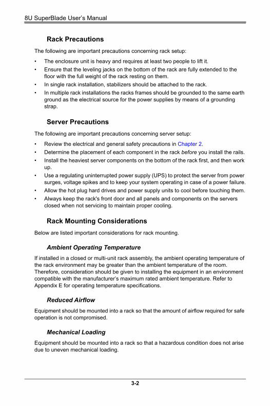
8U SuperBlade Userrsquos Manual
Rack Precautions
The following are important precautions concerning rack setup
bull The enclosure unit is heavy and requires at least two people to lift it
bull Ensure that the leveling jacks on the bottom of the rack are fully extended to the floor with the full weight of the rack resting on them
bull In single rack installation stabilizers should be attached to the rack
bull In multiple rack installations the racks frames should be grounded to the same earth ground as the electrical source for the power supplies by means of a grounding strap
Server Precautions
The following are important precautions concerning server setup
bull Review the electrical and general safety precautions in Chapter 2
bull Determine the placement of each component in the rack before you install the rails
bull Install the heaviest server components on the bottom of the rack first and then work up
bull Use a regulating uninterrupted power supply (UPS) to protect the server from power surges voltage spikes and to keep your system operating in case of a power failure
bull Allow the hot plug hard drives and power supply units to cool before touching them
bull Always keep the racks front door and all panels and components on the servers closed when not servicing to maintain proper cooling
Rack Mounting Considerations
Below are listed important considerations for rack mounting
Ambient Operating Temperature
If installed in a closed or multi-unit rack assembly the ambient operating temperature of the rack environment may be greater than the ambient temperature of the room Therefore consideration should be given to installing the equipment in an environment compatible with the manufacturerrsquos maximum rated ambient temperature Refer to Appendix E for operating temperature specifications
Reduced Airflow
Equipment should be mounted into a rack so that the amount of airflow required for safe operation is not compromised
Mechanical Loading
Equipment should be mounted into a rack so that a hazardous condition does not arise due to uneven mechanical loading
3-2
Chapter 3 Setup and Installation
Circuit Overloading
Consideration should be given to the connection of the equipment to the power supply circuitry and the effect that any possible overloading of circuits might have on over-current protection and power supply wiring Appropriate consideration of equipment nameplate ratings should be used when addressing this concern See the power calculation tables in Appendix A
Reliable Ground
A reliable ground must be maintained at all times To ensure this the rack itself should be grounded Particular attention should be given to power supply connections other than the direct connections to the branch circuit (such as the use of power strips and so on)
NOTE It is recommended that you seek the advice and assistance of a licensed electrician that can advise you on best practices for ensuring that the electrical supply and the rack are joined to a Common Bonding Network
Professional documents on grounding techniques include
bull ANSITIA-942 ndash Telecommunications Infrastructure Standard for Data Centers
bull J-STD-607-A-2002 ndash Commercial Building Grounding (Earthing) and Bonding Requirements for Telecommunications
bull IEEE Std 1100trade-2005 (IEEE Emerald Book) ndash IEEE Recommended Practice for Powering and Grounding Electronic Equipment
Installing the System Into a Rack
This section provides information on installing the 8U SuperBlade into a rack There are a variety of rack units on the market meaning the procedure may differ slightly Refer to the Enclosure Template that was included with the system for help
Rack Mounting Hardware
The following is a list of rack mounting hardware you will need for rack setup and installation
bull Two rail assemblies (one for each side of the enclosure)
bull Two handles
bull Four roundhead screws for fastening the enclosure ears to the rack
bull Eight flathead screws and washers for mounting the rails to the rack
3-3
8U SuperBlade Userrsquos Manual
Installation
Use the procedure below for installing an enclosure in a rack
Installing an enclosure
1 Decide where you want to place the blade enclosure into the rack (see Rack Mounting Considerations in the previous section)
2 Position the Enclosure Template at the front of the enclosure to determine the locations of the screws for the enclosure rails (see Figure 3-1)
Figure 3-1 Positioning the Enclosure Template
3 The two enclosure rail sections are screwed together to keep them immobile during shipping Release these screws just enough to allow the rails to slide apart Note the arrow on the rail which indicates the end that attaches to the front of the rack
4 Slide the rails apart far enough to match the depth of the rack Position the rails with the template and secure the front of each to the front of the rack with two flathead screws then secure the back of each rail to the rear of the rack with two flathead screws (see Figure 3-2) Note that the rails are leftright specific and very heavy
Figure 3-2 Securing the Rails to the Rack
5 (Optional step) Add the front left and right handles to the enclosure using five screws to secure each handle Install a thumbscrew through the bottom hole of each handle (see Figure 3-4)
3-4
Chapter 3 Setup and Installation
NOTE These handles are optional and need only be installed when mounting the system into a short rack When mounting into a deep rack they are unnecessary and regular screws should be used instead of thumbscrews
Be aware that these handles are not to be used for lifting the system they are only to be used to slide the system within the rack
6 With one person on either side (see the descriptive label on the side of the enclosure) lift the enclosure and slide it into the installed rails
WARNING Be sure that the enclosure is empty of all blades power supplies switches and management modules BEFORE lifting These should be installed AFTER the enclosure is mounted in the rack Injury and damage may occur if components are not removed from the rack prior to installation
7 After pushing the enclosure all the way into the rack use two roundhead screws on each side of the server to lock it into place
Figure 3-4 Attaching the Optional Handles
Figure 3-3 Sliding the Enclosure into the Rack
810 Enclosure 820 Enclosure
3-5
8U SuperBlade Userrsquos Manual
8 The enclosure is now securely installed in the rack (see Figure 3-5)
Figure 3-5 Enclosure Installed into Rack
3-6
Chapter 4 System Modules
Chapter 4System Modules
In addition to the blade units your blade system comes equipped with one or more system modules The modules fit into the rear of the enclosure into bays above andor below the power supplies This chapter describes the various blade modules that may be part of your blade system Module configurations can be customized you can install two of the same type module for redundancy purposes or you may omit a module altogether (except for the CMM which is a required module) Figure 4-1 shows a typical module configuration in a blade system See Chapter 5 for information on power supply modules
WARNING All module bays must be populated either with a module or a dummy module cover to maintain proper airflow
Figure 4-1 8U 820C Enclosure with 100G Switch Rear View
1 1
3
2
4 44
5 5 5 5
5555
4-1
8U SuperBlade Userrsquos Manual
Figure 4-2 8U 820J Enclosure with 2x25Gand 2x10G Switches Rear View
NOTE When setting up a bay the single wide bay is for 10G25G switches while the triple wide bay uses 100G switches for the 8U SuperBlade system
Table 4-1 Typical 8U Blade System Module Configuration Rear View
Item Description
1These bays can hold any of the following 1Gb Ethernet Switch Module or a 10Gb Ethernet Switch Module
2 CMM (Chassis Management Module) (x1 standard or x2 optional per enclosure)
3 These bays can hold a 25G Ethernet Switch
4 Dual System Fan Modules
5 2200W Power Supplies (x4 required x4 optional depending upon system requirements)
3 32
4 44
5 5 5 5
5555
2 11
4-2
Chapter 4 System Modules
Figure 4-3 8U 820L Enclosure with 2x10G Switches Rear View
Table 4-2 Typical 8U Blade System Module Configuration Rear View
Item Description
1These bays can hold any of the following 1Gb Ethernet Switch Module or a 10Gb Ethernet Switch Module
2 CMM (Chassis Management Module) (x1 standard or x2 optional per enclosure)
3 Dual System Fan Modules
4 2200W Power Supplies (x4 required x4 optional depending upon system requirements)
3 33
4 4 4 4
4444
2 11
4-3
8U SuperBlade Userrsquos Manual
4-1 Chassis Management ModuleThe Chassis Management Module (CMM) (Figure 4-4) is a required module in a blade system This ldquocommandrdquo module communicates with the blade units the power supplies and the blade switches Used in conjunction with the Web Interface or IPMI View management software the CMM provides administrator control over individual blade units power supplies cooling fans and networking switches and monitors onboard temperatures power status voltage levels and fan speeds The standard CMM module for the 8U SuperBlade system is the MBM-CMM-FIO or MBM-CMM-001
NOTE Using the MBM-CMM-FIO in the enclosure allows the use of the two front mounted RJ45 ports on the enclosure however using the MBM-CMM-001 does not allow these ports to function
The CMM provides a dedicated local and remote KVM (keyboardvideomouse) connection over an out of band TCPIP Ethernet network during any server state (functioning blue-screen powered down BIOS and so on) It also supports Virtual Media (VM) redirection for CD floppy and USB mass storage devices and configures such information as the switch IP addresses A summary of CMM features is shown in Table 4-4
Figure 4-4 Chassis Management Module MBM-CMM-FIO
Table 4-3 MBM-CMM-FIO Module Interface
Item Description
1 Power LED
2 Fault LED
3 Information LED
4 USB Ports
5 IPMI Port
6 Ethernet Ports
7 Reset Button
8 Module Release Handle
2
3
1
7 4 6
5
4-4
Chapter 4 System Modules
Figure 4-5 Chassis Management Module MBM-CMM-001
Table 4-4 MBM-CMM-FIO Module Features
Feature Description
Management Capabilities Can manage 10 to 20 blade units network modules and 8 power supplies
PortsTwo Ethernet ports one IPMI Ethernet port and two USB ports (for debug only)
Basic Functions SupportedRemote KVM remote storage Serial-over-LAN (SOL) blade monitoring and control
System Management System management interface provided via dedicated LAN
Power Consumption Approximately 20W
Operating System Firmware (upgradable)
Table 4-5 MBM-CMM-001 Module Interface
Item Description
1 Power LED
2 Fault LED
3 Information LED
4 USB Ports
5 Ethernet Ports
6 Serial Port
7 Reset Button
8 Module Release Handle
2
3
1
7 4 5
8
6
4-5
8U SuperBlade Userrsquos Manual
Module Redundancy
A blade system must have one CMM and may have two for redundancy is offered only on a specific enclosure model which has the hardware capability to incorporate two CMMs on one backplane Since the CMM uses its own processor all monitoring and control functions are carried out regardless of the operation or power status of the blade units CMM modules can only be installed in the upper andor lower right module bays
Determining MasterSlave Modules Status
When a blade system has two CMM modules they are assigned a masterslave status This is done automatically with the default primary CMM specified for per each enclosure while there will be no redundant in certain enclosures
If the master CMM is powered down or removed (or is being reset by its user) the second (slave) CMM module will then immediately be assigned as the master The redundant CMM mode is only offered on specific chassis models The slave uses the previous master IP config in case of a fail over
NOTE The Slave CMM keeps the same logstatus as the Master CMM and uses the previous master IP config
CMM Module Installation
Use this procedure to install the MBM-CMM-FIO or MBM-CMM-001 CMM module to the 8U SuperBlade chassis Make sure the cover to the module has been installed before proceeding Follow the anti-static precautions described in Chapter 2
Installing the Module
1 Remove the dummy cover from the bay you want to place the module in
2 Place the modules release handle in the open position
3 Slide the module into the module bay until it stops
4 Push the release handle to the closed position
Table 4-6 MBM-CMM-001 Module Features
Feature Description
Management Capabilities Can manage 10 to 20 blade units network modules and 8 power supplies
Ports Two Ethernet ports one serial port and two USB ports (for debug only)
Basic Functions SupportedRemote KVM remote storage Serial-over-LAN (SOL) blade monitoring and control switch PWS monitor thermal redundant based on specific enclosure model
System ManagementSystem management interface provided via dedicated LAN switch PWS monitor thermal and is redundant based on the specific enclosure model
Power Consumption Approximately 20W
Operating System Firmware (upgradeable)
4-6
Chapter 4 System Modules
5 After the module has been installed and the handle locked it will turn on and a POST test will run to verify it is working properly
Removing the Module
1 Pull out the release handle to the open position
2 Pull the module out of the bay
3 Replace immediately with another module or with a dummy module cover to maintain airflow integrity
Configuring the CMM
To accessconfigure the CMM you first have to configure the IP settings of the CMM depending on you network environment The below procedure for this configuration just serves as a reference for getting the CMM setup If your system has Linux OS please follow similar instructions to get the CMM setup
The CMM access topology is as follows
DHCP Access
1 Connect a network cable to the CMM module
2 The system should boot into the default Fail Over mode The DHCP mode will appear on the CLI mode screen
3 If the system fail over and CLI is not active it will proceed to the next default IP of CMM at https192168100100
4 If the CMM cannot enter the default IP then an RJ45USB cable can be connected from the CMMs RJ45 Ethernet LAN Port to the Desktop Host using the USB Port in Serial Port mode with a speed set at 115200 The DHCP IP can be manually set at the same subnet-mask for gateway access at 19216810010001
Default IP Access
1 Connect network cable to the network port at CMM
2 At system Prompt https192168100100
Requirements are
bull Computer system with LAN (RJ45) port
bull RJ -45 Ethernet cable
The default IP of the CMM is https192168100100 Configure the Computer system (connected through Ethernet-LAN to the CMM) to the same address range (for example https192168100101) The default mode is the Fail Over mode If the DHCP fails then the CMM will automatically default to the IP address of the CMM
Configuring the CMM in Windows OS
1 Go to START CONTROL PANEL NETWORK CONNECTIONS
2 Right-click on LAN to view properties
4-7
8U SuperBlade Userrsquos Manual
3 Choose ldquoInternet Protocol (TCPIP)rdquo under the GENERAL tab and click on PROPERTIES (see Figure 4-6)
4 Manually configure the IP address of the computer system to be in the same address range as the CMM (see Figure 4-7)
Example
bull IP address https192168100101
bull Subnet Mask 2552552550
bull Default Gateway 1921681001
5 Once the IP address for the computer system is configured the CMM can be accessed through the web browser by entering the default IP address 192168100100 of the CMM into the browserrsquos address bar
Figure 4-6 Choose Internal Protocol
Figure 4-7 Manually Configure the IP Address
4-8
Chapter 4 System Modules
6 Now the IP address subnet mask and default gateway of the CMM can be changed according to the network environment (see Figure 4-8) Please refer to the Web-based Management Utility Userrsquos Manual for more information
WARNING Dont change any other setting unless you are familiar with it
NOTE The above screens are examples for purposes of demonstrating this procedure The screens you actually view may or may not appear the same as those shown above
CMM Functions
The following sections describe local functions and remote functions of the CMM With only minor exceptions all of the remote functions can be performed by one of three mechanisms web-based access to the CMM module access to the CMM using IPMIview a client tool implemented in Java or via IPMItool commands (DOS commands or shell scripted commands)
When the web based browser is used the CMM acts as a web server requiring a higher bandwidth connection to the CMM If there are any bandwidth constraints IPMI will provide a superior experience Additionally since graphical updates are provided by client-side Java IPMIview can also be a superior user experience
IPMItool on the other hand can provide the ability to issue similaridentical commands to many 8U SuperBlade enclosuresCMMrsquos to manage all of them in a similar way
Figure 4-8 Changing Settings
4-9
8U SuperBlade Userrsquos Manual
Remote KVM over IP
Remote KVM over IP is independent from local KVM (although local KVM can operate in parallel with Remote KVM) Remote KVM encrypts all communication between the remote user and the CMM
To Use Remote KVM over IP is initiated with the management software (IPMI View or Web-based utility) Attach the LAN cable to the LAN port on the CMM module then refer to Web-based Management Utility on page 4-12 to login and use either utility
Remote Storage (Virtual Media)
The Remote Storage function allows the user to connect to a remote storage device (such as a floppy hard disk or USB storage device) and access the device as if it were local This can be used not only to read and write to remote storage devices but to load an operating system from a remote drive
Serial Over LAN (SOL)
Serial Over LAN allows you to redirect the input and output of a serial port via IPMI in order to manage blade modules from a remote location
To Use Serial Over LAN can be activated via the Web-based Management utility See the Web-based Management Utility Userrsquos Manual for the procedure to initiate SOL
Monitoring Functions
Used in conjunction with IPMI or the Web-based Management utility the CMM module can monitor and provide information on the hardware health of the blade modules and the system as a whole In addition to the monitoring functions you can remotely power on power off or reboot a system
Health information includes
bull Temperature levels
bull Fan speeds
bull Voltage levels
bull Power status
Power Consumption Management
The CMM modulersquos firmware can also control all power onoff activity in the whole blade system This is done by using the Power button onboard BMC or from any other use of remote management software
Once a blade module is installed in the enclosure the installed CMM immediately receives information on the rated Max Power Consumption value of the new blade module The CMM then calculates whether there is enough power for this new blade module by comparing the Max Power Consumption value of the new blade module with the calculated Remaining Power value of the system
4-10
Chapter 4 System Modules
If there is enough power the CMM will power on the blade However if there is not enough power in the blade system then the new blade module is not powered on and the front panel LED on the enclosure will blink
After the blade is powered on the CMM then collects the actual power consumption of this individual blade and updates the calculated Remaining Power value for the system
The CMM also reserves power for all the networking and chassis management modules installed on the system
WARNING One CMM module must be running to control the power systems and prevent overloading
USB Ports and Reset Button
The USB Ports and Reset Button on the CMM are described below
Figure 4-9 USB Ports on CMM
USB PortsMBM-CMM-FIO Reset Button
USB PortsMBM-CMM-001 Reset Button
4-11
8U SuperBlade Userrsquos Manual
USB Ports
The USB ports on both CMM modules are shown in Figure 4-9 They are only used for debugging purposes and not for communication with your system
Reset Button
The Reset button located on the front of the CMM module is used to reset the following software settings to their defaults
To reset the CMM to factory defaults press and hold the Reset button for five seconds
Firmware
The firmware for the CMM switch resides in the module This firmware can be updated with the web-based management utility
Within the utility go to the MAINTENANCE gt UPDATE FIRMWARE screen in the Web-based Management Utility Here you can enter the name of the firmware you want to update or click on BROWSE to select the firmware file Finish by clicking the UPLOAD button
NOTE This process is not reversible once the firmware is updated so proceed with caution It might take a few minutes to complete this procedure
Web-based Management Utility
System management may be performed with either of three software packages IPMIview SMCIPMItool or a Web-based Management Utility Any of these utilities are designed to provide an administrator with a comprehensive set of functions and monitored data to keep tabs on the system and perform management activities
The Web-based Management Utility is a web-based interface that consolidates and simplifies system management for Supermicro 8U SuperBlade systems The Web-based Management Utility aggregates and displays data from the CMM module
The Web-based Management Utility provides the following key management features
bull Enables IT administrators to view in-depth hardware configuration and status information using a single intuitive interface
bull Provides an OS-independent remote graphical console
Table 4-7 CMM Reset Settings
Software Setting Default
User Name and Password Reset to ADMIN and ADMIN (case sensitive)
IP Address Reset to https192168100100
Gateway Address Reset to 0000
Subnet Mask Reset to 2552552550
4-12
Chapter 4 System Modules
bull Allows remote users to map local media (floppy removable disks and hard drives) or ISO images on a shared network drive to a blade server
Supported Browsers
The following browsers have been tested for use with the Web-based Management Utility It is recommended that you use the most current revision of the browser you choose The minimum browser revisions supported by the Web-based Management Utility are shown below
bull Internet Explorer 7
bull Firefox 2007
bull Netscape 903b
Network ConnectionLogin
To log into the Web-based Management Utility
1 Launch a web browser
2 In the address field of the browser enter the IP address that you assigned to the system and hit the ltENTERgt key
3 When the browser makes contact with Supermicrorsquos Chassis Management Module enter your username and password then click LOGIN
4 The WEB-BASED MANAGEMENT UTILITY HOME PAGE will then display as shown in Figure 4-10
Address Defaults
Table 4-8 shows the default addresses that are initially set for the CMM Afterwards you can change these values within the program (see the Web-based Management Utility Userrsquos Manual M for more details)
Table 4-8 Address Defaults
Default Description
Default IP Address https192168100100a
a Note The web address must be entered as https192168100100 in the web browser Entering only http gives you instead an address error
Default Gateway Address 0000
Default Subnet Mask 2552552550
Default username ADMIN
Default password ADMIN
4-13
8U SuperBlade Userrsquos Manual
Home Page
Figure 4-10 displays the WEB-BASED MANAGEMENT UTILITY HOME PAGE and its controls
Figure 4-10 Home Page
NOTE For more information on the Web-based Management Utility and a description of its controls see the Superblade Web-based Management Utility Userrsquos Manual for more details
4-14
Chapter 5 Power Supply Modules
Chapter 5Power Supply Modules
The 8U SuperBlade enclosure comes standard with one CMM module (see the Chapter 4 for details on the CMM module) and either two or four power supplies See Appendix A for summary specification details on the power supplies available to the 8U SuperBlade enclosure
5-1 Power Supply ModulesThe minimum amount of modules required to power the system depends upon the full complement of blade units installed into an enclosure and the type of switches installed in the enclosure An LED on the back of a power supply will be green when AC power is present and amber color when it fails
When installing only a few power supplies in the enclosure they should be installed first in the lower rather than the upper power bays This is to provide increased airflow across the memory modules within each blade module
The 2200W power supply modules require a 100-240V AC input and a C14 socket which requires a power cord with a C13 connector
Supermicros high-efficiency blade system power supplies deliver continuous redundant power up to 96 peak efficiency Each power supply module includes a management module that monitors the power supplies and the power enclosure
The features of these power supplies are shown below
Table 5-1 Amperage Draw Specifications for the PWS-2K21A-BR Power Supply
Watts Low Volts High Volts Low Amps High Amps
1200W 100 127 11 14
1980W 220 230 98 10
2090W 230 240 98 10
1800W 200 220 95 10
2200W (ULcUL only) 220 240 11 12
2090W (ULcUL only) 180 220 11 14
5-1
8U SuperBlade Userrsquos Manual
Figure 5-1 PWS-2K21A-BR Power Supply
Table 5-2 PWS-2K21A-BR Power Supply Features
Feature Description
Output 2200W2090W1980W1800W1200W
Type Redundant Module (N+1N+N)
+12V18333A (2200W) 17417A (2090W) 165A (1980W) 150A (1800W) or 100A (1200W)
+12VSB 2A
PFC Yes
Peak Efficiency 96+ (Titanium Level)
Input AC Range100-127V (1200W) 200-220V (1800W) 220-230V (1980W) 230-240V (2090W) 200-220V (2090W for UL amp cUL) or 220-240V (2200W for UL amp cUL)
Operating ConditionsTemp 0 to 50 C
Humidity 5 to 95 RH
Fan Type 80x80mm counter rotating fan
Dimensions (LxWxH) 2453 x 1065 x 84mm
5-2
Chapter 5 Power Supply Modules
BPP Batteries
BBP Batteries like all rechargeable batteries are consumable components that eventually their capacity and performance decline as they age Regular maintenance by charge and discharge cycles is recommended to maintain the effectiveness of the BBP batteries At least one charge and discharge cycle for every 30 days is recommended The BBP maintenance scheduler can be enabled and configured through the CMM
When the BBP function is disabled through the CMM the battery will discharge until the minimum energy state is reached While the battery function is disabled regular BBP maintenance cannot be performed since the battery energy remains at the lowest state and will not re-charge As a result the battery capacity and performance will decline at a faster pace andor cause the battery to no longer operate The battery will remain the minimum charge until the BBP function is again re-enabled through CMM The user should use the disabling BBP function with caution knowing that the possible outcome of degraded battery performance or not operational battery
Figure 5-2 PWS-1K20B-BR Battery Backup Power (BPP) Module
5-3
8U SuperBlade Userrsquos Manual
Under typical conditions the above is the estimated runtime for the BPP modules The runtime can be extended by adding additional BPP modules to a system
Table 5-3 PWS-1K20B-BR Battery Backup Power (BPP) Module Specifications
Feature Description
Total Output Power 1200W
Input 112 to 129VDC
Output 12V 12VSB
Form Factor MicroBlade
Dimensions 2453 x 1065 x 84-mm
Battery Cell Capacity 68Whr
Redundant N+1 N+N
I2C Remote Monitoring FRUSmart Battery I2C
+12V Output 100A
12VSB Output 25A
Efficiency Online mode battery power consumption less than 5W
Discharge Duration 1200W for 35 Seconds
Cell Chemistry Lithium-Ion
Cooling Internal 80 x 80-mm colling fan
Operating Temperature 5degC - 50degC
Table 5-4 PWS-1K20B-BR BPP Module Estimated Runtime
Power Load Installed BPP Modules Discharge Duration
1000W 4 180 Seconds
2000W 4 120 Seconds
3000W 4 60 Seconds
4000W 4 35 Seconds
4800W 4 35 Seconds
Table 5-5 Chassis Compatible with the BPP
Model Output Power Capacity SBE-820CB-422 SBE-820JB-422
PWS-1K208-BR 1200W 68Whour Up to 4 Up to 4
5-4
Chapter 5 Power Supply Modules
Power Supply Failure
If a power supply or a fan in a power supply fails the system management software will notify you of the situation In either case you will need to replace the power supply module with another identical one
NOTE Refer to wwwsupermicroproductssuperblade for possible updates on part numbers
Installing a Power Supply
1 Insert a replacement unit into the empty power bay with the handle to the left
WARNING This leftright orientation depends on the power supplyrsquos top or bottom location If you inadvertently put a power supply upside down in the lower slots it can be VERY difficult to remove the power supply
2 Push unit all the way in until it is firmly seated
3 Push the handle back into the closed position until it clicks into the locked position
4 Move the locking clip away from the socket and reconnect the power cord
Removing a Power Supply
First make sure the power supply has been shut down You can remove power from a power unit via your system management software
1 Remove the power cord from the power supply unit
2 Release the locking clip to unlock the power supply module
3 Pull out the handle and remove the unit the two-piece handle locks into the closed position To release the handle squeeze together the two metal plates of the handle with your thumb and fingers and then pull out
5-2 Redundant Power SuppliesEach blade enclosure can hold up to four power supplies Installing all four power supplies may provide you with redundant power ndash depending upon the number of blades in the enclosure the model and power level of the power supplies installed and the power load from modules in your system In most blade enclosure systems power supplies may be redundant and therefore provide backup in case of power supply failure The configuration for power redundancy is created using the IPMIView application tool for the system
For purposes of denoting the amount of redundancy a server system has N main power supplies to support the whole system working with a ldquo+rdquo number after the N denoting the number of redundant power supplies Hence if there is one power supply for redundancy in a system that has the feature of ldquoredundant powerrdquo the total of power supplies for that server system is denoted as N+1
5-5
8U SuperBlade Userrsquos Manual
For example suppose a 10-blade system has four 2200 Watt Power Supply Units (PSU) for a total power supply of 8800 Watts The maximum power usage of each blade is 375 Watts for a total power demand of 3750 Watts to run the whole system So in this example there are effectively two redundant power supplies (N+1) over what is needed to power the blades in the system
In the IPMIView tool you can set the priority (default CPU power usage) of each blade first before any PSU fails (0-gtshut down 50-gtthrottling 100-gtRunning) See Figure 5-3 below for an example
Therefore the following redundancies apply to your system when as an example 2200W power supplies fail
bull If one PSU fails then you have 6600 Watts available The CMM will detect the remaining power left for the whole system But because the total blade power usage is only 3750 Watts every blade can still work properly
bull If 2 PSUs fail then only 4400 Watts are left available to support the blade power usage The system can still support all ten blades running in it
bull If 3 PSUs fail then the remaining 2200 Watts available cannot support the whole system Therefore the CMM will start to shut down or throttle down the load in order to keep blades running based upon the priority settings that were made for each blade using the IPMIView application until the load is enough to power the remaining blade modules
Figure 5-3 Power Supply Status
5-6
Chapter 5 Power Supply Modules
5-3 Power Supply FansEach power supply unit has two to four rear fans These fans are not hot-swappable If one fails the power supply will continue to operate but you should replace the power supply unit at the earliest opportunity If two or more fans fail the power supply unit will shut down and the LED on the back will turn amber
5-7
8U SuperBlade Userrsquos Manual
5-8
Appendix ASystem Specifications
A-1 Enclosure Specifications
NOTE Up to 8x (N+1 or N+N redundant) 2200W Titanium certified (96 efficiency) AC power supplies or 2000W DC power supplies battery back-up option on SBE-820CE-422 PDU specs and requirements for rack
Table A-1 8U Enclosure Specification Features
EnclosureSBE-820C-822622 rack mount blade enclosures
Dimensions (WxHxD) 122 x 176 x 29 in (3098 x 447 x 7366 mm)
Blade Module SupportUp to either 10 full-height 4-socket or 20 half-height 2 socket hot-plug blade modules
System CoolingThree twin-PWM fan modules in the rear chassis In addition up to four (4) optional cooling fan modules can be used in place of four power supplies can be mounted in an enclosure
Power Supplies (modules required varies)
Rated Output Power 2200W (Part PWS-2K21-BR C-20 type socket) power supplies
Rated Output Voltages +12V (183A) +12Vsb (2A) for 2200W +12V (174A) +12Vsb (2A) for 2090W +12V (165A) +12Vsb (2A) for 1980W +12V (150A) +12Vsb (2A) for 1800W +12V (100A) +12Vsb (2A) for 1200W
Power Supply Model Numbers
bull PWS-2K21A-BR (for the SBE-820C-822 enclosure)
bull PWS-DF006-2F (for the SBE-820C-622 enclosure)
bull PWS-DF005-2F (for the SBE-820C-42 enclosure)
System Input Requirements
AC Input Voltage 220~240V AC auto-range for 2200W 230~240V AC auto-range for 2090W 220~230V AC auto-range for 1980W 200~220V AC auto-range for 1800W 100-127V AC auto-range for 1200W
Rated Input Current 12A-11A for 2200W 14-11A for 2090W 10-98A for 1980W 10-95A for 1800W 14-11A for 1200W
Rated Input Frequency 50 to 60 Hz
Thermal Range
Supermicrorsquos new 8U SuperBlade Enclosure has a wide thermal support range to incorporate a significant range of CPU TDP this can range from 85W 105W 125W 130W 140W 150W 155W 165W and 205W
A special heatsink is required for the gold CPU with TDP ranging from 165W-200W Extra wide heatsinks are required for the 205W platinum CPU
For further details please check with thermal specifications and advisory for conditional thermal support of 15-32deg degree ambient and 10-35deg degree ambient temperatures The 8U system will not support 5-45deg degree ambient temperatures
A-1
8U SuperBlade Userrsquos Manual
A-2 Environmental Specifications
A-3 Address Defaults
Table A-2 Environmental Specification Features
Operating Environment
Operating Temperature 10ordm to 35ordm C (50ordm to 95ordm F)
Non-operating Temperature -40ordm to 70ordm C (-40ordm to 158ordm F)
Operating Relative Humidity 8 to 90 (non-condensing)
Non-operating Relative Humidity 5 to 95 (non-condensing)
Regulatory Compliance
Electromagnetic Emissions
FCC Class A EN 55022 Class A EN 61000-3-2-3-3 CISPR 22 Class A
Electromagnetic Immunity
EN 55024CISPR 24 (EN 61000-4-2 EN 61000-4-3 EN 61000-4-4 EN 61000-4-5 EN 61000-4-6 EN 61000-4-8 EN 61000-4-11)
Safety
EN 60950IEC 60950-Compliant UL Listed (USA) CUL Listed (Canada) TUV Certified (Germany) CE Marking (Europe)
California Best Management Practices Regulations for Perchlorate Materials This Perchlorate warning applies only to products containing CR (Manganese Dioxide) Lithium coin cells ldquoPerchlorate Material-special handling may apply See wwwdtsccagovhazardouswasteperchlorate for details
Table A-3 Address Defaults
CMM Module
IP Address 192168100100
Gateway Address 0000
Subnet Mask 2552552550
User Name and Password ADMIN and ADMIN (case sensitive)
GbE Switch
IP Address 192168100102
Gateway Address 1921681001
Subnet Mask 2552552550
A-2
A-4 Power Supply Power Calculations
Table A-4 Power Supply Power Calculations (PWS-2K21A-BR)
Calculation Value
Watts 2200
Volts (HighLow) 240220
Amps (HighLow) 1211
Efficiency (High) 96
Power Factor (High) 98
10 Reserve (High) 15
10 Reserve (Low) 13
Amps (Total) 11240 volts
Table A-5 Power Supply Power Calculations (PWS-1K20B-BR)
Calculation Value
Watts 1200
Volts (HighLow)DC Output 12V 12Vsb
DC Input 112 to 129Vdc
Amps (HighLow)+12V Output 100A
12Vsb Output 2A
Efficiency (High) 94
Power Factor (High) 98
10 Reserve (High) 15
10 Reserve (Low) 13
A-3
8U SuperBlade Userrsquos Manual
Notes
A-4
Disclaimer
The products sold by Supermicro are not intended for and will not be used in life support systems medical equipment nuclear facilities or systems aircraft aircraft devices aircraftemergency communication devices or other critical systems whose failure to perform be reasonably expected to result in significant injury or loss of life or catastrophic property damage Accordingly 8U SuperBlade disclaims any and all liability and should buyer use or sell such products for use in such ultra-hazardous applications it does so entirely at its own risk Furthermore buyer agrees to fully indemnify defend and hold Supermicro harmless for and against any and all claims demands actions litigation and proceedings of any kind arising out of or related to such ultra-hazardous use or sale
8U SuperBlade Userrsquos Manual

Chapter 3 Setup and Installation
Circuit Overloading
Consideration should be given to the connection of the equipment to the power supply circuitry and the effect that any possible overloading of circuits might have on over-current protection and power supply wiring Appropriate consideration of equipment nameplate ratings should be used when addressing this concern See the power calculation tables in Appendix A
Reliable Ground
A reliable ground must be maintained at all times To ensure this the rack itself should be grounded Particular attention should be given to power supply connections other than the direct connections to the branch circuit (such as the use of power strips and so on)
NOTE It is recommended that you seek the advice and assistance of a licensed electrician that can advise you on best practices for ensuring that the electrical supply and the rack are joined to a Common Bonding Network
Professional documents on grounding techniques include
bull ANSITIA-942 ndash Telecommunications Infrastructure Standard for Data Centers
bull J-STD-607-A-2002 ndash Commercial Building Grounding (Earthing) and Bonding Requirements for Telecommunications
bull IEEE Std 1100trade-2005 (IEEE Emerald Book) ndash IEEE Recommended Practice for Powering and Grounding Electronic Equipment
Installing the System Into a Rack
This section provides information on installing the 8U SuperBlade into a rack There are a variety of rack units on the market meaning the procedure may differ slightly Refer to the Enclosure Template that was included with the system for help
Rack Mounting Hardware
The following is a list of rack mounting hardware you will need for rack setup and installation
bull Two rail assemblies (one for each side of the enclosure)
bull Two handles
bull Four roundhead screws for fastening the enclosure ears to the rack
bull Eight flathead screws and washers for mounting the rails to the rack
3-3
8U SuperBlade Userrsquos Manual
Installation
Use the procedure below for installing an enclosure in a rack
Installing an enclosure
1 Decide where you want to place the blade enclosure into the rack (see Rack Mounting Considerations in the previous section)
2 Position the Enclosure Template at the front of the enclosure to determine the locations of the screws for the enclosure rails (see Figure 3-1)
Figure 3-1 Positioning the Enclosure Template
3 The two enclosure rail sections are screwed together to keep them immobile during shipping Release these screws just enough to allow the rails to slide apart Note the arrow on the rail which indicates the end that attaches to the front of the rack
4 Slide the rails apart far enough to match the depth of the rack Position the rails with the template and secure the front of each to the front of the rack with two flathead screws then secure the back of each rail to the rear of the rack with two flathead screws (see Figure 3-2) Note that the rails are leftright specific and very heavy
Figure 3-2 Securing the Rails to the Rack
5 (Optional step) Add the front left and right handles to the enclosure using five screws to secure each handle Install a thumbscrew through the bottom hole of each handle (see Figure 3-4)
3-4
Chapter 3 Setup and Installation
NOTE These handles are optional and need only be installed when mounting the system into a short rack When mounting into a deep rack they are unnecessary and regular screws should be used instead of thumbscrews
Be aware that these handles are not to be used for lifting the system they are only to be used to slide the system within the rack
6 With one person on either side (see the descriptive label on the side of the enclosure) lift the enclosure and slide it into the installed rails
WARNING Be sure that the enclosure is empty of all blades power supplies switches and management modules BEFORE lifting These should be installed AFTER the enclosure is mounted in the rack Injury and damage may occur if components are not removed from the rack prior to installation
7 After pushing the enclosure all the way into the rack use two roundhead screws on each side of the server to lock it into place
Figure 3-4 Attaching the Optional Handles
Figure 3-3 Sliding the Enclosure into the Rack
810 Enclosure 820 Enclosure
3-5
8U SuperBlade Userrsquos Manual
8 The enclosure is now securely installed in the rack (see Figure 3-5)
Figure 3-5 Enclosure Installed into Rack
3-6
Chapter 4 System Modules
Chapter 4System Modules
In addition to the blade units your blade system comes equipped with one or more system modules The modules fit into the rear of the enclosure into bays above andor below the power supplies This chapter describes the various blade modules that may be part of your blade system Module configurations can be customized you can install two of the same type module for redundancy purposes or you may omit a module altogether (except for the CMM which is a required module) Figure 4-1 shows a typical module configuration in a blade system See Chapter 5 for information on power supply modules
WARNING All module bays must be populated either with a module or a dummy module cover to maintain proper airflow
Figure 4-1 8U 820C Enclosure with 100G Switch Rear View
1 1
3
2
4 44
5 5 5 5
5555
4-1
8U SuperBlade Userrsquos Manual
Figure 4-2 8U 820J Enclosure with 2x25Gand 2x10G Switches Rear View
NOTE When setting up a bay the single wide bay is for 10G25G switches while the triple wide bay uses 100G switches for the 8U SuperBlade system
Table 4-1 Typical 8U Blade System Module Configuration Rear View
Item Description
1These bays can hold any of the following 1Gb Ethernet Switch Module or a 10Gb Ethernet Switch Module
2 CMM (Chassis Management Module) (x1 standard or x2 optional per enclosure)
3 These bays can hold a 25G Ethernet Switch
4 Dual System Fan Modules
5 2200W Power Supplies (x4 required x4 optional depending upon system requirements)
3 32
4 44
5 5 5 5
5555
2 11
4-2
Chapter 4 System Modules
Figure 4-3 8U 820L Enclosure with 2x10G Switches Rear View
Table 4-2 Typical 8U Blade System Module Configuration Rear View
Item Description
1These bays can hold any of the following 1Gb Ethernet Switch Module or a 10Gb Ethernet Switch Module
2 CMM (Chassis Management Module) (x1 standard or x2 optional per enclosure)
3 Dual System Fan Modules
4 2200W Power Supplies (x4 required x4 optional depending upon system requirements)
3 33
4 4 4 4
4444
2 11
4-3
8U SuperBlade Userrsquos Manual
4-1 Chassis Management ModuleThe Chassis Management Module (CMM) (Figure 4-4) is a required module in a blade system This ldquocommandrdquo module communicates with the blade units the power supplies and the blade switches Used in conjunction with the Web Interface or IPMI View management software the CMM provides administrator control over individual blade units power supplies cooling fans and networking switches and monitors onboard temperatures power status voltage levels and fan speeds The standard CMM module for the 8U SuperBlade system is the MBM-CMM-FIO or MBM-CMM-001
NOTE Using the MBM-CMM-FIO in the enclosure allows the use of the two front mounted RJ45 ports on the enclosure however using the MBM-CMM-001 does not allow these ports to function
The CMM provides a dedicated local and remote KVM (keyboardvideomouse) connection over an out of band TCPIP Ethernet network during any server state (functioning blue-screen powered down BIOS and so on) It also supports Virtual Media (VM) redirection for CD floppy and USB mass storage devices and configures such information as the switch IP addresses A summary of CMM features is shown in Table 4-4
Figure 4-4 Chassis Management Module MBM-CMM-FIO
Table 4-3 MBM-CMM-FIO Module Interface
Item Description
1 Power LED
2 Fault LED
3 Information LED
4 USB Ports
5 IPMI Port
6 Ethernet Ports
7 Reset Button
8 Module Release Handle
2
3
1
7 4 6
5
4-4
Chapter 4 System Modules
Figure 4-5 Chassis Management Module MBM-CMM-001
Table 4-4 MBM-CMM-FIO Module Features
Feature Description
Management Capabilities Can manage 10 to 20 blade units network modules and 8 power supplies
PortsTwo Ethernet ports one IPMI Ethernet port and two USB ports (for debug only)
Basic Functions SupportedRemote KVM remote storage Serial-over-LAN (SOL) blade monitoring and control
System Management System management interface provided via dedicated LAN
Power Consumption Approximately 20W
Operating System Firmware (upgradable)
Table 4-5 MBM-CMM-001 Module Interface
Item Description
1 Power LED
2 Fault LED
3 Information LED
4 USB Ports
5 Ethernet Ports
6 Serial Port
7 Reset Button
8 Module Release Handle
2
3
1
7 4 5
8
6
4-5
8U SuperBlade Userrsquos Manual
Module Redundancy
A blade system must have one CMM and may have two for redundancy is offered only on a specific enclosure model which has the hardware capability to incorporate two CMMs on one backplane Since the CMM uses its own processor all monitoring and control functions are carried out regardless of the operation or power status of the blade units CMM modules can only be installed in the upper andor lower right module bays
Determining MasterSlave Modules Status
When a blade system has two CMM modules they are assigned a masterslave status This is done automatically with the default primary CMM specified for per each enclosure while there will be no redundant in certain enclosures
If the master CMM is powered down or removed (or is being reset by its user) the second (slave) CMM module will then immediately be assigned as the master The redundant CMM mode is only offered on specific chassis models The slave uses the previous master IP config in case of a fail over
NOTE The Slave CMM keeps the same logstatus as the Master CMM and uses the previous master IP config
CMM Module Installation
Use this procedure to install the MBM-CMM-FIO or MBM-CMM-001 CMM module to the 8U SuperBlade chassis Make sure the cover to the module has been installed before proceeding Follow the anti-static precautions described in Chapter 2
Installing the Module
1 Remove the dummy cover from the bay you want to place the module in
2 Place the modules release handle in the open position
3 Slide the module into the module bay until it stops
4 Push the release handle to the closed position
Table 4-6 MBM-CMM-001 Module Features
Feature Description
Management Capabilities Can manage 10 to 20 blade units network modules and 8 power supplies
Ports Two Ethernet ports one serial port and two USB ports (for debug only)
Basic Functions SupportedRemote KVM remote storage Serial-over-LAN (SOL) blade monitoring and control switch PWS monitor thermal redundant based on specific enclosure model
System ManagementSystem management interface provided via dedicated LAN switch PWS monitor thermal and is redundant based on the specific enclosure model
Power Consumption Approximately 20W
Operating System Firmware (upgradeable)
4-6
Chapter 4 System Modules
5 After the module has been installed and the handle locked it will turn on and a POST test will run to verify it is working properly
Removing the Module
1 Pull out the release handle to the open position
2 Pull the module out of the bay
3 Replace immediately with another module or with a dummy module cover to maintain airflow integrity
Configuring the CMM
To accessconfigure the CMM you first have to configure the IP settings of the CMM depending on you network environment The below procedure for this configuration just serves as a reference for getting the CMM setup If your system has Linux OS please follow similar instructions to get the CMM setup
The CMM access topology is as follows
DHCP Access
1 Connect a network cable to the CMM module
2 The system should boot into the default Fail Over mode The DHCP mode will appear on the CLI mode screen
3 If the system fail over and CLI is not active it will proceed to the next default IP of CMM at https192168100100
4 If the CMM cannot enter the default IP then an RJ45USB cable can be connected from the CMMs RJ45 Ethernet LAN Port to the Desktop Host using the USB Port in Serial Port mode with a speed set at 115200 The DHCP IP can be manually set at the same subnet-mask for gateway access at 19216810010001
Default IP Access
1 Connect network cable to the network port at CMM
2 At system Prompt https192168100100
Requirements are
bull Computer system with LAN (RJ45) port
bull RJ -45 Ethernet cable
The default IP of the CMM is https192168100100 Configure the Computer system (connected through Ethernet-LAN to the CMM) to the same address range (for example https192168100101) The default mode is the Fail Over mode If the DHCP fails then the CMM will automatically default to the IP address of the CMM
Configuring the CMM in Windows OS
1 Go to START CONTROL PANEL NETWORK CONNECTIONS
2 Right-click on LAN to view properties
4-7
8U SuperBlade Userrsquos Manual
3 Choose ldquoInternet Protocol (TCPIP)rdquo under the GENERAL tab and click on PROPERTIES (see Figure 4-6)
4 Manually configure the IP address of the computer system to be in the same address range as the CMM (see Figure 4-7)
Example
bull IP address https192168100101
bull Subnet Mask 2552552550
bull Default Gateway 1921681001
5 Once the IP address for the computer system is configured the CMM can be accessed through the web browser by entering the default IP address 192168100100 of the CMM into the browserrsquos address bar
Figure 4-6 Choose Internal Protocol
Figure 4-7 Manually Configure the IP Address
4-8
Chapter 4 System Modules
6 Now the IP address subnet mask and default gateway of the CMM can be changed according to the network environment (see Figure 4-8) Please refer to the Web-based Management Utility Userrsquos Manual for more information
WARNING Dont change any other setting unless you are familiar with it
NOTE The above screens are examples for purposes of demonstrating this procedure The screens you actually view may or may not appear the same as those shown above
CMM Functions
The following sections describe local functions and remote functions of the CMM With only minor exceptions all of the remote functions can be performed by one of three mechanisms web-based access to the CMM module access to the CMM using IPMIview a client tool implemented in Java or via IPMItool commands (DOS commands or shell scripted commands)
When the web based browser is used the CMM acts as a web server requiring a higher bandwidth connection to the CMM If there are any bandwidth constraints IPMI will provide a superior experience Additionally since graphical updates are provided by client-side Java IPMIview can also be a superior user experience
IPMItool on the other hand can provide the ability to issue similaridentical commands to many 8U SuperBlade enclosuresCMMrsquos to manage all of them in a similar way
Figure 4-8 Changing Settings
4-9
8U SuperBlade Userrsquos Manual
Remote KVM over IP
Remote KVM over IP is independent from local KVM (although local KVM can operate in parallel with Remote KVM) Remote KVM encrypts all communication between the remote user and the CMM
To Use Remote KVM over IP is initiated with the management software (IPMI View or Web-based utility) Attach the LAN cable to the LAN port on the CMM module then refer to Web-based Management Utility on page 4-12 to login and use either utility
Remote Storage (Virtual Media)
The Remote Storage function allows the user to connect to a remote storage device (such as a floppy hard disk or USB storage device) and access the device as if it were local This can be used not only to read and write to remote storage devices but to load an operating system from a remote drive
Serial Over LAN (SOL)
Serial Over LAN allows you to redirect the input and output of a serial port via IPMI in order to manage blade modules from a remote location
To Use Serial Over LAN can be activated via the Web-based Management utility See the Web-based Management Utility Userrsquos Manual for the procedure to initiate SOL
Monitoring Functions
Used in conjunction with IPMI or the Web-based Management utility the CMM module can monitor and provide information on the hardware health of the blade modules and the system as a whole In addition to the monitoring functions you can remotely power on power off or reboot a system
Health information includes
bull Temperature levels
bull Fan speeds
bull Voltage levels
bull Power status
Power Consumption Management
The CMM modulersquos firmware can also control all power onoff activity in the whole blade system This is done by using the Power button onboard BMC or from any other use of remote management software
Once a blade module is installed in the enclosure the installed CMM immediately receives information on the rated Max Power Consumption value of the new blade module The CMM then calculates whether there is enough power for this new blade module by comparing the Max Power Consumption value of the new blade module with the calculated Remaining Power value of the system
4-10
Chapter 4 System Modules
If there is enough power the CMM will power on the blade However if there is not enough power in the blade system then the new blade module is not powered on and the front panel LED on the enclosure will blink
After the blade is powered on the CMM then collects the actual power consumption of this individual blade and updates the calculated Remaining Power value for the system
The CMM also reserves power for all the networking and chassis management modules installed on the system
WARNING One CMM module must be running to control the power systems and prevent overloading
USB Ports and Reset Button
The USB Ports and Reset Button on the CMM are described below
Figure 4-9 USB Ports on CMM
USB PortsMBM-CMM-FIO Reset Button
USB PortsMBM-CMM-001 Reset Button
4-11
8U SuperBlade Userrsquos Manual
USB Ports
The USB ports on both CMM modules are shown in Figure 4-9 They are only used for debugging purposes and not for communication with your system
Reset Button
The Reset button located on the front of the CMM module is used to reset the following software settings to their defaults
To reset the CMM to factory defaults press and hold the Reset button for five seconds
Firmware
The firmware for the CMM switch resides in the module This firmware can be updated with the web-based management utility
Within the utility go to the MAINTENANCE gt UPDATE FIRMWARE screen in the Web-based Management Utility Here you can enter the name of the firmware you want to update or click on BROWSE to select the firmware file Finish by clicking the UPLOAD button
NOTE This process is not reversible once the firmware is updated so proceed with caution It might take a few minutes to complete this procedure
Web-based Management Utility
System management may be performed with either of three software packages IPMIview SMCIPMItool or a Web-based Management Utility Any of these utilities are designed to provide an administrator with a comprehensive set of functions and monitored data to keep tabs on the system and perform management activities
The Web-based Management Utility is a web-based interface that consolidates and simplifies system management for Supermicro 8U SuperBlade systems The Web-based Management Utility aggregates and displays data from the CMM module
The Web-based Management Utility provides the following key management features
bull Enables IT administrators to view in-depth hardware configuration and status information using a single intuitive interface
bull Provides an OS-independent remote graphical console
Table 4-7 CMM Reset Settings
Software Setting Default
User Name and Password Reset to ADMIN and ADMIN (case sensitive)
IP Address Reset to https192168100100
Gateway Address Reset to 0000
Subnet Mask Reset to 2552552550
4-12
Chapter 4 System Modules
bull Allows remote users to map local media (floppy removable disks and hard drives) or ISO images on a shared network drive to a blade server
Supported Browsers
The following browsers have been tested for use with the Web-based Management Utility It is recommended that you use the most current revision of the browser you choose The minimum browser revisions supported by the Web-based Management Utility are shown below
bull Internet Explorer 7
bull Firefox 2007
bull Netscape 903b
Network ConnectionLogin
To log into the Web-based Management Utility
1 Launch a web browser
2 In the address field of the browser enter the IP address that you assigned to the system and hit the ltENTERgt key
3 When the browser makes contact with Supermicrorsquos Chassis Management Module enter your username and password then click LOGIN
4 The WEB-BASED MANAGEMENT UTILITY HOME PAGE will then display as shown in Figure 4-10
Address Defaults
Table 4-8 shows the default addresses that are initially set for the CMM Afterwards you can change these values within the program (see the Web-based Management Utility Userrsquos Manual M for more details)
Table 4-8 Address Defaults
Default Description
Default IP Address https192168100100a
a Note The web address must be entered as https192168100100 in the web browser Entering only http gives you instead an address error
Default Gateway Address 0000
Default Subnet Mask 2552552550
Default username ADMIN
Default password ADMIN
4-13
8U SuperBlade Userrsquos Manual
Home Page
Figure 4-10 displays the WEB-BASED MANAGEMENT UTILITY HOME PAGE and its controls
Figure 4-10 Home Page
NOTE For more information on the Web-based Management Utility and a description of its controls see the Superblade Web-based Management Utility Userrsquos Manual for more details
4-14
Chapter 5 Power Supply Modules
Chapter 5Power Supply Modules
The 8U SuperBlade enclosure comes standard with one CMM module (see the Chapter 4 for details on the CMM module) and either two or four power supplies See Appendix A for summary specification details on the power supplies available to the 8U SuperBlade enclosure
5-1 Power Supply ModulesThe minimum amount of modules required to power the system depends upon the full complement of blade units installed into an enclosure and the type of switches installed in the enclosure An LED on the back of a power supply will be green when AC power is present and amber color when it fails
When installing only a few power supplies in the enclosure they should be installed first in the lower rather than the upper power bays This is to provide increased airflow across the memory modules within each blade module
The 2200W power supply modules require a 100-240V AC input and a C14 socket which requires a power cord with a C13 connector
Supermicros high-efficiency blade system power supplies deliver continuous redundant power up to 96 peak efficiency Each power supply module includes a management module that monitors the power supplies and the power enclosure
The features of these power supplies are shown below
Table 5-1 Amperage Draw Specifications for the PWS-2K21A-BR Power Supply
Watts Low Volts High Volts Low Amps High Amps
1200W 100 127 11 14
1980W 220 230 98 10
2090W 230 240 98 10
1800W 200 220 95 10
2200W (ULcUL only) 220 240 11 12
2090W (ULcUL only) 180 220 11 14
5-1
8U SuperBlade Userrsquos Manual
Figure 5-1 PWS-2K21A-BR Power Supply
Table 5-2 PWS-2K21A-BR Power Supply Features
Feature Description
Output 2200W2090W1980W1800W1200W
Type Redundant Module (N+1N+N)
+12V18333A (2200W) 17417A (2090W) 165A (1980W) 150A (1800W) or 100A (1200W)
+12VSB 2A
PFC Yes
Peak Efficiency 96+ (Titanium Level)
Input AC Range100-127V (1200W) 200-220V (1800W) 220-230V (1980W) 230-240V (2090W) 200-220V (2090W for UL amp cUL) or 220-240V (2200W for UL amp cUL)
Operating ConditionsTemp 0 to 50 C
Humidity 5 to 95 RH
Fan Type 80x80mm counter rotating fan
Dimensions (LxWxH) 2453 x 1065 x 84mm
5-2
Chapter 5 Power Supply Modules
BPP Batteries
BBP Batteries like all rechargeable batteries are consumable components that eventually their capacity and performance decline as they age Regular maintenance by charge and discharge cycles is recommended to maintain the effectiveness of the BBP batteries At least one charge and discharge cycle for every 30 days is recommended The BBP maintenance scheduler can be enabled and configured through the CMM
When the BBP function is disabled through the CMM the battery will discharge until the minimum energy state is reached While the battery function is disabled regular BBP maintenance cannot be performed since the battery energy remains at the lowest state and will not re-charge As a result the battery capacity and performance will decline at a faster pace andor cause the battery to no longer operate The battery will remain the minimum charge until the BBP function is again re-enabled through CMM The user should use the disabling BBP function with caution knowing that the possible outcome of degraded battery performance or not operational battery
Figure 5-2 PWS-1K20B-BR Battery Backup Power (BPP) Module
5-3
8U SuperBlade Userrsquos Manual
Under typical conditions the above is the estimated runtime for the BPP modules The runtime can be extended by adding additional BPP modules to a system
Table 5-3 PWS-1K20B-BR Battery Backup Power (BPP) Module Specifications
Feature Description
Total Output Power 1200W
Input 112 to 129VDC
Output 12V 12VSB
Form Factor MicroBlade
Dimensions 2453 x 1065 x 84-mm
Battery Cell Capacity 68Whr
Redundant N+1 N+N
I2C Remote Monitoring FRUSmart Battery I2C
+12V Output 100A
12VSB Output 25A
Efficiency Online mode battery power consumption less than 5W
Discharge Duration 1200W for 35 Seconds
Cell Chemistry Lithium-Ion
Cooling Internal 80 x 80-mm colling fan
Operating Temperature 5degC - 50degC
Table 5-4 PWS-1K20B-BR BPP Module Estimated Runtime
Power Load Installed BPP Modules Discharge Duration
1000W 4 180 Seconds
2000W 4 120 Seconds
3000W 4 60 Seconds
4000W 4 35 Seconds
4800W 4 35 Seconds
Table 5-5 Chassis Compatible with the BPP
Model Output Power Capacity SBE-820CB-422 SBE-820JB-422
PWS-1K208-BR 1200W 68Whour Up to 4 Up to 4
5-4
Chapter 5 Power Supply Modules
Power Supply Failure
If a power supply or a fan in a power supply fails the system management software will notify you of the situation In either case you will need to replace the power supply module with another identical one
NOTE Refer to wwwsupermicroproductssuperblade for possible updates on part numbers
Installing a Power Supply
1 Insert a replacement unit into the empty power bay with the handle to the left
WARNING This leftright orientation depends on the power supplyrsquos top or bottom location If you inadvertently put a power supply upside down in the lower slots it can be VERY difficult to remove the power supply
2 Push unit all the way in until it is firmly seated
3 Push the handle back into the closed position until it clicks into the locked position
4 Move the locking clip away from the socket and reconnect the power cord
Removing a Power Supply
First make sure the power supply has been shut down You can remove power from a power unit via your system management software
1 Remove the power cord from the power supply unit
2 Release the locking clip to unlock the power supply module
3 Pull out the handle and remove the unit the two-piece handle locks into the closed position To release the handle squeeze together the two metal plates of the handle with your thumb and fingers and then pull out
5-2 Redundant Power SuppliesEach blade enclosure can hold up to four power supplies Installing all four power supplies may provide you with redundant power ndash depending upon the number of blades in the enclosure the model and power level of the power supplies installed and the power load from modules in your system In most blade enclosure systems power supplies may be redundant and therefore provide backup in case of power supply failure The configuration for power redundancy is created using the IPMIView application tool for the system
For purposes of denoting the amount of redundancy a server system has N main power supplies to support the whole system working with a ldquo+rdquo number after the N denoting the number of redundant power supplies Hence if there is one power supply for redundancy in a system that has the feature of ldquoredundant powerrdquo the total of power supplies for that server system is denoted as N+1
5-5
8U SuperBlade Userrsquos Manual
For example suppose a 10-blade system has four 2200 Watt Power Supply Units (PSU) for a total power supply of 8800 Watts The maximum power usage of each blade is 375 Watts for a total power demand of 3750 Watts to run the whole system So in this example there are effectively two redundant power supplies (N+1) over what is needed to power the blades in the system
In the IPMIView tool you can set the priority (default CPU power usage) of each blade first before any PSU fails (0-gtshut down 50-gtthrottling 100-gtRunning) See Figure 5-3 below for an example
Therefore the following redundancies apply to your system when as an example 2200W power supplies fail
bull If one PSU fails then you have 6600 Watts available The CMM will detect the remaining power left for the whole system But because the total blade power usage is only 3750 Watts every blade can still work properly
bull If 2 PSUs fail then only 4400 Watts are left available to support the blade power usage The system can still support all ten blades running in it
bull If 3 PSUs fail then the remaining 2200 Watts available cannot support the whole system Therefore the CMM will start to shut down or throttle down the load in order to keep blades running based upon the priority settings that were made for each blade using the IPMIView application until the load is enough to power the remaining blade modules
Figure 5-3 Power Supply Status
5-6
Chapter 5 Power Supply Modules
5-3 Power Supply FansEach power supply unit has two to four rear fans These fans are not hot-swappable If one fails the power supply will continue to operate but you should replace the power supply unit at the earliest opportunity If two or more fans fail the power supply unit will shut down and the LED on the back will turn amber
5-7
8U SuperBlade Userrsquos Manual
5-8
Appendix ASystem Specifications
A-1 Enclosure Specifications
NOTE Up to 8x (N+1 or N+N redundant) 2200W Titanium certified (96 efficiency) AC power supplies or 2000W DC power supplies battery back-up option on SBE-820CE-422 PDU specs and requirements for rack
Table A-1 8U Enclosure Specification Features
EnclosureSBE-820C-822622 rack mount blade enclosures
Dimensions (WxHxD) 122 x 176 x 29 in (3098 x 447 x 7366 mm)
Blade Module SupportUp to either 10 full-height 4-socket or 20 half-height 2 socket hot-plug blade modules
System CoolingThree twin-PWM fan modules in the rear chassis In addition up to four (4) optional cooling fan modules can be used in place of four power supplies can be mounted in an enclosure
Power Supplies (modules required varies)
Rated Output Power 2200W (Part PWS-2K21-BR C-20 type socket) power supplies
Rated Output Voltages +12V (183A) +12Vsb (2A) for 2200W +12V (174A) +12Vsb (2A) for 2090W +12V (165A) +12Vsb (2A) for 1980W +12V (150A) +12Vsb (2A) for 1800W +12V (100A) +12Vsb (2A) for 1200W
Power Supply Model Numbers
bull PWS-2K21A-BR (for the SBE-820C-822 enclosure)
bull PWS-DF006-2F (for the SBE-820C-622 enclosure)
bull PWS-DF005-2F (for the SBE-820C-42 enclosure)
System Input Requirements
AC Input Voltage 220~240V AC auto-range for 2200W 230~240V AC auto-range for 2090W 220~230V AC auto-range for 1980W 200~220V AC auto-range for 1800W 100-127V AC auto-range for 1200W
Rated Input Current 12A-11A for 2200W 14-11A for 2090W 10-98A for 1980W 10-95A for 1800W 14-11A for 1200W
Rated Input Frequency 50 to 60 Hz
Thermal Range
Supermicrorsquos new 8U SuperBlade Enclosure has a wide thermal support range to incorporate a significant range of CPU TDP this can range from 85W 105W 125W 130W 140W 150W 155W 165W and 205W
A special heatsink is required for the gold CPU with TDP ranging from 165W-200W Extra wide heatsinks are required for the 205W platinum CPU
For further details please check with thermal specifications and advisory for conditional thermal support of 15-32deg degree ambient and 10-35deg degree ambient temperatures The 8U system will not support 5-45deg degree ambient temperatures
A-1
8U SuperBlade Userrsquos Manual
A-2 Environmental Specifications
A-3 Address Defaults
Table A-2 Environmental Specification Features
Operating Environment
Operating Temperature 10ordm to 35ordm C (50ordm to 95ordm F)
Non-operating Temperature -40ordm to 70ordm C (-40ordm to 158ordm F)
Operating Relative Humidity 8 to 90 (non-condensing)
Non-operating Relative Humidity 5 to 95 (non-condensing)
Regulatory Compliance
Electromagnetic Emissions
FCC Class A EN 55022 Class A EN 61000-3-2-3-3 CISPR 22 Class A
Electromagnetic Immunity
EN 55024CISPR 24 (EN 61000-4-2 EN 61000-4-3 EN 61000-4-4 EN 61000-4-5 EN 61000-4-6 EN 61000-4-8 EN 61000-4-11)
Safety
EN 60950IEC 60950-Compliant UL Listed (USA) CUL Listed (Canada) TUV Certified (Germany) CE Marking (Europe)
California Best Management Practices Regulations for Perchlorate Materials This Perchlorate warning applies only to products containing CR (Manganese Dioxide) Lithium coin cells ldquoPerchlorate Material-special handling may apply See wwwdtsccagovhazardouswasteperchlorate for details
Table A-3 Address Defaults
CMM Module
IP Address 192168100100
Gateway Address 0000
Subnet Mask 2552552550
User Name and Password ADMIN and ADMIN (case sensitive)
GbE Switch
IP Address 192168100102
Gateway Address 1921681001
Subnet Mask 2552552550
A-2
A-4 Power Supply Power Calculations
Table A-4 Power Supply Power Calculations (PWS-2K21A-BR)
Calculation Value
Watts 2200
Volts (HighLow) 240220
Amps (HighLow) 1211
Efficiency (High) 96
Power Factor (High) 98
10 Reserve (High) 15
10 Reserve (Low) 13
Amps (Total) 11240 volts
Table A-5 Power Supply Power Calculations (PWS-1K20B-BR)
Calculation Value
Watts 1200
Volts (HighLow)DC Output 12V 12Vsb
DC Input 112 to 129Vdc
Amps (HighLow)+12V Output 100A
12Vsb Output 2A
Efficiency (High) 94
Power Factor (High) 98
10 Reserve (High) 15
10 Reserve (Low) 13
A-3
8U SuperBlade Userrsquos Manual
Notes
A-4
Disclaimer
The products sold by Supermicro are not intended for and will not be used in life support systems medical equipment nuclear facilities or systems aircraft aircraft devices aircraftemergency communication devices or other critical systems whose failure to perform be reasonably expected to result in significant injury or loss of life or catastrophic property damage Accordingly 8U SuperBlade disclaims any and all liability and should buyer use or sell such products for use in such ultra-hazardous applications it does so entirely at its own risk Furthermore buyer agrees to fully indemnify defend and hold Supermicro harmless for and against any and all claims demands actions litigation and proceedings of any kind arising out of or related to such ultra-hazardous use or sale
8U SuperBlade Userrsquos Manual

8U SuperBlade Userrsquos Manual
Installation
Use the procedure below for installing an enclosure in a rack
Installing an enclosure
1 Decide where you want to place the blade enclosure into the rack (see Rack Mounting Considerations in the previous section)
2 Position the Enclosure Template at the front of the enclosure to determine the locations of the screws for the enclosure rails (see Figure 3-1)
Figure 3-1 Positioning the Enclosure Template
3 The two enclosure rail sections are screwed together to keep them immobile during shipping Release these screws just enough to allow the rails to slide apart Note the arrow on the rail which indicates the end that attaches to the front of the rack
4 Slide the rails apart far enough to match the depth of the rack Position the rails with the template and secure the front of each to the front of the rack with two flathead screws then secure the back of each rail to the rear of the rack with two flathead screws (see Figure 3-2) Note that the rails are leftright specific and very heavy
Figure 3-2 Securing the Rails to the Rack
5 (Optional step) Add the front left and right handles to the enclosure using five screws to secure each handle Install a thumbscrew through the bottom hole of each handle (see Figure 3-4)
3-4
Chapter 3 Setup and Installation
NOTE These handles are optional and need only be installed when mounting the system into a short rack When mounting into a deep rack they are unnecessary and regular screws should be used instead of thumbscrews
Be aware that these handles are not to be used for lifting the system they are only to be used to slide the system within the rack
6 With one person on either side (see the descriptive label on the side of the enclosure) lift the enclosure and slide it into the installed rails
WARNING Be sure that the enclosure is empty of all blades power supplies switches and management modules BEFORE lifting These should be installed AFTER the enclosure is mounted in the rack Injury and damage may occur if components are not removed from the rack prior to installation
7 After pushing the enclosure all the way into the rack use two roundhead screws on each side of the server to lock it into place
Figure 3-4 Attaching the Optional Handles
Figure 3-3 Sliding the Enclosure into the Rack
810 Enclosure 820 Enclosure
3-5
8U SuperBlade Userrsquos Manual
8 The enclosure is now securely installed in the rack (see Figure 3-5)
Figure 3-5 Enclosure Installed into Rack
3-6
Chapter 4 System Modules
Chapter 4System Modules
In addition to the blade units your blade system comes equipped with one or more system modules The modules fit into the rear of the enclosure into bays above andor below the power supplies This chapter describes the various blade modules that may be part of your blade system Module configurations can be customized you can install two of the same type module for redundancy purposes or you may omit a module altogether (except for the CMM which is a required module) Figure 4-1 shows a typical module configuration in a blade system See Chapter 5 for information on power supply modules
WARNING All module bays must be populated either with a module or a dummy module cover to maintain proper airflow
Figure 4-1 8U 820C Enclosure with 100G Switch Rear View
1 1
3
2
4 44
5 5 5 5
5555
4-1
8U SuperBlade Userrsquos Manual
Figure 4-2 8U 820J Enclosure with 2x25Gand 2x10G Switches Rear View
NOTE When setting up a bay the single wide bay is for 10G25G switches while the triple wide bay uses 100G switches for the 8U SuperBlade system
Table 4-1 Typical 8U Blade System Module Configuration Rear View
Item Description
1These bays can hold any of the following 1Gb Ethernet Switch Module or a 10Gb Ethernet Switch Module
2 CMM (Chassis Management Module) (x1 standard or x2 optional per enclosure)
3 These bays can hold a 25G Ethernet Switch
4 Dual System Fan Modules
5 2200W Power Supplies (x4 required x4 optional depending upon system requirements)
3 32
4 44
5 5 5 5
5555
2 11
4-2
Chapter 4 System Modules
Figure 4-3 8U 820L Enclosure with 2x10G Switches Rear View
Table 4-2 Typical 8U Blade System Module Configuration Rear View
Item Description
1These bays can hold any of the following 1Gb Ethernet Switch Module or a 10Gb Ethernet Switch Module
2 CMM (Chassis Management Module) (x1 standard or x2 optional per enclosure)
3 Dual System Fan Modules
4 2200W Power Supplies (x4 required x4 optional depending upon system requirements)
3 33
4 4 4 4
4444
2 11
4-3
8U SuperBlade Userrsquos Manual
4-1 Chassis Management ModuleThe Chassis Management Module (CMM) (Figure 4-4) is a required module in a blade system This ldquocommandrdquo module communicates with the blade units the power supplies and the blade switches Used in conjunction with the Web Interface or IPMI View management software the CMM provides administrator control over individual blade units power supplies cooling fans and networking switches and monitors onboard temperatures power status voltage levels and fan speeds The standard CMM module for the 8U SuperBlade system is the MBM-CMM-FIO or MBM-CMM-001
NOTE Using the MBM-CMM-FIO in the enclosure allows the use of the two front mounted RJ45 ports on the enclosure however using the MBM-CMM-001 does not allow these ports to function
The CMM provides a dedicated local and remote KVM (keyboardvideomouse) connection over an out of band TCPIP Ethernet network during any server state (functioning blue-screen powered down BIOS and so on) It also supports Virtual Media (VM) redirection for CD floppy and USB mass storage devices and configures such information as the switch IP addresses A summary of CMM features is shown in Table 4-4
Figure 4-4 Chassis Management Module MBM-CMM-FIO
Table 4-3 MBM-CMM-FIO Module Interface
Item Description
1 Power LED
2 Fault LED
3 Information LED
4 USB Ports
5 IPMI Port
6 Ethernet Ports
7 Reset Button
8 Module Release Handle
2
3
1
7 4 6
5
4-4
Chapter 4 System Modules
Figure 4-5 Chassis Management Module MBM-CMM-001
Table 4-4 MBM-CMM-FIO Module Features
Feature Description
Management Capabilities Can manage 10 to 20 blade units network modules and 8 power supplies
PortsTwo Ethernet ports one IPMI Ethernet port and two USB ports (for debug only)
Basic Functions SupportedRemote KVM remote storage Serial-over-LAN (SOL) blade monitoring and control
System Management System management interface provided via dedicated LAN
Power Consumption Approximately 20W
Operating System Firmware (upgradable)
Table 4-5 MBM-CMM-001 Module Interface
Item Description
1 Power LED
2 Fault LED
3 Information LED
4 USB Ports
5 Ethernet Ports
6 Serial Port
7 Reset Button
8 Module Release Handle
2
3
1
7 4 5
8
6
4-5
8U SuperBlade Userrsquos Manual
Module Redundancy
A blade system must have one CMM and may have two for redundancy is offered only on a specific enclosure model which has the hardware capability to incorporate two CMMs on one backplane Since the CMM uses its own processor all monitoring and control functions are carried out regardless of the operation or power status of the blade units CMM modules can only be installed in the upper andor lower right module bays
Determining MasterSlave Modules Status
When a blade system has two CMM modules they are assigned a masterslave status This is done automatically with the default primary CMM specified for per each enclosure while there will be no redundant in certain enclosures
If the master CMM is powered down or removed (or is being reset by its user) the second (slave) CMM module will then immediately be assigned as the master The redundant CMM mode is only offered on specific chassis models The slave uses the previous master IP config in case of a fail over
NOTE The Slave CMM keeps the same logstatus as the Master CMM and uses the previous master IP config
CMM Module Installation
Use this procedure to install the MBM-CMM-FIO or MBM-CMM-001 CMM module to the 8U SuperBlade chassis Make sure the cover to the module has been installed before proceeding Follow the anti-static precautions described in Chapter 2
Installing the Module
1 Remove the dummy cover from the bay you want to place the module in
2 Place the modules release handle in the open position
3 Slide the module into the module bay until it stops
4 Push the release handle to the closed position
Table 4-6 MBM-CMM-001 Module Features
Feature Description
Management Capabilities Can manage 10 to 20 blade units network modules and 8 power supplies
Ports Two Ethernet ports one serial port and two USB ports (for debug only)
Basic Functions SupportedRemote KVM remote storage Serial-over-LAN (SOL) blade monitoring and control switch PWS monitor thermal redundant based on specific enclosure model
System ManagementSystem management interface provided via dedicated LAN switch PWS monitor thermal and is redundant based on the specific enclosure model
Power Consumption Approximately 20W
Operating System Firmware (upgradeable)
4-6
Chapter 4 System Modules
5 After the module has been installed and the handle locked it will turn on and a POST test will run to verify it is working properly
Removing the Module
1 Pull out the release handle to the open position
2 Pull the module out of the bay
3 Replace immediately with another module or with a dummy module cover to maintain airflow integrity
Configuring the CMM
To accessconfigure the CMM you first have to configure the IP settings of the CMM depending on you network environment The below procedure for this configuration just serves as a reference for getting the CMM setup If your system has Linux OS please follow similar instructions to get the CMM setup
The CMM access topology is as follows
DHCP Access
1 Connect a network cable to the CMM module
2 The system should boot into the default Fail Over mode The DHCP mode will appear on the CLI mode screen
3 If the system fail over and CLI is not active it will proceed to the next default IP of CMM at https192168100100
4 If the CMM cannot enter the default IP then an RJ45USB cable can be connected from the CMMs RJ45 Ethernet LAN Port to the Desktop Host using the USB Port in Serial Port mode with a speed set at 115200 The DHCP IP can be manually set at the same subnet-mask for gateway access at 19216810010001
Default IP Access
1 Connect network cable to the network port at CMM
2 At system Prompt https192168100100
Requirements are
bull Computer system with LAN (RJ45) port
bull RJ -45 Ethernet cable
The default IP of the CMM is https192168100100 Configure the Computer system (connected through Ethernet-LAN to the CMM) to the same address range (for example https192168100101) The default mode is the Fail Over mode If the DHCP fails then the CMM will automatically default to the IP address of the CMM
Configuring the CMM in Windows OS
1 Go to START CONTROL PANEL NETWORK CONNECTIONS
2 Right-click on LAN to view properties
4-7
8U SuperBlade Userrsquos Manual
3 Choose ldquoInternet Protocol (TCPIP)rdquo under the GENERAL tab and click on PROPERTIES (see Figure 4-6)
4 Manually configure the IP address of the computer system to be in the same address range as the CMM (see Figure 4-7)
Example
bull IP address https192168100101
bull Subnet Mask 2552552550
bull Default Gateway 1921681001
5 Once the IP address for the computer system is configured the CMM can be accessed through the web browser by entering the default IP address 192168100100 of the CMM into the browserrsquos address bar
Figure 4-6 Choose Internal Protocol
Figure 4-7 Manually Configure the IP Address
4-8
Chapter 4 System Modules
6 Now the IP address subnet mask and default gateway of the CMM can be changed according to the network environment (see Figure 4-8) Please refer to the Web-based Management Utility Userrsquos Manual for more information
WARNING Dont change any other setting unless you are familiar with it
NOTE The above screens are examples for purposes of demonstrating this procedure The screens you actually view may or may not appear the same as those shown above
CMM Functions
The following sections describe local functions and remote functions of the CMM With only minor exceptions all of the remote functions can be performed by one of three mechanisms web-based access to the CMM module access to the CMM using IPMIview a client tool implemented in Java or via IPMItool commands (DOS commands or shell scripted commands)
When the web based browser is used the CMM acts as a web server requiring a higher bandwidth connection to the CMM If there are any bandwidth constraints IPMI will provide a superior experience Additionally since graphical updates are provided by client-side Java IPMIview can also be a superior user experience
IPMItool on the other hand can provide the ability to issue similaridentical commands to many 8U SuperBlade enclosuresCMMrsquos to manage all of them in a similar way
Figure 4-8 Changing Settings
4-9
8U SuperBlade Userrsquos Manual
Remote KVM over IP
Remote KVM over IP is independent from local KVM (although local KVM can operate in parallel with Remote KVM) Remote KVM encrypts all communication between the remote user and the CMM
To Use Remote KVM over IP is initiated with the management software (IPMI View or Web-based utility) Attach the LAN cable to the LAN port on the CMM module then refer to Web-based Management Utility on page 4-12 to login and use either utility
Remote Storage (Virtual Media)
The Remote Storage function allows the user to connect to a remote storage device (such as a floppy hard disk or USB storage device) and access the device as if it were local This can be used not only to read and write to remote storage devices but to load an operating system from a remote drive
Serial Over LAN (SOL)
Serial Over LAN allows you to redirect the input and output of a serial port via IPMI in order to manage blade modules from a remote location
To Use Serial Over LAN can be activated via the Web-based Management utility See the Web-based Management Utility Userrsquos Manual for the procedure to initiate SOL
Monitoring Functions
Used in conjunction with IPMI or the Web-based Management utility the CMM module can monitor and provide information on the hardware health of the blade modules and the system as a whole In addition to the monitoring functions you can remotely power on power off or reboot a system
Health information includes
bull Temperature levels
bull Fan speeds
bull Voltage levels
bull Power status
Power Consumption Management
The CMM modulersquos firmware can also control all power onoff activity in the whole blade system This is done by using the Power button onboard BMC or from any other use of remote management software
Once a blade module is installed in the enclosure the installed CMM immediately receives information on the rated Max Power Consumption value of the new blade module The CMM then calculates whether there is enough power for this new blade module by comparing the Max Power Consumption value of the new blade module with the calculated Remaining Power value of the system
4-10
Chapter 4 System Modules
If there is enough power the CMM will power on the blade However if there is not enough power in the blade system then the new blade module is not powered on and the front panel LED on the enclosure will blink
After the blade is powered on the CMM then collects the actual power consumption of this individual blade and updates the calculated Remaining Power value for the system
The CMM also reserves power for all the networking and chassis management modules installed on the system
WARNING One CMM module must be running to control the power systems and prevent overloading
USB Ports and Reset Button
The USB Ports and Reset Button on the CMM are described below
Figure 4-9 USB Ports on CMM
USB PortsMBM-CMM-FIO Reset Button
USB PortsMBM-CMM-001 Reset Button
4-11
8U SuperBlade Userrsquos Manual
USB Ports
The USB ports on both CMM modules are shown in Figure 4-9 They are only used for debugging purposes and not for communication with your system
Reset Button
The Reset button located on the front of the CMM module is used to reset the following software settings to their defaults
To reset the CMM to factory defaults press and hold the Reset button for five seconds
Firmware
The firmware for the CMM switch resides in the module This firmware can be updated with the web-based management utility
Within the utility go to the MAINTENANCE gt UPDATE FIRMWARE screen in the Web-based Management Utility Here you can enter the name of the firmware you want to update or click on BROWSE to select the firmware file Finish by clicking the UPLOAD button
NOTE This process is not reversible once the firmware is updated so proceed with caution It might take a few minutes to complete this procedure
Web-based Management Utility
System management may be performed with either of three software packages IPMIview SMCIPMItool or a Web-based Management Utility Any of these utilities are designed to provide an administrator with a comprehensive set of functions and monitored data to keep tabs on the system and perform management activities
The Web-based Management Utility is a web-based interface that consolidates and simplifies system management for Supermicro 8U SuperBlade systems The Web-based Management Utility aggregates and displays data from the CMM module
The Web-based Management Utility provides the following key management features
bull Enables IT administrators to view in-depth hardware configuration and status information using a single intuitive interface
bull Provides an OS-independent remote graphical console
Table 4-7 CMM Reset Settings
Software Setting Default
User Name and Password Reset to ADMIN and ADMIN (case sensitive)
IP Address Reset to https192168100100
Gateway Address Reset to 0000
Subnet Mask Reset to 2552552550
4-12
Chapter 4 System Modules
bull Allows remote users to map local media (floppy removable disks and hard drives) or ISO images on a shared network drive to a blade server
Supported Browsers
The following browsers have been tested for use with the Web-based Management Utility It is recommended that you use the most current revision of the browser you choose The minimum browser revisions supported by the Web-based Management Utility are shown below
bull Internet Explorer 7
bull Firefox 2007
bull Netscape 903b
Network ConnectionLogin
To log into the Web-based Management Utility
1 Launch a web browser
2 In the address field of the browser enter the IP address that you assigned to the system and hit the ltENTERgt key
3 When the browser makes contact with Supermicrorsquos Chassis Management Module enter your username and password then click LOGIN
4 The WEB-BASED MANAGEMENT UTILITY HOME PAGE will then display as shown in Figure 4-10
Address Defaults
Table 4-8 shows the default addresses that are initially set for the CMM Afterwards you can change these values within the program (see the Web-based Management Utility Userrsquos Manual M for more details)
Table 4-8 Address Defaults
Default Description
Default IP Address https192168100100a
a Note The web address must be entered as https192168100100 in the web browser Entering only http gives you instead an address error
Default Gateway Address 0000
Default Subnet Mask 2552552550
Default username ADMIN
Default password ADMIN
4-13
8U SuperBlade Userrsquos Manual
Home Page
Figure 4-10 displays the WEB-BASED MANAGEMENT UTILITY HOME PAGE and its controls
Figure 4-10 Home Page
NOTE For more information on the Web-based Management Utility and a description of its controls see the Superblade Web-based Management Utility Userrsquos Manual for more details
4-14
Chapter 5 Power Supply Modules
Chapter 5Power Supply Modules
The 8U SuperBlade enclosure comes standard with one CMM module (see the Chapter 4 for details on the CMM module) and either two or four power supplies See Appendix A for summary specification details on the power supplies available to the 8U SuperBlade enclosure
5-1 Power Supply ModulesThe minimum amount of modules required to power the system depends upon the full complement of blade units installed into an enclosure and the type of switches installed in the enclosure An LED on the back of a power supply will be green when AC power is present and amber color when it fails
When installing only a few power supplies in the enclosure they should be installed first in the lower rather than the upper power bays This is to provide increased airflow across the memory modules within each blade module
The 2200W power supply modules require a 100-240V AC input and a C14 socket which requires a power cord with a C13 connector
Supermicros high-efficiency blade system power supplies deliver continuous redundant power up to 96 peak efficiency Each power supply module includes a management module that monitors the power supplies and the power enclosure
The features of these power supplies are shown below
Table 5-1 Amperage Draw Specifications for the PWS-2K21A-BR Power Supply
Watts Low Volts High Volts Low Amps High Amps
1200W 100 127 11 14
1980W 220 230 98 10
2090W 230 240 98 10
1800W 200 220 95 10
2200W (ULcUL only) 220 240 11 12
2090W (ULcUL only) 180 220 11 14
5-1
8U SuperBlade Userrsquos Manual
Figure 5-1 PWS-2K21A-BR Power Supply
Table 5-2 PWS-2K21A-BR Power Supply Features
Feature Description
Output 2200W2090W1980W1800W1200W
Type Redundant Module (N+1N+N)
+12V18333A (2200W) 17417A (2090W) 165A (1980W) 150A (1800W) or 100A (1200W)
+12VSB 2A
PFC Yes
Peak Efficiency 96+ (Titanium Level)
Input AC Range100-127V (1200W) 200-220V (1800W) 220-230V (1980W) 230-240V (2090W) 200-220V (2090W for UL amp cUL) or 220-240V (2200W for UL amp cUL)
Operating ConditionsTemp 0 to 50 C
Humidity 5 to 95 RH
Fan Type 80x80mm counter rotating fan
Dimensions (LxWxH) 2453 x 1065 x 84mm
5-2
Chapter 5 Power Supply Modules
BPP Batteries
BBP Batteries like all rechargeable batteries are consumable components that eventually their capacity and performance decline as they age Regular maintenance by charge and discharge cycles is recommended to maintain the effectiveness of the BBP batteries At least one charge and discharge cycle for every 30 days is recommended The BBP maintenance scheduler can be enabled and configured through the CMM
When the BBP function is disabled through the CMM the battery will discharge until the minimum energy state is reached While the battery function is disabled regular BBP maintenance cannot be performed since the battery energy remains at the lowest state and will not re-charge As a result the battery capacity and performance will decline at a faster pace andor cause the battery to no longer operate The battery will remain the minimum charge until the BBP function is again re-enabled through CMM The user should use the disabling BBP function with caution knowing that the possible outcome of degraded battery performance or not operational battery
Figure 5-2 PWS-1K20B-BR Battery Backup Power (BPP) Module
5-3
8U SuperBlade Userrsquos Manual
Under typical conditions the above is the estimated runtime for the BPP modules The runtime can be extended by adding additional BPP modules to a system
Table 5-3 PWS-1K20B-BR Battery Backup Power (BPP) Module Specifications
Feature Description
Total Output Power 1200W
Input 112 to 129VDC
Output 12V 12VSB
Form Factor MicroBlade
Dimensions 2453 x 1065 x 84-mm
Battery Cell Capacity 68Whr
Redundant N+1 N+N
I2C Remote Monitoring FRUSmart Battery I2C
+12V Output 100A
12VSB Output 25A
Efficiency Online mode battery power consumption less than 5W
Discharge Duration 1200W for 35 Seconds
Cell Chemistry Lithium-Ion
Cooling Internal 80 x 80-mm colling fan
Operating Temperature 5degC - 50degC
Table 5-4 PWS-1K20B-BR BPP Module Estimated Runtime
Power Load Installed BPP Modules Discharge Duration
1000W 4 180 Seconds
2000W 4 120 Seconds
3000W 4 60 Seconds
4000W 4 35 Seconds
4800W 4 35 Seconds
Table 5-5 Chassis Compatible with the BPP
Model Output Power Capacity SBE-820CB-422 SBE-820JB-422
PWS-1K208-BR 1200W 68Whour Up to 4 Up to 4
5-4
Chapter 5 Power Supply Modules
Power Supply Failure
If a power supply or a fan in a power supply fails the system management software will notify you of the situation In either case you will need to replace the power supply module with another identical one
NOTE Refer to wwwsupermicroproductssuperblade for possible updates on part numbers
Installing a Power Supply
1 Insert a replacement unit into the empty power bay with the handle to the left
WARNING This leftright orientation depends on the power supplyrsquos top or bottom location If you inadvertently put a power supply upside down in the lower slots it can be VERY difficult to remove the power supply
2 Push unit all the way in until it is firmly seated
3 Push the handle back into the closed position until it clicks into the locked position
4 Move the locking clip away from the socket and reconnect the power cord
Removing a Power Supply
First make sure the power supply has been shut down You can remove power from a power unit via your system management software
1 Remove the power cord from the power supply unit
2 Release the locking clip to unlock the power supply module
3 Pull out the handle and remove the unit the two-piece handle locks into the closed position To release the handle squeeze together the two metal plates of the handle with your thumb and fingers and then pull out
5-2 Redundant Power SuppliesEach blade enclosure can hold up to four power supplies Installing all four power supplies may provide you with redundant power ndash depending upon the number of blades in the enclosure the model and power level of the power supplies installed and the power load from modules in your system In most blade enclosure systems power supplies may be redundant and therefore provide backup in case of power supply failure The configuration for power redundancy is created using the IPMIView application tool for the system
For purposes of denoting the amount of redundancy a server system has N main power supplies to support the whole system working with a ldquo+rdquo number after the N denoting the number of redundant power supplies Hence if there is one power supply for redundancy in a system that has the feature of ldquoredundant powerrdquo the total of power supplies for that server system is denoted as N+1
5-5
8U SuperBlade Userrsquos Manual
For example suppose a 10-blade system has four 2200 Watt Power Supply Units (PSU) for a total power supply of 8800 Watts The maximum power usage of each blade is 375 Watts for a total power demand of 3750 Watts to run the whole system So in this example there are effectively two redundant power supplies (N+1) over what is needed to power the blades in the system
In the IPMIView tool you can set the priority (default CPU power usage) of each blade first before any PSU fails (0-gtshut down 50-gtthrottling 100-gtRunning) See Figure 5-3 below for an example
Therefore the following redundancies apply to your system when as an example 2200W power supplies fail
bull If one PSU fails then you have 6600 Watts available The CMM will detect the remaining power left for the whole system But because the total blade power usage is only 3750 Watts every blade can still work properly
bull If 2 PSUs fail then only 4400 Watts are left available to support the blade power usage The system can still support all ten blades running in it
bull If 3 PSUs fail then the remaining 2200 Watts available cannot support the whole system Therefore the CMM will start to shut down or throttle down the load in order to keep blades running based upon the priority settings that were made for each blade using the IPMIView application until the load is enough to power the remaining blade modules
Figure 5-3 Power Supply Status
5-6
Chapter 5 Power Supply Modules
5-3 Power Supply FansEach power supply unit has two to four rear fans These fans are not hot-swappable If one fails the power supply will continue to operate but you should replace the power supply unit at the earliest opportunity If two or more fans fail the power supply unit will shut down and the LED on the back will turn amber
5-7
8U SuperBlade Userrsquos Manual
5-8
Appendix ASystem Specifications
A-1 Enclosure Specifications
NOTE Up to 8x (N+1 or N+N redundant) 2200W Titanium certified (96 efficiency) AC power supplies or 2000W DC power supplies battery back-up option on SBE-820CE-422 PDU specs and requirements for rack
Table A-1 8U Enclosure Specification Features
EnclosureSBE-820C-822622 rack mount blade enclosures
Dimensions (WxHxD) 122 x 176 x 29 in (3098 x 447 x 7366 mm)
Blade Module SupportUp to either 10 full-height 4-socket or 20 half-height 2 socket hot-plug blade modules
System CoolingThree twin-PWM fan modules in the rear chassis In addition up to four (4) optional cooling fan modules can be used in place of four power supplies can be mounted in an enclosure
Power Supplies (modules required varies)
Rated Output Power 2200W (Part PWS-2K21-BR C-20 type socket) power supplies
Rated Output Voltages +12V (183A) +12Vsb (2A) for 2200W +12V (174A) +12Vsb (2A) for 2090W +12V (165A) +12Vsb (2A) for 1980W +12V (150A) +12Vsb (2A) for 1800W +12V (100A) +12Vsb (2A) for 1200W
Power Supply Model Numbers
bull PWS-2K21A-BR (for the SBE-820C-822 enclosure)
bull PWS-DF006-2F (for the SBE-820C-622 enclosure)
bull PWS-DF005-2F (for the SBE-820C-42 enclosure)
System Input Requirements
AC Input Voltage 220~240V AC auto-range for 2200W 230~240V AC auto-range for 2090W 220~230V AC auto-range for 1980W 200~220V AC auto-range for 1800W 100-127V AC auto-range for 1200W
Rated Input Current 12A-11A for 2200W 14-11A for 2090W 10-98A for 1980W 10-95A for 1800W 14-11A for 1200W
Rated Input Frequency 50 to 60 Hz
Thermal Range
Supermicrorsquos new 8U SuperBlade Enclosure has a wide thermal support range to incorporate a significant range of CPU TDP this can range from 85W 105W 125W 130W 140W 150W 155W 165W and 205W
A special heatsink is required for the gold CPU with TDP ranging from 165W-200W Extra wide heatsinks are required for the 205W platinum CPU
For further details please check with thermal specifications and advisory for conditional thermal support of 15-32deg degree ambient and 10-35deg degree ambient temperatures The 8U system will not support 5-45deg degree ambient temperatures
A-1
8U SuperBlade Userrsquos Manual
A-2 Environmental Specifications
A-3 Address Defaults
Table A-2 Environmental Specification Features
Operating Environment
Operating Temperature 10ordm to 35ordm C (50ordm to 95ordm F)
Non-operating Temperature -40ordm to 70ordm C (-40ordm to 158ordm F)
Operating Relative Humidity 8 to 90 (non-condensing)
Non-operating Relative Humidity 5 to 95 (non-condensing)
Regulatory Compliance
Electromagnetic Emissions
FCC Class A EN 55022 Class A EN 61000-3-2-3-3 CISPR 22 Class A
Electromagnetic Immunity
EN 55024CISPR 24 (EN 61000-4-2 EN 61000-4-3 EN 61000-4-4 EN 61000-4-5 EN 61000-4-6 EN 61000-4-8 EN 61000-4-11)
Safety
EN 60950IEC 60950-Compliant UL Listed (USA) CUL Listed (Canada) TUV Certified (Germany) CE Marking (Europe)
California Best Management Practices Regulations for Perchlorate Materials This Perchlorate warning applies only to products containing CR (Manganese Dioxide) Lithium coin cells ldquoPerchlorate Material-special handling may apply See wwwdtsccagovhazardouswasteperchlorate for details
Table A-3 Address Defaults
CMM Module
IP Address 192168100100
Gateway Address 0000
Subnet Mask 2552552550
User Name and Password ADMIN and ADMIN (case sensitive)
GbE Switch
IP Address 192168100102
Gateway Address 1921681001
Subnet Mask 2552552550
A-2
A-4 Power Supply Power Calculations
Table A-4 Power Supply Power Calculations (PWS-2K21A-BR)
Calculation Value
Watts 2200
Volts (HighLow) 240220
Amps (HighLow) 1211
Efficiency (High) 96
Power Factor (High) 98
10 Reserve (High) 15
10 Reserve (Low) 13
Amps (Total) 11240 volts
Table A-5 Power Supply Power Calculations (PWS-1K20B-BR)
Calculation Value
Watts 1200
Volts (HighLow)DC Output 12V 12Vsb
DC Input 112 to 129Vdc
Amps (HighLow)+12V Output 100A
12Vsb Output 2A
Efficiency (High) 94
Power Factor (High) 98
10 Reserve (High) 15
10 Reserve (Low) 13
A-3
8U SuperBlade Userrsquos Manual
Notes
A-4
Disclaimer
The products sold by Supermicro are not intended for and will not be used in life support systems medical equipment nuclear facilities or systems aircraft aircraft devices aircraftemergency communication devices or other critical systems whose failure to perform be reasonably expected to result in significant injury or loss of life or catastrophic property damage Accordingly 8U SuperBlade disclaims any and all liability and should buyer use or sell such products for use in such ultra-hazardous applications it does so entirely at its own risk Furthermore buyer agrees to fully indemnify defend and hold Supermicro harmless for and against any and all claims demands actions litigation and proceedings of any kind arising out of or related to such ultra-hazardous use or sale
8U SuperBlade Userrsquos Manual
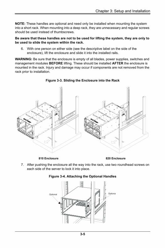

8U SuperBlade Userrsquos Manual
8 The enclosure is now securely installed in the rack (see Figure 3-5)
Figure 3-5 Enclosure Installed into Rack
3-6
Chapter 4 System Modules
Chapter 4System Modules
In addition to the blade units your blade system comes equipped with one or more system modules The modules fit into the rear of the enclosure into bays above andor below the power supplies This chapter describes the various blade modules that may be part of your blade system Module configurations can be customized you can install two of the same type module for redundancy purposes or you may omit a module altogether (except for the CMM which is a required module) Figure 4-1 shows a typical module configuration in a blade system See Chapter 5 for information on power supply modules
WARNING All module bays must be populated either with a module or a dummy module cover to maintain proper airflow
Figure 4-1 8U 820C Enclosure with 100G Switch Rear View
1 1
3
2
4 44
5 5 5 5
5555
4-1
8U SuperBlade Userrsquos Manual
Figure 4-2 8U 820J Enclosure with 2x25Gand 2x10G Switches Rear View
NOTE When setting up a bay the single wide bay is for 10G25G switches while the triple wide bay uses 100G switches for the 8U SuperBlade system
Table 4-1 Typical 8U Blade System Module Configuration Rear View
Item Description
1These bays can hold any of the following 1Gb Ethernet Switch Module or a 10Gb Ethernet Switch Module
2 CMM (Chassis Management Module) (x1 standard or x2 optional per enclosure)
3 These bays can hold a 25G Ethernet Switch
4 Dual System Fan Modules
5 2200W Power Supplies (x4 required x4 optional depending upon system requirements)
3 32
4 44
5 5 5 5
5555
2 11
4-2
Chapter 4 System Modules
Figure 4-3 8U 820L Enclosure with 2x10G Switches Rear View
Table 4-2 Typical 8U Blade System Module Configuration Rear View
Item Description
1These bays can hold any of the following 1Gb Ethernet Switch Module or a 10Gb Ethernet Switch Module
2 CMM (Chassis Management Module) (x1 standard or x2 optional per enclosure)
3 Dual System Fan Modules
4 2200W Power Supplies (x4 required x4 optional depending upon system requirements)
3 33
4 4 4 4
4444
2 11
4-3
8U SuperBlade Userrsquos Manual
4-1 Chassis Management ModuleThe Chassis Management Module (CMM) (Figure 4-4) is a required module in a blade system This ldquocommandrdquo module communicates with the blade units the power supplies and the blade switches Used in conjunction with the Web Interface or IPMI View management software the CMM provides administrator control over individual blade units power supplies cooling fans and networking switches and monitors onboard temperatures power status voltage levels and fan speeds The standard CMM module for the 8U SuperBlade system is the MBM-CMM-FIO or MBM-CMM-001
NOTE Using the MBM-CMM-FIO in the enclosure allows the use of the two front mounted RJ45 ports on the enclosure however using the MBM-CMM-001 does not allow these ports to function
The CMM provides a dedicated local and remote KVM (keyboardvideomouse) connection over an out of band TCPIP Ethernet network during any server state (functioning blue-screen powered down BIOS and so on) It also supports Virtual Media (VM) redirection for CD floppy and USB mass storage devices and configures such information as the switch IP addresses A summary of CMM features is shown in Table 4-4
Figure 4-4 Chassis Management Module MBM-CMM-FIO
Table 4-3 MBM-CMM-FIO Module Interface
Item Description
1 Power LED
2 Fault LED
3 Information LED
4 USB Ports
5 IPMI Port
6 Ethernet Ports
7 Reset Button
8 Module Release Handle
2
3
1
7 4 6
5
4-4
Chapter 4 System Modules
Figure 4-5 Chassis Management Module MBM-CMM-001
Table 4-4 MBM-CMM-FIO Module Features
Feature Description
Management Capabilities Can manage 10 to 20 blade units network modules and 8 power supplies
PortsTwo Ethernet ports one IPMI Ethernet port and two USB ports (for debug only)
Basic Functions SupportedRemote KVM remote storage Serial-over-LAN (SOL) blade monitoring and control
System Management System management interface provided via dedicated LAN
Power Consumption Approximately 20W
Operating System Firmware (upgradable)
Table 4-5 MBM-CMM-001 Module Interface
Item Description
1 Power LED
2 Fault LED
3 Information LED
4 USB Ports
5 Ethernet Ports
6 Serial Port
7 Reset Button
8 Module Release Handle
2
3
1
7 4 5
8
6
4-5
8U SuperBlade Userrsquos Manual
Module Redundancy
A blade system must have one CMM and may have two for redundancy is offered only on a specific enclosure model which has the hardware capability to incorporate two CMMs on one backplane Since the CMM uses its own processor all monitoring and control functions are carried out regardless of the operation or power status of the blade units CMM modules can only be installed in the upper andor lower right module bays
Determining MasterSlave Modules Status
When a blade system has two CMM modules they are assigned a masterslave status This is done automatically with the default primary CMM specified for per each enclosure while there will be no redundant in certain enclosures
If the master CMM is powered down or removed (or is being reset by its user) the second (slave) CMM module will then immediately be assigned as the master The redundant CMM mode is only offered on specific chassis models The slave uses the previous master IP config in case of a fail over
NOTE The Slave CMM keeps the same logstatus as the Master CMM and uses the previous master IP config
CMM Module Installation
Use this procedure to install the MBM-CMM-FIO or MBM-CMM-001 CMM module to the 8U SuperBlade chassis Make sure the cover to the module has been installed before proceeding Follow the anti-static precautions described in Chapter 2
Installing the Module
1 Remove the dummy cover from the bay you want to place the module in
2 Place the modules release handle in the open position
3 Slide the module into the module bay until it stops
4 Push the release handle to the closed position
Table 4-6 MBM-CMM-001 Module Features
Feature Description
Management Capabilities Can manage 10 to 20 blade units network modules and 8 power supplies
Ports Two Ethernet ports one serial port and two USB ports (for debug only)
Basic Functions SupportedRemote KVM remote storage Serial-over-LAN (SOL) blade monitoring and control switch PWS monitor thermal redundant based on specific enclosure model
System ManagementSystem management interface provided via dedicated LAN switch PWS monitor thermal and is redundant based on the specific enclosure model
Power Consumption Approximately 20W
Operating System Firmware (upgradeable)
4-6
Chapter 4 System Modules
5 After the module has been installed and the handle locked it will turn on and a POST test will run to verify it is working properly
Removing the Module
1 Pull out the release handle to the open position
2 Pull the module out of the bay
3 Replace immediately with another module or with a dummy module cover to maintain airflow integrity
Configuring the CMM
To accessconfigure the CMM you first have to configure the IP settings of the CMM depending on you network environment The below procedure for this configuration just serves as a reference for getting the CMM setup If your system has Linux OS please follow similar instructions to get the CMM setup
The CMM access topology is as follows
DHCP Access
1 Connect a network cable to the CMM module
2 The system should boot into the default Fail Over mode The DHCP mode will appear on the CLI mode screen
3 If the system fail over and CLI is not active it will proceed to the next default IP of CMM at https192168100100
4 If the CMM cannot enter the default IP then an RJ45USB cable can be connected from the CMMs RJ45 Ethernet LAN Port to the Desktop Host using the USB Port in Serial Port mode with a speed set at 115200 The DHCP IP can be manually set at the same subnet-mask for gateway access at 19216810010001
Default IP Access
1 Connect network cable to the network port at CMM
2 At system Prompt https192168100100
Requirements are
bull Computer system with LAN (RJ45) port
bull RJ -45 Ethernet cable
The default IP of the CMM is https192168100100 Configure the Computer system (connected through Ethernet-LAN to the CMM) to the same address range (for example https192168100101) The default mode is the Fail Over mode If the DHCP fails then the CMM will automatically default to the IP address of the CMM
Configuring the CMM in Windows OS
1 Go to START CONTROL PANEL NETWORK CONNECTIONS
2 Right-click on LAN to view properties
4-7
8U SuperBlade Userrsquos Manual
3 Choose ldquoInternet Protocol (TCPIP)rdquo under the GENERAL tab and click on PROPERTIES (see Figure 4-6)
4 Manually configure the IP address of the computer system to be in the same address range as the CMM (see Figure 4-7)
Example
bull IP address https192168100101
bull Subnet Mask 2552552550
bull Default Gateway 1921681001
5 Once the IP address for the computer system is configured the CMM can be accessed through the web browser by entering the default IP address 192168100100 of the CMM into the browserrsquos address bar
Figure 4-6 Choose Internal Protocol
Figure 4-7 Manually Configure the IP Address
4-8
Chapter 4 System Modules
6 Now the IP address subnet mask and default gateway of the CMM can be changed according to the network environment (see Figure 4-8) Please refer to the Web-based Management Utility Userrsquos Manual for more information
WARNING Dont change any other setting unless you are familiar with it
NOTE The above screens are examples for purposes of demonstrating this procedure The screens you actually view may or may not appear the same as those shown above
CMM Functions
The following sections describe local functions and remote functions of the CMM With only minor exceptions all of the remote functions can be performed by one of three mechanisms web-based access to the CMM module access to the CMM using IPMIview a client tool implemented in Java or via IPMItool commands (DOS commands or shell scripted commands)
When the web based browser is used the CMM acts as a web server requiring a higher bandwidth connection to the CMM If there are any bandwidth constraints IPMI will provide a superior experience Additionally since graphical updates are provided by client-side Java IPMIview can also be a superior user experience
IPMItool on the other hand can provide the ability to issue similaridentical commands to many 8U SuperBlade enclosuresCMMrsquos to manage all of them in a similar way
Figure 4-8 Changing Settings
4-9
8U SuperBlade Userrsquos Manual
Remote KVM over IP
Remote KVM over IP is independent from local KVM (although local KVM can operate in parallel with Remote KVM) Remote KVM encrypts all communication between the remote user and the CMM
To Use Remote KVM over IP is initiated with the management software (IPMI View or Web-based utility) Attach the LAN cable to the LAN port on the CMM module then refer to Web-based Management Utility on page 4-12 to login and use either utility
Remote Storage (Virtual Media)
The Remote Storage function allows the user to connect to a remote storage device (such as a floppy hard disk or USB storage device) and access the device as if it were local This can be used not only to read and write to remote storage devices but to load an operating system from a remote drive
Serial Over LAN (SOL)
Serial Over LAN allows you to redirect the input and output of a serial port via IPMI in order to manage blade modules from a remote location
To Use Serial Over LAN can be activated via the Web-based Management utility See the Web-based Management Utility Userrsquos Manual for the procedure to initiate SOL
Monitoring Functions
Used in conjunction with IPMI or the Web-based Management utility the CMM module can monitor and provide information on the hardware health of the blade modules and the system as a whole In addition to the monitoring functions you can remotely power on power off or reboot a system
Health information includes
bull Temperature levels
bull Fan speeds
bull Voltage levels
bull Power status
Power Consumption Management
The CMM modulersquos firmware can also control all power onoff activity in the whole blade system This is done by using the Power button onboard BMC or from any other use of remote management software
Once a blade module is installed in the enclosure the installed CMM immediately receives information on the rated Max Power Consumption value of the new blade module The CMM then calculates whether there is enough power for this new blade module by comparing the Max Power Consumption value of the new blade module with the calculated Remaining Power value of the system
4-10
Chapter 4 System Modules
If there is enough power the CMM will power on the blade However if there is not enough power in the blade system then the new blade module is not powered on and the front panel LED on the enclosure will blink
After the blade is powered on the CMM then collects the actual power consumption of this individual blade and updates the calculated Remaining Power value for the system
The CMM also reserves power for all the networking and chassis management modules installed on the system
WARNING One CMM module must be running to control the power systems and prevent overloading
USB Ports and Reset Button
The USB Ports and Reset Button on the CMM are described below
Figure 4-9 USB Ports on CMM
USB PortsMBM-CMM-FIO Reset Button
USB PortsMBM-CMM-001 Reset Button
4-11
8U SuperBlade Userrsquos Manual
USB Ports
The USB ports on both CMM modules are shown in Figure 4-9 They are only used for debugging purposes and not for communication with your system
Reset Button
The Reset button located on the front of the CMM module is used to reset the following software settings to their defaults
To reset the CMM to factory defaults press and hold the Reset button for five seconds
Firmware
The firmware for the CMM switch resides in the module This firmware can be updated with the web-based management utility
Within the utility go to the MAINTENANCE gt UPDATE FIRMWARE screen in the Web-based Management Utility Here you can enter the name of the firmware you want to update or click on BROWSE to select the firmware file Finish by clicking the UPLOAD button
NOTE This process is not reversible once the firmware is updated so proceed with caution It might take a few minutes to complete this procedure
Web-based Management Utility
System management may be performed with either of three software packages IPMIview SMCIPMItool or a Web-based Management Utility Any of these utilities are designed to provide an administrator with a comprehensive set of functions and monitored data to keep tabs on the system and perform management activities
The Web-based Management Utility is a web-based interface that consolidates and simplifies system management for Supermicro 8U SuperBlade systems The Web-based Management Utility aggregates and displays data from the CMM module
The Web-based Management Utility provides the following key management features
bull Enables IT administrators to view in-depth hardware configuration and status information using a single intuitive interface
bull Provides an OS-independent remote graphical console
Table 4-7 CMM Reset Settings
Software Setting Default
User Name and Password Reset to ADMIN and ADMIN (case sensitive)
IP Address Reset to https192168100100
Gateway Address Reset to 0000
Subnet Mask Reset to 2552552550
4-12
Chapter 4 System Modules
bull Allows remote users to map local media (floppy removable disks and hard drives) or ISO images on a shared network drive to a blade server
Supported Browsers
The following browsers have been tested for use with the Web-based Management Utility It is recommended that you use the most current revision of the browser you choose The minimum browser revisions supported by the Web-based Management Utility are shown below
bull Internet Explorer 7
bull Firefox 2007
bull Netscape 903b
Network ConnectionLogin
To log into the Web-based Management Utility
1 Launch a web browser
2 In the address field of the browser enter the IP address that you assigned to the system and hit the ltENTERgt key
3 When the browser makes contact with Supermicrorsquos Chassis Management Module enter your username and password then click LOGIN
4 The WEB-BASED MANAGEMENT UTILITY HOME PAGE will then display as shown in Figure 4-10
Address Defaults
Table 4-8 shows the default addresses that are initially set for the CMM Afterwards you can change these values within the program (see the Web-based Management Utility Userrsquos Manual M for more details)
Table 4-8 Address Defaults
Default Description
Default IP Address https192168100100a
a Note The web address must be entered as https192168100100 in the web browser Entering only http gives you instead an address error
Default Gateway Address 0000
Default Subnet Mask 2552552550
Default username ADMIN
Default password ADMIN
4-13
8U SuperBlade Userrsquos Manual
Home Page
Figure 4-10 displays the WEB-BASED MANAGEMENT UTILITY HOME PAGE and its controls
Figure 4-10 Home Page
NOTE For more information on the Web-based Management Utility and a description of its controls see the Superblade Web-based Management Utility Userrsquos Manual for more details
4-14
Chapter 5 Power Supply Modules
Chapter 5Power Supply Modules
The 8U SuperBlade enclosure comes standard with one CMM module (see the Chapter 4 for details on the CMM module) and either two or four power supplies See Appendix A for summary specification details on the power supplies available to the 8U SuperBlade enclosure
5-1 Power Supply ModulesThe minimum amount of modules required to power the system depends upon the full complement of blade units installed into an enclosure and the type of switches installed in the enclosure An LED on the back of a power supply will be green when AC power is present and amber color when it fails
When installing only a few power supplies in the enclosure they should be installed first in the lower rather than the upper power bays This is to provide increased airflow across the memory modules within each blade module
The 2200W power supply modules require a 100-240V AC input and a C14 socket which requires a power cord with a C13 connector
Supermicros high-efficiency blade system power supplies deliver continuous redundant power up to 96 peak efficiency Each power supply module includes a management module that monitors the power supplies and the power enclosure
The features of these power supplies are shown below
Table 5-1 Amperage Draw Specifications for the PWS-2K21A-BR Power Supply
Watts Low Volts High Volts Low Amps High Amps
1200W 100 127 11 14
1980W 220 230 98 10
2090W 230 240 98 10
1800W 200 220 95 10
2200W (ULcUL only) 220 240 11 12
2090W (ULcUL only) 180 220 11 14
5-1
8U SuperBlade Userrsquos Manual
Figure 5-1 PWS-2K21A-BR Power Supply
Table 5-2 PWS-2K21A-BR Power Supply Features
Feature Description
Output 2200W2090W1980W1800W1200W
Type Redundant Module (N+1N+N)
+12V18333A (2200W) 17417A (2090W) 165A (1980W) 150A (1800W) or 100A (1200W)
+12VSB 2A
PFC Yes
Peak Efficiency 96+ (Titanium Level)
Input AC Range100-127V (1200W) 200-220V (1800W) 220-230V (1980W) 230-240V (2090W) 200-220V (2090W for UL amp cUL) or 220-240V (2200W for UL amp cUL)
Operating ConditionsTemp 0 to 50 C
Humidity 5 to 95 RH
Fan Type 80x80mm counter rotating fan
Dimensions (LxWxH) 2453 x 1065 x 84mm
5-2
Chapter 5 Power Supply Modules
BPP Batteries
BBP Batteries like all rechargeable batteries are consumable components that eventually their capacity and performance decline as they age Regular maintenance by charge and discharge cycles is recommended to maintain the effectiveness of the BBP batteries At least one charge and discharge cycle for every 30 days is recommended The BBP maintenance scheduler can be enabled and configured through the CMM
When the BBP function is disabled through the CMM the battery will discharge until the minimum energy state is reached While the battery function is disabled regular BBP maintenance cannot be performed since the battery energy remains at the lowest state and will not re-charge As a result the battery capacity and performance will decline at a faster pace andor cause the battery to no longer operate The battery will remain the minimum charge until the BBP function is again re-enabled through CMM The user should use the disabling BBP function with caution knowing that the possible outcome of degraded battery performance or not operational battery
Figure 5-2 PWS-1K20B-BR Battery Backup Power (BPP) Module
5-3
8U SuperBlade Userrsquos Manual
Under typical conditions the above is the estimated runtime for the BPP modules The runtime can be extended by adding additional BPP modules to a system
Table 5-3 PWS-1K20B-BR Battery Backup Power (BPP) Module Specifications
Feature Description
Total Output Power 1200W
Input 112 to 129VDC
Output 12V 12VSB
Form Factor MicroBlade
Dimensions 2453 x 1065 x 84-mm
Battery Cell Capacity 68Whr
Redundant N+1 N+N
I2C Remote Monitoring FRUSmart Battery I2C
+12V Output 100A
12VSB Output 25A
Efficiency Online mode battery power consumption less than 5W
Discharge Duration 1200W for 35 Seconds
Cell Chemistry Lithium-Ion
Cooling Internal 80 x 80-mm colling fan
Operating Temperature 5degC - 50degC
Table 5-4 PWS-1K20B-BR BPP Module Estimated Runtime
Power Load Installed BPP Modules Discharge Duration
1000W 4 180 Seconds
2000W 4 120 Seconds
3000W 4 60 Seconds
4000W 4 35 Seconds
4800W 4 35 Seconds
Table 5-5 Chassis Compatible with the BPP
Model Output Power Capacity SBE-820CB-422 SBE-820JB-422
PWS-1K208-BR 1200W 68Whour Up to 4 Up to 4
5-4
Chapter 5 Power Supply Modules
Power Supply Failure
If a power supply or a fan in a power supply fails the system management software will notify you of the situation In either case you will need to replace the power supply module with another identical one
NOTE Refer to wwwsupermicroproductssuperblade for possible updates on part numbers
Installing a Power Supply
1 Insert a replacement unit into the empty power bay with the handle to the left
WARNING This leftright orientation depends on the power supplyrsquos top or bottom location If you inadvertently put a power supply upside down in the lower slots it can be VERY difficult to remove the power supply
2 Push unit all the way in until it is firmly seated
3 Push the handle back into the closed position until it clicks into the locked position
4 Move the locking clip away from the socket and reconnect the power cord
Removing a Power Supply
First make sure the power supply has been shut down You can remove power from a power unit via your system management software
1 Remove the power cord from the power supply unit
2 Release the locking clip to unlock the power supply module
3 Pull out the handle and remove the unit the two-piece handle locks into the closed position To release the handle squeeze together the two metal plates of the handle with your thumb and fingers and then pull out
5-2 Redundant Power SuppliesEach blade enclosure can hold up to four power supplies Installing all four power supplies may provide you with redundant power ndash depending upon the number of blades in the enclosure the model and power level of the power supplies installed and the power load from modules in your system In most blade enclosure systems power supplies may be redundant and therefore provide backup in case of power supply failure The configuration for power redundancy is created using the IPMIView application tool for the system
For purposes of denoting the amount of redundancy a server system has N main power supplies to support the whole system working with a ldquo+rdquo number after the N denoting the number of redundant power supplies Hence if there is one power supply for redundancy in a system that has the feature of ldquoredundant powerrdquo the total of power supplies for that server system is denoted as N+1
5-5
8U SuperBlade Userrsquos Manual
For example suppose a 10-blade system has four 2200 Watt Power Supply Units (PSU) for a total power supply of 8800 Watts The maximum power usage of each blade is 375 Watts for a total power demand of 3750 Watts to run the whole system So in this example there are effectively two redundant power supplies (N+1) over what is needed to power the blades in the system
In the IPMIView tool you can set the priority (default CPU power usage) of each blade first before any PSU fails (0-gtshut down 50-gtthrottling 100-gtRunning) See Figure 5-3 below for an example
Therefore the following redundancies apply to your system when as an example 2200W power supplies fail
bull If one PSU fails then you have 6600 Watts available The CMM will detect the remaining power left for the whole system But because the total blade power usage is only 3750 Watts every blade can still work properly
bull If 2 PSUs fail then only 4400 Watts are left available to support the blade power usage The system can still support all ten blades running in it
bull If 3 PSUs fail then the remaining 2200 Watts available cannot support the whole system Therefore the CMM will start to shut down or throttle down the load in order to keep blades running based upon the priority settings that were made for each blade using the IPMIView application until the load is enough to power the remaining blade modules
Figure 5-3 Power Supply Status
5-6
Chapter 5 Power Supply Modules
5-3 Power Supply FansEach power supply unit has two to four rear fans These fans are not hot-swappable If one fails the power supply will continue to operate but you should replace the power supply unit at the earliest opportunity If two or more fans fail the power supply unit will shut down and the LED on the back will turn amber
5-7
8U SuperBlade Userrsquos Manual
5-8
Appendix ASystem Specifications
A-1 Enclosure Specifications
NOTE Up to 8x (N+1 or N+N redundant) 2200W Titanium certified (96 efficiency) AC power supplies or 2000W DC power supplies battery back-up option on SBE-820CE-422 PDU specs and requirements for rack
Table A-1 8U Enclosure Specification Features
EnclosureSBE-820C-822622 rack mount blade enclosures
Dimensions (WxHxD) 122 x 176 x 29 in (3098 x 447 x 7366 mm)
Blade Module SupportUp to either 10 full-height 4-socket or 20 half-height 2 socket hot-plug blade modules
System CoolingThree twin-PWM fan modules in the rear chassis In addition up to four (4) optional cooling fan modules can be used in place of four power supplies can be mounted in an enclosure
Power Supplies (modules required varies)
Rated Output Power 2200W (Part PWS-2K21-BR C-20 type socket) power supplies
Rated Output Voltages +12V (183A) +12Vsb (2A) for 2200W +12V (174A) +12Vsb (2A) for 2090W +12V (165A) +12Vsb (2A) for 1980W +12V (150A) +12Vsb (2A) for 1800W +12V (100A) +12Vsb (2A) for 1200W
Power Supply Model Numbers
bull PWS-2K21A-BR (for the SBE-820C-822 enclosure)
bull PWS-DF006-2F (for the SBE-820C-622 enclosure)
bull PWS-DF005-2F (for the SBE-820C-42 enclosure)
System Input Requirements
AC Input Voltage 220~240V AC auto-range for 2200W 230~240V AC auto-range for 2090W 220~230V AC auto-range for 1980W 200~220V AC auto-range for 1800W 100-127V AC auto-range for 1200W
Rated Input Current 12A-11A for 2200W 14-11A for 2090W 10-98A for 1980W 10-95A for 1800W 14-11A for 1200W
Rated Input Frequency 50 to 60 Hz
Thermal Range
Supermicrorsquos new 8U SuperBlade Enclosure has a wide thermal support range to incorporate a significant range of CPU TDP this can range from 85W 105W 125W 130W 140W 150W 155W 165W and 205W
A special heatsink is required for the gold CPU with TDP ranging from 165W-200W Extra wide heatsinks are required for the 205W platinum CPU
For further details please check with thermal specifications and advisory for conditional thermal support of 15-32deg degree ambient and 10-35deg degree ambient temperatures The 8U system will not support 5-45deg degree ambient temperatures
A-1
8U SuperBlade Userrsquos Manual
A-2 Environmental Specifications
A-3 Address Defaults
Table A-2 Environmental Specification Features
Operating Environment
Operating Temperature 10ordm to 35ordm C (50ordm to 95ordm F)
Non-operating Temperature -40ordm to 70ordm C (-40ordm to 158ordm F)
Operating Relative Humidity 8 to 90 (non-condensing)
Non-operating Relative Humidity 5 to 95 (non-condensing)
Regulatory Compliance
Electromagnetic Emissions
FCC Class A EN 55022 Class A EN 61000-3-2-3-3 CISPR 22 Class A
Electromagnetic Immunity
EN 55024CISPR 24 (EN 61000-4-2 EN 61000-4-3 EN 61000-4-4 EN 61000-4-5 EN 61000-4-6 EN 61000-4-8 EN 61000-4-11)
Safety
EN 60950IEC 60950-Compliant UL Listed (USA) CUL Listed (Canada) TUV Certified (Germany) CE Marking (Europe)
California Best Management Practices Regulations for Perchlorate Materials This Perchlorate warning applies only to products containing CR (Manganese Dioxide) Lithium coin cells ldquoPerchlorate Material-special handling may apply See wwwdtsccagovhazardouswasteperchlorate for details
Table A-3 Address Defaults
CMM Module
IP Address 192168100100
Gateway Address 0000
Subnet Mask 2552552550
User Name and Password ADMIN and ADMIN (case sensitive)
GbE Switch
IP Address 192168100102
Gateway Address 1921681001
Subnet Mask 2552552550
A-2
A-4 Power Supply Power Calculations
Table A-4 Power Supply Power Calculations (PWS-2K21A-BR)
Calculation Value
Watts 2200
Volts (HighLow) 240220
Amps (HighLow) 1211
Efficiency (High) 96
Power Factor (High) 98
10 Reserve (High) 15
10 Reserve (Low) 13
Amps (Total) 11240 volts
Table A-5 Power Supply Power Calculations (PWS-1K20B-BR)
Calculation Value
Watts 1200
Volts (HighLow)DC Output 12V 12Vsb
DC Input 112 to 129Vdc
Amps (HighLow)+12V Output 100A
12Vsb Output 2A
Efficiency (High) 94
Power Factor (High) 98
10 Reserve (High) 15
10 Reserve (Low) 13
A-3
8U SuperBlade Userrsquos Manual
Notes
A-4
Disclaimer
The products sold by Supermicro are not intended for and will not be used in life support systems medical equipment nuclear facilities or systems aircraft aircraft devices aircraftemergency communication devices or other critical systems whose failure to perform be reasonably expected to result in significant injury or loss of life or catastrophic property damage Accordingly 8U SuperBlade disclaims any and all liability and should buyer use or sell such products for use in such ultra-hazardous applications it does so entirely at its own risk Furthermore buyer agrees to fully indemnify defend and hold Supermicro harmless for and against any and all claims demands actions litigation and proceedings of any kind arising out of or related to such ultra-hazardous use or sale
8U SuperBlade Userrsquos Manual

Chapter 4 System Modules
Chapter 4System Modules
In addition to the blade units your blade system comes equipped with one or more system modules The modules fit into the rear of the enclosure into bays above andor below the power supplies This chapter describes the various blade modules that may be part of your blade system Module configurations can be customized you can install two of the same type module for redundancy purposes or you may omit a module altogether (except for the CMM which is a required module) Figure 4-1 shows a typical module configuration in a blade system See Chapter 5 for information on power supply modules
WARNING All module bays must be populated either with a module or a dummy module cover to maintain proper airflow
Figure 4-1 8U 820C Enclosure with 100G Switch Rear View
1 1
3
2
4 44
5 5 5 5
5555
4-1
8U SuperBlade Userrsquos Manual
Figure 4-2 8U 820J Enclosure with 2x25Gand 2x10G Switches Rear View
NOTE When setting up a bay the single wide bay is for 10G25G switches while the triple wide bay uses 100G switches for the 8U SuperBlade system
Table 4-1 Typical 8U Blade System Module Configuration Rear View
Item Description
1These bays can hold any of the following 1Gb Ethernet Switch Module or a 10Gb Ethernet Switch Module
2 CMM (Chassis Management Module) (x1 standard or x2 optional per enclosure)
3 These bays can hold a 25G Ethernet Switch
4 Dual System Fan Modules
5 2200W Power Supplies (x4 required x4 optional depending upon system requirements)
3 32
4 44
5 5 5 5
5555
2 11
4-2
Chapter 4 System Modules
Figure 4-3 8U 820L Enclosure with 2x10G Switches Rear View
Table 4-2 Typical 8U Blade System Module Configuration Rear View
Item Description
1These bays can hold any of the following 1Gb Ethernet Switch Module or a 10Gb Ethernet Switch Module
2 CMM (Chassis Management Module) (x1 standard or x2 optional per enclosure)
3 Dual System Fan Modules
4 2200W Power Supplies (x4 required x4 optional depending upon system requirements)
3 33
4 4 4 4
4444
2 11
4-3
8U SuperBlade Userrsquos Manual
4-1 Chassis Management ModuleThe Chassis Management Module (CMM) (Figure 4-4) is a required module in a blade system This ldquocommandrdquo module communicates with the blade units the power supplies and the blade switches Used in conjunction with the Web Interface or IPMI View management software the CMM provides administrator control over individual blade units power supplies cooling fans and networking switches and monitors onboard temperatures power status voltage levels and fan speeds The standard CMM module for the 8U SuperBlade system is the MBM-CMM-FIO or MBM-CMM-001
NOTE Using the MBM-CMM-FIO in the enclosure allows the use of the two front mounted RJ45 ports on the enclosure however using the MBM-CMM-001 does not allow these ports to function
The CMM provides a dedicated local and remote KVM (keyboardvideomouse) connection over an out of band TCPIP Ethernet network during any server state (functioning blue-screen powered down BIOS and so on) It also supports Virtual Media (VM) redirection for CD floppy and USB mass storage devices and configures such information as the switch IP addresses A summary of CMM features is shown in Table 4-4
Figure 4-4 Chassis Management Module MBM-CMM-FIO
Table 4-3 MBM-CMM-FIO Module Interface
Item Description
1 Power LED
2 Fault LED
3 Information LED
4 USB Ports
5 IPMI Port
6 Ethernet Ports
7 Reset Button
8 Module Release Handle
2
3
1
7 4 6
5
4-4
Chapter 4 System Modules
Figure 4-5 Chassis Management Module MBM-CMM-001
Table 4-4 MBM-CMM-FIO Module Features
Feature Description
Management Capabilities Can manage 10 to 20 blade units network modules and 8 power supplies
PortsTwo Ethernet ports one IPMI Ethernet port and two USB ports (for debug only)
Basic Functions SupportedRemote KVM remote storage Serial-over-LAN (SOL) blade monitoring and control
System Management System management interface provided via dedicated LAN
Power Consumption Approximately 20W
Operating System Firmware (upgradable)
Table 4-5 MBM-CMM-001 Module Interface
Item Description
1 Power LED
2 Fault LED
3 Information LED
4 USB Ports
5 Ethernet Ports
6 Serial Port
7 Reset Button
8 Module Release Handle
2
3
1
7 4 5
8
6
4-5
8U SuperBlade Userrsquos Manual
Module Redundancy
A blade system must have one CMM and may have two for redundancy is offered only on a specific enclosure model which has the hardware capability to incorporate two CMMs on one backplane Since the CMM uses its own processor all monitoring and control functions are carried out regardless of the operation or power status of the blade units CMM modules can only be installed in the upper andor lower right module bays
Determining MasterSlave Modules Status
When a blade system has two CMM modules they are assigned a masterslave status This is done automatically with the default primary CMM specified for per each enclosure while there will be no redundant in certain enclosures
If the master CMM is powered down or removed (or is being reset by its user) the second (slave) CMM module will then immediately be assigned as the master The redundant CMM mode is only offered on specific chassis models The slave uses the previous master IP config in case of a fail over
NOTE The Slave CMM keeps the same logstatus as the Master CMM and uses the previous master IP config
CMM Module Installation
Use this procedure to install the MBM-CMM-FIO or MBM-CMM-001 CMM module to the 8U SuperBlade chassis Make sure the cover to the module has been installed before proceeding Follow the anti-static precautions described in Chapter 2
Installing the Module
1 Remove the dummy cover from the bay you want to place the module in
2 Place the modules release handle in the open position
3 Slide the module into the module bay until it stops
4 Push the release handle to the closed position
Table 4-6 MBM-CMM-001 Module Features
Feature Description
Management Capabilities Can manage 10 to 20 blade units network modules and 8 power supplies
Ports Two Ethernet ports one serial port and two USB ports (for debug only)
Basic Functions SupportedRemote KVM remote storage Serial-over-LAN (SOL) blade monitoring and control switch PWS monitor thermal redundant based on specific enclosure model
System ManagementSystem management interface provided via dedicated LAN switch PWS monitor thermal and is redundant based on the specific enclosure model
Power Consumption Approximately 20W
Operating System Firmware (upgradeable)
4-6
Chapter 4 System Modules
5 After the module has been installed and the handle locked it will turn on and a POST test will run to verify it is working properly
Removing the Module
1 Pull out the release handle to the open position
2 Pull the module out of the bay
3 Replace immediately with another module or with a dummy module cover to maintain airflow integrity
Configuring the CMM
To accessconfigure the CMM you first have to configure the IP settings of the CMM depending on you network environment The below procedure for this configuration just serves as a reference for getting the CMM setup If your system has Linux OS please follow similar instructions to get the CMM setup
The CMM access topology is as follows
DHCP Access
1 Connect a network cable to the CMM module
2 The system should boot into the default Fail Over mode The DHCP mode will appear on the CLI mode screen
3 If the system fail over and CLI is not active it will proceed to the next default IP of CMM at https192168100100
4 If the CMM cannot enter the default IP then an RJ45USB cable can be connected from the CMMs RJ45 Ethernet LAN Port to the Desktop Host using the USB Port in Serial Port mode with a speed set at 115200 The DHCP IP can be manually set at the same subnet-mask for gateway access at 19216810010001
Default IP Access
1 Connect network cable to the network port at CMM
2 At system Prompt https192168100100
Requirements are
bull Computer system with LAN (RJ45) port
bull RJ -45 Ethernet cable
The default IP of the CMM is https192168100100 Configure the Computer system (connected through Ethernet-LAN to the CMM) to the same address range (for example https192168100101) The default mode is the Fail Over mode If the DHCP fails then the CMM will automatically default to the IP address of the CMM
Configuring the CMM in Windows OS
1 Go to START CONTROL PANEL NETWORK CONNECTIONS
2 Right-click on LAN to view properties
4-7
8U SuperBlade Userrsquos Manual
3 Choose ldquoInternet Protocol (TCPIP)rdquo under the GENERAL tab and click on PROPERTIES (see Figure 4-6)
4 Manually configure the IP address of the computer system to be in the same address range as the CMM (see Figure 4-7)
Example
bull IP address https192168100101
bull Subnet Mask 2552552550
bull Default Gateway 1921681001
5 Once the IP address for the computer system is configured the CMM can be accessed through the web browser by entering the default IP address 192168100100 of the CMM into the browserrsquos address bar
Figure 4-6 Choose Internal Protocol
Figure 4-7 Manually Configure the IP Address
4-8
Chapter 4 System Modules
6 Now the IP address subnet mask and default gateway of the CMM can be changed according to the network environment (see Figure 4-8) Please refer to the Web-based Management Utility Userrsquos Manual for more information
WARNING Dont change any other setting unless you are familiar with it
NOTE The above screens are examples for purposes of demonstrating this procedure The screens you actually view may or may not appear the same as those shown above
CMM Functions
The following sections describe local functions and remote functions of the CMM With only minor exceptions all of the remote functions can be performed by one of three mechanisms web-based access to the CMM module access to the CMM using IPMIview a client tool implemented in Java or via IPMItool commands (DOS commands or shell scripted commands)
When the web based browser is used the CMM acts as a web server requiring a higher bandwidth connection to the CMM If there are any bandwidth constraints IPMI will provide a superior experience Additionally since graphical updates are provided by client-side Java IPMIview can also be a superior user experience
IPMItool on the other hand can provide the ability to issue similaridentical commands to many 8U SuperBlade enclosuresCMMrsquos to manage all of them in a similar way
Figure 4-8 Changing Settings
4-9
8U SuperBlade Userrsquos Manual
Remote KVM over IP
Remote KVM over IP is independent from local KVM (although local KVM can operate in parallel with Remote KVM) Remote KVM encrypts all communication between the remote user and the CMM
To Use Remote KVM over IP is initiated with the management software (IPMI View or Web-based utility) Attach the LAN cable to the LAN port on the CMM module then refer to Web-based Management Utility on page 4-12 to login and use either utility
Remote Storage (Virtual Media)
The Remote Storage function allows the user to connect to a remote storage device (such as a floppy hard disk or USB storage device) and access the device as if it were local This can be used not only to read and write to remote storage devices but to load an operating system from a remote drive
Serial Over LAN (SOL)
Serial Over LAN allows you to redirect the input and output of a serial port via IPMI in order to manage blade modules from a remote location
To Use Serial Over LAN can be activated via the Web-based Management utility See the Web-based Management Utility Userrsquos Manual for the procedure to initiate SOL
Monitoring Functions
Used in conjunction with IPMI or the Web-based Management utility the CMM module can monitor and provide information on the hardware health of the blade modules and the system as a whole In addition to the monitoring functions you can remotely power on power off or reboot a system
Health information includes
bull Temperature levels
bull Fan speeds
bull Voltage levels
bull Power status
Power Consumption Management
The CMM modulersquos firmware can also control all power onoff activity in the whole blade system This is done by using the Power button onboard BMC or from any other use of remote management software
Once a blade module is installed in the enclosure the installed CMM immediately receives information on the rated Max Power Consumption value of the new blade module The CMM then calculates whether there is enough power for this new blade module by comparing the Max Power Consumption value of the new blade module with the calculated Remaining Power value of the system
4-10
Chapter 4 System Modules
If there is enough power the CMM will power on the blade However if there is not enough power in the blade system then the new blade module is not powered on and the front panel LED on the enclosure will blink
After the blade is powered on the CMM then collects the actual power consumption of this individual blade and updates the calculated Remaining Power value for the system
The CMM also reserves power for all the networking and chassis management modules installed on the system
WARNING One CMM module must be running to control the power systems and prevent overloading
USB Ports and Reset Button
The USB Ports and Reset Button on the CMM are described below
Figure 4-9 USB Ports on CMM
USB PortsMBM-CMM-FIO Reset Button
USB PortsMBM-CMM-001 Reset Button
4-11
8U SuperBlade Userrsquos Manual
USB Ports
The USB ports on both CMM modules are shown in Figure 4-9 They are only used for debugging purposes and not for communication with your system
Reset Button
The Reset button located on the front of the CMM module is used to reset the following software settings to their defaults
To reset the CMM to factory defaults press and hold the Reset button for five seconds
Firmware
The firmware for the CMM switch resides in the module This firmware can be updated with the web-based management utility
Within the utility go to the MAINTENANCE gt UPDATE FIRMWARE screen in the Web-based Management Utility Here you can enter the name of the firmware you want to update or click on BROWSE to select the firmware file Finish by clicking the UPLOAD button
NOTE This process is not reversible once the firmware is updated so proceed with caution It might take a few minutes to complete this procedure
Web-based Management Utility
System management may be performed with either of three software packages IPMIview SMCIPMItool or a Web-based Management Utility Any of these utilities are designed to provide an administrator with a comprehensive set of functions and monitored data to keep tabs on the system and perform management activities
The Web-based Management Utility is a web-based interface that consolidates and simplifies system management for Supermicro 8U SuperBlade systems The Web-based Management Utility aggregates and displays data from the CMM module
The Web-based Management Utility provides the following key management features
bull Enables IT administrators to view in-depth hardware configuration and status information using a single intuitive interface
bull Provides an OS-independent remote graphical console
Table 4-7 CMM Reset Settings
Software Setting Default
User Name and Password Reset to ADMIN and ADMIN (case sensitive)
IP Address Reset to https192168100100
Gateway Address Reset to 0000
Subnet Mask Reset to 2552552550
4-12
Chapter 4 System Modules
bull Allows remote users to map local media (floppy removable disks and hard drives) or ISO images on a shared network drive to a blade server
Supported Browsers
The following browsers have been tested for use with the Web-based Management Utility It is recommended that you use the most current revision of the browser you choose The minimum browser revisions supported by the Web-based Management Utility are shown below
bull Internet Explorer 7
bull Firefox 2007
bull Netscape 903b
Network ConnectionLogin
To log into the Web-based Management Utility
1 Launch a web browser
2 In the address field of the browser enter the IP address that you assigned to the system and hit the ltENTERgt key
3 When the browser makes contact with Supermicrorsquos Chassis Management Module enter your username and password then click LOGIN
4 The WEB-BASED MANAGEMENT UTILITY HOME PAGE will then display as shown in Figure 4-10
Address Defaults
Table 4-8 shows the default addresses that are initially set for the CMM Afterwards you can change these values within the program (see the Web-based Management Utility Userrsquos Manual M for more details)
Table 4-8 Address Defaults
Default Description
Default IP Address https192168100100a
a Note The web address must be entered as https192168100100 in the web browser Entering only http gives you instead an address error
Default Gateway Address 0000
Default Subnet Mask 2552552550
Default username ADMIN
Default password ADMIN
4-13
8U SuperBlade Userrsquos Manual
Home Page
Figure 4-10 displays the WEB-BASED MANAGEMENT UTILITY HOME PAGE and its controls
Figure 4-10 Home Page
NOTE For more information on the Web-based Management Utility and a description of its controls see the Superblade Web-based Management Utility Userrsquos Manual for more details
4-14
Chapter 5 Power Supply Modules
Chapter 5Power Supply Modules
The 8U SuperBlade enclosure comes standard with one CMM module (see the Chapter 4 for details on the CMM module) and either two or four power supplies See Appendix A for summary specification details on the power supplies available to the 8U SuperBlade enclosure
5-1 Power Supply ModulesThe minimum amount of modules required to power the system depends upon the full complement of blade units installed into an enclosure and the type of switches installed in the enclosure An LED on the back of a power supply will be green when AC power is present and amber color when it fails
When installing only a few power supplies in the enclosure they should be installed first in the lower rather than the upper power bays This is to provide increased airflow across the memory modules within each blade module
The 2200W power supply modules require a 100-240V AC input and a C14 socket which requires a power cord with a C13 connector
Supermicros high-efficiency blade system power supplies deliver continuous redundant power up to 96 peak efficiency Each power supply module includes a management module that monitors the power supplies and the power enclosure
The features of these power supplies are shown below
Table 5-1 Amperage Draw Specifications for the PWS-2K21A-BR Power Supply
Watts Low Volts High Volts Low Amps High Amps
1200W 100 127 11 14
1980W 220 230 98 10
2090W 230 240 98 10
1800W 200 220 95 10
2200W (ULcUL only) 220 240 11 12
2090W (ULcUL only) 180 220 11 14
5-1
8U SuperBlade Userrsquos Manual
Figure 5-1 PWS-2K21A-BR Power Supply
Table 5-2 PWS-2K21A-BR Power Supply Features
Feature Description
Output 2200W2090W1980W1800W1200W
Type Redundant Module (N+1N+N)
+12V18333A (2200W) 17417A (2090W) 165A (1980W) 150A (1800W) or 100A (1200W)
+12VSB 2A
PFC Yes
Peak Efficiency 96+ (Titanium Level)
Input AC Range100-127V (1200W) 200-220V (1800W) 220-230V (1980W) 230-240V (2090W) 200-220V (2090W for UL amp cUL) or 220-240V (2200W for UL amp cUL)
Operating ConditionsTemp 0 to 50 C
Humidity 5 to 95 RH
Fan Type 80x80mm counter rotating fan
Dimensions (LxWxH) 2453 x 1065 x 84mm
5-2
Chapter 5 Power Supply Modules
BPP Batteries
BBP Batteries like all rechargeable batteries are consumable components that eventually their capacity and performance decline as they age Regular maintenance by charge and discharge cycles is recommended to maintain the effectiveness of the BBP batteries At least one charge and discharge cycle for every 30 days is recommended The BBP maintenance scheduler can be enabled and configured through the CMM
When the BBP function is disabled through the CMM the battery will discharge until the minimum energy state is reached While the battery function is disabled regular BBP maintenance cannot be performed since the battery energy remains at the lowest state and will not re-charge As a result the battery capacity and performance will decline at a faster pace andor cause the battery to no longer operate The battery will remain the minimum charge until the BBP function is again re-enabled through CMM The user should use the disabling BBP function with caution knowing that the possible outcome of degraded battery performance or not operational battery
Figure 5-2 PWS-1K20B-BR Battery Backup Power (BPP) Module
5-3
8U SuperBlade Userrsquos Manual
Under typical conditions the above is the estimated runtime for the BPP modules The runtime can be extended by adding additional BPP modules to a system
Table 5-3 PWS-1K20B-BR Battery Backup Power (BPP) Module Specifications
Feature Description
Total Output Power 1200W
Input 112 to 129VDC
Output 12V 12VSB
Form Factor MicroBlade
Dimensions 2453 x 1065 x 84-mm
Battery Cell Capacity 68Whr
Redundant N+1 N+N
I2C Remote Monitoring FRUSmart Battery I2C
+12V Output 100A
12VSB Output 25A
Efficiency Online mode battery power consumption less than 5W
Discharge Duration 1200W for 35 Seconds
Cell Chemistry Lithium-Ion
Cooling Internal 80 x 80-mm colling fan
Operating Temperature 5degC - 50degC
Table 5-4 PWS-1K20B-BR BPP Module Estimated Runtime
Power Load Installed BPP Modules Discharge Duration
1000W 4 180 Seconds
2000W 4 120 Seconds
3000W 4 60 Seconds
4000W 4 35 Seconds
4800W 4 35 Seconds
Table 5-5 Chassis Compatible with the BPP
Model Output Power Capacity SBE-820CB-422 SBE-820JB-422
PWS-1K208-BR 1200W 68Whour Up to 4 Up to 4
5-4
Chapter 5 Power Supply Modules
Power Supply Failure
If a power supply or a fan in a power supply fails the system management software will notify you of the situation In either case you will need to replace the power supply module with another identical one
NOTE Refer to wwwsupermicroproductssuperblade for possible updates on part numbers
Installing a Power Supply
1 Insert a replacement unit into the empty power bay with the handle to the left
WARNING This leftright orientation depends on the power supplyrsquos top or bottom location If you inadvertently put a power supply upside down in the lower slots it can be VERY difficult to remove the power supply
2 Push unit all the way in until it is firmly seated
3 Push the handle back into the closed position until it clicks into the locked position
4 Move the locking clip away from the socket and reconnect the power cord
Removing a Power Supply
First make sure the power supply has been shut down You can remove power from a power unit via your system management software
1 Remove the power cord from the power supply unit
2 Release the locking clip to unlock the power supply module
3 Pull out the handle and remove the unit the two-piece handle locks into the closed position To release the handle squeeze together the two metal plates of the handle with your thumb and fingers and then pull out
5-2 Redundant Power SuppliesEach blade enclosure can hold up to four power supplies Installing all four power supplies may provide you with redundant power ndash depending upon the number of blades in the enclosure the model and power level of the power supplies installed and the power load from modules in your system In most blade enclosure systems power supplies may be redundant and therefore provide backup in case of power supply failure The configuration for power redundancy is created using the IPMIView application tool for the system
For purposes of denoting the amount of redundancy a server system has N main power supplies to support the whole system working with a ldquo+rdquo number after the N denoting the number of redundant power supplies Hence if there is one power supply for redundancy in a system that has the feature of ldquoredundant powerrdquo the total of power supplies for that server system is denoted as N+1
5-5
8U SuperBlade Userrsquos Manual
For example suppose a 10-blade system has four 2200 Watt Power Supply Units (PSU) for a total power supply of 8800 Watts The maximum power usage of each blade is 375 Watts for a total power demand of 3750 Watts to run the whole system So in this example there are effectively two redundant power supplies (N+1) over what is needed to power the blades in the system
In the IPMIView tool you can set the priority (default CPU power usage) of each blade first before any PSU fails (0-gtshut down 50-gtthrottling 100-gtRunning) See Figure 5-3 below for an example
Therefore the following redundancies apply to your system when as an example 2200W power supplies fail
bull If one PSU fails then you have 6600 Watts available The CMM will detect the remaining power left for the whole system But because the total blade power usage is only 3750 Watts every blade can still work properly
bull If 2 PSUs fail then only 4400 Watts are left available to support the blade power usage The system can still support all ten blades running in it
bull If 3 PSUs fail then the remaining 2200 Watts available cannot support the whole system Therefore the CMM will start to shut down or throttle down the load in order to keep blades running based upon the priority settings that were made for each blade using the IPMIView application until the load is enough to power the remaining blade modules
Figure 5-3 Power Supply Status
5-6
Chapter 5 Power Supply Modules
5-3 Power Supply FansEach power supply unit has two to four rear fans These fans are not hot-swappable If one fails the power supply will continue to operate but you should replace the power supply unit at the earliest opportunity If two or more fans fail the power supply unit will shut down and the LED on the back will turn amber
5-7
8U SuperBlade Userrsquos Manual
5-8
Appendix ASystem Specifications
A-1 Enclosure Specifications
NOTE Up to 8x (N+1 or N+N redundant) 2200W Titanium certified (96 efficiency) AC power supplies or 2000W DC power supplies battery back-up option on SBE-820CE-422 PDU specs and requirements for rack
Table A-1 8U Enclosure Specification Features
EnclosureSBE-820C-822622 rack mount blade enclosures
Dimensions (WxHxD) 122 x 176 x 29 in (3098 x 447 x 7366 mm)
Blade Module SupportUp to either 10 full-height 4-socket or 20 half-height 2 socket hot-plug blade modules
System CoolingThree twin-PWM fan modules in the rear chassis In addition up to four (4) optional cooling fan modules can be used in place of four power supplies can be mounted in an enclosure
Power Supplies (modules required varies)
Rated Output Power 2200W (Part PWS-2K21-BR C-20 type socket) power supplies
Rated Output Voltages +12V (183A) +12Vsb (2A) for 2200W +12V (174A) +12Vsb (2A) for 2090W +12V (165A) +12Vsb (2A) for 1980W +12V (150A) +12Vsb (2A) for 1800W +12V (100A) +12Vsb (2A) for 1200W
Power Supply Model Numbers
bull PWS-2K21A-BR (for the SBE-820C-822 enclosure)
bull PWS-DF006-2F (for the SBE-820C-622 enclosure)
bull PWS-DF005-2F (for the SBE-820C-42 enclosure)
System Input Requirements
AC Input Voltage 220~240V AC auto-range for 2200W 230~240V AC auto-range for 2090W 220~230V AC auto-range for 1980W 200~220V AC auto-range for 1800W 100-127V AC auto-range for 1200W
Rated Input Current 12A-11A for 2200W 14-11A for 2090W 10-98A for 1980W 10-95A for 1800W 14-11A for 1200W
Rated Input Frequency 50 to 60 Hz
Thermal Range
Supermicrorsquos new 8U SuperBlade Enclosure has a wide thermal support range to incorporate a significant range of CPU TDP this can range from 85W 105W 125W 130W 140W 150W 155W 165W and 205W
A special heatsink is required for the gold CPU with TDP ranging from 165W-200W Extra wide heatsinks are required for the 205W platinum CPU
For further details please check with thermal specifications and advisory for conditional thermal support of 15-32deg degree ambient and 10-35deg degree ambient temperatures The 8U system will not support 5-45deg degree ambient temperatures
A-1
8U SuperBlade Userrsquos Manual
A-2 Environmental Specifications
A-3 Address Defaults
Table A-2 Environmental Specification Features
Operating Environment
Operating Temperature 10ordm to 35ordm C (50ordm to 95ordm F)
Non-operating Temperature -40ordm to 70ordm C (-40ordm to 158ordm F)
Operating Relative Humidity 8 to 90 (non-condensing)
Non-operating Relative Humidity 5 to 95 (non-condensing)
Regulatory Compliance
Electromagnetic Emissions
FCC Class A EN 55022 Class A EN 61000-3-2-3-3 CISPR 22 Class A
Electromagnetic Immunity
EN 55024CISPR 24 (EN 61000-4-2 EN 61000-4-3 EN 61000-4-4 EN 61000-4-5 EN 61000-4-6 EN 61000-4-8 EN 61000-4-11)
Safety
EN 60950IEC 60950-Compliant UL Listed (USA) CUL Listed (Canada) TUV Certified (Germany) CE Marking (Europe)
California Best Management Practices Regulations for Perchlorate Materials This Perchlorate warning applies only to products containing CR (Manganese Dioxide) Lithium coin cells ldquoPerchlorate Material-special handling may apply See wwwdtsccagovhazardouswasteperchlorate for details
Table A-3 Address Defaults
CMM Module
IP Address 192168100100
Gateway Address 0000
Subnet Mask 2552552550
User Name and Password ADMIN and ADMIN (case sensitive)
GbE Switch
IP Address 192168100102
Gateway Address 1921681001
Subnet Mask 2552552550
A-2
A-4 Power Supply Power Calculations
Table A-4 Power Supply Power Calculations (PWS-2K21A-BR)
Calculation Value
Watts 2200
Volts (HighLow) 240220
Amps (HighLow) 1211
Efficiency (High) 96
Power Factor (High) 98
10 Reserve (High) 15
10 Reserve (Low) 13
Amps (Total) 11240 volts
Table A-5 Power Supply Power Calculations (PWS-1K20B-BR)
Calculation Value
Watts 1200
Volts (HighLow)DC Output 12V 12Vsb
DC Input 112 to 129Vdc
Amps (HighLow)+12V Output 100A
12Vsb Output 2A
Efficiency (High) 94
Power Factor (High) 98
10 Reserve (High) 15
10 Reserve (Low) 13
A-3
8U SuperBlade Userrsquos Manual
Notes
A-4
Disclaimer
The products sold by Supermicro are not intended for and will not be used in life support systems medical equipment nuclear facilities or systems aircraft aircraft devices aircraftemergency communication devices or other critical systems whose failure to perform be reasonably expected to result in significant injury or loss of life or catastrophic property damage Accordingly 8U SuperBlade disclaims any and all liability and should buyer use or sell such products for use in such ultra-hazardous applications it does so entirely at its own risk Furthermore buyer agrees to fully indemnify defend and hold Supermicro harmless for and against any and all claims demands actions litigation and proceedings of any kind arising out of or related to such ultra-hazardous use or sale
8U SuperBlade Userrsquos Manual

8U SuperBlade Userrsquos Manual
Figure 4-2 8U 820J Enclosure with 2x25Gand 2x10G Switches Rear View
NOTE When setting up a bay the single wide bay is for 10G25G switches while the triple wide bay uses 100G switches for the 8U SuperBlade system
Table 4-1 Typical 8U Blade System Module Configuration Rear View
Item Description
1These bays can hold any of the following 1Gb Ethernet Switch Module or a 10Gb Ethernet Switch Module
2 CMM (Chassis Management Module) (x1 standard or x2 optional per enclosure)
3 These bays can hold a 25G Ethernet Switch
4 Dual System Fan Modules
5 2200W Power Supplies (x4 required x4 optional depending upon system requirements)
3 32
4 44
5 5 5 5
5555
2 11
4-2
Chapter 4 System Modules
Figure 4-3 8U 820L Enclosure with 2x10G Switches Rear View
Table 4-2 Typical 8U Blade System Module Configuration Rear View
Item Description
1These bays can hold any of the following 1Gb Ethernet Switch Module or a 10Gb Ethernet Switch Module
2 CMM (Chassis Management Module) (x1 standard or x2 optional per enclosure)
3 Dual System Fan Modules
4 2200W Power Supplies (x4 required x4 optional depending upon system requirements)
3 33
4 4 4 4
4444
2 11
4-3
8U SuperBlade Userrsquos Manual
4-1 Chassis Management ModuleThe Chassis Management Module (CMM) (Figure 4-4) is a required module in a blade system This ldquocommandrdquo module communicates with the blade units the power supplies and the blade switches Used in conjunction with the Web Interface or IPMI View management software the CMM provides administrator control over individual blade units power supplies cooling fans and networking switches and monitors onboard temperatures power status voltage levels and fan speeds The standard CMM module for the 8U SuperBlade system is the MBM-CMM-FIO or MBM-CMM-001
NOTE Using the MBM-CMM-FIO in the enclosure allows the use of the two front mounted RJ45 ports on the enclosure however using the MBM-CMM-001 does not allow these ports to function
The CMM provides a dedicated local and remote KVM (keyboardvideomouse) connection over an out of band TCPIP Ethernet network during any server state (functioning blue-screen powered down BIOS and so on) It also supports Virtual Media (VM) redirection for CD floppy and USB mass storage devices and configures such information as the switch IP addresses A summary of CMM features is shown in Table 4-4
Figure 4-4 Chassis Management Module MBM-CMM-FIO
Table 4-3 MBM-CMM-FIO Module Interface
Item Description
1 Power LED
2 Fault LED
3 Information LED
4 USB Ports
5 IPMI Port
6 Ethernet Ports
7 Reset Button
8 Module Release Handle
2
3
1
7 4 6
5
4-4
Chapter 4 System Modules
Figure 4-5 Chassis Management Module MBM-CMM-001
Table 4-4 MBM-CMM-FIO Module Features
Feature Description
Management Capabilities Can manage 10 to 20 blade units network modules and 8 power supplies
PortsTwo Ethernet ports one IPMI Ethernet port and two USB ports (for debug only)
Basic Functions SupportedRemote KVM remote storage Serial-over-LAN (SOL) blade monitoring and control
System Management System management interface provided via dedicated LAN
Power Consumption Approximately 20W
Operating System Firmware (upgradable)
Table 4-5 MBM-CMM-001 Module Interface
Item Description
1 Power LED
2 Fault LED
3 Information LED
4 USB Ports
5 Ethernet Ports
6 Serial Port
7 Reset Button
8 Module Release Handle
2
3
1
7 4 5
8
6
4-5
8U SuperBlade Userrsquos Manual
Module Redundancy
A blade system must have one CMM and may have two for redundancy is offered only on a specific enclosure model which has the hardware capability to incorporate two CMMs on one backplane Since the CMM uses its own processor all monitoring and control functions are carried out regardless of the operation or power status of the blade units CMM modules can only be installed in the upper andor lower right module bays
Determining MasterSlave Modules Status
When a blade system has two CMM modules they are assigned a masterslave status This is done automatically with the default primary CMM specified for per each enclosure while there will be no redundant in certain enclosures
If the master CMM is powered down or removed (or is being reset by its user) the second (slave) CMM module will then immediately be assigned as the master The redundant CMM mode is only offered on specific chassis models The slave uses the previous master IP config in case of a fail over
NOTE The Slave CMM keeps the same logstatus as the Master CMM and uses the previous master IP config
CMM Module Installation
Use this procedure to install the MBM-CMM-FIO or MBM-CMM-001 CMM module to the 8U SuperBlade chassis Make sure the cover to the module has been installed before proceeding Follow the anti-static precautions described in Chapter 2
Installing the Module
1 Remove the dummy cover from the bay you want to place the module in
2 Place the modules release handle in the open position
3 Slide the module into the module bay until it stops
4 Push the release handle to the closed position
Table 4-6 MBM-CMM-001 Module Features
Feature Description
Management Capabilities Can manage 10 to 20 blade units network modules and 8 power supplies
Ports Two Ethernet ports one serial port and two USB ports (for debug only)
Basic Functions SupportedRemote KVM remote storage Serial-over-LAN (SOL) blade monitoring and control switch PWS monitor thermal redundant based on specific enclosure model
System ManagementSystem management interface provided via dedicated LAN switch PWS monitor thermal and is redundant based on the specific enclosure model
Power Consumption Approximately 20W
Operating System Firmware (upgradeable)
4-6
Chapter 4 System Modules
5 After the module has been installed and the handle locked it will turn on and a POST test will run to verify it is working properly
Removing the Module
1 Pull out the release handle to the open position
2 Pull the module out of the bay
3 Replace immediately with another module or with a dummy module cover to maintain airflow integrity
Configuring the CMM
To accessconfigure the CMM you first have to configure the IP settings of the CMM depending on you network environment The below procedure for this configuration just serves as a reference for getting the CMM setup If your system has Linux OS please follow similar instructions to get the CMM setup
The CMM access topology is as follows
DHCP Access
1 Connect a network cable to the CMM module
2 The system should boot into the default Fail Over mode The DHCP mode will appear on the CLI mode screen
3 If the system fail over and CLI is not active it will proceed to the next default IP of CMM at https192168100100
4 If the CMM cannot enter the default IP then an RJ45USB cable can be connected from the CMMs RJ45 Ethernet LAN Port to the Desktop Host using the USB Port in Serial Port mode with a speed set at 115200 The DHCP IP can be manually set at the same subnet-mask for gateway access at 19216810010001
Default IP Access
1 Connect network cable to the network port at CMM
2 At system Prompt https192168100100
Requirements are
bull Computer system with LAN (RJ45) port
bull RJ -45 Ethernet cable
The default IP of the CMM is https192168100100 Configure the Computer system (connected through Ethernet-LAN to the CMM) to the same address range (for example https192168100101) The default mode is the Fail Over mode If the DHCP fails then the CMM will automatically default to the IP address of the CMM
Configuring the CMM in Windows OS
1 Go to START CONTROL PANEL NETWORK CONNECTIONS
2 Right-click on LAN to view properties
4-7
8U SuperBlade Userrsquos Manual
3 Choose ldquoInternet Protocol (TCPIP)rdquo under the GENERAL tab and click on PROPERTIES (see Figure 4-6)
4 Manually configure the IP address of the computer system to be in the same address range as the CMM (see Figure 4-7)
Example
bull IP address https192168100101
bull Subnet Mask 2552552550
bull Default Gateway 1921681001
5 Once the IP address for the computer system is configured the CMM can be accessed through the web browser by entering the default IP address 192168100100 of the CMM into the browserrsquos address bar
Figure 4-6 Choose Internal Protocol
Figure 4-7 Manually Configure the IP Address
4-8
Chapter 4 System Modules
6 Now the IP address subnet mask and default gateway of the CMM can be changed according to the network environment (see Figure 4-8) Please refer to the Web-based Management Utility Userrsquos Manual for more information
WARNING Dont change any other setting unless you are familiar with it
NOTE The above screens are examples for purposes of demonstrating this procedure The screens you actually view may or may not appear the same as those shown above
CMM Functions
The following sections describe local functions and remote functions of the CMM With only minor exceptions all of the remote functions can be performed by one of three mechanisms web-based access to the CMM module access to the CMM using IPMIview a client tool implemented in Java or via IPMItool commands (DOS commands or shell scripted commands)
When the web based browser is used the CMM acts as a web server requiring a higher bandwidth connection to the CMM If there are any bandwidth constraints IPMI will provide a superior experience Additionally since graphical updates are provided by client-side Java IPMIview can also be a superior user experience
IPMItool on the other hand can provide the ability to issue similaridentical commands to many 8U SuperBlade enclosuresCMMrsquos to manage all of them in a similar way
Figure 4-8 Changing Settings
4-9
8U SuperBlade Userrsquos Manual
Remote KVM over IP
Remote KVM over IP is independent from local KVM (although local KVM can operate in parallel with Remote KVM) Remote KVM encrypts all communication between the remote user and the CMM
To Use Remote KVM over IP is initiated with the management software (IPMI View or Web-based utility) Attach the LAN cable to the LAN port on the CMM module then refer to Web-based Management Utility on page 4-12 to login and use either utility
Remote Storage (Virtual Media)
The Remote Storage function allows the user to connect to a remote storage device (such as a floppy hard disk or USB storage device) and access the device as if it were local This can be used not only to read and write to remote storage devices but to load an operating system from a remote drive
Serial Over LAN (SOL)
Serial Over LAN allows you to redirect the input and output of a serial port via IPMI in order to manage blade modules from a remote location
To Use Serial Over LAN can be activated via the Web-based Management utility See the Web-based Management Utility Userrsquos Manual for the procedure to initiate SOL
Monitoring Functions
Used in conjunction with IPMI or the Web-based Management utility the CMM module can monitor and provide information on the hardware health of the blade modules and the system as a whole In addition to the monitoring functions you can remotely power on power off or reboot a system
Health information includes
bull Temperature levels
bull Fan speeds
bull Voltage levels
bull Power status
Power Consumption Management
The CMM modulersquos firmware can also control all power onoff activity in the whole blade system This is done by using the Power button onboard BMC or from any other use of remote management software
Once a blade module is installed in the enclosure the installed CMM immediately receives information on the rated Max Power Consumption value of the new blade module The CMM then calculates whether there is enough power for this new blade module by comparing the Max Power Consumption value of the new blade module with the calculated Remaining Power value of the system
4-10
Chapter 4 System Modules
If there is enough power the CMM will power on the blade However if there is not enough power in the blade system then the new blade module is not powered on and the front panel LED on the enclosure will blink
After the blade is powered on the CMM then collects the actual power consumption of this individual blade and updates the calculated Remaining Power value for the system
The CMM also reserves power for all the networking and chassis management modules installed on the system
WARNING One CMM module must be running to control the power systems and prevent overloading
USB Ports and Reset Button
The USB Ports and Reset Button on the CMM are described below
Figure 4-9 USB Ports on CMM
USB PortsMBM-CMM-FIO Reset Button
USB PortsMBM-CMM-001 Reset Button
4-11
8U SuperBlade Userrsquos Manual
USB Ports
The USB ports on both CMM modules are shown in Figure 4-9 They are only used for debugging purposes and not for communication with your system
Reset Button
The Reset button located on the front of the CMM module is used to reset the following software settings to their defaults
To reset the CMM to factory defaults press and hold the Reset button for five seconds
Firmware
The firmware for the CMM switch resides in the module This firmware can be updated with the web-based management utility
Within the utility go to the MAINTENANCE gt UPDATE FIRMWARE screen in the Web-based Management Utility Here you can enter the name of the firmware you want to update or click on BROWSE to select the firmware file Finish by clicking the UPLOAD button
NOTE This process is not reversible once the firmware is updated so proceed with caution It might take a few minutes to complete this procedure
Web-based Management Utility
System management may be performed with either of three software packages IPMIview SMCIPMItool or a Web-based Management Utility Any of these utilities are designed to provide an administrator with a comprehensive set of functions and monitored data to keep tabs on the system and perform management activities
The Web-based Management Utility is a web-based interface that consolidates and simplifies system management for Supermicro 8U SuperBlade systems The Web-based Management Utility aggregates and displays data from the CMM module
The Web-based Management Utility provides the following key management features
bull Enables IT administrators to view in-depth hardware configuration and status information using a single intuitive interface
bull Provides an OS-independent remote graphical console
Table 4-7 CMM Reset Settings
Software Setting Default
User Name and Password Reset to ADMIN and ADMIN (case sensitive)
IP Address Reset to https192168100100
Gateway Address Reset to 0000
Subnet Mask Reset to 2552552550
4-12
Chapter 4 System Modules
bull Allows remote users to map local media (floppy removable disks and hard drives) or ISO images on a shared network drive to a blade server
Supported Browsers
The following browsers have been tested for use with the Web-based Management Utility It is recommended that you use the most current revision of the browser you choose The minimum browser revisions supported by the Web-based Management Utility are shown below
bull Internet Explorer 7
bull Firefox 2007
bull Netscape 903b
Network ConnectionLogin
To log into the Web-based Management Utility
1 Launch a web browser
2 In the address field of the browser enter the IP address that you assigned to the system and hit the ltENTERgt key
3 When the browser makes contact with Supermicrorsquos Chassis Management Module enter your username and password then click LOGIN
4 The WEB-BASED MANAGEMENT UTILITY HOME PAGE will then display as shown in Figure 4-10
Address Defaults
Table 4-8 shows the default addresses that are initially set for the CMM Afterwards you can change these values within the program (see the Web-based Management Utility Userrsquos Manual M for more details)
Table 4-8 Address Defaults
Default Description
Default IP Address https192168100100a
a Note The web address must be entered as https192168100100 in the web browser Entering only http gives you instead an address error
Default Gateway Address 0000
Default Subnet Mask 2552552550
Default username ADMIN
Default password ADMIN
4-13
8U SuperBlade Userrsquos Manual
Home Page
Figure 4-10 displays the WEB-BASED MANAGEMENT UTILITY HOME PAGE and its controls
Figure 4-10 Home Page
NOTE For more information on the Web-based Management Utility and a description of its controls see the Superblade Web-based Management Utility Userrsquos Manual for more details
4-14
Chapter 5 Power Supply Modules
Chapter 5Power Supply Modules
The 8U SuperBlade enclosure comes standard with one CMM module (see the Chapter 4 for details on the CMM module) and either two or four power supplies See Appendix A for summary specification details on the power supplies available to the 8U SuperBlade enclosure
5-1 Power Supply ModulesThe minimum amount of modules required to power the system depends upon the full complement of blade units installed into an enclosure and the type of switches installed in the enclosure An LED on the back of a power supply will be green when AC power is present and amber color when it fails
When installing only a few power supplies in the enclosure they should be installed first in the lower rather than the upper power bays This is to provide increased airflow across the memory modules within each blade module
The 2200W power supply modules require a 100-240V AC input and a C14 socket which requires a power cord with a C13 connector
Supermicros high-efficiency blade system power supplies deliver continuous redundant power up to 96 peak efficiency Each power supply module includes a management module that monitors the power supplies and the power enclosure
The features of these power supplies are shown below
Table 5-1 Amperage Draw Specifications for the PWS-2K21A-BR Power Supply
Watts Low Volts High Volts Low Amps High Amps
1200W 100 127 11 14
1980W 220 230 98 10
2090W 230 240 98 10
1800W 200 220 95 10
2200W (ULcUL only) 220 240 11 12
2090W (ULcUL only) 180 220 11 14
5-1
8U SuperBlade Userrsquos Manual
Figure 5-1 PWS-2K21A-BR Power Supply
Table 5-2 PWS-2K21A-BR Power Supply Features
Feature Description
Output 2200W2090W1980W1800W1200W
Type Redundant Module (N+1N+N)
+12V18333A (2200W) 17417A (2090W) 165A (1980W) 150A (1800W) or 100A (1200W)
+12VSB 2A
PFC Yes
Peak Efficiency 96+ (Titanium Level)
Input AC Range100-127V (1200W) 200-220V (1800W) 220-230V (1980W) 230-240V (2090W) 200-220V (2090W for UL amp cUL) or 220-240V (2200W for UL amp cUL)
Operating ConditionsTemp 0 to 50 C
Humidity 5 to 95 RH
Fan Type 80x80mm counter rotating fan
Dimensions (LxWxH) 2453 x 1065 x 84mm
5-2
Chapter 5 Power Supply Modules
BPP Batteries
BBP Batteries like all rechargeable batteries are consumable components that eventually their capacity and performance decline as they age Regular maintenance by charge and discharge cycles is recommended to maintain the effectiveness of the BBP batteries At least one charge and discharge cycle for every 30 days is recommended The BBP maintenance scheduler can be enabled and configured through the CMM
When the BBP function is disabled through the CMM the battery will discharge until the minimum energy state is reached While the battery function is disabled regular BBP maintenance cannot be performed since the battery energy remains at the lowest state and will not re-charge As a result the battery capacity and performance will decline at a faster pace andor cause the battery to no longer operate The battery will remain the minimum charge until the BBP function is again re-enabled through CMM The user should use the disabling BBP function with caution knowing that the possible outcome of degraded battery performance or not operational battery
Figure 5-2 PWS-1K20B-BR Battery Backup Power (BPP) Module
5-3
8U SuperBlade Userrsquos Manual
Under typical conditions the above is the estimated runtime for the BPP modules The runtime can be extended by adding additional BPP modules to a system
Table 5-3 PWS-1K20B-BR Battery Backup Power (BPP) Module Specifications
Feature Description
Total Output Power 1200W
Input 112 to 129VDC
Output 12V 12VSB
Form Factor MicroBlade
Dimensions 2453 x 1065 x 84-mm
Battery Cell Capacity 68Whr
Redundant N+1 N+N
I2C Remote Monitoring FRUSmart Battery I2C
+12V Output 100A
12VSB Output 25A
Efficiency Online mode battery power consumption less than 5W
Discharge Duration 1200W for 35 Seconds
Cell Chemistry Lithium-Ion
Cooling Internal 80 x 80-mm colling fan
Operating Temperature 5degC - 50degC
Table 5-4 PWS-1K20B-BR BPP Module Estimated Runtime
Power Load Installed BPP Modules Discharge Duration
1000W 4 180 Seconds
2000W 4 120 Seconds
3000W 4 60 Seconds
4000W 4 35 Seconds
4800W 4 35 Seconds
Table 5-5 Chassis Compatible with the BPP
Model Output Power Capacity SBE-820CB-422 SBE-820JB-422
PWS-1K208-BR 1200W 68Whour Up to 4 Up to 4
5-4
Chapter 5 Power Supply Modules
Power Supply Failure
If a power supply or a fan in a power supply fails the system management software will notify you of the situation In either case you will need to replace the power supply module with another identical one
NOTE Refer to wwwsupermicroproductssuperblade for possible updates on part numbers
Installing a Power Supply
1 Insert a replacement unit into the empty power bay with the handle to the left
WARNING This leftright orientation depends on the power supplyrsquos top or bottom location If you inadvertently put a power supply upside down in the lower slots it can be VERY difficult to remove the power supply
2 Push unit all the way in until it is firmly seated
3 Push the handle back into the closed position until it clicks into the locked position
4 Move the locking clip away from the socket and reconnect the power cord
Removing a Power Supply
First make sure the power supply has been shut down You can remove power from a power unit via your system management software
1 Remove the power cord from the power supply unit
2 Release the locking clip to unlock the power supply module
3 Pull out the handle and remove the unit the two-piece handle locks into the closed position To release the handle squeeze together the two metal plates of the handle with your thumb and fingers and then pull out
5-2 Redundant Power SuppliesEach blade enclosure can hold up to four power supplies Installing all four power supplies may provide you with redundant power ndash depending upon the number of blades in the enclosure the model and power level of the power supplies installed and the power load from modules in your system In most blade enclosure systems power supplies may be redundant and therefore provide backup in case of power supply failure The configuration for power redundancy is created using the IPMIView application tool for the system
For purposes of denoting the amount of redundancy a server system has N main power supplies to support the whole system working with a ldquo+rdquo number after the N denoting the number of redundant power supplies Hence if there is one power supply for redundancy in a system that has the feature of ldquoredundant powerrdquo the total of power supplies for that server system is denoted as N+1
5-5
8U SuperBlade Userrsquos Manual
For example suppose a 10-blade system has four 2200 Watt Power Supply Units (PSU) for a total power supply of 8800 Watts The maximum power usage of each blade is 375 Watts for a total power demand of 3750 Watts to run the whole system So in this example there are effectively two redundant power supplies (N+1) over what is needed to power the blades in the system
In the IPMIView tool you can set the priority (default CPU power usage) of each blade first before any PSU fails (0-gtshut down 50-gtthrottling 100-gtRunning) See Figure 5-3 below for an example
Therefore the following redundancies apply to your system when as an example 2200W power supplies fail
bull If one PSU fails then you have 6600 Watts available The CMM will detect the remaining power left for the whole system But because the total blade power usage is only 3750 Watts every blade can still work properly
bull If 2 PSUs fail then only 4400 Watts are left available to support the blade power usage The system can still support all ten blades running in it
bull If 3 PSUs fail then the remaining 2200 Watts available cannot support the whole system Therefore the CMM will start to shut down or throttle down the load in order to keep blades running based upon the priority settings that were made for each blade using the IPMIView application until the load is enough to power the remaining blade modules
Figure 5-3 Power Supply Status
5-6
Chapter 5 Power Supply Modules
5-3 Power Supply FansEach power supply unit has two to four rear fans These fans are not hot-swappable If one fails the power supply will continue to operate but you should replace the power supply unit at the earliest opportunity If two or more fans fail the power supply unit will shut down and the LED on the back will turn amber
5-7
8U SuperBlade Userrsquos Manual
5-8
Appendix ASystem Specifications
A-1 Enclosure Specifications
NOTE Up to 8x (N+1 or N+N redundant) 2200W Titanium certified (96 efficiency) AC power supplies or 2000W DC power supplies battery back-up option on SBE-820CE-422 PDU specs and requirements for rack
Table A-1 8U Enclosure Specification Features
EnclosureSBE-820C-822622 rack mount blade enclosures
Dimensions (WxHxD) 122 x 176 x 29 in (3098 x 447 x 7366 mm)
Blade Module SupportUp to either 10 full-height 4-socket or 20 half-height 2 socket hot-plug blade modules
System CoolingThree twin-PWM fan modules in the rear chassis In addition up to four (4) optional cooling fan modules can be used in place of four power supplies can be mounted in an enclosure
Power Supplies (modules required varies)
Rated Output Power 2200W (Part PWS-2K21-BR C-20 type socket) power supplies
Rated Output Voltages +12V (183A) +12Vsb (2A) for 2200W +12V (174A) +12Vsb (2A) for 2090W +12V (165A) +12Vsb (2A) for 1980W +12V (150A) +12Vsb (2A) for 1800W +12V (100A) +12Vsb (2A) for 1200W
Power Supply Model Numbers
bull PWS-2K21A-BR (for the SBE-820C-822 enclosure)
bull PWS-DF006-2F (for the SBE-820C-622 enclosure)
bull PWS-DF005-2F (for the SBE-820C-42 enclosure)
System Input Requirements
AC Input Voltage 220~240V AC auto-range for 2200W 230~240V AC auto-range for 2090W 220~230V AC auto-range for 1980W 200~220V AC auto-range for 1800W 100-127V AC auto-range for 1200W
Rated Input Current 12A-11A for 2200W 14-11A for 2090W 10-98A for 1980W 10-95A for 1800W 14-11A for 1200W
Rated Input Frequency 50 to 60 Hz
Thermal Range
Supermicrorsquos new 8U SuperBlade Enclosure has a wide thermal support range to incorporate a significant range of CPU TDP this can range from 85W 105W 125W 130W 140W 150W 155W 165W and 205W
A special heatsink is required for the gold CPU with TDP ranging from 165W-200W Extra wide heatsinks are required for the 205W platinum CPU
For further details please check with thermal specifications and advisory for conditional thermal support of 15-32deg degree ambient and 10-35deg degree ambient temperatures The 8U system will not support 5-45deg degree ambient temperatures
A-1
8U SuperBlade Userrsquos Manual
A-2 Environmental Specifications
A-3 Address Defaults
Table A-2 Environmental Specification Features
Operating Environment
Operating Temperature 10ordm to 35ordm C (50ordm to 95ordm F)
Non-operating Temperature -40ordm to 70ordm C (-40ordm to 158ordm F)
Operating Relative Humidity 8 to 90 (non-condensing)
Non-operating Relative Humidity 5 to 95 (non-condensing)
Regulatory Compliance
Electromagnetic Emissions
FCC Class A EN 55022 Class A EN 61000-3-2-3-3 CISPR 22 Class A
Electromagnetic Immunity
EN 55024CISPR 24 (EN 61000-4-2 EN 61000-4-3 EN 61000-4-4 EN 61000-4-5 EN 61000-4-6 EN 61000-4-8 EN 61000-4-11)
Safety
EN 60950IEC 60950-Compliant UL Listed (USA) CUL Listed (Canada) TUV Certified (Germany) CE Marking (Europe)
California Best Management Practices Regulations for Perchlorate Materials This Perchlorate warning applies only to products containing CR (Manganese Dioxide) Lithium coin cells ldquoPerchlorate Material-special handling may apply See wwwdtsccagovhazardouswasteperchlorate for details
Table A-3 Address Defaults
CMM Module
IP Address 192168100100
Gateway Address 0000
Subnet Mask 2552552550
User Name and Password ADMIN and ADMIN (case sensitive)
GbE Switch
IP Address 192168100102
Gateway Address 1921681001
Subnet Mask 2552552550
A-2
A-4 Power Supply Power Calculations
Table A-4 Power Supply Power Calculations (PWS-2K21A-BR)
Calculation Value
Watts 2200
Volts (HighLow) 240220
Amps (HighLow) 1211
Efficiency (High) 96
Power Factor (High) 98
10 Reserve (High) 15
10 Reserve (Low) 13
Amps (Total) 11240 volts
Table A-5 Power Supply Power Calculations (PWS-1K20B-BR)
Calculation Value
Watts 1200
Volts (HighLow)DC Output 12V 12Vsb
DC Input 112 to 129Vdc
Amps (HighLow)+12V Output 100A
12Vsb Output 2A
Efficiency (High) 94
Power Factor (High) 98
10 Reserve (High) 15
10 Reserve (Low) 13
A-3
8U SuperBlade Userrsquos Manual
Notes
A-4
Disclaimer
The products sold by Supermicro are not intended for and will not be used in life support systems medical equipment nuclear facilities or systems aircraft aircraft devices aircraftemergency communication devices or other critical systems whose failure to perform be reasonably expected to result in significant injury or loss of life or catastrophic property damage Accordingly 8U SuperBlade disclaims any and all liability and should buyer use or sell such products for use in such ultra-hazardous applications it does so entirely at its own risk Furthermore buyer agrees to fully indemnify defend and hold Supermicro harmless for and against any and all claims demands actions litigation and proceedings of any kind arising out of or related to such ultra-hazardous use or sale
8U SuperBlade Userrsquos Manual

Chapter 4 System Modules
Figure 4-3 8U 820L Enclosure with 2x10G Switches Rear View
Table 4-2 Typical 8U Blade System Module Configuration Rear View
Item Description
1These bays can hold any of the following 1Gb Ethernet Switch Module or a 10Gb Ethernet Switch Module
2 CMM (Chassis Management Module) (x1 standard or x2 optional per enclosure)
3 Dual System Fan Modules
4 2200W Power Supplies (x4 required x4 optional depending upon system requirements)
3 33
4 4 4 4
4444
2 11
4-3
8U SuperBlade Userrsquos Manual
4-1 Chassis Management ModuleThe Chassis Management Module (CMM) (Figure 4-4) is a required module in a blade system This ldquocommandrdquo module communicates with the blade units the power supplies and the blade switches Used in conjunction with the Web Interface or IPMI View management software the CMM provides administrator control over individual blade units power supplies cooling fans and networking switches and monitors onboard temperatures power status voltage levels and fan speeds The standard CMM module for the 8U SuperBlade system is the MBM-CMM-FIO or MBM-CMM-001
NOTE Using the MBM-CMM-FIO in the enclosure allows the use of the two front mounted RJ45 ports on the enclosure however using the MBM-CMM-001 does not allow these ports to function
The CMM provides a dedicated local and remote KVM (keyboardvideomouse) connection over an out of band TCPIP Ethernet network during any server state (functioning blue-screen powered down BIOS and so on) It also supports Virtual Media (VM) redirection for CD floppy and USB mass storage devices and configures such information as the switch IP addresses A summary of CMM features is shown in Table 4-4
Figure 4-4 Chassis Management Module MBM-CMM-FIO
Table 4-3 MBM-CMM-FIO Module Interface
Item Description
1 Power LED
2 Fault LED
3 Information LED
4 USB Ports
5 IPMI Port
6 Ethernet Ports
7 Reset Button
8 Module Release Handle
2
3
1
7 4 6
5
4-4
Chapter 4 System Modules
Figure 4-5 Chassis Management Module MBM-CMM-001
Table 4-4 MBM-CMM-FIO Module Features
Feature Description
Management Capabilities Can manage 10 to 20 blade units network modules and 8 power supplies
PortsTwo Ethernet ports one IPMI Ethernet port and two USB ports (for debug only)
Basic Functions SupportedRemote KVM remote storage Serial-over-LAN (SOL) blade monitoring and control
System Management System management interface provided via dedicated LAN
Power Consumption Approximately 20W
Operating System Firmware (upgradable)
Table 4-5 MBM-CMM-001 Module Interface
Item Description
1 Power LED
2 Fault LED
3 Information LED
4 USB Ports
5 Ethernet Ports
6 Serial Port
7 Reset Button
8 Module Release Handle
2
3
1
7 4 5
8
6
4-5
8U SuperBlade Userrsquos Manual
Module Redundancy
A blade system must have one CMM and may have two for redundancy is offered only on a specific enclosure model which has the hardware capability to incorporate two CMMs on one backplane Since the CMM uses its own processor all monitoring and control functions are carried out regardless of the operation or power status of the blade units CMM modules can only be installed in the upper andor lower right module bays
Determining MasterSlave Modules Status
When a blade system has two CMM modules they are assigned a masterslave status This is done automatically with the default primary CMM specified for per each enclosure while there will be no redundant in certain enclosures
If the master CMM is powered down or removed (or is being reset by its user) the second (slave) CMM module will then immediately be assigned as the master The redundant CMM mode is only offered on specific chassis models The slave uses the previous master IP config in case of a fail over
NOTE The Slave CMM keeps the same logstatus as the Master CMM and uses the previous master IP config
CMM Module Installation
Use this procedure to install the MBM-CMM-FIO or MBM-CMM-001 CMM module to the 8U SuperBlade chassis Make sure the cover to the module has been installed before proceeding Follow the anti-static precautions described in Chapter 2
Installing the Module
1 Remove the dummy cover from the bay you want to place the module in
2 Place the modules release handle in the open position
3 Slide the module into the module bay until it stops
4 Push the release handle to the closed position
Table 4-6 MBM-CMM-001 Module Features
Feature Description
Management Capabilities Can manage 10 to 20 blade units network modules and 8 power supplies
Ports Two Ethernet ports one serial port and two USB ports (for debug only)
Basic Functions SupportedRemote KVM remote storage Serial-over-LAN (SOL) blade monitoring and control switch PWS monitor thermal redundant based on specific enclosure model
System ManagementSystem management interface provided via dedicated LAN switch PWS monitor thermal and is redundant based on the specific enclosure model
Power Consumption Approximately 20W
Operating System Firmware (upgradeable)
4-6
Chapter 4 System Modules
5 After the module has been installed and the handle locked it will turn on and a POST test will run to verify it is working properly
Removing the Module
1 Pull out the release handle to the open position
2 Pull the module out of the bay
3 Replace immediately with another module or with a dummy module cover to maintain airflow integrity
Configuring the CMM
To accessconfigure the CMM you first have to configure the IP settings of the CMM depending on you network environment The below procedure for this configuration just serves as a reference for getting the CMM setup If your system has Linux OS please follow similar instructions to get the CMM setup
The CMM access topology is as follows
DHCP Access
1 Connect a network cable to the CMM module
2 The system should boot into the default Fail Over mode The DHCP mode will appear on the CLI mode screen
3 If the system fail over and CLI is not active it will proceed to the next default IP of CMM at https192168100100
4 If the CMM cannot enter the default IP then an RJ45USB cable can be connected from the CMMs RJ45 Ethernet LAN Port to the Desktop Host using the USB Port in Serial Port mode with a speed set at 115200 The DHCP IP can be manually set at the same subnet-mask for gateway access at 19216810010001
Default IP Access
1 Connect network cable to the network port at CMM
2 At system Prompt https192168100100
Requirements are
bull Computer system with LAN (RJ45) port
bull RJ -45 Ethernet cable
The default IP of the CMM is https192168100100 Configure the Computer system (connected through Ethernet-LAN to the CMM) to the same address range (for example https192168100101) The default mode is the Fail Over mode If the DHCP fails then the CMM will automatically default to the IP address of the CMM
Configuring the CMM in Windows OS
1 Go to START CONTROL PANEL NETWORK CONNECTIONS
2 Right-click on LAN to view properties
4-7
8U SuperBlade Userrsquos Manual
3 Choose ldquoInternet Protocol (TCPIP)rdquo under the GENERAL tab and click on PROPERTIES (see Figure 4-6)
4 Manually configure the IP address of the computer system to be in the same address range as the CMM (see Figure 4-7)
Example
bull IP address https192168100101
bull Subnet Mask 2552552550
bull Default Gateway 1921681001
5 Once the IP address for the computer system is configured the CMM can be accessed through the web browser by entering the default IP address 192168100100 of the CMM into the browserrsquos address bar
Figure 4-6 Choose Internal Protocol
Figure 4-7 Manually Configure the IP Address
4-8
Chapter 4 System Modules
6 Now the IP address subnet mask and default gateway of the CMM can be changed according to the network environment (see Figure 4-8) Please refer to the Web-based Management Utility Userrsquos Manual for more information
WARNING Dont change any other setting unless you are familiar with it
NOTE The above screens are examples for purposes of demonstrating this procedure The screens you actually view may or may not appear the same as those shown above
CMM Functions
The following sections describe local functions and remote functions of the CMM With only minor exceptions all of the remote functions can be performed by one of three mechanisms web-based access to the CMM module access to the CMM using IPMIview a client tool implemented in Java or via IPMItool commands (DOS commands or shell scripted commands)
When the web based browser is used the CMM acts as a web server requiring a higher bandwidth connection to the CMM If there are any bandwidth constraints IPMI will provide a superior experience Additionally since graphical updates are provided by client-side Java IPMIview can also be a superior user experience
IPMItool on the other hand can provide the ability to issue similaridentical commands to many 8U SuperBlade enclosuresCMMrsquos to manage all of them in a similar way
Figure 4-8 Changing Settings
4-9
8U SuperBlade Userrsquos Manual
Remote KVM over IP
Remote KVM over IP is independent from local KVM (although local KVM can operate in parallel with Remote KVM) Remote KVM encrypts all communication between the remote user and the CMM
To Use Remote KVM over IP is initiated with the management software (IPMI View or Web-based utility) Attach the LAN cable to the LAN port on the CMM module then refer to Web-based Management Utility on page 4-12 to login and use either utility
Remote Storage (Virtual Media)
The Remote Storage function allows the user to connect to a remote storage device (such as a floppy hard disk or USB storage device) and access the device as if it were local This can be used not only to read and write to remote storage devices but to load an operating system from a remote drive
Serial Over LAN (SOL)
Serial Over LAN allows you to redirect the input and output of a serial port via IPMI in order to manage blade modules from a remote location
To Use Serial Over LAN can be activated via the Web-based Management utility See the Web-based Management Utility Userrsquos Manual for the procedure to initiate SOL
Monitoring Functions
Used in conjunction with IPMI or the Web-based Management utility the CMM module can monitor and provide information on the hardware health of the blade modules and the system as a whole In addition to the monitoring functions you can remotely power on power off or reboot a system
Health information includes
bull Temperature levels
bull Fan speeds
bull Voltage levels
bull Power status
Power Consumption Management
The CMM modulersquos firmware can also control all power onoff activity in the whole blade system This is done by using the Power button onboard BMC or from any other use of remote management software
Once a blade module is installed in the enclosure the installed CMM immediately receives information on the rated Max Power Consumption value of the new blade module The CMM then calculates whether there is enough power for this new blade module by comparing the Max Power Consumption value of the new blade module with the calculated Remaining Power value of the system
4-10
Chapter 4 System Modules
If there is enough power the CMM will power on the blade However if there is not enough power in the blade system then the new blade module is not powered on and the front panel LED on the enclosure will blink
After the blade is powered on the CMM then collects the actual power consumption of this individual blade and updates the calculated Remaining Power value for the system
The CMM also reserves power for all the networking and chassis management modules installed on the system
WARNING One CMM module must be running to control the power systems and prevent overloading
USB Ports and Reset Button
The USB Ports and Reset Button on the CMM are described below
Figure 4-9 USB Ports on CMM
USB PortsMBM-CMM-FIO Reset Button
USB PortsMBM-CMM-001 Reset Button
4-11
8U SuperBlade Userrsquos Manual
USB Ports
The USB ports on both CMM modules are shown in Figure 4-9 They are only used for debugging purposes and not for communication with your system
Reset Button
The Reset button located on the front of the CMM module is used to reset the following software settings to their defaults
To reset the CMM to factory defaults press and hold the Reset button for five seconds
Firmware
The firmware for the CMM switch resides in the module This firmware can be updated with the web-based management utility
Within the utility go to the MAINTENANCE gt UPDATE FIRMWARE screen in the Web-based Management Utility Here you can enter the name of the firmware you want to update or click on BROWSE to select the firmware file Finish by clicking the UPLOAD button
NOTE This process is not reversible once the firmware is updated so proceed with caution It might take a few minutes to complete this procedure
Web-based Management Utility
System management may be performed with either of three software packages IPMIview SMCIPMItool or a Web-based Management Utility Any of these utilities are designed to provide an administrator with a comprehensive set of functions and monitored data to keep tabs on the system and perform management activities
The Web-based Management Utility is a web-based interface that consolidates and simplifies system management for Supermicro 8U SuperBlade systems The Web-based Management Utility aggregates and displays data from the CMM module
The Web-based Management Utility provides the following key management features
bull Enables IT administrators to view in-depth hardware configuration and status information using a single intuitive interface
bull Provides an OS-independent remote graphical console
Table 4-7 CMM Reset Settings
Software Setting Default
User Name and Password Reset to ADMIN and ADMIN (case sensitive)
IP Address Reset to https192168100100
Gateway Address Reset to 0000
Subnet Mask Reset to 2552552550
4-12
Chapter 4 System Modules
bull Allows remote users to map local media (floppy removable disks and hard drives) or ISO images on a shared network drive to a blade server
Supported Browsers
The following browsers have been tested for use with the Web-based Management Utility It is recommended that you use the most current revision of the browser you choose The minimum browser revisions supported by the Web-based Management Utility are shown below
bull Internet Explorer 7
bull Firefox 2007
bull Netscape 903b
Network ConnectionLogin
To log into the Web-based Management Utility
1 Launch a web browser
2 In the address field of the browser enter the IP address that you assigned to the system and hit the ltENTERgt key
3 When the browser makes contact with Supermicrorsquos Chassis Management Module enter your username and password then click LOGIN
4 The WEB-BASED MANAGEMENT UTILITY HOME PAGE will then display as shown in Figure 4-10
Address Defaults
Table 4-8 shows the default addresses that are initially set for the CMM Afterwards you can change these values within the program (see the Web-based Management Utility Userrsquos Manual M for more details)
Table 4-8 Address Defaults
Default Description
Default IP Address https192168100100a
a Note The web address must be entered as https192168100100 in the web browser Entering only http gives you instead an address error
Default Gateway Address 0000
Default Subnet Mask 2552552550
Default username ADMIN
Default password ADMIN
4-13
8U SuperBlade Userrsquos Manual
Home Page
Figure 4-10 displays the WEB-BASED MANAGEMENT UTILITY HOME PAGE and its controls
Figure 4-10 Home Page
NOTE For more information on the Web-based Management Utility and a description of its controls see the Superblade Web-based Management Utility Userrsquos Manual for more details
4-14
Chapter 5 Power Supply Modules
Chapter 5Power Supply Modules
The 8U SuperBlade enclosure comes standard with one CMM module (see the Chapter 4 for details on the CMM module) and either two or four power supplies See Appendix A for summary specification details on the power supplies available to the 8U SuperBlade enclosure
5-1 Power Supply ModulesThe minimum amount of modules required to power the system depends upon the full complement of blade units installed into an enclosure and the type of switches installed in the enclosure An LED on the back of a power supply will be green when AC power is present and amber color when it fails
When installing only a few power supplies in the enclosure they should be installed first in the lower rather than the upper power bays This is to provide increased airflow across the memory modules within each blade module
The 2200W power supply modules require a 100-240V AC input and a C14 socket which requires a power cord with a C13 connector
Supermicros high-efficiency blade system power supplies deliver continuous redundant power up to 96 peak efficiency Each power supply module includes a management module that monitors the power supplies and the power enclosure
The features of these power supplies are shown below
Table 5-1 Amperage Draw Specifications for the PWS-2K21A-BR Power Supply
Watts Low Volts High Volts Low Amps High Amps
1200W 100 127 11 14
1980W 220 230 98 10
2090W 230 240 98 10
1800W 200 220 95 10
2200W (ULcUL only) 220 240 11 12
2090W (ULcUL only) 180 220 11 14
5-1
8U SuperBlade Userrsquos Manual
Figure 5-1 PWS-2K21A-BR Power Supply
Table 5-2 PWS-2K21A-BR Power Supply Features
Feature Description
Output 2200W2090W1980W1800W1200W
Type Redundant Module (N+1N+N)
+12V18333A (2200W) 17417A (2090W) 165A (1980W) 150A (1800W) or 100A (1200W)
+12VSB 2A
PFC Yes
Peak Efficiency 96+ (Titanium Level)
Input AC Range100-127V (1200W) 200-220V (1800W) 220-230V (1980W) 230-240V (2090W) 200-220V (2090W for UL amp cUL) or 220-240V (2200W for UL amp cUL)
Operating ConditionsTemp 0 to 50 C
Humidity 5 to 95 RH
Fan Type 80x80mm counter rotating fan
Dimensions (LxWxH) 2453 x 1065 x 84mm
5-2
Chapter 5 Power Supply Modules
BPP Batteries
BBP Batteries like all rechargeable batteries are consumable components that eventually their capacity and performance decline as they age Regular maintenance by charge and discharge cycles is recommended to maintain the effectiveness of the BBP batteries At least one charge and discharge cycle for every 30 days is recommended The BBP maintenance scheduler can be enabled and configured through the CMM
When the BBP function is disabled through the CMM the battery will discharge until the minimum energy state is reached While the battery function is disabled regular BBP maintenance cannot be performed since the battery energy remains at the lowest state and will not re-charge As a result the battery capacity and performance will decline at a faster pace andor cause the battery to no longer operate The battery will remain the minimum charge until the BBP function is again re-enabled through CMM The user should use the disabling BBP function with caution knowing that the possible outcome of degraded battery performance or not operational battery
Figure 5-2 PWS-1K20B-BR Battery Backup Power (BPP) Module
5-3
8U SuperBlade Userrsquos Manual
Under typical conditions the above is the estimated runtime for the BPP modules The runtime can be extended by adding additional BPP modules to a system
Table 5-3 PWS-1K20B-BR Battery Backup Power (BPP) Module Specifications
Feature Description
Total Output Power 1200W
Input 112 to 129VDC
Output 12V 12VSB
Form Factor MicroBlade
Dimensions 2453 x 1065 x 84-mm
Battery Cell Capacity 68Whr
Redundant N+1 N+N
I2C Remote Monitoring FRUSmart Battery I2C
+12V Output 100A
12VSB Output 25A
Efficiency Online mode battery power consumption less than 5W
Discharge Duration 1200W for 35 Seconds
Cell Chemistry Lithium-Ion
Cooling Internal 80 x 80-mm colling fan
Operating Temperature 5degC - 50degC
Table 5-4 PWS-1K20B-BR BPP Module Estimated Runtime
Power Load Installed BPP Modules Discharge Duration
1000W 4 180 Seconds
2000W 4 120 Seconds
3000W 4 60 Seconds
4000W 4 35 Seconds
4800W 4 35 Seconds
Table 5-5 Chassis Compatible with the BPP
Model Output Power Capacity SBE-820CB-422 SBE-820JB-422
PWS-1K208-BR 1200W 68Whour Up to 4 Up to 4
5-4
Chapter 5 Power Supply Modules
Power Supply Failure
If a power supply or a fan in a power supply fails the system management software will notify you of the situation In either case you will need to replace the power supply module with another identical one
NOTE Refer to wwwsupermicroproductssuperblade for possible updates on part numbers
Installing a Power Supply
1 Insert a replacement unit into the empty power bay with the handle to the left
WARNING This leftright orientation depends on the power supplyrsquos top or bottom location If you inadvertently put a power supply upside down in the lower slots it can be VERY difficult to remove the power supply
2 Push unit all the way in until it is firmly seated
3 Push the handle back into the closed position until it clicks into the locked position
4 Move the locking clip away from the socket and reconnect the power cord
Removing a Power Supply
First make sure the power supply has been shut down You can remove power from a power unit via your system management software
1 Remove the power cord from the power supply unit
2 Release the locking clip to unlock the power supply module
3 Pull out the handle and remove the unit the two-piece handle locks into the closed position To release the handle squeeze together the two metal plates of the handle with your thumb and fingers and then pull out
5-2 Redundant Power SuppliesEach blade enclosure can hold up to four power supplies Installing all four power supplies may provide you with redundant power ndash depending upon the number of blades in the enclosure the model and power level of the power supplies installed and the power load from modules in your system In most blade enclosure systems power supplies may be redundant and therefore provide backup in case of power supply failure The configuration for power redundancy is created using the IPMIView application tool for the system
For purposes of denoting the amount of redundancy a server system has N main power supplies to support the whole system working with a ldquo+rdquo number after the N denoting the number of redundant power supplies Hence if there is one power supply for redundancy in a system that has the feature of ldquoredundant powerrdquo the total of power supplies for that server system is denoted as N+1
5-5
8U SuperBlade Userrsquos Manual
For example suppose a 10-blade system has four 2200 Watt Power Supply Units (PSU) for a total power supply of 8800 Watts The maximum power usage of each blade is 375 Watts for a total power demand of 3750 Watts to run the whole system So in this example there are effectively two redundant power supplies (N+1) over what is needed to power the blades in the system
In the IPMIView tool you can set the priority (default CPU power usage) of each blade first before any PSU fails (0-gtshut down 50-gtthrottling 100-gtRunning) See Figure 5-3 below for an example
Therefore the following redundancies apply to your system when as an example 2200W power supplies fail
bull If one PSU fails then you have 6600 Watts available The CMM will detect the remaining power left for the whole system But because the total blade power usage is only 3750 Watts every blade can still work properly
bull If 2 PSUs fail then only 4400 Watts are left available to support the blade power usage The system can still support all ten blades running in it
bull If 3 PSUs fail then the remaining 2200 Watts available cannot support the whole system Therefore the CMM will start to shut down or throttle down the load in order to keep blades running based upon the priority settings that were made for each blade using the IPMIView application until the load is enough to power the remaining blade modules
Figure 5-3 Power Supply Status
5-6
Chapter 5 Power Supply Modules
5-3 Power Supply FansEach power supply unit has two to four rear fans These fans are not hot-swappable If one fails the power supply will continue to operate but you should replace the power supply unit at the earliest opportunity If two or more fans fail the power supply unit will shut down and the LED on the back will turn amber
5-7
8U SuperBlade Userrsquos Manual
5-8
Appendix ASystem Specifications
A-1 Enclosure Specifications
NOTE Up to 8x (N+1 or N+N redundant) 2200W Titanium certified (96 efficiency) AC power supplies or 2000W DC power supplies battery back-up option on SBE-820CE-422 PDU specs and requirements for rack
Table A-1 8U Enclosure Specification Features
EnclosureSBE-820C-822622 rack mount blade enclosures
Dimensions (WxHxD) 122 x 176 x 29 in (3098 x 447 x 7366 mm)
Blade Module SupportUp to either 10 full-height 4-socket or 20 half-height 2 socket hot-plug blade modules
System CoolingThree twin-PWM fan modules in the rear chassis In addition up to four (4) optional cooling fan modules can be used in place of four power supplies can be mounted in an enclosure
Power Supplies (modules required varies)
Rated Output Power 2200W (Part PWS-2K21-BR C-20 type socket) power supplies
Rated Output Voltages +12V (183A) +12Vsb (2A) for 2200W +12V (174A) +12Vsb (2A) for 2090W +12V (165A) +12Vsb (2A) for 1980W +12V (150A) +12Vsb (2A) for 1800W +12V (100A) +12Vsb (2A) for 1200W
Power Supply Model Numbers
bull PWS-2K21A-BR (for the SBE-820C-822 enclosure)
bull PWS-DF006-2F (for the SBE-820C-622 enclosure)
bull PWS-DF005-2F (for the SBE-820C-42 enclosure)
System Input Requirements
AC Input Voltage 220~240V AC auto-range for 2200W 230~240V AC auto-range for 2090W 220~230V AC auto-range for 1980W 200~220V AC auto-range for 1800W 100-127V AC auto-range for 1200W
Rated Input Current 12A-11A for 2200W 14-11A for 2090W 10-98A for 1980W 10-95A for 1800W 14-11A for 1200W
Rated Input Frequency 50 to 60 Hz
Thermal Range
Supermicrorsquos new 8U SuperBlade Enclosure has a wide thermal support range to incorporate a significant range of CPU TDP this can range from 85W 105W 125W 130W 140W 150W 155W 165W and 205W
A special heatsink is required for the gold CPU with TDP ranging from 165W-200W Extra wide heatsinks are required for the 205W platinum CPU
For further details please check with thermal specifications and advisory for conditional thermal support of 15-32deg degree ambient and 10-35deg degree ambient temperatures The 8U system will not support 5-45deg degree ambient temperatures
A-1
8U SuperBlade Userrsquos Manual
A-2 Environmental Specifications
A-3 Address Defaults
Table A-2 Environmental Specification Features
Operating Environment
Operating Temperature 10ordm to 35ordm C (50ordm to 95ordm F)
Non-operating Temperature -40ordm to 70ordm C (-40ordm to 158ordm F)
Operating Relative Humidity 8 to 90 (non-condensing)
Non-operating Relative Humidity 5 to 95 (non-condensing)
Regulatory Compliance
Electromagnetic Emissions
FCC Class A EN 55022 Class A EN 61000-3-2-3-3 CISPR 22 Class A
Electromagnetic Immunity
EN 55024CISPR 24 (EN 61000-4-2 EN 61000-4-3 EN 61000-4-4 EN 61000-4-5 EN 61000-4-6 EN 61000-4-8 EN 61000-4-11)
Safety
EN 60950IEC 60950-Compliant UL Listed (USA) CUL Listed (Canada) TUV Certified (Germany) CE Marking (Europe)
California Best Management Practices Regulations for Perchlorate Materials This Perchlorate warning applies only to products containing CR (Manganese Dioxide) Lithium coin cells ldquoPerchlorate Material-special handling may apply See wwwdtsccagovhazardouswasteperchlorate for details
Table A-3 Address Defaults
CMM Module
IP Address 192168100100
Gateway Address 0000
Subnet Mask 2552552550
User Name and Password ADMIN and ADMIN (case sensitive)
GbE Switch
IP Address 192168100102
Gateway Address 1921681001
Subnet Mask 2552552550
A-2
A-4 Power Supply Power Calculations
Table A-4 Power Supply Power Calculations (PWS-2K21A-BR)
Calculation Value
Watts 2200
Volts (HighLow) 240220
Amps (HighLow) 1211
Efficiency (High) 96
Power Factor (High) 98
10 Reserve (High) 15
10 Reserve (Low) 13
Amps (Total) 11240 volts
Table A-5 Power Supply Power Calculations (PWS-1K20B-BR)
Calculation Value
Watts 1200
Volts (HighLow)DC Output 12V 12Vsb
DC Input 112 to 129Vdc
Amps (HighLow)+12V Output 100A
12Vsb Output 2A
Efficiency (High) 94
Power Factor (High) 98
10 Reserve (High) 15
10 Reserve (Low) 13
A-3
8U SuperBlade Userrsquos Manual
Notes
A-4
Disclaimer
The products sold by Supermicro are not intended for and will not be used in life support systems medical equipment nuclear facilities or systems aircraft aircraft devices aircraftemergency communication devices or other critical systems whose failure to perform be reasonably expected to result in significant injury or loss of life or catastrophic property damage Accordingly 8U SuperBlade disclaims any and all liability and should buyer use or sell such products for use in such ultra-hazardous applications it does so entirely at its own risk Furthermore buyer agrees to fully indemnify defend and hold Supermicro harmless for and against any and all claims demands actions litigation and proceedings of any kind arising out of or related to such ultra-hazardous use or sale
8U SuperBlade Userrsquos Manual

8U SuperBlade Userrsquos Manual
4-1 Chassis Management ModuleThe Chassis Management Module (CMM) (Figure 4-4) is a required module in a blade system This ldquocommandrdquo module communicates with the blade units the power supplies and the blade switches Used in conjunction with the Web Interface or IPMI View management software the CMM provides administrator control over individual blade units power supplies cooling fans and networking switches and monitors onboard temperatures power status voltage levels and fan speeds The standard CMM module for the 8U SuperBlade system is the MBM-CMM-FIO or MBM-CMM-001
NOTE Using the MBM-CMM-FIO in the enclosure allows the use of the two front mounted RJ45 ports on the enclosure however using the MBM-CMM-001 does not allow these ports to function
The CMM provides a dedicated local and remote KVM (keyboardvideomouse) connection over an out of band TCPIP Ethernet network during any server state (functioning blue-screen powered down BIOS and so on) It also supports Virtual Media (VM) redirection for CD floppy and USB mass storage devices and configures such information as the switch IP addresses A summary of CMM features is shown in Table 4-4
Figure 4-4 Chassis Management Module MBM-CMM-FIO
Table 4-3 MBM-CMM-FIO Module Interface
Item Description
1 Power LED
2 Fault LED
3 Information LED
4 USB Ports
5 IPMI Port
6 Ethernet Ports
7 Reset Button
8 Module Release Handle
2
3
1
7 4 6
5
4-4
Chapter 4 System Modules
Figure 4-5 Chassis Management Module MBM-CMM-001
Table 4-4 MBM-CMM-FIO Module Features
Feature Description
Management Capabilities Can manage 10 to 20 blade units network modules and 8 power supplies
PortsTwo Ethernet ports one IPMI Ethernet port and two USB ports (for debug only)
Basic Functions SupportedRemote KVM remote storage Serial-over-LAN (SOL) blade monitoring and control
System Management System management interface provided via dedicated LAN
Power Consumption Approximately 20W
Operating System Firmware (upgradable)
Table 4-5 MBM-CMM-001 Module Interface
Item Description
1 Power LED
2 Fault LED
3 Information LED
4 USB Ports
5 Ethernet Ports
6 Serial Port
7 Reset Button
8 Module Release Handle
2
3
1
7 4 5
8
6
4-5
8U SuperBlade Userrsquos Manual
Module Redundancy
A blade system must have one CMM and may have two for redundancy is offered only on a specific enclosure model which has the hardware capability to incorporate two CMMs on one backplane Since the CMM uses its own processor all monitoring and control functions are carried out regardless of the operation or power status of the blade units CMM modules can only be installed in the upper andor lower right module bays
Determining MasterSlave Modules Status
When a blade system has two CMM modules they are assigned a masterslave status This is done automatically with the default primary CMM specified for per each enclosure while there will be no redundant in certain enclosures
If the master CMM is powered down or removed (or is being reset by its user) the second (slave) CMM module will then immediately be assigned as the master The redundant CMM mode is only offered on specific chassis models The slave uses the previous master IP config in case of a fail over
NOTE The Slave CMM keeps the same logstatus as the Master CMM and uses the previous master IP config
CMM Module Installation
Use this procedure to install the MBM-CMM-FIO or MBM-CMM-001 CMM module to the 8U SuperBlade chassis Make sure the cover to the module has been installed before proceeding Follow the anti-static precautions described in Chapter 2
Installing the Module
1 Remove the dummy cover from the bay you want to place the module in
2 Place the modules release handle in the open position
3 Slide the module into the module bay until it stops
4 Push the release handle to the closed position
Table 4-6 MBM-CMM-001 Module Features
Feature Description
Management Capabilities Can manage 10 to 20 blade units network modules and 8 power supplies
Ports Two Ethernet ports one serial port and two USB ports (for debug only)
Basic Functions SupportedRemote KVM remote storage Serial-over-LAN (SOL) blade monitoring and control switch PWS monitor thermal redundant based on specific enclosure model
System ManagementSystem management interface provided via dedicated LAN switch PWS monitor thermal and is redundant based on the specific enclosure model
Power Consumption Approximately 20W
Operating System Firmware (upgradeable)
4-6
Chapter 4 System Modules
5 After the module has been installed and the handle locked it will turn on and a POST test will run to verify it is working properly
Removing the Module
1 Pull out the release handle to the open position
2 Pull the module out of the bay
3 Replace immediately with another module or with a dummy module cover to maintain airflow integrity
Configuring the CMM
To accessconfigure the CMM you first have to configure the IP settings of the CMM depending on you network environment The below procedure for this configuration just serves as a reference for getting the CMM setup If your system has Linux OS please follow similar instructions to get the CMM setup
The CMM access topology is as follows
DHCP Access
1 Connect a network cable to the CMM module
2 The system should boot into the default Fail Over mode The DHCP mode will appear on the CLI mode screen
3 If the system fail over and CLI is not active it will proceed to the next default IP of CMM at https192168100100
4 If the CMM cannot enter the default IP then an RJ45USB cable can be connected from the CMMs RJ45 Ethernet LAN Port to the Desktop Host using the USB Port in Serial Port mode with a speed set at 115200 The DHCP IP can be manually set at the same subnet-mask for gateway access at 19216810010001
Default IP Access
1 Connect network cable to the network port at CMM
2 At system Prompt https192168100100
Requirements are
bull Computer system with LAN (RJ45) port
bull RJ -45 Ethernet cable
The default IP of the CMM is https192168100100 Configure the Computer system (connected through Ethernet-LAN to the CMM) to the same address range (for example https192168100101) The default mode is the Fail Over mode If the DHCP fails then the CMM will automatically default to the IP address of the CMM
Configuring the CMM in Windows OS
1 Go to START CONTROL PANEL NETWORK CONNECTIONS
2 Right-click on LAN to view properties
4-7
8U SuperBlade Userrsquos Manual
3 Choose ldquoInternet Protocol (TCPIP)rdquo under the GENERAL tab and click on PROPERTIES (see Figure 4-6)
4 Manually configure the IP address of the computer system to be in the same address range as the CMM (see Figure 4-7)
Example
bull IP address https192168100101
bull Subnet Mask 2552552550
bull Default Gateway 1921681001
5 Once the IP address for the computer system is configured the CMM can be accessed through the web browser by entering the default IP address 192168100100 of the CMM into the browserrsquos address bar
Figure 4-6 Choose Internal Protocol
Figure 4-7 Manually Configure the IP Address
4-8
Chapter 4 System Modules
6 Now the IP address subnet mask and default gateway of the CMM can be changed according to the network environment (see Figure 4-8) Please refer to the Web-based Management Utility Userrsquos Manual for more information
WARNING Dont change any other setting unless you are familiar with it
NOTE The above screens are examples for purposes of demonstrating this procedure The screens you actually view may or may not appear the same as those shown above
CMM Functions
The following sections describe local functions and remote functions of the CMM With only minor exceptions all of the remote functions can be performed by one of three mechanisms web-based access to the CMM module access to the CMM using IPMIview a client tool implemented in Java or via IPMItool commands (DOS commands or shell scripted commands)
When the web based browser is used the CMM acts as a web server requiring a higher bandwidth connection to the CMM If there are any bandwidth constraints IPMI will provide a superior experience Additionally since graphical updates are provided by client-side Java IPMIview can also be a superior user experience
IPMItool on the other hand can provide the ability to issue similaridentical commands to many 8U SuperBlade enclosuresCMMrsquos to manage all of them in a similar way
Figure 4-8 Changing Settings
4-9
8U SuperBlade Userrsquos Manual
Remote KVM over IP
Remote KVM over IP is independent from local KVM (although local KVM can operate in parallel with Remote KVM) Remote KVM encrypts all communication between the remote user and the CMM
To Use Remote KVM over IP is initiated with the management software (IPMI View or Web-based utility) Attach the LAN cable to the LAN port on the CMM module then refer to Web-based Management Utility on page 4-12 to login and use either utility
Remote Storage (Virtual Media)
The Remote Storage function allows the user to connect to a remote storage device (such as a floppy hard disk or USB storage device) and access the device as if it were local This can be used not only to read and write to remote storage devices but to load an operating system from a remote drive
Serial Over LAN (SOL)
Serial Over LAN allows you to redirect the input and output of a serial port via IPMI in order to manage blade modules from a remote location
To Use Serial Over LAN can be activated via the Web-based Management utility See the Web-based Management Utility Userrsquos Manual for the procedure to initiate SOL
Monitoring Functions
Used in conjunction with IPMI or the Web-based Management utility the CMM module can monitor and provide information on the hardware health of the blade modules and the system as a whole In addition to the monitoring functions you can remotely power on power off or reboot a system
Health information includes
bull Temperature levels
bull Fan speeds
bull Voltage levels
bull Power status
Power Consumption Management
The CMM modulersquos firmware can also control all power onoff activity in the whole blade system This is done by using the Power button onboard BMC or from any other use of remote management software
Once a blade module is installed in the enclosure the installed CMM immediately receives information on the rated Max Power Consumption value of the new blade module The CMM then calculates whether there is enough power for this new blade module by comparing the Max Power Consumption value of the new blade module with the calculated Remaining Power value of the system
4-10
Chapter 4 System Modules
If there is enough power the CMM will power on the blade However if there is not enough power in the blade system then the new blade module is not powered on and the front panel LED on the enclosure will blink
After the blade is powered on the CMM then collects the actual power consumption of this individual blade and updates the calculated Remaining Power value for the system
The CMM also reserves power for all the networking and chassis management modules installed on the system
WARNING One CMM module must be running to control the power systems and prevent overloading
USB Ports and Reset Button
The USB Ports and Reset Button on the CMM are described below
Figure 4-9 USB Ports on CMM
USB PortsMBM-CMM-FIO Reset Button
USB PortsMBM-CMM-001 Reset Button
4-11
8U SuperBlade Userrsquos Manual
USB Ports
The USB ports on both CMM modules are shown in Figure 4-9 They are only used for debugging purposes and not for communication with your system
Reset Button
The Reset button located on the front of the CMM module is used to reset the following software settings to their defaults
To reset the CMM to factory defaults press and hold the Reset button for five seconds
Firmware
The firmware for the CMM switch resides in the module This firmware can be updated with the web-based management utility
Within the utility go to the MAINTENANCE gt UPDATE FIRMWARE screen in the Web-based Management Utility Here you can enter the name of the firmware you want to update or click on BROWSE to select the firmware file Finish by clicking the UPLOAD button
NOTE This process is not reversible once the firmware is updated so proceed with caution It might take a few minutes to complete this procedure
Web-based Management Utility
System management may be performed with either of three software packages IPMIview SMCIPMItool or a Web-based Management Utility Any of these utilities are designed to provide an administrator with a comprehensive set of functions and monitored data to keep tabs on the system and perform management activities
The Web-based Management Utility is a web-based interface that consolidates and simplifies system management for Supermicro 8U SuperBlade systems The Web-based Management Utility aggregates and displays data from the CMM module
The Web-based Management Utility provides the following key management features
bull Enables IT administrators to view in-depth hardware configuration and status information using a single intuitive interface
bull Provides an OS-independent remote graphical console
Table 4-7 CMM Reset Settings
Software Setting Default
User Name and Password Reset to ADMIN and ADMIN (case sensitive)
IP Address Reset to https192168100100
Gateway Address Reset to 0000
Subnet Mask Reset to 2552552550
4-12
Chapter 4 System Modules
bull Allows remote users to map local media (floppy removable disks and hard drives) or ISO images on a shared network drive to a blade server
Supported Browsers
The following browsers have been tested for use with the Web-based Management Utility It is recommended that you use the most current revision of the browser you choose The minimum browser revisions supported by the Web-based Management Utility are shown below
bull Internet Explorer 7
bull Firefox 2007
bull Netscape 903b
Network ConnectionLogin
To log into the Web-based Management Utility
1 Launch a web browser
2 In the address field of the browser enter the IP address that you assigned to the system and hit the ltENTERgt key
3 When the browser makes contact with Supermicrorsquos Chassis Management Module enter your username and password then click LOGIN
4 The WEB-BASED MANAGEMENT UTILITY HOME PAGE will then display as shown in Figure 4-10
Address Defaults
Table 4-8 shows the default addresses that are initially set for the CMM Afterwards you can change these values within the program (see the Web-based Management Utility Userrsquos Manual M for more details)
Table 4-8 Address Defaults
Default Description
Default IP Address https192168100100a
a Note The web address must be entered as https192168100100 in the web browser Entering only http gives you instead an address error
Default Gateway Address 0000
Default Subnet Mask 2552552550
Default username ADMIN
Default password ADMIN
4-13
8U SuperBlade Userrsquos Manual
Home Page
Figure 4-10 displays the WEB-BASED MANAGEMENT UTILITY HOME PAGE and its controls
Figure 4-10 Home Page
NOTE For more information on the Web-based Management Utility and a description of its controls see the Superblade Web-based Management Utility Userrsquos Manual for more details
4-14
Chapter 5 Power Supply Modules
Chapter 5Power Supply Modules
The 8U SuperBlade enclosure comes standard with one CMM module (see the Chapter 4 for details on the CMM module) and either two or four power supplies See Appendix A for summary specification details on the power supplies available to the 8U SuperBlade enclosure
5-1 Power Supply ModulesThe minimum amount of modules required to power the system depends upon the full complement of blade units installed into an enclosure and the type of switches installed in the enclosure An LED on the back of a power supply will be green when AC power is present and amber color when it fails
When installing only a few power supplies in the enclosure they should be installed first in the lower rather than the upper power bays This is to provide increased airflow across the memory modules within each blade module
The 2200W power supply modules require a 100-240V AC input and a C14 socket which requires a power cord with a C13 connector
Supermicros high-efficiency blade system power supplies deliver continuous redundant power up to 96 peak efficiency Each power supply module includes a management module that monitors the power supplies and the power enclosure
The features of these power supplies are shown below
Table 5-1 Amperage Draw Specifications for the PWS-2K21A-BR Power Supply
Watts Low Volts High Volts Low Amps High Amps
1200W 100 127 11 14
1980W 220 230 98 10
2090W 230 240 98 10
1800W 200 220 95 10
2200W (ULcUL only) 220 240 11 12
2090W (ULcUL only) 180 220 11 14
5-1
8U SuperBlade Userrsquos Manual
Figure 5-1 PWS-2K21A-BR Power Supply
Table 5-2 PWS-2K21A-BR Power Supply Features
Feature Description
Output 2200W2090W1980W1800W1200W
Type Redundant Module (N+1N+N)
+12V18333A (2200W) 17417A (2090W) 165A (1980W) 150A (1800W) or 100A (1200W)
+12VSB 2A
PFC Yes
Peak Efficiency 96+ (Titanium Level)
Input AC Range100-127V (1200W) 200-220V (1800W) 220-230V (1980W) 230-240V (2090W) 200-220V (2090W for UL amp cUL) or 220-240V (2200W for UL amp cUL)
Operating ConditionsTemp 0 to 50 C
Humidity 5 to 95 RH
Fan Type 80x80mm counter rotating fan
Dimensions (LxWxH) 2453 x 1065 x 84mm
5-2
Chapter 5 Power Supply Modules
BPP Batteries
BBP Batteries like all rechargeable batteries are consumable components that eventually their capacity and performance decline as they age Regular maintenance by charge and discharge cycles is recommended to maintain the effectiveness of the BBP batteries At least one charge and discharge cycle for every 30 days is recommended The BBP maintenance scheduler can be enabled and configured through the CMM
When the BBP function is disabled through the CMM the battery will discharge until the minimum energy state is reached While the battery function is disabled regular BBP maintenance cannot be performed since the battery energy remains at the lowest state and will not re-charge As a result the battery capacity and performance will decline at a faster pace andor cause the battery to no longer operate The battery will remain the minimum charge until the BBP function is again re-enabled through CMM The user should use the disabling BBP function with caution knowing that the possible outcome of degraded battery performance or not operational battery
Figure 5-2 PWS-1K20B-BR Battery Backup Power (BPP) Module
5-3
8U SuperBlade Userrsquos Manual
Under typical conditions the above is the estimated runtime for the BPP modules The runtime can be extended by adding additional BPP modules to a system
Table 5-3 PWS-1K20B-BR Battery Backup Power (BPP) Module Specifications
Feature Description
Total Output Power 1200W
Input 112 to 129VDC
Output 12V 12VSB
Form Factor MicroBlade
Dimensions 2453 x 1065 x 84-mm
Battery Cell Capacity 68Whr
Redundant N+1 N+N
I2C Remote Monitoring FRUSmart Battery I2C
+12V Output 100A
12VSB Output 25A
Efficiency Online mode battery power consumption less than 5W
Discharge Duration 1200W for 35 Seconds
Cell Chemistry Lithium-Ion
Cooling Internal 80 x 80-mm colling fan
Operating Temperature 5degC - 50degC
Table 5-4 PWS-1K20B-BR BPP Module Estimated Runtime
Power Load Installed BPP Modules Discharge Duration
1000W 4 180 Seconds
2000W 4 120 Seconds
3000W 4 60 Seconds
4000W 4 35 Seconds
4800W 4 35 Seconds
Table 5-5 Chassis Compatible with the BPP
Model Output Power Capacity SBE-820CB-422 SBE-820JB-422
PWS-1K208-BR 1200W 68Whour Up to 4 Up to 4
5-4
Chapter 5 Power Supply Modules
Power Supply Failure
If a power supply or a fan in a power supply fails the system management software will notify you of the situation In either case you will need to replace the power supply module with another identical one
NOTE Refer to wwwsupermicroproductssuperblade for possible updates on part numbers
Installing a Power Supply
1 Insert a replacement unit into the empty power bay with the handle to the left
WARNING This leftright orientation depends on the power supplyrsquos top or bottom location If you inadvertently put a power supply upside down in the lower slots it can be VERY difficult to remove the power supply
2 Push unit all the way in until it is firmly seated
3 Push the handle back into the closed position until it clicks into the locked position
4 Move the locking clip away from the socket and reconnect the power cord
Removing a Power Supply
First make sure the power supply has been shut down You can remove power from a power unit via your system management software
1 Remove the power cord from the power supply unit
2 Release the locking clip to unlock the power supply module
3 Pull out the handle and remove the unit the two-piece handle locks into the closed position To release the handle squeeze together the two metal plates of the handle with your thumb and fingers and then pull out
5-2 Redundant Power SuppliesEach blade enclosure can hold up to four power supplies Installing all four power supplies may provide you with redundant power ndash depending upon the number of blades in the enclosure the model and power level of the power supplies installed and the power load from modules in your system In most blade enclosure systems power supplies may be redundant and therefore provide backup in case of power supply failure The configuration for power redundancy is created using the IPMIView application tool for the system
For purposes of denoting the amount of redundancy a server system has N main power supplies to support the whole system working with a ldquo+rdquo number after the N denoting the number of redundant power supplies Hence if there is one power supply for redundancy in a system that has the feature of ldquoredundant powerrdquo the total of power supplies for that server system is denoted as N+1
5-5
8U SuperBlade Userrsquos Manual
For example suppose a 10-blade system has four 2200 Watt Power Supply Units (PSU) for a total power supply of 8800 Watts The maximum power usage of each blade is 375 Watts for a total power demand of 3750 Watts to run the whole system So in this example there are effectively two redundant power supplies (N+1) over what is needed to power the blades in the system
In the IPMIView tool you can set the priority (default CPU power usage) of each blade first before any PSU fails (0-gtshut down 50-gtthrottling 100-gtRunning) See Figure 5-3 below for an example
Therefore the following redundancies apply to your system when as an example 2200W power supplies fail
bull If one PSU fails then you have 6600 Watts available The CMM will detect the remaining power left for the whole system But because the total blade power usage is only 3750 Watts every blade can still work properly
bull If 2 PSUs fail then only 4400 Watts are left available to support the blade power usage The system can still support all ten blades running in it
bull If 3 PSUs fail then the remaining 2200 Watts available cannot support the whole system Therefore the CMM will start to shut down or throttle down the load in order to keep blades running based upon the priority settings that were made for each blade using the IPMIView application until the load is enough to power the remaining blade modules
Figure 5-3 Power Supply Status
5-6
Chapter 5 Power Supply Modules
5-3 Power Supply FansEach power supply unit has two to four rear fans These fans are not hot-swappable If one fails the power supply will continue to operate but you should replace the power supply unit at the earliest opportunity If two or more fans fail the power supply unit will shut down and the LED on the back will turn amber
5-7
8U SuperBlade Userrsquos Manual
5-8
Appendix ASystem Specifications
A-1 Enclosure Specifications
NOTE Up to 8x (N+1 or N+N redundant) 2200W Titanium certified (96 efficiency) AC power supplies or 2000W DC power supplies battery back-up option on SBE-820CE-422 PDU specs and requirements for rack
Table A-1 8U Enclosure Specification Features
EnclosureSBE-820C-822622 rack mount blade enclosures
Dimensions (WxHxD) 122 x 176 x 29 in (3098 x 447 x 7366 mm)
Blade Module SupportUp to either 10 full-height 4-socket or 20 half-height 2 socket hot-plug blade modules
System CoolingThree twin-PWM fan modules in the rear chassis In addition up to four (4) optional cooling fan modules can be used in place of four power supplies can be mounted in an enclosure
Power Supplies (modules required varies)
Rated Output Power 2200W (Part PWS-2K21-BR C-20 type socket) power supplies
Rated Output Voltages +12V (183A) +12Vsb (2A) for 2200W +12V (174A) +12Vsb (2A) for 2090W +12V (165A) +12Vsb (2A) for 1980W +12V (150A) +12Vsb (2A) for 1800W +12V (100A) +12Vsb (2A) for 1200W
Power Supply Model Numbers
bull PWS-2K21A-BR (for the SBE-820C-822 enclosure)
bull PWS-DF006-2F (for the SBE-820C-622 enclosure)
bull PWS-DF005-2F (for the SBE-820C-42 enclosure)
System Input Requirements
AC Input Voltage 220~240V AC auto-range for 2200W 230~240V AC auto-range for 2090W 220~230V AC auto-range for 1980W 200~220V AC auto-range for 1800W 100-127V AC auto-range for 1200W
Rated Input Current 12A-11A for 2200W 14-11A for 2090W 10-98A for 1980W 10-95A for 1800W 14-11A for 1200W
Rated Input Frequency 50 to 60 Hz
Thermal Range
Supermicrorsquos new 8U SuperBlade Enclosure has a wide thermal support range to incorporate a significant range of CPU TDP this can range from 85W 105W 125W 130W 140W 150W 155W 165W and 205W
A special heatsink is required for the gold CPU with TDP ranging from 165W-200W Extra wide heatsinks are required for the 205W platinum CPU
For further details please check with thermal specifications and advisory for conditional thermal support of 15-32deg degree ambient and 10-35deg degree ambient temperatures The 8U system will not support 5-45deg degree ambient temperatures
A-1
8U SuperBlade Userrsquos Manual
A-2 Environmental Specifications
A-3 Address Defaults
Table A-2 Environmental Specification Features
Operating Environment
Operating Temperature 10ordm to 35ordm C (50ordm to 95ordm F)
Non-operating Temperature -40ordm to 70ordm C (-40ordm to 158ordm F)
Operating Relative Humidity 8 to 90 (non-condensing)
Non-operating Relative Humidity 5 to 95 (non-condensing)
Regulatory Compliance
Electromagnetic Emissions
FCC Class A EN 55022 Class A EN 61000-3-2-3-3 CISPR 22 Class A
Electromagnetic Immunity
EN 55024CISPR 24 (EN 61000-4-2 EN 61000-4-3 EN 61000-4-4 EN 61000-4-5 EN 61000-4-6 EN 61000-4-8 EN 61000-4-11)
Safety
EN 60950IEC 60950-Compliant UL Listed (USA) CUL Listed (Canada) TUV Certified (Germany) CE Marking (Europe)
California Best Management Practices Regulations for Perchlorate Materials This Perchlorate warning applies only to products containing CR (Manganese Dioxide) Lithium coin cells ldquoPerchlorate Material-special handling may apply See wwwdtsccagovhazardouswasteperchlorate for details
Table A-3 Address Defaults
CMM Module
IP Address 192168100100
Gateway Address 0000
Subnet Mask 2552552550
User Name and Password ADMIN and ADMIN (case sensitive)
GbE Switch
IP Address 192168100102
Gateway Address 1921681001
Subnet Mask 2552552550
A-2
A-4 Power Supply Power Calculations
Table A-4 Power Supply Power Calculations (PWS-2K21A-BR)
Calculation Value
Watts 2200
Volts (HighLow) 240220
Amps (HighLow) 1211
Efficiency (High) 96
Power Factor (High) 98
10 Reserve (High) 15
10 Reserve (Low) 13
Amps (Total) 11240 volts
Table A-5 Power Supply Power Calculations (PWS-1K20B-BR)
Calculation Value
Watts 1200
Volts (HighLow)DC Output 12V 12Vsb
DC Input 112 to 129Vdc
Amps (HighLow)+12V Output 100A
12Vsb Output 2A
Efficiency (High) 94
Power Factor (High) 98
10 Reserve (High) 15
10 Reserve (Low) 13
A-3
8U SuperBlade Userrsquos Manual
Notes
A-4
Disclaimer
The products sold by Supermicro are not intended for and will not be used in life support systems medical equipment nuclear facilities or systems aircraft aircraft devices aircraftemergency communication devices or other critical systems whose failure to perform be reasonably expected to result in significant injury or loss of life or catastrophic property damage Accordingly 8U SuperBlade disclaims any and all liability and should buyer use or sell such products for use in such ultra-hazardous applications it does so entirely at its own risk Furthermore buyer agrees to fully indemnify defend and hold Supermicro harmless for and against any and all claims demands actions litigation and proceedings of any kind arising out of or related to such ultra-hazardous use or sale
8U SuperBlade Userrsquos Manual

Chapter 4 System Modules
Figure 4-5 Chassis Management Module MBM-CMM-001
Table 4-4 MBM-CMM-FIO Module Features
Feature Description
Management Capabilities Can manage 10 to 20 blade units network modules and 8 power supplies
PortsTwo Ethernet ports one IPMI Ethernet port and two USB ports (for debug only)
Basic Functions SupportedRemote KVM remote storage Serial-over-LAN (SOL) blade monitoring and control
System Management System management interface provided via dedicated LAN
Power Consumption Approximately 20W
Operating System Firmware (upgradable)
Table 4-5 MBM-CMM-001 Module Interface
Item Description
1 Power LED
2 Fault LED
3 Information LED
4 USB Ports
5 Ethernet Ports
6 Serial Port
7 Reset Button
8 Module Release Handle
2
3
1
7 4 5
8
6
4-5
8U SuperBlade Userrsquos Manual
Module Redundancy
A blade system must have one CMM and may have two for redundancy is offered only on a specific enclosure model which has the hardware capability to incorporate two CMMs on one backplane Since the CMM uses its own processor all monitoring and control functions are carried out regardless of the operation or power status of the blade units CMM modules can only be installed in the upper andor lower right module bays
Determining MasterSlave Modules Status
When a blade system has two CMM modules they are assigned a masterslave status This is done automatically with the default primary CMM specified for per each enclosure while there will be no redundant in certain enclosures
If the master CMM is powered down or removed (or is being reset by its user) the second (slave) CMM module will then immediately be assigned as the master The redundant CMM mode is only offered on specific chassis models The slave uses the previous master IP config in case of a fail over
NOTE The Slave CMM keeps the same logstatus as the Master CMM and uses the previous master IP config
CMM Module Installation
Use this procedure to install the MBM-CMM-FIO or MBM-CMM-001 CMM module to the 8U SuperBlade chassis Make sure the cover to the module has been installed before proceeding Follow the anti-static precautions described in Chapter 2
Installing the Module
1 Remove the dummy cover from the bay you want to place the module in
2 Place the modules release handle in the open position
3 Slide the module into the module bay until it stops
4 Push the release handle to the closed position
Table 4-6 MBM-CMM-001 Module Features
Feature Description
Management Capabilities Can manage 10 to 20 blade units network modules and 8 power supplies
Ports Two Ethernet ports one serial port and two USB ports (for debug only)
Basic Functions SupportedRemote KVM remote storage Serial-over-LAN (SOL) blade monitoring and control switch PWS monitor thermal redundant based on specific enclosure model
System ManagementSystem management interface provided via dedicated LAN switch PWS monitor thermal and is redundant based on the specific enclosure model
Power Consumption Approximately 20W
Operating System Firmware (upgradeable)
4-6
Chapter 4 System Modules
5 After the module has been installed and the handle locked it will turn on and a POST test will run to verify it is working properly
Removing the Module
1 Pull out the release handle to the open position
2 Pull the module out of the bay
3 Replace immediately with another module or with a dummy module cover to maintain airflow integrity
Configuring the CMM
To accessconfigure the CMM you first have to configure the IP settings of the CMM depending on you network environment The below procedure for this configuration just serves as a reference for getting the CMM setup If your system has Linux OS please follow similar instructions to get the CMM setup
The CMM access topology is as follows
DHCP Access
1 Connect a network cable to the CMM module
2 The system should boot into the default Fail Over mode The DHCP mode will appear on the CLI mode screen
3 If the system fail over and CLI is not active it will proceed to the next default IP of CMM at https192168100100
4 If the CMM cannot enter the default IP then an RJ45USB cable can be connected from the CMMs RJ45 Ethernet LAN Port to the Desktop Host using the USB Port in Serial Port mode with a speed set at 115200 The DHCP IP can be manually set at the same subnet-mask for gateway access at 19216810010001
Default IP Access
1 Connect network cable to the network port at CMM
2 At system Prompt https192168100100
Requirements are
bull Computer system with LAN (RJ45) port
bull RJ -45 Ethernet cable
The default IP of the CMM is https192168100100 Configure the Computer system (connected through Ethernet-LAN to the CMM) to the same address range (for example https192168100101) The default mode is the Fail Over mode If the DHCP fails then the CMM will automatically default to the IP address of the CMM
Configuring the CMM in Windows OS
1 Go to START CONTROL PANEL NETWORK CONNECTIONS
2 Right-click on LAN to view properties
4-7
8U SuperBlade Userrsquos Manual
3 Choose ldquoInternet Protocol (TCPIP)rdquo under the GENERAL tab and click on PROPERTIES (see Figure 4-6)
4 Manually configure the IP address of the computer system to be in the same address range as the CMM (see Figure 4-7)
Example
bull IP address https192168100101
bull Subnet Mask 2552552550
bull Default Gateway 1921681001
5 Once the IP address for the computer system is configured the CMM can be accessed through the web browser by entering the default IP address 192168100100 of the CMM into the browserrsquos address bar
Figure 4-6 Choose Internal Protocol
Figure 4-7 Manually Configure the IP Address
4-8
Chapter 4 System Modules
6 Now the IP address subnet mask and default gateway of the CMM can be changed according to the network environment (see Figure 4-8) Please refer to the Web-based Management Utility Userrsquos Manual for more information
WARNING Dont change any other setting unless you are familiar with it
NOTE The above screens are examples for purposes of demonstrating this procedure The screens you actually view may or may not appear the same as those shown above
CMM Functions
The following sections describe local functions and remote functions of the CMM With only minor exceptions all of the remote functions can be performed by one of three mechanisms web-based access to the CMM module access to the CMM using IPMIview a client tool implemented in Java or via IPMItool commands (DOS commands or shell scripted commands)
When the web based browser is used the CMM acts as a web server requiring a higher bandwidth connection to the CMM If there are any bandwidth constraints IPMI will provide a superior experience Additionally since graphical updates are provided by client-side Java IPMIview can also be a superior user experience
IPMItool on the other hand can provide the ability to issue similaridentical commands to many 8U SuperBlade enclosuresCMMrsquos to manage all of them in a similar way
Figure 4-8 Changing Settings
4-9
8U SuperBlade Userrsquos Manual
Remote KVM over IP
Remote KVM over IP is independent from local KVM (although local KVM can operate in parallel with Remote KVM) Remote KVM encrypts all communication between the remote user and the CMM
To Use Remote KVM over IP is initiated with the management software (IPMI View or Web-based utility) Attach the LAN cable to the LAN port on the CMM module then refer to Web-based Management Utility on page 4-12 to login and use either utility
Remote Storage (Virtual Media)
The Remote Storage function allows the user to connect to a remote storage device (such as a floppy hard disk or USB storage device) and access the device as if it were local This can be used not only to read and write to remote storage devices but to load an operating system from a remote drive
Serial Over LAN (SOL)
Serial Over LAN allows you to redirect the input and output of a serial port via IPMI in order to manage blade modules from a remote location
To Use Serial Over LAN can be activated via the Web-based Management utility See the Web-based Management Utility Userrsquos Manual for the procedure to initiate SOL
Monitoring Functions
Used in conjunction with IPMI or the Web-based Management utility the CMM module can monitor and provide information on the hardware health of the blade modules and the system as a whole In addition to the monitoring functions you can remotely power on power off or reboot a system
Health information includes
bull Temperature levels
bull Fan speeds
bull Voltage levels
bull Power status
Power Consumption Management
The CMM modulersquos firmware can also control all power onoff activity in the whole blade system This is done by using the Power button onboard BMC or from any other use of remote management software
Once a blade module is installed in the enclosure the installed CMM immediately receives information on the rated Max Power Consumption value of the new blade module The CMM then calculates whether there is enough power for this new blade module by comparing the Max Power Consumption value of the new blade module with the calculated Remaining Power value of the system
4-10
Chapter 4 System Modules
If there is enough power the CMM will power on the blade However if there is not enough power in the blade system then the new blade module is not powered on and the front panel LED on the enclosure will blink
After the blade is powered on the CMM then collects the actual power consumption of this individual blade and updates the calculated Remaining Power value for the system
The CMM also reserves power for all the networking and chassis management modules installed on the system
WARNING One CMM module must be running to control the power systems and prevent overloading
USB Ports and Reset Button
The USB Ports and Reset Button on the CMM are described below
Figure 4-9 USB Ports on CMM
USB PortsMBM-CMM-FIO Reset Button
USB PortsMBM-CMM-001 Reset Button
4-11
8U SuperBlade Userrsquos Manual
USB Ports
The USB ports on both CMM modules are shown in Figure 4-9 They are only used for debugging purposes and not for communication with your system
Reset Button
The Reset button located on the front of the CMM module is used to reset the following software settings to their defaults
To reset the CMM to factory defaults press and hold the Reset button for five seconds
Firmware
The firmware for the CMM switch resides in the module This firmware can be updated with the web-based management utility
Within the utility go to the MAINTENANCE gt UPDATE FIRMWARE screen in the Web-based Management Utility Here you can enter the name of the firmware you want to update or click on BROWSE to select the firmware file Finish by clicking the UPLOAD button
NOTE This process is not reversible once the firmware is updated so proceed with caution It might take a few minutes to complete this procedure
Web-based Management Utility
System management may be performed with either of three software packages IPMIview SMCIPMItool or a Web-based Management Utility Any of these utilities are designed to provide an administrator with a comprehensive set of functions and monitored data to keep tabs on the system and perform management activities
The Web-based Management Utility is a web-based interface that consolidates and simplifies system management for Supermicro 8U SuperBlade systems The Web-based Management Utility aggregates and displays data from the CMM module
The Web-based Management Utility provides the following key management features
bull Enables IT administrators to view in-depth hardware configuration and status information using a single intuitive interface
bull Provides an OS-independent remote graphical console
Table 4-7 CMM Reset Settings
Software Setting Default
User Name and Password Reset to ADMIN and ADMIN (case sensitive)
IP Address Reset to https192168100100
Gateway Address Reset to 0000
Subnet Mask Reset to 2552552550
4-12
Chapter 4 System Modules
bull Allows remote users to map local media (floppy removable disks and hard drives) or ISO images on a shared network drive to a blade server
Supported Browsers
The following browsers have been tested for use with the Web-based Management Utility It is recommended that you use the most current revision of the browser you choose The minimum browser revisions supported by the Web-based Management Utility are shown below
bull Internet Explorer 7
bull Firefox 2007
bull Netscape 903b
Network ConnectionLogin
To log into the Web-based Management Utility
1 Launch a web browser
2 In the address field of the browser enter the IP address that you assigned to the system and hit the ltENTERgt key
3 When the browser makes contact with Supermicrorsquos Chassis Management Module enter your username and password then click LOGIN
4 The WEB-BASED MANAGEMENT UTILITY HOME PAGE will then display as shown in Figure 4-10
Address Defaults
Table 4-8 shows the default addresses that are initially set for the CMM Afterwards you can change these values within the program (see the Web-based Management Utility Userrsquos Manual M for more details)
Table 4-8 Address Defaults
Default Description
Default IP Address https192168100100a
a Note The web address must be entered as https192168100100 in the web browser Entering only http gives you instead an address error
Default Gateway Address 0000
Default Subnet Mask 2552552550
Default username ADMIN
Default password ADMIN
4-13
8U SuperBlade Userrsquos Manual
Home Page
Figure 4-10 displays the WEB-BASED MANAGEMENT UTILITY HOME PAGE and its controls
Figure 4-10 Home Page
NOTE For more information on the Web-based Management Utility and a description of its controls see the Superblade Web-based Management Utility Userrsquos Manual for more details
4-14
Chapter 5 Power Supply Modules
Chapter 5Power Supply Modules
The 8U SuperBlade enclosure comes standard with one CMM module (see the Chapter 4 for details on the CMM module) and either two or four power supplies See Appendix A for summary specification details on the power supplies available to the 8U SuperBlade enclosure
5-1 Power Supply ModulesThe minimum amount of modules required to power the system depends upon the full complement of blade units installed into an enclosure and the type of switches installed in the enclosure An LED on the back of a power supply will be green when AC power is present and amber color when it fails
When installing only a few power supplies in the enclosure they should be installed first in the lower rather than the upper power bays This is to provide increased airflow across the memory modules within each blade module
The 2200W power supply modules require a 100-240V AC input and a C14 socket which requires a power cord with a C13 connector
Supermicros high-efficiency blade system power supplies deliver continuous redundant power up to 96 peak efficiency Each power supply module includes a management module that monitors the power supplies and the power enclosure
The features of these power supplies are shown below
Table 5-1 Amperage Draw Specifications for the PWS-2K21A-BR Power Supply
Watts Low Volts High Volts Low Amps High Amps
1200W 100 127 11 14
1980W 220 230 98 10
2090W 230 240 98 10
1800W 200 220 95 10
2200W (ULcUL only) 220 240 11 12
2090W (ULcUL only) 180 220 11 14
5-1
8U SuperBlade Userrsquos Manual
Figure 5-1 PWS-2K21A-BR Power Supply
Table 5-2 PWS-2K21A-BR Power Supply Features
Feature Description
Output 2200W2090W1980W1800W1200W
Type Redundant Module (N+1N+N)
+12V18333A (2200W) 17417A (2090W) 165A (1980W) 150A (1800W) or 100A (1200W)
+12VSB 2A
PFC Yes
Peak Efficiency 96+ (Titanium Level)
Input AC Range100-127V (1200W) 200-220V (1800W) 220-230V (1980W) 230-240V (2090W) 200-220V (2090W for UL amp cUL) or 220-240V (2200W for UL amp cUL)
Operating ConditionsTemp 0 to 50 C
Humidity 5 to 95 RH
Fan Type 80x80mm counter rotating fan
Dimensions (LxWxH) 2453 x 1065 x 84mm
5-2
Chapter 5 Power Supply Modules
BPP Batteries
BBP Batteries like all rechargeable batteries are consumable components that eventually their capacity and performance decline as they age Regular maintenance by charge and discharge cycles is recommended to maintain the effectiveness of the BBP batteries At least one charge and discharge cycle for every 30 days is recommended The BBP maintenance scheduler can be enabled and configured through the CMM
When the BBP function is disabled through the CMM the battery will discharge until the minimum energy state is reached While the battery function is disabled regular BBP maintenance cannot be performed since the battery energy remains at the lowest state and will not re-charge As a result the battery capacity and performance will decline at a faster pace andor cause the battery to no longer operate The battery will remain the minimum charge until the BBP function is again re-enabled through CMM The user should use the disabling BBP function with caution knowing that the possible outcome of degraded battery performance or not operational battery
Figure 5-2 PWS-1K20B-BR Battery Backup Power (BPP) Module
5-3
8U SuperBlade Userrsquos Manual
Under typical conditions the above is the estimated runtime for the BPP modules The runtime can be extended by adding additional BPP modules to a system
Table 5-3 PWS-1K20B-BR Battery Backup Power (BPP) Module Specifications
Feature Description
Total Output Power 1200W
Input 112 to 129VDC
Output 12V 12VSB
Form Factor MicroBlade
Dimensions 2453 x 1065 x 84-mm
Battery Cell Capacity 68Whr
Redundant N+1 N+N
I2C Remote Monitoring FRUSmart Battery I2C
+12V Output 100A
12VSB Output 25A
Efficiency Online mode battery power consumption less than 5W
Discharge Duration 1200W for 35 Seconds
Cell Chemistry Lithium-Ion
Cooling Internal 80 x 80-mm colling fan
Operating Temperature 5degC - 50degC
Table 5-4 PWS-1K20B-BR BPP Module Estimated Runtime
Power Load Installed BPP Modules Discharge Duration
1000W 4 180 Seconds
2000W 4 120 Seconds
3000W 4 60 Seconds
4000W 4 35 Seconds
4800W 4 35 Seconds
Table 5-5 Chassis Compatible with the BPP
Model Output Power Capacity SBE-820CB-422 SBE-820JB-422
PWS-1K208-BR 1200W 68Whour Up to 4 Up to 4
5-4
Chapter 5 Power Supply Modules
Power Supply Failure
If a power supply or a fan in a power supply fails the system management software will notify you of the situation In either case you will need to replace the power supply module with another identical one
NOTE Refer to wwwsupermicroproductssuperblade for possible updates on part numbers
Installing a Power Supply
1 Insert a replacement unit into the empty power bay with the handle to the left
WARNING This leftright orientation depends on the power supplyrsquos top or bottom location If you inadvertently put a power supply upside down in the lower slots it can be VERY difficult to remove the power supply
2 Push unit all the way in until it is firmly seated
3 Push the handle back into the closed position until it clicks into the locked position
4 Move the locking clip away from the socket and reconnect the power cord
Removing a Power Supply
First make sure the power supply has been shut down You can remove power from a power unit via your system management software
1 Remove the power cord from the power supply unit
2 Release the locking clip to unlock the power supply module
3 Pull out the handle and remove the unit the two-piece handle locks into the closed position To release the handle squeeze together the two metal plates of the handle with your thumb and fingers and then pull out
5-2 Redundant Power SuppliesEach blade enclosure can hold up to four power supplies Installing all four power supplies may provide you with redundant power ndash depending upon the number of blades in the enclosure the model and power level of the power supplies installed and the power load from modules in your system In most blade enclosure systems power supplies may be redundant and therefore provide backup in case of power supply failure The configuration for power redundancy is created using the IPMIView application tool for the system
For purposes of denoting the amount of redundancy a server system has N main power supplies to support the whole system working with a ldquo+rdquo number after the N denoting the number of redundant power supplies Hence if there is one power supply for redundancy in a system that has the feature of ldquoredundant powerrdquo the total of power supplies for that server system is denoted as N+1
5-5
8U SuperBlade Userrsquos Manual
For example suppose a 10-blade system has four 2200 Watt Power Supply Units (PSU) for a total power supply of 8800 Watts The maximum power usage of each blade is 375 Watts for a total power demand of 3750 Watts to run the whole system So in this example there are effectively two redundant power supplies (N+1) over what is needed to power the blades in the system
In the IPMIView tool you can set the priority (default CPU power usage) of each blade first before any PSU fails (0-gtshut down 50-gtthrottling 100-gtRunning) See Figure 5-3 below for an example
Therefore the following redundancies apply to your system when as an example 2200W power supplies fail
bull If one PSU fails then you have 6600 Watts available The CMM will detect the remaining power left for the whole system But because the total blade power usage is only 3750 Watts every blade can still work properly
bull If 2 PSUs fail then only 4400 Watts are left available to support the blade power usage The system can still support all ten blades running in it
bull If 3 PSUs fail then the remaining 2200 Watts available cannot support the whole system Therefore the CMM will start to shut down or throttle down the load in order to keep blades running based upon the priority settings that were made for each blade using the IPMIView application until the load is enough to power the remaining blade modules
Figure 5-3 Power Supply Status
5-6
Chapter 5 Power Supply Modules
5-3 Power Supply FansEach power supply unit has two to four rear fans These fans are not hot-swappable If one fails the power supply will continue to operate but you should replace the power supply unit at the earliest opportunity If two or more fans fail the power supply unit will shut down and the LED on the back will turn amber
5-7
8U SuperBlade Userrsquos Manual
5-8
Appendix ASystem Specifications
A-1 Enclosure Specifications
NOTE Up to 8x (N+1 or N+N redundant) 2200W Titanium certified (96 efficiency) AC power supplies or 2000W DC power supplies battery back-up option on SBE-820CE-422 PDU specs and requirements for rack
Table A-1 8U Enclosure Specification Features
EnclosureSBE-820C-822622 rack mount blade enclosures
Dimensions (WxHxD) 122 x 176 x 29 in (3098 x 447 x 7366 mm)
Blade Module SupportUp to either 10 full-height 4-socket or 20 half-height 2 socket hot-plug blade modules
System CoolingThree twin-PWM fan modules in the rear chassis In addition up to four (4) optional cooling fan modules can be used in place of four power supplies can be mounted in an enclosure
Power Supplies (modules required varies)
Rated Output Power 2200W (Part PWS-2K21-BR C-20 type socket) power supplies
Rated Output Voltages +12V (183A) +12Vsb (2A) for 2200W +12V (174A) +12Vsb (2A) for 2090W +12V (165A) +12Vsb (2A) for 1980W +12V (150A) +12Vsb (2A) for 1800W +12V (100A) +12Vsb (2A) for 1200W
Power Supply Model Numbers
bull PWS-2K21A-BR (for the SBE-820C-822 enclosure)
bull PWS-DF006-2F (for the SBE-820C-622 enclosure)
bull PWS-DF005-2F (for the SBE-820C-42 enclosure)
System Input Requirements
AC Input Voltage 220~240V AC auto-range for 2200W 230~240V AC auto-range for 2090W 220~230V AC auto-range for 1980W 200~220V AC auto-range for 1800W 100-127V AC auto-range for 1200W
Rated Input Current 12A-11A for 2200W 14-11A for 2090W 10-98A for 1980W 10-95A for 1800W 14-11A for 1200W
Rated Input Frequency 50 to 60 Hz
Thermal Range
Supermicrorsquos new 8U SuperBlade Enclosure has a wide thermal support range to incorporate a significant range of CPU TDP this can range from 85W 105W 125W 130W 140W 150W 155W 165W and 205W
A special heatsink is required for the gold CPU with TDP ranging from 165W-200W Extra wide heatsinks are required for the 205W platinum CPU
For further details please check with thermal specifications and advisory for conditional thermal support of 15-32deg degree ambient and 10-35deg degree ambient temperatures The 8U system will not support 5-45deg degree ambient temperatures
A-1
8U SuperBlade Userrsquos Manual
A-2 Environmental Specifications
A-3 Address Defaults
Table A-2 Environmental Specification Features
Operating Environment
Operating Temperature 10ordm to 35ordm C (50ordm to 95ordm F)
Non-operating Temperature -40ordm to 70ordm C (-40ordm to 158ordm F)
Operating Relative Humidity 8 to 90 (non-condensing)
Non-operating Relative Humidity 5 to 95 (non-condensing)
Regulatory Compliance
Electromagnetic Emissions
FCC Class A EN 55022 Class A EN 61000-3-2-3-3 CISPR 22 Class A
Electromagnetic Immunity
EN 55024CISPR 24 (EN 61000-4-2 EN 61000-4-3 EN 61000-4-4 EN 61000-4-5 EN 61000-4-6 EN 61000-4-8 EN 61000-4-11)
Safety
EN 60950IEC 60950-Compliant UL Listed (USA) CUL Listed (Canada) TUV Certified (Germany) CE Marking (Europe)
California Best Management Practices Regulations for Perchlorate Materials This Perchlorate warning applies only to products containing CR (Manganese Dioxide) Lithium coin cells ldquoPerchlorate Material-special handling may apply See wwwdtsccagovhazardouswasteperchlorate for details
Table A-3 Address Defaults
CMM Module
IP Address 192168100100
Gateway Address 0000
Subnet Mask 2552552550
User Name and Password ADMIN and ADMIN (case sensitive)
GbE Switch
IP Address 192168100102
Gateway Address 1921681001
Subnet Mask 2552552550
A-2
A-4 Power Supply Power Calculations
Table A-4 Power Supply Power Calculations (PWS-2K21A-BR)
Calculation Value
Watts 2200
Volts (HighLow) 240220
Amps (HighLow) 1211
Efficiency (High) 96
Power Factor (High) 98
10 Reserve (High) 15
10 Reserve (Low) 13
Amps (Total) 11240 volts
Table A-5 Power Supply Power Calculations (PWS-1K20B-BR)
Calculation Value
Watts 1200
Volts (HighLow)DC Output 12V 12Vsb
DC Input 112 to 129Vdc
Amps (HighLow)+12V Output 100A
12Vsb Output 2A
Efficiency (High) 94
Power Factor (High) 98
10 Reserve (High) 15
10 Reserve (Low) 13
A-3
8U SuperBlade Userrsquos Manual
Notes
A-4
Disclaimer
The products sold by Supermicro are not intended for and will not be used in life support systems medical equipment nuclear facilities or systems aircraft aircraft devices aircraftemergency communication devices or other critical systems whose failure to perform be reasonably expected to result in significant injury or loss of life or catastrophic property damage Accordingly 8U SuperBlade disclaims any and all liability and should buyer use or sell such products for use in such ultra-hazardous applications it does so entirely at its own risk Furthermore buyer agrees to fully indemnify defend and hold Supermicro harmless for and against any and all claims demands actions litigation and proceedings of any kind arising out of or related to such ultra-hazardous use or sale
8U SuperBlade Userrsquos Manual

8U SuperBlade Userrsquos Manual
Module Redundancy
A blade system must have one CMM and may have two for redundancy is offered only on a specific enclosure model which has the hardware capability to incorporate two CMMs on one backplane Since the CMM uses its own processor all monitoring and control functions are carried out regardless of the operation or power status of the blade units CMM modules can only be installed in the upper andor lower right module bays
Determining MasterSlave Modules Status
When a blade system has two CMM modules they are assigned a masterslave status This is done automatically with the default primary CMM specified for per each enclosure while there will be no redundant in certain enclosures
If the master CMM is powered down or removed (or is being reset by its user) the second (slave) CMM module will then immediately be assigned as the master The redundant CMM mode is only offered on specific chassis models The slave uses the previous master IP config in case of a fail over
NOTE The Slave CMM keeps the same logstatus as the Master CMM and uses the previous master IP config
CMM Module Installation
Use this procedure to install the MBM-CMM-FIO or MBM-CMM-001 CMM module to the 8U SuperBlade chassis Make sure the cover to the module has been installed before proceeding Follow the anti-static precautions described in Chapter 2
Installing the Module
1 Remove the dummy cover from the bay you want to place the module in
2 Place the modules release handle in the open position
3 Slide the module into the module bay until it stops
4 Push the release handle to the closed position
Table 4-6 MBM-CMM-001 Module Features
Feature Description
Management Capabilities Can manage 10 to 20 blade units network modules and 8 power supplies
Ports Two Ethernet ports one serial port and two USB ports (for debug only)
Basic Functions SupportedRemote KVM remote storage Serial-over-LAN (SOL) blade monitoring and control switch PWS monitor thermal redundant based on specific enclosure model
System ManagementSystem management interface provided via dedicated LAN switch PWS monitor thermal and is redundant based on the specific enclosure model
Power Consumption Approximately 20W
Operating System Firmware (upgradeable)
4-6
Chapter 4 System Modules
5 After the module has been installed and the handle locked it will turn on and a POST test will run to verify it is working properly
Removing the Module
1 Pull out the release handle to the open position
2 Pull the module out of the bay
3 Replace immediately with another module or with a dummy module cover to maintain airflow integrity
Configuring the CMM
To accessconfigure the CMM you first have to configure the IP settings of the CMM depending on you network environment The below procedure for this configuration just serves as a reference for getting the CMM setup If your system has Linux OS please follow similar instructions to get the CMM setup
The CMM access topology is as follows
DHCP Access
1 Connect a network cable to the CMM module
2 The system should boot into the default Fail Over mode The DHCP mode will appear on the CLI mode screen
3 If the system fail over and CLI is not active it will proceed to the next default IP of CMM at https192168100100
4 If the CMM cannot enter the default IP then an RJ45USB cable can be connected from the CMMs RJ45 Ethernet LAN Port to the Desktop Host using the USB Port in Serial Port mode with a speed set at 115200 The DHCP IP can be manually set at the same subnet-mask for gateway access at 19216810010001
Default IP Access
1 Connect network cable to the network port at CMM
2 At system Prompt https192168100100
Requirements are
bull Computer system with LAN (RJ45) port
bull RJ -45 Ethernet cable
The default IP of the CMM is https192168100100 Configure the Computer system (connected through Ethernet-LAN to the CMM) to the same address range (for example https192168100101) The default mode is the Fail Over mode If the DHCP fails then the CMM will automatically default to the IP address of the CMM
Configuring the CMM in Windows OS
1 Go to START CONTROL PANEL NETWORK CONNECTIONS
2 Right-click on LAN to view properties
4-7
8U SuperBlade Userrsquos Manual
3 Choose ldquoInternet Protocol (TCPIP)rdquo under the GENERAL tab and click on PROPERTIES (see Figure 4-6)
4 Manually configure the IP address of the computer system to be in the same address range as the CMM (see Figure 4-7)
Example
bull IP address https192168100101
bull Subnet Mask 2552552550
bull Default Gateway 1921681001
5 Once the IP address for the computer system is configured the CMM can be accessed through the web browser by entering the default IP address 192168100100 of the CMM into the browserrsquos address bar
Figure 4-6 Choose Internal Protocol
Figure 4-7 Manually Configure the IP Address
4-8
Chapter 4 System Modules
6 Now the IP address subnet mask and default gateway of the CMM can be changed according to the network environment (see Figure 4-8) Please refer to the Web-based Management Utility Userrsquos Manual for more information
WARNING Dont change any other setting unless you are familiar with it
NOTE The above screens are examples for purposes of demonstrating this procedure The screens you actually view may or may not appear the same as those shown above
CMM Functions
The following sections describe local functions and remote functions of the CMM With only minor exceptions all of the remote functions can be performed by one of three mechanisms web-based access to the CMM module access to the CMM using IPMIview a client tool implemented in Java or via IPMItool commands (DOS commands or shell scripted commands)
When the web based browser is used the CMM acts as a web server requiring a higher bandwidth connection to the CMM If there are any bandwidth constraints IPMI will provide a superior experience Additionally since graphical updates are provided by client-side Java IPMIview can also be a superior user experience
IPMItool on the other hand can provide the ability to issue similaridentical commands to many 8U SuperBlade enclosuresCMMrsquos to manage all of them in a similar way
Figure 4-8 Changing Settings
4-9
8U SuperBlade Userrsquos Manual
Remote KVM over IP
Remote KVM over IP is independent from local KVM (although local KVM can operate in parallel with Remote KVM) Remote KVM encrypts all communication between the remote user and the CMM
To Use Remote KVM over IP is initiated with the management software (IPMI View or Web-based utility) Attach the LAN cable to the LAN port on the CMM module then refer to Web-based Management Utility on page 4-12 to login and use either utility
Remote Storage (Virtual Media)
The Remote Storage function allows the user to connect to a remote storage device (such as a floppy hard disk or USB storage device) and access the device as if it were local This can be used not only to read and write to remote storage devices but to load an operating system from a remote drive
Serial Over LAN (SOL)
Serial Over LAN allows you to redirect the input and output of a serial port via IPMI in order to manage blade modules from a remote location
To Use Serial Over LAN can be activated via the Web-based Management utility See the Web-based Management Utility Userrsquos Manual for the procedure to initiate SOL
Monitoring Functions
Used in conjunction with IPMI or the Web-based Management utility the CMM module can monitor and provide information on the hardware health of the blade modules and the system as a whole In addition to the monitoring functions you can remotely power on power off or reboot a system
Health information includes
bull Temperature levels
bull Fan speeds
bull Voltage levels
bull Power status
Power Consumption Management
The CMM modulersquos firmware can also control all power onoff activity in the whole blade system This is done by using the Power button onboard BMC or from any other use of remote management software
Once a blade module is installed in the enclosure the installed CMM immediately receives information on the rated Max Power Consumption value of the new blade module The CMM then calculates whether there is enough power for this new blade module by comparing the Max Power Consumption value of the new blade module with the calculated Remaining Power value of the system
4-10
Chapter 4 System Modules
If there is enough power the CMM will power on the blade However if there is not enough power in the blade system then the new blade module is not powered on and the front panel LED on the enclosure will blink
After the blade is powered on the CMM then collects the actual power consumption of this individual blade and updates the calculated Remaining Power value for the system
The CMM also reserves power for all the networking and chassis management modules installed on the system
WARNING One CMM module must be running to control the power systems and prevent overloading
USB Ports and Reset Button
The USB Ports and Reset Button on the CMM are described below
Figure 4-9 USB Ports on CMM
USB PortsMBM-CMM-FIO Reset Button
USB PortsMBM-CMM-001 Reset Button
4-11
8U SuperBlade Userrsquos Manual
USB Ports
The USB ports on both CMM modules are shown in Figure 4-9 They are only used for debugging purposes and not for communication with your system
Reset Button
The Reset button located on the front of the CMM module is used to reset the following software settings to their defaults
To reset the CMM to factory defaults press and hold the Reset button for five seconds
Firmware
The firmware for the CMM switch resides in the module This firmware can be updated with the web-based management utility
Within the utility go to the MAINTENANCE gt UPDATE FIRMWARE screen in the Web-based Management Utility Here you can enter the name of the firmware you want to update or click on BROWSE to select the firmware file Finish by clicking the UPLOAD button
NOTE This process is not reversible once the firmware is updated so proceed with caution It might take a few minutes to complete this procedure
Web-based Management Utility
System management may be performed with either of three software packages IPMIview SMCIPMItool or a Web-based Management Utility Any of these utilities are designed to provide an administrator with a comprehensive set of functions and monitored data to keep tabs on the system and perform management activities
The Web-based Management Utility is a web-based interface that consolidates and simplifies system management for Supermicro 8U SuperBlade systems The Web-based Management Utility aggregates and displays data from the CMM module
The Web-based Management Utility provides the following key management features
bull Enables IT administrators to view in-depth hardware configuration and status information using a single intuitive interface
bull Provides an OS-independent remote graphical console
Table 4-7 CMM Reset Settings
Software Setting Default
User Name and Password Reset to ADMIN and ADMIN (case sensitive)
IP Address Reset to https192168100100
Gateway Address Reset to 0000
Subnet Mask Reset to 2552552550
4-12
Chapter 4 System Modules
bull Allows remote users to map local media (floppy removable disks and hard drives) or ISO images on a shared network drive to a blade server
Supported Browsers
The following browsers have been tested for use with the Web-based Management Utility It is recommended that you use the most current revision of the browser you choose The minimum browser revisions supported by the Web-based Management Utility are shown below
bull Internet Explorer 7
bull Firefox 2007
bull Netscape 903b
Network ConnectionLogin
To log into the Web-based Management Utility
1 Launch a web browser
2 In the address field of the browser enter the IP address that you assigned to the system and hit the ltENTERgt key
3 When the browser makes contact with Supermicrorsquos Chassis Management Module enter your username and password then click LOGIN
4 The WEB-BASED MANAGEMENT UTILITY HOME PAGE will then display as shown in Figure 4-10
Address Defaults
Table 4-8 shows the default addresses that are initially set for the CMM Afterwards you can change these values within the program (see the Web-based Management Utility Userrsquos Manual M for more details)
Table 4-8 Address Defaults
Default Description
Default IP Address https192168100100a
a Note The web address must be entered as https192168100100 in the web browser Entering only http gives you instead an address error
Default Gateway Address 0000
Default Subnet Mask 2552552550
Default username ADMIN
Default password ADMIN
4-13
8U SuperBlade Userrsquos Manual
Home Page
Figure 4-10 displays the WEB-BASED MANAGEMENT UTILITY HOME PAGE and its controls
Figure 4-10 Home Page
NOTE For more information on the Web-based Management Utility and a description of its controls see the Superblade Web-based Management Utility Userrsquos Manual for more details
4-14
Chapter 5 Power Supply Modules
Chapter 5Power Supply Modules
The 8U SuperBlade enclosure comes standard with one CMM module (see the Chapter 4 for details on the CMM module) and either two or four power supplies See Appendix A for summary specification details on the power supplies available to the 8U SuperBlade enclosure
5-1 Power Supply ModulesThe minimum amount of modules required to power the system depends upon the full complement of blade units installed into an enclosure and the type of switches installed in the enclosure An LED on the back of a power supply will be green when AC power is present and amber color when it fails
When installing only a few power supplies in the enclosure they should be installed first in the lower rather than the upper power bays This is to provide increased airflow across the memory modules within each blade module
The 2200W power supply modules require a 100-240V AC input and a C14 socket which requires a power cord with a C13 connector
Supermicros high-efficiency blade system power supplies deliver continuous redundant power up to 96 peak efficiency Each power supply module includes a management module that monitors the power supplies and the power enclosure
The features of these power supplies are shown below
Table 5-1 Amperage Draw Specifications for the PWS-2K21A-BR Power Supply
Watts Low Volts High Volts Low Amps High Amps
1200W 100 127 11 14
1980W 220 230 98 10
2090W 230 240 98 10
1800W 200 220 95 10
2200W (ULcUL only) 220 240 11 12
2090W (ULcUL only) 180 220 11 14
5-1
8U SuperBlade Userrsquos Manual
Figure 5-1 PWS-2K21A-BR Power Supply
Table 5-2 PWS-2K21A-BR Power Supply Features
Feature Description
Output 2200W2090W1980W1800W1200W
Type Redundant Module (N+1N+N)
+12V18333A (2200W) 17417A (2090W) 165A (1980W) 150A (1800W) or 100A (1200W)
+12VSB 2A
PFC Yes
Peak Efficiency 96+ (Titanium Level)
Input AC Range100-127V (1200W) 200-220V (1800W) 220-230V (1980W) 230-240V (2090W) 200-220V (2090W for UL amp cUL) or 220-240V (2200W for UL amp cUL)
Operating ConditionsTemp 0 to 50 C
Humidity 5 to 95 RH
Fan Type 80x80mm counter rotating fan
Dimensions (LxWxH) 2453 x 1065 x 84mm
5-2
Chapter 5 Power Supply Modules
BPP Batteries
BBP Batteries like all rechargeable batteries are consumable components that eventually their capacity and performance decline as they age Regular maintenance by charge and discharge cycles is recommended to maintain the effectiveness of the BBP batteries At least one charge and discharge cycle for every 30 days is recommended The BBP maintenance scheduler can be enabled and configured through the CMM
When the BBP function is disabled through the CMM the battery will discharge until the minimum energy state is reached While the battery function is disabled regular BBP maintenance cannot be performed since the battery energy remains at the lowest state and will not re-charge As a result the battery capacity and performance will decline at a faster pace andor cause the battery to no longer operate The battery will remain the minimum charge until the BBP function is again re-enabled through CMM The user should use the disabling BBP function with caution knowing that the possible outcome of degraded battery performance or not operational battery
Figure 5-2 PWS-1K20B-BR Battery Backup Power (BPP) Module
5-3
8U SuperBlade Userrsquos Manual
Under typical conditions the above is the estimated runtime for the BPP modules The runtime can be extended by adding additional BPP modules to a system
Table 5-3 PWS-1K20B-BR Battery Backup Power (BPP) Module Specifications
Feature Description
Total Output Power 1200W
Input 112 to 129VDC
Output 12V 12VSB
Form Factor MicroBlade
Dimensions 2453 x 1065 x 84-mm
Battery Cell Capacity 68Whr
Redundant N+1 N+N
I2C Remote Monitoring FRUSmart Battery I2C
+12V Output 100A
12VSB Output 25A
Efficiency Online mode battery power consumption less than 5W
Discharge Duration 1200W for 35 Seconds
Cell Chemistry Lithium-Ion
Cooling Internal 80 x 80-mm colling fan
Operating Temperature 5degC - 50degC
Table 5-4 PWS-1K20B-BR BPP Module Estimated Runtime
Power Load Installed BPP Modules Discharge Duration
1000W 4 180 Seconds
2000W 4 120 Seconds
3000W 4 60 Seconds
4000W 4 35 Seconds
4800W 4 35 Seconds
Table 5-5 Chassis Compatible with the BPP
Model Output Power Capacity SBE-820CB-422 SBE-820JB-422
PWS-1K208-BR 1200W 68Whour Up to 4 Up to 4
5-4
Chapter 5 Power Supply Modules
Power Supply Failure
If a power supply or a fan in a power supply fails the system management software will notify you of the situation In either case you will need to replace the power supply module with another identical one
NOTE Refer to wwwsupermicroproductssuperblade for possible updates on part numbers
Installing a Power Supply
1 Insert a replacement unit into the empty power bay with the handle to the left
WARNING This leftright orientation depends on the power supplyrsquos top or bottom location If you inadvertently put a power supply upside down in the lower slots it can be VERY difficult to remove the power supply
2 Push unit all the way in until it is firmly seated
3 Push the handle back into the closed position until it clicks into the locked position
4 Move the locking clip away from the socket and reconnect the power cord
Removing a Power Supply
First make sure the power supply has been shut down You can remove power from a power unit via your system management software
1 Remove the power cord from the power supply unit
2 Release the locking clip to unlock the power supply module
3 Pull out the handle and remove the unit the two-piece handle locks into the closed position To release the handle squeeze together the two metal plates of the handle with your thumb and fingers and then pull out
5-2 Redundant Power SuppliesEach blade enclosure can hold up to four power supplies Installing all four power supplies may provide you with redundant power ndash depending upon the number of blades in the enclosure the model and power level of the power supplies installed and the power load from modules in your system In most blade enclosure systems power supplies may be redundant and therefore provide backup in case of power supply failure The configuration for power redundancy is created using the IPMIView application tool for the system
For purposes of denoting the amount of redundancy a server system has N main power supplies to support the whole system working with a ldquo+rdquo number after the N denoting the number of redundant power supplies Hence if there is one power supply for redundancy in a system that has the feature of ldquoredundant powerrdquo the total of power supplies for that server system is denoted as N+1
5-5
8U SuperBlade Userrsquos Manual
For example suppose a 10-blade system has four 2200 Watt Power Supply Units (PSU) for a total power supply of 8800 Watts The maximum power usage of each blade is 375 Watts for a total power demand of 3750 Watts to run the whole system So in this example there are effectively two redundant power supplies (N+1) over what is needed to power the blades in the system
In the IPMIView tool you can set the priority (default CPU power usage) of each blade first before any PSU fails (0-gtshut down 50-gtthrottling 100-gtRunning) See Figure 5-3 below for an example
Therefore the following redundancies apply to your system when as an example 2200W power supplies fail
bull If one PSU fails then you have 6600 Watts available The CMM will detect the remaining power left for the whole system But because the total blade power usage is only 3750 Watts every blade can still work properly
bull If 2 PSUs fail then only 4400 Watts are left available to support the blade power usage The system can still support all ten blades running in it
bull If 3 PSUs fail then the remaining 2200 Watts available cannot support the whole system Therefore the CMM will start to shut down or throttle down the load in order to keep blades running based upon the priority settings that were made for each blade using the IPMIView application until the load is enough to power the remaining blade modules
Figure 5-3 Power Supply Status
5-6
Chapter 5 Power Supply Modules
5-3 Power Supply FansEach power supply unit has two to four rear fans These fans are not hot-swappable If one fails the power supply will continue to operate but you should replace the power supply unit at the earliest opportunity If two or more fans fail the power supply unit will shut down and the LED on the back will turn amber
5-7
8U SuperBlade Userrsquos Manual
5-8
Appendix ASystem Specifications
A-1 Enclosure Specifications
NOTE Up to 8x (N+1 or N+N redundant) 2200W Titanium certified (96 efficiency) AC power supplies or 2000W DC power supplies battery back-up option on SBE-820CE-422 PDU specs and requirements for rack
Table A-1 8U Enclosure Specification Features
EnclosureSBE-820C-822622 rack mount blade enclosures
Dimensions (WxHxD) 122 x 176 x 29 in (3098 x 447 x 7366 mm)
Blade Module SupportUp to either 10 full-height 4-socket or 20 half-height 2 socket hot-plug blade modules
System CoolingThree twin-PWM fan modules in the rear chassis In addition up to four (4) optional cooling fan modules can be used in place of four power supplies can be mounted in an enclosure
Power Supplies (modules required varies)
Rated Output Power 2200W (Part PWS-2K21-BR C-20 type socket) power supplies
Rated Output Voltages +12V (183A) +12Vsb (2A) for 2200W +12V (174A) +12Vsb (2A) for 2090W +12V (165A) +12Vsb (2A) for 1980W +12V (150A) +12Vsb (2A) for 1800W +12V (100A) +12Vsb (2A) for 1200W
Power Supply Model Numbers
bull PWS-2K21A-BR (for the SBE-820C-822 enclosure)
bull PWS-DF006-2F (for the SBE-820C-622 enclosure)
bull PWS-DF005-2F (for the SBE-820C-42 enclosure)
System Input Requirements
AC Input Voltage 220~240V AC auto-range for 2200W 230~240V AC auto-range for 2090W 220~230V AC auto-range for 1980W 200~220V AC auto-range for 1800W 100-127V AC auto-range for 1200W
Rated Input Current 12A-11A for 2200W 14-11A for 2090W 10-98A for 1980W 10-95A for 1800W 14-11A for 1200W
Rated Input Frequency 50 to 60 Hz
Thermal Range
Supermicrorsquos new 8U SuperBlade Enclosure has a wide thermal support range to incorporate a significant range of CPU TDP this can range from 85W 105W 125W 130W 140W 150W 155W 165W and 205W
A special heatsink is required for the gold CPU with TDP ranging from 165W-200W Extra wide heatsinks are required for the 205W platinum CPU
For further details please check with thermal specifications and advisory for conditional thermal support of 15-32deg degree ambient and 10-35deg degree ambient temperatures The 8U system will not support 5-45deg degree ambient temperatures
A-1
8U SuperBlade Userrsquos Manual
A-2 Environmental Specifications
A-3 Address Defaults
Table A-2 Environmental Specification Features
Operating Environment
Operating Temperature 10ordm to 35ordm C (50ordm to 95ordm F)
Non-operating Temperature -40ordm to 70ordm C (-40ordm to 158ordm F)
Operating Relative Humidity 8 to 90 (non-condensing)
Non-operating Relative Humidity 5 to 95 (non-condensing)
Regulatory Compliance
Electromagnetic Emissions
FCC Class A EN 55022 Class A EN 61000-3-2-3-3 CISPR 22 Class A
Electromagnetic Immunity
EN 55024CISPR 24 (EN 61000-4-2 EN 61000-4-3 EN 61000-4-4 EN 61000-4-5 EN 61000-4-6 EN 61000-4-8 EN 61000-4-11)
Safety
EN 60950IEC 60950-Compliant UL Listed (USA) CUL Listed (Canada) TUV Certified (Germany) CE Marking (Europe)
California Best Management Practices Regulations for Perchlorate Materials This Perchlorate warning applies only to products containing CR (Manganese Dioxide) Lithium coin cells ldquoPerchlorate Material-special handling may apply See wwwdtsccagovhazardouswasteperchlorate for details
Table A-3 Address Defaults
CMM Module
IP Address 192168100100
Gateway Address 0000
Subnet Mask 2552552550
User Name and Password ADMIN and ADMIN (case sensitive)
GbE Switch
IP Address 192168100102
Gateway Address 1921681001
Subnet Mask 2552552550
A-2
A-4 Power Supply Power Calculations
Table A-4 Power Supply Power Calculations (PWS-2K21A-BR)
Calculation Value
Watts 2200
Volts (HighLow) 240220
Amps (HighLow) 1211
Efficiency (High) 96
Power Factor (High) 98
10 Reserve (High) 15
10 Reserve (Low) 13
Amps (Total) 11240 volts
Table A-5 Power Supply Power Calculations (PWS-1K20B-BR)
Calculation Value
Watts 1200
Volts (HighLow)DC Output 12V 12Vsb
DC Input 112 to 129Vdc
Amps (HighLow)+12V Output 100A
12Vsb Output 2A
Efficiency (High) 94
Power Factor (High) 98
10 Reserve (High) 15
10 Reserve (Low) 13
A-3
8U SuperBlade Userrsquos Manual
Notes
A-4
Disclaimer
The products sold by Supermicro are not intended for and will not be used in life support systems medical equipment nuclear facilities or systems aircraft aircraft devices aircraftemergency communication devices or other critical systems whose failure to perform be reasonably expected to result in significant injury or loss of life or catastrophic property damage Accordingly 8U SuperBlade disclaims any and all liability and should buyer use or sell such products for use in such ultra-hazardous applications it does so entirely at its own risk Furthermore buyer agrees to fully indemnify defend and hold Supermicro harmless for and against any and all claims demands actions litigation and proceedings of any kind arising out of or related to such ultra-hazardous use or sale
8U SuperBlade Userrsquos Manual

Chapter 4 System Modules
5 After the module has been installed and the handle locked it will turn on and a POST test will run to verify it is working properly
Removing the Module
1 Pull out the release handle to the open position
2 Pull the module out of the bay
3 Replace immediately with another module or with a dummy module cover to maintain airflow integrity
Configuring the CMM
To accessconfigure the CMM you first have to configure the IP settings of the CMM depending on you network environment The below procedure for this configuration just serves as a reference for getting the CMM setup If your system has Linux OS please follow similar instructions to get the CMM setup
The CMM access topology is as follows
DHCP Access
1 Connect a network cable to the CMM module
2 The system should boot into the default Fail Over mode The DHCP mode will appear on the CLI mode screen
3 If the system fail over and CLI is not active it will proceed to the next default IP of CMM at https192168100100
4 If the CMM cannot enter the default IP then an RJ45USB cable can be connected from the CMMs RJ45 Ethernet LAN Port to the Desktop Host using the USB Port in Serial Port mode with a speed set at 115200 The DHCP IP can be manually set at the same subnet-mask for gateway access at 19216810010001
Default IP Access
1 Connect network cable to the network port at CMM
2 At system Prompt https192168100100
Requirements are
bull Computer system with LAN (RJ45) port
bull RJ -45 Ethernet cable
The default IP of the CMM is https192168100100 Configure the Computer system (connected through Ethernet-LAN to the CMM) to the same address range (for example https192168100101) The default mode is the Fail Over mode If the DHCP fails then the CMM will automatically default to the IP address of the CMM
Configuring the CMM in Windows OS
1 Go to START CONTROL PANEL NETWORK CONNECTIONS
2 Right-click on LAN to view properties
4-7
8U SuperBlade Userrsquos Manual
3 Choose ldquoInternet Protocol (TCPIP)rdquo under the GENERAL tab and click on PROPERTIES (see Figure 4-6)
4 Manually configure the IP address of the computer system to be in the same address range as the CMM (see Figure 4-7)
Example
bull IP address https192168100101
bull Subnet Mask 2552552550
bull Default Gateway 1921681001
5 Once the IP address for the computer system is configured the CMM can be accessed through the web browser by entering the default IP address 192168100100 of the CMM into the browserrsquos address bar
Figure 4-6 Choose Internal Protocol
Figure 4-7 Manually Configure the IP Address
4-8
Chapter 4 System Modules
6 Now the IP address subnet mask and default gateway of the CMM can be changed according to the network environment (see Figure 4-8) Please refer to the Web-based Management Utility Userrsquos Manual for more information
WARNING Dont change any other setting unless you are familiar with it
NOTE The above screens are examples for purposes of demonstrating this procedure The screens you actually view may or may not appear the same as those shown above
CMM Functions
The following sections describe local functions and remote functions of the CMM With only minor exceptions all of the remote functions can be performed by one of three mechanisms web-based access to the CMM module access to the CMM using IPMIview a client tool implemented in Java or via IPMItool commands (DOS commands or shell scripted commands)
When the web based browser is used the CMM acts as a web server requiring a higher bandwidth connection to the CMM If there are any bandwidth constraints IPMI will provide a superior experience Additionally since graphical updates are provided by client-side Java IPMIview can also be a superior user experience
IPMItool on the other hand can provide the ability to issue similaridentical commands to many 8U SuperBlade enclosuresCMMrsquos to manage all of them in a similar way
Figure 4-8 Changing Settings
4-9
8U SuperBlade Userrsquos Manual
Remote KVM over IP
Remote KVM over IP is independent from local KVM (although local KVM can operate in parallel with Remote KVM) Remote KVM encrypts all communication between the remote user and the CMM
To Use Remote KVM over IP is initiated with the management software (IPMI View or Web-based utility) Attach the LAN cable to the LAN port on the CMM module then refer to Web-based Management Utility on page 4-12 to login and use either utility
Remote Storage (Virtual Media)
The Remote Storage function allows the user to connect to a remote storage device (such as a floppy hard disk or USB storage device) and access the device as if it were local This can be used not only to read and write to remote storage devices but to load an operating system from a remote drive
Serial Over LAN (SOL)
Serial Over LAN allows you to redirect the input and output of a serial port via IPMI in order to manage blade modules from a remote location
To Use Serial Over LAN can be activated via the Web-based Management utility See the Web-based Management Utility Userrsquos Manual for the procedure to initiate SOL
Monitoring Functions
Used in conjunction with IPMI or the Web-based Management utility the CMM module can monitor and provide information on the hardware health of the blade modules and the system as a whole In addition to the monitoring functions you can remotely power on power off or reboot a system
Health information includes
bull Temperature levels
bull Fan speeds
bull Voltage levels
bull Power status
Power Consumption Management
The CMM modulersquos firmware can also control all power onoff activity in the whole blade system This is done by using the Power button onboard BMC or from any other use of remote management software
Once a blade module is installed in the enclosure the installed CMM immediately receives information on the rated Max Power Consumption value of the new blade module The CMM then calculates whether there is enough power for this new blade module by comparing the Max Power Consumption value of the new blade module with the calculated Remaining Power value of the system
4-10
Chapter 4 System Modules
If there is enough power the CMM will power on the blade However if there is not enough power in the blade system then the new blade module is not powered on and the front panel LED on the enclosure will blink
After the blade is powered on the CMM then collects the actual power consumption of this individual blade and updates the calculated Remaining Power value for the system
The CMM also reserves power for all the networking and chassis management modules installed on the system
WARNING One CMM module must be running to control the power systems and prevent overloading
USB Ports and Reset Button
The USB Ports and Reset Button on the CMM are described below
Figure 4-9 USB Ports on CMM
USB PortsMBM-CMM-FIO Reset Button
USB PortsMBM-CMM-001 Reset Button
4-11
8U SuperBlade Userrsquos Manual
USB Ports
The USB ports on both CMM modules are shown in Figure 4-9 They are only used for debugging purposes and not for communication with your system
Reset Button
The Reset button located on the front of the CMM module is used to reset the following software settings to their defaults
To reset the CMM to factory defaults press and hold the Reset button for five seconds
Firmware
The firmware for the CMM switch resides in the module This firmware can be updated with the web-based management utility
Within the utility go to the MAINTENANCE gt UPDATE FIRMWARE screen in the Web-based Management Utility Here you can enter the name of the firmware you want to update or click on BROWSE to select the firmware file Finish by clicking the UPLOAD button
NOTE This process is not reversible once the firmware is updated so proceed with caution It might take a few minutes to complete this procedure
Web-based Management Utility
System management may be performed with either of three software packages IPMIview SMCIPMItool or a Web-based Management Utility Any of these utilities are designed to provide an administrator with a comprehensive set of functions and monitored data to keep tabs on the system and perform management activities
The Web-based Management Utility is a web-based interface that consolidates and simplifies system management for Supermicro 8U SuperBlade systems The Web-based Management Utility aggregates and displays data from the CMM module
The Web-based Management Utility provides the following key management features
bull Enables IT administrators to view in-depth hardware configuration and status information using a single intuitive interface
bull Provides an OS-independent remote graphical console
Table 4-7 CMM Reset Settings
Software Setting Default
User Name and Password Reset to ADMIN and ADMIN (case sensitive)
IP Address Reset to https192168100100
Gateway Address Reset to 0000
Subnet Mask Reset to 2552552550
4-12
Chapter 4 System Modules
bull Allows remote users to map local media (floppy removable disks and hard drives) or ISO images on a shared network drive to a blade server
Supported Browsers
The following browsers have been tested for use with the Web-based Management Utility It is recommended that you use the most current revision of the browser you choose The minimum browser revisions supported by the Web-based Management Utility are shown below
bull Internet Explorer 7
bull Firefox 2007
bull Netscape 903b
Network ConnectionLogin
To log into the Web-based Management Utility
1 Launch a web browser
2 In the address field of the browser enter the IP address that you assigned to the system and hit the ltENTERgt key
3 When the browser makes contact with Supermicrorsquos Chassis Management Module enter your username and password then click LOGIN
4 The WEB-BASED MANAGEMENT UTILITY HOME PAGE will then display as shown in Figure 4-10
Address Defaults
Table 4-8 shows the default addresses that are initially set for the CMM Afterwards you can change these values within the program (see the Web-based Management Utility Userrsquos Manual M for more details)
Table 4-8 Address Defaults
Default Description
Default IP Address https192168100100a
a Note The web address must be entered as https192168100100 in the web browser Entering only http gives you instead an address error
Default Gateway Address 0000
Default Subnet Mask 2552552550
Default username ADMIN
Default password ADMIN
4-13
8U SuperBlade Userrsquos Manual
Home Page
Figure 4-10 displays the WEB-BASED MANAGEMENT UTILITY HOME PAGE and its controls
Figure 4-10 Home Page
NOTE For more information on the Web-based Management Utility and a description of its controls see the Superblade Web-based Management Utility Userrsquos Manual for more details
4-14
Chapter 5 Power Supply Modules
Chapter 5Power Supply Modules
The 8U SuperBlade enclosure comes standard with one CMM module (see the Chapter 4 for details on the CMM module) and either two or four power supplies See Appendix A for summary specification details on the power supplies available to the 8U SuperBlade enclosure
5-1 Power Supply ModulesThe minimum amount of modules required to power the system depends upon the full complement of blade units installed into an enclosure and the type of switches installed in the enclosure An LED on the back of a power supply will be green when AC power is present and amber color when it fails
When installing only a few power supplies in the enclosure they should be installed first in the lower rather than the upper power bays This is to provide increased airflow across the memory modules within each blade module
The 2200W power supply modules require a 100-240V AC input and a C14 socket which requires a power cord with a C13 connector
Supermicros high-efficiency blade system power supplies deliver continuous redundant power up to 96 peak efficiency Each power supply module includes a management module that monitors the power supplies and the power enclosure
The features of these power supplies are shown below
Table 5-1 Amperage Draw Specifications for the PWS-2K21A-BR Power Supply
Watts Low Volts High Volts Low Amps High Amps
1200W 100 127 11 14
1980W 220 230 98 10
2090W 230 240 98 10
1800W 200 220 95 10
2200W (ULcUL only) 220 240 11 12
2090W (ULcUL only) 180 220 11 14
5-1
8U SuperBlade Userrsquos Manual
Figure 5-1 PWS-2K21A-BR Power Supply
Table 5-2 PWS-2K21A-BR Power Supply Features
Feature Description
Output 2200W2090W1980W1800W1200W
Type Redundant Module (N+1N+N)
+12V18333A (2200W) 17417A (2090W) 165A (1980W) 150A (1800W) or 100A (1200W)
+12VSB 2A
PFC Yes
Peak Efficiency 96+ (Titanium Level)
Input AC Range100-127V (1200W) 200-220V (1800W) 220-230V (1980W) 230-240V (2090W) 200-220V (2090W for UL amp cUL) or 220-240V (2200W for UL amp cUL)
Operating ConditionsTemp 0 to 50 C
Humidity 5 to 95 RH
Fan Type 80x80mm counter rotating fan
Dimensions (LxWxH) 2453 x 1065 x 84mm
5-2
Chapter 5 Power Supply Modules
BPP Batteries
BBP Batteries like all rechargeable batteries are consumable components that eventually their capacity and performance decline as they age Regular maintenance by charge and discharge cycles is recommended to maintain the effectiveness of the BBP batteries At least one charge and discharge cycle for every 30 days is recommended The BBP maintenance scheduler can be enabled and configured through the CMM
When the BBP function is disabled through the CMM the battery will discharge until the minimum energy state is reached While the battery function is disabled regular BBP maintenance cannot be performed since the battery energy remains at the lowest state and will not re-charge As a result the battery capacity and performance will decline at a faster pace andor cause the battery to no longer operate The battery will remain the minimum charge until the BBP function is again re-enabled through CMM The user should use the disabling BBP function with caution knowing that the possible outcome of degraded battery performance or not operational battery
Figure 5-2 PWS-1K20B-BR Battery Backup Power (BPP) Module
5-3
8U SuperBlade Userrsquos Manual
Under typical conditions the above is the estimated runtime for the BPP modules The runtime can be extended by adding additional BPP modules to a system
Table 5-3 PWS-1K20B-BR Battery Backup Power (BPP) Module Specifications
Feature Description
Total Output Power 1200W
Input 112 to 129VDC
Output 12V 12VSB
Form Factor MicroBlade
Dimensions 2453 x 1065 x 84-mm
Battery Cell Capacity 68Whr
Redundant N+1 N+N
I2C Remote Monitoring FRUSmart Battery I2C
+12V Output 100A
12VSB Output 25A
Efficiency Online mode battery power consumption less than 5W
Discharge Duration 1200W for 35 Seconds
Cell Chemistry Lithium-Ion
Cooling Internal 80 x 80-mm colling fan
Operating Temperature 5degC - 50degC
Table 5-4 PWS-1K20B-BR BPP Module Estimated Runtime
Power Load Installed BPP Modules Discharge Duration
1000W 4 180 Seconds
2000W 4 120 Seconds
3000W 4 60 Seconds
4000W 4 35 Seconds
4800W 4 35 Seconds
Table 5-5 Chassis Compatible with the BPP
Model Output Power Capacity SBE-820CB-422 SBE-820JB-422
PWS-1K208-BR 1200W 68Whour Up to 4 Up to 4
5-4
Chapter 5 Power Supply Modules
Power Supply Failure
If a power supply or a fan in a power supply fails the system management software will notify you of the situation In either case you will need to replace the power supply module with another identical one
NOTE Refer to wwwsupermicroproductssuperblade for possible updates on part numbers
Installing a Power Supply
1 Insert a replacement unit into the empty power bay with the handle to the left
WARNING This leftright orientation depends on the power supplyrsquos top or bottom location If you inadvertently put a power supply upside down in the lower slots it can be VERY difficult to remove the power supply
2 Push unit all the way in until it is firmly seated
3 Push the handle back into the closed position until it clicks into the locked position
4 Move the locking clip away from the socket and reconnect the power cord
Removing a Power Supply
First make sure the power supply has been shut down You can remove power from a power unit via your system management software
1 Remove the power cord from the power supply unit
2 Release the locking clip to unlock the power supply module
3 Pull out the handle and remove the unit the two-piece handle locks into the closed position To release the handle squeeze together the two metal plates of the handle with your thumb and fingers and then pull out
5-2 Redundant Power SuppliesEach blade enclosure can hold up to four power supplies Installing all four power supplies may provide you with redundant power ndash depending upon the number of blades in the enclosure the model and power level of the power supplies installed and the power load from modules in your system In most blade enclosure systems power supplies may be redundant and therefore provide backup in case of power supply failure The configuration for power redundancy is created using the IPMIView application tool for the system
For purposes of denoting the amount of redundancy a server system has N main power supplies to support the whole system working with a ldquo+rdquo number after the N denoting the number of redundant power supplies Hence if there is one power supply for redundancy in a system that has the feature of ldquoredundant powerrdquo the total of power supplies for that server system is denoted as N+1
5-5
8U SuperBlade Userrsquos Manual
For example suppose a 10-blade system has four 2200 Watt Power Supply Units (PSU) for a total power supply of 8800 Watts The maximum power usage of each blade is 375 Watts for a total power demand of 3750 Watts to run the whole system So in this example there are effectively two redundant power supplies (N+1) over what is needed to power the blades in the system
In the IPMIView tool you can set the priority (default CPU power usage) of each blade first before any PSU fails (0-gtshut down 50-gtthrottling 100-gtRunning) See Figure 5-3 below for an example
Therefore the following redundancies apply to your system when as an example 2200W power supplies fail
bull If one PSU fails then you have 6600 Watts available The CMM will detect the remaining power left for the whole system But because the total blade power usage is only 3750 Watts every blade can still work properly
bull If 2 PSUs fail then only 4400 Watts are left available to support the blade power usage The system can still support all ten blades running in it
bull If 3 PSUs fail then the remaining 2200 Watts available cannot support the whole system Therefore the CMM will start to shut down or throttle down the load in order to keep blades running based upon the priority settings that were made for each blade using the IPMIView application until the load is enough to power the remaining blade modules
Figure 5-3 Power Supply Status
5-6
Chapter 5 Power Supply Modules
5-3 Power Supply FansEach power supply unit has two to four rear fans These fans are not hot-swappable If one fails the power supply will continue to operate but you should replace the power supply unit at the earliest opportunity If two or more fans fail the power supply unit will shut down and the LED on the back will turn amber
5-7
8U SuperBlade Userrsquos Manual
5-8
Appendix ASystem Specifications
A-1 Enclosure Specifications
NOTE Up to 8x (N+1 or N+N redundant) 2200W Titanium certified (96 efficiency) AC power supplies or 2000W DC power supplies battery back-up option on SBE-820CE-422 PDU specs and requirements for rack
Table A-1 8U Enclosure Specification Features
EnclosureSBE-820C-822622 rack mount blade enclosures
Dimensions (WxHxD) 122 x 176 x 29 in (3098 x 447 x 7366 mm)
Blade Module SupportUp to either 10 full-height 4-socket or 20 half-height 2 socket hot-plug blade modules
System CoolingThree twin-PWM fan modules in the rear chassis In addition up to four (4) optional cooling fan modules can be used in place of four power supplies can be mounted in an enclosure
Power Supplies (modules required varies)
Rated Output Power 2200W (Part PWS-2K21-BR C-20 type socket) power supplies
Rated Output Voltages +12V (183A) +12Vsb (2A) for 2200W +12V (174A) +12Vsb (2A) for 2090W +12V (165A) +12Vsb (2A) for 1980W +12V (150A) +12Vsb (2A) for 1800W +12V (100A) +12Vsb (2A) for 1200W
Power Supply Model Numbers
bull PWS-2K21A-BR (for the SBE-820C-822 enclosure)
bull PWS-DF006-2F (for the SBE-820C-622 enclosure)
bull PWS-DF005-2F (for the SBE-820C-42 enclosure)
System Input Requirements
AC Input Voltage 220~240V AC auto-range for 2200W 230~240V AC auto-range for 2090W 220~230V AC auto-range for 1980W 200~220V AC auto-range for 1800W 100-127V AC auto-range for 1200W
Rated Input Current 12A-11A for 2200W 14-11A for 2090W 10-98A for 1980W 10-95A for 1800W 14-11A for 1200W
Rated Input Frequency 50 to 60 Hz
Thermal Range
Supermicrorsquos new 8U SuperBlade Enclosure has a wide thermal support range to incorporate a significant range of CPU TDP this can range from 85W 105W 125W 130W 140W 150W 155W 165W and 205W
A special heatsink is required for the gold CPU with TDP ranging from 165W-200W Extra wide heatsinks are required for the 205W platinum CPU
For further details please check with thermal specifications and advisory for conditional thermal support of 15-32deg degree ambient and 10-35deg degree ambient temperatures The 8U system will not support 5-45deg degree ambient temperatures
A-1
8U SuperBlade Userrsquos Manual
A-2 Environmental Specifications
A-3 Address Defaults
Table A-2 Environmental Specification Features
Operating Environment
Operating Temperature 10ordm to 35ordm C (50ordm to 95ordm F)
Non-operating Temperature -40ordm to 70ordm C (-40ordm to 158ordm F)
Operating Relative Humidity 8 to 90 (non-condensing)
Non-operating Relative Humidity 5 to 95 (non-condensing)
Regulatory Compliance
Electromagnetic Emissions
FCC Class A EN 55022 Class A EN 61000-3-2-3-3 CISPR 22 Class A
Electromagnetic Immunity
EN 55024CISPR 24 (EN 61000-4-2 EN 61000-4-3 EN 61000-4-4 EN 61000-4-5 EN 61000-4-6 EN 61000-4-8 EN 61000-4-11)
Safety
EN 60950IEC 60950-Compliant UL Listed (USA) CUL Listed (Canada) TUV Certified (Germany) CE Marking (Europe)
California Best Management Practices Regulations for Perchlorate Materials This Perchlorate warning applies only to products containing CR (Manganese Dioxide) Lithium coin cells ldquoPerchlorate Material-special handling may apply See wwwdtsccagovhazardouswasteperchlorate for details
Table A-3 Address Defaults
CMM Module
IP Address 192168100100
Gateway Address 0000
Subnet Mask 2552552550
User Name and Password ADMIN and ADMIN (case sensitive)
GbE Switch
IP Address 192168100102
Gateway Address 1921681001
Subnet Mask 2552552550
A-2
A-4 Power Supply Power Calculations
Table A-4 Power Supply Power Calculations (PWS-2K21A-BR)
Calculation Value
Watts 2200
Volts (HighLow) 240220
Amps (HighLow) 1211
Efficiency (High) 96
Power Factor (High) 98
10 Reserve (High) 15
10 Reserve (Low) 13
Amps (Total) 11240 volts
Table A-5 Power Supply Power Calculations (PWS-1K20B-BR)
Calculation Value
Watts 1200
Volts (HighLow)DC Output 12V 12Vsb
DC Input 112 to 129Vdc
Amps (HighLow)+12V Output 100A
12Vsb Output 2A
Efficiency (High) 94
Power Factor (High) 98
10 Reserve (High) 15
10 Reserve (Low) 13
A-3
8U SuperBlade Userrsquos Manual
Notes
A-4
Disclaimer
The products sold by Supermicro are not intended for and will not be used in life support systems medical equipment nuclear facilities or systems aircraft aircraft devices aircraftemergency communication devices or other critical systems whose failure to perform be reasonably expected to result in significant injury or loss of life or catastrophic property damage Accordingly 8U SuperBlade disclaims any and all liability and should buyer use or sell such products for use in such ultra-hazardous applications it does so entirely at its own risk Furthermore buyer agrees to fully indemnify defend and hold Supermicro harmless for and against any and all claims demands actions litigation and proceedings of any kind arising out of or related to such ultra-hazardous use or sale
8U SuperBlade Userrsquos Manual

8U SuperBlade Userrsquos Manual
3 Choose ldquoInternet Protocol (TCPIP)rdquo under the GENERAL tab and click on PROPERTIES (see Figure 4-6)
4 Manually configure the IP address of the computer system to be in the same address range as the CMM (see Figure 4-7)
Example
bull IP address https192168100101
bull Subnet Mask 2552552550
bull Default Gateway 1921681001
5 Once the IP address for the computer system is configured the CMM can be accessed through the web browser by entering the default IP address 192168100100 of the CMM into the browserrsquos address bar
Figure 4-6 Choose Internal Protocol
Figure 4-7 Manually Configure the IP Address
4-8
Chapter 4 System Modules
6 Now the IP address subnet mask and default gateway of the CMM can be changed according to the network environment (see Figure 4-8) Please refer to the Web-based Management Utility Userrsquos Manual for more information
WARNING Dont change any other setting unless you are familiar with it
NOTE The above screens are examples for purposes of demonstrating this procedure The screens you actually view may or may not appear the same as those shown above
CMM Functions
The following sections describe local functions and remote functions of the CMM With only minor exceptions all of the remote functions can be performed by one of three mechanisms web-based access to the CMM module access to the CMM using IPMIview a client tool implemented in Java or via IPMItool commands (DOS commands or shell scripted commands)
When the web based browser is used the CMM acts as a web server requiring a higher bandwidth connection to the CMM If there are any bandwidth constraints IPMI will provide a superior experience Additionally since graphical updates are provided by client-side Java IPMIview can also be a superior user experience
IPMItool on the other hand can provide the ability to issue similaridentical commands to many 8U SuperBlade enclosuresCMMrsquos to manage all of them in a similar way
Figure 4-8 Changing Settings
4-9
8U SuperBlade Userrsquos Manual
Remote KVM over IP
Remote KVM over IP is independent from local KVM (although local KVM can operate in parallel with Remote KVM) Remote KVM encrypts all communication between the remote user and the CMM
To Use Remote KVM over IP is initiated with the management software (IPMI View or Web-based utility) Attach the LAN cable to the LAN port on the CMM module then refer to Web-based Management Utility on page 4-12 to login and use either utility
Remote Storage (Virtual Media)
The Remote Storage function allows the user to connect to a remote storage device (such as a floppy hard disk or USB storage device) and access the device as if it were local This can be used not only to read and write to remote storage devices but to load an operating system from a remote drive
Serial Over LAN (SOL)
Serial Over LAN allows you to redirect the input and output of a serial port via IPMI in order to manage blade modules from a remote location
To Use Serial Over LAN can be activated via the Web-based Management utility See the Web-based Management Utility Userrsquos Manual for the procedure to initiate SOL
Monitoring Functions
Used in conjunction with IPMI or the Web-based Management utility the CMM module can monitor and provide information on the hardware health of the blade modules and the system as a whole In addition to the monitoring functions you can remotely power on power off or reboot a system
Health information includes
bull Temperature levels
bull Fan speeds
bull Voltage levels
bull Power status
Power Consumption Management
The CMM modulersquos firmware can also control all power onoff activity in the whole blade system This is done by using the Power button onboard BMC or from any other use of remote management software
Once a blade module is installed in the enclosure the installed CMM immediately receives information on the rated Max Power Consumption value of the new blade module The CMM then calculates whether there is enough power for this new blade module by comparing the Max Power Consumption value of the new blade module with the calculated Remaining Power value of the system
4-10
Chapter 4 System Modules
If there is enough power the CMM will power on the blade However if there is not enough power in the blade system then the new blade module is not powered on and the front panel LED on the enclosure will blink
After the blade is powered on the CMM then collects the actual power consumption of this individual blade and updates the calculated Remaining Power value for the system
The CMM also reserves power for all the networking and chassis management modules installed on the system
WARNING One CMM module must be running to control the power systems and prevent overloading
USB Ports and Reset Button
The USB Ports and Reset Button on the CMM are described below
Figure 4-9 USB Ports on CMM
USB PortsMBM-CMM-FIO Reset Button
USB PortsMBM-CMM-001 Reset Button
4-11
8U SuperBlade Userrsquos Manual
USB Ports
The USB ports on both CMM modules are shown in Figure 4-9 They are only used for debugging purposes and not for communication with your system
Reset Button
The Reset button located on the front of the CMM module is used to reset the following software settings to their defaults
To reset the CMM to factory defaults press and hold the Reset button for five seconds
Firmware
The firmware for the CMM switch resides in the module This firmware can be updated with the web-based management utility
Within the utility go to the MAINTENANCE gt UPDATE FIRMWARE screen in the Web-based Management Utility Here you can enter the name of the firmware you want to update or click on BROWSE to select the firmware file Finish by clicking the UPLOAD button
NOTE This process is not reversible once the firmware is updated so proceed with caution It might take a few minutes to complete this procedure
Web-based Management Utility
System management may be performed with either of three software packages IPMIview SMCIPMItool or a Web-based Management Utility Any of these utilities are designed to provide an administrator with a comprehensive set of functions and monitored data to keep tabs on the system and perform management activities
The Web-based Management Utility is a web-based interface that consolidates and simplifies system management for Supermicro 8U SuperBlade systems The Web-based Management Utility aggregates and displays data from the CMM module
The Web-based Management Utility provides the following key management features
bull Enables IT administrators to view in-depth hardware configuration and status information using a single intuitive interface
bull Provides an OS-independent remote graphical console
Table 4-7 CMM Reset Settings
Software Setting Default
User Name and Password Reset to ADMIN and ADMIN (case sensitive)
IP Address Reset to https192168100100
Gateway Address Reset to 0000
Subnet Mask Reset to 2552552550
4-12
Chapter 4 System Modules
bull Allows remote users to map local media (floppy removable disks and hard drives) or ISO images on a shared network drive to a blade server
Supported Browsers
The following browsers have been tested for use with the Web-based Management Utility It is recommended that you use the most current revision of the browser you choose The minimum browser revisions supported by the Web-based Management Utility are shown below
bull Internet Explorer 7
bull Firefox 2007
bull Netscape 903b
Network ConnectionLogin
To log into the Web-based Management Utility
1 Launch a web browser
2 In the address field of the browser enter the IP address that you assigned to the system and hit the ltENTERgt key
3 When the browser makes contact with Supermicrorsquos Chassis Management Module enter your username and password then click LOGIN
4 The WEB-BASED MANAGEMENT UTILITY HOME PAGE will then display as shown in Figure 4-10
Address Defaults
Table 4-8 shows the default addresses that are initially set for the CMM Afterwards you can change these values within the program (see the Web-based Management Utility Userrsquos Manual M for more details)
Table 4-8 Address Defaults
Default Description
Default IP Address https192168100100a
a Note The web address must be entered as https192168100100 in the web browser Entering only http gives you instead an address error
Default Gateway Address 0000
Default Subnet Mask 2552552550
Default username ADMIN
Default password ADMIN
4-13
8U SuperBlade Userrsquos Manual
Home Page
Figure 4-10 displays the WEB-BASED MANAGEMENT UTILITY HOME PAGE and its controls
Figure 4-10 Home Page
NOTE For more information on the Web-based Management Utility and a description of its controls see the Superblade Web-based Management Utility Userrsquos Manual for more details
4-14
Chapter 5 Power Supply Modules
Chapter 5Power Supply Modules
The 8U SuperBlade enclosure comes standard with one CMM module (see the Chapter 4 for details on the CMM module) and either two or four power supplies See Appendix A for summary specification details on the power supplies available to the 8U SuperBlade enclosure
5-1 Power Supply ModulesThe minimum amount of modules required to power the system depends upon the full complement of blade units installed into an enclosure and the type of switches installed in the enclosure An LED on the back of a power supply will be green when AC power is present and amber color when it fails
When installing only a few power supplies in the enclosure they should be installed first in the lower rather than the upper power bays This is to provide increased airflow across the memory modules within each blade module
The 2200W power supply modules require a 100-240V AC input and a C14 socket which requires a power cord with a C13 connector
Supermicros high-efficiency blade system power supplies deliver continuous redundant power up to 96 peak efficiency Each power supply module includes a management module that monitors the power supplies and the power enclosure
The features of these power supplies are shown below
Table 5-1 Amperage Draw Specifications for the PWS-2K21A-BR Power Supply
Watts Low Volts High Volts Low Amps High Amps
1200W 100 127 11 14
1980W 220 230 98 10
2090W 230 240 98 10
1800W 200 220 95 10
2200W (ULcUL only) 220 240 11 12
2090W (ULcUL only) 180 220 11 14
5-1
8U SuperBlade Userrsquos Manual
Figure 5-1 PWS-2K21A-BR Power Supply
Table 5-2 PWS-2K21A-BR Power Supply Features
Feature Description
Output 2200W2090W1980W1800W1200W
Type Redundant Module (N+1N+N)
+12V18333A (2200W) 17417A (2090W) 165A (1980W) 150A (1800W) or 100A (1200W)
+12VSB 2A
PFC Yes
Peak Efficiency 96+ (Titanium Level)
Input AC Range100-127V (1200W) 200-220V (1800W) 220-230V (1980W) 230-240V (2090W) 200-220V (2090W for UL amp cUL) or 220-240V (2200W for UL amp cUL)
Operating ConditionsTemp 0 to 50 C
Humidity 5 to 95 RH
Fan Type 80x80mm counter rotating fan
Dimensions (LxWxH) 2453 x 1065 x 84mm
5-2
Chapter 5 Power Supply Modules
BPP Batteries
BBP Batteries like all rechargeable batteries are consumable components that eventually their capacity and performance decline as they age Regular maintenance by charge and discharge cycles is recommended to maintain the effectiveness of the BBP batteries At least one charge and discharge cycle for every 30 days is recommended The BBP maintenance scheduler can be enabled and configured through the CMM
When the BBP function is disabled through the CMM the battery will discharge until the minimum energy state is reached While the battery function is disabled regular BBP maintenance cannot be performed since the battery energy remains at the lowest state and will not re-charge As a result the battery capacity and performance will decline at a faster pace andor cause the battery to no longer operate The battery will remain the minimum charge until the BBP function is again re-enabled through CMM The user should use the disabling BBP function with caution knowing that the possible outcome of degraded battery performance or not operational battery
Figure 5-2 PWS-1K20B-BR Battery Backup Power (BPP) Module
5-3
8U SuperBlade Userrsquos Manual
Under typical conditions the above is the estimated runtime for the BPP modules The runtime can be extended by adding additional BPP modules to a system
Table 5-3 PWS-1K20B-BR Battery Backup Power (BPP) Module Specifications
Feature Description
Total Output Power 1200W
Input 112 to 129VDC
Output 12V 12VSB
Form Factor MicroBlade
Dimensions 2453 x 1065 x 84-mm
Battery Cell Capacity 68Whr
Redundant N+1 N+N
I2C Remote Monitoring FRUSmart Battery I2C
+12V Output 100A
12VSB Output 25A
Efficiency Online mode battery power consumption less than 5W
Discharge Duration 1200W for 35 Seconds
Cell Chemistry Lithium-Ion
Cooling Internal 80 x 80-mm colling fan
Operating Temperature 5degC - 50degC
Table 5-4 PWS-1K20B-BR BPP Module Estimated Runtime
Power Load Installed BPP Modules Discharge Duration
1000W 4 180 Seconds
2000W 4 120 Seconds
3000W 4 60 Seconds
4000W 4 35 Seconds
4800W 4 35 Seconds
Table 5-5 Chassis Compatible with the BPP
Model Output Power Capacity SBE-820CB-422 SBE-820JB-422
PWS-1K208-BR 1200W 68Whour Up to 4 Up to 4
5-4
Chapter 5 Power Supply Modules
Power Supply Failure
If a power supply or a fan in a power supply fails the system management software will notify you of the situation In either case you will need to replace the power supply module with another identical one
NOTE Refer to wwwsupermicroproductssuperblade for possible updates on part numbers
Installing a Power Supply
1 Insert a replacement unit into the empty power bay with the handle to the left
WARNING This leftright orientation depends on the power supplyrsquos top or bottom location If you inadvertently put a power supply upside down in the lower slots it can be VERY difficult to remove the power supply
2 Push unit all the way in until it is firmly seated
3 Push the handle back into the closed position until it clicks into the locked position
4 Move the locking clip away from the socket and reconnect the power cord
Removing a Power Supply
First make sure the power supply has been shut down You can remove power from a power unit via your system management software
1 Remove the power cord from the power supply unit
2 Release the locking clip to unlock the power supply module
3 Pull out the handle and remove the unit the two-piece handle locks into the closed position To release the handle squeeze together the two metal plates of the handle with your thumb and fingers and then pull out
5-2 Redundant Power SuppliesEach blade enclosure can hold up to four power supplies Installing all four power supplies may provide you with redundant power ndash depending upon the number of blades in the enclosure the model and power level of the power supplies installed and the power load from modules in your system In most blade enclosure systems power supplies may be redundant and therefore provide backup in case of power supply failure The configuration for power redundancy is created using the IPMIView application tool for the system
For purposes of denoting the amount of redundancy a server system has N main power supplies to support the whole system working with a ldquo+rdquo number after the N denoting the number of redundant power supplies Hence if there is one power supply for redundancy in a system that has the feature of ldquoredundant powerrdquo the total of power supplies for that server system is denoted as N+1
5-5
8U SuperBlade Userrsquos Manual
For example suppose a 10-blade system has four 2200 Watt Power Supply Units (PSU) for a total power supply of 8800 Watts The maximum power usage of each blade is 375 Watts for a total power demand of 3750 Watts to run the whole system So in this example there are effectively two redundant power supplies (N+1) over what is needed to power the blades in the system
In the IPMIView tool you can set the priority (default CPU power usage) of each blade first before any PSU fails (0-gtshut down 50-gtthrottling 100-gtRunning) See Figure 5-3 below for an example
Therefore the following redundancies apply to your system when as an example 2200W power supplies fail
bull If one PSU fails then you have 6600 Watts available The CMM will detect the remaining power left for the whole system But because the total blade power usage is only 3750 Watts every blade can still work properly
bull If 2 PSUs fail then only 4400 Watts are left available to support the blade power usage The system can still support all ten blades running in it
bull If 3 PSUs fail then the remaining 2200 Watts available cannot support the whole system Therefore the CMM will start to shut down or throttle down the load in order to keep blades running based upon the priority settings that were made for each blade using the IPMIView application until the load is enough to power the remaining blade modules
Figure 5-3 Power Supply Status
5-6
Chapter 5 Power Supply Modules
5-3 Power Supply FansEach power supply unit has two to four rear fans These fans are not hot-swappable If one fails the power supply will continue to operate but you should replace the power supply unit at the earliest opportunity If two or more fans fail the power supply unit will shut down and the LED on the back will turn amber
5-7
8U SuperBlade Userrsquos Manual
5-8
Appendix ASystem Specifications
A-1 Enclosure Specifications
NOTE Up to 8x (N+1 or N+N redundant) 2200W Titanium certified (96 efficiency) AC power supplies or 2000W DC power supplies battery back-up option on SBE-820CE-422 PDU specs and requirements for rack
Table A-1 8U Enclosure Specification Features
EnclosureSBE-820C-822622 rack mount blade enclosures
Dimensions (WxHxD) 122 x 176 x 29 in (3098 x 447 x 7366 mm)
Blade Module SupportUp to either 10 full-height 4-socket or 20 half-height 2 socket hot-plug blade modules
System CoolingThree twin-PWM fan modules in the rear chassis In addition up to four (4) optional cooling fan modules can be used in place of four power supplies can be mounted in an enclosure
Power Supplies (modules required varies)
Rated Output Power 2200W (Part PWS-2K21-BR C-20 type socket) power supplies
Rated Output Voltages +12V (183A) +12Vsb (2A) for 2200W +12V (174A) +12Vsb (2A) for 2090W +12V (165A) +12Vsb (2A) for 1980W +12V (150A) +12Vsb (2A) for 1800W +12V (100A) +12Vsb (2A) for 1200W
Power Supply Model Numbers
bull PWS-2K21A-BR (for the SBE-820C-822 enclosure)
bull PWS-DF006-2F (for the SBE-820C-622 enclosure)
bull PWS-DF005-2F (for the SBE-820C-42 enclosure)
System Input Requirements
AC Input Voltage 220~240V AC auto-range for 2200W 230~240V AC auto-range for 2090W 220~230V AC auto-range for 1980W 200~220V AC auto-range for 1800W 100-127V AC auto-range for 1200W
Rated Input Current 12A-11A for 2200W 14-11A for 2090W 10-98A for 1980W 10-95A for 1800W 14-11A for 1200W
Rated Input Frequency 50 to 60 Hz
Thermal Range
Supermicrorsquos new 8U SuperBlade Enclosure has a wide thermal support range to incorporate a significant range of CPU TDP this can range from 85W 105W 125W 130W 140W 150W 155W 165W and 205W
A special heatsink is required for the gold CPU with TDP ranging from 165W-200W Extra wide heatsinks are required for the 205W platinum CPU
For further details please check with thermal specifications and advisory for conditional thermal support of 15-32deg degree ambient and 10-35deg degree ambient temperatures The 8U system will not support 5-45deg degree ambient temperatures
A-1
8U SuperBlade Userrsquos Manual
A-2 Environmental Specifications
A-3 Address Defaults
Table A-2 Environmental Specification Features
Operating Environment
Operating Temperature 10ordm to 35ordm C (50ordm to 95ordm F)
Non-operating Temperature -40ordm to 70ordm C (-40ordm to 158ordm F)
Operating Relative Humidity 8 to 90 (non-condensing)
Non-operating Relative Humidity 5 to 95 (non-condensing)
Regulatory Compliance
Electromagnetic Emissions
FCC Class A EN 55022 Class A EN 61000-3-2-3-3 CISPR 22 Class A
Electromagnetic Immunity
EN 55024CISPR 24 (EN 61000-4-2 EN 61000-4-3 EN 61000-4-4 EN 61000-4-5 EN 61000-4-6 EN 61000-4-8 EN 61000-4-11)
Safety
EN 60950IEC 60950-Compliant UL Listed (USA) CUL Listed (Canada) TUV Certified (Germany) CE Marking (Europe)
California Best Management Practices Regulations for Perchlorate Materials This Perchlorate warning applies only to products containing CR (Manganese Dioxide) Lithium coin cells ldquoPerchlorate Material-special handling may apply See wwwdtsccagovhazardouswasteperchlorate for details
Table A-3 Address Defaults
CMM Module
IP Address 192168100100
Gateway Address 0000
Subnet Mask 2552552550
User Name and Password ADMIN and ADMIN (case sensitive)
GbE Switch
IP Address 192168100102
Gateway Address 1921681001
Subnet Mask 2552552550
A-2
A-4 Power Supply Power Calculations
Table A-4 Power Supply Power Calculations (PWS-2K21A-BR)
Calculation Value
Watts 2200
Volts (HighLow) 240220
Amps (HighLow) 1211
Efficiency (High) 96
Power Factor (High) 98
10 Reserve (High) 15
10 Reserve (Low) 13
Amps (Total) 11240 volts
Table A-5 Power Supply Power Calculations (PWS-1K20B-BR)
Calculation Value
Watts 1200
Volts (HighLow)DC Output 12V 12Vsb
DC Input 112 to 129Vdc
Amps (HighLow)+12V Output 100A
12Vsb Output 2A
Efficiency (High) 94
Power Factor (High) 98
10 Reserve (High) 15
10 Reserve (Low) 13
A-3
8U SuperBlade Userrsquos Manual
Notes
A-4
Disclaimer
The products sold by Supermicro are not intended for and will not be used in life support systems medical equipment nuclear facilities or systems aircraft aircraft devices aircraftemergency communication devices or other critical systems whose failure to perform be reasonably expected to result in significant injury or loss of life or catastrophic property damage Accordingly 8U SuperBlade disclaims any and all liability and should buyer use or sell such products for use in such ultra-hazardous applications it does so entirely at its own risk Furthermore buyer agrees to fully indemnify defend and hold Supermicro harmless for and against any and all claims demands actions litigation and proceedings of any kind arising out of or related to such ultra-hazardous use or sale
8U SuperBlade Userrsquos Manual

Chapter 4 System Modules
6 Now the IP address subnet mask and default gateway of the CMM can be changed according to the network environment (see Figure 4-8) Please refer to the Web-based Management Utility Userrsquos Manual for more information
WARNING Dont change any other setting unless you are familiar with it
NOTE The above screens are examples for purposes of demonstrating this procedure The screens you actually view may or may not appear the same as those shown above
CMM Functions
The following sections describe local functions and remote functions of the CMM With only minor exceptions all of the remote functions can be performed by one of three mechanisms web-based access to the CMM module access to the CMM using IPMIview a client tool implemented in Java or via IPMItool commands (DOS commands or shell scripted commands)
When the web based browser is used the CMM acts as a web server requiring a higher bandwidth connection to the CMM If there are any bandwidth constraints IPMI will provide a superior experience Additionally since graphical updates are provided by client-side Java IPMIview can also be a superior user experience
IPMItool on the other hand can provide the ability to issue similaridentical commands to many 8U SuperBlade enclosuresCMMrsquos to manage all of them in a similar way
Figure 4-8 Changing Settings
4-9
8U SuperBlade Userrsquos Manual
Remote KVM over IP
Remote KVM over IP is independent from local KVM (although local KVM can operate in parallel with Remote KVM) Remote KVM encrypts all communication between the remote user and the CMM
To Use Remote KVM over IP is initiated with the management software (IPMI View or Web-based utility) Attach the LAN cable to the LAN port on the CMM module then refer to Web-based Management Utility on page 4-12 to login and use either utility
Remote Storage (Virtual Media)
The Remote Storage function allows the user to connect to a remote storage device (such as a floppy hard disk or USB storage device) and access the device as if it were local This can be used not only to read and write to remote storage devices but to load an operating system from a remote drive
Serial Over LAN (SOL)
Serial Over LAN allows you to redirect the input and output of a serial port via IPMI in order to manage blade modules from a remote location
To Use Serial Over LAN can be activated via the Web-based Management utility See the Web-based Management Utility Userrsquos Manual for the procedure to initiate SOL
Monitoring Functions
Used in conjunction with IPMI or the Web-based Management utility the CMM module can monitor and provide information on the hardware health of the blade modules and the system as a whole In addition to the monitoring functions you can remotely power on power off or reboot a system
Health information includes
bull Temperature levels
bull Fan speeds
bull Voltage levels
bull Power status
Power Consumption Management
The CMM modulersquos firmware can also control all power onoff activity in the whole blade system This is done by using the Power button onboard BMC or from any other use of remote management software
Once a blade module is installed in the enclosure the installed CMM immediately receives information on the rated Max Power Consumption value of the new blade module The CMM then calculates whether there is enough power for this new blade module by comparing the Max Power Consumption value of the new blade module with the calculated Remaining Power value of the system
4-10
Chapter 4 System Modules
If there is enough power the CMM will power on the blade However if there is not enough power in the blade system then the new blade module is not powered on and the front panel LED on the enclosure will blink
After the blade is powered on the CMM then collects the actual power consumption of this individual blade and updates the calculated Remaining Power value for the system
The CMM also reserves power for all the networking and chassis management modules installed on the system
WARNING One CMM module must be running to control the power systems and prevent overloading
USB Ports and Reset Button
The USB Ports and Reset Button on the CMM are described below
Figure 4-9 USB Ports on CMM
USB PortsMBM-CMM-FIO Reset Button
USB PortsMBM-CMM-001 Reset Button
4-11
8U SuperBlade Userrsquos Manual
USB Ports
The USB ports on both CMM modules are shown in Figure 4-9 They are only used for debugging purposes and not for communication with your system
Reset Button
The Reset button located on the front of the CMM module is used to reset the following software settings to their defaults
To reset the CMM to factory defaults press and hold the Reset button for five seconds
Firmware
The firmware for the CMM switch resides in the module This firmware can be updated with the web-based management utility
Within the utility go to the MAINTENANCE gt UPDATE FIRMWARE screen in the Web-based Management Utility Here you can enter the name of the firmware you want to update or click on BROWSE to select the firmware file Finish by clicking the UPLOAD button
NOTE This process is not reversible once the firmware is updated so proceed with caution It might take a few minutes to complete this procedure
Web-based Management Utility
System management may be performed with either of three software packages IPMIview SMCIPMItool or a Web-based Management Utility Any of these utilities are designed to provide an administrator with a comprehensive set of functions and monitored data to keep tabs on the system and perform management activities
The Web-based Management Utility is a web-based interface that consolidates and simplifies system management for Supermicro 8U SuperBlade systems The Web-based Management Utility aggregates and displays data from the CMM module
The Web-based Management Utility provides the following key management features
bull Enables IT administrators to view in-depth hardware configuration and status information using a single intuitive interface
bull Provides an OS-independent remote graphical console
Table 4-7 CMM Reset Settings
Software Setting Default
User Name and Password Reset to ADMIN and ADMIN (case sensitive)
IP Address Reset to https192168100100
Gateway Address Reset to 0000
Subnet Mask Reset to 2552552550
4-12
Chapter 4 System Modules
bull Allows remote users to map local media (floppy removable disks and hard drives) or ISO images on a shared network drive to a blade server
Supported Browsers
The following browsers have been tested for use with the Web-based Management Utility It is recommended that you use the most current revision of the browser you choose The minimum browser revisions supported by the Web-based Management Utility are shown below
bull Internet Explorer 7
bull Firefox 2007
bull Netscape 903b
Network ConnectionLogin
To log into the Web-based Management Utility
1 Launch a web browser
2 In the address field of the browser enter the IP address that you assigned to the system and hit the ltENTERgt key
3 When the browser makes contact with Supermicrorsquos Chassis Management Module enter your username and password then click LOGIN
4 The WEB-BASED MANAGEMENT UTILITY HOME PAGE will then display as shown in Figure 4-10
Address Defaults
Table 4-8 shows the default addresses that are initially set for the CMM Afterwards you can change these values within the program (see the Web-based Management Utility Userrsquos Manual M for more details)
Table 4-8 Address Defaults
Default Description
Default IP Address https192168100100a
a Note The web address must be entered as https192168100100 in the web browser Entering only http gives you instead an address error
Default Gateway Address 0000
Default Subnet Mask 2552552550
Default username ADMIN
Default password ADMIN
4-13
8U SuperBlade Userrsquos Manual
Home Page
Figure 4-10 displays the WEB-BASED MANAGEMENT UTILITY HOME PAGE and its controls
Figure 4-10 Home Page
NOTE For more information on the Web-based Management Utility and a description of its controls see the Superblade Web-based Management Utility Userrsquos Manual for more details
4-14
Chapter 5 Power Supply Modules
Chapter 5Power Supply Modules
The 8U SuperBlade enclosure comes standard with one CMM module (see the Chapter 4 for details on the CMM module) and either two or four power supplies See Appendix A for summary specification details on the power supplies available to the 8U SuperBlade enclosure
5-1 Power Supply ModulesThe minimum amount of modules required to power the system depends upon the full complement of blade units installed into an enclosure and the type of switches installed in the enclosure An LED on the back of a power supply will be green when AC power is present and amber color when it fails
When installing only a few power supplies in the enclosure they should be installed first in the lower rather than the upper power bays This is to provide increased airflow across the memory modules within each blade module
The 2200W power supply modules require a 100-240V AC input and a C14 socket which requires a power cord with a C13 connector
Supermicros high-efficiency blade system power supplies deliver continuous redundant power up to 96 peak efficiency Each power supply module includes a management module that monitors the power supplies and the power enclosure
The features of these power supplies are shown below
Table 5-1 Amperage Draw Specifications for the PWS-2K21A-BR Power Supply
Watts Low Volts High Volts Low Amps High Amps
1200W 100 127 11 14
1980W 220 230 98 10
2090W 230 240 98 10
1800W 200 220 95 10
2200W (ULcUL only) 220 240 11 12
2090W (ULcUL only) 180 220 11 14
5-1
8U SuperBlade Userrsquos Manual
Figure 5-1 PWS-2K21A-BR Power Supply
Table 5-2 PWS-2K21A-BR Power Supply Features
Feature Description
Output 2200W2090W1980W1800W1200W
Type Redundant Module (N+1N+N)
+12V18333A (2200W) 17417A (2090W) 165A (1980W) 150A (1800W) or 100A (1200W)
+12VSB 2A
PFC Yes
Peak Efficiency 96+ (Titanium Level)
Input AC Range100-127V (1200W) 200-220V (1800W) 220-230V (1980W) 230-240V (2090W) 200-220V (2090W for UL amp cUL) or 220-240V (2200W for UL amp cUL)
Operating ConditionsTemp 0 to 50 C
Humidity 5 to 95 RH
Fan Type 80x80mm counter rotating fan
Dimensions (LxWxH) 2453 x 1065 x 84mm
5-2
Chapter 5 Power Supply Modules
BPP Batteries
BBP Batteries like all rechargeable batteries are consumable components that eventually their capacity and performance decline as they age Regular maintenance by charge and discharge cycles is recommended to maintain the effectiveness of the BBP batteries At least one charge and discharge cycle for every 30 days is recommended The BBP maintenance scheduler can be enabled and configured through the CMM
When the BBP function is disabled through the CMM the battery will discharge until the minimum energy state is reached While the battery function is disabled regular BBP maintenance cannot be performed since the battery energy remains at the lowest state and will not re-charge As a result the battery capacity and performance will decline at a faster pace andor cause the battery to no longer operate The battery will remain the minimum charge until the BBP function is again re-enabled through CMM The user should use the disabling BBP function with caution knowing that the possible outcome of degraded battery performance or not operational battery
Figure 5-2 PWS-1K20B-BR Battery Backup Power (BPP) Module
5-3
8U SuperBlade Userrsquos Manual
Under typical conditions the above is the estimated runtime for the BPP modules The runtime can be extended by adding additional BPP modules to a system
Table 5-3 PWS-1K20B-BR Battery Backup Power (BPP) Module Specifications
Feature Description
Total Output Power 1200W
Input 112 to 129VDC
Output 12V 12VSB
Form Factor MicroBlade
Dimensions 2453 x 1065 x 84-mm
Battery Cell Capacity 68Whr
Redundant N+1 N+N
I2C Remote Monitoring FRUSmart Battery I2C
+12V Output 100A
12VSB Output 25A
Efficiency Online mode battery power consumption less than 5W
Discharge Duration 1200W for 35 Seconds
Cell Chemistry Lithium-Ion
Cooling Internal 80 x 80-mm colling fan
Operating Temperature 5degC - 50degC
Table 5-4 PWS-1K20B-BR BPP Module Estimated Runtime
Power Load Installed BPP Modules Discharge Duration
1000W 4 180 Seconds
2000W 4 120 Seconds
3000W 4 60 Seconds
4000W 4 35 Seconds
4800W 4 35 Seconds
Table 5-5 Chassis Compatible with the BPP
Model Output Power Capacity SBE-820CB-422 SBE-820JB-422
PWS-1K208-BR 1200W 68Whour Up to 4 Up to 4
5-4
Chapter 5 Power Supply Modules
Power Supply Failure
If a power supply or a fan in a power supply fails the system management software will notify you of the situation In either case you will need to replace the power supply module with another identical one
NOTE Refer to wwwsupermicroproductssuperblade for possible updates on part numbers
Installing a Power Supply
1 Insert a replacement unit into the empty power bay with the handle to the left
WARNING This leftright orientation depends on the power supplyrsquos top or bottom location If you inadvertently put a power supply upside down in the lower slots it can be VERY difficult to remove the power supply
2 Push unit all the way in until it is firmly seated
3 Push the handle back into the closed position until it clicks into the locked position
4 Move the locking clip away from the socket and reconnect the power cord
Removing a Power Supply
First make sure the power supply has been shut down You can remove power from a power unit via your system management software
1 Remove the power cord from the power supply unit
2 Release the locking clip to unlock the power supply module
3 Pull out the handle and remove the unit the two-piece handle locks into the closed position To release the handle squeeze together the two metal plates of the handle with your thumb and fingers and then pull out
5-2 Redundant Power SuppliesEach blade enclosure can hold up to four power supplies Installing all four power supplies may provide you with redundant power ndash depending upon the number of blades in the enclosure the model and power level of the power supplies installed and the power load from modules in your system In most blade enclosure systems power supplies may be redundant and therefore provide backup in case of power supply failure The configuration for power redundancy is created using the IPMIView application tool for the system
For purposes of denoting the amount of redundancy a server system has N main power supplies to support the whole system working with a ldquo+rdquo number after the N denoting the number of redundant power supplies Hence if there is one power supply for redundancy in a system that has the feature of ldquoredundant powerrdquo the total of power supplies for that server system is denoted as N+1
5-5
8U SuperBlade Userrsquos Manual
For example suppose a 10-blade system has four 2200 Watt Power Supply Units (PSU) for a total power supply of 8800 Watts The maximum power usage of each blade is 375 Watts for a total power demand of 3750 Watts to run the whole system So in this example there are effectively two redundant power supplies (N+1) over what is needed to power the blades in the system
In the IPMIView tool you can set the priority (default CPU power usage) of each blade first before any PSU fails (0-gtshut down 50-gtthrottling 100-gtRunning) See Figure 5-3 below for an example
Therefore the following redundancies apply to your system when as an example 2200W power supplies fail
bull If one PSU fails then you have 6600 Watts available The CMM will detect the remaining power left for the whole system But because the total blade power usage is only 3750 Watts every blade can still work properly
bull If 2 PSUs fail then only 4400 Watts are left available to support the blade power usage The system can still support all ten blades running in it
bull If 3 PSUs fail then the remaining 2200 Watts available cannot support the whole system Therefore the CMM will start to shut down or throttle down the load in order to keep blades running based upon the priority settings that were made for each blade using the IPMIView application until the load is enough to power the remaining blade modules
Figure 5-3 Power Supply Status
5-6
Chapter 5 Power Supply Modules
5-3 Power Supply FansEach power supply unit has two to four rear fans These fans are not hot-swappable If one fails the power supply will continue to operate but you should replace the power supply unit at the earliest opportunity If two or more fans fail the power supply unit will shut down and the LED on the back will turn amber
5-7
8U SuperBlade Userrsquos Manual
5-8
Appendix ASystem Specifications
A-1 Enclosure Specifications
NOTE Up to 8x (N+1 or N+N redundant) 2200W Titanium certified (96 efficiency) AC power supplies or 2000W DC power supplies battery back-up option on SBE-820CE-422 PDU specs and requirements for rack
Table A-1 8U Enclosure Specification Features
EnclosureSBE-820C-822622 rack mount blade enclosures
Dimensions (WxHxD) 122 x 176 x 29 in (3098 x 447 x 7366 mm)
Blade Module SupportUp to either 10 full-height 4-socket or 20 half-height 2 socket hot-plug blade modules
System CoolingThree twin-PWM fan modules in the rear chassis In addition up to four (4) optional cooling fan modules can be used in place of four power supplies can be mounted in an enclosure
Power Supplies (modules required varies)
Rated Output Power 2200W (Part PWS-2K21-BR C-20 type socket) power supplies
Rated Output Voltages +12V (183A) +12Vsb (2A) for 2200W +12V (174A) +12Vsb (2A) for 2090W +12V (165A) +12Vsb (2A) for 1980W +12V (150A) +12Vsb (2A) for 1800W +12V (100A) +12Vsb (2A) for 1200W
Power Supply Model Numbers
bull PWS-2K21A-BR (for the SBE-820C-822 enclosure)
bull PWS-DF006-2F (for the SBE-820C-622 enclosure)
bull PWS-DF005-2F (for the SBE-820C-42 enclosure)
System Input Requirements
AC Input Voltage 220~240V AC auto-range for 2200W 230~240V AC auto-range for 2090W 220~230V AC auto-range for 1980W 200~220V AC auto-range for 1800W 100-127V AC auto-range for 1200W
Rated Input Current 12A-11A for 2200W 14-11A for 2090W 10-98A for 1980W 10-95A for 1800W 14-11A for 1200W
Rated Input Frequency 50 to 60 Hz
Thermal Range
Supermicrorsquos new 8U SuperBlade Enclosure has a wide thermal support range to incorporate a significant range of CPU TDP this can range from 85W 105W 125W 130W 140W 150W 155W 165W and 205W
A special heatsink is required for the gold CPU with TDP ranging from 165W-200W Extra wide heatsinks are required for the 205W platinum CPU
For further details please check with thermal specifications and advisory for conditional thermal support of 15-32deg degree ambient and 10-35deg degree ambient temperatures The 8U system will not support 5-45deg degree ambient temperatures
A-1
8U SuperBlade Userrsquos Manual
A-2 Environmental Specifications
A-3 Address Defaults
Table A-2 Environmental Specification Features
Operating Environment
Operating Temperature 10ordm to 35ordm C (50ordm to 95ordm F)
Non-operating Temperature -40ordm to 70ordm C (-40ordm to 158ordm F)
Operating Relative Humidity 8 to 90 (non-condensing)
Non-operating Relative Humidity 5 to 95 (non-condensing)
Regulatory Compliance
Electromagnetic Emissions
FCC Class A EN 55022 Class A EN 61000-3-2-3-3 CISPR 22 Class A
Electromagnetic Immunity
EN 55024CISPR 24 (EN 61000-4-2 EN 61000-4-3 EN 61000-4-4 EN 61000-4-5 EN 61000-4-6 EN 61000-4-8 EN 61000-4-11)
Safety
EN 60950IEC 60950-Compliant UL Listed (USA) CUL Listed (Canada) TUV Certified (Germany) CE Marking (Europe)
California Best Management Practices Regulations for Perchlorate Materials This Perchlorate warning applies only to products containing CR (Manganese Dioxide) Lithium coin cells ldquoPerchlorate Material-special handling may apply See wwwdtsccagovhazardouswasteperchlorate for details
Table A-3 Address Defaults
CMM Module
IP Address 192168100100
Gateway Address 0000
Subnet Mask 2552552550
User Name and Password ADMIN and ADMIN (case sensitive)
GbE Switch
IP Address 192168100102
Gateway Address 1921681001
Subnet Mask 2552552550
A-2
A-4 Power Supply Power Calculations
Table A-4 Power Supply Power Calculations (PWS-2K21A-BR)
Calculation Value
Watts 2200
Volts (HighLow) 240220
Amps (HighLow) 1211
Efficiency (High) 96
Power Factor (High) 98
10 Reserve (High) 15
10 Reserve (Low) 13
Amps (Total) 11240 volts
Table A-5 Power Supply Power Calculations (PWS-1K20B-BR)
Calculation Value
Watts 1200
Volts (HighLow)DC Output 12V 12Vsb
DC Input 112 to 129Vdc
Amps (HighLow)+12V Output 100A
12Vsb Output 2A
Efficiency (High) 94
Power Factor (High) 98
10 Reserve (High) 15
10 Reserve (Low) 13
A-3
8U SuperBlade Userrsquos Manual
Notes
A-4
Disclaimer
The products sold by Supermicro are not intended for and will not be used in life support systems medical equipment nuclear facilities or systems aircraft aircraft devices aircraftemergency communication devices or other critical systems whose failure to perform be reasonably expected to result in significant injury or loss of life or catastrophic property damage Accordingly 8U SuperBlade disclaims any and all liability and should buyer use or sell such products for use in such ultra-hazardous applications it does so entirely at its own risk Furthermore buyer agrees to fully indemnify defend and hold Supermicro harmless for and against any and all claims demands actions litigation and proceedings of any kind arising out of or related to such ultra-hazardous use or sale
8U SuperBlade Userrsquos Manual

8U SuperBlade Userrsquos Manual
Remote KVM over IP
Remote KVM over IP is independent from local KVM (although local KVM can operate in parallel with Remote KVM) Remote KVM encrypts all communication between the remote user and the CMM
To Use Remote KVM over IP is initiated with the management software (IPMI View or Web-based utility) Attach the LAN cable to the LAN port on the CMM module then refer to Web-based Management Utility on page 4-12 to login and use either utility
Remote Storage (Virtual Media)
The Remote Storage function allows the user to connect to a remote storage device (such as a floppy hard disk or USB storage device) and access the device as if it were local This can be used not only to read and write to remote storage devices but to load an operating system from a remote drive
Serial Over LAN (SOL)
Serial Over LAN allows you to redirect the input and output of a serial port via IPMI in order to manage blade modules from a remote location
To Use Serial Over LAN can be activated via the Web-based Management utility See the Web-based Management Utility Userrsquos Manual for the procedure to initiate SOL
Monitoring Functions
Used in conjunction with IPMI or the Web-based Management utility the CMM module can monitor and provide information on the hardware health of the blade modules and the system as a whole In addition to the monitoring functions you can remotely power on power off or reboot a system
Health information includes
bull Temperature levels
bull Fan speeds
bull Voltage levels
bull Power status
Power Consumption Management
The CMM modulersquos firmware can also control all power onoff activity in the whole blade system This is done by using the Power button onboard BMC or from any other use of remote management software
Once a blade module is installed in the enclosure the installed CMM immediately receives information on the rated Max Power Consumption value of the new blade module The CMM then calculates whether there is enough power for this new blade module by comparing the Max Power Consumption value of the new blade module with the calculated Remaining Power value of the system
4-10
Chapter 4 System Modules
If there is enough power the CMM will power on the blade However if there is not enough power in the blade system then the new blade module is not powered on and the front panel LED on the enclosure will blink
After the blade is powered on the CMM then collects the actual power consumption of this individual blade and updates the calculated Remaining Power value for the system
The CMM also reserves power for all the networking and chassis management modules installed on the system
WARNING One CMM module must be running to control the power systems and prevent overloading
USB Ports and Reset Button
The USB Ports and Reset Button on the CMM are described below
Figure 4-9 USB Ports on CMM
USB PortsMBM-CMM-FIO Reset Button
USB PortsMBM-CMM-001 Reset Button
4-11
8U SuperBlade Userrsquos Manual
USB Ports
The USB ports on both CMM modules are shown in Figure 4-9 They are only used for debugging purposes and not for communication with your system
Reset Button
The Reset button located on the front of the CMM module is used to reset the following software settings to their defaults
To reset the CMM to factory defaults press and hold the Reset button for five seconds
Firmware
The firmware for the CMM switch resides in the module This firmware can be updated with the web-based management utility
Within the utility go to the MAINTENANCE gt UPDATE FIRMWARE screen in the Web-based Management Utility Here you can enter the name of the firmware you want to update or click on BROWSE to select the firmware file Finish by clicking the UPLOAD button
NOTE This process is not reversible once the firmware is updated so proceed with caution It might take a few minutes to complete this procedure
Web-based Management Utility
System management may be performed with either of three software packages IPMIview SMCIPMItool or a Web-based Management Utility Any of these utilities are designed to provide an administrator with a comprehensive set of functions and monitored data to keep tabs on the system and perform management activities
The Web-based Management Utility is a web-based interface that consolidates and simplifies system management for Supermicro 8U SuperBlade systems The Web-based Management Utility aggregates and displays data from the CMM module
The Web-based Management Utility provides the following key management features
bull Enables IT administrators to view in-depth hardware configuration and status information using a single intuitive interface
bull Provides an OS-independent remote graphical console
Table 4-7 CMM Reset Settings
Software Setting Default
User Name and Password Reset to ADMIN and ADMIN (case sensitive)
IP Address Reset to https192168100100
Gateway Address Reset to 0000
Subnet Mask Reset to 2552552550
4-12
Chapter 4 System Modules
bull Allows remote users to map local media (floppy removable disks and hard drives) or ISO images on a shared network drive to a blade server
Supported Browsers
The following browsers have been tested for use with the Web-based Management Utility It is recommended that you use the most current revision of the browser you choose The minimum browser revisions supported by the Web-based Management Utility are shown below
bull Internet Explorer 7
bull Firefox 2007
bull Netscape 903b
Network ConnectionLogin
To log into the Web-based Management Utility
1 Launch a web browser
2 In the address field of the browser enter the IP address that you assigned to the system and hit the ltENTERgt key
3 When the browser makes contact with Supermicrorsquos Chassis Management Module enter your username and password then click LOGIN
4 The WEB-BASED MANAGEMENT UTILITY HOME PAGE will then display as shown in Figure 4-10
Address Defaults
Table 4-8 shows the default addresses that are initially set for the CMM Afterwards you can change these values within the program (see the Web-based Management Utility Userrsquos Manual M for more details)
Table 4-8 Address Defaults
Default Description
Default IP Address https192168100100a
a Note The web address must be entered as https192168100100 in the web browser Entering only http gives you instead an address error
Default Gateway Address 0000
Default Subnet Mask 2552552550
Default username ADMIN
Default password ADMIN
4-13
8U SuperBlade Userrsquos Manual
Home Page
Figure 4-10 displays the WEB-BASED MANAGEMENT UTILITY HOME PAGE and its controls
Figure 4-10 Home Page
NOTE For more information on the Web-based Management Utility and a description of its controls see the Superblade Web-based Management Utility Userrsquos Manual for more details
4-14
Chapter 5 Power Supply Modules
Chapter 5Power Supply Modules
The 8U SuperBlade enclosure comes standard with one CMM module (see the Chapter 4 for details on the CMM module) and either two or four power supplies See Appendix A for summary specification details on the power supplies available to the 8U SuperBlade enclosure
5-1 Power Supply ModulesThe minimum amount of modules required to power the system depends upon the full complement of blade units installed into an enclosure and the type of switches installed in the enclosure An LED on the back of a power supply will be green when AC power is present and amber color when it fails
When installing only a few power supplies in the enclosure they should be installed first in the lower rather than the upper power bays This is to provide increased airflow across the memory modules within each blade module
The 2200W power supply modules require a 100-240V AC input and a C14 socket which requires a power cord with a C13 connector
Supermicros high-efficiency blade system power supplies deliver continuous redundant power up to 96 peak efficiency Each power supply module includes a management module that monitors the power supplies and the power enclosure
The features of these power supplies are shown below
Table 5-1 Amperage Draw Specifications for the PWS-2K21A-BR Power Supply
Watts Low Volts High Volts Low Amps High Amps
1200W 100 127 11 14
1980W 220 230 98 10
2090W 230 240 98 10
1800W 200 220 95 10
2200W (ULcUL only) 220 240 11 12
2090W (ULcUL only) 180 220 11 14
5-1
8U SuperBlade Userrsquos Manual
Figure 5-1 PWS-2K21A-BR Power Supply
Table 5-2 PWS-2K21A-BR Power Supply Features
Feature Description
Output 2200W2090W1980W1800W1200W
Type Redundant Module (N+1N+N)
+12V18333A (2200W) 17417A (2090W) 165A (1980W) 150A (1800W) or 100A (1200W)
+12VSB 2A
PFC Yes
Peak Efficiency 96+ (Titanium Level)
Input AC Range100-127V (1200W) 200-220V (1800W) 220-230V (1980W) 230-240V (2090W) 200-220V (2090W for UL amp cUL) or 220-240V (2200W for UL amp cUL)
Operating ConditionsTemp 0 to 50 C
Humidity 5 to 95 RH
Fan Type 80x80mm counter rotating fan
Dimensions (LxWxH) 2453 x 1065 x 84mm
5-2
Chapter 5 Power Supply Modules
BPP Batteries
BBP Batteries like all rechargeable batteries are consumable components that eventually their capacity and performance decline as they age Regular maintenance by charge and discharge cycles is recommended to maintain the effectiveness of the BBP batteries At least one charge and discharge cycle for every 30 days is recommended The BBP maintenance scheduler can be enabled and configured through the CMM
When the BBP function is disabled through the CMM the battery will discharge until the minimum energy state is reached While the battery function is disabled regular BBP maintenance cannot be performed since the battery energy remains at the lowest state and will not re-charge As a result the battery capacity and performance will decline at a faster pace andor cause the battery to no longer operate The battery will remain the minimum charge until the BBP function is again re-enabled through CMM The user should use the disabling BBP function with caution knowing that the possible outcome of degraded battery performance or not operational battery
Figure 5-2 PWS-1K20B-BR Battery Backup Power (BPP) Module
5-3
8U SuperBlade Userrsquos Manual
Under typical conditions the above is the estimated runtime for the BPP modules The runtime can be extended by adding additional BPP modules to a system
Table 5-3 PWS-1K20B-BR Battery Backup Power (BPP) Module Specifications
Feature Description
Total Output Power 1200W
Input 112 to 129VDC
Output 12V 12VSB
Form Factor MicroBlade
Dimensions 2453 x 1065 x 84-mm
Battery Cell Capacity 68Whr
Redundant N+1 N+N
I2C Remote Monitoring FRUSmart Battery I2C
+12V Output 100A
12VSB Output 25A
Efficiency Online mode battery power consumption less than 5W
Discharge Duration 1200W for 35 Seconds
Cell Chemistry Lithium-Ion
Cooling Internal 80 x 80-mm colling fan
Operating Temperature 5degC - 50degC
Table 5-4 PWS-1K20B-BR BPP Module Estimated Runtime
Power Load Installed BPP Modules Discharge Duration
1000W 4 180 Seconds
2000W 4 120 Seconds
3000W 4 60 Seconds
4000W 4 35 Seconds
4800W 4 35 Seconds
Table 5-5 Chassis Compatible with the BPP
Model Output Power Capacity SBE-820CB-422 SBE-820JB-422
PWS-1K208-BR 1200W 68Whour Up to 4 Up to 4
5-4
Chapter 5 Power Supply Modules
Power Supply Failure
If a power supply or a fan in a power supply fails the system management software will notify you of the situation In either case you will need to replace the power supply module with another identical one
NOTE Refer to wwwsupermicroproductssuperblade for possible updates on part numbers
Installing a Power Supply
1 Insert a replacement unit into the empty power bay with the handle to the left
WARNING This leftright orientation depends on the power supplyrsquos top or bottom location If you inadvertently put a power supply upside down in the lower slots it can be VERY difficult to remove the power supply
2 Push unit all the way in until it is firmly seated
3 Push the handle back into the closed position until it clicks into the locked position
4 Move the locking clip away from the socket and reconnect the power cord
Removing a Power Supply
First make sure the power supply has been shut down You can remove power from a power unit via your system management software
1 Remove the power cord from the power supply unit
2 Release the locking clip to unlock the power supply module
3 Pull out the handle and remove the unit the two-piece handle locks into the closed position To release the handle squeeze together the two metal plates of the handle with your thumb and fingers and then pull out
5-2 Redundant Power SuppliesEach blade enclosure can hold up to four power supplies Installing all four power supplies may provide you with redundant power ndash depending upon the number of blades in the enclosure the model and power level of the power supplies installed and the power load from modules in your system In most blade enclosure systems power supplies may be redundant and therefore provide backup in case of power supply failure The configuration for power redundancy is created using the IPMIView application tool for the system
For purposes of denoting the amount of redundancy a server system has N main power supplies to support the whole system working with a ldquo+rdquo number after the N denoting the number of redundant power supplies Hence if there is one power supply for redundancy in a system that has the feature of ldquoredundant powerrdquo the total of power supplies for that server system is denoted as N+1
5-5
8U SuperBlade Userrsquos Manual
For example suppose a 10-blade system has four 2200 Watt Power Supply Units (PSU) for a total power supply of 8800 Watts The maximum power usage of each blade is 375 Watts for a total power demand of 3750 Watts to run the whole system So in this example there are effectively two redundant power supplies (N+1) over what is needed to power the blades in the system
In the IPMIView tool you can set the priority (default CPU power usage) of each blade first before any PSU fails (0-gtshut down 50-gtthrottling 100-gtRunning) See Figure 5-3 below for an example
Therefore the following redundancies apply to your system when as an example 2200W power supplies fail
bull If one PSU fails then you have 6600 Watts available The CMM will detect the remaining power left for the whole system But because the total blade power usage is only 3750 Watts every blade can still work properly
bull If 2 PSUs fail then only 4400 Watts are left available to support the blade power usage The system can still support all ten blades running in it
bull If 3 PSUs fail then the remaining 2200 Watts available cannot support the whole system Therefore the CMM will start to shut down or throttle down the load in order to keep blades running based upon the priority settings that were made for each blade using the IPMIView application until the load is enough to power the remaining blade modules
Figure 5-3 Power Supply Status
5-6
Chapter 5 Power Supply Modules
5-3 Power Supply FansEach power supply unit has two to four rear fans These fans are not hot-swappable If one fails the power supply will continue to operate but you should replace the power supply unit at the earliest opportunity If two or more fans fail the power supply unit will shut down and the LED on the back will turn amber
5-7
8U SuperBlade Userrsquos Manual
5-8
Appendix ASystem Specifications
A-1 Enclosure Specifications
NOTE Up to 8x (N+1 or N+N redundant) 2200W Titanium certified (96 efficiency) AC power supplies or 2000W DC power supplies battery back-up option on SBE-820CE-422 PDU specs and requirements for rack
Table A-1 8U Enclosure Specification Features
EnclosureSBE-820C-822622 rack mount blade enclosures
Dimensions (WxHxD) 122 x 176 x 29 in (3098 x 447 x 7366 mm)
Blade Module SupportUp to either 10 full-height 4-socket or 20 half-height 2 socket hot-plug blade modules
System CoolingThree twin-PWM fan modules in the rear chassis In addition up to four (4) optional cooling fan modules can be used in place of four power supplies can be mounted in an enclosure
Power Supplies (modules required varies)
Rated Output Power 2200W (Part PWS-2K21-BR C-20 type socket) power supplies
Rated Output Voltages +12V (183A) +12Vsb (2A) for 2200W +12V (174A) +12Vsb (2A) for 2090W +12V (165A) +12Vsb (2A) for 1980W +12V (150A) +12Vsb (2A) for 1800W +12V (100A) +12Vsb (2A) for 1200W
Power Supply Model Numbers
bull PWS-2K21A-BR (for the SBE-820C-822 enclosure)
bull PWS-DF006-2F (for the SBE-820C-622 enclosure)
bull PWS-DF005-2F (for the SBE-820C-42 enclosure)
System Input Requirements
AC Input Voltage 220~240V AC auto-range for 2200W 230~240V AC auto-range for 2090W 220~230V AC auto-range for 1980W 200~220V AC auto-range for 1800W 100-127V AC auto-range for 1200W
Rated Input Current 12A-11A for 2200W 14-11A for 2090W 10-98A for 1980W 10-95A for 1800W 14-11A for 1200W
Rated Input Frequency 50 to 60 Hz
Thermal Range
Supermicrorsquos new 8U SuperBlade Enclosure has a wide thermal support range to incorporate a significant range of CPU TDP this can range from 85W 105W 125W 130W 140W 150W 155W 165W and 205W
A special heatsink is required for the gold CPU with TDP ranging from 165W-200W Extra wide heatsinks are required for the 205W platinum CPU
For further details please check with thermal specifications and advisory for conditional thermal support of 15-32deg degree ambient and 10-35deg degree ambient temperatures The 8U system will not support 5-45deg degree ambient temperatures
A-1
8U SuperBlade Userrsquos Manual
A-2 Environmental Specifications
A-3 Address Defaults
Table A-2 Environmental Specification Features
Operating Environment
Operating Temperature 10ordm to 35ordm C (50ordm to 95ordm F)
Non-operating Temperature -40ordm to 70ordm C (-40ordm to 158ordm F)
Operating Relative Humidity 8 to 90 (non-condensing)
Non-operating Relative Humidity 5 to 95 (non-condensing)
Regulatory Compliance
Electromagnetic Emissions
FCC Class A EN 55022 Class A EN 61000-3-2-3-3 CISPR 22 Class A
Electromagnetic Immunity
EN 55024CISPR 24 (EN 61000-4-2 EN 61000-4-3 EN 61000-4-4 EN 61000-4-5 EN 61000-4-6 EN 61000-4-8 EN 61000-4-11)
Safety
EN 60950IEC 60950-Compliant UL Listed (USA) CUL Listed (Canada) TUV Certified (Germany) CE Marking (Europe)
California Best Management Practices Regulations for Perchlorate Materials This Perchlorate warning applies only to products containing CR (Manganese Dioxide) Lithium coin cells ldquoPerchlorate Material-special handling may apply See wwwdtsccagovhazardouswasteperchlorate for details
Table A-3 Address Defaults
CMM Module
IP Address 192168100100
Gateway Address 0000
Subnet Mask 2552552550
User Name and Password ADMIN and ADMIN (case sensitive)
GbE Switch
IP Address 192168100102
Gateway Address 1921681001
Subnet Mask 2552552550
A-2
A-4 Power Supply Power Calculations
Table A-4 Power Supply Power Calculations (PWS-2K21A-BR)
Calculation Value
Watts 2200
Volts (HighLow) 240220
Amps (HighLow) 1211
Efficiency (High) 96
Power Factor (High) 98
10 Reserve (High) 15
10 Reserve (Low) 13
Amps (Total) 11240 volts
Table A-5 Power Supply Power Calculations (PWS-1K20B-BR)
Calculation Value
Watts 1200
Volts (HighLow)DC Output 12V 12Vsb
DC Input 112 to 129Vdc
Amps (HighLow)+12V Output 100A
12Vsb Output 2A
Efficiency (High) 94
Power Factor (High) 98
10 Reserve (High) 15
10 Reserve (Low) 13
A-3
8U SuperBlade Userrsquos Manual
Notes
A-4
Disclaimer
The products sold by Supermicro are not intended for and will not be used in life support systems medical equipment nuclear facilities or systems aircraft aircraft devices aircraftemergency communication devices or other critical systems whose failure to perform be reasonably expected to result in significant injury or loss of life or catastrophic property damage Accordingly 8U SuperBlade disclaims any and all liability and should buyer use or sell such products for use in such ultra-hazardous applications it does so entirely at its own risk Furthermore buyer agrees to fully indemnify defend and hold Supermicro harmless for and against any and all claims demands actions litigation and proceedings of any kind arising out of or related to such ultra-hazardous use or sale
8U SuperBlade Userrsquos Manual

Chapter 4 System Modules
If there is enough power the CMM will power on the blade However if there is not enough power in the blade system then the new blade module is not powered on and the front panel LED on the enclosure will blink
After the blade is powered on the CMM then collects the actual power consumption of this individual blade and updates the calculated Remaining Power value for the system
The CMM also reserves power for all the networking and chassis management modules installed on the system
WARNING One CMM module must be running to control the power systems and prevent overloading
USB Ports and Reset Button
The USB Ports and Reset Button on the CMM are described below
Figure 4-9 USB Ports on CMM
USB PortsMBM-CMM-FIO Reset Button
USB PortsMBM-CMM-001 Reset Button
4-11
8U SuperBlade Userrsquos Manual
USB Ports
The USB ports on both CMM modules are shown in Figure 4-9 They are only used for debugging purposes and not for communication with your system
Reset Button
The Reset button located on the front of the CMM module is used to reset the following software settings to their defaults
To reset the CMM to factory defaults press and hold the Reset button for five seconds
Firmware
The firmware for the CMM switch resides in the module This firmware can be updated with the web-based management utility
Within the utility go to the MAINTENANCE gt UPDATE FIRMWARE screen in the Web-based Management Utility Here you can enter the name of the firmware you want to update or click on BROWSE to select the firmware file Finish by clicking the UPLOAD button
NOTE This process is not reversible once the firmware is updated so proceed with caution It might take a few minutes to complete this procedure
Web-based Management Utility
System management may be performed with either of three software packages IPMIview SMCIPMItool or a Web-based Management Utility Any of these utilities are designed to provide an administrator with a comprehensive set of functions and monitored data to keep tabs on the system and perform management activities
The Web-based Management Utility is a web-based interface that consolidates and simplifies system management for Supermicro 8U SuperBlade systems The Web-based Management Utility aggregates and displays data from the CMM module
The Web-based Management Utility provides the following key management features
bull Enables IT administrators to view in-depth hardware configuration and status information using a single intuitive interface
bull Provides an OS-independent remote graphical console
Table 4-7 CMM Reset Settings
Software Setting Default
User Name and Password Reset to ADMIN and ADMIN (case sensitive)
IP Address Reset to https192168100100
Gateway Address Reset to 0000
Subnet Mask Reset to 2552552550
4-12
Chapter 4 System Modules
bull Allows remote users to map local media (floppy removable disks and hard drives) or ISO images on a shared network drive to a blade server
Supported Browsers
The following browsers have been tested for use with the Web-based Management Utility It is recommended that you use the most current revision of the browser you choose The minimum browser revisions supported by the Web-based Management Utility are shown below
bull Internet Explorer 7
bull Firefox 2007
bull Netscape 903b
Network ConnectionLogin
To log into the Web-based Management Utility
1 Launch a web browser
2 In the address field of the browser enter the IP address that you assigned to the system and hit the ltENTERgt key
3 When the browser makes contact with Supermicrorsquos Chassis Management Module enter your username and password then click LOGIN
4 The WEB-BASED MANAGEMENT UTILITY HOME PAGE will then display as shown in Figure 4-10
Address Defaults
Table 4-8 shows the default addresses that are initially set for the CMM Afterwards you can change these values within the program (see the Web-based Management Utility Userrsquos Manual M for more details)
Table 4-8 Address Defaults
Default Description
Default IP Address https192168100100a
a Note The web address must be entered as https192168100100 in the web browser Entering only http gives you instead an address error
Default Gateway Address 0000
Default Subnet Mask 2552552550
Default username ADMIN
Default password ADMIN
4-13
8U SuperBlade Userrsquos Manual
Home Page
Figure 4-10 displays the WEB-BASED MANAGEMENT UTILITY HOME PAGE and its controls
Figure 4-10 Home Page
NOTE For more information on the Web-based Management Utility and a description of its controls see the Superblade Web-based Management Utility Userrsquos Manual for more details
4-14
Chapter 5 Power Supply Modules
Chapter 5Power Supply Modules
The 8U SuperBlade enclosure comes standard with one CMM module (see the Chapter 4 for details on the CMM module) and either two or four power supplies See Appendix A for summary specification details on the power supplies available to the 8U SuperBlade enclosure
5-1 Power Supply ModulesThe minimum amount of modules required to power the system depends upon the full complement of blade units installed into an enclosure and the type of switches installed in the enclosure An LED on the back of a power supply will be green when AC power is present and amber color when it fails
When installing only a few power supplies in the enclosure they should be installed first in the lower rather than the upper power bays This is to provide increased airflow across the memory modules within each blade module
The 2200W power supply modules require a 100-240V AC input and a C14 socket which requires a power cord with a C13 connector
Supermicros high-efficiency blade system power supplies deliver continuous redundant power up to 96 peak efficiency Each power supply module includes a management module that monitors the power supplies and the power enclosure
The features of these power supplies are shown below
Table 5-1 Amperage Draw Specifications for the PWS-2K21A-BR Power Supply
Watts Low Volts High Volts Low Amps High Amps
1200W 100 127 11 14
1980W 220 230 98 10
2090W 230 240 98 10
1800W 200 220 95 10
2200W (ULcUL only) 220 240 11 12
2090W (ULcUL only) 180 220 11 14
5-1
8U SuperBlade Userrsquos Manual
Figure 5-1 PWS-2K21A-BR Power Supply
Table 5-2 PWS-2K21A-BR Power Supply Features
Feature Description
Output 2200W2090W1980W1800W1200W
Type Redundant Module (N+1N+N)
+12V18333A (2200W) 17417A (2090W) 165A (1980W) 150A (1800W) or 100A (1200W)
+12VSB 2A
PFC Yes
Peak Efficiency 96+ (Titanium Level)
Input AC Range100-127V (1200W) 200-220V (1800W) 220-230V (1980W) 230-240V (2090W) 200-220V (2090W for UL amp cUL) or 220-240V (2200W for UL amp cUL)
Operating ConditionsTemp 0 to 50 C
Humidity 5 to 95 RH
Fan Type 80x80mm counter rotating fan
Dimensions (LxWxH) 2453 x 1065 x 84mm
5-2
Chapter 5 Power Supply Modules
BPP Batteries
BBP Batteries like all rechargeable batteries are consumable components that eventually their capacity and performance decline as they age Regular maintenance by charge and discharge cycles is recommended to maintain the effectiveness of the BBP batteries At least one charge and discharge cycle for every 30 days is recommended The BBP maintenance scheduler can be enabled and configured through the CMM
When the BBP function is disabled through the CMM the battery will discharge until the minimum energy state is reached While the battery function is disabled regular BBP maintenance cannot be performed since the battery energy remains at the lowest state and will not re-charge As a result the battery capacity and performance will decline at a faster pace andor cause the battery to no longer operate The battery will remain the minimum charge until the BBP function is again re-enabled through CMM The user should use the disabling BBP function with caution knowing that the possible outcome of degraded battery performance or not operational battery
Figure 5-2 PWS-1K20B-BR Battery Backup Power (BPP) Module
5-3
8U SuperBlade Userrsquos Manual
Under typical conditions the above is the estimated runtime for the BPP modules The runtime can be extended by adding additional BPP modules to a system
Table 5-3 PWS-1K20B-BR Battery Backup Power (BPP) Module Specifications
Feature Description
Total Output Power 1200W
Input 112 to 129VDC
Output 12V 12VSB
Form Factor MicroBlade
Dimensions 2453 x 1065 x 84-mm
Battery Cell Capacity 68Whr
Redundant N+1 N+N
I2C Remote Monitoring FRUSmart Battery I2C
+12V Output 100A
12VSB Output 25A
Efficiency Online mode battery power consumption less than 5W
Discharge Duration 1200W for 35 Seconds
Cell Chemistry Lithium-Ion
Cooling Internal 80 x 80-mm colling fan
Operating Temperature 5degC - 50degC
Table 5-4 PWS-1K20B-BR BPP Module Estimated Runtime
Power Load Installed BPP Modules Discharge Duration
1000W 4 180 Seconds
2000W 4 120 Seconds
3000W 4 60 Seconds
4000W 4 35 Seconds
4800W 4 35 Seconds
Table 5-5 Chassis Compatible with the BPP
Model Output Power Capacity SBE-820CB-422 SBE-820JB-422
PWS-1K208-BR 1200W 68Whour Up to 4 Up to 4
5-4
Chapter 5 Power Supply Modules
Power Supply Failure
If a power supply or a fan in a power supply fails the system management software will notify you of the situation In either case you will need to replace the power supply module with another identical one
NOTE Refer to wwwsupermicroproductssuperblade for possible updates on part numbers
Installing a Power Supply
1 Insert a replacement unit into the empty power bay with the handle to the left
WARNING This leftright orientation depends on the power supplyrsquos top or bottom location If you inadvertently put a power supply upside down in the lower slots it can be VERY difficult to remove the power supply
2 Push unit all the way in until it is firmly seated
3 Push the handle back into the closed position until it clicks into the locked position
4 Move the locking clip away from the socket and reconnect the power cord
Removing a Power Supply
First make sure the power supply has been shut down You can remove power from a power unit via your system management software
1 Remove the power cord from the power supply unit
2 Release the locking clip to unlock the power supply module
3 Pull out the handle and remove the unit the two-piece handle locks into the closed position To release the handle squeeze together the two metal plates of the handle with your thumb and fingers and then pull out
5-2 Redundant Power SuppliesEach blade enclosure can hold up to four power supplies Installing all four power supplies may provide you with redundant power ndash depending upon the number of blades in the enclosure the model and power level of the power supplies installed and the power load from modules in your system In most blade enclosure systems power supplies may be redundant and therefore provide backup in case of power supply failure The configuration for power redundancy is created using the IPMIView application tool for the system
For purposes of denoting the amount of redundancy a server system has N main power supplies to support the whole system working with a ldquo+rdquo number after the N denoting the number of redundant power supplies Hence if there is one power supply for redundancy in a system that has the feature of ldquoredundant powerrdquo the total of power supplies for that server system is denoted as N+1
5-5
8U SuperBlade Userrsquos Manual
For example suppose a 10-blade system has four 2200 Watt Power Supply Units (PSU) for a total power supply of 8800 Watts The maximum power usage of each blade is 375 Watts for a total power demand of 3750 Watts to run the whole system So in this example there are effectively two redundant power supplies (N+1) over what is needed to power the blades in the system
In the IPMIView tool you can set the priority (default CPU power usage) of each blade first before any PSU fails (0-gtshut down 50-gtthrottling 100-gtRunning) See Figure 5-3 below for an example
Therefore the following redundancies apply to your system when as an example 2200W power supplies fail
bull If one PSU fails then you have 6600 Watts available The CMM will detect the remaining power left for the whole system But because the total blade power usage is only 3750 Watts every blade can still work properly
bull If 2 PSUs fail then only 4400 Watts are left available to support the blade power usage The system can still support all ten blades running in it
bull If 3 PSUs fail then the remaining 2200 Watts available cannot support the whole system Therefore the CMM will start to shut down or throttle down the load in order to keep blades running based upon the priority settings that were made for each blade using the IPMIView application until the load is enough to power the remaining blade modules
Figure 5-3 Power Supply Status
5-6
Chapter 5 Power Supply Modules
5-3 Power Supply FansEach power supply unit has two to four rear fans These fans are not hot-swappable If one fails the power supply will continue to operate but you should replace the power supply unit at the earliest opportunity If two or more fans fail the power supply unit will shut down and the LED on the back will turn amber
5-7
8U SuperBlade Userrsquos Manual
5-8
Appendix ASystem Specifications
A-1 Enclosure Specifications
NOTE Up to 8x (N+1 or N+N redundant) 2200W Titanium certified (96 efficiency) AC power supplies or 2000W DC power supplies battery back-up option on SBE-820CE-422 PDU specs and requirements for rack
Table A-1 8U Enclosure Specification Features
EnclosureSBE-820C-822622 rack mount blade enclosures
Dimensions (WxHxD) 122 x 176 x 29 in (3098 x 447 x 7366 mm)
Blade Module SupportUp to either 10 full-height 4-socket or 20 half-height 2 socket hot-plug blade modules
System CoolingThree twin-PWM fan modules in the rear chassis In addition up to four (4) optional cooling fan modules can be used in place of four power supplies can be mounted in an enclosure
Power Supplies (modules required varies)
Rated Output Power 2200W (Part PWS-2K21-BR C-20 type socket) power supplies
Rated Output Voltages +12V (183A) +12Vsb (2A) for 2200W +12V (174A) +12Vsb (2A) for 2090W +12V (165A) +12Vsb (2A) for 1980W +12V (150A) +12Vsb (2A) for 1800W +12V (100A) +12Vsb (2A) for 1200W
Power Supply Model Numbers
bull PWS-2K21A-BR (for the SBE-820C-822 enclosure)
bull PWS-DF006-2F (for the SBE-820C-622 enclosure)
bull PWS-DF005-2F (for the SBE-820C-42 enclosure)
System Input Requirements
AC Input Voltage 220~240V AC auto-range for 2200W 230~240V AC auto-range for 2090W 220~230V AC auto-range for 1980W 200~220V AC auto-range for 1800W 100-127V AC auto-range for 1200W
Rated Input Current 12A-11A for 2200W 14-11A for 2090W 10-98A for 1980W 10-95A for 1800W 14-11A for 1200W
Rated Input Frequency 50 to 60 Hz
Thermal Range
Supermicrorsquos new 8U SuperBlade Enclosure has a wide thermal support range to incorporate a significant range of CPU TDP this can range from 85W 105W 125W 130W 140W 150W 155W 165W and 205W
A special heatsink is required for the gold CPU with TDP ranging from 165W-200W Extra wide heatsinks are required for the 205W platinum CPU
For further details please check with thermal specifications and advisory for conditional thermal support of 15-32deg degree ambient and 10-35deg degree ambient temperatures The 8U system will not support 5-45deg degree ambient temperatures
A-1
8U SuperBlade Userrsquos Manual
A-2 Environmental Specifications
A-3 Address Defaults
Table A-2 Environmental Specification Features
Operating Environment
Operating Temperature 10ordm to 35ordm C (50ordm to 95ordm F)
Non-operating Temperature -40ordm to 70ordm C (-40ordm to 158ordm F)
Operating Relative Humidity 8 to 90 (non-condensing)
Non-operating Relative Humidity 5 to 95 (non-condensing)
Regulatory Compliance
Electromagnetic Emissions
FCC Class A EN 55022 Class A EN 61000-3-2-3-3 CISPR 22 Class A
Electromagnetic Immunity
EN 55024CISPR 24 (EN 61000-4-2 EN 61000-4-3 EN 61000-4-4 EN 61000-4-5 EN 61000-4-6 EN 61000-4-8 EN 61000-4-11)
Safety
EN 60950IEC 60950-Compliant UL Listed (USA) CUL Listed (Canada) TUV Certified (Germany) CE Marking (Europe)
California Best Management Practices Regulations for Perchlorate Materials This Perchlorate warning applies only to products containing CR (Manganese Dioxide) Lithium coin cells ldquoPerchlorate Material-special handling may apply See wwwdtsccagovhazardouswasteperchlorate for details
Table A-3 Address Defaults
CMM Module
IP Address 192168100100
Gateway Address 0000
Subnet Mask 2552552550
User Name and Password ADMIN and ADMIN (case sensitive)
GbE Switch
IP Address 192168100102
Gateway Address 1921681001
Subnet Mask 2552552550
A-2
A-4 Power Supply Power Calculations
Table A-4 Power Supply Power Calculations (PWS-2K21A-BR)
Calculation Value
Watts 2200
Volts (HighLow) 240220
Amps (HighLow) 1211
Efficiency (High) 96
Power Factor (High) 98
10 Reserve (High) 15
10 Reserve (Low) 13
Amps (Total) 11240 volts
Table A-5 Power Supply Power Calculations (PWS-1K20B-BR)
Calculation Value
Watts 1200
Volts (HighLow)DC Output 12V 12Vsb
DC Input 112 to 129Vdc
Amps (HighLow)+12V Output 100A
12Vsb Output 2A
Efficiency (High) 94
Power Factor (High) 98
10 Reserve (High) 15
10 Reserve (Low) 13
A-3
8U SuperBlade Userrsquos Manual
Notes
A-4
Disclaimer
The products sold by Supermicro are not intended for and will not be used in life support systems medical equipment nuclear facilities or systems aircraft aircraft devices aircraftemergency communication devices or other critical systems whose failure to perform be reasonably expected to result in significant injury or loss of life or catastrophic property damage Accordingly 8U SuperBlade disclaims any and all liability and should buyer use or sell such products for use in such ultra-hazardous applications it does so entirely at its own risk Furthermore buyer agrees to fully indemnify defend and hold Supermicro harmless for and against any and all claims demands actions litigation and proceedings of any kind arising out of or related to such ultra-hazardous use or sale
8U SuperBlade Userrsquos Manual

8U SuperBlade Userrsquos Manual
USB Ports
The USB ports on both CMM modules are shown in Figure 4-9 They are only used for debugging purposes and not for communication with your system
Reset Button
The Reset button located on the front of the CMM module is used to reset the following software settings to their defaults
To reset the CMM to factory defaults press and hold the Reset button for five seconds
Firmware
The firmware for the CMM switch resides in the module This firmware can be updated with the web-based management utility
Within the utility go to the MAINTENANCE gt UPDATE FIRMWARE screen in the Web-based Management Utility Here you can enter the name of the firmware you want to update or click on BROWSE to select the firmware file Finish by clicking the UPLOAD button
NOTE This process is not reversible once the firmware is updated so proceed with caution It might take a few minutes to complete this procedure
Web-based Management Utility
System management may be performed with either of three software packages IPMIview SMCIPMItool or a Web-based Management Utility Any of these utilities are designed to provide an administrator with a comprehensive set of functions and monitored data to keep tabs on the system and perform management activities
The Web-based Management Utility is a web-based interface that consolidates and simplifies system management for Supermicro 8U SuperBlade systems The Web-based Management Utility aggregates and displays data from the CMM module
The Web-based Management Utility provides the following key management features
bull Enables IT administrators to view in-depth hardware configuration and status information using a single intuitive interface
bull Provides an OS-independent remote graphical console
Table 4-7 CMM Reset Settings
Software Setting Default
User Name and Password Reset to ADMIN and ADMIN (case sensitive)
IP Address Reset to https192168100100
Gateway Address Reset to 0000
Subnet Mask Reset to 2552552550
4-12
Chapter 4 System Modules
bull Allows remote users to map local media (floppy removable disks and hard drives) or ISO images on a shared network drive to a blade server
Supported Browsers
The following browsers have been tested for use with the Web-based Management Utility It is recommended that you use the most current revision of the browser you choose The minimum browser revisions supported by the Web-based Management Utility are shown below
bull Internet Explorer 7
bull Firefox 2007
bull Netscape 903b
Network ConnectionLogin
To log into the Web-based Management Utility
1 Launch a web browser
2 In the address field of the browser enter the IP address that you assigned to the system and hit the ltENTERgt key
3 When the browser makes contact with Supermicrorsquos Chassis Management Module enter your username and password then click LOGIN
4 The WEB-BASED MANAGEMENT UTILITY HOME PAGE will then display as shown in Figure 4-10
Address Defaults
Table 4-8 shows the default addresses that are initially set for the CMM Afterwards you can change these values within the program (see the Web-based Management Utility Userrsquos Manual M for more details)
Table 4-8 Address Defaults
Default Description
Default IP Address https192168100100a
a Note The web address must be entered as https192168100100 in the web browser Entering only http gives you instead an address error
Default Gateway Address 0000
Default Subnet Mask 2552552550
Default username ADMIN
Default password ADMIN
4-13
8U SuperBlade Userrsquos Manual
Home Page
Figure 4-10 displays the WEB-BASED MANAGEMENT UTILITY HOME PAGE and its controls
Figure 4-10 Home Page
NOTE For more information on the Web-based Management Utility and a description of its controls see the Superblade Web-based Management Utility Userrsquos Manual for more details
4-14
Chapter 5 Power Supply Modules
Chapter 5Power Supply Modules
The 8U SuperBlade enclosure comes standard with one CMM module (see the Chapter 4 for details on the CMM module) and either two or four power supplies See Appendix A for summary specification details on the power supplies available to the 8U SuperBlade enclosure
5-1 Power Supply ModulesThe minimum amount of modules required to power the system depends upon the full complement of blade units installed into an enclosure and the type of switches installed in the enclosure An LED on the back of a power supply will be green when AC power is present and amber color when it fails
When installing only a few power supplies in the enclosure they should be installed first in the lower rather than the upper power bays This is to provide increased airflow across the memory modules within each blade module
The 2200W power supply modules require a 100-240V AC input and a C14 socket which requires a power cord with a C13 connector
Supermicros high-efficiency blade system power supplies deliver continuous redundant power up to 96 peak efficiency Each power supply module includes a management module that monitors the power supplies and the power enclosure
The features of these power supplies are shown below
Table 5-1 Amperage Draw Specifications for the PWS-2K21A-BR Power Supply
Watts Low Volts High Volts Low Amps High Amps
1200W 100 127 11 14
1980W 220 230 98 10
2090W 230 240 98 10
1800W 200 220 95 10
2200W (ULcUL only) 220 240 11 12
2090W (ULcUL only) 180 220 11 14
5-1
8U SuperBlade Userrsquos Manual
Figure 5-1 PWS-2K21A-BR Power Supply
Table 5-2 PWS-2K21A-BR Power Supply Features
Feature Description
Output 2200W2090W1980W1800W1200W
Type Redundant Module (N+1N+N)
+12V18333A (2200W) 17417A (2090W) 165A (1980W) 150A (1800W) or 100A (1200W)
+12VSB 2A
PFC Yes
Peak Efficiency 96+ (Titanium Level)
Input AC Range100-127V (1200W) 200-220V (1800W) 220-230V (1980W) 230-240V (2090W) 200-220V (2090W for UL amp cUL) or 220-240V (2200W for UL amp cUL)
Operating ConditionsTemp 0 to 50 C
Humidity 5 to 95 RH
Fan Type 80x80mm counter rotating fan
Dimensions (LxWxH) 2453 x 1065 x 84mm
5-2
Chapter 5 Power Supply Modules
BPP Batteries
BBP Batteries like all rechargeable batteries are consumable components that eventually their capacity and performance decline as they age Regular maintenance by charge and discharge cycles is recommended to maintain the effectiveness of the BBP batteries At least one charge and discharge cycle for every 30 days is recommended The BBP maintenance scheduler can be enabled and configured through the CMM
When the BBP function is disabled through the CMM the battery will discharge until the minimum energy state is reached While the battery function is disabled regular BBP maintenance cannot be performed since the battery energy remains at the lowest state and will not re-charge As a result the battery capacity and performance will decline at a faster pace andor cause the battery to no longer operate The battery will remain the minimum charge until the BBP function is again re-enabled through CMM The user should use the disabling BBP function with caution knowing that the possible outcome of degraded battery performance or not operational battery
Figure 5-2 PWS-1K20B-BR Battery Backup Power (BPP) Module
5-3
8U SuperBlade Userrsquos Manual
Under typical conditions the above is the estimated runtime for the BPP modules The runtime can be extended by adding additional BPP modules to a system
Table 5-3 PWS-1K20B-BR Battery Backup Power (BPP) Module Specifications
Feature Description
Total Output Power 1200W
Input 112 to 129VDC
Output 12V 12VSB
Form Factor MicroBlade
Dimensions 2453 x 1065 x 84-mm
Battery Cell Capacity 68Whr
Redundant N+1 N+N
I2C Remote Monitoring FRUSmart Battery I2C
+12V Output 100A
12VSB Output 25A
Efficiency Online mode battery power consumption less than 5W
Discharge Duration 1200W for 35 Seconds
Cell Chemistry Lithium-Ion
Cooling Internal 80 x 80-mm colling fan
Operating Temperature 5degC - 50degC
Table 5-4 PWS-1K20B-BR BPP Module Estimated Runtime
Power Load Installed BPP Modules Discharge Duration
1000W 4 180 Seconds
2000W 4 120 Seconds
3000W 4 60 Seconds
4000W 4 35 Seconds
4800W 4 35 Seconds
Table 5-5 Chassis Compatible with the BPP
Model Output Power Capacity SBE-820CB-422 SBE-820JB-422
PWS-1K208-BR 1200W 68Whour Up to 4 Up to 4
5-4
Chapter 5 Power Supply Modules
Power Supply Failure
If a power supply or a fan in a power supply fails the system management software will notify you of the situation In either case you will need to replace the power supply module with another identical one
NOTE Refer to wwwsupermicroproductssuperblade for possible updates on part numbers
Installing a Power Supply
1 Insert a replacement unit into the empty power bay with the handle to the left
WARNING This leftright orientation depends on the power supplyrsquos top or bottom location If you inadvertently put a power supply upside down in the lower slots it can be VERY difficult to remove the power supply
2 Push unit all the way in until it is firmly seated
3 Push the handle back into the closed position until it clicks into the locked position
4 Move the locking clip away from the socket and reconnect the power cord
Removing a Power Supply
First make sure the power supply has been shut down You can remove power from a power unit via your system management software
1 Remove the power cord from the power supply unit
2 Release the locking clip to unlock the power supply module
3 Pull out the handle and remove the unit the two-piece handle locks into the closed position To release the handle squeeze together the two metal plates of the handle with your thumb and fingers and then pull out
5-2 Redundant Power SuppliesEach blade enclosure can hold up to four power supplies Installing all four power supplies may provide you with redundant power ndash depending upon the number of blades in the enclosure the model and power level of the power supplies installed and the power load from modules in your system In most blade enclosure systems power supplies may be redundant and therefore provide backup in case of power supply failure The configuration for power redundancy is created using the IPMIView application tool for the system
For purposes of denoting the amount of redundancy a server system has N main power supplies to support the whole system working with a ldquo+rdquo number after the N denoting the number of redundant power supplies Hence if there is one power supply for redundancy in a system that has the feature of ldquoredundant powerrdquo the total of power supplies for that server system is denoted as N+1
5-5
8U SuperBlade Userrsquos Manual
For example suppose a 10-blade system has four 2200 Watt Power Supply Units (PSU) for a total power supply of 8800 Watts The maximum power usage of each blade is 375 Watts for a total power demand of 3750 Watts to run the whole system So in this example there are effectively two redundant power supplies (N+1) over what is needed to power the blades in the system
In the IPMIView tool you can set the priority (default CPU power usage) of each blade first before any PSU fails (0-gtshut down 50-gtthrottling 100-gtRunning) See Figure 5-3 below for an example
Therefore the following redundancies apply to your system when as an example 2200W power supplies fail
bull If one PSU fails then you have 6600 Watts available The CMM will detect the remaining power left for the whole system But because the total blade power usage is only 3750 Watts every blade can still work properly
bull If 2 PSUs fail then only 4400 Watts are left available to support the blade power usage The system can still support all ten blades running in it
bull If 3 PSUs fail then the remaining 2200 Watts available cannot support the whole system Therefore the CMM will start to shut down or throttle down the load in order to keep blades running based upon the priority settings that were made for each blade using the IPMIView application until the load is enough to power the remaining blade modules
Figure 5-3 Power Supply Status
5-6
Chapter 5 Power Supply Modules
5-3 Power Supply FansEach power supply unit has two to four rear fans These fans are not hot-swappable If one fails the power supply will continue to operate but you should replace the power supply unit at the earliest opportunity If two or more fans fail the power supply unit will shut down and the LED on the back will turn amber
5-7
8U SuperBlade Userrsquos Manual
5-8
Appendix ASystem Specifications
A-1 Enclosure Specifications
NOTE Up to 8x (N+1 or N+N redundant) 2200W Titanium certified (96 efficiency) AC power supplies or 2000W DC power supplies battery back-up option on SBE-820CE-422 PDU specs and requirements for rack
Table A-1 8U Enclosure Specification Features
EnclosureSBE-820C-822622 rack mount blade enclosures
Dimensions (WxHxD) 122 x 176 x 29 in (3098 x 447 x 7366 mm)
Blade Module SupportUp to either 10 full-height 4-socket or 20 half-height 2 socket hot-plug blade modules
System CoolingThree twin-PWM fan modules in the rear chassis In addition up to four (4) optional cooling fan modules can be used in place of four power supplies can be mounted in an enclosure
Power Supplies (modules required varies)
Rated Output Power 2200W (Part PWS-2K21-BR C-20 type socket) power supplies
Rated Output Voltages +12V (183A) +12Vsb (2A) for 2200W +12V (174A) +12Vsb (2A) for 2090W +12V (165A) +12Vsb (2A) for 1980W +12V (150A) +12Vsb (2A) for 1800W +12V (100A) +12Vsb (2A) for 1200W
Power Supply Model Numbers
bull PWS-2K21A-BR (for the SBE-820C-822 enclosure)
bull PWS-DF006-2F (for the SBE-820C-622 enclosure)
bull PWS-DF005-2F (for the SBE-820C-42 enclosure)
System Input Requirements
AC Input Voltage 220~240V AC auto-range for 2200W 230~240V AC auto-range for 2090W 220~230V AC auto-range for 1980W 200~220V AC auto-range for 1800W 100-127V AC auto-range for 1200W
Rated Input Current 12A-11A for 2200W 14-11A for 2090W 10-98A for 1980W 10-95A for 1800W 14-11A for 1200W
Rated Input Frequency 50 to 60 Hz
Thermal Range
Supermicrorsquos new 8U SuperBlade Enclosure has a wide thermal support range to incorporate a significant range of CPU TDP this can range from 85W 105W 125W 130W 140W 150W 155W 165W and 205W
A special heatsink is required for the gold CPU with TDP ranging from 165W-200W Extra wide heatsinks are required for the 205W platinum CPU
For further details please check with thermal specifications and advisory for conditional thermal support of 15-32deg degree ambient and 10-35deg degree ambient temperatures The 8U system will not support 5-45deg degree ambient temperatures
A-1
8U SuperBlade Userrsquos Manual
A-2 Environmental Specifications
A-3 Address Defaults
Table A-2 Environmental Specification Features
Operating Environment
Operating Temperature 10ordm to 35ordm C (50ordm to 95ordm F)
Non-operating Temperature -40ordm to 70ordm C (-40ordm to 158ordm F)
Operating Relative Humidity 8 to 90 (non-condensing)
Non-operating Relative Humidity 5 to 95 (non-condensing)
Regulatory Compliance
Electromagnetic Emissions
FCC Class A EN 55022 Class A EN 61000-3-2-3-3 CISPR 22 Class A
Electromagnetic Immunity
EN 55024CISPR 24 (EN 61000-4-2 EN 61000-4-3 EN 61000-4-4 EN 61000-4-5 EN 61000-4-6 EN 61000-4-8 EN 61000-4-11)
Safety
EN 60950IEC 60950-Compliant UL Listed (USA) CUL Listed (Canada) TUV Certified (Germany) CE Marking (Europe)
California Best Management Practices Regulations for Perchlorate Materials This Perchlorate warning applies only to products containing CR (Manganese Dioxide) Lithium coin cells ldquoPerchlorate Material-special handling may apply See wwwdtsccagovhazardouswasteperchlorate for details
Table A-3 Address Defaults
CMM Module
IP Address 192168100100
Gateway Address 0000
Subnet Mask 2552552550
User Name and Password ADMIN and ADMIN (case sensitive)
GbE Switch
IP Address 192168100102
Gateway Address 1921681001
Subnet Mask 2552552550
A-2
A-4 Power Supply Power Calculations
Table A-4 Power Supply Power Calculations (PWS-2K21A-BR)
Calculation Value
Watts 2200
Volts (HighLow) 240220
Amps (HighLow) 1211
Efficiency (High) 96
Power Factor (High) 98
10 Reserve (High) 15
10 Reserve (Low) 13
Amps (Total) 11240 volts
Table A-5 Power Supply Power Calculations (PWS-1K20B-BR)
Calculation Value
Watts 1200
Volts (HighLow)DC Output 12V 12Vsb
DC Input 112 to 129Vdc
Amps (HighLow)+12V Output 100A
12Vsb Output 2A
Efficiency (High) 94
Power Factor (High) 98
10 Reserve (High) 15
10 Reserve (Low) 13
A-3
8U SuperBlade Userrsquos Manual
Notes
A-4
Disclaimer
The products sold by Supermicro are not intended for and will not be used in life support systems medical equipment nuclear facilities or systems aircraft aircraft devices aircraftemergency communication devices or other critical systems whose failure to perform be reasonably expected to result in significant injury or loss of life or catastrophic property damage Accordingly 8U SuperBlade disclaims any and all liability and should buyer use or sell such products for use in such ultra-hazardous applications it does so entirely at its own risk Furthermore buyer agrees to fully indemnify defend and hold Supermicro harmless for and against any and all claims demands actions litigation and proceedings of any kind arising out of or related to such ultra-hazardous use or sale
8U SuperBlade Userrsquos Manual

8U SuperBlade Userrsquos Manual
Home Page
Figure 4-10 displays the WEB-BASED MANAGEMENT UTILITY HOME PAGE and its controls
Figure 4-10 Home Page
NOTE For more information on the Web-based Management Utility and a description of its controls see the Superblade Web-based Management Utility Userrsquos Manual for more details
4-14
Chapter 5 Power Supply Modules
Chapter 5Power Supply Modules
The 8U SuperBlade enclosure comes standard with one CMM module (see the Chapter 4 for details on the CMM module) and either two or four power supplies See Appendix A for summary specification details on the power supplies available to the 8U SuperBlade enclosure
5-1 Power Supply ModulesThe minimum amount of modules required to power the system depends upon the full complement of blade units installed into an enclosure and the type of switches installed in the enclosure An LED on the back of a power supply will be green when AC power is present and amber color when it fails
When installing only a few power supplies in the enclosure they should be installed first in the lower rather than the upper power bays This is to provide increased airflow across the memory modules within each blade module
The 2200W power supply modules require a 100-240V AC input and a C14 socket which requires a power cord with a C13 connector
Supermicros high-efficiency blade system power supplies deliver continuous redundant power up to 96 peak efficiency Each power supply module includes a management module that monitors the power supplies and the power enclosure
The features of these power supplies are shown below
Table 5-1 Amperage Draw Specifications for the PWS-2K21A-BR Power Supply
Watts Low Volts High Volts Low Amps High Amps
1200W 100 127 11 14
1980W 220 230 98 10
2090W 230 240 98 10
1800W 200 220 95 10
2200W (ULcUL only) 220 240 11 12
2090W (ULcUL only) 180 220 11 14
5-1
8U SuperBlade Userrsquos Manual
Figure 5-1 PWS-2K21A-BR Power Supply
Table 5-2 PWS-2K21A-BR Power Supply Features
Feature Description
Output 2200W2090W1980W1800W1200W
Type Redundant Module (N+1N+N)
+12V18333A (2200W) 17417A (2090W) 165A (1980W) 150A (1800W) or 100A (1200W)
+12VSB 2A
PFC Yes
Peak Efficiency 96+ (Titanium Level)
Input AC Range100-127V (1200W) 200-220V (1800W) 220-230V (1980W) 230-240V (2090W) 200-220V (2090W for UL amp cUL) or 220-240V (2200W for UL amp cUL)
Operating ConditionsTemp 0 to 50 C
Humidity 5 to 95 RH
Fan Type 80x80mm counter rotating fan
Dimensions (LxWxH) 2453 x 1065 x 84mm
5-2
Chapter 5 Power Supply Modules
BPP Batteries
BBP Batteries like all rechargeable batteries are consumable components that eventually their capacity and performance decline as they age Regular maintenance by charge and discharge cycles is recommended to maintain the effectiveness of the BBP batteries At least one charge and discharge cycle for every 30 days is recommended The BBP maintenance scheduler can be enabled and configured through the CMM
When the BBP function is disabled through the CMM the battery will discharge until the minimum energy state is reached While the battery function is disabled regular BBP maintenance cannot be performed since the battery energy remains at the lowest state and will not re-charge As a result the battery capacity and performance will decline at a faster pace andor cause the battery to no longer operate The battery will remain the minimum charge until the BBP function is again re-enabled through CMM The user should use the disabling BBP function with caution knowing that the possible outcome of degraded battery performance or not operational battery
Figure 5-2 PWS-1K20B-BR Battery Backup Power (BPP) Module
5-3
8U SuperBlade Userrsquos Manual
Under typical conditions the above is the estimated runtime for the BPP modules The runtime can be extended by adding additional BPP modules to a system
Table 5-3 PWS-1K20B-BR Battery Backup Power (BPP) Module Specifications
Feature Description
Total Output Power 1200W
Input 112 to 129VDC
Output 12V 12VSB
Form Factor MicroBlade
Dimensions 2453 x 1065 x 84-mm
Battery Cell Capacity 68Whr
Redundant N+1 N+N
I2C Remote Monitoring FRUSmart Battery I2C
+12V Output 100A
12VSB Output 25A
Efficiency Online mode battery power consumption less than 5W
Discharge Duration 1200W for 35 Seconds
Cell Chemistry Lithium-Ion
Cooling Internal 80 x 80-mm colling fan
Operating Temperature 5degC - 50degC
Table 5-4 PWS-1K20B-BR BPP Module Estimated Runtime
Power Load Installed BPP Modules Discharge Duration
1000W 4 180 Seconds
2000W 4 120 Seconds
3000W 4 60 Seconds
4000W 4 35 Seconds
4800W 4 35 Seconds
Table 5-5 Chassis Compatible with the BPP
Model Output Power Capacity SBE-820CB-422 SBE-820JB-422
PWS-1K208-BR 1200W 68Whour Up to 4 Up to 4
5-4
Chapter 5 Power Supply Modules
Power Supply Failure
If a power supply or a fan in a power supply fails the system management software will notify you of the situation In either case you will need to replace the power supply module with another identical one
NOTE Refer to wwwsupermicroproductssuperblade for possible updates on part numbers
Installing a Power Supply
1 Insert a replacement unit into the empty power bay with the handle to the left
WARNING This leftright orientation depends on the power supplyrsquos top or bottom location If you inadvertently put a power supply upside down in the lower slots it can be VERY difficult to remove the power supply
2 Push unit all the way in until it is firmly seated
3 Push the handle back into the closed position until it clicks into the locked position
4 Move the locking clip away from the socket and reconnect the power cord
Removing a Power Supply
First make sure the power supply has been shut down You can remove power from a power unit via your system management software
1 Remove the power cord from the power supply unit
2 Release the locking clip to unlock the power supply module
3 Pull out the handle and remove the unit the two-piece handle locks into the closed position To release the handle squeeze together the two metal plates of the handle with your thumb and fingers and then pull out
5-2 Redundant Power SuppliesEach blade enclosure can hold up to four power supplies Installing all four power supplies may provide you with redundant power ndash depending upon the number of blades in the enclosure the model and power level of the power supplies installed and the power load from modules in your system In most blade enclosure systems power supplies may be redundant and therefore provide backup in case of power supply failure The configuration for power redundancy is created using the IPMIView application tool for the system
For purposes of denoting the amount of redundancy a server system has N main power supplies to support the whole system working with a ldquo+rdquo number after the N denoting the number of redundant power supplies Hence if there is one power supply for redundancy in a system that has the feature of ldquoredundant powerrdquo the total of power supplies for that server system is denoted as N+1
5-5
8U SuperBlade Userrsquos Manual
For example suppose a 10-blade system has four 2200 Watt Power Supply Units (PSU) for a total power supply of 8800 Watts The maximum power usage of each blade is 375 Watts for a total power demand of 3750 Watts to run the whole system So in this example there are effectively two redundant power supplies (N+1) over what is needed to power the blades in the system
In the IPMIView tool you can set the priority (default CPU power usage) of each blade first before any PSU fails (0-gtshut down 50-gtthrottling 100-gtRunning) See Figure 5-3 below for an example
Therefore the following redundancies apply to your system when as an example 2200W power supplies fail
bull If one PSU fails then you have 6600 Watts available The CMM will detect the remaining power left for the whole system But because the total blade power usage is only 3750 Watts every blade can still work properly
bull If 2 PSUs fail then only 4400 Watts are left available to support the blade power usage The system can still support all ten blades running in it
bull If 3 PSUs fail then the remaining 2200 Watts available cannot support the whole system Therefore the CMM will start to shut down or throttle down the load in order to keep blades running based upon the priority settings that were made for each blade using the IPMIView application until the load is enough to power the remaining blade modules
Figure 5-3 Power Supply Status
5-6
Chapter 5 Power Supply Modules
5-3 Power Supply FansEach power supply unit has two to four rear fans These fans are not hot-swappable If one fails the power supply will continue to operate but you should replace the power supply unit at the earliest opportunity If two or more fans fail the power supply unit will shut down and the LED on the back will turn amber
5-7
8U SuperBlade Userrsquos Manual
5-8
Appendix ASystem Specifications
A-1 Enclosure Specifications
NOTE Up to 8x (N+1 or N+N redundant) 2200W Titanium certified (96 efficiency) AC power supplies or 2000W DC power supplies battery back-up option on SBE-820CE-422 PDU specs and requirements for rack
Table A-1 8U Enclosure Specification Features
EnclosureSBE-820C-822622 rack mount blade enclosures
Dimensions (WxHxD) 122 x 176 x 29 in (3098 x 447 x 7366 mm)
Blade Module SupportUp to either 10 full-height 4-socket or 20 half-height 2 socket hot-plug blade modules
System CoolingThree twin-PWM fan modules in the rear chassis In addition up to four (4) optional cooling fan modules can be used in place of four power supplies can be mounted in an enclosure
Power Supplies (modules required varies)
Rated Output Power 2200W (Part PWS-2K21-BR C-20 type socket) power supplies
Rated Output Voltages +12V (183A) +12Vsb (2A) for 2200W +12V (174A) +12Vsb (2A) for 2090W +12V (165A) +12Vsb (2A) for 1980W +12V (150A) +12Vsb (2A) for 1800W +12V (100A) +12Vsb (2A) for 1200W
Power Supply Model Numbers
bull PWS-2K21A-BR (for the SBE-820C-822 enclosure)
bull PWS-DF006-2F (for the SBE-820C-622 enclosure)
bull PWS-DF005-2F (for the SBE-820C-42 enclosure)
System Input Requirements
AC Input Voltage 220~240V AC auto-range for 2200W 230~240V AC auto-range for 2090W 220~230V AC auto-range for 1980W 200~220V AC auto-range for 1800W 100-127V AC auto-range for 1200W
Rated Input Current 12A-11A for 2200W 14-11A for 2090W 10-98A for 1980W 10-95A for 1800W 14-11A for 1200W
Rated Input Frequency 50 to 60 Hz
Thermal Range
Supermicrorsquos new 8U SuperBlade Enclosure has a wide thermal support range to incorporate a significant range of CPU TDP this can range from 85W 105W 125W 130W 140W 150W 155W 165W and 205W
A special heatsink is required for the gold CPU with TDP ranging from 165W-200W Extra wide heatsinks are required for the 205W platinum CPU
For further details please check with thermal specifications and advisory for conditional thermal support of 15-32deg degree ambient and 10-35deg degree ambient temperatures The 8U system will not support 5-45deg degree ambient temperatures
A-1
8U SuperBlade Userrsquos Manual
A-2 Environmental Specifications
A-3 Address Defaults
Table A-2 Environmental Specification Features
Operating Environment
Operating Temperature 10ordm to 35ordm C (50ordm to 95ordm F)
Non-operating Temperature -40ordm to 70ordm C (-40ordm to 158ordm F)
Operating Relative Humidity 8 to 90 (non-condensing)
Non-operating Relative Humidity 5 to 95 (non-condensing)
Regulatory Compliance
Electromagnetic Emissions
FCC Class A EN 55022 Class A EN 61000-3-2-3-3 CISPR 22 Class A
Electromagnetic Immunity
EN 55024CISPR 24 (EN 61000-4-2 EN 61000-4-3 EN 61000-4-4 EN 61000-4-5 EN 61000-4-6 EN 61000-4-8 EN 61000-4-11)
Safety
EN 60950IEC 60950-Compliant UL Listed (USA) CUL Listed (Canada) TUV Certified (Germany) CE Marking (Europe)
California Best Management Practices Regulations for Perchlorate Materials This Perchlorate warning applies only to products containing CR (Manganese Dioxide) Lithium coin cells ldquoPerchlorate Material-special handling may apply See wwwdtsccagovhazardouswasteperchlorate for details
Table A-3 Address Defaults
CMM Module
IP Address 192168100100
Gateway Address 0000
Subnet Mask 2552552550
User Name and Password ADMIN and ADMIN (case sensitive)
GbE Switch
IP Address 192168100102
Gateway Address 1921681001
Subnet Mask 2552552550
A-2
A-4 Power Supply Power Calculations
Table A-4 Power Supply Power Calculations (PWS-2K21A-BR)
Calculation Value
Watts 2200
Volts (HighLow) 240220
Amps (HighLow) 1211
Efficiency (High) 96
Power Factor (High) 98
10 Reserve (High) 15
10 Reserve (Low) 13
Amps (Total) 11240 volts
Table A-5 Power Supply Power Calculations (PWS-1K20B-BR)
Calculation Value
Watts 1200
Volts (HighLow)DC Output 12V 12Vsb
DC Input 112 to 129Vdc
Amps (HighLow)+12V Output 100A
12Vsb Output 2A
Efficiency (High) 94
Power Factor (High) 98
10 Reserve (High) 15
10 Reserve (Low) 13
A-3
8U SuperBlade Userrsquos Manual
Notes
A-4
Disclaimer
The products sold by Supermicro are not intended for and will not be used in life support systems medical equipment nuclear facilities or systems aircraft aircraft devices aircraftemergency communication devices or other critical systems whose failure to perform be reasonably expected to result in significant injury or loss of life or catastrophic property damage Accordingly 8U SuperBlade disclaims any and all liability and should buyer use or sell such products for use in such ultra-hazardous applications it does so entirely at its own risk Furthermore buyer agrees to fully indemnify defend and hold Supermicro harmless for and against any and all claims demands actions litigation and proceedings of any kind arising out of or related to such ultra-hazardous use or sale
8U SuperBlade Userrsquos Manual

Chapter 5 Power Supply Modules
Chapter 5Power Supply Modules
The 8U SuperBlade enclosure comes standard with one CMM module (see the Chapter 4 for details on the CMM module) and either two or four power supplies See Appendix A for summary specification details on the power supplies available to the 8U SuperBlade enclosure
5-1 Power Supply ModulesThe minimum amount of modules required to power the system depends upon the full complement of blade units installed into an enclosure and the type of switches installed in the enclosure An LED on the back of a power supply will be green when AC power is present and amber color when it fails
When installing only a few power supplies in the enclosure they should be installed first in the lower rather than the upper power bays This is to provide increased airflow across the memory modules within each blade module
The 2200W power supply modules require a 100-240V AC input and a C14 socket which requires a power cord with a C13 connector
Supermicros high-efficiency blade system power supplies deliver continuous redundant power up to 96 peak efficiency Each power supply module includes a management module that monitors the power supplies and the power enclosure
The features of these power supplies are shown below
Table 5-1 Amperage Draw Specifications for the PWS-2K21A-BR Power Supply
Watts Low Volts High Volts Low Amps High Amps
1200W 100 127 11 14
1980W 220 230 98 10
2090W 230 240 98 10
1800W 200 220 95 10
2200W (ULcUL only) 220 240 11 12
2090W (ULcUL only) 180 220 11 14
5-1
8U SuperBlade Userrsquos Manual
Figure 5-1 PWS-2K21A-BR Power Supply
Table 5-2 PWS-2K21A-BR Power Supply Features
Feature Description
Output 2200W2090W1980W1800W1200W
Type Redundant Module (N+1N+N)
+12V18333A (2200W) 17417A (2090W) 165A (1980W) 150A (1800W) or 100A (1200W)
+12VSB 2A
PFC Yes
Peak Efficiency 96+ (Titanium Level)
Input AC Range100-127V (1200W) 200-220V (1800W) 220-230V (1980W) 230-240V (2090W) 200-220V (2090W for UL amp cUL) or 220-240V (2200W for UL amp cUL)
Operating ConditionsTemp 0 to 50 C
Humidity 5 to 95 RH
Fan Type 80x80mm counter rotating fan
Dimensions (LxWxH) 2453 x 1065 x 84mm
5-2
Chapter 5 Power Supply Modules
BPP Batteries
BBP Batteries like all rechargeable batteries are consumable components that eventually their capacity and performance decline as they age Regular maintenance by charge and discharge cycles is recommended to maintain the effectiveness of the BBP batteries At least one charge and discharge cycle for every 30 days is recommended The BBP maintenance scheduler can be enabled and configured through the CMM
When the BBP function is disabled through the CMM the battery will discharge until the minimum energy state is reached While the battery function is disabled regular BBP maintenance cannot be performed since the battery energy remains at the lowest state and will not re-charge As a result the battery capacity and performance will decline at a faster pace andor cause the battery to no longer operate The battery will remain the minimum charge until the BBP function is again re-enabled through CMM The user should use the disabling BBP function with caution knowing that the possible outcome of degraded battery performance or not operational battery
Figure 5-2 PWS-1K20B-BR Battery Backup Power (BPP) Module
5-3
8U SuperBlade Userrsquos Manual
Under typical conditions the above is the estimated runtime for the BPP modules The runtime can be extended by adding additional BPP modules to a system
Table 5-3 PWS-1K20B-BR Battery Backup Power (BPP) Module Specifications
Feature Description
Total Output Power 1200W
Input 112 to 129VDC
Output 12V 12VSB
Form Factor MicroBlade
Dimensions 2453 x 1065 x 84-mm
Battery Cell Capacity 68Whr
Redundant N+1 N+N
I2C Remote Monitoring FRUSmart Battery I2C
+12V Output 100A
12VSB Output 25A
Efficiency Online mode battery power consumption less than 5W
Discharge Duration 1200W for 35 Seconds
Cell Chemistry Lithium-Ion
Cooling Internal 80 x 80-mm colling fan
Operating Temperature 5degC - 50degC
Table 5-4 PWS-1K20B-BR BPP Module Estimated Runtime
Power Load Installed BPP Modules Discharge Duration
1000W 4 180 Seconds
2000W 4 120 Seconds
3000W 4 60 Seconds
4000W 4 35 Seconds
4800W 4 35 Seconds
Table 5-5 Chassis Compatible with the BPP
Model Output Power Capacity SBE-820CB-422 SBE-820JB-422
PWS-1K208-BR 1200W 68Whour Up to 4 Up to 4
5-4
Chapter 5 Power Supply Modules
Power Supply Failure
If a power supply or a fan in a power supply fails the system management software will notify you of the situation In either case you will need to replace the power supply module with another identical one
NOTE Refer to wwwsupermicroproductssuperblade for possible updates on part numbers
Installing a Power Supply
1 Insert a replacement unit into the empty power bay with the handle to the left
WARNING This leftright orientation depends on the power supplyrsquos top or bottom location If you inadvertently put a power supply upside down in the lower slots it can be VERY difficult to remove the power supply
2 Push unit all the way in until it is firmly seated
3 Push the handle back into the closed position until it clicks into the locked position
4 Move the locking clip away from the socket and reconnect the power cord
Removing a Power Supply
First make sure the power supply has been shut down You can remove power from a power unit via your system management software
1 Remove the power cord from the power supply unit
2 Release the locking clip to unlock the power supply module
3 Pull out the handle and remove the unit the two-piece handle locks into the closed position To release the handle squeeze together the two metal plates of the handle with your thumb and fingers and then pull out
5-2 Redundant Power SuppliesEach blade enclosure can hold up to four power supplies Installing all four power supplies may provide you with redundant power ndash depending upon the number of blades in the enclosure the model and power level of the power supplies installed and the power load from modules in your system In most blade enclosure systems power supplies may be redundant and therefore provide backup in case of power supply failure The configuration for power redundancy is created using the IPMIView application tool for the system
For purposes of denoting the amount of redundancy a server system has N main power supplies to support the whole system working with a ldquo+rdquo number after the N denoting the number of redundant power supplies Hence if there is one power supply for redundancy in a system that has the feature of ldquoredundant powerrdquo the total of power supplies for that server system is denoted as N+1
5-5
8U SuperBlade Userrsquos Manual
For example suppose a 10-blade system has four 2200 Watt Power Supply Units (PSU) for a total power supply of 8800 Watts The maximum power usage of each blade is 375 Watts for a total power demand of 3750 Watts to run the whole system So in this example there are effectively two redundant power supplies (N+1) over what is needed to power the blades in the system
In the IPMIView tool you can set the priority (default CPU power usage) of each blade first before any PSU fails (0-gtshut down 50-gtthrottling 100-gtRunning) See Figure 5-3 below for an example
Therefore the following redundancies apply to your system when as an example 2200W power supplies fail
bull If one PSU fails then you have 6600 Watts available The CMM will detect the remaining power left for the whole system But because the total blade power usage is only 3750 Watts every blade can still work properly
bull If 2 PSUs fail then only 4400 Watts are left available to support the blade power usage The system can still support all ten blades running in it
bull If 3 PSUs fail then the remaining 2200 Watts available cannot support the whole system Therefore the CMM will start to shut down or throttle down the load in order to keep blades running based upon the priority settings that were made for each blade using the IPMIView application until the load is enough to power the remaining blade modules
Figure 5-3 Power Supply Status
5-6
Chapter 5 Power Supply Modules
5-3 Power Supply FansEach power supply unit has two to four rear fans These fans are not hot-swappable If one fails the power supply will continue to operate but you should replace the power supply unit at the earliest opportunity If two or more fans fail the power supply unit will shut down and the LED on the back will turn amber
5-7
8U SuperBlade Userrsquos Manual
5-8
Appendix ASystem Specifications
A-1 Enclosure Specifications
NOTE Up to 8x (N+1 or N+N redundant) 2200W Titanium certified (96 efficiency) AC power supplies or 2000W DC power supplies battery back-up option on SBE-820CE-422 PDU specs and requirements for rack
Table A-1 8U Enclosure Specification Features
EnclosureSBE-820C-822622 rack mount blade enclosures
Dimensions (WxHxD) 122 x 176 x 29 in (3098 x 447 x 7366 mm)
Blade Module SupportUp to either 10 full-height 4-socket or 20 half-height 2 socket hot-plug blade modules
System CoolingThree twin-PWM fan modules in the rear chassis In addition up to four (4) optional cooling fan modules can be used in place of four power supplies can be mounted in an enclosure
Power Supplies (modules required varies)
Rated Output Power 2200W (Part PWS-2K21-BR C-20 type socket) power supplies
Rated Output Voltages +12V (183A) +12Vsb (2A) for 2200W +12V (174A) +12Vsb (2A) for 2090W +12V (165A) +12Vsb (2A) for 1980W +12V (150A) +12Vsb (2A) for 1800W +12V (100A) +12Vsb (2A) for 1200W
Power Supply Model Numbers
bull PWS-2K21A-BR (for the SBE-820C-822 enclosure)
bull PWS-DF006-2F (for the SBE-820C-622 enclosure)
bull PWS-DF005-2F (for the SBE-820C-42 enclosure)
System Input Requirements
AC Input Voltage 220~240V AC auto-range for 2200W 230~240V AC auto-range for 2090W 220~230V AC auto-range for 1980W 200~220V AC auto-range for 1800W 100-127V AC auto-range for 1200W
Rated Input Current 12A-11A for 2200W 14-11A for 2090W 10-98A for 1980W 10-95A for 1800W 14-11A for 1200W
Rated Input Frequency 50 to 60 Hz
Thermal Range
Supermicrorsquos new 8U SuperBlade Enclosure has a wide thermal support range to incorporate a significant range of CPU TDP this can range from 85W 105W 125W 130W 140W 150W 155W 165W and 205W
A special heatsink is required for the gold CPU with TDP ranging from 165W-200W Extra wide heatsinks are required for the 205W platinum CPU
For further details please check with thermal specifications and advisory for conditional thermal support of 15-32deg degree ambient and 10-35deg degree ambient temperatures The 8U system will not support 5-45deg degree ambient temperatures
A-1
8U SuperBlade Userrsquos Manual
A-2 Environmental Specifications
A-3 Address Defaults
Table A-2 Environmental Specification Features
Operating Environment
Operating Temperature 10ordm to 35ordm C (50ordm to 95ordm F)
Non-operating Temperature -40ordm to 70ordm C (-40ordm to 158ordm F)
Operating Relative Humidity 8 to 90 (non-condensing)
Non-operating Relative Humidity 5 to 95 (non-condensing)
Regulatory Compliance
Electromagnetic Emissions
FCC Class A EN 55022 Class A EN 61000-3-2-3-3 CISPR 22 Class A
Electromagnetic Immunity
EN 55024CISPR 24 (EN 61000-4-2 EN 61000-4-3 EN 61000-4-4 EN 61000-4-5 EN 61000-4-6 EN 61000-4-8 EN 61000-4-11)
Safety
EN 60950IEC 60950-Compliant UL Listed (USA) CUL Listed (Canada) TUV Certified (Germany) CE Marking (Europe)
California Best Management Practices Regulations for Perchlorate Materials This Perchlorate warning applies only to products containing CR (Manganese Dioxide) Lithium coin cells ldquoPerchlorate Material-special handling may apply See wwwdtsccagovhazardouswasteperchlorate for details
Table A-3 Address Defaults
CMM Module
IP Address 192168100100
Gateway Address 0000
Subnet Mask 2552552550
User Name and Password ADMIN and ADMIN (case sensitive)
GbE Switch
IP Address 192168100102
Gateway Address 1921681001
Subnet Mask 2552552550
A-2
A-4 Power Supply Power Calculations
Table A-4 Power Supply Power Calculations (PWS-2K21A-BR)
Calculation Value
Watts 2200
Volts (HighLow) 240220
Amps (HighLow) 1211
Efficiency (High) 96
Power Factor (High) 98
10 Reserve (High) 15
10 Reserve (Low) 13
Amps (Total) 11240 volts
Table A-5 Power Supply Power Calculations (PWS-1K20B-BR)
Calculation Value
Watts 1200
Volts (HighLow)DC Output 12V 12Vsb
DC Input 112 to 129Vdc
Amps (HighLow)+12V Output 100A
12Vsb Output 2A
Efficiency (High) 94
Power Factor (High) 98
10 Reserve (High) 15
10 Reserve (Low) 13
A-3
8U SuperBlade Userrsquos Manual
Notes
A-4
Disclaimer
The products sold by Supermicro are not intended for and will not be used in life support systems medical equipment nuclear facilities or systems aircraft aircraft devices aircraftemergency communication devices or other critical systems whose failure to perform be reasonably expected to result in significant injury or loss of life or catastrophic property damage Accordingly 8U SuperBlade disclaims any and all liability and should buyer use or sell such products for use in such ultra-hazardous applications it does so entirely at its own risk Furthermore buyer agrees to fully indemnify defend and hold Supermicro harmless for and against any and all claims demands actions litigation and proceedings of any kind arising out of or related to such ultra-hazardous use or sale
8U SuperBlade Userrsquos Manual

8U SuperBlade Userrsquos Manual
Figure 5-1 PWS-2K21A-BR Power Supply
Table 5-2 PWS-2K21A-BR Power Supply Features
Feature Description
Output 2200W2090W1980W1800W1200W
Type Redundant Module (N+1N+N)
+12V18333A (2200W) 17417A (2090W) 165A (1980W) 150A (1800W) or 100A (1200W)
+12VSB 2A
PFC Yes
Peak Efficiency 96+ (Titanium Level)
Input AC Range100-127V (1200W) 200-220V (1800W) 220-230V (1980W) 230-240V (2090W) 200-220V (2090W for UL amp cUL) or 220-240V (2200W for UL amp cUL)
Operating ConditionsTemp 0 to 50 C
Humidity 5 to 95 RH
Fan Type 80x80mm counter rotating fan
Dimensions (LxWxH) 2453 x 1065 x 84mm
5-2
Chapter 5 Power Supply Modules
BPP Batteries
BBP Batteries like all rechargeable batteries are consumable components that eventually their capacity and performance decline as they age Regular maintenance by charge and discharge cycles is recommended to maintain the effectiveness of the BBP batteries At least one charge and discharge cycle for every 30 days is recommended The BBP maintenance scheduler can be enabled and configured through the CMM
When the BBP function is disabled through the CMM the battery will discharge until the minimum energy state is reached While the battery function is disabled regular BBP maintenance cannot be performed since the battery energy remains at the lowest state and will not re-charge As a result the battery capacity and performance will decline at a faster pace andor cause the battery to no longer operate The battery will remain the minimum charge until the BBP function is again re-enabled through CMM The user should use the disabling BBP function with caution knowing that the possible outcome of degraded battery performance or not operational battery
Figure 5-2 PWS-1K20B-BR Battery Backup Power (BPP) Module
5-3
8U SuperBlade Userrsquos Manual
Under typical conditions the above is the estimated runtime for the BPP modules The runtime can be extended by adding additional BPP modules to a system
Table 5-3 PWS-1K20B-BR Battery Backup Power (BPP) Module Specifications
Feature Description
Total Output Power 1200W
Input 112 to 129VDC
Output 12V 12VSB
Form Factor MicroBlade
Dimensions 2453 x 1065 x 84-mm
Battery Cell Capacity 68Whr
Redundant N+1 N+N
I2C Remote Monitoring FRUSmart Battery I2C
+12V Output 100A
12VSB Output 25A
Efficiency Online mode battery power consumption less than 5W
Discharge Duration 1200W for 35 Seconds
Cell Chemistry Lithium-Ion
Cooling Internal 80 x 80-mm colling fan
Operating Temperature 5degC - 50degC
Table 5-4 PWS-1K20B-BR BPP Module Estimated Runtime
Power Load Installed BPP Modules Discharge Duration
1000W 4 180 Seconds
2000W 4 120 Seconds
3000W 4 60 Seconds
4000W 4 35 Seconds
4800W 4 35 Seconds
Table 5-5 Chassis Compatible with the BPP
Model Output Power Capacity SBE-820CB-422 SBE-820JB-422
PWS-1K208-BR 1200W 68Whour Up to 4 Up to 4
5-4
Chapter 5 Power Supply Modules
Power Supply Failure
If a power supply or a fan in a power supply fails the system management software will notify you of the situation In either case you will need to replace the power supply module with another identical one
NOTE Refer to wwwsupermicroproductssuperblade for possible updates on part numbers
Installing a Power Supply
1 Insert a replacement unit into the empty power bay with the handle to the left
WARNING This leftright orientation depends on the power supplyrsquos top or bottom location If you inadvertently put a power supply upside down in the lower slots it can be VERY difficult to remove the power supply
2 Push unit all the way in until it is firmly seated
3 Push the handle back into the closed position until it clicks into the locked position
4 Move the locking clip away from the socket and reconnect the power cord
Removing a Power Supply
First make sure the power supply has been shut down You can remove power from a power unit via your system management software
1 Remove the power cord from the power supply unit
2 Release the locking clip to unlock the power supply module
3 Pull out the handle and remove the unit the two-piece handle locks into the closed position To release the handle squeeze together the two metal plates of the handle with your thumb and fingers and then pull out
5-2 Redundant Power SuppliesEach blade enclosure can hold up to four power supplies Installing all four power supplies may provide you with redundant power ndash depending upon the number of blades in the enclosure the model and power level of the power supplies installed and the power load from modules in your system In most blade enclosure systems power supplies may be redundant and therefore provide backup in case of power supply failure The configuration for power redundancy is created using the IPMIView application tool for the system
For purposes of denoting the amount of redundancy a server system has N main power supplies to support the whole system working with a ldquo+rdquo number after the N denoting the number of redundant power supplies Hence if there is one power supply for redundancy in a system that has the feature of ldquoredundant powerrdquo the total of power supplies for that server system is denoted as N+1
5-5
8U SuperBlade Userrsquos Manual
For example suppose a 10-blade system has four 2200 Watt Power Supply Units (PSU) for a total power supply of 8800 Watts The maximum power usage of each blade is 375 Watts for a total power demand of 3750 Watts to run the whole system So in this example there are effectively two redundant power supplies (N+1) over what is needed to power the blades in the system
In the IPMIView tool you can set the priority (default CPU power usage) of each blade first before any PSU fails (0-gtshut down 50-gtthrottling 100-gtRunning) See Figure 5-3 below for an example
Therefore the following redundancies apply to your system when as an example 2200W power supplies fail
bull If one PSU fails then you have 6600 Watts available The CMM will detect the remaining power left for the whole system But because the total blade power usage is only 3750 Watts every blade can still work properly
bull If 2 PSUs fail then only 4400 Watts are left available to support the blade power usage The system can still support all ten blades running in it
bull If 3 PSUs fail then the remaining 2200 Watts available cannot support the whole system Therefore the CMM will start to shut down or throttle down the load in order to keep blades running based upon the priority settings that were made for each blade using the IPMIView application until the load is enough to power the remaining blade modules
Figure 5-3 Power Supply Status
5-6
Chapter 5 Power Supply Modules
5-3 Power Supply FansEach power supply unit has two to four rear fans These fans are not hot-swappable If one fails the power supply will continue to operate but you should replace the power supply unit at the earliest opportunity If two or more fans fail the power supply unit will shut down and the LED on the back will turn amber
5-7
8U SuperBlade Userrsquos Manual
5-8
Appendix ASystem Specifications
A-1 Enclosure Specifications
NOTE Up to 8x (N+1 or N+N redundant) 2200W Titanium certified (96 efficiency) AC power supplies or 2000W DC power supplies battery back-up option on SBE-820CE-422 PDU specs and requirements for rack
Table A-1 8U Enclosure Specification Features
EnclosureSBE-820C-822622 rack mount blade enclosures
Dimensions (WxHxD) 122 x 176 x 29 in (3098 x 447 x 7366 mm)
Blade Module SupportUp to either 10 full-height 4-socket or 20 half-height 2 socket hot-plug blade modules
System CoolingThree twin-PWM fan modules in the rear chassis In addition up to four (4) optional cooling fan modules can be used in place of four power supplies can be mounted in an enclosure
Power Supplies (modules required varies)
Rated Output Power 2200W (Part PWS-2K21-BR C-20 type socket) power supplies
Rated Output Voltages +12V (183A) +12Vsb (2A) for 2200W +12V (174A) +12Vsb (2A) for 2090W +12V (165A) +12Vsb (2A) for 1980W +12V (150A) +12Vsb (2A) for 1800W +12V (100A) +12Vsb (2A) for 1200W
Power Supply Model Numbers
bull PWS-2K21A-BR (for the SBE-820C-822 enclosure)
bull PWS-DF006-2F (for the SBE-820C-622 enclosure)
bull PWS-DF005-2F (for the SBE-820C-42 enclosure)
System Input Requirements
AC Input Voltage 220~240V AC auto-range for 2200W 230~240V AC auto-range for 2090W 220~230V AC auto-range for 1980W 200~220V AC auto-range for 1800W 100-127V AC auto-range for 1200W
Rated Input Current 12A-11A for 2200W 14-11A for 2090W 10-98A for 1980W 10-95A for 1800W 14-11A for 1200W
Rated Input Frequency 50 to 60 Hz
Thermal Range
Supermicrorsquos new 8U SuperBlade Enclosure has a wide thermal support range to incorporate a significant range of CPU TDP this can range from 85W 105W 125W 130W 140W 150W 155W 165W and 205W
A special heatsink is required for the gold CPU with TDP ranging from 165W-200W Extra wide heatsinks are required for the 205W platinum CPU
For further details please check with thermal specifications and advisory for conditional thermal support of 15-32deg degree ambient and 10-35deg degree ambient temperatures The 8U system will not support 5-45deg degree ambient temperatures
A-1
8U SuperBlade Userrsquos Manual
A-2 Environmental Specifications
A-3 Address Defaults
Table A-2 Environmental Specification Features
Operating Environment
Operating Temperature 10ordm to 35ordm C (50ordm to 95ordm F)
Non-operating Temperature -40ordm to 70ordm C (-40ordm to 158ordm F)
Operating Relative Humidity 8 to 90 (non-condensing)
Non-operating Relative Humidity 5 to 95 (non-condensing)
Regulatory Compliance
Electromagnetic Emissions
FCC Class A EN 55022 Class A EN 61000-3-2-3-3 CISPR 22 Class A
Electromagnetic Immunity
EN 55024CISPR 24 (EN 61000-4-2 EN 61000-4-3 EN 61000-4-4 EN 61000-4-5 EN 61000-4-6 EN 61000-4-8 EN 61000-4-11)
Safety
EN 60950IEC 60950-Compliant UL Listed (USA) CUL Listed (Canada) TUV Certified (Germany) CE Marking (Europe)
California Best Management Practices Regulations for Perchlorate Materials This Perchlorate warning applies only to products containing CR (Manganese Dioxide) Lithium coin cells ldquoPerchlorate Material-special handling may apply See wwwdtsccagovhazardouswasteperchlorate for details
Table A-3 Address Defaults
CMM Module
IP Address 192168100100
Gateway Address 0000
Subnet Mask 2552552550
User Name and Password ADMIN and ADMIN (case sensitive)
GbE Switch
IP Address 192168100102
Gateway Address 1921681001
Subnet Mask 2552552550
A-2
A-4 Power Supply Power Calculations
Table A-4 Power Supply Power Calculations (PWS-2K21A-BR)
Calculation Value
Watts 2200
Volts (HighLow) 240220
Amps (HighLow) 1211
Efficiency (High) 96
Power Factor (High) 98
10 Reserve (High) 15
10 Reserve (Low) 13
Amps (Total) 11240 volts
Table A-5 Power Supply Power Calculations (PWS-1K20B-BR)
Calculation Value
Watts 1200
Volts (HighLow)DC Output 12V 12Vsb
DC Input 112 to 129Vdc
Amps (HighLow)+12V Output 100A
12Vsb Output 2A
Efficiency (High) 94
Power Factor (High) 98
10 Reserve (High) 15
10 Reserve (Low) 13
A-3
8U SuperBlade Userrsquos Manual
Notes
A-4
Disclaimer
The products sold by Supermicro are not intended for and will not be used in life support systems medical equipment nuclear facilities or systems aircraft aircraft devices aircraftemergency communication devices or other critical systems whose failure to perform be reasonably expected to result in significant injury or loss of life or catastrophic property damage Accordingly 8U SuperBlade disclaims any and all liability and should buyer use or sell such products for use in such ultra-hazardous applications it does so entirely at its own risk Furthermore buyer agrees to fully indemnify defend and hold Supermicro harmless for and against any and all claims demands actions litigation and proceedings of any kind arising out of or related to such ultra-hazardous use or sale
8U SuperBlade Userrsquos Manual

Chapter 5 Power Supply Modules
BPP Batteries
BBP Batteries like all rechargeable batteries are consumable components that eventually their capacity and performance decline as they age Regular maintenance by charge and discharge cycles is recommended to maintain the effectiveness of the BBP batteries At least one charge and discharge cycle for every 30 days is recommended The BBP maintenance scheduler can be enabled and configured through the CMM
When the BBP function is disabled through the CMM the battery will discharge until the minimum energy state is reached While the battery function is disabled regular BBP maintenance cannot be performed since the battery energy remains at the lowest state and will not re-charge As a result the battery capacity and performance will decline at a faster pace andor cause the battery to no longer operate The battery will remain the minimum charge until the BBP function is again re-enabled through CMM The user should use the disabling BBP function with caution knowing that the possible outcome of degraded battery performance or not operational battery
Figure 5-2 PWS-1K20B-BR Battery Backup Power (BPP) Module
5-3
8U SuperBlade Userrsquos Manual
Under typical conditions the above is the estimated runtime for the BPP modules The runtime can be extended by adding additional BPP modules to a system
Table 5-3 PWS-1K20B-BR Battery Backup Power (BPP) Module Specifications
Feature Description
Total Output Power 1200W
Input 112 to 129VDC
Output 12V 12VSB
Form Factor MicroBlade
Dimensions 2453 x 1065 x 84-mm
Battery Cell Capacity 68Whr
Redundant N+1 N+N
I2C Remote Monitoring FRUSmart Battery I2C
+12V Output 100A
12VSB Output 25A
Efficiency Online mode battery power consumption less than 5W
Discharge Duration 1200W for 35 Seconds
Cell Chemistry Lithium-Ion
Cooling Internal 80 x 80-mm colling fan
Operating Temperature 5degC - 50degC
Table 5-4 PWS-1K20B-BR BPP Module Estimated Runtime
Power Load Installed BPP Modules Discharge Duration
1000W 4 180 Seconds
2000W 4 120 Seconds
3000W 4 60 Seconds
4000W 4 35 Seconds
4800W 4 35 Seconds
Table 5-5 Chassis Compatible with the BPP
Model Output Power Capacity SBE-820CB-422 SBE-820JB-422
PWS-1K208-BR 1200W 68Whour Up to 4 Up to 4
5-4
Chapter 5 Power Supply Modules
Power Supply Failure
If a power supply or a fan in a power supply fails the system management software will notify you of the situation In either case you will need to replace the power supply module with another identical one
NOTE Refer to wwwsupermicroproductssuperblade for possible updates on part numbers
Installing a Power Supply
1 Insert a replacement unit into the empty power bay with the handle to the left
WARNING This leftright orientation depends on the power supplyrsquos top or bottom location If you inadvertently put a power supply upside down in the lower slots it can be VERY difficult to remove the power supply
2 Push unit all the way in until it is firmly seated
3 Push the handle back into the closed position until it clicks into the locked position
4 Move the locking clip away from the socket and reconnect the power cord
Removing a Power Supply
First make sure the power supply has been shut down You can remove power from a power unit via your system management software
1 Remove the power cord from the power supply unit
2 Release the locking clip to unlock the power supply module
3 Pull out the handle and remove the unit the two-piece handle locks into the closed position To release the handle squeeze together the two metal plates of the handle with your thumb and fingers and then pull out
5-2 Redundant Power SuppliesEach blade enclosure can hold up to four power supplies Installing all four power supplies may provide you with redundant power ndash depending upon the number of blades in the enclosure the model and power level of the power supplies installed and the power load from modules in your system In most blade enclosure systems power supplies may be redundant and therefore provide backup in case of power supply failure The configuration for power redundancy is created using the IPMIView application tool for the system
For purposes of denoting the amount of redundancy a server system has N main power supplies to support the whole system working with a ldquo+rdquo number after the N denoting the number of redundant power supplies Hence if there is one power supply for redundancy in a system that has the feature of ldquoredundant powerrdquo the total of power supplies for that server system is denoted as N+1
5-5
8U SuperBlade Userrsquos Manual
For example suppose a 10-blade system has four 2200 Watt Power Supply Units (PSU) for a total power supply of 8800 Watts The maximum power usage of each blade is 375 Watts for a total power demand of 3750 Watts to run the whole system So in this example there are effectively two redundant power supplies (N+1) over what is needed to power the blades in the system
In the IPMIView tool you can set the priority (default CPU power usage) of each blade first before any PSU fails (0-gtshut down 50-gtthrottling 100-gtRunning) See Figure 5-3 below for an example
Therefore the following redundancies apply to your system when as an example 2200W power supplies fail
bull If one PSU fails then you have 6600 Watts available The CMM will detect the remaining power left for the whole system But because the total blade power usage is only 3750 Watts every blade can still work properly
bull If 2 PSUs fail then only 4400 Watts are left available to support the blade power usage The system can still support all ten blades running in it
bull If 3 PSUs fail then the remaining 2200 Watts available cannot support the whole system Therefore the CMM will start to shut down or throttle down the load in order to keep blades running based upon the priority settings that were made for each blade using the IPMIView application until the load is enough to power the remaining blade modules
Figure 5-3 Power Supply Status
5-6
Chapter 5 Power Supply Modules
5-3 Power Supply FansEach power supply unit has two to four rear fans These fans are not hot-swappable If one fails the power supply will continue to operate but you should replace the power supply unit at the earliest opportunity If two or more fans fail the power supply unit will shut down and the LED on the back will turn amber
5-7
8U SuperBlade Userrsquos Manual
5-8
Appendix ASystem Specifications
A-1 Enclosure Specifications
NOTE Up to 8x (N+1 or N+N redundant) 2200W Titanium certified (96 efficiency) AC power supplies or 2000W DC power supplies battery back-up option on SBE-820CE-422 PDU specs and requirements for rack
Table A-1 8U Enclosure Specification Features
EnclosureSBE-820C-822622 rack mount blade enclosures
Dimensions (WxHxD) 122 x 176 x 29 in (3098 x 447 x 7366 mm)
Blade Module SupportUp to either 10 full-height 4-socket or 20 half-height 2 socket hot-plug blade modules
System CoolingThree twin-PWM fan modules in the rear chassis In addition up to four (4) optional cooling fan modules can be used in place of four power supplies can be mounted in an enclosure
Power Supplies (modules required varies)
Rated Output Power 2200W (Part PWS-2K21-BR C-20 type socket) power supplies
Rated Output Voltages +12V (183A) +12Vsb (2A) for 2200W +12V (174A) +12Vsb (2A) for 2090W +12V (165A) +12Vsb (2A) for 1980W +12V (150A) +12Vsb (2A) for 1800W +12V (100A) +12Vsb (2A) for 1200W
Power Supply Model Numbers
bull PWS-2K21A-BR (for the SBE-820C-822 enclosure)
bull PWS-DF006-2F (for the SBE-820C-622 enclosure)
bull PWS-DF005-2F (for the SBE-820C-42 enclosure)
System Input Requirements
AC Input Voltage 220~240V AC auto-range for 2200W 230~240V AC auto-range for 2090W 220~230V AC auto-range for 1980W 200~220V AC auto-range for 1800W 100-127V AC auto-range for 1200W
Rated Input Current 12A-11A for 2200W 14-11A for 2090W 10-98A for 1980W 10-95A for 1800W 14-11A for 1200W
Rated Input Frequency 50 to 60 Hz
Thermal Range
Supermicrorsquos new 8U SuperBlade Enclosure has a wide thermal support range to incorporate a significant range of CPU TDP this can range from 85W 105W 125W 130W 140W 150W 155W 165W and 205W
A special heatsink is required for the gold CPU with TDP ranging from 165W-200W Extra wide heatsinks are required for the 205W platinum CPU
For further details please check with thermal specifications and advisory for conditional thermal support of 15-32deg degree ambient and 10-35deg degree ambient temperatures The 8U system will not support 5-45deg degree ambient temperatures
A-1
8U SuperBlade Userrsquos Manual
A-2 Environmental Specifications
A-3 Address Defaults
Table A-2 Environmental Specification Features
Operating Environment
Operating Temperature 10ordm to 35ordm C (50ordm to 95ordm F)
Non-operating Temperature -40ordm to 70ordm C (-40ordm to 158ordm F)
Operating Relative Humidity 8 to 90 (non-condensing)
Non-operating Relative Humidity 5 to 95 (non-condensing)
Regulatory Compliance
Electromagnetic Emissions
FCC Class A EN 55022 Class A EN 61000-3-2-3-3 CISPR 22 Class A
Electromagnetic Immunity
EN 55024CISPR 24 (EN 61000-4-2 EN 61000-4-3 EN 61000-4-4 EN 61000-4-5 EN 61000-4-6 EN 61000-4-8 EN 61000-4-11)
Safety
EN 60950IEC 60950-Compliant UL Listed (USA) CUL Listed (Canada) TUV Certified (Germany) CE Marking (Europe)
California Best Management Practices Regulations for Perchlorate Materials This Perchlorate warning applies only to products containing CR (Manganese Dioxide) Lithium coin cells ldquoPerchlorate Material-special handling may apply See wwwdtsccagovhazardouswasteperchlorate for details
Table A-3 Address Defaults
CMM Module
IP Address 192168100100
Gateway Address 0000
Subnet Mask 2552552550
User Name and Password ADMIN and ADMIN (case sensitive)
GbE Switch
IP Address 192168100102
Gateway Address 1921681001
Subnet Mask 2552552550
A-2
A-4 Power Supply Power Calculations
Table A-4 Power Supply Power Calculations (PWS-2K21A-BR)
Calculation Value
Watts 2200
Volts (HighLow) 240220
Amps (HighLow) 1211
Efficiency (High) 96
Power Factor (High) 98
10 Reserve (High) 15
10 Reserve (Low) 13
Amps (Total) 11240 volts
Table A-5 Power Supply Power Calculations (PWS-1K20B-BR)
Calculation Value
Watts 1200
Volts (HighLow)DC Output 12V 12Vsb
DC Input 112 to 129Vdc
Amps (HighLow)+12V Output 100A
12Vsb Output 2A
Efficiency (High) 94
Power Factor (High) 98
10 Reserve (High) 15
10 Reserve (Low) 13
A-3
8U SuperBlade Userrsquos Manual
Notes
A-4
Disclaimer
The products sold by Supermicro are not intended for and will not be used in life support systems medical equipment nuclear facilities or systems aircraft aircraft devices aircraftemergency communication devices or other critical systems whose failure to perform be reasonably expected to result in significant injury or loss of life or catastrophic property damage Accordingly 8U SuperBlade disclaims any and all liability and should buyer use or sell such products for use in such ultra-hazardous applications it does so entirely at its own risk Furthermore buyer agrees to fully indemnify defend and hold Supermicro harmless for and against any and all claims demands actions litigation and proceedings of any kind arising out of or related to such ultra-hazardous use or sale
8U SuperBlade Userrsquos Manual

8U SuperBlade Userrsquos Manual
Under typical conditions the above is the estimated runtime for the BPP modules The runtime can be extended by adding additional BPP modules to a system
Table 5-3 PWS-1K20B-BR Battery Backup Power (BPP) Module Specifications
Feature Description
Total Output Power 1200W
Input 112 to 129VDC
Output 12V 12VSB
Form Factor MicroBlade
Dimensions 2453 x 1065 x 84-mm
Battery Cell Capacity 68Whr
Redundant N+1 N+N
I2C Remote Monitoring FRUSmart Battery I2C
+12V Output 100A
12VSB Output 25A
Efficiency Online mode battery power consumption less than 5W
Discharge Duration 1200W for 35 Seconds
Cell Chemistry Lithium-Ion
Cooling Internal 80 x 80-mm colling fan
Operating Temperature 5degC - 50degC
Table 5-4 PWS-1K20B-BR BPP Module Estimated Runtime
Power Load Installed BPP Modules Discharge Duration
1000W 4 180 Seconds
2000W 4 120 Seconds
3000W 4 60 Seconds
4000W 4 35 Seconds
4800W 4 35 Seconds
Table 5-5 Chassis Compatible with the BPP
Model Output Power Capacity SBE-820CB-422 SBE-820JB-422
PWS-1K208-BR 1200W 68Whour Up to 4 Up to 4
5-4
Chapter 5 Power Supply Modules
Power Supply Failure
If a power supply or a fan in a power supply fails the system management software will notify you of the situation In either case you will need to replace the power supply module with another identical one
NOTE Refer to wwwsupermicroproductssuperblade for possible updates on part numbers
Installing a Power Supply
1 Insert a replacement unit into the empty power bay with the handle to the left
WARNING This leftright orientation depends on the power supplyrsquos top or bottom location If you inadvertently put a power supply upside down in the lower slots it can be VERY difficult to remove the power supply
2 Push unit all the way in until it is firmly seated
3 Push the handle back into the closed position until it clicks into the locked position
4 Move the locking clip away from the socket and reconnect the power cord
Removing a Power Supply
First make sure the power supply has been shut down You can remove power from a power unit via your system management software
1 Remove the power cord from the power supply unit
2 Release the locking clip to unlock the power supply module
3 Pull out the handle and remove the unit the two-piece handle locks into the closed position To release the handle squeeze together the two metal plates of the handle with your thumb and fingers and then pull out
5-2 Redundant Power SuppliesEach blade enclosure can hold up to four power supplies Installing all four power supplies may provide you with redundant power ndash depending upon the number of blades in the enclosure the model and power level of the power supplies installed and the power load from modules in your system In most blade enclosure systems power supplies may be redundant and therefore provide backup in case of power supply failure The configuration for power redundancy is created using the IPMIView application tool for the system
For purposes of denoting the amount of redundancy a server system has N main power supplies to support the whole system working with a ldquo+rdquo number after the N denoting the number of redundant power supplies Hence if there is one power supply for redundancy in a system that has the feature of ldquoredundant powerrdquo the total of power supplies for that server system is denoted as N+1
5-5
8U SuperBlade Userrsquos Manual
For example suppose a 10-blade system has four 2200 Watt Power Supply Units (PSU) for a total power supply of 8800 Watts The maximum power usage of each blade is 375 Watts for a total power demand of 3750 Watts to run the whole system So in this example there are effectively two redundant power supplies (N+1) over what is needed to power the blades in the system
In the IPMIView tool you can set the priority (default CPU power usage) of each blade first before any PSU fails (0-gtshut down 50-gtthrottling 100-gtRunning) See Figure 5-3 below for an example
Therefore the following redundancies apply to your system when as an example 2200W power supplies fail
bull If one PSU fails then you have 6600 Watts available The CMM will detect the remaining power left for the whole system But because the total blade power usage is only 3750 Watts every blade can still work properly
bull If 2 PSUs fail then only 4400 Watts are left available to support the blade power usage The system can still support all ten blades running in it
bull If 3 PSUs fail then the remaining 2200 Watts available cannot support the whole system Therefore the CMM will start to shut down or throttle down the load in order to keep blades running based upon the priority settings that were made for each blade using the IPMIView application until the load is enough to power the remaining blade modules
Figure 5-3 Power Supply Status
5-6
Chapter 5 Power Supply Modules
5-3 Power Supply FansEach power supply unit has two to four rear fans These fans are not hot-swappable If one fails the power supply will continue to operate but you should replace the power supply unit at the earliest opportunity If two or more fans fail the power supply unit will shut down and the LED on the back will turn amber
5-7
8U SuperBlade Userrsquos Manual
5-8
Appendix ASystem Specifications
A-1 Enclosure Specifications
NOTE Up to 8x (N+1 or N+N redundant) 2200W Titanium certified (96 efficiency) AC power supplies or 2000W DC power supplies battery back-up option on SBE-820CE-422 PDU specs and requirements for rack
Table A-1 8U Enclosure Specification Features
EnclosureSBE-820C-822622 rack mount blade enclosures
Dimensions (WxHxD) 122 x 176 x 29 in (3098 x 447 x 7366 mm)
Blade Module SupportUp to either 10 full-height 4-socket or 20 half-height 2 socket hot-plug blade modules
System CoolingThree twin-PWM fan modules in the rear chassis In addition up to four (4) optional cooling fan modules can be used in place of four power supplies can be mounted in an enclosure
Power Supplies (modules required varies)
Rated Output Power 2200W (Part PWS-2K21-BR C-20 type socket) power supplies
Rated Output Voltages +12V (183A) +12Vsb (2A) for 2200W +12V (174A) +12Vsb (2A) for 2090W +12V (165A) +12Vsb (2A) for 1980W +12V (150A) +12Vsb (2A) for 1800W +12V (100A) +12Vsb (2A) for 1200W
Power Supply Model Numbers
bull PWS-2K21A-BR (for the SBE-820C-822 enclosure)
bull PWS-DF006-2F (for the SBE-820C-622 enclosure)
bull PWS-DF005-2F (for the SBE-820C-42 enclosure)
System Input Requirements
AC Input Voltage 220~240V AC auto-range for 2200W 230~240V AC auto-range for 2090W 220~230V AC auto-range for 1980W 200~220V AC auto-range for 1800W 100-127V AC auto-range for 1200W
Rated Input Current 12A-11A for 2200W 14-11A for 2090W 10-98A for 1980W 10-95A for 1800W 14-11A for 1200W
Rated Input Frequency 50 to 60 Hz
Thermal Range
Supermicrorsquos new 8U SuperBlade Enclosure has a wide thermal support range to incorporate a significant range of CPU TDP this can range from 85W 105W 125W 130W 140W 150W 155W 165W and 205W
A special heatsink is required for the gold CPU with TDP ranging from 165W-200W Extra wide heatsinks are required for the 205W platinum CPU
For further details please check with thermal specifications and advisory for conditional thermal support of 15-32deg degree ambient and 10-35deg degree ambient temperatures The 8U system will not support 5-45deg degree ambient temperatures
A-1
8U SuperBlade Userrsquos Manual
A-2 Environmental Specifications
A-3 Address Defaults
Table A-2 Environmental Specification Features
Operating Environment
Operating Temperature 10ordm to 35ordm C (50ordm to 95ordm F)
Non-operating Temperature -40ordm to 70ordm C (-40ordm to 158ordm F)
Operating Relative Humidity 8 to 90 (non-condensing)
Non-operating Relative Humidity 5 to 95 (non-condensing)
Regulatory Compliance
Electromagnetic Emissions
FCC Class A EN 55022 Class A EN 61000-3-2-3-3 CISPR 22 Class A
Electromagnetic Immunity
EN 55024CISPR 24 (EN 61000-4-2 EN 61000-4-3 EN 61000-4-4 EN 61000-4-5 EN 61000-4-6 EN 61000-4-8 EN 61000-4-11)
Safety
EN 60950IEC 60950-Compliant UL Listed (USA) CUL Listed (Canada) TUV Certified (Germany) CE Marking (Europe)
California Best Management Practices Regulations for Perchlorate Materials This Perchlorate warning applies only to products containing CR (Manganese Dioxide) Lithium coin cells ldquoPerchlorate Material-special handling may apply See wwwdtsccagovhazardouswasteperchlorate for details
Table A-3 Address Defaults
CMM Module
IP Address 192168100100
Gateway Address 0000
Subnet Mask 2552552550
User Name and Password ADMIN and ADMIN (case sensitive)
GbE Switch
IP Address 192168100102
Gateway Address 1921681001
Subnet Mask 2552552550
A-2
A-4 Power Supply Power Calculations
Table A-4 Power Supply Power Calculations (PWS-2K21A-BR)
Calculation Value
Watts 2200
Volts (HighLow) 240220
Amps (HighLow) 1211
Efficiency (High) 96
Power Factor (High) 98
10 Reserve (High) 15
10 Reserve (Low) 13
Amps (Total) 11240 volts
Table A-5 Power Supply Power Calculations (PWS-1K20B-BR)
Calculation Value
Watts 1200
Volts (HighLow)DC Output 12V 12Vsb
DC Input 112 to 129Vdc
Amps (HighLow)+12V Output 100A
12Vsb Output 2A
Efficiency (High) 94
Power Factor (High) 98
10 Reserve (High) 15
10 Reserve (Low) 13
A-3
8U SuperBlade Userrsquos Manual
Notes
A-4
Disclaimer
The products sold by Supermicro are not intended for and will not be used in life support systems medical equipment nuclear facilities or systems aircraft aircraft devices aircraftemergency communication devices or other critical systems whose failure to perform be reasonably expected to result in significant injury or loss of life or catastrophic property damage Accordingly 8U SuperBlade disclaims any and all liability and should buyer use or sell such products for use in such ultra-hazardous applications it does so entirely at its own risk Furthermore buyer agrees to fully indemnify defend and hold Supermicro harmless for and against any and all claims demands actions litigation and proceedings of any kind arising out of or related to such ultra-hazardous use or sale
8U SuperBlade Userrsquos Manual

Chapter 5 Power Supply Modules
Power Supply Failure
If a power supply or a fan in a power supply fails the system management software will notify you of the situation In either case you will need to replace the power supply module with another identical one
NOTE Refer to wwwsupermicroproductssuperblade for possible updates on part numbers
Installing a Power Supply
1 Insert a replacement unit into the empty power bay with the handle to the left
WARNING This leftright orientation depends on the power supplyrsquos top or bottom location If you inadvertently put a power supply upside down in the lower slots it can be VERY difficult to remove the power supply
2 Push unit all the way in until it is firmly seated
3 Push the handle back into the closed position until it clicks into the locked position
4 Move the locking clip away from the socket and reconnect the power cord
Removing a Power Supply
First make sure the power supply has been shut down You can remove power from a power unit via your system management software
1 Remove the power cord from the power supply unit
2 Release the locking clip to unlock the power supply module
3 Pull out the handle and remove the unit the two-piece handle locks into the closed position To release the handle squeeze together the two metal plates of the handle with your thumb and fingers and then pull out
5-2 Redundant Power SuppliesEach blade enclosure can hold up to four power supplies Installing all four power supplies may provide you with redundant power ndash depending upon the number of blades in the enclosure the model and power level of the power supplies installed and the power load from modules in your system In most blade enclosure systems power supplies may be redundant and therefore provide backup in case of power supply failure The configuration for power redundancy is created using the IPMIView application tool for the system
For purposes of denoting the amount of redundancy a server system has N main power supplies to support the whole system working with a ldquo+rdquo number after the N denoting the number of redundant power supplies Hence if there is one power supply for redundancy in a system that has the feature of ldquoredundant powerrdquo the total of power supplies for that server system is denoted as N+1
5-5
8U SuperBlade Userrsquos Manual
For example suppose a 10-blade system has four 2200 Watt Power Supply Units (PSU) for a total power supply of 8800 Watts The maximum power usage of each blade is 375 Watts for a total power demand of 3750 Watts to run the whole system So in this example there are effectively two redundant power supplies (N+1) over what is needed to power the blades in the system
In the IPMIView tool you can set the priority (default CPU power usage) of each blade first before any PSU fails (0-gtshut down 50-gtthrottling 100-gtRunning) See Figure 5-3 below for an example
Therefore the following redundancies apply to your system when as an example 2200W power supplies fail
bull If one PSU fails then you have 6600 Watts available The CMM will detect the remaining power left for the whole system But because the total blade power usage is only 3750 Watts every blade can still work properly
bull If 2 PSUs fail then only 4400 Watts are left available to support the blade power usage The system can still support all ten blades running in it
bull If 3 PSUs fail then the remaining 2200 Watts available cannot support the whole system Therefore the CMM will start to shut down or throttle down the load in order to keep blades running based upon the priority settings that were made for each blade using the IPMIView application until the load is enough to power the remaining blade modules
Figure 5-3 Power Supply Status
5-6
Chapter 5 Power Supply Modules
5-3 Power Supply FansEach power supply unit has two to four rear fans These fans are not hot-swappable If one fails the power supply will continue to operate but you should replace the power supply unit at the earliest opportunity If two or more fans fail the power supply unit will shut down and the LED on the back will turn amber
5-7
8U SuperBlade Userrsquos Manual
5-8
Appendix ASystem Specifications
A-1 Enclosure Specifications
NOTE Up to 8x (N+1 or N+N redundant) 2200W Titanium certified (96 efficiency) AC power supplies or 2000W DC power supplies battery back-up option on SBE-820CE-422 PDU specs and requirements for rack
Table A-1 8U Enclosure Specification Features
EnclosureSBE-820C-822622 rack mount blade enclosures
Dimensions (WxHxD) 122 x 176 x 29 in (3098 x 447 x 7366 mm)
Blade Module SupportUp to either 10 full-height 4-socket or 20 half-height 2 socket hot-plug blade modules
System CoolingThree twin-PWM fan modules in the rear chassis In addition up to four (4) optional cooling fan modules can be used in place of four power supplies can be mounted in an enclosure
Power Supplies (modules required varies)
Rated Output Power 2200W (Part PWS-2K21-BR C-20 type socket) power supplies
Rated Output Voltages +12V (183A) +12Vsb (2A) for 2200W +12V (174A) +12Vsb (2A) for 2090W +12V (165A) +12Vsb (2A) for 1980W +12V (150A) +12Vsb (2A) for 1800W +12V (100A) +12Vsb (2A) for 1200W
Power Supply Model Numbers
bull PWS-2K21A-BR (for the SBE-820C-822 enclosure)
bull PWS-DF006-2F (for the SBE-820C-622 enclosure)
bull PWS-DF005-2F (for the SBE-820C-42 enclosure)
System Input Requirements
AC Input Voltage 220~240V AC auto-range for 2200W 230~240V AC auto-range for 2090W 220~230V AC auto-range for 1980W 200~220V AC auto-range for 1800W 100-127V AC auto-range for 1200W
Rated Input Current 12A-11A for 2200W 14-11A for 2090W 10-98A for 1980W 10-95A for 1800W 14-11A for 1200W
Rated Input Frequency 50 to 60 Hz
Thermal Range
Supermicrorsquos new 8U SuperBlade Enclosure has a wide thermal support range to incorporate a significant range of CPU TDP this can range from 85W 105W 125W 130W 140W 150W 155W 165W and 205W
A special heatsink is required for the gold CPU with TDP ranging from 165W-200W Extra wide heatsinks are required for the 205W platinum CPU
For further details please check with thermal specifications and advisory for conditional thermal support of 15-32deg degree ambient and 10-35deg degree ambient temperatures The 8U system will not support 5-45deg degree ambient temperatures
A-1
8U SuperBlade Userrsquos Manual
A-2 Environmental Specifications
A-3 Address Defaults
Table A-2 Environmental Specification Features
Operating Environment
Operating Temperature 10ordm to 35ordm C (50ordm to 95ordm F)
Non-operating Temperature -40ordm to 70ordm C (-40ordm to 158ordm F)
Operating Relative Humidity 8 to 90 (non-condensing)
Non-operating Relative Humidity 5 to 95 (non-condensing)
Regulatory Compliance
Electromagnetic Emissions
FCC Class A EN 55022 Class A EN 61000-3-2-3-3 CISPR 22 Class A
Electromagnetic Immunity
EN 55024CISPR 24 (EN 61000-4-2 EN 61000-4-3 EN 61000-4-4 EN 61000-4-5 EN 61000-4-6 EN 61000-4-8 EN 61000-4-11)
Safety
EN 60950IEC 60950-Compliant UL Listed (USA) CUL Listed (Canada) TUV Certified (Germany) CE Marking (Europe)
California Best Management Practices Regulations for Perchlorate Materials This Perchlorate warning applies only to products containing CR (Manganese Dioxide) Lithium coin cells ldquoPerchlorate Material-special handling may apply See wwwdtsccagovhazardouswasteperchlorate for details
Table A-3 Address Defaults
CMM Module
IP Address 192168100100
Gateway Address 0000
Subnet Mask 2552552550
User Name and Password ADMIN and ADMIN (case sensitive)
GbE Switch
IP Address 192168100102
Gateway Address 1921681001
Subnet Mask 2552552550
A-2
A-4 Power Supply Power Calculations
Table A-4 Power Supply Power Calculations (PWS-2K21A-BR)
Calculation Value
Watts 2200
Volts (HighLow) 240220
Amps (HighLow) 1211
Efficiency (High) 96
Power Factor (High) 98
10 Reserve (High) 15
10 Reserve (Low) 13
Amps (Total) 11240 volts
Table A-5 Power Supply Power Calculations (PWS-1K20B-BR)
Calculation Value
Watts 1200
Volts (HighLow)DC Output 12V 12Vsb
DC Input 112 to 129Vdc
Amps (HighLow)+12V Output 100A
12Vsb Output 2A
Efficiency (High) 94
Power Factor (High) 98
10 Reserve (High) 15
10 Reserve (Low) 13
A-3
8U SuperBlade Userrsquos Manual
Notes
A-4
Disclaimer
The products sold by Supermicro are not intended for and will not be used in life support systems medical equipment nuclear facilities or systems aircraft aircraft devices aircraftemergency communication devices or other critical systems whose failure to perform be reasonably expected to result in significant injury or loss of life or catastrophic property damage Accordingly 8U SuperBlade disclaims any and all liability and should buyer use or sell such products for use in such ultra-hazardous applications it does so entirely at its own risk Furthermore buyer agrees to fully indemnify defend and hold Supermicro harmless for and against any and all claims demands actions litigation and proceedings of any kind arising out of or related to such ultra-hazardous use or sale
8U SuperBlade Userrsquos Manual

8U SuperBlade Userrsquos Manual
For example suppose a 10-blade system has four 2200 Watt Power Supply Units (PSU) for a total power supply of 8800 Watts The maximum power usage of each blade is 375 Watts for a total power demand of 3750 Watts to run the whole system So in this example there are effectively two redundant power supplies (N+1) over what is needed to power the blades in the system
In the IPMIView tool you can set the priority (default CPU power usage) of each blade first before any PSU fails (0-gtshut down 50-gtthrottling 100-gtRunning) See Figure 5-3 below for an example
Therefore the following redundancies apply to your system when as an example 2200W power supplies fail
bull If one PSU fails then you have 6600 Watts available The CMM will detect the remaining power left for the whole system But because the total blade power usage is only 3750 Watts every blade can still work properly
bull If 2 PSUs fail then only 4400 Watts are left available to support the blade power usage The system can still support all ten blades running in it
bull If 3 PSUs fail then the remaining 2200 Watts available cannot support the whole system Therefore the CMM will start to shut down or throttle down the load in order to keep blades running based upon the priority settings that were made for each blade using the IPMIView application until the load is enough to power the remaining blade modules
Figure 5-3 Power Supply Status
5-6
Chapter 5 Power Supply Modules
5-3 Power Supply FansEach power supply unit has two to four rear fans These fans are not hot-swappable If one fails the power supply will continue to operate but you should replace the power supply unit at the earliest opportunity If two or more fans fail the power supply unit will shut down and the LED on the back will turn amber
5-7
8U SuperBlade Userrsquos Manual
5-8
Appendix ASystem Specifications
A-1 Enclosure Specifications
NOTE Up to 8x (N+1 or N+N redundant) 2200W Titanium certified (96 efficiency) AC power supplies or 2000W DC power supplies battery back-up option on SBE-820CE-422 PDU specs and requirements for rack
Table A-1 8U Enclosure Specification Features
EnclosureSBE-820C-822622 rack mount blade enclosures
Dimensions (WxHxD) 122 x 176 x 29 in (3098 x 447 x 7366 mm)
Blade Module SupportUp to either 10 full-height 4-socket or 20 half-height 2 socket hot-plug blade modules
System CoolingThree twin-PWM fan modules in the rear chassis In addition up to four (4) optional cooling fan modules can be used in place of four power supplies can be mounted in an enclosure
Power Supplies (modules required varies)
Rated Output Power 2200W (Part PWS-2K21-BR C-20 type socket) power supplies
Rated Output Voltages +12V (183A) +12Vsb (2A) for 2200W +12V (174A) +12Vsb (2A) for 2090W +12V (165A) +12Vsb (2A) for 1980W +12V (150A) +12Vsb (2A) for 1800W +12V (100A) +12Vsb (2A) for 1200W
Power Supply Model Numbers
bull PWS-2K21A-BR (for the SBE-820C-822 enclosure)
bull PWS-DF006-2F (for the SBE-820C-622 enclosure)
bull PWS-DF005-2F (for the SBE-820C-42 enclosure)
System Input Requirements
AC Input Voltage 220~240V AC auto-range for 2200W 230~240V AC auto-range for 2090W 220~230V AC auto-range for 1980W 200~220V AC auto-range for 1800W 100-127V AC auto-range for 1200W
Rated Input Current 12A-11A for 2200W 14-11A for 2090W 10-98A for 1980W 10-95A for 1800W 14-11A for 1200W
Rated Input Frequency 50 to 60 Hz
Thermal Range
Supermicrorsquos new 8U SuperBlade Enclosure has a wide thermal support range to incorporate a significant range of CPU TDP this can range from 85W 105W 125W 130W 140W 150W 155W 165W and 205W
A special heatsink is required for the gold CPU with TDP ranging from 165W-200W Extra wide heatsinks are required for the 205W platinum CPU
For further details please check with thermal specifications and advisory for conditional thermal support of 15-32deg degree ambient and 10-35deg degree ambient temperatures The 8U system will not support 5-45deg degree ambient temperatures
A-1
8U SuperBlade Userrsquos Manual
A-2 Environmental Specifications
A-3 Address Defaults
Table A-2 Environmental Specification Features
Operating Environment
Operating Temperature 10ordm to 35ordm C (50ordm to 95ordm F)
Non-operating Temperature -40ordm to 70ordm C (-40ordm to 158ordm F)
Operating Relative Humidity 8 to 90 (non-condensing)
Non-operating Relative Humidity 5 to 95 (non-condensing)
Regulatory Compliance
Electromagnetic Emissions
FCC Class A EN 55022 Class A EN 61000-3-2-3-3 CISPR 22 Class A
Electromagnetic Immunity
EN 55024CISPR 24 (EN 61000-4-2 EN 61000-4-3 EN 61000-4-4 EN 61000-4-5 EN 61000-4-6 EN 61000-4-8 EN 61000-4-11)
Safety
EN 60950IEC 60950-Compliant UL Listed (USA) CUL Listed (Canada) TUV Certified (Germany) CE Marking (Europe)
California Best Management Practices Regulations for Perchlorate Materials This Perchlorate warning applies only to products containing CR (Manganese Dioxide) Lithium coin cells ldquoPerchlorate Material-special handling may apply See wwwdtsccagovhazardouswasteperchlorate for details
Table A-3 Address Defaults
CMM Module
IP Address 192168100100
Gateway Address 0000
Subnet Mask 2552552550
User Name and Password ADMIN and ADMIN (case sensitive)
GbE Switch
IP Address 192168100102
Gateway Address 1921681001
Subnet Mask 2552552550
A-2
A-4 Power Supply Power Calculations
Table A-4 Power Supply Power Calculations (PWS-2K21A-BR)
Calculation Value
Watts 2200
Volts (HighLow) 240220
Amps (HighLow) 1211
Efficiency (High) 96
Power Factor (High) 98
10 Reserve (High) 15
10 Reserve (Low) 13
Amps (Total) 11240 volts
Table A-5 Power Supply Power Calculations (PWS-1K20B-BR)
Calculation Value
Watts 1200
Volts (HighLow)DC Output 12V 12Vsb
DC Input 112 to 129Vdc
Amps (HighLow)+12V Output 100A
12Vsb Output 2A
Efficiency (High) 94
Power Factor (High) 98
10 Reserve (High) 15
10 Reserve (Low) 13
A-3
8U SuperBlade Userrsquos Manual
Notes
A-4
Disclaimer
The products sold by Supermicro are not intended for and will not be used in life support systems medical equipment nuclear facilities or systems aircraft aircraft devices aircraftemergency communication devices or other critical systems whose failure to perform be reasonably expected to result in significant injury or loss of life or catastrophic property damage Accordingly 8U SuperBlade disclaims any and all liability and should buyer use or sell such products for use in such ultra-hazardous applications it does so entirely at its own risk Furthermore buyer agrees to fully indemnify defend and hold Supermicro harmless for and against any and all claims demands actions litigation and proceedings of any kind arising out of or related to such ultra-hazardous use or sale
8U SuperBlade Userrsquos Manual

8U SuperBlade Userrsquos Manual
5-8
Appendix ASystem Specifications
A-1 Enclosure Specifications
NOTE Up to 8x (N+1 or N+N redundant) 2200W Titanium certified (96 efficiency) AC power supplies or 2000W DC power supplies battery back-up option on SBE-820CE-422 PDU specs and requirements for rack
Table A-1 8U Enclosure Specification Features
EnclosureSBE-820C-822622 rack mount blade enclosures
Dimensions (WxHxD) 122 x 176 x 29 in (3098 x 447 x 7366 mm)
Blade Module SupportUp to either 10 full-height 4-socket or 20 half-height 2 socket hot-plug blade modules
System CoolingThree twin-PWM fan modules in the rear chassis In addition up to four (4) optional cooling fan modules can be used in place of four power supplies can be mounted in an enclosure
Power Supplies (modules required varies)
Rated Output Power 2200W (Part PWS-2K21-BR C-20 type socket) power supplies
Rated Output Voltages +12V (183A) +12Vsb (2A) for 2200W +12V (174A) +12Vsb (2A) for 2090W +12V (165A) +12Vsb (2A) for 1980W +12V (150A) +12Vsb (2A) for 1800W +12V (100A) +12Vsb (2A) for 1200W
Power Supply Model Numbers
bull PWS-2K21A-BR (for the SBE-820C-822 enclosure)
bull PWS-DF006-2F (for the SBE-820C-622 enclosure)
bull PWS-DF005-2F (for the SBE-820C-42 enclosure)
System Input Requirements
AC Input Voltage 220~240V AC auto-range for 2200W 230~240V AC auto-range for 2090W 220~230V AC auto-range for 1980W 200~220V AC auto-range for 1800W 100-127V AC auto-range for 1200W
Rated Input Current 12A-11A for 2200W 14-11A for 2090W 10-98A for 1980W 10-95A for 1800W 14-11A for 1200W
Rated Input Frequency 50 to 60 Hz
Thermal Range
Supermicrorsquos new 8U SuperBlade Enclosure has a wide thermal support range to incorporate a significant range of CPU TDP this can range from 85W 105W 125W 130W 140W 150W 155W 165W and 205W
A special heatsink is required for the gold CPU with TDP ranging from 165W-200W Extra wide heatsinks are required for the 205W platinum CPU
For further details please check with thermal specifications and advisory for conditional thermal support of 15-32deg degree ambient and 10-35deg degree ambient temperatures The 8U system will not support 5-45deg degree ambient temperatures
A-1
8U SuperBlade Userrsquos Manual
A-2 Environmental Specifications
A-3 Address Defaults
Table A-2 Environmental Specification Features
Operating Environment
Operating Temperature 10ordm to 35ordm C (50ordm to 95ordm F)
Non-operating Temperature -40ordm to 70ordm C (-40ordm to 158ordm F)
Operating Relative Humidity 8 to 90 (non-condensing)
Non-operating Relative Humidity 5 to 95 (non-condensing)
Regulatory Compliance
Electromagnetic Emissions
FCC Class A EN 55022 Class A EN 61000-3-2-3-3 CISPR 22 Class A
Electromagnetic Immunity
EN 55024CISPR 24 (EN 61000-4-2 EN 61000-4-3 EN 61000-4-4 EN 61000-4-5 EN 61000-4-6 EN 61000-4-8 EN 61000-4-11)
Safety
EN 60950IEC 60950-Compliant UL Listed (USA) CUL Listed (Canada) TUV Certified (Germany) CE Marking (Europe)
California Best Management Practices Regulations for Perchlorate Materials This Perchlorate warning applies only to products containing CR (Manganese Dioxide) Lithium coin cells ldquoPerchlorate Material-special handling may apply See wwwdtsccagovhazardouswasteperchlorate for details
Table A-3 Address Defaults
CMM Module
IP Address 192168100100
Gateway Address 0000
Subnet Mask 2552552550
User Name and Password ADMIN and ADMIN (case sensitive)
GbE Switch
IP Address 192168100102
Gateway Address 1921681001
Subnet Mask 2552552550
A-2
A-4 Power Supply Power Calculations
Table A-4 Power Supply Power Calculations (PWS-2K21A-BR)
Calculation Value
Watts 2200
Volts (HighLow) 240220
Amps (HighLow) 1211
Efficiency (High) 96
Power Factor (High) 98
10 Reserve (High) 15
10 Reserve (Low) 13
Amps (Total) 11240 volts
Table A-5 Power Supply Power Calculations (PWS-1K20B-BR)
Calculation Value
Watts 1200
Volts (HighLow)DC Output 12V 12Vsb
DC Input 112 to 129Vdc
Amps (HighLow)+12V Output 100A
12Vsb Output 2A
Efficiency (High) 94
Power Factor (High) 98
10 Reserve (High) 15
10 Reserve (Low) 13
A-3
8U SuperBlade Userrsquos Manual
Notes
A-4
Disclaimer
The products sold by Supermicro are not intended for and will not be used in life support systems medical equipment nuclear facilities or systems aircraft aircraft devices aircraftemergency communication devices or other critical systems whose failure to perform be reasonably expected to result in significant injury or loss of life or catastrophic property damage Accordingly 8U SuperBlade disclaims any and all liability and should buyer use or sell such products for use in such ultra-hazardous applications it does so entirely at its own risk Furthermore buyer agrees to fully indemnify defend and hold Supermicro harmless for and against any and all claims demands actions litigation and proceedings of any kind arising out of or related to such ultra-hazardous use or sale
8U SuperBlade Userrsquos Manual

8U SuperBlade Userrsquos Manual
A-2 Environmental Specifications
A-3 Address Defaults
Table A-2 Environmental Specification Features
Operating Environment
Operating Temperature 10ordm to 35ordm C (50ordm to 95ordm F)
Non-operating Temperature -40ordm to 70ordm C (-40ordm to 158ordm F)
Operating Relative Humidity 8 to 90 (non-condensing)
Non-operating Relative Humidity 5 to 95 (non-condensing)
Regulatory Compliance
Electromagnetic Emissions
FCC Class A EN 55022 Class A EN 61000-3-2-3-3 CISPR 22 Class A
Electromagnetic Immunity
EN 55024CISPR 24 (EN 61000-4-2 EN 61000-4-3 EN 61000-4-4 EN 61000-4-5 EN 61000-4-6 EN 61000-4-8 EN 61000-4-11)
Safety
EN 60950IEC 60950-Compliant UL Listed (USA) CUL Listed (Canada) TUV Certified (Germany) CE Marking (Europe)
California Best Management Practices Regulations for Perchlorate Materials This Perchlorate warning applies only to products containing CR (Manganese Dioxide) Lithium coin cells ldquoPerchlorate Material-special handling may apply See wwwdtsccagovhazardouswasteperchlorate for details
Table A-3 Address Defaults
CMM Module
IP Address 192168100100
Gateway Address 0000
Subnet Mask 2552552550
User Name and Password ADMIN and ADMIN (case sensitive)
GbE Switch
IP Address 192168100102
Gateway Address 1921681001
Subnet Mask 2552552550
A-2
A-4 Power Supply Power Calculations
Table A-4 Power Supply Power Calculations (PWS-2K21A-BR)
Calculation Value
Watts 2200
Volts (HighLow) 240220
Amps (HighLow) 1211
Efficiency (High) 96
Power Factor (High) 98
10 Reserve (High) 15
10 Reserve (Low) 13
Amps (Total) 11240 volts
Table A-5 Power Supply Power Calculations (PWS-1K20B-BR)
Calculation Value
Watts 1200
Volts (HighLow)DC Output 12V 12Vsb
DC Input 112 to 129Vdc
Amps (HighLow)+12V Output 100A
12Vsb Output 2A
Efficiency (High) 94
Power Factor (High) 98
10 Reserve (High) 15
10 Reserve (Low) 13
A-3
8U SuperBlade Userrsquos Manual
Notes
A-4
Disclaimer
The products sold by Supermicro are not intended for and will not be used in life support systems medical equipment nuclear facilities or systems aircraft aircraft devices aircraftemergency communication devices or other critical systems whose failure to perform be reasonably expected to result in significant injury or loss of life or catastrophic property damage Accordingly 8U SuperBlade disclaims any and all liability and should buyer use or sell such products for use in such ultra-hazardous applications it does so entirely at its own risk Furthermore buyer agrees to fully indemnify defend and hold Supermicro harmless for and against any and all claims demands actions litigation and proceedings of any kind arising out of or related to such ultra-hazardous use or sale
8U SuperBlade Userrsquos Manual

8U SuperBlade Userrsquos Manual
Notes
A-4
Disclaimer
The products sold by Supermicro are not intended for and will not be used in life support systems medical equipment nuclear facilities or systems aircraft aircraft devices aircraftemergency communication devices or other critical systems whose failure to perform be reasonably expected to result in significant injury or loss of life or catastrophic property damage Accordingly 8U SuperBlade disclaims any and all liability and should buyer use or sell such products for use in such ultra-hazardous applications it does so entirely at its own risk Furthermore buyer agrees to fully indemnify defend and hold Supermicro harmless for and against any and all claims demands actions litigation and proceedings of any kind arising out of or related to such ultra-hazardous use or sale
8U SuperBlade Userrsquos Manual

8U SuperBlade Userrsquos Manual