Embed Size (px)
Citation preview

9. Culverts 9.1. Introduction Critical Depth 9.2. Policy Critical depth is the depth at which the specific energy
of a given flow rate is at a minimum. For a given discharge and cross-section geometry there is only one critical depth. Appendix A at the end of this chapter contains critical depth charts for different shapes.
9.3. Design Criteria 9.4. Design Philosophy 9.5. Design Equations 9.6. Design Procedure 9.7. Flood Routing Culvert Design Crown 9.1. Introduction The crown is the inside top of the culvert.
9.1.1 Definition Flow Type A culvert is defined as the following. The USGS has established seven culvert flow types
which assists in determining the flow conditions at a particular culvert site. Diagrams of these flow types are provided in the design methods section.
• A structure which is usually designed hydraulically to take advantage of submergence to increase hydraulic capacity.
• A structure used to convey surface runoff through embankments.
Free Outlet A free outlet has a tailwater equal to or lower than critical depth. For culverts having free outlets, lowering of the tailwater has no effect on the discharge or the backwater profile upstream of the tailwater.
• A structure, as distinguished from bridges, which is usually covered with embankment and is composed of structural material around the entire perimeter, although some are supported on spread footings with the streambed serving as the bottom of the culvert.
Inlet and Outlet Control Hydraulic performance of a culvert is governed by inlet or outlet control. See the discussions in Section 9.5 and Figure 9-1. • A structure which is 20 feet or less in
centerline length between extreme ends of openings for multiple boxes. However, a structure designed hydraulically as a culvert is treated in this chapter, regardless of length.
Improved Inlet An improved inlet has an entrance geometry which decreases the flow constriction at the inlet and thus increases the capacity of culverts. These inlets are referred to as either side- or slope-tapered (walls or bottom tapered).
9.1.2 Purpose This chapter provides design procedures for the hydraulic design of highway culverts which are based on FHWA Hydraulic Design Series Number 5 (HDS5), Hydraulic Design of Highway Culverts. This chapter also discusses the use of culvert analysis software for microcomputers and provides a summary of the design philosophy contained in the AASHTO Highway Drainage Guidelines, Chapter IV.
Invert The invert is the flowline of the culvert (inside bottom).
Normal Flow Normal flow occurs in a channel reach when the discharge, velocity and depth of flow do not change throughout the reach. The water surface profile and channel bottom slope will be parallel. This type of flow will exist in a culvert operating on a steep slope provided the culvert is sufficiently long.
9.1.3 Concepts Following are discussions of concepts which are important in culvert design.
Alaska Highway Drainage Manual 9-1 9. Culverts Revised June 1995

Slope • Steep slope occurs where the critical depth is
greater than the normal depth.
• Mild slope occurs where critical depth is less than normal depth.
Submerged • A submerged outlet occurs where the
tailwater elevation is higher than the crown of the culvert.
• A submerged inlet occurs where the headwater is greater than 1.2D.
9.1.4 Symbols To provide consistency within this chapter as well as throughout this manual the following symbols will be used. These symbols were selected because of their wide use in culvert publications.
9. Culverts 9-2 Alaska Highway Drainage Manual Revised June 1995
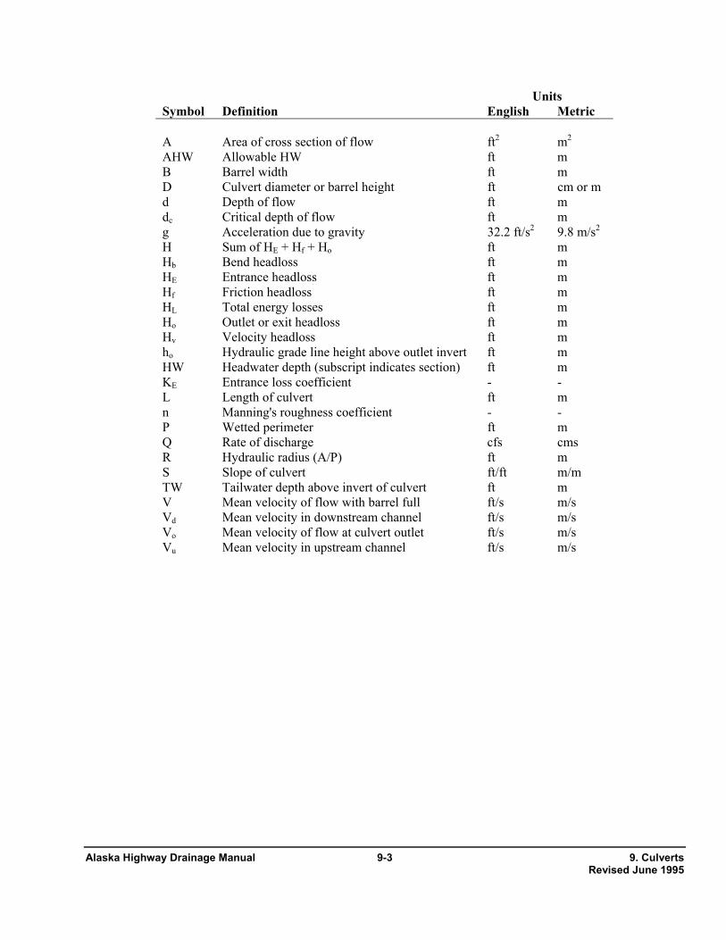
Units Symbol Definition English Metric A Area of cross section of flow ft2 m2 AHW Allowable HW ft m B Barrel width ft m D Culvert diameter or barrel height ft cm or m d Depth of flow ft m dc Critical depth of flow ft m g Acceleration due to gravity 32.2 ft/s2 9.8 m/s2 H Sum of HE + Hf + Ho ft m Hb Bend headloss ft m HE Entrance headloss ft m Hf Friction headloss ft m HL Total energy losses ft m Ho Outlet or exit headloss ft m Hv Velocity headloss ft m ho Hydraulic grade line height above outlet invert ft m HW Headwater depth (subscript indicates section) ft m KE Entrance loss coefficient - - L Length of culvert ft m n Manning's roughness coefficient - - P Wetted perimeter ft m Q Rate of discharge cfs cms R Hydraulic radius (A/P) ft m S Slope of culvert ft/ft m/m TW Tailwater depth above invert of culvert ft m V Mean velocity of flow with barrel full ft/s m/s Vd Mean velocity in downstream channel ft/s m/s Vo Mean velocity of flow at culvert outlet ft/s m/s Vu Mean velocity in upstream channel ft/s m/s
Alaska Highway Drainage Manual 9-3 9. Culverts Revised June 1995

• Culverts shall be designed to accommodate debris or proper provisions shall be made for debris maintenance.
9.2. Policy 9.2.1 Definition Policy is a set of goals that establish a definite course of action or method of action and that are selected to guide and determine present and future decisions (see Policy Chapter). Policy is implemented through design criteria for making decisions (see Section 9.3).
• Material selection shall include consideration of service life which includes abrasion and corrosion.
• Culverts shall be located and designed to present a minimum hazard to traffic and people. 9.2.2 Culvert Design Policy
The following policies are specific to culverts. • The detail of documentation for each culvert
site shall be commensurate with the risk and importance of the structure. Design data, assumptions, and calculations shall be assembled in an orderly fashion and retained for future reference as provided for in the Documentation Chapter.
• All culverts 48 inches in diameter or greater and all multiple culvert installations shall be hydraulically designed and a hydraulic summary provided on the project plans. The hydraulic summary shall include size, length, invert elevations, material, design discharge(s) with headwater elevations, discharge capacity at Hw/D=1.0, and purpose (e.g. local drainage, driveway ditch). It is recommended that culverts less than 48 inches also be hydraulically designed.
• Where practicable, some means shall be provided for personnel and equipment access to facilitate maintenance.
• Culverts shall be regularly inspected and maintained. • Fish passage shall be accommodated where
required. 9.3. Design Criteria
• The overtopping flood selected shall be consistent with the class of highway and commensurate with the risk at the site (see Chapter 7, Hydrology).
9.3.1 Definition Design criteria are the standards by which a policy is carried out or placed into action. They form the basis for the selection of the final design configuration. Listed below by categories are the design criteria which shall be considered for all culvert designs.
• Survey information shall include topographic features, channel characteristics, aquatic life, highwater information, existing structures, and other related site specific information. 9.3.2 Site Criteria
Structure Type Selection • Culvert location in both plan and profile shall be investigated to avoid sediment build-up in culvert barrels and potential areas of impact upstream and downstream.
Culverts are used:
• where bridges are not hydraulically required,
• where debris and ice are tolerable, and • Culverts shall be designed (sized) to accommodate adverse settlement in permafrost conditions. • where more economical than a bridge.
Bridges are used: • Where icing conditions occur, culvert design shall accommodate design flows with appropriate methods (e.g. oversize, thaw devices). The minimum size culvert for icing conditions shall be 36 inches.
• where culverts cannot be used,
• where more economical than a culvert,
• to satisfy land use requirements,
9. Culverts 9-4 Alaska Highway Drainage Manual Revised June 1995
9.3.3 Design Limitations • to mitigate environmental harm caused by a culvert, Allowable Headwater
Allowable headwater is the depth of water that can be ponded at the upstream end of the culvert which will be limited by one or more of the following:
• to avoid floodway encroachments, and
• to accommodate ice and large debris.
• non-damaging to upstream property, Length & Slope The culvert length & slope shall be chosen to approximate existing topography, and to the degree practicable:
• equal to an HW/D no greater than 1.5,
• no greater than the low point in the road grade potentially affected by the headwater, and • the culvert invert shall be aligned with the
channel bottom and the skew angle of the stream, and
• equal to the elevation where flow diverts around the culvert unless specifically designed as a relief. • the culvert entrance should match the
geometry of the roadway embankment. Review Headwater The review headwater is the flood depth that: Ice Buildup
Ice buildup shall be mitigated as necessary by appropriate methods, such as:
• does not exceed 1 foot increase over the existing 100-year flood elevation in a National Flood Insurance Program mapped floodplain or in the vicinity of insurable buildings, and
• increase the culvert size and/or slope,
• provide overflow culverts,
• has a level of inundation which is tolerable to upstream property and roadway for the review discharge.
• culvert thawing devices,
• ice fences, and
• adjust placement of snow storage Tailwater Relationship - Channel • Evaluate the hydraulic conditions of the
downstream channel to determine a tailwater depth for a range of discharges which includes the review discharge (see Channel Chapter).
Debris Control Debris control shall be considered:
• where experience or physical evidence indicates the watercourse will transport a heavy volume of controllable debris, • Calculate backwater curves at sensitive
locations or use a single cross section analysis. • for culverts located in mountainous or steep
regions, • Use the critical depth and equivalent hydraulic grade line if the culvert outlet is operating with a free outfall.
• for culverts that are under high fills,
• where clean out access is limited. However, access must be available to clean out the debris control device.
• Consider the backwater effects of any downstream drainage structures.
Tailwater Relationship - Confluence or Large Water Body
• use of FHWA Hydraulic Engineering Circular No. 9, "Debris-Control Structures" is suggested. • Use the high water elevation that has the same
frequency as the design flood if events are known to occur concurrently (statistically dependent).
Alaska Highway Drainage Manual 9-5 9. Culverts Revised June 1995

• If statistically independent, evaluate the joint probability of flood magnitudes and use a likely combination resulting in the greater tailwater depth.
• Use arch or oval shapes only if required by hydraulic limitations, site characteristics, structural criteria, or environmental criteria.
Multiple Barrels If tidal conditions are present, use the mean higher high tide elevation. Multiple barrel culverts shall fit within the natural
dominant channel. Caution should be used when designing multiple barrel installations as one tends to dominate as the others clog with sediment. They are to be avoided where:
Maximum Velocity The maximum velocity at the culvert exit shall be consistent with the velocity in the natural channel or shall be mitigated with:
• the approach flow is high velocity, particularly if supercritical, (These sites require either a single barrel or special inlet treatment to avoid adverse hydraulic jump effects.)
• channel stabilization (see Channel Chapter), and
• energy dissipation (see Energy Dissipator Chapter).
• fish passage is required unless special treatment is provided to insure adequate low flows (commonly one barrel is lowered).
Storage - Temporary or Permanent If storage is being assumed upstream of the culvert, consideration shall be given to:
Material Selection • the impacts of flooding, and The material selection shall consider replacement cost
and difficulty of construction as well as traffic delay. Available materials include steel, aluminum, concrete, and plastics.
• ensuring that the storage area will remain available for the life of the culvert through the purchase of right-of-way or easement.
• The culvert material selected shall be based on a comparison of the total cost of alternate materials over the design life of the structure which is dependent upon the following:
Flood Frequency The flood frequency used to design or review the culvert shall as shown in Appendix 7-A, Design Flood or Storm Selection Guidelines.
o durability (service life), o structural strength (gage,
corrugations, material strength), 9.3.4 Design Features Culvert Sizes and Shape o hydraulic roughness, The culvert size and shape selected shall be based on engineering and economic criteria related to site conditions.
o bedding conditions, o abrasion and corrosion resistance, and o water tightness requirements.
• The selection shall not be made using first cost as the only criteria.
• The following minimum sizes shall be used to avoid maintenance problems and clogging:
End Treatment (Inlet or Outlet) o 18 inches for side drains or driveways, o 24 inches for all road systems, The culvert inlet type shall be selected from the
following list based on the considerations given and the inlet coefficient, KE. (A table of recommended values of KE is included in Appendix A.) Consideration shall also be given to safety since some end treatments can be hazardous to errant vehicles.
o 36 inches for all culverts 100 feet or greater in length,
• Site and land use requirements can dictate a larger or different barrel geometry than required for hydraulic considerations. This can include driveways.
Projecting Inlets or Outlets (culverts less than 48 inches)
9. Culverts 9-6 Alaska Highway Drainage Manual Revised June 1995

• Extend beyond the embankment of the roadway.
• May be considered for culverts which will operate in inlet control.
• Can increase the hydraulic performance of the culvert, but may also add to the total culvert cost. Therefore, they should only be used if practicable. See HDS-5 for design procedures.
• Have low construction cost.
• Are susceptible to damage during roadway maintenance and automobile accidents.
• Have poor hydraulic efficiency for thin materials. Wingwalls
• Shall be mitered to fill slope. • Can be used in concert with full headwalls.
• Used predominantly with metal pipe. • Are used to retain the roadway embankment to avoid a projecting culvert barrel. • May include anchoring the inlet to concrete
slope paving to strengthen the weak leading edge.
• Are used where the side slopes of the channel are unstable.
• should consider attaching a commercial end section.
• Are used where the culvert is skewed to the normal channel flow.
Commercial End Sections (culverts less than 48 inches)
• Can affect hydraulic efficiency if the flare angle is < 30° or > 60°.
• Are available for both corrugated metal and concrete pipe.
Aprons
• Are used to reduce scour from high headwater depths or from approach velocity in the channel.
• They retard embankment erosion and incur less damage from maintenance.
• May improve projecting metal pipe entrances by increasing hydraulic efficiency, reducing the accident hazard, and improving their appearance.
• Shall extend at least one pipe diameter upstream.
• Shall not protrude above the normal streambed elevation.
• They are hydraulically equal to a headwall, but can be equal to a beveled or side- tapered entrance if a flared, enclosed transition takes place before the barrel.
Safety Considerations Culvert installations shall AASHTO Roadside Design Guidelines to protect traffic from culvert ends:
Headwalls with Bevels (culverts 48 inches or greater) Culverts greater than 30" in diameter shall receive one of the following treatments. • Increase the efficiency of metal pipe.
a. Be extended to the appropriate "clear zone" distance per AASHTO Roadside Design Guide, or protected by a traffic barrier.
• Provide embankment stability.
• Provide embankment erosion protection.
• Provide protection from buoyancy. b. Safety treated with a grate if the
consequences of clogging and causing a potential flooding hazard is less than the hazard of vehicles impacting an unprotected end. If a grate is used, an open area shall be provided between the
• Shorten the required structure length.
• Reduce maintenance damage.
Improved Inlets
Alaska Highway Drainage Manual 9-7 9. Culverts Revised June 1995

Land Use Culverts bars of 3.0 times the area of the culvert entrance. Consideration may be given to combining drainage
culverts with other land use requirements necessitating passage under a highway, such as pedestrian undercrossings:
Weep Holes If weep holes are used to relieve uplift pressure, they shall be designed in a manner similar to underdrain systems. • during the selected design flood the land use
is temporarily forfeited, but available during lesser floods, Performance Curves
Performance curves shall be developed for all culverts having hydraulic computations performed (i.e. 48 inches or greater in diameter) and all multiple pipe installations for evaluating the hydraulic capacity of a culvert for various headwaters, outlet velocities, and scour depths. These curves provide a basis for evaluating flood hazards at the site.
• two or more barrels are required with one situated so as to be dry during floods less than the selected design flood,
• the outlet of the higher land use barrel must be protected from headcutting,
• the height and width constraints shall satisfy the hydraulic or land use requirements, whichever is the larger.
9.3.5 Related Designs Buoyancy Protection Headwalls, endwalls, deadmen or other means of anchoring to provide buoyancy protection shall be considered for all flexible culverts. Buoyancy is more serious with steepness of the culvert slope, depth of the potential headwater (debris blockage may increase), flatness of the upstream fill slope, or height of the fill.
Environmental Considerations And Fishery Protection Care must be exercised in selecting the location of the culvert site to controlling erosion, sedimentation and debris. Select a site that will permit the culvert to be constructed and will limit the impact on the stream or wetlands. Fish passage and habitat issues shall be coordinated with resource agencies early in the design process.
Outlet Protection (See Energy Dissipator Chapter)
Outlet protection for a culvert shall be provided where the outlet scour hole depth computations indicate: High Velocity Culverts
At most locations the conventional culvert is the appropriate choice. A conventional culvert with an improved inlet may be a more economical alternative at some locations that possess certain unique site characteristics as explained below. There may, however, also be a few sites where a high velocity culvert would serve a useful purpose -- even though it perhaps would be somewhat more costly than other culvert alternatives.
• the scour hole will undermine the culvert outlet,
• the expected scour hole may cause costly property damage,
• the scour hole causes a nuisance effect (most common in urban areas),
• the scour hole blocks fish passage, and Because the inlet and outlet geometry are costly it is essential that a location have specific geometric characteristics in order for a high velocity culvert to be practicable. These characteristics would require that a culvert:
• the scour hole will restrict land use requirements.
Culverts designed with outlets above original ground, such as relief culverts and local cross drainage culverts on high fills, require special precautions to avoid erosion impacts.
• be relatively long,
• have a significant differential between inlet and outlet elevations, and
• operate in inlet control. 9. Culverts 9-8 Alaska Highway Drainage Manual Revised June 1995

Inverted siphons are easily designed, constructed, and have proven a reliable means of water conveyance. Normally, canal erosion at the ends of the siphon is inconsequential in earth waterways provided the transition and any erosion protection is properly designed and constructed.
Locations having the required geometric location characteristics where a high velocity culvert might prove appropriate are as follows.
• Less costly.
• Little or no backwater can be tolerated. Costs of design, construction, and maintenance for an inverted siphon are higher than for a culvert that might be used for the same purpose. However, the cost of raising the roadway gradeline may offset this higher cost. An inverted siphon may present a hazard to life, especially in areas of high population density. Inverted siphons cannot be used for drainage or irrigation where freezing may block the siphon's waterway.
• High approach velocities should be perpetuated.
• Minimize or eliminate upstream sediment deposition problems.
• Provide a grade control structure.
• Perhaps avoid flow conflicts with utilities.
Locations having geometric location characteristics where a high velocity culvert might be inappropriate are as follows.
Design procedures for sag culverts can be found in U.S. Bureau of Reclamation, "Design of Small Canal Structures."
• Fish passage is required. 9.4. Design Philosophy
• Prospective contractors would be too inexperienced to construct the complex inlet and outlet.
9.4.1 Overview The design of a culvert system for a highway crossing of a floodplain may involve using information from the following chapters in this manual (policy, documentation, surveys, hydrology, channels, storm drains, environment, erosion and sediment control, and environment). Each of these should be consulted as appropriate. The discussion in this section is focused on design methods.
High velocity culverts have four distinct geometric parts: inlet; barrel; expansion; stilling basin (if required). The design of each part is related to the design of the remaining three parts thus requiring a trial and error procedure. Design procedures can be found in AASHTO Model Drainage Manual, Chapter 9, Appendix A.
9.4.2 Design Methods Inverted Siphons (Sag Culverts) The designer shall: Inverted siphons (sometimes called sag culverts or sag lines) are used to convey water by gravity under roads, railroads, other structures, various types of drainage channels, and depressions. An inverted siphon is a closed conduit designed to run full and under pressure. The structure should operate without excess head when flowing at design capacity.
• select the drainage structure type based on site criteria and economics.
• assume a constant discharge or route a hydrograph.
• select design computation methodology. Economics and other considerations determine the feasibility of using an inverted siphon or another type of structure. The use of an elevated flume would be an alternative to an inverted siphon crossing such things as a deep roadway cut or another channel. The use of a raised gradeline and culvert may be a more economical alternative to employing a siphon under a road.
Hydrology Methods Constant Discharge
• Is assumed for most culvert designs.
• Is usually the peak discharge.
• Will yield a conservatively sized structure where temporary storage is available, but not used.
Alaska Highway Drainage Manual 9-9 9. Culverts Revised June 1995

Hydrograph & Routing • Plots performance curves for headwater, outlet velocity, and outlet scour.
• Storage capacity behind a highway embankment attenuates a flood hydrograph and reduces the peak discharge.
• Includes options for both design and analysis.
• Computes tailwater for any cross section shape with up to 10 subsections. • Significant storage will reduce the required
culvert size. • Has extensive flood routing capability.
• Is checked by routing the design hydrographs through the culvert site to determine the outflow hydrograph and stage (backwater) behind the culvert.
• Is documented in HYDRAIN Users Manual.
Other tools available which have culvert computation capabilities in varying levels of detail include one-dimensional open channel flow computer programs such as WSPRO and HEC-2, and two-dimensional flow computer programs such as FESWMS and FastTabs.
• Procedures are in Section 9.9 and HDS5, Section V.
Computational Methods Nomographs 9.5. Design Equations
• Require a trial and error solution which is quite easy and provides reliable designs for many applications.
9.5.1 General An exact theoretical analysis of culvert flow is extremely complex because the following is required:
• Require additional computations for tailwater, outlet velocity, hydrographs, routing, and roadway overtopping.
• analyzing nonuniform flow with regions of both gradually varying and rapidly varying flow,
Nomographs for circular, box, and other shapes and improved inlets are found in HDS5. • determining how the flow type change as the
flow rate and tailwater elevations change, identifying inlet and/or outlet control, Computer Software
HY8 (FHWA Culvert Analysis Software) • applying backwater and drawdown calculations, energy and momentum balance, • Is an interactive program written in Basic.
• applying the results of hydraulic model studies, and
• Uses the theoretical basis for the nomographs.
• Can compute tailwater, improved inlets, road overtopping, hydrographs, routing, and multiple independent barrels.
• determining if hydraulic jumps occur and if they are inside or downstream of the culvert barrel.
• Develops and plots tailwater rating curves. 9.5.2 Approach
• Develops and plots performance curves. The procedures in this chapter use the following: • Is documented in the HY8 Applications
Guide. Control Section The control section is the location where there is a unique relationship between the flow rate and the upstream water surface elevation.
CDS (Wyoming Culvert Design System)
• Is a batch operation program written in Fortran. Inlet control is governed by the inlet geometry.
• Includes road overtopping capability.
9. Culverts 9-10 Alaska Highway Drainage Manual Revised June 1995

Outlet control is governed by a combination of the culvert inlet geometry, the barrel characteristics, and the tailwater.
Minimum Performance Minimum performance is assumed by analyzing both inlet and outlet control and using the highest headwater for given flow conditions. The culvert may operate more efficiently at times (more flow for a given headwater level), but it will not operate at a lower level of performance than calculated.
9.5.3 Inlet Control For inlet control, the control section is at the upstream end of the barrel (the inlet). The flow passes through critical depth near the inlet and becomes shallow, high velocity (supercritical) flow in the culvert barrel. Depending on the tailwater, a hydraulic jump may occur downstream of the inlet.
Headwater Factors Figure 9-1 Headwater depth is measured from the inlet invert of the inlet control section to the surface of the upstream pool.
Unsubmerged, Transition And Submerged
Unsubmerged Inlet area is the cross-sectional area of the face of the culvert. Generally, the inlet face area is the same as the barrel area.
For headwater below the inlet crown, the entrance operates as a weir.
• A weir is a flow control section where the upstream water surface elevation can be predicted for a given flow rate.
Inlet edge configuration describes the entrance type. Some typical inlet edge configurations are thin edge projecting, mitered, square edges in a headwall, and beveled edge. • The relationship between flow and water
surface elevation must be determined by model tests of the weir geometry or by measuring prototype discharges.
Inlet shape is usually the same as the shape of the culvert barrel. Typical shapes are rectangular, circular, elliptical and arch. Check for an additional control section, if different than the barrel. • These tests are then used to develop
equations. Appendix A of HDS5 contains the equations which were developed from model test data, see Figure 9-2, Flow Type I:
Hydraulics Three regions of flow are shown in the Figure 9-1 below: unsubmerged, transition and submerged:
Figure 9-2
Flow Type I
Alaska Highway Drainage Manual 9-11 9. Culverts Revised June 1995
Submerged Barrel Roughness Barrel roughness is a function of the material used to fabricate the barrel. Typical materials include concrete and corrugated metal. The roughness is represented by a hydraulic resistance coefficient such as the Manning n value. Typical Manning n values are presented in Appendix A.
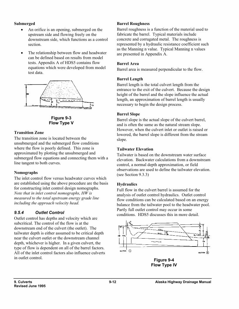
• An orifice is an opening, submerged on the upstream side and flowing freely on the downstream side, which functions as a control section.
• The relationship between flow and headwater can be defined based on results from model tests. Appendix A of HDS5 contains flow equations which were developed from model test data.
Barrel Area Barrel area is measured perpendicular to the flow.
Barrel Length
Barrel length is the total culvert length from the entrance to the exit of the culvert. Because the design height of the barrel and the slope influence the actual length, an approximation of barrel length is usually necessary to begin the design process.
Barrel Slope Figure 9-3
Flow Type V Barrel slope is the actual slope of the culvert barrel, and is often the same as the natural stream slope. However, when the culvert inlet or outlet is raised or lowered, the barrel slope is different from the stream slope.
Transition Zone The transition zone is located between the unsubmerged and the submerged flow conditions where the flow is poorly defined. This zone is approximated by plotting the unsubmerged and submerged flow equations and connecting them with a line tangent to both curves.
Tailwater Elevation Tailwater is based on the downstream water surface elevation. Backwater calculations from a downstream control, a normal depth approximation, or field observations are used to define the tailwater elevation. (see Section 9.3.3) Nomographs
The inlet control flow versus headwater curves which are established using the above procedure are the basis for constructing inlet control design nomographs. Note that in inlet control nomographs, HW is measured to the total upstream energy grade line including the approach velocity head.
Hydraulics Full flow in the culvert barrel is assumed for the analysis of outlet control hydraulics. Outlet control flow conditions can be calculated based on an energy balance from the tailwater pool to the headwater pool. Partly full outlet control may occur in some conditions. HDS5 discusses this in more detail. 9.5.4 Outlet Control
Outlet control has depths and velocity which are subcritical. The control of the flow is at the downstream end of the culvert (the outlet). The tailwater depth is either assumed to be critical depth near the culvert outlet or the downstream channel depth, whichever is higher. In a given culvert, the type of flow is dependent on all of the barrel factors. All of the inlet control factors also influence culverts in outlet control.
Figure 9-4 Flow Type IV
9. Culverts 9-12 Alaska Highway Drainage Manual Revised June 1995
Ho = Hv =V2/2g (9.4d) Losses HL = HE + Hf + Hv +
Hb + Hj + Hg (9.1)
Barrel losses H = HE + Ho + Hf Where: HL = total energy loss, ft HE = entrance loss, ft Hf = friction losses, ft Hv = exit loss (velocity head), ft Hb = bend losses, ft Hj = losses at junctions, ft Hg = loses at grates, ft
H = [1 + Ke + (29n2L/R1.33)] [V2/2g] (9.5) Energy Grade Line The energy grade line represents the total energy at any point along the culvert barrel. Equating the total energy at sections 1 and 2, upstream and downstream of the culvert barrel in Figure 9-4, the following relationship results:
HWo +( Vu2/2g) = TW +
(Vd2/2g) + HL
(9.6) Velocity V = Q/A (9.2)
Where: V = average barrel velocity, ft/s Q = flow rate, cfs A = cross sectional area of flow with the
barrel full, ft2
Where: HWo = headwater depth above the
outlet invert, ft Vu = approach velocity, ft/s TW = tailwater depth above the
outlet invert, ft Vd = downstream velocity, ft/s HL = sum of all losses (equation
9.1)
Velocity head Hv = V2/2g (9.3) Where: g = acceleration due to gravity, 32.2 ft/s2
Hydraulic Grade Line Entrance loss HE = KE (V2/2g) (9.4a) The hydraulic grade line is the depth to which water
would rise in vertical tubes connected to the sides of the culvert barrel. In full flow, the energy grade line and the hydraulic grade line are parallel lines separated by the velocity head except at the inlet and the outlet.
Where: KE = entrance loss coefficient, See Table 2
in Appendix A. Friction loss Hf = [(29n2L)/R1.33] [V2/2g] (9.4b
) Nomographs (full flow) Where: n = Manning's roughness coefficient (See
Table 1 in Appendix B) L = length of the culvert barrel, ft R = hydraulic radius of the full culvert
barrel = A/P, ft P = wetted perimeter of the barrel, ft
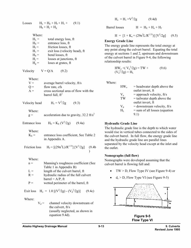
Nomographs were developed assuming that the culvert barrel is flowing full and:
• TW > D, Flow Type IV (see Figure 9-4) or
• dc > D, Flow Type VI (see Figure 9-5)
Exit loss Ho = 1.0 [(V2/2g) - (Vd
2/2g)] (9.4c) Where: Vd = channel velocity downstream of
the culvert, ft/s (usually neglected, as shown in
equation 9.4d). Figure 9-5 Flow Type VI
Alaska Highway Drainage Manual 9-13 9. Culverts Revised June 1995

HW = ho + H - SoL (9.8) • Vu is small and its velocity head can be considered to be a part of the available headwater (HW) used to convey the flow through the culvert.
Where: ho = the larger of TW or (dc + D)/2, ft
• Vd is small and its velocity head can be
neglected. Adequate results are obtained down to a HW = 0.75D. For lower headwaters, backwater calculations are required. • Equation (9.6) becomes:
(See Figure 9-7 if TW < dc and Figure 9-8 if TW > dc) HW = TW + H - SoL (9.7)
Where: HW = depth from the inlet invert to
the energy grade line, ft H = is the value read from the
nomographs (equation 9.5), ft SoL = drop from inlet to outlet
invert, ft
Figure 9-7
Flow Type II, TW < dc
Nomographs (Partly full flow)
Equations (9.1) through (9.7) were developed for full barrel flow. The equations also apply to the flow situations which are effectively full flow conditions, if TW < dc, Figure 9-6.
Figure 9-8
Flow Type III, TW > dc
9.5.5 Outlet Velocity Culvert outlet velocities shall be calculated to determine need for erosion protection at the culvert exit. Culverts usually result in outlet velocities which are higher than the natural stream velocities. These outlet velocities may require flow readjustment or energy dissipation to prevent downstream erosion. If outlet erosion protection is necessary, the flow depths and Froude number may also be needed.
Figure 9-6
Flow Type VII
• Backwater calculations may be required which begin at the downstream water surface and proceed upstream. If the depth intersects the top of the barrel, a full flow extends from that point upstream to the culvert entrance.
Inlet Control • If water surface profile (drawdown)
calculations are necessary, begin at dc at the entrance and proceed downstream to the exit. Determine at the exit the depth and flow area. The velocity is calculated from equation 9.2.
Nomographs (Partly full flow) - Approximate method Based on numerous backwater calculations performed by the FHWA staff, it was found that the hydraulic grade line pierces the plane of the culvert outlet at a point one-half way between critical depth and the top of the barrel or (dc + D)/2 above the outlet invert. TW should be used if higher than (dc + D)/2. The following equation should be used:
9. Culverts 9-14 Alaska Highway Drainage Manual Revised June 1995
• Use normal depth and velocity. This approximation may be used since the water surface profile converges towards normal depth if the culvert is of adequate length. The outlet velocity may be slightly higher than the actual velocity at the outlet. Normal depths
may also be obtained from design aids in publications such as HDS 3.
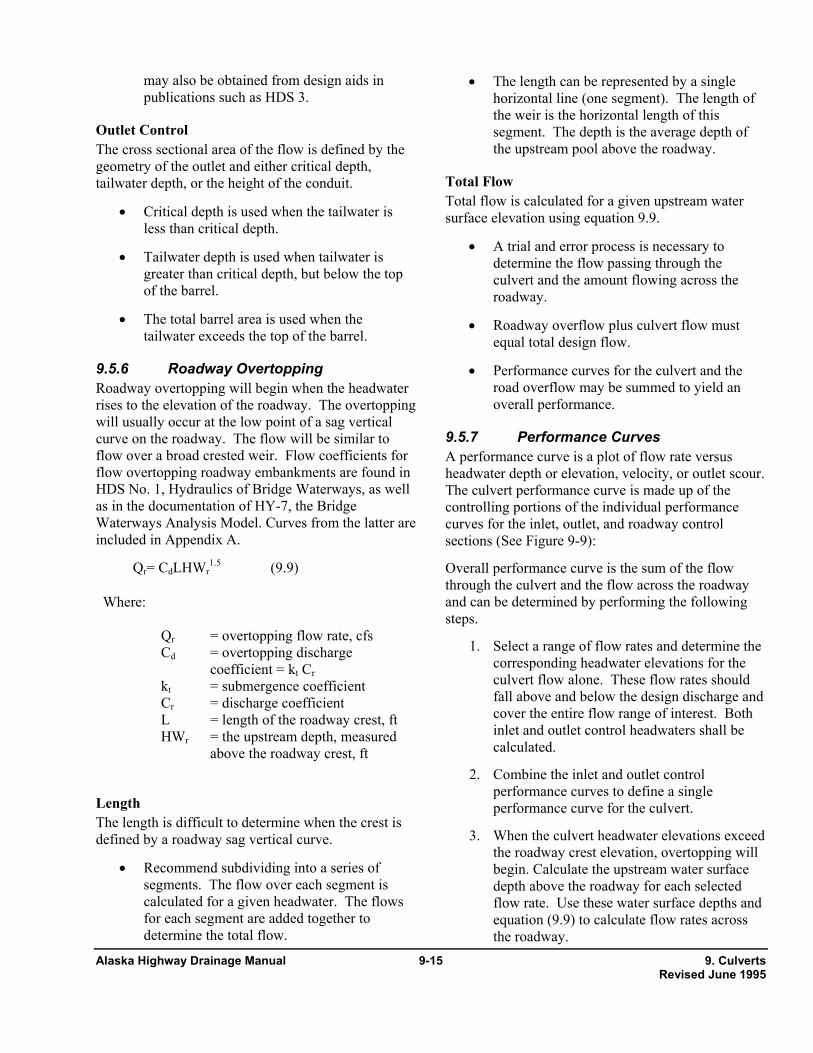
• The length can be represented by a single horizontal line (one segment). The length of the weir is the horizontal length of this segment. The depth is the average depth of the upstream pool above the roadway.
Outlet Control The cross sectional area of the flow is defined by the geometry of the outlet and either critical depth, tailwater depth, or the height of the conduit. Total Flow
Total flow is calculated for a given upstream water surface elevation using equation 9.9. • Critical depth is used when the tailwater is
less than critical depth. • A trial and error process is necessary to
determine the flow passing through the culvert and the amount flowing across the roadway.
• Tailwater depth is used when tailwater is greater than critical depth, but below the top of the barrel.
• The total barrel area is used when the tailwater exceeds the top of the barrel.
• Roadway overflow plus culvert flow must equal total design flow.
9.5.6 Roadway Overtopping • Performance curves for the culvert and the road overflow may be summed to yield an overall performance.
Roadway overtopping will begin when the headwater rises to the elevation of the roadway. The overtopping will usually occur at the low point of a sag vertical curve on the roadway. The flow will be similar to flow over a broad crested weir. Flow coefficients for flow overtopping roadway embankments are found in HDS No. 1, Hydraulics of Bridge Waterways, as well as in the documentation of HY-7, the Bridge Waterways Analysis Model. Curves from the latter are included in Appendix A.
9.5.7 Performance Curves A performance curve is a plot of flow rate versus headwater depth or elevation, velocity, or outlet scour. The culvert performance curve is made up of the controlling portions of the individual performance curves for the inlet, outlet, and roadway control sections (See Figure 9-9):
Qr= CdLHWr1.5 (9.9) Overall performance curve is the sum of the flow
through the culvert and the flow across the roadway and can be determined by performing the following steps.
Where: Qr = overtopping flow rate, cfs Cd = overtopping discharge
coefficient = kt Cr kt = submergence coefficient Cr = discharge coefficient L = length of the roadway crest, ft HWr = the upstream depth, measured
above the roadway crest, ft
1. Select a range of flow rates and determine the corresponding headwater elevations for the culvert flow alone. These flow rates should fall above and below the design discharge and cover the entire flow range of interest. Both inlet and outlet control headwaters shall be calculated.
2. Combine the inlet and outlet control performance curves to define a single performance curve for the culvert. Length
The length is difficult to determine when the crest is defined by a roadway sag vertical curve. 3. When the culvert headwater elevations exceed
the roadway crest elevation, overtopping will begin. Calculate the upstream water surface depth above the roadway for each selected flow rate. Use these water surface depths and equation (9.9) to calculate flow rates across the roadway.
• Recommend subdividing into a series of segments. The flow over each segment is calculated for a given headwater. The flows for each segment are added together to determine the total flow.
Alaska Highway Drainage Manual 9-15 9. Culverts Revised June 1995

4. Add the culvert flow and the roadway overtopping flow at the corresponding headwater elevations to obtain the overall
culvert performance curve as shown in Figure 9-9 below.
Figure 9-9
Overall Performance Curve
9.6. Design Procedure The following design procedure provides a convenient and organized method for designing culverts for a constant discharge, considering inlet and outlet control. The procedure does not address the effect of storage which is discussed in the Storage Chapter and Section 9.9. Many of the following computational procedures are integral in various computer software. This discussion illustrates methodology and pertinent areas for the designer to check to assure reasonableness of results.
• The designer should be familiar with all the equations in Section 9.5 before using these procedures.
• Following the design method or use of software without an understanding of culvert hydraulics can result in an inadequate, unsafe, or costly structure.
• The computation form has been provided in Appendix B to guide the user. It contains blocks for the project description, designer's identification, hydrologic data, culvert dimensions and elevations, trial culvert
9. Culverts 9-16 Alaska Highway Drainage Manual Revised June 1995

description, inlet and outlet control HW, culvert barrel selected, and comments.
Step 1: Assemble Site Data And Project File 1. See Data Chapter - The minimum data are:
• USGS, site, and location maps,
• embankment cross section,
• roadway profile,
• photographs,
• field visit (sediment, debris), and
• design data at nearby structures.
2. Hydrologic and Hydraulic studies by other agencies including:
• small dams - SCS, COE, BLM, USFS,
• floodplain - SCS, COE, FEMA, USGS, NOAA, and
• storm drain - local or private,
• streams and rivers - USGS, USFS, BLM.
3. Environmental constraints including:
• commitments contained in review documents,
• fish passage.
4. Design criteria
• review Section 9.3 for applicable criteria.
Step 2: Determine Hydrology See Hydrology Chapter.
Minimum data are drainage area map and a discharge-frequency information.
Step 3: Downstream Channel See Channel Chapter.
Minimum data are cross section of channel and the rating curve for channel.
Step 4: Summarize Data 1. See Chart in Appendix B.
2. Data from steps 1-3.
3. See ADOT&PF Highway Prconstruction Manual, Chapter 11.
Step 5: Select Initial Design Alternative 1. See Section 9.3.4 Design Features.
2. Choose culvert material, shape, size, and entrance type.
Step 6: Select Design Discharge Qd 1. See Section 9.3.3 Design Limitations.
2. Determine flood frequency from criteria.
3. Determine Q from plot (step 2).
4. Divide Q by the number of barrels.
Step 7: Determine Inlet Control Headwater Depth (HWi) See HDS5 for nomograph method or various computer software programs.
Step 8: Determine Outlet Control Headwater Depth At Inlet (HWoi) See HDS5 for nomograph method or various computer software programs.
Step 9: Determine Controlling Headwater (HWc) • Compare HWi and HWoi, use the higher.
• HWc = HWi, if HWi > HWoi - the culvert is in inlet control.
HWc = HWoi, if HWoi > HWi - the culvert is in outlet control. Step 10: Compute Discharge Over The Roadway (Qr) 1. Calculate depth above the roadway (HWr). HWr
= HWc - HWov; HWov = height of road above inlet invert
2. If HWr ≤ 0, Qr = 0; If HWr > 0, determine Cd from Appendix A
3. Determine length of roadway crest (L).
4. Calculate Qr using equation 9.12.
Qr = Cd L HWr1.5 (9.12)
Step 11: Compute Total Discharge (Qt) Qt = Qd + Qr (9.13)
Alaska Highway Drainage Manual 9-17 9. Culverts Revised June 1995

Step 12: Calculate Outlet Velocity (Vo) And Depth (dn) If inlet control is the controlling headwater:
1. Calculate flow depth at culvert exit.
• use normal depth (dn) • use water surface profile
2. Calculate flow area (A).
3. Calculate exit velocity (Vo) = Q/A.
If outlet control is the controlling headwater:
1. Calculate flow depth at culvert exit.
• use (dc) if dc > TW • use (TW) if dc < TW < D • use (D) if D < TW
2. Calculate flow area (A).
3. Calculate exit velocity (Vo) = Q/A.
Step 13: Review Results Compare alternative design with constraints and assumptions. If any of the following are not met, repeat steps 5 through 12:
• the barrel must have adequate cover,
• the length shall be close to the approximate length,
• the headwalls and wingwalls must fit site,
• when applicable, fish passage criteria,
• the allowable headwater shall not be exceeded, and
• the allowable overtopping flood frequency shall not be exceeded.
Step 14: Plot Performance Curve 1. Repeat steps 6 through 12 with a range of discharges.
2. Use the following upper limit for discharge:
o Q100 if Qo ≤ Q100 o Qo if Qo > Q100 o Q100 if no overtopping is possible
Step 15: Related Designs Consider the following options (See Sections 9.3.4 and 9.3.5).
• Flow routing if a large upstream headwater pool exits (See Section 9.9).
• Appropriate measures if Vo is larger than the normal V in the downstream channel (See Energy Dissipator or Channel Chapter).
• Sediment control storage for sites with sediment concerns such as alluvial fans (See Erosion and Sediment Control Chapter and Appendix C of AASHTO Model Drainage Manual, 1991).
Step 16: Documentation • See Documentation Chapter.
• Prepare report and file with background information.
9.7. Flood Routing Culvert Design
9.7.1 Introduction Flood routing through a culvert is a practice that evaluates the effect of temporary upstream ponding caused by the culvert's backwater. By not considering flood routing it is possible that the findings from culvert analyses will be conservative. If the selected allowable headwater is considered acceptable without flood routing, then costly overdesign of both the culvert and outlet protection may result, depending on the amount of temporary storage involved.
There are many ramifications associated with culvert flood routing.
• Ownership or easement of the upstream property may be required.
• A perceived loss of a subjective safety factor.
• Credibility, both in court as well as in technical negotiations may be improved.
• Evaluating environmental concerns.
• Realistic assessments of potential flood hazards.
There are, however, some limitations to culvert flood routing that should also be recognized.
Safety Factor Ignoring temporary storage effects on reducing the selected design flood magnitude by assuming that this provides a margin of safety is not recommended. This
9. Culverts 9-18 Alaska Highway Drainage Manual Revised June 1995
practice results in inconsistent margins of safety at culvert sites as it is dependent on the amount of temporary storage at each site. Further, with little or no temporary storage at a site there would be no safety margin. If risk is high, other methods such as increasing the return period for design discharge should be used.
Culvert Replacement Applications Improved hydrology methods or changed watershed conditions are factors that can cause an older, existing culvert to be inadequate. A culvert analysis that relies on findings that ignore any available temporary storage may be misleading. A flood routing analysis may show that what was thought to be an inadequate existing culvert is, in fact, adequate.
Often existing culverts require replacement due to corrosion or abrasion. This can be very costly, particularly where a high fill is involved. A less costly alternative is to place a smaller culvert inside the existing culvert. A flood routing analysis may, where there is sufficient storage, demonstrate that this is acceptable in that no increase in flood hazard results.
Credibility With legal proceedings or in resolving conflicting design findings it is essential that creditable and defensible practices be used. By ignoring flood routing where significant storage occurs, findings may be discredited.
Environmental Culvert flood routing can provide a more realistic assessment of culvert hydraulics where environmental concerns are important. The temporary time of upstream ponding can be easily identified. This allows environmental specialists to assess whether such ponding is beneficial or harmful to localized environmental features such as fisheries, beaver ponds, wetlands and uplands.
Flood Hazards Potential flood hazards increase whenever a culvert increases the natural flood stage. Some of these hazards can conservatively be assessed without flood routing. However, some damages associated with culvert backwater are time dependent and thus require an estimate of depth versus duration of inundation. Some vegetation and commercial crops can tolerate longer periods of inundation than others, and to
greater depths. Such considerations become even more important when litigation is involved.
Limitations There are situations where culvert sizes and velocities obtained through flood routing will not differ significantly from those obtained by designing to the selected peak discharge and ignoring any temporary upstream storage. This occurs when:
• there is no significant temporary pond storage available (as in deep incised channels),
• the culvert must pass the design discharge with no increase in the natural channel's flood stage, and
• runoff hydrographs last for long periods of time such as with snowmelt runoff.
9.7.2 Routing Equations In addition to the previous Design Equations (Section 9.5), the following routing equations shall be used.
The basic flood routing equation is:
I - O = S/∆t (9.14a) or 2S1/∆t - O1 + I1 + I2 = 2S2/∆t + O2 (9.14b)
For a finite interval of time, ∆t, equation 9.14a can be expressed by: ∆S = Qi∆t Q0∆t (9.14c)
From these equations: (I1 + I2)/2 = ∆S/∆t + O1/2 + 02/2 (9.14d)
Where: S1 = storage volume in the
temporary pond at the beginning of the incremental time period, ∆t.
S2 = storage volume in the temporary pond at the end of the incremental time period, ∆t
∆t = incremental routing time interval selected to subdivide hydrograph into finite time elements
I = average hydrograph inflow to the temporary pond during incremental time period, ∆t
Alaska Highway Drainage Manual 9-19 9. Culverts Revised June 1995

I1 = instantaneous inflow to the temporary pond at the beginning of the incremental time period, ∆t
I2 = instantaneous inflow at the end of the time period, ∆t
O = average outflow from the temporary pond during incremental time period, ∆
O1 = instantaneous outflow at the beginning of the time period, ∆t
O2 = instantaneous outflow at the end of the time period, ∆t
• flood routing computations are made with successive trial discharges until the flood routing equation is satisfied,
• the hydraulic findings are compared to the selected site criteria, and
• if the selected site criteria are satisfied then a trial discharge for the next time increment is selected and this procedure is repeated; if not, a new trial culvert is selected and the entire procedure is repeated.
Design Steps 9.7.3 Design Procedure The design steps are as follows: The design procedure for flood routing through a
culvert is the same as for reservoir routing. The site data and roadway geometry are obtained (Data Collection Chapter) and the hydrology analysis completed to include estimating a hydrograph (Hydrology Chapter). Once this essential information is available, the culvert can be designed.
Step 1 Hydrograph - Plot the selected design and review hydrograph as computed using the practices from the Hydrology Chapter. Select a time interval, ∆t, for use in the flood routing procedure and subdivide the hydrograph into these increments.
Flood routing through a culvert can be time consuming. It is recommended that the appropriate computer software such as the U.S. Army Corps of Engineers HEC-1 or FHWA HYDRAIN system be used.
Step 2 Discharge Curve - Using the practices in the Channel Chapter, compute and plot a stage-discharge curve for the downstream channel.
However, the designer should be familiar with the culvert flood routing design process. This familiarization is necessary in order to:
Step 3 Stage-Storage Curve - Compute and plot a stage-storage curve for the temporary upstream pond.
• recognize and test suspected software malfunctions, Step 4
Performance Curve - Compute and plot a culvert performance curve (headwater versus discharge) for the trial culvert(s). Where overtopping occurs, it is necessary that the upper end of this performance curve be adjusted to reflect this additional discharge. This additional discharge is computed using the weir equation as adjusted to reflect a roadway embankment and any downstream effects where a low roadway fill is involved. This performance curve is the spillway discharge curve commonly used in reservoir routing.
• circumvent any software limitations,
• flood route manually where the software is limited, and
• understand and discuss culvert flood routing in a creditable manner.
Design steps are outlined below. Design examples may be found in the appropriate software user's manual.
Step 5 Trial And Error Initial Routing Step - Start with the first hydrograph time increment.
A Multiple trial and error procedure is required for culvert flood routing. In general:
• Determine the average hydrograph inflow and the volume discharge corresponding to the first selected time increment.
• a trial culvert(s) is selected,
• a trial discharge for a particular hydrograph time element is selected,
9. Culverts 9-20 Alaska Highway Drainage Manual Revised June 1995

• Recognize that with an increasing headwater the temporary pond storage will generally reduce this inflow, select a trial outflow (from the culvert) discharge that is less than the inflow discharge.
• Compute the outflow volume corresponding to this selected outflow discharge and the previously selected time increment.
• Subtract this volume from the foregoing average inflow volume; this is the volume that would have to go into temporary upstream storage.
• With this smaller outflow discharge, estimate the headwater from the trial culvert(s) performance curve.
• Add this volume to the volume already in storage. • Use this headwater to estimate the storage
volume corresponding to this headwater from the upstream stage-storage curve. • Compare this total volume with the volume
corresponding to the previously estimated headwater. If they are the same (or nearly so), proceed to the next step. If not, repeat this step using a different trial outflow discharge.
• Compute the outflow volume corresponding to this selected outflow discharge and the previously selected time increment.
• Subtract this volume from the foregoing average inflow volume; this is the volume that would have to go into temporary upstream pond storage.
Step 6b Decreasing HW - The procedure is similar to the subsequent Routing Steps for an Increasing Headwater. The difference is (1) the selected trial culvert outflow discharge will be greater than the average inflow hydrograph discharge, and (2) the outflow volume is greater than the inflow volume so that the temporary pond storage volume will be decreasing.
• Compare this volume with the volume corresponding to the previously estimated headwater. If they are the same (or nearly so), proceed to the next step; if not, repeat this step using a different trial outflow discharge.
• Determine the average hydrograph inflow and volume discharge corresponding to the next selected time increment.
Step 6a Increasing HW - The procedure for subsequent routing steps where the headwater is increasing is similar to the Initial Routing Step. The difference is in how storage is handled.
• Recognize that with a decreasing headwater the temporary pond storage will be decreasing, select a trial outflow (from the culvert) discharge that is larger than the inflow discharge.
• Determine the average hydrograph inflow and volume discharge corresponding to the next selected time increment.
• With this larger outflow discharge, estimate the headwater from the trial culvert(s) performance curve.
• Recognize that with an increasing headwater the temporary pond storage will generally reduce this inflow, select a trial outflow (from the culvert) discharge that is less than the inflow discharge.
• Use this headwater to estimate the storage volume corresponding to this headwater from the upstream stage storage curve.
• With this smaller outflow discharge, estimate the headwater from the trial culvert(s) performance curve.
• Compute the outflow volume corresponding to this selected outflow discharge and the previously selected time increment.
• Use this headwater to estimate the storage volume corresponding to this headwater from the upstream stage-storage curve.
• Subtract this volume from the foregoing average inflow volume; this is the volume that would have to go into temporary upstream pond storage.
Alaska Highway Drainage Manual 9-21 9. Culverts Revised June 1995

S.W. Jens, "Design of Urban Highway Drainage - The State of the Art," FHWA-TS-79-225, Hydraulics Branch, Bridge Division, Office of Engineering, FHWA, Washington, D.C. 20590, August 1979
• Subtract this volume from the volume already in storage.
• Compare this total volume with the volume corresponding to the previously estimated headwater, If they are the same (or nearly so), proceed to the next step; if not, repeat this step using a different trial outflow discharge.
"Design of Small Canal Structures," Bureau of Reclamation, Denver, Co., 1974, revised 1978.
"Culvert Design System," FHWA-TS-80-245, Hydraulics Section, Wyoming Highway Department, Cheyenne, Wyoming 82001, December 1980. Step 7
Criteria Check - Following (or during) the foregoing routing steps compare the resulting headwater and outlet velocity, as well as temporary pond size and duration, with the corresponding criteria selected for the site. Should there be a violation of these criteria, return to Step 1 and select a larger trial culvert; a smaller trial culvert would be selected if there appeared to be a significant overdesign.
"Design Charts For Open Channel Flow," HDS No. 3, Hydraulics Branch, Bridge Division, Office of Engineering, FHWA, Washington, D.C. 20590, 1973.
J.N. Bradley, "Hydraulics of Bridge Waterways," HDS No. 1, Second Edition, Hydraulics Branch, Bridge Division, Office of Engineering, FHWA, Washington, D.C. 20590, September 1973.
References J.O. Shearman, W.H. Kirby, V.R. Schneider, and H.N. Flippo, "Bridge Waterways Analysis Model, "FHWA-RD-86-108, FHWA, Washington, D.C.
AASHTO, "Model Drainage Manual", American Association of State Highway and Transportation Officials, Washington D.C., 1991
H.W. King and E.F. Brater, "Handbook of Hydraulics," Sixth Edition, McGraw-Hill Book Co., 1976.
J.M Norman, R.J. Houghtalen, W.J. Johnston, "Hydraulic Design of Highway Culverts," HDS No. 5, FHWA-IP-85-15, FHWA, Washington, D.C. 20590, 1985
G.K. Young, J.S. Krolak, HYDRAIN - Integrated Drainage Design Computer System, Volumes 1-6, FHWA-RD-88-120, FHWA, 1987.
A. Ginsberg, HY8 - Culvert Analysis Microcomputer Program, Applications Guide, FHWA-EPD-87-101. and software available from McTrans Center, 512 Weil Hall, University of Florida, Gainesville, Florida 32611.
"Guidelines for the Hydraulic Design of Culverts," Task Force on Hydrology and Hydraulics, Subcommittee on Design, American Association of State Highway and Transportation Officials, 341 National Press Bldg., Washington, D.C. 20045, 1975.
G.L. Bodhaine, Measurement of Peak Discharge at Culverts by Indirect Methods, Techniques of Water-Resources Investigations of the USGS, Chapter A3, 1982.
G. Reihsen and L.J. Harrison, "Debris Control Structures," HEC No. 9, Hydraulics Branch, Bridge Division, Office of Engineering, FHWA, Washington, D.C. 20590, August 1971.
9. Culverts 9-22 Alaska Highway Drainage Manual Revised June 1995

Appendix A Tables and Forms
Table 1 - Recommended Manning's n Values*
Type of Conduit Wall Description Manning's n Concrete Pipe
Smooth Walls 0.010 - 0.013
Concrete Boxes
Smooth Walls 0.012 - 0.015
Corrugated Metal Pipes and Boxes, Annular or Helical Pipe (n varies with barrel size, See HDS-5)
2 2/3 by 1/2 inch corrugations 6 by 1 inch corrugations 5 by 1 inch corrugations 3 by 1 inch corrugations 6 by 2 inch structural plate 9 by 2 1/2 inch structural plate
0.022 - 0.027 0.022 - 0.025 0.025 - 0.026 0.027 - 0.028 0.033 - 0.035 0.033 - 0.037
Corrugated Metal Pipes, Helical Corrugations, Full Circular Flow
2 2/3 by 1/2 inch corrugations 0.012 - 0.024
Spiral Rib Metal Smooth Walls 0.012 - 0.013 Plastic Culvert Pipe
Smooth Walls 0.012 - 0.013
*Note 1: The values indicated in this table are recommended Manning's "n" design values. Actual field values
for older existing pipelines may vary depending on effects of abrasion, corrosion, deflection, and joint conditions. Concrete pipe with poor joints and deteriorated walls may have "n" values of 0.014 to 0.018. Corrugated metal pipe with joint and wall problems may also have higher "n" values, and in addition, may experience shape changes which could adversely effect the general hydraulic characteristics of the culvert.
Note 2: For further information concerning Manning n values for selected conduits, consult Hydraulic Design of Highway Culverts, Federal Highway Administration, HDS No. 5, page 163.
Alaska Highway Drainage Manual A9-23 9. Culverts Revised June 1995
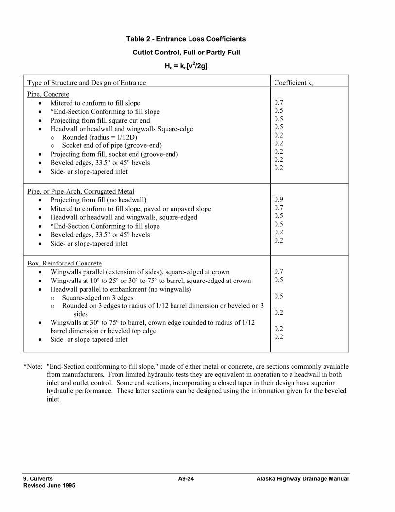
Table 2 - Entrance Loss Coefficients
Outlet Control, Full or Partly Full
He = ke[v2/2g]
Type of Structure and Design of Entrance Coefficient ke Pipe, Concrete
• Mitered to conform to fill slope • *End-Section Conforming to fill slope • Projecting from fill, square cut end • Headwall or headwall and wingwalls Square-edge
o Rounded (radius = 1/12D) o Socket end of of pipe (groove-end)
• Projecting from fill, socket end (groove-end) • Beveled edges, 33.5° or 45° bevels • Side- or slope-tapered inlet
0.7 0.5 0.5 0.5 0.2 0.2 0.2 0.2 0.2
Pipe, or Pipe-Arch, Corrugated Metal • Projecting from fill (no headwall) • Mitered to conform to fill slope, paved or unpaved slope • Headwall or headwall and wingwalls, square-edged • *End-Section Conforming to fill slope • Beveled edges, 33.5° or 45° bevels • Side- or slope-tapered inlet
0.9 0.7 0.5 0.5 0.2 0.2
Box, Reinforced Concrete • Wingwalls parallel (extension of sides), square-edged at crown • Wingwalls at 10° to 25° or 30° to 75° to barrel, square-edged at crown • Headwall parallel to embankment (no wingwalls)
o Square-edged on 3 edges o Rounded on 3 edges to radius of 1/12 barrel dimension or beveled on 3
sides • Wingwalls at 30° to 75° to barrel, crown edge rounded to radius of 1/12
barrel dimension or beveled top edge • Side- or slope-tapered inlet
0.7 0.5 0.5 0.2 0.2 0.2
*Note: "End-Section conforming to fill slope," made of either metal or concrete, are sections commonly available
from manufacturers. From limited hydraulic tests they are equivalent in operation to a headwall in both inlet and outlet control. Some end sections, incorporating a closed taper in their design have superior hydraulic performance. These latter sections can be designed using the information given for the beveled inlet.
9. Culverts A9-24 Alaska Highway Drainage Manual Revised June 1995

Alaska Highway Drainage Manual A9-25 9. Culverts Revised June 1995

9. Culverts A9-26 Alaska Highway Drainage Manual Revised June 1995

Alaska Highway Drainage Manual A9-27 9. Culverts Revised June 1995


![Hydraulic Design[1]](https://img.pdfslide.net/doc/110x75/5571f96149795991698f72eb/hydraulic-design1.jpg)