Embed Size (px)
Citation preview
C.P.Noi 246 A.R.C. Technical Report
C.P.$% 246 A.R.C. Technical Report
MINISTRY OF SUPPLY
AERONAUTICAL RESEARCH COUNCIL
CURRENT PAPERS
Some Tests on the Spread of 9 %$p
Velocity in a Cold Jet Dischatging I- with Excess Pressure from a
Sonic Exit into Still Air
J. Seddon, Ph.D. and L. Haverty
LONDON: HER MAJESTY’S STATIONERY OFFICE
1956
PRICE 2s. 6d. NET

C.P. No. 246
U.D.C. No. 532.529.3 : 532.525.2
Technical Note No. Aero.2400
November, 1955.
Some tests on the spread of velocity in a cold jet discharging with excess pressure from a sonic exit into still air
by
3. Se&an, Ph.D.
and
L. Iieverty
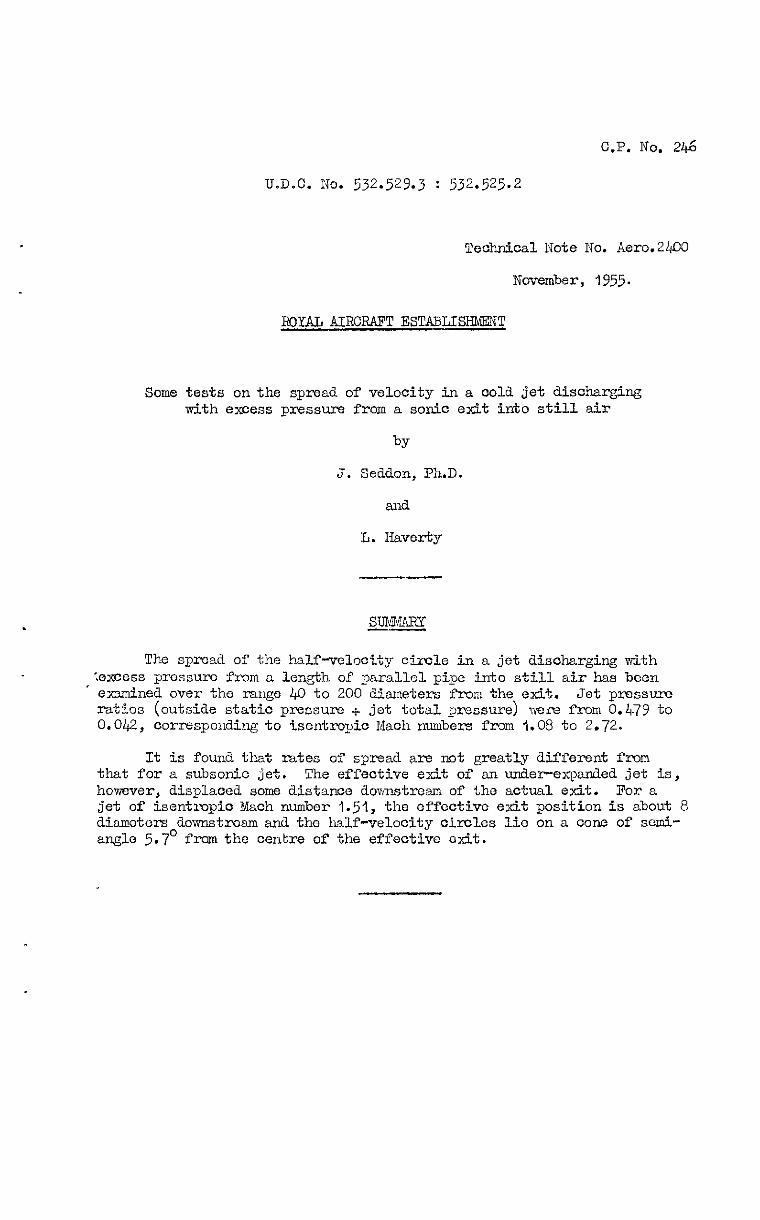
The spread of the half-velocity circle in a jet discharging with :e'xcess pressurn from a length of parallel pipe into still air has been
‘ edned over the range &O to 200 diameter f'rom the exit. Jet press- ratios (outside static pressure + jet total pressure) vece from 0.4.79 to 0.042, corresponding to isentropic Mach numbers fr-xn 1.08 to 2.72.
It is found that rates of spread are not greatly different from that for a subsonic jet. The effective exit of an under-expanded jet is, however, displaced some distance downstream of the actual exit. l?or a jet of isentknpic Mach number 1.51, the effective exit position is about 8 diameters downstream and the half-velocity circles lie on a OOIX? of semi- angle 5.7' from the centre of the effective exit.

LIST OF cONTmus
1 Introduction
2 Fkst ezqetient
3 Second experiment
4 Additional features of the results
4.1 Jet momentum l+2 Axial velocity
List of symbou-
Refemmes
LIST Gl? ILLUSTRATI~S
Velocity profiles with atmospheric pressure in the tunnel
Velocity profiles with 2.5 lb/sq in, (abs) pressure in the tunnel
r/xv. Jet pressure ratio ad corresponding isentmpic prlaoh number
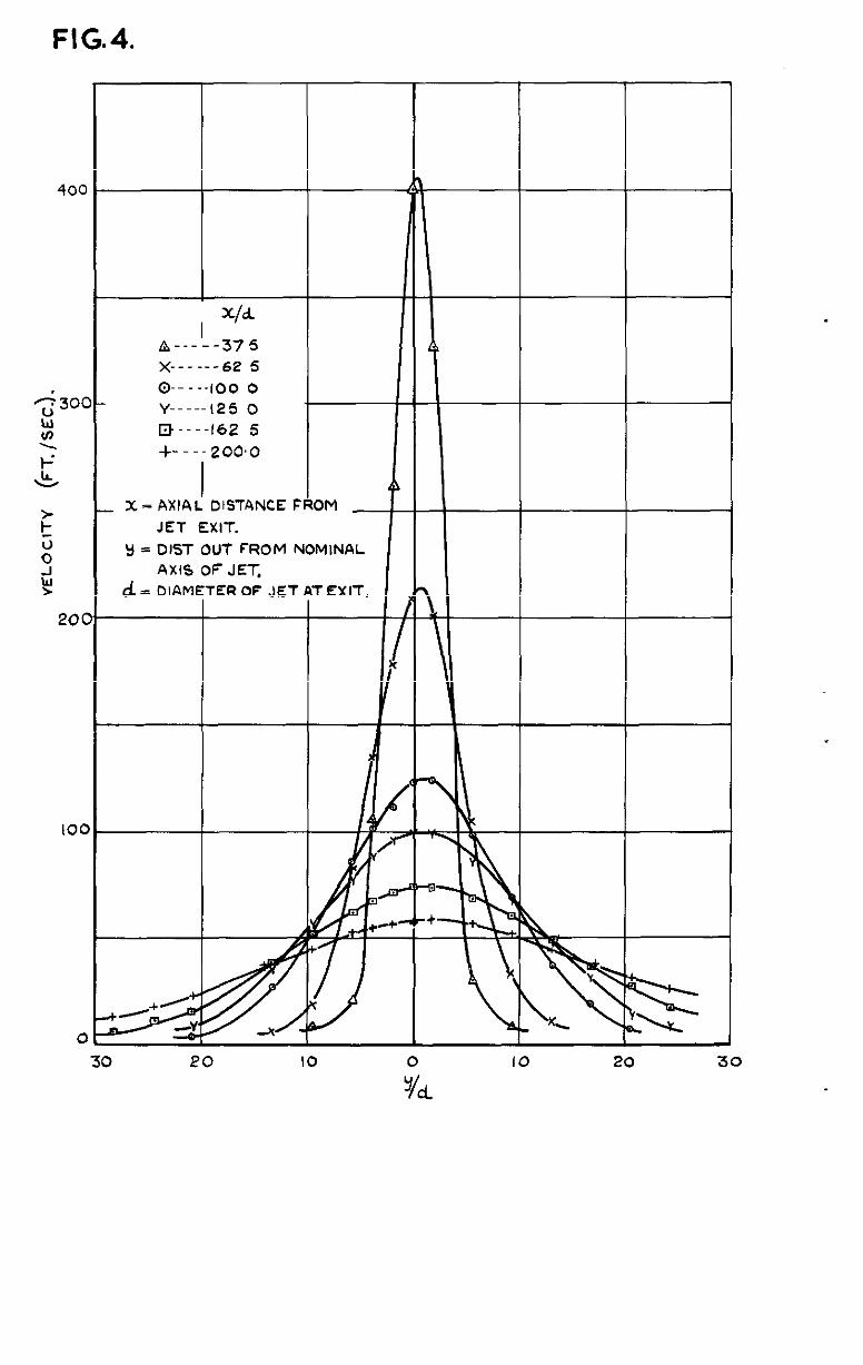
Velodty profiles when %/poj = 0.268, (ICI = 1.51), at various distances clomstresm
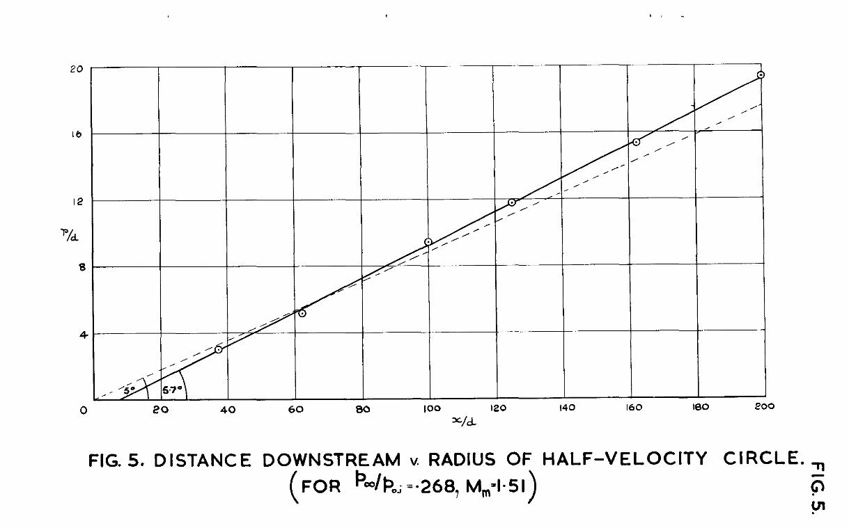
Distca.nce down&rem v. radius of half-velocity cimle (For '"/$oj = 0.268, N = 1.52)
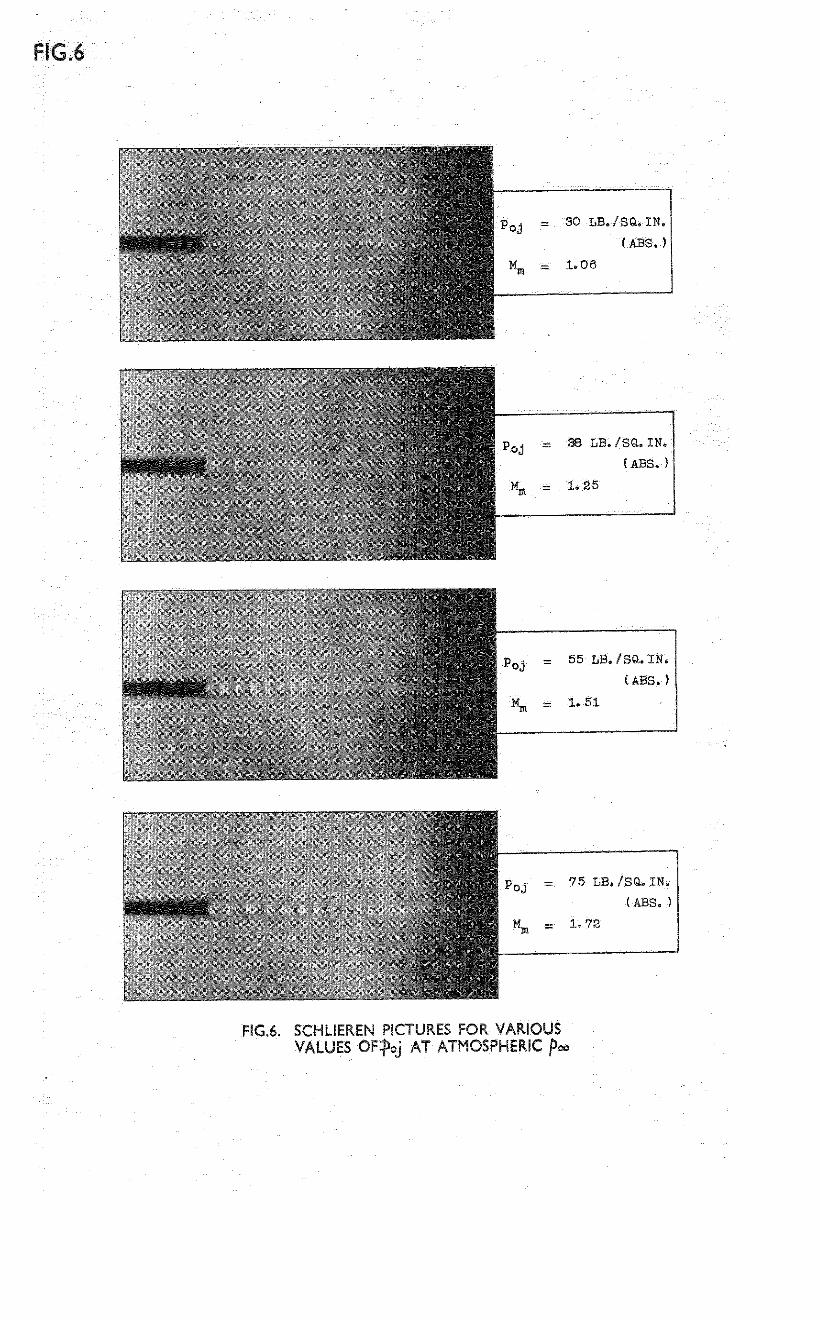
Schlieren pictures for various values ofpoj
Core length for supersonic jets
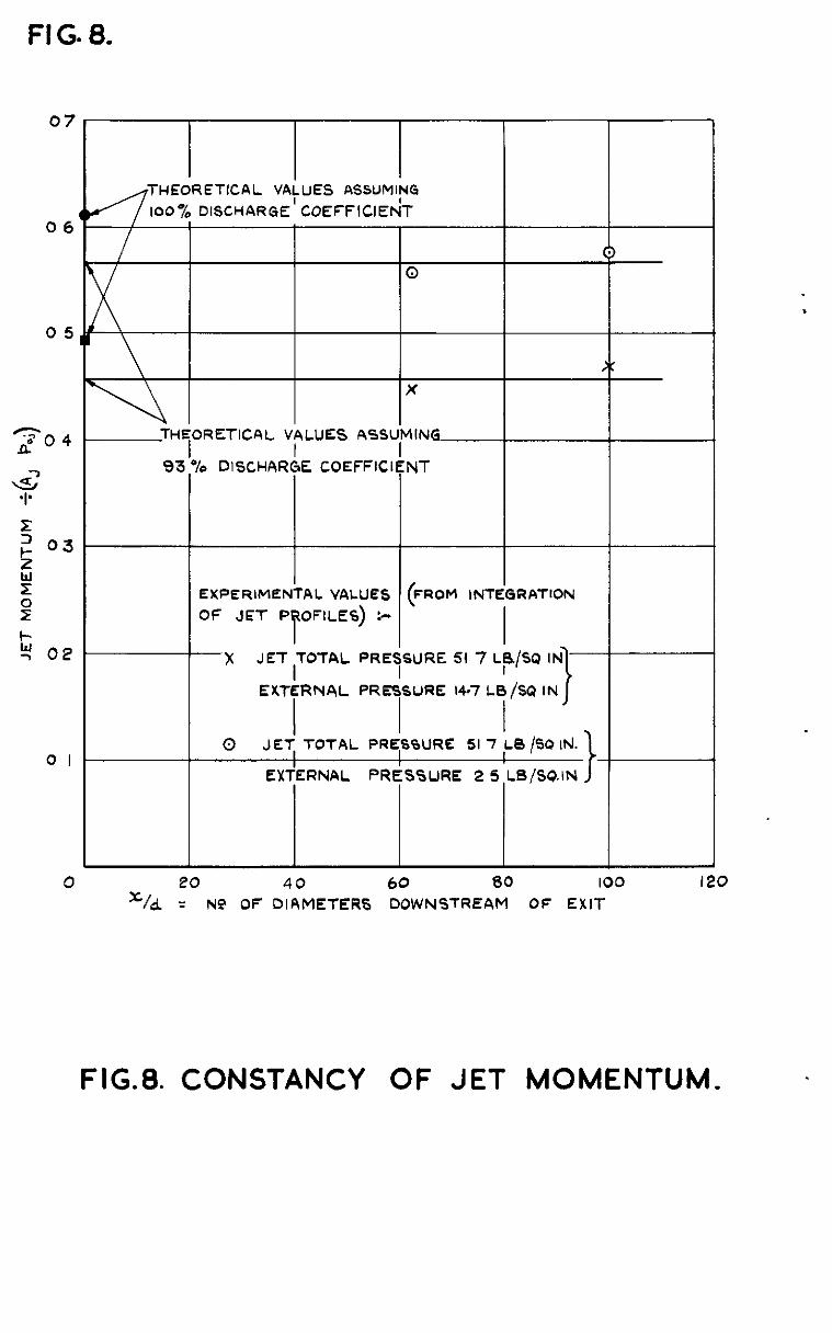
Constancy of jet momentum
Variation of jet &al velocity
&FE 3
3 4 5
z 6 6
4
-2-

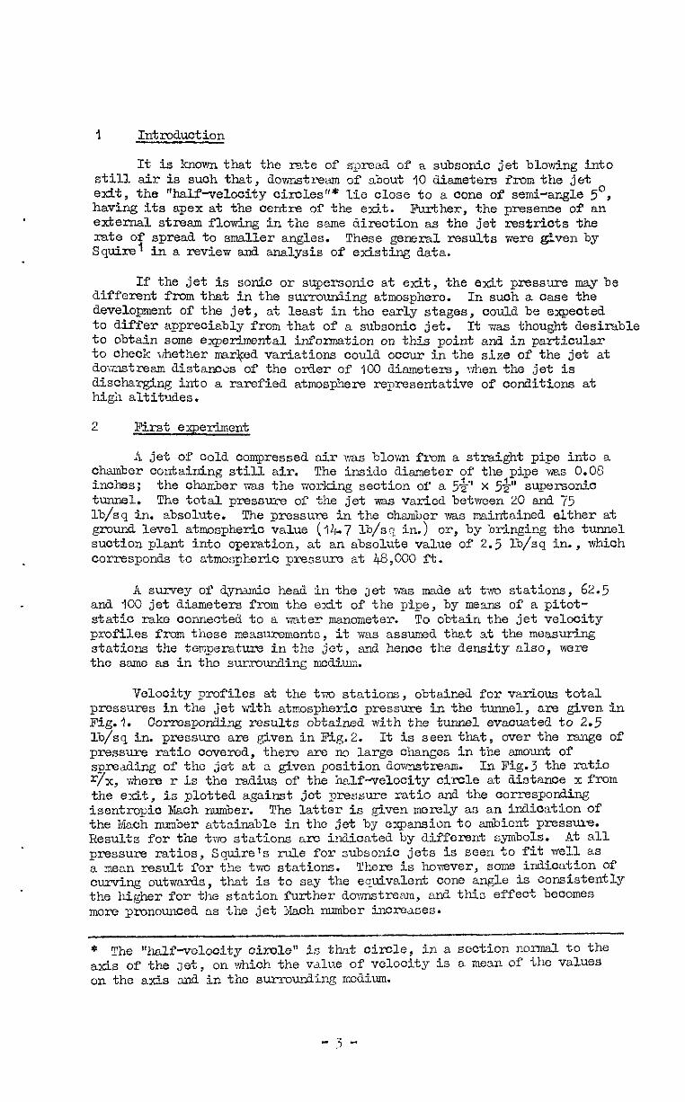
1 Introduction
It is known that the rate of spread of a subsonic jet blowing into still air is such that, ilownstrwm of about 10 diameters from the jet exit, the "halfvelocity circles"' ILie close to a cone of semi-angle 5’, having its apex at the centre of the exit. Further, the presence of an external stream flowing in the ssme direction as the jet restricts the rate of spread to smaller angles. These general results were even by Squire' in a review and analysis of existing data.
If the jet is sonic or supersonic at exit, the exit pressure may be different from that in the surroum%ing atmosphere. In s-h a case the development of the jet, at least in the early stages, could be expeoted to differ appreciably from that of a subsonic jet. It wss thought desirable to obtain some experimental information on this point and in particular to check whether marked variations could occur in the size of the jet at dorndB%m distanocs of the oiler of 100 dismeters, Trhen the jet is discharging into a rarefied atmosphsre representative of conditions at high altitudes.
2 First experiment
A jet of cold compressed air xas blown from a straight pipe into a chamber containing still air. The inside aiameter of the pipe MBS 0.08 inches; the chamber ~2s the working section of a 5&” x 5&" supersonic tunnel. The total pressure of the jet was varied between 20 an3 75 lb/sq in. absolute. The -pressure in the chamber was maintained either at ground level atmospheric value (j&+7 lb/sq in.) or, by bringing the tunnel suction plant into operation, at an absolute value of 2.5 lb/sq in., which corresponds to atmospherio pressure at 48,000 ft.
A survey of dyramio head in the Jet was made at t;vo stations, 62.5 and 100 jet diameters from the exit of the pipe, by means of a pitot- static rake connected to a water manometer. To obtain the jet velocity profiles from these measurements, it was assumed that at the measuring stations the temperature in the jet, and hence the density also, were the same as in the surrounding medium.
Velocity profiles at the two stations, obtained for various total pressures in the jet with atmospheric pressure in the tunnel, are given in l?ig. 1. Corresponding results obtained with the tunnel evacuated to 2.5 lb/sq in. pressure are given in Pig.2. It is seen that, over the range of pressure ratio covered, there are no large changes in the amount of spreading of the jet at a given position downstream. In Fig.3 the ratio r/x, where r is the radius of the half-velocity ci?xle at distance x from the exit, is plotted against jet pressure ratio and the corresponding isentropic &oh number. The latter is given merely as an indication Of the Mach number attainable in the jet by expansion to ambient pressure. Results for the two stations are indicated by different symbols. At all pressure ratios, Squire's rule for subsonic jets is seen to fit well as a mean result for the two stations. There is however, some indication of 0ur-vin.g outwards, that is to say the equivalent cone angle is oonSi.stently the higher for the station further downstream, and this effect becomes more pronounced. as the jet Maoh number increases.
* The 'half-velocity circle" is that circle, in a section normal to the axis of the Jet, on which the value of velocity is a mean Of tho values on the atis and in the s~rmunding medium.
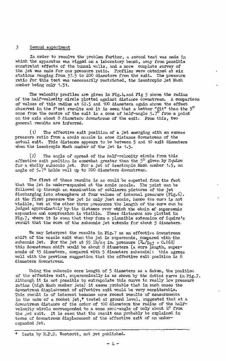
3 Secoril experiment
In o&x- to resolve the problem further, a second test was made in which the apparatus vms rigged on a laboratory bench, away from possible oonstraint effects of the tunnel walls, and a more complete survey of the jet was made for one pressure ratio. Profiles were obtained at six stations ranging from 37.5 to 200 diameters from the exit. Thepressure ratio for this test was necessarily restricted, the isentropic jet Mach nuder being only 1.51.
The velocity profiles are given in Fig.4,and Fig 5 shows the radius of the half-velocity circle plotted against distance downstream. A comparison of values of this radius at 62.5 and jO0 diameters again show the ef'feot observed in the first results and it is seen that a better "fit" than the 5' cone from the centre of the exit is a cone of half-angle 5.7' froma point on the axis about 8 diameter; downstream of the exit. From this, two general results are inferred.
(I) The effective exit position of a jet emerging with an excess pressure ratio from a sonic nozzle is some distance downstream of the actual exit. This distance appears to be between 5 arti 10 exit &maters vihen the isentropio Mach number of the jet is 1.5.
(21 The angle of spread of the half-velocity circle from this ef?ective exit position is somewhat greater than the 5O given by Squirs for a wholly subsonic jet. For a jet of isentmpic Bach number 1.5, an angle of 5.7O holds well up to 200 diameters downstream.
The first of these results is as could be expected from the fact that the jet is under-expanded. at the sonic nozzle. The point can be followed up though an examination of schlieren pictures of the jet discharging into atmosphere at four values of internal pressure (Fig.6). At the first pressure the jet is only just sonic, hence the cars is not visible, but at the other three pressures the length of the core can be judged ap??rwimatelYbyathe distance over which the chain of supersonic epxmsion and compression is visible. These distances are plotted in Fig.7, where it is seen that they form a plausible extension of Squire's result that the oore of the subsonic jet extends for about 5 diameters.
We may interpret the results in Fig.7 as an effective downstream shift of the nozzle exit when the jet is supersonic, co
7 ared with the
subsonic jet. For the jet at 55 lb/sq in. pressure (p- poj = 0.268) this downstream shift would be about 8 diameters (a core length, super sonic of 13 diemeters, compared with 5 diameters subsonic): this agrees well wLith the previous suggestion that the effective exit position is 8 diameters downstream.
Using the subsonic core length of 5 diameters as a datum, the position of the effective exit, supersonically is as shown by the dotted &rve inFig.7. Although it is not possible to extrapolate this curve to really low pressure ratios (high Mach number jets) it seems probable that in such cases the downstre~un displacement of effective exit would be very oor&.derable. This result is of interest booause sane recent results of measurements in the n&e of a rocket jet ,* tested at ground level, suggested that at a domstream distance of the order of 100 diameters the radius of the half- velociCy circle corresponded to a cone scni-angle of orib about 4' from the Jet exit. It is seen that the result can probably be e@ained in terms cf downstream displacement of the effective exit of an under- expanded jet.
* Tests by B.P.D. Westoott, not yet published.
-lL-
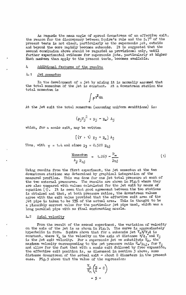
AS regmls the mean sngle of SPITX.~ do~w&resm of an effective otit, the reason for the discrepancy between Squire~s rule and the 5.7’ of the present tests is not clear, particularly as the supersonic Jet, outside and beyond the oorc rapidly becomes subsonic. It is suggested that the second conclusion above should be regarded as provisional only, urrtil further experimental evidence for supersonic jets, psrticularly at higher Mach numbers than apply to the present tests, becomes available.
4 Additiond. features of the results
4.1 Jet momentum
In the development of a jet by mixing it is nor+oally assxnnrd that the total momentum of the jet is constant. At a downstream station the total momentum is
At the jet exit the total momentum (assuming uniform conditions) is:
(Pjvj2 + Pj - p,) Aj
which, for a sonic exit, may be vtitten
[(Y i- 1) Pj - P,] Aj
Thus, with y = 1.4 and since Pj = 0.528 Poj
Momentm = , 269 -'- Aj Poj ' - Poj
Using results from the first experiment, the jet momentum at the two downstr72m stations mis d.etetined by graphical integration of the messurea pmfiles. This was dons for ens jet total pressure at each of the two external pressures. The results are shown in Fig.8 where they a+c also compared with values calculated for the jet exit by ~CXCIB of equation (1). It is seen that good agreement between the two stations is obtained and that, at both pressure ratios, the downstream values agree with the exit value provided that the effective exit area of the jet pipe is taken to be 73% of the actual area. This is thought to be a plausibly correct value for the Particular jet pipe used, which was a long parallel pipe dth no final contracting nossle.
L2 Axial velocity
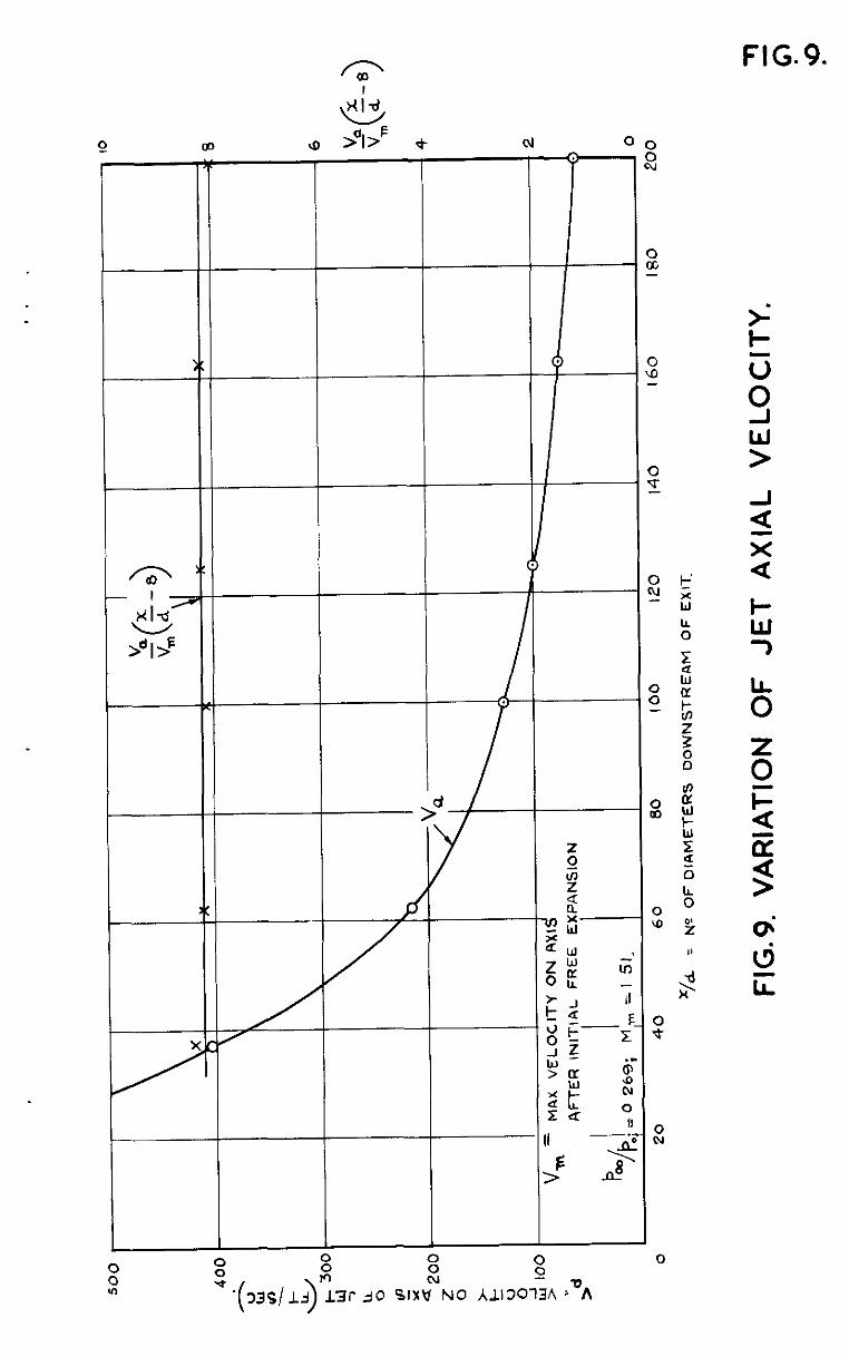
From the result of the secod experiment, the variation of velocity on the axis of the jet is as shown in Fig.9. The curve is approximately hyperbolic in fern. Conslant, where V, is
Squirt? shows that for a subsonia jet Vax/Vjd is the velocity on the alcis at distance X/a, and. Vj
is the jet exit velocity. For a supersonic jet w substitute V,, the nxc&num velocity corresponding to the Jet pressure ratio pm/Poj, for V. and allow for ths fact that with a sonic exit followed by free e&pans1 .d n, the effective exit position is, as discussed in section 3 above, some distance downstream of the actual exit - about 8 diameters in the present case. Fig.9 shows tht the value of the eqression:
V 2 ( 1 Ix-8
VPl cl
-5-
is comtarrt over the whole range of the test. If the value of V is calculated on the assumption that the stagnation temperature of %e jet is equal to laboratory temperatune, the constant value of this expression is 8.2 which is in agreement with Rolls Royce and previous B.A.% data quoted by Squire.
P =
v =
M =
P =
A =
a =
x =
Y =
r =
a
m
LIST OF'SYMBOLS
stream density
stream velooity '
Mach mber
pressure
Gross sectional area of jet at relevant station
internal dismzter of jet pipe
distance along jet from pipe exit
distance out from jet axis
rdius of half-velocity circle
refers to outside atmosphel-c
refers to jet exit
refers to stagnation corxiition
refers to axis of jet
maw velocity on jet axis
NO. Au-khOI. - -- Title, etc.
I H. B. Sqire Jet flow and its effects on aiircraft. R.A.E. Report No. Aero.2171, September, 1946. A.R.C.10189
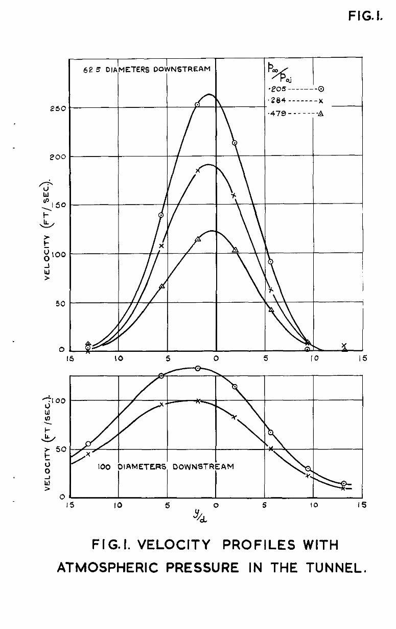
FIG. I.
250
200
6
w
350
L
F 3 o IO0
ii >
50
0
15 4’
FIGI. VELOCITY PROFILES WITH
ATMOSPHERIC PRESSURE IN THE TUNNEL,
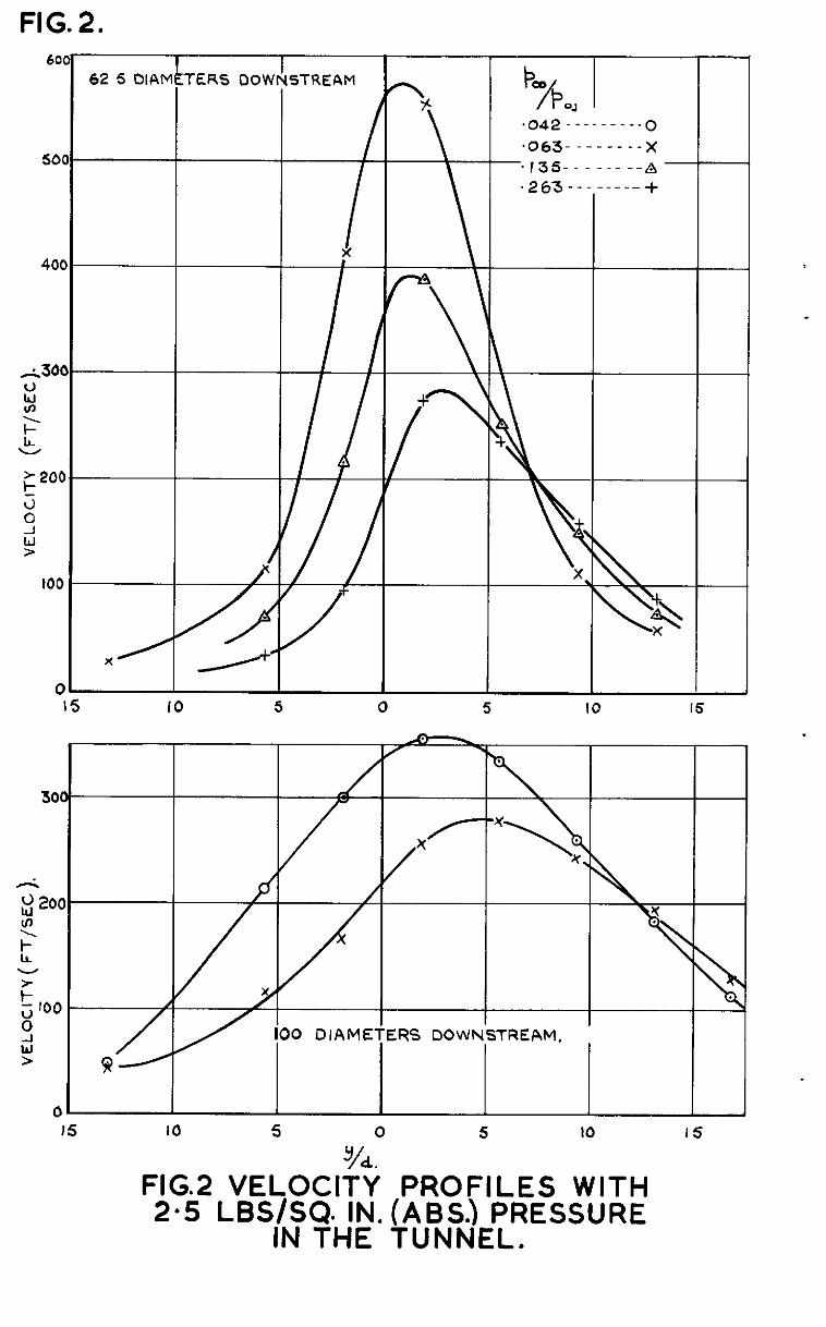
FIG. 2.
62 5 OlAl’ f /
/ I
II I
L
---0 _ __ X _ _- A ---+
IO 5 0 5 IO 16
IO0 DIAME ‘ERS DOWh
-
I5 IO 5
y/a0
5 IO 15
FIG.2 VELOCIT? PROFILES WITH 23 Lss/sca IN. (AM.) PRESSURE
IN THE TUNNEL.
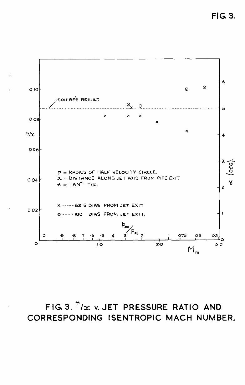
FIG 3.
0 IO- a a
/ SQUIRE’S RESULT.
- _--_-__-- -_- ----_-------- ---_ -2x --Q- _ -- -_ __- --- __ _ _--_ - _--- --
x x x
X 0 OS-
WC X
006-
0 04 -
002-
I
0
r = RADIUS OF HALF VELOCITY CIRCLE. X = DISTANCE ALONG JET AXIS FROM PIPE EXIT
dC = TAN-’ l-/x.
X -----62.5 DIAS FROM JET EXIT
0 ---- IO0 DIAS FROM JET EXIT.
6
5
4
I
FIG. 3. ‘Ix v. JET PRESSURE RATIO AND CORRESPONDING ISENTROPIC MACH NUMBER.
FlG.4.
400
Q-----375 x--- ---62 5
o-----100 0 Y-----l25 0 D----l62 5
+----zoo~o
I I _ X-AXIAL DISTANCE FROM -
JET EXIT.
Y = DIST OUT FROM NOMINAL AXIS OF JET.
d = DIAMETER OF JET AT EXIT,
1
I6
0 20
/ / ,I
,
I I I I I I I 40 60 80 IO0 120 140 I60 100 200
FIG. 5. DISTANCE DOWNSTREAM v. RADIUS OF HALF-VELOCITY CIRCLE. T
FOR p=‘k; =.268, Mm+5 I > 5
P
= 30 LB./SQ.IN. ( ABS. )
= 1.00
= 55 LB. /SQ. IN.
75 LB. /sa. IN.
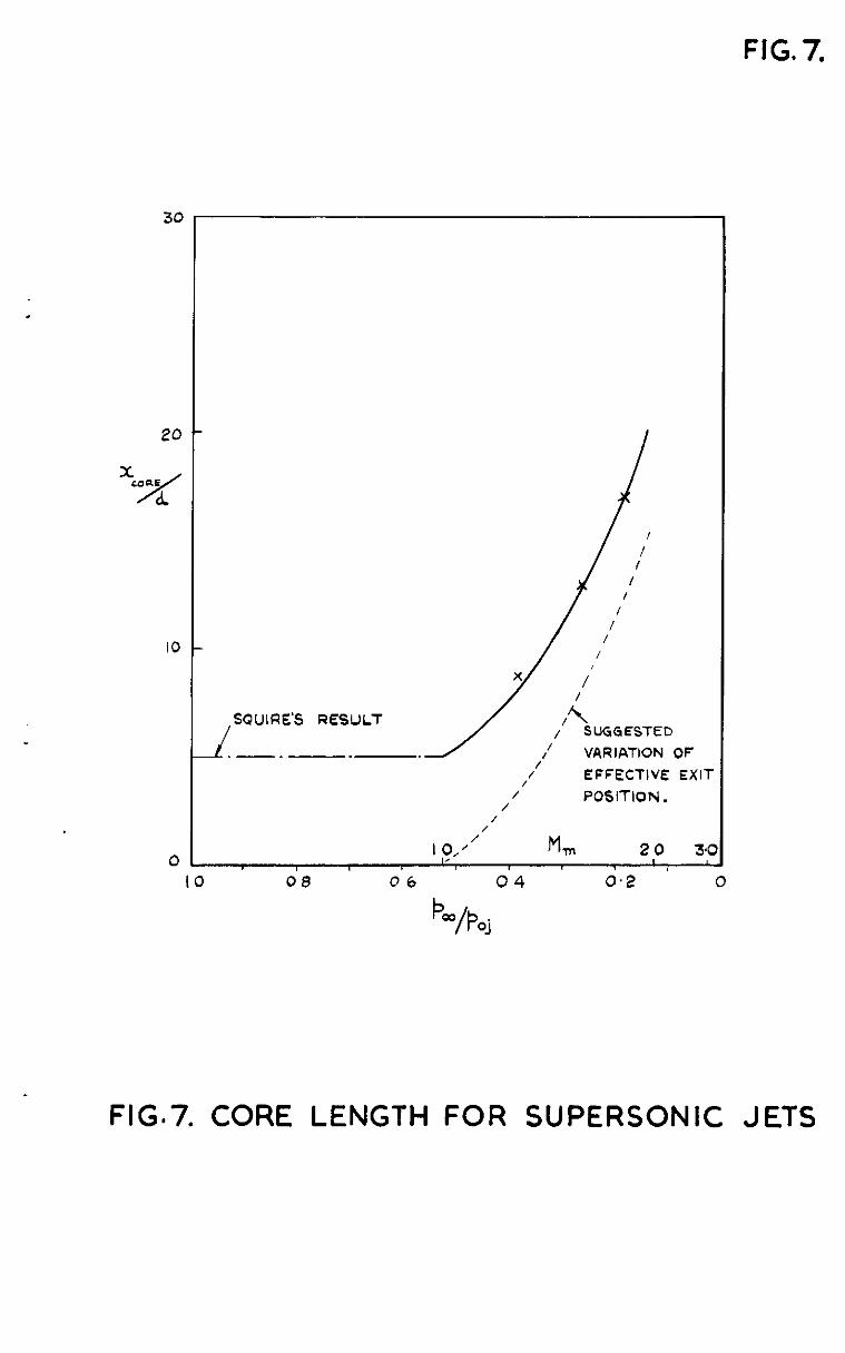
FIG. 7.
3c
IO
0
>-
/ / I / I / - / SQUIRE’S RESULT
SUGGESTED .-. VARIATION OF
// 1’
EFFECTIVE EXIT
/ POSITION.
I /
I p/ M, 2 0 3.0 I
IO 08 06 04 0.2 0
FIG.7. CORE LENGTH FOR SUPERSONIC JETS
Fi G. 0.
06
05
To4
d . .
f I- O3
:
z I- % 02
0 I
0
I I EXPERIMENTAL VALUES (FROM INTEGRATION
OF JET P OFILES) :-
P I X JET TOTAL PRESSURE 51 7
EXTERNAL PRESSURE 14-7 LB/S4 IN
0 JET TOTAL PRESGURE 517 LB /SO Iti. 1
EXTERNAL PRESSURE 2 5 LB/S&IN
f
60 80 100 “/d .‘” NO OF D::METERS DOWNSTREAM OF EXIT
120
FlG.8. CONSTANCY OF JET MOMENTUM.
FlG.9.
! +


Pubbshed by HER MAJESTY’s STATIONERY Owrcc
To be purchased from York House, Kmgsway, London w c.2
423 Oxford Street, London W.I P.O. Box 569, London s.E.,
‘3~ Castle Street, Edrnburgh 2 109 St Mary Street, Cardrff
39 King Street, Manchester z Tower Lane, Bristol I
z Edmund Street, Bwrungham 3 80 Chichester Street, Belfast
or through any bookseller
C.P. $l, 246 ARC. Technical Report