Embed Size (px)
Citation preview

Mc
Graw
Hill
The McGraw-Hill Companies
Higher Education
CHAPTER 1
Introduction to Mechanical
Engineering Design
CONTENTS 1.0 Design 2.0 Mechanical Engineering Design 3.0 Standards and Codes 4.0 Units 5.0 Specifications 6.0 Safety 7.0 Etc 8.0 Examples 1 9.0 Examples 2 10.0 Question & Answer
Chapter 6 Fatigue Failure Resulting from
Variable Loading

Mc
Graw
Hill
The McGraw-Hill Companies
Higher Education
Introduction
Non rotating shaft
F
Under static failure, the stress on the member is constant Problem: static failure, a very large deformation will occur on the structure or machine members. .

Mc
Graw
Hill
The McGraw-Hill Companies
Higher Education
Rotating shaft
F
Non rotating shaft
- F to F
F
F
-F
Alternating or fluctuating stresses on member will cause the member subjected to fatigue failure.
Mc
Graw
Hill
The McGraw-Hill Companies
Higher Education
R. R Moore Rotating Beam: Figure 6-9 pp 274
87 mm
7.6 mm
250 mm
Testing specimen Subject to pure bending (no traverse shear) Very well machined and polished No circumferential scratches

Mc
Graw
Hill
The McGraw-Hill Companies
Higher Education
Fatigue Strength and Cycle Graph (S-N Graph): Figure 6-10 pp274 F
atig
ue
Str
en
gth
S f
Endurance
limit Se
Cycle
Life
High CycleLow Cycle
Infinite LifeFinite Life
N
A
A
Cycle, N
103
S e
100 101 102 103 104 105 106 107 108
Mc
Graw
Hill
The McGraw-Hill Companies
Higher Education
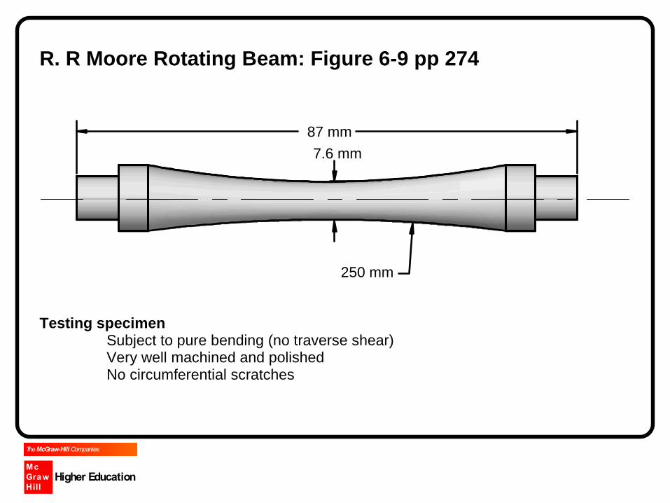
Terminology
N : Cycle : one rotation of the specimen = 1 cycle of alternating stress
Sf : fatigue strength is the limit of strength where failure occurs when the alternating
stress above the fatigue strength. However, when cycle is larger than 106, the fatigue
strength is constant to a value Se. This value is called Endurance Limit
Cycle: Cycle is related to the cycle of the specimen: boundary is 103
Life: The life is related to the stress of the specimen: boundary is Se.
Significance to design Designers have a choice to set the design life whether finite life or infinite life. Designers can predict the failure to occur (finite life): i.e. when the stress of the
member is sA the predicted life will be NA cycles.

Mc
Graw
Hill
The McGraw-Hill Companies
Higher Education
Endurance limit
Steel
MPaSMPa
MPaSSS
ut
utut
e1400700
14005.0'
Eq 6.8 pp 282
kpsiSkpsi
kpsiSSS
ut
utut
e200100
2005.0'
Note: Sut = 3.41 HB Mpa Eq 2.17 pp 37 Notes: Various class of cast iron, polished and machined: Table A-24 pp 1046 Aluminum alloy: does not have an endurance limit, fatigue strength from Table A-24 is set to 5(108) cycles

Mc
Graw
Hill
The McGraw-Hill Companies
Higher Education
Relationship between fatigue strength Sf and cycle N
ba
b
f
aN
aNS
1
Eq 6.13 and 6.14 pp 285
where a: slope of the curve (log vs log)a1
b: Sf @ 103
e
ut
e
ut
S
Sfa
S
Sfb
2)(
)log(3
1
Eq 6.14 and 6.15 pp 285
Note: f is fatigue strength factor @103

Mc
Graw
Hill
The McGraw-Hill Companies
Higher Education
How to determine fatigue strength factor f @103 1. From Figure 6.18 pp 285 2. Calculation
B
ut
F
Sf )102(
' 3
Eq 6-10 pp 284
where )N2log(
)S/'log(B
e
eF
Eq 6.12 pp 284
Mpa345S' utF Eq 6.11 pp 284
kpsiSutF 50'
*Please differentiate between b (6.15) and B (6.12) General equation for fatigue strength
B
Ff NS )2(' Eq 6-9 pp 284
Mc
Graw
Hill
The McGraw-Hill Companies
Higher Education
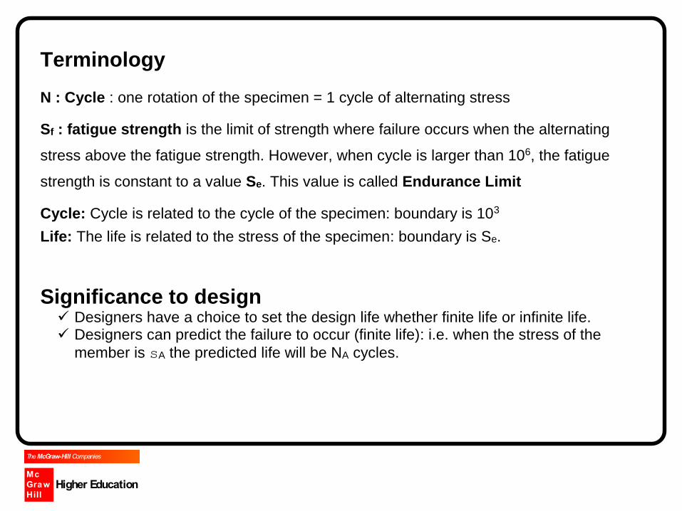
ENDURANCE LIMIT (Se)
eedcbae SkkkkkS '
where S’e : endurance limit based on R.R. Moore experiment ka: surface factor kb: size factor kc: loading factor kd: temperature factor ke:miscellaneous-effects factor
Discuss: Why do we need these variables? What do you expect the value of these variables and why?

Mc
Graw
Hill
The McGraw-Hill Companies
Higher Education
Example Calculate the endurance limit Se, if Material AISI 1010 HR, surface is machined until D = 30 mm, d = 20mm and r (fillet radius) = 2 mm is achieved.
d D
r
Surface Factor ka
b
uta aSk Eq 6.19 pp 287
a and b: Table 6-2 pp 280 Discuss: should the factor a and b be hot rolled or machined.

Mc
Graw
Hill
The McGraw-Hill Companies
Higher Education
Size Factor kb
mmdd
mmddkb
2545151.1
5179.224.1157.0
107.0
Eq 6.20 pp 288
indd
inddkb
10291.0
211.0879.0157.0
107.0
Note: only applicable to round rotating shaft due to torsion or bending
Other conditions i. Axial load
kb = 1 (for axial load) * Please refer to kc
ii. Round non-rotating shaft
95% stress area is applied 2
95.0 d0766.0A

Mc
Graw
Hill
The McGraw-Hill Companies
Higher Education
Dd
Dd
DA
e
e
37.0
0105.00766.0
0105.0
22
2
95.0
iii. For non circular non rotating beam 5.0)(808.0 hbde
iv. Common non-rotating structural *Refer to Table 6-3 pp 290 for common non rotating structural Loading factor kc Bending kc = 1 Axial kc = 0.85 Eq 6.26 pp 290
Temperature Factor
Refer to Table 6-4 pp 291

Mc
Graw
Hill
The McGraw-Hill Companies
Higher Education
Reliability Factor (ke)
Refer to Table 6-5 pp 293

Mc
Graw
Hill
The McGraw-Hill Companies
Higher Education
Stress concentration and notch sensitivity See Fig 6.3, 6,4 : fatigue failure originates from stress concentration Table A-13: Charts for theoretical Stress Concentration Factor (Kt) For the example above the suitable chart is Figure A-13-9
0 0.05 0.10 0.15 0.20
r/d
0.25 0.301.0
1.4
1.8
2.2
2.6
3.0
D/d=1.5
1.54
Figure A-13-9
geometrical property to be used
in calculating the stress.
o
4
Roundshaft withshoulder fillet
Mcinbending, ,where
I
d dc ,andI
2 64
K
t
Mc
Graw
Hill
The McGraw-Hill Companies
Higher Education
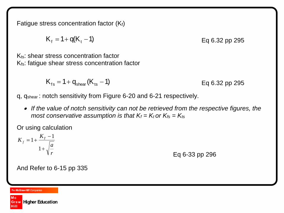
Fatigue stress concentration factor (Kf)
)1K(q1K tf Eq 6.32 pp 295
Kts: shear stress concentration factor Kfs: fatigue shear stress concentration factor
)1K(q1K tsshearf s Eq 6.32 pp 295
q, qshear : notch sensitivity from Figure 6-20 and 6-21 respectively.
If the value of notch sensitivity can not be retrieved from the respective figures, the most conservative assumption is that Kf = Kt or Kfs = Kts
Or using calculation
r
a
KK T
f
1
11
Eq 6-33 pp 296
And Refer to 6-15 pp 335

Mc
Graw
Hill
The McGraw-Hill Companies
Higher Education
Therefore the maximum stress will be
0fmax K or 0fmax K Eq 6.30 pp 285
Studio: example 6-17

Mc
Graw
Hill
The McGraw-Hill Companies
Higher Education
Combination of loading modes Combination purely alternating bending, purely alternating axial and alternating torsional stresses
Alternating axial stress )axial(0)axial(f)axial( K
Alternating bending stress )bend(0)bend(f)bend( K
Alternating torsional stress )torsion(0)torsion(f s)torsion( K
Total alternating stress (DET)
2
)torsion(
2
)axial(
)bend(t )(385.0
*Please note that kc for axial and bending are 0.85 and 1 respectively

Mc
Graw
Hill
The McGraw-Hill Companies
Higher Education
Application of S-N curve to fatigue design. Infinite life
Te
alln
S
Finite life
b
1
a
b
f
aN
aNS
where nT
a
Discuss Example 6-8 and 6-9 Question 6-11
Mc
Graw
Hill
The McGraw-Hill Companies
Higher Education
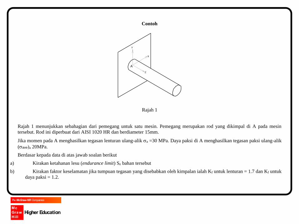
Contoh
A Z
X
Y
Rajah 1
Rajah 1 menunjukkan sebahagian dari pemegang untuk satu mesin. Pemegang merupakan rod yang dikimpal di A pada mesin
tersebut. Rod ini diperbuat dari AISI 1020 HR dan berdiameter 15mm.
Jika momen pada A menghasilkan tegasan lenturan ulang-alik a =30 MPa. Daya paksi di A menghasilkan tegasan paksi ulang-alik
(avea 20MPa.
Berdasar kepada data di atas jawab soalan berikut
a) Kirakan ketahanan lesu (endurance limit) Se bahan tersebut
b) Kirakan faktor keselamatan jika tumpuan tegasan yang disebabkan oleh kimpalan ialah Kf untuk lenturan = 1.7 dan Kf untuk
daya paksi = 1.2.

Mc
Graw
Hill
The McGraw-Hill Companies
Higher Education
Fluctuating Stresses
a : amplitudestress
Str
ess
m : midrangestres
max : maximumstress
min : minimumstress
Time
Midrange Stress 2
minmaxm
Alternating Stress 2
minmax
a

Mc
Graw
Hill
The McGraw-Hill Companies
Higher Education
Similarly for the fluctuating forces
Midrange Force 2
FFF minmax
m
Alternating Force 2
FFF minmax
a
These forces will generate respective midrange and alternating stresses.

Mc
Graw
Hill
The McGraw-Hill Companies
Higher Education
How to determine the midrange or alternating stress? Moment on rotating shaft.
MAI
4
32 S
tre
ss
Time1
2
3
4
1
2
3
4
1
When the shaft rotates in ccw direction, element A will rotate from position 1, 2, 3 and 4
for one full cycle. At the same time, the stresses of A will fluctuate from 0, smax, 0 and
smin. Therefore, moment on rotating shaft will generate sa = Mc/I and sm = 0.
Mc
Graw
Hill
The McGraw-Hill Companies
Higher Education
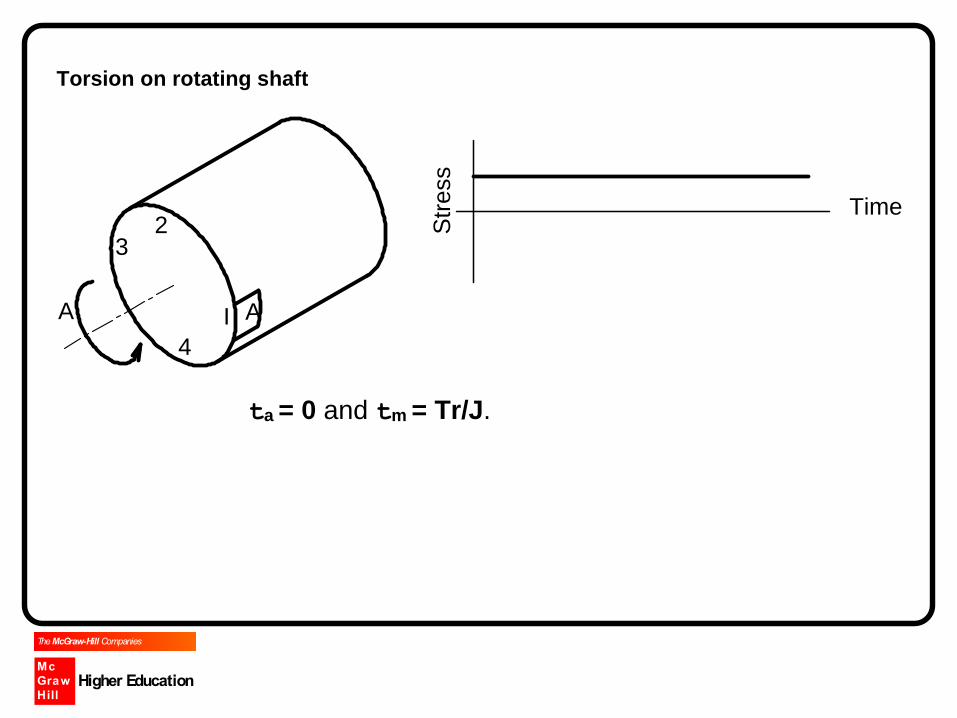
Torsion on rotating shaft
AI
4
32 S
tre
ss
Time
A
ta = 0 and tm = Tr/J.

Mc
Graw
Hill
The McGraw-Hill Companies
Higher Education
Determine the alternating and midrange stresses for the following cases? Rotating shaft
i. Axial load (P) ii. Combination of T and M
Non rotating shaft Moment (M) between -10Nm and 10Nm 20 Nm and 50 Nm -30 Nm and 10Nm Torsion (T) between 10Nm and 10Nm 20 Nm and 50 Nm -30 Nm and 10Nm

Mc
Graw
Hill
The McGraw-Hill Companies
Higher Education
Stress Ratio max
min
R
Amplitude Ratio m
aA
Mc
Graw
Hill
The McGraw-Hill Companies
Higher Education
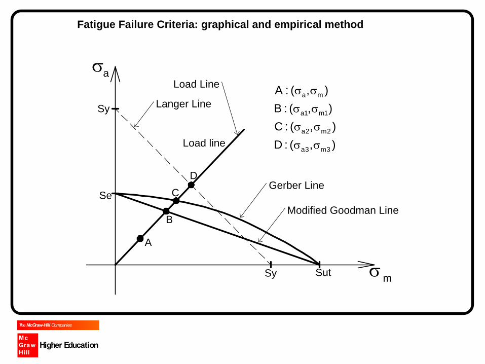
Fatigue Failure Criteria: graphical and empirical method
Load line
Sy
Se
Sy Sutm
A
B
C
D
a
a m
a1 m1
a2 m2
a3 m3
A : ( , )
B : ( , )
C : ( , )
D : ( , )
Langer Line
Gerber Line
Modified Goodman Line
Load Line

Mc
Graw
Hill
The McGraw-Hill Companies
Higher Education
Graphical Method
Goodman line m
1m
a
1a SSn
Gerber Failure Theory m
2m
a
2a SSn
Langer Line m
3m
a
3a SSn

Mc
Graw
Hill
The McGraw-Hill Companies
Higher Education
Empirical Method
Goodman Line
Basic line equation 1S
S
S
S
e
a
ut
m
For a known (sa, sm) nSS e
a
ut
m 1
Gerber Failure Locus (Parabolic Equation)
Basic parabolic equation 1
S
S
S
S
e
a
2
ut
m
For a known (sa, sm) 1
S
n
S
n
e
a
2
ut
m

Mc
Graw
Hill
The McGraw-Hill Companies
Higher Education
Langer Line (failure due to yielding)
Basic line equation 1
y
a
y
m
S
S
S
S
For a known (sa, sm) n
S
n
1
SS
ma
y
y
a
y
m
Other failure theories, same principles can be applied.
*In the following discussion, these three theories will be used to demonstrate and
similar principle can be applied to other theories.

Mc
Graw
Hill
The McGraw-Hill Companies
Higher Education
Langer line vs. other theories (i.e. Modified Goodman and Gerber Theory)
Sy
Se
Sy Sut
a
m
Sy
Se
Sy Sut
a
m
If the stresses on the member is plotted on the shaded area, the load line of the member
will intersect with Langer line first. Therefore, failure due to yielding will occur first. This is
type of failure is called Langer-first-cycle failure. Empirically, it can be determined when
nlanger < nf(other).

Mc
Graw
Hill
The McGraw-Hill Companies
Higher Education
Procedure in solving the fatigue problem
1. Determine sa, sm ta and tm.
2. Combine the alternating stresses using DET
3. Combine the mean stresses using DET
4. Using the theories to solve the problem
Question 6-39 (pp 352)

Mc
Graw
Hill
The McGraw-Hill Companies
Higher Education
Sy
Se
Sy Sut
a
m
Sy
Se
Sy Sut
a
m

Mc
Graw
Hill
The McGraw-Hill Companies
Higher Education
100 101 102 103 104 105 106 107 108
Fa
tig
ue
Str
en
gth
Sf
Endurance limit Se
Cycle
Life
High CycleLow Cycle
Infinite LifeFinite Life
N
A
A
Cycle, N
103
Se

Mc
Graw
Hill
The McGraw-Hill Companies
Higher Education
Notes
Purely alternating bending stresses ( 0 )
e
f
dcda
eedcdae
eall
SK
kkkk
SkkkkkS
n
S
'1
'
0
Combination purely alternating bending and purely alternating axial stress
Alternating axial stress )(ao
Alternating bending stress )(bo
Total alternating stress )()( boaoo
0 n
Seall

Mc
Graw
Hill
The McGraw-Hill Companies
Higher Education
What is the value of kc and Kf as both factors have different values Bending : kb (eq) kc = 1 and Kf from bending
Axial : kb,0778.023.1 utc Sk and Kf from axial
Soln : let kb,kc and Kf is common in Se which is equal to 1
Axial stress (assuming n =1)
)(
)(
)(
)(
)(
)()(
0
'111
1
'1
ao
ac
af
eda
b
aoe
af
dacaba
ae
all
k
KSkk
k
SK
kkkk
n
S

Mc
Graw
Hill
The McGraw-Hill Companies
Higher Education
Bending stress
)(
)()(
)(
)(
)(
)()(
'111
'1
bo
bbbc
bf
eda
boe
bf
dbcbba
obe
all
kk
KSkk
SK
kkkk
n
S
Final equation with factor of safety n
)(
)()(
)(
)(
)(
)('bo
bbbc
bf
ao
ac
afeda
kk
K
k
K
n
Skk

Mc
Graw
Hill
The McGraw-Hill Companies
Higher Education
CONTOH
A Z
X
Y
Rajah 1
Soalan
Rajah 1 menunjukkan sebahagian dari pemegang untuk satu mesin. Pemegang merupakan rod yang dikimpal di A pada mesin
tersebut. Rod ini diperbuat dari AISI 1020 HR dan berdiameter 15mm.
Jika momen pada A ialah (30 10%)Nm dan daya paksi ialah (8 10%) kN. Untuk memastikan getaran diambil kira, 10%
ditambah.
Berdasar kepada data di atas jawab soalan berikut
c) Kirakan ketahanan lesu (endurance limit) Se bahan tersebut
d) Tentukan a, m,a dan m jika faktor tumpuan tegasan yang disebabkan oleh kimpalan ialah Kf untuk lenturan = 1.7 dan Kf
untuk daya paksi = 1.2.
Kirakan faktor keselamatan terhadap kegagalan alahan dan kegagalan lesu. Yang mana akan gagal dahulu : alahan atau lesu?