Embed Size (px)
Citation preview

90°Box Bay Window Assembly and Installation Guidefor Andersen® Casement and Picture Windows
Instructions are for typical, new wood-framed wall construction with weather protection in place.
Instructions may not be right for all installations due to building design, construction materials or methods used and/or building or site conditions. Consult a contractor or architect for recommendations.
Flanges on the unit alone will not properly flash and seal the window. Follow these instructions carefully.
For questions call 1-888-888-7020 Monday - Friday, 7 a.m. to 7 p.m. and Saturday, 8 a.m. to 4 p.m. central time.
For more information and/or guides visit andersenwindows.com.
Please leave this guide with building owner.
Thank you for choosing Andersen.
▶▶ Read▶guide▶from▶beginning▶to▶end▶before▶starting▶installation.▶Read▶all▶warnings▶and▶cautions▶during▶unit▶installation.▶▶
Use caution when working at elevated heights and around unit openings. Follow manufacturers’ instructions for ladders and/or scaffolding. Failure to do so may result in injury or death.
Follow manufacturers’ instructions for hand or power tools. Always wear safety glasses. Failure to do so may result in injury and/or product damage.
Windows and doors can be heavy. Use safe lifting techniques and a reasonable number of people with enough strength to lift, carry and install window and door products to avoid injury and/or product damage.
“Andersen” and all other marks where denoted are trademarks of Andersen Corporation. ©2003-2010 Andersen Corporation. All rights reser ved. 0002086 BC Revised 03/03/10
Unless specifically ordered, Andersen windows and doors are not equipped with safety glass, and if broken, could fragment causing injury. Many laws and building codes require safety glass in locations adjacent to or near doors. Andersen windows are available with safety glass that may reduce the likelihood of injury when broken. Information on safety glass is available from your local Andersen dealer.
• Andersen® Head Flashing and Installation Flanges DO NOT take the place of standard window and door flashing. Unit must be properly flashed and sealed with sealant for protection against water and air infiltration. Use non-reflective flashings. Highly reflective flashing tapes can raise the surface temperature of the vinyl to the point where vinyl deformation and product damage may occur.
• Do not apply any type of film to glass. Thermal stress conditions resulting in glass damage could occur.
• Use of movable insulating materials such as window coverings, shutters, and other shading devices may damage glass and/or vinyl. In addition, excessive condensation may result causing deterioration of windows and doors.
Metal fasteners and other hardware components may corrode when exposed to preservative treated and fire-retardant treated lumber. Obtain and use the appropriate metal fasteners and hardware as called out by the installation guide to fasten unit to any rough opening made from pressure treated and fire-retardant treated lumber. Failure to use the appropriate materials for the installation may cause a failure resulting in injury, property or product damage.

Section One - 90˚ Box Bay Window Assembly Guide
2
Parts Included(1) Instruction Guide(2) 90° Mullion Posts(2) Wall Return Posts(2) Platforms(2) Head and Seat Boards(2) Outside Mullion Post Trim(2) Interior Mullion Post Casing
Optional AccessoriesHead FlashingAuxiliary CasingCable Support SystemExtension JambsPerma-Shield® Casing Vinyl Laminated BoardFibrex® Cellular Trim Board
Tools and Supplies• Safety Glasses• Hammer • Level• Carpenters Square• Combination Square• Tape Measure• Screw and Bar Clamps• Shims and blocks • Drill/Driver• 3/8" Drill Bit• 1/8" Drill Bit• Pencil• Awl• Sharp Utility Knife• 1-1/2" (4d) Finish Nails• Small Pry Bar• 2" x 4" Skid Material• 1" x 4" Cross Bracing• Soft Rags• Jack/Support• Caulk Gun• Sealant• Wood Saw • Flat Head Wood Screws #8 x 1-1/2" #8 x 2-1/2" #10 x 2-1/4" #8 x 3"
Center Unit
90º Mullion Post
Flanking Unit
Wall Return Post
Outside Mullion Post Trim
Inside Mullion Post Casing
Upper and Lower Platform
Head and Seat Board
Available joining material kits include, Non-Reinforced Joining, Aluminum Reinforced Joining, and Steel Reinforced Joining.
Transom joining and/or joining two-wide center units must be performed before bay assembly begins. The joining method is dependant on unit combination size, design load requirements and compliance with local building codes. Selection of the correct joining materials is the sole responsibility of the architect, building owner, contractor and/or consumer. Refer to the Combination Design section of the Andersen® Product Guide for further information. Failure to do so could result in personal injury, property and/or product damage.
Projecting units with transom units attached must not exceed 8'-1/8" in height.
Two-Wide Center UnitTransom Unit
Extension Jamb
Interior Side Up

Section One - 90˚ Box Bay Window Assembly Guide
3
1. Unit Preparation
• Carefully remove units from cartons and place exterior side up on a clean flat work surface. Remove foam packing blocks.
• Remove Side Installation Flanges only from vertical sides of Center Unit(s) using a sharp utility knife. Remove Side Installation Flanges from Flanking Units on side being joined only. Cut off flush with Side Jamb.
Remove Side Installation Flanges on Side Being Joined
Center Unit(s)
2. Remove Inside Stops
Side Stop on the lock side of tandem lock Casement Units has an underlying lock mechanism. Use caution when removing Side Stop on the lock side to avoid damage to lock mechanism and/or Side Stop.
• Turn units interior side up.• Carefully remove all Inside Stop nails with a hammer
and block of wood.• Remove Head and Sill Inside Stops first by inserting a
small pry bar between frame and stop. Repeat step for Side Inside Stops.
• Bundle Inside Stops and place in protected area until reinstallation.
Head Inside Stop (remove first)
Sill Inside Stop(remove first)
Side Inside Stop(remove second)
Side Inside Stop(remove second)
Exterior Side Up
Interior Side Up
Wall must be 4-9/16" to 7-1/8" for stock Platforms, Head Boards, and Seat Boards.
Remove Side Installation Flanges on Both Sides
Flanking Unit
Section One - 90° Box Bay Window Assembly Guidefor Andersen® Casement Window

Section One - 90˚ Box Bay Window Assembly Guide
4
4. Join and Secure 90° Mullion Posts to Center Unit(s) • Position 90° Mullion Posts next to
Center Unit making sure end of Mullion Post is flush with end of Center Unit.
• Clamp 90° Mullion Posts securely to Center Unit.
• Secure 90° Mullion Posts to Center Unit with #10 x 2-1/4" flat head screws. Locate screws as shown and space every 6" to 8". Repeat procedure for other 90° Mullion Post.
• Place 2 x 4 boards lengthwise under 90° Mullion Posts for support.
Clamps
90° Mullion Post
90° Mullion Post
Center Unit
Interior Side UpCross Section Detail
#10 x 2-1/4" Screws
90° Mullion PostWall Return Post
3. Arrange Components for Assembly
Center Unit(s)
• Arrange units, 90° Mullion Posts, and Wall Return Posts in position for assembly.
When arranging units for assembly, make sure that placement and direction of venting units is correct. Stationary units must be installed with installation arrow on label pointing up.
Flanker Unit Interior Side Up
5. Join and Secure Wall Return Posts to Flanker Units• Position Wall Return Post against side
of Flanking Unit with Installation Flange. Make sure end of Wall Return Post is flush with end of unit.
• Clamp Wall Return Post to unit.• Secure Wall Return Posts to Flanking
Unit with #10 x 2-1/4" flat head screws. Locate screws as shown and space every 6" to 8". Repeat step for other Wall Return Post.
Wall Return Post
Side Jamb
Wall Return Post
Clamps
#10 x 2-1/4" Screws
Wall Return Post
Interior Side Up
Cross Section Detail

Section One - 90˚ Box Bay Window Assembly Guide
5
6. Secure Flanker Units to 90° Mullion Posts • Position side of Flanking Unit without Installation
Flange on 90° Mullion Posts. Make sure top and bottom of unit is flush with ends of 90° Mullion Posts.
• Secure Flanking Units to 90° Mullion Posts using #10 x 2-1/4" Flat Head screws. Locate screws as shown and space every 6" to 8".
Flanking Unit
Center Unit(s)
#10 x 2-1/4" ScrewsFlanking Unit
90° Mullion Post
#10 x 2-1/4" Screws
Interior Side Up
Cross Section Detail
7. Prepare Platforms• Place Platforms rough side up on work surface. • Measure length of Platform along interior edge. Mark
center of Platform with pencil.• Mark centerline across width of Platform using
carpenters square.• Place centerline mark on inside edge of Platform.• Repeat step for other Platform. • Flip Platforms over, smooth side up (opposite side of
centerline mark).• Scribe a line 2-1/4" in from, and along entire length of
exterior edge of Platforms using combination square.
Platform (rough side)
2-1/4"
Platform (smooth side)
Carpenters Square
Combination Square
Scribed Line
Centerline Mark
Pencil
Inside Edge

Section One - 90˚ Box Bay Window Assembly Guide
6
8. Determine and Mark Centerline on Unit• Measure width of Center Unit along frame. With pencil,
place mark at center of unit on frame.• Repeat step at other end of Center Unit.
• Place pencil mark in center of joined units.• Repeat procedure to other end of joined units.
Mark Center
Mark Center
Pencil
Interior Side UpCenter Unit
2-Wide Center Units Only
9. Position and Secure Platforms• Slide Lower Platform into place between units Side
Installation Flange. Platform will rest on Sill Installation Flange.
• Center Lower Platform on unit.• Fasten Lower Platform to ends of center unit(s) along
scribed line using two #8 x 1-1/2" flat head wood screws.
• Repeat above procedure for Upper Platform.
Lower Platform (installed)
Upper Platform (installed)
#8 x 1-1/2" Screw Locations
Scribed Line
Head
Sill
Lower Platform
Scribed Line
Flanking Unit
Flanking Unit
Center Unit
Side Instal-lation Flange
Sill Installation Flange
Interior Side Up
Upper Platform

Section One - 90˚ Box Bay Window Assembly Guide
7
10. Position Head and Seat Boards
• Position Seat Board between Flanking Units making sure Seat Board is tight against Flanking Unit's jambs.
• Place clamps between Seat Board and Lower Platform and a bar clamp across unit as shown to insure tight fit between Seat Board and Flanking Unit.
• Place a carpenters square on exterior edges of Center and Flanking Units. Check to make sure unit is square.
• Fasten Lower Platform to ends of Flanking Units along scribed line using #8 x 1-1/2" flat head wood screws.
• Repeat above procedure for Head Board.
Carpenters Square
Head
Sill
Head Board
Clamp
Bar Clamp
Seat Board
#8 x 1-1/2" Screw Locations
Lower Plat-form
Seat Board (installed)
Lower PlatformInterior Side Up

Section One - 90˚ Box Bay Window Assembly Guide
8
2-1/4"
3/4"
3/4"
3/4"
3-1/4"
2"
3-1/4"
2"3/4"
11. Secure Platforms• Check Head and Seat Board for correct fit. If
adjustment is required remove the screws (applied in Step 11) fastening Flanking Units. Adjust as required.
• Fasten Platforms to units using #8 x 1-1/2" screws spaced at 6" to 8" intervals, using the scribed line on the Platform as a guide.
• Fasten Platforms to Joined Side Jambs using two #8 x 2-1/2" screws located 3-1/4" in from exterior edge of Platform.
• Fasten Platforms to Mullion Posts using two #8 x 3" screws located 3/4" and 2" from exterior edge of Platform.
#8 x 1-1/2" Flat Head Screw
#8 x 3" Flat Head Screw
#8 x 1-1/2" Flat Head Screw
#8 x 2-1/2" Flat Head Screw
#8 x 3" Flat Head Screw
Scribed LineJoined Side Jambs
#8 x 2-1/2" Flat Head Screw
6" to 8"
Scribed Line
#8 x 1-1/2" Screws
Platform
Head or Sill
Horizontal Cross Section Detail
Screw Size DetailScrew Locations Detail
Scribed Line
Scribed Line
#8 x 1-1/2" Flat Head Screws
Joined Side Jambs
Scribed Line
Clamp
Clamp

Section One - 90˚ Box Bay Window Assembly Guide
9
Custom Box Units Using Cable Support SystemPlatforms and Head and Seat Boards for Custom Box Bay Units may not have predrilled holes for the Cable Support System. Follow the Cable Hole Template instructions found in the Cable Support System Package to determine cable hole locations. Drill a 3/8" hole through Platforms and Head and Seat Boards at all mullion post locations before proceeding with Step 13.
12. Remove Head and Seat Boards• Label Head and Seat Boards for reinstallation when
unit is installed.• Remove clamps holding Head and Seat Boards to
Platforms. • Carefully remove and repackage Head and Seat Boards
for transport to installation site.
13. Replace Inside Stops
• Position Side Inside Stops first, then Head and Sill Inside Stops in frame groove and reapply by tacking into place using 1-1/2" (4d) finishing nails. Leave approximately 1/8" of nail head exposed to assist in removal of Inside Stops for finishing.
11. Secure Platforms (Continued)
• Fasten Platforms to Wall Return Posts using two #8 x 3" screws.
When reapplying Side Stop on the lock side of tandem lock Casement Units, nail through existing holes. Failure to do so could result in damage to underlying lock mechanism.
Fasten to Wall Return Posts Here using (2) #8 x 3" Flat Head Screws
Unit not shown in box assembly for clarity.
Head Inside Stop (reinstall second)
Sill Inside Stop(reinstall second)
Side Inside Stop(reinstall first)
Side Inside Stop(reinstall first)
Interior Side Up
Clamp
Interior Side Up
Clamp

Section One - 90˚ Box Bay Window Assembly Guide
10
14. Apply Cross Bracing and Skids Seal Mullion Post Ends• Cut and fasten two 2 x 4 skids to Lower Platform
with #8 x 2" screws for transporting unit.• Fasten 1 x 4 cross braces with screws to the
corners of platforms at a diagonal.
• Carefully turn unit over, exterior side up.• Clean exterior surface of Head and Sill at
Mullion Posts.• Apply sealant to Mullion Post ends.
1 x 4 Cross bracing
2 x 4 Skids
Apply Sealant Here to Both Sides
Windows and doors can be heavy. Use safe lifting techniques and a reasonable number of people with enough strength to lift, carry and install window and door products to avoid injury and/or product damage.
15. Apply Auxiliary Casing• Measure and cut Auxiliary Casing to fit along head
of unit. Cut 45° miters at joints. Cut ends of Auxiliary Casing flush with outside edge of outermost Flanking Units.
• Predrill Auxiliary Casing using a 1/8" drill bit, 1-1/4" deep, spacing holes every 8" to 12" inches.
• Apply sealant between Platform, Units, and at all mitered ends of Auxiliary Casing.
• Fasten Auxiliary Casing through predrilled holes using 1-1/2" (4d) wood screws.
• Remove excess sealant squeeze out on units or Auxiliary Casing with a soft rag.
Auxiliary Casing
Platform Head Jamb
Horizontal Detail
Auxiliary CasingSealant Sealant
Sealant
1-1/2" (4d) Wood Screws
Lower Platform
Exterior Side Up
Interior Side Up
Head

Section One - 90˚ Box Bay Window Assembly Guide
11
16. Prepare Unit for Transport• Fasten unit to pallet with screws, straps, and wood
support pieces for transport.• Make sure all components and accessories are located
and prepared for transport to installation site along with unit. These may include the following:
- Head and Seat Boards - Head and Seat Board Trim - Extension Jambs - Cable Support System - 3-1/2" or 5-1/2" Perma-Shield
® Casing
• Proceed to Section Two - 90° Box Bay Window Installation.
Pallet
Please attach this assembly and installation guide to window of unit using a piece of tape.
ATTENTION DEALER / DISTRIBUTOR
Exterior View

Section Two - 90˚ Box Bay Window Installation Guide
12
Cable
Cable
1. Identify Type of Installation
• Most common type of installation. • Used if rough opening height is smaller than Bay Unit.• If window unit must be raised above previously
installed header to meet soffit or to match line of adjoining window trim, cut top platform back to clear header as shown.
• If window is raised, install filler blocks at sill plate of equal dimension to amount raised.
Cable End
Lower Platform
Header
Cable Clamp
Center UnitCable End
Lower Platform
Upper Platform
Header
Cable Clamp
CenterUnit
Upper Platform(cut back)
Filler Block(raised area)
Shim
Installation of Custom Bow, Bay, and Box Units having a projection greater than 24" require the expertise of a structural engineer to determine needed structural support. Failure to use sufficient structural support could result in personal injury, product and/or property damage.
Standard Installation
Modified Standard Installation
Standard Installation Modified Standard Installation
Section Two - 90° Box Bay Window Installation Guidefor Andersen® Casement Window
Metal fasteners and other hardware components may corrode when exposed to preservative treated and fire-retardant treated lumber. Obtain and use the appropriate metal fasteners and hardware as called out by the installation guide to fasten unit to any rough opening made from pressure treated and fire-retardant treated lumber. Failure to use the appropriate materials for the installation may cause a failure resulting in injury, property or product damage.
3-1/2" Fibrex® Cellular Trim Board or wider trim by others
3-1/2" Fibrex® Cellular Trim Board or wider trim by others
3-1/2" Fibrex® Cellular Trim Board or wider trim by others
3-1/2" Fibrex® Cellular Trim Board or wider trim by others

Section Two - 90˚ Box Bay Window Installation Guide
13
Modified Standard Installation
• Masonry Anchoring Required
Center Unit
Header
Center Unit
Cable End
Lower Platform
Upper Platform
Cable Clamp
Cable
Masonry
Masonry
Shim/Nailer
Shim/Nailer
Head Board
Shim
Lower Platform Cut back to Wall Thickness
Masonry Installation
• Unit opening is extended down to floor line.
Walk-Out Installation
1. Identify Type of Installation (Continued)
Walk-Out Installation Masonry Installation
2. Determine Type of Support System Required
When a roof or bonnet is built over unit, make sure adequate support is provided to carry weight of roof and unit.
A support system such as a cable support system, post and foundation support, knee braces, and attachment to header or soffit support must be installed to properly support projecting window units. Failure to do so could result in product damage and/or incorrect operation of units.
• Projecting unit is supported by cables attached to header, gable or eaves. Cable Support System allows unit to be adjusted to overcome difficulties associated with normal building settlement. The Cable Support System in 9' and 12' versions are available through your Andersen Dealer. See Cable Support System installation guide for proper installation.
• Install Cable Support System after Step 9 of this guide.
Cable Support SystemCableSupportSystem
Cable Support System
Unit, flooring, and siding are omitted for clarity in all illustrations.
Exterior View
3-1/2" Fibrex® Cellular Trim Board or wider trim by others
3-1/2" Fibrex® Cellular Trim Board or wider trim by others
3-1/2" Fibrex® Cellular Trim Board or wider trim by others

Section Two - 90˚ Box Bay Window Installation Guide
14
2. Determine Type of Support System Required (Continued)
Unit, flooring, and siding are omitted for clarity in all illustrations.
Cantilever Mount or Header/Soffit
• Projecting unit is supported by cantilevered floor joist or unit is attached directly to header/soffit. Projection of cantilevered floor joist must not exceed 1/3 of overall length of support joist and comply with building code requirements.
• When adequate support cannot be achieved by Cable Support System or by header, soffit or cantilever support system, Knee Braces (provided by others) must be attached to structural member below each Mullion Post.
• Anchor Knee Brace into structural member or install double cripple below unit and secure braces into them. Knee Brace
Cantilever
Knee Braces
Knee Brace
Header
Soffit
Cantilever Mount or Header/Soffit
Knee Braces
1/3
2/3
• Unit is supported by post or foundation of dwelling.
Posts
Post or Foundation
Foundation
Post or Foundation Support
Unit, flooring, and siding are omitted for clarity in all illustrations.
Unit, flooring, and siding are omitted for clarity in all illustrations.
Exterior Views
Exterior Views
Exterior Views
Section Two - 90˚ Box Bay Window Installation Guide
15
Rough Opening Width
RoughOpeningHeight
3. Prepare Rough Opening
• Frame rough opening to dimensions recommended in the Andersen® Product Guide or prepare an existing rough opening.
• Make sure Sill Plate is level by checking with a level. Shim Sill Plate to level.• Make sure rough opening is plumb by checking with a level.• Make sure rough opening is square by placing tape measure diagonally
across rough opening, upper left to lower right and upper right to lower left corner. If measurements are within 1/8", opening is square.
Level
Double Sill Plate
Header
Wood Frame Installation
Acid solutions commonly used to wash masonry will damage glass, fasteners, hardware, and metal flashings. Follow the cleaning solution manufacturer's instructions carefully. Protect and/or cover Andersen® products during cleaning process to prevent acid contact. If solution does come in contact with unit immediately wash all surfaces with clean water.
• Determine overall wall thickness (excluding siding) by measuring wall from outside edge of exterior sheathing to inside edge of interior wall board.
• Determine interior offset dimension by subtracting 4" from wall thickness dimension.
4. Determine Wall Thickness and Position of Unit in Wall
Wood Frame Installation
Example: 6-9/16" -- 4" = 2-9/16"
Overall InteriorWall -- 4" == OffsetDimension Dimension
• From the interior use a combination square to transfer interior offset dimension to double sill plate and header.
Interior Wallboard
Interior Offset Dimension
Overall Wall Thickness
5. Mark Centerline on Rough Opening
Centerline Mark on Double Sill Plate
• Measure width of rough opening and place a centerline mark on Double Sill Plate.
Pencil
Pencil
Diagonal Measurement
Interior View
Interior View

Section Two - 90˚ Box Bay Window Installation Guide
16
7. Temporarily Support Unit in Rough Opening
2 x 4 Support Braces
Jack
• Temporarily place jack and 2 x 4 support braces under Lower Platform to prevent unit form tipping out of opening.
• Make sure unit is plumb. Temporarily fasten Upper Platform to header using three #8 x 3" flat head wood screws.
• Check unit for plumb and level and correct operation of operating units. If adjustment is required, remove screws and adjust unit as necessary with shims and jack.
• Refasten unit with #8 x 3" flat head wood screws.
8. Position and Fasten Unit• Align inside edge of Lower Platform with scribed line on Sill
Plate. Align centerline on unit with centerline on Sill Plate.• Temporarily fasten Lower Platform to Sill Plate using three
#8 x 3" flat head wood screws.• Align inside edge of Upper Platform with scribed line on
Header.
#8 x 3" Flat Head Wood Screws Lower Platform
Upper Platform
Level
Sill Plate
Center Lines
Scribed Line
Projecting unit must be supported during installation until fully fastened into opening to prevent tipping. Failure to do so could result in severe personal injury, product and/or product damage.
Projecting unit must be installed plumb and level regardless of plumbness or levelness of dwelling wall. Failure to do so may result in product damage.
6. Place Unit in Rough Opening
• From exterior of dwelling carefully lift unit into rough opening.
• Align centerline mark on interior edge of unit with centerline mark on Sill Plate.
Interior ViewScribed Line
• Remove cross bracing and skids from unit.
Sill Plate
Windows and doors can be heavy. Use safe lifting techniques and a reasonable number of people with enough strength to lift, carry and install window and door products to avoid injury and/or product damage.
Exterior View
Interior View

Section Two - 90˚ Box Bay Window Installation Guide
17
6" - 8"
• Shim space between header and Upper Platform.• Secure both Upper and Lower Platforms in rough
opening with #8 x 3" flat head wood screws spaced at 6" to 8" intervals.
Header
#8 x 3" Flat Head Wood Screws
Shims
9. Fasten Unit to Sill Plate and Header
Sill Plate
Support Systems such as Cable Support, Knee Brace, Cantilever Mount, or Post Support can be installed at this time. Refer to Page 15 and 16 of this guide. If support system is not installed at this time, jack and temporary support pieces must remain in place.
12"
10. Secure Unit to Wall• Predrill 1/8" hole, 3" deep, through Wall Return
Post at an angle into rough opening.• Secure Wall Return Post to rough opening using
#8 x 3" Flat Head wood screws spaced at 12" intervals.
Wall Return Post
#8 x 3" Flat head Screw
Wall Return Post
#8 x 3" Flat Head Screw
Support Pieces
Lower Platform
Horizontal Cross Section Detail
Window Unit(s) 5'-5" and Wider
90° Box Bay Unit(s) 5'-5" and Larger OnlyAdditional support must be installed on 90° Box Bay Window Units if any side of unit is 5'-5" or wider. Failure to do so could result in product damage and/or incorrect operation of units.
Cable Support System OnlyUse Template provided in Cable Support System to locate and drill holes through support pieces.
• Attach 2 x 4 support pieces with 2" flat head wood screws to Lower Platform to any side of projecting window 5'5" and wider.
Interior View
Interior View

Section Two - 90˚ Box Bay Window Installation Guide
18
Outside Casing Trim
Outside Casing Trim
• If Auxiliary Casing is being used apply sealant to exposed end of Auxiliary Casing.
• Apply backer rod and sealant to gap between unit and exterior sheathing or siding.
• Apply flashing tape around perimeter of unit.• Align Outside Casing Trim flush with top of
Auxiliary Casing and bottom of unit. • Push Outside Casing Trim tightly against Wall
Return Post and secure with 1-1/2" (4d) finishing nails.
• All exterior siding (or other finish) must have a recommended 1/4" clearance around unit, except at sill in masonry installations which require a 1/2" clearance.
• Apply a sealant around exterior perimeter of window after siding (or other finish) is applied.
Backer Rod/Sealant
Flashing Tape
Auxiliary Casing if used
11. Seal Exterior and Apply Flashing and Outside Casing Trim
Backer Rod/Sealant
Backer Rod/Sealant
J-Channel
Side Flashing
Siding
1/4" Clearance for Backer Rod and Sealant
Exterior Views
• This instruction step depicts one of many options for proper flashing.
• Moisture infiltration problems in any type of building can be reduced by properly flashing and/or sealing around all building openings, including windows and doors. Proper flashing under and around window and door openings can reduce moisture problems, but the performance of any building system depends upon the design and construction of the building system in its entirety, which should address local environment, climate, building codes and product and material limitations. The design and installation of flashing and sealing systems are the responsibility of the architect, contractor, installer, and/or the manufacturer of the building exterior specified for the project.
Unit must be properly flashed and sealed for protection against water and air infiltration. Use non-reflective flashings. Highly reflective flashing tapes can raise the surface temperature of the vinyl to the point where vinyl deformation and product damage may occur.
Exterior View
Flashing Tape
Sill(apply first)
Sides(apply second)
Head(apply third)

Section Two - 90˚ Box Bay Window Installation Guide
19
12. Seal Interior of Unit
• Insert insulation between frame and rough opening at head of unit. Do not overpack insulation. Bowed Head Jamb may result.
• Apply a vapor barrier to the warm side of Upper and Lower Platforms. For northern climates, apply on interior side. For southern climates, apply on exterior side.
Insulation at Head of UnitWhen insulating between the unit’s frame and rough
opening DO NOT overpack batt insulation or overfill with foam. Bowed jambs will result affecting product performance and/or improper unit operation.
Auxiliary Casing
13. Apply Insulation and Exterior Casing
• For applications having approximately 1-3/16" between unit and soffit.
Auxiliary Casing
Batt Insulation
• Install a self supporting roof structure over top of Auxiliary Casing.
• Install batt insulation.• Apply roof finish (shingles, copper).
Roof
Batt Insulation
Air Space
Self Supporting Roof by Others
Auxiliary Casing by Andersen
• Fibrex® Cellular Trim Board is available in 3-1/2" width.• Trim Fibrex Cellular® Trim Board to fit.• Install a nailer to soffit.• Insert batt insulation.• Install Fibrex Cellular Trim Board with corrosion resistant
fastener.
Nailer
Batt Insulation
Perma-Shield® Casing by Andersen
Interior View
3-1/2" Fibrex Cellular Trim Board or wider trim by others

Section Two - 90˚ Box Bay Window Installation Guide
20
• Fibrex® Cellular Trim Board is available in 3-1/2" width.• Vinyl Laminate Board can be used as soffit for
projecting windows. Vinyl Laminate Board is available in 24" or 48" widths and may be used in conjunction with rigid vinyl "J" or "H" channel by Andersen.
• Attach nailing block to outside edge of Lower Platform using appropriate length flat head wood screws.
• Cut Fibrex Cellular Trim Board to length and fasten to nailing block using 1-1/2" flat head wood screws.
• Cut Vinyl Laminate Board soffit to size and fasten to nailing block using 1-1/2" screws.
3-1/2" Wide Fibrex® Celllular Trim Board
5-1/2" Wide Trim by Others
Vinyl Laminated Board
Vinyl Laminated Board
2" Rigid Polystyrene Insulation
Nailing Block
Nailing Block
13. Apply Insulation and Exterior Casing (Continued)
When using the Cable Support System, access holes must be drilled through Lower Platform Soffit and insulation for Cable adjustments. Refer to Cable Support System installation guide.
Fibrex® Cellular Trim Board and Vinyl Laminated Board by Andersen
14. Position and Secure Seat Board and Interior Trim
• Position Seat Board directly on top of Lower Platform making sure that finished side is facing up.
• Center Seat Board and make sure interior edge of Seat Board is flush with interior wall.
• Secure with 1-1/2" (4d) finishing nails around perimeter of Seat Board 1/2" from edge. Space nails at 8" intervals.
Lower Platform
Seat Board
Interior Edge
OPTION 1: Seat Board Joined to Lower Platform
OPTION 1: Seat Board Joined to Lower PlatformAndersen supplied parts. Ideal for new construction and replacement applications. Allows more space under handle on operating units and minimizes drywall repair on replacement installations.
Interior View

Section Two - 90˚ Box Bay Window Installation Guide
21
OPTION 2: Head and Seat Board Spaced above Lower Platform
Spacers are required. Parts supplied by others. Ideal for new construction. Joined Transom Bays or other units requiring Steel Reinforced Mullion Posts must use the spaced Head and Seat Board method to conceal steel end bracket.
• Attach 1/2" Spacer Boards around perimeter of Upper and Lower Platform.
• Cut Rigid Insulation to fit between Spacer Boards and apply to Upper and Lower Platform.
• Position Seat Board tightly against window units making sure that finished side is facing outwards. Make sure Seat Board slides under window sill trim stop.
• Center Seat Board and make sure interior edge of Seat Board is flush with interior wall.
• Secure with 1-1/2" (4d) finishing nails around perimeter of Seat Board 1/2" from edge. Space nails at 8" intervals.
Seat Board
Rigid Polystyrene Insulation
Insulation
Spacer Interior Edge
14. Position and Secure Seat Board and Interior Trim (Continued)
OPTION 2: Head and Seat Board Spaced above Lower Platform
SpacersInterior View
Interior View
Interior View

Section Two - 90˚ Box Bay Window Installation Guide
22
• Using tape measure determine distance between installed Seat Board and Upper Platform.
• Subtract thickness of Head Board from above measurement. Cut Mullion Post Casing to calculated length.
• Position Interior Mullion Post Casing and secure with 1-1/2" (4d) finishing nails 1/2" from edge. Space nails at 8" intervals.
15. Apply Interior Mullion Post Casing
Interior Mullion Post Casing
Interior Mullion Post Casing
Installation with Spacers
Installation where Head and Seat Board are Joined to Platforms
Joined Method
Spaced Method
Seat Board
Spacers
Seat Board
Upper Platform
Upper Plat-form
• Using tape measure determine distance between installed Seat Board and Upper Platform Spacers.
• Subtract thickness of Head Board from above measurement. Cut Mullion Post Casing to calculated length.
• Position Interior Mullion Post Casing and secure with 1-1/2" (4d) finishing nails 1/2" from edge. Space nails at 8" intervals.
Spaced Method
Joined Method
Interior View
Interior View

Section Two - 90˚ Box Bay Window Installation Guide
23
Spaced Method Installation with Spacers
Interior Mullion Post Casing
Exterior Edge
16. Install Head Board
• Slide exterior edge of Head Board on top of Interior Mullion Post Casing making sure that finished side of Head Board is facing downwards.
• Push Head Board upwards against Upper Platform and center. Make sure interior edge of Head Board is flush with interior wall.
• Trim Head Board flush with interior wall if necessary.• Secure with 1-1/2" (4d) finishing nails around
perimeter of Head Board 1/2" from edge. Space nails at 8" intervals.
Head Board
Spaced Method
• Slide exterior edge of Head Board on top of Interior Mullion Post Casing making sure that finished side of Head Board is facing downwards.
• Push Head Board upwards against Upper Platform and center. Make sure interior edge of Head Board is flush with interior wall.
• Trim Head Board flush with interior wall if necessary.• Secure with 1-1/2" (4d) finishing nails around
perimeter of Head Board 1/2" from edge. Space nails at 8" intervals.
Installation where Head and Seat Board are Joined to Platforms
Head Board
Joined Method
Interior Mullion Post Casing
Exterior Edge
Joined Method
17. Trim-Out• Extension Jambs are available from your Andersen
Dealer in 4-9/16", 5-1/4", 6-9/16", and 7-1/8" wall dimensions.
• Secure with appropriate length finishing nails.
Extension Jamb
Extension Jamb
Spaced Method Applications OnlyExtension Jamb must be cut to length when applying to spaced Head and Seat Boards.
Interior View
Interior View
Interior View
Section Two - 90˚ Box Bay Window Installation Guide
24
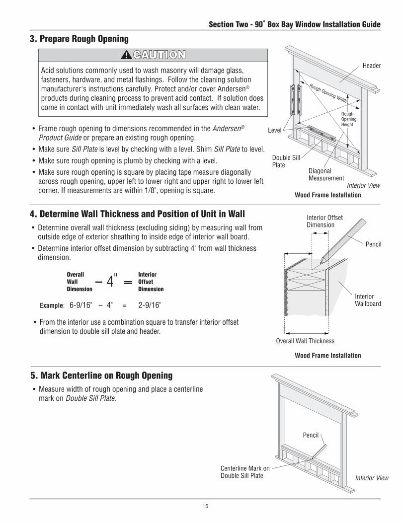
18. Head and Seat Board Inside Trim (Joined Head and Seat Board Only)
• Measure center unit along Seat Board between Interior Mullion Post Casings.
• Cut lengths from Head/Seat Board Inside Trim.• Position Head/Seat Board Inside Trim in place and
secure with several finish nails.• Repeat above procedure for Head Board and Flanking
Units.• Cut and apply interior casing (supplied by others)
around finished interior wall.
Interior Mullion Post Casing
Head/Seat Board Inside Trim
Head/Seat Board Inside Trim
Finishing, Cleaning, and Maintenance Instructions
• DO NOT expose unfinished wood to high moisture conditions, excessive heat or humidity. Finish interior wood surfaces immediately after installation. Unfinished wood surfaces will discolor, deteriorate, and/or may bow and split.
• DO NOT stain or paint weatherstrip, silicone beads, vinyl, glass, or hardware.
• Acid solutions used to wash masonry will damage glass, fasteners, hardware, and metal flashing. Follow the acid solution manufacturer's instructions carefully. Protect and/or cover Andersen products during the cleaning process to prevent acid contact. If acid does come in contact with unit, immediately wash all surfaces with clean water.
MAINTENANCEImmediately sand and refinish any interior wood thatbecomes stained or mildewed to prevent further discoloration and/or damage. For further information,contact your local Andersen dealer. Dealers can be found in the Yellow Pages under Windows.
INTERIOR FINISHINGRead and follow finishing manufacturer’s instructions and warnings on each container of finish material for priming, painting, staining, and varnishing.
CLEANINGClean exterior frame, sash members, and insect screens using a mild detergent-and-water solution and a soft cloth or brush. DO NOT use abrasive cleaners or solutions containing corrosive solvents. For persistent dirt or grime, use a nonabrasive cleanser or a mixture of water and alcohol or ammonia.
Interior View

Guía de instalación y ensamblaje de la ventana panorámica rectangular en ángulo de 90ºpara ventanas batientes y panorámicas de Andersen®
Las instrucciones son para la construcción nueva de paredes con marcos de madera que cuentan con protección contra la intemperie. Es posible que las instrucciones no sean correctas para todas las instalaciones debido al diseño del edificio, los materiales de construcción o los métodos utilizados, y/o las condiciones de la obra o el edificio. Consulte con un contratista o arquitecto para obtener recomendaciones.Las bridas en la unidad no proporcionarán por sí mismas un flashing ni sellarán la ventana de manera adecuada. Siga estas instrucciones con detenimiento.Si tiene alguna pregunta llame al 1-888-888-7020 de lunes a viernes, de 7 a.m. a 7 p.m., hora del centro, y los sábados de 8 a.m. a 4 p.m., hora del centro. Para obtener más información y/o guías, visite andersenwindows.com.Deje esta guía con el dueño de la construcción.
Gracias por elegir Andersen.
▶▶ Lea▶la▶guía▶por▶completo▶antes▶de▶comenzar▶la▶instalación.▶Lea▶todas▶las▶advertencias▶y▶precauciones▶durante▶la▶instalación▶de▶la▶unidad.▶
Tenga cuidado al trabajar en lugares elevados y cerca de las aberturas de la unidad. Siga las instrucciones del fabricante para el uso de escaleras y/o andamios. De no hacerlo así, podrían producirse lesiones o la muerte.
Siga las instrucciones del fabricante para el uso de herramientas eléctricas o manuales. Utilice siempre lentes de seguridad. De no hacerlo así, podrían producirse lesiones y/o daños al producto.
Las ventanas y puertas pueden ser pesadas. Utilice técnicas seguras de levantamiento de peso y una cantidad razonable de personas con suficiente fuerza para levantar, cargar e instalar las puertas y ventanas, a fin de evitar lesiones y/o daños al producto.
0002086 BC Revisado 03/03/10
A menos que se solicite específicamente, las ventanas y puertas Andersen no están equipadas con vidrios de seguridad, y si se rompen, se pueden fragmentar y causar lesiones. Muchas leyes y códigos de construcción exigen vidrios de seguridad en lugares adyacentes a puertas o cerca de éstas. Las ventanas Andersen se encuentran disponibles con vidrios de seguridad que pueden reducir la posibilidad de lesiones cuando se rompen. Para obtener información sobre el vidrio de seguridad, consulte a su distribuidor de Andersen local.
• Los flashings para cabecera y las bridas de instalación Andersen® NO reemplazan el flashing estándar de la ventana y puerta. La unidad debe estar instalada con flashing y sellada con sellador de manera adecuada para protegerla contra la filtración de agua y aire. Use flashing no reflectante. Las cintas de flashing altamente reflectante pueden aumentar la temperatura de la superficie de vinilo hasta el punto en que se puede producir deformación del vinilo y dañar el producto.
• No aplique ningún tipo de películas a los vidrios. Las condiciones de tensión térmica pueden ocasionar daños en el vidrio.
• El uso de materiales aislantes móviles, como cubiertas de ventanas, persianas y otros dispositivos similares pueden dañar el vidrio y/o el vinilo. Además, el exceso de condensación puede deteriorar las puertas y ventanas.
Los sujetadores y otros herrajes de metal pueden corroerse cuando quedan expuestos a madera tratada con retardador de fuego y con preservante. Obtenga y utilice los sujetadores e instrumentos metálicos apropiados, como se indica en la guía de instalación, para sujetar la unidad a cualquier abertura no acabada de madera tratada con retardador de fuego y a presión. Si no utiliza los materiales apropiados para la instalación, se pueden producir lesiones o daños al producto o a la propiedad.
“Andersen” y las demás marcas que aparezcan son marcas registradas de Andersen Corporation. ©2003-2010 Andersen Corporation. Todos los derechos reservados.

Sección uno - Guía de ensamblaje de la ventana panorámica rectangular en ángulo de 90º
2
Partes incluidas(1) Guíadeinstrucciones(2) Montantedelparteluzde90º(2) Montantesderetornodelapared(2) Plataformas(2) Cabeceraybases(2) Contramarcodelmontantedel
parteluzexterior(2) Molduradelmontantedelparteluz
interiorAccesorios opcionalesFlashingparacabeceraMolduraauxiliarSistemadesoportedecablesJambasdeextensiónMolduraPerma-Shield®BaselaminadadeviniloBasedelcontramarcodemaderacelularFibrex®
Herramientas y suministros•Lentesdeseguridad•Martillo•Nivel•Escuadradecarpintero•Escuadracombinada•Cintamétrica•Tornilloyabrazaderasde
barra•Cuñasybloques•Taladro/destornillador•Brocaparataladrode3/8"•Brocaparataladrode1/8"•Lápiz•Punzón•Cuchilladeusogeneral
afilada•Clavosdeacabadode4"de
diámetrox1-1/2"•Palancapequeña•Materialparacalzosde
2"x4"•Refuerzoencruzde1"x4"•Pañossuaves•Soporteregulabledealtura/
soporte•Pistolaparacalafatear•Sellador•Sierraparamadera•Tornillosdecabezaplana
paramaderaNo8x1-1/2"No8x2-1/2"No10x2-1/4"No8x3"
Unidadcentral
Montantedelparteluzde90º
Unidadlateral
Montantederetornodelapared
Contramarcodelmontantedelparteluzexterior
Molduradelmontantedelparteluzinterior
Plataformasuperioreinferior
Cabeceraybase
Losjuegosdematerialdeunióndisponiblesincluyen:unión no reforzada, unión reforzada de aluminio,yunión reforzada de acero.
Launióndelantepechoy/olaunióndelasunidadescentralesde2deanchodeberealizarseantesdecomenzarconelensamblaje.Elmétododeunióndependedeltamañocombinadodelaunidad,losrequisitosdecargadeldiseñoylaconformidadconloscódigosdeconstrucciónlocales.Laseleccióndelmaterialdeuniónadecuadoesresponsabilidadexclusivadelarquitecto,dueñodelaconstrucción,contratistay/oconsumidor.Paraobtenermásinformación,consultelasecciónDiseñosdecombinacióndelaGuíadeproductosAndersen®.Denohacerloasí,podríanproducirselesionespersonales,dañosalproductoy/oalapropiedad.
Lasunidadesquesobresalenconunidadesdeantepechoadosadasnodebenexcederlos8'-1/8"dealtura.
Unidad central de 2 de ancho
Unidad de antepecho
Jambadeextensión
Parte interior hacia arriba

Sección uno - Guía de ensamblaje de la ventana panorámica rectangular en ángulo de 90º
3
1. Preparación de la unidad
• Retirelasventanasdelpaqueteconcuidadoycoloquelaparteexteriorhaciaarribasobreunasuperficiedetrabajolimpiayplana.Retirelosbloquesdeembalajedeespuma.
• Retirelasbridas de instalación laterales sólodelosladosverticalesdela(s)unidad(es)central(es)conunacuchilladeusogeneralafilada.Retirelasbridas de instalación lateralesdelasunidadeslateralesdelladodeuniónúnicamente.Cortealrasconlajamba lateral.
Retirelasbridasdeinstalaciónlateralesdelladodeunión
Unidad(es) central(es)
2. Retire los topes interiores
Eltopelateraldelladodelcerrojodelasunidadesbatientesdecierreentándemcuentaconunmecanismodecerrojodebase.Tengacuidadoalretirareltopelateraldelladodelcerrojoparaevitardañarelmecanismodecerrojoy/oeltopelateral.
• Coloqueelladointeriordelasunidadeshaciaarriba.• Retireconcuidadotodoslosclavosdeltope interior
conunmartilloyunbloquedemadera.• Paraextraerlostopes interiores de cabeceraydel riel
inferiorprimero,introduzcaunapalancapequeñaentreelmarcoyeltope.Repitaestepasoenlostopes laterales interiores.
• Unalostopes interioresycolóquelosenunáreaprotegidahastaquevuelvaainstalarlos.
Topeinteriordecabecera(retireprimero)
Topeinteriordelrielinferior(retireprimero)
Topelateralinterior(retireensegundolugar)
Topelateralinterior(retireensegundolugar)
Exterior hacia arriba
Parte interior hacia arriba
Lapareddebeserde4-9/16"a7-1/8"paralasplataformas,lasbasesdecabeceraylasbasesenexistencia.
Retirelasbridasdeinstalaciónlateralesdeamboslados
Unidad lateral
Sección uno - Guía de ensamblaje de la ventana panorámica rectangular en ángulo de 90ºpara la ventana batiente de Andersen®

Sección uno - Guía de ensamblaje de la ventana panorámica rectangular en ángulo de 90º
4
4. Una y sujete los montantes del parteluz de 90º a la(s) unidad(es) central(es) • Coloquelosmontantes del parteluz de 90ºal
ladodelaunidad central yasegúresedequeelmontante del parteluzquedealrasconelextremodelaunidad central.
• Sujeteconabrazaderaslosmontantes del parteluz de 90ºalaunidad central.
• Sujetelosmontantes del parteluz de 90ºalaunidad centralcontornillosdecabezaplanaNo.10x2-1/4".Coloquelostornilloscomosemuestraysepárelosaunadistanciadeentre6"y8".Repitaesteprocedimientoparaelotromontante del parteluz de 90º.
• Coloquebasesde2x4ensentidolongitudinaldebajodelosmontantes del parteluz de 90ºparasujetarlos.
Abrazaderas
Montantedelparteluzde90º
Montantedelparteluzde90º
Unidadcentral
Parte interior hacia arribaDetalle de la sección transversal
TornillosNo.10x2-1/4"
Montantedelparteluzde90ºMontantederetornodelapared
3. Prepare los componentes para ensamblarlos
Unidad(es)central(es)
• Preparelasunidades,losmontantes del parteluzde90ºylosmontantes de retorno de la paredenlaposiciónadecuadaparaensamblarlos.
Cuandopreparelasunidadesparaensamblarlas,asegúresedequelasunidadesdeventilaciónesténubicadascorrectamenteyenladirecciónadecuada.Lasunidadesestacionariasdebeninstalarseconlaflechadeinstalaciónqueapareceenlaetiquetahaciaarriba.
Unidadlateral Parte interior hacia arriba
5. Una y sujete los montantes de retorno de la pared a las unidades laterales• Coloqueelmontante de retorno de la
paredcontraelladodelaunidad lateralconunabrida de instalación.Asegúresedequeelextremodelmontante de retorno de la paredseencuentrealrasconelextremodelaunidad.
• Sujeteconabrazaderaselmontante de retorno de la paredalaunidad.
• Sujetelosmontantes de retorno de la paredalaunidad lateralcontornillosdecabezaplanaNo.10x2-1/4".Coloquelostornilloscomosemuestraysepárelosaunadistanciadeentre6"y8".Repitaestepasoparaelotromontante de retorno de la pared.
Montantederetornodelapared
Jambalateral
Montantederetornodelapared
Abrazaderas
TornillosNo.10x2-1/4"
Montantederetornodelapared
Parte interior hacia arriba
Detalle de la sección transversal

Sección uno - Guía de ensamblaje de la ventana panorámica rectangular en ángulo de 90º
5
6. Sujete las unidades laterales a los montantes del parteluz de 90º • Coloqueelladodelaunidad lateralsinlabrida de
instalaciónsobrelosmontantes del parteluz de 90º. Asegúresedequelapartesuperioreinferiordelaunidadseencuentrenalrasdelosextremosdelosmontantes del parteluz de 90º.
• Sujetelasunidades lateralesalosmontantes del parteluz de 90ºcontornillosdecabezaplanaNo.10x2-1/4".Coloquelostornilloscomosemuestraysepárelosaunadistanciadeentre6"y8".
Unidadlateral
Unidad(es)central(es)
TornillosNo.10x2-1/4"Unidadlateral
Montantedelparteluzde90º
TornillosNo.10x2-1/4"
Parte interior hacia arriba
Detalle de la sección transversal
7. Prepare las plataformas• Coloqueelladonoacabadodelasplataformashacia
arribasobrelasuperficiedetrabajo.• Midalalongituddelaplataformaalolargodelborde
interior.Marqueelcentrodelaplataformaconunlápiz.• Marqueunalíneacentralenelanchodelaplataforma
conunaescuadradecarpintero.• Coloquelamarcadelalíneacentraldentrodelborde
interiordelaplataforma.• Repitaestepasoparalaotraplataforma. • Levantelasplataformasconelladouniformehacia
arriba(ladoopuestodelamarcadelalíneacentral).• Traceunalíneade2-1/4"haciaadentroyalolargode
todalalongituddelbordeexteriordelasplataformasconunaescuadracombinada.
Plataforma(ladonoacabado)
2-1/4"
Plataforma(ladouniforme)
Escuadradecarpintero
Escuadracombinada
Líneatrazada
Marcadelalíneacentral
Lápiz
Bordeinterior

Sección uno - Guía de ensamblaje de la ventana panorámica rectangular en ángulo de 90º
6
8. Determine y marque la línea central en la unidad• Midaelanchodelaunidad centralalolargodelmarco.
Hagaunamarcaconellápizenelcentrodelaunidadsobreelmarco.
• Repitaestepasoenelotroextremodelaunidad central.
• Hagaunamarcaconellápizenelcentrodelasunidadesunidas.
• Repitaesteprocedimientoenelotroextremodelasunidadesunidas.
Marqueelcentro
Marqueelcentro
Lápiz
Parte interior hacia arribaUnidadcentral
Unidades centrales de 2 de ancho solamente
9. Coloque las plataformas y sujételas• Deslicelaplataforma inferiorparacolocarlaenellugar
entrelasbridas de instalación lateralesdelasunidades.Laplataformaseapoyaráenlabrida de instalación del riel inferior.
• Centrelaplataforma inferiorsobrelaunidad.• Ajustelaplataforma inferioralosextremosdela(s)
unidad(es)central(es)alolargodelalíneatrazadacondostornillosdecabezaplanaparamaderaNo.8x1-1/2".
• Repitaelprocedimientoanteriorenlaplataforma superior.
Plataformainferior(instalada)
Plataformasuperior
(instalada)
UbicacióndelostornillosNo.8x1-1/2"
Líneatrazada
Cabecera
Riel inferior
Plataformainferior
Líneatrazada
Unidadlateral
Unidadlateral
Unidadcentral
Bridadeinstalaciónlateral
Bridadeinstalacióndelrielinferior
Parte interior hacia arriba
Plataformasuperior

Sección uno - Guía de ensamblaje de la ventana panorámica rectangular en ángulo de 90º
7
10. Coloque la cabecera y las bases
• Coloquelabaseentrelasunidades lateralesyasegúresedequelabaseseencuentreajustadacontralasjambasdelaunidad lateral.
• Coloqueabrazaderasentrelabaseylaplataforma inferioryunaabrazaderadebarrasobrelaunidadcomosemuestraparaasegurarquelabaseylaunidad lateralseencuentrenajustadasfirmemente.
• Coloqueunaescuadradecarpinteroenlosbordesexterioresdelasunidades centralesylaterales.Verifiqueparaasegurarsedequelaunidadestáaescuadra.
• Ajustelaplataforma inferioralosextremosdelasunidades lateralesalolargodelalíneatrazadacontornillosdecabezaplanaparamaderaNo.8x1-1/2".
• Repitaelprocedimientoanteriorenlabase de cabecera.
Escuadradecarpintero
Cabecera
Riel inferior
Basedecabecera
Abrazadera
Abrazaderadebarra
Base
UbicacióndelostornillosNo.8x1-1/2"
Plataformainferior
Base(instalada)
Plataformainferior
Parte interior hacia arriba

Sección uno - Guía de ensamblaje de la ventana panorámica rectangular en ángulo de 90º
8
2-1/4"
3/4"
3/4"
3/4"
3-1/4"
2"
3-1/4"
2"3/4"
11. Sujete las plataformas• Verifiquequelacabeceraylabaseseencuentren
encajadascorrectamente.Sinecesitarealizarajustes,extraigalostornillos(aplicadosenelpaso 11)quesujetanlasunidades laterales.Ajustesegúnseanecesario.
• AjustelasplataformasalasunidadescontornillosNo.8x1-1/2"separadosporunadistanciadeentre6"y8"yutilicelalíneatrazadasobrelaplataformacomoguía.
• Ajustelasplataformasalasjambas laterales unidascondostornillosNo.8x2-1/2"ubicadosa3-1/4"haciaadentrodelbordeexteriordelaplataforma.
• Ajustelasplataformasalosmontantes del parteluzcondostornillosNo.8x3"ubicadosa3/4"y2"delbordeexteriordelaplataforma.
TornillosdecabezaplanaNo.8x1-1/2”
Tornillosdecabezaplanade8x3"
TornillosdecabezaplanaNo.8x1-1/2”
TornillosdecabezaplanaNo.8x2-1/2”
Tornillosdecabezaplanade8x3"
LíneatrazadaJambaslateralesunidas
TornillosdecabezaplanaNo.8x2-1/2”
6" a 8"
Líneatrazada
TornillosNo.8x1-1/2"
Plataforma
Cabeceraoriel
Detalle de la sección transversal horizontal
Detalle del tamaño del tornilloDetalle de las ubicaciones del tornillo
Líneatrazada
Líneatrazada
TornillosdecabezaplanaNo.8x1-1/2”
Jambaslateralesunidas
Líneatrazada
Abrazadera
Abrazadera

Sección uno - Guía de ensamblaje de la ventana panorámica rectangular en ángulo de 90º
9
Unidades rectangulares a medida que utilizan sistema de soporte de cables
Esposiblequelasplataformasylacabeceraylasbasesdelasunidadespanorámicasrectangularesamedidanocuentenconorificiospretaladradosparaelsistemadesoportedecables.Paradeterminarlaubicacióndelosorificiosparacables,sigalasinstruccionesdelaPlantilladeorificiosparacablesqueseencuentraenelpaquetedelsistemadesoportedecables.Taladreorificiosde3/8"atravésdelasplataformasylacabeceraybasesentodaslasubicacionesdelmontantedelparteluzantesdecontinuarconelpaso 13
12. Retire la cabecera y las bases• Coloqueetiquetasenlacabecerayenlasbasespara
volverainstalarlasunavezquelaunidadestéinstalada.• Retirelasabrazaderasquesujetanlacabeceraylas
basesalasplataformas.• Retirelacabeceraylasbasesconcuidadoyvuelvaa
colocarlasenelpaqueteparaenviarlasallugardeinstalación
13. Reemplace los topes interiores
• Coloquelostopes laterales interioresprimero,luegolostopes interiores de cabecerayde riel inferiorenlaranuradelmarcoyvuelvaaaplicarlos ensulugarconclavosdeacabadode1-1/2"(4"dediámetro).Dejeaproximadamente1/8"delacabezadelclavoexpuestaparaayudaraextraerlostopes interioresparaelacabado.
11. Sujete las plataformas (continuación)
• Ajustelasplataformasalosmontantes de retorno de la paredcondostornillosNo.8x3".
Alcolocarnuevamenteeltopelateraldelladodelcerrojodelaunidadbatientedecierreentándem,coloqueclavosatravésdelosorificiosexistentes.Denohacerloasí,elmecanismodecerrojodebasepodríadañarse.
Aquí,ajustealosmontantesderetornodelaparedcontornillosdecabezaplanaNo.8x3"
Launidadnosemuestraenelensamblajedelaunidadrectangularparamayorclaridad.
Topeinteriordecabecera(vuelvaainstalarensegundolugar)
Topeinteriordelrielinferior(vuelvaainstalarensegundolugar)
Topelateralinterior(vuelvaainstalarprimero)
Topelateralinterior(vuelvaainstalarprimero)
Parte interior hacia arriba
Abrazadera
Parte interior hacia arriba
Abrazadera

Sección uno - Guía de ensamblaje de la ventana panorámica rectangular en ángulo de 90º
10
14. Coloque refuerzos en cruz y extremos del montante del parteluz con sellado para calzos• Corteyajustedoscalzosde2x4alaplataforma inferior
contornillosNo.8x2"paratransportarlaunidad.• Ajustelosrefuerzosencruzde1x4contornillosenlas
esquinasdelasplataformasenformadiagonal.
• Girelaunidadconcuidadoconelladoexteriorhaciaarriba.
• Limpielasuperficieexteriordelacabeceraydelriel inferiorenlosmontantes del parteluz.
• Coloqueselladorenlosextremosdelmontante del parteluz.
Refuerzoencruzde1x4
Calzosde2x4
Coloqueselladoraquíenamboslados
Lasventanasypuertaspuedenserpesadas.Utilicetécnicassegurasdelevantamientodepesoyunacantidadrazonabledepersonasconsuficientefuerzaparalevantar,cargareinstalarlaspuertasyventanas,afindeevitarlesionesy/odañosalproducto.
15. Coloque una moldura auxiliar• Midaycortelamoldura auxiliarparaqueencaje
alolargodelacabeceradelaunidad.Corteingletesde45ºenlasuniones.Cortelosextremosdelamoldura auxiliaralrasconelbordeexteriordelasunidades lateralesexteriores.
• Pretaladreorificiosde1-1/4"deprofundidadenlamoldura auxiliarconunabrocaparataladrode1/8"ydejeespaciosentrelosorificiosdeentre8"y12"dedistancia.
• Apliqueselladorentrelaplataforma, unidadesyentodoslosextremosingleteadosdelamoldura auxiliar.
• Ajustelamoldura auxiliaratravésdelosorificiospretaladradoscontornillosparamaderade1-1/2"(4"dediámetro).
• Retireelexcesodeselladordelasunidadesodelamoldura auxiliarconunpañosuave.
Molduraauxiliar
Plataforma Jambadecabecera
Detalle horizontal
MolduraauxiliarSellador Sellador
Sellador
Tornillosparamaderade1-1/2"(4"dediámetro)
Plataformainferior
Exterior hacia arriba
Parte interior hacia arriba
Cabecera
Sección uno - Guía de ensamblaje de la ventana panorámica rectangular en ángulo de 90º
11
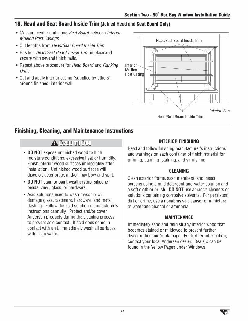
16. Prepare la unidad para transportarla• Ajustelaunidadalatarima contornillos,correas
ypiezasdesoportedemaderaparatransportarla.• Asegúresedequetodosloscomponentesyaccesorios
seencuentrenubicadosypreparadosparatransportarloshaciaellugardeinstalaciónjuntoconlaunidad.Éstospuedenincluirlossiguientes:
-Cabeceraybases -Contramarcodecabeceraybase -Jambasdeextensión -Sistemadesoportedecables -Moldurade3-1/2"ó5-1/2"Perma-Shield
®
• ContinúeconlaSección dos- Instalación de la ventana panorámica rectangular en ángulo de 90º.
Tarima
Pegueestaguíadeinstalaciónyensamblaje
enlaventanadelaunidadconcintaadhesiva.
ATENCIÓN VENDEDOR/DISTRIBUIDOR
Vista exterior

Sección dos- Guía de instalación de la ventana panorámica rectangular en ángulo de 90º
12
Cable
Cable
1. Identifique el tipo de instalación
• Tipodeinstalaciónmáscomún. • Seutilizasilaalturadelaaberturanoacabadaesmenorquelaunidadpanorámica.
• Silaventanadebelevantarseporencimadeldintelpreviamenteinstaladoparallegaralsofitooparaquecoincidaconlalíneadelcontramarcodelaventanacontigua,cortelaparteposteriordelaplataformasuperiorparadejarunespaciolibreeneldintel,comosemuestra.
• Silaventanaestálevantada,coloquebloquesderellenoenlaplacadelrielinferiorconlamismadimensiónquelaelevada.
Extremodelcable
Plataformainferior
Dintel
AbrazaderadelcableUnidadcentral
Extremodelcable
Plataformainferior
Plataformasuperior
Dintel
Abrazaderadelcable
Unidadcentral
Plataformasuperior(recorte)
Bloquederelleno(áreaelevada)
Cuña
Enelcasodelainstalacióndelasunidadesencurva,enánguloyrectangularesquesobresalganmásde24",uningenieroestructuraldeberádeterminarelsoporteestructuralquesenecesita.Sinoseutilizaelsoporteestructuralsuficiente,puedenproducirselesionespersonales,dañosalproductoy/oalapropiedad.
Instalación estándar
Instalación estándar modificada
Instalación estándar Instalación estándar modificada
Sección dos- Guía de instalación de la ventana panorámica rectangular en ángulo de 90ºpara la ventana batiente de Andersen®
Lossujetadoresyotrosherrajesdemetalpuedencorroersecuandoquedanexpuestosamaderatratadaconretardadordefuegoyconpreservante.Obtengayutilicelossujetadoreseinstrumentosmetálicosapropiados,comoseindicaenlaguíadeinstalación,parasujetarlaunidadacualquieraberturanoacabadademaderatratadaconretardadordefuegoyapresión.Sinoutilizalosmaterialesapropiadosparalainstalación,sepuedenproducirlesionesodañosalproductooalapropiedad.
BasedelcontramarcodemaderacelularFibrex®de3-1/2"ocontramarcomásanchodeotrasmarcas
BasedelcontramarcodemaderacelularFibrex®de3-1/2"ocontramarcomásanchodeotrasmarcas
BasedelcontramarcodemaderacelularFibrex®de3-1/2"ocontramarcomásanchodeotrasmarcas
BasedelcontramarcodemaderacelularFibrex®de3-1/2"ocontramarcomásanchodeotrasmarcas

Sección dos- Guía de instalación de la ventana panorámica rectangular en ángulo de 90º
13
• Senecesitaanclajeparalamampostería
Unidadcentral
Dintel
Unidadcentral
Extremodelcable
Plataformainferior
Plataformasuperior
Abrazaderadelcable
Cable
Mampostería
Mampostería
Cuña/clavadora
Cuña/clavadora
Basedecabecera
Cuña
Recortedelaplataformainferiorsegúnelespesordelapared
Instalación de la mampostería
• Laaberturadelaunidadseextiendehaciaabajohastalalíneadelpiso.
Instalación de salida
1. Identifique el tipo de instalación (continuación)
Instalación de salida Instalación de la mampostería
2. Determine el tipo de sistema de soporte requerido
Cuandoseconstruyeuntechoounacubiertasobrelaunidad,asegúresedeproporcionarelsoporteadecuadoparasostenerelpesodeltechoydelaunidad.
Parasostenerdemaneraadecuadalasventanasquesobresalen,sedebeinstalarunsistemadesoporte,comounsistemadesoportedecables,soportedemontanteoestructuradebase,refuerzosangularesydispositivosdesujeciónaldintelosofito.Denohacerloasí,podríanproducirsedañosalproductoy/oelfuncionamientocorrectodelaunidadseveríaafectado.
• Launidadquesobresaleestásostenidaporcablessujetosaldintel,alhastialolosaleros.Elsistema de soporte de cablespermiteelajustedelaunidadafindesolucionarlasdificultadesrelacionadasconelestablecimientonormaldeunaconstrucción.Elsistemadesoportedecablesenversionesde9'y12'seencuentrandisponiblesatravésdesudistribuidordeAndersen.ConsultelaGuíadeinstalacióndelsistemadesoportedecablesparaunainstalaciónadecuada.
• Instaleelsistema de soporte de cablesdespuésdelpaso 9deestaguía.
Sistema de soporte de cables
Sistemadesoportedecables
Sistema de soporte de cables
Entodaslasilustraciones,seomitieronlasunidades,elpisoylosrevestimientosparamayorclaridad.
Vista exterior
BasedelcontramarcodemaderacelularFibrex®de3-1/2"ocontramarcomásanchodeotrasmarcas
BasedelcontramarcodemaderacelularFibrex®de3-1/2"ocontramarcomásanchodeotrasmarcas
BasedelcontramarcodemaderacelularFibrex®de3-1/2"ocontramarcomásanchodeotrasmarcas

Sección dos- Guía de instalación de la ventana panorámica rectangular en ángulo de 90º
14
2. Determine el tipo de sistema de soporte requerido (continuación)
Entodaslasilustraciones,seomitieronlasunidades,elpisoylosrevestimientosparamayorclaridad.
Montaje de la viga voladiza o dintel/sofito
• Launidadquesobresaleestásostenidaporunavigadepisovoladizaolaunidadsecolocadirectamentealdintel/sofito.Laproyeccióndelavigadepisovoladizanodebesuperar1/3dellargogeneraldelavigadeapoyoydebecumplirconlosrequisitosdelcódigodeconstrucción.
• Cuandoelsistema de soporte de cablesoelsistemadesoportedeldintel,sofitoovigavoladizanoproporcionanunasujeciónadecuada,sedebencolocarrefuerzos angulares(proporcionadosporterceros)enlaestructuradebajodecadamontante del parteluz.
• Ancleelrefuerzo angular dentrodelaestructuraoinstaleunavigadobledebajodelaunidadysujételaalosrefuerzos.
Refuerzoangular
Vigavoladiza
Refuerzos angulares
Refuerzoangular
Dintel
Sofito
Montaje de la viga voladiza o dintel/sofito
Refuerzos angulares
1/3
2/3
• Launidadestásostenidaporelmontanteolaestructuradebasedelavivienda.
Montantes
Montante o estructura de base
Estructuradebase
Soporte de montante o de estructura de base
Entodaslasilustraciones,seomitieronlasunidades,elpisoylosrevestimientosparamayorclaridad.
Entodaslasilustraciones,seomitieronlasunidades,elpisoylosrevestimientosparamayorclaridad.
Vistas exteriores
Vistas exteriores
Vistas exteriores

Sección dos- Guía de instalación de la ventana panorámica rectangular en ángulo de 90º
15
Rough Opening Width
RoughOpeningHeight
3. Prepare la abertura no acabada
• EncuadrelaaberturanoacabadaconformealasdimensionesrecomendadasenlaGuía de productos Andersen®oprepareunaaberturanoacabadaexistente.
• Verifiqueconunnivelparaasegurarsedequelaplaca de riel inferiorseencuentrenivelada.Coloquecuñasenlaplaca de riel inferiorparanivelar.
• Verifiqueconunnivelparaasegurarsedequelaaberturanoacabadaseencuentrealineada.
• Asegúresedequelaaberturanoacabadaestéaescuadra.Paraello,coloquelacintamétricadiagonalmenteatravésdelaaberturanoacabada,desdelaesquinasuperiorizquierdahastalainferiorderechay,desdelaesquinasuperiorderechahastalainferiorizquierda.Silasmedidasseencuentrandentrode1/8",laaberturaestáaescuadra.
Nivel
Placaderieldoble
Dintel
Instalación del marco de madera
Lassolucionesácidasqueseutilizancomúnmenteparalimpiarlamamposteríadañanelvidrio,lossujetadores,losherrajesylosflashingdemetal.Sigaconatenciónlasinstruccionesdelfabricantedelasolucióndelimpieza.Protejay/ocubralosproductosAndersen® duranteelprocesodelimpiezaparaevitarelcontactoconelácido.Silasoluciónentraencontactoconlaunidad,lavedeinmediatotodaslassuperficiesconagualimpia.
• Paradeterminarelespesorgeneraldelapared(sinincluirelrevestimiento),midalapareddesdeelbordeexteriordelrecubrimientoexteriorhastaelbordeinteriordelatablarocainterior.
• Paradeterminarladimensióndeldesplazamientointerior,reste4"aladimensióndelespesordelapared.
4. Determine el espesor de la pared y la posición de la unidad en la pared
Instalación del marco de madera
Ejemplo:6-9/16"-4"=2-9/16"
Dimensión Dimensióngeneral -4" = de desplazamientode la pared interior
• Desdeelinterior,utiliceunaescuadracombinadaparatransferirladimensióndedesplazamientointeriorhaciaeldintelylaplacaderieldoble.
Tablarocainterior
Dimensióndeldesplazamientointerior
Espesorgeneraldelapared
5. Marque la línea central en la abertura no acabada
Marcadelíneacentralenlaplacaderieldoble
• Midaelanchodelaaberturanoacabadaymarqueunalíneacentralsobrelaplaca de riel doble.
Lápiz
Lápiz
Medidadiagonal
Vista interior
Vista interior
Anchodelaabertura
noacabada
Alturadeaberturanoacabada

Sección dos- Guía de instalación de la ventana panorámica rectangular en ángulo de 90º
16
Refuerzosdesoportede2x4
Soporteregulabledealtura
• Coloqueelsoporteregulabledealturaylosrefuerzosdesoporte2x4temporalmentedebajodelaplataforma inferiorafindeevitarquelaunidadsedesplacefueradelaabertura.
• Asegúresedequelaunidadseencuentrealineada.Ajustelaplataforma superiortemporalmentealdintelcontrestornillosdecabezaplanaparamaderaNo.8x3".
• Verifiquelaunidadparaobservarlaplomada,elnivelyparacorroborarquelasunidadesfuncionendemaneraadecuada.Sinecesitarealizarajustes,retirelostornillosyajustelaunidadsegúnseanecesarioconcuñasysoporteregulabledealtura.
• VuelvaaajustarlaunidadcontornillosdecabezaplanaparamaderaNo.8x3".
8. Coloque y ajuste la unidad• Alineeelbordeinteriordelaplataforma inferiorconlalíneatrazada
enlaplaca de riel.Alineelalíneacentraldelaunidadconlalíneacentraldelaplaca de riel.
• Ajustelaplataforma inferiortemporalmentealaplaca de riel inferiorcontrestornillosdecabezaplanaparamaderaNo.8x3".
• Alineeelbordeinteriordelaplataforma superiorconlalíneatrazadaeneldintel.
TornillosdecabezaplanaparamaderaNo.8x3" Plataformainferior
Plataformasuperior
Nivel
Placaderielinferior
Líneascentrales
Líneatrazada
Launidadquesobresaledebesostenersedurantelainstalaciónhastaqueseajusteporcompletoalaaberturaparaevitardesplazamientos.Denohacerloasí,podríanproducirselesionesgravesydañosalproducto.
Launidadquesobresaledebeinstalarsedemaneraquequedealineadayanivel,independientementedelaplomadaoelniveldelapareddelavivienda.Denohacerloasí,elproductopodríadañarse.
6. Coloque la unidad en la abertura no acabada
• Desdeelinteriordelavivienda,levanteconcuidadolaunidaddentrodelaaberturanoacabada.
• Alineelamarcadelalíneacentralenelbordeinteriordelaunidadconlamarcadelalíneacentralenlaplaca de riel.
Vista interiorLíneatrazada
• Retirelosrefuerzosencruzyloscalzosdelaunidad.
Placaderielinferior
Lasventanasypuertaspuedenserpesadas.Utilicetécnicassegurasdelevantamientodepesoyunacantidadrazonabledepersonasconsuficientefuerzaparalevantar,cargareinstalarlaspuertasyventanas,afindeevitarlesionesy/odañosalproducto.
Vista exterior
Vista interior
7. Sostenga la unidad temporalmente en la abertura no acabada

Sección dos- Guía de instalación de la ventana panorámica rectangular en ángulo de 90º
17
6" - 8"
• Coloquecuñasenelespacioentreeldintelylaplataforma superior.
• Sujetelasplataformas superioreinferiorenlaaberturanoacabadacontornillosdecabezaplanaparamaderaNo.8x3"separadosporunadistanciade6"a8".
Dintel
TornillosdecabezaplanaparamaderaNo.8x3"
Cuñas
9. Ajuste la unidad a la placa de riel inferior y al dintel
Placaderielinferior
Enestemomento,sepuedeninstalarlossistemasdesoporte,comoelsoportedecables,elrefuerzoangular,elmontajedelavigavoladizaoelsoportedemontante.Consultelaspáginas 15 y 16deestaguía.Denoinstalarelsistemadesoporteenestemomento,elsoporteregulabledealturaylaspiezasdesoportetemporalesdebenpermanecerensulugar.
12"
10. Sujete la unidad a la pared• Pretaladreorificiosde3"deprofundidadconuna
brocaparataladrode1/8"atravésdelmontante de retorno de la paredenángulodentrodelaaberturanoacabada.
• Ajusteelmontante de retorno de la paredalaaberturanoacabadacontornillosdecabezaplanaparamaderaNo.8x3"separadosporunadistanciade12".
Montantederetornodelapared
TornillosdecabezaplanaNo.8x3"
Montantederetornodelapared
Tornillosdecabezaplanade8x3"
Piezasdesoporte
Plataformainferior
Detalle de la sección transversal horizontal
Ventana(s) de 5'-5" de ancho y más
Unidad(es) panorámica(s) rectangular(es) en ángulo de 90º de 5'-5" y más grandes solamenteSiunodelosladosdeunaventanapanorámicarectangularenángulode90ºtieneunanchode5'-5"omás,sedebeinstalarsoporteadicional.Denohacerloasí,podríanproducirsedañosalproductoy/oelfuncionamientocorrectodelaunidadseveríaafectado.
Solamente sistema de soporte de cablesUtilicelaplantillaproporcionadaenelsistemadesoportedecablesparaubicaryrealizarlosorificiosenlaspiezasdesoporte.
• Coloquepiezasdesoportede2x4contornillosdecabezaplanaparamaderade2"enlaplataforma inferiorencualquieradelosladosdelaventanaquesobresalede5'5"anchoymás.
Vista interior
Vista interior

Sección dos- Guía de instalación de la ventana panorámica rectangular en ángulo de 90º
18
Contramarcodelamolduraexterior
Contramarcodelamolduraexterior
• Siseutilizaunamoldura auxiliar,apliqueselladoralosextremosexpuestosdelamoldura auxiliar.
• Coloqueunavarilladerespaldoyselladorenelespacioentrelaunidadyelrecubrimientoorevestimientoexterior.
• Apliquecintadeflashingalrededordelperímetrodelaunidad.
• Alineeelcontramarco de la moldura exterioralrasconlapartesuperiordelamoldura auxiliarylaparteinferiordelaunidad.
• Presioneselcontramarco de la moldura exteriordemaneraquequedefirmecontraelmontante de retorno de la paredyajusteconclavosdeacabadode1-1/2"(4"dediámetro).
• Serecomiendaquetodoslosrevestimientosexteriores(ocualquierotroacabado)tenganunespaciolibrede1/4"alrededordelaunidad,exceptoenelrielinferiorenlasinstalacionesdemampostería,lascualesrequierenunespaciolibrede1/2".
• Coloqueelselladoralrededordelperímetroexteriordelaventanadespuésdeaplicarelrevestimiento(uotroacabado).
Varilladerespaldo/sellador
Cintadeflashing
Molduraauxiliar,siseutiliza
11. Selle el exterior y aplique el flashing y el contramarco de la moldura exterior
Varilladerespaldo/sellador
Varilladerespaldo/sellador
CanaltipoJ
Flashinglateral
Revestimiento
Espaciode1/4"paralavarilladerespaldoyelsellador
Vistas exteriores
• Estepasodelasinstruccionesdescribeunadelastantasopcionesparaelusoadecuadodelflashing.
• Losproblemasdefiltracióndehumedadencualquiertipodeedificiosepuedenreducircolocandodemaneracorrectaflashingy/osellandotodaslasaberturasdeledificio,incluidasventanasypuertas.Colocarelflashingcorrectodebajoyalrededordelasaberturasdeventanasypuertaspuedereducirlosproblemasdehumedad,peroelrendimientodecualquiersistemadeedificiodependedeldiseñoylaconstruccióndelsistemadeledificioensutotalidad,elcualdebecumplirconloscódigoslocalesambientales,climáticosydeconstrucciónyconlaslimitacionesdelproductoydelmaterial.Eldiseñoylainstalacióndelossistemasdeflashingyselladosonresponsabilidaddelarquitecto,contratista,instaladory/ofabricantedelexteriordeledificioespecíficoparaelproyecto.
Launidaddebeestarinstaladaconflashingyselladademaneraadecuadaparaprotegerlacontralafiltracióndeaguayaire.Useflashingnoreflectante.Lascintasdeflashingaltamentereflectantepuedenaumentarlatemperaturadelasuperficiedevinilohastaelpuntoenquesepuedeproducirdeformacióndelviniloydañarelproducto.
Vista exterior
Cintadeflashing
Rielinferior(coloqueprimero)
Laterales(coloqueensegundolugar)
Cabecera(coloqueentercerlugar)

Sección dos- Guía de instalación de la ventana panorámica rectangular en ángulo de 90º
19
12. Selle el interior de la unidad
• Coloqueelaislamientoentreelmarcoylaaberturanoacabadaenlacabeceradelaunidad.Nocomprimaelaislamiento.Lasjambas de cabecerasepuedenpandear.
• Coloqueunabarreracontraelvaporenelladocálidodelasplataformas superiore inferior. Paraclimas de la región norte,aplíquelaenelladointerior.Paraclimas de la región sur,aplíquelaenelladoexterior.
Aislanteenlacabeceradelaunidad
Cuandocoloqueelaislanteentreelmarcodelaunidadylaaberturanoacabada,NOcomprimademasiadoelaislantedefibradevidrionirelleneconespuma.Silasjambassepandean,elrendimientodelproductoy/oelfuncionamientocorrectodelaunidadseveráafectado.
Molduraauxiliar
13. Aplique aislante y la moldura exterior
• Paraaplicacionesquetenganaproximadamente1-3/16"entrelaunidadyelsofito.
Molduraauxiliar
Aislantedefibradevidrio
• Instalelaestructuradeltechoautoportantesobrelapartesuperiordelamoldura auxiliar.
• Inserteelaislantedefibradevidrio.• Apliqueelacabadodeltecho(tejaasfáltica,cobre).
Techo
Aislantedefibradevidrio
Espaciodeaire
Techo autoportante de terceros
Moldura auxiliar de Andersen
• La base del contramarco de madera celular Fibrex® seencuentradisponibleconunanchode3-1/2".
• Recortela base del contramarco de madera celular Fibrex® amedida.
• Instaleunaclavadoraenelsofito.• Inserteelaislantedefibradevidrio.• Instalelabase del contramarco de madera celular Fibrexcon
unsujetadorresistentealacorrosión.
Clavadora
Aislantedefibradevidrio
Moldura Perma-Shield® de Andersen
Vista interior
BasedelcontramarcodemaderacelularFibrexde3-1/2"ocontramarcomásanchodeterceros

Sección dos- Guía de instalación de la ventana panorámica rectangular en ángulo de 90º
20
• La base del contramarco de madera celular Fibrex® seencuentradisponibleconunanchode3-1/2".
• Labase laminada de vinilopuedeutilizarsecomosofitoenlasventanasquesobresalen.Labase laminada de viniloseencuentradisponibleconanchosde24"ó48"ypuedeutilizarsejuntoconelcanaldevinilorígidotipo“J”o“H”deAndersen.
• Coloqueunbloquedeclavarenelbordeexteriordelaplataforma inferiorcontornillosdecabezaplanaparamaderadelalongitudadecuada.
• Cortelabase del contramarco de madera celular Fibrexsegúnellargoyajusteelbloquedeclavarcontornillosdecabezaplanaparamaderade1-1/2".
• Corteelsofitodelabase de laminado de vinilosegúneltamañoyajustealbloquedeclavarcontornillosde1-1/2".
BasedelcontramarcodemaderacelularFibrex®de3-1/2"deancho
Contramarcode5-1/2"deanchodeterceros
Baselaminadadevinilo
Baselaminadadevinilo
Aislamientodepoliestirenorígidode2"
Bloquedeclavar
Bloquedeclavar
13. Aplique aislante y la moldura exterior (continuación)
Cuandoutiliceelsistemadesoportedecables,perforelosorificiosdeaccesoatravésdelsofitodelaplataformainferioryelaislantepararealizarlosajustesalcable.Consultelaguíadeinstalacióndelsistemadesoportedecables.
Base del contramarco de madera celular Fibrex® y base laminada de vinilo de Andersen
14. Coloque y ajuste la base y el contramarco interior
• Coloquelabasedirectamentesobrelapartesuperiordelaplataforma inferioryasegúresedequeelladoacabadoquedehaciaarriba.
• Centrelabaseyasegúresedequeelbordeinteriordeéstaquedealrasconlaparedinterior.
• Ajusteconclavosdeacabadode1-1/2"(4"dediámetro)alrededordelperímetrodelabase,a1/2"delborde.Coloquelosclavosaunadistanciade8"entrecadauno.
Plataformainferior
Base
Bordeinterior
OPCIÓN 1: Base unida a la plataforma inferior
OPCIÓN 1: Base unida a la plataforma inferiorPiezasproporcionadasporAndersen.Idealparaconstruccionesnuevasyaplicacionesdereemplazos.Permiteunmayorespaciodebajodelamanijadelasunidadesoperativasyminimizalasreparacionesdelatablarocaenlasinstalacionesdereemplazo.
Vista interior

Sección dos- Guía de instalación de la ventana panorámica rectangular en ángulo de 90º
21
OPCIÓN 2: Cabecera y base separadas por encima de la plataforma inferior
Serequierenespaciadores.Piezasproporcionadasporterceros.Idealparaconstruccionesnuevas.Lasventanaspanorámicasdeantepechounidouotrasunidadesquerequierenmontantesdelparteluzreforzadosdeacerodebenutilizarelmétododecabeceraydebaseseparadasafindeocultarlaescuadradefijacióndeacero.
• Coloquebases espaciadoras de 1/2"alrededordelperímetrodelaplataforma superioreinferior.
• Corteelaislante rígidoamedidaparaqueencajeentrelasbases espaciadorasycolóqueloenlasplataformas superioreinferior.
• Coloquelabasedemaneraquequedefirmecontralasventanasyasegúresedequeellateralacabadoseencuentrehaciaafuera.Asegúresedequelabasesedeslicepordebajodeltopedelcontramarcodelrieldelaventana.
• Centrelabaseyasegúresedequeelbordeinteriordeéstaquedealrasconlaparedinterior.
• Ajusteconclavosdeacabadode1-1/2"(4"dediámetro)alrededordelperímetrodelabase,a1/2"delborde.Coloquelosclavosaunadistanciade8"entrecadauno.
Base
Aislantedepoliestirenorígido
Aislamiento
Espaciador Bordeinterior
14. Coloque y ajuste la base y el contramarco interior (continuación)
OPCIÓN 2: Cabecera y base separadas por encima de la plataforma inferior
EspaciadoresVista interior
Vista interior
Vista interior

Sección dos- Guía de instalación de la ventana panorámica rectangular en ángulo de 90º
22
• Conlacintamétrica,determineladistanciaentrelabaseyla plataforma superiorinstaladas.
• Resteelespesordelabase de cabeceradelamedidaanterior.Cortelamoldura del montante del parteluz segúnlalongitudcalculada.
• Coloquelamoldura del montante del parteluz interioryajusteconclavosdeacabadode1-1/2"(4"dediámetro),a1/2"delborde.Coloquelosclavosaunadistanciade8"entrecadauno.
15. Aplique la moldura del montante del parteluz interior
Molduradelmontantedelparteluzinterior
Molduradelmontantedelparteluzinterior
Instalaciónconespaciadores
Instalaciónenlacuallacabeceraylabaseseencuentranunidasalasplataformas
Método de unión
Método de separación
Base
Espaciadores
Base
Plataformasuperior
Plataformasuperior
• Conlacintamétrica,determineladistanciaentrelabaseyla plataforma superiorinstaladas.
• Resteelespesordelabase de cabeceradelamedidaanterior.Cortelamoldura del montante del parteluz segúnlalongitudcalculada.
• Coloquelamoldura del montante del parteluz interioryajusteconclavosdeacabadode1-1/2"(4"dediámetro),a1/2"delborde.Coloquelosclavosaunadistanciade8"entrecadauno.
Método de separación
Método de unión
Vista interior
Vista interior

Sección dos- Guía de instalación de la ventana panorámica rectangular en ángulo de 90º
23
Método de separación Instalaciónconespaciadores
Molduradelmontantedelparteluzinterior
Bordeexterior
16. Instale la base de cabecera
• Desliceelbordeexteriordelabase de cabeceraenlapartesuperiordelamoldura del montante del parteluz interioryasegúresedequeelladoacabadodelabase de cabeceraseencuentrehaciaabajo.
• Empujelabase de cabecerahaciaarribacontralaplataforma superiorycentre.Asegúresedequeelbordeinteriordelabase de cabeceraseencuentrealrasconlaparedinterior.
• Recortelabase de cabeceraalrasconlaparedinterior,sifueranecesario.
• Ajusteconclavosdeacabadode1-1/2"(4"dediámetro)alrededordelperímetrodelabase de cabecera,a1/2"delborde.Coloquelosclavosaunadistanciade8"entrecadauno.
Basedecabecera
Método de separación
• Desliceelbordeexteriordelabase de cabeceraenlapartesuperiordelamoldura del montante del parteluz interioryasegúresedequeelladoacabadodelabase de cabeceraseencuentrehaciaabajo.
• Empujelabase de cabecerahaciaarribacontralaplataforma superiorycentre.Asegúresedequeelbordeinteriordelabase de cabeceraseencuentrealrasconlaparedinterior.
• Recortelabase de cabeceraalrasconlaparedinterior,sifueranecesario.
• Ajusteconclavosdeacabadode1-1/2"(4"dediámetro)alrededordelperímetrodelabase de cabecera,a1/2"delborde.Coloquelosclavosaunadistanciade8"entrecadauno. Instalaciónenlacuallacabeceraylabase
seencuentranunidasalasplataformas
Basedecabecera
Método de unión
Molduradelmontantedelparteluzinterior
Bordeexterior
Método de unión
17. Corte• Lasjambas de extensiónseencuentrandisponiblesa
travésdesudistribuidordeAndersenparaparedesde4-9/16",5-1/4",6-9/16",y7-1/8".
• Ajusteconclavosdeacabadodelalongitudapropiada.
Jambadeextensión
Jambadeextensión
Aplicaciones del método de separación solamenteLajambadeextensióndebecortarsesegúnlalongitudcuandoseapliquealacabecerayalasbasesseparadas.
Vista interior
Vista interior
Vista interior

Sección dos- Guía de instalación de la ventana panorámica rectangular en ángulo de 90º
24
18. Cabecera y base dentro del contramarco(cabecera y base unidas solamente)
• Midalaunidadcentralalolargodelabaseentrelasmolduras del montante del parteluz interior.
• Cortelaslongitudesdelcontramarco interior de la cabecera/base.
• Coloqueelcontramarco interior de la cabecera/baseelellugaryajusteconvariosclavosdeacabado.
• Repitaelprocedimientoanteriorparalabase de cabeceraylasunidades laterales.
• Corteycoloquelamoldurainterior(proporcionadaporterceros)alrededordelaparedinterioracabada.
Molduradelmontantedelparteluzinterior
Contramarcointeriordelacabecera/base
Contramarcointeriordelacabecera/base
Instrucciones de acabado, limpieza y mantenimiento
• NOexpongalamaderasinacabadoahumedadocalorexcesivos.Apliqueelacabadoalassuperficiesinterioresdemaderainmediatamentedespuésdelainstalación.Dejarlasuperficiedemaderasindarleelacabadodecolorará,deterioraráy/opuedepandearseopartirse.
• NOmanchenipintelosburletes,loscordonesdesilicona,elvinilo,elvidrioylosherrajes.
• Lassolucionesácidasqueseutilizanparalimpiarlamamposteríadañanelvidrio,lossujetadores,losherrajesyelflashingdemetal.Sigaconatenciónlasinstruccionesdelfabricantedelasoluciónácida.Protejay/ocubralosproductosAndersenduranteelprocesodelimpiezaparaevitarelcontactoconelácido.Sielácidoentraencontactoconlaunidad,lavedeinmediatotodaslassuperficiesconagualimpia.
MANTENIMIENTOLijeyvuelvaaaplicaracabadoinmediatamenteenlassuperficiesinterioresdemaderaqueesténmanchadasoconmohoparaevitarunadecoloracióny/odaño.Paraobtenermásinformación,comuníqueseconsudistribuidordeAndersenlocal.LosdistribuidoressepuedenencontrarenlasPáginasamarillasenlacategoríaVentanas.
ACABADO INTERIORLeaysigalasinstruccionesyadvertenciasdelfabricantedelacabado,queseencuentranubicadasencadacontenedordematerialdeacabadoparaimprimar,pintar,teñirybarnizar.
LIMPIEZALimpieelmarcoexterior,lashojasylosmosquiteroscondetergentesuaveyaguausandounpañoocepillosuave.NOuselimpiadoresabrasivososolucionesquecontengansolventescorrosivos.Encasodepolvoosuciedadpersistente,useunlimpiadornoabrasivoounamezcladeaguayalcoholoamoníaco.
Vista interior