Embed Size (px)
Citation preview
90PF Slot Card
Dual Channel Programmable Introduction Filter/Amplifier Card
Description Each 90PF slot card provides two channels of precision, low noise and distortion (-100 dB typical) programmable filters with up to 60 dB of pre and 20 dB of post adjustable gain. Filter modules are programmable from 0.1 Hz to 300 kHz utilizing 4, 11-bit tuning ranges. When assembled with a high-pass filter in channel one (1) and a low-pass filter in channel two (2), 90PF slot cards can be configured on the fly to operate as a low-pass, high-pass, band-pass, or band-reject (notch) filter. Customers can select any combination of two available filter modules per slot card to meet their application specific signal conditioning needs. Front panel mounted BNC’s provide easy access for connection of signal input and output. Other features include differential or single-ended input, AC or DC-coupled input, single ended output, LED clipping indicators and fine adjustment of DC offset. Operating the 90PF in filter BYPASS mode allows the design engineer to use each channel as a precision instrumentation grade programmable amplifier. Features • 0.1 Hz to 300 kHz Tuning Range • Selectable single-ended or differential input • Gain/phase matched channels • LED clipping indicators • Memory storage for up to 9 set-ups/slot card • <-100 dB signal-to-noise ratio to 100 kHz BW • Programmable gain, 60 dB pre and 20 dB post Applications • Anti-Aliasing • Sound Measurement • Noise Testing • Audio Communications • Medical Research • Industrial Process Control • Seismic Analysis • Vibration Analysis
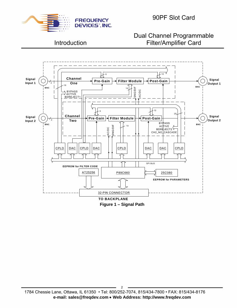
Available 90PF Low Pass Filters Part # dB # Poles Filter TypeL8B -100 8 Butterworth L8L -100 8 Bessel L8E -88 8, 6-zero Elliptic, 1.77 L8EX -80≤100kHz 8, 6-zero Elliptic, 1.56 -60>100kHz L8EY -100 8, 6-zero Elliptic, 2.00 L8D80 -80 8, 6-zero Constant Delay L8D10 -100 8, 6-zero Constant Delay Available 90PF High Pass Filters Part # dB # Poles Filter TypeH8B -100 8 Butterworth H8E -88 8, 6-zero Elliptic, 1.77 H8EX -80≤100kHz 8, 6-zero Elliptic, 1.56 -60>100kHz H8EY -100 8, 6-zero Elliptic, 2.00
1 1784 Chessie Lane, Ottawa, IL 61350 • Tel: 800/252-7074, 815/434-7800 • FAX: 815/434-8176
e-mail: [email protected] • Web Address: http://www.freqdev.com
90PF Slot Card
Dual Channel Programmable Introduction Filter/Amplifier Card
P89C660 25C080
Post-GainFilter ModulePre-Gain
Post-GainFilter ModulePre-Gain
SignalInput 1
SignalInput 2
SignalOutput 1
SignalOutput 2
ChannelOne
Channel Two
CPLD
SN
G/D
IF
AC
/DC
BYPASS
SN
G/D
IF
AC
/DC
14
6
14
10
ACTIVEBDREJECT1
BYPASSACTIVE
BDREJECT2CH2_NO_CASCADE
DAC CPLD
SPI BUS
CPLD DAC DAC DAC
AT25256
32-PIN CONNECTOR
TO BACKPLANE
19
20
EEPROM for FILTER CODE
EEPROM for PARAMETERS
2
2
BNC
BNCBNC
BNC
6
10
CPLD
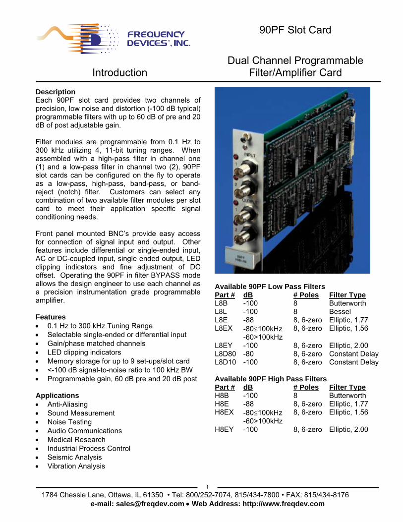
Figure 1 – Signal Path
2 1784 Chessie Lane, Ottawa, IL 61350 • Tel: 800/252-7074, 815/434-7800 • FAX: 815/434-8176
e-mail: [email protected] • Web Address: http://www.freqdev.com
90PF Slot Card
Low Pass Specifications Filter Options
Product Model 90PF - L8B 90PF - L8L 90PF - L8E 90PF - L8EX Transfer Function 8-Pole
Butterworth 8-Pole Bessel
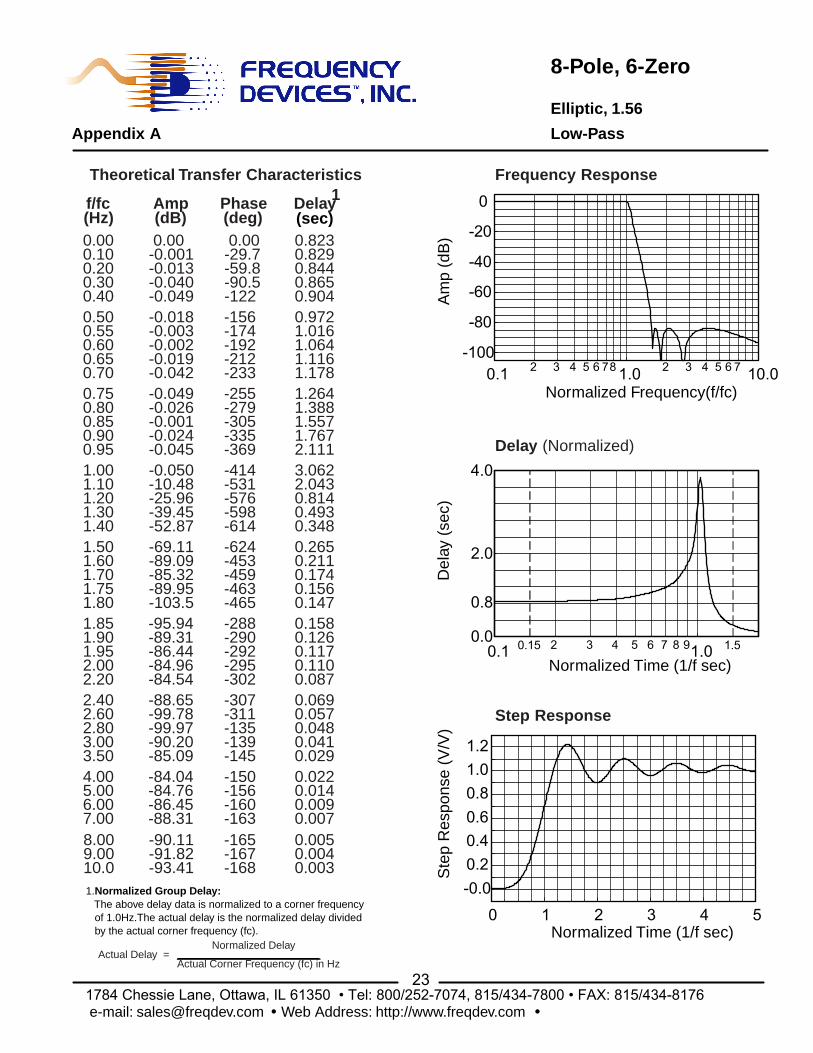
8-Pole, 6-Zero elliptic – 1.77
8-Pole, 6-Zero elliptic – 1.56
Tuning Range 0.1 Hz to 300 kHz 0.1 Hz to 300 kHz 0.1 Hz to 300 kHz 0.1 Hz to 300 kHz Theoretical Transfer Characteristics
Appendix A Page 9
Appendix A Page 4
Appendix A Page 24
Appendix A Page 23
Passband Ripple (theoretical)
0.0 dB 0.0 dB ±0.035 dB ±0.05 dB
Pass Band Gain (non-inverting)
0 ± 0.2 dB 0 ± 0.2 dB 0 ± 0.2 dB 0 ± 0.2 dB to 100 kHz
0 ± 0.4 dB >100 kHz Stop Band
Attenuation Rate 48 dB/octave
Attenuation Rate 48 dB/octave
Attenuation 80 dB
Attenuation 80 dB <100kHz> 60dB
Corner Frequency Accuracy
fc
±2% max.
fc
± 2% max.
fr
± 2% max.
fr
± 2% max.
± 3% > 100 kHzAmplitude -3 dB -3 dB -0.035 dB -0.05 dB Phase -360° -182° -323° -414° Phase Match1
0 - fc ±2º max. ±1º typ.
0 - fc ±2º max. ±1º typ.
0 – 0.8fr 0.8fr - fr
±2º max. ±1º typ. ±4º max. ±2º typ.
0 – 0.8fr 0.8fr - fr
±3ºmax ±4º>100kHz ±4º max. ±5º>100kHz
Filter Attenuation (theoretical) 0.12 dB 0.80 fc 1.91 dB 0.80 fc 0.035 dB 1.00 fr 0.5 dB 1.00 fr 3.01 dB 1.00 fc 3.01 dB 1.00 fc 3.01 dB 1.13 fr 3.01 dB 1.05 fr 60.0 dB 2.37 fc 60.0 dB 4.52 fc 60.0 dB 1.67 fr 60.0 dB 1.45 fr 80.0 dB 3.16 fc 80.0 dB 6.07 fc 80.0 dB 1.77 fr 80.0 dB 1.56 fr Amplitude Accuracy1
0.1 to 100 kHz (theoretical)
0 - 0.8 fc±0.2 dB max. ±0.1 dB typ. 0.8 fc - fc±0.3 dB max. ±0.15 dB typ.
0 - 0.8 fc±0.2 dB max. ±0.1 dB typ. 0.8 fc - fc
±0.3 dB max.±0.15 dB typ.
0 - 0.8 fr±0.2 dB max. ±0.1 dB typ. 0.8 fr - fr±0.4 dB max. ±0.2 dB typ.
0 - 0.8 fr ±0.2 dB max. ±0.1 dB typ. 0.8 fr - fr ±0.7 dB max. ±0.35 dB typ.
Total Harmonic Distortion @ 1 kHz
<-100dB typ.@3Vrms
<-100dB typ.@3Vrms
<-100dB typ.@3Vrms
<-100dB typ.@3Vrms
Broad Band Noise (5 Hz to 2MHz)
200µVrms typ. 200µVrms typ. 200µVrms typ. 200µVrms typ.
Narrow Band Noise <100nV/ Hz typ. <100nV/ Hz typ. <100nV/ Hz typ. <100nV/ Hz typ. Note 1: Channel to channel match for the same transfer function set to the same frequency and operating configuration.
3 1784 Chessie Lane, Ottawa, IL 61350 • Tel: 800/252-7074, 815/434-7800 • FAX: 815/434-8176
e-mail: [email protected] • Web Address: http://www.freqdev.com

90PF Slot Card
Low Pass Specifications Filter Options
4 1784 Chessie Lane, Ottawa, IL 61350 • Tel: 800/252-7074, 815/434-7800 • FAX: 815/434-8176
e-mail: [email protected] • Web Address: http://www.freqdev.com
Product Model 90PF - L8EY 90PF - L8D80 90PF - L8D10 Transfer Function 8-Pole, 6-Zero
elliptic – 2.00 8-Pole, 6-Zero constant delay
8-Pole, 6-Zero constant delay
Tuning Range 0.1 Hz to 300 kHz 0.1 Hz to 300 kHz 0.1 Hz to 300 kHz Theoretical Transfer Characteristics
Appendix A Page 25
Appendix A Page 21
Appendix A Page 22
Passband Ripple (theoretical)
0.05 dB 0.10 dB 0.15 dB
Pass Band Gain (non-inverting)
0 ± 0.2 dB 0 ± 0.2 dB 0 ± 0.2 dB
Stop Band
Attenuation Rate 100 dB
Attenuation Rate 80 dB
Attenuation Rate 100 dB
Corner Frequency Accuracy
fr
± 2% max.
fc
± 2% max.
fc
±2% max.
Amplitude -0.05 dB -3 dB -3 dB Phase -419° -306° -311° Phase Match1
0 – 0.8fr 0.8fr - fr
±3º max. ±1.5º typ. ±4º max. ±2º typ.
0 – 0.8fc 0.8fc – fc
±2º max. ±1º typ. ±4º max. ±2º typ.
0 – 0.8fc 0.8fc – fc
±2º max. ±1º typ. ±4º max. ±2º typ.
Filter Attenuation (theoretical) 0.5 dB 1.00 fr 3.01 dB 1.00 fc 3.01 dB 1.00 fc 3.01 dB 1.06 fr 60.0 dB 3.08 fc 80.0 dB 4.45 fc 80.0 dB 1.83 fr 80.0 dB 3.57 fc 100 dB 5.20 fc 100.0 dB 2.00 fr Amplitude Accuracy1
0.1 to 100 kHz (theoretical)
0 - 0.8 fr±0.2 dB max. ±0.1 dB typ. 0.8 fr - fr±0.5 dB max. ±0.25 dB typ.
0 - 0.8 fc±0.2 dB max. ±0.1 dB typ. 0.8 fc - fc±0.4 dB max. ±0.2 dB typ.
0 - 0.8 fc±0.2 dB max. ±0.1 dB typ. 0.8 fc - fc±0.5 dB max. ±0.25 dB typ.
Total Harmonic Distortion @ 1 kHz
<-100dB typ.@3Vrms
<-100dB typ.@3Vrms
<-100dB typ.@3Vrms
Broad Band Noise (5 Hz to 2MHz)
200µVrms typ. 200µVrms typ. 200µVrms typ.
Narrow Band Noise <100nV/ Hz typ. <100nV/ Hz typ. <100nV/ Hz typ. Note 1: Channel to channel match for the same transfer function set to the same frequency and operating configuration.
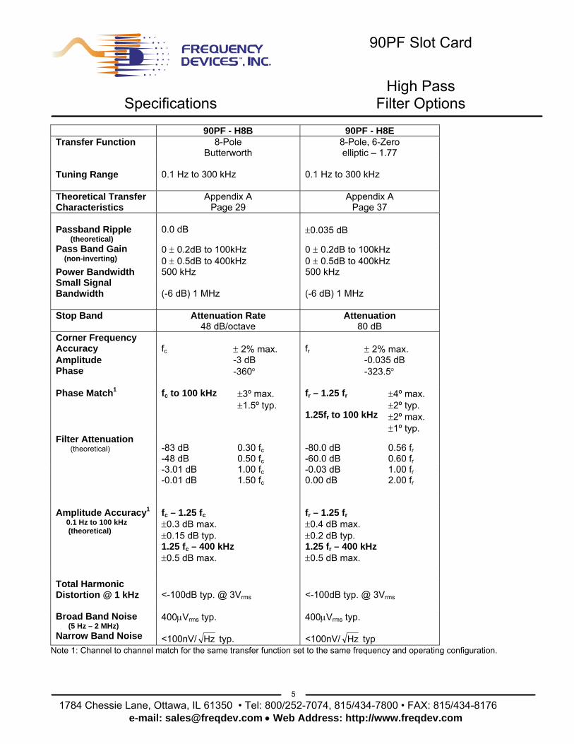
90PF Slot Card
High Pass Specifications Filter Options
5 1784 Chessie Lane, Ottawa, IL 61350 • Tel: 800/252-7074, 815/434-7800 • FAX: 815/434-8176
e-mail: [email protected] • Web Address: http://www.freqdev.com
90PF - H8B 90PF - H8E Transfer Function 8-Pole
Butterworth 8-Pole, 6-Zero elliptic – 1.77
Tuning Range 0.1 Hz to 300 kHz 0.1 Hz to 300 kHz Theoretical Transfer Characteristics
Appendix A Page 29
Appendix A Page 37
Passband Ripple (theoretical)
0.0 dB ±0.035 dB
Pass Band Gain (non-inverting)
0 ± 0.2dB to 100kHz 0 ± 0.5dB to 400kHz
0 ± 0.2dB to 100kHz 0 ± 0.5dB to 400kHz
Power Bandwidth 500 kHz 500 kHz Small Signal Bandwidth
(-6 dB) 1 MHz
(-6 dB) 1 MHz
Stop Band
Attenuation Rate 48 dB/octave
Attenuation 80 dB
Corner Frequency Accuracy
fc
± 2% max.
fr
± 2% max.
Amplitude -3 dB -0.035 dB Phase -360° -323.5° Phase Match1
fc to 100 kHz ±3º max. ±1.5º typ.
fr – 1.25 fr 1.25fr to 100 kHz
±4º max. ±2º typ. ±2º max. ±1º typ.
Filter Attenuation (theoretical) -83 dB 0.30 fc -80.0 dB 0.56 fr -48 dB 0.50 fc -60.0 dB 0.60 fr -3.01 dB 1.00 fc -0.03 dB 1.00 fr -0.01 dB 1.50 fc 0.00 dB 2.00 fr Amplitude Accuracy1
0.1 Hz to 100 kHz (theoretical)
fc – 1.25 fc±0.3 dB max. ±0.15 dB typ. 1.25 fc – 400 kHz ±0.5 dB max.
fr – 1.25 fr±0.4 dB max. ±0.2 dB typ. 1.25 fr – 400 kHz ±0.5 dB max.
Total Harmonic Distortion @ 1 kHz
<-100dB typ. @ 3Vrms
<-100dB typ. @ 3Vrms
Broad Band Noise (5 Hz – 2 MHz)
400µVrms typ. 400µVrms typ.
Narrow Band Noise <100nV/ Hz typ. <100nV/ Hz typ Note 1: Channel to channel match for the same transfer function set to the same frequency and operating configuration.
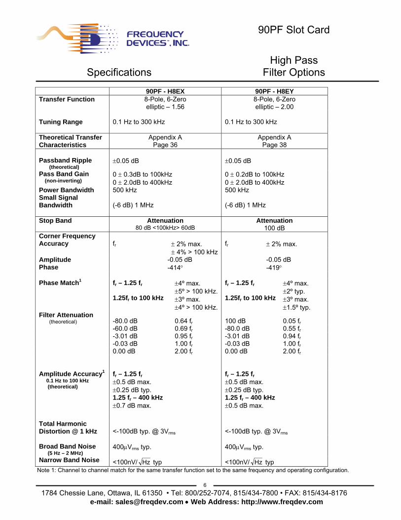
90PF Slot Card
High Pass Specifications Filter Options
6 1784 Chessie Lane, Ottawa, IL 61350 • Tel: 800/252-7074, 815/434-7800 • FAX: 815/434-8176
e-mail: [email protected] • Web Address: http://www.freqdev.com
90PF - H8EX 90PF - H8EY Transfer Function 8-Pole, 6-Zero
elliptic – 1.56 8-Pole, 6-Zero elliptic – 2.00
Tuning Range 0.1 Hz to 300 kHz 0.1 Hz to 300 kHz Theoretical Transfer Characteristics
Appendix A Page 36
Appendix A Page 38
Passband Ripple (theoretical)
±0.05 dB ±0.05 dB
Pass Band Gain (non-inverting)
0 ± 0.3dB to 100kHz 0 ± 2.0dB to 400kHz
0 ± 0.2dB to 100kHz 0 ± 2.0dB to 400kHz
Power Bandwidth 500 kHz 500 kHz Small Signal Bandwidth
(-6 dB) 1 MHz
(-6 dB) 1 MHz
Stop Band
Attenuation 80 dB <100kHz> 60dB
Attenuation 100 dB
Corner Frequency Accuracy
fr
± 2% max.
fr
± 2% max.
± 4% > 100 kHz Amplitude -0.05 dB -0.05 dB Phase -414° -419° Phase Match1
fr – 1.25 fr 1.25fr to 100 kHz
±4º max. ±5º > 100 kHz.±3º max. ±4º > 100 kHz.
fr – 1.25 fr 1.25fr to 100 kHz
±4º max. ±2º typ. ±3º max. ±1.5º typ.
Filter Attenuation (theoretical) -80.0 dB 0.64 fr 100 dB 0.05 fr -60.0 dB 0.69 fr -80.0 dB 0.55 fr -3.01 dB 0.95 fr -3.01 dB 0.94 fr -0.03 dB 1.00 fr -0.03 dB 1.00 fr 0.00 dB 2.00 fr 0.00 dB 2.00 fr Amplitude Accuracy1
0.1 Hz to 100 kHz (theoretical)
fr – 1.25 fr±0.5 dB max. ±0.25 dB typ. 1.25 fr – 400 kHz ±0.7 dB max.
fr – 1.25 fr±0.5 dB max. ±0.25 dB typ. 1.25 fr – 400 kHz ±0.5 dB max.
Total Harmonic Distortion @ 1 kHz
<-100dB typ. @ 3Vrms
<-100dB typ. @ 3Vrms
Broad Band Noise (5 Hz – 2 MHz)
400µVrms typ. 400µVrms typ.
Narrow Band Noise <100nV/ Hz typ <100nV/ Hz typ Note 1: Channel to channel match for the same transfer function set to the same frequency and operating configuration.
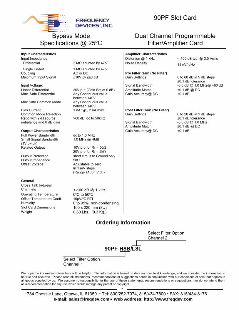
90PF Slot Card
Bypass Mode Dual Channel Programmable Specifications @ 25ºC Filter/Amplifier Card
7 1784 Chessie Lane, Ottawa, IL 61350 • Tel: 800/252-7074, 815/434-7800 • FAX: 815/434-8176
e-mail: [email protected] • Web Address: http://www.freqdev.com
Input Characteristics Amplifier Characteristics Input Impedance: Distortion @ 1 kHz <-100 dB typ. @ 3.0 Vrms Differential 2 MΩ shunted by 47pF Noise Density 14 nV/ Hz Single Ended 1 MΩ shunted by 47pF Coupling AC or DC Pre Filter Gain (No Filter) Maximum Input Signal ±10V pk @0 dB Gain Settings 0 to 60 dB in 5 dB steps
±0.1 dB tolerance Input Voltage: Signal Bandwidth -6.0 dB @ 1.0 MHz@ +60 dB Linear Differential 20V p-p (Gain Set at 0 dB) Amplitude Match ±0.1 dB @ DC Max. Safe Differential Any Continuous value
between ±40V Gain Accuracy@ DC ±0.1 dB
Max Safe Common Mode Any Continuous value between ±40V
Bias Current 1 nA typ., 2 nA max. Post Filter Gain (No Filter) Common Mode Rejection Ratio with 2kΩ source unbalance and 0 dB gain
>60 dB, dc to 50kHz
Gain Settings Signal Bandwidth
0 to 20 dB in 1 dB steps ±0.1 dB tolerance -6.0 dB @ 1.0 MHz
Amplitude Match ±0.1 dB @ DC Output Characteristics Gain Accuracy@ DC ±0.1 dB Full Power Bandwidth dc to 1.0 MHz Small Signal Bandwidth (1V pk-pk)
1.0 MHz @ -6dB
Related Output 10V p-p for RL = 50Ω 20V p-p for RL = 2kΩ Output Protection short circuit to Ground only Output Impedance 50Ω Offset Voltage Adjustable to zero,
In 1 mV steps. (Range ±100mV dc)
General Cross Talk between Channels
<-100 dB @ 1 kHz
Operating Temperature 0ºC to 50ºC Offset Temperature Coeff. 10µV/ºC RTI Humidity 0 to 95%, non-condensing Slot Card Dimensions 100 x 220 mm (3U) Weight 0.60 Lbs., (0.3 Kg.)
Ordering Information Select Filter Option Channel 2
90PF-H8B/L8L Select Filter Option Channel 1 We hope the information given here will be helpful. The information is based on data and our best knowledge, and we consider the information to be true and accurate. Please read all statements, recommendations or suggestions herein in conjunction with our conditions of sale that applies to all goods supplied by us. We assume no responsibility for the use of these statements, recommendations or suggestions, nor do we intend them as a recommendation for any use which would infringe any patent or copyright.
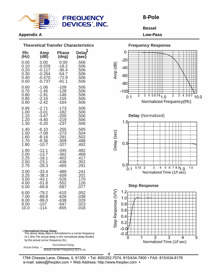
8-Pole
Bessel
Appendix A Low-Pass
4 1784 Chessie Lane, Ottawa, IL 61350 • Tel: 800/252-7074, 815/434-7800 • FAX: 815/434-8176e-mail: [email protected] · Web Address: http://www.freqdev.com ·
Normalized Time (1/f sec)
Ste
p R
espo
nse
(V/V
)
Step Response
0 1 2 3 4 5-0.2-0.00.20.40.60.81.01.2
Normalized Time (1/f sec)
Del
ay (
sec)
Delay (Normalized)
0.1 1.02 3 4 5 6 7 8 90.0
0.5
1.0
1.50.15
Normalized Frequency(f/fc)
Am
p (d
B)
Frequency Response
0.1 1.0 10.02 3 4 5 6 78 2 3 4 5 6 7-100
-80
-60
-40
-20
0(sec)
Theoretical Transfer Characteristics1
0.000.100.200.300.400.500.600.700.800.850.900.951.001.101.201.301.401.501.601.701.801.902.002.252.502.753.003.253.504.005.006.007.008.009.0010.0
1.Normalized Group Delay: The above delay data is normalized to a corner frequency of 1.0Hz.The actual delay is the normalized delay divided by the actual corner frequency (fc).
Actual Delay = Normalized Delay
Actual Corner Frequency (fc) in Hz
f/fc(Hz)
Amp(dB)
Phase(deg)
Delay
-79.2-89.8-99.0-107-114
-33.4-38.3-43.1-51.8-66.8
-12.1-13.7-18.1-23.1-28.3
-6.10-7.08-8.16-9.36-10.7
-2.71-3.01-3.67-4.40-5.20
-1.06-1.45-1.91-2.16-2.42
0.00-0.029-0.117-0.264-0.470-0.737
-610-626-638-647-655
-489-509-526-552-587
-345-362-402-436-465
-255-273-291-309-327
-173-182-200-219-237
-109-128-146-155-164
0.00-18.2-36.4-54.7-72.9-91.1
.052
.038
.029
.023
.018
.241
.201
.170
.126
.077
.482
.468
.417
.352
.291
.505
.504
.502
.498
.492
.506
.506
.506
.506
.506
.506
.506
.506
.506
.506
.506
.506
.506
.506
.506
.506
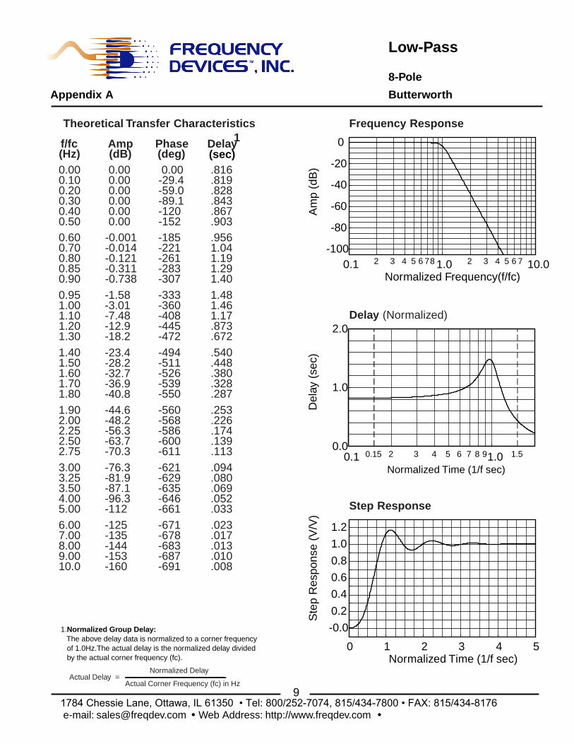
Low-Pass
8-Pole
Appendix A Butterworth
9
0.1 1.0 10.02 3 4 5 6 78 2 3 4 5 6 7
Normalized Frequency(f/fc)
-100
-80
-60
-40
-20
0
Am
p (d
B)
0.1 1.02 3 4 5 6 7 8 9
Normalized Time (1/f sec)
0.0
1.0
2.0D
elay
(se
c)
1.50.15
0 1 2 3 4 5Normalized Time (1/f sec)
-0.0
0.2
0.4
0.6
0.8
1.0
1.2
Ste
p R
espo
nse
(V/V
)
Frequency Response
Delay (Normalized)
Step Response
(sec)
Theoretical Transfer Characteristics1
0.000.100.200.300.400.500.600.700.800.850.900.951.001.101.201.301.401.501.601.701.801.902.002.252.502.753.003.253.504.005.006.007.008.009.0010.0
1.Normalized Group Delay: The above delay data is normalized to a corner frequency of 1.0Hz.The actual delay is the normalized delay divided by the actual corner frequency (fc).
Actual Delay = Normalized Delay
Actual Corner Frequency (fc) in Hz
f/fc(Hz)
Amp(dB)
Phase(deg)
Delay
-125-135-144-153-160
-76.3-81.9-87.1-96.3-112
-44.6-48.2-56.3-63.7-70.3
-23.4-28.2-32.7-36.9-40.8
-1.58-3.01-7.48-12.9-18.2
-671-678-683-687-691
-621-629-635-646-661
-560-568-586-600-611
-494-511-526-539-550
-0.001-0.014-0.121-0.311-0.738
0.000.000.000.000.000.00
-333-360-408-445-472
-185-221-261-283-307
0.00-29.4-59.0-89.1-120-152
.023
.017
.013
.010
.008
.094
.080
.069
.052
.033
.253
.226
.174
.139
.113
.540
.448
.380
.328
.287
1.481.461.17.873.672
.9561.041.191.291.40
.816
.819
.828
.843
.867
.903
1784 Chessie Lane, Ottawa, IL 61350 • Tel: 800/252-7074, 815/434-7800 • FAX: 815/434-8176e-mail: [email protected] · Web Address: http://www.freqdev.com ·

8-Pole, 6-Zero
Constant Delay
Appendix A Low-Pass (80 dB)
21 1784 Chessie Lane, Ottawa, IL 61350 • Tel: 800/252-7074, 815/434-7800 • FAX: 815/434-8176e-mail: [email protected] · Web Address: http://www.freqdev.com ·
Normalized Frequency(f/fc)
Am
p (d
B)
Normalized Time (1/f sec)
Del
ay (
sec)
Normalized Time (1/f sec)
Ste
p R
espo
nse
(V/V
)
Frequency Response
Delay (Normalized)
Step Response
0.1 1.0 10.02 3 4 5 6 78 2 3 4 5 6 7-100
-80
-60
-40
-20
0
0.1 1.02 3 4 5 6 7 8 90.0
0.5
1.0
1.50.15
0 1 2 3 4 5-0.2-0.00.20.40.60.81.01.2
1.Normalized Group Delay: The above delay data is normalized to a corner frequency of 1.0Hz.The actual delay is the normalized delay divided by the actual corner frequency (fc).
Actual Delay = Normalized Delay
Actual Corner Frequency (fc) in Hz
1.401.601.802.002.25
0.900.951.001.101.20
0.500.600.700.800.85
0.000.100.200.300.40
(sec)
Theoretical Transfer Characteristics1f/fc
(Hz)Amp(dB)
Phase(deg)
Delay
6.507.008.009.0010.0
5.005.255.505.756.00
3.754.004.254.504.75
2.502.753.003.253.50
-86.6-85.1-84.1-84.3-84.9
-92.8-104-101-93.3-89.9
-98.3-86.3-84.1-85.1-87.9
-43.4-50.3-57.6-62.5-75.4
-11.3-17.1-23.2-29.1-36.3
-1.89-2.41-3.01-4.50-6.39
0.034-0.157-0.510-1.07-1.44
0.00 0.017 0.058 0.099 0.105
-300-305-312-317-321
-462-466-289-293-295
-616-442-448-454-458
-561-576-589-599-608
-417-459-492-517-542
-276-291-306-336-365
-153-184-215-245-261
0.00-30.7-61.3-92.0-123
.026
.022
.017
.013
.011
.044
.040
.036
.033
.030
.079
.069
.061
.054
.049
.189
.153
.127
.107
.092
.656
.512
.396
.312
.239
.849
.846
.841
.821
.783
.852
.852
.852
.851
.850
.852
.852
.852
.852
.852
8-Pole, 6-Zero
Constant Delay
Appendix A Low-Pass (100 dB)
22 1784 Chessie Lane, Ottawa, IL 61350 • Tel: 800/252-7074, 815/434-7800 • FAX: 815/434-8176e-mail: [email protected] · Web Address: http://www.freqdev.com ·
1.Normalized Group Delay: The above delay data is normalized to a corner frequency of 1.0Hz.The actual delay is the normalized delay divided by the actual corner frequency (fc).
Normalized Frequency(f/fc)
Am
p (d
B)
Normalized Time (1/f sec)
Del
ay (
sec)
Normalized Time (1/f sec)
Ste
p R
espo
nse
(V/V
)
Actual Delay = Normalized Delay
Actual Corner Frequency (fc) in Hz
Frequency Response
Delay (Normalized)
Step Response
0 1 2 3 4 5
-0.00.20.40.60.81.01.2
-0.2
0.1 1.02 3 4 5 6 7 8 90.0
0.5
1.0
1.50.15
.007
.005
.004
.003
.003
.025
.022
.017
.013
.011
.054
.043
.036
.030
.028
.186
.151
.125
.090
.068
.650
.504
.389
.306
.235
.861
.857
.851
.828
.785
.865
.865
.865
.864
.863
.865
.865
.865
.865
.865
0.00-31.1-62.3-93.4-125-156-187-218-249-265-280-296-311-341-370-422-464-496-520-544-563-578-591-610-624-635-643-651-476-478-481-486-312-318-322-328-333-336-339-341
-105-106-107-108-109
-106-110-122-109-106
-81.3-93.4-142-105-105
-40.5-46.1-51.4-61.5-71.2
-11.2-16.8-22.5-28.0-34.5
-1.89-2.41-3.01-4.50-6.38
0.010-0.182-0.532-1.09-1.45
0.00 0.015 0.051 0.085 0.085
12.014.016.018.020.0
6.507.008.009.0010.0
4.505.005.506.006.20
2.502.753.003.504.00
1.401.601.802.002.25
0.900.951.001.101.20
0.500.600.700.800.85
0.000.100.200.300.40
(sec)
Theoretical Transfer Characteristics1f/fc
(Hz)Amp(dB)
Phase(deg)
Delay
0.1 1.0 10.02 3 4 5 678 2 3 4 5 67-120-100-80-60-40-20
0
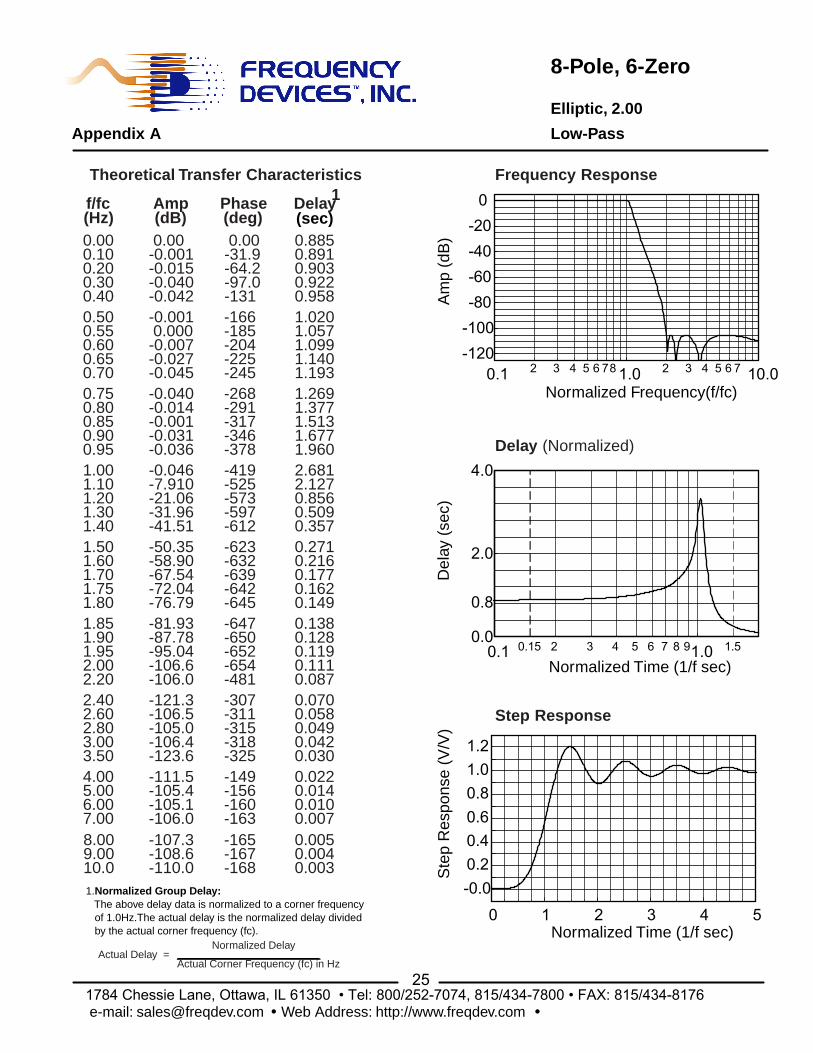
8-Pole, 6-Zero
Elliptic, 1.56
Low-Pass
Frequency Response
Appendix A
23 1784 Chessie Lane, Ottawa, IL 61350 • Tel: 800/252-7074, 815/434-7800 • FAX: 815/434-8176e-mail: [email protected] · Web Address: http://www.freqdev.com ·
Am
p (d
B)
Normalized Time (1/f sec)
Del
ay (
sec)
Normalized Time (1/f sec)
Ste
p R
espo
nse
(V/V
)Delay (Normalized)
Step Response
Normalized Frequency(f/fc)0.1 1.0 10.02 3 4 5 6 78 2 3 4 5 6 7
-100
-80
-60
-40
-20
0
0.1 1.02 3 4 5 6 7 8 90.0
2.0
4.0
1.50.15
0.8
0 1 2 3 4 5
-0.00.20.40.60.81.01.2
1.Normalized Group Delay: The above delay data is normalized to a corner frequency of 1.0Hz.The actual delay is the normalized delay divided by the actual corner frequency (fc).
Actual Delay = Normalized Delay
Actual Corner Frequency (fc) in Hz
(sec)
Theoretical Transfer Characteristics1f/fc
(Hz)Amp(dB)
Phase(deg)
Delay
4.005.006.007.00
2.402.602.803.003.50
1.851.901.952.002.20
1.501.601.701.751.80
1.001.101.201.301.40
0.750.800.850.900.95
0.500.550.600.650.70
8.009.0010.0
0.000.100.200.300.40
-90.11-91.82-93.41
-84.04-84.76-86.45-88.31
-88.65-99.78-99.97-90.20-85.09
-95.94-89.31-86.44-84.96-84.54
-69.11-89.09-85.32-89.95-103.5
-0.050-10.48-25.96-39.45-52.87
-0.049-0.026-0.001-0.024-0.045
-0.018-0.003-0.002-0.019-0.042
0.00-0.001-0.013-0.040-0.049
-165-167-168
-150-156-160-163
-307-311-135-139-145
-288-290-292-295-302
-624-453-459-463-465
-414-531-576-598-614
-255-279-305-335-369
-156-174-192-212-233
0.00-29.7-59.8-90.5-122
0.0050.0040.003
0.0220.0140.0090.007
0.0690.0570.0480.0410.029
0.1580.1260.1170.1100.087
0.2650.2110.1740.1560.147
3.0622.0430.8140.4930.348
1.2641.3881.5571.7672.111
0.9721.0161.0641.1161.178
0.8230.8290.8440.8650.904
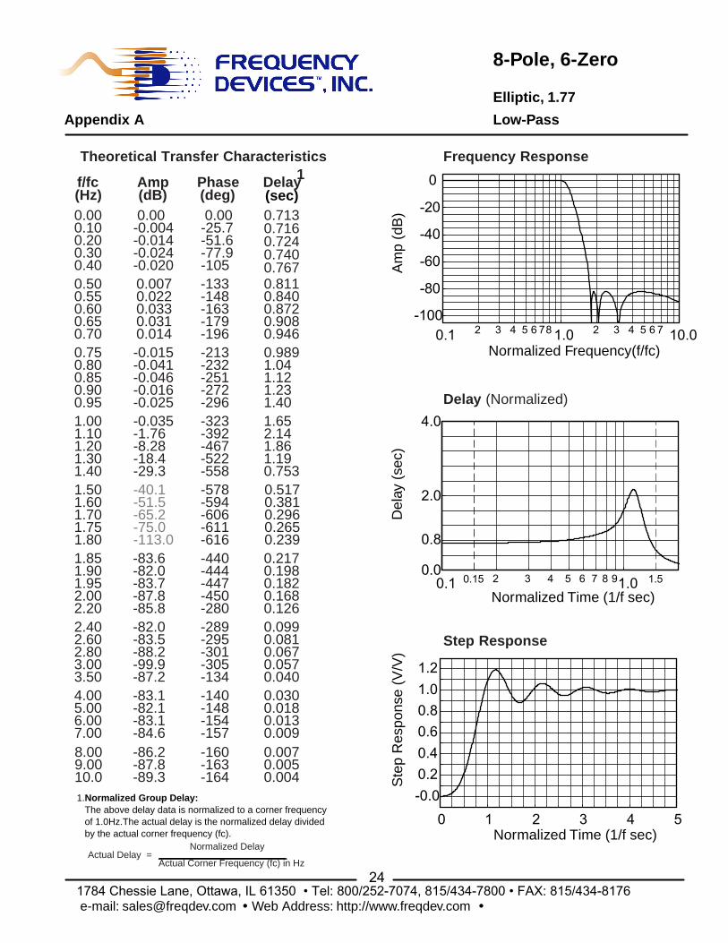
8-Pole, 6-Zero
Elliptic, 1.77
Appendix A Low-Pass
24 1784 Chessie Lane, Ottawa, IL 61350 • Tel: 800/252-7074, 815/434-7800 • FAX: 815/434-8176e-mail: [email protected] · Web Address: http://www.freqdev.com ·
Normalized Frequency(f/fc)
Am
p (d
B)
Normalized Time (1/f sec)
Del
ay (
sec)
Normalized Time (1/f sec)
Ste
p R
espo
nse
(V/V
)
Frequency Response
Delay (Normalized)
Step Response
0.1 1.02 3 4 5 6 7 8 90.0
2.0
4.0
1.50.15
0.8
0.1 1.0 10.02 3 4 5 6 78 2 3 4 5 6 7-100
-80
-60
-40
-20
0
0 1 2 3 4 5-0.00.20.40.60.81.01.2
1.Normalized Group Delay: The above delay data is normalized to a corner frequency of 1.0Hz.The actual delay is the normalized delay divided by the actual corner frequency (fc).
Actual Delay = Normalized Delay
Actual Corner Frequency (fc) in Hz
(sec)
Theoretical Transfer Characteristics1f/fc
(Hz)Amp(dB)
Phase(deg)
Delay
4.005.006.007.00
2.402.602.803.003.50
1.851.901.952.002.20
1.501.601.701.751.80
1.001.101.201.301.40
0.750.800.850.900.95
0.500.550.600.650.70
8.009.0010.0
0.000.100.200.300.40
-86.2-87.8-89.3
-83.1-82.1-83.1-84.6
-82.0-83.5-88.2-99.9-87.2
-83.6-82.0-83.7-87.8-85.8
-40.1-51.5-65.2-75.0-113.0
-0.035-1.76-8.28-18.4-29.3
-0.015-0.041-0.046-0.016-0.025
0.0070.0220.0330.0310.014
0.00-0.004-0.014-0.024-0.020
-160-163-164
-140-148-154-157
-289-295-301-305-134
-440-444-447-450-280
-578-594-606-611-616
-323-392-467-522-558
-213-232-251-272-296
-133-148-163-179-196
0.00-25.7-51.6-77.9-105
0.0070.0050.004
0.0300.0180.0130.009
0.0990.0810.0670.0570.040
0.2170.1980.1820.1680.126
0.5170.3810.2960.2650.239
1.652.141.861.190.753
0.9891.041.121.231.40
0.8110.8400.8720.9080.946
0.7130.7160.7240.7400.767
8-Pole, 6-Zero
Elliptic, 2.00
Low-Pass
Frequency Response
Appendix A
25 1784 Chessie Lane, Ottawa, IL 61350 • Tel: 800/252-7074, 815/434-7800 • FAX: 815/434-8176e-mail: [email protected] · Web Address: http://www.freqdev.com ·
Am
p (d
B)
Normalized Time (1/f sec)
Del
ay (
sec)
Normalized Time (1/f sec)
Ste
p R
espo
nse
(V/V
)Delay (Normalized)
Step Response
0.1 1.02 3 4 5 6 7 8 90.0
2.0
4.0
1.50.15
0.8
Normalized Frequency(f/fc)0.1 1.0 10.02 3 4 5 6 78 2 3 4 5 6 7
-120-100-80-60-40-20
0
0 1 2 3 4 5
-0.00.20.40.60.81.01.2
1.Normalized Group Delay: The above delay data is normalized to a corner frequency of 1.0Hz.The actual delay is the normalized delay divided by the actual corner frequency (fc).
Actual Delay = Normalized Delay
Actual Corner Frequency (fc) in Hz
(sec)
Theoretical Transfer Characteristics1f/fc
(Hz)Amp(dB)
Phase(deg)
Delay
4.005.006.007.00
2.402.602.803.003.50
1.851.901.952.002.20
1.501.601.701.751.80
1.001.101.201.301.40
0.750.800.850.900.95
0.500.550.600.650.70
8.009.0010.0
0.000.100.200.300.40
-107.3-108.6-110.0
-111.5-105.4-105.1-106.0
-121.3-106.5-105.0-106.4-123.6
-81.93-87.78-95.04-106.6-106.0
-50.35-58.90-67.54-72.04-76.79
-0.046-7.910-21.06-31.96-41.51
-0.040-0.014-0.001-0.031-0.036
-0.001 0.000-0.007-0.027-0.045
0.00-0.001-0.015-0.040-0.042
-165-167-168
-149-156-160-163
-307-311-315-318-325
-647-650-652-654-481
-623-632-639-642-645
-419-525-573-597-612
-268-291-317-346-378
-166-185-204-225-245
0.00-31.9-64.2-97.0-131
0.0050.0040.003
0.0220.0140.0100.007
0.0700.0580.0490.0420.030
0.1380.1280.1190.1110.087
0.2710.2160.1770.1620.149
2.6812.1270.8560.5090.357
1.2691.3771.5131.6771.960
1.0201.0571.0991.1401.193
0.8850.8910.9030.9220.958

High-Pass
8-Pole
Appendix A Butterworth
29
0.1 1.0 10.02 3 4 5 6 78 2 3 4 5 6 7
Normalized Frequency(f/fc)
-100
-80
-60
-40
-20
0
Am
p (d
B)
Frequency Response
(sec)
Theoretical Transfer Characteristics1
0.100.200.300.400.500.600.700.800.850.900.951.001.201.401.601.802.002.503.004.005.006.007.008.009.0010.0
1.Normalized Group Delay: The above delay data is normalized to a corner frequency of 1.0Hz.The actual delay is the normalized delay divided by the actual corner frequency (fc).
Actual Delay = Normalized Delay
Actual Corner Frequency (fc) in Hz
f/fc(Hz)
Amp(dB)
Phase(deg)
Delay
0.000.000.000.000.000.00
0.000.000.000.000.00
-5.15-3.01-0.229-0.020-0.002
59.049.042.136.832.729.4
-35.5-24.8-15.6-11.6-8.06
-160-112-83.7-63.7-48.2
38636027522619417015212099.274.0
535499459437413
691661631600568
0.0330.0230.0170.0130.0100.008
0.2870.2260.1390.0940.052
1.481.460.8730.5400.380
.9561.041.191.291.40
0.8190.8280.8430.8670.903
1784 Chessie Lane, Ottawa, IL 61350 • Tel: 800/252-7074, 815/434-7800 • FAX: 815/434-8176e-mail: [email protected] · Web Address: http://www.freqdev.com ·
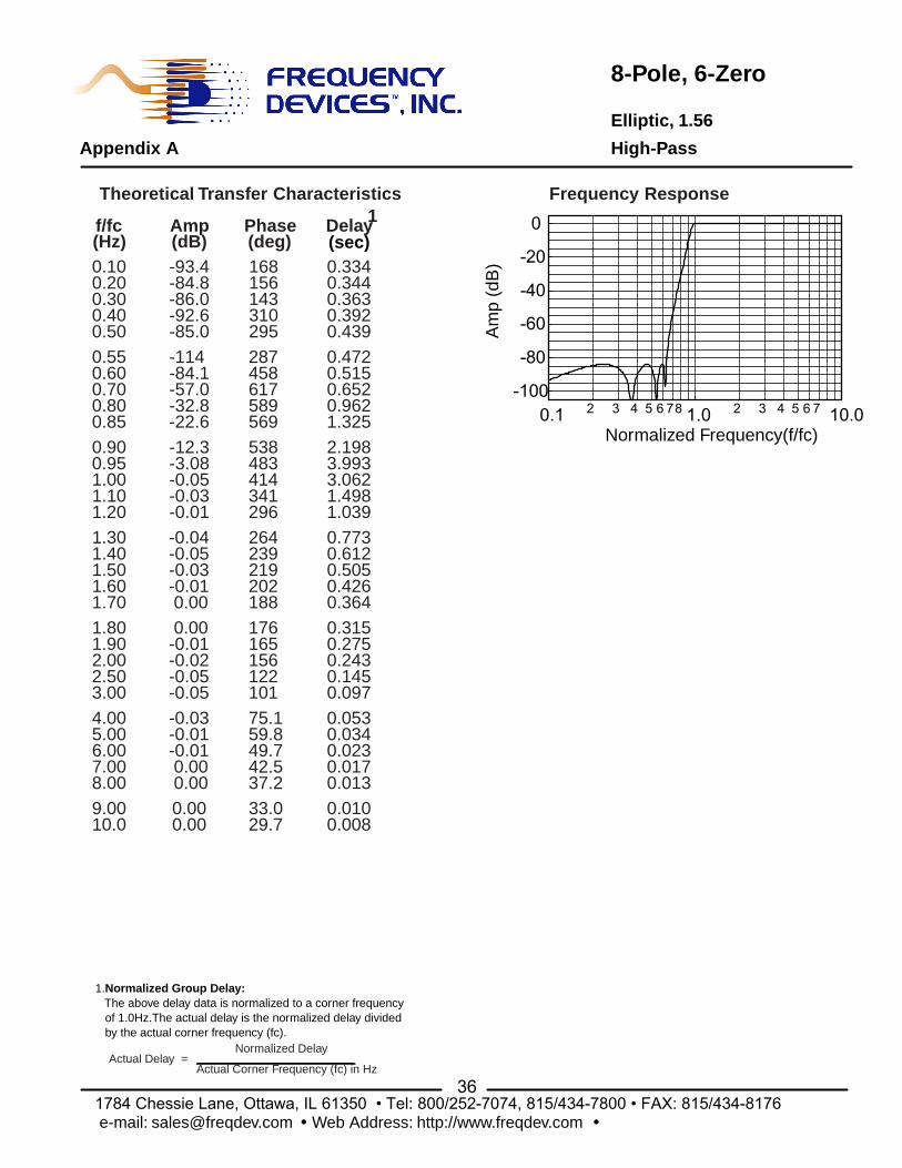
8-Pole, 6-Zero
Elliptic, 1.56
High-Pass
Frequency Response
Appendix A
36 1784 Chessie Lane, Ottawa, IL 61350 • Tel: 800/252-7074, 815/434-7800 • FAX: 815/434-8176e-mail: [email protected] · Web Address: http://www.freqdev.com ·
Am
p (d
B)
Normalized Frequency(f/fc)0.1 1.0 10.02 3 4 5 6 78 2 3 4 5 6 7
-100
-80
-60
-40
-20
0
1.Normalized Group Delay: The above delay data is normalized to a corner frequency of 1.0Hz.The actual delay is the normalized delay divided by the actual corner frequency (fc).
Actual Delay = Normalized Delay
Actual Corner Frequency (fc) in Hz
(sec)
Theoretical Transfer Characteristics1f/fc
(Hz)Amp(dB)
Phase(deg)
Delay
9.0010.0
4.005.006.007.008.00
1.801.902.002.503.00
1.301.401.501.601.70
0.900.951.001.101.20
0.550.600.700.800.85
0.100.200.300.400.50
0.000.00
-0.03-0.01-0.01 0.00 0.00
0.00-0.01-0.02-0.05-0.05
-0.04-0.05-0.03-0.01 0.00
-12.3-3.08-0.05-0.03-0.01
-114-84.1-57.0-32.8-22.6
-93.4-84.8-86.0-92.6-85.0
33.029.7
75.159.849.742.537.2
176165156122101
264239219202188
538483414341296
287458617589569
168156143310295
0.0100.008
0.0530.0340.0230.0170.013
0.3150.2750.2430.1450.097
0.7730.6120.5050.4260.364
2.1983.9933.0621.4981.039
0.4720.5150.6520.9621.325
0.3340.3440.3630.3920.439
8-Pole, 6-Zero
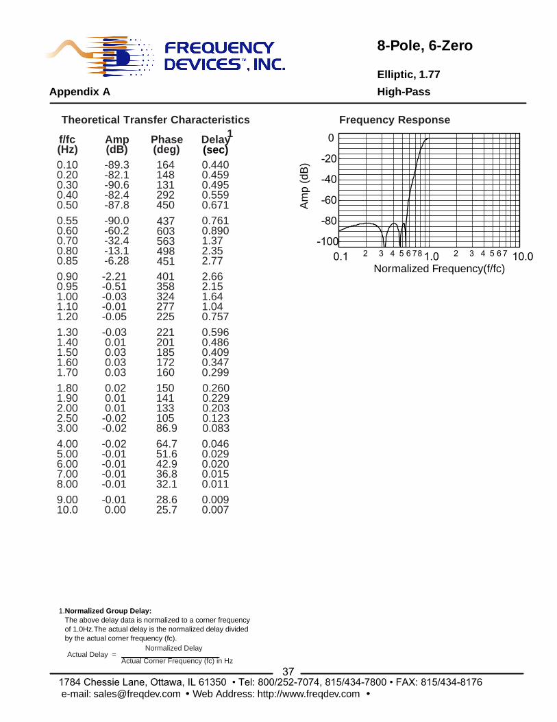
Elliptic, 1.77
Appendix A High-Pass
37 1784 Chessie Lane, Ottawa, IL 61350 • Tel: 800/252-7074, 815/434-7800 • FAX: 815/434-8176e-mail: [email protected] · Web Address: http://www.freqdev.com ·
Normalized Frequency(f/fc)
Am
p (d
B)
Frequency Response
0.1 1.0 10.02 3 4 5 6 78 2 3 4 5 6 7-100
-80
-60
-40
-20
0
1.Normalized Group Delay: The above delay data is normalized to a corner frequency of 1.0Hz.The actual delay is the normalized delay divided by the actual corner frequency (fc).
Actual Delay = Normalized Delay
Actual Corner Frequency (fc) in Hz
(sec)
Theoretical Transfer Characteristics1f/fc
(Hz)Amp(dB)
Phase(deg)
Delay
9.0010.0
4.005.006.007.008.00
1.801.902.002.503.00
1.301.401.501.601.70
0.900.951.001.101.20
0.550.600.700.800.85
0.100.200.300.400.50
-0.01 0.00
-0.02-0.01-0.01-0.01-0.01
0.02 0.01 0.01-0.02-0.02
-0.03 0.01 0.03 0.03 0.03
-2.21-0.51-0.03-0.01-0.05
-90.0-60.2-32.4-13.1-6.28
-89.3-82.1-90.6-82.4-87.8
28.625.7
64.751.642.936.832.1
15014113310586.9
221201185172160
401358324277225
437603563498451
164148131292450
0.0090.007
0.0460.0290.0200.0150.011
0.2600.2290.2030.1230.083
0.5960.4860.4090.3470.299
2.662.151.641.040.757
0.7610.8901.372.352.77
0.4400.4590.4950.5590.671
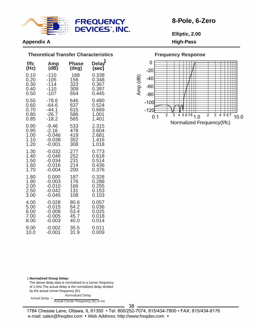
8-Pole, 6-Zero
Elliptic, 2.00
High-Pass
Frequency Response
Appendix A
38 1784 Chessie Lane, Ottawa, IL 61350 • Tel: 800/252-7074, 815/434-7800 • FAX: 815/434-8176e-mail: [email protected] · Web Address: http://www.freqdev.com ·
Am
p (d
B)
Normalized Frequency(f/fc)0.1 1.0 10.02 3 4 5 6 78 2 3 4 5 6 7
-120-100-80-60-40-20
0
1.Normalized Group Delay: The above delay data is normalized to a corner frequency of 1.0Hz.The actual delay is the normalized delay divided by the actual corner frequency (fc).
Actual Delay = Normalized Delay
Actual Corner Frequency (fc) in Hz
(sec)
Theoretical Transfer Characteristics1f/fc
(Hz)Amp(dB)
Phase(deg)
Delay
9.0010.0
4.005.006.007.008.00
1.801.902.002.503.00
1.301.401.501.601.70
0.900.951.001.101.20
0.550.600.700.800.85
0.100.200.300.400.50
-0.002-0.001
-0.028-0.015-0.008-0.005-0.003
0.000-0.003-0.010-0.042-0.045
-0.032-0.046-0.034-0.016-0.004
-9.46-2.16-0.046-0.038-0.001
-78.6-64.6-44.1-26.7-18.2
-110-105-114-110-107
35.531.9
80.664.253.445.740.0
187176166131108
277252231214200
533478419352308
646637615586565
168156323309654
0.0110.009
0.0570.0360.0250.0180.014
0.3280.2880.2550.1530.103
0.7730.6180.5140.4360.376
2.3153.6042.6811.4161.018
0.4800.5240.6691.0011.401
0.3380.3480.3670.3970.445