Embed Size (px)
Citation preview
1.7
Installation Instructions for
GATICA Recessed
920GATR
1A
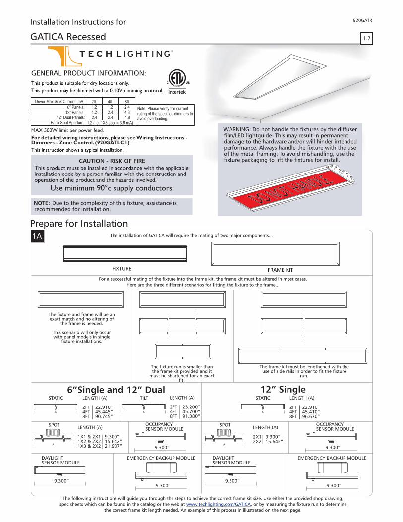
Prepare for InstallationThe installation of GATICA will require the mating of two major components...
FIXTURE FRAME KIT
For a successful mating of the fixture into the frame kit, the frame kit must be altered in most cases.
Here are the three different scenarios for fitting the fixture to the frame...
The fixture and frame will be anexact match and no altering of
the frame is needed.
This scenario will only occurwith panel models in single
fixture installations.
The fixture run is smaller thanthe frame kit provided and it
must be shortened for an exactfit.
The frame kit must be lengthened with theuse of side rails in order to fit the fixture
run.
WARNING diffuser: Do not handle the fixtures by thefilm/LED lightguide. This may result in permanentdamage to the hardware and/or will hinder intendedperformance. Always handle the fixture with the useof the metal framing. To avoid mishandling, use thefixture packaging to lift the fixtures for install.
NOTE: Due to the complexity of this fixture, assistance isrecommended for installation.
CAUTION RISK OF FIRE-This product must be installed in accordance with the applicableinstallation code by a person familiar with the construction andoperation of the product and the hazards involved.
Use minimum 90°c supply conductors.
MAX 500W limit per power feed.
For detailed wiring instructions, please see Wiring Instructions -Dimmers - Zone Control. (920GATLC1)
This instruction shows a typical installation.
Driver Max Sink Current [mA]
6” Panels:12” Panels:
12” Dual Panels:Each Spot Aperture:
2ft 4ft 8ft
Note: Please verify the currentrating of the specified dimmers toavoid overloading.
1.21.2
2.4
1.2
2.4
2.42.44.8
4.81.2 (i.e. 1X3 spot = 3.6 mA)
G P I :ENERAL RODUCT NFORMATION
This product is suitable for dry locations only.
This product may be dimmed with a 0-10V dimming protocol.
A
6”Single and 12” DualLENGTH (A)
2 | 22.910”FT4 | 45.445”FT8 | 90.745”FT
STATIC
A
TILT LENGTH (A)
2 | 23.200”FT4 | 45.700”FT8 | 91.380”FT
A
LENGTH (A)
1X1 & 2X1| 9.300”1X2 & 2X2| 15.642”1X3 & 2X2| 21.987”
SPOT
9.300”9.300”
9.300”
OCCUPANCYSENSOR MODULE
DAYLIGHTSENSOR MODULE
EMERGENCY BACK UP MODULE-
A
12” SingleLENGTH (A)
2 | 22.910”FT4 | 45.410”FT8 | 96.670”FT
STATIC
A
LENGTH (A)
2X1| 9.300”2X2| 15.642”
SPOT
9.300”9.300”
9.300”
OCCUPANCYSENSOR MODULE
DAYLIGHTSENSOR MODULE
EMERGENCY BACK UP MODULE-
The following instructions will guide you through the steps to achieve the correct frame kit size. Use either the provided shop drawing,
spec sheets which can be found in the catalog or the web at , or by measuring the fixture run to determinewww.techlighting.com/GATICA
the correct frame kit length needed. An example of this process in illustrated on the next page.

2
1B 6” EXAMPLE CONFIGURATION
23.2” 9.3” 45.445”
2FT TILT 4FT STATIC1X1 SPOT
77.945”
Determine the length of the complete fixture run using a shop drawing, the spec sheet, or by measuring the fixtures.
Cut the frame kit to fit the configuration using the overall measurements (see following sections for assembly details).
Determine the location of the mounting hardware, such as threaded rod or suspension cable, using the spanner locations on the framekit as a guide.
Cut the drywall according to frame kit’s assembled dimensions.
Install the frames and then the fixtures.
1
96” FRAME KIT
EXTRA PORTION REMOVED FROM CENTER
FRAME REASSEMBLED TO FIT FIXTURE CONFIGURATION
77.945”
MOUNTING HARDWARE LOCATION
SPANNER
FRAME KIT
DRYWALL
CUTOUTFORFRAMEKIT
2
3
4
5
NOTE: Map out the locations of fixtures and the locations of the frame kit spanners on the fixture(s), then install allsupporting hardware such as suspension cables and/or threaded rods that the frame kit will be supported from. Whenplanning for the location of the suspension hardware (threaded rod, suspension cable, etc.), keep in mind that thespanners must be spaced appropriately (every 2’) along the frame kit to ensure the frame’s rigidity and even distribution ofthe fixtures weight.
1
2
3
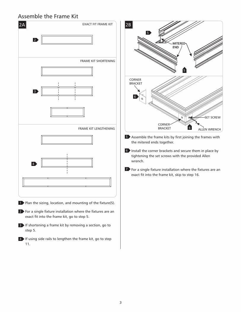
Assemble the Frame Kit
2A
1 Plan the sizing, location, and mounting of the fixture(S).
For a single fixture installation where the fixtures are an
exact fit into the frame kit, go to step 5.
If shortening a frame kit by removing a section, go to
step 5.
If using side rails to lengthen the frame kit, go to step
11.
2
2B
5 Assemble the frame kits by first joining the frames with
the mitered ends together.
Install the corner brackets and secure them in place by
tightening the set screws with the provided Allen
wrench.
For a single fixture installation where the fixtures are an
exact fit into the frame kit, skip to step 16.
MITEREDEND
CORNERBRACKET
MITEREDEND
CORNERBRACKET
SET SCREW
ALLEN WRENCH
5
5
6
6
3
3
4
6
4
7
2
EXACT FIT FRAME KIT
FRAME KIT SHORTENING
FRAME KIT LENGTHENING

2C
WARNING: Do not cut off the mitered ends to shorten
the rail. Remove a section from the center.
8 For all fixtures that require shortening of the frame for a
proper fit: determine the amount of rail that will need to
be removed, measure then cut out the extra portion
from the center of the longer mitered frame rails using a
fine toothed saw for minimal burrs.
Bring the shortened side rails together, install the side
bracket on the outside of the rail by centering them
over the cross section, and then tighten all set screws
with the provided Allen wrench.
Skip to step 16.
9
SET SCREW
ALLEN WRENCH
9
9
MITEREDEND
MITEREDEND
RAIL REMOVED
8
8
10
SIDE BRACKET
11 Evenly cut the two mitered side frame rails in half using
a fine toothed saw for minimal burrs.
2D
MITEREDEND
MITEREDEND
11
12 With the length of the mitered pieces in mind, calculate
and trim the frame kit side rails to the needed lengths.
Use the same precautions listed in the step above.
2E12
SIDE RAIL
2F
13 Assemble the frame kits by first joining the frames with
the mitered ends together.
Install the corner brackets and secure them in place by
tightening the set screws with the provided Allen
wrench.
MITEREDEND
CORNERBRACKET
MITEREDEND
CORNERBRACKET
SET SCREW
ALLEN WRENCH
13
13
14
14
14
4
STRAIGHTCUT
STRAIGHTCUT
STRAIGHTCUT
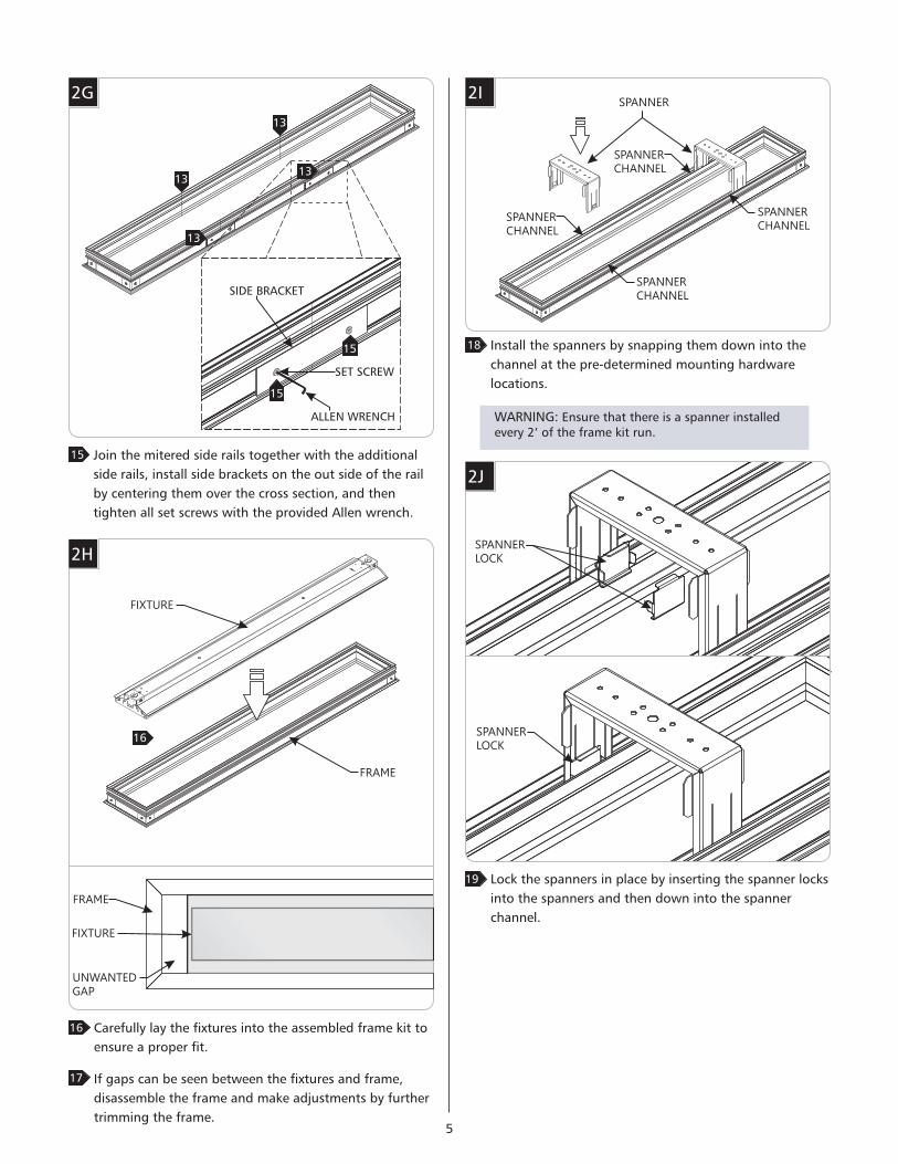
2G
15 Join the mitered side rails together with the additional
side rails, install side brackets on the out side of the rail
by centering them over the cross section, and then
tighten all set screws with the provided Allen wrench.
SET SCREW
ALLEN WRENCH
13
13
SIDE BRACKET
13
13
13
Carefully lay the fixtures into the assembled frame kit to
ensure a proper fit.
If gaps can be seen between the fixtures and frame,
disassemble the frame and make adjustments by further
trimming the frame.
16
17
16
FRAME
FIXTURE
FRAME
FIXTURE
UNWANTED
GAP
2H
SET SCREW
ALLEN WRENCH
15
15
SIDE BRACKET
5
Install the spanners by snapping them down into the
channel at the pre-determined mounting hardware
locations.
2I
18
SPANNER
SPANNER
CHANNEL
SPANNER
CHANNEL
SPANNER
CHANNEL
SPANNER
CHANNEL
Lock the spanners in place by inserting the spanner locks
into the spanners and then down into the spanner
channel.
2J
19
SPANNER
LOCK
SPANNER
LOCK
13
WARNING: Ensure that there is a spanner installedevery 2’ of the frame kit run.
6
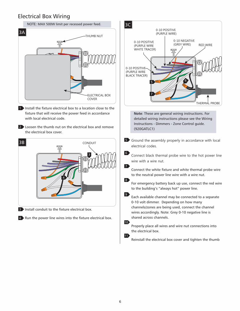
Install the fixture electrical box to a location close to the
fixture that will receive the power feed in accordance
with local electrical code.
Loosen the thumb nut on the electrical box and remove
the electrical box cover.
3A
1
THUMB NUT
ELECTRICAL BOX
COVER
Install conduit to the fixture electrical box.
Run the power line wires into the fixture electrical box.
3B
3
4
3
4
CONDUIT
Electrical Box Wiring
2
Ground the assembly properly in accordance with local
electrical codes.
Connect black thermal probe wire to the hot power line
wire with a wire nut.
Connect the white fixture and white thermal probe wire
to the neutral power line wire with a wire nut.
For emergency battery back up use, connect the red wire
to the building’s “always hot” power line.
Each available channel may be connected to a separate
0-10 volt dimmer. Depending on how many
channels/zones are being used, connect the channel
wires accordingly. Note: Grey 0-10 negative line is
shared across channels.
Properly place all wires and wire nut connections into
the electrical box.
Reinstall the electrical box cover and tighten the thumb
5
6
7
8
9
10
11
RED WIRE
0-10 NEGATIVE
(GREY WIRE)
0-10 POSITIVE
(PURPLE WIRE)
0-10 POSITIVE
(PURPLE WIRE
WHITE TRACER)
0-10 POSITIVE
(PURPLE WIRE
BLACK TRACER)
5
7
6
THERMAL PROBE
3CNOTE: 500W limit per recessed power feed.MAX
Note: These are general wiring instructions. For
detailed wiring instructions please see the Wiring
Instructions - Dimmers - Zone Control guide.
(920GATLC1)

7
Install the frame into the ceiling and mount it using the
threaded rod hole and/or the suspension cable holes
located on the spanners. Ensure the inside lip of the
flange is snug to the ceiling surface.
If the frame has been completely installed , skip to step
9.
2
Install the drywall and create an opening for the frame
kits using either the provided measurements,
measurements of the frame kit assembly, or shop
drawings as a cutting guide. cut the dry wallDO NOT
openings for the frames larger than the allotted size. The
example illustrated is an opening for a 48” Frame Kit.
4A
1
47.1”
7.5”
E.G.- CEILING OPENING FOR A 48” FRAME KIT
4B
THREADED ROD
SUSPENSION
CABLE
THREADED ROD
HOLE
SUSPENSION
CABLE HOLE
SUSPENSION
CABLE HOLE
SUSPENSION
CABLE
DRY WALL
FLANGE
NOTE: Drywall may be installed before or after theframe kit has been installed. If the drywall is installedafter, it must by positioned so it is on top of theflange or the plaster flange trim.
For short runs, the frame kit may be installed all at once asillustrated in section 4B. For long runs, the frame kits may beinstalled in separate end and side frame assemblies.
Installing the frame completely assembled, go tosection 4B.
Installing the frame separately, go to section 4C.
3
Install the Frame Kit
6”WIDE STATIC RECESSED FRAME KITS
7.5”
191mm
A
5.9”
150mm
LENGTH (A)24” Kit l 24.5” / 622mm48” Kit l 47.1” / 1196mm96” Kit l 92.4” / 2347mm
FLANGE WIDTHFlanged l 1.1” / 28mmFlangeless l 1.9” / 48mm
6”WIDE TILTABLE RECESSED FRAME KITS
A
LENGTH (A)24” Kit l 24.8” / 629mm48” Kit l 47.3” / 1201mm96” Kit l 93.1” / 2365mm
FLANGE WIDTHFlanged l 1.1” / 28mmFlangeless l 1.9” / 48mm
12” /DUALWIDE SINGLE STATIC RECESSED FRAME KITS
A
LENGTH (A)24” Kit l 24.5” / 622mm48” Kit l 47.0” / 1194mm96” Kit l 92.4” / 2347mm
FLANGE WIDTHFlanged l 1.1” / 28mmFlangeless l 1.9” / 48mm
A
LENGTH (A)24” Kit l 24.8” / 629mm48” Kit l 47.3” / 1201mm96” Kit l 93.1” / 2365mm
FLANGE WIDTHFlanged l 1.1” / 28mmFlangeless l 1.9” / 48mm
12” DUALWIDE TILTABLE RECESSED FRAME KITS
13.3”
338mm
11.7”
297mm
7.5”
191mm
5.9”
150mm
13.3”
338mm
11.7”
297mm
8
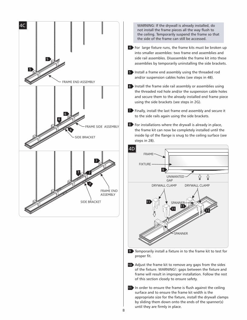
4D
Temporarily install a fixture in to the frame kit to test for
proper fit.
Adjust the frame kit to remove any gaps from the sides
of the fixture. !: gaps between the fixture andWARNING
frame will result in improper installation. Follow the rest
of this section closely to ensure safety.
In order to ensure the frame is flush against the ceiling
surface and to ensure the frame kit width is the
appropriate size for the fixture, install the drywall clamps
by sliding them down onto the ends of the spanner(s)
until they are firmly in place.
9
4C
For large fixture runs, the frame kits must be broken up
into smaller assembles: two frame end assemblies and
side rail assembles. Disassemble the frame kit into these
assemblies by temporarily uninstalling the side brackets.
Install a frame end assembly using the threaded rod
and/or suspension cables holes (see steps in 4B).
Install the frame side rail assembly or assemblies using
the threaded rod hole and/or the suspension cable holes
and secure them to the already installed end frame piece
using the side brackets (see steps in 2G).
Finally, install the last frame end assembly and secure it
to the side rails again using the side brackets.
For installations where the drywall is already in place,
the frame kit can now be completely installed until the
inside lip of the flange is snug to the ceiling surface (see
steps in 2B).
4
5
WARNING: If the drywall is already installed, donot install the frame pieces all the way flush tothe ceiling. Temporarily suspend the frame so thatthe side of the frame can still be accessed.
6
7
FRAME END ASSEMBLY
FRAME SIDE ASSEMBLY
SIDE BRACKET
FRAME END
ASSEMBLY
SIDE BRACKET
8
5
6
7
5
6
6
7
7
7
10
FRAME
FIXTURE
UNWANTED
GAP
9
11
DRYWALL CLAMP DRYWALL CLAMP
SPANNER
SPANNER
11
1111
11

9
Install the drywall clamp screws by screwing them
through the end holes in the spanner then just a few
threads into the drywall clamps on both sides.
Evenly tighten the drywall clamp screws until any small
visual gaps between the fixture and the frame kit are
gone and until the frame is firmly snug against the
ceiling.
12
DRYWALL/
CEILING
4E
GAP
FRAME
DRYWALL
CLAMP
DRYWALL
CLAMP
DRYWALL
CLAMP SCREWS
DRYWALL/
CEILING
FRAME
13
12 12
13 13
13 13
For flangeless versions only: properly plaster onto the
plaster flange and drywall.
4F
NOTE: The next two steps are for flangeless versions
only. Flanged installations can skip to the next section.
13
Finish around the frame opening to match drywall.
4G
14
42
CAUTION! Any size gap between the fixture and the
frame will not ensure proper fixture installation. This
may result in falling fixtures and serious injury. Take the
time to make sure the frame is properly positioned and
that the drywall clamps are tight to restrict the frame
from moving.

10
Remove the end plate from the end of the fixture.
Connect both panels together using the control and
power jumpers.
Carefully tuck the jumpers and connectors into the
fixture and re-install the end plate.
5
Wiring 12” Dual Panel Fixtures
NOTE: The installation for 12” dual panels followthe exact mounting methods illustrated in thefollowing sections with exception to the numberof jumper connections and interconnections withthe dual panels. Refer back to this section whenconnecting jumpers and before installing the finalor only fixture.
Single fixture installation: the panels on the fixture must
be connected by jumpers on one end. See section 5D.
1
3
POWER CONNECTOR PANEL 1
Remove all the end plates and build jumper assemblies
(as shown in Section 7) with 2 sets of power and control
jumpers.
Connect the power and control wire jumpers to the
connectors on each adjacent panel from the connecting
fixtures.
4
5A
POWER JUMPERCONTROL JUMPER
Multiple fixture installation: each panel on the fixture
must be connected by jumpers to panels on the next
adjacent fixture (see section 5C) and on one end of the
fixture run, the panels on the end fixture must be
connected together by jumpers (see section 5D).
2
5B
POWER JUMPERCONTROL JUMPER
5C CONTROLCONNECTOR
1PANEL
POWERCONNECTOR
2PANEL
CONTROLCONNECTOR
1PANEL
POWERCONNECTOR
1PANEL
CONTROLCONNECTOR
1PANEL
POWER CONNECTOR PANEL 2
CONTROL CONNECTOR PANEL 2
JUMPERASSEMBLY
POWER CONNECTOR PANEL 15D CONTROLCONNECTOR
1PANEL
POWERCONNECTOR
2PANEL
CONTROLCONNECTOR
2PANEL
POWERJUMPER
POWERJUMPER
6
7
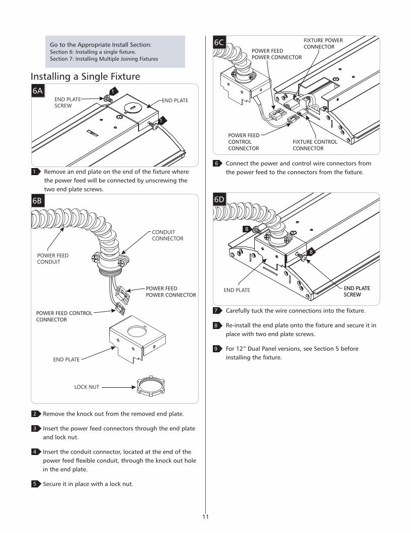
6C
Connect the power and control wire connectors from
the power feed to the connectors from the fixture.
6
POWER FEEDPOWER CONNECTOR
FIXTURE POWERCONNECTOR
POWER FEEDCONTROLCONNECTOR
FIXTURE CONTROLCONNECTOR
Go to the Appropriate Install Section:Section 6: Installing a single fixture.
Section 7: Installing Multiple Joining Fixtures
Installing a Single Fixture
6AEND PLATE
1
1
Remove an end plate on the end of the fixture where
the power feed will be connected by unscrewing the
two end plate screws.
1
END PLATE
SCREW
11
Carefully tuck the wire connections into the fixture.
Re-install the end plate onto the fixture and secure it in
place with two end plate screws.
For 12” Dual Panel versions, see Section 5 before
installing the fixture.
7
8
6D
END PLATE END PLATE
SCREW
8
8
END PLATE
SCREW
6B
2 Remove the knock out from the removed end plate.
Insert the power feed connectors through the end plate
and lock nut.
Insert the conduit connector, located at the end of the
power feed flexible conduit, through the knock out hole
in the end plate.
Secure it in place with a lock nut.
POWER FEED
CONDUIT
END PLATE
POWER FEEDPOWER CONNECTOR
POWER FEED CONTROLCONNECTOR
3
CONDUIT
CONNECTOR
LOCK NUT
4
5
9

Install the fixture into the frame by first tilting it and
then insert it completely in the frame opening.
Tilt the fixture back to position and gently lower it until
it is resting level in the frame.
6E
10
11
NOTE: If the fixture’s programable white capabilitiesare being utilized, refer to the provided GATICACommissioning Instructions before installing thefixture into the frame.
NOTE: If installing fixtures with single tilt capability,ensure that the fixture is oriented so the panel willtilt in the direction desired.
12

Installing Multiple Joining Fixtures
Prepare a jumper assembly by first installing one end of
a power and control jumper cable inside a strain relief.
Close the strain relief leaving 3” of cable for
connections.
1
4 Remove the knock out from an end plate and insert the
strain relief into the end plate until it snaps in place.
5 Repeat steps 1 through 3 for the other side of the
jumper cables.
Repeat steps 1 through 4 to build connector assemblies
for the complete fixture run.
13
JUMPERASSEMBLY
7D
POWERJUMPER
CONTROLJUMPER
7A
END PLATE
7C
STRAINRELIEF
6
2
NOTE: See section 5 for 12” dual panel applications.There will be two sets of jumpers need.
1
2
3”
3”
7E
7 Remove the knock out from an end plate.
Insert the power feed connectors through the end plate
and lock nut.
Insert the conduit connector, located at the end of the
power feed flexible conduit, through the knock out hole
in the end plate.
Secure it in place with a lock nut.
POWER FEED
CONDUIT
END PLATE
POWER FEEDPOWER CONNECTOR
POWER FEED CONTROLCONNECTOR
8
CONDUIT
CONNECTOR
LOCK NUT
9
10
7B 3
3
3
END PLATE
SCREWEND PLATE
Unscrew the two end plate screws and remove end
plates on all of the fixture ends with exception to the
last end in the run where the power feed will beNOT
connected.

14
Connect the power and control wire connectors from
the power feed to the connectors from the first fixture.
11
Carefully tuck the wire connections into the fixture.
Install the end plate onto the fixture and secure it in
place with two end plate screws.
7H
14
POWERCONNECTOR
CONTROL CONNECTOR
POWERJUMPER
CONTROL JUMPER
Connect the power and control jumpers from the
jumper assembly to the fixture’s power and control
connectors.
JUMPER ASSEMBLY
7IEND PLATE
16
16
Carefully tuck the wires and wire connections inside the
fixture.
Install the end plate on the jumper assembly on the
fixture end and secure it place with two end plate
screws.
15
END PLATE
SCREW
16
NOTE: If installing fixtures with single tilt capability,ensure that the fixture is oriented so the panel willtilt in the direction desired.
12
13
7FPOWER FEEDPOWER CONNECTOR
FIXTURE POWERCONNECTOR
POWER FEEDCONTROLCONNECTOR
FIXTURE CONTROLCONNECTOR
7G
END PLATE END PLATE
SCREW
13
13
END PLATE
SCREW

15
Install the fixture into the frame by first tilting it and
then insert it completely in the frame opening.
Tilt the fixture back to position and gently lower it until
it is resting level in the frame.
7J
17
18
NOTE: If the fixture’s channel selecting orprogramable white capabilities are being utilized,refer to the provided AdjustabilityGATICAinstructions before installing the fixture into theframe.
NOTE: If installing fixtures with single tilt capability,ensure that the fixture is oriented so the panel willtilt in the direction desired.
Connect the power and control wire connectors from
the jumpers to the connectors from the adjacent fixture.
20
POWER JUMPER
POWERCONNECTOR
CONTROLJUMPER
CONTROLCONNECTOR
7L
TOP VIEW
BOTTOM VIEW7K
Ensure that there is no spacing between the fixture and
the frame/adjacent fixture.
19

DIFFUSOR FILM
7400 Linder Ave, Skokie, 60077IL
847.410.4400
www.techlighting.com© 2017 Tech Lighting, L.L.C. All rights reserved. The "Tech Lighting" graphic isa registered trademark of Tech Lighting, L.L.C. Tech Lighting reserves the rightto change specifications for product improvements without notification.
A Generation Brands Company
SAVE THESE INSTRUCTIONS!
16
4W
END PLATE END PLATE
SCREW
21
22
32
32
END PLATE END PLATE
SCREW
22
22
7M
23
24
Carefully tuck the wire connections into the fixture.
Install the end plate on the connector assembly to the
fixture and secure it place with two end plate screws.
If installing more fixtures , repeat steps 14 through 22.
If this is the final fixture in the configuration, install the
last fixture into the ceiling by following steps 17
through 19. For 12” Dual Panel versions, see Section 5
before installing the final fixture into the ceiling.
7N
If the diffusor film is not completely flat on the LED
lightguide surface, gently smooth the diffusor film out
on both ends by hand with the use of clean gloves.
25
NOTE: Lightly press up on the LED lightguidesurface, if necessary, to allow the diffusor film toslide between the extrusion and the LED lightguidesurface or to reinsert a film edge.

![M100 Shapes LED Recessed [L10/L1R] selux€¦ · After Drywall Flange Mounting (SF3) 1. Drywall/Drywall screw (Ref.) 2. Drywall/Drywall (Ref.) 3. 1/6” Plaster skimcoat (Ref.) 4](https://img.pdfslide.net/doc/110x75/5f54633924da634fd0733121/m100-shapes-led-recessed-l10l1r-selux-after-drywall-flange-mounting-sf3-1.jpg)