Embed Size (px)
Citation preview

9.3 Composite Bodies9.3 Composite Bodies
Consists of a series of connected “simpler” shaped bodies, which may be rectangular, triangular or semicircular
A body can be sectioned or divided into its composite parts
Provided the weight and location of the center of gravity of each of these parts are known, the need for integration to determine the center of gravity for the entire body can be neglected

9.3 Composite Bodies9.3 Composite Bodies
Accounting for finite number of weights
Where represent the coordinates of the
center of gravity G of the composite bodyrepresent the coordinates of the
center of gravity at each composite part of the body
represent the sum of the weights of all the composite parts of the body or total weight
W
Wzz
W
Wyy
W
Wxx
~~~
W
zyx
zyx
~,~,~
,,

9.3 Composite Bodies9.3 Composite Bodies
When the body has a constant density or specified weight, the center of gravity coincides with the centroid of the body
The centroid for composite lines, areas, and volumes can be found using the equation
However, the W’s are replaced by L’s, A’s and V’s respectively
WWz
zWWy
yWWx
x
~~~

9.3 Composite Bodies9.3 Composite Bodies
Procedure for AnalysisComposite Parts Using a sketch, divide the body or
object into a finite number of composite parts that have simpler shapes
If a composite part has a hole, or a geometric region having no material, consider it without the hole and treat the hole as an additional composite part having negative weight or size
9.3 Composite Bodies9.3 Composite Bodies
Procedure for AnalysisMoment ArmsEstablish the coordinate axes on
the sketch and determine the coordinates of the center of gravity or centroid of each part

9.3 Composite Bodies9.3 Composite Bodies
Procedure for AnalysisSummationsDetermine the coordinates of the
center of gravity by applying the center of gravity equations
If an object is symmetrical about an axis, the centroid of the objects lies on the axis

9.3 Composite Bodies9.3 Composite Bodies
Example 9.9Locate the centroid of the wire.

SolutionComposite Parts
Moment Arms Location of the centroid for each piece is
determined and indicated in the diagram
9.3 Composite Bodies9.3 Composite Bodies

9.3 Composite Bodies9.3 Composite Bodies
SolutionSummations
Segment
L (mm)
x (mm) y (mm) z (mm) xL (mm2)
yL (mm2)
zL (mm2)
1 188.5 60 -38.2 0 11 310 -7200 0
2 40 0 20 0 0 800 0
3 20 0 40 -10 0 800 -200
Sum 248.5 11 310 -5600 -200

9.3 Composite Bodies9.3 Composite Bodies
SolutionSummations
mmL
Lzz
mmL
Lyy
mmL
Lxx
805.05.248
200~
5.225.248
5600~
5.455.248
11310~

9.3 Composite Bodies9.3 Composite Bodies
Example 9.10Locate the centroid of the plate
area.

9.3 Composite Bodies9.3 Composite Bodies
SolutionComposite Parts Plate divided into 3 segments Area of small rectangle considered
“negative”

9.3 Composite Bodies9.3 Composite Bodies
SolutionMoment Arm Location of the centroid for each piece is
determined and indicated in the diagram
9.3 Composite Bodies9.3 Composite Bodies
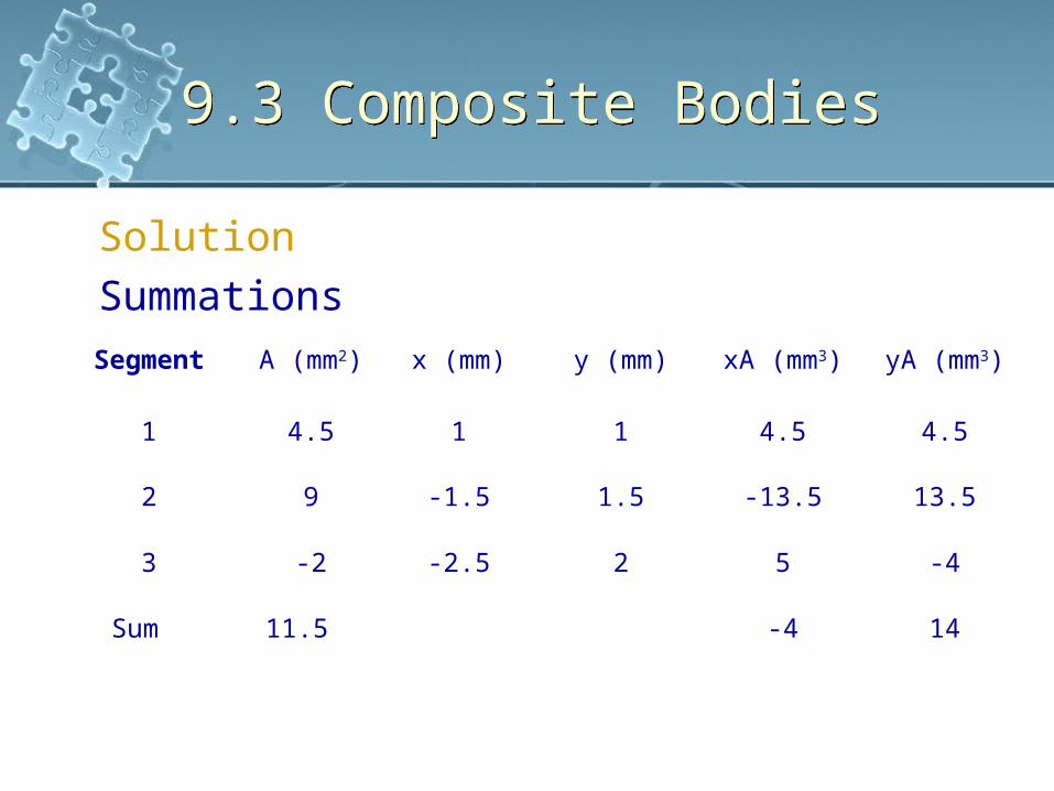
SolutionSummationsSegment A (mm2) x (mm) y (mm) xA (mm3) yA (mm3)
1 4.5 1 1 4.5 4.5
2 9 -1.5 1.5 -13.5 13.5
3 -2 -2.5 2 5 -4
Sum 11.5 -4 14

9.3 Composite Bodies9.3 Composite Bodies
SolutionSummations
mmA
Ayy
mmA
Axx
22.15.11
14~
348.05.11
4~

9.3 Composite Bodies9.3 Composite Bodies
Example 9.11Locate the center of mass of the composite assembly. The conical frustum has a density of ρc = 8Mg/m3 and the hemisphere
has a density of ρh = 4Mg/m3.
There is a 25mm radius cylindrical hole in the center.

9.3 Composite Bodies9.3 Composite Bodies
SolutionComposite PartsAssembly divided into 4 segmentsArea of 3 and 4 considered
“negative”
View Free Body Diagram

9.3 Composite Bodies9.3 Composite Bodies
SolutionMoment Arm Location of the centroid for each piece is
determined and indicated in the diagram
Summations Because of symmetry,
0yx

9.3 Composite Bodies9.3 Composite Bodies
SolutionSummationsSegment m (kg) z (mm) zm (kg.mm)
1 4.189 50 209.440
2 1.047 -18.75 -19.635
3 -0.524 125 -65.450
4 -1.571 50 -78.540
Sum 3.141 45.815

9.3 Composite Bodies9.3 Composite Bodies
SolutionSummations
mmm
mzz 6.14
141.3
815.45~

9.4 Theorems of Pappus and Guldinus
9.4 Theorems of Pappus and Guldinus
A surface area of revolution is generated by revolving a plane curve about a non-intersecting fixed axis in the plane of the curve
A volume of revolution is generated by revolving a plane area bout a nonintersecting fixed axis in the plane of area
Example Line AB is rotated about
fixed axis, it generates the surface area of a cone (less area of base)

9.4 Theorems of Pappus and Guldinus
9.4 Theorems of Pappus and Guldinus
Example Triangular area ABC rotated
about the axis would generate the volume of the cone
The theorems of Pappus and Guldinus are used to find the surfaces area and volume of any object of revolution provided the generating curves and areas do not cross the axis they are rotated
9.4 Theorems of Pappus and Guldinus
9.4 Theorems of Pappus and Guldinus
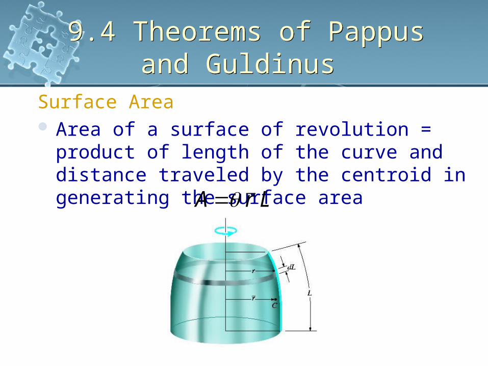
Surface Area Area of a surface of revolution = product of
length of the curve and distance traveled by the centroid in generating the surface area LrA

9.4 Theorems of Pappus and Guldinus
9.4 Theorems of Pappus and Guldinus
Volume Volume of a body of revolution = product
of generating area and distance traveled by the centroid in generating the volume
ArV

9.4 Theorems of Pappus and Guldinus
9.4 Theorems of Pappus and Guldinus
Composite Shapes The above two mentioned theorems
can be applied to lines or areas that may be composed of a series of composite parts
Total surface area or volume generated is the addition of the surface areas or volumes generated by each of the composite parts
ArV
LrA~
~

9.4 Theorems of Pappus and Guldinus
9.4 Theorems of Pappus and Guldinus
Example 9.12Show that the surface area of a sphere is
A = 4πR2 and its volume
V = 4/3 πR3

9.4 Theorems of Pappus and Guldinus
9.4 Theorems of Pappus and Guldinus
SolutionSurface Area Generated by rotating semi-arc about
the x axis For centroid,
For surface area,
242
2
;~
/2
RRR
A
LrA
Rr
View Free Body Diagram

9.4 Theorems of Pappus and Guldinus
9.4 Theorems of Pappus and Guldinus
SolutionVolume Generated by rotating semicircular area
about the x axis For centroid,
For volume,
32
34
21
34
2
;~
3/4
RRR
V
ArV
Rr

9.5 Resultant of a General Distributed
Loading
9.5 Resultant of a General Distributed
LoadingPressure Distribution over a Surface Consider the flat plate subjected to the
loading function ρ = ρ(x, y) Pa Determine the force dF acting on the
differential area dA m2 of the plate, located at the differential point (x, y)dF = [ρ(x, y) N/m2](d A m2)
= [ρ(x, y) d A]N Entire loading represented as
infinite parallel forces acting on separate differential area dA

9.5 Resultant of a General Distributed
Loading
9.5 Resultant of a General Distributed
LoadingPressure Distribution over a SurfaceThis system will be simplified to a
single resultant force FR acting through a unique point on the plate

Pressure Distribution over a SurfaceMagnitude of Resultant Force To determine magnitude of FR, sum the
differential forces dF acting over the plate’s entire surface area dA
Magnitude of resultantforce = total volume underthe distributed loadingdiagram
9.5 Resultant of a General Distributed
Loading
9.5 Resultant of a General Distributed
Loading
A VR dVdAyxFF ),(;
9.5 Resultant of a General Distributed
Loading
9.5 Resultant of a General Distributed
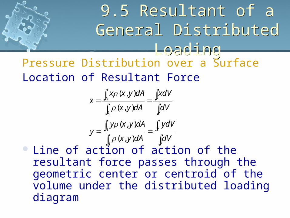
LoadingPressure Distribution over a SurfaceLocation of Resultant Force
Line of action of action of the resultant force passes through the geometric center or centroid of the volume under the distributed loading diagram
V
V
A
A
V
V
A
A
dV
ydV
dAyx
dAyxyy
dV
xdV
dAyx
dAyxxx
),(
),(
),(
),(