Embed Size (px)
Citation preview

930A COMMUNICATIONS TEST SET
BUYER'S GUIDE
Software Version 4.06 and above
This buyer's guide is designed to assist buyers and purchasing agents in determining theirneed for the Sage Instruments 930A Communications Test Set and its purchaseable options.As a condensed document, it describes only the main features of the unit and availableoptions. A full description of all 930A features, including specific applications, is contained inthe 930A Communications Test Set Operating Manual.
INSTRUMENTS9108-0001-01 Rev. 2 062597
240 Airport BoulevardFreedom, CA 95019Phone 408-761-1000w w w . s a g e i n s t . c o m

© Sage Instruments 1997 9108-0001-01 6/25/97
Buyer's Guide
i
TABLE OF CONTENTS
Contents Description Page
Contacting SageInstruments .....................................................................................................1
The Basic 930A Product Description ....................................................................3Applications ...........................................................................3Standard Features .................................................................3
930A Purchased Options Overview of Optional Features...................................................5
Option 930A-01 DP, MF, DTMF Receiver/Analyzer ..............................................6Option 930A-02 SF Supervision .............................................................................6Option 930A-06 Peak-to-Average Ratio (P/AR) ....................................................6Option 930A-07 3-Level Impulse Noise .................................................................7Option 930A-09E DS-1 PCM Dual Direction Drop/lnsert with D4 Superframe
and ESF Capibility .......................................................................7Option 930A-10C RS-232C Remote Control/Printer Interface ..................................8Option 930A-12 Remote Office Test Line (ROTL), Interrogator,
Responder (Type 105 Format) .....................................................8Option 930A-13 Ring Generator/True REN-3 Load ...............................................9Option 930A-16 -48 VDC Power Supply ................................................................9Option 930A-17 Removes 2W/4W Analog Interface ...........................................9Option 930A-18 Phase /Amplitude Jitter and Hits ............................................ 10Option 930A-19 Envelope Delay Distortion ........................................................ 10Option 930A-20 4-Tone Intermodulation Distortion ............................................ 10Option 930A-21 Absolute Delay......................................................................... 10Option 930A-22 DS-1 and DS-0 (56/64 kbps) Bit Error Rate Testing (BERT) ........ 10Option 930A-23 DS-1 and DS-0 (56/64 kbps) Bit Error Rate Testing (BERT)
with Long User Pattern ............................................................. 11Option 930A-25 FXO/FXS PCM Supervision ...................................................... 12Option 930A-28 Analog Rear Panel Access ...................................................... 12Option 930A-29 Batch Mode Testing.................................................................. 12Option 930A-30 Analog and Digital Rear Panel Access ................................... 12Option 930A-31 Digital Rear Panel Access ........................................................ 12Option 930A-34 Dual Direction Fractional T1/DDS ............................................ 13Option 930A-36 Extended Warranty ................................................................. 14Option 930A-40 Wideband TIMS with Enhanced TIMS Package ...................... 14Option 930A-44 Customer Service Unit (CSU) .................................................... 15Option 930A-45 DTAU/DCS Interface ................................................................ 15Option 930A-46 Wideband TMS......................................................................... 15Option 930A-47 Remote Audio Monitor ............................................................. 15Option 930A-51 Fractional T-1 ........................................................................... 16Option 930A-52 Digital Data Service (DDS) ........................................................ 17Option 930A-54 23 Tones ................................................................................... 17

ii
Sage Instruments 930A Communications Test Set
© Sage Instruments 1997 9108-0001-01 6/25/97
Contents Description Page
Option 930A-67 SS7 Error Monitor ...................................................................... 18Option 930A-90 High Stability Clock for ESF ...................................................... 18Option 930A-100 Data Test Package ................................................................... 18Option 930A-300 Enhanced Digital Signal Processor........................................... 18
Configurator Panels Front Panel Configurator Options............................................ 19

1© Sage Instruments 1997 9108-0001-01 6/25/97
Buyer's Guide
Contacting Sage Instruments
To contact Sage Instruments in writing, send correspondence to:
Sage Instruments, Inc.240 Airport Blvd.Freedom, CA 95019-2614
or send E- mail to:
[email protected] or [email protected]
or fax inquiries to our main office at:
(408) 761-2452
To reach our Technical Support and Customer Service Departments by phone, call:
(408) 761-1000, M-F, 9 a.m. to 5 p.m., Pacific Time.
or fax our Technical Support and Customer Service Departments any time at:
(408) 761-9246
To receive company and product information via the World Wide Web, visit our home page at:
http://www.sageinst.com
Be sure to specify Model 930A when asking for technical support. Customers located outside of the U.S.may also contact their nearest Sage distributor for assistance.

© Sage Instruments 1997 9108-0001-01 6/25/97
2
Sage Instruments 930A Communications Test Set

3© Sage Instruments 1997 9108-0001-01 6/25/97
Buyer's Guide
THE BASIC 930A COMMUNICATIONS TEST SET
Description
The 930A Communications Test Set combines the functions of a Voiceband Transmission MeasurementSet, Return Loss Measurement Set, and a Dial Pulse, Touch Tone (DTMF), and Multi-Frequency (MF)Sender in one lightweight package. The test set also provides Talk Battery to enable the user to talk overthe trunk under test.
Applications
This test set, while of general purpose in nature, is particularly useful for DEMARC and Central Officetesting, as well as PBX and Digital Switch installation testing. It is capable of performing all transmissionand signaling tests required at these locations, including those for Feature Groups A - D (Equal Access).The 930A can completely simulate either a PBX or Central Office switch (Local or Toll).
Standard Features
The following list shows the standard features and capabilities of the standard 930A (for standard VoiceBand applications).
The standard 930A transmission measurements are:
• Level and Frequency• Noise (C-Message, C-Notch, and 3 kHz Flat Weighted)• Noise-to-Ground• Signal-to-Noise Ratio• Return Loss (2- and 4-wire)
The standard 930A signaling and supervision simulation capabilities are:
• Loop Start (2- and 4-wire, normal and reverse battery)• Ground Start (normal and reverse battery)• E&M Signaling Types I through V• Wink Detection and Timing• Delay Dial• SX Supervision• DP, MF, and DTMF Signaling (parameters may be varied from nominal)
In addition to its supervisory signaling capability, the 930A can establish the talk conditions fortransmission testing and has the ability to hold circuits for testing.
The basic 930A also includes the ability to store and recall up to 999 tests, receive multi-wink sequences,and perform frequency sweeps such as those used for attenuation distortion measurements.

© Sage Instruments 1997 9108-0001-01 6/25/97
4
Sage Instruments 930A Communications Test Set

5© Sage Instruments 1997 9108-0001-01 6/25/97
Buyer's Guide
SAGE INSTRUMENTS 930A PURCHASED OPTIONS
OVERVIEW
The purchased options enhance the feature set of the 930A and greatly extend its testing capabilities.Listed below are some of the major extended test functions that can be performed only if the appropriateoptions are purchased:
• 23 tones testing• Fractional T1 testing• FXO/FXS Supervision• Wideband testing• 4-Tone Intermodulation Distortion Measurement• Batch testing• SS7 Call Tracing• DS-0, DS-1 Bit Error Rate (BERT) Testing• Absolute Delay Measurement• 3 Level Impulse Noise measurement• PCM Dual Drop and Insertion• Peak to Average Ratio (P/AR) measurement• DP, MF, and DTMF call receipt/analysis• Phase Amplitude and Jitter measurement
Each of these options, which are described in this buyer’s guide, is designated (SOFTWARE ONLY),(SOFTWARE/HARDWARE), or (HARDWARE ONLY) in the description headers. If an option says(SOFTWARE ONLY) then it can be installed in the field. If it is designated (SOFTWARE/HARDWARE)or (HARDWARE ONLY), it may be necessary to return the unit to the factory to have the option installed.The factory should be consulted on options requiring (HARDWARE ONLY) to determine whether or notthe unit must be returned.
Optional enhancements are described in the following sections.
© Sage Instruments 1997 9108-0001-01 6/25/97
6
Sage Instruments 930A Communications Test Set
PURCHASED OPTIONS LIST
Option Number Description Upgrade Type
OPTION 930A-01 DP, MF, DTMF RECEIVER/ANALYZER (HARDWARE/SOFTWARE)
This option enables the 930A to emulate a Central Office. The 930A can receive and analyze stringsof DP, MF, and DTMF digits up to a length of 72 digits. The digits may be analyzed for % break, dialspeed, interdigit time, amplitude of the low and high tones, frequency of the low and high tones,timing, and spurious tones .
A 930A equipped with this option can also send winks to emulate the far-end office receiver. The winkand pre-wink duration can be modified to allow the sending office to perform a margining analysis. Dueto the need to receive MF digits in Type 105 testing, this option is also required if Option 930A-12 ispurchased.
OPTION 930A-02 SF SUPERVISION (HARDWARE/SOFTWARE)
This option enables the 930A to send and detect the 2604 Hz SF supervisory signal on 4-wire analogcarrier derived circuits and other special circuits which may require this type of signaling.
The current SF option as described does not support SF on 2-wire circuits, or 2-tone SF types such asSS1, SS4, or SF on PCM trunks.
OPTION 930A-06 PEAK-TO-AVERAGE RATIO (P/AR) (SOFTWARE ONLY)
This option enables the 930A to send and measure the P/AR waveform over a 0–120 P/AR unit range.The P/AR test provides a measure of the channel dispersion (amplitude and phase distortion over time)due to transmission impairments. The P/AR waveform is a complex signal consisting of 16 non-harmonically related tones with a spectrum which approximates modem type data signals on VF trunks.
The P/AR test provides a quick method of gauging the deterioration of a channel, if any, without havingto resort to the very expensive and time consuming tests such as Attenuation Distortion , EnvelopeDelay Distortion , 4-Tone Intermodulation Distortion , or Phase Jitter .
It is important to note that P/AR is only valid as an end-to-end measurement. Test sets are required atboth ends of the circuit.
The 930A is fully compatible with existing P/AR test sets.
7© Sage Instruments 1997 9108-0001-01 6/25/97
Buyer's Guide
Option Number Description Upgrade Type
OPTION 930A-07 3-LEVEL IMPULSE NOISE (SOFTWARE ONLY)
This option enables the 930A to measure 3-level Impulse Noise . This measurement is described inAT&T and IEEE published standards and specifications for measurements on voice band data circuits.The default settings in the 930A take note of the fact that Impulse Noise is usually measured with theholding tone present. The 930A will allow a user to select the C-Message filter instead of the C-Notchfilter default. This parameter, while not a tariffed parameter, is extremely important on circuits carryingvoice band data.
The low threshold level setting range is 30–106 dBrnC . The measurement spread between the low,medium, and high thresholds may be set in 2, 4, 6, or 8 dB steps. The time duration of the measurementmay be adjusted from 1–99 minutes or set to run continuously, although the standard duration is 15minutes . The number of measurements per second can be varied from the standard value of 7, andup to 99 measurements per second .
OPTION 930A-09E DS-l PCM DUAL DIRECTION DROP/ (HARDWARE/SOFTWARE)INSERT WITH D4 SUPERFRAMEAND ESF CAPABILITY
This option enables the 930A to simultaneously monitor both directions of transmission on digitalfacilities and to perform true Drop and Insert tests. The 930A can be connected to a T1 carrier andperform the same measurements on PCM trunks as it does on metallic trunks. It also provides a dualdirection test capability and can monitor or do out-of-service testing when terminating a T1 span.
The Dual Direction Drop and Insert capability allows the 930A to sit in series with an in-service T1facility between two offices. One of the incoming 24 channels may be dropped out and a test may beinserted into the outgoing channel without taking the other 23 channels carrying traffic out-of-service.In addition, this option allows the user to compare the T1 clocks in both directions of transmission tomeasure wander or drifting clocks.
The PCM interface accommodates D1D, D2, and D3/D4 channel numbering sequences, accessesstandard D4 Superframe, Extended Superframe format, and SLC-96® trunks.
This option allows for both robbed-bit and CCIS signaling, as well as AMI or B8ZS line codes. Otherfeatures of the digital interface include:
• Internal/External (Loop Timed) Clock Source Operation• 100 Hz Internal Clock Offset to determine Loop Timing status• Send Remote (Yellow) Alarm and Blue Alarm signals• Normal Loop supervision or User Definable supervision states• Detection and counting of:
Bipolar Violations Frame Loss (Red Alarm)Frame Slips Loss of PCM or >15 consecutive zeroesBit Slips Remote Alarm (Yellow Alarm)Frame Errors Blue AlarmCRC Errors (ESF Mode)

© Sage Instruments 1997 9108-0001-01 6/25/97
8
Sage Instruments 930A Communications Test Set
Option Number Description Upgrade Type
OPTION 930A-09E DS-l PCM DUAL DIRECTION DROP/ (HARDWARE/SOFTWARE)(Continued) INSERT WITH D4 SUPERFRAME AND
ESF CAPABILITY
• Real time display of A and B Signaling Bits on all 24 channels simultaneously• Manual manipulation of A and B Signaling Bits on a selected channel• Measurement of DSX voltage• Error History in 15 minute blocks, for up to 24 hours• Single error injection of BPVs, Frame Errors, or CRC Errors (ESF)• DS-0 Loopback when ordered with Option 930A-01
Option 930A-09E includes Option 930A-25 (FXO/FXS) and Option 930A-44 (CSU) when ordered withOption 930A-300 .
OPTION 930A-10C RS-232C REMOTE CONTROL/PRINTER (HARDWARE/SOFTWARE)INTERFACE WITH REAL TIMECLOCK/CALENDAR
This option enables the user to control a 930A from a display terminal or computer, and provides aninterface to connect an 80 column serial printer. A standard female DB-25 connector is provided on therear panel of the 930A.
The 930A has been designed so that operation under remote control closely parallels manual operation.Each front panel key on the 930A can be activated remotely from a keyboard by pressing a single ASCIIcharacter.
The 930A does not use OpCodes. Section V of the 930A Communications Test Set OperatingManual gives full details.
A real time clock/calendar function places a day/date/time stamp on printouts showing when a test orevent occurred. This option is included with Option 930A-300 .

9© Sage Instruments 1997 9108-0001-01 6/25/97
Buyer's Guide
Option Number Description Upgrade Type
OPTION 930A-11 ATME DIRECTOR/RESPONDER (SOFTWARE ONLY)
The ATME Director enables you to set up the 930A as an ATME near end responder that controls theATME far end responder. This feature enables you to conduct level, noise, BERT and echo cancellertests, including:
• 1020Hz@0dBm • S/TDHz with -10dBm tone• 400Hz@0dBm • S/TD with -25dBm tone• 2800Hz@0dBm • EC LEVEL• 1020Hz@-10dBm • Far to Near Noise• 400Hz@-10dBm • Near to Far noise• 2800Hz@-10dBm • Bypass Loss• Noise/CMS • BER test (in PCM only)
The echo canceller feature provides echo cancellation over programmable delays and echo levels, andgives the echo cancellers the ability to remove themselves from a circuit when given a standard disablersignal.
The ATME Far End Responder feature enables you to configure the 930A the far end for the ATMEDirector. ATME can also provide this function directly on an E-1 channel.
OPTION 930A-12 REMOTE OFFICE TEST LINE (ROTL), (SOFTWARE ONLY)INTERROGATOR, RESPONDER(TYPE 105 FORMAT)(REQUIRES OPTION 930A-01)
This option enables the 930A to emulate either a Type 105 Test Line , a manual Remote Office TestLine/Near End Responder , or a ROTL Interrogator . When equipped with Option 930A-12 , the 930Aprovides a test capability similar to that provided by the CAROT system for automated routining of trunksin either manual or remote control applications. The tests performed by the 930A in this mode are:
• 1004 Hz Loss • ERL• Noise • SRL-LO• Noise with Tone • SRL-HI• Gain/Slope Tones

© Sage Instruments 1997 9108-0001-01 6/25/97
10
Sage Instruments 930A Communications Test Set
Option Number Description Upgrade Type
OPTION 930A-12 REMOTE OFFICE TEST LINE (ROTL), (SOFTWARE ONLY)(Continued) INTERROGATOR, RESPONDER
(TYPE 105 FORMAT)(REQUIRES OPTION 930A-01)
The user can perform two-way end-to-end testing without the necessity to have technicians at both endsof the circuit under test. All that would be required is a 930A, or a Type 105 responder at the far-end.
If the 930A is equipped with one or more of the voice band data tests (P/AR, Impulse Noise, EnvelopeDelay Distortion, Phase/Amplitude Jitter and Hits ), then this option will allow the 930A to extend the105 testing to those measurements as well. The 930A can interrogate another 930A (equipped with theappropriate options) acting as a far-end responder, or a Sage Instruments 356E Far-End Responder ,and perform the following tests in addition to those mentioned above:
• Attenuation Distortion • Phase/Amplitude Jitter (20-300 Hz)• Signal-to-Noise Ratio • Phase/Amplitude Jitter (4-300 Hz)• 3 kHz Flat Noise • 3-Level Impulse Noise and Hits• 4-Tone Intermodulation Distortion
OPTION 930A-13 RING GENERATOR/TRUE REN-3 LOAD (HARDWARE/SOFTWARE)
This option provides the 930A with a true sinewave ringing supply. The ringing frequency, ring voltage,and ring duration may all be varied from the standard default values. This option also includes a threeringer equivalent number load. The ringing frequency and voltage level are also measured in OptionMenu #: 5, REN-3 Load.
OPTION 930A-16 -48 VDC POWER SUPPLY (HARDWARE ONLY)
This option enables the 930A to be powered from the -48 VDC Central Office battery supply. Thisprovides operation from essentially an uninterruptible power supply, but removes the capability for the930A to operate from 110 VAC. As such, this means that this option is intended for 930As which arerack-mounted or otherwise permanently installed in systems, etc., and not for portable operation. The930A can be powered either from 110 VAC or -48 VDC, but not both in the same unit.
OPTION 930A-17 REMOVES 2W/4W ANALOG INTERFACE (HARDWARE/SOFTWARE)(REQUIRES OPTION 930A-09E)(NOT COMPATIBLE WITH OPTION 930A-46)
This option restricts the 930A to operation on DS-1 (T1) facilities by removing the metallic interface fromthe unit. This option is intended as a cost savings for those users who have an entirely digital networkand do require access to metallic trunks for test purposes. (This option can not be ordered withOption 930A-02 or -13.)

11© Sage Instruments 1997 9108-0001-01 6/25/97
Buyer's Guide
Option Number Description Upgrade Type
OPTION 930A-18 PHASE/AMPLITUDE JITTER AND HITS (SOFTWARE ONLY)(REQUIRES OPTION 930A-07)
This option enables the 930A to measure Phase and Amplitude Jitter simultaneously, as well as countPhase Hits, Gain Hits, and Dropouts in conjunction with the Impulse Noise counters. This option maybe used on metallic (analog) trunks, or on PCM channels on a T1 span. Do not confuse thismeasurement with Timing Jitter Measurements on a T1; they are different measurements.
The range of measurement is 0–25 degrees peak-to-peak Phase Jitter, and 0–25% peak AmplitudeJitter. Phase Hits are counted up to 999 events, and the threshold is adjustable over the range of 5–45degrees. Gain Hits up to 999 events are counted, and the threshold is adjustable from 2 dB–10 dB.Dropouts use a fixed threshold of 12 dB relative to the level of the holding tone. The received holdingtone level is measured at the start of testing; if the level drops more than 12 dB below the reference level,a dropout is declared.
OPTION 930A-19 ENVELOPE DELAY DISTORTION (SOFTWARE ONLY)
This option enables the 930A to measure the Envelope Delay Distortion on either metallic or PCMtrunks. The measurement range is up to 12000 microseconds, ±10 µsecs, with a resolution of 1 µsec.The SEND mode of Option 930A-19 is equivalent to other test sets in MASTER mode, and the REPEATmode is equivalent to other sets in SLAVE mode.
OPTION 930A-20 4-TONE INTERMODULATION DISTORTION (SOFTWARE ONLY)
This option enables the 930A to measure the 2nd and 3rd order harmonic distortion products using the4-Tone method. The 930A automatically adjusts itself for the Signal-to-Noise , and requires no manualcalculations to obtain the test results.
OPTION 930A-21 ABSOLUTE DELAY (SOFTWARE ONLY)
This option enables the 930A to measure roundtrip absolute delay on a 4-wire metallic or PCM circuitwith loopback. This measurement is made in milliseconds with a range of 0-1.2 seconds and anaccuracy of ± 1 ms.
OPTION 930A-22 DS-1 and DS-0 (56/64 kbps) BIT (SOFTWARE ONLY)ERROR RATE TESTING (BERT)(REQUIRES OPTION 930A-09E)
DS-1 BERT
DS-1 BERT allows the 930A to send patterns and detect logic errors in addition to bipolar violations,frame errors, and CRC errors which are already monitored. This option also gives the 930A a dualBERT capability. That is, a single 930A can emulate two ordinary BERT sets.

© Sage Instruments 1997 9108-0001-01 6/25/97
12
Sage Instruments 930A Communications Test Set
Option Number Description Upgrade Type
OPTION 930A-22 DS-1 and DS-0 (56/64 kbps) BIT (SOFTWARE ONLY)(Continued) ERROR RATE TESTING (BERT)
(REQUIRES OPTION 930A-09E)
The following patterns are available in Option Menu #: 46 DS-1 Bit Error Rate :
QRSS User (3-24 bit) 1:1 (alternating) 1:73 in 24 All Ones 55 Octet 223-1220-1 215-1 211-1 (2047) 29-1 (511)
DS-0 (56/64 kbps) BERT
DS-0 BERT allows the 930A to send patterns and detect logic errors within a single time slot of the DS-1 bit stream.
The following patterns are available in Option Menu #: 56 DS-0 Bit Error Rate :
211-1 (2047) 29-1 (511) User (3-8 bit) 1:7
OPTION 930A-23 DS-1 AND DS-0 (56/64 kbps) BIT ERROR (SOFTWARE ONLY)RATE TESTING (BERT)(REQUIRES OPTION 930A-09E)
DS-1 BERT
This option is identical to Option 930A-22 except for the addition of the long user patterns when Option930A-300 is installed. Option 930A-23 enables the user to send patterns and detect bit or logic errorsin addition to bipolar violations, frame errors , and CRC errors which are already monitored.
With system software version 4.xx , this option also gives the 930A a dual BERT capability. That is, asingle 930A can emulate two ordinary BERT sets.
The following patterns are available in Option Menu #: 46 DS-1 Bit Error Rate :
QRSS User (3-24 bit) 1:1 (alternating) 1:7 Long3 in 24 All Ones 55 Octet 223-1220-1 215-1 211-1 (2047) 29-1 (511)
DS-0 (56/64 kbps) BERT
This option allows the 930A to send patterns and detect logic errors within a single time slot of the DS-1 bit stream. With Option 930A-09E the user may perform this test on a single channel without affectingother channels on the T1.

13© Sage Instruments 1997 9108-0001-01 6/25/97
Buyer's Guide
Option Number Description Upgrade Type
OPTION 930A-23 DS-1 AND DS-0 (56/64 kbps) BIT ERROR (SOFTWARE ONLY)(Continued) RATE TESTING (BERT)
(REQUIRES OPTION 930A-09E)
The following patterns are available in Option Menu #: 56 DS-0 Bit Error Rate :
211-1 (2047) 29-1 (511) User (3-8 bit) 1:7 Long
OPTION 930A-25 FXO/FXS PCM SUPERVISION (SOFTWARE ONLY)(REQUIRES OPTION 930A-09E)
This option applies only to those 930As that are equipped with DS-1 interface capability (Option 930A-09E). It provides a simulation of the tri-state signaling on Ground Start Foreign Exchange trunks beingcarried on PCM trunks. This option is included when ordering both Option 930A-09E and Option 930A-300.
OPTION 930A-28 ANALOG REAR PANEL ACCESS (HARDWARE ONLY)
This option enables the 930A to obtain metallic (analog ) access to the 930A. It is generally used withthe 930A and is rack mounted for a hard-wired connection.
OPTION 930A-29 BATCH MODE TESTING (SOFTWARE ONLY)
This option enables you to program a 930A to place up to 200 calls to far-end responders, and to storethe results of the tests for downloading at some future time.
The memory capacity of the 930A has 998 storage locations available. For example, the user can setthe 930A to perform up to 100 tests, and then have it download the results to a computer on a dial-upbasis, rather than have the 930A remote port continuously tied to a dedicated phone line.
OPTION 930A-30 ANALOG AND DIGITAL REAR PANEL ACCESS (HARDWARE ONLY)(REQUIRES OPTIONS 930A-09E)
This option provides two sets of wire-wrap terminals, one for metallic (analog) connection on rackmount (permanent) 930A installations and another for PCM connection.
OPTION 930A-31 DIGITAL REAR PANEL ACCESS (HARDWARE ONLY)(REQUIRES OPTIONS 930A-09E)
This option provides wire-wrap terminals for PCM connection on rack mount (permanent) 930Ainstallations.

© Sage Instruments 1997 9108-0001-01 6/25/97
14
Sage Instruments 930A Communications Test Set
Option Number Description Upgrade Type
OPTION 930A-34 DUAL DIRECTION FRACTIONAL T1/DDS (SOFTWARE/HARDWARE)(REQUIRES OPTION 930A-09E and -22)
This option allows Fractional T1 and DDS testing from a T1 access point. When installed with Option930A-22 , DS-1 Bit Error Rate Testing , each option also adds long pattern testing (up to 256 byte longpre-programmed and user programmable patterns.
Fractional T1
Three modes of Fractional T1 testing are available: contiguous, noncontiguous and truenoncontagious . Selected DS-0s can be tested at 56 or 64 Kbit/s.
• Contiguous Fractional T1 testing allows channel selection on an N x 56 or N x 64 basis,where the channels are sequential and carried on the same transmission facilities.
• Noncontiguous Fractional T1 testing allows any combination of DS-0s to be specified fortesting; the DS-0s must still be carried on the same transmission facilities. Remote loopbackscan be performed with V.54 loopback codes.
• True noncontiguous Fractional T1 testing allows any combination of DS-0s to be tested.The DS-0s can be carried on separate transmission facilities (i.e., have unequal networkdelays). This allows testing of facilities at the T1 access point that are used with inversemultiplexers for resynchronization. With true noncontiguous testing, pattern synchronizationand error indications are available on a per DS-0 basis.
The following patterns are available in Option Menu #: 55 DS-1 Fractional T1 BERT when Option930A-22 DS-1 Bit Error Rate Testing , is installed :
True Noncontiguous:215-1 211-1 (2074) 29-1 (511) User (3-8 bit)
Contiguous/Noncontiguous:220-1 214-1 211-1 (2074) 29-1 (511) User (3-8 bit)
DDS Testing
DDS testing can be performed on DS0-A or DS0-B formatted signals at a T1 access point. Data ratesfrom 56K to 2400 bits per second are supported in DS0-A, and from 9600 to 2400 bits per secondin DS0-B. Testing can be performed with standard PRBS patterns and the special DDS stress patterns.Both latching and alternating loopbacks are available in all modes. Multiport junction unit (MJU)control and testing are supported.

15© Sage Instruments 1997 9108-0001-01 6/25/97
Buyer's Guide
Option Number Description Upgrade Type
OPTION 930A-34 DUAL DIRECTION FRACTIONAL T1/DDS (SOFTWARE/HARDWARE)(Continued) (REQUIRES OPTION 930A-09E and -22)
The following patterns are available in Option Menu #: 58 DDS Bit Error Rate when Option 930A-22 DS-1 Bit Error Rate Testing , is installed :
Switched 56 Kbit access:215-1 211-1 (2074) 29-1 (511) User (3-8 bit)
64 Kbit / DS0-A / DS0-B access:223-1 220-01 215-1 211-1 (2074)29-1 (511) DDS stress 1 DDS stress 2 DDS stress 3DDS stress 4 DDS stress 5*
*DDS stress pattern 5 is a composite of patterns 1 through 4.
DS-0 (56/64 kbps) BERT
Switched 56 Kbit and 64 Kbit clear channel testing are both supported. Echo canceller disable toneis available, compliant with CCITT G.164 / G.165. V.54 loopback is supported in switched 56 testing.
When installed in conjunction with Option 930A-22 , Option 930A-34 adds long test patterns for full DS-1 testing. Several pre-programmed patterns are available, and user patterns up to 256 bytes long canbe entered.
The following long patterns are available in Option Menu #:46 DS-1 Bit Error Rate when Option 930A-24 or -34 is installed in conjunction with Option 930A-22:
55 Octet 55 Octet Daly*72 Octet 96 Octet120 Octet User (1-256 bytes)
*55 Octet Daly is a 55 Octet pattern modified not to cause excess zeros when sent framed.
OPTION 930A-36 EXTENDED WARRANTY
This option increases the warranty on 930A parts and labor from 1 year to 3 years .
OPTION 930A-40 WIDEBAND TIMS WITH ENHANCED TIMS (SOFTWARE/HARDWARE)PACKAGE (INCLUDES OPTION 930A-100)
This option extends the measurement range of the 930A from 20 Hz – 5 kHz to 20 Hz – 300 kHz (thiscovers the HDSL testing range). Wideband provides additional noise filters for the 930A, includingProgram, 15 kHz Flat, 50 kB, E-Filter (IEEE standard for ISDN testing), and 3-Level Impulse Noise .
© Sage Instruments 1997 9108-0001-01 6/25/97
16
Sage Instruments 930A Communications Test Set
Option Number Description Upgrade Type
OPTION 930A-40 WIDEBAND TIMS WITH ENHANCED TIMS (SOFTWARE/HARDWARE)(Continued) PACKAGE (INCLUDES OPTION 930A-100)
In addition to wideband TIMS , this option also includes the enhanced TIMS package:
• Peak-to-Average Ratio• 3-Level Impulse Noise• Phase/Amplitude Jitter and Hits• Envelope Delay Distortion• 4-Tone Intermodulation Distortion.
Refer to the descriptions in this guide for Options 930A-06, -07, -18, -19, and -20.
OPTION 930A-44 CUSTOMER SERVICE UNIT (CSU) (SOFTWARE/HARDWARE)(REQUIRES OPTION 930A-09E)
This option provides CSU emulation which allows low-level direct connection of the 930A to a T1 spanwithout an intermediate office repeater or CSU unit. This option is included when ordering both Option930A-09E and Option 930A-300 .
OPTION 930A-45 DTAU/DCS INTERFACE (SOFTWARE ONLY)(REQUIRES OPTION 930A-09E)
This option adds Digital Cross-Connect (DCS) support to the 930A. This option also supports the DCS1/0 as described in Bellcore specification TR-TSY-000170 and allows the monitoring and testing of thedifferent channels on a single bit stream. Any DS-0 which is terminated on the DCS can be deliveredto the designated Test Access Di-group (TAD) via a Test Access Path (TAP).
OPTION 930A-46 WIDEBAND TMS (SOFTWARE/HARDWARE)(INCLUDES OPTION 930A-07)(REQUIRES OPTION 930A-300)
This option provides the 930A with additional noise filters that enable it to operate in wideband ,including Program, 15 kHz Flat, 50 kb, E-Filter (IEEE standard for ISDN testing), and 3-Level ImpulseNoise. This option also includes 3-Level Impulse Noise measurement capability.
OPTION 930A-47 REMOTE AUDIO MONITOR (SOFTWARE/HARDWARE)
This option allows monitoring of the test progress of a remote 930A over a telephone line, and allowstelephone conversation over the line under test from a remote site.

17© Sage Instruments 1997 9108-0001-01 6/25/97
Buyer's Guide
Option Number Description Upgrade Type
OPTION 930A-51 FRACTIONAL T1 (SOFTWARE/HARDWARE)(REQUIRES OPTIONS 930A-09E, -23, -300)
This option enables the 930A to perform Fractional T1 testing from a T1 access point. It also addslong pattern testing (up to 256 byte long pre-programmed and user-programmable patterns) to OptionMenu #: 55 Fractional T1 BERT and Option Menu #: 46 DS-1 Bit Error Rate .
Three modes of Fractional T1 testing are provided:
• Contiguous Fractional T1 allows channel selection on an N x 56 or N x 64 basis, where thechannels are sequential and carried on the same transmission facilities.
• Noncontiguous Fractional T1 allows any combination of DS-0s to be specified for testing;the DS-0s must still be carried on the same transmission facilities. Remote loopbacks can beperformed with V.54 loopback codes.
• Sage Instruments’ True-Noncontiguous Fractional T1 allows any combination of DS-0s tobe tested. The DS-0s can be carried on separate transmission facilities (i.e., have unequalnetwork delays). This allows testing of facilities at the T1 access point that are used withinverse multiplexers for resynchronization.
Selected DS-0s can be tested at 56 or 64 Kbits
The following patterns are available in Option Menu #: 55 Fractional T1 BERT:
True Noncontiguous:215-1 211-1 (2074) 29-1 (511) User (3-8 bit)
Contiguous/Noncontiguous:220-1 214-1 211-1 (2074) 29-1 (511) User (3-8 bit)
The following patterns are available in Option Menu #: 46 DS-1 Bit Error Rate:
55 Octet 55 Octet Daly* 72 Octet 96 Octet120 Octet User (1-256 bytes)
*55 Octet Daly is a 55 Octet pattern modified not to cause excess zeros when sent framed.

© Sage Instruments 1997 9108-0001-01 6/25/97
18
Sage Instruments 930A Communications Test Set
Option Number Description Upgrade Type
OPTION 930A-52 DIGITAL DATA SERVICE (DDS) (SOFTWARE/HARDWARE)(REQUIRES OPTION 930A-300)
This option allows the user to perform DDS testing from a T1 access point. When Option 930A-23, DS-1 Bit Error Rate Testing is also installed, long user pattern testing (up to 256 byte long pre-programmedand user programmable patterns) is added to Option Menu #: 58 and Option Menu #: 46 .
DDS testing can be performed on DS0-A or DS0-B formatted signals at a T1 access point. Data ratesfrom 56K to 2400 bits per second are supported in DS0-A, and from 9600 to 2400 bits per second inDS0-B. Testing can be performed with standard PRBS patterns and the special DDS stress patterns.Both latching and alternating loopbacks are available in all modes. Multiport junction unit (MJU)control and testing are supported.
The following patterns are available in Option Menu #: 58 DDS Bit Error Rate:
Switched 56 Kbit access:215-1 211-1 (2074) 29-1 (511) User (3-8 bit)
64 Kbit / DS0-A / DS0-B access:223-1 220-01 215-1 211-1 (2074)29-1 (511) DDS stress 1 DDS stress 2 DDS stress 3DDS stress 4 DDS stress 5*
*DDS stress pattern 5 is a composite of patterns 1 through 4.
OPTION 930A-54 23 TONES (SOFTWARE/HARDWARE)(REQUIRES OPTION 930A-300)
This option enables the 930A to make a variety of transmission impairment measurements across thefull channel spectrum in a short period of time. The test signal consists of 23 equally spaced, phasecoherent tones ranging from 203 Hz to 3228 Hz. The phase relationships of the tones create a signalthat simulates the probability density of high speed modems such as V.29, V.32, and V.34. A single burstof 23 tones lasting only three seconds can yield multiple measurements:
• Attenuation Distortion at 23 frequencies• Envelope Delay Distortion (EDD) at 22 frequencies• Signal to Total Distortion Ratio (S/TD)• Second and Third Order Intermodulation Distortion (IMD)
In addition, 23 tones has capabilities not available with traditional techniques:
• Two wire EDD is measured immediately without a repeater set or a return path.• The 23-Tone S/TD measurement uses a complex signal that stresses the channel much
better than a single tone and intermodulation products are included in the reading.• ADPCM detection : the complexity of the 23-Tone signal causes channels that use signal
compression to exhibit a characteristically high S/TD ratio.

19© Sage Instruments 1997 9108-0001-01 6/25/97
Buyer's Guide
Option Number Description Upgrade Type
OPTION 930A-67 SS7 ERROR MONITOR (SOFTWARE/HARDWARE)(REQUIRES OPTION 930A-300 and -09E)
This option allows non-intrusive error monitoring with direct T1 access. The 930A can monitor two 56or 64 kbps SS7 links in both directions. This option allows you to determine link status and isolatetransmission from protocol problems, trap and trace individual or multiple call segments and determineline activity and percent line utilization. The powerful pre-written programs auto-configure the unit,automatically find the SS7 links and allow the user to perform call trace functions. Use of this optionwith Option 930A-23, BERT will further quantify error analysis.
OPTION 930A-90 HIGH STABILITY CLOCK FOR ESF (SOFTWARE/HARDWARE)(REQUIRES OPTION 930A-09E)
This option provides a high stability clock source for Extended Superframe (ESF) operation. Thisoption is included when ordering both Option 930A-09E and Option 930A-300 .
OPTION 930A-100 ENHANCED TIMS PACKAGE (SOFTWARE ONLY)
This option includes the following testing capabilities:
• Peak-to-Average Ratio• 3-Level Impulse Noise• Phase/Amplitude Jitter and Hits• Envelope Delay Distortion• 4-Tone Intermodulation Distortion.
For information regarding these options, refer to the descriptions in this buyer's guide for Options930A-06, -07, -18, -19, and -20.
OPTION 930A-300 ENHANCED DIGITAL SIGNAL PROCESSOR (SOFTWARE/HARDWARE)
This option adds an enhanced digital signal processor (DSP) to the 930A hardware configuration,enabling you to run the latest versions of the 930A system software. It also includes:
• RS-232 remote control/printer interface.• Customer Service Unit (CSU) (when Option 930A-09E is also ordered)• FXO/FXS PCM Supervision (when Option 930A-09E is also ordered)• High stability clock. (when Option 930A-09E is also ordered)
For information regarding these features, refer to the descriptions in this guide for Options 930A-10C,-25, -44 and -90.
Option 930A-300 is a prerequisite for many of the extended testing features such as SS-7 testing, 23tones measurements, and extended BERT tests .

© Sage Instruments 1997 9108-0001-01 6/25/97
20
Sage Instruments 930A Communications Test Set
T1R1 TR
SB/SG E/M
No PCM
1 2
Slip
IN IN OUT
Type "310" jackfor Metallic(Analog) Trunks
LEDs for T1 PCMMonitor
"Bantam" jacks forT1 PCM TrunksPCM
TRSB/SG E/M
TRSB/SG E/M
Type "310" jackfor Metallic(Analog) Trunks
Type "310" jackfor Metallic(Analog) Trunks
IN OUTIN OUT
SAGE INSTRUMENTS PCM
ANALOG
Analog/PCM I/O Module
TR
SB/SG E/M IN
OUT
Type "310" jackfor Metallic(Analog) Trunks
LEDs for T1 PCMMonitor
"Bantam" jacks forT1 PCM TrunksPCM
Frame Loss
Frame Err
BPV
Excess 0s
Alarm
B8ZS
No PCMFrame LossFrm/CRC Err
BPVExcess 0s
AlarmB8ZSSync
1 32 4
T1R1
T1R1
T1R1
OUT
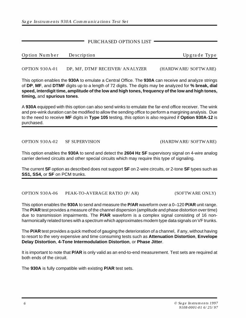
CONFIGURATOR PANELS
The LED Configurator is the standard configuratorfor PCM units. LEDs indicate status and errors onthe 2 T1 lines (PCM1 & PCM2).
This configurator also has 310-type jacks for theanalog input/output that are labeled SB/SG (SignalBattery/Signal Ground), E/M (The “E”- and “M”-leads), T/R (Tip and Ring), and T1/R1 (Tip1 andRing1). The E/M and SB/SG leads are used forE&M signaling. TR and T1R1 are used by all 4–wire analog trunks. All 2-wire signaling andtransmission is done over TR.
The Analog Configurator is used in 930Asintended for entirely analog operation and have noPCM options. The 310-type jacks are for the analoginput/output and are labeled SB/SG (Signal Battery/Signal Ground), E/M (The “E”- and “M”-leads), T/R(Tip and Ring), and T1/R1 (Tip1 and Ring1). The E/M and SB/SG leads are used for E&M signaling.TR and T1R1 are used by all 4–wire analog trunks.All 2-wire signaling and transmission is done overTR.
The 310 A/P Configurator is intended for use inthose units which have both analog and digital (T1PCM) capability. (Purchased Option 930A-08E or-09E has been installed.) Both sets of jacks are310-style and they are labeled PCM1 IN, PCM1OUT, PCM2 IN, PCM2 OUT, SB/SG (Signal Battery/Signal Ground), E/M (The “E”- and “M”-leads), T/R(Tip and Ring), and T1/R1 (Tip1 and Ring1).
The SS-7 Configurator is available with the SS-7line signaling purchased option. It is similar to thestandard LED Configurator , except that the thereare four sets of LEDs that indicate the status anderrors on four T1 lines carrying SS7 links. (PCM1,PCM2, PCM3 & PCM4). These PCM lines connectto the 930A via the four sets of PCM bantam jacks.
This configurator also has 310-type jacks for theanalog input/output that are labeled SB/SG (SignalBattery/Signal Ground), E/M (The “E”- and “M”-leads), T/R (Tip and Ring), and T1/R1 (Tip1 andRing1). The E/M and SB/SG leads are used forE&M signaling. TR and T1R1 are used by all 4-wireanalog trunks. All 2-wire signaling and transmissionis done over TR.


![[Welding] Miller Buyer's Guide; Plasma Cutting Buyer's Handbook (eBook, 20 Pages)](https://img.pdfslide.net/doc/110x75/55cf9a94550346d033a2702a/welding-miller-buyers-guide-plasma-cutting-buyers-handbook-ebook.jpg)