Embed Size (px)
Citation preview

9.36.2. Building Envelope
Module 2
BCBC 9.36.
2014
1 Richard Kadulski Architect

9.36.2. Building Envelope
• Focus is on total building performance, not
just thermal insulation
• Heat transfer and air leakage between
conditioned space and unconditioned space
• Reference to many requirements already in
Sections 9.7. and 9.25.
2 Richard Kadulski Architect
9.36.2. Building Envelope
Scope and Application
• The walls in skylight shafts are treated like exterior walls. 9.36.2.1.(3)
• Walls less than 60˚ from horizontal are considered as roof assemblies
• Windows must conform to section 9.7
• Properties of insulation, location and installation of air barriers, and vapour barriers must conform to section 9.25.
3 Richard Kadulski Architect
Scope and Application
• Any assembly that separates conditioned
space from an adjoining storage garage,
even if the garage is intended to be heated,
must be insulated to the requirements for
exterior assemblies. 9.36.2.1. (2)
4 Richard Kadulski Architect
• The thermal resistance of opaque assemblies uses
effective thermal resistance – this is a change from
nominal R-values that has been relied on up to now
• This takes into account all material layers in an
assembly, and the thermal bridging of high
conductivity materials – such as framing.
• Look-up tables are provided for most common
assemblies, and information on how to calculate
others (9.36.2.4.)
9.36.2.2. Determination of Thermal
Characteristics
5 Richard Kadulski Architect

9.36.2.2. Determination of Thermal
Characteristics
• Where a component of the building
envelope is enclosed by unconditioned
space, the effective R-value of the
component can be reduced by 0.16 RSI
• 9.36.2.4.(4)
Richard Kadulski Architect6

• Thermal characteristics of materials are determined
in accordance with listed product standards
• In absence of product standards, assemblies can be
tested to ASTM-C1363 as an alternative using an
indoor temperature of 21±1˚C and an outdoor air
temperature of -35±1˚C
• Log wall RSI-values must be determined by
calculation in accordance with Section 305 of ICC
400, “Design and Construction of Log Structures.”
9.36.2.2. Determination of Thermal
Characteristics
7 Richard Kadulski Architect

9.36.2.2. Determination of Thermal
Characteristics
• Product standards for many insulation materials are
listed in the code
• New products not listed are acceptable, but must be
tested in accordance with ASTM-C177 or ASTM- C518
• Calculations and tests at an average temperature of
24±2˚C and a temperature differential of 22±2˚C
8 Richard Kadulski Architect

9.36.2.4. Calculation of Effective Thermal
Resistance of Assemblies
• Heat transfer depends on the heat flow through a given area with a temperature difference across the element
• The NECB requires all building envelope assemblies and components to comply with the maximum U-values (overall thermal transmittance).
• Requirements in 9.36.2. are stated in RSI values which are the reciprocal of U-values.
9 Richard Kadulski Architect

9.36.2.4. Calculation of Effective Thermal
Resistance of Assemblies
• The same nominal insulation can produce
different effective thermal resistance values
depending framing type and material
configurations
• To calculate effective thermal resistance,
contributions from all portions of an
assembly, including heat flow through studs
and insulation are taken into account.
10 Richard Kadulski Architect

Difference Between Nominal and Effective
Thermal Resistance of Assemblies
AssemblyNominal
R-value
Effective
R-value
Conventional 2x6 wood stud @ 16” o/c; R-20
batt insul; gyp bd interior; ply sheathing;
wood siding
20
(RSI 3.52)
17.2
(RSI 3.02)
Advanced 2x6 framing, studs @ 24” o/c, R-
20 batt insul; gyp bd interior; ply sheathing;
wood siding
20
(RSI 3.52)
18.2
(RSI 3.20)
2x4 wood studs @ 16” o/c; R12 batt insul;
plus R-10 XPS, gyp bd interior; ply sheathing;
wood siding
22
(3.87)
22.4
(RSI 3.94)
2x6 steel studs @ 16” o/c, ; R-20 batt insul.;
gyp bd interior; ply sheathing; wood siding
20
(RSI 3.52)
11.35
(RSI 1.99)
11 Richard Kadulski Architect

9.36.2.6. Thermal Characteristics of Above
Ground Opaque Assemblies
• Prescriptive path: Requirements vary
whether or not an HRV is installed
• Table with minimum effective RSI-values
• Look-up tables for most common assemblies, and
information on how to calculate others provided in the
Appendix
12 Richard Kadulski Architect

9.36.2.6. Thermal Characteristics of Above
Ground Opaque Assemblies
Table 9.36.2.6.A
Assembly Climate Zone (Heating Degree Days ˚C)
Zone 4
< 3,000
Zone 5
3,001 to
3,999
Zone 6
4,000 to
4,999
Zone 7A
5,000 to
5,999
Zone 7B
6,000 to
6,999
Ceilings 6.91 (39.23)
8.67(49.2)
8.67
(49.2)
10.43
(59.2)
10.43
(59.2)
Cathedral
ceilings
4.67 (26.5)
4.67 (26.5)
4.67 (26.5)
5.02
(28.5)
5.02
(28.5)
Walls (2x6 @
16”)
2.78
(15.78)
3.08(17.48)
3.08(17.48)
3.08(17.48)
3.85(21.86)
Floors over
unheated
space
4.67 (26.5)
4.67 (26.5)
4.67 (26.5)
5.02
(28.5)
5.02
(28.5)
13
Effective RSI-values – without HRV
Richard Kadulski Architect

9.36.2.6. Thermal Characteristics of Above
Ground Opaque Assemblies
Table 9.36.2.6.B
Assembly Climate Zone (Heating Degree Days ˚C)
Zone 4
< 3,000
Zone 5
3,001 to
3,999
Zone 6
4,000 to
4,999
Zone 7A
5,000 to
5,999
Zone 7B
6,000 to
6,999
Ceilings 6.91 (39.23)
6.91
(39.23)
8.67
(49.2)
8.67
(49.2)
10.43
(59.2)
Cathedral
ceilings
4.67 (26.5)
4.67 (26.5)
4.67 (26.5)
5.02
(28.5)
5.02
(28.5)
Walls (2x6
@ 16”)
2.78
(15.78)
2.97(16.86)
2.97
(16.86)
2.97
(16.86)
3.08
(17.48)
Floors over
unheated
space
4.67 (26.5)
4.67 (26.5)
4.67 (26.5)
5.02
(28.5)
5.02
(28.5)
14
Effective RSI-values – with HRV
Richard Kadulski Architect

9.36.2.6. Thermal Characteristics of Above
Ground Opaque Assemblies
• Effective R-value can be reduced at the heel
of sloped roofs for no more than 1200 mm
in from the exterior to allow for framing; and
attic venting
• The minimum nominal R-value directly over
the outside wall must be no less than RSI
3.52 (R-20)
15 Richard Kadulski Architect

• Major structural penetrations through
assemblies are permitted – but total area
must not exceed 2%
• Allowable penetrations include balcony slabs,
beams, columns, and minor structural or
ornamental elements.
• Pipes, ducts, through-wall equipment vents are
considered minor penetrations and are not
considered.
9.36.2.4. Calculation of Effective Thermal
Resistance of Assemblies
16 Richard Kadulski Architect

Parallel-Path Flow Method
Differing rates of heat loss thru various components
of Building Assembly
17 Richard Kadulski Architect

Parallel-Path Flow Method
Need to determine cross sectional areas of the
various components of Building Assembly
Af Af AfA
c
A
c
18 Richard Kadulski Architect

Calculating Assembly RSI values
• Continuous layers of insulation
• Isothermal planes method – add RSI values of each layer
• Framed assemblies
• Isothermal planes method – add RSI values of each
Continuous layer PLUS
• Parallel-path flow method – need to determine Effective
Thermal Resistance (ETR) of Non-continuous layers
19 Richard Kadulski Architect

Effect of Thermal Bridging
• Where there is thermal bridging:
• Effective R < Nominal
• Where there is NO thermal bridging:
• Effective R = Nominal
20 Richard Kadulski Architect

9.36.2.4. Calculation of Effective Thermal
Resistance of Assemblies
RSIeffective vs. RSInominal
Include in
calculation
Exclude from Calculations
Repetitive
structural
members
- Studs
- Joists, lintels
- Sills, plates
Minor penetrations
- pipes, ducts
- Packaged air conditioners
- Shelf angles, anchors, fasteners
Credit for adjoining
unconditioned
spaces
Major structural penetrations
- Balcony slabs, beams, columns, ornamentation,
Provided: insulation is tight to penetrating element
- Total area of all major structural penetration is
limited to max 2% of wall area
RSIeff = RSInom
Richard Kadulski Architect21

RSI outside air film = 0.03
RSI outside air film =
0.03
RSI outside air film =
0.03
RSI inside air film = 0.11
Heat flow Up
RSI inside air film = 0.16
Heat flow Down
RSI inside air film =
0.12
Heat flow Horizontal
RSI inside air film =
0.12
Heat flow Horizontal
Insulating Effect of the Surface Air Films
22 Richard Kadulski Architect

Calculating Effective R-value:
Walls above Grade
R 20 batt Insulation
23 Richard Kadulski Architect
Air film (interior) 0.12 0.12
1/2” gypsum board 0.08 0.08
Polyethylene barrier 0.00 0.00
2”x6” stud @ 16”o/c 1.19 3.52
7/16 OSB sheathing 0.11 0.11
Hollow backed vinyl siding 0.11 0.11
Air film (exterior) 0.03 0.03
Effective Thermal Resistance 2.89 (R-16.37)
New Code Requirement zone 4 (less than 3,000 DDC):
Eff. R 2.78 (R 15.78)
Structure insulation

Parallel-Path Flow Method
100
% area of framing (Af) %area of cavity (Ac)
RSIf RSIc
+ RSIparallel =
24 Richard Kadulski Architect

Calculating Effective R-value:
Walls above Grade
R 20 batt Insulation
25 Richard Kadulski Architect
Air film (interior) 0.12 0.121/2” gypsum board 0.08 0.08
Polyethylene barrier 0.00 0.00
2”x6” stud @ 16” o/c 1.19 3.52
7/16 OSB sheathing 0.11 0.11
Hollow backed vinyl siding 0.11 0.11
Air film (exterior) 0.03 0.03
Effective Thermal Resistance 2.89 (R-16.37)
Code Requirement zone 4 (less than 3,000 DDC):
Eff. R 2.78 (R 15.78)
Code Requirement zone 5 (3,000 to 4,000 DDC):
Eff. R 2.97 (R 16.86) – with HRV
Eff. R 3.08 (R 17.48) – without HRV
Structure insulation

Walls above Grade
Code Requirement zone 5 & 6 (3,000 to 4,999 DDC):
Eff. R 2.97 (R 16.86) – with HRV
Eff. R 3.08 (R 17.48) – without HRV
RSI effective Reffective
2x6 @ 16” R-22 batt
insulation 3.11 17.63
2x4 @ 16” R14 batt insul
+ R-5 rigid insulation 3.19 18.09
2x4 @ 16” R14 batt insul
+ R-7.5 rigid insulation 3.66 20.78
26 Richard Kadulski Architect
✔✔✔

Calculating Effective R-value:
Ceilings with Attic Space
Air film (interior) 0.11
R 40 Blown Cellulose
27 Richard Kadulski Architect
1/2” gypsum board 0.08
Polyethylene barrier 0.00
2”x4” bottom chord cavity 1.96
3 ½” cellulose
3 ½” woodContinuous layer of cellulose 4.82Air film (exterior) 0.03
Effective Thermal Resistance 7.00
Code Requirement zone 4 (less than 3,000 HDD):
Eff. R 6.91 (R 39.23)
Raised Heel

Calculating Effective R-value:
Ceilings with Attic Space
Air film (interior) 0.11
1/2” gypsum board 0.08
Polyethylene barrier 0.00
2”x4” bottom chord cavity 1.96
Continuous layer of cellulose 4.82
Air film (exterior) 0.03
Effective Thermal Resistance 7.00
R 40 Blown Cellulose
Raised Heel
New Code Requirement zone 5
(3,000-3,999 HDD):
Eff. RSI 6.91 (R-39.23) with HRV
Eff. RSI 8.67 (R-49.2) without HRV
(requires R-50 cellulose)
28 Richard Kadulski Architect

Calculating Effective R-value:
Ceilings with Attic Space
Air film (interior) 0.11
1/2” gypsum board 0.08
Polyethylene barrier 0.00
2”x4” bottom chord cavity 1.96
Continuous layer of cellulose 6.59
Air film (exterior) 0.03
Effective Thermal Resistance 8.77
R 50 Blown Cellulose
Raised Heel
New Code Requirement zone 6
(4,000-4,999 HDD):
Eff. RSI 8.67 (R-49.2) with HRV
Eff. RSI 8.67 (R-49.2) without HRV
(requires R-50 cellulose)
29 Richard Kadulski Architect

9.36.2.4. Calculation of Effective Thermal
Resistance of Assemblies
• Appendix provides examples of calculations
and data tables:
• Framing & cavity percentages for typical wood
frame assemblies [Table A-9.36.2.4.(1)A]
• Factors for steel framing to address higher
thermal bridging through steel studs [Table A-
9.36.2.4.(1)B]
• Thermal resistance values for common materials
[Table A-9.36.2.4.(1)D]
30 Richard Kadulski Architect

9.36.2.4. Calculation of Effective Thermal
Resistance of Assemblies
Table A- 9.36.2.6.(1)A. presents the minimum nominal thermal resistance to
be made up in a given wall assembly for it to achieve the applicable RSI value
31 Richard Kadulski Architect

9.36.2.4. Calculation of Effective Thermal
Resistance of Assemblies
• Example using Table A-9.36.2.6.(1)A.
• Required effective RSI-value is 2.78• 38 x 140 mm studs @ 406 mm o.c. with R-19 batt insulation.
• RSI value of structural assembly is 2.36.
• Minimum additional required is 0.42
• Other components in wall assembly:
• Interior air film: 0.12
• 12.7 mm gyp board 0.08
• 12.7 mm ply sheathing 0.10
• Rain screen cavity 0.15
• stucco 0.013
• Exterior air film 0.03
• Total RSI of other components 0.49
32 Richard Kadulski Architect

9.36.2.5. Continuity of Insulation
• Insulation must be continuous across the entire envelope – but this does not mean continuous insulation across face.
• This applies to building components such as partitions, chimneys, fireplaces, and columns and beams that are embedded along exterior walls, but not to stud framing and ends of joists.
• Studs and joists in frame construction are dealt with by the calculation method for determining effective R-values.
Richard Kadulski Architect33
HP
O I
llu
str
ate
d G
uid
e: E
ne
rgy E
ffic
ien
cy
Re
qu
ire
me
nts
fo
r H
ou
ses i
n B
riti
sh
Co
lum
bia

9.36.2.5. Continuity of Insulation
• Article 9.36.2.5. (2) to (8) introducesrelaxations for various details
• Article 9.36.2.5. (9) allows completeexemption to sentence (1) for three specificdetails:
• At junction between foundation wall and floor slab
• The perimeter of a floating slab-on-grade
• Foundation wall portion that supports masonryveneer
34 Richard Kadulski Architect

9.36.2.5. Continuity of Insulation
• Allowable exemptions:
• Required fire safety clearances
• Major structural components that penetrate the
envelope (e.g. structural beams, balcony & canopy
slabs) provided
• total area is not more than 2% of gross wall area
• Insulation is installed tight against the penetration
35 Richard Kadulski Architect

9.36.2.5. Continuity of Insulation
• 9.36.2.5.(2) minimizing thermal bridging
• Where a wall or structural element
penetrates exterior envelope, it must be
insulated.
• Note that continuity of air barrier must also
be maintained at these details.
Richard Kadulski Architect36

9.36.2.5. Continuity of Insulation
• 9.36.2.5.(2)(a)
• Minimizing thermal bridging
where a wall or structural
element penetrates exterior
envelope, it must be
insulated on interior (or
exterior if element projects
outward).
Richard Kadulski Architect37

9.36.2.5. Continuity of Insulation
• 9.36.2.5.(2)(b)
• Minimizing thermal
bridging of a wall or
structural element at
exterior envelope, where
insulation is within plane of
wall.
Richard Kadulski Architect38

9.36.2.5. Continuity of Insulation
• 9.36.2.5.(2)(c)
• Minimizing thermal
bridging of a wall or
structural element at
exterior envelope, where
insulation is within plane of
wall.
Richard Kadulski Architect39

9.36.2.5. Continuity of Insulation
9.36.2.5.3. A masonry fireplace or flue on an
exterior wall must be insulated to an effective R-
value not less than 55% of that required for the
exterior wall
40 Richard Kadulski Architect

9.36.2.5. Continuity of Insulation
• Insulation placement can be
inside or outside; if there is a
cross-over, the over lap must
be 4 times the thickness of
the wall
• i.e. for 8” wall, the minimum
overlap will be 32”
Richard Kadulski Architect41

9.36.2.5. Continuity of Insulation
• 9.36.2.5. (6) mechanical,
plumbing or electrical system
components (such as pipes,
ducts, conduits, cabinets, chases,
panels or recessed heaters) within
or parallel to wall assembly must
be insulated to the same effective
insulation level as required for the
wall
Richard Kadulski Architect42

9.36.2.5. Continuity of Insulation
• 9.36.2.5. (7) ducts, plumbing pipes,
electrical or communication conduits placed
within the insulated portion of a floor or
ceiling assembly must have an effective
insulation level not less than RSI 2.78 (R-
15.78)
Richard Kadulski Architect43
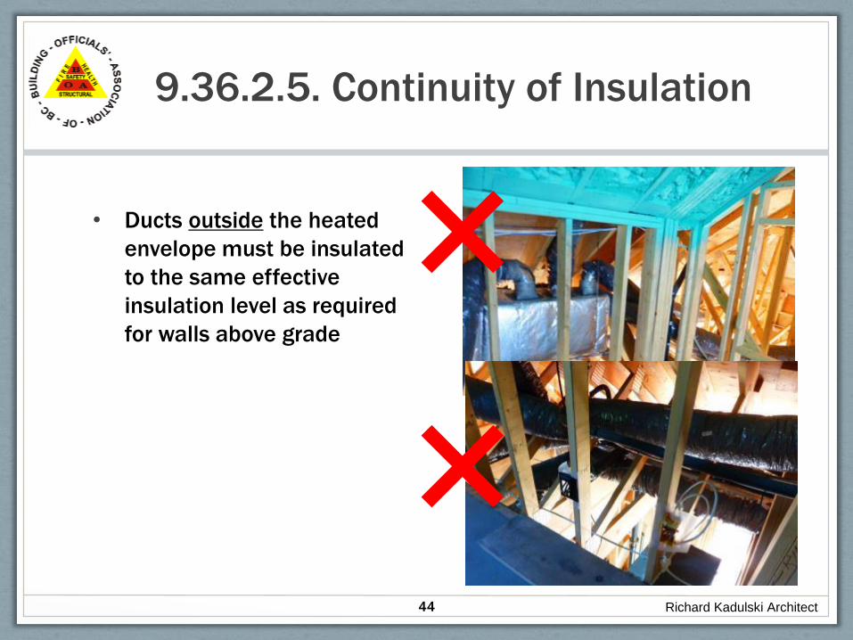
9.36.2.5. Continuity of Insulation
• Ducts outside the heated
envelope must be insulated
to the same effective
insulation level as required
for walls above grade
Richard Kadulski Architect44
✖
✖

9.36.2.5. Continuity of Insulation
• EXCEPTION: does not apply
where cladding is masonry and
foundation wall is insulated on
the exterior [9.36.2.5.(9)c]
45 Richard Kadulski Architect

9.36.2.5. Continuity of Insulation
• 9.36.2.5.(8) Joints and junctions between walls and other building envelope components shall be insulated in a manner that provides an effective thermal resistance that is no less than the lower of the minimum values required for the respective adjoining components.
Richard Kadulski Architect46

9.36.2.7. Fenestration, Doors &
Skylights
• Fenestration and doors must have a U-value no
greater than that in table 9.36.2.7.A, and skylights
as in table 9.36.2.7B
Richard Kadulski Architect47
Climate Zone (Heating Degree Days ˚C)
Zone 4
<
3,000
Zone 5
3,001 to
3,999
Zone 6
4,000 to
4,999
Zone 7A
5,000 to
5,999
Zone 7B
6,000 to
6,999
Zone 8
>7,000
Windows
& doors
1.80 1.80 1.60 1.60 1.40 1.40
skylights 2.90 2.90 2.70 2.70 2.40 2.40
9.36.2.7. Fenestration, Doors &
Skylights
•• Site assembled, or site glazed factory-made
products, curtain walls, and site built windows must
be tested or calculated
• Garage vehicular doors must have nominal RSI 1.1.
• Access hatches to unconditioned space: the U-value
not to exceed 2.6
Richard Kadulski Architect48

9.36.2.7. Fenestration, Doors & Skylights
Exceptions
• An exemption to requirements in table 9.36.2.7.A was
made for site-built windows and glazed doors, but they
must comply with properties laid out in Table 9.36.2.7.C
• Max U-value for glass block in an exterior wall must be
not more than 2.9, and total area of glass block must
not exceed 1.85 m (19.9 sq.ft.)
• One exterior door is permitted to have U-value of 2.6
• (this allows for a feature entry door)
• Storm windows are exempt form these requirements
Richard Kadulski Architect49

9.36.2.8. Assemblies In Contact With
Ground
• Full height basement wall insulation
required
• Top of foundation wall - up to 600 mm above
grade is insulated as a foundation wall.
• Appendix table lists typical assemblies
Richard Kadulski Architect50

9.36.2.8. Assemblies In Contact With
Ground
• Effective R-values requirements vary whether HRV is
installed or not
• Table 9.36.2.8.A. or 9.36.2.8.B
• Example – [required RSI effective is 1.99]:
• Concrete foundation wall, 38x89 (2x4) furring, RSI-2.11 (R-
12) insulation.
• From table A-9.36.2.8 (1)A the effective R-value of assembly
is 1.79. Minimum additional required is 0.20
• This can be made up by installing 12.7 mm gyp board
(0.0775) plus interior air film (0.12)
Richard Kadulski Architect51

9.36.2.8. Assemblies In Contact With
Ground
• Heated floor slabs must be insulated under
entire area, including the edges
• Floating slabs must be insulated under
entire floor slab, but not under integral
perimeter footing, but skirt insulation is
required to same value as under the slab
Richard Kadulski Architect52

9.36.2.8. Assemblies In Contact With
Ground
• Floor slab insulation depends whether or not
it is a heated slab, and above or below frost
line
• If entire floor fits into two categories, the
more restrictive applies.
Richard Kadulski Architect53

9.36.2.8. Assemblies In Contact
With Ground
• Unheated floor slabs must
be insulated min. 1.2m
horizontally or vertically
down from its perimeter,
with a thermal break along
edge of slab a min. 50% of
required insulation
Richard Kadulski Architect54