Embed Size (px)
Citation preview

5,/
NAVAL POSTGRADUATE SCHOOLL' affl=
___ Monterey, California
00
94-34396 THESIS ~NOV 39l1994 U
MITIGATION OF EMI GENERATED BY AVARIABLE-FREQUENCY-DRIVE CONTROLLER
FOR AN AC INDUCTION MOTOR
by
Philip E. VanWiltenburg
September, 1994
Thesis Advisor: Richard W. Adler
Approved for public release; distribution is unlimited.
94 11i 4 070
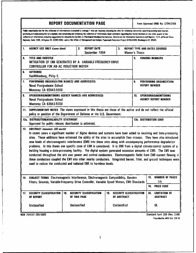
REPORT DOCUMENTATION PAGE Form Approved 0MB No. 0704-0188
Public reporting burden for this collection of information is estimated to average I hour pWr response, including the time for reviewing instruction, searching existing data sources,gathering and maintaining the data needed, and conpleting and reviewing the collection of information. Send commients regardingthis burden estimate or any other aspect of thiscollection of infonnation, including suggestions for reducing this burden, to Washington Headquarters Services, Directorate for Information Operations and Reports, 1215 Jefferson DavisHighway. Suite 1204, Arlington. VA 22202-4302 and to the Office of Management and Budget Paperwork Reduction Project (0704-0188) WashingtonOC 20503.
1. AGENCY USE ONLY (Leave blank) 2. REPORT DATE 3. REPORT TYPE AND DATES COVEREDSeptember 1994 Master's Thesis
4. TITLE AND SUBTITLE 5. FUNDING NUMBERSMITIGATION OF EMI GENERATED BY A VARIABLE-FREQUENCY-DRIVECONTROLLER FOR AN AC INDUCTION MOTOR
6. AUTHORIS)VanWiltenburg, Philip E.
7. PERFORMING ORGANIZArlON NAME(S) AND ADDRESS(ES) 8. PERFORMING ORGANIZATIONNaval Postgraduate School REPORT NUMBER
Monterey CA 93943-5000
9. SPONSORINGIMIONITORING AGENCY NAME(S) AND ADDRESS(ES) 10. SPONSORINGIMONITORINGNaval Postgraduate School AGENCY REPORT NUMBER
Monterey CA 93943-5000
11. SUPPLEMENTARY NOTES The views expressed in this thesis are those of the author and do not reflect the officialpolicy or position of the Department of Defense or the U.S. Government.
12a. DISTRIBUTIONIAVAILABILITY STATEMENT 12b. DISTRIBUTION CODEApproved for public release; distribution is unlimited.
13. ABSTRACT (maximum 200 words)In recent years a significant number of digital devices and systems have been added to receiving and data-processingsites. These additions have enhanced the ability of the sites to accomplish their mission. They have also introducednew kinds of electromagnetic interference (EMI) into these sites along with accompanying performance degradationproblems. In this thesis one specific case of EMI is considered. It is EMI from a digital climate-control system of abuilding housing a data-processing facility. The digital system generated excessive amounts of EMI. The EMI wasconducted throughout the site owbr power and control conductors. Electromagnetic fields from EMI current flowing inthese conductors coupled the EMI into other nearby conductors. Integrated barrier, filter, and ground techniques wereused to reduce the conducted and radiated EMI to harmless levels.
14. SUBJECT TERMS Electromagnetic Interference, Electromagnetic Compatibility, Barriers 15. NUMBER OF PAGES
Filters, Grounds, Variable-Frequency Drive Controller, Variable Speed Motors, EMI Standards 5916. PRICE CODE
17. SECURITY CLASSIFICATION 18. SECURITY CLASSIFICATION 19. SECURITY CLASSIFICATION 20. LIMITATION OFOF REPORT OF THIS PAGE OF ABSTRACT ABSTRACT
Unclassified Unclassified Unclassified UL
NSN 7540-01-280-5500 Standard Form 298 (Rev. 2-89)Prescribedby ANSI Std. 239-18
Approved for public release; distribution is unlimited.
MITIGATION OF EMI GENERATED BY A VARIABLE FREQUENCY DRIVECONTROLLER FOR AN AC INDUCTION MOTOR
by
Philip E. VanWiltenburgCaptain, United States Army
B.S., United States Military Academy, 1985
Submitted in partial fulfillmentof the requirements for the degree of
MASTER OF SCIENCE IN SYSTEMS ENGINEERING (EW)
from the
NAVAL POSTGRADUATE SCHOOLSeptember 1994
Author:
Approved by: w kRichard W. Adler, Thesis Advisor
Wilbur R. Vincent, Second Reader
Frederic H. Levien, ChairmanElectronic Warfare Academic Group
ABSTRACT
In recent years a significant number of digital devices and systems have been
added to recei\ ,ng and data-processing sites. These additions have enhanced the ability
of the sites to accomplish their mission. They have also introduced new kinds of
electromagnetic interference "'M1) into these sites along with accompanying performance
degradation problems. In ý. v- ' ..sis one specific case of EMI is considered. It is EMI
from a digital climate-control system of a building housing a data-processing facility.
The digital system generated excessive amounts of EMI. The EMI was conducted
throughout the site over power and control conductors. Elecz'a.,agnetic fields from EMI
current flowing in these conductors coupled the EMI into other nearby conductors.
Integrated barrier, filter, and ground techniques were used to reduce the conducted and
radiated EMI to harmless levels. , csion For
ý,,TIS CRA&M
bL FIC TABUnannournced -iJijthiK'atiorn
B y ..............................Dist ibliflo,/
Av~ha'.b,.,ty CodesSAvA11 d Of
Dist 5pcial
/JTLo
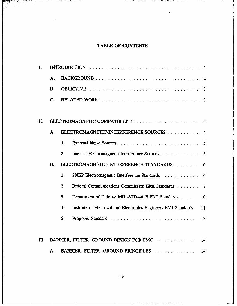
TABLE OF CONTENTS
INTRODUCTION ................................... 1
A. BACKGROUND ................................. 2
B. OBJECTIVE ................................... 2
C. RELATED WORK ............................... 3
II. ELECTROMAGNETIC COMPATIBILITY ...................... 4
A. ELECTROMAGNETIC-INTERFERENCE SOURCES ........... 4
1. External Noise Sources ........................... 5
2. Internal Electromagnetic-Interference Sources ............. 5
B. ELECTROMAGNETIC-INTERFERENCE STANDARDS ........ 6
1. SNEP Electromagnetic Interference Standards ............ 6
2. Federal Communications Commission EMI Standards ........ 7
3. Department of Defense MIL-STD-461B EMI Standards ...... 10
4. Institute of Electrical and Electronics Engineers EMI Standards 11
5. Proposed Standard .............................. 13
mI. BARRIER, FILTER, GROUND DESIGN FOR EMC ............... 14
A. BARRIER, FILTER, GROUND PRINCIPLES .............. 14
iv
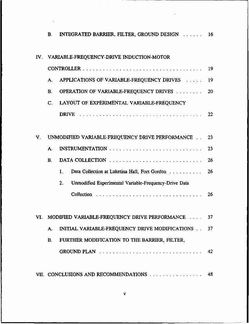
B. INTEGRATED BARRIER, FILTER, GROUND DESIGN ....... 16
IV. VARIABLE-FREQUENCY-DRIVE INDUCTION-MOTOR
CONTROLLER .................................... 19
A. APPLICATIONS OF VARIABLE-FREQUENCY DRIVES ..... 19
B. OPERATION OF VARIABLE-FREQUENCY DRIVES ........ 20
C. LAYOUT OF EXPERIMENTAL VARIABLE-FREQUENCY
D RIVE .................... ....... .. ........ 22
V. UNMODIFIED VARIABLE-FREQUENCY DRIVE PERFORMANCE . . 23
A. INSTRUMENTATION ............................ 23
B. DATA COLLECTION ............................ 26
1. Data Collection at Luketina Hall, Fort Gordon ........... 26
2. Unmodified Experimental Variable-Frequency-Drive Data
Collection ................................ 26
VI. MODIFIED VARIABLE-FREQUENCY DRIVE PERFORMANCE .... 37
A. INITIAL VARIABLE-FREQUENCY DRIVE MODIFICATIONS 37
B. FURTHER MODIFICATION TO THE BARRIER, FILTER,
GROUND PLAN ............................... 42
VII. CONCLUSIONS AND RECOMMENDATIONS .................. 48
V
A. CONCLUSIONS.................................48
B. RECOMMENDATIONS ................................ 49
LIST OF REFERENCES .................................. 50
INITIAL DISTRIBUTION LIST ............................. 51
vi
I. INTRODUCTION
The electromagnetic spectrum is divided into a number of separate bands, and these
bands are used for a number of purposes. Typical uses include point-to-point radio
communications, mobile-radio communications, satellite communications, radar,
navigation aids, and many other uses. All such applications of the radio spectrum
employ antennas and receivers to convert extremely weak electromagnetic ields into
useable analog or digital signals. Unfortunately, some electronic equipment and devices
generate significant levels of radio interference. In some cases this interference is
sufficiently large to degrade the ability of receivers to detect desired signals. Sometimes
the interference is strong enough to adversely affect the operation of other electronic
devices and systems.
An increasing number of modem digital devices and systems are being introduced
into receiving and data processing sites. While these systems result in significant
improvements in work efficiency, they sometimes generate excessive levels of radio
interference to radio receivers and other electronic systems. Typical examples of
interference sources include digital power-control systems, microwave ovens, computers,
printers, copy machines, digital-telephone systems, uninterruptible power supplies (UPS),
and other similar devices and systems.
This thesis describes a solution to one specific case of electromagnetic interference
(EMI) from a digitally-based, variable-frequency induction-motor controller. The
controller and induction motor were used in the air-handling system of a building housing
sensitive data-processing equipment.
A. BACKGROUND
Most receiving sites and data-processing centers require a controlled climate. For
most of these sites, air conditioners are used to maintain the climate at a near constant
temperature and humidity. The standard motor for most high-volume air-conditioning
systems (HVAC) is a 460-volt, 3-phase, AC induction motor which operates at a constant
speed. When the HVAC services more than one room, the amount of cooling the facility
requires will vary. By using a variable-frequency-drive (VFD) controller to run the
HVAC's motor at different speeds, the HVAC provides the exact amount of cooling
needed for the facility. Variable-frequency drives take a fixed voltage and frequency and
convert it into a variable voltage and frequency, hence the variable speed. The Halmar-
Robicon ID-PWM 454 series VFD used for this thesis is typical of the VFD drives
available today.
B. OBJECTIVE
This thesis investigates the electromagnetic interference generated by a variable-
frequency drive in the 1-kHz to 100-MHz portion of the electromagnetic spectrum and
recommends modifications to minimize these problems. Chapter 2 describes EMI
sources and various EMI standards. Chapter 3 describes barrier, filter, and ground
design. Chapter 4 describes the ID-PWM 454 VFD and its operation. Chapter 5
describes the performance of an unmodified VFD. Chapter 6 describes the performance
2
of a VFD modified to reduce EMI. Chapter 7 states conclusions and recommendations
for placing modified VFDs in service and the advantages of having an electromagnetic
compatibility (EMC) plan.
C. RELATED WORK
Electromagnetic compatibility studies have been ongoing throughout the world for
many years. However, several problems remain including confusing and conflicting
standards, poor measurement equipment, and incorrect perceptions about the control of
EMI. As a result, many mitigation efforts fail to solve EMI problems, and in some cases
they exacerbate EMC problems. An exception is the Signal-to-Noise Enhancement
Program (SNEP). Organized at the Naval Postgraduate School, a SNEP team conducts
EMI surveys and defines steps to mitigate EMI problems. The SNEP teams use
specialized equipment to define EMI problems, set limits for EMI emissions at receiving
sites, and recommend solutions. Both the U.S. Navy and the U.S. Army use SNEP
teams to conduct EMI surveys at receiving and data processing sites.
Some progress has been made in the control of EMI at receiving and data
processing sites by the SNEP. SNEP teams, consisting of experienced personnel and
specialized instrumentation from the Naval Postgraduate School, have investigated and
mitigated a number of complex EMI problems. These teams have proposed maximum
EMI current limits for all conductors that enter, leave, or support digital devices and
systems.
3
H. ELECTROMAGNETIC COMPATIBILITY
Electromagnetic compatibility is more important in today's dense electromagnetic
environment than anytime in the past. An electronic device or system is
electromagnetically compatible if it does not interfere with other systems, it is not
susceptible to EMI from other systems, and it does not interfere with itself. While
portions of the radio spectrum have been very crowded for many years, the increased
numbers and operating speed of today's digital devices greatly compound interference
problems in the HF, VHF, and UHF bands.
Digital devices and equipment have been widely installed in receiving and data
processing sites to increase productivity. But much of this equipment was installed with
little regard or understanding for EMC. As a result, some digital equipment degrades
mission effectiveness by adding EMI. As new digital equipment is added to sites, noise
increases. In addition, the area surrounding these sites often has digital equipment,
which can add to the EMI levels affecting receiving and data processing sites.
A. ELECTROMAGNETIC-INTERFERENCE SOURCES
EMI, both natural and man-made, has degraded the performance of radio systems
since the early days of radio. Examples of early systems degraded by EMI include
telegraphs and radios. EMI comes from two sources; (1) sources external to the facility
4

housing the system in question and (2) sources within the facility, including noise created
within electronic and electrical systems.
1. External Noise Sources
Unwanted electromagnetic waves that enter a site through antennas, or any
other c- ductor, are from external noise sources. Most of these waves can be classified
as radio-frequency interference (RFI). Examples of RFI sources include natural
phenomenon such as lightning, static frc n charged rain drops and static from dust/sand
storms. Lightning is major source of RFI up to 50 MHz. Static charge builds up when
charged raindrops, dust, or sand strike isolated conductive surfaces. When the charge
becomes large enough, corona discharge can occur at sharp projecting points on the
charged surfaces. Noise associated with power-line hardware is a significant man-made
source of external noise. Any power line within the line-of-sight of a receiving site is
a potential source of RFI. The most common examples of power-line noise include gap
noise, hardware noise, lightning-arrester noise, cable-head sparking, and corona noise.
[Ref. I]
2. Internal Electromagnetic-Interference Sources
Internal EMI sources include microscopic sources, electrical devices, and
electrical circuits. EMI generated from microscopic sources include thermal noise and
shot noise. Random velocity fluctuations of charge carriers in a resistive material
produces thermal noise. Shot noise occurs as a current passes a potential barrier (this
occurs in solid-state circuits). Electrical circuits and devices are another major source
5
of internal noise. Circuits that cause a significant amount of EMI/RFI include mixers
and oscillators. Heterodyning and signal modulation/demodulation also produce
EMI/RFI. Switching devices such as diodes, SCRs. and integrated circuits also generate
EMI. Computers, UPS, motor speed controls, and equipment with sliding contacts
generate broadband EMI. [Ref 1]
B. ELECTROMAGNETIC-INTERFERENCE STANDARDS
Limiting EMI current on site conductors to harmless levels will eliminate most EMI
problems. Many modem digital systems inject high levels of EMI current into grounds,
power wires, cable shields, and other conductors. The electromagnetic fields associated
with the EMI current can interfere with the reception of signals-of-interest (SOI) at
receiving sites. While data processing systems tolerate higher EMI currents than
receiving equipmept, no suitable documentation exists for a maximum acceptable EMI
limit for either.
1. SNEP Electromagnetic Interference Standards
The staff and students of the Naval Postgraduate School, in cooperation with
other government and civil agencies, have informally proposed maximum levels of EMI
currents for large HF, VHF, and UHF receiving sites. Large receiving sites are fixed
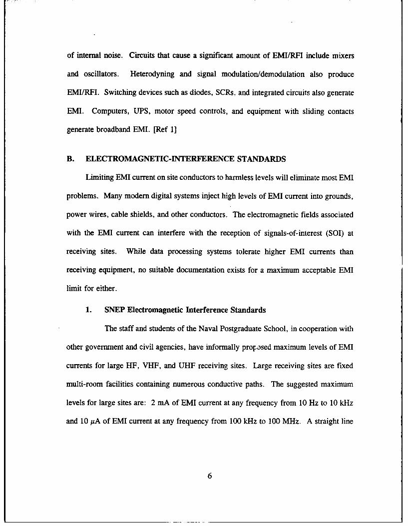
multi-room facilities containing numerous conductive paths. The suggested maximum
levels for large sites are: 2 mA of EMI current at any frequency from 10 Hz to 10 kHz
and 10 ,A of EMI current at any frequency from 100 kHz to 100 MHz. A straight line
6
can be used to connect the 2-mA and 10-AA levels. These guidelines are shown
graphically in Figure 1 below.
SNEP EMIfRFI Emission Limits
32
C 0.1
0.01
0.0030.01 10 100 1000-i-
Frequency -kHz
Figure 1. SNEP Maximum EMI Current Level
For a small field receiving site, the suggested maximum value of EMI current from 100
kHz to 100 MHz is reduced from 10 pA to 2 MA. [Ref. 2]
2. Federal Communications Commission EMI Standards
The Federal Communications Commission (FCC) regulates the use of radio
frequencies from 9 kHz to 3000 GHz under Title 47, Part 15 of the Code of Federal
Regulations. Any electronic system with digital circuits using clock signals or other
signals over 9 kHz must comply with the FCC limits for radiated and conducted
emissions. The FCC divides these digital devices into Class A and Class B. Class A
7
digital devices are for business, commercial, and industrial use while Class B digital
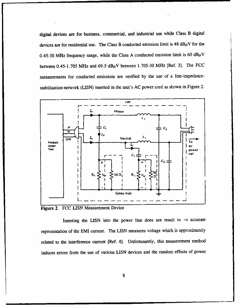
devices are for residential use. The Class B conducted emission limit is 48 dBpV for the
0.45-30 MHz frequency range, while the Class A conducted emission limit is 60 dB.tV
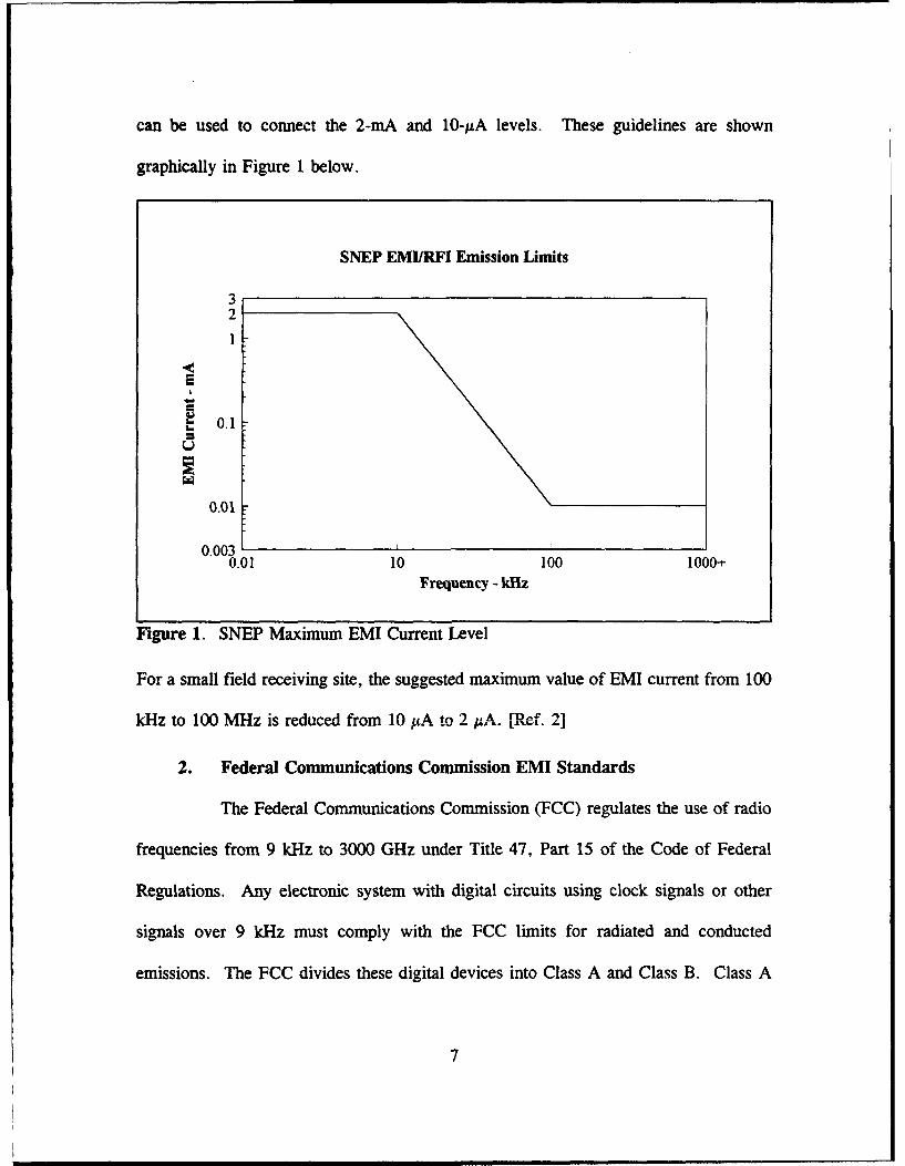
between 0.45-1.705 MHz and 69.5 dBAV between 1.705-30 MHz [Ref. 31. The FCC
measurements for conducted emissions are verified by the use of a line-impedance-
stabilization-network (LISN) inserted in the unit's AC power cord as shown in Figure 2.
1.ISNr I
1P IPhase
SCi ,
G 1N Neutral L IProduct T "/VY To
Under acTest power
, c -net
R, V,. 5oni R, .v vR1 v O1 R1 VN,
Green wire
L-
Figure 2. FCC LISN Measurement Device
Inserting the LISN into the power line does not result in in accurate
representation of the EMI current. The LISN measures voltage which is approximately
related to the interference current [Ref. 4]. Unfortunately, this measurement method
induces errors from the use of various LISN devices and the random effects of power
8
wiring impedance. These measurements can be converted to approximate values of
current in 1A using the following relationships:
Pow= V• I*ixl 0 -9(1)
and
IA=VPw*5x 01o. (2)
The maximum allowable EMI current of the FCC EMI standard is shown in Figure 3.
FCC Class A/Class B Emission Limits
3.5Class A
3Class B
2 2.512
0.5
0.45 1.705 30
Frequency - MHz
Figure 3. FCC Class A/B Emission Limits
9
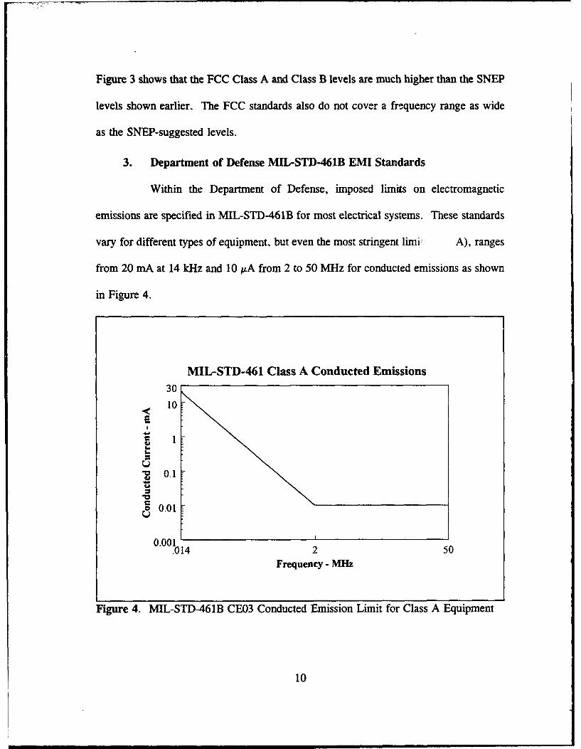
Figure 3 shows that the FCC Class A and Class B levels are much higher than the SNEP
levels shown earlier. The FCC standards also do not cover a frquency range as wide
as the SNEP-suggested levels.
3. Department of Defense MIL-STD-461B EMI Standards
Within the Department of Defense, imposed limits on electromagnetic
emissions are specified in MIL-STD-461B for most electrical systems. These standards
vary for different types of equipment, but even the most stringent limi A), ranges
from 20 mA at 14 kHz and 10 1.A from 2 to 50 MHz for conducted emissions as shown
in Figure 4.
MIL-STD-461 Class A Conducted Emissions
30
10T
I
a 0.10
o 0.01
0.001.014 2 50
Frequency - MIz
Figure 4. MIL-STD-461B CE03 Conducted Emission Limit for Class A Equipment
10
The MIL-STD-461B Class A emission limits shown in Figure 4 apply to
equipment which must operate when installed in critical areas such as aircraft,
submarines, surface ships, and ground facilities. MIL-STD-461B also controls the
susceptibility of equipment to EMI emissions from other electrojiuc equipment. Key
differences between MIL-STD-461B and the FCC standards include a much wider class
of products covered by MIL-STD-461B. Compliance with MIL-STD-461B can be
waived by the military agency procuring the system. [Ref 4]
While MIL-STD-461's EMI standards are closer to those of the SNEP
proposed guidelines, they still do not cover a frequency range as wide as the SNEP. The
waiverability of these standards make them practically useless as any EMI standard must
be strictly adhered to for effective implementation.
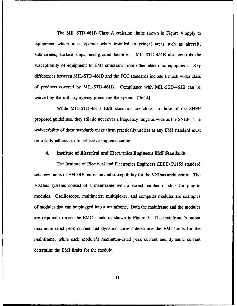
4. Institute of Electrical and Elect. hnics Engineers EMI Standards
The Institute of Electrical and Electronics Engineers (IEEE) P1155 standard
sets new limits of EMI/RFI emission and susceptibility for the VXIbus architecture. The
VXIbus systems consist of a mainframe with a varied number of slots for plug-in
modules. Oscilloscope, multimeter, multiplexer, and computer modules are examples
of modules that can be plugged into a mainframe. Both the mainframe and the modules
are required to meet the EMC standards shown in Figure 5. The mainframe's output
maximum-rated peak current and dynamic current determine the EMI limits for the
mainframe, while each module's maximum-rated peak current and dynamic current
determine the EMI limits for the module.
11
IEEE Conducted Emissions Limits
Imp - Max. Rated Peak Current
lmd • - Max. Rated Dynamic Current
20 dB" decade
Sx 10.3
0 I
0 20 104 Imd X 107 109
SFrequency - Hz
Figure 5. IEEE EMC Standards for VXIbus [Ref. 5]
The number of slots in the mainframe multiplied by 1 mA is the maximum EMI current
level from
Imd *1 07 Hz (3)no. Slots
to 1 GHz. If a VXIbus mainframe has 13 slots, a maximum-rated peak current of 3 A,
and a maximum-rated dynamic current of I A then the maximum EMI current from 770
kHz to 1 GHz would be 3 mA. [Ref. 5]
12
The IEEE PI155 EMI standard for the VXIbus is also very high when
compared to the SNEP recommended values. The lowest allowed level for EMI current
under the VXIbus standard is still measured in milliamperes. The VXIbus standard does
address a wider range of frequencies than the SNEP-reco-nmended levels.
5. Proposed Standard
An arbitrary guideline is the SNEP 2-mA level of current from 10 Hz to 10
kHz and the 10-IiA value of current from 100 kHz to 100 MHz. These EMI current
levels are significantly lower than the FCC EMI standards or the IEEE P1155 EMI
standard. The SNEP standard also covers a wider frequency range than the FCC EMI
standard and the MIL-STD-461 EMI standards. While the SNEP emission limits should
prevent large EMI problems, they may not be sufficiently low to prevent all EMI
problems [Ref 2]. The severity of any EMI problem depends on the susceptibility of the
equipment installed in the facility. Data-processing equipment is less susceptible to EMI
than receiving equipment, but the exact level that a specific piece of data-processing
equipment can accept without errors occurring must be measured.
13
HI. BARRIER, FILTER, GROUND DESIGN FOR EMC
Kirkoff's law of current flow states that the sum of all currents flowing out of any
point in a network at any instant equals zero [Ref. 6]. Thus, any current eventually must
return back to its source. This implies that EMI current flowing from a source will
return to that source over any available path. Barriers, filters, and grounds are
commonly used in an attempt to control EMI/RFI. Unfortunately, unified guidelines and
standards do not exist for barrier, filter, and ground techniques. As a result, attempts
to control EMI/RFI sometimes aggravate the problem. This chapter describes an
integrated approach to barriers, filters, and grounds for the control of EMI/RFI.
A. BARRIER, FILTER, GROUND PRINCIPLES
The primary function of barriers, filters, and grounds is to prevent EMI/RFI
generated by an electrical device from leaving an enclosure containing the device and to
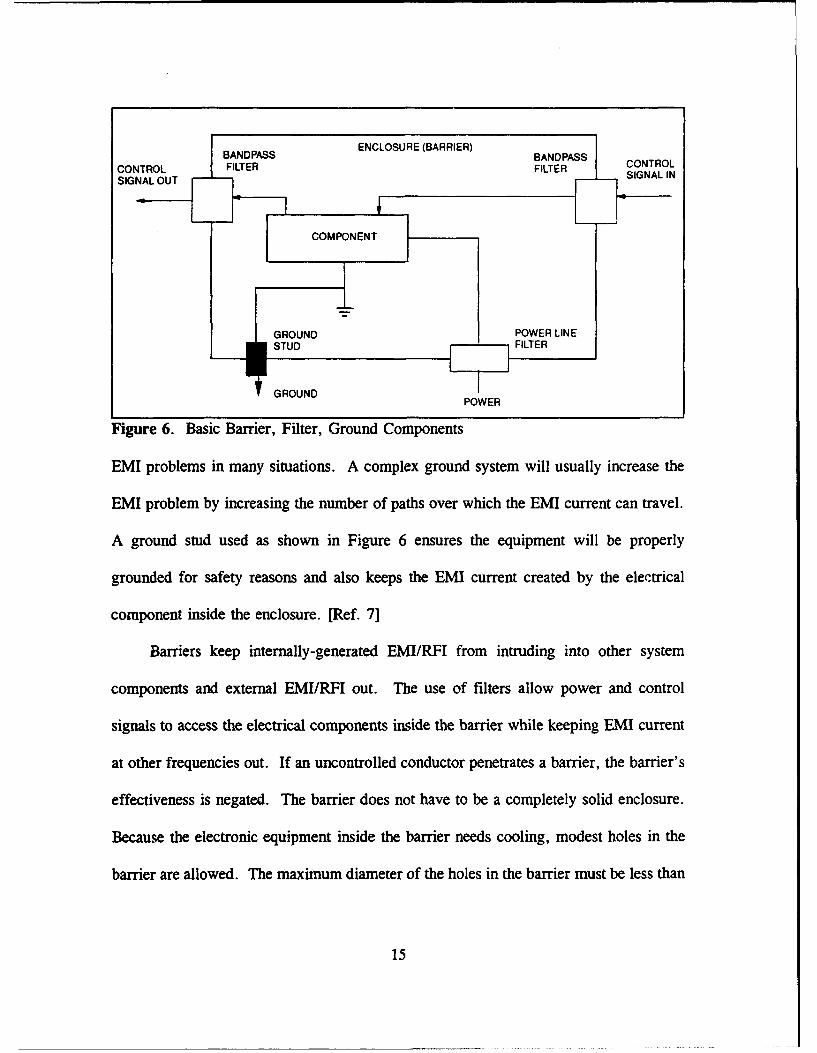
prevent external EMI/RFI from entering the enclosure. Figure 6 shows all three
components of a BFG design that must be included in any design for reducing EMI
current. [Ref. 7]
A common mistake in BFG design is that "better" grounds will help control site
generated EMI. These "better" grounds generally consist of ground grids, ground plates,
and other expensive multi-element systems. There is no ground system that, by itself,
helps control EMI current. "Better" grounds, when used by themselves, increase the
14
BANDPASS, ENCLOSURE (BARRIER)FILTERAS BAND PASS COTLCONTROL FILTER FILTER CONALSIGNAL OUT FLE INLI
COMPONENT
GROU1ND POWER LINE
GROUNDPOWER
Figure 6. Basic Barrier, Filter, Ground Components
EMI problems in many situations. A complex ground system will usually increase the
EMI problem by increasing the number of paths over which the EMI current can travel.
A ground stud used as shown in Figure 6 ensures the equipment will be properly
grounded for safety reasons and also keeps the EMI current created by the electrical
component inside the enclosure. [Ref. 7]
Barriers keep internally-generated EMI/RFI from intruding into other system
components and external EMI/RFI out. The use of filters allow power and control
signals to access the electrical components inside the barrier while keeping EMI current
at other frequencies out. If an uncontrolled conductor penetrates a barrier, the barrier's
effectiveness is negated. The barrier does not have to be a completely solid enclosure.
Because the electronic equipment inside the barrier needs cooling, modest holes in the
barrier are allowed. The maximum diameter of the holes in the barrier must be less than
15
about three tenths of the shortest wavelength being controlled with a waveguide three
times the holes' diameter in length attached. To be an effective barrier, the surface of
the enclosure must be electrically bonded with all structural elements. [Ref. 1]
B. INTEGRATED BARRIER, FILTER, GROUND DESIGN
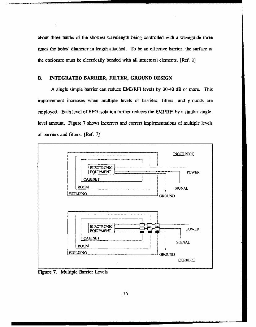
A single simple barrier can reduce EMI/RFI levels by 30-40 dB or more. This
improvement increases when multiple levels of barriers, filters, and grounds are
employed. Each level of BFG isolation further reduces the EMI/RFI by a similar single-
level amount. Figure 7 shows incorrect and correct implementations of multiple levels
of barriers and filters. [Ref. 7]
______________________INCORRECT
I ELECTRONICG
ON
EQUIPMIENT POWER
ROOM SIGNAL
BUILDING GROUND
EQUIPMIENT..-• OE
CABINETSIGNAL
ROOM
IBUILDING GROUND
CORRECT
Figure 7. Multiple Barrier Levels
16
In Figure 7, the incorrect implementation has conductors passing through multiple
barriers without being filtered, or without the grounds being terminated on the inside and
outside surfaces of the barriers. This negates the effectiveness of the barriers in
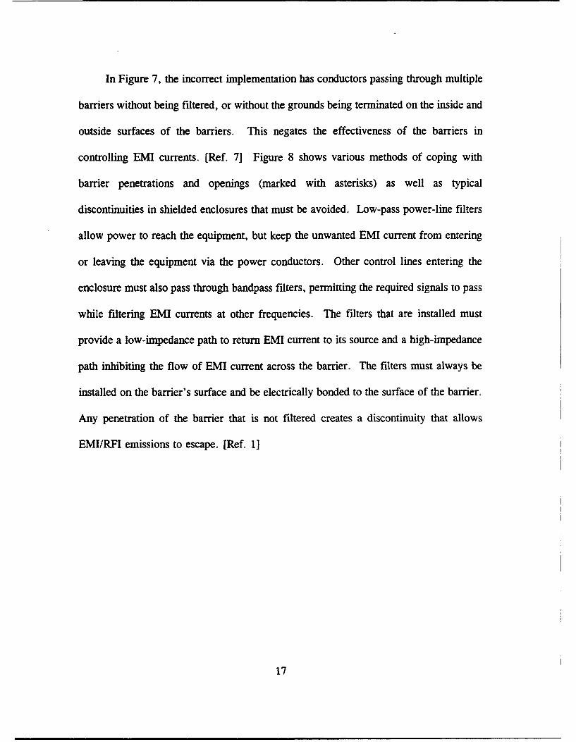
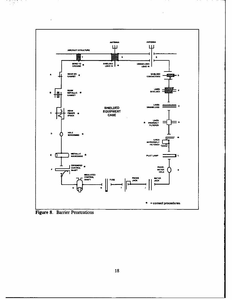
controlling EMI currents. [Ref. 7] Figure 8 shows various methods of coping with
barrier penetrations and openings (marked with asterisks) as well as typical
discontinuities in shielded enclosures that must be avoided. Low-pass power-line filters
allow power to reach the equipment, but keep the unwanted EMI current from entering
or leaving the equipment via the power conductors. Other control lines entering the
enclosure must also pass through bandpass filters, permitting the required signals to pass
while filtering EMI currents at other frequencies. The filters that are installed must
provide a low-impedance path to return EMI current to its source and a high-impedance
path inhibiting the flow of EMI current across the barrier. The filters must always be
installed on the barrier's surface and be electrically bonded to the surface of the barrier.
Any penetration of the barrier that is not filtered creates a discontinuity that allows
EMI/RFI emissions to escape. [Ref. 1]
17
ANTENNA ATENNA
AIRCRAFT STRUCTURE t
*TO ISIDEG ROUND EA LEAD IN
A SEAM NO . SHIELDEDGASKET CONDUCTORS
SERAM LINESU METALLIC *
SHIELDED P
GASKET
LINES0
SHIELDED u0sIRELDED360m EQUIPMENT
c FNGERSTOC CASE
LINESPROPERLY NFILTERED
HOLE
3CREENMIG *
LINESIMPROPERLY
FILTERED
EMETALLIC III
E WA'GUIDE PILOT LAMP L
CONTROLPANELSHF METER KC
* = correct procedures
Figure 8. Barrier Penetrations
18
IV. VARIABLE-FREQUENCY-DRIVE INDUCTION-MOTOR CONTROLLER
The Halmar-Robicon ID-PWM 454 series VFD is an updated model of the Halmar-
Robicon ID-PWM 455 series VFDs currently installed at Fort Gordon's Luketina Hall
facility. The major difference between these drives is that the 454 series VFD is
modularized for easier component replacement.
A. APPLICATIONS OF VARIABLE-FREQUENCY DRIVES
The Halmar-Robicon ID-PWM 454 series of variable-frequency drives are modular,
compact, transistor-based, pulse-width-midulated (PWM) drives. They have digital
controls for the precise control of the speed of three-phase induction motors and a serial
communi,.-ations port for interfacing with programmable controllers and computers. The
Halmar-Robicon ID-PWM 454 series VFDs are available from 3-1000 horsepower at 460
VAC. Variable-frequency drives are designed for speed control of induction motors in
positive-displacement pumps, supply/return fans, conveyors, cooling-tower fans/pumps,
and high-capacity air-conditioning systems. [Ref. 8]
A VFD allows a single-speed induction motor to run at 0-100% of the motor's
rated speed. For example, if an HVAC system had an induction motor running at 1800
rpm, the amount of cooling capacity provided by the HVAC system is fixed. If only a
small amount of cooling is needed, the HVAC cools areas that don't require cooling or
wastes the excess amount of cooling by shunting it elsewhere. With a VFD the motor
19
rotras from less than 400 up to 1800 rpm, depending on the amount of cooling required.
The VFD receives the percentage capacity that is needed through the serial
communications port and drives the induction motor of the HVAC at the speed required
to provide the correct amount of cooling. [Ref. 9]
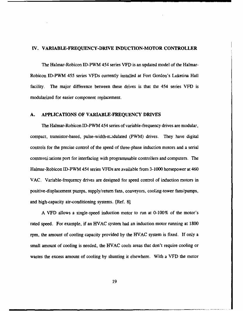
B. OPERATION OF VARIABLE-FREQUENCY DRIVES
Variable-frequency drives convert a fixed frequency and voltage into a variable-
voltage, variable-frequency output. The VFDs examined in this thesis are voltage
source, pulse-width-modulated VFDs, using a diode front-end with output transistors.
The variable speed is obtained by a three-stage process in the VFD as shown in Figure
9. [Ref. 91
ONVERTER (AC TO DC) DC BUS INVERTER LDC TO AC)A
PREOIARGERESISTORS
FIDIBYASSSCR FUSE : _
1__2 .J I ....... J ,.....
u6 DC BUS --IICAPACI TORS
LINEREACTOR 1 4..
INPUT DIOOE OUTPUT PCMER TRANSISTORSRECTIFIERS
Figure 9. Stages of ID-PWM 454 VFD
20
The converter section, a three-phase full-wave diode bridge, converts the 460-V,
60-Hz AC input into DC. This provides an improved power factor, phase-sequence
insensitivity, and lower harmonic content over the traditional phase-controlled front-end.
The second stage is a DC bus composed of electrolytic capacitors with a parallel
SCR and resistor arrangement. The bus charges through the resistors at currents less
than 50% of the drive rating. When the DC bus is charged, the SCR is switched on,
enabling full current operation.
The inverter section converts filtered DC bus voltage into AC. Six output
transistors are switched in the correct sequence to obtain an AC output voltage of the
desired "fundamental" frequency and output voltage. Voltage and current waveforms of
normal AC power to a resistive load are sinusoidal. Waveforms from an AC inverter
contain spectral components from switching that distort the waveforms. The extent of
this distortion is determined by the design of the inverter. Motor voltage from the VFD
is regulated by a proprietary algorithm in a dedicated, high-speed, digital processor. The
algorithm also compensates for varying supply voltage and motor load.
The control circuitry of the Halmar-Robicon ID-PWM 454 series VFD uses 120-
VAC, 60-Hz power. This VFD does not require a separate AC line for this power;
instead, the VFD contains a small transformer to convert the available 460-VAC, 60-Hz
power to 120-VAC, 60-Hz power for the processor power supply. [Ref. 9]
21
C. LAYOUT OF EXPERIMENTAL VARIABLE-FREQUENCY DRIVE
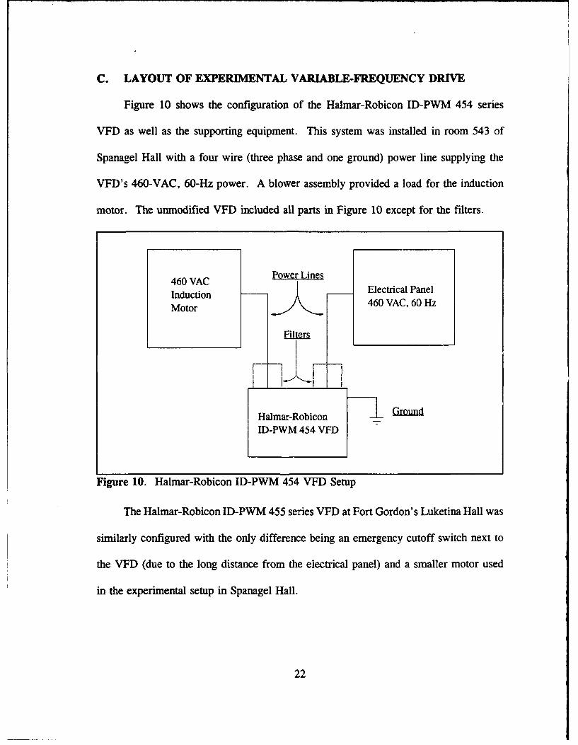
Figure 10 shows the configuration of the Halmar-Robicon ID-PWM 454 series
VFD as well as the supporting equipment. This system was installed in room 543 of
Spanagel Hall with a four wire (three phase and one ground) power line supplying the
VFD's 460-VAC, 60-Hz power. A blower assembly provided a load for the induction
motor. The unmodified VFD included all parts in Figure 10 except for the filters.
460 VAC Power Lines
Induction Electrical Panel
Motor 460 VAC, 60 Hz
Filters
Halmar-Robicon Ground
ID-PWM 454 VFD
Figure 10. Halmar-Robicon ID-PWM 454 VFD Setup
The Halmar-Robicon ID-PWM 455 series VFD at Fort Gordon's Luketina Hall was
similarly configured with the only difference being an emergency cutoff switch next to
the VFD (due to the long distance from the electrical panel) and a smaller motor used
in the experimental setup in Spanagel Hall.
22
V. UNMODIFIED VARIABLE-FREQUENCY DRIVE PERFORMANCE
Initial performance data was collected at Fort Gordon's Luketina Hall in December,
1993 on the Halmar-Robicon ID-PWM 455 series VFD. Because of the high ambient
EMI current at Luketina Hall, an additional VFD was acquired for experimental work.
The older 455 series VFD was no longer in production, so the newer model ID-PWM
454 series VFD was used for experimentation. Initial tests indicated that the newer ID-
PWM 454 and the ID-PWM 455 had approximately the same EMI characteristics.
A. INSTRUMENTATION
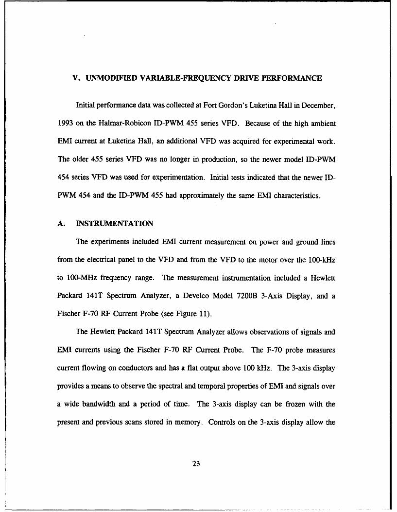
The experiments included EMI current measurement on power and ground lines
from the electrical panel to the VFD and from the VFD to the motor over the 100-kHz
to 100-MHz frequency range. The measurement instrumentation included a Hewlett
Packard 141T Spectrum Analyzer, a Develco Model 7200B 3-Axis Display, and a
Fischer F-70 RF Current Probe (see Figure 11).
The Hewlett Packard 141T Spectrum Analyzer allows observations of signals and
EMI currents using the Fischer F-70 RF Current Probe. The F-70 probe measures
current flowing on conductors and has a flat output above 100 kHz. The 3-axis display
provides a means to observe the spectral and temporal properties of EMI and signals over
a wide bandwidth and a period of time. The 3-axis display can be frozen with the
present and previous scans stored in memory. Controls on the 3-axis display allow the
23
Develco Hewlett Packard7200B 141T Spectrum3-Axis AnalyzerDisplay
0 Fischer F-70 RF
Current Probe
Figure 11. Instrumentation for EMI Measurement
operator to vary the viewing angles for maximum visual perception of the observed data.
Four, eight, 16, or 32 lines can be extracted from the view for expanded views of
portions of the time axis. [Ref. 10]
The lower left comer of each figure containing photos of EMI current provides the
following information:
0 Date, Time
* Location, Device being tested
* Center frequency, Frequency span, IF bandwidth, Scan time
* Probe identification, Amplification gain (dB), RF attenuation (dB), Reference
level (dBm)
24

Oldest Scan
AA? A
W 4/ ~OTIONAMost
M A- RecentA .s~ Scan
FREQUENCY
.X'
TIME
Figure 12. 3-Axis Display
To calculate the EMI current levels on the right of the photos, use the reference level
minus 80 dB and use this power (in mW) in Equation 2 to determine the lowest current
level. The power value can be modified by the amplification gain (subtract the dB gain
from the reference level). If the reference level was -20 dBm, the lowest power shown
would be -100 dBm. Putting this power (in mW) in Equation 2 yields 2.24 #tA as the
lowest current level.
25
B. DATA COLLECTION
1. Data Collection at Luketina Hall, Fort Gordon
Luketina Hall, Fort Gordon had two Halmar-Robicon JD-PWM 455 series
variable-frequency drives controlling two separate high-volume air conditioners for the
facility. A third HVAC in the facility did not have a VFD because it served
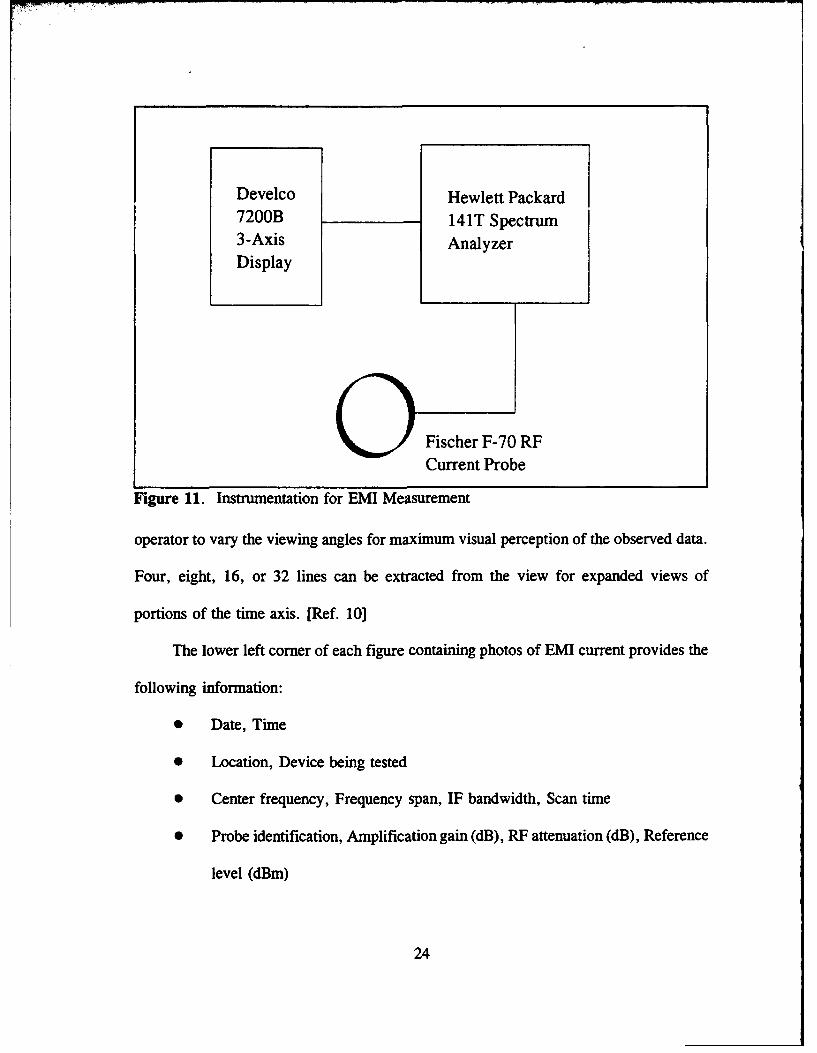
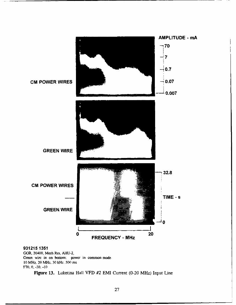
administrative areas that did not require precise temperature settings. Figure 13 shows
EMI current inserted into the power wires and the green wire (ground) by one of the
VFDs. The EMI current is over 7 mA from 100 kHz through 6 MHz and is 200 tA at
20 MHz [Ref. 111.
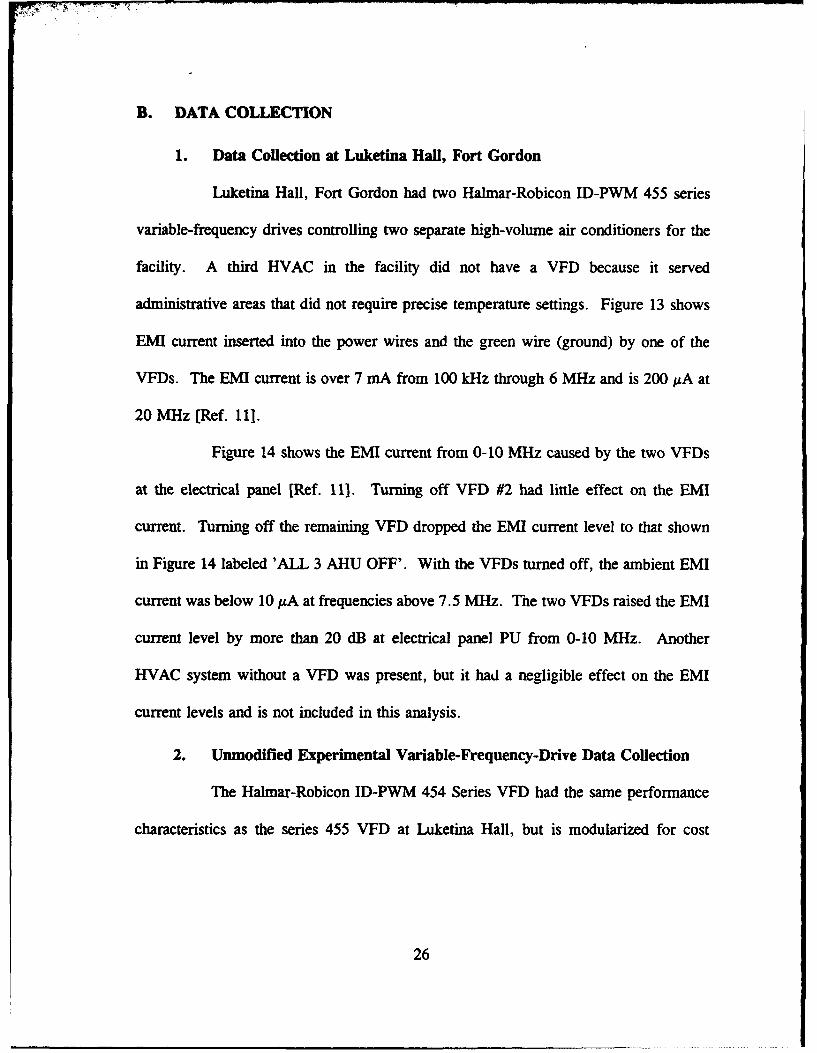
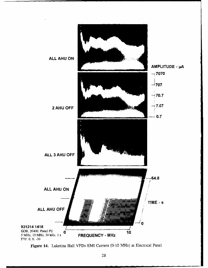
Figure 14 shows the EMI current from 0-10 MHz caused by the two VFDs
at the electrical panel [Ref. 11]. Turning off VFD #2 had little effect on the EMI
current. Turning off the remaining VFD dropped the EMI current level to that shown
in Figure 14 labeled 'ALL 3 AHU OFF'. With the VFDs turned off, the ambient EMI
current was below 10 jA at frequencies above 7.5 MHz. The two VFDs raised the EMI
current level by more than 20 dB at electrical panel PU from 0-10 MHz. Another
HVAC system without a VFD was present, but it had a negligible effect on the EMI
current levels and is not included in this analysis.
2. Unmodified Experimental Variable-Frequency-Drive Data Collection
The Halmar-Robicon ID-PWM 454 Series VFD had the same performance
characteristics as the series 455 VFD at Luketina Hall, but is modularized for cost
26
AMPLITUDE - mA
-70
0.7
CM POWER WIRES 0.07
'0.007
GREEN WIRE i
--- .32.8
CM POWER WIRES
:•'-•'- -"•TIME - s
GREEN WIRE
0 20FREQUENCY - MHz
931215 1351GOR. 20400., Mech Rm. AHU-2.Green wirc in on bottom: power in common mode10 MHz. 20 MHz. 30 kHz, 500 msF70.0. -30. -10
Figure 13. Luketina Hall VFD #2 EMI Current (0-20 MHz) Input Line
27
ALL AHU ON
AMPLITUDE - pA
---17070
2-707
-- 70.7
2 AHU OFF
- 0.7
ALL 3 AHU OFF
--- 64.8
ALL AHU ON
TIME - sALL AHU OFF • :
9312141418GOR. 20400. Panel PU 0 105 MHz. 10 MHz. 30 kHz. I s FREQUENCY - MHzF70'. 0. 0. -30
Figure 14. Luketina Hall VFDs EMI Current (0-10 MHz) at Electrica! Panel
28
effective and rapid repair of faulty components. This VFD was connected and passed
the diagnostic checks as detailed in the instruction manual.
The motor-idle portion of Figures 15 through 23 and 25 through 28 show the
VFD receiving power but not providing power to the induction motor. Much of the
ambient EMI current shown from 0-4.5 MHz in the motor-idle section is EMI caused by
Spanagel Hall's elevators, which are on the same circuit. The display shows an
increased EMI current level in this frequency range when the elevator was moving. The
motor running portion of these figures were when the VFD supplied power to its
induction motor. Little variation in EMI levels occurred when varying the speed of the
VFD.
Figure 15 shows initial measurements of the unmodified drive with a peak
of about 500 fLA at 4 MHz on one phase wire between the electrical panel and the VFD's
input terminal over a frequency range of 0-10 MHz. The experimental VFD's EMI
current level was lower than the EMI current caused by the Luketina Hall VFDs. A
lower noise floor in the experimental setup accounts for some of the variation in EMI
current levels between the two models of VFDs. The modular design of the experimental
VFD probably accounts for the remaining difference between these measurements. In
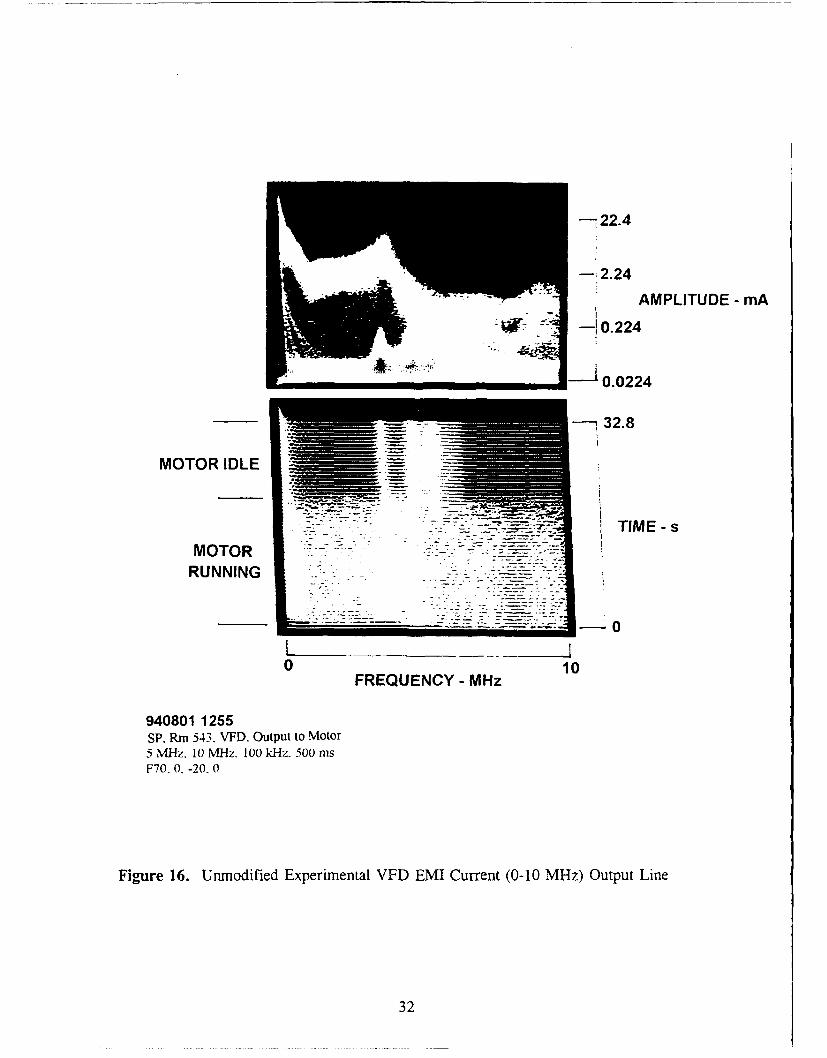
Figure 16 the average EMI current level is greater than 2 mA between 0-5 MHz with a
peak of approximately 10 mA at 4 MHz on one of the phase wires. The EMI current
level drops as the frequency increases after the peak. The other phase lines had similar
characteristics. The EMI current pictured in Figure 16 has few, if any, peaks and nulls
due to impedance variations with frequency. The lower EMI current in Figure 15
29
demonstrates that current division occurred at several junctions and some EMI current
returned to its source before reaching the phase line.
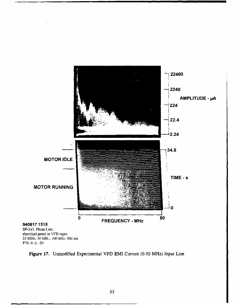
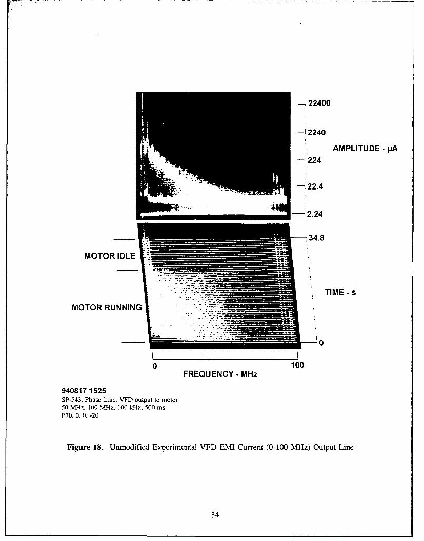
Figure 17 illustrates the EMI current injected by the experimental VFD from
0-50 MHz into the electrical panel. The EMI current at an output phase wire of the test
VFD is portrayed in Figure 18 for the frequency range of 0 to 100 MHz is pictured.
The four signals in Figure 18 from 90-100 MHz are FM radio stations received by the
wire connecting the VFD to the motor. Both of these figures show spectral peaks at 4
MHz with EMI current decreasing as frequency increases.
The likely source of EMI current is the inverter stage of the VFD. In the
process of converting DC to AC, harmonics are created across the frequency spectrum
similar to the harmonics produced by an uninterruptible power supply. However, the
VFD's harmonics are based on the frequency provided to the motor. The output lines
of the VFD had a larger EMI current level than the input lines. The EMI current
produced by the inverter stage had few junctions prior to coupling with the output
conductors, but had to travel through many junctions in the DC bus and AC-to-DC
converter stages to reach the input conductors.
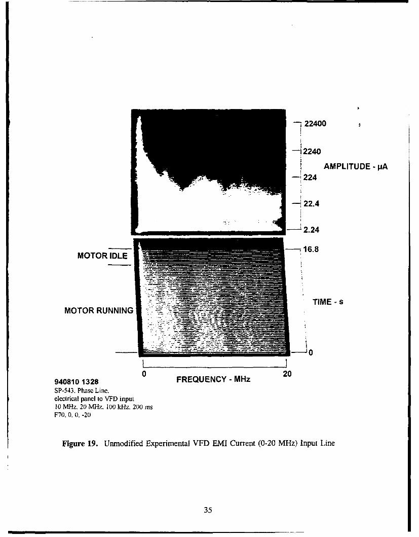
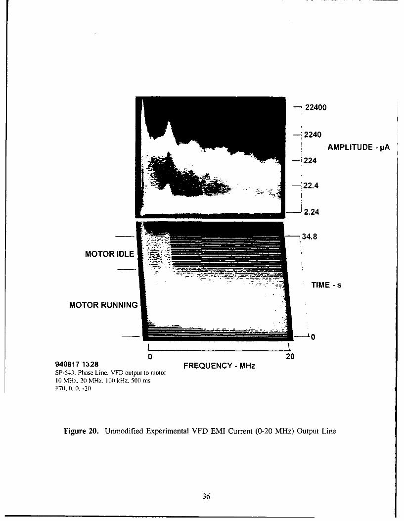
Figures 19 and 20 are provided for later comparison with a modified VFD.
Figure 19 shows the EMI current from 0-20 MHz on a phase wire from the electrical
panel to the VFD input terminal. The EMI current level drops from a high of 500 MA
at 4 MHz to under 100 uA at 20 MHz. Figure 20 shows the EMI current from 0-20
MHz on a phase wire from the VFD output terminal to the motor. The EMI current
level drops from a high of 10 mA at 4 MHz to 200 AA at 20 MHz.
30

-- 22400
--- 2240
AMPLITUDE - pA
• ~-:i224-
S.... - --t22.4
MOTOR IDLE - _-- __ ._ .
.- -" -TIME- s
MOTOR RUNNING
0
0 10
940810 1333 FREQUENCY - MHz
SP-543. Phasc Linc.clcctrical panci to VFD input5 MNlz. 10 MHz. 100 kHz. 500 rnsF70. 0. 0. -20
Figure 15. Unmodified Experimental VFD EMI Current (0-10 MHz) Electrical Panel
31
-22.4
-,2.24
* AMPLITUDE -mA- 1022
10.0224
MOTOR IDLE
-- T' TIME- sMOTOR 7ZZ
RUNNING
0 10FREQUENCY - MHz
940801 1255SP. Rin 543. VFD. Output to Motor5 MlHz. 10 M~z. 100 kHz. 500 iF70. 0. -20, 0
Figure 16. Unmodified Experimental VFD EMI Current (0-10 MHz) Output Line
32
22400
-12240
AMPLITUDE- pA
224
j-22.4
• -- 12.24
~34.8
MOTOR IDLE
• '::"::- •:: ... TIME - s
MOTOR RUNNING -.. .TIME-s
0 50
9481 1FREQUENCY - MHz 50940817 1515
SP-543. Phase Linc.electrical pancl to VFD input25 MHz. 50 MH::. 100 kHz. 500 rnsF70. 0. 0. -20
Figure 17. Unmodified Experimental VFD EMI Current (0-50 MHz) Input Line
33
- 22400
-I2240
AMPLITUDE -pA-~224
34.8
MOTOR IDLE ____________
TIME- s
MOTOR RUNNING_______
0 100FREQUENCY - MHz
940817 1525SP-543. Phase Linc. VFD output to motor50 MHz. 100 MHz. 10t) kHz. 500 mnsF70. 0. 0.-20
Figure 18. Unmodified Experimental VFD EMI Current (0-100 MHz) Output Line
34
22400
-12240
AMPLITUDE - pA-'224
-' 22.4
- 2.24
_--_ 16.8MOTOR IDLE
. -- T IM E - sMOTOR RUNNING - -
I I0 2o
940810 1328 FREQUENCY - MHz
SP-543. Phase Line.electrical panel to VFD input10 MHz. 20 MHz. 100 kHz. 200 msF70. 0. 0. -20
Figure 19. Unmodified Experimental VFD EMI Current (0-20 MHz) Input Line
35
-22400
-H-2240AMPLITUDE - pA
MOTOR IDLE
MOTOR RUNNING
0 20940817 1328 FREQUENCY - MHzSP-543. Phase Linc. VFD output to motor10 MI-l. 20 MI-z, 100 kHz. 300 msF70, 0. 0. -20
Figure 20. Unmodified Experimental VFD EMLI Current (0-20 MHz) Output Line
36
VI. MODIFIED VARIABLE-FREQUENCY DRIVE PERFORMANCE
Because of the high EMI current levels from the Luketina Hall variable-frequency
drives and the experimental VFD, modifications to the case housing the experimental
VFD were made using the barrier, filter, ground techniques described in chapter 3. The
experimental VFD will be the only VFD referred to in this chapter.
A. INITIAL VARIABLE-FREQUENCY DRIVE MODIFICATIONS
The initial modifications made to the VFD were as follows. The VFD cabinet was
an adequate barrier after the paint was sanded off the edges that were bolted together to
provide a good electrical bond. The rubber seal on the door was stripped off. The
internal ground for the system was adequate with the use of a ground stud to connect the
internal grounds inside the cabinet with the external ground. Both the input and output
lines were filtered using CORCOM 30T48 power-line filters which have a 460 volt, 31
ampere capacity which filter out frequencies over 18 kHz. These Pi-section filters have
a capacitor input to keep high frequency impedance low at the input. These filters keep
EMI potentials low on the short wires from the drive's terminals to the filter. The
VFD's layout was as pictured in Figure 10, including the filters.
Unfortunately, the VFD did not work with a filter on the power line from the
VFD's output terminal to the motor. The VFD shut down when any current was
delivered to the motor, displaying an "out-of-saturate" message on the VFD's message
37
panel. The VFD apparently required the inductive impedance of an induction motor; the
filter disrupted this impedance, causing the error. Removing the filter between the VFD
and the motor allowed full operation of the VFD.
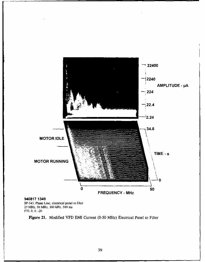
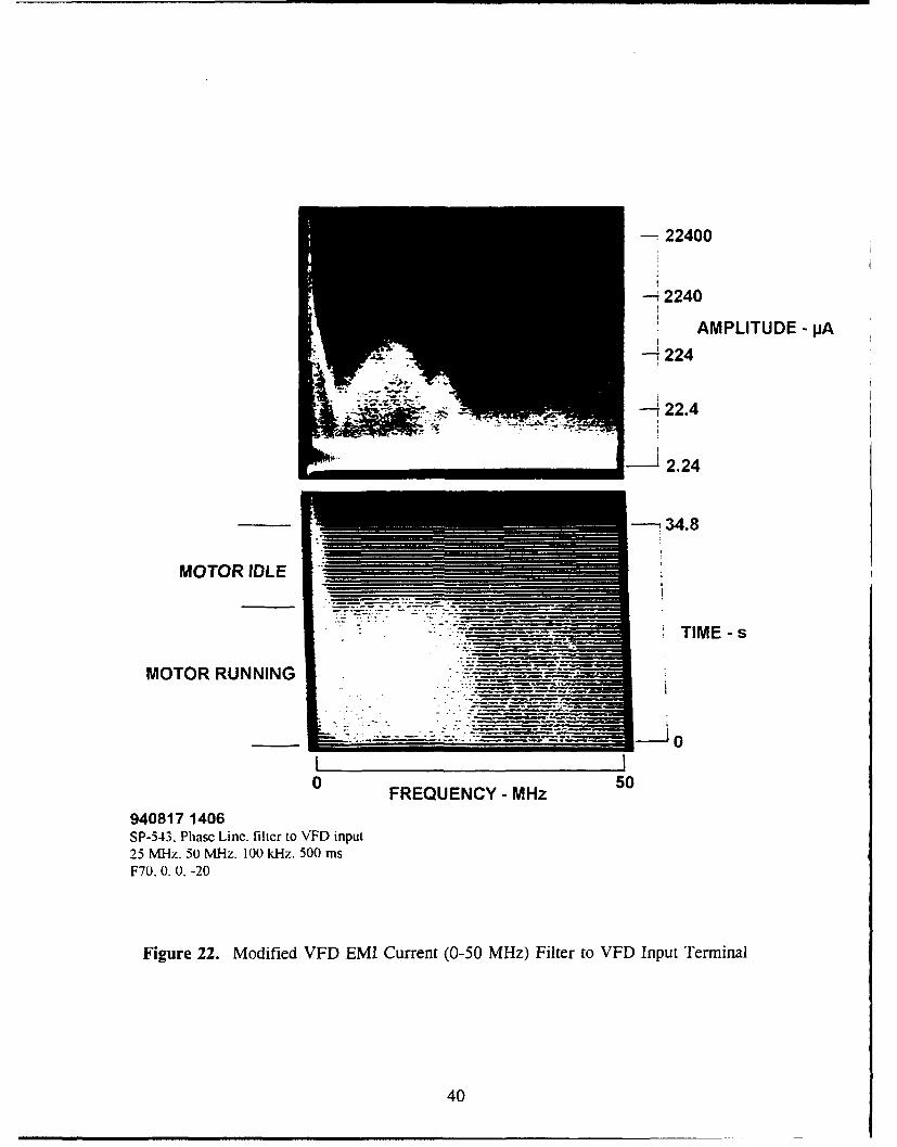
Measurements were taken with a filter on only the input line to the VFD. Figures
21 and 22 shows the EMI current from 0-50 MHz. In Figure 21 the EMI current from
the filter to the VFD's input terminal drops below 10 IA above 20.5 MHz and below 4
MHz, which is significantly lower than the unfiltered EMI current shown in Figure 17.
EMI current levels between 4 and 17 MHz ranged between 240 JAA and 22.4 ptA, a 6-dB
improvement. Figure 22 shows an EMI current level of 224 AA at 14 MHz between the
filter and the VFD's input terminal and above 10 AA across the entire 0-50 MHz region.
Figures 17 and 22 show that the EMI current level is actually higher between the filter
and VFD input terminal than before the filter was installed. This is caused by the
reflection of the EMI current back into the VFD, which is the purpose of the filter.
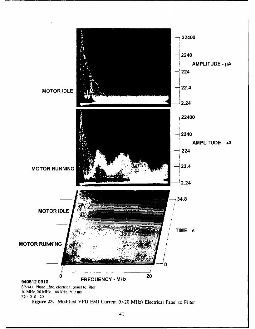
Figure 23 shows more clearly the effect of the filter from 0-4 MHz (the light shading
above 10 /A is due to the building's elevator).
To resolve the VFD's failure to operate with a filter on the output power line, a
new capacitive load filter with a frequency cutoff of 100 kHz was built. With this filter
the VFD still shut down when any current was supplied to the motor. At this point an
alternative approach was tried.
38
"- 22400
-- 2240
AMPLITUDE - PA
-: 224
-~22.4
-2.24
34.8
MOTOR IDLE
-. , .TIME-s
MOTOR RUNNING
0 50FREQUENCY - MHz
940817 1349SP-543. Phasc Linc. clctrical panel to filtcr25 MHz. 50 vfl-z. 100 kI-z. 500 msF70. 0. 0. -20
Figure 21. Modified VFD EMI Current (0-50 MHz) Electrical Panel to Filter
39
- 22400
- --- 2240
AMPLITUDE - pA
224
-:, 34.8
MOTOR IDLE
"". . --- T IM E - s
MOTOR RUNNING
I I0 5O
0 FREQUENCY - MHz 50
940817 1406SP-543. Phase Line. filter to VFD input25 MN"Iz. 50 MHz. 100 kl-lz. 500 msF70. 0. 0, -20
Figure 22. Modified VFD EMI Current (0-50 MHz) Filter to VFD Input Terminal
40
-22400
AMPLITUDE - IA
1'224
MOTOR IDLE I! 22.4
-!22400
AMPLITUDE - pA
224
MOTOR RUNNING
-2.24
34.8
MOTOR IDLE -
TIM -IE. 0=1 M-W
MOTOR RUNNING ~f~-
-~ ~ ~ ~ --- -jo -.-
940812 0910 0FREQUENCY -MHz 2
SP-543. Phase U nc. electrical panel to filter10) MHz. 20 MHz. 100) kl-z. 500 msF70, 0. 0. -20
Figure 23. Modified VFD EMI Current (0-20 MHz) Electrical Panel to Filter
41
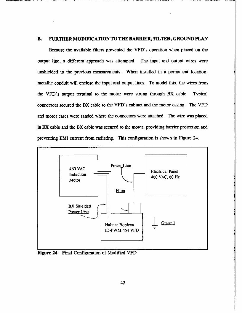
B. FURTHER MODIFICATION TO THE BARRIER, FILTER, GROUND PLAN
Because the available filters prevented the VFD's operation when placed on the
output line, a different approach was attempted. The input and output wires were
unshielded in the previous measurements. When installed in a permanent location,
metallic conduit will enclose the input and output lines. To model this, the wires from
the VFD's output terminal to the motor were strung through BX cable. Typical
connectors secured the BX cable to the VFD's cabinet and the motor casing. The VFD
and motor cases were sanded where the connectors were attached. The wire was placed
in BX cable and the BX cable was secured to the motor, providing barrier protection and
preventing EMI current from radiating. This configuration is shown in Figure 24.
Power Line
460 VAC •Electrical PanelInduction 460 VAC, 60 HzMotor
Filter
BX ShieldedPower • _• I-
Halmar-Robicon (t ( nd
ID-PWM 454 VFD
Figure 24. Final Configuration of Modified VFD
42
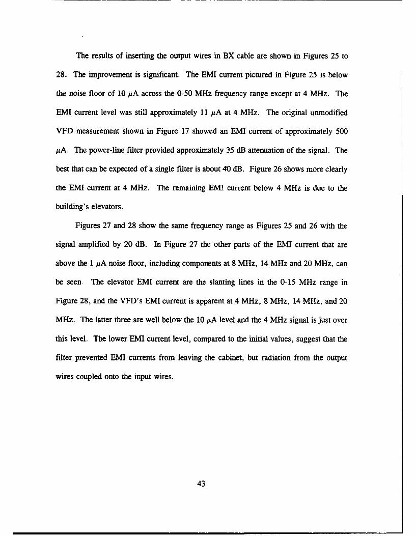
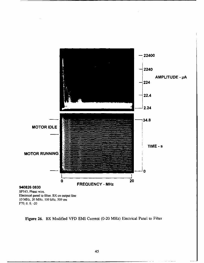
The results of inserting the output wires in BX cable are shown in Figures 25 to
28. The improvement is significant. The EMI current pictured in Figure 25 is below
the noise floor of 10 MA across the 0-50 MHz frequency range except at 4 MHz. The
EMI current level was still approximately 11 A at 4 MHz. The original unmodified
VFD measurement shown in Figure 17 showed an EMI current of approximately 500
AA. The power-line filter provided approximately 35 dB attenuation of the signal. The
best that can be expected of a single filter is about 40 dB. Figure 26 shows more clearly
the EMI current at 4 MHz. The remaining EMI current below 4 MHz is due to the
building's elevators.
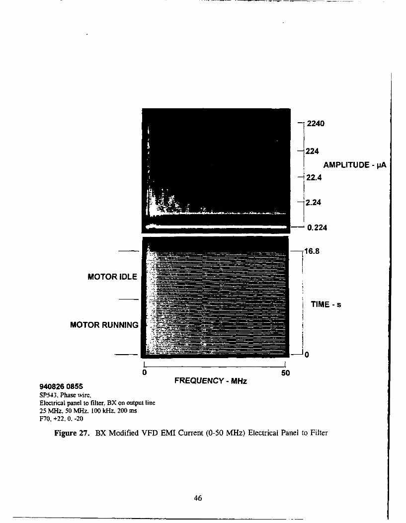
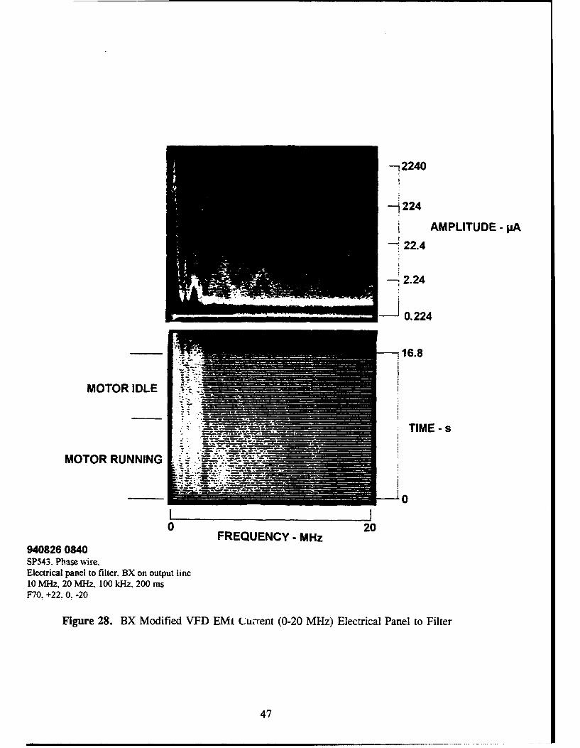
Figures 27 and 28 show the same frequency range as Figures 25 and 26 with the
signal amplified by 20 dB. In Figure 27 the other parts of the EMI current that are
above the I1MA noise floor, including components at 8 MHz, 14 MHz and 20 MHz, can
be seen The elevator EMI current are the slanting lines in the 0-15 MHz range in
Figure 28, and the VFD's EMI current is apparent at 4 MHz, 8 MHz, 14 MHz, and 20
MHz. The latter three are well below the 10 jA level and the 4 MHz signal is just over
this level. The lower EMI current level, compared to the initial values, suggest that the
filter prevented EMI currents from leaving the cabinet, but radiation from the output
wires coupled onto the input wires.
43

722400
-- 2240
4 AMPLITUDE - pA
-224
-22.4
-2.24
- 16.8
MOTOR IDLE.
TIME - s
MOTOR RUNNING
10
0 50FREQUENCY - MHz
940826 0850SP543. Phase wire.Electrical panel to filter. BX on output line25 MHz. 50 MHz. 100 kHz. 200 msF70. 0. 0. -20
Figure 25. BX Modified VFD EMI Current (0-50 MHz) Electrical Panel to Filter
44
-22400
-2240
AMPLITUDE - pA- 224
- 22.4
i:,,•'•! • 2.24
I ~----734.8
MOTOR IDLE i
TIME - s
MOTOR RUNNING
0 20FREQUENCY - MHz
940826 0830SP543,. Phasc wire.Electrical panel to filter., BX on output line10 MHz. 20 M-lz. 100 kHz. 500 msF70. 0. 0. -20
Figure 26. BX Modified VFD EMI Current (0-20 MHz) Electrical Panel to Filter
45
-12240
-'224
AMPLITUDE -pA
-22.4
2.24
-16.8
MOTOR IDLE
____ ____ ____ ____ ____TIME -s
MOTOR RUNNING
0 50FREQUENCY - MHz
940826 0855SP543. Phase wvire.Electrical panel to filter, BX on output line25 MHz, 50 M11z. 100 kHz, 200 msF70, +22. 0. -20
Figure 27. BX Modified VFD EMI Current (0-50 MHz) Electrical Panel to Filter
46
-7 2 2 4 0
-- 224
AMPLITUDE- pA
22.4
- 2.24
S- 0.224
"--i16.8
MOTOR IDLE
.Z- --.. TIME - s
MOTOR RUNNING
S 0I I0 20
FREQUENCY - MHz940826 0840SP543. Phase wire.Electrical panel to filter. BX on output line10 MHz, 20 NlHz. 100 kHz. 200 msF70, +22, 0. -20
Figure 28. BX Modified VFD EMI Current (0-20 MHz) Electrical Panel to Filter
47
VII. CONCLUSIONS AND RECOMMENDATIONS
A. CONCLUSIONS
The electromagnetic interference generated by a digital, variable-frequency,
induction-motor drive was examined in this thesis. Interference mitigation techniques
were explored and implemented on a VFD motor controller. Specific conclusions
reached during this work are as follows:
"* Existing EMI standards were reviewed for their application to receiving and dataprocessing sites. MIL-STD-461, the VXIbus standard, and the FCC standards donot provide sufficient EMI protection for the case where digital equipment is usedin receiving and data processing sites. No other appropriate standard or set ofguidelines was found that provided sufficient EMI protection. The suggestedmaximum EMI current limitations proposed by the SNEP teams were found to bemore appropriate.
"* Conducted and radiated EMI from a standard digital, variable-frequency, motorcontroller was found to be excessive. The use of the type of digital motorcontroller examined in this thesis is not recommended in receiving and dataprocessing sites unless it is modified to reduce EMI to acceptable levels.
"* Integrated BFG techniques were successfully used on the metal cabinet housing themotor controller to reduce EMI to acceptable levels. No circuit changes or othermodifications to the motor controller itself was required.
"* A standard Pi-section power-line filter was successfully used on the input powerconductors to limit conducted EMI current to SNEP-suggested maximum levels.
"* A standard Pi-section power-line filter installed on the motor power conductorsprevented the operation of the motor controller. The input capacitor of the filterappeared to affect the functioning of the motor controller. This was overcome byremoving the filter and extending the barrier to the motor housing with standardelectrical conduit.
48
"* No uncontrolled conductors were allowed to enter or leave the cabinet housing themotor controller.
"* All objectives of the thesis were met using the integrated BFG approach to thecontrol of EMI.
B. RECOMMENDATIONS
A number of recommendations were formulated during the course of the thesis
work. These are as follows:
"* EMI standards, guidelines, or other document that apply to receiving and dataprocessing sites need to be generated and made available to site designers,equipment purchasing personnel, and others involved in the operationalperformance of receiving and data processing sites. The SNEP-suggestedmaximum EMI current limits provide a starting point for the generation of asuitable document.
"* Similarly, a document providing details of the integrated BFG need to be producedand made generally available to designers, manufacturers, and installationpersonnel.
"* No new digital equipment should be procured for installation in receiving and dataprocessing sites unless it meets appropriate EMI limits.
"* Digital motor controllers of the type used in this thesis should be modified priorto installation in a receiving and data processing site.
49
LIST OF REFERENCES
1. Adler, R.W., Class notes for EC 3640 (Electromagnetic EnvironmentalEffects), Naval Postgraduate School (unpublished), 1994.
2. Vincent, Wilbur R. and Adler, Richard W., "Comments About ElectricalGrounds in CDAA Sites," Naval Postgraduate School note (unpublished),pp. 3-4, October 1992.
3. Code of Federal Regulations, U.S. National Archives and RecordsAdministration, Title 47- Telecommunications, p. 545, Government PrintingOffice, Washington, DC, October 1, 1992.
4. Paul, Clayton R., Introduction to Electromagnetic Compatibility, pp. 42-76,John Wiley & Sons, Inc., 1992.
5. Institute of Electrical and Electronic Engineers, Inc., IEEE Std 1155-1992,IEEE Standard for VMEbus Extensions for Instrumentation: VXlbus, 20September 1993.
6. Kraus, Allan D., Circuit Analysis, p. 38, West Publishing Company, 1991.
7. Performance Evaluation at Cryptologic Sites Technical Course Manual, Draft 1,Chapter 7, Signal-to-Noise Enhancement Program (SNEP) Team, April 1991.
8. Halmar-Robicon Group, Product Data, AC Variable Frequency Drives, ID-PWM454 Series, 1993.
9. Halmar-Robicon Group, Instruction Manual ID-PWM 454 Series, IntelligentDrive-Pulse Width Modulated Adjustable Speed A. C. Motor Drive, 3 through500 HP, 1993.
10. Ingram, V.D., Strategies in Topological Approach to ElectromagneticInterference Control, Master's Thesis, Naval Postgraduate School, Monterey,California, December 1987.
11. Mantech Field Engineering Company, Contract DAAB10-91-D-0502, DeliveryOrder 0033, EMI Site Survey: Luketina Hall, Ft. Gordon, Georgia, pp. 16-21,13 April 1994.
50

INITIAL DISTRIBUTION LIST
1. Defense Technical Information Center 2Cameron StationAlexandria, VA 22304-6145
2. Library, Code 052 2Naval Postgraduate SchoolMonterey, CA 93943-5101
3. Director, Space and Electronic Combat Division (N64)Space and Electronic Warfare DirectorateChief of Naval OperationsWashington, D.C. 20393-5220
4. Chairman, Electronic Warfare Academic GroupNaval Postgraduate SchoolMonterey, CA 93943-9528
5. Professor Richard W. Adler, Code EC/Ab 5Department of Electrical and Computer EngineeringNaval Postgraduate SchoolMonterey, CA 93943-5121
6. Professor Wilbur R. Vincent, Code EC/Ab 3Department of Electrical and Computer EngineeringNaval Postgraduate SchoolMonterey, CA 93943-5121
7. CPT Philip E. VanWiltenburg 37055 Bouman DriveMiddleville, MI 49333
8. CDR Gus K. Lott, Code ECJLtDepartment of Electrical and Computer EngineeringNaval Postgraduate SchoolMonterey, CA 93943-5000
51
9. Naval Security Group Command 2Attention: Jackie Sherry (G43)3801 Nebraska Avenue, N.W.Washington, D.C. 20390-5220
10. ManTechAttention: Chris Adams6593 Commerce AveGainsville, VA 22065
11. Engineering Research AssociatesAttention: Roy Bergeron1595 Springhill Rd.Vienna, VA 22180
12. USA INSCOM, IAMSA-V-EAQ 3Attention: Anne BilgihanBldg 160, MS26Vint Hill FarmsWarrenton, VA 22186-5160
52