Embed Size (px)
DESCRIPTION
uyvtfrewok
Citation preview
OptiX RTN 950 Acceptance
Test Procedure
Huawei Technologies Co., Ltd.
All Rights Reserved.
OptiX RTN 950 V100R001 Test Proposal
Table of Contents
1 OVERVIEW .................................................................................................................................................. 3
1.1 INTRODUCTION ........................................................................................................................................ 3
1.2 PRODUCT VERSION .................................................................................................................................. 3
1.3 PRECAUTIONS FOR TEST .......................................................................................................................... 3
2 REFERENCE STANDARDS (OPTIONAL) ......................................................................................................... 4
3 ACRONYMS AND ABBREVIATIONS ............................................................................................................... 6
4 OPTIX RTN 950 ACCEPTANCE TEST PROCEDURE ....................................................................................... 8
4.1 HARDWARE INSTALLATION INSPECTION ................................................................................................... 8
4.2 MICROWAVE PARAMETER CHECK .......................................................................................................... 11
4.3 ALLOCATION OF BANDWIDTH CHECK .................................................................................................... 12
4.4 ALARM FUNCTIONAL TEST ITEMS .......................................................................................................... 13
4.5 FREQUENCY INTERFERENCE TEST .......................................................................................................... 15
4.6 BIT ERROR TEST .................................................................................................................................... 16
4.7 ETHERNET SERVICE CONNECTIVITY TEST .............................................................................................. 18
4.8 ETHERNET THROUGHPUT TEST .............................................................................................................. 20
4.9 ETHERNET LATENCY TEST ..................................................................................................................... 22
OptiX RTN 950 Acceptance Test Procedure
1 Overview
1.1 Introduction
This proposal document describes the test cases used by Huawei® microwave radio
transmission platform RTN 600 series.
1.2 Product Version
If necessary, the layout of each board under test is attached here.
Product Version Quantity
RTN 910 V100R002 2
RTN 950 V100R002 2
WEBLCT U2000 V002R002C01 1
1.3 Precautions for Test
During the microwave radio product test, note the following:
1. Do not hot swap the cables connected to the IF port and the RF port of the ODU. Follow
the sequence of switching off the power first and then swapping the cable.
2. Before the ODU is powered on, make sure that the RF port has the service with its
impedance in the required range. For example, the RF port is connected to the opposite
ODU, or to the RF matcher. Do not power on the ODU when it has no service, to avoid RF
port total reflection damaging the front components of the RF port.
3. The RF coupler cannot necessarily guarantee the good coupling of full frequency bands.
Hence, one more attenuator is needed to further reduce the reflection and protect the ODU.
4. The maximum receive signal level (RSL) of the ODU receiver is low. Ensure that the input
signal level of the ODU receiver does not exceed –20 dBm.
5. When you are using a software control box to control the ODU, ensure that the ODU has
the 350 MHz input signal at its IF port when the ODU is powered on. Otherwise, the ODU
may be damaged.
6. All the RF meters, including the spectrum analyzer, power meter, signal generator, and
vector network analyzer, cannot access the signal with DC components.
7. Due to the internal splitter design, the input RSL the vector network analyzer is low. When
you are using the vector network analyzer to test the standing wave, ensure that the unit
OptiX RTN 950 Acceptance Test Procedure
under test is powered off, to avoid the internal amplifier self-excitation generating high
signal level and damaging the analyzer.
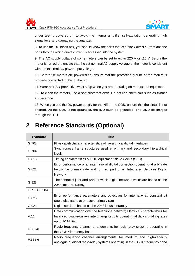
8. To use the DC block box, you should know the ports that can block direct current and the
ports through which direct current is accessed into the system.
9. The AC supply voltage of some meters can be set to either 220 V or 110 V. Before the
meter is turned on, ensure that the set nominal AC supply voltage of the meter is consistent
with the external AC power input voltage.
10. Before the meters are powered on, ensure that the protection ground of the meters is
properly connected to that of the lab.
11. Wear an ESD-preventive wrist strap when you are operating on meters and equipment.
12. To clean the meters, use a soft dustproof cloth. Do not use chemicals such as thinner
and acetone.
13. When you use the DC power supply for the NE or the ODU, ensure that the circuit is not
shorted. As the ODU is not grounded, the IDU must be grounded. The ODU discharges
through the IDU.
2 Reference Standards (Optional)
Standard Title
G.703 Physical/electrical characteristics of hierarchical digital interfaces
G.704 Synchronous frame structures used at primary and secondary hierarchical
levels
G.813 Timing characteristics of SDH equipment slave clocks (SEC)
G.821
Error performance of an international digital connection operating at a bit rate
below the primary rate and forming part of an Integrated Services Digital
Network
G.823 The control of jitter and wander within digital networks which are based on the
2048 kbit/s hierarchy
ETSI 300 284
G.826 Error performance parameters and objectives for international, constant bit
rate digital paths at or above primary rate
G.921 Digital sections based on the 2048 kbit/s hierarchy
V.11
Data communication over the telephone network; Electrical characteristics for
balanced double-current interchange circuits operating at data signalling rates
up to 10 Mbit/s
F.385-6 Radio frequency channel arrangements for radio-relay systems operating in
the 7 GHz frequency band
F.386-6 Radio frequency channel arrangements for medium and high-capacity
analogue or digital radio-relay systems operating in the 8 GHz frequency band
OptiX RTN 950 Acceptance Test Procedure
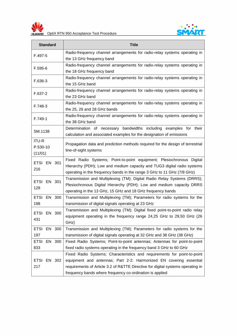
Standard Title
F.497-5 Radio-frequency channel arrangements for radio-relay systems operating in
the 13 GHz frequency band
F.595-6 Radio-frequency channel arrangements for radio-relay systems operating in
the 18 GHz frequency band
F.636-3 Radio-frequency channel arrangements for radio-relay systems operating in
the 15 GHz band
F.637-2 Radio-frequency channel arrangements for radio-relay systems operating in
the 23 GHz band
F.748-3 Radio-frequency channel arrangements for radio-relay systems operating in
the 25, 26 and 28 GHz bands
F.749-1 Radio-frequency channel arrangements for radio-relay systems operating in
the 38 GHz band
SM.1138 Determination of necessary bandwidths including examples for their
calculation and associated examples for the designation of emissions
ITU-R
P.530-10
(11/01)
Propagation data and prediction methods required for the design of terrestrial
line-of-sight systems
ETSI EN 301
216
Fixed Radio Systems; Point-to-point equipment; Plesiochronous Digital
Hierarchy (PDH); Low and medium capacity and TUG3 digital radio systems
operating in the frequency bands in the range 3 GHz to 11 GHz (7/8 GHz)
ETSI EN 301
128
Transmission and Multiplexing (TM); Digital Radio Relay Systems (DRRS);
Plesiochronous Digital Hierarchy (PDH); Low and medium capacity DRRS
operating in the 13 GHz, 15 GHz and 18 GHz frequency bands
ETSI EN 300
198
Transmission and Multiplexing (TM); Parameters for radio systems for the
transmission of digital signals operating at 23 GHz
ETSI EN 300
431
Transmission and Multiplexing (TM); Digital fixed point-to-point radio relay
equipment operating in the frequency range 24,25 GHz to 29,50 GHz (26
GHz)
ETSI EN 300
197
Transmission and Multiplexing (TM); Parameters for radio systems for the
transmission of digital signals operating at 32 GHz and 38 GHz (38 GHz)
ETSI EN 300
833
Fixed Radio Systems; Point-to-point antennas; Antennas for point-to-point
fixed radio systems operating in the frequency band 3 GHz to 60 GHz
ETSI EN 302
217
Fixed Radio Systems; Characteristics and requirements for point-to-point
equipment and antennas; Part 2-2: Harmonized EN covering essential
requirements of Article 3.2 of R&TTE Directive for digital systems operating in
frequency bands where frequency co-ordination is applied

OptiX RTN 950 Acceptance Test Procedure
3 Acronyms and Abbreviations
A
ADM add/drop multiplexer
AIS Alarm Indication Signal
ALS Automatic Laser Shutdown
ASE Amplified Spontaneous Emission
ATPC Automatic Transmit Power Control
B
BER Bit Error Ratio
BIP Bit-Interleaved Parity
C
CRC Cyclic Redundancy Check
CW Continuous Wave
D
DCC Data Communication Channel
E
ECC Embedded Control Channel
EMS Element Management System
ETSI European Telecommunication Standards Institute
F
FDDI Fiber Distributed Data Interface
FD Frequency Diversity
FE Fast Ethernet
FEC Forward Error Correction
G
H
HSB Hot-Standby
I
IDU Indoor Unit
IF Intermediate Frequency
IEEE Institute of Electrical and Electronics Engineers
ITU-T International Telecommunication Union-Telecommunication Sector
J
L
LCT Local Craft Terminal
LOF Loss of Frame
LPRDI Low Path Remote Defect Indication
LPRFI Low Path Remote Failure Indication
OptiX RTN 950 Acceptance Test Procedure
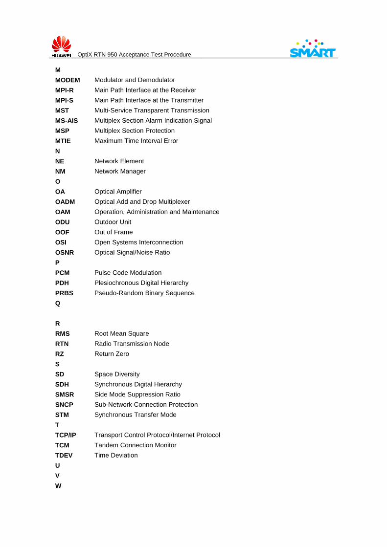
M
MODEM Modulator and Demodulator
MPI-R Main Path Interface at the Receiver
MPI-S Main Path Interface at the Transmitter
MST Multi-Service Transparent Transmission
MS-AIS Multiplex Section Alarm Indication Signal
MSP Multiplex Section Protection
MTIE Maximum Time Interval Error
N
NE Network Element
NM Network Manager
O
OA Optical Amplifier
OADM Optical Add and Drop Multiplexer
OAM Operation, Administration and Maintenance
ODU Outdoor Unit
OOF Out of Frame
OSI Open Systems Interconnection
OSNR Optical Signal/Noise Ratio
P
PCM Pulse Code Modulation
PDH Plesiochronous Digital Hierarchy
PRBS Pseudo-Random Binary Sequence
Q
R
RMS Root Mean Square
RTN Radio Transmission Node
RZ Return Zero
S
SD Space Diversity
SDH Synchronous Digital Hierarchy
SMSR Side Mode Suppression Ratio
SNCP Sub-Network Connection Protection
STM Synchronous Transfer Mode
T
TCP/IP Transport Control Protocol/Internet Protocol
TCM Tandem Connection Monitor
TDEV Time Deviation
U
V
W
OptiX RTN 950 Acceptance Test Procedure
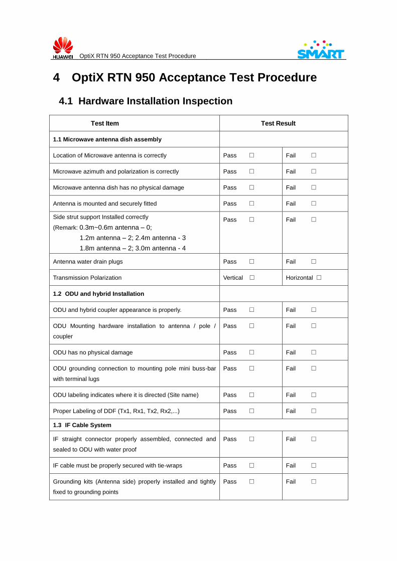
4 OptiX RTN 950 Acceptance Test Procedure
4.1 Hardware Installation Inspection
Test Item Test Result
1.1 Microwave antenna dish assembly
Location of Microwave antenna is correctly Pass □ Fail □
Microwave azimuth and polarization is correctly Pass □ Fail □
Microwave antenna dish has no physical damage Pass □ Fail □
Antenna is mounted and securely fitted Pass □ Fail □
Side strut support Installed correctly
(Remark: 0.3m~0.6m antenna – 0;
1.2m antenna – 2; 2.4m antenna - 3
1.8m antenna – 2; 3.0m antenna - 4
Pass □ Fail □
Antenna water drain plugs Pass □ Fail □
Transmission Polarization Vertical □ Horizontal □
1.2 ODU and hybrid Installation
ODU and hybrid coupler appearance is properly. Pass □ Fail □
ODU Mounting hardware installation to antenna / pole /
coupler
Pass □ Fail □
ODU has no physical damage Pass □ Fail □
ODU grounding connection to mounting pole mini buss-bar
with terminal lugs
Pass □ Fail □
ODU labeling indicates where it is directed (Site name) Pass □ Fail □
Proper Labeling of DDF (Tx1, Rx1, Tx2, Rx2,...) Pass □ Fail □
1.3 IF Cable System
IF straight connector properly assembled, connected and
sealed to ODU with water proof
Pass □ Fail □
IF cable must be properly secured with tie-wraps Pass □ Fail □
Grounding kits (Antenna side) properly installed and tightly
fixed to grounding points
Pass □ Fail □

OptiX RTN 950 Acceptance Test Procedure
Grounding kits (Feeder entry side) properly installed and
tightly fixed to grounding points
Pass □ Fail □
Grounding kits (The bottom of the tower side) properly
installed and tightly fixed to grounding points
Pass □ Fail □
IF cable properly labeled at ODU side marked with OMC
name
Pass □ Fail □
IF cable has no sharp bends, kinks areas Pass □ Fail □
IF straight connector properly assembled. Pass □ Fail □
Connection of IF cable from/to IFU2 card. Pass □ Fail □
1.4 Transmission Rack Installation
Location of transmission rack according to approved LOSR Pass □ Fail □
Bolts must be properly anchored to flooring metal plate;
Upper part of TX rack must be secured with brackets to avoid
swinging.
Pass □ Fail □
Laying of yellow green grounding cables from transmission
rack to main cabin buss-bar using white tie wrap.
Pass □ Fail □
All bolts and nuts must be properly tightened Pass □ Fail □
Transmission Rack must be labeled correctly Indicate OMC
name
Pass □ Fail □
1.5 IDU Radio Equipment Installation
IDU is securely installed to the transmission rack and
mounted according to link configuration
Pass □ Fail □
Grounding connection from IDU (left rear) grounding point to
transmission rack main grounding point using yellow green
cable with correct terminal lugs properly crimped
Pass □ Fail □
Grounding connections from IDU to IDU must be cascaded
using yellow green ground cable
Pass □ Fail □
IDU DC connector is secured and correctly terminated Pass □ Fail □
IDU labeling Indicate OMC name TO/FROM SITE NAME Pass □ Fail □
Power cable straight to the breaker of rectifier or DCPDB Pass □ Fail □
IDU bay face showing slot location: Pass □ Fail □

OptiX RTN 950 Acceptance Test Procedure
CSH CSH
IFU2 (STD.BY) EMS6T
IFU2 (MAIN) SP3S
Vacant Vacant
1.6 DDF Installation
Location and spacing is correctly Pass □ Fail □
Fixing and routing of interconnection cable from DDF to IDU Pass □ Fail □
DDF Frame must be properly grounded. Pass □ Fail □
Labeling indicate where it is directed (Site name). Pass □ Fail □
1.7 Patch Cables
All E1 patch cables must be properly patch. Pass □ Fail □
1.8 IP Connection Cables
All IP connection cables must be properly crimped. Pass □ Fail □
1.9 Other deficiencies:
Site cleaning; all garbage and excess materials must be
pulled out from the site
Pass □ Fail □
OptiX RTN 950 Acceptance Test Procedure
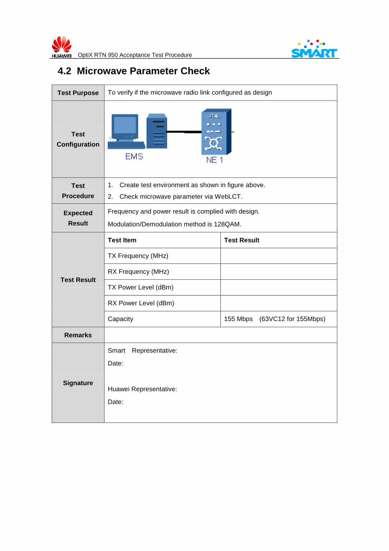
4.2 Microwave Parameter Check
Test Purpose To verify if the microwave radio link configured as design
Test
Configuration
Test
Procedure
1. Create test environment as shown in figure above.
2. Check microwave parameter via WebLCT.
Expected
Result
Frequency and power result is complied with design.
Modulation/Demodulation method is 128QAM.
Test Result
Test Item Test Result
TX Frequency (MHz)
RX Frequency (MHz)
TX Power Level (dBm)
RX Power Level (dBm)
Capacity 155 Mbps (63VC12 for 155Mbps)
Remarks
Signature
Smart Representative:
Date:
Huawei Representative:
Date:

OptiX RTN 950 Acceptance Test Procedure
4.3 Allocation of bandwidth Check
Test Purpose To verify if allocation of bandwidth is complied with requirement
Test
Configuration
Test
Procedure
1. Create test environment as shown in figure above.
2. Check allocation of bandwidth and cross-connection via WebLCT.
Expected
Result
The result is complied with design: 1~16VC12 for E1 channel, 17~63VC12 for
IP channel. IP port working mode is full duplex with Layer 2 feature.
Test Result
Test Item Test Result (Check in WebLCT)
Allocation of bandwidth timeslot (for E1): _____(VC12) ~ _____(VC12)
Cross-connection of the timeslot (for E1) _____(VC12) ~ _____(VC12)
Allocation of bandwidth timeslot (for IP): _____(VC12) ~ _____(VC12)
Cross-connection of the timeslot (for IP): _____(VC12) ~ _____(VC12)
IP Port Work Mode:
Remarks
Signature
Smart Representative:
Date:
Huawei Representative:
Date:
OptiX RTN 950 Acceptance Test Procedure
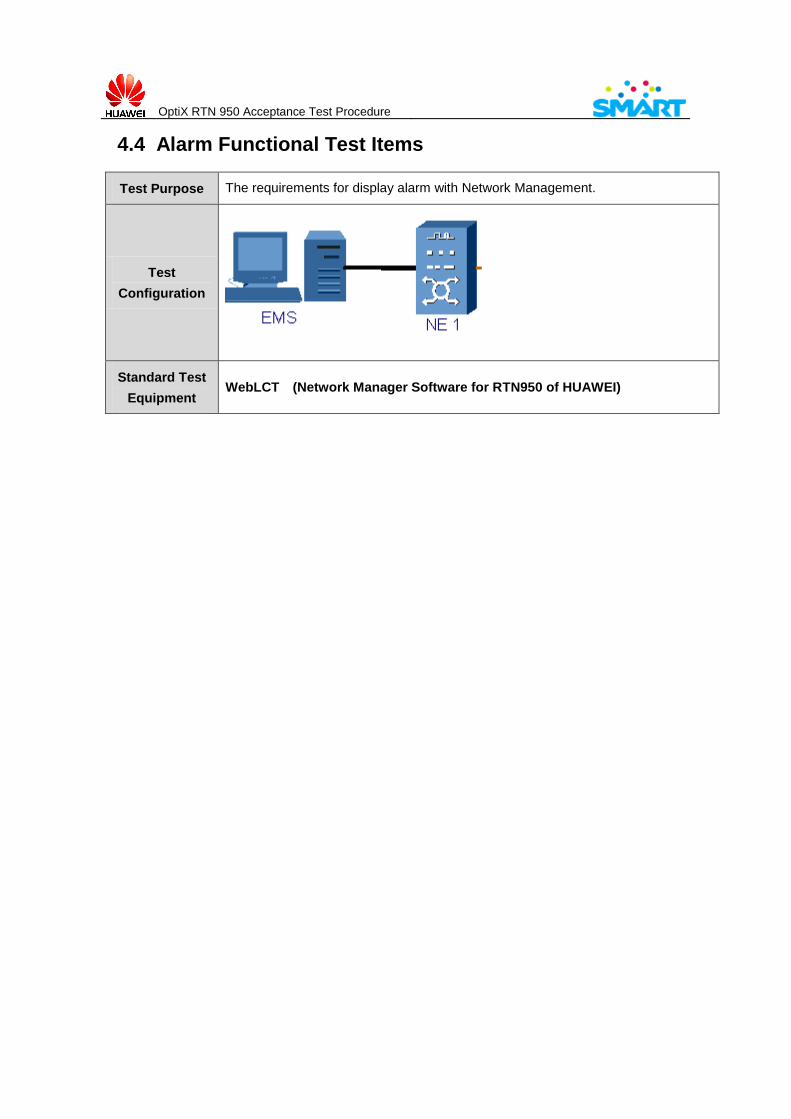
4.4 Alarm Functional Test Items
Test Purpose The requirements for display alarm with Network Management.
Test
Configuration
Standard Test
Equipment WebLCT (Network Manager Software for RTN950 of HUAWEI)
OptiX RTN 950 Acceptance Test Procedure
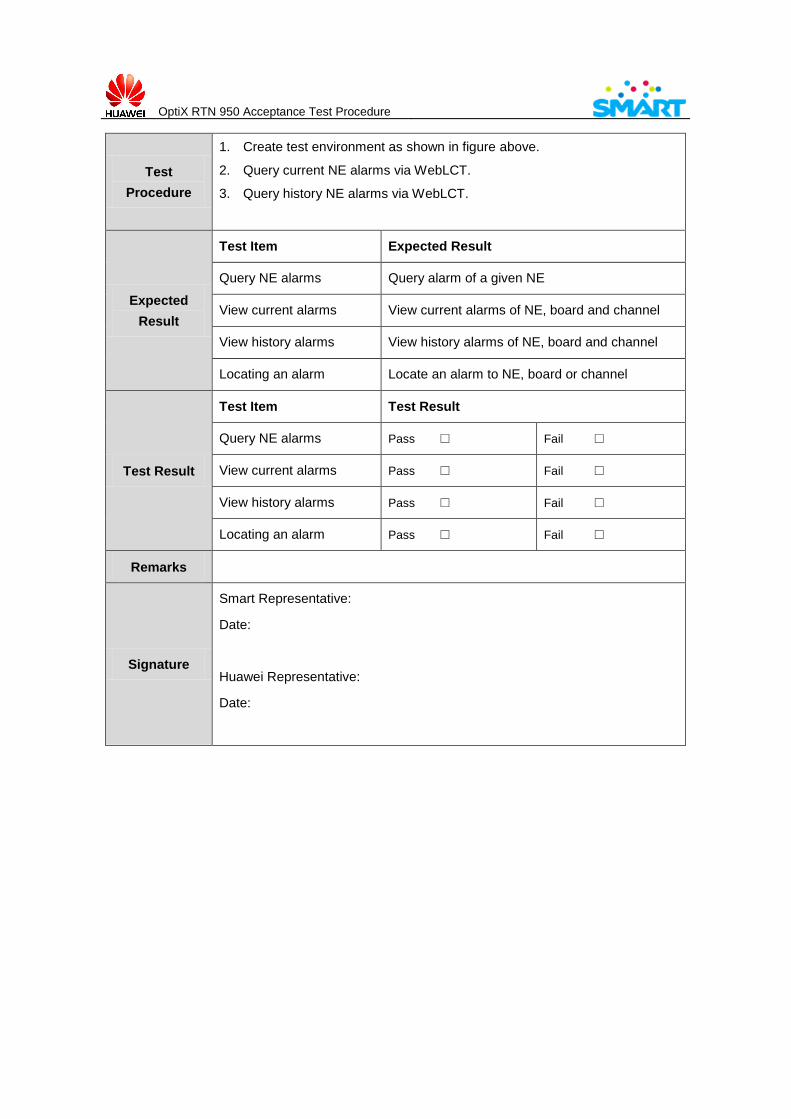
Test
Procedure
1. Create test environment as shown in figure above.
2. Query current NE alarms via WebLCT.
3. Query history NE alarms via WebLCT.
Expected
Result
Test Item Expected Result
Query NE alarms Query alarm of a given NE
View current alarms View current alarms of NE, board and channel
View history alarms View history alarms of NE, board and channel
Locating an alarm Locate an alarm to NE, board or channel
Test Result
Test Item Test Result
Query NE alarms Pass □ Fail □
View current alarms Pass □ Fail □
View history alarms Pass □ Fail □
Locating an alarm Pass □ Fail □
Remarks
Signature
Smart Representative:
Date:
Huawei Representative:
Date:
OptiX RTN 950 Acceptance Test Procedure
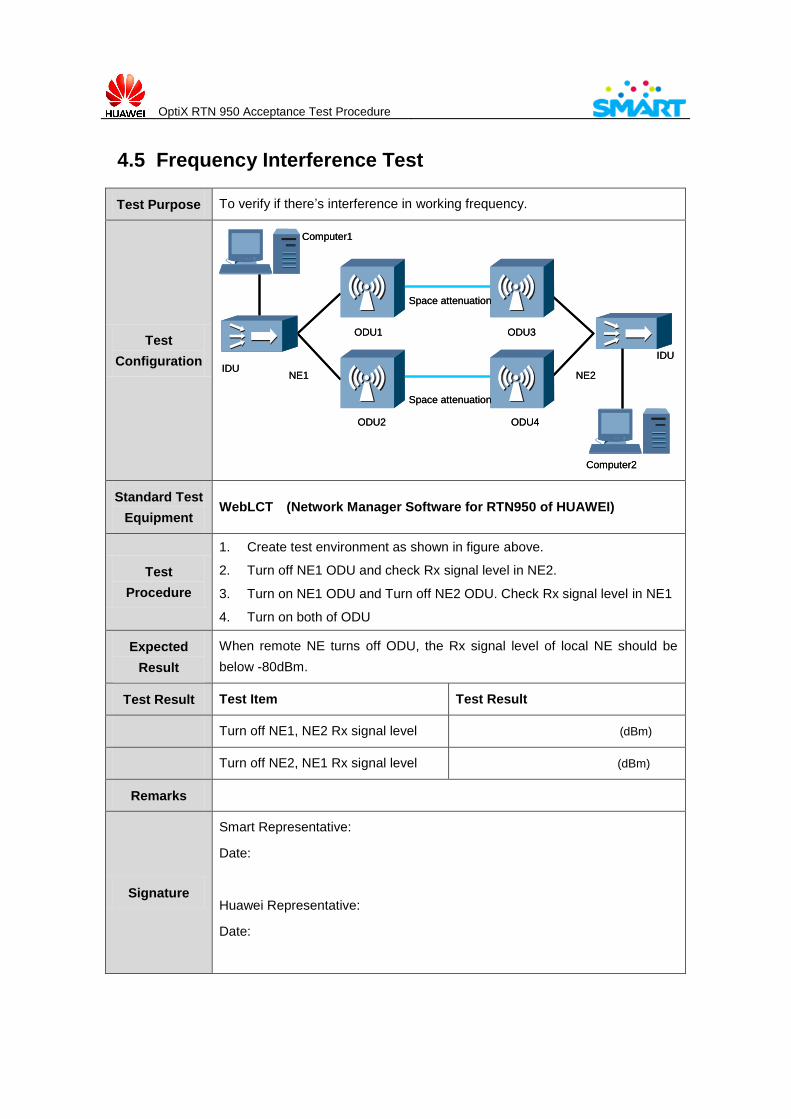
4.5 Frequency Interference Test
Test Purpose To verify if there’s interference in working frequency.
Test
Configuration
Computer1
ODU1
IDUNE1
ODU2
ODU3
ODU4
NE2
IDU
Space attenuation
Space attenuation
Computer2
Computer1
ODU1
IDUNE1
ODU2
ODU3
ODU4
NE2
IDU
Space attenuation
Space attenuation
Computer2
Standard Test
Equipment WebLCT (Network Manager Software for RTN950 of HUAWEI)
Test
Procedure
1. Create test environment as shown in figure above.
2. Turn off NE1 ODU and check Rx signal level in NE2.
3. Turn on NE1 ODU and Turn off NE2 ODU. Check Rx signal level in NE1
4. Turn on both of ODU
Expected
Result
When remote NE turns off ODU, the Rx signal level of local NE should be
below -80dBm.
Test Result Test Item Test Result
Turn off NE1, NE2 Rx signal level (dBm)
Turn off NE2, NE1 Rx signal level (dBm)
Remarks
Signature
Smart Representative:
Date:
Huawei Representative:
Date:
OptiX RTN 950 Acceptance Test Procedure
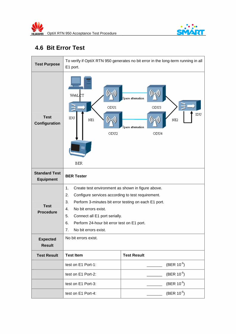
4.6 Bit Error Test
Test Purpose To verify if OptiX RTN 950 generates no bit error in the long-term running in all
E1 port.
Test
Configuration
Standard Test
Equipment BER Tester
Test
Procedure
1. Create test environment as shown in figure above.
2. Configure services according to test requirement.
3. Perform 3-minutes bit error testing on each E1 port.
4. No bit errors exist.
5. Connect all E1 port serially.
6. Perform 24-hour bit error test on E1 port.
7. No bit errors exist.
Expected
Result
No bit errors exist.
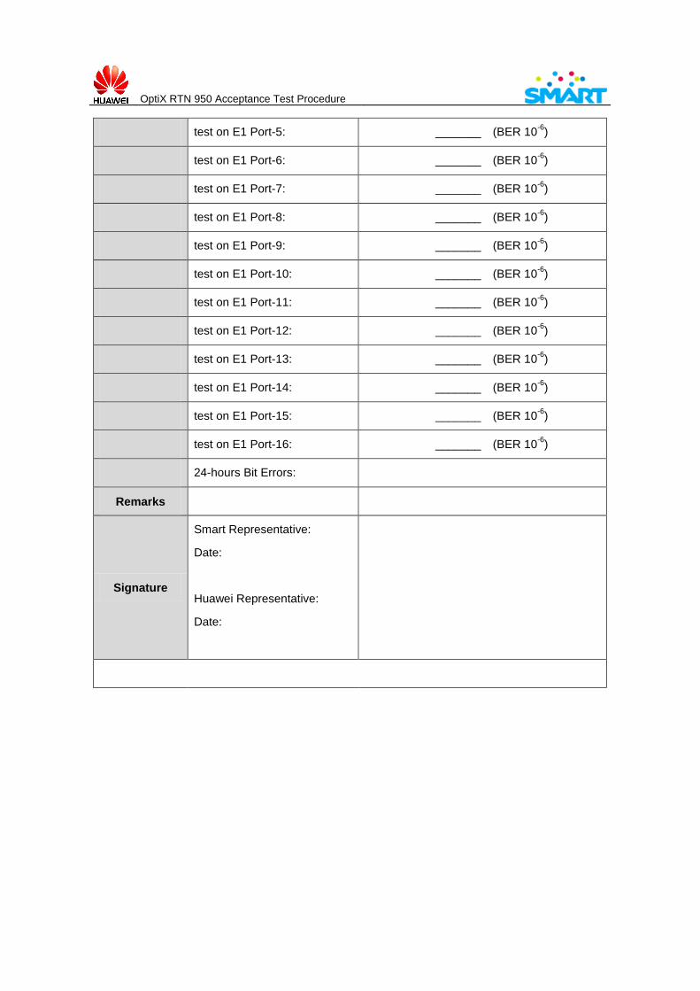
Test Result Test Item Test Result
test on E1 Port-1: _______ (BER 10-6
)
test on E1 Port-2: _______ (BER 10-6
)
test on E1 Port-3: _______ (BER 10-6
)
test on E1 Port-4: _______ (BER 10-6
)
OptiX RTN 950 Acceptance Test Procedure
test on E1 Port-5: _______ (BER 10-6
)
test on E1 Port-6: _______ (BER 10-6
)
test on E1 Port-7: _______ (BER 10-6
)
test on E1 Port-8: _______ (BER 10-6
)
test on E1 Port-9: _______ (BER 10-6
)
test on E1 Port-10: _______ (BER 10-6
)
test on E1 Port-11: _______ (BER 10-6
)
test on E1 Port-12: _______ (BER 10-6
)
test on E1 Port-13: _______ (BER 10-6
)
test on E1 Port-14: _______ (BER 10-6
)
test on E1 Port-15: _______ (BER 10-6
)
test on E1 Port-16: _______ (BER 10-6
)
24-hours Bit Errors:
Remarks
Signature
Smart Representative:
Date:
Huawei Representative:
Date:
OptiX RTN 950 Acceptance Test Procedure
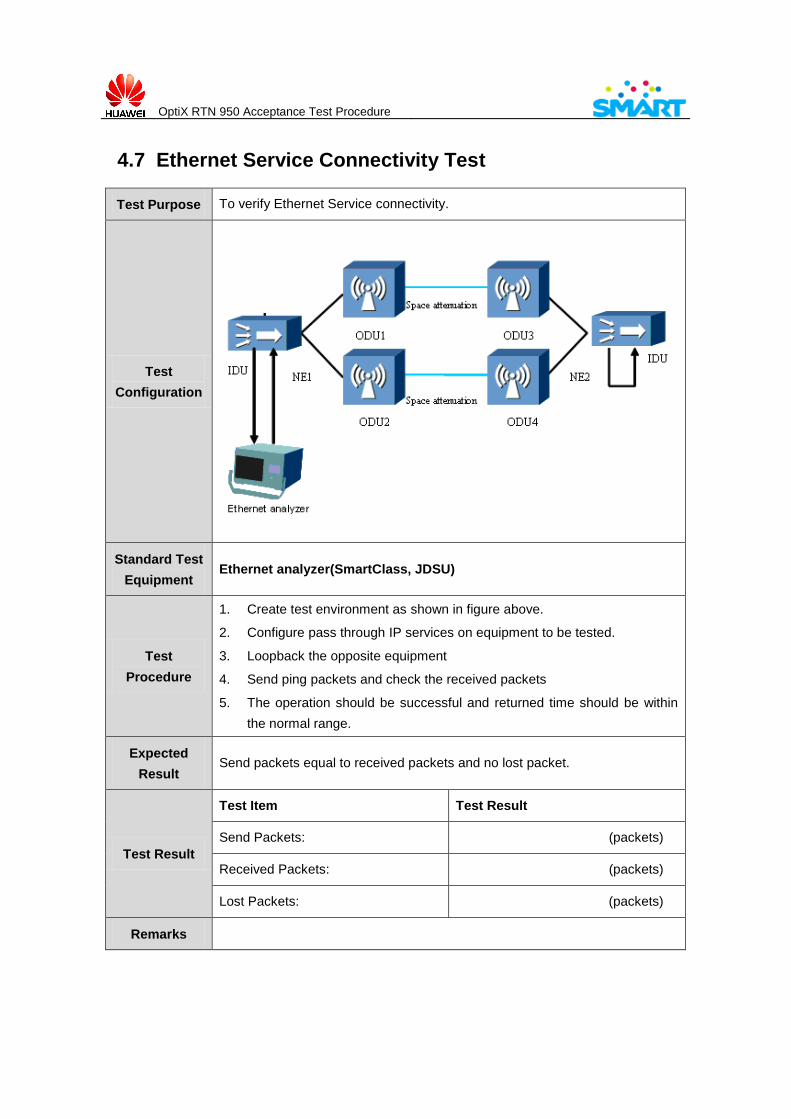
4.7 Ethernet Service Connectivity Test
Test Purpose To verify Ethernet Service connectivity.
Test
Configuration
Standard Test
Equipment Ethernet analyzer(SmartClass, JDSU)
Test
Procedure
1. Create test environment as shown in figure above.
2. Configure pass through IP services on equipment to be tested.
3. Loopback the opposite equipment
4. Send ping packets and check the received packets
5. The operation should be successful and returned time should be within
the normal range.
Expected
Result Send packets equal to received packets and no lost packet.
Test Result
Test Item Test Result
Send Packets: (packets)
Received Packets: (packets)
Lost Packets: (packets)
Remarks

OptiX RTN 950 Acceptance Test Procedure
Signature
Smart Representative:
Date:
Huawei Representative:
Date:
OptiX RTN 950 Acceptance Test Procedure
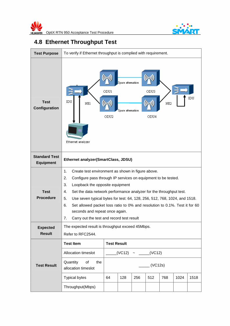
4.8 Ethernet Throughput Test
Test Purpose To verify if Ethernet throughput is complied with requirement.
Test
Configuration
Standard Test
Equipment Ethernet analyzer(SmartClass, JDSU)
Test
Procedure
1. Create test environment as shown in figure above.
2. Configure pass through IP services on equipment to be tested.
3. Loopback the opposite equipment
4. Set the data network performance analyzer for the throughput test.
5. Use seven typical bytes for test: 64, 128, 256, 512, 768, 1024, and 1518.
6. Set allowed packet loss ratio to 0% and resolution to 0.1%. Test it for 60
seconds and repeat once again.
7. Carry out the test and record test result
Expected
Result
The expected result is throughput exceed 45Mbps.
Refer to RFC2544.
Test Result
Test Item Test Result
Allocation timeslot _____(VC12) ~ _____(VC12)
Quantity of the
allocation timeslot _____ (VC12s)
Typical bytes 64 128 256 512 768 1024 1518
Throughput(Mbps)

OptiX RTN 950 Acceptance Test Procedure
Remarks
Signature
Smart Representative:
Date:
Huawei Representative:
Date:
OptiX RTN 950 Acceptance Test Procedure
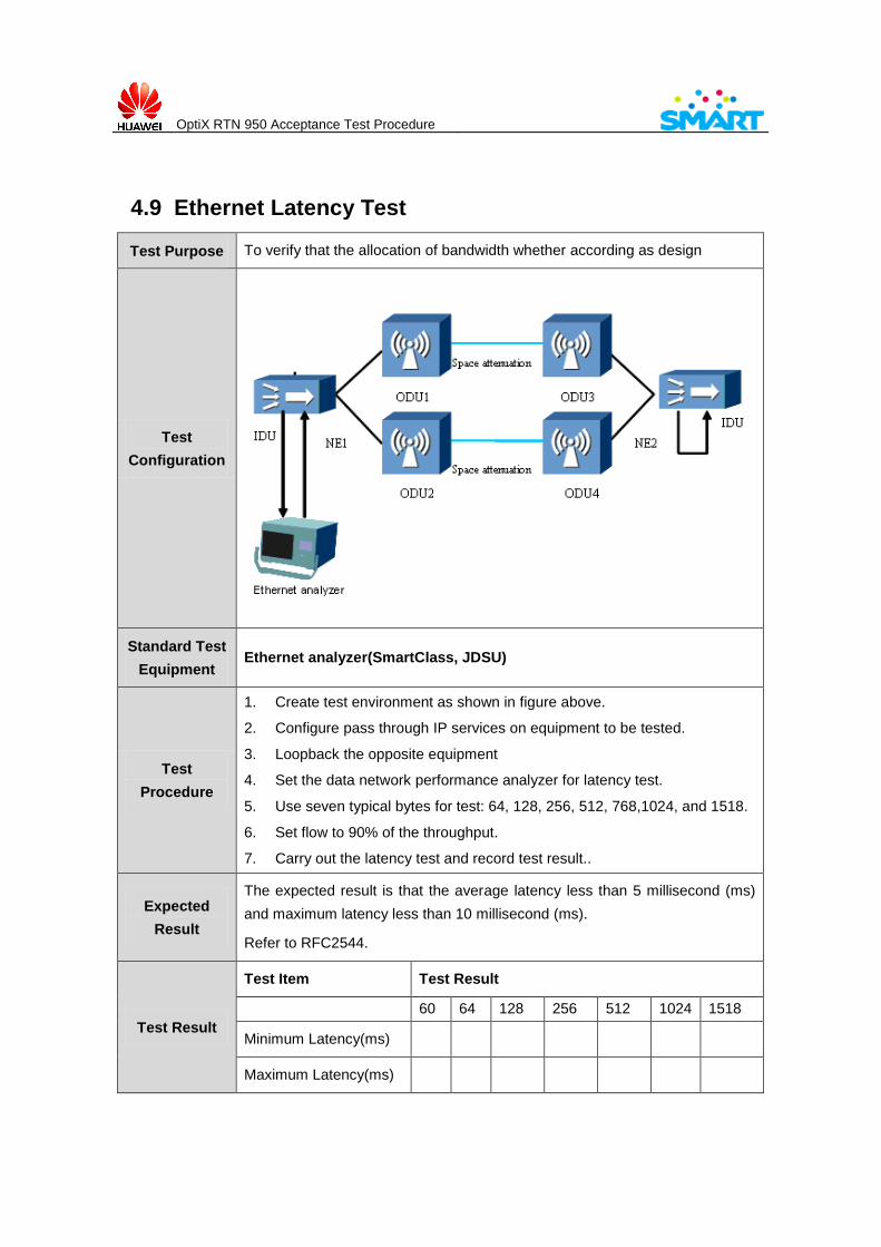
4.9 Ethernet Latency Test
Test Purpose To verify that the allocation of bandwidth whether according as design
Test
Configuration
Standard Test
Equipment Ethernet analyzer(SmartClass, JDSU)
Test
Procedure
1. Create test environment as shown in figure above.
2. Configure pass through IP services on equipment to be tested.
3. Loopback the opposite equipment
4. Set the data network performance analyzer for latency test.
5. Use seven typical bytes for test: 64, 128, 256, 512, 768,1024, and 1518.
6. Set flow to 90% of the throughput.
7. Carry out the latency test and record test result..
Expected
Result
The expected result is that the average latency less than 5 millisecond (ms)
and maximum latency less than 10 millisecond (ms).
Refer to RFC2544.
Test Result
Test Item Test Result
60 64 128 256 512 1024 1518
Minimum Latency(ms)
Maximum Latency(ms)

OptiX RTN 950 Acceptance Test Procedure
Average Latency (ms)
Remarks
Signature
Smart Representative:
Date:
Huawei Representative:
Date: