Embed Size (px)
Citation preview
Parts ManualGenerator Setwith PowerCommand 2100 and 3100 Control
DFLB (Spec S−T)DFLC (Spec V−W)DFLE (Spec D−F)
EnglishOriginal Instructions 12-2016 0960−0296 (Issue 9)
The following symbols are used in Cummins PowerGeneration manuals to alert users to the potentiallydangerous conditions relating to maintenance ofequipment and replacement of parts. Please readand observe.
This symbol warns of immediatehazards which will result in severepersonal injury or death.
This symbol refers to a hazard orunsafe practice which can resultin severe personal injury or death.
This symbol refers to a hazard orunsafe practice which can resultin severe personal injury or prod-uct or property damage.
To avoid errors or delay in filling your parts order, al-ways give the MODEL, SPEC NO. and SERIAL NO.from the Cummins Power Generation nameplate.
For handy reference, insert your nameplate in-formation in the spaces below.
MODEL AND SPEC NO.
SERIAL NO.
DIGITAL CONTROL SOFTWARE VERSIONAND DATE (IF APPLICABLE)
Contact with USED ENGINE OILS has been identified by a United States federal agency and some USAstate agencies as causing CANCER or REPRODUCTIVE TOXICITY. When checking or changing engineoils take all necessary precautions not to ingest, breathe the fumes or contact the used oil.
Contact with ASBESTOS has been identified by a United States federal agency and some USA state agen-cies as causing CANCER or REPRODUCTIVE TOXICITY. When handling engine gaskets take all neces-sary precautions not to ingest, breathe or contact the dust from the gaskets! Use adequate ventilationand wear protective gloves, masks and clothing!
Contact with BENZINE and LEAD, found in gasoline, fuel additives and solvents has been identified bya United States federal agency and some USA state agencies as causing CANCER or REPRODUCTIVETOXICITY. When checking, draining or adding gasoline and fuel additives or using solvents take all nec-essary precautions not to ingest, breathe the fumes or contact the liquids. Use adequate ventilation andwear protective gloves, masks and protective clothing!
PSP-1
Service and repair of Cummins Power Generation equipment must be performed by trained, experiencedpersonnel only. Improper service or repair may result in property damage, severe personal injury ordeath. Do not use this catalog as a guide to servicing your equipment. Read and follow the IMPORTANTSAFETY INSTRUCTIONS in the Service Manual appropriate for the equipment you are working on.
Copyright 2016 Cummins Inc. 1
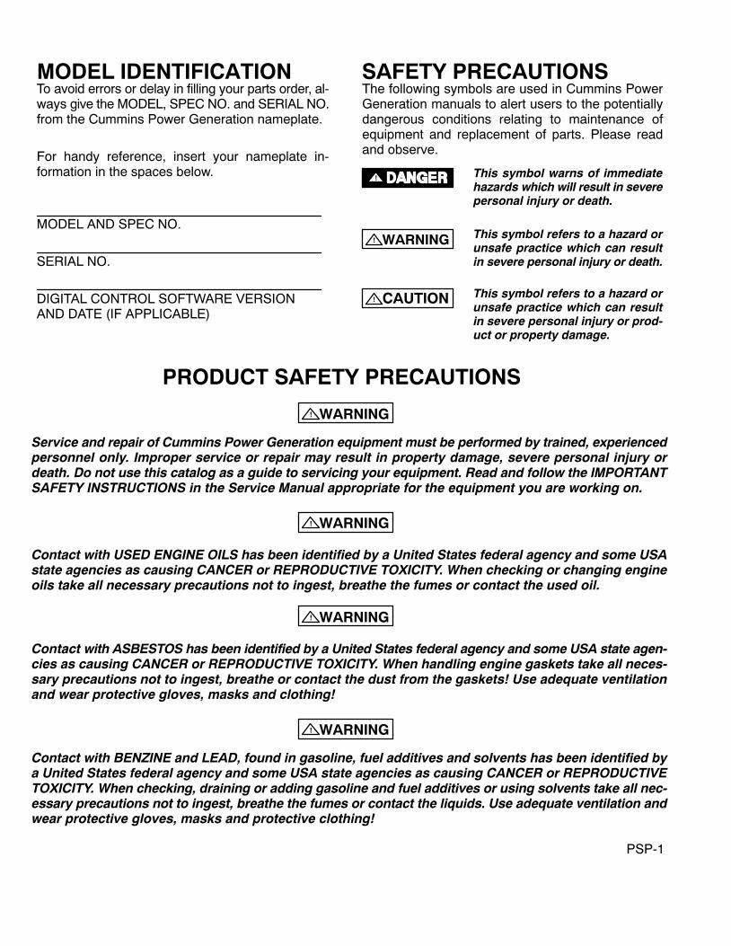
Introduction
This manual applies to Cummins Power Generation Models DFLB, DFLC and DFLE as listed in the Generator Set DataTable. Parts are arranged in groups of related items and each illustrated part is identified by a reference number corre-sponding to the same reference number in the parts list. Parts illustrations are typical. Unless otherwise mentioned inthe description or page heading, parts are interchangeable between models. Throughout this manual left and right sidesare determined by facing the engine end (front) of the set unless noted in the description column.
Engine parts that have been modified or added by Cummins Power Generation are identified in this manual. All otherengine replacement parts must be ordered from the engine manufacturer by referring to the engine manufacturer’s name-plate and supplying all available information. Contact your nearest engine parts distributor for assistance in ordering re-placement parts.
Replacement Engine
Cummins Power GenerationGenerator Model
Cummins Engine Model
DFLB KTA50−G2
DFLC − Spec V KTA50−G3
DFLC − Spec W KTA50−G11
1290DFLE1500DFLE
KTA50−G8KTA50−G9
Generator Set Data Table
Model and Electrical Data BatteryModel andSpecification Watts Volts Hertz Wire Phase
BatteryVoltage
1100DFLB/* 1,100,000 # 60 6 1 or 3 24 VDC
1120DFLC/*1250DFLC/*
1,120,0001,250,000
##
5060
66
1 or 31 or 3
24 VDC24 VDC
1290DFLE/*1500DFLE/*
1,290,0001,500,000
##
5060
66
1 or 31 or 3
24 VDC24 VDC
* − The diagonal line (/) in the model and specification number separates generator set characteristics from thespecification number and letter. The specification number denotes customer requested options or deviations from thestandard model. The specification letter advances (A to B, B to C, etc.) with major manufacturing changes.
# − Broad range reconnectible

Copyright 2016 Cummins Inc.2
“Intentionally Left Blank”
Index
3Copyright 2016 Cummins Inc.
AAbsorber, Shock − Fan − DFLB, 64
Absorber, Shock − Fan − DFLC, 65
Absorber, Shock − Fan Drive − DFLE, 66
Alternator − 55 Amp, 71
Alternator − Two Pump Two Loop − DFLE, 69
BBand, Mounting − Air Cleaner − Standard −
DFLE, 16
Band, Mounting − Water Inlet − DFLB, DFLC, 38
Bar Assembly, Neutral − Non−UL Listed CircuitBreaker, 107
Bar Assembly, Neutral − UL Listed Circuit Break-er, 105
Base, Heat Exchanger − DFLB, DFLC, 33
Belt, Alternator − 55 Amp, 71
Belt, Alternator − Two Pump Two Loop − DFLE,69
Belt, Fan − DFLC, 65
Belt, Ribbed − DFLB, 64
Belt, V − Fan Drive − DFLE, 66
Block, Short Circuit − Differential Current Trans-former, 101
Block, Terminal − Engine Coolant Heater Control,31
Block, Terminal − Woodward Governor, 73
Board, Printed Circuit − Bargraph, 91
Board, Printed Circuit − Base, 91
Board, Printed Circuit − LED, 91
Board, Printed Circuit − Lonworks, 91
Box, Control − Engine Coolant Heater, 31
Box, Control − PCC 2100, 91
Box, Entrance − DFLB Begin Spec T, DFLC Be-gin Spec W, DFLE Begin Spec E, 75
Box, Entrance − DFLB Spec S, DFLC Spec V,DFLE Spec D, 74
Box, Terminal − Generator Heater, 82
Brace, Access Door − Non−UL Listed CircuitBreaker, 107
Brace, Access Door − UL Listed Circuit Breaker,105
Brace, Air Starter, 68
Bracket, Adjusting − Alternator − 55 Amp, 71
Bracket, Adjusting − Alternator − Two Pump TwoLoop − DFLE, 69
Bracket, Battery, 67
Bracket, Circuit Breaker Mounting − Non−ULListed, 107
Bracket, Circuit Breaker Mounting − UL Listed,105
Bracket, Current Transformer, 101
Bracket, Mounting − Air Cleaner − Standard −DFLE, 16
Bracket, Radiator Support − 40DEGC Ambient −DFLE Begin Spec E, 53
Bracket, Radiator Support − DFLE Spec D, 51
Bracket, Saddle − Control Housing − Model HC7Generators, 79
Breaker, Circuit − Non−UL Listed, 107
Breaker, Circuit − NSJ, 113
Breaker, Circuit − P−Frame, 111
Breaker, Circuit − R−Frame, 109
Breaker, Circuit − UL Listed, 105
Bumper − Radiator − DFLE Spec D, 51
Bumper − Radiator 40DEGC Ambient − DFLEBegin Spec E, 53
Bumper − Skid, 67
CCable, Battery − PCC 2100, 13
Cable, Battery − PCC 3100, 11
Cap, Expansion Tank − Heat Exchanger − DFLB,DFLC, 33
Cap, Radiator − DFLE Spec D, 51
Cartridge, Heater − Generator Heater, 82
Check Valve, Radiator − 40DEGC Ambient Radia-tor − DFLC, 47
Check Valve, Radiator − 50DEGC Ambient Radia-tor − DFLC, 49
Check Valve, Radiator − DFLB, 45
Cleaner, Air − Heavy Duty − DFLB , 19
Cleaner, Air − Heavy Duty − DFLC, DFLE, 21
Cleaner, Air − Standard − DFLB , 14
Index
4 Copyright 2016 Cummins Inc.
Cleaner, Air − Standard − DFLC, 15
Cleaner, Air − Standard − DFLE, 16
Cock, Drain − Heat Exchanger − DFLB, DFLC, 33
Control − PCC 2100, 91
Control − PCC 3100, 86
Control, Electronic Governor, 72
Control, Engine Coolant Heater, 31
Cover, Battery, 114
Cover, Circuit Breaker − Non−UL Listed, 107
Cover, Circuit Breaker − UL Listed, 105
Cover, Control Box (Bottom) − Non−UL ListedCircuit Breaker, 107
Cover, Control Box (Bottom) − UL Listed CircuitBreaker, 105
Cover, Control Box (Top) − Non−UL Listed CircuitBreaker, 107
Cover, Control Box (Top) − UL Listed CircuitBreaker, 105
Cover, Control Housing − Model HC7 Generators,79
Cover, Damper Guard − Sets With Remote Ra-diator or Heat Exchanger − DFLB, DFLC, 43
Cover, Electronic Governor Control, 72
Cover, Entrance Box − DFLB Spec S, DFLC SpecV, DFLE Spec D, 74
Cover, Flange − Air Starter, 68
Cover, Hydraulic Hole − Fuel Transfer Pump, 23
DDisplay, Digital − Control − PCC 2100, 91
Drive, Fan − DFLB, 64
Drive, Fan − DFLC, 65
Drive, Fan − DFLE, 66
Drive, Fuel Transfer Pump, 23
EElbow, Exhaust − Pyrometer − PCC 3100, 94
Elbow, Outlet − Heat Exchanger − DFLB, DFLC,33
Element, Air Cleaner − Heavy Duty − DFLB, 19
Element, Air Cleaner − Heavy Duty − DFLC,DFLE, 21
Element, Oil Bypass Filter, 42
Exchanger, Heat − DFLB, DFLC, 33
External Engine Parts − PCC 2100, 13
External Engine Parts − PCC 3100, 11
FFan Shroud − 40DEGC Ambient Radiator −
DFLC, 47
Fan Shroud − 50DEGC Ambient Radiator −DFLC, 49
Fan Shroud − Radiator − DFLB, 45
Fan, Alternator − 55 Amp, 71
Fan, Alternator − Two Pump Two Loop − DFLE,69
Fan, Engine − DFLC, 65
Fan, Engine − DFLE, 66
Filter, Oil Bypass, 42
Flange − Thermostatic Valve − DFLB, DFLC, 35
GGasket, Connection − Water Outlet − DFLB, 39
Gasket, Connection − Water Outlet − DFLC, 40
Gasket, Flange − Heat Exchanger − DFLB,DFLC, 33
Gasket, Flange − Thermostatic Valve − DFLB,DFLC, 35
Gasket, Hand Hole − Fuel Transfer Pump, 23
Gasket, Heat Exchanger − DFLB, DFLC, 33
Gasket, Mounting − Fuel Transfer Pump, 23
Gasket, Thermostat Housing − Water Outlet −DFLB, 39
Gauge, Fuel Pressure, 24
Generator (Complete Replacement Part Num-bers), 84
Governor, Electronic, 72
Governor, Woodward, 73
Grille − Control Housing − Model HC7 Genera-tors, 79
Grille − Radiator − DFLE Spec D, 51
Grille, 50DEGC Ambient Radiator − DFLC, 49
Grille, Radiator − DFLB, 45
Index
5Copyright 2016 Cummins Inc.
Guard, Belt − 40DEGC Ambient Radiator −DFLC, 47
Guard, Belt − 50DEGC Ambient Radiator −DFLC, 49
Guard, Belt − Radiator − DFLB, 45
Guard, Fan − 40DEGC Ambient Radiator −DFLC, 47
Guard, Fan − 50DEGC Ambient Radiator −DFLC, 49
Guard, Fan − Radiator − DFLB, 45
Guard, Belt − Alternator − 55 Amp, 71
Guard, Belt − Radiator − 40DEGC Ambient −DFLE Begin Spec E, 53
Guard, Belt − Radiator − DFLE Spec D, 51
Guard, Damper − Sets With Remote Radiator orHeat Exchanger − DFLB, DFLC, 43
Guard, Fan − Radiator − 40DEGC Ambient −DFLE Begin Spec E, 53
Guard, Fan − Radiator − DFLE Spec D, 51
Guard, Heat Exchanger, 33
HHarness, Wiring − AC, 96
Harness, Wiring − Adapter − Woodward Governorto Engine Harness, 73
Harness, Wiring − DC − Engine Coolant HeaterControl, 31
Harness, Wiring − Engine to Control − DFLB Be-gin Spec T, DFLC Begin Spec W, 99
Harness, Wiring − Engine to Control − DFLBSpec S, DFLC Spec V, DFLE, 97
Harness, Wiring − Ground Fault Relay, 93
Harness, Wiring − Low Battery Voltage Sensor,26
Harness, Wiring − Temperature Switch − TwoLoop Two Loop Engine − DFLE, 25
Head, Oil Bypass Filter, 42
Heater, Control − PCC 2100, 87
Heater, Engine Coolant, 29
Heater, Generator, 82
Heater, Oil Pan, 41
Hood, Air Inlet− Heavy Duty − DFLB , 19
Hood, Air Inlet− Heavy Duty − DFLC, DFLE, 21
Hose, Check Valve − Sets With Remote Radiator− DFLB, DFLC, 43
Hose, Flexible − Oil Bypass Filter, 42
Hose, Fuel Pump − Woodward Governor, 73
Hose, Heat Exchanger − DFLB, DFLC, 33
Hose, Oil Drain − PCC 2100, 13
Hose, Oil Drain − PCC 3100, 11
Hose, Radiator − 40DEGC Ambient − DFLE Be-gin Spec E, 57
Hose, Radiator − DFLE Spec D, 51
Hose, Water Inlet − DFLB, DFLC, 38
Housing, Control − Model HC6 Generators, 77
Housing, Control − Model HC7 Generators, 79
Housing, Control − Model P7 Generators, 81
Housing, Thermostat − Water Outlet − DFLB, 39
IIdler Assembly, Fan − DFLB, 64
Idler, Fan − DFLE, 66
Indicator, Service − Air Cleaner − Heavy Duty −DFLB, 19
Indicator, Service − Air Cleaner − Heavy Duty −DFLC, DFLE, 21
Indicator, Service − Air Cleaner − Standard −DFLB, 14
Indicator, Service − Air Cleaner − Standard −DFLC, 15
Indicator, Service − Air Cleaner − Standard −DFLE, 16
Inlet, Water − DFLB, DFLC, 38
Isolator, Vibration − Control Housing − Model HC7Generators, 79
Isolator, Vibration − Pilot Solenoid − PCC 2100,13
Isolator, Vibration − Pilot Solenoid − PCC 3100,11
KKit Heater, Relay, 82
Kit, Repair − Radiator Sight Gauge − 40DEGCAmbient Radiator − DFLC, 47
Index
6 Copyright 2016 Cummins Inc.
Kit, Repair − Radiator Sight Gauge − 50DEGCAmbient Radiator − DFLC, 49
LLead, Circuit Breaker − Non−UL Listed, 107
Lead, Circuit Breaker − UL Listed, 105
Lead, Thermocouple − Pyrometer − PCC 3100,94
Lens, Indicator − Low Battery Voltage Sensor, 26
Line, Fuel − Flexible − Fuel Transfer Pump, 23
Lube, Fan, 63
MManifold, Inlet − Heat Exchanger − DFLB, DFLC,
33
Module, Alarm, 92
Mounting, Generator, 83
OOutlet, Water − DFLB, 39
Outlet, Water − DFLC, 40
PPaint, 8
Pickup, Magnetic − Electronic Governor, 72
Pickup, Magnetic − PCC 2100, 13
Pickup, Magnetic − PCC 3100, 11
Pickup, Magnetic − Woodward Governor, 73
Pulley, Alternator − 55 Amp, 71
Pulley, Alternator − Two Pump Two Loop − DFLE,69
Pulley, Fan Drive − DFLB, 64
Pulley, Fan Drive − DFLC, 65
Pulley, Fan Drive − DFLE, 66
Pump, Fuel Transfer, 23
Pyrometer − Dual Thermocouple − PCC 2100, 95
Pyrometer − PCC 3100, 94
RRadiator − Guard − Service Parts − 50DEGC
Ambient − DFLE Begin Spec E, 62
Radiator − 50DEGC Ambient − DFLE Begin SpecE, 58
Radiator − DFLB, 45
Radiator − DFLE Spec D, 51
Radiator Service Parts − 505C Ambient DFLEBegin Spec E, 60
Radiator, 40DEGC Ambient − DFLC, 47
Radiator, 40DEGC Ambient − DFLE Begin SpecE, 53 , 55 , 57
Radiator, 50DEGC Ambient − DFLC, 49
Rail, Enclosure − Control − PCC 2100, 88
Rectifier, Silicon − Engine Heater Wiring Harness,31
Relay, Control − PCC 2100, 89
Relay, Ground Fault, 93
Relay, Power − Engine Coolant Heater Control,31
Reservoir, Fuel − Fuel Transfer Pump, 23
SSeal, Thermostat − Water Outlet − DFLB, 39
Sealant, Thread, 8
Sender, Low Coolant Level, 34
Sender, Oil Pressure − PCC 2100, 13
Sender, Oil Pressure − PCC 3100, 11
Sender, Oil Temperature − Engine Block, Oil Pan− PCC 2100, 13
Sender, Oil Temperature − Engine Block, Oil Pan− PCC 3100, 11
Sensor − Low Battery Voltage, 26
Shaft, Fan Drive − DFLC, 65
Shaft, Fan Drive − DFLE, 66
Shim, Generator Mounting, 83
Shroud, Fan − Radiator − 40DEGC Ambient −DFLE Begin Spec E, 53
Shroud, Fan − Radiator − DFLE Spec D, 51
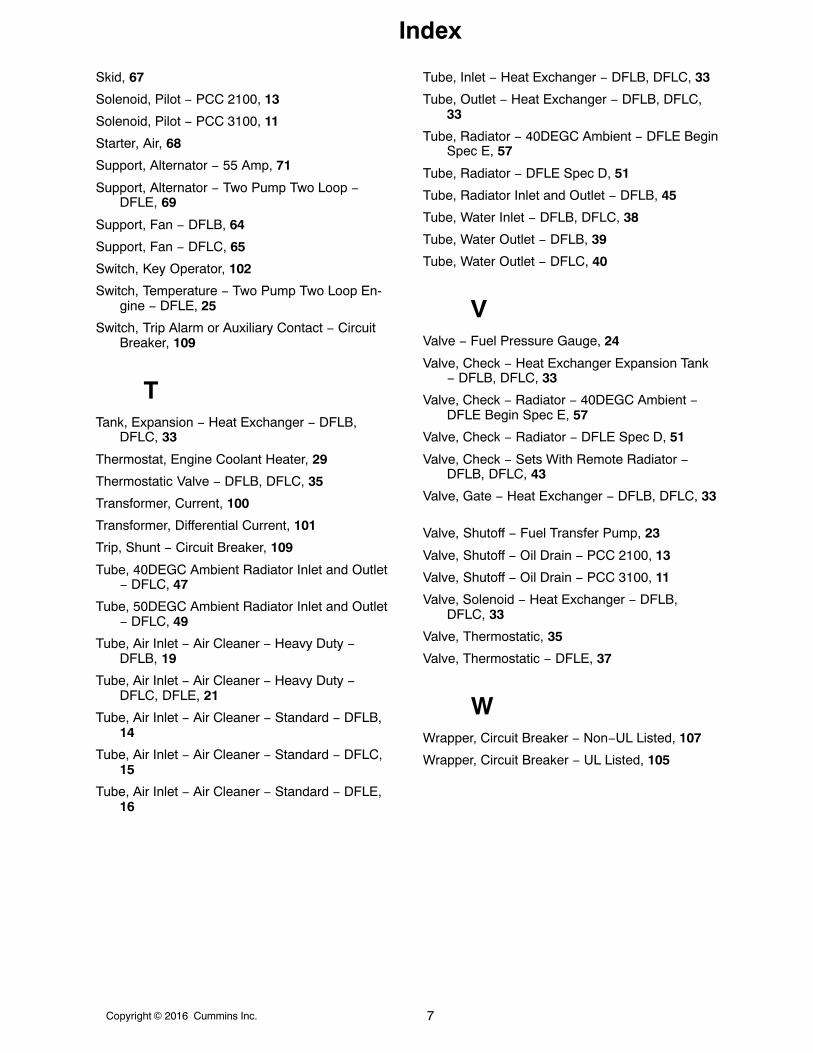
Index
7Copyright 2016 Cummins Inc.
Skid, 67
Solenoid, Pilot − PCC 2100, 13
Solenoid, Pilot − PCC 3100, 11
Starter, Air, 68
Support, Alternator − 55 Amp, 71
Support, Alternator − Two Pump Two Loop −DFLE, 69
Support, Fan − DFLB, 64
Support, Fan − DFLC, 65
Switch, Key Operator, 102
Switch, Temperature − Two Pump Two Loop En-gine − DFLE, 25
Switch, Trip Alarm or Auxiliary Contact − CircuitBreaker, 109
TTank, Expansion − Heat Exchanger − DFLB,
DFLC, 33
Thermostat, Engine Coolant Heater, 29
Thermostatic Valve − DFLB, DFLC, 35
Transformer, Current, 100
Transformer, Differential Current, 101
Trip, Shunt − Circuit Breaker, 109
Tube, 40DEGC Ambient Radiator Inlet and Outlet− DFLC, 47
Tube, 50DEGC Ambient Radiator Inlet and Outlet− DFLC, 49
Tube, Air Inlet − Air Cleaner − Heavy Duty −DFLB, 19
Tube, Air Inlet − Air Cleaner − Heavy Duty −DFLC, DFLE, 21
Tube, Air Inlet − Air Cleaner − Standard − DFLB,14
Tube, Air Inlet − Air Cleaner − Standard − DFLC,15
Tube, Air Inlet − Air Cleaner − Standard − DFLE,16
Tube, Inlet − Heat Exchanger − DFLB, DFLC, 33
Tube, Outlet − Heat Exchanger − DFLB, DFLC,33
Tube, Radiator − 40DEGC Ambient − DFLE BeginSpec E, 57
Tube, Radiator − DFLE Spec D, 51
Tube, Radiator Inlet and Outlet − DFLB, 45
Tube, Water Inlet − DFLB, DFLC, 38
Tube, Water Outlet − DFLB, 39
Tube, Water Outlet − DFLC, 40
VValve − Fuel Pressure Gauge, 24
Valve, Check − Heat Exchanger Expansion Tank− DFLB, DFLC, 33
Valve, Check − Radiator − 40DEGC Ambient −DFLE Begin Spec E, 57
Valve, Check − Radiator − DFLE Spec D, 51
Valve, Check − Sets With Remote Radiator −DFLB, DFLC, 43
Valve, Gate − Heat Exchanger − DFLB, DFLC, 33
Valve, Shutoff − Fuel Transfer Pump, 23
Valve, Shutoff − Oil Drain − PCC 2100, 13
Valve, Shutoff − Oil Drain − PCC 3100, 11
Valve, Solenoid − Heat Exchanger − DFLB,DFLC, 33
Valve, Thermostatic, 35
Valve, Thermostatic − DFLE, 37
WWrapper, Circuit Breaker − Non−UL Listed, 107
Wrapper, Circuit Breaker − UL Listed, 105
Copyright 2016 Cummins Inc.8
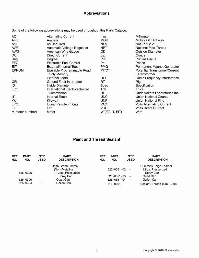
Abbreviations
Some of the following abbreviations may be used throughout this Parts Catalog:
AC Alternating CurrentAmp AmpereA/R As RequiredAVR Automatic Voltage RegulatorAWG American Wire GaugeDC Direct CurrentDeg DegreeEFC Electronic Fuel ControlEIT External/Internal ToothEPROM Erasable Programmable Read
Only MemoryET External ToothGFI Ground Fault InterrupterID Inside DiameterIEC International Electrotechnical CommissionIT Internal ToothkW KilowattLPG Liquid Petroleum GasLT LeftM(meter number) Meter
mm MillimeterMOH Mobile Off HighwayNFS Not For SaleNPT National Pipe ThreadOD Outside Diameteroz. OuncePC Printed CircuitPh PhasePMG Permanent Magnet GeneratorPT/CT Potential Transformer/Current
TransformerRFI Radio Frequency InterferenceRT RightSpec SpecificationThk ThickUL Underwriters Laboratories Inc.UNC Union National CoarseUNF Union National FineVAC Volts Alternating CurrentVDC Volts Direct CurrentW/(ET, IT, EIT) With
Paint and Thread Sealant
REF PART QTY PART REF PART QTY PARTNO. NO. USED DESCRIPTION NO. NO. USED DESCRIPTION
Onan Green Enamel(Non−Metallic)
525−0305 − 12 oz. PressurizedSpray Can
525−0306 − Quart Can525−0304 − Gallon Can
Cummins Beige Enamel525−0551−02 − 12 oz. Pressurized
Spray Can525−0551−03 − Quart Can525−0551−04 − Gallon Can
518−0601 − Sealant, Thread (6 ml Tube)

Copyright 2016 Cummins Inc. 9
“Intentionally Left Blank”
Copyright 2016 Cummins Inc.10
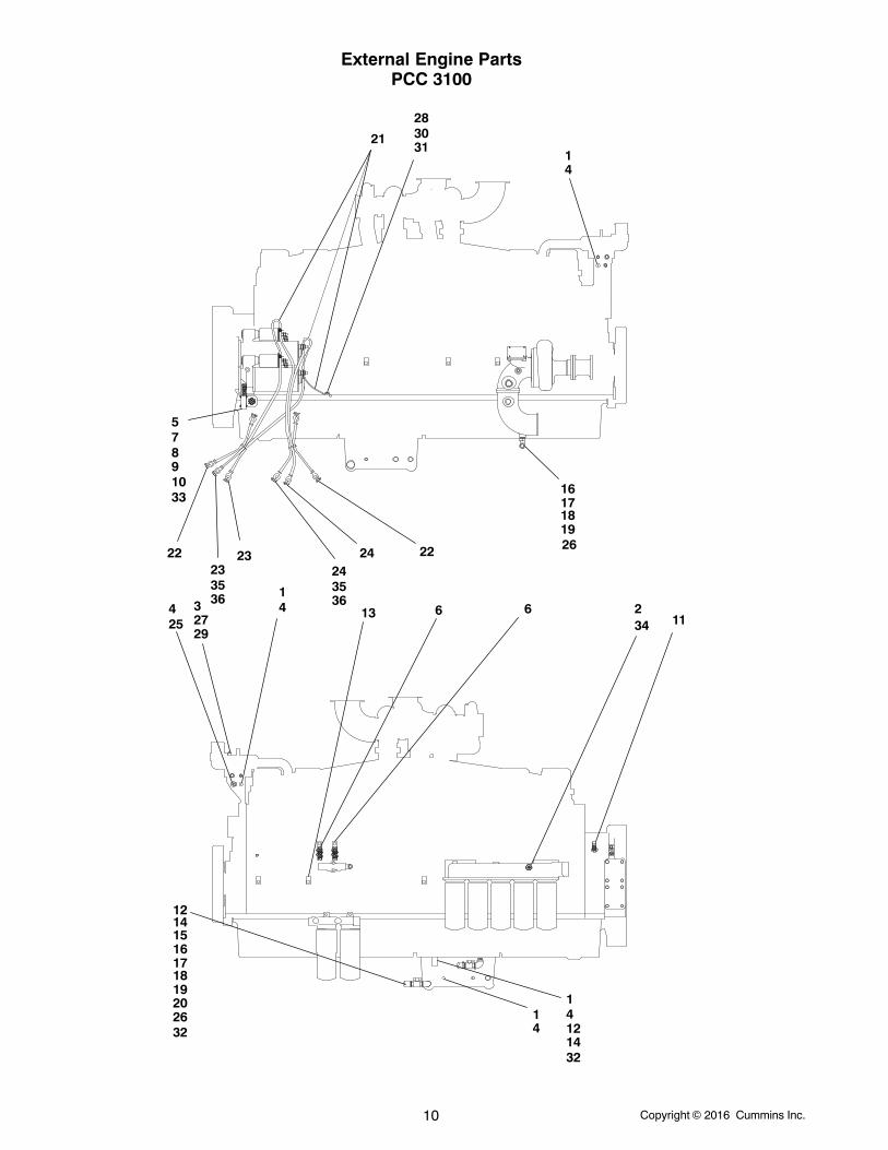
External Engine PartsPCC 3100
11
1
1
234 4
4
44
5
66
78910
11
12
12
13
14
1415
16
16
17
17
18
18
19
1920
21
222223
2324
24
25
26
26
27
28
29
3031
32
32
33
34
35 3536 36
Copyright 2016 Cummins Inc. 11
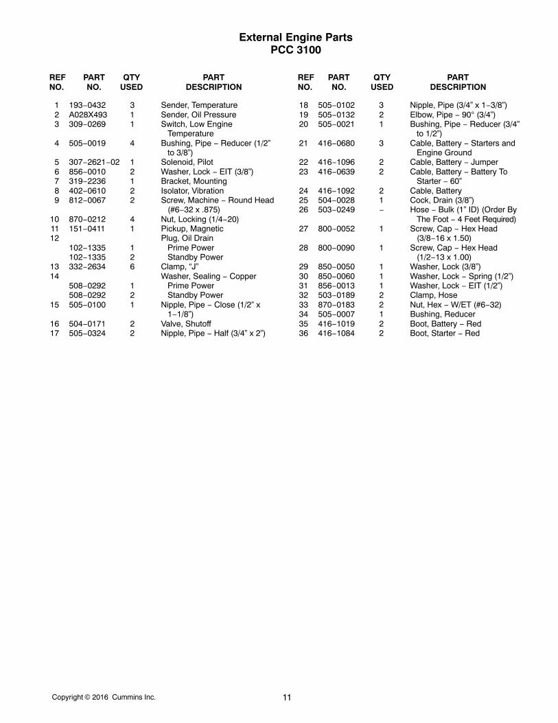
External Engine PartsPCC 3100
REF PART QTY PART REF PART QTY PARTNO. NO. USED DESCRIPTION NO. NO. USED DESCRIPTION
1 193−0432 3 Sender, Temperature2 A028X493 1 Sender, Oil Pressure3 309−0269 1 Switch, Low Engine
Temperature4 505−0019 4 Bushing, Pipe − Reducer (1/2”
to 3/8”)5 307−2621−02 1 Solenoid, Pilot6 856−0010 2 Washer, Lock − EIT (3/8”)7 319−2236 1 Bracket, Mounting8 402−0610 2 Isolator, Vibration9 812−0067 2 Screw, Machine − Round Head
(#6−32 x .875)10 870−0212 4 Nut, Locking (1/4−20)11 151−0411 1 Pickup, Magnetic12 Plug, Oil Drain
102−1335 1 Prime Power102−1335 2 Standby Power
13 332−2634 6 Clamp, “J”14 Washer, Sealing − Copper
508−0292 1 Prime Power508−0292 2 Standby Power
15 505−0100 1 Nipple, Pipe − Close (1/2” x1−1/8”)
16 504−0171 2 Valve, Shutoff17 505−0324 2 Nipple, Pipe − Half (3/4” x 2”)
18 505−0102 3 Nipple, Pipe (3/4” x 1−3/8”)19 505−0132 2 Elbow, Pipe − 90 (3/4”)20 505−0021 1 Bushing, Pipe − Reducer (3/4”
to 1/2”)21 416−0680 3 Cable, Battery − Starters and
Engine Ground22 416−1096 2 Cable, Battery − Jumper23 416−0639 2 Cable, Battery − Battery To
Starter − 60”24 416−1092 2 Cable, Battery25 504−0028 1 Cock, Drain (3/8”)26 503−0249 − Hose − Bulk (1” ID) (Order By
The Foot − 4 Feet Required)27 800−0052 1 Screw, Cap − Hex Head
(3/8−16 x 1.50)28 800−0090 1 Screw, Cap − Hex Head
(1/2−13 x 1.00)29 850−0050 1 Washer, Lock (3/8”)30 850−0060 1 Washer, Lock − Spring (1/2”)31 856−0013 1 Washer, Lock − EIT (1/2”)32 503−0189 2 Clamp, Hose33 870−0183 2 Nut, Hex − W/ET (#6−32)34 505−0007 1 Bushing, Reducer35 416−1019 2 Boot, Battery − Red36 416−1084 2 Boot, Starter − Red
Copyright 2016 Cummins Inc.12
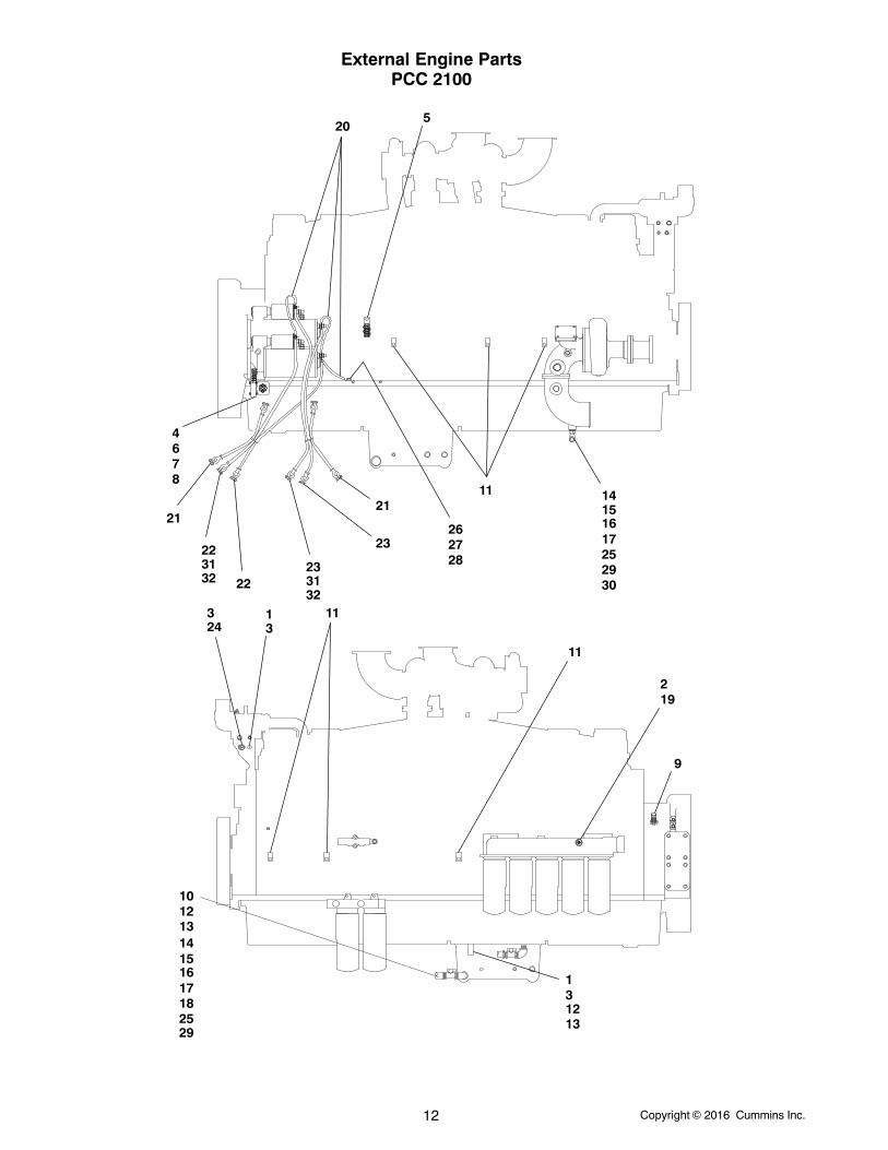
External Engine PartsPCC 2100
1
1
2
3
33
4
5
678
9
10
11
11
11
12
12
13
13
14
1415
1516
1617
1718
19
20
2121
22
2223
23
24
25
25
262728
29
29
31313232
30
Copyright 2016 Cummins Inc. 13
External Engine PartsPCC 2100
REF PART QTY PART REF PART QTY PARTNO. NO. USED DESCRIPTION NO. NO. USED DESCRIPTION
1 193−0529−01 1 Sensor, Temperature (S2)2 A028X493 1 Sender, Oil Pressure3 505−0019 2 Bushing, Pipe − Reducer (1/2”
to 3/8”)4 307−2621−02 1 Solenoid, Pilot5 856−0010 2 Washer, Lock − EIT (3/8”)6 319−2236 1 Bracket, Mounting7 402−0610 2 Isolator, Vibration8 870−0212 4 Nut, Locking (1/4−20)9 151−0411 1 Pickup, Magnetic
10 Plug, Oil Drain102−1335 1 Prime Power102−1335 2 Standby Power
11 332−2634 6 Clamp, “J”12 Washer, Sealing − Copper
508−0292 1 Prime Power508−0292 2 Standby Power
13 505−0100 1 Nipple, Pipe − Close (1/2” x1−1/8”)
14 504−0171 2 Valve, Shutoff15 505−0324 2 Nipple, Pipe − Half (3/4” x 2”)16 505−0102 3 Nipple, Pipe (3/4” x 1−3/8”)
17 505−0132 2 Elbow, Pipe − 90 (3/4”)18 505−0021 1 Bushing, Pipe − Reducer (3/4”
to 1/2”)19 505−0007 1 Bushing, Reducer20 416−0680 3 Cable, Battery − Starters and
Engine Ground21 416−0446 2 Cable, Battery − Jumper22 416−0639 2 Cable, Battery − Battery To
Starter − 60”23 416−0964 2 Cable, Battery24 504−0028 1 Cock, Drain (3/8”)25 503−0249 − Hose − Bulk (1” ID) (Order By
The Foot − 4 Feet Required)26 800−0090 1 Screw, Cap − Hex Head
(1/2−13 x 1.00)27 850−0060 1 Washer, Lock − Spring (1/2”)28 856−0013 1 Washer, Lock − EIT (1/2”)29 503−0189 2 Clamp30 503−2823 2 Clamp, Hose31 416−1019 2 Boot, Battery − Red32 416−1084 2 Boot, Starter − Red
Copyright 2016 Cummins Inc.14
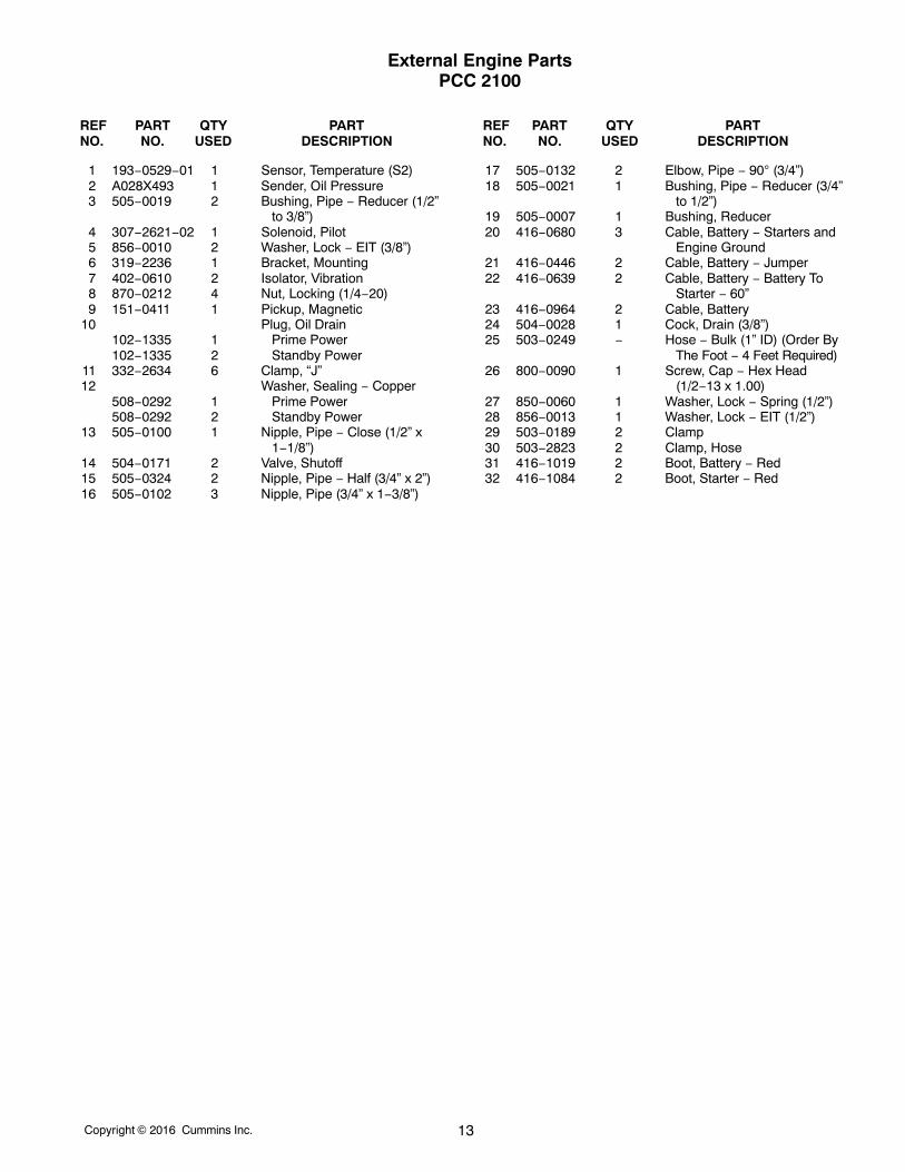
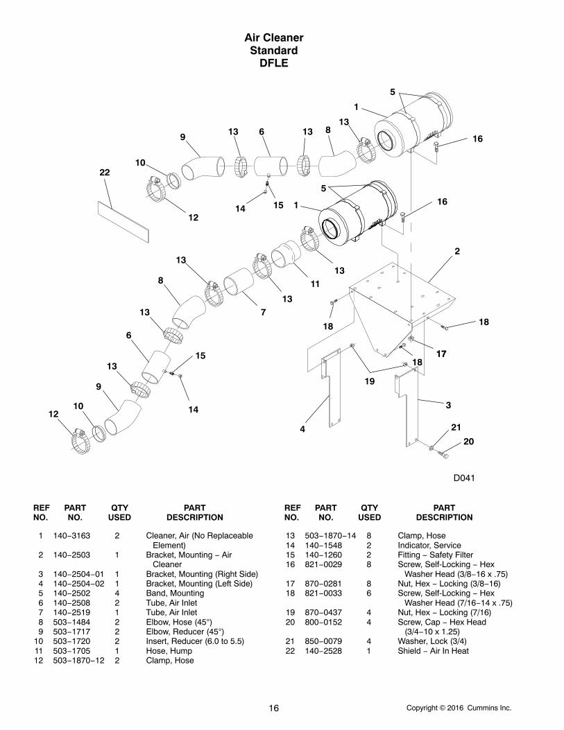
Air CleanerStandard
DFLB
34
56
57
5
89 10 5 7
5
2
1
11
12
1314
15 16 17 34
56
7
7
1
5
5
10 98
REF PART QTY PART REF PART QTY PARTNO. NO. USED DESCRIPTION NO. NO. USED DESCRIPTION
1 140−2501 2 Cleaner, Air (Disposable)2 140−2502 4 Band, Mounting3 503−1870−11 2 Clamp, Hose4 503−1675 2 Hose, Rubber − Reducer (7”
ID to 5−1/2” ID)5 503−1870−14 10 Clamp, Hose6 140−2519 2 Tube, Air Inlet (7” x 9”)7 503−0970 4 Elbow − 908 140−1548 2 Indicator, Service9 140−1260 2 Fitting, Safety Filter
10 140−2521 2 Tube, Air Inlet11 870−0281 8 Nut, Hex − Locking (3/8−16)
12 140−2515 1 Bracket, Mounting13 821−0029 8 Screw, Self−Locking − Hex
Washer Head (3/8−16 x 3/4”)14 821−0033 8 Screw, Self−Locking − Hex
Washer Head (7/16−14 x3/4”)
15 870−0257 2 Nut, Hex − Locking (5/16−18)16 518−0548−08 2 Clamp, “J”17 821−0016 2 Screw, Self−Locking − Hex
Washer Head (5/16−18 x3/4”)
Copyright 2016 Cummins Inc. 15
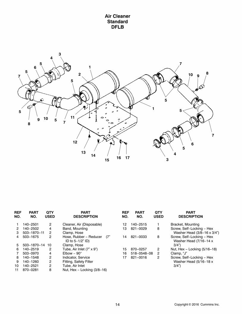
Air CleanerStandard
DFLC
D041
2
2
15
19
22
1
1
5
5
14
4
4
6
6
7
7
13
9
9
3
3
3
10
10
11
1112
12
3
3 33
1716
1616
18
21
20
8
3
REF PART QTY PART REF PART QTY PARTNO. NO. USED DESCRIPTION NO. NO. USED DESCRIPTION
1 140−2502 4 Band, Mounting − Air Cleaner2 140−2501 2 Cleaner, Air (Disposable)3 503−1870−14 8 Clamp, Hose4 503−1484 2 Elbow, Hose − 45 (7” ID)5 140−2508 2 Tube, Air Inlet (7” x 9−3/4”)6 503−1717 2 Elbow, Reducer − 45 (7” ID to
6” ID)7 503−1720 2 Insert, Reducer (6” OD to
5−1/2” ID)8 140−2528 1 Shield − Air In Heat9 503−1870−12 2 Clamp, Hose
10 140−1548 2 Indicator, Service11 140−1260 2 Fitting, Safety Filter12 821−0029 8 Screw, Self−Locking − Hex
Washer Head (3/8−16 x 3/4”)
13 503−1705 1 Hose, Hump (7” ID)14 140−2519 1 Tube, Air Inlet (7” x 9”)15 140−2503 1 Bracket, Mounting16 821−0033 6 Screw, Self−Locking − Hex
Washer Head (7/16−14 x3/4”)
17 870−0281 8 Nut, Locking − Hex (3/8−16)18 870−0437 4 Nut, Locking − Hex (7/16−14)19 140−2504−01 1 Bracket, Mounting (Right Side)20 850−0079 4 Washer, Lock − Spring (3/4”)21 800−0152 4 Screw, Cap − Hex Head
(3/4−10 x 1−1/4”)22 140−2504−02 1 Bracket , Mounting (Left Side)
Copyright 2016 Cummins Inc.16
Air CleanerStandard
DFLE
D041
1
1
2
3
4
5
5
6
6
7
8
8
9
9
10
10
11
12
12
13
13
13
14
14
15
15 16
16
13
13 1313
171718
1818
19
20
21
22
13
REF PART QTY PART REF PART QTY PARTNO. NO. USED DESCRIPTION NO. NO. USED DESCRIPTION
1 140−3163 2 Cleaner, Air (No ReplaceableElement)
2 140−2503 1 Bracket, Mounting − AirCleaner
3 140−2504−01 1 Bracket, Mounting (Right Side)4 140−2504−02 1 Bracket, Mounting (Left Side)5 140−2502 4 Band, Mounting6 140−2508 2 Tube, Air Inlet7 140−2519 1 Tube, Air Inlet8 503−1484 2 Elbow, Hose (45)9 503−1717 2 Elbow, Reducer (45)
10 503−1720 2 Insert, Reducer (6.0 to 5.5)11 503−1705 1 Hose, Hump12 503−1870−12 2 Clamp, Hose
13 503−1870−14 8 Clamp, Hose14 140−1548 2 Indicator, Service15 140−1260 2 Fitting − Safety Filter16 821−0029 8 Screw, Self-Locking − Hex
Washer Head (3/8−16 x .75)17 870−0281 8 Nut, Hex − Locking (3/8−16)18 821−0033 6 Screw, Self-Locking − Hex
Washer Head (7/16−14 x .75)19 870−0437 4 Nut, Hex − Locking (7/16)20 800−0152 4 Screw, Cap − Hex Head
(3/4−10 x 1.25)21 850−0079 4 Washer, Lock (3/4)22 140−2528 1 Shield − Air In Heat

Copyright 2016 Cummins Inc. 17
“Intentionally Left Blank”
Copyright 2016 Cummins Inc.18
Air CleanerHeavy Duty
DFLB
2
114
5
43
7
6
8
21
20
16
13
11
9
18
10
19
15
17
12
12
12
3
3
3
3
3
3
3
4
5
8
67
911
13
19
10
14
Copyright 2016 Cummins Inc. 19
Air CleanerHeavy Duty
DFLB
REF PART QTY PART REF PART QTY PARTNO. NO. USED DESCRIPTION NO. NO. USED DESCRIPTION
1 503−1870−11 2 Clamp, Hose2 503−1675 2 Hose, Rubber − Reducer (7” ID
to 5−1/2” ID)3 503−1870−14 8 Clamp, Hose4 140−2519 2 Tube, Air Inlet (7” x 9”)5 503−0970 2 Elbow − 906 140−1548 2 Indicator, Service7 140−1260 2 Fitting, Safety Filter8 140−2521 2 Tube, Air Inlet (7” x 18−1/2”)9 503−1485 2 Elbow, Reducer − 90 (8” ID to
7” ID)10 870−0437 6 Nut, Hex − Locking (7/16−14)11 503−1871−04 2 Clamp, Hose12 140−2098 2 Hood, Air Inlet (Includes
Mounting Clamp)
13 140−2099 4 Band, Mounting14 140−2097 2 Cleaner, Air (Includes
Elements)15 526−0219 2 Washer, Flat (7/16”)16 850−0055 2 Washer, Lock − Spring (7/16”)17 800−0072 2 Screw, Cap − Hex Head
(7/16−14 x 1−1/4”)18 140−2515 1 Bracket, Mounting19 821−0033 12 Screw, Self−Locking − Hex
Washer Head (7/16−14 x 3/4”)
20 140−2096 2 Element, Primary (Outer)21 140−2467 2 Element, Safety (Inner)

Copyright 2016 Cummins Inc.20
Air CleanerHeavy DutyDFLC, DFLE
16
3
19 18
7
1
24
23
109
11
22
13
8 5
14
15
6
21
17
4
20
12
2
26
25
3
1
7
9
1011
8
8
8
8
13
1415
15
15
17
15
4
4
2
Copyright 2016 Cummins Inc. 21
Air CleanerHeavy DutyDFLC, DFLE
REF PART QTY PART REF PART QTY PARTNO. NO. USED DESCRIPTION NO. NO. USED DESCRIPTION
1 140−2099 4 Band, Mounting2 140−2098 2 Hood, Air Inlet (Includes
Mounting Clamp)3 140−3230 2 Cleaner, Air (Includes Elements
− See Ref. No. 25 and 26)4 503−1871−04 3 Clamp, Hose5 503−1718 1 Elbow, Hose (45 Deg) (8” ID)6 503−1719 1 Insert, Reducer (8” OD to 7” ID)7 140−2509 2 Tube, Air Inlet (7” OD x 12”)8 503−1870−14 5 Clamp, Hose9 503−1717 2 Elbow, Reducer (45 Deg) (7”
ID to 6” ID)10 503−1720 2 Insert, Reducer (6” OD to
5−1/2” ID)11 503−1870−12 2 Clamp, Hose12 140−2528 1 Shield13 140−1548 2 Indicator, Service14 140−1260 2 Fitting, Safety Filter
15 821−0033 14 Screw, Self−Locking − HexWasher Head (7/16−14 x3/4”)
16 140−2503 1 Bracket, Mounting17 870−0437 12 Nut, Locking − Hex (7/16−14)18 140−2504−01 1 Bracket − Right Side19 140−2504−02 1 Bracket − Left Side20 850−0079 4 Washer, Lock − Spring (3/4”)21 800−0152 4 Screw, Cap − Hex Head
(3/4−10 x 1−1/4”)22 503−1721 1 Hose, Hump − Reducer (8” ID
to 7” ID)23 140−2395 1 Tube, Air Inlet (7” OD x
10−1/2”)24 503−1484 1 Elbow, Hose (45 Deg) (7” ID)25 140−2096 2 Element, Primary (Outer)26 140−2467 2 Element, Safety (Inner)
Copyright 2016 Cummins Inc.22
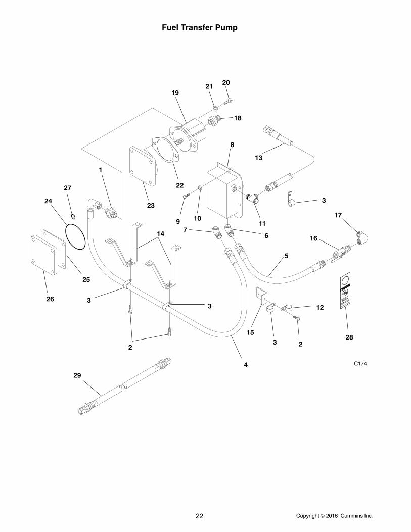
Fuel Transfer Pump
C174
1
23
33
3
4
5
67
8
9 1011
12
2
13
14
15
16
17
18
19
2021
24
25
26
27
23
22
28
29
Copyright 2016 Cummins Inc. 23
Fuel Transfer Pump
REF PART QTY PART REF PART QTY PARTNO. NO. USED DESCRIPTION NO. NO. USED DESCRIPTION
1 502−1267 1 Connector, Straight (7/8−14 x1−3/16−12)
2 821−5004−02 3 Screw, Self−Locking − HexWasher Head (3/8−16 x 3/4”)
3 518−0548−29 5 Clamp, Hose4 501−0651 1 Line, Fuel − Flexible (3/4” ID x
67”)5 501−0653 1 Line, Fuel − Flexible (1” ID x
26”)6 502−1266−02 1 Elbow − 45 (1-5/16−12 x
1-7/16−12)7 502−1266−01 1 Elbow − 45 (1−1/16−12 x
1−3/16−12)8 159−1445 1 Reservoir, Fuel9 800−0081 2 Screw, Cap − Hex Head
(7/16−14 x 3−1/2”)10 850−0055 2 Washer, Lock − Spring (7/16”)11 502−1269 1 Tee (1-3/16−12 x 1-3/16−12 x
1-1/16−12)12 518−0633 1 Clamp, “J”13 501−0654 1 Line, Fuel − Flexible (3/4” ID x
40”)
14 159−1450 2 Bracket15 159−1448 1 Bracket16 502−1270 1 Valve, Shutoff17 502−1271 1 Elbow − 90 (1-5/16−12 x
1-5/16−12)18 502−1268 1 Connector, Straight (7/8−14 x
1-5/16−12)19 159−1451 1 Pump, Fuel Transfer20 800−0050 2 Screw, Cap − Hex Head
(3/8−16 x 1”)21 850−0050 2 Washer, Lock − Spring (3/8”)22 121−0113 1 Gasket, Pump23 121−0111 1 Drive, Pump24 509−0336 1 Seal, O−Ring25 121−0117 1 Gasket, Hand Hole26 121−0116 1 Cover, Hydraulic Hole27 509−0337 1 Seal, O−Ring28 098−7301 1 Tag, Label29 Line, Flexible Fuel
501−0704 1 Fuel Out501−0707 1 Fuel In
Copyright 2016 Cummins Inc.24
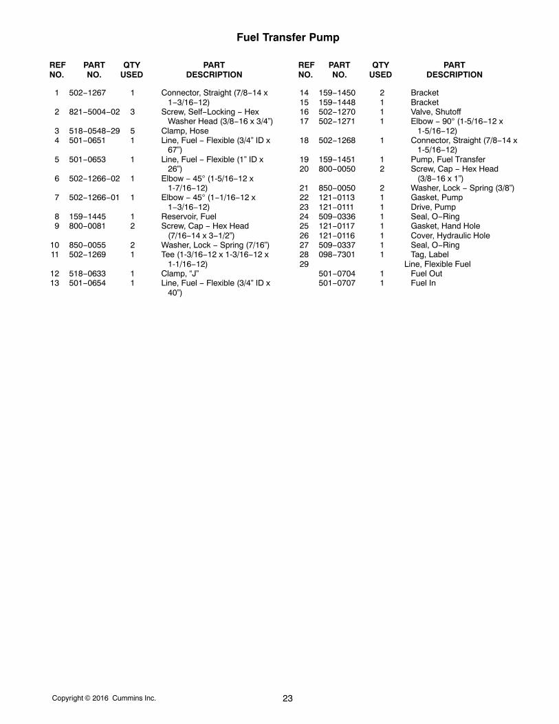
Fuel Pressure Gauge
1
2
3
4
5
6
7
REF PART QTY PART REF PART QTY PARTNO. NO. USED DESCRIPTION NO. NO. USED DESCRIPTION
1 193−0540 1 Gauge, Fuel Pressure(Includes MountingHardware)
2 193−0029 1 Bracket, Mounting3 504−0064 1 Valve, Tee (1/8”)4 149−2291−02 1 Tube, Fuel − Copper5 502−0034 1 Elbow, Compression − 90
(Includes Nut and Ring)
6 502−1302 1 Adapter, Female Pipe − Brass(1/8” x 1/2−20)
7 502−0067 2 Connector, Compression −Male
8 140−1260−01 1 Fitting, Safety Filter (NotIllustrated)
Copyright 2016 Cummins Inc. 25
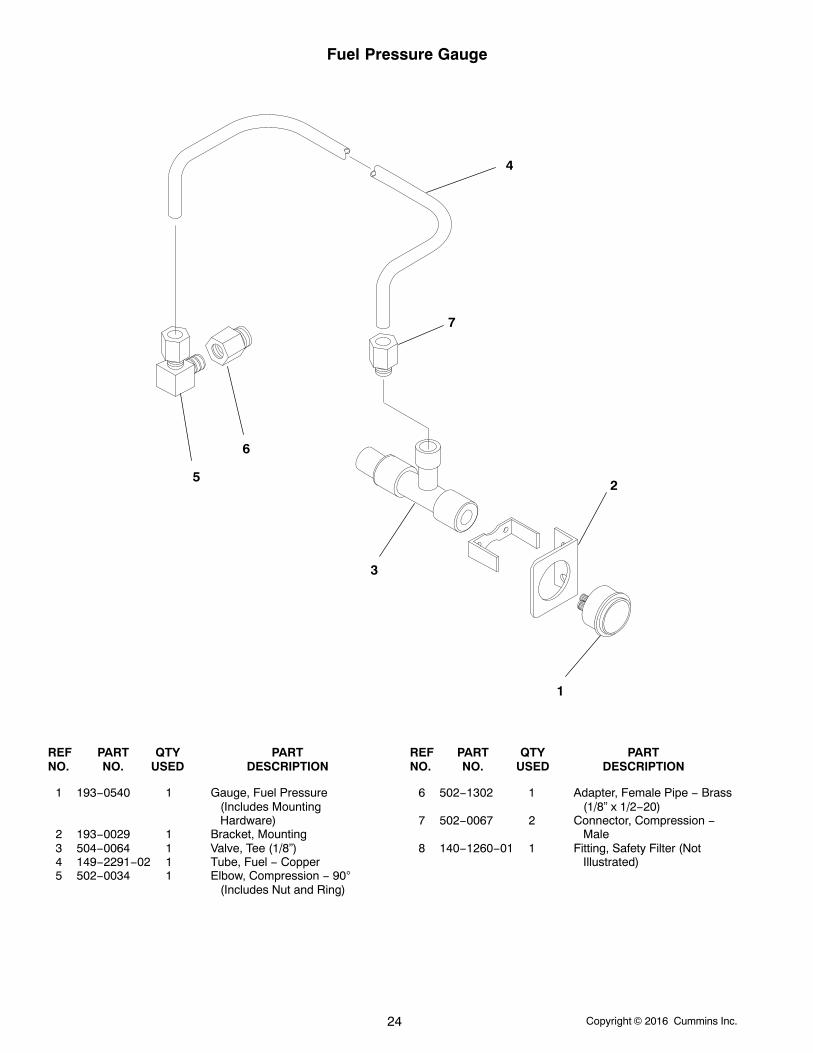
Temperature SwitchTwo Pump Two Loop Engine
DFLE
1
2
REF PART QTY PART REF PART QTY PARTNO. NO. USED DESCRIPTION NO. NO. USED DESCRIPTION
1 338−4027 1 Harness, Wiring 2 309−0676 1 Switch, Temperature
Copyright 2016 Cummins Inc.26
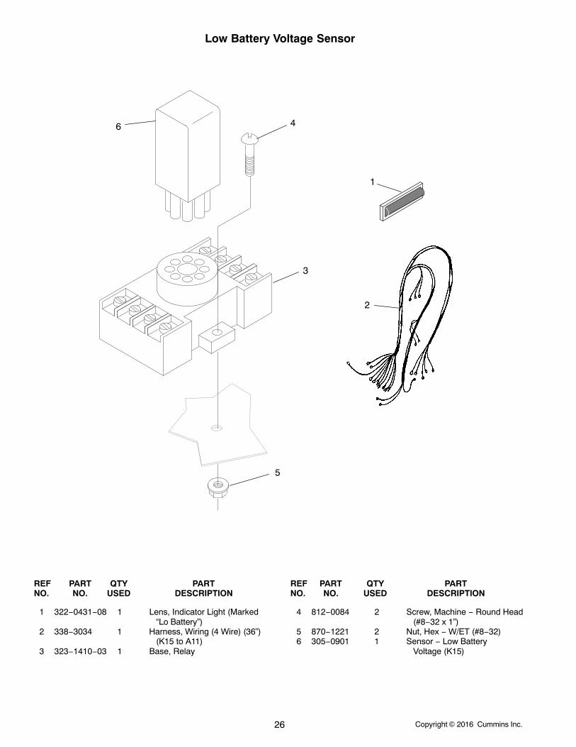
Low Battery Voltage Sensor
6 4
1
3
2
5
REF PART QTY PART REF PART QTY PARTNO. NO. USED DESCRIPTION NO. NO. USED DESCRIPTION
1 322−0431−08 1 Lens, Indicator Light (Marked“Lo Battery”)
2 338−3034 1 Harness, Wiring (4 Wire) (36”)(K15 to A11)
3 323−1410−03 1 Base, Relay
4 812−0084 2 Screw, Machine − Round Head(#8−32 x 1”)
5 870−1221 2 Nut, Hex − W/ET (#8−32)6 305−0901 1 Sensor − Low Battery
Voltage (K15)

Copyright 2016 Cummins Inc. 27
“Intentionally Left Blank”
Copyright 2016 Cummins Inc.28
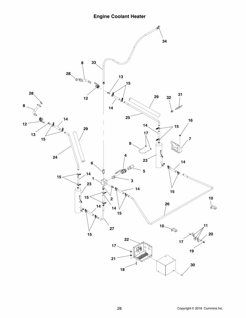
Engine Coolant Heater
1
2
3
4
5
6
7
8
8
9
10
10
11
12
12
13
13
14
14
14
14
1414
14
14
15
15
15
15
15
15
15
15
16
17
1717
18
19
20
21
22
23
2324
25
26
27
28
28
29
29
30
3132
33
34
Copyright 2016 Cummins Inc. 29
Engine Coolant Heater
REF PART QTY PART REF PART QTY PARTNO. NO. USED DESCRIPTION NO. NO. USED DESCRIPTION
1 133−0226 1 Manifold, Heater2 502−0827 2 Hose, Barb3 505−1576−02 1 Nipple, Hex − Pipe (1”)4 504−0214 1 Valve, Ball (1”)5 505−2031 1 Nipple, Pipe − Reducer (1-1/4”
x 1”)6 504−0215 1 Valve, Check (1/4”)7 130−4546 2 Bracket, Mounting − Coolant
Heater8 130−4519−03 2 Tube9 155−3021 2 Clamp, Mounting
10 130−4538 2 Bracket, Retainer11 332−2634 6 Clamp, “J”12 504−0213 2 Valve, Ball13 502−0827 2 Fitting, Hose − Barbed (1/2” ID
Pipe to 3/4” ID Hose)14 503−3062−01 8 Hose, Rubber15 503−2157−02 16 Clamp, Hose16 821−5004−02 6 Screw, Self−Locking − Hex
Washer Head (3/8−16 x 3/4”)17 870−0550−09 8 Nut, Hex − Flange (3/8−16)18 520−0544 2 Stud, Mounting (3/8−16 x
1−3/16”)19 821−5004−03 2 Screw, Self−Locking − Hex
Washer Head (3/8−16 x 1”)
20 526−0029 2 Washer, Flat (3/8”)21 526−0128 2 Washer, Flat (3/8”)22 — 1 Control Assembly, Coolant
Heater (See Page 25 ForComponents)
23 Heater, Coolant333−0677−01 2 4990 Watt333−0677−02 2 6420 Watt
24 130−5588−02 1 Tube, Water Heater25 130−5589−02 1 Tube, Water Heater26 130−5590−02 1 Tube, Water Heater27 130−5591−02 1 Tube, Water Heater28 509−0283−01 2 Seal, Rectangular Ring29 128−0108 − Insulation, Hose − Bulk (Order
By The Foot − 4 FeetRequired)
30 821−5002−03 4 Screw, Self−Locking − HexWasher Head (1/4−20 x 1/2”)
31 309−0649 1 Thermostat (Opens At 110 F,Closes At 130 F) (S11)
32 502−1336 1 Bushing, Reducer (1/2 x 3/8)33 501−0744−01 1 Hose, Coolant34 505−2037 1 Tee, Pipe (1/4”)
Copyright 2016 Cummins Inc.30
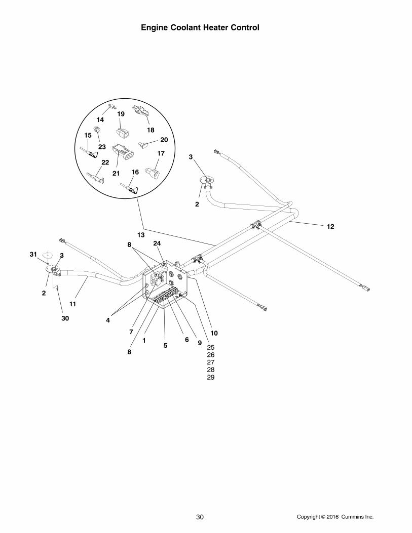
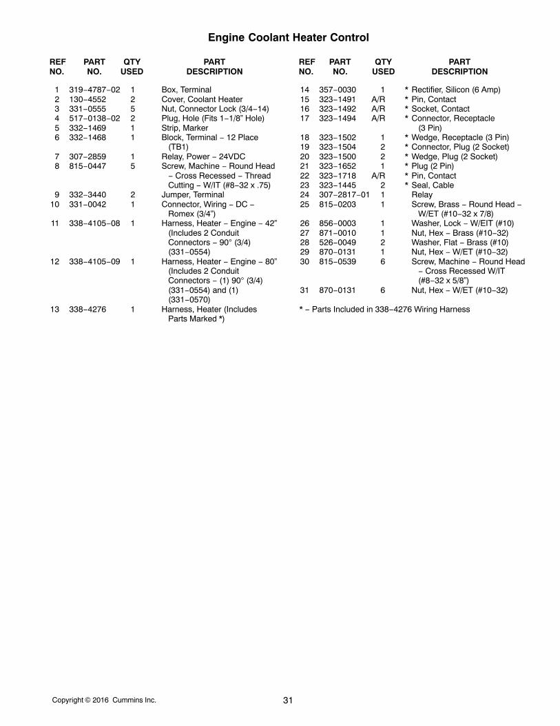
Engine Coolant Heater Control
1
2
3
2
3
4
56
7
8
8
910
11
12
14
15
16
17
18
19
20
21
22
23
1324
2526272829
30
31
Copyright 2016 Cummins Inc. 31
Engine Coolant Heater Control
REF PART QTY PART REF PART QTY PARTNO. NO. USED DESCRIPTION NO. NO. USED DESCRIPTION
1 319−4787−02 1 Box, Terminal2 130−4552 2 Cover, Coolant Heater3 331−0555 5 Nut, Connector Lock (3/4−14)4 517−0138−02 2 Plug, Hole (Fits 1−1/8” Hole)5 332−1469 1 Strip, Marker6 332−1468 1 Block, Terminal − 12 Place
(TB1)7 307−2859 1 Relay, Power − 24VDC8 815−0447 5 Screw, Machine − Round Head
− Cross Recessed − ThreadCutting − W/IT (#8−32 x .75)
9 332−3440 2 Jumper, Terminal10 331−0042 1 Connector, Wiring − DC −
Romex (3/4”)11 338−4105−08 1 Harness, Heater − Engine − 42”
(Includes 2 ConduitConnectors − 90 (3/4)(331−0554)
12 338−4105−09 1 Harness, Heater − Engine − 80”(Includes 2 ConduitConnectors − (1) 90 (3/4)(331−0554) and (1)(331−0570)
13 338−4276 1 Harness, Heater (IncludesParts Marked *)
14 357−0030 1 * Rectifier, Silicon (6 Amp)15 323−1491 A/R * Pin, Contact16 323−1492 A/R * Socket, Contact17 323−1494 A/R * Connector, Receptacle
(3 Pin)18 323−1502 1 * Wedge, Receptacle (3 Pin)19 323−1504 2 * Connector, Plug (2 Socket)20 323−1500 2 * Wedge, Plug (2 Socket)21 323−1652 1 * Plug (2 Pin)22 323−1718 A/R * Pin, Contact23 323−1445 2 * Seal, Cable24 307−2817−01 1 Relay25 815−0203 1 Screw, Brass − Round Head −
W/ET (#10−32 x 7/8)26 856−0003 1 Washer, Lock − W/EIT (#10)27 871−0010 1 Nut, Hex − Brass (#10−32)28 526−0049 2 Washer, Flat − Brass (#10)29 870−0131 1 Nut, Hex − W/ET (#10−32)30 815−0539 6 Screw, Machine − Round Head
− Cross Recessed W/IT(#8−32 x 5/8”)
31 870−0131 6 Nut, Hex − W/ET (#10−32)
* − Parts Included in 338−4276 Wiring Harness
Copyright 2016 Cummins Inc.32
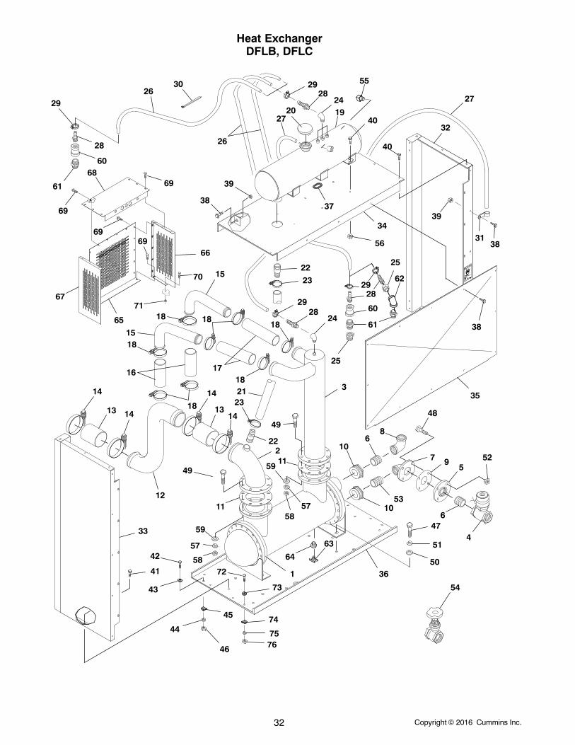
Heat ExchangerDFLB, DFLC
1
4
7
10
2
5
3
6
8
15
9
16
11
17
22
23
24
12
18
13
19
14 21
2627
20
37
41
38
39
47
48
40
49
50
51
53
54
56
57
52
55
58
2829
32
33
35
36
30
3431
59
63
64
106
11
1314
14
14
1518
18
18
18
23
22
24
40
38
5857
59
49
38
39
18
2829
27
26
29
29
69
61
25
28
28
72
73
7675
74
60
60
61
25
62
65
67
69
68
6669
69
70
71
46
44
45
42
43
Copyright 2016 Cummins Inc. 33
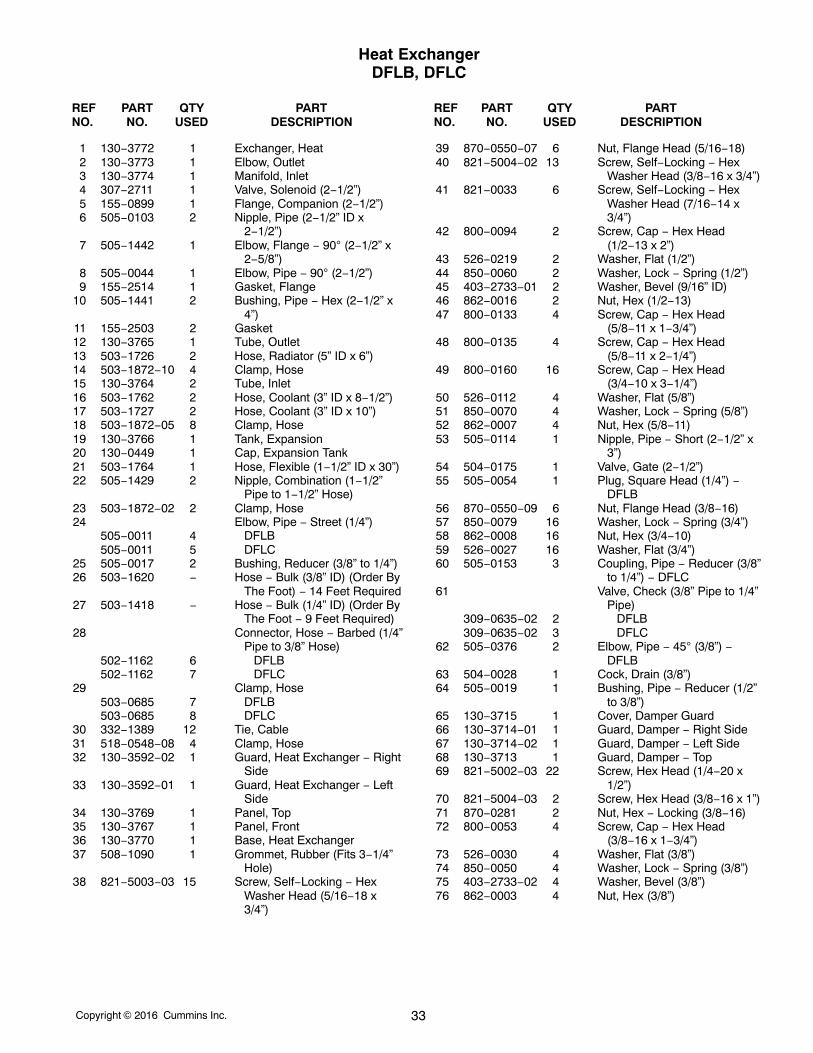
Heat ExchangerDFLB, DFLC
REF PART QTY PART REF PART QTY PARTNO. NO. USED DESCRIPTION NO. NO. USED DESCRIPTION
1 130−3772 1 Exchanger, Heat2 130−3773 1 Elbow, Outlet3 130−3774 1 Manifold, Inlet4 307−2711 1 Valve, Solenoid (2−1/2”)5 155−0899 1 Flange, Companion (2−1/2”)6 505−0103 2 Nipple, Pipe (2−1/2” ID x
2−1/2”)7 505−1442 1 Elbow, Flange − 90 (2−1/2” x
2−5/8”)8 505−0044 1 Elbow, Pipe − 90 (2−1/2”)9 155−2514 1 Gasket, Flange
10 505−1441 2 Bushing, Pipe − Hex (2−1/2” x4”)
11 155−2503 2 Gasket12 130−3765 1 Tube, Outlet13 503−1726 2 Hose, Radiator (5” ID x 6”)14 503−1872−10 4 Clamp, Hose15 130−3764 2 Tube, Inlet16 503−1762 2 Hose, Coolant (3” ID x 8−1/2”)17 503−1727 2 Hose, Coolant (3” ID x 10”)18 503−1872−05 8 Clamp, Hose19 130−3766 1 Tank, Expansion20 130−0449 1 Cap, Expansion Tank21 503−1764 1 Hose, Flexible (1−1/2” ID x 30”)22 505−1429 2 Nipple, Combination (1−1/2”
Pipe to 1−1/2” Hose)23 503−1872−02 2 Clamp, Hose24 Elbow, Pipe − Street (1/4”)
505−0011 4 DFLB505−0011 5 DFLC
25 505−0017 2 Bushing, Reducer (3/8” to 1/4”)26 503−1620 − Hose − Bulk (3/8” ID) (Order By
The Foot) − 14 Feet Required27 503−1418 − Hose − Bulk (1/4” ID) (Order By
The Foot − 9 Feet Required)28 Connector, Hose − Barbed (1/4”
Pipe to 3/8” Hose)502−1162 6 DFLB502−1162 7 DFLC
29 Clamp, Hose503−0685 7 DFLB503−0685 8 DFLC
30 332−1389 12 Tie, Cable31 518−0548−08 4 Clamp, Hose32 130−3592−02 1 Guard, Heat Exchanger − Right
Side33 130−3592−01 1 Guard, Heat Exchanger − Left
Side34 130−3769 1 Panel, Top35 130−3767 1 Panel, Front36 130−3770 1 Base, Heat Exchanger37 508−1090 1 Grommet, Rubber (Fits 3−1/4”
Hole)38 821−5003−03 15 Screw, Self−Locking − Hex
Washer Head (5/16−18 x3/4”)
39 870−0550−07 6 Nut, Flange Head (5/16−18)40 821−5004−02 13 Screw, Self−Locking − Hex
Washer Head (3/8−16 x 3/4”)41 821−0033 6 Screw, Self−Locking − Hex
Washer Head (7/16−14 x3/4”)
42 800−0094 2 Screw, Cap − Hex Head(1/2−13 x 2”)
43 526−0219 2 Washer, Flat (1/2”)44 850−0060 2 Washer, Lock − Spring (1/2”)45 403−2733−01 2 Washer, Bevel (9/16” ID)46 862−0016 2 Nut, Hex (1/2−13)47 800−0133 4 Screw, Cap − Hex Head
(5/8−11 x 1−3/4”)48 800−0135 4 Screw, Cap − Hex Head
(5/8−11 x 2−1/4”)49 800−0160 16 Screw, Cap − Hex Head
(3/4−10 x 3−1/4”)50 526−0112 4 Washer, Flat (5/8”)51 850−0070 4 Washer, Lock − Spring (5/8”)52 862−0007 4 Nut, Hex (5/8−11)53 505−0114 1 Nipple, Pipe − Short (2−1/2” x
3”)54 504−0175 1 Valve, Gate (2−1/2”)55 505−0054 1 Plug, Square Head (1/4”) −
DFLB56 870−0550−09 6 Nut, Flange Head (3/8−16)57 850−0079 16 Washer, Lock − Spring (3/4”)58 862−0008 16 Nut, Hex (3/4−10)59 526−0027 16 Washer, Flat (3/4”)60 505−0153 3 Coupling, Pipe − Reducer (3/8”
to 1/4”) − DFLC61 Valve, Check (3/8” Pipe to 1/4”
Pipe)309−0635−02 2 DFLB309−0635−02 3 DFLC
62 505−0376 2 Elbow, Pipe − 45 (3/8”) −DFLB
63 504−0028 1 Cock, Drain (3/8”)64 505−0019 1 Bushing, Pipe − Reducer (1/2”
to 3/8”)65 130−3715 1 Cover, Damper Guard66 130−3714−01 1 Guard, Damper − Right Side67 130−3714−02 1 Guard, Damper − Left Side68 130−3713 1 Guard, Damper − Top69 821−5002−03 22 Screw, Hex Head (1/4−20 x
1/2”)70 821−5004−03 2 Screw, Hex Head (3/8−16 x 1”)71 870−0281 2 Nut, Hex − Locking (3/8−16)72 800−0053 4 Screw, Cap − Hex Head
(3/8−16 x 1−3/4”)73 526−0030 4 Washer, Flat (3/8”)74 850−0050 4 Washer, Lock − Spring (3/8”)75 403−2733−02 4 Washer, Bevel (3/8”)76 862−0003 4 Nut, Hex (3/8”)
Copyright 2016 Cummins Inc.34
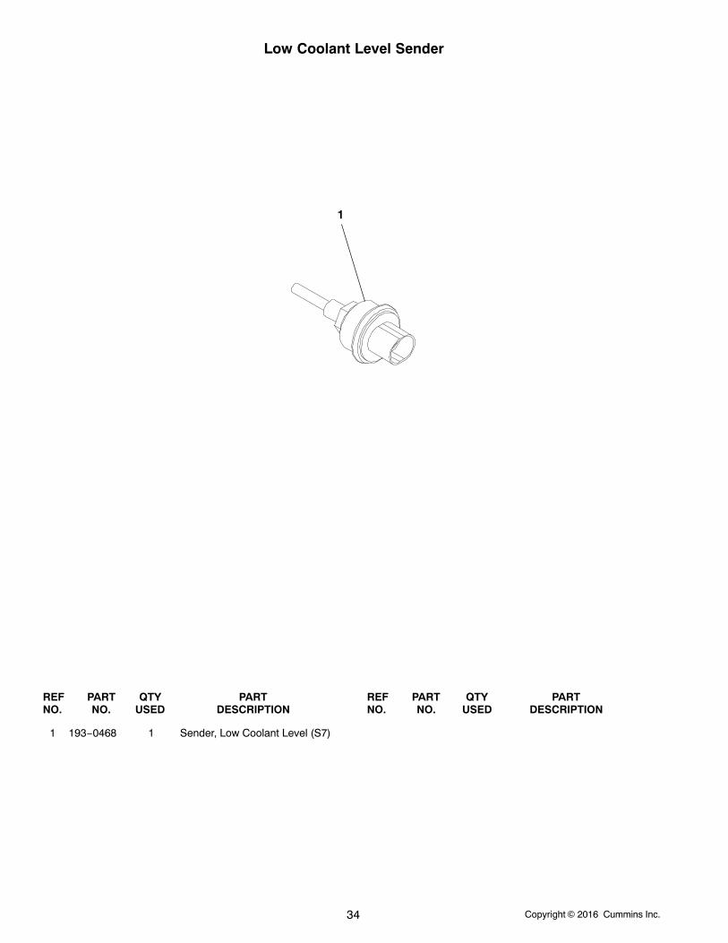
Low Coolant Level Sender
1
REF PART QTY PART REF PART QTY PARTNO. NO. USED DESCRIPTION NO. NO. USED DESCRIPTION
1 193−0468 1 Sender, Low Coolant Level (S7)
Copyright 2016 Cummins Inc. 35
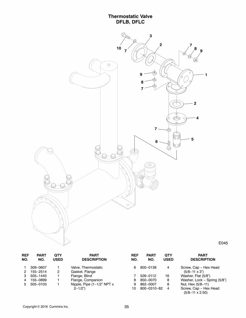
Thermostatic ValveDFLB, DFLC
7
E045
8 9
1
2
4
5
7
7
8
9
6
7
3
210
REF PART QTY PART REF PART QTY PARTNO. NO. USED DESCRIPTION NO. NO. USED DESCRIPTION
1 309−0607 1 Valve, Thermostatic2 155−2514 2 Gasket, Flange3 505−1440 1 Flange, Blind4 155−0899 1 Flange, Companion5 505−0103 1 Nipple, Pipe (1−1/2” NPT x
2−1/2”)
6 800−0138 4 Screw, Cap − Hex Head(5/8−11 x 3”)
7 526−0112 16 Washer, Flat (5/8”)8 850−0070 8 Washer, Lock − Spring (5/8”)9 862−0007 8 Nut, Hex (5/8−11)
10 800−0310−82 4 Screw, Cap − Hex Head(5/8−11 x 2.50)
Copyright 2016 Cummins Inc.36
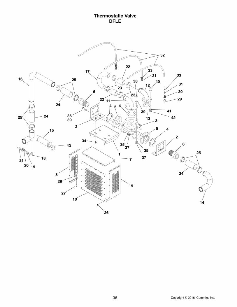
Thermostatic ValveDFLE
1
2
2
3
4
4
5
45
6
6
7
8
9
10
11
12
13
14
15
16
17
18
192021
22
22
23
23
24
24
24
25
25
25
26
27
28
29
30
31
32
333133
40
41
423639
3537
38
39
35
37
4334
Copyright 2016 Cummins Inc. 37
Thermostatic ValveDFLE
REF PART QTY PART REF PART QTY PARTNO. NO. USED DESCRIPTION NO. NO. USED DESCRIPTION
1 130−5407−02 1 Bracket, Angle2 130−5408−02 2 Bracket, L3 504−0207 1 Valve, Thermostatic4 155−2514−04 3 Gasket, Flange5 505−0601 2 Flange, Companion6 505−1549 2 Adapter, Pipe7 130−3713 1 Guard, Damper − Top8 130−3714−01 1 Guard, Damper − Side9 130−5308−02 1 Guard, Damper − Side
10 130−3715 1 Cover, Damper − Guard11 130−5403−02 1 Tube, Water (3”)12 130−5401−02 1 Tube, Water (2-1/2”)13 155−2514−03 1 Gasket, Flange14 130−5405−02 1 Tube, Water − LTA Out15 130−5406−02 1 Tube, Water − Lower LTA16 130−5402−02 1 Tube, Water − Bypass17 130−5404−02 1 Tube, Water − Upper LTA18 505−0051 1 Elbow, Street − 9019 505−0102 1 Nipple, Pipe (3/4 x 1.38)20 504−0171 1 Valve21 505−0324 1 Nipple, Pipe Half (3/4)22 503−1708 2 Hose, Radiator23 503−1872−04 4 Clamp, Hose24 503−1728 3 Hose, Radiator (3.00 x 5.50)
25 503−1872−05 6 Clamp, Hose26 821−5002−03 22 Screw, Hex (1/4−20 x .50)27 821−5004−03 2 Screw, Hex (3/8−16 x 1.00)28 870−0281 2 Nut, Hex − Whiz Lok (3/8−16)29 309−0635−02 2 Valve, Check30 505−0153 2 Coupling, Reducer (3/8 x 1/4)31 502−1162 3 Fitting, Barbed Hose32 503−1620 − Hose, Fuel (3/8 ID) − Bulk
(Order by the Foot − 5 FeetRequired)
33 503−0685 3 Clamp, Hose34 821−2061 4 Screw, Locking − Flange Head
(M10 x 1.5 x 25)35 850−0114−10 12 Washer, Lock − Split (5/8)36 800−0138 8 Screw, Cap − Hex Head
(5/8−11 x 3.0)37 862−0007 12 Nut, Hex (5/8−11)38 800−0310−82 4 Screw, Cap − Hex Head
(5/8−11 x 2.50)39 526−0399−28 12 Washer, Flat (5/8)40 526−0399−25 8 Washer, Flat (1/2)41 850−0114−09 4 Washer, Lock − Split (1/2)42 862−0005 4 Nut, Hex (1/2−13)43 155−3461 1 Gasket, Water Pump
Copyright 2016 Cummins Inc.38
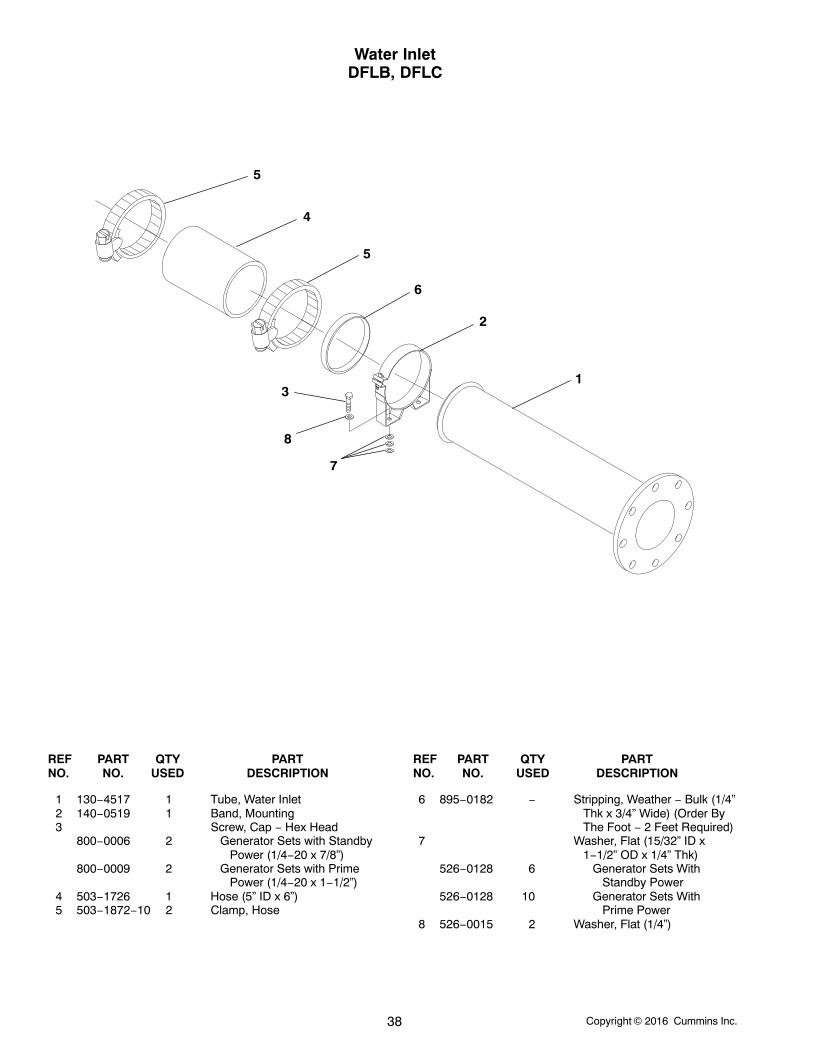
Water InletDFLB, DFLC
1
2
6
5
5
4
3
8
7
REF PART QTY PART REF PART QTY PARTNO. NO. USED DESCRIPTION NO. NO. USED DESCRIPTION
1 130−4517 1 Tube, Water Inlet2 140−0519 1 Band, Mounting3 Screw, Cap − Hex Head
800−0006 2 Generator Sets with Standby Power (1/4−20 x 7/8”)
800−0009 2 Generator Sets with Prime Power (1/4−20 x 1−1/2”)
4 503−1726 1 Hose (5” ID x 6”)5 503−1872−10 2 Clamp, Hose
6 895−0182 − Stripping, Weather − Bulk (1/4”Thk x 3/4” Wide) (Order ByThe Foot − 2 Feet Required)
7 Washer, Flat (15/32” ID x1−1/2” OD x 1/4” Thk)
526−0128 6 Generator Sets With Standby Power
526−0128 10 Generator Sets With Prime Power
8 526−0015 2 Washer, Flat (1/4”)
Copyright 2016 Cummins Inc. 39
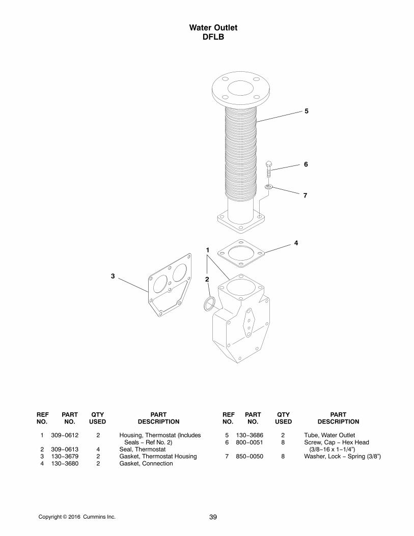
Water OutletDFLB
1
23
4
5
6
7
REF PART QTY PART REF PART QTY PARTNO. NO. USED DESCRIPTION NO. NO. USED DESCRIPTION
1 309−0612 2 Housing, Thermostat (IncludesSeals − Ref No. 2)
2 309−0613 4 Seal, Thermostat3 130−3679 2 Gasket, Thermostat Housing4 130−3680 2 Gasket, Connection
5 130−3686 2 Tube, Water Outlet6 800−0051 8 Screw, Cap − Hex Head
(3/8−16 x 1−1/4”)7 850−0050 8 Washer, Lock − Spring (3/8”)
Copyright 2016 Cummins Inc.40
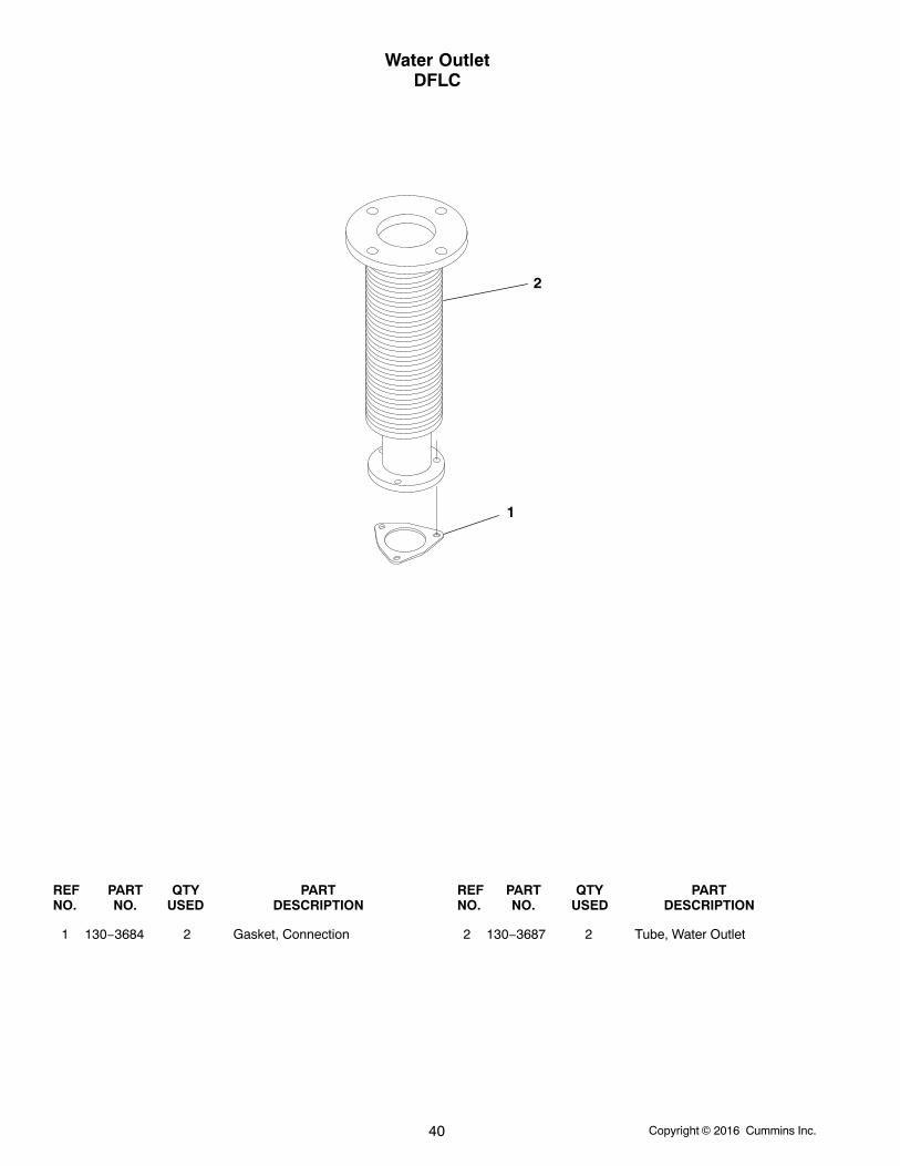
Water OutletDFLC
1
2
REF PART QTY PART REF PART QTY PARTNO. NO. USED DESCRIPTION NO. NO. USED DESCRIPTION
1 130−3684 2 Gasket, Connection 2 130−3687 2 Tube, Water Outlet
Copyright 2016 Cummins Inc. 41
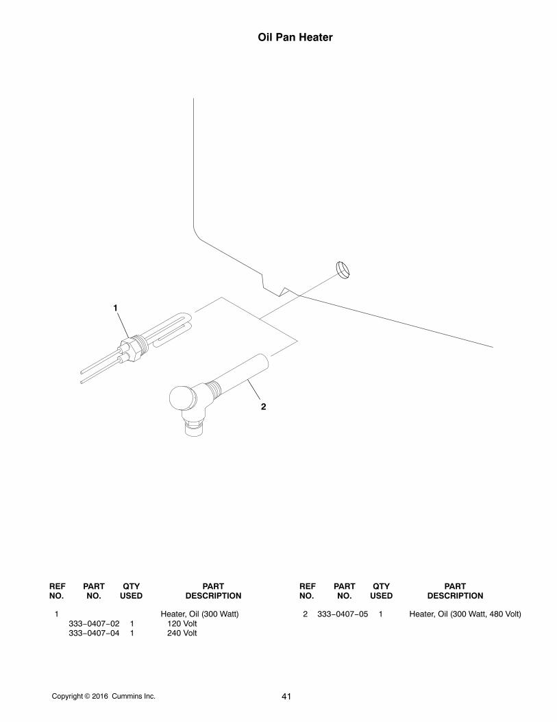
Oil Pan Heater
2
1
REF PART QTY PART REF PART QTY PARTNO. NO. USED DESCRIPTION NO. NO. USED DESCRIPTION
1 Heater, Oil (300 Watt)333−0407−02 1 120 Volt333−0407−04 1 240 Volt
2 333−0407−05 1 Heater, Oil (300 Watt, 480 Volt)
Copyright 2016 Cummins Inc.42
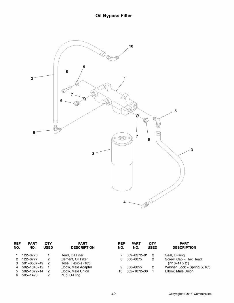
Oil Bypass Filter
1
23
3
4
5
5
6
6
7
7
89
10
REF PART QTY PART REF PART QTY PARTNO. NO. USED DESCRIPTION NO. NO. USED DESCRIPTION
1 122−0776 1 Head, Oil Filter2 122−0777 2 Element, Oil Filter3 501−0537−49 2 Hose, Flexible (18”)4 502−1043−12 1 Elbow, Male Adapter5 502−1072−14 2 Elbow, Male Union6 505−1428 2 Plug, O-Ring
7 509−0272−01 2 Seal, O-Ring8 800−0075 2 Screw, Cap − Hex Head
(7/16−14 x 2”)9 850−0055 2 Washer, Lock − Spring (7/16”)
10 502−1072−30 1 Elbow, Male Union
Copyright 2016 Cummins Inc. 43
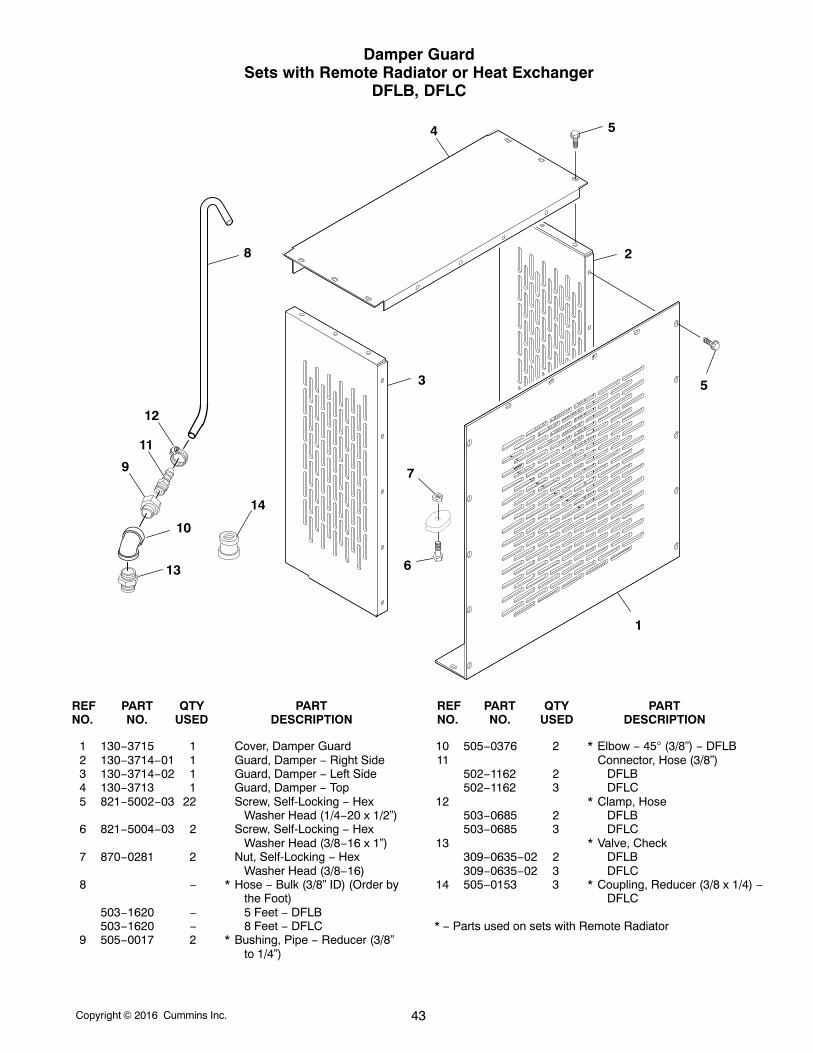
Damper GuardSets with Remote Radiator or Heat Exchanger
DFLB, DFLC
1
53
2
54
7
6
8
12
11
10
9
13
14
REF PART QTY PART REF PART QTY PARTNO. NO. USED DESCRIPTION NO. NO. USED DESCRIPTION
1 130−3715 1 Cover, Damper Guard2 130−3714−01 1 Guard, Damper − Right Side3 130−3714−02 1 Guard, Damper − Left Side4 130−3713 1 Guard, Damper − Top5 821−5002−03 22 Screw, Self-Locking − Hex
Washer Head (1/4−20 x 1/2”)6 821−5004−03 2 Screw, Self-Locking − Hex
Washer Head (3/8−16 x 1”)7 870−0281 2 Nut, Self-Locking − Hex
Washer Head (3/8−16)8 − * Hose − Bulk (3/8” ID) (Order by
the Foot)503−1620 − 5 Feet − DFLB503−1620 − 8 Feet − DFLC
9 505−0017 2 * Bushing, Pipe − Reducer (3/8”to 1/4”)
10 505−0376 2 * Elbow − 45 (3/8”) − DFLB11 Connector, Hose (3/8”)
502−1162 2 DFLB502−1162 3 DFLC
12 * Clamp, Hose503−0685 2 DFLB503−0685 3 DFLC
13 * Valve, Check309−0635−02 2 DFLB309−0635−02 3 DFLC
14 505−0153 3 * Coupling, Reducer (3/8 x 1/4) −DFLC
* − Parts used on sets with Remote Radiator
Copyright 2016 Cummins Inc.44
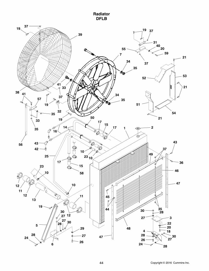
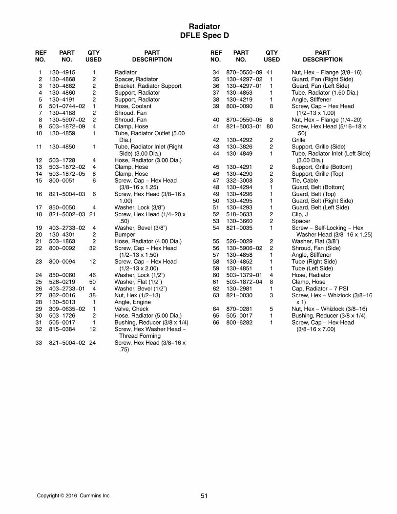
RadiatorDFLB
1937
39
7
55
19 37
31
2059
37
21
52
3435
51
53
54
38
33
35
56
16
19
3741
4133
57
35
19 50
14
42
17
12
11
13
5
2824
3027
10
17
17 1 2
6
27 30
29
27
26
47
48
44
45
49
37
43
36
46
47
35
22
30
27
4
26 2730
43
25
15
18
58
12
12
11
19
15
34
35
21
21
3
28
28
20
28
24
28
23
10
10
40
10
23
32
Copyright 2016 Cummins Inc. 45
RadiatorDFLB
REF PART QTY PART REF PART QTY PARTNO. NO. USED DESCRIPTION NO. NO. USED DESCRIPTION
1 130−3616 1 Radiator (Includes RadiatorCap [Ref No. 2] and OverflowTube)
2 130−3588 1 Cap, Radiator3 130−3642 2 Spacer, Radiator4 130−3639 2 Bracket, Radiator Support5 130−4860 2 Support, Radiator6 130−3644 2 Support7 130−3651 1 Fan Shroud Assembly
(Includes Bearing and Shaft −Ref No. 8 and 9)
8 130−4215 2 Bearing (Not Illustrated)9 130−4216 1 Shaft (Not Illustrated)
10 503−1872−02 4 Clamp, Hose11 503−1726 2 Hose, Radiator (5” ID x 6”)12 503−1872−10 4 Clamp, Hose13 130−4152−02 1 Tube, Radiator Outlet
(5” OD x 48”)14 130−3649 2 Tube, Radiator Inlet
(3” OD x 5−1/2”)15 503−1728 4 Hose, Radiator (3” ID)16 501−0744−04 2 Hose, Coolant17 503−1872−05 8 Clamp, Hose18 800−0051 4 Screw, Cap − Hex Head
(3/8−16 x 1−1/4”)19 821−5004−03 28 Screw, Self−Locking − Hex
Washer Head (3/8−16 x 1”)20 850−0050 6 Washer, Lock − Spring (3/8”)21 821−5002−03 21 Screw, Self−Locking − Hex
Washer Head (1/4−20 x 1/2”)22 403−2733−02 4 Washer, Bevel (3/8”)23 503−1863 2 Hose, Radiator (1−1/2” x 6”)24 800−0092 16 Screw, Cap − Hex Head
(1/2−13 x 1−1/2”)25 130−4155 1 Tube, Radiator (1−1/2” ID)26 800−0094 10 Screw, Cap − Hex Head
(1/2−13 x 2”)27 850−0060 26 Washer, Lock − Spring (1/2”)28 526−0219 32 Washer, Flat (1/2”)29 403−2733−01 4 Washer, Bevel (1/2”)
30 862−0016 26 Nut, Hex (1/2−13)31 130−3776 1 Angle, Stiffener32 518−0633 2 Clip, J33 526−0112 8 Washer, Flat (5/8”)34 850−0070 10 Washer, Lock − Spring (5/8”)35 862−0007 14 Nut, Hex (5/8−11)36 815−0384 12 Screw, Hex Washer Head −
Thread Forming (3/8−16 x3/4”)
37 870−0550−09 28 Nut, Hex − Locking (3/8−16)38 130−3647−01 1 Guard, Fan − Right Side39 130−3647−02 1 Guard, Fan − Left Side40 526−0029 2 Washer, Flat (3/8”)41 800−0132 8 Screw, Cap − Hex head (5/8−11
x 1−1/2”)42 309−0635−02 2 Valve, Check43 505−0376 2 Elbow, 45 (3/8”)44 870−0550−05 8 Nut, Hex − Locking (1/4−20)45 821−5003−01 20 Screw, Self−Locking − Hex
Washer Head (5/16−18 x1/2”)
46 130−3827 2 Grille − Spec S47 130−3826 2 Support, Grille48 Support, Grille − Bottom
130−3663 2 Spec S130−3663 1 Begin Spec T
49 Support, Grille − Top130−3662 2 Spec S130−3662 1 Begin Spec T
50 332−3008 10 Tie, Cable51 130−3675 1 Guard, Belt − Left Side52 130−3677 1 Guard, Belt − Top53 130−3676 1 Guard, Belt − Right Side54 130−3672 1 Guard, Belt − Bottom55 130−3779 1 Angle, Engine56 403−3278 1 Brace, Fan57 403−3277 1 Brace, Fan58 503−1870−05 2 Clamp, Hose59 800−0061 2 Screw, Cap − Hex Head
(3/8−16 x 3−3/4”)
Copyright 2016 Cummins Inc.46
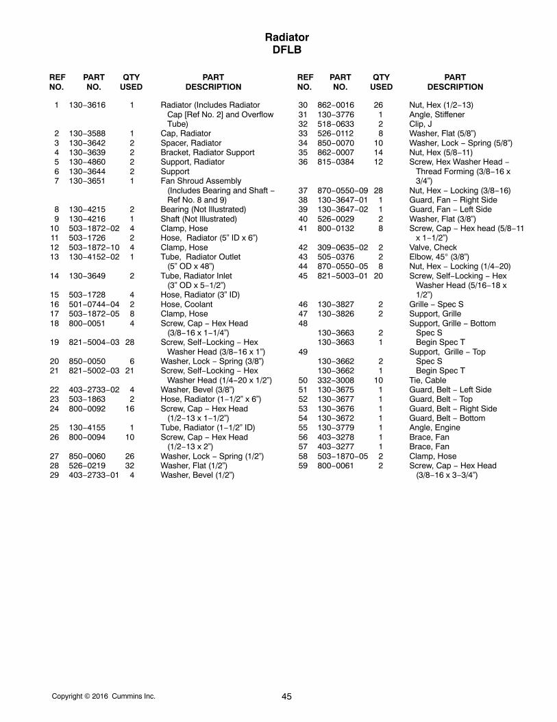
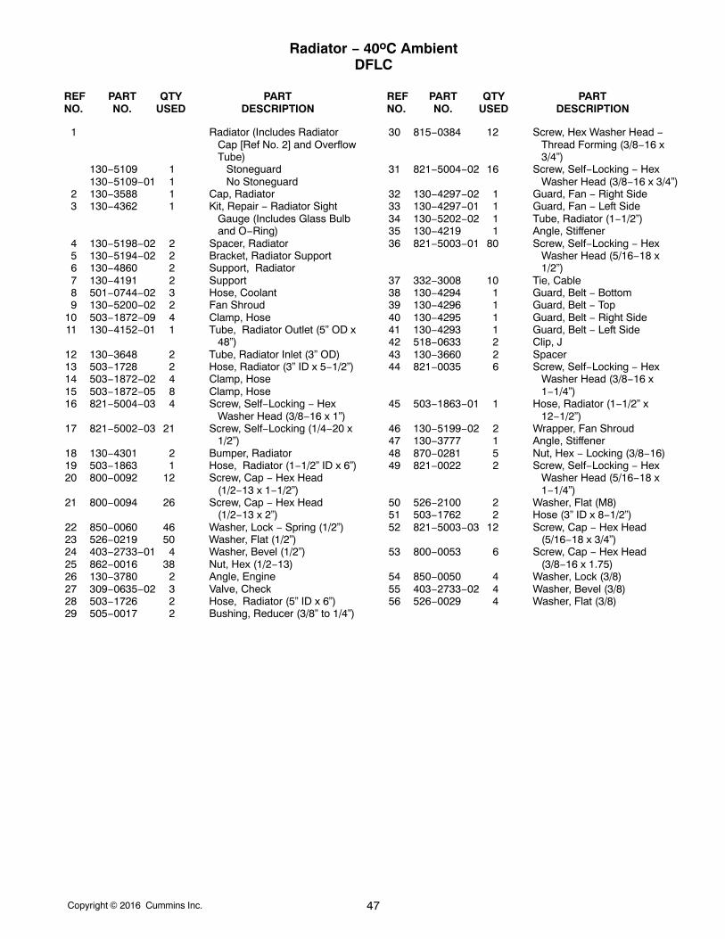
Radiator − 40oC AmbientDFLC
44
33
52
44
48
44
35
44
2647
48
32
48 1825
22
2320
4844
17
39
41
17
38
8
37
1213
27
15
51
15
34
27
15
51
1415
14
19
1028
10
11
16
6
2320
7
22
25
1028
10
29
14
8
12
378
30
43
36
49
50
42
46
46
9
31
9
21
13
15
45
3
4
2523 225
23
21
2522
20 23
17
2322 25
2423
21
2023 22
25
15
40
25
23
22
23
21
5354
5556
Copyright 2016 Cummins Inc. 47
Radiator − 40oC AmbientDFLC
REF PART QTY PART REF PART QTY PARTNO. NO. USED DESCRIPTION NO. NO. USED DESCRIPTION
1 Radiator (Includes RadiatorCap [Ref No. 2] and OverflowTube)
130−5109 1 Stoneguard130−5109−01 1 No Stoneguard
2 130−3588 1 Cap, Radiator3 130−4362 1 Kit, Repair − Radiator Sight
Gauge (Includes Glass Bulband O−Ring)
4 130−5198−02 2 Spacer, Radiator5 130−5194−02 2 Bracket, Radiator Support6 130−4860 2 Support, Radiator7 130−4191 2 Support8 501−0744−02 3 Hose, Coolant9 130−5200−02 2 Fan Shroud
10 503−1872−09 4 Clamp, Hose11 130−4152−01 1 Tube, Radiator Outlet (5” OD x
48”)12 130−3648 2 Tube, Radiator Inlet (3” OD)13 503−1728 2 Hose, Radiator (3” ID x 5−1/2”)14 503−1872−02 4 Clamp, Hose15 503−1872−05 8 Clamp, Hose16 821−5004−03 4 Screw, Self−Locking − Hex
Washer Head (3/8−16 x 1”)17 821−5002−03 21 Screw, Self−Locking (1/4−20 x
1/2”)18 130−4301 2 Bumper, Radiator19 503−1863 1 Hose, Radiator (1−1/2” ID x 6”)20 800−0092 12 Screw, Cap − Hex Head
(1/2−13 x 1−1/2”)21 800−0094 26 Screw, Cap − Hex Head
(1/2−13 x 2”)22 850−0060 46 Washer, Lock − Spring (1/2”)23 526−0219 50 Washer, Flat (1/2”)24 403−2733−01 4 Washer, Bevel (1/2”)25 862−0016 38 Nut, Hex (1/2−13)26 130−3780 2 Angle, Engine27 309−0635−02 3 Valve, Check28 503−1726 2 Hose, Radiator (5” ID x 6”)29 505−0017 2 Bushing, Reducer (3/8” to 1/4”)
30 815−0384 12 Screw, Hex Washer Head −Thread Forming (3/8−16 x3/4”)
31 821−5004−02 16 Screw, Self−Locking − HexWasher Head (3/8−16 x 3/4”)
32 130−4297−02 1 Guard, Fan − Right Side33 130−4297−01 1 Guard, Fan − Left Side34 130−5202−02 1 Tube, Radiator (1−1/2”)35 130−4219 1 Angle, Stiffener36 821−5003−01 80 Screw, Self−Locking − Hex
Washer Head (5/16−18 x1/2”)
37 332−3008 10 Tie, Cable38 130−4294 1 Guard, Belt − Bottom39 130−4296 1 Guard, Belt − Top40 130−4295 1 Guard, Belt − Right Side41 130−4293 1 Guard, Belt − Left Side42 518−0633 2 Clip, J43 130−3660 2 Spacer44 821−0035 6 Screw, Self−Locking − Hex
Washer Head (3/8−16 x1−1/4”)
45 503−1863−01 1 Hose, Radiator (1−1/2” x12−1/2”)
46 130−5199−02 2 Wrapper, Fan Shroud47 130−3777 1 Angle, Stiffener48 870−0281 5 Nut, Hex − Locking (3/8−16)49 821−0022 2 Screw, Self−Locking − Hex
Washer Head (5/16−18 x1−1/4”)
50 526−2100 2 Washer, Flat (M8)51 503−1762 2 Hose (3” ID x 8−1/2”)52 821−5003−03 12 Screw, Cap − Hex Head
(5/16−18 x 3/4”)53 800−0053 6 Screw, Cap − Hex Head
(3/8−16 x 1.75)54 850−0050 4 Washer, Lock (3/8)55 403−2733−02 4 Washer, Bevel (3/8)56 526−0029 4 Washer, Flat (3/8)
Copyright 2016 Cummins Inc.48
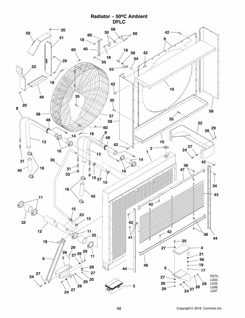
Radiator − 50oC AmbientDFLC
E074,L032,L033,L036,L037
13
5020
51
20
18
49
52
20
38
35
18
60
55
40
18
3059
60
1856
53
35
5442
9
58
10
5837
60
42
48
8
39
11
32
23
6
18
2724
24 2726
29 25
2728
2929
112627
726
3211
15
12
16
45
3331
15 5715
14
16
12
2235
10
2926
2724
4736
42
34
43
42
42
42
41
4644
36
2926
27 4
21
1917
5
27
25
24 27 2629
44
13
31
16
148
48
45 16
6018
15
3
42
42
56
Copyright 2016 Cummins Inc. 49
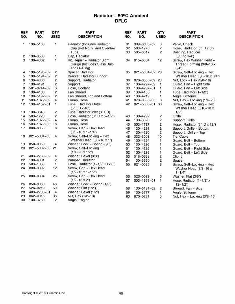
Radiator − 50oC AmbientDFLC
REF PART QTY PART REF PART QTY PARTNO. NO. USED DESCRIPTION NO. NO. USED DESCRIPTION
1 130−5108 1 Radiator (Includes RadiatorCap [Ref No. 2] and OverflowTube)
2 130−3588 1 Cap, Radiator3 130−4362 1 Kit, Repair − Radiator Sight
Gauge (Includes Glass Bulband O−Ring)
4 130−5195−02 2 Spacer, Radiator5 130−5194−02 2 Bracket, Radiator Support6 130−4860 2 Support, Radiator7 130−4191 2 Support8 501−0744−02 3 Hose, Coolant9 130−4188 2 Fan Shroud
10 130−5192−02 2 Fan Shroud, Top and Bottom11 503−1872−09 4 Clamp, Hose12 130−4152−01 1 Tube, Radiator Outlet
(5” OD x 48”)13 130−3648 2 Tube, Radiator Inlet (3” OD)14 503−1728 2 Hose, Radiator (3” ID x 5−1/2”)15 503−1872−02 4 Clamp, Hose16 503−1872−05 8 Clamp, Hose17 800−0053 6 Screw, Cap − Hex Head
(3/8−16 x 1−1/4”)18 821−5004−03 4 Screw, Self−Locking − Hex
Washer Head (3/8−16 x 1”)19 850−0050 4 Washer, Lock − Spring (3/8”)20 821−5002−03 21 Screw, Self−Locking
(1/4−20 x 1/2”)21 403−2733−02 4 Washer, Bevel (3/8”)22 130−4301 2 Bumper, Radiator23 503−1863 1 Hose, Radiator (1−1/2” ID x 6”)24 800−0092 12 Screw, Cap − Hex Head
(1/2−13 x 1−1/2”)25 800−0094 26 Screw, Cap − Hex Head
(1/2−13 x 2”)26 850−0060 46 Washer, Lock − Spring (1/2”)27 526−0219 50 Washer, Flat (1/2”)28 403−2733−01 4 Washer, Bevel (1/2”)29 862−0016 38 Nut, Hex (1/2−13)30 130−3780 2 Angle, Engine
31 309−0635−02 3 Valve, Check32 503−1726 2 Hose, Radiator (5” ID x 6”)33 505−0017 2 Bushing, Reducer
(3/8” to 1/4”)34 815−0384 12 Screw, Hex Washer Head −
Thread Forming (3/8−16 x3/4”)
35 821−5004−02 28 Screw, Self−Locking − HexWasher Head (3/8−16 x 3/4”)
36 870−0550−09 23 Nut, Lock − Hex (3/8−16)37 130−4297−02 1 Guard, Fan − Right Side38 130−4297−01 1 Guard, Fan − Left Side39 130−4155 1 Tube, Radiator (1−1/2”)40 130−4219 1 Angle, Stiffener41 870−0550−05 8 Nut, Hex − Locking (1/4−20)42 821−5003−01 80 Screw, Self−Locking − Hex
Washer Head (5/16−18 x1/2”)
43 130−4292 2 Grille44 130−3826 2 Support, Grille45 503−1727 2 Hose, Radiator (3” ID x 12”)46 130−4291 2 Support, Grille − Bottom47 130−4290 2 Support, Grille − Top48 332−3008 10 Tie, Cable49 130−4294 1 Guard, Belt − Bottom50 130−4296 1 Guard, Belt − Top51 130−4295 1 Guard, Belt − Right Side52 130−4293 1 Guard, Belt − Left Side53 518−0633 2 Clip, J54 130−3660 2 Spacer55 821−0035 8 Screw, Self−Locking − Hex
Washer Head (3/8−16 x1−1/4”)
56 526−0029 6 Washer, Flat (3/8”)57 503−1863−01 1 Hose, Radiator (1−1/2” x
12−1/2”)58 130−5191−02 2 Shroud, Fan − Side59 130−3777 1 Angle, Stiffener60 870−0281 5 Nut, Hex − Locking (3/8−16)
Copyright 2016 Cummins Inc.50
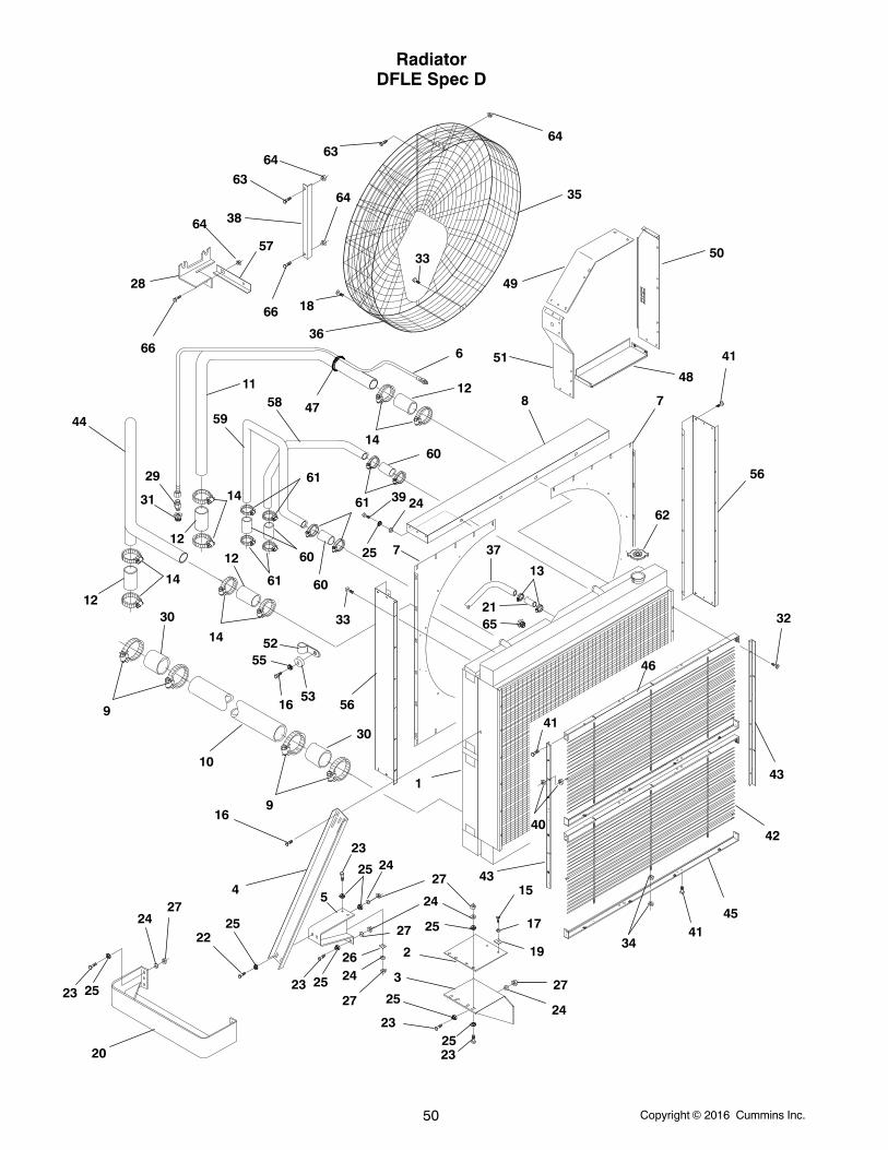
RadiatorDFLE Spec D
1
2
3
4
2325
19
17
15
25
24
27
23
2524
27
23
2624
27
2225
25 24
23 25
27
16
45
23 25
2427
3441
41
40
32
43
46
42
5
6
7
7
8
56
56
41
62
9
9
10
11
12
12
12
12
13
14
14
14
14
16
52
53
55
18
20
21
24
25
39
28
29
31
30
30
33
38
35
36
37
43
4447
48
49
50
51
57
5859
60
60
60
61
61
61
33
63
63
64
64
64
64
65
66
66
Copyright 2016 Cummins Inc. 51
RadiatorDFLE Spec D
REF PART QTY PART REF PART QTY PARTNO. NO. USED DESCRIPTION NO. NO. USED DESCRIPTION
1 130−4915 1 Radiator2 130−4868 2 Spacer, Radiator3 130−4862 2 Bracket, Radiator Support4 130−4860 2 Support, Radiator5 130−4191 2 Support, Radiator6 501−0744−02 1 Hose, Coolant7 130−4188 2 Shroud, Fan8 130−5907−02 2 Shroud, Fan9 503−1872−09 4 Clamp, Hose
10 130−4859 1 Tube, Radiator Outlet (5.00Dia.)
11 130−4850 1 Tube, Radiator Inlet (RightSide) (3.00 Dia.)
12 503−1728 4 Hose, Radiator (3.00 Dia.)13 503−1872−02 4 Clamp, Hose14 503−1872−05 8 Clamp, Hose15 800−0051 6 Screw, Cap − Hex Head
(3/8−16 x 1.25)16 821−5004−03 6 Screw, Hex Head (3/8−16 x
1.00)17 850−0050 4 Washer, Lock (3/8”)18 821−5002−03 21 Screw, Hex Head (1/4−20 x
.50)19 403−2733−02 4 Washer, Bevel (3/8”)20 130−4301 2 Bumper21 503−1863 2 Hose, Radiator (4.00 Dia.)22 800−0092 32 Screw, Cap − Hex Head
(1/2−13 x 1.50)23 800−0094 12 Screw, Cap − Hex Head
(1/2−13 x 2.00)24 850−0060 46 Washer, Lock (1/2”)25 526−0219 50 Washer, Flat (1/2”)26 403−2733−01 4 Washer, Bevel (1/2”)27 862−0016 38 Nut, Hex (1/2−13)28 130−5013 1 Angle, Engine29 309−0635−02 1 Valve, Check30 503−1726 2 Hose, Radiator (5.00 Dia.)31 505−0017 1 Bushing, Reducer (3/8 x 1/4)32 815−0384 12 Screw, Hex Washer Head −
Thread Forming33 821−5004−02 24 Screw, Hex Head (3/8−16 x
.75)
34 870−0550−09 41 Nut, Hex − Flange (3/8−16)35 130−4297−02 1 Guard, Fan (Right Side)36 130−4297−01 1 Guard, Fan (Left Side)37 130−4853 1 Tube, Radiator (1.50 Dia.)38 130−4219 1 Angle, Stiffener39 800−0090 8 Screw, Cap − Hex Head
(1/2−13 x 1.00)40 870−0550−05 8 Nut, Hex − Flange (1/4−20)41 821−5003−01 80 Screw, Hex Head (5/16−18 x
.50)42 130−4292 2 Grille43 130−3826 2 Support, Grille (Side)44 130−4849 1 Tube, Radiator Inlet (Left Side)
(3.00 Dia.)45 130−4291 2 Support, Grille (Bottom)46 130−4290 2 Support, Grille (Top)47 332−3008 3 Tie, Cable48 130−4294 1 Guard, Belt (Bottom)49 130−4296 1 Guard, Belt (Top)50 130−4295 1 Guard, Belt (Right Side)51 130−4293 1 Guard, Belt (Left Side)52 518−0633 2 Clip, J53 130−3660 2 Spacer54 821−0035 1 Screw − Self-Locking − Hex
Washer Head (3/8−16 x 1.25)55 526−0029 2 Washer, Flat (3/8”)56 130−5906−02 2 Shroud, Fan (Side)57 130−4858 1 Angle, Stiffener58 130−4852 1 Tube (Right Side)59 130−4851 1 Tube (Left Side)60 503−1379−01 4 Hose, Radiator61 503−1872−04 8 Clamp, Hose62 130−2981 1 Cap, Radiator − 7 PSI63 821−0030 3 Screw, Hex − Whizlock (3/8−16
x 1)64 870−0281 5 Nut, Hex − Whizlock (3/8−16)65 505−0017 1 Bushing, Reducer (3/8 x 1/4)66 800−6282 1 Screw, Cap − Hex Head
(3/8−16 x 7.00)
Copyright 2016 Cummins Inc.52
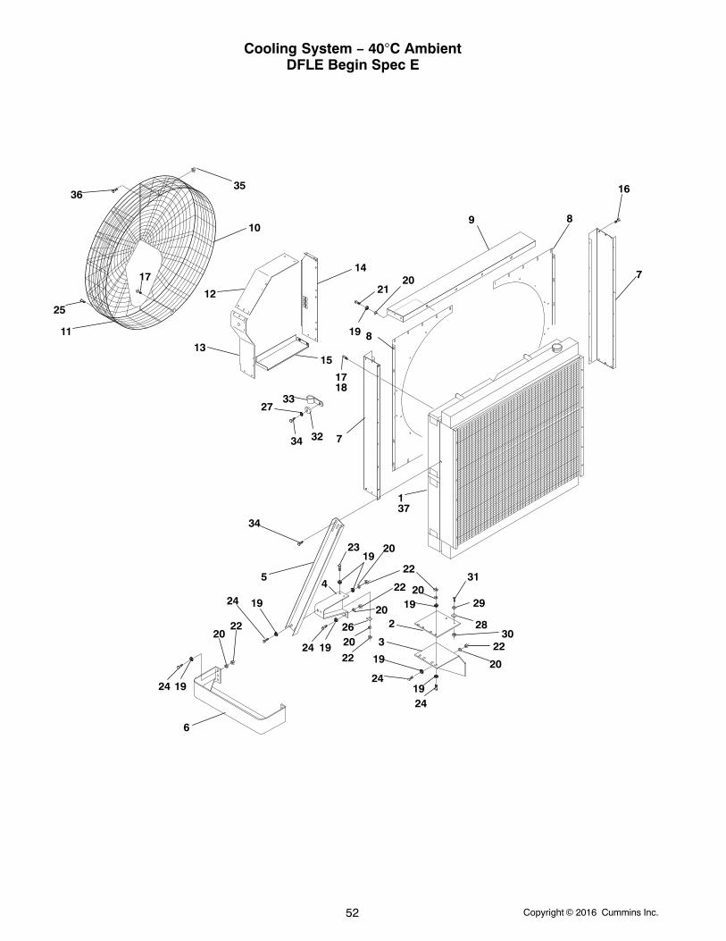
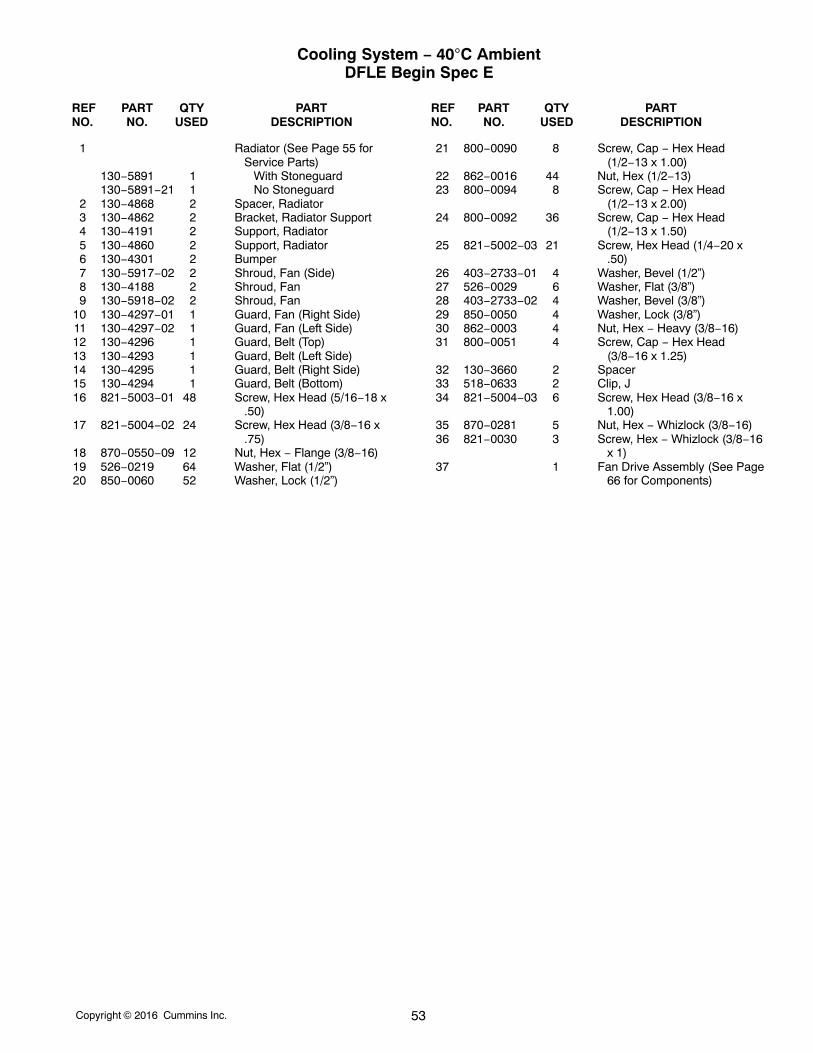
Cooling System − 40C AmbientDFLE Begin Spec E
1
5
34
2
3
4
6
16
9
3536
7
1718
17
25
1513
12
14
10
11
8
819
2021
37
33
34 32
27
23
19
2022
24
24 19
22
20
22
2024 19
2019
31
29
7
2830
22
20
2419
24
19
19
26
22
20
Copyright 2016 Cummins Inc. 53
Cooling System − 40C AmbientDFLE Begin Spec E
REF PART QTY PART REF PART QTY PARTNO. NO. USED DESCRIPTION NO. NO. USED DESCRIPTION
1 Radiator (See Page 55 forService Parts)
130−5891 1 With Stoneguard130−5891−21 1 No Stoneguard
2 130−4868 2 Spacer, Radiator3 130−4862 2 Bracket, Radiator Support4 130−4191 2 Support, Radiator5 130−4860 2 Support, Radiator6 130−4301 2 Bumper7 130−5917−02 2 Shroud, Fan (Side)8 130−4188 2 Shroud, Fan9 130−5918−02 2 Shroud, Fan
10 130−4297−01 1 Guard, Fan (Right Side)11 130−4297−02 1 Guard, Fan (Left Side)12 130−4296 1 Guard, Belt (Top)13 130−4293 1 Guard, Belt (Left Side)14 130−4295 1 Guard, Belt (Right Side)15 130−4294 1 Guard, Belt (Bottom)16 821−5003−01 48 Screw, Hex Head (5/16−18 x
.50)17 821−5004−02 24 Screw, Hex Head (3/8−16 x
.75)18 870−0550−09 12 Nut, Hex − Flange (3/8−16)19 526−0219 64 Washer, Flat (1/2”)20 850−0060 52 Washer, Lock (1/2”)
21 800−0090 8 Screw, Cap − Hex Head(1/2−13 x 1.00)
22 862−0016 44 Nut, Hex (1/2−13)23 800−0094 8 Screw, Cap − Hex Head
(1/2−13 x 2.00)24 800−0092 36 Screw, Cap − Hex Head
(1/2−13 x 1.50)25 821−5002−03 21 Screw, Hex Head (1/4−20 x
.50)26 403−2733−01 4 Washer, Bevel (1/2”)27 526−0029 6 Washer, Flat (3/8”)28 403−2733−02 4 Washer, Bevel (3/8”)29 850−0050 4 Washer, Lock (3/8”)30 862−0003 4 Nut, Hex − Heavy (3/8−16)31 800−0051 4 Screw, Cap − Hex Head
(3/8−16 x 1.25)32 130−3660 2 Spacer33 518−0633 2 Clip, J34 821−5004−03 6 Screw, Hex Head (3/8−16 x
1.00)35 870−0281 5 Nut, Hex − Whizlock (3/8−16)36 821−0030 3 Screw, Hex − Whizlock (3/8−16
x 1)37 1 Fan Drive Assembly (See Page
66 for Components)
Copyright 2016 Cummins Inc.54
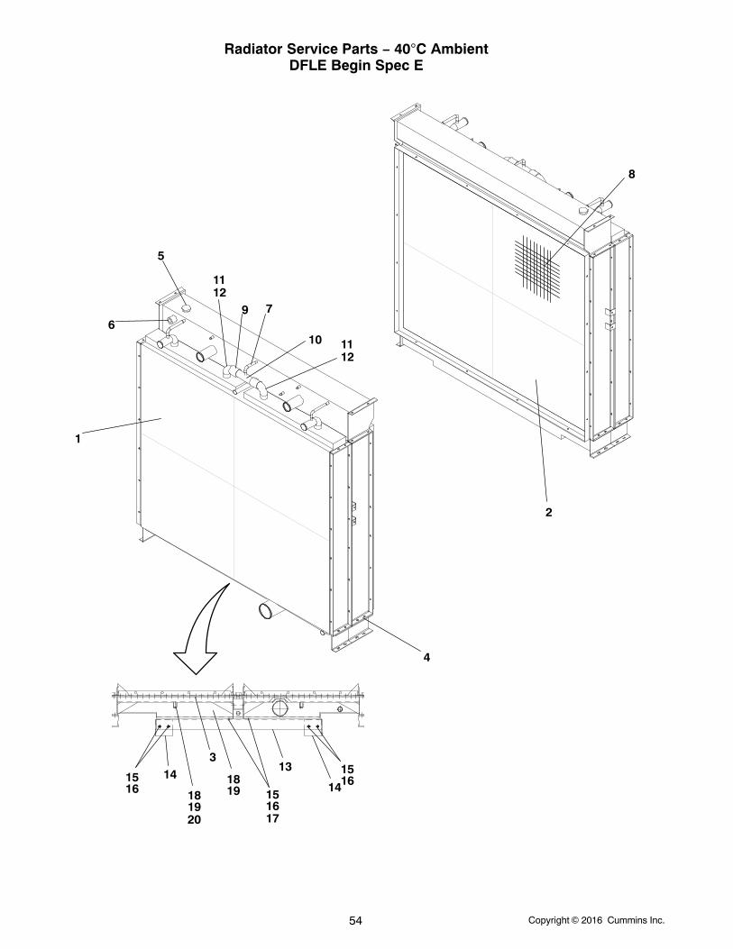
Radiator Service Parts − 40C AmbientDFLE Begin Spec E
1
2
3
4
5
67
8
9
10
1112
1112
131415
16
151614
17
1516
181920
1819
Copyright 2016 Cummins Inc. 55
Radiator Service Parts − 40C AmbientDFLE Begin Spec E
REF PART QTY PART REF PART QTY PARTNO. NO. USED DESCRIPTION NO. NO. USED DESCRIPTION
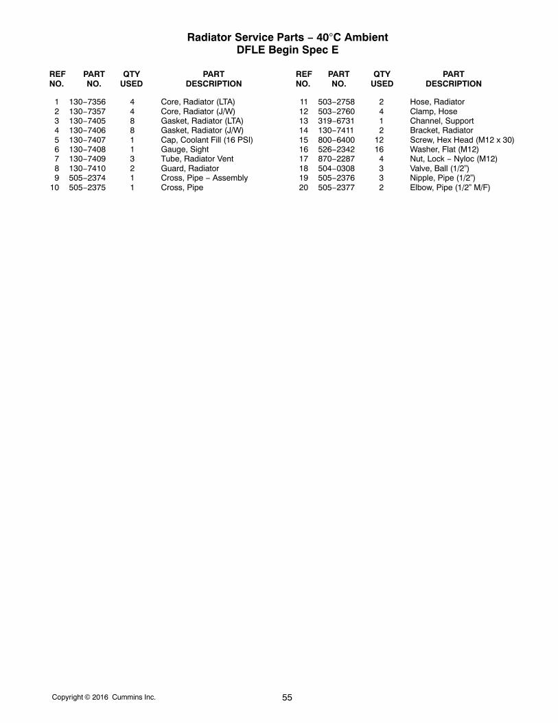
1 130−7356 4 Core, Radiator (LTA)2 130−7357 4 Core, Radiator (J/W)3 130−7405 8 Gasket, Radiator (LTA)4 130−7406 8 Gasket, Radiator (J/W)5 130−7407 1 Cap, Coolant Fill (16 PSI)6 130−7408 1 Gauge, Sight7 130−7409 3 Tube, Radiator Vent8 130−7410 2 Guard, Radiator9 505−2374 1 Cross, Pipe − Assembly
10 505−2375 1 Cross, Pipe
11 503−2758 2 Hose, Radiator12 503−2760 4 Clamp, Hose13 319−6731 1 Channel, Support14 130−7411 2 Bracket, Radiator15 800−6400 12 Screw, Hex Head (M12 x 30)16 526−2342 16 Washer, Flat (M12)17 870−2287 4 Nut, Lock − Nyloc (M12)18 504−0308 3 Valve, Ball (1/2”)19 505−2376 3 Nipple, Pipe (1/2”)20 505−2377 2 Elbow, Pipe (1/2” M/F)
Copyright 2016 Cummins Inc.56
Radiator − 40C AmbientDFLE Begin Spec ETubes and Hoses
14
12
12
14
6
13
17
3
13 17
25
10
16
16
10
1713
17
24
22
23
1
22
5
4
2
11
11
15
27
26
81820
921
7
19
1820
18
10
10
16
16
16
13
17
17
15
15
Copyright 2016 Cummins Inc. 57
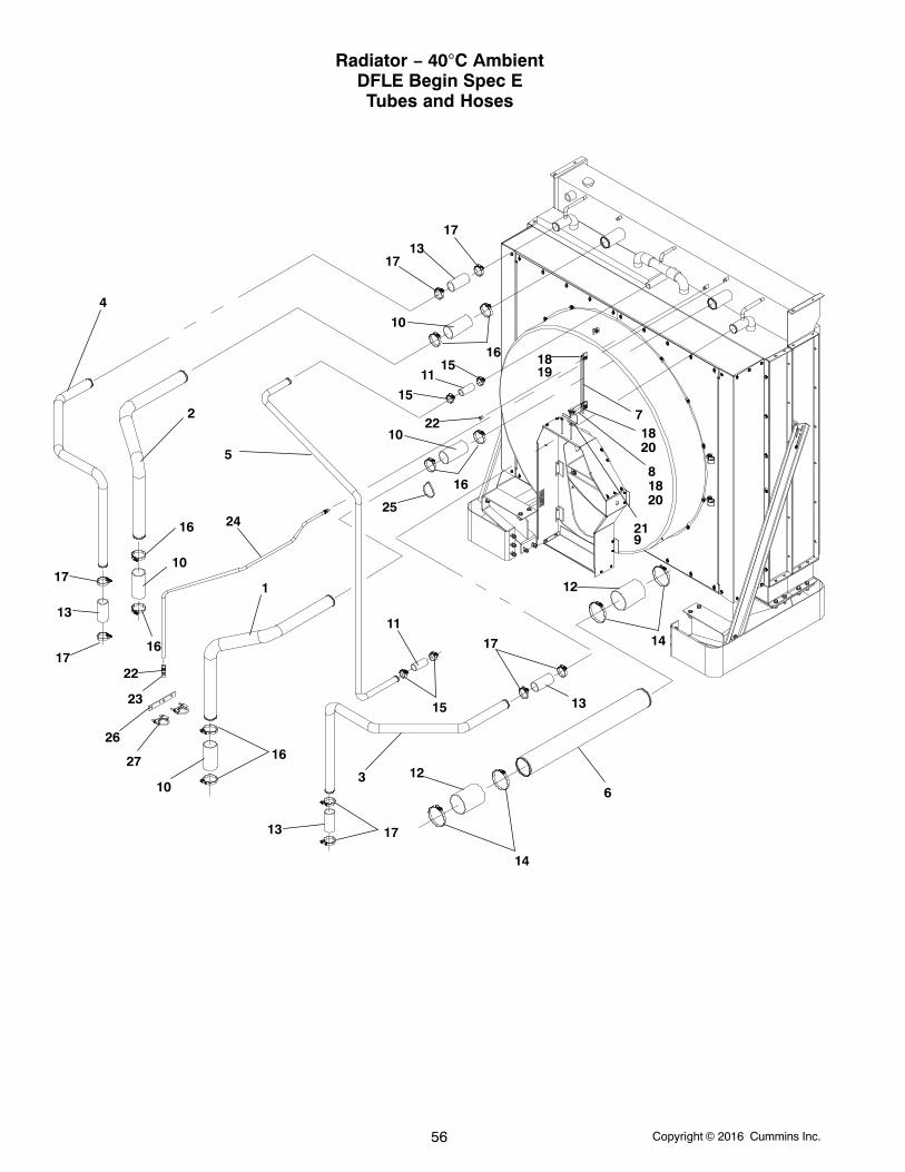
Radiator − 40C AmbientDFLE Begin Spec ETubes and Hoses
REF PART QTY PART REF PART QTY PARTNO. NO. USED DESCRIPTION NO. NO. USED DESCRIPTION
1 130−5908−02 1 Tube (Left Side)2 130−5909−02 1 Tube (Right Side)3 130−5910−02 1 Tube, Radiator Inlet (Left Side)4 130−5911−02 1 Tube, Radiator Inlet5 130−5912−02 1 Tube, Radiator (1.50 Dia.)6 130−4859 1 Tube, Radiator Outlet (5.00
Dia.)7 130−4219 1 Angle, Stiffener8 130−4858 1 Angle, Stiffener9 130−5013 1 Angle, Stiffener
10 503−1728 4 Hose, Radiator (3.00 Dia.)11 503−1863 2 Hose, Radiator (4.00 Dia.)12 503−1726 2 Hose, Radiator (5.00 Dia.)13 503−1379−01 4 Hose, Radiator14 503−1872−09 4 Clamp, Hose15 503−1872−02 4 Clamp, Hose
16 503−1872−05 8 Clamp, Hose17 503−1872−04 8 Clamp, Hose18 870−0281 5 Nut, Hex − Whizlock (3/8−16)19 821−0030 3 Screw, Hex − Whizlock (3/8−16
x 1)20 821−0035 2 Screw − Self-Locking − Hex
Washer Head (3/8−16 x 1.25)21 800−6282 2 Screw, Cap − Hex Head
(3/8−16 x 7.00)22 505−0017 2 Bushing, Reducer (3/8 x 1/4)23 309−0635−02 1 Valve, Check24 501−0744−02 1 Hose, Coolant25 332−3008 1 Tie, Cable26 130−5980−02 1 Plate, Support Tube27 155−4137 2 Clamp, Exhaust
Copyright 2016 Cummins Inc.58
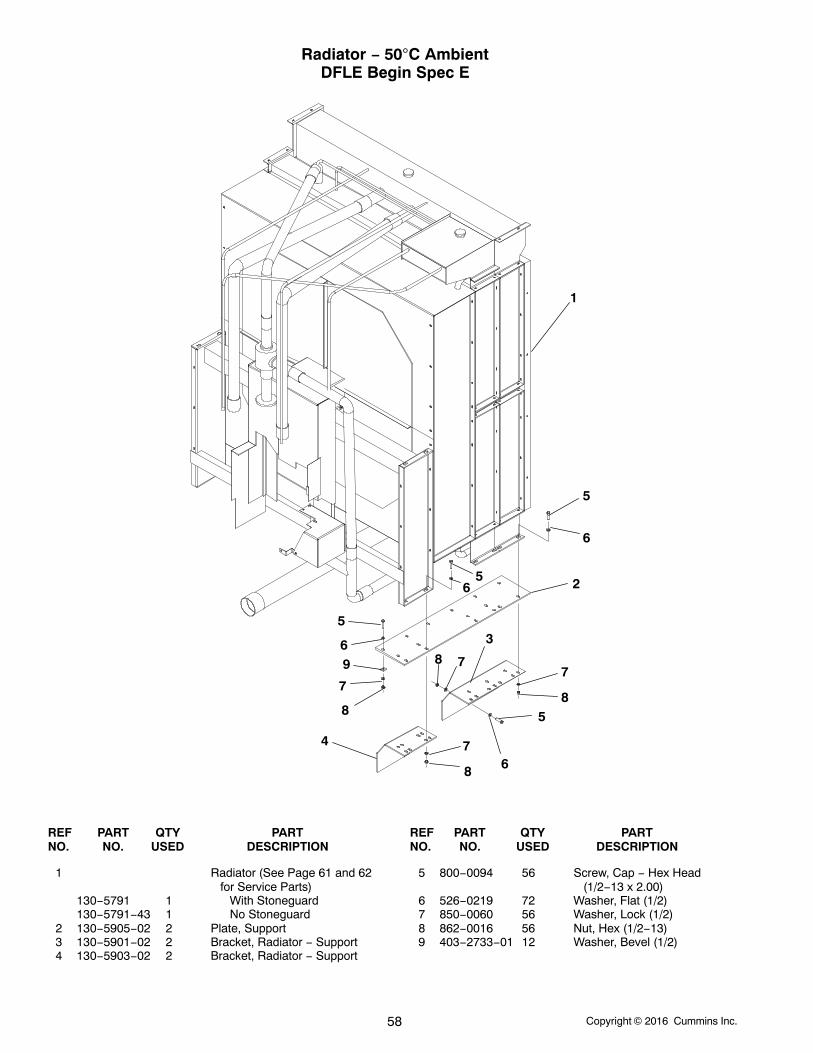
Radiator − 50C AmbientDFLE Begin Spec E
1
2
3
4
5
5
5
6
6
6
65
7
7
7
8
8
8
789
REF PART QTY PART REF PART QTY PARTNO. NO. USED DESCRIPTION NO. NO. USED DESCRIPTION
1 Radiator (See Page 61 and 62for Service Parts)
130−5791 1 With Stoneguard130−5791−43 1 No Stoneguard
2 130−5905−02 2 Plate, Support3 130−5901−02 2 Bracket, Radiator − Support4 130−5903−02 2 Bracket, Radiator − Support
5 800−0094 56 Screw, Cap − Hex Head(1/2−13 x 2.00)
6 526−0219 72 Washer, Flat (1/2)7 850−0060 56 Washer, Lock (1/2)8 862−0016 56 Nut, Hex (1/2−13)9 403−2733−01 12 Washer, Bevel (1/2)

Copyright 2016 Cummins Inc. 59
“Intentionally Left Blank”
Copyright 2016 Cummins Inc.60
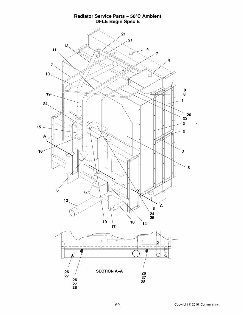
Radiator Service Parts − 50C AmbientDFLE Begin Spec E
21
13
74
4
20
11
19
22
10
24
9
1419
15
17
2627
6
2627
2627
8
2
3
3
8
5
16
25
24
12
1
2
.
21
18
7
A
A
SECTION A−A
2828
Copyright 2016 Cummins Inc. 61
Radiator Service Parts − 50C AmbientDFLE Begin Spec E
REF PART QTY PART REF PART QTY PARTNO. NO. USED DESCRIPTION NO. NO. USED DESCRIPTION
1 130−7464 4 Core, Radiator (J/W)2 130−7465 4 Core, Radiator (I/C)3 130−7466 8 Gasket, Radiator (J/W, I/C)4 130−7407 2 Cap, Coolant Fill (16 PSI)5 130−7468 1 Fan, Radiator (60” DIA)6 511−0238 1 Belt, Drive (PK Belt)7 503−2907 2 Hose, Vent (1/4” Vent)8 130−7470 2 * Hose, Radiator (1−1/2”)9 130−7471 1 * Hose Assy, Radiator (1−1/2”)
10 130−7472 1 * Hose, Radiator (J/W Top −RHS)
11 130−7473 1 * Hose, Radiator (J/W Top −LHS)
12 130−7474 1 * Hose Assy, Radiator (5” J/WBottom)
13 130−7475 1 * Hose, Radiator (2−1/2” I/C Top)14 130−7476 1 * Hose, Radiator (2−1/2” I/C
Bypass)15 130−7477 1 Tube, Radiator (2−1/2” I/C
Flanged)
16 130−7478 1 Gasket, Radiator17 130−7479 1 * Hose, Radiator (2−1/2” Tee)18 130−7480 1 * Hose, Radiator (2−1/2” I/C
Bottom)19 130−7481 2 Hose, Radiator (2−1/2” Stub)20 130−7482 1 Hose, Radiator Vent (1/4”)21 130−7483 2 Hose, Radiator Vent (1/4”)22 130−7484 1 Hose, Radiator Vent (1/4”)23 130−7485 1 Thermostat (Housing)24 510−0245 1 Bearing, Pillow Block25 510−0246 1 Bearing, Pillow Block26 504−0308 3 Valve, Ball (1/2”)27 505−2376 3 Valve, Ball (1/2”)28 505−2377 2 Elbow, Pipe (1/2” M/F)
* Before ordering a Hose or Hose Assy, it is recommended tomeasure the length of the hose and use a caliper to measurethe outside diameter of the pipe to obtain the proper insidediameter so the correct Hose or Hose Assy is sourced orordered.
Copyright 2016 Cummins Inc.62
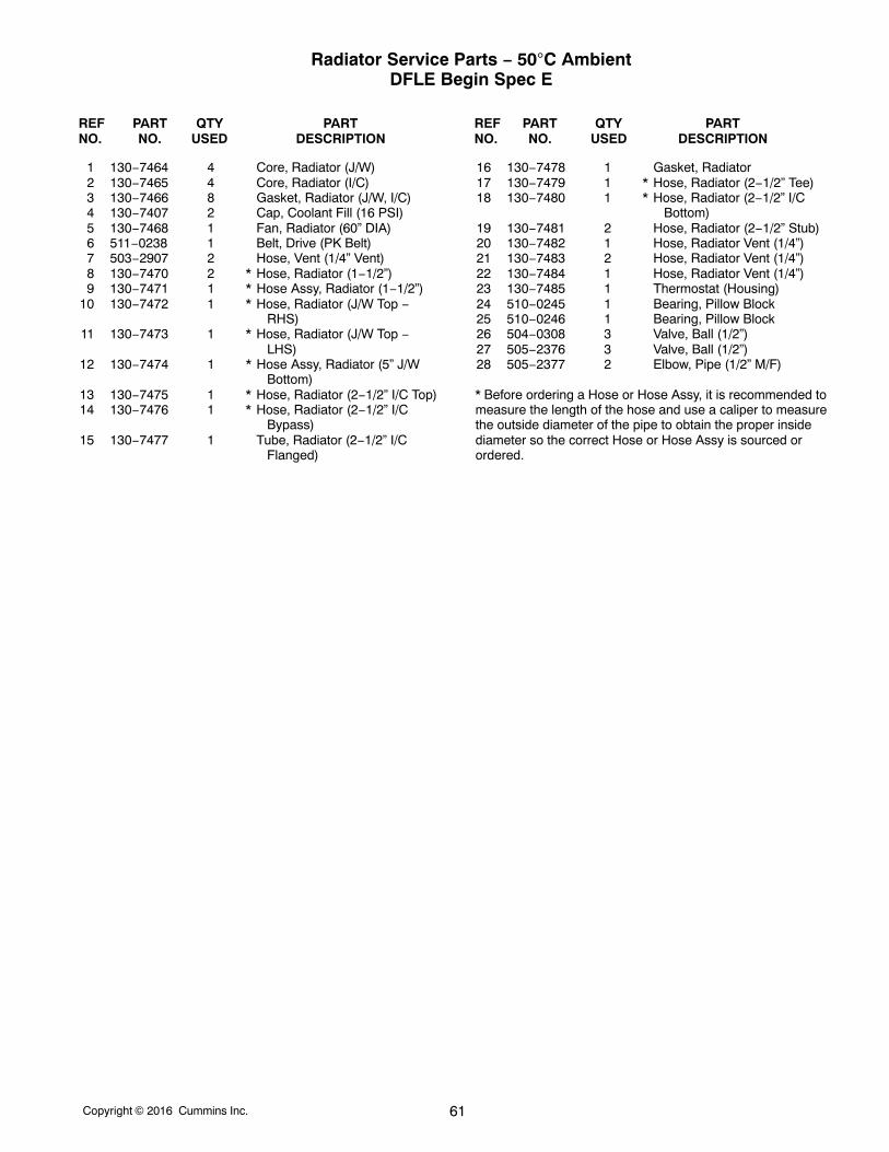
1.Radiator Guard Service Parts − 50C AmbientDFLE Begin Spec E
4
7
5
12 9
10
13
11
8
6
2
3
1
REF PART QTY PART REF PART QTY PARTNO. NO. USED DESCRIPTION NO. NO. USED DESCRIPTION
1 130−7499 1 Panel, Radiator Housing −Back
2 130−7500 1 Panel, Radiator Housing − L/H3 130−7501 1 Panel, Radiator Housing − R/H4 130−7502 1 Panel, Radiator Housing −
Bottom L/H5 130−7503 1 Panel, Radiator Housing −
Bottom R/H6 130−7504 1 Panel, Radiator Housing −
Back
7 130−7505 1 Panel, Radiator Housing −Bottom
8 191−2452 1 Guard, Alternator (Top)9 191−2453 1 Guard, Alternator (Front)
10 191−2454 1 Guard, Alternator (Bottom)11 191−2455 1 Guard, Alternator (Side)12 130−7506 1 Bracket, Radiator13 130−7507 1 Bracket, Radiator
Copyright 2016 Cummins Inc. 63
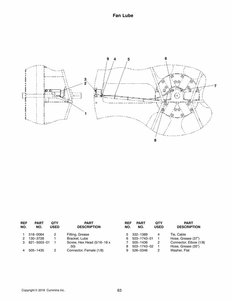
Fan Lube
1
23
4 5 6
7
8
9
REF PART QTY PART REF PART QTY PARTNO. NO. USED DESCRIPTION NO. NO. USED DESCRIPTION
1 518−0064 2 Fitting, Grease2 130−3728 1 Bracket, Lube3 821−5003−01 1 Screw, Hex Head (5/16−18 x
.50)4 505−1435 2 Connector, Female (1/8)
5 332−1389 4 Tie, Cable6 503−1743−01 1 Hose, Grease (37”)7 505−1436 2 Connector, Elbow (1/8)8 503−1743−02 1 Hose, Grease (35”)9 526−0346 2 Washer, Flat
Copyright 2016 Cummins Inc.64
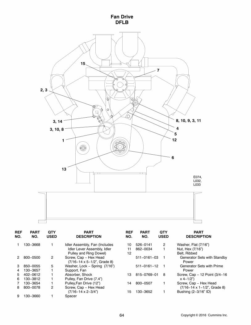
Fan DriveDFLB
1
7
2, 3
8, 10, 9, 3, 113, 14
43, 10, 85
15
12
13
6
E074,L032,L033
REF PART QTY PART REF PART QTY PARTNO. NO. USED DESCRIPTION NO. NO. USED DESCRIPTION
1 130−3668 1 Idler Assembly, Fan (IncludesIdler Lever Assembly, IdlerPulley and Ring Dowel)
2 800−0500 2 Screw, Cap − Hex Head(7/16−14 x 5−1/2”, Grade 8)
3 850−0055 5 Washer, Lock − Spring (7/16”)4 130−3657 1 Support, Fan5 402−0612 1 Absorber, Shock6 130−3812 1 Pulley, Fan Drive (7.4”)7 130−3654 1 Pulley,Fan Drive (12”)8 800−0078 2 Screw, Cap − Hex Head
(7/16−14 x 2−3/4”)9 130−3660 1 Spacer
10 526−0141 2 Washer, Flat (7/16”)11 862−0034 1 Nut, Hex (7/16”)12 Belt, Ribbed
511−0161−03 1 Generator Sets with Standby Power
511−0161−12 1 Generator Sets with Prime Power
13 815−0769−01 8 Screw, Cap − 12 Point (3/4−16x 4−1/2”)
14 800−0507 1 Screw, Cap − Hex Head(7/16−14 x 1−1/2”, Grade 8)
15 130−3652 1 Bushing (2−3/16” ID)
Copyright 2016 Cummins Inc. 65
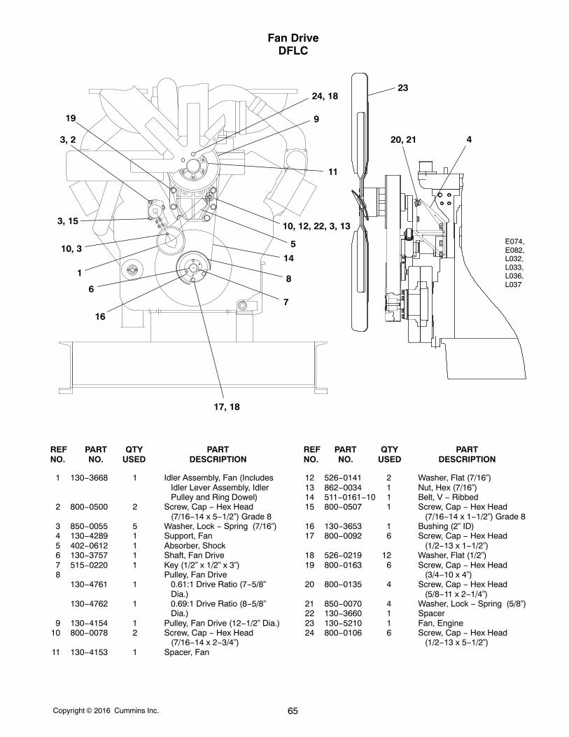
Fan DriveDFLC
1
9
3, 2
10, 12, 22, 3, 133, 15
17, 18
14
23
7
16
8
10, 3
6
24, 18
420, 21
19
5
11
E074,E082,L032,L033,L036,L037
REF PART QTY PART REF PART QTY PARTNO. NO. USED DESCRIPTION NO. NO. USED DESCRIPTION
1 130−3668 1 Idler Assembly, Fan (IncludesIdler Lever Assembly, IdlerPulley and Ring Dowel)
2 800−0500 2 Screw, Cap − Hex Head(7/16−14 x 5−1/2”) Grade 8
3 850−0055 5 Washer, Lock − Spring (7/16”)4 130−4289 1 Support, Fan5 402−0612 1 Absorber, Shock6 130−3757 1 Shaft, Fan Drive7 515−0220 1 Key (1/2” x 1/2” x 3”)8 Pulley, Fan Drive
130−4761 1 0.61:1 Drive Ratio (7−5/8”Dia.)
130−4762 1 0.69:1 Drive Ratio (8−5/8”Dia.)
9 130−4154 1 Pulley, Fan Drive (12−1/2” Dia.)10 800−0078 2 Screw, Cap − Hex Head
(7/16−14 x 2−3/4”)11 130−4153 1 Spacer, Fan
12 526−0141 2 Washer, Flat (7/16”)13 862−0034 1 Nut, Hex (7/16”)14 511−0161−10 1 Belt, V − Ribbed15 800−0507 1 Screw, Cap − Hex Head
(7/16−14 x 1−1/2”) Grade 816 130−3653 1 Bushing (2” ID)17 800−0092 6 Screw, Cap − Hex Head
(1/2−13 x 1−1/2”)18 526−0219 12 Washer, Flat (1/2”)19 800−0163 6 Screw, Cap − Hex Head
(3/4−10 x 4”)20 800−0135 4 Screw, Cap − Hex Head
(5/8−11 x 2−1/4”)21 850−0070 4 Washer, Lock − Spring (5/8”)22 130−3660 1 Spacer23 130−5210 1 Fan, Engine24 800−0106 6 Screw, Cap − Hex Head
(1/2−13 x 5−1/2”)
Copyright 2016 Cummins Inc.66
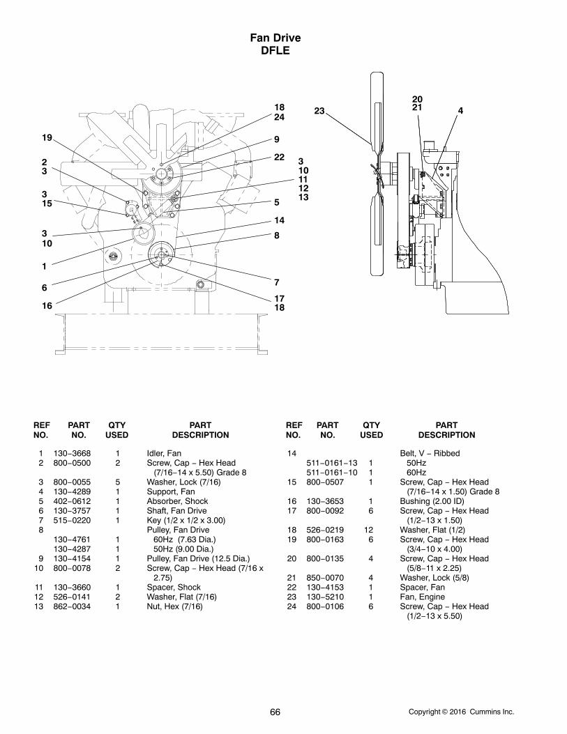
Fan DriveDFLE
1
23
4
5
6 7
8
9
103
111213
14
153
161718
19
2021
22
232418
310
REF PART QTY PART REF PART QTY PARTNO. NO. USED DESCRIPTION NO. NO. USED DESCRIPTION
1 130−3668 1 Idler, Fan2 800−0500 2 Screw, Cap − Hex Head
(7/16−14 x 5.50) Grade 83 800−0055 5 Washer, Lock (7/16)4 130−4289 1 Support, Fan5 402−0612 1 Absorber, Shock6 130−3757 1 Shaft, Fan Drive7 515−0220 1 Key (1/2 x 1/2 x 3.00)8 Pulley, Fan Drive
130−4761 1 60Hz (7.63 Dia.)130−4287 1 50Hz (9.00 Dia.)
9 130−4154 1 Pulley, Fan Drive (12.5 Dia.)10 800−0078 2 Screw, Cap − Hex Head (7/16 x
2.75)11 130−3660 1 Spacer, Shock12 526−0141 2 Washer, Flat (7/16)13 862−0034 1 Nut, Hex (7/16)
14 Belt, V − Ribbed511−0161−13 1 50Hz511−0161−10 1 60Hz
15 800−0507 1 Screw, Cap − Hex Head(7/16−14 x 1.50) Grade 8
16 130−3653 1 Bushing (2.00 ID)17 800−0092 6 Screw, Cap − Hex Head
(1/2−13 x 1.50)18 526−0219 12 Washer, Flat (1/2)19 800−0163 6 Screw, Cap − Hex Head
(3/4−10 x 4.00)20 800−0135 4 Screw, Cap − Hex Head
(5/8−11 x 2.25)21 850−0070 4 Washer, Lock (5/8)22 130−4153 1 Spacer, Fan23 130−5210 1 Fan, Engine24 800−0106 6 Screw, Cap − Hex Head
(1/2−13 x 5.50)
Copyright 2016 Cummins Inc. 67
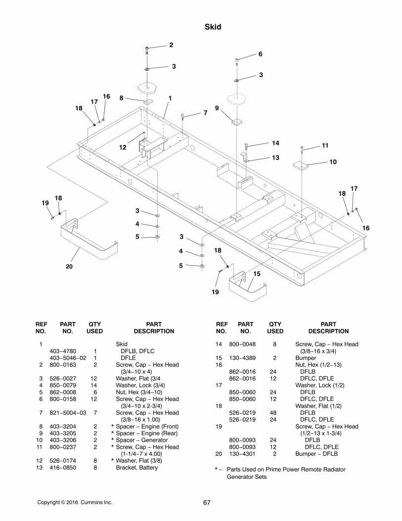
Skid
3
4
5
5
4
3
1
3
6
16
7
13
14
1918
1716
2015
19
18
3
8
2
9
10
1112
1718
18
REF PART QTY PART REF PART QTY PARTNO. NO. USED DESCRIPTION NO. NO. USED DESCRIPTION
1 Skid403−4780 1 DFLB, DFLC403−5046−02 1 DFLE
2 800−0163 2 Screw, Cap − Hex Head (3/4−10 x 4)
3 526−0027 12 Washer, Flat (3/44 850−0079 14 Washer, Lock (3/4)5 862−0008 6 Nut, Hex (3/4−10)6 800−0158 12 Screw, Cap − Hex Head
(3/4−10 x 2-3/4)7 821−5004−03 7 Screw, Cap − Hex Head
(3/8−16 x 1.00)8 403−3204 2 * Spacer − Engine (Front)9 403−3205 2 * Spacer − Engine (Rear)
10 403−3206 2 * Spacer − Generator11 800−0237 2 * Screw, Cap − Hex Head
(1-1/4−7 x 4.00)12 526−0174 8 * Washer, Flat (3/8)13 416−0850 8 Bracket, Battery
14 800−0048 8 Screw, Cap − Hex Head(3/8−16 x 3/4)
15 130−4389 2 Bumper16 Nut, Hex (1/2−13)
862−0016 24 DFLB862−0016 12 DFLC, DFLE
17 Washer, Lock (1/2)850−0060 24 DFLB850−0060 12 DFLC, DFLE
18 Washer, Flat (1/2)526−0219 48 DFLB526−0219 24 DFLC, DFLE
19 Screw, Cap − Hex Head(1/2−13 x 1-3/4)
800−0093 24 DFLB800−0093 12 DFLC, DFLE
20 130−4301 2 Bumper − DFLB
* − Parts Used on Prime Power Remote RadiatorGenerator Sets
Copyright 2016 Cummins Inc.68
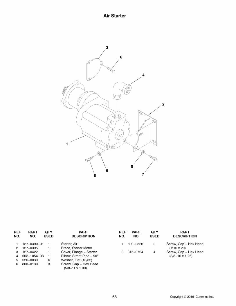
Air Starter
1
2
3
4
55
6
78
REF PART QTY PART REF PART QTY PARTNO. NO. USED DESCRIPTION NO. NO. USED DESCRIPTION
1 127−0390−01 1 Starter, Air2 127−0395 1 Brace, Starter Motor3 127−0422 1 Cover, Flange − Starter4 502−1054−08 1 Elbow, Street Pipe − 905 526−0030 6 Washer, Flat (13/32)6 800−0130 3 Screw, Cap − Hex Head
(5/8−11 x 1.00)
7 800−2526 2 Screw, Cap − Hex Head (M10 x 20)
8 815−0724 4 Screw, Cap − Hex Head (3/8−16 x 1.25)
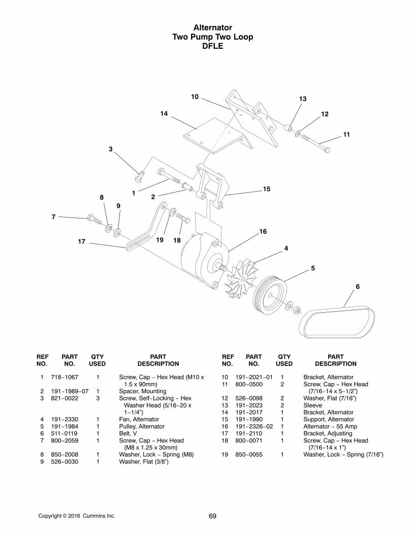
Copyright 2016 Cummins Inc. 69
AlternatorTwo Pump Two Loop
DFLE
6
5
4
16
17
7
89
19 18
15
3
1 2
14
10 13
12
11
REF PART QTY PART REF PART QTY PARTNO. NO. USED DESCRIPTION NO. NO. USED DESCRIPTION
1 718−1067 1 Screw, Cap − Hex Head (M10 x1.5 x 90mm)
2 191−1989−07 1 Spacer, Mounting3 821−0022 3 Screw, Self−Locking − Hex
Washer Head (5/16−20 x1−1/4”)
4 191−2330 1 Fan, Alternator5 191−1984 1 Pulley, Alternator6 511−0119 1 Belt, V7 800−2059 1 Screw, Cap − Hex Head
(M8 x 1.25 x 30mm)8 850−2008 1 Washer, Lock − Spring (M8)9 526−0030 1 Washer, Flat (3/8”)
10 191−2021−01 1 Bracket, Alternator11 800−0500 2 Screw, Cap − Hex Head
(7/16−14 x 5−1/2”)12 526−0098 2 Washer, Flat (7/16”)13 191−2023 2 Sleeve14 191−2017 1 Bracket, Alternator15 191−1990 1 Support, Alternator16 191−2326−02 1 Alternator − 55 Amp17 191−2110 1 Bracket, Adjusting18 800−0071 1 Screw, Cap − Hex Head
(7/16−14 x 1”)19 850−0055 1 Washer, Lock − Spring (7/16”)
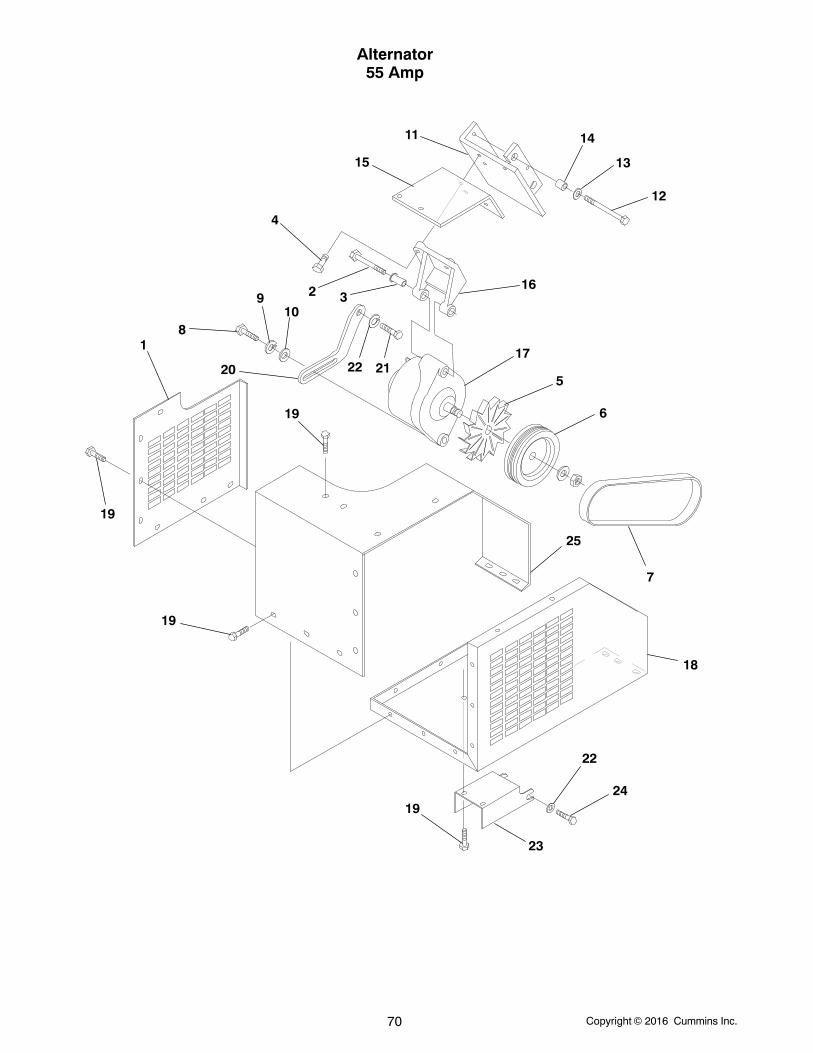
Copyright 2016 Cummins Inc.70
Alternator55 Amp
19
1
19
19
19
23
24
22
18
25
7
6
5
1720
8
910
22 21
16
4
2 3
15
11 14
13
12
Copyright 2016 Cummins Inc. 71
Alternator55 Amp
REF PART QTY PART REF PART QTY PARTNO. NO. USED DESCRIPTION NO. NO. USED DESCRIPTION
1 130−3870 1 Guard, Belt2 718−1067 1 Screw, Cap − Hex Head (M10 x
1.5 x 90mm)3 191−1989−07 1 Spacer, Mounting4 821−0022 3 Screw, Self−Locking − Hex
Washer Head (5/16−20 x1−1/4”)
5 191−2330 1 Fan, Alternator6 191−1984 1 Pulley, Alternator7 511−0119 1 Belt, V8 800−2059 1 Screw, Cap − Hex Head
(M8 x 1.25 x 30mm)9 850−2008 1 Washer, Lock − Spring (M8)
10 526−0030 1 Washer, Flat (3/8”)11 191−2021−01 1 Bracket, Alternator12 800−0500 2 Screw, Cap − Hex Head
(7/16−14 x 5−1/2”)
13 526−0098 2 Washer, Flat (7/16”)14 191−2023 2 Sleeve15 191−2017 1 Bracket, Alternator16 191−1990 1 Support, Alternator17 191−2326−02 1 Alternator − 55 Amp18 130−3868 1 Guard, Belt19 821−5002−04 21 Screw, Self−Locking − Hex
Washer Head (1/4−20 x 5/8”)20 191−2110 1 Bracket, Adjusting21 800−0071 1 Screw, Cap − Hex Head
(7/16−14 x 1”)22 850−0055 2 Washer, Lock − Spring (7/16”)23 130−5254−02 1 Bracket, Belt Guard24 800−0069 1 Screw, Cap − Hex Head
(7/16−14 x 3/4”)25 130−3869 1 Guard, Belt
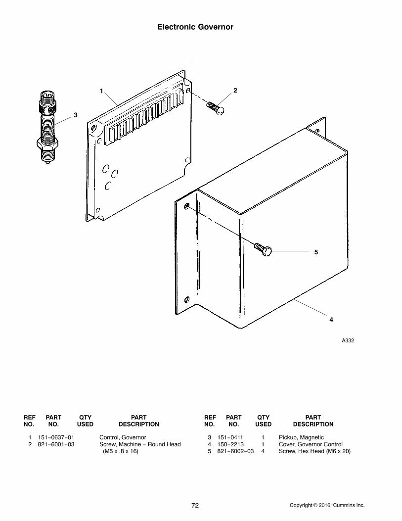
Copyright 2016 Cummins Inc.72
Electronic Governor
1
A332
3
2
4
5
REF PART QTY PART REF PART QTY PARTNO. NO. USED DESCRIPTION NO. NO. USED DESCRIPTION
1 151−0637−01 Control, Governor2 821−6001−03 Screw, Machine − Round Head
(M5 x .8 x 16)
3 151−0411 1 Pickup, Magnetic4 150−2213 1 Cover, Governor Control5 821−6002−03 4 Screw, Hex Head (M6 x 20)
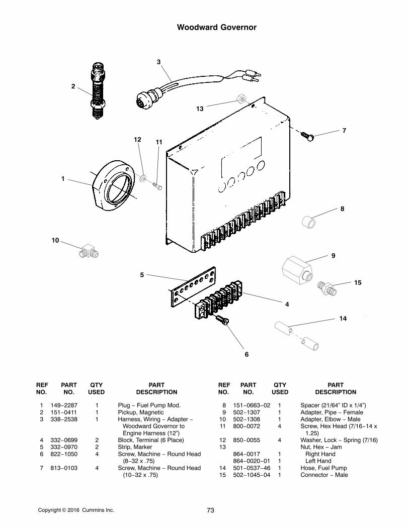
Copyright 2016 Cummins Inc. 73
Woodward Governor
1
2
3
4
5
6
15
7
8
9
10
11
13
14
12
REF PART QTY PART REF PART QTY PARTNO. NO. USED DESCRIPTION NO. NO. USED DESCRIPTION
1 149−2287 1 Plug − Fuel Pump Mod.2 151−0411 1 Pickup, Magnetic3 338−2538 1 Harness, Wiring − Adapter −
Woodward Governor toEngine Harness (12”)
4 332−0699 2 Block, Terminal (6 Place)5 332−0970 2 Strip, Marker6 822−1050 4 Screw, Machine − Round Head
(8−32 x .75)7 813−0103 4 Screw, Machine − Round Head
(10−32 x .75)
8 151−0663−02 1 Spacer (21/64” ID x 1/4”)9 502−1307 1 Adapter, Pipe − Female
10 502−1308 1 Adapter, Elbow − Male11 800−0072 4 Screw, Hex Head (7/16−14 x
1.25)12 850−0055 4 Washer, Lock − Spring (7/16)13 Nut, Hex − Jam
864−0017 1 Right Hand864−0020−01 1 Left Hand
14 501−0537−46 1 Hose, Fuel Pump15 502−1045−04 1 Connector − Male
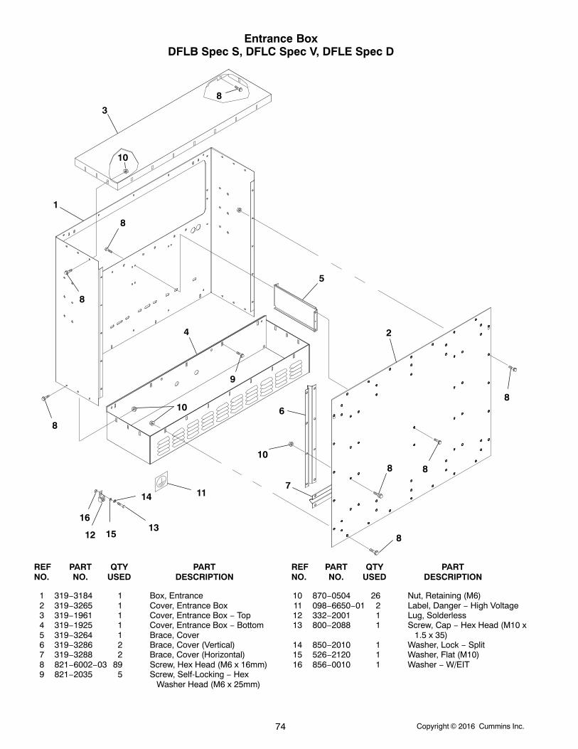
Copyright 2016 Cummins Inc.74
Entrance BoxDFLB Spec S, DFLC Spec V, DFLE Spec D
1
2
3
4
5
6
7
8
9
8
8
8
8
88
8
10
10
10
11
1213
14
15
16
REF PART QTY PART REF PART QTY PARTNO. NO. USED DESCRIPTION NO. NO. USED DESCRIPTION
1 319−3184 1 Box, Entrance2 319−3265 1 Cover, Entrance Box3 319−1961 1 Cover, Entrance Box − Top4 319−1925 1 Cover, Entrance Box − Bottom5 319−3264 1 Brace, Cover6 319−3286 2 Brace, Cover (Vertical)7 319−3288 2 Brace, Cover (Horizontal)8 821−6002−03 89 Screw, Hex Head (M6 x 16mm)9 821−2035 5 Screw, Self-Locking − Hex
Washer Head (M6 x 25mm)
10 870−0504 26 Nut, Retaining (M6)11 098−6650−01 2 Label, Danger − High Voltage12 332−2001 1 Lug, Solderless13 800−2088 1 Screw, Cap − Hex Head (M10 x
1.5 x 35)14 850−2010 1 Washer, Lock − Split15 526−2120 1 Washer, Flat (M10)16 856−0010 1 Washer − W/EIT
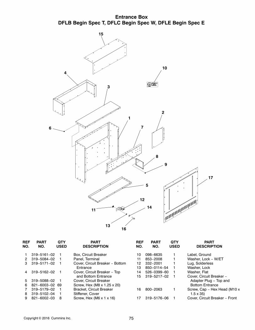
Copyright 2016 Cummins Inc. 75
Entrance BoxDFLB Begin Spec T, DFLC Begin Spec W, DFLE Begin Spec E
12
3
4
5
6 7
8
9
10
11
12
13
14
15
16
17
REF PART QTY PART REF PART QTY PARTNO. NO. USED DESCRIPTION NO. NO. USED DESCRIPTION
1 319−5161−02 1 Box, Circuit Breaker2 319−5084−02 1 Panel, Terminal3 319−5171−02 1 Cover, Circuit Breaker − Bottom
Entrance4 319−5162−02 1 Cover, Circuit Breaker − Top
and Bottom Entrance5 319−5088−02 1 Cover, Circuit Breaker6 821−6003−02 69 Screw, Hex (M8 x 1.25 x 20)7 319−5179−02 1 Bracket, Circuit Breaker8 319−5102−04 1 Stiffener, Cover9 821−6002−03 8 Screw, Hex (M6 x 1 x 16)
10 098−6635 1 Label, Ground11 853−2008 1 Washer, Lock − W/ET12 332−2001 1 Lug, Solderless13 850−0114−54 1 Washer, Lock14 526−0399−60 1 Washer, Flat15 319−5217−02 1 Cover, Circuit Breaker −
Adapter Plug − Top andBottom Entrance
16 800−2063 1 Screw, Cap − Hex Head (M10 x1.5 x 35)
17 319−5176−06 1 Cover, Circuit Breaker − Front
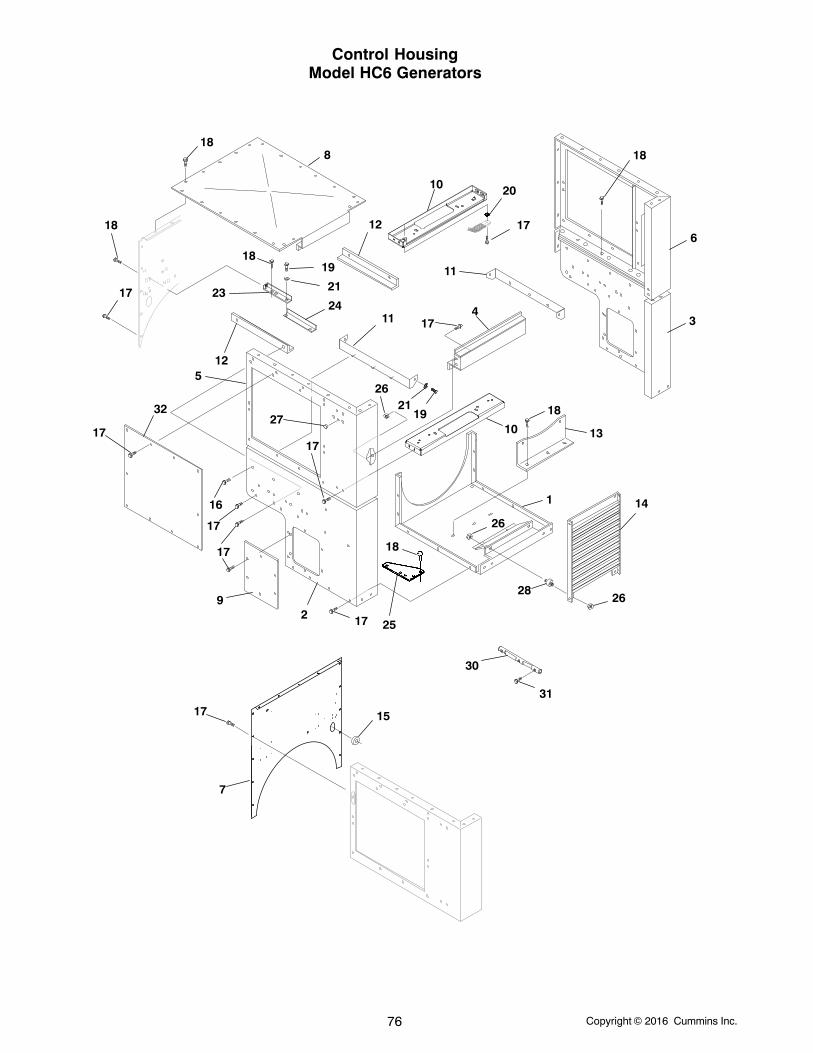
Copyright 2016 Cummins Inc.76
Control HousingModel HC6 Generators
188
10 20
17
11
41711
10
3
18
13
1 14
2628
26
17
2 17
9
17
16
17
17 15
7
27
17
12
17
12
2324
21
19
186
1921
18
25
26
18
5
18
32
31
30
Copyright 2016 Cummins Inc. 77
Control HousingModel HC6 Generators
REF PART QTY PART REF PART QTY PARTNO. NO. USED DESCRIPTION NO. NO. USED DESCRIPTION
1 319−3270−03 1 Panel, Bottom2 319−3283−01 1 Panel, Weldment − RH3 319−3283−02 1 Panel, Weldment − LH4 405−7245−02 1 Rail, Enclosure − Front5 319−3281−01 1 Panel, Weldment − RH6 319−3281−02 1 Panel, Weldment − LH7 319−3262 1 Panel, Control Housing − Rear8 319−1093 1 Panel, Control Housing − Top9 319−0881 2 Cover, Lower Housing − Side
10 405−7247−02 2 Rail, Enclosure − Support11 319−3267 2 Bracket, Saddle12 319−3260 2 Angle, Housing13 319−1091 1 Bracket, Panel14 319−2767 1 Grille15 508−1057 1 Grommet16 821−6004−01 12 Screw, Hex Head (M10 x 1.50 x
20)17 821−6002−03 30 Screw, Hex Head (M6 x 1.00 x
16)18 821−6003−02 63 Screw, Hex Head (M8 x 1.25 x
20)
19 800−2086 15 Screw, Cap − Hex Head (M10 x1.50 x 25)
20 856−0006 1 Washer, Lock − W/EIT (1/4)21 850−2010 15 Washer, Lock (M10)22 526−0141 10 Washer, Flat (3/8)23 319−3263 1 Angle, Support24 319−3269 1 Angle, Support25 319−1203−01 2 Gusset, Control Housing26 870−2054 10 Nut, Lock − Flange (M6 x 1.0)27 517−0131 1 Plug, Hole28 402−0729 4 Isolator, Vibration29 517−0135 1 Plug, Hole30 332−3740 1 Clamp, Strain31 814−2150 3 Screw, Flat Head − Cross
Recessed (M3 x 0.5 x 10)32 Cover, Side − Upper
319−1095 2 Without Circuit Breaker,Entrance Box or BUS Box
319−1095 1 With Circuit Breaker,Entrance Box or BUS Box
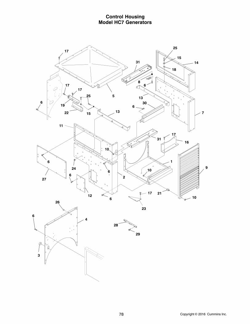
Copyright 2016 Cummins Inc.78
Control HousingModel HC7 Generators
1
2
3
4
5
6
6
6
6
6
7
8
9
10
10
10
11
14
12
16
17
17
266
6
21
23
17
13
13
24
25
15
19
22
1717
6
27
18
15
25
31
31
30
28
29
Copyright 2016 Cummins Inc. 79
Control HousingModel HC7 Generators
REF PART QTY PART REF PART QTY PARTNO. NO. USED DESCRIPTION NO. NO. USED DESCRIPTION
1 319−3270−04 1 Panel − Bottom2 319−3283−01 1 Panel − Right Side − Bottom3 508−1057 1 Grommet, Rubber (Fits 2−1/4”
Hole)4 319−3261 1 Panel − Front5 319−1093 1 Cover, Top6 821−6002−03 26 Screw, Hex Head (M6 x 16mm)7 319−3283−02 1 Panel − Left Side − Bottom8 856−0006 1 Washer, Lock − EIT (1/4”)9 319−2767 1 Grille
10 870−2054 10 Nut, Locking (M6)11 319−3281−01 1 Panel − Left Side − Upper12 319−0881 2 Cover, Side − Lower13 319−3268 2 Bracket, Saddle14 319−3281−02 1 Panel − Left Side − Upper15 850−2010 11 Washer, Lock − Spring (M10)16 319−1092 1 Bracket, Panel17 821−6003−02 62 Screw, Self−Locking − Hex
Washer Head (M8 x 20mm)18 526−0141 6 Washer, Flat (3/8”)
19 319−3263 1 Angle, Support (5−1/2”)20 517−0131 1 Plug, Hole (Fits 3/8” Hole)21 402−0729 4 Isolator, Vibration22 319−3269 1 Angle, Support (6−1/2”)23 319−1203−01 2 Gusset24 870−2056 6 Nut, Hex (M10)25 800−2086 11 Screw, Cap − Hex Head (M10 x
25mm)26 517−0135 1 Plug, Hole (Fits 5/8” Hole)27 Cover, Side − Upper
319−1095 2 Without Circuit Breaker, Entrance Box or BUS Box
319−1095 1 With Circuit Breaker, Entrance Box or BUS Box
28 332−3740 1 Clamp, Strain29 814−2150 3 Screw, Flat Head − Cross
Recessed (M3 x 0.5 x 10)30 405−7245−02 1 Rail, Enclosure − Front31 405−7247−02 2 Rail, Enclosure − Support
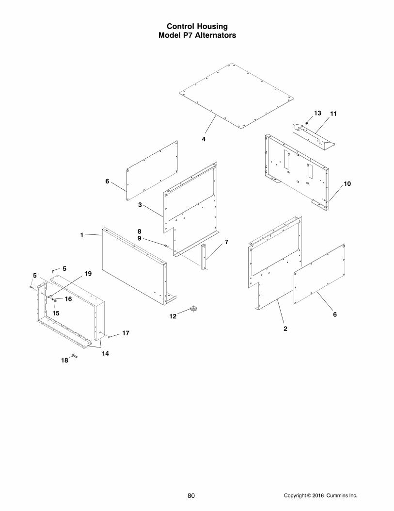
Copyright 2016 Cummins Inc.80
Control HousingModel P7 Alternators
1
2
3
4
55
6
6
7
89
10
11
12
13
14
15
16
19
17
18
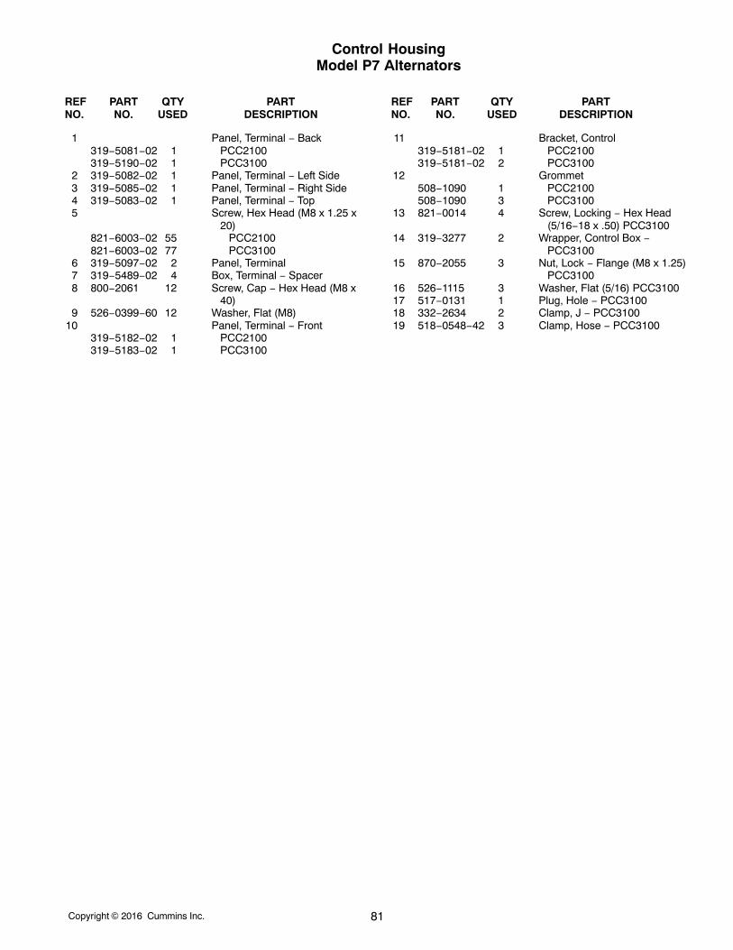
Copyright 2016 Cummins Inc. 81
Control HousingModel P7 Alternators
REF PART QTY PART REF PART QTY PARTNO. NO. USED DESCRIPTION NO. NO. USED DESCRIPTION
1 Panel, Terminal − Back319−5081−02 1 PCC2100319−5190−02 1 PCC3100
2 319−5082−02 1 Panel, Terminal − Left Side3 319−5085−02 1 Panel, Terminal − Right Side4 319−5083−02 1 Panel, Terminal − Top5 Screw, Hex Head (M8 x 1.25 x
20)821−6003−02 55 PCC2100821−6003−02 77 PCC3100
6 319−5097−02 2 Panel, Terminal7 319−5489−02 4 Box, Terminal − Spacer8 800−2061 12 Screw, Cap − Hex Head (M8 x
40)9 526−0399−60 12 Washer, Flat (M8)
10 Panel, Terminal − Front319−5182−02 1 PCC2100319−5183−02 1 PCC3100
11 Bracket, Control319−5181−02 1 PCC2100319−5181−02 2 PCC3100
12 Grommet508−1090 1 PCC2100508−1090 3 PCC3100
13 821−0014 4 Screw, Locking − Hex Head(5/16−18 x .50) PCC3100
14 319−3277 2 Wrapper, Control Box −PCC3100
15 870−2055 3 Nut, Lock − Flange (M8 x 1.25)PCC3100
16 526−1115 3 Washer, Flat (5/16) PCC310017 517−0131 1 Plug, Hole − PCC310018 332−2634 2 Clamp, J − PCC310019 518−0548−42 3 Clamp, Hose − PCC3100
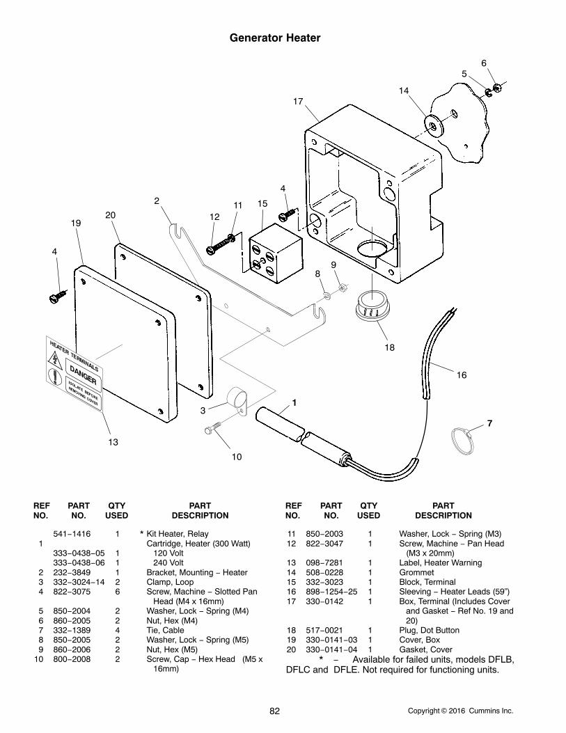
Copyright 2016 Cummins Inc.82
Generator Heater
4
1920
2
17
1211 15
4
14
56
98
18
16
3
10
1
7
13
REF PART QTY PART REF PART QTY PARTNO. NO. USED DESCRIPTION NO. NO. USED DESCRIPTION
541−1416 1 * Kit Heater, Relay1 Cartridge, Heater (300 Watt)
333−0438−05 1 120 Volt333−0438−06 1 240 Volt
2 232−3849 1 Bracket, Mounting − Heater3 332−3024−14 2 Clamp, Loop4 822−3075 6 Screw, Machine − Slotted Pan
Head (M4 x 16mm)5 850−2004 2 Washer, Lock − Spring (M4)6 860−2005 2 Nut, Hex (M4)7 332−1389 4 Tie, Cable8 850−2005 2 Washer, Lock − Spring (M5)9 860−2006 2 Nut, Hex (M5)
10 800−2008 2 Screw, Cap − Hex Head (M5 x16mm)
11 850−2003 1 Washer, Lock − Spring (M3)12 822−3047 1 Screw, Machine − Pan Head
(M3 x 20mm)13 098−7281 1 Label, Heater Warning14 508−0228 1 Grommet15 332−3023 1 Block, Terminal16 898−1254−25 1 Sleeving − Heater Leads (59”)17 330−0142 1 Box, Terminal (Includes Cover
and Gasket − Ref No. 19 and20)
18 517−0021 1 Plug, Dot Button19 330−0141−03 1 Cover, Box20 330−0141−04 1 Gasket, Cover
* − Available for failed units, models DFLB,DFLC and DFLE. Not required for functioning units.
Copyright 2016 Cummins Inc. 83
Generator Mounting
9
3
4
8
7 56
10
3
1
2
REF PART QTY PART REF PART QTY PARTNO. NO. USED DESCRIPTION NO. NO. USED DESCRIPTION
1 Screw, Cap − Hex Head800−0303 2 Model HC7 and P7
Generators (1−1/4−7 x 3−1/2”)
2 232−3551 2 Spacer − Model HC6Generators
3 526−0445 4 Washer, Flat (1−3/8” ID x 3” OD x .136” Thk)
4 862−0017 2 Nut, Hex (1−1/4−7)5 Screw, Cap − Hex Head −
Grade 8800−0576 16 Model HC6 Generators
(1/2−13 x 1−3/4”)800−0596 16 Model HC7 and P7
Generators (1/2−13 x 2−1/4”)
6 850−0060 16 Washer, Lock − Spring (1/2”)
7 805−0035 6 Bolt, Place (5/8−11 x 1−1/2”)Grade 8
8 526−0416 6 Washer, Flat (5/8”)9 Shim (Quantity Used As
Required)Model HC6 Generators
232−3552−01 4 1/64” Thk232−3552−02 4 5/64” Thk403−2921 4 7/64” Thk
Model HC7 and P7 Generators
232−3941−01 4 2.6 mm Thk232−3941−02 4 1.9 mm Thk232−3941−03 4 6 mm Thk232−3941−04 4 4.8 mm Thk
10 332−3196 1 Clamp, “J”
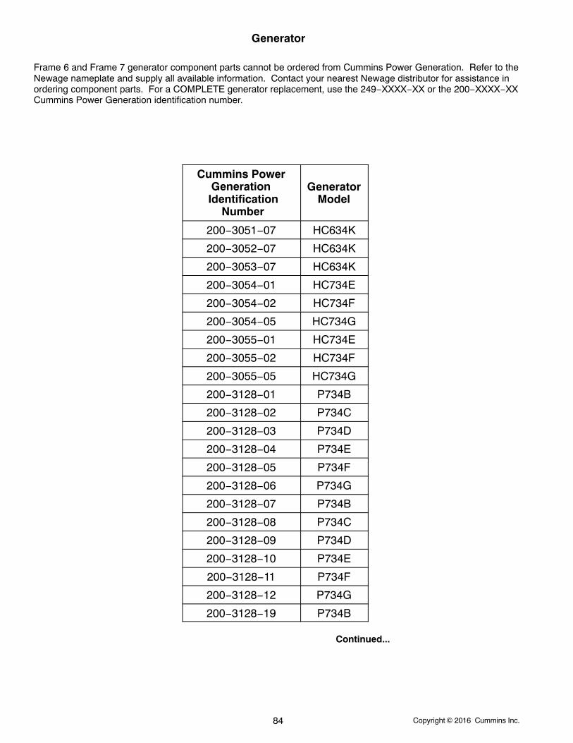
Copyright 2016 Cummins Inc.84
Generator
Frame 6 and Frame 7 generator component parts cannot be ordered from Cummins Power Generation. Refer to theNewage nameplate and supply all available information. Contact your nearest Newage distributor for assistance inordering component parts. For a COMPLETE generator replacement, use the 249−XXXX−XX or the 200−XXXX−XXCummins Power Generation identification number.
Cummins PowerGeneration
Identification Number
GeneratorModel
200−3051−07 HC634K
200−3052−07 HC634K
200−3053−07 HC634K
200−3054−01 HC734E
200−3054−02 HC734F
200−3054−05 HC734G
200−3055−01 HC734E
200−3055−02 HC734F
200−3055−05 HC734G
200−3128−01 P734B
200−3128−02 P734C
200−3128−03 P734D
200−3128−04 P734E
200−3128−05 P734F
200−3128−06 P734G
200−3128−07 P734B
200−3128−08 P734C
200−3128−09 P734D
200−3128−10 P734E
200−3128−11 P734F
200−3128−12 P734G
200−3128−19 P734B
Continued...
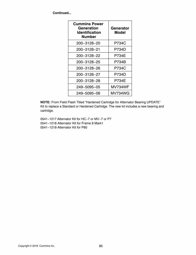
Copyright 2016 Cummins Inc. 85
Continued...
Cummins PowerGeneration
Identification Number
GeneratorModel
200−3128−20 P734C
200−3128−21 P734D
200−3128−22 P734E
200−3128−25 P734B
200−3128−26 P734C
200−3128−27 P734D
200−3128−28 P734E
249−5095−05 MV734WF
249−5095−06 MV734WG
NOTE: From Field Flash Titled “Hardened Cartridge for Alternator Bearing UPDATE”Kit to replace a Standard or Hardened Cartridge. The new kit includes a new bearing andcartridge.
0541−1217 Alternator Kit for HC−7 or MV−7 or P70541−1218 Alternator Kit for Frame 8 Mark10541−1219 Alternator Kit for P80
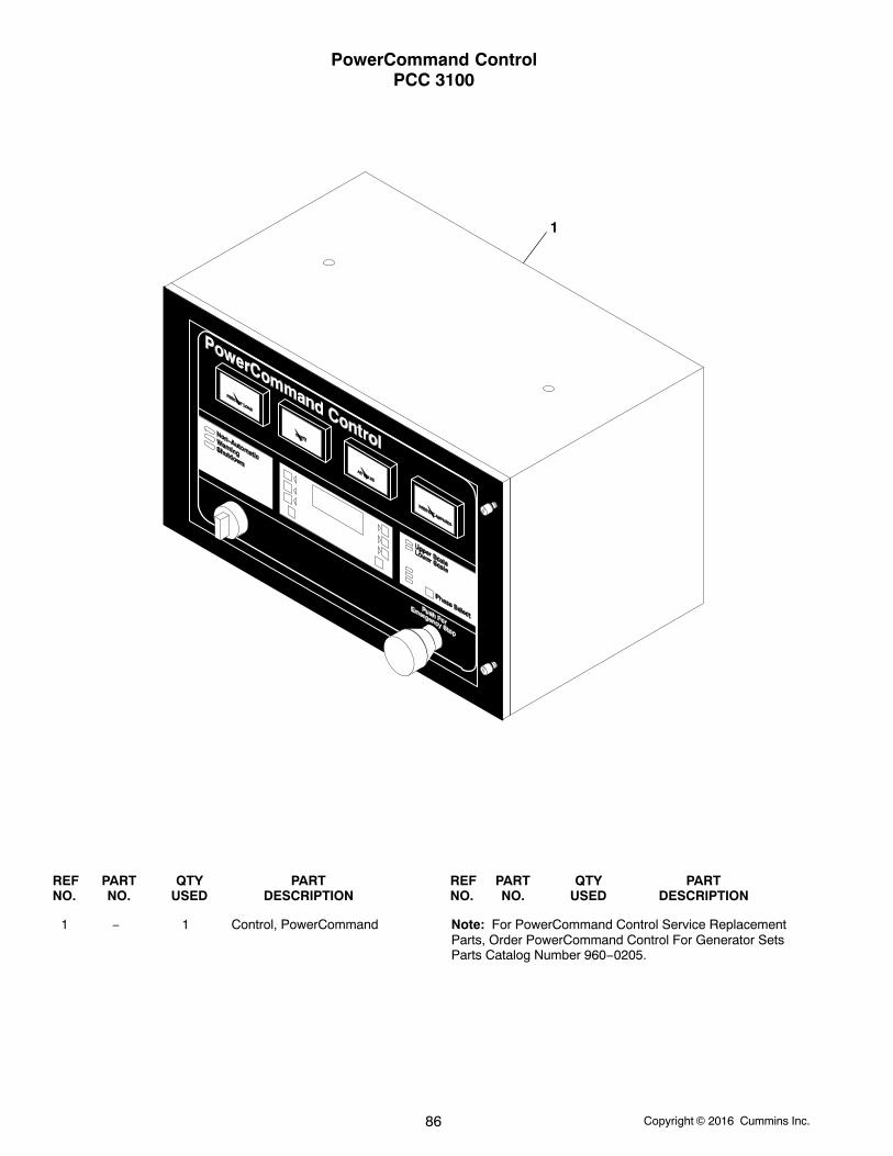
Copyright 2016 Cummins Inc.86
PowerCommand ControlPCC 3100
1
REF PART QTY PART REF PART QTY PARTNO. NO. USED DESCRIPTION NO. NO. USED DESCRIPTION
1 − 1 Control, PowerCommand Note: For PowerCommand Control Service ReplacementParts, Order PowerCommand Control For Generator SetsParts Catalog Number 960−0205.
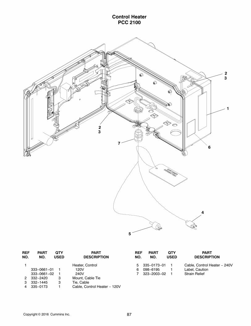
Copyright 2016 Cummins Inc. 87
Control HeaterPCC 2100
76
1
23
4
5
23
REF PART QTY PART REF PART QTY PARTNO. NO. USED DESCRIPTION NO. NO. USED DESCRIPTION
1 Heater, Control333−0661−01 1 120V333−0661−02 1 240V
2 332−2420 3 Mount, Cable Tie3 332−1445 3 Tie, Cable4 335−0173 1 Cable, Control Heater − 120V
5 335−0173−01 1 Cable, Control Heater − 240V6 098−6195 1 Label, Caution7 323−2003−02 1 Strain Relief
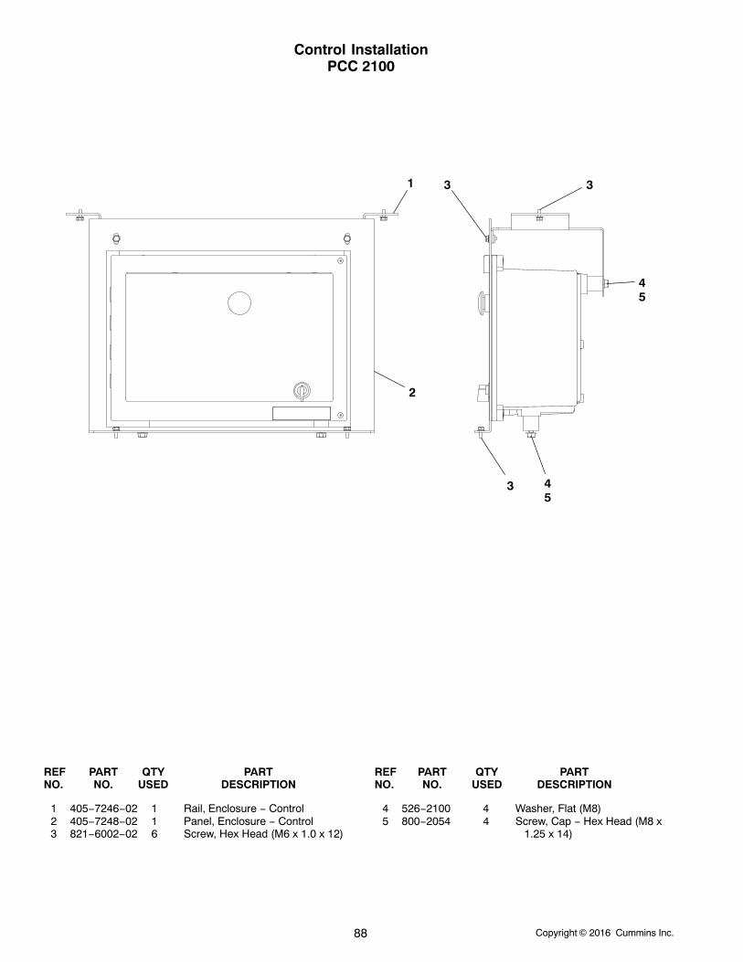
Copyright 2016 Cummins Inc.88
Control InstallationPCC 2100
1
2
3
3 3
45
45
REF PART QTY PART REF PART QTY PARTNO. NO. USED DESCRIPTION NO. NO. USED DESCRIPTION
1 405−7246−02 1 Rail, Enclosure − Control2 405−7248−02 1 Panel, Enclosure − Control3 821−6002−02 6 Screw, Hex Head (M6 x 1.0 x 12)
4 526−2100 4 Washer, Flat (M8)5 800−2054 4 Screw, Cap − Hex Head (M8 x
1.25 x 14)
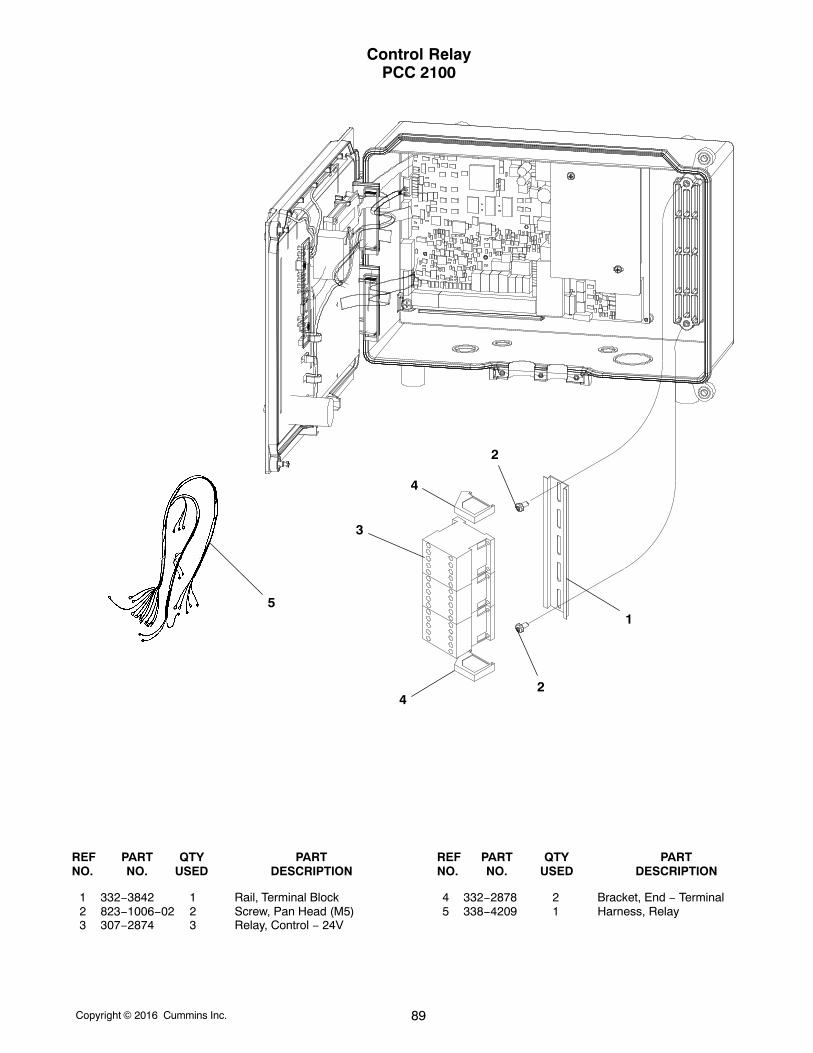
Copyright 2016 Cummins Inc. 89
Control RelayPCC 2100
1
2
2
3
4
4
5
REF PART QTY PART REF PART QTY PARTNO. NO. USED DESCRIPTION NO. NO. USED DESCRIPTION
1 332−3842 1 Rail, Terminal Block2 823−1006−02 2 Screw, Pan Head (M5)3 307−2874 3 Relay, Control − 24V
4 332−2878 2 Bracket, End − Terminal5 338−4209 1 Harness, Relay
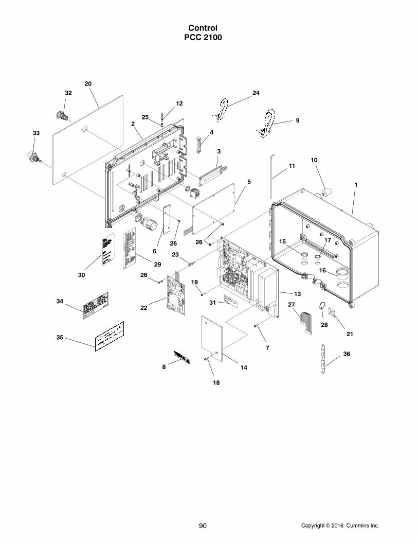
Copyright 2016 Cummins Inc.90
ControlPCC 2100
1
2
3
4
5
6
7
8
9
1011
12
13
14
15
16
17
18
19
20
21
22
23
24
25
26
2626
27
28
29
30
31
32
33
34
35
ÂÂ
ÂÂ
36
Copyright 2016 Cummins Inc. 91
ControlPCC 2100
REF PART QTY PART REF PART QTY PARTNO. NO. USED DESCRIPTION NO. NO. USED DESCRIPTION
1 319−4487 1 Box, Control2 319−4488 1 Door Control3 300−5467 1 Display, Digital4 332−3896 4 Clamp, Cable5 300−5180 1 Board, Printed Circuit −
Bargraph6 300−5383 1 Board, Printed Circuit − LED7 819−1137−02 4 Screw, Pan Head − Cross
Recessed (M3 x 8)8 098−7904 2 Label, Danger9 338−3991 1 Harness, Control − Door
10 402−0764−01 4 Mount, Isolator11 406−0845 1 Pin, Hinge12 322−0491 3 Lamp, LED13 300−5381 1 Board, Printed Circuit − Base14 319−4497 1 Guard, Electrical15 517−0356 1 Plug, Hole (Fits 22.5mm DIA.
Hole)16 517−0357 1 Plug, Hole (Fits 38mm DIA.
Hole)17 517−0355 2 Plug, Hole (Fits 16mm DIA.
Hole)18 815−0792−02 2 Screw, Machine − Pan Head
(M4 x 0.7 x 8)19 819−1144 2 Screw, Pan Head − Cross
Recessed (M6 x 8)
20 Panel, Membrane300−5446 1 With Bargraph300−5447 1 Without Bargraph
21 332−2420 2 Mount, Cable Tie22 327−1275 1 Board, Printed Circuit − NCM23 870−2213−02 4 Standoff, Hex Threaded − With
NCM24 338−3994 1 Harness, Panel Light25 322−0488 3 Lens, LED26 Screw, Pan Head − Cross
Recessed (M3 x 6)819−1137−01 9 Without Bargraph819−1137−01 15 With Bargraph
27 335−0189 1 Cable, Ribbon28 332−1445 3 Tie, Cable29 098−7918 1 Label, Information30 098−7961−01 1 Label, Information − Panel
Insert31 098−7989 1 Label, Instruction − Torque32 308−0999 1 Switch, Emergency Stop33 308−1085 1 Switch, Selector34 098−8057 1 Label, Information − Rating35 098−6984 1 Label, UL36 337−0049 1 Strap, Bond
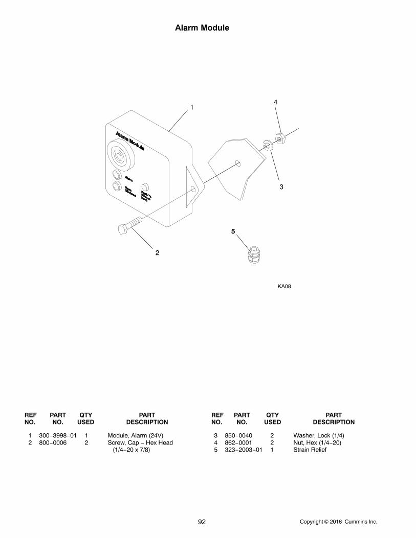
Copyright 2016 Cummins Inc.92
Alarm Module
14
3
2
KA08
5
REF PART QTY PART REF PART QTY PARTNO. NO. USED DESCRIPTION NO. NO. USED DESCRIPTION
1 300−3998−01 1 Module, Alarm (24V)2 800−0006 2 Screw, Cap − Hex Head
(1/4−20 x 7/8)
3 850−0040 2 Washer, Lock (1/4)4 862−0001 2 Nut, Hex (1/4−20)5 323−2003−01 1 Strain Relief
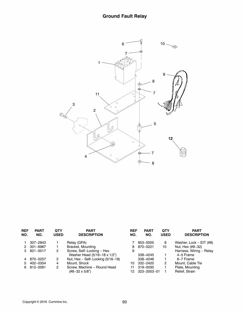
Copyright 2016 Cummins Inc. 93
Ground Fault Relay
3
4
2
11
1
7
6 10
9
8
7
5
7
8
12
REF PART QTY PART REF PART QTY PARTNO. NO. USED DESCRIPTION NO. NO. USED DESCRIPTION
1 307−2843 1 Relay (GFA)2 301−6987 1 Bracket, Mounting3 821−0017 2 Screw, Self−Locking − Hex
Washer Head (5/16−18 x 1/2”)4 870−0257 2 Nut, Hex − Self−Locking (5/16−18)5 402−0354 4 Mount, Shock6 812−0081 2 Screw, Machine − Round Head
(#8−32 x 5/8”)
7 853−0005 8 Washer, Lock − EIT (#8)8 870−0221 10 Nut, Hex (#8−32)9 Harness, Wiring − Relay
338−4245 1 4−5 Frame338−4246 1 6−7 Frame
10 332−2420 2 Mount, Cable Tie11 319−0030 1 Plate, Mounting12 323−2003−01 1 Relief, Strain
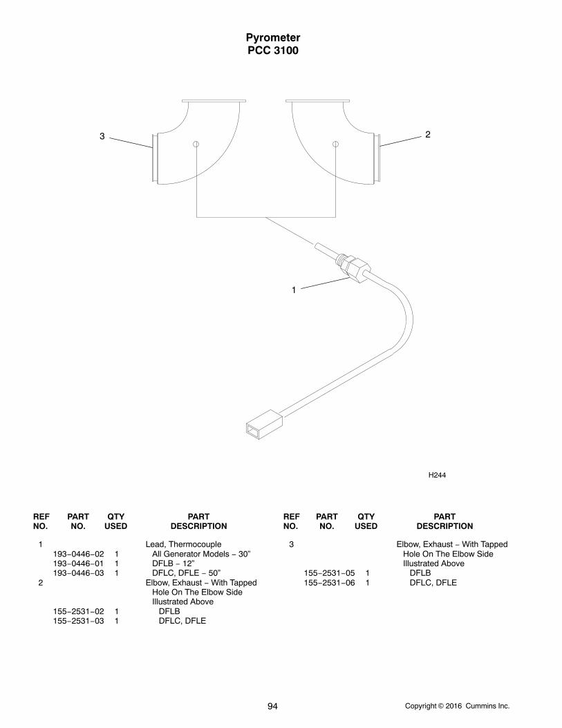
Copyright 2016 Cummins Inc.94
PyrometerPCC 3100
1
H244
23
REF PART QTY PART REF PART QTY PARTNO. NO. USED DESCRIPTION NO. NO. USED DESCRIPTION
1 Lead, Thermocouple193−0446−02 1 All Generator Models − 30”193−0446−01 1 DFLB − 12”193−0446−03 1 DFLC, DFLE − 50”
2 Elbow, Exhaust − With TappedHole On The Elbow SideIllustrated Above
155−2531−02 1 DFLB155−2531−03 1 DFLC, DFLE
3 Elbow, Exhaust − With TappedHole On The Elbow SideIllustrated Above
155−2531−05 1 DFLB155−2531−06 1 DFLC, DFLE
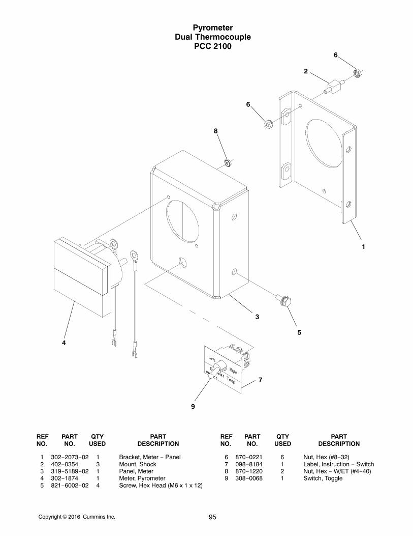
Copyright 2016 Cummins Inc. 95
PyrometerDual Thermocouple
PCC 2100
1
2
3
4
5
6
7
8
6
9
REF PART QTY PART REF PART QTY PARTNO. NO. USED DESCRIPTION NO. NO. USED DESCRIPTION
1 302−2073−02 1 Bracket, Meter − Panel2 402−0354 3 Mount, Shock3 319−5189−02 1 Panel, Meter4 302−1874 1 Meter, Pyrometer5 821−6002−02 4 Screw, Hex Head (M6 x 1 x 12)
6 870−0221 6 Nut, Hex (#8−32)7 098−8184 1 Label, Instruction − Switch8 870−1220 2 Nut, Hex − W/ET (#4−40)9 308−0068 1 Switch, Toggle
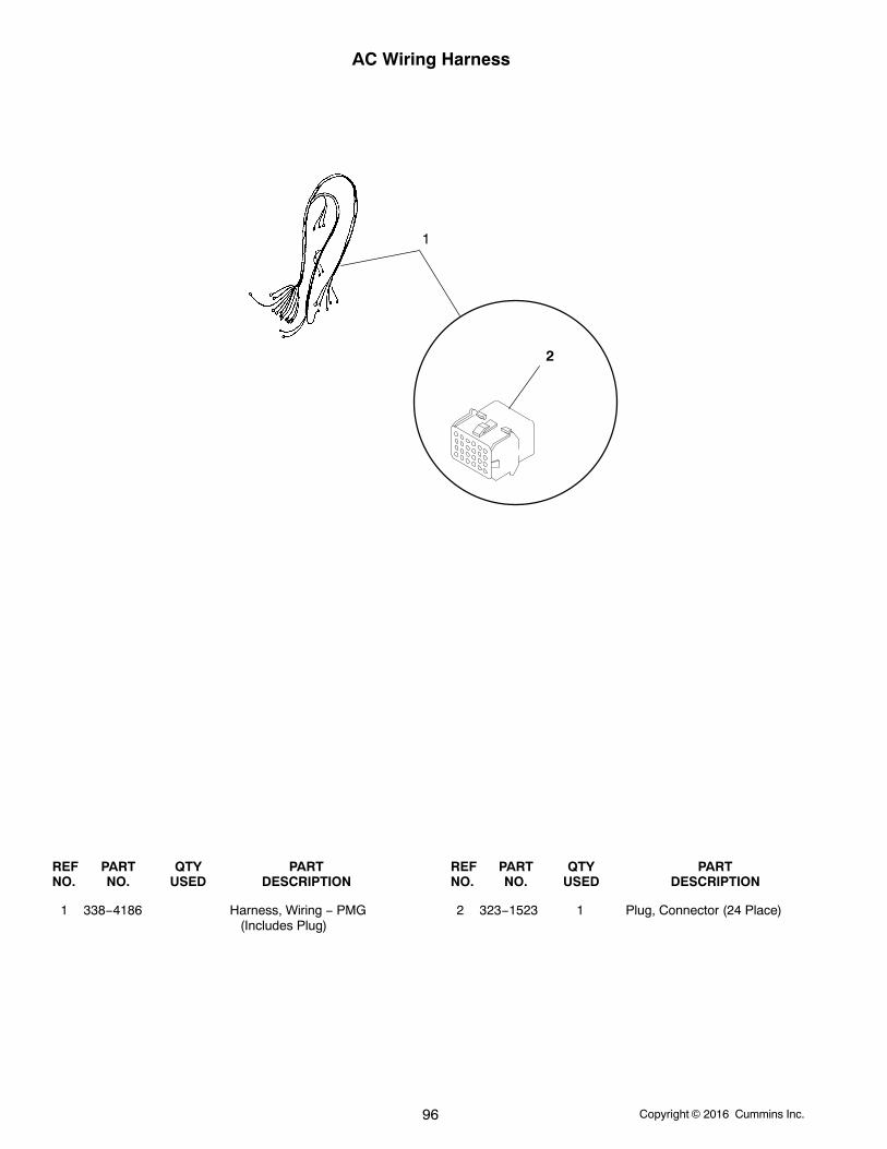
Copyright 2016 Cummins Inc.96
AC Wiring Harness
1
2
REF PART QTY PART REF PART QTY PARTNO. NO. USED DESCRIPTION NO. NO. USED DESCRIPTION
1 338−4186 Harness, Wiring − PMG(Includes Plug)
2 323−1523 1 Plug, Connector (24 Place)
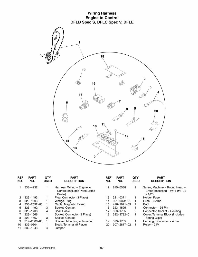
Copyright 2016 Cummins Inc. 97
Wiring HarnessEngine to Control
DFLB Spec S, DFLC Spec V, DFLE
1
2
3
4
5
6 7
8
9
10 11
12
13
1415
16
17
18
19
20
REF PART QTY PART REF PART QTY PARTNO. NO. USED DESCRIPTION NO. NO. USED DESCRIPTION
1 338−4232 1 Harness, Wiring − Engine toControl (Includes Parts ListedBelow)
2 323−1493 1 Plug, Connector (3 Place)3 323−1503 1 Wedge, Plug4 338−2592−03 1 Cable, Magnetic Pickup5 323−1492 3 Socket, Contact6 323−1708 4 Seal, Cable7 323−1666 1 Socket, Connector (3 Place)8 323−1667 3 Socket, Contact9 319−2006−05 1 Bracket, Mounting − Terminal
10 332−0604 1 Block, Terminal (5 Place)11 332−1043 4 Jumper
12 815−0538 2 Screw, Machine − Round Head −Cross Recessed − W/IT (#8−32x 1/2”)
13 321−0371 1 Holder, Fuse14 321−0372−01 1 Fuse − 3 Amp15 416−1021−03 2 Boot16 323−1525 1 Connector − 36 Pin17 323−1755 2 Connector, Socket − Housing18 332−3792−01 1 Cover, Terminal Block (Includes
Spring Clips)19 323−1765 1 Housing, Connector − 4 Pin20 307−2817−02 1 Relay − 24V
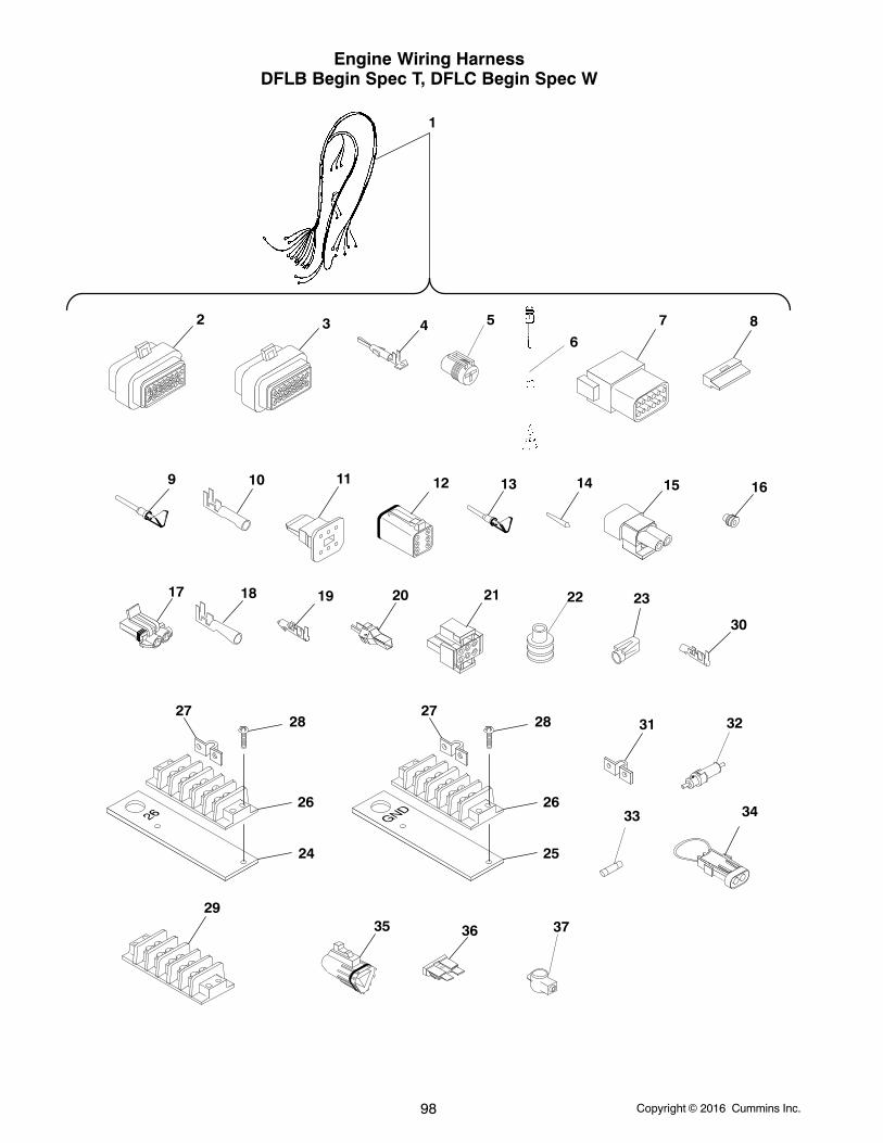
Copyright 2016 Cummins Inc.98
Engine Wiring HarnessDFLB Begin Spec T, DFLC Begin Spec W
1
12
35
7
21
2 3
15
17
4
18
9
30
1310
19
31
29
24
26
2728
36
11
20
8
14 16
25
26
2728
6
23
32
33
22
5
34
37
Copyright 2016 Cummins Inc. 99
Engine Wiring HarnessDFLB Begin Spec T, DFLC Begin Spec W
REF PART QTY PART REF PART QTY PARTNO. NO. USED DESCRIPTION NO. NO. USED DESCRIPTION
1 338−4321 1 Harness, Wiring − Engine toControl (Includes TheFollowing Parts)
2 323−1605−03 1 Connector, Plug (23 Pin Gray)(P5)
3 323−1605−02 2 Connector, Plug (23 PinNatural) (P4, P6)
4 323−1614−01 49 Socket, Contact (Used in P4,P5, P6)
5 323−1765 1 Connector, Housing6 338−2592−02 1 Cable, Magnetic Pickup (P1)7 323−1580 1 Housing Receptacle (J12)8 323−1581 1 Wedge, Receptacle (12 Pin)9 323−1491 5 Terminal, Socket
10 323−1648 5 Terminal, Socket11 323−1624 1 Wedge, Lock − Plug (P7)12 323−1623 1 Plug (6 Pin) (P7)13 323−1492 9 Socket, Female (P7)14 323−1615 9 Plug (Used in P4, P5, P6)15 323−1637 2 Connector, Socket (E6, E7)16 323−1445 10 Seal, Cable (E2, E3, E4, E6,
E7)17 323−1540 3 Connector, Socket (E2, E3, E4)18 323−1444 4 Terminal, Socket (E6, E7)
19 332−3096−01 6 Terminal, Socket (E2, E3, E4)20 323−1503 1 Wedge, Plug (3 Pin)21 323−1643−01 1 Housing, Plug22 323−1708 4 Seal, Cable23 323−1666 1 Connector, Socket (E1)24 319−2006−01 1 Bracket, Terminal Mounting
(T26)25 319−2006−02 1 Bracket, Terminal Mounting
(Ground)26 332−0604 2 Block, Terminal27 332−1043 8 Jumper28 815−0538 4 Screw, Machine − Round Head
− Cross Recessed W/IT(#8−32 x 1/2”)
29 332−0604 1 Block, Terminal30 323−1667 3 Terminal, Socket31 332−1043 3 Jumper32 321−0371 1 Holder, Fuse33 321−0372−01 1 Fuse − 3 Amp34 338−3285 2 Harness, Jumper35 323−1493 1 Plug (3 Pin) (P3)36 321−0307−07 1 Fuse (20 Amp, 32 Volt, Yellow)37 416−1021−03 2 Boot
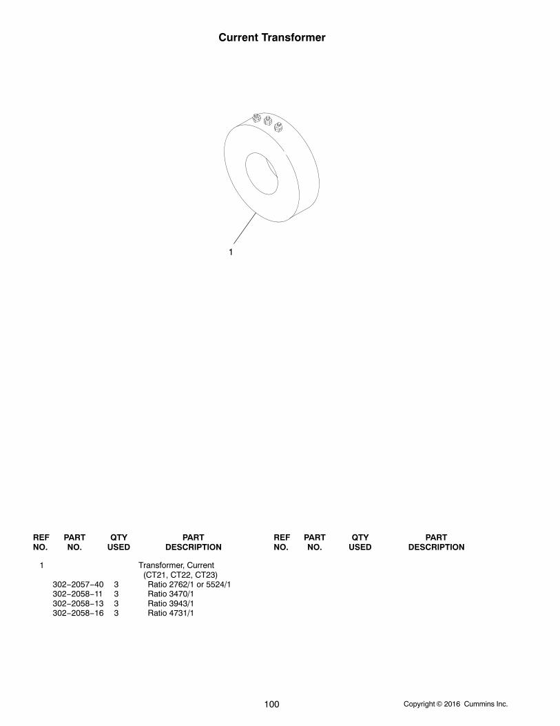
Copyright 2016 Cummins Inc.100
Current Transformer
1
REF PART QTY PART REF PART QTY PARTNO. NO. USED DESCRIPTION NO. NO. USED DESCRIPTION
1 Transformer, Current (CT21, CT22, CT23)
302−2057−40 3 Ratio 2762/1 or 5524/1302−2058−11 3 Ratio 3470/1302−2058−13 3 Ratio 3943/1302−2058−16 3 Ratio 4731/1
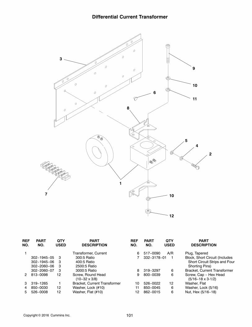
Copyright 2016 Cummins Inc. 101
Differential Current Transformer
1
2
3
45
6
7
8
9
10
10
11
12
REF PART QTY PART REF PART QTY PARTNO. NO. USED DESCRIPTION NO. NO. USED DESCRIPTION
1 Transformer, Current302−1945−05 3 300:5 Ratio302−1945−06 3 400:5 Ratio302−2060−06 3 2500:5 Ratio302−2060−07 3 3000:5 Ratio
2 813−0098 12 Screw, Round Head (10−32 x 3/8)
3 319−1265 1 Bracket, Current Transformer4 850−0030 12 Washer, Lock (#10)5 526−0008 12 Washer, Flat (#10)
6 517−0090 A/R Plug, Tapered7 332−3178−01 1 Block, Short Circuit (Includes
Short Circuit Strips and FourShorting Pins)
8 319−3297 6 Bracket, Current Transformer9 800−0039 6 Screw, Cap − Hex Head
(5/16−18 x 3-1/2)10 526−0022 12 Washer, Flat11 850−0045 6 Washer, Lock (5/16)12 862−0015 6 Nut, Hex (5/16−18)
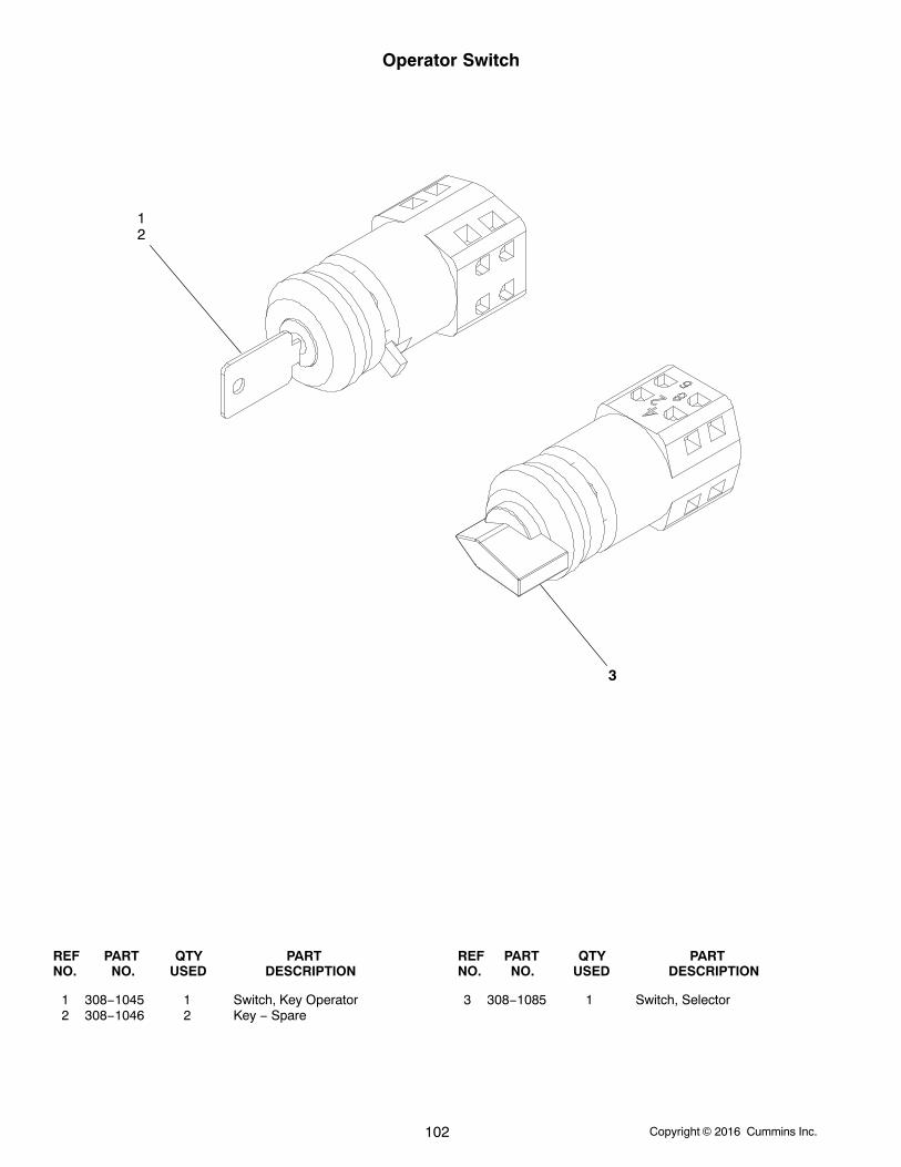
Copyright 2016 Cummins Inc.102
Operator Switch
12
3
REF PART QTY PART REF PART QTY PARTNO. NO. USED DESCRIPTION NO. NO. USED DESCRIPTION
1 308−1045 1 Switch, Key Operator2 308−1046 2 Key − Spare
3 308−1085 1 Switch, Selector

Copyright 2016 Cummins Inc. 103
“Intentionally Left Blank”
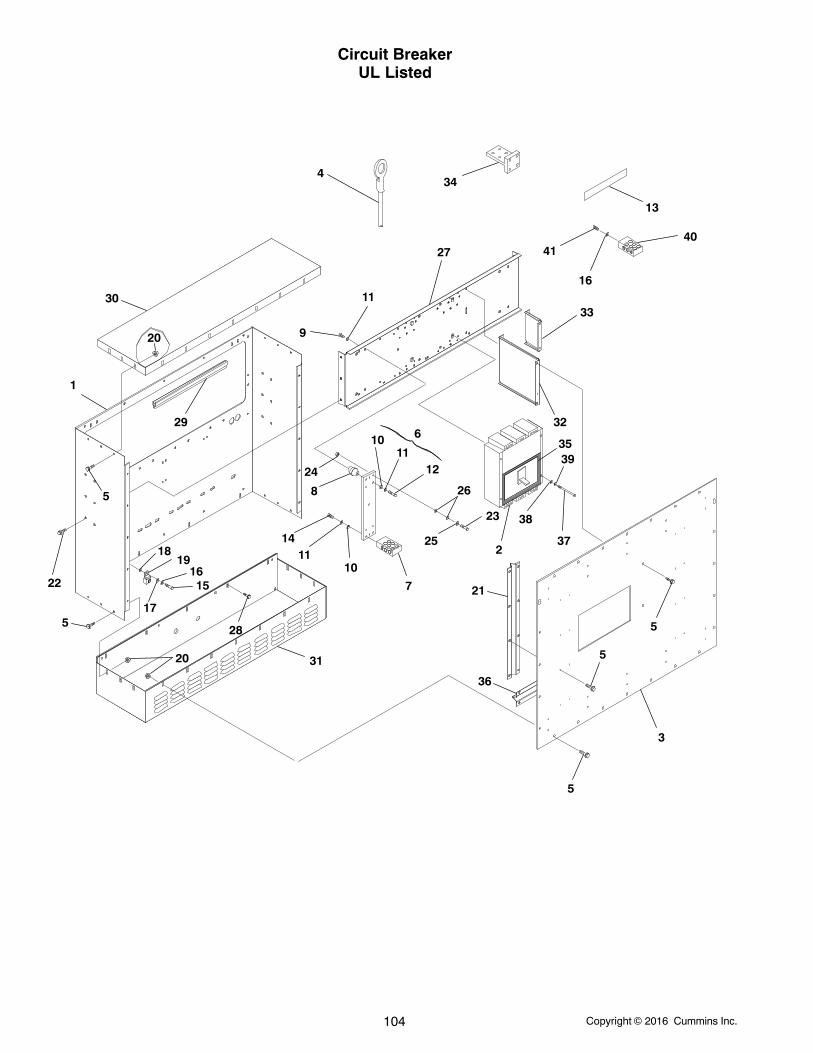
Copyright 2016 Cummins Inc.104
Circuit BreakerUL Listed
1
2
3
5
5
5
6
7
8
9
10
10
11
11
1112
13
14
1516
17
1819
20
5
5
20
2122
24
23
25
26
27
28
29
30
31
32
33
34
35
36
37
39
38
40
4
16
41
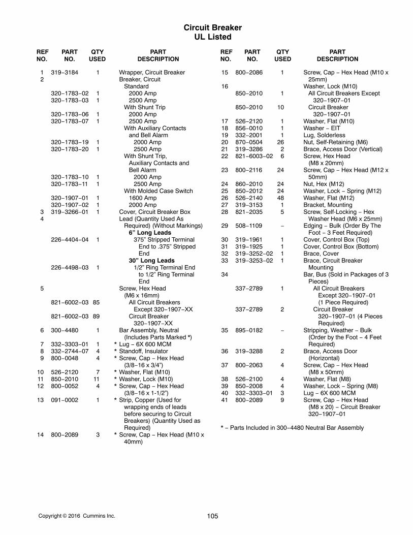
Copyright 2016 Cummins Inc. 105
Circuit BreakerUL Listed
REF PART QTY PART REF PART QTY PARTNO. NO. USED DESCRIPTION NO. NO. USED DESCRIPTION
1 319−3184 1 Wrapper, Circuit Breaker2 Breaker, Circuit
Standard320−1783−02 1 2000 Amp320−1783−03 1 2500 Amp
With Shunt Trip320−1783−06 1 2000 Amp320−1783−07 1 2500 Amp
With Auxiliary Contacts and Bell Alarm
320−1783−19 1 2000 Amp320−1783−20 1 2500 Amp
With Shunt Trip, Auxiliary Contacts and Bell Alarm
320−1783−10 1 2000 Amp320−1783−11 1 2500 Amp
With Molded Case Switch320−1907−01 1 1600 Amp320−1907−02 1 2000 Amp
3 319−3266−01 1 Cover, Circuit Breaker Box4 Lead (Quantity Used As
Required) (Without Markings)6” Long Leads
226−4404−04 1 375” Stripped Terminal End to .375” Stripped End
30” Long Leads226−4498−03 1 1/2” Ring Terminal End
to 1/2” Ring Terminal End
5 Screw, Hex Head (M6 x 16mm)
821−6002−03 85 All Circuit Breakers Except 320−1907−XX
821−6002−03 89 Circuit Breaker 320−1907−XX
6 300−4480 1 Bar Assembly, Neutral(Includes Parts Marked *)
7 332−3303−01 1 * Lug − 6X 600 MCM8 332−2744−07 4 * Standoff, Insulator9 800−0048 4 * Screw, Cap − Hex Head
(3/8−16 x 3/4”)10 526−2120 7 * Washer, Flat (M10)11 850−2010 11 * Washer, Lock (M10)12 800−0052 4 * Screw, Cap − Hex Head
(3/8−16 x 1-1/2”)13 091−0002 1 * Strip, Copper (Used for
wrapping ends of leadsbefore securing to CircuitBreakers) (Quantity Used asRequired)
14 800−2089 3 * Screw, Cap − Hex Head (M10 x40mm)
15 800−2086 1 Screw, Cap − Hex Head (M10 x25mm)
16 Washer, Lock (M10)850−2010 1 All Circuit Breakers Except
320−1907−01850−2010 10 Circuit Breaker
320−1907−0117 526−2120 1 Washer, Flat (M10)18 856−0010 1 Washer − EIT19 332−2001 1 Lug, Solderless20 870−0504 26 Nut, Self-Retaining (M6)21 319−3286 2 Brace, Access Door (Vertical)22 821−6003−02 6 Screw, Hex Head
(M8 x 20mm)23 800−2116 24 Screw, Cap − Hex Head (M12 x
50mm)24 860−2010 24 Nut, Hex (M12)25 850−2012 24 Washer, Lock − Spring (M12)26 526−2140 48 Washer, Flat (M12)27 319−3153 1 Bracket, Mounting28 821−2035 5 Screw, Self-Locking − Hex
Washer Head (M6 x 25mm)29 508−1109 − Edging − Bulk (Order By The
Foot − 3 Feet Required)30 319−1961 1 Cover, Control Box (Top)31 319−1925 1 Cover, Control Box (Bottom)32 319−3252−02 1 Brace, Cover33 319−3253−02 1 Brace, Circuit Breaker
Mounting34 Bar, Bus (Sold in Packages of 3
Pieces)337−2789 1 All Circuit Breakers
Except 320−1907−01 (1 Piece Required)
337−2789 2 Circuit Breaker 320−1907−01 (4 Pieces Required)
35 895−0182 − Stripping, Weather − Bulk(Order by the Foot − 4 FeetRequired)
36 319−3288 2 Brace, Access Door(Horizontal)
37 800−2063 4 Screw, Cap − Hex Head (M8 x 50mm)
38 526−2100 4 Washer, Flat (M8)39 850−2008 4 Washer, Lock − Spring (M8)40 332−3303−01 3 Lug − 6X 600 MCM41 800−2089 9 Screw, Cap − Hex Head
(M8 x 20) − Circuit Breaker320−1907−01
* − Parts Included in 300−4480 Neutral Bar Assembly
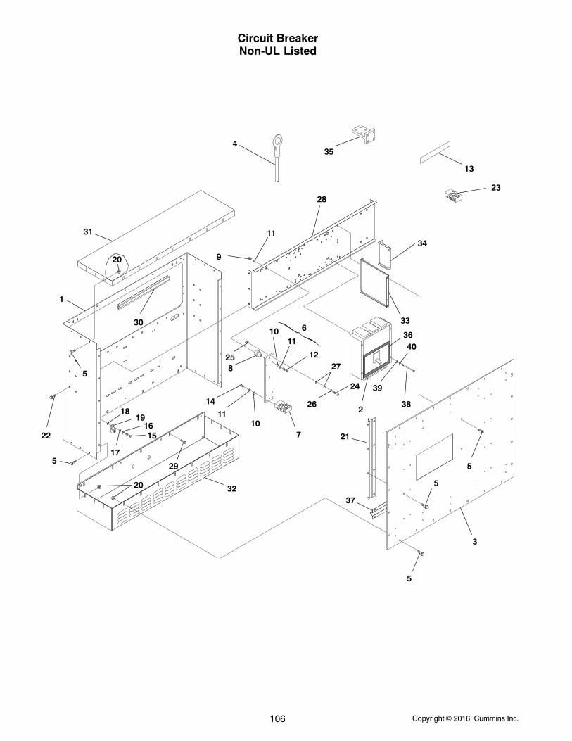
Copyright 2016 Cummins Inc.106
Circuit BreakerNon-UL Listed
1
2
3
5
5
55
5
6
7
8
9
10
1011
11
11
12
13
14
1516
17
1819
20
20
2122
23
24
25
26
27
28
29
30
31
32
33
34
35
36
37
38
39
40
4
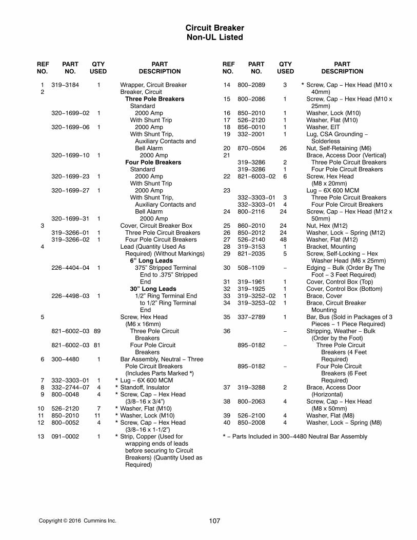
Copyright 2016 Cummins Inc. 107
Circuit BreakerNon-UL Listed
REF PART QTY PART REF PART QTY PARTNO. NO. USED DESCRIPTION NO. NO. USED DESCRIPTION
1 319−3184 1 Wrapper, Circuit Breaker2 Breaker, Circuit
Three Pole BreakersStandard
320−1699−02 1 2000 AmpWith Shunt Trip
320−1699−06 1 2000 AmpWith Shunt Trip,
Auxiliary Contacts and Bell Alarm
320−1699−10 1 2000 AmpFour Pole Breakers
Standard320−1699−23 1 2000 Amp
With Shunt Trip320−1699−27 1 2000 Amp
With Shunt Trip, Auxiliary Contacts and Bell Alarm
320−1699−31 1 2000 Amp3 Cover, Circuit Breaker Box
319−3266−01 1 Three Pole Circuit Breakers319−3266−02 1 Four Pole Circuit Breakers
4 Lead (Quantity Used AsRequired) (Without Markings)
6” Long Leads226−4404−04 1 375” Stripped Terminal
End to .375” Stripped End
30” Long Leads226−4498−03 1 1/2” Ring Terminal End
to 1/2” Ring Terminal End
5 Screw, Hex Head (M6 x 16mm)
821−6002−03 89 Three Pole Circuit Breakers
821−6002−03 81 Four Pole Circuit Breakers
6 300−4480 1 Bar Assembly, Neutral − ThreePole Circuit Breakers(Includes Parts Marked *)
7 332−3303−01 1 * Lug − 6X 600 MCM8 332−2744−07 4 * Standoff, Insulator9 800−0048 4 * Screw, Cap − Hex Head
(3/8−16 x 3/4”)10 526−2120 7 * Washer, Flat (M10)11 850−2010 11 * Washer, Lock (M10)12 800−0052 4 * Screw, Cap − Hex Head
(3/8−16 x 1-1/2”)13 091−0002 1 * Strip, Copper (Used for
wrapping ends of leadsbefore securing to CircuitBreakers) (Quantity Used asRequired)
14 800−2089 3 * Screw, Cap − Hex Head (M10 x40mm)
15 800−2086 1 Screw, Cap − Hex Head (M10 x25mm)
16 850−2010 1 Washer, Lock (M10)17 526−2120 1 Washer, Flat (M10)18 856−0010 1 Washer, EIT19 332−2001 1 Lug, CSA Grounding −
Solderless20 870−0504 26 Nut, Self-Retaining (M6)21 Brace, Access Door (Vertical)
319−3286 2 Three Pole Circuit Breakers319−3286 1 Four Pole Circuit Breakers
22 821−6003−02 6 Screw, Hex Head (M8 x 20mm)
23 Lug − 6X 600 MCM332−3303−01 3 Three Pole Circuit Breakers332−3303−01 4 Four Pole Circuit Breakers
24 800−2116 24 Screw, Cap − Hex Head (M12 x50mm)
25 860−2010 24 Nut, Hex (M12)26 850−2012 24 Washer, Lock − Spring (M12)27 526−2140 48 Washer, Flat (M12)28 319−3153 1 Bracket, Mounting29 821−2035 5 Screw, Self-Locking − Hex
Washer Head (M6 x 25mm)30 508−1109 − Edging − Bulk (Order By The
Foot − 3 Feet Required)31 319−1961 1 Cover, Control Box (Top)32 319−1925 1 Cover, Control Box (Bottom)33 319−3252−02 1 Brace, Cover34 319−3253−02 1 Brace, Circuit Breaker
Mounting35 337−2789 1 Bar, Bus (Sold in Packages of 3
Pieces − 1 Piece Required)36 − Stripping, Weather − Bulk
(Order by the Foot)895−0182 − Three Pole Circuit
Breakers (4 Feet Required)
895−0182 − Four Pole Circuit Breakers (6 Feet Required)
37 319−3288 2 Brace, Access Door(Horizontal)
38 800−2063 4 Screw, Cap − Hex Head (M8 x 50mm)
39 526−2100 4 Washer, Flat (M8)40 850−2008 4 Washer, Lock − Spring (M8)
* − Parts Included in 300−4480 Neutral Bar Assembly
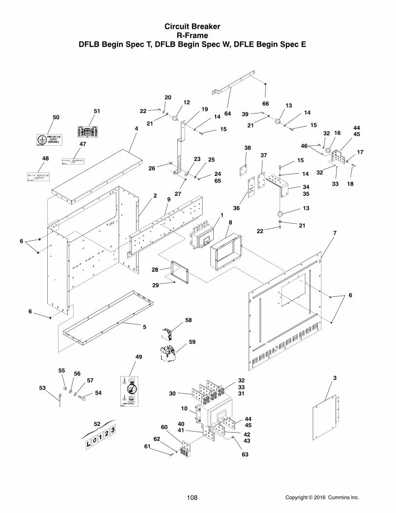
Copyright 2016 Cummins Inc.108
Circuit BreakerR-Frame
DFLB Begin Spec T, DFLB Begin Spec W, DFLE Begin Spec E
1
29
14
14
13
15
15
19
27
23
4
34
21
21
22
36
37
5
25
2624
7
20
8
28
5354
55 5657
58
59
4445
4243
4041
30
10
323331
12 13
16
14
15
17
18
35
21
39
22
38
324445
32
33
60
6162
63
3
6
6
6
29
46
52
5051
48
47
49
65
66
64
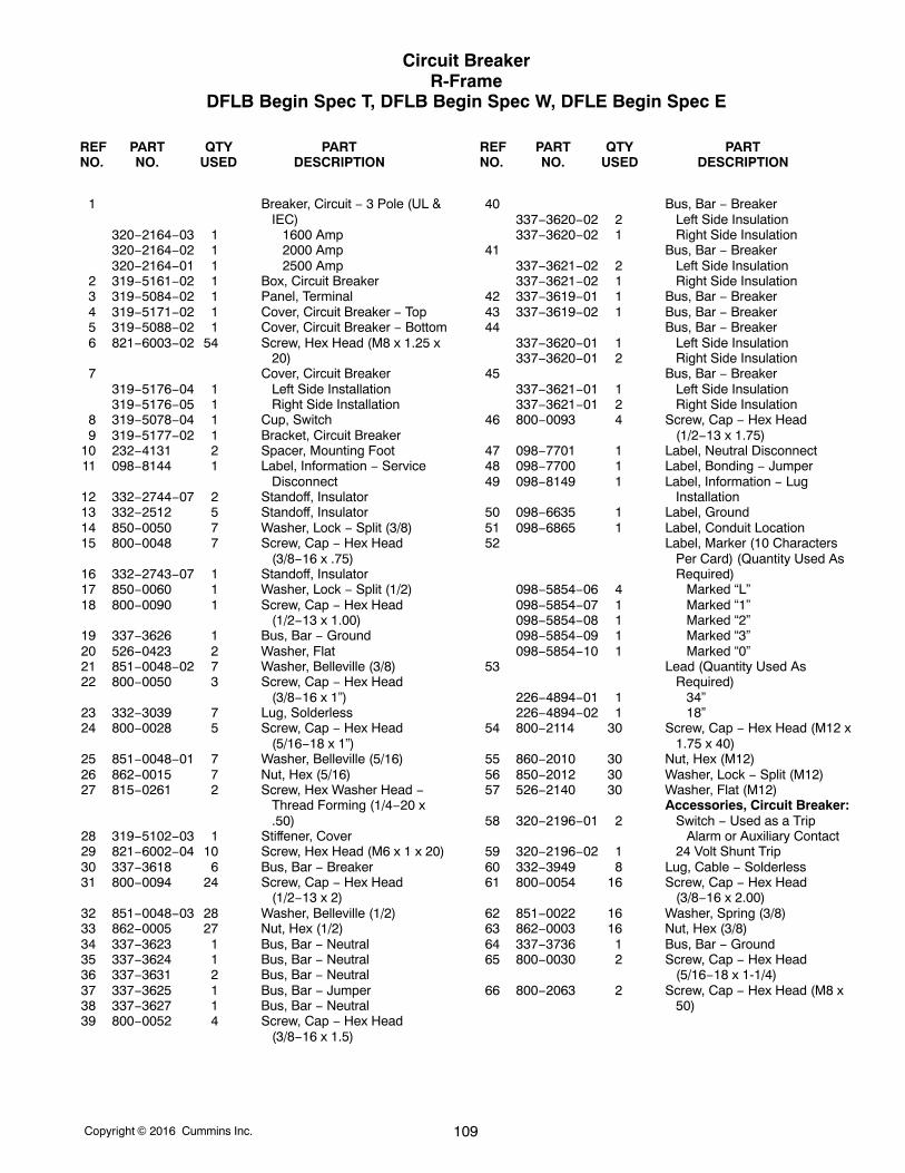
Copyright 2016 Cummins Inc. 109
Circuit BreakerR-Frame
DFLB Begin Spec T, DFLB Begin Spec W, DFLE Begin Spec E
REF PART QTY PART REF PART QTY PARTNO. NO. USED DESCRIPTION NO. NO. USED DESCRIPTION
1 Breaker, Circuit − 3 Pole (UL &IEC)
320−2164−03 1 1600 Amp320−2164−02 1 2000 Amp320−2164−01 1 2500 Amp
2 319−5161−02 1 Box, Circuit Breaker3 319−5084−02 1 Panel, Terminal4 319−5171−02 1 Cover, Circuit Breaker − Top5 319−5088−02 1 Cover, Circuit Breaker − Bottom6 821−6003−02 54 Screw, Hex Head (M8 x 1.25 x
20)7 Cover, Circuit Breaker
319−5176−04 1 Left Side Installation319−5176−05 1 Right Side Installation
8 319−5078−04 1 Cup, Switch9 319−5177−02 1 Bracket, Circuit Breaker
10 232−4131 2 Spacer, Mounting Foot11 098−8144 1 Label, Information − Service
Disconnect12 332−2744−07 2 Standoff, Insulator13 332−2512 5 Standoff, Insulator14 850−0050 7 Washer, Lock − Split (3/8)15 800−0048 7 Screw, Cap − Hex Head
(3/8−16 x .75)16 332−2743−07 1 Standoff, Insulator17 850−0060 1 Washer, Lock − Split (1/2)18 800−0090 1 Screw, Cap − Hex Head
(1/2−13 x 1.00)19 337−3626 1 Bus, Bar − Ground20 526−0423 2 Washer, Flat21 851−0048−02 7 Washer, Belleville (3/8)22 800−0050 3 Screw, Cap − Hex Head
(3/8−16 x 1”)23 332−3039 7 Lug, Solderless24 800−0028 5 Screw, Cap − Hex Head
(5/16−18 x 1”)25 851−0048−01 7 Washer, Belleville (5/16)26 862−0015 7 Nut, Hex (5/16)27 815−0261 2 Screw, Hex Washer Head −
Thread Forming (1/4−20 x.50)
28 319−5102−03 1 Stiffener, Cover29 821−6002−04 10 Screw, Hex Head (M6 x 1 x 20)30 337−3618 6 Bus, Bar − Breaker31 800−0094 24 Screw, Cap − Hex Head
(1/2−13 x 2)32 851−0048−03 28 Washer, Belleville (1/2)33 862−0005 27 Nut, Hex (1/2)34 337−3623 1 Bus, Bar − Neutral35 337−3624 1 Bus, Bar − Neutral36 337−3631 2 Bus, Bar − Neutral37 337−3625 1 Bus, Bar − Jumper38 337−3627 1 Bus, Bar − Neutral39 800−0052 4 Screw, Cap − Hex Head
(3/8−16 x 1.5)
40 Bus, Bar − Breaker337−3620−02 2 Left Side Insulation337−3620−02 1 Right Side Insulation
41 Bus, Bar − Breaker337−3621−02 2 Left Side Insulation337−3621−02 1 Right Side Insulation
42 337−3619−01 1 Bus, Bar − Breaker43 337−3619−02 1 Bus, Bar − Breaker44 Bus, Bar − Breaker
337−3620−01 1 Left Side Insulation337−3620−01 2 Right Side Insulation
45 Bus, Bar − Breaker337−3621−01 1 Left Side Insulation337−3621−01 2 Right Side Insulation
46 800−0093 4 Screw, Cap − Hex Head(1/2−13 x 1.75)
47 098−7701 1 Label, Neutral Disconnect48 098−7700 1 Label, Bonding − Jumper49 098−8149 1 Label, Information − Lug
Installation50 098−6635 1 Label, Ground51 098−6865 1 Label, Conduit Location52 Label, Marker (10 Characters
Per Card) (Quantity Used AsRequired)
098−5854−06 4 Marked “L”098−5854−07 1 Marked “1”098−5854−08 1 Marked “2”098−5854−09 1 Marked “3”098−5854−10 1 Marked “0”
53 Lead (Quantity Used AsRequired)
226−4894−01 1 34”226−4894−02 1 18”
54 800−2114 30 Screw, Cap − Hex Head (M12 x1.75 x 40)
55 860−2010 30 Nut, Hex (M12)56 850−2012 30 Washer, Lock − Split (M12)57 526−2140 30 Washer, Flat (M12)
Accessories, Circuit Breaker:58 320−2196−01 2 Switch − Used as a Trip
Alarm or Auxiliary Contact59 320−2196−02 1 24 Volt Shunt Trip60 332−3949 8 Lug, Cable − Solderless61 800−0054 16 Screw, Cap − Hex Head
(3/8−16 x 2.00)62 851−0022 16 Washer, Spring (3/8)63 862−0003 16 Nut, Hex (3/8)64 337−3736 1 Bus, Bar − Ground65 800−0030 2 Screw, Cap − Hex Head
(5/16−18 x 1-1/4)66 800−2063 2 Screw, Cap − Hex Head (M8 x
50)
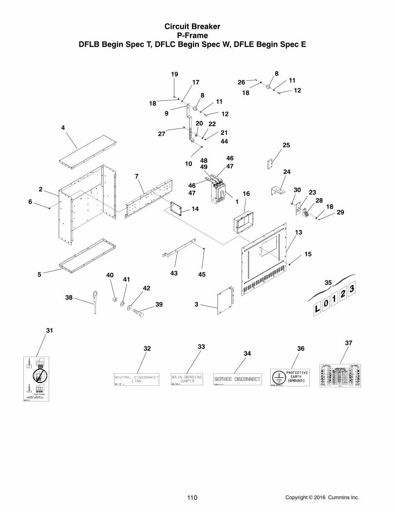
Copyright 2016 Cummins Inc.110
Circuit BreakerP-Frame
DFLB Begin Spec T, DFLC Begin Spec W, DFLE Begin Spec E
1
2
3
4
5
6
7
8
8
9
10
11
11
12
12
13
14
15
16
17
18
19
2021
22
23
24
25
26
18
27
28
2918
30
31
32 3334
35
3637
3839
4041
42
43
44
45
46
46
47
474849
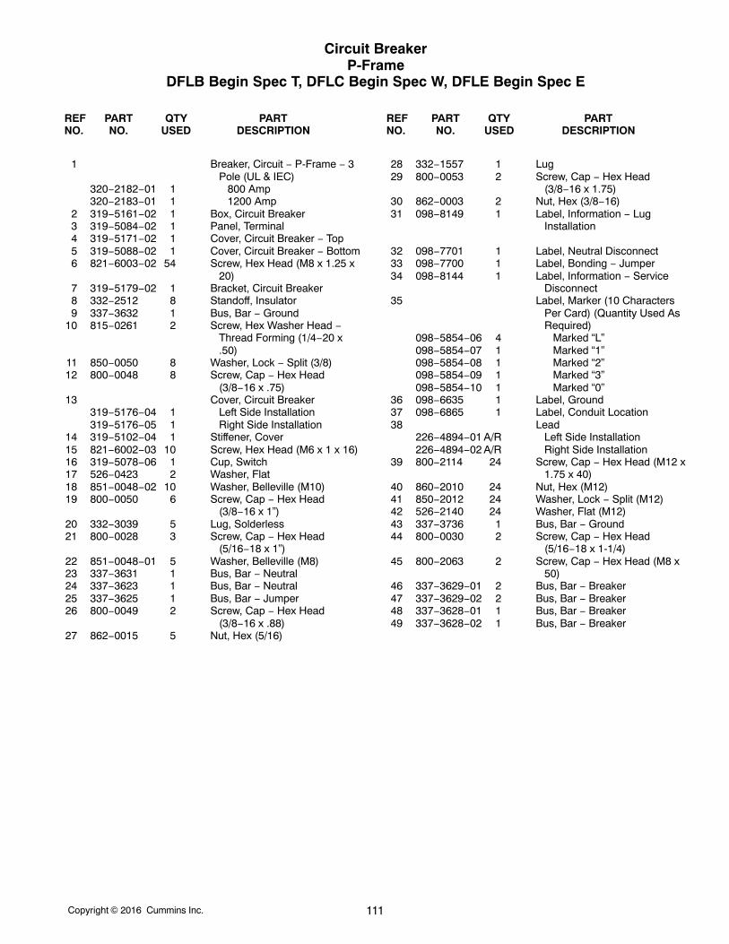
Copyright 2016 Cummins Inc. 111
Circuit BreakerP-Frame
DFLB Begin Spec T, DFLC Begin Spec W, DFLE Begin Spec E
REF PART QTY PART REF PART QTY PARTNO. NO. USED DESCRIPTION NO. NO. USED DESCRIPTION
1 Breaker, Circuit − P-Frame − 3Pole (UL & IEC)
320−2182−01 1 800 Amp320−2183−01 1 1200 Amp
2 319−5161−02 1 Box, Circuit Breaker3 319−5084−02 1 Panel, Terminal4 319−5171−02 1 Cover, Circuit Breaker − Top5 319−5088−02 1 Cover, Circuit Breaker − Bottom6 821−6003−02 54 Screw, Hex Head (M8 x 1.25 x
20)7 319−5179−02 1 Bracket, Circuit Breaker8 332−2512 8 Standoff, Insulator9 337−3632 1 Bus, Bar − Ground
10 815−0261 2 Screw, Hex Washer Head −Thread Forming (1/4−20 x.50)
11 850−0050 8 Washer, Lock − Split (3/8)12 800−0048 8 Screw, Cap − Hex Head
(3/8−16 x .75)13 Cover, Circuit Breaker
319−5176−04 1 Left Side Installation319−5176−05 1 Right Side Installation
14 319−5102−04 1 Stiffener, Cover15 821−6002−03 10 Screw, Hex Head (M6 x 1 x 16)16 319−5078−06 1 Cup, Switch17 526−0423 2 Washer, Flat18 851−0048−02 10 Washer, Belleville (M10)19 800−0050 6 Screw, Cap − Hex Head
(3/8−16 x 1”)20 332−3039 5 Lug, Solderless21 800−0028 3 Screw, Cap − Hex Head
(5/16−18 x 1”)22 851−0048−01 5 Washer, Belleville (M8)23 337−3631 1 Bus, Bar − Neutral24 337−3623 1 Bus, Bar − Neutral25 337−3625 1 Bus, Bar − Jumper26 800−0049 2 Screw, Cap − Hex Head
(3/8−16 x .88)27 862−0015 5 Nut, Hex (5/16)
28 332−1557 1 Lug29 800−0053 2 Screw, Cap − Hex Head
(3/8−16 x 1.75)30 862−0003 2 Nut, Hex (3/8−16)31 098−8149 1 Label, Information − Lug
Installation
32 098−7701 1 Label, Neutral Disconnect33 098−7700 1 Label, Bonding − Jumper34 098−8144 1 Label, Information − Service
Disconnect35 Label, Marker (10 Characters
Per Card) (Quantity Used AsRequired)
098−5854−06 4 Marked “L”098−5854−07 1 Marked “1”098−5854−08 1 Marked “2”098−5854−09 1 Marked “3”098−5854−10 1 Marked “0”
36 098−6635 1 Label, Ground37 098−6865 1 Label, Conduit Location38 Lead
226−4894−01 A/R Left Side Installation226−4894−02 A/R Right Side Installation
39 800−2114 24 Screw, Cap − Hex Head (M12 x1.75 x 40)
40 860−2010 24 Nut, Hex (M12)41 850−2012 24 Washer, Lock − Split (M12)42 526−2140 24 Washer, Flat (M12)43 337−3736 1 Bus, Bar − Ground44 800−0030 2 Screw, Cap − Hex Head
(5/16−18 x 1-1/4)45 800−2063 2 Screw, Cap − Hex Head (M8 x
50)46 337−3629−01 2 Bus, Bar − Breaker47 337−3629−02 2 Bus, Bar − Breaker48 337−3628−01 1 Bus, Bar − Breaker49 337−3628−02 1 Bus, Bar − Breaker
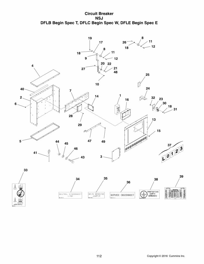
Copyright 2016 Cummins Inc.112
Circuit BreakerNSJ
DFLB Begin Spec T, DFLC Begin Spec W, DFLE Begin Spec E
12
3
4
5
6
7
8
8
9
10
11
11
12
12
13
14
15
16
17
18
19
2021
22
23
24
25
26
18
27
28
29
30
3118
32
33
34 3536
37
3839
40
4143
44 45
46
47
48
49
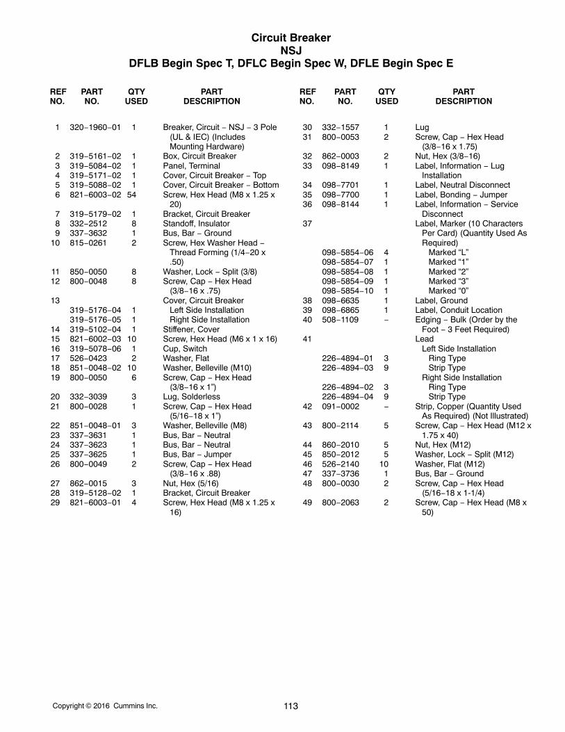
Copyright 2016 Cummins Inc. 113
Circuit BreakerNSJ
DFLB Begin Spec T, DFLC Begin Spec W, DFLE Begin Spec E
REF PART QTY PART REF PART QTY PARTNO. NO. USED DESCRIPTION NO. NO. USED DESCRIPTION
1 320−1960−01 1 Breaker, Circuit − NSJ − 3 Pole(UL & IEC) (IncludesMounting Hardware)
2 319−5161−02 1 Box, Circuit Breaker3 319−5084−02 1 Panel, Terminal4 319−5171−02 1 Cover, Circuit Breaker − Top5 319−5088−02 1 Cover, Circuit Breaker − Bottom6 821−6003−02 54 Screw, Hex Head (M8 x 1.25 x
20)7 319−5179−02 1 Bracket, Circuit Breaker8 332−2512 8 Standoff, Insulator9 337−3632 1 Bus, Bar − Ground
10 815−0261 2 Screw, Hex Washer Head −Thread Forming (1/4−20 x.50)
11 850−0050 8 Washer, Lock − Split (3/8)12 800−0048 8 Screw, Cap − Hex Head
(3/8−16 x .75)13 Cover, Circuit Breaker
319−5176−04 1 Left Side Installation319−5176−05 1 Right Side Installation
14 319−5102−04 1 Stiffener, Cover15 821−6002−03 10 Screw, Hex Head (M6 x 1 x 16)16 319−5078−06 1 Cup, Switch17 526−0423 2 Washer, Flat18 851−0048−02 10 Washer, Belleville (M10)19 800−0050 6 Screw, Cap − Hex Head
(3/8−16 x 1”)20 332−3039 3 Lug, Solderless21 800−0028 1 Screw, Cap − Hex Head
(5/16−18 x 1”)22 851−0048−01 3 Washer, Belleville (M8)23 337−3631 1 Bus, Bar − Neutral24 337−3623 1 Bus, Bar − Neutral25 337−3625 1 Bus, Bar − Jumper26 800−0049 2 Screw, Cap − Hex Head
(3/8−16 x .88)27 862−0015 3 Nut, Hex (5/16)28 319−5128−02 1 Bracket, Circuit Breaker29 821−6003−01 4 Screw, Hex Head (M8 x 1.25 x
16)
30 332−1557 1 Lug31 800−0053 2 Screw, Cap − Hex Head
(3/8−16 x 1.75)32 862−0003 2 Nut, Hex (3/8−16)33 098−8149 1 Label, Information − Lug
Installation34 098−7701 1 Label, Neutral Disconnect35 098−7700 1 Label, Bonding − Jumper36 098−8144 1 Label, Information − Service
Disconnect37 Label, Marker (10 Characters
Per Card) (Quantity Used AsRequired)
098−5854−06 4 Marked “L”098−5854−07 1 Marked “1”098−5854−08 1 Marked “2”098−5854−09 1 Marked “3”098−5854−10 1 Marked “0”
38 098−6635 1 Label, Ground39 098−6865 1 Label, Conduit Location40 508−1109 − Edging − Bulk (Order by the
Foot − 3 Feet Required)41 Lead
Left Side Installation226−4894−01 3 Ring Type226−4894−03 9 Strip Type
Right Side Installation226−4894−02 3 Ring Type226−4894−04 9 Strip Type
42 091−0002 − Strip, Copper (Quantity UsedAs Required) (Not Illustrated)
43 800−2114 5 Screw, Cap − Hex Head (M12 x1.75 x 40)
44 860−2010 5 Nut, Hex (M12)45 850−2012 5 Washer, Lock − Split (M12)46 526−2140 10 Washer, Flat (M12)47 337−3736 1 Bus, Bar − Ground48 800−0030 2 Screw, Cap − Hex Head
(5/16−18 x 1-1/4)49 800−2063 2 Screw, Cap − Hex Head (M8 x
50)
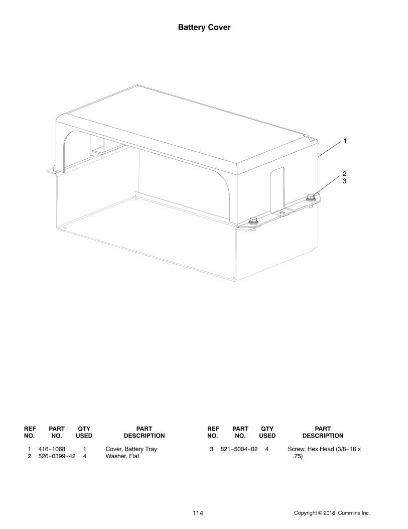
Copyright 2016 Cummins Inc.114
Battery Cover
1
23
REF PART QTY PART REF PART QTY PARTNO. NO. USED DESCRIPTION NO. NO. USED DESCRIPTION
1 416−1068 1 Cover, Battery Tray2 526−0399−42 4 Washer, Flat
3 821−5004−02 4 Screw, Hex Head (3/8−16 x.75)
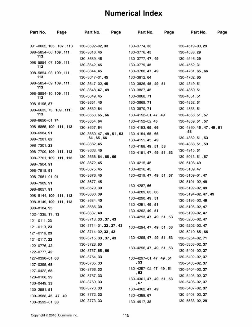
Numerical Index
Part No. Page Part No. Page Part No. Page Part No. Page
Copyright 2016 Cummins Inc. 115
091−0002, 105 , 107 , 113
098−5854−06, 109 , 111 ,113
098−5854−07, 109 , 111 ,113
098−5854−08, 109 , 111 ,113
098−5854−09, 109 , 111 ,113
098−5854−10, 109 , 111 ,113
098−6195, 87
098−6635, 75 , 109 , 111 ,113
098−6650−01, 74
098−6865, 109 , 111 , 113
098−6984, 91
098−7281, 82
098−7301, 23
098−7700, 109 , 111 , 113
098−7701, 109 , 111 , 113
098−7904, 91
098−7918, 91
098−7961−01, 91
098−7989, 91
098−8057, 91
098−8144, 109 , 111 , 113
098−8149, 109 , 111 , 113
098−8184, 95
102−1335, 11 , 13
121−0111, 23
121−0113, 23
121−0116, 23
121−0117, 23
122−0776, 42
122−0777, 42
127−0390−01, 68
127−0395, 68
127−0422, 68
128−0108, 29
130−0449, 33
130−2981, 51
130−3588, 45 , 47 , 49
130−3592−01, 33
130−3592−02, 33
130−3616, 45
130−3639, 45
130−3642, 45
130−3644, 45
130−3647−01, 45
130−3647−02, 45
130−3648, 47 , 49
130−3649, 45
130−3651, 45
130−3652, 64
130−3653, 65 , 66
130−3654, 64
130−3657, 64
130−3660, 47 , 49 , 51 , 53, 64 , 65 , 66
130−3662, 45
130−3663, 45
130−3668, 64 , 65 , 66
130−3672, 45
130−3675, 45
130−3676, 45
130−3677, 45
130−3679, 39
130−3680, 39
130−3684, 40
130−3686, 39
130−3687, 40
130−3713, 33 , 37 , 43
130−3714−01, 33 , 37 , 43
130−3714−02, 33 , 43
130−3715, 33 , 37 , 43
130−3728, 63
130−3757, 65 , 66
130−3764, 33
130−3765, 33
130−3766, 33
130−3767, 33
130−3769, 33
130−3770, 33
130−3772, 33
130−3773, 33
130−3774, 33
130−3776, 45
130−3777, 47 , 49
130−3779, 45
130−3780, 47 , 49
130−3812, 64
130−3826, 45 , 49 , 51
130−3827, 45
130−3868, 71
130−3869, 71
130−3870, 71
130−4152−01, 47 , 49
130−4152−02, 45
130−4153, 65 , 66
130−4154, 65 , 66
130−4155, 45 , 49
130−4188, 49 , 51 , 53
130−4191, 47 , 49 , 51 , 53
130−4215, 45
130−4216, 45
130−4219, 47 , 49 , 51 , 57
130−4287, 66
130−4289, 65 , 66
130−4290, 49 , 51
130−4291, 49 , 51
130−4292, 49 , 51
130−4293, 47 , 49 , 51 , 53
130−4294, 47 , 49 , 51 , 53
130−4295, 47 , 49 , 51 , 53
130−4296, 47 , 49 , 51 , 53
130−4297−01, 47 , 49 , 51, 53
130−4297−02, 47 , 49 , 51, 53
130−4301, 47 , 49 , 51 , 53, 67
130−4362, 47 , 49
130−4389, 67
130−4517, 38
130−4519−03, 29
130−4538, 29
130−4546, 29
130−4552, 31
130−4761, 65 , 66
130−4762, 65
130−4849, 51
130−4850, 51
130−4851, 51
130−4852, 51
130−4853, 51
130−4858, 51 , 57
130−4859, 51 , 57
130−4860, 45 , 47 , 49 , 51, 53
130−4862, 51 , 53
130−4868, 51 , 53
130−4915, 51
130−5013, 51 , 57
130−5108, 49
130−5109, 47
130−5109−01, 47
130−5191−02, 49
130−5192−02, 49
130−5194−02, 47 , 49
130−5195−02, 49
130−5198−02, 47
130−5199−02, 47
130−5200−02, 47
130−5202−02, 47
130−5210, 65 , 66
130−5254−02, 71
130−5308−02, 37
130−5401−02, 37
130−5402−02, 37
130−5403−02, 37
130−5404−02, 37
130−5405−02, 37
130−5406−02, 37
130−5407−02, 37
130−5408−02, 37
130−5588−02, 29
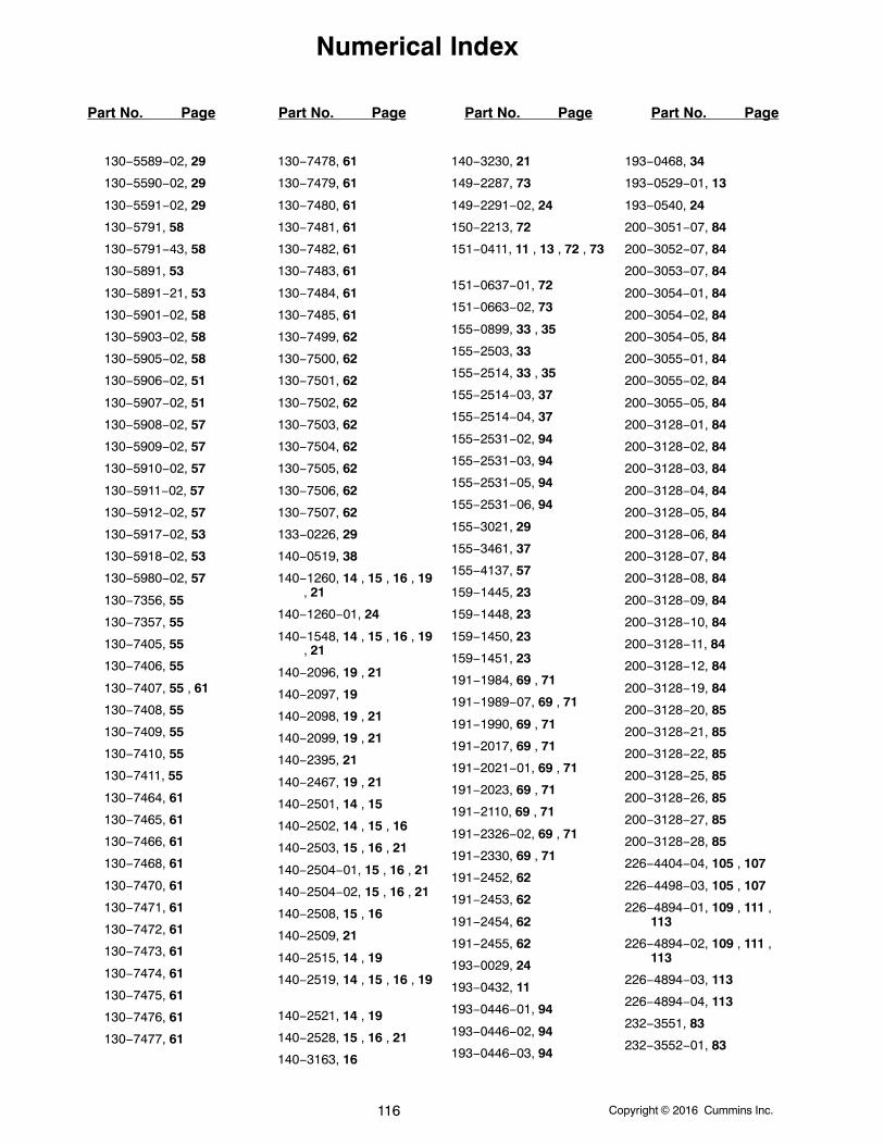
Numerical Index
Part No. Page Part No. Page Part No. Page Part No. Page
Copyright 2016 Cummins Inc.116
130−5589−02, 29
130−5590−02, 29
130−5591−02, 29
130−5791, 58
130−5791−43, 58
130−5891, 53
130−5891−21, 53
130−5901−02, 58
130−5903−02, 58
130−5905−02, 58
130−5906−02, 51
130−5907−02, 51
130−5908−02, 57
130−5909−02, 57
130−5910−02, 57
130−5911−02, 57
130−5912−02, 57
130−5917−02, 53
130−5918−02, 53
130−5980−02, 57
130−7356, 55
130−7357, 55
130−7405, 55
130−7406, 55
130−7407, 55 , 61
130−7408, 55
130−7409, 55
130−7410, 55
130−7411, 55
130−7464, 61
130−7465, 61
130−7466, 61
130−7468, 61
130−7470, 61
130−7471, 61
130−7472, 61
130−7473, 61
130−7474, 61
130−7475, 61
130−7476, 61
130−7477, 61
130−7478, 61
130−7479, 61
130−7480, 61
130−7481, 61
130−7482, 61
130−7483, 61
130−7484, 61
130−7485, 61
130−7499, 62
130−7500, 62
130−7501, 62
130−7502, 62
130−7503, 62
130−7504, 62
130−7505, 62
130−7506, 62
130−7507, 62
133−0226, 29
140−0519, 38
140−1260, 14 , 15 , 16 , 19, 21
140−1260−01, 24
140−1548, 14 , 15 , 16 , 19, 21
140−2096, 19 , 21
140−2097, 19
140−2098, 19 , 21
140−2099, 19 , 21
140−2395, 21
140−2467, 19 , 21
140−2501, 14 , 15
140−2502, 14 , 15 , 16
140−2503, 15 , 16 , 21
140−2504−01, 15 , 16 , 21
140−2504−02, 15 , 16 , 21
140−2508, 15 , 16
140−2509, 21
140−2515, 14 , 19
140−2519, 14 , 15 , 16 , 19
140−2521, 14 , 19
140−2528, 15 , 16 , 21
140−3163, 16
140−3230, 21
149−2287, 73
149−2291−02, 24
150−2213, 72
151−0411, 11 , 13 , 72 , 73
151−0637−01, 72
151−0663−02, 73
155−0899, 33 , 35
155−2503, 33
155−2514, 33 , 35
155−2514−03, 37
155−2514−04, 37
155−2531−02, 94
155−2531−03, 94
155−2531−05, 94
155−2531−06, 94
155−3021, 29
155−3461, 37
155−4137, 57
159−1445, 23
159−1448, 23
159−1450, 23
159−1451, 23
191−1984, 69 , 71
191−1989−07, 69 , 71
191−1990, 69 , 71
191−2017, 69 , 71
191−2021−01, 69 , 71
191−2023, 69 , 71
191−2110, 69 , 71
191−2326−02, 69 , 71
191−2330, 69 , 71
191−2452, 62
191−2453, 62
191−2454, 62
191−2455, 62
193−0029, 24
193−0432, 11
193−0446−01, 94
193−0446−02, 94
193−0446−03, 94
193−0468, 34
193−0529−01, 13
193−0540, 24
200−3051−07, 84
200−3052−07, 84
200−3053−07, 84
200−3054−01, 84
200−3054−02, 84
200−3054−05, 84
200−3055−01, 84
200−3055−02, 84
200−3055−05, 84
200−3128−01, 84
200−3128−02, 84
200−3128−03, 84
200−3128−04, 84
200−3128−05, 84
200−3128−06, 84
200−3128−07, 84
200−3128−08, 84
200−3128−09, 84
200−3128−10, 84
200−3128−11, 84
200−3128−12, 84
200−3128−19, 84
200−3128−20, 85
200−3128−21, 85
200−3128−22, 85
200−3128−25, 85
200−3128−26, 85
200−3128−27, 85
200−3128−28, 85
226−4404−04, 105 , 107
226−4498−03, 105 , 107
226−4894−01, 109 , 111 ,113
226−4894−02, 109 , 111 ,113
226−4894−03, 113
226−4894−04, 113
232−3551, 83
232−3552−01, 83
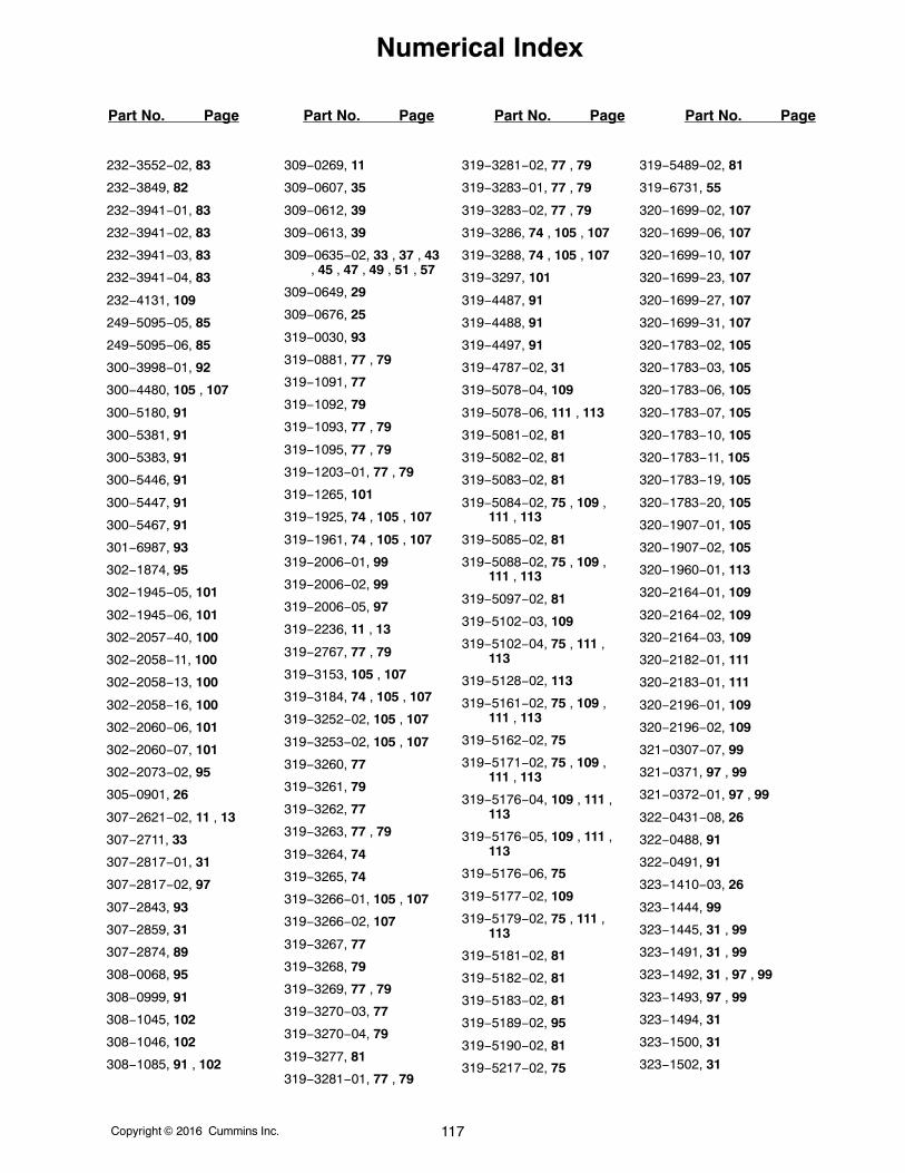
Numerical Index
Part No. Page Part No. Page Part No. Page Part No. Page
Copyright 2016 Cummins Inc. 117
232−3552−02, 83
232−3849, 82
232−3941−01, 83
232−3941−02, 83
232−3941−03, 83
232−3941−04, 83
232−4131, 109
249−5095−05, 85
249−5095−06, 85
300−3998−01, 92
300−4480, 105 , 107
300−5180, 91
300−5381, 91
300−5383, 91
300−5446, 91
300−5447, 91
300−5467, 91
301−6987, 93
302−1874, 95
302−1945−05, 101
302−1945−06, 101
302−2057−40, 100
302−2058−11, 100
302−2058−13, 100
302−2058−16, 100
302−2060−06, 101
302−2060−07, 101
302−2073−02, 95
305−0901, 26
307−2621−02, 11 , 13
307−2711, 33
307−2817−01, 31
307−2817−02, 97
307−2843, 93
307−2859, 31
307−2874, 89
308−0068, 95
308−0999, 91
308−1045, 102
308−1046, 102
308−1085, 91 , 102
309−0269, 11
309−0607, 35
309−0612, 39
309−0613, 39
309−0635−02, 33 , 37 , 43, 45 , 47 , 49 , 51 , 57
309−0649, 29
309−0676, 25
319−0030, 93
319−0881, 77 , 79
319−1091, 77
319−1092, 79
319−1093, 77 , 79
319−1095, 77 , 79
319−1203−01, 77 , 79
319−1265, 101
319−1925, 74 , 105 , 107
319−1961, 74 , 105 , 107
319−2006−01, 99
319−2006−02, 99
319−2006−05, 97
319−2236, 11 , 13
319−2767, 77 , 79
319−3153, 105 , 107
319−3184, 74 , 105 , 107
319−3252−02, 105 , 107
319−3253−02, 105 , 107
319−3260, 77
319−3261, 79
319−3262, 77
319−3263, 77 , 79
319−3264, 74
319−3265, 74
319−3266−01, 105 , 107
319−3266−02, 107
319−3267, 77
319−3268, 79
319−3269, 77 , 79
319−3270−03, 77
319−3270−04, 79
319−3277, 81
319−3281−01, 77 , 79
319−3281−02, 77 , 79
319−3283−01, 77 , 79
319−3283−02, 77 , 79
319−3286, 74 , 105 , 107
319−3288, 74 , 105 , 107
319−3297, 101
319−4487, 91
319−4488, 91
319−4497, 91
319−4787−02, 31
319−5078−04, 109
319−5078−06, 111 , 113
319−5081−02, 81
319−5082−02, 81
319−5083−02, 81
319−5084−02, 75 , 109 ,111 , 113
319−5085−02, 81
319−5088−02, 75 , 109 ,111 , 113
319−5097−02, 81
319−5102−03, 109
319−5102−04, 75 , 111 ,113
319−5128−02, 113
319−5161−02, 75 , 109 ,111 , 113
319−5162−02, 75
319−5171−02, 75 , 109 ,111 , 113
319−5176−04, 109 , 111 ,113
319−5176−05, 109 , 111 ,113
319−5176−06, 75
319−5177−02, 109
319−5179−02, 75 , 111 ,113
319−5181−02, 81
319−5182−02, 81
319−5183−02, 81
319−5189−02, 95
319−5190−02, 81
319−5217−02, 75
319−5489−02, 81
319−6731, 55
320−1699−02, 107
320−1699−06, 107
320−1699−10, 107
320−1699−23, 107
320−1699−27, 107
320−1699−31, 107
320−1783−02, 105
320−1783−03, 105
320−1783−06, 105
320−1783−07, 105
320−1783−10, 105
320−1783−11, 105
320−1783−19, 105
320−1783−20, 105
320−1907−01, 105
320−1907−02, 105
320−1960−01, 113
320−2164−01, 109
320−2164−02, 109
320−2164−03, 109
320−2182−01, 111
320−2183−01, 111
320−2196−01, 109
320−2196−02, 109
321−0307−07, 99
321−0371, 97 , 99
321−0372−01, 97 , 99
322−0431−08, 26
322−0488, 91
322−0491, 91
323−1410−03, 26
323−1444, 99
323−1445, 31 , 99
323−1491, 31 , 99
323−1492, 31 , 97 , 99
323−1493, 97 , 99
323−1494, 31
323−1500, 31
323−1502, 31
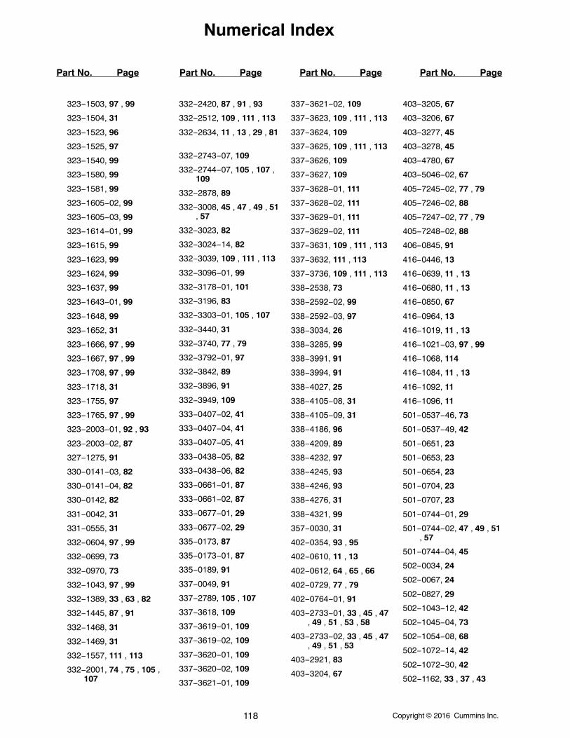
Numerical Index
Part No. Page Part No. Page Part No. Page Part No. Page
Copyright 2016 Cummins Inc.118
323−1503, 97 , 99
323−1504, 31
323−1523, 96
323−1525, 97
323−1540, 99
323−1580, 99
323−1581, 99
323−1605−02, 99
323−1605−03, 99
323−1614−01, 99
323−1615, 99
323−1623, 99
323−1624, 99
323−1637, 99
323−1643−01, 99
323−1648, 99
323−1652, 31
323−1666, 97 , 99
323−1667, 97 , 99
323−1708, 97 , 99
323−1718, 31
323−1755, 97
323−1765, 97 , 99
323−2003−01, 92 , 93
323−2003−02, 87
327−1275, 91
330−0141−03, 82
330−0141−04, 82
330−0142, 82
331−0042, 31
331−0555, 31
332−0604, 97 , 99
332−0699, 73
332−0970, 73
332−1043, 97 , 99
332−1389, 33 , 63 , 82
332−1445, 87 , 91
332−1468, 31
332−1469, 31
332−1557, 111 , 113
332−2001, 74 , 75 , 105 ,107
332−2420, 87 , 91 , 93
332−2512, 109 , 111 , 113
332−2634, 11 , 13 , 29 , 81
332−2743−07, 109
332−2744−07, 105 , 107 ,109
332−2878, 89
332−3008, 45 , 47 , 49 , 51, 57
332−3023, 82
332−3024−14, 82
332−3039, 109 , 111 , 113
332−3096−01, 99
332−3178−01, 101
332−3196, 83
332−3303−01, 105 , 107
332−3440, 31
332−3740, 77 , 79
332−3792−01, 97
332−3842, 89
332−3896, 91
332−3949, 109
333−0407−02, 41
333−0407−04, 41
333−0407−05, 41
333−0438−05, 82
333−0438−06, 82
333−0661−01, 87
333−0661−02, 87
333−0677−01, 29
333−0677−02, 29
335−0173, 87
335−0173−01, 87
335−0189, 91
337−0049, 91
337−2789, 105 , 107
337−3618, 109
337−3619−01, 109
337−3619−02, 109
337−3620−01, 109
337−3620−02, 109
337−3621−01, 109
337−3621−02, 109
337−3623, 109 , 111 , 113
337−3624, 109
337−3625, 109 , 111 , 113
337−3626, 109
337−3627, 109
337−3628−01, 111
337−3628−02, 111
337−3629−01, 111
337−3629−02, 111
337−3631, 109 , 111 , 113
337−3632, 111 , 113
337−3736, 109 , 111 , 113
338−2538, 73
338−2592−02, 99
338−2592−03, 97
338−3034, 26
338−3285, 99
338−3991, 91
338−3994, 91
338−4027, 25
338−4105−08, 31
338−4105−09, 31
338−4186, 96
338−4209, 89
338−4232, 97
338−4245, 93
338−4246, 93
338−4276, 31
338−4321, 99
357−0030, 31
402−0354, 93 , 95
402−0610, 11 , 13
402−0612, 64 , 65 , 66
402−0729, 77 , 79
402−0764−01, 91
403−2733−01, 33 , 45 , 47, 49 , 51 , 53 , 58
403−2733−02, 33 , 45 , 47, 49 , 51 , 53
403−2921, 83
403−3204, 67
403−3205, 67
403−3206, 67
403−3277, 45
403−3278, 45
403−4780, 67
403−5046−02, 67
405−7245−02, 77 , 79
405−7246−02, 88
405−7247−02, 77 , 79
405−7248−02, 88
406−0845, 91
416−0446, 13
416−0639, 11 , 13
416−0680, 11 , 13
416−0850, 67
416−0964, 13
416−1019, 11 , 13
416−1021−03, 97 , 99
416−1068, 114
416−1084, 11 , 13
416−1092, 11
416−1096, 11
501−0537−46, 73
501−0537−49, 42
501−0651, 23
501−0653, 23
501−0654, 23
501−0704, 23
501−0707, 23
501−0744−01, 29
501−0744−02, 47 , 49 , 51, 57
501−0744−04, 45
502−0034, 24
502−0067, 24
502−0827, 29
502−1043−12, 42
502−1045−04, 73
502−1054−08, 68
502−1072−14, 42
502−1072−30, 42
502−1162, 33 , 37 , 43
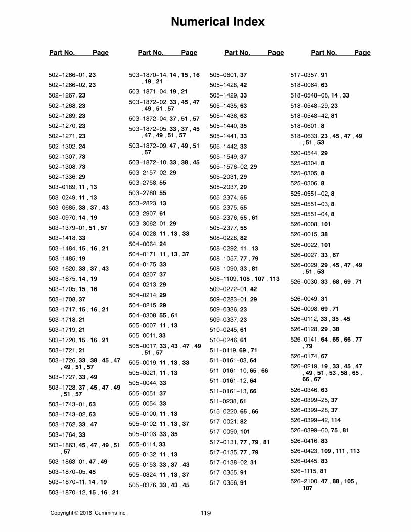
Numerical Index
Part No. Page Part No. Page Part No. Page Part No. Page
Copyright 2016 Cummins Inc. 119
502−1266−01, 23
502−1266−02, 23
502−1267, 23
502−1268, 23
502−1269, 23
502−1270, 23
502−1271, 23
502−1302, 24
502−1307, 73
502−1308, 73
502−1336, 29
503−0189, 11 , 13
503−0249, 11 , 13
503−0685, 33 , 37 , 43
503−0970, 14 , 19
503−1379−01, 51 , 57
503−1418, 33
503−1484, 15 , 16 , 21
503−1485, 19
503−1620, 33 , 37 , 43
503−1675, 14 , 19
503−1705, 15 , 16
503−1708, 37
503−1717, 15 , 16 , 21
503−1718, 21
503−1719, 21
503−1720, 15 , 16 , 21
503−1721, 21
503−1726, 33 , 38 , 45 , 47, 49 , 51 , 57
503−1727, 33 , 49
503−1728, 37 , 45 , 47 , 49, 51 , 57
503−1743−01, 63
503−1743−02, 63
503−1762, 33 , 47
503−1764, 33
503−1863, 45 , 47 , 49 , 51, 57
503−1863−01, 47 , 49
503−1870−05, 45
503−1870−11, 14 , 19
503−1870−12, 15 , 16 , 21
503−1870−14, 14 , 15 , 16, 19 , 21
503−1871−04, 19 , 21
503−1872−02, 33 , 45 , 47, 49 , 51 , 57
503−1872−04, 37 , 51 , 57
503−1872−05, 33 , 37 , 45, 47 , 49 , 51 , 57
503−1872−09, 47 , 49 , 51, 57
503−1872−10, 33 , 38 , 45
503−2157−02, 29
503−2758, 55
503−2760, 55
503−2823, 13
503−2907, 61
503−3062−01, 29
504−0028, 11 , 13 , 33
504−0064, 24
504−0171, 11 , 13 , 37
504−0175, 33
504−0207, 37
504−0213, 29
504−0214, 29
504−0215, 29
504−0308, 55 , 61
505−0007, 11 , 13
505−0011, 33
505−0017, 33 , 43 , 47 , 49, 51 , 57
505−0019, 11 , 13 , 33
505−0021, 11 , 13
505−0044, 33
505−0051, 37
505−0054, 33
505−0100, 11 , 13
505−0102, 11 , 13 , 37
505−0103, 33 , 35
505−0114, 33
505−0132, 11 , 13
505−0153, 33 , 37 , 43
505−0324, 11 , 13 , 37
505−0376, 33 , 43 , 45
505−0601, 37
505−1428, 42
505−1429, 33
505−1435, 63
505−1436, 63
505−1440, 35
505−1441, 33
505−1442, 33
505−1549, 37
505−1576−02, 29
505−2031, 29
505−2037, 29
505−2374, 55
505−2375, 55
505−2376, 55 , 61
505−2377, 55
508−0228, 82
508−0292, 11 , 13
508−1057, 77 , 79
508−1090, 33 , 81
508−1109, 105 , 107 , 113
509−0272−01, 42
509−0283−01, 29
509−0336, 23
509−0337, 23
510−0245, 61
510−0246, 61
511−0119, 69 , 71
511−0161−03, 64
511−0161−10, 65 , 66
511−0161−12, 64
511−0161−13, 66
511−0238, 61
515−0220, 65 , 66
517−0021, 82
517−0090, 101
517−0131, 77 , 79 , 81
517−0135, 77 , 79
517−0138−02, 31
517−0355, 91
517−0356, 91
517−0357, 91
518−0064, 63
518−0548−08, 14 , 33
518−0548−29, 23
518−0548−42, 81
518−0601, 8
518−0633, 23 , 45 , 47 , 49, 51 , 53
520−0544, 29
525−0304, 8
525−0305, 8
525−0306, 8
525−0551−02, 8
525−0551−03, 8
525−0551−04, 8
526−0008, 101
526−0015, 38
526−0022, 101
526−0027, 33 , 67
526−0029, 29 , 45 , 47 , 49, 51 , 53
526−0030, 33 , 68 , 69 , 71
526−0049, 31
526−0098, 69 , 71
526−0112, 33 , 35 , 45
526−0128, 29 , 38
526−0141, 64 , 65 , 66 , 77, 79
526−0174, 67
526−0219, 19 , 33 , 45 , 47, 49 , 51 , 53 , 58 , 65 ,66 , 67
526−0346, 63
526−0399−25, 37
526−0399−28, 37
526−0399−42, 114
526−0399−60, 75 , 81
526−0416, 83
526−0423, 109 , 111 , 113
526−0445, 83
526−1115, 81
526−2100, 47 , 88 , 105 ,107
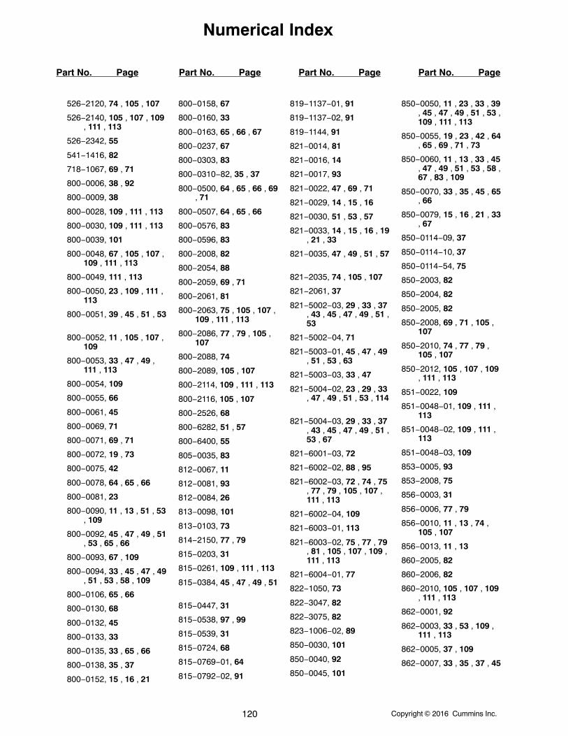
Numerical Index
Part No. Page Part No. Page Part No. Page Part No. Page
Copyright 2016 Cummins Inc.120
526−2120, 74 , 105 , 107
526−2140, 105 , 107 , 109, 111 , 113
526−2342, 55
541−1416, 82
718−1067, 69 , 71
800−0006, 38 , 92
800−0009, 38
800−0028, 109 , 111 , 113
800−0030, 109 , 111 , 113
800−0039, 101
800−0048, 67 , 105 , 107 ,109 , 111 , 113
800−0049, 111 , 113
800−0050, 23 , 109 , 111 ,113
800−0051, 39 , 45 , 51 , 53
800−0052, 11 , 105 , 107 ,109
800−0053, 33 , 47 , 49 ,111 , 113
800−0054, 109
800−0055, 66
800−0061, 45
800−0069, 71
800−0071, 69 , 71
800−0072, 19 , 73
800−0075, 42
800−0078, 64 , 65 , 66
800−0081, 23
800−0090, 11 , 13 , 51 , 53, 109
800−0092, 45 , 47 , 49 , 51, 53 , 65 , 66
800−0093, 67 , 109
800−0094, 33 , 45 , 47 , 49, 51 , 53 , 58 , 109
800−0106, 65 , 66
800−0130, 68
800−0132, 45
800−0133, 33
800−0135, 33 , 65 , 66
800−0138, 35 , 37
800−0152, 15 , 16 , 21
800−0158, 67
800−0160, 33
800−0163, 65 , 66 , 67
800−0237, 67
800−0303, 83
800−0310−82, 35 , 37
800−0500, 64 , 65 , 66 , 69, 71
800−0507, 64 , 65 , 66
800−0576, 83
800−0596, 83
800−2008, 82
800−2054, 88
800−2059, 69 , 71
800−2061, 81
800−2063, 75 , 105 , 107 ,109 , 111 , 113
800−2086, 77 , 79 , 105 ,107
800−2088, 74
800−2089, 105 , 107
800−2114, 109 , 111 , 113
800−2116, 105 , 107
800−2526, 68
800−6282, 51 , 57
800−6400, 55
805−0035, 83
812−0067, 11
812−0081, 93
812−0084, 26
813−0098, 101
813−0103, 73
814−2150, 77 , 79
815−0203, 31
815−0261, 109 , 111 , 113
815−0384, 45 , 47 , 49 , 51
815−0447, 31
815−0538, 97 , 99
815−0539, 31
815−0724, 68
815−0769−01, 64
815−0792−02, 91
819−1137−01, 91
819−1137−02, 91
819−1144, 91
821−0014, 81
821−0016, 14
821−0017, 93
821−0022, 47 , 69 , 71
821−0029, 14 , 15 , 16
821−0030, 51 , 53 , 57
821−0033, 14 , 15 , 16 , 19, 21 , 33
821−0035, 47 , 49 , 51 , 57
821−2035, 74 , 105 , 107
821−2061, 37
821−5002−03, 29 , 33 , 37, 43 , 45 , 47 , 49 , 51 ,53
821−5002−04, 71
821−5003−01, 45 , 47 , 49, 51 , 53 , 63
821−5003−03, 33 , 47
821−5004−02, 23 , 29 , 33, 47 , 49 , 51 , 53 , 114
821−5004−03, 29 , 33 , 37, 43 , 45 , 47 , 49 , 51 ,53 , 67
821−6001−03, 72
821−6002−02, 88 , 95
821−6002−03, 72 , 74 , 75, 77 , 79 , 105 , 107 ,111 , 113
821−6002−04, 109
821−6003−01, 113
821−6003−02, 75 , 77 , 79, 81 , 105 , 107 , 109 ,111 , 113
821−6004−01, 77
822−1050, 73
822−3047, 82
822−3075, 82
823−1006−02, 89
850−0030, 101
850−0040, 92
850−0045, 101
850−0050, 11 , 23 , 33 , 39, 45 , 47 , 49 , 51 , 53 ,109 , 111 , 113
850−0055, 19 , 23 , 42 , 64, 65 , 69 , 71 , 73
850−0060, 11 , 13 , 33 , 45, 47 , 49 , 51 , 53 , 58 ,67 , 83 , 109
850−0070, 33 , 35 , 45 , 65, 66
850−0079, 15 , 16 , 21 , 33, 67
850−0114−09, 37
850−0114−10, 37
850−0114−54, 75
850−2003, 82
850−2004, 82
850−2005, 82
850−2008, 69 , 71 , 105 ,107
850−2010, 74 , 77 , 79 ,105 , 107
850−2012, 105 , 107 , 109, 111 , 113
851−0022, 109
851−0048−01, 109 , 111 ,113
851−0048−02, 109 , 111 ,113
851−0048−03, 109
853−0005, 93
853−2008, 75
856−0003, 31
856−0006, 77 , 79
856−0010, 11 , 13 , 74 ,105 , 107
856−0013, 11 , 13
860−2005, 82
860−2006, 82
860−2010, 105 , 107 , 109, 111 , 113
862−0001, 92
862−0003, 33 , 53 , 109 ,111 , 113
862−0005, 37 , 109
862−0007, 33 , 35 , 37 , 45
Numerical Index
Part No. Page Part No. Page Part No. Page Part No. Page
Copyright 2016 Cummins Inc. 121
862−0008, 33 , 67
862−0015, 101 , 109 , 111, 113
862−0016, 33 , 45 , 47 , 49, 51 , 53 , 58 , 67
862−0017, 83
862−0034, 64 , 65 , 66
864−0017, 73
864−0020−01, 73
870−0131, 31
870−0183, 11
870−0212, 11 , 13
870−0221, 93 , 95
870−0257, 14 , 93
870−0281, 14 , 15 , 16 , 33, 37 , 43 , 47 , 49 , 51 ,53 , 57
870−0437, 15 , 16 , 19 , 21
870−0504, 74 , 105 , 107
870−0550−05, 45 , 49 , 51
870−0550−07, 33
870−0550−09, 29 , 33 , 45, 49 , 51 , 53
870−1220, 95
870−1221, 26
870−2054, 77 , 79
870−2055, 81
870−2056, 79
870−2213−02, 91
870−2287, 55
871−0010, 31
895−0182, 38 , 105 , 107
898−1254−25, 82
A028X493, 11 , 13

122
“Intentionally Left Blank”


power.cummins.comCopyright � 2016 Cummins Inc. All rights reserved.
Cummins Power Generation, the “C” logo, and Cummins are trademarks of Cummins Inc.
PowerCommand, AmpSentry, InPower and “Our energy working for you.” are trademarks of Cummins Power Generation Inc.
Other company, product, or service names may be trademarks or service marks of others.
Specifications are subject to change without notice.