Embed Size (px)
DESCRIPTION
sheet bulk forming
Citation preview
Proceedings in Manufacturing Systems, Volume 6, Issue 2, 2011
ISSN 2067-9238
INVESTIGATION ON THE PROCESS-MACHINE INTERACTION BY FORMING PARTS WITH SHEET-BULK METAL FORMING
Valerian SALFELD1,*, Richard KRIMM2, Thorsten MATTHIAS3, Bernd-Arno BEHRENS4
1) PhD, Eng, Research assistant, metal forming machines, Institute of metal forming and metal forming machines, Garbsen, Germany
2) PhD, Eng, Head of department, metal forming machines, Institute of metal forming and metal forming machines, Garbsen, Germany 3) M.Sc., Research assistant, numerical methods, Institute of metal forming and metal forming machines, Garbsen, Germany
4) Professor, PhD, Eng, Director, Institute of metal forming and metal forming machines, Garbsen, Germany Abstract: Although the interaction between the forming machine and process affects the quality of the fi-nished part significantly, the machine influence is usually ignored in the analysis of the forming process with the Finite-Element-Method. This contribution focuses on this interaction regarding the process of sheet-bulk metal forming. In order to represent the machine characteristics, a hybrid multi-body model of an experimental press has been developed. This model takes into account the machine kinematics and dy-namics as well as the elasticity of the press components. In order to validate the machine model the dis-placement of the press components under load have been determined by means of optical measuring sys-tems. The required three-axial load profiles have been provided by a new developed load device. Key words: sheet-bulk metal forming, interaction, load device, stiffness.
1. INTRODUCTION1
1.1. Process-machine interaction In sheet metal forming as well as in bulk metal form-
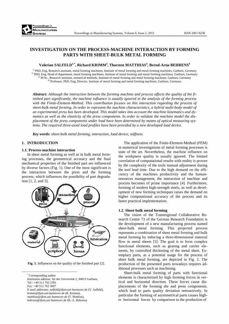
ing processes, the geometrical accuracy and the final mechanical properties of the finished part are influenced by diverse factors (Fig. 1). One of the most significant is the interaction between the press and the forming process, which influences the possibility of part degrada-tion [1, 2, and 3].
Fig. 1. Influences on the quality of the finished part [2].
* Corresponding author Institution address: An der Universität 2, 30823 Garbsen, Tel.: +49 511 762 2281 Fax: +49 511 762 3007 E-mail addresses: [email protected] (V. Salfeld), [email protected] (R. Krimm), [email protected] (T. Mathias), [email protected] (B.-A. Behrens)
The application of the Finite-Element-Method (FEM) in numerical investigations of metal forming processes is state of the art. Nevertheless, the machine influence on the workpiece quality is usually ignored. The limited correlation of computational results with reality is proven by the complexity of the tools manual adjustment during the tool lead time. Due to the high demand on the effi-ciency of the machines productivity and the human-resources management, the interaction of machine and process becomes of prime importance [4]. Furthermore, forming of modern high-strength steels, as well as devel-opment of new forming techniques raises the demand on higher computational accuracy of the process and its faster practical implementation.
1.2. Sheet-bulk metal forming
The vision of the Transregional Collaborative Re-search Centre 73 of the German Research Foundation is the development of a new manufacturing process named sheet-bulk metal forming. This projected process represents a combination of sheet metal forming and bulk metal forming by inducing a three-dimensional material flow in metal sheets [5]. The goal is to form complex functional elements, such as gearing and carrier ele-ments, by controlled thickening of the metal sheet. Ex-emplary parts, as a potential usage for the process of sheet bulk metal forming, are depicted in Fig. 2. The production of the presented parts nowadays requires ad-ditional processes such as machining. Sheet-bulk metal forming of parts with functional elements is characterized by high forming forces in ver-tical and horizontal direction. These forces cause dis-placements of the forming die and press components, which lead to parts quality deviation retroactively. In particular the forming of asymmetrical parts causes high-er horizontal forces by comparison to the production of
98 V. Salfeld et al. / Proceedings in Manufacturing Systems, Vol. 6, Iss. 2, 2011 / 97− 100
a b
Fig. 2. Examples for potential usage of sheet-bulk metal form-ing, a − spacer rings for multi-cone synchronization [6];
b − fine blanking parts [7]. symmetrical workpieces. Furthermore, the horizontal forces also arise with the complexity of the functional elements. The functional applications of these gearing and carrier elements such as fixation, motion and load transmission require compliance with high geometrical accuracy as well as high precision regarding the final mechanical properties of the part.
The present contribution gives an overview about the challenges in sheet-bulk metal forming of asymmetrical parts with regard the forming forces. In conclusion, a suitable approach to represent the machine characteristics is introduced.
2. NUMERICAL ANALYSIS OF PROCESS
2.1. Process The primary aim of the process simulation has been
to analyze the process forces while forming an asymme-trical part with functional elements. In this study the fi-nite element code Simufact.forming 9.0 has been used. The die and the die-plate are modelled as rigid bodies. The metal sheet is modelled as elastic-plastic material with the material properties of dc04 and dual phase steel dp600 (DIN EN 10027-1) subsequently. The initial thickness of the metal sheet is 3 mm and the simulated Coulomb friction coefficient µ is 0.2. The CAD-Model of the die-plate and die is shown in Fig. 3. Using this form-ing die, functional elements such as gearing and carrier elements are formed asymmetrically in a workpiece with 80mm diameter.
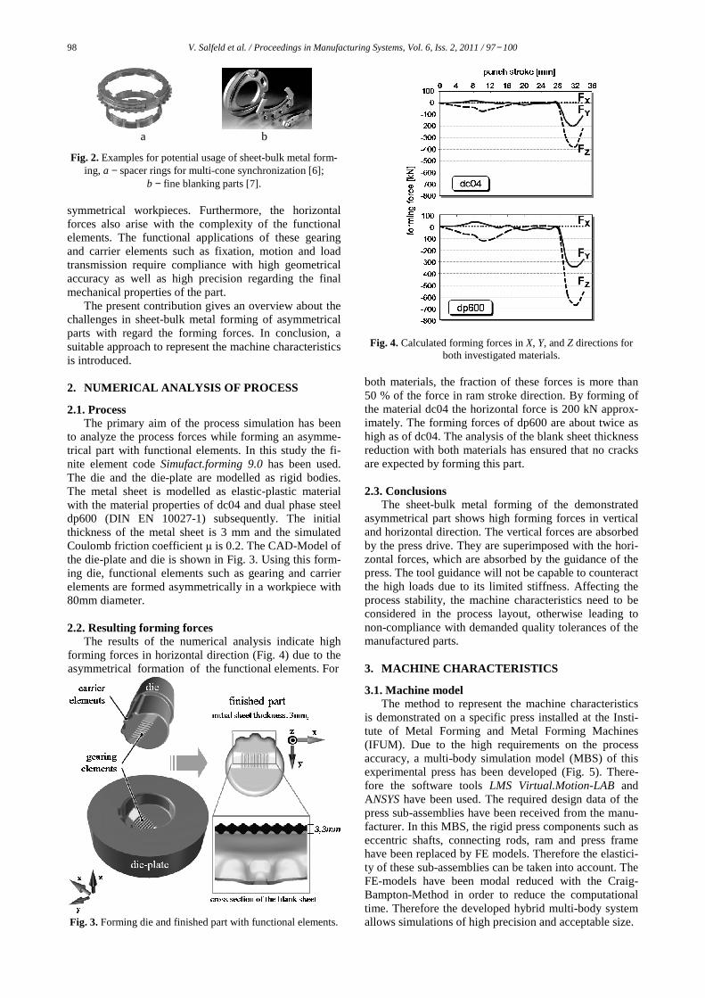
2.2. Resulting forming forces The results of the numerical analysis indicate high forming forces in horizontal direction (Fig. 4) due to the asymmetrical formation of the functional elements. For
Fig. 3. Forming die and finished part with functional elements.
Fig. 4. Calculated forming forces in X, Y, and Z directions for both investigated materials.
both materials, the fraction of these forces is more than 50 % of the force in ram stroke direction. By forming of the material dc04 the horizontal force is 200 kN approx-imately. The forming forces of dp600 are about twice as high as of dc04. The analysis of the blank sheet thickness reduction with both materials has ensured that no cracks are expected by forming this part.
2.3. Conclusions
The sheet-bulk metal forming of the demonstrated asymmetrical part shows high forming forces in vertical and horizontal direction. The vertical forces are absorbed by the press drive. They are superimposed with the hori-zontal forces, which are absorbed by the guidance of the press. The tool guidance will not be capable to counteract the high loads due to its limited stiffness. Affecting the process stability, the machine characteristics need to be considered in the process layout, otherwise leading to non-compliance with demanded quality tolerances of the manufactured parts. 3. MACHINE CHARACTERISTICS
3.1. Machine model The method to represent the machine characteristics
is demonstrated on a specific press installed at the Insti-tute of Metal Forming and Metal Forming Machines (IFUM). Due to the high requirements on the process accuracy, a multi-body simulation model (MBS) of this experimental press has been developed (Fig. 5). There-fore the software tools LMS Virtual.Motion-LAB and ANSYS have been used. The required design data of the press sub-assemblies have been received from the manu-facturer. In this MBS, the rigid press components such as eccentric shafts, connecting rods, ram and press frame have been replaced by FE models. Therefore the elastici-ty of these sub-assemblies can be taken into account. The FE-models have been modal reduced with the Craig-Bampton-Method in order to reduce the computational time. Therefore the developed hybrid multi-body system allows simulations of high precision and acceptable size.
V. Salfeld et al. / Proceedings in Manufacturing Systems, Vol. 6, Iss. 2, 2011 / 97− 100 99
Fig. 5. Hybrid multi-body model of the experimental press.
3.2. Three-axial load device In order to investigate the machines` characteristics
under load and to validate the machine model, a new hydraulic three-axial load device has been developed (Fig. 6). It enables a simultaneous application of vertical and horizontal forces between the ram and the bolster plate. The regulated force application allows an accurate determination of the machine characteristics. Therefore, the elastic characteristics of the press components under load can be inspected.
The load device consists of a mechanical part, a hy-draulic aggregate and a control PC. The mechanical part represents the actuator of the device, which has to be mounted in the die space of a press. The base plate with the installed hydraulic cylinder has to be fixed with the bolster plate. The upper plate of the mechanical part has to be mounted to the ram of the press.
Through specific location of the hydraulic cylinder it is possible to apply forces between the ram and the bol-ster plate in X, Y and Z directions simultaneously. The required pressure is provided by the hydraulic aggregate.
a
b
c
mechanical part
hydraulic aggregate
control-PC
Characteristics:
max. horizontal force: 750 kN max. vertical force: 2000 kN
a
b
c
upper plate withhollow block
horizontal / verticalcylinder base plate
aa
bb
cc
mechanical part
hydraulic aggregate
control-PC
Characteristics:
max. horizontal force: 750 kN max. vertical force: 2000 kN
a
b
c
upper plate withhollow block
horizontal / verticalcylinder base plate
aa
bb
cc
upper plate withhollow block
horizontal / verticalcylinder base plate
Fig. 6. Developed load device for applying three-axial load
profiles between bolster plate and ram.
press
optical measuring systems hydraulic aggregate
control-PC
loaddevice
presspress
optical measuring systemsoptical measuring systems hydraulic aggregate
control-PCcontrol-PC
loaddeviceload
device
Fig. 7. Experimental setup.
The triple radial piston pump allows the pressure in each cylinder to be set independently from each other. That means, a variety of load profiles can be applied. Each of the horizontal cylinders has a nominal force of 750 kN. The maximum force in vertical direction is about 2000 kN. The regulation and monitoring of the acting forces is provided by means of the control PC.
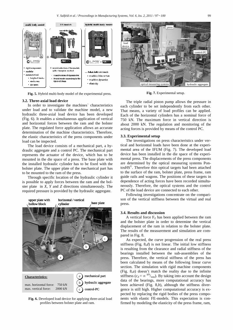
3.3. Experimental setup The investigations on press characteristics under ver-
tical and horizontal loads have been done at the experi-mental area of the IFUM (Fig. 7). The developed load device has been installed in the die space of the experi-mental press. The displacements of the press components are determined by the optical measuring systems Pon-tosHS©. Therefore thin optical targets had been attached to the surface of the ram, bolster plate, press frame, ram guide rails and wagons. The positions of these targets in dependence of acting forces have been recorded simulta-neously. Therefore, the optical systems and the control PC of the load device are connected to each other.
Following investigations concentrate on the compari-son of the vertical stiffness between the virtual and real press.
3.4. Results and discussion
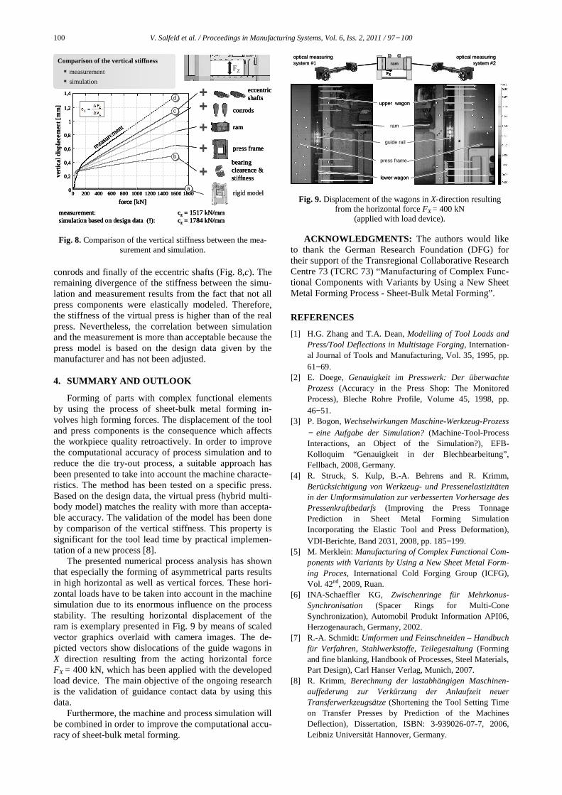
A vertical force FZ has been applied between the ram and the bolster plate in order to determine the vertical displacement of the ram in relation to the bolster plate. The results of the measurement and simulation are com-pared in Fig. 8.
As expected, the curve progression of the real press stiffness (Fig. 8,d) is not linear. The initial low stiffness is resulting from the clearance and radial stiffness of the bearings installed between the sub-assemblies of the press. Therefore, the vertical stiffness of the press has been calculated by means of the following linear curve section. The simulation with rigid machine components (Fig. 8,a) doesn’t match the reality due to the infinite stiffness (cZ = ∞ kN/mm). By taking into account the design data of the bearings, more computational accuracy has been achieved (Fig. 8,b), although the stiffness diver-gence is still high. Higher computational accuracy is ex-pected by replacing the rigid bodies of the press compo-nents with elastic FE-models. This expectation is con-firmed by modeling the elasticity of the press frame, ram,
100 V. Salfeld et al. / Proceedings in Manufacturing Systems, Vol. 6, Iss. 2, 2011 / 97− 100
measurement: cz = 1517 kN/mmsimulation based on design data (!): cz = 1784 kN/mm
0 200 400 600 800 1000 1200 1400 1600 18000
0,2
0,4
0,6
0,8
1
1,2
measure
ment
1,4
bearingclearence &stiffness
press frame
ram
conrods
eccentricshafts
FZ
Comparison of the vertical stiffness
� measurement
� simulation
force [kN]
vert
ica
l dis
pla
cem
en
t [m
m]
rigid modela
b
c
d
measurement: cz = 1517 kN/mmsimulation based on design data (!): cz = 1784 kN/mm
0 200 400 600 800 1000 1200 1400 1600 18000
0,2
0,4
0,6
0,8
1
1,2
measure
ment
1,4
bearingclearence &stiffness
press frame
ram
conrods
eccentricshafts
FZ
Comparison of the vertical stiffness
� measurement
� simulation
force [kN]
vert
ica
l dis
pla
cem
en
t [m
m]
rigid model
measurement: cz = 1517 kN/mmsimulation based on design data (!): cz = 1784 kN/mm
0 200 400 600 800 1000 1200 1400 1600 18000
0,2
0,4
0,6
0,8
1
1,2
measure
ment
1,4
bearingclearence &stiffness
press frame
ram
conrods
eccentricshafts
FZ
Comparison of the vertical stiffness
� measurement
� simulation
Comparison of the vertical stiffness
� measurement
� simulation
force [kN]
vert
ica
l dis
pla
cem
en
t [m
m]
rigid modelaa
bb
cc
dd
Fig. 8. Comparison of the vertical stiffness between the mea-surement and simulation.
conrods and finally of the eccentric shafts (Fig. 8,c). The remaining divergence of the stiffness between the simu-lation and measurement results from the fact that not all press components were elastically modeled. Therefore, the stiffness of the virtual press is higher than of the real press. Nevertheless, the correlation between simulation and the measurement is more than acceptable because the press model is based on the design data given by the manufacturer and has not been adjusted. 4. SUMMARY AND OUTLOOK
Forming of parts with complex functional elements by using the process of sheet-bulk metal forming in-volves high forming forces. The displacement of the tool and press components is the consequence which affects the workpiece quality retroactively. In order to improve the computational accuracy of process simulation and to reduce the die try-out process, a suitable approach has been presented to take into account the machine characte-ristics. The method has been tested on a specific press. Based on the design data, the virtual press (hybrid multi-body model) matches the reality with more than accepta-ble accuracy. The validation of the model has been done by comparison of the vertical stiffness. This property is significant for the tool lead time by practical implemen-tation of a new process [8].
The presented numerical process analysis has shown that especially the forming of asymmetrical parts results in high horizontal as well as vertical forces. These hori-zontal loads have to be taken into account in the machine simulation due to its enormous influence on the process stability. The resulting horizontal displacement of the ram is exemplary presented in Fig. 9 by means of scaled vector graphics overlaid with camera images. The de-picted vectors show dislocations of the guide wagons in X direction resulting from the acting horizontal force FX = 400 kN, which has been applied with the developed load device. The main objective of the ongoing research is the validation of guidance contact data by using this data.
Furthermore, the machine and process simulation will be combined in order to improve the computational accu-racy of sheet-bulk metal forming.
FX
ram
FXFX
ram
upper wagon
lower wagon
guide rail
press frame
ram
optical measuring system #1
optical measuring system #2
FX
ram
FXFX
ram
upper wagon
lower wagon
guide rail
press frame
ram
optical measuring system #1
optical measuring system #2
Fig. 9. Displacement of the wagons in X-direction resulting from the horizontal force FX = 400 kN
(applied with load device).
ACKNOWLEDGMENTS: The authors would like to thank the German Research Foundation (DFG) for their support of the Transregional Collaborative Research Centre 73 (TCRC 73) “Manufacturing of Complex Func-tional Components with Variants by Using a New Sheet Metal Forming Process - Sheet-Bulk Metal Forming”.
REFERENCES
[1] H.G. Zhang and T.A. Dean, Modelling of Tool Loads and Press/Tool Deflections in Multistage Forging, Internation-al Journal of Tools and Manufacturing, Vol. 35, 1995, pp. 61−69.
[2] E. Doege, Genauigkeit im Presswerk: Der überwachte Prozess (Accuracy in the Press Shop: The Monitored Process), Bleche Rohre Profile, Volume 45, 1998, pp. 46−51.
[3] P. Bogon, Wechselwirkungen Maschine-Werkzeug-Prozess − eine Aufgabe der Simulation? (Machine-Tool-Process Interactions, an Object of the Simulation?), EFB-Kolloquim “Genauigkeit in der Blechbearbeitung”, Fellbach, 2008, Germany.
[4] R. Struck, S. Kulp, B.-A. Behrens and R. Krimm, Berücksichtigung von Werkzeug- und Pressenelastizitäten in der Umformsimulation zur verbesserten Vorhersage des Pressenkraftbedarfs (Improving the Press Tonnage Prediction in Sheet Metal Forming Simulation Incorporating the Elastic Tool and Press Deformation), VDI-Berichte, Band 2031, 2008, pp. 185−199.
[5] M. Merklein: Manufacturing of Complex Functional Com-ponents with Variants by Using a New Sheet Metal Form-ing Proces, International Cold Forging Group (ICFG), Vol. 42nd, 2009, Ruan.
[6] INA-Schaeffler KG, Zwischenringe für Mehrkonus-Synchronisation (Spacer Rings for Multi-Cone Synchronization), Automobil Produkt Information API06, Herzogenaurach, Germany, 2002.
[7] R.-A. Schmidt: Umformen und Feinschneiden – Handbuch für Verfahren, Stahlwerkstoffe, Teilegestaltung (Forming and fine blanking, Handbook of Processes, Steel Materials, Part Design), Carl Hanser Verlag, Munich, 2007.
[8] R. Krimm, Berechnung der lastabhängigen Maschinen-auffederung zur Verkürzung der Anlaufzeit neuer Transferwerkzeugsätze (Shortening the Tool Setting Time on Transfer Presses by Prediction of the Machines Deflection), Dissertation, ISBN: 3-939026-07-7, 2006, Leibniz Universität Hannover, Germany.