Embed Size (px)
Citation preview
9700 SERIES
OWNERS OPERATION GUIDE
1 2
3

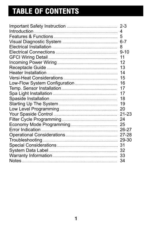
TABLE OF CONTENTS
1
Important Safety Instruction 2-3Introduction 4Features & Functions 5Visual Diagnostic System 6-7Electrical Installation 8Electrical Connections 9-10GFCI Wiring Detail 11Incoming Power Wiring 12Receptacle Guide 13Heater Installation 14Versi-Heat Considerations 15Low-Flow System Configuration 16Temp. Sensor Installation 17Spa Light Installation 17Spaside Installation 18Starting Up The System 19Low Level Programming 20Your Spaside Control 21-23Filter Cycle Programming 24Economy Mode Programming 25Error Indication 26-27Operational Considerations 27-28Troubleshooting 29-30Special Considerations 31System Data Label 32Warranty Information 33Notes 34
..................................................................................................................
.....................................................................................................
...........................................................................................................
.............................................................................................................
........................................................................................................................
..................................................................................
.....................................................................................................
..................................................................................................................................................................
................................................................................................
.........................................................................................................
............................................................................................................
..............................................................................................................
........................................................................................................................................
DANGER To reduce the risk of injury, do not permit children to use this product unless they are closely supervised at all times.
WARNING - RISK OF CHILD DROWNING. Extreme caution must be exercised to prevent unauthorized access by children. To avoid accidents, ensure that children cannot use a spa or hot tub unless they are supervised at all times.
DANGER To reduce the risk of injury to persons, do not remove suction fittings.
Spa location must accommodate sufficient drainage of water around the base of the structure, as well as the power source compartment.
Prolonged immersion in water that is warmer than normal body temperature can result in a dangerous condition known as HYPERTHERMIA. The causes, symptoms, and effects of hyperthermia may be described as follows: Hyperthermia occurs when the internal temperature of the body reaches a level several degrees above the normal body temperature of 98.6F. The symptoms of hyperthermia include dizziness, fainting, drowsiness, lethargy, and an increase in the internal temperature of the body. The effects of hyperthermia include (1) unawareness of impending hazard, (2) failure to perceive heat, (3) failure to recognize the need to exit spa, (4) physical inability to exit spa, (5) fetal damage in pregnant women, (6) unconsciousness resulting in danger of drowning. WARNING The use of alcohol, drugs or medication can greatly increase the risk of fatal hyperthermia in hot tubs and spas.
DANGER - RISK OF ELECTRICAL SHOCK. Install at least 5 feet (1.5m) from all metal surfaces. (A spa may be installed within 5 feet of metal surfaces if each metal surface is permanently connected by a solid copper conductor attached to the wire connector on the terminal box that is provided for this purpose. Refer to NEC and local codes in effect at the time of installation.)
A pressure wire connector is provided on the control box to permit connection of a solid copper bonding conductor between this point and any equipment, metal enclosures of electrical equipment, metal water pipe, or conduit within 5 feet (1.5m) of the unit as needed to comply with local requirements.
Bond accessible metal to the dedicated connector on the equipment grounding bus, bond the equipment ground bus to the local common bonding grid as part of the installation in the form of (1) a reinforced concrete slab for support, (2) a ground plate provided beneath the hot tub or spa, or (3) a permanent ground connection that is acceptable to the local inspection authority.
DANGER RISK OF ELECTRICAL SHOCK. Do not permit any electrical appliance, such as a light, telephone, radio, or television, within 5 feet (1.5m) of a spa or hot tub.
To reduce the risk of injury:
The water in a spa or hot tub should never exceed 104F (40C). Water temperatures between 100F (38C) and 104F (40C) are considered safe for a healthy adult. Lower water temperatures are recommended for extended use (exceeding 10-15 minutes) and for young children.
Excessive water temperatures have a high potential for causing fetal damage during the early months of pregnancy, pregnant or possibly pregnant women should limit spa or hot tub water temperatures to 100F(38C).
IMPORTANT SAFETY INSTRUCTIONSREAD AND FOLLOW ALL INSTRUCTIONS
!
!
!
!
!
2
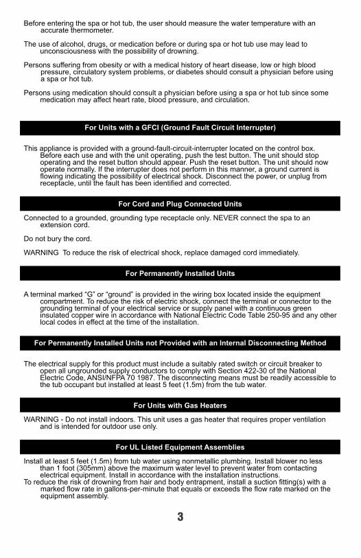
Before entering the spa or hot tub, the user should measure the water temperature with an accurate thermometer.
The use of alcohol, drugs, or medication before or during spa or hot tub use may lead to unconsciousness with the possibility of drowning.
Persons suffering from obesity or with a medical history of heart disease, low or high blood pressure, circulatory system problems, or diabetes should consult a physician before using a spa or hot tub.
Persons using medication should consult a physician before using a spa or hot tub since some medication may affect heart rate, blood pressure, and circulation.
For Units with a GFCI (Ground Fault Circuit Interrupter)
This appliance is provided with a ground-fault-circuit-interrupter located on the control box. Before each use and with the unit operating, push the test button. The unit should stop operating and the reset button should appear. Push the reset button. The unit should now operate normally. If the interrupter does not perform in this manner, a ground current is flowing indicating the possibility of electrical shock. Disconnect the power, or unplug from receptacle, until the fault has been identified and corrected.
For Cord and Plug Connected Units
Connected to a grounded, grounding type receptacle only. NEVER connect the spa to an extension cord.
Do not bury the cord.
WARNING To reduce the risk of electrical shock, replace damaged cord immediately.
For Permanently Installed Units
A terminal marked “G” or “ground” is provided in the wiring box located inside the equipment compartment. To reduce the risk of electric shock, connect the terminal or connector to the grounding terminal of your electrical service or supply panel with a continuous green insulated copper wire in accordance with National Electric Code Table 250-95 and any other local codes in effect at the time of the installation.
For Permanently Installed Units not Provided with an Internal Disconnecting Method
The electrical supply for this product must include a suitably rated switch or circuit breaker to open all ungrounded supply conductors to comply with Section 422-30 of the National Electric Code, ANSI/NFPA 70 1987. The disconnecting means must be readily accessible to the tub occupant but installed at least 5 feet (1.5m) from the tub water.
For Units with Gas Heaters
WARNING - Do not install indoors. This unit uses a gas heater that requires proper ventilation and is intended for outdoor use only.
For UL Listed Equipment Assemblies
Install at least 5 feet (1.5m) from tub water using nonmetallic plumbing. Install blower no less than 1 foot (305mm) above the maximum water level to prevent water from contacting electrical equipment. Install in accordance with the installation instructions.
To reduce the risk of drowning from hair and body entrapment, install a suction fitting(s) with a marked flow rate in gallons-per-minute that equals or exceeds the flow rate marked on the equipment assembly.
3
INTRODUCTION
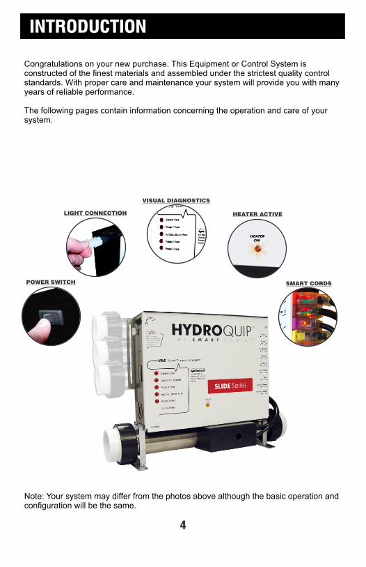
Congratulations on your new purchase. This Equipment or Control System is constructed of the finest materials and assembled under the strictest quality control standards. With proper care and maintenance your system will provide you with many years of reliable performance.
The following pages contain information concerning the operation and care of your system.
POWER SWITCH
LIGHT CONNECTION HEATER ACTIVE
SMART CORDS
Note: Your system may differ from the photos above although the basic operation and configuration will be the same.
VISUAL DIAGNOSTICS
4
FEATURES & FUNCTIONS
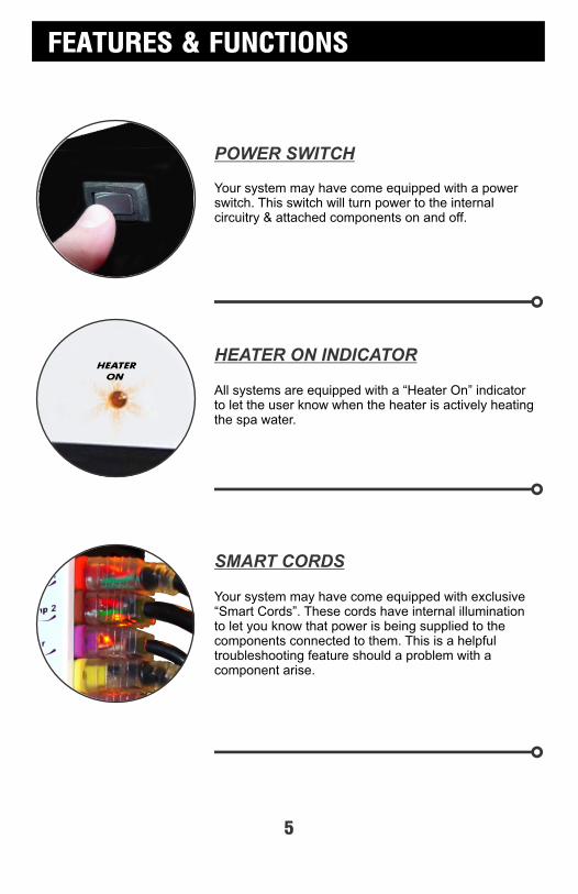
Your system may have come equipped with a power switch. This switch will turn power to the internal circuitry & attached components on and off.
All systems are equipped with a “Heater On” indicator to let the user know when the heater is actively heating the spa water.
HEATER ON INDICATOR
Your system may have come equipped with exclusive “Smart Cords”. These cords have internal illumination to let you know that power is being supplied to the components connected to them. This is a helpful troubleshooting feature should a problem with a component arise.
SMART CORDS
POWER SWITCH
5
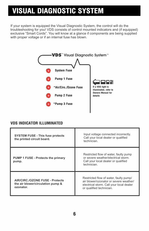
SYSTEM FUSE - This fuse protectsthe printed circuit board.
PUMP 1 FUSE - Protects the primarypump.
AIR/CIRC./OZONE FUSE - Protectsthe air blower/circulation pump &ozonator.
Input voltage connected incorrectly.Call your local dealer or qualifiedtechnician.
Restricted flow of water, faulty pumpor severe weather/electrical storm.Call your local dealer or qualified technician.
Restricted flow of water, faulty pump/air blower/ozonator or severe weather/electrical storm. Call your local dealer or qualified technician.
VISUAL DIAGNOSTIC SYSTEM
If your system is equipped the Visual Diagnostic System, the control will do the troubleshooting for you! VDS consists of control mounted indicators and (if equipped) exclusive “Smart Cords”. You will know at a glance if components are being supplied with proper voltage or if an internal fuse has blown.
*Pump 3 Fuse
Pump 2 Fuse
*Air/Circ./Ozone Fuse
Pump 1 Fuse
Visual Diagnostic SystemVDS
If a VDS light is
illuminated, refer to
Owners Manual for
details
System Fuse
6
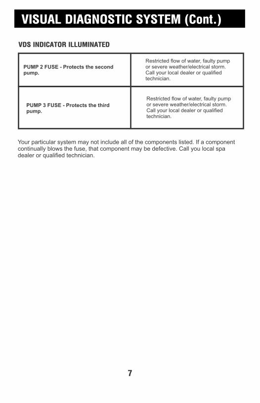
PUMP 2 FUSE - Protects the secondpump.
PUMP 3 FUSE - Protects the thirdpump.
Restricted flow of water, faulty pumpor severe weather/electrical storm.Call your local dealer or qualified technician.
VISUAL DIAGNOSTIC SYSTEM (Cont.)
Restricted flow of water, faulty pumpor severe weather/electrical storm.Call your local dealer or qualified technician.
Your particular system may not include all of the components listed. If a component continually blows the fuse, that component may be defective. Call you local spa dealer or qualified technician.
7

A qualified and licensed electrician in accordance with the National Electric Code (NEC) Article 680, Canadian Electric Code, and with any local codes must accomplish the electrical installation.
All connections must be made according to the electrical installation label on the outside of the control box (see page 33). Follow the instructions from the label if they are different than the instructions in this manual. If your electrician is not absolutely sure how to connect your system correctly, call your local dealer. Any mistake may be costly and void your equipment warranty.
The GFCI (Ground Fault Circuit Interrupter) is a mandatory electrical safety device required for all portable spas and hot tubs as specified in the National Electrical Code Article 680-42. The GFCI in your particular installation may be installed at the electrical service panel, a separate sub-panel or built into your Hydro-Quip System.
Your spa equipment requires a DEDICATED CIRCUIT. No other appliances or lights can be on this circuit. Refer to equipment data label for power supply requirements of your spa equipment.
Use copper conductors ONLY. The ground must be sized following the National Electric Code, Table 250-95.
For Power conductor size, refer to the National Electric Code Table 310-16.
NOTE: Due to the electrical requirements of some models, it may be required to SPLIT the incoming electrical service to accommodate the GFCI Circuit Breaker limits. Contact your electrician if you need additional information on this topic.
15A 20A 30A 40A 50A 60A 70A 80A
12A 16A 24A 32A 40A 48A 56A 64A
14 12 10 8 6 4 4 4
Circuit & BreakerRating
Maximum Amps
Minimum WireSize
Universal Systems require a Neutral wire therefore the service required is as follows: 120-volt systems require a three-wire electrical service including ground, consisting of Line 1 (Black), Neutral (White) and Ground (Green). 240-volt systems require a four wire electrical service including ground, consisting of Line 1 (Black), Line 2 (Red), Neutral (White) and Ground (Green).
ELECTRICAL INSTALLATION
8
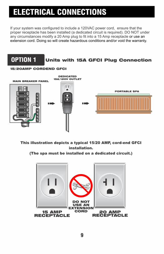
If your system was configured to include a 120VAC power cord, ensure that the proper receptacle has been installed (a dedicated circuit is required). DO NOT under any circumstances modify a 20 Amp plug to fit into a 15 Amp receptacle or use an extension cord. Doing so will create hazardous conditions and/or void the warranty.
15/20AMP CORDEND GFCI
PORTABLE SPA
DEDICATED15A/120V OUTLET
This illustration depicts a typical 15/20 AMP, cord-end GFCI
installation.
(The spa must be installed on a dedicated circuit.)
DO NOTUSE AN
EXTENSIONCORD15 AMP
RECEPTACLE20 AMP
RECEPTACLE
Units with 15A GFCI Plug Connection
MAIN BREAKER PANEL
ELECTRICAL CONNECTIONS
9
OPTION 1
ELECTRICAL CONNECTIONS
10
MAIN BREAKER PANEL
LINE 1
N
LINE 2
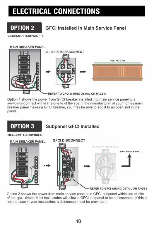
OPTION 2
MAIN BREAKER PANEL
20-60AMP HARDWIRED
Option 1 shows the power from GFCI breaker installed into main service panel to a service disconnect within line-of-site of the spa. If the manufacturer of your homes main breaker panel makes a GFCI breaker, you may be able to add it to an open slot in the panel.
Option 2 shows the power from main service panel to a GFCI subpanel within line-of-site of the spa. (Note: Most local codes will allow a GFCI subpanel to be a disconnect. If this is not the case in your installation, a disconnect must be provided.)
REFER TO GFCI WIRING DETAIL ON PAGE 8
GFCI Installed in Main Service Panel
Subpanel GFCI Installed
PORTABLE SPA
INLINE SPA DISCONNECT
20-60AMP HARDWIRED
GFCI DISCONNECT
LIN
E 1
N
LIN
E 2
INLINE SPA DISCONNECT
TO PORTABLE SPA
REFER TO GFCI WIRING DETAIL ON PAGE 8
OPTION 3
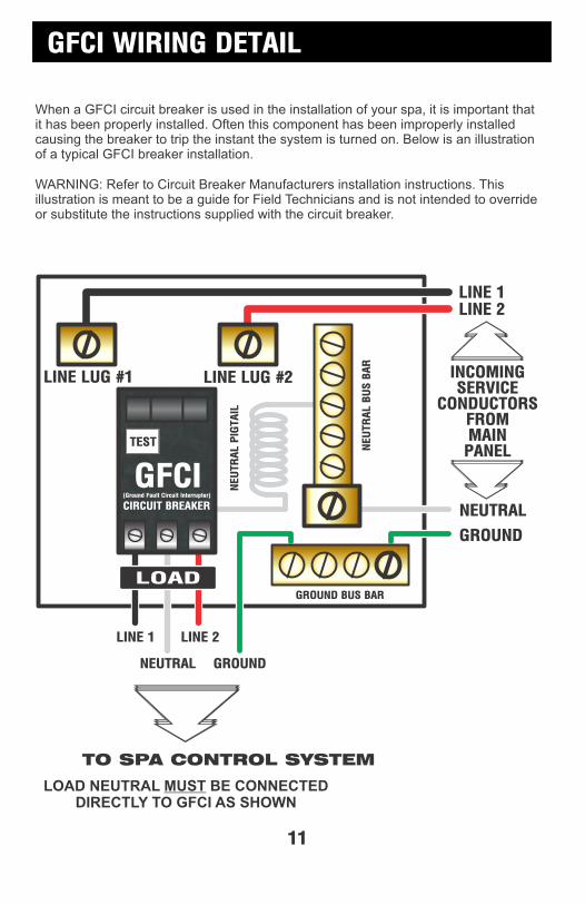
When a GFCI circuit breaker is used in the installation of your spa, it is important that it has been properly installed. Often this component has been improperly installed causing the breaker to trip the instant the system is turned on. Below is an illustration of a typical GFCI breaker installation.
WARNING: Refer to Circuit Breaker Manufacturers installation instructions. This illustration is meant to be a guide for Field Technicians and is not intended to override or substitute the instructions supplied with the circuit breaker.
GFCI
TEST
(Ground Fault Circuit Interrupter)
CIRCUIT BREAKER
NEU
TR
AL P
IGTAIL
NEU
TR
AL B
US B
AR
LINE 1
NEUTRAL
LINE 2
GROUND
GROUND BUS BAR
LINE LUG #1 LINE LUG #2
LINE 1LINE 2
INCOMINGSERVICE
CONDUCTORSFROMMAINPANEL
NEUTRAL
GROUND
TO SPA CONTROL SYSTEM
LOAD
LOAD NEUTRAL MUST BE CONNECTEDDIRECTLY TO GFCI AS SHOWN
GFCI WIRING DETAIL
11
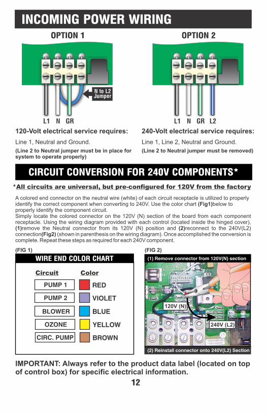
INCOMING POWER WIRING
120-Volt electrical service requires:
Line 1, Neutral and Ground.
(Line 2 to Neutral jumper must be in place for system to operate properly)
240-Volt electrical service requires:
Line 1, Line 2, Neutral and Ground.
(Line 2 to Neutral jumper must be removed)
L1 N GR L1 N GR L2
N to L2Jumper
OPTION 1 OPTION 2
IMPORTANT: Always refer to the product data label (located on top of control box) for specific electrical information.
12
See illustration and instructions below for converting the universal circuits of your control. Each Colored connectors are utilized to help identify each circuit (please see color chart below). Simply locate the colored connector on the Neutral (white) wire from each components receptacle. Using the wiring diagram provided with each control (located inside the hinged cover), (1)remove the Neutral connector from its 120V / Neutral position and (2)reconnect to the 240V / Line 2 connection (shown in parenthesis on the wiring diagram). Once accomplished the conversion is complete. Repeat these steps as required for each 240V component.
PUMP 1
PUMP 2
RED
VIOLET
BLOWER BLUE
OZONE
CIRC. PUMP
YELLOW
BROWN
Circuit Color
!! IMPORTANT !! All Circuits are Universal
120V (N)
240V (L2)
(2) Reinstall connector onto 240V(L2) Section
(1) Remove connector from 120V(N) section
120V (N)
240V (L2)
CIRCUIT CONVERSION FOR 240V COMPONENTS*
*All circuits are universal, but pre-configured for 120V from the factory
WIRE END COLOR CHART
A colored end connector on the neutral wire (white) of each circuit receptacle is utilized to properly identify the correct component when converting to 240V. Use the color chart (Fig1)below to properly identify the component circuit.Simply locate the colored connector on the 120V (N) section of the board from each component receptacle. Using the wiring diagram provided with each control (located inside the hinged cover), (1)remove the Neutral connector from its 120V (N) position and (2)reconnect to the 240V(L2) connection(Fig2) (shown in parenthesis on the wiring diagram). Once accomplished the conversion is complete. Repeat these steps as required for each 240V component.
(FIG 1) (FIG 2)
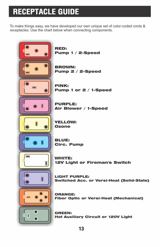
RED:Pump 1 / 2-Speed
BROWN:Pump 2 / 2-Speed
PINK:Pump 1 or 2 / 1-Speed
PURPLE:Air Blower / 1-Speed
YELLOW:Ozone
BLUE:Circ. Pump
WHITE:12V Light or Fireman's Switch
LIGHT PURPLE:Switched Acc. or Versi-Heat (Solid-State)
ORANGE:Fiber Optic or Versi-Heat (Mechanical)
GREEN:Hot Auxiliary Circuit or 120V Light
To make things easy, we have developed our own unique set of color-coded cords & receptacles. Use the chart below when connecting components.
RECEPTACLE GUIDE
13

The "U" Series Fixed Heater and "US" Series Slide Heater systems will arrive from the factory with the heater mounted in the bottom location as pictured in Step 1. The "US" Series Slide Heater can be installed and used in this configuration or you can move the Slide Heater to the back of the control as shown below to align easily with your particular plumbing arrangement.
Step 4
Step 5 Step 6
Step 1 Step 2
Ground/Bond the heater directly to the control box using the included #8 solid bonding wire.
Connect the power control cords from the heater to the matching receptacles on the control box.
Remove the control system from the carton and verify contents for completeness. If the application is a bottom mount installation then you are ready to go directly to step 6.
EZ-AccessHeater Retainer
Adjustable Clamp
If you need to relocate the heater for your installation, simply remove the EZ-Access Heater Retainers and remove the heater from under the box. To utilize the slide brackets, install adjustable stud clamps that are provided in the installation kit to the heater assembly.
Adjustable Clamp
Adjustable Clamp
When the adjustable clamps are mounted to the heater, adjust the stud locations to align with the slide brackets on one end. Do not tighten nuts yet.
Step 3
Align the other studded clamp and attach to the other slide bracket. Now determine the proper alignment for the heater and tighten the nuts and clamps
HEATER INSTALLATION
14
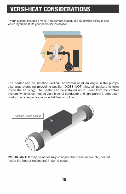
If your system includes a Versi-Heat remote heater, see illustration below to see which layout best fits your particular installation.
The heater can be installed vertical, horizontal or at an angle in the pumps discharge plumbing (providing position DOES NOT allow air pockets to form inside the housing). The heater can be installed up to 5-feet from the control system, which is connected via a black 3-conductor and light purple 3-conductor cord to the receptacles provided at the control box..
IMPORTANT: It may be necessary to adjust the pressure switch (located inside the heater enclosure) in some cases.
Pressure Switch Access
VERSI-HEAT CONSIDERATIONS
15
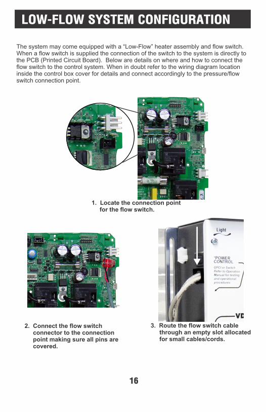
1. Locate the connection point for the flow switch.
2. Connect the flow switch connector to the connection point making sure all pins are covered.
3. Route the flow switch cable through an empty slot allocated for small cables/cords.
The system may come equipped with a “Low-Flow” heater assembly and flow switch. When a flow switch is supplied the connection of the switch to the system is directly to the PCB (Printed Circuit Board). Below are details on where and how to connect the flow switch to the control system. When in doubt refer to the wiring diagram location inside the control box cover for details and connect accordingly to the pressure/flow switch connection point.
LOW-FLOW SYSTEM CONFIGURATION
16
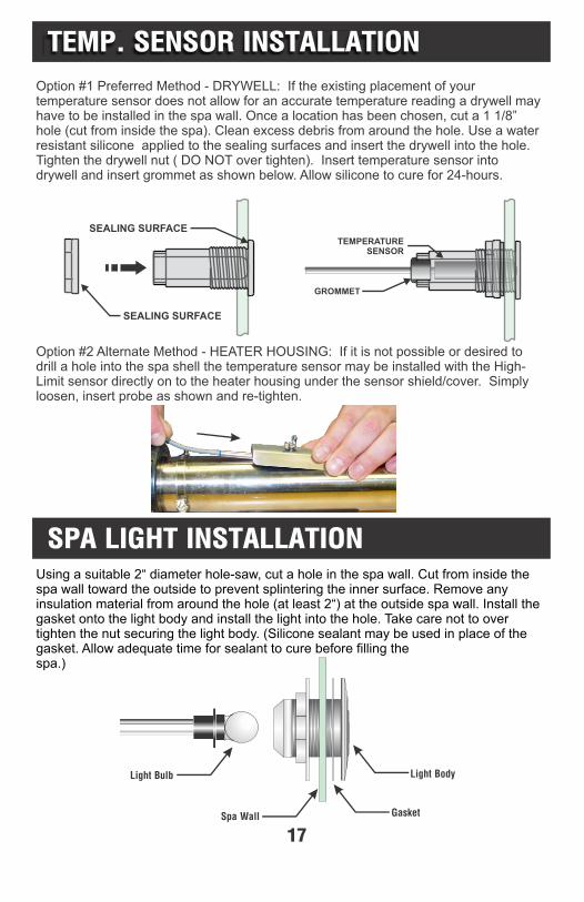
Option #1 Preferred Method - DRYWELL: If the existing placement of your temperature sensor does not allow for an accurate temperature reading a drywell may have to be installed in the spa wall. Once a location has been chosen, cut a 1 1/8” hole (cut from inside the spa). Clean excess debris from around the hole. Use a water resistant silicone applied to the sealing surfaces and insert the drywell into the hole. Tighten the drywell nut ( DO NOT over tighten). Insert temperature sensor into drywell and insert grommet as shown below. Allow silicone to cure for 24-hours.
SEALING SURFACE
SEALING SURFACE
GROMMET
TEMPERATURESENSOR
Using a suitable 2“ diameter hole-saw, cut a hole in the spa wall. Cut from inside the spa wall toward the outside to prevent splintering the inner surface. Remove any insulation material from around the hole (at least 2“) at the outside spa wall. Install the gasket onto the light body and install the light into the hole. Take care not to over tighten the nut securing the light body. (Silicone sealant may be used in place of the gasket. Allow adequate time for sealant to cure before filling the spa.)
Gasket
Light Body
Spa Wall
Light Bulb
TEMP. SENSOR INSTALLATION
SPA LIGHT INSTALLATION
Option #2 Alternate Method - HEATER HOUSING: If it is not possible or desired to drill a hole into the spa shell the temperature sensor may be installed with the High-Limit sensor directly on to the heater housing under the sensor shield/cover. Simply loosen, insert probe as shown and re-tighten.
17
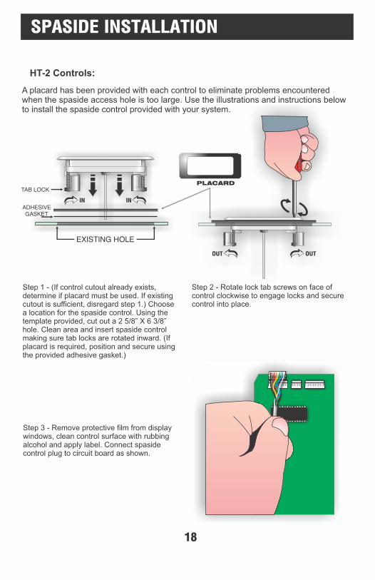
A placard has been provided with each control to eliminate problems encountered when the spaside access hole is too large. Use the illustrations and instructions below to install the spaside control provided with your system.
Step 1 - (If control cutout already exists, determine if placard must be used. If existing cutout is sufficient, disregard step 1.) Choose a location for the spaside control. Using the template provided, cut out a 2 5/8” X 6 3/8” hole. Clean area and insert spaside control making sure tab locks are rotated inward. (If placard is required, position and secure using the provided adhesive gasket.)
Step 2 - Rotate lock tab screws on face of control clockwise to engage locks and secure control into place.
Step 3 - Remove protective film from display windows, clean control surface with rubbing alcohol and apply label. Connect spaside control plug to circuit board as shown.
HT-2 Controls:
IN IN
EXISTING HOLE
PLACARD
OUT OUT
SPASIDE INSTALLATION
TAB LOCK
18
ADHESIVEGASKET
STARTING UP THE SYSTEM
System Startup Procedure:1) It’s required that you read and familiarize yourself with the provided systems operation manual, before attempting to start the system.
2) Inspect that the electrical equipment cover is secure on the pack, and there are no exposed wires, or incomplete work to be performed.
3) Make sure all hose bibs, drain valves, air controls ect are closed. Inspect equipment components, making sure the pump drains plugs, pump and heater unions are tight.
4) For spas equipped with a pressure filter, make sure the housing band, drain plug and air relief valves are closed and tight.
5) Using a garden hose, fill the spa with fresh water to the recommended level by the spa manufacturer.
6) If the pumps are equipped with strainer pots, remove the lid and continue to fill each pump pot completely. Make sure the basket is free of debris, and the o-ring is clean and lubricated before replacing lid.
7) Open all service shut-off valves to allow 100% water flow between the spa and equipment. Once again inspect all glued plumbing connections, unions and equipment for water leaks.
8) Power system on, and immediately test the Ground Fault Circuit Interrupter (GFCI) breakers for proper operation, according to the manufacturer’s instruction, Typically this is done by pressing the “test” button.
WARNING: If the breaker fails to trip to the off position when the button is pushed (not operating to manufactures test protocol) STOP ALL TESTING!, and place the breaker in the off position manually. DO NOT ATTEMPT SYSTEM OPERATION and consult your electrician before proceeding.
9) Once GFCI testing is confirmed, proceed to prime the main pump by pressing the “Jet” button for high speed operation. Allow pump to run until the plumbing lines have cleared the trapped air, and a steady water flow is achieved.
10) Follow this same priming and air purge procedure for optional pumps #2 and #3 if connected.
11) Once all pumps are purged and operating. Once again check for leaks.
12) Test system blower and light by pressing the identified spaside buttons.
*Refer to the troubleshooting guide in this manual if these components fail to operate
19
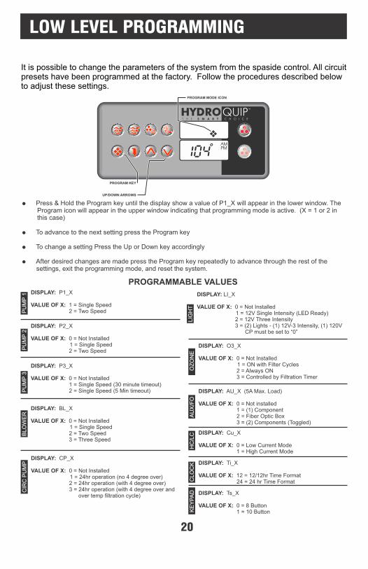
It is possible to change the parameters of the system from the spaside control. All circuit presets have been programmed at the factory. Follow the procedures described below to adjust these settings.
PROGRAM KEY
UP/DOWN ARROWS
PROGRAM MODE ICON
2
3
PU
MP
1
Press & Hold the Program key until the display show a value of P1_X will appear in the lower window. The Program icon will appear in the upper window indicating that programming mode is active. (X = 1 or 2 in this case)
To advance to the next setting press the Program key
To change a setting Press the Up or Down key accordingly
After desired changes are made press the Program key repeatedly to advance through the rest of the settings, exit the programming mode, and reset the system.
DISPLAY: P1_X
VALUE OF X: 1 = Single Speed 2 = Two Speed
DISPLAY: P2_X
VALUE OF X: 0 = Not Installed 1 = Single Speed 2 = Two Speed
DISPLAY: P3_X
VALUE OF X: 0 = Not Installed 1 = Single Speed (30 minute timeout) 2 = Single Speed (5 Min timeout)
DISPLAY: BL_X
VALUE OF X: 0 = Not Installed 1 = Single Speed 2 = Two Speed 3 = Three Speed
DISPLAY: LI_X
VALUE OF X: 0 = Not Installed 1 = 12V Single Intensity (LED Ready) 2 = 12V Three Intensity 3 = (2) Lights - (1) 12V-3 Intensity, (1) 120V CP must be set to “0”
PU
MP
2P
UM
P 3
BLO
WE
R
LIG
HT
DISPLAY: O3_X
VALUE OF X: 0 = Not Installed 1 = ON with Filter Cycles 2 = Always ON 3 = Controlled by Filtration Timer
OZ
ON
E
DISPLAY: CP_X
VALUE OF X: 0 = Not Installed 1 = 24hr operation (no 4 degree over) 2 = 24hr operation (with 4 degree over) 3 = 24hr operation (with 4 degree over and over temp filtration cycle)
CIR
C P
UM
P
AU
X/F
O
DISPLAY: AU_X (5A Max. Load)
VALUE OF X: 0 = Not installed 1 = (1) Component 2 = Fiber Optic Box 3 = (2) Components (Toggled)
HC
/LC DISPLAY: Cu_X
VALUE OF X: 0 = Low Current Mode 1 = High Current Mode
CLO
CK DISPLAY: Ti_X
VALUE OF X: 12 = 12/12hr Time Format 24 = 24 hr Time Format
KE
YP
AD DISPLAY: Ts_X
VALUE OF X: 0 = 8 Button 1 = 10 Button
PROGRAMMABLE VALUES
LOW LEVEL PROGRAMMING
20

1 2
3
YOUR SPASIDE CONTROL
PUMP 2 ICONHEATER ON ICON
PUMP 1 ICONLIGHT/ENTER KEY
PROGRAM KEYECONOMY/NORMAL
MODE KEYUP/DOWN ARROWS
LCD WINDOWSFILTERING ICON
TEMPERATURE SET ICONECONOMY MODE ICON
BLOWER/LIST KEYPUMP 2 KEYPUMP 1 KEY
AIR BLOWER ICONPROGRAM MODE ICONLIGHT ON ICON
Default System Operation: When power is applied, or there is a temporary loss of power, the system will initiate its default programming. The filter cycle will begin 24-hours after the system has been powered up. The filtration cycle will be active for 1-hour and will repeat every 24-hours. The temperature will be maintained at 95BF.
Pump 1 Key: Press this key once to turn Pump 1 on. A second press will turn it off. For dual speed pump operation; Press this key once to turn Pump 1 onto Low speed, press this key a second time to turn Pump 1 onto High speed, a third press will turn the pump off. A built-in timer will shut the pump off after 20 minutes of operation unless done so manually. The Pump 1 Icon will appear on the LCD while the pump is running in High speed and flash while it is in Low speed. If the filter icon appears, a filtration cycle has begun and you will not be able to turn the pump off.
Pump 2 Key: Press this key once to turn Pump 2 on. A second press will turn it off. For dual speed pump operation; Press this key once to turn Pump 2 onto Low speed, press this key a second time to turn Pump 2 onto High speed, a third press will turn the pump off. A built-in timer will shut the pump off after 20 minutes of operation unless done so manually. The Pump 2 Icon will appear while the pump is running in High speed and flash while it is in Low speed.
AUXILIARY 2 KEYAUXILIARY 3 KEY
21
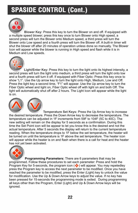
Blower Key: Press this key to turn the Blower on and off. If equipped with a multiple speed blower; press this key once to turn Blower onto High speed, a second press will turn the Blower onto Medium speed, a third press will turn the Blower onto Low speed and a fourth press will turn the Blower off. A built-in timer will shut the blower off after 20 minutes of operation unless done so manually. The Blower Icon will appear while the blower is running in High speed and flash while it is in Medium and Low speeds.
Light/Enter Key: Press this key to turn the light onto its highest intensity, a second press will turn the light onto medium, a third press will turn the light onto low and a fourth press will turn it off. If equipped with Fiber Optic: Press this key once to show “L1”. Use the Up arrow key to turn the light onto High, Medium, Low and Off. Press the light key a second time, “F1” will appear. Use the Up arrow key to turn the Fiber Optic wheel and light on, Fiber Optic wheel off with light on and both Off. The light will automatically shut off after 2 hours. The Light Icon will appear while the light is on.
Temperature Set Keys: Press the Up Arrow key to increase the desired temperature. Press the Down Arrow key to decrease the temperature. The temperature can be adjusted in 1F increments from 59F to 104F (5C to 40C). The new setting will remain on the display for 5 seconds as a confirmation. During this time the Set Point icon will be appear to let you know this is the desired and not the actual temperature. After 5 seconds the display will return to the current temperature reading. When the temperature drops to 1F below the set temperature, the heater will be turned on until the temperature is 1F above the set temperature. The heater icon will appear while the heater is on and flash when there is a call for heat and the heater has not yet been activated.
Programming Parameters: There are 6 parameters that may be programmed. Follow these procedures to set each parameter: Press and hold the Program Key for 5-seconds, the program icon ( ) will appear. You may repetedley press the Program key to access the next parameter to be modified. Once you have reached the parameter to be modified, press the Enter (Light) key to unlock the value for modification. Use the Up & Down Arrow keys to adjust the value. If no key has been pressed for 15-seconds the programming mode is exited. During programming all keys other than the Program, Enter (Light) and Up & Down Arrow keys will be ignored.
1
SPASIDE CONTROL (Cont.)
22
SPASIDE CONTROL - ADDITIONAL FEATURES
Inverted Display: The lower display can be inverted for easy viewing inside or outside the
spa. Press and hold the Economy key for 2 seconds to toggle between inverted and normal
display modes.
Panel Lock: It is possible to lock all of the spaside control keys. Press and hold the Pump 1
key for 5 seconds, “LocF” will appear indicating all the keys have been locked. To unlock
keys, simply press and hold the Pump 1 key for 5 seconds until “Uloc” will appear
indicating the spaside has returned to normal operation.
Temperature Readout (C or F): To change the temperature readout on the display from
fahrenheit to celsius (or visa-versa) simply press & hold the light key for 5 seconds.
Smart Winter Mode: If the system detects ambient conditions below a preset factory
setting, the system will automatically activate the Smart Winter Mode for a period of 24
hours. In this mode, if a pump has not been powered in the last 2 hours, the system will turn
it on for one minute to prevent freezing. The Filter Mode light indicator will flash while the
pump is running in this mode. Note: If you notice the pump coming on every 2 hours
this is the most likely cause. This will continue for a 24-hour period. This is normal
and is the Systems protection against freezing.
Over Heat Protection: If the water temperature exceeds 112F at the Temperature sensor OH will appear below the temperature display and the heater as well as all other outputs will shut off until water temp drops below 108F. If the spa water temperature does not seem to be elevated, the error indication may have been caused by poor water flow or electrical line interference (thunder storms, voltage surges, etc.). Simply reset and monitor the system.
Over Temperature Protection: If the water temperature exceeds 119F at the Temperature sensor HL will appear below the temperature display and the heater as well as all other outputs will shut off. After the water has cooled down power to the spa must be cycled off then on to reset the system. If the spa water temperature does not seem to be elevated, the error indication may have been caused by poor water flow or electrical line interference (thunder storms, voltage surges, etc.). Simply reset and monitor the system. Power-Up Detection: Upon first powering the system or if a power outage occurs, the display will flash until a key is pressed. This feature also lets the user know there has been a power failure.
23

Time of Day: This is the first parameter and will appear with the hour flashing. Use the Up
or Down Arrow keys to adjust the hour from 00: to 11:. Press the Program key again to
adjust minutes, use the Up or Down Arrow keys to adjust the minutes from :00 to :59. Press
the Program key to confirm the new setting and move to the next parameter to be
programmed.
AM (Morning) Filter Cycle Start Time: (”Fon1”) appears in the display. Press the Light button
to access the value. Use the Up/Down Arrow keys to adjust the hour from 00 to 11. Press the
Program key again and set the minutes using the Up/Down Arrow keys from 00 to 59. Press the
Program key to confirm the new setting and move to the next parameter to be programmed.
AM (Morning) Filter Cycle Duration: (”Fdu1”) appears in the display. Press the Light
button to access the value. Use the Up/Down Arrow keys to adjust from OFF to 12. Press
the Program key to confirm the new setting and move to the next parameter to be
programmed.
PM (Evening) Filter Cycle Start Time: (”Fon2”) appears in the display. Press the Light
button to access the value. Use the Up/Down Arrow keys to adjust the hour from 12 to 23.
Press the Program key again and set the minutes using the Up/Down Arrow keys from 00 to
59. Press the Program key to confirm the new setting and move to the next parameter to be
programmed.
PM (Evening) Filter Cycle Duration: (”Fdu2”) appears in the display. Press the Light button
to access the value. Use the Up/Down Arrow keys to adjust from OFF to 12. Press the
Program key to confirm the new setting and move to the next parameter to be programmed.
FILTER CYCLE PROGRAMMING
To Access & Adjust “Standard Programming”:
Press and hold the Program key for approximately 5-seconds. The “Program” icon will appear.
The first parameter is the time setting. The time will appear with the hour flashing
Press the Light/Enter Key to unlock the value for modification.
Use the Up & Down Arrow keys to increase or decrease the setting.
Once the desired setting has been achieved, press the Program key to save the change and move onto the next parameter. (See settings below)
24

ECONOMY MODE PROGRAMMING
Economy Mode: A user activated feature that can potentially save energy by causing the system to maintain a temperature of 20F below the user programmed set temperature during peak hours or when the spa is not in use.
Pressing this key displays the current Economy setting and allows you to adjust energy saving features built-in to your control.
Standard/Start-Up Mode: The first press will show "no EC". The system will maintain the spa water to the desired set temperature without restriction 24 hours a day. For use at start-up, and by the user that wishes to have their spa
ready at all times.
Vacation/Travel Mode: A second press will display "EC1". This mode causes Economy mode to be active 24hrs a day.
For the cost conscious traveler or when spa is rarely used. Allow several hours for spa to heat when using this mode.
Daytime/Peak Hour Mode: A third press will display "EC2" and activate the daytime/peak hour mode. Economy mode will be active between the hours of 10:00AM and 6:00PM.
Use to avoid peak electrical energy costs.
Nighttime Mode: A fourth press will display "EC3" and activate the nighttime mode. Economy mode will be active between the hours 11:00PM to 8:00AM.
For the user that does not wish to heat their spa during the nighttime hours.
Max Economy Mode: A fourth press will display "EC4" and activate the Max Economy mode. "Max" economy mode is a combination of EC2 & EC3. Economy mode is active between 10:00AM-6:00PM and 11:00PM-8:00AM. Use to avoid peak electrical energy cost for both daytime and
nighttime.
These settings are manual settings and must be activated and deactivated by pressing the economy key. The settings will be retained in system memory in the event of a power outage.
25
ERROR INDICATION
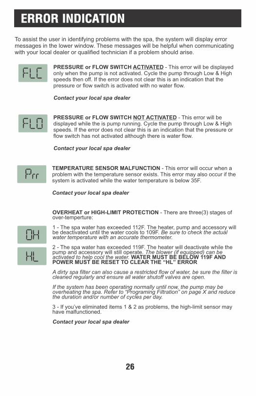
To assist the user in identifying problems with the spa, the system will display error messages in the lower window. These messages will be helpful when communicating with your local dealer or qualified technician if a problem should arise.
PRESSURE or FLOW SWITCH ACTIVATED - This error will be displayed only when the pump is not activated. Cycle the pump through Low & High speeds then off. If the error does not clear this is an indication that the pressure or flow switch is activated with no water flow.
Contact your local spa dealer
PRESSURE or FLOW SWITCH NOT ACTIVATED - This error will be displayed while the is pump running. Cycle the pump through Low & High speeds. If the error does not clear this is an indication that the pressure or flow switch has not activated although there is water flow.
Contact your local spa dealer
TEMPERATURE SENSOR MALFUNCTION - This error will occur when a problem with the temperature sensor exists. This error may also occur if the system is activated while the water temperature is below 35F.
Contact your local spa dealer
OVERHEAT or HIGH-LIMIT PROTECTION - There are three(3) stages of over-temperture:
1 - The spa water has exceeded 112F. The heater, pump and accessory will be deactivated until the water cools to 109F. Be sure to check the actual water temperature with an accurate thermometer.
2 - The spa water has exceeded 119F. The heater will deactivate while the pump and accessory will still operate. The blower (if equipped) can be activated to help cool the water. WATER MUST BE BELOW 119F AND POWER MUST BE RESET TO CLEAR THE “HL” ERROR
A dirty spa filter can also cause a restricted flow of water, be sure the filter is cleaned regularly and ensure all water shutoff valves are open.
If the system has been operating normally until now, the pump may be overheating the spa. Refer to “Programing Filtration” on page X and reduce the duration and/or number of cycles per day.
3 - If you’ve eliminated items 1 & 2 as problems, the high-limit sensor may have malfunctioned.
Contact your local spa dealer
26
ERROR INDICATION (Cont.)
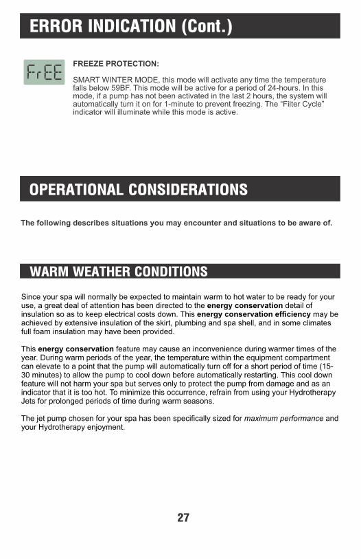
FREEZE PROTECTION:
SMART WINTER MODE, this mode will activate any time the temperature falls below 59BF. This mode will be active for a period of 24-hours. In this mode, if a pump has not been activated in the last 2 hours, the system will automatically turn it on for 1-minute to prevent freezing. The “Filter Cycle” indicator will illuminate while this mode is active.
OPERATIONAL CONSIDERATIONS
WARM WEATHER CONDITIONS
The following describes situations you may encounter and situations to be aware of.
Since your spa will normally be expected to maintain warm to hot water to be ready for your use, a great deal of attention has been directed to the energy conservation detail of insulation so as to keep electrical costs down. This energy conservation efficiency may be achieved by extensive insulation of the skirt, plumbing and spa shell, and in some climates full foam insulation may have been provided.
This energy conservation feature may cause an inconvenience during warmer times of the year. During warm periods of the year, the temperature within the equipment compartment can elevate to a point that the pump will automatically turn off for a short period of time (15-30 minutes) to allow the pump to cool down before automatically restarting. This cool down feature will not harm your spa but serves only to protect the pump from damage and as an indicator that it is too hot. To minimize this occurrence, refrain from using your Hydrotherapy Jets for prolonged periods of time during warm seasons.
The jet pump chosen for your spa has been specifically sized for maximum performance and your Hydrotherapy enjoyment.
27
CHEMICAL WATER TREATMENT
Your dealer is familiar with local water conditions and which chemicals are compatible with the water and are designed specifically for your spa. This is the best person to advise you on proper water quality management. The one thing you can do to insure years of trouble free equipment operation is to maintain proper water chemistry.Two basic goals of the chemical water treatment are sanitizing and balancing the water.Sanitizing simply means keeping the water free from living microorganisms including algae, bacteria and viruses. The current most popular chemicals for sanitizing include chlorine, bromine and ozone.Balancing water means establishing a balance among pH, total alkalinity and total hardness. Water that is unbalanced can corrode the spa and it's support equipment or leave deposits of minerals. Properly balanced water is essential to allow the sanitizing chemical to work effectively. There are numerous chemical additives to help you in controlling pH, total hardness and total alkalinity. NEVER use softened water when filling your spa. Softened water is extremely corrosive to the metal parts of the spa equipment and may lead to an unforeseen failure.Sometimes, despite your most diligent efforts, your water may become too far out of balance to be managed chemically. At this point it is probably better to drain and clean the spa and start over with fresh water.Equipment failure caused by improper water chemistry will not be covered under warranty.
FILTRATION SYSTEM
Please refer to your Spa Manufacturer's owner's manual regarding the operation, maintenance and cleaning of your filtration system.
Dirty or clogged filters can cause flow restrictions and you may experience difficulty in reaching and/or maintaining desired heat levels.
WINTERIZING
When freezing weather and/or power losses are expected, contact your local spa dealer for freeze protection or winterizing recommendations for both the spa and the equipment system. Freeze related damage is not covered by the warranty.
28
NO JETS OR BLOWER OPERATION
Blower or Pump Not Plugged-In - Plug in the Blower or Pump.Over-Temperature Protection On - Refer to page 26
NO THERAPY JET OPERATION
Water Shut-Off Valves are Closed - Open Shut-Off valves.Dirty Filter - Clean or replace filter.Jets Not Properly Adjusted - Adjust JetsDiverter Valve Not Properly Adjusted - Adjust diverter valveThermal Overload Tripping - Check for restricted flow of water.Over-Temperature Protection On - Refer to page 26
NO LOW SPEED PUMP OPERATION
Low Level Programming Incorrect - Contact your local dealer.Over-Temperature Protection On - Refer to page 26Pump Not Plugged-In - Plug in the Pump.
NO, LOW OR SURGING WATER FLOW
Air Lock in Plumbing System - “Bleed” the system.Restricted Flow - Insure that the water shut-off valves are open and that suction fittings
are not blocked by debris.Dirty Filter - Clean or replace filter.Low Water Level - Increase water level to recommended level.
TROUBLESHOOTING
NOTHING OPERATES
The following describes situations and possible solutions to common problems you may encounter as a spa owner.
Main Breaker is OFF - Set to On.Sub-Panel Breaker Off - Set to On.Power switch in Off position - Set to On.Component(s) not plugged in - Plug in components.Power cord not plugged in - Plug in power cord.Over-Temperature Protection On - Refer to page 26
29
HIGH HEAT
Temperature Sensor Not in Dry-Well - Place sensor in dry-well.Temperature Set Too High - Adjust Set Point.High Ambient Temperature - Remove spa cover.
GFCI TRIPS OCCASIONALLY
Lightning or Electrical Storm, Power Surge, Extremely Humid Conditions, or Radio Frequency Interference - Reset GFCI. NOTE: GFCI must be properly grounded and bonded.
GFCI TRIPS IMMEDIATELY
Defective Component - Contact a qualified service technician or the factory for assistance.
Light Bulb Defective - Replace bulb or contact your local dealer.Reflector has Fallen Off - Replace reflector or contact your local dealer.Light Not Plugged-In - Plug in the Light.
NO LIGHT OPERATION
WATER LEAKS
Spa Overfilled - Adjust water level.Too Many People in the Spa - Adjust water level.Drain-Valve Left Open - Close drain valve.Couplings or Unions Loose - Tighten or contact your local dealer.Pump Seal Leaking - Contact your local dealer.Plumbing Connections Leaking - Contact your local dealer.Water Leaking from Spaside Control - Contact your local dealer.Water in Air Blower Plumbing - Contact your local dealer.
NO HEAT
Temperature Not Set Correctly - Adjust Set Point.Over-Temperature Protection On - Refer tp page 26Current Limiting On - 120V Systems will not heat if High-Speed or Blower is on. Contact your local dealer. No Power - Reset breaker at service panel.Low Water Flow - Clean or Replace filter.Pressure Switch Not Adjusted Properly - Contact a qualified technician.
30
If your system is equipped with a pressure switch, the function of the pressure switch is to turn the heater off if the pump stops operating or if there is a restricted water flow (dirty filter, obstruction in the spa plumbing etc.).
The pressure switch has been preset at the factory to operate properly with your spas specific plumbing. Adjustment or other service may be required if you observe a flow related problem (FLO or FLC on spaside display). If adjustment is required, follow the next steps carefully.
IMPORTANT: After any pressure switch adjustment, it is important to test the control by turning on the pump low speed and heater. While operating, unplug the pump, the heater must turn off. If the heater stays on, plug the pump back in and readjust the pressure switch to achieve proper operation.
1) With power to system turned OFF, remove the wires from the pressure switch terminals (secure wires safely to prevent any chance of electrical shock).
2) Use temperature adjustment key to move “set point” temperature to its lowest setting.
3) Turn power to the system ON and activate the low-speed pump.
4) Place an Ohmmeter across the pressure switch terminals to verify an OPEN circuit.
5) Rotate the pressure switch adjustment screw counter-clockwise until the Ohmmeter indicates a CLOSED circuit.
6) Turn pump OFF and verify that the pressure switch circuit is once again OPEN.
7) Turn power to the system OFF and reconnect pressure switch wires. Reapply power to the system and operate the spa or hot tub as normal.
Adjustment
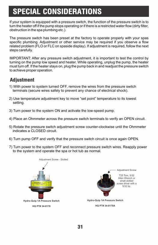
SPECIAL CONSIDERATIONS
Hydro-Quip 1A Pressure Switch
HQ PT# 34-0178
Adjustment Screw - Slotted
Hydro-Quip 1A Pressure Switch
HQ PT# 34-0178A
Adjustment Screw
T25 Torx, 5/32 Allen Wrench or
small slotted screw driver with a
5/32 tip.
31
SYSTEM DATA LABEL
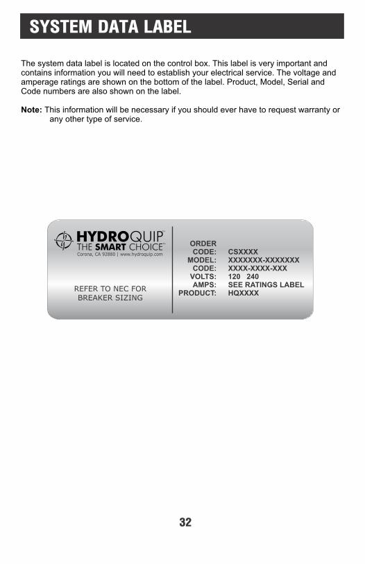
The system data label is located on the control box. This label is very important and contains information you will need to establish your electrical service. The voltage and amperage ratings are shown on the bottom of the label. Product, Model, Serial and Code numbers are also shown on the label.
Note: This information will be necessary if you should ever have to request warranty or any other type of service.
Corona, CA 92880 | www.hydroquip.com
REFER TO NEC FORBREAKER SIZING
ORDER CODE:
MODEL:CODE:
VOLTS: AMPS:
PRODUCT:
CSXXXXXXXXXXX-XXXXXXXXXXX-XXXX-XXX120 240SEE RATINGS LABELHQXXXX
32
WARRANTY INFORMATION
33
Hydro-Quip warrants its products to the original purchaser to be free from defects in material and workmanship for a period of 1 year (12 months) from the original date of purchase, except as noted below.
Products which become defective within the warranty period will be repaired or replaced (at the option of Hydro-Quip) except for damage due to freezing, water chemistry, negligence, abuse, misuse, misapplication, unauthorized modification, improper installation, normal wear and tear or chemical attack.
This warranty extends only to normal, personal (non-commercial) usage by the original purchaser. Pump seals, o-rings, gaskets, air blower brushes are only covered for 90 days from original date of purchase.
Hydro-Quip will not be responsible for labor incurred in removing, inspecting or reinstalling of warrantable products. Hydro-Quip will not be responsible for any travel related charges or labor costs attributable to disassembly and reassembly of the spa, skirt, decking or any other materials enclosing the product, or attributable to difficulties in gaining access to the product.
Hydro-Quip will not be responsible for labor incurred for routine maintenance, adjustments or alterations to the calibration of electrical devices.
Any products which are claimed to be defective must be shipped freight prepaid to Hydro-Quip and the repaired or replaced product will be returned to the sender freight collect. When sent to Hydro-Quip, the product must be accompanied by the sales receipt or other proof of the purchase date as well as the sender's name, mailing address, daytime phone number and a detailed description of the defect as well as any other information relating to this claim.
Unless state law expressly provides otherwise, Hydro-Quip will only be responsible for repair or replacement of any of its products that are found to be defective as provided above, and will not bear the cost of any consequential damages. This warranty gives you specific legal rights but you may have other rights which vary from state to state.

Dealer:
Contact:
Address:
City:
Phone:
State: Zip:
Date of Install:
Notes:
NOTES
Use this section to jot down any information you may need at a later date.
34


85-0066-A Rev 13 01/15


![[XLS]admapps.defesa.ptadmapps.defesa.pt/app_docs/entidadesconvencionadas/admen... · Web view9700 9700 9700 9700 9700 9900 9560 9560 9560 9630 9500 9500 9500 9500 9500 9500 9500 9500](https://img.pdfslide.net/doc/110x75/5bf6f08e09d3f279228ce4e7/xls-web-view9700-9700-9700-9700-9700-9900-9560-9560-9560-9630-9500-9500-9500.jpg)