Embed Size (px)
Citation preview
970M Pro3970M Pro3970M Pro3970M Pro3
Version 1.0
Published January 2015
Copyright©2015 ASRock INC. All rights reserved.
Copyright Notice:
No part of this documentation may be reproduced, transcribed, transmitted, or translated in any language, in any form or by any means, except duplication of documentation by the purchaser for backup purpose, without written consent of ASRock Inc.
Products and corporate names appearing in this documentation may or may not be registered trademarks or copyrights of their respective companies, and are used only for identiication or explanation and to the owners’ beneit, without intent to
infringe.
Disclaimer:
Speciications and information contained in this documentation are furnished for informational use only and subject to change without notice, and should not be constructed as a commitment by ASRock. ASRock assumes no responsibility for any errors or omissions that may appear in this documentation.
With respect to the contents of this documentation, ASRock does not provide warranty of any kind, either expressed or implied, including but not limited to the implied warranties or conditions of merchantability or itness for a particular purpose.
In no event shall ASRock, its directors, oicers, employees, or agents be liable for any indirect, special, incidental, or consequential damages (including damages for loss of proits, loss of business, loss of data, interruption of business and the like), even if ASRock has been advised of the possibility of such damages arising from any defect or error in the documentation or product.
his device complies with Part 15 of the FCC Rules. Operation is subject to the following two conditions: (1) this device may not cause harmful interference, and (2) this device must accept any interference received, including interference that
may cause undesired operation.
CALIFORNIA, USA ONLYhe Lithium battery adopted on this motherboard contains Perchlorate, a toxic substance controlled in Perchlorate Best Management Practices (BMP) regulations passed by the California Legislature. When you discard the Lithium battery in California, USA, please follow the related regulations in advance.“Perchlorate Material-special handling may apply, see www.dtsc.ca.gov/hazardouswaste/perchlorate”
ASRock Website: http://www.asrock.com
Contents
Chapter 1 Introduction 1
1.1 Package Contents 1
1.2 Speciications 2
1.3 Motherboard Layout 6
1.4 I/O Panel 8
Chapter 2 Installation 10
2.1 Installing the CPU 11
2.2 Installing the CPU Fan and Heatsink 13
2.3 Installing Memory Modules (DIMM) 14
2.4 Expansion Slots (PCI and PCI Express Slots) 16
2.5 Jumpers Setup 17
2.6 Onboard Headers and Connectors 18
2.7 CrossFireXTM
and Quad CrossFireXTM
Operation Guide 22
2.7.1 Installing Two CrossFireXTM
-Ready Graphics Cards 22
2.7.2 Driver Installation and Setup 24
Chapter 3 Software and Utilities Operation 25
3.1 Installing Drivers 25
3.2 ASRock EXTREME TUNING UTILITY 26
3.3 ASRock APP Shop 31
3.3.1 UI Overview 31
3.3.2 Apps 32
3.3.3 BIOS & Drivers 35
3.3.4 Setting 36
3.4 Start8 37
Chapter 4 UEFI SETUP UTILITY 40
4.1 Introduction 40
4.1.1 UEFI Menu Bar 40
4.1.2 Navigation Keys 41
4.2 Main Screen 42
4.3 OC Tweaker Screen 43
4.4 Advanced Screen 47
4.4.1 CPU Coniguration 48
4.4.2 North Bridge Coniguration 50
4.4.3 South Bridge Coniguration 51
4.4.4 Storage Coniguration 52
4.4.5 Super IO Coniguration 54
4.4.6 ACPI Coniguration 55
4.4.7 USB Coniguration 57
4.4.8 Trusted Computing 58
4.5 Tools 59
4.6 Hardware Health Event Monitoring Screen 62
4.7 Boot Screen 63
4.8 Security Screen 66
4.9 Exit Screen 67
970M Pro3
1
En
gli
sh
Chapter 1 Introduction
hank you for purchasing ASRock 970M Pro3 motherboard, a reliable motherboard
produced under ASRock’s consistently stringent quality control. It delivers excellent
performance with robust design conforming to ASRock’s commitment to quality
and endurance.
In this manual, Chapter 1 and 2 contains the introduction of the motherboard
and step-by-step installation guides. Chapter 3 contains the operation guide of the
sotware and utilities. Chapter 4 contains the coniguration guide of the BIOS setup.
1.1 Package Contents
• ASRock 970M Pro3 Motherboard (Micro ATX Form Factor)
• ASRock 970M Pro3 Quick Installation Guide
• ASRock 970M Pro3 Support CD
• 2 x Serial ATA (SATA) Data Cables (Optional)
• 1 x I/O Panel Shield
Because the motherboard speciications and the BIOS sotware might be updated, the
content of this manual will be subject to change without notice. In case any modiica-
tions of this manual occur, the updated version will be available on ASRock’s website
without further notice. If you require technical support related to this motherboard,
please visit our website for speciic information about the model you are using. You
may ind the latest VGA cards and CPU support list on ASRock’s website as well.
ASRock website http://www.asrock.com.
2
En
glish
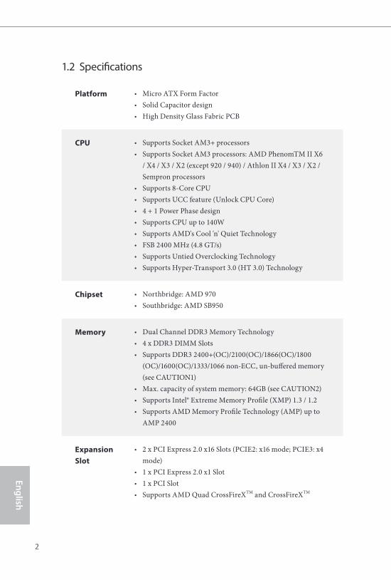
1.2 Speciications
Platform • Micro ATX Form Factor
• Solid Capacitor design
• High Density Glass Fabric PCB
CPU • Supports Socket AM3+ processors
• Supports Socket AM3 processors: AMD PhenomTM II X6
/ X4 / X3 / X2 (except 920 / 940) / Athlon II X4 / X3 / X2 /
Sempron processors
• Supports 8-Core CPU
• Supports UCC feature (Unlock CPU Core)
• 4 + 1 Power Phase design
• Supports CPU up to 140W
• Supports AMD's Cool 'n' Quiet Technology
• FSB 2400 MHz (4.8 GT/s)
• Supports Untied Overclocking Technology
• Supports Hyper-Transport 3.0 (HT 3.0) Technology
Chipset • Northbridge: AMD 970
• Southbridge: AMD SB950
Memory • Dual Channel DDR3 Memory Technology
• 4 x DDR3 DIMM Slots
• Supports DDR3 2400+(OC)/2100(OC)/1866(OC)/1800
(OC)/1600(OC)/1333/1066 non-ECC, un-bufered memory
(see CAUTION1)
• Max. capacity of system memory: 64GB (see CAUTION2)
• Supports Intel® Extreme Memory Proile (XMP) 1.3 / 1.2
• Supports AMD Memory Proile Technology (AMP) up to
AMP 2400
Expansion
Slot
• 2 x PCI Express 2.0 x16 Slots (PCIE2: x16 mode; PCIE3: x4
mode)
• 1 x PCI Express 2.0 x1 Slot
• 1 x PCI Slot
• Supports AMD Quad CrossFireXTM and CrossFireXTM
970M Pro3
3
En
gli
sh
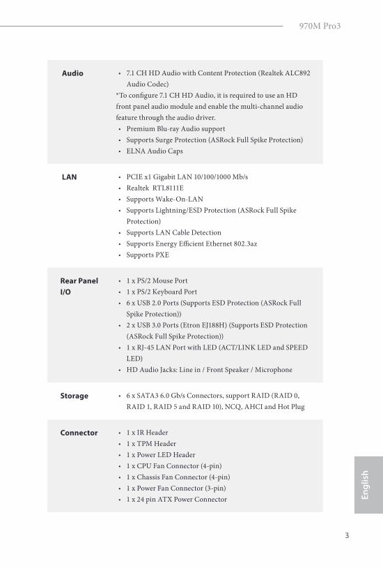
Audio • 7.1 CH HD Audio with Content Protection (Realtek ALC892
Audio Codec)
*To conigure 7.1 CH HD Audio, it is required to use an HD
front panel audio module and enable the multi-channel audio
feature through the audio driver.
• Premium Blu-ray Audio support
• Supports Surge Protection (ASRock Full Spike Protection)
• ELNA Audio Caps
LAN • PCIE x1 Gigabit LAN 10/100/1000 Mb/s
• Realtek RTL8111E
• Supports Wake-On-LAN
• Supports Lightning/ESD Protection (ASRock Full Spike
Protection)
• Supports LAN Cable Detection
• Supports Energy Eicient Ethernet 802.3az
• Supports PXE
Rear Panel
I/O
• 1 x PS/2 Mouse Port
• 1 x PS/2 Keyboard Port
• 6 x USB 2.0 Ports (Supports ESD Protection (ASRock Full
Spike Protection))
• 2 x USB 3.0 Ports (Etron EJ188H) (Supports ESD Protection
(ASRock Full Spike Protection))
• 1 x RJ-45 LAN Port with LED (ACT/LINK LED and SPEED
LED)
• HD Audio Jacks: Line in / Front Speaker / Microphone
Storage • 6 x SATA3 6.0 Gb/s Connectors, support RAID (RAID 0,
RAID 1, RAID 5 and RAID 10), NCQ, AHCI and Hot Plug
Connector • 1 x IR Header
• 1 x TPM Header
• 1 x Power LED Header
• 1 x CPU Fan Connector (4-pin)
• 1 x Chassis Fan Connector (4-pin)
• 1 x Power Fan Connector (3-pin)
• 1 x 24 pin ATX Power Connector
4
En
glish
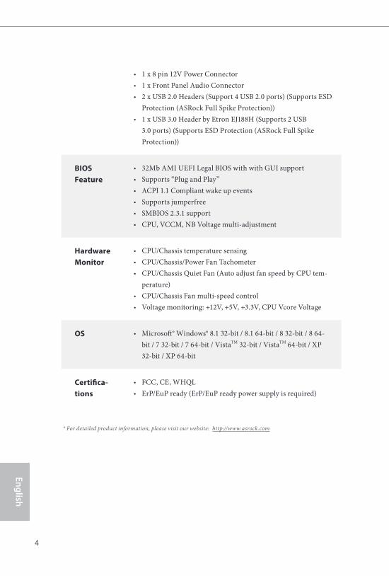
• 1 x 8 pin 12V Power Connector
• 1 x Front Panel Audio Connector
• 2 x USB 2.0 Headers (Support 4 USB 2.0 ports) (Supports ESD
Protection (ASRock Full Spike Protection))
• 1 x USB 3.0 Header by Etron EJ188H (Supports 2 USB
3.0 ports) (Supports ESD Protection (ASRock Full Spike
Protection))
BIOS
Feature
• 32Mb AMI UEFI Legal BIOS with with GUI support
• Supports “Plug and Play”
• ACPI 1.1 Compliant wake up events
• Supports jumperfree
• SMBIOS 2.3.1 support
• CPU, VCCM, NB Voltage multi-adjustment
Hardware
Monitor
• CPU/Chassis temperature sensing
• CPU/Chassis/Power Fan Tachometer
• CPU/Chassis Quiet Fan (Auto adjust fan speed by CPU tem-
perature)
• CPU/Chassis Fan multi-speed control
• Voltage monitoring: +12V, +5V, +3.3V, CPU Vcore Voltage
OS • Microsot® Windows® 8.1 32-bit / 8.1 64-bit / 8 32-bit / 8 64-
bit / 7 32-bit / 7 64-bit / VistaTM 32-bit / VistaTM 64-bit / XP
32-bit / XP 64-bit
Certiica-
tions
• FCC, CE, WHQL
• ErP/EuP ready (ErP/EuP ready power supply is required)
* For detailed product information, please visit our website: http://www.asrock.com
970M Pro3
5
En
gli
sh
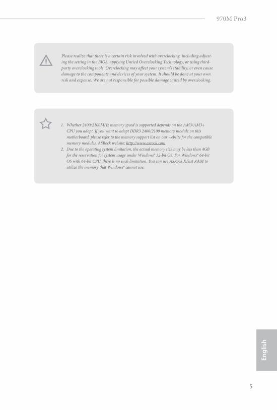
Please realize that there is a certain risk involved with overclocking, including adjust-
ing the setting in the BIOS, applying Untied Overclocking Technology, or using third-
party overclocking tools. Overclocking may afect your system’s stability, or even cause
damage to the components and devices of your system. It should be done at your own
risk and expense. We are not responsible for possible damage caused by overclocking.
1. Whether 2400/2100MHz memory speed is supported depends on the AM3/AM3+
CPU you adopt. If you want to adopt DDR3 2400/2100 memory module on this
motherboard, please refer to the memory support list on our website for the compatible
memory modules. ASRock website: http://www.asrock.com
2. Due to the operating system limitation, the actual memory size may be less than 4GB
for the reservation for system usage under Windows® 32-bit OS. For Windows® 64-bit
OS with 64-bit CPU, there is no such limitation. You can use ASRock XFast RAM to
utilize the memory that Windows® cannot use.
6
En
glish
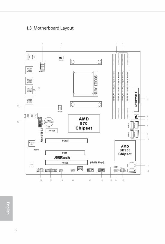
1.3 Motherboard Layout
FS
B8
00
DD
R3
_A
1 (
64
bit
, 2
40
-pin
mo
du
le)
DD
R3
_A
2 (
64
bit
, 2
40
-pin
mo
du
le)
FS
B8
00
DD
R3
_B
1 (
64
bit
, 2
40
-pin
mo
du
le)
DD
R3
_B
2 (
64
bit
, 2
40
-pin
mo
du
le)
AMDSB950
Chipset
32MbBIOS
CMOSBATTERY
CLRCMOS1
1
SuperI/O
PCIE1
HDLED RESET
PLED PWRBTN
1
PANEL 1
SPEAKER11
PCIE2
1
PLED1
PS
2
Mo
us
e
PS
2K
ey
bo
ard
Top:RJ-45
USB 2.0T: USB0B: USB1
RoHS
US
B3
_2
_3
SO
CK
ET
AM
3b
AMD970
Chipset
ATX12V2
USB 2.0T: USB2B: USB3
LAN
USB_8_9
1
To
p:
LIN
E IN
Ce
nte
r:F
RO
NT
Bo
ttom
:M
IC IN
5
6
7
8
9
10
14 131516
11
21 19
2 431
1718
PCIE3
PCI1
USB 2.0T: USB0B: USB1
USB 3.0T: USB0B: USB1
USB_10_11
1 12
22
23
HD_AUDIO1
1
IR1
CPU_FAN1
Fro
nt
US
B 3
.0
SATA3_1
SA
TA
3_
3
SATA3_2
1
PWR_FAN1
CHA_FAN1
SA
TA
3_
5
SA
TA
3_
4S
AT
A3
_6
AudioCODEC
970M Pro3
1
TPMS1
20
970M Pro3
7
En
gli
sh
No. Description
1 ATX 12V Power Connector (ATX12V2)
2 CPU Fan Connector (CPU_FAN1)
3 2 x 240-pin DDR3 DIMM Slots (DDR3_A1, DDR3_B1)
4 2 x 240-pin DDR3 DIMM Slots (DDR3_A2, DDR3_B2)
5 ATX Power Connector (ATXPWR1)
6 Power Fan Connector (PWR_FAN1)
7 SATA3 Connector (SATA3_5)
8 SATA3 Connector (SATA3_6)
9 SATA3 Connector (SATA3_4)
10 SATA3 Connector (SATA3_3)
11 SATA3 Connector (SATA3_1)
12 SATA3 Connector (SATA3_2)
13 System Panel Header (PANEL1)
14 Chassis Speaker Header (SPEAKER1)
15 Power LED Header (PLED1)
16 USB 2.0 Header (USB_8_9)
17 USB 2.0 Header (USB_10_11)
18 Clear CMOS Jumper (CLRCMOS1)
19 Infrared Module Header (IR1)
20 TPM Header (TPMS1)
21 Front Panel Audio Header (HD_AUDIO1)
22 USB 3.0 Header (USB3_2_3)
23 Chassis Fan Connector (CHA_FAN1)
8
En
glish
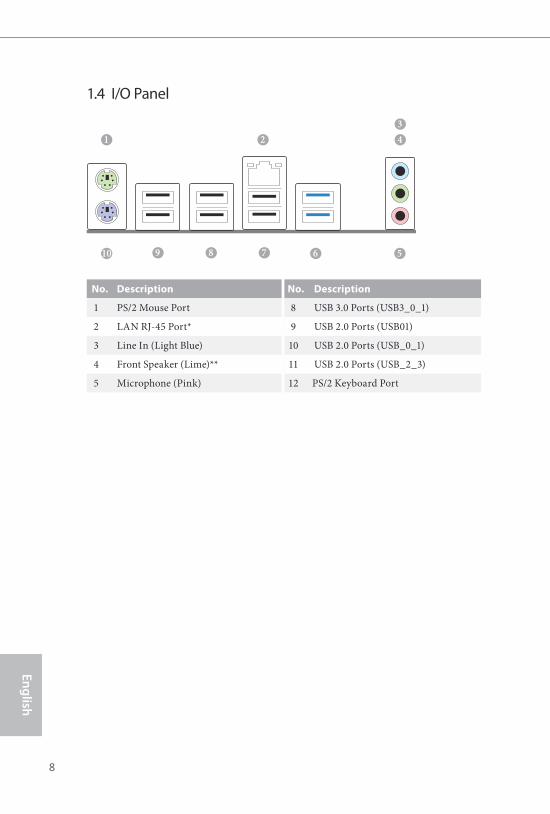
1.4 I/O Panel
No. Description No. Description
1 PS/2 Mouse Port 8 USB 3.0 Ports (USB3_0_1)
2 LAN RJ-45 Port* 9 USB 2.0 Ports (USB01)
3 Line In (Light Blue) 10 USB 2.0 Ports (USB_0_1)
4 Front Speaker (Lime)** 11 USB 2.0 Ports (USB_2_3)
5 Microphone (Pink) 12 PS/2 Keyboard Port
1
9 78 510 6
4
3
2
970M Pro3
9
En
gli
sh
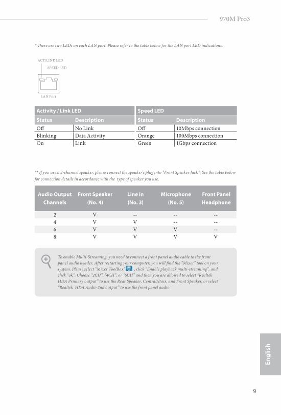
* here are two LEDs on each LAN port. Please refer to the table below for the LAN port LED indications.
Activity / Link LED Speed LED
Status Description Status Description
Of No Link Of 10Mbps connection
Blinking Data Activity Orange 100Mbps connection
On Link Green 1Gbps connection
** If you use a 2-channel speaker, please connect the speaker’s plug into “Front Speaker Jack”. See the table below
for connection details in accordance with the type of speaker you use.
Audio Output
Channels
Front Speaker
(No. 4)
Line in
(No. 3)
Microphone
(No. 5)
Front Panel
Headphone
2 V -- -- --
4 V V -- --
6 V V V --
8 V V V V
To enable Multi-Streaming, you need to connect a front panel audio cable to the front
panel audio header. Ater restarting your computer, you will ind the “Mixer” tool on your
system. Please select “Mixer ToolBox” , click “Enable playback multi-streaming”, and
click “ok”. Choose “2CH”, “4CH”, or “6CH” and then you are allowed to select “Realtek
HDA Primary output” to use the Rear Speaker, Central/Bass, and Front Speaker, or select
“Realtek HDA Audio 2nd output” to use the front panel audio.
ACT/LINK LED
SPEED LED
LAN Port
10
En
glish
his is a Micro ATX form factor motherboard. Before you install the motherboard,
study the coniguration of your chassis to ensure that the motherboard its into it.
Pre-installation Precautions
Take note of the following precautions before you install motherboard components
or change any motherboard settings.
• Make sure to unplug the power cord before installing or removing the motherboard.
Failure to do so may cause physical injuries to you and damages to motherboard
components.
• In order to avoid damage from static electricity to the motherboard’s components,
NEVER place your motherboard directly on a carpet. Also remember to use a grounded
wrist strap or touch a safety grounded object before you handle the components.
• Hold components by the edges and do not touch the ICs.
• Whenever you uninstall any components, place them on a grounded anti-static pad or
in the bag that comes with the components.
• When placing screws to secure the motherboard to the chassis, please do not over-
tighten the screws! Doing so may damage the motherboard.
Chapter 2 Installation
970M Pro3
11
En
gli
sh
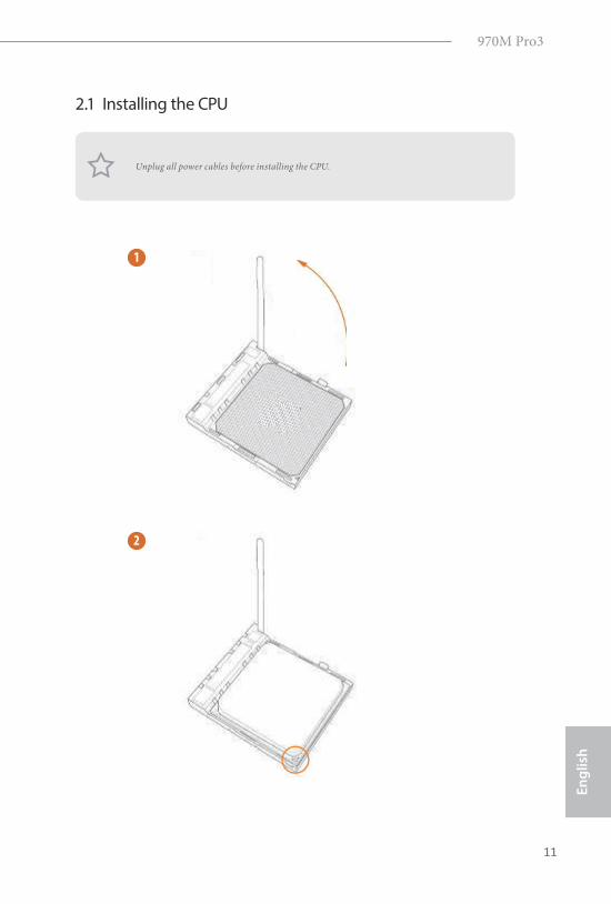
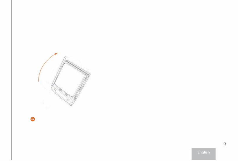
2.1 Installing the CPU
Unplug all power cables before installing the CPU.
2
1
12
English
3
970M Pro3
13
En
gli
sh
2.2 Installing the CPU Fan and Heatsink
Ater you install the CPU into this motherboard, it is necessary to install a larger
heatsink and cooling fan to dissipate heat. You also need to spray thermal grease
between the CPU and the heatsink to improve heat dissipation. Make sure that the
CPU and the heatsink are securely fastened and in good contact with each other.
hen connect the CPU fan to the CPU FAN connector. For proper installation,
please kindly refer to the instruction manuals of the CPU fan and the heatsink.
14
En
glish
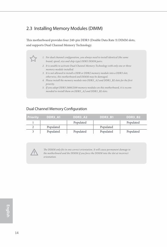
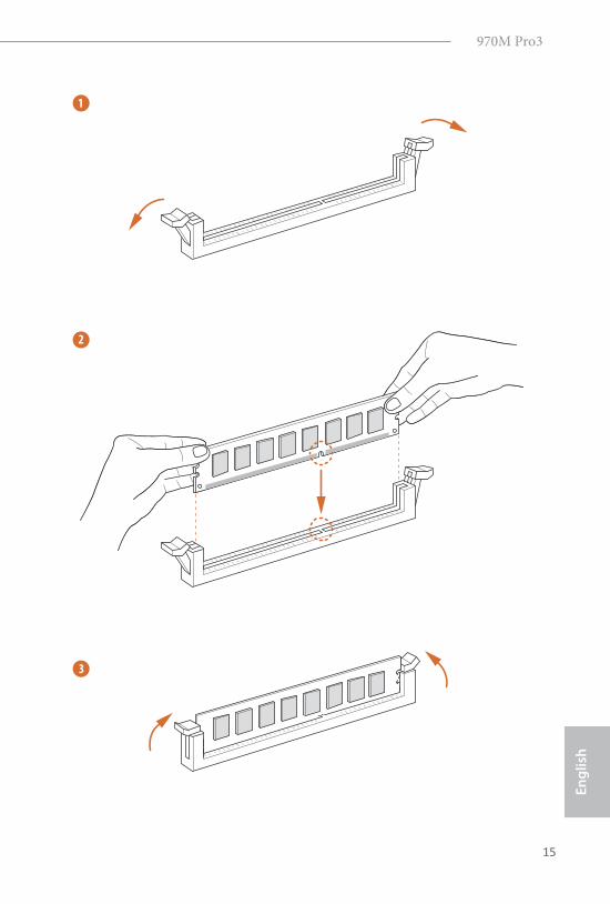
2.3 Installing Memory Modules (DIMM)
his motherboard provides four 240-pin DDR3 (Double Data Rate 3) DIMM slots,
and supports Dual Channel Memory Technology.
Dual Channel Memory Coniguration
he DIMM only its in one correct orientation. It will cause permanent damage to
the motherboard and the DIMM if you force the DIMM into the slot at incorrect
orientation.
Priority DDR3_A1 DDR3_A2 DDR3_B1 DDR3_B2
1 Populated Populated
2 Populated Populated
3 Populated Populated Populated Populated
1. For dual channel coniguration, you always need to install identical (the same
brand, speed, size and chip-type) DDR3 DIMM pairs.
2. It is unable to activate Dual Channel Memory Technology with only one or three
memory module installed.
3. It is not allowed to install a DDR or DDR2 memory module into a DDR3 slot;
otherwise, this motherboard and DIMM may be damaged.
4. Please install the memory module into DDR3_A2 and DDR3_B2 slots for the irst
priority.
5. If you adopt DDR3 2400/2100 memory modules on this motherboard, it is recom-
mended to install them on DDR3_A2 and DDR3_B2 slots.
970M Pro3
15
En
gli
sh
1
2
3
16
En
glish
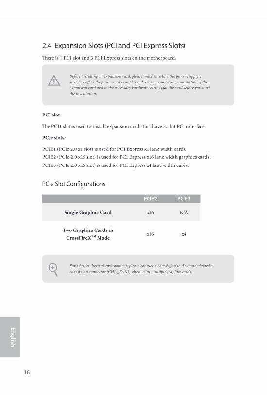
2.4 Expansion Slots (PCI and PCI Express Slots)
here is 1 PCI slot and 3 PCI Express slots on the motherboard.
PCI slot:
he PCI1 slot is used to install expansion cards that have 32-bit PCI interface.
PCIe slots:
PCIE1 (PCIe 2.0 x1 slot) is used for PCI Express x1 lane width cards.
PCIE2 (PCIe 2.0 x16 slot) is used for PCI Express x16 lane width graphics cards.
PCIE3 (PCIe 2.0 x16 slot) is used for PCI Express x4 lane width cards.
PCIe Slot Conigurations
PCIE2 PCIE3
Single Graphics Card x16 N/A
Two Graphics Cards in
CrossFireXTM Modex16 x4
For a better thermal environment, please connect a chassis fan to the motherboard’s
chassis fan connector (CHA_FAN1) when using multiple graphics cards.
Before installing an expansion card, please make sure that the power supply is
switched of or the power cord is unplugged. Please read the documentation of the
expansion card and make necessary hardware settings for the card before you start
the installation.
970M Pro3
17
En
gli
sh
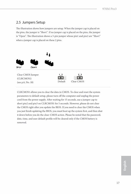
2.5 Jumpers Setup
he illustration shows how jumpers are setup. When the jumper cap is placed on
the pins, the jumper is “Short”. If no jumper cap is placed on the pins, the jumper
is “Open”. he illustration shows a 3-pin jumper whose pin1 and pin2 are “Short”
when a jumper cap is placed on these 2 pins.
Clear CMOS Jumper
(CLRCMOS1)
(see p.6, No. 18)
CLRCMOS1 allows you to clear the data in CMOS. To clear and reset the system
parameters to default setup, please turn of the computer and unplug the power
cord from the power supply. Ater waiting for 15 seconds, use a jumper cap to
short pin2 and pin3 on CLRCMOS1 for 5 seconds. However, please do not clear
the CMOS right ater you update the BIOS. If you need to clear the CMOS when
you just inish updating the BIOS, you must boot up the system irst, and then shut
it down before you do the clear-CMOS action. Please be noted that the password,
date, time, and user default proile will be cleared only if the CMOS battery is
removed.
Clear CMOSDefault
18
En
glish
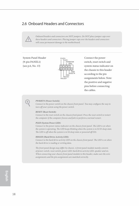
2.6 Onboard Headers and Connectors
System Panel Header
(9-pin PANEL1)
(see p.6, No. 13)
Connect the power
switch, reset switch and
system status indicator on
the chassis to this header
according to the pin
assignments below. Note
the positive and negative
pins before connecting
the cables.
PWRBTN (Power Switch):
Connect to the power switch on the chassis front panel. You may conigure the way to
turn of your system using the power switch.
RESET (Reset Switch):
Connect to the reset switch on the chassis front panel. Press the reset switch to restart
the computer if the computer freezes and fails to perform a normal restart.
PLED (System Power LED):
Connect to the power status indicator on the chassis front panel. he LED is on when
the system is operating. he LED keeps blinking when the system is in S1/S3 sleep state.
he LED is of when the system is in S4 sleep state or powered of (S5).
HDLED (Hard Drive Activity LED):
Connect to the hard drive activity LED on the chassis front panel. he LED is on when
the hard drive is reading or writing data.
he front panel design may difer by chassis. A front panel module mainly consists
of power switch, reset switch, power LED, hard drive activity LED, speaker and etc.
When connecting your chassis front panel module to this header, make sure the wire
assignments and the pin assignments are matched correctly.
Onboard headers and connectors are NOT jumpers. Do NOT place jumper caps over
these headers and connectors. Placing jumper caps over the headers and connectors
will cause permanent damage to the motherboard.
GND
RESET#
PWRBTN#PLED-
PLED+
GNDHDLED-
HDLED+
1
GND
970M Pro3
19
En
gli
sh
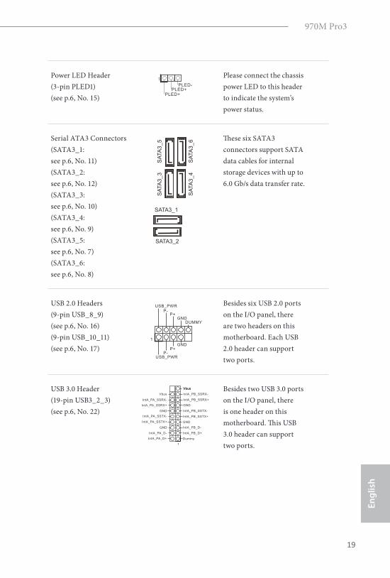
Power LED Header
(3-pin PLED1)
(see p.6, No. 15)
Please connect the chassis
power LED to this header
to indicate the system’s
power status.
Serial ATA3 Connectors
(SATA3_1:
see p.6, No. 11)
(SATA3_2:
see p.6, No. 12)
(SATA3_3:
see p.6, No. 10)
(SATA3_4:
see p.6, No. 9)
(SATA3_5:
see p.6, No. 7)
(SATA3_6:
see p.6, No. 8)
hese six SATA3
connectors support SATA
data cables for internal
storage devices with up to
6.0 Gb/s data transfer rate.
USB 2.0 Headers
(9-pin USB_8_9)
(see p.6, No. 16)
(9-pin USB_10_11)
(see p.6, No. 17)
Besides six USB 2.0 ports
on the I/O panel, there
are two headers on this
motherboard. Each USB
2.0 header can support
two ports.
USB 3.0 Header
(19-pin USB3_2_3)
(see p.6, No. 22)
Besides two USB 3.0 ports
on the I/O panel, there
is one header on this
motherboard. his USB
3.0 header can support
two ports.
1
PLED+PLED+
PLED-
SATA3_1
SA
TA
3_3
SA
TA
3_5
SA
TA
3_4
SA
TA
3_6
SATA3_2
DUMMYGND
GND
P+P-
USB_PWR
P+P-
USB_PWR
1
1
IntA_PB_D+
Dummy
IntA_PB_D-
GND
IntA_PB_SSTX+
GND
IntA_PB_SSTX-
IntA_PB_SSRX+
IntA_PB_SSRX-
VbusVbus
Vbus
IntA_PA_SSRX-
IntA_PA_SSRX+
GND
IntA_PA_SSTX-
IntA_PA_SSTX+
GND
IntA_PA_D-
IntA_PA_D+
20
En
glish
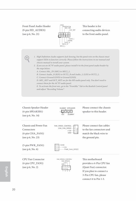
Front Panel Audio Header
(9-pin HD_AUDIO1)
(see p.6, No. 21)
his header is for
connecting audio devices
to the front audio panel.
Chassis Speaker Header
(4-pin SPEAKER1)
(see p.6, No. 14)
Please connect the chassis
speaker to this header.
Chassis and Power Fan
Connectors
(4-pin CHA_FAN1)
(see p.6, No. 23)
(3-pin PWR_FAN1)
(see p.6, No. 6)
Please connect fan cables
to the fan connectors and
match the black wire to
the ground pin.
CPU Fan Connector
(4-pin CPU_FAN1)
(see p.6, No. 2)
his motherboard
provides a 4-Pin CPU fan
(Quiet Fan) connector.
If you plan to connect a
3-Pin CPU fan, please
connect it to Pin 1-3.
1. High Deinition Audio supports Jack Sensing, but the panel wire on the chassis must
support HDA to function correctly. Please follow the instructions in our manual and
chassis manual to install your system.
2. If you use an AC’97 audio panel, please install it to the front panel audio header by
the steps below:
A. Connect Mic_IN (MIC) to MIC2_L.
B. Connect Audio_R (RIN) to OUT2_R and Audio_L (LIN) to OUT2_L.
C. Connect Ground (GND) to Ground (GND).
D. MIC_RET and OUT_RET are for the HD audio panel only. You don’t need to
connect them for the AC’97 audio panel.
E. To activate the front mic, go to the “FrontMic” Tab in the Realtek Control panel
and adjust “Recording Volume”.
GND
+12V
CHA_FAN_SPEED
FAN_SPEED_CONTROL
FAN_SPEED
FAN_SPEED_CONTROL
GND+12V
1 2 3 4
J _ S E N S E
O U T 2 _ L
1
MIC_RETPRESENCE#
GND
OUT2_RMIC2_R
MIC2_L
OUT_RET
1
+5V
DUMMY
DUMMY
SPEAKER
970M Pro3
21
En
gli
sh
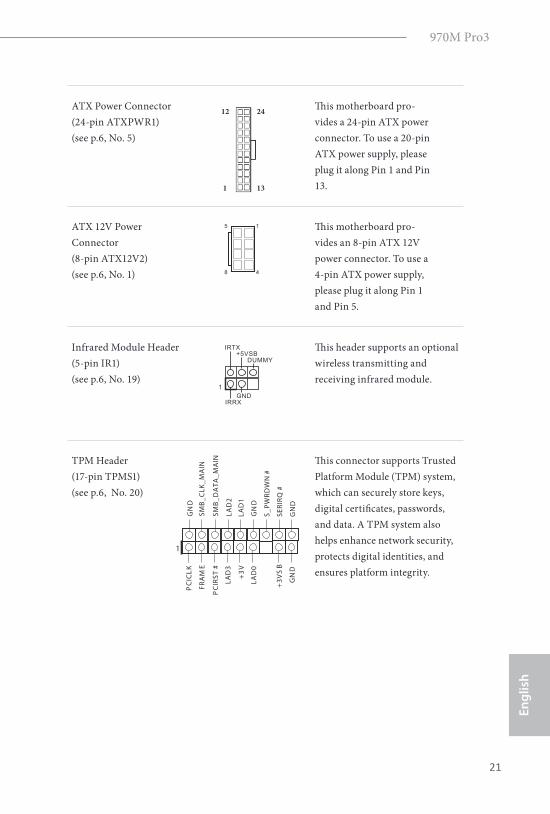
ATX Power Connector
(24-pin ATXPWR1)
(see p.6, No. 5)
his motherboard pro-
vides a 24-pin ATX power
connector. To use a 20-pin
ATX power supply, please
plug it along Pin 1 and Pin
13.
ATX 12V Power
Connector
(8-pin ATX12V2)
(see p.6, No. 1)
his motherboard pro-
vides an 8-pin ATX 12V
power connector. To use a
4-pin ATX power supply,
please plug it along Pin 1
and Pin 5.
Infrared Module Header
(5-pin IR1)
(see p.6, No. 19)
his header supports an optional
wireless transmitting and
receiving infrared module.
TPM Header
(17-pin TPMS1)
(see p.6, No. 20)
his connector supports Trusted
Platform Module (TPM) system,
which can securely store keys,
digital certiicates, passwords,
and data. A TPM system also
helps enhance network security,
protects digital identities, and
ensures platform integrity.
5
8
1
4
12
1
24
13
GNDIRRX
DUMMY+5VSB
IRTX
1
1
GND
SMB_DATA_MAIN
LAD2
LAD1
GND
S_PWRDWN#
SERIRQ#
GND
PCICLK
PCIRST#
LAD3
+3V
LAD0
+3VSB
GND
FRAME
SMB_CLK_MAIN
22
En
glish
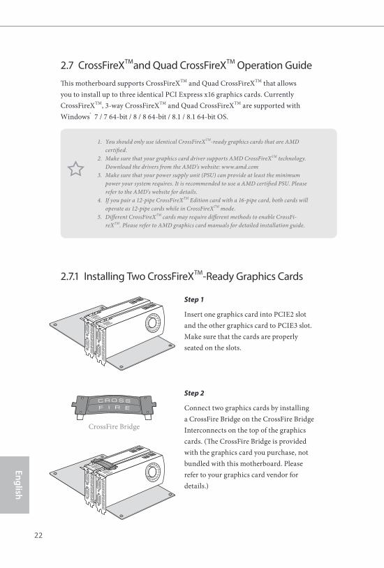
2.7 CrossFireXTM
and Quad CrossFireXTM
Operation Guide
his motherboard supports CrossFireXTM and Quad CrossFireXTM that allows
you to install up to three identical PCI Express x16 graphics cards. Currently
CrossFireXTM, 3-way CrossFireXTM and Quad CrossFireXTM are supported with
Windows® 7 / 7 64-bit / 8 / 8 64-bit / 8.1 / 8.1 64-bit OS.
2.7.1 Installing Two CrossFireXTM
-Ready Graphics Cards
Step 1
Insert one graphics card into PCIE2 slot
and the other graphics card to PCIE3 slot.
Make sure that the cards are properly
seated on the slots.
Step 2
Connect two graphics cards by installing
a CrossFire Bridge on the CrossFire Bridge
Interconnects on the top of the graphics
cards. (he CrossFire Bridge is provided
with the graphics card you purchase, not
bundled with this motherboard. Please
refer to your graphics card vendor for
details.)
1. You should only use identical CrossFireXTM-ready graphics cards that are AMD
certiied.
2. Make sure that your graphics card driver supports AMD CrossFireXTM technology.
Download the drivers from the AMD’s website: www.amd.com
3. Make sure that your power supply unit (PSU) can provide at least the minimum
power your system requires. It is recommended to use a AMD certiied PSU. Please
refer to the AMD’s website for details.
4. If you pair a 12-pipe CrossFireXTM Edition card with a 16-pipe card, both cards will
operate as 12-pipe cards while in CrossFireXTM mode.
5. Diferent CrossFireXTM cards may require diferent methods to enable CrossFi-
reXTM. Please refer to AMD graphics card manuals for detailed installation guide.
CrossFire Bridge
970M Pro3
23
En
gli
sh
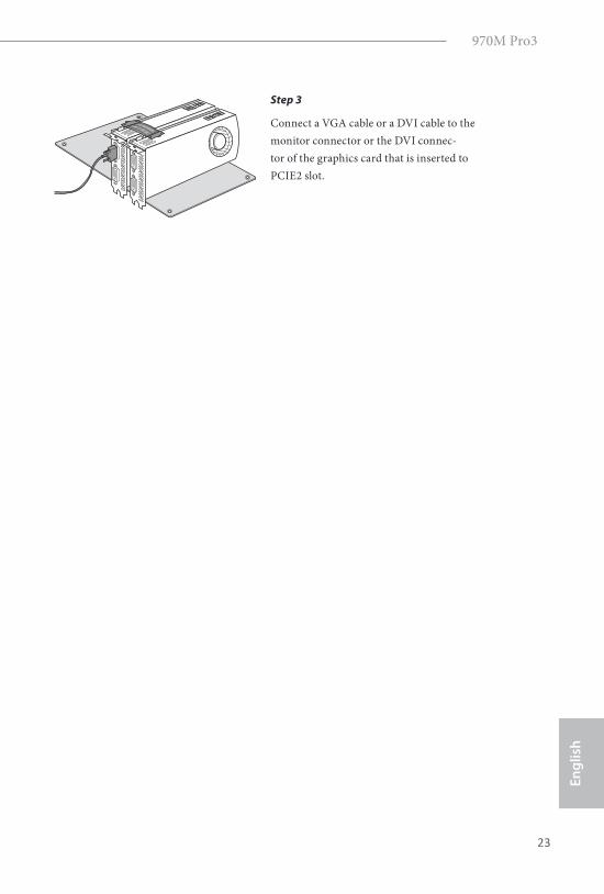
Step 3
Connect a VGA cable or a DVI cable to the
monitor connector or the DVI connec-
tor of the graphics card that is inserted to
PCIE2 slot.
24
En
glish
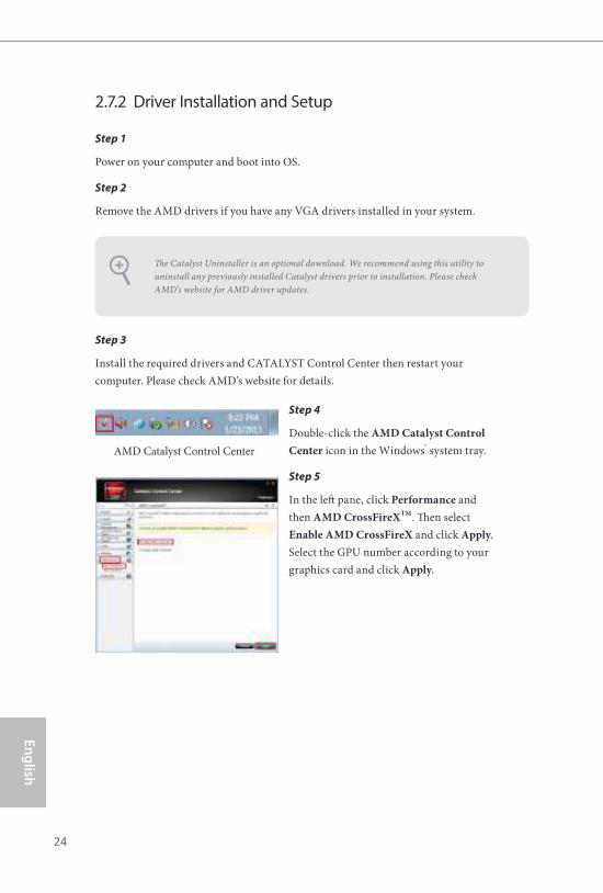
Step 1
Power on your computer and boot into OS.
Step 2
Remove the AMD drivers if you have any VGA drivers installed in your system.
Step 3
Install the required drivers and CATALYST Control Center then restart your
computer. Please check AMD’s website for details.
2.7.2 Driver Installation and Setup
Step 4
Double-click the AMD Catalyst Control
Center icon in the Windows® system tray.
Step 5
In the let pane, click Performance and
then AMD CrossFireXTM. hen select
Enable AMD CrossFireX and click Apply.
Select the GPU number according to your
graphics card and click Apply.
AMD Catalyst Control Center
he Catalyst Uninstaller is an optional download. We recommend using this utility to
uninstall any previously installed Catalyst drivers prior to installation. Please check
AMD’s website for AMD driver updates.
970M Pro3
25
En
gli
sh
Chapter 3 Software and Utilities Operation
3.1 Installing Drivers
he Support CD that comes with the motherboard contains necessary drivers and
useful utilities that enhance the motherboard’s features.
Running The Support CD
To begin using the support CD, insert the CD into your CD-ROM drive. he CD
automatically displays the Main Menu if “AUTORUN” is enabled in your computer.
If the Main Menu does not appear automatically, locate and double click on the ile
“ASRSETUP.EXE” in the Support CD to display the menu.
Drivers Menu
he drivers compatible to your system will be auto-detected and listed on the
support CD driver page. Please click Install All or follow the order from top to
bottom to install those required drivers. herefore, the drivers you install can work
properly.
Utilities Menu
he Utilities Menu shows the application sotware that the motherboard supports.
Click on a speciic item then follow the installation wizard to install it.
26
En
glish
3.2 ASRock EXTREME TUNING UTILITY
ASRock Extreme Tuning Utility (AXTU) is an all-in-one tool to ine-tune diferent
system functions in a user-friendly interface, which is including Hardware Monitor,
Fan Control, Overclocking, OC DNA, IES, XFast RAM and Restart to UEFI. In
Hardware Monitor, it shows the major readings of your system. In Fan Control, it
shows the fan speed and temperature for you to adjust. In Overclocking, you are
allowed to overclock CPU frequency for optimal system performance. In OC DNA,
you can save your OC settings as a proile and share with your friends. Your friends
then can load the OC proile to their own system to get the same OC settings. In
IES, you can enjoy the intelligent power saving feature. In XFast RAM, it fully uti-
lizes the memory space that cannot be used under Windows® OS 32-bit CPU. It also
shortens the loading time of previously visited websites, making web suring faster
than ever. And it also boosts the speed of Adobe Photoshop 5 times faster. Another
advantage is that it reduces the frequency of accessing your SSDs or HDDs in order
to extend their lifespan. In Restart to UEFI, it allows users to easily enter the UEFI
automatically under Windows® 8 when turning on the PC next time.
3.2.1 Installation
When you install all-in-one driver to your system from ASRock support CD,
ASRock Extreme Tuning Utility (AXTU) will be auto-installed as well. Ater
installation, you will ind the icon “ASRock eXtreme Tuner“ on your desktop.
Double-click “ASRock eXtreme Tuner“ icon, AXTU main menu will pop up.
3.2.2 Function
Please be noted that there is a button “Auto run when windows start“ on the lower
right corner. If you click this button, every time you turn on your system and enter
Windows®, the system will automatically start AXTU.
here are seven sections in AXTU main menu: Hardware Monitor, Fan Control,
Overclocking, OC DNA, IES, XFast RAM and Restart to UEFI.
970M Pro3
27
En
gli
sh
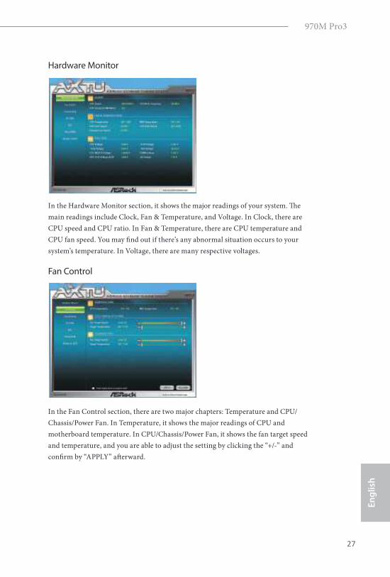
Hardware Monitor
In the Hardware Monitor section, it shows the major readings of your system. he
main readings include Clock, Fan & Temperature, and Voltage. In Clock, there are
CPU speed and CPU ratio. In Fan & Temperature, there are CPU temperature and
CPU fan speed. You may ind out if there’s any abnormal situation occurs to your
system’s temperature. In Voltage, there are many respective voltages.
Fan Control
In the Fan Control section, there are two major chapters: Temperature and CPU/
Chassis/Power Fan. In Temperature, it shows the major readings of CPU and
motherboard temperature. In CPU/Chassis/Power Fan, it shows the fan target speed
and temperature, and you are able to adjust the setting by clicking the “+/-” and
conirm by “APPLY” aterward.
28
En
glish
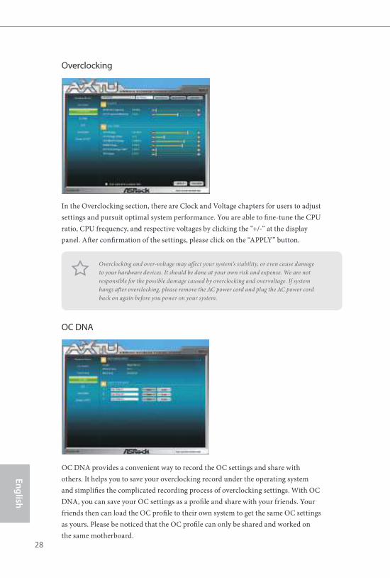
Overclocking
In the Overclocking section, there are Clock and Voltage chapters for users to adjust
settings and pursuit optimal system performance. You are able to ine-tune the CPU
ratio, CPU frequency, and respective voltages by clicking the “+/-” at the display
panel. Ater conirmation of the settings, please click on the “APPLY” button.
OC DNA
OC DNA provides a convenient way to record the OC settings and share with
others. It helps you to save your overclocking record under the operating system
and simpliies the complicated recording process of overclocking settings. With OC
DNA, you can save your OC settings as a proile and share with your friends. Your
friends then can load the OC proile to their own system to get the same OC settings
as yours. Please be noticed that the OC proile can only be shared and worked on
the same motherboard.
Overclocking and over-voltage may afect your system’s stability, or even cause damage
to your hardware devices. It should be done at your own risk and expense. We are not
responsible for the possible damage caused by overclocking and overvoltage. If system
hangs ater overclocking, please remove the AC power cord and plug the AC power cord
back on again before you power on your system.
970M Pro3
29
En
gli
sh
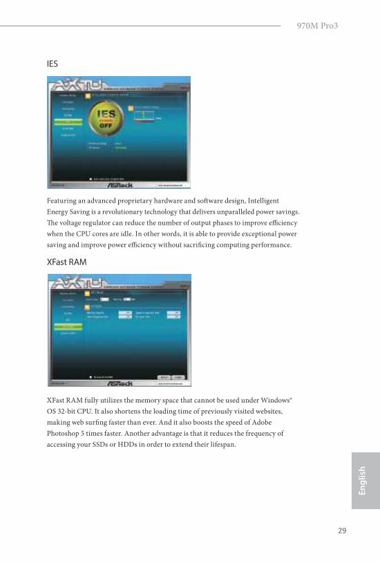
IES
Featuring an advanced proprietary hardware and sotware design, Intelligent
Energy Saving is a revolutionary technology that delivers unparalleled power savings.
he voltage regulator can reduce the number of output phases to improve eiciency
when the CPU cores are idle. In other words, it is able to provide exceptional power
saving and improve power eiciency without sacriicing computing performance.
XFast RAM
XFast RAM fully utilizes the memory space that cannot be used under Windows®
OS 32-bit CPU. It also shortens the loading time of previously visited websites,
making web suring faster than ever. And it also boosts the speed of Adobe
Photoshop 5 times faster. Another advantage is that it reduces the frequency of
accessing your SSDs or HDDs in order to extend their lifespan.
30
En
glish
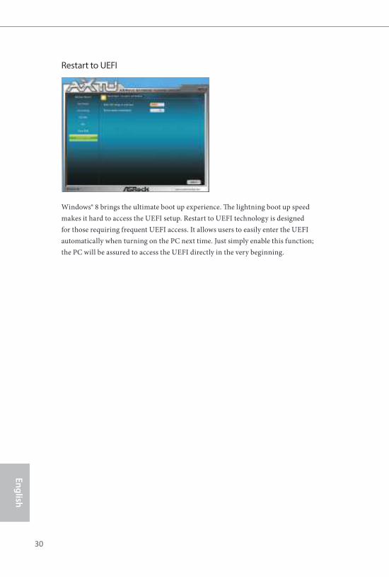
Restart to UEFI
Windows® 8 brings the ultimate boot up experience. he lightning boot up speed
makes it hard to access the UEFI setup. Restart to UEFI technology is designed
for those requiring frequent UEFI access. It allows users to easily enter the UEFI
automatically when turning on the PC next time. Just simply enable this function;
the PC will be assured to access the UEFI directly in the very beginning.
970M Pro3
31
En
gli
sh
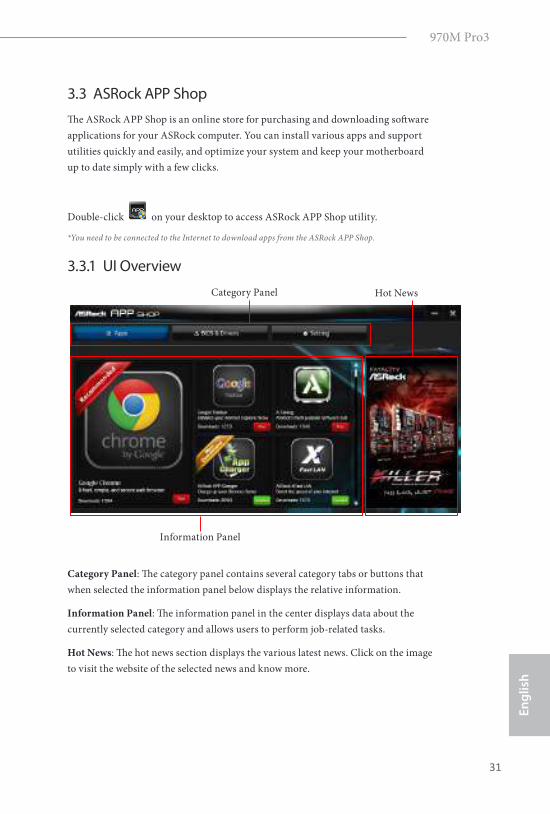
3.3 ASRock APP Shop
he ASRock APP Shop is an online store for purchasing and downloading sotware
applications for your ASRock computer. You can install various apps and support
utilities quickly and easily, and optimize your system and keep your motherboard
up to date simply with a few clicks.
Double-click on your desktop to access ASRock APP Shop utility.
*You need to be connected to the Internet to download apps from the ASRock APP Shop.
3.3.1 UI Overview
Category Panel: he category panel contains several category tabs or buttons that
when selected the information panel below displays the relative information.
Information Panel: he information panel in the center displays data about the
currently selected category and allows users to perform job-related tasks.
Hot News: he hot news section displays the various latest news. Click on the image
to visit the website of the selected news and know more.
Information Panel
Hot NewsCategory Panel
32
En
glish
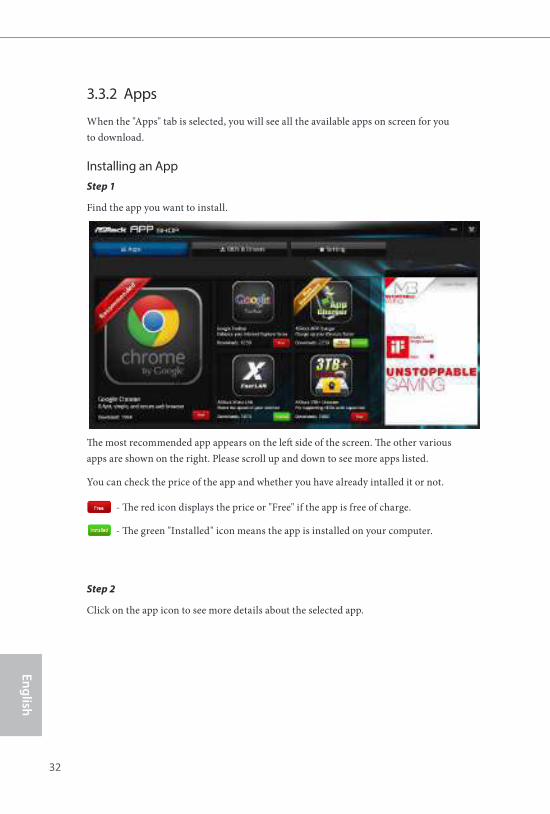
3.3.2 Apps
When the "Apps" tab is selected, you will see all the available apps on screen for you
to download.
Installing an App
Step 1
Find the app you want to install.
he most recommended app appears on the let side of the screen. he other various
apps are shown on the right. Please scroll up and down to see more apps listed.
You can check the price of the app and whether you have already intalled it or not.
- he red icon displays the price or "Free" if the app is free of charge.
- he green "Installed" icon means the app is installed on your computer.
Step 2
Click on the app icon to see more details about the selected app.
970M Pro3
33
En
gli
sh
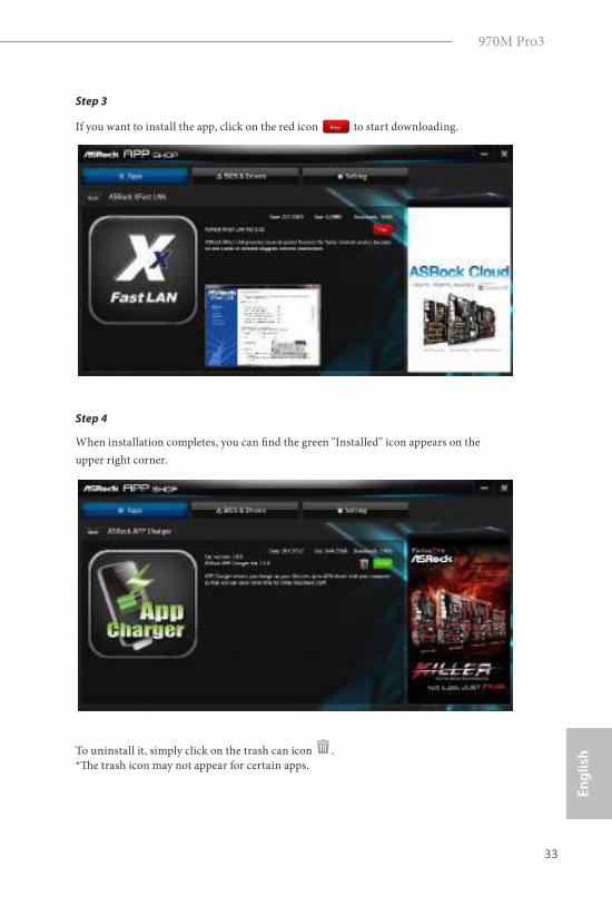
Step 3
If you want to install the app, click on the red icon to start downloading.
Step 4
When installation completes, you can ind the green "Installed" icon appears on the
upper right corner.
To uninstall it, simply click on the trash can icon .
*he trash icon may not appear for certain apps.
34
En
glish
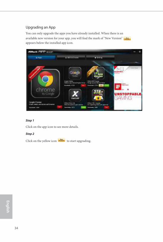
Upgrading an App
You can only upgrade the apps you have already installed. When there is an
available new version for your app, you will ind the mark of "New Version"
appears below the installed app icon.
Step 1
Click on the app icon to see more details.
Step 2
Click on the yellow icon to start upgrading.
970M Pro3
35
En
gli
sh
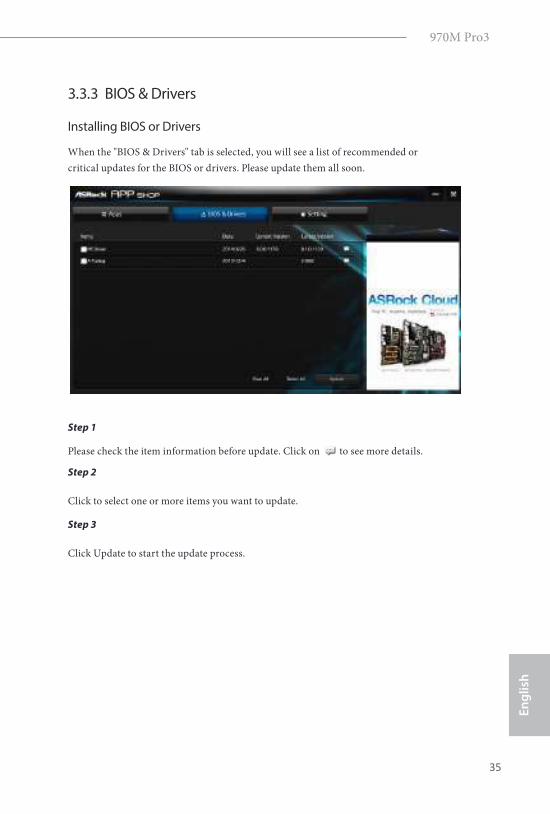
3.3.3 BIOS & Drivers
Installing BIOS or Drivers
When the "BIOS & Drivers" tab is selected, you will see a list of recommended or
critical updates for the BIOS or drivers. Please update them all soon.
Step 1
Please check the item information before update. Click on to see more details.
Step 2
Click to select one or more items you want to update.
Step 3
Click Update to start the update process.
36
En
glish
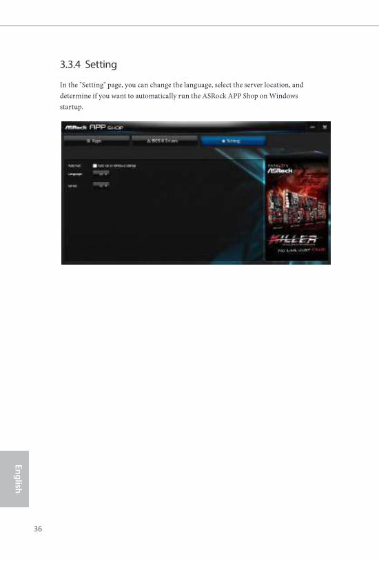
3.3.4 Setting
In the "Setting" page, you can change the language, select the server location, and
determine if you want to automatically run the ASRock APP Shop on Windows
startup.
970M Pro3
37
En
gli
sh
3.4 Start8
For those Windows 8 users who miss the Start Menu, Start8 is an ideal solution that
brings back the familiar Start Menu along with added customizations for greater
eiciency.
3.4.1 Installing Start8
Install Start8, which is located in the folder at the following path of the Support CD:
\ ASRock Utility > Start8.
3.4.2 Coniguring Start8
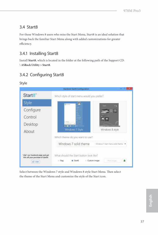
Style
Select between the Windows 7 style and Windows 8 style Start Menu. hen select
the theme of the Start Menu and customize the style of the Start icon.
38
En
glish
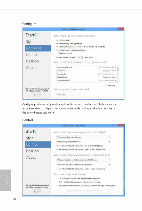
Conigure
Conigure provides coniguration options, including icon sizes, which shortcuts you
want Start Menu to display, quick access to recently used apps, the functionality of
the power button, and more.
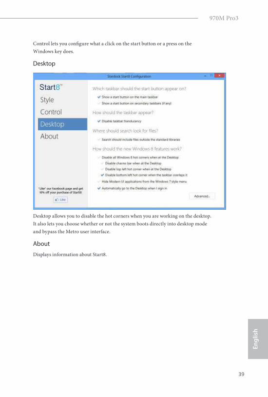
Control
970M Pro3
39
En
gli
sh
Control lets you conigure what a click on the start button or a press on the
Windows key does.
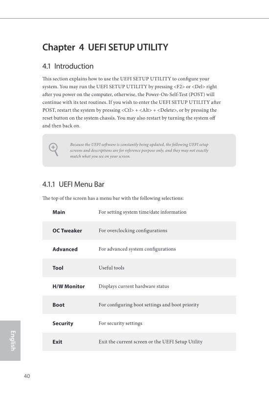
Desktop
Desktop allows you to disable the hot corners when you are working on the desktop.
It also lets you choose whether or not the system boots directly into desktop mode
and bypass the Metro user interface.
About
Displays information about Start8.
40
En
glish
Chapter 4 UEFI SETUP UTILITY
4.1 Introduction
his section explains how to use the UEFI SETUP UTILITY to conigure your
system. You may run the UEFI SETUP UTILITY by pressing <F2> or <Del> right
ater you power on the computer, otherwise, the Power-On-Self-Test (POST) will
continue with its test routines. If you wish to enter the UEFI SETUP UTILITY ater
POST, restart the system by pressing <Ctl> + <Alt> + <Delete>, or by pressing the
reset button on the system chassis. You may also restart by turning the system of
and then back on.
4.1.1 UEFI Menu Bar
he top of the screen has a menu bar with the following selections:
Main For setting system time/date information
OC Tweaker For overclocking conigurations
Advanced For advanced system conigurations
Tool Useful tools
H/W Monitor Displays current hardware status
Boot For coniguring boot settings and boot priority
Security For security settings
Exit Exit the current screen or the UEFI Setup Utility
Because the UEFI sotware is constantly being updated, the following UEFI setup
screens and descriptions are for reference purpose only, and they may not exactly
match what you see on your screen.
970M Pro3
41
En
gli
sh
4.1.2 Navigation Keys
Use < > key or < > key to choose among the selections on the menu bar, and
use < > key or < > key to move the cursor up or down to select items, then
press <Enter> to get into the sub screen. You can also use the mouse to click your
required item.
Please check the following table for the descriptions of each navigation key.
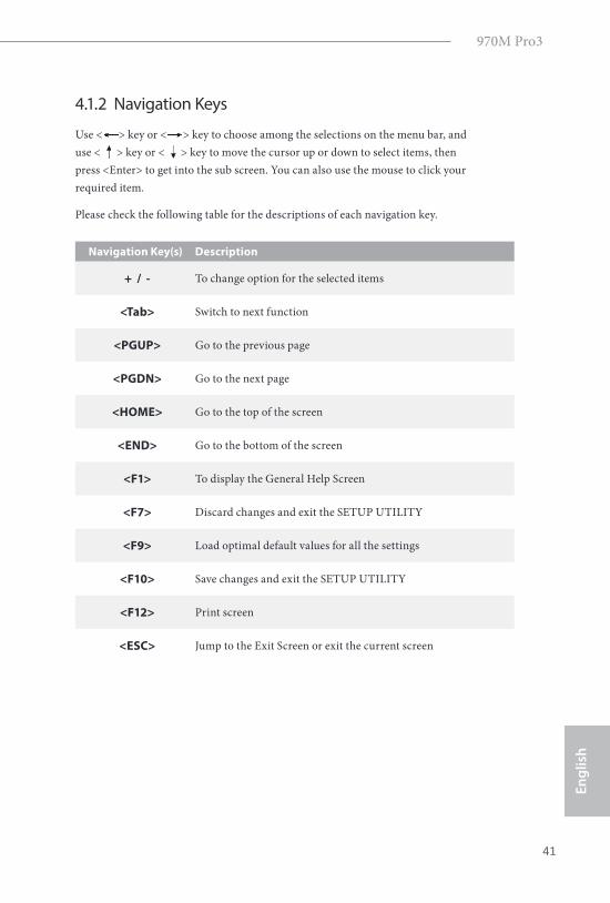
Navigation Key(s) Description
+ / - To change option for the selected items
<Tab> Switch to next function
<PGUP> Go to the previous page
<PGDN> Go to the next page
<HOME> Go to the top of the screen
<END> Go to the bottom of the screen
<F1> To display the General Help Screen
<F7> Discard changes and exit the SETUP UTILITY
<F9> Load optimal default values for all the settings
<F10> Save changes and exit the SETUP UTILITY
<F12> Print screen
<ESC> Jump to the Exit Screen or exit the current screen
42
En
glish
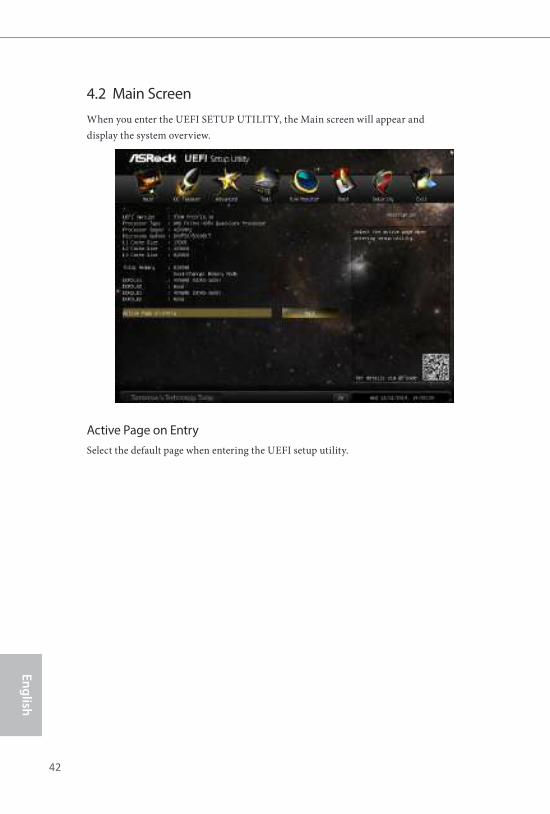
4.2 Main Screen
When you enter the UEFI SETUP UTILITY, the Main screen will appear and
display the system overview.
Active Page on Entry
Select the default page when entering the UEFI setup utility.

970M Pro3
43
En
gli
sh
4.3 OC Tweaker Screen
In the OC Tweaker screen, you can set up overclocking features.
OC Mode
Use this to select Overclock Mode. Please note that overclocing may cause damage
to your components and motherboard. It should be done at your own risk and
expense.
Load Optimized CPU OC Setting
Please note that overclocking may cause damage to your CPU and motherboard. It
should be done at your own risk and expense.
CPU Coniguration
Overclock Mode
Use this to select Overclock Mode. Coniguration options: [Auto] and [Manual]. he
default value is [Auto].
Because the UEFI sotware is constantly being updated, the following UEFI setup
screens and descriptions are for reference purpose only, and they may not exactly
match what you see on your screen.
44
En
glish
Spread Spectrum
his item should always be [Auto] for better system stability.
CPU Active Core Control
his allows you to adjust CPU Active Core Control feature. he coniguration options
depend on the CPU core you adopt. he default value is [Disabled].
AMD Turbo Core Technology
his item appears only when the processor you adopt supports this feature. Use this
to select enable or disable AMD Turbo Core Technology. Coniguration options:
[Enabled] and [Disabled]. he default value is [Enabled].
AMD Application Power Management
Application Power Management (APM) ensures that average power con-sumption
over a thermally signiicant time period remains at or below the TDP for the CPU
mode being used. If [Enabled] is selected, the power consumption is reduced when
overclocking.
Multiplier/Voltage Change
his item is set to [Auto] by default. If it is set to [Manual], you may adjust the value of
Processor Frequency and Processor Voltage. However, it is recommended to keep the
default value for system stability.
HT Bus Speed
his feature allows you selecting Hyper-Transport bus speed. Coniguration options:
[200MHz] to [2000MHz].
HT Bus Width
his feature allows you selecting Hyper-Transport bus width. Coniguration options: [8
Bit] and [16 Bit].
DRAM Timing Coniguration
Load Proile Setting
Select the Intel® Extreme Memory Proile (X.M.P.).
DRAM Frequency
If [Auto] is selected, the motherboard will detect the memory module(s) inserted
and assign the appropriate frequency automatically.
970M Pro3
45
En
gli
sh
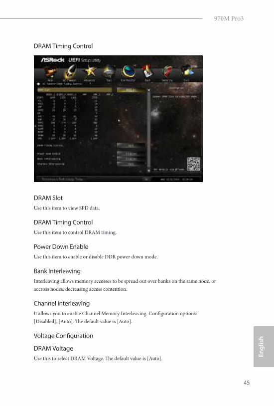
DRAM Timing Control
DRAM Slot
Use this item to view SPD data.
DRAM Timing Control
Use this item to control DRAM timing.
Power Down Enable
Use this item to enable or disable DDR power down mode.
Bank Interleaving
Interleaving allows memory accesses to be spread out over banks on the same node, or
accross nodes, decreasing access contention.
Channel Interleaving
It allows you to enable Channel Memory Interleaving. Coniguration options:
[Disabled], [Auto]. he default value is [Auto].
Voltage Coniguration
DRAM Voltage
Use this to select DRAM Voltage. he default value is [Auto].
46
En
glish
CPU Voltage Ofset
Conigure the dynamic CPU voltage added to the CPU.
NB Voltage
Use this to select NB Voltage. he default value is [Auto].
HT Voltage
Use this to select HT Voltage. he default value is [Auto].
970M Pro3
47
En
gli
sh
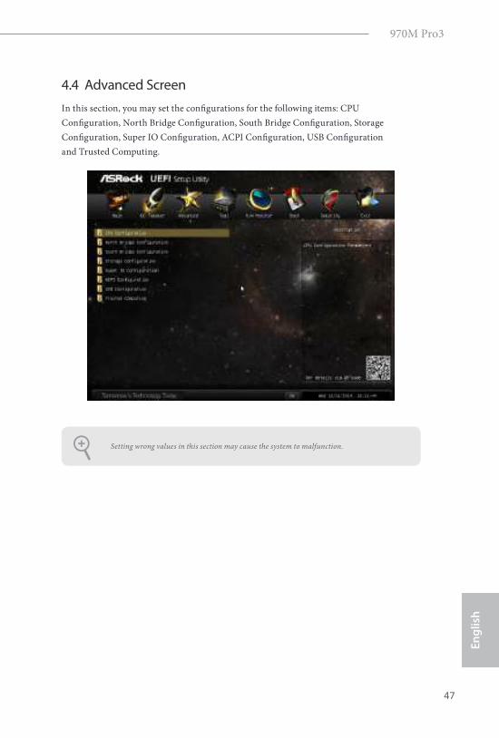
4.4 Advanced Screen
In this section, you may set the conigurations for the following items: CPU
Coniguration, North Bridge Coniguration, South Bridge Coniguration, Storage
Coniguration, Super IO Coniguration, ACPI Coniguration, USB Coniguration
and Trusted Computing.
Setting wrong values in this section may cause the system to malfunction.
48
En
glish
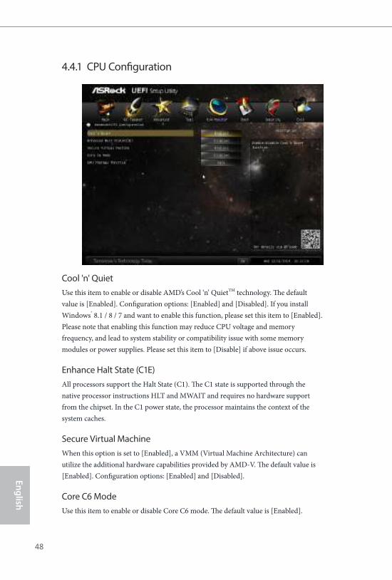
4.4.1 CPU Coniguration
Cool 'n' Quiet
Use this item to enable or disable AMD’s Cool ‘n’ QuietTM technology. he default
value is [Enabled]. Coniguration options: [Enabled] and [Disabled]. If you install
Windows® 8.1 / 8 / 7 and want to enable this function, please set this item to [Enabled].
Please note that enabling this function may reduce CPU voltage and memory
frequency, and lead to system stability or compatibility issue with some memory
modules or power supplies. Please set this item to [Disable] if above issue occurs.
Enhance Halt State (C1E)
All processors support the Halt State (C1). he C1 state is supported through the
native processor instructions HLT and MWAIT and requires no hardware support
from the chipset. In the C1 power state, the processor maintains the context of the
system caches.
Secure Virtual Machine
When this option is set to [Enabled], a VMM (Virtual Machine Architecture) can
utilize the additional hardware capabilities provided by AMD-V. he default value is
[Enabled]. Coniguration options: [Enabled] and [Disabled].
Core C6 Mode
Use this item to enable or disable Core C6 mode. he default value is [Enabled].
970M Pro3
49
En
gli
sh
CPU Thermal Throttle
Use this item to enable CPU internal thermal control mechanism to keep the CPU
from overheated. he default value is [Auto].
50
En
glish
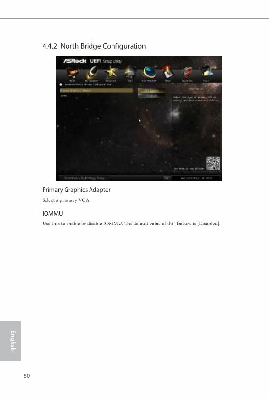
4.4.2 North Bridge Coniguration
Primary Graphics Adapter
Select a primary VGA.
IOMMU
Use this to enable or disable IOMMU. he default value of this feature is [Disabled].
970M Pro3
51
En
gli
sh
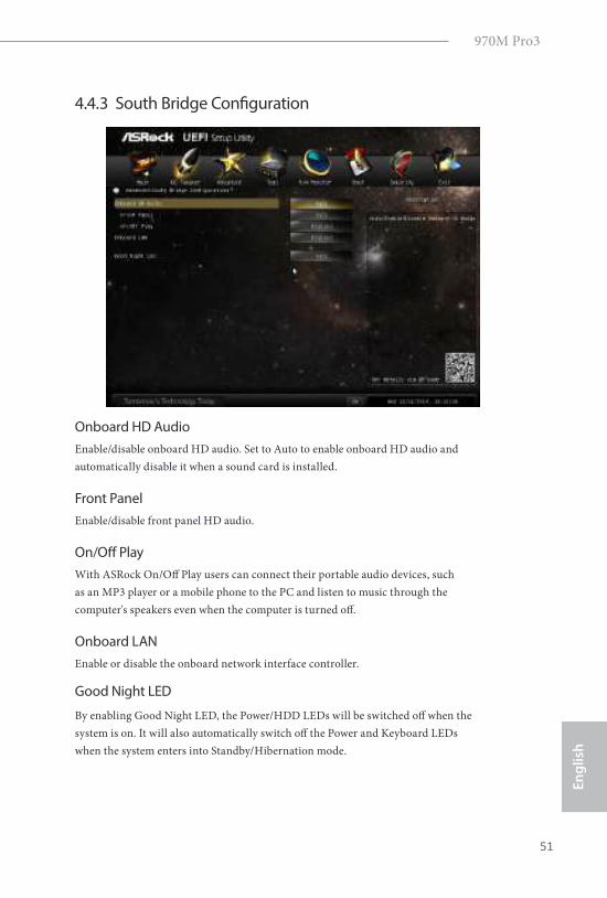
4.4.3 South Bridge Coniguration
Onboard HD Audio
Enable/disable onboard HD audio. Set to Auto to enable onboard HD audio and
automatically disable it when a sound card is installed.
Front Panel
Enable/disable front panel HD audio.
On/Of Play
With ASRock On/Of Play users can connect their portable audio devices, such
as an MP3 player or a mobile phone to the PC and listen to music through the
computer's speakers even when the computer is turned of.
Onboard LAN
Enable or disable the onboard network interface controller.
Good Night LED
By enabling Good Night LED, the Power/HDD LEDs will be switched of when the
system is on. It will also automatically switch of the Power and Keyboard LEDs
when the system enters into Standby/Hibernation mode.
52
En
glish
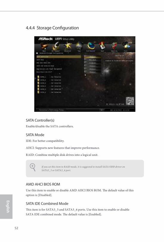
4.4.4 Storage Coniguration
SATA Controller(s)
Enable/disable the SATA controllers.
SATA Mode
IDE: For better compatibility.
AHCI: Supports new features that improve performance.
RAID: Combine multiple disk drives into a logical unit.
AMD AHCI BIOS ROM
Use this item to enable or disable AMD AHCI BIOS ROM. he default value of this
option is [Disabled].
SATA IDE Combined Mode
his item is for SATA3_5 and SATA3_6 ports. Use this item to enable or disable
SATA IDE combined mode. he default value is [Enabled].
If you set this item to RAID mode, it is suggested to install SATA ODD driver on
SATA3_5 or SATA3_6 port.
970M Pro3
53
En
gli
sh
Aggressive Link Power Management
Aggressive Link Power Management allows SATA devices to enter a low power state
during periods of inactivity to save power. It is only supported by AHCI mode.
Hard Disk S.M.A.R.T.
S.M.A.R.T stands for Self-Monitoring, Analysis, and Reporting Technology. It is a
monitoring system for computer hard disk drives to detect and report on various
indicators of reliability.
If you want to build RAID on SATA3_5 and SATA3_6 ports, please disable this item.
54
En
glish
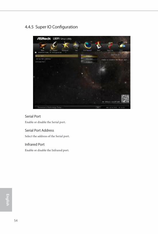
4.4.5 Super IO Coniguration
Serial Port
Enable or disable the Serial port.
Serial Port Address
Select the address of the Serial port.
Infrared Port
Enable or disable the Infrared port.
970M Pro3
55
En
gli
sh
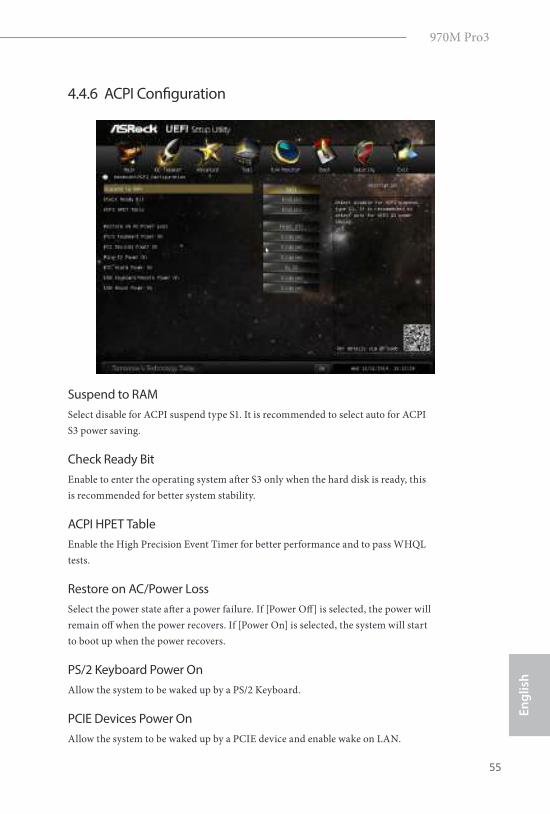
4.4.6 ACPI Coniguration
Suspend to RAM
Select disable for ACPI suspend type S1. It is recommended to select auto for ACPI
S3 power saving.
Check Ready Bit
Enable to enter the operating system ater S3 only when the hard disk is ready, this
is recommended for better system stability.
ACPI HPET Table
Enable the High Precision Event Timer for better performance and to pass WHQL
tests.
Restore on AC/Power Loss
Select the power state ater a power failure. If [Power Of] is selected, the power will
remain of when the power recovers. If [Power On] is selected, the system will start
to boot up when the power recovers.
PS/2 Keyboard Power On
Allow the system to be waked up by a PS/2 Keyboard.
PCIE Devices Power On
Allow the system to be waked up by a PCIE device and enable wake on LAN.
56
En
glish
Ring-In Power On
Allow the system to be waked up by onboard COM port modem Ring-In signals.
RTC Alarm Power On
Allow the system to be waked up by the real time clock alarm. Set it to By OS to let
it be handled by your operating system.
USB Keyboard/Remote Power On
Allow the system to be waked up by an USB keyboard or remote controller.
USB Mouse Power On
Allow the system to be waked up by an USB mouse.
970M Pro3
57
En
gli
sh
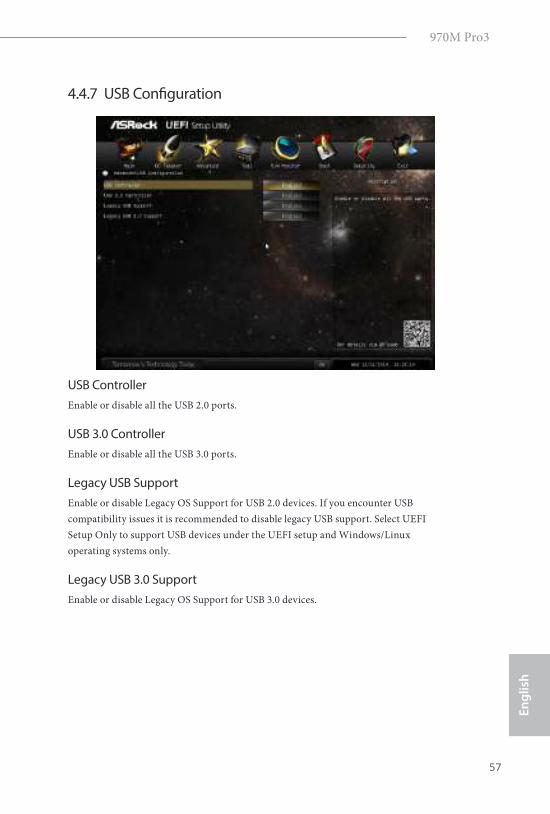
4.4.7 USB Coniguration
USB Controller
Enable or disable all the USB 2.0 ports.
USB 3.0 Controller
Enable or disable all the USB 3.0 ports.
Legacy USB Support
Enable or disable Legacy OS Support for USB 2.0 devices. If you encounter USB
compatibility issues it is recommended to disable legacy USB support. Select UEFI
Setup Only to support USB devices under the UEFI setup and Windows/Linux
operating systems only.
Legacy USB 3.0 Support
Enable or disable Legacy OS Support for USB 3.0 devices.
58
En
glish
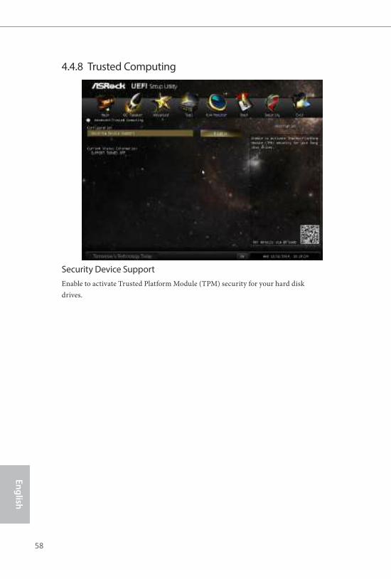
4.4.8 Trusted Computing
Security Device Support
Enable to activate Trusted Platform Module (TPM) security for your hard disk
drives.
970M Pro3
59
En
gli
sh
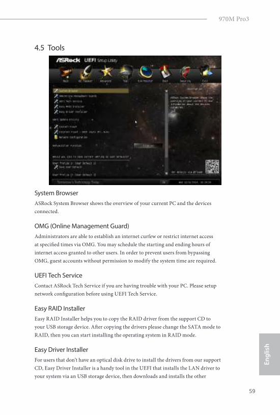
4.5 Tools
System Browser
ASRock System Browser shows the overview of your current PC and the devices
connected.
OMG (Online Management Guard)
Administrators are able to establish an internet curfew or restrict internet access
at speciied times via OMG. You may schedule the starting and ending hours of
internet access granted to other users. In order to prevent users from bypassing
OMG, guest accounts without permission to modify the system time are required.
UEFI Tech Service
Contact ASRock Tech Service if you are having trouble with your PC. Please setup
network coniguration before using UEFI Tech Service.
Easy RAID Installer
Easy RAID Installer helps you to copy the RAID driver from the support CD to
your USB storage device. Ater copying the drivers please change the SATA mode to
RAID, then you can start installing the operating system in RAID mode.
Easy Driver Installer
For users that don’t have an optical disk drive to install the drivers from our support
CD, Easy Driver Installer is a handy tool in the UEFI that installs the LAN driver to
your system via an USB storage device, then downloads and installs the other
60
En
glish
required drivers automatically.
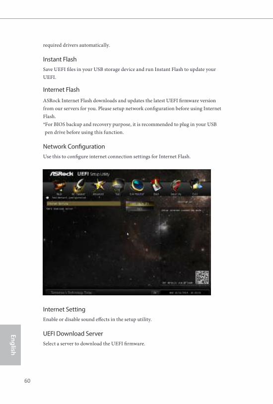
Instant Flash
Save UEFI iles in your USB storage device and run Instant Flash to update your
UEFI.
Internet Flash
ASRock Internet Flash downloads and updates the latest UEFI irmware version
from our servers for you. Please setup network coniguration before using Internet
Flash.
*For BIOS backup and recovery purpose, it is recommended to plug in your USB
pen drive before using this function.
Network Coniguration
Use this to conigure internet connection settings for Internet Flash.
Internet Setting
Enable or disable sound efects in the setup utility.
UEFI Download Server
Select a server to download the UEFI irmware.
970M Pro3
61
En
gli
sh
Dehumidiier Function
If Dehumidiier Function is enabled, the computer will power on automatically to
dehumidify the system ater entering S4/S5 state.
Dehumidiier Period
Conigure the period of time until the computer powers on and enables
Dehumidiier ater entering S4/S5 state.
Dehumidiier Duration
Conigure the duration of the dehumidifying process before it returns to S4/S5
state.
Dehumidiier CPU Fan Setting
Conigure the speed of the CPU fan while Dehumidiier is enabled. he higher the
value, the faster the fan speed.
Max: 255
Min: 1
Save User Default
Type a proile name and press enter to save your settings as user default.
Load User Default
Load previously saved user defaults.
62
En
glish
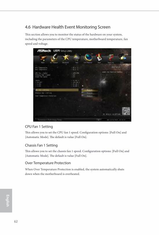
4.6 Hardware Health Event Monitoring Screen
his section allows you to monitor the status of the hardware on your system,
including the parameters of the CPU temperature, motherboard temperature, fan
speed and voltage.
CPU Fan 1 Setting
his allows you to set the CPU fan 1 speed. Coniguration options: [Full On] and
[Automatic Mode]. he default is value [Full On].
Chassis Fan 1 Setting
his allows you to set the chassis fan 1 speed. Coniguration options: [Full On] and
[Automatic Mode]. he default is value [Full On].
Over Temperature Protection
When Over Temperature Protection is enabled, the system automatically shuts
down when the motherboard is overheated.
970M Pro3
63
En
gli
sh
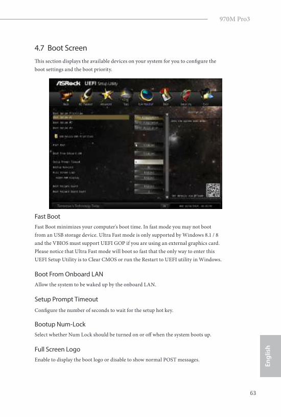
4.7 Boot Screen
his section displays the available devices on your system for you to conigure the
boot settings and the boot priority.
Fast Boot
Fast Boot minimizes your computer's boot time. In fast mode you may not boot
from an USB storage device. Ultra Fast mode is only supported by Windows 8.1 / 8
and the VBIOS must support UEFI GOP if you are using an external graphics card.
Please notice that Ultra Fast mode will boot so fast that the only way to enter this
UEFI Setup Utility is to Clear CMOS or run the Restart to UEFI utility in Windows.
Boot From Onboard LAN
Allow the system to be waked up by the onboard LAN.
Setup Prompt Timeout
Conigure the number of seconds to wait for the setup hot key.
Bootup Num-Lock
Select whether Num Lock should be turned on or of when the system boots up.
Full Screen Logo
Enable to display the boot logo or disable to show normal POST messages.
64
En
glish
AddOn ROM Display
Enable AddOn ROM Display to see the AddOn ROM messages or conigure the
AddOn ROM if you've enabled Full Screen Logo. Disable for faster boot speed.
Boot Failure Guard
If the computer fails to boot for a number of times the system automatically restores
the default settings.
Boot Failure Guard Count
Conigure the number of attempts to boot until the system automatically restores
the default settings.
970M Pro3
65
En
gli
sh
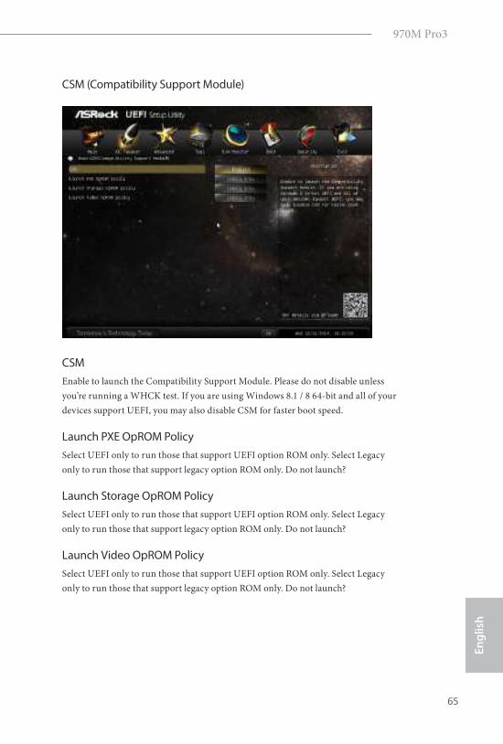
CSM (Compatibility Support Module)
CSM
Enable to launch the Compatibility Support Module. Please do not disable unless
you’re running a WHCK test. If you are using Windows 8.1 / 8 64-bit and all of your
devices support UEFI, you may also disable CSM for faster boot speed.
Launch PXE OpROM Policy
Select UEFI only to run those that support UEFI option ROM only. Select Legacy
only to run those that support legacy option ROM only. Do not launch?
Launch Storage OpROM Policy
Select UEFI only to run those that support UEFI option ROM only. Select Legacy
only to run those that support legacy option ROM only. Do not launch?
Launch Video OpROM Policy
Select UEFI only to run those that support UEFI option ROM only. Select Legacy
only to run those that support legacy option ROM only. Do not launch?
66
En
glish
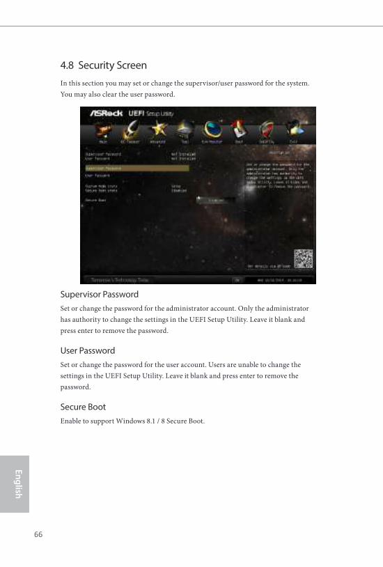
4.8 Security Screen
In this section you may set or change the supervisor/user password for the system.
You may also clear the user password.
Supervisor Password
Set or change the password for the administrator account. Only the administrator
has authority to change the settings in the UEFI Setup Utility. Leave it blank and
press enter to remove the password.
User Password
Set or change the password for the user account. Users are unable to change the
settings in the UEFI Setup Utility. Leave it blank and press enter to remove the
password.
Secure Boot
Enable to support Windows 8.1 / 8 Secure Boot.
970M Pro3
67
En
gli
sh
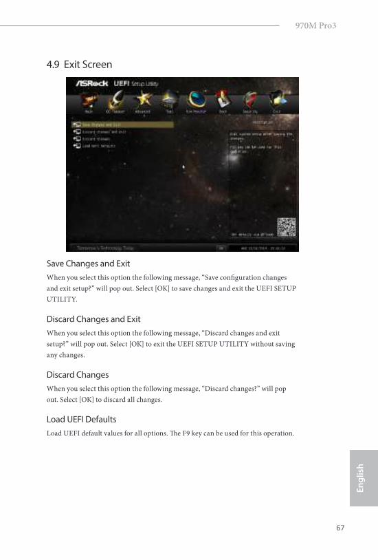
4.9 Exit Screen
Save Changes and Exit
When you select this option the following message, “Save coniguration changes
and exit setup?” will pop out. Select [OK] to save changes and exit the UEFI SETUP
UTILITY.
Discard Changes and Exit
When you select this option the following message, “Discard changes and exit
setup?” will pop out. Select [OK] to exit the UEFI SETUP UTILITY without saving
any changes.
Discard Changes
When you select this option the following message, “Discard changes?” will pop
out. Select [OK] to discard all changes.
Load UEFI Defaults
Load UEFI default values for all options. he F9 key can be used for this operation.
68
En
glish
Contact Information
If you need to contact ASRock or want to know more about ASRock, you’re welcome
to visit ASRock’s website at http://www.asrock.com; or you may contact your dealer
for further information. For technical questions, please submit a support request
form at http://www.asrock.com/support/tsd.asp
ASRock Incorporation
2F., No.37, Sec. 2, Jhongyang S. Rd., Beitou District,
Taipei City 112, Taiwan (R.O.C.)
ASRock EUROPE B.V.
Bijsterhuizen 3151
6604 LV Wijchen
he Netherlands
Phone: +31-24-345-44-33
Fax: +31-24-345-44-38
ASRock America, Inc.
13848 Magnolia Ave, Chino, CA91710
U.S.A.
Phone: +1-909-590-8308
Fax: +1-909-590-1026