Embed Size (px)
Citation preview

©2014-2019 Dynojet Research, Inc. All Rights Reserved.
Installation Guide for In Ground Model 224 Automotive Dynamometers.
This manual is copyrighted by Dynojet Research, Inc., hereafter referred to as Dynojet, and all rights are reserved. This manual, and the software described in it, is furnished under license and may only be used or copied in accordance with the terms of such license. This manual is furnished for informational use only, is subject to change without notice, and should not be construed as a commitment by Dynojet. Dynojet assumes no responsibility or liability for any error or inaccuracies that may appear in this manual. Except as permitted by such license, no part of this manual may be reproduced, stored in a retrieval system, or transmitted, in any form or by any means, electronic, mechanical, recording, or otherwise, without the prior written permission of Dynojet.
The Dynojet logo is a trademark of Dynojet Research, Inc.
Any trademarks, trade names, service marks, or service names owned or registered by any other company and used in this guide are the property of their respective companies.
Dynojet Research, Inc., 2191 Mendenhall Drive, North Las Vegas, Nevada 89081, USA.
Printed in USA.
Part Number: 98200046 Version 4 (05/2019)
#RECORD
Dynamometer Number:
#RECORDEddy Current Brake Number:
i
In Ground Model 224 Automotive Dynamometer Installation Guide
TABLE OF CONTENTS
Warnings . . . . . . . . . . . . . . . . . . . . . . . . . . . . . . . . . . . . . . . . . . . . . . . . . . . . . . . . . . v
Chapter 1 Specifications and Operating RequirementsIntroduction . . . . . . . . . . . . . . . . . . . . . . . . . . . . . . . . . . . . . . . . . . . . . . . . . . . . . . . . . . . . 1-2
Conventions Used In This Manual . . . . . . . . . . . . . . . . . . . . . . . . . . . . . . . . . . . . . . . 1-3Technical Support . . . . . . . . . . . . . . . . . . . . . . . . . . . . . . . . . . . . . . . . . . . . . . . . . . . . 1-3Your Dyno Room . . . . . . . . . . . . . . . . . . . . . . . . . . . . . . . . . . . . . . . . . . . . . . . . . . . . . 1-4
Dynamometer Specifications and Requirements . . . . . . . . . . . . . . . . . . . . . . . . . . 1-5Chassis Specifications . . . . . . . . . . . . . . . . . . . . . . . . . . . . . . . . . . . . . . . . . . . . . . . . . 1-5Compressed Air . . . . . . . . . . . . . . . . . . . . . . . . . . . . . . . . . . . . . . . . . . . . . . . . . . . . . . 1-8Computer Specifications . . . . . . . . . . . . . . . . . . . . . . . . . . . . . . . . . . . . . . . . . . . . . . . 1-8Electrical Requirements . . . . . . . . . . . . . . . . . . . . . . . . . . . . . . . . . . . . . . . . . . . . . . . 1-9Environmental Requirements . . . . . . . . . . . . . . . . . . . . . . . . . . . . . . . . . . . . . . . . . . . 1-9Fire Suppression . . . . . . . . . . . . . . . . . . . . . . . . . . . . . . . . . . . . . . . . . . . . . . . . . . . . . 1-9Forklift Requirements . . . . . . . . . . . . . . . . . . . . . . . . . . . . . . . . . . . . . . . . . . . . . . . . . 1-9Grounding Requirements . . . . . . . . . . . . . . . . . . . . . . . . . . . . . . . . . . . . . . . . . . . . . . 1-9Phone and Internet Access . . . . . . . . . . . . . . . . . . . . . . . . . . . . . . . . . . . . . . . . . . . 1-10Tie-Down Straps . . . . . . . . . . . . . . . . . . . . . . . . . . . . . . . . . . . . . . . . . . . . . . . . . . . . 1-10Tool Requirements . . . . . . . . . . . . . . . . . . . . . . . . . . . . . . . . . . . . . . . . . . . . . . . . . . . 1-10
Model 224xLC In Ground Automotive Dynamometer . . . . . . . . . . . . . . . . . . . . . 1-11DynoWare RT Electronics . . . . . . . . . . . . . . . . . . . . . . . . . . . . . . . . . . . . . . . . . . . . . . 1-12
Main Module Connections . . . . . . . . . . . . . . . . . . . . . . . . . . . . . . . . . . . . . . . . . . . . 1-13Network Connections . . . . . . . . . . . . . . . . . . . . . . . . . . . . . . . . . . . . . . . . . . . . . . . . 1-14
Pit Specifications . . . . . . . . . . . . . . . . . . . . . . . . . . . . . . . . . . . . . . . . . . . . . . . . . . . . . . 1-15224 Pit Requirements and Specifications . . . . . . . . . . . . . . . . . . . . . . . . . . . . . . . . 1-15
In Ground Model 224 Automotive Dynamometer Installation Guide
ii
T A B L E O F C O N T E N T S
In Ground Model 224 Automotive Dynamometer Installation Guide
ii
Chapter 2 Dyno InstallationUnpacking and Inspecting the Dyno . . . . . . . . . . . . . . . . . . . . . . . . . . . . . . . . . . . . . 2-2Dyno Installation . . . . . . . . . . . . . . . . . . . . . . . . . . . . . . . . . . . . . . . . . . . . . . . . . . . . . . . . 2-5
Removing the Dyno from the Crate . . . . . . . . . . . . . . . . . . . . . . . . . . . . . . . . . . . . . . 2-5Anchoring the Dyno . . . . . . . . . . . . . . . . . . . . . . . . . . . . . . . . . . . . . . . . . . . . . . . . . . 2-7
Eddy Current Brake Installation . . . . . . . . . . . . . . . . . . . . . . . . . . . . . . . . . . . . . . . . . . 2-8Cable Routing . . . . . . . . . . . . . . . . . . . . . . . . . . . . . . . . . . . . . . . . . . . . . . . . . . . . . . . . . . 2-9
Identifying the Cables . . . . . . . . . . . . . . . . . . . . . . . . . . . . . . . . . . . . . . . . . . . . . . . . . 2-9Routing the Cables . . . . . . . . . . . . . . . . . . . . . . . . . . . . . . . . . . . . . . . . . . . . . . . . . . 2-11Aligning the Optical Pickup Card Tab . . . . . . . . . . . . . . . . . . . . . . . . . . . . . . . . . . . 2-13
Pit Cover Installation . . . . . . . . . . . . . . . . . . . . . . . . . . . . . . . . . . . . . . . . . . . . . . . . . . . 2-14Ground Hook Installation . . . . . . . . . . . . . . . . . . . . . . . . . . . . . . . . . . . . . . . . . . . . . . . 2-16
Chapter 3 Eddy Current Brake InstallationEddy Current Brake Installation . . . . . . . . . . . . . . . . . . . . . . . . . . . . . . . . . . . . . . . . . . 3-2
Before Installing the Eddy Current Brake—Verify Optimal Brake Cooling . . . . . . 3-2Before Installing the Eddy Current Brake—Verify The Mounting Holes . . . . . . . . 3-3Unpacking the Eddy Current Brake . . . . . . . . . . . . . . . . . . . . . . . . . . . . . . . . . . . . . . 3-4Installing the Temperature Sensor . . . . . . . . . . . . . . . . . . . . . . . . . . . . . . . . . . . . . . 3-7Installing the Bearing, Spline Shaft, and Driveline Assembly . . . . . . . . . . . . . . . . 3-8Installing the Eddy Current Brake . . . . . . . . . . . . . . . . . . . . . . . . . . . . . . . . . . . . . . 3-10Installing the Load Cell . . . . . . . . . . . . . . . . . . . . . . . . . . . . . . . . . . . . . . . . . . . . . . . 3-13Installing the Pit Cover Supports and Eddy Current Brake Driver . . . . . . . . . . . . 3-14Securing the Brake to the Dyno Room Floor . . . . . . . . . . . . . . . . . . . . . . . . . . . . . 3-16Installing the Pit Covers . . . . . . . . . . . . . . . . . . . . . . . . . . . . . . . . . . . . . . . . . . . . . . 3-17
Load Cell Calibration . . . . . . . . . . . . . . . . . . . . . . . . . . . . . . . . . . . . . . . . . . . . . . . . . . . 3-18
Chapter 4 Basic Dyno OperationLoading the Vehicle . . . . . . . . . . . . . . . . . . . . . . . . . . . . . . . . . . . . . . . . . . . . . . . . . . . . . 4-2Connecting the RPM Pickup . . . . . . . . . . . . . . . . . . . . . . . . . . . . . . . . . . . . . . . . . . . . . 4-5
RPM Pickup Descriptions . . . . . . . . . . . . . . . . . . . . . . . . . . . . . . . . . . . . . . . . . . . . . . 4-5Connecting the Secondary Inductive Pickup . . . . . . . . . . . . . . . . . . . . . . . . . . . . . . 4-6Connecting the Primary Inductive Pickup . . . . . . . . . . . . . . . . . . . . . . . . . . . . . . . . 4-7
Grounding the Vehicle . . . . . . . . . . . . . . . . . . . . . . . . . . . . . . . . . . . . . . . . . . . . . . . . . . 4-8Pre-Run Inspection . . . . . . . . . . . . . . . . . . . . . . . . . . . . . . . . . . . . . . . . . . . . . . . . . . . . . 4-9
Before Starting the Engine . . . . . . . . . . . . . . . . . . . . . . . . . . . . . . . . . . . . . . . . . . . . . 4-9Engine Warm Up . . . . . . . . . . . . . . . . . . . . . . . . . . . . . . . . . . . . . . . . . . . . . . . . . . . . 4-10After Engine Warm Up . . . . . . . . . . . . . . . . . . . . . . . . . . . . . . . . . . . . . . . . . . . . . . . 4-10
Making a Test Run . . . . . . . . . . . . . . . . . . . . . . . . . . . . . . . . . . . . . . . . . . . . . . . . . . . . . 4-11Preventative Maintenance . . . . . . . . . . . . . . . . . . . . . . . . . . . . . . . . . . . . . . . . . . . . . . 4-12
Things to Check . . . . . . . . . . . . . . . . . . . . . . . . . . . . . . . . . . . . . . . . . . . . . . . . . . . . . 4-12Verifying the SAAR Brake Pressure . . . . . . . . . . . . . . . . . . . . . . . . . . . . . . . . . . . . . 4-13Maintaining the SAAR Brake Shoe Clearance . . . . . . . . . . . . . . . . . . . . . . . . . . . . 4-14
T A B L E O F C O N T E N T S
iii
Version 4 In Ground Model 224 Automotive Dynamometer Installation Guide
Appendix A Red Head Anchor InstallationWarnings . . . . . . . . . . . . . . . . . . . . . . . . . . . . . . . . . . . . . . . . . . . . . . . . . . . . . . . . . . . . . . . A-1Contact Information for ITW Ramset/Red Head . . . . . . . . . . . . . . . . . . . . . . . . . . . A-1Installation . . . . . . . . . . . . . . . . . . . . . . . . . . . . . . . . . . . . . . . . . . . . . . . . . . . . . . . . . . . . . A-2
Appendix B Power Requirements and InstallationNorth America, Japan, and Locations Using 60 Hz Power . . . . . . . . . . . . . . . . . B-2
Installing the Wall Receptacle . . . . . . . . . . . . . . . . . . . . . . . . . . . . . . . . . . . . . . . . . . B-2Testing for Correct Voltages . . . . . . . . . . . . . . . . . . . . . . . . . . . . . . . . . . . . . . . . . . . . B-3Hard Wiring to the Building . . . . . . . . . . . . . . . . . . . . . . . . . . . . . . . . . . . . . . . . . . . . B-4
Excluding North America and Japan . . . . . . . . . . . . . . . . . . . . . . . . . . . . . . . . . . . . . B-5Installing the Wall Receptacle . . . . . . . . . . . . . . . . . . . . . . . . . . . . . . . . . . . . . . . . . . B-6Testing for Correct Voltages . . . . . . . . . . . . . . . . . . . . . . . . . . . . . . . . . . . . . . . . . . . . B-7Hard Wiring to the Building . . . . . . . . . . . . . . . . . . . . . . . . . . . . . . . . . . . . . . . . . . . . B-7
Appendix C Torque ValuesStandard Bolt Torque Values . . . . . . . . . . . . . . . . . . . . . . . . . . . . . . . . . . . . . . . . . . . . C-2
Grade 5 . . . . . . . . . . . . . . . . . . . . . . . . . . . . . . . . . . . . . . . . . . . . . . . . . . . . . . . . . . . . . C-2Grade 8 . . . . . . . . . . . . . . . . . . . . . . . . . . . . . . . . . . . . . . . . . . . . . . . . . . . . . . . . . . . . . C-3
Metric Bolt Torque Values . . . . . . . . . . . . . . . . . . . . . . . . . . . . . . . . . . . . . . . . . . . . . . . C-4Grade 8.8 . . . . . . . . . . . . . . . . . . . . . . . . . . . . . . . . . . . . . . . . . . . . . . . . . . . . . . . . . . . . C-4Grade 10.9 . . . . . . . . . . . . . . . . . . . . . . . . . . . . . . . . . . . . . . . . . . . . . . . . . . . . . . . . . . . C-4
Index . . . . . . . . . . . . . . . . . . . . . . . . . . . . . . . . . . . . . . . . . . . . . . . . . . . . . . . . . . . . Index-i

v
In Ground Model 224 Automotive Dynamometer Installation Guide
WARNINGS
Disclaimers
Dynojet Research, Inc. (Dynojet) makes no representation or warranties with respect to the contents hereof and specifically disclaims any implied warranties of merchantability for any particular purpose.Dynojet reserves the right to revise this publication and to make changes from time to time in the content hereof without obligation of Dynojet to notify any person of such revision or changes.Dynojet is not responsible for false operation due to unexpected dynamometer operation such as may be caused by static, software bugs, hardware failure, etc.Dynojet is not responsible for damage resulting from improper installation of the dynamometer or from improper service rendered to the dynamometer. Dynojet is not responsible for damage incurred due to alteration of the dynamometer or components, use of unapproved parts, or abuse to the dynamometer.Do not connect or disconnect cables or components on the dynamometer with the power on.Always wear protective clothing, ear protection, and eye protection (goggles, safety glasses) when using and servicing the dynamometer.
Equipment Power Requirements
The dynamometer has specific power requirements. Connecting the dynamometer to the incorrect voltage will void the dynamometer warranty. Installation may require a licensed electrician.
Potentially Lethal Voltages
Components attached to and within the dynamometer operate with potentially lethal voltages. To provide the greatest assurance of safety, the AC power cord(s) must be disconnected from the power source before servicing electrical components or wiring. Disconnect all power cords before servicing electrical components for the greatest assurance of safety.
In Ground Model 224 Automotive Dynamometer Installation Guide
vi
W A R N I N G S
Electrostatic Discharge Precautions
Electrostatic DischargeElectrostatic Discharge (ESD), or static shock, can damage electronic components within the dynamometer. The damage may occur at the time of an ESD occurrence, or the shock may degrade the component, resulting in a premature component failure later. To avoid ESD damage, always practice good ESD control precautions when servicing the dynamometer. Dynojet designs its dynamometers to be very tolerant of static shocks by the users, but the electronics are vulnerable when the electronics are exposed. ESD occurs as a result of a difference of potential between two objects when the two objects touch. Damage occurs as a result of the energy released when the discharge (touch) occurs. The difference of potential can accumulate by as simple an action as a user moving across carpet or a seat. If that person’s energy is discharged directly to the electronics, the electronics can be damaged.
PrecautionsTo protect against ESD damage, you must eliminate the difference of potential before the electronics are handled. Touch the chassis of the dynamometer before touching any of the electronics. By touching the chassis, you discharge any static shocks to the chassis instead of to the electronics.If you are holding a circuit board or dynamometer component in your hand when you approach the machine, touch the chassis of the dynamometer with your hand before installing the circuit board or component.When handling a circuit board or component to someone, touch that person with your hand first, then hand them the component.Always carry circuit boards in anti-static bags when the boards are exposed (removed from the dynamometer).
Battery Fire and Explosion Hazards
There is a danger of explosion if the battery is incorrectly replaced. Replace only with the same or equivalent type recommended by the manufacturer. Discard used batteries according to the manufacturer’s instructions.
Automotive BatteriesIn operation, batteries generate and release flammable hydrogen gas. They must always be assumed to contain this gas which, if ignited by burning cigarette, naked flame or spark, may cause battery explosion with dispersion of casing fragments and corrosive liquid electrolyte. Carefully follow manufacturer's instructions for installation and service. Keep away all sources of gas ignition and do not allow metallic articles to simultaneously contact the negative and positive terminals of a battery.Do not allow the positive and negative terminals to short-circuit. The dynamometer chassis is tied to the negative side of the battery. Do not short between the positive battery terminal or the starter connections to the chassis. In addition, make sure metal tools such as screw drivers, wrenches, and torque wrenches do not come in contact with the negative and positive terminals of the battery. Short circuiting the terminals of the battery can cause burn injuries, damage to the dynamometer, or trigger explosions.
ChargingBatteries being charged will generate and release flammable hydrogen gas. Charging space should be ventilated. Keep battery vent caps in position. Prohibit smoking and avoid creation of flames and sparks nearby.Wear protective clothing, eye and face protection, when charging or handling batteries.
vii
Version 4 In Ground Model 224 Automotive Dynamometer Installation Guide
W A R N I N G S
Grounding Requirements
Always ground the vehicle to the dynamometer. Never operate the dynamometer without properly grounding the vehicle to the dynamometer.
Other Potential Hazards
The AC power outlet shall be installed near the equipment and it shall be easily accessible to allow for disconnect before service.The dynamometer should be located in a well ventilated area. There is a carbon monoxide hazard with all internal combustion engines. Engine exhaust contains poisonous carbon monoxide gas. Breathing it could cause death.Any dynamometer room design must incorporate sufficient exhaust extraction.Always wear proper ear and eye protection when operating the dynamometer.Never operate the dynamometer with the covers removed.Never stand behind the dynamometer when in operation.Never operate the dynamometer when there is excessive vibration or noise. Resolve these problems before proceeding.Never fuel the vehicle on the dynamometer unless appropriate safety measures are taken.Verify brake operation before beginning any dynamometer testing.Verify the vehicle is properly secured to the dynamometer.Verify the vehicle is properly grounded to the dynamometer.Never operate the blowers without the guards installed.Exercise care with any dynamometer testing; portions of the dynamometer and vehicle may become hot.As with any equipment using electricity and having moving parts, there are potential hazards. To use this dynamometer safely, the operator should become familiar with the instructions for operation of the dynamometer and always exercise care when using it.Do not repair or replace any part of the dynamometer or attempt any servicing unless specifically recommended in published user-repair instructions that you understand and have the skills to carry out.

1-1
In Ground Model 224 Automotive Dynamometer Installation Guide
CHAPTER 1
SPECIFICATIONS AND OPERATING
REQUIREMENTS
Thank you for purchasing Dynojet’s In Ground Model 224 Automotive Dynamometer (dyno). Dynojet’s software and dynamometers will give you the power to get the maximum performance out of vehicles you evaluate. Whether you are new to the benefits of a chassis dynamometer or an experienced performance leader, the repeatability and diagnostic tools of Power Core software and a Dynojet dynamometer will give you the professional results you require.
This document provides instructions for installing the dyno. This document will walk you through operating requirements, installation, and basic dyno operation. To ensure safety and accuracy in the procedures, perform the procedures as they are described.
Document Part Number: 98200046
Version 4
Last Updated: 05-30-2019
This chapter is divided into the following categories:
• Introduction, page 1-2
• Dyno Specifications and Requirements, page 1-5
• Model 224 In Ground Dynamometer, page 1-11
• DynoWare RT Electronics, page 1-12
• Pit Specifications, page 1-15
C H A P T E R 1
Introduction
In Ground Model 224 Automotive Dynamometer Installation Guide
1-2
INTRODUCTION
Before installing your dyno, please take a moment to read this guide for installation instructions, dyno features, and other important information.
This guide is designed to be a reference tool in your everyday work and includes the following chapters and information:
SPECIFICATIONS AND OPERATING REQUIREMENTS
This chapter describes the requirements and specifications for the dyno.
DYNO INSTALLATION
This chapter describes the procedures for installing the dyno.
EDDY CURRENT BRAKE INSTALLATION
This chapter describes the procedures for installing the eddy current brake and load cell. This chapter also includes the procedures for load cell calibration.
BASIC DYNO OPERATION
This chapter describes basic dyno operating procedures and maintenance.
RED HEAD INSTALLATION
This appendix describes the procedures for installing the Red Head anchors.
POWER REQUIREMENTS AND INSTALLATION
This appendix describes the power requirements and installation instructions for the eddy current brake.
TORQUE VALUES
This appendix describes standard and metric torque values.
1-3
S P E C I F I C A T I O N S A N D O P E R A T I N G R E Q U I R E M E N T S
Introduction
Version 4 In Ground Model 224 Automotive Dynamometer Installation Guide
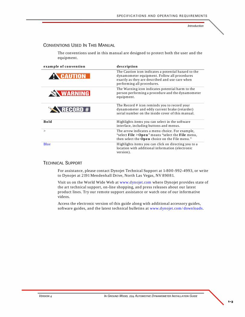
CONVENTIONS USED IN THIS MANUAL
The conventions used in this manual are designed to protect both the user and the equipment.
TECHNICAL SUPPORT
For assistance, please contact Dynojet Technical Support at 1-800-992-4993, or write to Dynojet at 2191 Mendenhall Drive, North Las Vegas, NV 89081.
Visit us on the World Wide Web at www.dynojet.com where Dynojet provides state of the art technical support, on-line shopping, and press releases about our latest product lines. Try our remote support assistance or watch one of our informative videos.
Access the electronic version of this guide along with additional accessory guides, software guides, and the latest technical bulletins at www.dynojet.com/downloads.
example of convention description
The Caution icon indicates a potential hazard to the dynamometer equipment. Follow all procedures exactly as they are described and use care when performing all procedures.
The Warning icon indicates potential harm to the person performing a procedure and the dynamometer equipment.
#RECORDThe Record # icon reminds you to record your dynamometer and eddy current brake (retarder) serial number on the inside cover of this manual.
Bold Highlights items you can select in the software interface, including buttons and menus.
> The arrow indicates a menu choice. For example, “select File >Open” means “select the File menu, then select the Open choice on the File menu.”
Blue Highlights items you can click on directing you to a location with additional information (electronic version).
C H A P T E R 1
Introduction
In Ground Model 224 Automotive Dynamometer Installation Guide
1-4
YOUR DYNO ROOM
This section is not meant to imply that a dyno room is essential to repeatable results on a Dynojet dynamometer. However, a dyno room with an engine cooling intake fan, exhaust extraction, and noise reduction capabilities can add a new dimension to your shop.
A proper dyno room design will help to ensure repeatable, accurate runs. A good dyno room should do the following:
• minimize noise
• provide a controlled environment for testing
• provide a view window (safety glass) for customers
• be designed with safety in mind
Intake Air Fan—After building your dyno room, you will need to supply an intake air fan. The intake air fan supplies air to cool the vehicle’s engine while supplying fresh oxygen for you and your vehicle to breathe. It is a common misconception that you cannot tune a vehicle without a large fan simulating exact road conditions; however, a good cooling fan is the only requirement for consistent diagnostics and tuning. The dyno room requires a minimum of seven (7) air changes per minute (CFM). Use the formula Room Volume × Air Changes Per Minute = CFM to calculate the CFM needed for your dyno room. For example, if your room is 10 x 10 x 10 (room volume is L×W×H), then 1000 × 7 = 7000 CFM. The CFM value is room size dependent.
Equalizer Box—If the air flow rate coming into the dyno room is greater than the air flow rate leaving the dyno room, the room will become pressurized. A pressurized dyno room will make measured power misleading. To compensate, you need an equalizer box. The equalizer box is a baffled (to reduce noise) vent to the outside of your dyno room. The size of the equalizer box is dependent on the size of your dyno room and the size of your fans.
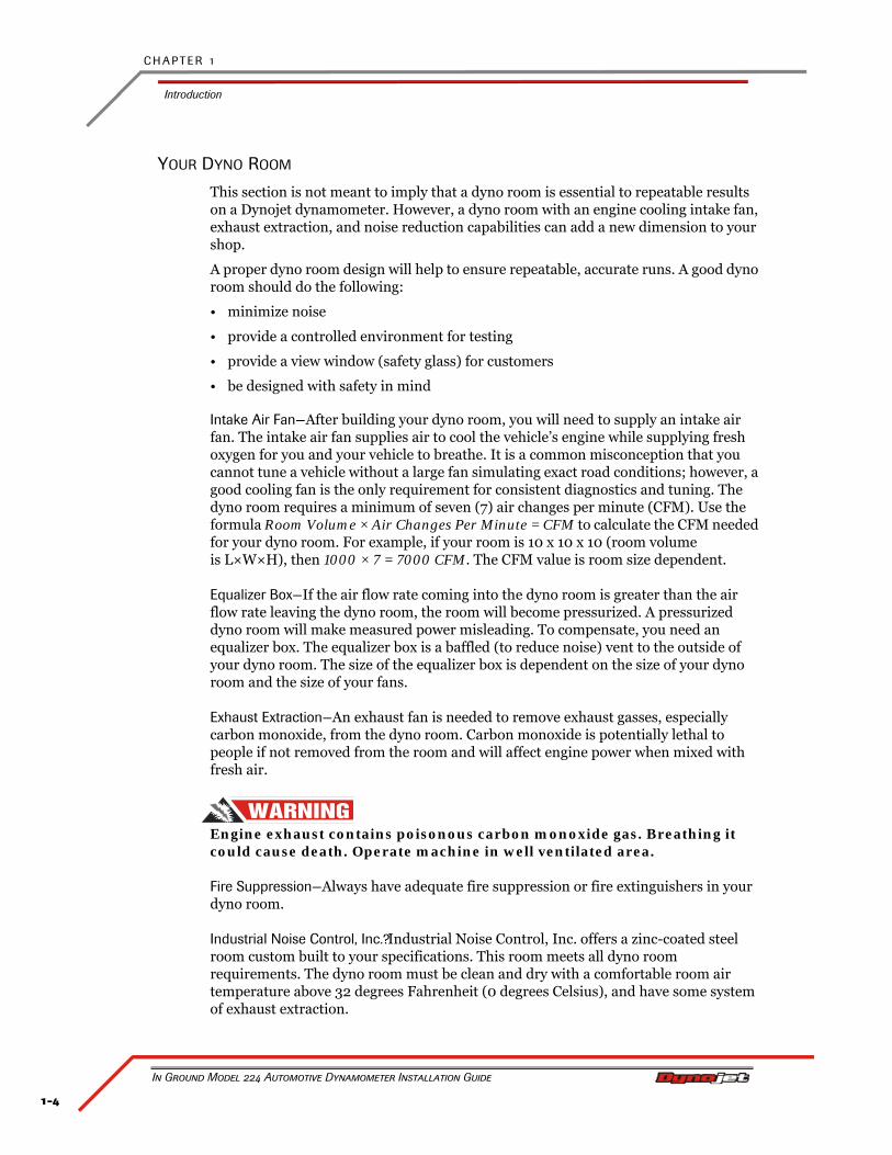
Exhaust Extraction—An exhaust fan is needed to remove exhaust gasses, especially carbon monoxide, from the dyno room. Carbon monoxide is potentially lethal to people if not removed from the room and will affect engine power when mixed with fresh air.
Engine exhaust contains poisonous carbon monoxide gas. Breathing it could cause death. Operate machine in well ventilated area.
Fire Suppression—Always have adequate fire suppression or fire extinguishers in your dyno room.
Industrial Noise Control, Inc.?Industrial Noise Control, Inc. offers a zinc-coated steel room custom built to your specifications. This room meets all dyno room requirements. The dyno room must be clean and dry with a comfortable room air temperature above 32 degrees Fahrenheit (0 degrees Celsius), and have some system of exhaust extraction.
1-5
S P E C I F I C A T I O N S A N D O P E R A T I N G R E Q U I R E M E N T S
Dynamometer Specifications and Requirements
Version 4 In Ground Model 224 Automotive Dynamometer Installation Guide
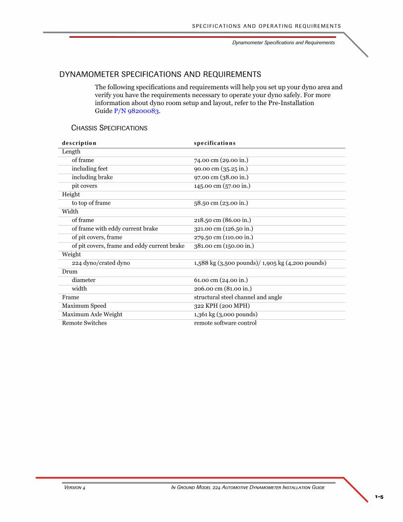
DYNAMOMETER SPECIFICATIONS AND REQUIREMENTS
The following specifications and requirements will help you set up your dyno area and verify you have the requirements necessary to operate your dyno safely. For more information about dyno room setup and layout, refer to the Pre-Installation Guide P/N 98200083.
CHASSIS SPECIFICATIONS
description specifications
Length
of frame 74.00 cm (29.00 in.)
including feet 90.00 cm (35.25 in.)
including brake 97.00 cm (38.00 in.)
pit covers 145.00 cm (57.00 in.)
Height
to top of frame 58.50 cm (23.00 in.)
Width
of frame 218.50 cm (86.00 in.)
of frame with eddy current brake 321.00 cm (126.50 in.)
of pit covers, frame 279.50 cm (110.00 in.)
of pit covers, frame and eddy current brake 381.00 cm (150.00 in.)
Weight
224 dyno/crated dyno 1,588 kg (3,500 pounds)/ 1,905 kg (4,200 pounds)
Drum
diameter 61.00 cm (24.00 in.)
width 206.00 cm (81.00 in.)
Frame structural steel channel and angle
Maximum Speed 322 KPH (200 MPH)
Maximum Axle Weight 1,361 kg (3,000 pounds)
Remote Switches remote software control
C H A P T E R 1
Dynamometer Specifications and Requirements
In Ground Model 224 Automotive Dynamometer Installation Guide
1-6
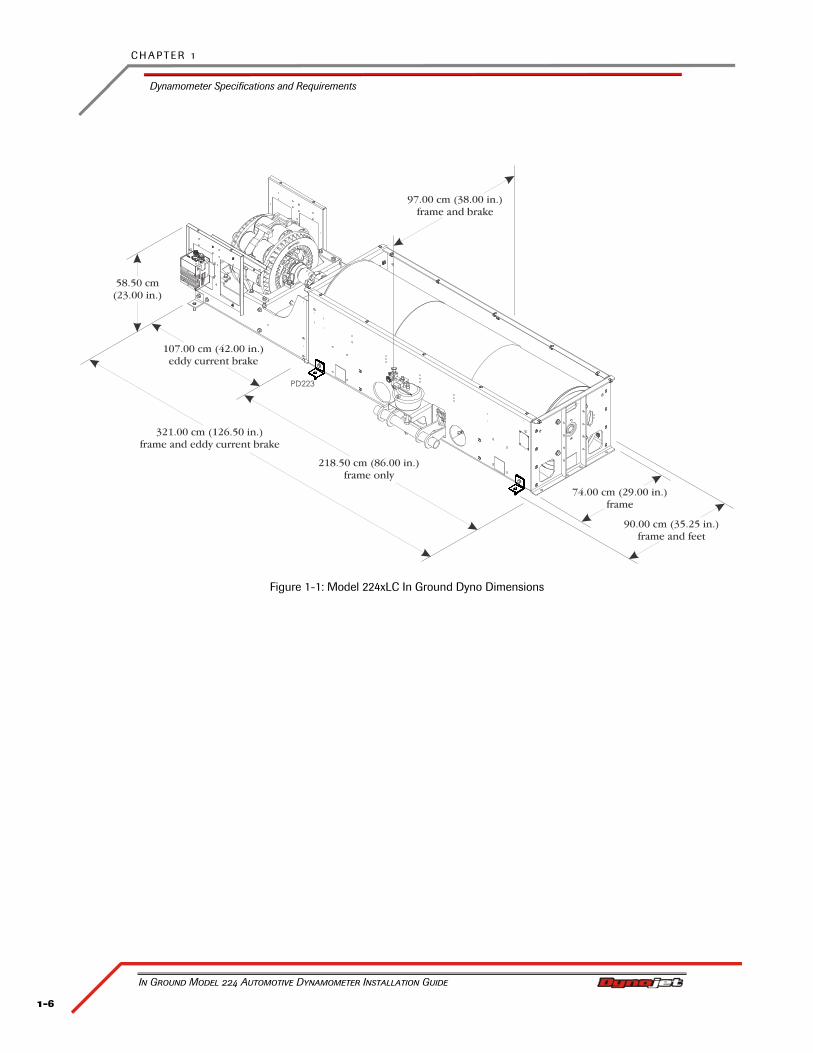
Figure 1-1: Model 224xLC In Ground Dyno Dimensions
1-7
S P E C I F I C A T I O N S A N D O P E R A T I N G R E Q U I R E M E N T S
Dynamometer Specifications and Requirements
Version 4 In Ground Model 224 Automotive Dynamometer Installation Guide
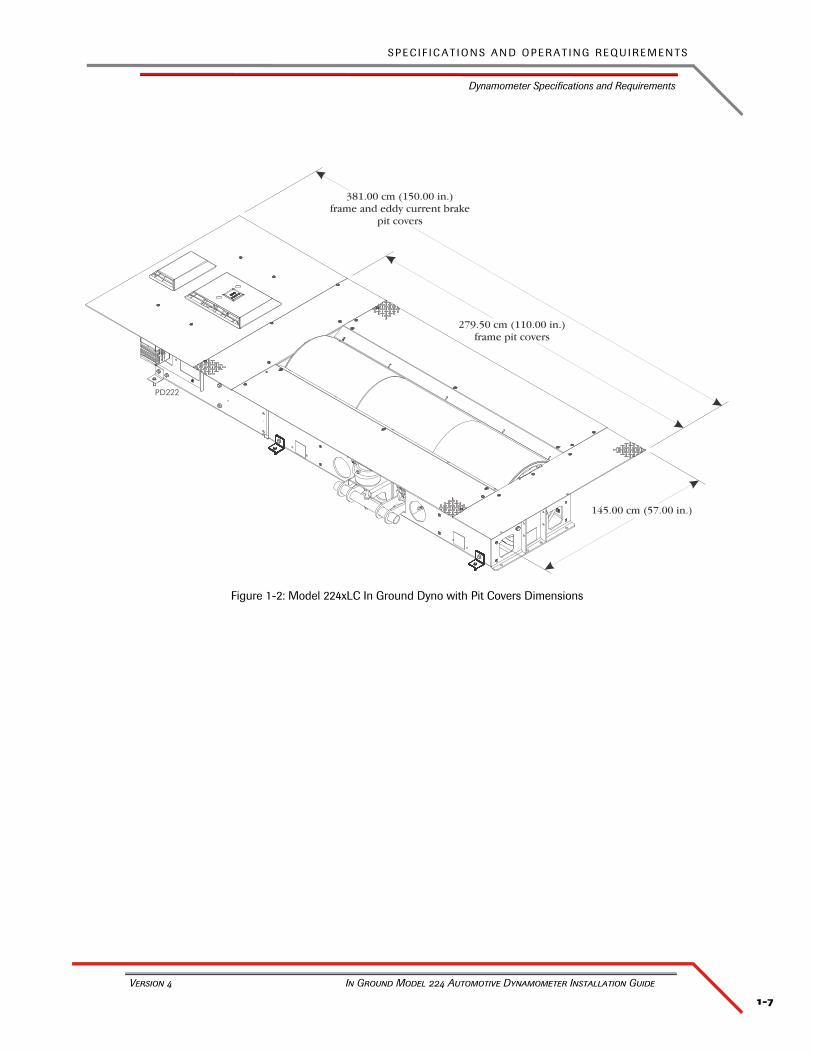
Figure 1-2: Model 224xLC In Ground Dyno with Pit Covers Dimensions
C H A P T E R 1
Dynamometer Specifications and Requirements
In Ground Model 224 Automotive Dynamometer Installation Guide
1-8
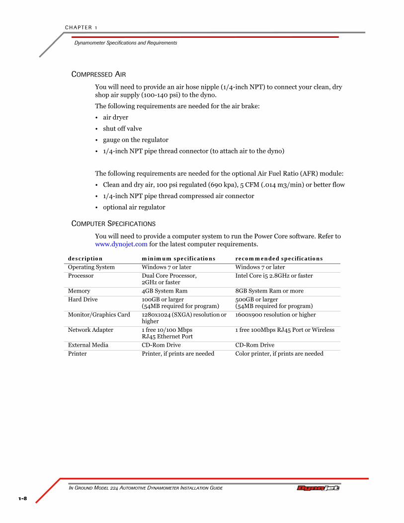
COMPRESSED AIR
You will need to provide an air hose nipple (1/4-inch NPT) to connect your clean, dry shop air supply (100-140 psi) to the dyno.
The following requirements are needed for the air brake:
• air dryer
• shut off valve
• gauge on the regulator
• 1/4-inch NPT pipe thread connector (to attach air to the dyno)
The following requirements are needed for the optional Air Fuel Ratio (AFR) module:
• Clean and dry air, 100 psi regulated (690 kpa), 5 CFM (.014 m3/min) or better flow
• 1/4-inch NPT pipe thread compressed air connector
• optional air regulator
COMPUTER SPECIFICATIONS
You will need to provide a computer system to run the Power Core software. Refer to www.dynojet.com for the latest computer requirements.
description minimum specifications recommended specifications
Operating System Windows 7 or later Windows 7 or later
Processor Dual Core Processor, 2GHz or faster
Intel Core i5 2.8GHz or faster
Memory 4GB System Ram 8GB System Ram or more
Hard Drive 100GB or larger(54MB required for program)
500GB or larger(54MB required for program)
Monitor/Graphics Card 1280x1024 (SXGA) resolution or higher
1600x900 resolution or higher
Network Adapter 1 free 10/100 MbpsRJ45 Ethernet Port
1 free 100Mbps RJ45 Port or Wireless
External Media CD-Rom Drive CD-Rom Drive
Printer Printer, if prints are needed Color printer, if prints are needed
1-9
S P E C I F I C A T I O N S A N D O P E R A T I N G R E Q U I R E M E N T S
Dynamometer Specifications and Requirements
Version 4 In Ground Model 224 Automotive Dynamometer Installation Guide
ELECTRICAL REQUIREMENTS
The eddy current braking power source require user supplied grounded electrical outlets with over current and short-circuit protection. These must be accessible to the operator to be used as a disconnect.
ENVIRONMENTAL REQUIREMENTS
FIRE SUPPRESSION
Always have adequate fire suppression or fire extinguishers in your dyno room.
FORKLIFT REQUIREMENTS
You will need to provide equipment capable of lifting a minimum of 2,722 kg. (6,000 lb.) to lift the dyno off the crate and into position in your dyno room. You will also need a pair of straps capable of supporting the uncrated dyno. Dynojet recommends using single loop style straps. Use an approved strap lifting attachment for the forklift to prevent strap slippage. Using lift straps with bare forks is not OSHA compliant.
GROUNDING REQUIREMENTS
You will need to ground the vehicle to the dyn0 before every run using the vehicle grounding kit P/N 76100015. Never operate the dyn0 without first grounding the vehicle to the dyn0. Refer to “Grounding the Vehicle” on page 4-8.
Never operate the dyno without properly grounding the vehicle to the dyno.
description specifications
Power Requirements: 4WD electronics 100-240 VAC, 50/60 Hz
Power Requirements: dyno electronics 100-240 VAC, 50/60 Hz
Power Requirements: AFR 100-240 VAC, 50/60 Hz
Power Requirements: computer Per computer manufacturer specifications
Power Requirements: optional eddy current brake
240v 30amp single phase circuit for each eddy current brakeRefer to Appendix B for more information.
description specifications
Temperature
operating min./max 10°C/50°C (50°F/122°F)
storage min./max 0°C/70°C (32°F/158°F)
Humidity 0 to 95% non-condensing
C H A P T E R 1
Dynamometer Specifications and Requirements
In Ground Model 224 Automotive Dynamometer Installation Guide
1-10
PHONE AND INTERNET ACCESS
Dynojet recommends you have a phone close to the dyno to call for assistance in an emergency. You may also wish to contact Dynojet to troubleshoot your dyno.
Internet access on your computer is desirable for contacting Dynojet and downloading new information and updates.
TIE-DOWN STRAPS
Dynojet recommends using tie-down straps for securing the car on the dyno. The dyno comes with an automotive tie-down package.
TOOL REQUIREMENTS
You will need to provide a drill and drill bit capable of drilling holes in concrete. Refer to Appendix A for more information on installing Red Head Anchors.
• drill bit size: ½-inch
• minimum hole depth: 1 ⅝-inch (41.2 mm)
1-11
S P E C I F I C A T I O N S A N D O P E R A T I N G R E Q U I R E M E N T S
Model 224xLC In Ground Automotive Dynamometer
Version 4 In Ground Model 224 Automotive Dynamometer Installation Guide
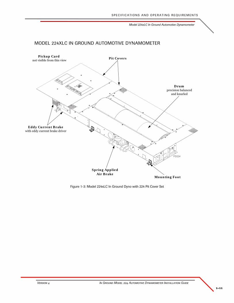
MODEL 224XLC IN GROUND AUTOMOTIVE DYNAMOMETER
Figure 1-3: Model 224xLC In Ground Dyno with 224 Pit Cover Set
Drumprecision balanced
and knurled
Spring Applied Air Brake
Pickup Card not visible from this view
Mounting Foot
Pit Covers
Eddy Current Brakewith eddy current brake driver
C H A P T E R 1
DynoWare RT Electronics
In Ground Model 224 Automotive Dynamometer Installation Guide
1-12
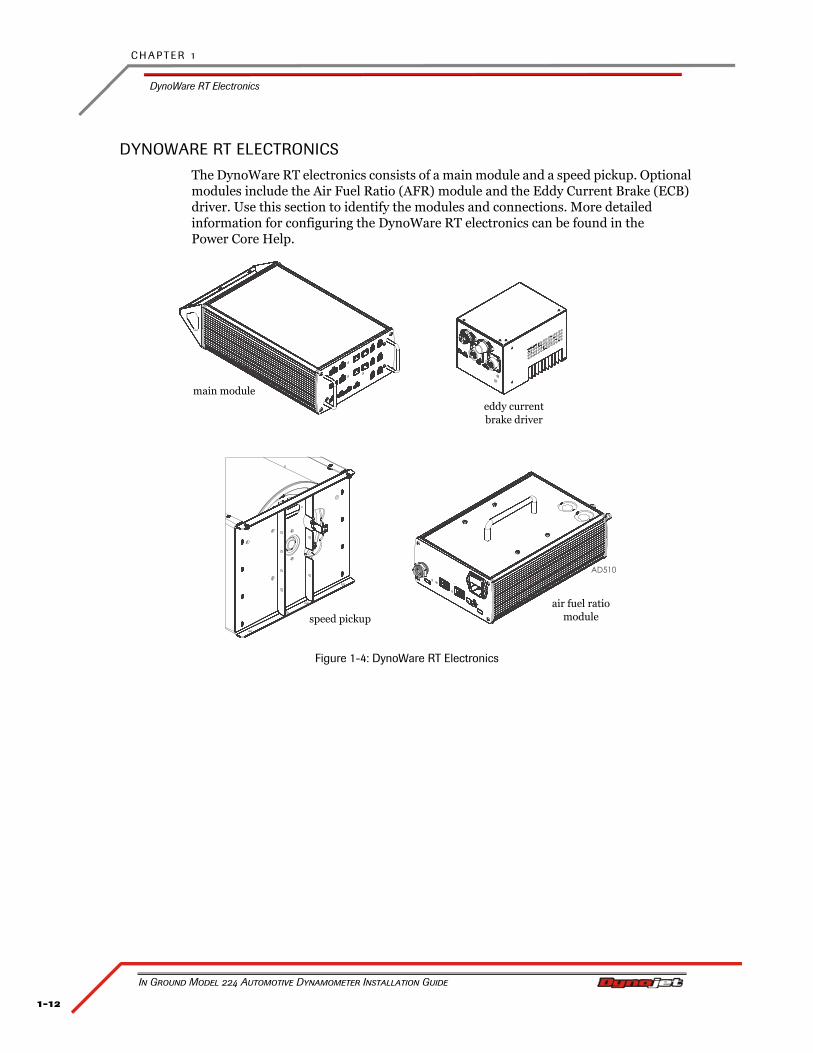
DYNOWARE RT ELECTRONICS
The DynoWare RT electronics consists of a main module and a speed pickup. Optional modules include the Air Fuel Ratio (AFR) module and the Eddy Current Brake (ECB) driver. Use this section to identify the modules and connections. More detailed information for configuring the DynoWare RT electronics can be found in the Power Core Help.
Figure 1-4: DynoWare RT Electronics
air fuel ratio module
eddy current brake driver
main module
speed pickup
1-13
S P E C I F I C A T I O N S A N D O P E R A T I N G R E Q U I R E M E N T S
DynoWare RT Electronics
Version 4 In Ground Model 224 Automotive Dynamometer Installation Guide
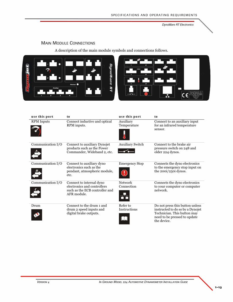
MAIN MODULE CONNECTIONS
A description of the main module symbols and connections follows.
use this port to use this port to
RPM Inputs Connect inductive and optical RPM inputs.
Auxiliary Temperature
Connect to an auxiliary input for an infrared temperature sensor.
Communication I/O Connect to auxiliary Dynojet products such as the Power Commander, Wideband 2, etc.
Auxiliary Switch Connect to the brake air pressure switch on 248 and older 224 dynos.
Communication I/O Connect to auxiliary dyno electronics such as the pendant, atmospheric module, etc.
Emergency Stop Connects the dyno electronics to the emergency stop input on the 200i/250i dynos.
Communication I/O Connect to internal dyno electronics and controllers such as the ECB controller and AFR module.
Network Connection
Connects the dyno electronics to your computer or computer network.
Drum Connect to the drum 1 and drum 2 speed inputs and digital brake outputs.
Refer to Instructions
Do not press this button unless instructed to do so by a Dynojet Technician. This button may need to be pressed to update the device.
1 2
1 2
1 2
Linx
!
C
Dynojet Research, Inc.2191 Mendenhall Drive
N. Las Vegas, NV 89081100-240 VAC
50-60 Hz1.0 A
1
2
1 2 3 4
Analog
Status
BA
A
B !
C
C H A P T E R 1
DynoWare RT Electronics
In Ground Model 224 Automotive Dynamometer Installation Guide
1-14
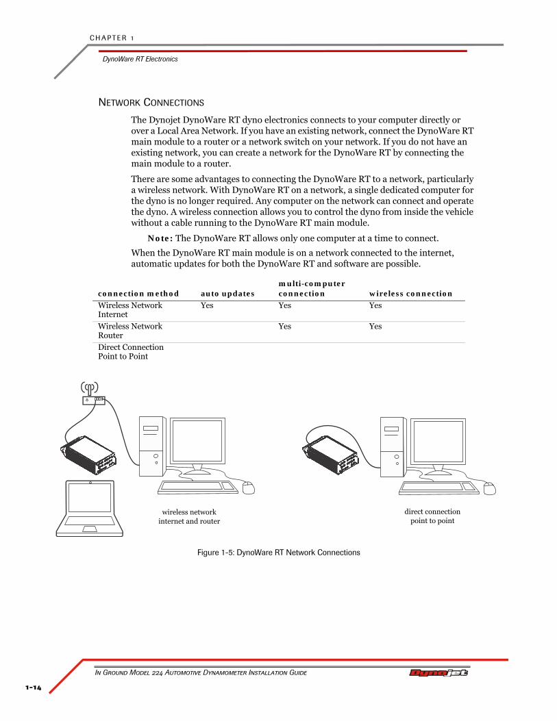
NETWORK CONNECTIONS
The Dynojet DynoWare RT dyno electronics connects to your computer directly or over a Local Area Network. If you have an existing network, connect the DynoWare RT main module to a router or a network switch on your network. If you do not have an existing network, you can create a network for the DynoWare RT by connecting the main module to a router.
There are some advantages to connecting the DynoWare RT to a network, particularly a wireless network. With DynoWare RT on a network, a single dedicated computer for the dyno is no longer required. Any computer on the network can connect and operate the dyno. A wireless connection allows you to control the dyno from inside the vehicle without a cable running to the DynoWare RT main module.
Note: The DynoWare RT allows only one computer at a time to connect.
When the DynoWare RT main module is on a network connected to the internet, automatic updates for both the DynoWare RT and software are possible.
Figure 1-5: DynoWare RT Network Connections
connection method auto updatesmulti-computer connection wireless connection
Wireless Network Internet
Yes Yes Yes
Wireless NetworkRouter
Yes Yes
Direct ConnectionPoint to Point
wireless networkinternet and router
direct connectionpoint to point
1-15
S P E C I F I C A T I O N S A N D O P E R A T I N G R E Q U I R E M E N T S
Pit Specifications
Version 4 In Ground Model 224 Automotive Dynamometer Installation Guide
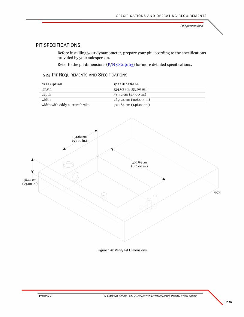
PIT SPECIFICATIONS
Before installing your dynamometer, prepare your pit according to the specifications provided by your salesperson.
Refer to the pit dimensions (P/N 98219103) for more detailed specifications.
224 PIT REQUIREMENTS AND SPECIFICATIONS
Figure 1-6: Verify Pit Dimensions
description specifications
length 134.62 cm (53.00 in.)
depth 58.42 cm (23.00 in.)
width 269.24 cm (106.00 in.)
width with eddy current brake 370.84 cm (146.00 in.)
134.62 cm(53.00 in.)
370.84 cm(146.00 in.)
58.42 cm(23.00 in.)

2-1
In Ground Model 224 Automotive Dynamometer Installation Guide
CHAPTER 2
DYNO INSTALLATION
This chapter will walk you through unpacking and installing the dynamometer. To ensure safety and accuracy in the procedures, perform the procedures as they are described.
This chapter is divided into the following categories:
• Unpacking and Inspecting the Dyno, page 2-2
• Dyno Installation, page 2-5
• Eddy Current Brake Installation, page 2-8
• Cable Routing, page 2-9
• Pit Cover Installation, page 2-14
• Ground Hook Installation, page 2-16
C H A P T E R 2
Unpacking and Inspecting the Dyno
In Ground Model 224 Automotive Dynamometer Installation Guide
2-2
UNPACKING AND INSPECTING THE DYNO
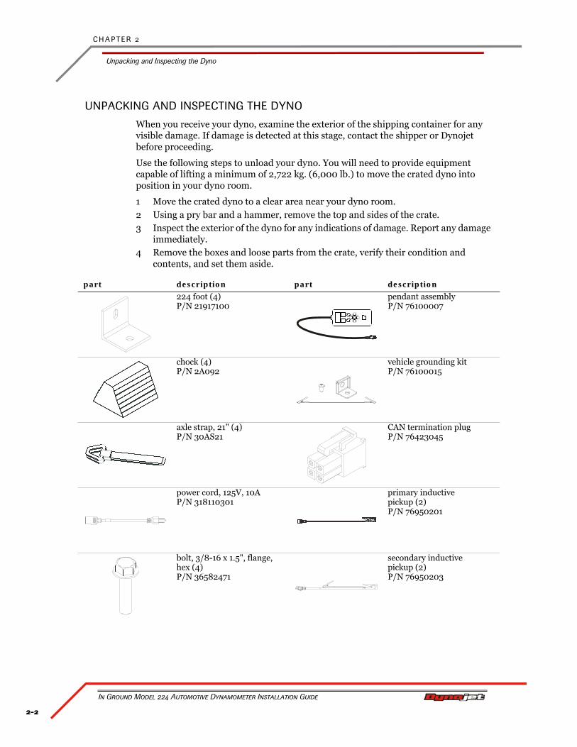
When you receive your dyno, examine the exterior of the shipping container for any visible damage. If damage is detected at this stage, contact the shipper or Dynojet before proceeding.
Use the following steps to unload your dyno. You will need to provide equipment capable of lifting a minimum of 2,722 kg. (6,000 lb.) to move the crated dyno into position in your dyno room.
1 Move the crated dyno to a clear area near your dyno room.2 Using a pry bar and a hammer, remove the top and sides of the crate.3 Inspect the exterior of the dyno for any indications of damage. Report any damage
immediately.4 Remove the boxes and loose parts from the crate, verify their condition and
contents, and set them aside.
part description part description
224 foot (4)P/N 21917100
pendant assemblyP/N 76100007
chock (4)P/N 2A092
vehicle grounding kitP/N 76100015
axle strap, 21" (4)P/N 30AS21
CAN termination plugP/N 76423045
power cord, 125V, 10AP/N 318110301
primary inductive pickup (2)P/N 76950201
bolt, 3/8-16 x 1.5", flange, hex (4)P/N 36582471
secondary inductive pickup (2)P/N 76950203
2-3
D Y N O I N S T A L L A T I O N
Unpacking and Inspecting the Dyno
Version 4 In Ground Model 224 Automotive Dynamometer Installation Guide
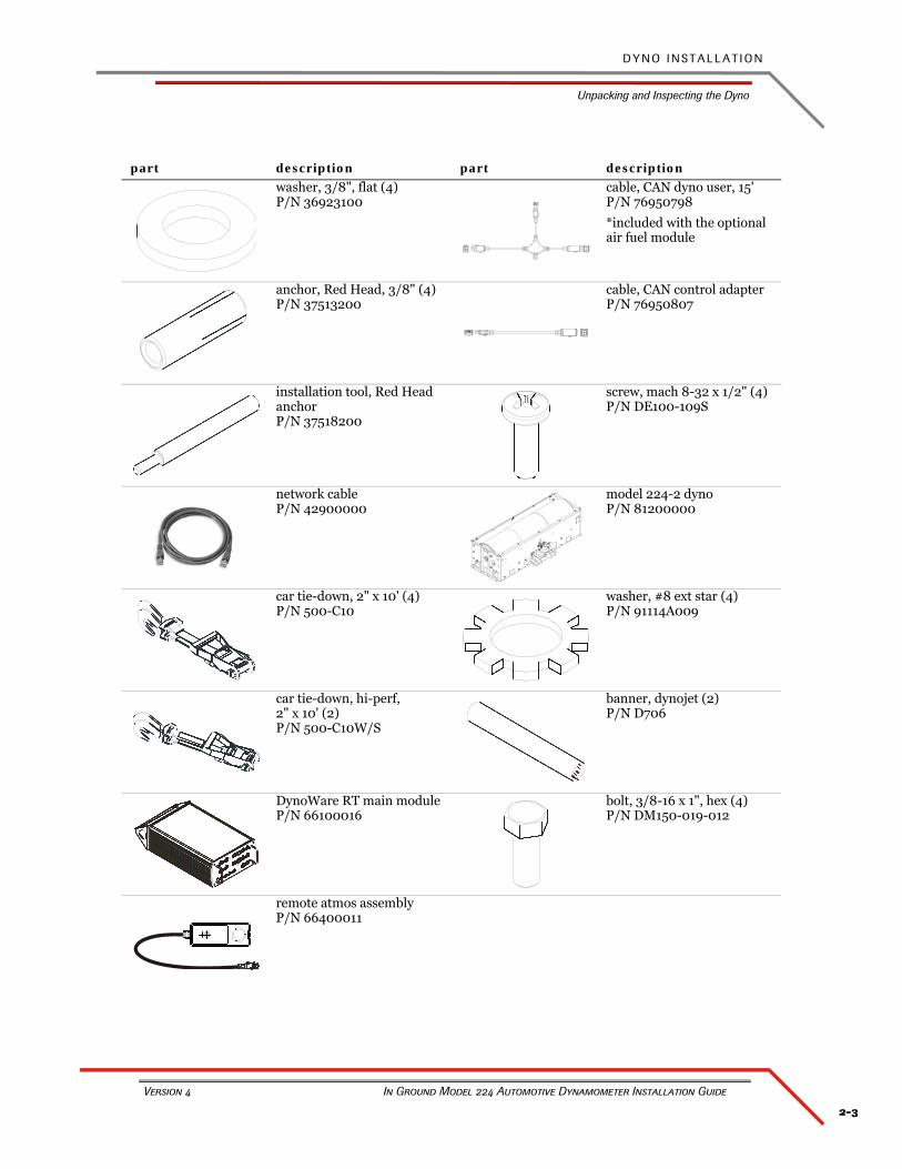
washer, 3/8", flat (4)P/N 36923100
cable, CAN dyno user, 15'P/N 76950798
*included with the optional air fuel module
anchor, Red Head, 3/8" (4)P/N 37513200
cable, CAN control adapterP/N 76950807
installation tool, Red Head anchorP/N 37518200
screw, mach 8-32 x 1/2" (4)P/N DE100-109S
network cableP/N 42900000
model 224-2 dynoP/N 81200000
car tie-down, 2" x 10' (4)P/N 500-C10
washer, #8 ext star (4)P/N 91114A009
car tie-down, hi-perf, 2" x 10' (2)P/N 500-C10W/S
banner, dynojet (2)P/N D706
DynoWare RT main moduleP/N 66100016
bolt, 3/8-16 x 1", hex (4)P/N DM150-019-012
remote atmos assemblyP/N 66400011
part description part description
C H A P T E R 2
Unpacking and Inspecting the Dyno
In Ground Model 224 Automotive Dynamometer Installation Guide
2-4
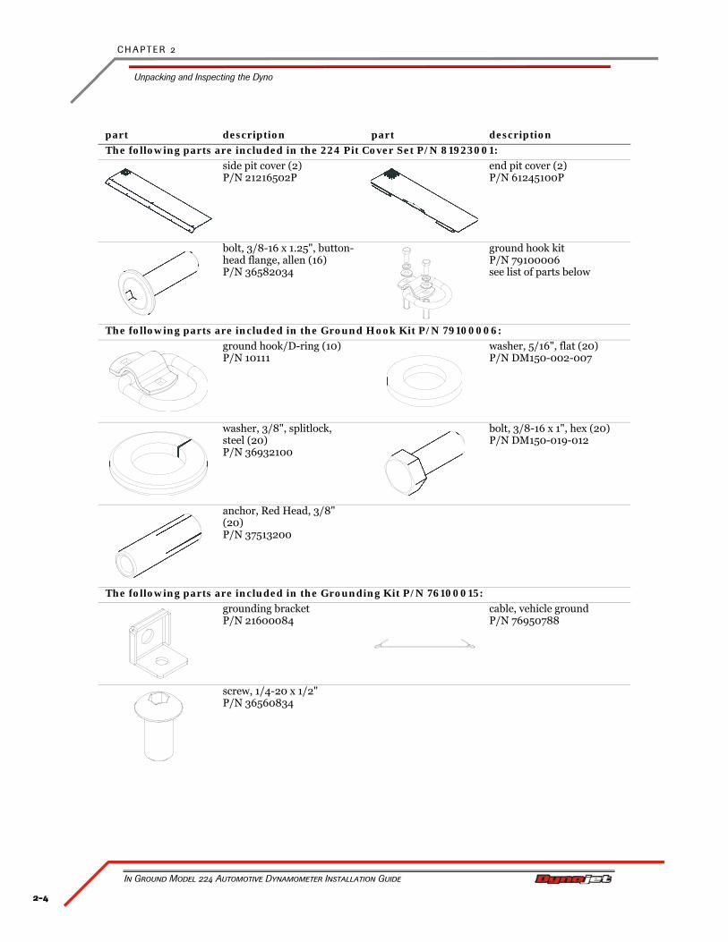
The following parts are included in the 224 Pit Cover Set P/N 81923001:
side pit cover (2)P/N 21216502P
end pit cover (2)P/N 61245100P
bolt, 3/8-16 x 1.25", button-head flange, allen (16)P/N 36582034
ground hook kit P/N 79100006see list of parts below
The following parts are included in the Ground Hook Kit P/N 79100006:
ground hook/D-ring (10)P/N 10111
washer, 5/16", flat (20)P/N DM150-002-007
washer, 3/8", splitlock, steel (20)P/N 36932100
bolt, 3/8-16 x 1", hex (20)P/N DM150-019-012
anchor, Red Head, 3/8" (20)P/N 37513200
The following parts are included in the Grounding Kit P/N 76100015:
grounding bracketP/N 21600084
cable, vehicle groundP/N 76950788
screw, 1/4-20 x 1/2"P/N 36560834
part description part description
2-5
D Y N O I N S T A L L A T I O N
Dyno Installation
Version 4 In Ground Model 224 Automotive Dynamometer Installation Guide
DYNO INSTALLATION
This section will walk you through removing the dyno from the crate and installing the dyno in the pit.
REMOVING THE DYNO FROM THE CRATE
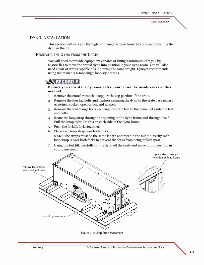
You will need to provide equipment capable of lifting a minimum of 2,722 kg.(6,000 lb.) to move the crated dyno into position in your dyno room. You will also need a pair of straps capable of supporting the same weight. Dynojet recommends using two 2-inch x 6-foot single loop style straps.
#RECORDBe sure you record the dynamometer number on the inside cover of this manual.1 Remove the crate braces that support the top portion of the crate.2 Remove the four lag bolts and washers securing the dyno to the crate base using a
9/16-inch socket, open or box end wrench.3 Remove the four flange bolts securing the crate feet to the dyno. Set aside the feet
and bolts.4 Route the loop strap through the opening in the dyno frame and through itself.
Pull the strap tight. Do this on each side of the dyno frame.5 Push the forklift forks together.6 Place each loop strap over both forks.
Note: The straps must be the same length and meet in the middle. Verify each loop strap is over both forks to prevent the forks from being pulled apart.
7 Using the forklift, carefully lift the dyno off the crate and move it into position in your dyno room.
Figure 2-1: Loop Strap Placement
place strap through opening in dyno frame
record dyno number
remove feet and set aside feet and bolts
C H A P T E R 2
Dyno Installation
In Ground Model 224 Automotive Dynamometer Installation Guide
2-6
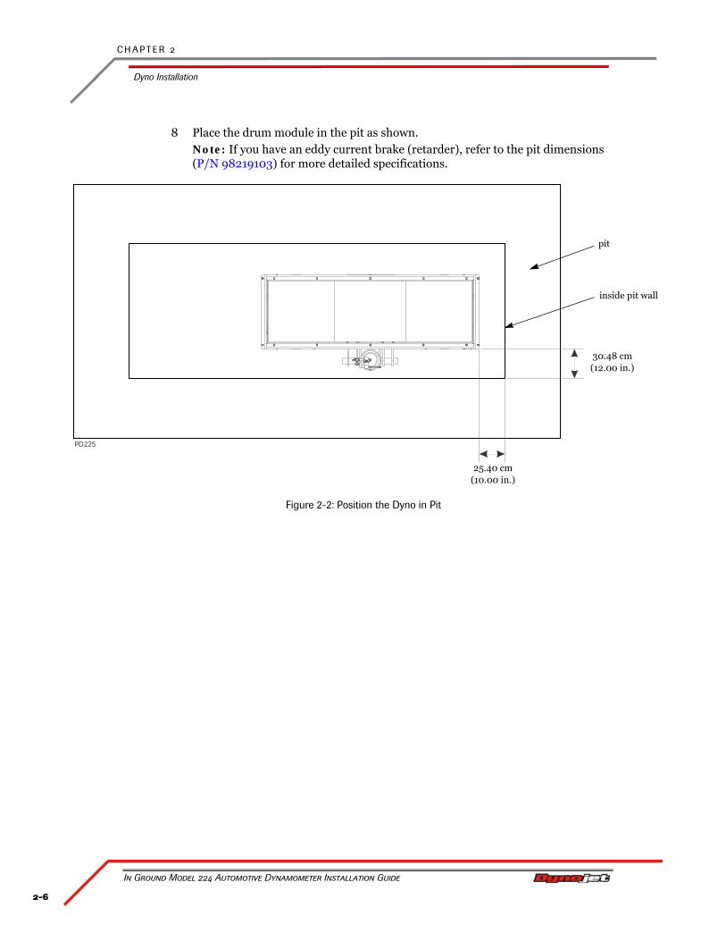
8 Place the drum module in the pit as shown.Note: If you have an eddy current brake (retarder), refer to the pit dimensions (P/N 98219103) for more detailed specifications.
Figure 2-2: Position the Dyno in Pit
P 225D
30.48 cm(12.00 in.)
25.40 cm(10.00 in.)
pit
inside pit wall
2-7
D Y N O I N S T A L L A T I O N
Dyno Installation
Version 4 In Ground Model 224 Automotive Dynamometer Installation Guide
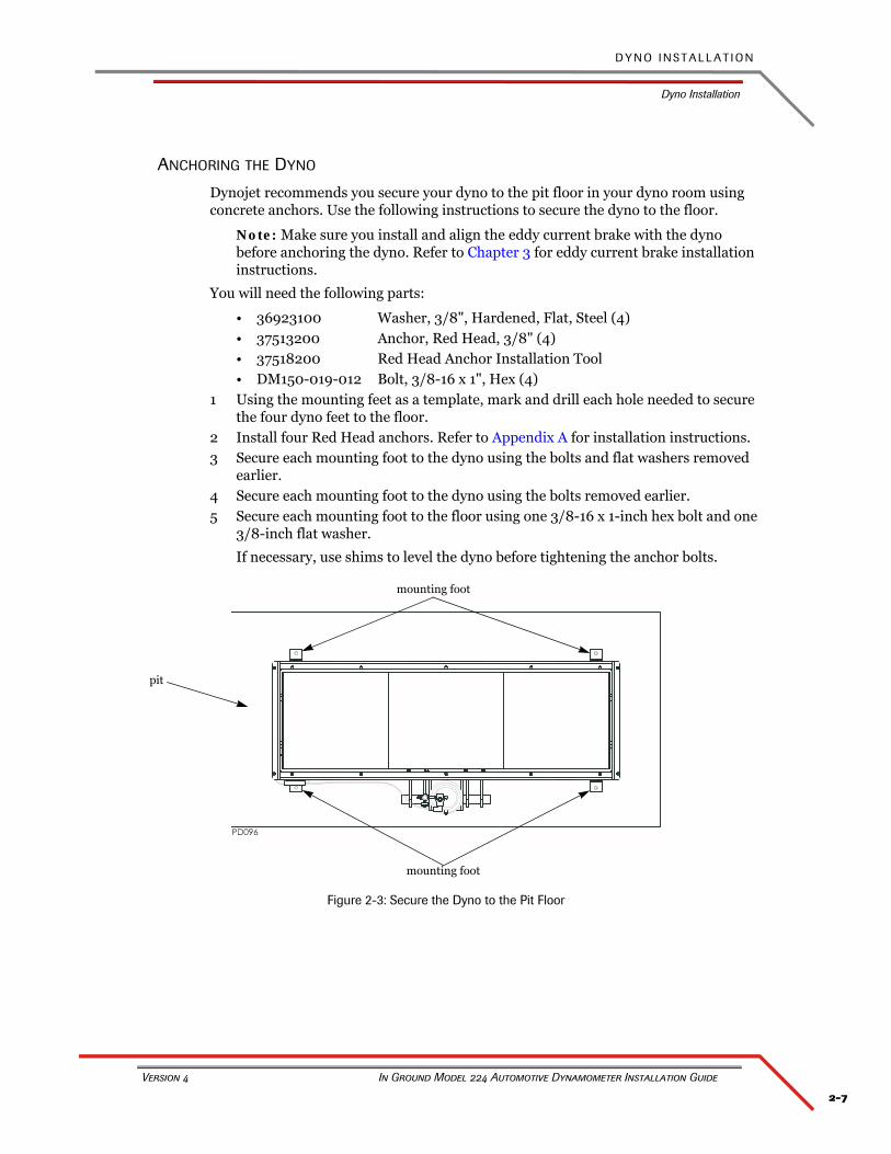
ANCHORING THE DYNO
Dynojet recommends you secure your dyno to the pit floor in your dyno room using concrete anchors. Use the following instructions to secure the dyno to the floor.
Note: Make sure you install and align the eddy current brake with the dyno before anchoring the dyno. Refer to Chapter 3 for eddy current brake installation instructions.
You will need the following parts:
• 36923100 Washer, 3/8", Hardened, Flat, Steel (4)• 37513200 Anchor, Red Head, 3/8" (4)• 37518200 Red Head Anchor Installation Tool• DM150-019-012 Bolt, 3/8-16 x 1", Hex (4)
1 Using the mounting feet as a template, mark and drill each hole needed to secure the four dyno feet to the floor.
2 Install four Red Head anchors. Refer to Appendix A for installation instructions.3 Secure each mounting foot to the dyno using the bolts and flat washers removed
earlier.4 Secure each mounting foot to the dyno using the bolts removed earlier.5 Secure each mounting foot to the floor using one 3/8-16 x 1-inch hex bolt and one
3/8-inch flat washer.
If necessary, use shims to level the dyno before tightening the anchor bolts.
Figure 2-3: Secure the Dyno to the Pit Floor
mounting foot
mounting foot
pit
C H A P T E R 2
Eddy Current Brake Installation
In Ground Model 224 Automotive Dynamometer Installation Guide
2-8
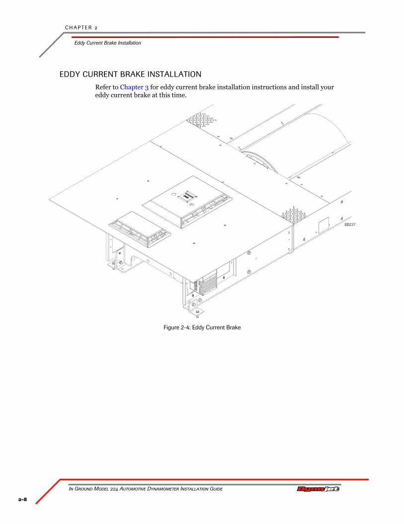
EDDY CURRENT BRAKE INSTALLATION
Refer to Chapter 3 for eddy current brake installation instructions and install your eddy current brake at this time.
Figure 2-4: Eddy Current Brake
EB237
2-9
D Y N O I N S T A L L A T I O N
Cable Routing
Version 4 In Ground Model 224 Automotive Dynamometer Installation Guide
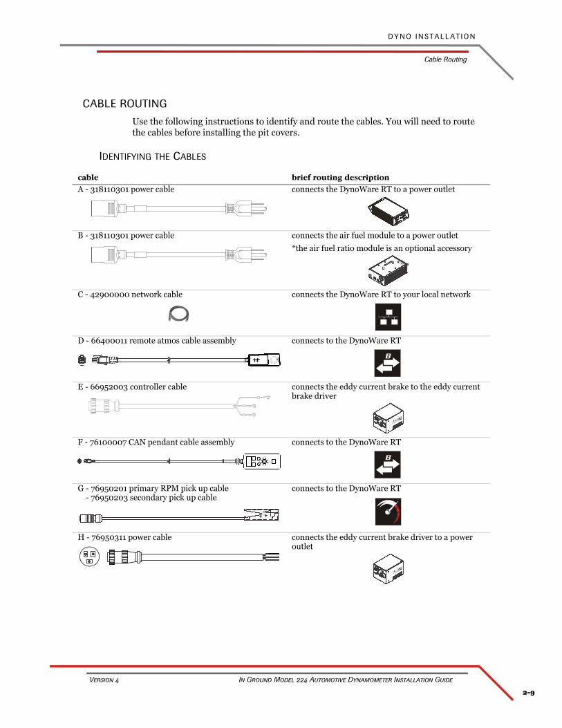
CABLE ROUTING
Use the following instructions to identify and route the cables. You will need to route the cables before installing the pit covers.
IDENTIFYING THE CABLES
cable brief routing description
A - 318110301 power cable connects the DynoWare RT to a power outlet
B - 318110301 power cable connects the air fuel module to a power outlet
*the air fuel ratio module is an optional accessory
C - 42900000 network cable connects the DynoWare RT to your local network
D - 66400011 remote atmos cable assembly connects to the DynoWare RT
E - 66952003 controller cable connects the eddy current brake to the eddy current brake driver
F - 76100007 CAN pendant cable assembly connects to the DynoWare RT
G - 76950201 primary RPM pick up cable - 76950203 secondary pick up cable
connects to the DynoWare RT
H - 76950311 power cable connects the eddy current brake driver to a power outlet
B
B
C H A P T E R 2
Cable Routing
In Ground Model 224 Automotive Dynamometer Installation Guide
2-10
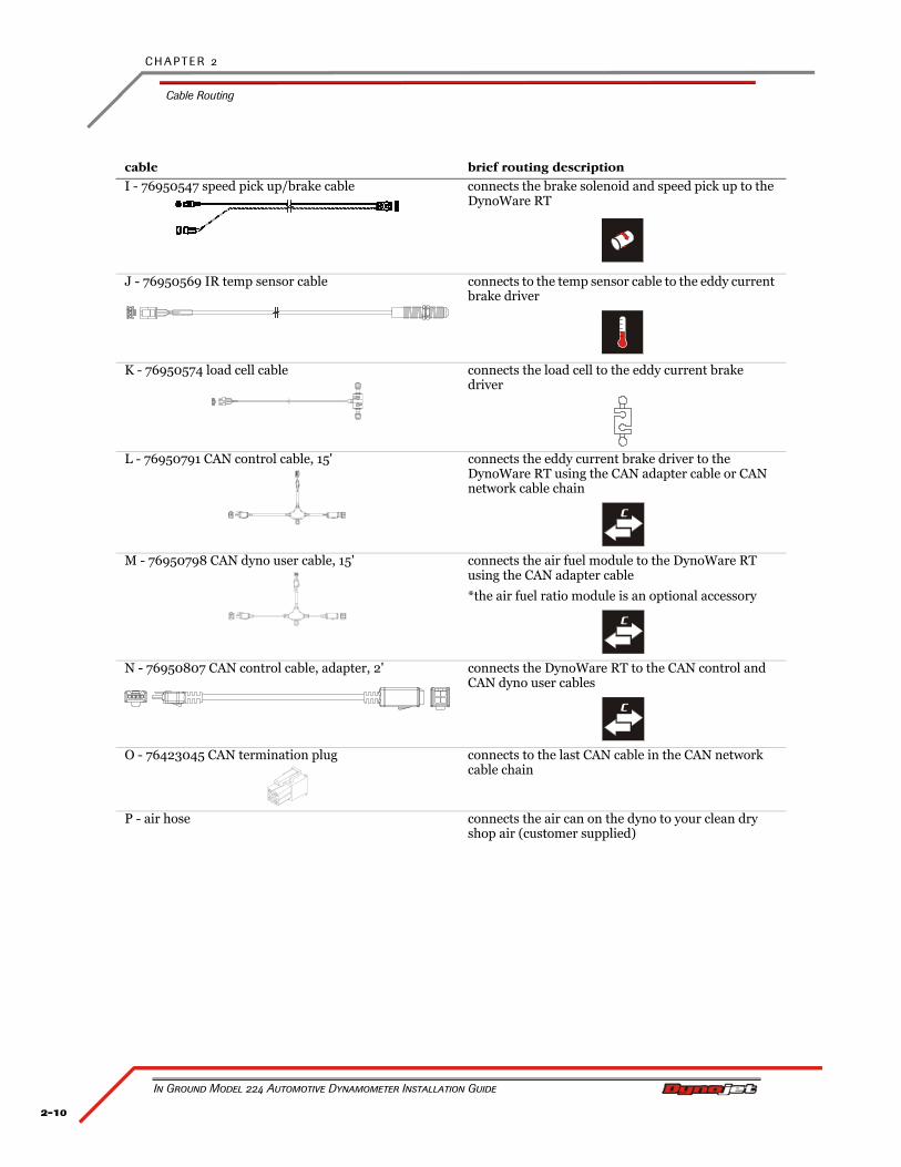
I - 76950547 speed pick up/brake cable connects the brake solenoid and speed pick up to the DynoWare RT
J - 76950569 IR temp sensor cable connects to the temp sensor cable to the eddy current brake driver
K - 76950574 load cell cable connects the load cell to the eddy current brake driver
L - 76950791 CAN control cable, 15' connects the eddy current brake driver to the DynoWare RT using the CAN adapter cable or CAN network cable chain
M - 76950798 CAN dyno user cable, 15' connects the air fuel module to the DynoWare RT using the CAN adapter cable
*the air fuel ratio module is an optional accessory
N - 76950807 CAN control cable, adapter, 2' connects the DynoWare RT to the CAN control and CAN dyno user cables
O - 76423045 CAN termination plug connects to the last CAN cable in the CAN network cable chain
P - air hose connects the air can on the dyno to your clean dry shop air (customer supplied)
cable brief routing description
C
C
C
2-11
D Y N O I N S T A L L A T I O N
Cable Routing
Version 4 In Ground Model 224 Automotive Dynamometer Installation Guide
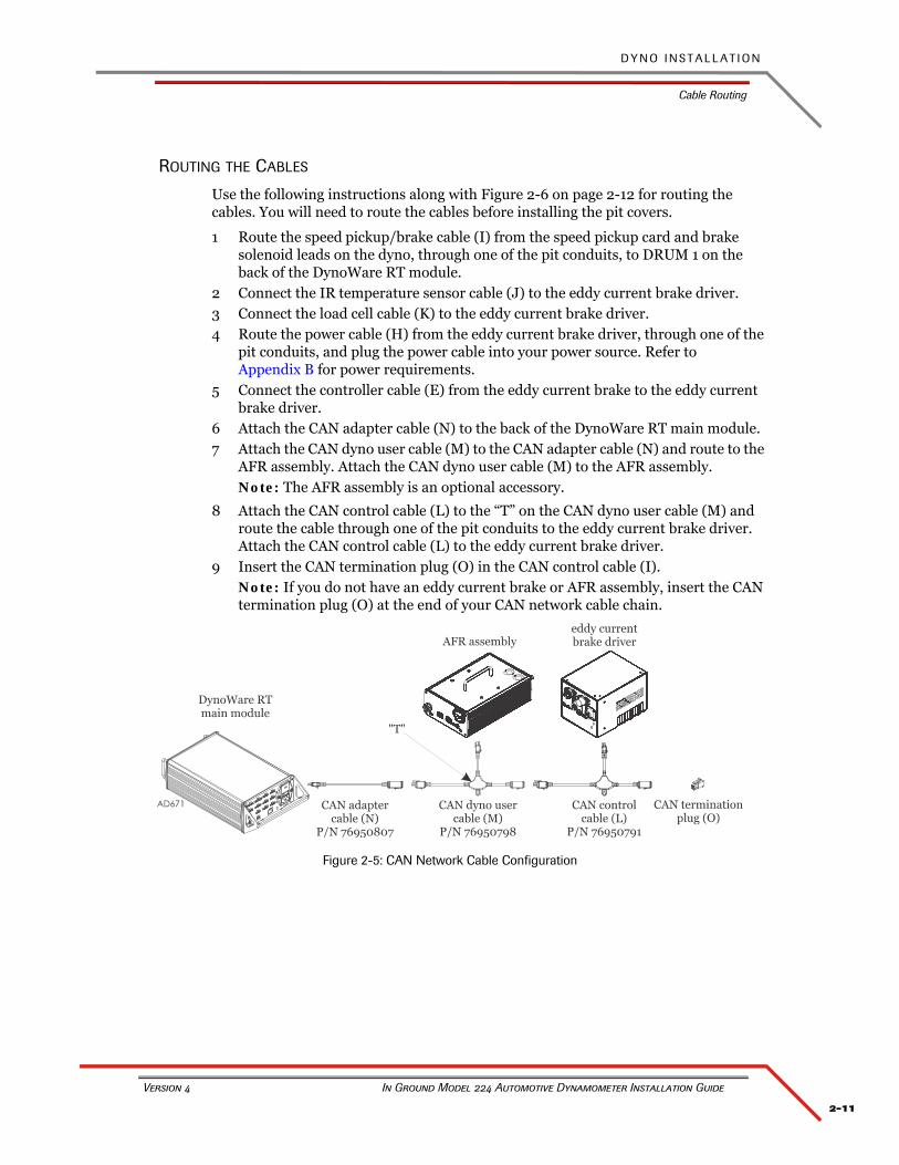
ROUTING THE CABLES
Use the following instructions along with Figure 2-6 on page 2-12 for routing the cables. You will need to route the cables before installing the pit covers.
1 Route the speed pickup/brake cable (I) from the speed pickup card and brake solenoid leads on the dyno, through one of the pit conduits, to DRUM 1 on the back of the DynoWare RT module.
2 Connect the IR temperature sensor cable (J) to the eddy current brake driver.3 Connect the load cell cable (K) to the eddy current brake driver.4 Route the power cable (H) from the eddy current brake driver, through one of the
pit conduits, and plug the power cable into your power source. Refer to Appendix B for power requirements.
5 Connect the controller cable (E) from the eddy current brake to the eddy current brake driver.
6 Attach the CAN adapter cable (N) to the back of the DynoWare RT main module.7 Attach the CAN dyno user cable (M) to the CAN adapter cable (N) and route to the
AFR assembly. Attach the CAN dyno user cable (M) to the AFR assembly.Note: The AFR assembly is an optional accessory.
8 Attach the CAN control cable (L) to the “T” on the CAN dyno user cable (M) and route the cable through one of the pit conduits to the eddy current brake driver. Attach the CAN control cable (L) to the eddy current brake driver.
9 Insert the CAN termination plug (O) in the CAN control cable (I).Note: If you do not have an eddy current brake or AFR assembly, insert the CAN termination plug (O) at the end of your CAN network cable chain.
Figure 2-5: CAN Network Cable Configuration
C H A P T E R 2
Cable Routing
In Ground Model 224 Automotive Dynamometer Installation Guide
2-12
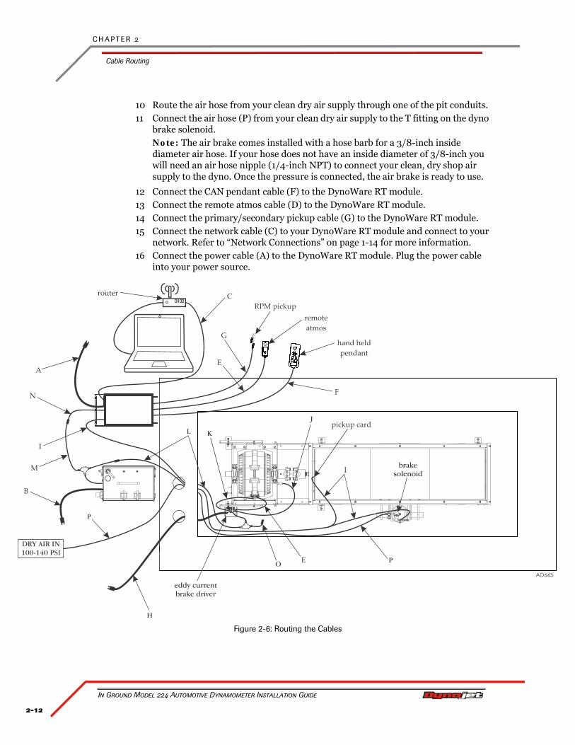
10 Route the air hose from your clean dry air supply through one of the pit conduits.11 Connect the air hose (P) from your clean dry air supply to the T fitting on the dyno
brake solenoid.Note: The air brake comes installed with a hose barb for a 3/8-inch inside diameter air hose. If your hose does not have an inside diameter of 3/8-inch you will need an air hose nipple (1/4-inch NPT) to connect your clean, dry shop air supply to the dyno. Once the pressure is connected, the air brake is ready to use.
12 Connect the CAN pendant cable (F) to the DynoWare RT module.13 Connect the remote atmos cable (D) to the DynoWare RT module.14 Connect the primary/secondary pickup cable (G) to the DynoWare RT module.15 Connect the network cable (C) to your DynoWare RT module and connect to your
network. Refer to “Network Connections” on page 1-14 for more information.16 Connect the power cable (A) to the DynoWare RT module. Plug the power cable
into your power source.
Figure 2-6: Routing the Cables
2-13
D Y N O I N S T A L L A T I O N
Cable Routing
Version 4 In Ground Model 224 Automotive Dynamometer Installation Guide
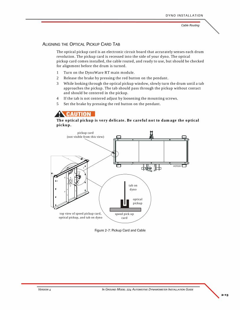
ALIGNING THE OPTICAL PICKUP CARD TAB
The optical pickup card is an electronic circuit board that accurately senses each drum revolution. The pickup card is recessed into the side of your dyno. The optical pickup card comes installed, the cable routed, and ready to use, but should be checked for alignment before the drum is turned.
1 Turn on the DynoWare RT main module.2 Release the brake by pressing the red button on the pendant.3 While looking through the optical pickup window, slowly turn the drum until a tab
approaches the pickup. The tab should pass through the pickup without contact and should be centered in the pickup.
4 If the tab is not centered adjust by loosening the mounting screws.5 Set the brake by pressing the red button on the pendant.
The optical pickup is very delicate. Be careful not to damage the optical pickup.
Figure 2-7: Pickup Card and Cable
AD516
optical pickup
pickup card(not visible from this view)
tab on dyno
speed pick up card
top view of speed pickup card, optical pickup, and tab on dyno
C H A P T E R 2
Pit Cover Installation
In Ground Model 224 Automotive Dynamometer Installation Guide
2-14
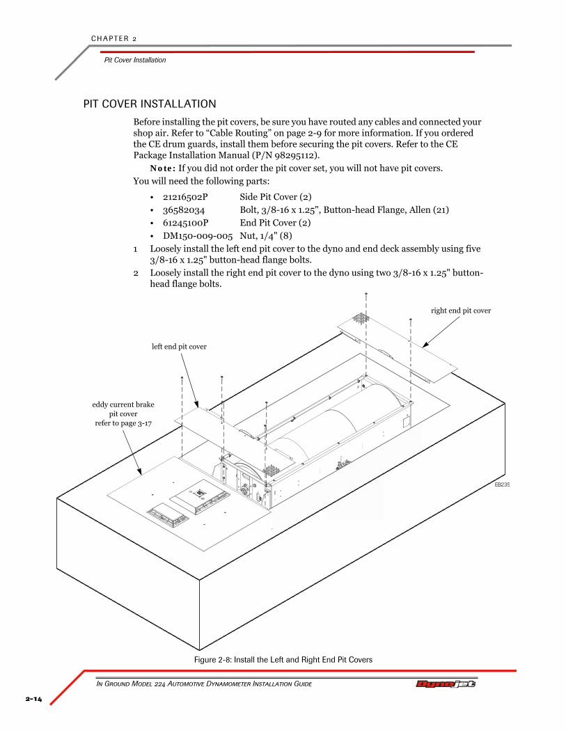
PIT COVER INSTALLATION
Before installing the pit covers, be sure you have routed any cables and connected your shop air. Refer to “Cable Routing” on page 2-9 for more information. If you ordered the CE drum guards, install them before securing the pit covers. Refer to the CE Package Installation Manual (P/N 98295112).
Note: If you did not order the pit cover set, you will not have pit covers.You will need the following parts:
• 21216502P Side Pit Cover (2)• 36582034 Bolt, 3/8-16 x 1.25", Button-head Flange, Allen (21)• 61245100P End Pit Cover (2)• DM150-009-005 Nut, 1/4" (8)
1 Loosely install the left end pit cover to the dyno and end deck assembly using five 3/8-16 x 1.25" button-head flange bolts.
2 Loosely install the right end pit cover to the dyno using two 3/8-16 x 1.25" button-head flange bolts.
Figure 2-8: Install the Left and Right End Pit Covers
EB235
eddy current brakepit cover
refer to page 3-17
left end pit cover
right end pit cover
2-15
D Y N O I N S T A L L A T I O N
Pit Cover Installation
Version 4 In Ground Model 224 Automotive Dynamometer Installation Guide
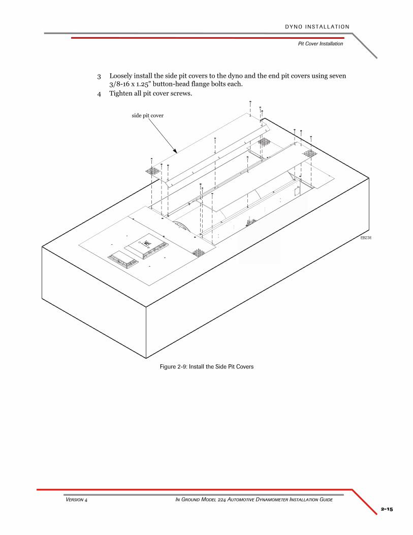
3 Loosely install the side pit covers to the dyno and the end pit covers using seven 3/8-16 x 1.25" button-head flange bolts each.
4 Tighten all pit cover screws.
Figure 2-9: Install the Side Pit Covers
EB236
side pit cover
C H A P T E R 2
Ground Hook Installation
In Ground Model 224 Automotive Dynamometer Installation Guide
2-16
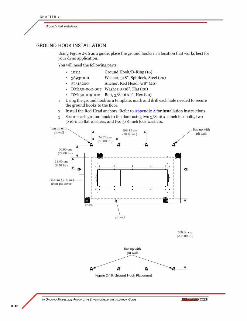
GROUND HOOK INSTALLATION
Using Figure 2-10 as a guide, place the ground hooks in a location that works best for your dyno application.
You will need the following parts:
• 10111 Ground Hook/D-Ring (10)• 36932100 Washer, 3/8", Splitlock, Steel (20)• 37513200 Anchor, Red Head, 3/8" (20)• DM150-002-007 Washer, 5/16", Flat (20)• DM150-019-012 Bolt, 3/8-16 x 1", Hex (20)
1 Using the ground hook as a template, mark and drill each hole needed to secure the ground hooks to the floor.
2 Install the Red Head anchors. Refer to Appendix A for installation instructions.3 Secure each ground hook to the floor using two 3/8-16 x 1-inch hex bolts, two
5/16-inch flat washers, and two 3/8-inch lock washers.
Figure 2-10: Ground Hook Placement
A 530D
198.12 cm(78.00 in.)
7.62 cm (3.00 in.)from pit cover
76.20 cm(30.00 in.)
60.96 cm(24.00 in.)
21.59 cm(8.50 in.)
508.00 cm(200.00 in.)
line up with pit wall
pit wall
line up with pit wall
line up with pit wall
3-1
In Ground Model 224 Automotive Dynamometer Installation Guide
CHAPTER 3
EDDY CURRENT BRAKE INSTALLATION
The eddy current brake, when added to Dynojet’s market leading inertia dynamometer, results in a complete vehicle performance test.
This chapter provides instructions for installing the eddy current brake (retarder) to the model 224 automotive dynamometer. This chapter also provides instructions for installing the load cell along with load cell calibration procedures. To ensure safety and accuracy in the procedures, perform the procedures as they are described.
This chapter is divided into the following categories:
• Eddy Current Brake Installation, page 3-2
• Load Cell Calibration, page 3-18
C H A P T E R 3
Eddy Current Brake Installation
In Ground Model 224 Automotive Dynamometer Installation Guide
3-2
EDDY CURRENT BRAKE INSTALLATION
This section will walk you through removing the eddy current brake from the crate, installing the eddy current brake to the dyno, and installing the eddy current brake driver.
You will need to provide equipment capable of lifting the eddy current brake off the crate and into position in your dyno room. You will also need a pair of straps. Dynojet recommends using single loop style straps.
Refer to Appendix B for information on the power requirements for the eddy current brake.
To prevent possible injury, turn off the dyno electronics and unplug the dyno.
BEFORE INSTALLING THE EDDY CURRENT BRAKE—VERIFY OPTIMAL BRAKE COOLING
Placing the eddy current brake on the left or right side of the dyno will determine the direction that it turns.
For optimal eddy current brake cooling, the brake should turn in the direction of the arrows on the rotors.
When running mostly rear wheel drive cars, orient the dyno and brake so the brake is turning in the direction of the arrows when a rear wheel drive car is on the dyno.
Note: The dyno will function correctly for front wheel drive cars, but cooling of the rotors will not be optimal.
3-3
E D D Y C U R R E N T B R A K E I N S T A L L A T I O N
Eddy Current Brake Installation
Version 4 In Ground Model 224 Automotive Dynamometer Installation Guide
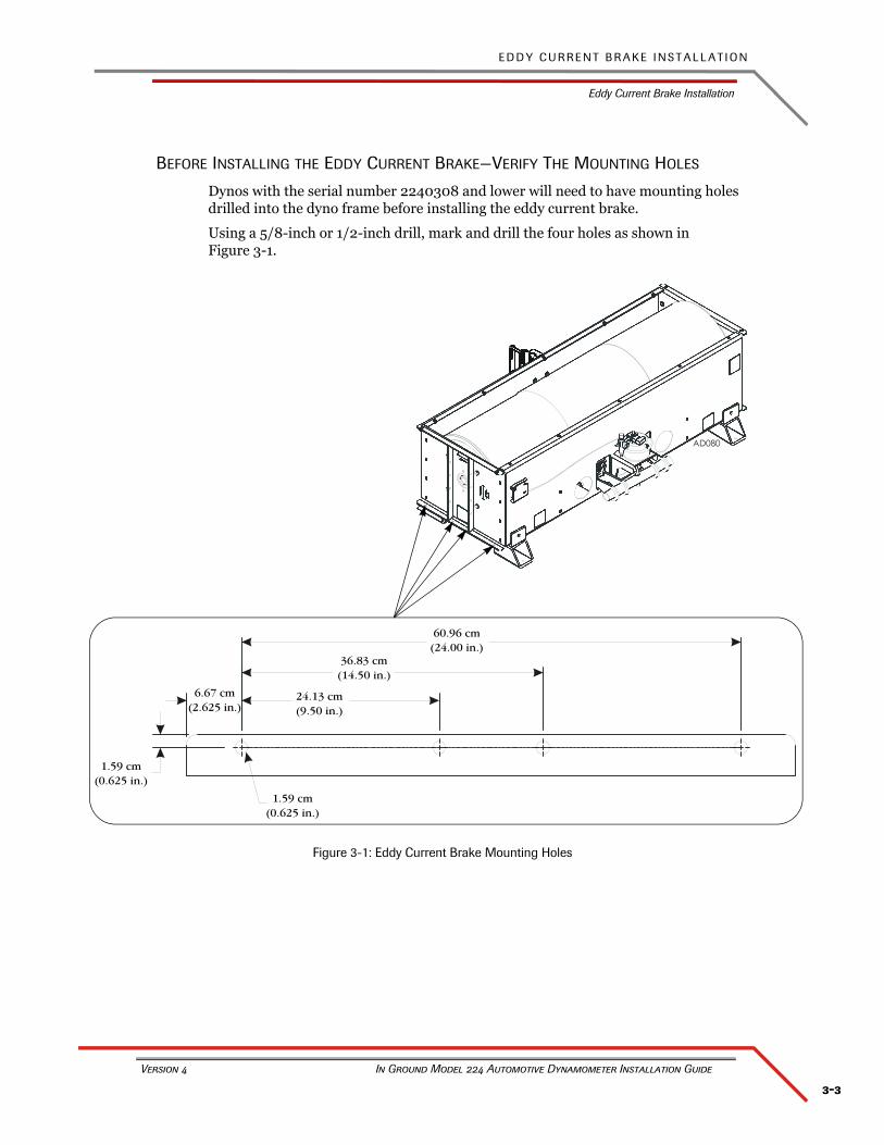
BEFORE INSTALLING THE EDDY CURRENT BRAKE—VERIFY THE MOUNTING HOLES
Dynos with the serial number 2240308 and lower will need to have mounting holes drilled into the dyno frame before installing the eddy current brake.
Using a 5/8-inch or 1/2-inch drill, mark and drill the four holes as shown in Figure 3-1.
Figure 3-1: Eddy Current Brake Mounting Holes
1.59 cm(0.625 in.)
6.67 cm(2.625 in.)
24.13 cm(9.50 in.)
36.83 cm(14.50 in.)
60.96 cm(24.00 in.)
1.59 cm(0.625 in.)
C H A P T E R 3
Eddy Current Brake Installation
In Ground Model 224 Automotive Dynamometer Installation Guide
3-4
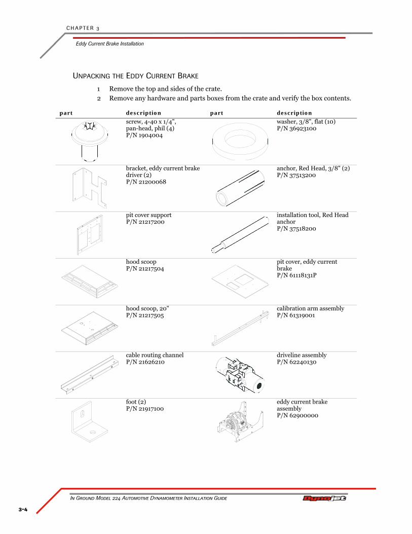
UNPACKING THE EDDY CURRENT BRAKE
1 Remove the top and sides of the crate.2 Remove any hardware and parts boxes from the crate and verify the box contents.
part description part description
screw, 4-40 x 1/4", pan-head, phil (4)P/N 1904004
washer, 3/8", flat (10)P/N 36923100
bracket, eddy current brake driver (2)P/N 21200068
anchor, Red Head, 3/8" (2)P/N 37513200
pit cover supportP/N 21217200
installation tool, Red Head anchorP/N 37518200
hood scoopP/N 21217504
pit cover, eddy current brakeP/N 61118131P
hood scoop, 20"P/N 21217505
calibration arm assemblyP/N 61319001
cable routing channelP/N 21626210
driveline assemblyP/N 62240130
foot (2)P/N 21917100
eddy current brake assemblyP/N 62900000
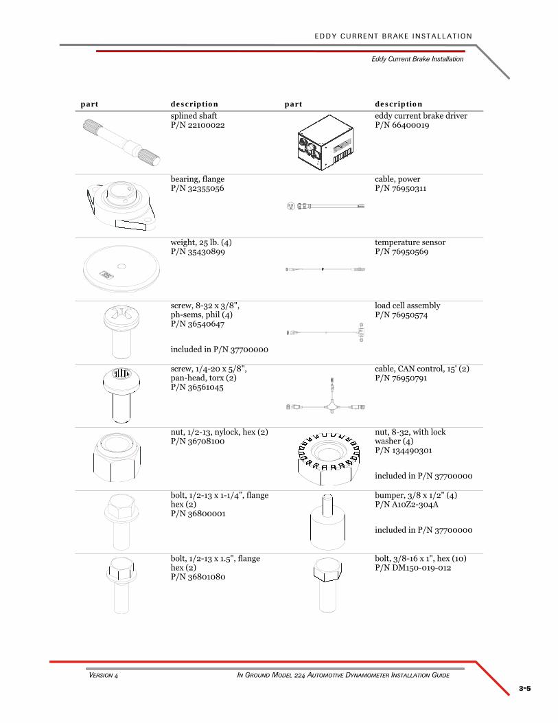
3-5
E D D Y C U R R E N T B R A K E I N S T A L L A T I O N
Eddy Current Brake Installation
Version 4 In Ground Model 224 Automotive Dynamometer Installation Guide
splined shaftP/N 22100022
eddy current brake driverP/N 66400019
bearing, flangeP/N 32355056
cable, powerP/N 76950311
weight, 25 lb. (4)P/N 35430899
temperature sensorP/N 76950569
screw, 8-32 x 3/8", ph-sems, phil (4)P/N 36540647
included in P/N 37700000
load cell assemblyP/N 76950574
screw, 1/4-20 x 5/8", pan-head, torx (2)P/N 36561045
cable, CAN control, 15' (2)P/N 76950791
nut, 1/2-13, nylock, hex (2)P/N 36708100
nut, 8-32, with lock washer (4)P/N 134490301
included in P/N 37700000
bolt, 1/2-13 x 1-1/4”, flange hex (2)P/N 36800001
bumper, 3/8 x 1/2" (4)P/N A10Z2-304A
included in P/N 37700000
bolt, 1/2-13 x 1.5", flange hex (2)P/N 36801080
bolt, 3/8-16 x 1", hex (10)P/N DM150-019-012
part description part description
C H A P T E R 3
Eddy Current Brake Installation
In Ground Model 224 Automotive Dynamometer Installation Guide
3-6
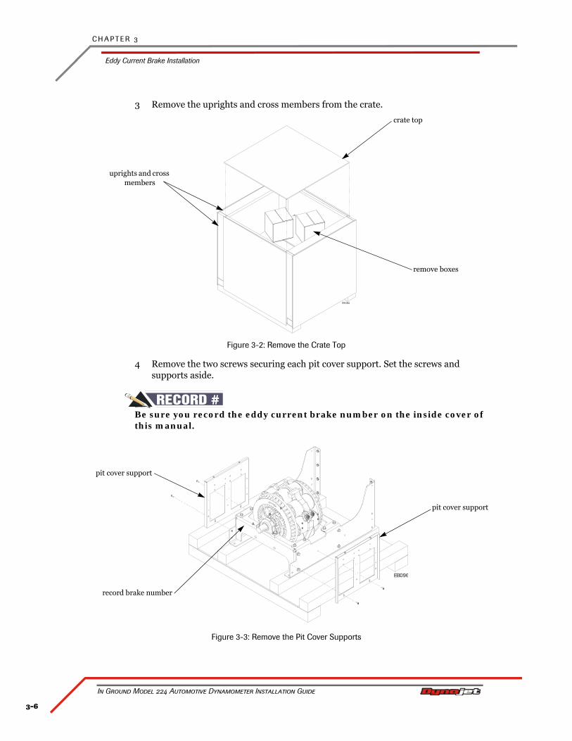
3 Remove the uprights and cross members from the crate.
Figure 3-2: Remove the Crate Top
4 Remove the two screws securing each pit cover support. Set the screws and supports aside.
#RECORDBe sure you record the eddy current brake number on the inside cover of this manual.
Figure 3-3: Remove the Pit Cover Supports
uprights and cross members
crate top
remove boxes
EB096
pit cover support
pit cover support
record brake number
3-7
E D D Y C U R R E N T B R A K E I N S T A L L A T I O N
Eddy Current Brake Installation
Version 4 In Ground Model 224 Automotive Dynamometer Installation Guide
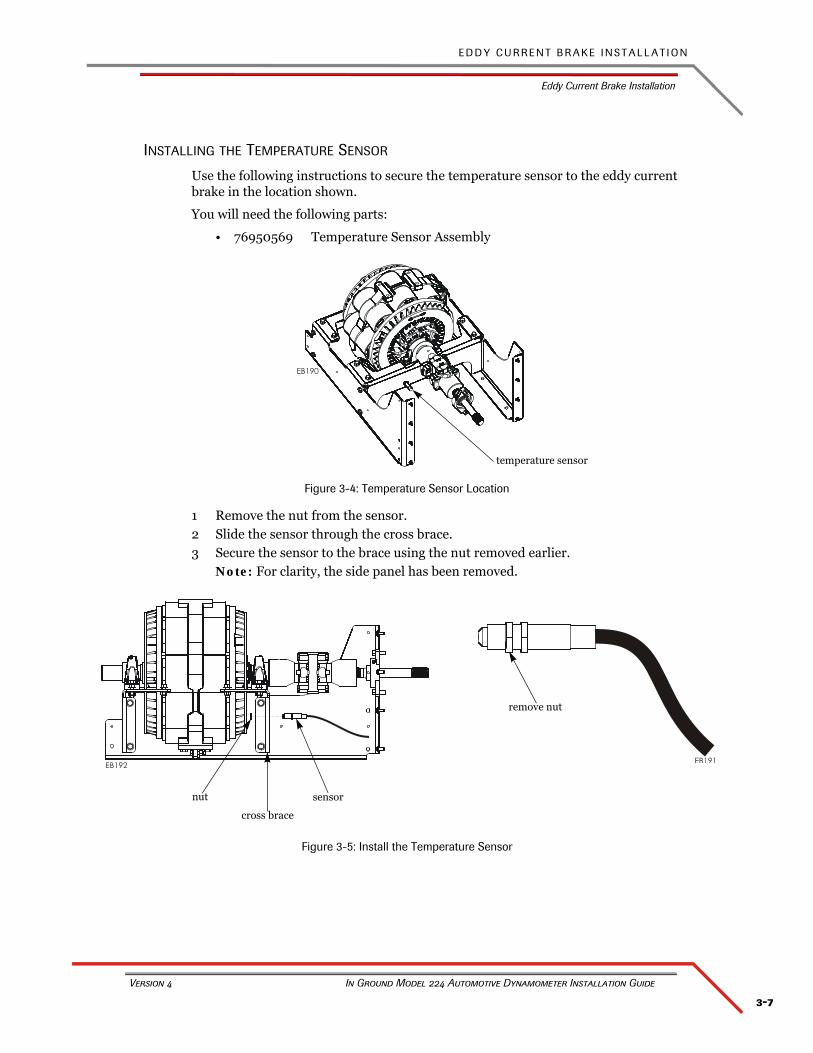
INSTALLING THE TEMPERATURE SENSOR
Use the following instructions to secure the temperature sensor to the eddy current brake in the location shown.
You will need the following parts:
• 76950569 Temperature Sensor Assembly
Figure 3-4: Temperature Sensor Location
1 Remove the nut from the sensor.2 Slide the sensor through the cross brace.3 Secure the sensor to the brace using the nut removed earlier.
Note: For clarity, the side panel has been removed.
Figure 3-5: Install the Temperature Sensor
temperature sensor
sensor
remove nut
nut
cross brace
C H A P T E R 3
Eddy Current Brake Installation
In Ground Model 224 Automotive Dynamometer Installation Guide
3-8
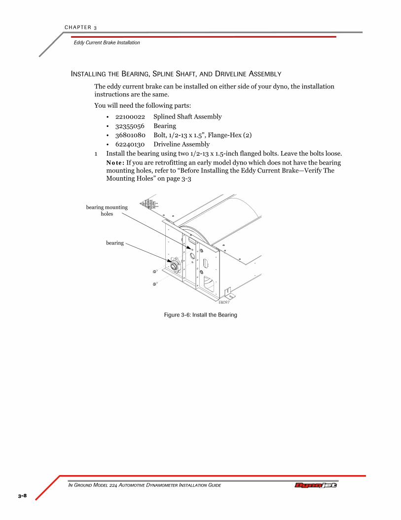
INSTALLING THE BEARING, SPLINE SHAFT, AND DRIVELINE ASSEMBLY
The eddy current brake can be installed on either side of your dyno, the installation instructions are the same.
You will need the following parts:
• 22100022 Splined Shaft Assembly• 32355056 Bearing• 36801080 Bolt, 1/2-13 x 1.5", Flange-Hex (2)• 62240130 Driveline Assembly
1 Install the bearing using two 1/2-13 x 1.5-inch flanged bolts. Leave the bolts loose.Note: If you are retrofitting an early model dyno which does not have the bearing mounting holes, refer to “Before Installing the Eddy Current Brake—Verify The Mounting Holes” on page 3-3
Figure 3-6: Install the Bearing
bearing
bearing mounting holes
3-9
E D D Y C U R R E N T B R A K E I N S T A L L A T I O N
Eddy Current Brake Installation
Version 4 In Ground Model 224 Automotive Dynamometer Installation Guide
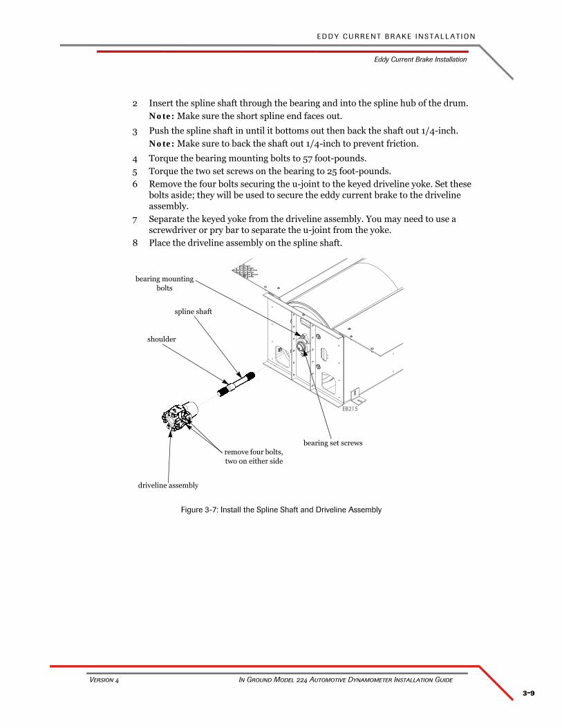
2 Insert the spline shaft through the bearing and into the spline hub of the drum.Note: Make sure the short spline end faces out.
3 Push the spline shaft in until it bottoms out then back the shaft out 1/4-inch.Note: Make sure to back the shaft out 1/4-inch to prevent friction.
4 Torque the bearing mounting bolts to 57 foot-pounds.5 Torque the two set screws on the bearing to 25 foot-pounds.6 Remove the four bolts securing the u-joint to the keyed driveline yoke. Set these
bolts aside; they will be used to secure the eddy current brake to the driveline assembly.
7 Separate the keyed yoke from the driveline assembly. You may need to use a screwdriver or pry bar to separate the u-joint from the yoke.
8 Place the driveline assembly on the spline shaft.
Figure 3-7: Install the Spline Shaft and Driveline Assembly
driveline assembly
spline shaft
bearing set screws
bearing mounting bolts
remove four bolts, two on either side
shoulder
C H A P T E R 3
Eddy Current Brake Installation
In Ground Model 224 Automotive Dynamometer Installation Guide
3-10
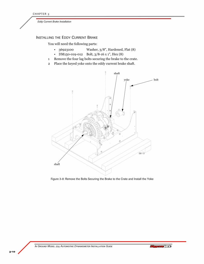
INSTALLING THE EDDY CURRENT BRAKE
You will need the following parts:
• 36923100 Washer, 3/8", Hardened, Flat (8)• DM150-019-012 Bolt, 3/8-16 x 1", Hex (8)
1 Remove the four lag bolts securing the brake to the crate.2 Place the keyed yoke onto the eddy current brake shaft.
Figure 3-8: Remove the Bolts Securing the Brake to the Crate and Install the Yoke
shaft
boltyoke
shaft
3-11
E D D Y C U R R E N T B R A K E I N S T A L L A T I O N
Eddy Current Brake Installation
Version 4 In Ground Model 224 Automotive Dynamometer Installation Guide
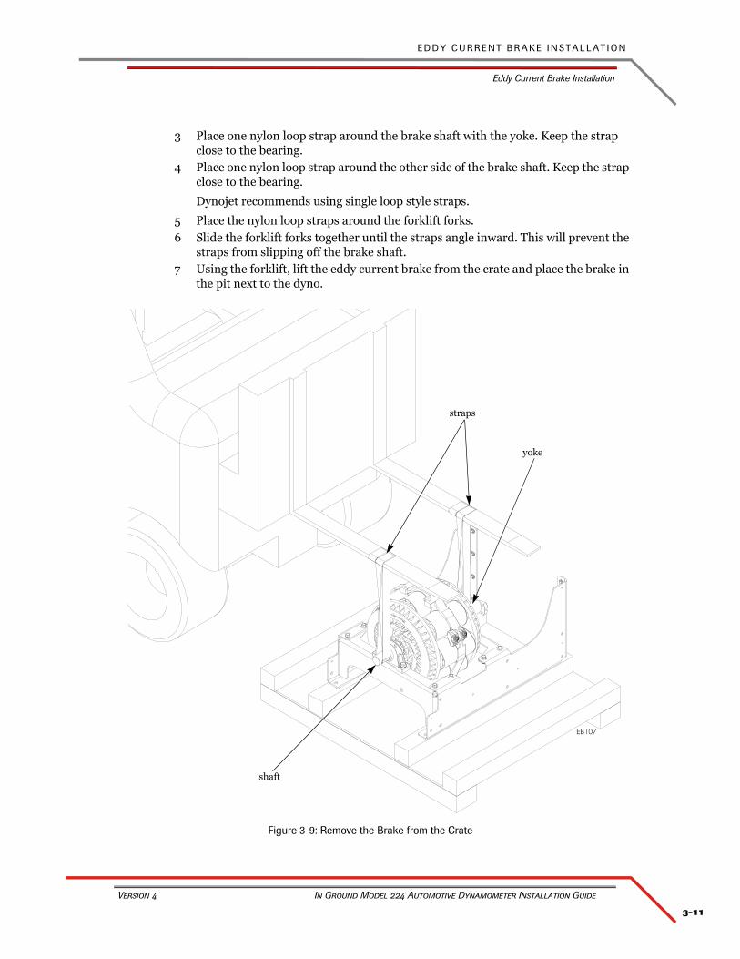
3 Place one nylon loop strap around the brake shaft with the yoke. Keep the strap close to the bearing.
4 Place one nylon loop strap around the other side of the brake shaft. Keep the strap close to the bearing.
Dynojet recommends using single loop style straps.
5 Place the nylon loop straps around the forklift forks.6 Slide the forklift forks together until the straps angle inward. This will prevent the
straps from slipping off the brake shaft.7 Using the forklift, lift the eddy current brake from the crate and place the brake in
the pit next to the dyno.
Figure 3-9: Remove the Brake from the Crate
shaft
straps
yoke
C H A P T E R 3
Eddy Current Brake Installation
In Ground Model 224 Automotive Dynamometer Installation Guide
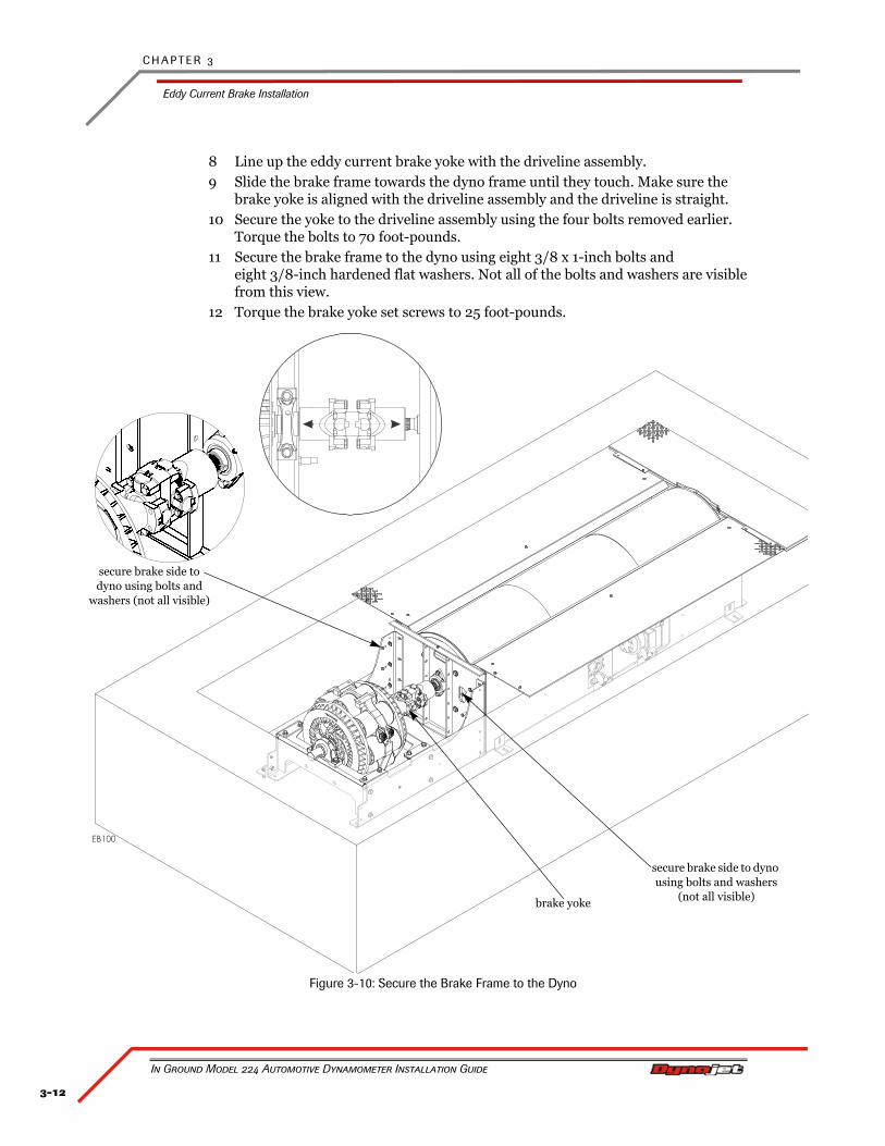
3-12
8 Line up the eddy current brake yoke with the driveline assembly.9 Slide the brake frame towards the dyno frame until they touch. Make sure the
brake yoke is aligned with the driveline assembly and the driveline is straight.10 Secure the yoke to the driveline assembly using the four bolts removed earlier.
Torque the bolts to 70 foot-pounds.11 Secure the brake frame to the dyno using eight 3/8 x 1-inch bolts and
eight 3/8-inch hardened flat washers. Not all of the bolts and washers are visible from this view.
12 Torque the brake yoke set screws to 25 foot-pounds.
Figure 3-10: Secure the Brake Frame to the Dyno
brake yoke
secure brake side to dyno using bolts and
washers (not all visible)
secure brake side to dyno using bolts and washers
(not all visible)
3-13
E D D Y C U R R E N T B R A K E I N S T A L L A T I O N
Eddy Current Brake Installation
Version 4 In Ground Model 224 Automotive Dynamometer Installation Guide
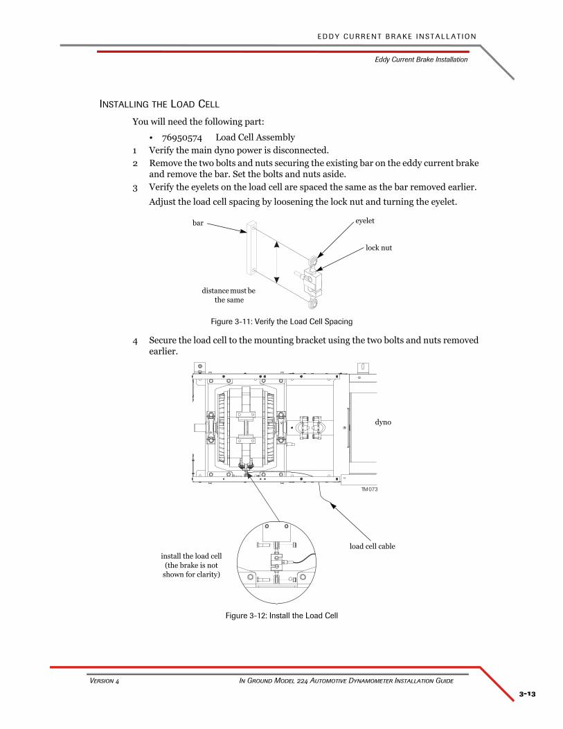
INSTALLING THE LOAD CELL
You will need the following part:
• 76950574 Load Cell Assembly1 Verify the main dyno power is disconnected.2 Remove the two bolts and nuts securing the existing bar on the eddy current brake
and remove the bar. Set the bolts and nuts aside.3 Verify the eyelets on the load cell are spaced the same as the bar removed earlier.
Adjust the load cell spacing by loosening the lock nut and turning the eyelet.
Figure 3-11: Verify the Load Cell Spacing
4 Secure the load cell to the mounting bracket using the two bolts and nuts removed earlier.
Figure 3-12: Install the Load Cell
distance must be the same
eyeletbar
lock nut
T 073M
install the load cell(the brake is not
shown for clarity)
load cell cable
dyno
C H A P T E R 3
Eddy Current Brake Installation
In Ground Model 224 Automotive Dynamometer Installation Guide
3-14
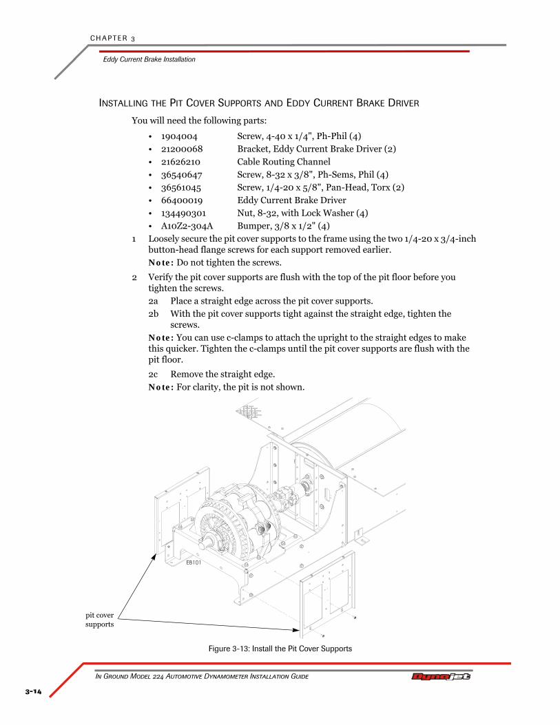
INSTALLING THE PIT COVER SUPPORTS AND EDDY CURRENT BRAKE DRIVER
You will need the following parts:
• 1904004 Screw, 4-40 x 1/4", Ph-Phil (4)• 21200068 Bracket, Eddy Current Brake Driver (2)• 21626210 Cable Routing Channel• 36540647 Screw, 8-32 x 3/8", Ph-Sems, Phil (4)• 36561045 Screw, 1/4-20 x 5/8", Pan-Head, Torx (2)• 66400019 Eddy Current Brake Driver• 134490301 Nut, 8-32, with Lock Washer (4)• A10Z2-304A Bumper, 3/8 x 1/2" (4)
1 Loosely secure the pit cover supports to the frame using the two 1/4-20 x 3/4-inch button-head flange screws for each support removed earlier.Note: Do not tighten the screws.
2 Verify the pit cover supports are flush with the top of the pit floor before you tighten the screws.2a Place a straight edge across the pit cover supports.2b With the pit cover supports tight against the straight edge, tighten the
screws.Note: You can use c-clamps to attach the upright to the straight edges to make this quicker. Tighten the c-clamps until the pit cover supports are flush with the pit floor.
2c Remove the straight edge.Note: For clarity, the pit is not shown.
Figure 3-13: Install the Pit Cover Supports
pit cover supports
3-15
E D D Y C U R R E N T B R A K E I N S T A L L A T I O N
Eddy Current Brake Installation
Version 4 In Ground Model 224 Automotive Dynamometer Installation Guide
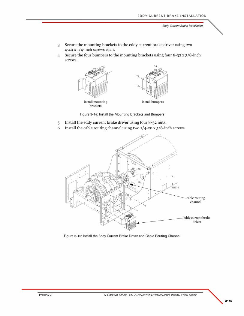
3 Secure the mounting brackets to the eddy current brake driver using two 4-40 x 1/4-inch screws each.
4 Secure the four bumpers to the mounting brackets using four 8-32 x 3/8-inch screws.
Figure 3-14: Install the Mounting Brackets and Bumpers
5 Install the eddy current brake driver using four 8-32 nuts.6 Install the cable routing channel using two 1/4-20 x 5/8-inch screws.
Figure 3-15: Install the Eddy Current Brake Driver and Cable Routing Channel
install bumpersinstall mounting brackets
EB232
cable routing channel
eddy current brake driver
C H A P T E R 3
Eddy Current Brake Installation
In Ground Model 224 Automotive Dynamometer Installation Guide
3-16
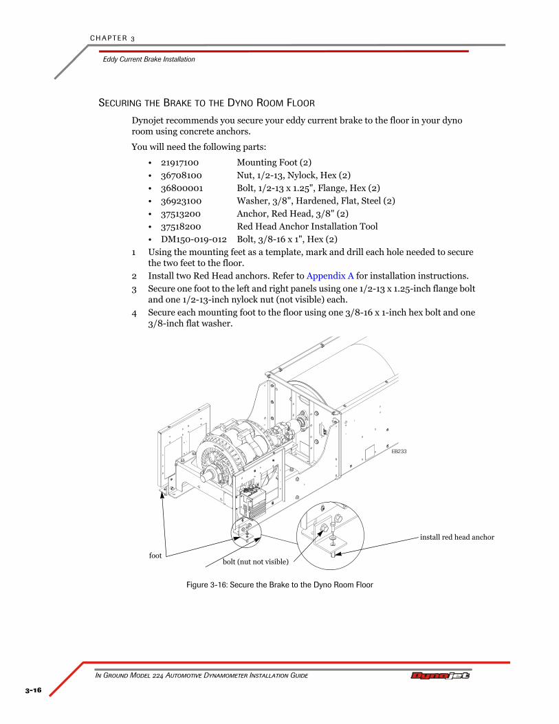
SECURING THE BRAKE TO THE DYNO ROOM FLOOR
Dynojet recommends you secure your eddy current brake to the floor in your dyno room using concrete anchors.
You will need the following parts:
• 21917100 Mounting Foot (2)• 36708100 Nut, 1/2-13, Nylock, Hex (2)• 36800001 Bolt, 1/2-13 x 1.25", Flange, Hex (2)• 36923100 Washer, 3/8", Hardened, Flat, Steel (2)• 37513200 Anchor, Red Head, 3/8" (2)• 37518200 Red Head Anchor Installation Tool• DM150-019-012 Bolt, 3/8-16 x 1", Hex (2)
1 Using the mounting feet as a template, mark and drill each hole needed to secure the two feet to the floor.
2 Install two Red Head anchors. Refer to Appendix A for installation instructions.3 Secure one foot to the left and right panels using one 1/2-13 x 1.25-inch flange bolt
and one 1/2-13-inch nylock nut (not visible) each.4 Secure each mounting foot to the floor using one 3/8-16 x 1-inch hex bolt and one
3/8-inch flat washer.
Figure 3-16: Secure the Brake to the Dyno Room Floor
EB233
foot
install red head anchor
bolt (nut not visible)
3-17
E D D Y C U R R E N T B R A K E I N S T A L L A T I O N
Eddy Current Brake Installation
Version 4 In Ground Model 224 Automotive Dynamometer Installation Guide
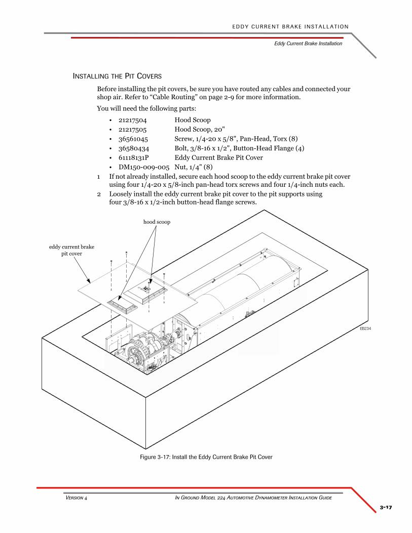
INSTALLING THE PIT COVERS
Before installing the pit covers, be sure you have routed any cables and connected your shop air. Refer to “Cable Routing” on page 2-9 for more information.
You will need the following parts:
• 21217504 Hood Scoop• 21217505 Hood Scoop, 20"• 36561045 Screw, 1/4-20 x 5/8", Pan-Head, Torx (8)• 36580434 Bolt, 3/8-16 x 1/2", Button-Head Flange (4)• 61118131P Eddy Current Brake Pit Cover• DM150-009-005 Nut, 1/4" (8)
1 If not already installed, secure each hood scoop to the eddy current brake pit cover using four 1/4-20 x 5/8-inch pan-head torx screws and four 1/4-inch nuts each.
2 Loosely install the eddy current brake pit cover to the pit supports using four 3/8-16 x 1/2-inch button-head flange screws.
Figure 3-17: Install the Eddy Current Brake Pit Cover
EB234
eddy current brakepit cover
hood scoop
C H A P T E R 3
Load Cell Calibration
In Ground Model 224 Automotive Dynamometer Installation Guide
3-18
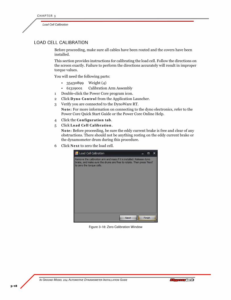
LOAD CELL CALIBRATION
Before proceeding, make sure all cables have been routed and the covers have been installed.
This section provides instructions for calibrating the load cell. Follow the directions on the screen exactly. Failure to perform the directions accurately will result in improper torque values.
You will need the following parts:
• 35430899 Weight (4)• 61319001 Calibration Arm Assembly
1 Double-click the Power Core program icon.2 Click Dyno Control from the Application Launcher.3 Verify you are connected to the DynoWare RT.
Note: For more information on connecting to the dyno electronics, refer to the Power Core Quick Start Guide or the Power Core Online Help.
4 Click the Configuration tab.5 Click Load Cell Calibration.
Note: Before proceeding, be sure the eddy current brake is free and clear of any obstructions. There should not be anything resting on the eddy current brake or the dynamometer drum during this procedure.
6 Click Next to zero the load cell.
Figure 3-18: Zero Calibration Window
3-19
E D D Y C U R R E N T B R A K E I N S T A L L A T I O N
Load Cell Calibration
Version 4 In Ground Model 224 Automotive Dynamometer Installation Guide
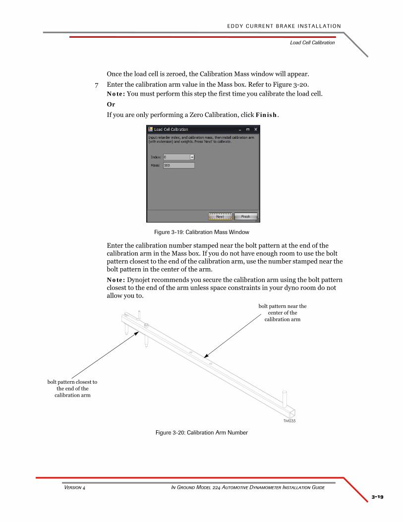
Once the load cell is zeroed, the Calibration Mass window will appear.
7 Enter the calibration arm value in the Mass box. Refer to Figure 3-20.Note: You must perform this step the first time you calibrate the load cell.
Or
If you are only performing a Zero Calibration, click Finish.
Figure 3-19: Calibration Mass Window
Enter the calibration number stamped near the bolt pattern at the end of the calibration arm in the Mass box. If you do not have enough room to use the bolt pattern closest to the end of the calibration arm, use the number stamped near the bolt pattern in the center of the arm.
Note: Dynojet recommends you secure the calibration arm using the bolt pattern closest to the end of the arm unless space constraints in your dyno room do not allow you to.
Figure 3-20: Calibration Arm Number
bolt pattern closest to the end of the
calibration arm
bolt pattern near the center of the
calibration arm
C H A P T E R 3
Load Cell Calibration
In Ground Model 224 Automotive Dynamometer Installation Guide
3-20
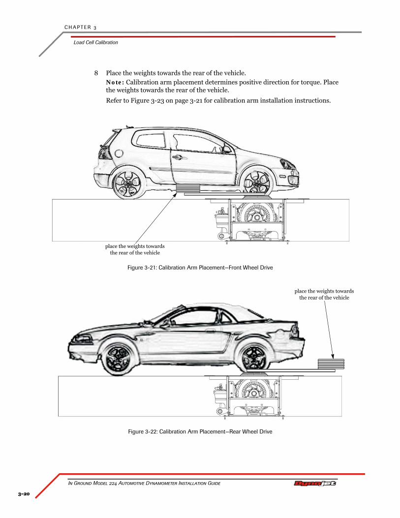
8 Place the weights towards the rear of the vehicle.Note: Calibration arm placement determines positive direction for torque. Place the weights towards the rear of the vehicle.
Refer to Figure 3-23 on page 3-21 for calibration arm installation instructions.
Figure 3-21: Calibration Arm Placement—Front Wheel Drive
Figure 3-22: Calibration Arm Placement—Rear Wheel Drive
place the weights towards the rear of the vehicle
place the weights towards the rear of the vehicle
3-21
E D D Y C U R R E N T B R A K E I N S T A L L A T I O N
Load Cell Calibration
Version 4 In Ground Model 224 Automotive Dynamometer Installation Guide
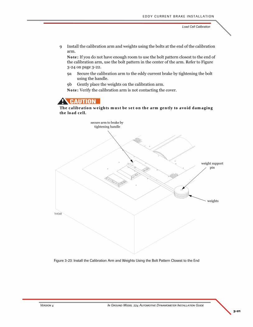
9 Install the calibration arm and weights using the bolts at the end of the calibration arm.Note: If you do not have enough room to use the bolt pattern closest to the end of the calibration arm, use the bolt pattern in the center of the arm. Refer to Figure 3-24 on page 3-22.
9a Secure the calibration arm to the eddy current brake by tightening the bolt using the handle.
9b Gently place the weights on the calibration arm.Note: Verify the calibration arm is not contacting the cover.
The calibration weights must be set on the arm gently to avoid damaging the load cell.
Figure 3-23: Install the Calibration Arm and Weights Using the Bolt Pattern Closest to the End
weights
weight support pin
secure arm to brake by tightening handle
C H A P T E R 3
Load Cell Calibration
In Ground Model 224 Automotive Dynamometer Installation Guide
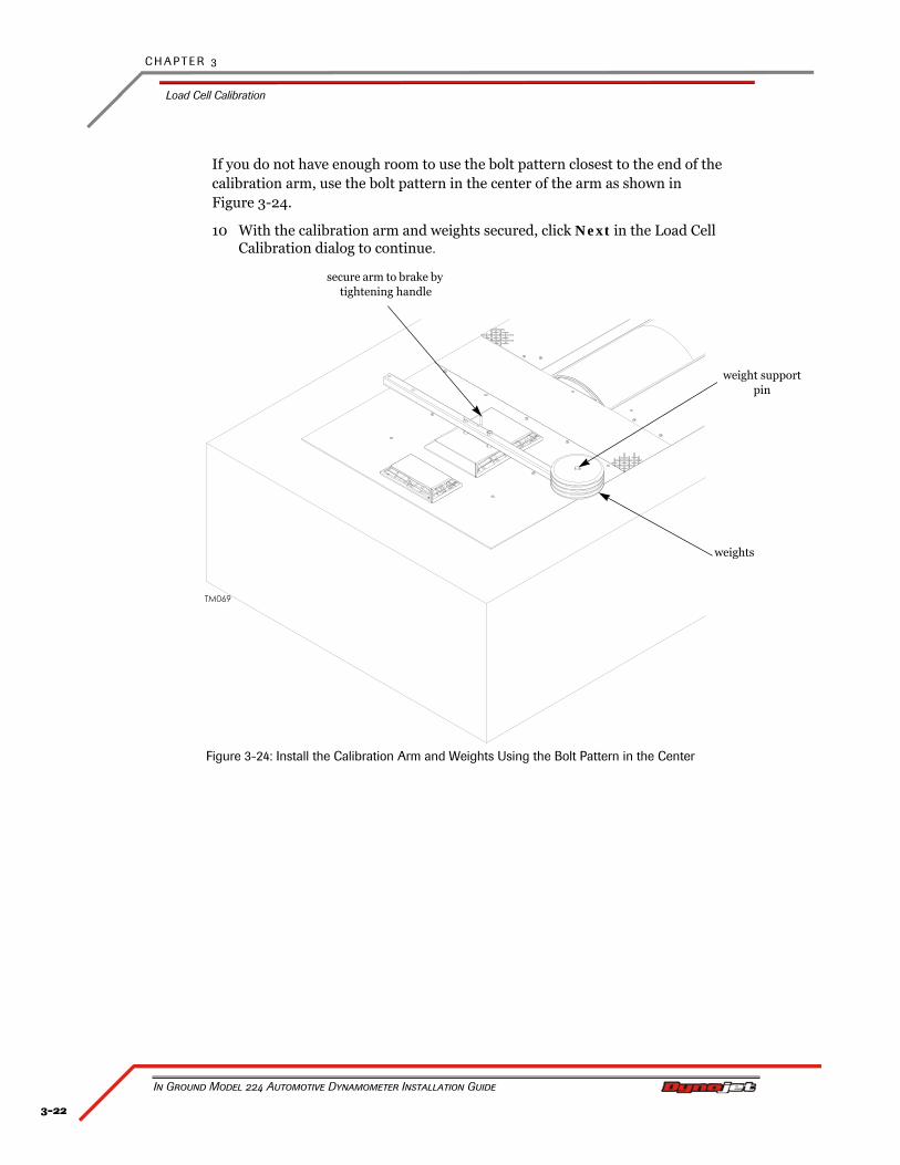
3-22
If you do not have enough room to use the bolt pattern closest to the end of the calibration arm, use the bolt pattern in the center of the arm as shown in Figure 3-24.
10 With the calibration arm and weights secured, click Next in the Load Cell Calibration dialog to continue.
Figure 3-24: Install the Calibration Arm and Weights Using the Bolt Pattern in the Center
weights
weight support pin
secure arm to brake by tightening handle
3-23
E D D Y C U R R E N T B R A K E I N S T A L L A T I O N
Load Cell Calibration
Version 4 In Ground Model 224 Automotive Dynamometer Installation Guide
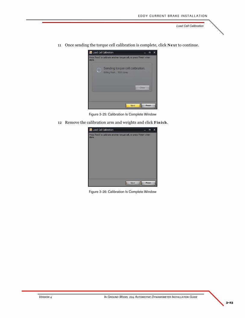
11 Once sending the torque cell calibration is complete, click Next to continue.
Figure 3-25: Calibration Is Complete Window
12 Remove the calibration arm and weights and click Finish.
Figure 3-26: Calibration Is Complete Window


4-1
In Ground Model 224 Automotive Dynamometer Installation Guide
CHAPTER 4
BASIC DYNO OPERATION
The Dynojet Dynamometer gives you the state of the art technology, durability, and accuracy that you need. Dynojet’s advanced engineering delivers the precise horsepower measurements a technician needs to make quick and accurate evaluations of engine performance and drivetrain problems.
This chapter includes instructions for basic dyno operation. For more detailed instructions, refer to the Power Core Help.
This chapter is divided into the following categories:
• Loading the Vehicle, page 4-2
• Connecting the RPM Pickup, page 4-5
• Grounding the Vehicle, page 4-8
• Pre-Run Inspection, page 4-9
• Making a Test Run, page 4-11
• Preventative Maintenance, page 4-12
C H A P T E R 4
Loading the Vehicle
In Ground Model 224 Automotive Dynamometer Installation Guide
4-2
LOADING THE VEHICLE
Use the following steps to load a vehicle on the dyno.
You will need the following parts:
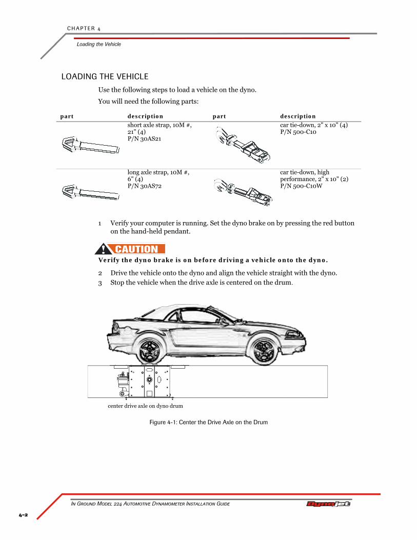
1 Verify your computer is running. Set the dyno brake on by pressing the red button on the hand-held pendant.
Verify the dyno brake is on before driving a vehicle onto the dyno.
2 Drive the vehicle onto the dyno and align the vehicle straight with the dyno.3 Stop the vehicle when the drive axle is centered on the drum.
Figure 4-1: Center the Drive Axle on the Drum
part description part description
short axle strap, 10M #, 21" (4) P/N 30AS21
car tie-down, 2" x 10" (4)P/N 500-C10
long axle strap, 10M #, 6" (4) P/N 30AS72
car tie-down, high performance, 2" x 10" (2)P/N 500-C10W
center drive axle on dyno drum
4-3
B A S I C D Y N O O P E R A T I O N
Loading the Vehicle
Version 4 In Ground Model 224 Automotive Dynamometer Installation Guide
4 When the vehicle is positioned properly on the dyno, shut the engine off.• If the vehicle has an automatic transmission, place it in park.• If the vehicle has a manual transmission, place it in gear.
5 Set the vehicle’s emergency brake.6 Secure the non-drive wheels using the provided tire chocks. Do not use tire chocks
for four wheel drive vehicles on four wheel drive dynos.7 Attach the tie-down straps.
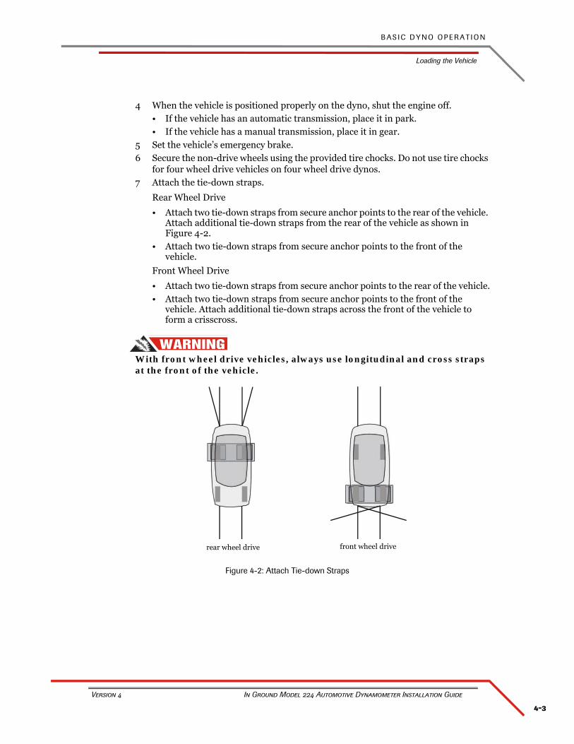
Rear Wheel Drive
• Attach two tie-down straps from secure anchor points to the rear of the vehicle. Attach additional tie-down straps from the rear of the vehicle as shown in Figure 4-2.
• Attach two tie-down straps from secure anchor points to the front of the vehicle.
Front Wheel Drive
• Attach two tie-down straps from secure anchor points to the rear of the vehicle.• Attach two tie-down straps from secure anchor points to the front of the
vehicle. Attach additional tie-down straps across the front of the vehicle to form a crisscross.
With front wheel drive vehicles, always use longitudinal and cross straps at the front of the vehicle.
Figure 4-2: Attach Tie-down Straps
rear wheel drive front wheel drive
C H A P T E R 4
Loading the Vehicle
In Ground Model 224 Automotive Dynamometer Installation Guide
4-4
8 Tighten the tie-down straps evenly making sure the drive wheels remain centered on the drum.
The tie-down straps should always be connected to the vehicle’s solid axle or the suspension control arms. Factory tie-down hooks connected to the vehicle’s frame may be used on the end opposite the drive wheels (for example: the front end of a rear driven vehicle).
9 Release the brake on the vehicle and the dyno.10 Start the vehicle and put the transmission into first gear or drive.11 Press the accelerator pedal so the drums begin turning slowly. While the drums
are slowly turning, verify the stability of the vehicle.12 Press the brake button to bring the dyno and vehicle to a stop.13 Check all the straps and ensure the vehicle is tracking straight on the dyno.
4-5
B A S I C D Y N O O P E R A T I O N
Connecting the RPM Pickup
Version 4 In Ground Model 224 Automotive Dynamometer Installation Guide
CONNECTING THE RPM PICKUP
Your Dynojet dynamometer includes two primary wire inductive pickups and two secondary wire inductive pickups. These small “clothespin like” inductive pickups are used to sense RPM. An RPM pickup is required if you want to view torque graphs. Generally, you will use one secondary wire inductive pickup on a spark plug wire. The primary wire inductive pickup senses RPM pulses from the coil. Although this pickup location generally works better, it is harder to find the correct location to connect the RPM pickup.
The optional Optical Sensor is useful on diesel powered vehicles, MSD ignitions, and other high RFI ignition systems. For more detailed information on the Optical Sensor, refer to the Optical RPM Sensor Installation Guide (P/N 98200044).
Inductive pickups are very fragile. The ferrite core can easily be damaged and is not covered under warranty. Dropping, snapping, vibration, and heat can all damage the ferrite core.
The DynoWare RT contains the electronics that sense the RPM pulses.
You will need the following parts:
RPM PICKUP DESCRIPTIONS
part description part description
inductive primarypickup (2)P/N 76950201
inductive secondary pickup (2)P/N 76950203
RPM pickup description
Secondaries (Non-wasted spark system) Use one secondary pickup. Set the degrees between plug fires to 720° in Power Core.
Secondaries (Wasted spark ignition system)
Use one secondary pickup. Set the degrees between plug fires to 360° in Power Core.
Primary pickup Attach the primary wire pickup to the primary side of the coil. Set the degrees between plug fires by taking 720/number of cylinders. For example, the number of degrees between plug fires on a V-8 engine with a single coil is 720/8=90 degrees.
Optional Optical RPM Sensor Attach the sensor wire to the RPM port on the DynoWare RT module. The other end of the wire attaches to the Optical Sensor. Set the degrees between plug fires to 360° in Power Core. Refer to the Optical RPM Sensor Installation Guide (P/N 98200044).
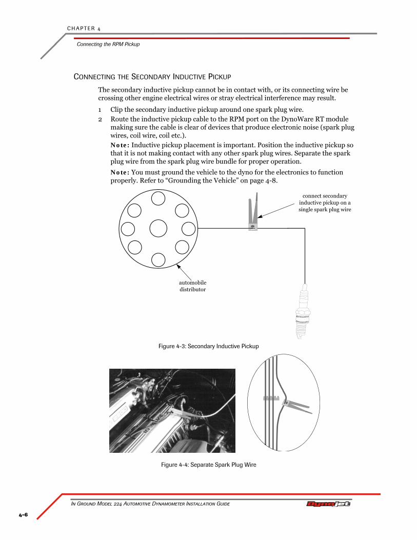
C H A P T E R 4
Connecting the RPM Pickup
In Ground Model 224 Automotive Dynamometer Installation Guide
4-6
CONNECTING THE SECONDARY INDUCTIVE PICKUP
The secondary inductive pickup cannot be in contact with, or its connecting wire be crossing other engine electrical wires or stray electrical interference may result.
1 Clip the secondary inductive pickup around one spark plug wire.2 Route the inductive pickup cable to the RPM port on the DynoWare RT module
making sure the cable is clear of devices that produce electronic noise (spark plug wires, coil wire, coil etc.).Note: Inductive pickup placement is important. Position the inductive pickup so that it is not making contact with any other spark plug wires. Separate the spark plug wire from the spark plug wire bundle for proper operation.
Note: You must ground the vehicle to the dyno for the electronics to function properly. Refer to “Grounding the Vehicle” on page 4-8.
Figure 4-3: Secondary Inductive Pickup
Figure 4-4: Separate Spark Plug Wire
connect secondary inductive pickup on a single spark plug wire
automobile distributor
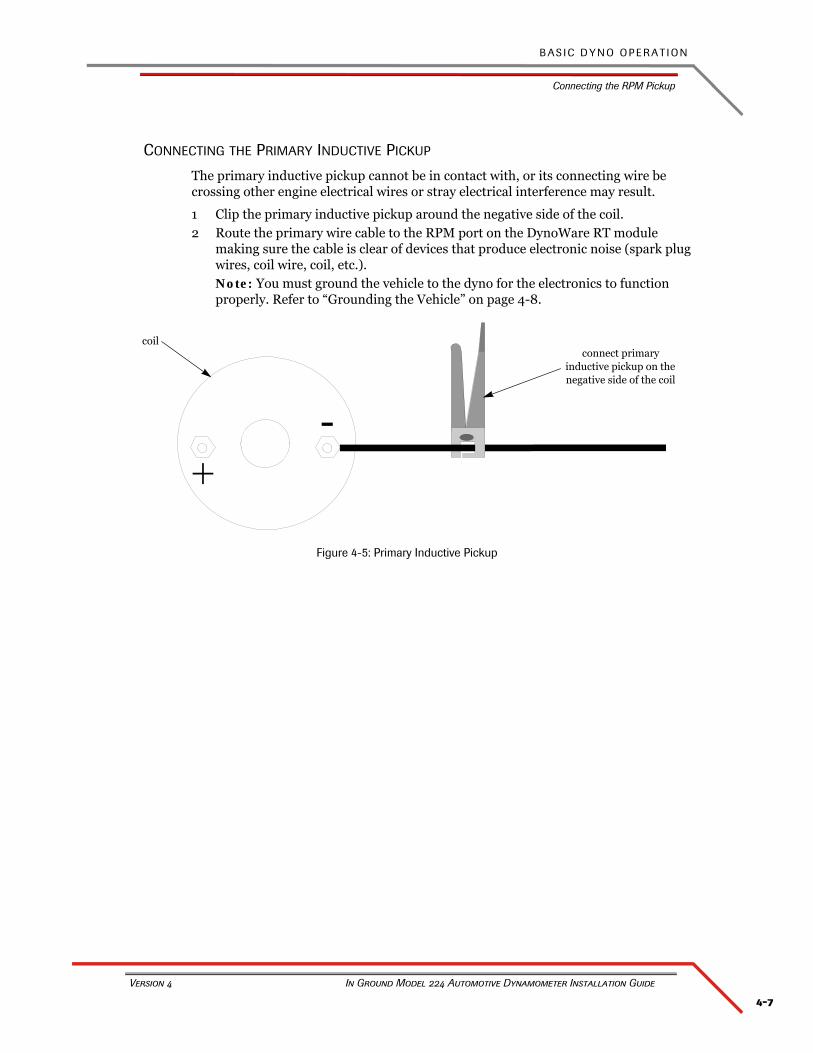
4-7
B A S I C D Y N O O P E R A T I O N
Connecting the RPM Pickup
Version 4 In Ground Model 224 Automotive Dynamometer Installation Guide
CONNECTING THE PRIMARY INDUCTIVE PICKUP
The primary inductive pickup cannot be in contact with, or its connecting wire be crossing other engine electrical wires or stray electrical interference may result.
1 Clip the primary inductive pickup around the negative side of the coil.2 Route the primary wire cable to the RPM port on the DynoWare RT module
making sure the cable is clear of devices that produce electronic noise (spark plug wires, coil wire, coil, etc.).Note: You must ground the vehicle to the dyno for the electronics to function properly. Refer to “Grounding the Vehicle” on page 4-8.
Figure 4-5: Primary Inductive Pickup
connect primary inductive pickup on the negative side of the coil
coil
C H A P T E R 4
Grounding the Vehicle
In Ground Model 224 Automotive Dynamometer Installation Guide
4-8
GROUNDING THE VEHICLE
You will need to ground the vehicle to the dyno before every run. Use the following steps to install the grounding bracket and ground the vehicle to the dyno.
Never operate the dyno without first grounding the vehicle to the dyno.
You will need the following parts:
• 21600084 Grounding Bracket• 36560834 Screw, 1/4-20 x 1/2"• 76950788 Vehicle Grounding Cable
1 Choose any location on your dyno with a black 1/4-20 x 5/8-inch torx screw that threads directly into the sheet metal and remove this screw.
2 Secure the grounding bracket to this location using one 1/4-20 x 1/2-inch screw.3 Attach the vehicle ground cable to an exhaust bolt or engine bolt on the vehicle.4 Attach the vehicle ground cable to the grounding bracket.
4-9
B A S I C D Y N O O P E R A T I O N
Pre-Run Inspection
Version 4 In Ground Model 224 Automotive Dynamometer Installation Guide
PRE-RUN INSPECTION
Perform a vehicle inspection before making a run.
• Check the radiator coolant and oil levels.
• Check the fuel source.
• Rotate the drum(s) and check for rocks caught in the tire tread that could fly out.
• Check the tire pressure and tire speed rating. Improperly inflated tires or exceeding the maximum speed rating can result in premature wear or severe tire damage. Make sure the tire has no major deficiencies (cracks in sidewalls, tread life, etc.).
• Visually inspect the vehicle. Make sure it is in safe running order.
• Make sure ear protection and safety glasses are used when the dyno is being operated.
• Check the tie-down straps to make sure that they are tight and secured.
• Check the drive tires to be sure that they are aligned correctly on the dyno drums.
• Keep all rotating components clear at all times.
• Only the operator should be near the dyno or the vehicle during the test.
• Never allow any person(s) to stand behind the dyno or vehicle when it is being operated.
• Perform any other safety inspections appropriate to running your vehicle on the dyno.
Never allow any person(s) to stand behind the dyno or vehicle when it is being operated. Only the operator should be near the dyno or the vehicle during the test.
BEFORE STARTING THE ENGINE
Connect an exhaust hose or hoses (if dual exhaust) on the vehicle, make sure the hose fits over the tail pipe, is not plugged or kinked and the hose is vented correctly out of the dyno room.
Engine exhaust contains poisonous carbon monoxide gas. Breathing it could cause death. Operate machine in well ventilated area.
C H A P T E R 4
Pre-Run Inspection
In Ground Model 224 Automotive Dynamometer Installation Guide
4-10
ENGINE WARM UP
Warm the vehicle’s engine and drivetrain before beginning testing. Consistent engine temperatures will assure your runs are repeatable.
AFTER ENGINE WARM UP
Always leave the vehicle in park (automatic transmission) or in first gear (manual transmission), with the engine off, and make sure the emergency brake and the dyno brake are on when you get out of the vehicle.
• Fix any fuel, oil, or coolant leaks that may have shown up after engine warm up and check the carburetor for leaks.
• Any loud or unusual engine noises or excessive exhaust smoke should be resolved before continuing.
4-11
B A S I C D Y N O O P E R A T I O N
Making a Test Run
Version 4 In Ground Model 224 Automotive Dynamometer Installation Guide
MAKING A TEST RUN
Dyno runs provide safe, reliable road testing right in the shop. The dyno allows you to measure, record, and diagnose performance problems quickly. The dyno combined with the Power Core software produces consistent, easily interpretable power graphs. Use the following instructions to ensure repeatable and accurate measurements.
1 Verify the vehicle is secured properly.2 Verify the vehicle is grounded to the dynamometer properly. Refer to “Grounding
the Vehicle” on page 4-8.
Never operate the dyno without first grounding the vehicle to the dyno.
3 Double-click the Power Core program icon to start the software.4 Click Dyno Control from the Application Launcher.5 Test the tachometer operation.
5a Rev the engine. The gauges on the computer screen should be moving. If the tachometer is moving but not registering the correct RPM values, the number of degrees of revolution of the crank shaft (the plug fires number) is incorrect.
5b Select Run File Information to enter vehicle information.6 Place the vehicle in a low gear and release the dyno brake using the hand held
pendant.7 Slowly accelerate the vehicle to 20 m.p.h.8 Press the red brake button to apply 100% braking and slow down the vehicle.
Using the vehicle’s own brakes to slow or stop the drum at speeds over 30 m.p.h. can severely overheat the brake parts. Dynojet dynamometers with the air brake or eddy current brake accessory can be used to slow the vehicle and drum to a full stop at any speed. The vehicle’s brakes should be used in an emergency stop situation only.
9 Shut the engine off and put the vehicle in gear (manual transmission) or park (automatic transmission).
10 Set the vehicle’s parking brake and leave the dyno brake on.11 Select MakeRun Configuration Run Information, and enter the correct value for
the plug firing order.12 Perform a final inspection.
• Verify the drive tire’s alignment on the dyno drums.• Make any adjustments to the tie-down straps as needed.• Perform any other safety checks that you deem appropriate to your particular
situation.You are now ready to make a high speed run on the dyno. Refer to your Power Core Help for more detailed instructions.
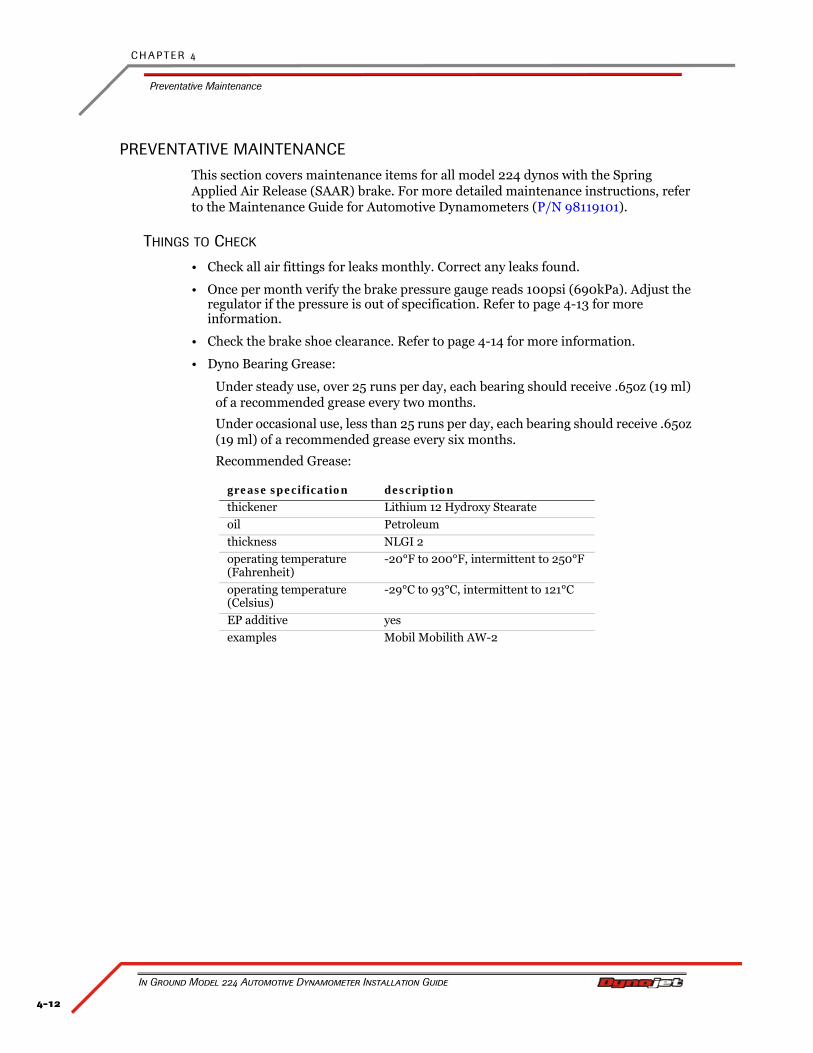
C H A P T E R 4
Preventative Maintenance
In Ground Model 224 Automotive Dynamometer Installation Guide
4-12
PREVENTATIVE MAINTENANCE
This section covers maintenance items for all model 224 dynos with the Spring Applied Air Release (SAAR) brake. For more detailed maintenance instructions, refer to the Maintenance Guide for Automotive Dynamometers (P/N 98119101).
THINGS TO CHECK
• Check all air fittings for leaks monthly. Correct any leaks found.
• Once per month verify the brake pressure gauge reads 100psi (690kPa). Adjust the regulator if the pressure is out of specification. Refer to page 4-13 for more information.
• Check the brake shoe clearance. Refer to page 4-14 for more information.
• Dyno Bearing Grease:
Under steady use, over 25 runs per day, each bearing should receive .65oz (19 ml) of a recommended grease every two months.
Under occasional use, less than 25 runs per day, each bearing should receive .65oz (19 ml) of a recommended grease every six months.
Recommended Grease:
grease specification description
thickener Lithium 12 Hydroxy Stearate
oil Petroleum
thickness NLGI 2
operating temperature (Fahrenheit)
-20°F to 200°F, intermittent to 250°F
operating temperature (Celsius)
-29°C to 93°C, intermittent to 121°C
EP additive yes
examples Mobil Mobilith AW-2
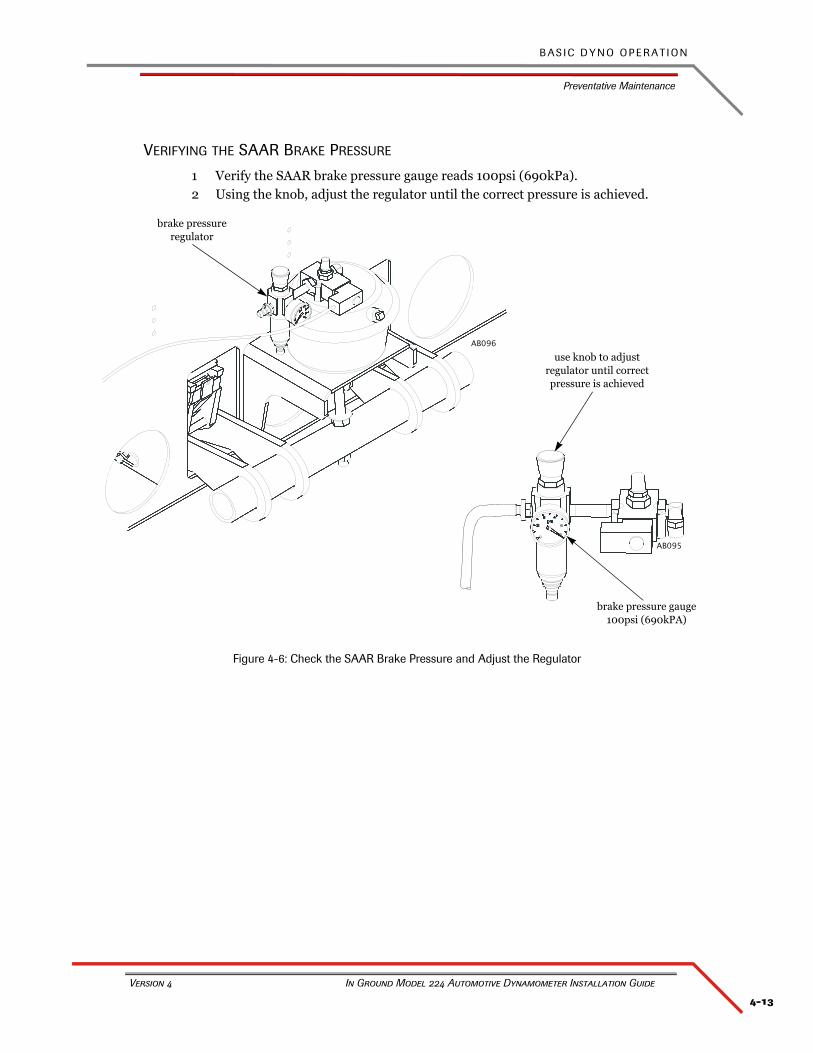
4-13
B A S I C D Y N O O P E R A T I O N
Preventative Maintenance
Version 4 In Ground Model 224 Automotive Dynamometer Installation Guide
VERIFYING THE SAAR BRAKE PRESSURE
1 Verify the SAAR brake pressure gauge reads 100psi (690kPa).2 Using the knob, adjust the regulator until the correct pressure is achieved.
Figure 4-6: Check the SAAR Brake Pressure and Adjust the Regulator
AB096
use knob to adjust regulator until correct pressure is achieved
brake pressure regulator
0
AB095
brake pressure gauge100psi (690kPA)
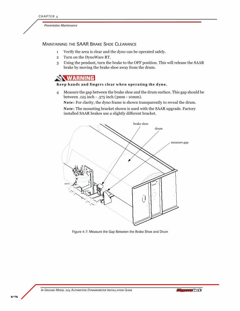
C H A P T E R 4
Preventative Maintenance
In Ground Model 224 Automotive Dynamometer Installation Guide
4-14
MAINTAINING THE SAAR BRAKE SHOE CLEARANCE
1 Verify the area is clear and the dyno can be operated safely.2 Turn on the DynoWare RT.3 Using the pendant, turn the brake to the OFF position. This will release the SAAR
brake by moving the brake shoe away from the drum.
Keep hands and fingers clear when operating the dyno.
4 Measure the gap between the brake shoe and the drum surface. This gap should be between .125 inch - .375 inch (3mm - 10mm). Note: For clarity, the dyno frame is shown transparently to reveal the drum.
Note: The mounting bracket shown is used with the SAAR upgrade. Factory installed SAAR brakes use a slightly different bracket.
Figure 4-7: Measure the Gap Between the Brake Shoe and Drum
AB094
brake shoe
measure gap
drum
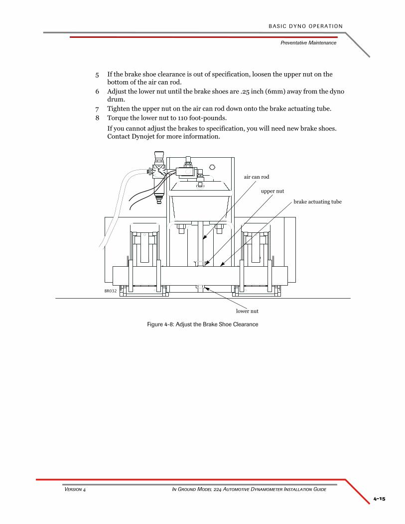
4-15
B A S I C D Y N O O P E R A T I O N
Preventative Maintenance
Version 4 In Ground Model 224 Automotive Dynamometer Installation Guide
5 If the brake shoe clearance is out of specification, loosen the upper nut on the bottom of the air can rod.
6 Adjust the lower nut until the brake shoes are .25 inch (6mm) away from the dyno drum.
7 Tighten the upper nut on the air can rod down onto the brake actuating tube.8 Torque the lower nut to 110 foot-pounds.
If you cannot adjust the brakes to specification, you will need new brake shoes. Contact Dynojet for more information.
Figure 4-8: Adjust the Brake Shoe Clearance
BR032
lower nut
air can rod
upper nut
brake actuating tube


A-1
In Ground Model 224 Automotive Dynamometer Installation Guide
APPENDIX A
RED HEAD ANCHOR INSTALLATION
This appendix contains instructions for installing the Red Head Multi-Set™II Anchors. The anchors will be used to secure the dyno to concrete. To ensure safety and accuracy in the procedures, perform the procedures as they are described. Be sure to read and understand the warnings included in this appendix.
WARNINGS
Always wear safety glasses and other necessary protective devices or apparel when installing or working with anchors.
ITW Ramset/Red Head Multi-Set II Anchors are designed to operate properly only when installed with ITW Ramset/Red Head brand Setting Tools.
The use of a 24 to 40 ounce hammer is recommended for expanding Multi-Set II anchors.
The use of carbide drill bits manufactured with ANSI B94. 12-77 drill bit diameter requirements is recommended for installation of this anchor.
Not recommended for use in lightweight masonry material such as block or brick.
Use of core drills is not recommended to drill holes for use with this anchor.
Not recommended for use in new concrete which has not had sufficient time to cure.
Anchor spacing and edge distance requirements (anchor installation locations) are the responsibility of the engineer of record.
CONTACT INFORMATION FOR ITW RAMSET/RED HEAD
Contact ITW Ramset/Red Head at 1-630-350-0370, or 1300 North Michael Drive, Wood Dale, IL 60191.
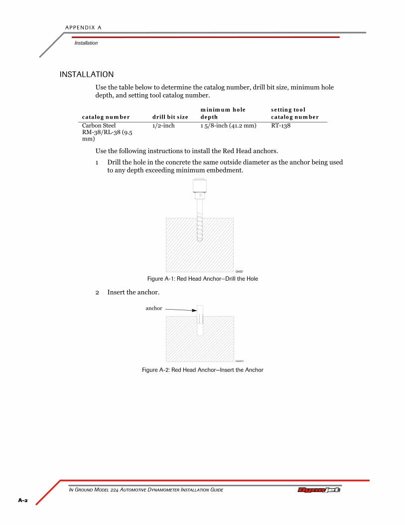
A P P E N D I X A
Installation
In Ground Model 224 Automotive Dynamometer Installation Guide
A-2
INSTALLATION
Use the table below to determine the catalog number, drill bit size, minimum hole depth, and setting tool catalog number.
Use the following instructions to install the Red Head anchors.
1 Drill the hole in the concrete the same outside diameter as the anchor being used to any depth exceeding minimum embedment.
Figure A-1: Red Head Anchor—Drill the Hole
2 Insert the anchor.
Figure A-2: Red Head Anchor—Insert the Anchor
catalog number drill bit sizeminimum hole depth
setting tool catalog number
Carbon SteelRM-38/RL-38 (9.5 mm)
1/2-inch 1 5/8-inch (41.2 mm) RT-138
anchor
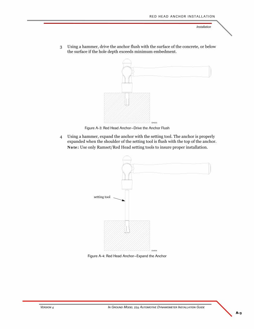
A-3
R E D H E A D A N C H O R I N S T A L L A T I O N
Installation
Version 4 In Ground Model 224 Automotive Dynamometer Installation Guide
3 Using a hammer, drive the anchor flush with the surface of the concrete, or below the surface if the hole depth exceeds minimum embedment.
Figure A-3: Red Head Anchor—Drive the Anchor Flush
4 Using a hammer, expand the anchor with the setting tool. The anchor is properly expanded when the shoulder of the setting tool is flush with the top of the anchor.Note: Use only Ramset/Red Head setting tools to insure proper installation.
Figure A-4: Red Head Anchor—Expand the Anchor
setting tool


B-1
In Ground Model 224 Automotive Dynamometer Installation Guide
APPENDIX B
POWER REQUIREMENTS AND INSTALLATION
This appendix contains power requirements and installation instructions for the eddy current brake. To ensure safety and accuracy in the procedures, perform the procedures as they are described. Be sure to read and understand the warnings included in this appendix.
Note: The following instructions are intended as a guide to aide in the electrical installation of your dynamometer. All local regulations shall supersede any instructions herein and should always be considered.
This Appendix is divided into the following categories:
• North America, Japan, and Locations Using 60 Hz Power, on page B-2
• Excluding North America and Japan, on page B-5
A P P E N D I X B
North America, Japan, and Locations Using 60 Hz Power
In Ground Model 224 Automotive Dynamometer Installation Guide
B-2
NORTH AMERICA, JAPAN, AND LOCATIONS USING 60 HZ POWER
The following power requirements and instructions are for North America, Japan, and locations using 60 Hz power. Refer to “Excluding North America and Japan” on page B-5 for all other locations.
The eddy current brake requires a dedicated 240VAC single-phase power outlet rated for 30A for proper operation. Failure to follow these instructions could result in personal injury or damage to the brake. Connecting the brake to the incorrect voltage will void the warranty. Contact Dynojet with any questions.
Each eddy current brake requires a dedicated wall receptacle which must be wired for operation and is included with the brake or may be shipped in advanced in a separate package. The brake is equipped with a twenty-five foot power cord with a twist lock plug pre-wired on the end.
The dedicated wall receptacle is a twist lock four wire grounded 30A NEMA L14-30 type and must be wired in accordance with local building codes and requirements. If the facility does not have 120/240 volt single-phase power, and it does have 120/208 volt three-phase Y power, then it is acceptable to connect the four wire receptacle with two of the three-phase lines, the neutral and the ground. With this arrangement, there will only be 208 volts between line 1 and line 2 instead of 240 volts. This is acceptable, but performance of the eddy current brake will be reduced. In no case shall all three-phase lines be connected to the receptacle! Installation may require a licensed electrician and must conform to UL and NEC safety standards.
Note: If you are installing your brake in North American or Japan and the brake is not equipped with twist lock four wire grounded plug, contact Dynojet before attempting to connect the brake.
Local and national electrical codes require a grounded receptacle box.
• This circuit should have a dedicated 30A double pole circuit breaker.• The brake should be the only device connected to this circuit.
INSTALLING THE WALL RECEPTACLE
The wall receptacle is included with your brake and is shipped in a separate box or may be shipped in advance in a separate package.
The wall receptacle is a single-phase 240 volt 30A dedicated circuit with a neutral wire. The neutral wire is not used by the brake, but needs to be connected to terminal W.
The cable carrying the power to this receptacle should be ten gauge or larger. Check with local building codes for the correct size.
1 Connect one of the 240V legs to the X terminal (gold colored screw).2 Connect the other 240V leg to the Y terminal (gold colored screw).3 Connect the neutral conductor to the W or WH terminal (silver screw).4 Connect the ground conductor to the G terminal (green colored screw).
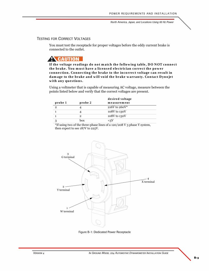
B-3
P O W E R R E Q U I R E M E N T S A N D I N S T A L L A T I O N
North America, Japan, and Locations Using 60 Hz Power
Version 4 In Ground Model 224 Automotive Dynamometer Installation Guide
TESTING FOR CORRECT VOLTAGES
You must test the receptacle for proper voltages before the eddy current brake is connected to the outlet.
If the voltage readings do not match the following table, DO NOT connect the brake. You must have a licensed electrician correct the power connection. Connecting the brake to the incorrect voltage can result in damage to the brake and will void the brake warranty. Contact Dynojet with any questions.
Using a voltmeter that is capable of measuring AC voltage, measure between the points listed below and verify that the correct voltages are present.
Figure B-1: Dedicated Power Receptacle
probe 1 probe 2desired voltage measurement
2 4 216V to 260V*
1 4 108V to 130V
1 2 108V to 130V
3 box <5V
*If using two of the three-phase lines of a 120/208 V 3 phase Y system, then expect to see 187V to 225V.
4X terminal
1W terminal
2Y terminal
3G terminal
A P P E N D I X B
North America, Japan, and Locations Using 60 Hz Power
In Ground Model 224 Automotive Dynamometer Installation Guide
B-4
HARD WIRING TO THE BUILDING
Use the following instructions to wire the brake directly to the building.
The brake must connect to a two pole disconnect switch to allow the removal of all power to the brake for servicing. This box may contain fusing, circuit breakers, or the circuit protection may be upstream in the building power system. The circuit must be protected to 30A with slow blow fuses or time delayed circuit breakers.
The power cord that attaches to the brake has three conductors internally and their colors are white, black, and green.
1 Remove the brake power plug and connect 240VAC single-phase between the black and the white wires through the disconnect switch.
2 Connect the green wire to the ground connection. 3 Refer to the previous table for testing and probe the new connections as follows:
• white wire as location #2• black wire as location #4• green wire as location #3
B-5
P O W E R R E Q U I R E M E N T S A N D I N S T A L L A T I O N
Excluding North America and Japan
Version 4 In Ground Model 224 Automotive Dynamometer Installation Guide
EXCLUDING NORTH AMERICA AND JAPAN
The eddy current brake (excluding North America and Japan) requires a dedicated wall receptacle which must be wired for operation and is included with the brake or may be shipped in advanced in a separate package. The brake is equipped with a twenty-five foot power cord with a twist lock plug pre-wired on the end.
The brake requires a dedicated 240VAC single-phase power outlet rated for 30A for proper operation. Failure to follow these instructions could result in personal injury or damage to the brake. Connecting the brake to the incorrect voltage will void the brake warranty. Contact Dynojet with any questions.
The dedicated wall receptacle is a three-pin IEC grounded 30A type and must be wired in accordance with local building codes and requirements. Installation may require a licensed electrician to conform to applicable safety standards.
If you are installing your brake in a location other than North America or Japan and the brake is not equipped with a three pin IEC grounded plug, contact Dynojet before attempting to connect the brake.
Local and national electrical codes will require that the box containing the receptacle is grounded.
• This circuit should have a dedicated 30A double-pole circuit breaker.• The brake should be the only device connected to this circuit.
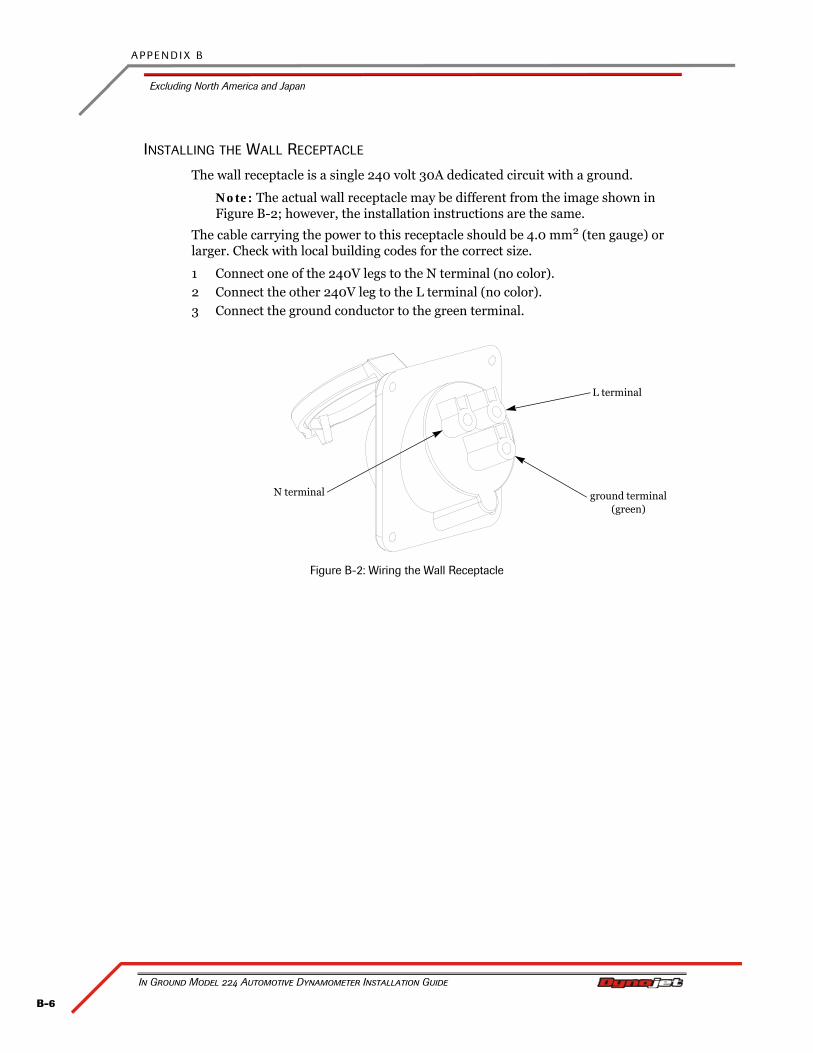
A P P E N D I X B
Excluding North America and Japan
In Ground Model 224 Automotive Dynamometer Installation Guide
B-6
INSTALLING THE WALL RECEPTACLE
The wall receptacle is a single 240 volt 30A dedicated circuit with a ground.
Note: The actual wall receptacle may be different from the image shown in Figure B-2; however, the installation instructions are the same.
The cable carrying the power to this receptacle should be 4.0 mm2 (ten gauge) or larger. Check with local building codes for the correct size.
1 Connect one of the 240V legs to the N terminal (no color).2 Connect the other 240V leg to the L terminal (no color).3 Connect the ground conductor to the green terminal.
Figure B-2: Wiring the Wall Receptacle
N terminal
L terminal
ground terminal (green)
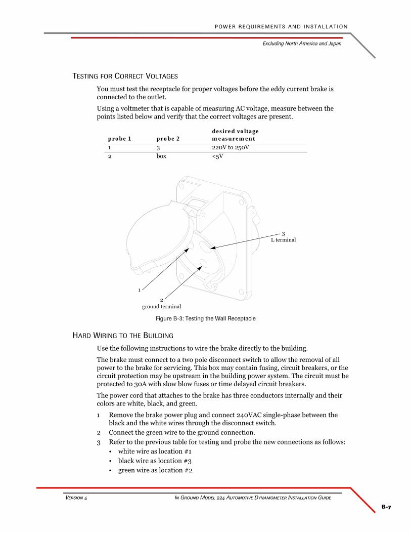
B-7
P O W E R R E Q U I R E M E N T S A N D I N S T A L L A T I O N
Excluding North America and Japan
Version 4 In Ground Model 224 Automotive Dynamometer Installation Guide
TESTING FOR CORRECT VOLTAGES
You must test the receptacle for proper voltages before the eddy current brake is connected to the outlet.
Using a voltmeter that is capable of measuring AC voltage, measure between the points listed below and verify that the correct voltages are present.
Figure B-3: Testing the Wall Receptacle
HARD WIRING TO THE BUILDING
Use the following instructions to wire the brake directly to the building.
The brake must connect to a two pole disconnect switch to allow the removal of all power to the brake for servicing. This box may contain fusing, circuit breakers, or the circuit protection may be upstream in the building power system. The circuit must be protected to 30A with slow blow fuses or time delayed circuit breakers.
The power cord that attaches to the brake has three conductors internally and their colors are white, black, and green.
1 Remove the brake power plug and connect 240VAC single-phase between the black and the white wires through the disconnect switch.
2 Connect the green wire to the ground connection. 3 Refer to the previous table for testing and probe the new connections as follows:
• white wire as location #1• black wire as location #3• green wire as location #2
probe 1 probe 2desired voltage measurement
1 3 220V to 250V
2 box <5V
1
2ground terminal
3L terminal


C-1
In Ground Model 224 Automotive Dynamometer Installation Guide
APPENDIX C
TORQUE VALUES
This appendix contains tables for standard and metric torque values. Use these values when specified values are not given in other sections of this manual.

A P P E N D I X C
Standard Bolt Torque Values
In Ground Model 224 Automotive Dynamometer Installation Guide
C-2
STANDARD BOLT TORQUE VALUES
Always use the torque values specified in other sections of this manual. When specific values are not available, use the torque values listed below. Use the following guidelines when tightening torque:
• These values are based on use of clean, dry threads.
• The following tables include values for plain finish and plated fasteners.
• Reduce torque by 10% when engine oil is used as a lubricant.
The following tables are meant to be used as guidelines for Dynojet product torque values only. Always use caution when torquing fasteners.
GRADE 5
size torque, plain torque, plated
in-threads/in in•lb ft•lb N•m in•lb ft•lb N•m
1/4-20 101 8 11 76 6 9
1/4-28 116 10 13 87 7 10
5/16-18 209 17 24 157 13 18
5/16-24 231 19 26 173 14 20
3/8-16 371 31 42 278 23 31
3/8-24 420 35 47 315 26 36
7/16-14 593 49 67 445 37 50
7/16-20 662 55 75 497 41 56
1/2-13 905 75 102 678 57 77
1/2-20 1019 85 115 765 64 86
9/16-12 1305 109 147 979 82 111
9/16-18 1456 121 164 1092 91 123
5/8-11 1801 150 203 1351 113 153
5/8-18 2040 170 230 1530 128 173
3/4-10 3194 266 361 2395 200 271
3/4-16 3567 297 403 2675 223 302
7/8-9 5154 430 582 3866 322 437
7/8-14 5679 473 642 4259 355 481
1-8 7727 644 873 5795 483 655
1-12 8453 704 955 6340 528 716
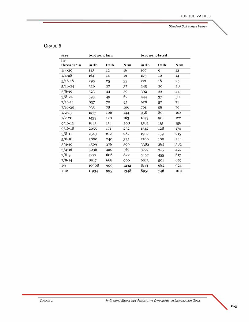
C-3
T O R Q U E V A L U E S
Standard Bolt Torque Values
Version 4 In Ground Model 224 Automotive Dynamometer Installation Guide
GRADE 8
size torque, plain torque, plated
in-threads/in in•lb ft•lb N•m in•lb ft•lb N•m
1/4-20 143 12 16 107 9 12
1/4-28 164 14 19 123 10 14
5/16-18 295 25 33 221 18 25
5/16-24 326 27 37 245 20 28
3/8-16 523 44 59 392 33 44
3/8-24 593 49 67 444 37 50
7/16-14 837 70 95 628 52 71
7/16-20 935 78 106 701 58 79
1/2-13 1277 106 144 958 80 108
1/2-20 1439 120 163 1079 90 122
9/16-12 1843 154 208 1382 115 156
9/16-18 2055 171 232 1542 128 174
5/8-11 2543 212 287 1907 159 215
5/8-18 2880 240 325 2160 180 244
3/4-10 4509 376 509 3382 282 382
3/4-16 5036 420 569 3777 315 427
7/8-9 7277 606 822 5457 455 617
7/8-14 8017 668 906 6013 501 679
1-8 10908 909 1232 8181 682 924
1-12 11934 995 1348 8951 746 1011

A P P E N D I X C
Metric Bolt Torque Values
In Ground Model 224 Automotive Dynamometer Installation Guide
C-4
METRIC BOLT TORQUE VALUES
Always use the torque values specified in other sections of this manual. When specific values are not available, use the torque values listed below. Use the following guidelines when tightening torque:
• These values are based on use of clean, dry threads.
• The following tables include values for plain finish and plated fasteners.
• Reduce torque by 10% when engine oil is used as a lubricant.
The following tables are meant to be used as guidelines for Dynojet product torque values only. Always use caution when torquing fasteners.
GRADE 8.8
GRADE 10.9
size torque, plain torque, plated
mm x pitch in•lb ft•lb N•m in•lb ft•lb N•m
M6 X 1 96 8 11 72 6 8
M8 X 1.25 233 19 26 175 15 20
M10 X 1.5 462 38 52 346 29 39
M12 X 1.75 805 67 91 604 50 68
M14 X 2 1287 107 145 966 80 109
M16 X 2 1997 166 226 1498 125 169
M20 X 2.5 3900 325 441 2925 244 330
M24 X 3 6739 562 761 5054 421 571
size torque, plain torque, plated
mm x pitch in•lb ft•lb N•m in•lb ft•lb N•m
M6 X 1 133 11 15 100 8 11
M8 X 1.25 323 27 36 242 20 27
M10 X 1.5 639 53 72 479 40 54
M12 X 1.75 1114 93 126 836 70 94
M14 X 2 1781 148 201 1336 111 151
M16 X 2 2762 230 312 2072 173 234
M20 X 2.5 5395 450 610 4046 337 457
M24 X 3 9322 777 1053 6992 583 790

Index-i
In Ground Model 224 Automotive Dynamometer Installation Guide
INDEX
Aair brake 2-12air hose 2-10
routing 2-10anchor the dyno 2-7atmos cable 2-9, 2-12
Bbattery hazards vibearing 3-8bearing grease 4-12brake
pressure gauge 4-12, 4-13regulator 4-12, 4-13shoe clearance 4-14
brake cable 2-10, 2-11
Ccable routing channel 3-15calibration arm 3-19
number 3-19weights 3-21
CAN control cable 2-10CAN dyno user cable 2-10CAN pendant cable 2-9, 2-12ce drum guards 2-14chassis specifications 1-5compressed air requirements 1-8computer specifications 1-8controller cable 2-9conventions 1-3crate
removing the dyno 2-5unpacking the dyno 2-2
Ddimensions 1-6, 1-7disclaimers vdocument part number 1-1drill and drill bit 1-10driveline assembly 3-9dyno electronics 1-12, 2-11
dyno requirementssee also requirements
dyno room 1-4DynoWare RT
module connections 1-13network connections 1-14overview 1-12power cable 2-9
Eeddy current brake 2-6, 2-8
bearing 3-8cable routing channel 3-15controller cable 2-9driveline assembly 3-9driver 3-15installing 3-10installing pit covers 3-17keyed yoke 3-9, 3-10load cell 3-13load cell calibration 3-18mounting holes 3-3optimal cooling 3-2pit cover 3-17power cable 2-9, 2-11securing to floor 3-16spline hub 3-9spline shaft 3-9straps 3-2, 3-11temperature sensor 3-7u-joint 3-9unpacking 3-4using forklift 3-2, 3-11zero calibration 3-18
electrical requirements 1-9electrostatic discharge viend pit covers 2-14environmental requirements 1-9equalizer box 1-4ESD precautions viexhaust extraction 1-4

I N D E X
In Ground Model 224 Automotive Dynamometer Installation Guide
Index-ii
Ffire suppression 1-4, 1-9forklift requirements 1-9
Ggrade 10.9 torque values C-4grade 5 torque values C-2grade 8 torque values C-3grade 8.8 torque values C-4ground hooks 2-16grounding bracket 4-8grounding requirements 1-9, 4-8
Hhazards viiheight 1-5
IIndustrial Noise Control, Inc. 1-4intake air fan 1-4IR temp sensor cable 2-10, 2-11
Kkeyed yoke 3-9, 3-10
Llength 1-5load cell
cable 2-10, 2-11calibration 3-18calibration arm 3-19calibration number 3-19calibration weights 3-21installing 3-13zero calibration 3-18
loading the vehicle 4-2loop straps 2-5
Mmaking a test run 4-11metric torque values
grade 10.9 C-4grade 8.8 C-4
model 224 dyno 1-11
Nnetwork cable 2-9network connections 1-14
Ooptical pickup card
aligning the tab 2-13optical RPM sensor 4-5optimal brake cooling 3-2
Ppendant cable 2-9, 2-12pickup card cable
routing 2-13pit
dyno placement 2-6specifications 1-15
pit cover supportsinstalling 3-14removing 3-6
pit coversce drum guards 2-14end pit covers 2-14hood scoop 3-17installing 2-14installing, eddy current brake 3-17side pit covers 2-15
power B-2, B-5hard wiring B-4, B-7installation B-2, B-5installing receptacle B-2, B-6requirements B-2, B-5testing voltages B-3, B-7
pre-run inspection 4-9preventative maintenance 4-12primary inductive pickup 4-7
Rred head anchor
contact information A-1installation A-2setting tool A-3warnings A-1
remote atmos cable 2-9, 2-12requirements
chassis 1-5compressed air 1-8computer specifications 1-8drill and drill bit 1-10electrical 1-9environmental 1-9fire suppression 1-9forklift 1-9grounding 1-9tie-down straps 1-10
routing cablesair hose 2-10brake cable 2-10, 2-11CAN control 2-10CAN dyno user 2-10CAN pendant 2-9, 2-12CAN termination plug 2-10controller cable 2-9dyno electronics 2-11DynoWare RT power 2-9eddy current brake power 2-9, 2-11IR temp sensor 2-10, 2-11

Index-iii
I N D E X
Version 4 In Ground Model 224 Automotive Dynamometer Installation Guide
load cell cable 2-10, 2-11network 2-9pickup card cable 2-13remote atmos 2-9, 2-12RPM pickup 2-9shop air 2-11speed pickup 2-10, 2-11
RPM pickup 4-5primary inductive 4-7routing cables 2-9secondary inductive 4-6
SSAAR brake
pressure gauge 4-12, 4-13regulator 4-12, 4-13shoe clearance 4-14
secondary inductive pickup 4-6setting tool A-3shop air 2-11side pit covers 2-15speed pickup cable 2-10, 2-11spline hub 3-9spline shaft 3-9standard torque values
grade 5 C-2grade 8 C-3
strap 1-9
Ttechnical support 1-3temperature sensor
installing 3-7location 3-7
termination plugCAN 2-10
testing voltages B-3, B-7torque values
metric C-4standard C-2
Uu-joint 3-9
Vvehicle ground cable 4-8
Wwarnings vweight 1-5width 1-5
Yyour dyno room 1-4
equalizer box 1-4exhaust extraction 1-4fire suppression 1-4intake air fan 1-4noise control 1-4
Zzero calibration 3-18