Embed Size (px)
Citation preview

�
�
“SAP2000BridgeExamples” — 2007/7/2 — 11:42 — page i — #1�
�
�
�
�
�
SAP2000BRIDGE EXAMPLES
Computers and Structures, Inc.1995 University Avenue
Berkeley, California 94704, USAhttp://www.csiberkeley.com

�
�
“SAP2000BridgeExamples” — 2007/7/2 — 11:42 — page ii — #2�
�
�
�
�
�
SAP2000 Bridge Examples
Copyright © by Computers and Structures, Inc, 2006All rights reserved.
The computer program SAP2000 and all associated documentation are propri-etary and copyrighted products. Worldwide rights of ownership rest with Com-puters and Structures, Inc. Unlicensed use of the program or reproduction ofthe documentation in any form, without prior written authorization from Comput-ers and Structures, Inc., is explicitly prohibited.
Further information and copies of this documentation may be obtained from:
CSI Educational ServicesComputers and Structures, Inc.1995 University AvenueBerkeley, California 94704 USA
Phone: (510) 845-2177Fax: (510) 845-4096
Email: [email protected] (for general questions)Email: [email protected] (for technical support questions)Web: www.csiedu.com
The CSI Logo, ETABS®, SAP2000® and SAP90® are registered trademarksof Computers and Structures, Inc.; SAFE™ is a trademark of Computers andStructures, Inc.

�
�
“SAP2000BridgeExamples” — 2007/7/2 — 11:42 — page iii — #3�
�
�
�
�
�
PREFACE
This lecture is generally geared towards the intermediate user level of SAP2000. How-ever, if you have never used SAP2000 or SAP2000 Bridge Modeler before, the level ofinformation provided is intended to give the user sufficient information to reproduceall of the bridge examples contained in this booklet. We have designed this coursesuch that the inexperienced SAP2000 user will have no problem following along. Theend-to-end examples that are presented will exhibit the most general and commonmodeling techniques.
It is strongly recommended that the SAP2000 user read Chapter XXVI, Bridge Analy-sis, of the Analysis Reference Manual. The SAP2000 user can use the Help / Documan-tation / Manuals command to find this document.
iii

�
�
“SAP2000BridgeExamples” — 2007/7/2 — 11:42 — page v — #5�
�
�
�
�
�
SEMINAR TOPICS
Preface . . . . . . . . . . . . . . . . . . . . . . . . iii
Seminar Topics . . . . . . . . . . . . . . . . . . . . . v
Part I Concrete Box Girder Bridge 1
I.1 Concrete Box Girder Bridge Example . . . . . . . . . . 1I.2 Description . . . . . . . . . . . . . . . . . . . 1I.3 Model Parameters . . . . . . . . . . . . . . . . . 2I.4 Modeling Steps . . . . . . . . . . . . . . . . . . 2I.5 Step 1: Layout Lines . . . . . . . . . . . . . . . . 3I.6 Step 2: Deck Section Definition . . . . . . . . . . . . 3I.7 Step 3: Abutment Definition . . . . . . . . . . . . . 4I.8 Step 4: Bent Definition . . . . . . . . . . . . . . . 5I.9 Step 5: Diaphragm Definition . . . . . . . . . . . . . 7I.10 Step 6: Hinge Definition . . . . . . . . . . . . . . . 7I.11 Step 7: Parametric Variation Definition . . . . . . . . . . 8I.12 Step 8: Bridge Object Definition . . . . . . . . . . . . 9I.13 Step 9: Update Linked Model . . . . . . . . . . . . . 12I.14 Step 10: Lane Definition . . . . . . . . . . . . . . . 13I.15 Step 11: Vehicle Definition . . . . . . . . . . . . . . 14I.16 Step 12: Analysis Cases . . . . . . . . . . . . . . . 15I.17 Results . . . . . . . . . . . . . . . . . . . . 16
Part II Steel Bridge 21
II.1 Steel Bridge Example 1.0 . . . . . . . . . . . . . . 21II.2 Layout Line Definition . . . . . . . . . . . . . . . 22II.3 Deck Section Definition . . . . . . . . . . . . . . . 24II.4 Bridge Object 1 Definition . . . . . . . . . . . . . . 24II.5 Create Linked Model . . . . . . . . . . . . . . . . 25II.6 Modify Abutment Properties . . . . . . . . . . . . . 28II.7 Modify Bent Properties . . . . . . . . . . . . . . . 29II.8 Modify Vertical Diaphragm Properties . . . . . . . . . . 30II.9 Further Modify Bridge Object 1 . . . . . . . . . . . . 30II.10 Update Linked Bridge Model . . . . . . . . . . . . . 31II.11 Analyze BOBJ1 . . . . . . . . . . . . . . . . . 33II.12 Live Loads . . . . . . . . . . . . . . . . . . . 34
v

�
�
“SAP2000BridgeExamples” — 2007/7/2 — 11:42 — page vi — #6�
�
�
�
�
�
vi CSI SAP2000 BRIDGE EXAMPLES
II.13 Add Vehicles . . . . . . . . . . . . . . . . . . 36II.14 Add Analysis Case . . . . . . . . . . . . . . . . 37II.15 Add Trucks with Speed and Direction . . . . . . . . . . 40II.16 Add Bridge Extensions . . . . . . . . . . . . . . . 47II.17 Completed Model . . . . . . . . . . . . . . . . . 50II.18 Final Analysis . . . . . . . . . . . . . . . . . . 52
Part III Cablestayed Bridge 53III.1 Cable stayed Bridge Example . . . . . . . . . . . . . 53III.2 Description of Cable stayed Bridge . . . . . . . . . . . 54III.3 Description of Model . . . . . . . . . . . . . . . 54III.4 Nonlinear Material Property Definition . . . . . . . . . . 55III.5 Cable Property Definition . . . . . . . . . . . . . . 57III.6 Deck Section Definition . . . . . . . . . . . . . . . 57III.7 Pylon Section Definition . . . . . . . . . . . . . . . 58III.8 Model Creation . . . . . . . . . . . . . . . . . . 60III.9 Group Assignments . . . . . . . . . . . . . . . . 63III.10 Staged Construction Analysis Case . . . . . . . . . . . 65
APPENDIX 67
Part A Mesh Transitioning, Compatibility, and Line Constraint 69A.1 Introduction . . . . . . . . . . . . . . . . . . . 69A.2 Example 1: Simply Supported Plate (Mismatched Meshing) . . . 70A.3 Example 2: Curved Ramp Supported by Curved Wall . . . . . 71A.4 Example 3: Floor Slab – Shear Wall Compatibility . . . . . . 71A.5 Example 4: Shear Wall – Spandrel Transition . . . . . . . . 71
Bibliography . . . . . . . . . . . . . . . . . . . . . . 75
About the Speakers . . . . . . . . . . . . . . . . . . . 77

�
�
“SAP2000BridgeExamples” — 2007/7/2 — 11:42 — page 1 — #9�
�
�
�
�
�
PART I
Concrete Box Girder Bridge
I.1 Concrete Box Girder Bridge Example
Figure I.1: Full Concrete Box Girder Bridge
I.2 Description
This example demonstrates the powerful bridge module in SAP2000. The model is aconcrete box girder bridge with a 200 ft span and is loaded with 2 traffic lanes. Thebridge has 3 columns with different heights supporting the deck at midspan. Thereare parametric variations along the length of the bridge as well as prestressed tendonsassigned to the deck. The bridge abutments are skewed 15 degrees at the 2 ends of thebridge deck.
1

�
�
“SAP2000BridgeExamples” — 2007/7/2 — 11:42 — page 2 — #10�
�
�
�
�
�
2 CSI SAP2000 BRIDGE EXAMPLES
I.3 Model ParametersThe overall deck depth has a depth 5 ft and a width of 36 ft. Kip-feet-second unitsare used. To see the deck cross-section geometry, please refer to Figure below. Otherparameters associated with the structure are as follows:
Clear span of bridge = 200 ftOverall depth of deck = 5 ftWidth of deck, b = 36 ftConcrete strength, f’c = 4000 psiYield strength of steel, fy = 60000 psiConcrete unit weight, Wc = 150 pcfModulus of elasticity, Ec = 3600 ksiModulus of elasticity, Es = 29000 ksiPoisson’s ratio, v = 0.2
Table I.1: Model Parameters
I.4 Modeling StepsThis concrete box girder example is intended to give the user some experience witheach of the steps defined in the Bridge Wizard. Twelve steps are used to complete theconcrete box girder example and various dialog boxes are shown to make it easier forthe first time user to follow along or reconstruct the model. This model will make useof many of the SAP200 Bridge Module features including bridge analysis, influencelines and surfaces, and the use of prestress tendons. To build the bridge model, a12-step process is described below.
1. Layout Lines2. Deck Sections3. Abutments4. Bents5. Diaphragms6. Hinges7. Parametric Variations8. Bridge Object definitions9. Update of linked model10. Lanes11. Vehicles/Vehicle Classes12. Analysis Cases
Table I.2: Modeling Steps
The user can quickly define a basic model that applies program defaults using thefollowing abbreviated approach:

�
�
“SAP2000BridgeExamples” — 2007/7/2 — 11:42 — page 3 — #11�
�
�
�
�
�
PART I. CONCRETE BOX GIRDER BRIDGE 3
a. Define a layout line using Step 1.b. Define a deck section using Step 2.c. Skip to Step 8 to create a bridge object.d. Create a linked model using Step 9.
Table I.3: Abbreviated Approach
For the abbreviated approach, SAP2000 will apply default abutment, bent, hinge, anddiaphragm properties. If necessary, Steps 3, 4, 5 and 6 of this Wizard can be used tochange those default definitions. In addition, prestressed tendons can be added as partof the bridge object definition (see Step 8).
Each one of the 12-steps is described in detail.
I.5 Step 1: Layout Lines
The first step in creating a bridge object is to define the layout line. Layout lines areused as reference lines for defining the vertical and horizontal layout of bridge objectsand lanes.
Layout lines are defined in terms of stations, bearings and grades. The lines maybe straight, bent or curved both in the horizontal and the vertical plane. Horizontalcurves are circular (with spirals if necessary) and vertical curves are parabolic. In thisexample, the End Station is defined as 220 ft. The final bridge will have a span of 200ft and will shorter then the layout line.
Use the Quick Start options to quickly define a layout line. You will see the manychoices available for both Horizontal and Vertical curves. Select the Straight line inboth cases.
I.6 Step 2: Deck Section Definition
Various parametric bridge deck sections are available for use in defining a bridge. Theyinclude concrete box girders, concrete beam and steel beam sections. Select the Exter-nal Girders Vertical option. Enter the total width and depth shown in Figure I.2below.After a deck section has been defined it can be assigned to a span as part of the bridgeobject definition (see Step 8).

�
�
“SAP2000BridgeExamples” — 2007/7/2 — 11:42 — page 4 — #12�
�
�
�
�
�
4 CSI SAP2000 BRIDGE EXAMPLES
Figure I.2: Define Bridge Deck Section Data
I.7 Step 3: Abutment DefinitionAbutment definitions specify the support conditions at the ends of the bridge.
An abutment definition can be a specified Link/Support property or it can be a userdefined support condition. The user support condition allows each of the six degreesof freedom at the abutment to be specified as fixed, free or partially restrained with aspecified spring constant.
An abutment definition also allows the horizontal location of the abutment supports tobe specified. A single abutment support can be located at the reference line locationor multiple abutment supports can be located either at each girder or equally spacedover the bridge width. When multiple locations are indicated the specified abutmentsupport properties are provided at each support location.
It is also possible to specify that a closure (vertical diaphragm) of some thickness is tobe provided at the abutment. This closure is only applicable to area object and solidobject models.
For this example, select the U2, R1, and R3 DOF directions to have a ’Free’ releasetype. The other directions should have a ’Fixed’ release type. Under the HorizontalLocation of Abutment Supports, select the every girder location option.

�
�
“SAP2000BridgeExamples” — 2007/7/2 — 11:42 — page 5 — #13�
�
�
�
�
�
PART I. CONCRETE BOX GIRDER BRIDGE 5
Figure I.3: Parametric Variation Definition
I.8 Step 4: Bent DefinitionBent definitions specify the geometry and section properties of the bent cap beam andthe bent column(s). They also specify the base support condition of the bent columns.
The specified base support condition for a bent column can be Fixed, Pinned or a user

�
�
“SAP2000BridgeExamples” — 2007/7/2 — 11:42 — page 6 — #14�
�
�
�
�
�
6 CSI SAP2000 BRIDGE EXAMPLES
defined column support. A user defined column support can be a specified Link/Supportproperty or it can be a user defined support condition. The user support condition al-lows each of the six degrees of freedom at the column base to be specified as fixed,free or partially restrained with a specified spring constant. The user defined columnsupport is defined separately from the bent.
It is also possible to specify that a vertical diaphragm is to be provided at the bentlocation. The diaphragm is only applicable to area object and solid object models. Itdoes not apply to spine models.
After a bent is defined it can be assigned to the bridge as part of the bridge objectdefinition (see Step 8).
In this example, click on the Bride menu¿ Bents and select the Add New Bridge Bentoption. In the Bent Data box, type in the number of columns: 3. Next, click on theModify/Show Column Data box in the lower left hand corner. Fill out the form asshown in Figure I.4below and click OK. Make sure you are in Kip-ft units.
Figure I.4: Define Bridge Bent Properties

�
�
“SAP2000BridgeExamples” — 2007/7/2 — 11:42 — page 7 — #15�
�
�
�
�
�
PART I. CONCRETE BOX GIRDER BRIDGE 7
I.9 Step 5: Diaphragm Definition
Diaphragm definitions specify properties of vertical diaphragms that span transverseacross the bridge.
A diaphragm property can be solid concrete; steel X, V or K bracing; or a single steelbeam. Solid concrete diaphragm properties are only applicable to concrete bridgesections. Steel diaphragm properties are only applicable to steel bridge sections.
Diaphragms in general are only applicable to area object and solid object models. Theydo not apply to spine models.
After a diaphragm definition has been created it can be assigned to one or more spansin the bridge object (see Step 8).
It is not necessary to define a diaphragm property before defining a bridge object.If no diaphragms are defined when a diaphragm is first added to a bridge object, theprogram automatically creates a default diaphragm property. For this example, we willnot assign specific diaphragm properties.
I.10 Step 6: Hinge Definition
Hinge definitions specify properties of hinges (expansion joints) and restrainers.
A hinge property can be a specified Link/Support property or it can be a user-definedspring. The user spring allows each of the six degrees of freedom at the hinge to bespecified as fixed, free or partially restrained with a specified spring constant.
A restrainer property can be a specified Link/Support property or it can be a user-defined restrainer. The user restrainer is specified by a length, area and modulus ofelasticity.
A hinge definition also allows the horizontal location of the hinge springs and restrain-ers to be specified. A single hinge spring (and restrainer) can be located at the referenceline location or multiple hinge springs (and restrainers) can be located at each girderor equally spaced over the bridge width. When multiple locations are indicated thespecified spring and restrainer properties are provided at each support location.
It is also possible to specify that a vertical diaphragm is to be provided at the hinge lo-cation. The specified diaphragm is provided on each side of the hinge. This diaphragmis only applicable to area object and solid object models. It does not apply to spinemodels.
After a hinge definition has been created it can be assigned to one or more spans in thebridge object (see Step 8). It is not necessary to define a hinge property before defininga bridge object.

�
�
“SAP2000BridgeExamples” — 2007/7/2 — 11:42 — page 8 — #16�
�
�
�
�
�
8 CSI SAP2000 BRIDGE EXAMPLES
I.11 Step 7: Parametric Variation Definition
Parametric variations define variations in the deck section along the length of thebridge. Any parameter used in the parametric definition of the deck section can bespecified to vary. One or more of the parameters can vary at the same time. Eachvarying parameter can have its own unique variation.
Example uses of parametric variations include varying the bridge depth and the thick-ness of girders and slabs along the length of the bridge. The variations may be linear,parabolic or circular.
After a variation has been defined it can be assigned to spans in the bridge object (seeStep 8). When a variation is defined it should be defined with the same length as thebridge span to which it is assigned.
For this example, we will define 2 variations (one for each span of the bridge.) Underthe Bridge/Parametric Definitions command, select the Add New Variation, then usingthe quick start button, select the Parabolic Linear variation. Fill out the form as shownin Figure I.5 below:
Figure I.5: Parametric Variation Definition

�
�
“SAP2000BridgeExamples” — 2007/7/2 — 11:42 — page 9 — #17�
�
�
�
�
�
PART I. CONCRETE BOX GIRDER BRIDGE 9
Next, in the same manner as described in the steps above, create a 2nd variation. Only,this time the variation shall be defined with the Linear Parabolic quick start option.The new PARV2 variation should be the exact mirror of the PARV1 variation. Nextthe user needs to apply these variations to the bridge object. This can be accomplishedby first using the Bridge/Bridge Objectscommand, then opening the Bridge Objectsdialog box and selecting the modify/show spans command. The user should apply thePARV1 and PARV2 variations to the Span1 and SpanToEnd as shown in Figure I.6below. See also, the steps outlined in Step 8 below.
Figure I.6: Assign Parametric Variation To Span
I.12 Step 8: Bridge Object DefinitionThe bridge object is the heart of the bridge modeler. The following is included in thebridge object definition: a. The bridge spans are defined.
b. Deck section properties are assigned to each span.
c. Parametric deck section variations may be assigned to each span.
d. Abutment properties and skews are assigned.
e. Bent properties and skews are assigned.
f. Hinge locations, properties and skews are assigned.
g. Super elevations are assigned.
h. Prestressed tendons are defined.
Any time a bridge object definition is modified the linked model must be updated (seestep 9) for the changes to appear in the SAP2000 model.

�
�
“SAP2000BridgeExamples” — 2007/7/2 — 11:42 — page 10 — #18�
�
�
�
�
�
10 CSI SAP2000 BRIDGE EXAMPLES
The prestress tendon quick start options allow quick and easy layout of prestressedtendons. The prestress tendon parabolic calculator makes quick work of the layout ofparabolic prestress tendons.
To work within the Bridge Object menu, click on the modify/show bridge object usingDefine/Bridge Object command. The Bridge Object menu should appear as shown inFigure I.7.
Figure I.7: Bridge Object Menu
Next, click the on Modify/Show spans button. In this dialogue box, for Span 1, doubleclick on the span varies box. A Bridge section variation box will open. Double-clickon the variation for Total Depth box and select PVAR1 and click OK. Do the same forthe next span except select PVAR2 for the variation. See Figure I.6.
To apply a skew to the ends of the bridge, click on the Modify/Show Spans and simplytype in the bearing angle as shown in the dialog box in Figure I.10

�
�
“SAP2000BridgeExamples” — 2007/7/2 — 11:42 — page 11 — #19�
�
�
�
�
�
PART I. CONCRETE BOX GIRDER BRIDGE 11
Figure I.8: Abutment Bearings
Bridge Prestress button and select Add new Tendon. Fill in a tendon area of 10 in2and load force of 1500 kips. Select a Prestress load case. (To create a Prestress loadcase, go to Define/Static Load Cases dialogue box.) Click on the Quick Start buttonfor vertical layout and select parabolic tendon 1 and click Ok twice. The tendon lossparameters should also be defined.
Figure I.9: Tendon Definition

�
�
“SAP2000BridgeExamples” — 2007/7/2 — 11:42 — page 12 — #20�
�
�
�
�
�
12 CSI SAP2000 BRIDGE EXAMPLES
Once a single tendon has been defined, it can be copied to each of the concrete girderlocations by simply clicking on the Copy To All Girders command.
Figure I.10: Tendon Definition
The user can verify the location of the tendon graphically by selecting the the ShowAll Tendons command and viewing the tendon profiles and locations.
I.13 Step 9: Update Linked ModelThe update linked model command creates the SAP2000 object-based model from thebridge object definition. If an object-based model of the bridge object already exists,it will be deleted when the new object-based model is created using all of the latestchanges to the bridge object definition.
Spine models, area object models and solid object models of the bridge can be createdwhen the linked model is updated. The type of object-based model created from thebridge object definition can be switched at any time.
Under the Bridge menu, select the Update Linked Bridge Model option. Then click onthe Update as Area Object option.

�
�
“SAP2000BridgeExamples” — 2007/7/2 — 11:42 — page 13 — #21�
�
�
�
�
�
PART I. CONCRETE BOX GIRDER BRIDGE 13
Figure I.11: Update Linked Bridge Model Dialog Box
In Figure I.12, you can see the parametric variation along the length of the deck. Youcan also view the tendons located inside the bridge deck by turning off the area objectfill if desired.
Figure I.12: Updated Linked Bridge Model
I.14 Step 10: Lane DefinitionLanes must be defined if you want to analyze your bridge for moving vehicle live loads.Lanes can be defined with reference to either layout lines or existing frame objects. Asingle lane is referenced to one or more layout lines or one or more frame objects.Lanes can be defined with width if desired. Lanes are used in the definition of MovingLoad type analysis cases and in Bridge Live load cases. The SAP2000 Vehicle LiveLoader is complex. The user is strongly recommended to read Chapter XXVI, of theAnalysis Reference Manual.
For this example, click on the Add New Lane Defined From Layout Line button. Adda lane at two stations. (0 ft and 220 ft) Each of these stations has the same centerlineoffset (7ft) and lane width (14ft). Click OK. Next, add a copy of a lane and change

�
�
“SAP2000BridgeExamples” — 2007/7/2 — 11:42 — page 14 — #22�
�
�
�
�
�
14 CSI SAP2000 BRIDGE EXAMPLES
offset by specified amount (-14ft).
Figure I.13: Lane Definition
I.15 Step 11: Vehicle Definition
Vehicles must be defined if you want to analyze your bridge for vehicle live loads. InSAP2000 vehicles loads are applied to the structure through lanes.
If you plan to use a moving load type analysis case then you must also define one ormore vehicle classes. A vehicle class is simply a group of one or more vehicles forwhich a moving load analysis is performed (one vehicle at a time).
Numerous standard vehicle definitions are built into the program. In addition the Gen-eral Vehicle feature can be used to create your own vehicle definition. Each vehicledefinition consists of one or more concentrated and/or uniform loads.
Under the Bridge menu, select vehicles and click the Add Vehicle button. Add anHSN-44-1 type vehicle and click OK. From the Bridge menu again, select the VehicleClasses option. Click Add New Class and select the HSN-44-1 vehicle and click Add.
�
�
“SAP2000BridgeExamples” — 2007/7/2 — 11:42 — page 15 — #23�
�
�
�
�
�
PART I. CONCRETE BOX GIRDER BRIDGE 15
Figure I.14: Vehicle Definition
I.16 Step 12: Analysis CasesAlthough any analysis case type can be used when analyzing your bridge, there areseveral analysis options that are specialized for analysis of vehicle live loads.
Moving load analysis cases compute influence lines for various quantities and solveall permutations of lane loading to obtain the maximum and minimum response quan-tities.
Multi-step static and multi-step dynamic (direct integration time history) analysis casescan be used to analyze one or more vehicles moving across the bridge at any speed.These multi-step analysis cases are defined using special Bridge Live Load Cases thatdefine the direction, starting time and speed of vehicles moving along lanes.
Under the Define/Analysis Casescommand, select the Add New Case. Under the anal-ysis case type, select Moving Load and add the VECL1 vehicle class and click OK.
I.16.1 Creep and Shrinkage
Under the Define/Material Propertiescommand, select the concrete material prop-erty used in the deck property definition click Modify/Show Properties. Toggle theShow Advanced Properties button and complete the Creep and Shrinkage propertiesas shown in Figure I.15

�
�
“SAP2000BridgeExamples” — 2007/7/2 — 11:42 — page 16 — #24�
�
�
�
�
�
16 CSI SAP2000 BRIDGE EXAMPLES
Figure I.15: Updated Linked Bridge Model
I.17 Results
I.17.1 Influence Surfaces
The influence lines can be displayed for the various displacements, reactions, forces,moments, shears, torsion or axial loads on joints, frames, shells, planes, solids, solids,and links resulting from a unit load on a defined bridge lane in the structure. As an ex-ample, after lanes have been defined and a moving analysis case has been defined andrun, select a column and use the Display/Show Influence Lines/Surfaces command todisplay the Show Influence Lines/Surfaces form. See Figure I.16

�
�
“SAP2000BridgeExamples” — 2007/7/2 — 11:42 — page 17 — #25�
�
�
�
�
�
PART I. CONCRETE BOX GIRDER BRIDGE 17
Figure I.16: Influence Surface Plot Options
Figure I.17: Influence Surface Plot for Axial Force of Bent Columns

�
�
“SAP2000BridgeExamples” — 2007/7/2 — 11:42 — page 18 — #26�
�
�
�
�
�
18 CSI SAP2000 BRIDGE EXAMPLES
I.17.2 Bridge Forces and Stresses
You can view bridge forces and stresses for any load case. Use the Display/ShowBridge Forces/Stressescommand to display the forces and stress in the bridge deck.As an example, select the Stress,Longitudinal Stress - Top and Bottom - Center (S11)for the prestress load case. The following plot can be viewed.
Figure I.18: Bridge Object Response Display
I.17.3 Section Cut Forces
There are two options available to define Section Cuts:
1. The first option is to define the location of the cut. Use the Define/SectionCuts command to obtain resultant forces acting at section cuts through a model. Definesection cuts before or after an analysis is run; however, it is safest to wait until afterthe analysis has been run. Typically, do not define section cuts, and more importantly,the groups used in the section cut definition, until all manual meshing of the model (ifany) has been completed. If the groups are defined before manual meshing, some ofthe point objects that should be in the group may not yet be created.
2. The second option is to manually draw the section cut on any portion ofthe model. This can be by utilizing the Draw/Draw Section Cut command. Youmust make sure that the model has been analyzed and you are viewing a memberforce/stress diagram. This can be found under Display/Show Member Force/StressDiagramcommand by selecting either the frame or shell forces.

�
�
“SAP2000BridgeExamples” — 2007/7/2 — 11:42 — page 19 — #27�
�
�
�
�
�
PART I. CONCRETE BOX GIRDER BRIDGE 19
To obtain shell forces on the bridge deck, go to Draw/Section Cut. Draw a line throughany portion of the structure that you would like to sum forces about. The flashing linerepresents the section cut. Section Cut forces will then be visible on the screen.

�
�
“SAP2000BridgeExamples” — 2007/7/2 — 11:42 — page 21 — #29�
�
�
�
�
�
PART II
Steel Bridge
II.1 Steel Bridge Example 1.0
Figure II.1: Full Bridge
This Example is intended to help the new SAP2000 Bridge User navigate through theprogram and is intended to get the new SAP2000 user familiar with the Bridge Module.This example provides a step-by-step tutorial for the bridge model shown below. Thebridge model is broken down into five distinct steps using the file names Steel Bridge 1through Steel Bridge 5. A copy of these input files can be obtained from Computer and
21

�
�
“SAP2000BridgeExamples” — 2007/7/2 — 11:42 — page 22 — #30�
�
�
�
�
�
22 CSI SAP2000 BRIDGE EXAMPLES
Structures, Inc.
To begin the Example 1 steel bridge model we will initiate the SAP2000 program andselect a blank screen using Kip-Ft units and a single window. Then using the Bridgepull down menu we will begin to define the first of three bridge objects that will beused to complete this bridge example. Each of the bridge objects are shown below.
Bridge Object 1
Bridge Object 2
Bridge
Obje
ct 3
Station1200
FT
Station1100
FT
Sta
tion
1000
FT
Figure II.2: Bridge Objects
II.2 Layout Line Definition
To define the first bridge object BOBJ1 we will first define the layout line properties.From the Bridge>Layout Lines command we get the following dialog box:

�
�
“SAP2000BridgeExamples” — 2007/7/2 — 11:42 — page 23 — #31�
�
�
�
�
�
PART II. STEEL BRIDGE 23
Figure II.3: Layout Line Definition
From the layout line menu the Quick Start menus can be used to define various curved,straight or combined curved-straight shapes. For this example the bridge layout line1(BLL1) will have a straight shape.
Figure II.4: Layout Quickdraw
Using the layout line dialog box shown in Figure 1.3 the end station is set at 1210 andthe start station is set at 990. Note that the bridge layout line is longer than the actualbridge.

�
�
“SAP2000BridgeExamples” — 2007/7/2 — 11:42 — page 24 — #32�
�
�
�
�
�
24 CSI SAP2000 BRIDGE EXAMPLES
II.3 Deck Section DefinitionUsing the Bridge>Bridge Deck Sections¿Add New Section command and selectingthe Steel and Concrete template the following dialog bow appears:
Figure II.5: Deck Section Definition
For this example four interior beams will be specified and the size of the bridge girderswill be assigned as W36X230. No other changes to this deck template will be made.The bridge deck section will be given the default name of BSEC1.
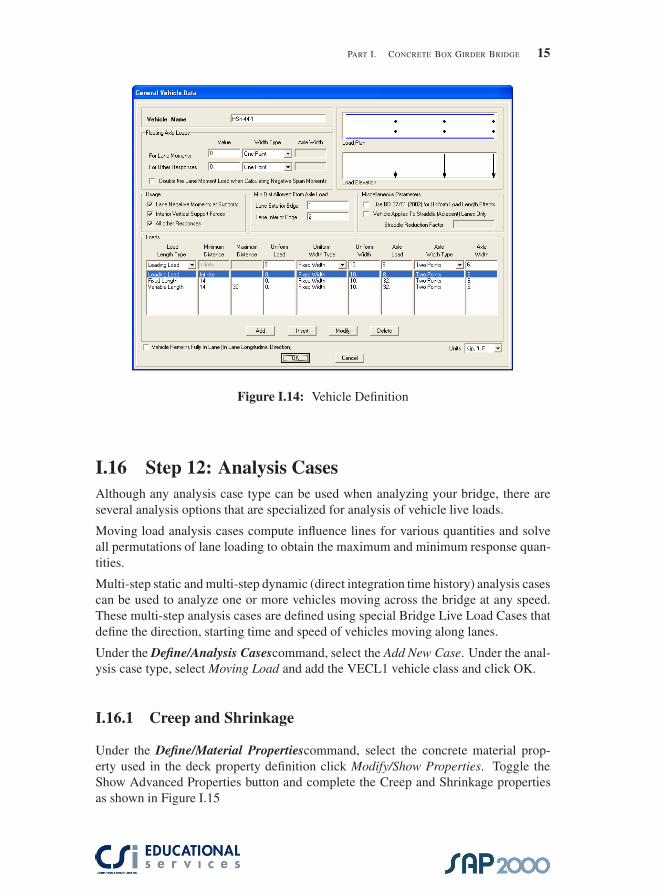
II.4 Bridge Object 1 DefinitionUsing the Bridge¿Bridge Object>Add New Bridge Object command the dialog boxshown below will appear. Using the Insert Below command and the Insert commandthe Span1 and Span 2 information needs to be specified. Note that the bridge layoutline is longer than the length of the bridge object 1 (BOBJ1) being defined. For thisexample the first abutment (Abut1) will be located at station 1000. A bent is placed atstation 1050 and at this stage of the model an end abutment (Abut3) is placed at station1100. In later stages of this model creation, Abut3 will be moved back by ten feet andin its place a free abutment will be used.
�
�
“SAP2000BridgeExamples” — 2007/7/2 — 11:42 — page 25 — #33�
�
�
�
�
�
PART II. STEEL BRIDGE 25
Figure II.6: Bridge Object 1 (BOBJ1)
It will be important for the SAP2000 bridge user to become familiar with each of theBridge Object Assignment. Several of the assignment options will be used in thisexample but the SAP2000 user is encouraged to explore the range of definitions thatare possible.
II.5 Create Linked Model
Using the Bridge>Update Linked Bridge Model> command the dialog box shownbelow will appear. From the Structural Model Options the user can choose to workwith a Spine Model(frame) or an Area Object Model(shell). For this example eachwill be used. The user can alternate as necessary between a frame model and shellmodel. Starting with the spine model the Maximum Segment Lengths are set to fivefeet.

�
�
“SAP2000BridgeExamples” — 2007/7/2 — 11:42 — page 26 — #34�
�
�
�
�
�
26 CSI SAP2000 BRIDGE EXAMPLES
Figure II.7: Update Linked Bridge Model
Pressing the OK button returns the user to following view of BOBJ1:
Figure II.8: Spine Model BOBJ1
The spine model of BOBJ1 can be viewed in its extruded form using the View>SetDisplay Options command and checking the Extruded option. The following imagecan be rotated and displayed as follows:

�
�
“SAP2000BridgeExamples” — 2007/7/2 — 11:42 — page 27 — #35�
�
�
�
�
�
PART II. STEEL BRIDGE 27
Figure II.9: Extruded View of Spine Model
At this stage of model creation the center bent has only a single column support andthe end abutment is defined as a single point restraint. The center bent has horizontalgirder located flush with the deck instead of being offset vertically. The bent and abut-ments will be further modified such that additional columns will be added to the bentand point restraints will be added to each of the wide flange supports at the abutment.
Figure II.10: Modified Spine Model

�
�
“SAP2000BridgeExamples” — 2007/7/2 — 11:42 — page 28 — #36�
�
�
�
�
�
28 CSI SAP2000 BRIDGE EXAMPLES
II.6 Modify Abutment Properties
Using the Bridge>Abutments command the ABUT1 properties can be modified usingthe following dialog box:
Figure II.11: Abutment 1 Modified
All the translational and rotational degrees of freedom are set to ’fixed’ except thetranslation in the U2 direction. Additionally, the horizontal location of the abutmentsupports is set to ’each girder location’. Diaphragms are added at the abutment byselecting the ’include vertical diaphragm’ option.

�
�
“SAP2000BridgeExamples” — 2007/7/2 — 11:42 — page 29 — #37�
�
�
�
�
�
PART II. MODIFY ABUTMENT PROPERTIES 29
II.7 Modify Bent PropertiesUsing the Bridge>Bents command the BENT1 properties can be modified using thefollowing dialog box:
Figure II.12: Modified Bent
The reference point of the cap beam is set to 16.5ft which is half the width of the 33ftwide deck section. The number of columns is set to 3 and the vertical diaphragms areincluded. To define the column heights and locations the Modify/Show Column Databutton needs to be selected. upon doing so the following dialog box is displayed:
Figure II.13: Modify Bent Columns

�
�
“SAP2000BridgeExamples” — 2007/7/2 — 11:42 — page 30 — #38�
�
�
�
�
�
30 CSI SAP2000 BRIDGE EXAMPLES
The column locations are set to 4, 16.5 and 29 with heights of 24, 27 and 30ft.
II.8 Modify Vertical Diaphragm PropertiesUsing the Bridge>Bridge Diaphragms command the bridge diaphragm property (BDIA1)can be modified using the following dialog box:
Figure II.14: Cross Diaphragms Definition
Using the Chord and Brace option and using a W8X10 as the chord and brace membersizes, the BDIA1 properties are modified.
II.9 Further Modify Bridge Object 1Using the Bridge>Bridge Objects command the bridge object 1 (BOBJ1) can be mod-ified using the following dialog box:

�
�
“SAP2000BridgeExamples” — 2007/7/2 — 11:42 — page 31 — #39�
�
�
�
�
�
PART II. MODIFY ABUTMENT PROPERTIES 31
Figure II.15: Bridge Object 1 (BOBJ1)
From this dialog box the Modify/Show Bents button can be selected and a value of -5ftcan be assigned to the vertical offset of the bent. Similarly, the Modify/Show CrossDiaphragms button can be selected to add cross diaphragms at 25ft along span1 and25ft along span2.
II.10 Update Linked Bridge Model
Using the Bridge>Update Linked Bridge Model command the BOBJ1 can be dis-played again but now with the updated abutment, bent and cross diaphragm modifica-tion. Turning off the Extrude option and displaying the BOBJ1 as a spine model showsthe following:

�
�
“SAP2000BridgeExamples” — 2007/7/2 — 11:42 — page 32 — #40�
�
�
�
�
�
32 CSI SAP2000 BRIDGE EXAMPLES
Figure II.16: Updated Spine Model
Not that the spine model above does not show the cross diaphragms. Updating thelinked bridge model as an area object model produces the following model:
Figure II.17: Updated Shell Model

�
�
“SAP2000BridgeExamples” — 2007/7/2 — 11:42 — page 33 — #41�
�
�
�
�
�
PART II. MODIFY ABUTMENT PROPERTIES 33
II.11 Analyze BOBJ1
The SAP2000 program has, as a default, an analysis case already defined DEAD andMODAL. Running the model at this time will produce results for each of these de-fault analysis cases. With the linked bridge model defined as a spine model the framemember bending moments can be displayed as follows:
Figure II.18: Bridge Object 1 - Spine Model
Unlocking the model and changing the linked bridge model to area objects, the BOBJ1model can be rerun. Below left are the F11 shell resultant forces. Below right the framemember M33 moments are displayed.

�
�
“SAP2000BridgeExamples” — 2007/7/2 — 11:42 — page 34 — #42�
�
�
�
�
�
34 CSI SAP2000 BRIDGE EXAMPLES
Figure II.19: M33 Moments
Displacements and mode shapes can be displayed as shown below:
Figure II.20: BOBJ1 Displacements
II.12 Live LoadsUsing the Bridge>Lanes command the dialog box below can be used to define thewidth and extent of various lanes over the bridge.

�
�
“SAP2000BridgeExamples” — 2007/7/2 — 11:42 — page 35 — #43�
�
�
�
�
�
PART II. MODIFY ABUTMENT PROPERTIES 35
Figure II.21: Lane Definitions
The first of two lanes is defined as having an end station of 1100ft and a beginningstation of 1000ft. the width of the lane is set at 12ft with an offset of 8ft and the coloris set to a shade of blue. The Lane Load Discretization is set at 5ft along the span and10ft across the span. The second lane is defined as a copy of the first with an offset of-16ft. The BOBJ1 can be shown with the lanes visible using the Display>Show Lanescommand.
Figure II.22: Display Lanes

�
�
“SAP2000BridgeExamples” — 2007/7/2 — 11:42 — page 36 — #44�
�
�
�
�
�
36 CSI SAP2000 BRIDGE EXAMPLES
II.13 Add Vehicles
The SAP2000 Bridge Module has a variety of predefined auto, truck and train vehicles.These can be found using the Bridge>Vehicles command. For this example the HS20-44, HS2044l and AML vehicles will be selected and be added as General Vehicles asshown below:
Figure II.23: Vehicle Definitions
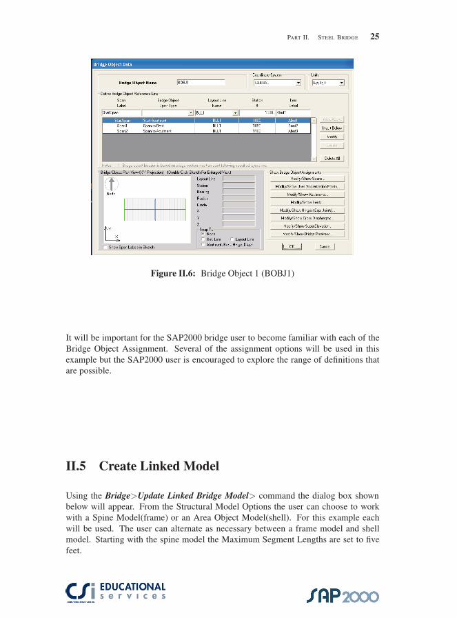
Now that the vehicles have been defined the vehicles need to be assigned to a vehicleclass. This is necessary in order to have the vehicles assigned to a specific analysiscase which will be assign later. Using the Bridge>Vehicle Class command the threegeneral vehicles are assigned to a vehicle class names HS.
�
�
“SAP2000BridgeExamples” — 2007/7/2 — 11:42 — page 37 — #45�
�
�
�
�
�
PART II. MODIFY ABUTMENT PROPERTIES 37
Figure II.24: Vehicle Class Definitions
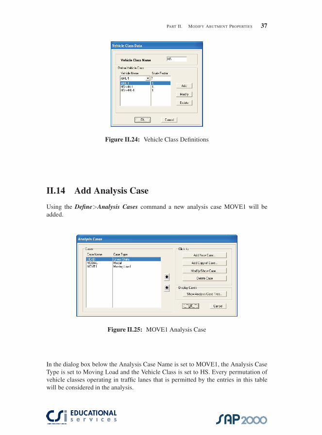
II.14 Add Analysis Case
Using the Define>Analysis Cases command a new analysis case MOVE1 will beadded.
Figure II.25: MOVE1 Analysis Case
In the dialog box below the Analysis Case Name is set to MOVE1, the Analysis CaseType is set to Moving Load and the Vehicle Class is set to HS. Every permutation ofvehicle classes operating in traffic lanes that is permitted by the entries in this tablewill be considered in the analysis.

�
�
“SAP2000BridgeExamples” — 2007/7/2 — 11:42 — page 38 — #46�
�
�
�
�
�
38 CSI SAP2000 BRIDGE EXAMPLES
Figure II.26: Analysis Case MOVE1 Definition
With the MOVE1 analysis case now defined the model can be run. If the model is runas a spine model (See previous Section xx)and a combination COMB1 is defined asDEAD plus MOVE1 the resulting M3 moments can be displayed.
Figure II.27: Combination Dead and MOVE1

�
�
“SAP2000BridgeExamples” — 2007/7/2 — 11:42 — page 39 — #47�
�
�
�
�
�
PART II. MODIFY ABUTMENT PROPERTIES 39
With the MOVE1 analysis case now defined the model can be run. If the model is runas a spine model (See previous Section xx)and a combination COMB1 is defined asDEAD plus MOVE1 the resulting M3 moments can be displayed.
Figure II.28: COMB1 - Frame M3 Moments
Figure II.29: Influence Surfaces
With the MOVE1 analysis case now defined the model can be run. If the model is runas a spine model (See previous Section xx)and a combination COMB1 is defined asDEAD plus MOVE1 the resulting M3 moments can be displayed.

�
�
“SAP2000BridgeExamples” — 2007/7/2 — 11:42 — page 40 — #48�
�
�
�
�
�
40 CSI SAP2000 BRIDGE EXAMPLES
Figure II.30: Response Display
It is recommended that the new SAP2000 Bridge User spend some time reviewingthe analysis results for the MOVE1 load case and examine various individual memberforces and stresses. The user can compare this results of this model with the results ofthe Steel Bridge PR model that has been provided. Upon completion of the analysisthe current model should be saved as Steel Bridge 3
II.15 Add Trucks with Speed and Direction
Using the Define>Load Cases command two moving loads will be added. The firstmoving load case will be named ’moving’ and will be assigned the as follows:

�
�
“SAP2000BridgeExamples” — 2007/7/2 — 11:42 — page 41 — #49�
�
�
�
�
�
PART II. MODIFY ABUTMENT PROPERTIES 41
Figure II.31: Moving Load Case Definition
The menu above allows the user to assign a specific vehicle to a specific lane travelingwith a specific direction starting at a specific time. For the load case defined named’moving’, three trucks are set in motion, two in lane one and one in lane two, with thestart times of 0, 7 and 3 seconds. The speeds are defined as 44, 44 and 22 feet persecond and the truck in lane two has been assigned a backward direction. Below, asecond loads case is given the name ’move’ and consists of three vehicles assigned tolane one with staggered start times of 0, 5 and 9 sec. The speeds are different for eachvehicle with the assignments of 44,88 and 176 feet per second.
Figure II.32: Move Load Case Definition
Next, the analysis cases are defined using the Define>Analysis Cases command. The’move’ case and the ’moving’ case are added to the existing ’DEAD’, ’MODAL’ and

�
�
“SAP2000BridgeExamples” — 2007/7/2 — 11:42 — page 42 — #50�
�
�
�
�
�
42 CSI SAP2000 BRIDGE EXAMPLES
’MOVE1’ cases using the Add New Case command. For the ’moving’ case the Anal-ysis Case Type is set to Multi-step Static. This analysis case will produce an analysisresult for each step of the applied load as it has been defined in the Load Case defini-tion.
Figure II.33: Multi-step moving Analysis Case Definition
The analysis case ’move’ will be analyzed using a time-history analysis method. Thiswill allow the user to examine the vibratory response of the bridge for each of the truckswhich are traveling at different speeds. To define the time-history case the followingdialog box is modified as follows:
Figure II.34: Move Time-History Analysis case Definition

�
�
“SAP2000BridgeExamples” — 2007/7/2 — 11:42 — page 43 — #51�
�
�
�
�
�
PART II. MODIFY ABUTMENT PROPERTIES 43
For the time-history load case a damping value of 2% has been specified by selectingthe Damping>ShowModify button and assigning the values as:
Figure II.35: Damping Assignments for Time History Case
To view the shell stresses for the moving load case the SAP2000 user can use theDisplay>Show Forces/Stresses>Shells and selecting the ’moving’ load case, ’F11’resultant forces with the multivalued option set to ’step 1’ the graphic display willshow the unstressed bridge deck. To see the deck stresses the user can simply stepthrough the various analysis output steps that SAP has saved as part of the multi-stepped analysis. Stepping through the F11 force graphic shows the following:
Figure II.36: F11 Resultant Forces for Moving Case

�
�
“SAP2000BridgeExamples” — 2007/7/2 — 11:42 — page 44 — #52�
�
�
�
�
�
44 CSI SAP2000 BRIDGE EXAMPLES
Figure II.37: Axial Frame Forces for Moving Case
In lieu of stepping through the output manually, the SAP2000 user can create an AVIor movie file. This is done by selecting the File>Create Viedo>Create Multi-stepAnimation Video. When the following window appears the user needs to select the’moving’ load case. The image below was created with a magnification of 10 and aspeed of 10 frames per second.

�
�
“SAP2000BridgeExamples” — 2007/7/2 — 11:42 — page 45 — #53�
�
�
�
�
�
PART II. MODIFY ABUTMENT PROPERTIES 45
Figure II.38: Create AVI Video
To view the time-history results the SAP2000 user can use the Display>Show PlotFunctions command.

�
�
“SAP2000BridgeExamples” — 2007/7/2 — 11:42 — page 46 — #54�
�
�
�
�
�
46 CSI SAP2000 BRIDGE EXAMPLES
Figure II.39: Time History Plot Function
After selecting a joint, in this case joint 144, the following dialog box is used to selectthe ’move’ load case and define the desired plot function. For this example the U2displacements are plotted below:
Figure II.40: U2 Displacements for the Move TH Analysis
This plot shows the third vehicle, t=9sec, inducing a larger dynamic response than the

�
�
“SAP2000BridgeExamples” — 2007/7/2 — 11:42 — page 47 — #55�
�
�
�
�
�
PART II. MODIFY ABUTMENT PROPERTIES 47
two previous vehicles, t=0 and t=5 sec.
II.16 Add Bridge Extensions
Before proceeding with changes to the model it is recommended that the current modelnow be saved as Steel Bridge 4. If necessary this model can be compared to the modelprovided.
Adding the two narrower bridge extensions will consist of defining a new ’free’ abut-ment, defining an additional bridge deck section, defining a new curved layout line,modifying BOBJ1 and adding two new bridge objects. These steps can be brokendown as follows:
1. Using the Bridge>Abutments command add a new abutment with the nameAbutFree. Set all restraint degrees of freedom to ’free’
2. Add a new bridge deck using the same bridge template as before except thatthe width of the deck is defined as 18 feet wide and the number of interior girders usedis set to one. Offset the Insertion Pt in the local-y dir by 9ft.
3. Add copy of Bent1 and call it Bent2. Edit the width to be 15ft, the referencepoint set at 7.5ft and a single column located at 7.5ft with a height of 27ft.
4. Add a copy of the Layout Line 1 and name it BLL2. The Quick Start buttoncan be used and the ’Curved Right option should be selected. The ’Initial Y’ dimen-sion needs to be set at -18ft.
5. Modify BOBJ1 as follows:

�
�
“SAP2000BridgeExamples” — 2007/7/2 — 11:42 — page 48 — #56�
�
�
�
�
�
48 CSI SAP2000 BRIDGE EXAMPLES
Figure II.41: BOBJ1 Modified
6. Add copy of BOBJ1 and name it BOBJ2 and modify as follows:
1. ”Span4” Span to Abutment @ 1200 ”Abut5”
2. ”Span3” Spans to Bent @ 1145 ”Bent4”
3. ”Split” Start @ 1100 ”Split”
4. Modify Spans: Set spans to the BSEC2 property
5. Modify Abutments: Assign the AbutFree property ABUT2
6. Modify Bents: Assign BENT to have a horizontal offset of 9ft and a drop of -5
7. Modify Diaphragms: Add BDIA1 to Span3 @ 22.4 and Span4 @ 27.5.
The BOBJ2 dialog box should appear as follows:

�
�
“SAP2000BridgeExamples” — 2007/7/2 — 11:42 — page 49 — #57�
�
�
�
�
�
PART II. MODIFY ABUTMENT PROPERTIES 49
Figure II.42: Bridge Object 2 — BOBJ2
7. Add a copy of BOBJ1 and name it BOBJ3 with the following modifications:
a. ”Split”, Start @ 1100 ”Split
b. ”Span3”, Span to Bent @ 1145 ”Bent2”
c. ”Span4”, Span to Abutment @ 1200 ”Abut5”
d. Modify Spans, change to BSEC2
e. Modify Abutments, change to ABUT2, ABUT1
f. Modify bents, change to BENT2 @ 9, -5
g. Modify diaphragms, properties BDIA1, Span3 @ 22.5, Span4 @ 27.5
h. Update Bridge model and mesh at 5ft

�
�
“SAP2000BridgeExamples” — 2007/7/2 — 11:42 — page 50 — #58�
�
�
�
�
�
50 CSI SAP2000 BRIDGE EXAMPLES
i. Modify Superelevations, BBL2 to have 0 @ 1100 and 10% @ 1200
When the edits above are completed the BOBJ3 dialog box should appear as follows:
Figure II.43: Bridge Object 3 — BOBJ3
II.17 Completed Model
The Steel Bridge - Example 1 is now complete and ready for analysis. It is recom-mended that the new SAP2000 Bridge User spend some time viewing the results togain a better understanding of the program capabilities. The results can be checkedagainst the models provided.
�
�
“SAP2000BridgeExamples” — 2007/7/2 — 11:42 — page 51 — #59�
�
�
�
�
�
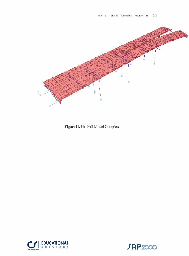
PART II. MODIFY ABUTMENT PROPERTIES 51
Figure II.44: Full Model Complete

�
�
“SAP2000BridgeExamples” — 2007/7/2 — 11:42 — page 52 — #60�
�
�
�
�
�
52 CSI SAP2000 BRIDGE EXAMPLES
II.18 Final Analysis
Figure II.45: Full Model - Shell Stresses
With the bridge complete the user can run the final bridge configuration and look atthe analysis results.

�
�
“SAP2000BridgeExamples” — 2007/7/2 — 11:42 — page 53 — #61�
�
�
�
�
�
PART III
cablestayed Bridge
III.1 Cable stayed Bridge Example
Figure III.1: Full Bridge
53
�
�
“SAP2000BridgeExamples” — 2007/7/2 — 11:42 — page 54 — #62�
�
�
�
�
�
54 CSI SAP2000 BRIDGE EXAMPLES
This bridge model is intended to demonstrate the SAP2000 Staged Construction Anal-ysis using a cablestayed bridge as an illustrative example. This example provides astep-by-step tutorial for the staged construction analysis case. A copy of the input filecan be obtained from Computer and Structures, Inc.
III.2 Description of Cable stayed Bridge
This cable stayed bridge example consists of a concrete bridge deck that is supportedby cable stays which in turn are supported by a center pylon. The bridge is analyzedfor dead, modal and stage construction loadings.
III.3 Description of Model
The bridge is modeled using a concrete deck section that defined as a hollow boxsection having a width of 6 meters and a depth of 1.2 meters. The deck spans oneach side of the pylon are are divided into ten segments that are assigned separategroup names which are used to define the staged construction sequence. The concreteassigned to the deck section has been defined using nonlinear material properties tomodel creep and shrinkage. The center pylon is nonprismatic with a top diameter of0.6 meters and a base diameter of 1.2 meters. The cables connect from the bridge deckto special joints on the pylon.
No live loads are included in this example.

�
�
“SAP2000BridgeExamples” — 2007/7/2 — 11:42 — page 55 — #63�
�
�
�
�
�
PART III. CABLESTAYED BRIDGE 55
Figure III.2: Bridge Objects
III.4 Nonlinear Material Property Definition
Using theDefine>Materials/ command we get the following dialog box:

�
�
“SAP2000BridgeExamples” — 2007/7/2 — 11:42 — page 56 — #64�
�
�
�
�
�
56 CSI SAP2000 BRIDGE EXAMPLES
Figure III.3: Material Property Definition
The ”Show Advanced Material Properties” box needs to be selected to providethe user with the option to define the Advanced Material Property Data. For this ex-ample the Time Dependent Properties option was selected which gives the user thefollowing dialog box:
Figure III.4: Time Dependent Properties for Concrete

�
�
“SAP2000BridgeExamples” — 2007/7/2 — 11:42 — page 57 — #65�
�
�
�
�
�
PART III. CABLESTAYED BRIDGE 57
III.5 Cable Property Definition
Using the Define>Cable Sections command we get the following dialog box:
Figure III.5: Layout Line Definition
The cable diameter is specified as 0.05 meters. The cable properties are calcu-lated using the specified diameter. Similarly, the cable properties can be determined ifthe user specifies the cable area.
III.6 Deck Section Definition
Using the Define>Frame Section>Add Box Section command the bridge deck isdefined having a width of 6 meters and a depth of 1.2 meters with the wall thicknessesof the webs and flanges as 0.3 and 0.2 meters, respectively.

�
�
“SAP2000BridgeExamples” — 2007/7/2 — 11:42 — page 58 — #66�
�
�
�
�
�
58 CSI SAP2000 BRIDGE EXAMPLES
Figure III.6: Layout Line Definition
III.7 Pylon Section Definition
Using the Define>Frame Section>Add Pipe Sectioncommand the section propertyPYLTOP is defined as a pipe section with a diameter of 0.6 meters and a wall thick-ness of 0.05 meters. The section property PYLBOT is defined as a pipe section with adiameter of 1.2 meters and a wall thickness of 0.05 meters. Using the Define>FrameSection>Add Nonprismatic command the pylon section is defined as nonprismatichaving the section property PYLBOT at the start station and PYLBOT at the end sta-tion. The SAP2000 user need only select the base point while using the frame drawcommand and drag the pointer to the top point of the pylon to place the pylon into themodel.

�
�
“SAP2000BridgeExamples” — 2007/7/2 — 11:42 — page 59 — #67�
�
�
�
�
�
PART III. CABLESTAYED BRIDGE 59
Figure III.7: Bridge Object 1 (BOBJ1)
With the pylon placed into the model the model will appear as follows:
Figure III.8: Bridge Object 1 (BOBJ1)

�
�
“SAP2000BridgeExamples” — 2007/7/2 — 11:42 — page 60 — #68�
�
�
�
�
�
60 CSI SAP2000 BRIDGE EXAMPLES
III.8 Model Creation
Using the xy command and then using the up or down arrows, the X-Y Plane @ Z=0can be displayed. Several methods can be used to draw the deck elements, offset nodesand rigid links. One way this can is to draw the deck section along the x− axis usingthe Draw Frame command. The deck property is selected and the member is initiallydrawn from one end to the pylon and then from the pylon to the opposite end. The decksections can then be selected and divided into 10 segments each for a total of twentysegments(ten on each side of the pylon). A fixed joint restraint has been assigned tothe pylon base and the deck end restraints have been assigned as uy, uz, rx, rz . Themodel now appears as follows:
Figure III.9: Bridge Object 1 (BOBJ1)
The offset nodes that will be used to connect the cables to the bridge deck can bedrawn using the Draw Special Joint command. An offset of 3 m and -3 m in the y-direction can be used to create a single pair of nodes located at x=-90 m. Next, a rigidlink can be drawn connecting each of these nodes to the deck node at x=-90 m. Usingthe Replicate command, these nodes and links can be replicated in the x-direction 18times to provide points of connection for the cable elements. The replicate commandwill create a pair of nodes and links at the pylon as well but this particulat pair of nodesand links are not needed and should be deleted. The deck, nodes and links now looklike follows:

�
�
“SAP2000BridgeExamples” — 2007/7/2 — 11:42 — page 61 — #69�
�
�
�
�
�
PART III. CABLESTAYED BRIDGE 61
Figure III.10: Segmented Deck with Offset Nodes and Links
Next, the draw special joint command can be used to place nine special joints alongthe upper portion of the pylon. These special joints are to be located 2 m apart withthe uppermost special joint located 4 m from the top of the pylon. Using the offsetcommand, the first special joint can be drawn 4 m below the top of the pylon and theother 8 joints can be easily replicated with a spacing of 2 m. With the special joints inplace the cable elements can now be drawn. For this example a cable diameter of 0.05m was used. Using the Draw Frame/ Cable Element command, the cables can beadded by snapping to the start and end joint of each cable and inserting the appropriateparameters. After the end node is selected the following dialog box appears:

�
�
“SAP2000BridgeExamples” — 2007/7/2 — 11:42 — page 62 — #70�
�
�
�
�
�
62 CSI SAP2000 BRIDGE EXAMPLES
Figure III.11: Cable Parameters
Specifying the Cable Type as ”Tension At I-End” allows the user to control the initialdrape of the cable. A tension amount must be specified if this option is selected.The cable element uses an elastic catenary formulation to represent the behavior of aslender element under self weight, temperature and strain loading. This behavior ishighly nonlinear and inherently includes p-delta and large displacement geometry. Itis highly recommended that the user read the Cable Element chapter in the AnalysisReference Manual.

�
�
“SAP2000BridgeExamples” — 2007/7/2 — 11:42 — page 63 — #71�
�
�
�
�
�
PART III. CABLESTAYED BRIDGE 63
Figure III.12: Cables Complete
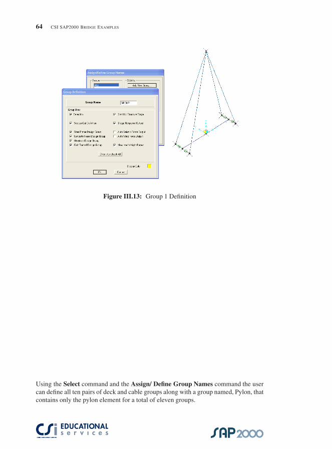
III.9 Group Assignments
Before a staged analysis case can be defined, the user must first decide how the struc-ture is going to be assembled. Therefore, the user must define unique groups thatrepresent stages in the construction sequence. Then the data for each stage, namely,the operation being performed, the objects affected, the age of any added sections,loading and any scale factors, can be defined using the staged construction analysiscase. For this example, the pylon is intended to be constructed first followed by theplacement of adjacent 10 m deck sections with the respective cable pairs. The Group1 elements are identified below.
�
�
“SAP2000BridgeExamples” — 2007/7/2 — 11:42 — page 64 — #72�
�
�
�
�
�
64 CSI SAP2000 BRIDGE EXAMPLES
Figure III.13: Group 1 Definition
Using the Select command and the Assign/ Define Group Names command the usercan define all ten pairs of deck and cable groups along with a group named, Pylon, thatcontains only the pylon element for a total of eleven groups.

�
�
“SAP2000BridgeExamples” — 2007/7/2 — 11:42 — page 65 — #73�
�
�
�
�
�
PART III. CABLESTAYED BRIDGE 65
Figure III.14: Group 2 Definition
III.10 Staged Construction Analysis Case
By selecting the Define/Analysis Cases command the user needs to add a new case.The Analysis Case Type shall be ”Static” and the ”Analysis Type” shall be ”NonlinearStaged Construction”. The user can then begin to develop the analysis case by definingthe various stages along with the data for each stage. For the dialog box below, the datafor the 6th stage is show. The user can see that Group 5is being added along with thedead load of group 5.

�
�
“SAP2000BridgeExamples” — 2007/7/2 — 11:42 — page 66 — #74�
�
�
�
�
�
66 CSI SAP2000 BRIDGE EXAMPLES
Figure III.15: Group 2 Definition
For this example, the nonlinear creep and shrinkage effects are included in the anal-ysis. If desired, the creep effects can be studied for the for any period of time aftercompletion of the structure. This can be done by adding additional stages having the”Duration” input specifying the appropriate number of days. In this example stage 12is aged 10 additional days. Stage 18 that is aged 10000 additional days. Stages 13through 17 vary from 30 to 3000 days bringing the total number of days that the modelis aged to 14,473 days.

�
�
“SAP2000BridgeExamples” — 2007/7/2 — 11:42 — page 67 — #75�
�
�
�
�
�
APPENDIX

�
�
“SAP2000BridgeExamples” — 2007/7/2 — 11:42 — page 69 — #77�
�
�
�
�
�
APPENDIX A
Mesh Transitioning and CompatibilityThe Automated Line Constraint
Ashraf Habibullah1, S.E.M. Iqbal Suharwardy2, S.E., Ph.D.
A.1 IntroductionIn the application of the Finite Element Analysis Method, the most time consumingtask is usually the creation and modification of the finite element mesh of the system.Not to mention the fact that creation of mesh transitions from coarse to fine meshescan be very tedious. Also matching up node points to create compatible meshes atintersecting planes, such as walls and floors can be very labor intensive. And even ifthe mesh generation is automated the mesh transitioning usually produces irregular orskewed elements that may perform poorly. This may have adverse effects on the de-sign, especially in regions of stress concentration, such as in the vicinity of intersectingplanes.
The object based modeling environment of ETABS & SAP2000 clearly ad-dresses these time-consuming shortcomings of the Finite Element Method.
In the object-based modeling environment the Engineer generates the structuralmodel by creating only a few large area objects that physically define the structuralunits such as wall panels, floors or ramps. The finite element mesh is not explicitlycreated by the user, but is automatically generated by assigning meshing parametersto the area objects. These parameters may include variables, such as mesh size, meshspacing and mesh grading among others. With this capability the engineer can studythe effects of mesh refinement by just defining a few control parameters. The newmodel with the desired level of refinement is thus created with minimal effort.
If the meshes on common edges of adjacent area objects do not match up, au-tomated line constraints are generated along those edges. These Line Constraints en-force displacement compatibility between the mismatched meshes of adjacent objectsand eliminate the need for mesh transition elements.
1President & CEO, Computers & Structures, Inc.2Director of Research & Development, Computers & Structures, Inc.
69

�
�
“SAP2000BridgeExamples” — 2007/7/2 — 11:42 — page 70 — #78�
�
�
�
�
�
70 CSI SAP2000 BRIDGE EXAMPLES
What makes this technology really powerful is that while making modificationsto the model the Engineer need only be concerned about the few large physical objectsof the structure. The modified finite element analytical model gets recreated automat-ically with any changes to the base objects.
The following examples are designed to illustrate the power and practicality ofthis technology.
A.2 Example 1: Simply Supported Plate (MismatchedMeshing)
As illustrated in Figure A.1, this is a model of a simply supported plate, which has beenmodeled in two different ways. In one case the mesh is uniform across the plate and inthe other case the mesh is fine on one half of the plate and coarse on the other half ofthe plate. In the latter case, an interpolating line constraint is automatically generatedto enforce displacement compatibility between the adjacent halves of the plate wherethe mesh does not match. As shown in the figure, correlation between the two modelsis very good.
Figure A.1: Simply Supported Plate with Mismatching Edges

�
�
“SAP2000BridgeExamples” — 2007/7/2 — 11:42 — page 71 — #79�
�
�
�
�
�
APPENDIX A. MESH TRANSITIONING, COMPATIBILITY, AND LINE CONSTRAINT 71
A.3 Example 2: Curved Ramp Supported by CurvedWall
This example, Figure A.2, illustrates the use of Line Constraints to capture the interac-tion of a curved shear wall supporting a curved ramp. Notice that there are no joints atthe points where the ramp element edges intersect the wall element edges. Displace-ment compatibility along the lines of intersection of the ramp and the wall is enforcedautomatically by the generation of Line Constraints along those lines. Notice how theapplication of Line Constraints allows the wall and ramp mesh to retain a simple rect-angular (or quadrilateral) configuration. A conventional finite element model wouldbe very irregular because it would need all the additional joints (and correspondingelements) to allow for the ramp element and wall element edge intersections.
A.4 Example 3: Floor Slab – Shear Wall CompatibilityThis example, Figure A.3, illustrates a 3D Concrete Flat Plate Building with shearwalls and an elevator core. Again, in this model, Line Constraints automatically ap-pear at the lines where the floor and wall objects intersect. This, of course, as inprevious examples, will enforce displacement compatibility when mesh geometries donot match. As shown in the deformed shape of the Elevator Core, in many places thewall meshing does not match the floor meshing. All elements meeting at commonedges, however, still show no displacement incompatibilities, even though the elementnodes do not coincide.
A.5 Example 4: Shear Wall – Spandrel TransitionThis example, Figure A.4, models a Shear wall – Spandrel System, illustrating meshtransitioning from the spandrel to the shear wall. Line Constraints are generated asneeded in any direction. In this case the Line Constraints are vertical as well as hori-zontal.

�
�
“SAP2000BridgeExamples” — 2007/7/2 — 11:42 — page 72 — #80�
�
�
�
�
�
72 CSI SAP2000 BRIDGE EXAMPLES
Figure A.2: Curved Ramp Supported by Curved Wall

�
�
“SAP2000BridgeExamples” — 2007/7/2 — 11:42 — page 73 — #81�
�
�
�
�
�
APPENDIX A. MESH TRANSITIONING, COMPATIBILITY, AND LINE CONSTRAINT 73
Figure A.3: Floor Slab – Shear Wall Compatibility
Figure A.4: Shear Wall – Spandrel Transition

�
�
“SAP2000BridgeExamples” — 2007/7/2 — 11:42 — page 75 — #83�
�
�
�
�
�
BIBLIOGRAPHY
Computers and Structures Inc. [2006a], ETABS — Three Dimensional Analysis ofBuilding Systems, Berkeley, California. Technical Reference Manual.
Computers and Structures Inc. [2006b], SAP2000 — Integrated Structural Analysisand Design Software, Berkeley, California. Technical Reference Manual.
Computers and Structures Inc. [2006c], ‘Website’, www.computersandstructures.com.See the latest web contents.
75

�
�
“SAP2000BridgeExamples” — 2007/7/2 — 11:42 — page 77 — #85�
�
�
�
�
�
ABOUT THE SPEAKERS
Robert Tovani, PE, SE: Robert Tovani has twenty-five years of experience in struc-tural analysis, design, project management, and construction administration. Heis currently president of Engineering Analysis Corporation and an employee ofComputer and Structures, Inc. Mr. Tovani received his Bachelors and Mastersof Science Degrees for the University of California, Berkeley and is licensed inCalifornia as a Civil and Structural Engineer.
Mr. Tovani has developed an extensive background in computer-aided analysisand design. His analysis background includes work on a variety of structuresusing linear and nonlinear analysis of new and existing structures in static anddynamic loading environments. He has developed computer models on high risestructures in excess of 100 stories and has provided design work on a varietyof structural framing types including base isolation and other complex framingsystems. Mr. Tovani has been using the SAP and ETABS computer programsfor over twenty-five years and has worked at CSI providing training, analysisand modeling assistance to CSI and Engineering Analysis clients. Recently,Mr. Tovani has provided detailed SAP2000 Bridge Training Seminars.
Atif Habibullah, PE: Atif Habibullah has extensive experience using CSI products,having worked in CSI’s Software Support department for five years. For the pasttwo years, Atif has helped instruct engineers through CSI Educational Servicestraining seminars. He has a strong background in modeling a variety of structuralsystems, solving special modeling problems and in the interpretation of analysisresults. Prior to working at CSI, Atif worked at a leading design firm for 4 yearsusing CSI products, particularly in the design of multi-story steel and concretebuilding structures such as hospitals, office buildings, towers, bridges, stadiumsand dams.
77