Embed Size (px)
Citation preview

98/99™ Series Exit Devices

98/99™ Finishes
© 2004 Ingersoll-Rand. May be copied for use with specification submittal.
Finishes*Color US Number BHMA Number
Chromium, Polished US26 625
Anodized, Aluminum US28 628
Chromium, Dull US26D 626
Brass, Polished US3 605
Brass, Dull US4 606
Bronze, Dull US10 612
Anodized Duranodic (Dark Bronze) 313AN 710
Anodized Black 315AN ––
Pushpad Options — Knurled Embossed “Push” Braille (Caution-Stairwell), satin stainless steel onlySS – (EMERGENCY EXIT – PUSH TO OPEN AND SOUND ALARM) – Red Silkscreen lettering on US32D
* NOTE: Durable powder coated finishes available at specific special request. PLEASE CONTACT FACTORY.
98/99™ Exit Devices
1
IndexIntroduction. . . . . . . . . . . . . . . . . . . . . . . . . . . . . . . . . . . . . . . . . . . . . . . . . . . . . . . . . . . . . . . . . . . . . . . . . . . 3
Exit Hardware • Rim Devices• 98/99™ Rim Exit Device . . . . . . . . . . . . . . . . . . . . . . . . . . . . . . . . . . . . . . . . . . . . . . . . . . . . . . . . . . . 4• 98/99™ Rim Exit Device Trim . . . . . . . . . . . . . . . . . . . . . . . . . . . . . . . . . . . . . . . . . . . . . . . . . . . . . . . 5
• Mortise Lock Device• 9875/9975 Mortise Lock Device . . . . . . . . . . . . . . . . . . . . . . . . . . . . . . . . . . . . . . . . . . . . . . . . . . . . . 8• 9875/9975 Mortise Lock Device Trim . . . . . . . . . . . . . . . . . . . . . . . . . . . . . . . . . . . . . . . . . . . . . . . . . 9
• Surface Mounted Vertical Rod Devices• 9827/9927 Surface Mounted Vertical Rod Device . . . . . . . . . . . . . . . . . . . . . . . . . . . . . . . . . . . . . . . 12• 9827/9927 Surface Mounted Vertical Rod Device Trim . . . . . . . . . . . . . . . . . . . . . . . . . . . . . . . . . . . 13
• Three-Point Latching Device• 9857/9957 Three-Point Latching Device . . . . . . . . . . . . . . . . . . . . . . . . . . . . . . . . . . . . . . . . . . . . . . 16• 9857/9957 Three-Point Latching Device Trim . . . . . . . . . . . . . . . . . . . . . . . . . . . . . . . . . . . . . . . . . . 17
• Concealed Vertical Rod Device• 9847/9947 Concealed Vertical Rod Device . . . . . . . . . . . . . . . . . . . . . . . . . . . . . . . . . . . . . . . . . . . . 20• 9847/9947 Concealed Vertical Rod Device Trim . . . . . . . . . . . . . . . . . . . . . . . . . . . . . . . . . . . . . . . . 21• 9848/9948 Concealed Vertical Rod Device . . . . . . . . . . . . . . . . . . . . . . . . . . . . . . . . . . . . . . . . . . . . 24• 9848/9948 Concealed Vertical Rod Device Trim . . . . . . . . . . . . . . . . . . . . . . . . . . . . . . . . . . . . . . . . 25
• Wood Door Concealed Vertical Rod Device• 9847/9947 Wood Door Concealed Vertical Rod Device . . . . . . . . . . . . . . . . . . . . . . . . . . . . . . . . . . . 28• 9847/9947 Wood Door Concealed Vertical Rod Device Trim . . . . . . . . . . . . . . . . . . . . . . . . . . . . . . . 29
Fire Exit Hardware • Fire Exit Rim Devices• 98-F/99-F Rim Exit Device. . . . . . . . . . . . . . . . . . . . . . . . . . . . . . . . . . . . . . . . . . . . . . . . . . . . . . . . . . 6• 98-F/99-F Rim Exit Device Trim. . . . . . . . . . . . . . . . . . . . . . . . . . . . . . . . . . . . . . . . . . . . . . . . . . . . . . 7
• Fire Exit Mortise Lock Device• 9875-F/9975-F Fire Exit Mortise Lock Device . . . . . . . . . . . . . . . . . . . . . . . . . . . . . . . . . . . . . . . . . . 10• 9875-F/9975-F Fire Exit Mortise Lock Device Trim. . . . . . . . . . . . . . . . . . . . . . . . . . . . . . . . . . . . . . . 11
• Fire Exit Surface Mounted Vertical Rod Devices• 9827-F/9927-F Surface Mounted Vertical Rod Device . . . . . . . . . . . . . . . . . . . . . . . . . . . . . . . . . . . . 14• 9827-F/9927-F Surface Mounted Vertical Rod Device Trim . . . . . . . . . . . . . . . . . . . . . . . . . . . . . . . . 15
• Fire Exit Three-Point Latching Device• 9857-F/9957-F Three-Point Latching Device . . . . . . . . . . . . . . . . . . . . . . . . . . . . . . . . . . . . . . . . . . . 18• 9857-F/9957-F Three-Point Latching Device Trim . . . . . . . . . . . . . . . . . . . . . . . . . . . . . . . . . . . . . . . 19
• Fire Exit Concealed Vertical Rod Devices• 9847-F/9947-F Concealed Vertical Rod Device . . . . . . . . . . . . . . . . . . . . . . . . . . . . . . . . . . . . . . . . . 22• 9847-F/9947-F Concealed Vertical Rod Device Trim . . . . . . . . . . . . . . . . . . . . . . . . . . . . . . . . . . . . . 23• 9848-F/9948-F Concealed Vertical Rod Device . . . . . . . . . . . . . . . . . . . . . . . . . . . . . . . . . . . . . . . . . 26• 9848-F/9948-F Concealed Vertical Rod Device Trim . . . . . . . . . . . . . . . . . . . . . . . . . . . . . . . . . . . . . 27
• Fire Exit Wood Door Concealed Vertical Rod Device• 9847-F/9947-F Wood Door Concealed Vertical Rod Device . . . . . . . . . . . . . . . . . . . . . . . . . . . . . . . . 30• 9847-F/9947-F Wood Door Concealed Vertical Rod Device Trim . . . . . . . . . . . . . . . . . . . . . . . . . . . . 31
Trim Selection • Optional Trim . . . . . . . . . . . . . . . . . . . . . . . . . . . . . . . . . . . . . . . . . . . . . . . . . . . . . . . . . . . . . . . . . . . . . 32-34• Lever Designs . . . . . . . . . . . . . . . . . . . . . . . . . . . . . . . . . . . . . . . . . . . . . . . . . . . . . . . . . . . . . . . . . . . . . . . 32• Operation Options . . . . . . . . . . . . . . . . . . . . . . . . . . . . . . . . . . . . . . . . . . . . . . . . . . . . . . . . . . . . . . . . . . . . 35• HL Trim . . . . . . . . . . . . . . . . . . . . . . . . . . . . . . . . . . . . . . . . . . . . . . . . . . . . . . . . . . . . . . . . . . . . . . . . . . . . 35• Vandal Resistant Trim . . . . . . . . . . . . . . . . . . . . . . . . . . . . . . . . . . . . . . . . . . . . . . . . . . . . . . . . . . . . . . . . . 35• CM993 and PRO993 Exit Trim . . . . . . . . . . . . . . . . . . . . . . . . . . . . . . . . . . . . . . . . . . . . . . . . . . . . . . . . . . . 36• How To Order CM993 and PRO993 Exit Trim. . . . . . . . . . . . . . . . . . . . . . . . . . . . . . . . . . . . . . . . . . . . . . . . 37
Strike Selection • Strikes. . . . . . . . . . . . . . . . . . . . . . . . . . . . . . . . . . . . . . . . . . . . . . . . . . . . . . . . . . . . . . . . . . . . . . . . . . . . . 39• Strike/Stile. . . . . . . . . . . . . . . . . . . . . . . . . . . . . . . . . . . . . . . . . . . . . . . . . . . . . . . . . . . . . . . . . . . . . . . . . . 38
98/99™ Exit Devices
2 © 2004 Ingersoll-Rand. May be copied for use with specification submittal.
Index, pg. 2
Device Electrical Options • EL Electric Latch Retraction. . . . . . . . . . . . . . . . . . . . . . . . . . . . . . . . . . . . . . . . . . . . . . . . . . . . . . . . . . . . . 43• E - Electric Rim Device . . . . . . . . . . . . . . . . . . . . . . . . . . . . . . . . . . . . . . . . . . . . . . . . . . . . . . . . . . . . . . . . 44• E7500 Mortise Lock . . . . . . . . . . . . . . . . . . . . . . . . . . . . . . . . . . . . . . . . . . . . . . . . . . . . . . . . . . . . . . . . . . 44• Chexit . . . . . . . . . . . . . . . . . . . . . . . . . . . . . . . . . . . . . . . . . . . . . . . . . . . . . . . . . . . . . . . . . . . . . . . . . . . . . 45• ALK Exit Alarm Kit . . . . . . . . . . . . . . . . . . . . . . . . . . . . . . . . . . . . . . . . . . . . . . . . . . . . . . . . . . . . . . . . . . . . 42• SS Signal Switch . . . . . . . . . . . . . . . . . . . . . . . . . . . . . . . . . . . . . . . . . . . . . . . . . . . . . . . . . . . . . . . . . . . . . 43• LX Latch Bolt Monitoring. . . . . . . . . . . . . . . . . . . . . . . . . . . . . . . . . . . . . . . . . . . . . . . . . . . . . . . . . . . . . . . 42• RX - Request to Exit . . . . . . . . . . . . . . . . . . . . . . . . . . . . . . . . . . . . . . . . . . . . . . . . . . . . . . . . . . . . . . . . . . 42• RX2 - Double Request to Exit . . . . . . . . . . . . . . . . . . . . . . . . . . . . . . . . . . . . . . . . . . . . . . . . . . . . . . . . . . . 42
Device Accessories • Glass Bead Kit . . . . . . . . . . . . . . . . . . . . . . . . . . . . . . . . . . . . . . . . . . . . . . . . . . . . . . . . . . . . . . . . . . . . . . . 49• Dummy Push Pad . . . . . . . . . . . . . . . . . . . . . . . . . . . . . . . . . . . . . . . . . . . . . . . . . . . . . . . . . . . . . . . . . . . . 50• Cylinders . . . . . . . . . . . . . . . . . . . . . . . . . . . . . . . . . . . . . . . . . . . . . . . . . . . . . . . . . . . . . . . . . . . . . . . . . . . 50• Cover Plate Kit. . . . . . . . . . . . . . . . . . . . . . . . . . . . . . . . . . . . . . . . . . . . . . . . . . . . . . . . . . . . . . . . . . . . . . . 49• RG-27 Vertical Rod and Latch Guard . . . . . . . . . . . . . . . . . . . . . . . . . . . . . . . . . . . . . . . . . . . . . . . . . . . . . . 49
Device Options • Braille, Embossed and Knurled Touchpads . . . . . . . . . . . . . . . . . . . . . . . . . . . . . . . . . . . . . . . . . . . . . . . . . 48• Cylinder Dogging. . . . . . . . . . . . . . . . . . . . . . . . . . . . . . . . . . . . . . . . . . . . . . . . . . . . . . . . . . . . . . . . . . . . . 48• CDK, HDK Cylinder Dogging and Hex Key Dogging Kits. . . . . . . . . . . . . . . . . . . . . . . . . . . . . . . . . . . . . . . . 48• Pnuematic Controlled Exit Device . . . . . . . . . . . . . . . . . . . . . . . . . . . . . . . . . . . . . . . . . . . . . . . . . . . . . . . . 48• Double Cylinder Exit Device . . . . . . . . . . . . . . . . . . . . . . . . . . . . . . . . . . . . . . . . . . . . . . . . . . . . . . . . . . . . . 48• LBR, Less Bottom Rod . . . . . . . . . . . . . . . . . . . . . . . . . . . . . . . . . . . . . . . . . . . . . . . . . . . . . . . . . . . . . . . . 49• PL, Pullman Latch . . . . . . . . . . . . . . . . . . . . . . . . . . . . . . . . . . . . . . . . . . . . . . . . . . . . . . . . . . . . . . . . . . . . 49
Device Electrical Accessories • Power Supplies• PS9. . . . . . . . . . . . . . . . . . . . . . . . . . . . . . . . . . . . . . . . . . . . . . . . . . . . . . . . . . . . . . . . . . . . . . . . . . 47• PS861. . . . . . . . . . . . . . . . . . . . . . . . . . . . . . . . . . . . . . . . . . . . . . . . . . . . . . . . . . . . . . . . . . . . . . . . 47• PS873. . . . . . . . . . . . . . . . . . . . . . . . . . . . . . . . . . . . . . . . . . . . . . . . . . . . . . . . . . . . . . . . . . . . . . . . 46
• EPT Electric Power Transfer. . . . . . . . . . . . . . . . . . . . . . . . . . . . . . . . . . . . . . . . . . . . . . . . . . . . . . . . . . . . . 47
Additional Information • ANSI Grade, Type & Function . . . . . . . . . . . . . . . . . . . . . . . . . . . . . . . . . . . . . . . . . . . . . . . . . . . . . . . . . . . 40• Device Dimensions . . . . . . . . . . . . . . . . . . . . . . . . . . . . . . . . . . . . . . . . . . . . . . . . . . . . . . . . . . . . . . . . . . . 40• UL Fire Labeling and Opening Size. . . . . . . . . . . . . . . . . . . . . . . . . . . . . . . . . . . . . . . . . . . . . . . . . . . . . . . . 41• Finishes. . . . . . . . . . . . . . . . . . . . . . . . . . . . . . . . . . . . . . . . . . . . . . . . . . . . . . . . . . . . . . . . . . . . . . . . . . . . 52• Handing. . . . . . . . . . . . . . . . . . . . . . . . . . . . . . . . . . . . . . . . . . . . . . . . . . . . . . . . . . . . . . . . . . . . . . . . . . . . 50• How-To-Order Information. . . . . . . . . . . . . . . . . . . . . . . . . . . . . . . . . . . . . . . . . . . . . . . . . . . . . . . . . . . . . . 53• Nomenclature . . . . . . . . . . . . . . . . . . . . . . . . . . . . . . . . . . . . . . . . . . . . . . . . . . . . . . . . . . . . . . . . . . . . . . . 53• Popular Double Door Applications . . . . . . . . . . . . . . . . . . . . . . . . . . . . . . . . . . . . . . . . . . . . . . . . . . . . . . . . 51

98/99™ Exit Devices
33
IntroductionExit devices are a critical part of the Fire and Life Safety egress system and will provide safe and reliableservice when properly applied and maintained. Von Duprin designs and manufactures exit devices inaccordance to ISO 9001 Quality Management System and meets or exceeds accepted U.S. domestic andInternational standards. All 98 and 99 series exit devices are UL listed for Panic Hardware or FireHardware, and are certified to ANSI A156.3, 2001, Grade 1. Many models are also certified for HurricaneResistant Applications. Consult your local IR Security & Safety consultant or the Von Duprin factory forcurrent listings.
It is intended that the information included in this publication, when properly used, will provide clear andreliable guidelines to the proper general selection and application. However, the scope of the information isnecessarily limited.
Unusual operating conditions and environments and other external influences can affect the proper applicationof the products represented. Modifications of these products will also affect UL listings. It is recommendedthat whenever an unusual application condition exists, or when any modification of a product is considered,that our engineers review the application.
Application engineering services are available to help ensure proper selection or to review any areas whereusers of Von Duprin products may have questions.
Von Duprin push pad exit devices are available in two external surface styles, designated 98 Series and 99 Series.
The two styles are mechanically and dimensionally identical and provide a wide selection of appearance options.
Latch BoltDeadlocking latchbolt provides security and improved performance at standard device cost.
The Quiet One®
A fluid dampener decelerates the pushpad on its return stroke and eliminates most noise associated with exitdevice operations. Furnished on all 98/99™ series exit devices.
99 Series features grooved mechanism case.
98 Series features smooth mechanism case.
Latch Bolt(98 Rim device shown)
4 © 2004 Ingersoll-Rand. May be copied for use with specification submittal.
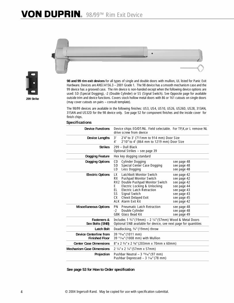
98/99™ Rim Exit Device
299 Strike
98 and 99 rim exit devices for all types of single and double doors with mullion, UL listed for Panic ExitHardware. Devices are ANSI A156.3 – 2001 Grade 1. The 98 device has a smooth mechanism case and the99 device has a grooved case. The rim device is non-handed except when the following device options areused: SD (Special Dogging), -2 (Double Cylinder) or SS (Signal Switch). See Opposite page for availableoutside trim and device functions. Covers stock hollow metal doors with 86 or 161 cutouts on single doors(may cover cutouts on pairs – consult template).
The 98/99 devices are available in the following finishes: US3, US4, US10, US26, US26D, US28, 313AN,315AN and US32D for the 98 device only. See page 52 for component finishes and the inside cover forfinish chips.
Specifications
Device Functions Device ships EO/DT/NL. Field selectable. For TP,K,or L remove NL drive screw from device
Device Lengths 3’ 2’4" to 3’ (711mm to 914 mm) Door Size4’ 2’10" to 4’ (864 mm to 1219 mm) Door Size
Strikes 299 – Dull BlackOptional Strikes – see page 39
Dogging Feature Hex key dogging standard
Dogging Options CD Cylinder Dogging see page 48 SD Special Center Case Dogging see page 48 LD Less Dogging see page 48
Electric Options LX Latchbolt Monitor Switch see page 42 RX Pushpad Monitor Switch see page 42 RX2 Double Pushpad Monitor Switch see page 42E Electric Locking & Unlocking see page 44EL Electric Latch Retraction see page 43 SS Signal Switch see page 43 CX Chexit Delayed Exit see page 45ALK Alarm Exit Kit see page 42
Miscellaneous Options PN Pneumatic Latch Retraction see page 48 -2 Double Cylinder see page 48 GBK Glass Bead Kit see page 49
Fasteners & Includes 1 ³�₄" (19mm) – 2 ¹�₄" (57mm) Wood & Metal DoorsSex Bolts (SNB) Optional SNB available for device, see next page for quantities
Latch Bolt Deadlocking, ³�₄" (19mm) throw
Device Centerline from 39 ¹³�₁₆" (1011 mm)Finished Floor 39 ¹¹�₁₆" (1008 mm) with Mullion
Center Case Dimensions 8" x 2 ³�₄" x 2 ³�₈" (203mm x 70mm x 60mm)
Mechanism Case Dimensions 2 ¹�₄" x 2 ¹�₄" (57mm x 57mm)
Projection Pushbar Neutral – 3 ¹³�₁₆" (97 mm)Pushbar Depressed – 3 ¹�₁₆" (78 mm)
See page 53 for How to Order specification
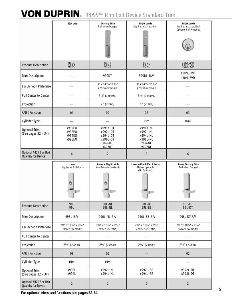
98/99™ Rim Exit Device Standard Trim
5
Exit only Dummy Trim Night Latch Night LatchPull when Dogged Key Retracts Latchbolt Key Retracts Latchbolt
Optional Pull Required
Product Description
Trim Description
Escutcheon Plate Size
Pull Center to Center
Projection
ANSI Function
Cylinder Type
Optional Trim(See pages 32 – 34)
Optional #425 Sex Bolt Quantity for Device
98EO 98DT 98NL 98NL-OP99EO 99DT 99NL 99NL-OP
110NL-MD110NL-WD
3" x 14³�₁₆" x ³�₃₂" 3" x 14³�₁₆" x ³�₃₂"(76x360x2mm) (76x360x2mm)
–– 5¹�₂" (140mm) 5¹�₂" (140mm) ––
–– 2" (51mm) 2" (51mm) ––
01 02 03 03
–– –– Rim Rim
x990EO x991K-DT x991K-NLx992EO x992L-DT x992L-NLx994EO x994L-DT x994L-NLx996EO x996L-DT x996L-NL
x696DT x696NLx697DT x697NL
6 2 2 6
–– 990DT 990NL-R/V
–– ––
Lever Lever – Night Latch Lever – Blank Escutcheon Lever Dummy TrimKey Locks & Unlocks Key Retracts Latchbolt Always operable Pull when Dogged
(No Cylinder)
Product Description
Trim Description
Escutcheon Plate Size
Pull Center to Center
Projection
ANSI Function
Cylinder Type
Optional Trim(See pages 32 – 34)
Optional #425 Sex Bolt Quantity for Device
98L 98L-NL 98L-BE 98L-DT99L 99L-NL 99L-BE 99L-DT
996L-R/V 996L-NL-R/V 996L-BE-R/V 996L-DT-R/V
2³�₄" x 10³�₄" x ²⁷�₃₂" 2³�₄" x 10³�₄" x ²⁷�₃₂" 2³�₄" x 10³�₄" x ²⁷�₃₂" 2³�₄" x 10³�₄" x ²⁷�₃₂"(70x273x21mm) (70x273x21mm) (70x273x21mm) (70x273x21mm)
–– –– –– ––
2⁷�₈" (73mm) 2⁷�₈" (73mm) 2⁷�₈" (73mm) 2⁷�₈" (73mm)
08 09 –– 02
Rim Rim –– ––
x992L x992L-NL x992L-BE x992L-DTx994L x994L-NL x994L-BE x994L-DT
2 2 2 2
For optional trims and functions see pages 32-34
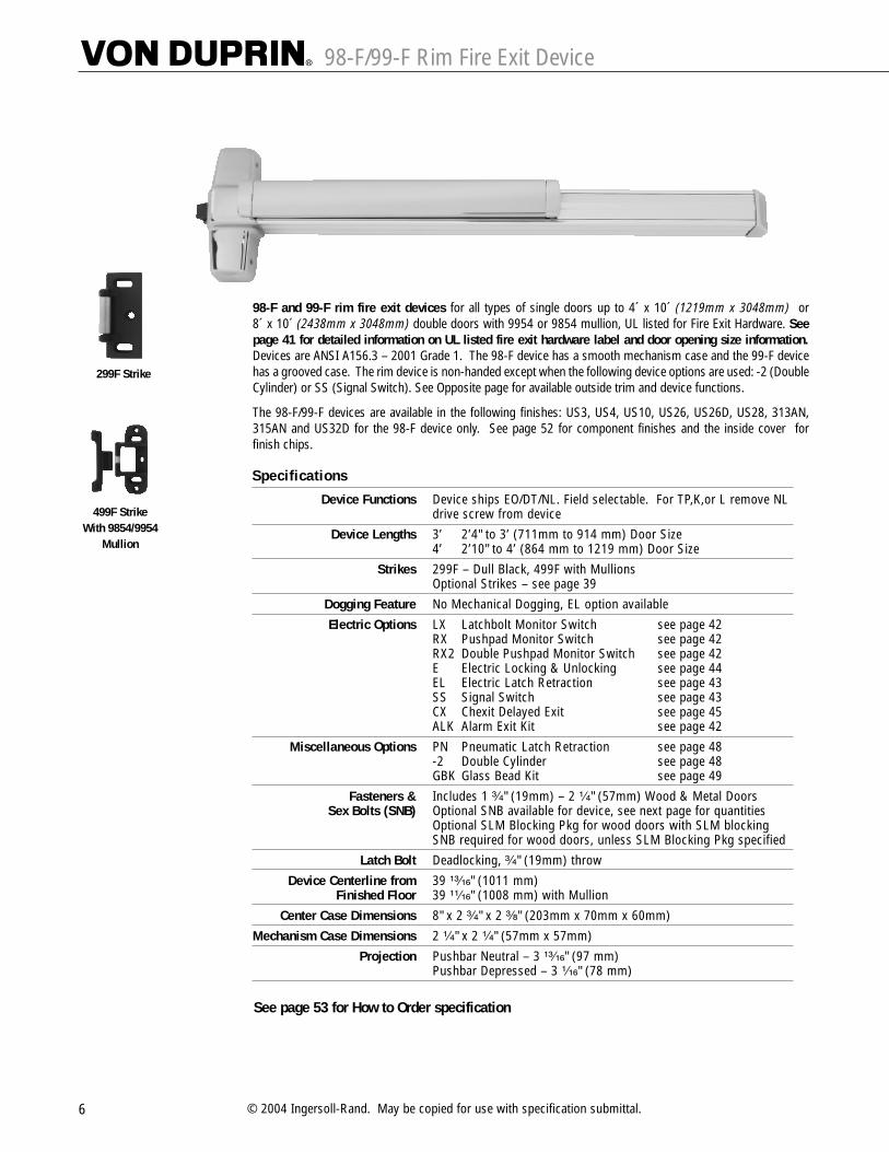
98-F/99-F Rim Fire Exit Device
6 © 2004 Ingersoll-Rand. May be copied for use with specification submittal.
98-F and 99-F rim fire exit devices for all types of single doors up to 4´ x 10´ (1219mm x 3048mm) or8´ x 10´ (2438mm x 3048mm) double doors with 9954 or 9854 mullion, UL listed for Fire Exit Hardware. Seepage 41 for detailed information on UL listed fire exit hardware label and door opening size information.Devices are ANSI A156.3 – 2001 Grade 1. The 98-F device has a smooth mechanism case and the 99-F devicehas a grooved case. The rim device is non-handed except when the following device options are used: -2 (DoubleCylinder) or SS (Signal Switch). See Opposite page for available outside trim and device functions.
The 98-F/99-F devices are available in the following finishes: US3, US4, US10, US26, US26D, US28, 313AN,315AN and US32D for the 98-F device only. See page 52 for component finishes and the inside cover forfinish chips.
299F Strike
499F StrikeWith 9854/9954
Mullion
Specifications
Device Functions Device ships EO/DT/NL. Field selectable. For TP,K,or L remove NL drive screw from device
Device Lengths 3’ 2’4" to 3’ (711mm to 914 mm) Door Size4’ 2’10" to 4’ (864 mm to 1219 mm) Door Size
Strikes 299F – Dull Black, 499F with MullionsOptional Strikes – see page 39
Dogging Feature No Mechanical Dogging, EL option available
Electric Options LX Latchbolt Monitor Switch see page 42 RX Pushpad Monitor Switch see page 42 RX2 Double Pushpad Monitor Switch see page 42E Electric Locking & Unlocking see page 44EL Electric Latch Retraction see page 43 SS Signal Switch see page 43 CX Chexit Delayed Exit see page 45ALK Alarm Exit Kit see page 42
Miscellaneous Options PN Pneumatic Latch Retraction see page 48 -2 Double Cylinder see page 48 GBK Glass Bead Kit see page 49
Fasteners & Includes 1 ³�₄" (19mm) – 2 ¹�₄" (57mm) Wood & Metal DoorsSex Bolts (SNB) Optional SNB available for device, see next page for quantities
Optional SLM Blocking Pkg for wood doors with SLM blockingSNB required for wood doors, unless SLM Blocking Pkg specified
Latch Bolt Deadlocking, ³�₄" (19mm) throw
Device Centerline from 39 ¹³�₁₆" (1011 mm)Finished Floor 39 ¹¹�₁₆" (1008 mm) with Mullion
Center Case Dimensions 8" x 2 ³�₄" x 2 ³�₈" (203mm x 70mm x 60mm)
Mechanism Case Dimensions 2 ¹�₄" x 2 ¹�₄" (57mm x 57mm)
Projection Pushbar Neutral – 3 ¹³�₁₆" (97 mm)Pushbar Depressed – 3 ¹�₁₆" (78 mm)
See page 53 for How to Order specification

98-F/99-F Fire Exit Rim Device Standard Trim
7
Exit only Dummy Trim Night Latch Night LatchPull when Dogged Key Retracts Latchbolt Key Retracts Latchbolt
(Not recommened for Fire Device) Optional Pull Required
Product Description
Trim Description
Escutcheon Plate Size
Pull Center to Center
Projection
ANSI Function
Cylinder Type
Optional Trim(See pages 32 – 34)
#425 SNB optional-HMDReq. WD w/o SLM Pkg. #825 SNB Req. WD w/o SLM Pkg.#425 SNB Req. w/ 499F
98EO-F –– 98NL-F 98NL-OP-F99EO-F –– 99NL-F 99NL-OP-F
110NL-MD110NL-WD
3" x 14³�₁₆" x ³�₃₂" 3" x 14³�₁₆" x ³�₃₂"(76x360x2mm) (76x360x2mm)
–– 5¹�₂" (140mm) 5¹�₂" (140mm) ––
–– 2" (51mm) 2" (51mm) ––
01 02 03 03
–– –– Rim Rim
x990EO x991K-DT x991K-NLx992EO x992L-DT x992L-NLx994EO x994L-DT x994L-NLx996EO x996L-DT x996L-NL
x696DT x696NLx697DT x697NL
6 2 2 6
2 2 2 2
2 2 2 2
–– 990DT 990NL-R/V
–– ––
Lever Lever – Night Latch Lever – Blank Escutcheon Lever Dummy TrimKey Locks & Unlocks Key Retracts Latchbolt Always operable Pull when Dogged
(No Cylinder) (Not recommened for Fire Device)
Product Description
Trim Description
Escutcheon Plate Size
Pull Center to Center
Projection
ANSI Function
Cylinder Type
Optional Trim(See pages 32 – 34)#425 SNB optional-HMDReq. WD w/o SLM Pkg. #825 SNB Req. WD w/o SLM Pkg.#425 SNB Req. w/ 499F
98L-F 98L-NL-F 98L-BE-F ––99L-F 99L-NL-F 99L-BE-F ––
996L-R/V 996L-NL-R/V 996L-BE-R/V 996L-DT-R/V
2³�₄" x 10³�₄" x ²⁷�₃₂" 2³�₄" x 10³�₄" x ²⁷�₃₂" 2³�₄" x 10³�₄" x ²⁷�₃₂" 2³�₄" x 10³�₄" x ²⁷�₃₂"(70x273x21mm) (70x273x21mm) (70x273x21mm) (70x273x21mm)
–– –– –– ––
2⁷�₈" (73mm) 2⁷�₈" (73mm) 2⁷�₈" (73mm) 2⁷�₈" (73mm)
08 09 –– 02
Rim Rim –– ––
x992L x992L-NL x992L-BE x992L-DTx994L x994L-NL x994L-BE x994L-DT
2 2 2 2
2 2 2 2
2 2 2 2
For optional trims and functions see pages 32-34
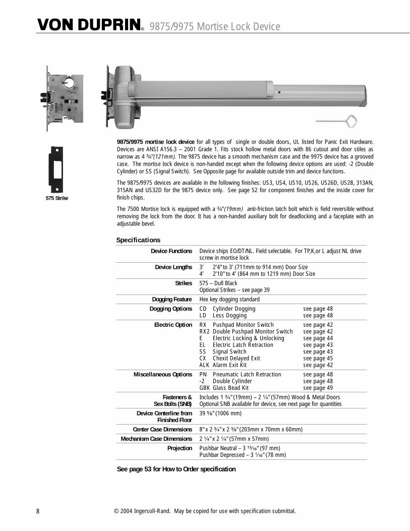
9875/9975 Mortise Lock Device
8 © 2004 Ingersoll-Rand. May be copied for use with specification submittal.
9875/9975 mortise lock device for all types of single or double doors, UL listed for Panic Exit Hardware.Devices are ANSI A156.3 – 2001 Grade 1. Fits stock hollow metal doors with 86 cutout and door stiles asnarrow as 4 ³�₄" (121mm). The 9875 device has a smooth mechanism case and the 9975 device has a groovedcase. The mortise lock device is non-handed except when the following device options are used: -2 (DoubleCylinder) or SS (Signal Switch). See Opposite page for available outside trim and device functions.
The 9875/9975 devices are available in the following finishes: US3, US4, US10, US26, US26D, US28, 313AN,315AN and US32D for the 9875 device only. See page 52 for component finishes and the inside cover forfinish chips.
The 7500 Mortise lock is equipped with a ³�₄" (19mm) anti-friction latch bolt which is field reversible withoutremoving the lock from the door. It has a non-handed auxiliary bolt for deadlocking and a faceplate with anadjustable bevel.
575 Strike
Specifications
Device Functions Device ships EO/DT/NL. Field selectable. For TP,K,or L adjust NL drive screw in mortise lock
Device Lengths 3’ 2’4" to 3’ (711mm to 914 mm) Door Size4’ 2’10" to 4’ (864 mm to 1219 mm) Door Size
Strikes 575 – Dull BlackOptional Strikes – see page 39
Dogging Feature Hex key dogging standard
Dogging Options CD Cylinder Dogging see page 48 LD Less Dogging see page 48
Electric Option RX Pushpad Monitor Switch see page 42 RX2 Double Pushpad Monitor Switch see page 42E Electric Locking & Unlocking see page 44EL Electric Latch Retraction see page 43 SS Signal Switch see page 43 CX Chexit Delayed Exit see page 45ALK Alarm Exit Kit see page 42
Miscellaneous Options PN Pneumatic Latch Retraction see page 48 -2 Double Cylinder see page 48 GBK Glass Bead Kit see page 49
Fasteners & Includes 1 ³�₄" (19mm) – 2 ¹�₄" (57mm) Wood & Metal DoorsSex Bolts (SNB) Optional SNB available for device, see next page for quantities
Device Centerline from 39 ⁵�₈" (1006 mm)Finished Floor
Center Case Dimensions 8" x 2 ³�₄" x 2 ³�₈" (203mm x 70mm x 60mm)
Mechanism Case Dimensions 2 ¹�₄" x 2 ¹�₄" (57mm x 57mm)
Projection Pushbar Neutral – 3 ¹³�₁₆" (97 mm)Pushbar Depressed – 3 ¹�₁₆" (78 mm)
See page 53 for How to Order specification
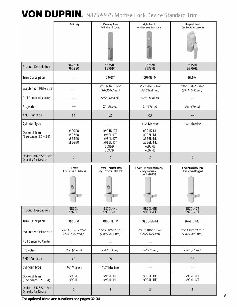
9875/9975 Mortise Lock Device Standard Trim
9
Exit only Dummy Trim Night Latch Hospital LatchPull when Dogged Key Retracts Latchbolt Key Locks & Unlocks
Product Description
Trim Description
Escutcheon Plate Size
Pull Center to Center
Projection
ANSI Function
Cylinder Type
Optional Trim(See pages 32 – 34)
Optional #425 Sex Bolt Quantity for Device
9875EO 9875DT 9875NL 9875HL9975EO 9975DT 9975NL 9975HL
3" x 14³�₁₆" x ³�₃₂" 3" x 14³�₁₆" x ³�₃₂" 2⁹�₁₆" x 5¹�₂" x 2⁵�₈"(76x360x2mm) (76x360x2mm) (65x140x67mm)
–– 5¹�₂" (140mm) 5¹�₂" (140mm) ––
–– 2" (51mm) 2" (51mm) 2⁵�₈" (67mm)
01 02 03 ––
–– –– 1¹�₄" Mortise 1¹�₄" Mortise
x990EO x991K-DT x991K-NLx992EO x992L-DT x992L-NLx994EO x994L-DT x994L-NLx996EO x996L-DT x996L-NL
x696DT x696NLx697DT x697NL
6 2 2 2
–– 990DT 990NL-M HL6M
––
Lever Lever – Night Latch Lever – Blank Escutceon Lever Dummy TrimKey Locks & Unlocks Key Retracts Latchbolt Always operable Pull when Dogged
(No Cylinder)
Product Description
Trim Description
Escutcheon Plate Size
Pull Center to Center
Projection
ANSI Function
Cylinder Type
Optional Trim(See pages 32 – 34)
Optional #425 Sex Bolt Quantity for Device
9875L 9875L-NL 9875L-BE 9875L-DT9975L 9975L-NL 9975L-BE 9975L-DT
996L-M 996L-NL-M 996L-BE-M 996L-DT-M
2³�₄" x 10³�₄" x ²⁷�₃₂" 2³�₄" x 10³�₄" x ²⁷�₃₂" 2³�₄" x 10³�₄" x ²⁷�₃₂" 2³�₄" x 10³�₄" x ²⁷�₃₂"(70x273x21mm) (70x273x21mm) (70x273x21mm) (70x273x21mm)
–– –– –– ––
2⁷�₈" (73mm) 2⁷�₈" (73mm) 2⁷�₈" (73mm) 2⁷�₈" (73mm)
08 09 –– 02
1¹�₄" Mortise 1¹�₄" Mortise –– ––
x992L x992L-NL x992L-BE x992L-DTx994L x994L-NL x994L-BE x994L-DT
2 2 2 2
For optional trims and functions see pages 32-34

9875-F/9975-F Mortise Lock Fire Exit Device
10 © 2004 Ingersoll-Rand. May be copied for use with specification submittal.
9875-F/9975-F fire exit mortise lock devices for all types of single doors up to 4´ x 10´ (1219mm x 3048mm)or 8´ x 10´ (2438mm x 3048mm) double doors installations, UL listed for Fire Exit Hardware; See page 41 fordetailed information on UL listed fire exit hardware label and door opening size information. Devices areANSI A156.3 – 2001 Grade 1. Fits door stiles as narrow as 4 ³�₄" (121mm). The 9875-F device has a smoothmechanism case and the 9975-F device has a grooved case. The mortise lock device is non-handed except whenthe following device options are used: -2 (Double Cylinder) or SS (Signal Switch) devices. See Opposite pagefor available outside trim and functions.
The 9875-F/9975-F devices are available in the following finishes: US3, US4, US10, US26, US26D, US28, 313AN,315AN and US32D for the 9875-F device only. See page 52 for component finishes and the inside cover forfinish chips.
The 7500 Mortise lock is equipped with a ³�₄" (19mm) anti-friction latch bolt which is field reversible withoutremoving the lock from the door. It has a non-handed auxiliary bolt for deadlocking and a faceplate with anadjustable bevel.
575 Strike
Specifications
Device Functions Device ships EO/DT/NL. Field selectable. For TP,K,or L remove NL drive screw from device
Device Lengths 3’ 2’4" to 3’ (711mm to 914 mm) Door Size4’ 2’10" to 4’ (864 mm to 1219 mm) Door Size
Strikes 575 – Dull BlackOptional Strikes – see page 39
Dogging Feature No Mechanical Dogging, EL option available
Electric Options RX Pushpad Monitor Switch see page 42 RX2 Double Pushpad Monitor Switch see page 42E Electric Locking & Unlocking see page 44EL Electric Latch Retraction see page 43 SS Signal Switch see page 43 CX Chexit Delayed Exit see page 45ALK Alarm Exit Kit see page 42
Miscellaneous Options PN Pneumatic Latch Retraction see page 48 -2 Double Cylinder see page 48 GBK Glass Bead Kit see page 49
Fasteners & Includes 1 ³�₄" (19mm) – 2 ¹�₄" (57mm) Wood & Metal DoorsSex Bolts (SNB) Optional SNB available for device, see next page for quantities
Optional SLM Blocking Pkg for wood doors with SLM blockingSNB required for wood doors, unless SLM Blocking Pkg. specified
Device Centerline from 39 ⁵�₈" (1006 mm)Finished Floor
Center Case Dimensions 8" x 2 ³�₄" x 2 ³�₈" (203mm x 70mm x 60mm)
Mechanism Case Dimensions 2 ¹�₄" x 2 ¹�₄" (57mm x 57mm)
Projection Pushbar Neutral – 3 ¹³�₁₆" (97 mm)Pushbar Depressed – 3 ¹�₁₆" (78 mm)
See page 53 for How to Order specification

9875-F/9975-F Mortise Lock Fire Exit Device Standard Trim
11
Exit only Dummy Trim Night Latch Hospital LatchPull when Dogged Key Retracts Latchbolt Key Locks & Unlocks
(Not recommened for Fire Device)
Product Description
Trim Description
Escutcheon Plate Size
Pull Center to Center
Projection
ANSI Function
Cylinder Type
Optional Trim(See pages 32 – 34)
#425 SNB optional-HMDReq. WD w/o SLM Pkg.
9875EO-F –– 9875NL-F 9875HL-F9975EO-F –– 9975NL-F 9975HL-F
3" x 14³�₁₆" x ³�₃₂" 3" x 14³�₁₆" x ³�₃₂" 2⁹�₁₆" x 5¹�₂" x 2⁵�₈"(76x360x2mm) (76x360x2mm) (65x140x67mm)
–– 5¹�₂" (140mm) 5¹�₂" (140mm) ––
–– 2" (51mm) 2" (51mm) 2⁵�₈" (67mm)
01 02 03 ––
–– –– 1¹�₄" Mortise 1¹�₄" Mortise
x990EO x991K-DT x991K-NLx992EO x992L-DT x992L-NLx994EO x994L-DT x994L-NLx996EO x996L-DT x996L-NL
x696DT x696NLx697DT x697NL
6 2 2 2
–– 990DT 990NL-R/V HL6M
––
Lever Lever – Night Latch Lever – Blank Escutcheon Lever Dummy TrimKey Locks & Unlocks Key Retracts Latchbolt Always operable Pull when Dogged
(No Cylinder) (Not recommended for Fire Device)
Product Description
Trim Description
Escutcheon Plate Size
Pull Center to Center
Projection
ANSI Function
Cylinder Type
Optional Trim(See pages 32 – 34)#425 SNB optional-HMDReq. WD w/o SLM Pkg.
9875L-F 9875L-NL-F 9875L-BE-F ––9975L-F 9975L-NL-F 9975L-BE-F ––
996L-M 996L-NL-M 996L-BE-M 996L-DT-M
2³�₄" x 10³�₄" x ²⁷�₃₂" 2³�₄" x 10³�₄" x ²⁷�₃₂" 2³�₄" x 10³�₄" x ²⁷�₃₂" 2³�₄" x 10³�₄" x ²⁷�₃₂"(70x273x21mm) (70x273x21mm) (70x273x21mm) (70x273x21mm)
–– –– –– ––
2⁷�₈" (73mm) 2⁷�₈" (73mm) 2⁷�₈" (73mm) 2⁷�₈" (73mm)
08 09 –– 02
1¹�₄" Mortise 1¹�₄" Mortise –– ––
x992L x992L-NL x992L-BE x992L-DTx994L x994L-NL x994L-BE x994L-DT
2 2 2 2
For optional trims and functions see pages 32-34

9827/9927 Surface Mounted Vertical Rod Device
12 © 2004 Ingersoll-Rand. May be copied for use with specification submittal.
9827/9927 surface mounted vertical rod device for all types of single or double doors, UL listed for Panic ExitHardware. Devices are ANSI A156.3 – 2001 Grade 1. Covers stock hollow metal doors with 86 or 161 cutouts.The 9827 device has a smooth mechanism case and the 9927 device has a grooved case. The surface verticalrod device is non-handed except when the following device options are used: SD (Special Dogging), or SS (SignalSwitch). See Opposite page for available outside trim and functions.
The 9827/9927 devices are available in the following finishes: US3, US4, US10, US26, US26D, US28, 313AN,315AN and US32D for the 9827 device only. See page 52 for component finishes and the inside cover forfinish chips.
Vertical rod and latch guards are available to protect the bottom rod of the exit device from damage by impactsof carts or gurneys passing through doors. Refer to page 49
299 Top Strike
248L4 Bottom Strikefor use with
flat threshold
Top Latch
Bottom Latch
304L Bottom Strike
SpecificationsDevice Functions Device ships EO/DT/NL. Field selectable. For TP,K,or L remove NL drive
screw from deviceDevice Lengths 3’ 2’4" to 3’ (711mm to 914 mm) Door Size
4’ 2’10" to 4’ (864 mm to 1219 mm) Door SizeStrikes Top - 299 – Dull Black, Bottom – 248L4 & 304L - Unfinished
Optional Strikes – see page 39Dogging Feature Hex key dogging standard
Dogging Options CD Cylinder Dogging see page 48 SD Special Center Case Dogging see page 48 LD Less Dogging see page 48
Electric Options LX Latchbolt Monitor Switch see page 42 RX Pushpad Monitor Switch see page 42 RX2 Double Pushpad Monitor Switch see page 42EL Electric Latch Retraction see page 43 SS Signal Switch see page 43 CX Chexit Delayed Exit see page 45ALK Alarm Exit Kit see page 42
Miscellaneous Options PN Pneumatic Latch Retraction see page 48 LBR Less Bottom Rod see page 49 GBK Glass Bead Kit see page 49PL Pullman Latch see page 49
Fasteners & Includes 1 ³�₄" (19mm) – 2 ¹�₄" (57mm) Wood & Metal DoorsSex Bolts (SNB) SNB furnished for top & bottom latches
Optional SNB available for device, see next page for quantitiesLatch Bolt Deadlocking Anti-friction Top & Bottom Bolt, ⁵�₈ " (16mm) throw
Device Centerline from 39 ⁵�₈" (1006 mm)Finished FloorDoor Undercut ¹�₄" (7mm)
Center Case Dimensions 8" x 2 ³�₄" x 2 ³�₈" (203mm x 70mm x 60mm)Mechanism Case Dimensions 2 ¹�₄" x 2 ¹�₄" (57mm x 57mm)
Top & Bottom Latch Case 4 ¹�₂" x 2 ¹�₈" x 1 ¹�₂" (114mm x 54mm x 38mm)Vertical Rods ¹�₂" square tubing, standard rods accommodate 7’ (2134mm) door
Top rod length is 34 ¹⁵�₁₆" (887mm)Bottom rod length is 31 ¹�₄" (794mm)Extension rods available, 1’ (205mm) or 3’ (914mm) for doors over 7’ One piece top rod available for 8’ (2438mm) – 10’ (3048mm) door
Projection Pushbar Neutral – 3 ¹³�₁₆" (97 mm)Pushbar Depressed – 3 ¹�₁₆" (78 mm)
See page 53 for How to Order specification

9827/9927 Surface Mounted Vertical Rod Device Standard Trim
13
Exit only Dummy Trim Night Latch Night Latch Thumbturn ThumbturnPull when Dogged Key Retracts Latchbolt Key Retracts Latchbolt Key Locks & Unlocks Blank Escutcheon
Optional Pull Required (Use with DT Trim) Always Operable(No Cylinder)
(Use with DT Trim)
Product Description
Trim Description
Escutcheon Plate Size
Pull Center to Center
Projection
ANSI Function
Cylinder Type
Optional Trim(See pages 32 – 34)
Optional #425 Sex Bolt Quantity for Device
9827EO 9827DT 9827NL 9827NL-OP 9827TL 9827TL-BE9927EO 9927DT 9927NL 9927NL-OP 9927TL 9927TL-BE
–– 990DT 990NL-R/V 374T x 990DT 374T-BE x 990DT
3" x 14³�₁₆" x ³�₃₂" 3" x 14³�₁₆" x ³�₃₂" 2⁹�₁₆" x 5¹�₂" x 2⁵�₈" 2³�₄" x 10³�₄" x ²⁷�₃₂"(76x360x2mm) (76x360x2mm) (65x140x67mm) (70x273x21mm)
–– 5¹�₂" (140mm) 5¹�₂" (140mm) –– –– ––
–– 2" (51mm) 2" (51mm) –– 3¹�₄" (83mm) 3¹�₄" (83mm)
01 02 03 03 11 ––
–– –– Rim Rim 1¹�₄" Mortise ––
x990EO x991K-DT x991K-NLx992EO x992L-DT x992L-NLx994EO x994L-DT x994L-NLx996EO x996L-DT x996L-NL
x696DT x696NLx697DT x697NL
6 2 2 6 2 2
–– ––
Lever Lever – Night Latch Lever – Blank Escutcheon Lever Dummy TrimKey Locks & Unlocks Key Retracts Latchbolt Always operable Pull when Dogged
(No Cylinder)
Product Description
Trim Description
Escutcheon Plate Size
Pull Center to Center
Projection
ANSI Function
Cylinder Type
Optional Trim(See pages 32 – 34)
Optional #425 Sex Bolt Quantity for Device
9827L 9827L-NL 9827L-BE 9827L-DT9927L 9927L-NL 9927L-BE 9927L-DT
996L-R/V 996L-NL-R/V 996L-BE-R/V 996L-DT-RV
2³�₄" x 10³�₄" x ²⁷�₃₂" 2³�₄" x 10³�₄" x ²⁷�₃₂" 2³�₄" x 10³�₄" x ²⁷�₃₂" 2³�₄" x 10³�₄" x ²⁷�₃₂"(70x273x21mm) (70x273x21mm) (70x273x21mm) (70x273x21mm)
–– –– –– ––
2⁷�₈" (73mm) 2⁷�₈" (73mm) 2⁷�₈" (73mm) 2⁷�₈" (73mm)
08 09 –– 02
Rim Rim –– ––
x992L x992L-NL x992L-BE x992L-DTx994L x994L-NL x994L-BE x994L-DT
2 2 2 2
For optional trims and functions see pages 32-34
110NL-MD110NL-WD
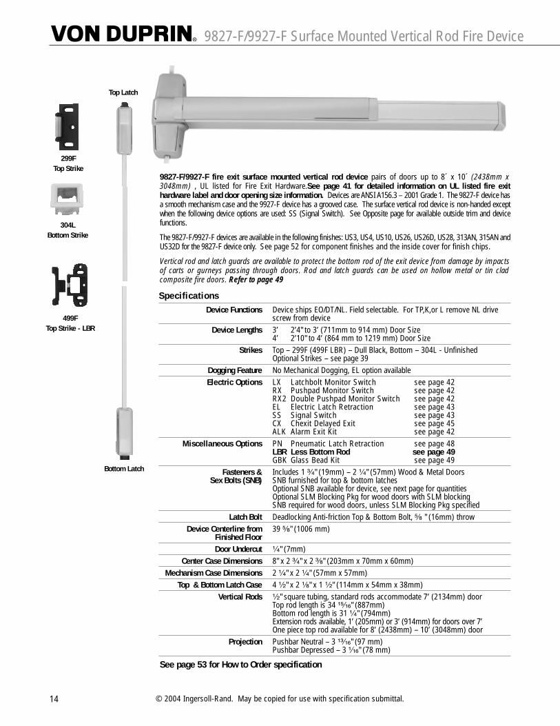
9827-F/9927-F Surface Mounted Vertical Rod Fire Device
14 © 2004 Ingersoll-Rand. May be copied for use with specification submittal.
9827-F/9927-F fire exit surface mounted vertical rod device pairs of doors up to 8´ x 10´ (2438mm x3048mm) , UL listed for Fire Exit Hardware.See page 41 for detailed information on UL listed fire exithardware label and door opening size information. Devices are ANSI A156.3 – 2001 Grade 1. The 9827-F device hasa smooth mechanism case and the 9927-F device has a grooved case. The surface vertical rod device is non-handed exceptwhen the following device options are used: SS (Signal Switch). See Opposite page for available outside trim and devicefunctions.
The 9827-F/9927-F devices are available in the following finishes: US3, US4, US10, US26, US26D, US28, 313AN, 315AN andUS32D for the 9827-F device only. See page 52 for component finishes and the inside cover for finish chips.
Vertical rod and latch guards are available to protect the bottom rod of the exit device from damage by impactsof carts or gurneys passing through doors. Rod and latch guards can be used on hollow metal or tin cladcomposite fire doors. Refer to page 49
299F Top Strike
Top Latch
Bottom Latch
304L Bottom Strike
499F Top Strike - LBR
SpecificationsDevice Functions Device ships EO/DT/NL. Field selectable. For TP,K,or L remove NL drive
screw from deviceDevice Lengths 3’ 2’4" to 3’ (711mm to 914 mm) Door Size
4’ 2’10" to 4’ (864 mm to 1219 mm) Door SizeStrikes Top – 299F (499F LBR) – Dull Black, Bottom – 304L - Unfinished
Optional Strikes – see page 39Dogging Feature No Mechanical Dogging, EL option availableElectric Options LX Latchbolt Monitor Switch see page 42
RX Pushpad Monitor Switch see page 42 RX2 Double Pushpad Monitor Switch see page 42EL Electric Latch Retraction see page 43 SS Signal Switch see page 43 CX Chexit Delayed Exit see page 45ALK Alarm Exit Kit see page 42
Miscellaneous Options PN Pneumatic Latch Retraction see page 48 LBR Less Bottom Rod see page 49GBK Glass Bead Kit see page 49
Fasteners & Includes 1 ³�₄" (19mm) – 2 ¹�₄" (57mm) Wood & Metal DoorsSex Bolts (SNB) SNB furnished for top & bottom latches
Optional SNB available for device, see next page for quantitiesOptional SLM Blocking Pkg for wood doors with SLM blockingSNB required for wood doors, unless SLM Blocking Pkg specified
Latch Bolt Deadlocking Anti-friction Top & Bottom Bolt, ⁵�₈ " (16mm) throwDevice Centerline from 39 ⁵�₈" (1006 mm)
Finished FloorDoor Undercut ¹�₄" (7mm)
Center Case Dimensions 8" x 2 ³�₄" x 2 ³�₈" (203mm x 70mm x 60mm)Mechanism Case Dimensions 2 ¹�₄" x 2 ¹�₄" (57mm x 57mm)
Top & Bottom Latch Case 4 ¹�₂" x 2 ¹�₈" x 1 ¹�₂" (114mm x 54mm x 38mm)Vertical Rods ¹�₂" square tubing, standard rods accommodate 7’ (2134mm) door
Top rod length is 34 ¹⁵�₁₆" (887mm)Bottom rod length is 31 ¹�₄" (794mm)Extension rods available, 1’ (205mm) or 3’ (914mm) for doors over 7’ One piece top rod available for 8’ (2438mm) – 10’ (3048mm) door
Projection Pushbar Neutral – 3 ¹³�₁₆" (97 mm)Pushbar Depressed – 3 ¹�₁₆" (78 mm)
See page 53 for How to Order specification

9827-F/9927-F Surface Mounted Vertical Rod Fire DeviceStandard Trim
15
Exit only Dummy Trim Night Latch Night Latch Thumbturn ThumbturnPull when Dogged Key Retracts Latchbolt Key Retracts Latchbolt Key Locks & Unlocks Blank Escutcheon
(Not recommended for Optional Pull Required (Use with DT Trim) Always OperableFire Device) (No Cylinder)
(Use with DT Trim)
Product Description
Trim Description
Escutcheon Plate Size
Pull Center to Center
Projection
ANSI Function
Cylinder Type
Optional Trim(See pages 32 – 34)
#425 SNB optional-HMDReq. WD w/o SLM Pkg.
9827EO-F –– 9827NL-F 9827NL-OP-F 9827TL-F 9827TL-BE-F9927EO-F –– 9927NL-F 9927NL-OP-F 9927TL-F 9927TL-BE-F
–– 990DT 990NL-R/V 374T x 990DT 374T-BE x 990DT
3" x 14³�₁₆" x ³�₃₂" 3" x 14³�₁₆" x ³�₃₂" 2³�₄" x 10³�₄" x ²⁷�₃₂" 2³�₄" x 10³�₄" x ²⁷�₃₂"(76x360x2mm) (76x360x2mm) (70x273x21mm) (70x273x21mm)
–– 5¹�₂" (140mm) 5¹�₂" (140mm) –– –– ––
–– 2" (51mm) 2" (51mm) –– 3¹�₄" (83mm) 3¹�₄" (83mm)
01 02 03 03 11 ––
–– –– Rim Rim 1¹�₄" Mortise ––
x990EO x991K-DT x991K-NLx992EO x992L-DT x992L-NLx994EO x994L-DT x994L-NLx996EO x996L-DT x996L-NL
x696DT x696NLx697DT x697NL
6 2 2 6 2 2
–– ––
Lever Lever – Night Latch Lever – Blank Escutcheon Lever Dummy TrimKey Locks & Unlocks Key Retracts Latchbolt Always operable Pull when Dogged
(No Cylinder) (Not recommended for Fire Device)
Product Description
Trim Description
Escutcheon Plate Size
Pull Center to Center
Projection
ANSI Function
Cylinder Type
Optional Trim(See pages 32 – 34)
#425 SNB optional-HMDReq. WD w/o SLM Pkg.
9827L-F 9827L-NL-F 9827L-BE-F ––9927L-F 9927L-NL-F 9927L-BE-F ––
996L-R/V 996L-NL-R/V 996L-BE-R/V 996L-DT-RV
2³�₄" x 10³�₄" x ²⁷�₃₂" 2³�₄" x 10³�₄" x ²⁷�₃₂" 2³�₄" x 10³�₄" x ²⁷�₃₂" 2³�₄" x 10³�₄" x ²⁷�₃₂"(70x273x21mm) (70x273x21mm) (70x273x21mm) (70x273x21mm)
–– –– –– ––
2⁷�₈" (73mm) 2⁷�₈" (73mm) 2⁷�₈" (73mm) 2⁷�₈" (73mm)
08 09 –– 02
Rim Rim –– ––
x992L x992L-NL x992L-BE x992L-DTx994L x994L-NL x994L-BE x994L-DT
2 2 2 2
For optional trims and functions see pages 32-34
110NL-MD110NL-WD
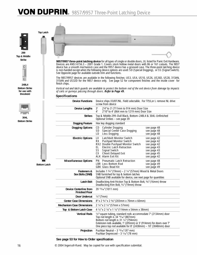
9857/9957 Three-Point Latching Device
16 © 2004 Ingersoll-Rand. May be copied for use with specification submittal.
9857/9957 three-point latching device for all types of single or double doors, UL listed for Panic Exit Hardware.Devices are ANSI A156.3 – 2001 Grade 1. Covers stock hollow metal doors with 86 or 161 cutouts. The 9857device has a smooth mechanism case and the 9957 device has a grooved case. The three-point latching deviceis non-handed except when the following device options are used: SD (Special Dogging), or SS (Signal Switch).See Opposite page for available outside trim and functions.
The 9857/9957 devices are available in the following finishes: US3, US4, US10, US26, US26D, US28, 313AN,315AN and US32D for the 9857 device only. See page 52 for component finishes and the inside cover forfinish chips.
Vertical rod and latch guards are available to protect the bottom rod of the exit device from damage by impactsof carts or gurneys passing through doors. Refer to Page 49.
Top Latch
Bottom Latch
299 Top & Middle
Strike
248L4Bottom Strikefor use withthreshold
304L Bottom Strike
SpecificationsDevice Functions Device ships EO/DT/NL. Field selectable. For TP,K,or L remove NL drive
screw from deviceDevice Lengths 3’ 2’4" to 3’ (711mm to 914 mm) Door Size
4’ 2’10" to 4’ (864 mm to 1219 mm) Door SizeStrikes Top & Middle-299–Dull Black, Bottom–248L4 & 304L-Unfinished
Optional Strikes – see page 39Dogging Feature Hex key dogging standard
Dogging Options CD Cylinder Dogging see page 48 SD Special Center Case Dogging see page 48 LD Less Dogging see page 48
Electric Options LX Latchbolt Monitor Switch see page 42 RX Pushpad Monitor Switch see page 42 RX2 Double Pushpad Monitor Switch see page 42EL Electric Latch Retraction see page 43 SS Signal Switch see page 43 CX Chexit Delayed Exit see page 45ALK Alarm Exit Kit see page 42
Miscellaneous Options PN Pneumatic Latch Retraction see page 48 LBR Less Bottom Rod see page 49 GBK Glass Bead Kit see page 49
Fasteners & Includes 1 ³�₄" (19mm) – 2 ¹�₄" (57mm) Wood & Metal DoorsSex Bolts (SNB) SNB furnished for top & bottom latches
Optional SNB available for device, see next page for quantitiesLatch Bolt Deadlocking Anti-friction Top & Bottom Bolt, ⁵�₈" (16mm) throw
Deadlocking Rim Bolt, ³�₄" (19mm) throw Device Centerline from 39 ¹³�₁₆" (1011 mm)
Finished FloorDoor Undercut ¹�₄" (7mm)
Center Case Dimensions 8" x 2 ³�₄" x 2 ³�₈" (203mm x 70mm x 60mm)Mechanism Case Dimensions 2 ¹�₄" x 2 ¹�₄" (57mm x 57mm)
Top & Bottom Latch Case 4 ¹�₂" x 2 ¹�₈" x 1 ¹�₂" (114mm x 54mm x 38mm)Vertical Rods ¹�₂" square tubing, standard rods accommodate 7’ (2134mm) door
Top rod length is 34 ¹⁵�₁₆" (887mm)Bottom rod length is 31 ¹�₄" (794mm)Extension rods available, 1’ (205mm) or 3’ (914mm) for doors over 7’ One piece top rod available for 8’ (2438mm) – 10’ (3048mm) door
Projection Pushbar Neutral – 3 ¹³�₁₆" (97 mm)Pushbar Depressed – 3 ¹�₁₆" (78 mm)
See page 53 for How to Order specification

9857/9957 Three-Point Latching Device Standard Trim
17
Exit only Dummy Trim Night Latch Night Lacth Thumbturn ThumbturnPull when Dogged Key Retracts Latchbolt Key Retracts Latchbolt Key Locks & Unlocks Blank Escutcheon
Optional Pull Required (Use with DT Trim) Always Operable(No Cylinder)
(Use with DT Trim)
Product Description
Trim Description
Escutcheon Plate Size
Pull Center to Center
Projection
ANSI Function
Cylinder Type
Optional Trim(See pages 32 – 34)
Optional #425 Sex Bolt Quantity for Device
9857EO 9857DT 9857NL 9857NL-OP 9857TL 9857TL-BE9957EO 9957DT 9957NL 9957NL-OP 9957TL 9957TL-BE
–– 990DT 990NL-R/V 374T x 990DT 374T-BE x 990DT
3" x 14³�₁₆" x ³�₃₂" 3" x 14³�₁₆" x ³�₃₂" 2³�₄" x 10³�₄" x ²⁷�₃₂" 2³�₄" x 10³�₄" x ²⁷�₃₂"(76x360x2mm) (76x360x2mm) (70x273x21mm) (70x273x21mm)
–– 5¹�₂" (140mm) 5¹�₂" (140mm) –– –– ––
–– 2" (51mm) 2" (51mm) –– 3¹�₄" (83mm) 3¹�₄" (83mm)
01 02 03 03 11 ––
–– –– Rim Rim 1¹�₄" Mortise ––
x990EO x991K-DT x991K-NLx992EO x992L-DT x992L-NLx994EO x994L-DT x994L-NLx996EO x996L-DT x996L-NL
x696DT x696NLx697DT x697NL
6 2 2 6 2 2
–– ––
Lever Lever – Night Latch Lever – Blank Escutcheon Lever Dummy TrimKey Locks & Unlocks Key Retracts Latchbolt Always operable Pull when Dogged
(No Cylinder)
Product Description
Trim Description
Escutcheon Plate Size
Pull Center to Center
Projection
ANSI Function
Cylinder Type
Optional Trim(See pages 32 – 34)
Optional #425 Sex Bolt Quantity for Device
9857L 9857L-NL 9857L-BE 9857L-DT9957L 9957L-NL 9957L-BE 9957L-DT
996L-R/V 996L-NL-R/V 996L-BE-R/V 996L-DT-RV
2³�₄" x 10³�₄" x ²⁷�₃₂" 2³�₄" x 10³�₄" x ²⁷�₃₂" 2³�₄" x 10³�₄" x ²⁷�₃₂" 2³�₄" x 10³�₄" x ²⁷�₃₂"(70x273x21mm) (70x273x21mm) (70x273x21mm) (70x273x21mm)
–– –– –– ––
2⁷�₈" (73mm) 2⁷�₈" (73mm) 2⁷�₈" (73mm) 2⁷�₈" (73mm)
08 09 –– 02
Rim Rim –– ––
x992L x992L-NL x992L-BE x992L-DTx994L x994L-NL x994L-BE x994L-DT
2 2 2 2
For optional trims and functions see pages 32-34
110NL-MD110NL-WD

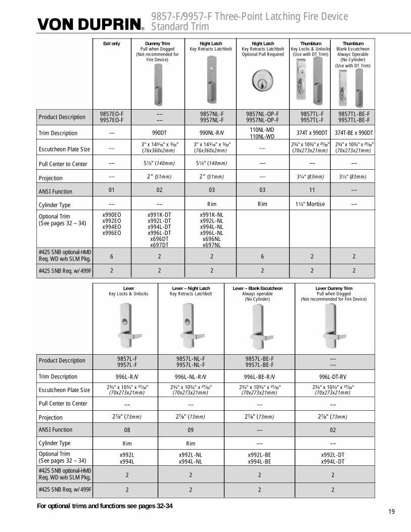
9857-F/9957-F Three-Point Latching Fire Device
18 © 2004 Ingersoll-Rand. May be copied for use with specification submittal.
9857-F/9957-F fire exit three-point latching device for all types of single doors up to 4´ x 8´(1219mm x 2438mm) or up to 8´ x 8´(2438mm x 2438mm) double doors with 9954 or 9854 mullion, ULlisted for Fire Exit Hardware. See page 41 for detailed information on UL listed fire exit hardware label anddoor opening size information. Devices are ANSI A156.3 – 2001 Grade 1. The 9857-F device has a smoothmechanism case and the 9957-F device has a grooved case. The three-point latch device is non-handed exceptwhen the following device option is used: SS (Signal Switch). See Opposite page for available outside trim anddevice functions.
The 9857-F/9957-F devices are available in the following finishes: US3, US4, US10, US26, US26D, US28,313AN, 315AN and US32D for the 9827-F device only. See page 52 for component finishes and the insidecover for finish chips.
Vertical rod and latch guards are available to protect the bottom rod of the exit device from damage by impactsof carts or gurneys passing through doors. Refer to Page 49.
Top Latch
Bottom Latch
299F Top & Middle
Strike
304L Bottom Strike
499F Rim StrikeFor MullionApplications
SpecificationsDevice Functions Device ships EO/DT/NL. Field selectable. For TP,K,or L remove NL drive
screw from deviceDevice Lengths 3’ 2’4" to 3’ (711mm to 914 mm) Door Size
4’ 2’10" to 4’ (864 mm to 1219 mm) Door SizeStrikes Top & Middle-299F–Dull Black, Bottom–304L-Unfinished
Optional Strikes – see page 39Dogging Feature No Mechanical Dogging, EL option availableElectric Options LX Latchbolt Monitor Switch see page 42
RX Pushpad Monitor Switch see page 42 RX2 Double Pushpad Monitor Switch see page 42EL Electric Latch Retraction see page 43 SS Signal Switch see page 43 CX Chexit Delayed Exit see page 45ALK Alarm Exit Kit see page 42
Miscellaneous Options PN Pneumatic Latch Retraction see page 48 GBK Glass Bead Kit see page 49
Fasteners & Includes 1 ³�₄" (19mm) – 2 ¹�₄" (57mm) Wood & Metal DoorsSex Bolts (SNB) SNB furnished for top & bottom latches
Optional SNB available for device, see next page for quantitiesOptional SLM Blocking Pkg for wood doors with SLM blockingSNB required for wood doors, unless SLM Blocking Pkg specified
Latch Bolt Deadlocking Anti-friction Top & Bottom Bolt, ⁵�₈" (16mm) throwDeadlocking Rim Bolt, ³�₄" (19mm) throw
Device Centerline from 39 ¹³�₁₆" (1011 mm)Finished FloorDoor Undercut ¹�₄" (7mm)
Center Case Dimensions 8" x 2 ³�₄" x 2 ³�₈" (203mm x 70mm x 60mm)Mechanism Case Dimensions 2 ¹�₄" x 2 ¹�₄" (57mm x 57mm)
Top & Bottom Latch Case 4 ¹�₂" x 2 ¹�₈" x 1 ¹�₂" (114mm x 54mm x 38mm)Vertical Rods ¹�₂" square tubing, standard rods accommodate 7’ (2134mm) door
Top rod length is 34 ¹⁵�₁₆" (887mm)Bottom rod length is 31 ¹�₄" (794mm)Extension rods available, 1’ (205mm) or 3’ (914mm) for doors over 7’ One piece top rod available for 8’ (2438mm) – 10’ (3048mm) door
Projection Pushbar Neutral – 3 ¹³�₁₆" (97 mm)Pushbar Depressed – 3 ¹�₁₆" (78 mm)
See page 53 for How to Order specification
9857-F/9957-F Three-Point Latching Fire Device Standard Trim
19
Exit only Dummy Trim Night Latch Night Latch Thumbturn ThumbturnPull when Dogged Key Retracts Latchbolt Key Retracts Latchbolt Key Locks & Unlocks Blank Escutcheon
(Not recommended for Optional Pull Required (Use with DT Trim) Always OperableFire Device) (No Cylinder)
(Use with DT Trim)
Product Description
Trim Description
Escutcheon Plate Size
Pull Center to Center
Projection
ANSI Function
Cylinder Type
Optional Trim(See pages 32 – 34)
#425 SNB optional-HMDReq. WD w/o SLM Pkg.
#425 SNB Req. w/ 499F
9857EO-F –– 9857NL-F 9857NL-OP-F 9857TL-F 9857TL-BE-F9957EO-F –– 9957NL-F 9957NL-OP-F 9957TL-F 9957TL-BE-F
–– 990DT 990NL-R/V 374T x 990DT 374T-BE x 990DT
3" x 14³�₁₆" x ³�₃₂" 3" x 14³�₁₆" x ³�₃₂" 2³�₄" x 10³�₄" x ²⁷�₃₂" 2³�₄" x 10³�₄" x ²⁷�₃₂"(76x360x2mm) (76x360x2mm) (70x273x21mm) (70x273x21mm)
–– 5¹�₂" (140mm) 5¹�₂" (140mm) –– –– ––
–– 2" (51mm) 2" (51mm) –– 3¹�₄" (83mm) 3¹�₄" (83mm)
01 02 03 03 11 ––
–– –– Rim Rim 1¹�₄" Mortise ––
x990EO x991K-DT x991K-NLx992EO x992L-DT x992L-NLx994EO x994L-DT x994L-NLx996EO x996L-DT x996L-NL
x696DT x696NLx697DT x697NL
6 2 2 6 2 2
2 2 2 2 2 2
–– ––
Lever Lever – Night Latch Lever – Blank Escutcheon Lever Dummy TrimKey Locks & Unlocks Key Retracts Latchbolt Always operable Pull when Dogged
(No Cylinder) (Not recommended for Fire Device)
Product Description
Trim Description
Escutcheon Plate Size
Pull Center to Center
Projection
ANSI Function
Cylinder Type
Optional Trim(See pages 32 – 34)
#425 SNB optional-HMDReq. WD w/o SLM Pkg.
#425 SNB Req. w/ 499F
9857L-F 9857L-NL-F 9857L-BE-F ––9957L-F 9957L-NL-F 9957L-BE-F ––
996L-R/V 996L-NL-R/V 996L-BE-R/V 996L-DT-RV
2³�₄" x 10³�₄" x ²⁷�₃₂" 2³�₄" x 10³�₄" x ²⁷�₃₂" 2³�₄" x 10³�₄" x ²⁷�₃₂" 2³�₄" x 10³�₄" x ²⁷�₃₂"(70x273x21mm) (70x273x21mm) (70x273x21mm) (70x273x21mm)
–– –– –– ––
2⁷�₈" (73mm) 2⁷�₈" (73mm) 2⁷�₈" (73mm) 2⁷�₈" (73mm)
08 09 –– 02
Rim Rim –– ––
x992L x992L-NL x992L-BE x992L-DTx994L x994L-NL x994L-BE x994L-DT
2 2 2 2
2 2 2 2
For optional trims and functions see pages 32-34
110NL-MD110NL-WD

9847/9947 Concealed Vertical Rod Device
20 © 2004 Ingersoll-Rand. May be copied for use with specification submittal.
9847/9947 concealed vertical rod device for use on single or double metal doors, UL listed for Panic ExitHardware. Devices are ANSI A156.3 – 2001 Grade 1. The 9847 device has a smooth mechanism case and the9947 device has a grooved case. The concealed vertical rod device is non-handed except when the followingdevice options are used: SD (Special Dogging), or SS (Signal Switch). See Opposite page for available outsidetrim and device functions.
The 9847/9947 devices are available in the following finishes: US3, US4, US10, US26, US26D, US28, 313AN,315AN and US32D for the 9847 device only. See page 52 for component finishes and the inside cover forfinish chips.
See page 53 for How to Order specification
Top Latch
Bottom Latch
385A Bottom Strike
338 Top Strike
SpecificationsDevice Functions Device ships EO/DT/NL. Field selectable. For TP,K,or L remove NL drive
screw from deviceDevice Lengths 3’ 2’4" to 3’ (711mm to 914 mm) Door Size
4’ 2’10" to 4’ (864 mm to 1219 mm) Door SizeStrikes Top - 338 – Unfinished, Bottom – 385A - Unfinished
Optional Strikes – see page 39Dogging Feature Hex key dogging standard
Dogging Options CD Cylinder Dogging see page 48 SD Special Center Case Dogging see page 48 LD Less Dogging see page 48
Electric Options LX Latchbolt Monitor Switch see page 42 RX Pushpad Monitor Switch see page 42 RX2 Double Pushpad Monitor Switch see page 42EL Electric Latch Retraction see page 43 SS Signal Switch see page 43 CX Chexit Delayed Exit see page 45ALK Alarm Exit Kit see page 42
Miscellaneous Options PN Pneumatic Latch Retraction see page 48 LBR Less Bottom Rod see page 49 GBK Glass Bead Kit see page 49PL Pullman Latch see page 49
Fasteners & Includes 1 ³�₄" (19mm) – 2 ¹�₄" (57mm) Wood & Metal DoorsSex Bolts (SNB) Optional SNB available for device, see next page for quantities
Latch Bolt Deadlocking Top & Bottom Bolt, ⁵�₈" (16mm) throw Device Centerline from 39 ⁵�₈" (1006 mm) Standard, Adjustable from 35 ⁵�₈" (905mm) to
Finished Floor 49 ⁵�₈" (1260mm)Door Undercut ¹�₄" (7mm) maximum
Center Case Dimensions 8" x 2 ³�₄" x 2 ³�₈" (203mm x 70mm x 60mm)Mechanism Case Dimensions 2 ¹�₄" x 2 ¹�₄" (57mm x 57mm)
Top & Bottom Latch Case 4 ¹�₂" x 2 ¹�₈" x 1 ¹�₂" (114mm x 54mm x 38mm)Vertical Rods Round 2 piece adjustable rods
Top rod adjustable from 6’8" (2027mm) to 8’4"(2533mm)Bottom rod adjustable 35 ⁵�₈" (905 mm) to 49 ⁵�₈" (1260 mm)Extension rod kits available for doors over 8’4" (2533mm)
Projection Pushbar Neutral – 3 ¹³�₁₆" (97 mm)Pushbar Depressed – 3 ¹�₁₆" (78 mm)

9847/9947 Concealed Vertical Rod Device Standard Trim
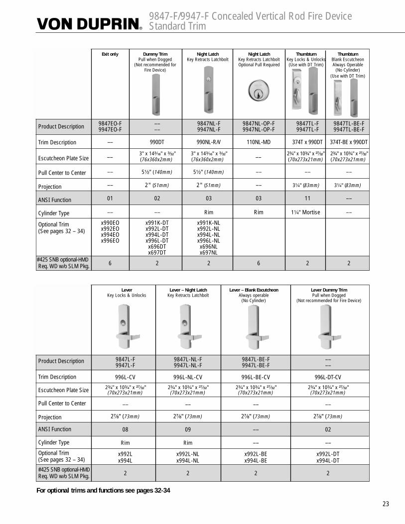
21
Exit only Dummy Trim Night Latch Night Latch Thumbturn ThumbturnPull when Dogged Key Retracts Latchbolt Key Retracts Latchbolt Key Locks & Unlocks Blank Escutcheon
Optional Pull Required (Use with DT Trim) Always Operable(No Cylinder)
(Use with DT Trim)
Product Description
Trim Description
Escutcheon Plate Size
Pull Center to Center
Projection
ANSI Function
Cylinder Type
Optional Trim(See pages 32 – 34)
Optional #425 Sex Bolt Quantity for Device
9847EO 9847DT 9847NL 9847NL-OP 9847TL 9847TL-BE9947EO 9947DT 9947NL 9947NL-OP 9947TL 9947TL-BE
–– 990DT 990NL-R/V 110NL-MD 374T x 990DT 374T-BE x 990DT
3" x 14³�₁₆" x ³�₃₂" 3" x 14³�₁₆" x ³�₃₂" 2³�₄" x 10³�₄" x ²⁷�₃₂" 2³�₄" x 10³�₄" x ²⁷�₃₂"(76x360x2mm) (76x360x2mm) (70x273x21mm) (70x273x21mm)
–– 5¹�₂" (140mm) 5¹�₂" (140mm) –– –– ––
–– 2" (51mm) 2" (51mm) –– 3¹�₄" (83mm) 3¹�₄" (83mm)
01 02 03 03 11 ––
–– –– Rim Rim 1¹�₄" Mortise ––
x990EO x991K-DT x991K-NLx992EO x992L-DT x992L-NLx994EO x994L-DT x994L-NLx996EO x996L-DT x996L-NL
x696DT x696NLx697DT x697NL
6 2 2 6 2 2
–– ––
Lever Lever – Night Latch Lever – Blank Escutcheon Lever Dummy TrimKey Locks & Unlocks Key Retracts Latchbolt Always operable Pull when Dogged
(No Cylinder)
Product Description
Trim Description
Escutcheon Plate Size
Pull Center to Center
Projection
ANSI Function
Cylinder Type
Optional Trim(See pages 32 – 34)
Optional #425 Sex Bolt Quantity for Device
9847L 9847L-NL 9847L-BE 9847L-DT9947L 9947L-NL 9947L-BE 9947L-DT
996L-CV 996L-NL-CV 996L-BE-CV 996L-DT-CV
2³�₄" x 10³�₄" x ²⁷�₃₂" 2³�₄" x 10³�₄" x ²⁷�₃₂" 2³�₄" x 10³�₄" x ²⁷�₃₂" 2³�₄" x 10³�₄" x ²⁷�₃₂"(70x273x21mm) (70x273x21mm) (70x273x21mm) (70x273x21mm)
–– –– –– ––
2⁷�₈" (73mm) 2⁷�₈" (73mm) 2⁷�₈" (73mm) 2⁷�₈" (73mm)
08 09 –– 02
Rim Rim –– ––
x992L x992L-NL x992L-BE x992L-DTx994L x994L-NL x994L-BE x994L-DT
2 2 2 2
For optional trims and functions see pages 32-34
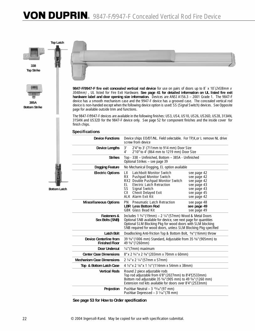
9847-F/9947-F Concealed Vertical Rod Fire Device
22 © 2004 Ingersoll-Rand. May be copied for use with specification submittal.
9847-F/9947-F fire exit concealed vertical rod device for use on pairs of doors up to 8´ x 10´(2438mm x3048mm) , UL listed for Fire Exit Hardware. See page 41 for detailed information on UL listed fire exithardware label and door opening size information. Devices are ANSI A156.3 – 2001 Grade 1. The 9847-Fdevice has a smooth mechanism case and the 9947-F device has a grooved case. The concealed vertical roddevice is non-handed except when the following device option is used: SS (Signal Switch) devices. See Oppositepage for available outside trim and functions.
The 9847-F/9947-F devices are available in the following finishes: US3, US4, US10, US26, US26D, US28, 313AN,315AN and US32D for the 9847-F device only. See page 52 for component finishes and the inside cover forfinish chips.
Top Latch
Bottom Latch
385A Bottom Strike
338 Top Strike
SpecificationsDevice Functions Device ships EO/DT/NL. Field selectable. For TP,K,or L remove NL drive
screw from deviceDevice Lengths 3’ 2’4" to 3’ (711mm to 914 mm) Door Size
4’ 2’10" to 4’ (864 mm to 1219 mm) Door SizeStrikes Top - 338 – Unfinished, Bottom – 385A - Unfinished
Optional Strikes – see page 39Dogging Feature No Mechanical Dogging, EL option availableElectric Options LX Latchbolt Monitor Switch see page 42
RX Pushpad Monitor Switch see page 42 RX2 Double Pushpad Monitor Switch see page 42EL Electric Latch Retraction see page 43 SS Signal Switch see page 43 CX Chexit Delayed Exit see page 45ALK Alarm Exit Kit see page 42
Miscellaneous Options PN Pneumatic Latch Retraction see page 48 LBR Less Bottom Rod see page 49GBK Glass Bead Kit see page 49
Fasteners & Includes 1 ³�₄" (19mm) – 2 ¹�₄" (57mm) Wood & Metal DoorsSex Bolts (SNB) Optional SNB available for device, see next page for quantities
Optional SLM Blocking Pkg for wood doors with SLM blockingSNB required for wood doors, unless SLM Blocking Pkg specified
Latch Bolt Deadlocking Anti-friction Top & Bottom Bolt, ⁵�₈" (16mm) throw Device Centerline from 39 ⁵�₈" (1006 mm) Standard, Adjustable from 35 ⁵�₈" (905mm) to
Finished Floor 49 ⁵�₈" (1260mm)Door Undercut ¹�₄" (7mm) maximum
Center Case Dimensions 8" x 2 ³�₄" x 2 ³�₈" (203mm x 70mm x 60mm)Mechanism Case Dimensions 2 ¹�₄" x 2 ¹�₄" (57mm x 57mm)
Top & Bottom Latch Case 4 ¹�₂" x 2 ¹�₈" x 1 ¹�₂" (114mm x 54mm x 38mm)Vertical Rods Round 2 piece adjustable rods
Top rod adjustable from 6’8" (2027mm) to 8’4"(2533mm)Bottom rod adjustable 35 ⁵�₈" (905 mm) to 49 ⁵�₈" (1260 mm)Extension rod kits available for doors over 8’4" (2533mm)
Projection Pushbar Neutral – 3 ¹³�₁₆" (97 mm)Pushbar Depressed – 3 ¹�₁₆" (78 mm)
See page 53 for How to Order specification
9847-F/9947-F Concealed Vertical Rod Fire Device Standard Trim
23
Exit only Dummy Trim Night Latch Night Latch Thumbturn ThumbturnPull when Dogged Key Retracts Latchbolt Key Retracts Latchbolt Key Locks & Unlocks Blank Escutcheon
(Not recommended for Optional Pull Required (Use with DT Trim) Always OperableFire Device) (No Cylinder)
(Use with DT Trim)
Product Description
Trim Description
Escutcheon Plate Size
Pull Center to Center
Projection
ANSI Function
Cylinder Type
Optional Trim(See pages 32 – 34)
#425 SNB optional-HMDReq. WD w/o SLM Pkg.
9847EO-F –– 9847NL-F 9847NL-OP-F 9847TL-F 9847TL-BE-F9947EO-F –– 9947NL-F 9947NL-OP-F 9947TL-F 9947TL-BE-F
–– 990DT 990NL-R/V 110NL-MD 374T x 990DT 374T-BE x 990DT
3" x 14³�₁₆" x ³�₃₂" 3" x 14³�₁₆" x ³�₃₂" 2³�₄" x 10³�₄" x ²⁷�₃₂" 2³�₄" x 10³�₄" x ²⁷�₃₂"(76x360x2mm) (76x360x2mm) (70x273x21mm) (70x273x21mm)
–– 5¹�₂" (140mm) 5¹�₂" (140mm) –– –– ––
–– 2" (51mm) 2" (51mm) –– 3¹�₄" (83mm) 3¹�₄" (83mm)
01 02 03 03 11 ––
–– –– Rim Rim 1¹�₄" Mortise ––
x990EO x991K-DT x991K-NLx992EO x992L-DT x992L-NLx994EO x994L-DT x994L-NLx996EO x996L-DT x996L-NL
x696DT x696NLx697DT x697NL
6 2 2 6 2 2
–– ––
Lever Lever – Night Latch Lever – Blank Escutcheon Lever Dummy TrimKey Locks & Unlocks Key Retracts Latchbolt Always operable Pull when Dogged
(No Cylinder) (Not recommended for Fire Device)
Product Description
Trim Description
Escutcheon Plate Size
Pull Center to Center
Projection
ANSI Function
Cylinder Type
Optional Trim(See pages 32 – 34)
#425 SNB optional-HMDReq. WD w/o SLM Pkg.
9847L-F 9847L-NL-F 9847L-BE-F ––9947L-F 9947L-NL-F 9947L-BE-F ––
996L-CV 996L-NL-CV 996L-BE-CV 996L-DT-CV
2³�₄" x 10³�₄" x ²⁷�₃₂" 2³�₄" x 10³�₄" x ²⁷�₃₂" 2³�₄" x 10³�₄" x ²⁷�₃₂" 2³�₄" x 10³�₄" x ²⁷�₃₂"(70x273x21mm) (70x273x21mm) (70x273x21mm) (70x273x21mm)
–– –– –– ––
2⁷�₈" (73mm) 2⁷�₈" (73mm) 2⁷�₈" (73mm) 2⁷�₈" (73mm)
08 09 –– 02
Rim Rim –– ––
x992L x992L-NL x992L-BE x992L-DTx994L x994L-NL x994L-BE x994L-DT
2 2 2 2
For optional trims and functions see pages 32-34

9848/9948 Concealed Vertical Rod Device
24 © 2004 Ingersoll-Rand. May be copied for use with specification submittal.
9848/9948 Concealed vertical rod device for use on single or double metal doors, UL listed for Panic ExitHardware. Covers stock hollow metal doors with 86 or 161 cutouts. Devices are ANSI A156.3 – 2001 Grade 1.The 9848 device has a smooth mechanism case and the 9948 device has a grooved case. The concealedvertical rod device is non-handed except when the following device options are used: SD (Special Dogging), orSS (Signal Switch). See Opposite page for available outside trim and functions.
The 9848/9948 devices are available in the following finishes: US3, US4, US10, US26, US26D, US28, 313AN,315AN and US32D for the 9848 device only. See page 52 for component finishes and the inside cover forfinish chips.
See page 53 for How to Order specification
Top Latch
Bottom Latch
385A Bottom Strike
338 Top Strike
SpecificationsDevice Functions Device ships EO/DT/NL. Field selectable. For TP,K,or L remove NL drive
screw from deviceDevice Lengths 3’ 2’4" to 3’ (711mm to 914 mm) Door Size
4’ 2’10" to 4’ (864 mm to 1219 mm) Door SizeStrikes Top - 338 – Unfinished, Bottom – 385A - Unfinished
Optional Strikes – see page 39Dogging Feature Hex key dogging standard
Dogging Options CD Cylinder Dogging see page 48 SD Special Center Case Dogging see page 48 LD Less Dogging see page 48
Electric Options LX Latchbolt Monitor Switch see page 42 RX Pushpad Monitor Switch see page 42 RX2 Double Pushpad Monitor Switch see page 42EL Electric Latch Retraction see page 43 SS Signal Switch see page 43 CX Chexit Delayed Exit see page 45ALK Alarm Exit Kit see page 42
Miscellaneous Options PN Pneumatic Latch Retraction see page 48 GBK Glass Bead Kit see page 49
Fasteners & Includes 1 ³�₄" (19mm) – 2 ¹�₄" (57mm) Wood & Metal DoorsSex Bolts (SNB) Optional SNB available for device, see next page for quantities
Latch Bolt Deadlocking Top Bolt, ³�₄" (19mm) throw Deadlocking Bottom Bolt, 1 ¹�₂" (38mm) throw
Device Centerline from 39 5/8" (1006 mm) Standard, Adjustable from 35 ⁵�₈" (905mm) toFinished Floor 49 5/8" (1260mm)Door Undercut ¹�₄" (7mm) maximum
Center Case Dimensions 8" x 2 ³�₄" x 2 ³�₈" (203mm x 70mm x 60mm)Mechanism Case Dimensions 2 ¹�₄" x 2 ¹�₄" (57mm x 57mm)
Top & Bottom Latch Case 4 ¹�₂" x 2 1/8" x 1 ¹�₂" (114mm x 54mm x 38mm)Vertical Rods Round 2 piece adjustable rods
Top rod adjustable from 6’8" (2027mm) to 8’4"(2533mm)Bottom rod adjustable 35 ⁵�₈" (905 mm) to 49 ⁵�₈" (1260 mm)Extension rod kits available for doors over 8’4" (2533mm)
Projection Pushbar Neutral – 3 ¹³�₁₆" (97 mm)Pushbar Depressed – 3 ¹�₁₆" (78 mm)

9848/9948 Concealed Vertical Rod Device Standard Trim
25
Exit only Dummy Trim Night Latch Night Latch Thumbturn ThumbturnPull when Dogged Key Retracts Latchbolt Key Retracts Latchbolt Key Locks & Unlocks Blank Escutcheon
Optional Pull Required (Use with DT Trim) Always Operable(No Cylinder)
(Use with DT Trim)
Product Description
Trim Description
Escutcheon Plate Size
Pull Center to Center
Projection
ANSI Function
Cylinder Type
Optional Trim(See pages 32 – 34)
Optional #425 Sex Bolt Quantity for Device
9848EO 9848DT 9848NL 9848NL-OP 9848TL 9848TL-BE9948EO 9948DT 9948NL 9948NL-OP 9948TL 9948TL-BE
–– 990DT 990NL-R/V 110NL-MD 374T x 990DT 374T-BE x 990DT
3" x 14³�₁₆" x ³�₃₂" 3" x 14³�₁₆" x ³�₃₂" 2³�₄" x 10³�₄" x ²⁷�₃₂" 2³�₄" x 10³�₄" x ²⁷�₃₂"(76x360x2mm) (76x360x2mm) (70x273x21mm) (70x273x21mm)
–– 5¹�₂" (140mm) 5¹�₂" (140mm) –– –– ––
–– 2" (51mm) 2" (51mm) –– 3¹�₄" (83mm) 3¹�₄" (83mm)
01 02 03 03 11 ––
–– –– Rim Rim 1¹�₄" Mortise ––
x990EO x991K-DT x991K-NLx992EO x992L-DT x992L-NLx994EO x994L-DT x994L-NLx996EO x996L-DT x996L-NL
x696DT x696NLx697DT x697NL
6 2 2 6 2 2
–– ––
Lever Lever – Night Latch Lever – Blank Escutcheon Lever Dummy TrimKey Locks & Unlocks Key Retracts Latchbolt Always operable Pull when Dogged
(No Cylinder)
Product Description
Trim Description
Escutcheon Plate Size
Pull Center to Center
Projection
ANSI Function
Cylinder Type
Optional Trim(See pages 32 – 34)
Optional #425 Sex Bolt Quantity for Device
9848L 9848L-NL 9848L-BE 9848L-DT9948L 9948L-NL 9948L-BE 9948L-DT
996L-CV 996L-NL-CV 996L-BE-CV 996L-DT-CV
2³�₄" x 10³�₄" x ²⁷�₃₂" 2³�₄" x 10³�₄" x ²⁷�₃₂" 2³�₄" x 10³�₄" x ²⁷�₃₂" 2³�₄" x 10³�₄" x ²⁷�₃₂"(70x273x21mm) (70x273x21mm) (70x273x21mm) (70x273x21mm)
–– –– –– ––
2⁷�₈" (73mm) 2⁷�₈" (73mm) 2⁷�₈" (73mm) 2⁷�₈" (73mm)
08 09 –– 02
Rim Rim –– ––
x992L x992L-NL x992L-BE x992L-DTx994L x994L-NL x994L-BE x994L-DT
2 2 2 2
For optional trims and functions see pages 32-34

9848-F/9948-F Concealed Vertical Rod Fire Device
26 © 2004 Ingersoll-Rand. May be copied for use with specification submittal.
9848-F/9948-F concealed vertical rod device for use on pairs of doors up to 8´ x 10´(2438mm x 3048mm),UL listed for Fire Exit Hardware. See page 41 for detailed information on UL listed fire exit hardware label anddoor opening size information. Devices are ANSI A156.3 – 2001 Grade 1. The 9848-F device has a smoothmechanism case and the 9948-F device has a grooved case. The concealed vertical rod device is non-handedexcept when the following device option is used: SS (Signal Switch). See Opposite page for available outsidetrim and functions.
The 9848-F/9948-F devices are available in the following finishes: US3, US4, US10, US26, US26D, US28, 313AN,315AN and US32D for the 9848-F device only. See page 52 for component finishes and the inside cover forfinish chips.
Top Latch
Bottom Latch
385A Bottom Strike
338 Top Strike
SpecificationsDevice Functions Device ships EO/DT/NL. Field selectable. For TP,K,or L remove NL drive
screw from deviceDevice Lengths 3’ 2’4" to 3’ (711mm to 914 mm) Door Size
4’ 2’10" to 4’ (864 mm to 1219 mm) Door SizeStrikes Top - 338 – Unfinished, Bottom – 385A - Unfinished
Optional Strikes – see page 39Dogging Feature No Mechanical Dogging, EL option availableElectric Options LX Latchbolt Monitor Switch see page 42
RX Pushpad Monitor Switch see page 42 RX2 Double Pushpad Monitor Switch see page 42EL Electric Latch Retraction see page 43 SS Signal Switch see page 43 CX Chexit Delayed Exit see page 45ALK Alarm Exit Kit see page 42
Miscellaneous Options PN Pneumatic Latch Retraction see page 48 GBK Glass Bead Kit see page 49
Fasteners & Includes 1 ³�₄" (19mm) – 2 ¹�₄" (57mm) Wood & Metal DoorsSex Bolts (SNB) Optional SNB available for device, see next page for quantities
Optional SLM Blocking Pkg for wood doors with SLM blockingSNB required for wood doors, unless SLM Blocking Pkg specified
Latch Bolt Deadlocking Top Bolt, ³�₄" (19mm) throw Deadlocking Bottom Bolt, 1 ¹�₂" (38mm) throw
Device Centerline from 39 5/8" (1006 mm) Standard, Adjustable from 35 ⁵�₈" (905mm) toFinished Floor 49 5/8" (1260mm)Door Undercut ¹�₄" (7mm) maximum
Center Case Dimensions 8" x 2 ³�₄" x 2 ³�₈" (203mm x 70mm x 60mm)Mechanism Case Dimensions 2 ¹�₄" x 2 ¹�₄" (57mm x 57mm)
Top & Bottom Latch Case 4 ¹�₂" x 2 1/8" x 1 ¹�₂" (114mm x 54mm x 38mm)Vertical Rods Round 2 piece adjustable rods
Top rod adjustable from 6’8" (2027mm) to 8’4"(2533mm)Bottom rod adjustable 35 ⁵�₈" (905 mm) to 49 ⁵�₈" (1260 mm)Extension rod kits available for doors over 8’4" (2533mm)
Projection Pushbar Neutral – 3 ¹³�₁₆" (97 mm)Pushbar Depressed – 3 ¹�₁₆" (78 mm)
See page 53 for How to Order specification

9848-F/9948-F Concealed Vertical Rod Fire Device Standard Trim
27
Exit only Dummy Trim Night Latch Night Latch Thumbturn ThumbturnPull when Dogged Key Retracts Latchbolt Key Retracts Latchbolt Key Locks & Unlocks Blank Escutcheon
(Not recommended for Optional Pull Required (Use with DT Trim) Always OperableFire Device) (No Cylinder)
(Use with DT Trim)
Product Description
Trim Description
Escutcheon Plate Size
Pull Center to Center
Projection
ANSI Function
Cylinder Type
Optional Trim(See pages 32 – 34)
#425 SNB optional-HMDReq. WD w/o SLM Pkg.
9848EO-F –– 9848NL-F 9848NL-OP-F 9848TL-F 9848TL-BE-F9948EO-F –– 9948NL-F 9948NL-OP-F 9948TL-F 9948TL-BE-F
–– 990DT 990NL-R/V 110NL-MD 374T x 990DT 374T-BE x 990DT
3" x 14³�₁₆" x ³�₃₂" 3" x 14³�₁₆" x ³�₃₂" 2³�₄" x 10³�₄" x ²⁷�₃₂" 2³�₄" x 10³�₄" x ²⁷�₃₂"(76x360x2mm) (76x360x2mm) (70x273x21mm) (70x273x21mm)
–– 5¹�₂" (140mm) 5¹�₂" (140mm) –– –– ––
–– 2" (51mm) 2" (51mm) –– 3¹�₄" (83mm) 3¹�₄" (83mm)
01 02 03 03 11 ––
–– –– Rim Rim 1¹�₄" Mortise ––
x990EO x991K-DT x991K-NLx992EO x992L-DT x992L-NLx994EO x994L-DT x994L-NLx996EO x996L-DT x996L-NL
x696DT x696NLx697DT x697NL
6 2 2 6 2 2
–– ––
Lever Lever – Night Latch Lever – Blank Escutcheon Lever Dummy TrimKey Locks & Unlocks Key Retracts Latchbolt Always operable Pull when Dogged
(No Cylinder) (Not recommended for Fire Device)
Product Description
Trim Description
Escutcheon Plate Size
Pull Center to Center
Projection
ANSI Function
Cylinder Type
Optional Trim(See pages 32 – 34)
#425 SNB optional-HMDReq. WD w/o SLM Pkg.
9848L-F 9848L-NL-F 9848L-BE-F ––9948L-F 9948L-NL-F 9948L-BE-F ––
996L-CV 996L-NL-CV 996L-BE-CV 996L-DT-CV
2³�₄" x 10³�₄" x ²⁷�₃₂" 2³�₄" x 10³�₄" x ²⁷�₃₂" 2³�₄" x 10³�₄" x ²⁷�₃₂" 2³�₄" x 10³�₄" x ²⁷�₃₂"(70x273x21mm) (70x273x21mm) (70x273x21mm) (70x273x21mm)
–– –– –– ––
2⁷�₈" (73mm) 2⁷�₈" (73mm) 2⁷�₈" (73mm) 2⁷�₈" (73mm)
08 09 –– 02
Rim Rim –– ––
x992L x992L-NL x992L-BE x992L-DTx994L x994L-NL x994L-BE x994L-DT
2 2 2 2
For optional trims and functions see pages 32-34

9847/9947 Wood Door Concealed Vertical Rod Device
28 © 2004 Ingersoll-Rand. May be copied for use with specification submittal.
9847WDC/9947WDC concealed vertical rod device for use on single or double wood doors, UL listed forPanic Exit Hardware. Devices are ANSI A156.3 – 2001 Grade 1. The 9847WDC device has a smooth mechanismcase and the 9947WDC device has a grooved case. The concealed vertical rod device is non-handed except whenthe following device options are used: SD (Special Dogging), or SS (Signal Switch). See Opposite page foravailable outside trim and functions.
The 9847WDC/9947WDC devices are available in the following finishes: US3, US4, US10, US26, US26D, US28,313AN, 315AN and US32D for the 9847WDC device only. See page 52 for component finishes and the insidecover for finish chips.
Scalp Plate Device is furnished standard with an 8" (203mm) long scalp plate for easy access to rods.Note: Do not use on pair of doors with 9975.
Top Latch
Bottom Latch
385A Bottom Strike
338 Top Strike
283Top Strike
For use with Wood Frames
SpecificationsDevice Functions Device ships EO/DT/NL. Field selectable. For TP,K,or L remove NL drive
screw from deviceDevice Lengths 3’ 2’4" to 3’ (711mm to 914 mm) Door Size
4’ 2’10" to 4’ (864 mm to 1219 mm) Door SizeStrikes Top - 338 – Unfinished, Bottom – 385A - Unfinished
Optional Strikes – see page 39Dogging Feature Hex key dogging standard
Dogging Options CD Cylinder Dogging see page 48 SD Special Center Case Dogging see page 48 LD Less Dogging see page 48
Electric Options LX Latchbolt Monitor Switch see page 42 RX Pushpad Monitor Switch see page 42 RX2 Double Pushpad Monitor Switch see page 42EL Electric Latch Retraction see page 43 SS Signal Switch see page 43 CX Chexit Delayed Exit see page 45ALK Alarm Exit Kit see page 42
Miscellaneous Options PN Pneumatic Latch Retraction see page 48 GBK Glass Bead Kit see Page 49PL Pullman Latch see page 49
Fasteners & Includes 1 ³�₄" (19mm) – 2 ¹�₄" (57mm) Wood & Metal DoorsSex Bolts (SNB) Optional SNB available for device, see next page for quantities
Latch Bolt Deadlocking Top & Bottom Bolt, ⁵�₈" (16mm) throwDevice Centerline from 39 ⁵�₈" (1006 mm) Standard, Adjustable from 35 ⁵�₈" (905mm) to
Finished Floor 49 ⁵�₈" (1260mm)Door Undercut ¹�₄" (7mm) maximum
Center Case Dimensions 8" x 2 ³�₄" x 2 ³�₈" (203mm x 70mm x 60mm)Mechanism Case Dimensions 2 ¹�₄" x 2 ¹�₄" (57mm x 57mm)
Top & Bottom Latch Case 4 ¹�₂" x 2 1/8" x 1 ¹�₂" (114mm x 54mm x 38mm)Vertical Rods Round 2 piece adjustable rods
Top rod adjustable from 6’8" (2027mm) to 8’4"(2533mm)Bottom rod adjustable 35 ⁵�₈" (905 mm) to 49 ⁵�₈" (1260 mm)Extension rod kits available for doors over 8’4" (2533mm)
Projection Pushbar Neutral – 3 ¹³�₁₆" (97 mm)Pushbar Depressed – 3 ¹�₁₆" (78 mm)
See page 53 for How to Order specification

9847/9947 Wood Door Concealed Vertical Rod Device Standard Trim
29
Exit only Dummy Trim Night Latch Night Latch Thumbturn ThumbturnPull when Dogged Key Retracts Latchbolt Key Retracts Latchbolt Key Locks & Unlocks Blank Escutcheon
Optional Pull Required (Use with DT Trim) Always Operable(No Cylinder)
(Use with DT Trim)
Product Description
Trim Description
Escutcheon Plate Size
Pull Center to Center
Projection
ANSI Function
Cylinder Type
Optional Trim(See pages 32 – 34)
Optional #425 Sex Bolt Quantity for Device
9847WDC-EO 9847WDC-DT 9847WDC-NL 9847WDC-NL-OP 9847WDC-TL 9847WDC-TL-BE9947WDC-EO 9947WDC-DT 9947WDC-NL 9947WDC-NL-OP 9947WDC-TL 9947WDC-TL-BE
–– 990DT 990NL-R/V 110NL-WD 374T x 990DT 374T-BE x 990DT
3" x 14³�₁₆" x ³�₃₂" 3" x 14³�₁₆" x ³�₃₂" 2³�₄" x 10³�₄" x ²⁷�₃₂" 2³�₄" x 10³�₄" x ²⁷�₃₂"(76x360x2mm) (76x360x2mm) (70x273x21mm) (70x273x21mm)
–– 5¹�₂" (140mm) 5¹�₂" (140mm) –– –– ––
–– 2" (51mm) 2" (51mm) –– 3¹�₄" (83mm) 3¹�₄" (83mm)
01 02 03 03 11 ––
–– –– Rim Rim 1¹�₄" Mortise ––
x990EO x991K-DT x991K-NLx992EO x992L-DT x992L-NLx994EO x994L-DT x994L-NLx996EO x996L-DT x996L-NL
x696DT x696NLx697DT x697NL
6 2 2 6 2 2
–– ––
Lever Lever – Night Latch Lever – Blank Escutcheon Lever Dummy TrimKey Locks & Unlocks Key Retracts Latchbolt Always operable Pull when Dogged
(No Cylinder)
Product Description
Trim Description
Escutcheon Plate Size
Pull Center to Center
Projection
ANSI Function
Cylinder Type
Optional Trim(See pages 32 – 34)
Optional #425 Sex Bolt Quantity for Device
9847WDC-L 9847WDC-L-NL 9847WDC-L-BE 9847WDC-L-DT9947WDC-L 9947WDC-L-NL 9947WDC-L-BE 9947WDC-L-DT
996L-CV 996L-NL-CV 996L-BE-CV 996L-DT-CV
2³�₄" x 10³�₄" x ²⁷�₃₂" 2³�₄" x 10³�₄" x ²⁷�₃₂" 2³�₄" x 10³�₄" x ²⁷�₃₂" 2³�₄" x 10³�₄" x ²⁷�₃₂"(70x273x21mm) (70x273x21mm) (70x273x21mm) (70x273x21mm)
–– –– –– ––
2⁷�₈" (73mm) 2⁷�₈" (73mm) 2⁷�₈" (73mm) 2⁷�₈" (73mm)
08 09 –– 02
Rim Rim –– ––
x992L x992L-NL x992L-BE x992L-DTx994L x994L-NL x994L-BE x994L-DT
2 2 2 2
For optional trims and functions see pages 32-34

9847WDC-F/9947WDC-F Wood Door Concealed Vertical Rod Fire Device
30 © 2004 Ingersoll-Rand. May be copied for use with specification submittal.
9847WDC-F/9947WDC-F fire exit concealed vertical rod device for use on pairs of doors up to 8’ x 9’ 3”(2438mm x 2819mm) double wood doors, UL listed for Fire Exit Hardware. See page 41 for detailedinformation on UL listed fire exit hardware label and door opening size information. Devices areANSI A156.3 – 2001 Grade 1. The 9847WDC-F device has a smooth mechanism case and the 9947WDC-F devicehas a grooved case. The concealed vertical rod device is non-handed except when the following device options areused: SS (Signal Switch). See Opposite page for available outside trim and functions.
The 9847WDC-F/9947WDC-F devices are available in the following finishes: US3, US4, US10, US26, US26D, US28,313AN, 315AN and US32D for the 9847WDC-F device only. See page 52 for component finishes and the insidecover for finish chips.
Scalp Plate Device is furnished standard with an 8" (203mm) long scalp plate for easy access to rods.Note: Do not use on pair of doors with 9975.
Top Latch
Bottom Latch
385A Bottom Strike
338 Top Strike
283Top Strike
For use with Wood Frames
SpecificationsDevice Functions Device ships EO/DT/NL. Field selectable. For TP,K,or L remove NL drive
screw from deviceDevice Lengths 3’ 2’4" to 3’ (711mm to 914 mm) Door Size
4’ 2’10" to 4’ (864 mm to 1219 mm) Door SizeStrikes Top - 338 – Unfinished, Bottom – 385A - Unfinished
Optional Strikes – see page 39Dogging Feature No Mechanical Dogging, EL option availableElectric Options LX Latchbolt Monitor Switch see page 42
RX Pushpad Monitor Switch see page 42 RX2 Double Pushpad Monitor Switch see page 42EL Electric Latch Retraction see page 43 SS Signal Switch see page 43 CX Chexit Delayed Exit see page 45ALK Alarm Exit Kit see page 42
Miscellaneous Options PN Pneumatic Latch Retraction see page 48 LBR Less Bottom Rod see page 49GBK Glass Bead Kit see page 49
Fasteners & Includes 1 ³�₄" (19mm) – 2 ¹�₄" (57mm) Wood & Metal DoorsSex Bolts (SNB) Optional SNB available for device, see next page for quantities
Optional SLM Blocking Pkg for wood doors with SLM blockingSNB required for wood doors, unless SLM Blocking Pkg specified
Latch Bolt Deadlocking Anti-friction Top & Bottom Bolt, ⁵�₈" (16mm) throwDevice Centerline from 39 ⁵�₈" (1006 mm) Standard, Adjustable from 35 ⁵�₈" (905mm) to
Finished Floor 49 ⁵�₈" (1260mm)Door Undercut ¹�₄" (7mm) maximum
Center Case Dimensions 8" x 2 ³�₄" x 2 ³�₈" (203mm x 70mm x 60mm)Mechanism Case Dimensions 2 ¹�₄" x 2 ¹�₄" (57mm x 57mm)
Top & Bottom Latch Case 4 ¹�₂" x 2 1/8" x 1 ¹�₂" (114mm x 54mm x 38mm)Vertical Rods Round 2 piece adjustable rods
Top rod adjustable from 6’8" (2027mm) to 8’4"(2533mm)Bottom rod adjustable 35 ⁵�₈" (905 mm) to 49 ⁵�₈" (1260 mm)Extension rod kits available for doors over 8’4" (2533mm)
Projection Pushbar Neutral – 3 ¹³�₁₆" (97 mm)Pushbar Depressed – 3 ¹�₁₆" (78 mm)
See page 53 for How to Order specification

9847WDC-F/9947WDC-F Wood Door Concealed Vertical Rod Fire Device Standard Trim
31
Exit only Dummy Trim Night Latch Night Latch Thumbturn ThumbturnPull when Dogged Key Retracts Latchbolt Key Retracts Latchbolt Key Locks & Unlocks Blank Escutcheon
(Not recommended for Optional Pull Required (Use with DT Trim) Always OperableFire Device) (No Cylinder)
(Use with DT Trim)
Product Description
Trim Description
Escutcheon Plate Size
Pull Center to Center
Projection
ANSI Function
Cylinder Type
Optional Trim(See pages 32 – 34)
#425 SNB optional-HMDReq. WD w/o SLM Pkg.
9847WDC-EO-F –– 9847WDC-NL-F 9847WDC-NL-OP-F 9847WDC-TL-F 9847WDC-TL-BE-F9947WDC-EO-F –– 9947WDC-NL-F 9947WDC-NL-OP-F 9947WDC-TL-F 9947WDC-TL-BE-F
–– 990DT 990NL-R/V 110NL-WD 374T x 990DT 374T-BE x 990DT
3" x 14³�₁₆" x ³�₃₂" 3" x 14³�₁₆" x ³�₃₂" 2³�₄" x 10³�₄" x ²⁷�₃₂" 2³�₄" x 10³�₄" x ²⁷�₃₂"(76x360x2mm) (76x360x2mm) (70x273x21mm) (70x273x21mm)
–– 5¹�₂" (140mm) 5¹�₂" (140mm) –– –– ––
–– 2" (51mm) 2" (51mm) –– 3¹�₄" (83mm) 3¹�₄" (83mm)
01 02 03 03 11 ––
–– –– Rim Rim 1¹�₄" Mortise ––
x990EO x991K-DT x991K-NLx992EO x992L-DT x992L-NLx994EO x994L-DT x994L-NLx996EO x996L-DT x996L-NL
x696DT x696NLx697DT x697NL
6 2 2 6 2 2
–– ––
Lever Lever – Night Latch Lever – Blank Escutcheon Lever Dummy TrimKey Locks & Unlocks Key Retracts Latchbolt Always operable Pull when Dogged
(No Cylinder) (Not recommended for Fire Device)
Product Description
Trim Description
Escutcheon Plate Size
Pull Center to Center
Projection
ANSI Function
Cylinder Type
Optional Trim(See pages 32 – 34)
#425 SNB optional-HMDReq. WD w/o SLM Pkg.
9847WDC-L-F 9847WDC-L-NL-F 9847WDC-L-BE-F ––9947WDC-L-F 9947WDC-L-NL-F 9947WDC-L-BE-F ––
996L-CV 996L-NL-CV 996L-BE-CV 996L-DT-CV
2³�₄" x 10³�₄" x ²⁷�₃₂" 2³�₄" x 10³�₄" x ²⁷�₃₂" 2³�₄" x 10³�₄" x ²⁷�₃₂" 2³�₄" x 10³�₄" x ²⁷�₃₂"(70x273x21mm) (70x273x21mm) (70x273x21mm) (70x273x21mm)
–– –– –– ––
2⁷�₈" (73mm) 2⁷�₈" (73mm) 2⁷�₈" (73mm) 2⁷�₈" (73mm)
08 09 –– 02
Rim Rim –– ––
x992L x992L-NL x992L-BE x992L-DTx994L x994L-NL x994L-BE x994L-DT
2 2 2 2
For optional trims and functions see pages 32-34

98/99™ Optional Trim
32 © 2004 Ingersoll-Rand. May be copied for use with specification submittal.
Knob Knob – Night Latch Knob – Blank Knob – Dummy Trim Thumbpiece ThumbpieceKey Locks Key Retracts Latchbolt Escutcheon Pull when Dogged Key Locks Blank Escutcheon& Unlocks Alwaya Operable & Unlocks Always Operable
(No Cylinder) (No Cylinder)
Trim Description
Escutcheon Plate Size
Pull Center to Center
Projection
ANSI Function
Cylinder TypeRim or Vertical Rod Device
Mortise Lock Device
#425 SNB optional-HMDReq. WD w/o SLM Pkg.
#825 SNB Req. WD w/o SLM Pkg.F Rim device ONLY#425 SNB Req. w/ 499F
991K 991K-NL 991K-BE 991K-DT 990TP 990TP-BE
2³�₄" x 10³�₄" x ²⁷�₃₂" 2³�₄" x 10³�₄" x ²⁷�₃₂" 2³�₄" x 10³�₄" x ²⁷�₃₂" 2³�₄" x 10³�₄" x ²⁷�₃₂" 2³�₄" x 10³�₄" x ²⁷�₃₂" 2³�₄" x 10³�₄" x ²⁷�₃₂"(70x273x21mm) (70x273x21mm) (70x273x21mm) (70x273x21mm) (70x273x21mm) (70x273x21mm)
–– –– –– –– 5¹�₂" (140mm) 5¹�₂" (140mm)
3¹�₄" (83mm) 3¹�₄" (83mm) 3¹�₄" (83mm) 3¹�₄" (83mm) 2" (51mm) 2" (51mm)
08 09 –– 02 05 05
Rim Rim –– –– Rim ––
1¹�₄" Mortise 1¹�₄" Mortise 1¹�₄" Mortise ––
2 2 2 2 2 2
2 2 2 2 2 2
2 2 2 2 2 2
Knob and Thumbpiece Trim
Lever Design Options
#01 #02 #03 #05 #06Standard
#07 #12 #16 #17 #18Handed
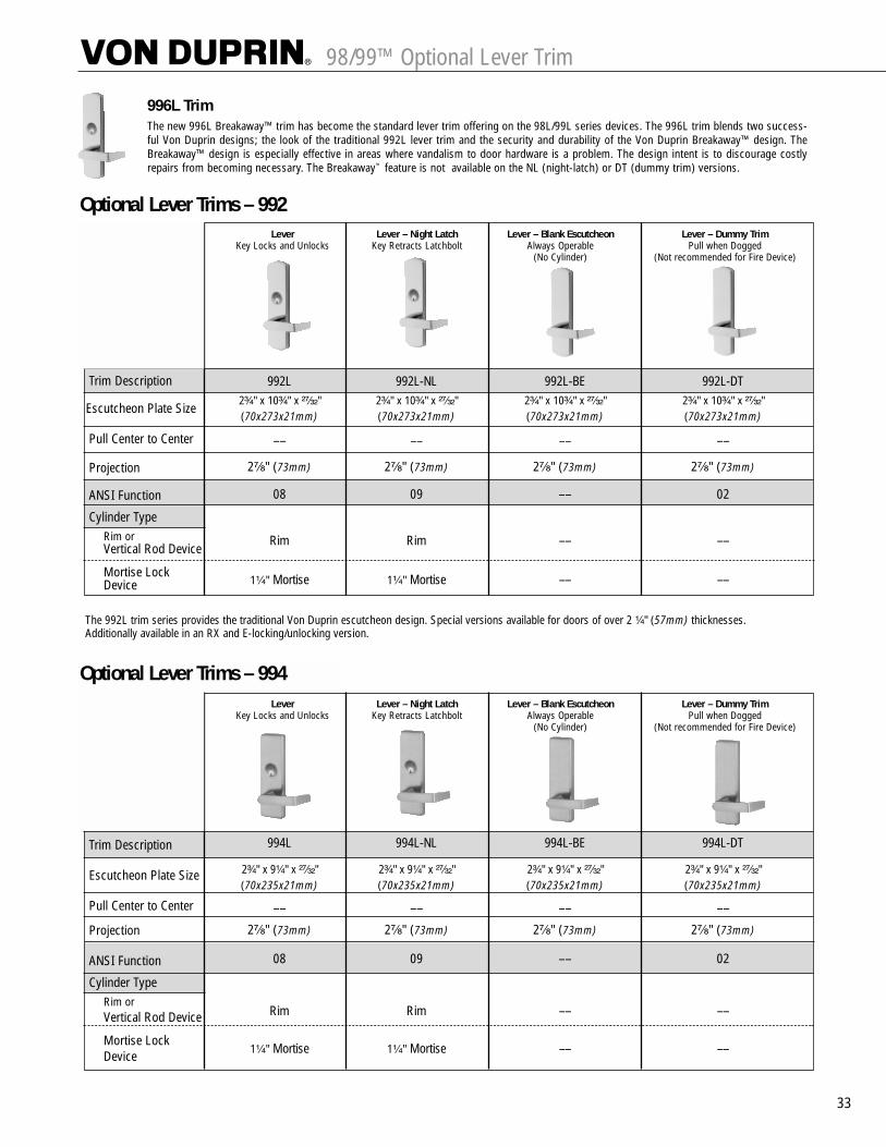
98/99™ Optional Lever Trim
33
Lever Lever – Night Latch Lever – Blank Escutcheon Lever – Dummy TrimKey Locks and Unlocks Key Retracts Latchbolt Always Operable Pull when Dogged
(No Cylinder) (Not recommended for Fire Device)
Trim Description
Escutcheon Plate Size
Pull Center to Center
Projection
ANSI Function
Cylinder TypeRim or Vertical Rod Device
Mortise Lock Device
992L 992L-NL 992L-BE 992L-DT2³�₄" x 10³�₄" x ²⁷�₃₂" 2³�₄" x 10³�₄" x ²⁷�₃₂" 2³�₄" x 10³�₄" x ²⁷�₃₂" 2³�₄" x 10³�₄" x ²⁷�₃₂"(70x273x21mm) (70x273x21mm) (70x273x21mm) (70x273x21mm)
–– –– –– ––
2⁷�₈" (73mm) 2⁷�₈" (73mm) 2⁷�₈" (73mm) 2⁷�₈" (73mm)
08 09 –– 02
Rim Rim –– ––
1¹�₄" Mortise 1¹�₄" Mortise –– ––
Optional Lever Trims – 992
Optional Lever Trims – 994Lever Lever – Night Latch Lever – Blank Escutcheon Lever – Dummy Trim
Key Locks and Unlocks Key Retracts Latchbolt Always Operable Pull when Dogged(No Cylinder) (Not recommended for Fire Device)
Trim Description
Escutcheon Plate Size
Pull Center to Center
Projection
ANSI Function
Cylinder TypeRim or Vertical Rod Device
Mortise Lock Device
994L 994L-NL 994L-BE 994L-DT
2³�₄" x 9¹�₄" x ²⁷�₃₂" 2³�₄" x 9¹�₄" x ²⁷�₃₂" 2³�₄" x 9¹�₄" x ²⁷�₃₂" 2³�₄" x 9¹�₄" x ²⁷�₃₂"(70x235x21mm) (70x235x21mm) (70x235x21mm) (70x235x21mm)
–– –– –– ––
2⁷�₈" (73mm) 2⁷�₈" (73mm) 2⁷�₈" (73mm) 2⁷�₈" (73mm)
08 09 –– 02
Rim Rim –– ––
1¹�₄" Mortise 1¹�₄" Mortise –– ––
The new 996L Breakaway™ trim has become the standard lever trim offering on the 98L/99L series devices. The 996L trim blends two success-ful Von Duprin designs; the look of the traditional 992L lever trim and the security and durability of the Von Duprin Breakaway™ design. TheBreakaway™ design is especially effective in areas where vandalism to door hardware is a problem. The design intent is to discourage costlyrepairs from becoming necessary. The Breakaway™ feature is not available on the NL (night-latch) or DT (dummy trim) versions.
996L Trim
The 992L trim series provides the traditional Von Duprin escutcheon design. Special versions available for doors of over 2 ¹�₄" (57mm) thicknesses. Additionally available in an RX and E-locking/unlocking version.
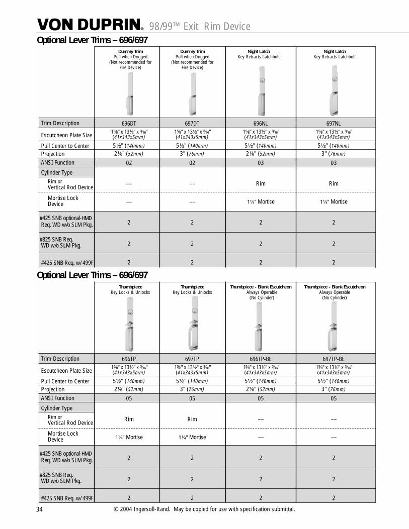
98/99™ Exit Rim Device
34 © 2004 Ingersoll-Rand. May be copied for use with specification submittal.
696DT 697DT 696NL 697NL1⁵�₈" x 13¹�₂" x ³�₁₆" 1⁵�₈" x 13¹�₂" x ³�₁₆" 1⁵�₈" x 13¹�₂" x ³�₁₆" 1⁵�₈" x 13¹�₂" x ³�₁₆"(41x343x5mm) (41x343x5mm) (41x343x5mm) (41x343x5mm)
5¹�₂" (140mm) 5¹�₂" (140mm) 5¹�₂" (140mm) 5¹�₂" (140mm)2¹�₆" (52mm) 3" (76mm) 2¹�₆" (52mm) 3" (76mm)
02 02 03 03
–– –– Rim Rim
–– –– 1¹�₄" Mortise 1¹�₄" Mortise
2 2 2 2
2 2 2 2
2 2 2 2
Optional Lever Trims – 696/697
Thumbpiece Thumbpiece Thumbpiece - Blank Escutcheon Thumbpiece - Blank EscutcheonKey Locks & Unlocks Key Locks & Unlocks Always Operable Always Operable
(No Cylinder) (No Cylinder)Fire Device)
Trim Description
Escutcheon Plate Size
Pull Center to CenterProjectionANSI Function
Cylinder TypeRim or Vertical Rod Device
Mortise Lock Device
#425 SNB optional-HMDReq. WD w/o SLM Pkg.
#825 SNB Req. WD w/o SLM Pkg.
#425 SNB Req. w/ 499F
696TP 697TP 696TP-BE 697TP-BE1⁵�₈" x 13¹�₂" x ³�₁₆" 1⁵�₈" x 13¹�₂" x ³�₁₆" 1⁵�₈" x 13¹�₂" x ³�₁₆" 1⁵�₈" x 13¹�₂" x ³�₁₆"(41x343x5mm) (41x343x5mm) (41x343x5mm) (41x343x5mm)
5¹�₂" (140mm) 5¹�₂" (140mm) 5¹�₂" (140mm) 5¹�₂" (140mm)2¹�₆" (52mm) 3" (76mm) 2¹�₆" (52mm) 3" (76mm)
05 05 05 05
Rim Rim –– ––
1¹�₄" Mortise 1¹�₄" Mortise –– ––
2 2 2 2
2 2 2 2
2 2 2 2
Optional Lever Trims – 696/697
Dummy Trim Dummy Trim Night Latch Night LatchPull when Dogged Pull when Dogged Key Retracts Latchbolt Key Retracts Latchbolt
(Not recommended for (Not recommended for Fire Device) Fire Device)
Trim Description
Escutcheon Plate Size
Pull Center to CenterProjectionANSI Function
Cylinder TypeRim or Vertical Rod Device
Mortise Lock Device
#425 SNB optional-HMDReq. WD w/o SLM Pkg.
#825 SNB Req. WD w/o SLM Pkg.
#425 SNB Req. w/ 499F
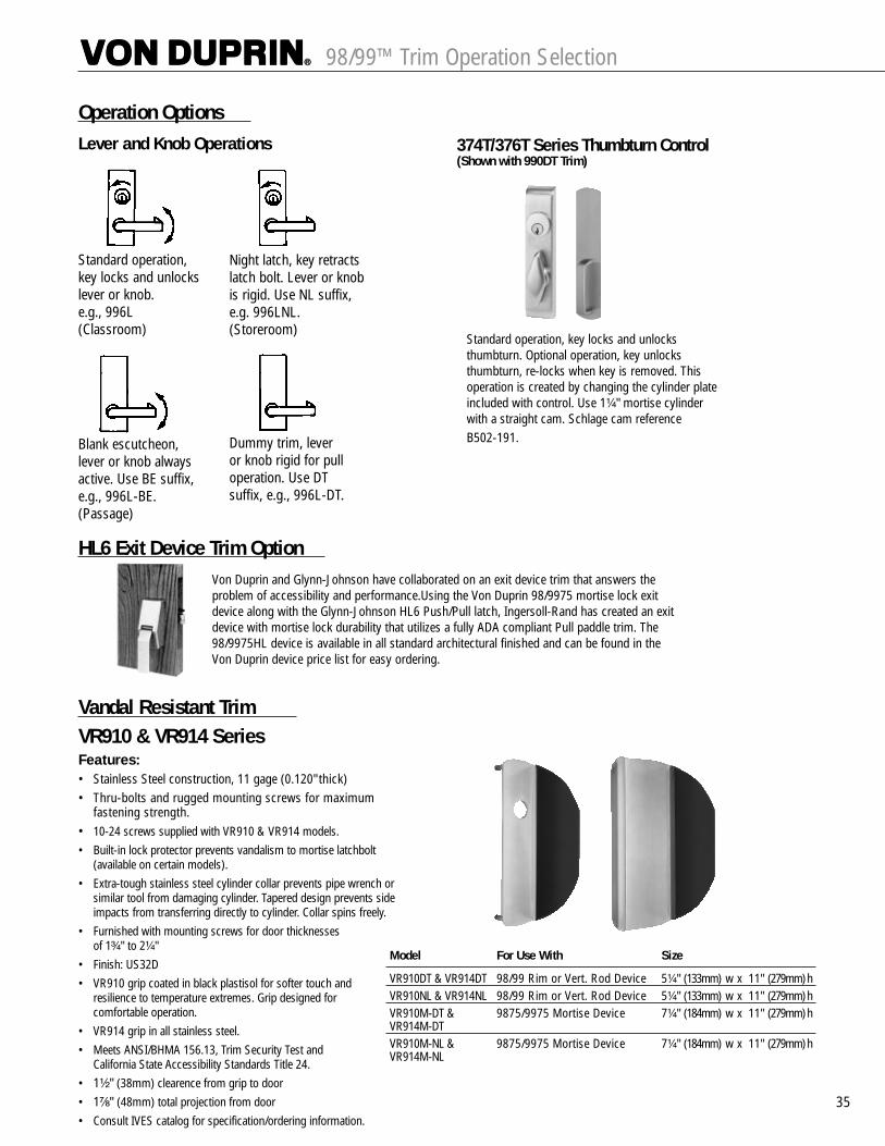
98/99™ Trim Operation Selection
35
Operation Options
HL6 Exit Device Trim Option
Vandal Resistant TrimVR910 & VR914 SeriesFeatures:• Stainless Steel construction, 11 gage (0.120" thick)• Thru-bolts and rugged mounting screws for maximum
fastening strength.• 10-24 screws supplied with VR910 & VR914 models.• Built-in lock protector prevents vandalism to mortise latchbolt
(available on certain models).• Extra-tough stainless steel cylinder collar prevents pipe wrench or
similar tool from damaging cylinder. Tapered design prevents side impacts from transferring directly to cylinder. Collar spins freely.
• Furnished with mounting screws for door thicknesses of 1³�₄" to 2¹�₄"
• Finish: US32D• VR910 grip coated in black plastisol for softer touch and
resilience to temperature extremes. Grip designed for comfortable operation.
• VR914 grip in all stainless steel.• Meets ANSI/BHMA 156.13, Trim Security Test and
California State Accessibility Standards Title 24.• 1¹�₂" (38mm) clearence from grip to door• 1⁷�₈" (48mm) total projection from door• Consult IVES catalog for specification/ordering information.
Standard operation, key locks and unlocksthumbturn. Optional operation, key unlocksthumbturn, re-locks when key is removed. Thisoperation is created by changing the cylinder plateincluded with control. Use 1¹�₄" mortise cylinderwith a straight cam. Schlage cam referenceB502-191.
Standard operation, key locks and unlockslever or knob.e.g., 996L(Classroom)
Night latch, key retractslatch bolt. Lever or knobis rigid. Use NL suffix,e.g. 996LNL.(Storeroom)
Blank escutcheon, lever or knob alwaysactive. Use BE suffix,e.g., 996L-BE.(Passage)
Dummy trim, lever or knob rigid for pull operation. Use DT suffix, e.g., 996L-DT.
Lever and Knob Operations 374T/376T Series Thumbturn Control(Shown with 990DT Trim)
Von Duprin and Glynn-Johnson have collaborated on an exit device trim that answers theproblem of accessibility and performance.Using the Von Duprin 98/9975 mortise lock exitdevice along with the Glynn-Johnson HL6 Push/Pull latch, Ingersoll-Rand has created an exitdevice with mortise lock durability that utilizes a fully ADA compliant Pull paddle trim. The98/9975HL device is available in all standard architectural finished and can be found in theVon Duprin device price list for easy ordering.
Model For Use With Size
VR910DT & VR914DT 98/99 Rim or Vert. Rod Device 5¹�₄" (133mm) w x 11" (279mm) hVR910NL & VR914NL 98/99 Rim or Vert. Rod Device 5¹�₄" (133mm) w x 11" (279mm) hVR910M-DT & 9875/9975 Mortise Device 7¹�₄" (184mm) w x 11" (279mm) hVR914M-DTVR910M-NL & 9875/9975 Mortise Device 7¹�₄" (184mm) w x 11" (279mm) hVR914M-NL
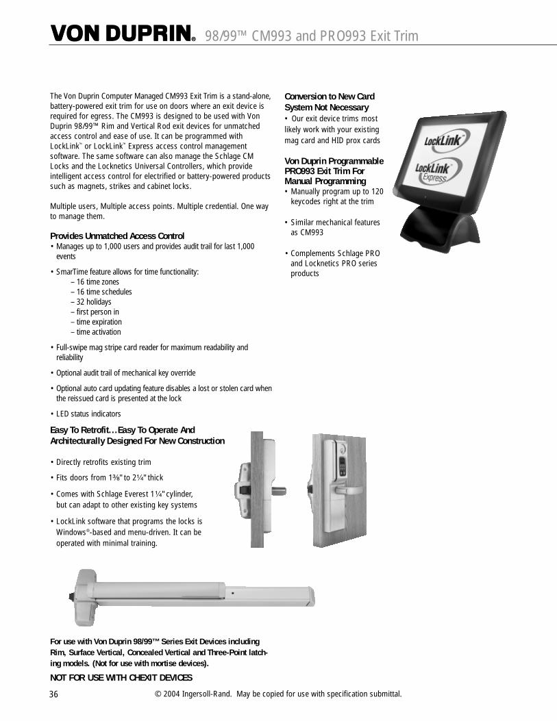
36 © 2004 Ingersoll-Rand. May be copied for use with specification submittal.
98/99™ CM993 and PRO993 Exit Trim
The Von Duprin Computer Managed CM993 Exit Trim is a stand-alone,battery-powered exit trim for use on doors where an exit device isrequired for egress. The CM993 is designed to be used with VonDuprin 98/99™ Rim and Vertical Rod exit devices for unmatchedaccess control and ease of use. It can be programmed withLockLink™ or LockLink™ Express access control managementsoftware. The same software can also manage the Schlage CMLocks and the Locknetics Universal Controllers, which provideintelligent access control for electrified or battery-powered productssuch as magnets, strikes and cabinet locks.
Multiple users, Multiple access points. Multiple credential. One wayto manage them.
Provides Unmatched Access Control• Manages up to 1,000 users and provides audit trail for last 1,000
events
• SmarTime feature allows for time functionality:– 16 time zones – 16 time schedules– 32 holidays– first person in– time expiration– time activation
• Full-swipe mag stripe card reader for maximum readability andreliability
• Optional audit trail of mechanical key override
• Optional auto card updating feature disables a lost or stolen card whenthe reissued card is presented at the lock
• LED status indicators
Easy To Retrofit...Easy To Operate And Architecturally Designed For New Construction
• Directly retrofits existing trim
• Fits doors from 1³�₈" to 2¹�₄" thick
• Comes with Schlage Everest 1¹�₄" cylinder, but can adapt to other existing key systems
• LockLink software that programs the locks is Windows®-based and menu-driven. It can be operated with minimal training.
For use with Von Duprin 98/99™ Series Exit Devices includingRim, Surface Vertical, Concealed Vertical and Three-Point latch-ing models. (Not for use with mortise devices).
NOT FOR USE WITH CHEXIT DEVICES
Conversion to New CardSystem Not Necessary• Our exit device trims mostlikely work with your existingmag card and HID prox cards
Von Duprin ProgrammablePRO993 Exit Trim ForManual Programming• Manually program up to 120
keycodes right at the trim
• Similar mechanical features as CM993
• Complements Schlage PROand Locknetics PRO seriesproducts

37
How To Order CM993 and PRO993 Exit Trim
1. Select Model
2. Select Access Credential Option (CMs only)
3. Select Lever
4. Select Handing
RH Right HandLH Left HandNote: Handing is field-reversible
5. Select Key Cylinder Option
KD Schlage Everest CylinderLC Less CylinderNote: Master keyed cylinders order separately
6. Select Finish:
605 Bright Brass 625 Bright Chrome612 Satin Bronze 626 Satin Chrome (Standard)613 Oil-Rubbed Bronze 695 Duranodic Dark Bronze
7. Select Trim Options
ATK Audit trail of mechanical key override, includes ATR (Requires computer programming).
T3 ABA Track 3 Mag Card Reader (ABA Track 2 is standard for MGI and MGK Series only).
EXT is now standard. Specify if for interior use.Mag Card Reader for exterior use (for MGI and MGK Series only).
CM993 – MGK – 06 – LH – KD – 695 – EXTSelect ModelSelect Access Credential OptionSelect LeverSelect HandingSelect Key Cylinder OptionSelect FinishSelect Trim Options
IBA iButton (adhesive backed)IBF iButton on FobMAG1 Magnetic Stripe Card – BlankMAG2 Magnetic Stripe Card – Pre-encodedPRX1 Prox Card – Standard .070" thickPRX2 Prox Card – Adhesive backed for photo
application, .070" thickPRX3 Prox Card – ISO – credit card size and
thickness, .031" thickPRX4 Prox Card – Dual Technologies, magnetic
stripe and Prox, .031" thickPF1 Prox Fob
Select Credentials
PRO993 Manuallyprogrammed exit trim
CM993 Computermanaged exit trim
KPI Keypad iButton Reader
IBOiButton Reader
MGK Mag Card Reader KeypadiButton Reader
MGI Mag CardReaderiButton Reader
PXK HID prox ReaderKeypad iButtonReader
PXI HID prox ReaderiButton Reader
#03 #06 Standard
#17
Door Thickness State door thickness. Available from 1³�₈" to 2³�₄" in ¹�₈" increments

38 © 2004 Ingersoll-Rand. May be copied for use with specification submittal.
98/99™ Strike/Stile Information
DEVICE TYPE
98/99
98-F/99-F
98759975
9875-F9975-F
98579957
9857-F9957-F
98279927LATCH RETRACTIONPL9827/PL9927PULLMAN LATCH9827-F9927-F98479947984899489847-F9947-F9848-F9948-F
9847WDC9947WDC
9847WDC-F9947WDC-F
STANDARD STANDARD OPTIONAL OPTIONALSINGLE DOOR DOUBLE DOOR SINGLE DOOR DOUBLE DOOR
STRIKE TRIM/STILE STRIKE W/MULLION* TRIM/STILE STRIKE TRIM/STILE STRIKE W/MULLION* TRIM/STILE990/992 696/697994/996
299 x 5654 4-7/16" 4-1/4"3-13/16" 3-13/16" (113mm) (108mm)
299 4-1/2" 4-3/8" 299 x 4954 4-7/8" 4-3/4" (97mm) (97mm) 1408 x 5754 3-13/16" 3-13/16"(114mm) (111mm) (124mm) (121mm) (97mm) (97mm)
1606 4-1/16" 3-15/16" 1606 x 1654 4-7/16" 4-1/4"(103mm) (100mm) (113mm) (108mm)
4-3/4" 4-3/4" 4-3/4" 4-3/4"(121mm) (121mm) (121mm) (121mm)
4-3/4" 4-3/4" 4-3/4" 4-3/4"(121mm) (121mm) (121mm) (121mm)
299 x 4954 4-7/16" 4-1/4"3-13/16" 3-13/16" (113mm) (108mm)
4-1/2" 4-3/8" 4-7/8" 4-3/4" (97mm) (97mm) 1408 x 5754 3-13/16" 3-13/16"(114mm) (111mm) (124mm) (121mm) (97mm) (97mm)
1606 4-1/16" 3-15/16" 1606 x 1654 4-7/16" 4-1/4"(103mm) (100mm) (113mm) (108mm)
4-1/2" 4-3/8" 4-7/8" 4-3/4"(114mm) (111mm) (124mm) (121mm)
STRIKE APPLICATION TRIM/STILE OPTIONAL STRIKE APPLICATION TRIM/STILE
299 (Top)304L/248L-4 (Bottom)
299 (Top)304L/248L-4 (Bottom)
299 (Top) 260U (Stainless)304L (Bottom) 385A (Bottom)
338 (Top)385A (Bottom)
338 (Top)385A (Bottom)
338 (Top)385A (Bottom)
338 (Top)385A (Bottom)
4-1/2" 4-3/8" 4-7/8" 4-3/4" 499F x 9854(114mm) (111mm) (124mm) (121mm) KR9954
*Mullion information–refer to the General and Auxiliary catalog.
990/992 696/697994/996
990/992 696/697994/996
990/992 696/697994/996
1439or
1410
299F 499F x 9954 –– –– –– –– ––
575 575-2 –– –– –– –– –– 576A-576B
575 575-2 –– –– –– –– –– 576A-576B
499F x 9954 –– –– –– –– –– ––
299 x 4954299 (Top)299 (Middle)304L/284-L (Bottom)
299F (Top)299F (Middle)304L (Bottom)
1439or
1410
990/992 696/697994/996
990/992 696/697994/996
Single Door
Two Vertical Rod Devices
Vertical Rod with Mortise Lock Device
Two Vertical Rods
Vertical Rod with Mortise Lock Device
Single Door
Two Vertical Rod Devices
Vertical Rod with Mortise Lock Device
Two Vertical Rod Devices
Single Door
Two Vertical Rod Devices
Vertical Rod with Mortise Lock Device
Two Vertical Rods
Vertical Rod with Mortise Lock Device
Single Door
Two Vertical Rod Devices
Vertical Rod with Mortise Lock Device
Two Vertical Rod Devices
3-11/16" 3-5/8"(94mm) (92mm)
3-11/16" 3-5/8"(94mm) (92mm)
4-3/4" 4-3/4"(121mm) (121mm)
4-1/4" 4-1/8"(108mm) (105mm)
4-3/4" 4-3/4"(121mm) (121mm)
4-1/4" 4-1/4"(108mm) (108mm)4-1/4" 4-1/4"(108mm) (108mm)4-3/4" 4-3/4"(121mm) (121mm)
4-1/4" 4-1/4"(108mm) (108mm)
260U (Top)
385A (Bottom)
304L (Bottom)
304L (Bottom)
304L
304L
3-11/16" 3-5/8"(94mm) (92mm)
3-11/16" 3-5/8"(94mm) (92mm)
4-3/4" 4-3/4"(121mm) (121mm)
4-1/4" 4-1/8"(108mm) (105mm)
4-3/4" 4-3/4"(121mm) (121mm)
4-1/4" 4-1/4"(108mm) (108mm)4-1/4" 4-1/4"(108mm) (108mm)4-3/4" 4-3/4"(121mm) (121mm)4-1/4" 4-1/4"(108mm) (108mm)
299F
304L
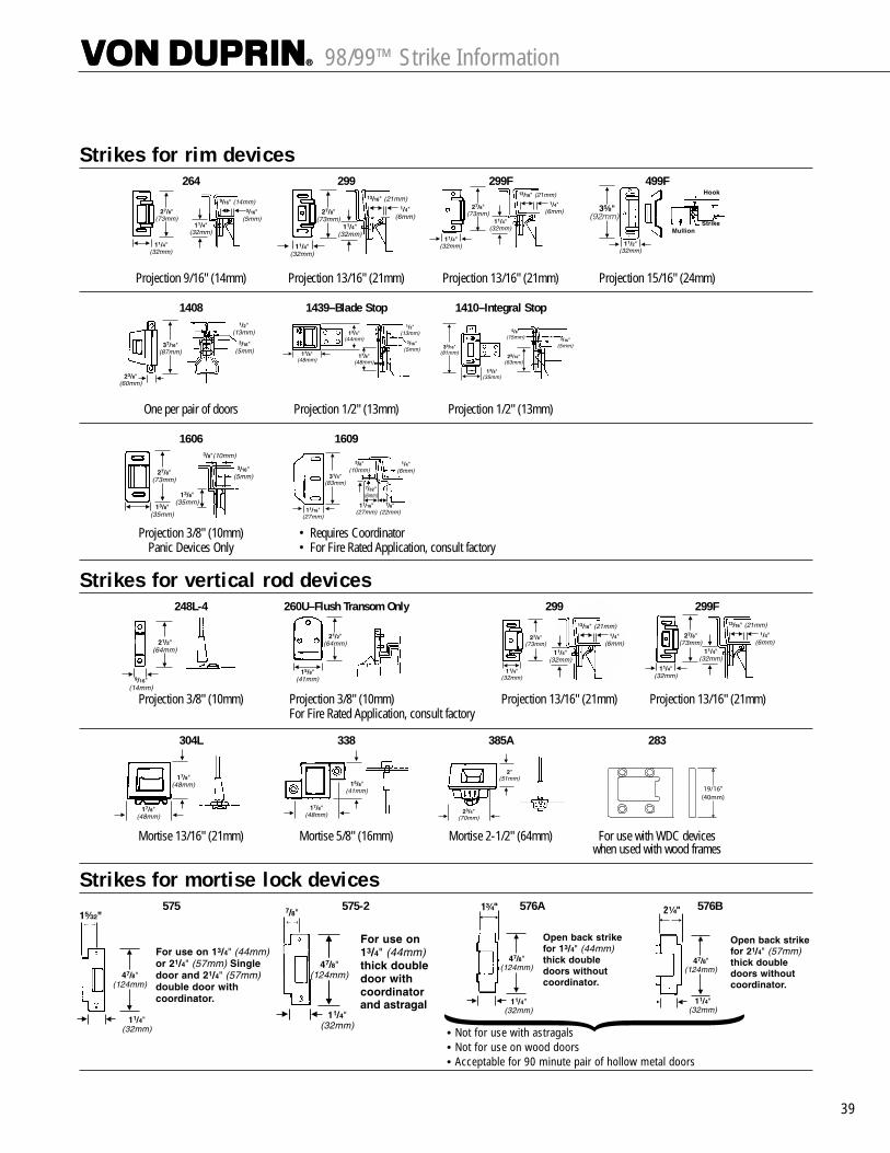
39
98/99™ Strike Information
Strikes for rim devices264 299 299F 499F
Projection 9/16" (14mm) Projection 13/16" (21mm) Projection 13/16" (21mm) Projection 15/16" (24mm)
1408 1439–Blade Stop 1410–Integral Stop
One per pair of doors Projection 1/2" (13mm) Projection 1/2" (13mm)
1606 1609
Projection 3/8" (10mm) • Requires CoordinatorPanic Devices Only • For Fire Rated Application, consult factory
Strikes for vertical rod devices248L-4 260U–Flush Transom Only 299 299F
Projection 3/8" (10mm) Projection 3/8" (10mm) Projection 13/16" (21mm) Projection 13/16" (21mm)For Fire Rated Application, consult factory
304L 338 385A 283
Mortise 13/16" (21mm) Mortise 5/8" (16mm) Mortise 2-1/2" (64mm) For use with WDC deviceswhen used with wood frames
Strikes for mortise lock devices575 575-2 576A 576B
• Not for use with astragals• Not for use on wood doors• Acceptable for 90 minute pair of hollow metal doors

40 © 2004 Ingersoll-Rand. May be copied for use with specification submittal.
Grade, Type, Function Options and Dimensions
ANSI Grade, Type & FunctionFunction Grade 1, Type 1 Grade 1, Type 2 Grade 1, Type 3 Grade 1, Type 7 Grade 1, Type 8 Grade 1, Type 9
98EO, 98EO-F 9827EO, 9827EO-F 9875EO, 9875EO-F 9847WDC-EO & EO-F 9847EO, 9848EO-F 9857EO, 9857EO-F99EO, 99EO-F 9927EO, 9927EO-F 9975EO, 9975EO-F 9947WDC-EO & EO-F 9947EO, 9947EO-F 9957EO, 9957EO-F
98DT 9827DT 9875DT 9847WDC-DT* 9848DT 9857DT99DT 9927DT 9975DT 9947WDC-DT 9948DT 9957DT
98NL, 98NL-F 9827NL, 9827NL-F 9875NL, 9875NL-F 9847WDC-NL & NL-F 9847NL, 9847NL-F 9857NL, 9857NL-F99NL,99NL-F 9927NL, 9927NL-F 9975NL, 9975NL-F 9947WDC-NL & NL-F 9947NL, 9947NL-F 9957NL, 9957NL-F
98TP, 98TP-F 9827TP, 9827TP-F 9875TP, 9875TP-F 9847WDC-TP & TP-F 9847TP, 9847TP-F 9857TP, 9857TP-F99TP, 99TP-F 9927TP, 9927TP-F 9975TP, 9975TP-F 9947WDC-TP & TP-F 9947TP, 9947TP-F 9957TP, 9957TP-F
98TP-2, 98TP-F-2 –– –– –– –– ––99TP-2, 99TP-F-2 –– –– –– –– ––
98K, 98K-F 9827K, 9827K-F 9875K, 9875K-F 9847WDC-K & WDC-K-F 9847K, 9847K-F 9857K, 9857K-F99K, 99K-F 9927K, 9927K-F 9975K, 9975K-F 9947WDC-K & WDC-K-F 9947K, 9947K-F 9957K, 9957K-F
98L, 98L-F 9827L, 9827L-F 9875L, 9875L-F 9847WDC-L & WDC-L-F 9847L, 9847L-F 9857L, 9857L-F99L, 99L-F 9927L, 9927L-F 9975L, 9975L-F 9947WDC-L & WDC-L-F 9947L, 9947L-F 9957L, 9957L-F
98K-NL, 98K-NL-F 9827K-NL, 9827K-NL-F 9875K-NL, 9875K-NL-F 9847WDC-K-NL & WDC-K-NL-F 9847K-NL, 9847K-NL-F 9857K-NL, 9857K-NL-F99K-NL, 99K-NL-F 9927K-NL, 9927K-NL-F 9975K-NL, 9975K-NL-F 9947WDC-K-NL & WDC-K-NL-F 9947K-NL, 9947K-NL-F 9957K-NL, 9957K-NL-F
98L-NL, 98L-NL-F 9827L-NL, 9827L-NL-F 9875L-NL, 9875L-NL-F 9847WDC-L-NL & WDC-L-NL-F 9847L-NL, 9847L-NL-F 9857L-NL, 9857L-NL-F99L-NL, 99L-NL-F 9927L-NL, 9927L-NL-F 9975L-NL, 9975L-NL-F 9947WDC-L-NL & WDC-L-NL-F 9927L-NL, 9947L-NL-F 9957L-NL, 9957L-NL-F
98K-2, 98K-F-2 –– –– –– –– ––99K-2, 99K-F-2 –– –– –– –– ––
98K-2, 98K-F-2 –– –– –– –– ––99K-2, 99K-F-2 –– –– –– –– ––
–– 9827TL, 9827TL-F –– 9847WDC-TL & TL-F 9847TL, 9847TL-F –––– 9927TL, 9927TL-F –– 9947WDC-TL & TL-F 9947TL, 9947TL-F ––
01
02
03
05
07
08*
08
09*
09
10*
10
11-12
*Device is Grade 1, 991K trim is Grade 2.
Dimensions

UL Listing for Fire Exit Hardware
41
UL Listed Fire Exit Hardware Label and Opening SizeDouble Door
With 9954 With 9854 With KR9954 With KR9854 VR/VR VR/Mortise VR/VRExit Device Door Material Single Door Mullion Mullion Mullion Mullion Same Direction Same Direction Double Egress
98-F 3 Hour 3 Hour 3 Hour 3 Hour 3 Hour99-F 4’ x 10’ 8’ x 10’ 8’ x 10’ 8’ x 8’ 8’ x 8’
9875-F 3 Hour 3 Hour9975-F 4’ x 10’ 8’ x 10’9827-F 90 Minute* 3 Hour 3 Hour9927-F 8’ x 10’ 8’ x 10’ 8’ x 10’
9827LBR-F 90 Minute* 3 Hour9927LBR-F 8’ x 10’ 8’ x 10’
9857-F 3 Hour 3 Hour 3 Hour 3 Hour 3 Hour9957-F 4’ x 8’ 8’ x 8’ 8’ x 8’ 8’ x 8’ 8’ x 8’9847-F 90 Minute* 3 Hour 3 Hour9947-F 8’ x 10’ 8’ x 10’ 8’ x 10’
9847LBR-F 90 Minute* 3 Hour9947LBR-F 8’ x 10’ 8’ x 10’
9848-F 90 Minute* 3 Hour 3 Hour9948-F 8’ x 10’ 8’ x 10’ 8’ x 10’
Metal –– –– ––
Metal –– –– –– –– –– ––
Metal –– –– –– –– ––
Metal –– –– –– –– –– ––
Metal –– –– ––
Metal –– –– — –– ––
Metal –– –– –– –– –– ––
Metal –– –– –– –– ––
* Currently, no door manufacturers offer a listing over 90 minutes with doors swinging same direction.
Consult wood door manufacturers for current UL listings.

42 © 2004 Ingersoll-Rand. May be copied for use with specification submittal.
98/99™ Electrical Options
Alarm Kit – ALK
The ALK battery alarm kit is a simple yet effective way to deterunauthorized use of an opening. While the exit device is still a means ofegress, the ALK kit contains an internal horn. When the touch bar isdepressed, the horn sounds to provide an audible means of signalingthat the opening has been violated. The alarm kit can be armedor disarmed by key. Thus allowing the exit device to be set in an armedor disarmed mode. The horn is rated at 85 decibel.
The key switch uses a standard 1¹�₄" (32mm) mortise cylinder with a straight cam (Schlage Cam reference B502-191). The unit operates on one standard 9-volt alkaline battery. When the battery is weak, the horn will emit an intermittent low battery alert signal.
Also can be powered using the PS9 Power Supply. See PS9 for additional information.
Alarm kits are available with a choice of two switch kits, RX or LX. RXmonitors the touchpad and is furnished standard. LX optional latch boltmonitoring is recommended for use with surface vertical rod exitdevices. Specify ALK-LX.
Note: For latch bolt monitoring on a 98/9975 with ALK, specify a SS7500 lock. LX switch not available for 98/9975 devices.
The ALK is available in two styles, 33A/99ALK, grooved cover and35A/98ALK, smooth cover.
The ALK includes “EMERGENCY EXIT ONLY. ALARM WILL SOUND”decal for application on door, or the SS push bar trim can be usedinstead of the door decal,specify SS push bar trim.
The ALK is available with 2 optional circuit boards. External Inhibit (EI)allows for the use of external switch to be used to arm, disarm and resetthe alarm. Auto Reset (AR) rearms the alarm after a preset time. AR isavailable in three factory set times – 1¹�₂, 3 or 6 minutes.
To Order, Specify:1. External Inhibit – ALK-EI2. Auto Reset – ALK-AR3
When the ALK is used, standard dogging is removed. If cylinder doggingis required there are two choices. Special center case dogging is availableor for 3’ or 4’ doors the ALK can be moved to the hinge side of the deviceand standard cylinder dogging can be added.
To Order, Specify:1. Standard, 98NL ALK2. Cylinder Dogging, CD98NL ALK3. Special Center Case Dogging, SD98NL ALK
Minimum Door Opening Sizes on ALK Applications
Device 3' (914mm) 4' (1219mm)Length Length
98/98-F/99/99-F 2'9" (838mm) 3'3" (991mm)9875/9875-F/9975/9975-F 2'9" (838mm) 3'3" (991mm)9827/9827-F/9927/9927-F 2'8" (813mm) 3'2" (966mm)9857/9857-F/9957/9957-F 2'8" (813mm) 3'2" (966mm)9847/9847-F/9947/9947-F 2'8" (813mm) 3'2" (966mm)9848/9848-F/9948/9948-F 2'8" (813mm) 3'2" (966mm)
Request to Exit — RX
The RX (Request to Exit) feature is used to signal the use of an opening.This device is equipped with one internal SPDT switch which monitors the pushpad.
The device can be connected to a security console, or may be used as asingle door alarm when used with a horn and power supply. A continuouscurrent electric transfer must be used for transferring power from theframe to the door.
The RX switch option should not be used to control a load, but as asignalling switch (0.5 amps. resisitive maximum).
The RX switch is available in a low current (LC) switch. Most commonlyused in computer operated monitoring systems.
To Order, Specify:• Standard – Use prefix RX, example RX99EO• Low Current – Use prefix RX-LC, example RX-LC98EO
Double Request to Exit — RX2The RX2 feature uses 2 RX switches. Also available with the Low Current(LC) switch.
To Order, Specify:• Standard – Use prefix RX2, example RX299EO• Low Current – Use prefix RX2-LC, example RX2-LC98EO
Latch Bolt Monitoring — LX
The LX feature is used to signal the use of an opening. This device isequipped with one internal SPDT switch which monitors the latch bolt. The device can be connected to a security console, or may be used as asingle door alarm when used with a horn and power supply. A continuouscurrent electric transfer must be used for transferring power from theframe to the door.
The LX switch option should not be used to control a load, but as asignalling switch (0.5 amps. resistive maximum).
The LX switch is available in a low current (LC) switch. Most commonlyused in computer operated monitoring systems.
To Order, Specify:• Standard – Use prefix LX, example LX99EO• Low Current – Use prefix LX-LC, example LX-LC98EO
Electrical Rating for all Switches:• Standard – up to 0.5 Amp @ 24VDC Maximum• Low Current (LC) - up to .05 Amp @ 24VDC Maximum
Note: All Switches can be either factory or field installed
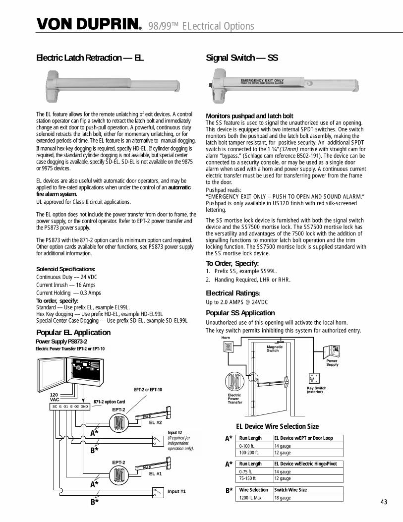
4343
98/99™ ELectrical Options
Electric Latch Retraction — EL
The EL feature allows for the remote unlatching of exit devices. A controlstation operator can flip a switch to retract the latch bolt and immediatelychange an exit door to push-pull operation. A powerful, continuous dutysolenoid retracts the latch bolt, either for momentary unlatching, or forextended periods of time. The EL feature is an alternative to manual dogging.If manual hex-key dogging is required, specify HD-EL. If cylinder dogging isrequired, the standard cylinder dogging is not available, but special centercase dogging is available, specify SD-EL. SD-EL is not available on the 9875or 9975 devices.
EL devices are also useful with automatic door operators, and may beapplied to fire-rated applications when under the control of an automaticfire alarm system.UL approved for Class II circuit applications.
The EL option does not include the power transfer from door to frame, thepower supply, or the control operator. Refer to EPT-2 power transfer andthe PS873 power supply.
The PS873 with the 871-2 option card is minimum option card required.Other option cards available for other functions, see PS873 power supplyfor additional information.
Solenoid Specifications:Continuous Duty –– 24 VDCCurrent Inrush –– 16 AmpsCurrent Holding –– 0.3 AmpsTo order, specify:Standard –– Use prefix EL, example EL99L.Hex Key dogging –– Use prefix HD-EL, example HD-EL99LSpecial Center Case Dogging –– Use prefix SD-EL, example SD-EL99L
Popular EL Application
Signal Switch — SS
Monitors pushpad and latch boltThe SS feature is used to signal the unauthorized use of an opening.This device is equipped with two internal SPDT switches. One switchmonitors both the pushpad and the latch bolt assembly, making thelatch bolt tamper resistant, for positive security. An additional SPDTswitch is connected to the 1 ¹�₄" (32mm) mortise with straight cam foralarm “bypass.” (Schlage cam reference B502-191). The device can beconnected to a security console, or may be used as a single dooralarm when used with a horn and power supply. A continuous currentelectric transfer must be used for transferring power from the frameto the door. Pushpad reads:“EMERGENCY EXIT ONLY – PUSH TO OPEN AND SOUND ALARM.”Pushpad is only available in US32D finish with red silk-screenedlettering.
The SS mortise lock device is furnished with both the signal switchdevice and the SS7500 mortise lock. The SS7500 mortise lock hasthe versatility and advantages of the 7500 lock with the addition ofsignalling functions to monitor latch bolt operation and the trimlocking function. The SS7500 mortise lock is supplied standard withthe SS mortise lock device.
To Order, Specify:1. Prefix SS, example SS99L.2. Handing Required, LHR or RHR.
Electrical Ratings:Up to 2.0 AMPS @ 24VDC
Popular SS ApplicationUnauthorized use of this opening will activate the local horn.The key switch permits inhibiting this system for authorized entry.
Power Supply PS873-2
120VAC
EL #2
EL #1
SC I1 O1 I2 O2 GNDEPT-2
EPT-2
Input #2(Required forindependentoperation only).
Input #1
A*
A*
B*
B*
Run Length EL Device w/EPT or Door Loop
0-100 ft. 14 gauge100-200 ft. 12 gauge
Run Length EL Device w/Electric Hinge/Pivot
0-75 ft. 14 gauge75-150 ft. 12 gauge
EL Device Wire Selection Size
Wire Selection Switch Wire Size
1200 ft. Max. 18 gauge
A*
A*
B*
EPT-2 or EPT-10
871-2 option Card
Input #2(Required for independent operation only).
Electric Power Transfer EPT-2 or EPT-10
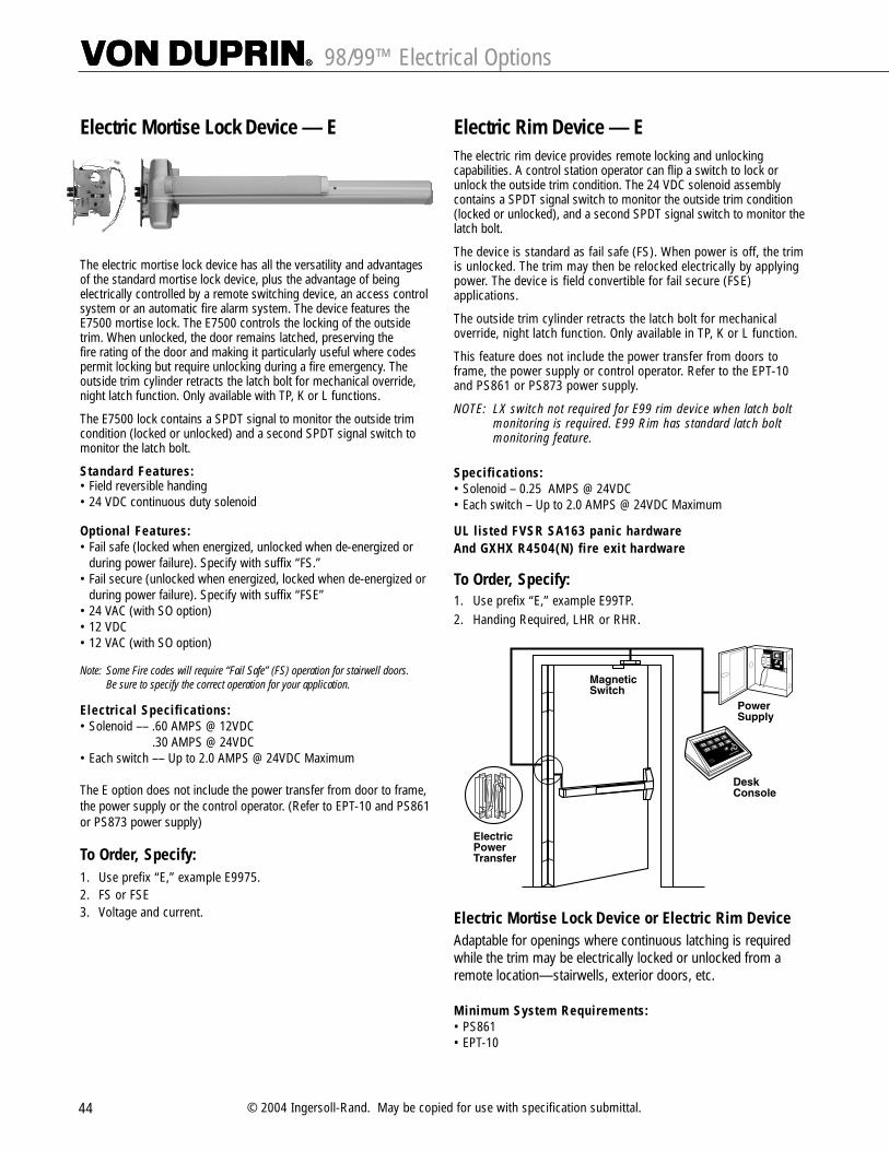
44 © 2004 Ingersoll-Rand. May be copied for use with specification submittal.
98/99™ Electrical Options
Electric Mortise Lock Device — E
The electric mortise lock device has all the versatility and advantagesof the standard mortise lock device, plus the advantage of beingelectrically controlled by a remote switching device, an access controlsystem or an automatic fire alarm system. The device features theE7500 mortise lock. The E7500 controls the locking of the outsidetrim. When unlocked, the door remains latched, preserving the fire rating of the door and making it particularly useful where codespermit locking but require unlocking during a fire emergency. Theoutside trim cylinder retracts the latch bolt for mechanical override,night latch function. Only available with TP, K or L functions.
The E7500 lock contains a SPDT signal to monitor the outside trimcondition (locked or unlocked) and a second SPDT signal switch tomonitor the latch bolt.
Standard Features:• Field reversible handing• 24 VDC continuous duty solenoid
Optional Features:• Fail safe (locked when energized, unlocked when de-energized or
during power failure). Specify with suffix “FS.”• Fail secure (unlocked when energized, locked when de-energized or
during power failure). Specify with suffix “FSE”• 24 VAC (with SO option)• 12 VDC • 12 VAC (with SO option)
Note: Some Fire codes will require “Fail Safe” (FS) operation for stairwell doors. Be sure to specify the correct operation for your application.
Electrical Specifications:• Solenoid –– .60 AMPS @ 12VDC
.30 AMPS @ 24VDC• Each switch –– Up to 2.0 AMPS @ 24VDC Maximum
The E option does not include the power transfer from door to frame,the power supply or the control operator. (Refer to EPT-10 and PS861or PS873 power supply)
To Order, Specify:1. Use prefix “E,” example E9975.2. FS or FSE3. Voltage and current.
Electric Rim Device — EThe electric rim device provides remote locking and unlockingcapabilities. A control station operator can flip a switch to lock orunlock the outside trim condition. The 24 VDC solenoid assemblycontains a SPDT signal switch to monitor the outside trim condition(locked or unlocked), and a second SPDT signal switch to monitor thelatch bolt.
The device is standard as fail safe (FS). When power is off, the trimis unlocked. The trim may then be relocked electrically by applyingpower. The device is field convertible for fail secure (FSE)applications.
The outside trim cylinder retracts the latch bolt for mechanicaloverride, night latch function. Only available in TP, K or L function.
This feature does not include the power transfer from doors toframe, the power supply or control operator. Refer to the EPT-10and PS861 or PS873 power supply.
NOTE: LX switch not required for E99 rim device when latch boltmonitoring is required. E99 Rim has standard latch bolt monitoring feature.
Specifications:• Solenoid – 0.25 AMPS @ 24VDC• Each switch – Up to 2.0 AMPS @ 24VDC Maximum
UL listed FVSR SA163 panic hardwareAnd GXHX R4504(N) fire exit hardware
To Order, Specify:1. Use prefix “E,” example E99TP.2. Handing Required, LHR or RHR.
Electric Mortise Lock Device or Electric Rim DeviceAdaptable for openings where continuous latching is requiredwhile the trim may be electrically locked or unlocked from aremote location—stairwells, exterior doors, etc.
Minimum System Requirements:• PS861• EPT-10
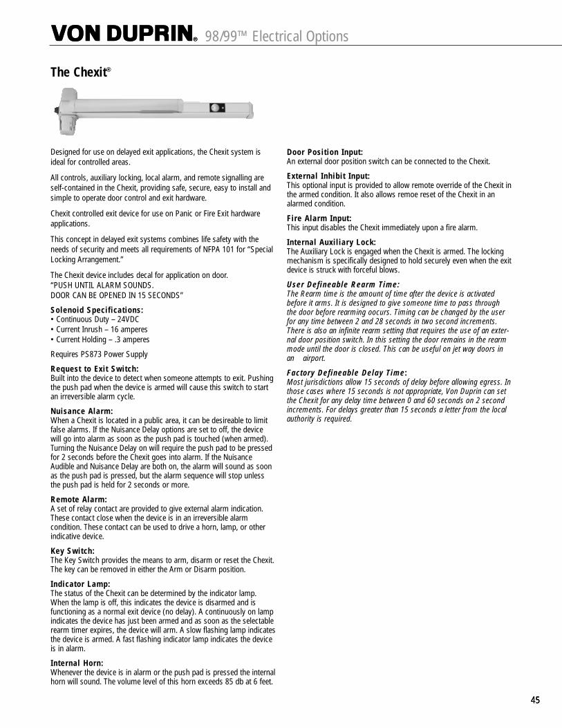
454545
98/99™ Electrical Options
The Chexit®
Designed for use on delayed exit applications, the Chexit system isideal for controlled areas.
All controls, auxiliary locking, local alarm, and remote signalling areself-contained in the Chexit, providing safe, secure, easy to install andsimple to operate door control and exit hardware.
Chexit controlled exit device for use on Panic or Fire Exit hardwareapplications.
This concept in delayed exit systems combines life safety with theneeds of security and meets all requirements of NFPA 101 for “SpecialLocking Arrangement.”
The Chexit device includes decal for application on door. “PUSH UNTIL ALARM SOUNDS. DOOR CAN BE OPENED IN 15 SECONDS”
Solenoid Specifications:• Continuous Duty – 24VDC• Current Inrush – 16 amperes• Current Holding – .3 amperes
Requires PS873 Power Supply
Request to Exit Switch:Built into the device to detect when someone attempts to exit. Pushingthe push pad when the device is armed will cause this switch to startan irreversible alarm cycle.
Nuisance Alarm:When a Chexit is located in a public area, it can be desireable to limitfalse alarms. If the Nuisance Delay options are set to off, the devicewill go into alarm as soon as the push pad is touched (when armed).Turning the Nuisance Delay on will require the push pad to be pressedfor 2 seconds before the Chexit goes into alarm. If the NuisanceAudible and Nuisance Delay are both on, the alarm will sound as soonas the push pad is pressed, but the alarm sequence will stop unlessthe push pad is held for 2 seconds or more.
Remote Alarm:A set of relay contact are provided to give external alarm indication.These contact close when the device is in an irreversible alarmcondition. These contact can be used to drive a horn, lamp, or otherindicative device.
Key Switch:The Key Switch provides the means to arm, disarm or reset the Chexit.The key can be removed in either the Arm or Disarm position.
Indicator Lamp:The status of the Chexit can be determined by the indicator lamp.When the lamp is off, this indicates the device is disarmed and isfunctioning as a normal exit device (no delay). A continuously on lampindicates the device has just been armed and as soon as the selectablerearm timer expires, the device will arm. A slow flashing lamp indicatesthe device is armed. A fast flashing indicator lamp indicates the deviceis in alarm.
Internal Horn:Whenever the device is in alarm or the push pad is pressed the internalhorn will sound. The volume level of this horn exceeds 85 db at 6 feet.
Door Position Input:An external door position switch can be connected to the Chexit.
External Inhibit Input:This optional input is provided to allow remote override of the Chexit inthe armed condition. It also allows remoe reset of the Chexit in analarmed condition.
Fire Alarm Input:This input disables the Chexit immediately upon a fire alarm.
Internal Auxiliary Lock:The Auxiliary Lock is engaged when the Chexit is armed. The lockingmechanism is specifically designed to hold securely even when the exitdevice is struck with forceful blows.
User Defineable Rearm Time:The Rearm time is the amount of time after the device is activatedbefore it arms. It is designed to give someone time to pass throughthe door before rearming oocurs. Timing can be changed by the userfor any time between 2 and 28 seconds in two second increments.There is also an infinite rearm setting that requires the use of an exter-nal door position switch. In this setting the door remains in the rearmmode until the door is closed. This can be useful on jet way doors inan airport.
Factory Defineable Delay Time:Most jurisdictions allow 15 seconds of delay before allowing egress. Inthose cases where 15 seconds is not appropriate, Von Duprin can setthe Chexit for any delay time between 0 and 60 seconds on 2 secondincrements. For delays greater than 15 seconds a letter from the localauthority is required.

46 © 2004 Ingersoll-Rand. May be copied for use with specification submittal.
98/99™ Electrical Accessories
Power Supplies
SERIES PS873The series PS873 power supply is designed to operate a widevariety of electrical products. EL panics require 871-2 PCB minimum. The regulated output power is field selectable foreither 24VDC @ 2 ampere or 12VDC @ 4 ampere. Standardinput 120VAC @ 1.0 ampere or 240VAC @ 0.5 ampere available.Enclosure is 10" high x 12 1⁄2" wide x 5" deep (254mm x 323mmx 127mm), gray with a hinged cover and constructed of heavy19 gauge steel. Five 1⁄2" x 3⁄4" (13mm x 19mm) knockout holesare provided for conduit connection. Terminal block will accept up to 12 gauge wire.
The PS873 can be ordered with three standard options: Keylock secures the cover to eliminate tampering and providessafety; Battery backup provides two hours backup power at fullload during a A.C. power failure. Batteries will automaticallyrecharge when failed power is restored. Fire Alarm providesinput for a normally closed fire alarm contact. When the firealarm contact is “open”, power to locks or other component isremoved. Restoring power is field selectable for automatic or manual.
Eight standard configurations:PS873 StandardPS873K With keylockPS873B With batteryPS873BK With battery and keylockPS873FA With fire alarmPS873K-FA With keylock and fire alarmPS873B-FA With battery and fire alarmPS873BK-FA With battery, keylock and fire alarm
The series PS873 is available with several optional circuit cardsto provide system flexibility. The power supply will accept oneor a combination of any two cards.
Factory or Field Installed Circuit Cards:
871-2, Two Zone controller provides two inputs and twooutputs. Will operate one or two EL exit devices. Use suffix “-2”for factory installed, example PS873-2.
873-AL, Alarm function monitors 1 or 2 zones and providesalarm output, upon detecting a door in the open position.Delayed alarming is selectable from 5 to 75 seconds. Use suffix“-AL” for factory installed, example PS873-AL
873-AO, Auto Operator function coordinates the release of oneor two locks and signals an auto-operator to open a door.Signaling the auto operator can be performed in two methods;by receiving a signal from a monitoring switch that the lock isunlatched, or upon expiration of a time delay triggered by a“RX” type input switch. Use suffix “-AO” for factory installed,example PS873-AO
873-SI, Security/Safety Interlock provide interlock function fortwo zones. When combined with a second 873-SI card, theinter-locking of groups are available in two, three or four zones.Safety interlock is available, consult factory for additional information. Use suffix “-SI” for factory installed, examplePS873-SI
873-4TD, Four Zone controller with Time Delay provides fourinputs and four outputs with time delay. Time delay is fieldselectable from 0 to 75 seconds, in intervals of 5 seconds. Willoperate up to 4 EL devices. Use suffix “-4TD” for factoryinstalled, example PS873-4TD
873-AC, Access Control provides supervision of one zone usingan electromagnetic lock. Input signals required are: access control contact, motion detector contact, and motion detectoroverride contact. FA, Fire Alarm option is required. Use suffix “-AC”for factory installed, example PS873-AC
Factory Installed Only Circuit Card
873-DE, Delayed Egress provides 15 second delay release frompushbar activation to electro-magnetic lock release. Idealfunction for use with Locknetics electromagnetic locks, willoperate two zones simultaneously. To operate two separatezones, a second 873-DE card is required. UL listed component,when used as part of a Von Duprin delayed egress system. Usesuffix “- DE”, example, PS873-DE.Note: “DE” cards CANNOT be combined with any other optional cards.
Electrical Accessories

47474747
Power SuppliesPS861 Power Supply
StandardUL ListedClass 2, Power SupplyUL1012UL1310
The series PS861 power supply is designed for electric locking or monitoring on single or double door applications. The output power isfield selectable for either 24 VDC @ 1 ampere or 12 VDC @ 2 ampere.Standard input 120 VAC @ 0.6 ampere and 240 VAC @ 3.0 ampere available. The terminal block will accept up to 14 gauge stranded wire.
The gray enclosure is 10" x 10" x 4" (254mm x 254mm x 102mm), has ahinged cover, and is constructed of heavy 19 gauge steel. Six ¹�₂" (13mm)knockout holes are provided for conduit connection.
Options include keylock cover or Battery Backup. The pair of batteries,which are sealed lead acid battery packs, will provide back-up power forthree hours at full load or seven hours at half load. Batteries will automati-cally recharge when failed power is restored.
Four Models:PS861 Standard supplyPS861K Standard supply
with keylock coverPS861B Battery backupPS861FA Fire AlarmPS861BK Battery backup and
keylock coverPS861BKFA Battery backup and
keylock cover withFA board (24VDC only)
PS9 Power SupplyThe PS9 is an AC power supply that provides 9 VDC power to operatethe ALK alarm kit. The unit will power one or two alarm kits. Included isa 9-volt sealed battery that provides backup power in case of an ACpower failure.
Electrical Power Transfer –– EPTPneumatic Transfer – PNT
Electric Power Transfer provides a means of transferring electrical powerfrom a door frame to the edge of a swinging door. The units arecompletely concealed when the door is in the closed position, and areideally suite for installations involving abuse or heavy traffic.
Two models are available; EPT-2, two 18 gauge wires and EPT-10, ten 24 gauge wires. The EPT-2 and EPT-10 are U/L listed as“miscellaneous door accessory”.
Pneumatic ControlsPNT-1 is available for pneumatic latch retraction exit devices.Appearance and dimensions are identical to EPT models.
UL Listed for use on firedoors
Door applications:up to 5" butt hinges – 180 ̊swing, 5 ¹�₂" butt hinges – 130 ̊swing, 6" butt hinges – 110 ̊swing,³�₄" butt offset pivots 180˚ swing.
Not for use with swing clear hinges or center-hung pivots.
FinishesSP28 (sprayed aluminum) SP313 (sprayed duranodic).
DimensionsHousing 9" x 1 ¹�₄" x 1 ⁵�₈" (229mm x 32mm x 38mm)EPT-2 Two 18 gauge wires,
Up to 2 AMPS @ 24VDC, with a 16 AMPS Maximum Surge
EPT-10 Ten 24 gauge wires, Up to 1 AMPS @ 24VDC, with a16 AMPS Maximum Surge
PNT-1 ⁵�₃₂" Tubing
To order, specify:1. EPT-2 ,EPT-10 or PNT-1.2. Finish, SP28 or SP313.
98/99™ Electrical Accessories
Electrical Accessories

48 © 2004 Ingersoll-Rand. May be copied for use with specification submittal.
Pneumatic Controlled Exit Devices–PN
The PN feature provides remote latch bolt retraction in hazardous areaswhere electrically operated devices would not be permitted. Thepneumatic solenoid will retract the latch bolt for momentary orprolonged periods. PN exit devices are particularly suited for use withautomatic door operators. The PN feature is available on both Panic andFire Exit Hardware devices.
The PN feature includes a special actuating linkage that gives buildingowners the option of mechanically or pneumatically dogging the exitdevice. If manual hex-key dogging is required, specify HD-PN (Doggingthe device, whether mechanically or pneumatically, makes the devicefunction as a push/pull unit and reduces the wear on its moving parts.)If cylinder dogging is required, the standard cylinder dogging is notavailable, but special center case dogging is available, specify SD-PN.SD-PN is not available on the 9875 or 9975 devices.
When activated pneumatically, the latch bolt(s) of the exit device retractin ¹�₂ to 1 ¹�₂ seconds. This pneumatic operation uses air pressure ranging from 50 to 100 pounds per square inch.
This product will function only when it is part of a pneumatic system(air compressor, air lines, pneumatic system, etc.). Contact LCN for correct control boxes
To Order, Specify:• Standard –– Use prefix PN, example PN99NL• Hex Key Dogging –– Use prefix HD-PN, example HD-PN99NL• Special Center Case Dogging –– Use prefix SD-PN,
example SD-PN99NL
Double Cylinder – 2
Double cylinder features an inside key cylinder which locks or unlocksthe outside trim and an outside key cylinder which retracts the latch boltonly(Night Latch Function) . Available on rim or mortise lock device.
Rim requires two rim type cylinders. Mortise device requires 1 rimcylinder and 1 mortise cylinder 1¹�₄" with a straight cam. (Schlage camreference B502-191.)
Available functions are thumbpiece, knob or lever.
To Order, Specify:1. Suffix-2 with device/trim number, example 99TP-2.2. Handing required, LHR or RHR.
Less Dogging – LDLess Dogging is available in all 98/99™ Panic Exit devices to remove thedogging option.
To Order, Specify:• Use prefix LD, example LD99L
Special Center Case Dogging – SD
Special cylinder dogging in the center case is available for Chexit, EL, ALKpanic devices to allow for mechanical push/pull operation. With this option,the latchbolt is held retracted and pushbar is still operable. Specifyhanding –– RHR or LHR.
SD requires 1 ¹�₄" (32mm) mortise cylinder with a straight cam. (Schlagecam reference B502-191.)
Note: Available on Rim and Vertical Rod Panic Exit Devices only.
To Order, Specify:• Use prefix SD, example SD99L
Cylinder Dogging — CDCylinder dogging is available on all 98/99™ Panic Exitdevices to replace the standard hex key dogging. Unitrequires a standard 1¹�₄" (32mm) mortise cylinderwith a straight cam (Schlage Cam B502-191reference).
To Order, Specify:• Use prefix, CD, example CD99L
Cylinder Dogging Kit — CDKFor field conversion, a cylinder dogging conversion kit is available.Cannot be added to fire exit hardware.
Order: 33A/99CDK or 35A/98CDK, specify finish.
Hex Key Dogging Kit — HDKFor field conversion, a hex key dogging conversion kit is available.Cannot be added to fire exit hardware.
Order: 33A/99HDK or 35A/98HDK, specify finish.
Braille, Embossed and Knurled Touchpads
Braille touchpad is embossed with the message “CAUTIONSTAIRWELL” in braille and raised letters provides assistance to personwith impaired vision. Letters are ¹�₂" (13mm) high and braille is #2,raised height is ³�₃₂" (2mm). Other messages are available on specialorder, limited to 20 characters per line.
Embossed touchpad is embossed with the word “PUSH”Knurled touchpad is to provide warning to person with impaired vision.
98/99™ Options

49494949
98/99™ Options & Accessories
Vertical Rod and Latch Guard — RG-27Series RG-27 Vertical Rod and Latch Guards protectthe bottom rods of exit devices from the damagingimpacts of carts or gurneys passing through doors.(If bottom rods become damaged, the exit devicewill not function as intended and can jeopardize theability to exit safely during an emergency.)
In addition to protecting the vertical rod, the guardprovides a smooth, unobstructed surface so thedoor can be pushed open easily with the bumpersof a wheelchair. The latch guard portion is 10" high.The standard latch guard features a 45° ramp. Theextended latch guard offers a continuous ramp in 3' or 4' widths.
All stainless steel construction in US32D finish.Latch guards can cover latches as large as 1¹�₄"W x 10"H x 1⁷�₈" projection.
ModelsRGO — Rod guard only (Projection 1 ³�₁₆").RG-27 — Rod and latch guard.RG-27-3 — 3' (914mm) Rod Guard
and Extended Latch Guard.RG-27-4 — 4' (1219mm) Rod Guard
and Extended Latch Guard.
Extended Latch Guard
LGO — Latch guard only.LGO-3 — 3' (914mm) Extended latch guard only. LGO-4 — 4' (1219mm) Extended latch guard only.
Note: Not for use on wood fire doors
To Order, Specify:1. Model number.2. Handing (except on RGO).3. Door material if other than Hollow Metal.4. Optional sex bolt mounting available.
Less Bottom Rod – LBRLBR option is available, using a spring loaded auxiliary latch boltinstalled in the lower door edge. When exposed to heat the auxiliarylatch bolt releases, keeping the doors in alignment and closed duringa fire. UL listed 3 hours on hollow metal doors double egress, 90minute swinging same direction, and 20 minutes wood doors(consult wood door manufacturer). Fits door stiles as narrow as 3⁵�₈".
LBR devices must be ordered in pairs or must be used inconjunction with an approved automatic or constant latching flushbolt.
Pullman Latch – PLWhen PL is specified the standard latches are replaced with pullmanstyle latches. Pullman latches are always extended and are mostcommonly used in conjunction with electric strikes and LBR-lessbottom rod application. Not available with Fire rated devices. Notrecommended where security is of the utmost since latches do notdeadlock.
Glass Bead Kit – GBKGlass bead conversion kits are available for all 98/99™ Series devicesfor use on doors with raised glass beads. Each kit consists of ¹�₄" (6mm)shim sets. GBK for Surface Vertical Rod ships with ¹�₈" shims for rodguides.
To order, specify:1. 99GBK2. Device type (Rim, Mortise, Surface Vertical Rod,
Concealed Vertical Rod)3. Wood Door, when used with Concealed Vertical Rod
997 Cover Plate Kit
36"
10´́
4 ³�₈"
33 ¹�₈" – 3' door45 ¹�₈" – 4' door
2 ¹�₄"
12"
Rod Guard
Latch Guard
For 99 rim device, kitcontains inside and outsideplates for hinge stilecutouts, an inside plate forthe lock stile, and necessaryscrews. Plates are designedto cover cutouts requiredby most existing exit deviceinstallations. Specify finish.

CylindersCylinders are not furnished with device or trim and must be specified when ordering. Refer to trim pages for cylinder type.
Mortise — 3215 (Schlage B502-191 cam) Rim 3216
50 © 2004 Ingersoll-Rand. May be copied for use with specification submittal.
98/99™ Accessories and Door Handing
Dogged (Inverted) Cam Undogged Cam(Standard Operations)
For Cylinder Dogging For Standard Trim Functions
Door Handing
Dummy Pushpad
The 330 dummy pushpad is designed as a companion unit for all 99 devices. The 350 dummy pushpad is a companion unit for all 98 devices. The pushpad is rigid or nonfunctioning. A push/pull operation can be accomplished by using 990DT, 996DT trim or any Ives Pull.
The 330/350 can be equipped with a functional pushpad and will accommodate an RX switch. Specify RX-330. May also be equipped with the RX2,double RX switch. Specify RX2-330
To order, specify:1. 330 or 350.
2. Size 3' or 4' (914mm or 1219mm)
3. Finish, US3, US4, US10, US26, US26D, US28, 313AN, 315AN, 350 Only US32D.
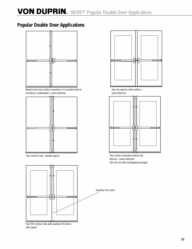
51515151
98/99™ Popular Double Door Applications
Mortise lock and surface mounted or Concealed Verticalrod device combination—same direction
Two vertical rods—double egress
Two rim devices with mullion—same direction
Two surface mounted vertical rod devices—same direction (do not use with overlapping astragal)
Popular Double Door Applications
Two FEH vertical rods with auxiliary fire latch—LBR option
Auxiliary Fire Latch

52 © 2004 Ingersoll-Rand. May be copied for use with specification submittal.
98/99™ Finishes
FinishesColor US Number BHMA Number A, B, E C D & F
Brass, Polished US3 605 Plated Brass, Polished US3, 605 Buffed Anodized
Brass, Satin US4 606 Plated Brass, Dull US4, 606 Anodized
Bronze, Satin US10 612 Plated/Anodized Bronze, Dull US10, 612 Anodized
Chrome, Polished US26 625 Plated Stainless Steel, Polished US32, 629 Buffed Anodized
Chrome, Satin US26D 626 Plated Stainless Steel, Satin US32D, 630 Anodized
Stainless Steel, Satin* US32D 630 Stainless Steel Stainless Steel, Satin US32D, 630 Anodized
Aluminum, Anodized US28 628 Powder Coat Stainless Steel, Satin US32D, 630 Anodized
Duranodic Dark Bronze 313AN 710 Powder Coat Brown Wrinkle Powder Coat Anodized
Black Anodized 315AN – Powder Coat Black Wrinkle Powder Coat Anodized
Special FinishesColor US Number BHMA Number A, B, E C D & F
Bronze, Oil-Rubbed Satin US10B 613 Plated Bronze, US10B, 613 Anodized
Powder Coat RAL # – Powder Coat Stainless Steel, Satin US32D, 630 Powder Coat
Bronze, Polished US9 611 Plated Bronze, Polished US9, 611 Buffed Anodized
Nickel, Satin US15 619 Plated Stainless Steel, Satin US32D Anodized
Touch Bar Trim Options:
KnurledEmbossed “Push” Braille, US32D Only, Embossed “Caution Stairwell”SS, US32D Only, Red silk screen lettered “EMERGENCY EXIT ONLY – PUSH TO OPEN AND SOUND ALARM.”*US32D Finish—available on Series 98 only
A. Center Case Cover
B. Touch Bar End Cap C. Touch Bar Trim
D. Cover Plate
F. Mechanism CaseE. Mechanism End Cap

5353535353
98/99™ Additional Information
Nomenclature – How To Order
SD –– Special Dogging - Panic OnlyCD — Cylinder Dogging - Panic OnlyCX –– ChexitE –– Electric Locking (Rim or Mortise)EL — Electric Latch RetractionLX — Latch Bolt MonitoringPL — Pullman LatchPN –– Pneumatic Latch RetractionRX — Request to ExitRX2 –– Double Request to ExitSS –– Signal Switch
98 — Series 98-smooth99 — Series 99-grooved
None — Rim Device27 — Surface Mounted Vertical Rod Device47 — Concealed Vertical Rod Device47WDC –– Concealed Vertical Rod Wood Door Device48 — Concealed Vertical Rod Device57 –– Three Point Latch Device75 –– Mortise Lock Device
DT — Dummy TrimEO — Exit OnlyK –– Knob (Classroom)K-BE –– Knob-Blank EscutcheoonK-DT –– Knob-Dummy TrimK-NL –– Rigid Knob - NightLatch (Key retracts Latchbolt)L — Lever (Classroom)L-BE –– Lever-Blank EscutcheonL-DT –– Lever-Dummy TrimL-NL –– Rigid Lever - Night Latch (Key retracts Latchbolt)NL –– Night Latch (Key retracts Latchbolt)NL-OP — Night Latch Cylinder Assembly –– Optional PullTL — Turn LeverTL-BE –– Turn Lever-Blank EscutcheonTP –– ThumbpieceTP-BE –– Thumbpiece-Blank Escutcheon
XX –– Lever Style 06 standardoptional –– 01, 02, 03, 05, 07, 12, 16, 17, 18
F — Fire Exit Device
LBR — Less Bottom Rod2 –– Double Cylinder (Rim & Mortise Only)ALK –– Standard Alarm KitALK-EI –– External Inhibit Alarm KitALK-AR1 –– Auto-Reset 1¹�₂ minute Alarm KitALK-AR3 –– Auto-Reset 3 minute Alarm kitALK-AR6 –– Auto-Reset 6 minute Alarm Kit
3’ –– 3’ Device (2’ 4” –– 3’ Door Size)4’ –– 4’ Device (2’ 10” –– 4’ Door Size)
US3, US4, US10, US26, US26D, 313AN, 315ANUS32D – 98 ONLY
– HR –– Handing – RHR or LHR
EL 99 27 -L -16 -F LBR 3’ US3 RHR

98/99™ Notes
54 © 2004 Ingersoll-Rand. May be copied for use with specification submittal.

©2004 Ingersoll-Rand Form VD-GN-1005 Rev. 2/04 Printed in USA
VON DUPRINAdministrative Offices2720 Tobey Dr.Indianapolis, IN 46219317-613-8944317-613-8302 Fax
Customer Service800-999-0408800-999-0328 Fax
Technical Support888-371-7331317-613-8509 Fax
Canada / Latin America
IR Security & Safety1076 Lakeshore Road EastMississauga, Ontario, L5E 1E4, Canada(905) 403-1800(905) 278-1413 FAX(877) 590-4734
North-East Asia
IR Security & Safety23/F, 625 King’s RoadNorthpoint, Hong Kong+(852) 2235-0600+(852) 2565-1409 FAX
South-East Asia / Australia / NZ
IR Architectural Hardware Ltd.P.O. Box 19-347437 Rosebank Road,Avondale, Auckland, New Zealand+64 (0) 9-829-0550+64 (0) 9-829-0552 FAXwww.irarchitecturalhardware.co.nz
Mexico
IR Security & SafetyBlvd. Centro Industrial No. 11Puentas de Vigag, TlalnepantlaEstado de Mexico, 54070 Mexico+525-5-8503-6614
Europe / Middle-East / Africa
IR Security & Safety Ltd.Bescot CrescentWalsall, West Midlands WS1 4DLUnited Kingdom+44 (0)1922 707400+44 (0)1922 646303 FAXwww.irsecurityandsafety.co.uk
Visit Von Duprin on the web
www.vonduprin.comor contact an
IR Security & Safety Consultant1-877-840-3621
International Offices
98/99™ Series Exit Devices