Embed Size (px)
Citation preview

Press Tool
WARNING!Read this Operator’s Manualcarefully before using thistool. Failure to understandand follow the contents ofthis manual may result inelectrical shock, fire and/orserious personal injury.
99 Washington Street Melrose, MA 02176 Phone 781-665-1400Toll Free 1-800-517-8431
Visit us at www.TestEquipmentDepot.com
ii
RP 210 Press Tool
Table of ContentsRecording Form For Machine Serial Number ............................................................................................................1
General Safety RulesWork Area Safety........................................................................................................................................................2Electrical Safety ..........................................................................................................................................................2Personal Safety ..........................................................................................................................................................3Power Tool Use And Care ..........................................................................................................................................3Battery Tool Use And Care ........................................................................................................................................3Service ........................................................................................................................................................................3
Specific Safety InformationPress Tool Safety........................................................................................................................................................4Battery And Charger Safety ........................................................................................................................................4
Description, Specifications And Standard EquipmentDescription ..................................................................................................................................................................4Specifications..............................................................................................................................................................5Standard Equipment ..................................................................................................................................................5
Tool Inspection..............................................................................................................................................................5
Tool And Work Area Set-Up ........................................................................................................................................6
Operating InstructionsPreparing The Connection ..........................................................................................................................................7Pressing A Fitting With Typical Scissor Jaws ............................................................................................................7Pressing A Fitting With Typical Actuator And Press Ring Set ....................................................................................8
Cold Weather Operation ..............................................................................................................................................9
Maintenance InstructionsCleaning And Lubrication..........................................................................................................................................10Required Maintenance At RIDGID Authorized Service Center ................................................................................10
Accessories ................................................................................................................................................................10
Storage ........................................................................................................................................................................10
Service And Repair ....................................................................................................................................................10
Disposal ......................................................................................................................................................................11
Machine Disposal ........................................................................................................................................................11
Troubleshooting ..........................................................................................................................................................11
RP 210 Diagnostic Codes ..........................................................................................................................................12
Lifetime Warranty ........................................................................................................................................Back Cover
Test Equipment Depot - 800.517.8431 - 99 Washington Street Melrose, MA 02176TestEquipmentDepot.com

RP 210 Press ToolRecord Serial Number below and retain product serial number which is located on nameplate.
SerialNo.
Press Tool
RP 210
Test Equipment Depot - 800.517.8431 - 99 Washington Street Melrose, MA 02176 - TestEquipmentDepot.com

2
RP 210 Press Tool
General Safety Rules*
WARNINGRead all safety warnings and instructions. Failure to followthe warnings and instructions may result in electric shock,fire and/or serious injury.
SAVE ALL WARNINGS AND INSTRUCTIONSFOR FUTURE REFERENCE!
The term "power tool" in the warnings refers to yourmains-operated (corded) power tool or battery-operated(cordless) power tool.
Work Area Safety• Keep your work area clean and well lit. Cluttered or
dark areas invite accidents.
• Do not operate power tools in explosive atmo-spheres, such as in the presence of flammableliquids, gases, or dust. Power tools create sparkswhich may ignite the dust or fumes.
• Keep children and by-standers away while oper-ating a power tool. Distractions can cause you to losecontrol.
Electrical Safety
• Power tool plugs must match the outlet. Never
modify the plug in any way. Do not use any adap-ter plugs with earthed (grounded) power tools.Unmodified plugs and matching outlets will reducerisk of electric shock.
• Avoid body contact with earthed or grounded sur-faces such as pipes, radiators, ranges and refrig-erators. There is an increased risk of electrical shockif your body is earthed or grounded.
• Do not expose power tools to rain or wet condi-tions. Water entering a power tool will increase the riskof electrical shock.
• Do not abuse the cord. Never use the cord forcarrying, pulling or unplugging the power tool.Keep cord away from heat, oil, sharp edges ormoving parts. Damaged or entangled cords increasethe risk of electric shock.
• When operating a power tool outdoors, use anextension cord suitable for outdoor use. Use of acord suitable for outdoor use reduces the risk of elec-tric shock.
• If operating a power tool in a damp location isunavoidable, use a ground fault circuit interrupter(GFCI) protected supply. Use of a GFCI reduces therisk of electric shock.
Safety SymbolsIn this operator’s manual and on the product, safety symbols and signal words are used to communicate important safe-ty information. This section is provided to improve understanding of these signal words and symbols.
This is the safety alert symbol. It is used to alert you to potential personal injury hazards. Obey all safety messages that follow thissymbol to avoid possible injury or death.
DANGER indicates a hazardous situation which, if not avoided, will result in death or serious injury.
WARNING indicates a hazardous situation which, if not avoided, could result in death or serious injury.
CAUTION indicates a hazardous situation which, if not avoided, could result in minor or moderate injury.
NOTICE indicates information that relates to the protection of property.
This symbol means read the operator’s manual carefully before using the equipment. The operator’s manual containsimportant information on the safe and proper operation of the equipment.
This symbol means always wear safety glasses with side shields or goggles when handling or using this equipment to reducethe risk of eye injury.
This symbol indicates the risk of hands, fingers or other body parts being crushed.
This symbol indicates the risk the electrical shock.
* The text used in the General Safety Rule section of this manual is verbatim, as required, from the applicable UL/CSA 60745 standard. This section containsgeneral safety practices for many different types of power tools. Not every precaution applies to every tool, and some do not apply to this tool.
NOTICE
DANGER
WARNING
CAUTION
Test Equipment Depot - 800.517.8431 - 99 Washington Street Melrose, MA 02176TestEquipmentDepot.com

Ridge Tool Company 3
Personal Safety
• Stay alert, watch what you are doing and use com-mon sense when operating a power tool. Do notuse a power tool while you are tired or under theinfluence of drugs, alcohol, or medication. A mo-ment of inattention while operating power tools mayresult in serious personal injury.
• Use personal protective equipment. Always weareye protection. Protective equipment such as dustmask, non-skid safety shoes, hard hat, or hearingprotection used for appropriate conditions will reducepersonal injuries.
• Prevent unintentional starting. Ensure the switchis in the off-position before connecting to powersource and/or battery pack, picking up or carryingthe tool. Carrying power tools with your finger on theswitch or energizing power tools that have the switchon invites accidents.
• Remove any adjusting key or wrench before turn-ing the power tool on. A wrench or a key left attachedto a rotating part of the power tool may result in per-sonal injury.
• Do not overreach. Keep proper footing and bal-ance at all times. This enables better control of thepower tool in unexpected situations.
• Dress properly. Do not wear loose clothing orjewelry. Keep your hair, clothing, and gloves awayfrom moving parts. Loose clothes, jewelry, or longhair can be caught in moving parts.
• If devices are provided for the connection of dustextraction and collection facilities, ensure these areconnected and properly used. Use of dust collectioncan reduce dust-related hazards.
Power Tool Use And Care• Do not force power tool. Use the correct power tool
for your application. The correct power tool will do thejob better and safer at the rate for which it is designed.
• Do not use power tool if the switch does not turn itON and OFF. Any power tool that cannot be con-trolled with the switch is dangerous and must berepaired.
• Disconnect the plug from the power source and/orthe battery pack from the power tool before mak-ing any adjustments, changing accessories, orstoring power tools. Such preventive safety mea-sures reduce the risk of starting the power tool acci-dentally.
RP 210 Press Tool
• Store idle power tools out of the reach of childrenand do not allow persons unfamiliar with the pow-er tool or these instructions to operate the powertool. Power tools are dangerous in the hands ofuntrained users.
• Maintain power tools. Check for misalignment orbinding of moving parts, breakage of parts and anyother condition that may affect the power tool’s op-eration. If damaged, have the power tool repairedbefore use. Many accidents are caused by poorlymaintained power tools.
• Keep cutting tools sharp and clean. Properly main-tained cutting tools with sharp cutting edges are lesslikely to bind and are easier to control.
• Use the power tool, accessories and tool bits etc.in accordance with these instructions, taking intoaccount the working conditions and the work to beperformed. Use of the power tool for operations dif-ferent from those intended could result in a hazardoussituation.
Battery Tool Use And Care
• Recharge only with the charger specified by themanufacturer. A charger that is suitable for one typeof battery pack may create a risk of fire when used withanother battery pack.
• Use power tools only with specifically designatedbattery packs. Use of any other battery packs maycreate a risk of injury and fire.
• When battery pack is not in use, keep it awayfrom other metal objects, like paper clips, coins,keys, nails, screws or other small metal objectsthat can make a connection from one terminal toanother. Shorting the battery terminals together maycause burns or a fire.
• Under abusive conditions, liquid may be ejectedfrom the battery; avoid contact. If contact acciden-tally occurs, flush with water. If liquid contactseyes, additionally seek medical help. Liquid ejectedfrom the battery may cause irritation or burns.
Service
• Have your power tool serviced by a qualified repairperson using only identical replacement parts.This will ensure that the safety of the power tool ismaintained.

Battery And Charger Safety WARNING
Read the battery charger manual before using thecharger or batteries. Failure to read, understand andfollow the contents of the charger manual mayresult in extensive property damage, severe per-sonal injury, or death.
• Charge batteries only in the appropriate batterycharger as specified in the charger manual. Othertypes of batteries or non-rechargeable batteries mayburst resulting in personal injury and damage.
• Do not probe battery with conductive objects.Shorting of battery terminals may cause sparks, burnsor electrical shock.
• Do not insert battery with cracked case into tool orcharger. Do not operate battery if it has been drop-ped or damaged in any way. Damaged batteryincreases the risk of electrical shock.
• Do not burn batteries for any reason. Batteriesexplode in fire.
• Charge batteries in temperatures above +41°F(+5°C) and below +113°F (45°C). Store tool andbattery pack in locations where temperatures willnot exceed +104°F (40°C). Proper care will preventserious damage to batteries. Improper care of batteriesmay result in battery leakage, electrical shock or burns.
• Do not allow anything to cover the charger while inuse. May result in fire.
• Unplug the charger when not in use. Reduces riskof injury to children and untrained persons.
• Do not charge battery in damp or wet environ-ment. Do not expose to rain or snow. Increases therisk of electrical shock.
• Do not open the charger. Have repairs done only byauthorized experts.
Description, SpecificationsAnd Standard EquipmentDescriptionThe RP 210 Press Tool, when used with appropriatejaws, is designed to mechanically press fittings onto tubingto create a water-tight and permanent seal. When theswitch on the RP 210 is depressed, an internal electricmotor powers a hydraulic pump which forces fluid intothe cylinder of the tool, forcing the ram forward and apply-ing thousands of pounds of pressing force onto speciallydesigned fittings. Attachments are also available for otheruses.
Specific Safety Information
WARNINGThis section contains important safety information that isspecific to this tool.
Read these precautions carefully before using the RP 210Press Tool to reduce the risk of electrical shock or seriouspersonal injury.
SAVE THESE INSTRUCTIONS!
A compartment in the RP 210 carrying case is included tokeep this manual with the machine for use by the operator.
Press Tool Safety
• Use the RP 210 Press Tool only with RIDGID Com-pact pressing attachments (jaws, press ring, actu-ator, etc.). Other uses or modifying the RP 210 PressTool for other applications may damage the presstool, damage the attachments and/or cause personalinjury.
• Keep your fingers and hands away from pressingattachments during press cycle. Your fingers orhands can be crushed, fractured or amputated if theybecome caught between the jaws or between thesecomponents and any other object.
• Never attempt to repair damaged jaws, press ring, actuator or other attachments. An attachment that has been welded, ground, drilled or modified in any manner can shatter during pressing resulting in serious injury. Discard the entire damaged jaws. Replace with new jaws. Never replace individual components except for damaged jaw return springs.
• Read and understand this operator’s manual, theattachment instructions, the fitting manufactur-er’s installation instructions and the instructionsfor any other equipment used with this tool beforeoperating the RP 210. Failure to follow all instructionsmay result in property damage and/or serious per-sonal injury.
4
RP 210 Press Tool
Test Equipment Depot - 800.517.8431 - 99 Washington Street Melrose, MA 02176TestEquipmentDepot.com

NOTE! RIDGID jaws and attachments are offered in two“series”• Standard Series• Compact SeriesThese series are not interchangeable. Only stan-dard series jaws will work with standard series
tools (RP 330, 320-E, CT-400). Similarly, onlycompact series jaws will work with the compactseries tools (Compact 100-B, RP 210). Pleaserefer to the standard tool’s operator's manuals forfurther information on standard tools and jaws.
Selection of appropriate materials and joiningmethods is the responsibility of the system designerand/or installer. Before any installation is attempted, care-ful evaluation of the specific service environment, includ-ing chemical environment and service temperature, shouldbe completed. Consult Press Fitting System manufactur-er for selection information.
Tool InspectionWARNING
Daily before use, inspect your press tool and correctany problems to reduce the risk of serious injuryfrom electric shock, crushing injures, attachmentfailure and other causes, and prevent tool dam-age.
1. Make sure that the press tool battery is removed.Inspect the battery for damage. If any damage ormodifications are found, do not use until the batteryhas been properly repaired or replaced.
2. Clean any oil, grease or dirt from the equipment,especially the handles and controls. This helps toprevent the machine or controls from slipping fromyour grip.
3. Inspect the press tool for any broken, worn, missing,mis-aligned or binding parts or any other conditionwhich may prevent safe and normal operation. Makesure that the attachment mounting pin moves smooth-ly between the fully open and full closed positionand locks into each. Confirm that the switch movesfreely and does not bind or stick. If any problemsare found, do not use machine until problems havebeen repaired.
4. Inspect and maintain the tool attachments and batterycharger as directed in their instructions. Failure to
The entire cycle duration is approximately five (5) seconds.Once the cycle begins to deform a fitting, it will automat-ically continue until completion, even if the trigger switchis released. The LED displays on the back of the tool indi-cate problems such as improper temperature, open attach-ment mounting pin or maintenance required.
Figure 1 – RP 210-B Press Tool And Compact Series Jaw
Specifications
RP 210-B Battery Press Tool:
MotorVoltage ...................18V DCAmperage ...............18 AmpPower .....................324 Watts
Weight ........................5.6 lbs. (2.5 Kg) (Tool Only - NoBattery)
Ram Force .................5,400 lbs. (24kN)
Operating TemperatureRange ...........................15° F to 122° F (-10° C to 50° C)
0°F to 122°F (-20°C to 50°C) withBattery Maintained Above 15°F (-10°C) or By Using HigherCapacity Batteries. See ColdWeather Operation.
Duty Cycle...................1 Crimp /min.
Standard Equipment
The RP 210, if ordered with batteries, comes with 1.1Ahbatteries. 2.2Ah and 3.3Ah batteries are available asaccessories (See Page 10). Higher amp hour batteriesallow more press connections per charge, but also weighmore.
NOTE! RP 210 Press Tools and Compact Jaws are pro-tected under various U.S. and international pat-ents and patent applications.
Ridge Tool Company 5
RP 210 Press Tool
LED DisplayPanel (Rear)
Scissor StyleJaw Set
Jaw ArmAttachment
Mounting Pin
Battery
Tool Housing
Switch
Handle
JawSideplate
NOTICE

properly inspect and maintain attachments and charg-ers can result in serious injury and property damage.
5. Check that the warning label is present and firmlyattached to the tool and if required, the battery. Do notoperate the press tool without the warning label. SeeFigure 2 for the location of the press tool warninglabel. Figure 3 shows the labels on the bottom of thebatteries.
Figure 2 – Press Tool Warning Label
Figure 3 – Label On Bottom Of Battery
6. With dry hands, insert a fully charged battery. Pressthe ON/OFF button on the LED panel one time to turnthe press tool ON. The green, red and yellow LED onthe display panel should all blink one time on powerup, and then the green LED will remain on to indicatethat the tool is ready for use. For use in cold weather(temperatures below 15°F (-10°C)), see Cold Weath-er Operation Section. If any other conditions exist, usethe Diagnostic Codes information on Page 12 todetermine the next step and do not use the tool untilit is working properly. With your hands and fingersaway from the tool ram, test the operation of theswitch to confirm proper operation. When used withan attachment, once the tool sees enough load itwill lock on to insure that a complete press is made.
Once the operation has been checked, with dryhands remove the battery.
Tool And Work Area Set-UpWARNING
Set up the press tool and work area according tothese procedures to reduce the risk of injury fromelectric shock, fire, crushing injuries and othercauses, and prevent tool and system damage.
1. Check work area for:• Adequate lighting.• Flammable liquids, vapors or dust that may ignite.
If present, do not work in area until sources havebeen identified and corrected. The press tool isnot explosion proof and can cause sparks.
• Clear, level, stable and dry place for operator. Donot use the machine while standing in water.
2. Inspect the work to be done and determine the correct RIDGID tool and attachment(s) for the application. Using an incorrect attachment for an application can cause injury, damage the tool and make incomplete connections. For a complete listing of RIDGID attach-ments available for this tool, see the Ridge Tool Catalog.
3. Evaluate the work area and determine if any barriersare needed to keep bystanders out. Bystanders candistract the tool operator during use.
4. Confirm that the battery is removed and fully open theattachment mounting pin. See Figure 4. If there is anattachment in the tool, slide it out of the tool.
5. Slide the correct attachment into the press tool asshown in Figure 5 and fully close the attachmentmounting pin. The tool will not operate unless themounting pin is fully closed.
Figure 4 – Fully Open Attachment Mounting Pin
Ridge Tool Company6
RP 210 Press Tool

Ridge Tool Company 7
Pressing A Fitting With Typical ScissorJaws
1. Make sure the RP 210 Press Tool has the correct jawinstalled. (See Tool And Work Area Set Up Section.)
2. Insert fully charged battery into the base of the handle.
3. Depress ON/OFF button on display panel one time toturn tool ON. All three light emitting diodes (LED’s) willblink once. Then, the green LED should be solidly illu-minated indicating the tool is ready to press.
NOTE! Tool will automatically turn off if left unused for ten(10) minutes. To restart tool, it is necessary toonce again depress the ON/OFF button on thetop display panel.
4. Squeeze jaw arms to open the jaws (Figure 6).
5. Place open jaws around the fitting (Figure 7). Makesure the contour of the jaws is properly aligned withthe contour of the fitting as specified in Fitting Systemsoperator's manual. Do not attempt to hang the jawsand tool from fitting. Tool could unexpectedly drop andcause serious injury or death.
6. Make sure the tubing is inserted to the proper depthin fitting, as specified in the appropriate fitting system’sinstructions.
Figure 6 – Opening The Scissor-Style Jaws
Figure 5 – Slide Attachment Into Tool
Operating InstructionsWARNING
Always wear eye protection to protect your eyesagainst dirt and other foreign objects.Keep your fingers and hands away from the toolattachment during the press cycle. Your fingers orhands can be crushed, fractured or amputated inthe attachment or tool or between the attach-ment, work piece and other objects.
Follow operating instructions to reduce the risk ofinjury from crushing and other causes and to pre-vent tool damage.
These instructions are generalized practicesfor several types of press tool attachments. Always followthe specific instructions for the press tool attachmentbeing used and the fitting manufacturers specific instal-lation instructions. Failure to follow the specific attachmentand fitting installation instructions may result in improperpress connections that can lead to extensive propertydamage.
Preparing The Connection1. Make sure that the work area is free of bystanders
and other distractions and that the tool and workarea has been properly set up.
2. Prepare the connection according to the fitting man-ufacturers instructions.
RP 210 Press Tool
NOTICE

Figure 7 – Placing Scissor-Style Jaw Set Around Fitting
Figure 8 – RP 210 Tool Square To Tubing
7. Make sure the jaws and tool are square to the tubing.(Figure 8) If the jaw and tool are not square to thetube, they will try to align as the press is made. Thiscould cause an improperly pressed fitting or damagethe tool.
Depress the tool trigger switch (Figure 1). Keep fingersand hands away from the jaws to avoid crushinginjuries in jaws and between jaws and surrounds.The press cycle takes about five (5) seconds. Once apress cycle begins and the rollers contact the jawarms, the tool will lock-on and automatically com-plete the press cycle. Releasing the trigger will not stopthe tool once the pressing process has begun. Thisassures consistent, repeatable press joint integrity.
NOTE! If yellow LED service indicator blinks, the toolshould be sent to a RIDGID Authorized ServiceCenter for required maintenance. The tool willnot run if it is not serviced within 2,000 cyclesafter the first blinking yellow LED.
The RP 210-B Press Tool will turn off auto-matically if the battery is too low to successfully com-plete a pressed connection. This will be indicated byblinking of the green LED. A fully charged battery should
be inserted in the tool and the pressed connection shouldbe repeated as indicated above.
To retract the rollers and remove the tool from the fitting ifbattery dies or tool malfunctions during pressed connec-tion, it is necessary to press the pressure release buttonon the right hand side of the tool (Figure 11). If this hap-pens, the connection will need to be pressed again toinsure completion.
8. After the cycle is complete, squeeze jaw arms toopen the jaws.
9. Remove the RP 210 and jaws from tube. Avoid sharpedges that may have formed on the fitting during thepressing operation.
Pressing A Fitting With Typical ActuatorAnd Press Ring Set1. Make sure the RP 210 Press Tool has the correct
actuator installed.2. Insert fully charged battery into the base of the RP
210 handle.
3. Depress ON/OFF button on display panel one time toturn tool ON. All three light emitting diodes (LED’s) willblink once. Then, the green LED should solidly illu-minate indicating the tool is ready to press.
NOTE! Tool will automatically turn off if left unused forten (10) minutes. To restart tool, it is neces-sary to once again depress the ON/OFF buttonon the top display panel.
4. Make sure the tubing is inserted to the proper depthin fitting, as specified in the appropriate fitting system’soperator's manual.
5. Open the appropriate press ring and place at rightangle onto the fitting (Figure 9). Align ring with fittingaccording to fitting system’s operator’s manual. Re-check insertion depth before completing press process.
6. Squeeze actuator arms to open the actuator assem-bly. Engage actuator ends into the actuator pockets inthe press ring (Figure 10). Make sure actuator endsare fully engaged in pockets. Do not attempt to hangtool and actuator from press ring. Tool could unex-pectedly drop causing serious injury or death.
7. Depress the tool trigger switch. The press cycle takesabout five (5) seconds. Once a press cycle begins andthe rollers contact the actuator arms, the tool willlock-on and automatically complete the press cycle.Releasing the trigger will not stop the tool once thepressing process has begun. This assures consis-tent, repeatable press joint integrity. To avoid pinchpoint injuries, keep fingers away from actuator andpress ring during the press cycle.
8
RP 210 Press Tool
NOTICE
Test Equipment Depot - 800.517.8431 - 99 Washington Street Melrose, MA 02176TestEquipmentDepot.com

Figure 11 – Pressure Release Button
Inspecting The Pressed Connection1. Inspect the pressed fitting. If the fitting is supplied with
a control ring and/or a control label by the fittingmanufacturer, remove it. Control rings and labelsare supplied by the manufacturer to indicate that thefitting has not yet been pressed. Removal of thecontrol ring and label indicates to others that theconnection has been pressed.Look for the following:• Excessive misalignment of the tubes. Note that a
slight amount of misalignment at the pressed con-nection is considered normal.
• Tubes that are not fully inserted into the fitting –double check the insertion marks made on thetube to see that they are still aligned with the end ofthe fitting.
• Incorrect jaw or ring alignment with the fitting con-tour, distorted or deformed fitting.
• Any other issues per the fitting manufacturer.If any of these problems are found, then removal ofthe fitting is required and a new fitting and tube willneed to be prepared and pressed in its place.
2. Test system in accordance with normal practice andlocal codes.
3. See fitting system’s operator’s manual for specificinspection criteria.
Cold Weather OperationAs temperature drops, all batteries experience perfor-mance degradation. The lowest temperature at which atool and 1.1Ah battery can make a complete press is15°F (-10°C). At temperatures below this, the 1.1Ah bat-tery is not able to provide sufficient power to the press tool.
Figure 9 – Installing Press Ring Onto Fitting
Figure 10 – Attaching Actuator To Press Ring
NOTE! If yellow LED service indicator blinks, the toolshould be sent to a RIDGID Authorized ServiceCenter for required maintenance. The tool will notrun if it is not serviced within 2,000 cycles after thefirst blinking yellow LED.
The RP 210-B Press Tool will turn off auto-matically if the battery is too low to successfully com-plete a pressed connection. This will be indicated byblinking of the green LED. A fully charged battery shouldbe inserted in the tool and the pressed connection shouldbe repeated as indicated above.
To retract the rollers and remove the tool from the fitting ifbattery dies or tool malfunctions during pressed connec-tion, it is necessary to press the pressure release buttonon the right hand side of the tool (Figure 11). If this hap-pens, the connection will need to be pressed again toinsure completion.
8. After cycle is complete, squeeze actuator arms toopen and separate actuator from press ring. Removethe press ring from fitting by manually grasping ringhalves and opening assembly. Avoid any sharp edgeswhich may have formed on fitting during pressingoperation.
Ridge Tool Company 9
RP 210 Press Tool
NOTICE
Pressure ReleaseButton
AccessoriesWARNING
The following tool accessories have been designedto function with the RP 210 Press Tools. Otheraccessories suitable for use with other tools maybecome hazardous when used on the RP 210. Toprevent serious injury, use only accessories specif-ically designed and recommended for use with theRP 210, such as those listed below.
Ridge Tool Company provides Compact Pressing attachments designed specifically for use with RIDGID Compact Press Tools. Only use attach-ments that are specifically designed to press the fit-ting system you are installing. For a complete listing of RIDGID attachments available for this tool, see the Ridge Tool Catalog
StorageRemove battery from tool and store tool and battery incase. Avoid storing the tool, batteries or charger in extremeheat or cold. The tool temperature sensor will not allow thetool to turn on if oil temperature is not within the temper-ature range of 0°F (-20°C) to 104°F (40°C). So it may benecessary to allow the tool to warm or cool to a temper-ature within the operating range by placing it in a condi-tioned room before use. This will be indicated by a redglowing LED on the display panel.
Store the carrying case in a dry, secured,locked area that is out of reach of children and peopleunfamiliar with the RP 210 Press Tool. The tool is dan-gerous in the hands of untrained users.
Service And RepairWARNING
Improper service or repair can make machineunsafe to operate.
Service and repair on this RP 210 Press Tool must be per-formed by a RIDGID Authorized Press Tool Service Cent-er. The tool fasteners have been marked to indicate ifservice has been performed by unauthorized individuals.
Ridge Tool Company10
RP 210 Press Tool
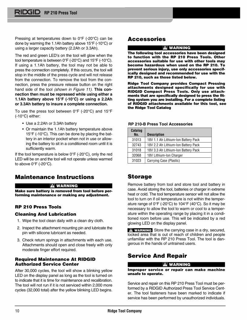
Pressing at temperatures down to 0°F (-20°C) can bedone by warming the 1.1Ah battery above 15°F (-10°C) orusing a larger capacity battery (2.2Ah or 3.3Ah).
The red and green LED’s on the tool will glow when thetool temperature is between 0°F (-20°C) and 15°F (-10°C).If using a 1.1Ah battery, the tool may not be able topress the connection completely. If this occurs, the tool willstop in the middle of the press cycle and will not releasefrom the connection. To remove the tool from the con-nection, press the pressure release button on the righthand side of the tool (shown in Figure 11). This con-nection then must be repressed while using either a1.1Ah battery above 15°F (-10°C) or using a 2.2Ahor 3.3Ah battery to insure a complete connection.
To use the press tool between 0°F (-20°C) and 15°F (-10°C) either:
• Use a 2.2Ah or 3.3Ah battery• Or maintain the 1.1Ah battery temperature above
15°F (-10°C). This can be done by placing the bat-tery in an interior pocket when not in use or allow-ing the battery to sit in a conditioned room until it issufficiently warm.
If the tool temperature is below 0°F (-20°C), only the redLED will be on and the tool will not operate unless warmedto above 0°F (-20°C).
Maintenance InstructionsWARNING
Make sure battery is removed from tool before per-forming maintenance or making any adjustment.
RP 210 Press Tools
Cleaning And Lubrication1. Wipe the tool clean daily with a clean dry cloth.
2. Inspect the attachment mounting pin and lubricate thepin with silicone lubricant as needed.
3. Check return springs in attachments with each use.Attachments should open and close freely with onlymoderate finger effort required.
Required Maintenance At RIDGIDAuthorized Service CenterAfter 30,000 cycles, the tool will show a blinking yellowLED on the display panel as long as the tool is turned onto indicate that it is time for maintenance and recalibration.The tool will not run if it is not serviced within 2,000 morecycles (32,000 total) after the yellow blinking LED begins.
CatalogNo. Description
31013 18V 1.1 Ah Lithium-Ion Battery Pack32743 18V 2.2 Ah Lithium-Ion Battery Pack31018 18V 3.3 Ah Lithium-Ion Battery Pack32068 18V Lithium-Ion Charger31023 Carrying Case (Plastic)
RP 210-B Press Tool Accessories
WARNING

DisposalThe RBRC™ (Rechargeable BatteryRecycling Corporation) Seal on thebattery packs means that RIDGIDhas already paid the cost of recyclingthe lithium-ion battery packs oncethey have reached the end of theiruseful life.
RBRC™, RIDGID®, and other battery suppliers havedeveloped programs in the USA and Canada to collectand recycle rechargeable batteries. Normal and recharge-able batteries contain materials that should not be direct-
Ridge Tool Company 11
RP 210 Press Tool
SYMPTOM POSSIBLE REASONS SOLUTION
Tool will not turn ONwhen ON/OFF button ondisplay panel is pressed.
Tool turns OFF eitherwhen trigger is de-pressed or in the middleof a press cycle. RedLED glows.
Yellow LED blinksrepeatedly as long astool is turned ON andtool functions properly.
Troubleshooting
Battery is completely discharged or battery hasfailed.
Battery not properly inserted into handle of tool.
Battery is too low.
Tool or battery is too cold or too hot.
Scheduled maintenance/recalibration is requiredafter 30,000 presses.
Insert fully charged battery/recharge dead battery.
Check to assure battery is fully inserted.
Insert fully charged battery/recharge dead battery.
Bring tool and battery to correct operating rangebetween 0°F (-20°C) to 122°F (50°C) by allowingthe tool to sit in a conditioned room. If using toolin cold temperatures, refer to Cold WeatherOperation Section of this manual.NOTE! Fitting must be repressed if tool stops
in the middle of a press cycle. Failureto do so may result in a leaking fitting.
Return to Test Equipment Depot
ly disposed of in nature, and contain valuable materialsthat can be recycled. Help to protect the environmentand conserve natural resources by returning your usedbatteries to your local retailer or an authorized RIDGID ser-vice center for recycling. Your local recycling center canalso provide you with additional drop off locations.
RBRC™ is a registered trademark of the RechargeableBattery Recycling Corporation.
Machine DisposalParts of this unit are valuable materials and can berecycled. There are companies that specialize in recy-cling that may be found locally.
Dispose of in compliance with any and all applicable reg-ulations. Contact your local waste management author-ity for more information.

12
RP 210 Press Tool
RP 210 Diagnostic Codes
LED Status Description IconGreen Glows Tool ON.
Blinks Out of acceptable voltage range.— Replace battery with a fully charged battery.
Red Blinks Attachment mounting pin not fully engaged. Insert pin.
Glows If only red light is ON, Out of temperature range 15°F (-10°C) to 122°F (50°C).
Yellow Blinks Service indicator after 30,000 cycles. NOTE: Tool will lock after 32,000 cycles.
Glows Machine is locked – Service after 32,000 cycles or after a malfunction.
SYMPTOM POSSIBLE REASONS SOLUTION
Yellow LED glows con-tinuously and tool willnot begin press cyclewhen trigger switch isdepressed.
Red LED blinks repeated-ly and tool will not beginpress cycle when triggerswitch is depressed.
Yellow LED glows whentool is turned ON.
Jaws are locked onto fitting.
The pressed connectionsproduced are not com-plete.
Troubleshooting (Continued)
Scheduled maintenance/recalibration is manda-tory after 32,000 presses. Tool is “locked” andwill not function until tool is serviced.
Attachment mounting pin not fully closed.
Tool malfunction detected.
Press was not successfully completed.
Used wrong jaws for the tube size or material.
The tool was not square to the tube.
Jaw contour was not aligned with the fitting contour.
Tool is in need of repair.
Return to Test Equipment Depot
Insert attachment mounting pin to the fully closedposition.
Remove and reinsert fully charged battery. Be sureto repress fitting. If LED’s continue to glow, contactRidge Tool Company, Technical Service Depart-ment at (800) 519-3456 for nearest AuthorizedService outlet.
Push pressure release valve to remove jaws from fit-ting. Inspect and repress fitting.
Install the correct jaws.
Redo the joint with new fitting and new tube.Make sure that the tool is square to the tube.
Redo the joint with new tube and new fitting.Make sure the jaw contour is aligned with the fitting contour.
Figure 12 – LED Diagnostic Codes
Test Equipment Depot - 800.517.8431 - 99 Washington Street Melrose, MA 02176TestEquipmentDepot.com