Embed Size (px)
Citation preview
SECTION 00001
PROJECT TITLE PAGE
999 BRADY AVENUE MIXED-USE CENTER999 BRADY AVENUE
ATLANTA, GA 30318
24 DECEMBER 2008
ARCHITECT: PLEXUS R+D, INC.
914 HOWELL MILL ROAD, SUITE 300
ATLANTA, GA 30318
404-519-7728
STRUCTURAL ENGINEER: STABILITY ENGINEERING, INC.
431 WEST PONCE DE LEON AVENUE, SUITE 4
DECATUR, GA 30030
404-377-9316
MEP & FP ENGINEERING: BARRETT, WOODYARD & ASSOCIATES
3495 HOLCOMB BRIDGE ROAD
NORCROSS, GA 30092
770-810-8800
CIVIL ENGINEER: EBERLY & ASSOCIATES
1852 CENTURY PLACE, SUITE 202
ATLANTA, GA 30345
770-452-7849
END OF PROJECT TITLE PAGE
PXX / 999 Brady 00001 - 1 PROJECT TITLE PAGE

SECTION 00010
TABLE OF CONTENTS (MASTERFORMAT 1995)
DOCUMENTS 0 -- INTRODUCTORY INFORMATION, BIDDING REQUIREMENTS, AND CONTRACT REQUIREMENTS
1.01 00001 - PROJECT TITLE PAGE
1.02 00010 - TABLE OF CONTENTS
1.03 00015 - LIST OF DRAWINGS
DIVISION 1 -- GENERAL REQUIREMENTS
2.01 01100 - SUMMARY
2.02 01200 - PRICE AND PAYMENT PROCEDURES
2.03 01600 - PRODUCT REQUIREMENTS
DIVISION 2 -- SITE CONSTRUCTION
DIVISION 3 -- CONCRETE
4.01 03100 - CONCRETE FORMS AND ACCESSORIES
DIVISION 4 -- MASONRY
DIVISION 5 -- METALS
6.01 05400 - COLD-FORMED METAL FRAMING
DIVISION 6 -- WOOD AND PLASTICS
DIVISION 7 -- THERMAL AND MOISTURE PROTECTION
8.01 07212 - BOARD AND BATT INSULATION
DIVISION 8 -- DOORS AND WINDOWS
9.01 08800 - GLAZING
DIVISION 9 -- FINISHES
10.01 09260 - GYPSUM BOARD ASSEMBLIES
DIVISION 10 -- SPECIALTIES
DIVISION 11 -- EQUIPMENT
DIVISION 12 -- FURNISHINGS
DIVISION 13 -- SPECIAL CONSTRUCTION
DIVISION 14 -- CONVEYING SYSTEMS
DIVISION 15 -- MECHANICAL
DIVISION 16 -- ELECTRICAL
END OF TABLE OF CONTENTS
PXX / 999 Brady 00010 - 1 TABLE OF CONTENTS (MASTERFORMAT 1995)
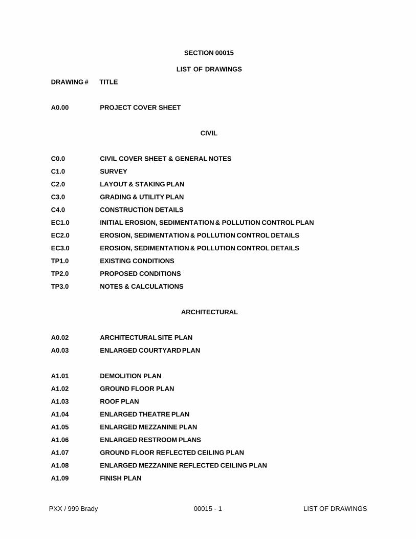
SECTION 00015
LIST OF DRAWINGS
DRAWING # TITLE
A0.00 PROJECT COVER SHEET
CIVIL
C0.0 CIVIL COVER SHEET & GENERAL NOTES
C1.0 SURVEY
C2.0 LAYOUT & STAKING PLAN
C3.0 GRADING & UTILITY PLAN
C4.0 CONSTRUCTION DETAILS
EC1.0 INITIAL EROSION, SEDIMENTATION & POLLUTION CONTROL PLAN
EC2.0 EROSION, SEDIMENTATION & POLLUTION CONTROL DETAILS
EC3.0 EROSION, SEDIMENTATION & POLLUTION CONTROL DETAILS
TP1.0 EXISTING CONDITIONS
TP2.0 PROPOSED CONDITIONS
TP3.0 NOTES & CALCULATIONS
ARCHITECTURAL
A0.02 ARCHITECTURAL SITE PLAN
A0.03 ENLARGED COURTYARD PLAN
A1.01 DEMOLITION PLAN
A1.02 GROUND FLOOR PLAN
A1.03 ROOF PLAN
A1.04 ENLARGED THEATRE PLAN
A1.05 ENLARGED MEZZANINE PLAN
A1.06 ENLARGED RESTROOM PLANS
A1.07 GROUND FLOOR REFLECTED CEILING PLAN
A1.08 ENLARGED MEZZANINE REFLECTED CEILING PLAN
A1.09 FINISH PLAN
PXX / 999 Brady 00015 - 1 LIST OF DRAWINGS
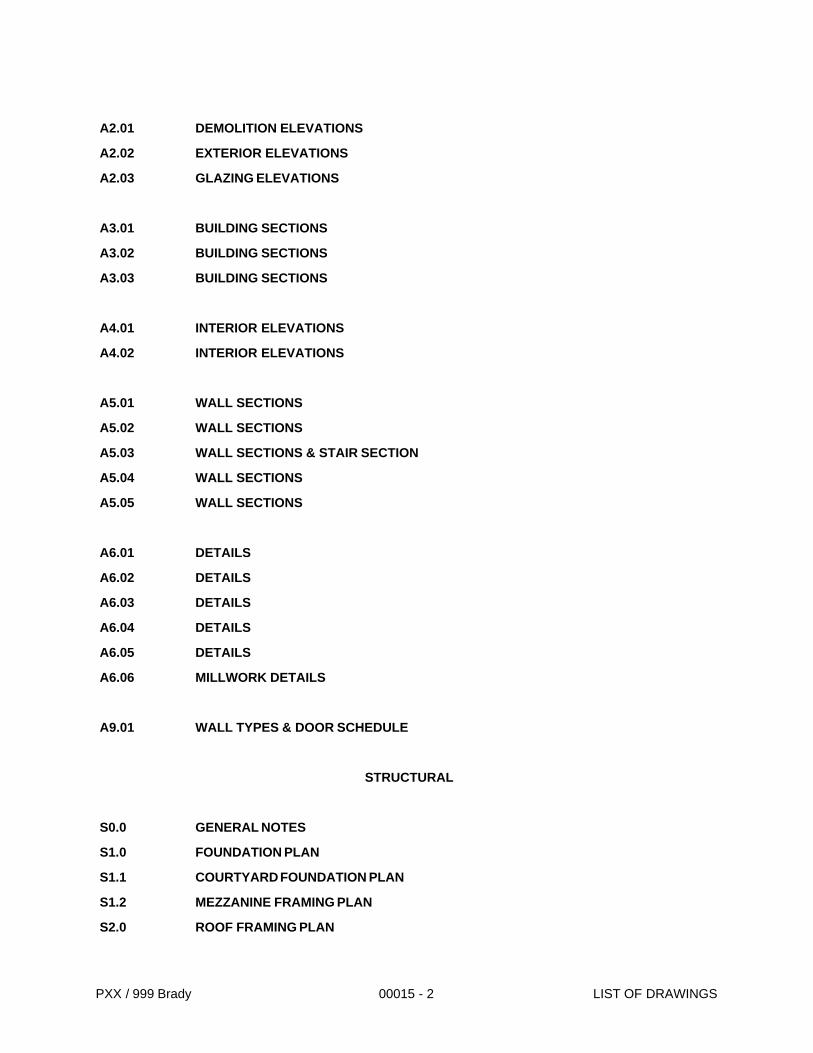
A2.01 DEMOLITION ELEVATIONS
A2.02 EXTERIOR ELEVATIONS
A2.03 GLAZING ELEVATIONS
A3.01 BUILDING SECTIONS
A3.02 BUILDING SECTIONS
A3.03 BUILDING SECTIONS
A4.01 INTERIOR ELEVATIONS
A4.02 INTERIOR ELEVATIONS
A5.01 WALL SECTIONS
A5.02 WALL SECTIONS
A5.03 WALL SECTIONS & STAIR SECTION
A5.04 WALL SECTIONS
A5.05 WALL SECTIONS
A6.01 DETAILS
A6.02 DETAILS
A6.03 DETAILS
A6.04 DETAILS
A6.05 DETAILS
A6.06 MILLWORK DETAILS
A9.01 WALL TYPES & DOOR SCHEDULE
STRUCTURAL
S0.0 GENERAL NOTES
S1.0 FOUNDATION PLAN
S1.1 COURTYARD FOUNDATION PLAN
S1.2 MEZZANINE FRAMING PLAN
S2.0 ROOF FRAMING PLAN
PXX / 999 Brady 00015 - 2 LIST OF DRAWINGS

S3.0 SECTIONS & DETAILS
S4.0 SECTIONS & DETAILS
S5.0 SECTIONS & DETAILS
S6.0 SECTIONS & DETAILS
S7.0 SECTIONS & DETAILS
MECHANICAL
M0.01 SCHEDULES & DETAILS
M1.02 GROUND FLOOR PLAN
M1.03 ROOF PLAN
M4.01 ENLARGED THEATRE PLAN
M4.02 ENLARGED MEZZANINE PLAN
ELECTRICAL
E0.01 LEGENDS, NOTES, DETAILS & SCHEDULES
E1.01 GROUND FLOOR PLAN - ELECTRICAL
E2.01 GROUND FLOOR PLAN - LIGHTING
E3.01 ROOF PLAN - ELECTRICAL
E4.01 ENLARGED THEATRE PLAN - ELECTRICAL
E4.02 ENLARGED MEZZANINE PLAN - ELECTRICAL
E4.03 ENLARGED THEATRE PLAN - LIGHTING
E4.04 ENLARGED MEZZANINE PLAN - LIGHTING
E5.01 PANEL SCHEDULES
PLUMBING
P0.01 SCHEDULES & DETAILS
P1.02 GROUND FLOOR PLAN
P4.01 ENLARGED THEATRE PLAN
P4.02 ENLARGED MEZZANINE PLAN
P4.03 ENLARGED GROUND FLOOR PARTS PLAN
P4.04 RISER DIAGRAMS
PXX / 999 Brady 00015 - 3 LIST OF DRAWINGS

END OF LIST OF DRAWINGS
PXX / 999 Brady 00015 - 4 LIST OF DRAWINGS
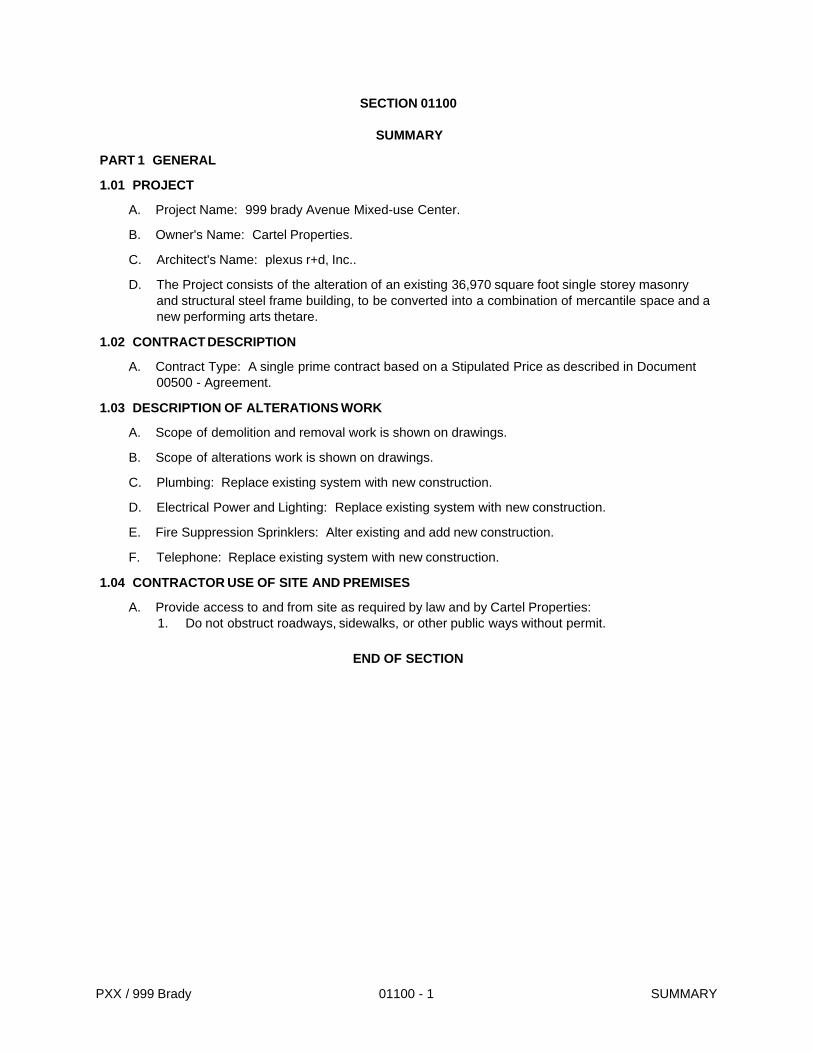
SECTION 01100
SUMMARY
PART 1 GENERAL
1.01 PROJECT
A. Project Name: 999 brady Avenue Mixed-use Center.
B. Owner's Name: Cartel Properties.
C. Architect's Name: plexus r+d, Inc..
D. The Project consists of the alteration of an existing 36,970 square foot single storey masonry and structural steel frame building, to be converted into a combination of mercantile space and a new performing arts thetare.
1.02 CONTRACT DESCRIPTION
A. Contract Type: A single prime contract based on a Stipulated Price as described in Document 00500 - Agreement.
1.03 DESCRIPTION OF ALTERATIONS WORK
A. Scope of demolition and removal work is shown on drawings.
B. Scope of alterations work is shown on drawings.
C. Plumbing: Replace existing system with new construction.
D. Electrical Power and Lighting: Replace existing system with new construction.
E. Fire Suppression Sprinklers: Alter existing and add new construction.
F. Telephone: Replace existing system with new construction.
1.04 CONTRACTOR USE OF SITE AND PREMISES
A. Provide access to and from site as required by law and by Cartel Properties:1. Do not obstruct roadways, sidewalks, or other public ways without permit.
END OF SECTION
PXX / 999 Brady 01100 - 1 SUMMARY

SECTION 01200
PRICE AND PAYMENT PROCEDURES
PART 1 GENERAL
1.01 SECTION INCLUDES
A. Procedures for preparation and submittal of applications for progress payments.
B. Documentation of changes in Contract Price and Contract Time.
1.02 APPLICATIONS FOR PROGRESS PAYMENTS
A. Payment Period: Submit at intervals stipulated in the Agreement.
B. Electronic media printout including equivalent information will be considered in lieu of standard form specified; submit sample to plexus r+d, Inc. for approval.
C. For each item, provide a column for listing each of the following:1. Item Number.2. Description of work.3. Scheduled Values.4. Previous Applications.5. Work in Place and Stored Materials under this Application.6. Authorized Change Orders.7. Total Completed and Stored to Date of Application.8. Percentage of Completion.9. Balance to Finish.10. Retainage.
D. Execute certification by signature of authorized officer.
E. Submit three copies of each Application for Payment.
1.03 MODIFICATION PROCEDURES
A. For minor changes not involving an adjustment to the Contract Price or Contract Time, plexus r+d, Inc. will issue instructions directly to Contractor.
B. For other required changes, plexus r+d, Inc. will issue a document signed by Cartel Properties instructing Contractor to proceed with the change, for subsequent inclusion in a Change Order.1. The document will describe the required changes and will designate method of determining
any change in Contract Price or Contract Time.2. Promptly execute the change.
C. For changes for which advance pricing is desired, plexus r+d, Inc. will issue a document that includes a detailed description of a proposed change with supplementary or revised drawings and specifications, a change in Contract Time for executing the change and the period of time during which the requested price will be considered valid. Contractor shall prepare and submit a fixed price quotation within 10 days.
D. Contractor may propose a change by submitting a request for change to plexus r+d, Inc., describing the proposed change and its full effect on the Work, with a statement describing the reason for the change, and the effect on the Contract Price and Contract Time with full documentation and a statement describing the effect on Work by separate or other contractors. Document any requested substitutions in accordance with Section 01600.
E. Computation of Change in Contract Amount: As specified in the Agreement and Conditions of the Contract.
PXX / 999 Brady 01200 - 1 PRICE AND PAYMENT PROCEDURES
1. For change requested by plexus r+d, Inc. for work falling under a fixed price contract, the amount will be based on Contractor's price quotation.
2. For change requested by Contractor, the amount will be based on the Contractor's request for a Change Order as approved by plexus r+d, Inc..
END OF SECTION
PXX / 999 Brady 01200 - 2 PRICE AND PAYMENT PROCEDURES
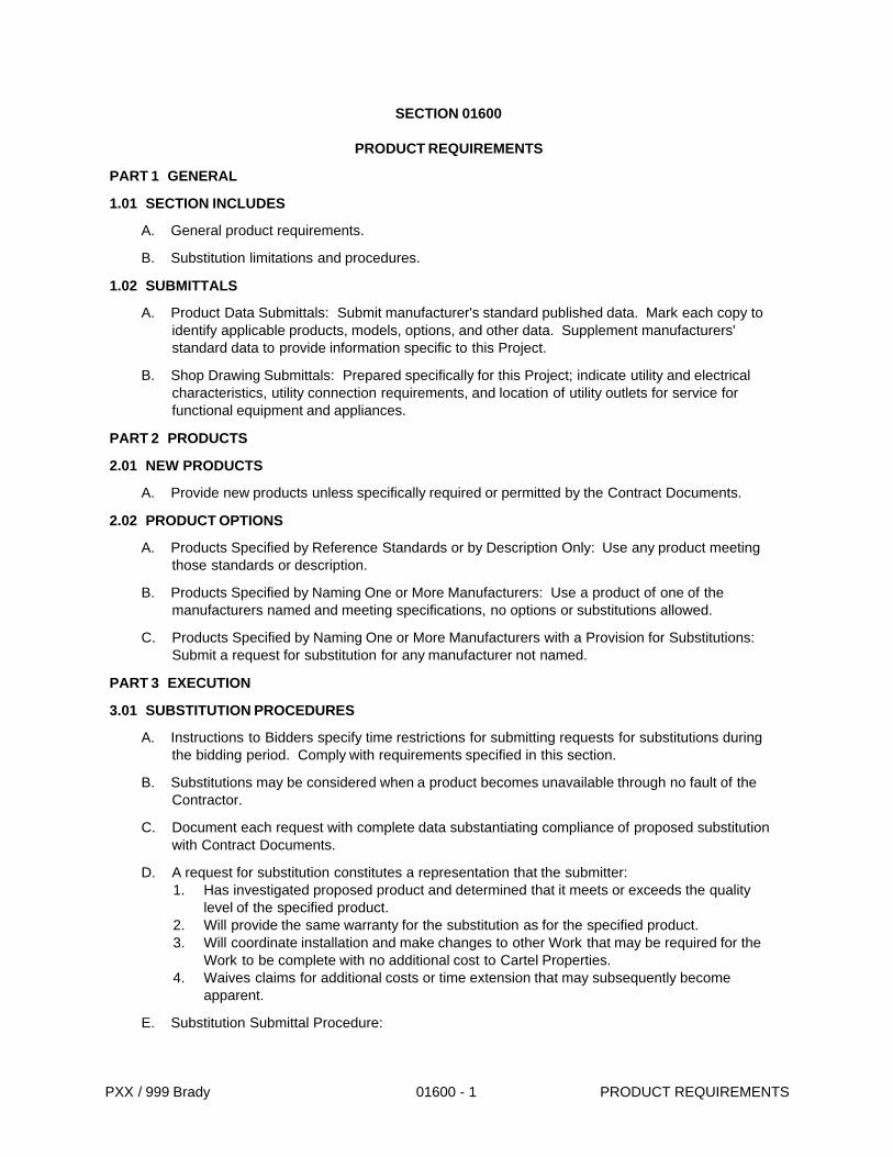
SECTION 01600
PRODUCT REQUIREMENTS
PART 1 GENERAL
1.01 SECTION INCLUDES
A. General product requirements.
B. Substitution limitations and procedures.
1.02 SUBMITTALS
A. Product Data Submittals: Submit manufacturer's standard published data. Mark each copy to identify applicable products, models, options, and other data. Supplement manufacturers' standard data to provide information specific to this Project.
B. Shop Drawing Submittals: Prepared specifically for this Project; indicate utility and electrical characteristics, utility connection requirements, and location of utility outlets for service for functional equipment and appliances.
PART 2 PRODUCTS
2.01 NEW PRODUCTS
A. Provide new products unless specifically required or permitted by the Contract Documents.
2.02 PRODUCT OPTIONS
A. Products Specified by Reference Standards or by Description Only: Use any product meeting those standards or description.
B. Products Specified by Naming One or More Manufacturers: Use a product of one of the manufacturers named and meeting specifications, no options or substitutions allowed.
C. Products Specified by Naming One or More Manufacturers with a Provision for Substitutions: Submit a request for substitution for any manufacturer not named.
PART 3 EXECUTION
3.01 SUBSTITUTION PROCEDURES
A. Instructions to Bidders specify time restrictions for submitting requests for substitutions during the bidding period. Comply with requirements specified in this section.
B. Substitutions may be considered when a product becomes unavailable through no fault of the Contractor.
C. Document each request with complete data substantiating compliance of proposed substitution with Contract Documents.
D. A request for substitution constitutes a representation that the submitter:1. Has investigated proposed product and determined that it meets or exceeds the quality
level of the specified product.2. Will provide the same warranty for the substitution as for the specified product.3. Will coordinate installation and make changes to other Work that may be required for the
Work to be complete with no additional cost to Cartel Properties.4. Waives claims for additional costs or time extension that may subsequently become
apparent.
E. Substitution Submittal Procedure:
PXX / 999 Brady 01600 - 1 PRODUCT REQUIREMENTS

1. Submit three copies of request for substitution for consideration. Limit each request to one proposed substitution.
2. Submit shop drawings, product data, and certified test results attesting to the proposed product equivalence. Burden of proof is on proposer.
3. The plexus r+d, Inc. will notify Contractor in writing of decision to accept or reject request.
3.02 TRANSPORTATION AND HANDLING
A. Coordinate schedule of product delivery to designated prepared areas in order to minimize site storage time and potential damage to stored materials.
B. Transport and handle products in accordance with manufacturer's instructions.
C. Transport materials in covered trucks to prevent contamination of product and littering of surrounding areas.
D. Promptly inspect shipments to ensure that products comply with requirements, quantities are correct, and products are undamaged.
E. Provide equipment and personnel to handle products by methods to prevent soiling, disfigurement, or damage.
F. Arrange for the return of packing materials, such as wood pallets, where economically feasible.
3.03 STORAGE AND PROTECTION
A. Designate receiving/storage areas for incoming products so that they are delivered according to installation schedule and placed convenient to work area in order to minimize waste due to excessive materials handling and misapplication.
B. Store and protect products in accordance with manufacturers' instructions.
C. Store with seals and labels intact and legible.
D. Store sensitive products in weather tight, climate controlled, enclosures in an environment favorable to product.
E. For exterior storage of fabricated products, place on sloped supports above ground.
F. Cover products subject to deterioration with impervious sheet covering. Provide ventilation to prevent condensation and degradation of products.
G. Prevent contact with material that may cause corrosion, discoloration, or staining.
H. Provide equipment and personnel to store products by methods to prevent soiling, disfigurement, or damage.
I. Arrange storage of products to permit access for inspection. Periodically inspect to verify products are undamaged and are maintained in acceptable condition.
END OF SECTION
PXX / 999 Brady 01600 - 2 PRODUCT REQUIREMENTS
SECTION 03100
CONCRETE FORMS AND ACCESSORIES
PART 1 GENERAL
1.01 SECTION INCLUDES
A. Formwork for cast-in place concrete, with shoring, bracing and anchorage.
B. Form accessories.
C. Form stripping.
1.02 RELATED REQUIREMENTS
A. Section 03300 - Cast-in-Place Concrete.
1.03 REFERENCE STANDARDS
A. ACI 117 - Standard Specifications for Tolerances for Concrete Construction and Materials; American Concrete Institute; 2006.
B. ACI 301 - Specifications for Structural Concrete for Buildings; American Concrete Institute; 2005.
C. ACI 347 - Guide to Formwork for Concrete; American Concrete Institute; 2004.
D. PS 1 - Structural Plywood; 2007.
PART 2 PRODUCTS
2.01 FORMWORK - GENERAL
A. Provide concrete forms, accessories, shoring, and bracing as required to accomplish cast-in-place concrete work.
B. Design and construct to provide resultant concrete that conforms to design with respect to shape, lines, and dimensions.
C. Comply with applicable State and local codes with respect to design, fabrication, erection, and removal of formwork.
2.02 WOOD FORM MATERIALS
A. Softwood Plywood: PS 1, B-B High Density Concrete Form Overlay, Class I.
2.03 FORMWORK ACCESSORIES
A. Form Ties: Removable type, galvanized metal, fixed length, cone type, with waterproofing washer, free of defects that could leave holes larger than 1 inch (25 mm) in concrete surface.
B. Form Release Agent: Colorless mineral oil that will not stain concrete.
PART 3 EXECUTION
3.01 EXAMINATION
A. Verify lines, levels and centers before proceeding with formwork. Ensure that dimensions agree with drawings.
3.02 ERECTION - FORMWORK
A. Erect formwork, shoring and bracing to achieve design requirements, in accordance with requirements of ACI 301.
PXX / 999 Brady 03100 - 1 CONCRETE FORMS AND ACCESSORIES
B. Provide bracing to ensure stability of formwork. Shore or strengthen formwork subject to overstressing by construction loads.
C. Arrange and assemble formwork to permit dismantling and stripping. Do not damage concrete during stripping. Permit removal of remaining principal shores.
D. Install formwork to acheive joints indicated in drawings.
3.03 APPLICATION - FORM RELEASE AGENT
A. Apply form release agent on formwork in accordance with manufacturer's recommendations.
3.04 FORM REMOVAL
A. Do not remove forms or bracing until concrete has gained sufficient strength to carry its own weight and imposed loads.
END OF SECTION
PXX / 999 Brady 03100 - 2 CONCRETE FORMS AND ACCESSORIES
SECTION 05400
COLD FORMED METAL FRAMING
PART 1 GENERAL
1.01 SECTION INCLUDES
A. Formed steel stud exterior wall and interior wall framing.
B. Exterior wall sheathing.
1.02 RELATED REQUIREMENTS
A. Section 06100 - Rough Carpentry: Wood blocking and miscellaneous framing.
B. Section 07212 - Board and Batt Insulation: Insulation within framing members.
C. Section 07260 - Weather Barriers: Weather barrier over sheathing.
D. Section 09220 - Portland Cement Plaster.
1.03 REFERENCE STANDARDS
A. ASTM A 153/A 153M - Standard Specification for Zinc Coating (Hot-Dip) on Iron and Steel Hardware; 2005.
B. ASTM C 955 - Standard Specification for Load-Bearing (Transverse and Axial) Steel Studs, Runners (Tracks), and Bracing or Bridging for Screw Application of Gypsum Panel Products and Metal Plaster Bases; 2007.
C. ASTM C 1177/C 1177M - Standard Specification for Glass Mat Gypsum Substrate for Use as Sheathing; 2006.
1.04 QUALITY ASSURANCE
PART 2 PRODUCTS
2.01 FRAMING SYSTEM
A. Provide primary and secondary framing members, bridging, bracing, plates, gussets, clips, fittings, reinforcement, and fastenings as required to provide a complete framing system.
2.02 FRAMING MATERIALS
A. Studs and Track: ASTM C 955; studs formed to channel, "C", or "Sigma" shape with punched web; U-shaped track in matching nominal width and compatible height. 1. Gage and depth: As indicated on the drawings.
2.03 WALL SHEATHING
A. Wall Sheathing: Glass mat faced gypsum; ASTM C 1177/C 1177M, square long edges, 1/2 inch (12.5 mm).
2.04 FASTENERS
A. Self-Drilling, Self-Tapping Screws, Bolts, Nuts and Washers: Hot dip galvanized per ASTM A 153/A 153M.
B. Anchorage Devices: Power actuated.
PART 3 EXECUTION
3.01 EXAMINATION
PXX / 999 Brady 05400 - 1 COLD FORMED METAL FRAMING

A. Verify that substrate surfaces are ready to receive work.
B. Verify field measurements and adjust installation as required.
3.02 INSTALLATION OF STUDS
A. Install components in accordance with manufacturers' instructions and ASTM C 1007 requirements.
3.03 WALL SHEATHING
A. Wall Sheathing: Secure with long dimension perpendicular to wall studs, with ends over firm bearing and staggered, using self-tapping screws.
END OF SECTION
PXX / 999 Brady 05400 - 2 COLD FORMED METAL FRAMING
SECTION 07195
AIR INFILTRATION BARRIER / SECONDARY WEATHER RESISTIVE MEMBRANE
GENERAL
1.01 SUMMARY
1.02 INCLUDES BUT NOT LIMITED TO:
A. Furnish and install over exterior of wall sheathing at all locations excluding those with E.I.F.S., regardless of whether or not indicated on drawings to protect exterior sheathing and interior walls.
B. REFERENCES
C. AATCC - 127
D. TAPPI T - 460 (sec/100cc)
E. ASTME 96 (g/m2 -24 hr.)
1.03 SUBMITTALS
A. General: Submit each item in this Article according to the conditions of the Contract and Division 1 Specifications Sections.
B. Product Data: Submit product specifications, technical data and installation instructions of manufacturer equaling or exceeding those specified.
1.04 PRODUCTS
1.05 Air infiltration barrier/secondary weather resistive membrane:
A. Spunbonded olefin, None-woven, Non-perforated.
B. Performance Requirements:1. Water penetration resistance of 210 cm in accordance with AATCC - 127.2. Air infiltration at 300 seconds in accordance with TAPPI T - 460 (sec/100cc).3. Water vapor transmission of 58 perms in accordance with ASTM E 96 Method B(g/m2 - 24
hr.).4. Basis weight of 2.5oz/yd in accordance with TAPPIT- 410.5. Membrane shall be free from holes and breaks other than those created by fasteners and
construction system due to attachment.6. Approved Manufacturer:
a. DuPont Tyvek® HomeWrap® by DuPont Company, Wilmington, Delaware.b. SEALING TAPE / FASTENERS:
C. Approved Tape Manufacturers.1. DuPont Contractor Tape, by DuPont Company, Wilmington Delaware. 2. Recommended fasteners for wood framed construction:
a. Nails with large heads or plastic washers.3. Recommended fasteners for steel framed construction:
a. Rust resistant screws with washers4. Recommended fastening to masonry:
a. Polyurethane or elastomeric adhesives.
1.06 EXECUTION
1.07 AIR INFILTRATION BARRIER
A. Install air infiltration barrier over exterior side of exterior wall sheathing.
PXX / 999 Brady 07195 - 1 AIR INFILTRATION BARRIER / SECONDARY WEATHER RESISTIVE MEMBRANE

1. Install air infiltration barrier after sheathing is installed and before windows and doors are installed. Install lower level barrier prior to upper layers to ensure proper shingling of layers.
2. Overlap air infiltration barrier at corners of building by a minimum of 12 inches.3. Overlap air infiltration barrier vertical seams by a minimum of 6 inches.4. Ensure barrier is plum and level with foundation, and unroll extending air infiltration barrier
over window and door openings.5. Attach air infiltration barrier to wood, insulated sheathing board or exterior gypsum with
plastic cap nails every 12” to 18” on vertical stud line with wood stud framing, and screws with washers to metal stud framing.
6. Prepare window and door rough openings as follows:a. Horizontally cut air infiltration barrier along bottom of header.b. Vertically cut air infiltration barrier down the center of window openings from the top of
the window opening down to 2/3 of the way to the bottom of the window openings.c. Diagonally cut air infiltration barrier from the bottom of the vertical cut to the left and
right corners of opening.d. Fold side and bottom flaps into window opening and fasten every 6 inches. Trim off
excess.7. Prepare each rough door opening by cutting a standard “I” pattern in the air infiltration
barrier. This is done as follows:a. Horizontally cut air infiltration barrier along bottom of door frame header and along top
of sill.b. Vertically cut air infiltration barrier down the center of door openings from the top of
the door opening (header) down to the bottom of the door opening (sill).c. Fold side flaps inside around door openings and fasten every 6 inches. Trim off
excess.8. Tape all horizontal and vertical seams of air infiltration barrier.9. Tape a patch over all tears and cuts in air infiltration barrier.
END OF SECTION
PXX / 999 Brady 07195 - 2 AIR INFILTRATION BARRIER / SECONDARY WEATHER RESISTIVE MEMBRANE
SECTION 07212
BOARD AND BATT INSULATION
PART 1 GENERAL
1.01 SECTION INCLUDES
A. Batt insulation in exterior wall, ceiling, and roof construction.
1.02 RELATED REQUIREMENTS
A. Section 05400 - Cold Formed Metal Framing: Supporting construction for batt insulation.
B. Section 07260 - Weather Barriers: Separate air barrier and vapor retarder materials.
C. Section 09260 - Gypsum Board Assemblies: Acoustic insulation.
1.03 REFERENCE STANDARDS
A. ASTM C 665 - Standard Specification for Mineral-Fiber Blanket Thermal Insulation for Light Frame Construction and Manufactured Housing; 2006.
B. ASTM E 136 - Standard Test Method for Behavior of Materials in a Vertical Tube Furnace At 750 Degrees C; 2004.
PART 2 PRODUCTS
2.01 APPLICATIONS
A. Insulation in Metal Framed Walls: Batt insulation with no vapor retarder.
2.02 BATT INSULATION MATERIALS
A. Batt Insulation: ASTM C 665; preformed batt; friction fit, conforming to the following:1. Combustibility: Non-combustible, when tested in accordance with ASTM E 136, except for
facing, if any.2. Manufacturers:
a. CertainTeed Corporation: www.certainteed.com.b. Johns Manville Corporation: www.jm.com.c. Owens Corning Corp: www.owenscorning.com.
3. Substitutions: See Section 01600 - Product Requirements.
PART 3 EXECUTION
3.01 EXAMINATION
A. Verify that substrate, adjacent materials, and insulation materials are dry and that substrates are ready to receive insulation and adhesive.
B. Verify substrate surfaces are flat, free of honeycomb, fins, irregularities, or materials or substances that may impede adhesive bond.
3.02 BATT INSTALLATION
A. Install insulation in accordance with manufacturer's instructions.
B. Install in exterior wall and roof spaces without gaps or voids. Do not compress insulation.
C. Trim insulation neatly to fit spaces. Insulate miscellaneous gaps and voids.
D. Fit insulation tightly in cavities and tightly to exterior side of mechanical and electrical services within the plane of the insulation.
PXX / 999 Brady 07212 - 1 BOARD AND BATT INSULATION
E. At metal framing, place vapor retarder on warm side of insulation; lap and seal sheet retarder joints over member face.
F. Tape seal tears or cuts in vapor retarder.
G. Extend vapor retarder tightly to full perimeter of adjacent window and door frames and other items interrupting the plane of the membrane. Tape seal in place.
END OF SECTION
PXX / 999 Brady 07212 - 2 BOARD AND BATT INSULATION
SECTION 08411
ALUMINUM STOREFRONTS (SERIES 3000 FLUSH GLAZE)
PART 1 - GENERAL
1.01 SUMMARY
A. Related Documents: Conditions of the Contract, Division 1 - General Requirements, and Drawings apply to Work of this Section.
B. Section Includes:1. Storefront system, complete with reinforcing, fasteners, anchors, and attachment devices.2. Accessories necessary to complete work.
C. Products Furnished But Not Installed Under This Section:1. Anchoring devices that are built into masonry.2. Anchoring devices that are cast in concrete.
D. Related Sections:1. Section 07900 - Joint Sealers.2. Section 08810 - Glass and Glazing.
1.02 REFERENCES
A. Aluminum Association (AA):1. DAF-45 Designation System for Aluminum Finishes.
B. American Society for Testing and Materials (ASTM):1. B221 Aluminum-Alloy Extruded Bars, Rods, Wire, Shapes, and Tubes.2. E331 Test Method for Water Penetration of Exterior Windows, Curtain Walls and Doors by
Uniform Static Air Pressure Difference.
C. Glass Association of North America (GANA):1. Glazing Manual
1.03 SYSTEM REQUIREMENTS
A. Design Requirements:1. Drawings are diagrammatic and do not purport to identify nor solve problems of thermal or
structural movement, glazing, anchorage, or moisture disposal.2. Requirements shown by details are intended to establish basic dimension of units, sight
lines and profiles of members.3. Provide concealed fastening.4. Provide entrance and storefront systems, including necessary modifications, to meet
specified requirements and maintaining visual design concepts.5. Attachment considerations are to take into account site peculiarities and expansion and
contraction movements so there is no possibility of loosening, weakening or fracturing connection between units and building structure or between units themselves.
6. Anchors, fasteners and braces shall be structurally stressed not more than 50% of allowable stress when maximum loads are applied.
7. Provide for expansion and contraction due to structural movement without detriment to appearance or performance.
8. Framing systems shall accommodate expansion and contraction movement due to surface temperature differentials of 180 degrees F without causing buckling, stress on glass, failure of joint seals, excessive stress on structural elements, reduction of performance, or other detrimental effects.
B. Performance Requirements:
PXX / 999 Brady 08411 - 1 ALUMINUM STOREFRONTS (SERIES 3000 FLUSH GLAZE)
1. Wind loads: Provide framing system capable of withstanding wind load design pressures as established in applicable building codes. The design pressures are based on the International Building Code; 2006 Edition.
2. Air infiltration: Air leakage through fixed light areas of storefront shall not exceed 0.06 cfm per square foot of surface area when tested in accordance with ASTM E283 at differential static pressure of 6.24 psf.
3. Water infiltration: No uncontrolled leakage when tested in accordance with ASTM E331 at test pressure of 10 psf as defined in AAMA 501.
4. Deflection:a. Maximum calculated deflection of any framing member in direction normal to plane of
wall when subjected to specified design pressures for spans up to and including 13'-6” shall be limited to [1/175] of its clear span and for spans greater than 13'-6” deflection shall be limited to [1/240] of its clear span + 1/4”, except that maximum deflection of members supporting plaster surfaces shall not exceed 1/360 of its span.
C. Testing Requirements: Provide components that have been previously tested by an independent testing laboratory.
1.04 SUBMITTALS
A. General: Submit in accordance with Section 01300.
B. Product Data:1. Submit manufacturer's descriptive literature and product specifications.2. Include information for factory finishes, hardware, accessories, and other required
components.3. Include color charts for finish indicating manufacturer's standard colors available for
selection.]
C. Shop Drawings:1. Submit shop drawings covering fabrication, installation and finish of specified systems.2. Include following:
a. Fully dimensioned plans and elevations with detail coordination keys.b. Locations of exposed fasteners and joints.
3. Provide detailed drawings of:a. Composite members.b. Joint connections for framing systems and for entrance doors.c. Anchorage.d. System reinforcements.e. System expansion and contraction provisions.f. Glazing methods and accessories.g. Internal sealant requirements.
4. Schedule of finishes.
D. Samples:1. Submit manufacturers standard samples indicating quality of finish.2. Where normal texture or color variations are expected, include additional samples
illustrating range of variation.3. Submit samples for each type of glass, 12 x 12 inch size.]
E. Test Reports:1. Standard Systems: Submit certified copies of previous test reports substantiating
performance of system in lieu of retesting. Include other supportive data as necessary.
1.05 QUALITY ASSURANCE
A. Single Source Responsibility:
PXX / 999 Brady 08411 - 2 ALUMINUM STOREFRONTS (SERIES 3000 FLUSH GLAZE)
1. To ensure quality of appearance and performance, obtain materials for systems from either a single manufacturer or from manufacturer approved by systems manufacturer.
B. Perform Work in accordance with AAMA SFM-1 and manufacturer's written instructions.
1.06 DELIVERY, STORAGE, AND HANDLING
A. Comply with requirements of Section 01600.
B. Protect finished surfaces as necessary to prevent damage.
C. Do not use adhesive papers or sprayed coatings that become firmly bonded when exposed to sun.
D. Do not leave coating residue on any surfaces.
E. Replace damaged units.
1.07 WARRANTY
A. Provide warranties in accordance with Section 01700.
B. Provide written warranty in form acceptable to Owner jointly signed by manufacturer, installer and Contractor warranting work to be watertight, free from deflective materials, defective workmanship, glass breakage due to defective design, and agreeing to replace components which fail within 1 year from date of Substantial Completion.
C. Warranty shall cover following:1. Complete watertight and airtight system installation within specified tolerances.2. System is structurally sound and free from distortion.
D. Provide written warranty stating organic coating finish will be free from fading more than 10%, chalking, yellowing, peeling, cracking, pitting, corroding or non-uniformity of color, or gloss deterioration beyond manufacturer's descriptive standards for 1 year from date of Substantial Completion and agreeing to promptly correct defects.
PART 2 - PRODUCTS
2.01 MANUFACTURERS AND PRODUCTS
A. Subject to compliance with requirements indicated, provide products by one of the following: 1. Vistawall Architectural Products, Terrell, TX.
B. Substitutions: Substitutions: See Section 01600 - Product Requirements.
C. Acceptable Storefront Framing System:1. Flush Glazed System, center set, exterior loaded2. Series 3000 - 2" x 4-1/2" mullion profile. This system accommodates 1" glass
thickness, with 1/4" as an option.
2.02 FRAMING MATERIALS AND ACCESSORIES
A. Aluminum:1. ASTM B221, alloy 6063-T5 for extrusions; ASTM B209, alloy 5005-H16 for sheets; or other
alloys and temper recommended by manufacturer appropriate for specified finish.
B. Internal Reinforcing:1. ASTM A36 for carbon steel.2. Shapes and sizes to suit installation.3. Steel components factory coated with alkyd type zinc chromate primer complying with FS
TT-P-645.
PXX / 999 Brady 08411 - 3 ALUMINUM STOREFRONTS (SERIES 3000 FLUSH GLAZE)

C. Anchorage Devices:1. Manufacturer's standard formed or fabricated steel or aluminum assemblies of shapes,
plates, bars or tubes.2. Hot-dip galvanize steel assemblies after fabrication; comply with ASTM A123, 2.0 ounce
minimum coating.
D. Fasteners:1. Aluminum, non-magnetic stainless steel or other non-corrosive materials compatible with
items being fastened.2. Provide concealed fasteners wherever possible.3. For exposed locations, provide Phillips flathead screws with finish matching item fastened.4. For concealed locations, provide manufacturer's standard fasteners.
E. Expansion Anchor Devices: Lead-shield or toothed-steel, drilled-in, expansion bolt anchors.
F. Protective Coatings: Cold-applied asphalt mastic complying with SSPC, compounded for 30 mil thickness for each coat; or alkyd type zinc chromate primer complying with FS TT-P-645.
G. Touch-Up Primer for Galvanized Components: Zinc oxide conforming with FS TT-P-641.
H. Glazing Gaskets:1. Compression type design, replaceable, molded or extruded, of neoprene, polyvinyl chloride
(PVC), or ethylene propylene diene monomer (EPDM).2. Profile and hardness as required to maintain uniform pressure for watertight seal.
I. Weatherstripping:1. Wool pile conforming to AAMA 701.2.2. Provide EPDM or vinyl-blade gasket weatherstripping in bottom door rail, adjustable for
contact with threshold.
J. Internal Sealants and Baffles.
2.03 GLASS AND GLAZING ACCESSORIES
A. Refer to Section 08810.
2.04 FABRICATION
A. Coordination of Fabrication:1. Check actual frame or door openings required in construction work by accurate field
measurements before fabrication.2. Fabricate units to withstand loads that will be applied when system is in place.
B. General
2.05 Conceal fasteners wherever possible.
A. Reinforce work as necessary for performance requirements, and for support to structure.
B. Separate dissimilar metals and aluminum in contact with concrete utilizing protective coating or preformed separators, which will prevent contact and corrosion.
C. Comply with Section 08810 for glazing requirements.
D. Aluminum Framing:1. Provide members of size, shape and profile indicated, designed to provide for glazing from
[exterior] [interior].2. Fabricate frame assemblies with joints straight and tight fitting.3. Reinforce internally with structural members as necessary to support design loads.4. Maintain accurate relation of planes and angles, with hairline fit of contacting members.5. Seal horizontals and direct moisture accumulation to exterior.
PXX / 999 Brady 08411 - 4 ALUMINUM STOREFRONTS (SERIES 3000 FLUSH GLAZE)
6. Provide flashings and other materials used internally or externally that are corrosive resistant, non-staining, non-bleeding and compatible with adjoining materials.
7. Provide manufacturer's extrusions and accessories to accommodate expansion and contraction due to temperature changes without detrimental to appearance or performance.
E. Welding:1. Comply with recommendations of the American Welding Society.2. Use recommended electrodes and methods to avoid distortion and discoloration.3. Grind exposed welds smooth and flush with adjacent surfaces; restore mechanical finish.
F. Flashings: Form from sheet aluminum with same finish as extruded sections. Apply finish after fabrication. Material thickness as required to suit condition without deflection or "oil-canning".
2.06 FINISHES
A. Clear Anodized:1. Conforming to AA-M12C22A31 and AAMA 611.2. Architectural Class II, etched, medium matte, clear anodic coating, 0.4 mil minimum
thickness.]
PART 3 - EXECUTION
3.01 EXAMINATION
A. Examine conditions and proceed with Work in accordance with Section 01400.
3.02 INSTALLATION
A. Erection Tolerances:1. Limit variations from plumb and level:
B. 1/8 inch in 10'-0" vertically.
C. Limit offsets in theoretical end-to-end and edge-to-edge alignment: 1/16 inch from flush surfaces not more than 2 inches apart or out-of-flush by more than 1/4 inch.
D. Install doors and hardware in accordance with manufacturer's printed instructions.
E. Set units plumb, level and true to line, without warp or rack of frame.
F. Anchor securely in place, allowing for required movement, including expansion and contraction.
G. Separate dissimilar materials at contact points, including metal in contact with masonry or concrete surfaces, with bituminous paint or preformed separators to prevent contact and corrosion.
H. Set sill members in bed of sealant. Set other members with internal sealants and baffles to provide weather-tight construction.
I. Coordinate installation of perimeter sealant and backing materials between assemblies and adjacent construction in accordance with requirements of Section 07920.
J. Glazing: Refer to requirements of Section 08810.
3.03 ADJUSTING
A. Test door operating functions. Adjust closing and latching speeds and other hardware in accordance with manufacturer's instructions to ensure smooth operation.
3.04 CLEANING
A. Clean surfaces in compliance with manufacturer's recommendations; remove excess mastic, mastic smears, foreign materials and other unsightly marks.
PXX / 999 Brady 08411 - 5 ALUMINUM STOREFRONTS (SERIES 3000 FLUSH GLAZE)
B. Clean metal surfaces exercising care to avoid damage.
END OF SECTION
PXX / 999 Brady 08411 - 6 ALUMINUM STOREFRONTS (SERIES 3000 FLUSH GLAZE)
SECTION 08800
GLAZING
PART 1 GENERAL
1.01 SECTION INCLUDES
A. Glass.
B. Glazing compounds and accessories.
1.02 RELATED REQUIREMENTS
A. Section 07900 - Joint Sealers: Sealant and back-up material.
B. Section 08410 - Metal-Framed Storefronts.
1.03 REFERENCE STANDARDS
A. 16 CFR 1201 - Safety Standard for Architectural Glazing Materials; current edition.
B. ANSI Z97.1 - American National Standard for Safety Glazing Materials Used in Buildings, Safety Performance Specifications and Methods of Test; 2004.
C. ASTM C 864 - Standard Specification for Dense Elastomeric Compression Seal Gaskets, Setting Blocks, and Spacers; 2005.
D. ASTM C 920 - Standard Specification for Elastomeric Joint Sealants; 2005.
E. ASTM E 1300 - Standard Practice for Determining Load Resistance of Glass in Buildings; 2007.
F. ASTM E 2190 - Standard Specification for Insulating Glass Unit Performance and Evaluation; 2002.
G. GANA (GM) - GANA Glazing Manual; Glass Association of North America; 2004.
H. GANA (SM) - FGMA Sealant Manual; Glass Association of North America; 1990.
1.04 ADMINISTRATIVE REQUIREMENTS
A. Preinstallation Meeting: Convene a preinstallation meeting one week before starting work of this section; require attendance by all affected installers.
1.05 SUBMITTALS
A. See Section 01300 - Administrative Requirements, for submittal procedures.
B. Product Data on Glass Types: Provide structural, physical and environmental characteristics, size limitations, special handling or installation requirements.
C. Product Data on Glazing Compounds: Provide chemical, functional, and environmental characteristics, limitations, special application requirements. Identify available colors.
1.06 QUALITY ASSURANCE
A. Perform Work in accordance with GANA Glazing Manual and FGMA Sealant Manual for glazing installation methods.
1.07 WARRANTY
A. See Section 01780 - Closeout Submittals, for additional warranty requirements.
B. Provide a five (5) year warranty to include coverage for sealed glass units from seal failure, interpane dusting or misting, and replacement of same.
PXX / 999 Brady 08800 - 1 GLAZING
PART 2 PRODUCTS
2.01 EXTERIOR GLAZING ASSEMBLIES
A. Structural Design Criteria: Select type and thickness to withstand dead loads and wind loads acting normal to plane of glass at design pressures calculated in accordance with 2006 Edition of International Building code.1. Use the procedure specified in ASTM E 1300 to determine glass type and thickness.2. Limit glass deflection to 1/200 or flexure limit of glass, whichever is less, with full recovery
of glazing materials.3. Thicknesses listed are minimum.
2.02 SEALED INSULATING GLASS MATERIALS
A. Manufacturers:1. Cardinal Glass Industries: www.cardinalcorp.com.2. Guardian Industries Corp: www.guardian.com.3. Viracon, Apogee Enterprises, Inc: www.viracon.com.4. Substitutions: Refer to Section 01600 - Product Requirements.
B. Insulated Glass Units: Double pane with glass to elastomer edge seal.1. Outer pane of clear glass, inner pane of clear glass.2. Durability: Certified by an independent testing agency to comply with ASTM E 2190.3. Purge interpane space with dry hermetic air.4. Total unit thickness of 1 inch (____ mm) minimum.
2.03 GLAZING COMPOUNDS
2.04 GLAZING ACCESSORIES
A. Setting Blocks: Neoprene, 80 to 90 Shore A durometer hardness, ASTM C 864 Option I. Length of 0.1 inch for each square foot (25 mm for each square meter) of glazing or minimum 4 inch (100 mm) x width of glazing rabbet space minus 1/16 inch (1.5 mm) x height to suit glazing method and pane weight and area.
B. Glazing Gaskets: Resilient silicone extruded shape to suit glazing channel retaining slot; ASTM C 864 Option I; ________ color.
PART 3 EXECUTION
3.01 EXAMINATION
A. Verify that openings for glazing are correctly sized and within tolerance.
B. Verify that surfaces of glazing channels or recesses are clean, free of obstructions that may impede moisture movement, weeps are clear, and ready to receive glazing.
3.02 PREPARATION
A. Clean contact surfaces with solvent and wipe dry.
B. Install sealant in accordance with manufacturer's instructions.
3.03 INSTALLATION - EXTERIOR/INTERIOR DRY METHOD (GASKET GLAZING)
A. Place setting blocks at 1/4 points with edge block no more than 6 inches (150 mm) from corners.
B. Rest glazing on setting blocks and push against fixed stop with sufficient pressure on gasket to attain full contact.
PXX / 999 Brady 08800 - 2 GLAZING
C. Install removable stops without displacing glazing gasket; exert pressure for full continuous contact.
3.04 MANUFACTURER'S FIELD SERVICES
A. Glass and Glazing product manufacturers to provide field surveillance of the installation of their products.
B. Monitor and report installation procedures and unacceptable conditions.
3.05 CLEANING
A. Remove glazing materials from finish surfaces.
B. Remove labels after Work is complete.
C. Clean glass and adjacent surfaces.
3.06 PROTECTION
A. After installation, mark pane with an 'X' by using removable plastic tape or paste; do not mark heat absorbing or reflective glass units.
END OF SECTION
PXX / 999 Brady 08800 - 3 GLAZING

SECTION 09260
GYPSUM BOARD ASSEMBLIES
PART 1 GENERAL
1.01 SECTION INCLUDES
A. Performance criteria for gypsum board assemblies.
B. Metal stud wall framing.
C. Metal channel ceiling framing.
D. Acoustic insulation.
E. Gypsum sheathing.
F. Gypsum wallboard.
G. Joint treatment and accessories.
1.02 RELATED REQUIREMENTS
A. Section 05400 - Cold Formed Metal Framing: Exterior wind-load-bearing metal stud framing.
B. Section 07212 - Board and Batt Insulation: Acoustic insulation.
C. Section 07260 - Weather Barriers: Water-resistive barrier over sheathing.
1.03 REFERENCE STANDARDS
A. ASTM C 475/C 475M - Standard Specification for Joint Compound and Joint Tape for Finishing Gypsum Board; 2002 (Reapproved 2007).
B. ASTM C 645 - Standard Specification for Nonstructural Steel Framing Members; 2007.
C. ASTM C 665 - Standard Specification for Mineral-Fiber Blanket Thermal Insulation for Light Frame Construction and Manufactured Housing; 2006.
D. ASTM C 754 - Standard Specification for Installation of Steel Framing Members to Receive Screw-Attached Gypsum Panel Products; 2007.
E. ASTM C 840 - Standard Specification for Application and Finishing of Gypsum Board; 2007.
F. ASTM C 954 - Standard Specification for Steel Drill Screws for the Application of Gypsum Panel Products or Metal Plaster Bases to Steel Studs From 0.033 in. (0.84 mm) to 0.112 in. (2.84 mm) in Thickness; 2007.
G. ASTM C 1002 - Standard Specification for Steel Self-Piercing Tapping Screws for the Application of Gypsum Panel Products or Metal Plaster Bases to Wood Studs or Steel Studs; 2007.
H. ASTM C 1047 - Standard Specification for Accessories for Gypsum Wallboard and Gypsum Veneer Base; 2005.
I. ASTM C 1177/C 1177M - Standard Specification for Glass Mat Gypsum Substrate for Use as Sheathing; 2006.
J. ASTM C 1396/C 1396M - Standard Specification for Gypsum Board; 2006a.
K. ASTM E 90 - Standard Test Method for Laboratory Measurement of Airborne Sound Transmission Loss of Building Partitions and Elements; 2004.
L. ASTM E 413 - Classification for Rating Sound Insulation; 2004.
PXX / 999 Brady 09260 - 1 GYPSUM BOARD ASSEMBLIES

M. GA-216 - Application and Finishing of Gypsum Board; Gypsum Association; 2007.
PART 2 PRODUCTS
2.01 GYPSUM BOARD ASSEMBLIES
A. Provide completed assemblies complying with ASTM C 840 and GA-216.1. See PART 3 for finishing requirements.
B. Interior Partitions Indicated as Acoustic: Provide completed assemblies with the following characteristics:1. Acoustic Attenuation: STC of 50-54 calculated in accordance with ASTM E 413, based on
tests conducted in accordance with ASTM E 90.
2.02 METAL FRAMING MATERIALS
A. Manufacturers - Metal Framing, Connectors, and Accessories:1. Clark Western Building Systems; Product ____: www.clarkwestern.com.2. Dietrich Metal Framing; Product ____: www.dietrichindustries.com.3. Marino\Ware; Product ____: www.marinoware.com.4. The Steel Network, Inc; Product _____: www.SteelNetwork.com.5. Substitutions: See Section 01600 - Product Requirements.
B. Non-Loadbearing Framing System Components: ASTM C 645; galvanized sheet steel, of size and properties necessary to comply with ASTM C 754 for the spacing indicated, with maximum deflection of wall framing of L/240 at 5 psf (240 Pa).1. Studs: "C" shaped with flat or formed webs with knurled faces.2. Runners: U shaped, sized to match studs.3. Ceiling Channels: C shaped.4. Furring: Hat-shaped sections, minimum depth of 7/8 inch (22 mm).
C. Ceiling Hangers: Type and size as specified in ASTM C 754 for spacing required.
2.03 BOARD MATERIALS
A. Manufacturers - Gypsum-Based Board:1. American Gypsum: www.americangypsum.com.2. CertainTeed Corporation: www.certainteed.com.3. Georgia-Pacific Gypsum LLC: www.gp.com/gypsum.4. Lafarge North America Inc: www.lafargenorthamerica.com.5. National Gypsum Company: www.nationalgypsum.com.6. PABCO Gypsum: www.pabcogypsum.com.7. Temple-Inland Inc: www.templeinland.com.8. USG Corporation: www.usg.com.9. Substitutions: See Section 01600 - Product Requirements.
B. Wallboard: Paper-faced gypsum wallboard as defined in ASTM C 1396/C 1396M; sizes to minimize joints in place; ends square cut.1. Application: Use for vertical surfaces and ceilings, unless otherwise indicated.2. Thickness:
a. Vertical Surfaces: 5/8 inch (16 mm).b. Ceilings: 5/8 inch (16 mm).
C. Exterior Sheathing Board: Sizes to minimize joints in place; ends square cut.1. Application: Exterior sheathing, unless otherwise indicated.2. Glass-Mat-Faced Sheathing: Glass mat faced gypsum substrate as defined in ASTM C
1177/C 1177M.3. Edges: Square, for vertical application.4. Glass-Mat-Faced Products:
PXX / 999 Brady 09260 - 2 GYPSUM BOARD ASSEMBLIES
a. CertainTeed Corporation; GlasRoc Brand.b. Georgia-Pacific Gypsum LLC; DensGlass Gold Sheathing.c. National Gypsum Company; Gold Bond Brand e2XP Extended Exposure Sheathing.d. Substitutions: See Section 01600 - Product Requirements.
D. Exterior Soffit Board: Exterior gypsum soffit board as defined in ASTM C 1396/C 1396M; sizes to minimize joints in place; ends square cut.1. Application: Ceilings and soffits in protected exterior areas, unless otherwise indicated.2. Regular Type Thickness: 1/2 inch (13 mm).3. Edges: Tapered.4. Products:
a. American Gypsum; Exterior Soffit Wallboard.b. CertainTeed Corporation; ProRoc Brand Exterior Soffit Board.c. Georgia-Pacific Gypsum LLC; ToughRock Soffit Board.d. Lafarge North America Inc; Soffitboard.e. National Gypsum Company; Gold Bond Brand Exterior Soffit Board.f. Pacific Coast Building Products, Inc; PABCO.g. Temple-Inland Inc; Exterior Gypsum Soffit Board.h. USG Corporation; Sheetrock Exterior Gypsum Ceiling Board.i. Substitutions: See Section 01600 - Product Requirements.
2.04 ACCESSORIES
A. Acoustic Insulation: ASTM C 665; preformed glass fiber, friction fit type, unfaced.
B. Finishing Accessories: ASTM C 1047, galvanized steel or rolled zinc, unless otherwise indicated.1. Types: As detailed or required for finished appearance.2. Special Shapes: In addition to conventional cornerbead and control joints, provide U-bead
at exposed panel edges.
C. Joint Materials: ASTM C 475 and as recommended by gypsum board manufacturer for project conditions.
D. Screws for Attachment to Steel Members Less Than 0.03 inch (0.7 mm) In Thickness, to Wood Members, and to Gypsum Board: ASTM C 1002; self-piercing tapping type; cadmium-plated for exterior locations.
E. Screws for Attachment to Steel Members From 0.033 to 0.112 inch (0.8 to 2.8 mm) in Thickness: ASTM C 954; steel drill screws for application of gypsum board to loadbearing steel studs.
PART 3 EXECUTION
3.01 EXAMINATION
A. Verify that project conditions are appropriate for work of this section to commence.
3.02 FRAMING INSTALLATION
A. Metal Framing: Install in accordance with ASTM C 754 and manufacturer's instructions.
B. Suspended Ceilings and Soffits: Space framing and furring members as indicated.1. Level ceiling system to a tolerance of 1/1200.2. Laterally brace entire suspension system.3. Install bracing as required at exterior locations to resist wind uplift.
C. Studs: Space studs as indicated in drawings.1. Extend partition framing to structure where indicated and to ceiling in other locations.2. Partitions Terminating at Ceiling: Attach ceiling runner securely to ceiling track in
accordance with manufacturer's instructions.
PXX / 999 Brady 09260 - 3 GYPSUM BOARD ASSEMBLIES

3.03 ACOUSTIC ACCESSORIES INSTALLATION
A. Acoustic Insulation: Place tightly within spaces, around cut openings, behind and around electrical and mechanical items within partitions, and tight to items passing through partitions.
B. Acoustic Sealant: Install in accordance with manufacturer's instructions.
3.04 INSTALLATION OF TRIM AND ACCESSORIES
A. Control Joints: Place control joints consistent with lines of building spaces and as indicated.
B. Corner Beads: Install at external corners, using longest practical lengths.
C. Edge Trim: Install at locations where gypsum board abuts dissimilar materials and as indicated.
3.05 JOINT TREATMENT
A. Finish gypsum board in accordance with levels defined in ASTM C 840, as follows:1. Level 4: Walls and ceilings to receive paint finish or wall coverings, unless otherwise
indicated.2. Level 1: Fire rated wall areas above finished ceilings, whether or not accessible in the
completed construction.
B. Tape, fill, and sand exposed joints, edges, and corners to produce smooth surface ready to receive finishes.1. Feather coats of joint compound so that camber is maximum 1/32 inch (0.8 mm).
3.06 TOLERANCES
A. Maximum Variation of Finished Gypsum Board Surface from True Flatness: 1/8 inch in 10 feet (3 mm in 3 m) in any direction.
END OF SECTION
PXX / 999 Brady 09260 - 4 GYPSUM BOARD ASSEMBLIES
999 Brady Avenue 15010-1
163.00 / BW&A 08956 December 23, 2008
Issued for Pricing
SECTION 15010
MECHANICAL GENERAL
1.0 GENERAL
1.01 DESCRIPTION
A. This Division 15 and the accompanying drawings cover the provision of all
labor, equipment, appliances, and materials and performing all operations in
connection with the construction of the air conditioning, ventilating, heating,
fire suppression and plumbing systems as specified herein and as shown.
B. The General Provisions and Division 1, including the general, supplementary
and other conditions and other Divisions, as appropriate, apply to work
specified in this Division.
1.02 EXISTING CONDITIONS
A. Attention is called to the fact that the work is to be performed within an
existing facility. Prior to the submission of bids, each bidder shall visit the
project site, thoroughly investigate and be familiar with all existing conditions
which will affect their work; especially the work.
B. Connect new work to existing work in a neat and workmanlike manner. Where
an existing structure must be cut or existing utilities interfere, such obstructions
shall be bypassed, removed, replaced or relocated, patched and repaired. Work
disturbed or damaged shall be replaced or repaired to its prior condition.
1.03 INTENT OF DRAWINGS AND SPECIFICATIONS
A. The implied and stated intent of the drawings and specifications is to establish
minimum acceptable standards for materials, equipment and workmanship, and
to provide operable mechanical systems complete in every respect.
B. The engineering drawings are diagrammatic, intended to show general
arrangement and sizes of system components, and shall not be scaled. Rather,
the architectural and structural drawings shall govern space constraints,
dimensions and finishes. All offsets and fittings which will be necessary to
accomplish the finished installation shall be provided at no additional cost or
increase in the Contract.

999 Brady Avenue 15010-2
163.00 / BW&A 08956 December 23, 2008
Issued for Pricing
1.04 SPACE PRIORITY
A. Ensure optimum use of available space for materials and equipment installed
above ceilings. Allocate space in the order of priority as listed below except as
otherwise detailed. Items are listed in the order of priority, with items of equal
importance listed under a single priority number.
1. Gravity flow piping systems
2. Vent piping systems
3. Recessed lighting fixtures
4. Concealed HVAC terminals and equipment
5. Air duct systems
6. Sprinkler piping systems
7. Pressurized piping systems
8. Electrical conduit, wiring, control air tubing
B. Order of space priority does not dictate installation sequence. Installation
sequence shall be as required to install all affected trades.
C. The work of this Division 15 shall not obstruct access for installation, operation
and maintenance of the work of any other Division.
D. All major items of equipment shall be arranged so as to provide a minimum of
28" clear aisle space. Additional space shall be provided between and around
equipment for maintenance and proper operation as shown in the equipment
manufacturer's literature.
1.05 COORDINATION
A. Coordinate all work under this Division 15 with work under all other Divisions,
providing adjustment as necessary.
B. Coordination of space requirements with respect to Division 16 shall be
performed such that:
999 Brady Avenue 15010-3
163.00 / BW&A 08956 December 23, 2008
Issued for Pricing
1. No equipment, piping or ductwork, other than electrical, shall be
installed within 42" of switchboards or panelboards.
2. No piping or ductwork which ever operates at a temperature in excess of
120 degrees F. shall be installed within 3" of any electrical conductor.
C. All items mounted in or below the ceiling, and all items penetrating the ceiling,
shall be coordinated with the architectural reflected ceiling plans. If any items
are not shown on these plans, or any items need to be relocated for coordination
purposes, prepare a reflected ceiling plan and submit it to the ** Owner **
Architect ** for approval.
1.06 CODE COMPLIANCE
A. All workmanship and materials provided under this Division 15 shall comply
with all laws, ordinances, codes and regulations of all Federal, State and Local
Authorities having jurisdiction.
B. All fire suppression, plumbing, heating, ventilating, and air conditioning
materials and workmanship shall comply with the following codes and
standards as minimum requirements:
1. NFPA 101 Life Safety Code, 2000 Edition, with Georgia Amendments.
2. NFPA 13, Standard for the Installation of Sprinkler Systems, 2002
Edition, with Georgia Amendments.
3. NFPA 45, Standard on Fire Protection for Laboratories Using Chemicals,
2000 Edition, with Georgia Amendments.
4. NFPA 70, National Electrical Code, 2005 Edition, with Georgia
Amendments.
5. NFPA 72, National Fire Alarm Code, 2002 Edition, with Georgia
Amendments.
6. Georgia Accessibly Code, 120-3-20, June 25, 1997.
7. Americans with Disabilities Act, January 26, 1992.
8. ASME A17.1 Safety Code Elevators and Escalators, 2000 Edition, with
2002 Georgia Amendments.

999 Brady Avenue 15010-4
163.00 / BW&A 08956 December 23, 2008
Issued for Pricing
9. International Building Code, 2006 Edition, with Georgia Amendments.
10. International Fuel Gas Code, 2006 Edition, with Georgia Amendments.
11. International Mechanical Code, 2006 Edition, with Georgia Amendments.
12. International Plumbing Code, 2006 Edition, with Georgia Amendments.
13. National Electrical Code, 2005 Edition, with Georgia Amendments.
14. International Fire Code, 2006 Edition, with Georgia Amendments.
15. International Energy Conservation Code, 2006 Edition, with 2008
Georgia Amendments.
C. Secure and pay all fees associated with all permits and licenses required for
execution of the Contract. Arrange for all inspections required by city, county,
state and other authorities having jurisdiction, and deliver certificates of
approval to the Architect.
D. The code requirements are strictly a minimum and shall be met without
incurring additions to the Contract. Where requirements of the drawings or
specifications exceed the code requirements, the work shall be provided in
accordance with these drawings or specifications. In the event of conflict or
ambiguity between the various codes, the most stringent requirement shall
govern.
1.07 ELECTRICAL REQUIREMENTS AND INTERFACE
A. All electrical equipment and wiring provided under this Division 15 shall
comply with the electrical system characteristics indicated on the electrical
drawings and specified in Division 16.
B. Electric controls, contactors, starters, pilot lights, push buttons, etc., shall be
provided complete as part of the motor, heater or other equipment which it
operates. All electrical components shall be in conformance with the
requirements of the National Electrical Code and Division 16. Reference
Division 16 and the electrical engineering drawings for those motor starters
provided under that Division 16. All starters not shown shall be provided under
this Division 15. Unless specified otherwise under other individual equipment
Sections, motor starters shall conform to the following minimum requirements:
999 Brady Avenue 15010-5
163.00 / BW&A 08956 December 23, 2008
Issued for Pricing
1. Starters for motors 1/3 horsepower or smaller shall be manual unless
remote or automatic starting is required, in which case the starters shall
be magnetic, full voltage, non-reversing, single-speed, unless otherwise
indicated. All other starters shall be magnetic.
2. Each starter for a three-phase motor shall be furnished with three (3)
overload relays sized for the full load running current of the motor
actually provided. Provide an external "HAND-OFF-AUTO" selector
switch with red "RUNNING" light. Provide a green pilot light to
indicate motor "STOPPED". Each pilot light shall have a legend plate
indicating reason for signal.
3. Each overload relay shall have a normally open alarm contact which
will close only when actuated by an overload (not to be confused with
N.O. or N.C. auxiliary contacts). These contacts shall be properly wired
to their respective blue pilot light provided on the starter front cover and
having a "TRIPPED" legend plate.
4. Individually mounted motor starters shall be in a NEMA Type 1 general
purpose enclosure in unfinished areas and shall be flush mounted in all
finished areas. All starters mounted in exterior areas shall have a
NEMA 3R enclosure. Each starter shall have a laminated nameplate to
indicate equipment unit number, function and circuit number.
5. All motor starters, push buttons and pilot lights shall be of the same
manufacturer as the switchboard and shall be General Electric, Square
D, Siemens I.T.E., or Westinghouse.
C. Motor starters for the following equipment shall be provided under this
Division 15 by the manufacturer of the equipment:
1. Packaged air conditioning equipment
2. Other equipment hereinafter specified in other Sections to be provided
with integral starters.
D. Unless otherwise noted or specified in individual Sections, all 3-phase motors
shall be standard NEMA continuous duty "B" type, with Class B insulation,
open drip-proof frame for indoor service, TEFC for outdoor service and a
service factor of 1.15. All motors 5 HP and larger shall be U.S. Motors Hi-
Efficiency Model or Reliance XE Hi-Efficiency Model.

999 Brady Avenue 15010-6
163.00 / BW&A 08956 December 23, 2008
Issued for Pricing
E. All power wiring and final connections to equipment shall be provided under
Division 16.
F. Control components, all interlocks (motor-operated dampers, fire alarm motors,
etc.) and control wiring (120 volt, single phase and less) shall be provided
under this Division 15 as required to achieve the specified control sequences.
G. All control wiring over 30 volts shall be installed by a licensed electrician
working under this Division 15.
1.08 SLEEVES, SEALS AND ESCUTCHEONS
A. Sleeves shall be provided through all pipe penetrations of concrete or masonry
walls, elevated floors and roofs, except those plumbing piping penetrations for
fixtures, vents, etc.
B. Sleeves shall be fabricated from Schedule 40 steel pipe through 10" and
Standard Wall steel pipe for sleeve sizes 12" and larger. All sleeves penetrating
exterior walls, underground walls, pit or vault walls shall be provided with a 3"
x 3/8" thick waterstop ring welded completely to the midpoint of the sleeve.
C. All sleeves penetrating exterior walls, underground walls, pit or vault walls and
elevated floors shall be packed and sealed watertight.
D. Sleeves through roofs shall extend above the roof surface and be flashed
watertight.
E. Sleeves through walls shall be cut and finished flush with each surface of the
wall in which they are installed.
F. Sleeves shall be sized to provide a minimum of 1/2" clearance between the
inside surface of the sleeve and the outside finished surface of the pipe plus any
insulation specified.
G. Fire-stops shall be provided as specified herein. All annular spaces between
piping and sleeves, which do not require fire-stops, shall be packed with
mineral wool and caulked.
H. Provide round, chrome-plated escutcheons on all exposed piping penetrations
passing through walls, floors, partitions and ceilings.
1.09 FIRE-STOPS
999 Brady Avenue 15010-7
163.00 / BW&A 08956 December 23, 2008
Issued for Pricing
A. Where ductwork, piping, conduit, etc. pass through fire partitions, fire walls
and floors, a fire-stop shall be provided that will ensure an effective barrier
against the spread of fire, smoke and gases. Fire-stop material shall be packed
tight and completely fill gaps between the ductwork, piping, conduit, etc. and
the perimeter of their rough openings.
B. Fire-stopping material shall maintain its dimensions and integrity while
preventing the passage of flame, smoke and gases under conditions of
installation and use when exposed to the ASTM E119 time-temperature curve
for a time period equivalent to the rating of the assembly penetrated. Fire-
stopping material shall be noncombustible as defined by ASTM E136; and, for
insulation materials, melt point shall be a minimum of 1700 degrees F. for 1-
hour protection and 1850 degrees F. for 2-hour protection. Fire-stopping
material shall be Dow-Corning RTV Foam or 3M Fire Barrier Products or
Sohio Carborundum Fyre Putty.
C. See Section 15400 for fire stopping of PVC piping.
1.10 CORE DRILLING
A. Cutting of holes through concrete and masonry shall be by diamond core or
concrete saw. Pneumatic hammer, impact electric and hand or manual hammer
type drills will not be allowed, except as permitted by the Architect where
required by limited working space. Locate holes such that they will not affect
structural sections such as ribs or beams. Holes shall be laid out well in
advance of the installation. These layout locations shall be approved by the
Architect prior to drilling.
2.0 PRODUCTS
2.01 BID BASIS AND SUBSTITUTION PROCEDURES
A. Manufacturers names, series and model numbers, as noted or specified, are for
the purpose of describing type, capacity, and quality of equipment, materials
and products to be used. Unless "or equal" is specifically stated, bids shall be
based only on the specified "basis of design" manufacturer. The listing of a
particular manufacturer as an "equal" or "acceptable substitute" manufacturer
shall not be misconstrued as approving nor allowing the substitution of that
manufacturer's standard product in place of the basis of design. No
consideration will be given to a product, which would require dimensional,
spatial or aesthetic changes to the project. "Acceptable substitute" and "equal"
manufacturers shall only bid those products, which exactly match the size and
999 Brady Avenue 15010-8
163.00 / BW&A 08956 December 23, 2008
Issued for Pricing
other characteristics of the specified basis of design. Any changes to other
disciplines and trades of work required by an "or equal" or "substitute" product
shall be duly considered and priced accordingly prior to bidding or pricing. The
decision as to whether or not a proposed substitute or "equal" product is
actually equal to that specified shall rest solely with the Architect.
B. Requests to provide "equal" products in lieu of those specified shall be
submitted to the Architect in writing at least ten (10) days prior to final pricing
and execution of the Contract. No consideration will be given to substitute
products after final pricing and execution of the Contract.
C. Any "or equal" product or proposed product substitution which will cause a
change in the appearance, dimensions or design of any part of the building, it
structure, electrical system or any other engineered systems shall be
accompanied by a scaled drawing and written description of the required
change(s) for approval by the Architect. If deemed necessary by the Architect,
design changes shall be signed and sealed by a registered Professional Engineer,
currently licensed in this State.
2.02 MINIMUM STANDARDS
A. Every piece of energy consuming equipment, all fire suppression products and
life safety equipment shall comply with the following standards as applicable;
especially in regard to prevailing codes:
1. Factory Mutual Laboratories (FM)
2. Industrial Risk Insurers (IRI)
3. Underwriters Laboratories, Inc. (UL)
4. ADC: Air Diffusion Council
5. AGA: American Gas Association
6. AMCA: Air Moving and Conditioning Association, Inc.
7. ANSI: American National Standards Institute
8. API: American Petroleum Institute
9. ARI: American Refrigeration Institute
999 Brady Avenue 15010-9
163.00 / BW&A 08956 December 23, 2008
Issued for Pricing
10. ASHRAE: American Society of Heating, Refrigerating and Air
Conditioning Engineers
11. ASME: American Society of Mechanical Engineers
12. ASTM: American Society of Testing and Materials
13. AWWA: American Water Works Association
14. IBR: Institute of Boiler and Radiator Manufacturers
15. MSS: Manufacturers Standardization Society
16. NBBPVI: National Board of Boiler and Pressure Vessel Inspectors
17. NEMA: National Electrical Manufacturer's Association
18. OSHA: Occupational Safety & Health Administration
19. PDI: Plumbing Drainage Institute
20. PPI: Plastic Pipe Institute
21. SMACNA: Sheet Metal and Air Conditioning Contractors National
Association, Inc.
3.0 EXECUTION
3.01 SUBMITTALS
A. Before preparing submittals, study all Contract Drawings and specifications in
detail, obtain manufacturer's recommended instructions, and have submittals
prepared based on specific equipment and material proposed for installation.
An officer of the contracting firm shall sign all shop drawings (certifying
conformance with plans and specifications) before submitting to the Architect
or releasing to the field.
B. The submittal process shall not be utilized as an avenue to substitute products
after the execution of the contract. Should an unspecified or unequal product
be submitted, it will be rejected. If a second attempt at substitution is made
during the resubmittal of the same product, then no more reviews of that
product will be performed without direct compensation to the Engineer being

999 Brady Avenue 15010-10
163.00 / BW&A 08956 December 23, 2008
Issued for Pricing
paid for the additional services required for the third review and any further
reviews.
C. No more than four (4) copies of submittal data will be reviewed. Any
additional copies will be returned unmarked. The responsibility of copying
review comments on any additional copies will rest solely with the Contractor.
D. Submittals will not be accepted for review unless they:
1. Comply with the requirements of Division 1.
2. Include complete information pertaining to all appurtenances and
accessories.
3. Are submitted as complete packages which pertain to all related items in
Division 15. Separate packages shall be submitted as follows:
a. All HVAC equipment and components
b. All plumbing equipment, fixtures and components
c. The fire suppression system
d. The automatic controls and EMS
4. Are properly marked with equipment, service or function identification
as related to the project and are marked with pertinent specification
paragraph number.
E. Submit catalog information, factory assembly drawings, field installation
drawings and certifications as required for complete explanation and
description of all items of equipment. The submittal data shall provide ample,
unquestionable compliance with the Contract Documents.
F. Review of submittals shall not be construed as authorizing any deviations from
the plans and specifications unless such deviations are clearly identified and
separately submitted in the form of a letter that is enclosed with the submittals.
G. Submittals are required on all manufactured equipment, especially energy
consuming equipment. Submittals shall include, but are not limited to, the
following items of equipment:
999 Brady Avenue 15010-11
163.00 / BW&A 08956 December 23, 2008
Issued for Pricing
1. Piping Specialties
2. Insulation
3. Pumps
4. Water Heaters
5. Plumbing Fixtures
6. Fire Protection System
7. Split Systems
8. Packaged Rooftop Units
9. Air Distribution Devices
10. Ductwork Accessories
11. Centrifugal Fans
3.02 EXCAVATION, TRENCHING AND BACKFILLING
A. Perform all excavation, trenching and backfilling for underground work under
this Division 15. During excavation, the excavated material shall be piled back
from the banks of the trench to avoid overloading, slides or cave-ins. Do not
exceed the angle of repose unless written approval is obtained in advance from
the Architect for shoring, bracing or other alternate excavation methods. All
excavated material not used for backfilling shall be removed from the building
and disposed of as indicated or directed by the Architect. Take measures to
prevent surface water from flowing into trenches and other excavations and any
water accumulating therein shall be removed by pumping. All excavation shall
be made by open cut. Tunneling shall not be allowed.
B. The bottom of all trenches shall be evenly graded to provide firm support and
an even bearing surface. Pipe shall be laid on firm soil, laid in straight lines
and on uniform grades. Provide bell holes so that the barrel of the pipe rests
evenly on the bottom of the trench along the entire length of the pipe.
C. Pipe shall be inspected and tested prior to backfilling. Trench shall be
handfilled to a minimum of 12" above the top of pipe with suitable earth (free
999 Brady Avenue 15010-12
163.00 / BW&A 08956 December 23, 2008
Issued for Pricing
of rocks, trash, large clods and organic material) and compacted to a minimum
95% proctor. After the first layer is completed, subsequent layers shall be filled
and compacted the same as the first layer. Settling the backfill with water shall
not be permitted.
3.03 INSTALLATION REQUIREMENTS
A. All equipment shall be installed in strict conformance with the
recommendations of the equipment manufacturer, as indicated on the Drawings
and as specified.
B. Provide installation manuals for each piece of equipment. Submit in separately
bound volumes after review of submittals.
C. Provide supplementary steel framing and welded steel equipment support
stands as required for proper hanging and support of the mechanical systems.
Steel angles, channels and tubing utilized for such framing shall be selected for
a maximum deflection of 1/360th of the span.
D. All roof curbs shall be a minimum of 12" high and selected for the various roof
pitches. Curbs installed on roofs having pitches of not more than 1/4" per foot
may be standard curbs shimmed level with steel channels or Zs to provide
suitable support and flashing surfaces.
3.04 CLEANING, LUBRICATION AND ADJUSTMENT
A. The exterior surfaces of all mechanical equipment, piping, ductwork, conduit,
etc., shall be cleaned and free of all dirt, grease, oil, paint splatter, and other
construction debris.
B. Ducts, plenums, and air unit casings shall be cleaned of all debris and either
vacuumed or blown free of all rubbish, dirt, and dust before installing grilles,
registers or diffusers.
C. Bearings that require lubrication shall be lubricated in strict accordance with the
manufacturers recommendations.
D. All control equipment shall be adjusted to the settings required for the
performance specified.
E. Fans shall be adjusted to the speed indicated by the manufacturer to meet the
installed final system pressure at the airflows indicated. Any additional sheaves

999 Brady Avenue 15010-13
163.00 / BW&A 08956 December 23, 2008
Issued for Pricing
and belts required for final adjustments shall be provided with no increase in
the Contract amount.
F. Any fans operated during construction shall have temporary filters. Temporary
filters shall be changed regularly to minimize contamination of the equipment
and duct systems. Permanent filters shall be installed prior to final inspection.
G. All coils shall be thoroughly cleaned and combed prior to final inspection.
3.05 PAINTING
A. All uncoated and uninsulated steel surfaces exposed to sight inside the building,
such as piping, equipment hangers and supports which are not provided with
factory prime coat or galvanizing, shall be cleaned and painted with one coat of
rust inhibiting primer. In addition, all surfaces in finished spaces shall also be
painted with two coats of finish paint in a color selected by the Architect.
B. All ductwork surfaces visible through grilles, registers and diffusers in finished
areas shall be painted flat black.
C. Steel items exposed outside the building, such as equipment supports,
uninsulated piping and hangers, which are not factory painted or galvanized,
shall be cleaned and painted with one coat of rust inhibiting primer and two
coats of asphaltic base aluminum paint. Insulated steel pipes outside the
building shall be cleaned and painted with one coat of rust inhibiting primer
before installing insulation.
D. Factory painted equipment that has been scratched or marred shall be repainted
to match the original factory color.
3.06 DUCTWORK AND PIPING LEAK TESTING
A. Underground, concealed and insulated ductwork and piping shall be tested for
leaks in place before backfilling, concealing or covering. Tests shall be
conducted in the presence of the Architect or his designated representative.
B. All low pressure ductwork (design operating pressure of 1.0" W.C. E.S.P. or
less) shall be tested by the operation of the system to which it is connected.
C. All medium and high pressure ductwork (operating pressure of more than 1.0"
W.C. E.S.P.) shall be tested at 1.5 times the design operating pressure of the
system to which it is connected, or at the total fan pressure at shut-off,

999 Brady Avenue 15010-14
163.00 / BW&A 08956 December 23, 2008
Issued for Pricing
whichever is greater.
D. All visible and audible air leaks from the ductwork systems shall be repaired.
E. Soil, waste, storm and vent piping shall be tested with water before installing
fixtures. Water test shall be applied to the system either in its entirety or to the
individual sections. Each opening except the highest opening of the section
under test shall be plugged, and the section shall be filled with water and tested
with a head of water of at least ten (10) feet above the highest point in the
system. The water shall be kept in the portion under test for at least thirty (30)
minutes; no drop in the water level will be acceptable.
F. The water piping systems shall be tested at a minimum pressure of 125 psi and
proved tight at this pressure for not less than thirty (30) minutes or longer if
required to permit inspection of all joints. No loss in pressure will be
permitted.
G. All gas piping shall be tested pneumatically and proved tight at a pressure of
not less than 100 psi for a period of not less than two (2) hours. No loss in
pressure will be permitted.
H. All compressed air piping shall be tested pneumatically and proved tight at a
pressure of not less than 100 psi for a period of not less than two (2) hours. No
loss in pressure will be permitted.
I. Chilled water, condenser water and hot water supply and return piping shall be
hydrostatically tested at a pressure of 100 psig (60 psig for PVC piping) for a
minimum of one hour. No loss in pressure shall be permitted.
J. Steam and condensate return piping shall be tested at a test pressure of 100 psig
minimum but not less than 1.25 times the system operating pressure for a
minimum of one hour. No loss of pressure shall be permitted.
K. All refrigerant piping shall be 100% tested with a halide torch leak detector.
L. All leaks shall be repaired by tightening, remaking joints, or replacing pipe and
fittings. Caulking of joints shall not be permitted.
3.07 RECORD (AS-BUILT) DRAWINGS
A. At the completion of the project, provide a set of reproducible sepias to the
Architect which reflect all changes, deviations and revisions made to the
999 Brady Avenue 15010-15
163.00 / BW&A 08956 December 23, 2008
Issued for Pricing
original design documents. Locations of all underground piping and utilities
shall be clearly shown and dimensioned from permanent reference points such
as building column lines.
3.08 OPERATING AND MAINTENANCE MANUALS AND INSTRUCTIONS
A. Complete operating and maintenance manuals shall be provided to the Owner.
Four copies shall be provided. Each copy shall be bound in a separate 3-ring,
loose-leaf notebook. Operating instructions shall be provided for each
mechanical system, and shall each include a brief system description, a simple
schematic and a sequence of operation. Operating and maintenance instructions
shall be provided for each piece of equipment. A control system wiring
diagram shall be included in each operating and maintenance manual.
B. Prior to final acceptance or beneficial occupancy, provide the services of a
competent technician for not less than one (1) day to instruct the Owner in the
operation of the mechanical systems.
3.09 TESTING AND BALANCING
A. Testing and balancing of the HVAC system shall be performed as specified in
Section 15043. Note that this work is to be performed under a separate
Contract directly under the General Contractor. Submit four (4) copies of the
test and balance report directly to the Architect.
3.10 WARRANTY
A. All work provided under this Division 15 shall be subject to a minimum one
year warranty. The warranty shall include prompt repair or replacement of
equipment or system failures and shall include all parts and labor. In addition,
all reciprocating air conditioning compressors shall carry an additional four year
parts-only warranty. Extended warranties shall be provided on all other
equipment so specified in other Sections.
END OF SECTION
999 Brady Avenue 15043-1
163.00 / BW&A 08956 December 23, 2008
Issued for Pricing
SECTION 15043
HVAC TEST & BALANCE
1.0 GENERAL
1.01 DESCRIPTION
A. All work specified in this Section is governed by the Mechanical General
Section 15010.
B. This Section 15043 and the accompanying drawings cover the provision of all
labor, equipment, appliances, and materials and performing all operations in
connection with the testing and balancing (T&B) of the heating, ventilating and
air conditioning (HVAC) systems as specified herein and as shown. These
systems include, but are not limited to, the following:
1. Supply distribution systems
2. Return and exhaust air systems
3. Heating, ventilating and air conditioning equipment (all scheduled
equipment as a minimum)
1.02 INTENT
A. It is the intent of this Section of the specifications to provide a complete
operable and balanced HVAC system as shown and specified which is
reasonably airtight, comfortable and free of objectionable noise and vibration.
1.03 SCOPE OF WORK
A. HVAC test and balance shall be performed by an independent agency certified
by the Associated Air Balance Council (AABC) or National Environmental
Balancing Bureau (NEBB) under direct contract to the General Contractor. All
work performed by this agency shall be performed by qualified technicians
under the direct supervision of an AABC or NEBB certified test and balance
engineer. The agency shall be independent and shall not be associated in any
way with the installing HVAC subcontractor.
B. HVAC test and balance shall be performed in accordance with the 6th edition
of the AABC National Standards, 2002 for Total System Balance or the NEBB

999 Brady Avenue 15043-2
163.00 / BW&A 08956 December 23, 2008
Issued for Pricing
Procedural Standards for TAB of Environmental Systems, 7th Edition, 2005
together with the NEBB TAB Manual for Technicians, 2nd
Edition.
C. The final T&B report shall serve to substantiate compliance with the intent of
the Contract Documents, specifically the HVAC systems.
D. HVAC test and balance shall not begin until the systems are substantially
complete.
E. Upon the completion of the T&B work, the Agency shall submit four copies of
the complete HVAC Test and Balance Report directly to the Architect.
F. The Agency, as a part of its contract with the General Contractor, shall act as an
authorized inspection agency, responsible to the General Contractor and the
Architect and shall, during the test and balance, list those items which require
correction or have not been installed in accordance with the Contract
Documents.
G. The Agency shall plainly mark the settings of all valves, dampers and other
adjustable devices. If a balancing device is provided with a memory stop, it
shall be set, locked and marked.
1.04 SUBMITTALS
A. The name and certification of the Agency, along with the name and certification
of the Certified Test and Balance Engineer, shall be submitted to the Architect
for review within 30 days after the award of the general contract.
B. The selected Agency shall submit to the Owner:
1. Procedural Manual
2. Report Forms
3. AABC or NEBB Performance Guaranty
4. Instrument List and Calibration Dates
5. Schedule
C. A reviewed copy of each of the above shall be returned to the Agency before
the HVAC Test and Balance begins.
999 Brady Avenue 15043-3
163.00 / BW&A 08956 December 23, 2008
Issued for Pricing
D. If a complete submittal in accordance with these requirements is not received
within 60 days from award of the general contract, then the Architect reserves
the right to select the Agency.
2.0 PRODUCTS
2.01 (Not applicable).
3.0 EXECUTION
3.01 GENERAL CONTRACTOR'S DUTIES
A. The General Contractor shall provide the following, within 10 days after his
receipt, to the Agency:
1. Contract drawings
2. Contract applicable specification division 15 (others as applicable)
3. Addenda
4. Change orders
5. Reviewed submittals
B. The General Contractor shall start-up and maintain the HVAC systems and
shall continue the operation of the HVAC systems during each day of testing
and balancing. Start-up and operation shall include, as a minimum, the
following:
1. All equipment operable and in safe condition.
2. Temperature control system complete.
3. Proper thermal overload protection in place for electrical equipment.
4. Ductwork leakage rates not exceeding those specified and all duct
systems clean of debris.
5. Air transfer systems shall have:
a. Correct fan rotation and RPM.
999 Brady Avenue 15043-4
163.00 / BW&A 08956 December 23, 2008
Issued for Pricing
b. Coil fins cleaned and combed.
c. Filters clean and in place.
d. Access doors closed.
e. All dampers in place and open.
f. All grilles, registers and diffusers installed.
C. Provide sufficient time before final completion date so that testing and
balancing can be accomplished. Coordinate the submitted T&B schedule.
D. Provide immediate labor and tools to make required corrections and repairs
without undue delay.
E. The General Contractor and his subcontractors shall cooperate fully with the
Agency to provide the following:
1. Access to HVAC system components.
2. The right to adjust the systems.
F. Any conditions which prevent a proper HVAC Test and Balance shall be
reported by the Agency to the General Contractor and Architect within 7 days
of their discovery.
G. If it is determined by the Agency and confirmed by the Architect that drive
changes or additional balancing dampers are required, the Contractor shall
obtain and install all necessary components.
H. The Agency shall cooperate with the Architect and the Contractor and all his
subcontractors to perform the work in such a manner as to meet the job
schedule.
I. The Agency shall verify that all system components are in place and in proper
working order prior to leaving the project.
J. All reported, recorded data shall represent true measured conditions.
END OF SECTION
999 Brady Avenue 15066-1
163.00 / BW&A 08956 December 23, 2008
Issued for Pricing
SECTION 15066
REFRIGERANT PIPING SYSTEMS
1.0 GENERAL
1.01 DESCRIPTION
A. All work specified in this Section is governed by the Mechanical General
Section 15010.
B. This Section 15066 and the accompanying drawings cover the provisions of all
labor, equipment, appliances, and materials and performing all operations in
connection with the construction of the piping systems as specified herein and
as shown for the heating, ventilating and air conditioning (HVAC) systems.
These piping systems include, but are not limited to, the following:
1. Refrigerant suction and liquid (RS&RL)
2. Condensate drains (DR)
1.02 INTENT
A. It is the intent of this Section of the specifications to provide complete and
operable piping systems as shown and specified which are free of leaks,
properly vented, free of noise, vibration and sweating, and fabricated so as to fit
the space allotted and to exhibit a minimum resistance to fluid flow. It is also
the intent of this Section of the specifications to provide a complete piping
insulation system which is free of gaps and tears, properly fitted and finished,
free of sweating, and fabricated so as to fit the space allotted and to exhibit a
negligible heat transfer.
B. The word "piping" is defined to mean all piping, fittings, joints, hangers,
coatings, valves, test and sensor wells and accessories necessary for the
refrigerant piping systems described, shown and specified.
1.03 GENERAL REQUIREMENTS
A. Provide all reducing fittings, flanges, couplings and unions of the size and type
of material to match the piping to each piece of equipment, valve and
accessory.

999 Brady Avenue 15066-2
163.00 / BW&A 08956 December 23, 2008
Issued for Pricing
B. Union joints, couplings or flanges shall be provided in each pipe line connected
to each piece of equipment and elsewhere as indicated and specified. Unions
shall match the piping system in which they are installed.
1. Unions or flanges shall be provided between all copper to steel
connections in water-carrying piping. These unions shall be dielectric,
insulating type.
C. All changes in direction and branches shall be made with manufactured fittings.
D. All pipe joints shall be cut square and all burrs shall be removed.
E. Fabrication of a bull-head tee connection is strictly prohibited.
F. Open ends of pipe lines not currently being handled shall be plugged during
installation to keep dirt, water and foreign material out of the system.
G. Horizontal refrigerant and drain piping shall slope down in the direction of flow
at a minimum slope of 1/8" per foot of run.
H. All insulation products installed indoors shall meet NFPA 90A, 90B and 255
requirements for Flame Spread Rating 25 and Smoke Developed Rating 50.
1.04 FIRE-STOPS
A. Where pipes pass through fire partitions, fire walls and floors, install a fire-stop
that shall provide an effective barrier against the spread of fire, smoke and
gases. Fire-stop material shall be packed tight and completely fill clearances
between pipes and openings. Fire-stop material shall conform to the following:
1. Fire-stopping material shall maintain its dimensions and integrity while
preventing the passage of flame, smoke and gases under conditions of
installation and use when exposed to the ASTM E119 time-temperature
curve for a time period equivalent to the rating of the assembly
penetrated. Fire-stopping material shall be noncombustible as defined
by ASTM E136; and in addition for insulation materials melt point shall
be a minimum of 1700 degrees F. for 1-hour protection and 1850
degrees F. for 2-hour protection. Fire-stopping material shall be Dow-
Corning RTV Foam or an approved equal.
1.05 ACCEPTABLE MANUFACTURERS
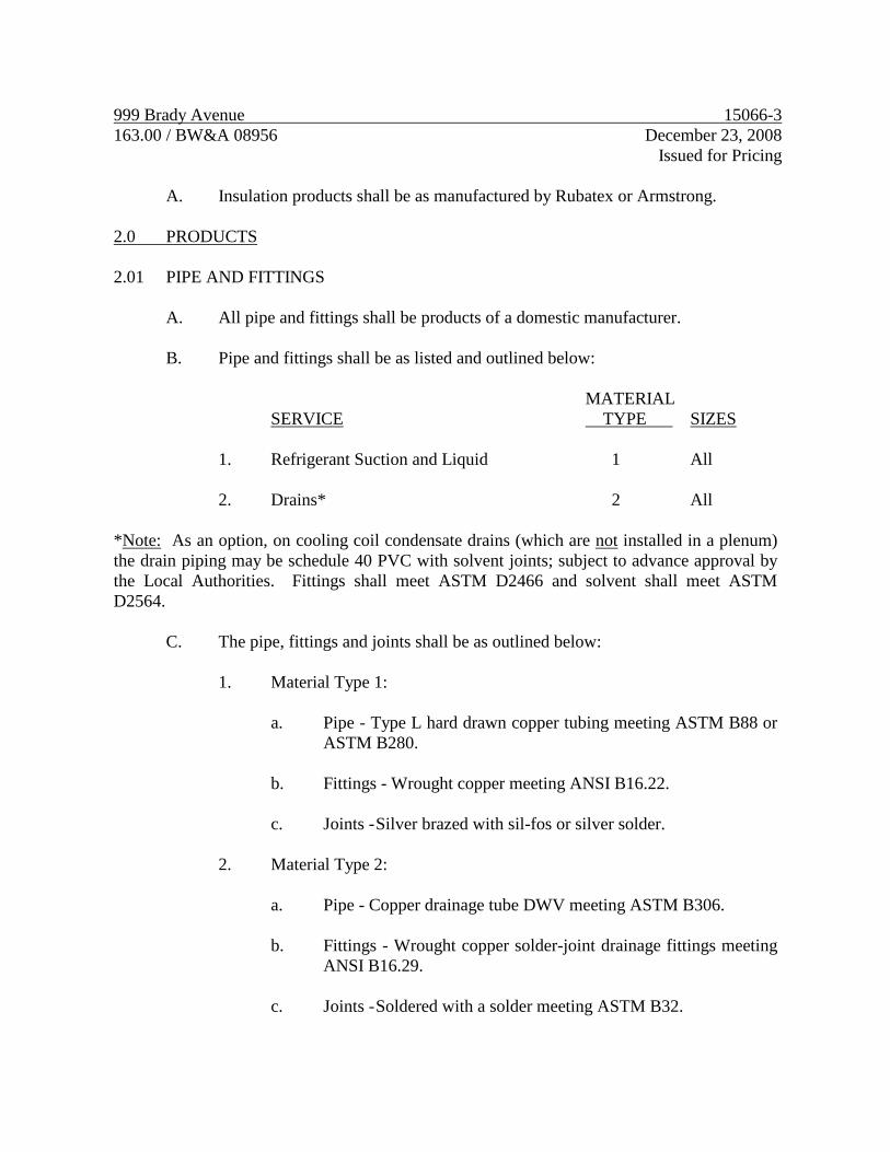
999 Brady Avenue 15066-3
163.00 / BW&A 08956 December 23, 2008
Issued for Pricing
A. Insulation products shall be as manufactured by Rubatex or Armstrong.
2.0 PRODUCTS
2.01 PIPE AND FITTINGS
A. All pipe and fittings shall be products of a domestic manufacturer.
B. Pipe and fittings shall be as listed and outlined below:
MATERIAL
SERVICE TYPE SIZES
1. Refrigerant Suction and Liquid 1 All
2. Drains* 2 All
*Note: As an option, on cooling coil condensate drains (which are not installed in a plenum)
the drain piping may be schedule 40 PVC with solvent joints; subject to advance approval by
the Local Authorities. Fittings shall meet ASTM D2466 and solvent shall meet ASTM
D2564.
C. The pipe, fittings and joints shall be as outlined below:
1. Material Type 1:
a. Pipe - Type L hard drawn copper tubing meeting ASTM B88 or
ASTM B280.
b. Fittings - Wrought copper meeting ANSI B16.22.
c. Joints - Silver brazed with sil-fos or silver solder.
2. Material Type 2:
a. Pipe - Copper drainage tube DWV meeting ASTM B306.
b. Fittings - Wrought copper solder-joint drainage fittings meeting
ANSI B16.29.
c. Joints - Soldered with a solder meeting ASTM B32.
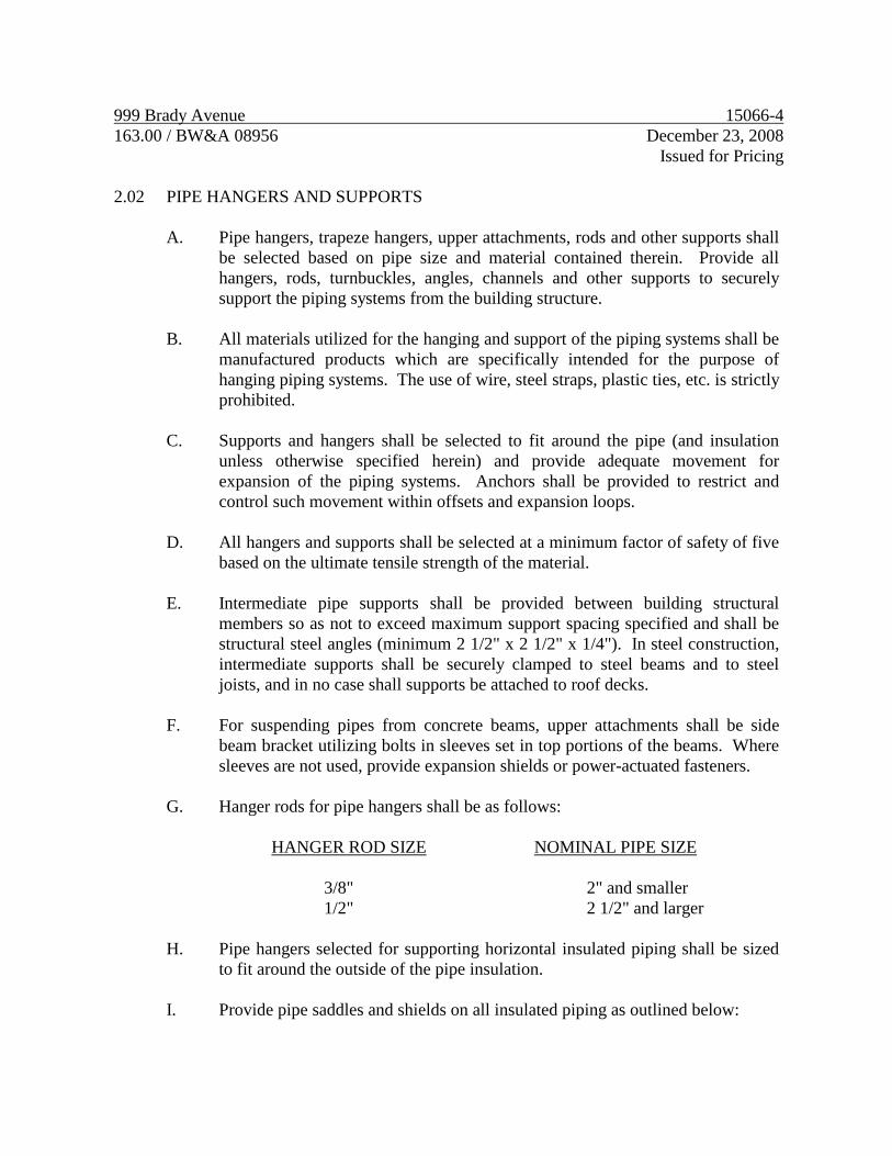
999 Brady Avenue 15066-4
163.00 / BW&A 08956 December 23, 2008
Issued for Pricing
2.02 PIPE HANGERS AND SUPPORTS
A. Pipe hangers, trapeze hangers, upper attachments, rods and other supports shall
be selected based on pipe size and material contained therein. Provide all
hangers, rods, turnbuckles, angles, channels and other supports to securely
support the piping systems from the building structure.
B. All materials utilized for the hanging and support of the piping systems shall be
manufactured products which are specifically intended for the purpose of
hanging piping systems. The use of wire, steel straps, plastic ties, etc. is strictly
prohibited.
C. Supports and hangers shall be selected to fit around the pipe (and insulation
unless otherwise specified herein) and provide adequate movement for
expansion of the piping systems. Anchors shall be provided to restrict and
control such movement within offsets and expansion loops.
D. All hangers and supports shall be selected at a minimum factor of safety of five
based on the ultimate tensile strength of the material.
E. Intermediate pipe supports shall be provided between building structural
members so as not to exceed maximum support spacing specified and shall be
structural steel angles (minimum 2 1/2" x 2 1/2" x 1/4"). In steel construction,
intermediate supports shall be securely clamped to steel beams and to steel
joists, and in no case shall supports be attached to roof decks.
F. For suspending pipes from concrete beams, upper attachments shall be side
beam bracket utilizing bolts in sleeves set in top portions of the beams. Where
sleeves are not used, provide expansion shields or power-actuated fasteners.
G. Hanger rods for pipe hangers shall be as follows:
HANGER ROD SIZE NOMINAL PIPE SIZE
3/8" 2" and smaller
1/2" 2 1/2" and larger
H. Pipe hangers selected for supporting horizontal insulated piping shall be sized
to fit around the outside of the pipe insulation.
I. Provide pipe saddles and shields on all insulated piping as outlined below:
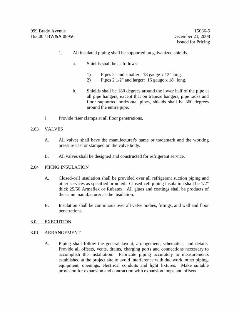
999 Brady Avenue 15066-5
163.00 / BW&A 08956 December 23, 2008
Issued for Pricing
1. All insulated piping shall be supported on galvanized shields.
a. Shields shall be as follows:
1) Pipes 2" and smaller: 18 gauge x 12" long.
2) Pipes 2 1/2" and larger: 16 gauge x 18" long.
b. Shields shall be 180 degrees around the lower half of the pipe at
all pipe hangers, except that on trapeze hangers, pipe racks and
floor supported horizontal pipes, shields shall be 360 degrees
around the entire pipe.
J. Provide riser clamps at all floor penetrations.
2.03 VALVES
A. All valves shall have the manufacturer's name or trademark and the working
pressure cast or stamped on the valve body.
B. All valves shall be designed and constructed for refrigerant service.
2.04 PIPING INSULATION
A. Closed-cell insulation shall be provided over all refrigerant suction piping and
other services as specified or noted. Closed-cell piping insulation shall be 1/2"
thick 25/50 Armaflex or Rubatex. All glues and coatings shall be products of
the same manufacturer as the insulation.
B. Insulation shall be continuous over all valve bodies, fittings, and wall and floor
penetrations.
3.0 EXECUTION
3.01 ARRANGEMENT
A. Piping shall follow the general layout, arrangement, schematics, and details.
Provide all offsets, vents, drains, charging ports and connections necessary to
accomplish the installation. Fabricate piping accurately to measurements
established at the project site to avoid interference with ductwork, other piping,
equipment, openings, electrical conduits and light fixtures. Make suitable
provision for expansion and contraction with expansion loops and offsets.
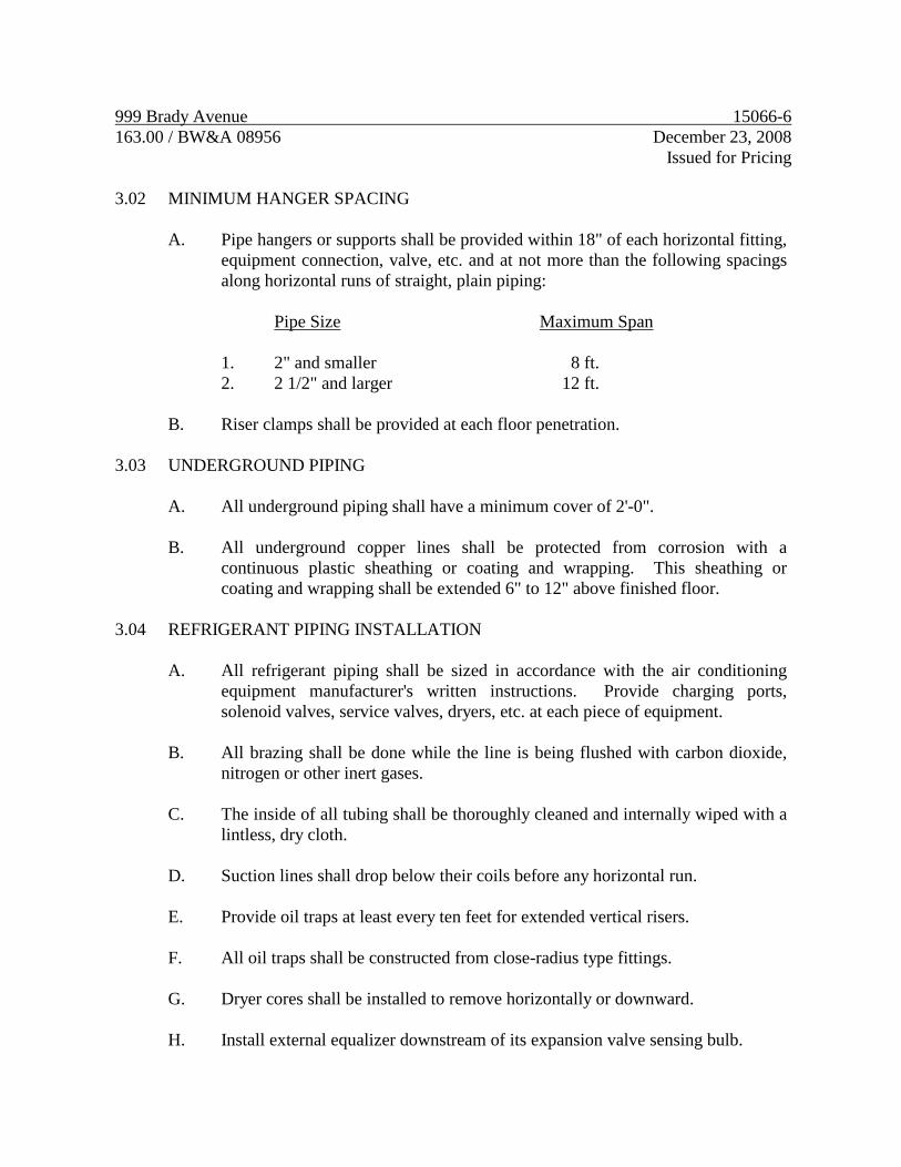
999 Brady Avenue 15066-6
163.00 / BW&A 08956 December 23, 2008
Issued for Pricing
3.02 MINIMUM HANGER SPACING
A. Pipe hangers or supports shall be provided within 18" of each horizontal fitting,
equipment connection, valve, etc. and at not more than the following spacings
along horizontal runs of straight, plain piping:
Pipe Size Maximum Span
1. 2" and smaller 8 ft.
2. 2 1/2" and larger 12 ft.
B. Riser clamps shall be provided at each floor penetration.
3.03 UNDERGROUND PIPING
A. All underground piping shall have a minimum cover of 2'-0".
B. All underground copper lines shall be protected from corrosion with a
continuous plastic sheathing or coating and wrapping. This sheathing or
coating and wrapping shall be extended 6" to 12" above finished floor.
3.04 REFRIGERANT PIPING INSTALLATION
A. All refrigerant piping shall be sized in accordance with the air conditioning
equipment manufacturer's written instructions. Provide charging ports,
solenoid valves, service valves, dryers, etc. at each piece of equipment.
B. All brazing shall be done while the line is being flushed with carbon dioxide,
nitrogen or other inert gases.
C. The inside of all tubing shall be thoroughly cleaned and internally wiped with a
lintless, dry cloth.
D. Suction lines shall drop below their coils before any horizontal run.
E. Provide oil traps at least every ten feet for extended vertical risers.
F. All oil traps shall be constructed from close-radius type fittings.
G. Dryer cores shall be installed to remove horizontally or downward.
H. Install external equalizer downstream of its expansion valve sensing bulb.
999 Brady Avenue 15066-7
163.00 / BW&A 08956 December 23, 2008
Issued for Pricing
I. Install expansion sensing valve bulb on top centerline of piping up to 5/8" size;
install 45 degrees down from the horizontal centerline on pipe sizes 7/8" and
larger.
3.05 CLOSED-CELL PIPING INSULATION INSTALLATION
A. Insulation shall be provided on all refrigerant suction and indoor condensate
drain lines. The insulation shall be installed by the slip-on method; slitting of
the insulation is prohibited and shall be cause for rejection. All elbows shall be
mitered and all such joints and butt joints shall be tightly made and glued.
B. All insulation installed outdoors shall be coated with a glossy white, ultraviolet
protective coating applied in two coats; Armacote or approved equal.
END OF SECTION
999 Brady Avenue 15400-1
163.00 / BW&A 08956 December 23, 2008
Issued for Pricing
SECTION 15400
PLUMBING SYSTEMS
1.0 GENERAL
1.01 DESCRIPTION
A. All work specified in this Section is governed by the Mechanical General
Section 15010.
B. This Section 15400 and the accompanying drawings cover the provision of all
labor, equipment, appliances, and materials and performing all operations in
connection with the construction of the plumbing systems as specified herein
and as shown. These systems include, but are not limited to, the following:
1. Sanitary waste and vent systems.
2. Domestic water systems.
C. Provide all final plumbing connections to all equipment furnished by Owner.
D. Provide gate valve and reduced pressure backflow preventer or vacuum breaker
at the service entrance and at those connections (especially to kitchen
equipment) required by local plumbing code.
1.02 INTENT
A. It is the intent of this Section of the specifications to provide complete and
operable plumbing systems as shown and specified which are free of leaks,
properly vented, free of unreasonable noise, vibration and sweating, and
fabricated so as to fit the space allotted and to exhibit a minimum resistance to
fluid flow.
B. The word "piping" is defined to mean all piping, fittings, joints, hangers,
coatings, valves, cocks, insulation and accessories necessary for the plumbing
systems described, shown and specified.
1.03 GENERAL REQUIREMENTS
A. Provide all reducing fittings, flanges, couplings and unions of the size and type
of material to match the piping connections at each fixture, piece of equipment,

999 Brady Avenue 15400-2
163.00 / BW&A 08956 December 23, 2008
Issued for Pricing
valve and accessory.
B. Union joints, couplings or flanges shall be provided in each pipe line connected
to each piece of equipment, fixture and elsewhere as indicated and specified,
Unions shall match the piping system in which they are installed.
1. Unions or flanges shall be provided between all copper to steel
connections. These unions shall be dielectric, insulating type.
C. All changes in direction and branches shall be made with manufactured fittings.
D. The use of offset-type reducers is strictly prohibited in any piping system.
E. In all water piping systems, changes in horizontal pipe line sizes shall be made
with eccentric reducers installed flat on top for proper air venting. Reducing
tees, reducing elbows and concentric reducers shall only be allowed in water
piping systems for changing pipe sizes in vertical risers and for making
connections to equipment and accessories from vertical risers.
F. All pipe joints shall be cut square and all burrs shall be removed.
G. Open ends of pipe lines not currently being handled shall be plugged during
installation to keep dirt, water and foreign material out of the system.
H. Sanitary waste and storm drainage piping shall slope down in the direction of
flow as shown on the drawings or as prescribed by Code, but not less than 1
percent.
I. All vents through roof (VTR'S) shall be offset just below the roof such that
their termination points are at least 10 ft. from any outside air intake of any
HVAC unit; special attention is called to packaged rooftop units.
J. Trap primers shall be provided at all floor drains and hub drains.
1.04 IDENTIFICATION OF PIPING
A. All aboveground plumbing systems piping and valves sized 3/4" and larger
which are installed in accessible locations (including piping above removable
ceilings and behind access panels) shall be identified in strict conformance with
the "Scheme for the Identification of Piping Systems" (ANSI A13.1 - 1981).
B. Each identification marker shall include the following:
999 Brady Avenue 15400-3
163.00 / BW&A 08956 December 23, 2008
Issued for Pricing
1. Proper color-coded background.
2. Proper color of legend in relation to background color.
3. Proper legend letter size.
4. Proper marker length.
5. Direction of flow arrow shall be included on each marker.
C. Locations for pipe markers shall be as follows:
1. Adjacent to each valve and fitting.
2. At each branch and riser take off.
3. At each pipe passage through walls, floors and ceilings.
4. On all straight pipe runs every 25 feet.
D. Identification markers may be stenciled or shall be Setmark Pipe Markers, as
manufactured by Seton Name Plate Corporation.
E. All valves shall be identified with the appropriate service designation and valve
number brass valve tags. Each valve tag shall be 19 gauge brass with 1/4"
black-filled letters over 1/2" black-filled numbers. Tags shall be fastened to
valves with brass "S" hooks or brass jack chain. Brass tags and fasteners shall
be as manufactured by Seton Name Plate Corporation
F. Provide charts of all valves. Valve charts shall include the following items:
1. Valve identification Number
2. Location
3. Purpose/Material
2.0 PRODUCTS
2.01 SANITARY WASTE AND VENT SYSTEMS
A. All underground sanitary waste and vent piping shall be PVC, DWV Solid Wall

999 Brady Avenue 15400-4
163.00 / BW&A 08956 December 23, 2008
Issued for Pricing
Schedule 40 with socket-type, solvent welded joints in sizes up to 12"; all 15"
piping shall be PVC, DWV Solid Wall Schedule 40 with socket-type, solvent
welded joints.
B. Cleanouts shall be provided at the locations indicated and, as a minimum,
where required by Code. Floor cleanouts shall be a minimum of 4" and shall be
complete with a flush plug and removable, scoriated bronze floor plate.
Provide carpet buttons in carpeted areas.
C. Joints on hubless cast iron soil pipe shall be made with neoprene couplings and
stainless steel clamps.
D. All aboveground sanitary, waste and vent piping shall be **PVC DWV Solid
Wall Schedule 40 with socket-type, solvent welded joints; except that sanitary,
waste and vent piping located within return air plenums or as noted on plans
shall be hubless cast iron soil pipe.
E. Floor drains in toilets and finished areas shall be J. R. Smith 2000 Series with
6" Type B square adjustable strainers finished in satin nickel bronze; or equal
products by Josam or Zurn. Provide vandalproof secured tops. All floor drains
shall be provided with a trap primer.
F. Floor drains in mechanical rooms and unfinished concrete floors shall be J. R.
Smith 2131 Series with round 11 3/4" cast iron grate, sediment bucket and
deep-seal P-trap; or equal products by Josam or Zurn. Provide vandalproof
secured tops. All floor drains shall be provided with a trap primer.
2.02 DOMESTIC WATER SYSTEM
A. Underground domestic water service entrance piping 3" and smaller in size
shall be Type K hard drawn copper tubing with wrought copper fittings. All
joints shall be brazed.
B. All underground copper branch lines (1/2" and 3/4" only) shall be continuous
lengths of soft Type K copper tubing with no joints allowed underground.
C. Underground domestic water service entrance piping above 3" in size shall be
Class 150 ductile iron pipe with mechanical joints.
D. Aboveground domestic water system piping 3" in size and smaller shall be
Type L hard drawn copper tubing with wrought copper fittings and soldered
joints.

999 Brady Avenue 15400-5
163.00 / BW&A 08956 December 23, 2008
Issued for Pricing
E. Aboveground domestic water piping 4” and larger shall by Type L hard drawn
copper tubing with rolled grooved joints and fittings.
F. Gate valves 3" or less in size shall be constructed with a bronze body, non-
rising stem. Stem to be bronze ASTM B-62 or silicon bronze ASTM B-371
with malleable iron handwheels. Valve shall meet MSS-SP80. Valve shall be
manufactured by Milwaukee, Hammond, Nibco or Stockham.
G. Ball valves 2 inch and smaller:
1. Ball valves shall be two piece bronze body, large port with solid,
smooth bore chrome plated brass ball, meeting MSS-SP110. Seats shall
be reinforced TFE with Teflon packing ring and threaded adjustable
packing nut. Valves on insulated lines will be provided with stem
extensions to provide clearance for two inches of pipe insulation.
Valves to be Apollo 70, Hammond 8501 or Watts B-6000.
H. Non-freeze wall hydrants (NFWH) shall be non-freeze, bronze box type with
vacuum breaker, loose key and wall clamp. Finish shall be rough bronze. Wall
hydrants shall be Smith 5509QTPB or approved equal by Josam or Zurn.
I. Backflow preventers shall be Watts Series 909 reduced pressure principle
backflow preventers complete with strainer and shut-off valves. Air gap drain
shall be piped into nearest floor drain or outside of building to a concrete
splashblock.
J. Water pressure reducing valves (PRV) shall be the self-contained direct
operating type with bronze body, stainless steel seat, stainless steel spring, and
sealed spring cage. The strainer shall have bronze body with 20 mesh stainless
steel screen. Strainer shall be attached with a bronze nipple. The unit shall be
constructed in accordance with ASSE Standard 1003 and shall bear the seal of
approval. The capacities shall be based on maximum reduced pressure fall-off,
as defined in the ASSE Standard, of 10 pounds. Pressure regulators shall be
Watts Regulator Company's Series 223S or approved equal.
K. All water hammer arresters (WHA) shall be PDI Certified, Size A, B, C, D, E
or F, as indicated for the fixture units served; Josam, Jay R. Smith or Zurn.
L. Soldered joints shall be made with tin-antimony/silver solder. Solder
containing lead shall not be permitted.
2.03 PLUMBING INSULATION

999 Brady Avenue 15400-6
163.00 / BW&A 08956 December 23, 2008
Issued for Pricing
A. All pipe insulation products shall have a permanent composite insulation, jacket
and adhesive fire and smoke hazard rating as tested by procedure ASTM-84,
NFPA 255 and UL 723 not exceeding Flame Spread 25 or Smoke Developed
50.
B. Blanket-type insulation shall have an average thermal conductivity not to
exceed 0.27 BTU-in. per sq. ft. per degrees F. per hour at a mean temperature of
75 degrees F. Insulation shall have a minimum density of 1 lb./cu.ft. and shall
be 2" thick.
C. Preformed insulation for all domestic hot and cold water piping shall be
minimum 1" thick preformed fiberglass pipe insulation with white all-service
jacket. All longitudinal joints shall be lapped, self-sticking type with all butt
joints, tears, etc. sealed with a matching white vapor barrier tape. Elbows shall
be mitered or may be Zeston covers filled with equivalent fiberglass insulation.
The maximum K value of the insulation shall be 0.23 at 70 degrees F.
2.04 PIPE HANGERS AND SUPPORTS
A. Pipe hangers, hanger rods, trapeze type hangers, upper attachments and other
supports shall be selected based on pipe size (plus insulation of pipes specified
to be insulated) and the weight of the medium being transported or the medium
used for testing, whichever is greater. Provide all hangers and rods,
turnbuckles, angles, channels, and other structural supports to support the
piping systems. Rods for pipe hangers shall be full size of the hanger
manufacturer's catalog listed rod size for each type hanger specified. Hangers
and supports shall be Michigan, ITT Grinnell or B-Line.
B. All material utilized for the hanging and support of the piping systems shall be
manufactured products which are specifically intended for the purpose of
hanging piping systems. The use of wire, steel straps, plastic ties, etc. is strictly
prohibited.
C. Pipe hangers selected for supporting horizontal insulated piping shall be sized
to fit around the outside of the pipe insulation. Insulated piping shall be
supported on galvanized shields.
1. Shields shall be as follows:
a. Pipes 2" and smaller: 18 gauge x 12" long.
b. Pipes 2 1/2" and larger: 16 gauge x 18" long.
999 Brady Avenue 15400-7
163.00 / BW&A 08956 December 23, 2008
Issued for Pricing
2. Shields shall be 180 degrees around the lower half of the pipe at all pipe
hangers, except that on trapeze hangers, pipe racks and floor supported
horizontal pipes, shields shall be 360 degrees around the entire pipe.
D. Pipe hangers for copper piping shall be copper plated or the piping shall be
dielectrically isolated from any steel hangers or clamps that are used.
E. Steel rods, framing and clamps shall be plated or primed to prevent rust
formation.
3.0 EXECUTION
3.01 ARRANGEMENT
A. Follow the general piping layout, arrangement, schematics and details. Provide
all offsets, vents, drains and connections necessary to accomplish the
installation. Fabricate piping accurately to measurements established at the
project site to avoid interference with ductwork, other piping, equipment,
openings, electrical conduits and light fixtures. Make suitable provision for
expansion and contraction with expansion loops and offsets.
B. Water hammer arresters shall be installed at the top of each riser and on each
fixture branch in accordance with Plumbing and Drainage Institute Standard
WH201.
C. Cleanouts shall be provided at the base of all sanitary and storm risers.
3.02 UNDERGROUND WATER PIPING
A. All underground domestic water piping shall have a minimum cover of 3'-0".
B. Provide concrete thrust blocks at all changes of direction and secure all
mechanical joints with restraining rods.
C. All underground copper water lines shall be protected from corrosion with a
continuous plastic sheathing or coating and wrapping. This sheathing or
coating and wrapping shall be extended 6" to 12" above finished floor.
3.03 MINIMUM HANGER SPACING
A. Pipe hangers or supports shall be provided within 18" of each horizontal fitting,
equipment connection, valve, etc. and at not more than 10 ft. spacings along
999 Brady Avenue 15400-8
163.00 / BW&A 08956 December 23, 2008
Issued for Pricing
horizontal runs of straight, plain piping.
B. Riser clamps shall be provided at each floor penetration.
3.04 FIRESTOPPING PVC PIPING
A. PVC, soil, waste and vent stacks penetrating fire-rated floors and walls shall be
flamestopped, firestopped, and waterproofed using ProSet Systems, Inc. Series
45 "Firestop" couplings and Series 90 "Code Red" firestop devices. All other
PVC drain, waste, and vent piping penetrating fire-rated floors shall be
firestopped and waterproofed using ProSet Systems Series 48 closet stubs, tub
boxes, floor drains, shower drains, and "E-Z Flex" flexible couplings. All shall
be installed in accordance with the manufacturer's instructions.
B. ProSet "Firestop" couplings used in the DWV system shall be of type I PVC
conforming to ASTM D2665 standard. ProSet "Code Red" stack fittings shall
be of gray cast iron conforming to ASTM A-48 standard. ProSet "E-Z Flex"
connector couplings shall be of flexible PVC conforming to ASTM C594 and
ASTM F477 performance standards. Band used for compression joint on the
"E-Z Flex" coupling shall be #300 stainless steel. IPS P-70 Primer and Weld-
on 795 cement or equal shall be used for all solvent welds in the system.
3.05 INSULATION INSTALLATION
A. Provide blanket insulation over all horizontal roof drain piping which is within
the building and including the vertical risers to the roof drains and the
underbody of the roof drains.
1. Blanket insulation shall be wrapped around the piping and underbodies
of roof drains. Ends of insulation shall overlap at least 2" and bottom of
insulation shall overlap pipe insulation at pipe connection to roof drain
at least 3". Adhere insulation to roof drain underbodies with 100%
coverage of fire retardant adhesive and tape all joints with 3" wide foil
reinforced kraft tape.
B. Provide insulation over all above ground hot and cold water piping, except that
no insulation is required on cold water lines installed inside interior plumbing
chases (those chases with no exterior wall).
1. All joints and tears shall be sealed with matching white vapor barrier
tape.
999 Brady Avenue 15400-9
163.00 / BW&A 08956 December 23, 2008
Issued for Pricing
3.06 PIPING INSTALLATION ABOVE CEILINGS
A. All domestic hot and cold water piping installed above the insulated ceilings
shall be installed just above (within 2") of the top of the finished ceiling with
the building insulation over the piping to avoid freeze-up.
3.07 DISINFECTION
A. All domestic water piping installed under this Division shall be disinfected with
chlorine before it is placed into operation. The chlorinating material shall be
liquid chlorine conforming to Federal Specification BB-C-120 and shall be
introduced to the system by experienced operators only. The chlorine solution
applied to the piping sections or system shall contain at least fifty parts per
million of available chlorine and shall remain in the sections or system for a
period of not less than sixteen (16) hours. During the disinfection period, all
valves shall be opened and closed at least four times. After the disinfection
period, the chlorinated water shall be flushed from the system with clear water
until the residual chlorine content is not greater than two-tenths parts per
million (0.2 PPM). Submit certification to the Architect that the system was
disinfected.
END OF SECTION
999 Brady Avenue 15424-1
163.00 / BW&A 08956 December 23, 2008
Issued for Pricing
SECTION 15424
WATER HEATERS AND ACCESSORIES
1.0 GENERAL
1.01 DESCRIPTION
A. All work specified in this Section is governed by the Mechanical General
Section 15010.
B. This Section 15424 and the accompanying drawings cover the provisions of all
labor, equipment, appliances, and materials and performing all operations in
connection with the construction of the water heating systems as specified
herein and as shown. These systems include, but are not limited to, the
following:
1. Water heaters
2. Hot water circulator
2.0 PRODUCTS
2.01 INSTANTANEOUS WATER HEATERS
A. Instantaneous water heaters shall be electric instantaneous type, as scheduled on
the plans.
B. Water heater shall be U.L. listed, complete with thermostat and an ASME
temperature and pressure relief valve.
C. Water heater shall be a Chronomite or an approved equal.
2.02 WATER HEATER COMMERCIAL ELECTRIC
A. The water heater shall be A.O. Smith Conservationist Series Model with three
(3) elements or DEL Series, as scheduled on the plans.
B. Water heater shall have an approved working pressure of 150 psi. The tank
shall be glass-lined and shall have a magnesium anode to provide electrolytic
protection. The entire heater shall be UL listed, shall meet or exceed the
ASHRAE Standard 90 for energy efficiency and shall be insulated with high
999 Brady Avenue 15424-2
163.00 / BW&A 08956 December 23, 2008
Issued for Pricing
density polyurethane foam insulation for maximum heat retention.
C. Controls shall include an operating thermostat and manual reset high limit
control. All controls shall be factory-wired and require no external power
source.
D. Water heater shall be provided with access door and ASME T&P relief valve.
2.03 HOT WATER CIRCULATOR
A. Hot water circulator shall be Bell & Gossett as scheduled on plans.
3.0 EXECUTION
3.01 INSTALLATION
A. The water heaters and accessories shall be installed in strict accordance with the
manufacturer's recommendations and the Contract Documents.
B. All temperature and pressure relief valves shall be piped full size to an indirect
waste such as the nearest floor drain, service sink, sink tailpiece, etc.
END OF SECTION
999 Brady Avenue 15450-1
163.00 / BW&A 08956 December 23, 2008
Issued for Pricing
SECTION 15450
PLUMBING FIXTURES AND TRIM
1.0 GENERAL
1.01 DESCRIPTION
A. All work specified in this section is governed by the Mechanical General Section
15010.
B. This Section 15450 and the accompanying drawings cover the provisions of all
labor, fixtures, equipment, appliances and materials, and performing all
operations in connection with the construction and installation of the plumbing
fixtures and trim as specified herein and as shown.
C. All exposed piping, valves, stops, P-traps, etc. shall be chrome-plated. Also, all
exposed piping penetrations through walls, floors or ceilings shall be provided
with chrome-plated cast brass escutcheons.
D. All P-traps shall be minimum 17-gauge brass.
E. Flush valves shall have non-hold open feature, vacuum breakers and cover cap on
angle-type stop.
F. Provide all final connections to all equipment and fixtures furnished by Owner.
G. Unless otherwise specified in an individual fixture description, all enameled cast-
iron and porcelain fixtures shall be white.
1.02 INTENT
A. It is the intent of this Section of the specifications to provide complete, operable,
adjusted, clean plumbing fixtures as shown and specified, which are free of leaks,
noise, air, vibration and waterflow fluctuations.
1.03 BASIS OF DESIGN
A. The basis of design is as outlined for each fixture in the 2.0 PRODUCTS
subsection. Any proposed substitutions shall be proven equal in all respects to
the equipment specified as the basis of design.
999 Brady Avenue 15450-2
163.00 / BW&A 08956 December 23, 2008
Issued for Pricing
1.04 ACCEPTABLE MANUFACTURERS
A. Acceptable fixture manufacturers are American Standard, Zurn, Falcon and
Kohler, provided that their units are equal in all respects for this specific project.
Faucets and trim may be equal products as manufactured by Chicago, Delany,
Zurn, T&S Bronze, Brass Craft, Speakman and McQuire.
B. Flush valves may be equal products by Sloan, Zurn and Delany. Stainless steel
sinks and drinking fountains shall be as manufactured by those companies
specified for each specific item outlined under subsection 2.0 PRODUCTS.
2.0 PRODUCTS
2.01 PLUMBING FIXTURES
A. Refer to architectural plans for fixture specifications.
3.0 EXECUTION
3.01 INSTALLATION
A. Units shall be installed as indicated and in conformance with the manufacturer's
recommendations. Coordinate the actual units to be provided with all trades.
B. All plumbing fixtures shall be free of leaks, provided completely finished,
trimmed, adjusted, cleaned and ready for use. They shall be properly secured to
the structure by the use of thru-bolting, backplates, carriers, expansion shields (for
floor mounting only) or toggle bolts.
C. Wall hung fixtures supported on chair carriers shall be bolted to the floor slab.
Carefully coordinate space requirements and fixture mounting height
requirements with supports being furnished.
D. Fixtures supported with wall hangers on masonry chase walls shall be fastened to
the wall with not less than 3/8" bolts which shall pass through the wall and
through a 1/4" x 4" wide steel backplate on the unfinished chase wall side.
E. Where fixtures are hung on single masonry walls without a pipe chase behind,
they shall be mounted with 3/8" toggle bolts.
F. Fixtures on steel stud walls shall have a 1/4" x 4" wide steel backplate wired with
1/16" steel wire to the studs. Bolts not less than 3/8" shall secure the fixtures

999 Brady Avenue 15450-3
163.00 / BW&A 08956 December 23, 2008
Issued for Pricing
through the fixture hanger and the backplate.
G. All mounting holes provided in fixtures shall be used for support. In addition to
the main hangers, 1/4" toggle bolts shall secure the bottom of all wall hung
fixtures at each drilling provided for this purpose.
H. Mount wall-hung fixtures at the heights indicated on the Architectural Drawings
or as prescribed by local code. Special attention is called to the installation
requirements of the ANSI Handicap Code.
3.02 CLEANING AND ADJUSTMENT
A. The units shall be cleaned, tested and field-adjusted to provide optimum flow and
drainage.
END OF SECTION
999 Brady Avenue 15525-1
163.00 / BW&A 08956 December 23, 2008
Issued for Pricing
SECTION 15525
FIRE SUPPRESSION SYSTEMS
1.0 GENERAL
1.01 DESCRIPTION
A. All work specified in this Section is governed by the Mechanical General
Section 15010.
B. This Section 15525 and the accompanying drawings cover the provisions of all
labor, equipment, appliances, and materials and performing all operations in
connection with the engineering, design and construction of the fire suppression
systems as specified herein and as shown.
C. Attention is called to the different hazards, classes and types of fire suppression
systems required within the facility. Systems shall include, but not be limited
to the following:
1. Light hazard
2. Ordinary hazard
D. The work included under this Section 15525 shall include, but is not limited to,
the following:
1. Risers including all check valves, indicator valves, alarms, etc.
2. Standpipes, hose connections, hose cabinets and hoses
3. Siamese connections
4. Piping and sprinkler heads
5. Hydraulic design computations
6. Shop drawings and procurement of all approvals
1.02 STANDARDS AND APPROVALS

999 Brady Avenue 15525-2
163.00 / BW&A 08956 December 23, 2008
Issued for Pricing
A. The standpipes and sprinkler systems shall be designed and installed in
conformance with the applicable standards of NFPA 13, NFPA 14, NFPA 20,
NFPA 24, NFPA 72, Underwriters Laboratories (UL), the standards of the
Underwriter (IRI/FM/ISO) and local codes.
B. The hydraulic calculations, standpipes and sprinkler system design and
installation shop drawings shall be submitted and approved by the Owner's
Underwriter and the Fire Marshal.
C. The standpipes and sprinkler systems shall be installed by a firm which is duly
licensed to install such systems in the State of Georgia and carries a current
certificate from the Georgia State Fire Marshal's Office.
1.03 RECORD DRAWINGS
A. Upon completion of the work, provide record as-built documentation of the fire
protection systems as actually installed to the Owner. Drawings shall be to
scale, and shall include all details required to accurately indicate the system as
installed. Record drawings shall be produced in electronic format compatible
with AUTOCAD 2006. Furnish two (2) CD’s with all drawings in dwg.
format, one (1) vellum copy and two (2) bond copies of all drawing sheets.
1.04 IDENTIFICATION
A. All control, check, drain, test and alarm valves and alarms shall be provided
with identification signs of the standard design as adopted by the sprinkler
industry and as recommended for the particular services. The signs shall be
securely attached to each piece of equipment.
1.05 HOSE THREADS
A. Hose threads shall conform to the standards of the local Fire Department. The
exact threads used shall be verified with the Fire Department before ordering
materials.
2.0 PRODUCTS
2.01 MINIMUM QUALITY LEVEL
A. All equipment and materials provided under this Section 15525 shall be new
and of the best grade commercial quality, shall be of the latest design of the
999 Brady Avenue 15525-3
163.00 / BW&A 08956 December 23, 2008
Issued for Pricing
manufacturer, and shall be listed and approved by U.L. and the Underwriter.
Materials and equipment manufactured outside of the United States will not be
acceptable. All components shall be suitable for the pressures indicated on the
flow test.
2.02 VALVES
A. Materials shall be as follows:
1. Valves 2" and smaller: Bronze body
2. Valves over 2": Iron body with bronze trim
B. Connections shall be as follows:
1. Valves 4" and smaller: Threaded or flanged
2. Valves over 4": Flanged
C. Gate valves shall be double seat; type as follows:
1. Valves 2" and smaller: Rising stem type, except where space requires
non-rising stem, solid wedge with union bonnet and replaceable seat
rings.
2. Valves over 2": Outside screw and yoke type with solid wedge and
replaceable seat rings.
D. Butterfly valves shall have bronze or ductile iron discs, stainless steel shaft and
lock bolts, Buna N liner and as follows:
1. Valves through 6": Full lug type with lever operators
2. Valves over 6": Full lug type, gear operators
E. Fire department valves (FDV) shall be 2 1/2" screwed, U.L. approved, brass
hose valves for working pressure of 175 psig with 2 1/2" male hose threads, 1
1/2" removable reducer, polished brass cap and chain.
F. Swing checks shall be gravity operated with renewable composition discs.
Wafer checks shall have renewable clapper facings and non-stick coated

999 Brady Avenue 15525-4
163.00 / BW&A 08956 December 23, 2008
Issued for Pricing
clappers, valve shall be approved for both horizontal and vertical installation.
G. All valves shall comply with requirements of NFPA and shall be Underwriters'
Laboratories, Inc. (UL) listed.
H. Working pressure of all valves shall be minimum **175/300** psig at 70
degrees F. water temperature.
I. All valves utilized for shut-off service shall be lockable in the open position.
J. Alarm valves shall have electrical circuit closers.
2.03 ROOF MANIFOLDS
A. Roof manifolds shall be Y-type, 4" x 2 1/2" x 2 1/2"; brass construction
complete with caps and chains.
2.04 FIRE DEPARTMENT SIAMESE CONNECTIONS
A. Provide 2-1/2" x 2-1/2" x 4", chrome plated, lettered **"Standpipe & Auto-
Spkr"**, threads to match local Fire Department, with caps and chains.
2.05 DRAINS
A. Drains shall be provided in all risers and auxiliary drains at all low points in the
system. Inspector's test drains shall be installed on each sprinkler system.
B. Pipe the main drain and test lines full size to the outside. Do not spill on
walkways.
C. Pipe small drips and drains to the outside of the building or to an indirect drain
within the building.
2.06 WATER FLOW SWITCHES
A. Water flow switches with normally closed electrical contacts shall be provided
in all required locations to open the electrical contacts at any time water flows
in the associated riser or zone piping system.
2.07 TAMPER SWITCHES
999 Brady Avenue 15525-5
163.00 / BW&A 08956 December 23, 2008
Issued for Pricing
A. Tamper switches with normally closed electrical contacts shall be provided in
all required locations to open the electrical contacts at any time the associated
valve is not fully open.
2.08 ALARM SYSTEM
A. Provide interlocks to the building fire alarm system to provide automatic
signaling to an approved remote location with adequate dialing and
communication system to alert the local fire department. Connection and
leased line shall be provided by owner.
2.09 SPRINKLER HEADS
A. All sprinkler heads shall be automatic, closed-type standard spray heads.
B. Sprinkler Heads in Ceilings:
1. All areas with suspended ceilings shall have heads equal to Reliable
Model G, semi-recessed type. Finish shall be as selected by the
Architect.
2. All public areas shall be provided with concealed, fully recessed heads.
Finish shall be as selected by the Architect.
3. All leasable future tenant areas with suspended acoustical tile ceilings
shall have heads equal to Reliable Model G, semi-recessed type.
Finish shall be as selected by the Architect.
C. Sprinkler heads installed in storage, utility, mechanical equipment rooms and
similar “back-of-house” areas without ceilings shall be bronze heads in the
upright position unless otherwise noted.
D. The temperature rating of the sprinkler heads shall be in accordance with
applicable code and the recommendations of the Underwriter.
E. Sprinkler guards shall be provided for all heads within seven feet of the floor,
in mechanical, electrical and storage rooms, and elsewhere as required by the
Underwriter.
F. Provide to the Owner a cabinet containing two (2) head wrenches and a
minimum of six (6) spare heads of each type and temperature rating used in the
999 Brady Avenue 15525-6
163.00 / BW&A 08956 December 23, 2008
Issued for Pricing
systems.
G. All heads installed in areas with tile ceilings shall have the heads centered in
the tile.
2.10 PIPING
A. Piping shall be Schedule 40, grade A53 or A120; except that Schedule 10
piping is acceptable on pipe sizes 2 1/2” and larger where permitted by the
applicable codes and standards. Schedule 10 piping shall not be threaded nor
cut-grooved. Couplings and fitting shall be Victaulic.
B. The use of light-wall threaded pipe such as Allied XL is prohibited.
C. At the contractor’s option, individual drops to sprinkler heads may be flexible
corrugated stainless steel hose with stainless steel braid, approved by both
Factory Mutual and U.L. Flexible hose shall be secured above the ceiling with
galvanized sheetmetal brackets and clamps. Flexible hose, brackets and clamp
shall be as manufactured by Flexhead Industries, Inc. or an approved equal.
D. Underground sprinkler entrance piping shall be Class 150 ductile iron pipe with
mechanical joints.
2.11 PIPE HANGERS AND SUPPORTS
A. Provide all necessary hangers, supports, bracing, accessories, etc., as required
for proper installation of the work, and only approved type hangers shall be
used. All sprinkler piping shall be supported from building structure; sprinkler
lines under ducts shall not be supported from ductwork but shall be supported
from building structure with trapeze hangers where necessary.
B. Piping supported from floors shall be provided with steel support bases.
2.12 ESCUTCHEONS
A. Each penetration through walls and ceilings shall be equipped with a chrome-
plated escutcheon at the point the pipe passes through the wall or ceiling.
3.0 EXECUTION
3.01 DESIGN AND INSTALLATION

999 Brady Avenue 15525-7
163.00 / BW&A 08956 December 23, 2008
Issued for Pricing
A. The design and installation of the fire suppression systems shall be based on the
hazards and classes required by the occupancies indicated.
B. Underground piping shall be provided with a minimum of 3'-0" of ground
cover. Concrete thrust blocks shall be provided at all changes of direction.
Provide restraining rods at all mechanical joints.
3.02 FLUSHING
A. All underground lines, before connecting to the sprinkler systems, shall be
flushed thoroughly in accordance with NFPA procedures.
3.03 TESTING
A. The entire sprinkler system shall be tested at not less than 200 psi for not less
than 2 hours. The 300 psi sections shall be tested at not less than 300 psi for
not less than 2 hours. All leaks discovered shall be repaired by tightening,
replacing or re-working the leaking component or joint.
END OF SECTION
999 Brady Avenue 15773-1
163.00 / BW&A 08956 December 23, 2008
Issued for Pricing
SECTION 15773
SPLIT SYSTEMS
1.0 GENERAL
1.01 DESCRIPTION
A. All work specified in this Section is governed by the Mechanical General
Section 15010.
B. This Section 15773 and the accompanying drawings cover the provision of all
labor, equipment, appliances and materials, and performing all operations in
connection with the construction and installation of the split systems as
specified herein and as shown. This work includes, but is not limited to, the
following:
1. Split system fan coil, heating section and condensing units
2. Control system (interlocked to all split system components)
C. Split system units shall be self-contained, automatic, packaged units. These
units shall be completely factory assembled as unitary packages complete with
operating controls, internal wiring and piping and fully charged with R-22
refrigerant. Only one electrical power connection shall be required for each
unit.
D. Units shall be UL listed and cooling capacities shall be certified in accordance
with ARI 210.
1.02 INTENT
A. It is the intent of this Section of the specifications to provide complete,
operable, adjusted split systems, as shown and specified, which operate
efficiently and automatically, and are free of excessive noise and vibration.
1.03 BASIS OF DESIGN
A. The basis of design is Carrier. Any proposed substitutions shall be submitted in
accordance with the prior approval requirements.
2.0 PRODUCTS
999 Brady Avenue 15773-2
163.00 / BW&A 08956 December 23, 2008
Issued for Pricing
2.01 UNIT CASINGS
A. Unit casings shall be formed, galvanized steel construction with welded
assembly. Galvanized steel surfaces shall be bonderized and painted with
baked acrylic enamel for complete weather protection. Accessories and
components shall match and interlock with all other split system components.
Fan coil unit casings shall be fully internally insulated with liner which meets
NFPA 25/50 flame spread/smoke developed ratings.
2.02 CONDENSING UNITS
A. Condensing unit refrigeration systems shall be factory charged and ready for
operation. All units with capacities greater than five (5) tons shall be provided
with minimum 2-stage (50% and 100%) cooling. Compressor(s) shall be direct
drive, 3600 RPM, hermetic reciprocating type with centrifugal oil pump,
crankcase heater and internal pressure relief valve. Compressor(s) shall have
internal spring isolation and sound muffling and exhibit minimum vibration
transmission and noise. Anti-recycle timers shall be provided to prevent
excessive cycling of compressors thru utilization of a minimum five (5) minute
time shutdown of unit on interruption of power or controlled shutdown.
B. Condensing unit condenser fans shall be direct-driven, propeller blade type.
Condensing unit heat rejection shall be vertically upward.
2.03 COILS
A. Evaporator and condenser coils shall be copper tubing mechanically bonded to
heavy duty aluminum fins. Aluminum tubes shall not be acceptable.
2.04 ELECTRIC HEATING SECTIONS
A. Electric heating sections shall be UL listed with nickel-chromium open coil
resistance heating elements. Each heater shall be protected by an automatic
reset high-limit thermostat and manual reset high-limit thermostat for the
primary and secondary overcurrent/thermal protection. A proof of airflow/fan
interlock shall also be provided. Controls shall provide for multiple stage start-
up and operation.
2.05 CONTROLS AND ACCESSORIES
A. All operating and safety controls which are internal to each unit shall be factory
installed and shall include, as a minimum, solid state compressor overload
999 Brady Avenue 15773-3
163.00 / BW&A 08956 December 23, 2008
Issued for Pricing
protection, magnetic contactors, thermostatic expansion valve(s), refrigerant
line drier(s), outdoor fan and compressor cycling thermostats, high and low
limit protection against excessive temperatures or pressures.
B. A 24 volt transformer shall be provided to accommodate an accessory 24 volt
indoor thermostat complete with an electronic programmable night setback,
separate automatic heat/cool settings, auto/manual fan control and seasonal
selector. Thermostat shall provide staging of the cooling and heating to match
the stages of each component.
C. Provide a locking cover for each indoor thermostat.
D. Controls on electric heat section shall meet NEMA specifications and
requirements.
E. Automatic shutdown controls shall be provided to meet local codes (or NFPA
90A as a minimum) and shall consist of firestats and duct-mounted smoke
detectors interlocked to the fan coil unit for shutdown on the detection of fire or
smoke.
2.06 FILTERS
A. Units shall have minimum 1 inch thick, low velocity, glass fiber throwaway
filters in commercially available sizes.
3.0 EXECUTION
3.01 INSTALLATION
A. The split systems and associated controls shall be installed in strict accordance
with the manufacturer's recommendations.
B. The control system shall be completely wired under this Division 15. Wiring
shall be in accordance with the N.E.C. and shall meet all requirements for this
installation.
3.02 STARTUP
A. Provide the services of a factory trained and qualified service technician
employed by the unit manufacturer who shall inspect the installation including
external interlock and power connections; supervise leak testing, initial
operation, calibration of operating and safety controls and supervise electrical
999 Brady Avenue 15773-4
163.00 / BW&A 08956 December 23, 2008
Issued for Pricing
testing including insulation resistance of motors and voltage balance between
phases during starting and running.
B. This service technician shall forward a report in four (4) copies to the Owner
when the unit is in safe and proper operating condition. This report shall
include all pressure and control settings, meg readings, voltage readings per
phase during start and run, and shall list minor discrepancies to be corrected
that affect safe and reliable operation. One additional copy of the report shall
be left in the unit control panel. One copy of bound installation, operation,
maintenance service and parts brochures, including applicable serial numbers,
full unit description and parts ordering sources, shall be placed in the unit
control panel at the time of startup; four (4) additional copies shall be
forwarded to the Owner.
END OF SECTION

999 Brady Avenue 15774-1
163.00 / BW&A 08956 December 23, 2008
Issued for Pricing
SECTION 15774
PACKAGED ROOFTOP UNITS
1.0 GENERAL
1.01 DESCRIPTION
A. All work specified in this Section is governed by the Mechanical General
Section 15010.
B. This Section 15774 and the accompanying drawings cover the provisions of all
labor, equipment, appliances and materials, and performing all operations in
connection with the construction and installation of the packaged rooftop units
as specified herein and as shown. This work includes, but is not limited to, the
following:
1. Packaged rooftop units including curbs and accessories
2. Control system (interlocked to the units)
C. Units shall be self-contained, rooftop curb-mounted, single package type. The
rooftop units shall be completely factory assembled as a unitary package
complete with operating controls and shall be completely piped, internally
wired and fully charged with R-22 refrigerant. Only one electrical power
connection shall be required.
1.02 INTENT
A. It is the intent of this Section of the specifications to provide complete,
operable, adjusted single package rooftop units, as shown and specified which
are free of excessive noise and vibration.
1.03 BASIS OF DESIGN
A. The basis of design is Carrier. Any proposed substitutions or equals by other
manufacturers shall be proven equal in all respects to the equipment specified
as the basis of design. Particular attention is called to the requirements of
Section 15010.
B. Equal units by Trane or York are acceptable.

999 Brady Avenue 15774-2
163.00 / BW&A 08956 December 23, 2008
Issued for Pricing
2.0 PRODUCTS
2.01 CURB
A. Each unit shall be provided with a full perimeter roof curb. The roof curb shall
be of the same manufacturer as the unit, shall support the unit and provide a
watertight enclosure to protect ductwork and utility services. Curb design shall
comply with National Roofing Contractors Association requirements.
Supply/return air opening gasketing shall be provided. Channel shall be
provided allowing for adjustment of return air opening location to match the
building structural frame indicated.
2.02 UNIT CABINETS
A. Rooftop unit cabinets shall be formed, galvanized steel construction with
welded base assembly. Galvanized steel surfaces shall be bonderized and
painted with baked acrylic enamel for complete weather protection. All sheet
metal screws shall be stainless steel. The outside air dampers shall be low leak
gasketed dampers which must match and interlock with the single package
rooftop units. Cabinets shall be fully insulated.
B. Unit cabinets shall be designed for curb mounting and mate with the full
perimeter roof curb for a complete weathertight seal. Unit sides shall overhang
the curb to form protective drip lip.
C. Access doors for the filter section and the fan section of all units sized 20
nominal tons and larger shall be hinged, walk-in type.
2.03 COMPRESSOR SECTION
A. Compressor section refrigeration system shall be factory charged, ready for
operation, providing minimum two stage cooling capacity (50% and 100%) on
units of over 5 tons capacity, minimum of three stages on units of nominal 20
and 25 tons and minimum of four stages on units larger than 25 nominal tons.
Compressor protection shall include high and low pressure control, outdoor
ambient protection, compressor sump heat, three-phase overload protection,
anticycling timer providing a minimum five (5) minute time shut down of unit
on interruption of power or automatic control shutoff.
2.04 COILS
A. Evaporator and condenser coils shall be copper tubing mechanically bonded to
999 Brady Avenue 15774-3
163.00 / BW&A 08956 December 23, 2008
Issued for Pricing
heavy duty aluminum fins. Aluminum tubes shall not be acceptable.
2.05 FANS
A. Fans shall be either single or double wheels, forward-curved and mounted on a
common shaft with adjustable sheave drive. All fans shall be statically and
dynamically balanced and tested in the factory. Fan shall not pass thru its first
critical speed in order to meet the scheduled performance. Fan shaft shall be
mounted on not less than two grease-lubricated ball bearings with all fan
wheels mounted inboard of the bearings. The fan and motor assembly shall be
mounted on a common base; on units with motor sizes larger than five (5) HP,
the entire assembly shall be isolated from the rest of the unit by double
deflection vibration isolators.
2.06 ELECTRIC HEATING SECTIONS
A. Electric heating sections shall be furnished with nickel-chromium open coil
resistance heating elements with each element protected by an automatic reset
high-limit thermostat and manual reset high- limit thermostat for the primary
and secondary overcurrent/thermal protection. Controls shall provide for
multiple stage start-up and operation.
2.07 CONTROLS AND ACCESSORIES
B. All operating and safety controls shall be factory installed and shall include
solid state compressor overload protection, magnetic contactors, thermostatic
expansion valve, refrigerant line drier and automatic damper motors.
C. A 24 volt transformer shall be provided to accommodate controls and
accessories. Each unit shall be complete with an indoor thermostat and control
panel complete with the following minimum list of features and capabilities:
1. Seven day programmable electronic timeclock for programming heating
and cooling temperatures as well as night setback times and
temperatures.
2. Battery back-up to protect the programs for up to 24 hours after a power
failure.
3. Manual overrides and a failsafe program.
D. Controls on electric heat section shall meet NEMA specifications and
requirements.
999 Brady Avenue 15774-4
163.00 / BW&A 08956 December 23, 2008
Issued for Pricing
E. During night setback operation, morning warm-ups after night setbacks and
whenever the unit is off, the outside air dampers shall be fully closed and admit
no outside air.
F. Interlocks shall be made to the duct-mounted smoke detectors in each unit's
supply and return ductwork to shut the unit off and fully close the return air
dampers to prevent migration of smoke upon its detection.
F. Provide a factory mounted disconnect and integral duplex GFI convenience
outlet on all units larger than 25 tons.
2.08 FILTERS
A. Units shall have 2-inch thick, low velocity throwaway filters in commercially
available sizes. Filters shall be not less than 30%/30% average dust spot
efficient when tested in accordance with ASHRAE Test Standard 52-76; Farr
30/30 or an approved equal.
2.09 AIRSIDE ECONOMIZER
A. An airside economizer shall be provided with each unit. The economizer shall
be factory-assembled complete with dampers, electrical actuators, exhaust fans
and all controls. The outside air dampers shall be low-leakage type.
B. The airside economizer shall provide "free" cooling whenever the outside air
enthalpy is less than the set point of the outside air enthalpy sensor and cooling
is required. The enthalpy sensor shall be adjustable for temperature and
humidity setpoints.
C. If the cooling load is satisfied by the airside economizer alone, no mechanical
refrigeration shall be initiated and the economizer dampers shall be modulated
to maintain the desired discharge air temperature. The economizer shall
modulate up to its full open position to meet the cooling load. When the
economizer is at its maximum outside air position and further cooling is
required, mechanical refrigeration shall be utilized. When the enthalpy of the
outside air is above its setpoint and during normal heating cycles, the outside
air damper shall be at its minimum outdoor air position.
D. Exhaust fans and staged, static-pressure controls shall be provided to prevent
over-pressurization of the building during economizer mode. Units serving the
first floor shall have 100% exhaust capacity. All other units shall have a
minimum 50% exhaust capacity. Provide variable frequency drives on exhaust

999 Brady Avenue 15774-5
163.00 / BW&A 08956 December 23, 2008
Issued for Pricing
fans in all units over 25 tons. Drives shall be controlled by a building pressure
sensor.
E. The position of the return and outside air dampers shall also be controlled as
specified elsewhere in response to unit and external controls.
3.0 EXECUTION
3.01 INSTALLATION
A. The packaged rooftop units and associated controls shall be installed in strict
accordance with the manufacturer's recommendations.
B. The control system shall be completely wired under this Division 15. Wiring
shall be in accordance with the N.E.C. and shall meet all requirements for this
installation.
3.02 STARTUP
A. Provide the services of a factory trained and qualified service technician
employed by the unit manufacturer who shall inspect the installation including
external control interlock and electrical power connections; supervise leak
testing, initial operation, calibration of operating and safety controls and
supervise electrical testing including insulation resistance of motors and voltage
balance between phases during starting and running.
B. This service technician shall forward a report in four (4) copies to the Owner
when the unit is in safe and proper operating condition. This report shall
include all pressure and control settings, meg readings, voltage readings per
phase during start and run, and shall list minor discrepancies to be corrected
that affect safe and reliable operation. One additional copy of the report shall
be left in the unit control panel. One copy of bound installation, operation,
maintenance service and parts brochures, including applicable serial numbers,
full unit description and parts ordering sources, shall be placed in the unit
control panel at the time of startup; four (4) additional copies shall be
forwarded to the Owner.
END OF SECTION
999 Brady Avenue 15800-1
163.00 / BW&A 08956 December 23, 2008
Issued for Pricing
SECTION 15800
AIR DISTRIBUTION DEVICES
1.0 GENERAL
1.01 DESCRIPTION
A. All work specified in this section is governed by the Mechanical General
Section 15010.
B. This Section 15800 and the accompanying drawings cover the provisions of all
labor, equipment, appliances and materials, and performing all operations in
connection with the construction and installation of air distribution devices as
specified herein and as shown. These units include, but are not limited to the
following:
1. Exhaust Registers (ER)
2. Fire Rated Exhaust Registers (ER-FR)
3. Exhaust Grilles (EG)
4. Supply Registers (SR)
5. Fire Rated Supply Registers (SR-FR)
6. Supply Grilles (SG)
7. Return Air Registers (RAR)
8. Fire Rated Return Air Registers (RAR-FR)
1.02 INTENT
A. It is the intent of this Section of the specifications to provide complete,
operable, adjusted air distribution devices as shown and specified which are
free of excessive noise, vibration and airflow fluctuations.
1.03 SELECTION CRITERIA

999 Brady Avenue 15800-2
163.00 / BW&A 08956 December 23, 2008
Issued for Pricing
A. All air distribution devices shall be selected in accordance with the following
minimum criteria unless otherwise noted below or on the drawings:
1. Method of mounting shall be compatible with the ceiling, wall or duct
surface which it mounts on or in; i.e. lay-in, surface mounting, plaster
frame, duct collar, etc. The architectural drawings shall be referenced to
determine the mounting method for each device. All flanges on surface
mounted devices shall be provided with a gasket.
2. Finish of all ceiling mounted devices shall be selected to match the
color of the adjacent ceiling. Finish of all wall mounted devices shall be
primer which is compatible with the finish coating specified for the
adjacent wall; finish coat will be applied under Division 9.
1.04 BASIS OF DESIGN
A. The basis of design is Carnes. Any proposed substitutions shall be proven
equal in all respects to the equipment specified as the basis of design. Any
modifications to ductwork, controls, ceilings, building structure, etc., that result
from any substitution shall be coordinated with all trades. This coordination
shall occur before delivery of equipment and any modifications shall be
performed without incurring additions to the Contract.
1.05 ACCEPTABLE MANUFACTURERS
A. Acceptable manufacturers are Price, Metal Aire and Titus, provided that their
units, performance, appearance and physical characteristics are equal in all
respects for this specific project.
2.0 GENERAL
2.01 DESCRIPTION
A. Exhaust Registers (ER)
1. Exhaust registers shall be surface mounted, fixed curved blade steel
registers with blades at 0.666 to 0.750 inches on center. Provide
opposed blade dampers with each ER for balancing purposes. ERs shall
be Carnes RWLA (aluminum) Carnes RTLB (steel) sized as indicated.
B. Fire Rated Exhaust Registers (ER-FR)
999 Brady Avenue 15800-3
163.00 / BW&A 08956 December 23, 2008
Issued for Pricing
1. Exhaust registers shall be surface mounted, fixed curve blade steel
registers with blades at 0.666 to 0.750 inches on center. Provide
opposed blade dampers with each ER-FR for balancing purposes. Each
ER-FR shall be Carnes RTLA sized as indicated. Each ER-FR shall be
provided with a Prefco 5600 Series fire radiation damper. The ER-FR
and damper assembly shall be UL R7365 certified and listed for
installation in a fire-rated ceiling.
C. Exhaust Grilles (EG)
1. Exhaust grilles shall be surface mounted, fixed curved blade steel grilles
with blades at 0.666 to 0.750 inches on center. EGs shall be Carnes
RALA (aluminum) Carnes RSLA (steel) sized as indicated.
D. Supply Registers (SR)
1. Supply registers shall be surface mounted, steel, adjustable double-
deflection type complete with opposed blade dampers for balancing
purposes. The outermost set of deflection blades shall be parallel to the
long dimension of the SR and the innermost set of deflection blades
shall be parallel to the short dimension of the SR. The registers shall be
tested in accordance with ADC standards and shall be selected to
provide design airflow at a maximum NC of 35. SRs shall be Carnes
RTDB Series, sized as indicated.
E. Fire Rated Supply Registers (SR-FR)
1. Supply registers shall be surface mounted, steel, adjustable double-
deflection type complete with opposed blade dampers for balancing
purposes. The outermost set of deflection blades shall be parallel to the
long dimension of the SR and the innermost set of deflection blades
shall be parallel to the short dimension of the SR. The registers shall be
tested in accordance with ADC standards and shall be selected to
provide design airflow at a maximum NC of 35. SRs shall be Carnes
RTDB Series, sized as indicated. Each SR-FR shall be provided with a
Prefco 5600 Series fire radiation damper. The SR-FR and damper
assembly shall be UL R7365 certified and listed for installation in a fire
rated ceiling.
F. Supply Grilles (SG)

999 Brady Avenue 15800-4
163.00 / BW&A 08956 December 23, 2008
Issued for Pricing
1. Supply grilles shall be surface mounted, steel, adjustable double-
deflection type. The outermost set of deflection blades shall be parallel
to the long dimension of the SG and the innermost set of deflection
blades shall be parallel to the short dimension of the SG. The grilles
shall be tested in accordance with ADC standards and shall be selected
to provide design airflow at a maximum NC of 35. SGs shall be Carnes
RSDB Series, sized as indicated.
G. Return Air Registers (RAR)
1. Return air registers shall be surface mounted, steel, registers with
curved hemmed edge blades with an opposed blade damper. Damper
blades shall be gang operated by means of a key which can be removed
after balancing. RARs shall be Carnes RTLA, sized as indicated.
H. Fire Rated Return Air Registers (RAR-FR)
1. Return air registers shall be surface mounted, steel, with curved
hemmed edge blades with an opposed blade damper. Damper blades
shall be gang operated by means of a key which can be removed after
balancing. RARs shall be Carnes RTLA sized as indicated. Each RAR-
Fr shall be provided with a Prefco 5600 Series fire radiation damper.
The RAR-FR and damper assembly shall be UL R7365 certified and
listed for installation in a fire rated ceiling.
3.0 EXECUTION
3.01 INSTALLATION
A. Air distribution devices shall be installed as indicated and in conformance with
the manufacturer's recommendations. The color, frame and border types shall
be coordinated with Architectural requirements and shall be selected to install
in the finished surface indicated.
3.02 ADJUSTMENT
A. Grilles, registers and diffusers shall be tested and adjusted to provide the
scheduled air flow capacities.
B. All adjustable air distribution devices located within three feet of any wall shall
be set to blow directly away from, or parallel to, the wall.
999 Brady Avenue 15800-5
163.00 / BW&A 08956 December 23, 2008
Issued for Pricing
C. In all slot diffuser applications, the inactive sections of the slot shall be finished
with perforated steel, painted flat black, selected to match the CDs. These
sections shall be open to the plenum as a return air path.
END OF SECTION
999 Brady Avenue 15820-1
163.00 / BW&A 08956 December 23, 2008
Issued for Pricing
SECTION 15820
FANS
1.0 GENERAL
1.01 DESCRIPTION
A. All work specified in this section is governed by the Mechanical General
Section 15010.
B. This Section 15820 and the accompanying drawings cover the provision of all
labor, equipment, appliances and materials, and performing all operations in
connection with the construction and installation of the fans as specified herein
and as shown. These fans include, but are not limited to the following:
1. Roof-mounted centrifugal exhaust fans
2. Ceiling/cabinet fans
1.02 INTENT
A. It is the intent of this Section of the specifications to provide complete,
operable, adjusted fans as shown and specified which are free of excessive
noise, vibration and airflow fluctuations.
1.03 BASIS OF DESIGN
A. The basis of design is Greenheck. Any proposed substitutions shall be proven
equal in all aspects to the equipment specified as the basis of design. Particular
attention is called to the requirements of Section 15010.
1.04 ACCEPTABLE SUBSTITUTE MANUFACTURERS
A. Acceptable substitute manufacturers are Carnes, Cook, Acme and Penn.
2.0 PRODUCTS
2.01 GENERAL REQUIREMENTS
A. All non-filtered fans shall be factory tested, rated and certified in accordance
with the requirements of AMCA Standard No. 210 and shall be labeled
999 Brady Avenue 15820-2
163.00 / BW&A 08956 December 23, 2008
Issued for Pricing
accordingly. Filtered fans may be non-labeled but must be rated in an AMCA
approved laboratory in accordance with 210.
B. All roof-mounted fans shall be constructed such that water cannot enter the
building through the fan regardless of whether or not the fan is operating.
C. All roof-mounted fans shall be provided complete with roof curbs. Roof curbs
shall be of aluminum construction, insulated, canted and complete with wood
nailer strips. Insulation shall meet NFPA 25/50 flame spread/smoke developed
ratings.
D. All exhaust fans (except those utilized for grease exhaust service) shall be
provided complete with gravity-type backdraft dampers.
E. All belt-drive assemblies shall be mounted on vibration isolators.
F. All motors on belt-drive assemblies shall be mounted on slide bases to provide
adjustment of belt tension.
G. All belt-drives shall be rated for not less than 150% of the connected motor
horsepower.
H. All belt-drives driven by a 5 HP or larger motor shall be multiple belt
arrangements.
I. All belt-drives shall be adjustable to a minimum speed variation of plus or
minus 20% of the design RPM.
J. All centrifugal fan wheels shall be statically and dynamically balanced.
K. All electric motors and equipment shall be UL labeled.
L. Refer to Division 16 of these specifications and to the electrical contract
drawings for electrical characteristics and connections to all equipment.
Coordinate all electric motors and other equipment with these electrical
documents.
M. Where fan is indicated to be spark resistant, fan shall be constructed and wired
of spark proof material and motor shall be explosion proof type. Motor and
drive shall be located in a ventilated compartment outside the air stream.
N. All fans indicated to be coated shall be provided with factory applied heresite or
999 Brady Avenue 15820-3
163.00 / BW&A 08956 December 23, 2008
Issued for Pricing
Epoxy coating. Coating shall be electrostatically or spray applied to a final
coating thickness of 2.5 mil, minimum.
2.02 ROOF-MOUNTED CENTRIFUGAL EXHAUST FANS
A. Roof-mounted centrifugal exhaust fans shall be Greenheck Model G for direct
drive fans and Greenheck Model GB for belt-drive fans, or an approved equal.
2.03 CEILING/CABINET EXHAUST FANS
A. Ceiling/cabinet exhaust fans shall be Greenheck Model CSP or Greenheck
Model SP with integral grille, or an approved equal.
3.0 EXECUTION
3.01 INSTALLATION
A. Fans shall be installed as indicated and in conformance with the manufacturer's
recommendations. Coordinate the actual units to be provided with all trades.
3.02 ADJUSTMENT
A. The fans shall be tested and adjusted after installation to provide the capacities
indicated.
END OF SECTION
999 Brady Avenue 15840-1
163.00 / BW&A 08956 December 23, 2008
Issued for Pricing
SECTION 15840
DUCTWORK
1.0 GENERAL
1.01 DESCRIPTION
A. All work specified in this Section is governed by the Mechanical General
Section 15010.
B. This Section 15840 and the accompanying drawings cover the provisions of all
labor, equipment, appliances, and materials and performing all operations in
connection with the construction of the ductwork systems as specified herein
and as shown. These systems include, but are not limited to, the following:
1. Supply air ductwork
2. Return, transfer and relief air ductwork
3. Exhaust ductwork
4. Outside air ductwork
1.02 INTENT
A. It is the intent of this Section of the specifications to provide a complete
operable duct system as shown and specified which is reasonably airtight, free
of noise, vibration and sweating, and fabricated so as to fit into the space
allotted and to exhibit a minimum resistance to airflow.
1.03 DESIGN AND CONSTRUCTION
A. Ductwork shall be provided in strict accordance with the first edition - 1985 - of
the SMACNA HVAC Duct Construction Standards - Metal and Flexible,
NFPA No. 90A, 90B, 91 and 96, and UL 181.
B. Ductwork dimensions shown are net, clear, inside dimensions with no
allowance shown for duct liner. All ductwork specified to be lined shall be 2"
larger than shown in each dimension to compensate for the liner. Ductwork
shall be square, rectangular, round, spiral or flat oval as noted. Conversion of
duct shapes and sizes shown shall be accomplished without increasing air
999 Brady Avenue 15840-2
163.00 / BW&A 08956 December 23, 2008
Issued for Pricing
velocities or friction losses and is subject to prior approval by the Architect.
C. Elbows shall be either full radius type (inside radius equal to duct width), five-
gore radiused flat-oval type or, in low pressure systems only, mitered with
double-thickness turning vanes.
D. Abrupt changes in duct sizes and shapes shall not be permitted. The total angle
of diverging transitions shall be not more than 15 degrees; converging
transitions shall be not more than 30 degrees unless otherwise noted or required
due to structural constraints.
E. Offsets, transitions, rises and drops are not individually called out on the design
drawings. They shall be provided as required to fit the ductwork into the
allocated spaces.
F. Transition rectangular ductwork on bottom and sides. Maintain top of
ductwork level and as high as possible.
G. All supply air ductwork between the VAV self-contained *** air handling
**conditioning units** packaged rooftop** fan coil** unit and the terminal
units shall be constructed for 3" WC static pressure class at 4000 FPM velocity
with Class A seals and is herein defined as "medium-pressure" ductwork. All
other ductwork shall be constructed for standard 1" WC static pressure class at
2500 FPM with Class C seals and is herein defined as "low pressure ductwork."
H. Grease exhaust ductwork joints shall be continuously welded and be liquid
tight.
I. Provide the following types of ductwork material for the services indicated:
TYPE OF MATERIAL SERVICE
1. Galvanized sheetmetal Supply, return, exhaust and relief
of comfort conditioned and
outside air.
2. Black Steel Grease exhaust
3. Stainless Steel Dishwasher exhaust
2.0 PRODUCTS
999 Brady Avenue 15840-3
163.00 / BW&A 08956 December 23, 2008
Issued for Pricing
2.01 GALVANIZED SHEETMETAL
A. Galvanized sheetmetal shall be lock-forming grade G90-ASTM A 525 hot dip
galvanized steel sheets. Sheetmetal shall be galvanized on each side with not
less than 1.25 ounces of zinc per square foot.
2.02 SPIRAL DUCT
A. Spiral duct shall be utilized for all flat-oval and round ductwork in medium and
high-pressure systems.
B. Spiral duct shall be the product of United McGill Corporation, R.V. Money or
an approved equal.
C. Spiral ribbed duct is not acceptable.
2.03 DAMPERS
A. Manual Volume Dampers
1. Single blade butterfly dampers are acceptable up to 12" round or 12" x
12" square. Dampers larger than these dimensions shall be multi-blade
type. Single blade dampers shall be constructed of 16 gauge or heavier
galvanized sheetmetal.
2. No multi-blade damper blade shall exceed 8" in width. All multiple
blade dampers shall be constructed of 16 gauge galvanized steel or
heavier. The damper frame shall be 16 gauge or heavier. The damper
action shall be opposed-blade type.
3. Each blade shall pivot on a 1/2" cadmium plated, cold-rolled steel axle
which pivots within self-lubricating, oilite bronze bearings.
4. The top and bottom edges of each rectangular damper blade shall be
crimped for stiffness.
5. The operating rod for all dampers shall be extended outside the damper
frame for attachment of an operator. Each operator shall have a position
indicator and locking quadrant.
6. All dampers utilized for introduction of outside air shall have flexible,
gasketed edge and end seals. The leakage rate shall be less than 4 CFM

999 Brady Avenue 15840-4
163.00 / BW&A 08956 December 23, 2008
Issued for Pricing
per sq. ft. of face area against a 1" W.G. differential pressure, based on a
nominal 48" x 48" damper size.
7. Manual volume dampers shall be as manufactured by Louvers &
Dampers, Inc. or an approved equal.
B. Control Dampers
1. Control dampers shall be of the same construction as manual volume
dampers, except that no manual operator and quadrant is required. The
operating rod shall be suitable for operation by an automatic pneumatic
or electric operator.
C. Fire Dampers
1. Fire dampers shall be UL-listed and labeled for 1 1/2 hours and shall be
provided with 160 degrees F. links. Dampers installed within ducts
shall be Type B or Type C with the blades out of the air stream. Areas
indicated shall be net, clear, open areas.
D. Smoke Dampers
1. Smoke dampers shall be UL-listed as Class 1 low-leakage smoke
dampers and shall be products of Prefco.
2.04 LOW-PRESSURE DUCT BRANCHES
A. Splitter dampers shall be provided at all low-pressure ductwork branches. All
low-pressure ductwork branches shall be radiused or 45 degree take-offs;
straight taps are unacceptable. The length of the damper blade shall be the
same as the width of the widest duct section at the split, but in no case shall
blade length be less than 12". Each operator rod shall have a locking swivel
joint.
2.05 FLEXIBLE DUCT
A. Flexible ductwork shall be Class 1, UL 181 air duct and meet NFPA 90A and
90B Standards.
B. The internal duct surface shall be acoustically rated, black CPE bonded to a
coated steel wire helix. The external jacket shall be a fiberglass, bi-
directionally reinforced, metallized vapor barrier with a standing, triple ply
999 Brady Avenue 15840-5
163.00 / BW&A 08956 December 23, 2008
Issued for Pricing
seam. Fiberglass insulation shall be provided between the duct surface and the
jacket to achieve a maximum thermal conductance of 0.23 BTU/Hr./sq.
ft./degree F. at 75 degrees F. mean.
C. Flexible ductwork shall be suitable for 10" W.G. positive pressure and 1" W.G.
negative pressure.
D. Flexible ductwork, insulation and insulation cover shall be suitable for ceiling
return air plenum installation and shall comply with all applicable codes and
standards regarding such ceiling plenum installations.
E. Flexible duct shall be Thermalfex M-KE or an approved equal.
F. The maximum allowable installed length of flexible ductwork shall be as
follows:
1. 8'-0" on low-pressure supply air systems limited to short runouts and
end of runs connected to round neck supply diffusers and registers.
2. 4'-0" on medium and high-pressure supply air systems limited to the
runouts from the sheetmetal ductwork to each terminal unit.
3. 2'-0" on connections from round neck grilles to sheetmetal ductwork on
return, exhaust and transfer ductwork.
G. Provide a spin-in fitting with integral scoop and volume damper at all flexible
run-out connections in low-pressure supply air ductwork only.
2.06 FLEXIBLE CONNECTIONS
A. Provide flexible duct connections at the inlet and outlet of each belt-driven fan,
indoor unit, fan coil unit, air handling unit, etc., and at all other locations
indicated. Flexible connections shall be fabricated from a glass fabric coated
on both sides with neoprene. Minimum weight shall be 30 oz. per sq. yard.
2.07 DUCT HARDWARE
A. Duct hardware shall be as manufactured by Young Regulator or an approved
equal.
2.08 ACCESS DOORS

999 Brady Avenue 15840-6
163.00 / BW&A 08956 December 23, 2008
Issued for Pricing
A. A duct access door shall be provided at each fire damper. Access doors shall be
designed for 1.5 times the pressure of the duct in which they are mounted.
Access doors shall be of sufficient size to provide access to the dampers for
resetting the blades and replacing the links. Access doors in medium and high-
pressure ductwork shall be installed downstream of fire dampers and shall be
implosion type. Where access is provided through gypsum board walls or
ceilings, furnish access door for installation under Division 9. Each door shall
match the fire-rating of the wall or ceiling indicated.
2.09 DUCT LINER
A. Duct liner shall be one inch thick, 1 1/2 lb. density (3 lb. density on medium-
and high-pressure supply air systems) fibrous glass with one face coated with a
black fire retardant compound. The permanent composite fire and smoke
hazard rating of the liner shall be stenciled on the liner face and shall be:
1. Maximum flame spread 25
2. Maximum smoke developed 50
2.10 DUCT INSULATION
A. Duct insulation shall be 2" thick, minimum 3/4 lb. density fiberglass with an
FSKL 0.00035" thick aluminum foil jacket, reinforced with fiberglass scrim.
Thermal conductivity shall be a maximum of K = 0.24 at 75 degrees F. mean
temperature.
B. Insulation adhesive shall be Benjamin Foster 85-20. Tape shall be aluminum
foil and shall be SMACNA listed and labeled.
C. The composite NFPA 90A and 90B, ASTM E84, UL rating of the installed
insulation shall not exceed 25/50.
3.0 EXECUTION
3.01 INSTALLATION
A. Ductwork shall be installed in strict accordance with SMACNA, UL and NFPA
standards.
B. Duct liner shall be provided for the following minimum distances or through
the first elbow(s) or as otherwise indicated on the drawings, whichever is
999 Brady Avenue 15840-7
163.00 / BW&A 08956 December 23, 2008
Issued for Pricing
greater, downstream of each unit indicated below:
1. Packaged rooftop unit 25 feet
2. Air handling unit 25 feet
3. Terminal unit 5 feet
Duct liner shall also be provided throughout all return air, transfer and plenums.
C. Duct liner shall be cut to provide overlapped and compressed longitudinal
corner joints. Liner shall be installed with the coated surface facing the air
stream. Duct liner shall be adhered to the ductwork with a 100% coverage of
the sheet metal surfaces using a fire retardant adhesive applied by spraying.
Coat all exposed leading edges and all transverse joints with fire retardant
adhesive. The liner shall be additionally secured using metal pins welded to the
duct and speed washers. All leading edges shall be secured with sheet metal
airfoils.
D. All supply air ductwork which is not lined shall be insulated. All outside air
ductwork shall be insulated. Insulation shall be cut slightly longer than
circumference of duct to insure full thickness at corners. All insulation shall be
applied with edges tightly banded. Insulation shall be adhered to duct with fire
resistant adhesive. Adhesive shall be applied so that insulation conforms to
duct surfaces uniformly and firmly. In addition to the adhesive, the insulation
shall be additionally secured to the bottom of all ducts 18" or wider by means of
welded pins and speed clips. The protruding end of the pins shall be cut off
flush after the speed clips have been applied. The vapor-barrier facing shall be
thoroughly sealed with tape where the pins have pierced through. All joints
shall be sealed with 2" wide SMACNA tape. Any cuts or tears shall be sealed
with SMACNA tape.
E. Flexible ducts utilized in the low-pressure ductwork systems shall be installed
without kinks or bends which are less than a centerline radius equal to or
greater than twice the diameter of the flexible duct being installed.
END OF SECTION
999 Brady Avenue 15900-1
163.00 / BW&A 08956 December 23, 2008
Issued for Pricing
SECTION 15900
CONTROLS
1.0 GENERAL
1.01 DESCRIPTION
A. All work specified in this Section is governed by the Mechanical General Section
15010.
B. This Section 15900 and the accompanying drawings cover the provision of all
labor, equipment, appliances and materials, and performing all operations in
connection with the construction and installation of the Automatic Controls as
specified herein and as shown. This work includes, but is not limited to, the
following:
1. Thermostats
2. Life safety shutdowns and interlock wiring
3. Relays, contactors and transformers
4. Wiring
5. Coordination with packaged equipment controls
1.02 SCOPE OF WORK
A. The scope of work includes, but is not limited to, provision of all equipment,
hardware and devices for a complete system of automatic temperature control and
integrated life safety functions.
1.03 AUTOMATIC LIFE SAFETY SHUTDOWNS
A. All recirculating air systems which, supply air to paths of egress (exits, corridors,
lobbies, etc.) shall be provided with smoke detectors in the supply and all return
air paths for automatic shutdown of that system in the event of smoke detection.
B. All recirculating air systems (rooftop units), having a design airflow capacity of
2000 CFM or greater shall have smoke detectors provided to detect the presence
of smoke and automatically stop the fan(s):

999 Brady Avenue 15900-2
163.00 / BW&A 08956 December 23, 2008
Issued for Pricing
1. In the return system prior to any mixing with outside air.
2. In the supply system downstream of the filters.
C. Smoke detectors shall be provided in accordance with NFPA 72E. No system
shall restart until the controls are manually reset.
D. Activation of any smoke detector shall sound on audible alarm in a normally
occupied area of the building.
E. Detector trouble condition shall be indicated visually or audibly in a normally
occupied area of the building and shall be identified as air duct detector trouble.
F. Smoke detectors shall be interlocked with building fire alarm system.
1.04 INTENT
A. It is the intent of this Section of the specifications to provide a complete,
operable, adjusted Automatic Control System as shown and specified, which is
free of hunting and excessive cycling.
1.05 ACCEPTABLE MANUFACTURERS
A. Acceptable manufacturers for the automatic controls are Carrier, Trane and
Johnson.
B. All automatic controls shall be installed by technicians who are either directly
employed by the manufacturer or are properly trained technicians in the direct
employ of an authorized dealer and installer for the manufacturer.
2.0 PRODUCTS
2.01 THERMOSTATS
A. Thermostats for split-systems units shall be as specified in Section 15773.
Thermostats for packaged rooftop units shall be as specified in Section 15774.
3.0 EXECUTION
3.01 INSTALLATION
A. The controls shall be installed in strict accordance with the manufacturer's
999 Brady Avenue 15900-3
163.00 / BW&A 08956 December 23, 2008
Issued for Pricing
recommendations.
B. The control system shall be completely wired under this Division 15. Wiring
shall be in accordance with the N.E.C. and shall meet all requirements for this
installation.
3.02 SEQUENCES OF OPERATION
A. All split systems shall be controlled as specified in Section 15773 and provided
with automatic life safety shutdowns.
B. All packaged rooftop units shall be controlled as specified in Section 15774 and
provided with automatic life safety shutdowns.
END OF SECTION
999 Brady Avenue 16010-1
163.00 / BW&A 08956 December 23, 2008
Issued for Pricing
SECTION 16010
ELECTRICAL GENERAL
1.0 GENERAL
1.01 SCOPE
A. Division 16 includes all Specifications in the 16000 series and the
accompanying Electrical Drawings. Provide all labor, materials and equipment,
and all necessary operations to provide the complete scope of the electrical
systems intended under this Division. Division 16 is not a stand alone
document, but a part of the complete Project Documents.
B. Attention is called to the fact that there are many interfaces between the work
required in this Division and the work required in other Divisions. Provide the
necessary interface and coordination with other Divisions to provide a complete
project.
1.02 EXISTING CONDITIONS
A. Attention is called to the fact that the work is to be performed within an
existing, operational facility. Prior to the submission of bids, each bidder shall
visit the project site, thoroughly investigate and be familiar with all existing
conditions, which will affect their work; especially the work to be performed
above the existing ceilings.
B. When this project is finished, the work under this Division shall be complete in
every respect, completely integrated with all the existing systems, and left in
perfect operating condition. The electrical service to the building shall not be
interrupted at any time without written coordination of the building's Owner.
All existing electrical equipment removed during the project shall be removed
from the site after inspection of the building's Owner. All existing electrical
systems required to be operating at the project's completion or required to
remain in use during the project shall be reconnected, replaced, rerouted or
otherwise made to fit with proper workmanship techniques and left in safe
working order.
C. Connect new work to existing work in a neat and workmanlike manner. Where
an existing structure must be cut or existing utilities interfere, such obstructions
shall be bypassed, removed, replaced or relocated, patched and repaired. Work
disturbed or damaged shall be replaced or repaired to its prior condition.
999 Brady Avenue 16010-2
163.00 / BW&A 08956 December 23, 2008
Issued for Pricing
D. Prior to the start of any demolition or construction, secure the services of a
qualified, EPA Certified asbestos abatement agency to check the existing
insulation, etc. for asbestos. Should asbestos be found, do not proceed with
demolition or construction; notify the Architect in any case in writing of the
agency's findings.
1.03 CODES AND REGULATIONS
A. All work under this Division shall comply with all local building codes, laws,
regulations, ordinances and the requirements of the 2005 National Electrical
Code.
B. Where conflicts of installation requirements occur between the aforementioned
codes, regulations or the Contract Documents, the most restrictive shall govern.
C. Obtain all permits and licenses and pay all fees required by local authorities.
Arrange for all necessary inspections required by the authorities having
jurisdiction and provide written certificates of approval to the project Owner or
his designated representative.
1.04 DEFINITIONS
A. Contract Documents: The complete set of project Drawings and Specifications.
B. Provide: Furnish, install and connect.
C. Work: All materials installed, including all labor to provide complete system.
D. Wiring or Wired: All wire or cable installed in conduit from panelboard to
equipment and connected at both ends with all required boxes, connectors,
couplings, etc.
E. Conduit: Rigid steel conduit intermediate metal conduit (I.M.C.), electrical
metallic tubing (EMT) plastic conduit (PVC), electrical non-metal tubing
(ENT), or flexible steel conduit.
1.05 DRAWINGS AND SPECIFICATIONS
A. The Drawings and Specifications together are to be considered as the Contract
Documents. Any work shown in one and not shown in the other, or implied by
either, shall be provided to give a complete project.
999 Brady Avenue 16010-3
163.00 / BW&A 08956 December 23, 2008
Issued for Pricing
B. Should any conflicts exist between the Drawings and Specifications or there is
an item shown/called for which is not clearly defined, immediately submit a
request for clarification. No additional monies will be granted later when a
conflict is resolved or an item is more clearly defined.
C. The Drawings are schematic and are not intended to show the exact location
outlets, etc. or the routing of conduit.
D. The exact location of equipment requiring electrical connections (mechanical
equipment, theatrical lighting, etc.) shall be as located by other Divisions of the
Contract Documents. Refer to the Architectural, Structural and Mechanical
Documents for dimensions and details of building construction and provide
work described in this Division so that it conforms to the details of the project.
The right is reserved to relocate any receptacle, switch or other outlet a
maximum of 10'-0" before it is permanently installed without incurring
additions to the Contract amount.
1.06 SITE VISIT
A. Visit the site and become familiar with all aspects of the site and existing
conditions before submitting Contract price.
B. No allowance will be made for lack of knowledge of existing conditions.
1.07 DEVIATIONS
A. No deviations from the Contract Documents shall be made without the full
knowledge and written consent of the Architect.
B. If the existing conditions make it desirable to modify the Contract Documents
in regard to any item, provide a written request to the Architect.
2.0 PRODUCTS
2.01 STANDARDS FOR MATERIALS AND WORKMANSHIP
A. All materials used shall be new and shall be stamped with the label of
Underwriters Laboratories, Inc. (UL).
B. All materials shall meet the standards of the following associations and
institutes where applicable:

999 Brady Avenue 16010-4
163.00 / BW&A 08956 December 23, 2008
Issued for Pricing
1. National Fire Protection Association (NFPA)
2. American Society of Testing Materials (ASTM)
3. American National Standards Institute (ANSI)
4. National Electrical Manufacturer's Association (NEMA)
5. Institute of Electrical and Electronic Engineers (IEEE)
C. Manufacturer’s names and catalog numbers specified herein are intended to
describe the material and set the standard of quality. All bids shall be based on
material specified. Requests for approval of material not specified shall be
considered if the request is in written form and submitted to the Architect no
later than fourteen (14) days before bid date. All requests shall conform with
the provisions of the general and supplementary conditions.
D. Samples of materials requested to be substituted shall be furnished upon the
request of the Architect.
2.02 SHOP DRAWINGS AND SUBMITTAL
A. The Engineer's review of shop drawings or submittals is a cursory review to
check for general compliances of submittals with the design intent of the
Contract Documents. The Engineer's review does not relieve the Contractor of
his responsibility of complying with the Contract Documents. All coordination
of the work in strict compliance with the Contract Documents is the sole
responsibility of the Contractor.
B. The following items shall be submitted for review:
1. Conduit and wire
2. Grounding system
3. Devices
4. Coverplates
5. Metering equipment
6. Panelboards
7. Switchboard
8. Fuses
9. Overcurrent devices
10. Ground fault system
11. Disconnect switches
12. Lighting fixtures
13. Lighting control system
14. Life safety system
15. Motor starters
999 Brady Avenue 16010-5
163.00 / BW&A 08956 December 23, 2008
Issued for Pricing
16. Transient Voltage Surge Suppression
C. All shop drawings and submittals shall be submitted in compliance with the
requirements of the general and supplementary conditions. No more than four
(4) copies of submittal data will be reviewed. Any additional copies will be
returned unmarked. The responsibility of copying review comments on any
additional copies will rest solely with the contractor.
D. All submittals shall bear the name of the manufacturer to be used.
E. All shop drawings and submittals shall include a stamped indication signifying
that the submittal has been reviewed for compliance with the Contract
Documents by the Contractor. This stamped indication also represents the fact
that the Contractor has checked this submittal for its interaction with all other
Divisions and certifies by his signature or initials that all coordination has taken
place. The stamp shall include the date, name of the Contracting Firm, the
signature of the Contractor, certification of compliance and approval. This
stamp shall be on the submittal before the Engineer will review it.
F. The engineer will review an individual submittal not more than twice. If the
submittal is rejected again on the second review, the contractor will bare all
responsibility for paying for the engineer's time for additional reviews. Such
payments to the engineer shall be withheld from the next monthly pay
application.
2.03 RECORD (AS-BUILT) DRAWINGS AND MAINTENANCE MANUALS
A. At job completion, submit to the Architect, a set of prints showing all
deviations from the Contract Documents. The Drawings shall also have
dimensions locating all underground conduits.
B. At job completion, submit to the Architect, three (3) sets of maintenance and
instruction manuals for all equipment furnished on the project.
3.0 EXECUTION
3.01 COORDINATION
A. Coordinate all space requirements with all other Divisions before installing any
work. Install work such that adequate space will be allotted for all other work
from other Divisions to be installed and also will allow room for future access
for repair and maintenance.
999 Brady Avenue 16010-6
163.00 / BW&A 08956 December 23, 2008
Issued for Pricing
B. Any work installed without proper coordination shall be relocated at the
Architect's direction without increasing the Contract price.
C. During the bidding process or the pricing for a guaranteed maximum price,
coordinate with all other Divisions for the total amount of work required in
Division 16. Any work shown or implied in another Division requiring work in
Division 16 shall be included in the Contract price regardless of whether or not
it is addressed in Division 16.
3.02 PROTECTION OF MATERIALS
A. All equipment shall have the original finish when the building is turned over to
the Owner.
B. Protect equipment during construction from dirt, water, chemical, mechanical
damage, etc. Protect all conduit openings so that no foreign material will enter
the conduit.
3.03 TESTS, DEMONSTRATION AND INSTRUCTIONS
A. Test all systems described in this Division in the presence of the Owner or a
designated representative upon completion of the work. Demonstrate that the
installation is in accordance with Contract Documents.
B. Any work found not to be in compliance with the Contract Documents shall be
repaired or replaced without incurring any additions to the Contract price.
C. Provide to the Owner, all instruction on maintenance and operation of all
systems and equipment provided under this Division. Provide all necessary
tools and personnel to thoroughly present these instructions.
3.04 GUARANTEE
A. All systems, equipment, components, work, etc. provided under this Division
shall be covered by a one year guarantee starting at the time of final acceptance
of the work by the Owner. Any defects in the work, systems, equipment or
components found during this year shall be corrected at no charge. The
guarantee shall include providing all necessary cutting, patchwork, repainting,
etc. to make the work complete and new.
B. Present this guarantee and any additional warranties or guarantees on furnished
equipment or systems to the Architect. All equipment or system guarantees are
999 Brady Avenue 16010-7
163.00 / BW&A 08956 December 23, 2008
Issued for Pricing
in addition to the general guarantee.
END OF SECTION
999 Brady Avenue 16100-1
163.00 / BW&A 08956 December 23, 2008
Issued for Pricing
SECTION 16100
ELECTRICAL BASIC MATERIALS & METHODS
1.0 GENERAL
1.01 DESCRIPTION
A. All work specified in this Section shall comply with the provisions of Section
16010.
B. This Section describes the basic electrical materials and installation methods
that are acceptable and applicable to Division 16.
2.0 PRODUCTS
2.01 CONDUIT
A. Galvanized rigid steel conduit shall be low carbon, hot-dipped galvanized both
inside and out with threaded joints.
B. Intermediate metal conduit (IMC) shall be steel, galvanized both inside and out
with threaded joints.
C. Electrical metallic tubing (EMT) shall be steel, galvanized both inside and out.
D. Plastic conduit (PVC) shall be schedule 40 PVC heavy wall type. A grounding
conductor shall be provided.
Electrical non-metallic tubing (ENT) shall be of such material that it is resistant
to moisture, chemical atmospheres and is flame retardant. A grounding
electrode conductor shall be provided.
E. Flexible metal conduit shall be flexible steel conduit tubing and shall meet
Underwriters Laboratories Standard for Flexible Steel Conduit.
F. Liquid-tight flexible metal conduit and liquid-tight non-metallic conduits shall
be liquid-tight and sunlight resistant.
G. Steel conduit approved manufacturers are Allied, Triangle and Republic.
H. PVC and ENT conduit approved manufacturers are Carlon and Triangle.
999 Brady Avenue 16100-2
163.00 / BW&A 08956 December 23, 2008
Issued for Pricing
2.02 CONDUIT FITTINGS
A. Rigid conduit and IMC conduit fittings shall be zinc-coated, ferrous metal and
taper threaded type.
B. EMT fittings shall be zinc-coated steel and hexnut compression or set-screw
type. EMT connectors shall have insulated throats.
C. PVC fittings, elbows and cement shall be produced by the same manufacturer.
All joints shall be solvent welded in accordance with the manufacturer's
recommendations.
D. Conduit connections to switchboards, motor control centers, transformers,
panel cabinets, and pull boxes shall have grounding wedge lugs between the
bushing and the box or locknuts designed to bite into the metal.
E. Each conduit end shall be provided with either an insulated throat connector or
separate locknut and insulated bushing. Bushing shall be installed before any
wire is pulled.
F. Conduit fittings approved manufacturers are Raco, Steel City, O.Z. Gedney,
Thomas & Betts and Appleton.
G. Expansion fittings shall be provided in all conduit which crosses and expansion
joint.
2.03 CONDUCTORS
A. Conductors shall be copper of 98% conductivity, 600 volt insulation. Sizes
specified are AWG gauge for No. 4/0 and smaller and circular mils (MCM) for
all sizes larger than no. 4/0. Conductors No. 10 and smaller shall be solid and
type "THHN" or "THWN" insulation. No. 8 and larger shall be stranded and
type "THW" or "XHHW" insulation. Aluminum conductors may be used for
service lateral conductor if the same or larger capacity of the conductors
specified. Aluminum conductors shall be Alcan 8000 series, Stabiloy or
approved equal.
2.04 OUTLETS
A. Outlet boxes and covers shall be of such form and dimensions as to be adapted
to their specified usage, locations, size and quantity of conduit, and size and
quantity of conductors entering the boxes. In special "Fire Rated" partitions,
999 Brady Avenue 16100-3
163.00 / BW&A 08956 December 23, 2008
Issued for Pricing
outlets shall comply with ASTM No. E119.
B. Flush ceiling outlets for surface or pendant mounted lighting fixtures shall be
one-piece 4" square or octagonal pressed steel boxes. Boxes for devices in
unfinished masonry walls or stud walls shall be pressed steel, square corner,
sectional switch boxes, or shall be 4" square box with a square cornered tile
wall cover, set flush with masonry construction. Boxes in concrete ceiling slab
shall be octagonal, shallow concrete boxes. Welded boxes are not acceptable.
C. All outlet boxes in plaster or masonry walls or ceiling shall be provided with
plaster rings.
D. Junction boxes and all outlets not indicated as containing wiring devices or
lighting fixtures shall have covers. Covers for outlets in walls shall be as
specified for wall switches and receptacles.
E. Outlet boxes exposed to the weather and outlet boxes for vaportight lighting
fixtures and devices shall be of cast iron corrosion resistant type.
F. Outlet box approved manufacturers are Appleton, Raco, Steel City or Crouse-
Hinds.
2.05 DISCONNECT SWITCHES
A. Disconnect switches shall be "heavy-duty" type, enclosed switches of quick-
make, quick-break construction. Switches shall be horsepower rated for 600
volts AC as required. Lugs shall be UL listed for copper and aluminum.
B. Padlocking provisions shall be provided for padlocking in the OFF position.
C. Switches shall be furnished in NEMA I General purpose enclosure unless noted
otherwise. Switches located on the exterior of the building or in "wet"
locations shall have NEMA 3R enclosures.
D. Fused disconnect switches shall have rejection type fuse clips with dual
element, current limiting fuses of rating shown.
E. Disconnect switches shall be mounted to structure. Disconnect switches shall
not be mounted to mechanical equipment or ductwork.
2.06 NAMEPLATES
999 Brady Avenue 16100-4
163.00 / BW&A 08956 December 23, 2008
Issued for Pricing
A. Nameplates shall have 3/8" high engraved letters.
B. 120 or 208 volts: white core laminated bakelite with black finish.
2.07 WALL SWITCHES
A. Wall switches shall be plastic, totally enclosed, quiet type, self-grounding, 120
volts and 20A rating and shall match existing if possible and equal the
following:
Single Pole: Hubbell No. CS1221, or equal by Leviton, P&S or Cooper.
Double Pole: Hubbell No. CS1222, or equal by Leviton, P&S or Cooper.
Three-Way: Hubbell No. CS1223, or equal by Leviton, P&S or Cooper.
Four-Way: Hubbell No. CS1224, or equal by Leviton, P&S or Cooper.
B. Color shall be as selected by architect.
C. Flush motor switches with red pilot light and with overload protection for
fractional horsepower motors shall be Hubbell No. HBL1221PL.
D. Key switches shall be Hubbell No. HBL1221L 20A Series or approved equal by
P&S or Leviton.
2.08 WALL MOUNTED OCCUPANCY SWITCHES
A. The passive infrared sensor shall be a completely self-contained control system
that replaces a standard toggle switch. Sensor shall have ground wire for
safety. Switching mechanism shall be a latching air gap relay, compatible with
electronic ballasts, compact fluorescent, and inductive loads. Triac and other
harmonic generating devices shall not be allowed.
B. Sensor shall cover up to 1000 sq. ft. for walking motion, with a field of view of
180 degrees.
C. Sensor shall have system which provides superior 180 degree coverage.
D. Sensor shall operate at 120 VAC or 277 VAC.
E. Sensor shall have no minimum load requirement and shall be capable of
999 Brady Avenue 16100-5
163.00 / BW&A 08956 December 23, 2008
Issued for Pricing
switching from 0 to 500 watt incandescent; 0 to 800 watts fluorescent or 1/6 hp
@ 120 VAC, 60 Hz; and 0 to 1200 watts fluorescent or 1/3 hp @ 277 VAC, 60
Hz.
F. For accuracy and consistency, sensor shall have a DIP switch controlled, digital
time delay adjustable from 15 seconds to 30 minutes.
G. Sensor shall have standard 5 year warranty and shall be UL and CUL listed.
H. Sensor shall be Wattstopper WI Series, Leviton Decora Series or approved
equal by engineer.
2.09 RECEPTACLES
A. Duplex receptacles shall be plastic, two-pole, three wire, self-grounding, side
wired, 125 volts and 15A rating and shall match existing if possible and be
equal to the following: Duplex receptacles shall be Hubbell No. CR5262
Series, or equal by Leviton, P&S or Cooper. Isolated ground type shall be
Hubbell No. CR5252IG Series, or equal by Leviton, P&S or Cooper.
B. Single receptacles shall be two-pole, three wire, self-grounding, side wired, 125
volts and 20A rating and shall be equal to the following: Single receptacles
shall be Hubbell No. HBL5361 Series, or equal by Leviton, P&S or Cooper.
Isolated ground type to be Hubbell No. IG-5361 Series, or equal by Leviton,
P&S or Cooper.
C. Ground fault circuit interrupt (GFI) receptacles shall be Hubbell GFR5352, or
equal by P&S, Leviton or Cooper.
D. Color shall be as selected by the Architect.
2.10 COVERPLATES
A. Coverplates for flush mounted devices shall be brushed finished stainless steel
standard size, Hubbell “P” Series or equal by Leviton, P&S or Cooper.
B. Telephone outlet coverplates shall have same finish as above and have a bushed
hole in the center.
C. Coverplates for exterior devices shall be self-closing, die cast aluminum
Hubbell WP8M or equal by Leviton, P&S or Cooper.
999 Brady Avenue 16100-6
163.00 / BW&A 08956 December 23, 2008
Issued for Pricing
2.11 PLYWOOD BACKBOARDS
A. Provide plywood backboards where shown. Backboards shall be minimum
3/4" thick and sized as shown or to accommodate equipment indicated to be
mounted thereon.
B. Secure plywood to the building structure and paint with two coats of gray paint.
2.12 SMOKE AND FIRE STOP FITTINGS
A. Smoke and Fire Stop Fittings shall be UL listed for that purpose. The fittings
used to seal conduit either on the outside of the conduit, busway or cable or
internally shall have heat activated intumescent material, which expands to fill
all voids. Smoke and fire stop fittings shall be O.Z./Gedney "FIRE-SEAL" or
Dow Corning silicone RTV foam with an hourly fire-rating equal to or higher
than the rating of the floor, ceiling or wall through which the cable or conduit
passes. The seals for conduit shall be of the flanged type.
2.13 FUSES
A. Provide all fuses. All fuses shall be of the same manufacturer. All fuses shall
be of the high interrupting rating (200,000 Amps), current limiting type and
manufactured by Bussmann. Fuses shall be provided for each fuse cutout and
the specified quantity of fuses shall be furnished for spares.
B. Circuits 0 to 600 ampere shall be protected by rejection type, current limiting
BUSSMANN LOWPEAK Dual Element Fuses LPN-RK (250 volts) or LPS-
RK (600 volts). All dual-element fuses shall have separate overload and short-
circuit clearing chamber. The fuse must hold 500% of rated current for a
minimum of 10 seconds and be listed by Underwriter's Laboratories, Inc., with
an interrupting rating of 200,000 amperes RMS symmetrical. The fuses shall
be UL Class RK-1.
C. Circuits 601 to 6000 ampere shall be protected by current limiting
BUSSMANN HI-CAP Time-Delay Fuses KRP-C. Fuses shall employ "O"
rings as positive seals between the end bells and the glass melamine fuse barrel.
The terminals shall be opened. Fuses shall be time-delay and must hold 500%
of rated current for a minimum of 4 seconds, clear 20 times rated current in 0.1
seconds or less and be listed by Underwriter's Laboratories, Inc., with an
interrupting rating of 200,000 amperes RMS symmetrical. The fuses shall be
UL Class L.
999 Brady Avenue 16100-7
163.00 / BW&A 08956 December 23, 2008
Issued for Pricing
D. Furnish and turn over to the Owner a minimum of one (1) set of spare fuses (set
consisting of three fuses) for each type and rating of fuse used. When the
number of fuse sets of the same type and rating actually installed exceeds five
(5) sets, furnish an additional spare set of fuses for each five (5) or fraction
thereof.
E. Provide a cabinet in which to store all spare fuses, Bussman Catalog No. SFC
F. Acceptable manufacturers are Bussman or equal by Littlefuse.
3.0 EXECUTION
3.01 CONDUIT
A. Rigid steel (or IMC) shall be used for service entrance and all feeders and
branch circuits where exposed to damage.
B. EMT shall be used for branch circuits, fire alarm and telephone when not
underground or in concrete in contact with the earth.
C. Schedule 40 PVC may be used for all underground feeders, service entrance
conductors when encased in 4" of concrete on all sides, or under the lowest
floor slab.
ENT may be used for branch circuits in concealed areas which is not used as an
environmental air plenum.
D. Conduit shall be continuous from outlet to outlet, from outlet to cabinet,
junction box and pull box. Conduit shall enter and be secured to all boxes, etc.,
in such a manner that each system will be electrically continuous from service
to all outlets such that a good ground is provided. All conduit from cabinets
and junction boxes shall terminate in approved outlet boxes or conduit fittings.
Conduit connections to any box which has no threaded hub shall be double
locknutted.
E. Provide junction boxes or pull boxes where shown and where necessary to
avoid excessive runs or too many bends between outlets. The conduit sizes
shown may increase if desired to facilitate the pulling of cables.
F. All conduit shall be concealed unless indicated otherwise. Install exposed
conduit parallel with or at right angles to the building walls and support from
walls or ceilings at intervals required by Code with approved galvanized iron
999 Brady Avenue 16100-8
163.00 / BW&A 08956 December 23, 2008
Issued for Pricing
clamps or hangers. Concealed conduit above the ceiling shall be supported
independent of ceiling construction. Where ceilings of lay-in type are used,
conduit must be installed high enough to permit removal of ceiling panels and
lighting fixtures. Use threaded rods and hangers for supporting single conduit.
Use trapeze hangers consisting of double-nutted threaded rods and "Unistrut"
channels or angles of 12 gauge minimum steel for supporting multiple conduit.
G. Minimum size conduit for branch circuits shall not be smaller than 1/2". Home
runs shall extend from outlets shown to panel designated. Home runs shown
shall not be combined. Home run conduit shall not be smaller than 3/4".
H. At couplings, conduit ends shall be threaded so that they meet in the coupling.
Right and left hand couplings shall not be used; conduit couplings of the
Erikson Type shall be used at locations requiring such joints.
I. All conduit for future use, for telephone wire, or for data communication cable,
shall be left with No. 16 gauge wire pulled in them or a pull line as
manufactured by Ideal, and the ends securely corked or capped.
J. Expansion fittings shall be installed in all conduit which pass through the cross-
sectional area of expansion joints.
K. Provide non-hardening elastic type duct seal compound, Neer No. DC., 3M Co.
"Scotchfil", or Gardner Bender duct seal, for each conduit entering the building
from outside and for each conduit passing from one space into another which is
normally at a lower temperature.
L. Provide watertight conduit hubs on conduit terminating in a box or cabinet
exposed to the weather.
M. Space in sleeves or around conduit that pass through fire resistive or fire rated
walls, partitions, floors or ceilings shall be closed by packing with an
unlabelled fire resistive material that will maintain the rating of the barrier
penetrated.
3.02 FLEXIBLE CONDUIT
A. PVC extruded cover flexible conduit shall be used in making short flexible
connections to rotating or vibrating machinery or equipment. The flexible
conduit at these locations shall be as short as possible, but shall have a
minimum length of 12".

999 Brady Avenue 16100-9
163.00 / BW&A 08956 December 23, 2008
Issued for Pricing
B. A green stranded bonding jumper shall be installed outside of all flexible
conduit that extends directly from a non-flex conduit to a rotating or vibrating
machine. Where a junction box is used, the green stranded bonding jumper
shall be installed inside the flexible conduit and attached to the junction box
and to the machine. When the bonding jumper is installed outside of the
flexible conduit, plastic wire straps shall be used 6" o.c. to secure the jumper to
the flexible conduit.
C. Flexible metal (MC) conduit system may be utilized where concealed in walls
and/or millwork only. MC Cable shall run from point of exit from wall or
millwork to nearest structurally support junction box. MC cable will not be
permitted to be installed in the above ceiling space and shall not pass through a
fire rated partition. Conductor colors of the MC cable shall comply with 16100
3.04 D.
1. MC cable shall be constructed to have an insulated, copper ground
conductor. Sheathing with a bare aluminum conductor shall not be used
as the ground.
3.03 CONDUIT PROTECTION
A. All conduit installed in the ground outside the building exterior line (with the
exception of exterior lighting circuits) shall be encased in 4" of concrete on all
sides. Concrete shall be a minimum of 3000 P.S.I. mix. All threaded joints in
rigid conduit that is encased in concrete shall have a U.L. listed joint compound
applied. All conduit installed outside the building underground shall be buried
a minimum of 30" below finished grade but in no case shall be buried deeper
than 48". Where conduit is installed below the ground floor slab inside the
building exterior line, the conduit shall be run between the floor slab and the
vapor barrier. These conduits shall be installed in the slab itself where feasible.
When a conduit duct bank must be installed then the entire duct bank shall be
encased in concrete and installed per Appendix B of the NEC. Derating of
conductors in the underslab duct bank shall be the responsibility of the
contractor. Conduit installed in any slab, where permitted above, shall be above
the bottom steel and below the top steel.
B. Conduit shall be secured in place and protected where necessary to prevent
damage to work during construction. The ends of all conduit shall be plugged
to avoid filling with any foreign matter. All conduit shall be blown out and
swabbed clear of water and trash prior to pulling wire.
C. Provide identifying marker tape the entire length of each conduit installed in the
999 Brady Avenue 16100-10
163.00 / BW&A 08956 December 23, 2008
Issued for Pricing
ground outside the building. The tape shall be constructed of inert
polyethylene, resistant to acids, alkalis, etc., in the soil, and shall be a minimum
4 mil thickness. The tape shall be yellow, 6" wide, and shall have the words,
"CAUTION - ELECTRIC LINE BURIED BELOW," imprinted with
contrasting permanent ink. The imprint shall repeat itself for the entire length
of the tape. The tape shall be buried at a maximum of 18" below finished
grade, above a portion of the earth fill shall be "Terra Tape" as manufactured by
Reef Industries, Inc., P.O. Box 33248, Houston, Texas 77033 (1-800-231-
6074).
3.04 WIRING
A. All conductors shall be installed in conduit. No conductors shall be pulled into
the conduit until the conduit system is complete and plaster had dried. Wire
pulling lubricants shall be Gardner-Bender "Wireaide" or Ideal "Yellow 77".
B. Conductors shall be continuous from outlet to outlet and from outlet to junction
box or pull box. All splices and joints shall be carefully and securely made to
be mechanically and electrically solid with pressure type connectors, Gardner
Bender "Winggard" or Ideal "Wingnut". Tape shall be "Scotch" No. 33 for
indoor and No. 88 for outdoor or Gardner Bender No. 95-661. Where
connection is made to any terminals of more than 30 amperes capacity and
where conductors larger than No. 10 are connected to any terminal, copper
terminal lugs shall be bolted to the conductors. Where multiple connections are
made to the same terminal, individual lugs for each conductor shall be used.
Aluminum conductors, if used for service conductors, shall be made with high
compression lugs as manufactured by Square D, Ideal or MAC.
C. Each conduit shall have a minimum of two (2) conductors pulled in unless that
particular conduit is noted as being for systems other than electrical circuitry
and/or future use or unless noted otherwise.
D. Conductors for lighting and receptacle circuits shall have color coded jackets.
The wiring shall be color coded with the same color used with its respective
phase through the entire job as follows:
208/120 Volt System
Phase A - Black
Phase B - Red
Phase C - Blue
Neutral - White
999 Brady Avenue 16100-11
163.00 / BW&A 08956 December 23, 2008
Issued for Pricing
Ground - Green
E. The feeder and service entrance conductors shall be color coded by the use of
colored plastic tape applied within 6" of each conductor end.
F. Branch circuit conductors shall not be smaller than No. 12 and where the home
run from center of load exceeds 100'-0", the conductors from home run outlet to
panel shall be No. 10 minimum.
G. For branch circuits terminating in outlet without device, leave minimum of 12"
of slack wire coiled for connection of equipment. All conductors shall be
identified with proper circuit numbers at terminals, junction boxes at
panelboards within 6" of conductor ends.
3.05 OUTLETS
A. Provide galvanized steel or cast type boxes for all outlets.
B. Where outlet boxes are used to support lighting fixtures, the outlet box shall be
anchored to the structural members of the building per NEC 370-13.
C. Outlet boxes shall be flush mounted unless they are specifically shown as being
used with exposed conduit or are located above a ceiling.
D. Where outlets are supplied from conduit run in or below floor slabs, the conduit
shall be stubbed up at the location shown and the wall built up around the
conduit.
E. Cuts for outlet boxes in masonry walls shall be made so that the coverplate will
completely cover the cut. The mounting height of switch, receptacle and other
outlets may be varied slightly, with the Architects approvals, so that the outlet
box, top or bottom, will occur at a masonry joint.
F. The edge of all outlet boxes shall be flush with the surface in which they are
recessed. The devices that fit into the outlet boxes shall be screwed tight before
the coverplate is installed and the coverplate shall not be used as a means of
tightening the devices in place.
G. Where outlets are shown as being adjacent and different mounting heights are
specified for each, they shall be mounted one directly over the other, on the
centerline of the group.
999 Brady Avenue 16100-12
163.00 / BW&A 08956 December 23, 2008
Issued for Pricing
3.06 NAMEPLATES
A. Provide specified nameplates on the main switchboard, distribution panels,
feeder switches, feeder breakers, panelboards motor control centers, disconnect
switches, contactors, starters, transformers, start-stop push buttons and motor
switches.
B. Provide nameplates on every device in the main switchboard, distribution
panels and motor control centers.
C. Nameplates for surface mounted equipment shall be installed on the exterior of
equipment with sheetmetal screws. Nameplates for flush or recessed mounted
equipment shall be installed on the inside of the panel door or cover with epoxy
cement.
3.07 WALL SWITCHES AND RECEPTACLES
A. Where more than one device is indicated at a location, the devices shall be
gang-mounted in combined multi-gang boxes and covered jointly by a common
coverplate. Provide barriers as required by the devices and voltages being used.
3.08 COVERPLATES
A. All junction boxes, outlet boxes, multi-gang switch boxes, utility boxes, etc.,
shall be covered with a coverplate. The coverplate shall be a finished plate as
specified unless designated otherwise.
B. Coverplates shall be mounted vertically unless designated otherwise.
3.09 GROUNDING
A. Ground connections shall be in accordance with the 2005 National Electrical
Code.
1. Provide a grounding electrode system consisting of a minimum of three
(3) copperweld rods, 3/4" x 10'-0", driven 24" below grade a minimum
of 72" apart in the form of an equilateral triangle, bonded together with
No. 4/0 conductors. Install rods a minimum of 36" clear of foundation
walls to effect the building ground. If the resistance to ground exceeds
25 ohms, additional rods shall be driven and bonded together until a
reading of 25 ohms or less to ground is obtained. After completion of
the grounding system, measure the system ground resistance with a

999 Brady Avenue 16100-13
163.00 / BW&A 08956 December 23, 2008
Issued for Pricing
"Megger Earth Tester". Submit directly to the Architect two (2) copies
of each test report certified by the testing technician and the Owner's
representative.
2. Extend from the electrodes to the main service disconnect with a No.
4/0 copper insulated ground conductor in a 1" conduit and connect to
the neutral bar, housing and frame.
3. Provide a No. 4/0 copper insulated conductor across the water meter
with the conductor attached with clamps to the water line on each side
of the meter.
4. Provide a No. 4/0 copper insulated ground conductor in a 1" conduit
from cold water entrance pipe ahead of first valve to the main service
disconnect and connect to the neutral bar, housing and frame.
5. Where nonmetallic insulating couplings or dielectric flanges are used in
metallic water piping systems, provide a No. 4/0 copper, insulated
ground conductor across the couplings with the conductor attached with
clamps to the water line on each side of the coupling.
6. All ground connections in the building system ground shall be done
with Cadweld.
7. All ground clamps shall be equipped with compression type cable lugs
independent of the compression device clamping the pipe or rod.
8. All steel conduit entering the main service disconnect shall have
threaded conduit insulated grounding bushings. All bushings shall be
bonded together and bonded to the main grounding bus with a No. 4
bare conductor.
B. Provide an insulated green bonding jumper from the grounding lug of all
receptacles to a Steel City "GEE" clip or a sheet metal screw in the outlet box.
The ground wire installed behind the device mounting screws will not be
acceptable.
C. Provide 1 #6 AWG ground in 3/4" conduit from the system ground to the
telephone company main distribution frame or service cabinet and to each
telephone backboard.
3.10 TELEPHONE CONDUIT SYSTEM
999 Brady Avenue 16100-14
163.00 / BW&A 08956 December 23, 2008
Issued for Pricing
A. Telephone service shall include plywood backboards and equipment cabinets
with service entrance conduit as shown.
B. Telephone service entrance cable, all branch cabling and telephone instruments
shall be provided by the telephone equipment vendor.
C. Provide an outlet and conduit system for the telephones as shown and leave the
same in readiness for wiring by others. Provide pull line in all telephone
conduit. Terminate all conduit at a uniform height with smooth insulated
bushings at the telephone plywood backboards.
D. Telephone wall outlets shall be pressed steel sectional switch boxes, wall
mounted at the locations indicated. Coverplate shall have a bushed hole.
E. Telephone floor outlets shall be floor boxes as specified at the locations
indicated.
3.11 CONNECTION TO EQUIPMENT
A. Equipment furnished by the Owner or under other Sections, such as mechanical
equipment, elevators, escalators, signs, kitchen equipment, etc., will be
installed by others. Provide electrical service and make the electrical circuit
connection to this equipment.
B. Provide PVC insulated flexible cord sets for all cord and plug connected
building appliances and equipment. Cords shall be sized in accordance with
electrical circuits indicated. Multiple conductor cords shall be "SO" cable with
PVC jacket and green insulated ground conductor.
3.12 CORING, CUTTING AND PATCHING
A. Set sleeves for conduit accurately before the concrete floors are poured, or set
boxes on the forms so as to leave openings in the floors in which the required
sleeves can be subsequently located. Fill in the voids around the sleeves with
concrete.
B. Should the performance of this preliminary work be neglected and should
cutting be required in order to install conduit, then the expense of the cutting
and restoring of surfaces to their original conditions shall be accomplished
without incurring additions to the Contract.
3.13 EQUIPMENT ANCHORING
999 Brady Avenue 16100-15
163.00 / BW&A 08956 December 23, 2008
Issued for Pricing
A. All items of electrical equipment, such as switchboards, motor control centers,
transformers, standby generator, etc., shall be securely anchored to the building
structure. The anchoring shall be accomplished by utilizing a minimum size of
3/8" steel anchor bolts in the structure and to the item of equipment. A
minimum of two (2) anchor bolts shall be provided on each side of each item of
equipment with the following exceptions:
Exception No. 1: If the equipment manufacturer includes more than two (2)
anchor holes per side in the base or base frame of the equipment item, then
there shall be one anchor for each anchor hole.
Exception No. 2: If the equipment manufacturer recommends a particular
quantity greater than two (2) per side, then that quantity of anchors shall be
provided.
END OF SECTION

999 Brady Avenue 16200-1
163.00 / BW&A 08956 December 23, 2008
Issued for Pricing
SECTION 16200
SERVICE AND DISTRIBUTION
1.0 GENERAL
1.01 DESCRIPTION
A. All work specified in this Section shall comply with the provisions of Section
16010.
B. Provide a complete electrical distribution system. The system shall include the
service entrance, main switchboard, service wire gutter, feeders, distribution
panels, panelboards, remote control switches, contactors, etc., to provide a
complete system.
C. All distribution switchgear (branch circuit panelboards, switchboard, distribution
panelboards, etc.) shall be the unit responsibility of one manufacturer. All
component parts of the above listed items shall be of the same manufacturer
except where a written request for deviation from this requirement has been
approved prior to bid date.
D. Shop drawings for equipment specified in this Section shall show that all
specified requirements have been incorporated.
E. All floor mounted distribution equipment shall be mounted on a 4" high concrete
pad.
1.02 ELECTRICAL SERVICE
A. Make all arrangements with the power company and pay all charges made by the
power company for permanent electric service. In the event that the power
company's charges are not available at the time the project is bid, the bids shall be
qualified to notify the Owner that such charges are not included.
B. The power company will provide the underground primary service and the pad
mounted transformer.
C. Provide the pad for the pad-mounted transformer in accordance with the power
company specification.
D. The secondary service to the building shall be 120/208 volts, 3-phase, 4-wire, 60
999 Brady Avenue 16200-2
163.00 / BW&A 08956 December 23, 2008
Issued for Pricing
Hertz AC. Provide all conduit and wire as specified from the secondary terminals
of the transformer to the main switchboard.
E. Each tenant will be responsible for sizing (based on service demand), installing
service equipment and extending the Landlord's conduit from the electrical wire
gutter into the premises.
F. The electrical service for retail lease areas is sized to accommodate a nominal
electrical installation of 25 Watts per square foot. Loads in excess of this
allowance will require special review and written permission of the building
management. Any required revisions to the shell building electrical distribution
system to accommodate the increased electrical load will be by the Tenant.
G. The electrical services for restaurant lease areas is sized to accommodate a
nominal load of 50 Watts per square foot. Loads in excess of this allowance
will require special review and written permission of the building management.
Any required revisions to the shell building electrical distribution system to
accommodate the increased electrical load will be by the Tenant.
1.01 METERING
A. Metering equipment will be by the power company. The power company will
furnish the meter cabinet(s) for installation at a location as directed by the power
company and as detailed at the pad-mounted transformer.
B. Provide a 1" conduit from the transformer to the meter cabinet. The power
company will provide the control wires to the meter.
C. Each individual tenant will be responsible for arranging service with the power
company and installing service related equipment.
2.0 PRODUCTS
2.01 BRANCH CIRCUIT PANELBOARDS
A. Panelboards (panels) shall be general purpose enclosures and shall be surface or
flush mounted as indicated. Panels shall be of the automatic circuit breaker type,
factory assembled by the manufacturer of the circuit breakers. Panels shall be for
the voltage indicated with the quantity of poles and ampacity of circuit breakers
shown.
B. Boxes and trim shall be made from code gauge steel. Boxes shall be sufficient

999 Brady Avenue 16200-3
163.00 / BW&A 08956 December 23, 2008
Issued for Pricing
size to provide a minimum gutter space of 4" on all sides. Boxes shall be
minimum 20" width and 5 3/4" depth.
C. Hinged door covering all device handles shall be included in all panel trim.
Doors shall have flush-type cylinder lock and catch, except that doors over 48" in
height shall have auxiliary fasteners at top and bottom of door in addition to
flush-type cylinder lock and catch. Door hinges shall be concealed. All locks
shall be keyed alike. Directory frame and card having a transparent cover shall be
furnished each panel door.
D. Trims for flush panels shall overlap the box by at least 3/4" all around. Surface
trims shall have the same width and height as the box. Trims shall be mountable
by a screwdriver without the need for special tools. After installation, trim
mounting mechanism or hardware shall not be accessible when panel door is
closed and locked.
E. All exterior and interior steel surfaces of the trim shall be cleaned and finished
with gray paint over a rust-inhibiting phosphatized coating.
F. All interiors shall be completely factory assembled with protective devices, wire
connectors, etc. All wire connectors, except screw terminals, shall be of the anti-
turn solderless type and all shall be suitable for copper or aluminum wire.
G. Interiors shall be so designed that devices can be replaced without disturbing
adjacent units and without removing the main bus connectors, and shall be so
designed that devices may be changed without machining, drilling or tapping.
H. Bus bars for the mains shall be of copper sized in accordance with U.L. standards.
Full size bars shall be included. Bus bar taps for panels with single pole
branches shall be arranged for sequence phasing of the branch circuit devices.
I. Phase bussing shall be full height without reduction. Cross and center connectors
shall be of the same material as the bus.
J. The neutral bus shall utilize setscrews to bond the neutral wire to the neutral bus
through holes drilled in the neutral bar. A sheet copper neutral bus utilizing
flathead screws to hold the neutral wires will not be acceptable.
K. Spaces for future devices shall be included as indicated and shall be bussed for
the maximum rated device that can be fitted into them.
L. All circuit breakers shall be manually operated, thermal-magnetic, automatic, of
999 Brady Avenue 16200-4
163.00 / BW&A 08956 December 23, 2008
Issued for Pricing
the ampacity and poles as indicated. They shall be quick-make, quick-break, both
on manual and automatic operation. Breakers shall be over-the-center toggle
operating type, with the handle going to a position between ON and OFF to
indicate automatic tripping. All multi-pole breakers shall have internal common
trip. Breakers shall have a minimum of 10,000 RMS symmetrical amperes
interrupting capacity unless designated otherwise. The breakers furnished shall
be determined by the specifications and by the minimum U.L. labeled RMS
symmetrical amperes interrupting capacity at circuit voltage. All circuit breakers
shall be bolted on and rigidly braced.
M. Panels having sub-feed lugs for feeding through shall have 8" minimum extra
gutter space at the lug end and on one side.
N. Each panel as a complete unit shall have a short-circuit current rating equal to or
greater than the equipment rating indicated.
O. Panels shall be as manufactured by General Electric, Square D, or Cutler-
Hammer.
2.02 DISTRIBUTION PANELBOARDS
A. Distribution panelboards (panels) shall be of the circuit breaker type, factory
assembled by the manufacturer of the circuit breakers, complete with front door
cover. The main breaker and the branch circuit breakers shall be as indicated.
The main bus shall be 98% conductivity silver plated copper, rated as and of
capacity equal to or greater than the rating or setting of the over-current protective
device next back in the line. Panel shall be suitable for the voltage and phase
indicated. Provide 25% ground bus.
B. Panels shall be flush or surface mounted as indicated, with baked-on enamel trim,
adjustable trim clamps and door with chromium plated combination cylinder lock
and catch, all locks keyed alike. Provide a specified nameplate for each device
and a blank (not engraved) nameplate for each spare breaker or space.
C. The neutral bus shall utilize setscrews to bond the neutral bus through holes
drilled in the neutral bar. A sheet copper neutral bus utilizing flathead screws to
hold the neutral wires will not be acceptable.
D. All circuit breakers shall be manually operated, thermal-magnetic, automatic, of
the ampacity and poles as indicated. They shall be quick-make, quick-break both
on manual and on automatic operation. Breakers shall be over-the-center toggle
operating type, with the handle going to a position between "ON" and "OFF" to

999 Brady Avenue 16200-5
163.00 / BW&A 08956 December 23, 2008
Issued for Pricing
indicate automatic tripping. All multi-pole breakers shall have internal common
trip.
E. The interrupting capacity of the breakers furnished shall be 10,000 RMS
symmetrical unless indicated otherwise.
F. All main circuit breakers shall be molded case and vertically mounted. All
vertically mounted molded case circuit breakers shall be mounted so that the
handle is up for "ON" and down for "OFF", when viewed from the normal
standing position. All vertically mounted molded case main circuit breakers shall
be UL approved for feeding in the bottom and out the top.
G. All circuit breakers, including any connectors to the main bus, shall be bolted and
rigidly braced.
H. Spaces for future installation of molded case circuit breakers are specifically by
range of trip rather than a single trip size or frame size. The spaces so scheduled
shall be complete with all bus and required bus connectors such that future
breakers can be installed without adding or changing bus connectors on the main
bus and without using a larger (frame size) or more expensive breaker than the
trip size and interrupting capacity would require. If the bus connectors furnished
on the main bus will not cover the trip range specified, then duplicate sets of
connectors shall be furnished on the main bus for each frame size required.
I. Distribution panels shall be as manufactured by General Electric, Square D, or
Cutler-Hammer.
2.03 MAIN SWITCHBOARD
A. General
1. Provide where indicated, a front and rear accessible dead front type,
completely metal enclosed, self-supporting structure independent of wall
supports. It shall consist of the required number of vertical sections
bolted together to form one rigid switchboard approximately 90" high
incorporating switching and protective devices of the number, ratings and
type noted herein or shown with necessary interconnections,
instrumentation and control wiring. The sides, top and rear shall be
covered with removable screw-on plates. Front plates shall be
sectionalized and removable. All covers shall be secured by self-tapping
screws. Ventilation openings shall be provided where required. The
switchboard shall be vermin proof.
999 Brady Avenue 16200-6
163.00 / BW&A 08956 December 23, 2008
Issued for Pricing
2. All sections of the switchboard shall be 20 inches deep except service
sections containing large ampacity main circuit breaker or pressure
contact type main fusable switch which may be deeper. All section of the
switchboard shall align so that the back of the complete structure may be
placed flush against a wall. Construction shall allow maintenance of
incoming line terminations, main device connections and all main bus
bolted connections to be performed with front and rear access.
3. The feeder or branch devices shall be removable from the front and shall
be panel mounted with the necessary device line and load connections
front accessible.
4. All exterior and interior steel surfaces of the switchboard shall be cleaned
and finished with gray hard dried enamel over a rust-inhibiting
phosphatized coating.
5. Small wiring, necessary fuse blocks and terminal blocks within the
switchboard shall be furnished when required. All groups of control
wires leaving the switchboard shall be provided with terminal blocks with
numbering strips.
B. Bussing
1. The bus shall be tin plated aluminum or silver plated copper adequately
braced and supported to withstand mechanical forces exerted during short
circuit conditions. The main horizontal bus bars shall be mounted on
glass polyester insulators with all three phases arranged in the same
vertical plane. The main bus shall be braced for short circuits up to the
RMS ampere value as shown.
2. A ground bus shall be provided firmly secured to each vertical structure
and shall extend the entire length of the switchboard. A ground lug shall
be furnished attached to the ground bus in an accessible location.
3. Provide a removable link (solid bar) in the neutral bus where the main
disconnect device is provided.
4. Provide a bonding strap from the neutral bus to the switchboard frame.
The bonding strap shall be located on the line side of the removable
neutral link.
C. Fusible Switches
999 Brady Avenue 16200-7
163.00 / BW&A 08956 December 23, 2008
Issued for Pricing
1. The main service entrance disconnect device and other protective devices
shall be fusible switches as scheduled. The switches shall be NEMA 1
construction and shall have provisions with clear indications that the
device is in "ON" or "OFF". The switches shall be quick-make, quick-
break mechanisms with a defeatable door interlock to prevent door from
being opened when the operating handle is in the "ON" position.
2. Switches shall be operated by a lever-type handle extending through a
door with provisions for padlocking in the closed position.
3. Switches of 30-600 amperes shall have plug-on line side connections.
Switches of 30-100 amperes shall have built-in fuse pullers. Switches
shall have a 200,000 ampere short-circuit rating. Switch enclosures shall
have formed openings for maximum protection of load side cables.
4. Switches 800 amperes and larger shall be of the bolted pressure contact
type with rating as shown. Pressure contacts are to be made by firmly
bolting blades to both top and bottom stationary contacts. Switches shall
have quick-make, quick break Kinematic-action mechanisms, interphase
barriers and arcing equipment. Switches shall be manually operated and
have an electric trip mechanism piloted by the output of ground fault
sensing circuitry and other protection features. Power for the electric trip
circuit shall be obtained from a control transformer connected from phase
to phase on the line side of the switch. The electric trip coil shall be
designed to operate at 55% of the rated voltage. Switches shall have an
interrupting rating of 12 times continuous rating and have an operating
mechanism that shall permit closure of the switch only after the opening
mechanism has been charged, to assure that electrical tripping means shall
immediately be in condition to open the switch.
D. Circuit Breakers
1. Electrical circuits shall be protected by molded case circuit breakers.
Each pole shall provide inverse time delay and instantaneous circuit
protection.
2. Circuit breakers shall be operated by a toggle type handle and shall have a
quick-make, quick-break overcenter switching mechanism that is
mechanically trip free from the handle so that the contacts cannot be held
closed against short circuits and abnormal circuits. Tripping due to
overload or short circuit shall be indicated by the handle automatically
assuming a position midway between ON and OFF positions.
999 Brady Avenue 16200-8
163.00 / BW&A 08956 December 23, 2008
Issued for Pricing
3. Breakers must be completely enclosed in a molded case. Non-
interchangeable trip breakers shall have the trip unit sealed to prevent
tampering. Ampere ratings shall be clearly visible. Contacts shall be of
the non-welding silver alloy. Arc extinction must be accomplished by
means of arc chutes.
4. All circuit breakers with frame sized 600 amps and larger shall have solid
state trip units that are insensitive to changes in ambient temperature and
a push-to-trip button to mechanically check the trip mechanism or for the
use under emergency trip conditions. Interchangeable rating plugs shall
establish the continuous current rating of each breaker. An interlock in
the rating plug shall trip the breaker if an attempt is made to remove the
plug with the breaker in the ON position. With the plug removed, it shall
not be possible to close the breaker.
5. The solid state trip breakers shall provide long delay and magnetic
tripping similar to thermal magnetic breakers. In addition, the magnetic
trip shall include a short time delay permitting coordination and selective
tripping with downstream devices. It shall be possible to check the
breaker electrically and mechanically while in service without dismantling
equipment and with minimum down time.
E. Ground Fault Protection
1. An adjustable ground fault protection system shall be provided as an
integral part of the main circuit breaker or main fused switch, designated
feeder breakers and fused switches.
2. The ground fault protection system shall consist of a current sensor
enclosing all phase and neutral conductors of the circuits to be monitored,
appropriate relaying equipment to provide the desired ground current
sensitivity and time-current response characteristics, and equipped to
function in conjunction with the other elements of the system.
3. The current sensor shall be of sufficient size to encircle the phase and
neutral conductors of the circuit to be monitored. Current sensor output
shall be coordinated with the required input to the delay. The current
sensor shall have a ground fault current pick-up range of 200 to 1200
amperes. A test winding shall be included to simulate the flow of ground
fault current through the sensor to test the operation of the ground fault
protection system. The frame of the current sensor shall be constructed so
that one leg can be opened to allow removal or installation around cable
999 Brady Avenue 16200-9
163.00 / BW&A 08956 December 23, 2008
Issued for Pricing
without disturbing that cable.
4. The ground fault relay shall be solid state construction, except that a coil
operated output relay may be provided to control 120 volt power to
operate a fusible bolted pressure contact switch. The relay shall have an
adjustable current sensitivity for ground fault pick-up currents from 200
amperes to 1200 amperes.
5. Provide a monitor panel on the switchboard, including a push-to-test
button for the test circuit and a red ground fault indicator light to indicate
the circuit interrupter has opened due to a ground fault condition. The
unit shall operate on a 120 volt AC source.
6. Provide a pulsating audible horn that is activated when a ground fault
condition occurs. Horn shall stop when ground fault protection system is
reset. Horn shall operate during testing of ground fault protection system.
F. Short Circuit Current Rating
1. The switchboard as a complete unit shall be given a single short circuit
current by the manufacturer of the rating as shown. Such a rating shall be
established by actual test in accordance with U.L. specifications.
G. Provide ammeter with selector switch and voltmeter with selector switch and all
associated internal wiring. Ammeter, voltmeter and associated selector switches
shall be flush mounted on front of switchboard.
H. Main switchboards shall be as manufactured by General Electric, Square D, or
Cutler-Hammer.
2.04 SINGLE PHASE PROTECTION
A. Provide Taylor Electronics Model #PND-3, 6, 9, 12 ADJ-REM LED’s, or equal,
single phase relay behind hinged panel in switchboard. Provide green and amber
LED’s on a plug in cable for mounting on face of switchboard. Provide snap on
lenses and labels identifying the green LED as “SYSTEM NORMAL” and the
amber LED as “SINGLE PHASE CONDITION”.
B. Provide shunt trip coils on all main devices, operated by the phase failure relay.
C. Provide capacitive trip unit to guarantee relay and shunt trip operation during a
single phase occurrence.

999 Brady Avenue 16200-10
163.00 / BW&A 08956 December 23, 2008
Issued for Pricing
3.0 EXECUTION
3.01 INSTALLATION
A. Provide a typewritten directory under plastic for all panelboards with spares
marked in pencil.
B. Provide all necessary hardware to level and secure the switchgear as required by
the manufacturer's instructions. Make all electrical connections for supply and
load circuits and leave in operating condition.
C. Clean enclosure of all switchgear of all foreign matter, including dust.
D. Remove all rust marks and repaint to leave switchgear in new condition.
3.02 STUDIES
A. Provide a complete short circuit and coordination study for the actual switchgear
manufacturer provided from the service entrance to all end devices.
END OF SECTION
999 Brady Avenue 16300-1
163.00 / BW&A 08956 December 23, 2008
Issued for Pricing
SECTION 16300
LIGHTING
1.0 GENERAL
1.01 DESCRIPTION
A. All work in this Section shall comply with the provisions of Section 16010.
B. Provide all lighting fixtures and lamps as specified herein and as shown.
C. All lamps shall be operating at the time of the final inspection and for a period
of six (6) months after the final acceptance of the project by the Owner.
D. Confirm exact locations of all lighting fixtures by coordination with the
Architects Reflected Ceiling Plans, Theatrical lighting consultant plans and
mechanical equipment above or on the ceiling.
E. Confirm all ceiling types before ordering lighting fixtures.
F. Each lighting fixture shall have been tested and certified for proper operation by
the fixture manufacturer for the type mounting and ceiling on/in, which it is
installed.
2.0 PRODUCTS
2.01 LIGHTING FIXTURES
A. Each lighting fixture shall be as specified in the Lighting Fixture Schedule
corresponding with its fixture type indication (letter).
B. Most lighting outlets are lettered or groups of outlets are indicated by a letter.
C. Each lighting fixture shall have a manufacturer's label affixed and shall comply
with the requirements of all authorities having jurisdiction.
D. The lighting fixtures that are indicated by the letters shall be as indicated on the
Lighting Fixture Schedule.
2.02 LAMPS
999 Brady Avenue 16300-2
163.00 / BW&A 08956 December 23, 2008
Issued for Pricing
A. The type lamps shall be as specified for each lighting fixture in the lighting
fixture schedule.
B. The lamp catalog number is the catalog number is generally for Sylvania
Lighting and is given as a standard of the quality and performance required.
Equal lamps by General Electric or Philips will be acceptable. When a lamp
manufacturer's name is used along with the catalog number in the lighting
fixture schedule, it is considered unequaled by any other lamp and shall not be
substituted for. The lamp performance with energy conserving ballasts
furnished under this Section shall be certified by a nationally recognized
independent testing laboratory.
C. Fluorescent lamps shall be as specified in the Lighting Fixture Schedule.
D. Incandescent lamps shall be as specified in Lighting Fixture Schedule.
E. All incandescent lamps, except quartz tubes, shall be rated for 130 volt
operation.
F. High Intensity Discharge (HID) lamps shall be as specified in the Lighting
Fixture Schedule.
2.03 BALLASTS
A. Fluorescent ballast shall be electronic type manufactured by Motorola,
Magnetek or Advance.
B. Ballast shall operate lamps at a frequency or 25 KHz or higher with less than
2% lamp flicker.
C. Ballast shall operate at an input voltage of 108 - 132 Vac (120V line) at an
input frequency of 60 Hz. Light output shall remain constant for line voltage
fluctuation of + 5%.
D. Ballast shall comply with EMI and RFI limits set by the FCC (CFR 47 part 18)
for non-residential applications and not interfere with normal electrical
equipment.
E. Ballast shall withstand transients as specified by ANSI C.62.41 for location
category A3 in the normal mode and location category A1 in the common
mode.
999 Brady Avenue 16300-3
163.00 / BW&A 08956 December 23, 2008
Issued for Pricing
F. Ballast shall meet applicable ANSI standards.
G. Ballast shall have a minimum power factor of 0.99.
H. Ballast shall not be potted or weigh more than 1.3 pounds.
I. Ballast shall have less than 10% Total Harmonic Distortion.
J. Ballast shall have less than 6% Third Harmonic Distortion.
K. Ballast height shall be less than or equal to 1.5 inches.
L. Ballast shall have a poke-in wiretrap connector.
M. Ballast shall meet sound rating "A".
N. Ballast must be Underwriters Laboratories (UL) listed Class P, Type 1 Outdoor.
O. Ballast shall provide normal rated lamp life as stated by lamp manufacturers.
P. Rapid start ballasts are series wired and shall maintain full cathode heat during
operation.
Q. Rapid start ballast shall have less than a 1.5 Lamp Current Crest Factor (LCCF)
and instant start ballasts have less than a 1.7 LCCF.
R. Instant start ballast shall have parallel lamp operation.
S. Ballast factor standard is .875+0.025 on all normal light output products.
T. Ballasts for "PL" fluorescent lamps shall be coordinated with lamps and 2-pin
or 4-pin configuration ballasts shall be provided to match lamps. Manufacturer
for "PL" fluorescent fixtures shall be Advance, Roberson, Lightolier or Lutron.
U. Ballasts for High Intensity Discharge (HID) lamps shall be Constant Wattage
Autotransformer (CWA) type or equal type with minimum power factor of 0.9.
2.04 DIFFUSERS
A. Unless specified otherwise, all prismatic diffusers for fluorescent lighting
fixtures shall be prismatic acrylic KSH K12 with a thickness of 0.125",
measured from the back side to the peak of the prism.

999 Brady Avenue 16300-4
163.00 / BW&A 08956 December 23, 2008
Issued for Pricing
B. All wraparound lenses shall be virgin acrylic, one-piece and injection molded.
2.05 EMERGENCY BATTERY LIGHTING
A. Lighting fixtures indicated on the drawings to be provided with an emergency
battery ballast shall provide emergency lighting by using a standard fluorescent
lamp or lamps and an emergency battery ballast. The ballast shall consist of a
field replaceable high temperature, maintenance free nickel cadmium battery,
charger and electronic circuitry contained in one metal case. Provide a solid
state charging indicator light to monitor the charger and battery, double pole
test switch and installation hardware. The battery ballast shall provide power to
the fluorescent lamp upon failure of the normal supply to the fixture.
B. The test button and indicator light shall be integral in the fixture reflector and
shall be positioned within or on the surface of the fixture so as to be accessible
and identifiable.
C. Under normal mode the battery ballast shall keep the batteries at full charge.
Upon loss of normal power the battery ballast shall operate the fluorescent lamp
or lamps for 90 minutes.
D. Battery recharge time shall not exceed 16 hours to fully recharge and shall not
exceed 225 milliamperes charging current
E. The lumen output of the lamp or lamps powered by battery unit shall be not less
than 1,100 lumens initially for a four-foot fluorescent lamp.
F. The battery ballast shall meet or exceed all the requirements set forth in UL924
“Emergency Lighting and Power Equipment” and shall be UL listed for
installation on top of or remote from the fixture. Emergency illumination shall
meet or exceed the requirements set forth in the National Electric Code, Life
Safety Code and UL 90-Minute Requirements.
2.06 LIGHT FIXTURE TRIM
A. Each recessed lighting fixture shall have a trim to match the type of ceiling
(plaster, exposed grid, concealed spline, exposed panel, etc.) in which it is
being installed, regardless of catalog number given. Coordinate with the
Architect's reflected ceiling plan to provide the right trim for the type of ceiling
the fixture is to be installed in.
B. Each lighting fixture recessed in a plastered ceiling of any type shall have a

999 Brady Avenue 16300-5
163.00 / BW&A 08956 December 23, 2008
Issued for Pricing
plaster frame.
2.07 LIGHTING CONTROL
A. Provide a Photo/Time Control Center of the digital electronic type, which shall
be suitable to operate mechanically held relays. The time switch shall function
to prevent energization of lighting for preset periods each day. The time switch
shall permit programming to allow 40 different ON-OFF settings for each day
of the week per circuit with provision for omitting selected days. When
permitted by the time switch, photocontrol shall operate the control center to
energize whenever natural lighting falls below 25 footcandles.
B. The Control Center shall have a manual switching for each circuit to maintain
lighting "ON" or "OFF" until manually returned to the "Automatic" position.
The Control Center shall have a case cover to prevent external accessibility of
the bypass switches.
C. The Control Center shall have one-year cumulative battery reserve.
D. The Control Center shall have a duty cycling feature allowing 1 to 99 ON or
OFF inputs per circuit per day.
E. A Tork 5401 DPST shall be provided with the Control Center.
F. The Control Center shall have capability of controlling three (3) different types
of circuits as described below:
Circuit A - Dusk (Photocell) On - Preset (Timeswitch) Off
Circuit B - Dusk (Photocell) On - Dawn (Photocell) Off
Circuit C - Preset (Timeswitch) On - Preset (Timeswitch) Off
G. The Time Control Center shall be Tork Model K800 (or Paragon DL series
equal). Submit all devices and connection diagrams.
H. Provide all necessary contactors and/or to operate all circuits shown to be
controlled. The relays/contactors shall have the number of poles required by
the circuits controlled plus two (2) spare poles.
2.08 RECESSED INCANDESCENT FIXTURES
A. All recessed incandescent fixtures shall comply with Article 410-65, C of the
N.E.C.
999 Brady Avenue 16300-6
163.00 / BW&A 08956 December 23, 2008
Issued for Pricing
2.09 FLUORESCENT FIXTURES
A. All indoor fluorescent fixtures utilizing double ended lamps or that are supplied
from multi-wire branch circuits, shall have a disconnecting means that complies
with Article 410-73, G of the N.E.C.
3.0 EXECUTION
3.01 SUPPORT OF LIGHTING FIXTURES
A. All lighting shall be supported from the building structure. The fixtures shall
be supported in a manner that will insure the fixture weight being equally
distributed from each support and the fixture remaining in a level position.
B. Fluorescent fixtures installed recessed in a suspended ceiling system shall be
supported from the building structure with two (2) 12 gauge wires on diagonal
corners of the fixture. In addition, the fixture shall be clipped to members of
the ceiling suspension system.
C. Fluorescent fixtures installed in or on any ceiling other than a suspended ceiling
system specifically mentioned above shall be supported with concealed steel
rods. Rods shall be 1/4" diameter minimum and shall be located where
recommended by the fixture manufacturer. Provide a minimum of two (2)
supports for each 4' or 8' fixture chassis. Supports shall be a maximum of 48"
centers. For incandescent fixtures, steel hanging wire may be used by attaching
the wire to the fixture mounting frame.
D. Pendant mounted incandescent fixtures shall be stem supported by a fixture
stud mounted in the outlet box. Suspended fluorescent fixtures shall have
mounting stems located as per the manufacturer's recommendations, but in no
case shall have less than two (2) stems per chassis.
3.02 AIMING OF ADJUSTABLE LIGHT FIXTURES
A. All fixtures with lamp position, tilt, shutters, rotation, or other types of
adjustments during the final inspection. Fixtures serving areas where day
lighting is predominant will be adjusted after sunset.
3.03 LIGHTING FIXTURES IN MILLWORK
A. Special attention shall be given to lighting fixtures indicated to be mounted
within, under, on or otherwise incorporated into millwork or cabinetry.

999 Brady Avenue 16300-7
163.00 / BW&A 08956 December 23, 2008
Issued for Pricing
B. Refer to the Architectural drawings and details for specific dimensions. This
coordination shall occur prior to ordering fixtures to assure fixtures will fit the
space limitations of the millwork.
C. This requirement is intended to preclude incurring additions to the Contract due
to fixtures being too small or too large for the space.
3.04 FINAL PREPARATION
A. All plastic covers shall be removed from fluorescent fixtures.
B. Clean all lens and reflectors from debris, fingerprints, dust, etc.
END OF SECTION
999 Brady Avenue 16650-1
163.00 / BW&A 08956 December 23, 2008
Issued for Pricing
SECTION 16650
TRANSIENT SUPPRESSION
1.0 GENERAL
1.01 DESCRIPTION
A. All work in this Section shall comply with the provisions of Section 16010.
1.02 CODES AND REGULATIONS
A. The following codes and regulations shall govern the design of the transient
suppression system:
1. Underwriters Laboratories UL 1449 Second Edition and 1283
2. Underwriters Laboratories UL 489 and UL 198
3. Underwriters Laboratories 248-1
4. National Electrical Manufacturers Association (NEMA LS1-1992
Guidelines)
5. ANSI/IEEE C62.41-1991 and C62.45-1992
6. National Fire Protection Association (NFPA 70 [NEC], 75, and 78)
7. ANSI/IEEE C62.1 and C62.11
8. Canadian Standards; (CUL)
9. Federal Information Processing Standards Publication 94 (FIPS PUB 94)
B. The unit shall be UL 1449 Second Edition Listed and CUL Approved as a Transient
Voltage Surge Suppressor and UL 1283 listed as an Electromagnetic Interference
Filter.
1.03 SUBMITTAL
A. The manufacturer shall furnish an equipment manual that details the installation,
operation and maintenance instructions for the specified unit as part of the submittal.
999 Brady Avenue 16650-2
163.00 / BW&A 08956 December 23, 2008
Issued for Pricing
B. Provide electrical and mechanical drawings that show unit dimensions, weights,
mounting provisions, connection details and layout diagram of the unit as part of the
submittal.
C. Provide data showing UL 1449 Second Edition product listing, and certified
documentation of applicable Location Category Testing in full compliance with
NEMA LS 1-1992, paragraphs 2.2.10 and 3.10 as part of the submittal.
D. Provide data showing UL 1283 listing classification page and listing number(s).
E. Provide certified documentation of the unit’s Single Pulse Surge Current Capacity
Testing as part of the submittal demonstrating that the testing has been performed on
a COMPLETE TVSS which includes all necessary fusing, integral disconnects,
thermal fusing (when used), monitoring circuits, etc.
F. Provide certified documentation of the unit’s Minimum Repetitive Surge Current
Capacity Testing as part of the submittal demonstrating that the testing has been
performed on a COMPLETE TVSS which includes all necessary fusing, integral
disconnects, thermal fusing (when used), monitoring circuits, etc.
G. Short Circuit Current Rating (AIC): Provide 3rd
party test data verifying that
testing has been performed on a COMPLETE device.
1.04 MANUFACTURER'S
A. These specifications are based on Current Technology's TransGuard suppression
filter system, Surge Suppression Incorporated suppression filter system or Liebert’s
LM Series TVSS. No substitutes will be accepted..
2.0 PRODUCTS
2.01 GENERAL
A. The unit shall be designed for parallel connection to the facility's wiring system.
The suppression filter system shall be designed and manufactured in the USA by a
qualified manufacturer of suppression filter system equipment. The qualified
manufacturer shall have been engaged in the commercial design and manufacture of
such products for a minimum of five (5) years.
B. Unit shall not require disconnection of power to customer equipment for testing
and/or maintenance.
999 Brady Avenue 16650-3
163.00 / BW&A 08956 December 23, 2008
Issued for Pricing
C. The primary suppression path shall not be to ground.
D. Scheduled parts replacement or preventive maintenance shall not be required.
E. High Performance Suppression System. The unit shall include an engineered solid-
state high performance suppression system utilizing arrays of non-linear voltage
dependent metal oxide varistors with similar operating characteristics. The
suppression system components shall optimally share surge currents in a
seamless, low-stress manner assuring maximum performance and proven
reliability. The suppression system shall not utilize gas tubes, spark gaps, silicon
avalanche diodes or other components which might short or crowbar the line, thus
leading to interruption of normal power flow to or system upset of connected
loads.
F. The Maximum Continuous Operating Voltage (MCOV) shall be greater than
115% of nominal voltage for all products. The suppression filter systems
maximum continuous operating voltages shall be in compliance with test and
evaluation procedures outlined in NEMA LS 1-1992, paragraphs 2.2.6 and 3.6.
G. The unit shall include an EMI/RFI noise filter and shall be UL 1283 listed as an
Electromagnetic Interference Filter. The filter noise rejection and attenuation
values shall be in compliance with test and evaluation procedures outlined in
NEMA LS-1-1992, Paragraphs 2.2.11 and 3.11. The filter shall reduce fast rise-
time, high frequency, error-producing transients and electrical line noise to
harmless levels, thus eliminating disturbances, which may lead to electronic
system upset. The filter shall provide minimum noise attenuation as follows:
1. 44dB @ 100KHz
2. 33dB @ 1MHz
3. 36dB @ 10MHz
4. 53dB @ 100MHz
H. All full magnitude transient current shall be conducted on low-impedance solid
copper bussing. If printed circuit boards are utilized in surge current paths, no
single trace shall be allowed to conduct more than the proportional current share
of the connected TVSS component.
I. The unit shall include mechanical or compression lugs for each phase, neutral and
ground connection. Lugs shall accommodate wire sizes up to 1/0 AWG. Wire size
shall be not less than #2 AWG copper for phase, neutral and ground.

999 Brady Avenue 16650-4
163.00 / BW&A 08956 December 23, 2008
Issued for Pricing
J. The unit shall include long-life, solid state, externally visible phase indicators that
monitor the on-line status of each phase of the unit.
2.02 PHYSICAL REQUIREMENTS
A. Standard unit shall be supplied in a NEMA 12 metallic enclosure. Enclosure sizes
and weights shall be clearly indicated in the product submittal.
B. Pilot lights indicating only internal component failure while continuing to allow
the main power flow are NOT acceptable.
C. The device shall have a NEMA designed and certified safety interlocked integral
disconnect switch located within the unit with an externally mounted metal
manual operator. The switch shall disconnect all ungrounded circuit conductors
from the distribution system to enable testing and maintenance without
interruption to the facility’s distribution system. The switch shall be rated for
600Vac. The TVSS device shall be UL1449 Second Edition listed with the
integral disconnect switch and the UL1449 Second Edition Suppression Voltage
Ratings shall be provided. The integral disconnect switch shall be capable of
withstanding, without failure, the published maximum surge current magnitude
without failure or damage to the switch.
2.03 ENVIRONMENT REQUIREMENTS
A. The unit shall not add appreciably to air conditioning load. Heat load shall not
exceed 0.2kVA (0.682 BTU/hr.).
B. Average power consumption shall be less than 0.2kVA. Average power factor
inefficiencies or harmonic distortion shall not result from use (THD - 0%).
C. The unit shall not generate any audible noise.
D. No appreciable magnetic fields shall be generated. Unit shall be capable of use in
computer rooms without danger to data storage systems or devices.
E. Operating temperature range : -40 to +60 C (-40 to +140 F).
F. Storage temperature range: -40 to +85 C (-40 to +185 F).
G. Reliable operation with 5% to 95% non-condensing relative humidity.
H. Capable operation up to 18,000 feet above sea level.
999 Brady Avenue 16650-5
163.00 / BW&A 08956 December 23, 2008
Issued for Pricing
2.04 ELECTRICAL REQUIREMENTS
A. The power conditioning and transient suppression capability shall be bi-
directional and treat both positive and negative surge transients, yielding line
control and short flicker ride-through. Unit shall be parallel connected and not
limited by load current. Unit shall be unlimited in kVA capability.
B. The power handling capacity of the unit shall exceed 150,000A L-N, 150,000A L-
G, 150,000A N-G, 150,000A L-L and 300,000A per phase as outlined in NEMA LS1-1992. Independent 3rd party test results must be provided to substantiate published values.
In compliance with NEMA LS-1-1992, Paragraphs 2.2.9 and 3.9, the suppression
filter system shall be single pulse surge current tested in all modes at rated surge
currents by an industry-recognized independent test laboratory. Single pulse
surge current capacities of 250,000 amps or less are established by single-unit
testing of all components within each mode. Due to present industry test
equipment limitations, single pulse surge current capacities over 250,000 amps
are established via testing of sub-assemblies within the device mode. The test
shall include a UL1449 Second Edition surge defined as a 1.2 X 50 microsec, 6000V
open circuit voltage waveform and an 8 X 20 microsec, 500A short circuit current
waveform to benchmark the unit’s suppression voltage, followed by a single pulse
surge of maximum rated surge current magnitude with an approximated 8 X 20
microsec waveform. To complete the test, another UL1449 surge shall be applied to
verify the unit’s survival. Survival is achieved if the suppression voltage measured
from the two UL1449 surges does not vary by more than 10%.
C. Per ANSI/IEEE C62.41-1991 and ANSI/IEEE C62.45-1992, all suppression filter
systems shall be repetitive surge current capacity tested in every mode utilizing a
1.2 x 50 microsec, 20 KV open circuit voltage, 8 x 20 microsec, 10 KA short
circuit current Category C3 bi-wave at one minute intervals without suffering
either performance degradation or more than 10% deviation of clamping voltage
at the specified surge current when subjected to not less than 10,000 impulses.
D. The UL 1449 certified suppression level after all duty/cycle and life tests shall
have peak voltage ratings of 400 volts or less L-N, 400 volts or less L-G, 400
volts or less N-G and 700 volts or less L-L for units protecting 240 or 208 volt
equipment and 700 volts or less L-N, 700 volts or less L-G, 700 volts or less N-G
and 1500 volts or less L-L for units protecting 380 or 480 volt equipment.
E. Each suppression element shall be individually fused such that the failure of a
single component or the operation of a single fuse element remains isolated and
does not render the entire mode, or product, inoperable
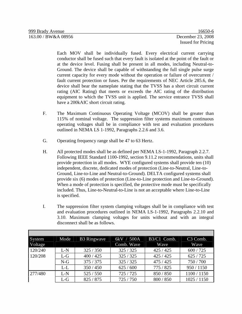
999 Brady Avenue 16650-6
163.00 / BW&A 08956 December 23, 2008
Issued for Pricing
Each MOV shall be individually fused. Every electrical current carrying
conductor shall be fused such that every fault is isolated at the point of the fault or
at the device level. Fusing shall be present in all modes, including Neutral-to-
Ground. The device shall be capable of withstanding the full single pulse surge
current capacity for every mode without the operation or failure of overcurrent /
fault current protection or fuses. Per the requirements of NEC Article 285.6, the
device shall bear the nameplate stating that the TVSS has a short circuit current
rating (AIC Rating) that meets or exceeds the AIC rating of the distribution
equipment to which the TVSS unit is applied. The service entrance TVSS shall
have a 200kAIC short circuit rating.
F. The Maximum Continuous Operating Voltage (MCOV) shall be greater than
115% of nominal voltage. The suppression filter systems maximum continuous
operating voltages shall be in compliance with test and evaluation procedures
outlined in NEMA LS 1-1992, Paragraphs 2.2.6 and 3.6.
G. Operating frequency range shall be 47 to 63 Hertz.
H. All protected modes shall be as defined per NEMA LS-1-1992, Paragraph 2.2.7.
Following IEEE Standard 1100-1992, section 9.11.2 recommendations, units shall
provide protection in all modes. WYE configured systems shall provide ten (10)
independent, discrete, dedicated modes of protection (Line-to-Neutral, Line-to-
Ground, Line-to-Line and Neutral-to-Ground). DELTA configured systems shall
provide six (6) modes of protection (Line-to-Line protection and Line-to-Ground).
When a mode of protection is specified, the protective mode must be specifically
included. Thus, Line-to-Neutral-to-Line is not an acceptable where Line-to-Line
is specified.
I. The suppression filter system clamping voltages shall be in compliance with test
and evaluation procedures outlined in NEMA LS-1-1992, Paragraphs 2.2.10 and
3.10. Maximum clamping voltages for units without and with an integral
disconnect shall be as follows.
System
Voltage
Mode B3 Ringwave 6kV / 500A
Comb. Wave
B3/C1 Comb.
Wave
C3 Comb.
Wave
120/240 L-N 325 / 350 325 / 325 425 / 425 600 / 725
120/208 L-G 400 / 425 325 / 325 425 / 425 625 / 725
N-G 375 / 375 325 / 325 475 / 425 750 / 700
L-L 350 / 450 625 / 600 775 / 825 950 / 1150
277/480 L-N 525 / 550 725 / 725 850 / 850 1100 / 1150
L-G 825 / 875 725 / 750 800 / 850 1025 / 1150
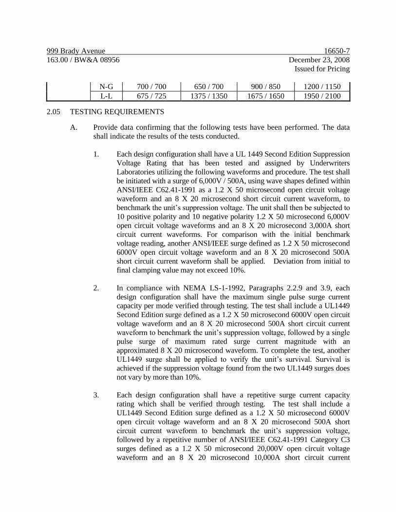
999 Brady Avenue 16650-7
163.00 / BW&A 08956 December 23, 2008
Issued for Pricing
N-G 700 / 700 650 / 700 900 / 850 1200 / 1150
L-L 675 / 725 1375 / 1350 1675 / 1650 1950 / 2100 2.05 TESTING REQUIREMENTS A. Provide data confirming that the following tests have been performed. The data
shall indicate the results of the tests conducted.
1. Each design configuration shall have a UL 1449 Second Edition Suppression
Voltage Rating that has been tested and assigned by Underwriters
Laboratories utilizing the following waveforms and procedure. The test shall
be initiated with a surge of 6,000V / 500A, using wave shapes defined within
ANSI/IEEE C62.41-1991 as a 1.2 X 50 microsecond open circuit voltage
waveform and an 8 X 20 microsecond short circuit current waveform, to
benchmark the unit’s suppression voltage. The unit shall then be subjected to
10 positive polarity and 10 negative polarity 1.2 X 50 microsecond 6,000V
open circuit voltage waveforms and an 8 X 20 microsecond 3,000A short
circuit current waveforms. For comparison with the initial benchmark
voltage reading, another ANSI/IEEE surge defined as 1.2 X 50 microsecond
6000V open circuit voltage waveform and an 8 X 20 microsecond 500A
short circuit current waveform shall be applied. Deviation from initial to
final clamping value may not exceed 10%.
2. In compliance with NEMA LS-1-1992, Paragraphs 2.2.9 and 3.9, each
design configuration shall have the maximum single pulse surge current
capacity per mode verified through testing. The test shall include a UL1449
Second Edition surge defined as a 1.2 X 50 microsecond 6000V open circuit
voltage waveform and an 8 X 20 microsecond 500A short circuit current
waveform to benchmark the unit’s suppression voltage, followed by a single
pulse surge of maximum rated surge current magnitude with an
approximated 8 X 20 microsecond waveform. To complete the test, another
UL1449 surge shall be applied to verify the unit’s survival. Survival is
achieved if the suppression voltage found from the two UL1449 surges does
not vary by more than 10%.
3. Each design configuration shall have a repetitive surge current capacity
rating which shall be verified through testing. The test shall include a
UL1449 Second Edition surge defined as a 1.2 X 50 microsecond 6000V
open circuit voltage waveform and an 8 X 20 microsecond 500A short
circuit current waveform to benchmark the unit’s suppression voltage,
followed by a repetitive number of ANSI/IEEE C62.41-1991 Category C3
surges defined as a 1.2 X 50 microsecond 20,000V open circuit voltage
waveform and an 8 X 20 microsecond 10,000A short circuit current
999 Brady Avenue 16650-8
163.00 / BW&A 08956 December 23, 2008
Issued for Pricing
waveform. To complete the test, another UL1449 surge shall be applied to
verify survival. Survival is achieved if the suppression voltage resulting
from the two UL1449 surges do not vary by more than 10%. Proof of such
testing shall be the test log generated by the surge generator.
4. Each design configuration shall be short circuit tested in accordance with the
type of fusing utilized in the suppression path. Testing shall include
application of a sustained overvoltage that causes the unit to enter a bolted
fault condition. This bolted fault condition shall occur with the full rated AIC
current of the fuse available. The fuse shall fail in a safe manner with no
physical or structural damage to the unit and any failure shall be self-
contained within the unit.
5. Each design configuration shall be surge tested with fusing in series to verify
that a transient of maximum surge current capacity magnitude is fully suppressed without fuse failure, operation, or degradation.
6. The unit shall be factory tested at the applicable Maximum Continuous
Operating Voltage to assure proper field operation.
7. Each unit shall be thoroughly factory tested before shipment. Testing of each unit shall include, but shall not be limited to, UL manufacturing and production-line tests, quality assurance checks, MCOV and clamping voltage verification tests.
2.06 STANDARD FEATURES
A. Unit Status Indicators The specified unit shall have an integral status circuit that
monitors the operational status of all modes of protection, including Line to
Neutral, Line to Ground, and Neutral to Ground. In the unlikely event the unit
fails, the green LED will go out and the red LED will be lit. LED indication shall
be provided internal and external to the product.
B. Dry Contacts for Remote Monitoring – TVSS must have electrically isolated
Form C dry contacts, one normally open and one normally closed.
C. Undervoltage Detection – TVSS shall be equipped with 70% undervoltage
detection.
D. Phase Loss Monitoring – TVSS shall be equipped with phase loss monitoring.
2.07 OPTIONAL FEATURES
A. Audible Alarm – The specified system shall be equipped with an audible alarm
that is activated during a fault condition. In conjunction with alarm, an alarm
999 Brady Avenue 16650-9
163.00 / BW&A 08956 December 23, 2008
Issued for Pricing
on/off switch shall be provided to silence the alarm, and an alarm push-to-test
switch shall be provided to test the alarm’s function. A visible LED will confirm
whether alarm is on or disabled. Both switches shall be located on the unit’s
hinged front cover.
3.0 EXECUTION
3.01 INSTALLATION
A. The unit must be installed in accordance with the manufacturer's printed
instruction to maintain warranty. All local and national codes must be observed.
B. Units shall be installed of the same voltage rating as the intended protected
equipment, at no more than 2 feet from the panel to which it is connected with as
few wire bends as possible. Provide overcurrent protection where required by the
AHJ.
C. Start-Up Testing. Upon completion of installation, a factory-certified local
service technician shall provide testing services per the manufacturers written
requirements.
3.02 WARRANTY
A. Provide a Five Year Limited Warranty from date of acceptance of start up testing by
the owner as indicated above.
B. The contractor shall provide a letter from the manufacturer’s representative to the
engineer, at the time of permanent power, certifying that all TVSS units have
been tested and installed per the manufacturer’s recommendation.
END OF SECTION
999 Brady Avenue 16721-1
163.00 / BW&A 08956 December 23, 2008
Issued for Pricing
SECTION 16721
LIFE SAFETY SYSTEMS
1.0 GENERAL
1.01 DESCRIPTION
A. This section of the specification includes the furnishing, installation, connection
and testing of the microprocessor controlled, intelligent reporting fire alarm
equipment required to form a complete, operative, and coordinated system.
B. The fire alarm system shall comply with requirements of the NFPA Standard 72
for Protected Premises Signaling Systems and all local codes and regulations.
The system shall be electrically supervised and monitor the integrity of all
conductors.
C. Alarm, trouble and supervisory signals from all intelligent reporting devices
shall be encoded onto the Signaling Line Circuits.
D. The system shall be an active/interrogative type system where each transponder
is repetitively scanned, causing a signal to be transmitted to the local fire alarm
control panel/node indicating that the transponder and its associated initiating
device and notification appliance circuit wiring is functional. Loss of this signal
at the local FACP shall result in a trouble indication on both the FACP display
and at the network display, as specified hereinafter for the particular input.
E. The system shall be arranged such that not less than 20 percent additional
transponders may be inserted into any network communication loop.
F. The FACP and peripheral devices shall be manufactured by Notifier, Edwards
or Siemens.
G. The installing company shall employ NICET (minimum Level II Fire Alarm
Technology) technicians on site. To guide the final checkout and to ensure the
systems integrity, the submitting company shall employ NICET Level IV
minimum managers and engineers. Proof of NICET level training shall be
included as part of submittal package and kept on site with personnel.
999 Brady Avenue 16721-2
163.00 / BW&A 08956 December 23, 2008
Issued for Pricing
H. The installing company shall be UL listed for fire alarm installations. UL
certificate shall accompany submittal package. The certification listing category
shall be UUJJ and shall be indicated in the project submittal.
I. The Contractor shall make arrangements and pay all fees in connection with the
testing of the Life Safety System. All system devices shall be tested for their
correct operation, except non-restorable type heat detectors which shall be
sample tested. All tests carried out shall meet the requirements of the local
authority having jurisdiction.
J. The system shall have proper listing and/or approval from the following
nationally recognized agencies:
1. Factory Mutual Systems
2. Underwriters Laboratories
1.02 SCOPE
A. A new intelligent reporting, microprocessor controlled fire detection system
shall be installed in accordance to the project specifications and drawings.
B. Basic Performance
1. Each SLC loop shall be wired NFPA 72 Style 4 (Class B).
2. Initiation Device Circuits (IDC) shall be wired (NFPA Style B) as part
of an addressable device connected by the SLC circuit.
3. Notification Appliance Circuits (NAC) shall be wired (NFPA Style Y)
as part of an addressable device connected by the SLC circuit or a panel
circuit.
4. NAC speaker circuits shall be arranged such that there is a minimum of
one speaker circuit per 1,000 sq. ft. of the building or smoke zone,
which ever is greater.
5. NAC speaker circuits and control equipment shall be arranged such that
loss of any one (1) speaker circuit will not cause the loss of any other
speaker circuit in the system.

999 Brady Avenue 16721-3
163.00 / BW&A 08956 December 23, 2008
Issued for Pricing
C. Basic System Functional Operation
1. As part of the fire alarm; when a fire alarm condition is detected and
reported by one of the system initiating devices, the following functions
shall immediately occur:
a. FACP will sound and display the alarm condition showing the
device address, location, zone information, time/date, and device
type.
b. The remote annunciator will sound and display the same
information as shown on the FACP display unit.
c. Via system programming, the horn/bell outputs for all zones will
activate and sound in temporal 3-3 pattern in synchronized
fashion until silenced from FACP panel.
d. All strobes in areas with activated horn/bell outputs shall flash in
a synchronized pattern until silenced from the FACP panel.
e. Automatic functions including, but not limited to: smoke
evacuation, smoke door release and supply/return fan shutdown
shall be activated via system programming as directed by codes
and/or drawings.
f. Release all magnetically held smoke doors.
g. Provide signals to the mechanical controls including smoke
dampers to shut down or reroute air-handling systems to prevent
the recirculation of smoke.
i. Provide a DACT (Digital Alarm Communicator Transmitter)
and a signal via DACT for connection to a central station or
local municipal fire department (connection and leased line, if
required, shall be provided by building owner).
j. Initiate a preprogrammed timing sequence.

999 Brady Avenue 16721-4
163.00 / BW&A 08956 December 23, 2008
Issued for Pricing
k. Additionally, actuation of any smoke detector located in the air
handling units and/or equipment rooms shall activate signals to
the mechanical controls indicating the area of occurrence.
l. It shall be possible to silence the alarm signals by operating the
signal silence switch. However, the activation of another zone
shall repeat the entire alarm process, thus causing the signals to
resound.
m. Silencing the alarm shall cause all speakers to silence. Firelights
will continue to flash.
4. General Operation
A. Power failures, opens, grounds or any disarrangement of the
system wiring or components shall be indicated by a visual and
audible trouble signal. The audible trouble signal may be
silenced; however, the trouble LED shall remain lit until the
system has been returned to normal operating condition.
1.03 SUBMITTALS
A. General
1. Copies of all submittals shall be submitted to the Architect/Engineer for
review prior to acceptance of system.
2. All references to manufacturer's model numbers and other pertinent
information herein is intended to establish minimum standards of
performance, function and quality.
3. The authority having jurisdiction shall be notified prior to installation of
equipment and wiring. Complete information regarding the system
including specifications, wiring diagrams, battery and power supply
calculations, floor plans and graphics shall be submitted for approval.
4. If submittals, upon review by the Owner and/or the Owners
Representative, are found not to conform with the performance, type
and quality of products as well as all other requirements of these
specifications; the Contractor shall be required to resubmit. The
999 Brady Avenue 16721-5
163.00 / BW&A 08956 December 23, 2008
Issued for Pricing
Contractor shall be responsible for the Owner's extra expenses for
subsequent review(s) of rejected submittals. Such extra fees shall be
deducted from payments by the Owner to the Contractor. Approval of
the submittals by the Owner shall, in no case, relieve the Contractor of
the responsibility to meet the requirements of this specification.
B. Shop Drawings
1. Drawings shall include the following minimum requirements for
submittal:
a. Point-to-point wiring/conduit layout for all devices on 1/8” scale
plans.
b. Device placement showing all addresses and device ID.
c. All panel and equipment terminations.
d. All circuit voltage drop and current calculations spread sheets.
e. All battery calculation spreadsheets.
f. Legend reflecting device description, manufacturer, model
number, and backbox requirement.
g. Wiring legend reflecting wire function, type, and recommended
manufacturer’s part number.
h. Full sequence of operations.
i. Power supply and amplifier calculations.
2. Specification data sheets on each individual system component.
C. Data Sheets
1. Submit simultaneously with the shop drawings, complete
manufacturer’s technical data sheets showing product description,
listings, and specs.
999 Brady Avenue 16721-6
163.00 / BW&A 08956 December 23, 2008
Issued for Pricing
2. Copies of NICET II and IV certifications.
3. Copy of company UL listing certificate.
1.04 APPLICABLE STANDARDS AND SPECIFICATIONS:
A. The specifications and standards listed below form a part of this specification.
The system shall comply with the latest standards.
1. National Fire Protection Association (NFPA), 2000 Edition - USA:
No. 13 Sprinkler Systems
No. 13A Halon 1301 Extinguishing Systems
No. 17 Dry Chemical Extinguishing Systems
No. 17A Wet Chemical Extinguishing Systems
Clean Agent Extinguishing Systems
No. 70 National Electrical Code
Specifically Article 760
No. 72 1999 National Fire Alarm Code
No. 101 Life Safety Code
2. Standard Building Code, 2000 Edition
3. American National Standard A17.1-1980
4. Underwriter’s Laboratories Fire Resistance Directory
5. Local and State Building Codes
6. ADA Public Law 101-336
7. All requirements of the Authority Having Jurisdiction (AHJ)
1.05 APPROVALS
A. The system shall have proper listing, approval and labeling from the following
nationally recognized agencies:
FM Factory Mutual Systems
UL Underwriters Laboratories

999 Brady Avenue 16721-7
163.00 / BW&A 08956 December 23, 2008
Issued for Pricing
1.06 SYSTEM FEATURES
A. The system shall include the following features as a minimum:
1. During an alarm condition, the LCD annunciator shall display the
activated alarm until acknowledged. This shall allow determination of
where the last alarm has taken place.
2. Ground fault detection in wiring on either plus or minus side.
3. Separate alarm and trouble shall be displayed on the LCD annunciator.
4. Resound feature.
5. “Dead Front” design control panel with all LED alarm trouble and
power on indicators and all switches located behind a locked tempered
glass door.
6. Solid state construction.
7. All alarm initiating circuit wiring, signal circuit wiring, speaker circuit
wiring shall be supervised.
8. Automatic transfer to standby batteries upon power failure.
9. Lightning and surge protection.
2.0 PRODUCTS
2.01 Conduit and wire
A. All fire alarm wiring shall be installed in conduit. Conduit shall be installed as
required by specification section 16100.
1. Wiring shall be in accordance with local, state and National codes (e.g.,
NEC Article 760) and as recommended by the manufacturer of the fire
alarm system.
999 Brady Avenue 16721-8
163.00 / BW&A 08956 December 23, 2008
Issued for Pricing
2. All wire and cable shall be listed and/or approved by a recognized
testing agency for use with a protective signaling system.
3. The fire alarm control panel shall be connected to a separate dedicated
branch circuit, maximum 20 amperes from the 120 volt normal power
source or from a generator powered source if available.
2.02 MAIN FIRE ALARM CONTROL PANEL:
A. The FACP shall be completely microprocessor based.
B. System Capacity and General Operation:
1. Configure size of panel to operate number of SLC circuits in a fashion
so that each circuit handles no greater than 70% load of capacity.
2. The fire alarm control panel shall include a full-featured operator
interface and backlit 80-character Liquid Crystal Display (LCD).
3. The system shall be fully field programmable from the display panel.
Panels requiring the use of external keyboards for programming and
changes are not acceptable.
4. The FACP shall provide the minimum following features:
a. Drift compensation to extend detector accuracy over life.
b. Detector sensitivity test, per NFPA 72, Chpt 7.
c. Maintenance alert, to warn of excessive smoke detector dirt or
dust accumulation.
d. Multiple sensitivity levels for alarm, selected by detector.
e. System status reports to display and printer. Provide printer.
f. Alarm verification, with verification counters.
g. Cross zoning with the capability of counting two detectors in
alarm.
999 Brady Avenue 16721-9
163.00 / BW&A 08956 December 23, 2008
Issued for Pricing
h. Walk test.
i. UL-1076 security monitor points.
j. Control-by-time with holiday schedules.
k. Day/night automatic adjustment of detector sensitivity.
l. Device blink control for sleeping areas.
m. Releasing capability.
n. Pre-Alarm.
o. Selectable sensitivity levels, three minimum.
p. History Storage, with a minimum of 400 events.
q. Point Enable/Disable.
r. Point Read (status and level of obscuration).
s. Output point for connection to any building EMS.
C. Signaling Line Circuits (SLC)
1. Each SLC interface shall provide power to communicate with 99
intelligent detectors (ionization, photoelectric or thermal) and 99
intelligent modules (monitor or control).
2. Each SLC circuit shall not exceed 70%, load capacity.
D. Serial Interface
1. The system shall include two serial EIA-232 interfaces. Each interface
shall be a means of connecting UL Listed Electronic Data Processing
(EDP) peripherals.
a. One serial port shall support a serial printer.

999 Brady Avenue 16721-10
163.00 / BW&A 08956 December 23, 2008
Issued for Pricing
b. One serial port shall support a CRT/NRT device.
c. The system shall include an EIA-485 port for the serial.
Connection of annunciators and remote LCD displays.
E. Field Charging Power Supply (FCPS): The FCPS is a device designed for use
as either a remote 24-volt power supply or used to power Notification
Appliances.
1. The FCPS shall offer up to 6.0 amps (4.0 amps continuous) of regulated
24-volt power. It shall include an integral charger designed to charge 7.0
amp hour batteries. Provide batteries to support 60-hour standby with
ten minutes of alarm indication at the end of this period. Battery charger
shall be capable of recharging all batteries to seventy percent capacity in
twelve hours.
2. The Field Charging Power Supply shall have four outputs (two Style
Y/Z and two style Y) shall be available for connection to the
Notification devices.
3. Provide a 20-watt minimum spare capacity in each power supply for
future tenant audible circuits. Locate in a junction box clearly labeled
"tenant fire alarm audible circuits".
4. Provide Field Charging Power Supply (DC) to allow for future tenant
build-out expansion of NAC devices. At no time shall there exceed 70%
load capacity of any FCPS on any of the common levels.
5. Locate audible (where required) and visual power supplies adjacent to
one another and in a location within each room approved by the
engineer.
6. Provide battery capacity and amplifier capacity in the main fire control
panel for addition of future tenant devices described above.
F. Provide and install ceiling mounted smoke detector within 5 horizontal feet of
FACP.
2.03 SYSTEM COMPONENTS
999 Brady Avenue 16721-11
163.00 / BW&A 08956 December 23, 2008
Issued for Pricing
A. Horns/Bells
1. All Horns/Bells shall be installed as shown on drawings and in
accordance with NFPA-72 and local codes.
2. Horns in corridors and all public spaces shall produce a nominal sound
output of 15dBA above average ambient noise levels with a minimum
sound output of 15dBA.
3. Horns shall be UL-464 listed for fie evacuation and operate on 12 0r 24
voltage in a temporal 3-3 pattern.
4. Speakers shall be bone white in color.
5. Provide a unit cost to add horns. This unit cost shall be applied to
additional horns that may be required at the request of the fire marshal
during field inspections.
B. Speakers (theater only)
1. All speakers shall operate on 25 VRMS or with field selectable output
taps from 0.25 to 2.0 Watts.
2. Speakers in corridors and public spaces shall produce a nominal sound
output of 84 dBA at 10 feet (3m) when set at one watt as measured per
UL Standard 1480.
3. Frequency response shall be a minimum of 400 HZ to 4000 HZ.
4. The back of each speaker shall be sealed to protect the speaker cone
from damage and dust.
5. Speakers shall be bone white in color.
6. Provide a unit cost to add speakers. This unit cost shall be applied to
additional speakers that may be required at the request of the fire
marshal during field inspections.
C. Strobe Lights
999 Brady Avenue 16721-12
163.00 / BW&A 08956 December 23, 2008
Issued for Pricing
1. All Strobe Lights shall meet the requirements of the ADA, UL Standard
1971.
2. Strobe intensity and flash rate shall meet the requirements of UL 1971,
ADA and NFPA 72.
3. Combination Horn/Strobe devices shall meet all above requirements as
well as horn/bell requirements listed herein.
4. Strobe unit shall mount to a four inch square electrical outlet box. The
strobe light shall have a white lens with red “FIRE” imprinted on it.
When the unit is combination speaker/strobe, the speaker portion shall
comply with the requirements stated in A. above.
5. All strobes shall have selectable output intensities from 15 to 110 cd.
The intensity selected shall meet NFPA 72 requirements for the layout
shown on the drawings.
6. Strobe spacing shall be as follows:
a. Strobes shall be spaced a maximum of 100’ apart in corridors
and within 15’ of the end of every corridor to comply with the
requirements of NFPA 72.
b. Strobes in open areas shall be provided to comply with NFPA
72.
c. Provide strobes in public spaces such as restrooms, kitchens,
breakrooms, cafeterias, conference rooms, training rooms and
any other space where six or more people are likely to gather.
7. Provide a unit cost to add 5 strobes including required signal circuits.
This unit cost shall be applied to additional strobes that may be required
at the request of the fire marshal during field inspections.
D. Manual Fire Alarm Stations
1. Manual fire alarm stations shall be dual-action, non-coded, non-break
glass type, equipped with key lock so that they may be tested without
operating the handle.
999 Brady Avenue 16721-13
163.00 / BW&A 08956 December 23, 2008
Issued for Pricing
2. Stations must be designed such that after an actual activation, they
cannot be restored to normal except by key reset. Units shall be master
keyed with control equipment.
3. An operated station shall automatically condition itself so as to be
visually detected, as operated, at a minimum distance of 100 feet (30.5
m) front or side. This shall be achieved with the pull lever remaining at
a right angle to the station body until reset.
4. The station body shall be constructed so that chips and scratches will
not expose metal.
5. Manual fire alarm stations shall be located as required by NFPA 101
and the Standard Building Code.
E. Duct Smoke Detectors
1. Duct smoke detectors shall be addressable type with visual alarm and
power indicators. Provide remote LED/test stations where duct
detectors are mounted in non-visible areas such as above ceiling.
2. Each detector shall be installed upon the composite supply/return air
ducts(s), with properly sized air sampling tubes where required. Provide
smoke detectors in each return air path of any mechanical equipment
that moves air in excess of 2000 CFM to meet the requirements of
NFPA 72 and 90A. Provide smoke detectors in each supply and return
air path of any mechanical equipment that moves air in excess of 15,000
CFM to meet the requirements of NFPA 72 and 90A. Confirm
quantities of smoke detectors required for mechanical equipment with
Division 15. Room detectors may be used to accomplish smoke
detection in the supply/return air paths if the application permits.
3. Each duct detector shall be installed along with addressable control
module as needed for fan shutdown and/or smoke control. Detectors
zoned with other devices shall be capable of operating its control
module even if all other devices on their circuit have gone into alarm.
999 Brady Avenue 16721-14
163.00 / BW&A 08956 December 23, 2008
Issued for Pricing
4. Duct detectors shall be provided by this division, installed by the
mechanical contractor and electrically connected to the fire alarm
system by the electrical contractor.
F. Smoke Dampers
1. Smoke dampers shall be provided by division 15.
2. Provide a smoke detector at each smoke damper location to meet the
requirements of NFPA 72. Confirm quantities and locations of smoke
detectors required for smoke dampers with Division 15. Provide 120
volt power as required for operation of smoke dampers.
G. LCD Alphanumeric Display Remote Annunciator
1. The alphanumeric display annunciator shall be a supervised, backlit
LCD display containing a minimum of eighty, (80) characters for alarm
annunciation in clear English text. Annunciator shall be located as
shown on the drawings or at the location selected by the local fire
department.
2. The LCD annunciator shall display all alarm, supervisory, and trouble
conditions from the FACP via the serial card.
H. Voice Evacuation System (theater only)
1. The Voice Evacuation System shall contain equipment required for all
audio control, signaling and supervisory functions. This shall include:
a. Tone generators.
b. Digital voice units.
c. Microphone for manual paging/all call.
d. Speaker/phone circuit annunciation and control modules for
manual activation of each individual speaker circuit and each
individual microphone/annunciator circuit.
999 Brady Avenue 16721-15
163.00 / BW&A 08956 December 23, 2008
Issued for Pricing
e. Integral Digital Message Generator with a capacity of up to 60
seconds. The Digital Message Generator shall be capable of
primary and secondary messages (30 seconds each). These
messages shall be field programmable without the use of
additional equipment.
f. Built in alert tone generators with steady, slow whoop, high/low
and chime tone field programmable.
g. Provide list of evacuation pre-recorded messages and pre-alert
tones to owner before ordering for selection.
i. The Voice Control Panel shall have the ability to transmit up to
4 simultaneous evacuation message channels.
2. The one-way voice communications system shall be comprised of a
local microphone, single channel audio controller/tone generator/digital
message player and, if shown on the plans up to eight (8) remote
microphone/annunciator panels.
3. Provide amplifiers. Size the amplifiers to accommodate each speaker
being set at a one-watt tap with twenty watts reserve.
a. The audio amplifiers will provide audio power (@ 25 Volts
RMS) for distribution to the speaker circuits.
b. The amplifier shall include audio input and amplified output
supervision; back up input, and automatic switchover to back up
(if primary amplifier should fail).
c. Amplifiers shall be available in 30, 100, and 120-watt versions.
d. Hardwired indicating appliance circuits (fire lights and speakers)
shall be Style Y per NFPA 72.
2.04 SYSTEM COMPONENTS - ADDRESSABLE DEVICES
A. Addressable Devices - General
1. Detectors shall be intelligent (analog) and addressable, and shall connect
with two wires to the fire alarm control panel signaling line circuits.
999 Brady Avenue 16721-16
163.00 / BW&A 08956 December 23, 2008
Issued for Pricing
2. Addressable photoelectric smoke and thermal detectors shall provide
alarm and power/polling LEDs. LED(s) shall flash under normal
conditions and LED(s) shall be placed into steady illumination by the
control panel, indicating an alarm condition.
3. The fire alarm control panel shall permit detector sensitivity adjustment
through field programming of the system.
4. Detectors will operate in an analog fashion, where the detector simply
measures its designed environment variable and transmits an analog
value to the FACP based on real-time measured values. The FACP
software, not the detector, shall make the alarm/normal decision,
thereby allowing the sensitivity of each detector to be set in the FACP
program and allowing the system operator to view the current analog
value of each detector.
5. All field wiring is to be terminated on the detector base, not on the
sensor head. Addressing of detectors shall be via integral decade
switches built into sensor. Devices requiring separate addressing means
will not be accepted.
6. Any additional equipment required to program devices are not
acceptable.
B. Intelligent Photoelectric Smoke Detector
1. The detectors shall use the photoelectric (light-scattering) principal to
measure smoke density and shall, on command from the control panel,
send data to the panel representing the analog level of smoke density.
2. Provide photoelectric smoke detector heads with bases as required.
Detectors shall be of the solid state photoelectric type utilizing a stable
LED light source and a silicone photo diode as the receiving element to
form a highly accurate means of smoke detection. Internal detector
circuits shall be shielded against electrical interference and resistant to
transients, noise and, RF interference. Detector shall be low profile, the
complete unit including base shall not exceed 1.875 inches in depth.
Detector shall have a dual purpose red LED that flashes continuously to
show that the device is operating and, that comes on steady to show that
the device is in alarm.
999 Brady Avenue 16721-17
163.00 / BW&A 08956 December 23, 2008
Issued for Pricing
3. Nominal detector sensitivity shall be 1.4% per foot obscuration with a
range of 1% to. 1.84%. Regardless of sensitivity settings, the detector's
stability shall be unaffected by high air velocity. No radioactive
materials shall be used.
4. Provide smoke detectors at stairwell doors, in telephone rooms,
electrical rooms, mechanical rooms, adjacent to the fire alarm control
panel, and pump rooms.
C. Linear Beam Smoke Detector
1. Each beam shall be comprised of a solid state infrared (IR) transmitter,
photodiode receiver and microprocessor based control module. Should
IR output be attenuated below the desired alarm obscuration level as a
result of smoke interference an alarm will be annunciated. Total
obscuration of the beam is annunciated as a beam blockage trouble
signal. All wiring from the control module to the transmitter and
receiver heads is supervised.
2. The projected beam smoke detector system shall have an operating
range of 10M. (33 ft.) to 100M. (330 ft.) and be listed for spacing the
beam 30 ft. from a wall and 60 ft. on center. The transmitter and
receiver optical elements shall be adjustable +/- 90 degrees horizontally
and +/- 30 degrees vertically. The sensitivity shall be field selectable
from 7% to 50% obscuration.
D. Intelligent Thermal Detectors
1. Thermal detectors shall be intelligent addressable devices rated at 135
degrees Fahrenheit (58 degrees Celsius) and have a rate-of-rise element
rated at 15 degrees F (9.4 degrees C) per minute. It shall connect via two
wires to the fire alarm control panel signaling line circuit.
E. Addressable Dry Contact Monitor Module
1. Addressable monitor modules shall be provided to connect one
supervised IDC zone of conventional alarm initiating devices (any N.O.
dry contact device such as flow, tamper, release systems, future tenant
devices, etc.) to one of the fire alarm control panel SLCs.

999 Brady Avenue 16721-18
163.00 / BW&A 08956 December 23, 2008
Issued for Pricing
2. The IDC zone shall be suitable for Style D or Style B operation. An
LED shall be provided that shall flash under normal conditions,
indicating that the monitor module is operational and in regular
communication with the control panel.
3. For difficult to reach areas, the monitor module shall be available in a
miniature package and shall be no larger than 2-3/4 inch (70 mm) x 1-
1/4 inch (31.7 mm) x 1/2 inch (12.7 mm). This version need not include
Style D or an LED.
4. Monitor module shall be provided for all sprinkler flow and tamper
switches. Switches are furnished and installed by others and electrically
connected to the fire alarm system by the electrical contractor. Verify
quantities and locations and coordinate installation of devices required
with fire protection shop drawings. Provide connections to devices per
fire protection shop drawings.
F. Addressable Control Module:
1. Addressable control modules shall be provided to supervise and control
the operation of one conventional NACs of compatible, 24 VDC
powered, polarized audio/visual notification appliances. For fan
shutdown and other auxiliary control functions, the control module may
be set to operate as a dry contract relay. Each relay shall have a red LED
mounted on its cover to indicate if that relay has been activated.
2. The control module NAC may be wired for Style Z or Style Y (Class
A/B) with up to 1 amp of inductive A/V signal, or 2 amps of resistive
A/V signal operation, or as a dry contact (Form-C) relay. The relay coil
shall be magnetically latched to reduce wiring connection requirements,
and to insure that 100% of all auxiliary relay or NACs may be energized
at the same time on the same pair of wires.
G. Door Holders
1. Provide door holders for wall mounting and for floor mounting. Door
holders shall operate on twenty-four volt dc power and each holder shall
not draw more than seventy milliamp of power. Coordinate quantities
of door holders required with architect’s door schedule.
999 Brady Avenue 16721-19
163.00 / BW&A 08956 December 23, 2008
Issued for Pricing
2.05 BATTERIES
A. The batteries shall be sealed, 12 volt nominal (two required).
B. The battery shall have sufficient capacity to power the fire alarm system for the
time required in NFPA 72. This time shall be based on the type of system
installed. At the end of this period the system shall be capable of operating all
alarm notification appliances used for evacuation or to direct aid to the location
of an emergency for 5 minutes upon a normal AC power failure.
3.0 EXECUTION
3.01 INSTALLATION
A. Provide all equipment, wiring, conduit and outlet boxes required for the
erection of a complete and operating system in accordance with applicable
local, state and national codes, the manufacturer's recommendations, these
plans and specifications. Color code shall be used throughout.
B. Provide weatherproof devices with gasketed coverplates for exterior or damp
locations.
3.02 TEST
A. The manufacturer's authorized representative shall provide supervision of final
system panel connections, perform a complete functional test of the system and
submit a written report to the contractor attesting to the proper operation of the
system.
3.03 FINAL INSPECTION
A. Upon completion of the installation, the electrical contractor shall provide to
the architect, with a copy to the manufacturer's representative, a signed written
statement attesting that all system equipment was installed in accordance with
these specifications and in accordance with wiring diagrams, instructions and
directions provided to the contractor by the manufacturer.
3.04 INSTRUCTION
999 Brady Avenue 16721-20
163.00 / BW&A 08956 December 23, 2008
Issued for Pricing
A. Instruction shall be provided as required for operating the system. Hands-on
demonstrations of the operation of all system components shall be provided and
shall include one session for a period of 8 hours. Additional time that may be
required for end-user training will be at added cost to owner.
3.05 GUARANTEE
A. All equipment and wiring shall be guaranteed against defects in materials and
workmanship for a two year period from the start up and beneficial use of the
system. Warranty service for the equipment shall be provided by the
manufacturer's factory trained representative during normal working hours,
Monday through Friday excluding holidays. Emergency service provided at
times other than as stipulated above shall be available from the same source at
additional cost to the owner.
3.06 INSPECTIONS
A. Upon satisfactory completion of the system test, the manufacturer's
representative shall present for the owner's consideration, a proposal to provide
semi-annual inspection and tests of the system.
END OF SECTION
999 Brady Avenue 16920-1
163.00 / BW&A 08956 December 23, 2008
Issued for Pricing
SECTION 16920
MOTOR CONTROLS AND WIRING
1.0 GENERAL
1.01 SCOPE
A. All work specified in this Section shall comply with the provisions of Section
16010.
B. All motors shall be provided under Division 15.
C. A motor starter shall be provided under this Section for each motor except for
those specified in Division 15 to be furnished with integral starters. Motor
starters shall be installed separately mounted adjacent to the motor served.
D. Motor power wiring is defined as those conductors between the energy source and
the motor. This power wiring shall be terminated at the motor terminals.
E. All control wiring required for automatic starting and stopping of motors shall be
provided under Division 15 unless specifically shown on the electrical drawings.
F. Power wiring shall be connected through all line voltage control devices such as
firestats and thermostats.
2.0 PRODUCTS
2.01 MOTOR STARTERS
A. Starters for motors 1/3 horsepower or smaller shall be manual unless remote or
automatic starting is required, in which case the starters shall be magnetic, full
voltage, non-reversing, single-speed, unless otherwise indicated. All other starters
shall be magnetic.
B. Each starter for a three-phase motor shall be furnished with three (3) overload
relays sized for the full load running current of the motor actually provided.
Provide an external "HAND-OFF-AUTO" selector switch with green
"RUNNING" light. Provide a red pilot light to indicate motor "STOPPED". Each
pilot light shall have a legend plate indicating reason for signal.
999 Brady Avenue 16920-2
163.00 / BW&A 08956 December 23, 2008
Issued for Pricing
C. Each overload relay shall have a normally open alarm contact which will close
only when actuated by an overload (not to be confused with N.O. or N.C.
auxiliary contacts). These contacts shall be properly wired to their respective blue
pilot light provided on the starter front cover and having a "TRIPPED" legend
plate.
D. Individually mounted motor starters shall be in a NEMA Type 1 general purpose
enclosure in unfinished areas and shall be flush mounted in all finished areas. All
starters mounted in exterior areas shall have a NEMA 3R enclosure. Each starter
shall have a laminated nameplate to indicate Division 15 unit number, function
and circuit number.
E. A control power transformer shall be provided at each motor starter for
connection to the controls provided under Division 15. The control power
transformer shall be mounted inside the motor starter enclosure. All control
transformers at 50 VA or greater shall have primary fusing. Coordinate all control
equipments with Division 15 and equipment manufacturers.
F. All motor starters, push buttons and pilot lights shall be of the same manufacturer
as the switchboard and shall be General Electric, Square D, Siemens I.T.E, Joslyn
Clark Controls or Westinghouse.
2.02 COMBINATION STARTERS
A. Combination starters shall consist of a circuit breaker and a motor starter mounted
in a common NEMA Type 1 general purpose enclosure.
B. The motor starter components shall be as specified in paragraph 2.01 for motor
starters.
C. The circuit breaker component shall be a minimum 22,000 RMS interrupting
capacity and shall be as required in Section 16200.
3.0 EXECUTION
3.01 INSTALLATION
A. Provide power wiring to and install all motor starters, unless integrally factory
mounted on a piece of equipment.
B. Provide power wiring to all motors except packaged units that are prewired

999 Brady Avenue 16920-3
163.00 / BW&A 08956 December 23, 2008
Issued for Pricing
between the starter and motor.
C. Where line voltage control devices are mounted at, on or inside a unit, such as
aquastats, firestat for single phase devices, etc., the power wiring to the unit shall
be connected through such a control device.
D. On final inspection, it shall be demonstrated to the Architect or his representative,
that each overload relay control circuit is properly wired and functioning correctly
by manually tripping each overload relay individually, one at a time. This
inspection procedure shall not involve removing any wiring or disconnecting any
current carrying parts.
END OF SECTION