Embed Size (px)
Citation preview
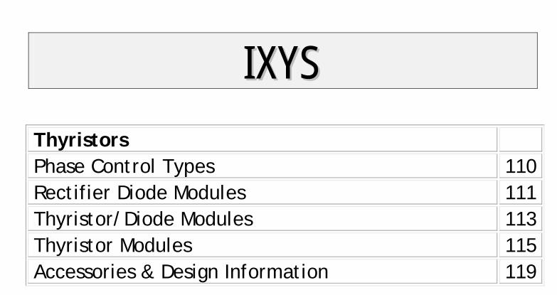
IIXXYYSS
Thyristors Phase Control Types 110 Rectifier Diode Modules 111 Thyristor/Diode Modules 113 Thyristor Modules 115 Accessories & Design Information 119
109Data according to IEC 60747 and refer to a single diode or thyristor unless otherwise stated.
Fig. 2: Principal cross section of an IXYS module with DCB technology
Thyristor / Diode Modules
One of the essential advantages of powersemiconductor modules compared todiscrete designs is the electrical isolationbetween the baseplate of the module andthe parts subject to voltage (3.6 kVRMS
tested). This makes possible the mount-down of any number of the same or diffe-rent modules on a common heatsink. It isfeasible to use standard housings withappropriate accessories for designingcompact power converter operating fromAC mains up to 690 V.
Plastic Housing with DCB Sub-strate
IXYS has succeeded in simplifying theconventional multilayer module con-struction by the DCB (Direct Copper Bon-ding) technique.
Other features are:
• top-side electrical terminals withcaptured nuts;
• series-connected diode/diode, thyristor/diode and thyristor/thyristor modules;
• easy assembly.
All thyristor modules with DCB ceramicbase contacts are available in volumewith two standardized twin plugs (2.8 mmx 0.8 mm) for gate and auxiliary cathodecontrol terminals (version 1). Modules inTO-240 housing of the version 8 aredelivered with gate plugs only (withoutauxiliary cathode terminal; mountingsrews available on request). The modulehousing is designed for adequateclearance and creepage distanceresulting in recognition by Under-writers Laboratories, Inc., USA for alltypes.
New Generation Silicon Chips
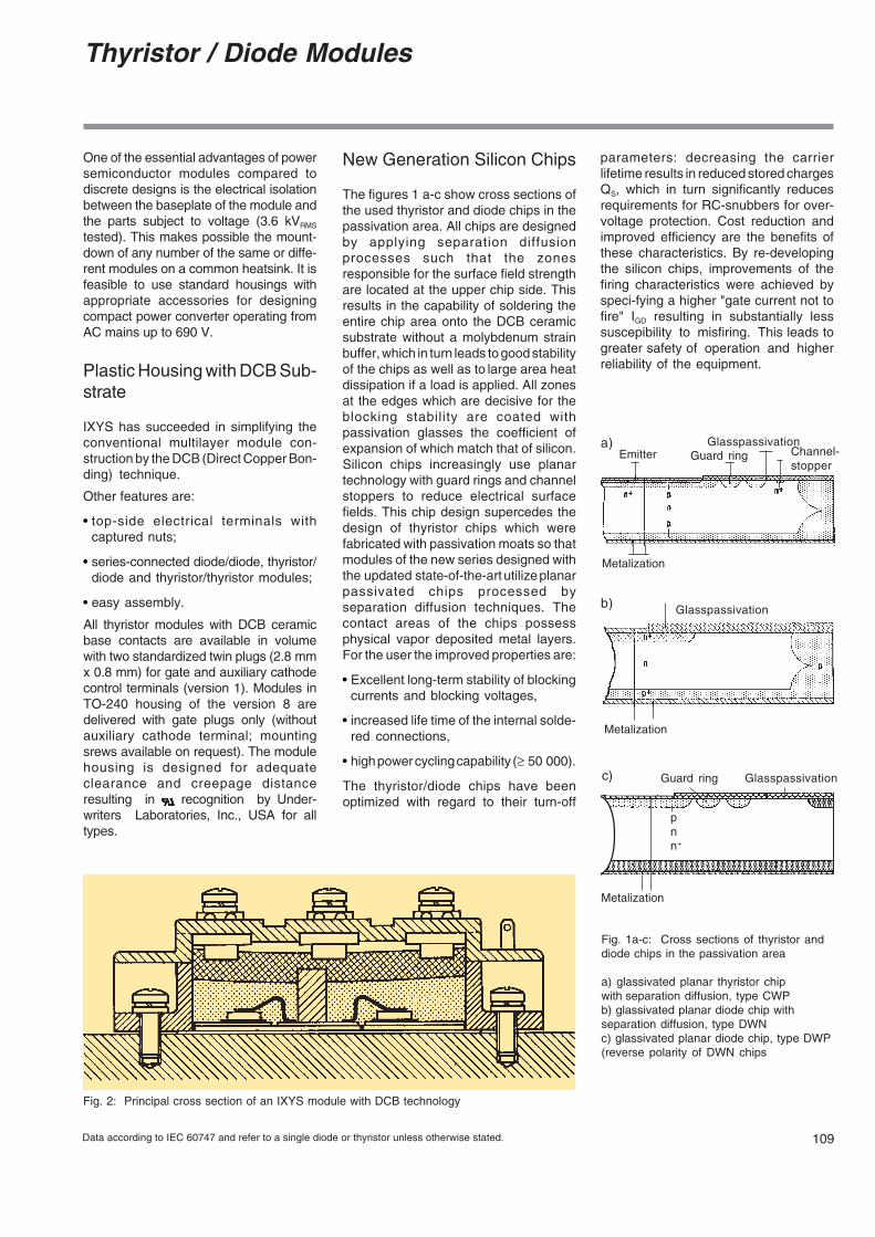
The figures 1 a-c show cross sections ofthe used thyristor and diode chips in thepassivation area. All chips are designedby applying separation diffusionprocesses such that the zonesresponsible for the surface field strengthare located at the upper chip side. Thisresults in the capability of soldering theentire chip area onto the DCB ceramicsubstrate without a molybdenum strainbuffer, which in turn leads to good stabilityof the chips as well as to large area heatdissipation if a load is applied. All zonesat the edges which are decisive for theblocking stability are coated withpassivation glasses the coefficient ofexpansion of which match that of silicon.Silicon chips increasingly use planartechnology with guard rings and channelstoppers to reduce electrical surfacefields. This chip design supercedes thedesign of thyristor chips which werefabricated with passivation moats so thatmodules of the new series designed withthe updated state-of-the-art utilize planarpassivated chips processed byseparation diffusion techniques. Thecontact areas of the chips possessphysical vapor deposited metal layers.For the user the improved properties are:
• Excellent long-term stability of blockingcurrents and blocking voltages,
• increased life time of the internal solde-red connections,
• high power cycling capability (≥ 50 000).
The thyristor/diode chips have beenoptimized with regard to their turn-off
c)
pnn+
GlasspassivationGuard ring
Metalization
Fig. 1a-c: Cross sections of thyristor anddiode chips in the passivation area
a) glassivated planar thyristor chipwith separation diffusion, type CWPb) glassivated planar diode chip withseparation diffusion, type DWNc) glassivated planar diode chip, type DWP(reverse polarity of DWN chips
Channel-stopper
Metalization
Glasspassivationa)Emitter Guard ring
b) Glasspassivation
Metalization
parameters: decreasing the carrierlifetime results in reduced stored chargesQS, which in turn significantly reducesrequirements for RC-snubbers for over-voltage protection. Cost reduction andimproved efficiency are the benefits ofthese characteristics. By re-developingthe silicon chips, improvements of thefiring characteristics were achieved byspeci-fying a higher "gate current not tofire" IGD resulting in substantially lesssuscepibility to misfiring. This leads togreater safety of operation and higherreliability of the equipment.
110 Data according to IEC 60747 and refer to a single diode or thyristor unless otherwise stated.
(SCR = Silicon Controlled Rectifier)
Thyristors, SCRs
Phase Control Thyristors
Thyristors are very rugged devices. Comparedto all other controlled semi-conductorcomponents, they feature the highest currentcapacity per chip area, especially at highvoltage. They are mainly used as controldevices in 50 and 60 Hz AC mains equipment.
Principal applications are static convertercircuits for speed control of DC-drives, orswitching and control functions fortemperature, lighting, soft-start, etc. in single-phase and three-phase AC switchconfigurations . Phase control thyristors are
designed for optimal forward conduction andreverse blocking characteristics, due to onlymoderate requirements for turn-on and turn-off parameters.
Phase Control Thyristors
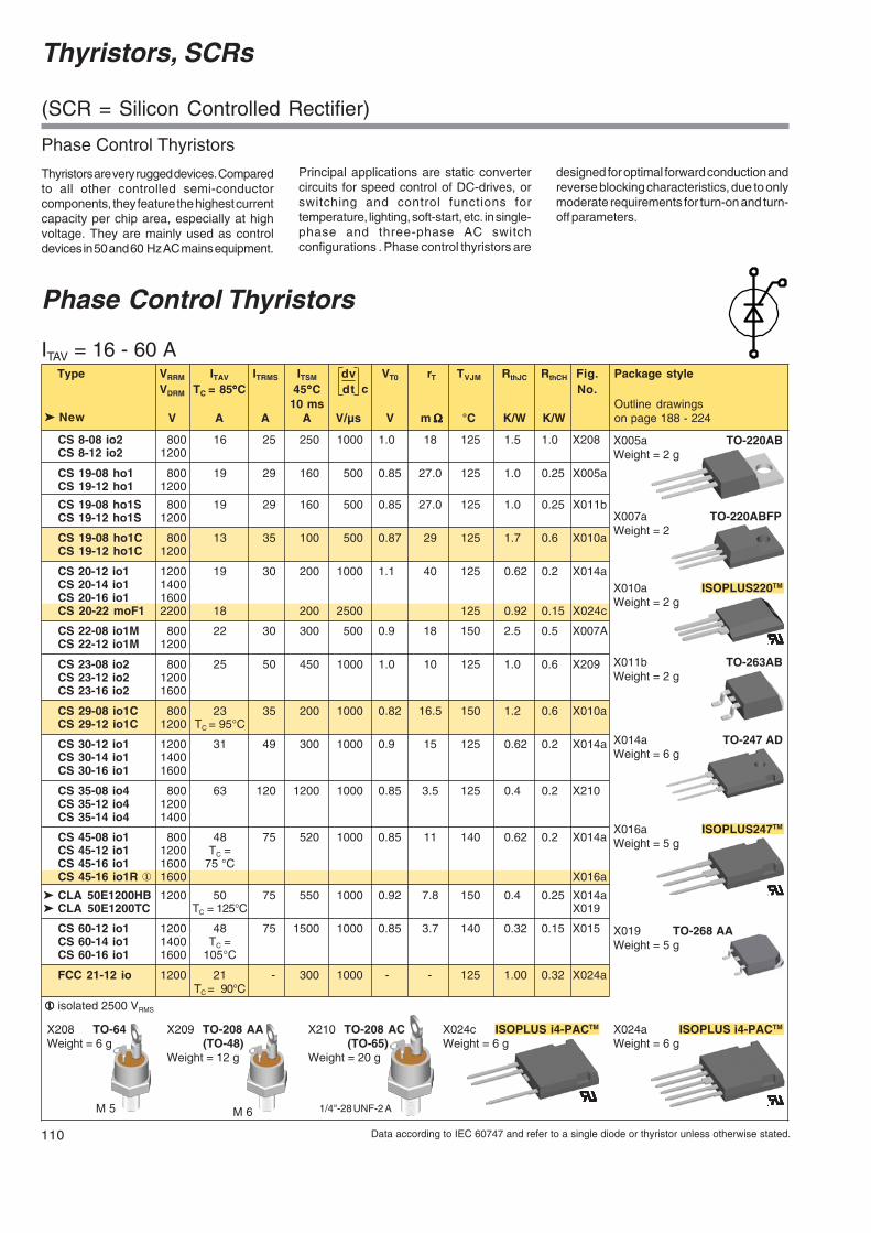
ITAV = 16 - 60 A Type VRRM ITAV ITRMS ITSM dv VT0 rT TVJM RthJC RthCH Fig. Package style
VDRM TC = 85°°°°°C 45°°°°°C dt No.10 ms Outline drawings
V A A A V/µs V m ΩΩΩΩΩ °C K/W K/W on page 188 - 224
CS 8-08 io2 800 16 25 250 1000 1.0 18 125 1.5 1.0 X208CS 8-12 io2 1200
CS 19-08 ho1 800 19 29 160 500 0.85 27.0 125 1.0 0.25 X005aCS 19-12 ho1 1200
CS 19-08 ho1S 800 19 29 160 500 0.85 27.0 125 1.0 0.25 X011bCS 19-12 ho1S 1200
CS 19-08 ho1C 800 13 35 100 500 0.87 29 125 1.7 0.6 X010aCS 19-12 ho1C 1200
CS 20-12 io1 1200 19 30 200 1000 1.1 40 125 0.62 0.2 X014aCS 20-14 io1 1400CS 20-16 io1 1600CS 20-22 moF1 2200 18 200 2500 125 0.92 0.15 X024c
CS 22-08 io1M 800 22 30 300 500 0.9 18 150 2.5 0.5 X007ACS 22-12 io1M 1200
CS 23-08 io2 800 25 50 450 1000 1.0 10 125 1.0 0.6 X209CS 23-12 io2 1200CS 23-16 io2 1600
CS 29-08 io1C 800 23 35 200 1000 0.82 16.5 150 1.2 0.6 X010aCS 29-12 io1C 1200 TC = 95°C
CS 30-12 io1 1200 31 49 300 1000 0.9 15 125 0.62 0.2 X014aCS 30-14 io1 1400CS 30-16 io1 1600
CS 35-08 io4 800 63 120 1200 1000 0.85 3.5 125 0.4 0.2 X210CS 35-12 io4 1200CS 35-14 io4 1400
CS 45-08 io1 800 48 75 520 1000 0.85 11 140 0.62 0.2 X014aCS 45-12 io1 1200 TC =CS 45-16 io1 1600 75 °CCS 45-16 io1R ① 1600 X016a
CLA 50E1200HB 1200 50 75 550 1000 0.92 7.8 150 0.4 0.25 X014a CLA 50E1200TC TC = 125°C X019
CS 60-12 io1 1200 48 75 1500 1000 0.85 3.7 140 0.32 0.15 X015CS 60-14 io1 1400 TC =CS 60-16 io1 1600 105°C
FCC 21-12 io 1200 21 - 300 1000 - - 125 1.00 0.32 X024aTC = 90°C
①①①①① isolated 2500 VRMS
c
New
1/4"-28 UNF-2 A
X210 TO-208 AC (TO-65)Weight = 20 g
M 6
X209 TO-208 AA (TO-48)Weight = 12 g
M 5
X208 TO-64Weight = 6 g
X005a TO-220ABWeight = 2 g
X011b TO-263ABWeight = 2 g
X024c ISOPLUS i4-PACTM
Weight = 6 g
X014a TO-247 ADWeight = 6 g
X007a TO-220ABFPWeight = 2 g
X010a ISOPLUS220TM
Weight = 2 g
X016a ISOPLUS247TM
Weight = 5 g
X024a ISOPLUS i4-PACTM
Weight = 6 g
X019 TO-268 AAWeight = 5 g
111Data according to IEC 60747 and refer to a single diode or thyristor unless otherwise stated.
Diode Modules, Single and Dual
MDD 26-08N1B 800 36 100 60 650 0.8 6.1 150 1.0 0.2 X125eMDD 26-12N1B 1200MDD 26-14N1B 1400MDD 26-16N1B 1600MDD 26-18N1B 1800
MDD 44-08N1B 800 59 100 100 1150 0.8 4.3 150 0.59 0.2MDD 44-12N1B 1200MDD 44-14N1B 1400MDD 44-16N1B 1600MDD 44-18N1B 1800
MDD 56-08N1B 800 71 100 150 1400 0.8 3.0 150 0.51 0.2MDD 56-12N1B 1200MDD 56-14N1B 1400MDD 56-16N1B 1600MDD 56-18N1B 1800
MDD 72-08N1B 800 99 100 180 1700 0.8 2.3 150 0.35 0.2MDD 72-12N1B 1200MDD 72-14N1B 1400MDD 72-16N1B 1600MDD 72-18N1B 1800
MDD 95-08N1B 800 120 105 180 2800 0.75 1.95 150 0.26 0.2MDD 95-12N1B 1200MDD 95-14N1B 1400MDD 95-16N1B 1600MDD 95-18N1B 1800MDD 95-20N1B 2000MDD 95-22N1B 2200
MDD 142-08N1 800 165 100 300 4700 0.8 1.3 150 0.21 0.1 X126cMDD 142-12N1 1200MDD 142-14N1 1400MDD 142-16N1 1600MDD 142-18N1 1800
MDD 172-08N1 800 190 100 300 6600 0.8 0.8 150 0.21 0.1MDD 172-12N1 1200MDD 172-14N1 1400MDD 172-16N1 1600MDD 172-18N1 1800
MDD 200-14N1 1400 224 100 350 10500 0.8 1.5 150 0.13 0.1MDD 200-16N1 1600MDD 200-18N1 1800MDD 200-22N1 2200
Type VRRM IFAV TC IFRMS IFSM VT0 rT TVJM RthJC RthCH Fig. Package style45°°°°°C per Chip per Chip No.
10 ms Outline drawings New V A °°°°°C A A V m ΩΩΩΩΩ °°°°°C K/W K/W on page 188 - 224
@
IFAV = 36-224 A MDD
X126cWeight 150 g
X125e TO-240 AAWeight = 90 g
112 Data according to IEC 60747 and refer to a single diode or thyristor unless otherwise stated.
X129cWeight = 310 g
X131cWeight = 750 g
X136aWeight = 1550 g
X132bWeight = 730 g
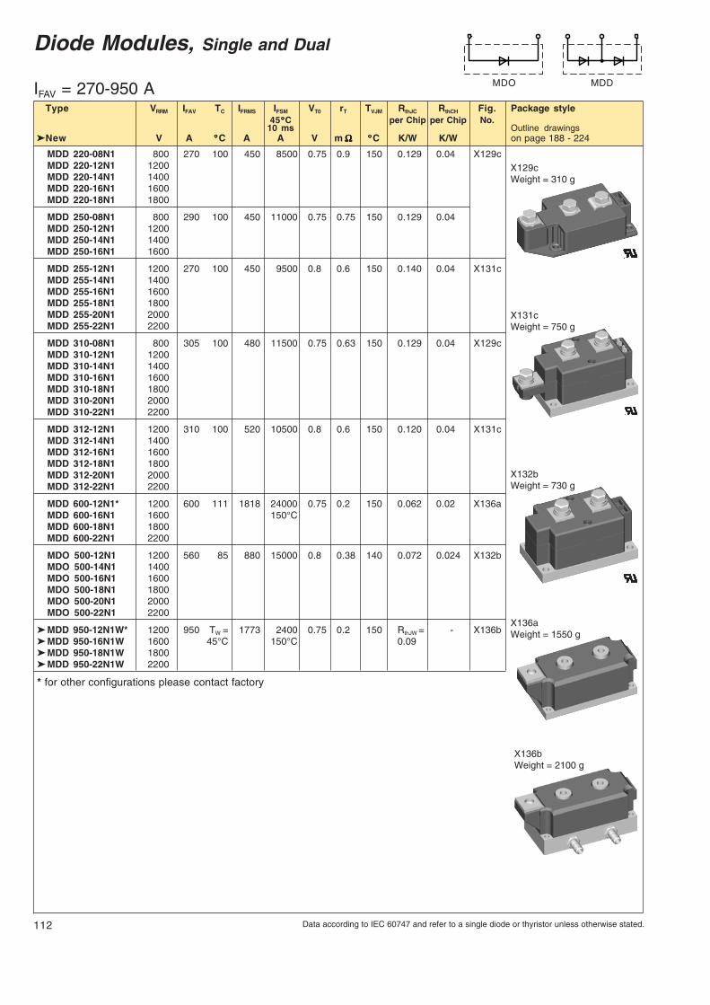
MDD 220-08N1 800 270 100 450 8500 0.75 0.9 150 0.129 0.04 X129cMDD 220-12N1 1200MDD 220-14N1 1400MDD 220-16N1 1600MDD 220-18N1 1800
MDD 250-08N1 800 290 100 450 11000 0.75 0.75 150 0.129 0.04MDD 250-12N1 1200MDD 250-14N1 1400MDD 250-16N1 1600
MDD 255-12N1 1200 270 100 450 9500 0.8 0.6 150 0.140 0.04 X131cMDD 255-14N1 1400MDD 255-16N1 1600MDD 255-18N1 1800MDD 255-20N1 2000MDD 255-22N1 2200
MDD 310-08N1 800 305 100 480 11500 0.75 0.63 150 0.129 0.04 X129cMDD 310-12N1 1200MDD 310-14N1 1400MDD 310-16N1 1600MDD 310-18N1 1800MDD 310-20N1 2000MDD 310-22N1 2200
MDD 312-12N1 1200 310 100 520 10500 0.8 0.6 150 0.120 0.04 X131cMDD 312-14N1 1400MDD 312-16N1 1600MDD 312-18N1 1800MDD 312-20N1 2000MDD 312-22N1 2200
MDD 600-12N1* 1200 600 111 1818 24000 0.75 0.2 150 0.062 0.02 X136aMDD 600-16N1 1600 150°CMDD 600-18N1 1800MDD 600-22N1 2200
MDO 500-12N1 1200 560 85 880 15000 0.8 0.38 140 0.072 0.024 X132bMDO 500-14N1 1400MDO 500-16N1 1600MDO 500-18N1 1800MDO 500-20N1 2000MDO 500-22N1 2200
MDD 950-12N1W* 1200 950 TW = 1773 2400 0.75 0.2 150 RthJW = - X136b MDD 950-16N1W 1600 45°C 150°C 0.09 MDD 950-18N1W 1800 MDD 950-22N1W 2200
* for other configurations please contact factory
Diode Modules, Single and Dual
Type VRRM IFAV TC IFRMS IFSM VT0 rT TVJM RthJC RthCH Fig. Package style45°°°°°C per Chip per Chip No.
10 ms Outline drawings New V A °°°°°C A A V m ΩΩΩΩΩ °°°°°C K/W K/W on page 188 - 224
IFAV = 270-950 A MDO MDD
X136bWeight = 2100 g
113Data according to IEC 60747 and refer to a single diode or thyristor unless otherwise stated.
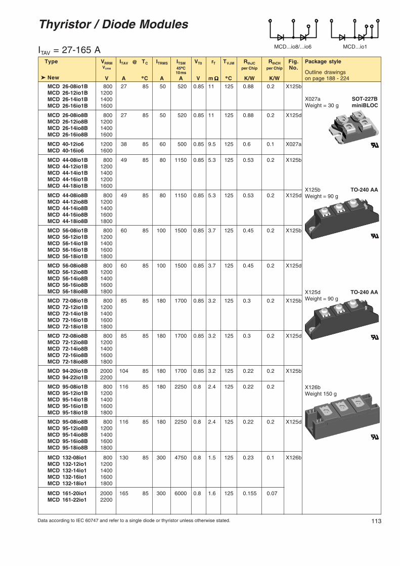
Thyristor / Diode Modules
MCD...io8/...io6 MCD...io1
@
ITAV = 27-165 AType VRRM ITAV TC ITRMS ITSM VT0 rT TVJM RthJC RthCH Fig. Package style
VDRM 45°°°°°C per Chip per Chip No.10 ms Outline drawings
V A °°°°°C A A V m ΩΩΩΩΩ °°°°°C K/W K/W on page 188 - 224
MCD 26-08io1B 800 27 85 50 520 0.85 11 125 0.88 0.2 X125bMCD 26-12io1B 1200MCD 26-14io1B 1400MCD 26-16io1B 1600
MCD 26-08io8B 800 27 85 50 520 0.85 11 125 0.88 0.2 X125dMCD 26-12io8B 1200MCD 26-14io8B 1400MCD 26-16io8B 1600
MCD 40-12io6 1200 38 85 60 500 0.85 9.5 125 0.6 0.1 X027aMCD 40-16io6 1600
MCD 44-08io1B 800 49 85 80 1150 0.85 5.3 125 0.53 0.2 X125bMCD 44-12io1B 1200MCD 44-14io1B 1400MCD 44-16io1B 1200MCD 44-18io1B 1600
MCD 44-08io8B 800 49 85 80 1150 0.85 5.3 125 0.53 0.2 X125dMCD 44-12io8B 1200MCD 44-14io8B 1400MCD 44-16io8B 1600MCD 44-18io8B 1800
MCD 56-08io1B 800 60 85 100 1500 0.85 3.7 125 0.45 0.2 X125bMCD 56-12io1B 1200MCD 56-14io1B 1400MCD 56-16io1B 1600MCD 56-18io1B 1800
MCD 56-08io8B 800 60 85 100 1500 0.85 3.7 125 0.45 0.2 X125dMCD 56-12io8B 1200MCD 56-14io8B 1400MCD 56-16io8B 1600MCD 56-18io8B 1800
MCD 72-08io1B 800 85 85 180 1700 0.85 3.2 125 0.3 0.2 X125bMCD 72-12io1B 1200MCD 72-14io1B 1400MCD 72-16io1B 1600MCD 72-18io1B 1800
MCD 72-08io8B 800 85 85 180 1700 0.85 3.2 125 0.3 0.2 X125dMCD 72-12io8B 1200MCD 72-14io8B 1400MCD 72-16io8B 1600MCD 72-18io8B 1800
MCD 94-20io1B 2000 104 85 180 1700 0.85 3.2 125 0.22 0.2 X125bMCD 94-22io1B 2200
MCD 95-08io1B 800 116 85 180 2250 0.8 2.4 125 0.22 0.2MCD 95-12io1B 1200MCD 95-14io1B 1400MCD 95-16io1B 1600MCD 95-18io1B 1800
MCD 95-08io8B 800 116 85 180 2250 0.8 2.4 125 0.22 0.2 X125dMCD 95-12io8B 1200MCD 95-14io8B 1400MCD 95-16io8B 1600MCD 95-18io8B 1800
MCD 132-08io1 800 130 85 300 4750 0.8 1.5 125 0.23 0.1 X126bMCD 132-12io1 1200MCD 132-14io1 1400MCD 132-16io1 1600MCD 132-18io1 1800
MCD 161-20io1 2000 165 85 300 6000 0.8 1.6 125 0.155 0.07MCD 161-22io1 2200
New
X125b TO-240 AAWeight = 90 g
X125d TO-240 AAWeight = 90 g
X027a SOT-227BWeight = 30 g miniBLOC
X126bWeight 150 g

114 Data according to IEC 60747 and refer to a single diode or thyristor unless otherwise stated.
MCD...io1
Thyristor / Diode Modules
MCD 162-08io1 800 181 85 300 6000 0.88 1.15 125 0.155 0.07 X126bMCD 162-12io1 1200MCD 162-14io1 1400MCD 162-16io1 1600MCD 162-18io1 1800
MCD 200-14io1 1400 216 85 340 8000 0.8 1.0 125 0.13 0.05MCD 200-16io1 1600MCD 200-18io1 1800
MCD 224-20io1 2000 240 85 400 8000 0.8 0.76 130 0.139 0.04 X131bMCD 224-22io1 2200
MCD 220-08io1 800 250 85 400 8500 0.9 1.0 140 0.139 0.04 X129bMCD 220-12io1 1200MCD 220-14io1 1400MCD 220-16io1 1600
MCD 225-12io1 1200 221 85 400 8000 0.8 0.76 130 0.157 0.04 X131bMCD 225-14io1 1400MCD 225-16io1 1600MCD 225-18io1 1800
MCD 250-08io1 800 287 85 450 9000 0.85 0.82 140 0.129 0.04 X129bMCD 250-12io1 1200MCD 250-14io1 1400MCD 250-16io1 1600MCD 250-18io1 1800
MCD 255-12io1 1200 250 85 450 9000 0.8 0.68 130 0.14 0.04 X131bMCD 255-14io1 1400MCD 255-16io1 1600MCD 255-18io1 1800
MCD 310-08io1 800 320 85 500 9200 0.8 0.82 140 0.112 0.04 X129bMCD 310-12io1 1200MCD 310-14io1 1400MCD 310-16io1 1600MCD 310-18io1 1800
MCD 310-20io1 2000 320 85 500 8000 0.8 0.82 140 0.112 0.04 X129bMCD 310-22io1 2200
MCD 312-12io1 1200 320 85 520 9200 0.8 0.68 140 0.12 0.04 X131bMCD 312-14io1 1400MCD 312-16io1 1600MCD 312-18io1 1800
MCD 500-12io1* 1200 500 89 1294 18200 0.85 0.27 125 0.062 0.02 X136aMCD 500-16io1 1600 125°CMCD 500-18io1 1800
MCD 500-22io1 2200 500 80 1071 15400 0.88 0.46 125 0.062 0.02125°C
MCD 700-12io1W* 1200 700 TW = 1331 18200 0.85 0.27 125 0.062 RthJW = X136bMCD 700-16io1W 1600 42°C 125°C 0.09MCD 700-18io1W 1800
* for other configurations please contact factory
Type VRRM ITAV TC ITRMS ITSM VT0 rT TVJM RthJC RthCH Fig. Package styleVDRM 45°°°°°C per Chip per Chip No.
10 ms Outline drawingsV A °°°°°C A A V m ΩΩΩΩΩ °°°°°C K/W K/W on page 188 - 224
@
ITAV = 181 - 700 A
New
X136aWeight = 1550 g
X129bWeight = 750 g
X136bWeight = 2100 g
X126bWeight 150 g
X131bWeight = 750 g
115Data according to IEC 60747 and refer to a single diode or thyristor unless otherwise stated.
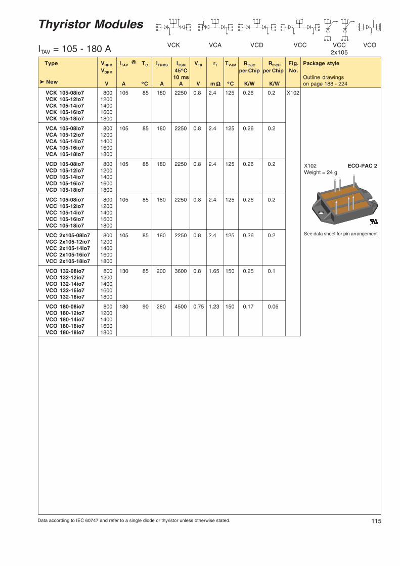
Thyristor Modules
VCOVCC2x105
VCCVCDVCAVCK
@Type VRRM ITAV TC ITRMS ITSM VT0 rT TVJM RthJC RthCH Fig. Package styleVDRM 45°°°°°C per Chip per Chip No.
10 ms Outline drawingsV A °°°°°C A A V m ΩΩΩΩΩ °°°°°C K/W K/W on page 188 - 224 New
VCK 105-08io7 800 105 85 180 2250 0.8 2.4 125 0.26 0.2 X10²VCK 105-12io7 1200VCK 105-14io7 1400VCK 105-16io7 1600VCK 105-18io7 1800
VCA 105-08io7 800 105 85 180 2250 0.8 2.4 125 0.26 0.2VCA 105-12io7 1200VCA 105-14io7 1400VCA 105-16io7 1600VCA 105-18io7 1800
VCD 105-08io7 800 105 85 180 2250 0.8 2.4 125 0.26 0.2VCD 105-12io7 1200VCD 105-14io7 1400VCD 105-16io7 1600VCD 105-18io7 1800
VCC 105-08io7 800 105 85 180 2250 0.8 2.4 125 0.26 0.2VCC 105-12io7 1200VCC 105-14io7 1400VCC 105-16io7 1600VCC 105-18io7 1800
VCC 2x10⁵-08io7 800 105 85 180 2250 0.8 2.4 125 0.26 0.2VCC 2x10⁵-12io7 1200VCC 2x10⁵-14io7 1400VCC 2x10⁵-16io7 1600VCC 2x10⁵-18io7 1800
VCO 132-08io7 800 130 85 200 3600 0.8 1.65 150 0.25 0.1VCO 132-12io7 1200VCO 132-14io7 1400VCO 132-16io7 1600VCO 132-18io7 1800
VCO 180-08io7 800 180 90 280 4500 0.75 1.23 150 0.17 0.06VCO 180-12io7 1200VCO 180-14io7 1400VCO 180-16io7 1600VCO 180-18io7 1800
See data sheet for pin arrangement
X102 ECO-PAC 2Weight = 24 g
ITAV = 105 - 180 A
Typbez.xx-06 --> -0818.05.06

116 Data according to IEC 60747 and refer to a single diode or thyristor unless otherwise stated.
MCC...io1B MCC...io8B
Thyristor Modules
ITAV = 18-116 A
Type VRRM ITAV TC ITRMS ITSM VT0 rT TVJM RthJC RthCH Fig. Package styleVDRM 45°°°°°C per Chip per Chip No.
10 ms Outline drawingsV A °°°°°C A A V m ΩΩΩΩΩ °°°°°C K/W K/W on page 188 - 224
@
MCC 19-08io1B 800 18 85 40 400 0.85 18 125 1.3 0.2 X125aMCC 19-12io1B 1200MCC 19-14io1B 1400MCC 19-16io1B 1600
MCC 19-08io8B 800 18 85 40 400 0.85 18 125 1.3 0.2 X125cMCC 19-12io8B 1200MCC 19-14io8B 1400MCC 19-16io8B 1600
MCC 21-08io8B 800 21 85 33 320 0.85 15 125 1.1 0.2 X125cMCC 21-12io8B 1200MCC 21-14io8B 1400MCC 21-16io8B 1600MCC 26-08io1B 800 27 85 50 520 0.85 11 125 0.88 0.2 X125aMCC 26-12io1B 1200MCC 26-14io1B 1400MCC 26-16io1B 1600
MCC 26-08io8B 800 27 85 50 520 0.85 11 125 0.88 0.2 X125cMCC 26-12io8B 1200MCC 26-14io8B 1400MCC 26-16io8B 1600
MCC 44-08io1B 800 49 85 80 1150 0.85 5.3 125 0.53 0.2 X125aMCC 44-12io1B 1200MCC 44-14io1B 1400MCC 44-16io1B 1600MCC 44-18io1B 1800MCC 44-08io8B 800 49 85 80 1150 0.85 5.3 125 0.53 0.2 X125cMCC 44-12io8B 1200MCC 44-14io8B 1400MCC 44-16io8B 1600MCC 44-18io8B 1800
MCC 56-08io1B 800 60 85 100 1500 0.85 3.7 125 0.45 0.2 X125aMCC 56-12io1B 1200MCC 56-14io1B 1400MCC 56-16io1B 1600MCC 56-18io1B 1800
MCC 56-08io8B 800 60 85 100 1500 0.85 3.7 125 0.45 0.2 X125cMCC 56-12io8B 1200MCC 56-14io8B 1400MCC 56-16io8B 1600MCC 56-18io8B 1800MCC 72-08io1B 800 85 85 180 1700 0.85 3.2 125 0.3 0.2 X125aMCC 72-12io1B 1200MCC 72-14io1B 1400MCC 72-16io1B 1600MCC 72-18io1B 1800
MCC 72-08io8B 800 85 85 180 1700 0.85 3.2 125 0.3 0.2 X125cMCC 72-12io8B 1200MCC 72-14io8B 1400MCC 72-16io8B 1600MCC 72-18io8B 1800
MCC 94-20io1B 2000 104 85 180 1700 0.85 3.2 125 0.22 0.2 X125aMCC 94-22io1B 2200MCC 95-08io1B 800 116 85 180 2250 0.8 2.4 125 0.22 0.2 X125aMCC 95-12io1B 1200MCC 95-14io1B 1400MCC 95-16io1B 1600MCC 95-18io1B 1800
X125a TO-240 AAWeight = 90 g
X125c TO-240 AAWeight = 90 g
117Data according to IEC 60747 and refer to a single diode or thyristor unless otherwise stated.
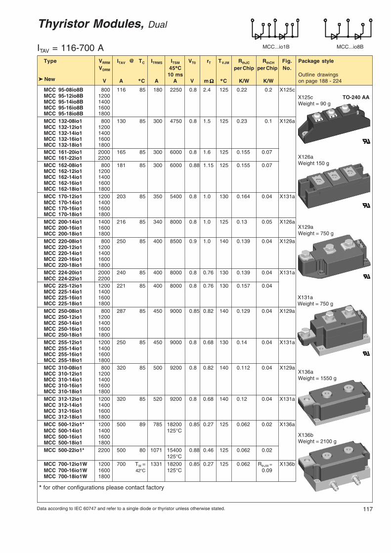
Thyristor Modules, Dual
MCC...io1B MCC...io8B
@
ITAV = 116-700 AType VRRM ITAV TC ITRMS ITSM VT0 rT TVJM RthJC RthCH Fig. Package style
VDRM 45°°°°°C per Chip per Chip No.10 ms Outline drawings
V A °°°°°C A A V m ΩΩΩΩΩ °°°°°C K/W K/W on page 188 - 224
MCC 95-08io8B 800 116 85 180 2250 0.8 2.4 125 0.22 0.2 X125cMCC 95-12io8B 1200MCC 95-14io8B 1400MCC 95-16io8B 1600MCC 95-18io8B 1800MCC 132-08io1 800 130 85 300 4750 0.8 1.5 125 0.23 0.1 X126aMCC 132-12io1 1200MCC 132-14io1 1400MCC 132-16io1 1600MCC 132-18io1 1800MCC 161-20io1 2000 165 85 300 6000 0.8 1.6 125 0.155 0.07MCC 161-22io1 2200MCC 162-08io1 800 181 85 300 6000 0.88 1.15 125 0.155 0.07MCC 162-12io1 1200MCC 162-14io1 1400MCC 162-16io1 1600MCC 162-18io1 1800MCC 170-12io1 1200 203 85 350 5400 0.8 1.0 130 0.164 0.04 X131aMCC 170-14io1 1400MCC 170-16io1 1600MCC 170-18io1 1800MCC 200-14io1 1400 216 85 340 8000 0.8 1.0 125 0.13 0.05 X126aMCC 200-16io1 1600MCC 200-18io1 1800MCC 220-08io1 800 250 85 400 8500 0.9 1.0 140 0.139 0.04 X129aMCC 220-12io1 1200MCC 220-14io1 1400MCC 220-16io1 1600MCC 220-18io1 1800MCC 224-20io1 2000 240 85 400 8000 0.8 0.76 130 0.139 0.04 X131aMCC 224-22io1 2200MCC 225-12io1 1200 221 85 400 8000 0.8 0.76 130 0.157 0.04MCC 225-14io1 1400MCC 225-16io1 1600MCC 225-18io1 1800MCC 250-08io1 800 287 85 450 9000 0.85 0.82 140 0.129 0.04 X129aMCC 250-12io1 1200MCC 250-14io1 1400MCC 250-16io1 1600MCC 250-18io1 1800MCC 255-12io1 1200 250 85 450 9000 0.8 0.68 130 0.14 0.04 X131aMCC 255-14io1 1400MCC 255-16io1 1600MCC 255-18io1 1800MCC 310-08io1 800 320 85 500 9200 0.8 0.82 140 0.112 0.04 X129aMCC 310-12io1 1200MCC 310-14io1 1400MCC 310-16io1 1600MCC 310-18io1 1800MCC 312-12io1 1200 320 85 520 9200 0.8 0.68 140 0.12 0.04 X131aMCC 312-14io1 1400MCC 312-16io1 1600MCC 312-18io1 1800MCC 500-12io1* 1200 500 89 785 18200 0.85 0.27 125 0.062 0.02 X136aMCC 500-14io1 1400 125°CMCC 500-16io1 1600MCC 500-18io1 1800MCC 500-22io1* 2200 500 80 1071 15400 0.88 0.46 125 0.062 0.02
125°CMCC 700-12io1W 1200 700 TW = 1331 18200 0.85 0.27 125 0.062 RthJW = X136bMCC 700-16io1W 1600 42°C 125°C 0.09MCC 700-18io1W 1800
* for other configurations please contact factory
New
X125c TO-240 AAWeight = 90 g
X126aWeight 150 g
X131aWeight = 750 g
X136aWeight = 1550 g
X129aWeight = 750 g
X136bWeight = 2100 g
118 Data according to IEC 60747 and refer to a single diode or thyristor unless otherwise stated.
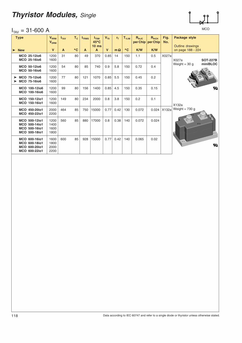
Thyristor Modules, Single
MCO
MCO 25-12io6 1200 31 80 49 370 0.85 14 150 1.1 0.5 X027aMCO 25-16io6 1600
MCO 50-12io6 1200 54 80 85 740 0.9 5.8 150 0.72 0.4MCO 50-16io6 1600
MCO 75-12io6 1200 77 80 121 1070 0.85 5.5 150 0.45 0.2 MCO 75-16io6 1600
MCO 100-12io6 1200 99 80 156 1400 0.85 4.5 150 0.35 0.15MCO 100-16io6 1600
MCO 150-12io1 1200 149 80 234 2000 0.8 3.8 150 0.2 0.1MCO 150-16io1 1600
MCO 450-20io1 2000 464 85 750 15000 0.77 0.42 130 0.072 0.024 X132aMCO 450-22io1 2200
MCO 500-12io1 1200 560 85 880 17000 0.8 0.38 140 0.072 0.024MCO 500-14io1 1400MCO 500-16io1 1600MCO 500-18io1 1800
MCO 600-16io1 1600 600 85 928 15000 0.77 0.42 140 0.065 0.02MCO 600-18io1 1800MCO 600-20io1 2000MCO 600-22io1 2200
Type VRRM ITAV TC ITRMS ITSM VT0 rT TVJM RthJC RthCH Fig. Package styleVDRM 45°°°°°C per Chip per Chip No.
10 ms Outline drawingsV A °°°°°C A A V m ΩΩΩΩΩ °°°°°C K/W K/W on page 188 - 224
ITAV = 31-600 A
New
X132aWeight = 730 g
X027a SOT-227BWeight = 30 g miniBLOC

119Data according to IEC 60747 and refer to a single diode or thyristor unless otherwise stated.
Optional Accessories for Thyristor / Diode Modules
Design InformationFor Thyristors, Diodes, Thyristor / Diode Modules and Rectifier Bridges
The 60 Hz value of ITSM is 10 % higher than the 50 Hz valueThe ITSM value at TVJM is 10 to 15 % lower than the 45°C value
50 Hz: I2t (in A2s) = ITSM (A) • ITSM (A) • 0.005 (s); use rated ITSM value (10 ms)60 Hz: I2t (in A2s) = ITSM (A) • ITSM (A) • 0.0042 (s); use 60-Hz-value of ITSM
The average current ratings in tables are mostly specified for temperatureconditions of: TA = 45°C, TC = 85°C or TC = 100°C.For other temperature conditions, the current ratings can be calculated using thefollowing formulas, applicable up to 400 Hz.
-VT0 + √ VT02 + 4 • k2 • rT • P TVJM - TC TVJM - TA
ITAV = where P = or P =2 • k2 • rT RthJC RthJA
ITAV (A), P (W); VTO (V); rT (Ω), TVJM (°C), TC (°C), TA (°C)RthJC (K/W), RthJA (K/W)
k2 = 1 for DC currentk2 = 2.5 for sinusoidal half wave currentk2 = 3.0 for 120° rectangular currentk2 = 6.0 for 60° rectangular current
The average forward current is limited by the RMS current value ITRMS. When thecalculated value ITAV is higher than ITRMS/ k, replace it by ITAV = ITRMS/k.
Surge current
Limiting I2t
Forward current
14
20 12
For module-types MCC 19, 26, 44, 56, 60, 72,94 and 95 version 1:Keyed Gate Cathode twin plugs with wirelength = 350 mm;gate = yellow, cathode = red
Type ZY 200 L (L = Left for pin pair 4/5)Type ZY 200 R (R = Right for pin pair 6/7)
For ZY 180 and ZY 200: UL Styles 1385
For module types MCC/MCD/MCO 122, 132,161, 162, 170, 200, 220, 224, 225, 250, 255, 310,312, 500 and MII 400 (for MCD/MCO only L-type):Keyed Gate Cathode twin plugswith wire length = 350 mmgate = yellow, cathode = red
Type ZY 180 L (L = Left for pin pair 4/5)Type ZY 180 R (R = Right for pin pair 6/7)
For module typesMCC/MCD/MDD 220, 250, 310Threaded spacer for higher Anode /Cathode construction:
Type ZY 250 (material brass)

![[MG2460] Datasheet - IXYS Corporation: IXYS Powerixapps.ixys.com/DataSheet/ADS0601-[MG2460]_Datash… · · 2015-08-135.1. ABSOLUTE MAXIMUM RATINGS ... ADS0601 MG2460 Datasheet](https://img.pdfslide.net/doc/110x75/5aef32107f8b9aa9168c3b16/mg2460-datasheet-ixys-corporation-ixys-mg2460datash2015-08-1351-absolute.jpg)