Embed Size (px)
Citation preview
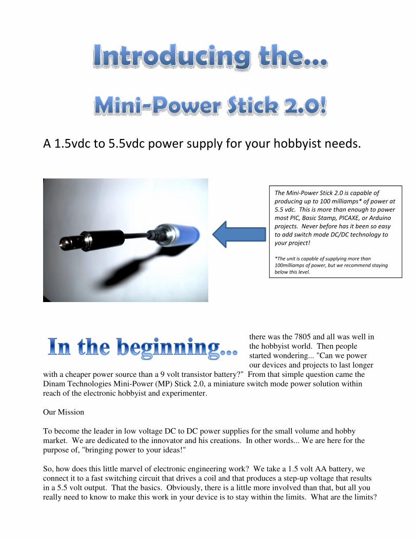
A 1.5vdc to 5.5vdc power supply for your hobbyist needs.
there was the 7805 and all was well in the hobbyist world. Then people started wondering... "Can we power our devices and projects to last longer
with a cheaper power source than a 9 volt transistor battery?" From that simple question came the Dinam Technologies Mini-Power (MP) Stick 2.0, a miniature switch mode power solution within reach of the electronic hobbyist and experimenter.
Our Mission
To become the leader in low voltage DC to DC power supplies for the small volume and hobby market. We are dedicated to the innovator and his creations. In other words... We are here for the purpose of, "bringing power to your ideas!"
So, how does this little marvel of electronic engineering work? We take a 1.5 volt AA battery, we connect it to a fast switching circuit that drives a coil and that produces a step-up voltage that results in a 5.5 volt output. That the basics. Obviously, there is a little more involved than that, but all you really need to know to make this work in your device is to stay within the limits. What are the limits?
The Mini-Power Stick 2.0 is capable of
producing up to 100 milliamps* of power at
5.5 vdc. This is more than enough to power
most PIC, Basic Stamp, PICAXE, or Arduino
projects. Never before has it been so easy
to add switch mode DC/DC technology to
your project!
*The unit is capable of supplying more than
100milliamps of power, but we recommend staying
below this level.
1. The input limit is 1.5 vdc. This shouldn’t be a problem because the device is only large enough for 1 AA battery. We’re sure someone will figure a way around this, but please don’t.
2. The absolute output current is 100 milliamps. Even if you could get more than that out of the device you would probably need to buy stock in a battery company or use rechargeable batteries, because the resulting current demand on the battery will start to approach 1 amp and will completely discharge your battery in short order!
3. Obviously, this device is not intended for underwater projects and is not covered under the manufacturer’s warranty for such defects. Even though it does have a sleek cylindrical body, it’s not a submarine so don’t treat it like one.
4. That’s about it. As customers come up with creative ways to stretch the limits of this device, we’ll undoubtedly have to list more things you shouldn’t do with your MP Stick 2.0. Until then, just keep the previously mentioned limits in mind when using the Mini-Power Stick 2.0.
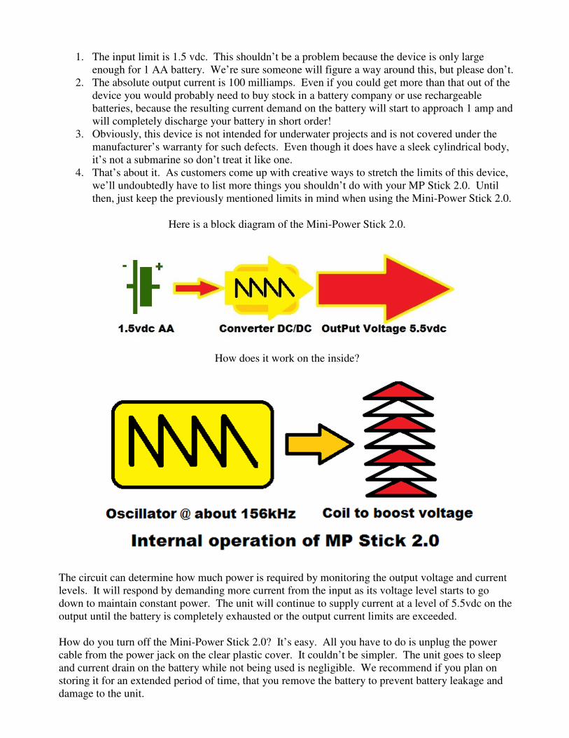
Here is a block diagram of the Mini-Power Stick 2.0.
How does it work on the inside?
The circuit can determine how much power is required by monitoring the output voltage and current levels. It will respond by demanding more current from the input as its voltage level starts to go down to maintain constant power. The unit will continue to supply current at a level of 5.5vdc on the output until the battery is completely exhausted or the output current limits are exceeded.
How do you turn off the Mini-Power Stick 2.0? It’s easy. All you have to do is unplug the power cable from the power jack on the clear plastic cover. It couldn’t be simpler. The unit goes to sleep and current drain on the battery while not being used is negligible. We recommend if you plan on storing it for an extended period of time, that you remove the battery to prevent battery leakage and damage to the unit.

So you might be asking, “Doesn’t the oscillator produce DC with a noise on the output? Well, um… The short answer is “yes.” As with all things, there is usually a trade-off. However, for most projects that aren’t audio or RF based, it shouldn’t be a problem. For some projects that are audio or RF based it shouldn’t be a big deal either. This is why…
In the first picture, you see an oscilloscope reading of the 5.5 volt DC voltage. It looks fairly clean without any defects.
NOTE: The ground level was moved to the bottom of the display.
Now let’s look at the DC noise by switching the scope to AC input and to the 50 millivolt scale.
As you can see, the noise is now visible and is about a 50 millivolt AC saw tooth ripple riding on top of the 5.5 volt DC output. That represents a noise component of only 0.9%. Not bad. However the ripple level does change as the current changes and the frequency of the ripple (in this example, it was 600 kHz) will change as the load changes.

You can eliminate the noise with filtering and by using a low dropout regulator on the input to your project. A SchmartBoard Power Module will work nicely for this and can costs less than $10.00. However, the SchmartBoard Power Module does draw 6.5milliamps of power from the MP Stick 2.0 to power the LED on the module. Fortunately, most PIC/PICAXE/Basic Stamp/Arduino projects won’t require much (if any) filtering except in the most noise sensitive applications.
We also mentioned that using the MP Stick 2.0 with audio project shouldn’t matter in most cases. This is because the frequency is so high that no normal person could possibly hear the noise that is generated. If you know someone that can hear this high a frequency, it’s time to start looking for some silver bullets or a wooden stake. There is a possibility of low frequency harmonics being generated from the high frequency noise on the DC output from the MP Stick 2.0, so some experimentation would be needed to see if this would be an issue with your project. However, in most cases, adding a Low dropout linear regulator, like the 78L05 or any of the SchmartBoard Power Modules (except the 9vdc version) will eliminate the offending 50millivolt ripple and give you a clean regulated 5vdc output.
Here we see a Mini-Power Stick 2.0 being used with a Basic Stamp blinking LED project.
Here we have a Mini-Power Stick 2.0 connected to a SchmartBoard Power Module.

Here we have a Mini-Power Stick 2.0 connected to a Schmitt-Board Power Module.
Notice that the LED on the MP Stick 2.0 is on with the Basic Stamp experimenter’s board and not
with the SchmartBoard. Why is this? The SchmartBoard is only drawing 6.5 milliamps (.0065 amps)
from the MP Stick 2.0 and the Basic Stamp Experimenter’s board is running a blinking LED program
and is drawing 40 milliamps. The LED on the MP Stick 2.0 indicates a lower switching efficiency.
With the 6.5 milliamp load the efficiency of the unit is around 97%. However, at 40 milliamp loads
the efficiency drops to around 64%. As long as the LED on the MP Stick 2.0 is not on, unless you
overloaded the unit, then you are enjoying the most efficient use of the Mini-Power Stick 2.0 and the
best possible battery life from the AA battery.
Voltage in
Input current in amps
voltage out
Output current in amps
Circuit Resistance
Efficiency Status LED
1.5 vdc 0.0037 5.5 vdc 0.001 5500 99% no
1.5 vdc 0.0075 5.5 vdc 0.002 2750 98% no
1.5 vdc 0.0112 5.5 vdc 0.003 1833 98% no
1.5 vdc 0.0149 5.5 vdc 0.004 1375 98% no
1.5 vdc 0.0199 5.5 vdc 0.005 1038 98% no
1.5 vdc 0.0400 5.5 vdc 0.010 550 92% no
1.5 vdc 0.0700 5.5 vdc 0.015 367 79% dim/yes
1.5 vdc 0.1000 5.5 vdc 0.020 275 73% dim/yes
1.5 vdc 0.1300 5.5 vdc 0.025 220 71% dim/yes
1.5 vdc 0.1700 5.5 vdc 0.030 183 65% yes
1.5 vdc 0.1990 5.5 vdc 0.035 157 64% yes
1.5 vdc 0.2300 5.5 vdc 0.040 138 64% yes
1.5 vdc 0.2850 5.5 vdc 0.050 110 64% yes
1.5 vdc 0.3440 5.5 vdc 0.060 92 64% yes
In the above chart it shows the efficiency and the input/output currents that can be expected. For a
more complete chart, please refer to Reference Material section at the end of this user guide.
We’ll present an example of how to use the Mini-Power Stick 2.0 with a PICAXE 20X2, and the
MicroChip PIC microcontroller.
Here are a few examples of what you can do with the Mini-Power Stick 2.0 and a Basic Stamp®.
The first example will take advantage of the sleep mode of the Basic stamp and its ability to reduce
its power consumption down below 1milliamp when sleeping and then wake up, take a measurement,
then go back to sleep. It is possible to run the Basic Stamp® for up to two weeks on a single AAA
battery! The circuit diagram for this application is listed below.

Voltage in Input current
in amps
voltage out Output current
in amps
Circuit
Resistance
Efficiency Status
LED
1.5 vdc 0.0037 5.5 vdc 0.001 5500 99% no
1.5 vdc 0.0075 5.5 vdc 0.002 2750 98% no
1.5 vdc 0.0112 5.5 vdc 0.003 1833 98% no
1.5 vdc 0.0149 5.5 vdc 0.004 1375 98% no
1.5 vdc 0.0199 5.5 vdc 0.005 1038 98% no
1.5 vdc 0.0400 5.5 vdc 0.010 550 92% no
1.5 vdc 0.0700 5.5 vdc 0.015 367 79% dim/yes
1.5 vdc 0.1000 5.5 vdc 0.020 275 73% dim/yes
1.5 vdc 0.1300 5.5 vdc 0.025 220 71% yes
1.5 vdc 0.1700 5.5 vdc 0.030 183 65% yes
1.5 vdc 0.1990 5.5 vdc 0.035 157 64% yes
1.5 vdc 0.2300 5.5 vdc 0.040 138 64% yes
1.5 vdc 0.2850 5.5 vdc 0.050 110 64% yes
1.5 vdc 0.3440 5.5 vdc 0.060 92 64% yes
1.5 vdc 0.4000 5.5 vdc 0.070 79 64% yes
1.5 vdc 0.4550 5.5 vdc 0.080 69 64% yes
1.5 vdc 0.5150 5.5 vdc 0.090 61 64% yes
1.5 vdc 0.5700 5.5 vdc 0.100 55 64% yes
1.5 vdc 0.6350 5.5 vdc 0.110 50 64% dim/yes
1.5 vdc 0.7050 5.5 vdc 0.120 46 62% dim/yes
1.5 vdc 0.7800 5.5 vdc 0.130 42 61% dim/yes
1.5 vdc 0.8400 5.5 vdc 0.140 39 61% dim/yes
1.5 vdc 0.9000 5.5 vdc 0.150 37 61% no
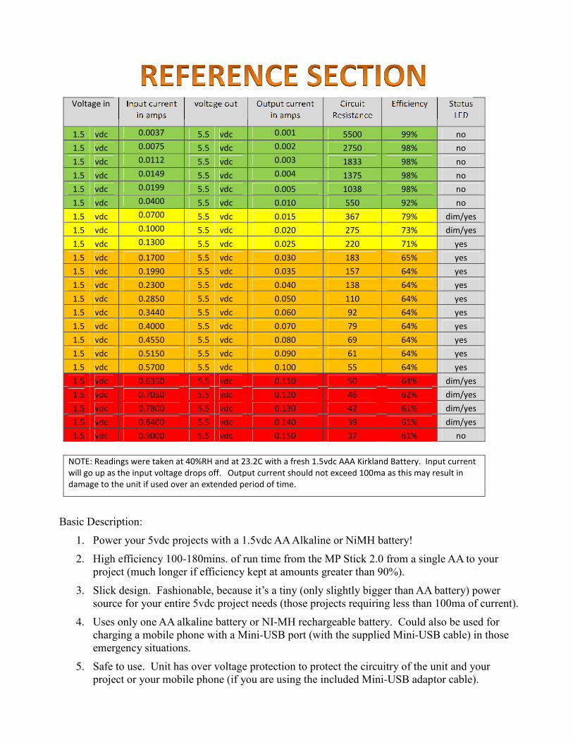
NOTE: Readings were taken at 40%RH and at 23.2C with a fresh 1.5vdc AAA Kirkland Battery. Input current
will go up as the input voltage drops off. Output current should not exceed 100ma as this may result in
damage to the unit if used over an extended period of time.
Basic Description:
1. Power your 5vdc projects with a 1.5vdc AA Alkaline or NiMH battery!
2. High efficiency 100-180mins. of run time from the MP Stick 2.0 from a single AA to your
project (much longer if efficiency kept at amounts greater than 90%).
3. Slick design. Fashionable, because it’s a tiny (only slightly bigger than AA battery) power
source for your entire 5vdc project needs (those projects requiring less than 100ma of current).
4. Uses only one AA alkaline battery or NI-MH rechargeable battery. Could also be used for
charging a mobile phone with a Mini-USB port (with the supplied Mini-USB cable) in those emergency situations.
5. Safe to use. Unit has over voltage protection to protect the circuitry of the unit and your
project or your mobile phone (if you are using the included Mini-USB adaptor cable).
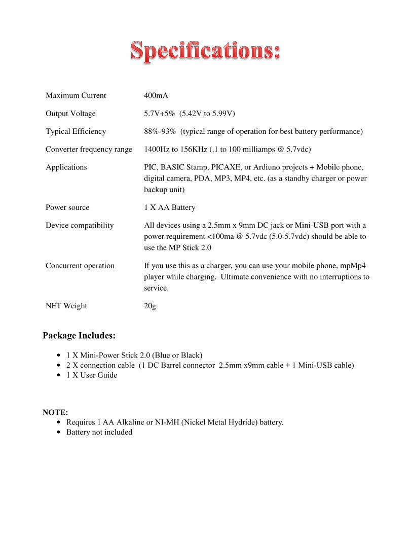
Maximum Current
400mA
Output Voltage 5.7V+5% (5.42V to 5.99V)
Typical Efficiency 88%-93% (typical range of operation for best battery performance)
Converter frequency range 1400Hz to 156KHz (.1 to 100 milliamps @ 5.7vdc)
Applications PIC, BASIC Stamp, PICAXE, or Ardiuno projects + Mobile phone,
digital camera, PDA, MP3, MP4, etc. (as a standby charger or power
backup unit)
Power source 1 X AA Battery
Device compatibility All devices using a 2.5mm x 9mm DC jack or Mini-USB port with a
power requirement <100ma @ 5.7vdc (5.0-5.7vdc) should be able to
use the MP Stick 2.0
Concurrent operation If you use this as a charger, you can use your mobile phone, mpMp4
player while charging. Ultimate convenience with no interruptions to
service.
NET Weight 20g
Package Includes:
• 1 X Mini-Power Stick 2.0 (Blue or Black)
• 2 X connection cable (1 DC Barrel connector 2.5mm x9mm cable + 1 Mini-USB cable)
• 1 X User Guide
NOTE:
• Requires 1 AA Alkaline or NI-MH (Nickel Metal Hydride) battery.
• Battery not included
Our warranty is not like a lot of the warranties that software companies (or some hardware companies for that matter) give
you. We don’t charge you an arm and a leg for something that sort of works, then tell you that if anything goes wrong,
it’s your fault. Our warranty is simple.
1. If the unit does not function when you receive it.
Or…
2. If the unit quits functioning after you’ve owned it for less than 90 days.
Or…
3. If you don’t like the color (okay, maybe that’s a stretch… forget that one)
We will repair or replace, at our option, the unit as long as it’s returned to us at one of the addresses listed below within
90 days from date of purchase. You will need to pay the shipping to us, but we’ll pay the shipping back to the address
from where it was sent.
Where to send it (Pick the address that is closest to you):
West Coast Midwest East Coast
Dinam-Technologies Dinam-Technologies Dinam-Technologies
Attn: RMA Department Attn: RMA Department Attn: Warranty Department
1680 Hidden Valley Rd. 1680 Hidden Valley Rd 3327 Back Creek Church Road
Sandy Utah 84092 Sandy Utah 84092 Charlotte NC 28213
Please send us an email at [email protected] before sending the defective unit to receive an RMA number that you
will need to place on the box you use to send it to us. This helps us to keep things in the proper order and not lose your
unit. In some cases, we may elect to just send you a new replacement circuit board (especially if we determine there is a
common issue among customers with this product), so please send an email before sending it in to determine if you need
to do so. Thanks in advance for your cooperation in this matter.
Warranty Disclaimer: Caveat emptor (not really)
This should be obvious to most, but we have to state it anyway…
If you drive over this with a car, or you figure out a way to connect it to an outlet in your home (Which we definitely don’t recommend), or you try to
use it as a defibrillator on your wife’s favorite cat that you accidently fried with that really cool project idea that you had, then we’ll probably not replace
it for you. We put a lot of work into bringing you a great product that should give you many years of service and therefore it should be cared for like a
new born baby. In other words, if you abuse it, then we don’t feel that we should have to fix it for you. Fair is far.
Although this unit was designed to power electronic devices and such, we don’t guarantee that it will power your electronic device, nor do we guarantee
that it will be suitable for any situation or purpose that you dream up. Let’s face it, the way some home brewed electronic projects are designed a car
battery would have a hard time supplying enough power. Even though it has protective circuitry to prevent catastrophic failure of the device, your
project, or your phone (if you elect to charge your phone with this device), we don’t guarantee that this feature it will work every time. For example, if
you do something not wise like shorting the output for an extended period of time, it probably will fail.
If you elect to modify the unit in any way, we will elect not to repair it. You can of course modify it if you wish, but don’t expect us to repair something
that you changed and now fails to work as a result. We suggest that you wait until the warranty has expired and then modify the unit if you wish. If it
fails to function after your modifications, then you can send it to us to fix for a fee. That way, you will have at least received 90 days of service out of
the device before it was rendered inoperable. At this time, we don’t have extra circuit boards to sell if a customer caused malady should result. We’ll
probably have some in the near future, because you can never tell how many people will need to be rescued from themselves.
Our Moto: Ut imperdiet odio et
The silly things that lawyers make us say, so we won’t get sued:
Even though the Mini-Power Stick 2.0 is a product of Dinam Technologies, we do have to state that the basic unit and all components are made in China
and assembled, modified, and tested in the USA. We also have to pay our respects to the people at Revolution Education Ltd, Parallax®, The Arduino
Foundation®, and MicroChip® because the names, PICAXE™, BASIC Stamp™, Arduino™, and PIC™ are the trademarks of these companies and
they would probably get mad at us if we forgot to mention their names. SchmartBoard Power Modules™ and boards are really cool and you should try
these out sometime in the future, but once again, they are also the trademark of their owners (in this case SchmartBoard® Inc.). Everything in this User
Guide is copyrighted by Dinam-Technologies and all rights are reserved. However, if you want to use something in this User’s Guide in your
documentation (unless it’s copyrighted by one of those other companies mentioned earlier) for a product that you have or an article that you want to
write on the web or in a magazine, then feel free to do so as long as you give credit to Dave Lawson and the crew at Dinam Technologies.
Our lawyer was on vacation when we wrote this legal disclaimer, so that’s why you can actually understand it. He’ll probably make us change it, but
until then this is all we have to say on the subject of “Legal Stuff.”
Note: The phrase “Ut imperdiet odio et” is Latin for “We hate lawyers too.” It was translated using Google Translator™ (a product of Google Inc.)
as none of us here speak Latin. So, if you know Latin, and know that this phrase is not a correct translation, then send us an email at sales@dinam-
tech.com and we’ll fix it. Also, there might be a reward (a very small reward) for helping us out. Thank you for reading all this and we do appreciate
it. However, shouldn’t you be playing with your MP Stick 2.0? After all, that is why we built it. – The team at Dinam Technologies and dinam-tech.com