Embed Size (px)
Citation preview

Step One
SPECIFICATIONS
2.8"(71mm)
7.4
"(18
8m
m)
4.2
"(10
6m
m)
B (S
pe
cify)
A (S
pe
cify)
C (S
pe
cify)
2" N
PT
(2" G
)
Specifications:Length: 8" to 10' (20 cm to 3m)Switch points: 2 (field adjustable)Orientation: ± 30˚ verticalSupply voltage: 120/240 VAC @ 50-60 Hz.Strobe type: 431_: N/A
432_: Xenon tubeStrobe flash: 431_: N/A
432_: 1 per secondContact type: (1) SPDT relay, latchingContact rating: 250 VAC @ 10AContact latch: Selectable ON/OFFContact delay: 0-60 secondsLED indication: Power, relay and sensor statusProcess temp.: F: -40˚ to 194˚
C: -40˚ to 90˚Electronics temp.: F: -40˚ to 140˚
C: -40˚ to 60˚Pressure: AtmosphericWetted material: PP (20% glass fill)Process mount: 2" NPT (2" G)Enclosure rating: NEMA 4X (IP65)Installed height: 431_: 5.7" (14.4 cm)
432_: 7.4" (18.8 cm)Encl. material: PP, UL94VOConduit entrance: Single, 1/2" NPTClassification: General purposeCE compliance: EN 50082-2 immunity
EN 55011 emissionEN 61010-1 safety
Sensor Technologies:Vibration (LZ10 series)Typically applied in wastewater media with light coat-ing and/or foaming characteristics
Ultrasonic (LU10 series)Broadly applied in chemical, solvent, hydrocarbon andlight weight oil media
Buoyancy (LV10 series)Best applied in clean water or water-like chemicalmedia that is non-coating or scaling
Flowline Online Sales - 888.773.2832 - [email protected]

Step Two
COMPONENTS
UltrasonicAU23-4323
2 x LU10-13051 x LM10-1_012 x LM30-10011 x LC10-1002
AU23-43272 x LU10-13251 x LM10-1_612 x LM30-10511 x LC10-1002
BuoyancyAV23-4323
2 x LV10-13011 x LM10-1_012 x LM30-10011 x LC10-1002
AV23-43272 x LV10-13511 x LM10-1_612 x LM30-10511 x LC10-1002
VibrationAZ23-4323
2 x LZ12-14051 x LM10-1_012 x LM30-10011 x LC10-1002
AZ23-43272 x LZ12-14051 x LM10-1_612 x LM30-10011 x LC10-1002
Component List:
C (Specify)
B (Specify)A (Specify)
Smart Trak FittingP/N: LM10-1_01 or LM10-1_61
Compact Relay ControllerP/N: LC10-1001, LC10-1051,
LC10-1002 or LC10-1052
Switch Car KitP/N: LM30-1001 or LM30-1051
Switch-Tek Level SwitchP/N: LU10-1305. LU10-1325,
LV10-1301, LV10-1351 or LZ12-1405
B (Specify)
A (Specify)
C (Specify)
UltrasonicAU23-4313
2 x LU10-13051 x LM10-1_012 x LM30-10011 x LC10-1001
AU23-43172 x LU10-13251 x LM10-1_612 x LM30-10511 x LC10-1051
BuoyancyAV23-4313
2 x LV10-13011 x LM10-1_012 x LM30-10011 x LC10-1001
AV23-43172 x LV10-13511 x LM10-1_612 x LM30-10511 x LC10-1051
VibrationAZ23-4313
2 x LZ12-14051 x LM10-1_012 x LM30-10011 x LC10-1001
AZ23-43172 x LZ12-14051 x LM10-1_612 x LM30-10011 x LC10-1051
Strobe Alert Configuration:(AU23-432_, AV23-432_ or AZ23-432_)
Standard Configuration:(AU23-431_, AV23-431_ or AZ23-431_)
Flowline Online Sales - 888.773.2832 - [email protected]

Step Four
ASSEMBLY OF SMART TRAK™Step Three
SAFETY PRECAUTIONS
About this Manual: PLEASE READ THE ENTIRE MANU-AL PRIOR TO INSTALLING OR USING THIS PRODUCT. Thismanual includes information on the Smart Trak™ with CompactRelay Controller: AU23-43__, AZ23-43__ and AV23-34__. Theunits are identical except for the number of switch points and thesensors technology.
User's Responsibility for Safety: Flowline manufacturesa wide range of liquid level sensors, controllers, and mounting sys-tems. It is the user's responsibility to select components that areappropriate for the application, install them properly, perform testsof the installed system, and maintain all components. The failure todo so could result in property damage or serious injury.
Proper Installation and Handling: Use a proper sealantwith all installations. Never overtighten the components. Alwayscheck for leaks prior to system start-up.
Material Compatibility:Glass filled Polypropylene (PP, a polyolefin): Track, end cap, wireretainer clips, bayonet adapter, level switch and sensor car for allSmart Trak Assemblies.
Polychlorotrifluoroethylene (PCTFE, a fluoroplastic): Sensor carlocking bolt and screw.
Polypropylene (PP, a polyolefin): Sensor, top compression fitting,thrust plate, locking pin and 2" NPT fitting.
Viton (a fluorocarbon): O-ring.
Neoprene(w/silicon gel for lubrication): Wire gasket.
Santoprene(w/silicon gel for lubrication): Seal plug.
Make sure that the application liquids are compatible with thematerials that will be wetted. To determine the chemical compati-bility between the components and its application liquids, refer tothe Compass Corrosion Guide, available from CompassPublications (phone 858-589-9636).
Temperature and Pressure: Smart Trak™ is designed foruse in application temperatures up to 90° C (194° F). It is notdesigned for pressurized applications due to the wiring that musttravel through a gasket at the head.
Wiring and Electrical: Electrical wiring of any liquid levelcontrol system should be performed in accordance with all applic-able national, state, and local codes. Take care not to cut or breakthe outer insulation jacket of wiring that may be immersed whilerouting cables in the Smart Trak™ system. Such breaks of the liq-uid seal of the sensor system may lead to component failure.
Flammable, Explosive and Hazardous Applications:The AU23-43__, AZ23-43__ and AV23-34__ Smart Trak™ shouldnot be used within classified hazardous environments.
Make a Fail-Safe System: Design a fail-safe system thataccommodates the possibility of system or power failure. In criti-cal applications, Flowline recommends the use of redundant back-up systems and alarms in addition to the primary system.
About Smart Trak™: Flowline’s Smart Trak™ with CompactRelay Controller Assembly is an adjustable mounting system forinstalling two level sensors vertically within a tank. Mounted througha single point at the top of the tank, both sensors can be adjusted in thefield. The compact relay controller features a 120/240 VAC latchedcontroller with a 250 VAC, 10A SPDT relay contract. Smart Trak™mounts vertically through a standard 2" NPT tank adapter, or on a sidemount bracket (such as the LM50-1001). Unlike prefabricated “trees”or pipes, Smart Trak™ allows you to experiment with sensor positionto account for variations in the point of actuation of each sensor dur-ing process testing.
Track: The track itself is approximately 1" square, and is from 8”to 10' long depending on the A-Dimension. The track may be cut tolength if desired. Four separate grooves run the length of the track,one on each side of the square. These grooves hold the sensor cars thatattach to Flowline sensors, and also serve to contain the switch cable.The bottom of the track is capped with an end cap.
Relay Controller: Both level switchesare pre-wired before shipment to the 4-poleterminal strip [Input 1A (+) & (-) & Input 1B(+) & (-)]. The switch technologies used toindicate level are either Ultrasonic, Buoyancyor Vibration. The Compact Relay Controllerprovides a 1/2” Conduit connection and 6poles for wire termination of power and relaycontact. Use the AC, AC and GND terminalsfor providing power. Use the NC, NC andCOM terminals for interfacing to the relaycontact.
Vibration (LZ12-1405) Wire Configuration:
RELAY
RedBlackWhiteGreen
Orange
(+)(-)N/AN/AN/AShld
RELAY
(+)
(-)
N/A
N/A
Shld
Red
Black
White
Green
REED
N/A
(-)
(+)
Shld
Red
Black
White
Ultrasonic (LU10-1305 or LU10-1325) WireConfiguration:
Buoyancy (LV10-1301 or LV10-1351) WireConfiguration:
CompactRelay Controller(inside shown)
Flowline Online Sales - 888.773.2832 - [email protected]
Step Five
INSTALLATION
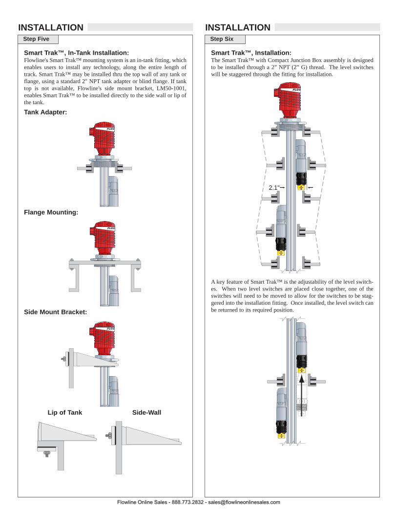
Smart Trak™, In-Tank Installation:Flowline's Smart Trak™ mounting system is an in-tank fitting, whichenables users to install any technology, along the entire length oftrack. Smart Trak™ may be installed thru the top wall of any tank orflange, using a standard 2" NPT tank adapter or blind flange. If tanktop is not available, Flowline's side mount bracket, LM50-1001,enables Smart Trak™ to be installed directly to the side wall or lip ofthe tank.
Tank Adapter:
Flange Mounting:
Side Mount Bracket:
Lip of Tank Side-Wall
Step Six
INSTALLATION
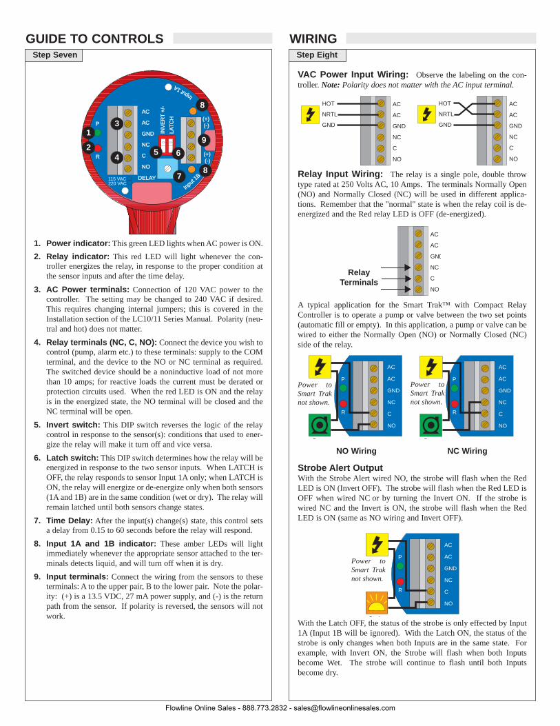
2.1"
Smart Trak™, Installation:The Smart Trak™ with Compact Junction Box assembly is designedto be installed through a 2” NPT (2” G) thread. The level switcheswill be staggered through the fitting for installation.
A key feature of Smart Trak™ is the adjustability of the level switch-es. When two level switches are placed close together, one of theswitches will need to be moved to allow for the switches to be stag-gered into the installation fitting. Once installed, the level switch canbe returned to its required position.
Flowline Online Sales - 888.773.2832 - [email protected]
Step Seven
GUIDE TO CONTROLSStep Eight
WIRING
INV
ER
INV
ER
T +
/- +
/-
LALAT
CH
TC
HDELAY
AC
AC
GND
NC
C
NO
RR
PP
Input 1A
(+)(-)
115 VAC220 VAC
Input
1B
(+)(-)
13
7
42 5 6
8
9
8
1. Power indicator: This green LED lights when AC power is ON.
2. Relay indicator: This red LED will light whenever the con-troller energizes the relay, in response to the proper condition atthe sensor inputs and after the time delay.
3. AC Power terminals: Connection of 120 VAC power to thecontroller. The setting may be changed to 240 VAC if desired.This requires changing internal jumpers; this is covered in theInstallation section of the LC10/11 Series Manual. Polarity (neu-tral and hot) does not matter.
4. Relay terminals (NC, C, NO): Connect the device you wish tocontrol (pump, alarm etc.) to these terminals: supply to the COMterminal, and the device to the NO or NC terminal as required.The switched device should be a noninductive load of not morethan 10 amps; for reactive loads the current must be derated orprotection circuits used. When the red LED is ON and the relayis in the energized state, the NO terminal will be closed and theNC terminal will be open.
5. Invert switch: This DIP switch reverses the logic of the relaycontrol in response to the sensor(s): conditions that used to ener-gize the relay will make it turn off and vice versa.
6. Latch switch: This DIP switch determines how the relay will beenergized in response to the two sensor inputs. When LATCH isOFF, the relay responds to sensor Input 1A only; when LATCH isON, the relay will energize or de-energize only when both sensors(1A and 1B) are in the same condition (wet or dry). The relay willremain latched until both sensors change states.
7. Time Delay: After the input(s) change(s) state, this control setsa delay from 0.15 to 60 seconds before the relay will respond.
8. Input 1A and 1B indicator: These amber LEDs will lightimmediately whenever the appropriate sensor attached to the ter-minals detects liquid, and will turn off when it is dry.
9. Input terminals: Connect the wiring from the sensors to theseterminals: A to the upper pair, B to the lower pair. Note the polar-ity: (+) is a 13.5 VDC, 27 mA power supply, and (-) is the returnpath from the sensor. If polarity is reversed, the sensors will notwork.
VAC Power Input Wiring: Observe the labeling on the con-troller. Note: Polarity does not matter with the AC input terminal.
Relay Input Wiring: The relay is a single pole, double throwtype rated at 250 Volts AC, 10 Amps. The terminals Normally Open(NO) and Normally Closed (NC) will be used in different applica-tions. Remember that the "normal" state is when the relay coil is de-energized and the Red relay LED is OFF (de-energized).
A typical application for the Smart Trak™ with Compact RelayController is to operate a pump or valve between the two set points(automatic fill or empty). In this application, a pump or valve can bewired to either the Normally Open (NO) or Normally Closed (NC)side of the relay.
AC
AC
GND
NC
C
NO
R
P
Strobe
HOT
NRTL
GND
AC
AC
GND
NC
C
NO
AC
AC
GND
NC
C
NO
HOT
NRTL
GND
AC
AC
GND
NC
C
NO
Relay Terminals
Strobe Alert OutputWith the Strobe Alert wired NO, the strobe will flash when the RedLED is ON (Invert OFF). The strobe will flash when the Red LED isOFF when wired NC or by turning the Invert ON. If the strobe iswired NC and the Invert is ON, the strobe will flash when the RedLED is ON (same as NO wiring and Invert OFF).
With the Latch OFF, the status of the strobe is only effected by Input1A (Input 1B will be ignored). With the Latch ON, the status of thestrobe is only changes when both Inputs are in the same state. Forexample, with Invert ON, the Strobe will flash when both Inputsbecome Wet. The strobe will continue to flash until both Inputsbecome dry.
AC
AC
GND
NC
C
NO
R
P
Pump
AC
AC
GND
NC
C
NO
R
P
P mp
NO Wiring NC Wiring
Power toSmart Traknot shown.
Power toSmart Traknot shown.
Power toSmart Traknot shown.
Flowline Online Sales - 888.773.2832 - [email protected]

Step Nine
WIRING
Smart Trak™ Assembly Drawing (Side View)
Inventory:One Smart Trak™ kit (LM10-1__1) includes the following parts:
1 Seal Plug 1 Top compression fitting1 Wire gasket 1 Thrust Plate1 Locking pin 1 2" NPT fitting1 Track 1 End cap2 Wire retainer clips (not shown)
Smart Trak™ Assembly Drawing (Top View):
Seal Plug Assembly Drawing (Side View)
Seal Plug
Seal Plug
Sensor Wire
Wire GasketThrust Plate
Locking Pin
2” NPTFitting
2” NPTFitting
Cable
Cablemust fit
into side oftrack next
to locking pin
Track
End cap
Wires
Top CompressionFitting
Top CompressionFitting
Step Ten
ASSEMBLY OF SMART TRAK™
Automatic Fill: This system consists of a tank with a high andlow level sensor, and a pump or valve that is operated by the con-troller. Proper fail-safe design for this system is to stop filling ifpower is lost. Therefore, we connectthe pump/valve to the NO side of therelay. When energized, the devicewill activate and fill the tank. Therelay LED will correspond directly tothe ON/OFF status of thepump/valve. NOTE: If the pumpmotor load exceeds the rating ofrelay controller, a stepper relay ofhigher capacity must be used as part of the system design.
Determining the settings of LATCH and INVERTThis is the way the system must operate:
• When both the high and low sensors are dry, the device shouldactivate, starting to fill the tank.
• When the low sensor gets wet, the device should stay ON.
• When the high sensor gets wet, the device should turn OFF.
Latch: In any two-sensor control system, LATCH must be ON.
Invert: Referring to the logic chart in Step Nine, we look for the set-ting that will de-energize the relay (start the pump) when both inputsare wet (Amber LEDs). In this system, Invert should be ON.
Automatic Empty: Note that asimilar system logic can be used foran automatic empty operation simplyby controlling a pump/valve thattakes fluid out of the tank instead ofinto it. Connect the pump/valve tothe NO side of the relay. When ener-gized, the device will activate andempty the tank.
Determining the settings of LATCH and INVERT
This is the way the system must operate:
• When both the high and low sensors are wet, the device shouldactivate, starting to empty the tank.
• When the high sensor gets dry, the device should stay ON.
• When the low sensor gets dry, the device should turn OFF.
Latch: In any two-sensor control system, LATCH must be ON.
Invert: Referring to the logic chart in Step Nine, we look for the set-ting that will de-energize the relay (start the pump) when both inputsare wet (Amber LEDs). In this system, Invert should be OFF.
AC
AC
GND
NC
C
NO
R
P
Pump
AC
AC
GND
NC
C
NO
R
P
Pump
Relay Latch Logic Table: With Latch ON, the relay will actu-ate when INPUT 1A and INPUT 1B are in the same condition. The relaywill not change its condition until both inputs reverse their state.
Input1A
ON
OFF
ON
OFF
Input1B
ON
ON
OFF
OFF
Relay
ON
No Change
No Change
OFF
Invert OFF Latch Off
Input1A
ON
OFF
ON
OFF
Input1B
ON
ON
OFF
OFF
Relay
OFF
No Change
No Change
ON
Invert OFF Latch Off
Flowline Online Sales - 888.773.2832 - [email protected]

Step Eleven
ASSEMBLY OF SWITCH CARStep Twelve
MAINTENANCE
General: The Smart Trak™ with Compact Junction Box requiresno periodic maintenance except cleaning as required. It is the respon-sibility of the user to determine the appropriate maintenance schedule,based on the specific characteristics of the application liquids.
Cleaning Procedure:1. Power: Make Sure that all power to the sensor, controller and/or
power supply is completely disconnected.
2. Sensor Removal: Make sure that the tank is in a state where itis safe to remove the sensors. Carefully, remove the Smart Trak™from the installation.
3. Cleaning the Sensor: Use a soft bristle brush and mild deter-gent, carefully wash the Smart Trak™. Do not use harsh abra-sives such as steel wool or sandpaper, which might damage thesurface sensor. Do not use incompatible solvents which maydamage the sensor's PP or Ryton plastic body.
4. Sensor Installation: Follow the appropriate steps of installa-tion as outlined in the installation section of this manual.
Controller Logic: 1. Power LED: Make sure the Green power LED is On when
power is supplied to the controller.2. Input LED(s): The input LED(s) on the controller will be
Amber when the switch(es) is/are wet and Off when theswitch(es) is/are dry. Note: see Step 5 regarding reed switches. Ifthe LED's are not switching the input LED, test the level switch.
3. Relays: When both inputs are wet (Amber LED's On), the relaywill be energized (Red LED On). After that, if one switchbecomes dry, the relay will remain energized. Only when bothswitches are dry (both amber LED's Off) will the controller de-energize the relay. The relay will not energize again until bothswitches are wet. See the Relay Latch Logic Chart below for fur-ther explanation.
Current Test (Ultrasonic and Vibration only):Used to verify if the sensor is indicating a wet or dry condition. Thistest uses only two wires (Red and Black). The sensor draws 5 mA(ultrasonic) or 8 mA (vibration) when it is dry, and 19 mA when wet.The White and Green wires are not used.
Contact Test (Buoyancy only):Used to verify if the reed switch is switching between dry (open) andwet (closed). Check for continuity across Black and White (open fordry and closed for wet). Checking across Black and Red will resultin a closed when dry and open when wet condition.
Red24 VDC
Power Supply
+
-
Multimeter(mA)
-
+Black
White
BlackMultimeter(Continuity)
-
+
Normally Open(Dry)
Sensor car and bayonet adapter:The sensor car assembly is the heart of the Smart Trak™ system. Itslides in the grooves of the track, and is locked into position by a plas-tic bolt and screw. The bayonet to 3/4" NPT adapter has a female 3/4"NPT fitting on one end where the sensor (not included) will screw in,and a bayonet fitting on the other end that attaches it onto the sensorcar with a slight turn, with an O-ring in-between to provide tensionfor the push-and-turn connection.
Switch Car Kit Assembly Drawing (Side View)
Inventory:One switch car kit (LM30-10_1) consists of the following parts:
1 Locking bolt 1 Locking Nut1 Sensor car 1 O-ring1 Bayonet to 3/4” NPT adapter
Switch Car Kit to Smart Trak™(Top View) (Side View)
Determine the Proper Wire Length:Don’t make the mistake of trimming the sensor wires too short beforethe process is tested. If the sensors might need to be lowered in thefuture, leave sufficient slack in the wires to allow for future adjust-ment. This extra wire may be stored in the bottom of the terminal striphousing, or elsewhere above the compression fitting.
SensorWire
Shoe
Sensor LockBolt & Nut
SensorCar
O-ring
FlowlineSensor
Bayonet to3/4” NPTAdapter
Flowline Online Sales - 888.773.2832 - [email protected]


![[iGIP Sales] Flow de reunião](https://img.pdfslide.net/doc/110x75/55ac2e3d1a28abfc6a8b472d/igip-sales-flow-de-reuniao.jpg)