Embed Size (px)
Citation preview

A161 A162
A162
LH Series
A-5-1.3 LH Series
(1) Features1. High self-aligning capability (rolling
direction) Same as the DF combination in angular contact bearings, self-aligning capability is high because the cross point of the contact lines of balls and grooves comes inside, reducing moment rigidity.This increases the capacity to absorb errors in installation.
2. High load carrying capacity to vertical direction
The contact angle is set at 50 degrees, increasing load carrying capacity as well as rigidity in vertical direction.
3. High resistance against impact loadThe bottom ball groove is formed in Gothic arch and the center of the top and bottom grooves are offset as shown in Fig. 2. The vertical load is generally carried by the top rows, where balls are contacting at two points. Because of this design, the bottom rows will carry load when a large impact load is applied vertically as shown in Fig. 3. This assures high resistance to the impact load.
4. High accuracyAs showing in Fig. 4, fixing the master rollers is easy thanks to the Gothic arch groove. This makes easy and accurate measuring of ball grooves.
5. Easy to handle, and designed with safety in mind.
Balls are retained in the retainer, therefore they do not fall out when the ball slide is withdrawn from the rail. (LH10 to LH65)
6. Abundant models and sizesEach series has various models of ball slides, rendering the linear guide available for numerous uses.
7. Fast deliveryLineup of random-matching rails and ball slides supports and facilitates fast delivery. (LH15 to LH65)
Contact stress
AQ
B
M
Fig. 2 Enlarged illustration of the offset Gothic arch groove
Fig. 1 LH Series
Normal load
Supported by 2 rows
Impact load
Supported by 4 rows
Fig. 3 When load is applied
W
h
Grinding wheel
Grinding of datum surfaceand ball grooves
Master roller
Measuringof ball grooves
Fig. 4 Rail grinding and measuring
(2) Ball slide shape
L1
Shape/installation methodBall slide
ModelType
ANBN
ALBL
ELGL
FLHL
EMGM
High-load type Super-high-load type
AN
L1
BN
L1
ELL1
GL
L1
FLL1
HL
L1
EML1
GM
L1
AL
L1
BL
A161-A184.indd 161-162 A161-A184.indd 161-162 10/9/09 1:33:26 PM10/9/09 1:33:26 PM

C
A
D
B
W2
H
Groove mark for datum face(Marked on either lateral or bottom surface for a rail)
KL markReference railof preloaded assembly type only
C
A
D
B
H
W3
Groove mark for datum face Groove mark
for datum face(Marked on either lateral or bottom surface for a rail)
KL markReference railof preloaded assembly type only
C
A
D
B
W2
H
Datum face mark KL markReference railof preloaded assembly type only
Groove mark for datum face
DC
A
B
W3
H
Datum face markKL markReference railof preloaded assembly type only
Groove mark for datum face
A163 A164
A164
LH Series
(3) Accuracy and preload
1. Running parallelism of ball slide
2. Accuracy standardThe preloaded assembly has five accuracy grades; Ultra precision P3, Super precision P4, High precision P5, Precision P6 and Normal PN grades, while the random-matching type has Normal PC grade.• Tolerance of preloaded assembly
• Tolerance of random-matching type: Normal grade PC
Note: LH08, 10, and 12 are not available in random matching. For LH08,10, and 12, P4, P5, P6, and PN grades are available.
Table 1 Unit: µm
Preloaded assembly (not random matching)
– 50 2 2 2 4.5 6 6 50 – 80 2 2 3 5 6 6 80 – 125 2 2 3.5 5.5 6.5 6.5 125 – 200 2 2 4 6 7 7 200 – 250 2 2.5 5 7 8 8 250 – 315 2 2.5 5 8 9 9 315 – 400 2 3 6 9 11 11 400 – 500 2 3 6 10 12 12 500 – 630 2 3.5 7 12 14 14 630 – 800 2 4.5 8 14 16 16 800 – 1000 2.5 5 9 16 18 18 1000 – 1250 3 6 10 17 20 20 1250 – 1600 4 7 11 19 23 23 1600 – 2000 4.5 8 13 21 26 26 2000 – 2500 5 10 15 22 29 29 2500 – 3150 6 11 17 25 32 32 3150 – 4000 9 16 23 30 34 34
Table 2 Unit: µm Accuracy grade Ultra precision Super precision High precision Precision grade Normal glade Characteristics P3 P4 P5 P6 PN Mounting height H ±10 Variation of H 3 (All ball slides on a set of rails) Mounting width W2 or W3 ±15 Variation of W2 or W3 3 (All ball slides on reference rail) Running parallelism of face C to face A Shown in Table 1, Fig. 5, and Fig. 6 Running parallelism of face D to face B
Note: For LH08, 10, and 12, accuracy of P4, P5, P6, and PN grades are available.
LH08,10,12 LH15 – ±10 ±10 3 5
LH08,10,12 LH15 – ±20 ±20 5 7
LH08,10,12 LH15 – ±40 ±40 7 15
LH08,10,12 LH15 – ±80 ±80 15 25
LH08,10,12 LH15 – ±10 ±15 5 7
LH08,10,12 LH15 – ±15 ±25 7 10
LH08,10,12 LH15 – ±25 ±50 10 20
LH08,10,12 LH15 – ±50 ±100 20 30
4. Assembled accuracy
Fig. 5 Special high carbon steel
Fig. 6 Stainless steel
Mounting width W2
Mounting width W2
Mounting width W3
Mounting width W3
Rail over all length (mm)
over or less
Ultra precision P3
Super precision P4
High precision P5
Precision grade P6
Normal grade PN
Normal grade PC
Table 3 Unit: µm Model No. LH15, 20, 25, 30, 35 LH45, 55, 65 Characteristics Mounting height H ±20 ±30 Variation of mounting height H 151 201 302 352 Mounting width W2 or W3 ±30 ±35 Variation of mounting width W2 or W3 25 30 Running parallelism of face C to face A See Table 1, Fig. 5 and Fig. 6 Running parallelism of face D to face B
Note: 1) LH08, 10, 12 are not available in random matching. 2) 1 Variation on the same rail 2 Variation on multiple rails
3. Combinations of accuracy and preload
Accuracy grade
Ultra precision Super precision High precision Precision grade Normal grade Normal grade
Without NSK K1 lubrication unit P3 P4 P5 P6 PN PC
With NSK K1 lubrication unit K3 K4 K5 K6 KN KC
With NSK K1 for food and medical equipment F3 F4 F5 F6 FN FC
Fine clearance a a a a a —
Z0
Slight preload a a a a a —
Z1
Medium preload a a a a — —
Z3
Random-matching type with fine clearance — — — — — a
ZT
Random-matching type with slight preload — — — — — a
ZZ
Pre
load
Table 4
Random-matching type
A161-A184.indd 163-164 A161-A184.indd 163-164 10/9/09 1:33:29 PM10/9/09 1:33:29 PM

A165 A166
A166
LH Series
(4) Available length of rail
Table 7 shows the limitations of rail length (maximum length). However, the limitations vary by
accuracy grade.
Table 6 Unit: µm
Model No.
Fine clearance Slight preload ZT ZZ LH15 –4 – 15 –4 – 0 LH20 –5 – 0 LH25 –5 – 0 LH30 –7 – 0 LH35 –7 – 0 LH45 –7 – 0 LH55 –9 – 0 LH65 –9 – 0
–5 – 15
• Clearance and preload of random-matching type
(5) Installation
1. Permissible values of mounting error
2. Shoulder height of the mounting face and corner radius r
Fig. 7
e1
Fig. 8
e2
500
H''rb
rb
Fig. 10 Shoulder for the ball
slide datum face
ra
H'
ra
Fig. 9 Shoulder for the
rail datum face
Table 8
Value Preload
Model No. LH08 LH10 LH12 LH15 LH20 LH25 LH30 LH35 LH45 LH55 LH65 Permissible values of
Z0, ZT 9 12 19 22 30 40 45 55 65 80 110 parallelism in two rails e1
Z1, ZZ 8 11 18 18 20 25 30 35 45 55 70 Z3 – – – 13 15 20 25 30 40 45 60 Permissible values of Z0, ZT 375 µm/500 mm parallelism (height) in two rails e2 Z1, ZZ, Z3 330 µm/500 mm
Table 7 Length limitations of rails
Series
Size
Material 08 10 12 15 20 25 30 35 45 55 65
LH
Special high carbon steel 2000 3960 3960 4000 4000 3990 3960 3900
Stainless steel 375 600 800 1800 3500 3500 3500
Unit: mm
Note: Rails can be butted if user requirement exceeds the rail length shown in the Table. Please consult NSK.
Table 5
Preload (N)
Rigidity (N/µm) Vertical direction Lateral direction Slight preload Medium preload Slight preload Medium preload Slight preload Medium preload Z1 Z3 Z1 Z3 Z1 Z3 LH08 AN 5 — 33 — 23 — LH10 AN 9 — 44 — 31 — LH12 AN 22 — 68 — 47 — LH15 AN, EL, FL, EM 78 490 137 226 98 186 LH20 AN, EL, FL, EM 147 835 186 335 137 245 LH25 AN, AL, EL, FL, EM 196 1270 206 380 147 284 LH30 AN, AL 245 1570 216 400 157 294 LH30 EL, FL, EM 294 1770 265 480 186 355 LH35 AN, AL, EL, FL, EM 390 2350 305 560 216 390 LH45 AN, AL, BL, EL, FL, EM 635 3900 400 745 284 540 LH55 AN, AL, EL, FL, EM 980 5900 490 910 345 645 LH65 AN, EL, FL, EM 1470 8900 580 1070 400 755 LH15 BN, GL, HL, GM 98 685 196 345 137 284 LH20 BN, GL, HL, GM 196 1080 265 480 196 355 LH25 BN, BL, GL, HL, GM 245 1570 294 560 216 400 LH30 BN, BL, GL, HL, GM 390 2260 360 665 265 480 LH35 BN, BL, GL, HL, GM 490 2940 430 795 305 570 LH45 BN, BL, GL, HL, GM 785 4800 520 960 370 695 LH55 BN, BL, GL, HL, GM 1180 7050 635 1170 440 835 LH65 BN, GL, HL, GM 1860 11300 805 1480 550 1040
Su
per
-hig
h-l
oad
typ
eH
igh
-lo
ad t
ype
Note: Clearance for fine clearance Z0 is 0 to 3µm. Therefore, preload is zero. However, Z0 of PN grade is 0 to 15µm.
5. Preload and rigidityWe offer five levels of preload: slight preload Z1, medium preload Z3 and fine clearance Z0, along with random-matching type of fine clearance ZT and slight preload ZZ. Values for preload and rigidity of the preloaded assembly are shown in Table 5. Rigidities are for the median of the preload range.• Preload and rigidity of preloaded assembly
Table 9Unit: mm
Model No. Corner radius (maximum) Shoulder height ra rb H' H" LH08 0.3 0.5 1.8 3 LH10 0.3 0.5 2.1 4 LH12 0.5 0.5 2.7 4 LH15 0.5 0.5 4 4 LH20 0.5 0.5 4.5 5 LH25 0.5 0.5 5 5 LH30 0.5 0.5 6 6 LH35 0.5 0.5 6 6 LH45 0.7 0.7 8 8 LH55 0.7 0.7 10 10 LH65 1 1 11 11
Unit: µm
Note: 1) Minus sign denotes that a value is an amount of preload (elastic deformation of balls). 2) LH08, 10, and 12 are not available in random matching.
Model No.
A161-A184.indd 165-166 A161-A184.indd 165-166 10/9/09 1:33:29 PM10/9/09 1:33:29 PM

A167 A168
A168
LH Series
(7) Dust proof components
1. Standard specification
To keep foreign matters from entering inside
the ball slide, LH Series has an end seal on both
ends, and bottom seals at the bottom.
However, the bottom seals are not used to LH08
and 10.
Fig. 13
Bottom seal
End seal
Table 11 Seal friction per ball slide (maximum value) Unit : N
Series Size 08 10 12 15 20 25 30 35 45 55 65
LH 0.5 1 1.5 8 9 10 10 12 17 22 29
Model No. Ball slide length Ball slide model
Standard ballslide length
Ball slide length installed with two
NSK K1 L
Per NSK K1 thickness
V1
Protective cover thickness V2
Protruding area ofthe grease fitting
N
LH08 Standard AN 24 31 3 0.5 — LH10 Standard AN 31 40 4 0.5 — LH12 Standard AN 45 54 4 0.5 (4)
LH15 Standard AN, EL, FL, EM 55 65.6
4.5 0.8 (5) Long BN, GL, HL, GM 74 84.6
LH20 Standard AN, EL, FL, EM 69.8 80.4
4.5 0.8 (14) Long BN, GL, HL, GM 91.8 102.4
LH25 Standard AL, AN, EL, FL, EM 79.0 90.6
5.0 0.8 (14) Long BL, BN, GL, HL, GM 107 118.6 Standard AL, AN 85.6 97.6 LH30 Flange type EL, FL, EM 98.6 110.6 5.0 1.0 (14) Long BL, BN, GL, HL, GM 124.6 136.6
LH35 Standard AL, AN, EL, FL, EM 109 122
5.5 1.0 (14) Long BL, BN, GL, HL, GM 143 156
LH45 Standard AL, AN, EL, FL, EM 139 154
6.5 1.0 (15) Long BL, BN, GL, HL, GM 171 186
LH55 Standard AL, AN, EL, FL, EM 163 178
6.5 1.0 (15) Long BL, BN, GL, HL, GM 201 216
LH65 Standard AN, EL, FL, EM 193 211
8.0 1.0 (16) Long BN, GL, HL, GM 253 271
Unit : mm
Note: 1) NSK K1 for food and medical equipments are available for LH12 to LH35. 2) Ball slide length equipped with NSK K1 = (Standard ball slide length) + (Thickness of NSK K1, V1 × Number of NSK
K1) + (Thickness of the protective cover, V2 × 2)
Table 12
V1V2V2
NV1
L
NSK K1Protective cover
End seal
Fig. 12 Mounting position of lubrication accessories
Ball slide body
End capStandard position
Optional position
(6) Lubrication components
Refer to page A38 and D13 for the lubrication of
linear guides.
1. Types of lubrication accessories
Figure 11 and Table 10 show grease fittings and
tube fittings.
We provide lubrication accessories with
extended thread body length (L) for the addition
of dust proof accessories such as NSK K1
lubrication unit, double seal and protector.
We provide a suitable lubrication accessory
for the special requirement on dust proof
accessories.
Consult NSK for a lubrication accessory with
extended length of thread body for your
convenience of replenishing lubricant.
Please ask NSK for stainless lubrication
accessories.
2. Mounting position of lubrication accessories
The standard position of grease fittings is the
end face of ball slide. We mount them on a side
of end cap for an option. (Fig. 12)
Please consult NSK for installation of grease or
tube fittings to the ball slide body or side of end
cap.
When using a piping unit with thread of M6×1,
you require a connector to connect to a grease
fitting mounting hole with M6 × 0.75. The
connector is available from NSK.
Table 10
Dust proof
Grease fitting
Tube fitting Model No.
specification
Thread body length L Thread body length L Standard 5 –
LH12 With NSK K1 10 –
Double seal * – Protector * – Standard 5 –
LH15 With NSK K1 10 –
Double seal * – Protector * – Standard 5 –
LH20 With NSK K1 12 –
Double seal 10 – Protector 10 – Standard 5 6**
LH25 With NSK K1 12 11**
Double seal 10 9** Protector 10 9** Standard 5 6
LH30 With NSK K1 14 13
Double seal 12 11 Protector 12 11 Standard 5 6
LH35 With NSK K1 14 13
Double seal 12 11 Protector 12 11 Standard 8 17
LH45 With NSK K1 18 21.5
Double seal 14 17 Protector 14 17 Standard 8 17
LH55 With NSK K1 18 21.5
Double seal 14 17 Protector 14 17 Standard 8 17
LH65 With NSK K1 20 25.5
Double seal 16 19 Protector 16 17
*) Please contact NSK as a connector is required.**) Only available for AN and BN type ball slides.
Unit: mm
L L L
L L L L
L
Grease fitting
Drive-in type (j3) B type C typeA type
Tube fitting
SF type LF type
Rc1/8 Rc1/8
Fig. 11 Grease fitting and tube fitting
2. NSK K1TM
Table 12 shows the dimension of linear guides equipped with the NSK K1.
A161-A184.indd 167-168 A161-A184.indd 167-168 10/9/09 1:33:30 PM10/9/09 1:33:30 PM
A169 A170
A170
LH Series
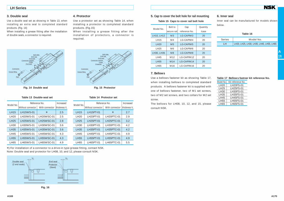
3. Double seal
Use a double seal set as showing in Table 13, when installing an extra seal to completed standard products. (Fig. 14)When installing a grease fitting after the installation of double seals, a connector is required.
4. Protector
Use a protector set as showing Table 14, when installing a protector to completed standard products. (Fig.15)When installing a grease fitting after the installation of protectors, a connector is required.
*) For installation of a connector to a drive-in type grease fitting, contact NSK.Note: Double seal and protector for LH08, 10, and 12, please consult NSK.
Table 14 Protector set
Model No.
Reference No. Increased
Without connector With connector thickness V2
LH15 LH15PT-01 * 2.7
LH20 LH20PT-01 LH20PTC-01 2.9
LH25 LH25PT-01 LH25PTC-01 3.2
LH30 LH30PT-01 LH30PTC-01 4.2
LH35 LH35PT-01 LH35PTC-01 4.2
LH45 LH45PT-01 LH45PTC-01 4.9
LH55 LH55PT-01 LH55PTC-01 4.9
LH65 LH65PT-01 LH65PTC-01 5.5
Table 13 Double-seal set
Model No.
Reference No. Increased
Without connector With connector thickness V1
LH15 LH15WS-01 * 2.5
LH20 LH20WS-01 LH20WSC-01 2.5
LH25 LH25WS-01 LH25WSC-01 2.8
LH30 LH30WS-01 LH30WSC-01 3.6
LH35 LH35WS-01 LH35WSC-01 3.6
LH45 LH45WS-01 LH45WSC-01 4.3
LH55 LH55WS-01 LH55WSC-01 4.3
LH65 LH65WS-01 LH65WSC-01 4.9
7. Bellows
Use a bellows fastener kit as showing Table 17,
when installing bellows to completed standard
products. A bellows fastener kit is supplied with
one of bellows fastener, two of M1 set screws,
two of M2 set screws, and two collars for M2 set
screw.
The bellows for LH08, 10, 12, and 15, please
consult NSK.
6. Inner seal5. Cap to cover the bolt hole for rail mounting
Inner seal can be manufactured for models shown
below.
Table 16
Series Model No.
LH LH20, LH25, LH30, LH35, LH45, LH55, LH65
Model No. Kit reference No. LH20 LH20FS-01 LH25 LH25FS-01 LH30 LH30FS-01 LH35 LH35FS-01 LH45 LH45FS-01 LH55 LH55FS-01 LH65 LH65FS-01
Table 17 Bellows fastner kit reference No.
Table 15 Caps to cover rail bolt hole
Model No.
Bolt to Cap Quantity
secure rail reference No. /case
LH10, LH12 M3 LG-CAP/M3 20
LH15 M4 LG-CAP/M4 20
LH20 M5 LG-CAP/M5 20
LH25 M6 LG-CAP/M6 20
LH30, LH35 M8 LG-CAP/M8 20
LH45 M12 LG-CAP/M12 20
LH55 M14 LG-CAP/M14 20
LH65 M16 LG-CAP/M16 20
V1 V2
(2 end seals)Double seal End seal
Protector(Steel)
Fig. 16
End capBall slide
End sealConnector washer
CollarEnd seal
Connector
Grease fitting
Rail
Fig. 14 Double seal
End capBall slide
End sealConnector washer
CollarProtector
Connector
Grease fitting
Rail
Fig. 15 Protector
A161-A184.indd 169-170 A161-A184.indd 169-170 10/9/09 1:33:31 PM10/9/09 1:33:31 PM

A171 A172
A172
LH Series
Table 19 Numbers of folds (BL) and lengths of bellows Unit: mm
Model No. Number of BL 2 4 6 8 10 12 14 16 18 20 Lmin 34 68 102 136 170 204 238 272 306 340 JAH20N Stroke 106 212 318 424 530 636 742 848 954 1060 Lmax 140 280 420 560 700 840 980 1120 1260 1400 JAH25L Stroke 106 212 318 424 530 636 742 848 954 1060 Lmax 140 280 420 560 700 840 980 1120 1260 1400
JAH25N Stroke 176 352 528 704 880 1056 1232 1408 1584 1760 Lmax 210 420 630 840 1050 1260 1470 1680 1890 2100 JAH30L Stroke 134 268 402 536 670 804 938 1072 1206 1340 Lmax 168 336 504 672 840 1008 1176 1344 1512 1680
JAH30N Stroke 176 352 528 704 880 1056 1232 1408 1584 1760 Lmax 210 420 630 840 1050 1260 1470 1680 1890 2100 JAH35L Stroke 176 352 528 704 880 1056 1232 1408 1584 1760 Lmax 210 420 630 840 1050 1260 1470 1680 1890 2100 JAH35N Stroke 246 492 738 984 1230 1476 1722 1968 2214 2460 Lmax 280 560 840 1120 1400 1680 1960 2240 2520 2800 JAH45L Stroke 176 352 528 704 880 1058 1232 1408 1584 1760 Lmax 210 420 630 840 1050 1260 1470 1680 1890 2100
JAH45N Stroke 316 632 948 1264 1580 1896 2212 2528 2844 3160 Lmax 350 700 1050 1400 1750 2100 2450 2800 3150 3500
JAH55L Stroke 246 492 738 984 1230 1476 1722 1968 2214 2460 Lmax 280 560 840 1120 1400 1680 1960 2240 2520 2800 JAH55N Stroke 386 772 1158 1544 1930 2316 2702 3088 3474 3860 Lmax 420 840 1260 1680 2100 2520 2940 3360 3780 4200
JAH65N Stroke 386 772 1158 1544 1930 2316 2702 3088 3474 3860 Lmax 420 840 1260 1680 2100 2520 2940 3360 3780 4200
Remarks: Values of odd numbers BL (3, 5, 7, ...) can be obtained by adding two values of even number BLs on both sides, then dividing the sum by two.
Dimension tables of bellowsLH Series
Bellows reference number
J A H 2 0 N 0 8 — — — –— — –—Bellows
A: Bellows for the endsB: Middle bellows
Bellows for LH series
Number of BL (fold number)
N: High type L: Low type
Size number of linear guide
LmaxLmin
M2
Ball slide
M1
h1H
E
P
aW
b
Fig. 17 Dimensions of bellows
Table 18 Dimensions of bellows Unit: mm
Model No. H h1 E W P a b BL minimum length M1Tap x depth M2Tap x depth JAH20N 29.5 24.5 5 48 10 13 22 17 M3×5 M2.5×16 JAH25L 35 28
7 51 10
16 26 17 M3×5 M3×18 JAH25N 39 32 61 15 JAH30L 41 32
9 60 12
18 31 17 M4×6 M4×22 JAH30N 44 35 66 15 JAH35L 47 37.5
9.5 72 15
24 34 17 M4×6 M4×23 JAH35N 54 44.5 82 20 JAH45L 59 45
14 83 15
32 44.5 17 M5×8 M5×28 JAH45N 69 55 103 25 JAH55L 69 54
15 101 20
40 50.5 17 M5×8 M5×30 JAH55N 79 64 121 30 JAH65N 89 73 16 131 30 48 61 17 M6×8 M6×35
A161-A184.indd 171-172 A161-A184.indd 171-172 10/9/09 1:33:31 PM10/9/09 1:33:31 PM

A174
A174
A173
LH Series
Table 20 Material/surface treatment code
Code Description
C Special high carbon steel (NSK standard)
K Stainless steel (LH08 to LH30 only)
D Special high carbon steel with surface treatment
H Stainless steel with surface treatment
Z Other, special
Table 21 Accuracy code
Accuracy Standard (Without NSK K1) With NSK K1 With NSK K1 for food and medical equipment
Ultra precision grade P3 K3 F3
Super precision grade P4 K4 F4
High precision grade P5 K5 F5
Precision grade P6 K6 F6
Normal grade PN KN FN
Normal grade (random-matching type) PC KC FC
Note: Refer to Page A38 and A61 for NSK K1 lubrication unit.
(8) Reference number
Reference numbers shall be set to individual NSK linear guide when its specifications are finalized, and it is indicated on its specification drawing. Please specify the reference number, except design serial number, to identify the product when ordering, requiring estimates, or inquiring about specifications from NSK.
Reference number for assembly of random-matching ball slide and rail is the same as the coding of preloaded assembly. However, preload code is fine clearance "T" or slight preload "Z" (Refer to page A164).
LH 30 1000 AN C 2 -** P5 3 ——— —— ———— ——— — — ———— ——— —Series name
Size
Rail length (mm)
Ball slide shape code (See page A162)
Material/surface treatment code (See Table 20)
Preload code (See page A164)
Accuracy code (See Table 21)
Design serial numberAdded to the reference number.
Number of ball slides per rail
2. Reference number for random-matching type
1. Reference number for preloaded assembly
L1H 30 1200 L C N -** PC Z ——— —— ————— — — — ———— ——— —Random-matching rail series codeL1H : LH Series random-matching rail
Size
Rail length (mm)
Rail shape code: LL : Standard
Material/surface treatment code (See Table 20)
Preload codeT: Fine clearance. Z: Slight preload (See page A164)
Accuracy code : PCPC: Normal grade is only available
Design serial numberAdded to the reference number.
*Butting rail specificationN: Non-butting. L: Butting specification
*Please consult with NSK for butting rail specification.
LAH 30 AN C -** PC Z ———— —— ——— — ——— —— —Random-matching ball slide series codeLAH : LH Series random-matching ball slide
Size
Ball slide shape code (See page A162)
Material/surface treatment code (See Table 20)
Preload codeT: Fine clearance. Z: Slight preload (See page A164)
Accuracy code : PCPC: Normal grade is only available
Design serial numberAdded to the reference number.
Ball slide
Rail
A161-A184.indd 173-174 A161-A184.indd 173-174 10/9/09 1:33:31 PM10/9/09 1:33:31 PM

A175 A176
A176
LH Series
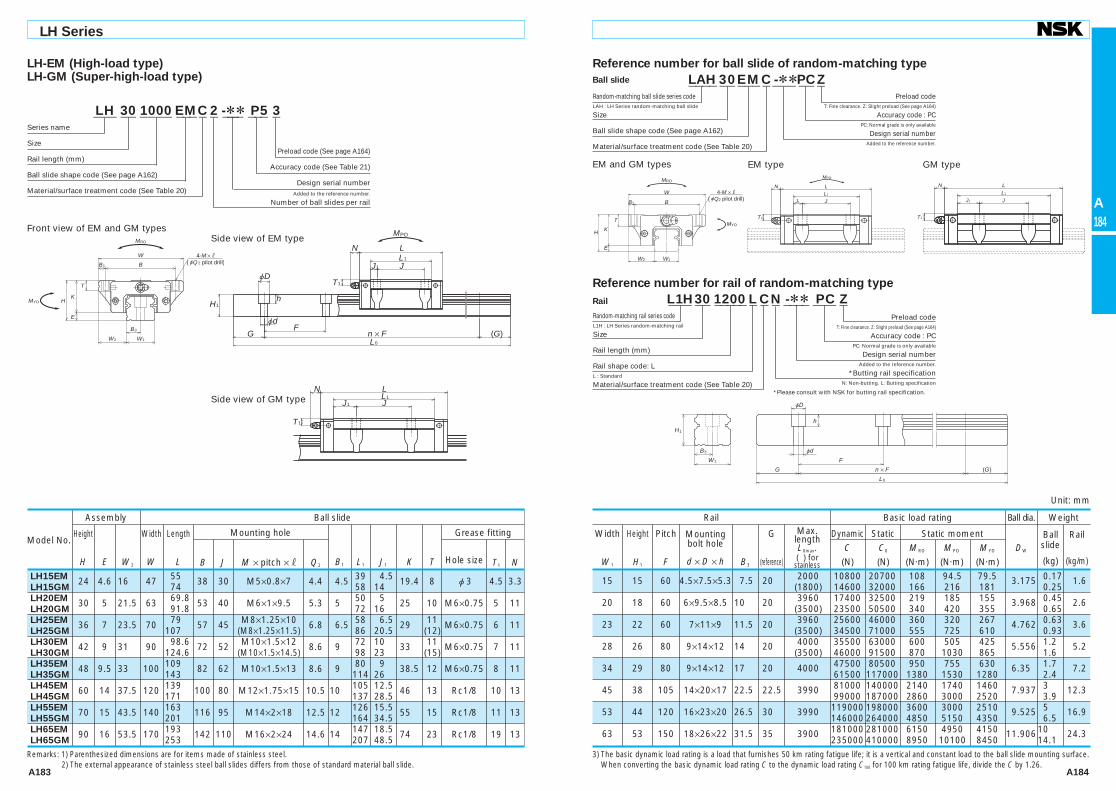
(9) DimensionsLH-AN (High-load type)LH-BN (Super-high-load type)
T
KH
E
W2 W1
W
B
4-M ×l
MRO
MYO
B3
B1
L1
J1
T1
N L
J
L1
J1
T1
N L
J
h
jD
H1
jd
F
G
L0
n × F (G)
MPO
Model No.
Assembly
Height
H E W2
Width
W
Length
L
Mounting hole
B1 L1 J1 K T
Grease fitting
Hole size T1 N
Width
W1
Height
H1
Pitch
F B3
G
(reference)
Rail
(kg/m)
Ball slide
(kg)DW
Max. lengthL0max.( ) for
stainless
Dynamic Static Static moment C C0 MRO MPO MYO
(N) (N) (N·m) (N·m) (N·m)
Mounting bolt hole
d × D × hB J M × pitch × l
Ball slide Rail Basic load rating Ball dia. Weight
Unit: mm
LH08AN 11 2.1 4 16 24 10 10 M2×0.4×2.5 3 15 2.5 8.9 — — — — LH10AN 13 2.4 5 20 31 13 12 M2.6×0.45×3 3.5 20.2 4.1 10.6 6 — — — LH12AN 20 3.2 7.5 27 45 15 15 M4×0.7×5 6 31 8 16.8 6 j3 5 4 LH15AN
28 4.6 9.5 34 55
26 26 M4×0.7×6 4 39 6.5
23.4 8 j3 8.5 3.3 LH15BN 74 58 16 LH20AN
30 5 12 44 69.8
32 36
M5×0.8×6 6 50 7
25 12 M6×0.75 5 11 LH20BN 91.8 50 72 11 LH25AN
40 7 12.5 48 79
35 35
M6×1×9 6.5 58 11.5
33 12 M6×0.75 10 11 LH25BN 107 50 86 18 LH30AN
45 9 16 60 85.6
40 40
M8×1.25×10 10 59 9.5
36 14 M6×0.75 10 11 LH30BN 124.6 60 98 19 LH35AN
55 9.5 18 70 109
50 50
M8×1.25×12 10 80 15
45.5 15 M6×0.75 15 11 LH35BN 143 72 114 21 LH45AN
70 14 20.5 86 139
60 60
M10×1.5×17 13 105 22.5
56 17 Rc1/8 20 13 LH45BN 171 80 137 28.5 LH55AN
80 15 23.5 100 163
75 75
M12×1.75×18 12.5 126 25.5
65 18 Rc1/8 21 13 LH55BN 201 95 164 34.5 LH65AN
90 16 31.5 126 193
76 70
M16×2×20 25 147 38.5
74 23 Rc1/8 19 13 LH65BN 253 120 207 43.5
8 5.5 20 2.4×4.2×2.3 4 7.5 (375) 1240 2630 7.25 4.55 3.8 1.2000 0.013 0.31 10 6.5 25 3.5×6×3.5 5 10 (600) 2250 4500 16.2 10.5 8.8 1.5875 0.026 0.44 12 10.5 40 3.5×6×4.5 6 15 (800) 5650 11300 47.5 41.5 35 2.3812 0.082 0.88
15 15 60 4.5×7.5×5.3 7.5 20 2000 10800 20700 108 94.5 79.5
3.175 0.18
1.6 (1800) 14600 32000 166 216 181 0.26
20 18 60 6×9.5×8.5 10 20 3960 17400 32500 219 185 155
3.968 0.33
2.6 (3500) 23500 50500 340 420 355 0.48
23 22 60 7×11×9 11.5 20
3960 25600 46000 360 320 267 4.762
0.55 3.6
(3500) 34500 71000 555 725 610 0.82
28 26 80 9×14×12 14
20 4000 31000 51500 490 350 292
5.556 0.77
5.2 (3500) 46000 91500 870 1030 865 1.3
34 29 80 9×14×12 17 20 4000 47500 80500 950 755 630
6.350 1.5
7.2 61500 117000 1380 1530 1280 2.1
45 38 105 14×20×17 22.5 22.5 3990 81000 140000 2140 1740 1460
7.937 3.0
12.3 99000 187000 2860 3000 2520 3.9
53 44 120 16×23×20 26.5 30 3960 119000 198000 3600 3000 2510
9.525 4.7
16.9 146000 264000 4850 5150 4350 6.1
63 53 150 18×26×22 31.5 35 3900 181000 281000 6150 4950 4150
11.906 7.7
24.3 235000 410000 8950 10100 8450 10.8
Side view of AN type
Side view of BN type
Front view of AN and BN types
4) The basic dynamic load rating is a load that furnishes 50 km rating fatigue life; it is a vertical and constant load to the ball slide mounting surface. When converting the basic dynamic load rating C to the dynamic load rating C100 for 100 km rating fatigue life, divide the C by 1.26.5) Random matching is available for LH15 to LH65.
4-M × l
B
W
W1
T
K
E
H
MRO
MYO
W2
B1
T1
L
MPO
JJ1
L1
N
T1
L
JJ1
L1
N
AN type BN type
Remarks : 1) LH08 does not have a ball retainer. Be aware that balls fall out when the ball slide is withdrawn from the rail. 2) The external appearance of stainless steel ball slides differs from those of standard material ball slide. 3) Only stainless steel models are available for LH08 to LH12.
LH 30 1000 AN C 2 -** P5 3 ——— —— ———— ——— — — ———— ——— —Series name
Size
Rail length (mm)
Ball slide shape code (See page A162)
Material/surface treatment code (See Table 20)
Preload code (See page A164)
Accuracy code (See Table 21)
Design serial numberAdded to the reference number.
Number of ball slides per rail
Reference number for ball slide of random-matching type
LAH 30 AN C -** PC Z ———— —— ——— — ——— —— —Random-matching ball slide series codeLAH : LH Series random-matching ball slide
Size
Ball slide shape code (See page A162)
Material/surface treatment code (See Table 20)
Preload codeT: Fine clearance. Z: Slight preload (See page A164)
Accuracy code : PCPC: Normal grade is only available
Design serial numberAdded to the reference number.
Reference number for rail of random-matching type
jD
H1
L0
n × FF
(G)G
W1
jd
h
B3
L1H 30 1200 L C N -** PC Z ——— —— ————— — — — ———— ——— —Random-matching rail series codeL1H : LH Series random-matching rail
Size
Rail length (mm)
Rail shape code: LL : Standard
Material/surface treatment code (See Table 20)
Preload codeT: Fine clearance. Z: Slight preload (See page A164)
Accuracy code : PCPC: Normal grade is only available
Design serial numberAdded to the reference number.
*Butting rail specificationN: Non-butting. L: Butting specification
*Please consult with NSK for butting rail specification.
AN and BN types
Ball slide
Rail
A161-A184.indd 175-176 A161-A184.indd 175-176 10/9/09 1:33:32 PM10/9/09 1:33:32 PM

A177 A178
A178
LH Series
LH-AL (High-load type)LH-BL (Super-high-load type)
4-M × lBB1
W
B3
W1W2
T
K
E
H
MRO
MYO
JJ1
L1
L
jD
jdF
G (G)n × FL0
N
T1
hH1
MPO
Model No.
Assembly
Height
H E W2
Width
W
Length
L
Mounting hole
B1 L1 J1 K T
Grease fitting
Hole size T1 N
Width
W1
Height
H1
Pitch
F B3
G
(reference)
Rail
(kg/m)
Ball slide
(kg)DW
Max. lengthL0max.( ) for
stainless
Dynamic Static Static moment C C0 MRO MPO MYO
(N) (N) (N·m) (N·m) (N·m)
Mounting bolt hole
d × D × hB J M × pitch × l
Ball slide Rail Basic load rating Ball dia. Weight
Unit: mm
LH25AL 36
7 12.5 48
79 35
35 M6×1×6 6.5
58 11.5 29 12 M6×0.75 6 11
LH25BL 107 50 86 18 LH30AL
42
9 16 60 85.6
40 40
M8×1.25×8 10 59 9.5
33 14 M6×0.75 7 11 LH30BL 124.6 60 98 19 LH35AL
48
9.5 18 70 109
50 50
M8×1.25×8 10 80 15
38.5 15 M6×0.75 8 11 LH35BL 143 72 114 21 LH45AL
60 14 20.5 86 139
60 60
M10×1.5×10 13 105 22.5
46 17 Rc1/8 10 13 LH45BL 171 80 137 28.5 LH55AL
70 15 23.5 100 163
75 75
M12×1.75×13 12.5 126 25.5
55 15 Rc1/8 11 13 LH55BL 201 95 164 34.5
23 22 60 7×11×9 11.5
20
3960 25600 46000 360 320 267 4.762
0.46 3.6
(3500) 34500 71000 555 725 610 0.69
28 26 80 9×14×12 14
20 4000 31000 51500 490 350 292
5.556 0.69
5.2 (3500) 46000 91500 870 1030 865 1.16
34 29 80 9×14×12 17 20 4000 47500 80500 950 755 630
6.350 1.2
7.2 61500 117000 1380 1530 1280 1.7
45 38 105 14×20×17 22.5 22.5 3990 81000 140000 2140 1740 1460
7.937 2.2
12.3 99000 187000 2860 3000 2520 2.9
53 44 120 16×23×20 26.5 30 3960 119000 198000 3600 3000 2510
9.525 3.7
16.9 146000 264000 4850 5150 4350 4.7
Side view of AL typeFront view of AL and BL types
Side view of BL type
2) The basic dynamic load rating is a load that furnishes 50 km rating fatigue life; it is a vertical and constant load to the ball slide mounting surface.
When converting the basic dynamic load rating C to the dynamic load rating C100 for 100 km rating fatigue life, divide the C by 1.26.
4-M × lBB1
W
W2 W1
TK
E
H
MRO
MYO
JJ1
L1
LN
T1
MPO
JJ1
L1
L
T1
N
T1
JJ1
L1
LN
Remarks : 1) The external appearance of stainless steel ball slides differs from those of standard material ball slide.
LH 30 1000 AL C 2 -** P5 3 ——— —— ———— ——— — — ———— ——— —Series name
Size
Rail length (mm)
Ball slide shape code (See page A162)
Material/surface treatment code (See Table 20)
Preload code (See page A164)
Accuracy code (See Table 21)
Design serial numberAdded to the reference number.
Number of ball slides per rail
AL type BL type
Reference number for ball slide of random-matching type
LAH 30 AL C -** PC Z ———— —— ——— — ——— —— —Random-matching ball slide series codeLAH : LH Series random-matching ball slide
Size
Ball slide shape code (See page A162)
Material/surface treatment code (See Table 20)
Preload codeT: Fine clearance. Z: Slight preload (See page A164)
Accuracy code : PCPC: Normal grade is only available
Design serial numberAdded to the reference number.
Reference number for rail of random-matching type
jD
H1
L0
n × FF
(G)G
W1
jd
h
B3
L1H 30 1200 L C N -** PC Z ——— —— ————— — — — ———— ——— —Random-matching rail series codeL1H : LH Series random-matching rail
Size
Rail length (mm)
Rail shape code: LL : Standard
Material/surface treatment code (See Table 20)
Preload codeT: Fine clearance. Z: Slight preload (See page A164)
Accuracy code : PCPC: Normal grade is only available
Design serial numberAdded to the reference number.
*Butting rail specificationN: Non-butting. L: Butting specification
*Please consult with NSK for butting rail specification.
AL and BL types
Ball slide
Rail
A161-A184.indd 177-178 A161-A184.indd 177-178 10/9/09 1:33:33 PM10/9/09 1:33:33 PM

A179 A180
A180
LH Series
LH-EL (High-load type)LH-GL (Super-high-load type)
W2 W1
T
KH
E
W
B
MRO
MYO
4-M × l
B3
B1
L1
J1
T1
N L
J
L1
J1
T1
N L
J
h
jD
jd
F
G
H1
L0
n × F (G)
MPO
G
(reference)
Side view of EL type
Front view of EL and GL types
Side view of GL type
Model No.
Assembly
Height
H E W2
Width
W
Length
L
Mounting hole
B1 L1 J1 K T
Grease fitting
Hole size T1 N
Width
W1
Height
H1
Pitch
F B3
Rail
(kg/m)
Ball slide
(kg)DW
Max. lengthL0max.( ) for
stainless
Dynamic Static Static moment C C0 MRO MPO MYO
(N) (N) (N·m) (N·m) (N·m)
Mounting bolt hole
d × D × hB J M × pitch × l
Ball slide Rail Basic load rating Ball dia. Weight
Unit: mm
LH15EL 24 4.6 16 47 55 38 30 M5×0.8×8 4.5 39 4.5 19.4 8 j3 4.5 3.3 LH15GL 74 58 14 LH20EL
30 5 21.5 63 69.8
53 40 M6×1×10 5 50 5
25 10 M6×0.75 5 11 LH20GL 91.8 72 16 LH25EL
36 7 23.5 70 79
57 45 M8×1.25×16
6.5 58 6.5
29 11
M6×0.75 6 11 LH25GL 107 (M8×1.25×12) 86 20.5 (12) LH30EL
42 9 31 90 98.6
72 52 M10×1.5×18
9 72 10
33 11
M6×0.75 7 11 LH30GL 124.6 (M10×1.5×15) 98 23 (15) LH35EL
48 9.5 33 100 109
82 62 M10×1.5×20 9 80 9
38.5 12 M6×0.75 8 11 LH35GL 143 114 26 LH45EL
60 14 37.5 120 139
100 80 M12×1.75×24 10 105 12.5
46 13 Rc1/8 10 13 LH45GL 171 137 28.5 LH55EL
70 15 43.5 140 163
116 95 M14×2×28 12 126 15.5
55 15 Rc1/8 11 13 LH55GL 201 164 34.5 LH65EL
90 16 53.5 170 193
142 110 M16×2×24 14 147 18.5
74 23 Rc1/8 19 13 LH65GL 253 207 48.5
15 15 60 4.5×7.5×5.3 7.5 20
2000 10800 20700 108 94.5 79.5 3.175
0.17 1.6
(1800) 14600 32000 166 216 181 0.25
20 18 60 6×9.5×8.5 10
20 3960 17400 32500 219 185 155
3.968 0.45
2.6 (3500) 23500 50500 340 420 355 0.65
23 22 60 7×11×9 11.5 20
3960 25600 46000 360 320 267 4.762
0.63 3.6
(3500) 34500 71000 555 725 610 0.93
28 26 80 9×14×12 14
20 4000 35500 63000 600 505 425
5.556 1.2
5.2 (3500) 46000 91500 870 1030 865 1.6
34 29 80 9×14×12 17 20 4000 47500 80500 950 755 630
6.350 1.7
7.2 61500 117000 1380 1530 1280 2.4
45 38 105 14×20×17 22.5 22.5 3990 81000 140000 2140 1740 1460
7.937 3.0
12.3 99000 187000 2860 3000 2520 3.9
53 44 120 16×23×20 26.5 30 3960 119000 198000 3600 3000 2510
9.525 5.0
16.9 146000 264000 4850 5150 4350 6.5
63 53 150 18×26×22 31.5 35 3900 181000 281000 6150 4950 4150
11.906 10.0
24.3 235000 410000 8950 10100 8450 14.1
3) The basic dynamic load rating is a load that furnishes 50 km rating fatigue life; it is a vertical and constant load to the ball slide mounting surface. When converting the basic dynamic load rating C to the dynamic load rating C100 for 100 km rating fatigue life, divide the C by 1.26.
Remarks: 1) Parenthesized dimensions are for items made of stainless steel. 2) The external appearance of stainless steel ball slides differs from those of standard material ball slide.
4-M × l
B
W
W1
T
K
E
H
MRO
MYO
W2
B1
T1
L
MPO
JJ1
L1
N
T1
L
JJ1
L1
N
LH 30 1000 EL C 2 -** P5 3 ——— —— ———— ——— — — ———— ——— —Series name
Size
Rail length (mm)
Ball slide shape code (See page A162)
Material/surface treatment code (See Table 20)
Preload code (See page A164)
Accuracy code (See Table 21)
Design serial numberAdded to the reference number.
Number of ball slides per rail
EL type GL type
Reference number for ball slide of random-matching type
LAH 30 EL C -** PC Z ———— —— ——— — ——— —— —Random-matching ball slide series codeLAH : LH Series random-matching ball slide
Size
Ball slide shape code (See page A162)
Material/surface treatment code (See Table 20)
Preload codeT: Fine clearance. Z: Slight preload (See page A164)
Accuracy code : PCPC: Normal grade is only available
Design serial numberAdded to the reference number.
Reference number for rail of random-matching type
jD
H1
L0
n × FF
(G)G
W1
jd
h
B3
L1H 30 1200 L C N -** PC Z ——— —— ————— — — — ———— ——— —Random-matching rail series codeL1H : LH Series random-matching rail
Size
Rail length (mm)
Rail shape code: LL : Standard
Material/surface treatment code (See Table 20)
Preload codeT: Fine clearance. Z: Slight preload (See page A164)
Accuracy code : PCPC: Normal grade is only available
Design serial numberAdded to the reference number.
*Butting rail specificationN: Non-butting. L: Butting specification
*Please consult with NSK for butting rail specification.
EL and GL types
Ball slide
Rail
A161-A184.indd 179-180 A161-A184.indd 179-180 10/9/09 1:33:34 PM10/9/09 1:33:34 PM

A181 A182
A182
LH Series
LH-FL (High-load type)LH-HL (Super-high-load type)
W2 W1
4-jQ1 × l
T
KH
E
W
B
MRO
MYO
B3
B1
JJ1
L1
LN
T1
L1
J1
T1
N L
J
h
jD
jd
F
G
H1
L0
n × F (G)
MPO
Side view of FL typeFront view of FL and HL types
Side view of HL type
B
W
W1
T
K
E
H
MRO
MYO
W2
B1
4-jQ1 × l JJ1
L1
LN
T1
MPO
JJ1
L1
LN
T1
G
(reference)
3) The basic dynamic load rating is a load that furnishes 50 km rating fatigue life; it is a vertical and constant load to the ball slide mounting surface. When converting the basic dynamic load rating C to the dynamic load rating C100 for 100 km rating fatigue life, divide the C by 1.26.
Model No.
Assembly
Height
H E W2
Width
W
Length
L
Mounting hole
B1 L1 J1 K T
Grease fitting
Hole size T1 N
Width
W1
Height
H1
Pitch
F B3
Rail
(kg/m)
Ball slide
(kg)DW
Max. lengthL0max.( ) for
stainless
Dynamic Static Static moment C C0 MRO MPO MYO
(N) (N) (N·m) (N·m) (N·m)
Mounting bolt hole
d × D × hB J Q1 × l
Ball slide Rail Basic load rating Ball dia. Weight
Unit: mm
Remarks: 1) Parenthesized dimensions are for items made of stainless steel. 2) The external appearance of stainless steel ball slides differs from those of standard material ball slide.
LH15FL 24 4.6 16 47 55 38 30 4.5×7 4.5 39 4.5 19.4 8 j3 4.5 3.3 LH15HL 74 58 14 LH20FL 30 5 21.5 63 69.8 53 40 6×9.5 5 50 5 25 10 M6×0.75 5 11 LH20HL 91.8 72 16 LH25FL 36 7 23.5 70 79 57 45 7×10 (7×11.5) 6.5 58 6.5 29 11 M6×0.75 6 11 LH25HL 107 86 20.5 (12) LH30FL 42 9 31 90 98.6 72 52 9×12 (9×14.5) 9 72 10 33 11 M6×0.75 7 11 LH30HL 124.6 98 23 (15) LH35FL 48 9.5 33 100 109 82 62 9×13 9 80 9 38.5 12 M6×0.75 8 11 LH35HL 143 114 26 LH45FL 60 14 37.5 120 139 100 80 11×15 10 105 12.5 46 13 Rc1/8 10 13 LH45HL 171 137 28.5 LH55FL 70 15 43.5 140 163 116 95 14×18 12 126 15.5 55 15 Rc1/8 11 13 LH55HL 201 164 34.5 LH65FL 90 16 53.5 170 193 142 110 16×24 14 147 18.5 74 23 Rc1/8 19 13 LH65HL 253 207 48.5
15 15 60 4.5×7.5×5.3 7.5 20 2000 10800 20700 108 94.5 79.5 3.175 0.17 1.6 (1800) 14600 32000 166 216 181 0.25 20 18 60 6×9.5×8.5 10 20 3960 17400 32500 219 185 155 3.968 0.45 2.6 (3500) 23500 50500 340 420 355 0.65 23 22 60 7×11×9 11.5 20 3960 25600 46000 360 320 267 4.762 0.63 3.6 (3500) 34500 71000 555 725 610 0.93 28 26 80 9×14×12 14 20 4000 35500 63000 600 505 425 5.556 1.2 5.2 (3500) 46000 91500 870 1030 865 1.6 34 29 80 9×14×12 17 20 4000 47500 80500 950 755 630 6.35 1.7 7.2 61500 117000 1380 1530 1280 2.4 45 38 105 14×20×17 22.5 22.5 3990 81000 140000 2140 1740 1460 7.937 3 12.3 99000 187000 2860 3000 2520 3.9 53 44 120 16×23×20 26.5 30 3990 119000 198000 3600 3000 2510 9.525 5 16.9 146000 264000 4850 5150 4350 6.5 63 53 150 18×26×22 31.5 35 3900 181000 281000 6150 4950 4150 11.906 10 24.3 235000 410000 8950 10100 8450 14.1
LH 30 1000 FL C 2 -** P5 3 ——— —— ———— ——— — — ———— ——— —Series name
Size
Rail length (mm)
Ball slide shape code (See page A162)
Material/surface treatment code (See Table 20)
Preload code (See page A164)
Accuracy code (See Table 21)
Design serial numberAdded to the reference number.
Number of ball slides per rail
FL type HL type
Reference number for ball slide of random-matching type
LAH 30 FL C -** PC Z ———— —— ——— — ——— —— —Random-matching ball slide series codeLAH : LH Series random-matching ball slide
Size
Ball slide shape code (See page A162)
Material/surface treatment code (See Table 20)
Preload codeT: Fine clearance. Z: Slight preload (See page A164)
Accuracy code : PCPC: Normal grade is only available
Design serial numberAdded to the reference number.
Reference number for rail of random-matching type
jD
H1
L0
n × FF
(G)G
W1
jd
h
B3
L1H 30 1200 L C N -** PC Z ——— —— ————— — — — ———— ——— —Random-matching rail series codeL1H : LH Series random-matching rail
Size
Rail length (mm)
Rail shape code: LL : Standard
Material/surface treatment code (See Table 20)
Preload codeT: Fine clearance. Z: Slight preload (See page A164)
Accuracy code : PCPC: Normal grade is only available
Design serial numberAdded to the reference number.
*Butting rail specificationN: Non-butting. L: Butting specification
*Please consult with NSK for butting rail specification.
FL and HL types
Ball slide
Rail
A161-A184.indd 181-182 A161-A184.indd 181-182 10/9/09 1:33:35 PM10/9/09 1:33:35 PM
A183 A184
A184
LH Series
LH-EM (High-load type)LH-GM (Super-high-load type)
W2 W1
4-M × l(jQ 2 pilot drill)
T
KH
E
W
B
MRO
MYO
B3
B1
JJ1
L1
LN
T1
JJ1
L1
L
jD
jdF
G n × F (G)L0
T1
N
hH1
MPOSide view of EM typeFront view of EM and GM types
Side view of GM type
B
W
W1
T
K
E
H
MRO
MYO
W2
B1
4-M × l(jQ2 pilot drill) JJ1
L1
L
T1
N
MPO
JJ1
L1
LN
T1
G
(reference)Q2
3) The basic dynamic load rating is a load that furnishes 50 km rating fatigue life; it is a vertical and constant load to the ball slide mounting surface. When converting the basic dynamic load rating C to the dynamic load rating C100 for 100 km rating fatigue life, divide the C by 1.26.
Model No.
Assembly
Height
H E W2
Width
W
Length
L
Mounting hole
B1 L1 J1 K T
Grease fitting
Hole size T1 N
Width
W1
Height
H1
Pitch
F B3
Rail
(kg/m)
Ball slide
(kg)DW
Max. lengthL0max.( ) for
stainless
Dynamic Static Static moment C C0 MRO MPO MYO
(N) (N) (N·m) (N·m) (N·m)
Mounting bolt hole
d × D × hB J M × pitch × l
Ball slide Rail Basic load rating Ball dia. Weight
Unit: mm
Remarks: 1) Parenthesized dimensions are for items made of stainless steel. 2) The external appearance of stainless steel ball slides differs from those of standard material ball slide.
LH15EM 24 4.6 16 47 55 38 30 M5×0.8×7 4.4 4.5 39 4.5 19.4 8 j3 4.5 3.3 LH15GM 74 58 14 LH20EM 30 5 21.5 63 69.8 53 40 M6×1×9.5 5.3 5 50 5 25 10 M6×0.75 5 11 LH20GM 91.8 72 16 LH25EM 36 7 23.5 70 79 57 45 M8×1.25×10 6.8 6.5 58 6.5 29 11 M6×0.75 6 11 LH25GM 107 (M8×1.25×11.5) 86 20.5 (12) LH30EM 42 9 31 90 98.6 72 52 M10×1.5×12 8.6 9 72 10 33 11 M6×0.75 7 11 LH30GM 124.6 (M10×1.5×14.5) 98 23 (15) LH35EM 48 9.5 33 100 109 82 62 M10×1.5×13 8.6 9 80 9 38.5 12 M6×0.75 8 11 LH35GM 143 114 26 LH45EM 60 14 37.5 120 139 100 80 M12×1.75×15 10.5 10 105 12.5 46 13 Rc1/8 10 13 LH45GM 171 137 28.5 LH55EM 70 15 43.5 140 163 116 95 M14×2×18 12.5 12 126 15.5 55 15 Rc1/8 11 13 LH55GM 201 164 34.5 LH65EM 90 16 53.5 170 193 142 110 M16×2×24 14.6 14 147 18.5 74 23 Rc1/8 19 13 LH65GM 253 207 48.5
15 15 60 4.5×7.5×5.3 7.5 20 2000 10800 20700 108 94.5 79.5 3.175 0.17 1.6 (1800) 14600 32000 166 216 181 0.25 20 18 60 6×9.5×8.5 10 20 3960 17400 32500 219 185 155 3.968 0.45 2.6 (3500) 23500 50500 340 420 355 0.65 23 22 60 7×11×9 11.5 20 3960 25600 46000 360 320 267 4.762 0.63 3.6 (3500) 34500 71000 555 725 610 0.93 28 26 80 9×14×12 14 20 4000 35500 63000 600 505 425 5.556 1.2 5.2 (3500) 46000 91500 870 1030 865 1.6 34 29 80 9×14×12 17 20 4000 47500 80500 950 755 630 6.35 1.7 7.2 61500 117000 1380 1530 1280 2.4 45 38 105 14×20×17 22.5 22.5 3990 81000 140000 2140 1740 1460 7.937 3 12.3 99000 187000 2860 3000 2520 3.9 53 44 120 16×23×20 26.5 30 3990 119000 198000 3600 3000 2510 9.525 5 16.9 146000 264000 4850 5150 4350 6.5 63 53 150 18×26×22 31.5 35 3900 181000 281000 6150 4950 4150 11.906 10 24.3 235000 410000 8950 10100 8450 14.1
LH 30 1000 EM C 2 -** P5 3 ——— —— ———— ——— — — ———— ——— —Series name
Size
Rail length (mm)
Ball slide shape code (See page A162)
Material/surface treatment code (See Table 20)
Preload code (See page A164)
Accuracy code (See Table 21)
Design serial numberAdded to the reference number.
Number of ball slides per rail
EM type GM type
Reference number for ball slide of random-matching type
LAH 30 EM C -** PC Z ———— —— ——— — ——— —— —Random-matching ball slide series codeLAH : LH Series random-matching ball slide
Size
Ball slide shape code (See page A162)
Material/surface treatment code (See Table 20)
Preload codeT: Fine clearance. Z: Slight preload (See page A164)
Accuracy code : PCPC: Normal grade is only available
Design serial numberAdded to the reference number.
Reference number for rail of random-matching type
jD
H1
L0
n × FF
(G)G
W1
jd
h
B3
L1H 30 1200 L C N -** PC Z ——— —— ————— — — — ———— ——— —Random-matching rail series codeL1H : LH Series random-matching rail
Size
Rail length (mm)
Rail shape code: LL : Standard
Material/surface treatment code (See Table 20)
Preload codeT: Fine clearance. Z: Slight preload (See page A164)
Accuracy code : PCPC: Normal grade is only available
Design serial numberAdded to the reference number.
*Butting rail specificationN: Non-butting. L: Butting specification
*Please consult with NSK for butting rail specification.
EM and GM types
Ball slide
Rail
A161-A184.indd 183-184 A161-A184.indd 183-184 10/9/09 1:33:36 PM10/9/09 1:33:36 PM


![LH-3500A Series INSTRUCTION MANUAL (ENGLISH) - Jukijukidigital.com/pub/media/wysiwyg/products/LH-3578... · [LH-3528A, 3568A, 3578A, 3588A] [LH-3528A-7, 3568A-7, 3578A-7, 3588A-7]](https://img.pdfslide.net/doc/110x75/5f0f24307e708231d442b140/lh-3500a-series-instruction-manual-english-lh-3528a-3568a-3578a-3588a-lh-3528a-7.jpg)


![LH-3500A Series ИНСТРУКЦИЯ ПО …softorg.com.ua/upload/instruction/5b9f9665707b8.pdf[LH-3528A, 3568A, 3578A, 3588A] [LH-3528A-7, 3568A-7, 3578A-7, 3588A-7] При транспортировке](https://img.pdfslide.net/doc/110x75/5f0f2e9d7e708231d442e4e2/lh-3500a-series-lh-3528a-3568a-3578a-3588a-lh-3528a-7.jpg)