Embed Size (px)
Citation preview

Project Engineering, Transmission Department
Page 1 of 28
Prepared By Reviewed By Approved By Rev Date
V.D.Vini / Smita Shah Ashish Waknis Shekhar Huprikar
Dy. In charge (Engineering) In charge ( Engineering) Head (Engineering ) 0
ANNEXURE 9
TECHNICAL SPECIFICATION FOR
SUPPLY, REPLACEMENT, INSTALLATION AND T&C OF LINE
DIFFERENTIAL CUM DISTANCE PROTECTION RELAYS ON EXISTING
220KV CONTROL RELAY PANEL AT AEML CHEMBUR EHV S/S

Project – 2nd FEED CHEMBUR Doc No: TD-SP-220KVCRP-RELAYS- 347-R0
Page 2 of 28
RECORD OF REVISION
S.No Revision No
Item/Clause No Nature of change Explanatory Notes

Project – 2nd FEED CHEMBUR Doc No: TD-SP-220KVCRP-RELAYS- 347-R0
Page 3 of 28
TABLE OF CONTENTS
1. SCOPE ............................................................................................................................................. 4
1.1 SCOPE OF SUPPLY .................................................................................................................................. 4
1.2 SCOPE OF SERVICE ................................................................................................................................. 4
1.3 EXCLUSION OF SERVICES ....................................................... ERROR! BOOKMARK NOT DEFINED.
2. CODES AND STANDARDS ............................................................................................................. 6
3. SERVICE CONDITION ...................................................................................................................... 7
4. SYSTEM DESCRIPTION .................................................................................................................. 7
5. TECHNICAL SPECIFICATION .......................................................................................................... 7
6. BILL OF MATERIAL ...................................................................................................................... 24
7. MANDATORY SPARES ................................................................................................................. 24
8. GUARANTEED TECHNICAL PARTICULARS (GTP) ..................................................................... 24
9. DEVIATIONS ................................................................................................................................. 28

Project – 2nd FEED CHEMBUR Doc No: TD-SP-220KVCRP-RELAYS- 347-R0
Page 4 of 28
SUPPLY, REPLACEMENT, INSTALLATION AND T&C OF
LINE DISTANCE CUM DIFFERENTAIL PROTECTION RELAYS
1. SCOPE
This specification covers technical requirements, design, manufacturing, testing at
manufacturer's works, packing, transportation with transit insurance, loading at works,
delivery at site, unloading at site, shifting of relays to desired location, removing of relays on
exisitng panel, making cut out for new relays, mounting and wiring of new rerlays, testing
and commissioning relays and scheme at site.
1.1 SCOPE OF SUPPLY
Supply of distance cum differential protections relays for 220kV hybrid lines (AEML
Chembur – MSETCL Trombay and AEML Chembur-MSETCL Nerul) as per this specification
and BOM.
DETAIL OF EXISTING RELAYS
Sl No. Location No of
feeders
No of
relays/feeder
Make / Type of existing
relays
1 AEML Chembur S/S 2 2 Siemens make 7SD52
ABB make REL 670
1.2 SCOPE OF SERVICE
Replacement, testing and commissioing of four (4) nos of exisiting distance cum
differential protection relays with new distance cum differential protection relays. Scope of
services is detailed below
a. Unloading of relays at site.
b. Removing exisitng relays on panels
c. Making cut out suitable for new relay. Providing and fixing blanking plate to cover
undesired opening, as applicable
d. Mounting and wiring of loose relays on exisitng panel

Project – 2nd FEED CHEMBUR Doc No: TD-SP-220KVCRP-RELAYS- 347-R0
Page 5 of 28
e. Recommendation of relay setting for new relays along with supporting calculation
f. Preparation of configuration files for new relays
g. Configuring new relays as per recommended setting
h. Testing (on service setting) and commissioning of new relays. Tests to be performed
and format of test reports shall be in line with customer (AEML) requirement
i. Testing and commissioning of exisitng CRP of two (2) nos spare bays
j. Testing of scheme in totality as per scheme drawing provided by AEML
k. Checking of differential scheme with remote end relay of other Utility (MSETCL).
l. Submission of relay test report.
m. Provide data like SID, CID & ICD files etc and technical support at site for integration
of new relays to exisitng SCADA system
n. Supply of fiber patch cords for connectivity to two (2) nos of ethernet switches to
achieve relay connectivity to SCADA
o. Supply of fiber patch cord and steel reinforced conduit for connecting relays to FMS
(Fiber Management System) panel for line differential protection
p. Laying of duplex single mode fiber patch cord in conduit from relay panel to FMS
panel
q. Preparation of as built scheme drawing of CRP at AEML Chembur incorporating all
modifications done at site. Scheme drawing of exisitng CRP shall be provided in pdf
format. Bidder has to provide revised scheme drawing in pdf and dwg format. Six (6)
nos of printed copy of drawing shall be provided .
r. Installation of relay software in Owner’s laptop. Verifying device communication
with Owner’s laptop.
2. EXCLUSION OF SERVICES
Nill
Project – 2nd FEED CHEMBUR Doc No: TD-SP-220KVCRP-RELAYS- 347-R0
Page 6 of 28
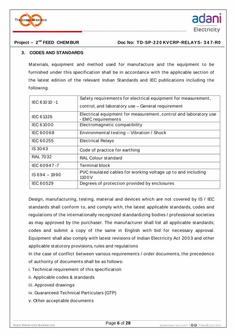
3. CODES AND STANDARDS
Materials, equipment and method used for manufacture and the equipment to be
furnished under this specification shall be in accordance with the applicable section of
the latest edition of the relevant Indian Standards and IEC publications including the
following.
IEC 61010 -1 Safety requirements for electrical equipment for measurement,
control, and laboratory use – General requirement
IEC 61326 Electrical equipment for measurement, control and laboratory use - EMC requirements
IEC 61000 Electromagnetic compatibility
IEC 60068 Environmental testing – Vibration / Shock
IEC 60255 Electrical Relays
IS 3043 Code of practice for earthing RAL 7032 RAL Colour standard
IEC 60947 -7 Terminal block
IS 694 – 1990 PVC Insulated cables for working voltage up to and including 1100V
IEC 60529 Degrees of protection provided by enclosures
Design, manufacturing, testing, material and devices which are not covered by IS / IEC
standards shall conform to, and comply with, the latest applicable standards, codes and
regulations of the internationally recognized standardizing bodies / professional societies
as may approved by the purchaser. The manufacturer shall list all applicable standards;
codes and submit a copy of the same in English with bid for necessary approval.
Equipment shall also comply with latest revisions of Indian Electricity Act 2003 and other
applicable statutory provisions, rules and regulations
In the case of conflict between various requirements / order documents, the precedence
of authority of documents shall be as follows:
i. Technical requirement of this specification
ii. Applicable codes & standards
iii. Approved drawings
iv. Guaranteed Technical Particulars (GTP)
v. Other acceptable documents

Project – 2nd FEED CHEMBUR Doc No: TD-SP-220KVCRP-RELAYS- 347-R0
Page 7 of 28
4. SERVICE CONDITION
Service Indoor
Ambient temperature 0 to 50°C
Seismic Data (as per IS 1893) Zone III
Altitude above mean sea level ≤1000m
Relative Humidity ≤ 100 %.
Atmosphere Corrosive, Saline. GX as per ISA 71.04 -
1985
5. SYSTEM DESCRIPTION
System voltage 220kV
CT secondary rating 1A
PT secondary rating 110V AC
Aux supply 220V DC
System grounding Solidly
6. TECHNICAL SPECIFICATION
Sr No Description Specification
a.
Current
Differential &
Distance
Protection Relay
1. Protection relays shall be suitable for line / cable
/ hybrid feeders & clear the faults within shortest
possible time with reliability & sensitivity to all
type of faults.
2. Redundant (Main–I & Main–II) differential cum
distance protection relays shall be provided.
Main-I and Main-II relays shall be of different
make.
3. The maximum system fault current could be as
high as 50kA and the minimum fault current
could be as low as 20% of rated current of CT
secondary. Relay shall satisfactory operate under

Project – 2nd FEED CHEMBUR Doc No: TD-SP-220KVCRP-RELAYS- 347-R0
Page 8 of 28
these extremely varying conditions.
4. Relay shall have following protection functions
Current Differentail Protection
Distance Protection with permissive
scheme for intertrip and ancillary
functions of distance protection
Directional Over Current
Directional Earth Fault
Over Voltage
Under Voltage
Fuse Failure Supervision
CT supervision (broken conductor)
Power switng, Switch onto fault (SOFT)
High speed Auto reclose
Local breaker back up protection
5. Current Differential Protection
Line differential protection shall work with
different CT ratios at both ends of the line.
It shall work based on phase segregated
current comparison philosophy.
It shall have redundant differential
communication port for redundancy of
communication channel
It shall support differential communication
through multiplexer. It shall support

Project – 2nd FEED CHEMBUR Doc No: TD-SP-220KVCRP-RELAYS- 347-R0
Page 9 of 28
optical fiber based communication
standard IEEE C37.94 and ITU-T G703 for
differential communication.
Relays shall have user settable pick up and
slope characteristics
It shall be suitable for single phase
tripping.
It shall have cable charging current
compensation feature
6. Distance Protection.
It shall be non-switch type with separate
measurements for all phase to phase and phase to
ground faults.
It shall have stepped time-distance directional
characteristics & four independent zones (zone 1,
zone2, zone 3 & zone4).
It shall be possible to configure all zones as either
‘forward’ or ‘reverse’.
It shall have quadrilateral and mho characteristics
which is configurable by user
It shall be capable to issue single phase and three
phase tripping
It shall be possible to transfer permissive signals
to remote end relay through multiplexer.
7. Directional Over Current & Earth Fault
Protection
Directional over current and directional earth fault
protection trip characteristic shall be as per IEC
60255.
Pick up, time delay and TMS shall be user settable.
Directional earth fault protection shall work on

Project – 2nd FEED CHEMBUR Doc No: TD-SP-220KVCRP-RELAYS- 347-R0
Page 10 of 28
measured and calculated residual over voltage
from phase voltages.
8. Voltage Protection (Over Voltage & Under
Voltage)
Operation of voltage function (over voltage &
under voltage) shall be preferably based on phase
to neutral voltage.
Function shall have minimum two (2) configurable
stages.
Operation of the function should not be blocked in
absence of feeder current. If the feature (current
supervision on UV operation) is available, it shall be
user configurable as per site requirement.
Relay operation characteristic shall be based on
inverse and definite time operation (trip)
characteristic as per IEC 60255.
Minimum range of pick up setting for under
voltage shall be 0 – 120% of PT secondary rating.
Operating time shall be configurable with minimum
setting of 0 -20sec for definite time.
Minimum range of pick up setting for over voltage
shall be 50 – 200% of PT secondary rating.
Operating time shall be configurable with minimum
setting of 0 -20sec for definite time.
It shall be possible to block operation of under
voltage function based on the status of signal
(MCB contact) wired to digital input of the relay.
Under voltage function shall be automatically
blocked on fuse failure
9. Power switng & Switch onto fault
Relay shall have Power swing function.
It shall be possible to block trips by distance
protection during stable power swings

Project – 2nd FEED CHEMBUR Doc No: TD-SP-220KVCRP-RELAYS- 347-R0
Page 11 of 28
There shall be provision for tripping during
unstable power swing.
Stages of distance protection to be blocked
during stable power swing shall be user
configurable
It shall have SOFT function to disconnect feeders
when switch ONTO fault.
Instantaneous disconnection of feeder shall be
possible
Pick up and delay for SOFT function shall be user
configurable
10. Auto reclosure
Relay shall have single phase and three phase
auto reclosing facilities.
Single phase and three phase dead time shall be
continuously variable and in the range of 0.-10
seconds.
It shall have a continuously variable reclaim time
in the range of 5-300 seconds
Non auto reclosing modes have facilities for
selecting check synchronizing or dead line
charging features.
It shall be possible to block AR function as per
design requirement
Auto reclose initiation shall be possible through
external protection device and by internal
protection function
It shall have features of high speed and time
delayed auto reclosing.
It shall be possible to enable/disable the function
by external signal, communication signal and
through protection setting
Auto reclose shall be possible with synch check
(dead line/live bus or live line/dead bus conditions

Project – 2nd FEED CHEMBUR Doc No: TD-SP-220KVCRP-RELAYS- 347-R0
Page 12 of 28
exist signal,) from external synch check device
and inbuilt synch check function relays.
Auto-reclose lockout shall operate on following
conditions like protection operation during
reclaim time, receipt of block auto-reclose signal,
multi phase faults, circuit breaker failure to close,
persistent fault etc
Auto-reclose lockout conditions shall be reset by
external signal wired to binary input, breaker
closed status or after a user settable time delay
11. Loca Breaker Back up (LBB)
LBB function shall be initiated by trip signal of
internal protective function and external trip
signal which is wired to digital input of the relay.
Method of initiation (Internal or external) shall be
user programmable.
Three phase (common phase) and single phase
(segregated phase) LBB initiation shall be possible
to take care of three phase and single phase
tripping respectively.
Independent operation times shall be settable for
single (1) pole and three (3) pole LBB initiation.
Reset of LBB function shall be based on current or
breaker contact or both current and breaker
contact. Reset criteria preferably shall be user
selectable.
Reset current of LBB function shall be settable.
Pick up setting for reset current shall be sensitive
to high resistance (like tree fault) fault.
Relay shall have definite time operation (trip)
characteristic as per IEC 60255.
Operating time of all stages shall be configurable
with minimum setting range of 0 – 30sec with
step size of 0.01sec.

Project – 2nd FEED CHEMBUR Doc No: TD-SP-220KVCRP-RELAYS- 347-R0
Page 13 of 28
12. Monitoring function - Fuse failure, CT
supervision (broken wire)
Relay shall have VT fuse failure supervision
function.
On fuse failure detection, operation of under
voltage function shall be blocked automatically.
It shall have CT secondary circuit monitoring
(broken wire) function.
In case broken wire condition, relay shall generate
alarm and block differential protection.
Configuration of “Alarm or block differential
function” shall be user configurable.
Blocking of differential function at one end shall
result in blocking of function in relay at both ends
of lines.
Transfer of blocking message shall be possible
through multiplexer
13. It shall have fault location feature.
14. It shall be possible to communicate breaker
inter trip and direct trip to remote end relay
through multiplexer used for differential
protection.
15. It shall be possible to transfer signals wired to
digital input of local relay to remote end rely.
16. Relay shall have following number of analog
and digital input.
Three phase CT - one(1) No (one CT /phase)
Single phase CT – one(1) No (for neutral)
Three phase PT - one(1) No
Single phase PT - one(1) No (for open delta input)
Digital Input – Minimum 20No
Digital output – Minimum 20 No

Project – 2nd FEED CHEMBUR Doc No: TD-SP-220KVCRP-RELAYS- 347-R0
Page 14 of 28
Digital output shall not be grouped type. It shall
be able to use each output signal in separate
circuit as per scheme requirement.
b. Disturbance
Recorder
a) Triggering of disturbance records shall be possible
on following conditions
With pick up of any protection function.
Energization or de-energisation of digital input
and digital output
Through logic created in the relay
Threshold of analog values. Analog values could
be directly measured or calculated
b) It shall have the facility to record minimum eight
(8) no oscillographic records each of length two
(2) seconds. Total time of recording including pre
and post fault record time shall be settable.
c) It shall record oscillography records of all
connected analog and digital channels (DI & DO)
for each trigger.
d) Sampling rate of oscillographic record shall be
minimum 32 samples per power system cycle
(1600Hz)
e) Events shall be generated and recorded in the
relay during operation of the device regarding the
status of device functions, measured data,
protection setting and configuration change,
status of digital input, status of digital output ,
status of LED , status of logic created in the relay
etc
f) Relay shall record trip logs for all protection trip
issued by the relay. Details given in trip log shall
be time stamped with events and waveforms
recorded in the relay. Details like date of
occurrence, time of operation of various
functions; fault current etc shall be recorded in

Project – 2nd FEED CHEMBUR Doc No: TD-SP-220KVCRP-RELAYS- 347-R0
Page 15 of 28
chronological order.
g) It shall record min five hundred (500) time tagged
events.
h) It shall be possible to extract disturbance records
from relay via through laptop locally and remote
through communication PC. The data shall be
available in COMTRADE (Common Format for
Transient Data Exchange) format.
c. Self Monitoring
Relays
a) The relay shall have comprehensive self-
diagnostic feature. This feature shall
continuously monitor the healthiness of hardware
and software elements of the relay and shall
generate alarm in case of any abnormality. The
fault diagnosis information shall be displayed on
the LCD (HMI) and also available through the
communication port.
b) It shall be possible to report device fail signal on
IEC 61850 to SCADA. In addition to this, any
failure detected shall be annunciated through a
dedicated output contact (watchdog).
d. Environmental
Conditions
a) Operating temperature – 0 - 50ºC
b) Storage temperature - -25 - 70ºC
c) Humidity range - 5 - 100% non condensing
d) Degree of protection – IP 51
e) As per the International Society for Automation
(ISA) Standard 71.04-1985, our site environmental
condition is under GX (severity level harsh)
classification. All numerical relays shall be suitable
to work in Harsh Corrosion and Contaminants
level : GX as per ISA 71.04-1985 and Class 4
special as per IEC 60654-4. Relays shall be
provided with Conformal coating to make it
suitable to work in GX as per ISA 71.04-1985 and

Project – 2nd FEED CHEMBUR Doc No: TD-SP-220KVCRP-RELAYS- 347-R0
Page 16 of 28
Class 4 special as per IEC 60654-4. Conformal
coated relays shall be tested as per IEC 60068-2-
60(method 3), IEC 60068-2-42 & 43
f) Vibration / Shock / Temperature / Humidity - The
device shall be immune to all type of environment
shocks / vibration requirement as per IEC 61000
or IEC 60068 or equivalent standard. It shall
comply with operating temperature and humidity
as per IEC 60068.
g) The instrument shall be suitable for continuous
operation at specified ratings. The temperature
rise of the components shall be limited to the
permissible values stipulated in relevant
standards.
e.
Software for all
types of Numerical
Relays
a. The software shall be original and licensed. Incase
higher software version is available at the time of
Factory Acceptance Test (FAT), bidder shall supply
latest version of software without any extra
expenses. The Supplier shall keep Buyer informed
of the latest releases of software after the system
is shipped.
b. Software shall be supplied in CDs along with
necessary instruction manual.
c. Data cord with end connectors for connecting to
Buyer’s PC / laptop shall be supplied along with
software. Front port for communication with
laptop shall necessarily be USB port. In case USB
port is not available, hardware (converter)
required for converting port available on relay to
USB port shall be provided.
d. The PC / laptop need not be supplied unless
explicitly mentioned in guaranteed technical
particulars (GTP).

Project – 2nd FEED CHEMBUR Doc No: TD-SP-220KVCRP-RELAYS- 347-R0
Page 17 of 28
f. Accessories for
Numerical Relays
a. The accessories necessary for successful
operation and maintenance shall be supplied
along with the relay.
b. These shall include but not limited to battery (if
applicable), data cable with end connectors for
connecting device to laptop, RS 232 / USB
converter (if applicable), technical /operating /
maintenance and application manual (both in soft
copy & printed copies), software CD with manual,
any other accessory required for trouble free
operation maintenance and testing of relay.
c. Length of data cable for connecting relay to
laptop shall be of minimum four (4) meter.
g.
Communication
protocol with
SCADA
a) Communication protocol to SCADA shall be IEC
IEC 61850
b) Redundant port shall be provided for relay
communication with SCADA
h.
HMI (Human
Machine Interface)
for all types of
Numerical relays
a) Front panel user interface shall consist of an LCD
display, navigation key pad, function keys, LEDs
etc. The user interface and menu texts shall be in
English. LEDs shall be user configurable.
b) HMI (Human Machine Interface) shall have
provision to view and perform setting changes. In
addition, HMI should display the measured
quantities, operation indications and time tagged
events.
c) Password protection shall be independently
applied to the front user interface, front
communication port and rear communication port.
Password protection shall be available for view,
control and setting change etc
i. Terminal block and a) Heavy duty terminal block shall be provided on

Project – 2nd FEED CHEMBUR Doc No: TD-SP-220KVCRP-RELAYS- 347-R0
Page 18 of 28
connection for
Relay
rear side for CT and VT inputs (as applicable) to
relay and meters. Terminals for power supply,
digital input, digital output and communication
port shall be provided on rear side. Terminal block
for analog input shall be suitable for ring lug
connection. Minimum cross-section of cables is
2.5 mm2 for CT & PT and1.5 mm2 for control
cable.
b) Provision for case grounding shall be provided on
rear side (two stud connection) and shall be
suitable for ring lug connection.
j. Guarantee
a) Performance of relays shall be guaranteed for
minimum three (3) years from the date of supply
or two and half (2.5) years from the date of
successful commissioning at site whichever is
shorter.
b) Within guarantee / warranty period, if the device
needs to be shifted to suppliers works for repairs,
supplier shall bear the cost of spares, software,
transportation, transit insurance (to & fro) etc for
repair at works.
c) On receipt of complaint from Buyer, Supplier shall
ensure to attend the complaint within seven (7)
days of reporting. In case GOODS need to be sent
back to factory for repair, Supplier shall arrange
his representative to collect the material from site
within seven (7) days of report of complaint.
Transit insurance will be in Supplier’s scope.
Repaired / replaced GOODS shall be redelivered at
site within 21 days after receipt of complaint.
While redelivering GOODS, Supplier’s
reperesentaive shall verify proper functioning of
repaired GOODS.

Project – 2nd FEED CHEMBUR Doc No: TD-SP-220KVCRP-RELAYS- 347-R0
Page 19 of 28
d) All the expenses for maintaining supplied
instrument “healthy and in working condition” to
be borne by Supplier during guarantee period.
k. Training a) The supplier shall arrange necessary training as
per Clause 1.2.
l. Documentation
a) Supplier shall note that the drawings, data and
manuals listed in Table-1 are minimum
requirements only.
b) The supplier shall ensure that all other necessary
write up, information etc required to fully describe
device / system shall be submitted during bidding
c) Documents to be submitted during bidding is
given in Table -1
d) The manual shall clearly indicate in English the
functions, installation, operation and maintenance
m. Mandatory spares a) Mandatory spares shall be supplied as per list
furnished in this specification
n. Deviation
a) Should the Bidder wish to deviate from this
specification in any way, it shall be clearly
mentioned in DeviationFormat (which is part of
bid documents) with reference to the respective
clause of the specification.
b) Unless such deviations are recorded in deviation
sheet and submitted with the offer, it will be
taken for granted that the offer is made in
conformity with this specification in all respects
o.
Testing and Inspection
a) Bidder shall give Buyer written notice well in
advance (minimum one week) for inspection
when relay is ready for testing at works.
b) Bidder has to submit test plans of inspection at
least two week prior to inspection to Buyer for

Project – 2nd FEED CHEMBUR Doc No: TD-SP-220KVCRP-RELAYS- 347-R0
Page 20 of 28
approval.
c) The Bidder shall carryout all routine tests as per
IEC/IS standard , which shall also include test on
different components, wherever applicable.
d) Functional test of relay on service setting
e) Verification of scheme as per approved drawing
and functional test shall also be done
f) Differential scheme testing shall be done
g) Supplier shall submit factory test reports and
routine test report of all components for
purchaser’s approval.
p. Drawing approval
a) Before starting manufacture of any equipment,
the Bidder shall take approval of relevant
drawings, data sheet and Quality Assurance Plan
(QAP) from Buyer in writing.
b) After receipt of PO (Purchase Order) the vendor
shall submit the drawings within 10 days. Owner
shall provide comments within 7 days on each
submission. The bidder shall get all the drawings
approved within 30 days of submission on
compliance to all the comments / observations
raised by Buyer.
c) Bidder shall consider time period for drawing
approval while stating delivery period of panels.
d) Manufacturing done prior to the approval of
drawings/data sheet shall be rectified in
accordance with the approved drawings/data by
the Bidder at his own cost and the equipment
shall be supplied within the stipulated period.
e) The drawings and document marked for
‘reference’ may also be reviewed by Owner, if
found necessary. The Bidder shall note that the

Project – 2nd FEED CHEMBUR Doc No: TD-SP-220KVCRP-RELAYS- 347-R0
Page 21 of 28
approval of drawings & documents by the Buyer
does not relieve him of his contractual obligation.
f) All drawings shall be prepared by using Auto CAD,
approved version and documents shall be
generated using MS Office. Printed copies of six
(6) nos of the drawings & document shall be
submitted for approval & reference. All final
drawings and documents shall be submitted in CD
in Auto CAD (approved version) and MS office
format as applicable for Buyer’s future reference.
g) As built drawings shall be prepared after
incorporation of changes / modifications during
inspection / commissioning. Printed copies in six
(6) nos of the as built drawings shall be submitted
to Owner.
q. Packing and Transportation
a) The equipment shall be properly packed for
transportation by ship/rail or trailer. It shall be
wrapped in polyethylene sheets before being
placed in crates/ cases to prevent damage to
finish. The crates / cases shall skid bottoms for
handling. Special notations such as ‘Fragile’, ‘This
side up’, ‘Center of gravity’, ‘weight’, ‘owner’s
particulars’, ‘PO no’, etc., shall be clearly and
indelibly marked on the packages together with
other details as per purchase order.
b) The shipping section(s) shall be provided with
supports in the form of steel sections, lifting eyes
etc. to maintain alignment of parts during
shipping, handling, hoisting and installation.
Location of lifting points shall be clearly marked
on shipping containers and on drawings. The
shipping section(s) shall have its weight and
center of gravity clearly marked on the container.
c) Preparation for shipment shall protect the

Project – 2nd FEED CHEMBUR Doc No: TD-SP-220KVCRP-RELAYS- 347-R0
Page 22 of 28
component parts against corrosion, dampness,
and breakage or vibration injury during
transportation or handling. Where equipment has
to be split for shipping, instructions shall be
provided for reassembly. Materials and special
tools shall be provided if necessary for reassembly
at site.
d) The equipment may be stored outdoors for long
periods before installation. The packing shall be
completely suitable for outdoor storage in areas
with heavy rains and high ambient temperature
unless otherwise agreed.
e) The equipment complete with its accessories,
spares, special tools and tackles shall be suitably
protected by respective packing for shipment
considering handling during transit, distance and
weather conditions involved. The Bidder shall
submit the packaging method for shipment to be
adopted by him, if so desired by the Buyer.
f) Each consignment shall be marked with
Equipment name, Purchaser’s name & address,
Project details, handling instruction etc. It shall be
completed with part list and identification details.
The copies of the part list of each consignment
shall also be furnished to the Buyer after dispatch.
g) Equipment shall be packaged for transportation
so as to meet the space and weight limitation of
transport facilities. The Bidder shall obtain
approval from concerned authorities for
transportation of over dimensioned consignment/
package, if any, before starting manufacture of
such equipment.
h) When system is despatched in containers, all small
loose items shall be suitably packed in boxes

Project – 2nd FEED CHEMBUR Doc No: TD-SP-220KVCRP-RELAYS- 347-R0
Page 23 of 28
along with packing list of materials
Table: 1
Documents to be submitted With the bid
After award
For approval
For referenc
e
General arrangement drawing (Front view, rear view, side view ) X X
Deviation, if any, from the specification X
List of makes of various items/ components X X
Leaflets and catalogues of different protection, aux. relays and accessories along with write up on special feature
X X
Bill of material X X
Type test report X
Supporting document for QR X
Guaranteed technical particulars X X
Quality assurance plan X X
Scheme drawing & Design Instruction Sheet X
List of mandatory spares X X Transport / shipping details such as method of packaging, dimension & weight of package, part list etc.
X
Certified reports of Routine tests and Acceptance tests of all equipments prior to dispatch
X
Instruction manuals of the equipment and various accessories. The manual shall clearly indicate method of installation check up and tests to be carried out before commissioning of the equipment
X

Project – 2nd FEED CHEMBUR Doc No: TD-SP-220KVCRP-RELAYS- 347-R0
Page 24 of 28
7. BILL OF MATERIAL
Sl No Item description Unit Quantity
1
Supply of Main –I distance cum differential protection relays along with accessories like
a) Licensed Relay software - 1No b) Relay front communication cord (4m)
with laptop - 2Nos c) USB Converter (if applicable) – 1No
Nos 2
2
Supply of Main -II distance cum differential protection relays along with accessories like
a) Licensed Relay software - 1Nos b) Relay front communication cord (4m)
with laptop - 2Nos c) USB Converter (if applicable) 1No
Nos 2
3 Aux relays, MCB & Terminal block, fiber patch cord, steel reinforced conduit LS 1
4
Replacing, testing and commissioning of relays on existing 220kV control and relay panel at AEML Chembur (Refer Clause 1.2 of Spec Doc No: TD-SP-CRP220KV-RELAYS- 347-R0 for detailed scope of service)
a. Unloading, replacing, mounting, wiring, testing and commissioning of relays on existing 220kV control and relay panel.
b. Recommendation of relay setting and configuration with supporting calculation
LS 1
8. MANDATORY SPARES
Sl No Item description Unit Quantity
a) Current Differential Protection Relay–Main 1 (Make 1) No 1
b) Current Differential Protection Relay –Main 2 (Make -2) No 1
9. GUARANTEED TECHNICAL PARTICULARS (GTP)
Sl Description Customer Data to be

Project – 2nd FEED CHEMBUR Doc No: TD-SP-220KVCRP-RELAYS- 347-R0
Page 25 of 28
No Requirement filled by Bidder
1 Distance cum current differential protection relay – Main -I
a Make / Type of relay Bidder to provide data
b Number of 3 phase CT & PT 1No each
c Number of 1 phase CT & PT 1No each
d Secondary rating of CT & VT 1A / 110V
e Binary input & binary output 20 BI & 20 BO + watch dog
f Number of channels for differential protection
Two number (redundant)
g Mode of communication of differential protection
Using multiplexer through fiber based protocol IEEE C37.94
h Communication protocol IEC 61850
i No of ports for SCADA communication Dual FO port on PRP for IEC 61850
j Aux supply 220V DC
k Ordering code of Main-I relay Bidder to provide details
l
Relay provided with conformal coating suitable to work in GX as per ISA 71.04-1985 and Class 4 special as per IEC 60654-4.
Yes / No
2 Distance cum current differential protection relay – Main -II
a Make / Type of relay Bidder to provide data
b Number of 3 phase CT & PT 1No each
c Number of 1 phase CT & PT 1No each
d Secondary rating of CT/VT 1A / 110V

Project – 2nd FEED CHEMBUR Doc No: TD-SP-220KVCRP-RELAYS- 347-R0
Page 26 of 28
e Binary input & binary output 20 BI & 20 BO + watch dog
f Number of channels for differential protection
Two number (redundant)
g Mode of communication of differential protection
Using multiplexer through electrical based protocol ITU-T G703
h Communication protocol IEC 61850
i No of ports for SCADA communication Dual FO port for IEC 61850
j Aux supply 220V DC
k Ordering code of Main-II relay Bidder to provide details
l
Relay provided with conformal coating suitable to work in GX as per ISA 71.04-1985 and Class 4 special as per IEC 60654-4.
Yes / No
3 Nameplate
a Material Black colour Anodised aluminium with white engraving
b Thickness (mm) Min 3mm
c Size for
c.1 Equipment To be submitted for approval
c.2 Panels To be submitted for approval
d Name plate provided on both front and rear side for equipment and panel Yes / No
4 Isolating MCB units provided for AC / DC Supply:
a AC supply Yes / No
b DC supply Yes / No
5 Internal Wiring
a Wire type PVC FRLS
b Voltage grade 1100V
Project – 2nd FEED CHEMBUR Doc No: TD-SP-220KVCRP-RELAYS- 347-R0
Page 27 of 28
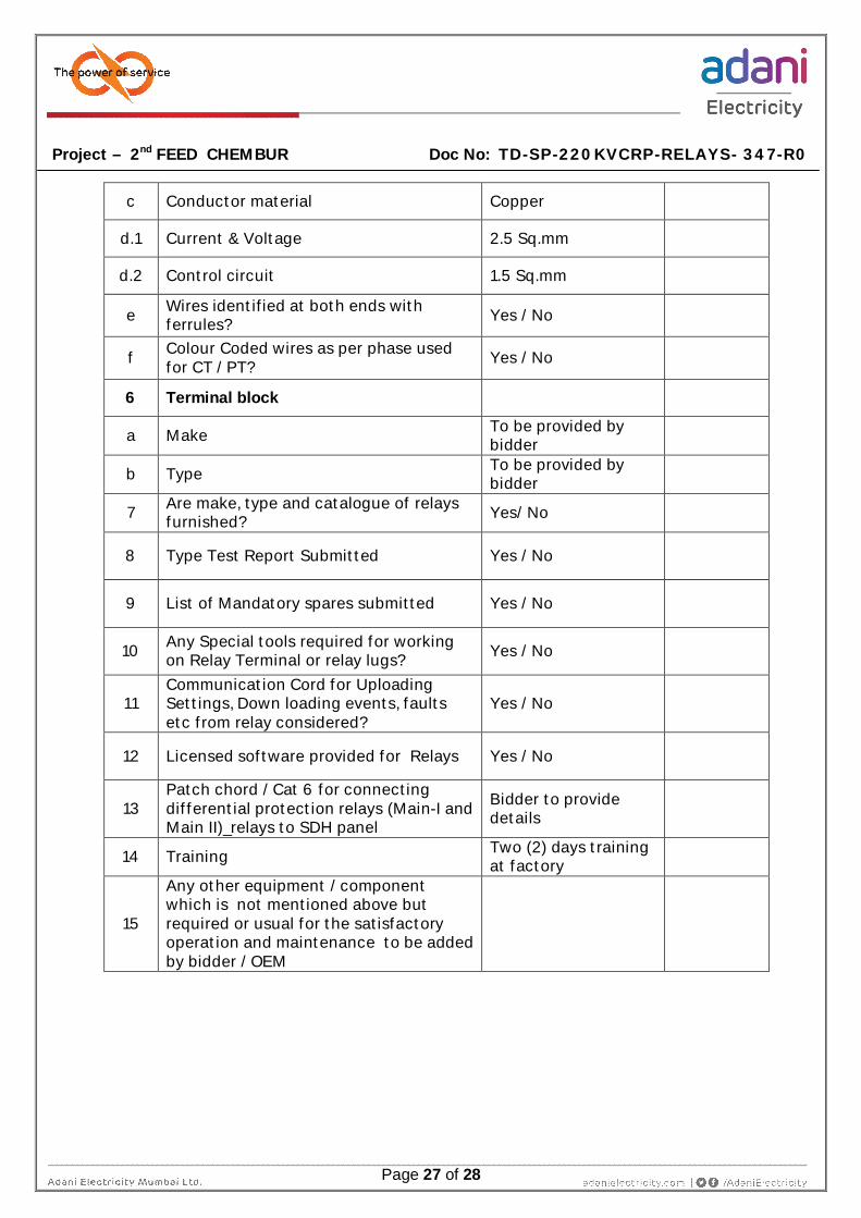
c Conductor material Copper
d.1 Current & Voltage 2.5 Sq.mm
d.2 Control circuit 1.5 Sq.mm
e Wires identified at both ends with ferrules? Yes / No
f Colour Coded wires as per phase used for CT / PT? Yes / No
6 Terminal block
a Make To be provided by bidder
b Type To be provided by bidder
7 Are make, type and catalogue of relays furnished? Yes/ No
8 Type Test Report Submitted Yes / No
9 List of Mandatory spares submitted Yes / No
10 Any Special tools required for working on Relay Terminal or relay lugs? Yes / No
11 Communication Cord for Uploading Settings, Down loading events, faults etc from relay considered?
Yes / No
12 Licensed software provided for Relays Yes / No
13 Patch chord / Cat 6 for connecting differential protection relays (Main-I and Main II)_relays to SDH panel
Bidder to provide details
14 Training Two (2) days training at factory
15
Any other equipment / component which is not mentioned above but required or usual for the satisfactory operation and maintenance to be added by bidder / OEM

Project – 2nd FEED CHEMBUR Doc No: TD-SP-220KVCRP-RELAYS- 347-R0
Page 28 of 28
10. DEVIATIONS
Deviation Schedule (Technical)
If the proposal has got any deviation from the technical specification, scope of supply, etc.,
bidder shall tabulate those deviations and sign below. Attach more sheets if necessary. It will
automatically be confirmed that except these deviations, as tabulated hereunder, the
complete offer is in agreement with the specification requirement. Deviations for Technical
and Commercial Conditions shall be given separately.
Sl
N
o
Document No &
description
Clause No &
Page No
Description of
Clause Deviation
Note:
a. Any deviations taken by the Bidder to the stipulations of the Bid document shall be brought
as per given format and shall be enclosed along with offer.
b. Any deviations not brought out in this form and written elsewhere in the Bid documents
shall not be recognized and the same is treated as null and void.
Seal of Company ……………
Name of Firm ……………………
Signature of Bidder ……………………
Name of Bidder ……………………
Designation ……………………
Date ……………………