Embed Size (px)
Citation preview
R. G. Sparber KG7MQL March 7, 2019 Page 1 of 50
A Beginner's Guide to the Yaesu FT-60R/E Handy-Talkie, version 3.3
By R. G. Sparber KG7MQL
Copyleft protect this document1.
This is a work in progress. Please send me your comments, corrections, and
question. Rick [email protected]
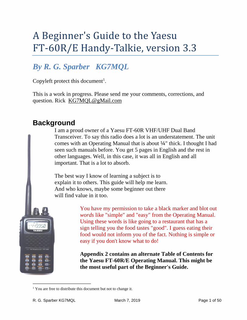
Background I am a proud owner of a Yaesu FT-60R VHF/UHF Dual Band
Transceiver. To say this radio does a lot is an understatement. The unit
comes with an Operating Manual that is about ¼" thick. I thought I had
seen such manuals before. You get 5 pages in English and the rest in
other languages. Well, in this case, it was all in English and all
important. That is a lot to absorb.
The best way I know of learning a subject is to
explain it to others. This guide will help me learn.
And who knows, maybe some beginner out there
will find value in it too.
You have my permission to take a black marker and blot out
words like "simple" and "easy" from the Operating Manual.
Using these words is like going to a restaurant that has a
sign telling you the food tastes "good". I guess eating their
food would not inform you of the fact. Nothing is simple or
easy if you don't know what to do!
Appendix 2 contains an alternate Table of Contents for
the Yaesu FT-60R/E Operating Manual. This might be
the most useful part of the Beginner's Guide.
1 You are free to distribute this document but not to change it.
R. G. Sparber KG7MQL March 7, 2019 Page 2 of 50
Contents
Background .............................................................................................................. 1
You Will Need ......................................................................................................... 5
Overview ................................................................................................................. 7
Operation: Switching Power On and Off [12] ........................................................ 8
Operation: Adjusting the Audio Volume Level and Squelch Settings [12] ............ 8
Operation: Selecting the Operating Band [13] ........................................................ 9
Operation: Frequency Navigation [13] .................................................................10
Operation: Transmission [15] ................................................................................13
Advanced Operation: Keyboard Locking [16] ......................................................14
Advanced Operation: Keypad/LCD Illumination [17] .........................................14
Advanced Operation: Disabling the Keypad Beeper [17] .....................................14
Advanced Operation: RF Squelch [18] .................................................................14
Advanced Operation: Checking the Battery Voltage [18] ....................................14
Repeater Operation ................................................................................................15
Manual Repeater Shift Activation: Checking the Repeater Uplink (Input)
Frequency [21] .......................................................................................................17
Repeater Operation: Repeater Shifts [19] .............................................................18
Repeater Operation: Automatic Repeater Shifts (ARS) [19] ................................18
Repeater Operation: Manual Repeater Shift Activation [20] ................................19
Manual Repeater Shift Activation: Checking the Repeater Uplink (Input)
Frequency [21] .......................................................................................................19
CTCSS/DCS Operation: CTCSS Operation [22] ..................................................19
CTCSS/DCS Operation: DCS Operation [23] ......................................................20
CTCSS/DCS Operation: Tone Search Scanning [24] ...........................................20
CTCSS/DCS Operation: Split Tone Operation [25] .............................................20
CTCSS/DCS Operation: Tone Calling (1750 Hz) [26] .........................................20
Memory Mode [27] ...............................................................................................21
Memory Mode: Memory Storage [28] ..................................................................23
Memory Mode: Storing Independent Transmit Frequencies ("Odd Splits") [28] 23
Memory Mode: Memory Recall [29] ....................................................................24
R. G. Sparber KG7MQL March 7, 2019 Page 3 of 50
Memory Mode: HOME Channel Memory [29] ....................................................26
Memory Mode: Labeling Memories [30] ..............................................................27
Memory Mode: To Display the alpha-numeric "Tag" (label): [30] ......................30
Memory Mode: Memory Offset Tuning [31] ........................................................31
Memory Mode: Deleting Memories [32] ..............................................................32
Memory Mode: Moving Memory Data to the VFO [32] ......................................32
Memory Mode: Memory Bank Operation [33] .....................................................33
Memory Mode: Assigning Memories to a Memory Bank [33] ............................34
Memory Mode: Memory Bank Recall [33]...........................................................35
Memory Mode: Removing Memories from a Memory Bank [34] .......................36
Memory Mode: Memory Only Mode [34] ............................................................36
Weather Broadcast Channels [34] .........................................................................37
Scanning [35] .........................................................................................................38
Scanning: VFO Scanning [35] ..............................................................................38
Scanning: Memory Scanning [37] .........................................................................40
Scanning: How to Skip (Omit) a Channel during Memory Scan Operation [37] .40
Scanning: Preferential Memory Scan [38] ............................................................40
Scanning: Memory Bank Scan [39] ......................................................................41
Scanning: Weather Alert Scan [39] .......................................................................41
Scanning: Programmable (Band Limit) Memory Scan (PMS) [40] .....................41
Scanning: "Priority Channel" Scanning (Dual Watch) [41] .................................42
Scanning: Priority Revert Mode [42] ....................................................................43
Scanning: Automatic Lamp Illumination on Scan Stop [43] ................................43
Scanning: Band Edge Beeper [43] ........................................................................43
EPCS (Enhanced Paging and Code Squelch) [44] ................................................43
Emergency Features: Emergency Channel Operation [46] ...................................43
Smart Search Operation [48] .................................................................................43
Internet Connection Feature [49] ..........................................................................44
ARTS™ (Automatic Range Transponder System) [51] .......................................44
Reset Procedure [64] .............................................................................................44
R. G. Sparber KG7MQL March 7, 2019 Page 4 of 50
Acknowledgments .................................................................................................45
Appendix 1: Operation Reminders ........................................................................46
Appendix 2: Alternate Table of Contents for the FT-60 R/E Operating Manual .46
R. G. Sparber KG7MQL March 7, 2019 Page 5 of 50
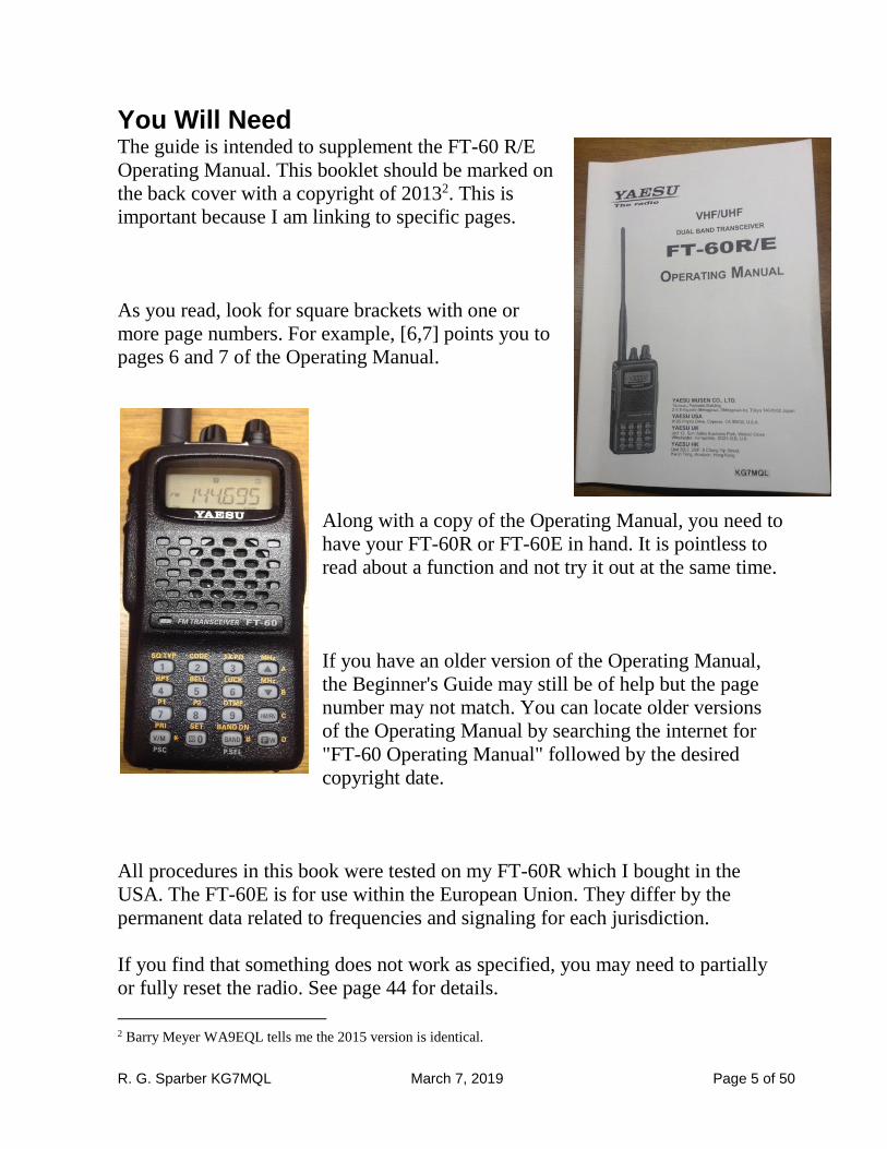
You Will Need The guide is intended to supplement the FT-60 R/E
Operating Manual. This booklet should be marked on
the back cover with a copyright of 20132. This is
important because I am linking to specific pages.
As you read, look for square brackets with one or
more page numbers. For example, [6,7] points you to
pages 6 and 7 of the Operating Manual.
Along with a copy of the Operating Manual, you need to
have your FT-60R or FT-60E in hand. It is pointless to
read about a function and not try it out at the same time.
If you have an older version of the Operating Manual,
the Beginner's Guide may still be of help but the page
number may not match. You can locate older versions
of the Operating Manual by searching the internet for
"FT-60 Operating Manual" followed by the desired
copyright date.
All procedures in this book were tested on my FT-60R which I bought in the
USA. The FT-60E is for use within the European Union. They differ by the
permanent data related to frequencies and signaling for each jurisdiction.
If you find that something does not work as specified, you may need to partially
or fully reset the radio. See page 44 for details.
2 Barry Meyer WA9EQL tells me the 2015 version is identical.
R. G. Sparber KG7MQL March 7, 2019 Page 6 of 50
At the bottom of some sections is a reminder of the key and knob sequence. If the
reminder starts with "VFO-" it means you must be in VFO mode. "MEM-" means
you must be in Memory mode. If neither is present, then the sequence works in
both VFO and memory modes. All of these reminders have been collected and
are presented in Appendix 1.
Each action is followed by a "/" except the last one.
"Dial" means you turn the Dial knob to select some parameter or state.
If only a key is shown, then you press it briefly. If the key is followed by " 1s" it
means you press the key for about 1 second.
Appendix 2 holds an alternative Table of Contents for the FT-60 R/E Operating
Manual. The topics have been organized in a different sequence so the page
numbers are not always in order.
R. G. Sparber KG7MQL March 7, 2019 Page 7 of 50
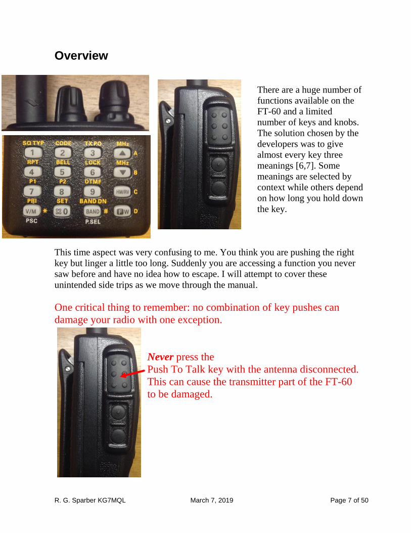
Overview
There are a huge number of
functions available on the
FT-60 and a limited
number of keys and knobs.
The solution chosen by the
developers was to give
almost every key three
meanings [6,7]. Some
meanings are selected by
context while others depend
on how long you hold down
the key.
This time aspect was very confusing to me. You think you are pushing the right
key but linger a little too long. Suddenly you are accessing a function you never
saw before and have no idea how to escape. I will attempt to cover these
unintended side trips as we move through the manual.
One critical thing to remember: no combination of key pushes can
damage your radio with one exception.
Never press the
Push To Talk key with the antenna disconnected.
This can cause the transmitter part of the FT-60
to be damaged.
R. G. Sparber KG7MQL March 7, 2019 Page 8 of 50
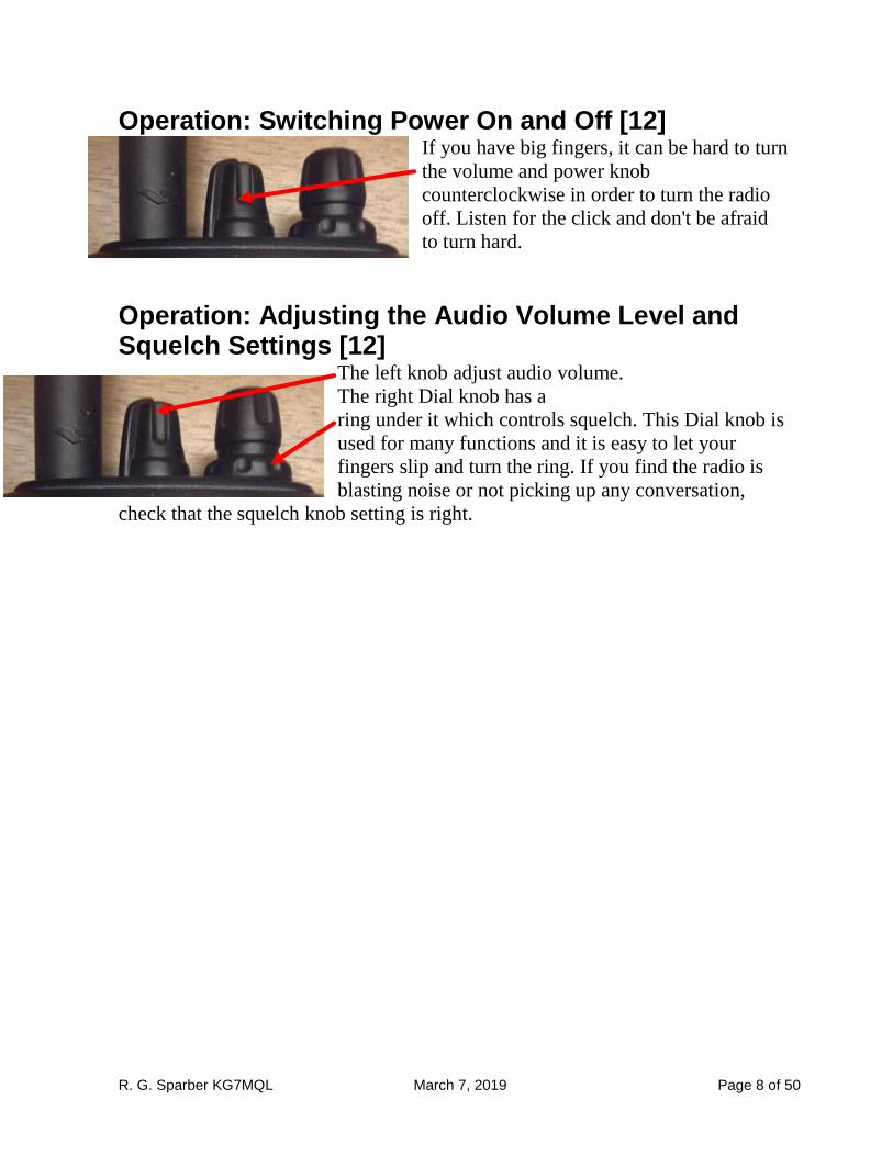
Operation: Switching Power On and Off [12] If you have big fingers, it can be hard to turn
the volume and power knob
counterclockwise in order to turn the radio
off. Listen for the click and don't be afraid
to turn hard.
Operation: Adjusting the Audio Volume Level and Squelch Settings [12]
The left knob adjust audio volume.
The right Dial knob has a
ring under it which controls squelch. This Dial knob is
used for many functions and it is easy to let your
fingers slip and turn the ring. If you find the radio is
blasting noise or not picking up any conversation,
check that the squelch knob setting is right.
R. G. Sparber KG7MQL March 7, 2019 Page 9 of 50
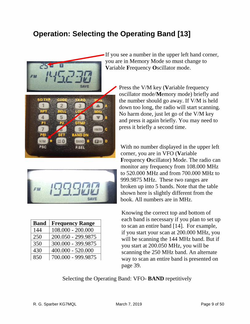
Operation: Selecting the Operating Band [13]
If you see a number in the upper left hand corner,
you are in Memory Mode so must change to
Variable Frequency Oscillator mode.
Press the V/M key (Variable frequency
oscillator mode/Memory mode) briefly and
the number should go away. If V/M is held
down too long, the radio will start scanning.
No harm done, just let go of the V/M key
and press it again briefly. You may need to
press it briefly a second time.
With no number displayed in the upper left
corner, you are in VFO (Variable
Frequency Oscillator) Mode. The radio can
monitor any frequency from 108.000 MHz
to 520.000 MHz and from 700.000 MHz to
999.9875 MHz. These two ranges are
broken up into 5 bands. Note that the table
shown here is slightly different from the
book. All numbers are in MHz.
Knowing the correct top and bottom of
each band is necessary if you plan to set up
to scan an entire band [14]. For example,
if you start your scan at 200.000 MHz, you
will be scanning the 144 MHz band. But if
you start at 200.050 MHz, you will be
scanning the 250 MHz band. An alternate
way to scan an entire band is presented on
page 39.
Selecting the Operating Band: VFO- BAND repetitively
Band Frequency Range
144 108.000 - 200.000
250 200.050 - 299.9875
350 300.000 - 399.9875
430 400.000 - 520.000
850 700.000 - 999.9875
R. G. Sparber KG7MQL March 7, 2019 Page 10 of 50
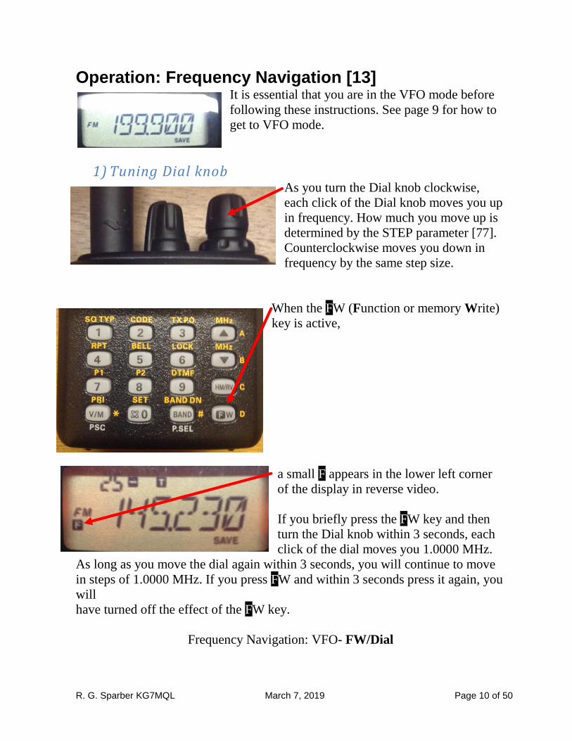
Operation: Frequency Navigation [13] It is essential that you are in the VFO mode before
following these instructions. See page 9 for how to
get to VFO mode.
1) Tuning Dial knob As you turn the Dial knob clockwise,
each click of the Dial knob moves you up
in frequency. How much you move up is
determined by the STEP parameter [77].
Counterclockwise moves you down in
frequency by the same step size.
When the FW (Function or memory Write)
key is active,
a small F appears in the lower left corner
of the display in reverse video.
If you briefly press the FW key and then
turn the Dial knob within 3 seconds, each
click of the dial moves you 1.0000 MHz.
As long as you move the dial again within 3 seconds, you will continue to move
in steps of 1.0000 MHz. If you press FW and within 3 seconds press it again, you
will
have turned off the effect of the FW key.
Frequency Navigation: VFO- FW/Dial
R. G. Sparber KG7MQL March 7, 2019 Page 11 of 50
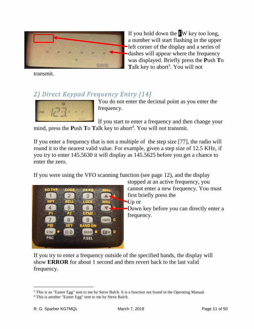
If you hold down the FW key too long,
a number will start flashing in the upper
left corner of the display and a series of
dashes will appear where the frequency
was displayed. Briefly press the Push To
Talk key to abort3. You will not
transmit.
2) Direct Keypad Frequency Entry [14] You do not enter the decimal point as you enter the
frequency.
If you start to enter a frequency and then change your
mind, press the Push To Talk key to abort4. You will not transmit.
If you enter a frequency that is not a multiple of the step size [77], the radio will
round it to the nearest valid value. For example, given a step size of 12.5 KHz, if
you try to enter 145.5630 it will display as 145.5625 before you get a chance to
enter the zero.
If you were using the VFO scanning function (see page 12), and the display
stopped at an active frequency, you
cannot enter a new frequency. You must
first briefly press the
Up or
Down key before you can directly enter a
frequency.
If you try to enter a frequency outside of the specified bands, the display will
show ERROR for about 1 second and then revert back to the last valid
frequency.
3 This is an "Easter Egg" sent to me by Steve Balch. It is a function not found in the Operating Manual. 4 This is another "Easter Egg" sent to me by Steve Balch.
R. G. Sparber KG7MQL March 7, 2019 Page 12 of 50
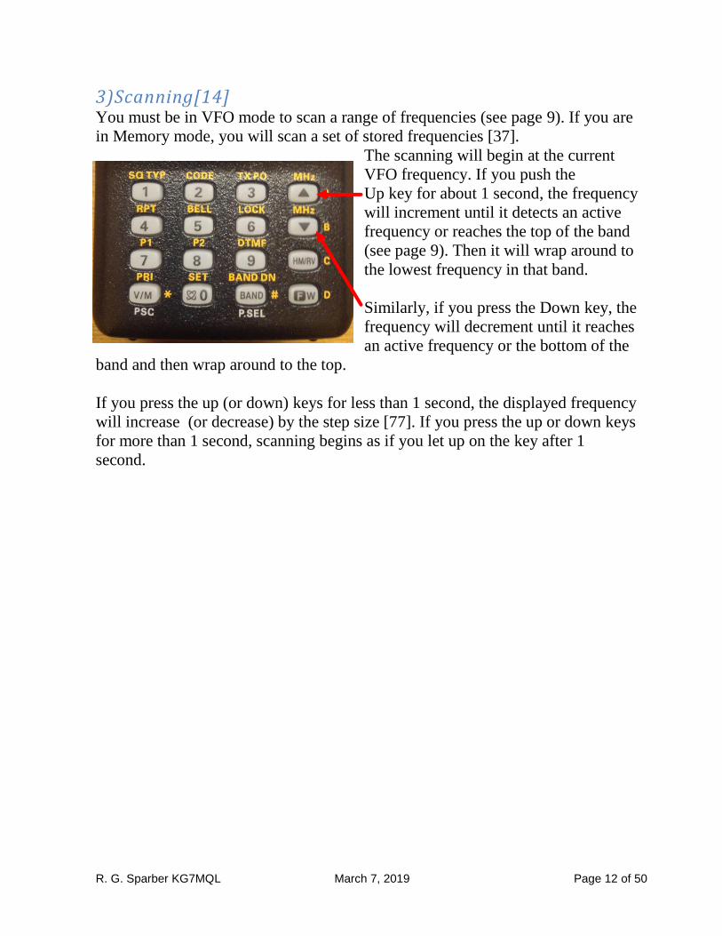
3)Scanning[14] You must be in VFO mode to scan a range of frequencies (see page 9). If you are
in Memory mode, you will scan a set of stored frequencies [37].
The scanning will begin at the current
VFO frequency. If you push the
Up key for about 1 second, the frequency
will increment until it detects an active
frequency or reaches the top of the band
(see page 9). Then it will wrap around to
the lowest frequency in that band.
Similarly, if you press the Down key, the
frequency will decrement until it reaches
an active frequency or the bottom of the
band and then wrap around to the top.
If you press the up (or down) keys for less than 1 second, the displayed frequency
will increase (or decrease) by the step size [77]. If you press the up or down keys
for more than 1 second, scanning begins as if you let up on the key after 1
second.
R. G. Sparber KG7MQL March 7, 2019 Page 13 of 50
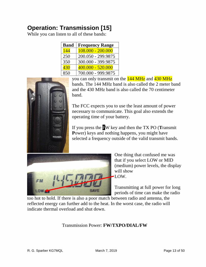
Operation: Transmission [15] While you can listen to all of these bands:
Band Frequency Range
144 108.000 - 200.000
250 200.050 - 299.9875
350 300.000 - 399.9875
430 400.000 - 520.000
850 700.000 - 999.9875
you can only transmit on the 144 MHz and 430 MHz
bands. The 144 MHz band is also called the 2 meter band
and the 430 MHz band is also called the 70 centimeter
band.
The FCC expects you to use the least amount of power
necessary to communicate. This goal also extends the
operating time of your battery.
If you press the FW key and then the TX PO (Transmit
Power) keys and nothing happens, you might have
selected a frequency outside of the valid transmit bands.
One thing that confused me was
that if you select LOW or MID
(medium) power levels, the display
will show
LOW.
Transmitting at full power for long
periods of time can make the radio
too hot to hold. If there is also a poor match between radio and antenna, the
reflected energy can further add to the heat. In the worst case, the radio will
indicate thermal overload and shut down.
Transmission Power: FW/TXPO/DIAL/FW
R. G. Sparber KG7MQL March 7, 2019 Page 14 of 50
Advanced Operation: Keyboard Locking [16] Advanced Operation: Keypad/LCD Illumination [17] Advanced Operation: Disabling the Keypad Beeper [17] Advanced Operation: RF Squelch [18] Advanced Operation: Checking the Battery Voltage [18]
R. G. Sparber KG7MQL March 7, 2019 Page 15 of 50
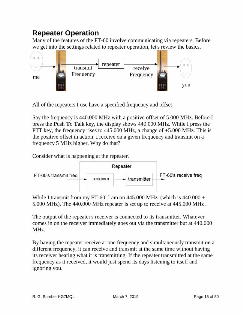
Repeater Operation Many of the features of the FT-60 involve communicating via repeaters. Before
we get into the settings related to repeater operation, let's review the basics.
All of the repeaters I use have a specified frequency and offset.
Say the frequency is 440.000 MHz with a positive offset of 5.000 MHz. Before I
press the Push To Talk key, the display shows 440.000 MHz. While I press the
PTT key, the frequency rises to 445.000 MHz, a change of +5.000 MHz. This is
the positive offset in action. I receive on a given frequency and transmit on a
frequency 5 MHz higher. Why do that?
Consider what is happening at the repeater.
While I transmit from my FT-60, I am on 445.000 MHz (which is 440.000 +
5.000 MHz). The 440.000 MHz repeater is set up to receive at 445.000 MHz .
The output of the repeater's receiver is connected to its transmitter. Whatever
comes in on the receiver immediately goes out via the transmitter but at 440.000
MHz.
By having the repeater receive at one frequency and simultaneously transmit on a
different frequency, it can receive and transmit at the same time without having
its receiver hearing what it is transmitting. If the repeater transmitted at the same
frequency as it received, it would just spend its days listening to itself and
ignoring you.
repeater
you
transmit
Frequency receive
Frequency me
R. G. Sparber KG7MQL March 7, 2019 Page 16 of 50
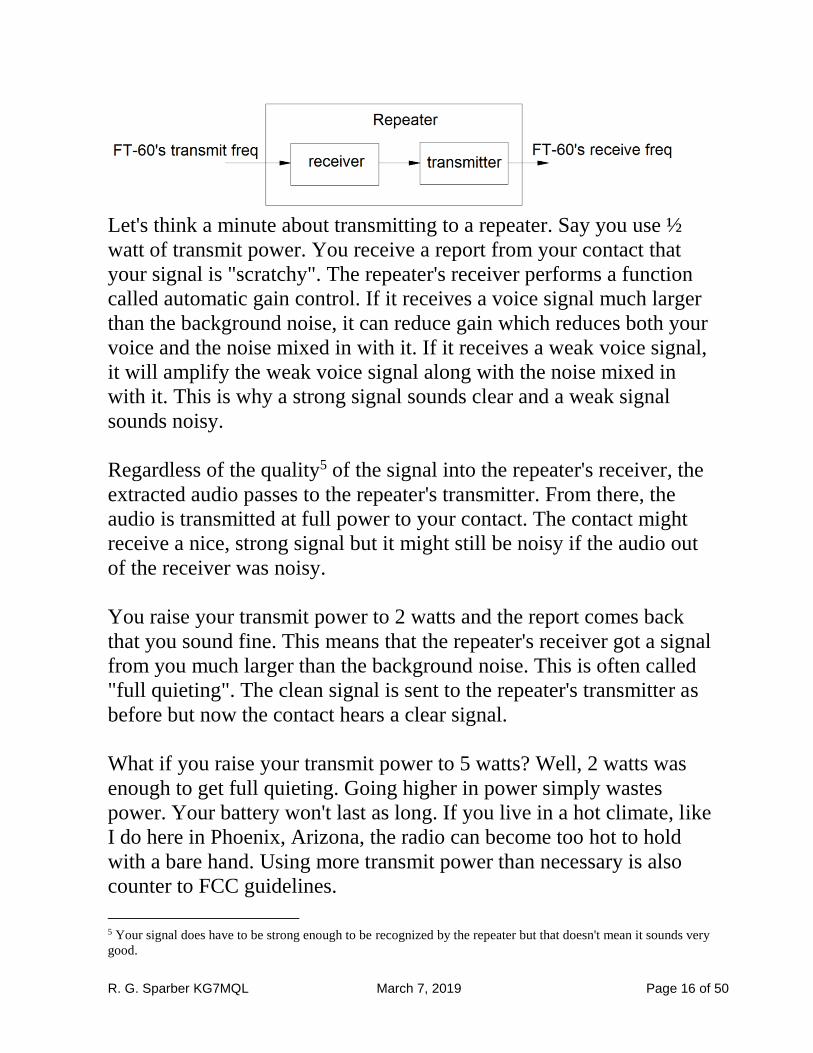
Let's think a minute about transmitting to a repeater. Say you use ½
watt of transmit power. You receive a report from your contact that
your signal is "scratchy". The repeater's receiver performs a function
called automatic gain control. If it receives a voice signal much larger
than the background noise, it can reduce gain which reduces both your
voice and the noise mixed in with it. If it receives a weak voice signal,
it will amplify the weak voice signal along with the noise mixed in
with it. This is why a strong signal sounds clear and a weak signal
sounds noisy.
Regardless of the quality5 of the signal into the repeater's receiver, the
extracted audio passes to the repeater's transmitter. From there, the
audio is transmitted at full power to your contact. The contact might
receive a nice, strong signal but it might still be noisy if the audio out
of the receiver was noisy.
You raise your transmit power to 2 watts and the report comes back
that you sound fine. This means that the repeater's receiver got a signal
from you much larger than the background noise. This is often called
"full quieting". The clean signal is sent to the repeater's transmitter as
before but now the contact hears a clear signal.
What if you raise your transmit power to 5 watts? Well, 2 watts was
enough to get full quieting. Going higher in power simply wastes
power. Your battery won't last as long. If you live in a hot climate, like
I do here in Phoenix, Arizona, the radio can become too hot to hold
with a bare hand. Using more transmit power than necessary is also
counter to FCC guidelines.
5 Your signal does have to be strong enough to be recognized by the repeater but that doesn't mean it sounds very
good.
R. G. Sparber KG7MQL March 7, 2019 Page 17 of 50
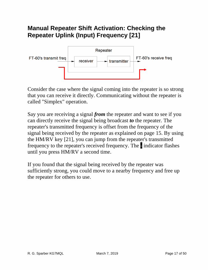
Manual Repeater Shift Activation: Checking the Repeater Uplink (Input) Frequency [21]
Consider the case where the signal coming into the repeater is so strong
that you can receive it directly. Communicating without the repeater is
called "Simplex" operation.
Say you are receiving a signal from the repeater and want to see if you
can directly receive the signal being broadcast to the repeater. The
repeater's transmitted frequency is offset from the frequency of the
signal being received by the repeater as explained on page 15. By using
the HM/RV key [21], you can jump from the repeater's transmitted
frequency to the repeater's received frequency. The - indicator flashes
until you press HM/RV a second time.
If you found that the signal being received by the repeater was
sufficiently strong, you could move to a nearby frequency and free up
the repeater for others to use.
R. G. Sparber KG7MQL March 7, 2019 Page 18 of 50
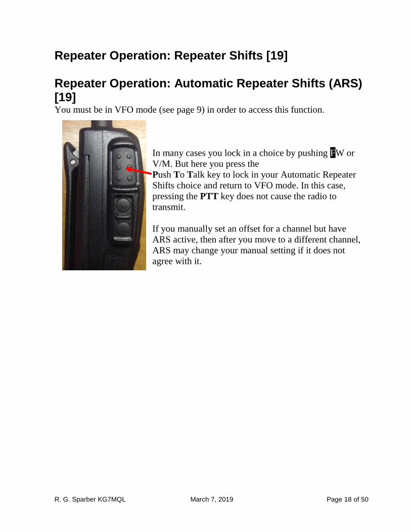
Repeater Operation: Repeater Shifts [19] Repeater Operation: Automatic Repeater Shifts (ARS) [19] You must be in VFO mode (see page 9) in order to access this function.
In many cases you lock in a choice by pushing FW or
V/M. But here you press the
Push To Talk key to lock in your Automatic Repeater
Shifts choice and return to VFO mode. In this case,
pressing the PTT key does not cause the radio to
transmit.
If you manually set an offset for a channel but have
ARS active, then after you move to a different channel,
ARS may change your manual setting if it does not
agree with it.
R. G. Sparber KG7MQL March 7, 2019 Page 19 of 50
Repeater Operation: Manual Repeater Shift Activation [20]
Manual Repeater Shift Activation: Checking the Repeater Uplink (Input) Frequency [21] See page 17.
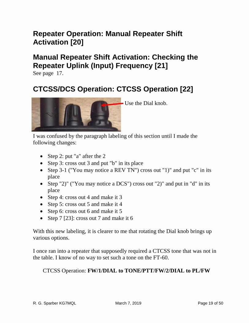
CTCSS/DCS Operation: CTCSS Operation [22]
Use the Dial knob.
I was confused by the paragraph labeling of this section until I made the
following changes:
• Step 2: put "a" after the 2
• Step 3: cross out 3 and put "b" in its place
• Step 3-1 ("You may notice a REV TN") cross out "1)" and put "c" in its
place
• Step "2)" ("You may notice a DCS") cross out "2)" and put in "d" in its
place
• Step 4: cross out 4 and make it 3
• Step 5: cross out 5 and make it 4
• Step 6: cross out 6 and make it 5
• Step 7 [23]: cross out 7 and make it 6
With this new labeling, it is clearer to me that rotating the Dial knob brings up
various options.
I once ran into a repeater that supposedly required a CTCSS tone that was not in
the table. I know of no way to set such a tone on the FT-60.
CTCSS Operation: FW/1/DIAL to TONE/PTT/FW/2/DIAL to PL/FW
R. G. Sparber KG7MQL March 7, 2019 Page 20 of 50
CTCSS/DCS Operation: DCS Operation [23] CTCSS/DCS Operation: Tone Search Scanning [24] CTCSS/DCS Operation: Split Tone Operation [25] CTCSS/DCS Operation: Tone Calling (1750 Hz) [26]

R. G. Sparber KG7MQL March 7, 2019 Page 21 of 50
Memory Mode [27] We have a memory space that contains user
defined frequencies. Each address is called a
Channel and they are numbered from 000 to
999. Each Channel holds a frequency plus other
parameters. Let's focus on just frequency
for now.
If I retrieve the data held in Channel 002, I will get 435.000 MHz in this
example.
This channel memory space doesn't really have a name. The figure on [27] just
refers to the individual channels and calls them Standard Memory Channels.
We also have a memory space that contains collections of what I call "pointers".
A pointer is just a channel number. This space is divided into 10 Memory Banks.
For example, I could have a Memory Bank like this:
I added "Pointer to" in the above table in order to differentiate these entries from
the Channel Memory shown at the top of this page.
By selecting this Memory Bank, I will have access to only channels 10, 7, 42, 73,
and 128. This would be handy if only these channels are operational within a
given town. Change towns and I could change Memory Banks.
Any of the Memory Banks can contain a pointer to any Channel. So if you liked,
all 10 Memory Banks could point to Channel 042.
The diagram on [27] implies that you can store both Standard Memory Channels
pointers and PMS Memory Channel pointers in one or more Memory Banks. This
is not correct. You can only store Standard Memory channels to Memory Banks.
Pointer to Channel 010
Pointer to Channel 007
Pointer to Channel 042
Pointer to Channel 073
Pointer to Channel 128
Channel 000 145.000 MHz
Channel 001 145.500 MHz
Channel 002 435.000 MHz
Channel 003 435.500 MHz
Channel 004 145.800 MHz
R. G. Sparber KG7MQL March 7, 2019 Page 22 of 50
Referring to the figure on [27], you see that following the Standard Memory
Channels there are the PMS Memory Channels. As you turn the tuning knob to
sequence through the channels, you should see 1 through 999, then 0 which is
really 000, and then the L/U pairs of registers. When I first got my radio, I seem
to remember seeing the L/U pairs. But when I recently looked for them, they
were gone. A partial reset of the radio restored them (see [64] and page 44).
Lesson learned: if the radio does not work as described, there might be damage to
the data and/or software image that can be corrected by a reset. See page 44 for
details on the different levels of reset. Doing a factory reset should be a last resort
as this will erase your data.
Not shown in the figure on [27] is another set of memories used by the Smart
Search Operation [48]. See also page 44.
R. G. Sparber KG7MQL March 7, 2019 Page 23 of 50
Memory Mode: Memory Storage [28] This section deals with storing frequencies and associated data into channels. It is
not dealing with storing pointers. The task is performed in VFO mode.
If you are rotating the tuning Dial knob clockwise starting at Channel 1, then
expect to see 1 through 999, then 0, and then the L/U pairs of registers.
Note: Channel 1 has a special meaning if you plan to use the Memory Channel
Priority function. You may want to leave it blank for now (see page 42 for
details).
Memory Storage: MEM- FW 1s/DIAL/FW
Memory Mode: Storing Independent Transmit Frequencies ("Odd Splits") [28]
R. G. Sparber KG7MQL March 7, 2019 Page 24 of 50
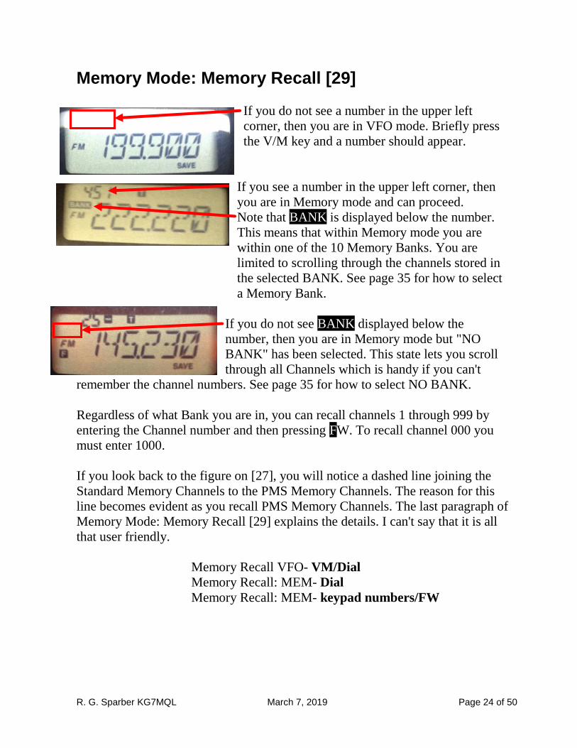
Memory Mode: Memory Recall [29]
If you do not see a number in the upper left
corner, then you are in VFO mode. Briefly press
the V/M key and a number should appear.
If you see a number in the upper left corner, then
you are in Memory mode and can proceed.
Note that BANK is displayed below the number.
This means that within Memory mode you are
within one of the 10 Memory Banks. You are
limited to scrolling through the channels stored in
the selected BANK. See page 35 for how to select
a Memory Bank.
If you do not see BANK displayed below the
number, then you are in Memory mode but "NO
BANK" has been selected. This state lets you scroll
through all Channels which is handy if you can't
remember the channel numbers. See page 35 for how to select NO BANK.
Regardless of what Bank you are in, you can recall channels 1 through 999 by
entering the Channel number and then pressing FW. To recall channel 000 you
must enter 1000.
If you look back to the figure on [27], you will notice a dashed line joining the
Standard Memory Channels to the PMS Memory Channels. The reason for this
line becomes evident as you recall PMS Memory Channels. The last paragraph of
Memory Mode: Memory Recall [29] explains the details. I can't say that it is all
that user friendly.
Memory Recall VFO- VM/Dial
Memory Recall: MEM- Dial
Memory Recall: MEM- keypad numbers/FW
R. G. Sparber KG7MQL March 7, 2019 Page 25 of 50
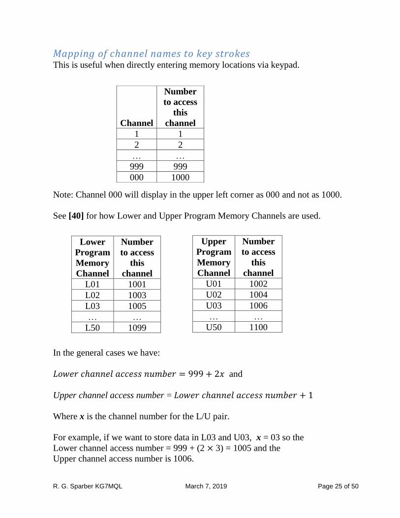
Mapping of channel names to key strokes This is useful when directly entering memory locations via keypad.
Note: Channel 000 will display in the upper left corner as 000 and not as 1000.
See [40] for how Lower and Upper Program Memory Channels are used.
In the general cases we have:
𝐿𝑜𝑤𝑒𝑟 𝑐ℎ𝑎𝑛𝑛𝑒𝑙 𝑎𝑐𝑐𝑒𝑠𝑠 𝑛𝑢𝑚𝑏𝑒𝑟 = 999 + 2𝑥 and
Upper channel access number = 𝐿𝑜𝑤𝑒𝑟 𝑐ℎ𝑎𝑛𝑛𝑒𝑙 𝑎𝑐𝑐𝑒𝑠𝑠 𝑛𝑢𝑚𝑏𝑒𝑟 + 1
Where x is the channel number for the L/U pair.
For example, if we want to store data in L03 and U03, x = 03 so the
Lower channel access number = 999 + (2 × 3) = 1005 and the
Upper channel access number is 1006.
Channel
Number
to access
this
channel
1 1
2 2
… …
999 999
000 1000
Lower
Program
Memory
Channel
Number
to access
this
channel
L01 1001
L02 1003
L03 1005
… …
L50 1099
Upper
Program
Memory
Channel
Number
to access
this
channel
U01 1002
U02 1004
U03 1006
… …
U50 1100
R. G. Sparber KG7MQL March 7, 2019 Page 26 of 50
Memory Mode: HOME Channel Memory [29]
Step "6" will only work if step "1" was previously executed. However, if
REV/HM is set to REV, you can press FW and then HM/RV to bring up the
HOME channel.
R. G. Sparber KG7MQL March 7, 2019 Page 27 of 50
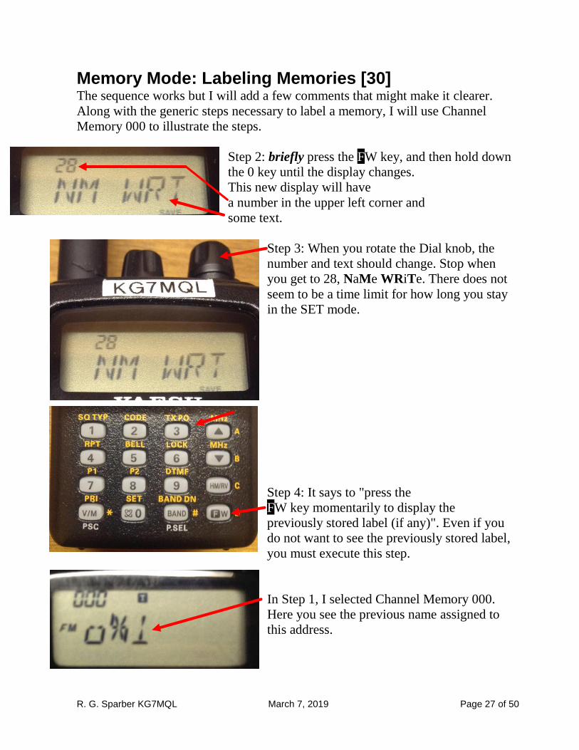
Memory Mode: Labeling Memories [30] The sequence works but I will add a few comments that might make it clearer.
Along with the generic steps necessary to label a memory, I will use Channel
Memory 000 to illustrate the steps.
Step 2: briefly press the FW key, and then hold down
the 0 key until the display changes.
This new display will have
a number in the upper left corner and
some text.
Step 3: When you rotate the Dial knob, the
number and text should change. Stop when
you get to 28, NaMe WRiTe. There does not
seem to be a time limit for how long you stay
in the SET mode.
Step 4: It says to "press the
FW key momentarily to display the
previously stored label (if any)". Even if you
do not want to see the previously stored label,
you must execute this step.
In Step 1, I selected Channel Memory 000.
Here you see the previous name assigned to
this address.
R. G. Sparber KG7MQL March 7, 2019 Page 28 of 50
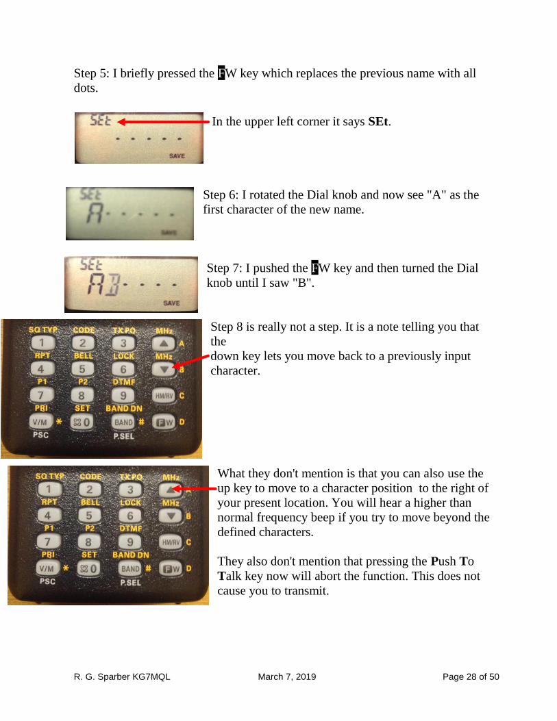
Step 5: I briefly pressed the FW key which replaces the previous name with all
dots.
In the upper left corner it says SEt.
Step 6: I rotated the Dial knob and now see "A" as the
first character of the new name.
Step 7: I pushed the FW key and then turned the Dial
knob until I saw "B".
Step 8 is really not a step. It is a note telling you that
the
down key lets you move back to a previously input
character.
What they don't mention is that you can also use the
up key to move to a character position to the right of
your present location. You will hear a higher than
normal frequency beep if you try to move beyond the
defined characters.
They also don't mention that pressing the Push To
Talk key now will abort the function. This does not
cause you to transmit.
R. G. Sparber KG7MQL March 7, 2019 Page 29 of 50
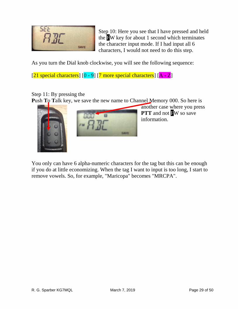
Step 10: Here you see that I have pressed and held
the FW key for about 1 second which terminates
the character input mode. If I had input all 6
characters, I would not need to do this step.
As you turn the Dial knob clockwise, you will see the following sequence:
[21 special characters] [0 - 9] [7 more special characters] [A - Z]
Step 11: By pressing the
Push To Talk key, we save the new name to Channel Memory 000. So here is
another case where you press
PTT and not FW so save
information.
You only can have 6 alpha-numeric characters for the tag but this can be enough
if you do at little economizing. When the tag I want to input is too long, I start to
remove vowels. So, for example, "Maricopa" becomes "MRCPA".
R. G. Sparber KG7MQL March 7, 2019 Page 30 of 50
Memory Mode: To Display the alpha-numeric "Tag" (label): [30]
In step "1" they say to set the radio to Memory Recall mode. See page 24 for how
to do this action.
Note in step "6" that you lock in the change by pressing the Push To Talk key on
the side of the radio. In most other functions, pressing PTT aborts the function
and data is often entered by pressing FW.
The decision to display frequency or tag is on a single channel basis. It is not
possible to set all of the channels the same way with a single operation.
R. G. Sparber KG7MQL March 7, 2019 Page 31 of 50
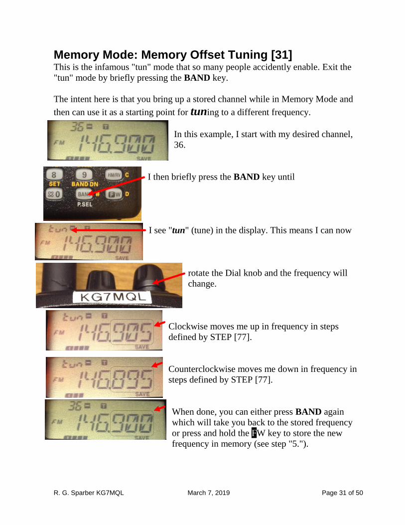
Memory Mode: Memory Offset Tuning [31] This is the infamous "tun" mode that so many people accidently enable. Exit the
"tun" mode by briefly pressing the BAND key.
The intent here is that you bring up a stored channel while in Memory Mode and
then can use it as a starting point for tuning to a different frequency.
In this example, I start with my desired channel,
36.
I then briefly press the BAND key until
I see "tun" (tune) in the display. This means I can now
rotate the Dial knob and the frequency will
change.
Clockwise moves me up in frequency in steps
defined by STEP [77].
Counterclockwise moves me down in frequency in
steps defined by STEP [77].
When done, you can either press BAND again
which will take you back to the stored frequency
or press and hold the FW key to store the new
frequency in memory (see step "5.").
R. G. Sparber KG7MQL March 7, 2019 Page 32 of 50
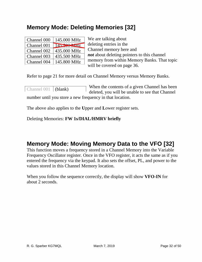
Memory Mode: Deleting Memories [32]
We are talking about
deleting entries in the
Channel memory here and
not about deleting pointers to this channel
memory from within Memory Banks. That topic
will be covered on page 36.
Refer to page 21 for more detail on Channel Memory versus Memory Banks.
When the contents of a given Channel has been
deleted, you will be unable to see that Channel
number until you store a new frequency in that location.
The above also applies to the Upper and Lower register sets.
Deleting Memories: FW 1s/DIAL/HMRV briefly
Memory Mode: Moving Memory Data to the VFO [32] This function moves a frequency stored in a Channel Memory into the Variable
Frequency Oscillator register. Once in the VFO register, it acts the same as if you
entered the frequency via the keypad. It also sets the offset, PL, and power to the
values stored in this Channel Memory location.
When you follow the sequence correctly, the display will show VFO-IN for
about 2 seconds.
Channel 000 145.000 MHz
Channel 001 145.500 MHz
Channel 002 435.000 MHz
Channel 003 435.500 MHz
Channel 004 145.800 MHz
Channel 001 (blank)
R. G. Sparber KG7MQL March 7, 2019 Page 33 of 50
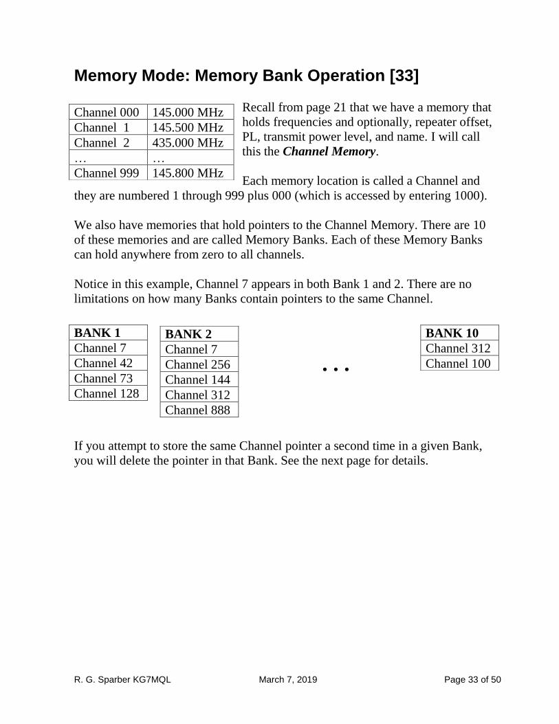
Memory Mode: Memory Bank Operation [33]
Recall from page 21 that we have a memory that
holds frequencies and optionally, repeater offset,
PL, transmit power level, and name. I will call
this the Channel Memory.
Each memory location is called a Channel and
they are numbered 1 through 999 plus 000 (which is accessed by entering 1000).
We also have memories that hold pointers to the Channel Memory. There are 10
of these memories and are called Memory Banks. Each of these Memory Banks
can hold anywhere from zero to all channels.
Notice in this example, Channel 7 appears in both Bank 1 and 2. There are no
limitations on how many Banks contain pointers to the same Channel.
If you attempt to store the same Channel pointer a second time in a given Bank,
you will delete the pointer in that Bank. See the next page for details.
Channel 000 145.000 MHz
Channel 1 145.500 MHz
Channel 2 435.000 MHz
… …
Channel 999 145.800 MHz
BANK 1
Channel 7
Channel 42
Channel 73
Channel 128
BANK 2
Channel 7
Channel 256
Channel 144
Channel 312
Channel 888
BANK 10
Channel 312
Channel 100 …
R. G. Sparber KG7MQL March 7, 2019 Page 34 of 50
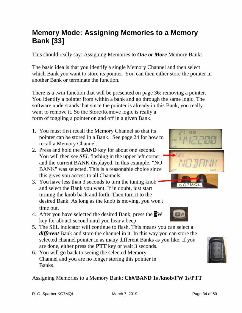
Memory Mode: Assigning Memories to a Memory Bank [33]
This should really say: Assigning Memories to One or More Memory Banks
The basic idea is that you identify a single Memory Channel and then select
which Bank you want to store its pointer. You can then either store the pointer in
another Bank or terminate the function.
There is a twin function that will be presented on page 36: removing a pointer.
You identify a pointer from within a bank and go through the same logic. The
software understands that since the pointer is already in this Bank, you really
want to remove it. So the Store/Remove logic is really a
form of toggling a pointer on and off in a given Bank.
1. You must first recall the Memory Channel so that its
pointer can be stored in a Bank. See page 24 for how to
recall a Memory Channel.
2. Press and hold the BAND key for about one second.
You will then see SEL flashing in the upper left corner
and the current BANK displayed. In this example, "NO
BANK" was selected. This is a reasonable choice since
this gives you access to all Channels.
3. You have less than 3 seconds to turn the tuning knob
and select the Bank you want. If in doubt, just start
turning the knob back and forth. Then turn it to the
desired Bank. As long as the knob is moving, you won't
time out.
4. After you have selected the desired Bank, press the FW
key for about1 second until you hear a beep.
5. The SEL indicator will continue to flash. This means you can select a
different Bank and store the channel in it. In this way you can store the
selected channel pointer in as many different Banks as you like. If you
are done, either press the PTT key or wait 3 seconds.
6. You will go back to seeing the selected Memory
Channel and you are no longer storing this pointer in
Banks.
Assigning Memories to a Memory Bank: Ch#/BAND 1s /knob/FW 1s/PTT
R. G. Sparber KG7MQL March 7, 2019 Page 35 of 50
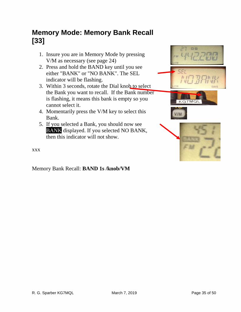
Memory Mode: Memory Bank Recall [33]
1. Insure you are in Memory Mode by pressing
V/M as necessary (see page 24)
2. Press and hold the BAND key until you see
either "BANK" or "NO BANK". The SEL
indicator will be flashing.
3. Within 3 seconds, rotate the Dial knob to select
the Bank you want to recall. If the Bank number
is flashing, it means this bank is empty so you
cannot select it.
4. Momentarily press the V/M key to select this
Bank.
5. If you selected a Bank, you should now see
BANK displayed. If you selected NO BANK,
then this indicator will not show.
xxx
Memory Bank Recall: BAND 1s /knob/VM
R. G. Sparber KG7MQL March 7, 2019 Page 36 of 50
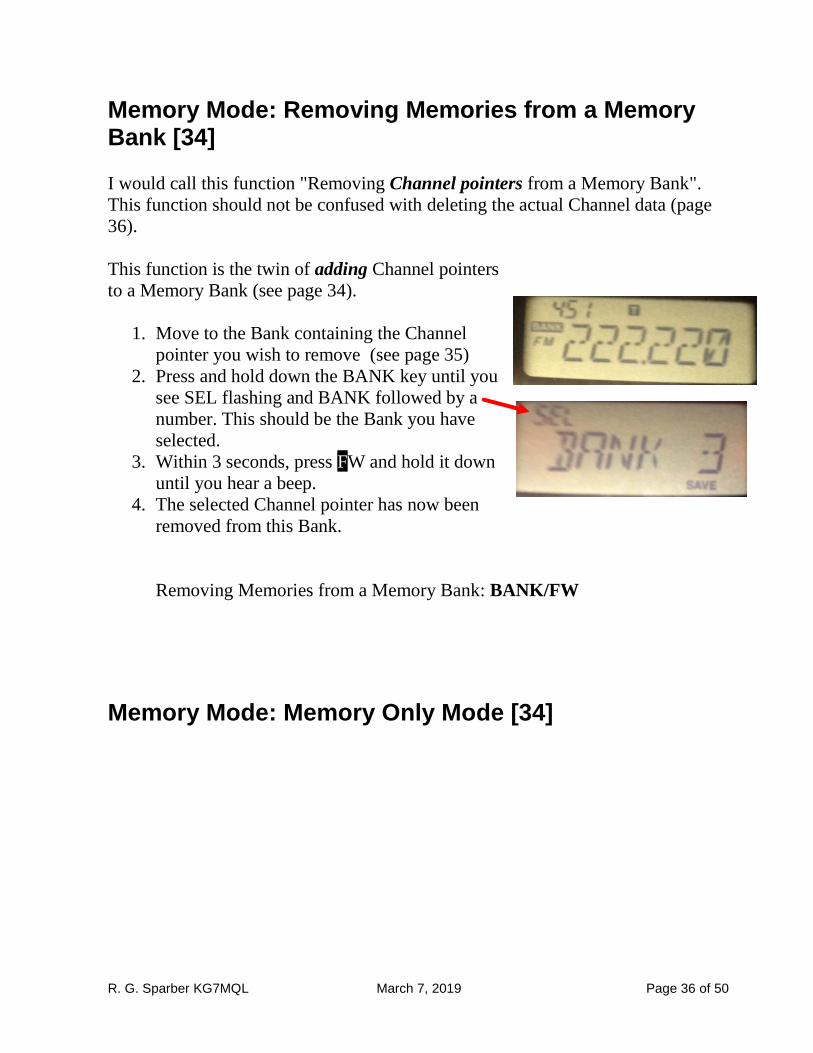
Memory Mode: Removing Memories from a Memory Bank [34]
I would call this function "Removing Channel pointers from a Memory Bank".
This function should not be confused with deleting the actual Channel data (page
36).
This function is the twin of adding Channel pointers
to a Memory Bank (see page 34).
1. Move to the Bank containing the Channel
pointer you wish to remove (see page 35)
2. Press and hold down the BANK key until you
see SEL flashing and BANK followed by a
number. This should be the Bank you have
selected.
3. Within 3 seconds, press FW and hold it down
until you hear a beep.
4. The selected Channel pointer has now been
removed from this Bank.
Removing Memories from a Memory Bank: BANK/FW
Memory Mode: Memory Only Mode [34]
R. G. Sparber KG7MQL March 7, 2019 Page 37 of 50
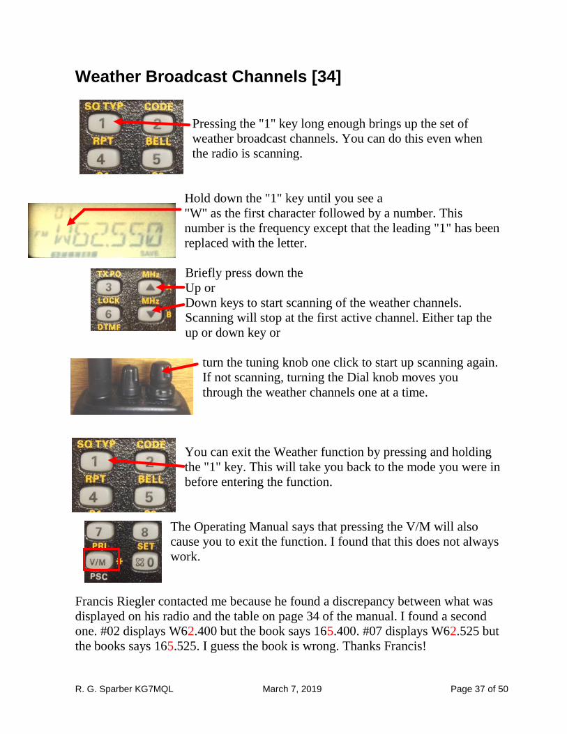
Weather Broadcast Channels [34]
Pressing the "1" key long enough brings up the set of
weather broadcast channels. You can do this even when
the radio is scanning.
Hold down the "1" key until you see a
"W" as the first character followed by a number. This
number is the frequency except that the leading "1" has been
replaced with the letter.
Briefly press down the
Up or
Down keys to start scanning of the weather channels.
Scanning will stop at the first active channel. Either tap the
up or down key or
turn the tuning knob one click to start up scanning again.
If not scanning, turning the Dial knob moves you
through the weather channels one at a time.
You can exit the Weather function by pressing and holding
the "1" key. This will take you back to the mode you were in
before entering the function.
The Operating Manual says that pressing the V/M will also
cause you to exit the function. I found that this does not always
work.
Francis Riegler contacted me because he found a discrepancy between what was
displayed on his radio and the table on page 34 of the manual. I found a second
one. #02 displays W62.400 but the book says 165.400. #07 displays W62.525 but
the books says 165.525. I guess the book is wrong. Thanks Francis!
R. G. Sparber KG7MQL March 7, 2019 Page 38 of 50
Scanning [35] The Operating Manual says that when the scanning function stops when an active
channel is found and you are then able to talk to the station if desired. This
depends on frequency. The Specifications [79] show the wide range of receive
frequencies and the relatively narrow range of transmit frequencies.
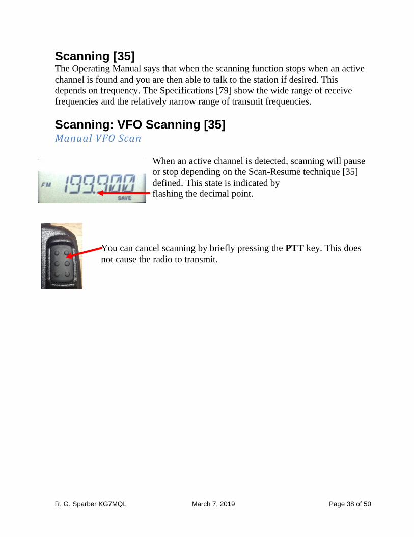
Scanning: VFO Scanning [35] Manual VFO Scan
When an active channel is detected, scanning will pause
or stop depending on the Scan-Resume technique [35]
defined. This state is indicated by
flashing the decimal point.
You can cancel scanning by briefly pressing the PTT key. This does
not cause the radio to transmit.
R. G. Sparber KG7MQL March 7, 2019 Page 39 of 50
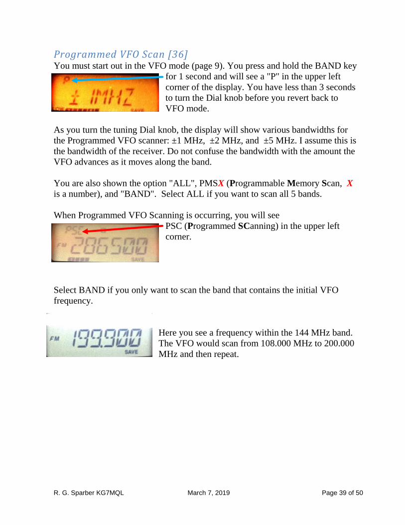
Programmed VFO Scan [36] You must start out in the VFO mode (page 9). You press and hold the BAND key
for 1 second and will see a "P" in the upper left
corner of the display. You have less than 3 seconds
to turn the Dial knob before you revert back to
VFO mode.
As you turn the tuning Dial knob, the display will show various bandwidths for
the Programmed VFO scanner: ±1 MHz, ±2 MHz, and ±5 MHz. I assume this is
the bandwidth of the receiver. Do not confuse the bandwidth with the amount the
VFO advances as it moves along the band.
You are also shown the option "ALL", PMSX (Programmable Memory Scan, X
is a number), and "BAND". Select ALL if you want to scan all 5 bands.
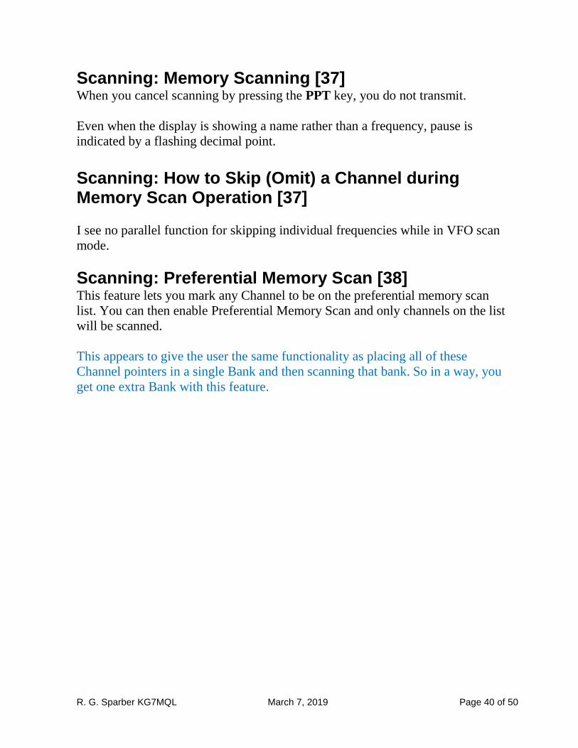
When Programmed VFO Scanning is occurring, you will see
PSC (Programmed SCanning) in the upper left
corner.
Select BAND if you only want to scan the band that contains the initial VFO
frequency.
Here you see a frequency within the 144 MHz band.
The VFO would scan from 108.000 MHz to 200.000
MHz and then repeat.
R. G. Sparber KG7MQL March 7, 2019 Page 40 of 50
Scanning: Memory Scanning [37] When you cancel scanning by pressing the PPT key, you do not transmit.
Even when the display is showing a name rather than a frequency, pause is
indicated by a flashing decimal point.
Scanning: How to Skip (Omit) a Channel during Memory Scan Operation [37]
I see no parallel function for skipping individual frequencies while in VFO scan
mode.
Scanning: Preferential Memory Scan [38] This feature lets you mark any Channel to be on the preferential memory scan
list. You can then enable Preferential Memory Scan and only channels on the list
will be scanned.
This appears to give the user the same functionality as placing all of these
Channel pointers in a single Bank and then scanning that bank. So in a way, you
get one extra Bank with this feature.
R. G. Sparber KG7MQL March 7, 2019 Page 41 of 50
Scanning: Memory Bank Scan [39]
I would call this Memory Bank Link Scan. If you just want to know how to do
Memory Bank Scanning, see page 40 and [37].
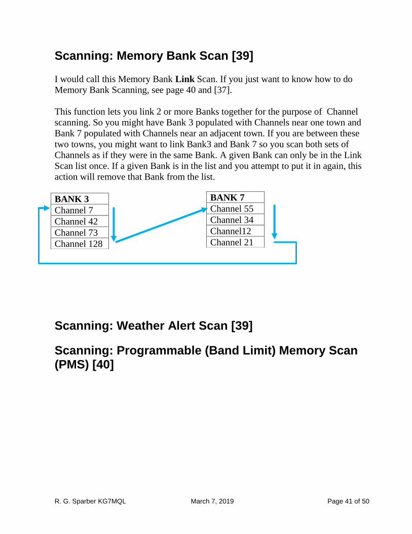
This function lets you link 2 or more Banks together for the purpose of Channel
scanning. So you might have Bank 3 populated with Channels near one town and
Bank 7 populated with Channels near an adjacent town. If you are between these
two towns, you might want to link Bank3 and Bank 7 so you scan both sets of
Channels as if they were in the same Bank. A given Bank can only be in the Link
Scan list once. If a given Bank is in the list and you attempt to put it in again, this
action will remove that Bank from the list.
Scanning: Weather Alert Scan [39]
Scanning: Programmable (Band Limit) Memory Scan (PMS) [40]
BANK 3
Channel 7
Channel 42
Channel 73
Channel 128
BANK 7
Channel 55
Channel 34
Channel12
Channel 21
R. G. Sparber KG7MQL March 7, 2019 Page 42 of 50
Scanning: "Priority Channel" Scanning (Dual Watch) [41] While primarily monitoring one Channel, you can periodically check another
channel for activity.
VFO Priority 1. See page 24 for how to recall a memory channel.
2. Briefly press V/M and you should go to VFO mode
3. Briefly press FW and the briefly press V/M
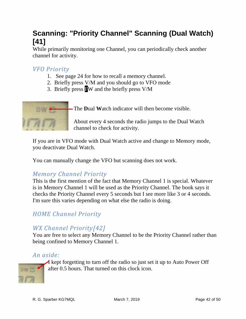
The Dual Watch indicator will then become visible.
About every 4 seconds the radio jumps to the Dual Watch
channel to check for activity.
If you are in VFO mode with Dual Watch active and change to Memory mode,
you deactivate Dual Watch.
You can manually change the VFO but scanning does not work.
Memory Channel Priority This is the first mention of the fact that Memory Channel 1 is special. Whatever
is in Memory Channel 1 will be used as the Priority Channel. The book says it
checks the Priority Channel every 5 seconds but I see more like 3 or 4 seconds.
I'm sure this varies depending on what else the radio is doing.
HOME Channel Priority
WX Channel Priority[42] You are free to select any Memory Channel to be the Priority Channel rather than
being confined to Memory Channel 1.
An aside: I kept forgetting to turn off the radio so just set it up to Auto Power Off
after 0.5 hours. That turned on this clock icon.
R. G. Sparber KG7MQL March 7, 2019 Page 43 of 50
Scanning: Priority Revert Mode [42] You must be in Dual Watch mode in order to use this function. Note that the
setting is entered by pressing PTT.
Scanning: Automatic Lamp Illumination on Scan Stop [43] Note that the setting is entered by pressing PTT.
Scanning: Band Edge Beeper [43] Note that the setting is entered by pressing PTT.
EPCS (Enhanced Paging and Code Squelch) [44] Storing the CTCSS Tone Pairs for EPCS Operation Activating the Enhanced Paging and Code Squelch System Paging Answer Back
Emergency Features: Emergency Channel Operation [46] Emergency Automatic ID (EAI) Feature[46,47]
Smart Search Operation [48] Setting the Smart Search Mode [48] Storing Smart Search Memories
R. G. Sparber KG7MQL March 7, 2019 Page 44 of 50
Internet Connection Feature [49] I have heard a lot of interest in this feature but it is always related to how to turn
off WiRes™. The most detailed instructions can be found at
http://wa3fkg.blogspot.com/2010/02/something-every-ft-60-owner-should-know.html
The basic idea is to first insure that the memory location used to hold the
transmitted DTMF string is empty. Then tell the software to use this memory
location when WiRES is active. So if WiRES is not active, no harm done. If it
accidently gets activated, no tones are transmitted.
It is not clear if you still get the initial 0.1 second blanking at the start of the
transmission if there is nothing to transmit.
ARTS™ (Automatic Range Transponder System) [51] Basic ARTS Setup and Operation
ARTS Polling Time Options [52]
ARTS Alert Beep Option [52]
CW Identifier Setup [53] This feature of ARTS automatically transmits your call sign in CW every 10
minutes. Too bad it only works if ARTS is active.
Reset Procedure [64] There are a total of 4 levels of reset. The lowest level resets the Set Menu mode
data to factory defaults. The highest level clears everything.
If you have all radio data stored on a PC and can restore via a cable, then you
might as well clear everything first. But if you must manually input data, I
recommend you start with the lowest level reset, see if that fixed the problem,
and escalate as needed.
Jack Travis suggested removing the battery from the radio (for a few seconds)
and then putting it back in. He has found that this solves 90% of his errant
software behavior problems.

R. G. Sparber KG7MQL March 7, 2019 Page 45 of 50
Acknowledgments
Thanks to the following people for making suggestions and corrections to this
guide: Brian Scott (N0PGH),Jardy Dawson (WA7JRD), Jack Travis (AE8P),
Sam Cook (ACØOK/R), David Audley (KB3DRA), Dale Martin (KG5U) and
Jeff Vanderklipp (N8OSS). Thanks to Nicole Crosby (N7XBY) for reading the
guide so closely that she found typos no others saw. Thanks to Francis Riegler
for finding the discrepancy between what is displayed for weather radio
frequencies and what is shown on page 34 of the manual.
Thanks to Dennis Bruna (K0DGB) for the suggestion to put my contact
information where it would be easy to find.
Thanks to Gustavo Merle for pointing out that the table of contents was "dead"
and providing a way to fix it.
Thanks to Dean Herrington for finding typos and suggesting improvements to
clarity.
Thanks to Ernie Murphy (NH7L) for pointing out a clarity issue.
Thanks to Geof Schwer for finding a typo that has been there since day 1.
I welcome your comments and questions.
If you wish to be contacted each time I update this guide, email me with just
"FT-60 Alias" in the subject line.
Rick Sparber
Rick.Sparber.org
R. G. Sparber KG7MQL March 7, 2019 Page 46 of 50
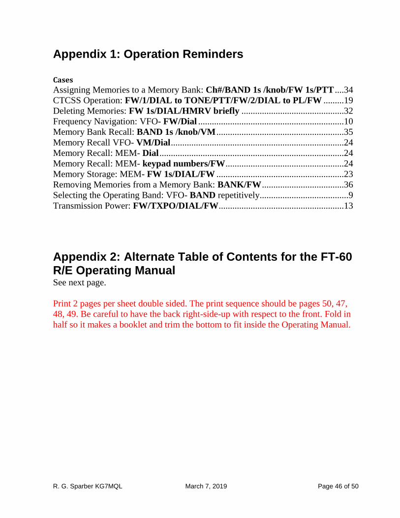
Appendix 1: Operation Reminders
Cases
Assigning Memories to a Memory Bank: Ch#/BAND 1s /knob/FW 1s/PTT ....34
CTCSS Operation: FW/1/DIAL to TONE/PTT/FW/2/DIAL to PL/FW .........19
Deleting Memories: FW 1s/DIAL/HMRV briefly .............................................32
Frequency Navigation: VFO- FW/Dial ................................................................10
Memory Bank Recall: BAND 1s /knob/VM ........................................................35
Memory Recall VFO- VM/Dial ............................................................................24
Memory Recall: MEM- Dial .................................................................................24
Memory Recall: MEM- keypad numbers/FW ....................................................24
Memory Storage: MEM- FW 1s/DIAL/FW ........................................................23
Removing Memories from a Memory Bank: BANK/FW ....................................36
Selecting the Operating Band: VFO- BAND repetitively....................................... 9
Transmission Power: FW/TXPO/DIAL/FW .......................................................13
Appendix 2: Alternate Table of Contents for the FT-60 R/E Operating Manual See next page.
Print 2 pages per sheet double sided. The print sequence should be pages 50, 47,
48, 49. Be careful to have the back right-side-up with respect to the front. Fold in
half so it makes a booklet and trim the bottom to fit inside the Operating Manual.
R. G. Sparber KG7MQL March 7, 2019 Page 47 of 50
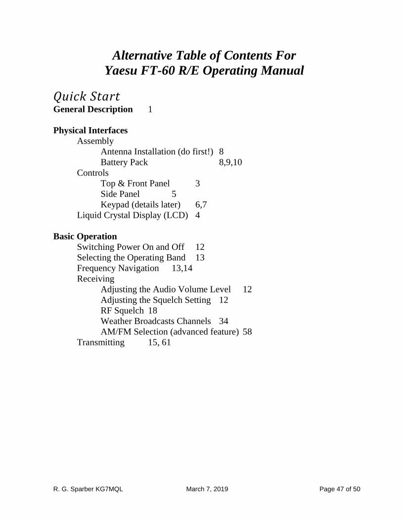
Alternative Table of Contents For
Yaesu FT-60 R/E Operating Manual
Quick Start General Description 1
Physical Interfaces
Assembly
Antenna Installation (do first!) 8
Battery Pack 8,9,10
Controls
Top & Front Panel 3
Side Panel 5
Keypad (details later) 6,7
Liquid Crystal Display (LCD) 4
Basic Operation
Switching Power On and Off 12
Selecting the Operating Band 13
Frequency Navigation 13,14
Receiving
Adjusting the Audio Volume Level 12
Adjusting the Squelch Setting 12
RF Squelch 18
Weather Broadcasts Channels 34
AM/FM Selection (advanced feature) 58
Transmitting 15, 61
R. G. Sparber KG7MQL March 7, 2019 Page 48 of 50
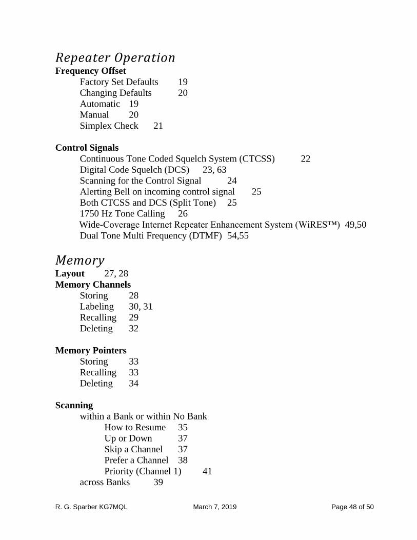
Repeater Operation Frequency Offset
Factory Set Defaults 19
Changing Defaults 20
Automatic 19
Manual 20
Simplex Check 21
Control Signals
Continuous Tone Coded Squelch System (CTCSS) 22
Digital Code Squelch (DCS) 23, 63
Scanning for the Control Signal 24
Alerting Bell on incoming control signal 25
Both CTCSS and DCS (Split Tone) 25
1750 Hz Tone Calling 26
Wide-Coverage Internet Repeater Enhancement System (WiRES™) 49,50
Dual Tone Multi Frequency (DTMF) 54,55
Memory Layout 27, 28
Memory Channels
Storing 28
Labeling 30, 31
Recalling 29
Deleting 32
Memory Pointers
Storing 33
Recalling 33
Deleting 34
Scanning
within a Bank or within No Bank
How to Resume 35
Up or Down 37
Skip a Channel 37
Prefer a Channel 38
Priority (Channel 1) 41
across Banks 39
R. G. Sparber KG7MQL March 7, 2019 Page 49 of 50
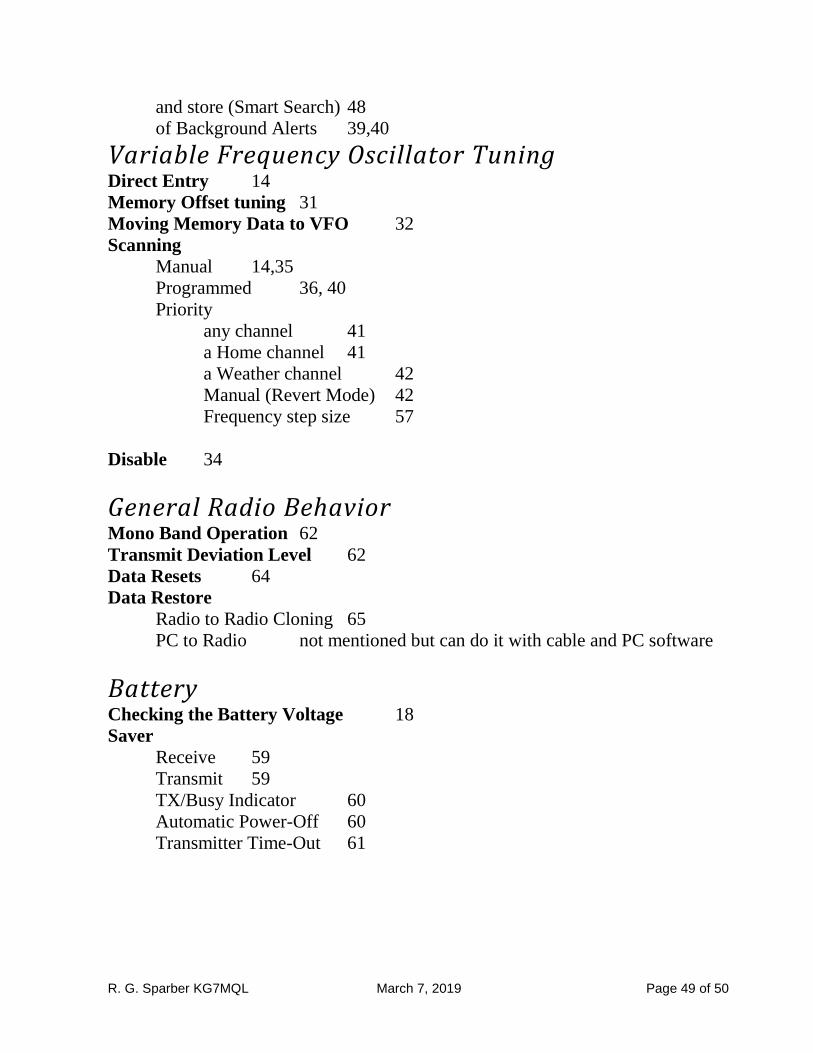
and store (Smart Search) 48
of Background Alerts 39,40
Variable Frequency Oscillator Tuning Direct Entry 14
Memory Offset tuning 31
Moving Memory Data to VFO 32
Scanning
Manual 14,35
Programmed 36, 40
Priority
any channel 41
a Home channel 41
a Weather channel 42
Manual (Revert Mode) 42
Frequency step size 57
Disable 34
General Radio Behavior Mono Band Operation 62
Transmit Deviation Level 62
Data Resets 64
Data Restore
Radio to Radio Cloning 65
PC to Radio not mentioned but can do it with cable and PC software
Battery Checking the Battery Voltage 18
Saver
Receive 59
Transmit 59
TX/Busy Indicator 60
Automatic Power-Off 60
Transmitter Time-Out 61
R. G. Sparber KG7MQL March 7, 2019 Page 50 of 50
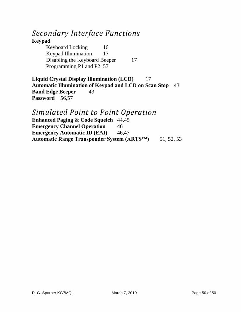
Secondary Interface Functions Keypad
Keyboard Locking 16
Keypad Illumination 17
Disabling the Keyboard Beeper 17
Programming P1 and P2 57
Liquid Crystal Display Illumination (LCD) 17
Automatic Illumination of Keypad and LCD on Scan Stop 43
Band Edge Beeper 43
Password 56,57
Simulated Point to Point Operation Enhanced Paging & Code Squelch 44,45
Emergency Channel Operation 46
Emergency Automatic ID (EAI) 46,47
Automatic Range Transponder System (ARTS™) 51, 52, 53