Embed Size (px)
Citation preview

21
A Biomedical Application by Using Optimal Fuzzy Sliding-Mode Control
Bor-Jiunn Wen Center for Measurement Standards,
Industrial Technology Research Institute Hsinchu, Taiwan, R.O.C.
1. Introduction
The development of biochips is a major thrust of the rapidly growing biotechnology industry. Research on biomedical or biochemical analysis miniaturization and integration has made explosive progress by using biochips recently. For example, capillary electrophoresis (CE), sample preconcentration, genomic DNA extraction, and DNA hybridization have been successfully miniaturized and operated in a single-step chip. However, there is still a considerable technical challenge in integrating these procedures into a multiple-step system. In biometric and biomedical applications, the special transporting mechanism must be designed for the μTAS (micro total analysis system) to move samples and reagents through the microchannels that connect the unit procedure components in the system. Therefore, an important issue for this miniaturization and integration is microfluid management technique, i.e., microfluid transportation, metering, and mixing. This charter introduced a method to achieve the microfluidic manipulated implementation on biochip system with a pneumatic pumping actuator and a feedback-signal flowmeter by using an optimal fuzzy sliding-mode control (OFSMC) design based on the 8051 microprocessor. However, the relationships of the pumping mechanisms, the operating conditions of the devices, and the transporting behavior of the multi-component fluids in these channels are quite complicated. Because the main disadvantages of the mechanical valves utilized moving parts are the complexity and expense of fabrication, and the fragility of the components. Therefore, a novel recursively-structured apparatus of valveless microfluid manipulating method based on a pneumatic pumping mechanism has been utilized in this study. The working principle of this pumping design on this device should not directly relate to the nature of the fluid components. The driving force acting on the microliquid drop in the microchannel of this device is based on the pneumatic pumping which is induced by a blowing airflow. Furthermore, the pneumatic pumping actuator should be independent of the actuation responsible for the biochemical analysis on the chip system, so the contamination of pneumatic pumping source can be avoided. The total biochip mechanism consists of an external pneumatic actuator and an on-chip planar structure for airflow reception. In order to achieve microfluidic manipulation in the microchannel of the biochip system, pneumatic pumping controller plays an important role. Therefore, a design of the controller
www.intechopen.com
Sliding Mode Control
410
has been investigated numerically and experimentally in the present charter. In the control structure of biochip system, at first, the mathematical model of the biochip mechanism is identified by ARX model. Second, according to the results of the biochip-mechanism identification, the control-algorithm design is developed. By the simulation results of the biochip system with a feedback-signals flowmeter, they show the effectiveness of the developed control algorithm. Third, architecture of the control algorithm is integrated on a microprocessor to implement microfluidic manipulation. Since the mathematical model of the flow control mechanism in the biochip microchannels is a complicated nonlinear plant, the fuzzy logic control (FLC) design of the controller will be utilized. Design of the FLC based on the fuzzy set theory has been widely applied to consumer products or industrial process controls. In particular, they are very effective techniques for complicated, nonlinear, and imprecise plants for which either no mathematical model exists or the mathematical model is severely nonlinear. The FLC can approximate the human expert’s control behaviors to work fine in such ill-defined environments. For some applications, the FLC can be divided into two classes 1) the general-purpose fuzzy processor with specialized fuzzy computations and 2) the dedicated fuzzy hardware for specific applications. Because the general-purpose fuzzy processor can be implemented quickly and applied flexibly, and dedicated fuzzy hardware requires long time for development, the general-purpose fuzzy processor-8051 microcontroller can be used. Nevertheless, there are also systemic uncertainties and disturbance in FLC controller. Because sliding-mode control (SMC) had been known as an effective approach to restrain the systemic uncertainties and disturbance, SMC algorithm was utilized. In order to achieve a robust control system, the microcontroller of the biochip system combining FLC and SMC algorithms optimally has been developed. Therefore, an OFSMC based on an 8051 microcontroller has been investigated numerically and experimentally in this charter. Hence, microfluidic manipulation in the microchannel of the biochip system based on OFSMC has been implemented by using an 8051 microcontroller. The microfluidic manipulation based on the microcontroller has successfully been utilized to improve the reaction efficiency of molecular biology. First, it was used in DNA hybridization. There are two methods to improve the efficiency of the nucleic acid hybridization in this charter. The first method is to increase the velocity of the target nucleic acid molecules, which increases the effective collision into the probe molecules as the target molecules flow back and forth. The second method is to introduce the strain rates of the target mixture flow on the hybridization surface. This hybridization chip was able to increase hybridization signal 6-fold, reduce non-specific target-probe binding and background noises within 30 minutes, as compared to conventional hybridization methods, which may take from 4 hours to overnight. Second, it was used in DNA extraction. When serum existed in the fluid, the extraction efficiency of immobilized beads with solution flowing back and forth was 88-fold higher than that of free-beads. Third, it could be integrated in lab-on-a-chip. For the Tee-connected channels, it demonstrated the ability of manipulating the liquid drop from a first channel to a second channel, while simultaneously preventing flow into the third channel. Because there is a continuous airflow at the “outlet” during fluid manipulation, it can avoid contamination of the air source similar to the “laminar flow hook” in biological experiments. The charter is organized as follows. In Section 2, we introduce the structure of the biochip control system. In Section 3, the fundamental knowledge of OFSMC and the model of the biochip system are introduced, and we address the OFSMC scheme and the associated
www.intechopen.com

A Biomedical Application by Using Optimal Fuzzy Sliding-Mode Control
411
simulations. In Section 4, the OFSMC IC based on 8051 microprocessor is designed, and the results of the real-time experiment are presented. In Section 5, the efficiency improvement for the molecular biology reaction and DNA extraction by using OFSMC method are presented. Finally, the conclusion is given in Section 6.
2. Structure of the biochip control system
The structure of the biochip control system (Fig. 1) contains six parts: an air compressor, two flow controllers and two flowmeters, a flow-control chip, a biochip, photodiodes system, and a control-chip circuit system. One had designed a pneumatic device with planar structures for microfluidic manipulation (Chung, Jen, Lin, Wu & Wu, 2003). Pneumatic devices without any microfabricated electrodes or heaters, which will have a minimal effect on the biochemical properties of the microfluid by not generating electrical current or heat, are most suitable for µTAS. A pneumatic structure possessing the ability of bi-directional pumping should be utilized in order to implement a pneumatic device which can control the movement of microfluid without valves or moving parts.
8051
Feedback signalsControl-input signals
ADCDAC
CONTROL CIRCUIT
flowmeterFlow controller Flow Control Chip
Biochip
Feedback-Signal
Process of Photodiode
System
IR
IR
PD2
Air Compressor
Buffer Tank
PD1
Fig. 1. Structure of the biochip control system.
The schematic diagram of the single pneumatic structure, which provides suction and exclusion by two inlets, is depicted in Fig. 2. When the air flows through inlet A only, it causes a low-pressure zone behind the triangular block and suction occurs in the vertical microchannel. Furthermore, when the air flows through inlet B only, the airflow is induced into the vertical microchannel to generate exclusion. The numerical and experimental results of the pressure and the stream tracers for the condition of the flow-control chip have been demonstrated (Marquardt, 1963). According to the principle of the flow-control chip, the microfluidic manipulation on the biochip is presented in this study by using OFSMC rules
www.intechopen.com

Sliding Mode Control
412
with two flow controllers and two flowmeters. Since the biochip in the biochip system is a consumer, the photodiodes system should be utilized for sensing the feedback signals of the position of the reagent in the microchannel of the biochip. Hence, DNA extraction can be achieved in this study.
Inlet A
Inlet B
QA
QB
Suction
2.0
2.0
2.0
3.0
20.024.0
Y=4.0
Unit: mmExclusion
Fig. 2. Single pneumatic structure.
3. Design of the biochip control system
3.1 Design of optimal fuzzy sliding mode control
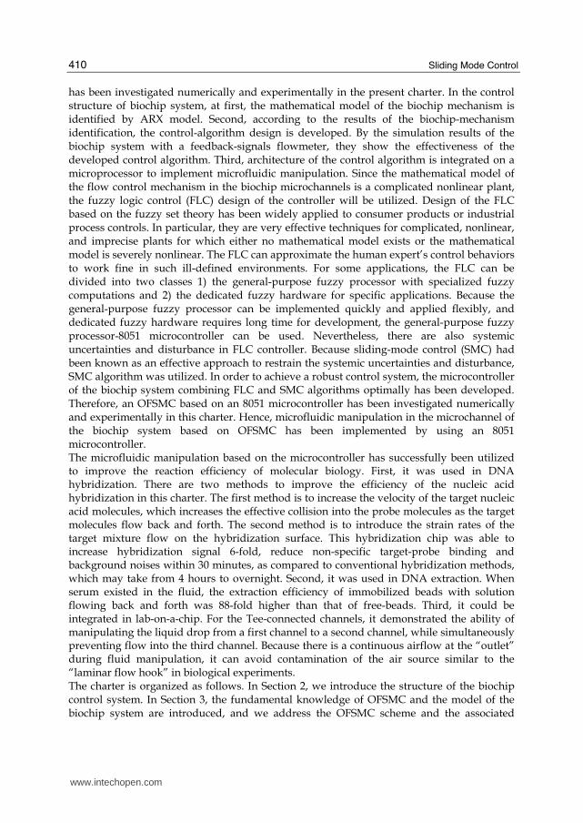
The biochip system of this design is shown in Fig. 1. If the biochip is DNA extraction chip, the extraction beads are immobilized on the channels. When the bio-fluidics does not flow the place without beads, the time of not extracting DNA can be reduced, and the extraction efficiency will also be improved. So the control of bio-fluidics’ location is critical to DNA extraction (or hybridization) efficiency. The biochip system depicted in Fig. 1 is a nonlinear system. Since the mathematical model of the flow-control mechanism and the microchannels in the biochip is a complicated nonlinear model, FLC design of the controller was utilized. The basic idea behind FLC is to incorporate the expert experience of a human operator in the design of the controller in controlling a process whose input-output relationship is described by a collection of fuzzy control rules (Altrock, Krause & Zimmermann, 1992). The heart of the fuzzy control rules is a knowledge base consisting of the so-called fuzzy IF-THEN rules involving linguistic variables rather than a complicated dynamic model. The typical architecture of a FLC, shown in Fig. 3, is comprised of four principal components: a fuzzification interface, a knowledge base, an inference engine, and defuzzification interface. The fuzzification interface has the effect of transforming crisp measured data into suitable linguistic values; it was designed first so that further fuzzy inferences could be performed according to the fuzzy rules (Polkinghorne, Roberts, Burns & Winwood, 1994). The heart of the fuzzification interface is the design of membership function. There are many kinds of membership
www.intechopen.com
A Biomedical Application by Using Optimal Fuzzy Sliding-Mode Control
413
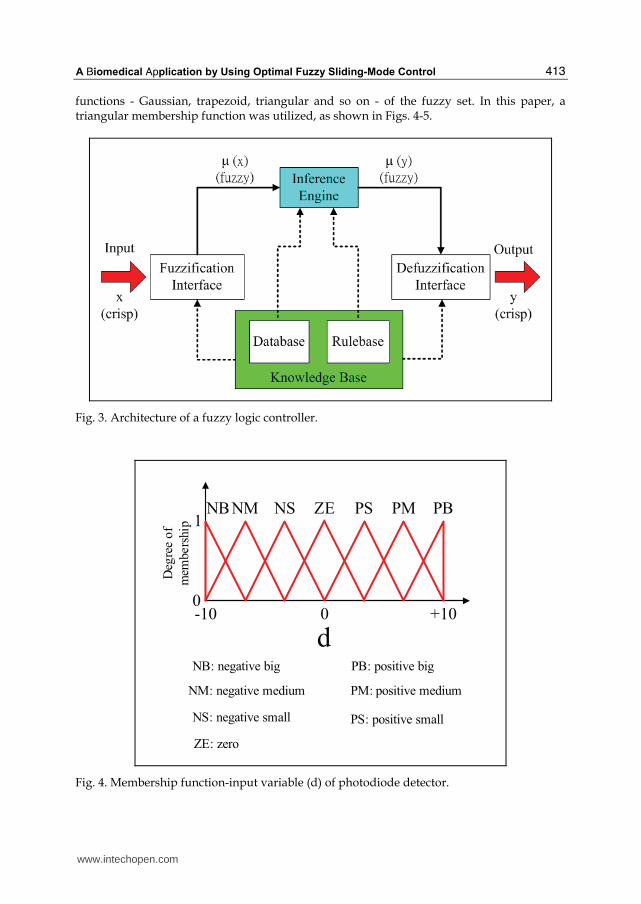
functions - Gaussian, trapezoid, triangular and so on - of the fuzzy set. In this paper, a triangular membership function was utilized, as shown in Figs. 4-5.
Fig. 3. Architecture of a fuzzy logic controller.
0 +10-10
NBNM NS ZE PS PM PB
NB: negative big
NM: negative medium
NS: negative small
ZE: zero
PB: positive big
PM: positive medium
PS: positive small
d
1
Deg
ree o
f
mem
bers
hip
0
Fig. 4. Membership function-input variable (d) of photodiode detector.
www.intechopen.com

Sliding Mode Control
414
5 100
MNB MNM MNS M MPS MPM MPB
MNB: medium negative big
MNM: medium negative medium
MNS: medium negative small
M: medium
MPB: medium positive big
MPM: medium positive medium
MPS: medium positive small
z0
1D
egre
e of
mem
eber
ship
Fig. 5. Membership function-output variable (z) of photodiode detector.
The overall fuzzy rules for the biochip system are defined as the following:
IF d is NB then jz is MPB
IF d is NM then jz is MPM
IF d is NS then jz is MPS
IF d is ZE then jz is M
IF d is PS then jz is MNS
IF d is PM then jz is MNM
IF d is PB then jz is MNB
where d is input variable of the photodiode signal, and z is output variable of the
photodiode signal.
The inference engine is based on the compositional rule of inference with knowledge base
for approximate reasoning suggested by Zadeh (Zadeh, 1965; Zadeh, 1968). An inference
engine is the kernel of the FLC in modeling human decision making within the conceptual
framework of fuzzy logic and reasoning. Hence, the fuzzification interface and fuzzy rules
are designed completely before fuzzy reasoning. In this paper, since there are many
structures of inference engine, fuzzy reasoning-Mamdani’s minimum fuzzy implication rule
(MMFIR) method (Mamdani, 1977; Lee, 1990; Altrock, Krause & Zimmermann, 1992; Lin
and Lee, 1999) was utilized. For simplicity, assume two fuzzy rules as follows:
R1: IF x is A1 and y is B1, then z is C1,
R2: IF x is A2 and y is B2, then z is C2.
www.intechopen.com

A Biomedical Application by Using Optimal Fuzzy Sliding-Mode Control
415
Then the firing strengths 1α and 2α of the first and second rules may be expressed as
1 11 0 0( ) ( )A Bx yα μ μ= ∧ and 2 22 0 0( ) ( )A Bx yα μ μ= ∧ ,
where 1 0( )A xμ and
1 0( )B yμ indicate the degrees of partial match between the user-supplied
data and the data in the fuzzy rule base. In MMFIR fuzzy resoning, the ith fuzzy control rule leads to the control decision
' ( ) ( )ii
i CCw wμ α μ= ∧ .
The final inferred consequent C is given by
' '1 21 2
1 2( ) [ ( )] [ ( )]C C CC Cw w wμ μ μ α μ α μ= ∨ = ∧ ∨ ∧ .
The fuzzy reasoning process is illustrated in Fig. 6.
1
1
1
1
1
1
10 0
00
0
0
0
X
X Y
Y Z
Z
Z
x0 y0
A1
A2
B1
B2
C1
C2
Cμ
2Cμ
1Cμ
2Bμ
1Bμ
2Aμ
1Aμ
min
Fig. 6. Fuzzy reasoning of MMFIR method.
Defuzzification is a mapping from a space of fuzzy control actions defined over an output
universe of discourse into a space of crisp control actions. This process is necessary because
fuzzy control actions cannot be utilized in controlling the plant for practical applications.
Hence, the widely used center of area (COA) method, which generates the center of gravity
of the possibility distribution of a control action, was utilized. In the case of a discrete
universe, this method yields
1
1
( )
( )
nC j jj
COA nC jj
z zz
z
μμ
==
=∑∑ (1)
where n is the number of quantization levels of the output, jz is the amount of control
output at the quantization level j, and ( )C jzμ represents its membership degree in the
output fuzzy set C.
www.intechopen.com

Sliding Mode Control
416
The biochip system depicted in Fig. 1 is a nonlinear system that has been used as an
application to study real world nonlinear control problems by different control techniques
(Cheng & Li, 1998; Li & Shieh, 2000). The model of the biochip system is identified by ARX
model, as
( 1) ( ) ( )
( ) ( )z z
z
X k A X k B u k
y k C X k
+ = +⎧⎨ =⎩ (2)
where ( ) nX k R∈ is the state variables of system, ( ) mu k R∈ is the input voltage of the flow
controller and ( ) ry k R∈ is the assumed model output related to the position of the reagent
in the microchannel of the biochip. The system is controllable and observable. Sliding mode control’s robust and disturbance-insensitive characteristics enable the SMC
controller to perform well in systems with model uncertainty, disturbances and noises. In
this paper, in addition to FLC controller, SMC controller was utilized to design the control
input voltage of the flow controller. To design SMC controllers, a sliding function was
designed first, and then enforced a system trajectory to enter sliding surface in a finite time.
As soon as the system trajectory entered the sliding surface, they moved the sliding surface
to a control goal. To sum up, there are two procedures of sliding mode, as shown in Fig. 7.
X(0)
X(th)Touch super
space in a finite tim e th
Super space
S(X)=0
Control goal point X(∞ )=0
Approaching
m ode
Sliding m ode
Fig. 7. Generation of sliding mode.
The proposed SMC controller was based on pole placement (Chang, 1999), since the sliding
function could be designed by pole placement. Some conditions were set for the sliding
vector design in the proposed sliding mode control:
1. { }Re 0iλ < , j Rα ∈ , 0jα < , j iα λ≠ .
2. Any eigenvalue in { }1 ,..., mα α is not in the spectrum of zA .
3. The number of any repeated eigenvalues in { }1 1,..., , ,...,n m mλ λ α α− is not greater than m,
the rank of zB .
where { }1 2, ,..., n mλ λ λ − are sliding-mode eigenvalues and { }1 2, ,..., mα α α are virtual
eigenvalues.
www.intechopen.com

A Biomedical Application by Using Optimal Fuzzy Sliding-Mode Control
417
As proved by Sinswat and Fallside (Sinswat & Fallside, 1977), if the condition (3) in the
above is established, the control system matrix z zA B K− can be diagonalized as
10
0V
z zF
V VA B K
F F
− Φ⎡ ⎤ ⎡ ⎤ ⎡ ⎤− = ⎢ ⎥ ⎢ ⎥ ⎢ ⎥Γ⎣ ⎦ ⎣ ⎦ ⎣ ⎦ (3)
where [ ]1 2, ,...,V n mdiag λ λ λ −Φ = , [ ]1 2, ,...,F mdiag α α αΓ = , and V and F are left eigenvectors
with respect to VΦ and FΓ , respectively. Hence, Eq. (3) can be rewritten as
( )
( )z z V
z z F
V A B K V
F A B K F
− = Φ⎧⎨ − = Γ⎩ (4)
Rearrangement of Eq. (4) yields
( )z F zFA F FB K− Γ = (5)
According to Chang (Chang, 1999),
( ) ( )z Frank FA F rank F− Γ = (6)
Since F contains m independent left eigenvectors, one has ( )rank F m= . From Eqs. (5) and
(6), it is also true that ( )z Frank FA F− Γ = (( ) )zrank Fb K = ( )rank F m= . In other words, zFB is
invertible. With the designed left eigenvector F above, the sliding function ( )S k is designed
as
( ) ( )S k FX k= (7)
The second step is the discrete-time switching control design. A different and much more expedient approach than that of Gao et al. (Gao, Wang & Homaifa, 1995) is adopted here. This approach is called the reaching law approach that has been proposed for continuous variable structure control (VSC) systems (Gao, 1990; Hung, Gao & Hung, 1993; Gao & Hung, 1993). This control law is synthesized from the reaching law in conjunction with a plant model and the known bounds of perturbations. For a discrete-time system, the reaching law is (Gao, Wang & Homaifa, 1995)
( 1) ( ) ( ) sgn( ( ))S k S k qTS k T S kε+ − = − − (8)
where 0T > is the sampling period, 0q > , 0ε > and 1 0qT− > . Therefore, the switching
control law for the discrete-time system is derived based on this reaching law. From Eq. (7)
and pole-placement method, ( )S k and ( 1)S k + can be obtained in terms of sliding vector F
as,
( ) ( )
( 1) ( 1) ( ) ( ) ( )z z z
S k FX k
S k FX k F A B K X k FB u k
=⎧⎨ + = + = − +⎩ (9)
where nK R∈ is a gain matrix obtained by assigning n desired eigenvalues { }1 1,..., , ,...,n m mλ λ α α− of A BK− . It follows that
www.intechopen.com

Sliding Mode Control
418
( 1) ( ) ( ) ( ) ( ) ( )z z zS k S k F A B K X k FB u k FX k+ − = − + − (10)
From Eqs. (8) and (10),
( 1) ( ) ( ) sgn( ( ))S k S k qTS k T S kε+ − = − − ( ) ( ) ( ) ( )z z zF A B K X k FB u k FX k= − + −
Solving for ( )u k obtains the switching control law
1( ) ( ) [ ( ) ( ) ( 1) ( ) sgn( ( ))]z z zu k FB F A B K X k qT FX k T FX kε−= − − + − + (11)
In order to achieve the output tracking control, a reference command input ( )r k is
introduced into the system by modifying the state feedback control law ( ) ( )pu k KX k= − with
pole-placement design method (Franklin, Powell & Workman, 1998) to become
( ) ( ) ( ( ) ( ))p u xu k N r k K X k N r k= − − (12)
where
10
0u z z
x z
N A I B
N C I
−−⎡ ⎤ ⎡ ⎤ ⎡ ⎤=⎢ ⎥ ⎢ ⎥ ⎢ ⎥⎣ ⎦ ⎣ ⎦ ⎣ ⎦ (13)
The proposed SMC input, based on Eq. (13), is assumed to be
( ) ( ) ( ) ( ( ) ( ))s p u xu k u k u N r k K X k N r k u= + = − − + (14)
Substituting Eq. (11) into (14) gives the proposed SMC input as
1
( ) ( ) ( ( ) ( ))
( ) [ ( ) ( ) ( 1) ( ) sgn( ( ))]
s u x
z z z
u k N r k K X k N r k
FB F A B K X k qT FX k T FX kε−= − −− − + − + (15)
The pole-placement SMC design method utilizes the feedback of all the state variables to form the desired sliding vector. In practice, not all the state variables are available for direct measurement. Hence, it is necessary to estimate the state variables that are not directly measurable. In practice, a discrete linear time-invariant system sometimes has system disturbances and measurement noise. Hence, linear quadratic estimator (LQE) will be applied here to estimate optimal states in having system disturbances and measurement noise. According to Eq. (2), consider a system model as
( 1) ( ) ( ) ( )
( ) ( ) ( )z z
z
X k A X k B u k G k
y k C X k k
νω
+ = + +⎧⎨ = +⎩ (16)
where ( ) nX k R∈ is the state variable, ( ) mu k R∈ is the control input voltage , '( ) ry k R∈ is
the assumed plant output related to the XY stage position, and ( ) nk Rν ∈ and ( ) rk Rω ∈ are
system disturbances and measurement noise with covariances [ ]TE Qωω = , [ ]TE Rνν = and
[ ] 0TE ων = .
The objective of LQE is to find a vector ˆ ( )X k which is an optimal estimation of the present
state ( )X k . Here “optimal” means the cost function
www.intechopen.com

A Biomedical Application by Using Optimal Fuzzy Sliding-Mode Control
419
{ }0lim ( )
T T T
TJ E X QX u Ru dt→∞= +∫ (17)
is minimized. The solution is the estimator as
^ ^ ^
^ ^
( 1) ( ) ( ) ( ( ) ( ))
( ) ( )
z z f z
z
X k A X k B u k K y k C X k
y k C X k
⎧ + = + + −⎪⎨⎪ =⎩ (18)
where fK is the “optimal Kalman” gain 1Tf zK PC R−= and P is the solution of the algebraic
Riccati equation
1 0T Tz z z zA P PA PC R C P Q−+ − + = (19)
FLC, SMC, and LQE were combined into the so called optimal fuzzy sliding-mode control
(OFSMC) and utilized to control input voltage of the flow controller. The OFSMC block
diagram with LQE is shown in Fig. 8.
PlantNu
Nx
K
+
+_
_
r(k) u(k) y'(k)
X(k)
SC
++
SC: Switching Controller
Sliding Mode Controller
~
Fuzzy controller
Z-1I
Az
Bz
Kf
+
+
+ +_y'(k)Cz
~
LQE
Fig. 8. OFSMC block diagram.
In the biochip system, the photodiode system provided the position feedback signal for FLC
and LQE. Then, the FLC could use the position feedback signals to generate the input
signals for SMC. And the LQE could estimate optimal states in having system disturbances
and measurement noise for SMC by the position feedback signals. Hence, the SMC with FLC
and LQE could implement the microfuildic manipulation very well and robustly. The
performance of the OFSMC would be explained in detail by simulation and experimental
results, which are presented in Section 3.2.
www.intechopen.com

Sliding Mode Control
420
3.2 Simulation of OFSMC
This section deals with a system model described by Eq. (2) and defines a reference command input ( )r k , which is an input voltage of the flow controller by fuzzy controller with designed photodiode signals. The pole-placement algorithm described in Section 3.1 is utilized to determine a sliding vector. In this study, Ackermann’s Formula is used to determine the pole-placement feedback gain matrix K . In practice, the fact that not all state variables are available for direct measurement results in the necessity to estimate the state variables that are not directly measurable. Hence, the full-order state observer designed by Ackermann’s Formula and LQE will be utilized in this study. In order to achieve the biochip application, the microfluidic reagent has to be manipulated to flow back and forth in the central zone of the microchannel between the PD1 and PD2, shown in Fig. 1. During the simulations, the external disturbance would be added in system plant. Figs. 9 and 10 show the simulations of the biochip system model at 2 Hz of back and forth flowing based on FLC, and fuzzy sliding mode control (FSMC), respectively, with the full-order estimator (FOE), and OFSMC by using the MATLAB and Simulink. In Figure 9, the blue solid lines represent reference command input whereas the red dotted lines, the green dash-dot lines and the magenta dashed line are the system output based on FLC, FSMC with FOE and OFSMC respectively. Every turn of the curve represents a reversal of the flowing reagent during its back and forth flow in the microchannel on the biochip. Fig. 10 is the error performance of the simulation results of biochip system model based on the three controllers.
0 0.5 1 1.5 2 2.5 3 3.5 40
0.5
1
1.5
2
2.5
Time (s)
Positio
n (cm
)
Command input
FLC
FSMC with FOE
OFSMC
Fig. 9. Simulation results of biochip system model based on FLC, FSMC with the FOE and OFSMC at 2 Hz. The blue solid lines represent reference command input whereas the red dotted lines, the green dash-dot lines and the magenta dashed line are the system output based on FLC, FSMC with FOE and OFSMC respectively.
Increasing emphasis on the mathematical formulation and measurement of control system performance can be found in recent literature on modern control. Therefore, as an always-
www.intechopen.com
A Biomedical Application by Using Optimal Fuzzy Sliding-Mode Control
421
positive number or zero, the performance index that can be calculated or measured and used to evaluate the system’s performance is usually utilized. The best system is defined as the system that minimizes this index. In this study, integrated absolute error (IAE) that is often of practical significance is used as the performance index and is expressed as
0
( )T
IAE e t dt= ∫ (20)
where ( )e t is a error function of the plant and T is a finite time. In addition to IAE, integral of time multiplied by absolute error (ITAE) that provides the performance index of the best sensitivity is expressed as
0
( )T
ITAE t e t dt= ∫ (21)
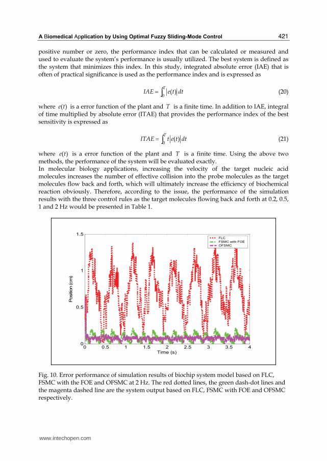
where ( )e t is a error function of the plant and T is a finite time. Using the above two methods, the performance of the system will be evaluated exactly. In molecular biology applications, increasing the velocity of the target nucleic acid molecules increases the number of effective collision into the probe molecules as the target molecules flow back and forth, which will ultimately increase the efficiency of biochemical reaction obviously. Therefore, according to the issue, the performance of the simulation results with the three control rules as the target molecules flowing back and forth at 0.2, 0.5, 1 and 2 Hz would be presented in Table 1.
0 0.5 1 1.5 2 2.5 3 3.5 40
0.5
1
1.5
Time (s)
Positio
n (cm
)
FLC
FSMC with FOE
OFSMC
Fig. 10. Error performance of simulation results of biochip system model based on FLC, FSMC with the FOE and OFSMC at 2 Hz. The red dotted lines, the green dash-dot lines and the magenta dashed line are the system output based on FLC, FSMC with FOE and OFSMC respectively.
www.intechopen.com

Sliding Mode Control
422
The overshoot means the reagent is out of the central zone as it is manipulated. Here, out of the length of the central zone is defined as overshoot value. And the error performance of the simulation results were also evaluated by using IAE and ITAE indices and the results are shown in Tables 2 and 3. The following conclusions can be arrived at from the analysis of the simulation results from Figs. 9 and 10, and Tables 1 to 3.
Overshot(mm)
Frequency (Hz)
FLC FSMC OFSMC
0.2 8.0 1.1 0.5
0.5 10.0 1.3 0.7
1 11.5 1.7 0.9
2 12.0 1.8 1.1
Table 1. Performances of the simulation results with FLC, FSMC, and OFSMC control rules
IAE
Frequency (Hz)
FLC FSMC OFSMC
0.2 3061 1106 73
0.5 2888 1084 100
1 2889 1279 162
2 2892 1824 301
Table 2. IAE index of the control systems with FLC, FSMC, and OFSMC control rules
ITAE
Frequency (Hz)
FLC FSMC OFSMC
0.2 5438 2063 118
0.5 5514 2023 170
1 5712 2473 303
2 5814 3529 570
Table 3. ITAE index of the control systems with FLC, FSMC, and OFSMC control rules
www.intechopen.com

A Biomedical Application by Using Optimal Fuzzy Sliding-Mode Control
423
1. According to Figs. 9, 10, and the values of IAE and ITAE (Table 1), the biochip system
model based on OFSMC controller at 2 Hz performs better than that based on FLC, or
FSMC controller with FOE. In addition, the performances of the biochip system model
based on OFSMC controller at 0.2, 0.5, and 1 Hz are obviously better than the other two,
according to Tables 1 to 3. Therefore, the OFSMC controller can perform well in the
biochip system with disturbances.
2. It is certain that the OFSMC control method is capable of manipulating the position of
the reagent in the microchannel on the biochip robustly and successfully. The
experimental results of microfluidic manipulation on biochip system with OFSMC
controller based on 8051 microprocessor are shown in Section 4.
4. Experimental results of OFSMC
The control block diagram of the biochip system with OFSMC controller described in Section 2 and 3 is shown in Fig. 8. In order to provide a quick and useful product for non PC-based systems, the microfluidic manipulation is implemented by 8051 microprocessor in this study. And the A/D and D/A chips were utilized to convert the photodiode or flowmeter feedback analog signals into digital signals for the microprocessor as well as to convert digital signals into analog signals for the flow controller. Then, the circuit of the photodiode-signal process should be designed. Assembly language was utilized to program the OFSMC control rules to embed into 8051 microprocessor with flow chart of the program shown in Fig. 11. The experimental results of microfluidic manipulation on biochip system with OFSMC controller based on 8051 microprocessor are shown in Fig.
12, where the volume of reagent used is 94 μL. The reagent on the biochip system was controlled excellently to flow back and forth at 2 Hz, because the overshoot of the control performance was very small and the control system was very stable. The experimental results of the control performance with FLC, FSMC, and OFSMC control rules are shown in Fig. 13. According to Fig. 13, the microfluidic manipulation with FLC control rule can only be
implemented to flow back and forth at 0.2 Hz, and the overshoot of the performance is -10,
which means the reagent could not be manipulated between the PD1 and PD2. Either it was
pushed out of the biochip, or it was manipulated under 1 cm length of the undershoot at 0.2
Hz of back and forth flowing. In addition, according to the results of the performance with
FSMC control rule, the overshoot became larger and larger by increasing the frequency of
back and forth flowing. Compared to FLC and FSMC control rule, the overshoots of the
performance with OFSMC control rule were the least of the three control rules and the
performance was the most stable and the best of the three at all frequencies of back and
forth flowing. The microfluidic manipulation on biochip system with OFSMC rules can keep
flowing back and forth at 2 Hz within 1 h while the other two can not.
Since the experimental and simulation results are in good agreement, it could be concluded
that the control performance with OFSMC control rule was better than that with FLC and
FSMC. Compared to FLC and FSMC, it was more successful to overcome the variable
parameters and nonlinear model to achieve a better microfluid management with OFSMC
control rule when using different biochip for every time. Therefore, it is certain that the
OFSMC control method is capable of manipulating the position of the reagent in the
microchannel on the biochip robustly and successfully.
www.intechopen.com

Sliding Mode Control
424
START
ADC Conversion ready
Controller read flowmeter and PD signals by
ADCs
Calculate control
OFSMC control rule
Flowmeter
Signals (Analog)
DAC Conversion ready
Controller transport
control signals by DAC
Control signals (Analog)
Yes
No
Yes
No
Voltage signals
Voltage signals By 10ms period
PD Signals (Analog)
Voltage signals
Finished manipulation
No
STOP Yes
signals by
Fig. 11. Flow chart of the program.
www.intechopen.com

A Biomedical Application by Using Optimal Fuzzy Sliding-Mode Control
425
IR
FL
IR: Infrared
FL: Front Line of reagent
RL
RL: Rear Line of reagent
(A) (B) (C) (D)
Fig. 12. Experimental results of microfluidic manipulation at 2 Hz (A period from (A) to (D)).
∴′5
∴′°
∴5
°
5
′°
°♂″ °♂5 ′ ″
F♯e‰†e∫c0 <H1>
O‡e
♯♭h∬
♪ <∵
∵>
F〒C
FS→C
OFS→C
Fig. 13. Experimental results of microfluidic manipulation with FLC, FSMC, and OFSMC control rules.
5. Biomedical application results
According to the experimental results given in Section 4, the microfluidic manipulation based on the microcontroller could be utilized in biotechnology, as it successfully improved the efficiency of the biochemical reaction. First, it was used in DNA hybridization. There are
www.intechopen.com

Sliding Mode Control
426
two methods to improve the efficiency of the nucleic acid hybridization in this charter. The first method is to increase the velocity of the target nucleic acid molecules, which increases the effective collision into the probe molecules as the target molecules flow back and forth. The second method is to introduce the strain rates of the target mixture flow on the hybridization surface. This hybridization chip was able to increase hybridization signal 6-fold, reduce non-specific target-probe binding and background noises within 30 minutes, as compared to conventional hybridization methods, which may take from 4 hours to overnight. Second, it was used in DNA extraction. In this section, DNA extraction from Chung, Wen and Lin (Chung, Wen & Lin, 2007) is introduced. The microfluidic DNA extraction chip was designed and fabricated onto a poly-methylmethacrylate (PMMA) substrate with flow channels. Machined and immobilized-beads PMMA substrate and blank PMMA were bonded together to form the device. The beads used for DNA extraction was obtained from Magic Bead Inc. (USA) A plasma generator was used to perform the surface treatment. Plasma source gas consisting of a mixture of ammonia and oxygen was used to activate the surface of PMMA substrate. Escherichia coli (E. coli) was cultured in 5 ml of LB medium (NaCl: 10 g/l, Tryptone: 10 g/l, yeast extract: 5 g/l) in 15 ml tubes at 37°C and 225 rpm. After 16 h, the optical density (OD) of the culture was measured in a spectrophotometer (U-2100, Hitachi, Japan). The number of E. coli cells or the amount of DNA was calculated from an OD versus cell number. The culture was then diluted by distilled water to obtain varying numbers (102 -105) of E. coli cells per micro liter. DNA was extracted from the blood of one of the members of the group using the microchip. Whole blood was directly used without any pretreatment. The sample flowed forward and backward with the immobilized beads at a frequency of 1 Hz inside the channel. E. coli cells were treated with a buffer (B1+B2, Magic Bead, USA) to lyse the cells and to release the DNA. The DNA extracted using the microchips was amplified by PCR (Polymerase Chain Reaction). The forward and reverse primers were 5’-CAGGATTAGATACCCTGGTAG-3’ and 5’-TTCCCCTACGGTTACCTTGTT-3’, respectively. The PCR condition was: one cycle of 5 min at 95°C, 40 cycles of 30 s at 95°C, 40 s at 58°C and 40 s at 72°C, and one cycle of 10 min at 72°C. The PCR products were analyzed qualitatively in a Mupid-2 electrophoresis equipment (Advance, Japan) and quantitatively in an Agilent 2100 bioanalyzer (Agilent Technologies, USA). The extraction efficiencies of E. coli cell number in the whole blood were tested and are shown in Fig. 18a. It showed that the free beads could efficiently extract DNA as the number of E. coli cells was higher than 5×10⁴, but could hardly extract DNA as the number was smaller than 104 in 25 μl of whole blood. And for the immobilized beads, the corresponding boundary number of E. coli cells for efficient and hard extractions of DNA were 2×10² and 102, respectively. After the analysis in the bioanalyzer, the results were as shown in Fig. 18b. When the number of E. coli cells was 2×10² to 104 in 25 μl of whole blood, the extraction efficiency of immobilized beads with solution flowing back and forth was about 600-fold larger than that of free beads.
6. Conclusions
In biometric and biomedical applications, an important issue for miniaturization and integration is microfluid management. This charter introduced the optimal fuzzy sliding-mode control (OFSMC) design based on the 8051 microprocessor and the complete microfluidic manipulated system implementation of biochip system with a pneumatic pumping actuator, two feedback-signal photodiodes and flowmeters for better microfluid
www.intechopen.com
A Biomedical Application by Using Optimal Fuzzy Sliding-Mode Control
427
management. The newly developed microfluid management technique was successfully utilized to improve the reaction and extraction efficiency of a biochemical reaction.
7. Acknowledgements
Thanks for Prof. Chung to provide the flow control chip and biochip.
8. References
Altrock, C., Krause V. B., & Zimmermann, H. J. (1992). Advanced Fuzzy Logic Control of a Model Car in Extreme Situation. Fuzzy Sets and Systems, Vol. 48, 41-52.
Alfaro-Cid, E., McGookin, E. W., Murray-Smith, D. J. & Fossen, T. I. (2005), Genetic algorithms optimisation of decoupled Sliding Mode controllers: simulated and real results, Control Engineering Practice, Vol. 13, No.6, 739-748.
Bart, S. F., Tavrow, L. S., Mehregany, M., & Lang, J. H. (1990). Microfabricated electrohydrodynamic pumps. Sens. Actuators, A21-A23, 193-197.
Bousse, L., & Minalla. A. (1999). Optimization of sample injection components in electrokinetic microfluid system. Technical Digest of Twelfth IEEE International Conference on Micro Electro Mechanical Systems, 309-314, Orlando, Florida, U.S.A..
Cheng, C. C., & Li, T. H. S. (1998). Parallel Fuzzy Sliding-mode Control of a spring-linked Cart-pole system. IEEE IECON’98. Aachen.
Chang, J. L. (1999). Sliding-Mode Control Design based on Conventional Pole-Assignment Method. Ph D dissertation, National Chiao Tung University.
Chung, Y. C., Jen, C. P., Lin, Y. C., Wu, C. Y., & Wu, T. C. (2003). Design of a Recursively-Structured Valveless Device for Microfluidic Manipulation. Lab on a Chip, Vol. 3, No. 3, 168-172.
Chung, Y. C., Wen, B. J. & Lin, Y. C. (2007), Optimal Fuzzy Sliding-mode Control for Bio-microfluidic Manipulation. Control Engineering Practice, Vol. 15, 1093–1105.
Edwards, C and Tan, C. P. (2006), Sensor fault tolerant control using sliding mode observers, Control Engineering Practice, Vol. 14, No. 8, 897-908.
Fuhr, G., Hagedorn, R., Muller, T, Benecke, W., & Wagner, B. (1992). Pumping of water solution in microfabricated electrohydrodynamic systems. Proceedings of the IEEE Micro Electro Mechanical Systems, 25-29, Travemünde, Germany.
Franklin, G. F., Powell, J. D., & Workman, M. L. (1998). Digital Control of Dynamic Systems, Addison Wesley Longman, Inc., 3rd ed..
Gao, W. B. (1990). Foundation of Variable Structure Control. Beijing: China Press of Science and Technology.
Gao, W. B., & Hung, J. C. (1993). Variable Structure Control of Nonlinear System: A New Approach. IEEE Transactions on Industrial Electronics, Vol. 40, No. 1, 45-56.
Gao, W. B., Wang, Y., & Homaifa, A. (1995). Discrete-Time Variable Structure Control Systems. IEEE Transactions on Industrial Electronics, Vol. 42, No. 2.
Harrison, D. J., Seiler, K., Manz, A., & Fan, Z. (1992). Chemical analysis and electrophoresis systems integrated on glass and silicon chips. Technical Digest of IEEE Solid-State Sensor and Actuators Workshop, 110-113, Hilton Head Island, South Carolina, U.S.A..
Hung, J. Y., Gao, W. B., & Hung, J. C. (1993). Variable Structure Control: A Survey. IEEE Transactions on Industrial Electronics, Vol. 40, No. 1, 2-22.
www.intechopen.com

Sliding Mode Control
428
Hashimoto, Y., Farkas, I., Murase, H., Carson, E. R. and Sano, A. (2004), Control approaches to bio- and ecological systems, Control Engineering Practice, Vol. 12, No.5, Fuzzy System Applications in Control, 595-603.
Jen, C. P., & Lin, Y. C. (2002). Design and simulation of bi-directional microfluid driving systems. J. Micromech. Microeng., Vol. 17, 115-121.
Lintel, H. T. G. van, Pol, F. C. M. van de, Bouwstra, S. (1988). A piezoelectric micropump based on micromachining of silicon. Sens. Actuators, A 15, 153-167.
Lee, C. C. (1990). Fuzzy Logic in Control System: Fuzzy Logic Controller-Part I, and II. IEEE Trans. Systems, Mans, and Cybernetics, Vol. 20, No.2, 404-435.
Lammerink, T. S. J., Elwenspoek, M., & Fluitman, J. H. J. (1993). Integrated micro-liquid dosing system. Proceedings of the IEEE Micro Electro Mechanical Systems, 254-259, Fort Lauderdale, U.S.A..
Lin, C. T., & Lee, C. S. (1999). Neural Fuzzy Systems. Prentice-Hall Pte Ltd. Li, T. H. S., & Shieh, M. Y. (2000). Switching-type Fuzzy Sliding Mode Control of a Cart-pole
System. Mechatronics, Vol. 10, 91-109. Marquardt, D. (1963). An algorithm for least-squares estimation of nonlinear parameters.
SIAM Journal of Applied Mathematics, Vol. 11, 431–441. Mamdani, E. H. (1977). Application of Fuzzy Logic to Approximate Reasoning using
Linguistic Synthesis. IEEE Trans. Computers, C-26. Miyazaki, S., Kawai, T., & Araragi, M. (1991). A piezo-electric pump driven by a flexural
progressive wave. Proceedings of the IEEE Micro Electro Mechanical Systems, 283-288. Moroney, R. M., White, R. M., & Howe, R. T. (1991). Ultrasonic induced microtransport.
Proceedings of the IEEE Micro Electro Mechanical Systems, 277-282. Polkinghorne, M. N., Roberts, G. N., Burns, R. S., & Winwood, D. (1994). The
implementation of fixed rulebase fuzzy logic to the control of small surface ships. Control Engineering Practice, Vol. 3, No. 3, 321–328.
Peng, H., Ozaki, T., Toyoda, Y., & Oda, K. (2001). Exponential ARX model based long-range predictive control strategy for power plants. Control Engineering Practice, Vol. 9, 1353–1360.
Richter, A., Plettner, A., Hofmann, K. A., & Sandmaier H. (1991). Electrohydrodynamic pumping and flow measurement. Proceedings of the IEEE Micro Electro Mechanical Systems, 271-276, Nara, Japan.
Sinswat, V., & Fallside, F. (1977). Eigenvalue/Eigenvector Assignment by State Feedback. Int. J. Control, Vol. 23, 183-196.
Sentoni, G., Agamennoni, O., Desages, A., & Romagnoli, J. (1996). Approximate models for nonlinear process control. A.I.Ch.E. Journal, Vol. 42, 2240–2250.
Tas, N. R., Berenschot, J. W., Lammerink, T. S. J., Elwenspoek M., & Berg, A. van-der. (2002). Nanofluidic bubble pump using surface tension directed gas injection. Anal. Chem., Vol. 74, 2224-2227.
Wen, B. J. (2003). Sliding- Mode Control for Nanoparticle Manipulation Using an Atomic Force Microscopy. Master Thesis, National Chiao Tung University.
Zadeh, L. A. (1965). Fuzzy Sets. Inform. Control, Vol. 8, 338-353. Zadeh, L. A. (1968). Fuzzy Algorithm. Inform. Control, Vol. 12, 94-102. Zengerle, R., Richer, A., & Sandmaier, H. (1992). A micro membrane pump with electrostatic
actuation. Proceedings of the IEEE Micro Electro Mechanical Systems, 19-24, Travemünde, Germany.
www.intechopen.com

Sliding Mode ControlEdited by Prof. Andrzej Bartoszewicz
ISBN 978-953-307-162-6Hard cover, 544 pagesPublisher InTechPublished online 11, April, 2011Published in print edition April, 2011
InTech EuropeUniversity Campus STeP Ri Slavka Krautzeka 83/A 51000 Rijeka, Croatia Phone: +385 (51) 770 447 Fax: +385 (51) 686 166www.intechopen.com
InTech ChinaUnit 405, Office Block, Hotel Equatorial Shanghai No.65, Yan An Road (West), Shanghai, 200040, China
Phone: +86-21-62489820 Fax: +86-21-62489821
The main objective of this monograph is to present a broad range of well worked out, recent applicationstudies as well as theoretical contributions in the field of sliding mode control system analysis and design. Thecontributions presented here include new theoretical developments as well as successful applications ofvariable structure controllers primarily in the field of power electronics, electric drives and motion steeringsystems. They enrich the current state of the art, and motivate and encourage new ideas and solutions in thesliding mode control area.
How to referenceIn order to correctly reference this scholarly work, feel free to copy and paste the following:
Bor-Jiunn Wen (2011). A Biomedical Application by Using Optimal Fuzzy Sliding-Mode Control, Sliding ModeControl, Prof. Andrzej Bartoszewicz (Ed.), ISBN: 978-953-307-162-6, InTech, Available from:http://www.intechopen.com/books/sliding-mode-control/a-biomedical-application-by-using-optimal-fuzzy-sliding-mode-control