Embed Size (px)
Citation preview
A brief discussion over safety costs in new enterprises
Alejandro Esparza, CFSE exida.com L.L.C. [email protected] Monica Levy Hochleitner, CFSE exida.com L.L.C. [email protected]
Abstract
The starting point of a new industrial plant concerning the levels of reliability required to keep the process under a defined tolerable risk is a challenge most contractors company face. During the embryonic phases, in the bidding process and for budget purposes, a pre-defined Safety Instrumented System (SIS) design must be provided to the contractor, sometimes even before the process conceptual design is well defined. The consequences of such situation, in which no risk analysis have been considered, not only disregards the Safety Lifecycle template suggested by the recent versions of the functional safety standards applied to the process industry, IEC 61511 [1] and ANSI/ISA 84.01 [2] but also implies in unpredictable outcomes.
By means of actual examples, where the customers names will be suppressed for confidentiality matters, this paper will present and briefly discuss the pros and cons of some actual applications, the achieved safety of the resulting design and the impact of investments during implementation and operation phases of the enterprise.
I. INTRODUCTION
Risk is a condition in which there is a possibility of an adverse deviation from a desired outcome that is expected or hoped for [3]. Because intrinsically in every enterprise there is a lack of knowledge of what will or will not happen in the future, risk management became an important tool to assess the possibility of loss, existence of risk and exposition, insurance negotiation, etc.
When it comes to the process industry, the functional safety standards state the need of an in depth study of the potential risks that can jeopardize people, environment, company image and financial health, among others. So, after identifying independent layers of protection that mitigate the consequences of an undesired event (dikes, relief valves, control system, alarm management, etc.), it may be necessary to develop a Safety Instrumented System that will reduce the residual risk to a tolerable level [4].
In real life, however, despite all requirements stated in the international standards concerning Safety in the Process industry, it is still a challenge for engineers to justify and estimate investments in Safety Instrumented Systems, mainly during the enterprise initial phases.
It's a common practice these days for operator companies, regarding new facilities, to assign to a contractor a fixed price supply contract. So, in the bidding process and for budget purposes, a pre-defined SIS design must be provided to the front-end engineering and design (FEED) contractor, most of the times even before the process conceptual design is well defined. This pre-defined SIS design provides an equal basis for all the contractors participating in the bidding process, all of them looking for the contract. Questions are:
1. What if the pre-defined SIS design is below the real safety requirements? 2. What if the pre-defined SIS design is above the real safety requirements?
I.1 The Safety Lifecycle
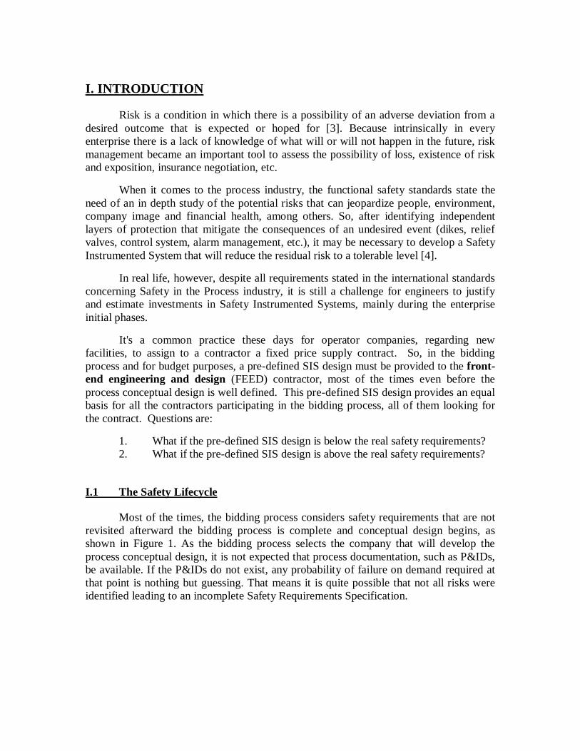
Most of the times, the bidding process considers safety requirements that are not revisited afterward the bidding process is complete and conceptual design begins, as shown in Figure 1. As the bidding process selects the company that will develop the process conceptual design, it is not expected that process documentation, such as P&IDs, be available. If the P&IDs do not exist, any probability of failure on demand required at that point is nothing but guessing. That means it is quite possible that not all risks were identified leading to an incomplete Safety Requirements Specification.
Figure 1: The hypothetical bidding process "Safety Life Cycle".
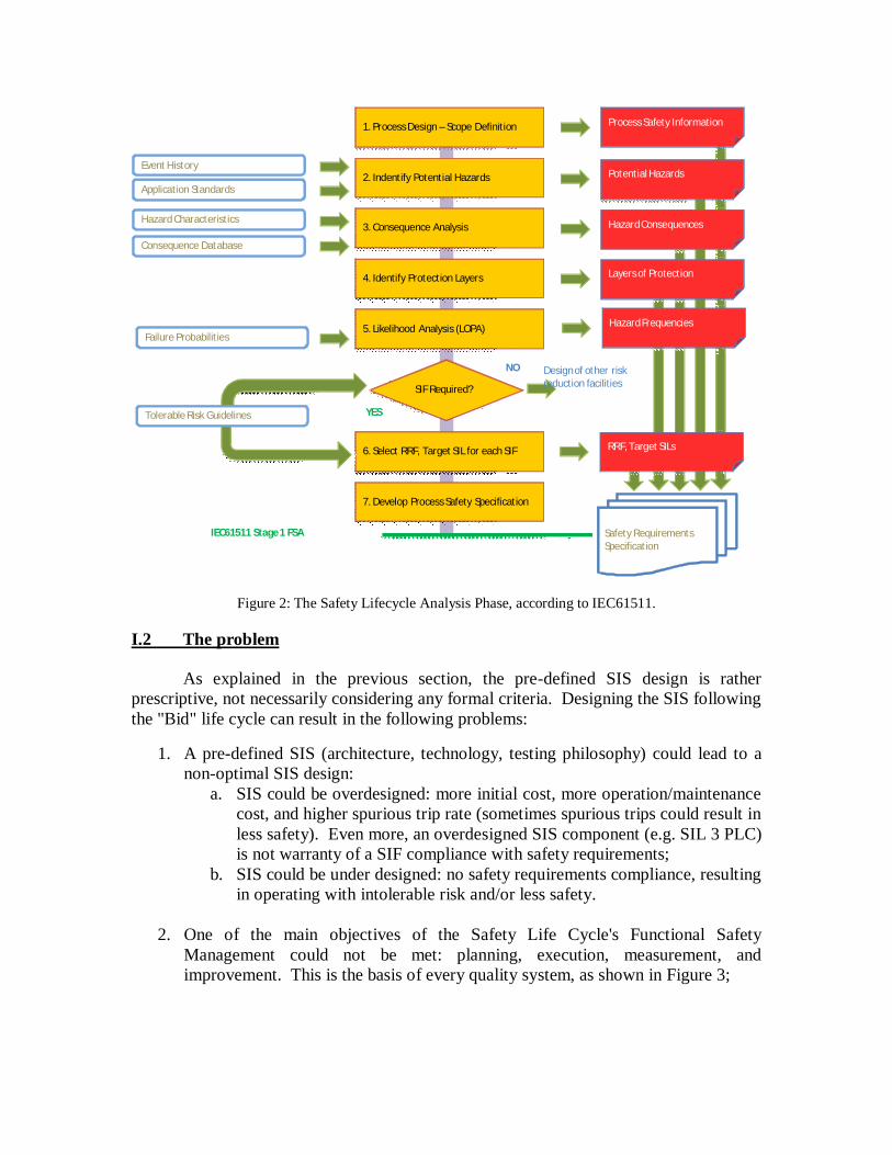
IEC 61511 safety lifecycle (Figure 2) shows that only after process conceptual design is defined, and after PHA/Risk Analysis is performed, the SIS can be defined. That’s because the tasks developed during the analysis phase will result in the process safety information, the potential hazards and its consequences, the layers of protection and hazard frequencies. Without this information one cannot identify the risk reduction needed to take the process into a tolerable risk level.
2
1. Process Design – Scope Definition
Event History
SIF Required?
Application Standards
Hazard Characteristics
Consequence Database
Failure Probabilities
2. Indentify Potential Hazards
3. Consequence Analysis
4. Identify Protection Layers
5. Likelihood Analysis (LOPA)
6. Select RRF, Target SIL for each SIF
7. Develop Process Safety Specification
Tolerable Risk Guidelines
Potential Hazards
Process Safety Information
Hazard Consequences
Layers of Protection
Hazard Frequencies
RRF, Target SILs
Safety Requirements Specification
Design of other risk reduction facilities
NO
YES
IEC61511 Stage 1 FSA
Figure 2: The Safety Lifecycle Analysis Phase, according to IEC61511.
I.2 The problem
As explained in the previous section, the pre-defined SIS design is rather prescriptive, not necessarily considering any formal criteria. Designing the SIS following the "Bid" life cycle can result in the following problems:
1. A pre-defined SIS (architecture, technology, testing philosophy) could lead to a non-optimal SIS design:
a. SIS could be overdesigned: more initial cost, more operation/maintenance cost, and higher spurious trip rate (sometimes spurious trips could result in less safety). Even more, an overdesigned SIS component (e.g. SIL 3 PLC) is not warranty of a SIF compliance with safety requirements;
b. SIS could be under designed: no safety requirements compliance, resulting in operating with intolerable risk and/or less safety.
2. One of the main objectives of the Safety Life Cycle's Functional Safety
Management could not be met: planning, execution, measurement, and improvement. This is the basis of every quality system, as shown in Figure 3;
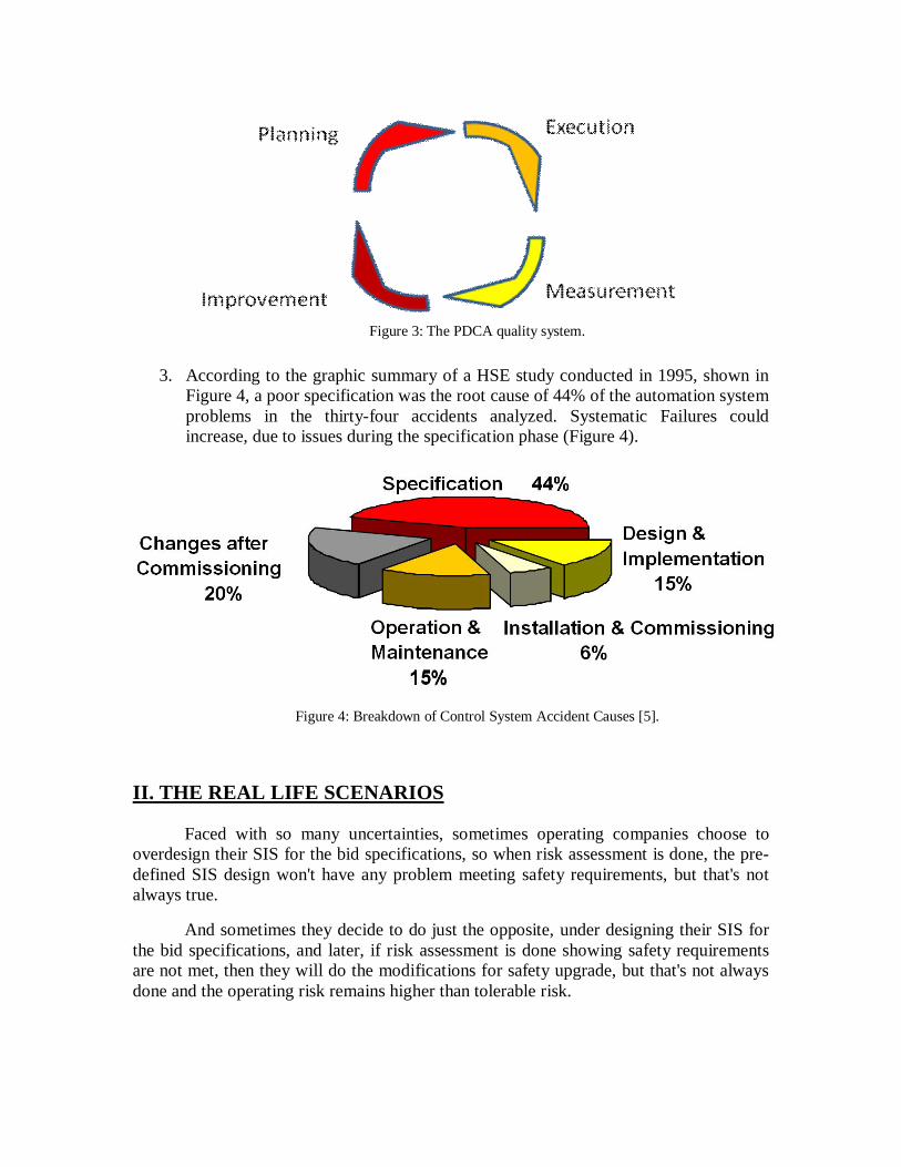
Figure 3: The PDCA quality system.
3. According to the graphic summary of a HSE study conducted in 1995, shown in
Figure 4, a poor specification was the root cause of 44% of the automation system problems in the thirty-four accidents analyzed. Systematic Failures could increase, due to issues during the specification phase (Figure 4).
Figure 4: Breakdown of Control System Accident Causes [5].
II. THE REAL LIFE SCENARIOS
Faced with so many uncertainties, sometimes operating companies choose to overdesign their SIS for the bid specifications, so when risk assessment is done, the pre-defined SIS design won't have any problem meeting safety requirements, but that's not always true.
And sometimes they decide to do just the opposite, under designing their SIS for the bid specifications, and later, if risk assessment is done showing safety requirements are not met, then they will do the modifications for safety upgrade, but that's not always done and the operating risk remains higher than tolerable risk.
The following sections will present both scenarios using real examples1: under designed and overdesigned SIS specifications. Further discussion over the achieved result after PHA and the alternate solution to comply with the safety requirements will also be explored.
II.1 The under designed SIS
During the past years it has been our experience that some contractors opt to under design the Safety Instrumented Systems for bidding purposes when the application is not known yet and wait until the implementation phase of the project to properly design the SIS. In this section, it is presented an example of under designed safety specification based on a real petrochemical application in which the customer name will be suppressed for confidentiality reasons. This example will be identified as Project 1.
II.1.1 Project 1 bid safety specifications:
- Sensor elements o 1oo1 voting architecture o "Smart" transmitters, no safety certification
- Logic Solver o Hot-Backup PLC with single I/O's - 1oo1 voting architecture o Generic Industrial PLC, no safety certification
- Final elements o 1oo2 voting architecture (double block & bleed) o Pneumatic valves, with 3 way solenoid, no safety certification
According to this specification, the resulting SIS may achieve SIL 1. Depending on the components reliability data it won’t achieve even SIL 0! In terms of acquisition of the equipment, this safety system may be implemented with a very economic investment; however it is likely it will result in a LOW AVAILABILITY safety system, recurring in other kinds of costs which will be explained briefly.
II.1.2 Achieved result after PHA
It is good practice that at some point a process hazard analysis (PHA) is conducted. In fact, hazard identification and consequence analysis is required by the IEC 61511 Safety Life Cycle ( SLC ) In Project 1 it happened after the BID.
1 Note that the example SIL levels provided in this paper are only examples. They are not to be assumed recommended levels of protection. The selection of an appropriate Safety Integrity Level (SIL) is site-specific and the analysis requires selecting criteria for tolerable risk, and evaluating process conditions, specific chemicals, equipment design-limits, control schemes, process conditions, and unique hazards. Experts in process engineering, instrumentation, operations, and process safety should undertake SIL selection.
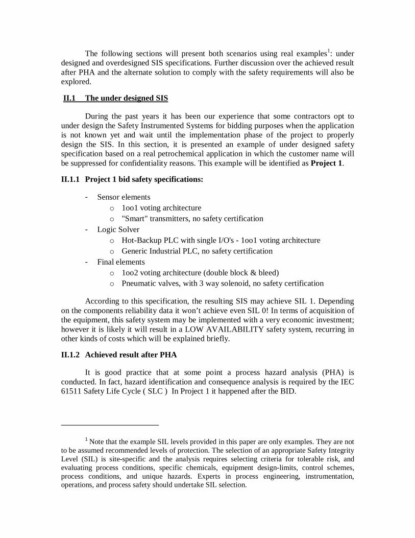
After the risk analysis and subsequent Safety Requirements Specification (SRS) it was identified the need of 9 Safety Instrumented Functions (SIF). Five of them required a Safety Integrity Level of 1. According to Table 1 these SIFs need a Risk Reduction Factor (RRF) between 10 and 100 to achieve the tolerable risk level. The other four of the identified Safety Instrumented Functions require SIL 2 and as for Table 1, they need a Risk Reduction Factor (RRF) between 100 and 1000.
Table 1: A chart of Safety Integrity Levels (SIL) [6].
Table 2 shows the differences between safety specifications for the BID and after the SRS. The five SIL 1 Safety Instrumented Functions were optimally designed according to the safety requirements. However, the SIL 2 Safety Instrumented Functions did not achieve the required Risk Reduction Factor.
SIL 1 SIF's: 5
under-designed SIFs - 0% of the SIL 1 assigned SIFs were under designed (target SIL not met)
optimally designed SIF 5 100%
of the SIL 1 assigned SIFs were designed according to safety requirements
Over-designed SIF - 0% of the SIL 1 assigned SIFs were overdesigned SIL 2 SIF's: 4
under-designed SIFs 4 100% of the SIL 2 assigned SIFs were under designed (target SIL not met)
optimally designed SIF - 0%
of the SIL 2 assigned SIFs were designed according to safety requirements
over-designed SIF - 0% of the SIL 2 assigned SIFs were overdesigned Table 2: Differences between safety specifications (BID spec vs. SRS) in Project 1.
The overall result, showed in Graphic 1, was that 44% of the Safety Instrumented Functions were under designed and therefore the target SIL was not met. 56% of the Safety Instrumented Functions were optimally designed and provided the required safety. As expected, there was not even one case of over designed SIF.
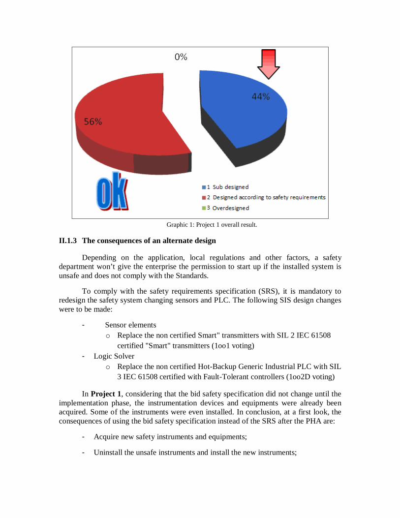
Graphic 1: Project 1 overall result.
II.1.3 The consequences of an alternate design
Depending on the application, local regulations and other factors, a safety department won’t give the enterprise the permission to start up if the installed system is unsafe and does not comply with the Standards.
To comply with the safety requirements specification (SRS), it is mandatory to redesign the safety system changing sensors and PLC. The following SIS design changes were to be made:
- Sensor elements o Replace the non certified Smart" transmitters with SIL 2 IEC 61508
certified "Smart" transmitters (1oo1 voting) - Logic Solver
o Replace the non certified Hot-Backup Generic Industrial PLC with SIL 3 IEC 61508 certified with Fault-Tolerant controllers (1oo2D voting)
In Project 1, considering that the bid safety specification did not change until the implementation phase, the instrumentation devices and equipments were already been acquired. Some of the instruments were even installed. In conclusion, at a first look, the consequences of using the bid safety specification instead of the SRS after the PHA are:
- Acquire new safety instruments and equipments;
- Uninstall the unsafe instruments and install the new instruments;
- Cost of delays on the project due to installation and commissioning.
Section 3 will cover other costs resulting of a bad design.
II.2 The over designed SIS
This section presents the opposite example of Project 1. In this case the contractor does not want to take a chance and specifies full redundancy for the safety system. For the same reason as the previous example, the customer’s name will be suppressed. This example will be identified as Project 2.
II.2.1 Project 2 bid safety specifications:
- Sensor elements o 2oo3 voting architecture o "Smart" transmitters, no safety certification
- Logic Solver o IEC 61508 certification (SIL 3) with Fault-Tolerant controllers (2oo3
voting) - Final elements
o 1oo2 voting architecture o Pneumatic valves, with 3 way solenoid, no partial stroke test, no safety
certification
This specification may seem really safe, but sensors with no certification, even with redundancy, in some cases will only achieve SIL 1. And let’s not forget that redundancy could cause higher spurious trip rate (MTTFsp is higher)! As a result, one will end up not having the proper instrumentation and it probably won’t be compliant with the company’s production goals.
II.2.2 Achieved result after PHA
As evaluated for Project 1, the resulting Safety Requirements Specification (SRS) after the PHA/Risk Analysis was conducted identified 31 Safety Instrumented Functions with the following SIL determination:
o 22 SIFs with SIL 1 safety requirement o 8 SIFs with SIL 2 safety requirement o 1 SIFs with SIL 3 safety requirement
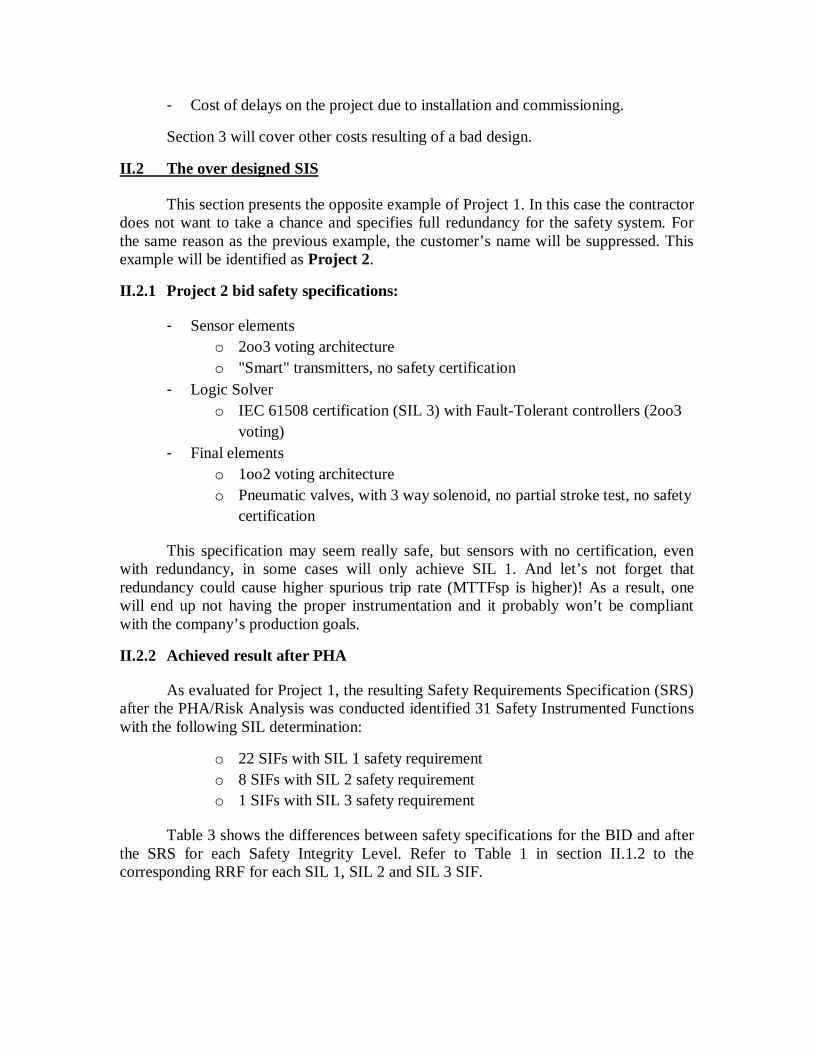
Table 3 shows the differences between safety specifications for the BID and after the SRS for each Safety Integrity Level. Refer to Table 1 in section II.1.2 to the corresponding RRF for each SIL 1, SIL 2 and SIL 3 SIF.
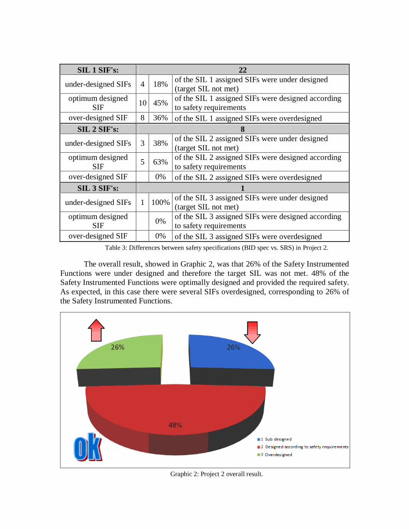
SIL 1 SIF's: 22
under-designed SIFs 4 18% of the SIL 1 assigned SIFs were under designed (target SIL not met)
optimum designed SIF 10 45% of the SIL 1 assigned SIFs were designed according
to safety requirements over-designed SIF 8 36% of the SIL 1 assigned SIFs were overdesigned
SIL 2 SIF's: 8
under-designed SIFs 3 38% of the SIL 2 assigned SIFs were under designed (target SIL not met)
optimum designed SIF 5 63% of the SIL 2 assigned SIFs were designed according
to safety requirements over-designed SIF 0% of the SIL 2 assigned SIFs were overdesigned
SIL 3 SIF's: 1
under-designed SIFs 1 100% of the SIL 3 assigned SIFs were under designed (target SIL not met)
optimum designed SIF 0% of the SIL 3 assigned SIFs were designed according
to safety requirements over-designed SIF 0% of the SIL 3 assigned SIFs were overdesigned
Table 3: Differences between safety specifications (BID spec vs. SRS) in Project 2.
The overall result, showed in Graphic 2, was that 26% of the Safety Instrumented Functions were under designed and therefore the target SIL was not met. 48% of the Safety Instrumented Functions were optimally designed and provided the required safety. As expected, in this case there were several SIFs overdesigned, corresponding to 26% of the Safety Instrumented Functions.
Graphic 2: Project 2 overall result.
II.2.3 The consequences of an alternate design
Although 50% of the SIFs are designed according to safety requirements and 26% seem to provide more safety than needed, to comply with the safety requirements specification (SRS), the following SIS design changes were to be made:
- Sensor elements o 2oo3 voting architecture should be used only in SIL 2 & SIL 3 SIFs.
The SIL 1 SIFs should be configured in 1oo1 voting architecture - Final elements
o 1oo2 voting architecture should be used only in SIL 2 & SIL 3 SIFs. The SIL 1 SIFs should be configured in 1oo1 voting architecture
As in Project 1, some of the instruments were already installed, and at a first look, the consequences of using the bid safety specification instead of the SRS after the PHA are:
- Uninstall the not needed instruments and reconfigure them properly;
- Cost of delays on the project due to installation and commissioning.
III. COLATERAL EFFECTS: THE COST OF SPURIOUS TRIPS
One important performance parameter calculated during SIL Verification is the MTTFsp: Mean Time to Failure due to nuisances or Spurious Trips. This variable indicates how often the SIS is expected to suffer a false trip and shut the plant down. It is commonly known how long a particular process will be down when a trip happens and how much it costs the down time. Table 4 shows the estimate of Spurious Trip Cost in different process industries [7].
Process Application Spurious Trip Cost (in US Dollars)
Oil & Gas Platforms Up to $2 million/day
Polystyrene 20 days to recover at $20k/day = $400 k
Refinery Coker Heater $35k/day
Refinery Catalytic Cracker $500k
Complete Refinery $1 million/day
Ammonia & Urea Plants $1 million/day
Power Generation $100k/MW hour to $millions/site
Ethylene $1 million to include getting product to specification
Table 4: Spurious Trip Cost in Several Different Process Industries [7].
For both examples explored in this paper, it was compared the MTTFsp using the BID safety specification with the MTTFsp using the safety requirements full compliance. In Project 1, the impact of under designed SIF in spurious trip rate was:
o SIS MTTFsp (original design – bid) = 4 years o SIS MTTFsp (suggested design – SRS) = 5 years
In Project 2, the impact of over designed SIF in spurious trip rate:
o SIS MTTFsp (original design – bid) = 0.4 years o SIS MTTFsp (suggested design – SRS) = 0.5 years
In both examples, if a good design of the SIS is used, not only a better safety is achieved but it will be possible to accomplish lower spurious trip rate. This will achieve the production requirements, for the plants won’t be tripping that often.
To provide the right information to the design team, a spurious trip rate (STR) requirement should be specified in the safety requirements specification (SRS) for each safety instrumented function (SIF) based on how much these trips cost in lost production and potential plant damage. The STR must then be verified for the proposed SIF design as part of SIF verification.
IV. CONCLUSION
Although benefits regarding insurance after SIS implementation could justify the investment in safety design itself and most of the time insurance cost is the primarily motivation for this kind of project, it is our experience that much can be said about instrumentation costs.
This paper provided an overview of the factors impacting safety costs during the different phases of a Project and the opportunities experienced by some of our customers. Some detailed analysis were discussed for projects where the basic engineering, mainly for bidding purposes, had pre-designed the SIS with some redundancy level, like dual valves (1oo2) and triple (2oo3) sensors. After the PHA / SIL Selection / Conceptual SIS design (SIL verification), the customer sometimes decides to simplify the design and/or reduce the redundancy in safety instrumentation. In other cases, these SIS design simplifications have been done by the contractor early on (less equipment to supply in a fixed price project), and sometimes by the final user (larger proof test intervals, less equipment to maintain and/or less spurious trips).
It is our experience that following Safety Lifecycle will help contractors to get a good SIS design. And it can be defined a good SIS design as the one that provides:
1. Full compliance with the safety requirements obtained after a full risk assessment. In other words, operate below the tolerable risk.
2. SIS lower cost, not only from the initial investment point of view, but also in the operational cost point of view (lower spurious trips).
As seen in Project 1 exemplified above, under designed Safety Instrumented Functions before the risk assessment, and may represent more risk, less safety and maybe more spurious trips rate!
As per Project 2, overdesigned Safety Instrumented Functions before the risk assessment, may represent more initial cost, more operational cost (more maintenance, more spare parts, more spurious trips), and the risk won’t necessarily be below tolerable levels!
Specifying the safety system prior to the risk analysis/assessment is the same as buying the medicine before going to the doctor. Sometimes you will get it right but sometimes not. Consequences are that the resulting system (bad design) will cause higher cost in maintenance, insurance, spurious trip cost, etc.
V. REFERENCES 1. IEC 61511, Functional safety: Safety Instrumented Systems for the process industry sector, Geneva: International Electrotechnical Commission, 2003. 2. ANSI/ISA 84.01, Application of Safety Instrumented Systems for the Process Industries, Research Triangle Park : Instrument Society of America, 2004. 3. Vaughan, Emmett J., and Vaughan, Therese M., Fundamentals of Risk and Insurance, 10th Edition, New York: John Wiley & Sons, Inc., 2008. 4. Marszal, Edward M., and Scharpf, Eric W., Safety Integrity Level Selection: systematic methods including layer of protection analysis, Research Triangle Park : Instrument Society of America, 2004. 5. Out of Control: Why Control Systems go Wrong and How to Prevent Failure, U.K.: Sheffield, Heath and Safety Executive, 1995 (Ed 2, 2003). 6. Goble, William M., and Cheddie, Harry L., Safety Instrumented Systems Verification: Practical Probabilistic Calculations, Research Triangle Park:ISA The Instrumentation, Systems and Automation Society, 2005. 7. Miller, Curt, Win-Win: a manager’s guide to functional safety, Sellersville: exida.com LLC, 2008.


![A.I. Enterprises Ltd. and A.I. Enterprises Ltd. et …...[2014] 1 R.C.S. A.I. ENTERPRISES c. BRAM ENTERPRISES 177 A.I. Enterprises Ltd. et Alan Schelew Appelants c. Bram Enterprises](https://img.pdfslide.net/doc/110x75/5e918dac94e60f42b949e30a/ai-enterprises-ltd-and-ai-enterprises-ltd-et-2014-1-rcs-ai-enterprises.jpg)