Embed Size (px)
Citation preview


A Brief History of PDM
To The Trade
Processing Equipment & Services
Hot Rolled Bars
Structural Shapes
Tubing Products
Pipe Products
Plate Products
Sheet Products
Expanded Metal & Grating Products
Cold Finished & Alloy Bar Products
Rebar
Color Codes

INTRODUCTION
Service LocationsRocky Mountain Region
PDM Spanish Fork1100 N. 300 W. P.O. Box 280Spanish Fork, UT 84660(801) 798-8676(800) 444-7361(801) 798-3605 Fax
PDM Denver4755 N. Washington StreetDenver, CO 80216(303) 297-1456(800) 736-4277(303) 295-3538 Fax
PDM Grand Junction1960 Hwy 6 & 50Fruita, CO 81521(970) 858-3441(888) 811-4736(970) 858-3620 Fax
Nevada
PDM Las Vegas4475 Alto AvenueLas Vegas, NV 89115(702) 413-0067(888) 413-4736(702) 413-0006 Fax
PDM Sparks1250 Kleppe LaneSparks, NV 89431(775) 358-1441(800) 736-1400(775) 355-1443 Fax
California
PDM Corporate9245 Laguna Springs Dr., Suite 350Elk Grove, CA 95758(916) 513-4548
PDM Santa Clara3500 Bassett StreetSanta Clara, CA 95054(408) 988-3000(800) 672-8801(408) 988-6966 Fax
PDM Plate Processing Center4005 E. Church AvenueFresno, CA 93725(559) 442-1410(800) 222-3235(559) 442-1409 Fax
PDM Stockton3535 E. Myrtle Street P.O. Box 310Stockton, CA 95205(209) 943-0513(800) 800-4736(209) 466-8420 Fax
Feralloy PDM Steel Service 936 Performance Dr. Stockton, CA 95206(209) 234-0548(800) 972-5986(209) 234-0549 Fax
Pacific Northwest
PDM Woodland1785 Schurman Way Woodland, WA 98674 (360) 225-1133(800) 451-9581(360) 225-0204 Fax
Service When and Where You Need Itwww.PDMSteel.com
Copyright 2018 PDM Steel Service Centers, Inc.
Printed in U.S.A.

Service Locations

Page 3 Table of Contents
TABLE OF CONTENTS
Table of Contents
A Brief History of PDM . . . . . . . . . . . . . . . . .4
To The Trade . . . . . . . . . . . . . . . . . . . . . . . . .6
Processing Equipment & Services . . . . . . . .13
Hot Rolled Bars . . . . . . . . . . . . . . . . . . . . . .21Bar Size Channels, Bar Size Tees, Bar Size Angles, Hot Rolled Flats, Weights for UM Plates, Hot Rolled Rounds, Hot Rolled Squares, Hot Rolled Strips
Structural Shapes . . . . . . . . . . . . . . . . . . . .30Structural Angles, Structural Channels, Miscellaneous Structural Channels, Wide Flange Beams, Standard I Beams, Miscellaneous Beams, H Pilings
Tubing Products . . . . . . . . . . . . . . . . . . . . .42Square & Rectangular Mechanical Tubing, Round Mechanical Tubing, Square Structural Tubing, Rectangular Structural Tubing, Round Structural Tubing,Pipe Sized Tubing
Pipe Products . . . . . . . . . . . . . . . . . . . . . . .50Gauge Pipe, Standard, Heavy & Extra Heavy Pipe
Plate Products . . . . . . . . . . . . . . . . . . . . . . .56A36, A572/50, A516 PVQ, Corrosion Resistant A588, High Brinell, A514 Constructional Alloy & Floor Plate
Sheet Products . . . . . . . . . . . . . . . . . . . . . .67Commercial Quality, High Tensile, Cold RolledHot Rolled Galvanized & Paintable Galvanized
Expanded Metal & Grating Products . . . . .74Regular & Flattened Expanded Metal & GratingDiamond Grip & Welded Bar Grating
Cold Finished & Alloy Bar Products . . . . . .81Cold Drawn Round, Flats, Squares, Hex, Stressproof, C1045, C12L14
Rebar . . . . . . . . . . . . . . . . . . . . . . . . . . . . . .90
Color Codes . . . . . . . . . . . . . . . . . . . . . . . .92

PDM entered the steel service center industry in 1954 with the acquisition of the Proctor-James Steel Company in San Jose, California. In 1955, Kyle & Company was purchased, with facilities in Fresno, Stockton, and Sacramento. With four service centers, PDM was able to provide outstanding service throughout central and northern California.
In 1962, a new facility was constructed in Fresno, California. In 1968, the existing operations were greatly augmented by the completion of a large, state of the art service center in Stockton, California. The facility utilized the most modern material handling equipment of the time.
In 1974, a new warehouse was built in Reno, Nevada to improve service in central and northern Nevada as well as the Eastern Sierras in California.
To provide the greatest possible service and selection to customers, the “Common Inventory Concept” was adopted which provided customers throughout the company, access to uncommon, hard to find, slow mov-ing items, without the burden of carrying duplicate inventories in each location. Under the Common Inventory Concept, the new Stockton facility became the geographical hub of the service wheel with spokes running east to Reno, south to Fresno and west to Santa Clara. The “Interplant Transfer System” was developed to quickly move this common inventory between service centers, providing short lead-time delivery of most items regardless of the inventory location. This concept proved to be so successful that future PDM operations were either built or expanded to provide other “hub” type distribution facilities.
In 1977, a new service center was established in Spanish Fork, (close to Provo) Utah. Over the years, this location was expanded numerous times to meet the market demands. It is now a full line distribution and processing facility acting as the “hub” for the Intermountain Region providing service for customers in Utah, Idaho, Wyoming, Montana, Colorado, and New Mexico.
In January 1997, PDM purchased General Steel, a carbon steel service center in Vancouver, Washington. In April of 1999 this operation moved into a newly designed and built facility in Woodland, Washington and be-came the next “hub” in the Great Northwest. The Woodland service center serves Washington, Oregon, and parts of Idaho, Alaska and Canada. In July 2001, the Reliance Steel & Aluminum Co. of Los Angeles, California pur-chased PDM Steel Service Centers. Today PDM Steel operates as a wholly owned subsidiary now named: PDM Steel Service Centers, Inc.
PDM entered the Las Vegas market in late 2003 working from a remote office with delivery supplemented through both the Fresno and Spanish Fork locations. By early 2005, the company moved into a small full-service warehouse with delivery throughout Southern Nevada, Southern Utah, and Northern Arizona.
A Brief History Of PDM
Page 4
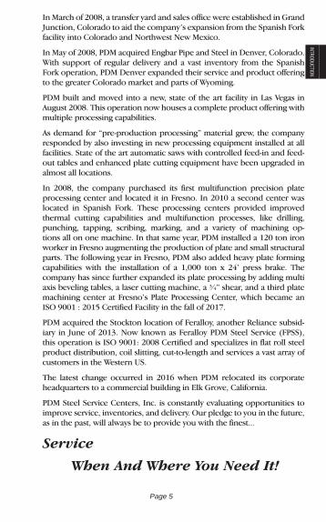
INTRODUCTIONIn March of 2008, a transfer yard and sales office were established in Grand Junction, Colorado to aid the company’s expansion from the Spanish Fork facility into Colorado and Northwest New Mexico.
In May of 2008, PDM acquired Engbar Pipe and Steel in Denver, Colorado. With support of regular delivery and a vast inventory from the Spanish Fork operation, PDM Denver expanded their service and product offering to the greater Colorado market and parts of Wyoming.
PDM built and moved into a new, state of the art facility in Las Vegas in August 2008. This operation now houses a complete product offering with multiple processing capabilities.
As demand for “pre-production processing” material grew, the company responded by also investing in new processing equipment installed at all facilities. State of the art automatic saws with controlled feed-in and feed-out tables and enhanced plate cutting equipment have been upgraded in almost all locations.
In 2008, the company purchased its first multifunction precision plate processing center and located it in Fresno. In 2010 a second center was located in Spanish Fork. These processing centers provided improved thermal cutting capabilities and multifunction processes, like drilling, punching, tapping, scribing, marking, and a variety of machining op-tions all on one machine. In that same year, PDM installed a 120 ton iron worker in Fresno augmenting the production of plate and small structural parts. The following year in Fresno, PDM also added heavy plate forming capabilities with the installation of a 1,000 ton x 24’ press brake. The company has since further expanded its plate processing by adding multi axis beveling tables, a laser cutting machine, a ¾” shear, and a third plate machining center at Fresno’s Plate Processing Center, which became an ISO 9001 : 2015 Certified Facility in the fall of 2017.
PDM acquired the Stockton location of Feralloy, another Reliance subsid-iary in June of 2013. Now known as Feralloy PDM Steel Service (FPSS), this operation is ISO 9001: 2008 Certified and specializes in flat roll steel product distribution, coil slitting, cut-to-length and services a vast array of customers in the Western US.
The latest change occurred in 2016 when PDM relocated its corporate headquarters to a commercial building in Elk Grove, California.
PDM Steel Service Centers, Inc. is constantly evaluating opportunities to improve service, inventories, and delivery. Our pledge to you in the future, as in the past, will always be to provide you with the finest...
Service
When And Where You Need It!
Page 5

To The TradeThis catalog is published for general information. It is not a stock list. Call to confirm the availability of particular sizes and grades. Specific application of the information or products listed herein may require professional assistance or interpretation. Information on product specifications is highly abridged. The latest ASTM (www.astm.org) documents should be consulted for full and accurate information on product specifications. Technical information on any questions as to structural design, weldability, formability, allowable stress, heat treat-ing, material properties or characteristics, etc. should be referred to the appropriate professional consultant.
Page 6
PDM Steel Service Centers, Inc.
TERMS AND CONDITIONS OF SALE
PDM Steel Service Centers, Inc. (“Seller”) and the party purchasing goods and/or materials (“Customer”) hereby agree to the following Terms and Conditions of Sale (“Terms and Conditions”):
1. Customer’s Acceptance of Terms. These Terms and Conditions of Sale constitute the final and entire understanding and agreement between Seller and Customer relating to the goods and/or materials (“Products”) sold by Seller to Customer. Customer’s acceptance of the Products is expressly conditioned on Customer’s acceptance of these Terms and Conditions. Customer’s acceptance is limited to these Terms and Conditions, and no different, inconsistent and/or additional terms and conditions submitted by Customer in acknowledging or ac-cepting these Terms and Conditions or in issuing any purchase or-ders, releases, shipping instructions or other documents in connec-tion with the Products, whether prior or subsequent, shall modify or amend these Terms and Conditions or be valid or binding against Seller, unless specifically accepted by Seller in writing. In the event of any conflict, discrepancy or inconsistency between these Terms and Conditions and the terms and conditions contained in any document submitted by Customer, these Terms and Conditions shall govern even if Customer’s document expressly limits acceptance to Customer’s terms and conditions. No course or pattern of dealings or conduct between Seller and Customer and no usage of trade shall be relevant to determine the meaning or intent of these Terms and Conditions even though the accepting or acquiescing party has knowledge of the nature of the performance and an opportunity for objection.
2. Open Credit Account. Seller reserves the right in its sole discre-tion to approve, conditionally approve or disapprove any request by Customer for credit. The amount of credit Seller extends to Customer will be determined by Seller in its discretion and may vary from time to time. Customer shall notify Seller, in writing, of any error in any in-voice within ten (10) days after the Customer’s receipt of such invoice,
Effective 2017

INTRODUCTION
Page 7
and, if no such notice from Customer is received by Seller, the invoice shall be deemed to be correct and payable as delivered to Customer.
3. Open Account Payment Terms. TIME FOR CUSTOMER’S PAY-MENT OF THE PURCHASE PRICE FOR THE PRODUCTS SHALL BE OF THE ESSENCE. All sums owing Seller by Customer shall be paid in accordance with the provisions of Seller’s invoice or any written quotation issued by Seller and signed by Customer. In the absence of such express provisions, Seller’s terms will be net thirty (30) days from the date of invoice. All sums past due and owing to Seller shall bear interest at the rate of the lesser of one and one-half percent (1.5%) per month or the maximum rate permitted by applicable law from the in-voice date until paid in full. All payments made by Customer to Seller shall be applied in the following priority: (a) first to the amounts, if any, due to Seller for attorneys’ fees and court costs, (b) second to the amounts, if any, due to Seller in the event of Customer’s default, (c) third to the amount, if any, of interest due to Seller as a result of Customer’s late payment and (d) finally to the balance of the purchase price due to Seller for the Products.
4. Customer’s Representations and Warranties. Upon Seller’s re-quest from time to time, Customer will provide Seller with current financial information. Customer represents and warrants that any fi-nancial information provided to Seller will be true and correct in all material respects and shall fairly and accurately present the financial condition of Customer as of the date of such financial statements. Customer hereby authorizes Seller to review and evaluate Customer’s credit background from time to time.
5. Security Interest. To secure Customer’s full and prompt payment of the purchase price for the Products, Customer hereby grants to Sell-er a first priority, purchase money security interest in and to the Prod-ucts and all products and proceeds therefrom. Customer authorizes Seller to file a UCC financing statement to perfect this security interest at any time.
6. Cancellation and Returns. Customer may not cancel any order of Products for Customer’s convenience without Seller’s prior written consent. Seller may, in its sole opinion, authorize Customer in writing to cancel Products normally carried in Seller’s inventory. Any cancella-tion so authorized shall be subject to a cancellation charge of 15% of the purchase price. Customer may not cancel any processed Products, specially manufactured Products, or Products not normally carried in Seller’s inventory.
7. Approval of Sale; Prior Sale. No sale shall be final until approved by the corporate office of Seller. All quotations for Products normally carried in Seller’s inventory are subject to prior sale, unless otherwise specified in writing by Seller. All quotations for specially manufactured Products and Products not normally carried in Seller’s inventory are subject to mill availability.
Page 8
8. Price; Basis of Invoices. Seller’s price is subject to and contingent upon Customer purchasing the entire quantity of Products identified in Seller’s quotation. If Customer purchases less than the entire quan-tity of Products identified therein, prices may vary. Seller shall invoice all Products in accordance with Seller’s published schedule of weights, areas, sizes and lengths. All weights shall be theoretical and shall be determined in accordance with ASTM standards.
9. Force Majeure. Neither Customer nor Seller shall be liable for any delay, breach or nonperformance of these Terms and Conditions (other than the payment of money) wholly or partly due to any cause beyond such party’s control (“Force Majeure”) including, without limi-tation, acts of God; war; civil disturbances; acts of any foreign, federal, state, local or other governmental authority; non-availability, delay or diversion of shipping or other transport; lock outs, strikes or trade dis-putes; break down or interruption of any plant, machinery, equipment or utilities; shortage, non-availability or allocation of raw materials or commodities; any combination of the foregoing, or any other cause outside of such party’s control whether similar to or different from those stated herein. On the happening of Force Majeure, the affected party shall advise the other party in writing with reasonable prompt-ness and the affected party may suspend its performance during such Force Majeure without liability to the other party.
10. Title; Risk of Loss. All prices quoted by Seller are Ex Works Sell-er’s loading dock. Risk of loss shall pass to Customer at the time of delivery. Title shall pass to Customer upon loading on the transporta-tion facility (i.e. truck or railcar), irrespective of any freight allowance, prepayment of freight or delivery terms.
11. Inspection; Claims. Customer shall carefully inspect all Prod-ucts and shipping documents promptly upon delivery. No claim for shortages or Products damaged during delivery will be valid or en-forceable against Seller unless (a) Customer notifies Seller in writing specifying in detail the shortage or damage within five (5) days from the date of delivery; (b) Customer returns the damaged Products to Seller within ten (10) days following delivery; (c) upon return, Seller confirms such damage; and (d) Customer has fulfilled all of the pay-ment terms. Customer’s notice must be accompanied by the original freight bill, with notation on the face thereof by an authorized agent for the carrier as to the Products claimed to be short or damaged dur-ing transit. Customer shall be deemed to have waived any claim for shortages or Products damaged in transit if Customer fails to so notify Seller within five (5) days following delivery. Any processing or use of the Products by Customer, other than return to Seller, shall be conclu-sive as to Customer’s acceptance of the Products as being satisfactory and in accordance with these Terms and Conditions.
12. Limited Warranty. Seller warrants to Customer for a period of twelve (12) months following delivery only that (a) the Products shall

INTRODUCTIONconform to the description and specifications, subject to industry stan-dard tolerances and variations; and (b) Seller has good title to the Products free and clear of liens, security interests or encumbrances by any party claiming by, through or under Seller. SELLER HEREBY DISCLAIMS AND CUSTOMER HEREBY WAIVES ANY AND ALL OTHER ORAL OR WRITTEN WARRANTIES IN RESPECT OF THE PRODUCTS, EXPRESS OR IMPLIED, INCLUDING, WITHOUT LIMI-TATION, THE WARRANTIES OF MERCHANTABILITY AND FITNESS FOR A PARTICULAR PURPOSE. SELLER EXPRESSLY DISCLAIMS ANY AND ALL OTHER WARRANTIES UNLESS EXPRESSLY MADE IN WRITING AND SIGNED BY AN OFFICER OF SELLER.
Seller’s liability shall be limited, at Seller’s option, to repair or replacement of non-conforming Products or refund of the purchase price. The foregoing sets forth Seller’s entire obligation and liability to Customer in respect of the Products, and Customer accepts the same as its entire right and sole remedy in relation to any breach by Seller of these Terms and Conditions. IN NO EVENT OR CIRCUMSTANCE WHATSOEVER SHALL SELLER BE LIABLE FOR ANY CONSEQUEN-TIAL, INCIDENTAL, INDIRECT, EXEMPLARY, PUNITIVE OR SPE-CIAL DAMAGES OF ANY TYPE OR NATURE EVEN IF SELLER HAS REASON TO KNOW OF THE POSSIBILITY OF SUCH DAMAGES. SELLER’S TOTAL LIABILITY ARISING OUT OF OR IN ANY WAY RELATED TO THE PRODUCTS, WHETHER BASED IN CONTRACT, WARRANTY, TORT (INCLUDING NEGLIGENCE AND/OR GROSS NEGLIGENCE), STRICT LIABILITY, OR ANY OTHER CAUSE OF AC-TION, SHALL IN NO EVENT EXCEED THE PURCHASE PRICE AC-TUALLY PAID BY CUSTOMER FOR THE PRODUCTS TO WHICH SUCH LIABILITY RELATES.
13. Unofficial Communications. No agents, employees, or repre-sentatives of Seller have any authority to bind Seller to any affirmation, representation, guaranty or warranty other than those expressly set forth in these Terms and Conditions. Any technical advice furnished by Seller with respect to the selection or use of Products is given without charge, and Seller assumes no obligation or liability whatsoever for the advice given or the results obtained, all such advice being given and accepted at Customer’s sole risk.
14. Taxes. All prices quoted by Seller are exclusive of all taxes. In addition to the purchase price, Customer shall pay or reimburse Seller the amount of all sales, use and ad valorem taxes, excises, duties and/or other governmental charges that Seller may be required to pay with respect to the Products.
15. Indemnification. Customer shall indemnify, defend, and hold harmless Seller, its affiliates, and the shareholders, directors, officers, employees, agents, successors and assigns of all of them (collectively, the “Seller Indemnified Parties”) from and against any and all losses, claims, damages, injuries, liabilities, taxes, fines, penalties, costs or ex-
Page 9

penses (including attorneys’ fees and court costs) incurred or suffered by any of the Seller Indemnified Parties to the extent directly or indi-rectly arising out of, relating to or resulting from (a) Customer’s un-loading, storing, handling, packaging, processing, fabrication, or use of the Products; or (b) any negligence, act, or omission of Customer, its employees, agents and anyone for whom Customer may be legally liable.
16. Default; Bankruptcy. Upon failure of Customer to make any payment required hereunder, without deduction, setoff or counter-claim, within ten (10) days after the same becomes due, or if Cus-tomer defaults in the performance of any other obligation, term, or condition, or if Customer shall make an assignment for the benefit of creditors, or in the event of a commencement of proceedings by or against Customer involving bankruptcy, insolvency, reorganization or arrangement, or in the case of other significant financial instability of Customer, Seller, without demand or notice of any kind and without prejudice to any other right or remedy of Seller, may (a) terminate the sale of all or any of the Products; (b) suspend the release of any Prod-ucts on consignment to Customer and defer further deliveries; (c) re-quire Customer to return or allow Seller to reclaim and/or pick-up any unpaid Products; (d) require Customer to pay the purchase price for any or all the Products not yet paid for in full (whether such Products are on-hand, in process or on-order, and whether or not delivered) and any other sums due from Customer to Seller, which Customer shall pay on Seller’s first demand notwithstanding any credit period or other forbearance; (e) place any Products identified to Customer in storage at the cost and risk of Customer; (f) apply any payments made by Customer as Seller may elect without regard to any appropriation by Customer; (g) sell any or all of the Products at such price as may be available but without having any duty to Customer to do so at the best or any particular price, and collect any shortage in price from Cus-tomer; and/or (h) exercise any other right or remedy that Seller may have at law or in equity in the event of Customer’s default. Seller is entitled to immediate relief from the automatic stay should Customer file for protection under the bankruptcy code. Customer agrees not to oppose relief from the automatic stay if sought by Seller.
17. Waiver. Any waiver of these Terms and Conditions, to be valid or binding, must be in writing and signed by the party against which such waiver is to be enforced, and shall not constitute a continuing waiver of any other breach or default, and acceptance by Seller of any payments with knowledge of any breach or default shall not constitute such waiver. No omission or delay by either party in exercising any right, power or privilege shall operate as a waiver thereof, nor shall any single or partial exercise of any such right, power or privilege preclude any other or further exercise thereof or exercise of any other right, power, or privilege.
Page 10
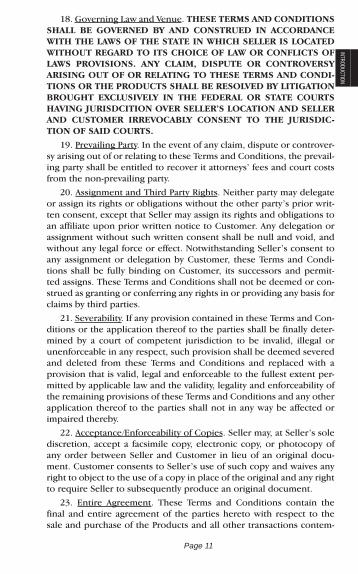
INTRODUCTION18. Governing Law and Venue. THESE TERMS AND CONDITIONS
SHALL BE GOVERNED BY AND CONSTRUED IN ACCORDANCE WITH THE LAWS OF THE STATE IN WHICH SELLER IS LOCATED WITHOUT REGARD TO ITS CHOICE OF LAW OR CONFLICTS OF LAWS PROVISIONS. ANY CLAIM, DISPUTE OR CONTROVERSY ARISING OUT OF OR RELATING TO THESE TERMS AND CONDI-TIONS OR THE PRODUCTS SHALL BE RESOLVED BY LITIGATION BROUGHT EXCLUSIVELY IN THE FEDERAL OR STATE COURTS HAVING JURISDCITION OVER SELLER’S LOCATION AND SELLER AND CUSTOMER IRREVOCABLY CONSENT TO THE JURISDIC-TION OF SAID COURTS.
19. Prevailing Party. In the event of any claim, dispute or controver-sy arising out of or relating to these Terms and Conditions, the prevail-ing party shall be entitled to recover it attorneys’ fees and court costs from the non-prevailing party.
20. Assignment and Third Party Rights. Neither party may delegate or assign its rights or obligations without the other party’s prior writ-ten consent, except that Seller may assign its rights and obligations to an affiliate upon prior written notice to Customer. Any delegation or assignment without such written consent shall be null and void, and without any legal force or effect. Notwithstanding Seller’s consent to any assignment or delegation by Customer, these Terms and Condi-tions shall be fully binding on Customer, its successors and permit-ted assigns. These Terms and Conditions shall not be deemed or con-strued as granting or conferring any rights in or providing any basis for claims by third parties.
21. Severability. If any provision contained in these Terms and Con-ditions or the application thereof to the parties shall be finally deter-mined by a court of competent jurisdiction to be invalid, illegal or unenforceable in any respect, such provision shall be deemed severed and deleted from these Terms and Conditions and replaced with a provision that is valid, legal and enforceable to the fullest extent per-mitted by applicable law and the validity, legality and enforceability of the remaining provisions of these Terms and Conditions and any other application thereof to the parties shall not in any way be affected or impaired thereby.
22. Acceptance/Enforceability of Copies. Seller may, at Seller’s sole discretion, accept a facsimile copy, electronic copy, or photocopy of any order between Seller and Customer in lieu of an original docu-ment. Customer consents to Seller’s use of such copy and waives any right to object to the use of a copy in place of the original and any right to require Seller to subsequently produce an original document.
23. Entire Agreement. These Terms and Conditions contain the final and entire agreement of the parties hereto with respect to the sale and purchase of the Products and all other transactions contem-
Page 11

plated herein, and supersede all prior or contemporaneous discus-sions, negotiations, agreements or understandings, whether written or oral, between the parties relating to the subject matter hereof. These Terms and Conditions may be changed, amended, modified, revised or supplemented only by a written instrument signed by an authorized manager or officer of Seller.
Page 12

Page 13 Processing
PROCESSING
Nearly all band saws throughout PDM are fed with state of the art conveyor systems that greatly increase productivity and overall tolerances. With CNC controlled indexing and automated miter cutting, these operations are efficient and very accurate.
Capacities: Jaw openings up to 40” x 48” Miter cutting capacity up to 25” x 25” and 45 degrees CNC indexing, accurate bundle cutting Cost saving nesting capabilities
Driven by large hydraulic rams, high carbon blades come together like a large pair of scissors to cut steel plates. Plate shears provide fast and accurate square and rectangular part production in a wide variety of thicknesses.
Capacities: Cuts up to ¼’ thick mild steel plate Cuts up to 13’-0” wide
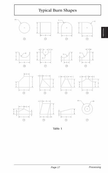
Thermal cutting employs the processes of oxy fuel or high defini-tion plasma cutting. Oxy fuel cutting is utilized to handle thicker plate cutting (up to 8”) while high definition plasma cuts much faster in thickness ranging from 16 ga. up to 2 ½” thick.
Capacities: Cuts up to 240” wide Cuts up to 60’ long
* See Shape Chart on page 17.
Processing & Equipment
Sawing to Length
Plate Shearing
Thermal Shape Cutting

Page 14Processing
Our precision plate processing machines can cut, punch, drill, tap, mark, scribe, and mill parts in a multitude of thicknesses and grades with improved accuracy. Due to a method of stationary gantry for fixed points of operation, this provides greater accuracy in cutting and the other processes.
Capacities: Milling both face and end Drilling up to 3’’ in diameter in 3” plate Punching up to 1-1/2” in diameter Tapping up to 1-1/2’’ in diameter Scribing layout lines and customized lettering Marking letter and number size: 2/3’’ wide x 5/8’’ tall High definition plasma up to 3’’ thick
A 1,000 ton x 24’ Cincinnati Press Brake provides a wide variety of forming shapes including angles, channels, zee’s and more com-plex shapes.
Capacities: 1,000 ton downward force 24’ forming bed 1/2” thick mild steel plate up to 24’ long 1” thick mild steel plate up to 14” long
* See Forming Chart on page 17-20.
Chamfering and plate edge preparation using a full range of multiple axis beveling machines allows full beveling capabilities. From beveling on the fly, including radius bevel-ing, these machines provide a vast array of beveling and edge preparation needs.
Capacities: Radius Beveling Multiple angle beveling on the fly Multiple axis beveling
Multiple Angle Beveling
Steel Forming Services
Punching, Drilling, Tapping, Marking, Scribing, and Milling
Page 15 Processing
PROCESSING
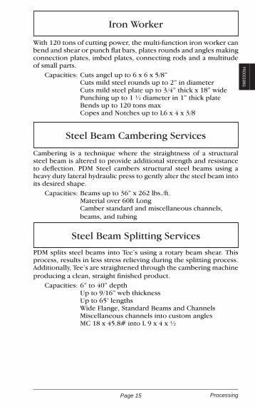
With 120 tons of cutting power, the multi-function iron worker can bend and shear or punch flat bars, plates rounds and angles making connection plates, imbed plates, connecting rods and a multitude of small parts.
Capacities: Cuts angel up to 6 x 6 x 5/8” Cuts mild steel rounds up to 2” in diameter Cuts mild steel plate up to 3/4” thick x 18” wide Punching up to 1 ½ diameter in 1” thick plate Bends up to 120 tons max Copes and Notches up to L6 x 4 x 3/8
Cambering is a technique where the straightness of a structural steel beam is altered to provide additional strength and resistance to deflection. PDM Steel cambers structural steel beams using a heavy duty lateral hydraulic press to gently alter the steel beam into its desired shape.
Capacities: Beams up to 36” x 262 lbs./ft. Material over 60ft Long Camber standard and miscellaneous channels, beams, and tubing
PDM splits steel beams into Tee’s using a rotary beam shear. This process, results in less stress relieving during the splitting process. Additionally, Tee’s are straightened through the cambering machine producing a clean, straight finished product.
Capacities: 6” to 40” depth Up to 9/16” web thickness Up to 65’ lengths Wide Flange, Standard Beams and Channels Miscellaneous channels into custom angles MC 18 x 45.8# into L 9 x 4 x ½
Steel Beam Cambering Services
Steel Beam Splitting Services
Iron Worker

Page 16Processing
Leveling is the process where large steel coils are straightened and then cut-to-length for a specific requirement. This meets custom-er’s needs to purchase exact length of material eliminating drop that would result from using stock size sheet or plate.
Capacities: 28 ga. to ½” thick 36” to 96” in width 17” to 480” in length
Laser cutting employs a highly concentrated laser beam to cut steel plate and sheet to precise tolerances without excessive heat in the cutting process.
Capacities: Up to ¼” thick Up to 60” wide Up to 120” long
* See Typical Burning Shapes on page 17.
Slitting is the process of cutting a master coil into multiple nar-rower coils in one continuous pass. The finished narrower coils are rewound and packaged for shipment. Slit coils are often used in roll forming lines or continuous stamping operations. Very tight width tolerances (+/- .005”) are possible.
Capacities: Thickness .018 Min to .250 Max Slit Coil Widths: 1” to 60”
Coil Sheet & Plate Services: Leveling, & Cut-to-Length
Laser Cutting
Slitting
Page 17 Processing
PROCESSING
Table 1
B251 FICEP Technical Specifications
Thickness Specifications:
Typical Burn Shapes
Table 1

Page 18Processing

Page 19 Processing
PROCESSING

Page 20Processing
Page 21 Hot Rolled Bar Products
HOT ROLLED BARS
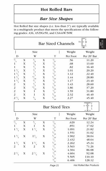
Hot Rolled Bars
Bar Size Shapes
Hot Rolled Bar size shapes (i.e. less than 3”) are typically available in a multigrade product that meets the specifications of the follow-ing grades: A36, A529Gr50, and CSA44W/50W.
| Size | Weight Weight
D W T Per Foot Per 20' Bar
Bar Sized Tees
3/4 X 3/4 X 1/8 .620 12.241 X 1 X 1/8 .851 17.021 1/4 X 1 1/4 X 1/8 1.091 21.82 3/16 1.551 31.021 1/2 X 11/2 X 3/16 1.902 38.04 1/4 2.432 48.641 3/4 X 1 3/4 X 3/16 2.262 45.242 X 2 X 1/4 3.563 71.26 5/16 4.304 86.082 1/2 X 2 1/2 X 1/4 4.604 92.08 5/16 5.505 110.10 3/8 6.406 128.12
Bar Sized Channels
| Size | Weight Weight
D W T Per Foot Per 20' Bar3/4 X 3/8 X 1/8 .56 11.201 X 3/8 X 1/8 .68 13.601 X 1/2 X 1/8 .82 16.401 1/4 X 1/2 X 1/8 1.01 20.201 1/2 X 1/2 X 1/8 1.12 22.401 1/2 X 9/16 X 3/16 1.44 28.801 1/2 X 3/4 X 1/8 1.17 23.402 X 1/2 X 1/8 1.43 28.602 X 9/16 X 3/16 1.86 37.202 X 1 X 1/8 1.59 31.802 X 1 X 3/16 2.32 46.402 1/2 X 5/8 X 3/16 2.27 45.40
D
W
T

Page 22Hot Rolled Bar Products
Bar Sized Angles
1/2 X 1/2 X 1/8 .380 7.605/8 X 5/8 X 1/8 .480 9.603/4 X 3/4 X 1/8 .591 11.827/8 X 7/8 X 1/8 .701 14.021 X 1 X 1/8 .801 16.02 3/16 1.161 23.22 1/4 1.491 29.821 1/4 X 1 1/4 X 1/8 1.011 20.22 3/16 1.481 29.62 1/4 1.922 38.441 1/2 X 1 1/2 X 1/8 1.231 24.62 3/16 1.802 36.04 1/4 2.342 46.84 5/16 2.863 57.26 3/8 3.353 67.061 3/4 X 1 3/4 X 1/8 1.441 28.82 3/16 2.122 42.44 1/4 2.773 55.462 X 1 1/2 X 1/8 1.441 28.82 3/16 2.122 42.44 1/4 2.773 55.462 X 2 X 1/8 1.652 33.04 3/16 2.442 48.84 1/4 3.193 63.86 5/16 3.924 78.48 3/8 4.704 94.082 1/2 X 1 1/2 X 3/16 2.442 48.84 1/4 3.193 63.862 1/2 X 2 X 3/16 2.753 55.06 1/4 3.623 72.46 5/16 4.504 90.08 3/8 5.305 106.102 1/2 X 21/2 X 3/16 3.073 61.46 1/4 4.104 82.08 5/16 5.005 100.10 3/8 5.906 118.12 1/2 7.707 154.14
A
B
T
| Size | Weight Weight
A B T Per Foot Per 20' Bar
Many bar sized shapes are also available in 30’ & 40’ lengths.

Page 23 Hot Rolled Bar Products
HOT ROLLED BARS
Hot Rolled Flats
1/4 x 1/2 .425 8.50 5/8 .531 10.62 3/4 .639 12.78 7/8 .745 14.90 1 .851 17.02 1 1/4 1.064 21.28 1 1/2 1.276 25.52 1 3/4 1.489 29.78 2 1.702 34.04 2 1/4 1.915 38.30 2 1/2 2.127 42.54 2 3/4 2.340 46.80 3 2.552 51.04 3 1/4 2.766 55.32 3 1/2 2.978 59.56 4 3.403 68.06 4 1/2 3.829 76.58 5 4.254 85.08 5 1/2 4.679 93.58 6 5.105 102.10 7 5.956 119.12 8 6.806 136.125/16 x 1/2 .531 10.62 5/8 .665 13.30 3/4 .798 15.96 7/8 .931 18.62 1 1.064 21.28 1 1/4 1.329 26.58 1 1/2 1.594 31.88 1 3/4 1.861 37.22 2 2.127 42.54 2 1/4 2.393 47.86 2 1/2 2.658 53.16
5/16 x 2 3/4 2.925 58.50 3 3.191 63.82 3 1/2 3.723 74.46 4 4.254 85.08 4 1/2 4.785 95.70 5 5.318 106.36 5 1/2 5.850 117.00 6 6.381 127.62 7 7.445 148.90 8 8.508 170.163/8 x 1/2 .639 12.78 5/8 .798 15.96 3/4 .957 19.14 7/8 1.117 22.34 1 1.276 25.52 1 1/4 1.596 31.92 1 1/2 1.915 38.30 1 3/4 2.233 44.66 2 2.552 51.04 2 1/4 2.872 57.44 2 1/2 3.191 63.82 2 3/4 3.509 70.18 3 3.829 76.58 3 1/4 4.148 82.96 3 1/2 4.467 89.34 4 5.105 102.10 4 1/2 5.743 114.86 5 6.381 127.62 5 1/2 7.020 140.40 6 7.657 153.14 7 8.933 178.66 8 10.210 204.20
Size In Inches
Weight Per Foot
Weight Per 20'
Size In Inches
Weight Per Foot
WeightPer 20'

Page 24Hot Rolled Bar Products
Hot Rolled Flats (Continued)
1/2 x 3/4 1.276 25.52 7/8 1.489 29.78 1 1.702 34.04 1 1/4 2.127 42.54 1 1/2 2.552 51.04 1 3/4 2.978 59.56 2 3.403 68.06 2 1/4 3.829 76.58 2 1/2 4.254 85.08 2 3/4 4.679 93.58 3 5.105 102.10 3 1/4 5.530 110.60 3 1/2 5.956 119.12 4 6.806 136.12 4 1/2 7.657 153.14 5 8.508 170.16 5 1/2 9.359 187.18 6 10.210 204.20 7 11.911 238.22 8 13.613 272.265/8 x 1 2.127 42.54 1 1/4 2.658 53.16 1 1/2 3.191 63.82 1 3/4 3.723 74.46 2 4.254 85.08 2 1/4 4.785 95.70 2 1/2 5.318 106.36 2 3/4 5.850 117.00 3 6.381 127.62 3 1/4 6.913 138.26 3 1/2 7.445 148.90 4 8.508 170.16 4 1/2 9.572 191.44 5 10.640 212.80
5/8 x 5 1/2 11.699 233.98 6 12.762 255.24 7 14.894 297.88 8 17.016 340.323/4 x 1 2.552 51.04 1 1/4 3.191 63.82 1 1/2 3.829 76.58 1 3/4 4.467 89.34 2 5.105 102.10 2 1/4 5.743 114.86 2 1/2 6.381 127.62 2 3/4 7.020 140.40 3 7.657 153.14 3 1/2 8.933 178.66 4 10.210 204.20 4 1/2 11.491 229.82 5 12.762 255.24 5 1/2 14.038 280.76 6 15.314 306.28 7 17.867 357.34 8 20.419 408.387/8 x 1 2.978 59.56 1 1/4 3.723 74.46 1 1/2 4.467 89.34 2 5.956 119.12 2 1/2 7.445 148.90 3 8.933 178.66 3 1/2 10.420 208.40 4 11.911 238.22 4 1/2 13.403 268.06 5 14.894 297.88 6 17.867 357.34 7 20.830 416.60 8 23.822 476.44
Size In Inches
Weight Per Foot
Weight Per 20'
Size In Inches
Weight Per Foot
WeightPer 20'

Page 25 Hot Rolled Bar Products
HOT ROLLED BARS
Hot Rolled Flats (Continued)
Size In Inches
Weight Per Foot
Weight Per 20'
Size In Inches
Weight Per Foot
WeightPer 20'
1 x 11/4 4.254 85.08
1 1/2 5.105 102.10
1 3/4 5.956 119.12
2 6.806 136.12
2 1/4 7.657 153.14
2 1/2 8.508 170.16
2 3/4 9.359 187.18
3 10.210 204.20
3 1/4 11.060 221.20
3 1/2 11.911 238.22
4 13.613 272.26
4 1/2 15.314 306.28
5 17.016 340.32
5 1/2 18.718 374.36
6 20.419 408.38
7 23.822 476.44
8 27.226 544.52
1 1/4 x l 1/2 6.381 127.62
1 3/4 7.445 148.90
2 8.508 170.16
2 1/4 9.572 191.44
2 1/2 10.640 212.80
3 12.762 255.24
3 1/2 14.894 297.88
4 17.816 340.32
1 1/4 x 4 1/2 19.148 382.96
5 21.270 425.40
6 25.524 510.48
7 29.778 595.56
8 34.032 680.64
1 1/2 x 2 10.210 204.20
2 1/2 12.762 255.24
3 15.314 306.28
3 1/2 17.867 357.34
4 20.419 408.38
4 1/2 22.972 459.44
5 25.524 510.48
6 30.629 612.58
7 35.734 714.68
8 40.834 816.76
2 x 2 1/2 17.016 340.32
3 20.419 408.38
3 1/2 23.822 476.44
4 27.226 544.52
4 1/2 30.629 612.58
5 34.032 680.64
6 40.838 816.76
7 47.600 952.00
8 54.451 1089.02

Page 26Hot Rolled Bar Products
l/4 x 9 7.66 153.1 10 8.51 170.2 11 9.36 187.2 12 10.21 204.2 14 11.91 238.25/16 x 9 9.57 191.4 10 10.64 212.8 12 12.76 255.2 14 14.89 297.73/8 x 9 11.49 229.8 10 12.76 255.2 11 14.03 280.6 12 15.31 306.3 14 17.86 357.21/2 x 9 15.31 306.3 10 17.02 340.4
1/2 x 11 18.72 374.4 12 20.42 408.4 14 23.82 476.55/8 x 9 19.15 383.0 10 21.27 425.4 12 25.52 510.5 14 29.77 595.53/4 x 9 22.97 459.4 10 25.52 510.5 12 30.63 612.6 14 35.74 714.71 x 9 30.63 612.6 10 34.03 680.6 12 40.84 816.8 14 47.65 952.9
Weights For UM Plates
Size In Inches
Wt. Per Foot
Wt. Per 20 Ft.
Size In Inches
Wt. Per Foot
Wt. Per 20 Ft.

Page 27 Hot Rolled Bar Products
HOT ROLLED BARS
Hot Rolled Rounds
Size In Inches
Wt. Per Foot
Wt. Per 20 Ft.
Size In Inches
Wt. Per Foot
Wt. Per 20 Ft.
3/16 .094 1.88
1/4 .167 3.34
5/16 .261 5.22
3/8 .376 7.52
7/16 .511 10.22
1/2 .669 13.38
9/16 .846 16.92
5/8 1.044 20.88
3/4 1.503 30.06
7/8 2.046 40.92
1 2.673 53.46
1 1/8 3.382 67.64
1 1/4 4.177 83.54
1 3/8 5.054 101.08
1 1/2 6.014 120.28
1 5/8 7.058 141.16
1 3/4 8.186 163.72
1 7/8 9.397 187.94
2 10.690 213.80
2 1/8 12.071 241.42
2 1/4 13.533 270.66
2 5/16 14.293 285.86
2 3/8 15.074 301.48
2 1/2 16.706 334.12
2 5/8 18.417 368.34
2 3/4 20.219 404.38
2 7/8 22.091 441.82
3 24.053 481.06
3 1/4 28.237 564.74
3 3/8 30.449 608.98
3 1/2 32.741 654.82
3 5/8 35.123 702.46
3 3/4 37.585 751.70
3 7/8 40.138 802.76
4 42.770 855.40
4 1/4 48.275 965.50
4 1/2 54.131 1082.62
4 3/4 60.307 1206.14
5 66.823 1336.46
5 1/4 73.669 1473.38
5 1/2 80.856 1617.12
5 3/4 88.373 1767.46
6 96.221 1924.42
6 1/4 104.398 2087.96
6 1/2 112.926 2258.52
6 3/4 121.785 2435.70
7 130.973 2619.46
7 1/4 140.492 2809.84
7 1/2 150.352 3007.04
7 3/4 160.541 3210.82
8 171.061 3421.22
8 1/4 181.921 3638.42
8 1/2 193.112 3862.24
8 3/4 204.643 4092.86
9 216.504 4330.08
9 1/4 228.695 4573.90
9 1/2 241.227 4824.54
10 267.342 5346.84

Page 28Hot Rolled Bar Products
Hot Rolled Squares
1/4 .213 4.26 5/16 .332 6.64 3/8 .478 9.56 7/16 .652 13.04 1/2 .851 17.02 5/8 1.329 26.58 3/4 1.915 38.30 7/8 2.605 52.10 1 3.403 68.06 1 1/8 4.307 86.14 1 1/4 5.318 106.36 1 3/8 6.434 128.68 1 1/2 7.567 153.14
1 5/8 8.986 179.72 1 3/4 10.423 208.46 2 13.310 266.20 2 1/8 15.367 307.34 2 1/4 17.229 344.58 2 1/2 21.270 425.40 2 3/4 25.737 514.74 3 30.629 612.58 3 1/4 35.944 718.88 3 1/2 41.689 833.78 4 54.451 1089.02 4 1/2 68.915 1378.30 5 85.080 1701.60
Size In Inches
Wt. Per Foot
Wt. Per 20 Ft.
Size In Inches
Wt. Per Foot
Wt. Per 20 Ft.
Commercial Quality
Commercial Quality bars are typically produced in grades C1008, C1020, to chemical specifications. Commercial Quality bars are not subject to mechanical property tests. Typical properties are given for reference only. Mill size tolerances apply to all Commercial Quality bars.
Applications
Commercial Quality bars are used in many applications. Among them are structural uses involving moderate cold bending or hot forming, welding, punching, and the production of non- critical parts of buildings, bridges, railway equipment, road building equipment, agricultural equipment and implements, and general machinery.

Page 29 Hot Rolled Bar Products
HOT ROLLED BARS
Hot Rolled Strips
Size In Inches
Weight Per Foot
Weight Per 20'
Size In Inches
Weight Per Foot
WeightPer 20'
1/8 x 1/2 0.213 4.26
5/8 0.266 5.32
3/4 0.319 6.38
7/8 0.372 7.44
1 0.425 8.50
1 1/8 0.478 9.56
1 1/4 0.531 10.62
1 1/2 0.639 12.78
1 3/4 0.745 14.90
2 0.851 17.02
2 1/4 0.957 19.14
2 1/2 1.064 21.28
2 3/4 1.170 23.40
3 1.276 25.52
3 1/2 1.489 29.78
4 1.702 34.04
4 1/2 1.915 38.30
5 2.127 42.54
6 2.552 51.04
8 3.403 68.06
10 4.254 85.08
12 5.105 102.10
3/16 x 1/2 0.319 6.38
5/8 0.398 7.96
3/4 0.478 9.56
7/8 0.559 11.18
1 0.639 12.78
1 1/8 0.718 14.36
1 1/4 0.798 15.96
1 1/2 0.957 19.14
1 3/4 1.117 22.34
2 1.276 25.52
2 1/4 1.435 28.70
2 1/2 1.596 31.92
2 3/4 1.755 35.10
3 1.915 38.30
3 1/2 2.233 44.66
4 2.552 51.04
4 1/2 2.872 57.44
5 3.191 63.82
6 3.829 76.58
8 5.105 102.10
10 6.381 127.62
12 7.657 l53.14

Page 30Structural Shapes
Structural ShapesStructural shapes are those whose greatest dimension, not includ-ing length, is three inches or greater.
Structural Quality products (i.e. 3” and larger) are typically available in a multigrade product that will meet the specifications of the following grades: A36, A529Gr50 & 55, A572Gr50 & 55, A709Gr36 & 50, CAN 44W 50W & 55W, CSA44, 50W, AASHTO M270, M270M-10gr36 Gr50, ASME SA36M-07.
Weldability
When any grade of steel is used in welded construction, proce-dures must be suitable for the steel and the intended service.
ASTM A36 steel presents no welding problems when using all weld-ing processes. The quality of the welds is generally extremely high for both welds and joints. Welding rod specifications are depen-dent on welding conditions such as the thickness of the sections to be welded, service requirements and design.
High Strength, Low Alloy grades such as A572 Grade 50 and A992 are weldable with welding techniques suitable for the grade and intended service application.

Page 31 Structural Shapes
STRUCTURAL SHAPES
Structural Angles
| Size | Weight Weight
A B T Per Foot Per 40' Bar
3 X 2 X 3/16 3.073 122.92 1/4 4.104 164.16 5/16 5.005 200.20 3/8 5.906 236.24 1/2 7.707 308.283 X 2 1/2 X 3/16 3.393 135.72 1/4 4.504 180.16 5/16 5.605 224.20 3/8 6.606 264.24 1/2 8.508 340.323 X 3 X 3/16 3.714 148.56 1/4 4.905 196.20 5/16 6.106 244.24 3/8 7.207 288.28 1/2 9.409 376.363 1/2 X 2 1/2 X 3/16 3.393 135.72 1/4 4.905 196.20 5/16 6.106 244.24 3/8 7.207 288.28 1/2 9.409 376.363 1/2 X 3 X 1/4 5.405 216.20 5/16 6.606 264.24 3/8 7.907 316.28 1/2 10.210 408.403 1/2 X 3 1/2 X 1/4 5.805 232.20 5/16 7.207 288.28 3/8 8.508 340.32 1/2 11.110 444.404 X 3 X 1/4 5.805 232.20 5/16 7.207 288.28 3/8 8.508 340.32 1/2 11.110 444.40 5/8 13.613 544.524 X 3 1/2 X 1/4 6.206 248.24 5/16 7.707 308.28
AT
B

Page 32Structural Shapes
| Size | Weight Weight
D W T Per Foot Per 40' Bar
Structural Angles (Continued)
4 X 3 1/2 X 3/8 9.109 364.36 1/2 11.911 476.444 X 4 X 1/4 6.606 264.24 5/16 8.208 328.32 3/8 9.809 392.36 1/2 12.812 512.48 5/8 15.715 628.60 3/4 18.517 740.685 X 3 X 1/4 6.606 264.24 5/16 8.208 328.32 3/8 9.809 392.36 1/2 12.812 512.48 5/8 15.715 628.605 X 3 1/2 X 1/4 7.007 280.28 5/16 8.708 348.32 3/8 10.410 416.40 1/2 13.613 544.52 5/8 16.816 672.64 3/4 19.810 792.765 X 5 X 5/16 10.310 412.40 3/8 12.312 492.48 7/16 14.313 572.52 1/2 16.215 648.60 5/8 20.019 800.76 3/4 23.622 944.886 X 3 1/2 X 1/4 7.907 316.28 5/16 9.809 392.36 3/8 11.711 468.44 1/2 15.314 612.56 5/8 19.018 760.726 X 4 X 5/16 10.310 412.40 3/8 12.312 492.48 7/16 14.313 572.52
Please Note: Most Structural Angles are stocked in 20', 30', and 40' lengths.
AT
B

Page 33 Structural Shapes
STRUCTURAL SHAPES
Structural Angles (Continued)
| Size | Weight Weight
D W T Per Foot Per 40' Bar
6 X 4 X 1/2 16.215 648.60 5/8 20.019 800.76 3/4 23.622 944.886 X 6 X 1/4 9.989 399.56 5/16 12.400 500.48 3/8 14.914 596.56 7/16 17.216 688.64 1/2 19.618 784.72 5/8 24.223 968.92 3/4 28.727 1149.08 1 37.435 1497.407 X 4 X 3/8 13.613 544.52 7/16 15.700 632.60 1/2 17.917 716.68 5/8 22.121 884.84 3/4 26.225 1049.008 X 4 X 1/2 19.618 784.72 5/8 24.200 968.00 3/4 28.727 1149.08 1 37.435 1497.408 X 6 X 1/2 23.022 920.88 5/8 28.527 1141.08 3/4 33.832 1353.28 1 44.242 1769.688 X 8 X 1/2 26.425 1057.00 5/8 32.731 1309.24 3/4 38.937 1557.48 1 51.048 2041.929 X 4 X 1/2 21.320 852.80 3/4 31.300 1252.00
Please Note: Most Structural Angles are stocked in 20', 30', and 40' lengths.
AT
B

Page 34Structural Shapes
Structural Channels D
W
T
| Size | Weight
D Lbs. / Foot W T Per 40' Bar
3 3.5 1.372 .132 140 4.1 1.410 .170 164 5.0 1.498 .258 200 6.0 1.596 .356 2404 4.5 1.584 .125 180 5.4 1.584 .184 216 6.25 1.647 .247 250 7.25 1.721 .321 2905 6.7 1.750 .190 268 9.0 1.885 .325 3606 8.2 1.920 .200 328 10.5 2.034 .314 420 13.0 2.157 .437 5207 9.8 2.090 .210 392 12.25 2.194 .314 490 14.75 2.299 .419 5908 11.50 2.260 .220 460 13.75 2.343 .303 550 18.75 2.527 .487 7509 13.4 2.433 .233 536 15.0 2.485 .285 600 20.0 2.648 .448 80010 15.3 2.600 .240 612 20.0 2.739 .379 800 25.0 2.886 .526 1000 30.0 3.033 .673 120012 20.7 2.942 .282 828 25.0 3.047 .387 1000 30.0 3.170 .510 120015 33.9 3.400 .400 1356 40.0 3.520 .520 1600 50.0 3.716 .716 2000
Please Note: Most Structural Channels are available in 20', 30', 40', 50', and 60' lengths.

Page 35 Structural Shapes
STRUCTURAL SHAPES
3 7.1 1.938 .312 2844 13.8 2.500 .500 5526 6.5 1.850 .155 260 7.0 1.875 .179 280 12.0 2.497 .310 480 15.1 2.941 .316 604 15.3 3.500 .340 612 16.3 3.000 .375 652 18.0 3.504 .379 7207 19.1 3.452 .352 764 22.7 3.603 .503 9088 8.5 1.874 .179 340 18.7 2.978 .353 748 20.0 3.025 .400 800 21.4 3.450 .375 856 22.8 3.502 .427 9129 23.9 3.450 .400 956 25.4 3.500 .450 101610 6.5 1.170 .152 260 8.4 1.500 .170 336 22.0 3.315 .290 880 25.0 3.405 .380 1000 28.5 3.950 .425 1140 33.6 4.100 .575 1244 41.1 4.321 .796 164412 10.6 1.500 .190 424 14.3 2.125 .250 572 31.0 3.670 .370 1240 35.0 3.765 .465 1400 40.0 3.890 .590 1600 45.0 4.010 .710 1800 50.0 4.135 .835 200013 31.8 4.000 .375 1272 35.0 4.072 .447 1360 40.0 4.185 .560 1600 50.0 4.412 .787 200018 42.7 3.950 .450 1708 45.8 4.000 .500 1832 51.9 4.100 .600 2076 58.0 4.200 .700 2320
Misc. Structural Channels
| Size | Weight
D Lbs. / Foot W T Per 40' Bar
D
W
T

Page 36Structural Shapes
Wide Flange BeamsW
DT
4 x 13 4.16 4.060 .280
5 x 16 5.01 5.000 .240 19 5.15 5.030 .270
6 x 8.5 5.83 3.940 .170 9 5.90 3.940 .170 12 6.03 4.000 .230 16 6.28 4.030 .260
6 x 15 5.99 5.990 .230 20 6.20 6.020 .260 25 6.38 6.080 .320
8 x 10 7.89 3.940 .170 13 7.99 4.000 .230 15 8.11 4.015 .245
8 x 18 8.14 5.250 .230 21 8.28 5.270 .250
8 x 24 7.93 6.495 .245 28 8.06 6.535 .285
8 x 31 8.00 7.995 .285 35 8.12 8.020 .310 40 8.25 8.070 .360 48 8.50 8.110 .400 58 8.75 8.220 .510 67 9.00 8.280 .570
10 x 12 9.87 3.960 .190 15 9.99 4.000 .230 17 10.11 4.010 .240 19 10.24 4.020 .250
10 x 22 10.17 5.750 .240 26 10.33 5.770 .260 30 10.47 5.810 .300
10 x 33 9.73 7.960 .290 39 9.92 7.985 .315 45 10.10 8.020 .35010 x 49 9.98 10.000 .340 54 10.09 10.030 .370 60 10.22 10.080 .420 68 10.40 10.130 .470 77 10.60 10.190 .530 88 10.84 10.265 .605 100 11.10 10.340 .680 112 11.36 10.415 .755
12 x 14 11.91 3.970 .200 16 11.99 3.990 .220 19 12.16 4.005 .235 22 12.31 4.030 .260
12 x 26 12.22 6.490 .230 30 12.34 6.520 .260 35 12.50 6.560 .300
12 x 40 11.94 8.005 .295 45 12.06 8.045 .335 50 12.19 8.080 .370
12 x 53 12.06 9.995 .345 58 12.19 10.010 .360
12 x 65 12.12 12.000 .390 72 12.25 12.040 .430 79 12.38 12.080 .470 87 12.53 12.125 .515 96 12.71 12.160 .550 106 12.89 12.220 .610 120 13.12 12.320 .710 136 13.41 12.400 .790 152 13.71 12.480 .870 170 14.03 12.570 .960 190 14.38 12.670 1.060 210 14.71 12.790 1.180
| Size |
Lbs/Ft D W T
| Size |
Lbs/Ft D W T

Page 37 Structural Shapes
STRUCTURAL SHAPES
230 15.05 12.895 1.285 252 15.41 13.005 1.395 279 15.85 13.140 1.530 305 16.32 13.235 1.625 336 16.82 13.385 1.775
14 x 22 13.74 5.000 .230 26 13.91 5.025 .255
14 x 30 13.84 6.730 .270 34 13.98 6.745 .285 38 14.10 6.770 .310
14 x 43 13.66 7.995 .305 48 13.79 8.030 .340 53 13.92 8.060 .370
14 x 61 13.89 9.995 .375 68 14.04 10.035 .415 74 14.17 10.070 .450 82 14.31 10.130 .510
14 x 90 14.02 14.520 .440 99 14.16 14.565 .485 109 14.32 14.605 .525 120 14.48 14.670 .590 132 14.66 14.725 .645
14 x 145 14.78 15.500 .680 159 14.98 15.565 .745 176 15.22 15.650 .830 193 15.48 15.710 .890 211 15.72 15.800 .980 233 16.04 15.890 1.070 257 16.38 15.995 1.175 283 16.74 16.110 1.290 311 17.12 16.230 1.410 342 17.54 16.360 1.540 370 17.92 16.475 1.655
398 18.29 16.590 1.770
14 x 426 18.67 16.695 1.875 455 19.02 16.835 2.015 500 19.60 17.010 2.190 550 20.24 17.200 2.380 605 20.92 17.415 2.595 665 21.64 17.650 2.830 730 22.42 17.890 3.070
16 x 26 15.69 5.500 .250 31 15.88 5.525 .275
16 x 36 15.86 6.985 .295 40 16.01 6.995 .305 45 16.13 7.035 .345 50 16.26 7.070 .380 57 16.43 7.120 .430
16 x 67 16.33 10.235 .395 77 16.52 10.295 .455 89 16.75 10.365 .525 100 16.97 10.425 .585
18 x 35 17.70 6.000 .300 40 17.90 6.015 .315 46 18.06 6.060 .360
18 x 50 17.99 7.495 .355 55 18.11 7.530 .390 60 18.24 7.555 .415 65 18.35 7.590 .450 71 18.47 7.635 .495
18 x 76 18.21 11.035 .425 86 18.39 11.090 .480 97 18.59 11.145 .535 106 18.73 11.200 .590 119 18.97 11.265 .655
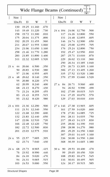
Wide Flange Beams (Continued)W
DT
| Size |
Lbs/Ft D W T
| Size |
Lbs/Ft D W T
Page 38Structural Shapes
130 19.25 11.160 .670 143 19.49 11.220 .730 158 19.72 11.300 .810 175 20.04 11.375 .890 192 20.35 11.455 .960 211 20.67 11.555 1.060 234 21.06 11.650 1.160 258 21.46 11.770 1.280 283 21.85 11.890 1.400 311 22.32 12.005 1.520
21 x 44 20.66 6.500 .350 50 20.83 6.530 .380 57 21.06 6.555 .40521 x 48 20.62 8.140 .350 55 20.80 8.220 .375 62 20.99 8.240 .400 68 21.13 8.270 .430 73 21.24 8.295 .455 83 21.43 8.355 .515 93 21.62 8.420 .580
21 x 101 21.36 12.290 .500 111 21.51 12.340 .550 122 21.68 12.390 .600 132 21.83 12.440 .650 147 22.06 12.510 .720 166 22.48 12.420 .750 182 22.72 12.500 .830 201 23.03 12.575 .910
24 x 55 23.57 7.005 .395 62 23.74 7.040 .430
24 x 68 23.73 8.965 .415 76 23.92 8.990 .440 84 24.10 9.020 .470 94 24.31 9.065 .515 103 24.53 9.000 .550
24 x 104 24.06 12.750 .500 117 24.26 12.800 .550 131 24.48 12.855 .605 146 24.74 12.900 .650 162 25.00 12.955 .705 176 25.24 12.890 .750 192 25.47 12.950 .810 207 25.71 13.010 .870 229 26.02 13.110 .960 250 26.34 13.185 1.040 279 26.73 13.305 1.160 306 27.13 13.405 1.260 335 27.52 13.520 1.380 370 27.99 13.660 1.520
27 x 84 26.71 9.960 .460 94 26.92 9.990 .490 102 27.09 10.015 .515 114 27.29 10.070 .570 129 27.63 10.010 .610
27 x 146 27.38 13.965 .605 161 27.59 14.020 .660 178 27.81 14.085 .725 194 28.11 14.035 .750 217 28.43 14.115 .830 235 28.66 14.190 .910 258 28.98 14.270 .980 281 29.29 14.350 1.060 307 29.61 14.445 1.160 336 30.00 14.550 1.260 368 30.39 14.665 1.380
30 x 90 29.53 10.400 .470 99 29.65 10.450 .520 108 29.83 10.475 .545 116 30.01 10.495 .565 124 30.17 10.515 .585
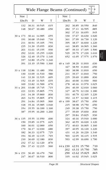
Wide Flange Beams (Continued)W
DT
| Size |
Lbs/Ft D W T
| Size |
Lbs/Ft D W T
Page 39 Structural Shapes
STRUCTURAL SHAPES
132 30.31 10.545 .615 148 30.67 10.480 .650
30 x 173 30.44 14.985 .655 191 30.68 15.040 .710 211 30.94 15.105 .755 235 31.30 15.055 .830 261 31.61 15.155 .930 292 32.01 15.255 1.020 326 32.40 15.370 1.140 357 32.80 15.470 1.240 391 33.19 15.590 1.360
33 x 118 32.86 11.480 .550 130 33.09 11.510 .580 141 33.30 11.535 .605 152 33.49 11.565 .635 169 33.82 11.500 .67033 x 201 33.68 15.745 .715 221 33.93 15.805 .775 241 34.18 15.860 .830 263 34.53 15.805 .870 291 34.84 15.905 .960 318 35.16 15.985 1.040 354 35.55 16.100 1.160 387 35.95 16.200 1.260
36 x 135 35.55 11.950 .600 150 35.85 11.975 .625 160 36.01 12.000 .650 170 36.17 12.030 .680 182 36.33 12.075 .725 194 36.49 12.115 .765 210 36.69 12.180 .830 232 37.12 12.120 .870 256 37.43 12.215 .960
36 x 231 36.49 16.470 .760 247 36.67 16.510 .800
262 36.85 16.550 .840 282 37.11 16.595 .885 302 37.33 16.655 .945 330 37.67 16.630 1.020 361 37.99 16.730 1.120 395 38.37 16.830 1.220 441 38.85 16.965 1.360 487 39.33 17.105 1.500 529 39.79 17.220 1.610 652 41.05 17.575 1.970
40 x 149 38.20 11.810 .630 167 38.59 11.810 .650 183 38.98 11.810 .650 211 39.37 11.810 .750 235 39.69 11.890 .830 264 40.00 11.930 .960 278 40.16 11.970 1.025 294 40.39 12.010 1.060 327 40.79 12.130 1.180 331 40.79 12.165 1.220 392 41.57 12.360 1.415 40 x 199 38.67 15.750 .650 215 38.98 15.750 .650 249 39.38 15.750 .750 277 39.69 15.830 .830 297 39.84 15.825 .930 324 40.16 15.910 1.000 362 40.55 16.020 1.120 372 40.63 16.065 1.160 397 40.95 16.120 1.220 431 41.26 16.220 1.340 503 42.05 16.415 1.535 593 42.99 16.690 1.790
44 x 230 42.91 15.750 .710 262 43.31 15.750 .785 290 43.62 15.825 .865 335 44.02 15.945 1.025
Wide Flange Beams (Continued)W
DT
| Size |
Lbs/Ft D W T
| Size |
Lbs/Ft D W T
Page 40Structural Shapes
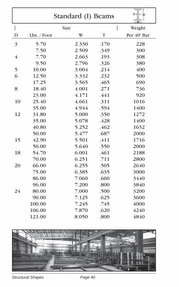
Standard (I) Beams
| Size | Weight
D Lbs. / Foot W T Per 40' Bar
W
DT
3 5.70 2.330 .170 228 7.50 2.509 .349 3004 7.70 2.663 .193 308 9.50 2.796 .326 380 5 10.00 3.004 .214 400 6 12.50 3.332 .232 500 17.25 3.565 .465 690 8 18.40 4.001 .271 736 23.00 4.171 .441 920 10 25.40 4.661 .311 1016 35.00 4.944 .594 1400 12 31.80 5.000 .350 1272 35.00 5.078 .428 1400 40.80 5.252 .462 1632 50.00 5.477 .687 2000 15 42.90 5.501 .411 1716 50.00 5.640 .550 2000 18 54.70 6.001 .461 2188 70.00 6.251 .711 2800 20 66.00 6.255 .505 2640 75.00 6.385 .635 3000 86.00 7.060 .660 3440 96.00 7.200 .800 3840 24 80.00 7.000 .500 3200 90.00 7.125 .625 3600 100.00 7.245 .745 4000 106.00 7.870 .620 4240 121.00 8.050 .800 4840
Page 41 Structural Shapes
STRUCTURAL SHAPES
8 36.0 8.155 .445 144010 42.0 10.075 .415 168010 57.0 10.225 .565 228012 53.0 12.045 .435 212012 63.0 12.125 .515 252012 74.0 12.215 .605 296012 84.0 12.295 .685 336014 73.0 14.585 .505 292014 89.0 14.695 .615 356014 102.0 14.785 .705 408014 117.0 14.885 .805 4680
H PilingsT
D
W
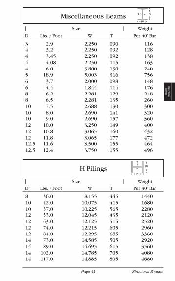
3 2.9 2.250 .090 1164 3.2 2.250 .092 1284 3.45 2.250 .092 1384 4.08 2.250 .115 1634 6.0 3.800 .130 2405 18.9 5.003 .316 7566 3.7 2.000 .098 1486 4.4 1.844 .114 1768 6.2 2.281 .129 2488 6.5 2.281 .135 26010 7.5 2.688 .130 30010 8.0 2.690 .141 32010 9.0 2.690 .157 36012 10.0 3.250 .149 40012 10.8 3.065 .160 43212 11.8 3.065 .177 47212.5 11.6 3.500 .155 46412.5 12.4 3.750 .155 496
Miscellaneous Beams D
W
T
| Size | Weight
D Lbs. / Foot W T Per 40' Bar
| Size | Weight
D Lbs. / Foot W T Per 40' Bar

Page 42Tubing Products
Tubing ProductsThe steel for square, rectangular and round structural tubing is produced to a flat strip that is cold formed into the final shape and electric resistance welded. Structural tubing is manufactured to the chemical and mechanical requirements of ASTM A-500 Grade A, ASTM A-500 Grade B, A-500 Grade C, and A1085. Some ornamen-tal sizes of square, rectangular and round tubing are made to the chemical requirements of ASTM A-513.
ApplicationsHollow Structural Tubing offers maximum strength and compact-ness with low cost design features for general building construc-tion. These carbon steel square and rectangular sections can be used as columns, posts or spandrel beams, and in complete load bearing panels, window walls, and entry structures.
Workability and WeldabilityHollow Structural Tubing can be subjected to the usual fabricating operations. The ductility of tubing products is good. It bends well, flattens, cuts, punches, flares and flanges easily and can be welded by the commonly employed techniques and practices.
Availability of LengthsOrnamental Tubing is generally available in 20' and 24' lengths. Struc-tural Tubing is generally available in 20', 24', 30', 32', 34', 40', 48', 56’ and 60’ lengths. Call for availability of particular sizes and lengths.
A500/A1085 Comparison A500 Grade A A500 Grade B A500 Grade C A1085
Manufacture Cold Formed Cold Formed Cold Formed Cold FormedProcess Welded Welded Welded Welded
Max Perimeter 88” 88” 88” 88”
Thickness less than less than less thanRange .875” .875” .875” .148”-/875”
YieldRounds 33k min 42k min 46k min 50k min 70k maxShapes 39k min 46k min 50k min 50k min 70k max
TensileRounds 45k min 58k min 62k min 65k minShapes 45k min 58k min 62k min 65k min
Wall plus or minus plus or minus plus or minus minus 5% toThickness 10% 10% 10% plus 10%
Mass Tolerance N/A N/A N/A -3.50%
Corner no more no more no more t= to or less than .40” 1.6t to 3.0tRadius than 3T max than 3T max than 3T max t greater than .40” 1.8t to 3.0t
CVN N/A N/A N/A 25 ft lbs @ 40 Deg F
Elongation min 2” 25% 23% 21% 21%

Page 43 Tubing Products
TUBING
Square & Rectangular Mechanical Tubing
1/2 x 1/2 x .048 .301 .060 .3625/8 x 5/8 x .048 .367 .060 .4423/4 x 3/4 x .048 .457 .060 .552 .075 .690 .083 .753 .090 .800 .120 1.0291 x 1 x .048 .629 .060 .763 .075 .945 .083 1.036 .090 1.115 .120 1.4371 1/4 x 1 1/4 x .048 .807 .060 .981 .075 1.200 .083 1.318 .090 1.443 .120 1.8461 1/2 x 1 1/2 x .048 .956 .060 1.163 .075 1.455 .083 1.602 .090 1.716 .120 2.2541 3/4 x 1 3/4 x .060 1.370 .083 1.884 .090 2.011 .120 2.6632 x 2 x .060 1.564 .075 1.966 .083 2.143 .090 2.316 .120 3.0501 x 1/2 x .060 .552 .075 .6791 1/2 x 1/2 x .060 .763
1 1/2 x 3/4 x .060 .879 .075 1.072 .083 1.176 .120 1.6401 1/2 x 1 x .048 .800 .060 .981 .075 1.200 .083 1.318 .090 1.443 .120 1.8462 x 1 x .060 1.163 .075 1.455 .083 1.602 .090 1.716 .120 2.2542 x 1 1/2 x .060 1.370 .075 .709 .090 2.011 .120 2.6632 1/2 x 1 x .120 2.6632 1/2 x 1 1/2 x .060 1.564 .075 1.945 .090 2.316 .120 2.9403 x 1 x .060 1.564 .075 1.945 .083 2.166 .090 2.316 .120 2.9403 x 1 1/2 x .060 1.779 .083 2.448 .120 3.4793 x 2 x .083 2.756 .120 3.8904 x 1 1/2 x .120 4.2924 x 2 x .083 3.296 .090 3.518 .120 4.700
Outside Wall Wt. /
Dims. Thickness Foot
Outside Wall Wt. /
Dims. Thickness Foot

Page 44Tubing Products
1/2 x .048 .236 4.72
.060 .282 5.645/8 x .048 .301 6.02
.060 .362 7.24
.083 .481 9.623/4 x .049 .367 7.34
.060 .442 8.84
.083 .591 11.82
.090 .634 12.687/8 x .048 .432 8.64
.060 .552 11.04
.083 .702 14.04
1 x .049 .498 9.96
.060 .602 12.04
.075 .741 14.82
.083 .813 16.26
.090 .875 17.50
.120 1.128 22.56
1 1/4 x .048 .629 12.58
.060 .763 15.26
.083 1.034 20.68
1 1/4 x .090 1.115 22.30
.120 1.448 28.96
1 1/2 x .060 .923 18.46
.083 1.256 25.12
.090 1.355 27.10
.120 1.769 35.38
1 3/4 x .060 1.083 21.66
.083 1.478 29.56
.090 1.596 31.92
.120 2.100 42.00
2 x .060 1.243 24.86
.083 1.699 33.98
.090 1.836 36.72
.120 2.409 48.18
2 1/2 x .048 1.283 25.66
.060 1.564 31.28
.083 2.143 42.86
.120 3.050 61.00
3 x .060 1.884 37.68
.090 2.797 55.94
.120 3.619 73.82
Round Mechanical Tubing
Outside Wt. / Wt. /
Dims. Foot 20'
Outside Wt. / Wt. /
Dims. Foot 20'

Page 45 Tubing Products
TUBING
Square Structural Tubing
1 1/4 x 1 1/4 x .188 2.401 1/2 x 1 1/2 x .188 3.23 .250 3.702 x 2 x .188 4.32 .250 5.41 .313 6.322 1/2 x 2 1/2 x .090 2.979 .120 3.89 .188 5.59 .250 7.11 .313 8.453 x 3 x .120 4.70 .188 6.87 .250 8.81 .313 10.58 .375 11.753 1/2 x 3 1/2 x .120 5.52 .188 8.15 .250 10.51 .313 12.70 .375 14.714 x 4 x .120 6.34 .188 9.42 .250 12.21 .313 14.83 .375 17.27 .500 21.634 1/2 x 4 1/2 x .120 7.31 .188 10.70 .250 13.91 .313 16.98 .375 19.825 x 5 x .120 7.84 .188 11.97 .250 15.62 .313 19.08 .375 22.37 .500 28.435 1/2 x 5 1/2 x .125 9.01 .165 11.74 .188 13.30 .250 17.32 .313 21.22 .375 24.93 .500 31.846 x 6 x .188 14.53 .250 19.02 .313 23.34 .375 27.48
6 x 6 x .500 35.24 .625 42.307 x 7 x .188 17.08 .250 22.42 .313 27.59 .375 32.58 .500 42.05 .625 50.768 x 8 x .188 19.63 .250 25.82 .313 31.84 .375 37.69 .500 48.85 .625 59.329 x 9 x .250 29.23 .313 36.10 .375 42.79 .500 55.66 .625 67.8210 x 10 x .188 24.75 .250 32.63 .313 40.35 .375 47.90 .500 62.46 .625 76.3312 x 12 x .250 39.43 .313 48.86 .375 58.10 .500 76.07 .625 93.3414 x 14 x .313 57.36 .375 68.31 .500 89.68 .625 110.2316 x 16 x .313 65.87 .375 78.52 .500 103.30 .625 127.3418 x 18 x .500 116.91 .625 144.39 .750 171.16 .870 197.2420 x 20 x .500 130.52 .625 161.40 .750 191.58 .875 221.0622 x 22 x .750 212.00 .875 244.88
Outside Wall Wt. /
Dims. Thickness Foot
Outside Wall Wt. /
Dims. Thickness Foot

Page 46Tubing Products
2 1/2 x 1 1/2 x .188 4.32 .250 5.413 x 1 1/2 x .188 4.963 x 2 x .188 5.59 .250 7.11 .313 8.453 1/2 x 1 1/2 x .188 5.593 1/2 x 2 1/2 x .188 7.05 .250 8.814 x 1 1/2 x .188 6.214 x 2 x .188 6.87 .250 8.81 .313 10.584 x 2 1/2 x .120 5.114 x 3 x .120 5.52 .188 8.15 .250 10.51 .313 12.70 .375 14.715 x 2 x .120 5.52 .188 8.15 .250 10.51 .313 12.705 x 3 x .120 6.34 .188 9.42 .250 12.21 .313 14.83 .375 17.27 .500 21.635 x 4 x .120 7.15 .188 10.70 .250 13.91 .313 16.96 .375 19.826 x 2 x .120 6.34 .188 9.42 .250 12.21 .313 14.83 .375 17.276 x 3 x .120 7.16 .188 10.70 .250 13.91 .313 16.96 .375 19.82 .500 25.00
6 x 4 x .120 7.97 .188 11.97 .250 15.62 .313 19.08 .375 22.37 .500 28.437 x 3 x .188 11.97 .250 15.62 .313 19.08 .375 22.377 x 4 x .188 13.25 .250 17.32 .313 21.21 .375 24.93 .500 31.837 x 5 x .188 14.53 .250 19.02 .313 23.34 .375 27.48 .500 35.248 x 2 x .188 11.97 .250 15.62 .313 19.08 .375 22.378 x 3 x .188 13.25 .250 17.32 .313 21.21 .375 24.93 .500 31.848 x 4 x .188 14.53 .250 19.02 .313 23.34 .375 27.48 .500 35.248 x 6 x .188 17.08 .250 22.42 .313 27.59 .375 32.58 .500 42.05 .625 50.8110 x 2 x .188 14.53 .250 19.02 .313 23.3410 x 3 x .188 15.80 .250 20.72
Rectangular Structural Tubing
Outside Wall Wt. /
Dims. Thickness Foot
Outside Wall Wt. /
Dims. Thickness Foot

Page 47 Tubing Products
TUBING
10 x 4 x .188 17.08 .250 22.42 .313 27.59 .375 32.58 .500 42.05 .625 50.7710 x 5 x .188 18.35 .250 24.12 .313 29.72 .375 35.14 .500 45.4010 x 6 x .188 19.62 .250 25.82 .313 31.84 .375 37.69 .500 48.85 .625 59.3210 x 8 x .188 22.18 .250 29.23 .313 36.10 .375 42.79 .500 55.6612 x 2 x .188 17.08 .250 22.4212 x 3 x .188 18.35 .250 24.12 .313 29.7212 x 4 x .188 19.63 .250 25.82 .313 31.84 .375 37.69 .500 48.85 .625 59.3212 x 6 x .188 22.18 .250 29.23 .313 36.10 .375 42.79 .500 55.6612 x 8 x .250 32.63 .313 40.35 .375 47.90 .500 63.97 .625 76.3312 x 10 x .250 36.03 .313 44.60
12 x 10 x .375 53.00 .500 69.2714 x 4 x .250 29.23 .313 36.10 .375 42.79 .500 55.6614 x 6 x .250 32.63 .313 40.35 .375 47.90 .500 62.4614 x 10 x .313 48.86 .375 58.10 .500 76.07 .625 93.2516 x 4 x .313 40.35 .375 47.90 .500 62.4616 x 8 x .250 40.84 .313 48.86 .375 58.10 .500 76.07 .625 93.3016 x 12 x .313 57.36 .375 68.31 .500 89.6818 x 6 x .250 39.43 .313 48.86 .375 58.10 .500 76.07 .625 93.3420 x 4 x .313 48.86 .375 58.10 .500 76.07 .625 97.7220 x 8 x .313 57.36 .375 68.31 .500 89.68 .625 110.2320 x 12 x .313 65.87 .375 78.52 .500 103.30 .625 127.00 .750 150.7524 x 12 x .500 116.91 .625 144.39 .750 171.16
Outside Wall Wt. /
Dims. Thickness Foot
Outside Wall Wt. /
Dims. Thickness Foot
Rectangular Structural Tubing (Continued)

Page 48Tubing Products
Round Structural Tubing
OD ODPipe Sized Pipe SizedSchedule ScheduleWall WallWPF WPF
3
3.5
4
4.5
5
5.5
5.563
6
3
3.5
4
5
10
40
80
10
40
80
10
40
80
10
40
80
0.1880.1250.2500.313
0.1200.1880.2160.2500.3000.313
0.1200.1880.2260.2500.3130.3180.375
0.1200.1880.2370.2500.3130.3370.375
0.1250.1880.2500.3130.375
0.1250.1880.2500.3130.375
0.1250.1880.2500.2580.3130.3750.500
0.1250.1880.2500.3130.375
3.875.647.348.98
4.336.657.588.68
10.2510.64
4.977.669.11
10.0212.3312.5114.53
5.618.66
10.7911.3513.9614.9816.52
6.519.67
12.6815.6718.52
7.1810.6714.0217.3420.53
7.2610.7914.1914.6217.5520.7827.06
7.8511.6815.3519.0222.53
6.625
7
8.625
9.625
10
10.75
11.75
12.75
6
8
9
10
11
12
40
80
120
20
40
80
40
XH
20
40
XH80
40XH
20
STD40XH
0.1560.1880.2500.2800.3130.3750.4320.5000.562
0.1880.2500.3130.3750.500
0.1880.2500.3130.3220.3750.500
0.1880.2500.3130.3420.3750.5000.625
0.250
0.1880.2500.3130.3650.3750.5000.5930.625
0.2500.3130.3750.5000.625
0.2500.3130.3750.4060.500
10.7912.9217.0218.9921.0425.0328.5732.7136.42
13.6818.0422.3526.5634.74
16.9422.3627.7928.5833.0743.43
18.9525.0631.1333.9437.0848.7760.13
26.032
21.2128.0634.8940.5241.5954.7964.3367.65
30.7338.2345.5660.0874.33
33.4141.6149.6153.5865.48
Page 49 Tubing Products
TUBING
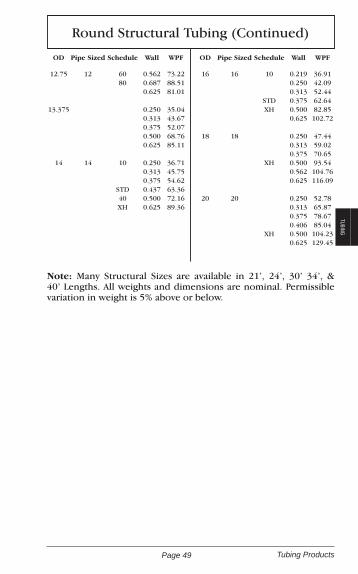
Round Structural Tubing (Continued)
OD ODPipe Sized Pipe SizedSchedule ScheduleWall WallWPF WPF
12.75
13.375
14
12
14
6080
10
STD40XH
0.5620.6870.625
0.2500.3130.3750.5000.625
0.2500.3130.3750.4370.5000.625
73.2288.5181.01
35.0443.6752.0768.7685.11
36.7145.7554.6263.3672.1689.36
16
18
20
16
18
20
10
STDXH
XH
XH
0.2190.2500.3130.3750.5000.625
0.2500.3130.3750.5000.5620.625
0.2500.3130.3750.4060.5000.625
36.9142.0952.4462.6482.85102.72
47.4459.0270.6593.54104.76116.09
52.7865.8778.6785.04104.23129.45
Note: Many Structural Sizes are available in 21’, 24’, 30’ 34’, & 40’ Lengths. All weights and dimensions are nominal. Permissible variation in weight is 5% above or below.

Page 50Pipe Products
Pipe ProductsStandard, Continuous Weld, Electric Weld or Seamless
Pipe is generally available with Plain Ends which are square cut, Threaded and Coupled Ends and with Beveled Ends.
Scope
The term “pipe” covers black and hot dipped galvanized, welded and seamless in nominal pipe sizes 1/8 through 26 inches with aver-age nominal wall thickness as given in the following pages. Pipe ordered to this specification is intended for mechanical and pres-sure applications and is also acceptable for ordinary uses in steam, water, gas and air lines. It is suitable for welding and suitable for some forming operations.
Manufacture
The weld seam of electric-resistance welded pipe in Grade B shall be heat treated after welding to a minimum of 1000O (540OC) so that no untempered martensite remains, or otherwise processed in such a manner that no untempered martensite remains. All pipe sold under this specification must meet ASTM testing requirements to assure proper application.
Strength RequirementsSeamless Or Electric Weld Tensile Strength
(P.S.I.)Yield Strength
(P.S.I.)
A53 Grade A 48,000 Min. 30,000 Min.
A53 Grade B 60,000 Min. 35,000 Min.
Note: Many Structural Sizes are available in 21', 24', 30', 34', & 40' Lengths. All weights and dimensions are nominal. Permissible variation in weight is 5 % above or below.
Page 51 Pipe Products
PIPE
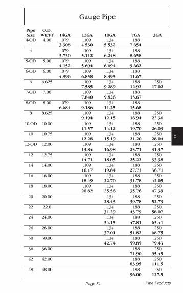
Pipe O.D. Size WT/FT 14GA 12GA 10GA 7GA 3GA 4-OD 4.00 .079 .109 .134 .188 3.308 4.530 5.532 7.654 4 .079 .109 .134 .188 3.730 5.112 6.248 8.658 5-OD 5.00 .079 .109 .134 .188 4.152 5.694 6.694 9.662 6-OD 6.00 .079 .109 .134 .188 4.996 6.858 8.395 11.67 6 6.625 .109 .134 .188 .250 7.585 9.289 12.92 17.02 7-OD 7.00 .109 .134 .188 7.840 9.826 13.67 8-OD 8.00 .079 .109 .134 .188 6.684 9.186 11.25 15.68 8 8.625 .109 .134 .188 .250 9.194 12.15 16.94 22.36 10-OD 10.00 .109 .134 .188 .250 11.57 14.12 19.70 26.03 10 10.75 .109 .134 .188 .250 12.28 15.19 21.20 28.04 12-OD 12.00 .109 .134 .188 .250 13.84 16.98 23.71 31.37 12 12.75 .109 .134 .188 .250 14.71 18.05 25.22 33.38 14 14.00 .109 .134 .188 .250 16.17 19.84 27.73 36.71 16 16.00 .109 .134 .188 .250 18.49 22.70 31.78 42.05 18 18.00 .109 .134 .188 .250 20.82 25.56 35.76 47.39 20 20.00 .134 .188 .250 28.43 39.78 52.73 22 22.0 .134 .188 .250 31.29 43.79 58.07 24 24.00 .134 .188 .250 34.15 47.81 63.41 26 26.00 .134 .188 .250 37.01 51.82 68.75 30 30.00 .134 .188 .250 42.74 59.85 79.43 36 36.00 .188 .250 71.90 95.45 42 42.00 .188 .250 83.95 111.5 48 48.00 .188 .250 96.00 127.5
Gauge Pipe
Page 52Pipe Products
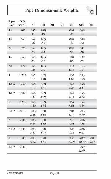
Pipe O.D. Size WT/FT 5 10 20 30 40 Std. 60
1/8 .405 .035 .049 .068 .068 .14 .19 .24 .24
1/4 .540 .049 .065 .088 .088 .26 .33 .42 .42
3/8 .675 .049 .065 .091 .091 .33 .42 .56 .56
1/2 .840 .065 .083 .109 .109 .54 .67 .85 .85
3/4 1.050 .065 .083 .113 .113 .68 .86 1.13 1.13
1 1.315 .065 .109 .133 .133 .87 1.40 1.68 1.68
1-1/4 1.660 .065 .109 .140 .140 1.11 1.81 2.27 2.27
1-1/2 1.900 .065 .109 .145 .145 1.27 2.09 2.72 2.72
2 2.375 .065 .109 .154 .154 1.60 2.64 3.65 3.65
2-1/2 2.875 .083 .120 .203 .203 2.48 3.53 5.79 5.79
3 3.500 .083 .120 .216 .216 3.03 4.33 7.58 7.58
3-1/2 4.000 .083 .120 .226 .226 3.47 4.97 9.11 9.11
4 4.500 .083 .120 .237 .237 .281 3.92 5.61 10.79 10.79 12.66
4-1/2 5.000 .247 12.53
Pipe Dimensions & Weights

Page 53 Pipe Products
PIPE
Pipe O.D. Dble. Size WT/FT 80 E.H. 100 120 140 160 E.H.
1/8 .405 095 .095 .31 .31
1/4 .540 .119 .119 .53 .53
3/8 .675 .126 .126 .73 .73
1/2 .840 .147 .147 .187 .294 1.09 1.09 1.30 1.71
3/4 1.050 .154 .154 .218 .308 1.47 1.47 1.94 2.44
1 1.315 .179 .179 .250 .358 2.17 2.17 2.84 3.66
1-1/4 1.660 .191 .191 .250 .382 3.00 3.00 3.77 5.21
1-1/2 1.900 .200 .200 .281 .400 3.63 3.63 4.86 6.41
2 2.375 .218 .218 .343 .436 5.02 5.02 7.46 9.03
2-1/2 2.875 .276 .276 .375 .552 7.66 7.66 10.01 13.70
3 3.500 .300 .300 .437 .600 310.25 10.25 14.32 18.58
3-1/2 4.000 .318 .318 .636 12.51 12.51 22.85
4 4.500 .337 .337. 437 .531 .674 14.98 14.98 19.01 22.51 27.54
4-1/2 5.000 .355 .710 17.61 32.53
Pipe Dimensions & Weights

Page 54Pipe Products
Pipe O.D. Size WT/FT 5 10 20 30 40 Std. 60
5 5.563 .109 .134 .258 .258 6.35 7.77 14.62 14.62
6 6.625 .109 .134 .280 .280 7.59 9.29 18.97 18.97
7 7.625 .301 23.57
8 8.625 .109 .148 .250 .277 .322 .322 .406 9.91 13.40 22.36 24.70 28.55 28.55 35.64
9 9.625 .342 33.90
10 10.750 .134 .165 .250 .307 .365 .365 .500 15.19 18.70 28.04 34.24 40.48 40.48 54.74
11 11.750 .375 45.55
12 12.750 .165 .180 .250 .330 .406 .375 .562 22.18 24.20 33.38 43.77 53.53 49.56 73.16
14 14.000 .250 .312 .375 .437 .375 .594 36.71 45.68 54.57 63.37 54.57 85.05
16 16.000 .250 .312 .375 .500 .375 .656 42.05 52.36 62.58 82.77 62.58 107.5
18 18.000 .250 .312 .437 .562 .375 .750 47.39 59.03 82.06 104.7 70.59 138.2
20 20.000 .250 .375 .500 .594 .375 .812 52.73 78.60 104.1 123.1 78.60 166.4
24 24.000 .250 .375 .562 .688 .375 .969 63.41 94.62 140.8 171.3 94.62 238.4
Pipe Dimensions & Weights

Page 55 Pipe Products
PIPE
Pipe O.D. Dble. Size WT/FT 80 E.H. 100 120 140 160 E.H.
5 5.563 .375 .375 .500 .625 .750 20.78 20.78 27.04 32.96 38.55
6 6.625 .432 .432 .562 .718 .864 28.57 28.57 36.39 45.30 53.16
7 7.625 .500 .875 38.05 63.08
8 8.625 .500 .500 .593 .718 .812 .906 .875 43.39 43.39 50.87 60.93 67.76 74.69 72.42
9 9.625 .500 48.72
10 10.750 .594 .500 .719 .844 1.000 1.125 64.43 54.74 77.03 89.29 104.1 115.6
11 11.750 .500 60.07
12 12.750 .688 .500 .844 1.000 1.125 1.312 88.63 65.42 107.3 125.5 139.7 160.3
14 14.000 .750 .500 .938 1.094 1.250 1.406 106.1 72.09 130.9 150.8 170.2 189.1
16 16.000 .844 .500 1.031 1.219 1.438 1.594 136.6 82.77 164.8 192.4 223.6 245.3
18 18.000 .938 .500 1.156 1.375 1.562 1.781 170.9 93.45 208.0 244.1 274.2 308.5
20 20.000 1.031 500 1.280 1.500 1.750 1.968 208.9 104.1 256.1 296.4 341.1 379.0
24 24.000 1.218 .500 1.531 1.812 2.062 2.343 296.4 125.5 367.4 429.4 483.1 541.9
Pipe Dimensions & Weights

Page 56Plate Products
Plate Products
Hot rolled plates made to ASTM-A36 are intended for use in struc-tural applications. Plates 1/2” and under are normally sheared: while heavier plates are flame cut. Flame cutting is necessary when plate thickness exceeds mill shearing limits.
AnalysisThickness Carbon Manganese Phosphorus Sulphur Silicon3/16 To 3/4" .25 Max .80 / 1.20 .04 Max .05 Max .40 Max3/4 - 1 1/2" .25 Max .80 / 1.20 .04 Max .05 Max .40 Max
1 1/2 - 2 1/2" .26 Max .80 / 1.20 .04 Max .05 Max .15 / .40
2 1/2 - 4" .27 Max .85 / 1.20 .04 Max .05 Max .15 / .40
4” & Up .29 Max .85 / 1.20 .04 Max .05 Max .15 / .40
Applications
Carbon steel plates have so many and such varied uses that a com-prehensive list of plate applications would be impossible in these pages, however a few uses are: tanks, tubes, truck frames, railroad cars, and many structural uses, such as: base plates, girders, etc.
Mechanical PropertiesTensile Strength
(P.S.I.)Yield Point
(P.S.I.)ElongationIn 8 Inches
58,000 - 80,000 36,000 Minimum* 20%
* Yield Point 32,000 P.S.I. for plates over 8 inches thick.
Machinability
This grade is satisfactory for ordinary machining or drilling but it is not considered a free machining grade.
Weldability
These grades present no problems when using all welding processes. The quality is generally high for both welds and joints. Welding rod specifications are dependent on conditions such as the thickness of the sections to be welded, service require-ments and design.
Hot Rolled ASTM-A36

Page 57 Plate Products
PLATE
High Tensile Plates are low alloy steel, which produce high strength and are intended primarily for weight reduction, or longer life, by means of greater strength.
Analysis (Typical)Carbon Mn P Sulphur Silicon Cb
Gr. 50 .23 Max 1.35 Max .04 Max .05 Max .40 Max .01 Min
Mechanical Properties (Typical)Tensile Strength Yield Point Elongation
(P.S.I.) (P.S.I.) In 2"
Gr. 50 65,000 Min. 50,000 Min. 21%
Pressure Vessel Quality Plate
A516 Grade 70
High Tensile Plates
ASTM A572 Grade 50
Applications
A516/70 is a carbon steel plate for boilers for stationary service and other pressure vessels. The maximum thickness under this specifi-cation is 6”.
Analysis (Typical)Carbon Mn Phosphorus Sulphur Silicon
A516 Gr. 70 .28 Max 1.2 Max .035 Max .04 Max. .15-.40
Mechanical PropertiesTensile Strength Yield Point Elongation
(P.S.I.) (P.S.I.) In 8"
A516 Gr. 70 70,000 - 90,000 38,000 Min. 17%
Weldability
These grades present no problems when using all welding process-es. Welding rod specifications depend on conditions such as thick-ness of section, service requirements and design.

Page 58Plate Products
This specification covers high strength low alloy steel which is made to reduce weight without sacrificing strength and is primarily used in structural applications. Additionally, this grade is more resistant to atmospheric corrosion in most environments than carbon steel and when properly exposed to the atmosphere this steel is suitable for many applications in the bare or unpainted/uncoated condition.
ApplicationsA588 steel is intended to be used in structural applications demanding higher strength in a low alloy product for enhance weld ability like bridges. However it is also made to a fine grain standard making it ideal for manufactured goods like tubing. This material performs well in structural applications where corrosion resistance is desired with or without painting or coating the finished product. A prime example again is bridges. In uncoated applications the material will allow surface rust to a point where the corrosion is halted or retarded depending on the corrosive nature of the sur-rounding atmosphere.
Analysis (Typical)C Mn P Sulphur Silicon Ni Cr Cu
A588 Gr. A
.19 .80-1.25
.04 Max
.05 Max .30-.065 .40 Max
.04-.65
.25-
.40
A588 Gr. B
.20 Max
.75-1.35
.04 Max
.05 Max .15-.50 .50 Max
.04-.70
.20-
.040
Mechanical Properties (Typical)Tensile Strength Yield Point Elongation
(P.S.I.) (P.S.I.) In 2"
A588 Gr. A&B
70,000 Min. 50,000 18%
Weldability
Welding this grade of steel presents no problems when using the welding specification outlines in the A6 guidelines of the ASTM manuals. Welding wire or rod specifications depend on thickness of section, service requirements and design. Some heating before and after welding may be necessary.
Corrosion Resistant Plate A588
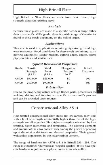
Page 59 Plate Products
PLATE
High Brinell or Wear Plates are made from heat treated, high strength, abrasion resisting steels.
Analysis
Because these plates are made to a specific hardness range rather than to a specific ASTM grade, there is a wide range of chemistries found in these steels depending on the mill of origin.
Applications
This steel is used in applications requiring high strength and high wear resistance. Good candidates for these steels are mining, earth moving equipment, loader buckets, cutting edges, chutes, slurry pipe, ore bins, and similar uses.
Typical Mechanical PropertiesGrade Tensile
Strength(P.S.I.)
YieldPoint(P.S.I.)
ElongationPercent
In 2"
BrinellHardness
AR400 180,000 145,000 14 400
AR500 230,000 190,000 14 500
Fabrication
Due to the proprietary nature of High Brinell plate, procedures for welding, drilling and forming are specific to each mill’s product and can be provided upon request.
Heat treated constructional alloy steels are low-carbon alloy steel with a level of strength substantially higher than that of the high-strength low alloy grades. This higher strength is obtained by heat treating, water quenching and tempering. The alloying elements and amount of the alloy content vary among the grades depending upon the section thickness and desired properties. Their general weldability is improved by the lower carbon content.
The range of hardness for ASTM A-514 is Brinell 235 - 293. This range is sometimes referred to as “Regular Quality.” If you have spe-cific hardness requirements, please contact our sales office.
High Brinell Plate
Constructional Alloy A514

Page 60Plate Products
Typical Analysis of A514Carbon Manganese Phosphorus Sulphur Silicon
.12 - .21 .70 - 1.00 .035 Max. .035 Max. .20 - .35
Chromium Molybdenum Vanadium Titanium Boron
.40 - .0065 .15 - .25 .03 - .08 .01 - .03 .0005 - .005
Mechanical Properties For Regular QualityReduction of Area (Min. %)
TensileStrength(P.S.I.)
YieldPoint(P.S.I.)
Elonga-tionIn 2"
3/4 InchAnd
Under
Over3/4 Inch
110 to 130,000
100,000 Min.
18% Min. 40% 50%
Applications
Regular Quality is used in general structural applications where its greater strength permits reduction in weight by using smaller cross-sectional areas. It is for welded construction where procedures are suitable to maintain the properties of the plate.
321 and 360 Minimum Brinell Quality are for applications where higher hardness and strength in conjunction with increased resis-tance to impact abrasion are important.
Forming
Regular Quality can be cold-formed readily, provided sufficient power is available and allowance is made for greater spring back than with mild steel.
Thickness Of Material Minimum Radius
Up to 1" inclusive Two Times Thickness
Over 1 inch to 2" inclusive Three Times Thickness
Warm forming may be done at temperatures below 1100oF. with-out destroying the mechanical properties or toughness. Hot form-ing may be done at 1600-1800oF, but the formed part must be heat-treated to restore its original properties. To insure proper safety and the structural integrity of the finished product we will assist you with heat number and source-mill information so that you can obtain accurate information from the producing mill prior to any attempt to form this material.

Page 61 Plate Products
PLATEMachinability
The cutting speed of Regular Quality is 65 surface feet per minute or approximately 40% of 1212.
Weldability
Similar techniques to those used in structural carbon steels apply but precautions must be used. Hydrogen must be kept out of the welding operation. Large sections or those under high restraint should be preheated to temperatures not exceeding 400°F.
Heat Treating
Stress relieving may be performed by heating at temperatures up to 1100oF. If Regular Quality material is heated over 1100oF, it must be heat treated again to restore the original strength.
Austinize Quench Temper
1650oF to 1700oF Agitated Water 1150oF to 1250oF
3/16
Inch 7.66 Lbs. / Sq. Ft.48 x 96 245.1 120 306.4 144 367.7 240 612.8 288 735.460 x 96 306.4 120 383.0 144 459.6 240 766.0 288 919.272 x 120 459.6 144 551.5 240 919.2 288 1103.0 360 1378.884 x 240 1072.4 360 1608.6
3/16
Inch (Cont.)96 x 120 612.8 144 735.4 240 1225.6 288 1470.7 360 1838.4120 x 240 1532.0 360 2298.01/
4 Inch
10.21 Lbs. / Sq. Ft.48 x 96 326.7 120 408.4 144 490.1 240 816.8 288 980.260 x 96 408.4 120 510.5 144 612.6 240 102l.0
1/4 Inch (Cont.)
288 1225.272 x 96 490.1 120 612.672 x 144 735.1 240 1225.2 288 1470.2 360 1837.684 x 240 1429.4 360 2144.196 x 96 653.4 120 816.8 144 980.2 240 1633.6 288 1960.3 360 2450.4120 x 240 2042.0 360 3063.0
Weights For Plate Products
Weight Weight Weight
Per Plate Per Plate Per Plate
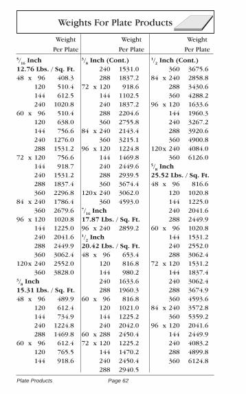
Page 62Plate Products
Weights For Plate Products
Weight Weight Weight
Per Plate Per Plate Per Plate5/
16 Inch
12.76 Lbs. / Sq. Ft. 48 x 96 408.3 120 510.4 144 612.5 240 1020.860 x 96 510.4 120 638.0 144 756.6 240 1276.0 288 1531.272 x 120 756.6 144 918.7 240 1531.2 288 1837.4 360 2296.884 x 240 1786.4 360 2679.696 x 120 1020.8 144 1225.0 240 2041.6 288 2449.9 360 3062.4120 x 240 2552.0 360 3828.03/
8 Inch
15.31 Lbs. / Sq. Ft.48 x 96 489.9 120 612.4 144 734.9 240 1224.8 288 1469.860 x 96 612.4 120 765.5 144 918.6
3/8 Inch (Cont.)
240 1531.0 288 1837.272 x 120 918.6 144 1102.5 240 1837.2 288 2204.6 360 2755.884 x 240 2143.4 360 3215.196 x 120 1224.8 144 1469.8 240 2449.6 288 2939.5 360 3674.4120 x 240 3062.0 360 4593.07/
16 Inch
17.87 Lbs. / Sq. Ft. 96 x 240 2859.21/
2 Inch
20.42 Lbs. / Sq. Ft.48 x 96 653.4 120 816.8 144 980.2 240 1633.6 288 1960.360 x 96 816.8 120 1021.0 144 1225.2 240 2042.060 x 288 2450.472 x 120 1225.2 144 1470.2 240 2450.4 288 2940.5
1/2 Inch (Cont.)
360 3675.684 x 240 2858.8 288 3430.6 360 4288.296 x 120 1633.6 144 1960.3 240 3267.2 288 3920.6 360 4900.8120 x 240 4084.0 360 6126.05/
8 Inch
25.52 Lbs. / Sq. Ft.48 x 96 816.6 120 1020.8 144 1225.0 240 2041.6 288 2449.960 x 96 1020.8 144 1531.2 240 2552.0 288 3062.472 x 120 1531.2 144 1837.4 240 3062.4 288 3674.9 360 4593.684 x 240 3572.8 360 5359.296 x 120 2041.6 144 2449.9 240 4083.2 288 4899.8 360 6124.8

Page 63 Plate Products
PLATE
Weights For Plate Products (Continued)
Weight Weight Weight
Per Plate Per Plate Per Plate5/
8 Inch (Cont.)
120 x 240 5104.0 360 7656.03/
4 Inch
30.63 Lbs. / Sq. Ft. 48 x 96 980.2 120 1225.2 144 1470.2 240 2450.460 x 96 1225.2 120 1531.5 144 1837.8 240 3063.0 288 3675.672 x 120 1837.8 144 2205.4 240 3675.6 288 4410.7 360 7351.284 x 240 4288.2 360 6432.296 x 120 2450.4 144 2940.5 240 4900.8 288 5881.0 360 7351.2120 x 240 6126.0 360 9189.07/
8 Inch
35.73 Lbs. / Sq. Ft. 48 x 96 1143.4 120 1429.2 144 1715.0 240 2858.4
7/8 Inch (Cont.)
60 x 96 1429.2 120 1786.5 144 2143.8 240 3573.0 288 4287.6 360 5395.572 x 120 2143.8 144 2572.6 240 4287.6 288 5145.1 360 6431.484 x 240 5002.2 360 7503.396 x 120 2858.4 144 3430.1 240 5716.8 288 6860.2 360 8575.2120 x 240 7146.0 360 10719.01 Inch40.84 Lbs. / Sq. Ft.48 x 96 1306.9 120 1633.6 144 1960.3 240 3267.2 288 3920.660 x 96 1633.6 120 2042.0 144 2940.5 240 4084.0 288 4900.872 x l20 2450.4
1 Inch (Cont.) 144 2940.5 240 4900.8 288 5881.0 360 7351.284 x 240 5717.6 360 8576.496 x 120 3267.2 144 3920.6 240 6534.4 288 7841.3 360 9801.6120 x 240 8168.0120 x 360 12252.01 1/
8 Inch
45.95 Lbs. / Sq. Ft. 96 x 240 7352.01 1/
4 Inch
51.05 Lbs. / Sq. Ft. 48 x 96 1633.6 120 2042.0 144 2450.4 192 3267.2 240 4084.060 x 96 2042.0 120 2552.5 144 3063.0 192 4084.0 240 5105.072 x 120 3063.0 144 3675.6 192 4900.8 240 6126.0 360 9189.0
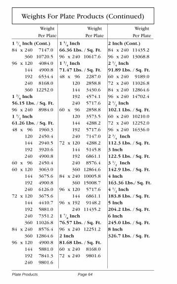
Page 64Plate Products
Weight Weight Weight
Per Plate Per Plate Per Plate
Weights For Plate Products (Continued)
1 1/4 Inch (Cont.)
84 x 240 7147.0 360 10720.596 x 120 4084.0 144 4900.8 192 6534.4 240 8168.0 360 12252.01 3/
8 Inch
56.15 Lbs. / Sq. Ft.96 x 240 8984.01 1/
2 Inch
61.26 Lbs. / Sq. Ft. 48 x 96 1960.3 120 2450.4 144 2940.5 192 3920.6 240 4900.860 x 96 2450.460 x 120 3063.0 144 3675.6 192 4900.8 240 6126.072 x 120 3675.6 144 4410.7 192 5881.0 240 7351.2 360 11026.884 x 240 8576.4 360 12864.696 x 120 4900.8 144 5881.0 192 7841.3 240 9801.6
1 5/8 Inch
66.36 Lbs. / Sq. Ft.96 x 240 10617.61 3/
4 Inch
71.47 Lbs. / Sq. Ft. 48 x 96 2287.0 120 2858.8 144 3430.6 192 4574.1 240 5717.660 x 96 2858.8 120 3573.5 144 4288.2 192 5717.6 240 7147.072 x 120 4288.2 144 5145.8 192 6861.1 240 8576.4 360 12864.684 x 240 10005.8 360 15008.796 x 120 5717.6 144 6861.196 x 192 9148.2 240 11435.21 7/
8 Inch
76.57 Lbs. / Sq. Ft.96 x 240 12251.22 Inch81.68 Lbs. / Sq. Ft.60 x 240 8168.072 x 240 9801.6
2 Inch (Cont.)84 x 240 11435.296 x 240 13068.82 1/
4 Inch
91.89 Lbs. / Sq. Ft.60 x 240 9189.072 x 240 11026.884 x 240 12864.696 x 240 14702.42 1/
2 Inch
102.1 Lbs. / Sq. Ft.60 x 240 10210.072 x 240 12252.096 x 240 16336.02 3/
4 Inch
112.3 Lbs. / Sq. Ft. 3 Inch122.5 Lbs. / Sq. Ft.3 1/
2 Inch
142.9 Lbs. / Sq. Ft.4 Inch163.36 Lbs./ Sq. Ft.4 1/
2 Inch
183.8 Lbs. / Sq. Ft.5 Inch 204.2 Lbs. / Sq. Ft.6 Inch245.0 Lbs. / Sq. Ft. 8 Inch326.7 Lbs. / Sq. Ft.

Page 65 Plate Products
PLATE
Floor PlateA786 Commercial Quality
Diamond Floor Plate is made of rolled carbon steel that has great structural strength and long wearing qualities. The practical safety tread pattern provides 4-way traction, easy cleaning and drainage.
Applications
Diamond Floor Plate is extensively used in safety floors, step treads, walkways, truck beds, truck bumpers, conveyors, cover plates, running boards, cab floors, and truck tail gates.
Weldability
This material presents no welding problems when using all welding processes. The quality of the welds is generally extremely high for both welds and joints. Welding rod specifications are dependent on welding conditions such as the thickness of the sections to be welded, service requirements and design.

Page 66Plate Products
Floor Plate
Weight Weight Weight
Per Plate Per Plate Per Plate16 Ga.3.00 Lbs. / Sq. Ft.36 x 96 72.0 120 90.0 144 108.048 x 96 96.0 120 120.0 192 192.0 240 240.014 Ga.3.75 Lbs. / Sq. Ft.48 x 96 120.0 120 150.0 192 240.0 240 300.012 Ga.5.25 Lbs. / Sq. Ft.48 x 96 168.0 120 210.0 192 336.0 240 420.060 x 120 262.5 240 525.01/
8 Inch
6.15 Lbs. / Sq. Ft.36 x 120 184.548 x 96 196.8 120 246.0 240 492.0 288 590.460 x 120 307.5 240 615.0 288 710.472 x 240 738.0 288 885.63/16 Inch8.71 Lbs. / Sq. Ft.48 x 96 278.7
3/16
Inch (Cont.) 120 348.4 240 696.860 x 96 348.4 120 435.5 240 871.0 288 1045.272 x 240 1045.2 288 1254.284 x 240 1219.4 288 1463.31/
4 Inch
11.26 Lbs. / Sq. Ft.48 x 96 360.3 120 450.4 240 900.8 288 1081.060 x 120 563.0 240 1126.0 288 1351.272 x 240 1351.2 288 1621.496 x 240 1801.6 288 2161.95/
16 Inch
13.81 Lbs. / Sq. Ft.48 x 96 441.9 120 552.4 240 1104.8 288 1325.860 x 120 690.5 240 1381.0 288 1657.272 x 240 1657.2 288 1988.696 x 240 2209.6 288 2651.5
3/8 Inch
16.37 Lbs. / Sq. Ft.48 x 96 523.8 120 654.8 240 1309.648 x 288 1571.560 x 240 1637.0 288 1964.472 x 240 1964.4 288 2357.396 x 240 2619.2 288 3143.01/
2 Inch
21.47 Lbs. / Sq. Ft.48 x 96 687.0 120 858.8 240 1717.6 288 2061.160 x 240 2147.0 288 2576.472 x 240 2576.4 288 3091.796 x 240 3435.2 288 4122.25/
8 Inch
26.58 Lbs. / Sq. Ft.48 x 240 2126.460 x 240 2658.072 x 240 3189.696 x 240 4252.83/
4 Inch
31.68 Lbs. / Sq. Ft.48 x 240 2534.460 x 240 3168.072 x 240 3801.696 x 240 5068.896 x 288 6082.6

Page 67 Sheet Products
SHEET
Sheet Products
Hot Rolled ASTM-A1011
Commercial Quality is suitable for all ordinary purposes where the presence of oxide on the surface is not objection-able. Sheets of this quality may be suitable for bending and moderate forming; however, they are not guaranteed against breakage except that caused by piped steel (material with tu-bular voids). Commercial Quality sheets should be capable of withstanding standard test bends, i.e., being bent flat on itself in any direction at room temperature.
AnalysisCarbon Manganese Phosphorus Sulphur
.15 Max. .30 - .60 .04 Max. .05 Max.
Applications
Commercial Quality sheets have good ductility. They are easy to fabricate and are used for a wide variety of purposes, such as barrels and drums, lockers, cabinets, doors, blower and ventilating systems, bins, partitions, chutes, steel jackets, and agricultural equipment.
Weldability
This quality of sheet presents no welding problems, when using all welding processes. Welding quality is generally ex-tremely high for welds and joints. Welding rod specifications are dependent on welding conditions such as thickness of section, service requirements and design to name a few of the probable welding conditions.

Page 68Sheet Products
High Tensile Sheet ASTM A1011 Grade 50
High Strength / Low Alloy sheets (sometimes referred to as High Tensile sheets) are rolled and generally stocked in Grade 50.
AnalysisCarbon Manganese Phosphorus Sulphur Columbium Vanadium
.23 Max 1.35 Max .04 Max .05 Max .01 Min .01 Min
Applications
This material is extensively used in industrial and domestic air conditioning equipment, farm buildings, farm elevators, farm wagons, fertilizer wagons, hay balers, potato planter hoppers, tractors, bins, blowers, booms, concrete forms, conveyors, fil-ing cabinet parts, floor plates, door frames, furnace parts, ma-terial handling equipment, pole line hardware, lamp and sign posts, pump parts, scraper parts, tanks, trailers, transformer shells, trucks, wheelbarrows and, worm gears.
Mechanical PropertiesTensile Strength
(P.S.I.)Yield Strength
(P.S.I.)Elongation In
2"
All Gauges - Gr 50 65,000 Min. 50,000 Min. 22% Min.
Forming
High Tensile Sheet may be hot or cold formed. To insure proper safety and the structural integrity of the finished prod-uct we will assist you with heat number and source-mill infor-mation so that you can obtain accurate information from the producing mill prior to any attempt to form this material.
For cold forming, a greater force is required to produce a permanent set because of the higher yield point than carbon steel. It is suggested for cold forming that the inside radius of the bend should be at least equal to the thickness of the mate-rial for sheet and strip up to 1/16" inclusive; at least twice the thickness of the material over 1/16" to 1/4", inclusive; and three times the thickness for material over 1/4" to 1/2" inclusive.

Page 69 Sheet Products
SHEETPunching and Shearing
Shearing may require tighter and more secure clamping if a clamp hold down is used because the metal tends to pull more than structural carbon steel. Punching requires up to 20% greater force than for equal thicknesses of ASTM-A569 material.
Gas Cutting
No special precautions need be taken beyond those required for structural steel, and the heat effects and cutting speeds are similar for both grades. This material can be plasma-cut with minimal warpage.
Weldability
High Tensile is readily welded by all the usual methods, i.e., shielded metal arc, submerged arc, and electrical resistance, including spot welding. An important advantage in welded structures is the fact that this material experiences an increase in the yield and tensile strength with practically no decrease in elongation when stress-relieved.
Specification: Commercial Quality
Sheets of this quality should be suitable for bending and moderate forming; however, they are not guaranteed against breakage except that caused by piped steel (material with tu-bular voids). Sheets of Commercial Quality should be capable of withstanding a standard bend test, i.e., being bent flat on itself in any direction at room temperature.
Cold Rolled Sheets are from continuous mill production from low-carbon open-hearth rimmed, texture or capped steel with a carbon maximum of 0.15.
Applications
The dull surface texture is suitable for paints, lacquers and enamels. Cabinets, appliances, auto body parts, furniture, file cases and desks, partitions, and doors are some applications for cold rolled sheets.
Cold Rolled Sheet ASTM A1008
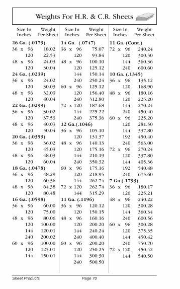
Page 70Sheet Products
26 Ga. (.0179)36 x 96 18.02 120 22.5348 x 96 24.03 120 30.0424 Ga. (.0239)36 x 96 24.02 120 30.0348 x 96 32.03 120 40.0422 Ga. (.0299)36 x 96 30.02 120 37.5348 x 96 40.03 120 50.0420 Ga. (.0359)36 x 96 36.02 120 45.0348 x 96 48.03 120 60.0418 Ga. (.0478)36 x 96 48.29 120 60.3648 x 96 64.38 120 80.4816 Ga. (.0598)36 x 96 60.00 120 75.0048 x 96 80.06 120 100.00 144 120.01 240 200.0260 x 96 100.00 120 125.01 144 150.01
14 Ga. (.0747) 36 x 96 75.07 120 93.8448 x 96 100.10 120 125.12 144 150.14 240 250.2460 x 96 125.12 120 156.40 240 312.8072 x 120 187.68 144 225.22 240 375.3612 Ga. (.1046) 36 x 96 105.10 120 131.3748 x 96 140.13 120 175.16 144 210.19 240 350.3260 x 96 175.16 120 218.95 144 262.7472 x 120 262.74 144 315.2911 Ga. (.1196) 36 x 96 120.12 120 150.1548 x 96 160.16 120 200.20 144 240.24 240 400.4060 x 96 200.20 120 250.25 144 300.30 240 500.50
11 Ga. (Cont.) 72 x 96 240.24 120 300.30 144 360.36 240 600.6010 Ga. (.1345) 36 x 96 135.12 120 168.9048 x 96 180.16 120 225.20 144 270.24 240 450.4060 x 96 225.20 120 281.50 144 337.80 192 450.40 240 563.0072 x 96 270.24 120 337.80 144 405.36 192 540.48 240 675.607 Ga (.1793)36 x 96 180.17 120 225.2148 x 96 240.22 120 300.28 144 360.34 240 600.5660 x 96 300.28 120 375.35 144 450.42 240 750.7072 x 120 450.42 144 540.50
Weights For H.R. & C.R. Sheets
Size In Inches
Weight Per Sheet
Size In Inches
Weight Per Sheet
Size In Inches
WeightPer Sheet

Page 71 Sheet Products
SHEET
Thickness In Inches
Gage Number
Decimal Equivalent
Tol. Range H.R. & P.&O.
Tol RangeC.R. Sheet
Pounds Per Sq. Foot
7 .1793 .1873.1713
.0883
.17037.507
10 .1345 .1425.1265
.1405
.12855.630
11 .1196 .1276.1116
.1256
.11365.005
12 .1046 .1126.0966
.1106
.09864.379
13 .0897 .0967.0827
.0947
.08473.75
14 .0747 .0817.0677
.0797
.06973.128
16 .0598 .0658.0538
.0648
.05482.502
18 .0478 .0528.0428
.0518
.04382.102
20 .0359 ----- .0389.0329
1.501
22 .0299 ----- .0329.0269
1.261
24 .0239 ----- .0269.0209
1.001
26 .0179 ----- .0199.0159
.751
AISI Thickness Tolerance H.R. & C.R. Sheet

Page 72Sheet Products
Galvanized Sheet ASTM-A653, G-90
Commercial Quality
Flat galvanized sheets are flat, have closely guarded shearing tolerances, and are ductile and soft.
These sheets are produced by passing the base sheets through a bath of molten zinc which, after controlled cooling, gives a clean, bright, uniform spangle.
Stamping, cold drawing, double seaming and brake or roll forming will not impair the protective quality of these sheets.
Applications
Flat galvanized sheets are used as the prime general sheet metal for heating, cooling, joist hangers, and for sign work if the sheets are primed before painting.
Paintable Galvanized Sheet ASTM-A653, A-40/A-60
Paintable Galvanized Sheet, sometimes called Paint Bond, Jetkote or Wiped Galvanized, has a surface coating that makes priming unnecessary.
Applications
Paintable galvanized sheets are used in applications where paint, enamels and lacquers will be used or where flat, stretch-er-leveled sheets are needed. These sheets can be drawn, stamped, formed, and sheared without cracking, peeling or flaking.
Office furniture, cabinets of all types, appliance shells, truck and trailer bodies, lighting fixtures, signs, air conditioning and refrigeration equipment are some applications for Paint-able Galvanized sheet.
Chemical Composition (Typical)Carbon Manganese Phosphorus Sulphur.15 Max. .30 - .60 .05 Max. .05 Max.

Page 73 Sheet Products
SHEET
10 Ga. (.138)
Wt. / Sq. Ft. 5.786
48 X 96 185.15 120 231.44
12 Ga. (.109)
Wt. / Sq. Ft. 4.535
48 X 96 145.12 120 181.40
14 Ga. (.079)
Wt. / Sq. Ft. 3.284
48 X 96 105.09 120 131.36
16 Ga. (.064)
Wt. / Sq. Ft. 2.658
48 X 96 85.06 120 106.32
18 Ga. (.052)
Wt. / Sq. Ft. 2.158
48 X 96 69.06 120 86.32
20 Ga. (.040)
Wt. / Sq. Ft. 1.658
48 X 96 53.06 120 66.32
22 Ga. (.034)
Wt. / Sq. Ft. 1.407
48 X 96 45.02 120 56.28
24 Ga. (.028)
Wt. / Sq. Ft. 1.157
48 X 96 37.02 120 46.28
26 Ga. (.022)
Wt. / Sq. Ft. .907
48 X 96 29.02 120 36.28
28 Ga. (.019)
Wt. / Sq. Ft. .782
36 X 96 18.77 120 23.46
30 Ga. (.016)
Wt. / Sq. Ft. .657
36 X 96 15.77
Weights For Galvanized Sheets
Size In Inches
Weight Per Sheet
Size In Inches
Weight Per Sheet
Size In Inches
WeightPer Sheet
AISI Thickness Tolerance For Galv. Sheet
10 .1382 .1472 To .1292
11 .1233 .1323 To .1143
12 .1084 .1174 To .0994
14 .0785 .0865 To .0705
16 .0635 .0695 To .0575
18 .0516 .0566 To .1466
20 .0396 .0436 To .0356
22 .0336 .0376 To .0296
24 .0276 .0316 To .0236
26 .0217 .0247 To .0187
28 .0187 .0217 To .0157
30 .0157 .0187 To .0127
Ga. No.
Dec.Equiv.
ToleranceRange
Ga. Dec.Equiv.
ToleranceRange

Page 74Expanded Metal & Grating
Expanded Metal & Grating ProductsExpanded Metal, Expanded Metal Grating, Bar Grating, and Diamond Grip are all products that have openings in their horizontal surfaces which increase friction for safer climbing and standing, and allow dirt, oil, etc. to fall through. This provides a certain amount of self-cleaning.Stock sizes are generally 48 x 96 sheets. However, 48 x 120, 48 x 144 and custom sizes are available upon request.
StyleCenter To Cen-ter Of Bonds Thickness
Weight In Pounds Per Square Foot
Designation Width Length Of Strand Plain Galv.
1/4 - No. 18 .255 1.00 .048 1.14 1.711/2 - No. 18 .500 1.20 .048 .70 .851/2 - No. 16 .500 1.20 .060 .86 .971/2 - No. 13 .500 1.20 .092 1.47 1.733/4 - No. 16 .923 2.00 .060 .54 .653/4 - No. 13 .923 2.00 .092 .80 .923/4 - No. 10 .923 2.00 .092 1.20 1.363/4 - No. 9 .923 2.00 .134 1.80 1.951- No. 16 1.090 2.40 .060 .44 .511 1/2 - No. 16 1.330 3.00 .060 .40 .481 1/2 - No. 13 1.330 3.00 .092 .60 .681 1/2 - No. 10 1.330 3.00 .092 .79 .891 1/2 - No. 9 1.330 3.00 .134 1.20 1.311 1/2 - No. 6 1.330 3.00 .198 2.50 2.732 - No. 9 1.850 4.00 .134 .90 1.02
Expanded Metal - Raised

Page 75 Expanded Metal & Grating
EXPANDED METAL
& GRATING
Expanded Metal - Flattened
StyleCenter To Cen-ter Of Bonds Strand
Weight Per Square Foot
Designation Width Length Thickness Plain Galv1/4 - No. 20 .255 1.03 .030 .83 1.241/4 - No. 18 .255 1.03 .040 1.11 1.651/2 - No. 20 .500 1.26 .029 .40 .511/2 - No. 18 .500 1.26 .039 .66 .881/2 - No. 16 .500 1.26 .050 .82 1.001/2 - No. 13 .500 1.26 .070 1.40 1.623/4 - No. 16 .923 2.10 .048 .51 .613/4 - No. 14 .923 2.12 .061 .63 .753/4 - No. 13 .923 2.10 .070 .76 .863/4 - No. 9 .923 2.12 .120 1.71 1.861 - No. 16 1.090 2.56 .048 .41 .501 1/2 - No. 13 1.330 3.20 .070 .57 .681 1/2 - No. 9 1.330 3.20 .110 1.11 1.28
Style Center To Center
Of BondsWeight Per Square Foot
Designation Width Length Plain Galv
3.0 Lb. Catwalk 1.33 5.33 3.00 3.20
3.0 Lb. Grating 1.33 5.33 3.00 3.20
3.0 Lb. Grating 1.33 5.33 3.00 3.20
3.14 Lb Skywalk 2.00 6.00 3.14 3.34
3.14 Lb Skywalk 2.00 6.00 3.14 3.34
4.0 Lb. Grating 1.33 5.33 4.00 4.30
4.0 Lb. Grating 1.33 5.33 4.00 4.30
4.27 Lb Walkway 1.41 4.00 4.27 4.57
5.0 Lb. Grating 1.33 5.33 5.00 5.50
5.0 Lb. Grating 1.33 5.33 5.00 5.50
6.25 Lb Grating 1.41 5.33 6.25 6.85
Expanded Metal - Grating

Page 76Expanded Metal & Grating
Expanded Metal TerminologyMaterial Terminology
Expanded Metal (also called raised or regular expanded metal) is metal sheet that is simultaneously slit and stretched into a rigid, open mesh. It is available in carbon, stainless and galvanized steel, and in aluminum. Flattened Expanded Metal is made by passing expanded metal through a rolling mill to flatten it. This process reduces the thickness slightly and provides a smooth, flat surface.Expanded Metal Grating is made from thicker sheet or plate, by a process similar to that which produces expanded metal. Expanded metal grating is often used for catwalks and platform applications where self cleaning and good footing are required.Decorative Expanded Metal is manufactured so that the open areas have unique, decorative shapes.Expanded Metal Stair Treads use expanded metal grating for the hori-zontal surfaces, flat bar for the vertical surfaces and angles at the corners.The Bond is the point where adjacent Strands intersect. The bond is always twice the width of the Strand.C.S.F. (100 Square Feet) is the unit of measure that is used to weigh and price expanded metal. Camber is a slight bow which can occur during manufacturing and results in an out-of-square condition.Deburring is a process whereby most expanded metal is passed through rotary steel brushes to remove burrs and rough edges. Expanded metal grat-ing and very light expanded metal are generally not deburred.The Diamond is the diamond-shaped open area formed by the Strands and bonds (also referred to as the Opening).F.X.M. is the commonly used abbreviation for Flattened Expanded Metal.L.W.D. or L.W.O. refers to the Long Way of the Diamond or Long Way of the Opening. This is used to make it clear that you are measuring in a direction that is parallel to the largest dimension of the diamond. Expanded Metal and Expanded Metal Grating is manufactured with the LWD running the width of the sheet or the length of the sheet. Mesh is the nominal distance, expressed in inches, from the center of one bond to the center of an adjacent bond measured across the S.W.D.The Opening Size is the area enclosed by the Strands and bonds.The Overall Thickness is the finished thickness of the sheet which often determines the selection of framing components.The Percent of Open Area is used by designers to calculate the degree to which light and air can pass through a piece of expanded metal.The Pitch is the measurement from a point on one diamond to the same point on an adjacent diamond.R.X.M. is the commonly used abbreviation for Raised Expanded Metal.S.W.D. or S.W.O. refers to the Short Way of the Diamond or the Short Way of the Opening. This is used to make it clear that you are measuring in a di-rection that is parallel to the smallest dimension of the diamond. Expanded Metal and Expanded Metal Grating is manufactured with the SWD running the width of the sheet or the length of the sheet.The Strand is the single metal strip that forms the border of the diamond, or opening. The strand has thickness (the thickness of the sheet) and width.
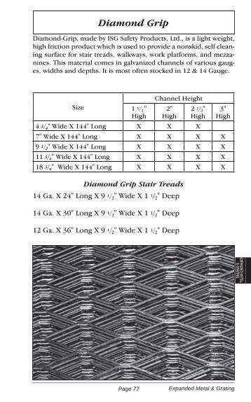
Page 77 Expanded Metal & Grating
EXPANDED METAL
& GRATING
Diamond GripDiamond-Grip, made by ISG Safety Products, Ltd., is a light weight, high friction product which is used to provide a nonskid, self clean-ing surface for stair treads, walkways, work platforms, and mezza-nines. This material comes in galvanized channels of various gaug-es, widths and depths. It is most often stocked in 12 & 14 Gauge.
SizeChannel Height
1 1/2 " High
2"High
2 1/2"High
3"High
4 3/4" Wide X 144" Long X X X
7" Wide X 144" Long X X X X
9 1/2" Wide X 144" Long X X X X
11 3/4" Wide X 144" Long X X X X
18 3/4" Wide X 144" Long X X X X
Diamond Grip Stair Treads
14 Ga. X 24" Long X 9 1/2" Wide X 1 1/2" Deep
14 Ga. X 30" Long X 9 1/2" Wide X 1 1/2" Deep
12 Ga. X 36" Long X 9 1/2" Wide X 1 1/2" Deep

Page 78Expanded Metal & Grating
Bar Grating Products
Welded Bar Grating is a manufactured product which has a multitude of uses. For instance, it is used to cover trenches in pavement, to make self-cleaning stair treads and to construct platforms around equipment. There are a number of questions that you will need to answer when order-ing Welded Bar Grating:
1. What material? Most Welded Bar Grating is made from carbon steel but it is also available in Stainless Steel and Aluminum. A similar product is made from fiberglass for use in highly corrosive applications.2. Which way do the bearing bars run? For greatest strength the bearing bars will usually run the short way of the span. (If you had a trench that was 10" X 120" the bearing bars would normally span the 10" dimension of your trench. See the illustration of bearing and cross bars on the next page)3. What is the size of the area that you need to cover? Give the size in inches and remember to allow for clearance. If you are putting grating into a 10" wide trench, a 10" wide piece of grating will not fit. You would want to order your grating somewhat narrower, say 9 3/4" or 9 7/8" in width in order to clear.4. Are the pieces to be banded? Banding is used to close the spaces be-tween the bearing bars. This makes for a more finished look, keeps the ends from being bent out of shape and reduces the chance of injury from the exposed ends of the bearing bars when the pieces have to be han-dled.5. Are the pieces to be painted or galvanized? When special ordering you may specify that the grating be painted or galvanized by the manufac-turer.6. Are the bearing bars to be serrated or smooth? When special ordering you may specify that the top edge of the bearing bars be cut in such a man-ner that a series of bumps will provide greater friction.
Remember that while Welded Bar Grating is available in custom sizes, you will want to work from standard 3' X 24' panels whenever possible. (4' wide panels may be special ordered) This means that in the example of a 10" X 120" trench used above it would take 3 pieces 10" by 36" and 1 piece 10" X 12" to cover the trench with bearing bars running the short way of the span.
While it might seem easier to cover the area with one piece, you would have to run the bearing bars the 10' way to cover the trench with one piece. The 10' span would be very weak. Remember also, that you may occasionally have to remove the grating to clean your trench and one man can handle three-foot long pieces more easily than he can handle a ten foot long piece.
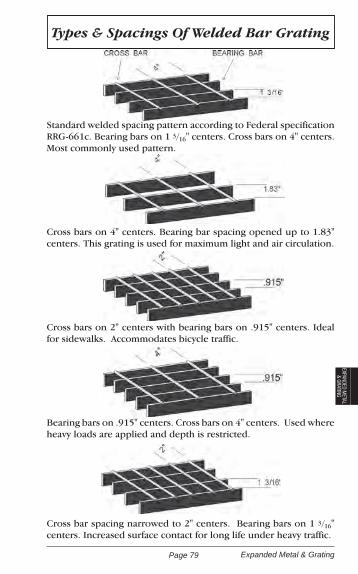
Page 79 Expanded Metal & Grating
EXPANDED METAL
& GRATING
Standard welded spacing pattern according to Federal specification RRG-661c. Bearing bars on 1 3/16" centers. Cross bars on 4" centers. Most commonly used pattern.
Cross bars on 4" centers. Bearing bar spacing opened up to 1.83" centers. This grating is used for maximum light and air circulation.
Cross bars on 2" centers with bearing bars on .915" centers. Ideal for sidewalks. Accommodates bicycle traffic.
Bearing bars on .915" centers. Cross bars on 4" centers. Used where heavy loads are applied and depth is restricted.
Cross bar spacing narrowed to 2" centers. Bearing bars on 1 3/16" centers. Increased surface contact for long life under heavy traffic.
Types & Spacings Of Welded Bar Grating

Page 80Expanded Metal & Grating
Bar Grating Load Table
U= Uniform Load D = Deflection C=Concentrated Load
Bearing Bar Size In Inches
Span
2'0" 2'6" 3'0" 3'6" 4'0"
3/16 X 3/4UD
575.093
370.152
259.218
186.294
144.373
CD
579 .077
463.120
388.173
330.235
289.310
1/8 X 1UD
688.073
440.110
304.160
225.219
172.286
CD
688.059
549.091
459.129
391.175
343.232
3/16 X 1UD
1030.073
659.112
460.160
335.219
256.287
CD
1029.058
822.090
687.129
588.176
513.230
1/8 X 1 1/4UD
1072.059
688.090
475.175
351.233
269.290
CD
1074.048
859.073
714.104
610.142
538.180
3/16 X 1 1/4UD
1610.059
1029.090
714.128
528.174
401.230
CD
1610.048
1283.073
1074.105
919.141
801.180
1/8 X 1 1/2UD
1541.045
988.074
687.106
501.148
387.193
CD
1542.038
1237.058
1030.086
884.116
723.155
3/16 X 1 1/2UD
2320.047
1484.076
1032.107
758.148
580.193
CD
2320.038
1858.060
1548.088
1325.116
1160.154
3/16 X 1 3/4UD
3140.041
2018.062
1401.093
1030.126
788.164
CD
3150.031
2522.053
2100.075
1803.100
1573.134
3/16 X 2 UD
4118.038
2633.058
1830.080
1346.112
1029.140
CD
4118.029
3293.047
2748.062
2350.089
2059.116
3/16 X 2 1/4 UD
5210.033
3330.050
2310.073
1670.099
1301.128
CD
5210.028
4169.040
3475.058
2913.080
2604.103

Page 81 Cold Finished Bar Products
COLD FINISHED BARS
Cold Finished Bar Products ASTM A108A low carbon steel of “machine” grade without “brittleness” when formed or bent. The manganese content is high, making it a good steel for carburized parts, since it produces a harder and more uni-form case.
Rounds of 4" diameter and smaller are cold drawn and rounds over 4" are turned and polished having a high degree of accuracy, con-centricity, straightness and a highly polished surface.
AnalysisCarbon Manganese Phosphorus Sulphur
.15 - .20 .60 - .90 .04 Max. .05 Max.
Applications
Suitable for general shafting purposes and other uses not requiring the greater strength of alloy or high carbon steel. Extensively used for parts to be case hardened, where requirements are not too high or too severe, such as worms, pinions, gears, ratchets, dogs, chain pins and king pins.
Typical Mechanical Properties
The following data is from mill lab tests. It is only a guide and can-not be used as a basis for the acceptance or rejection of material.
Cold Drawn BarsTensile Strength
(P.S.I.)Yield Point
(P.S.I.)Elongationin 2 Inches
% ReductionOf Area
70,000 - 80,000 55,000 - 70,000 18 - 25% 45 - 57
BrinellHardness
RockwellHardness
PercentMachinability
Surface Feet Per Minute
160 - 180 B-87 65 108
Weldability
This steel presents no welding problems when using all welding processes. Welding quality is generally high. Welding rod specifica-tions are dependent on welding conditions such as thickness of section, service requirements and design.
Hardening
This steel will respond to any of the standard carburizing methods. The following heat treatment is suggested for a hard case and tough core: Carburize at 1650o /1700o F for approximately eight hours, cool in box and reheat to 1400/1450o F.

Page 82Cold Finished Bar Products
Weights For Cold Drawn Round Bars
1/8 .042 .50 3/16 .094 1.13 1/4 .167 2.00 5/16 .261 3.13 3/8 .376 4.51 7/16 .511 6.13 1/2 .669 8.03 9/16 .846 10.15 5/8 1.044 12.53 11/16 1.263 15.16 3/4 1.503 18.04 13/16 1.765 21.18 7/8 2.046 24.55 15/16 2.349 28.19 1 2.673 32.08 1 1/16 3.017 36.20 1 1/8 3.382 40.58 1 3/16 3.770 45.24 1 1/4 4.177 50.12 1 5/16 4.604 55.25 1 3/8 5.054 60.65 1 7/16 5.523 66.28 1 1/2 6.014 72.17 1 9/16 6.525 78.30 1 5/8 7.058 84.70 1 11/16 7.611 91.33 1 3/4 8.186 98.23 1 13/16 8.781 105.37 1 7/8 9.397 112.76 1 15/16 10.033 120.40 2 10.690 128.28 2 1/16 11.371 136.45 2 1/8 12.071 144.85 2 3/16 12.790 153.48 2 1/4 13.533 162.40 2 5/16 14.293 171.52 2 3/8 15.074 180.89 2 7/16 15.885 190.62 2 1/2 16.706 200.47 2 5/8 18.417 221.00 2 11/16 19.308 231.70
2 3/4 20.219 242.63 2 7/8 22.091 265.09 2 15/16 23.062 276.74 3 24.053 288.64 3 1/16 25.074 300.89 3 1/8 26.105 313.26 3 3/16 27.156 325.87 3 1/4 28.237 338.84 3 5/16 29.328 351.94 3 3/8 30.449 365.39 3 7/16 31.580 378.96 3 1/2 32.741 392.89 3 5/8 35.123 421.48 3 3/4 37.585 451.02 3 7/8 40.138 481.66 3 15/16 41.439 497.27 4 42.770 513.24 4 1/8 45.483 545.80 4 1/4 48.275 579.30 4 7/16 52.630 631.56 4 1/2 54.31 649.57 4 3/4 60.307 723.68 4 15/16 65.161 781.93 5 66.823 801.88 5 1/4 73.669 884.035 1/2 80.856 970.275 3/4 88.373 1060.486 96.221 1154.656 1/4 104.398 1252.786 1/2 112.926 1355.116 3/4 121.785 1461.42 7 130.973 1571.68 7 1/4 140.492 1685.90 7 1/2 150.352 1804.22 7 3/4 160.541 1926.49 8 171.061 2052.73 8 1/4 181.921 2183.05 8 1/2 193.112 2317.34 8 3/4 204.643 2455.72 9 216.504 2598.05 9 1/4 228.695 2744.34
Size In Inches
Wt. Per Ft.
Wt. Per 12'
Size In Inches
Wt. Per Ft.
Wt. Per12'

Page 83 Cold Finished Bar Products
COLD FINISHED BARS
Weights For Cold Drawn Flat Bars
1/8 x 1/4 .106 1.27 5/16 .133 1.60 3/8 .159 1.91 1/2 .213 2.56 5/8 .266 3.19 3/4 .319 3.83 7/8 .372 4.46 1 .425 5.10 1 1/8 .478 5.74 1 1/4 .531 6.37 1 1/2 .639 7.67 1 3/4 .745 8.94 2 .851 10.21 2 1/4 .957 11.48 2 1/2 1.064 12.77 2 3/4 1.170 14.04 3 1.276 15.31 3 1/2 1.489 17.87 4 1.702 20.42 4 1/2 1.915 22.98 5 2.127 25.52 6 2.552 30.623/16 x 1/4 .159 1.91 5/16 .199 2.39 3/8 .239 2.87 1/2 .319 3.83 5/8 .398 4.78 3/4 .478 5.74 7/8 .559 6.71 1 .639 7.67 1 1/8 .718 18.62 1 1/4 .798 19.58 1 1/2 .957 11.48 1 3/4 1.117 13.40 2 1.276 15.31 2 1/4 1.435 17.22 2 1/2 1.596 19.15 2 3/4 1.755 21.06 3 1.915 22.98 3 1/2 2.233 26.80 4 2.552 30.62 4 1/2 2.872 34.46
3/16 x 5 3.191 38.29 6 3.829 45.95 8 5.105 61.26 10 6.381 76.571/4 x 5/16 .266 3.19 3/8 .319 3.83 1/2 .425 5.10 5/8 .531 6.37 3/4 .639 7.67 7/8 .745 8.94 1 .851 10.21 1 1/8 .957 11.48 1 1/4 1.064 12.77 1 3/8 1.170 14.04 1 1/2 1.276 15.31 1 3/4 1.489 17.87 2 1.702 20.42 2 1/4 1.915 22.98 2 1/2 2.127 25.52 2 3/4 2.340 28.08 3 2.552 30.62 3 1/2 2.978 35.74 4 3.403 40.84 4 1/2 3.829 45.95 5 4.254 51.05 5 1/2 4.679 56.15 6 5.105 61.26 7 5.956 71.47 8 6.806 81.67 10 8.508 102.105/16 x 3/8 .398 4.78 1/2 .531 6.37 5/8 .665 7.98 3/4 .798 9.58 7/8 .931 11.17 1 1.064 12.77 1 1/8 1.196 14.35 1 1/4 1.329 15.95 1 1/2 1.596 19.15 1 3/4 1.861 22.33 2 2.127 25.52 2 1/4 2.393 28.72
Size In Inches Wt. Per Ft.
Wt. Per 12'
Size In Inches Wt. Per Ft.
Wt. Per 12'

Page 84Cold Finished Bar Products
5/16 x 2 1/2 2.658 31.90 2 3/4 2.925 35.10 3 3.151 38.29 3 1/2 3.723 44.68 4 4.254 51.05 4 1/2 4.785 57.42 5 5.318 63.82 5 1/2 5.850 70.20 6 6.302 75.62 8 8.508 102.10 10 10.635 127.623/8 x 1/2 .639 7.67 5/8 .798 9.58 3/4 .957 11.48 7/8 1.117 13.40 1 1.276 15.31 1 1/8 1.435 17.22 1 1/4 1.596 19.15 1 1/2 1.915 22.98 1 3/4 2.233 26.80 2 2.552 30.62 2 1/4 2.872 34.46 2 1/2 3.191 38.29 2 3/4 3.509 42.11 3 3.829 45.95 3 1/4 4.148 49.78 3 1/2 4.467 53.60 4 5.105 61.26 4 1/2 5.743 68.92 5 6.381 76.57 5 1/2 7.020 84.24 6 7.657 91.88 7 8.933 107.20 8 10.210 122.52 10 12.762 153.147/16 x 1/2 .745 8.94 3/4 1.117 13.40 1 1.489 17.87 1 1/4 1.861 22.33 1 1/2 2.233 26.80 1 3/4 2.605 31.26 2 2.979 35.75
7/16 x 2 1/4 3.350 40.20 2 1/2 3.721 44.65 3 4.467 53.60 4 5.956 71.471/2 x 5/8 1.064 12.77 3/4 1.276 15.31 7/8 1.489 17.87 1 1.702 20.42 1 1/8 1.915 22.98 1 1/4 2.127 25.52 1 1/2 2.552 30.62 2 3.403 40.84 2 1/4 3.829 45.95 2 1/2 4.254 51.05 2 3/4 4.679 56.15 3 5.105 61.26 3 1/4 5.530 66.36 3 1/2 5.956 71.47 4 6.806 81.67 4 1/2 7.657 91.88 5 8.508 102.10 5 1/2 9.359 112.31 6 10.210 122.52 7 11.911 142.93 8 13.613 163.96 9 15.314 183.77 10 17.016 204.195/8 x 3/4 1.596 19.15 7/8 1.861 22.33 1 2.127 25.52 1 1/8 2.393 28.72 1 1/4 2.658 31.90 1 1/2 3.191 38.29 1 3/4 3.723 44.68 2 4.254 51.05 2 1/4 4.785 57.42 2 1/2 5.318 63.82 2 3/4 5.850 70.20 3 6.381 76.57 3 1/2 7.445 89.34 4 8.508 102.10 4 1/2 9.572 114.86
Size In Inches Wt. Per Ft.
Wt. Per 12'
Size In Inches Wt. Per Ft.
Wt. Per 12'
Weights For Cold Drawn Flat Bars (Cont.)
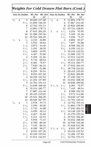
Page 85 Cold Finished Bar Products
COLD FINISHED BARS
Weights For Cold Drawn Flat Bars (Cont.)
5/8 x 5 10.640 127.68 5 1/2 11.699 140.39 6 12.762 153.14 7 14.894 178.73 8 17.015 204.29 10 21.280 255.36 12 25.524 306.293/4 x 7/8 2.233 26.80 1 2.552 30.62 1 1/8 2.872 34.46 1 1/4 3.191 38.29 1 1/2 3.829 45.95 1 3/4 4.467 53.60 2 5.105 61.26 2 1/4 5.743 68.92 2 1/2 6.381 76.57 2 3/4 7.020 84.24 3 7.857 91.88 3 1/4 8.295 99.54 3 1/2 8.933 107.20 4 10.210 122.52 4 1/2 11.491 137.89 5 12.762 153.14 5 1/2 14.038 168.46 6 15.314 183.77 7 17.887 214.40 8 20.419 245.03 10 25.524 306.29 12 30.629 367.557/8 x 1 2.978 35.74 1 1/8 3.350 40.20 1 1/4 3.723 44.68 1 3/8 4.059 49.14 1 1/2 4.467 53.60 1 3/4 5.211 62.53 2 5.956 71.47 2 1/4 6.700 80.40 2 1/2 7.445 89.34 2 3/4 8.189 98.27 3 8.933 107.20 3 1/2 10.420 125.04 4 11.911 142.93
7/8 x 5 14.894 178.73 6 17.867 214.40 8 23.822 285.86 12 35.734 428.811 x 1 1/4 4.254 51.05 1 1/2 5.105 61.26 1 3/4 5.956 71.47 2 6.806 81.67 2 1/4 7.657 91.88 2 1/2 8.508 102.10 2 3/4 9.359 112.31 3 10.210 122.52 3 1/4 11.060 132.72 3 1/2 11.911 142.93 4 13.613 163.36 4 1/2 15.314 183.77 5 17.016 204.19 5 1/2 18.718 224.62 6 20.419 245.03 7 23.822 285.86 8 27.226 326.71 10 34.032 408.38 12 40.838 490.061 1/4 x 1 1/2 6.381 76.57 1 3/4 7.445 89.34 2 8.508 102.10 2 1/4 9.572 114.86 2 1/2 10.640 127.68 2 3/4 11.701 140.41 3 12.762 153.14 3 1/2 14.894 178.73 4 17.016 204.19 4 1/2 19.148 229.78 5 21.270 255.24 6 25.524 306.29 8 34.032 408.38 10 42.540 410.48 12 51.048 612.581 1/2 x 1 3/4 8.933 107.20 2 10.210 122.52 2 1/4 11.486 137.83 2 1/2 12.762 153.14
Size In Inches Wt. Per Ft.
Wt. Per 12'
Size In Inches Wt. Per Ft.
Wt. Per 12'
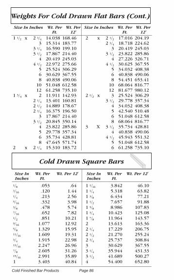
Page 86Cold Finished Bar Products
1 1/2 x 2 3/4 14.038 168.46 3 15.314 183.77 3 1/4 16.590 199.10 3 1/2 17.867 214.40 4 20.419 245.03 4 1/2 22.972 275.66 5 25.524 306.29 6 30.629 367.55 8 40.838 490.06 10 51.048 612.58 12 61.258 735.101 3/4 x 2 11.911 142.93 2 1/4 13.401 160.81 2 1/2 14.889 178.67 2 3/4 16.375 196.50 3 17.867 214.40 3 1/2 20.845 350.14 4 23.822 285.86 5 29.778 357.34 6 35.734 428.81 8 47.645 571.742 x 2 1/4 15.310 183.72
2 x 2 1/2 17.016 204.19 2 3/4 18.718 224.62 3 20.419 245.03 3 1/2 23.822 285.86 4 27.226 326.71 4 1/2 30.625 367.55 5 34.032 408.38 6 40.838 490.06 8 54.451 653.41 10 68.064 816.77 12 81.677 980.122 1/2 x 3 25.524 306.29 3 1/2 29.778 357.34 4 34.032 408.38 5 42.540 510.48 6 51.048 612.58 8 68.064 816.773 X 3 1/2 35.734 428.81 4 40.838 490.06 4 1/2 45.943 551.32 5 51.048 612.58 6 61.258 735.10
Size In Inches Wt. Per Ft.
Wt. Per 12'
Size In Inches Wt. Per Ft.
Wt. Per 12'
Weights For Cold Drawn Flat Bars (Cont.)
1/8 .053 .643/16 .120 1.441/4 .213 2.565/16 .332 3.983/8 .478 5.747/16 .652 7.821/2 .851 10.219/16 1.077 12.925/8 1.329 15.9511/16 1.609 19.313/4 1.915 22.9813/16 2.247 26.967/8 2.605 31.2615/16 2.991 35.891 3.403 40.84
1 1/16 3.842 46.101 1/4 5.318 63.821 3/8 6.434 77.211 1/2 7.657 91.881 5/8 8.986 107.831 3/4 10.423 125.081 7/8 11.964 143.572 13.613 163.362 1/4 17.229 206.752 1/2 21.270 255.242 3/4 25.737 308.843 30.629 367.553 1/4 35.944 431.333 1/2 41.689 500.274 54.400 652.80
Cold Drawn Square Bars
Size In Inches
Wt. Per Ft.
Wt. Per 12' Size In Inches
Wt. Per Ft.
Wt. Per 12'

Page 87 Cold Finished Bar Products
COLD FINISHED BARS
Cold Drawn Hexagon Bars
Size In Inches
Wt. Per Ft.
Wt. Per 12' Size In Inches
Wt. Per Ft.
Wt. Per 12'
3/16 .104 1.25 1/4 .184 2.21 5/16 .288 3.46 3/8 .414 4.97 7/16 .565 6.78 1/2 .737 8.84 9/16 .933 11.20 5/8 1.151 13.81 11/16 1.393 16.72 3/4 1.658 19.90 13/16 1.946 23.35 7/8 2.256 27.07 15/16 2.590 31.08 1 2.947 35.36 1 1/8 3.731 44.77 1 3/16 4.156 49.87 1 1/4 4.605 55.26 1 1/8 5.572 66.86
1 7/16 6.091 73.09 1 1/2 6.631 79.57 1 5/8 7.782 93.38 1 3/4 9.026 108.31 1 7/8 10.360 124.32 2 11.791 141.49 2 1/8 13.313 159.76 2 1/4 14.556 174.67 2 3/8 16.626 199.51 2 1/2 18.417 221.00 2 5/8 20.309 243.71 2 3/4 22.291 267.49 3 26.525 318.30 3 1/8 28.787 345.44 3 1/4 31.101 373.20 3 1/2 36.104 433.25 4 47.154 565.85
This is a heavily cold worked, strain relieved carbon killed steel bar. It is available as a Cold Drawn Bar in 12 foot lengths. Some loca-tions stock an ASTM-1144 bar with similar properties.
AnalysisCarbon Manganese Sulphur Silicon
.40 - .48 1.35 - 1.65 .24 - .33 .15 - .30
Applications
Ideal for general maintenance and repair, as all properties are “built in” the bar. Production parts include axles, collets, gears, spline shafts, spindles, pump shafts, feed and lead screws to all kinds, worms, studs, etc.
Machinability
Stressproof machines well for its strength, with excellent tool life and a smooth finish. Cutting speeds of about 125 surface feet per minute are recommended.
Stressproof® Cold Finished Shafting

Page 88Cold Finished Bar Products
Mechanical PropertiesSize In Inches Min. Yield Point Average Tensile Strength
1/2" To 2" 100,000 p.s.i. 125,000 p.s.i.
Over 2" To 3 1/4" 90,000 p.s.i. 120,000 p.s.i.
TolerancesSize In Inches Cold Drawn (Plus) Cold Drawn (Minus)
5/16 to 1 1/2" Inc. 0.000 0.004
1 1/2 to 2 1/2" Inc. 0.000 0.005
2 1/4 to 4" 0.000 0.006
Warpage
Almost completely free from strains, it may be splined, key seated, broached, drilled, reamed, milled or threaded. Expensive straight-ening operations are eliminated.
Wearability
Although easily machined, wear resistant properties are un-usually high. Many heat treated or carburized parts have been successfully replaced by unhardened Stressproof in spite of its relative softness.
Reduced Costs
By eliminating hardening and straightening operations, re-ducing machining time, lowering steel costs when replacing alloy steels, and by improving the quality of the finished part, STRESSPROOF will give you reductions in costs on many parts. While the price is slightly higher than ordinary carbon bars, its increased strength, wearability and service life make it the most economical steel to use in many applications.
Precision Shafting represents the highest degree of straight-ness, accuracy, concentricity and surface perfection obtainable in commercial practice. These bars are turned and centerless ground to close limits over their entire length, and burnished to a high finish after grinding. It is important to note that turning does not alter the physical properties of the bar.
Precision C-1045 Shafting

Page 89 Cold Finished Bar Products
COLD FINISHED BARS
Screw Machine Stock
AnalysisSpecification Carbon Manganese Phosphorus Sulphur
C-1045 .43 - .50 .60 - .90 .04 Max .05 Max.
Application
This steel is often called pump rod or pump shafting due to its high degree of straightness (important in high speed shaft-ing). The special straightness serves to prevent vibrations and wear on packings and bearings which must be avoided in deep well pump work. Other uses include motor shafts and other applications where high speed work necessitates straightness and accuracy along with the ability to be machined unsym-metrically with practically no danger of warpage.
Typical Mechanical PropertiesSpec. Tensile
(P.S.I.)Yield
(P.S.I.)Elongation In 2 Inches
% Reduction of Area
C-1045 110,000 78,000 20% 55
TolerancesDiameter Of Bar Plus Tolerance Minus Tolerance
Less Than 1 1/2" 0 .001”
1 1/2" To Under 2 1/2" 0 .0015”
2 1/2" To 3" Inclusive 0 .002”
Over 3" To 4" Inclusive 0 .003”
C-12L14 Cold Finished Rounds
These special quality CF rounds have a machinability rating on automatic screw machines of 300 surface feet per minute. These rounds are of screw stock quality used for instruments, electronic parts, and machine shafts. They are also suitable for nickel plating.
AnalysisSpec. Carbon Manganese Phosphorus Sulphur Lead
C-12L14 .15 Max. .085 - 1.15 .04 - .09 .26 - .35 .15 - .35

Page 90Rebar
Mechanical PropertiesGr. 40 Gr. 60 Gr. 75
Tensile Strength, Min. P.S.I. 60,000 90,000 100,000
Yield Strength, Min. P.S.I. 40,000 60,000 75,000
Bar Number Minimum % of elongation in 8 in.
3 11% 9% 7%
4,5,6 12% 9% 7%
7,8 8% 7%
9,10 7% 6%
11, 14, 18 7% 6%
Bend Test Requirements(Minimum Diameter for Bend Tests = 180o, d = Nominal Diameter of Bar)
Bars are capable of being bent around a pin without cracking on the outside diameter as follows: (Number 14 & 18 are bent 90o ).
Bar Number Grade 40 Grade 60 Grade 75
3,4,5 3 1/2 X d 3 1/2 X d 5 X d
6 5 X d 5 X d 5 X d
7,8 5 X d 5 X d
9,10 7 X d 7 X d
11 7 X d 7 X d
14,18 9 X d 9 X d
ASTM-A706 Specification pertains to low-alloy steel deformed bars in cut lengths or coils for concrete reinforcement, intended for applications where welding and/or bending, are of importance.
Concrete Reinforcing Bars ASTM-A615
The ASTM-A615 Specification pertains to deformed and plain bil-let-steel concrete reinforcement bars in cut lengths or coils. A de-formed bar is defined as a bar whose surface is provided with lugs or protrusions (referred to as deformations) which inhibit longitu-dinal movement of the bar relative to the concrete which surrounds the bar in such construction. The standard sizes and their number designations are listed below.
Bars are of 3 minimum yields: namely, 40,000 psi, 60,000 psi, and 75,000 psi; designated as Gr. 40, Gr. 60, and Gr. 75, respectively.

Page 91 Rebar
REBAR
Concrete Reinforcing Bars ASTM-A706
Bend Test Requirements(Minimum Diameter for Bend Tests = 180o, d = Nominal Diameter of Bar)
Bars are capable of being bent around a pin without cracking on the outside diameter as follows:
Bar Number Diameter of Pin
3, 4, 5 3 X d
6, 7, 8 4 X d
9, 10, 11 6 X d
14, 18 8 X d
Concrete Reinforcing BarsWeights & Dimensions
BarNumber
WeightPer Ft.
NominalDiameter
NominalDec.
Diam.
Cross Sec-tion
Area (In2)
PerimeterIn Inches
3 .376 3/8 0.375 0.11 1.178
4 .669 1/2 0.500 0.20 1.571
5 1.044 5/8 0.625 0.31 1.963
6 1.503 3/4 0.750 0.44 2.356
7 2.046 7/8 0.875 0.60 2.749
8 2.673 1 1.000 0.79 3.142
9 3.403 1 1/8 1.128 1.00 3.544
10 4.307 1 1/4 1.270 1.27 3.990
11 5.318 1 3/8 1.410 1.56 4.430
14 7.650 1 5/8 1.693 2.25 5.320
18 13.600 2 1/4 2.257 4.00 7.090
Mechanical PropertiesTensile Strength, Min. P.S.I. 80,000
Yield Strength, Min. P.S.I. 60,000
Yield Strength, Max. P.S.I. 78,000Tensile Strength shall not be less than 1.25 times the actual yield strength.
Bar Number Minimum % of elongation in 8 in.3, 4, 5, 6 14%7, 8, 9, 10, 11 12%14, 18 10%

Page 92Color Codes
Color CodesTo assist you in the identification of steel products purchased from PDM Steel Service Centers, please refer to the following Color Codes. The color code list which follows is arranged according to product category and description:
Hot Rolled Strip & Bars Structural Shapes Pipe & Round Tubing
Cold Rolled Strip & Bars Sq. & Rectangular Tubing Expanded Metal
Alloy Rounds Sheet Expanded Met. Grating
Rebar Plate
Hot Rolled Strip & BarsHR Strip
Thickness Specification Color1/8" Comm.Qual. Yellow3/16" Comm. Qual. Green
HR Flats, Rounds, and Squares Thickness Specification Color
1/8" A36 Yellow3/16" A36 Green1/4" A36 Red5/16" A36 White3/8" A36 Blue7/16" A36 Gold1/2" A36 Orange9/16" A36 Copper5/8" A36 Yellow3/4" A36 Green7/8" A36 Pink1" A36 Black1 1/8" A36 Yellow1 1/4" A36 Red1 3/8" A36 Blue1 1/2" A36 Orange2" A36 Black
Description Specification ColorHR Flat and Round (Min. 50 ksi) A529 Blue and WhiteHR Flat A572 Gr. 50 Green and WhiteHR Flat C1008 Blue and GreenHR Flat and Round C1018 Black & BlueHR Flat, Round, and Square C1040/1045 Green and RedHR Flat C1055 Green and OrangeHR Flat, Hollow, and Solid Tul Bar C1070 Red and Orange HR Flat, Round, Square C1095 SilverB.E. Weedcutter C1055 GreenB.E. Weedcutter C1070 Orange

Page 93 Color Codes
COLOR CODESHot Rolled Bar Shapes
Bar Angles, Channels & Tees Thickness Specification Color
1/8" A36 Yellow3/16" A36 GreenBar Tees A36 Blue
Alloy BarsDescription Specification Color
HR HT Stress Relieved Round 4140 Blue and PurpleCF HT Stress Relieved Round 4140 Green and PurpleCF HT Stress Relieved Square 4130 White and PurpleCF HT Sq. (NOT Stress Relieved) 4130 White and OrangeCF Round ETD 150® Purple
RebarDescription Specification Color
Rebar GR 40 A615 BlueRebar GR 60 A615 RedRebar GR 60 (Weldable) A706 Yellow
Cold Finished BarsDescription Specification Color
CF Flat C1018 BlackCF Round C1018 BlackCF Rd-Drawn G.&P./T.G.&P. C1018 Black and WhiteCF Round C1045 RedCF Round C1215 WhiteCF Round-Leaded 12L14 OrangeCF Round 1117 GoldCF Rd. Stressproof® 1144 YellowCF Rd. Stress Relieved 1144 GreenFatigue Proof® 1137 BrownPrecision Ground Shaft C1045 Pinkxx Undersize **Over 1" stored in cardboard tubes. CF Square C1018 BlackCF Square (Round Corners) C1018 PinkCF Hex C1018 BlackCF Hex - Leaded 12L14 Orange

Page 94Color Codes
Structural ShapesStructural Angles
Thickness Specification Color1/8" A36 Yellow3/16" A36 Green1/4" A36 Red5/16" A36 White3/8" A36 Blue7/16" A36 Gold1/2" A36 Orange5/8" A36 Yellow3/4" A36 Green7/8" A36 Pink1" A36 Black
Description Specification ColorWide Flange A36 BlueHi Tensile A572 Gr.50 Green & YellowDual Grade A992 M Beams (Misc.) A36 BlueS Beams (Std. I) A36 BlueH Pilings (Domestic) A36 Blue and RedH Pilings (Import) A36 Blue and WhiteChannels A529 Blue and WhiteChannels, Standard A36 1st wt. Blue 2nd wt. Blue and Red 3rd wt. Blue and Green 4th wt. Blue and Yellow Channels, Misc. A36 Blue
Tube, Square & RectangularWall Thickness Specification Color
.049 A500 A / A513 Black
.060, .063, .065 A500 A / B / C / A513 White
.072, .073, .075 A500 A / A513 Copper
.083 A500 A / B / C / A513 Pink
.090, .095 A500 A / A513 Blue
.109 A500 A / A513 Purple
.120, .125 A500 A / B / C Yellow
.180, .188 A500 B / C Green
.238, .250 A500 B / C Red
.313 A500 B White
.375 A500 B Blue
.500 A500 B Orange
.625 A500 B Yellow
Tube, Pre-PrimedWall Thickness Specification Color
Under 2" Sq. & 3" X 1" Rect. A513 As AboveOver 2" Sq. & 3" X 1 1/2" Rect. A500 B As Above

Page 95 Color Codes
COLOR CODES
Tube, Flashout2.53 X 2.53 X 0.250 Red and Gold
Tube, Round HREW & CREWWall Thickness Specification Color
Mech Tube-HREW & CREW A513-T1 & T2 Same as Square Tube
PipeDescription Specification Color
Pipe Std (Sch 40) A53A GreenX Heavy (Sch 80) A53A WhitePipe Std (Sch 40) A53B BlueX Heavy (Sch 80) A53B RedPre-Primed (KleenKote®) Pipe No Grade N/CUncoated Pipe A53A OrangeUncoated Pipe A53B PinkUncoated Pipe (Sched. 10) A53A Gold
PlatePlate products are marked with the color code for the grade on the cor-ners of the plate. The color code for the thickness of the plate is marked as a stripe of color on the ends of the plate. (Example: 5/8" A572 Gr 50 would have Green & Yellow on all four corners to denote the grade and a stripe of Blue on both ends to denote the thickness.)
Color Code For GradeDescription Specification (On all Corners)
Hot Rolled A36 BlueFloor Plate Comm. Q No ColorAbrasion Resistant AR235 YellowBrinell 321 Purple and YellowBrinell 360 Red and YellowBrinell 400 Copper and YellowBrinell 500 Black and YellowBrinell, Formable 400 White and YellowBrinell, Formable 440 Pink and YellowBrinell, Formable 500 Pink, Black and YellowConstructional Alloy (Tl® Type) A514 PinkHigh Strength, Low Alloy A656 Gr 80 Pink and WhiteHigh Tensile A572 Gr 42 Green and WhiteHigh Tensile A572 Gr 50 Green and YellowHigh Tensile A572 Gr 60 Green and GrayABS Certified A283 Gr C Green and BlueWeathering A588 Blue and YellowHR Corten® A242 Blue and WhiteHR Pressure Vessel Quality A516 Gr 70 WhiteHR Low Carbon C1010 CopperHR Low Carbon C1015 Copper and BlueHR Low Carbon (Robinson Proc.) C1010 Copper and PurpleHR (Robinson Proc.) A36 Blue and PurpleHR Stress Free Plate A36 Blue and OrangeHR Stress Free Plate C1008 Yellow and OrangeHR Stress Free Plate A570 Red and OrangeHR Med Carbon C1035 OrangeHR Med Carbon C1040/1045 Green

Page 96Color Codes
HR Med Carbon C1055 Green and OrangeHR UM A36 BlueHR UM (Min. 50 ksi) A529 Blue and White33 Max. Carbon 33 Max. Carbon Gold
Plate Thickness Color Code/Thickness (Marked on both ends)
3/16" Green 1/4" Red 5/16" White 3/8" Blue 7/16" Gold 1/2" Orange 5/8" Yellow 3/4" Green 7/8" Pink 1" Black 1 1/8" Yellow 1 3/16" Green 1 1/4" Red 1 3/8" Blue 1 1/2" Orange 1 5/8" Yellow 1 3/4" Green 1 7/8" Pink 2" Black 2 1/8" Yellow 2 1/4" Red 2 1/2" Orange 2 3/4" Green 3" Black 3 1/2" Orange 4" Black 4 1/2" Orange
Sheet, Hot Rolled and Gauge Floor PlateThickness Specification Color
7 Ga (.1793) A-1011 Orange10 Ga (.1345) A-1011 Gold11 Ga (.1196) A-1011 Black12 Ga (.1046) A-1011 Yellow13 Ga (.0847) A-1011 Orange14 Ga (.0747) A-1011 Red16 Ga (.0598) A-1011 Green
Sheet MiscellaneousDescription Specification Color
Sheet (Calwell®) PQ55 Red and BlackSheet (Robinson Process) C1010 Copper and PurpleSheet (High Tensile) A-1011 (Gr 45) WhiteSheet (High Tensile) A-1011 (Gr 50) Green and Yellow

Page 97 Color Codes
COLOR CODESSheet, Cold Rolled
Thickness Spec. Color10 Ga (.1345) A366 Gold11 Ga (.1196) A366 Black12 Ga (.1046) A366 Yellow13 Ga (.0847) A366 Orange14 Ga (.0745) A366 Red16 Ga (.0598) A366 Green18 Ga (.0478) A366 Pink20 Ga (.0359) A366 Gold22 Ga (.0299) A366 Yellow24 Ga (.0239) A366 Red26 Ga (.0179) A366 Green
Sheet, Flat GalvanizedThickness Spec. Color
10 Ga (.138) A653 CQ, CTD Gold12 Ga (.109) A653 CQ, CTD Yellow14 Ga (.079) A653 CQ, CTD Red16 Ga (.064) A653 LFQ, CTD Green18 Ga (.052) A653 LFQ, CTD Pink20 Ga (.040) A653 LFQ, CTD Gold22 Ga (.034) A653 LFQ, CTD Yellow24 Ga (.028) A653 LFQ, CTD Red26 Ga (.022) A653 LFQ, CTD Green28 Ga (.019) A653 LFQ, CTD Pink30 Ga (.016) A653 LFQ, CTD GoldPQS Electro Galvanized (Chromated)A653 Class C As AbovePQS Wiped Galvanized (A40) A653 LFQ As AboveAluzinc Plus (Steel sheet with aluminum/zinc coating) As Above
Expanded MetalWidth of opening (color end). Thickness of strand (color side)
Opening Thickness Color1/4" # 6 Black1/2" # 9 Red1/2" # 10 Gold3/4" # 13 Green1" # 14 White1" # 16 Orange1 1/2" # 18 Blue2" # 20 YellowExample: 1/4" #20—Black end, yellow side.
Expanded Metal GratingWeight Spec. Color
3.00 Lb. Comm Q White3.14 Comm Q Orange4.00 Comm Q Yellow4.27 Comm Q Green5.00 Comm Q Blue6.25 Comm Q Gold7.00 Comm Q RedAll Other Products No Color

Page 98Color Codes
Notes

Page 99 Color Codes
COLOR CODES
Notes