Embed Size (px)
Citation preview

A Brief Overview of the MPEG2 Standard
Dr. David Corrigan

MPEG-2 the Basics We have already covered a lot of the background of how video
compression (or coding) works inside MPEG2. Intra-Coding (I-frames) v Prediction Coding (P-frames) v Bi-Directional
Prediction Coding (B-frames) & the Group of Pictures (GOP)
Most of the subsequent coding architecture is inherited from JPEG DCT. Quantisation. Variable Length Coding (VLC) – ie Huffman + Run Length Coding.
But it is not that simple motion vectors need to be coded, we may need to include direction
prediction information must deal with interlaced video plus what about audio & subtitles (either in text or lossless image format)? and what about streaming so….

MPEG-2 the Basics MPEG 2 is about more than video coding
Part 1 – Systems (describes how audio and video are plugged together)
Part 2 – Video Part 3 – Audio (an extension of the MPEG 1 audio
standards) Part 4 – conformance testing Part 5 – software simulation Part 6 – Digital Storage Media Command and Control –
(eg. rewind forward etc etc) Part 7 – Advanced Audio Coding (AAC) – a 2nd audio
standard there are even more parts

Challenges in MPEG2 (besides compression)1. Multiplexing
How to combine audio video and text? They must appear at the same time.
2. Media Streams can be stored on a hard drive or DVD Data can be broadcast or streamed on the internet
3. Sequencing how to send data so that it will be received in the
correct order? how to sychronise the decoder and encoder?
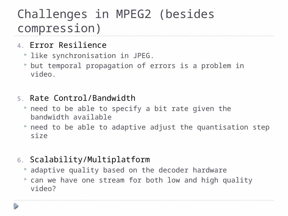
Challenges in MPEG2 (besides compression)4. Error Resilience
like synchronisation in JPEG. but temporal propagation of errors is a problem in video.
5. Rate Control/Bandwidth need to be able to specify a bit rate given the bandwidth
available need to be able to adaptive adjust the quantisation step
size
6. Scalability/Multiplatform adaptive quality based on the decoder hardware can we have one stream for both low and high quality
video?

Scalability in MPEG 2
SNR Scalability
Spatial Scalability

Profiles and Levels MPEG 2 supports a wide variety of scenarios
eg. high quality tv broadcast, low bit rate internet streaming etc
decoders can have varying degrees of complexity + plus a decoder for internet streaming should not have to support decoding of digital tv signals.
MPEG 2 defines Profiles and Level for streams Profiles define the required decoder complexity
(feature set) to decode the stream Levels define the maximum allowed resolution
frame rate and bit rate.

Levels in MPEG 2

Levels in MPEG 2

Allowed Profile/Level Combinations
4:2:2 profile extends on the main profile but does not support
scalabilty

Profile/Level Combinations Standard Definition TV uses the Main Profile and
the Main Level allows bi-directional prediction but not scalability and
stream must use 4:2:0 YCbCr chroma downsampling Streams have a max resolution of 720x576, max frame
rate of 30 fps and max bit rate of 15 mbits/second also used on DVDs
HDTV uses the Main Profile and the High Level
The Main Profile defines the core set of algorithms in MPEG 2.

MPEG 2 Main Profile (Layers) MPEG Sequence is organised into a hierarchy of layers, like
an onion
The Sequence Layer – the entire video sequence The GOP Layer – delineating exactly one Group of Pictures
(PAL max 15, NTSC max 18 frames) The Picture Layer – referring to a single I- P- or B-frame. The Slice Layer – represents a horizontal group of
macroblocks that do not span multiple rows. The Macrobock Layer – represents unit of data for motion
estimation (16x16). Conists of blocks for luminance and chrominance.
The Block Layer – contains the DCT coefficients for 1 8x8 block of pixels (can be either a luminance of chrominance block).

The GOP Layer (Frame Ordering) When using IBBP…. prediction mode we have
to reorder frames so that all prediction is “backward” (ie. causal) so if a B-frame requires a subsequent P-frame for
forward prediction the p-frame is placed first in the stream.
B-frames from previous
GOP come after I frame
P-frame 4 is sent before B-frames 2
and 3

The Picture Layer (Interlacing) The odd and even fields can be coded
together as if it were a frame or the can be coded independently if there is no motion then we can combine the two
fields into a single image called a “frame-picture.” Better for compression efficiency.
if there is motion then the two fields are coded separately as if they were two pictures called “field-pictures”.
Odd Field-Picture
Even Field-Picture
Frame Picture

The Slice Layer (Synchronisation) Slices can be of arbitrary length but can not extend
onto a new line.
They are the MPEG-2 solution to the problem of spatial synchronisation (errors can not propagate spatially between slices).
Slice length set depending on the error conditions ie. shorter when the error rate is high.
Can get temporal propagation of errors too but they can extend longer than 1 GOP because of the prediction strategy.

The Macroblock Layer Each macroblock contains 4 luminance blocks and 2
chrominance blocks if 4:2:0 (4 chrominance if 4:2:2)
I-frame macroblocks contain no vectors, 1 in P-frames and 2 in B-frames. If interlaced then the number of vectors doubles.
Macroblocks for P- and B-frames can be intra-coded if the prediction error (DFD) is too large.
Motion estimator not specified but the vectors are limited in range and are quantised to 0.5 pixel accuracy.

Coding of Motion Vectors Motion Vectors are differentially coded wrt the
vector for the previous macroblock (ie. to the left)
PMV – previous motion vector. MV – motion vector for the current
macroblock.
Define . multiply by 2 as 0.5 pel quantisation used. and are coded separately.
Coding Δx and Δy
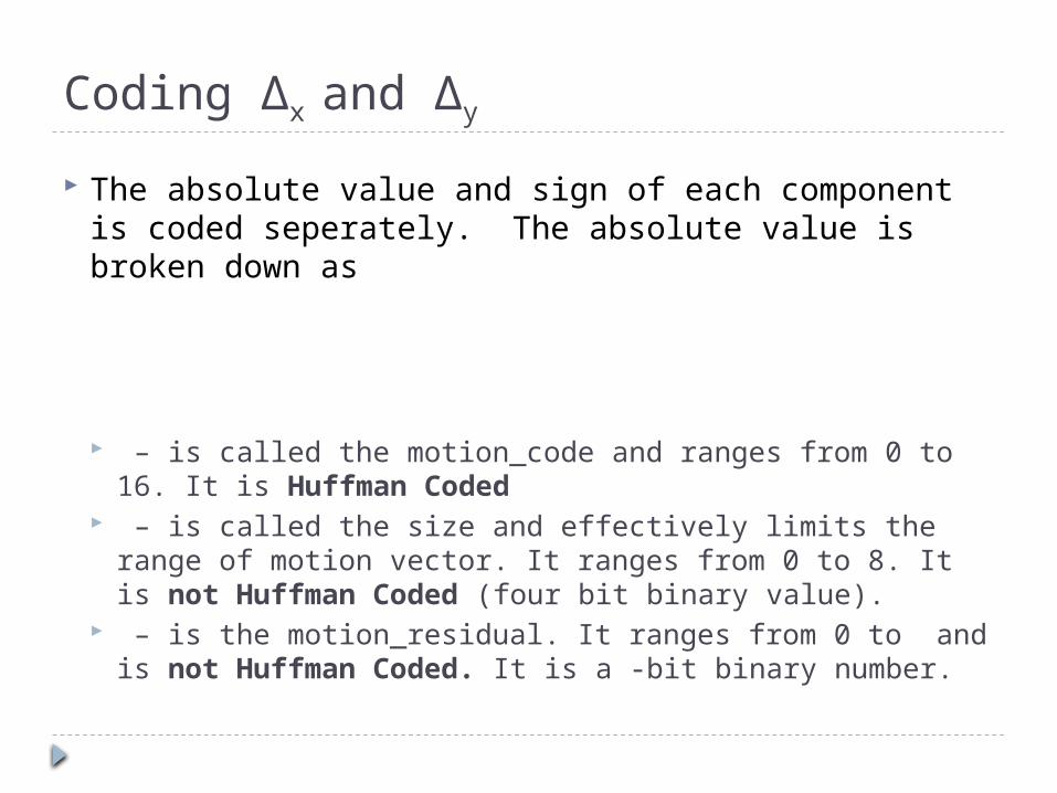
The absolute value and sign of each component is coded seperately. The absolute value is broken down as
– is called the motion_code and ranges from 0 to 16. It is Huffman Coded
– is called the size and effectively limits the range of motion vector. It ranges from 0 to 8. It is not Huffman Coded (four bit binary value).
– is the motion_residual. It ranges from 0 to and is not Huffman Coded. It is a -bit binary number.

Coding Δx and Δy
Δ∗
A table of how the choice of Size effects the range of difference that can be coded. Size is set once at the start of each Picture Layer. (ie. it is the
same over the entire picture). It is common to choose larger size for P-frames cause motion
is bigger.

Coding Δx and Δy
Size is chosen based on the range of motion vectors. eg. say we limit search width to 10. Then we
could have a vector [10, 10] and a previous vector [-10 10].
The max or is . Therefore we need to choose .
Given an MV [4.5, 3] and PMV [5, -1] then
Then for , 𝑎=1 ,𝑏=2 ,𝑐=0𝑎=2 ,𝑏=2 ,𝑐=3

Huffman Codes for motion_code s is 0 if the component is
positive and 1 if negative.
each vector is specified by a (motion_code, motion_residual) pair. the Size value is specified at
the start of the Picture Layer.
If then we set the motion_code to 0 (codeword is 1). There is no motion_residual.
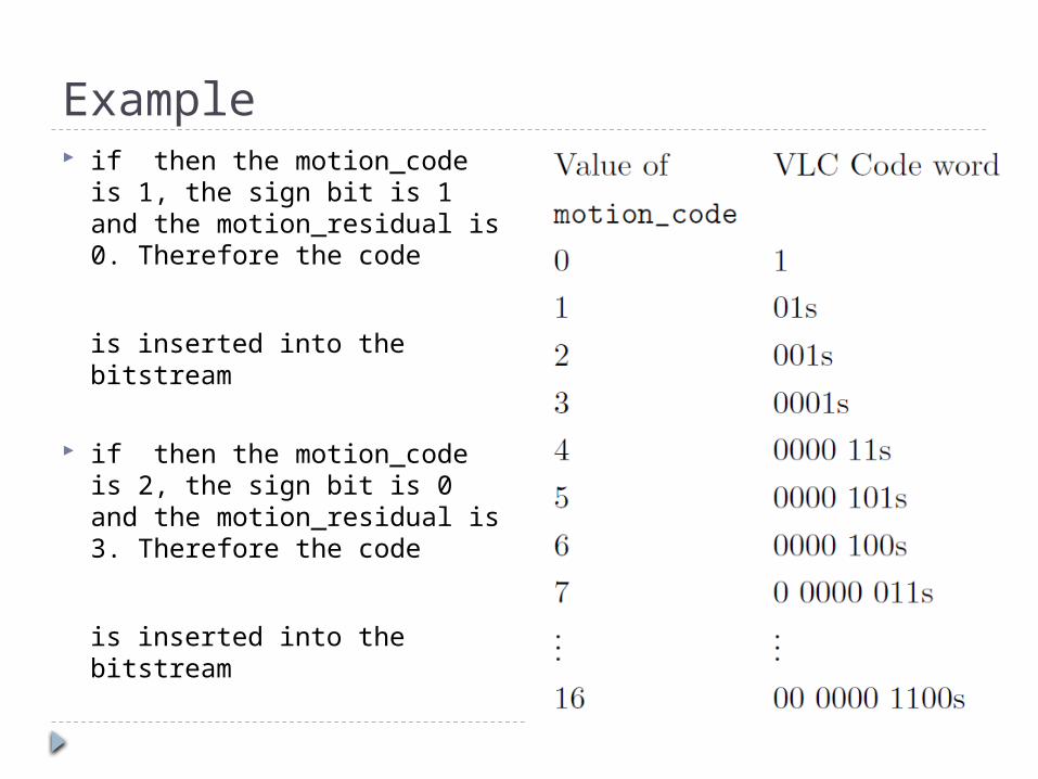
Example if then the motion_code is 1,
the sign bit is 1 and the motion_residual is 0. Therefore the code
is inserted into the bitstream
if then the motion_code is 2, the sign bit is 0 and the motion_residual is 3. Therefore the code
is inserted into the bitstream

The Block Layer (Quantisation)
Quantisation step sizes for intra-coded blocks
Quantisation step size for prediction-coded blocks
similar to the matrix used in JPEG
a fixed Qstep = 16 for all coefficients

The Block Layer (Quantisation) One of the ways rate control is achieved is by
increasing the quantisation step size in blocks which would otherwise have a higher entropy.
We can specify a quantisation scale value that scale the coefficient of the Q matrix. ie. the effective step sizes are
This will reduce quality in these areas.

The Block Layer (Scan Order)
Scan Order for Progressive Video Scan Order for Interlaced Video

The Block Layer (Scan Order) Idea is to maximise length of runs of zeros in
the block.
So progressive frames use the zig-zag scan like JPEG
Interlaced Frames use an alternative scan because there are likely to be non-zero DCT coefficients toward the bottom left corner of the block.

Sequencing, Media and Multiplexing We could have multiple elementary streams (ie. video, audio, text etc.).
They have to combined into a single non-elementary stream and have to be both decoded and displayed in a certain order in the receiver.
The MPEG 2 Part 1 (Systems) standard specifies two different ways of doing this Program Stream (PS) – used for reliable media such as DVDs Transport Stream (TS) – used for Digital TV Transmission over noisy channels.
Note there are other ways of doing this that exist outside of the standard eg. the avi and mov file formats can be used with compressed MPEG2 data.
To do this the notions of time and packets are introduced. each elementary stream is divided into packets. They can be of fixed or
variable length. these packets are interleaved by the encoder. each packet carries a timestamp which tells the decoder the correct order.

MPEG 2 Program Stream (PS) Consists of Packetised Elementary Stream (PES) packets.
PES packets contain 2 timestamps1. Decoding Time Stamp (DTS) – this tells the decoder when the
packet should be decoded. The data is then decoded into the bit stream.
2. Presentation Time Stamp (PTS) – this tells the decoder when the data should be displayed.
The systems part specifies that the decoder must contain a Systems Clock called the STC when a decoder’s STC is equal to a packet’s DTS the data in the
packet is decoded when the STC is equal to a packet’s PTS the decoded data is sent to
the display device (eg. graphics card or sound card) the state of the encoders clock is placed in the stream at regular
intervals. This synchronises the decoder with the encoder.

MPEG-2 Transport Stream (TS) The transport stream uses a fixed packet length
(188 bytes) this allows easy decoder/encoder synchronisation. it also allows error correction codes to be inserted.
Transport Streams can contain packets from a number of Programs These can be different TV channels or maybe an
EPG. Each program has a unique Packet ID placed in the
packet header. Decoder can discard packets of other programs by
checking the PID.
![Corrigan Collection Artist Surname or Place of Year of ... · Corrigan Collection Artist Surname or ... Robyn Brady 1989 Corrigan 4/8 ... Donald Gregor Grant commons [Sydney]](https://img.pdfslide.net/doc/110x75/5b1842347f8b9a41258ba6d5/corrigan-collection-artist-surname-or-place-of-year-of-corrigan-collection.jpg)