Embed Size (px)
Citation preview

International
OPEN ACCESS Journal
Of Modern Engineering Research (IJMER)
| IJMER | ISSN: 2249–6645 | www.ijmer.com | Vol. 5 | Iss. 10 | October 2015 | 5 |
A Brief Research, Study, Design and Analysis on Wind turbine
KunduruAkhil Reddy1, KalyanDagamoori
2, ArimalaParamasivamSruthi
3,
Sai Apurva.N4,Nimmala Naga Maha Lakshmi Naidu
5,
A.Vamsi Krishna Reddy6, Beri Rajesh
7, KudaKiran Kumar
8,
ChithaluriShivasri9, SumamaYaqub Ali
10
1Student, Department Of Mechanical Engineering, GITAM UNIVERSITY. Hyderabad.
2,6,10 Student, Department Of Aeronautical Engineering, MLR Institute Of Technology and
Management, Hyderabad. 3,4,7,8
Student, Department Of Aeronautical Engineering, MLR Institute Of Technology, Hyderabad. 9Student, Aeronautical Department, Institute Of Aeronautical Engineering, Hyderabad.
5Senior Advisor In Technical Automotive Works, CNG India Pvt.Ltd.
I. INTRODUCTION 1.1 INTRODUCTION
Wind is a form of solar energy and is a result of the uneven heating of the atmosphere by the sun, the
irregularities of the earth's surface, and the rotation of the earth. Wind is the movement of air from an area of
high pressure to an area of low pressure. Humans use this wind flow, or motion energy, for many purposes:
sailing, flying a kite, and even generating electricity. In fact, Ancient mariners used sails to capture the wind and
explore the world. Farmers uses windmills to grind their grains and pump water. Today, more and more people
are using wind turbines to wring electricity from the breeze. Over the past decade, wind turbine use has
increased at more than 25 percent a year. Many people believe that the windmill and wind turbine are the same
thing. They are actually very unique and different in many ways. The wind turbine was made to produce energy
for a clean and safe environment.
Fig 1.11 Wind Turbines in INDIA
ABSTRACT:- The projects aims to evaluate the aerodynamic performance of variable-speed fixed-pitch
horizontal-axis wind turbine blades through two and three dimensional computational fluid dynamics(CFD)
analysis. A wind turbine is a device that converts kinetic energy from the wind into electrical power. This
project describes about the principle and working of wind turbine as they are becoming popular in the
renewable energy world. Primary objective in wind turbine design is to maximize the aerodynamic
efficiency, or power extracted from the wind. The blade is designed using different types of airfoils which
are oriented at different angle of attack and the blade design is responsible for the efficiency for the wind
turbine. The designs of blades are done using Q-BLADE software, the power output is also determined
using this software which uses Blade Elemental Theory. The comparative study is done considering the
power output of the designed wind turbine blades and the existing wind turbine blade. Structural analysis is
performed by ANSYS software.
Keywords:- Wind turbine, On Shore Wind turbine, Off Shore Wind turbine, Catia V5, Ansys.

A Brief Research, Study, Design and Analysis on Wind turbine
| IJMER | ISSN: 2249–6645 | www.ijmer.com | Vol. 5 | Iss. 10 | October 2015 | 6 |
1.2 How Does Wind Turbines Make Electricity
The terms wind energy or wind power describes the process by which the wind is used to generate
mechanical power or electricity. Wind turbines convert the kinetic energy in the wind into mechanical power.
This mechanical power can be used for specific tasks (such as grinding grain or pumping water) or a generator
can convert this mechanical power into electricity. A wind turbine works the opposite of a fan. Instead of using
electricity to make wind, like a fan, wind turbines use wind to make electricity.
A wind turbine is a device that converts kinetic energy from the wind into electrical power. Wind
turbines operate on a simple principle. The energy in the wind turns two or three propeller-like blades around a
rotor. The rotor is connected to the main shaft, which spins a generator to create electricity.
A quantitative measure of the wind energy available at any location is called the Wind Power Density
(WPD). It is a calculation of the mean annual power available per square meter of swept area of a turbine. The
wind power density, measured in watts per square meter, indicates how much energy is available at the site for
conversion by a wind turbine.
The major types of wind power are:
o Utility-scale wind, wind turbines larger than 100 kilowatts are developed with electricity
delivered to the power grid and distributed to the end user by electric utilities or power system
operators.
o Distributed or "small" wind, which uses turbines of 100 kilowatts or smaller to directly power
a home, farm or small business as it primary use.
o Offshore wind, which are wind turbines erected in bodies of water around the world.
Most modern wind turbines have three blades. A number of variations have been tried, two blades, even one
blade – but three blades works the best. Modern wind turbines rotate anti clock wise.
Fig 1.2.1 Parts of Wind Turbine
1.3Advantages Of Wind Turbine
Wind is the cheapest form of renewable energy.
Wind turbine blade rotates 15-20rpm to generate electricity.
It spins 70-80% of the time producing power.
A wind turbine produces power which is equal to power produce by 16000 solar panels.
Energy is used in constructing wind turbine, but the turbine generates equivalent energy with in 6
months and it keeps on generating energy.
Modern wind turbines are extremely quiet and they are pollution free.

A Brief Research, Study, Design and Analysis on Wind turbine
| IJMER | ISSN: 2249–6645 | www.ijmer.com | Vol. 5 | Iss. 10 | October 2015 | 7 |
Fig 1.2.2 Functioning Of Wind Turbine
III. LITERATURE SURVEY 2.1 Types of Wind Turbines
Wind turbines can be separated into two basic types determined by which way the turbine spins. The
mechanism is same for the both wind turbines but only the direction changes. Wind turbines that rotate around a
horizontal axis are called as horizontal axis wind turbines(HAWT) and are more common (like a wind mill),
while the wind turbines that rotate around a vertical axis are called as vertical axis wind turbines(VAWT) and
are less frequent compared to HAWT.
2.2 Vertical Wind Turbine
Fig 2.1.1 Vertical Axis Wind Turbine
Vertical-axis wind turbines (VAWTs) are a type of wind turbine where the main rotor shaft is set
vertically and the main components are located at the base of the turbine. The Savonius is a drag-type VAWT,
so it cannot rotate faster than the wind speed. This means that the tip speed ratio is equal to 1 or smaller, making
this turbine not very suitable for electricity generation. Moreover, the efficiency is very low compared to other
types, so it can be employed for other uses, such as pumping water or grinding grain. Much of the swept area of
near the ground, making the overall energy extraction less effective due to lower wind speed at lower heights. A
VAWT does not need to be oriented into the wind and the power transition mechanisms can be mounted at
ground level for easy access. The Savonius can be used where reliability is more important than efficiency:
small application such as deep-water buoys, most of the anemometers are Savonius-type , used as advertising
signs where the rotation helps to draw attention. The Darrieus turbine is composed of a vertical rotor and several
vertically-oriented blades. A small powered motor is required to start its rotation, since it is not self-starting.
A Brief Research, Study, Design and Analysis on Wind turbine
| IJMER | ISSN: 2249–6645 | www.ijmer.com | Vol. 5 | Iss. 10 | October 2015 | 8 |
When it already has enough speed, the wind passing through the airfoils generate torque and thus, the rotor is
driven around by the wind. The Darrieus turbine is then powered by the lift forces produced by the airfoils. The
blades allow the turbine to reach speeds that are higher than the actual speed of the wind, thus, this makes them
well-suited to electricity generation when there is a turbulent wind.
The blades of a VAWT rotate on a rotational surface whose axis is at right angle to the wind direction.
The aerodynamic angle of attack of the blades varies constantly during the rotation. Moreover, one blade moves
on the downwind side of the other blade in the range of 180° to 360° of rotational angle so that the wind speed
in this area is already reduced due to the energy extracted by the upwind blades. Hence, power generation is less
in the downwind sector of rotation. Consideration of the flow velocities and aerodynamic forces shows that,
nevertheless, a torque is produced in this way which is caused by the lift forces. The breaking torque of the drag
forces in much lower, by comparison.
2.3 Horizontal Wind Turbine
Fig 2.3.1 Horizontal Axis Wind Turbine
Horizontal axis wind turbines have been the standard for years which are now gaining favour with
homeowners. Horizontal axis wind turbines, as the name implies turn on a horizontal axis or axel. The
horizontal axis wind turbines (HAWT) need to be pointed into the wind for optimal efficiency.When the air
flow acts on the blade, it generates two kind of forces, named lift and drag, which are responsible for the
rotating of the blades.There are two kinds of Horizontal Axis Wind Turbines:
The upwind wind turbine
The downwind wind turbine
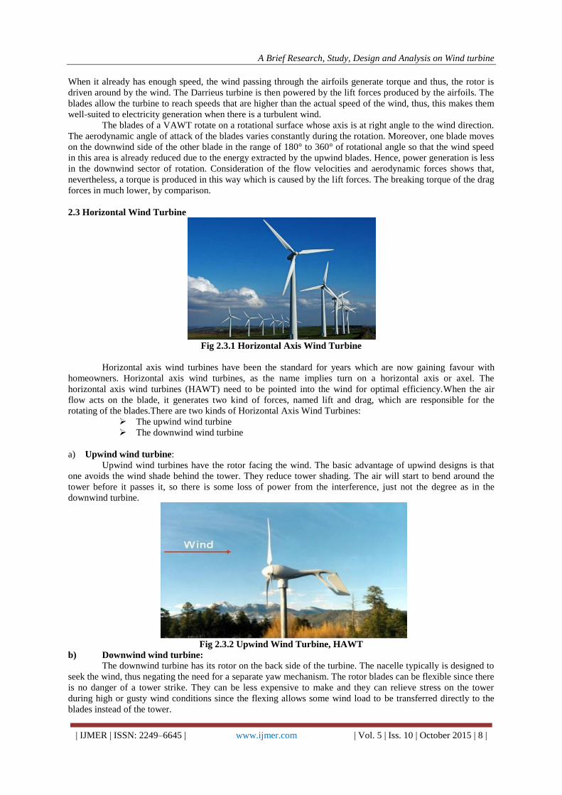
a) Upwind wind turbine:
Upwind wind turbines have the rotor facing the wind. The basic advantage of upwind designs is that
one avoids the wind shade behind the tower. They reduce tower shading. The air will start to bend around the
tower before it passes it, so there is some loss of power from the interference, just not the degree as in the
downwind turbine.
Fig 2.3.2 Upwind Wind Turbine, HAWT
b) Downwind wind turbine:
The downwind turbine has its rotor on the back side of the turbine. The nacelle typically is designed to
seek the wind, thus negating the need for a separate yaw mechanism. The rotor blades can be flexible since there
is no danger of a tower strike. They can be less expensive to make and they can relieve stress on the tower
during high or gusty wind conditions since the flexing allows some wind load to be transferred directly to the
blades instead of the tower.

A Brief Research, Study, Design and Analysis on Wind turbine
| IJMER | ISSN: 2249–6645 | www.ijmer.com | Vol. 5 | Iss. 10 | October 2015 | 9 |
Fig 2.3.3 Down Wind Turbine, HAWT
2.4 Basic Parts Of HAWT
The basic parts of a horizontal axis wind turbine (HAWT) are foundation, tower, nacelle, Generator,
Rotor Blades.
Foundation: A very good foundation is required to support the tower and various parts of a wind turbine which
weighs in tones.
Tower:A tower that supports the nacelle and rotor hub at its top. These are made from tubular steel, concrete, or
steel lattice. Height of the tower is an important in design of HWAT. Because wind speed increases with height,
taller towers enable turbines to capture more energy and generate more electricity. Generally output power of
the wind system increase with increase in height and also reduces the turbulence in wind.
Nacelle: A housing which contains all the components which is essential to operate the turbine efficiently is
called a nacelle. It is fitted at the top of a tower and includes the gear box, low- and high-speed shafts, generator,
controller, and brakes. A wind speed anemometer and a wind vane are mounted on the nacelle.
Blades: Wind turbine blades are used to extract the kinetic energy of wind and convert to mechanical energy.
These blades are made up of fiber glass-reinforced polyester or wood-epoxy. Wind turbines have one or two or
three or multiple blades based up on the construction. Most of the HAWT have three blades. These are
connected to rotor hub. Multiple blade concepts are used in earlier days for pumping water and grinding etc
Fig 2.4.1 Parts of HAWT
1) Single blade HAWT: It reduces the cost and weight of the turbine. These are rarely used due to tower
shadow effects, needs counter weights on the other side of the blade, less stability.
2) Two blades HAWT: It requires more complex design due to sustain of wind shocks. It is also less
stable. It saves the cost and weight of one rotor blade. Two- and one-bladed machines require a more complex design with a hinged (teetering hub) rotor, i.e. the rotor
has to be able to tilt in order to avoid too heavy shocks to the turbine when a rotor blade passes the tower. The
rotor is fitted onto a shaft which is perpendicular to the main shaft, and which rotates along with the main shaft.
This arrangement may require additional shock absorbers to prevent the rotor blade from hitting the tower.
3) Three blades HAWT: Modern wind turbines use three blade concept. Because this structure have
height strength to withstand heavy wind storms. Less effect due to tower shadow. Produces high output than the
four bladed wind turbine.

A Brief Research, Study, Design and Analysis on Wind turbine
| IJMER | ISSN: 2249–6645 | www.ijmer.com | Vol. 5 | Iss. 10 | October 2015 | 10 |
With more number of blades, blades should be thinner to be aerodynamically efficient. But blades with
thinner portion at the root may not withstand bending stress induced due to axial wind load. So generally wind
turbines with 3 blades which can accommodate a thicker root cross-section are use.As the number of blades in
the wind turbine increases aerodynamic efficiency increases, but in a diminishing manner. When we move from
2 blades to 3 blades design efficiency gain is about 3%. The more blades there are on a wind turbine, the higher
will be the torque (the force that creates rotation) and the slower the rotational speed (because of the increased
drag caused by wind flow resistance). But as we move from 3 blades to 4 blades design, efficiency gain is
marginal. As we increase number of blades, cost of the system increases drastically. Along with that mechanical
design of blades also becomes a difficult affair.
There are two types of HAWT:
1. Onshore wind turbine
2. Offshore wind turbine
Most wind turbines start operating at a speed of 4-5 meters per second and reach maximum power at
about 15 meters per second. Wind turbines operate on a simple principle. The energy in the wind turns two or
three propeller-like blades around a rotor. The rotor is connected to the main shaft, which spins a generator to
create electricity. Wind turbines are mounted on a tower to capture the most energy. At 100 feet (30 meters) or
more above ground, they can take advantage of faster and less turbulent wind.
2.4 Principle Of Wind Turbine A condition for an efficient conversion of the wind energy into mechanical energy with wind turbines
is the optimal design of the rotor blades. Methods for rapid development, reliable and robust predictions of the
aerodynamics characteristics and simulation of the flow conditions around a rotor blade are essential for this
design task.
The shape and dimensions of the blades of the wind turbine are determined by the aerodynamic
performance required to efficiently extract energy from the wind, and by the strength required to resist the
forces on the blade. The rotation of the blades is due to the different in pressure on the surface of the blade
causes it to lift as the blade is attached to the hub it revolves. To design a blade different types of airfoils are
used, and the twist is different at different positions.
Blades play a part in the wind turbine principle by combining with the pillar that goes down to the
generator. Every time they are revolved, they impart some mechanical energy on the middle part of the
structure, which is shaped like a rod with coils upon it. These turn anticlockwise to the spin of the wing-like
devices above in order to impart this energy through friction to the generator below. The latter is able to convert
the sent waves into power that can be stored in terms of volts.

A Brief Research, Study, Design and Analysis on Wind turbine
| IJMER | ISSN: 2249–6645 | www.ijmer.com | Vol. 5 | Iss. 10 | October 2015 | 11 |
2.5 Working of Wind Turbine
Fig 2.5.1 Working Of HAWT
Rotor blades take the energy out of the wind. They "capture" the wind and convert its motive energy
into the rotation of the hub. The profile is similar to that of airplane wings. Rotor blades utilize the same "lift"
principle. A wind turbine tower is not just a support structure. It raises the wind turbine so that its blades safely
clear the ground and so it can reach the cleaner, stronger winds at higher elevations. The hub directs the energy
from the rotor blades on to the generator. If the wind turbines have a gearbox, the hub is connected to the slowly
rotating gearbox shaft, converting the energy from the wind into rotation energy. If the turbine has a direct drive,
the hub passes the energy directly on to the ring generator. A gearbox is typically used in a wind turbine to
increase rotational speed from a low-speed rotor to a higher speed electrical generator.
2.6 Design of The Blade
The wind turbine blade is designed by using different airfoils, the airfoils are used according to the
efficiency required and circular foil is used at the root of the blade for the structure to be fixed in the hub and for
structural stability.
Fig 2.6.1 Internal Design of The Blade
The blade section consists of the root, primary and tip. At the root section circular foils are used and
then the airfoils are placed at a twist angle with the root and it is continued till the tip section. The placing of
different airfoils, the chord and the position of the airfoils is required for designing.
The modern blade can be divided into three main areas classified by aerodynamic and structural
function

A Brief Research, Study, Design and Analysis on Wind turbine
| IJMER | ISSN: 2249–6645 | www.ijmer.com | Vol. 5 | Iss. 10 | October 2015 | 12 |
Fig 2.6.2 Parts Of Blade
The blade root: The transition between the circular mount and the first aerofoil profile this section carries
the highest loads. Its low relative wind velocity is due to the relatively small rotor radius. The low wind
velocity leads to reduced aerodynamic lift leading to large chord lengths. Therefore the blade profile
becomes excessively large at the rotor hub. The problem of low lift is compounded by the need to use
excessively thick aerofoil sections to improve structural integrity at this load intensive region. Therefore the
root region of the blade will typically consist of thick aerofoil profiles with low aerodynamic efficiency.
The mid span: Aerodynamically significant the lift to drag ratio will be maximised. Therefore utilising the
thinnest possible aerofoil section that structural considerations will allow.
The tip: Aerodynamically critical the lift to drag ratio will be maximised. Therefore using slender aerofoils
and specially designed tip geometries to reduce noise and losses. Such tip geometries are as yet unproven in
the field, in any case they are still used by some manufacturers.
Fig 2.6.3 Different Views Of Wind Turbine Blade
The aerodynamic design principles for a modern wind turbine blade are detailed, including blade plan
shape/quantity, aerofoil selection and optimal attack angles. A detailed review of design loads on wind turbine
blades is offered, describing aerodynamic, gravitational, centrifugal, gyroscopic and operational conditions. The
orientation of the shaft and rotational axis determines the first classification of the wind turbine. A turbine with a
shaft mounted horizontally parallel to the ground is known as a horizontal axis wind turbine or (HAWT). A
vertical axis wind turbine (VAWT) has its shaft normal to the ground these two configurations have instantly
distinguishable rotor designs, each with its own favourable.
2.7 Aerodynamics:
Aerodynamic performance is fundamental for efficient rotor design. Aerodynamic lift is the force
responsible for the power yield generated by the turbine and it is therefore essential to maximise this force using
appropriate design. A resistant drag force which opposes the motion of the blade is also generated by friction

A Brief Research, Study, Design and Analysis on Wind turbine
| IJMER | ISSN: 2249–6645 | www.ijmer.com | Vol. 5 | Iss. 10 | October 2015 | 13 |
which must be minimised. It is then apparent that an aerofoil section with a high lift to drag ratio, be chosen for
rotor blade
The co-efficient for the lift and drag of aerofoils is difficult to predict mathematically, although freely
available software, such as XFOIL model results accurately with the exception of post stall, excessive angles of
attack and aerofoil thickness conditions. Traditionally aerofoils aretested experimentally with tables correlating
lift and drag at given angles of attack and Reynolds numbers.
Tip Speed Ratio:
The tip speed ratio defined as the relationship between rotor blade velocity and relative wind velocity
is the foremost design parameter around which all other optimum rotor dimensions are calculated.
Aspects such as efficiency, torque, mechanical stress, aerodynamics and noise should be considered in
selecting the appropriate tip speed . The efficiency of a turbine can be increased with higher tip speeds, although
the increase is not significant when considering some penalties such as increased noise, aerodynamic and
centrifugal stress an increase in centrifugal and aerodynamic forces is associated with higher tip speeds. The
increased forces signify that difficulties exist with maintaining structural integrity and preventing blade failure.
As the tip speed increases the aerodynamics of the blade design become increasingly critical. A blade which is
designed for high relative wind speeds develops minimal torque at lower speeds. This results in a higher cut in
speed and difficulty self-starting.
2.8 Blade Shape:
An efficient rotor blade consists of several aerofoil profiles blended at an angle of twist terminatingat a circular
flange. It may also include tip geometries for reducing losses. Tofacilitate production, several simplifications
maybe made:
Reducing the angle of twist.
Linearization of the chord width.
Reducing the number of differing aerofoil profiles.
All manufacturing simplifications are detrimental to rotor efficiency and should be well justified.The
introduction of new moulding techniques and materials has allowed the manufacture ofincreasingly complex
blade shapes. Leading wind turbine suppliers now include mostoptimisation features such as angle of twist,
variable chord length and multiple aerofoil geometries
Blade Loads: Multiple aerofoil sections and chord lengths, specified load cases and an angle of twistwith numerous
blade pitching angles results in a complex engineering scenario. Therefore, the use ofcomputer analysis software
such as fluid dynamics (CFD) and finite element (FEA) is nowcommonplace within the wind turbine industry
Aerodynamic Load:
Aerodynamic load is generated by lift and drag of the blades aerofoil section, which isdependent on
wind velocity (VW), blade velocity (U), surface finish, angle of attack (α) and yaw. Theangle of attack is
dependent on blade twist and pitch
2.9 Airfoils:
The structural requirements of turbine blades signify that aerofoils with a high thickness to chordratio
be used in the root region. Such aerofoils are rarely used in the aerospace industry. Thick aerofoilsections
generally have a lower lift to drag ratio. Special consideration is therefore made for increasingthe lift of thick
aerofoil sections for use in wind turbine blade designs.
National Advisory Committee for Aeronautics (NACA) four and five digit designs have been usedfor
early modern wind turbines. The classification shows the geometric profile of a NACA aerofoilwhere the 1st
digit refers to maximum chamber to chord ratio, 2nd digit is the camber position intenths of the chord and the
3rd & 4th digits are the maximum thickness to chord ratio in percent.
6-series:
An improvement over 1-series airfoils with emphasis on maximizing laminar flow. The airfoil is
described using six digits in the following sequence:
The number "6" indicating the series.
NACA 65(3)-618
NACA 65(3)-618 airfoil
Max thickness 18% at 39.8% chord.
Max camber 3.3% at 50% chord

A Brief Research, Study, Design and Analysis on Wind turbine
| IJMER | ISSN: 2249–6645 | www.ijmer.com | Vol. 5 | Iss. 10 | October 2015 | 14 |
Fig 2.9.1 (a) NACA airfoil
5 is the 10 times the position of minimum pressure as a fraction of chord (0.5 chord) although it is also the
position of maximum thickness.
3 is the intended span of lift coefficients that low drag occurs over in tenths (CL plus or minus 0.3).
6 is the designed lift coefficient in tenths (CL = 0.6)
18 is the maximum thickness as a percent
Maximum thickness 18% at 50% chord
NACA 64A-010 10.0%
NACA 64A010 airfoil
Max thickness 10% at 40% chord.
Max camber 0% at 0% chord
Fig 2.9.1 (b) NACA Airfoil
The emergence of wind turbine specific aerofoils such as the Delft University, LS, SERI-NREL and
FFA and RISO now provide alternatives specifically tailored to the needs of the wind turbine industry.
S-Series:
NREL's S-Series airfoils come in thin and thick families. The thin airfoil families lend themselves to
stall regulated wind turbines where performance losses to airfoil soiling are significant. For variable-pitch and
variable-speed turbines, airfoil soiling is not a major problem. Generally, a primary airfoil is grouped with root
and tip airfoils. Most wind turbine blades have a circular section that attaches to the hub. This is especially
important for pitching blades. There is then a transition from the circular section to the root airfoil section,
which usually occurs around the maximum chord. Between the circular section and the root airfoil section, the
transition is faired. The fairing process should avoid concavities to prevent buckling. The primary airfoil
usually occurs in its pure state around the 75% radius and the tip airfoil is usually pure around the 95% location.
Various interpolation methods are used to define airfoil shapes between the three pure airfoils. The tip airfoil is
also usually retained out to the tip of the blade, but some allowances can be made to accommodate special tip
shapes. The root airfoil usually has the greatest thickness ratio (maximum thickness to chord ratio) and the
thickness ratio gets smaller as one approaches the tip. At the blade root, large airfoil thickness is needed to

A Brief Research, Study, Design and Analysis on Wind turbine
| IJMER | ISSN: 2249–6645 | www.ijmer.com | Vol. 5 | Iss. 10 | October 2015 | 15 |
accommodate blade structural considerations and toward the tip thinner airfoils are needed to minimize drag and
blade soiling losses.
Fig 2.9.2 S-Series airfoil
The angle of attack is the angle of the oncoming flow relative to the chord line, and all figures forCL
and CD are quoted relative to this angle. The use of a single aerofoil for the entire blade lengthwould result in
inefficient design. Each section of the blade has a differing relative air velocityand structural requirement and
therefore should have its aerofoil section tailored accordingly. At theroot, the blade sections have large
minimum thickness which is essential for the intensive loads carriedresulting in thick profiles. Approaching the
tip blades blend into thinner sections with reduced load,higher linear velocity and increasingly critical
aerodynamic performance. The differing aerofoilrequirements relative to the blade region are apparent when
considering airflow velocities andstructural loads
An aerodynamic phenomenon known as stall should be considered carefully in turbine bladedesign.
Stall typically occurs at large angles of attack depending on the aerofoil design. The boundarylayer separates at
the tip rather than further down the aerofoil causing a wake to flow over the uppersurface drastically reducing
lift and increasing drag forces
The sensitivity of blades to soiling, off design conditions including stall and thick cross sections
forstructural purposes are the main driving forces for the development of wind turbine specific aerofoil profiles.
The use of modern materials with superior mechanical properties may allow for thinnerstructural sections with
increased lift to drag ratios at root sections. Thinner sections also offer achance to increase efficiency through
reducing drag. Higher lift coefficients of thinner aerofoil sectionswill in turn lead to reduced chord lengths
reducing material usage
Angle of Twist: The lift generated by an aerofoil section is a function of the angle of attack to the inflowing airstream.
The inflow angle of the air stream is dependent on the rotational speed and windspeed velocity at a specified
radius. The angle of twist required is dependent upon tip speed ratio anddesired aerofoil angle of attack.
Generally the aerofoil section at the hub is angled into the wind due tothe high ratio of wind speed to blade
radial velocity. In contrast the blade tip is likely to be almostnormal to the wind.
The total angle of twist in a blade maybe reduced simplifying the blade shape to cut
manufacturingcosts. However, this may force aerofoils to operate at less than optimum angles of attack where
lift todrag ratio is reduced. Such simplifications must be well justified considering the overall loss inturbine
performance.
Off-Design Conditions and Power Regulation:
Early wind turbine generator and gearbox technology required that blades rotate at a fixed
rotationalvelocity therefore running at non design tip speed ratios incurring efficiency penalties in all but
therated wind conditions. For larger modern turbines this is no longer applicable and it is suggestedthat the
gearbox maybe obsolete in future turbines. Today the use of fixed speed turbines islimited to smaller designs
therefore the associated off-design difficulties is omitted.
The method of limiting the rotational speed must be implemented to prevent excessive loading ofthe
blade, hub, gearbox and generator. The turbine is also required to maintain a reasonably highefficiency at below
rated wind speeds.

A Brief Research, Study, Design and Analysis on Wind turbine
| IJMER | ISSN: 2249–6645 | www.ijmer.com | Vol. 5 | Iss. 10 | October 2015 | 16 |
As the oncoming wind velocity directly affects the angle of incidence of the resultant airflow ontothe
blade, the blade pitch angle must be altered accordingly. This is known as pitching, whichmaintains the lift force
of the aerofoil section. Generally the full length of the blade is twistedmechanically through the hub to alter the
blade angle. This method is effective at increasing lift inlower than rated conditions and is also used to prevent
over speed of the rotor which may lead togenerator overload or catastrophic failure of the blade under excessive
load.
Two methods of blade pitching are used to reduce the lift force and therefore the rotational velocityof
the rotor during excessive wind speeds. Firstly decreasing the pitch angle reduces the angle of attackwhich
therefore reduces the lift generated. This method is known as feathering. The alternative methodis to increase
the pitch angle which increases the angle of attack to a critical limit inducing the stallcondition and reducing lift.
The feathering requires the maximum amount of mechanical movement inpitching the blade. However, it is still
favoured as stalling can result in excessive dynamic loads. Theseloads are a result of the unpredictable transition
from attached to detached airflow around the bladewhich may lead to undesirable fluttering.
Utilising the stall condition a limiting speed can be designed into the rotor blade known as passive stall
control. Increased wind velocity and rotor speed produce an angle at which stall is initiatedtherefore
automatically limiting the rotor speed. In practice accurately ensuring stall occurs is difficultand usually leads to
a safety margin. The use of a safety margin indicates that normal operation occursat below optimum
performance, consequently this method is utilised only by smaller turbines.
Full blade feathered pitching at the hub is used by the majority of today‟s wind turbine market leaders.
Feathered pitching offers increased performance, flexibility and the capability offully pitching the blades to a
parked configuration. Manufacturers are reported as using collective pitch, in that all the blades are pitched at
identical angles. However, further load reductions can befound by pitching blades individually. This requires no
extra mechanism in most designs and it is expected to be widely adopted
Fig 2.9.3 Power Generation with Blade Length
III. METHODOLOGY 3.1 Design and Analysis ofthe Blade
The design of the blade and analysis are done using different software‟s they are:
Q-BLADE
CATIA
MESH LAB
SOLID WORKS
ANSYS WORKBENCH
The blade is created in the Q-Blade software and further modelling is done in the CATIA, the mesh lab and
the solid works software‟s are used for the conversion of the format of the files which are to be exported and
imported. Then the blade is imported to ANSYS and the structural analysis is performed on the blade.
3.2 Q-BLADE:
The designing of the blade is done in software called QBLADE. It is an open source wind turbine
designing software. The software is seamlessly integrated into XFOIL, an airfoil design and analysis tool. The
purpose of this software is the design and aerodynamic simulation of wind turbine blades. Extrapolations the

A Brief Research, Study, Design and Analysis on Wind turbine
| IJMER | ISSN: 2249–6645 | www.ijmer.com | Vol. 5 | Iss. 10 | October 2015 | 17 |
performance data to a range of 360°Angle of attack, and directly integrate them into a wind turbine rotor
simulation.
Fig 3.2.1 Qblade Logo
The blade design method for the wind turbine, originates from the aircraft design industry and apply the
same techniques. But the flow conditions that a turbine blade experiences are quite different from those
affecting a plane
The designing of the blade requires the airfoil date, coordinates of the airfoils to import, twist of the blade,
positioning of the airfoils and the circular foil parameters used as root for the blade.
The start screen of the software shows us the main tool bars and the functionalities of the tools, then by
using the Foils the airfoils required for designing the blade of the turbine are imported by using a “.dat”
format file, now the imported airfoils are analyzed in the X Foil tool. The analysis will only converge for a
limited range of angle of attack values so they are given in the menu bar and the analysis is done.
To simulate a wind turbine, the Angle of attack range of the polar needs to be extrapolated to 360degrees,
this is done in the polar extrapolation module. Only extrapolated polar data can be used to simulate a
turbine or rotor.
By using the rotor blade design in the main tool bar the design of the blade is started the positions of the
airfoils and the twist in the blades are given as the input for design. The geometric blade data (chord, radial
position, twist, offset etc.) of the specified blade sections and the associated foils and 360-polars. It is
defined by a name. If a blade object is deleted, all associated simulations and turbines are deleted as well.
The blade is created by using specifications and then Blade Element Momentum Blade Element Momentum
(BEM) method are used to predict the efficiency of Horizontal Axis Wind Turbines (HAWT) in the
industry.
The functionality of the BEM software includes the following features:
Extrapolation of XFOIL generated or imported polar data to 360 – Angle of attack
Advanced blade design and optimization, including 3D visualization, using XFOIL generated or
imported profiles
Wind turbine definition (rotor blade, turbine control, generator type, losses)
Computation of wind turbine performance over wind speed range
export functionality for all created simulation data
blade geometry export in .stl format
To design a blade in Q-blade we require
The airfoil data.
Coordinates of the airfoils to import.
Twist of the blade.
Positioning of the airfoils and
The circular foil parameters used as root for the blade.
Q-blade design:
From the setup open the Q-blade start screen.

A Brief Research, Study, Design and Analysis on Wind turbine
| IJMER | ISSN: 2249–6645 | www.ijmer.com | Vol. 5 | Iss. 10 | October 2015 | 18 |
Fig 3.2.2 Start Screen Of Q blade
From the tool menu available on the screen, press the Airfoil Design button (first red button) and then
import the airfoils which are required for designing.
NACA airfoils are inbuilt they can be used directly from the software to import other foils it can be
done if the airfoil data file is in „.dat‟ format.
The scale and chamber of the airfoils can also be adjusted.
Fig 3.2.3 Airfoil Data
The S-Series airfoils are S815 and S811 are selected, as these airfoils produce more lift. NACA 64A-
010 and NACA 653-618 airfoils with less thickness are also selected for the tip selection of the blade. Circular
foils are also used at the tip of the blade so that the blade can be fixed in the hub.
press the XFOIL Direct Design button (second red button)
click Analysis > Define an Analysis such as the Reynolds number, angle of attack of the blade with the
increment. Then analyse each airfoil.
S-815 airfoil

A Brief Research, Study, Design and Analysis on Wind turbine
| IJMER | ISSN: 2249–6645 | www.ijmer.com | Vol. 5 | Iss. 10 | October 2015 | 19 |
S-811 airfoil
NACA 64A-010
X-Foil analysis is performed on the airfoils and the CL and alpha graphs are obtained.360 EXTRAPOLATION:
1. Press the Polar Extrapolation to 360 button (360 button)
2. Select the Montgomery radio button and press Create New 360 Polar
3. Configure the initial polar via the CD90 value, the A_ and B_ sliders and press Save 360 Polar
4. Click 360 Polar > Generate a Circular Foil
Fig 3.2.4 360 Extrapolation Graph
The blade cl and cd is calculated for all the 360 degrees of rotation of the blade and the data is obtained
in a single graph. And this graph can be changed so that the design of the blade is modified with required
efficiency
1. Press the HAWT Rotor blade Design button (first blue button)
2. Press New Blade
3. Enter the blade data using the Scale, Optimize and Advanced Design options and save

A Brief Research, Study, Design and Analysis on Wind turbine
| IJMER | ISSN: 2249–6645 | www.ijmer.com | Vol. 5 | Iss. 10 | October 2015 | 20 |
Fig 3.2.5 Design of Blade
Design table:
Fig 3.2.6 Blade Specifications
The different airfoils are used to generate various lifts at given twist. To generate the maximum power they are
placed at different positions and chords. The airfoils at the tip have less twist when compared to the airfoils from
the root since they have to generate more lift. It is considered by the analysis in CL vs α graph. When the air
flow on the airfoil this twist is sufficient to lift the blade.
Circular foil:
The circular foil is placed in the hub position which is fixed. The circular foil is positioned till 1.2 along the
length of the blade. The chord is given as 0.86, 0.92, 0.94 at three different positions as 0, 1, 1.2 with zero twist.
S815ed:
The airfoil S815ed is an edited foil alone is thickness. It is positioned next to the circular foil till a distance of
7.42 from the hub. the maximum chord of the airfoils along the blade is positioned at 3.32 distance and the other
at 7.42 distance with a twists of 13.25 and 11.25
S815:
This is an single airfoil placed at a position of 10.326 from the hub. It has chord of 0.809 with a twist of 9.632
S811:
This is positioned at distance of 16.235 from the hub. It is placed after the S815 airfoil. The two airfoils with
same series are placed at a distance of 13.26 and 16.23 with a chord of 0.73, 0.66 and twist 7.68, 6.523.
NACA 65(3)-618:

A Brief Research, Study, Design and Analysis on Wind turbine
| IJMER | ISSN: 2249–6645 | www.ijmer.com | Vol. 5 | Iss. 10 | October 2015 | 21 |
This is placed at a position of 23.452 from the hub. The three airfoils of same series is placed after S811 airfoils.
Compared to all the airfoils these are efficient. The twist is less when compared to the previous airfoils. So we
can say that these give more lift at different angle of attack.
NACA 64A-010:
The last set of airfoils placed at a position of 30.26 from the hub position. This gives the total length of blade.
The twist is giving very minimum i.e 1.28. the chord of the airfoil is also very less, it is 0.22.
Fig 3.2.7 Design of Blade
Fig 3.2.8 3D Rotor Design
As the three blades are of same design, so it is easy to create 3D blade. Then power simulation is performed on
the rotor blade.
Press the rotor BEM simulation and define rotor simulation. Enter the simulation parameters tip speed,
and start the analysis, observe the extracted graphs.
Fig 3.2.9 BEM Simulation Graphs
Then define the parameters in the multi parameter BEM simulation and then analysis it.
Press the turbine blade simulation and give the input wind speed and output wind speed and calculate
the power generated by the wind turbine blade.

A Brief Research, Study, Design and Analysis on Wind turbine
| IJMER | ISSN: 2249–6645 | www.ijmer.com | Vol. 5 | Iss. 10 | October 2015 | 22 |
Fig 3.2.10 Turbine Blade Simulation
Thus the blades are designed with different specifications and by verifying the power available the
blade design is selected for further modelling.
The selected blade can be exported from the Q-blade, this is an .STL file.
3.3 Mesh Lab:
Mesh Lab is an open source, portable, and extensible system for the processing and editing of
unstructured 3D triangular meshes. Mesh Lab also includes an interactive direct paint-on-mesh system that
allows to interactively change the colour of a mesh, to define selections and to directly smooth out noise and
small features.
Fig 3.3.1 Mesh Lab Logo
Mesh Lab is oriented to the management and processing of unstructured large meshes and provides a
set of tools for editing, cleaning, healing, inspecting, rendering and converting these kinds of meshes. Files can
be imported and exported in many formats:
Import: PLY, STL, OFF, OBJ, 3DS, COLLADA, PTX, V3D, PTS, APTS, XYZ, GTS, TRI, ASC, X3D, X3DV,
VRML, ALN.
Export: PLY, STL, OFF, OBJ, 3DS, COLLADA, VRML, DXF, GTS, U3D, IDTF, X3D.
Fig 3.3.2 Mesh Lab Start Screen

A Brief Research, Study, Design and Analysis on Wind turbine
| IJMER | ISSN: 2249–6645 | www.ijmer.com | Vol. 5 | Iss. 10 | October 2015 | 23 |
An STL file is a triangular representation of a 3D surface geometry. The surface is tessellated logically
into a set of oriented triangles this STL file is imported in the mesh lab soft ware so that the file can be
converted to other format.
The file is imported in to the mesh lab software in .stl format, then the file is exported from the file > export
mesh as, then the type of the required available format is given as .DXF then the file is exported.
3.4 Solid Works:
Solid Works is solid modeling CAD (computer-aided design) software. It is a solid modeler, and
utilizes a parametric feature-based approach to create models and assemblies. This software makes it possible
for designers to quickly sketch out ideas, experiment with features and dimensions, and produce models and
detailed drawings. The Solid Works software enables to design models quickly and precisely.
Fig 3.4.1 solid works logo
Solid works software can import files in STL,STEP,DXF,DXG and many other formats. The modeling
in the solid work software is assigned with the designing and the modeling tools. The modeled files are exported
in IGES,STEP and other formats.
Fig 3.4.2 Solid Works Start Screen
This software is used to change the format of the file so that it can be imported in CATIA. The
exported modelling the mesh lab which is in(.DXF) format is imported into solid work and then the model is
exported in to .IGES format. This helps in creating the entities to the body and thus an .IGES modelled file is
made.
3.5 CATIA:
CATIA (Computer Aided Three-dimensional Interactive Application) is the leading product
development solution for all manufacturing organizations and is a multi-platform
CAD/CAM/CAE commercial software suite developed by the French company Dassault Systems.
Fig 3.5.1 Catia Logo
CATIA enables the creation of 3D parts, from 3D sketches, sheet metal, composites, forged or tooling
parts up to the definition of mechanical assemblies. The software provides advanced technologies for
mechanical surfacing. It provides tools to complete product definition, including functional tolerances as well
as kinematics definition.
CATIA offers a solution to shape design, styling, surfacing workflow and visualization to create,
modify, and validate complex innovative shapes from industrial design to surfacing with the ICEM surfacing
technologies. CATIA is able to read and produce STEP format files and IGES format files and many other file
formats.

A Brief Research, Study, Design and Analysis on Wind turbine
| IJMER | ISSN: 2249–6645 | www.ijmer.com | Vol. 5 | Iss. 10 | October 2015 | 24 |
The range of CATIA capabilities allows it to be applied in a wide variety of industries, such as
aerospace, automotive, industrial machinery, electrical, electronics, shipbuilding, plant design, and consumer
goods, including design for such diverse products as jewelry and clothing. Various workbenches in CATIA
with surface creation tools are:
1. Wireframe and Surface Design.
2. Generative Shape Design.
3. Part design
4. Assembly design
Fig 3.5.2 Catia Start Screen
In this modelling software the total body of design is examined by importing the file in IGES format.
Fig 3.5.3 Importing File InCatia
To import file in catia the file is browsed from the saved folder, and it is opened in the .IGES format.
Modelling In Catia: If model has any disturbances it is modelled In the catia software as the model deals with the surface
body, the designing is performed in the wireframe and surface design. By using this the disturbances in the body
are rectified or corrected and the surface are created on the body.
Fig 3.5.4 Designing InCatia
The imported geometry is opened in wire frame and structure design, then surface is created for the
body by using the multi section join command and joining the lines by creating the surface. If necessary off set
command is also used to create the surface to the body.
Fig 3.5.5 Surface Created Blade InCatia

A Brief Research, Study, Design and Analysis on Wind turbine
| IJMER | ISSN: 2249–6645 | www.ijmer.com | Vol. 5 | Iss. 10 | October 2015 | 25 |
The model is created and it is saved in .IGES format so that it can be imported easily in to the analysis
software.
STATIC STRUCTURAL SETUP
Analysis Of Wind turbine Blade Using Ansys Workbench:
ANSYS is advanced CAD/Cam software that deals with industrial concepts of Structures, Mechanics and Fluid
Dynamics. The software deals with Aerospace, Mechanical, Civil and Marine applications mostly. This is also
well defined and accepted by many multi-national companies and manufacturing industries.
Engineers routinely use the Finite Element Method (FEM) to solve everyday problems of stress,
deformation, heat transfer, fluid flow, etc, using commercial as well as purpose computer codes. Using ANSYS
,which is one of the most versatile and widely used of the commercial finite element programs.
4.1 Importing The Geometry
1) Open ANSYS Workbench by going to Start > ANSYS > Workbench.
As we are only doing a force loading, we will be doing a Static Structural simulation. Load
the StaticStructural tool box by dragging and dropping it into the Project Schematic.
Fig 4.1.1 ANSYS Workbench Start Screen
2) To the left of the start up window, we have analysis system. Load the Static Structural tool box by
dragging and dropping it into the Project Schematic.
3) Save the file.
4) In the Project Schematic page, right click on Geometry and import the file.
Fig 4.1.2 Importing Geometry
5) Open the file to generate the geometry. Double click the imported geometry to
open the Design Modeller.
Fig 4.1.3 Imported Model In ANSYS
6) Now the geometry is imported and generated and ready to mesh.
7) Close the Design Modeler and open ANSYS Mechanical by double clicking. When ANSYS
Mechanical opens, notice that there is no question mark next to Geometry in the Project Outline. If there is any
question mark means that there is something missing in the section. For example :

A Brief Research, Study, Design and Analysis on Wind turbine
| IJMER | ISSN: 2249–6645 | www.ijmer.com | Vol. 5 | Iss. 10 | October 2015 | 26 |
Fig 4.1.4 Creating Surface Body
Expand Geometry, expand Part 3, and select any of the surface bodies. theThickness is highlighted as it does not
have a value specified.
Fig 4.1.5 Creating Thickness To Body
There should no longer be a question mark next to Geometry.
4.2 Meshing The Geometry
8) Right click onMesh and check onto the top and bottom surface of the wind blade in isometric view.
Fig 4.2.1 Blade To Be Meshed
9) Right click on Mesh and insert Sizing.
Fig 4.2.2 Size Of Meshing
Right click in the graphics window and click on Select All. Change the Element Size.
10) Right click on Mesh and click on Generate Mesh. The meshed wind blade is shown below:
Fig 4.2.3 Meshed Blade
A Brief Research, Study, Design and Analysis on Wind turbine
| IJMER | ISSN: 2249–6645 | www.ijmer.com | Vol. 5 | Iss. 10 | October 2015 | 27 |
11) The geometry has been meshed and ready to setup the physics controlling the simulation.
12) The contact between the wind blade and the spar needs to be modeled. Right click on Connections and
insert a Connection Group. In the connection group named contact 2, change the Face/Face detection to No and
Face/Edge detection to Yes.
Fig 4.2.4 Creating Connections To Body
Right click on Contacts 2 and click on Create Automatic Connections. For each surface body, check that
Structural Steel is assigned as the material.
Fig 4.2.5 creating automatic connections
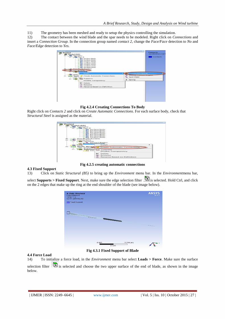
4.3 Fixed Support
13) Click on Static Structural (B5) to bring up the Environment menu bar. In the Environmentmenu bar,
select Supports > Fixed Support. Next, make sure the edge selection filter is selected. Hold Ctrl, and click
on the 2 edges that make up the ring at the end shoulder of the blade (see image below).
Fig 4.3.1 Fixed Support of Blade
4.4 Force Load
14) To initialize a force load, in the Environment menu bar select Loads > Force. Make sure the surface
selection filter is selected and choose the two upper surface of the end of blade, as shown in the image
below.
A Brief Research, Study, Design and Analysis on Wind turbine
| IJMER | ISSN: 2249–6645 | www.ijmer.com | Vol. 5 | Iss. 10 | October 2015 | 28 |
Fig 4.4.1 Loading On Blade
Application Of Loads On Blade:
15) When the surface have been selected, press Geometry > Apply in the Details window. Next, select
Define By > Components. Define the Component.
Fig 4.4.2 Loads Tabular Colum
Fig 4.4.3 application of loads and supports
IV. RESULTS AND DISCUSSION Analyzing the blade:
Now it is ready to set up the solution and solve.
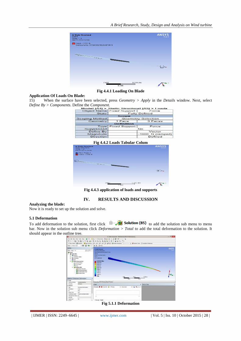
5.1 Deformation
To add deformation to the solution, first click to add the solution sub menu to menu
bar. Now in the solution sub menu click Deformation > Total to add the total deformation to the solution. It
should appear in the outline tree.
Fig 5.1.1 Deformation

A Brief Research, Study, Design and Analysis on Wind turbine
| IJMER | ISSN: 2249–6645 | www.ijmer.com | Vol. 5 | Iss. 10 | October 2015 | 29 |
The Minimum Deformation along Y-Axis is 0
The Maximum Deformation along Y-axis is 0.00020221
16) In the solution sub menu, select Stress > Equivalent (von-Mises). In the details pane, ensure Geometry
is set to All Bodies.
17) In the solution sub menu, select Stain > normal. And solve the geometry.
18) In the solution sub menu, select stress > maximum shear stress
A Brief Research, Study, Design and Analysis on Wind turbine
| IJMER | ISSN: 2249–6645 | www.ijmer.com | Vol. 5 | Iss. 10 | October 2015 | 30 |
V. RESULT
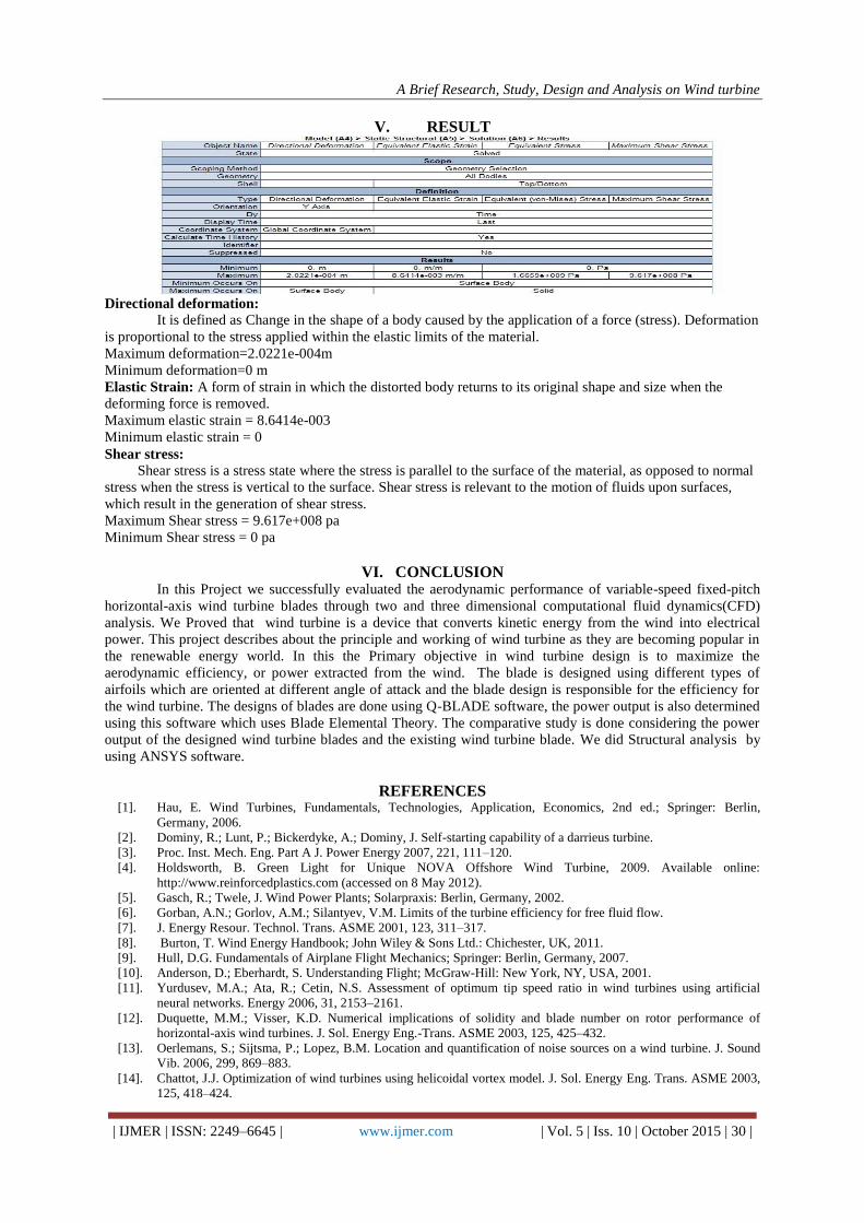
Directional deformation:
It is defined as Change in the shape of a body caused by the application of a force (stress). Deformation
is proportional to the stress applied within the elastic limits of the material.
Maximum deformation=2.0221e-004m
Minimum deformation=0 m
Elastic Strain: A form of strain in which the distorted body returns to its original shape and size when the
deforming force is removed.
Maximum elastic strain = 8.6414e-003
Minimum elastic strain = 0
Shear stress:
Shear stress is a stress state where the stress is parallel to the surface of the material, as opposed to normal
stress when the stress is vertical to the surface. Shear stress is relevant to the motion of fluids upon surfaces,
which result in the generation of shear stress.
Maximum Shear stress = 9.617e+008 pa
Minimum Shear stress = 0 pa
VI. CONCLUSION In this Project we successfully evaluated the aerodynamic performance of variable-speed fixed-pitch
horizontal-axis wind turbine blades through two and three dimensional computational fluid dynamics(CFD)
analysis. We Proved that wind turbine is a device that converts kinetic energy from the wind into electrical
power. This project describes about the principle and working of wind turbine as they are becoming popular in
the renewable energy world. In this the Primary objective in wind turbine design is to maximize the
aerodynamic efficiency, or power extracted from the wind. The blade is designed using different types of
airfoils which are oriented at different angle of attack and the blade design is responsible for the efficiency for
the wind turbine. The designs of blades are done using Q-BLADE software, the power output is also determined
using this software which uses Blade Elemental Theory. The comparative study is done considering the power
output of the designed wind turbine blades and the existing wind turbine blade. We did Structural analysis by
using ANSYS software.
REFERENCES [1]. Hau, E. Wind Turbines, Fundamentals, Technologies, Application, Economics, 2nd ed.; Springer: Berlin,
Germany, 2006.
[2]. Dominy, R.; Lunt, P.; Bickerdyke, A.; Dominy, J. Self-starting capability of a darrieus turbine.
[3]. Proc. Inst. Mech. Eng. Part A J. Power Energy 2007, 221, 111–120.
[4]. Holdsworth, B. Green Light for Unique NOVA Offshore Wind Turbine, 2009. Available online:
http://www.reinforcedplastics.com (accessed on 8 May 2012).
[5]. Gasch, R.; Twele, J. Wind Power Plants; Solarpraxis: Berlin, Germany, 2002.
[6]. Gorban, A.N.; Gorlov, A.M.; Silantyev, V.M. Limits of the turbine efficiency for free fluid flow.
[7]. J. Energy Resour. Technol. Trans. ASME 2001, 123, 311–317.
[8]. Burton, T. Wind Energy Handbook; John Wiley & Sons Ltd.: Chichester, UK, 2011.
[9]. Hull, D.G. Fundamentals of Airplane Flight Mechanics; Springer: Berlin, Germany, 2007.
[10]. Anderson, D.; Eberhardt, S. Understanding Flight; McGraw-Hill: New York, NY, USA, 2001.
[11]. Yurdusev, M.A.; Ata, R.; Cetin, N.S. Assessment of optimum tip speed ratio in wind turbines using artificial
neural networks. Energy 2006, 31, 2153–2161.
[12]. Duquette, M.M.; Visser, K.D. Numerical implications of solidity and blade number on rotor performance of
horizontal-axis wind turbines. J. Sol. Energy Eng.-Trans. ASME 2003, 125, 425–432.
[13]. Oerlemans, S.; Sijtsma, P.; Lopez, B.M. Location and quantification of noise sources on a wind turbine. J. Sound
Vib. 2006, 299, 869–883.
[14]. Chattot, J.J. Optimization of wind turbines using helicoidal vortex model. J. Sol. Energy Eng. Trans. ASME 2003,
125, 418–424.