Embed Size (px)
Citation preview

A Camera Based Virtual Keyboard with Touch
Detection by Shadow Analysis
Joseph Thomas
December 10, 2013
1 Introduction
Recent years have marked a sharp increase in the number of ways in whichpeople interact with computers. Where the keyboard and mouse were once theprimary interfaces for controlling a computer, users now utilize touchscreens,infrared cameras (like Microsoft’s Kinect), and accelerometers (for example,within the iPhone) to interact with their technology. In light of these changesand the proliferation of small cameras in many phones and tablets, human-computer interface researchers have investigated the possibility of implementinga keyboard-style interface using a camera as a substitute for actual keyboardhardware.
Broadly speaking, these researchers envision the following scenario: A cam-era observes the user’s hands, which rest on a flat surface. The camera mayobserve the hands from above the surface, or at an angle.1 The virtual key-board’s software analyzes those images in real-time to determine the sequenceof keystrokes chosen by the user. These researchers envision several applicationsfor this technology:
• In some countries (for example, India), users speak many different lan-guages, which makes producing physical keyboards for many different or-thographies expensive. A camera-based keyboard can easily support manylanguages, as is discussed in [1].
• Smart-phone and tablet users may occasionally want to use a full-sizedkeyboard with their device, but are unwilling to carry a physical keyboard.Since most mobile devices are equipped with a camera, a camera-basedkeyboard could provide a software-based solution for this problem.
The objective of this semester project was to implement a virtual keyboardusing the image analysis techniques described in [1], [2], and [3]. In the systemwe implemented, a single low-quality camera captures RGB images of a user’s
1One might envision that the camera sits at one end of a phone/tablet, which has beenpropped up in front of the user.
1
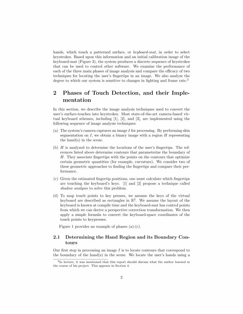
hands, which touch a patterned surface, or keyboard-mat, in order to selectkeystrokes. Based upon this information and an initial calibration image of thekeyboard-mat (Figure 3), the system produces a discrete sequence of keystrokesthat can be used to control other software. We examine the performance ofeach of the three main phases of image analysis and compare the efficacy of twotechniques for locating the user’s fingertips in an image. We also analyze thedegree to which our system is sensitive to changes in lighting and frame rate.2
2 Phases of Touch Detection, and their Imple-mentation
In this section, we describe the image analysis techniques used to convert theuser’s surface-touches into keystrokes. Most state-of-the-art camera-based vir-tual keyboard schemes, including [1], [2], and [3], are implemented using thefollowing sequence of image analysis techniques:
(a) The system’s camera captures an image I for processing. By performing skinsegmentation on I, we obtain a binary image with a region H representingthe hand(s) in the scene.
(b) H is analyzed to determine the locations of the user’s fingertips. The ref-erences listed above determine contours that parameterize the boundary ofH. They associate fingertips with the points on the contours that optimizecertain geometric quantities (for example, curvature). We consider two ofthese geometric approaches to finding the fingertips and compare their per-formance.
(c) Given the estimated fingertip positions, one must calculate which fingertipsare touching the keyboard’s keys. [1] and [2] propose a technique calledshadow analysis to solve this problem.
(d) To map touch points to key presses, we assume the keys of the virtualkeyboard are described as rectangles in R2. We assume the layout of thekeyboard is known at compile time and the keyboard-mat has control pointsfrom which we can derive a perspective correction transformation. We thenapply a simple formula to convert the keyboard-space coordinates of thetouch points to keypresses.
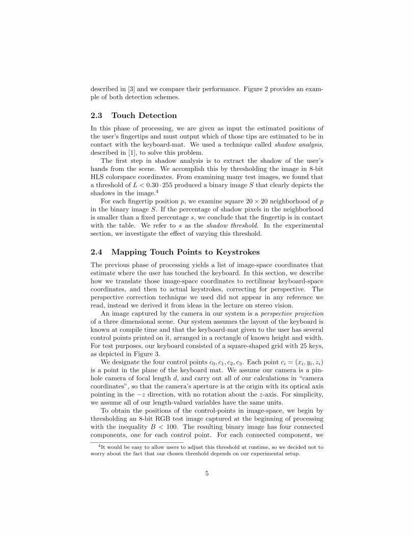
Figure 1 provides an example of phases (a)-(c).
2.1 Determining the Hand Region and its Boundary Con-tours
Our first step in processing an image I is to locate contours that correspond tothe boundary of the hand(s) in the scene. We locate the user’s hands using a
2In lecture, it was mentioned that this report should discuss what the author learned inthe course of his project. This appears in Section 4.
2
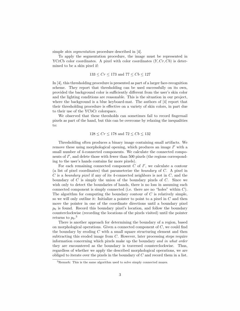
simple skin segmentation procedure described in [4].To apply the segmentation procedure, the image must be represented in
YCrCb color coordinates. A pixel with color coordinates (Y,Cr, Cb) is deter-mined to be a skin pixel if:
133 ≤ Cr ≤ 173 and 77 ≤ Cb ≤ 127
In [4], this thresholding procedure is presented as part of a larger face-recognitionscheme. They report that thresholding can be used successfully on its own,provided the background color is sufficiently different from the user’s skin colorand the lighting conditions are reasonable. This is the situation in our project,where the background is a blue keyboard-mat. The authors of [4] report thattheir thresholding procedure is effective on a variety of skin colors, in part dueto their use of the YCbCr colorspace.
We observed that these thresholds can sometimes fail to record fingernailpixels as part of the hand, but this can be overcome by relaxing the inequalitiesto:
128 ≤ Cr ≤ 178 and 72 ≤ Cb ≤ 132
Thresholding often produces a binary image containing small artifacts. Weremove these using morphological opening, which produces an image I ′ with asmall number of 4-connected components. We calculate the connected compo-nents of I ′, and delete those with fewer than 500 pixels (the regions correspond-ing to the user’s hands contains far more pixels).
For each remaining connected component C of I ′, we calculate a contour(a list of pixel coordinates) that parameterize the boundary of C. A pixel inC is a boundary pixel if any of its 4-connected neighbors is not in C, and theboundary of C is simply the union of the boundary pixels of C. Since wewish only to detect the boundaries of hands, there is no loss in assuming eachconnected component is simply connected (i.e. there are no “holes” within C).The algorithm for computing the boundary contour of C is relatively simple,so we will only outline it: Initialize a pointer to point to a pixel in C and thenmove the pointer in one of the coordinate directions until a boundary pixelp0 is found. Record this boundary pixel’s location, and follow the boundarycounterclockwise (recording the locations of the pixels visited) until the pointerreturns to p0.3
There is another approach for determining the boundary of a region, basedon morphological operations. Given a connected component of C, we could findthe boundary by eroding C with a small square structuring element and thensubtracting this eroded image from C. However, later processing steps requireinformation concerning which pixels make up the boundary and in what orderthey are encountered as the boundary is traversed counterclockwise. Thus,regardless of whether we apply the described morphological operations, we areobliged to iterate over the pixels in the boundary of C and record them in a list.
3Remark: This is the same algorithm used to solve simply connected mazes.
3

Also, the morphological operations we described are not guaranteed to producea contiguous one-pixel wide boundary, so they would not substantially simplifyour boundary-traversal procedure. For these reasons we decided to omit themorphological operations entirely.
2.2 Fingertip Detection
In this step, we estimate the locations of the user’s fingertips (in image-space)based on geometrical features of the contours and regions obtained from the laststep.
We represent a contour γ as a sequence of positions {p1 = (x1, y1), p2 =(x2, y2), . . .} in image-space. Given a contour, one can derive several othersequences of geometrical significance and use these to locate the fingertips.
The previous processing step gives us a contour γ consisting of pixel locationspi such that the Euclidean distance between pi and pi+1 is 1 for all i, andthe angle θi between the displacement vectors pi+1 − pi and pi−1 − pi is in{−π/2, 0, π/2, π}. This angular information does not give a very good idea ofhow the contour bends around the hand, so we consider a subsequence γ inwhich the points of the contour are spaced further apart. In experiments, wetook γ to be every tenth point of γ. We then define a sequence of angles θi (in(−π, π]) from γ as we did with γ, by considering the angle between displacementvectors.
A second important property we derive from γ is curvature. Curvaturecan most easily be understood in the situation where γ is parameterized byarclength. In this situation, the acceleration vector γ′′(t) is always perpendicularto the contour. The curvature K(t) is simply the magnitude of γ′′(t), with largervalues indicating that the curve is bending more severely. The data we use torepresent γ does not parameterize the contour by arclength, but the authors of[3] report there is still a formula for calculating K(t)
K(t) =det(γ′(t), γ′′(t))2
‖γ′(t)‖3
which they discretize, using the data γ = {pi}, to obtain:
vi = pi+1 − pi−1ai = vi+1 − vi−1
Ki =det(vi, ai)
2
‖vi‖3
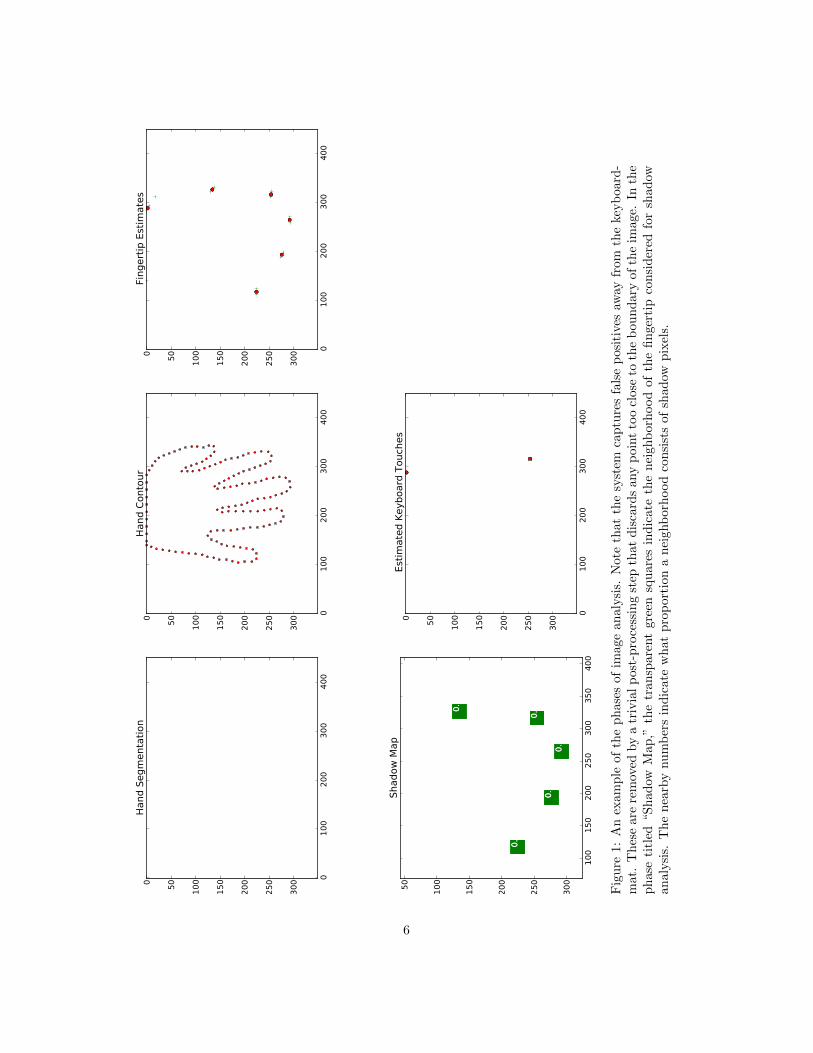
Given this geometrical data, we have two approaches for locating the finger-tips in an image. The first approach is to calculate the sequence of angles θi, andassociate fingertips with points where θi is maximized. The second approachis to calculate the curvature values Ki and associate fingertips with positionswhere Ki is maximized. Naturally, both approaches require non-maximum sup-pression or other post-processing to be effective. Both of these approaches are
4
described in [3] and we compare their performance. Figure 2 provides an exam-ple of both detection schemes.
2.3 Touch Detection
In this phase of processing, we are given as input the estimated positions ofthe user’s fingertips and must output which of those tips are estimated to be incontact with the keyboard-mat. We used a technique called shadow analysis,described in [1], to solve this problem.
The first step in shadow analysis is to extract the shadow of the user’shands from the scene. We accomplish this by thresholding the image in 8-bitHLS colorspace coordinates. From examining many test images, we found thata threshold of L < 0.30 ·255 produced a binary image S that clearly depicts theshadows in the image.4
For each fingertip position p, we examine square 20× 20 neighborhood of pin the binary image S. If the percentage of shadow pixels in the neighborhoodis smaller than a fixed percentage s, we conclude that the fingertip is in contactwith the table. We refer to s as the shadow threshold. In the experimentalsection, we investigate the effect of varying this threshold.
2.4 Mapping Touch Points to Keystrokes
The previous phase of processing yields a list of image-space coordinates thatestimate where the user has touched the keyboard. In this section, we describehow we translate those image-space coordinates to rectilinear keyboard-spacecoordinates, and then to actual keystrokes, correcting for perspective. Theperspective correction technique we used did not appear in any reference weread, instead we derived it from ideas in the lecture on stereo vision.
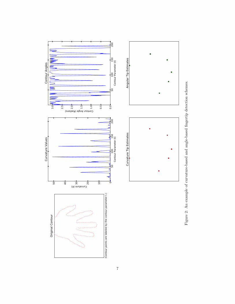
An image captured by the camera in our system is a perspective projectionof a three dimensional scene. Our system assumes the layout of the keyboard isknown at compile time and that the keyboard-mat given to the user has severalcontrol points printed on it, arranged in a rectangle of known height and width.For test purposes, our keyboard consisted of a square-shaped grid with 25 keys,as depicted in Figure 3.
We designate the four control points c0, c1, c2, c3. Each point ci = (xi, yi, zi)is a point in the plane of the keyboard mat. We assume our camera is a pin-hole camera of focal length d, and carry out all of our calculations in “cameracoordinates”, so that the camera’s aperture is at the origin with its optical axispointing in the −z direction, with no rotation about the z-axis. For simplicity,we assume all of our length-valued variables have the same units.
To obtain the positions of the control-points in image-space, we begin bythresholding an 8-bit RGB test image captured at the beginning of processingwith the inequality B < 100. The resulting binary image has four connectedcomponents, one for each control point. For each connected component, we
4It would be easy to allow users to adjust this threshold at runtime, so we decided not toworry about the fact that our chosen threshold depends on our experimental setup.
5
01
00
20
03
00
40
0
0
50
10
0
15
0
20
0
25
0
30
0
Hand S
egm
enta
tion
01
00
20
03
00
40
0
0
50
10
0
15
0
20
0
25
0
30
0
Hand C
onto
ur
01
00
20
03
00
40
0
0
50
10
0
15
0
20
0
25
0
30
0
Fingert
ip E
stim
ate
s
10
01
50
20
02
50
30
03
50
40
0
50
10
0
15
0
20
0
25
0
30
0
0.1
54
0.4
31
0.5
19
0.4
92
0.5
19
0.4
31
0.4
15
0.1
54
0.4
15
0.4
92
Shadow
Map
01
00
20
03
00
40
0
0
50
10
0
15
0
20
0
25
0
30
0
Est
imate
d K
eyboard
Touch
es
Fig
ure
1:A
nex
amp
leof
the
phas
esof
imag
ean
aly
sis.
Note
that
the
syst
emca
ptu
res
fals
ep
osi
tive
saw
ayfr
om
the
keyb
oard
-m
at.
Th
ese
are
rem
oved
by
atr
ivia
lp
ost-
pro
cess
ing
step
that
dis
card
sany
poin
tto
ocl
ose
toth
eb
ou
nd
ary
of
the
image.
Inth
ep
has
eti
tled
“Sh
adow
Map
,”th
etr
ansp
aren
tgr
een
squ
are
sin
dic
ate
the
nei
ghb
orh
ood
of
the
fin
ger
tip
con
sid
ered
for
shad
owan
alysi
s.T
he
nea
rby
nu
mb
ers
ind
icat
ew
hat
pro
port
ion
an
eighb
orh
ood
con
sist
sof
shad
owp
ixel
s.
6
(Contourpointsare
labeledbythecontourparametert.)
0
20 40
60
80
100
120
140
160
180
200
OriginalContour
50
100
150
200
ContourParameter(t)
0
10
20
30
40
50
Curvature(K)
Curvature
Values
50
100
150
200
ContourParameter(t)
0.0
0.5
1.0
1.5
2.0
2.5
3.0
ContourAngle(Radians)
ContourAngles
Curvature
TipEstimates
AngularTipEstimates
Fig
ure
2:A
nex
amp
leof
curv
atu
re-b
ase
dan
dan
gle
-base
dfi
nger
tip
det
ecti
on
sch
emes
.
7
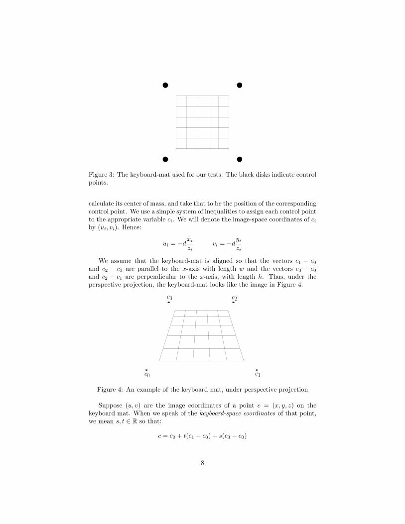
Figure 3: The keyboard-mat used for our tests. The black disks indicate controlpoints.
calculate its center of mass, and take that to be the position of the correspondingcontrol point. We use a simple system of inequalities to assign each control pointto the appropriate variable ci. We will denote the image-space coordinates of ciby (ui, vi). Hence:
ui = −dxizi
vi = −dyizi
We assume that the keyboard-mat is aligned so that the vectors c1 − c0and c2 − c3 are parallel to the x-axis with length w and the vectors c3 − c0and c2 − c1 are perpendicular to the x-axis, with length h. Thus, under theperspective projection, the keyboard-mat looks like the image in Figure 4.
c0 c1
c3 c2
Figure 4: An example of the keyboard mat, under perspective projection
Suppose (u, v) are the image coordinates of a point c = (x, y, z) on thekeyboard mat. When we speak of the keyboard-space coordinates of that point,we mean s, t ∈ R so that:
c = c0 + t(c1 − c0) + s(c3 − c0)
8
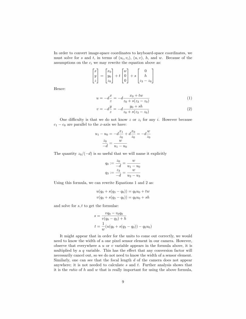
In order to convert image-space coordinates to keyboard-space coordinates, wemust solve for s and t, in terms of (ui, vi), (u, v), h, and w. Because of theassumptions on the ci we may rewrite the equation above as:xy
z
=
x0y0z0
+ t
w00
+ s
0h
z3 − z0
Hence:
u = −dxz
= −d x0 + tw
z0 + s(z3 − z0)(1)
v = −dyz
= −d y0 + sh
z0 + s(z3 − z0)(2)
One difficulty is that we do not know z or zi for any i. However becausec1 − c0 are parallel to the x-axis we have:
u1 − u0 = −dx1z0
+ dx0z0
= −d wz0
z0−d
=w
u1 − u0
The quantity z0/(−d) is so useful that we will name it explicitly
q0 :=z0−d
=w
u1 − u0q3 :=
z3−d
=w
u2 − u3
Using this formula, we can rewrite Equations 1 and 2 as:
u(q0 + s(q3 − q0)) = q0u0 + tw
v(q0 + s(q3 − q0)) = q0u0 + sh
and solve for s, t to get the formulae:
s =vq0 − v0q0
v(q0 − q3) + h
t =1
w(u(q0 + s(q3 − q0))− q0u0)
It might appear that in order for the units to come out correctly, we wouldneed to know the width of a one pixel sensor element in our camera. However,observe that everywhere a u or v variable appears in the formula above, it ismultiplied by a q variable. This has the effect that any conversion factor willnecessarily cancel out, so we do not need to know the width of a sensor element.Similarly, one can see that the focal length d of the camera does not appearanywhere; it is not needed to calculate s and t. Further analysis shows thatit is the ratio of h and w that is really important for using the above formula,
9
not their exact values.5 Once we have the keyboard-coordinates of a point, weassign it to a button identifier (a pair in {1, . . . , 5}×{1, . . . , 5}) by applying themapping (t, s) 7→ (b7tc, b7sc) and discarding output that does not fall withinour set of button identifiers.
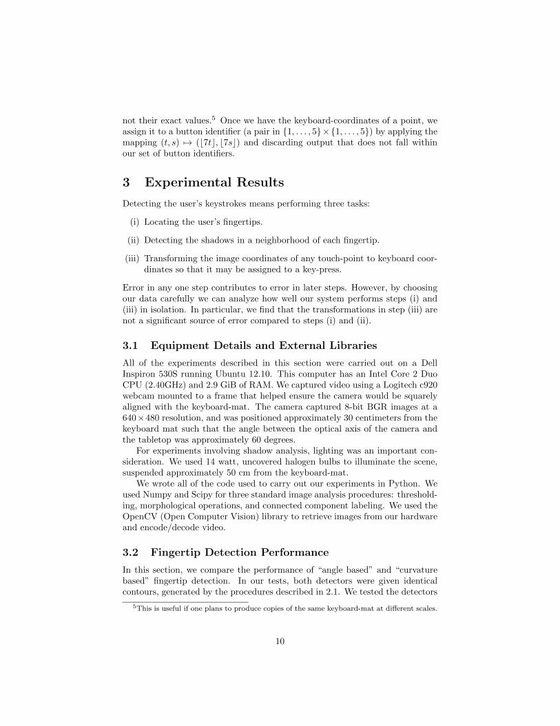
3 Experimental Results
Detecting the user’s keystrokes means performing three tasks:
(i) Locating the user’s fingertips.
(ii) Detecting the shadows in a neighborhood of each fingertip.
(iii) Transforming the image coordinates of any touch-point to keyboard coor-dinates so that it may be assigned to a key-press.
Error in any one step contributes to error in later steps. However, by choosingour data carefully we can analyze how well our system performs steps (i) and(iii) in isolation. In particular, we find that the transformations in step (iii) arenot a significant source of error compared to steps (i) and (ii).
3.1 Equipment Details and External Libraries
All of the experiments described in this section were carried out on a DellInspiron 530S running Ubuntu 12.10. This computer has an Intel Core 2 DuoCPU (2.40GHz) and 2.9 GiB of RAM. We captured video using a Logitech c920webcam mounted to a frame that helped ensure the camera would be squarelyaligned with the keyboard-mat. The camera captured 8-bit BGR images at a640×480 resolution, and was positioned approximately 30 centimeters from thekeyboard mat such that the angle between the optical axis of the camera andthe tabletop was approximately 60 degrees.
For experiments involving shadow analysis, lighting was an important con-sideration. We used 14 watt, uncovered halogen bulbs to illuminate the scene,suspended approximately 50 cm from the keyboard-mat.
We wrote all of the code used to carry out our experiments in Python. Weused Numpy and Scipy for three standard image analysis procedures: threshold-ing, morphological operations, and connected component labeling. We used theOpenCV (Open Computer Vision) library to retrieve images from our hardwareand encode/decode video.
3.2 Fingertip Detection Performance
In this section, we compare the performance of “angle based” and “curvaturebased” fingertip detection. In our tests, both detectors were given identicalcontours, generated by the procedures described in 2.1. We tested the detectors
5This is useful if one plans to produce copies of the same keyboard-mat at different scales.
10
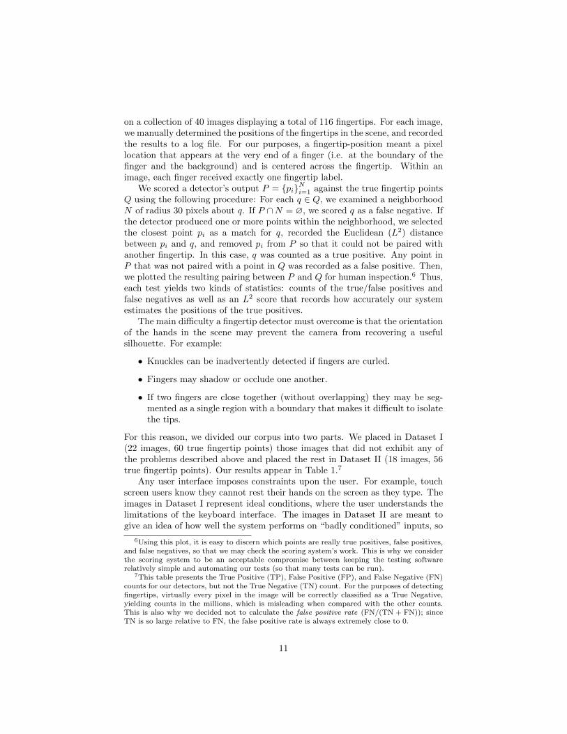
on a collection of 40 images displaying a total of 116 fingertips. For each image,we manually determined the positions of the fingertips in the scene, and recordedthe results to a log file. For our purposes, a fingertip-position meant a pixellocation that appears at the very end of a finger (i.e. at the boundary of thefinger and the background) and is centered across the fingertip. Within animage, each finger received exactly one fingertip label.
We scored a detector’s output P = {pi}Ni=1 against the true fingertip pointsQ using the following procedure: For each q ∈ Q, we examined a neighborhoodN of radius 30 pixels about q. If P ∩N = ∅, we scored q as a false negative. Ifthe detector produced one or more points within the neighborhood, we selectedthe closest point pi as a match for q, recorded the Euclidean (L2) distancebetween pi and q, and removed pi from P so that it could not be paired withanother fingertip. In this case, q was counted as a true positive. Any point inP that was not paired with a point in Q was recorded as a false positive. Then,we plotted the resulting pairing between P and Q for human inspection.6 Thus,each test yields two kinds of statistics: counts of the true/false positives andfalse negatives as well as an L2 score that records how accurately our systemestimates the positions of the true positives.
The main difficulty a fingertip detector must overcome is that the orientationof the hands in the scene may prevent the camera from recovering a usefulsilhouette. For example:
• Knuckles can be inadvertently detected if fingers are curled.
• Fingers may shadow or occlude one another.
• If two fingers are close together (without overlapping) they may be seg-mented as a single region with a boundary that makes it difficult to isolatethe tips.
For this reason, we divided our corpus into two parts. We placed in Dataset I(22 images, 60 true fingertip points) those images that did not exhibit any ofthe problems described above and placed the rest in Dataset II (18 images, 56true fingertip points). Our results appear in Table 1.7
Any user interface imposes constraints upon the user. For example, touchscreen users know they cannot rest their hands on the screen as they type. Theimages in Dataset I represent ideal conditions, where the user understands thelimitations of the keyboard interface. The images in Dataset II are meant togive an idea of how well the system performs on “badly conditioned” inputs, so
6Using this plot, it is easy to discern which points are really true positives, false positives,and false negatives, so that we may check the scoring system’s work. This is why we considerthe scoring system to be an acceptable compromise between keeping the testing softwarerelatively simple and automating our tests (so that many tests can be run).
7This table presents the True Positive (TP), False Positive (FP), and False Negative (FN)counts for our detectors, but not the True Negative (TN) count. For the purposes of detectingfingertips, virtually every pixel in the image will be correctly classified as a True Negative,yielding counts in the millions, which is misleading when compared with the other counts.This is also why we decided not to calculate the false positive rate (FN/(TN + FN)); sinceTN is so large relative to FN, the false positive rate is always extremely close to 0.
11
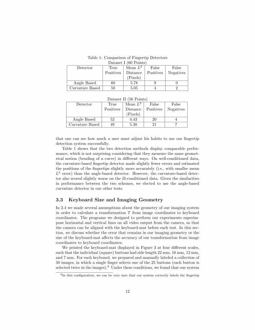
Table 1: Comparison of Fingertip DetectorsDataset I (60 Points)
Detector True Mean L2 False FalsePositives Distance Positives Negatives
(Pixels)Angle Based 60 5.78 9 0
Curvature Based 58 5.05 4 2
Dataset II (56 Points)Detector True Mean L2 False False
Positives Distance Positives Negatives(Pixels)
Angle Based 52 4.43 20 4Curvature Based 49 5.38 21 7
that one can see how much a user must adjust his habits to use our fingertipdetection system successfully.
Table 1 shows that the two detection methods display comparable perfor-mance, which is not surprising considering that they measure the same geomet-rical notion (bending of a curve) in different ways. On well-conditioned data,the curvature-based fingertip detector made slightly fewer errors and estimatedthe positions of the fingertips slightly more accurately (i.e., with smaller meanL2 error) than the angle-based detector. However, the curvature-based detec-tor also scored slightly worse on the ill-conditioned data. Given the similaritiesin performance between the two schemes, we elected to use the angle-basedcurvature detector in our other tests.
3.3 Keyboard Size and Imaging Geometry
In 2.4 we made several assumptions about the geometry of our imaging systemin order to calculate a transformation T from image coordinates to keyboardcoordinates. The programs we designed to perform our experiments superim-pose horizontal and vertical lines on all video output from the camera, so thatthe camera can be aligned with the keyboard-mat before each test. In this sec-tion, we discuss whether the error that remains in our imaging geometry or thesize of the keyboard-mat affects the accuracy of our transformation from imagecoordinates to keyboard coordinates.
We printed the keyboard-mat displayed in Figure 3 at four different scales,such that the individual (square) buttons had side length 22 mm, 16 mm, 12 mm,and 7 mm. For each keyboard, we prepared and manually labeled a collection of50 images, in which a single finger selects one of the 25 buttons (each button isselected twice in the images).8 Under these conditions, we found that our system
8In this configuration, we can be very sure that our system correctly labels the fingertip
12

was able to correctly label all 50 of the images, for each of the four keyboard-mats. From this we conclude that the true geometry of our imaging system issufficiently compatible with our assumptions, and neither the transformationT nor the size of the keyboard-mat has a significant effect on our system’saccuracy. In other words, the errors we will discuss in 3.4 arise because of errorsin fingertip detection and shadow analysis, and not error in the transformationT .
3.4 Touch Detection Experiments
From an implementation perspective, shadow analysis is a very appealing tech-nique for detecting whether the user is touching the keyboard mat. The tech-nique is computationally inexpensive, does not require special hardware,9 andcan be applied on a frame-by-frame basis. However, shadow analysis requiresstrong assumptions on the lighting conditions in the scene. Specifically, weassume:
(a) There is a strong point-source light illuminating the scene, that produceswell defined shadows.
(b) The light source has been aligned with the camera, so that in the cameracoordinates defined in 2.4, it lies in the yz-plane, between (and above) thecamera and the user’s hands.
In this section, we discuss the consequences of violating these assumptions.We adjusted our lighting conditions in several ways. First, we considered the
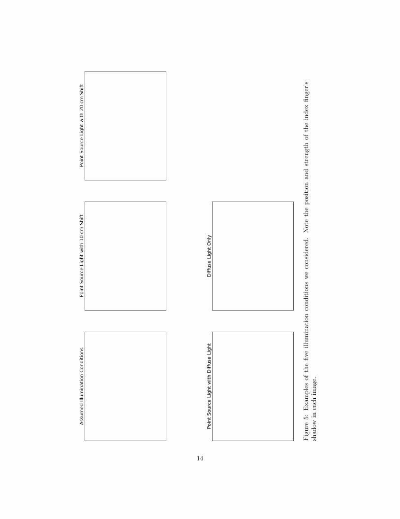
effect of shifting the point-source light so that it appears some distance to theside of the keyboard mat, instead of directly above it, which shifts the shadowsin the scene. We also considered the effect of adding diffuse light, which hasthe effect of weakening the shadows in the scene, and the effect of using onlydiffuse light for illumination, which yields very weak shadows. Figure 5 providesexamples of these illumination conditions, for comparison.
For each of the five lighting conditions, we recorded a total of 50 images(taking care to keep the hand poses the same between different lighting condi-tions) with 50 fingertips to be classified as either touching or not touching thekeyboard-mat (25 touching, 25 not touching). In the cases where the fingertiptouched the keyboard-mat, the system needed to report the correct key in orderfor the result to be scored as a true positive. For these experiments, we used a20× 20 window around each fingertip point, with shadow threshold 0.15.
Table 2 summarizes our results, which clarify our lighting assumptions intwo ways. Our system performed acceptably on Dataset 2, so we can refineassumption (b) by saying that the point source light does not need to be perfectlyaligned with the camera, so long as the shadows of the fingertips appear nearthe fingertips. If the shadows are too far from the fingertips, as was the case
and whether it is in contact with the tabletop.9For example the authors of [5] use a 3D range camera to determine distances to fingertips
and the keyboard-mat, so that touch detection is a matter of comparing distances.
13
Ass
um
ed Illu
min
ati
on C
ondit
ions
Poin
t Sourc
e L
ight
wit
h 1
0 c
m S
hift
Poin
t Sourc
e L
ight
wit
h 2
0 c
m S
hift
Poin
t Sourc
e L
ight
wit
h D
iffu
se L
ight
Diffu
se L
ight
Only
Fig
ure
5:E
xam
ple
sof
the
five
illu
min
atio
nco
nd
itio
ns
we
con
sid
ered
.N
ote
the
posi
tion
an
dst
ren
gth
of
the
ind
exfi
nger
’ssh
adow
inea
chim
age.
14
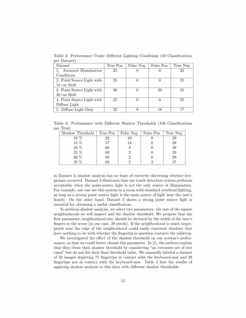
Table 2: Performance Under Different Lighting Conditions (50 Classificationsper Dataset)
Dataset True Pos. False Neg. False Pos. True Neg.1. Assumed IlluminationConditions
25 0 0 25
2. Point Source Light with10 cm Shift
25 0 0 25
3. Point Source Light with20 cm Shift
30 0 20 25
4. Point Source Light withDiffuse Light
25 0 0 25
5. Diffuse Light Only 32 8 18 17
Table 3: Performance with Different Shadow Thresholds (100 Classificationsper Trial)
Shadow Threshold True Pos. False Neg. False Pos. True Neg.10 % 22 49 0 2915 % 57 14 0 2920 % 68 3 0 2925 % 69 2 0 2930 % 69 2 0 2935 % 69 2 2 27
in Dataset 3, shadow analysis has no hope of correctly discerning whether key-presses occurred. Dataset 4 illustrates that our touch detection system performsacceptably when the point-source light is not the only source of illumination.For example, one can use this system in a room with standard overhead lighting,as long as a strong point source light is the main source of light near the user’shands. On the other hand, Dataset 5 shows a strong point source light isessential for obtaining a useful classification.
To perform shadow analysis, we select two parameters: the size of the squareneighborhoods we will inspect and the shadow threshold. We propose that thefirst parameter, neighborhood size, should be dictated by the width of the user’sfingers in the scene (in our case, 20 pixels). If the neighborhood is much larger,pixels near the edge of the neighborhood could easily represent shadows thathave nothing to do with whether the fingertip in question contacts the tabletop.
We investigated the effect of the shadow threshold on our system’s perfor-mance, so that we could better choose this parameter. In [1], the authors explainthat they chose their shadow threshold by considering “an extensive set of testcases” but do not list their final threshold value. We manually labeled a datasetof 50 images depicting 71 fingertips in contact with the keyboard-mat and 29fingertips not in contact with the keyboard-mat. Table 3 lists the results ofapplying shadow analysis to this data with different shadow thresholds.
15
As both intuition and the data in Table 3 indicate, a smaller shadow thresh-old makes it more difficult for a fingertip to be classified as touching the keyboard-mat. Hence, a very low shadow threshold yields few false positives and manyfalse negatives. However, the shadow threshold may be increased substantially,to around 35%, before the number of false positives increases. Based on thetable, a shadow threshold between 20% and 25% appears to deliver the bestperformance.
3.5 Frame Rate
The frame rate of our system depends somewhat on our hardware choices. Log-itech reports that their camera is capable of recording video at approximately30 frames per second (fps) and our own tests agree with that statistic. Our mainvirtual keyboard program consists of a loop in which we sample an image fromthe camera, analyze it, and display any resulting button presses. The additionaltime required to analyze the images means that our virtual keyboard systemcaptures an average of 10 frames per second. (For comparison, the authors of[1] report their system runs at 3 fps, albeit on different hardware.)
We wished to determine the extent to which our program’s frame rate affectsits accuracy, since this determines how fast a user can type. To simulate differentframe rates, we recorded image sequences (at 30 fps) of hands typing, and thenran our system on different subsequences of those frames. For example, todetermine the performance of our system at 5 fps, we would provide our programwith every sixth frame of the original 30 fps image sequence. In this way, weexamined how well the system performed at 5, 10, 15, and 30 fps.10
We recorded four different image sequences for our experiments. In sequenceV1 (32 seconds) an index finger presses each of the 25 keys on the keyboardonce. In sequence V2 (15 seconds) a pair of fingers alternate between pressingtwo distinct keys, for a total of 10 key-presses. In sequence V3 (5 seconds), anindex finger presses a sequence of 5 keys rapidly. In sequence V4 (7 seconds),a pair of fingers on the same hand rapidly presses a sequence of 8 keys on twodifferent rows.
Since the purpose of our experiment was to determine the effect of frame rateon accuracy, in each video sequence we chose hand poses that would be relativelyeasy for our system to accurately process. In this way, when the system failsto identify a key-press it does so because it failed to observe a frame in whicha fingertip was sufficiently close to a key (and not because the system failed toidentify a fingertip entirely). For this reason, we observed no false positives andreport only the number of failed identifications in each experiment.
From an initial image sequence {Ij} sampled at 30 fps one can obtain severaldistinct image sequences sampled at 5, 10, and 15 fps. For each dataset Vi,we ran our tests on three subsequences sampled at 5 fps, three subsequences
10Most users type somewhere between 30-120 words per minute [6] (here a word meansa sequence of 5 characters). From this fact one can roughly estimate that the frame rateshould be 2 to 10 fps; hence, the frame rates we chose for our experiments are not completelyarbitrary.
16
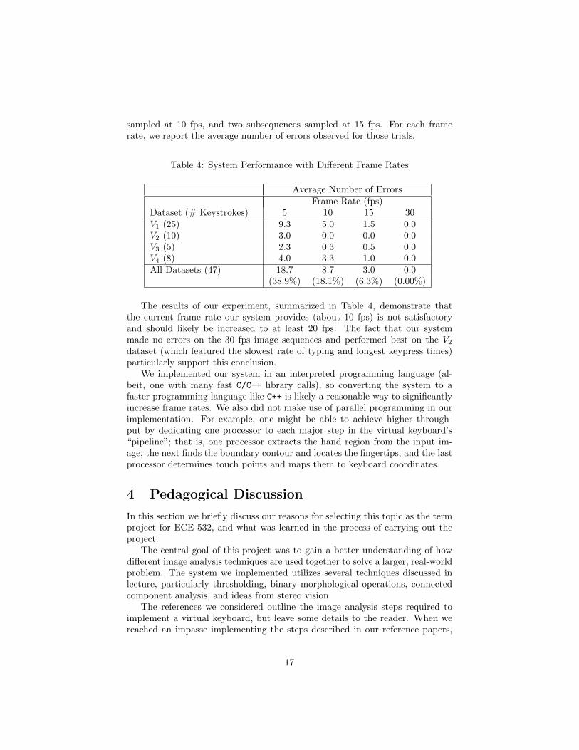
sampled at 10 fps, and two subsequences sampled at 15 fps. For each framerate, we report the average number of errors observed for those trials.
Table 4: System Performance with Different Frame Rates
Average Number of ErrorsFrame Rate (fps)
Dataset (# Keystrokes) 5 10 15 30V1 (25) 9.3 5.0 1.5 0.0V2 (10) 3.0 0.0 0.0 0.0V3 (5) 2.3 0.3 0.5 0.0V4 (8) 4.0 3.3 1.0 0.0All Datasets (47) 18.7 8.7 3.0 0.0
(38.9%) (18.1%) (6.3%) (0.00%)
The results of our experiment, summarized in Table 4, demonstrate thatthe current frame rate our system provides (about 10 fps) is not satisfactoryand should likely be increased to at least 20 fps. The fact that our systemmade no errors on the 30 fps image sequences and performed best on the V2dataset (which featured the slowest rate of typing and longest keypress times)particularly support this conclusion.
We implemented our system in an interpreted programming language (al-beit, one with many fast C/C++ library calls), so converting the system to afaster programming language like C++ is likely a reasonable way to significantlyincrease frame rates. We also did not make use of parallel programming in ourimplementation. For example, one might be able to achieve higher through-put by dedicating one processor to each major step in the virtual keyboard’s“pipeline”; that is, one processor extracts the hand region from the input im-age, the next finds the boundary contour and locates the fingertips, and the lastprocessor determines touch points and maps them to keyboard coordinates.
4 Pedagogical Discussion
In this section we briefly discuss our reasons for selecting this topic as the termproject for ECE 532, and what was learned in the process of carrying out theproject.
The central goal of this project was to gain a better understanding of howdifferent image analysis techniques are used together to solve a larger, real-worldproblem. The system we implemented utilizes several techniques discussed inlecture, particularly thresholding, binary morphological operations, connectedcomponent analysis, and ideas from stereo vision.
The references we considered outline the image analysis steps required toimplement a virtual keyboard, but leave some details to the reader. When wereached an impasse implementing the steps described in our reference papers,
17
we often had to consider three questions:
• Had we made a mistake in our implementation?
• Should we search the literature for a better technique for performing thatstep?
• Should we try to carefully characterize the difficulties our system wasencountering, in the hope that the step described in our reference paperscould be mildly adjusted to overcome those difficulties?
When considering such questions, we learned it was crucial to have a robustlibrary of “utilities” that would allow us to display the data in every step in oursystem. With the right plotting tools, virtually every problem became easy tounderstand.
Implementing a virtual keyboard system gave us a better understanding ofthe trade-offs one must consider when choosing image analysis techniques in thecontext of a larger system. For example, an important first step in our systemis to perform a skin segmentation on an input image. Selecting a technique toperform this segmentation meant balancing competing goals, particularly sim-plicity of implementation, computation time, and quality of segmentation. Skinsegmentation by thresholding, as in 2.1, is easy to implement and runs quickly,but only performs useful segmentations on a relatively limited class of images.A more sophisticated thresholding scheme, like Kittler and Illingworth’s infor-mation minimization procedure, might yield a more consistent segmentation, atthe cost of a more complicated implementation and longer runtime. As we sawin the experimental section, both speed (which affects frame rate) and accuracy(which affects the quality of the analysis we can perform in later steps) areimportant considerations that must be balanced.
One major difficulty we faced in the course of this project was acquiringthe necessary data for testing our system. The papers we consulted, particu-larly [1] and [2], give a reasonably clear outline for how to construct a virtualkeyboard system. However, they do not precisely explain what images are “well-conditioned” input to their virtual keyboard systems. In the beginning phasesof the project, we recorded many ill-conditioned test images, so that we oftenstruggled to discern whether the techniques described in the papers were notworking or whether the data was problematic.
To put it another way, in the process of developing the software that imple-ments our virtual keyboard system we had to concurrently develop an idea ofwhat “reasonable images” our system could process. For example:
• At one point we realized that our poor choice of lighting conditions andbackground were causing the skin-segmentation procedures in [1] to fail.
• In another early experiment, we realized that glare and the very poorquality of our first camera were producing test images with inaccuratecolors that could not be easily processed.
18
We overcame these difficulties in part by upgrading to a camera with slightlyhigher resolution (640× 480) and frame rate (30 fps). We also exercised greatercontrol over the lighting conditions of our experiments. We suspect the au-thors of [1] and [2] constructed similar conditions in which to conduct theirexperiments. Alternatively, perhaps we are simply unaware of standard “bestpractices” for recording test data that are well known to computer-vision re-searchers.11
5 Conclusion
In this project, we implemented a virtual keyboard following the steps describedin [1] and [2]. Though we achieved a frame rate and accuracy comparable to thereferences we considered, our experiments show that a virtual keyboard systembased on shadow analysis has limitations.
Shadow analysis demands very strong assumptions about the lighting andhand poses that will appear in virtual keyboard images. Unfortunately, as wesaw in Section 3, these demands are not necessarily rewarded with dependableperformance. We observed similar difficulties with fingertip identification. Bothcurvature and contour-angle techniques can acceptably identify isolated finger-tips, but do not deliver dependable performance when two fingers are mergedinto a single region or when one finger occludes another. Either technique isprone to assigning false-positives to finger-like objects, particularly knuckles.
We do not believe a truly useful virtual keyboard based on shadow analysiscould be incorporated into an existing mobile-computing technology (e.g. asmartphone). To achieve widespread adoption, such a technology must have afar lower rate of error and much weaker lighting assumptions. It is unclear howone could guarantee the assumptions of shadow analysis are satisfied withoutmaking burdensome demands on the user.
It would be interesting to know whether shadow analysis could be replacedby a motion analysis technique, such as in [7]. For example, given the locationof a fingertip in several consecutive images, one could calculate the fingertip’svelocity and identify key-presses as by considering when the fingertip’s velocityreverses direction. Naturally, such an approach would require additional datastructures and processing steps for tracking multiple fingertips over time.
It may also be the case that current approaches to camera-based virtualkeyboards appear unpromising because we are implicitly comparing their per-formance with the standard physical keyboard interface. One might insteadtry to characterize what typing tasks users currently perform on their touch-screens and then examine whether those tasks can be performed effectively witha virtual keyboard.
11The author is in the graduate mathematics program and has no background in computervision.
19
References
[1] Y. Adajania, J. Gosalia, A. Kanade, H. Mehta, and N. Shekokar. Virtualkeyboard using shadow analysis. In Emerging Trends in Engineering andTechnology (ICETET), 2010 3rd International Conference on, page 163 to165, 2010.
[2] E. Posner, N. Starzicki, and E. Katz. A single camera based floating virtualkeyboard with improved touch detection. In Electrical Electronics Engineersin Israel (IEEEI), 2012 IEEE 27th Convention of, page 1 to 5, 2012.
[3] M. Hagara and J. Pucik. Fingertip detection for virtual keyboard based oncamera. In Radioelektronika (RADIOELEKTRONIKA), 2013 23rd Interna-tional Conference, page 356 to 360, 2013.
[4] D. Chai and K.N. Ngan. Face segmentation using skin-color map in video-phone applications. Circuits and Systems for Video Technology, IEEETransactions on, 9(4):551 to 564, 1999.
[5] Huan Du, Thierry Oggier, Felix Lustenberger, and Edoardo Charbon. AVirtual Keyboard Based on True-3D Optical Ranging. In Proceedings of theBritish Machine Vision Conference, volume 1, page 220 to 229, 2005.
[6] R.U. Ayres and K. Martinas. On the Reappraisal of Microeconomics: Eco-nomic Growth and Change in a Material World. Edward Elgar, 2005.
[7] Sumit Srivastava and Ramesh Chandra Tripathi. Real time mono-visionbased customizable virtual keyboard using finger tip speed analysis. InMasaaki Kurosu, editor, Human-Computer Interaction. Interaction Modal-ities and Techniques, volume 8007 of Lecture Notes in Computer Science,page 497 to 505. Springer Berlin Heidelberg, 2013.
[8] Jr. Tomita, A. and R. Ishii. Hand shape extraction from a sequence ofdigitized gray-scale images. In Industrial Electronics, Control and Instru-mentation, 1994. IECON ’94., 20th International Conference on, volume 3,page 1925 to 1930 vol.3, 1994.
20