Embed Size (px)
Citation preview
A Case Study of Solar Powered Cellular Base Stations
1
DEPARTMENT OF TECHNOLOGY
A Case Study of Solar Powered Cellular Base Stations
By
Geetha Pande
September 2009
Master’s Thesis in Energy Systems
Supervisor/Examiner: Dr. Taghi Karimpanah
A Case Study of Solar Powered Cellular Base Stations
2
ACKNOWLEDGEMENTS
First of all, I would like to thank my supervisor and examiner Dr.Taghi Karimpanah
for his able guidance and support to perform the thesis work. I am also grateful to Ulf
Larsson, head of Master of Science program, for providing me the opportunity to
perform the thesis.
I would also like to thanks Dalarna university library staff for providing me required
articles for the thesis work. Apart from this I am also grateful to all those who directly
or indirectly contributed to the completion of my thesis work.
Finally, I can’t forget my family members in India and friends for their
encouragement and support during my stay abroad.
A Case Study of Solar Powered Cellular Base Stations
3
ABSTRACT
Green power, environment protection and emission reduction are key factors
nowadays in the telecom industry. Balancing of these modes while reducing the
capital and operational costs are of prime importance. Cost efficient and reliable
supply of electricity for mobile phone base stations must be ensured while expanding
the mobile phone network. In this context, solar energy, using sophisticated
photovoltaic cell technology, is considered to be playing very important role.
Currently, companies such as ABI research, Flexenclosure AB, etc believe that the
solar powered cellular base stations are capable of transforming the telecom industry
into one of the greenest in the world. Hence, lot of research is in progress across the
globe to use solar power in telecom industry.
In this thesis work, the significance of solar power as renewable energy source for
cellular base stations is reviewed. Moreover, simulation software called PVSYST4.37
is used not only to obtain an estimate of the cost of generation of solar power for
cellular base stations but also to obtain the system parameters such as the number of
modules, batteries and inverters needed for designing the solar powered cellular base
stations. The simulations were carried out for the Grid-Connected and the Stand-
Alone solar power systems by considering the cases of New Delhi, India and
Stockholm, Sweden.
The PVSYST4.37 simulation results shows that the power generation costs for the
grid connected solar powered system is less compare to standalone solar powered
system both in New Delhi, India as well as in Stockholm, Sweden.
A Case Study of Solar Powered Cellular Base Stations
4
INDEX
CHAPTER 1
1.1 INTRODUCTION...................................................................................................5
1.2 THESIS OBJECTIVE.............................................................................................6
1.3 ORGANISATION OF THESIS..............................................................................6
CHAPTER2
SOLAR POWER AS RENEWABLE ENERGY
2.1Introduction...............................................................................................................7
2.2Solar Photo Voltaic(PV) Technologies.....................................................................8
2.3Construction of PV cell.............................................................................................8
2.2.2Material used for PV cell........................................................................................9
2.2.3PV array Design and Sun tracking.......................................................................10
2.2.4Types of Solar Powered Systems.........................................................................10
2.3Solar power as Renewable energy in India.............................................................12
CHAPTER3
SOLAR POWER FOR CELLULAR BASE STATIONS
3.1Introduction............................................................................................................13
3.2Power requirement of cellular Base Stations.........................................................14
CHAPTER4
Simulation Using PVSYST 4 Software......................................................................15
CHAPTER5
Simulation Results and Analysis.................................................................................16
CHAPTER6
CONCLUSIONS AND FUTUREWORK....................................................................39
REFERENCES.............................................................................................................40
A Case Study of Solar Powered Cellular Base Stations
5
CHAPTER 1
1.1 Introduction
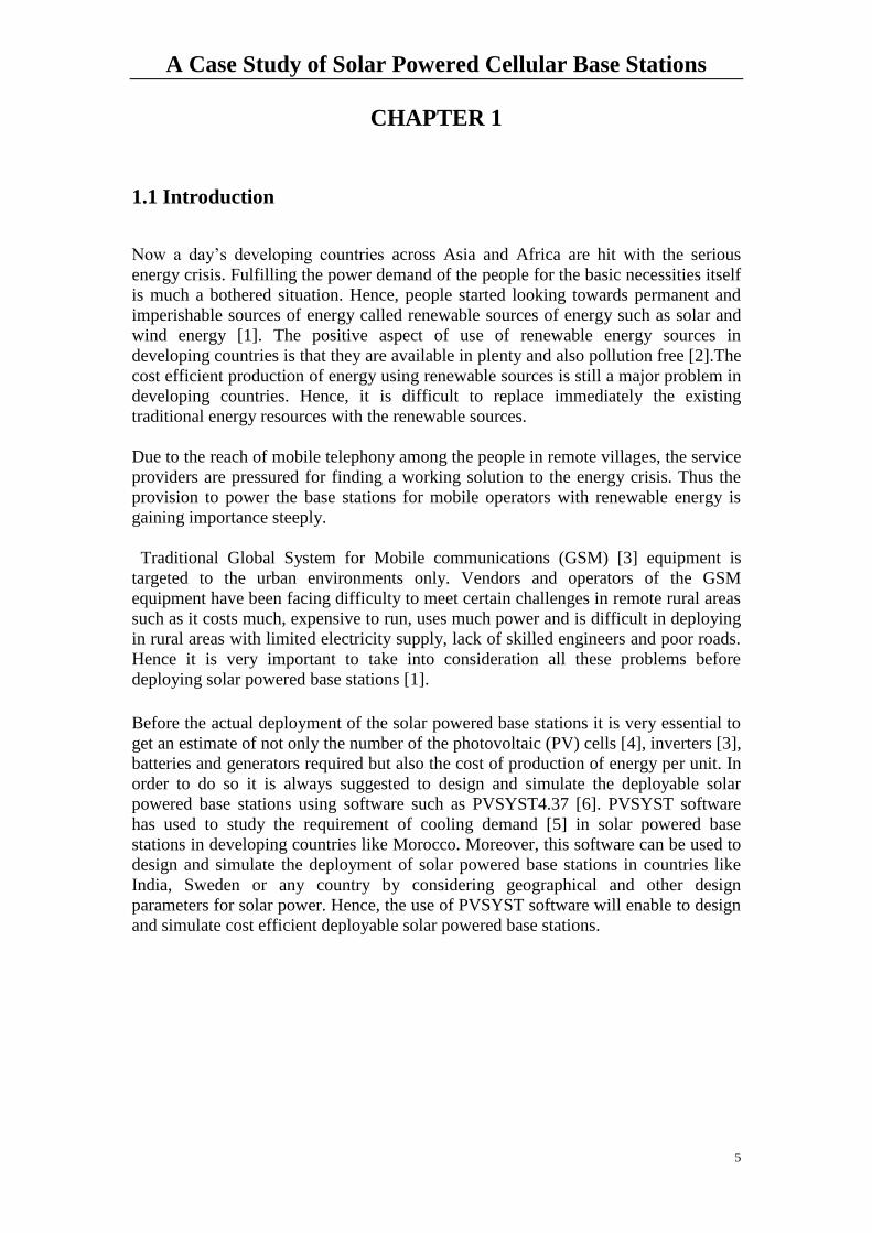
Now a day’s developing countries across Asia and Africa are hit with the serious
energy crisis. Fulfilling the power demand of the people for the basic necessities itself
is much a bothered situation. Hence, people started looking towards permanent and
imperishable sources of energy called renewable sources of energy such as solar and
wind energy [1]. The positive aspect of use of renewable energy sources in
developing countries is that they are available in plenty and also pollution free [2].The
cost efficient production of energy using renewable sources is still a major problem in
developing countries. Hence, it is difficult to replace immediately the existing
traditional energy resources with the renewable sources.
Due to the reach of mobile telephony among the people in remote villages, the service
providers are pressured for finding a working solution to the energy crisis. Thus the
provision to power the base stations for mobile operators with renewable energy is
gaining importance steeply.
Traditional Global System for Mobile communications (GSM) [3] equipment is
targeted to the urban environments only. Vendors and operators of the GSM
equipment have been facing difficulty to meet certain challenges in remote rural areas
such as it costs much, expensive to run, uses much power and is difficult in deploying
in rural areas with limited electricity supply, lack of skilled engineers and poor roads.
Hence it is very important to take into consideration all these problems before
deploying solar powered base stations [1].
Before the actual deployment of the solar powered base stations it is very essential to
get an estimate of not only the number of the photovoltaic (PV) cells [4], inverters [3],
batteries and generators required but also the cost of production of energy per unit. In
order to do so it is always suggested to design and simulate the deployable solar
powered base stations using software such as PVSYST4.37 [6]. PVSYST software
has used to study the requirement of cooling demand [5] in solar powered base
stations in developing countries like Morocco. Moreover, this software can be used to
design and simulate the deployment of solar powered base stations in countries like
India, Sweden or any country by considering geographical and other design
parameters for solar power. Hence, the use of PVSYST software will enable to design
and simulate cost efficient deployable solar powered base stations.
A Case Study of Solar Powered Cellular Base Stations
6
1.2 Thesis Objectives:
The objectives of this thesis work is to
Study the significance of Solar Power as renewable energy
Design and analyse the use of Solar power for cellular base stations using
PVSYST4 simulation software
Design and Costs analysis for implementation of Solar powered cellular base
stations in New Delhi, India and Stockholm, Sweden using PVSYST4
simulation software.
Comparison of Simulation results of New Delhi, India and Stockholm,
Sweden.
1.3 Organisation of the Thesis
The entire thesis is organised as follows:
Chapter2 gives an overview about the significance of Solar power, working principle
of Solar power PV cell construction, material used for PV cell, different types of Solar
powering systems and Solar power in India.
Chapter3 describes Solar power for base stations and power needed for base stations.
Chapter4 gives description of basic knowledge of PVSYST software.
Chapter5 describes simulation results for grid connected system and stand alone
system for New Delhi (India), Stockholm (Sweden).
Chapter6 describes conclusions and future work to be done.
References are numbered continuously and listed at the end of the thesis.
A Case Study of Solar Powered Cellular Base Stations
7
CHAPTER 2
Solar Power as Renewable Energy
2.1 Introduction
Currently, our society’s energy demands are fulfilled using conventional energy
sources such as water, coal, oil, natural gases or uranium. The production of energy
using these conventional sources is a cause of concern of many environmentalists.
The major problems can be quoted as follows:
1. It causes atmospheric pollution, climate changes or nuclear waste and thus can
endanger our living condition on the earth.
2. The extensive use of these limited conventional energy sources may result in
complete depletion of energy sources and hence, there is no guarantee of
energy supply for future.
The above mentioned problems can be solved by using renewable energy sources
such as Sun and Wind.The renewable energy sources use natural resources and do not
cause any pollution. Hence they are termed as Green Energy sources[2].Moreover,
these renewable energy sources only use a small part of the flow that is why they
cannot damage natural surrounding and also do have the risk of being depleted.
Sun is considered as a potential source of renewable energy. Hence, the use of solar
energy for applications such as generation of electricity, running of automobiles, etc is
becoming popular. The generation of electricity using solar energy is done using
photovoltaic technology (4).The term ‘Photovoltaic’ is a combination of two words.
They are ‘photo’ meaning ‘light’ and ‘voltaic’ meaning electricity. Generally,
photovoltaic is abbreviated as ‘PV’. The solar PV cell works on the principle of
conversion of sun light into electricity. For generation of electricity in large amounts,
an array of solar PV cells are either connected in series or parallel. Despite high cost
of PV cells, solar power is considered as an alternative source of energy in many parts
of the world.
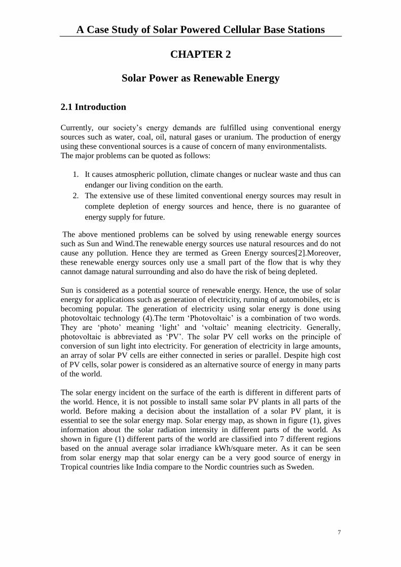
The solar energy incident on the surface of the earth is different in different parts of
the world. Hence, it is not possible to install same solar PV plants in all parts of the
world. Before making a decision about the installation of a solar PV plant, it is
essential to see the solar energy map. Solar energy map, as shown in figure (1), gives
information about the solar radiation intensity in different parts of the world. As
shown in figure (1) different parts of the world are classified into 7 different regions
based on the annual average solar irradiance kWh/square meter. As it can be seen
from solar energy map that solar energy can be a very good source of energy in
Tropical countries like India compare to the Nordic countries such as Sweden.
A Case Study of Solar Powered Cellular Base Stations
8
Figure 1: Solar Energy Map [7]
2.2 Solar Photovoltaic (PV) Technologies:
Solar PV technology is about generation of electricity from sunlight. This technology
involves construction of PV cell, materials used for PV cell construction and the
design of PV cell array.
2.2.1 Construction of PV Cell:
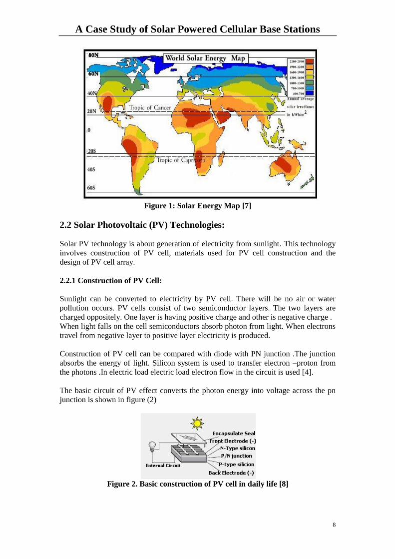
Sunlight can be converted to electricity by PV cell. There will be no air or water
pollution occurs. PV cells consist of two semiconductor layers. The two layers are
charged oppositely. One layer is having positive charge and other is negative charge .
When light falls on the cell semiconductors absorb photon from light. When electrons
travel from negative layer to positive layer electricity is produced.
Construction of PV cell can be compared with diode with PN junction .The junction
absorbs the energy of light. Silicon system is used to transfer electron –proton from
the photons .In electric load electric load electron flow in the circuit is used [4].
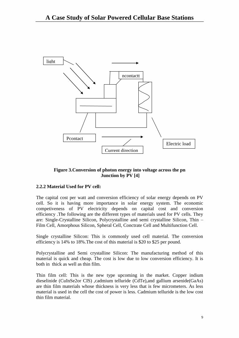
The basic circuit of PV effect converts the photon energy into voltage across the pn
junction is shown in figure (2)
Figure 2. Basic construction of PV cell in daily life [8]
A Case Study of Solar Powered Cellular Base Stations
9
Figure 3.Conversion of photon energy into voltage across the pn
Junction by PV [4]
2.2.2 Material Used for PV cell:
The capital cost per watt and conversion efficiency of solar energy depends on PV
cell. So it is having more importance in solar energy system. The economic
competiveness of PV electricity depends on capital cost and conversion
efficiency .The following are the different types of materials used for PV cells. They
are: Single-Crystalline Silicon, Polycrystalline and semi crystalline Silicon, Thin –
Film Cell, Amorphous Silicon, Spheral Cell, Conctrate Cell and Multifunction Cell.
Single crystalline Silicon: This is commonly used cell material. The conversion
efficiency is 14% to 18%.The cost of this material is $20 to $25 per pound.
Polycrystalline and Semi crystalline Silicon: The manufacturing method of this
material is quick and cheap. The cost is low due to low conversion efficiency. It is
both in thick as well as thin film.
Thin film cell: This is the new type upcoming in the market. Copper indium
dieselinide (CuInSe2or CIS) ,cadmium telluride (CdTe),and gallium arsenide(GaAs)
are thin film materials whose thickness is very less that is few micrometers. As less
material is used in the cell the cost of power is less. Cadmium telluride is the low cost
thin film material.
light
Electric load Pcontact
Current direction
ncontactt
A Case Study of Solar Powered Cellular Base Stations
10
Amorphous Silicon: It is only 2-um-thick.It uses only 1%of the material comparing
with crystalline silicon. The efficiency is only 50percent of the crystalline silicon and
cost is less.
Spheral cell: The cost of this material is $1 per pound. Thickness is 2um.The
conversion efficiency is high that is 16 to 20%
Concentrator Cell: It is focusing on small area with high efficiency (37%).The
disadvantage with this is that it requires focusing optics.
Multifunction Cell: In this electricity is generated by using red and infrared light. Blue
and ultraviolet is not used for the electricity. It has high efficiency(34%) and cost is
also high[4].
2.2.3 PV Array Design and Sun tracking
The factors that influence the electrical design of the solar photovoltaic array are the
sun intensity and the sun angle
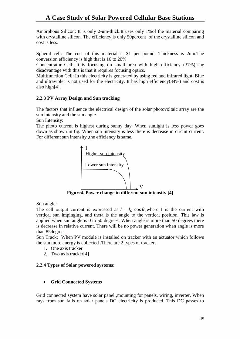
Sun Intensity:
The photo current is highest during sunny day. When sunlight is less power goes
down as shown in fig. When sun intensity is less there is decrease in circuit current.
For different sun intensity ,the efficiency is same.
I
Higher sun intensity
Lower sun intensity
V
Figure4. Power change in different sun intensity [4]
Sun angle:
The cell output current is expressed as 𝐼 = 𝐼𝑂 cos 𝜃 ,where I is the current with
vertical sun impinging, and theta is the angle to the vertical position. This law is
applied when sun angle is 0 to 50 degrees. When angle is more than 50 degrees there
is decrease in relative current. There will be no power generation when angle is more
than 85degrees.
Sun Track: When PV module is installed on tracker with an actuator which follows
the sun more energy is collected .There are 2 types of trackers.
1. One axis tracker
2. Two axis tracker[4]
2.2.4 Types of Solar powered systems:
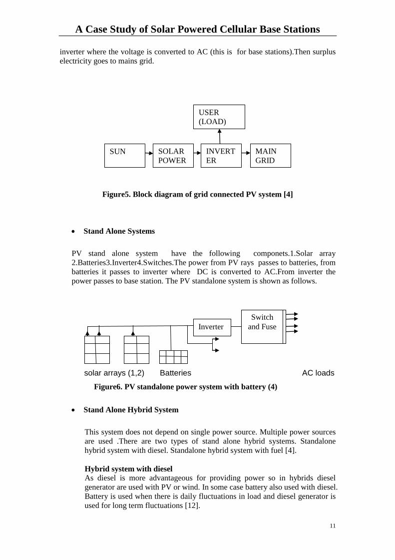
Grid Connected Systems
Grid connected system have solar panel ,mounting for panels, wiring, inverter. When
rays from sun falls on solar panels DC electricity is produced. This DC passes to
A Case Study of Solar Powered Cellular Base Stations
11
inverter where the voltage is converted to AC (this is for base stations).Then surplus
electricity goes to mains grid.
Figure5. Block diagram of grid connected PV system [4]
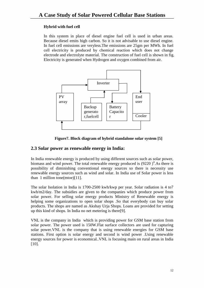
Stand Alone Systems
PV stand alone system have the following componets.1.Solar array
2.Batteries3.Inverter4.Switches.The power from PV rays passes to batteries, from
batteries it passes to inverter where DC is converted to AC.From inverter the
power passes to base station. The PV standalone system is shown as follows.
solar arrays (1,2) Batteries AC loads
Figure6. PV standalone power system with battery (4)
Stand Alone Hybrid System
This system does not depend on single power source. Multiple power sources
are used .There are two types of stand alone hybrid systems. Standalone
hybrid system with diesel. Standalone hybrid system with fuel [4].
Hybrid system with diesel
As diesel is more advantageous for providing power so in hybrids diesel
generator are used with PV or wind. In some case battery also used with diesel.
Battery is used when there is daily fluctuations in load and diesel generator is
used for long term fluctuations [12].
Inverter
Switch
and Fuse
SOLAR
POWER
INVERT
ER
MAIN
GRID SUN
USER
(LOAD)
A Case Study of Solar Powered Cellular Base Stations
12
Hybrid with fuel cell
In this system in place of diesel engine fuel cell is used in urban areas.
Because diesel emits high carbon. So it is not advisable to use diesel engine.
In fuel cell emissions are veryless.The emissions are 25gm per MWh. In fuel
cell electricity is produced by chemical reaction which does not change
electrode and electrolyte material. The construction of fuel cell is shown in fig.
Electricity is generated when Hydrogen and oxygen combined from air.
Figure7. Block diagram of hybrid standalone solar system [5]
2.3 Solar power as renewable energy in India: In India renewable energy is produced by using different sources such as solar power,
biomass and wind power. The total renewable energy produced is (9220 )4.As there is
possibility of diminishing conventional energy sources so there is necessity use
renewable energy sources such as wind and solar. In India use of Solar power is less
than 1 million tone(mtoe)[11].
The solar Isolation in India is 1700-2500 kwh/kwp per year. Solar radiation is 4 to7
kwh/m2/day. The subsidies are given to the companies which produce power from
solar power. For selling solar energy products Ministry of Renewable energy is
helping some organizations to open solar shops .So that everybody can buy solar
products. The shops are named as Akshay Urja Shops. Loans are provided for setting
up this kind of shops. In India no net metering is there[9].
VNL is the company in India which is providing power for GSM base station from
solar power. The power used is 150W.Flat surface collectors are used for capturing
solar power.VNL is the company that is using renewable energies for GSM base
stations. First option is solar energy and second is wind power .Using renewable
energy sources for power is economical..VNL is focusing main on rural areas in India
[10].
PV
array
Backup
generato
r,fuelcell
Battery
Capacito
r
End
user
End
user
Cooler
Inverter
A Case Study of Solar Powered Cellular Base Stations
13
CHAPTER 3
Solar Power for Cellular Base stations
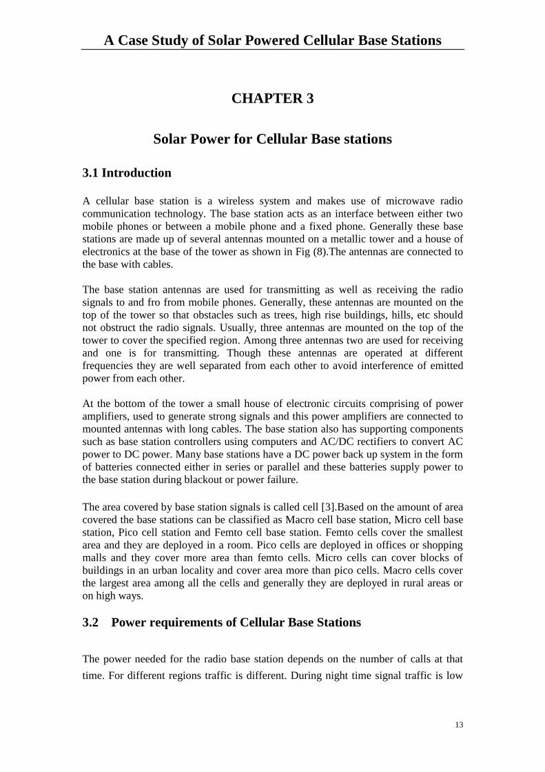
3.1 Introduction
A cellular base station is a wireless system and makes use of microwave radio
communication technology. The base station acts as an interface between either two
mobile phones or between a mobile phone and a fixed phone. Generally these base
stations are made up of several antennas mounted on a metallic tower and a house of
electronics at the base of the tower as shown in Fig (8).The antennas are connected to
the base with cables.
The base station antennas are used for transmitting as well as receiving the radio
signals to and fro from mobile phones. Generally, these antennas are mounted on the
top of the tower so that obstacles such as trees, high rise buildings, hills, etc should
not obstruct the radio signals. Usually, three antennas are mounted on the top of the
tower to cover the specified region. Among three antennas two are used for receiving
and one is for transmitting. Though these antennas are operated at different
frequencies they are well separated from each other to avoid interference of emitted
power from each other.
At the bottom of the tower a small house of electronic circuits comprising of power
amplifiers, used to generate strong signals and this power amplifiers are connected to
mounted antennas with long cables. The base station also has supporting components
such as base station controllers using computers and AC/DC rectifiers to convert AC
power to DC power. Many base stations have a DC power back up system in the form
of batteries connected either in series or parallel and these batteries supply power to
the base station during blackout or power failure.
The area covered by base station signals is called cell [3].Based on the amount of area
covered the base stations can be classified as Macro cell base station, Micro cell base
station, Pico cell station and Femto cell base station. Femto cells cover the smallest
area and they are deployed in a room. Pico cells are deployed in offices or shopping
malls and they cover more area than femto cells. Micro cells can cover blocks of
buildings in an urban locality and cover area more than pico cells. Macro cells cover
the largest area among all the cells and generally they are deployed in rural areas or
on high ways.
3.2 Power requirements of Cellular Base Stations
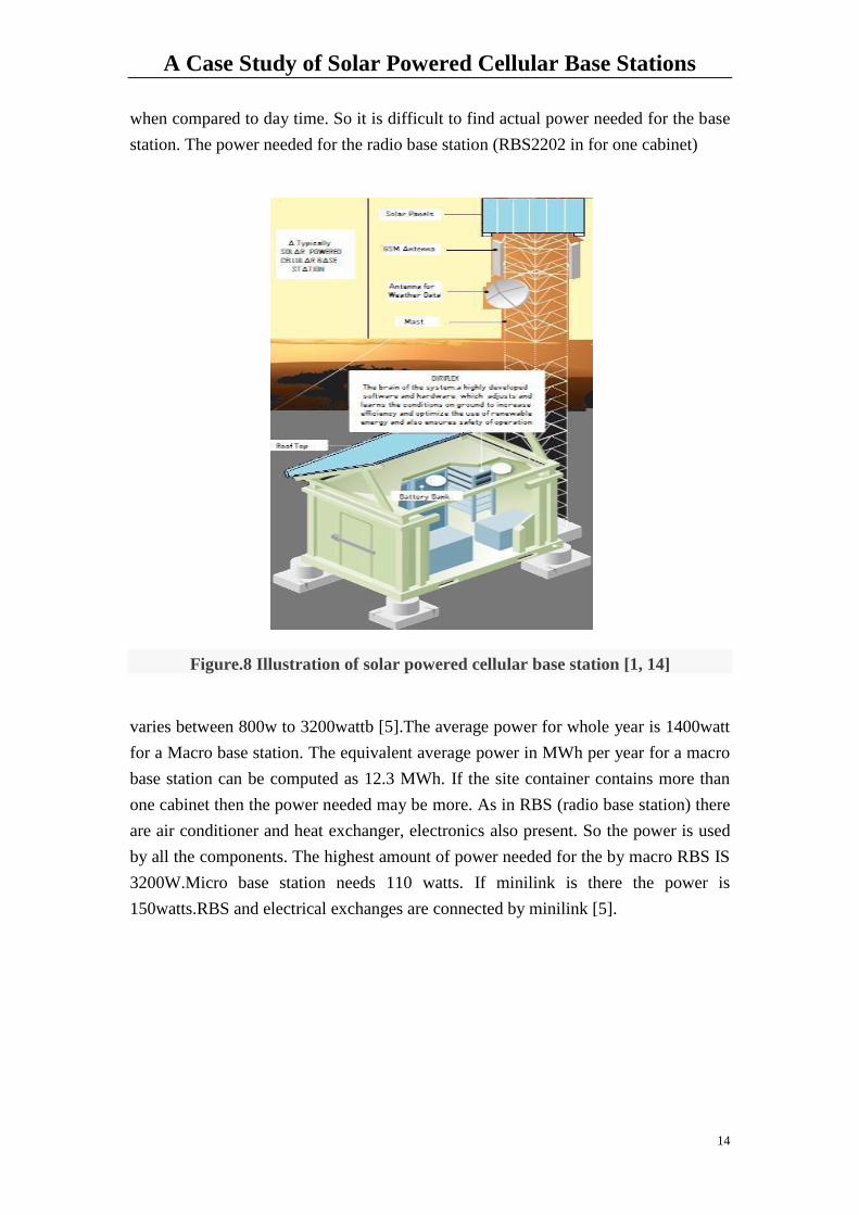
The power needed for the radio base station depends on the number of calls at that
time. For different regions traffic is different. During night time signal traffic is low
A Case Study of Solar Powered Cellular Base Stations
14
when compared to day time. So it is difficult to find actual power needed for the base
station. The power needed for the radio base station (RBS2202 in for one cabinet)
Figure.8 Illustration of solar powered cellular base station [1, 14]
varies between 800w to 3200wattb [5].The average power for whole year is 1400watt
for a Macro base station. The equivalent average power in MWh per year for a macro
base station can be computed as 12.3 MWh. If the site container contains more than
one cabinet then the power needed may be more. As in RBS (radio base station) there
are air conditioner and heat exchanger, electronics also present. So the power is used
by all the components. The highest amount of power needed for the by macro RBS IS
3200W.Micro base station needs 110 watts. If minilink is there the power is
150watts.RBS and electrical exchanges are connected by minilink [5].
A Case Study of Solar Powered Cellular Base Stations
15
CHAPTER 4
Simulation Using PVSYST4 Software
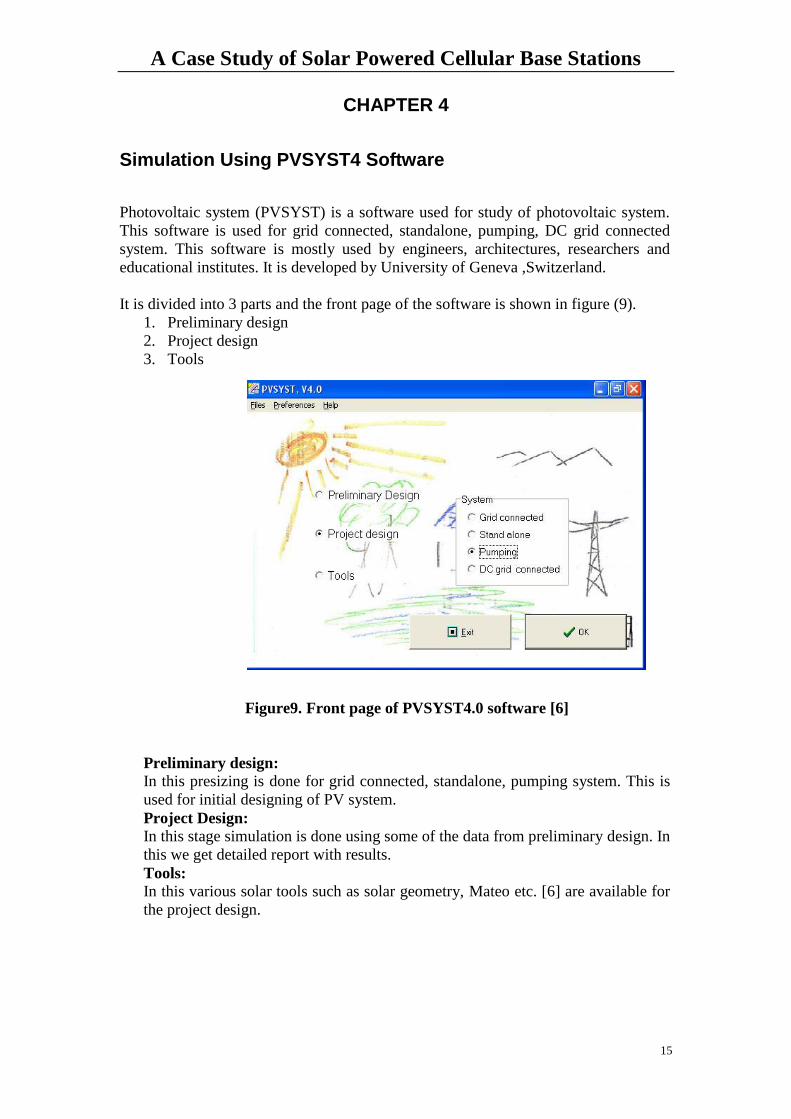
Photovoltaic system (PVSYST) is a software used for study of photovoltaic system.
This software is used for grid connected, standalone, pumping, DC grid connected
system. This software is mostly used by engineers, architectures, researchers and
educational institutes. It is developed by University of Geneva ,Switzerland.
It is divided into 3 parts and the front page of the software is shown in figure (9).
1. Preliminary design
2. Project design
3. Tools
Figure9. Front page of PVSYST4.0 software [6]
Preliminary design:
In this presizing is done for grid connected, standalone, pumping system. This is
used for initial designing of PV system.
Project Design: In this stage simulation is done using some of the data from preliminary design. In
this we get detailed report with results.
Tools:
In this various solar tools such as solar geometry, Mateo etc. [6] are available for
the project design.
A Case Study of Solar Powered Cellular Base Stations
16
CHAPTER 5
Simulation Results and Analysis
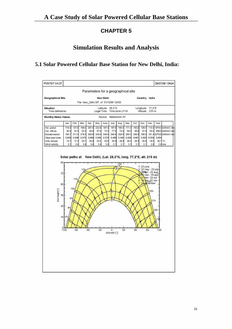
5.1 Solar Powered Cellular Base Station for New Delhi, India:
A Case Study of Solar Powered Cellular Base Stations
17
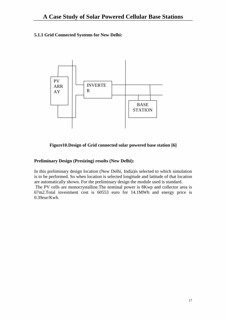
5.1.1 Grid Connected Systems for New Delhi:
Figure10.Design of Grid connected solar powered base station [6]
Preliminary Design (Presizing) results (New Delhi):
In this preliminary design location (New Delhi, India)is selected to which simulation
is to be performed. So when location is selected longitude and latitude of that location
are automatically shown. For the preliminary design the module used is standard.
The PV cells are monocrystalline.The nominal power is 8Kwp and collector area is
67m2.Total investment cost is 60553 euro for 14.1MWh and energy price is
0.39eur/Kwh.
PV
ARR
AY
INVERTE
R
BASE
STATION
A Case Study of Solar Powered Cellular Base Stations
18
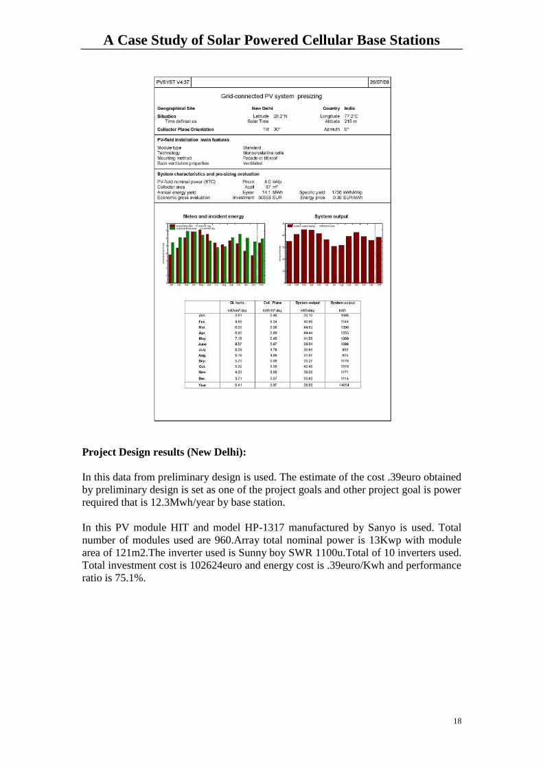
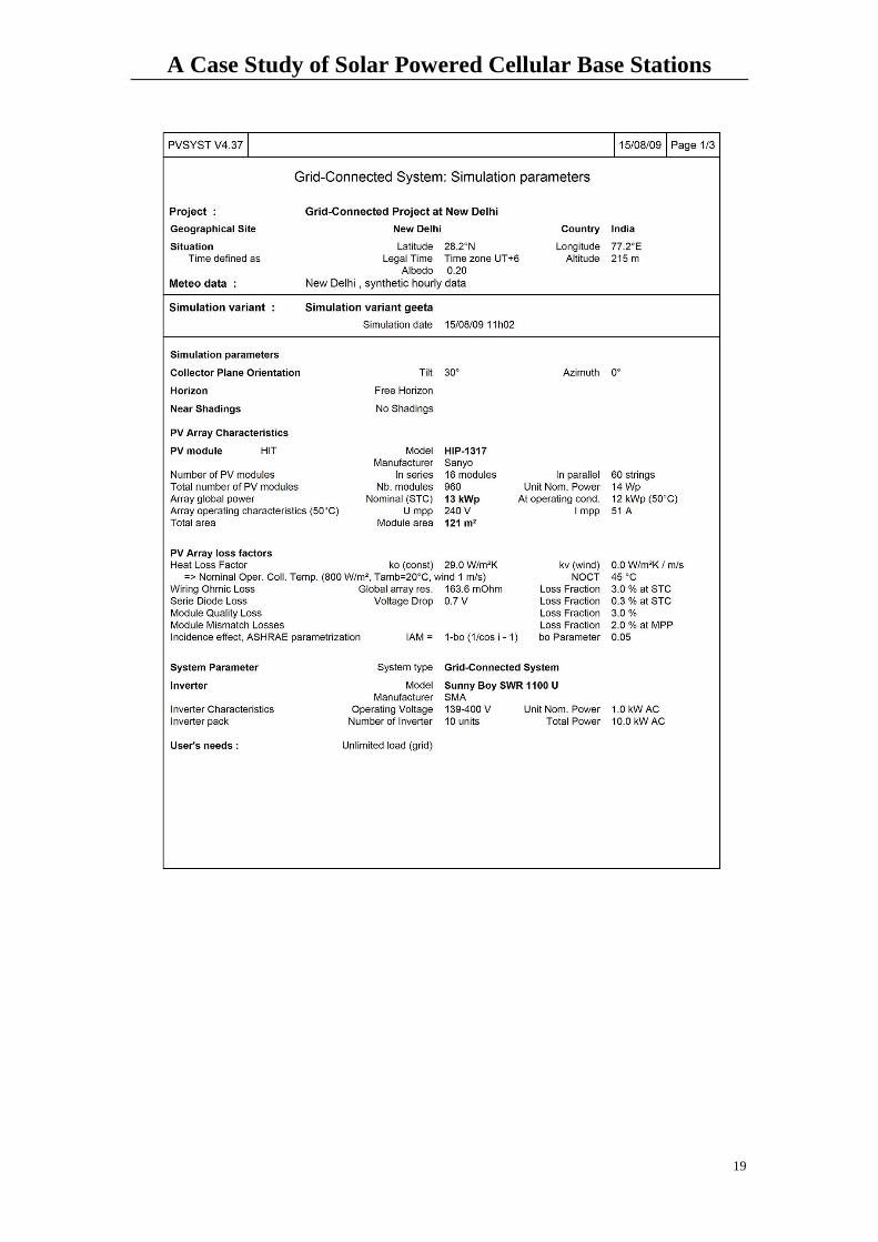
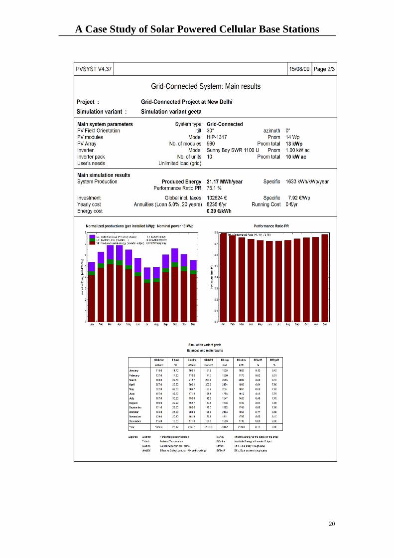
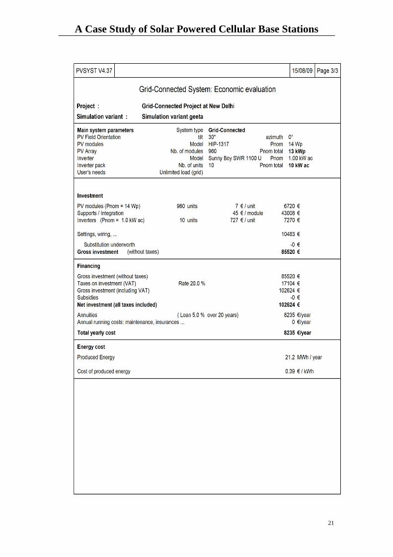
Project Design results (New Delhi):
In this data from preliminary design is used. The estimate of the cost .39euro obtained
by preliminary design is set as one of the project goals and other project goal is power
required that is 12.3Mwh/year by base station.
In this PV module HIT and model HP-1317 manufactured by Sanyo is used. Total
number of modules used are 960.Array total nominal power is 13Kwp with module
area of 121m2.The inverter used is Sunny boy SWR 1100u.Total of 10 inverters used.
Total investment cost is 102624euro and energy cost is .39euro/Kwh and performance
ratio is 75.1%.
A Case Study of Solar Powered Cellular Base Stations
19
A Case Study of Solar Powered Cellular Base Stations
20
A Case Study of Solar Powered Cellular Base Stations
21
A Case Study of Solar Powered Cellular Base Stations
22
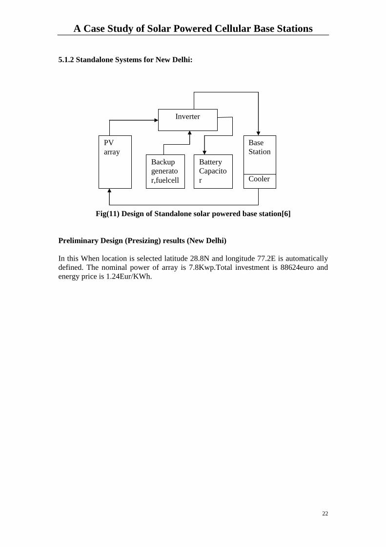
5.1.2 Standalone Systems for New Delhi:
Fig(11) Design of Standalone solar powered base station[6]
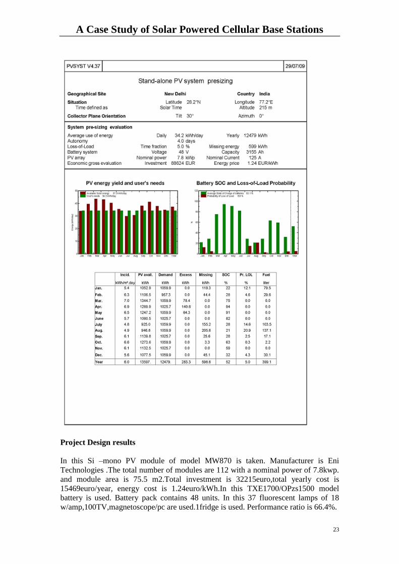
Preliminary Design (Presizing) results (New Delhi)
In this When location is selected latitude 28.8N and longitude 77.2E is automatically
defined. The nominal power of array is 7.8Kwp.Total investment is 88624euro and
energy price is 1.24Eur/KWh.
PV
array
Backup
generato
r,fuelcell
Battery
Capacito
r
End
user
Base
Station
Cooler
Inverter
A Case Study of Solar Powered Cellular Base Stations
23
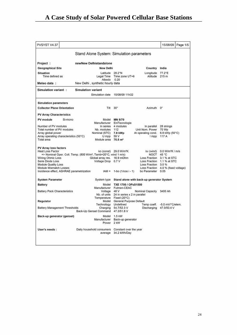
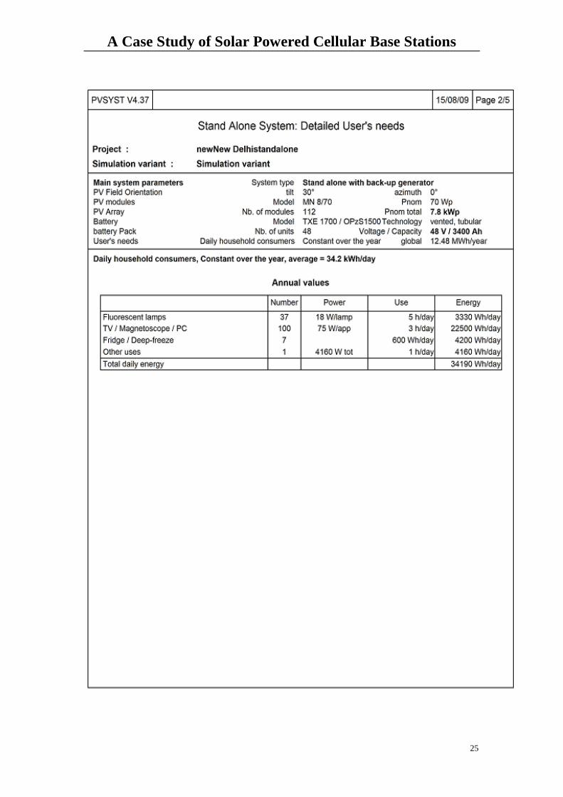
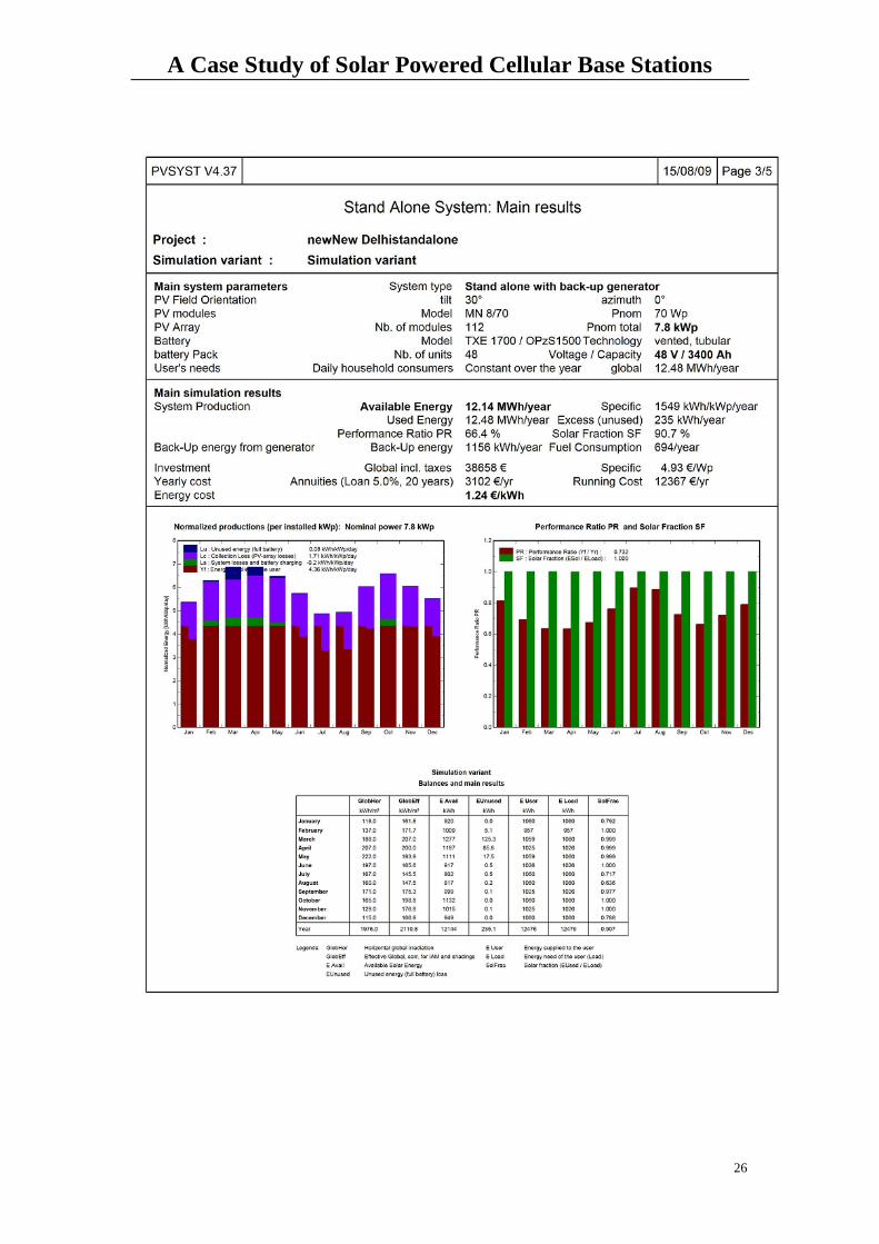
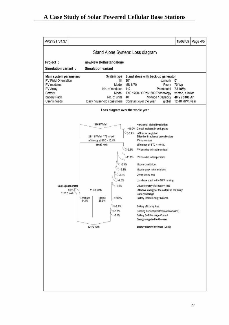
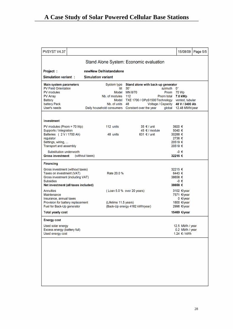
Project Design results
In this Si –mono PV module of model MW870 is taken. Manufacturer is Eni
Technologies .The total number of modules are 112 with a nominal power of 7.8kwp.
and module area is 75.5 m2.Total investment is 32215euro,total yearly cost is
15469euro/year, energy cost is 1.24euro/kWh.In this TXE1700/OPzs1500 model
battery is used. Battery pack contains 48 units. In this 37 fluorescent lamps of 18
w/amp,100TV,magnetoscope/pc are used.1fridge is used. Performance ratio is 66.4%.
A Case Study of Solar Powered Cellular Base Stations
24
A Case Study of Solar Powered Cellular Base Stations
25
A Case Study of Solar Powered Cellular Base Stations
26
A Case Study of Solar Powered Cellular Base Stations
27
A Case Study of Solar Powered Cellular Base Stations
28
A Case Study of Solar Powered Cellular Base Stations
29
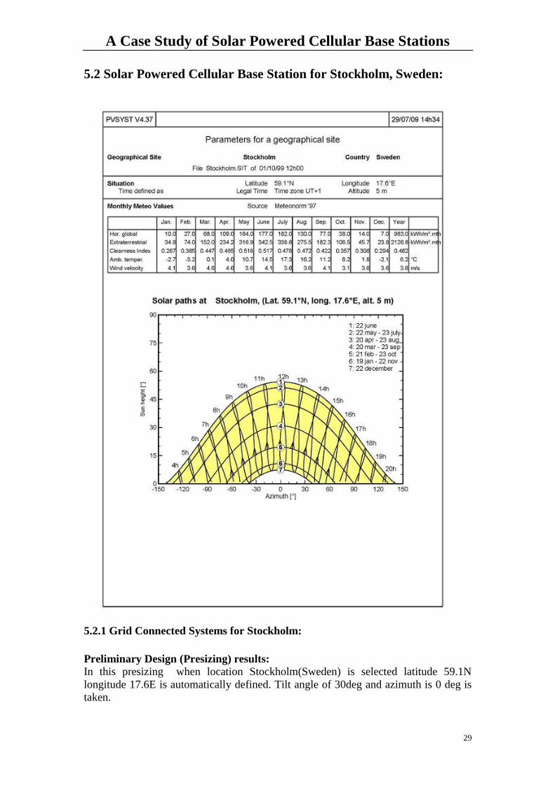
5.2 Solar Powered Cellular Base Station for Stockholm, Sweden:
5.2.1 Grid Connected Systems for Stockholm:
Preliminary Design (Presizing) results:
In this presizing when location Stockholm(Sweden) is selected latitude 59.1N
longitude 17.6E is automatically defined. Tilt angle of 30deg and azimuth is 0 deg is
taken.
A Case Study of Solar Powered Cellular Base Stations
30
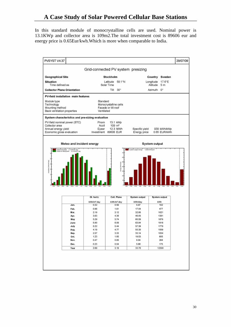
In this standard module of monocrystalline cells are used. Nominal power is
13.1KWp and collector area is 109m2.The total investment cost is 89606 eur and
energy price is 0.65Eur/kwh.Which is more when comparable to India.
A Case Study of Solar Powered Cellular Base Stations
31
Project Design results
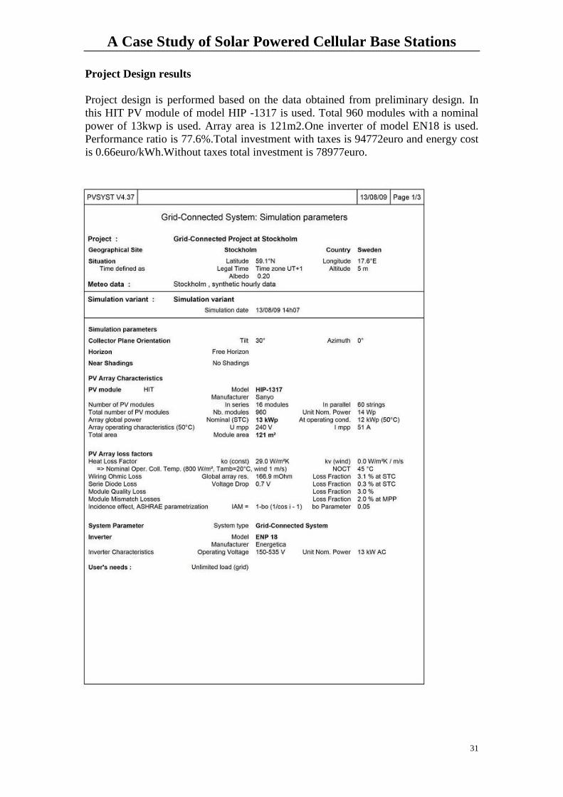
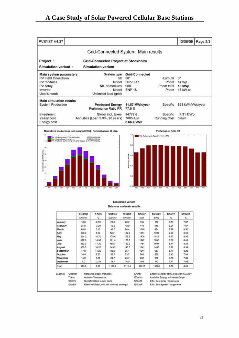
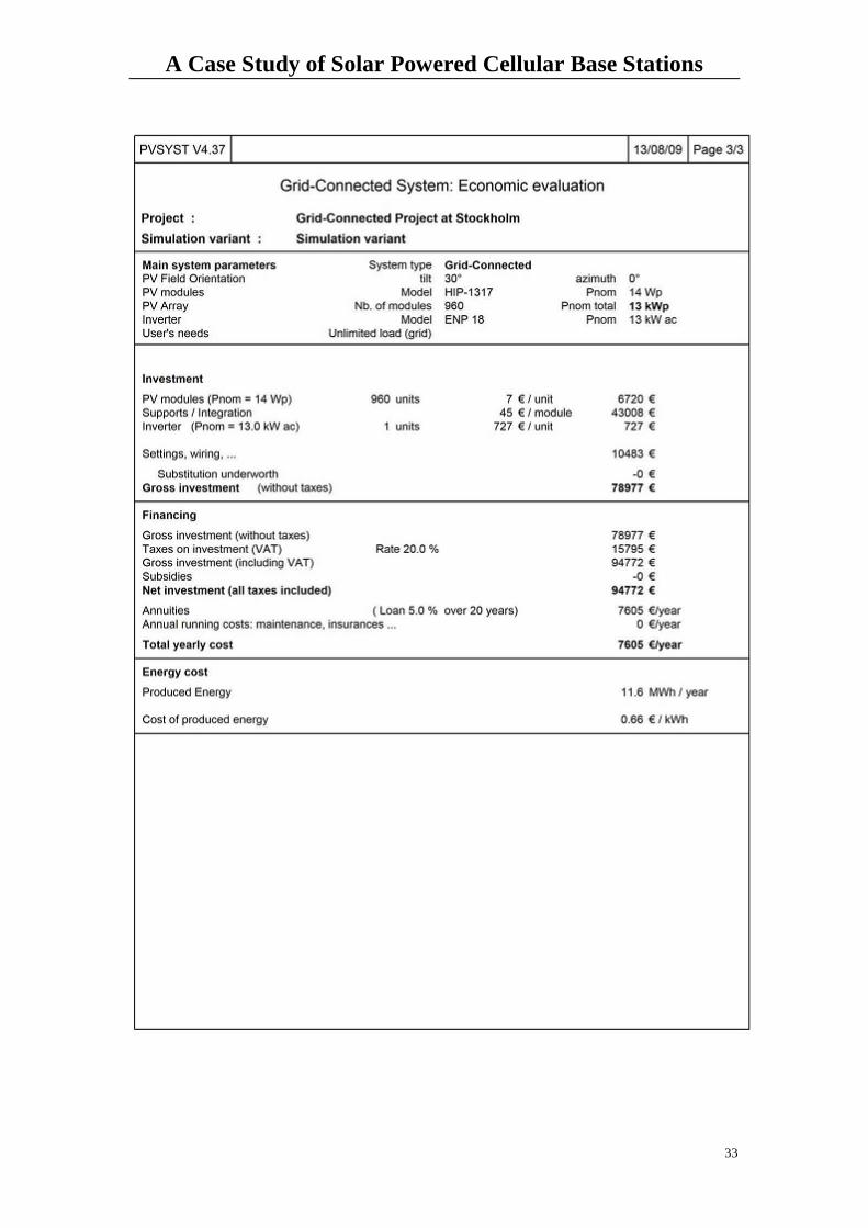
Project design is performed based on the data obtained from preliminary design. In
this HIT PV module of model HIP -1317 is used. Total 960 modules with a nominal
power of 13kwp is used. Array area is 121m2.One inverter of model EN18 is used.
Performance ratio is 77.6%.Total investment with taxes is 94772euro and energy cost
is 0.66euro/kWh.Without taxes total investment is 78977euro.
A Case Study of Solar Powered Cellular Base Stations
32
A Case Study of Solar Powered Cellular Base Stations
33
A Case Study of Solar Powered Cellular Base Stations
34
5.2.2 Standalone Systems for Stockholm
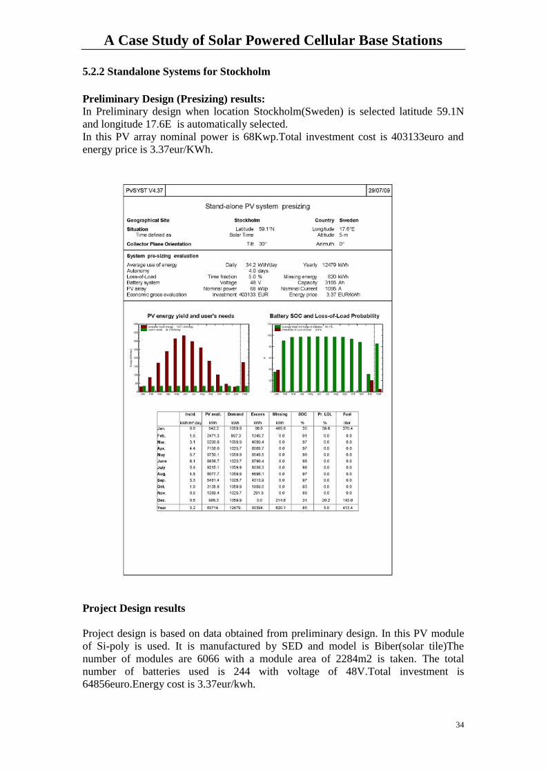
Preliminary Design (Presizing) results:
In Preliminary design when location Stockholm(Sweden) is selected latitude 59.1N
and longitude 17.6E is automatically selected.
In this PV array nominal power is 68Kwp.Total investment cost is 403133euro and
energy price is 3.37eur/KWh.
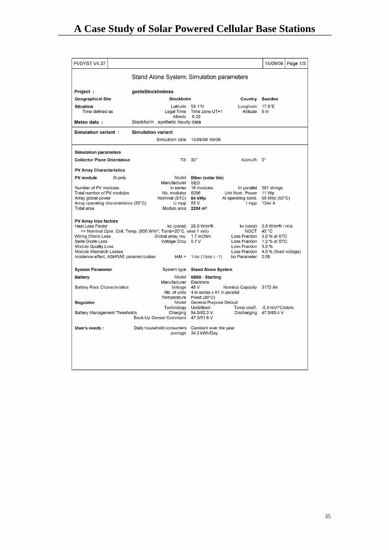
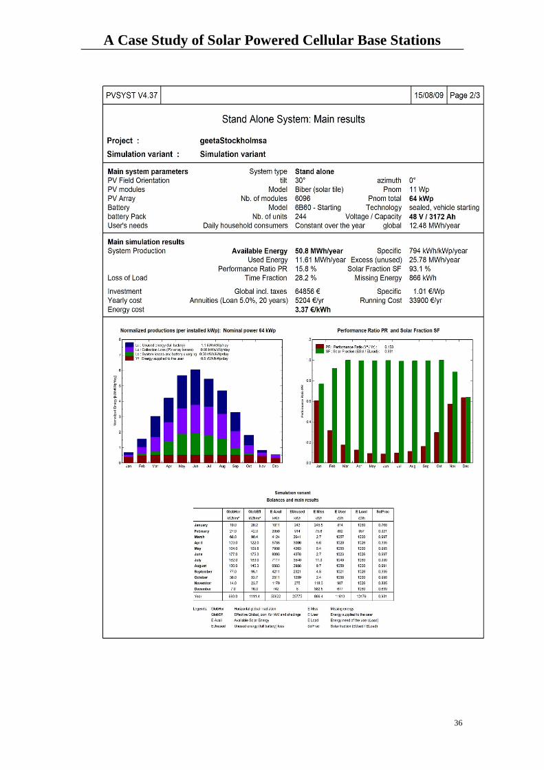
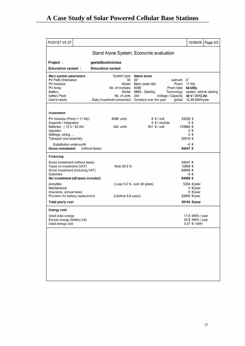
Project Design results
Project design is based on data obtained from preliminary design. In this PV module
of Si-poly is used. It is manufactured by SED and model is Biber(solar tile)The
number of modules are 6066 with a module area of 2284m2 is taken. The total
number of batteries used is 244 with voltage of 48V.Total investment is
64856euro.Energy cost is 3.37eur/kwh.
A Case Study of Solar Powered Cellular Base Stations
35
A Case Study of Solar Powered Cellular Base Stations
36
A Case Study of Solar Powered Cellular Base Stations
37
A Case Study of Solar Powered Cellular Base Stations
38
CHAPTER 6
Conclusions
The simulation results of the solar powered macro cellular base station suggests that it
is very cost efficient to deploy grid connected system compare to standalone system
either in New Delhi, India or in Stockholm, Sweden. Simulation results show that
estimate of the cost of production was found to be 0.39 euro/kwh for grid connected
system compare to 1.24euro/kwh for standalone system in New Delhi, India. In
Stockholm, Sweden it is found that Grid system will cost 0.66euro/kwh compare to
3.37euro/kwh for Standalone.
It can also be concluded that system design for standalone system is more complicated
compare to grid connected as the standalone system contains batteries and generators
apart from inverters and PV modules. This adds extra constraint to the design.
Grid connected systems are suitable if the supply of solar energy is reliable. In other
words it is suggested to use grid connected system in summers in India. If the supply
of solar energy is not reliable like during monsoon season in India or anytime of the
year in Stockholm, Sweden then it is suggested to use standalone system though it is
costly compare to grid connected system. Hence there is always trade off between
reliability and cost efficiency while deploying solar powered cellular base stations.
Future Work
The obtained simulation results can be compared with the practically implemented
solar powered cellular base stations in New Delhi, India and Stockholm, Sweden.
A Case Study of Solar Powered Cellular Base Stations
39
REFERENCES
1. http://www.pegrocoinvest.com/news/flexenclosure- launches-unique-green-base-station
2. Renewable Energy Power for a Sustainable Future edited by Godfrey Boyle
3. Wireless Communications: Principles and Practice, 2nd Edition by Theodore Rappaport
4. Wind and Solar POWER SYSTEMS Design, Analysis, and Operation, Mukund R.Patel
5. Cost Analysis on Solar Powered Radio Base Station with cooling Demand, by Christer Olsson,
Högskolan Dalarna, Master’s Level Thesis, No.10.March 2002.
6.http://www.google.com/search?hl=en&source=hp&q=pvsyst+v4.33&rlz=1R2ADRA_enSE336&aq=
7&oq=PVSYS&aqi=g3g-s1g6
7. http://www.rise.org.au/info/Applic/Solarpump/image003.jpg
8. http://www.ekotek-energija.com/PV_Basics_Part1-hr.htm
9.http://www.globalgreen.org/solarreportcard/SolarReportCard.pdf (India)
10.Solar Imperative: Using sustainable energy for mass deployment of GSM installations in rural India,
White Paper by Anders Hansson, February 2008
11.http://www.kpmg.de/docs/080402_Oil_Gas_Scenario_India_032008.pd
12. www.utilityfree.com/powerstation2.html
13. http://www.unu.edu/unupress/unupbooks/uu24ee/uu24ee0j.htm
14http://www.vnl.in/tag/fuel/
15. http://www.solarbuzz.com/Moduleprices.htm
.