Embed Size (px)
Citation preview
IOSR Journal of Electrical and Electronics Engineering (IOSR-JEEE)
e-ISSN: 2278-1676,p-ISSN: 2320-3331, Volume 11, Issue 5 Ver. II (Sep - Oct 2016), PP 109-120
www.iosrjournals.org
DOI: 10.9790/1676-110502109120 www.iosrjournals.org 109 | Page
A Coaxial-to-CPW Transition for Microwave Breast Cancer
Detection Antennas
A. F. Desouky1, T.G.Abouelnaga
2, M.B. Tayel
3
1(T. A., Communication and Electronics Engineering, HIET/Kafr El-Shiekh, Egypt)
2(Researcher, Microstrip Circuits, Electronic Research Institute /Giza, Egypt)
2(Assistant professor Communication and Electronics Engineering, HIET/ Kafr El-Shiekh, Egypt)
3(Professor, Electrical Engineering/ Alexandria University, Egypt)
Abstract: A transition from coaxial-to- coplanar waveguide (CPW) for microwave breast cancer detection
antennas is presented and design rules based on analytical calculations and simulated one using CST
Microwave Studio 2014 simulator are presented. The measured results show that an operating frequency range
extends from 1GHz to 15GHz is obtained. This paper discuss mathematical method of coplanar waveguide
(CPW) characteristic impedance calculation and also, developed a graphical charts for coplanar waveguide
(CPW) design. Both measured and calculated results are compared and good agreement is obtained.
Keywords: Coplanar waveguide, Microwave, Breast cancer.
I. Introduction A transition from coaxial-to-coplanar waveguide (CPW) is required to extract accurate measurement
result for microwave breast cancer detection antennas.This transition is important for avoiding the air gap that
happen when we put the conventional antennas that used in breast cancer detection directly on the skin of the
patient. An air gap is found between the connector that fed the antenna and the breast tissue, this air gap cause
power losses due to transition from antenna to air and then to breast tissue. This power loss make the cancer
detection process more difficult either for end-fire or broad side antenna.There are different types of transition
published in the last years, one of the most commonly transition was transform from coplanar waveguide
(CPW)-to-microstrip line. Zheng, Papapolymerou and Tentezeris [1] had discussed a transition from CPW-to-
microstrip line without vias with afrequency range (10-40 GHz) and this transition used in variety of
applications due to its compatibility with RF systems-on-a chip. Zhou and Melde [2] had made a modification
and had discussed a transition from coplanar waveguide (CPW)-to-microstrip line with vias to achieve low
frequency limit and achieved 36 GHz bandwidth. This transition had been employed on-wafer measurements if
microstrip in cases when a low measurement frequency is required. Fang and Wang [3] had discussed a new
type of transition from miniaturized coplanar waveguide (CPW) to rectangular waveguide using inductance
compensated slot line which almost coveredthe whole X-band (8.2-12.4 GHz) in order to attain the broadband
performance and reduce the transition size with 18%. White, Song and Yason [4] had discussed a transition
from a coaxial cable-to-coplanar waveguide (CPW) and had achieved insertion loss less than 0.5 dB on printed
on-glass antenna operate in the range 0.9 to 2.4 GHz. Mezzanotte and et al [5] had discussed a FD-TD analysis
of coplanar waveguide (CPW) to slotline transitions accounting for air-bridge, shielding effects and coaxial
connector as well as interaction between discontinuities. Microwave breast cancer detection had been interest
for many years. Microwave breast cancer detection had the potential to detect small tumors because microwave
imaging depends on the electrical property distributions in the body [9]. The breast was illuminated with an
ultra-wide band pulse and the backscattered signals was recorded [10]. The use of ultra-wide band signal was to
provide ultra-wideband reflections or microwave signatures and high resolution [9]. The ultra-wide band signal
provide high resolution because the resolution was inversely proportional to bandwidth [10]. The goal was to
generate an ultra-wide band frequency. Many researches in this field have discussed various types of antenna
working in ultra-wide band range.R. Nilavalan and et al [11] had discussed a wideband microstrip patch antenna
designed for breast cancer tumor detection to radiate frequencies in the range 4–9.5 GHz into human breast
tissue. Maciej Klemm and et al [12] had discussed a radar-based breast cancer detection using ahemispherical
antenna array consists of 16 UWB aperture-coupled stacked-patch antennas. Bourqui and et al [13] had
discussed a balanced antipodal vivaldi antenna with dielectric director for microwave breast cancer detection
system in the frequency range from 2.4 to 18 GHz.Matteo Bassi and et al [14] had discussed an integrated
microwave imaging radar with planar antennas for breast cancer detectionoperates on the broad frequency range
from 2 to 16 GHz. Mamadou Hady BAHand et al[15] had discussed a vivaldi antenna design for breast cancer
imaging within the range of 3.1-10.6 GHz. Malyhe Jalilvandand et al [16] had discussed an ultra-widebandof a
hemispherical array of 16 compact bowtie antennas operate in the frequency range of 1.2–7 GHz for breast
cancer detection. Most of printed monopole antennas present an ultra-wide band but have a problem in matching
A Coaxial-to-CPW Transition for Microwave Breast Cancer Detection Antennas
DOI: 10.9790/1676-110502109120 www.iosrjournals.org 110 | Page
to a 50 Ω coaxial line, [17]. This paper presents a novel coaxial-to-coplanar waveguide (CPW) that is suitable
for breast cancer detection antennas. Ordinarily, the coaxial inner connector’s pin is soldered on top of the
middle conductor of a Coplanar while the connector’s shield is soldered to the ground plane. In this way, the
axes of the coaxial and coplanar are perpendicular, presenting a transformation from transverse electromagnetic
(TEM) to quasi-TEM.The proposed transition cover the frequency band from 1 to 15 GHz. The measurements
show good agreement with simulated results. Also, CPW characteristic impedance charts have been developed
for different geometries of CPW and for different relative dielectric constant.This paper is organized as,
coplanar waveguide (CPW) design and analysis is described in section II, the proposed structure design and
analysis is presented in section III and section IV gives conclusions.
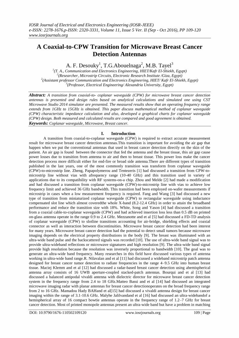
II. Coplanar Waveguide (Cpw) Design And Analysis Coplanar waveguide (CPW), [6] is used for transmission lines where all the conductors are in the same
plane; precisely, on the top surface of the dielectric substrate. Coplanar waveguide (CPW) is composed of a
median metallic strip separated by two narrow slits from a finite ground plane as shown in Fig.1.
Fig.1. CPW with finite dielectric thickness and finite width ground plane
Coplanar lines advantages arise from the fact that amounting lumped elements is much easier than
drilling holes to reach ground plane in other configurations. The performance of coplanar lines is comparable to
and sometimes even better than microstrip line in terms of guide wavelength, dispersion, and losses,[6].coplanar
waveguides are most promising because of their integration capability with electronic devices and fabrication
compatibility with ultra-large scale integration processing (ULSI), [7]. Active elements such as MESFETs can
easily be connected to coplanar lines because they are also coplanar in nature. So, coplanar lines are used
commonly in monolithic microwave integrated circuits (MMICs), [6]. Borah and Battacharyya [8] use coplanar
waveguides to determine the complex permittivity and loss tangent of nano magnetic composite materials over
X-band. There is no low-frequency cutoff because of the quasi-TEM mode of propagation. However, the RF
electric field between thecenter conducting strip and the ground electrodes tangential to the air dielectric
boundary produces a discontinuity in displacement current density at the interface, giving rise to an axial, as
well as transverse, component of RF magnetic field, Fig.2.
Fig.2. Electric and magnetic field distribution in CPW
There are various types of coplanar waveguides such as CPW with finite dielectric thickness, CPW with finite
width ground planes, CPW with a cover shield, conductor backed CPW with a cover shield, conductor-backed
CPW, multilayered CPW, asymmetric CPW and asymmetric CPW with finite dielectric thickness.For practical
use, CPW with finite dielectric thickness and finite ground plane width is used.
Fig.3. CPW geometry.

A Coaxial-to-CPW Transition for Microwave Breast Cancer Detection Antennas
DOI: 10.9790/1676-110502109120 www.iosrjournals.org 111 | Page
The characteristic impedance of the coplanar waveguide (CPW) transmission line is determined by a,
band Co as shown in Fig.3. The relative dielectric constant ϵr , the effective dielectric constant ϵreff , phase
velocityυph , and characteristic impedanceZocp , of a transmission line are given as, [5]
Where,Cis the speed of light in free space and K is the complete elliptical integral of the first kind, and
K (k) = K(k ) .A different values of a, b and Coare considered thencalculate Zocp iscalculated.The process is
repeated till the needed value of Zocp is obtained.Figure 4, shows the flow chart of the CPW impedance
calculation tohave the suitable value of Zocp that we need in our design

A Coaxial-to-CPW Transition for Microwave Breast Cancer Detection Antennas
DOI: 10.9790/1676-110502109120 www.iosrjournals.org 112 | Page
Fig. 4.The flow chart of the CPW impedance calculation
A MATLAB code has been built to calculate the characteristic impedance of CPW in terms of its
geometry. The proposed charts give a very fast way in the CPW design process. Figure 5.a shows that the
dimensions of a 50Ω CPW of a=1.0115 mm, b=1.2775 mm and Co=9.9775 mm are obtained. One can notice
that any other dimensions could be chosen for the 50 Ω CPW. Also, one can notice that effect of the ground
plane size on the impedance value, for example for the 50 Ω CPW with dimension a=1 mm the impedance value
is achieved with b=1.22 mm for Co=9.9775 mm. Also same impedance could be obtained for b=1.27 mm and
Co=7.4775 mm. Also for b=1.23 mm and Co=4.977531 mm same impedance could be obtained, Figs.5 b and c.
So, the developed charts add another degree of freedom to the designer to obtain same impedance but with
different geometries according to the antenna or circuit design situation.
(a)

A Coaxial-to-CPW Transition for Microwave Breast Cancer Detection Antennas
DOI: 10.9790/1676-110502109120 www.iosrjournals.org 113 | Page
(b)
(c)
Fig.5. CPW impedance (𝑍𝑜𝑐𝑝𝑓 ) charts (a) Co=9.9775 mm, (b) Co=7.4.775 mm, (c) Co=4.977531 mm and
𝜖𝑟=4.6.
The previous charts can calculate the dimension of the coplanar waveguide at a specific impedance
value. The code is repeated at different substrate materials with different relative dielectric constant. Figure 6,
Fig.7 and Fig.8 show 𝑍𝑜𝑐𝑝𝑓 charts for different values of Co . Table, 1 show that 50 Ω CPW different
dimensions at a = 0.95 mm.
Table 1. 50 Ω CPW dimensions at a = 0.95 mm. b (mm) 𝐜𝐨 (mm) 𝛜𝐫 1.171 9.9775 4.6
1.169 7.4775 4.6
1.165 4.977531 4.6
1.645 9.9775 10.2
1.64 7.4775 10.2
1.622 4.977531 10.2
1.295 9.9775 6.2
1.293 7.4775 6.2
1.286 4.977531 6.2
1.019 9.9775 2.2
1.018 7.4775 2.2
1.017 4.977531 2.2
(a)

A Coaxial-to-CPW Transition for Microwave Breast Cancer Detection Antennas
DOI: 10.9790/1676-110502109120 www.iosrjournals.org 114 | Page
(b)
(c)
Fig.6. CPW impedance (𝑍𝑜𝑐𝑝𝑓 ) charts (a) Co=9.9775 mm, (b) Co=7.4775 mm, (c) Co=4.977531 mm and
𝜖𝑟=10.2.
(a)
(b)

A Coaxial-to-CPW Transition for Microwave Breast Cancer Detection Antennas
DOI: 10.9790/1676-110502109120 www.iosrjournals.org 115 | Page
(c)
Fig.7. CPW impedance (𝑍𝑜𝑐𝑝𝑓 ) charts (a) Co=9.9775 mm, (b) Co=7.4.775 mm, (c) Co=4.977531 mm and
𝜖𝑟=6.2.
(a)
(b)
(c)
Fig.8. CPW impedance (𝑍𝑜𝑐𝑝𝑓 ) charts (a) Co=9.9775 mm, (b) Co=7.4.775 mm, (c) Co=4.977531 mm and
𝜖𝑟=2.2.

A Coaxial-to-CPW Transition for Microwave Breast Cancer Detection Antennas
DOI: 10.9790/1676-110502109120 www.iosrjournals.org 116 | Page
III. Cpw Proposed Structure, Design And Analysis To evaluate this approach, a FR4 substrate with relative permittivity 𝜖𝑟=4.6, dielectric thickness of 1.53
mm and loss tangent of 0.02 is used.A conventional CPW with a=1.0115 mm, b=1.2775 mm and Co=9.9775
mm is firstly, considered. A coaxial connector with impedance 50Ω is connected in the back of the substrate,the
coaxial inner connector is connected with the median strip of CPW and the coaxial ground with the outer strips
of the CPW, Fig.10.
(a) (b)
Fig.9. (a) Conventional CPW front side (b) ConventionalCPW backside
The transformation from coaxial line to CPW is simulated using CST Microwave Studio 2014
software, the S-parameters are shown in Fig.11.
1 2 3 4 5 6 7 8 9 10 11 12 13 14 15 16 17
-40
-35
-30
-25
-20
-15
-10
-5
0
5
S-Pa
ram
eter
s (dB
)
Frequency (GHz)
S11
S12
S21
S22
Fig.10. Simulated S-parameters of conventional CPW.
Figure 11 shows that the simulated S-parameters where the operating frequency band extends from 1
GHz to 10 GHz. A slits has been added to the proposed transition for matching purpose [18]. An improvement
of about 10 dB has been obtained. The proposed structure parameter and the parameter values are shown in
Fig.12 and Table 2.
Table 2. CPW parameter values

A Coaxial-to-CPW Transition for Microwave Breast Cancer Detection Antennas
DOI: 10.9790/1676-110502109120 www.iosrjournals.org 117 | Page
Fig.11.Proposed structure of CPW
Fig.12. Simulated proposed CPW (a) front side (b) backside.
Fig.13. Simulated S-parameter of the proposed transition.
Figure 14 shows that the simulated proposed transition S21P and S12P are almost the same. S11P and
S22P are different this due to different feeding schemes one is parallel to the CPW axe and the other is
perpendicular to it. Figure 15 show the simulated S-parameters of the conventional CPW and the proposed one.
It can be observed, that the return lossS11P of the proposed transition isbetter by 10 dB than the conventional
one S11Cand its band extends from 1 GHz to 15 GHz.
Fig.14. The simulated S-parameters of the conventional and the proposed transition.

A Coaxial-to-CPW Transition for Microwave Breast Cancer Detection Antennas
DOI: 10.9790/1676-110502109120 www.iosrjournals.org 118 | Page
Figures 16 a and b show the current distributions of the conventional and the proposed transition.
Fig.15. (a) Current distribution on conventional (b) Current distribution on proposed transition.
Figure 17 shows the fabricated proposed Coaxial-to-CPW transition from front side and from backside.
Figure 18 shows the measurement process of the Coaxial-to-CPW transition using Vector Network Analyzer
(VNA).
(a) (b)
Fig.16. Fabricated Coaxial-to-CPW transition (a) front side (b) backside.
Fig.17.Coaxial-to-CPW transition measurement setup.
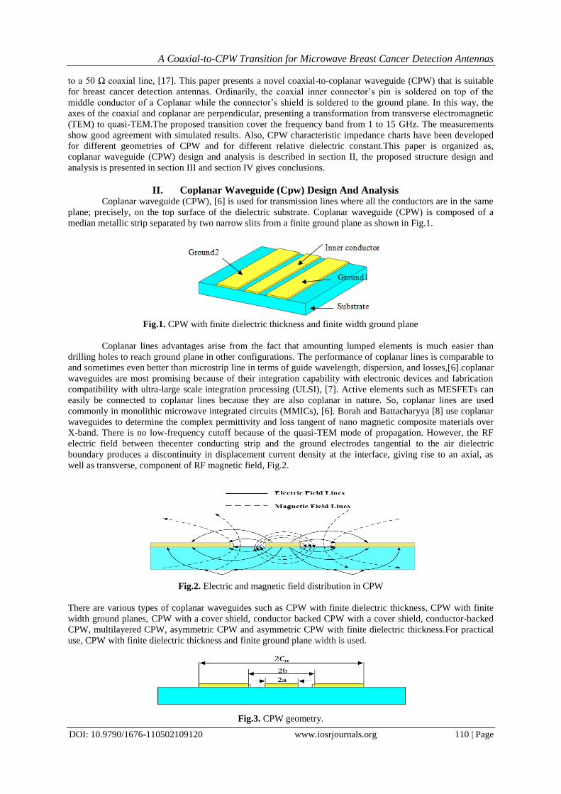
Figure 19 shows the measured and simulated return loss and insertion loss of the proposed Coaxial-to-
CPW transition. It can be observed, the bandwidth is extended from 1 to 15 GHz which agree well with the
simulated results and that’s a good result to have a successful transition from Coaxial cable-to-Coplanar
waveguide (CPW).
A Coaxial-to-CPW Transition for Microwave Breast Cancer Detection Antennas
DOI: 10.9790/1676-110502109120 www.iosrjournals.org 119 | Page
Fig.18. Measured and Simulated Return loss and Insertion loss of Coaxial-to-CPW transition
IV. Conclusion
A transition from coaxial-to-coplanar waveguide (CPW) for microwave breast cancer detection
antennas was presented and design rules based on analytical calculations and simulated one using CST
Microwave Studio 2014 simulator were presented. A design charts which add a degree of freedom to the CPW
was also proposed. The measured results show that an operating frequency range extends from 1 GHz to 15GHz
compared with the conventional CPW which extends from 1 GHz to 10 GHz was obtained. Also, an
enhancement of about 10 dB was obtained all over the frequency band. The proposed transition presents a good
start to any UWB antenna using a CPW as a feeding scheme.
Refernences [1] Guizhen Zheng, J. Papapolymerou, and M. M. Tentzeris, Wideband Coplanar Waveguide RF Probe Pad to Microstrip Transitions
without Via Holes, IEEE Microwave and Wireless Components Letters, Volume:13, Year: 2003, Pages:544 – 546
[2] Zhen Zhou, and Kathleen L. Melde, Development of a Broadband Coplanar Waveguide-to-Microstrip Transition with Vias,IEEE Transactions on Advanced Packaging, Volume:31, Year:2008,Pages:861 – 872.
[3] Ruei-Ying Fang, and Chun-Long Wang, Miniaturized Coplanar Waveguide to Rectangular Waveguide Transition Using
Inductance-Compensated Slotline,IEEE Transactions on Components, Packaging and Manufacturing Technology, Volume:2,Year:2012,Pages1666 – 1671.
[4] Carson R. White, Hyok J. Song, and Eray Yasan, A Wideband Stick-On Connector for CPW-Fed On-Glass Antennas ,IEEE
Antennas and Wireless Propagation Letters, Volume 9,Year: 2010, Pages: 171 – 174. [5] P. Mezzanotte, G. Pompei, L. Roselli and R. Sorrentino, FD-TD Analysis of Coplanar Waveguide to Slotline Transitions
Accounting for Air-Bridge, Shielding effects and Coaxial Connectors, IEEEMicrowave Conference, 24th European, Volume:
2,Year:1994, Pages: 1929 - 1932 [6] K.C.Gupta, Ramesh Garg, Inder Bahl and Parakash Bahratia ,Microstrip Lines and Slot Lines, Second Edition, Boston, London.
[7] B. Nataraj, and K. Porkumaran, CONFORMAL MAPPING ANALYSIS OF VARIOUS COPLANAR WAVEGUIDE
STRUCTURES, ICTACT Journal on Communication Technology, Volume: 3, Year:2012, Pages:532–535.
[8] S. Borah, and N. S. Bhattacharyya, Broadband measurement of complex permittivity of composite at microwave frequencies using
scalar scattering parameters, Progress In Electromagnetics Research M (PIER M), Volume: 13, Year: 2010, Pages: 53-68.
[9] E. C. Fear, P. M. Meaney, and M. A. Stuchly,Microwaves for breast cancer detection, IEEE Potentials,Volume: 22, Year: 2003,
Pages: 12 – 18.
[10] E. C. Fear, and M. A. Stuchly,Microwave detection of breast cancer,IEEE Transactions on Microwave Theory and Techniques,
Volume: 48, Year: 2000, Pages: 1854 – 1863. [11] R. Nilavalan,I. J. Craddock, A. Preece, J. Leendertz, and R. Benjamin ,Wideband microstrip patch antenna design for breast
cancer tumor detection,IET Microwaves, Antennas & Propagation, Volume: 1,Year: 2007, Pages: 277 – 281.
[12] Maciej Klemm, Ian J. Craddock, Jack A. Leendertz, Alan Preece, and Ralph Benjamin, Radar Based Breast Cancer Detection Using a Hemispherical Antenna Array-Experimental Results, IEEE Transactions on Antennas and Propagation, Volume: 57,Year:
2009, Pages: 1692 – 1704.
[13] Jeremie Bourqui,Michal Okoniewski and Elise C. Fear, Balanced Antipodal Vivaldi Antenna With Dielectric Director for NearFieldMicrowave Imaging, IEEE Transactions on Antennas and Propagation,Volume: 58, Year: 2010,Pages: 2318 – 2326.
[14] Matteo Bassi, Michele Caruso, Muhammad Saeed Khan, Andrea Bevilacqua, Antonio-Daniele Capobianco and Andrea Neviani, An
Integrated Microwave Imaging Radar With Planar Antennas for Breast Cancer Detection, IEEE Transactions on Microwave Theory and Techniques, Volume: 61, Year: 2013,Pages: 2108 – 2118.
[15] Mamadou Hady Bah, Jingsong Hong, Deedar Ali Jamrom, Jia Jun Liang, and Elisee A. Kponou, Vivaldi antenna and breast
phantom design for breast cancer imaging,2014 7th International Conference on Biomedical Engineering and Informatics,Year: 2014,Pages: 90 – 93.
[16] Malyhe Jalilvand, Xuyang Li, Lukasz Zwirello, and Thomas Zwick, Ultra wideband compact near-field imaging system for
breast cancer detection, IET Microwaves, Antennas & Propagation, Volume: 9,Year: 2015, Pages: 1009 – 1014. [17] Müzeyyen Karamanoğlu, Mehmet Abbak, Serkan Şimşek, A simple and compactCPW-fed UWB printed monopole antenna with
defected ground structures, IEEE Electrical and Electronics Engineering (ELECO), 2013 8th International Conference onYear:
2013,Pages: 443 – 447. [18] K. Kumar, and N. Gunasekaran, A Novel Wideband Slotted mm wave Microstrip Patch Antenna, IEEE, Signal Processing,
Communication, Computing and Networking Technologies (ICSCCN), 2011 International Conference on Year: 2011, Pages: 10 –
14.

A Coaxial-to-CPW Transition for Microwave Breast Cancer Detection Antennas
DOI: 10.9790/1676-110502109120 www.iosrjournals.org 120 | Page
Author Bibliography Asmaa Fereg Desoukey is a Post Graduate Student (master), Alexandria University, Egypt. She was born in
Kafer El-Shiekh, Egypt on August, 1989. She is a demonstrator at Higher Institute of
Engineering and Technology (HIET) in Kafer El-Shiekh, Egypt.
Tamer ABOUELNAGA was born in 1976. He received his M.Sc. and his Ph.D. in 2007 and 2012 from Ain
Shams University respectively. His research interests include antennas, microstrip circuit
components and RFID system components.
Mazhar B. Tayel was born in Alexandria, Egypt on Nov. 20th, 1939. He was graduated from Alexandria
University Faculty of Engineering Electrical and Electronics department class 1963. He
published many papers and books in electronics, biomedical, and measurements. Prof. Dr.
Mazhar Basyouni Tayel had his B.Sc. with honor degree in 1963, and then he had his Ph.D.
Electro-physics degree in 1970. He had this Prof. Degree of elect. And communication and
Biomedical Engineering and systems in 1980. Now he is Emeritus Professor since 1999. From
1987 to 1991 he worked as a chairman, communication engineering section, EED BAU-
Lebanon and from 1991 to 1995 he worked as Chairman, Communication Engineering Section, EED
Alexandria. University, Alexandria Egypt, and from 1995 to 1996 he worked as a chairman, EED, Faculty of
Engineering, BAU-Lebanon, and from 1996 to 1997 he worked as the dean, Faculty of Engineering, BAU -
Lebanon, and from 1999 to 2009 he worked as a senior prof., Faculty of Engineering, Alexandria. University,
Alexandria Egypt, finally from 2009 to now he worked as Emeritus Professor, Faculty of Engineering,
Alexandria University, Alexandria Egypt. Prof. Dr. Tayel worked as a general consultant in many companies
and factories also he is Member in supreme consul of Egypt. E.Prof. Mazhar Basyouni Tayel.


![A Compact Ultra Wideband CPW-Fed Circular Polarized Slot ... · waveguide type, coaxial, and microstrip are the deferent technical feeding structures in UWB antennas [4]. The coplanar](https://img.pdfslide.net/doc/110x75/5e945e8f1e74497797241759/a-compact-ultra-wideband-cpw-fed-circular-polarized-slot-waveguide-type-coaxial.jpg)