Embed Size (px)
Citation preview
BarcelonaTech
Departament de Projectes d'Enginyeria
Escola Tècnica Superior d'Enginyeria Industrial de Barcelona
Projectes d'Innovació Tecnològica en l'Enginyeria de Producte i Procés
A Collection of Resources for the Study of Educational Reverse Engineering Activities in
Engineering Design Education
Una tesi presentada per a obtenir el grau de
Doctor per la Universitat Politècnica de Catalunya
Presentat Per
Marco Lino Calderón Saldierna
Doctorand
Director de Tesi
Prof. Dr. Ing. Joaquim Lloveras Macià
Octubre 2015 Barcelona, Espanya

2
This page intentionally left blank

3
Acta de qualificació de tesi doctoral Curs acadèmic: 2015 - 2016 Nom i cognoms
Marco Lino Calderón Saldierna Programa de doctorat
Proyectos de Innovación Tecnológica en la Ingeniería de Producto y Proceso
Unitat estructural responsable del programa
Proyectos de Ingeniería
Resolució del Tribunal Reunit el Tribunal designat a l'efecte, el doctorand / la doctoranda exposa el tema de la seva tesi doctoral
titulada A Collection of Resources for the Study of Educational Reverse Engineering Activities in Engineering
Design Education
Acabada la lectura i després de donar resposta a les qüestions formulades pels membres titulars del tribunal,
aquest atorga la qualificació:
NO APTE APROVAT NOTABLE EXCEL·LENT
(Nom, cognoms i signatura) President/a
(Nom, cognoms i signatura) Secretari/ària
(Nom, cognoms i signatura) Vocal
(Nom, cognoms i signatura) Vocal
(Nom, cognoms i signatura) Vocal
______________________, _______ d'/de __________________ de _______________
El resultat de l’escrutini dels vots emesos pels membres titulars del tribunal, efectuat per l’Escola de
Doctorat, a instància de la Comissió de Doctorat de la UPC, atorga la MENCIÓ CUM LAUDE:
SÍ NO
(Nom, cognoms i signatura) President de la Comissió Permanent de l’Escola de Doctorat
(Nom, cognoms i signatura) Secretari de la Comissió Permanent de l’Escola de Doctorat
Barcelona, _______ d'/de ____________________ de _________
Diligència “Internacional del títol de doctor o doctora”
• Com a secretari/ària del tribunal faig constar que la tesi s’ha defensat en part, i com a mínim pel
que fa al resum i les conclusions, en una de les llengües habituals per a la comunicació científica en
el seu camp de coneixement i diferent de les que són oficials a Espanya. Aquesta norma no s’aplica
si l’estada, els informes i els experts provenen d’un país de parla hispana.
(Nom, cognoms i signatura) Secretari/ària del Tribunal

4
This page intentionally left blank

5
DEDICATION
A Dios
A mi familia y amigos por el apoyo incondicional a través de los años
Marco Lino Calderón Saldierna

6
This page intentionally left blank
7
ACKNOWLEDGEMENTS
This doctoral research was funded with a grant from Mexico’s National Council on
Science and Technology (CONACYT) and was only possible thanks to the guidance and
support from my thesis supervisor Prof. Dr. Ing. Joaquim Lloveras Macià and from the
academic staff at the Technical University of Catalonia in Barcelona.
My deepest gratitude goes to the reviewers of this dissertation Prof. Dr. Eduardo Héctor
Calvillo Gámez founder of Startup Lab MX and founder and president of the Mexican
Association of Human Computer Interaction; Prof. Dr. Homero Miranda Vidales from the
Faculty of Engineering of the Autonomous University of San Luis Potosí (UASLP), and
Prof. Dr. Guillermo Urriolagoitia from the Faculty of Mechanical and Electrical Engineering
of the National Polytechnic Institute (IPN) for their meaningful insight and fruitful advice
towards the success of it.
A special acknowledgement goes to Univ.-Prof. Dr.-Ing. Christian Weber and the
academic staff of the Engineering Design Department of the Faculty of Mechanical
Engineering at the Technical University of Ilmenau in Germany for accepting me as a
visiting doctoral researcher where on-site training and support were given to develop the
ideas presented in this dissertation.
My earnest gratitude also goes to professors Lucienne Blessing; Mogens M. Andreasen
M. and Christian Weber of the 2009 edition of the European Summer School on
Engineering Design Research for the counselling given for the development of this
project and where I had the opportunity to learn first-hand about the research
methodology followed in this dissertation.
Last but not least I’d like to express my gratitude to Dr. Aida Salazar Garcia; Dr. Juan
Daniel Castillo, Prof. Mario A. Hernandez, and also to all of the evaluators of the
intermediate results from this research at varied academic institutions across Europe.
Marco Lino Calderón Saldierna
Barcelona, Spain
October 2015

8
This page intentionally left blank
9
ABOUT THE UNIVERSITY
The School of Engineering of Barcelona was created in 1851. In 1971 it merged with
other schools of engineering and architecture to form the Universitat Politècnica de
Catalunya (UPC) and what is now the School of Industrial Engineering of Barcelona
(ETSEIB) which combines its long-standing tradition with its endeavours to bring about
renewal and continuous improvement; this has made it one of the best schools of
engineering in Spain and it enjoys an excellent reputation on the international stage. The
school has close ties with industry, the financial sector and local businesses (e.g. Seat,
Nissan, and HP) which contribute towards its efforts to secure international outreach and
recognition. The research, technology, and knowledge transfer activities that the school’s
departments; research centres, and groups carry out have made it a pioneer in many
fields of science and technology which in turn has favoured its extensive involvement with
the industrial sector.

10
This page intentionally left blank
11
ABOUT THE AUTHOR
My name is Marco Lino Calderón Saldierna, I am a Mexican national with a doctoral
research grant from Mexico’s National Council on Science and Technology (CONACYT);
I hold a degree in Electronics Engineering from the San Luis Potosi Institute of
Technology in Mexico (ITSLP:2000) and a MBA from the Hochschule für Technik und
Wirtschaft Berlin in Germany (HTW Berlin:2005). I’ve been the recipient of research
grants by foreign governments such as (JICA - Japan:2003) and (ITEC India:2004) to
attend specialization courses abroad, and I’ve had industrial working experience in the
companies General Electric (GE:2000-2003) and Honeywell (HON:2006), as well as
teaching experience at the Polytechnic University of San Luis Potosi in Mexico
(UPSLP:2006-2007).
Apart from the contents in this doctoral dissertation, the following five peer-reviewed
conference papers were also presented at relevant conferences across Europe:
• Product Visualization Praxis and its Integration to Academic Curricula, [Calderon.
2008]
• Analysis of Existing Products as a Tool for Engineering Design Education, [Calderon.
2009]
• Application of Reverse Engineering Activities in the Teaching of Engineering Design,
[Calderon. 2010a]
• A Comparison of Competences Required in Reverse Engineering Exercises Versus
Conventional Engineering Exercises and its Relationship to IPMA’s Competence
Baseline, [Calderon. 2010b]
• The Design Research Methodology as a Framework for the Development of a Tool for
Engineering Design Education, [Calderon. 2010c]
Additionally, a work report was submitted to the Engineering Design Department of the
Faculty of Mechanical Engineering at the Technical University of Ilmenau in Germany
after being accepted for a three-month visiting internship in 2010.

12
This page intentionally left blank
13
RESUM
Les Activitats Educatives d'Enginyeria Inversa "AEII" també conegudes com "EREA" pel
seu acrònim en anglès ajuden els estudiants d'enginyeria de disseny a: Adquirir i
desenvolupar un conjunt d'habilitats que eleven el seu coneixement del procés de
disseny; expandir les seves fonts d'inspiració, situar les seves accions dins el cicle de
vida d'un producte, i transformar coneixement teòric en pràctic. No obstant això, es va
detectar que tot i que aquestes activitats despertaven l’ interès dels professors de l'àrea
d'enginyeria de disseny elles estaven o absents dels típics programes d'enginyeria de
disseny o no explotades en la seva totalitat.
Després d'analitzar les causes d'això i determinar que la creació d'una col·lecció de
recursos per a l'estudi de les activitats educatives d'enginyeria de disseny en l’àrea de
l'ensenyament de l'enginyeria de disseny era la millor manera d'accedir a un grup
geogràficament dispers i així començar a intentar canviar la situació de recerca existent ,
el desenvolupament d'aquests recursos va començar amb la meta d'atendre tantes
inquietuds com fos possible, de les trobades sempre que s'intentava implementar "AEII"
en programes existents d'enginyeria de disseny.
Els continguts seleccionats per a formar part de la col·lecció de recursos, van ser definits
en base a converses inicials d'exploració amb experts en l'acadèmia i la indústria; sobre
la base de la retroalimentació rebuda dels articles en conferència avaluats per parells
procedents d'aquesta recerca doctoral, i de la presentació de resultats als revisors
preliminars d'aquest projecte; per tals raons, la informació presentada en els diferents
recursos està dirigida a instructors per primera vegada (o principiants) d'activitats
d'enginyeria inversa i prenen en compte no només les consideracions tècniques sinó
també les pedagògiques i administratives involucrades en l'estudi d'activitats
acadèmiques i la seva potencial incorporació a un programa existent en enginyeria de
disseny.
Atès que certa informació rellevant al tema de recerca ja existia però estava dispersa
entre diverses àrees del coneixement; en comptes de desenvolupar tots els temes des
de zero novament, es va realitzar un esforç conscient per examinar la literatura existent i
consultar amb experts en el tema per així integrar i contextualitzar tota la informació
disponible en un estudi coherent que pogués ser complementat amb els resultats
originals produïts per aquesta investigació.
Les seccions principals que comprenen la col·lecció de recursos s'enumera a
continuació:
14
• Recurs 1: Fonaments de les Activitats Educatives d'Enginyeria Inversa
• Recurs 2: Enginyeria Inversa i Aprenentatge
• Recurs 3: Interpretacions equívoques sobre l'Enginyeria Inversa
• Recurs 4: Beneficis de l'Enginyeria Inversa
• Recurs 5: Una Proposta de Metodologia per Utilitzar Anàlisi d'Enginyeria Inversa a
l'Ensenyament de l'Enginyeria de Disseny
• Recurs 6: Una Proposta de Pedagogia per a l'Ensenyament d'Activitats Educatives
d'Enginyeria Inversa
• Recurs 7: Exemple d'una Activitat Educativa d'Enginyeria Inversa en una càmera
fotogràfica d’un sol ús
• Recurs 8: Conclusions i Apunts Finals
• Recurs 9: Recursos Diversos per a l'Estudi de l'Enginyeria Inversa
Els recursos van ser escrits utilitzant la metodologia "DRM" per a la investigació en l'àrea
d'enginyeria de disseny i es va contactar a diverses institucions acadèmiques per saber
del seu interès en aquests recursos, al final 12 institucions al Regne Unit; Irlanda,
França, Dinamarca i Alemanya van mostrar el seu interès en el projecte i van accedir a
rebre el document, ajudant així a complir una de les metes principals d'aquesta
investigació que va ser difondre els resultats entre estudiosos de l'enginyeria inversa
educativa. 5 articles en conferència també poden ser comptats com a resultat d'aquesta
investigació.
Paraules Clau: Activitats educatives d'Enginyeria Inversa; ensenyament de l'enginyeria
de disseny, habilitats de l'estudiant, materials d'ensenyament.
Codis UNESCO: 580101, 580103, 580107, 61042
15
ABSTRACT
Educational Reverse Engineering Activities referred to as the acronym “EREA” help
engineering design students to: Acquire and develop a set of abilities that raise their
awareness of the design process; expand their sources of inspiration, position their
actions within the lifecycle of a product, and transform theoretical knowledge into
practice. However, it was detected that although such activities sparked interest among
engineering design educators, they were either absent from typical engineering design
curricula or were not fully exploited.
After analysing the causes for it and determining that the creation of a collection of
resources for the study of educational reverse engineering activities in the area of
engineering design education was the best way to reach a geographically dispersed
community and thus start trying to change the existing research situation, the
development of such resources began with the goal to address as many of the concerns
as possible found whenever trying to implement EREA into existing engineering design
curricula.
The contents selected for inclusion in the collection of resources then, were derived
based on initial exploratory discussions with experts in academia and industry; from the
feedback received from peer reviewed conference papers stemming from this doctoral
research, and from the presentation of intermediate results to early reviewers of this
project; for such reasons, the information presented in the different resources target first
time (or novice) instructors of reverse engineering activities and takes into account not
only the technical but also the pedagogical and administrative considerations implicated
in the study of academic activities and their potential introduction into an existing
engineering design curriculum.
Given that some relevant information about the topic already existed but it was dispersed
across different areas of knowledge; rather than developing all topics from scratch again,
a conscious effort was made to examine published literature and to consult with domain
experts to integrate and contextualise all existing information into a coherent body that
could be complemented with the original results originating from this project.
The major sections comprising the collection of resources then, are listed below:
• Resource 1: Fundamentals of Educational Reverse Engineering Activities
• Resource 2: Reverse Engineering and Learning
16
• Resource 3: Misconceptions about Reverse Engineering
• Resource 4: Benefits of Reverse Engineering
• Resource 5: A Proposed Methodology for Reverse Engineering Analysis in Engineering
Design Education
• Resource 6: A Suggested Pedagogy for the Teaching of Educational Reverse
Engineering Activities
• Resource 7: Integrated Example of an Educational Reverse Engineering Activity on a
Disposable Camera
• Resource 8: Conclusions and Final Remarks
• Resource 9: Miscellaneous Resources for the Study of Reverse Engineering
The abovementioned resources were of a self-contained nature, could be read either
individually or sequentially, and were written using the “DRM” framework for research in
the area of engineering design. Once finished, a number of academic institutions were
contacted to measure their interest in the resources and in the end 12 different ones in
the United Kingdom, Ireland, France, Denmark and Germany showed their interest in the
research project and agreed to receive the document for reading thus helping fulfil one of
the main goals of this research which was to disseminate the results from it. Other results
from this project include five peer-reviewed conference papers, and a report presented at
the Technical University of Ilmenau in Germany after spending a visiting internship
abroad to learn about similar approaches to the research into reverse engineering by
other schools and traditions of design.
Keywords: Educational reverse engineering activities; engineering design education,
student’s abilities, instructional materials.
UNESCO Codes: 580101, 580103, 580107, 61042
17
RESUMEN
Las Actividades Educativas de Ingeniería Inversa “AEII” o conocidas como “EREA” por
su acrónimo en inglés ayudan a los estudiantes de ingeniería de diseño a: Adquirir y
desarrollar un conjunto de habilidades que elevan su conocimiento del proceso de
diseño; expandir sus fuentes de inspiración, situar sus acciones dentro del ciclo de vida
de un producto, y transformar conocimiento teórico en practico. Sin embargo, se detectó
que a pesar de que tales actividades despertaban el interés de los profesores del área
de ingeniería de diseño ellas estaban o ausentes de los típicos programas de ingeniería
de diseño o no explotadas en su totalidad.
Después de analizar las causas de ello y determinar que la creación de una colección de
recursos para el estudio de las actividades educativas de ingeniería de diseño en el área
de la enseñanza de la ingeniería de diseño era la mejor forma de acceder a un grupo
geográficamente disperso y así empezar a intentar cambiar la situación de investigación
existente, el desarrollo de tales recursos empezó con la meta de atender tantas
inquietudes como fuera posible, de las encontradas siempre que se intentaba
implementar “AEII” en programas existentes de ingeniería de diseño.
Los contenidos seleccionados para formar parte de la colección de recursos, fueron
definidos en base a conversaciones iniciales de exploración con expertos en la academia
y la industria; en base a la retroalimentación recibida de los artículos en conferencia
evaluados por pares procedentes de esta investigación doctoral, y de la presentación de
resultados preliminares a los revisores preliminares de este proyecto; por tales razones,
la información presentada en los diferentes recursos están dirigidos a instructores por
primera vez (o principiantes) de actividades de ingeniería inversa y toman en cuenta no
solo las consideraciones técnicas sino también las pedagógicas y administrativas
involucradas en el estudio de actividades académicas y su potencial incorporación a un
programa existente en ingeniería de diseño.
Dado que cierta información relevante al tema de investigación ya existía pero estaba
dispersa entre varias áreas del conocimiento; en vez de desarrollar todos los temas
desde cero nuevamente, se realizó un esfuerzo consciente para examinar la literatura
existente y consultar con expertos en el tema para así integrar y contextualizar toda la
información disponible en un estudio coherente que pudiera ser complementado con los
resultados originales producidos por esta investigación.
Las secciones principales que comprenden la colección de recursos se enumera a
continuación:

18
• Recurso 1: Fundamentos de las Actividades Educativas de Ingeniería Inversa
• Recurso 2: Ingeniería Inversa y Aprendizaje
• Recurso 3: Interpretaciones Equívocas acerca de la Ingeniería Inversa
• Recurso 4: Beneficios de la Ingeniería Inversa
• Recurso 5: Una Propuesta de Metodología para Utilizar Análisis de Ingeniería Inversa
en la Enseñanza de la Ingeniería de Diseño
• Recurso 6: Una Propuesta de Pedagogía para la Enseñanza de Actividades
Educativas de Ingeniería Inversa
• Recurso 7: Ejemplo de una Actividad Educativa de Ingeniería Inversa en una Cámara
Desechable
• Recurso 8: Conclusiones y Apuntes Finales
• Recurso 9: Recursos Diversos para el Estudio de la Ingeniería Inversa
Los recursos fueron escritos utilizando la metodología “DRM” para la investigación en el
área de ingeniería de diseño y se contactó a diversas instituciones académicas para
saber de su interés en tales recursos, al final 12 instituciones en el Reino Unido; Irlanda,
Francia, Dinamarca y Alemania mostraron su interés en el proyecto y accedieron a recibir
el documento, ayudando así a cumplir una de las metas principales de esta investigación
que fue difundir sus resultados entre estudiosos de la ingeniería inversa educativa. Entre
los resultado adicionales a esta tesis doctoral también se incluyen cinco artículos en
conferencia revisados por pares, y un informe de trabajo presentado en la Universidad
Técnica de Ilmenau en Alemania después de ser aceptado como investigador doctoral
visitante para aprender sobre los diferente enfoques hacia la investigación de la
ingeniería inversa por parte de otras escuelas y tradiciones de diseño.
Palabras Clave: Actividades educativas de Ingeniería Inversa; enseñanza de la
ingeniería de diseño, habilidades del estudiante, materiales de enseñanza.
Códigos UNESCO: 580101, 580103, 580107, 61042
19
INDEX
Page
DEDICATION ......................................................................................................................... 5
ACKNOWLEDGEMENTS ...................................................................................................... 7
ABOUT THE UNIVERSITY .................................................................................................... 9
ABOUT THE AUTHOR ........................................................................................................ 11
RESUM ................................................................................................................................ 13
ABSTRACT ......................................................................................................................... 15
RESUMEN ........................................................................................................................... 17
INDEX .................................................................................................................................. 19
LIST OF TABLES ................................................................................................................ 23
LIST OF FIGURES .............................................................................................................. 25
GLOSSARY ......................................................................................................................... 29
PREFACE ............................................................................................................................ 31
CHAPTER 1 INTRODUCTION............................................................................................. 35
1.1 Introduction to the Research Topic ...................................................................................... 35
1.2 Research Specifics ................................................................................................................. 37
1.2.1 Research Problem Statement ........................................................................................ 37
1.2.1.1 Research Situation .................................................................................................. 37
1.2.2 Research Approach ........................................................................................................ 38
1.2.3 The Research Questions ................................................................................................. 39
1.2.4 The Research Hypotheses .............................................................................................. 40
1.2.5 General Research Objective ........................................................................................... 42
1.2.5.1 Specific Research Objectives ................................................................................... 42
1.2.6 Research Scope .............................................................................................................. 43
1.2.6.1 Research Focus ........................................................................................................ 44
1.2.7 Research Justification ..................................................................................................... 44
1.2.8 Research Assumptions ................................................................................................... 45
1.2.9 Expected Research Results ............................................................................................. 45
1.3 Chapter Conclusions .............................................................................................................. 45
CHAPTER 2 THE RESEARCH METHODOLOGY ............................................................... 47
2.1 Chapter Introduction ............................................................................................................. 47
2.2 “DRM” A Design Research Methodology .............................................................................. 48
20
2.2.1 Objectives and Benefits of Using “DRM” ....................................................................... 48
2.2.2 General Overview of the “DRM” Framework ................................................................ 49
2.2.3 Possible Research Types According to the DRM Framework ......................................... 50
2.3 Deliverables from the DRM Framework ............................................................................... 51
2.3.1 Deliverables from the Research Clarification Stage ....................................................... 51
2.3.1.1 The Initial Reference Model .................................................................................... 52
2.3.1.2 The Initial Impact Model ......................................................................................... 53
2.3.1.3 Areas of Relevance and Contribution “ARC” Diagram ............................................ 56
2.3.1.4 Summarised Work Schedule ................................................................................... 56
2.3.2 Deliverables from the Descriptive Study I Stage ............................................................ 57
2.3.2.1 The Completed Reference Model ........................................................................... 58
2.3.2.2 The Updated Initial Impact Model .......................................................................... 59
2.3.2.3 Clarification of the Area under Study and of the Relevance of the Research Results ............................................................................................................................................. 61
2.3.2.3.1 Engineering Design Education under Design Research .................................... 61
2.3.2.3.2 Education as a Research Topic in Design ......................................................... 62
2.3.2.4 Data Collection and Research Methods .................................................................. 63
2.3.2.5 Implications for the Development / Evaluation of the Support Tool ..................... 66
2.2.5.5.1 Determined Requirements Lists for the Support Tool ..................................... 66
2.2.5.5.2 Analysis of Concepts and Variants for the Support Tool ................................. 67
2.3.2.6 Expected Research Deliverables ............................................................................. 69
2.3.3 Deliverables from the Prescriptive Study Stage ............................................................. 70
2.3.3.1 Analysis of Objectives and Requirements ............................................................... 70
2.3.3.2 Development of the Support Tool in Relation to the Development of the whole Doctoral Research ............................................................................................................... 71
2.3.3.2.1 Use of the Term “A Collection of Resources” .................................................. 71
2.3.3.2.2 Description of the Collection of Resources ...................................................... 72
2.3.3.2.3 Justification for the Development of a Collection of Resources ...................... 72
2.3.3.2.4 General Goal of the Collection of Resources ................................................... 72
2.3.3.2.5 Specific Goals of the Collection of Resources .................................................. 72
2.3.3.2.6 Added Value of the Collection of Resources .................................................... 73
2.3.3.2.7 Expectations from the Collection of Resources ............................................... 73
2.3.3.2.8 Description of the Collection of Resources and its Contents ........................... 73
2.3.3.2.9 Specific Area of Support of the Guiding Manual in Regard to the Resources Available for its Development ......................................................................................... 75
21
2.3.3.2.10 Scope and Assumptions of the Collection of Resources ................................ 76
2.3.3.2.11 Underlying Assumptions Considered for the Success of the Support Tool ... 82
2.3.4 Deliverables from the Descriptive Study II Stage ........................................................... 83
2.3.4.1 Account of the Development of the Collection of Resources ................................. 83
2.3.4.2 Provisions to Avoid Unexpected Outcomes and Ensure the Success of the Support Tool ...................................................................................................................................... 84
2.3.4.3 Major Items to Test in the Support Tool ................................................................. 85
2.3.4.4 Research Plan and Methodology for the Testing of the Research’s Hypotheses ... 85
2.3.4.4.1 Recipients of the Guiding Manual .................................................................... 86
2.3.4.4.2 Demographics of the Recipients of the Guiding Manual ................................. 86
2.3.4.5 Challenges in the Development of the Support Tool .............................................. 88
2.4 Chapter Conclusions .............................................................................................................. 89
3 CHAPTER 3 RESEARCH RESULTS ............................................................................... 91
3.1 Chapter Introduction ............................................................................................................. 91
3.2 Major Results ........................................................................................................................ 91
3.2.1 The Collection of Resources for the Study of Educational Reverse Engineering Activities in Engineering Design Education ............................................................................................. 91
3.2.1.1 Summary of Resource 1: Fundamentals of Educational Reverse Engineering Activities. ............................................................................................................................. 91
3.2.1.2 Summary of Resource 2: Reverse Engineering and Learning. ................................ 91
3.2.1.3 Summary of Resource 3: Misconceptions about Reverse Engineering. ................. 92
3.2.1.4 Summary of Resource 4: Benefits of Reverse Engineering. .................................... 92
3.2.1.5 Summary of Resource 5: A Proposed Methodology for Reverse Engineering Analysis in Engineering Design Education. .......................................................................... 92
3.2.1.6 Summary of Resource 6: A Suggested Pedagogy for the Teaching of Educational Reverse Engineering Activities. ........................................................................................... 92
3.2.1.7 Summary of Resource 7: Integrated Example of an Educational Reverse Engineering Activity on a Disposable Camera. .................................................................... 92
3.2.1.8 Summary of Resource 8: Conclusions and Final Remarks. ...................................... 93
3.2.1.9 Summary of Resource 9: Miscellaneous Resources for the Study of Reverse Engineering. ........................................................................................................................ 93
3.3 Published Results from this Dissertation .............................................................................. 93
3.4 Measurements against Bias in the Research Results ............................................................ 95
3.4.1 Validity and Verification of the Findings and Results from this Research ..................... 96
3.4.2 Reflective Questions before Communicating Research Results .................................... 97
3.5 Plans for the Dissemination of Research Results .................................................................. 98
22
3.6 Chapter Conclusions .............................................................................................................. 98
CHAPTER 4 RESEARCH CONCLUSIONS AND FINAL REMARKS ................................ 101
4.1 Chapter Introduction ........................................................................................................... 101
4.2 Attainment of the Expected Outcomes of the Research .................................................... 101
4.1.1 Answer to the Research Questions .............................................................................. 101
4.1.2. Validation of Research Hypotheses ............................................................................ 107
4.1.3 Assessment of Initial Research Assumptions ............................................................... 110
4.1.4 Attainment of the General and Specific Research Objectives ..................................... 111
4.3 Specifics of the Doctoral Research ...................................................................................... 111
4.2.1 Type (Applied Research) .............................................................................................. 111
4.2.2 Academic Relevance .................................................................................................... 112
4.2.3 Novelty ......................................................................................................................... 112
4.2.4 Original Contributions to the Body of Knowledge of the Topic ................................... 113
4.2.3 Applicability of Research Results to Varied Academic Institutions .............................. 113
4.2.4 Challenges Faced .......................................................................................................... 114
4.3 General Conclusions ............................................................................................................ 115
4.3.1 Present of Reverse Engineering Activities in Engineering Design Education ............... 115
4.3.2 Future of Reverse Engineering Activities in Engineering Design Education ................ 117
4.3.2.1 Other Authors’ Views on the Future of Educational Reverse Engineering and Similar Activities ................................................................................................................ 121
4.4 Specific Conclusions ............................................................................................................ 122
4.4.1 Use of EREA in Engineering Design Education ............................................................. 122
4.4.2 Teaching Approach of EREA ......................................................................................... 122
4.4.3. Conclusions regarding the use of the DRM Framework ............................................. 122
4.5. Expectations ....................................................................................................................... 123
4.6 Future work and Self-critique ............................................................................................. 124
4.7 Final Remarks ...................................................................................................................... 125
REFERENCES .................................................................................................................. 127
ANNEX A A COLLECTION OF RESOURCES FOR THE STUDY OF EREA IN ENGINERING DESIGN EDUCATION ................................................................................ 135
23
LIST OF TABLES
Page
Table 2.1 Types of Design Research Projects and Their Main Focus (Iterations Omitted), Source: [Blessing & Chakrabarti. 2009] ................................................................................ 50
Table 2.2 Summarised Work Schedule ................................................................................ 57
Table 2.3 Archer’s ten Fields of Design, After: [Archer. 1981] .............................................. 62
Table 2.4 Question-Method Matrix for Data Collection and Research Methods .................... 65
Table 2.5 Methods used in this Research for Synthesizing Support Proposals .................... 68
Table 2.6 Analysis of Concepts and Variants of Support Tool Candidates ........................... 68
Table 2.7 Methods Used for Analysing Objectives and Establishing Requirements ............. 71
Table 2.8 Scope and Assumptions of the Collection of Resources ....................................... 82
Table 2.9 Recipients of the Support Tool ............................................................................. 88
Table 3.1 Suitability Rankings of Existing Studies about Competences and their Relation to EREA, After: [Calderon. 2010b] ........................................................................................ 95
Table 4.1 Potential Research Lines in Educational Reverse Engineering ........................... 121

24
This page intentionally left blank
25
LIST OF FIGURES
Page
Figure 1.1 The Doctoral Research’s Questions .................................................................... 39
Figure 1.2 The Research’s Hypotheses ............................................................................... 41
Figure 2.1 DRM Framework: Stages, Basic Means, and Deliverables, [Blessing & Chakrabarti. 2009]................................................................................................................ 49
Figure 2.2 The Initial Reference Model, as Published in [Calderon. 2010a] .......................... 53
Figure 2.3 Initial Impact Model ............................................................................................. 55
Figure 2.4 Diagram of Areas of Relevance and Contribution, as published in: [Calderon. 2010a] .................................................................................................................................. 56
Figure 2.5 The Completed Reference Model, After [Calderon. 2010c].................................. 59
Figure 2.6 The Updated Impact Model ................................................................................. 60
Figure 2.7 Research in Design Knowledge, Source: [Horváth.2004] .................................... 63
Figure 2.8 Schematic View of the area in which the Collection of Resources should Function, After: [Verschuren. 1997] and [Blessing & Chakrabarti. 2009] .............................. 75
Figure 2.9 Core Contribution in Relation to Intended and Actual Support, Source: [Blessing & Chakrabarti. 2009] ............................................................................................. 76
Figure 4.1 Research Questions against Impacted Stages of the DRM Framework............. 102
Figure 4.2 Doctoral Research’s Hypotheses against Impacted Stages of the DRM Framework ......................................................................................................................... 108

26
This page intentionally left blank
27
INDEX OF ANNEX A
Page (Numbering relative to its own section)
COPYRIGHT AND ATTRIBUTION POLICY .......................................................................... 3
INDEX .................................................................................................................................... 5
LIST OF TABLES ................................................................................................................ 15
LIST OF FIGURES .............................................................................................................. 19
PREFACE ............................................................................................................................ 23
INTRODUCTION ................................................................................................................. 25
RESOURCE 1: FUNDAMENTALS OF EDUCATIONAL REVERSE ENGINEERING ACTIVITIES ......................................................................................................................... 29
RESOURCE 2: REVERSE ENGINEERING AND LEARNING ............................................. 75
RESOURCE 3: MISCONCEPTIONS ABOUT REVERSE ENGINEERING .......................... 99
RESOURCE 4: BENEFITS OF REVERSE ENGINEERING ............................................... 123
RESOURCE 5: A PROPOSED METHODOLOGY FOR REVERSE ENGINEERING ANALYSIS IN ENGINEERING DESIGN EDUCATION ...................................................... 147
RESOURCE 6: A SUGGESTED PEDAGOGY FOR THE TEACHING OF EDUCATIONAL REVERSE ENGINEERING ACTIVITIES ................................................. 203
RESOURCE 7: INTEGRATED EXAMPLE OF AN EDUCATIONAL REVERSE ENGINEERING ACTIVITY ON A DISPOSABLE CAMERA ............................................... 331
RESOURCE 8: CONCLUSIONS AND FINAL REMARKS ................................................. 407
RESOURCE 9: MISCELLANEOUS RESOURCES FOR THE STUDY OF EDUCATIONAL REVERSE ENGINEERING ..................................................................... 415
GLOSSARY ....................................................................................................................... 431
ACKNOWLEDGMENTS .................................................................................................... 433
REFERENCES .................................................................................................................. 435
BACK COVER ................................................................................................................... 464
*Unless otherwise stated all Tables / Figures were created by the author

28
This page intentionally left blank
29
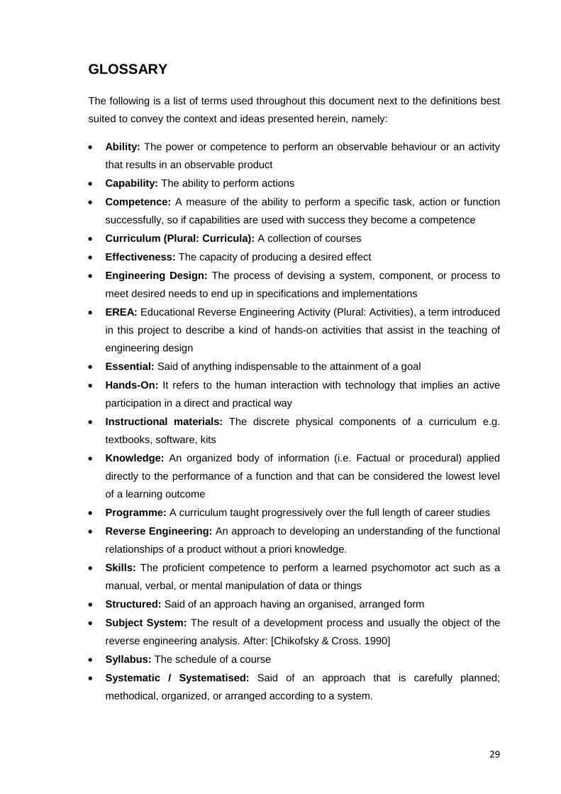
GLOSSARY
The following is a list of terms used throughout this document next to the definitions best
suited to convey the context and ideas presented herein, namely:
• Ability: The power or competence to perform an observable behaviour or an activity
that results in an observable product
• Capability: The ability to perform actions
• Competence: A measure of the ability to perform a specific task, action or function
successfully, so if capabilities are used with success they become a competence
• Curriculum (Plural: Curricula): A collection of courses
• Effectiveness: The capacity of producing a desired effect
• Engineering Design: The process of devising a system, component, or process to
meet desired needs to end up in specifications and implementations
• EREA: Educational Reverse Engineering Activity (Plural: Activities), a term introduced
in this project to describe a kind of hands-on activities that assist in the teaching of
engineering design
• Essential: Said of anything indispensable to the attainment of a goal
• Hands-On: It refers to the human interaction with technology that implies an active
participation in a direct and practical way
• Instructional materials: The discrete physical components of a curriculum e.g.
textbooks, software, kits
• Knowledge: An organized body of information (i.e. Factual or procedural) applied
directly to the performance of a function and that can be considered the lowest level
of a learning outcome
• Programme: A curriculum taught progressively over the full length of career studies
• Reverse Engineering: An approach to developing an understanding of the functional
relationships of a product without a priori knowledge.
• Skills: The proficient competence to perform a learned psychomotor act such as a
manual, verbal, or mental manipulation of data or things
• Structured: Said of an approach having an organised, arranged form
• Subject System: The result of a development process and usually the object of the
reverse engineering analysis. After: [Chikofsky & Cross. 1990]
• Syllabus: The schedule of a course
• Systematic / Systematised: Said of an approach that is carefully planned;
methodical, organized, or arranged according to a system.

30
This page intentionally left blank
31
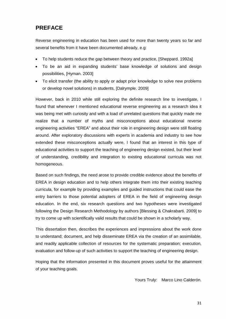
PREFACE
Reverse engineering in education has been used for more than twenty years so far and
several benefits from it have been documented already, e.g:
• To help students reduce the gap between theory and practice, [Sheppard. 1992a]
• To be an aid in expanding students’ base knowledge of solutions and design
possibilities, [Hyman. 2003]
• To elicit transfer (the ability to apply or adapt prior knowledge to solve new problems
or develop novel solutions) in students, [Dalrymple. 2009]
However, back in 2010 while still exploring the definite research line to investigate, I
found that whenever I mentioned educational reverse engineering as a research idea it
was being met with curiosity and with a load of unrelated questions that quickly made me
realize that a number of myths and misconceptions about educational reverse
engineering activities “EREA” and about their role in engineering design were still floating
around. After exploratory discussions with experts in academia and industry to see how
extended these misconceptions actually were, I found that an interest in this type of
educational activities to support the teaching of engineering design existed, but their level
of understanding, credibility and integration to existing educational curricula was not
homogeneous.
Based on such findings, the need arose to provide credible evidence about the benefits of
EREA in design education and to help others integrate them into their existing teaching
curricula, for example by providing examples and guided instructions that could ease the
entry barriers to those potential adopters of EREA in the field of engineering design
education. In the end, six research questions and two hypotheses were investigated
following the Design Research Methodology by authors [Blessing & Chakrabarti. 2009] to
try to come up with scientifically valid results that could be shown in a scholarly way.
This dissertation then, describes the experiences and impressions about the work done
to understand; document, and help disseminate EREA via the creation of an assimilable,
and readily applicable collection of resources for the systematic preparation; execution,
evaluation and follow-up of such activities to support the teaching of engineering design.
Hoping that the information presented in this document proves useful for the attainment
of your teaching goals.
Yours Truly: Marco Lino Calderón.

32
This page intentionally left blank

33
I hear and I forget; I see and I remember; I do and I understand
Confucius, 551 BC – 479 BC

34
This page intentionally left blank
35
CHAPTER 1 INTRODUCTION
1.1 Introduction to the Research Topic
Educational reverse engineering can be understood as the methodological analysis of a
subject system (e.g. A consumer product) done by students in an academic setting and
through hands-on activities that help discover the technological and non-technological
principles of the system under analysis.
Educational reverse engineering entails the investigation of the structure; function and
operation of a subject system by taking it apart and analyzing its workings in detail, to try
to recapture the abstract and functional top level specifications envisioned by the original
designers during the Product Design Specification (PDS) stage of the engineering design
process, in a orderly sequence of steps that helps engineering design students not only
to understand and compare against their own knowledge the design rationale and
tradeoffs the original designers faced to go from multiple design solutions initially
available down to the delimited solution boundaries featured in a final existing product,
but also to asses a product’s fulfilment of customer requirements and the reasons for its
eventual market failure or success.
“Reverse Engineering” is a generic concept spanning several disciplines, but for a
specific design education context it is theoretically founded on the product tear down
analyses conducted in 1972 by Yoshihiko Sato, [Sato & Kaufman. 2005]; on the reverse
engineering for product design methodology proposed by authors Otto and Wood, [Otto &
Wood. 2001], and on Kolb’s model of learning, [Kolb 1984] which states that concrete and
practical experience can be obtained through product dissection activities, which in turn
help reduce the gap between theory and practice in experimental learning environments.
The term “Reverse Engineering” has been traced back by author [Tilton. 2004] to at least
1960 in connection with hardware, when it meant an attempt to fathom and reconstruct
the circuitry inside a potted electronic module, the first quotable definition of reverse
engineering though, was given until 1985 by author [Rekoff. 1985] as “The process of
developing a set of specifications for a complex hardware system by an orderly
examination of specimens of that system”; other names for “Reverse Engineering” in the
design education context include “Mechanical Dissection”; “Product Dissection”, “D/A/A
(Disassemble, Analyse, Assemble) Activities”, and “Product Archaeology”; whereas
similar engineering methods that share the concept of disassembling a subject system to
further analyze it are called depending on their ultimate goal “Tear down analyses”;
36
“Analysis of known solutions”, “Weak points analysis”, “Value engineering”, “Forensic
engineering” and the German term “Konstruktionskritik” – roughly translated as – critique
of designs. However, they are all traditionally associated to formal studies of design itself
and are typically oriented to systems analysis or commercial, industrial applications that
neither fully focus on the pedagogical value of the hands-on activities themselves nor on
the non-technical aspects defining a system under analysis.
The first full scale implementation of educational reverse engineering activities in
engineering design education then, can be traced back to Prof. Sheppard’s course “ME99
Mechanical Dissection”, [Sheppard. 1992a] offered at Stanford University in the USA in
1991, whose course’s objective was to give mechanical engineering students an
understanding of mechanical artifacts by answering the question, “How did others solve a
particular problem?”, such course marked the birth of the systematic study of dissection
and reverse engineering activities in engineering education and proved the pedagogical
viability of them.
For the purposes of this doctoral dissertation “Educational Reverse Engineering
Activities” (EREA) is a term that describes an educational exercise which essentially
follows the ideas and approaches of systems engineering, to analyse and understand a
subject system (cf. a consumer product) through a combination of cognitive processes;
engineering tests, and analyses of published data. If they are focused on the student’s
acquisition of practice-related abilities rather than on their numerical exactness, such
activities can indeed contribute to the overall fulfilment of the educational requirements of
an engineering design student.
Note: A thorough analysis about the state of the art and fundamentals of educational
reverse engineering activities that discusses among other topics:
• The principles of educational reverse engineering
• Similar approaches to reverse engineering
• Characteristics of subject systems
• The historical development of reverse engineering
• The drawbacks of the practice of reverse engineering
• The validity of reverse engineering as an academic subject in design education
is not shown here, but it can be found in Chapter 1 of annex A which is a self contained
document titled “Resources for the Study of Educational Reverse Engineering Activities in
Engineering Design Education” and it’s found at the end of the main body of this
dissertation.
37
1.2 Research Specifics
1.2.1 Research Problem Statement
Educational reverse engineering activities, are in general, highly regarded hands-on
activities cf. [Sheppard 1992a]; [Lamancusa et al.1996] and [Dalrymple. 2009] that help
students bridge the gap between theory and practice in the safety of an educational
environment; they can be included in any engineering design curriculum to help students
increase their awareness and understanding of the design process, and to show through
real-life examples, what worked for other designers and what didn’t. However, as useful
as they may sound, their understanding, credibility, and integration into existing
engineering design curricula has been unequal, cf. [Calderon. 2010a], with a good level
of integration found in design programs in the United States of America, the United
Kingdom, and Germany for example, but with an irregular, rather low integration of them
found anywhere else.
1.2.1.1 Research Situation
Initial, exploratory studies conducted as part of this research (e.g. Mentored colloquia
during the first two years of the doctoral studies, discussions with experts and
stakeholders in academia and practice, etc.) showed that the low integration of
educational reverse engineering activities into existing teaching curricula in the area of
engineering design could be associated to:
• The limited awareness about their educational benefits, especially in relation to their
potential contribution to the expected competences of an engineering design student
at the time of graduation
• The lack of a standardized guideline on how to actually prepare; deliver, and evaluate
these activities to make the most out of them
• The perception that the existing resources for the study of EREA were either
dispersed or unsuitable as a tutorial (i.e. Self-directed learning)
• The idea that current literature on the topic required a re-contextualization in light of
progressing technologies now available in education
• A number of misconceptions about educational reverse engineering activities, mostly
concerning their lawfulness and ethics.
And thus, the opportunity to improve the existing situation by investigating and developing
solutions for the abovementioned issues was acknowledged.
38
1.2.2 Research Approach
This research was about the promotion of the use of reverse engineering activities in
engineering design education by trying to increase in the engineering design community
the awareness of their benefits and credibility as a teaching tool. To achieve this, there
were two possible ways, one of them was to develop a new theory about the area of
educational reverse engineering to come up with alternate concepts to the existing ones
and then go to the field to conduct the required tests to evaluate the associated
hypotheses and finally present the results to the academic community. In the author’s
opinion, this approach to the research and confirmation of the benefits and effectiveness
of reverse engineering in education has been covered several times already by pioneer
authors such as [Lamancusa et al. 1996] or [Otto et al. 1998] and more recently by
authors such as [Dalrymple et al. 2011], but since the understanding and actual inclusion
of this type of exercises in engineering design curricula still remained somewhat unequal,
[Calderon. 2010] a second approach to promote the use of reverse engineering activities
in engineering design education was devised as part of this doctoral project which dealt
with analysing the status quo and why reverse engineering activities were not fully
integrated into engineering design curricula, and then through tangible actions create a
support tool, that could change the research situation (e.g. by addressing the most
relevant barriers for the adoption and growth of reverse engineering activities in existing
engineering design curricula).
Existing approaches to the study of methodologies for educational reverse engineering
activities such as those by [Otto & Wood. 2001] or [Ogot & Kremer. 2006] differ with the
one taken in this dissertation, in the sense that in here a more inclusive approach to the
analysis of a subject system is favoured in order to understand the holistic context of a
system’s design, one that considers for example, its global; societal, ethical, economic
and environmental aspects and not only those of a technical nature -and for which a large
body of knowledge already exists- .This means that in the educational reverse
engineering analysis of a product as suggested in the self contained document in Annex
A of this dissertation, a number of educated guesses and speculations will have to
support whatever raw data can be recovered from the inspection of a subject system.
The idea of an inclusive approach to educational reverse engineering analysis is not new,
but it had been only barely explored, to the extent that as recent as 2011 authors such as
[Lewis et al. 2011] were still stating that the majority of the product dissection activities
(another name for EREA) that had resulted from previous efforts tended to focus solely
on the technological aspects of a product (e.g. How it functioned (Function-form
39
determinations) and how it was made (Product architecture)); to what they even added
that “many existing product dissection activities have missed opportunities to highlight the
wide range of issues (e.g. Global, economic, environmental, and societal) that influence
product design and development”, [Lewis et al. 2011]. The approach followed in this
dissertation for the study of EREA then, aimed to fit in the modern view of educational
reverse engineering research and thus not only considered a broader range of analyses
and criteria for the evaluations of a system but also placed the students’ acquisition and
development of practice-related abilities during reverse engineering exercises at the
forefront of its research approach.
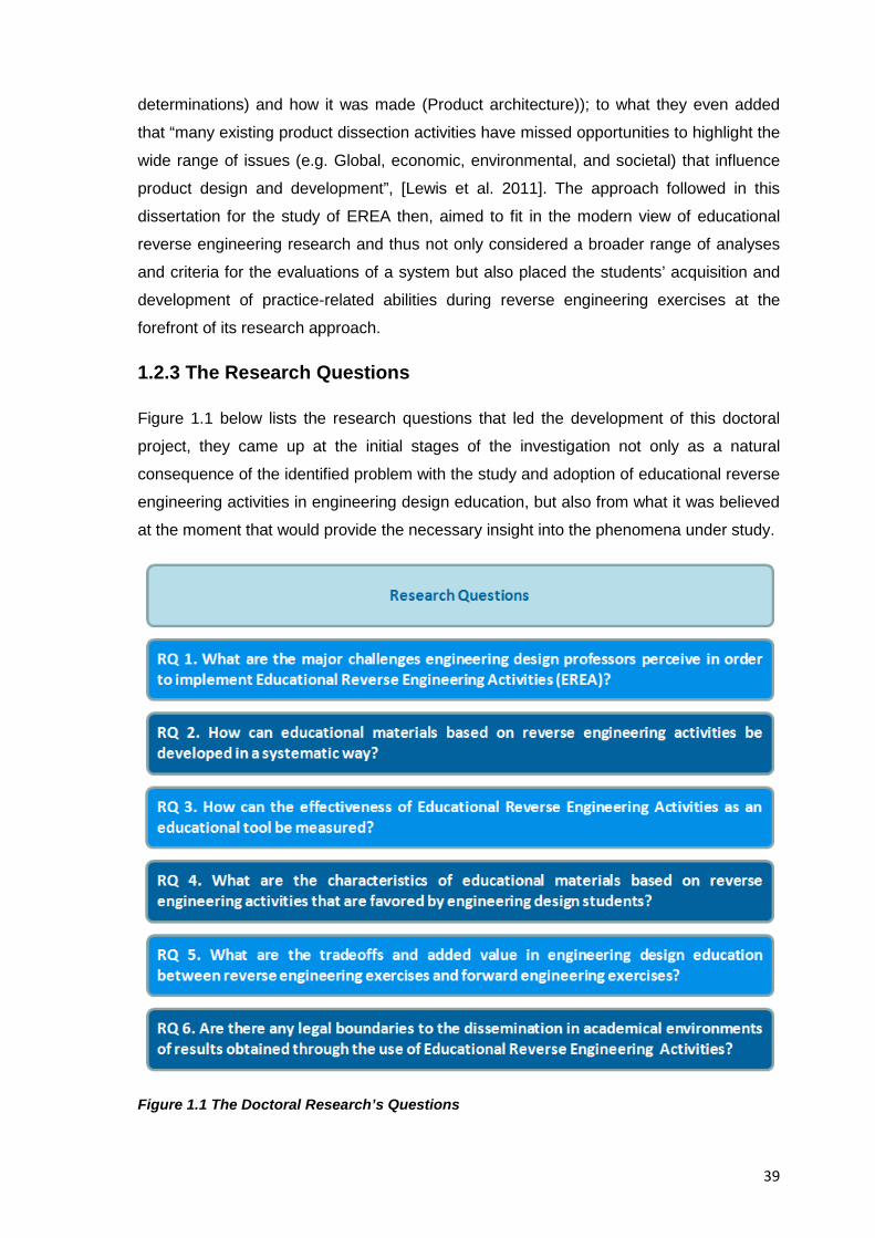
1.2.3 The Research Questions
Figure 1.1 below lists the research questions that led the development of this doctoral
project, they came up at the initial stages of the investigation not only as a natural
consequence of the identified problem with the study and adoption of educational reverse
engineering activities in engineering design education, but also from what it was believed
at the moment that would provide the necessary insight into the phenomena under study.
Figure 1.1 The Doctoral Research’s Questions
40
The research questions intended to address those concerns expressed by potential
adopters of EREA in exploratory discussions held at the beginning of the research project
and were worded in a fully detailed way so they could be answered through empirical
studies at the initial stages of this research, and also so they could be considered
according to author’s [Trochim. 2006] description of research questions as:
• Descriptive in the sense that the aim was “to describe what was going on or what
existed”
• Relational because they aimed “to look at the relationships between two or more
variables”
• Causal because they tried to determine “whether one or more variables caused or
affected one or more outcome variables”
Unlike the research hypotheses that will be shown next, the research questions remained
the same throughout the duration of the research project, and only certain subquestions
arose from time to time until they were answered and incorporated into the different
chapters of the collection of resources presented in Annex A of this document. A
discussion of the rationale of the research questions though, and of the results obtained
from them is presented in Chapter 4 of this dissertation.
1.2.4 The Research Hypotheses
Figure 1.2 below lists the definitive hypotheses that were tested in this dissertation and
which helped to evaluate if the proposed solution to improve the research situation was
indeed suitable for the problem detected.
The three hypotheses listed below though, were being tested initially in this dissertation:
• H1: The development, conduction and evaluation of reverse engineering exercises to
support the teaching of engineering design can be systematized through a guiding
manual that takes into account documented experiences, conclusions and best
practices in reverse engineering praxis as well as relevant learning topics on the
teaching of engineering design.
• H2: Increased awareness of a reverse engineering methodology as a tool to teach
engineering design through the presentation of a guiding manual will increase
professors’ eagerness to use it and include it in an engineering design curriculum.
• H3: The analysis and explanation of a reverse engineering exercise to teach
engineering design presented in a guiding manual will provide professors with ideas
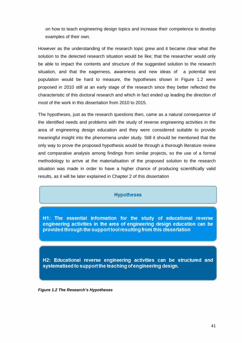
41
on how to teach engineering design topics and increase their competence to develop
examples of their own.
However as the understanding of the research topic grew and it became clear what the
solution to the detected research situation would be like; that the researcher would only
be able to impact the contents and structure of the suggested solution to the research
situation, and that the eagerness, awareness and new ideas of a potential test
population would be hard to measure, the hypotheses shown in Figure 1.2 were
proposed in 2010 still at an early stage of the research since they better reflected the
characteristic of this doctoral research and which in fact ended up leading the direction of
most of the work in this dissertation from 2010 to 2015.
The hypotheses, just as the research questions then, came as a natural consequence of
the identified needs and problems with the study of reverse engineering activities in the
area of engineering design education and they were considered suitable to provide
meaningful insight into the phenomena under study. Still it should be mentioned that the
only way to prove the proposed hypothesis would be through a thorough literature review
and comparative analysis among findings from similar projects, so the use of a formal
methodology to arrive at the materialisation of the proposed solution to the research
situation was made in order to have a higher chance of producing scientifically valid
results, as it will be later explained in Chapter 2 of this dissertation
Figure 1.2 The Research’s Hypotheses
42
Since no researcher is free of assumptions though, close attention was paid to comply
with authors’ [Frankfort-Nachmias & Nachmias. 1996] criteria so the characteristics of the
definite hypotheses could be considered:
• Clear: So all of the variables were conceptually and operationally defined (e.g.
Observed and assessed)
• Unspecific: To avoid bias and the expected direction of the answers
• Answerable: So it was possible to find an answer with available methods
• Value-free: To deal only with facts without needing to take a stand on values
The major constraint then, as in every doctoral project, was to assess each of the
research questions and hypotheses within the timeframe of the project and the resources
available for it.
1.2.5 General Research Objective
To facilitate the inclusion of educational reverse engineering activities in the teaching of
engineering design.
1.2.5.1 Specific Research Objectives
Additional to the general objective, a number of specific ones based on the analysis of
the research situation at the time, and on the needs detected in the initial exploratory
studies were also pursued, namely:
• To investigate and document the benefits and drawbacks of educational reverse
engineering activities
• To validate (either through bibliographical search or through direct experimentation)
the use of EREA as a tool for the teaching of engineering design
• To clarify the line between the educational and non educational contexts of reverse
engineering
• To lay the foundations to help educators develop their own scalable instructional
materials, teaching strategies, and educational innovations applied to educational
reverse engineering activities.
• To find out the areas specific to engineering design where educational reverse
engineering activities could better enhance student’s abilities
• To document how EREA could support creativity, innovation and invention
43
• To document how the properties of EREA could contribute towards the attainment of
the desired learning outcomes of typical engineering design programs and of the
expected competences from graduates of them.
• To provide engineering design professors with the information that justified the
inclusion of EREA into existing teaching curricula.
• To highlight the suitability of EREA as a tool to reach some of the desired educational
goals of an engineering design program.
The results from this doctoral research then, tried to provide an unbiased view of
educational reverse engineering activities pointing out both their strengths and
weaknesses.
1.2.6 Research Scope
This research was focused on the educational (rather than commercial) aspects of
reverse engineering, and dealt with the exploration of the causes that contributed to the
lack of diffusion and regard for reverse engineering activities in education, and also with
the creation of a support tool to try to change the existing research situation (a “Collection
of resources” as it’ll be later explained in Chapter 3), and unlike previous related theses
such as that by [Jounghyun. 1994] that focused mostly on the use of DFA (Design for
Assembly) techniques to reconstruct the design history of a product; that of [Leek &
Larsson. 2007] that focused on the development of an educational exercise, or the one
by [Dalrymple. 2009] that focused on the pedagogical value of reverse engineering
activities, this research instead, focused on the collection of existing evidence and
approaches to educational reverse engineering, to come up with a comprehensive outline
of the existing resources that could help educators to implement the educational benefits
of reverse engineering activities as smoothly as possible into existing and future
educational curricula in the area of engineering design, and also to measure their impact
in supporting individual and group learning.
Because an actual contribution to the state of the art on the topic was sought in this
doctoral research; its efforts and resources were not concentrated on the individual
analysis tools, techniques or technologies for reverse engineering analysis itself -and for
which an overwhelming amount of knowledge dispersed across several engineering
domains is already available- but instead on the methodology to deliver them to students
so they could acquire, develop or exercise practice-related abilities while doing them,
because of this, familiar topics in engineering design and technical systems analysis such
as:
44
• Artificial systems; product organs, inputs, physical effects, physical phenomena
,changes of state, behavioural models and the different constructs and relationships
for modelling them
• Design analysis and optimization techniques
are barely mentioned in this document, and only whenever they truly add to the
explanation of the topic in question.
The replication then; of previous research efforts or of previous researchers’ results just
to independently confirm them once again, was not the focus of this research either; that
doesn’t mean that previous results and conclusions from other authors were naively
accepted and blindly followed, it only meant that given the available resources, all efforts
were directed to the areas where an original contribution to the existing body of
knowledge in the topic was actually possible.
1.2.6.1 Research Focus
The investigation of the causes that impede the adoption and expansion of educational
reverse engineering activities in the teaching of engineering design, as well as the
creation of a potential solution to such issue.
1.2.7 Research Justification
Additional to the reported benefits of EREA in the learning of engineering design which
provided and still provide any researcher enough reason to keep investigating on the
topic; a number of authors at the time of the beginning of this doctoral project had in fact
already raised their concerns in regard to need to clarify the connection between reverse
engineering analysis; design proficiency, education, and the fundamentals of such
activities overall, examples of the statements that justified the development of this
research include but are not limited to:
• Authors’ [Lamancusa et al. 1997] statement regarding “the lack of professional
quality, self standing course materials to support the teaching of product dissection”
• Authors’ [Abe & Starr. 2003] statement that “in the literature, there is rarely an explicit
connection between take-apart activities and the design process. It appears that the
attitude is that ‘it cannot hurt, but we are not sure how it helps.’”
• Authors’ [Jensen et al. 2004] statement that there is already considerable literature
that addresses the advantages of using hands-on experiences in an engineering
curriculum but “despite the importance of active learning activities is well recognized,
little formal guidance in a systematic approach for development exists”
45
• Authors’ [Simpson et al. 2007] statement regarding the lack of materials “to support
the planning that ensures a successful dissection activity”
The acknowledgment of such statements then, helped to commit to the definite topic for
investigation in this research and marked the starting point of the creation of a suggested
solution for the research situation.
1.2.8 Research Assumptions
This research operated under two basic assumptions, namely:
• That engineering design professors truly wanted to provide their students with hands-
on experiences in the classroom (either through EREA; Make-and-Test activities
cf.[Andrew. 2006], capstone projects, or any other delivery method of their choice).
• That the clear, contextualized presentation of evidence about the learning benefits of
educational reverse engineering activities, and of the information on how to benefit
from them would actually increase an engineering design professor’s eagerness to
integrate EREA into his/her teaching.
The discussion about these assumptions and how findings and results from this research
directly or indirectly supported them is presented in Chapter 4
1.2.9 Expected Research Results
The expectation at the beginning of this research project was to document the
experiences in developing a support tool that helped professors to integrate educational
reverse engineering activities into their engineering design curriculum. It was believed at
that time that by easing the potential adopter’s learning curve for the preparation,
execution, evaluation and follow up of such tasks; the knowledge gaps, unwanted
complexity, and unnecessary steps that they could entail would be avoided and so
suitable guidelines, methods, and tools to develop educational resources for instructor-
led or self-directed learning would be produced by the results from this doctoral project.
Chapter 4 discusses the findings and results from striving to achieve those goals.
1.3 Chapter Conclusions
Although early studies stated that hands-on activities such as educational reverse
engineering ones could become a popular pedagogy to provide students with practical
experience in the classroom, cf. [Lamancusa et al. 1996], at the time of the beginning of
this doctoral research though, there were still many areas left to explore in the topic and
46
thus there was a scarcity of relevant resources for its study; this situation became
particularly evident early in the planning of this doctoral project when it was found that
guidelines to develop educational initiatives based on reverse engineering activities were
also lacking.
The set of initial exploratory studies; suggested research questions, and hypotheses
then, intended to lead the investigation efforts towards the search of relevant answers
and resources dispersed across varied areas of knowledge, and from which this research
could eventually benefit.
The main challenge in planning the development of this research topic then, came from
trying to find an appropriate balance that included the social; technical, didactic, and
experiential issues relevant to the topic under study, while at the same time taking into
consideration the research interests of potential adopters of EREA, as well as the existing
administrative structures in academic institutions that could support or hinder the
inclusion of new educational initiatives into existing educational programmes.
47
CHAPTER 2 THE RESEARCH METHODOLOGY
2.1 Chapter Introduction
At the beginning of this doctoral research some educators in the area of reverse
engineering stated that engineering design students in modern times were less prepared
to do well in engineering, since they lacked the experience and intuition that developed
from "hands-on" activities from adolescent years; at the same time they declared that “To
teach and study engineering design could be difficult sometimes, especially when
transforming theoretical knowledge into practice”, [Ogot et al. 2008]. These two
arguments could be logically related by author’s [Kolb. 1984] findings in the sense that
reverse engineering activities can provide students with concrete and practical
experience, and so ,as explained already, the need to provide high quality hands-on
experiences to students was acknowledged.
To address such issue, this doctoral research developed as end result a collection of
resources bundled together as a self contained document shown here in Annex A to help
engineering design professors study and eventually implement, educational reverse
engineering activities that could be adapted to the requirements of a typical curriculum in
engineering design (e.g. Specific learning objectives; fundamentals, methods, test
materials, and feedback mechanisms). The project required the documentation of the
theoretical background behind hands-on activities in education, and of the technical and
methodological knowledge needed to conduct reverse engineering exercises so the
project’s hypotheses could be tested and the research questions thoroughly answered.
In order to give this doctoral project and the results from it the scientific rigor and scholar
approach required, a research methodology to support the development of this
investigation was sought and three major methodologies suitable for the area of
engineering design education were found, namely:
• The research framework and methodology by [Duffy & Andreasen. 1995] and [Duffy &
O’Donell. 1999]
• The soft systems methodology “SSM” by [Checkland. 1981] and [Checkland. 1999]
• The design research methodology “DRM” by [Blessing & Chakrabarti. 2009]
In the end, it was decided to go with the DRM methodology not only because it explicitly
worked with the existing and the desired research situations and supported the
development of solutions to get from one to the other but also because in 2009 the author
had the opportunity to learn first-hand about the research methodology with her co-author
48
Lucienne Blessing during the 2009 summer school on engineering design research held
first in Croatia to learn the theory behind it and then in Finland to present results related
to one’s doctoral research. Throughout this chapter then, the experiences and findings
from using authors’ [Blessing & Chakrabarti. 2009] “DRM” methodology for design
research are presented.
2.2 “DRM” A Design Research Methodology
A design research methodology is an approach and a set of supporting methods and
guidelines to be used as a framework for doing design research, The design research
methodology by authors [Blessing & Chakrabarti. 2009] called “DRM” was chosen as the
supporting framework for this doctoral project since its methods were intended to support
a more rigorous research approach by helping to plan and implement design research,
and because, if used flexibly as the authors suggested, this methodology should help
make design research more effective and efficient.
The methodology framework proposed by Blessing and Chakrabarti consists of four
stages, namely: Research Clarification (RC), Descriptive Study I (DS-I), Prescriptive
Study (PS) and Descriptive Study II (DS-II), and as stated by the authors:
• The RC stage helps clarify the current understanding and the overall research aim,
develop a research plan and provide a focus for the subsequent stages.
• The DS-I stage aims at understanding the situation under study and the factors that
influence its behaviour, so the information obtained helps researchers develop their
core contribution to science through the possible means, aids and measures to
improve the research situation and that enable the evaluation of the core contribution
of the researcher (a collection of resources for the study of EREA in engineering
design education in this case)
• The PS stage aims at developing support tool in a systematic way, taking into account
the results of DS-I.
• The DS-II stage focuses on evaluating the usability and applicability of the actual
support and its usefulness.
2.2.1 Objectives and Benefits of Using “DRM”
Design education is a complex multidisciplinary research topic and as stated already
“DRM” was used as the supporting framework for this project not only because it aimed to
provide a set of supporting methods and guidelines to be used as a framework for doing
design research, but also because it suited the variety of fields involved in the research of
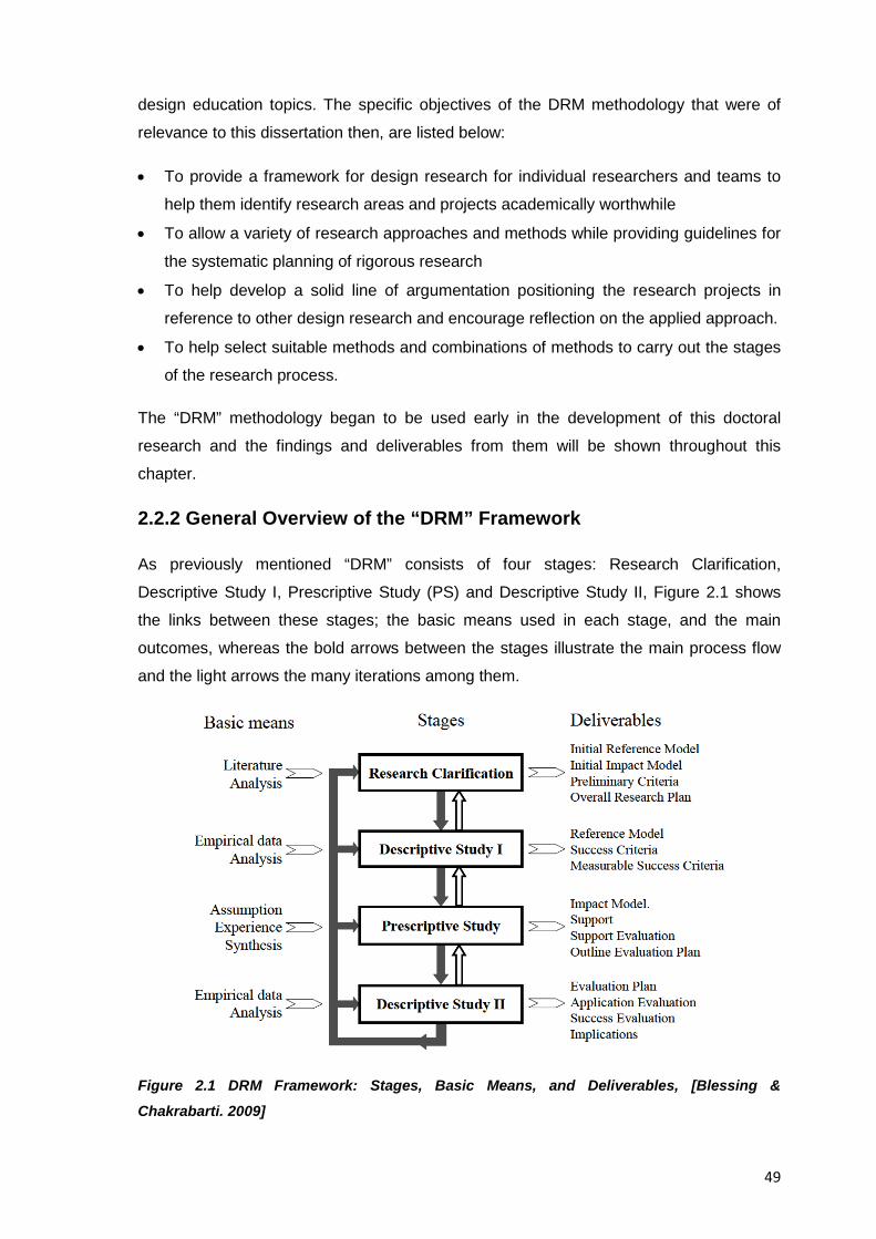
49
design education topics. The specific objectives of the DRM methodology that were of
relevance to this dissertation then, are listed below:
• To provide a framework for design research for individual researchers and teams to
help them identify research areas and projects academically worthwhile
• To allow a variety of research approaches and methods while providing guidelines for
the systematic planning of rigorous research
• To help develop a solid line of argumentation positioning the research projects in
reference to other design research and encourage reflection on the applied approach.
• To help select suitable methods and combinations of methods to carry out the stages
of the research process.
The “DRM” methodology began to be used early in the development of this doctoral
research and the findings and deliverables from them will be shown throughout this
chapter.
2.2.2 General Overview of the “DRM” Framework
As previously mentioned “DRM” consists of four stages: Research Clarification,
Descriptive Study I, Prescriptive Study (PS) and Descriptive Study II, Figure 2.1 shows
the links between these stages; the basic means used in each stage, and the main
outcomes, whereas the bold arrows between the stages illustrate the main process flow
and the light arrows the many iterations among them.
Figure 2.1 DRM Framework: Stages, Basic Means, and Deliverables, [Blessing &
Chakrabarti. 2009]
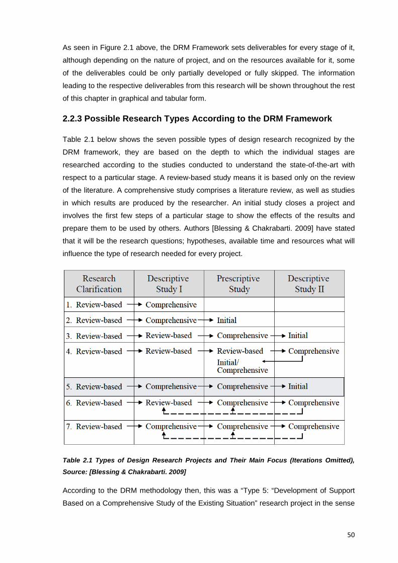
50
As seen in Figure 2.1 above, the DRM Framework sets deliverables for every stage of it,
although depending on the nature of project, and on the resources available for it, some
of the deliverables could be only partially developed or fully skipped. The information
leading to the respective deliverables from this research will be shown throughout the rest
of this chapter in graphical and tabular form.
2.2.3 Possible Research Types According to the DRM Framework
Table 2.1 below shows the seven possible types of design research recognized by the
DRM framework, they are based on the depth to which the individual stages are
researched according to the studies conducted to understand the state-of-the-art with
respect to a particular stage. A review-based study means it is based only on the review
of the literature. A comprehensive study comprises a literature review, as well as studies
in which results are produced by the researcher. An initial study closes a project and
involves the first few steps of a particular stage to show the effects of the results and
prepare them to be used by others. Authors [Blessing & Chakrabarti. 2009] have stated
that it will be the research questions; hypotheses, available time and resources what will
influence the type of research needed for every project.
Table 2.1 Types of Design Research Projects and Their Main Focus (Iterations Omitted),
Source: [Blessing & Chakrabarti. 2009]
According to the DRM methodology then, this was a “Type 5: “Development of Support
Based on a Comprehensive Study of the Existing Situation” research project in the sense
51
that the understanding of the research situation obtained from the comprehensive study
of existing literature; initial, exploratory analyses and original results produced by the
researcher from it, were enough to start the development of a support tool (The collection
of resources for the study of EREA in engineering design education shown in Annex A of
this document), therefore, this research involved both the development of the
understanding of the situation (Comprehensive DS-I Stage) and based on this, the
development of a support tool to change it (Comprehensive PS Stage) which in turn led
to an Initial DS-II stage which closed the research project; showed some potential
consequences of the results, and prepared them to be used and tested by others,
meaning that the support tool itself is only initially or indirectly tested by the researcher in
terms of its coherence and scientific validity, but it rests on others (e.g. the users) the
confirmation of the usability the support tool. This type of research project then, is
considered common for research situations such as this one where resources to achieve
a given goal weren’t suitable or didn’t exist at all. The types of research six and seven in
Table 2.1 for example are those developed by research groups with enough resources
and people, whereas student project usually fall on the first five types, being type three
and five the most common ones among them.
2.3 Deliverables from the DRM Framework
In the sections further below this research’s deliverables for each stage of the DRM
framework will be shown.
2.3.1 Deliverables from the Research Clarification Stage
Two main deliverables are expected from this research stage which can take one or
several forms of the options listed below, namely:
A. Current understanding and expectations
1. Initial reference model
2. Initial impact model
3. Preliminary criteria
B. Overall research plan
1. Research focus and goals
2. Research problems, main research questions and hypotheses
3. Relevant areas to be consulted
4. Approach (Type of research, main stages and methods)
52
5. Expected area of contributions and deliverables
6. Time Schedule
Most of the stage deliverables concerning research questions, hypotheses, and research
approaches have been presented already throughout Chapter 1 so it only rests to present
here the following ones:
2.3.1.1 The Initial Reference Model
The design research methodology (DRM) required the visualization of the initial research
conditions through a network of influencing factors and the relationships between them to
better analyse the research situation and come up with a suggested support tool that
could improve it.
At this initial stage and according to experience; assumptions, literature search, and own
studies it was identified that the ultimate “Success Criteria” for this research project
would be represented by a high level of “Integration of educational reverse engineering
activities (EREA) into engineering design curricula”, but the “Measurable Success
Criteria” that could be identified and analysed in this research project would focus on the
“Degree of applicability (of EREA) by engineering design professors” and “The students’
understanding of engineering design principles (through EREA)” where the “Key Factor”
considered to be addressed through the support tool would be the “Development of
reverse engineering activities (a.k.a. D/A/A Activities)” which were considered to trigger a
logical path of actual relationships and educated assumptions that would characterize the
“Success criteria”.
Figure 2.2 below graphically shows the initial reference model obtained for this research
that was published to show the initial understanding of the research problem
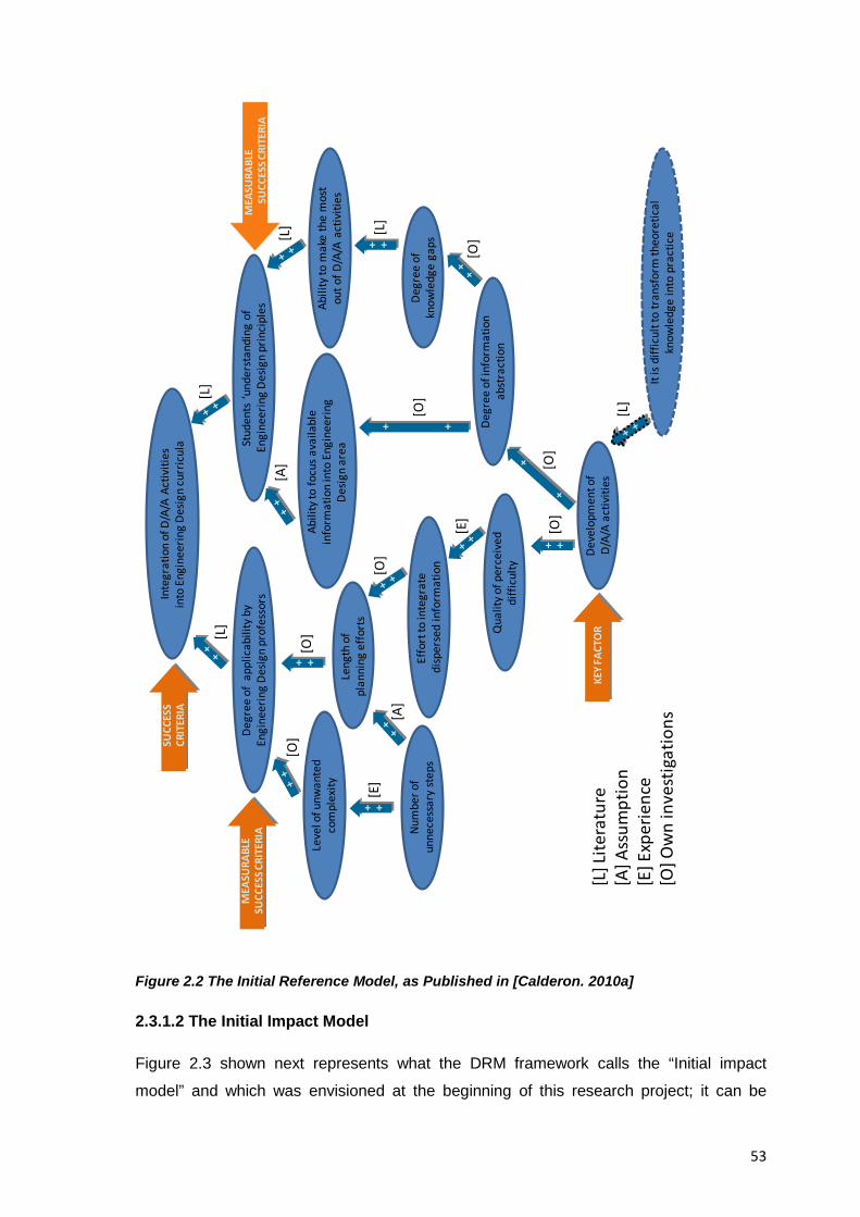
53
Figure 2.2 The Initial Reference Model, as Published in [Calderon. 2010a]
2.3.1.2 The Initial Impact Model
Figure 2.3 shown next represents what the DRM framework calls the “Initial impact
model” and which was envisioned at the beginning of this research project; it can be
Inte
grat
ion
of D
/A/A
Act
iviti
es
into
Eng
inee
ring
Desig
n cu
rric
ula
Degr
ee o
f ap
plic
abili
ty b
y En
gine
erin
g De
sign
prof
esso
rsSt
uden
ts ‘u
nder
stan
ding
of
Engi
neer
ing
Desig
n pr
inci
ples
Deve
lopm
ent o
fD/
A/A
activ
ities
It is
diffi
cult
to tr
ansf
orm
theo
retic
al
know
ledg
e in
to p
ract
ice
Effo
rt to
inte
grat
edi
sper
sed
info
rmat
ion
Abili
ty to
mak
e th
e m
ost
out o
f D/A
/A a
ctiv
ities
Degr
ee o
f inf
orm
atio
n ab
stra
ctio
n
Abili
ty to
focu
s ava
ilabl
e in
form
atio
n in
to E
ngin
eerin
g De
sign
area
Degr
ee o
f kn
owle
dge
gaps
Leve
l of u
nwan
ted
com
plex
ity
Num
ber o
f un
nece
ssar
y st
eps
Qua
lity o
f per
ceiv
ed
diffi
culty
Leng
th o
f pl
anni
ng e
ffort
s
+ +
+ +
+ +
+ +
+ +
[L] L
itera
ture
[A] A
ssum
ptio
n[E
] Exp
erie
nce
[O] O
wn
inve
stig
atio
ns
[L][L
]
[L]
[O]
[E]
[O]
[E]
[O]
[O][L
]
[A]
[L]
[O]
[O]
[A]
[O]
SUCC
ESS
CRIT
ERIA
MEA
SURA
BLE
SUCC
ESS C
RITE
RIA
MEA
SURA
BLE
SUCC
ESS C
RITE
RIA
KEY
FACT
OR
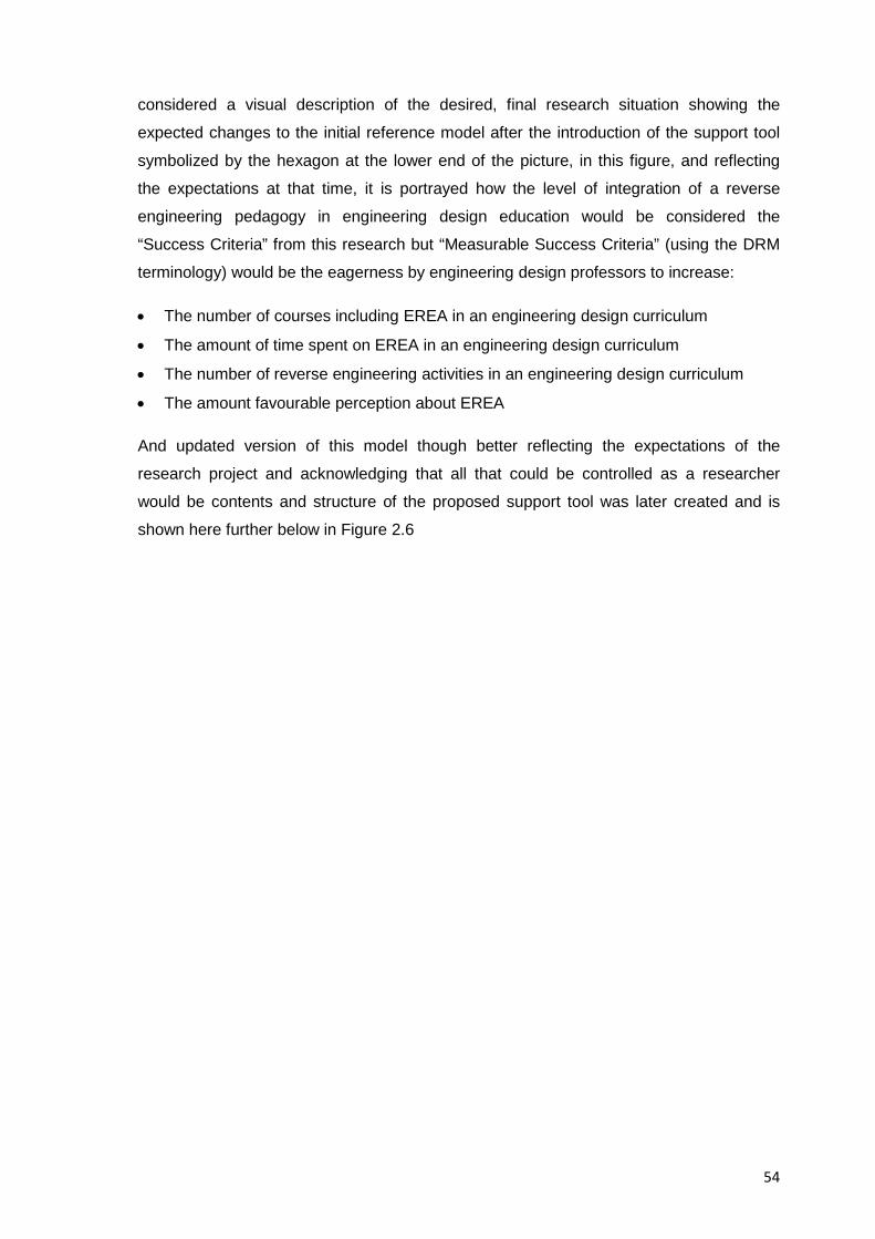
54
considered a visual description of the desired, final research situation showing the
expected changes to the initial reference model after the introduction of the support tool
symbolized by the hexagon at the lower end of the picture, in this figure, and reflecting
the expectations at that time, it is portrayed how the level of integration of a reverse
engineering pedagogy in engineering design education would be considered the
“Success Criteria” from this research but “Measurable Success Criteria” (using the DRM
terminology) would be the eagerness by engineering design professors to increase:
• The number of courses including EREA in an engineering design curriculum
• The amount of time spent on EREA in an engineering design curriculum
• The number of reverse engineering activities in an engineering design curriculum
• The amount favourable perception about EREA
And updated version of this model though better reflecting the expectations of the
research project and acknowledging that all that could be controlled as a researcher
would be contents and structure of the proposed support tool was later created and is
shown here further below in Figure 2.6
55
Figure 2.3 Initial Impact Model
Leve
l of
eage
rnes
s to
incl
ude
Reve
rse
Engi
neer
ing
activ
ities
in e
ngin
eerin
g De
sign
cour
ses
Leve
l of c
redi
bilit
y of R
ever
se
Engi
neer
ing
as a
n ef
fect
ive
tool
for E
ngin
eerin
g De
sign
educ
atio
n
Num
ber a
nd S
tren
gth
of
Misc
once
ptio
ns a
bout
Rev
erse
En
gine
erin
g Ex
erci
ses (
i.e.
illeg
ality
, lac
k of c
reat
ivity
)
Leve
l of a
war
enes
s of e
xist
ence
of
peda
gogi
es in
volv
ing
Reve
rse
Engi
neer
ing
as a
n ai
d to
teac
h En
gine
erin
g De
sign
Leve
l of p
erce
ived
diff
icul
ties
to im
plem
ent R
ever
se
Engi
neer
ing
exer
cise
s in
an
Engi
neer
ing
Desig
n cu
rric
ulum
+ ++ +
--
[L]
[A]
[O]
[A]
[A]
[O]
[A]
[A]
[L] [O
][O
]
[A]
[O]
SUCC
ESS
CRIT
ERIA
MEA
SURA
BLE
SUCC
ESS C
RITE
RIA
MEA
SURA
BLE
SUCC
ESS C
RITE
RIA
KEY
FACT
OR
Leve
l of e
ager
ness
to in
crea
se th
e am
ount
of t
ime
spen
t on
Rev
erse
En
gine
erin
g ac
tiviti
es in
an
Engi
neer
ing
Desig
n cu
rric
ulum
Amou
nt o
f fa
vora
ble
perc
eptio
n ab
out R
ever
se
Engi
neer
ing
activ
ities
by
Engi
neer
ing
Desig
n pr
ofes
sors
Leve
l of i
nteg
ratio
n of
a
Reve
rse
Engi
neer
ing
peda
gogy
in E
ngin
eerin
g De
sign
educ
atio
n
Num
ber o
f ext
erna
l fac
tors
affe
ctin
g En
gine
erin
g De
sign
curr
icul
a o
utsid
e th
e sc
ope
of th
is re
sear
ch
i.e. g
over
nmen
tal g
uide
lines
or t
rend
s in
curr
icul
um
deve
lopm
ent o
r rig
idity
to m
odify
exi
stin
g cu
rric
ula’
s co
nten
t for
Eng
inee
ring
Desig
n ed
ucat
ion
Leve
l of a
ppea
l of R
ever
se
Engi
neer
ing
act
iviti
es a
s to
ol fo
r Eng
inee
ring
Desig
n ed
ucat
ion
Know
ledg
e of
ben
efits
and
ad
ded
valu
e th
at R
ever
se
Engi
neer
ing
act
iviti
es ca
n br
ing
to E
ngin
eerin
g De
sign
educ
atio
n
Leve
l of
eage
rnes
s to
incr
ease
th
e nu
mbe
r of
Reve
rse
Engi
neer
ing
activ
ities
in
Engi
neer
ing
Desig
n co
urse
s
Leve
l of e
ager
ness
to in
crea
se th
e nu
mbe
r of c
ours
es in
clud
ing
Reve
rse
Engi
neer
ing
activ
ities
in
an E
ngin
eerin
g De
sign
curr
icul
um
-+
+ +
+ +
[A]
[A]
[A]
Qua
lity o
f cre
atio
n an
d di
ssem
inat
ion
of S
uppo
rt
Tool
(Gui
ding
man
ual f
or
the
deve
lopm
ent,
exec
utio
n an
d ev
alua
tion
of R
ever
se
Engi
neer
ing
activ
ities
Prof
esso
rs' a
bilit
y to
crea
te
thei
r ow
n Re
vers
e En
gine
erin
g ac
tiviti
es a
nd
mak
e th
e m
ost o
f the
m
Amou
nt o
f unw
ante
d co
mpl
exity
, kno
wle
dge
gaps
, un
nece
ssar
y st
eps,
time
inve
sted
in p
lann
ing
effo
rts
Chan
ge in
favo
rabl
e re
cogn
ition
of
the
adde
d va
lue
that
Rev
erse
en
gine
erin
g ex
erci
ses c
an b
ring
to
an E
ngin
eerin
g De
sign
curr
icul
um
Amou
nt o
f wor
k re
quire
d to
im
plem
ent R
ever
se E
ngin
eerin
g ac
tiviti
es in
an
Engi
neer
ing
Desig
n Cu
rric
ulum
Prof
esso
rs ‘
leve
l of c
omfo
rt
teac
hing
Eng
inee
ring
Desig
n st
uden
ts R
ever
se E
ngin
eerin
g ac
tiviti
es
[A]
+ + [A]
[A]
-+
[A]
-+
[A]
+ +
[A]
+ +
CAP
TIO
NS:
[L] L
itera
ture
[A] A
ssum
ptio
n[E
] Exp
erie
nce
[O] O
wn
inve
stig
atio
ns
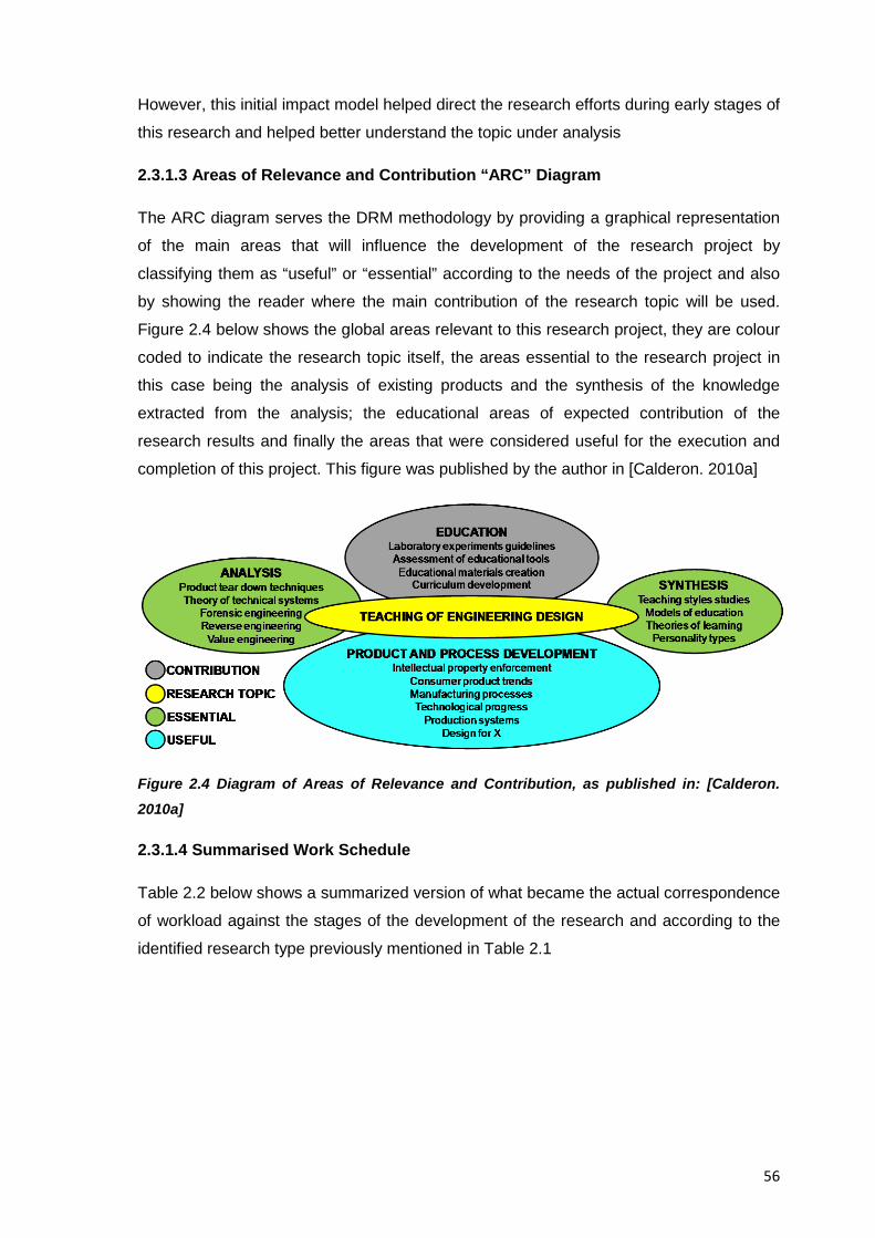
56
However, this initial impact model helped direct the research efforts during early stages of
this research and helped better understand the topic under analysis
2.3.1.3 Areas of Relevance and Contribution “ARC” Diagram
The ARC diagram serves the DRM methodology by providing a graphical representation
of the main areas that will influence the development of the research project by
classifying them as “useful” or “essential” according to the needs of the project and also
by showing the reader where the main contribution of the research topic will be used.
Figure 2.4 below shows the global areas relevant to this research project, they are colour
coded to indicate the research topic itself, the areas essential to the research project in
this case being the analysis of existing products and the synthesis of the knowledge
extracted from the analysis; the educational areas of expected contribution of the
research results and finally the areas that were considered useful for the execution and
completion of this project. This figure was published by the author in [Calderon. 2010a]
Figure 2.4 Diagram of Areas of Relevance and Contribution, as published in: [Calderon. 2010a]
2.3.1.4 Summarised Work Schedule
Table 2.2 below shows a summarized version of what became the actual correspondence
of workload against the stages of the development of the research and according to the
identified research type previously mentioned in Table 2.1
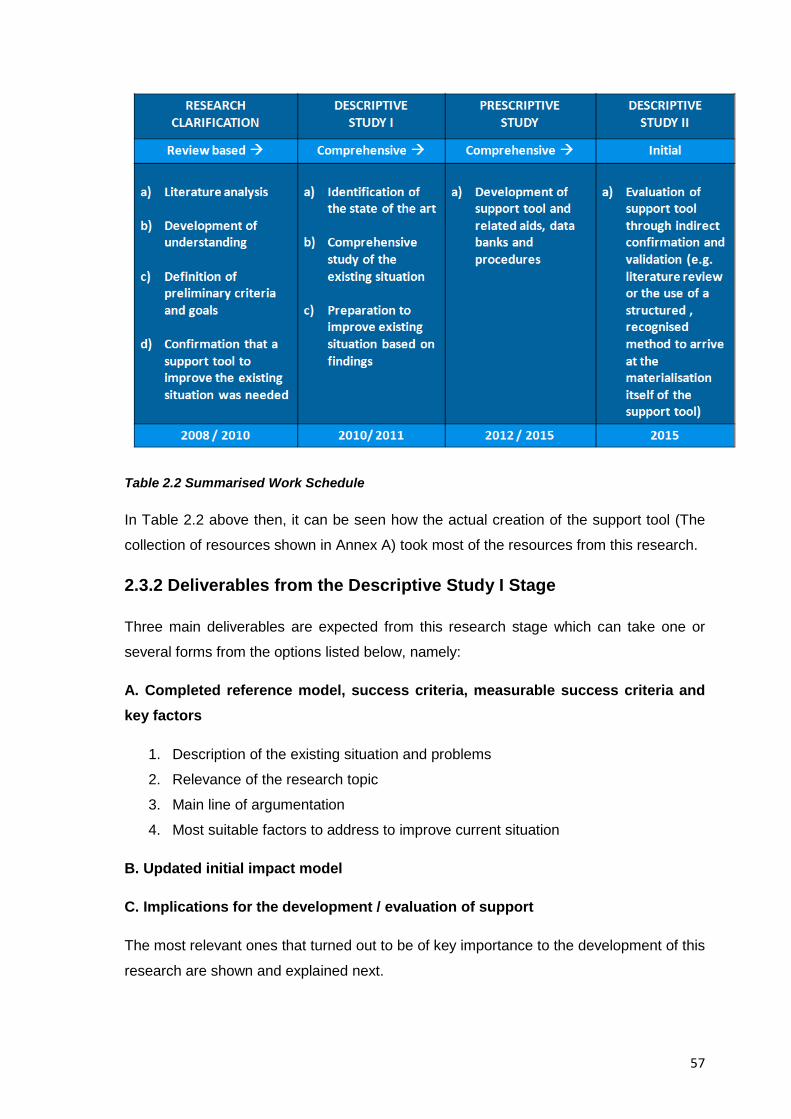
57
Table 2.2 Summarised Work Schedule
In Table 2.2 above then, it can be seen how the actual creation of the support tool (The
collection of resources shown in Annex A) took most of the resources from this research.
2.3.2 Deliverables from the Descriptive Study I Stage
Three main deliverables are expected from this research stage which can take one or
several forms from the options listed below, namely:
A. Completed reference model, success criteria, measurable success criteria and key factors
1. Description of the existing situation and problems
2. Relevance of the research topic
3. Main line of argumentation
4. Most suitable factors to address to improve current situation
B. Updated initial impact model
C. Implications for the development / evaluation of support
The most relevant ones that turned out to be of key importance to the development of this
research are shown and explained next.

58
2.3.2.1 The Completed Reference Model
As mentioned already the design research methodology (DRM) requires the visualization
of the research conditions to better analyse the research situation and come up with a
suggested support tool that can improve it; Figure 2.5 below shows the graphical
representation of the completed reference model for the research situation, this figure
was updated in late 2011 from the original one from 2010 (shown above in Figure 2.2) to
better reflect the research conditions where according to experience; assumptions,
literature search, and own studies, it was identified that:
• The ultimate success criteria for this research project would be a high level of
integration of EREA into existing engineering design curricula
• Measurable success criteria that could be actually identified and analysed in this
research project would focus only on the quality of the support tool to assist the use;
adaption, appropriation, and discovery of EREA (which are common terms to
measure adoption rates in education, cf. [Ceoforum. 1999])
• The key factor to be addressed through the support tool (the collection of resources
presented in Annex A) would be the level of awareness of engineering design
professors about the benefits and fundamentals of EREA in support of the teaching of
engineering design
The major difference from the initial and the updated reference models then, was the
discard of the aspects related to the measurements of the eagerness of the target users
of the support tool, and instead it was decided to focus only on the quality of the contents
and the methodological creation of the support tool
Figure 2.5 below graphically shows the network of influencing factors and the
relationships between major actors in the research situation in a format that helped clarify
its understanding and thus start developing a potential solution to it.
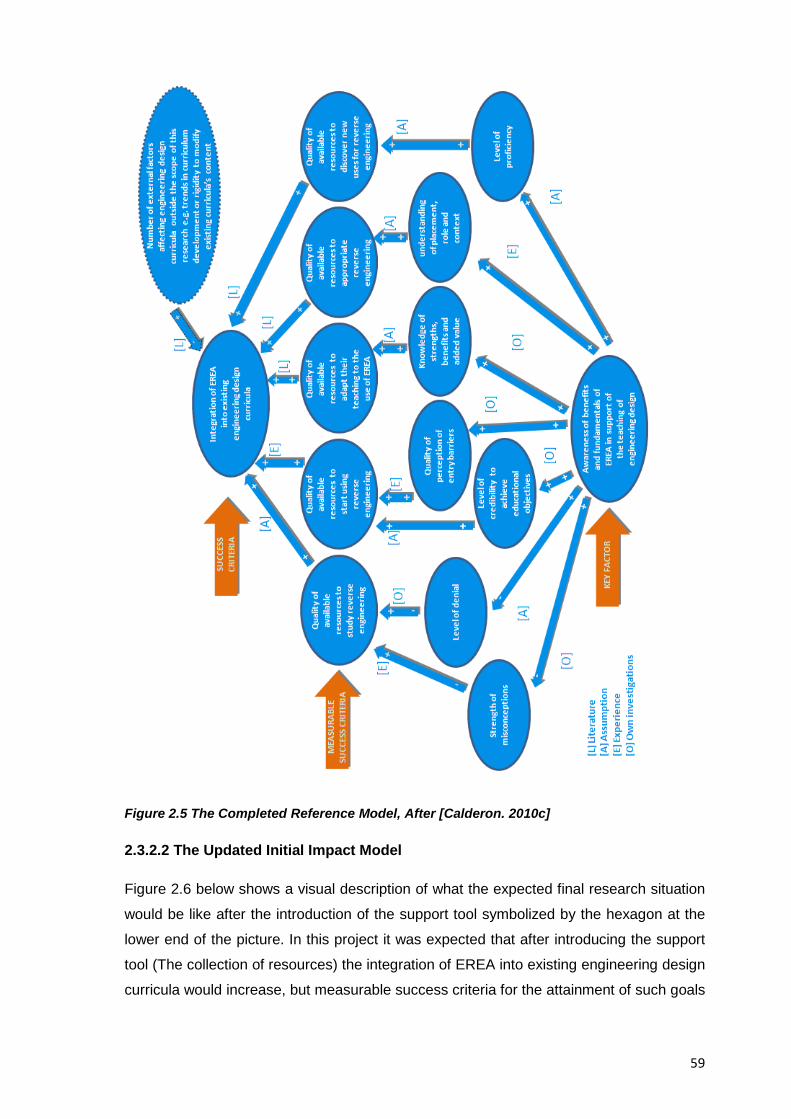
59
Figure 2.5 The Completed Reference Model, After [Calderon. 2010c]
2.3.2.2 The Updated Initial Impact Model
Figure 2.6 below shows a visual description of what the expected final research situation
would be like after the introduction of the support tool symbolized by the hexagon at the
lower end of the picture. In this project it was expected that after introducing the support
tool (The collection of resources) the integration of EREA into existing engineering design
curricula would increase, but measurable success criteria for the attainment of such goals
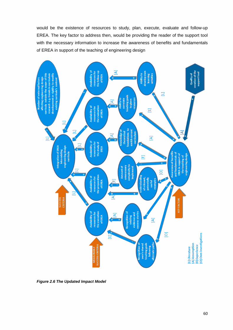
60
would be the existence of resources to study, plan, execute, evaluate and follow-up
EREA. The key factor to address then, would be providing the reader of the support tool
with the necessary information to increase the awareness of benefits and fundamentals
of EREA in support of the teaching of engineering design
Figure 2.6 The Updated Impact Model
61
Additionally, the updated impact model also considered how other external factors could
also hinder the introduction of EREA into existing engineering design curricula but they
might be outside the scope of this research project (e.g. Rigidity to change existing
curricula contents, or future governmental trends on the contents of engineering
education programs). The attainment of the final research situation and the findings from
striving towards it are discussed at the conclusions chapter of this document.
2.3.2.3 Clarification of the Area under Study and of the Relevance of the Research Results
In order to place the results from this research in the right context and thus help
disseminate them and reach the right audience, it was determined that the area under
study would be “Engineering Design Education” and thus it also had to be proved that it
was indeed a scientifically valid area of research continuously studied by several authors.
The paragraphs shown below thus, were actually published by the author in [Calderon.
2010c] to explain the scientific and academic validity of the topic under study.
2.3.2.3.1 Engineering Design Education under Design Research
Engineering design education can be interpreted as the academic process that enables
students to learn the required knowledge and skills necessary to fulfil the expected
requirements of a professional design practice, this interpretation is derived from the
three following definitions:
• “Engineering design is a systematic; intelligent process in which designers generate,
evaluate, and specify concepts for devices, systems, or processes whose form and
function achieve clients' objectives or users' needs while satisfying a specified set of
constraints”, [Engineering Education Community. 2010]
• “Design education is primarily focused on students, and on helping them understand
and experience the process and methods of realizing an artifact. The quality of the
student-created artifact is often of secondary importance in the learning process”,
[Sheppard & Rollie. 1996]
• “Engineering education is the activity of teaching engineering and technology, at
school, college and university levels. The goal of engineering education is to prepare
people to practice engineering as a profession and also to spread technological
literacy, increase student interest in technical careers through science and math
education, and hands-on learning”, [Douglas & Chitra. 2004]
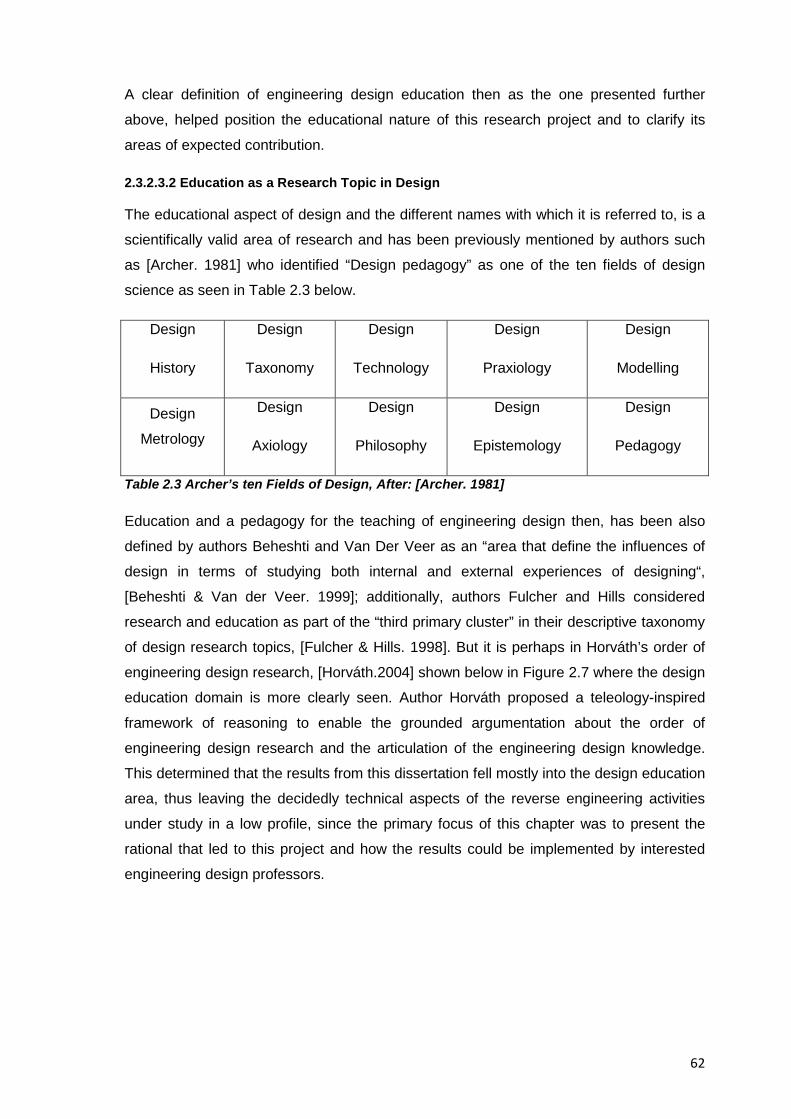
62
A clear definition of engineering design education then as the one presented further
above, helped position the educational nature of this research project and to clarify its
areas of expected contribution.
2.3.2.3.2 Education as a Research Topic in Design
The educational aspect of design and the different names with which it is referred to, is a
scientifically valid area of research and has been previously mentioned by authors such
as [Archer. 1981] who identified “Design pedagogy” as one of the ten fields of design
science as seen in Table 2.3 below.
Design
History
Design
Taxonomy
Design
Technology
Design
Praxiology
Design
Modelling
Design
Metrology
Design
Axiology
Design
Philosophy
Design
Epistemology
Design
Pedagogy
Table 2.3 Archer’s ten Fields of Design, After: [Archer. 1981]
Education and a pedagogy for the teaching of engineering design then, has been also
defined by authors Beheshti and Van Der Veer as an “area that define the influences of
design in terms of studying both internal and external experiences of designing“,
[Beheshti & Van der Veer. 1999]; additionally, authors Fulcher and Hills considered
research and education as part of the “third primary cluster” in their descriptive taxonomy
of design research topics, [Fulcher & Hills. 1998]. But it is perhaps in Horváth’s order of
engineering design research, [Horváth.2004] shown below in Figure 2.7 where the design
education domain is more clearly seen. Author Horváth proposed a teleology-inspired
framework of reasoning to enable the grounded argumentation about the order of
engineering design research and the articulation of the engineering design knowledge.
This determined that the results from this dissertation fell mostly into the design education
area, thus leaving the decidedly technical aspects of the reverse engineering activities
under study in a low profile, since the primary focus of this chapter was to present the
rational that led to this project and how the results could be implemented by interested
engineering design professors.
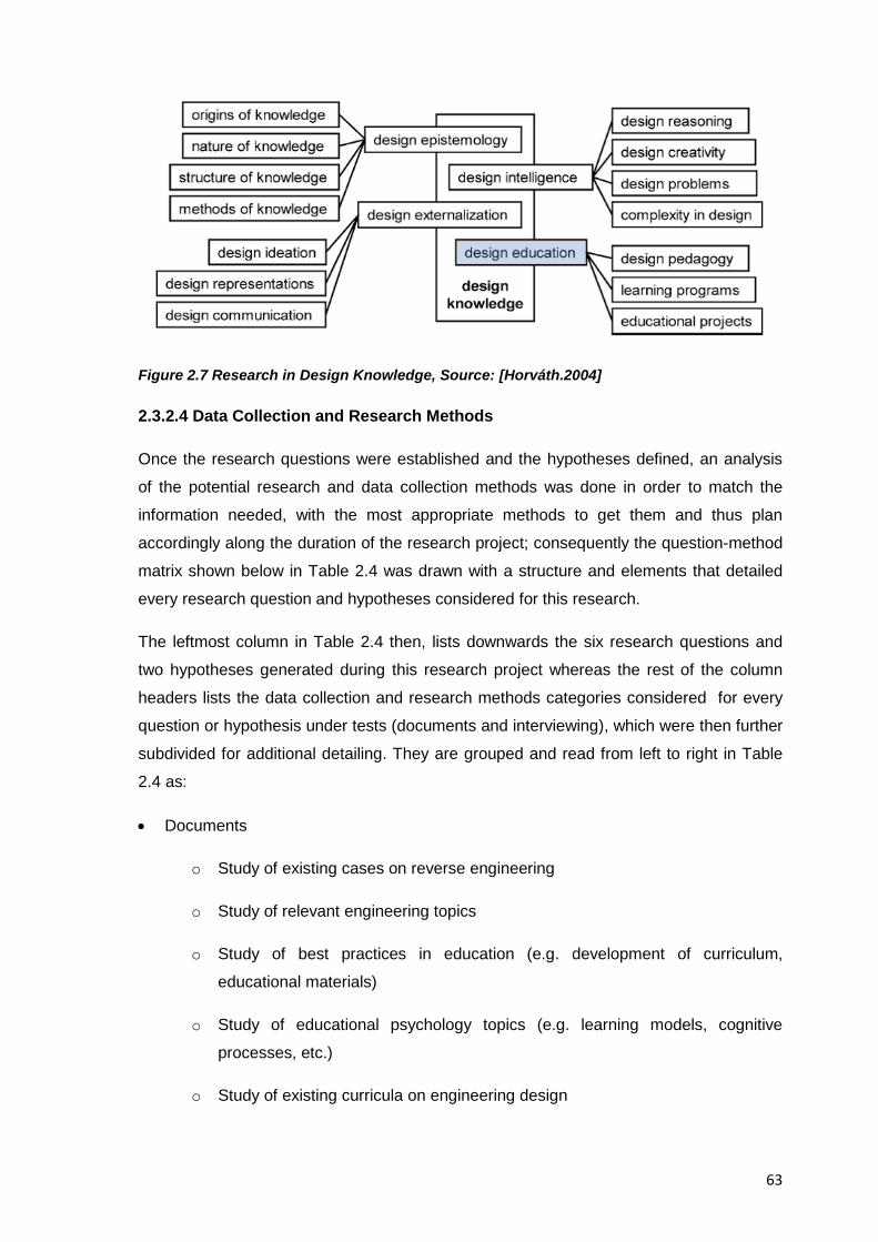
63
Figure 2.7 Research in Design Knowledge, Source: [Horváth.2004]
2.3.2.4 Data Collection and Research Methods
Once the research questions were established and the hypotheses defined, an analysis
of the potential research and data collection methods was done in order to match the
information needed, with the most appropriate methods to get them and thus plan
accordingly along the duration of the research project; consequently the question-method
matrix shown below in Table 2.4 was drawn with a structure and elements that detailed
every research question and hypotheses considered for this research.
The leftmost column in Table 2.4 then, lists downwards the six research questions and
two hypotheses generated during this research project whereas the rest of the column
headers lists the data collection and research methods categories considered for every
question or hypothesis under tests (documents and interviewing), which were then further
subdivided for additional detailing. They are grouped and read from left to right in Table
2.4 as:
• Documents
o Study of existing cases on reverse engineering
o Study of relevant engineering topics
o Study of best practices in education (e.g. development of curriculum,
educational materials)
o Study of educational psychology topics (e.g. learning models, cognitive
processes, etc.)
o Study of existing curricula on engineering design
64
o Study of guidelines and standards on engineering design
o Study of intellectual property law
o Study of competitive intelligence topics
• Interviewing
o Professors
o Students
o Product Designers
o Educational Researchers
o Intellectual Property Experts (Although a thorough bibliographical analysis
also yielded enough information to answer the research questions posed).
To populate such matrix, cells were individually divided into an upper part that indicated
the suitability of the method for addressing the research questions or hypotheses and a
lower part that indicated the effort required from the researcher and the participants. In
the cell’s upper part, the number of ticks indicated whether the method was expected to
fully answer the research questions and hypotheses or just to obtain a partial answer
from it. Two ticks (√√) for example, indicated that the method was expected to fully
answer the question or verify the hypothesis completely while one tick (√) meant that
answers could only be obtained partially or indirectly.
The information in the cell’s lower part referred to the effort ( e.g. Preparation; application,
processing, analysis, etc) from the researcher and the participants to address the
research question or hypotheses and they were indicated either by a single letter “R”
indicating a small effort for the researchers or two “RR” indicating a large effort. In the
same way, a single letter “P” meant a small effort for the participant and two letters “PP”
indicated a large effort, whenever the effort could be negligible though, this part of the cell
could remain empty.
The two most common data collection methods used in design research are real-time,
and retrospective, none is better than the other, they are used for different purposes. This
research for example, did not require real time data collection methods; instead, it relied
on retrospective data collection methods such as documents and interviewing, the reason
for this was that both the research questions and hypotheses were focused on evaluating
impressions and requests from the participants and not on the execution of the reverse
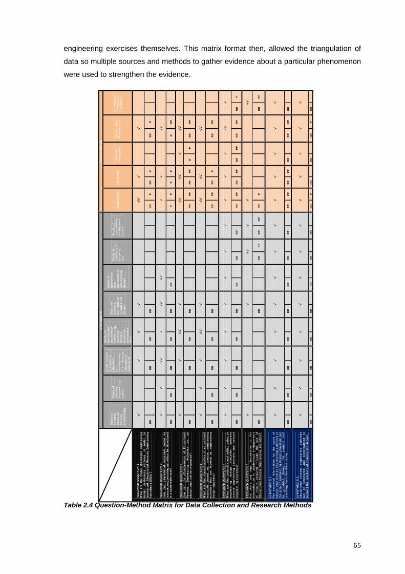
65
engineering exercises themselves. This matrix format then, allowed the triangulation of
data so multiple sources and methods to gather evidence about a particular phenomenon
were used to strengthen the evidence.
Table 2.4 Question-Method Matrix for Data Collection and Research Methods
D
OC
UM
ENTS
IN
TER
VIE
WIN
G
Stu
dy o
f ex
isti
ng
ca
ses
on
reve
rse
eng
inee
rin
g
Stu
dy o
f re
leva
nt
eng
inee
rin
g
top
ics
Stu
dy o
f b
est
pra
ctic
es in
ed
uca
tion
(e
.g.
dev
elop
men
t of
cu
rric
ulu
m,
edu
cati
onal
m
ater
ials
)
Stu
dy o
f ed
uca
tion
al
psy
chol
ogy
top
ics
(e.g
. le
arn
ing
m
odel
s,
cog
nit
ive
pro
cess
es,
etc.
)
Stu
dy o
f ex
isti
ng
cu
rric
ula
on
en
gin
eeri
ng
d
esig
n
Stu
dy o
f g
uid
elin
es
and
stan
dard
s on
en
gin
eeri
ng
d
esig
n
Stu
dy o
f in
telle
ctu
al
pro
pert
y la
w
Stu
dy o
f co
mpe
titi
ve
inte
llige
nce
to
pic
s
Pro
fess
ors
Stu
den
ts
Pro
du
ct
Des
ign
ers
Edu
cati
onal
R
esea
rch
ers
Inte
lect
ual
P
rop
erty
Ex
pert
s
RES
EAR
CH
QU
ESTI
ON
1:
Wh
at a
re t
he
maj
or c
hal
len
ges
en
gin
eeri
ng
des
ign
p
rofe
ssor
s pe
rcei
ve
in
orde
r to
im
ple
men
t Ed
uca
tion
al R
ever
se E
ng
inee
rin
g A
ctiv
itie
s (E
REA
)?
√
√
√
√
√√
√
√
RR
RR
RR
RR
RR
P
R
R
P
RR
P
RES
EAR
CH
QU
ESTI
ON
2:
How
ca
n
edu
cati
onal
m
ater
ials
b
ased
on
re
vers
e en
gin
eeri
ng
act
ivit
ies
be d
evel
oped
in
a s
yste
mat
ic w
ay?
√
√
√√
√
√√
√√
√
√
√√
RR
RR
RR
RR
RR
RR
R
P
R
P
R
PP
RES
EAR
CH
QU
ESTI
ON
3:
How
ca
n
the
effe
ctiv
enes
s of
Ed
uca
tion
al
Rev
erse
En
gin
eeri
ng
A
ctiv
itie
s as
an
ed
uca
tion
al t
ool b
e m
easu
red
?
√
√
√√
√
√√
√√
√
√√
RR
RR
RR
RR
RR
P
P
RR
P
P
R
P
RR
P
P
RES
EAR
CH
QU
ESTI
ON
4:
Wh
at a
re t
he
char
acte
rist
ics
of e
du
cati
onal
m
ater
ials
b
ased
on
re
vers
e en
gin
eeri
ng
acti
viti
es
that
ar
e fa
vore
d
by
engi
nee
rin
g d
esig
n s
tude
nts
?
√
√
√
√√
√
√√
√√
√√
RR
RR
RR
RR
RR
RR
P
P
RR
P
R
R
PP
RES
EAR
CH
QU
ESTI
ON
5:
Wh
at a
re t
he
trad
eoff
s an
d a
dde
d va
lue
in
eng
inee
rin
g
desi
gn
edu
cati
on
betw
een
re
vers
e en
gin
eeri
ng
exer
cise
s an
d fo
rwar
d en
gin
eeri
ng
exe
rcis
es?
√
√
√
√
√
√
√
√
√
√
√
√√
√
RR
RR
RR
RR
RR
RR
RR
RR
RR
P
P
RR
P
P
RR
P
P
RR
P
P
RR
P
RES
EAR
CH
QU
ESTI
ON
6:
Are
th
ere
any
leg
al
bou
nd
arie
s to
th
e d
isse
min
atio
n
in
acad
emic
al
envi
ron
men
ts
of
resu
lts
obta
ined
th
rou
gh
th
e u
se
of
Edu
cati
onal
Rev
erse
En
gin
eeri
ng
Act
ivit
ies?
√
√
√√
√
√
√√
RR
RR
RR
P
P
RR
P
P
RR
P
R
R
PP
HY
PO
THES
IS 1
: Th
e es
sen
tial
in
form
atio
n f
or t
he
stu
dy
of
edu
cati
onal
rev
erse
en
gin
eeri
ng
acti
viti
es i
n
the
area
of
engi
nee
rin
g d
esig
n e
du
cati
on c
an
be
pro
vide
d
thro
ugh
th
e su
pp
ort
tool
re
sult
ing
fro
m t
his
dis
sert
atio
n.
√
√
√
√
√
√
√
√
√
√
√
√
√
RR
RR
RR
RR
RR
RR
RR
RR
RR
P
P
RR
P
P
RR
RR
P
P
RR
HY
PO
THES
IS 2
: Ed
uca
tion
al
reve
rse
engi
nee
rin
g
acti
viti
es
can
be
st
ruct
ure
d
and
syst
emat
ised
to
su
ppor
t th
e te
ach
ing
of
eng
inee
rin
g d
esig
n.
√
√
√
√
√
√
√
√
√
√
√
√
√
RR
RR
RR
RR
RR
RR
RR
RR
RR
P
R
R
R
R
R
R
P
RR
66
2.3.2.5 Implications for the Development / Evaluation of the Support Tool
Based on the understanding of what the key factors and success criteria for the results
from this research would be, the search for the best solution to the research situation
began, which ultimately ended in the selection of the creation of a collection of resources
for the study of EREA in engineering design education but whose reasons for choosing it
as the preferred support tool will be detailed further below.
2.2.5.5.1 Determined Requirements Lists for the Support Tool
The following is the list of requirements that were initially set for the support tool and that
were considered suitable to improve the research situation, namely:
A. Impending Need:
• To develop a support tool to help engineering design educators to study educational
reverse engineering activities in the area of engineering design education.
B. Performance:
• The support should suggest modifications to existing teaching curricula
• The support should be able to support the preparation, conduction, evaluation, and
follow-up of educational reverse engineering activities
• The support should provide guidelines on how to integrate existing resources to the
suggested activities
• The support should be able to use the information available in engineering design
education as input
• The suggested activities should be achievable enough to be used as a regular activity
within the engineering design education process
C. Ergonomics:
• The support should be usable by individual, experienced, and non experienced
engineering design educators
• The support should be easy to introduce to the target population
• The contents of the support should be easy to learn
• The support should be easy to use
• The support should be easy to maintain
D. Cost:
• The support should be free and of unrestricted distribution

67
• The support should not be costly to maintain (i.e. No more than 10hr/month to be
invested by the author or the reader to maintain it up-to-date or relevant)
E. Introduction:
• Only a computer, internet connection or a printer should be necessary to acquire the
support tool
• It should be possible to use the support tool in conjunction with existing support
available in engineering design laboratories
F. Life:
• The support, with maintenance, should have indefinite life, unless research in
education changed paradigms completely at some point in time
D. Disposal:
• The electronic version of the support should have no problems beings disposed, the
hard copy of it should be disposed in accordance with existing policies for
environmental care
These requirements were derived from the analysis of existing resources for the study of
educational reverse engineering: through exploratory discussions with experienced
educators and potential users, as well as from the detected needs in the teaching of
engineering design.
It should be mentioned though that the materialised resources did not comply properly
with the ergonomic requirements set here since their length doesn’t allow the easy
transportation of a hard copy comprising all of them, however a wealth of resources are
contained therein and thus the presentation of relevant information to the readers was
favoured over complying with the ergonomic requirements.
2.2.5.5.2 Analysis of Concepts and Variants for the Support Tool
As mentioned before, design support in the DRM methodology can take several forms, it
includes all possible means, aids and measures that can be used to improve design and
as authors [Blessing & Chakrabarti. 2009] state, these are “prescriptions” – suggesting
ways by which design tasks should be carried out – and can include strategies;
methodologies, procedures, methods, techniques, software tools, guidelines, knowledge
bases, workbooks, checklists, knowledge, tools and so on”.
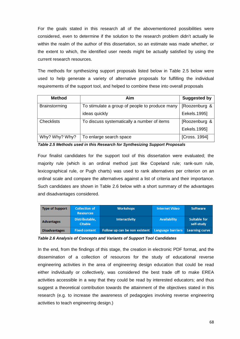
68
For the goals stated in this research all of the abovementioned possibilities were
considered, even to determine if the solution to the research problem didn’t actually lie
within the realm of the author of this dissertation, so an estimate was made whether, or
the extent to which, the identified user needs might be actually satisfied by using the
current research resources.
The methods for synthesizing support proposals listed below in Table 2.5 below were
used to help generate a variety of alternative proposals for fulfilling the individual
requirements of the support tool, and helped to combine these into overall proposals
Method Aim Suggested by Brainstorming To stimulate a group of people to produce many
ideas quickly
[Roozenburg &
Eekels.1995]
Checklists To discuss systematically a number of items [Roozenburg &
Eekels.1995]
Why? Why? Why? To enlarge search space [Cross. 1994] Table 2.5 Methods used in this Research for Synthesizing Support Proposals
Four finalist candidates for the support tool of this dissertation were evaluated; the
majority rule (which is an ordinal method just like Copeland rule; rank-sum rule,
lexicographical rule, or Pugh charts) was used to rank alternatives per criterion on an
ordinal scale and compare the alternatives against a list of criteria and their importance.
Such candidates are shown in Table 2.6 below with a short summary of the advantages
and disadvantages considered.
Table 2.6 Analysis of Concepts and Variants of Support Tool Candidates
In the end, from the findings of this stage, the creation in electronic PDF format, and the
dissemination of a collection of resources for the study of educational reverse
engineering activities in the area of engineering design education that could be read
either individually or collectively, was considered the best trade off to make EREA
activities accessible in a way that they could be read by interested educators; and thus
suggest a theoretical contribution towards the attainment of the objectives stated in this
research (e.g. to increase the awareness of pedagogies involving reverse engineering
activities to teach engineering design.)
69
The advantage of creating an electronic, printable collection of resources then, lied in its
ability to collect and distribute the results and findings from this doctoral research. The
other approaches mentioned in Table 2.6 above were discarded for a variety of reasons
including the lack of training from the author on software and video related topics; the
lack of resources to conduct intensive workshops on the topic, and also not being a
native English language speaker. In the end the creation of the electronic resources
provided the most reasonable balance in content vs. delivery method, and in
personalized vs. self-directed training.
It should be still clarified though, that although at first sight the terms “support tool” and
“collection of resources” might seem interchangeable, they are not, since the term
“support tool” is used in the DRM methodology to refer to a general concept and
“collection of resources” was the final form it took from a myriad that it could have taken
2.3.2.6 Expected Research Deliverables
Finally, for this stage of the DRM methodology the expected deliverables as a result from
the whole research were determined, namely:
• A doctoral thesis: Scholarly documenting the research studies needed to test the
hypotheses and to answer the research questions that led to the creation of the
collection of resources shown in Annex A
• A collection of resources: To document the theoretical background behind hands-on
activities in education and to help engineering design professors implement reverse
engineering activities adapted to the requirements of a curriculum in engineering
design (e.g. Specific learning objectives, fundamentals, techniques, methodologies,
test materials, venues, and feedback mechanisms)
• Academic Papers: To be presented at congresses or journals on relevant topics.
This document is the doctoral thesis itself; whereas the collection of resources is shown
in annex A (and independently from the main body of this dissertation), the conference
papers resulting from intermediate results from this research then, are listed below for
reference:
• Product Visualization Praxis and its Integration to Academic Curricula, [Calderon.
2008]
• Analysis of Existing Products as a Tool for Engineering Design Education, [Calderon.
2009]
70
• Application of Reverse Engineering Activities in the Teaching of Engineering Design,
[Calderon. 2010a]
• A Comparison of Competences Required in Reverse Engineering Exercises Versus
Conventional Engineering Exercises and its Relationship to IPMA’s Competence
Baseline, [Calderon. 2010b]
• The Design Research Methodology as a Framework for the Development of a Tool for
Engineering Design Education, [Calderon. 2010c]
2.3.3 Deliverables from the Prescriptive Study Stage
Five main deliverables are expected from this research stage which can take one or
several forms of the options listed below, namely:
A. Documentation of the Intended Support
1. Intended: Support description, introduction plan, impact model
B. Actual Support:
1. The guiding manual itself
C. Documentation of the Actual Support:
1. Actual: Support description, introduction plan, impact model
D. Results of the Support Evaluation:
1. Consistency check: Each part at one level of detail is addressed by some part at the
other
2. Completeness Check: each function intended to be addressed by the support is
indeed addressed
E. Outline Evaluation Plan:
1. Evaluation of: Support itself, its application, success.
Those that were developed according to the nature of this research and to the resources
available for it are shown and explained further below.
2.3.3.1 Analysis of Objectives and Requirements
The list of methods seen in Table 2.7 below were used by the author during this stage to
help analyse the support tool’s objectives; clarify the requirements that the support tool
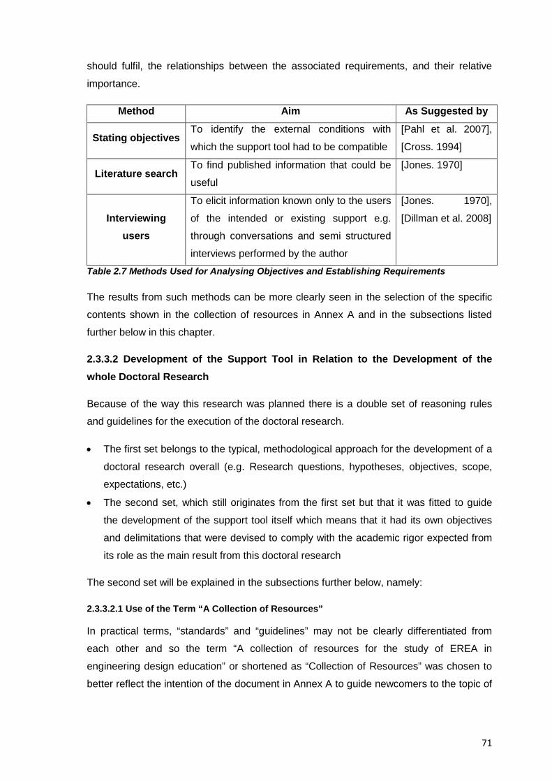
71
should fulfil, the relationships between the associated requirements, and their relative
importance.
Method Aim As Suggested by
Stating objectives To identify the external conditions with
which the support tool had to be compatible
[Pahl et al. 2007],
[Cross. 1994]
Literature search To find published information that could be
useful
[Jones. 1970]
Interviewing users
To elicit information known only to the users
of the intended or existing support e.g.
through conversations and semi structured
interviews performed by the author
[Jones. 1970],
[Dillman et al. 2008]
Table 2.7 Methods Used for Analysing Objectives and Establishing Requirements
The results from such methods can be more clearly seen in the selection of the specific
contents shown in the collection of resources in Annex A and in the subsections listed
further below in this chapter.
2.3.3.2 Development of the Support Tool in Relation to the Development of the whole Doctoral Research
Because of the way this research was planned there is a double set of reasoning rules
and guidelines for the execution of the doctoral research.
• The first set belongs to the typical, methodological approach for the development of a
doctoral research overall (e.g. Research questions, hypotheses, objectives, scope,
expectations, etc.)
• The second set, which still originates from the first set but that it was fitted to guide
the development of the support tool itself which means that it had its own objectives
and delimitations that were devised to comply with the academic rigor expected from
its role as the main result from this doctoral research
The second set will be explained in the subsections further below, namely:
2.3.3.2.1 Use of the Term “A Collection of Resources”
In practical terms, “standards” and “guidelines” may not be clearly differentiated from
each other and so the term “A collection of resources for the study of EREA in
engineering design education” or shortened as “Collection of Resources” was chosen to
better reflect the intention of the document in Annex A to guide newcomers to the topic of
72
educational reverse engineering into its fundamentals and the challenges for their
implementation as an tool in the teaching of engineering design.
2.3.3.2.2 Description of the Collection of Resources
An electronic; freely distributable, and printable document comprised of nine major
sections “Resources” suitable for individual or sequential reading, that intend to provide
the reader with the fundamentals behind educational reverse engineering activities and
their eventual integration into an existing engineering design curriculum by providing
resources for the planning, execution, evaluation and follow-up of them
2.3.3.2.3 Justification for the Development of a Collection of Resources
Given that no clear correlation exists between effective research and effective teaching a
freely distributable guiding manual was prepared under commonly accepted pedagogic
principles (e.g. Presentation of sequential, accumulative information; use of an
introduction; method, results, conclusions structure, etc.) to help engineering design
professors to ease the learning curve about EREA and about their implementation into an
existing educational curriculum
2.3.3.2.4 General Goal of the Collection of Resources
The support tool pursues its own goal which is related but different to that of the overall
research project, the goal of the collection of resources then, is to increase the readers’
eagerness to try reverse engineering activities in their teaching practice and it aims to do
so by providing them with the information necessary to understand the benefits of reverse
engineering activities and the ways to incorporate them into their teaching practice.
2.3.3.2.5 Specific Goals of the Collection of Resources
The specific goals of the collection of resources intended to address important concerns
found in trying to implement EREA into existing engineering design curricula, namely:
• To help first time instructors of educational reverse engineering with the associated
entry barriers and learning curves by providing them with accessible information,
know-how and sample activities to start with.
• To provide engineering design professors with resources for the eventual
development of further instructional courseware for the benefit of their students
• To support future lines of research and new approaches to educational reverse
engineering
73
• To help potential adopters to make the most out of EREA and provide them with
credible justifications and advises for each stage of their introduction into their
teaching practices
The contents comprising the collection of resources then, directly and indirectly try to
tackle these concerns.
2.3.3.2.6 Added Value of the Collection of Resources
The resources take into account and cite the most relevant; documented experiences,
conclusions, and best practices in the research about educational reverse engineering
and incorporate the latest findings (at the time of publishing of this dissertation) in the
area
2.3.3.2.7 Expectations from the Collection of Resources
Given that a formal research methodology (DRM) was followed to satisfy the detected
need to improve the teaching of engineering design; the collection of resources’
contribution was also believed to be academically worthwhile since it exceeded the depth
and span of information previously presented to the general public in past, related
research, not to mention that the freely-distributable nature of the guiding manual was
thought to contribute to its dissemination
2.3.3.2.8 Description of the Collection of Resources and its Contents
The collection of resources includes numerous references, reflections and Insight that
can be used not only for the contextualization and understanding of the field of
educational reverse engineering but also for the self production of laboratory activities
and hands-on demonstrations that can be brought into the teaching practice. The
information and guidelines provided there are aimed at the study of the fundamentals of
the topic and towards an implementation of reverse engineering activities at the
undergraduate level, still, enough detail is provided so they can be ported to different
educational settings such as introductory high school activities or even graduate level
projects. The contents of the collection of resources itself is aimed at engineering design
professors but every effort has been made to present the information in a nontechnical
terminology so its benefits and limitations can be better understood should a broader
audience ever read the resources.
In order to present systematically developed statements to assist practitioners of EREA in
their appropriate implementation in academic settings, the collection of resources itself
74
includes a set of recommendations and steps that can be followed and that are supported
by links to external resources on available research and evidence on the topic.
A short description of the contents of each of the resources in the collection is listed next:
• Resource 1 Fundamentals of Educational Reverse Engineering Activities:
Foundations and contextualization of reverse engineering research in the field of
engineering design; differences and similarities with other approaches that bring
practical experience to the classroom, challenges in the implementation of EREA, etc.
• Resource 2 Reverse Engineering and Learning: Cognitive processes students
undergo when performing educational reverse engineering activities.
• Resource 3 Misconceptions about Reverse Engineering: Clarification of
misunderstandings about reverse engineering in education.
• Resource 4 Benefits of Reverse Engineering: An account of previously published
advantages; potentialities, and added value reverse engineering activities can bring to
the teaching and learning of engineering design.
• Resource 5 A Proposed Methodology for Reverse Engineering Analysis in
Engineering Design Education: A methodology addressed to the field of engineering
design for the educational analysis of consumer products
• Resource 6 A Suggested Pedagogy for the Teaching of Educational Reverse
Engineering Activities: A collection of tips and advices dealing with the practical
aspects behind the execution of the steps; analyses, tasks, and questions proposed
in the methodology of Resource 5
• Resource 7 Integrated Example of an Educational Reverse Engineering Activity on a
Disposable Camera: A guided example, suitable for self-directed learning of an
educational reverse engineering activity using a disposable photographic camera as
subject system
• Resource 8 Conclusions and Final Remarks: Thoughts on the present and future use
of reverse engineering in education based on collected experience and an analysis of
existing, published research
• Resource 9 Miscellaneous Resources for the Study of Reverse Engineering: An
assortment of references linking to published research with the potential to support
the eventual development of additional, instructional courseware
The abovementioned resources can be considered self-contained and can be read
individually, depending on the interests and needs of the reader in turn, however they can
be considered of a sequential nature too since they purposefully converge at Resource 7
of the collection, given that the guided example shown therein expects to contribute in
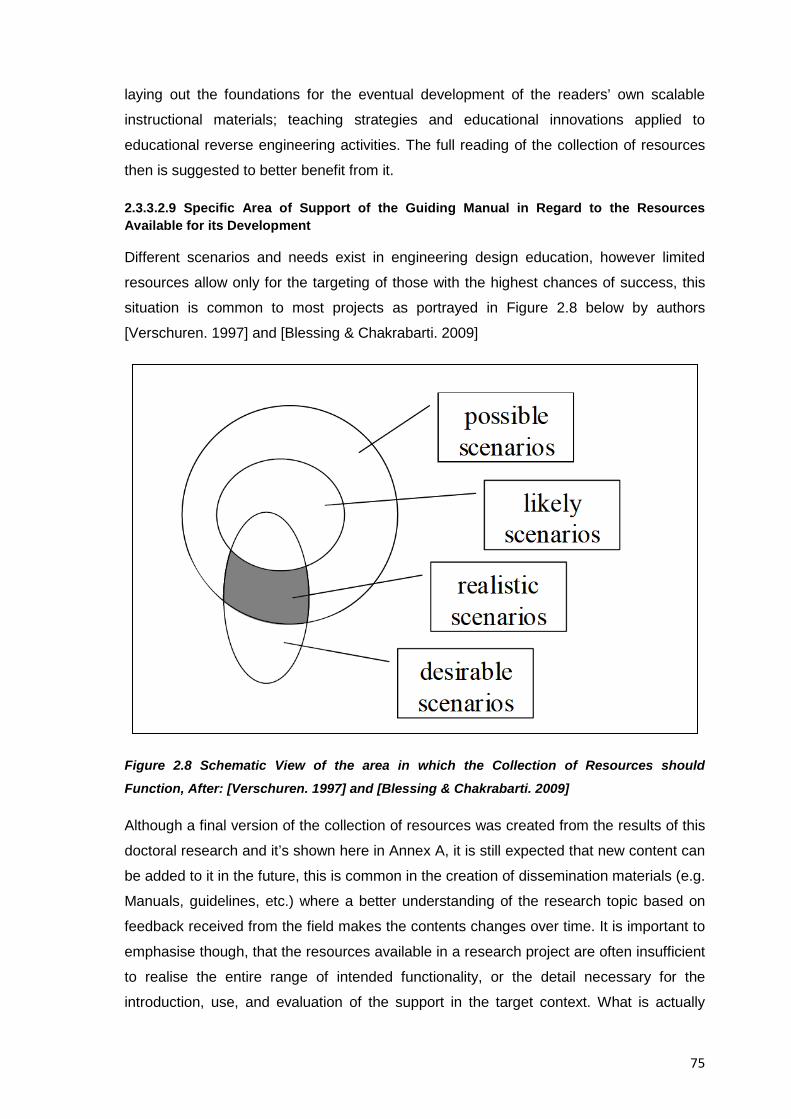
75
laying out the foundations for the eventual development of the readers’ own scalable
instructional materials; teaching strategies and educational innovations applied to
educational reverse engineering activities. The full reading of the collection of resources
then is suggested to better benefit from it.
2.3.3.2.9 Specific Area of Support of the Guiding Manual in Regard to the Resources Available for its Development
Different scenarios and needs exist in engineering design education, however limited
resources allow only for the targeting of those with the highest chances of success, this
situation is common to most projects as portrayed in Figure 2.8 below by authors
[Verschuren. 1997] and [Blessing & Chakrabarti. 2009]
Figure 2.8 Schematic View of the area in which the Collection of Resources should
Function, After: [Verschuren. 1997] and [Blessing & Chakrabarti. 2009]
Although a final version of the collection of resources was created from the results of this
doctoral research and it’s shown here in Annex A, it is still expected that new content can
be added to it in the future, this is common in the creation of dissemination materials (e.g.
Manuals, guidelines, etc.) where a better understanding of the research topic based on
feedback received from the field makes the contents changes over time. It is important to
emphasise though, that the resources available in a research project are often insufficient
to realise the entire range of intended functionality, or the detail necessary for the
introduction, use, and evaluation of the support in the target context. What is actually
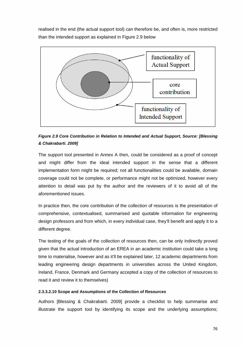
76
realised in the end (the actual support tool) can therefore be, and often is, more restricted
than the intended support as explained in Figure 2.9 below
Figure 2.9 Core Contribution in Relation to Intended and Actual Support, Source: [Blessing
& Chakrabarti. 2009]
The support tool presented in Annex A then, could be considered as a proof of concept
and might differ from the ideal intended support in the sense that a different
implementation form might be required; not all functionalities could be available, domain
coverage could not be complete, or performance might not be optimized, however every
attention to detail was put by the author and the reviewers of it to avoid all of the
aforementioned issues.
In practice then, the core contribution of the collection of resources is the presentation of
comprehensive, contextualised, summarised and quotable information for engineering
design professors and from which, in every individual case, they’ll benefit and apply it to a
different degree.
The testing of the goals of the collection of resources then, can be only indirectly proved
given that the actual introduction of an EREA in an academic institution could take a long
time to materialise, however and as it’ll be explained later, 12 academic departments from
leading engineering design departments in universities across the United Kingdom,
Ireland, France, Denmark and Germany accepted a copy of the collection of resources to
read it and review it to themselves)
2.3.3.2.10 Scope and Assumptions of the Collection of Resources
Authors [Blessing & Chakrabarti. 2009] provide a checklist to help summarise and
illustrate the support tool by identifying its scope and the underlying assumptions;
77
according to them, the resulting description clarifies the problem that is addressed; the
approach, and the possible implications, and can thus allow the intended support and its
concept to be more easily understood and assessed. The checklist helps to reveal how
realistic the support is, and whether its scope has to be narrowed, it can also be used for
drawing up profiles of the suggested support and hence compare it between similar,
previous supports. Table 2.8 below summarises in five major categories and twenty
elements the vision of the collection of resources as intended in this doctoral research
and as presented in Annex A
Header Elements Description
Area of Use
Aims
The support is intended to
help engineering design
professors study and
understand educational
reverse engineering activities
so they eventually
incorporate them into their
teaching curricula, the goal is
both of a scientific and social
nature since students can
also benefit from having
practical experiences in the
classroom.
Product type or domain
The supports serves the
educational domain of
engineering design in specific
and engineering education in
general
Process type
Since educators regularly
incorporate changes to their
teaching curricula the change
implied after reading the
collection of resources can be
considered only a “variant” of
what they already do
Users and Tasks Tasks or process to be
supported
The collection of resources
intends to support the
78
learning and continuous
training of educators (direct
users) by providing them in a
comprehensive manner the
information on how to
prepare, execute, evaluate,
and follow up educational
reverse engineering activities.
The indirect user of the
support tool is the author of
the collection of resources
who will be in charge of
maintaining and updating the
contents of the document
Functions to be fulfilled
The collection of resources is
intended to support the task
of providing information for
learning and guidance. As
such the inputs are the
attention of the readers,
whereas the outputs are the
impressions the information
provided creates
Number of users working
in parallel
The support was written
having a number of
individually working users in
mind, an eventual group
interaction among the users
is possible but only to provide
feedback about the manual
User description
Aimed mostly at
undergraduate professors
(though graduate level ones
can also benefit) with little
experience in hands-on
activities in the classroom,
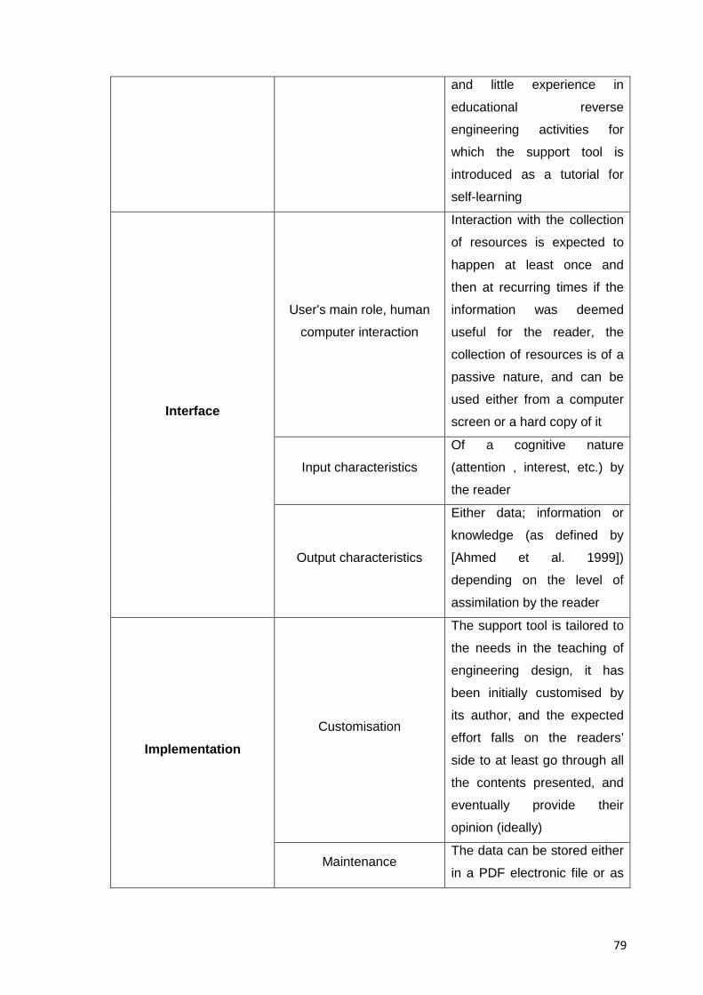
79
and little experience in
educational reverse
engineering activities for
which the support tool is
introduced as a tutorial for
self-learning
Interface
User's main role, human
computer interaction
Interaction with the collection
of resources is expected to
happen at least once and
then at recurring times if the
information was deemed
useful for the reader, the
collection of resources is of a
passive nature, and can be
used either from a computer
screen or a hard copy of it
Input characteristics
Of a cognitive nature
(attention , interest, etc.) by
the reader
Output characteristics
Either data; information or
knowledge (as defined by
[Ahmed et al. 1999])
depending on the level of
assimilation by the reader
Implementation Customisation
The support tool is tailored to
the needs in the teaching of
engineering design, it has
been initially customised by
its author, and the expected
effort falls on the readers’
side to at least go through all
the contents presented, and
eventually provide their
opinion (ideally)
Maintenance The data can be stored either
in a PDF electronic file or as
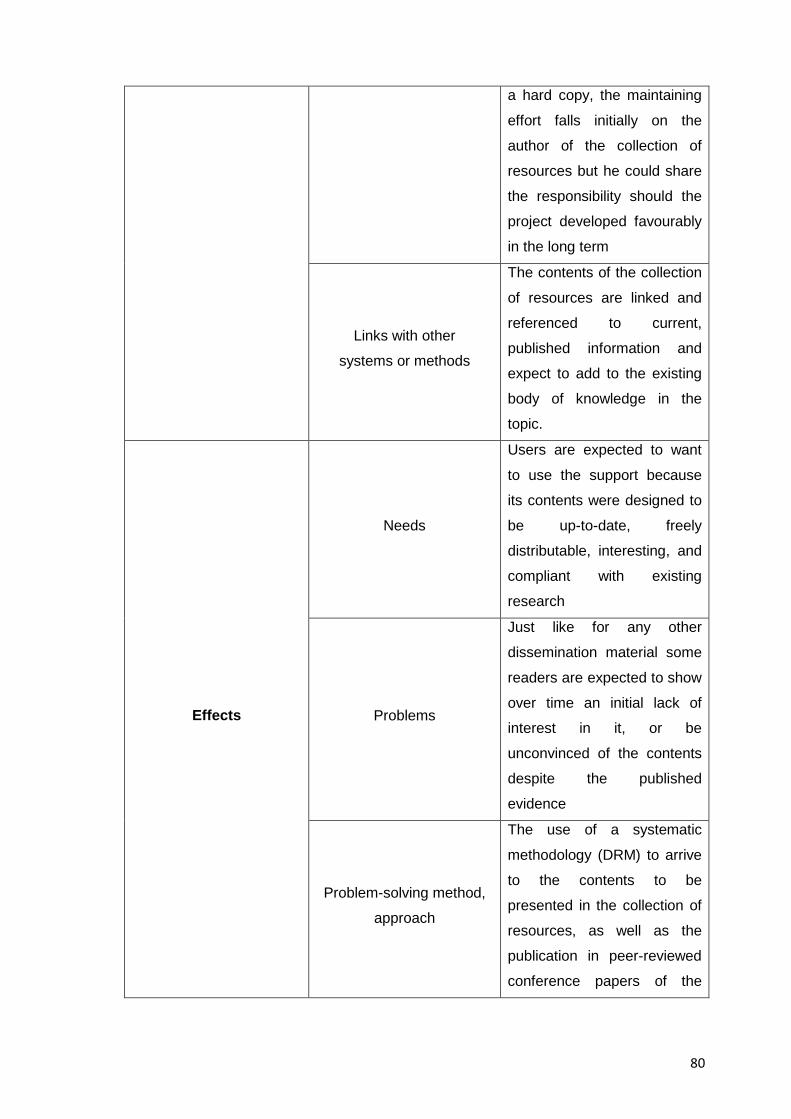
80
a hard copy, the maintaining
effort falls initially on the
author of the collection of
resources but he could share
the responsibility should the
project developed favourably
in the long term
Links with other
systems or methods
The contents of the collection
of resources are linked and
referenced to current,
published information and
expect to add to the existing
body of knowledge in the
topic.
Effects
Needs
Users are expected to want
to use the support because
its contents were designed to
be up-to-date, freely
distributable, interesting, and
compliant with existing
research
Problems
Just like for any other
dissemination material some
readers are expected to show
over time an initial lack of
interest in it, or be
unconvinced of the contents
despite the published
evidence
Problem-solving method,
approach
The use of a systematic
methodology (DRM) to arrive
to the contents to be
presented in the collection of
resources, as well as the
publication in peer-reviewed
conference papers of the
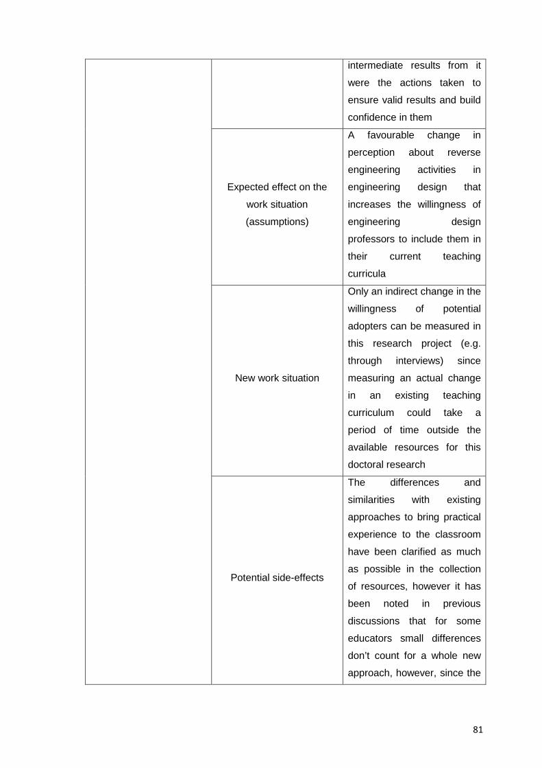
81
intermediate results from it
were the actions taken to
ensure valid results and build
confidence in them
Expected effect on the
work situation
(assumptions)
A favourable change in
perception about reverse
engineering activities in
engineering design that
increases the willingness of
engineering design
professors to include them in
their current teaching
curricula
New work situation
Only an indirect change in the
willingness of potential
adopters can be measured in
this research project (e.g.
through interviews) since
measuring an actual change
in an existing teaching
curriculum could take a
period of time outside the
available resources for this
doctoral research
Potential side-effects
The differences and
similarities with existing
approaches to bring practical
experience to the classroom
have been clarified as much
as possible in the collection
of resources, however it has
been noted in previous
discussions that for some
educators small differences
don’t count for a whole new
approach, however, since the
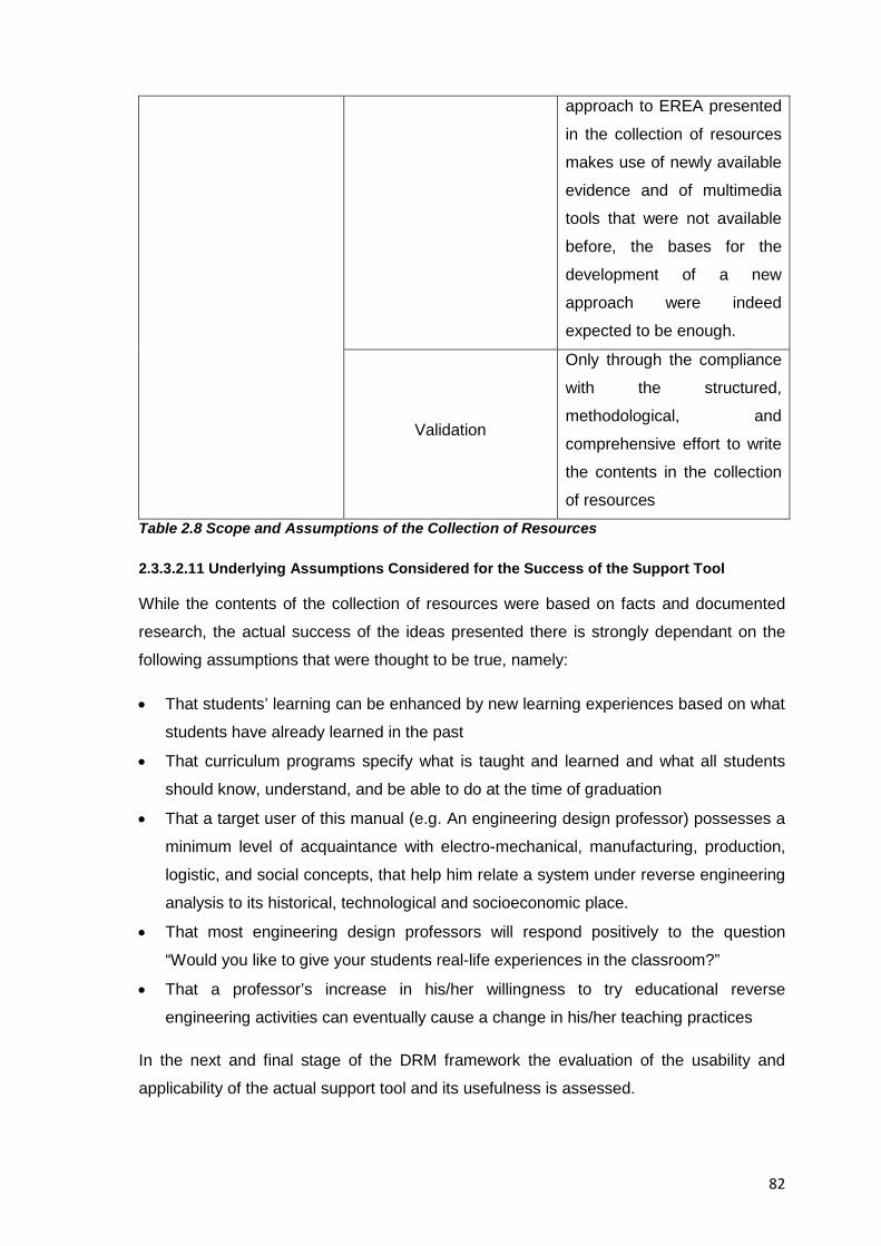
82
approach to EREA presented
in the collection of resources
makes use of newly available
evidence and of multimedia
tools that were not available
before, the bases for the
development of a new
approach were indeed
expected to be enough.
Validation
Only through the compliance
with the structured,
methodological, and
comprehensive effort to write
the contents in the collection
of resources Table 2.8 Scope and Assumptions of the Collection of Resources
2.3.3.2.11 Underlying Assumptions Considered for the Success of the Support Tool
While the contents of the collection of resources were based on facts and documented
research, the actual success of the ideas presented there is strongly dependant on the
following assumptions that were thought to be true, namely:
• That students’ learning can be enhanced by new learning experiences based on what
students have already learned in the past
• That curriculum programs specify what is taught and learned and what all students
should know, understand, and be able to do at the time of graduation
• That a target user of this manual (e.g. An engineering design professor) possesses a
minimum level of acquaintance with electro-mechanical, manufacturing, production,
logistic, and social concepts, that help him relate a system under reverse engineering
analysis to its historical, technological and socioeconomic place.
• That most engineering design professors will respond positively to the question
“Would you like to give your students real-life experiences in the classroom?”
• That a professor’s increase in his/her willingness to try educational reverse
engineering activities can eventually cause a change in his/her teaching practices
In the next and final stage of the DRM framework the evaluation of the usability and
applicability of the actual support tool and its usefulness is assessed.
83
2.3.4 Deliverables from the Descriptive Study II Stage
Three main deliverables are expected from this research stage which can take one or
several forms of the options listed below, namely:
A. Results of application evaluation
• Verify if the actual support was used for the task intended
• Verify expected effect on the Key Factors
B. Results of success evaluation
• Identify whether the support indeed contributes to success
C. Implications and suggestions for improvement of:
• The actual support
• The intended support
• The actual and intended introduction plan
• The actual and intended impact model
• The reference model
• The criteria used
2.3.4.1 Account of the Development of the Collection of Resources
The collection of resources addressed what were found to be the main concerns
regarding the perception of educational reverse engineering activities as a valid teaching
aid in the area of engineering design, as such it contained what the exploratory results
indicated to be the contents with the highest possibility to impact the research situation
and cause the planned changes, it contained for example, a historical account of the
development and contextualization of reverse engineering activities as well as a guided
example that intended to help the readers, to prepare; execute, evaluate, follow-up and
eventually create their own instructional learning activities suited to their teaching
practice.
The pedagogical approach chosen in the collection of resources for the teaching of EREA
to students of engineering design was geared towards an instructor-assisted team
learning rather than a self-directed learning by students, in this way, students can benefit
not only from their professor’s experience but also from a teamwork setting where
information gaps can be filled by other team members and by the efforts of a pool of
students contributing towards a unified goal.
84
Concerning the resources for the execution of the activities themselves, traditional
consumer products were the artifacts chosen for the educational activities, since they
integrate a number of technologies that can be discussed and studied in the classroom,
and that serve as examples of design and its impact on the state of the art; the
environment, and the quality of life. The examples of reverse engineering activities
presented in the collection of resources then, intend to illustrate the interdisciplinary
research, common to engineering design that help students understand the connections
among materials science, manufacturing processes, general engineering, ecodesign, and
the socioeconomic sciences.
2.3.4.2 Provisions to Avoid Unexpected Outcomes and Ensure the Success of the Support Tool
In order to avoid or at least minimize potentially negative or unexpected outcomes from
the support tool, the following points were considered in designing it:
a) Needs of the users: The support tool intended to address the real needs of the users
at the current time of use, the needs were not considered to be obsolete or come from
unsubstantiated perceived needs
b) Theoretical framework: The theories and assumptions that link the concepts in the
collection of resources to the expected benefits from it are thought to be correct
based on an analysis of the state of the art
c) Concept: The concept was assumed to be well thought out based on existing
research and similar approaches to the needs detected
d) Support realization: The support tool was assumed to have been realized correctly
using the means that could reveal the expected impact
e) Introduction of the support: Although some related resources (cf. Theses) were
introduced by others during the duration of this doctoral research, the resulting
support tool was still thought to have been introduced correctly; using suitable means,
with clear instructions for its use, and at the right time
f) Unexpected changes to the working environment: No counterproductive changes
to the working environment caused by the introduction of the collection of resources
itself were considered plausible
g) Target work atmosphere: The support tool was targeted to individuals who were
supposed to work under academic freedom, however the author of this dissertation
85
was aware that the context where the support tool would be used is dynamic and
policies of all sorts could have a large influence in its acceptance / rejection
h) User’s competencies: The target population are engineering design professors at
the undergraduate level who were expected to have the appropriate competencies to
benefit from the support tool
i) User’s Preferences: This is indeed the major threat to the goals of the support tool
since the users’ preferences; beliefs, interests and motivations towards EREA might
not be in line with the goals of the support tool despite the submitted evidence
j) Resources available: Though the resources for the completion of the support tool
were limited, an appropriate research and scientific result was expected from it
k) Unsuitable work environments: The collection of resources was written so it could
benefit any university even those with minimum resources at disposal, however there
could be cases in the field where the available resources (e.g. People, time,
equipment) are insufficient, or the available environment (e.g. Organisational and
technical infrastructure, help service, etc.) could be unsuitable for carrying out
educational reverse engineering activities as proposed in the collection of resources
2.3.4.3 Major Items to Test in the Support Tool
The comprehensiveness, structure, and academic validity of the collection of resources
were the major items to test, its user interfaces, that is, the aesthetic elements of it were
not a major concern because they don’t make part of the core contribution of the
collection, however, a readable and pleasing format was sought after to the best of the
author’s understanding not to affect the functionality of the collection of resources. The
evaluation of the resources then, and in an effort to provide a real contribution to the body
of knowledge that was academically and practically worthwhile, was focused on the core,
essential and unique features of the support tool
2.3.4.4 Research Plan and Methodology for the Testing of the Research’s Hypotheses
The hypotheses of this research were pre-tested via a literature review and then indirectly
tested through the acceptance and publication in peer-reviewed conferences of the
intermediate results from the research, the comments by those professors who received
the support tool (e.g. “looks interesting”, “send it”, “I’ll see what I can do”, “looks
promising” could add a certain, subjective feedback, but it was not taken into
86
consideration since the reception of feedback came after the creation of the guiding
manual and submission of the doctoral thesis for review. However the author intends to
keep updating the support tool with feedback from the field for as long as it is relevant.
2.3.4.4.1 Recipients of the Guiding Manual
Instead of a formal test population to evaluate the hypotheses presented in this research
two groups of researchers in academic institutions throughout Europe were contacted to
know about their interest in the support tool.
The first group of researchers had previously expressed their interest in the final results
from this research in 2008, 2009 and 2010 when intermediate results from it were
presented at the following congresses:
• 10th Engineering and Product Design Education International Conference, E&PDE’08.
Barcelona, Spain
• 11th Engineering and Product Design Education International Conference, E&PDE'09.
Brighton, UK
• International Design Conference - Design 2010. Dubrovnik, Croatia
• XIV International Congress on Project Engineering, 2010. Madrid, Spain
• 12th Engineering and Product Design Education International Conference,
E&PDE’10. Trondheim, Norway
The second group consisted of researchers who agreed to receive the support tool for
their own perusal (and even provide some feedback without obligation, and at some point
in time) and who belonged to one of the 38 different academic institutions with accredited
courses on engineering design by the Institution of Engineering Designers of the UK
(IED), (Database available at http://www.institution-engineering-designers.co.uk/courses)
that were contacted to find out about their interest in this research
2.3.4.4.2 Demographics of the Recipients of the Guiding Manual
The demographics of the respondents included 13 engineering design professors (11
Male / 2 Female) from 12 different institutions with a background in engineering practice
and research from several major disciplines and types of businesses (e.g. Consulting,
manufacturing, maintenance, etc) and more than ten years of experience in academic
practice, in the author’s opinion they could be considered a relevant representation of the
community of engineering design researchers at an European scale. Table 2.9 further
below details the recipient institutions of the guiding manual (the names of the recipients
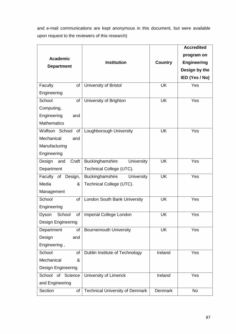
87
and e-mail communications are kept anonymous in this document, but were available
upon request to the reviewers of this research)
Academic Department
Institution Country
Accredited program on Engineering
Design by the IED (Yes / No)
Faculty of
Engineering
University of Bristol UK Yes
School of
Computing,
Engineering and
Mathematics
University of Brighton UK Yes
Wolfson School of
Mechanical and
Manufacturing
Engineering
Loughborough University UK Yes
Design and Craft
Department
Buckinghamshire University
Technical College (UTC).
UK Yes
Faculty of Design,
Media &
Management
Buckinghamshire University
Technical College (UTC).
UK Yes
School of
Engineering
London South Bank University UK Yes
Dyson School of
Design Engineering
Imperial College London UK Yes
Department of
Design and
Engineering ,
Bournemouth University UK Yes
School of
Mechanical &
Design Engineering
Dublin Institute of Technology Ireland Yes
School of Science
and Engineering
University of Limerick Ireland Yes
Section of Technical University of Denmark Denmark No
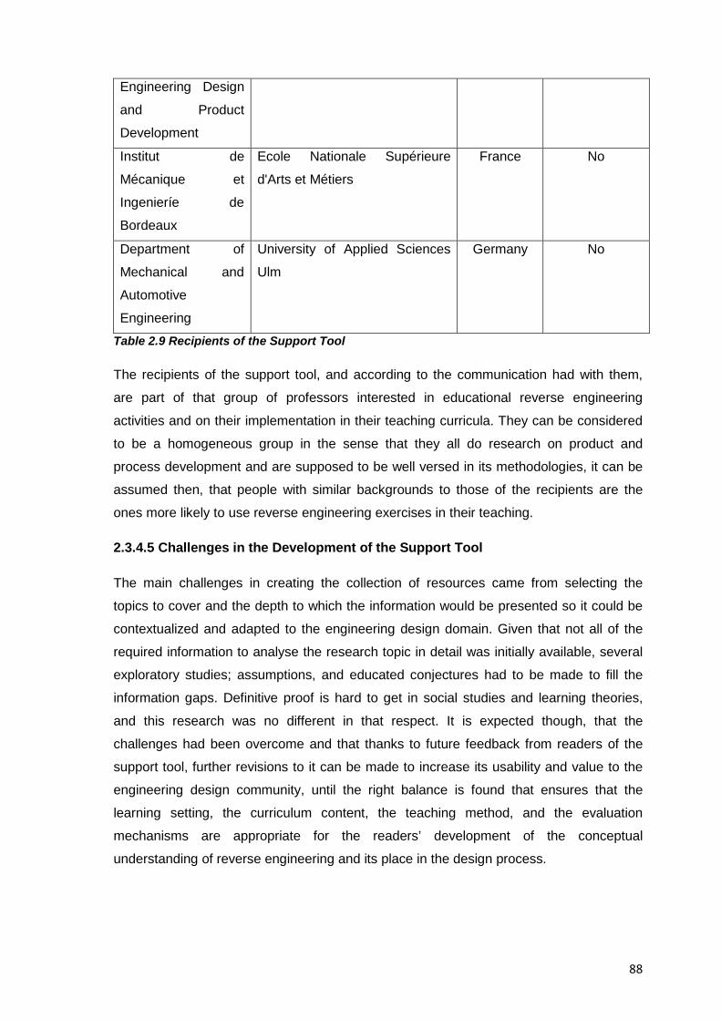
88
Engineering Design
and Product
Development
Institut de
Mécanique et
Ingenieríe de
Bordeaux
Ecole Nationale Supérieure
d'Arts et Métiers
France No
Department of
Mechanical and
Automotive
Engineering
University of Applied Sciences
Ulm
Germany No
Table 2.9 Recipients of the Support Tool
The recipients of the support tool, and according to the communication had with them,
are part of that group of professors interested in educational reverse engineering
activities and on their implementation in their teaching curricula. They can be considered
to be a homogeneous group in the sense that they all do research on product and
process development and are supposed to be well versed in its methodologies, it can be
assumed then, that people with similar backgrounds to those of the recipients are the
ones more likely to use reverse engineering exercises in their teaching.
2.3.4.5 Challenges in the Development of the Support Tool
The main challenges in creating the collection of resources came from selecting the
topics to cover and the depth to which the information would be presented so it could be
contextualized and adapted to the engineering design domain. Given that not all of the
required information to analyse the research topic in detail was initially available, several
exploratory studies; assumptions, and educated conjectures had to be made to fill the
information gaps. Definitive proof is hard to get in social studies and learning theories,
and this research was no different in that respect. It is expected though, that the
challenges had been overcome and that thanks to future feedback from readers of the
support tool, further revisions to it can be made to increase its usability and value to the
engineering design community, until the right balance is found that ensures that the
learning setting, the curriculum content, the teaching method, and the evaluation
mechanisms are appropriate for the readers’ development of the conceptual
understanding of reverse engineering and its place in the design process.
89
As it could be seen from this last stage of the DRM framework one of the most important
deliverables was to identify the mechanisms of the situation under analysis. Because of
this several conclusions from the research situation could be drawn now and were shown
later in the general conclusions chapter.
2.4 Chapter Conclusions
Research in the area of engineering design education carried a number of challenges;
since the integration of the technical knowledge inherent to the topic of study itself
needed to be placed in the context of education and of the varied fields it comprised,
such as cognitive psychology in students, and educational strategies in academic
institutions. However, the stepwise approach, and the need to provide specific
deliverables for every step of the DRM methodology helped to build a research ground
since the beginning of the project, where the ongoing work and progresses in the
development of the investigation could always be referred back to the previous stages of
the methodology as one kept moving forward.
It is also worth mentioning that in coming up with a thorough methodological approach to
the development of this research the author sought to be accepted to the 2009 European
Summer School on Engineering Design where he was admitted indeed and where he met
Professor Lucienne Blessing who is one of the two creators of the DRM methodology and
learned there first-hand how to use it, the author also met Univ.-Prof. Dr.-Ing. Christian
Weber who provided valuable counselling for the progress of this research and who gave
the author of this dissertation the opportunity to spend a period of three months at the
Engineering Design Department of the Faculty of Mechanical Engineering at the
Technical University of Ilmenau in Germany as a visiting doctoral student and where the
following study opportunities were given that turned out to be highly relevant to the
development of this doctoral research, namely:
• To analyse and understand the approach, procedures and examples used for the
teaching of Konstruktionskritik (Systematic analysis of technical products / systems)
at their department of engineering design
• To learn from the articles published by the faculty of TU Ilmenau at the International
Symposium on History of Machines and Mechanisms.
• To learn from the Digital Mechanism and Gear Library DMG-LIB Project and the
university’s long tradition in engineering design
• To learn from VDI norms such as VDI 2221 and 2206
90
Although DRM was a framework that provided supporting methods and guidelines to
formulate and validate models and theories for the multidisciplinary nature of engineering
design research; research in engineering design education was bound not only by
technical topics but also by the cognitive processes of students and the educational
strategies of the institutions under study as mentioned already, for this reason, it could be
said that the stepwise approach of the DRM methodology helps novice and experienced
researchers to develop a solid line of argumentation to plan and implement research
stages in a more effective and efficient way to provide structured deliverables that
enhance information traceability throughout the project stages
It should still be mentioned that while the DRM framework’s emphasis on the
documentation and scholar treatment of its stages helps to come up with a higher chance
of scientifically valid and reliable results, the researcher’s selection, application and
design of methods to investigate and interpret research data can still influence the final
results. While no research approach can guarantee perfect results from any given project
then, it is still believed that the use of a methodology helped to come up with scientifically
valid results that could be presented to the right audiences and that in the end were
materialised into the collection of resources for the study of educational reverse
engineering activities in engineering design education presented in Annex A of this
doctoral research.
91
3 CHAPTER 3 RESEARCH RESULTS
3.1 Chapter Introduction
In this chapter an explanation of the results from this doctoral project is presented. It is
explained here how the results themselves are of a decidedly empirical (cf. Observation
and testing) nature and reflect a practical approximation to what was believed to cause a
positive change in the detected research situation.
3.2 Major Results
The most important result from this research is the collection of resources for the study of
educational reverse engineering activities in engineering design education presented in
Annex A. Why it is considered a valid result and how it expects to elicit a change in the
research situation is explained next.
3.2.1 The Collection of Resources for the Study of Educational Reverse Engineering Activities in Engineering Design Education
In Annex A nine major individual resources bundled as a collection are presented, each
of them as a self contained document dealing with one relevant aspect necessary for the
comprehensive study of EREA. The resources themselves are properly structured
according to common conventions on the presentation of data and they include
introductory, explanatory, original results, and final sections, they can be read individually
according to the reader’s needs, or they can be read sequentially to gradually increase
the reader’s awareness of the topic, the resources then, eventually converge at Resource
7 which presents a practical example of how an educational reverse engineering activity
is done in a typical engineering design program. A summary of each resource in the
collection is presented next.
3.2.1.1 Summary of Resource 1: Fundamentals of Educational Reverse Engineering Activities.
Contextualization of the varied scientific aspects that make educational reverse
engineering activities a valid topic of research , it intends provide the reader with actual,
published facts about the background, use, and future of such activities and intends to
mitigate the perception of potential adopters of EREA about the lack of a formal theory
behind them
3.2.1.2 Summary of Resource 2: Reverse Engineering and Learning.
92
An account of the mechanisms and conditions that explain the connection between the
hands-on activities inherent to EREA and the associated cognitive processes that allow
the students’ acquisition of abilities related to the practice of engineering design. It
intends to address potential adopters’ perception of a lack of pedagogical value of EREA
3.2.1.3 Summary of Resource 3: Misconceptions about Reverse Engineering.
An explanation of how the use of reverse engineering in commercial contexts has
damaged the view of the educational aspects of them because of their shared name. This
annex intends to address the perception by early reviewers of this work that EREA could
be unlawful or induce negative habits to students
3.2.1.4 Summary of Resource 4: Benefits of Reverse Engineering.
A report about published benefits, as well as the investigation towards original results
regarding the strongest elements EREA can add to the teaching of engineering design.
This annex intends to provide definite evidence about the benefits of EREA and thus help
increase the reader’s eagerness to include them into their teaching practice
3.2.1.5 Summary of Resource 5: A Proposed Methodology for Reverse Engineering Analysis in Engineering Design Education.
The original, core contribution from the collection of resources for the study of EREA that
suggests a method for the reverse engineering analysis of consumer products in
education and that covers the relevant aspects of the analysis of a product in the field of
engineering design. This annex intends to solve the previously published concerns about
the lack of resources to execute reverse engineering activities (cf. Section 1.2.7)
3.2.1.6 Summary of Resource 6: A Suggested Pedagogy for the Teaching of Educational Reverse Engineering Activities.
A suggested pedagogy for the teaching of EREA that consists of a collection of tips and
advices regarding the analyses, tasks and questions that have proved successful in the
past in guiding and supporting each of the individual stages of an educational reverse
engineering methodology. This annex aims mitigate the potential adopters perception
about a lack of resources for self-directed study of EREA (cf. 1.2.7)
3.2.1.7 Summary of Resource 7: Integrated Example of an Educational Reverse Engineering Activity on a Disposable Camera.
93
a self-contained example of an educational reverse engineering activity using a
disposable photographic camera as a subject system. This annex is intended to show
professors of engineering design in an integrated, practical way what an EREA would
look like in a real educational setting, thus each step of the example, how it is handled
and what the results from it are, should be understood both as an indication of what an
EREA would comprise and how experience recommends to deal with, its main intention is
to mitigate the potential adopters perception about the lack of guided examples of EREA
(cf. 1.2.7)
3.2.1.8 Summary of Resource 8: Conclusions and Final Remarks.
An account of the present and future of the research and practice of EREA that intends to
mitigate the potential adopters’ perception that EREA is a distant area of research where
no new results are being produced
3.2.1.9 Summary of Resource 9: Miscellaneous Resources for the Study of Reverse Engineering.
A group of links and references to existing resources from several fields of knowledge
brought together to provide a comprehensive view of educational reverse engineering
activities. This chapter intends to provide potential adopters of EREA with the elements
for the study of the topic and the eventual creation of their own instructional materials.
The contents included in each of the resources and that if linked together could be
thought of as a guiding manual –albeit a rather long one- for the integration of educational
reverse engineering activities into an engineering design curriculum, intended to tackle
the perceived needs of potential adopters of EREA, and thus positively impact their
perception about them.
The contents in the collection of resources cite and reference to as much as possible of
the existing, published research on the topic and still they can be considered an original
contribution to existing body of knowledge in the topic because of their
comprehensiveness; contextualisation to the field of engineering design, integrative
nature, and the novel approach to the delivery of information presented therein
3.3 Published Results from this Dissertation
Although the collection of resources presented in Annex A was the actual result from this
doctoral research, five conference papers -mentioned already in Section 2.3.2.6-
stemming from this doctoral research were peer reviewed and presented at different
94
conferences during the initial stages of the doctoral research, each of the conference
papers then, can be considered an intermediate result from this research from a time
where the fundamentals of it were still being explored, the results presented in the papers
then, helped to clarify the topic of investigation and to come up with a methodology for its
analysis, and for the direction to follow in pursuing a solution to the research situation.
Most of the tables and figures presented in the four main chapters of this dissertation and
in the collection of resources presented in Annex A at the end of this document derive in
one way or another from those papers and the presentations that were delivered to the
engineering design community.
A detailed account of the tables, figures and results from such papers is not given here
and instead the information to find the full papers is given in the bibliography section of
this document should the reader wanted to access them, still the following results are
worth mentioning because of their importance in leading the research efforts in this
project and in making their way in one way or another into the Resources 1 to 9
presented in this document, namely:
• An exploratory study on how to integrate design praxis into an academic curriculum
taking product visualization techniques as a test case in [Calderon. 2008]
• Exploration into future research lines on the topic of EREA in [Calderon. 2009] and
[Calderon 2010a]
• Fundamentals and descriptions of the research topic in [Calderon. 2010a]
• Determination of the different contexts of the term “Reverse Engineering” in
[Calderon. 2010a]
• Publication of an account of the main milestones of reverse engineering in education
in [Calderon. 2010a]
• Categorization of the desirable competences of a typical engineering design student
and their links to the specific steps of a reverse engineering methodology in
[Calderon. 2010a]
• Comparison of a reverse engineering exercise vs. a conventional engineering design
exercise by showing events, competences and results to provide a solid argument for
the added benefit that reverse engineering exercises can bring to engineering design
education in [Calderon. 2010a] and [Calderon. 2010b]
• Determination of the suitability of EREA to exercise and develop the expected and
desired competences of engineering design students, shown in Resource 4 and after
[Calderon. 2010b]
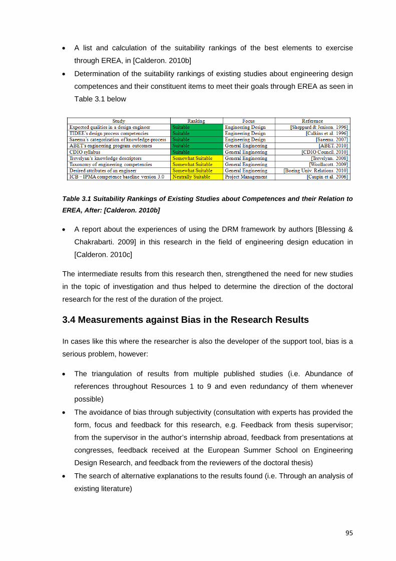
95
• A list and calculation of the suitability rankings of the best elements to exercise
through EREA, in [Calderon. 2010b]
• Determination of the suitability rankings of existing studies about engineering design
competences and their constituent items to meet their goals through EREA as seen in
Table 3.1 below
Table 3.1 Suitability Rankings of Existing Studies about Competences and their Relation to EREA, After: [Calderon. 2010b]
• A report about the experiences of using the DRM framework by authors [Blessing &
Chakrabarti. 2009] in this research in the field of engineering design education in
[Calderon. 2010c]
The intermediate results from this research then, strengthened the need for new studies
in the topic of investigation and thus helped to determine the direction of the doctoral
research for the rest of the duration of the project.
3.4 Measurements against Bias in the Research Results
In cases like this where the researcher is also the developer of the support tool, bias is a
serious problem, however:
• The triangulation of results from multiple published studies (i.e. Abundance of
references throughout Resources 1 to 9 and even redundancy of them whenever
possible)
• The avoidance of bias through subjectivity (consultation with experts has provided the
form, focus and feedback for this research, e.g. Feedback from thesis supervisor;
from the supervisor in the author’s internship abroad, feedback from presentations at
congresses, feedback received at the European Summer School on Engineering
Design Research, and feedback from the reviewers of the doctoral thesis)
• The search of alternative explanations to the results found (i.e. Through an analysis of
existing literature)
96
• The independent arrival to similarly reported results by other researchers (i.e.
Through an analysis of existing literature)
• The explicit attempt to consciously use alternative views to find alternative
explanations across the different topics covered in this research (i.e. Through an
analysis of existing literature and feedback from thesis supervisor)
• Making all research assumptions explicit (cf. Sections 1.2.8, 2.3.3.2.10, and
2.3.3.2.11 of this document)
All of them counted as the strategies to detect and reduce bias in the results from this
dissertation.
3.4.1 Validity and Verification of the Findings and Results from this Research
The following “Logical verification and verification by acceptance” methods proposed by
author [Buur. 1990] were used to verify the validity of results in this research, namely:
A. Logical verification:
• Consistency: There are no internal conflicts between individual elements of the results
(e.g. No contradictions arose from the results or ideas presented in Resources 1 to 9)
• Completeness: All relevant phenomena previously observed can be explained or
rejected by the theories presented (e.g. The results and ideas presented in the
collection of resources reference as much as possible existing, published research
and Resources 1 to 4 in specific provide theoretical frameworks and explanations to
the situations described therein)
• Well-established and successful methods were used and are in agreement with
existing theories (e.g. The research method employed (DRM), and the results of a
decidedly practical nature are presented in the collection of resources according to
common conventions (i.e. format) for the dissemination of results)
• Cases and specific design actions can be explained by means of the results
presented here (e.g. The proposed methodology, the suggested pedagogy, and the
guided example of Resources 5 to 7, can be linked together and their deliverables are
sustained by past published research)
B. Verification by acceptance
• The theories supporting this research are accepted by a relevant scientific community
(e.g. Multitude of references and quotes across the length of the collection of
97
resources , as well as original findings and results from the doctoral research always
being presented in relation to past published research)
• The models and methods derived from this research were acceptable to experienced
designers and educators (e.g. The proposed methodology for educational reverse
engineering analysis in Resource 5, albeit new and integrative in its approach, can
still be considered a derivative one from previous published ones by authors such as
[Lamancusa et al. 1996] and [Otto & Wood. 2001]. Several elements from the results
from Resources 6 and 7 are also based on past published research and are quoted
accordingly)
Verification by acceptance then, provides the strongest support to the findings from this
dissertation.
3.4.2 Reflective Questions before Communicating Research Results
Authors [Blessing & Chakrabarti. 2009] provide a series of reflective questions that are
important to ask oneself in order to communicate credible, scientific results, the answer to
such questions adapted to the results from this dissertation are listed below, namely:
• Q1: What is my contribution?
A1: The dissemination of the benefits of educational reverse engineering activities in
engineering design education through a freely distributable collection of resources
that show how to study; prepare, execute, evaluate, and follow them up
• Q2: Why do I believe it to be academically worthwhile?
A2: the DRM methodology which is specially suited for research in the area of
engineering design education was used, along with standard peer-reviewed research
practices
• Q3: Why do I believe it to be practically worthwhile, or to contribute to a practical
goal?
A3: The need to provide practical experience in the classroom to engineering
students has been published several times (cf. Section 2.1) and reverse engineering
activities can fulfil this need, thus the collection of resources for the study of EREA in
engineering design education stemming from this doctoral research is presented in
Annex A
98
• Q4: Why do I believe that I have the competences or can obtain the competences to
execute this evaluation?
• A4: An interest in the research topic made the author of this research gather the
information needed to go on with this investigation (e.g. Acceptance to the European
summer school on engineering design research, and the acceptance as a visiting
doctoral researcher abroad), also, the consultation with experts at multiple venues
allowed for an exchange of views; valuable information, and guidance to complete
this research project.
3.5 Plans for the Dissemination of Research Results
Besides aiming for the publication of a paper journal explaining the results and findings
from this dissertation, at the end of the doctoral project an updated, freely distributable
collection of resources for the study of EREA in engineering design education was
expected to be re-sent to the academic departments mentioned in Table 2.9 above.
Additionally the collection of resources was intended to be listed with NEEDS – the
National Engineering Education Delivery System (http://www.needs.org/) and with the
Engineering Pathway (http://www.engineeringpathway.com) which were two North
American websites on resources for the teaching of engineering, unfortunately at the time
of conclusion of this project both sites had closed already. After the completion of the
research project though, the author expected to start writing the collection of resources
again but in Spanish language time.
3.6 Chapter Conclusions
Unless otherwise stated all the findings from this research were of a purely practical
nature but in order to properly contextualise the results from this research though, it
should be mentioned that the resources available for the project (cf. Time) didn’t allow the
field testing of the collection of resources since it took extremely long to receive any
feedback from it, results from the field though were expected to be added to future papers
resulting from this dissertation
It should be mentioned too that the contents of the nine individual resources in the
collection, represent the main deliverables from this dissertation but it was impractical to
evaluate them through peer consensus because of their length and comprehensiveness.
Because of this, the collection of resources in Annex A (despite being the result of a
formal methodological approach) is presented only as a theoretical, exploratory
approximation to what could cause the desired change in the detected research situation.
99
The full research project then, consisted of:
• A doctoral thesis for the dissemination of results among the academic community,
and as an evaluation of the author’s performance as a researcher
• A collection of freely distributable resources (the only one available as of October
2015) for the study of EREA in the field of engineering design education that
documented the theoretical background behind hands-on activities in education and
the technical and methodological knowledge needed to perform reverse engineering
exercises in an engineering design curriculum,
• A paper-like summary of the whole research for those interested in the project but
with little time available to get involved in it
• Five peer reviewed conference papers presented at congresses across Europe
discussing relevant topics to the research project
• A detailed power point presentation (available to everyone by contacting the author)
that was aimed at a general audience in order to disseminate the results from this
research
All other plausible views and alternatives to the results from this research were
acknowledged by the author and will still serve as a starting point for further research in
the topic; in the next and last chapter then, the conclusions from this doctoral project are
presented.

100
This page intentionally left blank
101
CHAPTER 4 RESEARCH CONCLUSIONS AND FINAL REMARKS
4.1 Chapter Introduction
Although published studies stated that hands-on activities such as EREA could become a
popular pedagogy to provide students with practical experiences in the classroom,
[Lamancusa et al. 1996]; at the beginning of this doctoral research around 2008 there
were still several pedagogical, organizational, and even methodological areas left to
explore in the topic. After initial exploratory studies and discussions with domain experts
in academia and industry the need to provide resources for the study of EREA in
engineering design education to the potential adopters of them was acknowledged, and a
research effort was planned to materialise a possible solution to such situation.
This chapter discusses the conclusions from trying to achieve the research goals of this
dissertation and provides the reader with an overview of the present and future of the
practice of educational reverse engineering activities as an aid in the teaching of
engineering design.
4.2 Attainment of the Expected Outcomes of the Research
At the beginning of this project the expected result from it was the contribution of new
practical knowledge to the area of engineering design education by documenting and
understanding the impact educational reverse engineering activities could have in it. It
was believed at the time that by easing the potential adopters’ learning curve for the
preparation; execution, evaluation and follow up of such tasks, the knowledge gaps and
unwanted complexity they could entail could be avoided, and so a planned effort started
to come up with a support tool (a collection of resources) for the study of EREA in
engineering design education that included suitable guidelines; methods, and examples
for self-directed learning. This section discusses the conclusions from striving to achieve
those goals and lists the steps and considerations taken to answer the research
questions, assess the research objectives and assumptions, and validate the research
hypotheses.
4.1.1 Answer to the Research Questions
In projects of an eminently practical nature such as this one, research questions are of
paramount importance since the answer to them provides a solid ground on the
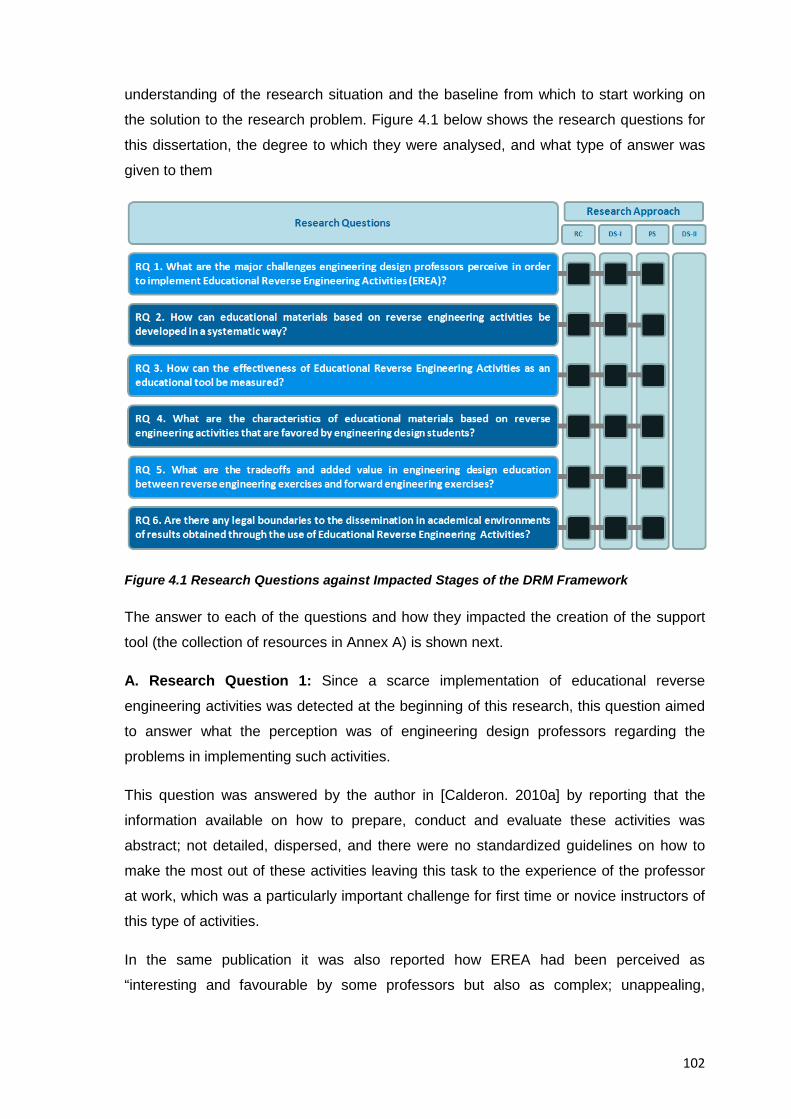
102
understanding of the research situation and the baseline from which to start working on
the solution to the research problem. Figure 4.1 below shows the research questions for
this dissertation, the degree to which they were analysed, and what type of answer was
given to them
Figure 4.1 Research Questions against Impacted Stages of the DRM Framework
The answer to each of the questions and how they impacted the creation of the support
tool (the collection of resources in Annex A) is shown next.
A. Research Question 1: Since a scarce implementation of educational reverse
engineering activities was detected at the beginning of this research, this question aimed
to answer what the perception was of engineering design professors regarding the
problems in implementing such activities.
This question was answered by the author in [Calderon. 2010a] by reporting that the
information available on how to prepare, conduct and evaluate these activities was
abstract; not detailed, dispersed, and there were no standardized guidelines on how to
make the most out of these activities leaving this task to the experience of the professor
at work, which was a particularly important challenge for first time or novice instructors of
this type of activities.
In the same publication it was also reported how EREA had been perceived as
“interesting and favourable by some professors but also as complex; unappealing,
103
unlawful, and unnecessary by others” and so an effort was committed to “improve their
credibility as a teaching tool and easing the entry barriers and learning curve for those
interested in integrating them into their teaching”, [Calderon. 2010a]
The work done to fulfil that promise then, was reflected in the writing of the collection of
resources shown in Annex A and specifically in:
• Resource 3, “Misconceptions about Reverse Engineering”, to clarify major
misconceptions about EREA in education.
• Resource 4, “Benefits of Reverse Engineering”, to present the reader with previously
published advantages; potentialities, and added value reverse engineering activities
could bring to the teaching and learning of engineering design.
• Resource 5, “A Proposed Methodology for Reverse Engineering Analysis in
Engineering Design Education”, to suggest a methodology for educational reverse
engineering analysis that included the planning; executing, evaluating and following-
up of them
• Resource 6, “A Suggested Pedagogy for the Teaching of Educational Reverse
Engineering Activities” to provide a collection of tips and advices dealing with the
practical aspects behind the execution of the steps; analyses, tasks, and questions
inherent to an educational reverse engineering analysis
• Resource 7, “Integrated Example of an Educational Reverse Engineering Activity on a
Disposable Camera” To provide a guided example, suitable for self-directed learning
of an educational reverse engineering activity using a disposable photographic
camera as subject system
• Resource 9, “Miscellaneous Resources for the Study of Reverse Engineering” to
provide the reader with an assortment of references linking to published research to
support the study of EREA
Because an actual result was created by the researcher in order to answer Research
Question 1, it means that it covered the three first stages of the DRM framework and thus
an actual understanding of the situation was first achieved, followed by a deeper research
into the factors that influenced it, to finally end in the creation of a result (the collection of
resources) to answer the research question.
B. Research Question 2: This question aimed to find the patterns that educational
reverse engineering activities could have, in terms of content and methodology that had
been considered successful in the past, or that could be considered successful in the
current conditions. It was answered by the author in [Calderon.2010b] where it was
104
published the intention to “develop and document the practical knowledge across
dispersed disciplines needed to develop an assimilable and readily applicable manual for
the systematic and effective development, execution and evaluation of D/A/A
(Disassemble, Analysis, Assembly) activities to support the teaching of engineering
design adapted to the requirements of a typical curriculum” and the specific actions that
were considered necessary to lead to it were listed as “considering specific learning
objectives, fundamentals, methodologies, tools, test materials and feedback
mechanisms” all of this done “through the use of a methodological framework that allows
the creation of systematic, structured, methodological , scientifically valid results” in order
to “ease the learning curve for the preparation, execution and evaluation tasks by
reducing knowledge gaps, unwanted complexity and unnecessary steps”,
[Calderon.2010b]
In the end, an analysis of previously published educational materials based on
educational reverse engineering activities revealed that they were based on the work led
by four major individuals or research groups, namely: [Sheppard. 1992a]; [Lamancusa et
al. 1996], [Otto & Wood. 2001], or [Lewis et al. 2011], however, it was noted that certain
methods, analyses, or desired goals published by a given researcher were absent in the
examples from the others and vice versa, and so an analysis of all available examples at
the time was done to come up with a comprehensive, summarised, and contextualised
methodology that included all relevant steps and tools suggested by previous researchers
but that for a number of reasons had been ignored by others
Additionally, an analysis of the strongest elements EREA could add to the teaching of
engineering design was done and presented in Resource 4 “Benefits of Reverse
Engineering” after the work already done leading to the publication of “A Comparison of
Competences Required in Reverse Engineering Exercises Versus Conventional
Engineering Exercises and its Relationship to IPMA’s Competence Baseline” in
[Calderon. 2010b] and from those elements listed therein that were suitable to be taught
through EREA the guided example of an EREA presented in Resource 7 was planned (cf.
Focus on activities dealing with information collection; disassembly, the analysis-
synthesis cycle, the redesign of a subject system, and the dissemination of results). This
novel approach to a comprehensive methodology for educational reverse engineering
analysis suited to the field of engineering design that united the best practices in the
practice of educational reverse engineering was indeed the core contribution of the
collection of resources
105
Because Resources 4 and 7 were written to answer this research question and it could
be determined that EREA share the characteristics of hands-on activities and that this
same level of interactivity is what should be replicated in EREA, this research questions
also covered the three first stages of the DRM framework and thus an actual
understanding of the situation was first achieved, followed by a deeper research into the
factors that influenced it, to finally end in the creation of a result (Resources 4 and 7) to
answer the research question.
C. Research Question 3: After defining effectiveness as the capacity of producing a
desired effect, this question aimed to measure how educational reverse engineering
activities as an educational tool compared against traditional (forward) engineering
design exercises. After analysing previously reported benefits of EREA by past
researchers and after determining in Resource 4 what the strongest elements EREA
could add to the teaching of engineering design, it was found out that after performing
EREA students were expected:
• To improve the understanding of simple information (Vocabulary; facts, equations,
quotes)
• To improve the understanding of complex information (Differentiation; comparison,
contrasting, synthesizing of information)
• To improve their theorizing, analyzing, and problem solving performance
• To improve the use of tools and procedures
• To investigate the natural and industrial world
• To improve their communication and team work skills
And so Resource 6 was written where one of its four major sections deals specifically with
the evaluation of EREA from professors to students, from students to students and even
from students to professors considering the abovementioned points (e.g. Tools;
techniques, grading policies, standards of evaluation, etc.). Additionally an example of
evaluation of an EREA that focused on measuring the progress in abilities and knowledge
of students after an EREA and that had been previously published by researcher
[Dalrymple. 2009] was presented and contextualised to fit the goals of this research and
to show the reader one of the possible ways to measure the effectiveness of EREA as an
educational tool in the field of engineering design
Finally, in Resource 2, an exploratory analysis regarding the cycle of students' acquisition
and development of competences through EREA was made and presented and thus it
can be said that the answer to this research question covered the three first stages of the
106
DRM framework and thus an actual understanding of the situation was first achieved,
followed by a deeper research into the factors that influenced it, to finally end in the
creation of a result (Resources 2,4,6) to answer the research question.
D. Research Question 4: This question was devised to detect the successful elements
of educational reverse engineering activities so they could be replicated in varied
exercises but sticking to a common core of best practices; proved strategies, and
contents. The development of the suggested methodology for educational reverse
engineering analysis in engineering design education shown in Resource 5 as well as the
guided example of an EREA following such methodology in Resource 7 are the practical
answer to this research question given that in order to come up with them, an analysis of
all available examples of EREA at the time was done to write a comprehensive,
summarised, and contextualised methodology for educational reverse engineering
analysis that included all relevant steps and tools deemed successful by previous
researchers such as [Sheppard. 1992a]; [Lamancusa et al. 1996], [Otto & Wood. 2001],
[Durfee. 2008] and [Lewis et al. 2011]. The answer to this research question covered the
three first stages of the DRM framework and thus an actual understanding of the situation
was first achieved, followed by a deeper research into the factors that influenced it, to
finally end in the creation of a result (Resources 5 and 7) to answer the research
question.
E. Research Question 5: It is a common mistake to think that reverse engineering is the
opposite of forward engineering, the answer to this question aimed to clarify such
misunderstanding so a proper comparison among the two activities could be made and
thus be able to correlate them as complementing teaching tools rather than competing
ones. In Resource 1 an explanation was first given about the positioning and focus of
reverse engineering against traditional “forward” engineering, later in Resource 2 a
comparison between the two approaches in education was illustrated by showing their
typical events, associated competences exercised, and results. This comparison ended
up being published in [Calderon. 2010a] and thus it can be said that the answer to this
research question covered the three first stages of the DRM framework and so an actual
understanding of the situation was first achieved, followed by a deeper research into the
factors that influenced it, to finally end in the creation of a result (Resource 1 and 2) and
the publication of the answer in [Calderon. 2010a]
F. Research Question 6: Since the educational aspects of reverse engineering activities
are wrongly equated by many people with the illegal uses of reverse engineering in
commercial; software, and intellectual property contexts, this question aimed to clarify the
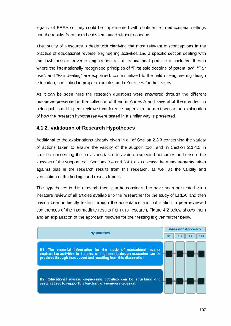
107
legality of EREA so they could be implemented with confidence in educational settings
and the results from them be disseminated without concerns.
The totality of Resource 3 deals with clarifying the most relevant misconceptions in the
practice of educational reverse engineering activities and a specific section dealing with
the lawfulness of reverse engineering as an educational practice is included therein
where the internationally recognised principles of “First sale doctrine of patent law”, “Fair
use”, and “Fair dealing” are explained, contextualized to the field of engineering design
education, and linked to proper examples and references for their study.
As it can be seen here the research questions were answered through the different
resources presented in the collection of them in Annex A and several of them ended up
being published in peer-reviewed conference papers. In the next section an explanation
of how the research hypotheses were tested in a similar way is presented.
4.1.2. Validation of Research Hypotheses
Additional to the explanations already given in all of Section 2.3.3 concerning the variety
of actions taken to ensure the validity of the support tool, and in Section 2.3.4.2 in
specific, concerning the provisions taken to avoid unexpected outcomes and ensure the
success of the support tool. Sections 3.4 and 3.4.1 also discuss the measurements taken
against bias in the research results from this research, as well as the validity and
verification of the findings and results from it.
The hypotheses in this research then, can be considered to have been pre-tested via a
literature review of all articles available to the researcher for the study of EREA, and then
having been indirectly tested through the acceptance and publication in peer-reviewed
conferences of the intermediate results from this research, Figure 4.2 below shows them
and an explanation of the approach followed for their testing is given further below.
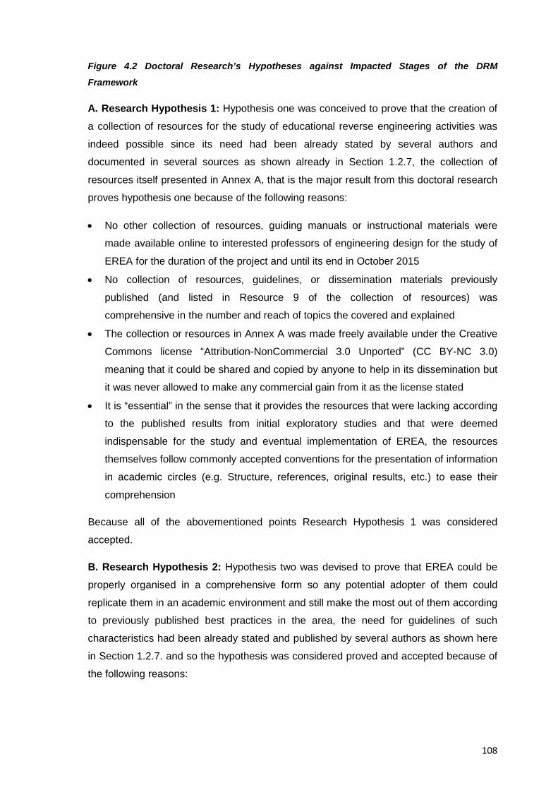
108
Figure 4.2 Doctoral Research’s Hypotheses against Impacted Stages of the DRM
Framework
A. Research Hypothesis 1: Hypothesis one was conceived to prove that the creation of
a collection of resources for the study of educational reverse engineering activities was
indeed possible since its need had been already stated by several authors and
documented in several sources as shown already in Section 1.2.7, the collection of
resources itself presented in Annex A, that is the major result from this doctoral research
proves hypothesis one because of the following reasons:
• No other collection of resources, guiding manuals or instructional materials were
made available online to interested professors of engineering design for the study of
EREA for the duration of the project and until its end in October 2015
• No collection of resources, guidelines, or dissemination materials previously
published (and listed in Resource 9 of the collection of resources) was
comprehensive in the number and reach of topics the covered and explained
• The collection or resources in Annex A was made freely available under the Creative
Commons license “Attribution-NonCommercial 3.0 Unported” (CC BY-NC 3.0)
meaning that it could be shared and copied by anyone to help in its dissemination but
it was never allowed to make any commercial gain from it as the license stated
• It is “essential” in the sense that it provides the resources that were lacking according
to the published results from initial exploratory studies and that were deemed
indispensable for the study and eventual implementation of EREA, the resources
themselves follow commonly accepted conventions for the presentation of information
in academic circles (e.g. Structure, references, original results, etc.) to ease their
comprehension
Because all of the abovementioned points Research Hypothesis 1 was considered
accepted.
B. Research Hypothesis 2: Hypothesis two was devised to prove that EREA could be
properly organised in a comprehensive form so any potential adopter of them could
replicate them in an academic environment and still make the most out of them according
to previously published best practices in the area, the need for guidelines of such
characteristics had been already stated and published by several authors as shown here
in Section 1.2.7. and so the hypothesis was considered proved and accepted because of
the following reasons:
109
• An analysis of all relevant resources about educational reverse engineering activities
available to the author and published before the year 2013 (more than 400
documents dispersed across several fields of knowledge including books, papers,
presentations and web pages) was done to come up with the commonly accepted
elements that comprised an EREA and that had proven successful according to their
authors’ opinions. The results from such analyses were reflected in the suggested
methodology for educational reverse engineering analysis in engineering design
education presented in Resource 5 which reflects the agreed understanding about
EREA, their potential, and their associated best practices. This proposed
methodology is considered by the author the core contribution from this doctoral
research.
• To support the teaching of engineering design, an analysis of the most suitable
competence elements that could be taught through EREA to students of engineering
design (cf. Focus on activities dealing with information collection; disassembly, the
analysis-synthesis cycle, the redesign of a subject system, and the dissemination of
results) was done, after information previously published by the author in [Calderon.
2010b], and these elements determined the kind of analyses, questions and tests that
were favoured in the suggested methodology, pedagogy, and examples of EREA
written by the author and presented as the result from this doctoral research in the
collection of resources in Annex A and more specifically in Resources 4;5,6, and 7
Because of the above-mentioned points Research Hypotheses 2 was considered
accepted.
From Figure 4.2 above then, it can be seen that in order to prove the research
hypotheses, every stage of the DRM methodology and their encompassing studies were
considered, meaning that an actual understanding of the situation was first achieved;
followed by a deeper research into the factors that influenced it, that resulted in the
creation of a support tool that could be expected to change the detected research
problem, and then this support tool was prepared and distributed for testing and use by
others, meaning that the support tool itself (the collection of resources in Annex A) was
only initially or indirectly tested by the researcher in terms of its coherence and scientific
validity, but it rested on others (e.g. the users) the confirmation of the usability the support
tool.
The way the hypotheses were tested in this project though, obeyed the nature of the end
results from it, meaning that on the one side the actual implementation of EREA in the
teaching curriculum of a potential adopter could take a long time to happen and the time
110
span and resources allocated for this dissertation would be unsuitable, and on the other,
the comprehensive nature of the collection of resources made its length unsuitable for
field testing since a potential reader would hardly have enough time to go through the
nine different resources included therein. It should be mentioned though that the
comprehensiveness vs. usability tradeoff was deemed acceptable by the author since
resources of this kind didn’t exist and weren’t available to the general public before, so as
a future project, and as it’ll be explained later the creation of a short guideline for the
study of EREA based on the results presented in this dissertation will remain a future task
for the author.
Based on the information presented above then, it can be considered that the hypotheses
were tested and accepted to a depth seemed reasonable enough, but just as in any other
research project, there are always trade-offs, lines of research, and assumptions that
could benefit from further investigation.
Last but not least, it should be considered that authors [Blessing & Chakrabarti. 2009]
stated that in current times and ”in particular because of the lack of understanding in
design, much research will be non-experimental, but not less worthwhile or necessarily
easier”; authors [King et al. 1994] also wrote that “both experimental and non-
experimental research have their advantages and drawbacks; one is not better in all
research situations than the other” and even author [Yin. 1994] stated that “paradoxically,
the ‘softer’ a research strategy, the harder it is to do”. With the resources allocated to this
research and to the best of the author’s understanding the goals of this doctoral project
were met and a freely distributable collection of resources for the study of EREA was
made available to anyone interested in it.
4.1.3 Assessment of Initial Research Assumptions
Although no formal way to prove if the research assumptions turned out to be true is
usually required, still, and as a personal experience from the author, it should be
mentioned that through the feedback collected at the different venues where the
theoretical fundamentals and the intermediate results from this research were presented,
the assumptions mentioned before in Section 1.2.8 concerning the engineering
professors’ desire to provide hands-on experiences to their students; and concerning the
statement that the clear, contextualized presentation of evidence about the learning
benefits of EREA could actually increase an engineering design professor’s eagerness to
integrate EREA into his/her teaching, both of them indeed, can be said to be true and
correlate to a high degree based on the feedback received from reputed professors in the
111
field of engineering design, however this will remain information of a purely anecdotic
nature, since a formal, numerical result to support this statement would require measuring
methods other than the informal conversations where this assumptions were discussed at
the beginning of the doctoral research.
In regard to sections 2.3.3.2.10 and 2.3.3.2.11 of this document, concerning the scope
and assumptions of the support tool and the underlying assumptions considered for the
success of it. Not only can be stated that they turned to be true in the end but also that
the author believed so strongly in them that the form the results from this research took
(the collection of resources) were heavily influenced by these assumptions.
4.1.4 Attainment of the General and Specific Research Objectives
Concerning the general objective from this research presented already in Sections 1.2.5
further above, it can be said the facilitation of the inclusion of educational reverse
engineering in the teaching of engineering design has been achieved through the writing
of the collection of resources freely given to anyone interested and presented here in
Annex A, although concerns remain regarding the actual usability of the support tool
because of its length, it is expected though, that because the resources were written so
they could be read individually too, some of this usability concerns are mitigated. It
remains future work for the author then, to come up with a short simplified collection of
resources for anyone interested in the topic, not only engineering design professors as
done for this dissertation.
Concerning the attainment of the specific research objectives presented in Section
1.2.5.1 already, they can be considered to have been achieved since each of them has a
direct 1-to-1 relationship with the topics covered in the collection of resources in Annex A.
4.3 Specifics of the Doctoral Research
In this section, relevant information to better classify and assess this research and its
results is presented.
4.2.1 Type (Applied Research)
The work done in this dissertation can be described as “applied research” since the aim
was to determine whether a research situation had improved (practically or potentially)
after an intervention. Applied research then, deals with solving practical problems and
generally employs empirical methodologies where strict research protocols are relaxed
and thus the transparency in the methodology used is crucial (a formal research
112
methodology to have a higher chance to come up with scientifically valid results was
followed in this research and is thoroughly explained in Chapter 2).
4.2.2 Academic Relevance
The added value and differentiating factor this dissertation brings, is that it is adapted and
contextualized to the engineering design domain rather than the more general
engineering one, and that the depth with which this dissertation interconnects the
cognitive aspects of these activities to the rest of the components of the reverse
engineering process can serve as evidence and support to those needing to justify why
they would want to integrate reverse engineering activities in their teaching curricula.
The relevance of this dissertation then, lies in addressing the understanding and
implementation of reverse engineering activities and their potential exploitation within
engineering design education. In trying to prove the main proposition, this thesis also
assessed the role of legality; cognitive processes, and a number of procedural tasks, that
are also part of reverse engineering and that added up to an integrative view of EREA in
engineering design education.
The presentation of solid evidence about their value and their relationship to engineering
design education, should help reverse engineering activities in their integration and
dissemination in educational curricula, therefore to find out which were the areas where
reverse engineering activities could better enhance engineering design student’s abilities,
several planned investigation efforts were done as it can be seen in Resource 4 of the
collection of resources
Finally, a possible associated benefit of this dissertation would be that the same steps
taken to prove the validity of reverse engineering activities as a teaching tool could be
used to test the credibility and effectiveness of any other new educational approach to be
introduced in engineering design education.
This research then, aimed to provide a small but valid contribution to the current body of
knowledge in the topic.
4.2.3 Novelty
In regard to the originality of this research, the author concludes that this is the first effort
to integrate all available information about educational reverse engineering activities in
engineering design education into a collection of resources that is directed at engineering
design professors, it is also expected that the freely-distributable nature of it helps to
113
reach interested readers more easily and thus benefit from an eventual collection of
feedback that helps keep updated the collection of resources.
4.2.4 Original Contributions to the Body of Knowledge of the Topic
The main contribution of this doctoral thesis is to present and review the proposition that
educational reverse engineering activities are a valid tool in the teaching of engineering
design, for such purpose a collection of resources directed at professors of engineering
design that describes how to prepare, execute, evaluate, and follow up such activities to
eventually integrate them into their teaching practice was presented in Annex A
No significant theoretical contribution to the state of the art was made in this research,
however, practical knowledge and contributions from this research include:
• The detailed documenting to support the study and introduction of EREA into existing
engineering design curricula (given that no detailed support was available before this,
other than very generic guidelines and examples)
• The organization and contextualization in the field of engineering design education of
the existing knowledge and experiences with educational reverse engineering
activities
• The collection of resources for the study, preparation, execution, evaluation and
follow-up of EREA
• Five published peer-reviewed conference papers presenting intermediate results from
this research as listed in Section already 2.3.2.6
• A proposed methodology for the reverse engineering analysis of consumer products
for the area of engineering design education that is comprised of proved and tested
analytical tools common to the subject area (e.g. Technical systems analysis, DfX
analyses, engineering tests, etc.), as well as comprised of methodological tasks
arranged in a such a way that allow for the sequential, accumulative analysis of a
subject system. This methodology indeed can be considered the core contribution
from this doctoral research.
This research then, helped concentrate into a single document (cf. the collection of
resources) the knowledge scattered over different areas of knowledge, in order to
facilitate the study of EREA in engineering design education
4.2.3 Applicability of Research Results to Varied Academic Institutions
114
This research and the results stemming from it are aimed, and are relevant, only for the
educational context of reverse engineering, other contexts dealing with commercial
reverse engineering were outside the scope of this research since the very beginning and
would have required the consideration of different theories, individuals, tools,
organisational aspects, and testing methodologies, as such no inferences or associations
can be made to contexts other that the educational one.
For the educational context of reverse engineering then, this research was developed
with a general view in mind so the findings could apply to educators and institutions even
with the minimum infrastructure available for the introduction EREA (the only condition
was that the students’ safety could be ensured at all times), in this sense EREA can work
well in different educational settings, but the greater the differences in levels of technical
support; training, resource materials, and facilities, the greater the caution instructors
need to pay in ensuring that EREA will work well in their institutions. The advice given in
the collection of resources in Annex A then, has been written considering all realistic
scenarios for the implementation of EREA and thus the core learning effect in students
and the results brought about by them should remain valid irrespective of the amount of
resources available at the time of their implementation.
4.2.4 Challenges Faced
The results from this dissertation show that reverse engineering is a special subject not
easily understood or taught; and because proficiency in it requires knowledge from many
different areas, it requires its practitioners to be synergistic, which generally demands
expertise in all underlying subjects. In practice for example, reverse engineering a
product requires knowledge about all parts of it which requires a heavy amount of
information to be gathered and contextualized by teachers and students alike. This is the
main reason behind the length and comprehensiveness of the collection of resources
resulting from this research and presented in Annex A
Concerning the research topic itself, regarding the proposition to prove the worthiness of
EREA as teaching aid, it was challenged indeed several times during the development of
this dissertation and the two questions that arose most of the time were:
• Why should the engineering design community give reverse engineering activities a
try in the teaching of engineering design if they already have other proven methods
for instruction?
• Is it academically worthwhile to consider what at first sight seems like an
unproductive, questionable way to learn about a subject?
115
This research tried to answer favourably those questions based on past published
research and original results from this investigation, and then, should the readers had
been convinced of the answers presented, it provided them with a way to prepare,
execute, evaluate and follow-up EREA with an emphasis on the cognitive process, the
rational sequence of steps, and the potential sources of information that empower
educational reverse engineering analysis.
4.3 General Conclusions
EREA and the effort done in this dissertation to promote their use as an educational tool
has left the author with a range of experiences about what EREA currently are and what
they could still become, these experiences seem worth sharing and will be described in
the following sections for the consideration of the reader
4.3.1 Present of Reverse Engineering Activities in Engineering Design Education
From the research leading to the writing of this dissertation, which included the analysis
of all available data to the researcher, and the drawing of conclusions from published
results, and experiences collected throughout the duration of the project, it could be
concluded about the use of EREA as an educational tool, that they:
• Are just another tool for the teaching of engineering design, they don’t try to abolish
other approaches and as such they are a complement rather than a substitute for
traditional engineering design projects or any other existing teaching tool.
• Are fun: Because students have the opportunity to disassemble and see the insides of
everyday products, thus engaging in a novel and appealing challenge that can help
them stay motivated and interested.
• Are dynamic: Because in to order to complete a successful activity; a simultaneous
collection, integration, and contextualisation of knowledge from different areas has to
be done which demands from students an increased sense of awareness and a
display of resourcefulness.
• Provide a realistic opportunity for practice: EREA provide opportunities for repetition
and reinforcement of key information where students can make mistakes and learn
from them and also from the feedback provided by their instructor, besides, the
infrastructure and rules inherent to an educational environment provide students with
116
a safe environment to fail and try again, thus encouraging them to test new ideas and
behaviours.
• Make learning concrete: EREA are realistic, complex experiences that allow students
to link information to action, and to reinforce engineering concepts through hands-on
experiences which could later help them use concrete learning in real life situations.
• Help learning to permeate: EREA have the potential to enhance students’ learning by
providing them with an opportunity to bring whatever has been learnt theoretically,
into a practical environment where all information can be challenged; analyzed,
discussed and interpreted to come up with a realistic explanation of what has
happened during the design process of the product under analysis and during its
actual operation
• Help students work as team: EREA are a group activity where specific roles and
responsibilities are set; and as such, students can mix their abilities and ideas with
those of their team members thereby helping reinforce learning and interaction in the
team; should noticeable differences in experience; knowledge and status among team
members arise during an EREA, the opportunity to safely repeat the activity until a
desired state is attained contributes to level the knowledge about the product under
analysis of all team members.
• Let the instructors observe the learning process: Professors and teaching assistants
can observe the students while they perform the hands-on tasks and discuss about
what they see and how they relate it to theory; educators then, can provide feedback
and guidance whenever needed while team members take active responsibility for the
learning that occurs during the activity.
• Foster cooperation with industry partners: Existing industrial requirements could be
handed to students to help find a suitable solution, (e.g. By proposing and designing
improved derivative products from the one under analysis)
• Are mostly technology oriented: As previously mentioned, EREA are just another tool
available to support the teaching of engineering design and as such they will cover
just a set of the total possible, expected competences of an engineering design
student
• Have an added value that lies in giving students early in their studies, the opportunity
to acquire and develop, through interesting and engaging activities, some of the
abilities required to lead a successful career in engineering design.
117
These points represent the current understanding in the practice of EREA whereas in the
next section a discussion about the future of them is presented
4.3.2 Future of Reverse Engineering Activities in Engineering Design Education
In complement to the abovementioned conclusions; and given that the actual introduction
and development of EREA in the field of engineering design can still be considered a
relatively recent one, several lines of new research were identified throughout the
duration of this project, and the most promising ones are mentioned in Table 4.1 below to
help the interested reader get an overview of potential, future developments in the area.
Category Research
Line Description
Product Engineering
Cycle time
compression
How reverse engineering in product development can
further shorten lead times to market a new product
Effectiveness
of technical
obfuscation
measures
Development of obfuscation measures to avoid
reverse engineering of sensible designs
Reverse
engineering of
processes
rather than
products
Development of analyses to help uncover a whole
manufacturing process and its practical limits, rather
than just uncovering a manufacturing process that is
already optimised for a specific product
Software
Virtual
(product)
dissection
Virtual reality-based dissection for real time
interaction between students and the object of study
(but reconciling the fact that the physical object is
being taken away from the student again for the sake
of convenience and mass reaching)
Creation /
Expansion of
digitized
product
The capturing and digital publishing of product
teardown reports to be accessible to interested
people all over
118
teardowns
Education
Integration of
reverse
engineering
activities with
new
technologies
Streamlining of the reverse engineering method
considering the integration of existing and future
technologies. (e.g. The current integration of
computational techniques in the analysis, tracking and
support of a reverse engineering project is still limited)
Curriculum
development
To study the mechanisms that could help instructors
of educational reverse engineering to add the value
from their industrial experience and research
accomplishments into their teaching curriculum.
Also, to research on how to reuse the findings and
conclusions at a class level from one semester to the
next, etc.
Capturing of
embedded
knowledge
and
transference to
new designs
(i.e. Transfer)
Exploration into research opportunities about the
statement by author [Kutz. 2007] in the sense that “an
important challenge both to those doing reverse
engineering and to those attempting to apply its
lessons is how to capture the embedded knowledge
in such a way that it can be both readily identified and
applied to new design contexts.”
Educational
experiences
beyond purely
technical
topics
Exploration into research opportunities about the
statement by author [Kang. 2011] in the sense that
“Integrating the global, economic, environmental, and
societal issues in engineering design education is a
promising new direction for courses that incorporate
product dissection activities”
Delivery of real
life-like
experiences in
the classroom
Measures to avoid the reverse engineering
experience to be taught by non-practitioners or by non
experienced professors (this research itself focuses
on that line)
Product To understand and evaluate a product’s performance
119
performance
prediction
based only on available data about it without resorting
to a dissection or testing of the actual, physical
product.
Design for X Reverse engineering activities enhance the
awareness of materials and manufacturing processes
used in consumer products, thus the inclusion of
Design for Disassembly (DFD) and other relevant DfX
areas into a reverse engineering methodology should
be explored
Software
assisted
product
teardowns
The reverse engineering method proposed in
Resource 5 follows a rather algorithmic, brute force
approach, and as such, it is prone to a software
implementation of computer assisted reverse
engineering tools that can serve students as an
interactive guide in the realization; planning,
structuring and contextualization of a reverse
engineering exercise
Product
families and
platforms
Author [Kang. 2011] for example, has suggested to
update his own product dissection methodology “for
dissecting a group of products, and for an after-
dissection analysis of the product family and product
platform”, further research opportunities in this topic
then, should be also available for the interested
reader
Dissemination
Creation and
dissemination
of study
materials
Development of physical hands-on kits; textbooks,
resources and reference materials not only for
students but also for, independent, self-paced
learners; the same materials could be further
translated to languages which are currently lacking.
(e.g. Spanish)
Engineering Design
Codes and
standards of
engineering
The results obtained through a reverse engineering
analysis help to learn from the mistakes and
successes of others, this experience should not be
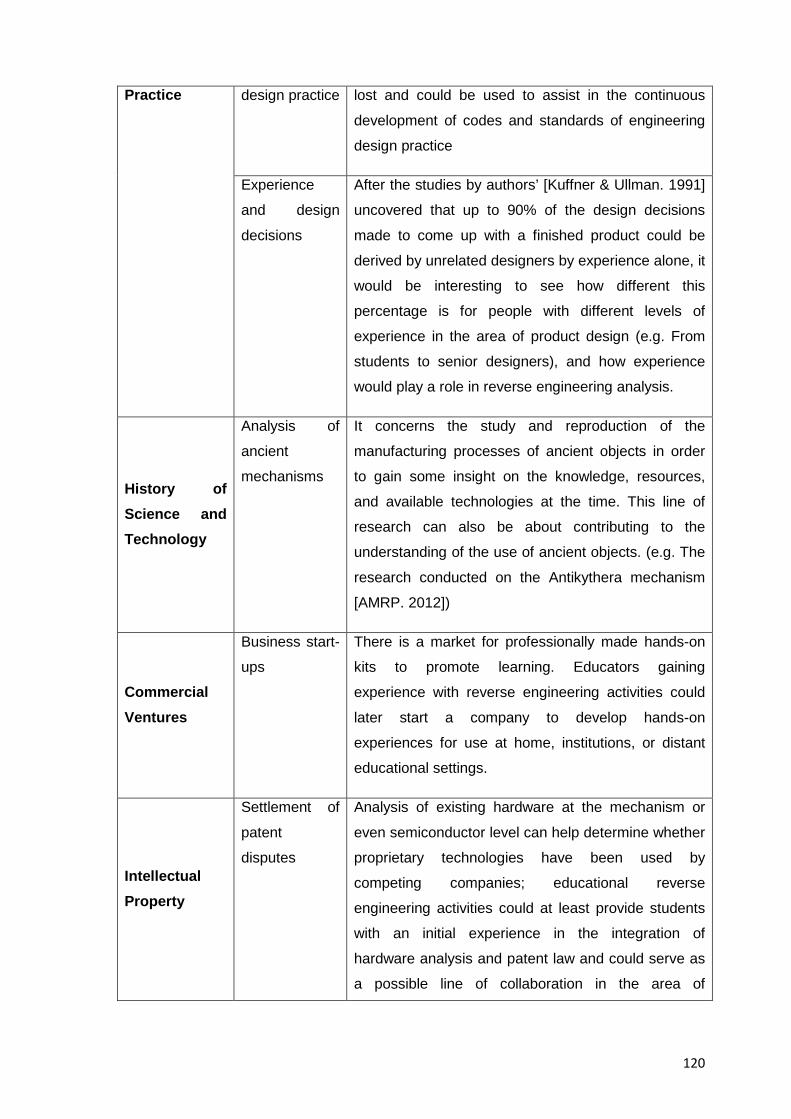
120
Practice design practice lost and could be used to assist in the continuous
development of codes and standards of engineering
design practice
Experience
and design
decisions
After the studies by authors’ [Kuffner & Ullman. 1991]
uncovered that up to 90% of the design decisions
made to come up with a finished product could be
derived by unrelated designers by experience alone, it
would be interesting to see how different this
percentage is for people with different levels of
experience in the area of product design (e.g. From
students to senior designers), and how experience
would play a role in reverse engineering analysis.
History of Science and Technology
Analysis of
ancient
mechanisms
It concerns the study and reproduction of the
manufacturing processes of ancient objects in order
to gain some insight on the knowledge, resources,
and available technologies at the time. This line of
research can also be about contributing to the
understanding of the use of ancient objects. (e.g. The
research conducted on the Antikythera mechanism
[AMRP. 2012])
Commercial Ventures
Business start-
ups
There is a market for professionally made hands-on
kits to promote learning. Educators gaining
experience with reverse engineering activities could
later start a company to develop hands-on
experiences for use at home, institutions, or distant
educational settings.
Intellectual Property
Settlement of
patent
disputes
Analysis of existing hardware at the mechanism or
even semiconductor level can help determine whether
proprietary technologies have been used by
competing companies; educational reverse
engineering activities could at least provide students
with an initial experience in the integration of
hardware analysis and patent law and could serve as
a possible line of collaboration in the area of
121
intellectual property.
Manufacturing
Uncovering of
manufacturing
processes
involving non
reversible
reactions
Although materials and manufacturing analyses are
an integral part of educational reverse engineering
activities, manufacturing and materials’ processes
that include irreversible reactions (e.g. Plastic
deformations, chemical interactions, etc.) are beyond
the reach of typical engineering design practitioners
and call for the collaboration of multiple specialists;
the reverse engineering of such processes rather than
that of specific products then, opens up another
potential line for future research as hinted in the
article “Investigation of the Brewing Process: An
Introduction to Reverse Process Engineering and
Design in the Freshman Clinic at Rowan University”
by [Farrell et al. 1999]
Table 4.1 Potential Research Lines in Educational Reverse Engineering
While some other potential lines of research also exist, the abovementioned ones
represent the state of the art in the field at the time of submitting this dissertation
(October 2015)
4.3.2.1 Other Authors’ Views on the Future of Educational Reverse Engineering and Similar Activities
Of relevance to this research are the words by editor Myer Kutz who has provided an
interesting view on what he expects reverse engineering to achieve as an educational
practice , he states for example that the practice of reverse engineering principles will
“facilitate the education of a new generation of students on knowledge areas critical to
their survival and success as engineers such as functional modelling; competitive product
design, information technology, globalization, and product platforming within an
enterprise”. What’s more, he states that, “the proliferation of reverse engineering
principles and practice has even further-reaching implications” (since) “the sustained
development of engineering principles, technologies, and tools will continue to shape and
influence product development processes in globally competitive markets” (and)
“similarly, the teaching of these principles, technologies, and tools will help prepare a
wide range of engineering students to enter the workforce with a more effective
understanding of how to efficiently develop consumer-driven; cost-effective, and
122
environmentally friendly products in a distributed, technology-mediated environment.”,
[Kutz. 2007], the information presented in this chapter, and in Resource 4 of the collection
of resources about the documented benefits of reverse engineering activities aim indeed
to support author Kutz’s views on the topic
4.4 Specific Conclusions
The following conclusions are of a rather specific nature and describe experiences in the
development and presentation of results from research
4.4.1 Use of EREA in Engineering Design Education
There is no better or worst approach to the teaching of engineering design and in that
sense educational reverse engineering activities are not a panacea for the teaching of
engineering design, as such, they are only suitable for a subset of the total expected
competences (technical and behavioural) of an engineering design graduate, that’s why
they are considered only as one of the tools in the teaching of engineering design as a
whole, and should not be seen as a substitute for traditional (forward) engineering
exercises which in turn are also suitable only for a subset of the total expected
competences of a student too
4.4.2 Teaching Approach of EREA
It can be said that the approach to the teaching of engineering design through EREA as
envisioned in this dissertation doesn’t focus on the explanation of a given technical topic
from a typical engineering design curriculum, but rather on presenting students with an
opportunity to acquire and develop certain competences that can be introduced via EREA
as explained in Resource 4 of the collection of resources
4.4.3. Conclusions regarding the use of the DRM Framework
Concerning the use of the DRM framework by authors [Blessing & Chakrabarti. 2009] for
the research done in this dissertation it can be concluded that:
• At the end of this doctoral research the use of the DRM methodology provided a
foundation not only for the execution of the research project itself but also for the
dissemination of results, and the presentation of results with a scholarly approach
• DRM is a framework that provides supporting methods and guidelines to formulate
and validate models and theories for the multidisciplinary nature of engineering
design research.
123
• The stepwise approach of the DRM methodology helps the novice researcher to
develop a line of argumentation to plan and implement research stages in a more
effective and efficient way with the aim to provide structured deliverables that
enhance information traceability throughout the stages of the doctoral project
• Research in engineering design education is bound not only by technical topics but
also by the cognitive processes of students, and the educational strategies of the
institutions under study.
• Just like any other methodology, it only tells where one is in the research, but the
development of the individual stages, and the use of the right methods and tools for a
particular project, still depend on experience and interaction among the stakeholders.
• The framework allowed the creation of a collection of resources that emanated from a
transparently presented and systematic methodology that aimed to produce results of
a consistent nature
As the framework becomes more popular then, new research, approaches, and
experiences will be published and will help enrich the understanding of the stages,
transitions, steps and praxis of the methodology.
4.5. Expectations
At the end of this project, and after presenting the reader the information resulting from
the triangulation of published evidence with the findings and conclusions from this
research, it is expected that:
• A meaningful contribution is made so EREA can finally be properly contextualised and
disseminated
• Interested educators will have a better understanding not only about EREA but also
about the assessment of their learning outcomes
• A basis for a shared understanding of what to expect from EREA is established so
researchers and educators understand the position and potentialities of EREA in
engineering design education
• The interdisciplinary and articulated domains that take part in an EREA are better
understood
• Educators can identify the location of EREA within the global area of engineering
design and thus better integrate them at the appropriate course and time from those
in their teaching curriculum
• Interested educators can eventually create subject materials and courses based on
EREA and for the benefit of their students
124
• Granters and those who take decisions about potential investments in education can
better connect the potential of EREA with their educational programs and with the
needs of the local industry
It is one of the intentions from this research then, to provide curriculum planners with the
evidence and support to justify the inclusion (or at least the test) of EREA into their
existing teaching curricula
4.6 Future work and Self-critique
Despite having written the collection of resources in Annex A as self-contained, individual
elements, the length of the resulting collection made the document itself of interest to a
niche population (engineering design professors with a strong interest in EREA), this was
not the initial intention of the author since the original idea was to come up with
comprehensive yet short, guiding manual for the preparation; execution, evaluation and
follow-up of EREA in engineering design education directed to any professor of
engineering design irrespective of his/her interest in the topic
Because of the length and comprehensiveness of the resources too, a traditional field test
of the resulting document to measure the impressions of the readers was not possible
either, since few of them would have the willingness to go through all of them and provide
meaningful feedback, and so once it was detected around 2012 that the length of the
resources would be bigger than that of a traditional guiding manual a different approach
to their testing had to be devised
It should be emphasised though that to the author, the tradeoff between
Comprehensiveness vs. Usability was well worth it, since there were no similar resources
available to the reader before the one resulting from this research, and the freely
distributable nature and length of them only reflects the intention to cover every relevant
detail about the current practice of EREA and make it reachable to anyone, after all,
every project (specially a student one) is prone to be improved over time and the
feedback from future evaluators will help find the right balance in the information
presented that ensures that the learning setting; the curriculum content, the teaching
method, and the evaluation mechanisms suggested support students in their attainment
of the learning goals expected from an EREA.
It remains as future work for the author then:
• The creation of a short guide for the study of EREA with better usability, and
addressed to a general rather than specialist audience
125
• The search of new areas of application for the topic such as those concerning the
development of computer assisted tools for the automation of reverse engineering
analysis, and the use of virtual reality in product dissection exercises,
• The writing in Spanish language of the collection of resources in Annex A
It is also expected that the author eventually joins a community of educational reverse
engineering practitioners and new publications that benefit from the experience gained in
this research are produced
4.7 Final Remarks
The planning of the introduction of a novel educational experience in the field of
engineering design posed a number of challenges to the researcher where domain
knowledge had to be derived from the study of relevant bits of information dispersed
across several areas of science, it can be said then, that this research was not only
bound by the technical topics inherent to the activities under study themselves but also by
the impact in the research of:
• The administrative issues in trying to suggest changes to the way engineering design
was taught in a typical target institution
• The didactic and experiential activities suggested for students in accordance with best
practices in education
• The existing learning theories and the implications in trying to suggest educational
activities that still fit into them
• The differences in target students in terms of gender; intellect, and socio-cultural
backgrounds
• The shift in moving from faculty centred activities to student centred activities that
EREA propose
• The presentation of objective information regarding the reasonable expectations from
an EREA so educators could plan their introduction at a time that fitted their teaching
needs
• The setting of a baseline so the reader of this work could actually benefit from
previously published findings as well as from the original results presented here
• The technical, societal, and organizational challenges found in trying to create a
viable interdisciplinary solution for the current teaching of engineering
It is concluded for this dissertation that there will always be a need to improve
engineering education and thus, new approaches such as EREA will have to be explored;

126
tested and expanded, because of this, continuing studies about educational reverse
engineering can be reasonably expected and should be considered healthy for the
development of the topic.
127
REFERENCES
All links to references provided below are valid at the time of issuing of dissertation;
should web resources go offline or change addresses because of the temporary nature of
data published online, several tools exist for the retrieval of old versions of webpages.
More information for the interested reader can be found in pages such as “The Internet
Archive” at http://archive.org/web/web.php or by selecting the “cached” version of a
webpage at the Google search engine’s webpage itself at
https://support.google.com/websearch/answer/1687222?hl=en&ref_topic=4386094:
[Abe & Starr. 2003] Abe, T. Starr, P. Teaching the writing and role of specifications via a
structured teardown process. Design Studies, Volume 24, Issue 6, November 2003,
Pages 475-489, ISSN 0142-694X, 10.1016/S0142-694X(03)00037-1. Available at
http://www.sciencedirect.com/science/article/pii/S0142694X03000371
[ABET. 2010] ABET, Engineering Accreditation Commission, 2009-2010, Criteria for
Accrediting Engineering Programs, available at:
http://www.abet.org/linked%20documents-update/criteria%20and%20pp/e001%2009-
10%20eac%20criteria%2012-01-08.pdf and http://www.abet.org/.
[Ahmed et al. 1999] Ahmed, S., Blessing, L.T.M. and Wallace, K.M., The relationship
between data, information and knowledge based on a preliminary study of engineering
designers, in 1999 ASME Design Engineering Technical Conferences (DETC'99), Las
Vegas, Nevada, USA
[AMRP. 2012] AMRP, Antikythera Mechanism Research Project, Project Overview,
Available at http://www.antikythera-mechanism.gr/
[Andrew. 2006] Andrew, E.S. Make and Test Projects in Engineering Design. 2006, XXVI,
278 p. 242 illus. ISBN 978-1-84628-285-0, Springer Science+Business Media, Available
at http://www.springer.com/engineering/mechanical+engineering/book/978-1-85233-915-
9
[Archer. 1981] Archer L. A view of the nature of design research. In Jacques R, Powell JA
(eds.) Design, science, method. 1981, (Butterworths, Guildford), pp. 30–35.
[Beheshti & Van der Veer. 1999] Beheshti, R. Van der Veer, P. Design science and
technology: setting the agenda for the 21st century. EuropIA2000 session initiation paper,
Civil Engineering Informatics, 1999.
128
[Blessing & Chakrabarti. 2009] Source: Blessing L., Chakrabarti A. DRM, A design
research methodology, 2009. © Springer-Verlag London limited. ISBN: 978-1-84882-
586-4.
[Boeing University Relations. 2010] Boeing University Relations, 2010, Desired Attributes
of an Engineer, Available at http://www.boeing.com/educationrelations/attributes.html
[Buur. 1990] Buur, J. Theoretical Approach to Mechatronics Design. Institute for
Engineering Design, TU of Denmark, PhD Thesis, 1990.
[Calderon. 2008] Calderon M. Product Visualization Praxis and its Integration to
Academic Curricula. 10th Engineering and Product Design Education International
Conference, E&PDE'08, Vol. 1, September 2008, pp. 417-422. Artyplan Global Printers
Ltd, Barcelona. ISBN: 1-904670-04-0. Barcelona, Spain
[Calderon. 2009] Calderon M. Analysis of Existing Products as a Tool for Engineering
Design Education. 11th Engineering and Product Design Education International
Conference, E&PDE'09, Creating a Better World, September 2009, pp.65. Institution of
Engineering Designers, The Design Society. ISBN: 978-1-904670-17-9. Brighton, United
Kingdom
[Calderon. 2010a] Calderon M. Application of Reverse Engineering Activities in the
Teaching of Engineering Design, International Design Conference - Design 2010, Design
2010 Proceedings Volume 2. Pp. 1249-1258, Marjanovic et al. Editors. (Faculty of
Mechanical Engineering and Naval Architecture, University of Zagreb, The Design
Society, Glasgow), ISBN: 978-953-7738-05-1, Dubrovnik, Croatia
[Calderon. 2010b] Calderon M. A Comparison Of Competences Required In Reverse
Engineering Exercises Versus Conventional Engineering Exercises And Its Relationship
To IPMA’s Competence Baseline, Abstracts book of the XIV International Congress on
Project Engineering, Fundación General de la Universidad Politécnica de Madrid Editors,
Ibersaf Industrial Press, Pp.230 ISBN:978-84-614-2608-9 Madrid, Spain.
[Calderon. 2010c] Calderon M. The Design Research Methodology As A Framework For
The Development Of A Tool For Engineering Design Education, Proceedings of the 12th
Engineering and Product Design Education International Conference, E&PDE’10.
Norwegian University of Science and Technology, Copyright © 2010 Institution of
Engineering Designers, The Design Society, Boks et al. Editors. ISBN: 978-1-904670-19-
3, Trondheim, Norway
129
[Calkins et al. 1996] Calkins, D.et al. 1996, TIDEE: The First Year of a Design
Engineering Educational Partnership for Washington State, FIE '96 Proceedings, IEEE 0-
7803-3348-9
[Caupin et al. 2006] Caupin, G et al. ICB–IPMA Competence Baseline, Version 3.0. in
International Project Management Association (IPMA), 2006. Available at
http://www.ipma.ch/documents/icb_v._3.0.pdf
[CDIO Council. 2010] CDIO Council, 2010, CDIO Syllabus. Worldwide CDIO Initiative,
Available at http://www.cdio.org/framework-benefits/cdio-syllabus
[Ceoforum. 1999] Ceoforum. The CEO Forum School Technology and Readiness Report
— Professional Development: A Link to Better Learning, Year Two. The CEO Forum on
Education and Technology, February 22, 1999, available at
http://www2.uca.es/lace/documentos/99report.pdf, and with further information in
http://www.lmsd.org/staff/techmentor/
[Checkland. 1981] Checkland, P. Systems thinking, systems practice. Wiley, Chichester,
1981.
[Checkland. 1999] Checkland, P. Soft systems methodology: 30-year retrospective.
Wiley, Chichester, 1999.
[Chikofsky & Cross. 1990] Chikofsky, E.J. Cross, J.H. Reverse engineering and design
recovery: A taxonomy. IEEE Software, 7(1):13-17, 1990. Available at http://www.weidl-
rektenwald.at/swe/chikofsky90.pdf
[Cross. 1994] Cross, N. Engineering Design Methods: strategies for product design, 2th
edn. John Wiley and Sons Ltd, Chichester, 1994.
[Dalrymple et al. 2011] Dalrymple, O., Sears, D., Evangelou, D. The Motivational and
Transfer Potential of Disassemble/Analyze/Assemble (DAA) Activities, Journal of
Engineering Education, October 2011, Vol. 100, No. 4, pp. 741–759. Available at
http://www.jee.org/2011/October/06.pdf
[Dalrymple. 2009] Dalrymple, O. O. Ph.D. Dissertation. The pedagogical value of
disassemble/analyze/assemble (DAA) activities: assessing the potential for motivation
and transfer, Purdue University, 2009, 140 pages; AAT 3402322, ISBN: 9781109744002,
available at: http://proquest.umi.com/pqdlink?did=2038894311&fmt=7&clienti
d=40968&rqt=309&vname=pqd
130
[Dillman et al. 2008] Dillman, D.A. Smyth, J.D. Christian, L.M. Internet, mail, and mixed-
mode surveys: The tailored design method. John Wiley and Sons, 2008.
[Douglas & Chitra. 2004] Douglas, E. Chitra, K. Engineering in the K-12 Classroom, An
Analysis of Current Practices & Guidelines for the Future. The American Society for
Engineering Education, 2004.
[Duffy & Andreasen. 1995] Duffy, AHB. Andreasen, MM. Enhancing the evolution of
design science. In: Hubka V (ed.) Proceedings of the 10th International Conference on
Engineering Design (ICED’95), 2005. Heurista, Zürich, Prague, pp 29–35
[Duffy & O’Donell. 1999] Duffy, AHB. O’Donnell, FJO. A design research approach. In:
Mortensen NH, Sigurjonsson J (eds) Critical enthusiasm - contributions to design science.
Tapir, Trondheim, N., pp 33–40, 1999.
[Durfee. 2008] Durfee, W. Guide to Mechanical Dissection, University of Minnesota, USA,
2008, available at
http://www.me.umn.edu/courses/me2011/handouts/dissection_guide.html
[Engineering Education Community. 2010] Engineering Education Community. Design.
Available at http://www.engineeringpathway.
com/ep/interdiscipline/interdiscipline.jhtml?comm=Design, last accessed on 25/02/10
[Farrell et al. 1999] Farrell, S. Hesketh, R.P. Slater, C.S. "Investigation of the brewing
process: an introduction to reverse process engineering and design in the Freshman
Clinic at Rowan University", FIE, vol. 2, pp.12B4/14-12B4/18, vol.2, Frontiers in
Education Conference, 1999. FIE '99. 29th Annual, 1999, available at
http://www.computer.org/csdl/proceedings/fie/1999/5643/02/00841586-abs.html
[Frankfort-Nachmias & Nachmias. 1996] Frankfort-Nachmias, C. Nachmias, D. Research
methods in the social sciences. 5th ed. St. Martin Press, Inc., London, 1996.
[Fulcher & Hills. 1998] Fulcher, A. Hills, P. A taxonomy of design research topics by
multivariate agglomerative clustering. J Eng Design 9(4): pp. 343– 354,1998.
[Horváth.2004] Horváth, I. Research in design knowledge. A treatise on order in
engineering design research. Research in Engineering Design. 15: 155–181, 2004.
[Hyman. 2003] Hyman, B. Public Policy and Engineering Design Education, Int. J. Engng
Ed. Vol. 19, No. 1, pp. 110±117, 2003.
131
[Jensen et al. 2004] Jensen, D. Wood, J. Wood, K. “A Design Methodology for Hands-on
Classroom Experiences”. Proceedings of the ASEE Annual Conference and Exposition,
June, 2004
[Jones. 1970] Jones, J.C. Design methods; seeds of human futures. Wiley, New York,
1970.
[Jounghyun. 1994] Jounghyun, G. K. A thesis proposal: Redesign by Reverse
Engineering. University of Southern California, USA, 1994 available at
http://citeseerx.ist.psu.edu/viewdoc/summary?doi=10.1.1.50.8369
[Kang. 2011] Kang, K. Using Product Dissection to Expose Engineering Students To
Cultural Issues In Product Design. A Thesis in Industrial Engineering for the Degree of
Master of Science at the Harold and Inge Marcus Department of Industrial and
Manufacturing Engineering of the Graduate School of The Pennsylvania State University.
Available at https://etda.libraries.psu.edu/paper/12323/7719
[King et al. 1994] King, G. Keohane, RO. Verba, S. Designing social inquiry: scientific
inference in qualitative research. Princeton University Press, Princeton NJ, 2004.
[Kolb. 1984] Kolb, D. A. Experiential Learning: Experience as the source of learning and
development, Prentice Hall, Englewood-Cliffs, NJ, 1984. 1st ed.
[Kuffner & Ullman. 1991] Kuffner, T.A. Ullman, D.G. The Information Requests of
Mechanical Design Engineers. Design Studies; Vol. 12, No. 1, January 1991, Butterworth
- Heinemann Ltd. Available at http://web.engr.oregonstate.edu/~ullman/kuffner1.htm
[Kutz. 2007] Kutz, M. (Ed.); Kemper L.E. Catellani, M. Simpson, T.W. Stone, R. B. Wood,
W. H. Regli, W. Environmentally Conscious Mechanical Design. Wiley Series in
Environmentally Conscious Engineering (Vol. 1). Chapter 4, Fundamentals and
Applications of Reverse Engineering. © 2007 John Wiley & Sons, Inc. ISBN: 978-0-471-
72636-4), Hoboken, NJ, USA. doi: 10.1002/9780470168202.
[Lamancusa et al. 1996] Lamancusa, J.S. Jorgensen, J. Kumar, V. Torres, M. "Learning
Engineering by Product Dissection", Proceedings of the 1996 ASEE Annual Meeting,
Washington DC, June 1996, Available at
http://www.me.psu.edu/lamancusa/papers/asee96pd.pdf
[Lamancusa et al. 1997] Lamancusa, J.S. Jorgensen, J.E. Zayas - Castro, J.L. "The
Learning Factory -- A New Approach to Integrating Design and Manufacturing into
132
Engineering Curricula", ASEE, Journal of Engineering Education, Vol. 86, No. 2, pp. 103-
112, April 1997, available at http://www.me.psu.edu/lamancusa/papers/aseejour.pdf
[Leek & Larsson. 2007] Leek, T. Larsson, A. A reversible engineering process. University
essay from Högskolan i Jönköping/JTH, Maskinteknik; Högskolan i Jönköping/JTH,
Maskinteknik, 2007. Available at http://hj.diva-portal.org/smash/record.jsf?pid=diva2:4474
[Lewis et al. 2011] Lewis, K. Moore-Russo, D. Kremer, G. Simpson, T. McKenna, A.
Chen, W. CCLI Phase II: Collaborative Research - Teaching the Global, Economic,
Environmental, and Societal Foundations of Engineering Design through Product
Archaeology. Available at
http://productarchaeology.org/docs/resources/CCLI.Product.Archaeology.pdf
[Ogot & Kremer. 2006] Ogot, M. Kremer, G. Developing a framework for
disassemble/assemble/analyze (DAA) activities in engineering education. Proceedings of
the 2006 ASEE Annual Conference & Exposition: Excellence in Education Chicago, IL.
[Ogot et al. 2008] Ogot, M. Okudan, G.E. Simpson, T.S. Lamancusa, J.S. (2008). “A
framework for classifying disassemble/analyze/assemble activities in engineering design
education”. J. Design Research, Vol. 7, No. 2, pp.120–135.
[Otto & Wood. 2001] Otto, K. Wood, K. Product Design: Techniques in Reverse
Engineering and New Product Development. 1st ed. And Book’s companion website,
Design, 1/e: Book Resources, Software and Templates, © 2001, Prentice-Hall, Inc.
Available at http://cwx.prenhall.com/bookbind/pubbooks/otto_wood/chapter0/deluxe.html
[Otto et al. 1998] Otto, K. Wood, K. Bezdek, J. Murphy, M. Jensen, D. (1998). Building
better mousetrap builders: Courses to incrementally and systematically teach design.
Proceedings of the 1998 ASEE Annual Conference & Exposition: Engineering Education
Contributing to U. S. Competitiveness, Seattle, WA. Available at
http://www.sutd.edu.sg/cmsresource/idc/papers/1998-
_Building_Better_Mousetrap_Builders-
_Courses_To_Incrementally_And_Systematically_Teach_Design.pdf
[Pahl et al. 2007] Pahl, G. Wallace, K. Engineering design: a systematic approach. – 3rd
ed. 2007. Springer-Verlag London Limited
[Rekoff. 1985] Rekoff, M. G. “On Reverse Engineering”. IEEE Trans. on Systems, Man,
and Cybernetics, Vol. 15, No. 2, 1985, pp. 244–252.
[Roozenburg & Eekels. 1995] Roozenburg, N.F.M. Eekels, J. Product Design,
Fundamentals and Methods. (Wiley, Chichester, UK), 1995.
133
[Saeema. 2007] Saeema, A. An Industrial Case Study: Identification of Competencies of
Design Engineers. Contributed by the Design Education Committee of ASME for
Publication in the Journal of Mechanical Design, Vol. 129 / 709, Paper Presented at the
ICED 2005. July 2007.
[Sato & Kaufman. 2005] Sato, Y. Kaufman, J. Value Analysis Tear-Down: A New Process
for Product Development and Innovation. Industrial Press Inc., 2005, ISBN
0831132035, 1st ed. Available at
http://books.google.es/books/about/Value_Analysis_Tear_Down.html?id=UTZJhEzgpXcC
&redir_esc=y
[Sheppard & Jenison.1996] Sheppard, S. Jenison, R. Table 1: Qualities Expected in a
Design Engineer and that Engineering Courses Should be Helping Engineering Students
to Develop. Available at http://www-adl.stanford.edu/images/frdestbl.pdf, Accessed on
28/03/10, Referred from (S. Sheppard and R. Jenison, Freshman Engineering Design
Experiences: An Organizational Framework. Int. J. Eng. Ed., 13, (1997) pp. 190±197.),
“under review” version available at http://www-adl.stanford.edu/images/freshdes.pdf.
[Sheppard & Rollie. 1996] Sheppard, S. Rollie, J. Thoughts on Freshman Engineering
Design Experiences in Electronic Proceedings for Frontiers In Education 1996
Conference.
[Sheppard. 1992a] Sheppard, S. "Dissection as a Learning Tool". Proceedings of the
IEEE Frontiers in Education Conference, Nashville, TN, IEEE. 1992.
[Simpson et al. 2007] Simpson, T.W. Lewis, K.E. Stone, R.B. Regli, W.C. Using
Cyberinfrastructure to Enhance Product Dissection in the Classroom. Proceedings of the
2007 Industrial Engineering Research Conference G. Bayraksan, W. Lin, Y. Son, and R.
Wysk, eds. Available at http://gicl.cs.drexel.edu/images/1/1d/IERC.07.CIBER-U.pdf
[Tilton. 2004] Tilton, H. B. Reverse engineer the universe! Smarandache Notions Journal.
2004
[Trevelyan. 2008] Trevelyan, J.P. A Framework for Understanding Engineering Practice.
In American Association for Engineering Education (ASEE) Annual Conference. 2008.
Pittsburgh.
[Verschuren. 1997] Verschuren, P.J.M. Ontwerpgericht onderzoek: een methodologische
bezinning. Bedrijfskunde 69:82–89, 1997.

134
[Woollacott. 2009] Woollacott, L. C. Validating the CDIO Syllabus for Engineering
Education Using the Taxonomy of Engineering Competencies. European Journal of
Engineering Education, 34: 6, 545-559. 2009.
[Yin. 1994] Yin, RK. Case study research. Sage, London, 1994.

135
ANNEX A A COLLECTION OF RESOURCES FOR THE STUDY OF EREA IN ENGINERING DESIGN EDUCATION

136
This page intentionally left blank
BarcelonaTech
Departament de Projectes d'Enginyeria
Escola Tècnica Superior d'Enginyeria Industrial de Barcelona
Projectes d'Innovació Tecnològica en l'Enginyeria de Producte i Procés
A Collection of Resources for the Study of EREA in Engineering Design Education
Presented by
Marco Lino Calderón Saldierna
October 2015 Barcelona, Spain

2
This page intentionally left blank
3
COPYRIGHT AND ATTRIBUTION POLICY
This work is published under the Creative Commons license “Attribution-NonCommercial
3.0 Unported” (CC BY-NC 3.0) meaning that you are free to:
• Share (to copy, distribute and transmit the work) and
• To remix (to adapt the work)
Under the following conditions:
• You must attribute the work in the manner specified by the author or licensor (but
not in any way that suggests that they endorse you or your use of the work) and
• You may not use this work for commercial purposes
With the understanding that:
• Any of the above conditions can be waived if you get permission from the
copyright holder
• Wherever the work or any of its elements is in the public domain under applicable
law, that status is in no way affected by the license
And in no way are any of the following rights affected by the license:
• Your fair dealing or fair use rights, or other applicable copyright exceptions and
limitations
• The author's moral rights
• Rights other persons may have either in the work itself or in how the work is used,
such as publicity or privacy rights.
This type of copyright has been chosen to ensure the free (non-profit) and timely
dissemination of scholarly and technical work while at the same time protecting the
quoted; copyrighted or trademarked work of authors mentioned throughout the document;
indeed in most cases, these works may not be reposted without the explicit permission of
the copyright holder but under Section 107 of the Copyright Act 1976, allowance is made
for "fair use" for purposes such as criticism; commenting, news reporting, teaching,
scholarship, and research. Fair use then, as done in this collection of resources is a use
permitted by copyright statute that might otherwise be infringing. However, if anyone feels
that copyrights have been affected somehow you should notify immediately the author of
this document at the contact information options provided herein.

4
This page intentionally left blank
5
INDEX
Page
COPYRIGHT AND ATTRIBUTION POLICY .......................................................................... 3
INDEX .................................................................................................................................... 5
LIST OF TABLES ................................................................................................................ 15
LIST OF FIGURES .............................................................................................................. 19
PREFACE ............................................................................................................................ 23
INTRODUCTION ................................................................................................................. 25
RESOURCE 1: FUNDAMENTALS OF EDUCATIONAL REVERSE ENGINEERING ACTIVITIES ......................................................................................................................... 29
1.1 Resource Introduction ........................................................................................................... 29
1.2. Principles of Educational Reverse Engineering .................................................................... 29
1.2.1 What is Reverse Engineering? ........................................................................................ 29
1.2.1.1 The Different Contexts of the Term “Reverse Engineering” ................................... 30
1.2.2 Reverse Engineering as an Integrative Activity that Links Theory and Practice ............ 32
1.2.2.1 Technical analyses as a Starting Point for Educational Reverse Engineering ......... 33
1.2.2.2 The Subject System of Educational Reverse Engineering Activities ........................ 35
1.2.2.3 Educational Reverse Engineering Activities as a Source of Integrative Knowledge: ............................................................................................................................................. 36
1.2.2.4 EREA as an aid to Expand Students’ Base Knowledge of Solutions and Design Possibilities .......................................................................................................................... 37
1.2.2.5 EREA as a Vehicle for the Acquisition of Experience and Expertise ........................ 38
1.2.3 Similar Approaches to EREA in the Teaching of Engineering ......................................... 39
1.2.3.1 Introduction to the Terminology in use in the Area of Educational Reverse Engineering ......................................................................................................................... 42
1.2.4 Historical Development of Reverse Engineering in Education ....................................... 43
1.2.4.1 Birth and Milestones of Reverse Engineering in Education .................................... 45
1.2.5 Past and Present Research Initiatives for the Inclusion of Dissection Activities in Education ................................................................................................................................ 49
1.2.5.1 Dissemination Efforts for Reverse Engineering-like Activities ................................ 51
1.2.5.2 The Need to Collect and Contextualise all Relevant Knowledge about Educational Reverse Engineering ............................................................................................................ 53
1.2.6 Relationship of Educational Reverse Engineering Activities to the Engineering Design Process .................................................................................................................................... 54
1.2.7 Cognitive Enablers of Educational Reverse Engineering Analysis .................................. 57
6
1.2.7.1 Drawbacks of the Practice of Reverse Engineering................................................. 57
1.2.8 Validity of Reverse Engineering as an Academic Subject in Design Education .............. 60
1.2.8.1 Pedagogical Viability of EREA .................................................................................. 62
1.2.8.2 Teaching Approach of Educational Reverse Engineering Activities ........................ 64
1.2.8.3 Educational Reasons to Reverse Engineer a Consumer Product ............................ 64
1.2.8.4 Uses of Educational Reverse Engineering at the College Level............................... 65
1.2.8.5 Reception in the Engineering Design Community of Similar Approaches to Reverse Engineering ......................................................................................................................... 66
1.2.9 An Introduction to Commercial Reverse Engineering .................................................... 67
1.2.9.1 Commercial Reverse Engineering as a Trigger for Industrial Development ........... 70
1.3 Resource Conclusions ............................................................................................................ 72
RESOURCE 2: REVERSE ENGINEERING AND LEARNING ............................................. 75
2.1 Resource Introduction ........................................................................................................... 75
2.2 Pedagogical Framework of EREA .......................................................................................... 75
2.3 Cognitive Processes and the Construction of Knowledge in an EREA................................... 75
2.3.1 The Kolb’s Learning Model and its Relation to Educational Reverse Engineering Activities .................................................................................................................................. 78
2.3.1.1 Students’ Roles During an EREA .............................................................................. 82
2.3.2 The Data, Information, and Knowledge Triad in EREA ................................................... 82
2.4 Cycle of Students' Acquisition and Development of Competences through EREA ............... 84
2.4.1 Comparison of Competences Exercised in an EREA against those in a Conventional “Forward” Engineering Design Exercise .................................................................................. 92
2.5 Gender, Prior Experience and Motivation in EREA ............................................................... 97
2.6 Resource Conclusions ............................................................................................................ 97
RESOURCE 3: MISCONCEPTIONS ABOUT REVERSE ENGINEERING .......................... 99
3.1 Resource Introduction ........................................................................................................... 99
3.2 Negative Associations of the Term “Reverse Engineering” .................................................. 99
3.3. Lawfulness of Reverse Engineering as an Educational Practice ......................................... 100
3.4 Major Misconceptions and Misunderstandings Regarding the Practice of Reverse Engineering ............................................................................................................................... 104
3.5 Misconceptions about the Relationship between Reverse Engineering and Creativity ..... 113
3.5.1 EREA, Teaching and Development of Creativity .......................................................... 116
3.6 Reverse Engineering in Support of the Innovation Process ................................................ 117
3.6.1 Suitability of EREA to come up with Incremental Innovation Designs ......................... 117
7
3.7 Benefits of Replicating Typical Commercial Reverse Engineering Activities in an Academic Exercise ..................................................................................................................................... 120
3.7 Resource Conclusions .......................................................................................................... 122
RESOURCE 4: BENEFITS OF REVERSE ENGINEERING ............................................... 123
4.1 Resource Introduction ......................................................................................................... 123
4.2 Documented Benefits of Educational Reverse Engineering Activities ................................ 123
4.2.1 Benefits at the Organizational Level of Introducing Educational Reverse Engineering Activities ................................................................................................................................ 137
4.3 Strongest Elements Educational Reverse Engineering Activities can add to the Teaching of Engineering Design .................................................................................................................... 139
4.4 Added Value of Reverse Engineering Activities in Design Education .................................. 145
4.5 Resource Conclusions .......................................................................................................... 145
RESOURCE 5: A PROPOSED METHODOLOGY FOR REVERSE ENGINEERING ANALYSIS IN ENGINEERING DESIGN EDUCATION ...................................................... 147
5.1 Resource Introduction ......................................................................................................... 147
5.2 Conceptual Stages of a Proposed Methodology for Educational Reverse Engineering Analysis ...................................................................................................................................... 147
5.3 Conceptual and Procedural Explanation of the Stages of the Proposed Methodology for Educational Reverse Engineering Analysis ................................................................................ 154
5.4 Stages of the Proposed Methodology for Reverse Engineering Analysis in Design Education ................................................................................................................................................... 155
5.4.1 Stage 1: Task Clarification: ........................................................................................... 156
5.4.1.1 Stage Purpose: ...................................................................................................... 156
5.4.1.2 Stage Tasks, Questions and Analyses: ................................................................... 156
5.4.2. Stage 2: Product Procurement: ................................................................................... 156
5.4.2.1 Stage Purpose: ...................................................................................................... 156
5.4.2.2 Stage Tasks, Questions and Analyses: ................................................................... 157
5.4.3. Stage 3: Team Selection: ............................................................................................. 157
5.4.3.1 Stage Purpose: ...................................................................................................... 157
5.4.3.2 Stage Tasks, Questions and Analyses: ................................................................... 158
5.4.4 Stage 4: Data Collection: .............................................................................................. 158
5.4.4.1 Stage Introduction:................................................................................................ 158
5.4.4.2 Stage Purpose: ...................................................................................................... 158
5.4.4.3 Difference to other Stages of the Methodology: .................................................. 158
5.4.4.4 Link to Other Stages of the Methodology: ............................................................ 158
5.4.4.5 Students’ Learning from this Stage: ...................................................................... 159
8
5.4.4.6 Stage Tasks, Questions and Analyses: ................................................................... 159
5.4.5 Stage 5: Product Performance Test I:........................................................................... 161
5.4.5.1 Stage Purpose: ...................................................................................................... 161
5.4.5.2 Stage Characteristics: ............................................................................................ 161
5.4.5.3 Stage Tasks, Questions and Analyses: ................................................................... 161
5.4.6 Stage 6: Product Disassembly: ..................................................................................... 162
5.4.6.1 Stage Introduction:................................................................................................ 162
5.4.6.2 Stage Purpose: ...................................................................................................... 162
5.4.6.3 Major Activities from this Stage: ........................................................................... 162
5.4.6.4 Background Information: ...................................................................................... 162
5.4.6.5 Link to Other Stages of the Methodology: ............................................................ 162
5.4.6.6 Stage Tasks, Questions and Analyses: ................................................................... 163
5.4.7 Stage 7: Product Analysis: ............................................................................................ 164
5.4.7.1 Stage Introduction:................................................................................................ 164
5.4.7.2 Stage Purpose: ...................................................................................................... 164
5.4.7.3 Background Information: ...................................................................................... 165
5.4.7.4 Link to Other Stages of the Methodology: ............................................................ 165
5.4.7.5 Students’ Learning from this Stage: ...................................................................... 165
5.4.7.6 Stage Tasks, Questions and Analyses: ................................................................... 165
5.4.8 Stage 8 Product Reassembly: ....................................................................................... 169
5.4.8.1 Stage Introduction:................................................................................................ 169
5.4.8.2 Stage Purpose: ...................................................................................................... 170
5.4.8.3 Background: .......................................................................................................... 170
5.4.8.4 Stage Tasks, Questions and Analyses: ................................................................... 170
5.4.9 Stage 9: Product Performance Test II:.......................................................................... 171
5.4.9.1 Section Introduction: ............................................................................................ 171
5.4.9.2 Stage Purpose: ...................................................................................................... 171
5.4.9.3 Background Information: ...................................................................................... 171
5.4.9.4 Link to Subsequent Stages of the Methodology: .................................................. 171
5.4.9.5 Main differences to other stages of the methodology: ........................................ 172
5.4.9.6 Stage Tasks, Questions and Analyses: ................................................................... 172
5.4.10 Stage 10 Knowledge Synthesis: .................................................................................. 173
5.4.10.1 Stage Introduction: ............................................................................................. 173
5.4.10.2 Stage Purpose: .................................................................................................... 174
9
5.4.10.3 Background: ........................................................................................................ 175
5.4.10.4 Relationship to Other Stages of the Methodology: ............................................ 176
5.4.10.5 Difference to Other Stages of the Methodology: ............................................... 176
5.4.10.6 Stage Tasks, Questions and Analyses: ................................................................. 176
5.4.11 Stage 11: Redesign Suggestions: ................................................................................ 190
5.4.11.1 Introduction: ....................................................................................................... 190
5.4.11.2 Stage Purpose: .................................................................................................... 190
5.4.11.3 Background: ........................................................................................................ 191
5.4.11.4 Link to Subsequent Stages of the Methodology: ................................................ 191
5.4.11.5 Stage Tasks, Questions and Analyses: ................................................................. 192
5.4.12 Stage 12: Conclusions: ............................................................................................... 195
5.4.12.1 Stage Introduction: ............................................................................................. 195
5.4.12.2 Stage Purpose: .................................................................................................... 196
5.4.12.3 Background: ........................................................................................................ 196
5.4.12.4 Link to Subsequent Stages of the Methodology: ................................................ 196
5.4.12.5 Stage Tasks, Questions and Analyses: ................................................................. 196
5.4.13 Stage 13: Results Dissemination: ............................................................................... 198
5.4.13.1 Stage Introduction: ............................................................................................. 198
5.4.13.2 Stage Purpose: .................................................................................................... 198
5.4.13.3 Background: ........................................................................................................ 198
5.4.13.4 Link to Subsequent Stages of the Methodology: ................................................ 198
5.4.13.5 Stage Tasks, Questions and Analyses: ................................................................. 199
5.4.14 Stage 14: Project Closure/Follow Up: ........................................................................ 200
5.4.14.1 Stage Introduction: ............................................................................................. 200
5.4.14.2 Stage Purpose: .................................................................................................... 200
5.4.14.3 Background: ........................................................................................................ 200
5.4.14.4 Stage Tasks, Questions and Analyses: ................................................................. 200
5. 5 Resource Conclusions ......................................................................................................... 201
RESOURCE 6: A SUGGESTED PEDAGOGY FOR THE TEACHING OF EDUCATIONAL REVERSE ENGINEERING ACTIVITIES ................................................. 203
6.1 Resource Introduction ......................................................................................................... 203
6.2 The Rationale behind a Pedagogy for the Teaching of EREA .............................................. 203
6.3 The Different Phases in the Teaching of EREA .................................................................... 204
6.4 Fundamentals of the Teaching of EREA .............................................................................. 207
10
6.4.1 Setting the Goal and Learning Outcomes of an EREA .................................................. 207
6.4.2. Suitable Format of EREA to fit an Engineering Design Syllabus .................................. 209
6.4.3 Setting the Depth of an EREA ....................................................................................... 210
6.4.3.1 Setting the level of disassembly for the subject system ....................................... 210
6.4.3.2 Advice Specific to the Guided Example in Resource 7 .......................................... 211
6.4.4 Time of Inclusion of an EREA in an Engineering Design Curriculum ............................ 211
6.4.5 Introductory Talks ........................................................................................................ 212
6.4.6 Familiarising Students with Vocabulary and Terminology ........................................... 213
6.5 A Suggested Pedagogy for Educational Reverse Engineering Activities ............................. 214
6.5.1 Phase 1 Preparation of an EREA: .................................................................................. 215
6.5.1.1 Task Clarification: .................................................................................................. 215
6.5.1.2 Specific Phase and Stage Advise for the Guided Example in Resource 7 .............. 223
6.5.1.3 Creation of Supporting Documents for Students .................................................. 223
6.5.1.3.1 Activity Handout for Students ndergoing an EREA ........................................ 224
6.5.1.4 Additional Guidelines for the Success of Hands-On and Similar Activities ........... 237
6.5.2 Phase 2: Execution of an EREA ..................................................................................... 241
6.5.2.1 A Suggested Pedagogy for the Teaching of the Product Procurement Stage ....... 241
6.5.2.2 A Suggested Pedagogy for the Teaching of the Team Selection Stage ................. 245
6.5.2.3 A Suggested Pedagogy for the Teaching of the Data Collection Stage ................. 248
6.5.2.4 A Suggested Pedagogy for the Teaching of the Product Performance Test I Stage ........................................................................................................................................... 249
6.5.2.5 A Suggested Pedagogy for the Teaching of the Product Disassembly Stage ........ 250
6.5.2.6 A Suggested Pedagogy for the Teaching of the Product Analysis Stage ............... 253
6.5.2.6.1 Suggested Questions and Analyses Specific to the Guided Example Presented in Resource 7 ................................................................................................................. 276
6.5.2.6.2 Minimum Case Analysis of the Subject System ............................................. 278
6.5.2.6.3 Alternative Methods of Analysis for the Product Analysis Stage ................... 280
6.5.2.7 A Suggested Pedagogy for the Teaching of the Product Reassembly Stage ......... 287
6.5.2.8 A Suggested Pedagogy for the Teaching of the Product Performance Test II Stage ........................................................................................................................................... 288
6.5.2.9 A Suggested Pedagogy for the Teaching of the Knowledge Synthesis Stage ........ 288
6.5.2.10 A Suggested Pedagogy for the Teaching of the Redesign Suggestions Stage ..... 307
6.5.3 Phase 3: Evaluation of an EREA .................................................................................... 309
6.5.3.1 Fundamentals of the Evaluation of Educational Reverse Engineering Activities .. 310
6.5.3.2 A Suggested Pedagogy for the Teaching of the Conclusions Stage ...................... 315
11
6.5.3.3 A Suggested Pedagogy for the Teaching of the Results Dissemination Stage ...... 317
6.5.3.4 Sample Students’ Evaluation Tests Specific to the Guided Example of Resource 7 ........................................................................................................................................... 318
6.5.4 Phase 4: Follow up of an EREA ..................................................................................... 327
6.5.4.1 Project Closure/Follow Up .................................................................................... 328
6.6. Resource Conclusions ......................................................................................................... 328
RESOURCE 7: INTEGRATED EXAMPLE OF AN EDUCATIONAL REVERSE ENGINEERING ACTIVITY ON A DISPOSABLE CAMERA ............................................... 331
7.1 Resource Introduction ......................................................................................................... 331
7.1.1 The Methodology Subsections ..................................................................................... 331
7.1.2 The Suggested Pedagogy Subsections ......................................................................... 332
7.1.3 The Sample Deliverables Subsections .......................................................................... 332
7.1.4 Specifics of this Resource ............................................................................................. 332
7.2 Integrated Example of an EREA ........................................................................................... 334
7.2.1 Stage I: Task Clarification ............................................................................................. 334
7.2.1.1 Methodology ......................................................................................................... 334
7.2.1.2 Suggested Pedagogy ............................................................................................. 334
7.2.1.3 Sample Deliverables .............................................................................................. 334
7.2.2 Stage II: Product Procurement ..................................................................................... 336
7.2.2.1 Methodology ......................................................................................................... 336
7.2.2.2 Suggested Pedagogy ............................................................................................. 336
7.2.2.3 Sample Deliverables .............................................................................................. 337
7.2.3 Stage III: Team Selection .............................................................................................. 339
7.2.3.1 Methodology ......................................................................................................... 339
7.2.3.2 Suggested Pedagogy ............................................................................................. 339
7.2.3.3 Sample Deliverables .............................................................................................. 340
7.2.4 Stage IV: Data Collection .............................................................................................. 341
7.2.4.1 Methodology ......................................................................................................... 341
7.2.4.2 Suggested Pedagogy ............................................................................................. 341
7.2.4.3 Sample Deliverables .............................................................................................. 341
7.2.5 Stage V: Product Performance Test I ........................................................................... 346
7.2.5.1 Methodology ......................................................................................................... 346
7.2.5.2 Suggested Pedagogy ............................................................................................. 347
7.2.5.3 Sample Deliverables .............................................................................................. 347
7.2.6 Stage VI: Product Disassembly ..................................................................................... 350
12
7.2.6.1 Methodology ......................................................................................................... 350
7.2.6.2 Suggested Pedagogy ............................................................................................. 350
7.2.6.3 Sample Deliverables .............................................................................................. 350
7.2.7 Stage VII: Product Analysis ........................................................................................... 364
7.2.7.1 Methodology ......................................................................................................... 364
7.2.7.2 Suggested Pedagogy ............................................................................................. 364
7.2.7.3 Sample Deliverables .............................................................................................. 365
7.2.8 Stage VIII: Product Reassembly .................................................................................... 380
7.2.8.1 Methodology ......................................................................................................... 380
7.2.8.2 Suggested Pedagogy ............................................................................................. 380
7.2.8.3 Sample Deliverables .............................................................................................. 380
7.2.9 Stage IX: Product Performance Test II.......................................................................... 384
7.2.9.1 Methodology ......................................................................................................... 384
7.2.9.2 Suggested Pedagogy ............................................................................................. 385
7.2.9.3. Sample Deliverables ............................................................................................. 385
7.2.10 Stage X: Knowledge Synthesis .................................................................................... 386
7.2.10.1 Methodology ....................................................................................................... 386
7.2.10.2 Suggested Pedagogy ........................................................................................... 386
7.2.10.3 Sample Deliverables ............................................................................................ 387
7.2.11 Stage XI: Redesign Suggestions .................................................................................. 393
7.2.11.1 Methodology ....................................................................................................... 393
7.2.11.2 Suggested Pedagogy ........................................................................................... 393
7.2.11.3 Sample Deliverables ............................................................................................ 394
7.2.12 Stage XII: Conclusions................................................................................................. 399
7.2.12.1 Methodology ....................................................................................................... 399
7.2.12.2 Suggested Pedagogy ........................................................................................... 399
7.2.12.3 Sample Deliverables ............................................................................................ 400
7.2.13 Stage XIII: Results Dissemination ............................................................................... 401
7.2.13.1 Methodology ....................................................................................................... 401
7.2.13.2 Suggested Pedagogy ........................................................................................... 402
7.2.13.3 Sample Deliverables ............................................................................................ 402
7.2.14 Stage XIV: Project Closure / Follow Up ...................................................................... 403
7.2.14.1 Methodology ....................................................................................................... 403
7.2.14.2 Suggested Pedagogy ........................................................................................... 403
13
7.2.14.3 Sample Deliverables ............................................................................................ 404
7. 3 Resource Conclusions ......................................................................................................... 404
RESOURCE 8: CONCLUSIONS AND FINAL REMARKS ................................................. 407
8.1 Resource Introduction ......................................................................................................... 407
8.2 Present of Reverse Engineering Activities in Education...................................................... 407
8.3 Future of Reverse Engineering Activities in Education ....................................................... 409
8.3.1 Other Authors’ Views on the Future of Educational Reverse Engineering and Similar Activities ................................................................................................................................ 412
8.4 Resource Conclusions .......................................................................................................... 413
RESOURCE 9: MISCELLANEOUS RESOURCES FOR THE STUDY OF EDUCATIONAL REVERSE ENGINEERING ..................................................................... 415
9.1 Resource Introduction ......................................................................................................... 415
9.2 How to Look for Information about Educational Reverse Engineering .............................. 415
9.3 Resources for the Understanding of EREA .......................................................................... 415
9.3.1 Ideal Examples of what Educational Reverse Engineering can Become ...................... 415
9.3.1.1. The Study of the Antikythera Mechanism ........................................................... 415
9.3.1.2 Video Dissection and Analysis of an iPad Device by Product Design Engineers ... 416
9.3.2 Relevant Authors on the History and Development of EREA....................................... 416
9.3.3 Published Academic Resources for the Study of EREA ................................................ 420
9.3.3.1. Conferences Dealing With EREA-related Topics .................................................. 420
9.3.3.2 Published Dissertations on EREA-related Topics .................................................. 421
9.3.3.3 Peer Reviewed Journals Publishing Reverse Engineering and Related Topics...... 422
9.3.3.4 Published Book Chapters on the Study of Educational Reverse Engineering ....... 423
9.3.4 Academic Repositories with Information for the Study of Educational Reverse Engineering ........................................................................................................................... 426
9.3.4.1 Digital Search Engines and Databases ................................................................... 426
9.3.4.2 The ME 240 Course on Product Dissection ........................................................... 426
9.3.4.3 The CIBER-U Initiative ........................................................................................... 427
9.3.4.4 Selected Resources that Complement the Study of Educational Reverse Engineering ....................................................................................................................... 427
9.3.5 Resources to Support the Study of the Guided Example Presented in Resource 7 ..... 428
9.4 Resource Conclusions .......................................................................................................... 429
GLOSSARY ....................................................................................................................... 431
ACKNOWLEDGMENTS .................................................................................................... 433
REFERENCES .................................................................................................................. 435

14
BACK COVER ................................................................................................................... 464
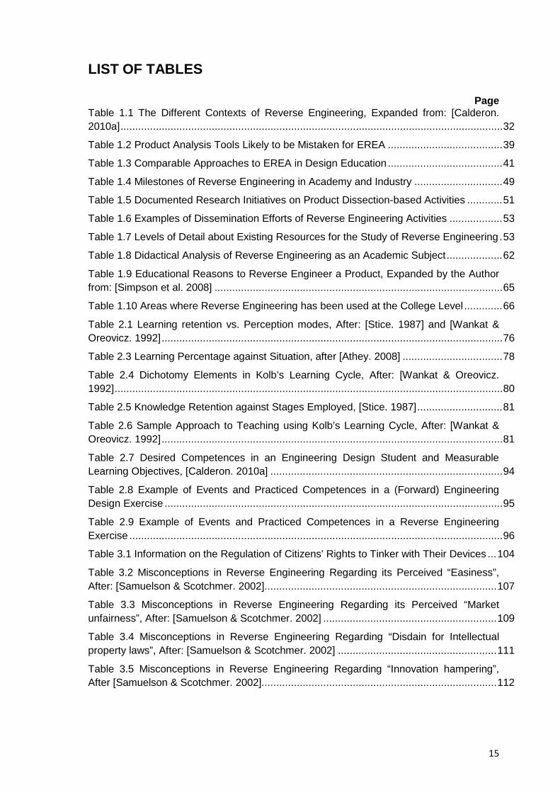
15
LIST OF TABLES
Page Table 1.1 The Different Contexts of Reverse Engineering, Expanded from: [Calderon. 2010a] .................................................................................................................................. 32
Table 1.2 Product Analysis Tools Likely to be Mistaken for EREA ....................................... 39
Table 1.3 Comparable Approaches to EREA in Design Education ....................................... 41
Table 1.4 Milestones of Reverse Engineering in Academy and Industry .............................. 49
Table 1.5 Documented Research Initiatives on Product Dissection-based Activities ............ 51
Table 1.6 Examples of Dissemination Efforts of Reverse Engineering Activities .................. 53
Table 1.7 Levels of Detail about Existing Resources for the Study of Reverse Engineering . 53
Table 1.8 Didactical Analysis of Reverse Engineering as an Academic Subject ................... 62
Table 1.9 Educational Reasons to Reverse Engineer a Product, Expanded by the Author from: [Simpson et al. 2008] .................................................................................................. 65
Table 1.10 Areas where Reverse Engineering has been used at the College Level ............. 66
Table 2.1 Learning retention vs. Perception modes, After: [Stice. 1987] and [Wankat & Oreovicz. 1992] .................................................................................................................... 76
Table 2.3 Learning Percentage against Situation, after [Athey. 2008] .................................. 78
Table 2.4 Dichotomy Elements in Kolb’s Learning Cycle, After: [Wankat & Oreovicz. 1992] .................................................................................................................................... 80
Table 2.5 Knowledge Retention against Stages Employed, [Stice. 1987] ............................. 81
Table 2.6 Sample Approach to Teaching using Kolb’s Learning Cycle, After: [Wankat & Oreovicz. 1992] .................................................................................................................... 81
Table 2.7 Desired Competences in an Engineering Design Student and Measurable Learning Objectives, [Calderon. 2010a] ............................................................................... 94
Table 2.8 Example of Events and Practiced Competences in a (Forward) Engineering Design Exercise ................................................................................................................... 95
Table 2.9 Example of Events and Practiced Competences in a Reverse Engineering Exercise ............................................................................................................................... 96
Table 3.1 Information on the Regulation of Citizens' Rights to Tinker with Their Devices ... 104
Table 3.2 Misconceptions in Reverse Engineering Regarding its Perceived “Easiness”, After: [Samuelson & Scotchmer. 2002]............................................................................... 107
Table 3.3 Misconceptions in Reverse Engineering Regarding its Perceived “Market unfairness”, After: [Samuelson & Scotchmer. 2002] ........................................................... 109
Table 3.4 Misconceptions in Reverse Engineering Regarding “Disdain for Intellectual property laws”, After: [Samuelson & Scotchmer. 2002] ...................................................... 111
Table 3.5 Misconceptions in Reverse Engineering Regarding “Innovation hampering”, After [Samuelson & Scotchmer. 2002]................................................................................ 112
16
Table 3.6 Misconceptions in Reverse Engineering Regarding “Invention weakening”, After [Samuelson & Scotchmer. 2002] ........................................................................................ 113
Table 4.1 Documented Benefits of Reverse Engineering and Similar Activities in Engineering Education, Expanded and Arranged for this Collection of Resources from the Works by [Jensen & Bowe. 1999]; [Simpson et al. 2007], [Simpson et al. 2008], [Shooter. 2008], [Dalrymple. 2009] and [Dalrymple et al. 2011] ......................................................... 124
Table 4.2 Documented Benefits of Reverse Engineering and Similar Activities in Engineering Education, Expanded and Arranged for this Collection of Resources from the Works by [Jensen & Bowe. 1999]; [Simpson et al. 2007], [Simpson et al. 2008], [Shooter. 2008], [Dalrymple. 2009] and [Dalrymple et al. 2011] ......................................................... 127
Table 4.3 Documented Benefits of Reverse Engineering and Similar Activities in Engineering Education, Expanded and Arranged for this Collection of Resources from the Works by [Jensen & Bowe. 1999]; [Simpson et al. 2007], [Simpson et al. 2008], [Shooter. 2008]; [Dalrymple. 2009] and [Dalrymple et al. 2011] ......................................................... 130
Table 4.4 Documented Benefits of Reverse Engineering and Similar Activities in Engineering Education, Expanded and Arranged for this Collection of Resources from the Works by [Jensen & Bowe. 1999]; [Simpson et al. 2007], [Simpson et al. 2008], [Shooter. 2008], [Dalrymple. 2009] and [Dalrymple et al. 2011] ......................................................... 131
Table 4.5 Documented Benefits of Reverse Engineering and Similar Activities in Engineering Education, Expanded and Arranged for this Collection of Resources from the Works by [Jensen & Bowe. 1999]; [Simpson et al. 2007], [Simpson et al. 2008], [Shooter. 2008], [Dalrymple. 2009] and [Dalrymple et al. 2011] ......................................................... 133
Table 4.6 Documented Benefits of Reverse Engineering and Similar Activities in Engineering Education, Expanded and Arranged for this Collection of Resources from the Works by [Jensen & Bowe. 1999]; [Simpson et al. 2007], [Simpson et al. 2008], [Shooter. 2008], [Dalrymple. 2009] and [Dalrymple et al. 2011] ......................................................... 134
Table 4.7 Documented Benefits of Reverse Engineering and Similar Activities in Engineering Education, Expanded and Arranged for this Collection of Resources from the Works by [Jensen & Bowe. 1999]; [Simpson et al. 2007], [Simpson et al. 2008], [Shooter. 2008], [Dalrymple. 2009] and [Dalrymple et al. 2011] ......................................................... 137
Table 4.8 Documented Benefits of Reverse Engineering and Similar Activities in Engineering Education, Expanded and Arranged for this Collection of Resources from the Works by [Jensen & Bowe. 1999]; [Simpson et al. 2007], [Simpson et al. 2008], [Shooter. 2008], [Dalrymple. 2009] and [Dalrymple et al. 2011] ......................................................... 137
Table 4.9 Representative Studies on Engineering Design Competences, After [Calderon. 2010b] ................................................................................................................................ 140
Table 4.10 Strongest Elements Educational Reverse Engineering Activities can bring to Engineering Design Education (Rephrased as Action Verbs and Sorted under Fourteen Higher Order Competence Categories) .............................................................................. 144
Table 5.1 Expanded Methodology for the Educational Reverse Engineering Analysis of a Consumer Product ............................................................................................................. 153
Table 6.1 Sample Vocabulary of an EREA ......................................................................... 214
Table 6.2 Class Schedule Example .................................................................................... 218
17
Table 6.3 Summary of guidelines for the success of hands-on and similar activities, Source: [Malmqvist et al. 2004] .......................................................................................... 241
Table 6.4 Sample BOM to Document the Dissection of a Product ...................................... 252
Table 6.5 Guidelines for material use, fasteners and product structure, Source [Jeswiet et al. 2007] ............................................................................................................................. 256
Table 6.6 Resources for the Study of the Design of Product Families by Using Disposable Cameras, Source: [Simpson. 2013] .................................................................................... 257
Table 6.7 Sample Calculations of Product Commonality Index for a Family of Kodak Disposable Cameras, Source: [Simpson. 2013] ................................................................. 258
Table 6.8 Design Structure Matrix for the Kodak Water & Sport One-Time-Use Camera, Source [Kutz. 2007] ............................................................................................................ 261
Table 6.9 Function-Component Matrix for the Kodak Water & Sport One-Time-Use Camera, Source [Kutz. 2007] ............................................................................................. 262
Table 6.10 Examples of DFA Rules, Source: [Jounghyun. 1994] ....................................... 268
Table 6.11 Design for Assembly Guidelines by [Boothroyd & Dewhurst. 2002] .................. 269
Table 6.12 Design for Disassembly Guidelines, Source [Willems. 2005] ............................ 272
Table 6.13 Design for Disassembly Guidelines, After: [Chiodo. 2005] ................................ 273
Table 6.14 Product criteria against information it provides Minimal case analysis .............. 279
Tables 6.15 PDS Items; Description, Examples, Associated Test and Derivable Information ......................................................................................................................... 280
Table 6.16 Analysis of Factors that Influence the Design of a Product, Source: [Devendorf et al. 2011] ......................................................................................................................... 285
Table 6.17 Standardized Template for the Organization of Design Data in a Reverse Engineering Analysis .......................................................................................................... 291
Table 6.18 Examples of Design Actions, Source: [Jounghyun. 1994] ................................. 300
Table 6.19 Traits of Highly Successful Explanations, Source: [Fogelin. 2007] .................... 306
Table 7.1 Students’ Understanding of the Situation ............................................................ 335
Table 7.2 Expected Timetable for the EREA ...................................................................... 336
Table 7.3 Relevant Patents for the Study of Disposable Cameras ..................................... 346
Table 7.4 Disassembly of a Kodak Flash Camera, After: [CIBER-U. 2012] ........................ 354
Table 7.5 Bill of Materials and Part Analysis for a Kodak Funsaver Disposable Camera, Source: [CIBER-U. 2012] ................................................................................................... 357
Table 7.6 Sample Weights of a Disposable Kodak Flash Camera ...................................... 357
Table 7.7 Sample Parts List and Material Description of an Earlier Generation Kodak Flash Camera, Source: [Simpson. 2009] ............................................................................ 358
Table 7.8 Overview of a Kodak Waterproof Camera’s Materials and Production Processes .......................................................................................................................... 360
Table 7.9 Overview of the Kodak Flash camera, After: [Castellani. 2006] & [CIBER-U. 2012] .................................................................................................................................. 366
18
Table 7.10 Kodak Camera’s Applicable UNSPSC Codes, Source [Castellani. 2006] ......... 367
Table 7.11 Kodak Camera’s Sumo Entries, Source: [Castellani. 2006] .............................. 367
Table 7.12 Kodak Camera’s NIST Functional Basis Elements, Source: [Castellani. 2006] . 368
Table 7.13 Design Structure Matrix for the Kodak Water & Sport One-Time-Use Camera, Source [Kutz. 2007] ............................................................................................................ 372
Table 7.14 Function-Component Matrix for the Kodak Water & Sport One-Time-Use Camera, Source: [Kutz. 2007] ............................................................................................ 373
Table 7.15 Sample Calculations of Product Commonality Index for a Family of Kodak Disposable Cameras, Source: [Simpson. 2013] ................................................................. 374
Table 7.16 Reassembly Process of a Disposable Kodak Flash Camera, Source: [CIBER-U. 2012] ............................................................................................................................. 383
Table 7.17 Lifecycle Stages of Kodak’s Single-Use Cameras, [Simpson. 2009] ................. 392
Table 7.18 Kodak’s Single-Use Cameras Component Recycling and Reuse, After: [Simpson. 2009] ................................................................................................................. 393
Table 7.19 Typical Findings after Reverse Engineering a Disposable Camera, After [Sidler-Kellog & Jenison. 1997] .......................................................................................... 395
Table 7.20 Common Improvement Suggestions for Kodak’s Disposable Cameras, After [Sidler-Kellog & Jenison. 1997], [CIBER-U. 2012] and this Collection of Resources’s own Suggestions ....................................................................................................................... 399
Table 8.1 Potential Research Lines in Educational Reverse Engineering ........................... 412
Table 9.1 Resources for the Study of the Antikythera Mechanism ...................................... 416
Table 9.2 Video Dissection and Analysis of an iPad Device ............................................... 416
Table 9.3 Relevant People in the Development of EREA ................................................... 420
Table 9.4 Peer-reviewed Conferences where Topics about Educational Reverse Engineering are usually Covered ....................................................................................... 421
Table 9.5 Indicative Dissertations on Educational Reverse Engineering and Associated Topics ................................................................................................................................ 422
Table 9.6 Academic Journals where Educational Reverse Engineering Papers have been Published ........................................................................................................................... 423
Table 9.7 Indicative Bibliography with Dedicated Chapters Covering Reverse Engineering Activities ............................................................................................................................. 425
Table 9.8 Specialized Search Engines and Databases with Articles on Educational Reverse Engineering .......................................................................................................... 426
Table 9.9 The ME 240 Product Dissection Course by the Pennsylvania State University in the USA ............................................................................................................................. 427
Table 9.10 Examples of Product Dissection Exercises by the CIBER-U Initiative ............... 427
Table 9.11 Complementary Resources for the Study of Educational Reverse Engineering 428
Table 9.12 Resources for the Study of the Subject System Used in the Guided Example of Resource 7 ..................................................................................................................... 429
19
LIST OF FIGURES
Page
Figure 1.1 Involvement of Various Functional Groups in the Design of Consumer Mechatronic Products, Source: [Chan & Leung. 1996] ......................................................... 32
Figure 1.2 Related Knowledge Domains that Support Design and Development, Source: [Pahl et al. 2007] .................................................................................................................. 33
Figure 1.3 Inability of hardware to withstand real world pressures, Source: [Augustine. 1983] .................................................................................................................................... 34
Figure 1.4: Sources contributing to the knowledge of the designer, Source: [Blessing. 1994] .................................................................................................................................... 36
Figure 1.5 Aircraft Design by Special Interest Groups of Engineers, Source: [Hyman. 2003] .................................................................................................................................... 37
Figure 1.6 Learning Engineering Design by Developing Links between Experiential and Abstract Understandings, Source: [Brereton et al. 1995] ..................................................... 38
Figure 1.7 Concept map for Engineering, Source: [Turns et al. 2000] .................................. 55
Figure 1.8 General Approach to design [VDI Verlag GmbH. 1987] ....................................... 56
Figure 1.9 The Four questions of Didactical Analysis, Source: [Grimheden.2006] ................ 60
Figure 1.10 Comparison of (Forward) Engineering to Reverse Engineering ......................... 68
Figure 1.11 Relationship of Form and Function in Reverse Engineering and Design, Source: [Shooter. 2008] ....................................................................................................... 68
Figure 1.12 The Saqqara Bird, Source: [Wikimedia Commons. 2011] .................................. 69
Figure 1.13 Celtic Stone a.k.a Rattleback, Source: [Wikimedia Commons. 2006] ................ 69
Figure 1.14 The Developmental Process of Korea’s National Technological Ability, Source: [NTRM. 2002] ......................................................................................................... 71
Figure 1.15 Movement from low Technology to high Technology, Source: [Methe. 1995] .... 72
Figure 2.1 Increasing Student Learning as a Result of Teaching Technique, Source: [Wang. 2004] ........................................................................................................................ 77
Figure 2.2 Annotated Kolb’s Model of Learning Superimposed with Suggested Activities for each Quadrant, [Wood et al. 2005] also Published by [Aziz & Chassapis. 2008] ............. 79
Figure 2.3 Data, Information and Knowledge Relative to the Potential User. Source: [Ahmed et al. 1999] .............................................................................................................. 83
Figure 2.4 Model of Learning through Designing and Reverse Engineering, Source: [Brereton. 2001] ................................................................................................................... 84
Figure 2.5 Cycle of Student’s Acquisition and Development of Competences through EREA ................................................................................................................................... 86
Figure 2.6 Levels at Which Students Acquire Competences through EREA ......................... 87
Figure 2.7 Levels Involved in the Acquisition of Competences through Reverse Engineering Activities ........................................................................................................... 91
20
Figure 2.8 Levels and Corresponding Outcomes Involved in Educational Reverse Engineering Exercises ......................................................................................................... 92
Figure 2.9 Reasonably Expected Areas of Competence of a University Graduate, Source: [Meijers et al. 2005] .............................................................................................................. 93
Figure 3.1 Product Development: Opportunity Areas, from low risk to high risk, Source: [Cross. 2008] ...................................................................................................................... 119
Figure 5.1 Cycle of Analysis and Synthesis while Analyzing a Subject System .................. 148
Figure 5.2 Essential Stages for an Educational Reverse Engineering Analysis .................. 148
Figure 5.3 Conceptual Methodology for the Educational Reverse Engineering Analysis of a Consumer Product .......................................................................................................... 149
Figure 6.1 Phases of the pedagogy for the teaching of an EREA and their match to the stages of the methodology for educational reverse engineering analysis ........................... 205
Figure 6.2 Function Relation Analysis of a Kodak Disposable Camera with Flash, Source: [Comparini & Cagan. 1998] ................................................................................................ 263
Figure 6.3 Function structure for the Kodak Water & Sport Camera, Source: [Kutz. 2007] . 264
Figure 6.4 Generic Example of a Life-Cycle Inventory, Source: [Comparini & Cagan. 1998] .................................................................................................................................. 274
Figure 6.5 Stages of Life-Cycle Inventory Analysis of a Kodak Single Use Camera, Source: [Comparini & Cagan. 1998] ................................................................................... 274
Figure 6.6 Classification of Design Ideation Methods, Source: [Shah. 2006] ...................... 304
Figure 6.7 Selection of Fujifilm Disposable Camera Components, Photocredits: [Dalrymple. 2009] ............................................................................................................... 320
Figure 6.8 Superimposed image, Photocredits: [Dalrymple. 2009] ..................................... 321
Figure 6.9 Example 1, Picture. Photocredits: [Dalrymple. 2009] ......................................... 323
Figure 6.10 Example 2, Picture. Photocredits [Dalrymple. 2009] ........................................ 324
Figure 6.11 Example 3, Picture. Photocredits [Dalrymple. 2009] ........................................ 324
Figure 6.12 Example 4, Picture. Photocredits [Dalrymple. 2009] ........................................ 325
Figure 6.13 Sample Fujifilm Single Use Camera Parts, Source: [Dalrymple. 2009] ............ 326
Figure 7.1 Disposable Kodak Flash Camera ...................................................................... 337
Figure 7.2 Disposable Kodak Sport Camera ...................................................................... 338
Figure 7.3 Disposable Fujifilm QuickSnap Superia camera ................................................ 338
Figure 7.4 Camera Disassembly and Recycling Process, Source [Kutz. 2007] .................. 343
Figure 7.5 Graphical representation of Kodak’s Closed-loop recycling program, From Use to Reuse, Source: [Eastman Kodak Company. 2013] ......................................................... 344
Figure 7.6 Cameras Returned Annually Worldwide, Source: [Kutz. 2007] .......................... 344
Figure 7.7 Exploded view I of a Dissected Kodak Flash Camera, [Edwards et al. 2010] .... 359
Figure 7.8 Exploded view II of a Dissected Kodak Flash Camera, [Edwards et al. 2010] ... 359
Figure 7.9 Sample CAD Diagram of a Disposable Camera, Source: [CIESE. 2008] ........... 360
21
Figure 7.10 Assembly Drawing of an Early Generation of Kodak’s Disposable Cameras, Source: [Simpson. 2009] .................................................................................................... 361
Figure 7.11 Sample CAD models of components in a Kodak Waterproof camera, Source: [Kutz. 2007] ........................................................................................................................ 362
Figure 7.12 Assembly Drawing of the Internal Housing of a Kodak Waterproof Camera, [Kutz. 2007] ........................................................................................................................ 362
Figure 7.13 Digitization of Front Outer Shell (a) Raw scan—top, (b) Raw scan—side, (c) Merged images, and (d) Actual component, Source: [Kutz. 2007] ...................................... 363
Figure 7.14 Digitization of Front Housing inside outer Shell: (a) Raw scan—top, (b) Raw scan—side, (c) Merged images, and (d) Actual component, Source: [Kutz. 2007].............. 363
Figure 7.15 Force Flow Diagram of a Disposable Kodak Flash Camera, [Edwards et al. 2010] .................................................................................................................................. 369
Figure 7.16 Functional Model of a Kodak Flash Camera, Source: [Edwards et al. 2010] .... 370
Figure 7.17 Function Relation Analysis of a Kodak Flash Camera, Source: [Comparini & Cagan. 1998] ..................................................................................................................... 371
Figure 7.18 Function Structure for the Kodak Water & Sport Camera, Source: [Kutz. 2007] .................................................................................................................................. 373
Figure 7.19 Partially Completed Morphological Chart for a Disposable Kodak Camera, Source: [Dalrymple et al. 2011] .......................................................................................... 375
Figure 7.20 Manufacturing Date Stamp on a Camera’s Rear Housing, Source: [Kutz. 2007] .................................................................................................................................. 376
Figure 7.21 Special Film Canister for one-time-use Cameras, Source: [Kutz. 2007] ........... 378
Figure 7.22 Stages of Life-Cycle Inventory Analysis of a Kodak Single Use Camera, Source: [Comparini & Cagan. 1998] ................................................................................... 379
Figure 7.23 Sample Assembly Hierarchy for a Kodak Flash Camera, Source: [Edwards et al. 2010] ............................................................................................................................. 383
Figure 7.24 Sample Photographic Changing Bag, Photocredits: [Freestyle. 2013] ............. 384
Figure 7.25 Exploded View of the Chassis of an Original Kodak’s FunSaver one-time-use Camera, Source: [Kutz. 2007] ............................................................................................ 388
Figure 7.26 Camera Mechanism in the Kodak Water & Sport one-time-use Camera, Source: [Kutz. 2007] ........................................................................................................... 389
Figure 7.27 Top view of Finder on four of Kodak’s one-time-use Cameras, Source: [Kutz. 2007] .................................................................................................................................. 389
Figure 7.28 Close-up of Viewfinder in four of Kodak’s one-time-use Cameras, Source: [Kutz. 2007] ........................................................................................................................ 390
Figure 7.29 Sample Dissemination Posters and PowerPoint Presentations to Discuss the Details and Findings from an EREA ................................................................................... 403
Unless otherwise stated all Tables / Figures were created by the author of this collection of resources

22
This page intentionally left blank
23
PREFACE
Educational reverse engineering activities are in general, highly regarded hands-on
activities that help students bridge the gap between theory and practice in the safety of
an educational environment; they can be included in any engineering design curriculum
to help students increase their awareness and understanding of the design process and
to show through real-life examples what worked for other designers and what didn’t.
However, as promising as they sound, the number of programmes that have introduced
them into their teaching curricula can still be considered low in comparison to the number
of academic institutions offering degrees in the global community of engineering design;
while the causes for it are many and of a varied nature, it was found during initial
exploratory studies with experts and stakeholders in academia and industry that major
factors impeding their full adoption were:
1. The limited awareness of their educational benefits, especially in relation to the
expected competences of an engineering design student at the time of graduation
2. The lack of a standardized guideline on how to actually prepare; deliver, and
evaluate these activities to make the most out of them, to not leave this
responsibility solely to the experience of the professor in turn (a challenge for first
time instructors of this type of activities)
3. The perception that the already existing resources on the topic were either
dispersed or unsuitable as a tutorial (c.f. Self-directed learning)
4. The idea that current literature on the topic required a re-contextualization in light
of progressing technologies now available in education
5. A number of misconceptions about educational reverse engineering, mostly
concerning its lawfulness and ethics
This collection of resources then, is a freely distributable document that intends to deal
with the causes that contribute to the lack of diffusion; adoption and regard for reverse
engineering activities in engineering design education and presents a potential solution to
such issues by providing potential adopters with the information and guidance for a
seamless integration of educational reverse engineering activities into their existing
teaching curriculum.
Every effort has been made to ensure the quality of this collection of resources that
intends to be rigorous at the bibliographical level and comprehensive in content so the
work and ideas presented here can be verified empirically by independent practitioners,
your questions and feedback to help improve this document are most welcome indeed.

24
This page left intentionally blank
25
INTRODUCTION
Educational reverse engineering activity(es) -hereinafter referred to as the acronym
“EREA”- help engineering design students to: Acquire and develop a set of abilities that
raise their awareness of the design process; expand their sources of inspiration, position
their actions within the lifecycle of a product, and transform theoretical knowledge into
practice. However, as mentioned already, it was noted that although such activities spark
interest among engineering design educators, they are either absent from typical
engineering design curricula or are not fully exploited
After analysing the causes for it and determining that the creation of a collection of
resources was the best way to reach a geographically dispersed community and thus
start trying to change the existing situation, the development of this document began with
the goal to address as many of the concerns as possible found whenever trying to
implement EREA into existing engineering design curricula
The contents selected for this collection of resources then, were derived based on the
feedback received from peer reviewed conference papers stemming from the doctoral
research from which this document also originates, and from the presentation of
intermediate results to early reviewers of this collection of resources; because of this, the
information presented here targets first time (or novice) instructors of reverse engineering
activities and takes into account not only the technical but also the pedagogical and
administrative considerations implicated in the introduction of new academic activities into
an existing engineering curriculum
Given that some relevant information about the topic already existed but it was dispersed
across different areas of knowledge; rather than developing all topics from scratch again,
a conscious effort was made to examine published literature and to consult with domain
experts to integrate and contextualise all existing information into a coherent body that
could be complemented with the original results originating from this project.
The major sections of this document then, are listed below along a brief explanation of
their contents:
• Resource 1: Fundamentals of Educational Reverse Engineering Activities: Foundations
and contextualization of reverse engineering research in the field of engineering design;
differences and similarities with other approaches that bring practical experience to the
classroom, challenges in the implementation of EREA, etc.
26
• Resource 2: Reverse Engineering and Learning: Cognitive processes students undergo
when performing reverse engineering activities.
• Resource 3: Misconceptions about Reverse Engineering: Clarification of
misunderstandings about reverse engineering in education.
• Resource 4: Benefits of Reverse Engineering: An account of previously published
advantages; potentialities, and added value reverse engineering activities can bring to the
teaching and learning of engineering design.
• Resource 5: A Proposed Methodology for Reverse Engineering Analysis in Engineering
Design Education: A methodology addressed to the field of engineering design for the
educational analysis of consumer products
• Resource 6: A Suggested Pedagogy for the Teaching of Educational Reverse
Engineering Activities: A collection of tips and advices dealing with the practical aspects
behind the execution of the steps; analyses, tasks, and questions proposed in the
methodology of Resource 5
• Resource 7: Integrated Example of an Educational Reverse Engineering Activity on a
Disposable Camera: A guided example, suitable for self-directed learning of an
educational reverse engineering activity using a disposable photographic camera as
subject system
• Resource 8: Conclusions and Final Remarks: Thoughts on the present and future use of
reverse engineering in education based on collected experience and an analysis of
existing, published research
• Resource 9: Miscellaneous Resources for the Study of Reverse Engineering: An
assortment of references linking to published research with the potential to support the
eventual development of additional, instructional courseware
The abovementioned sections are of a sequential nature and purposefully converge at
Resource 7, given that the guided example shown therein expects to contribute in laying
out the foundations for the eventual development of the readers’ own scalable
instructional materials; teaching strategies and educational innovations applied to
educational reverse engineering activities.
The information presented here thus, intends to provide an unbiased view of educational
reverse engineering activities that points out both their strengths and weaknesses to help
those educators interested in these activities to:
27
• Implement them as smoothly as possible into existing and future educational curricula in
the area of engineering design
• Make the most out of them by providing a general framework; credible evidence and
advice for each of the comprising stages
• Measure the impact of EREA in supporting individual and group activities in ways that
extend current engineering design student’s experiences.
The document in your hands, aims to provide engineering design professors with an
assimilable and readily applicable collection of resources for the systematic and effective
planning; execution, evaluation and follow-up of Educational Reverse Engineering
Activities (EREA) in support of the teaching of engineering design; and it is the author’s
belief that by providing students with non-traditional educational experiences and by
encouraging educators to deliver content and knowledge in a non-traditional way,
beneficial, opening experiences can be brought to the teaching of engineering design.

28
This page intentionally left blank
29
RESOURCE 1: FUNDAMENTALS OF EDUCATIONAL REVERSE ENGINEERING ACTIVITIES
1.1 Resource Introduction
The beneficial use of reverse engineering analysis in design education is confirmed by a
variety of findings dispersed across several areas of knowledge, in this resource a
presentation of them and an analysis of how they contributed to the development and
shaping of EREA in its current form is introduced to the reader.
1.2. Principles of Educational Reverse Engineering
1.2.1 What is Reverse Engineering?
Reverse engineering has different meanings depending on the context where it is
mentioned; the different areas of applicability of the term then, generate a concept that
can be found in such diverse areas as legacy software; geometrical shape extraction,
component analysis, intellectual property and more, the term can be even used as a verb,
“to reverse engineer (something)” for example, portrays the idea that any system or
situation can be understood by investigating the traces left by their current, perceivable
effects and matching them to the potential causes that originated them at a previous point
in time.
Reverse engineering as an exploratory activity per se, is founded on the designers’
capability to analyse available pieces of information, and to reconstruct those unavailable
ones based on their domain knowledge and expertise in gathering and contextualizing
new data, because of this, reverse engineering can be used for commercial, competitive
or educational purposes; in this document though, only the educational aspects of
reverse engineering are considered and thus Educational Reverse Engineering (ERE) is
seen as an investigative method to support the teaching of engineering design that is
defined here, as the analysis in the areas of interest of an engineering design program of
an existing consumer product, by taking it apart and studying its structure, function and
operation, with the attempt to recapture the abstract and functional top level
specifications envisioned by the original designers during the Product Design
Specification (PDS) stage, and thus compare against the analysts’ own knowledge, the
design rationale and tradeoffs the original designers faced to go from the multiple
solutions originally available, to the delimited solution boundaries embedded in a final
product, therefore providing the analysts with an educational hands-on experience, and
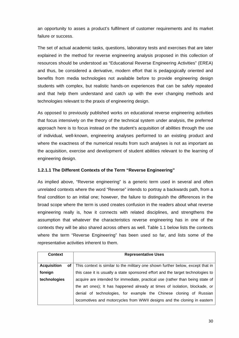
30
an opportunity to asses a product’s fulfilment of customer requirements and its market
failure or success.
The set of actual academic tasks, questions, laboratory tests and exercises that are later
explained in the method for reverse engineering analysis proposed in this collection of
resources should be understood as “Educational Reverse Engineering Activities” (EREA)
and thus, be considered a derivative, modern effort that is pedagogically oriented and
benefits from media technologies not available before to provide engineering design
students with complex, but realistic hands-on experiences that can be safely repeated
and that help them understand and catch up with the ever changing methods and
technologies relevant to the praxis of engineering design.
As opposed to previously published works on educational reverse engineering activities
that focus intensively on the theory of the technical system under analysis, the preferred
approach here is to focus instead on the student’s acquisition of abilities through the use
of individual, well-known, engineering analyses performed to an existing product and
where the exactness of the numerical results from such analyses is not as important as
the acquisition, exercise and development of student abilities relevant to the learning of
engineering design.
1.2.1.1 The Different Contexts of the Term “Reverse Engineering”
As implied above, “Reverse engineering” is a generic term used in several and often
unrelated contexts where the word “Reverse” intends to portray a backwards path, from a
final condition to an initial one; however, the failure to distinguish the differences in the
broad scope where the term is used creates confusion in the readers about what reverse
engineering really is, how it connects with related disciplines, and strengthens the
assumption that whatever the characteristics reverse engineering has in one of the
contexts they will be also shared across others as well. Table 1.1 below lists the contexts
where the term “Reverse Engineering” has been used so far, and lists some of the
representative activities inherent to them.
Context Representative Uses
Acquisition of foreign technologies
This context is similar to the military one shown further below, except that in
this case it is usually a state sponsored effort and the target technologies to
acquire are intended for immediate, practical use (rather than being state of
the art ones); It has happened already at times of isolation, blockade, or
denial of technologies, for example the Chinese cloning of Russian
locomotives and motorcycles from WWII designs and the cloning in eastern
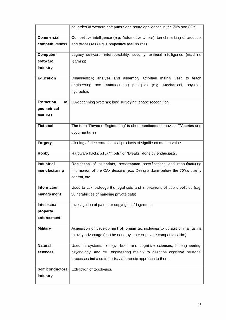
31
countries of western computers and home appliances in the 70’s and 80’s.
Commercial competitiveness
Competitive intelligence (e.g. Automotive clinics), benchmarking of products
and processes (e.g. Competitive tear downs).
Computer software industry
Legacy software; interoperability, security, artificial intelligence (machine
learning).
Education Disassembly; analyse and assembly activities mainly used to teach
engineering and manufacturing principles (e.g. Mechanical, physical,
hydraulic).
Extraction of geometrical features
CAx scanning systems; land surveying, shape recognition.
Fictional The term “Reverse Engineering” is often mentioned in movies, TV series and
documentaries.
Forgery Cloning of electromechanical products of significant market value.
Hobby Hardware hacks a.k.a “mods” or “tweaks” done by enthusiasts.
Industrial manufacturing
Recreation of blueprints, performance specifications and manufacturing
information of pre CAx designs (e.g. Designs done before the 70’s), quality
control, etc.
Information management
Used to acknowledge the legal side and implications of public policies (e.g.
vulnerabilities of handling private data)
Intellectual property enforcement
Investigation of patent or copyright infringement
Military Acquisition or development of foreign technologies to pursuit or maintain a
military advantage (can be done by state or private companies alike)
Natural sciences
Used in systems biology; brain and cognitive sciences, bioengineering,
psychology, and cell engineering mainly to describe cognitive neuronal
processes but also to portray a forensic approach to them.
Semiconductors industry
Extraction of topologies.
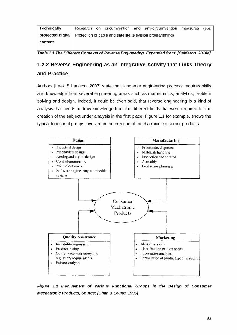
32
Technically protected digital content
Research on circumvention and anti-circumvention measures (e.g.
Protection of cable and satellite television programming)
Table 1.1 The Different Contexts of Reverse Engineering, Expanded from: [Calderon. 2010a]
1.2.2 Reverse Engineering as an Integrative Activity that Links Theory and Practice
Authors [Leek & Larsson. 2007] state that a reverse engineering process requires skills
and knowledge from several engineering areas such as mathematics, analytics, problem
solving and design. Indeed, it could be even said, that reverse engineering is a kind of
analysis that needs to draw knowledge from the different fields that were required for the
creation of the subject under analysis in the first place. Figure 1.1 for example, shows the
typical functional groups involved in the creation of mechatronic consumer products
Figure 1.1 Involvement of Various Functional Groups in the Design of Consumer
Mechatronic Products, Source: [Chan & Leung. 1996]
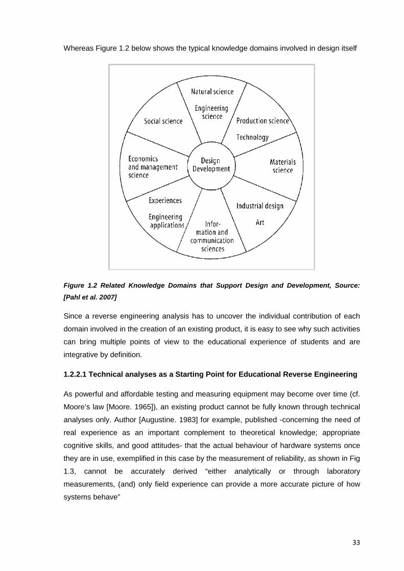
33
Whereas Figure 1.2 below shows the typical knowledge domains involved in design itself
Figure 1.2 Related Knowledge Domains that Support Design and Development, Source:
[Pahl et al. 2007]
Since a reverse engineering analysis has to uncover the individual contribution of each
domain involved in the creation of an existing product, it is easy to see why such activities
can bring multiple points of view to the educational experience of students and are
integrative by definition.
1.2.2.1 Technical analyses as a Starting Point for Educational Reverse Engineering
As powerful and affordable testing and measuring equipment may become over time (cf.
Moore’s law [Moore. 1965]), an existing product cannot be fully known through technical
analyses only. Author [Augustine. 1983] for example, published -concerning the need of
real experience as an important complement to theoretical knowledge; appropriate
cognitive skills, and good attitudes- that the actual behaviour of hardware systems once
they are in use, exemplified in this case by the measurement of reliability, as shown in Fig
1.3, cannot be accurately derived “either analytically or through laboratory
measurements, (and) only field experience can provide a more accurate picture of how
systems behave”
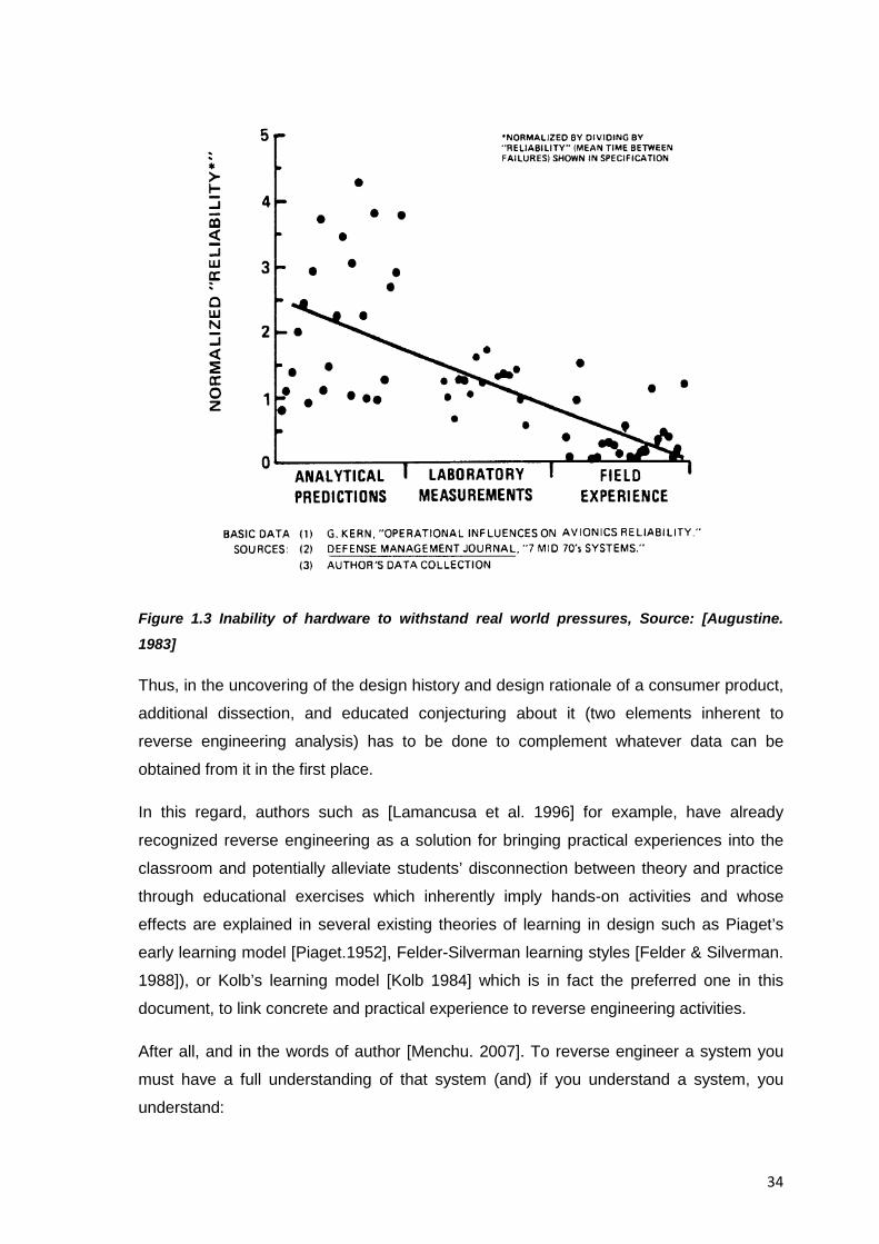
34
Figure 1.3 Inability of hardware to withstand real world pressures, Source: [Augustine.
1983]
Thus, in the uncovering of the design history and design rationale of a consumer product,
additional dissection, and educated conjecturing about it (two elements inherent to
reverse engineering analysis) has to be done to complement whatever data can be
obtained from it in the first place.
In this regard, authors such as [Lamancusa et al. 1996] for example, have already
recognized reverse engineering as a solution for bringing practical experiences into the
classroom and potentially alleviate students’ disconnection between theory and practice
through educational exercises which inherently imply hands-on activities and whose
effects are explained in several existing theories of learning in design such as Piaget’s
early learning model [Piaget.1952], Felder-Silverman learning styles [Felder & Silverman.
1988]), or Kolb’s learning model [Kolb 1984] which is in fact the preferred one in this
document, to link concrete and practical experience to reverse engineering activities.
After all, and in the words of author [Menchu. 2007]. To reverse engineer a system you
must have a full understanding of that system (and) if you understand a system, you
understand:
35
• The players: the key components that make up the system.
• The functions: the main building blocks of the system.
• The relationships: the threads that tie the functions together.
• The flow of information: the energy and the information used to carry out the
system strategy.
• The strategies: which define what the system is supposed to do and how it will do
it
And the stimulus; processes, and the outcomes from user inputs to all the steps that take
place and lead to the system’s output.
1.2.2.2 The Subject System of Educational Reverse Engineering Activities
Consumer products are devices that are usually mass produced; they are based on
customer and market demand and thus, cost effectiveness and efficiency of resources
employed during all phases of their development is of utmost importance, because they
are affordable; feature current technologies, serve as examples of design, and impact the
state of the art, the environment and the quality of life, they have been considered
already an ideal test bed for educational exercises. Author [Dalrymple. 2009] for example,
has explained how consumer products support reverse engineering activities by
describing said activities as a discovery based instructional method (i.e. One where
regularities of previously unrecognized relations and similarities between ideas are
uncovered by the learner, resulting in a sense of self confidence in one’s abilities) as
opposed to being an expository method (i.e. One where the student is given the problem
along with the correct answer), and thus, in order to provide sufficient parameters to
direct students’ attention to topic-relevant concepts and avoid the inability to constrain
students’ exploration without guidance (e.g. What students self- discover may not always
be what was intended to be taught in the sense that actively constructing objects is not
necessarily the same as constructing an understanding of how they work) she suggests
that an alternative approach to traditional discovery-based activities is where an “expert
version” (e.g. A consumer product that will serve as a vehicle for learning) is provided to
students to let them deconstruct it and understand it, given that “The hope is that such an
approach includes an inherent restraint that will provide better parameters for students’
discoveries so subsequent learning will be facilitated and motivation will remain high”,
[Dalrymple. 2009]. Analyzing a consumer product in detail then, helps unveils the design
choices and tradeoffs made not just for engineering reasons but also in targeting
particular markets.
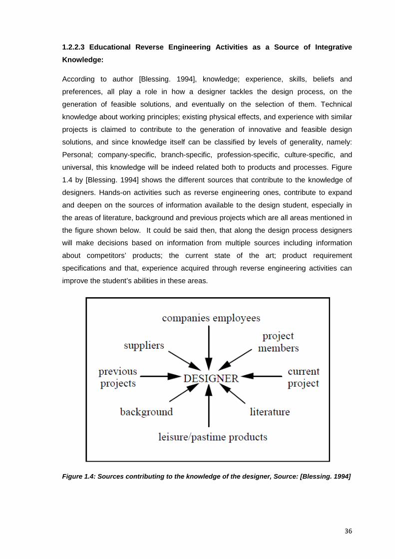
36
1.2.2.3 Educational Reverse Engineering Activities as a Source of Integrative Knowledge:
According to author [Blessing. 1994], knowledge; experience, skills, beliefs and
preferences, all play a role in how a designer tackles the design process, on the
generation of feasible solutions, and eventually on the selection of them. Technical
knowledge about working principles; existing physical effects, and experience with similar
projects is claimed to contribute to the generation of innovative and feasible design
solutions, and since knowledge itself can be classified by levels of generality, namely:
Personal; company-specific, branch-specific, profession-specific, culture-specific, and
universal, this knowledge will be indeed related both to products and processes. Figure
1.4 by [Blessing. 1994] shows the different sources that contribute to the knowledge of
designers. Hands-on activities such as reverse engineering ones, contribute to expand
and deepen on the sources of information available to the design student, especially in
the areas of literature, background and previous projects which are all areas mentioned in
the figure shown below. It could be said then, that along the design process designers
will make decisions based on information from multiple sources including information
about competitors’ products; the current state of the art; product requirement
specifications and that, experience acquired through reverse engineering activities can
improve the student’s abilities in these areas.
Figure 1.4: Sources contributing to the knowledge of the designer, Source: [Blessing. 1994]
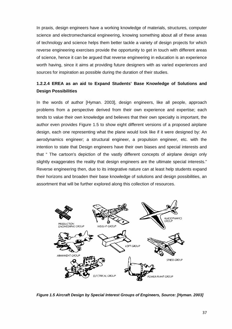
37
In praxis, design engineers have a working knowledge of materials, structures, computer
science and electromechanical engineering, knowing something about all of these areas
of technology and science helps them better tackle a variety of design projects for which
reverse engineering exercises provide the opportunity to get in touch with different areas
of science, hence it can be argued that reverse engineering in education is an experience
worth having, since it aims at providing future designers with as varied experiences and
sources for inspiration as possible during the duration of their studies.
1.2.2.4 EREA as an aid to Expand Students’ Base Knowledge of Solutions and Design Possibilities
In the words of author [Hyman. 2003], design engineers, like all people, approach
problems from a perspective derived from their own experience and expertise; each
tends to value their own knowledge and believes that their own specialty is important, the
author even provides Figure 1.5 to show eight different versions of a proposed airplane
design, each one representing what the plane would look like if it were designed by: An
aerodynamics engineer; a structural engineer, a propulsion engineer, etc. with the
intention to state that Design engineers have their own biases and special interests and
that “ The cartoon's depiction of the vastly different concepts of airplane design only
slightly exaggerates the reality that design engineers are the ultimate special interests.”
Reverse engineering then, due to its integrative nature can at least help students expand
their horizons and broaden their base knowledge of solutions and design possibilities, an
assortment that will be further explored along this collection of resources.
Figure 1.5 Aircraft Design by Special Interest Groups of Engineers, Source: [Hyman. 2003]
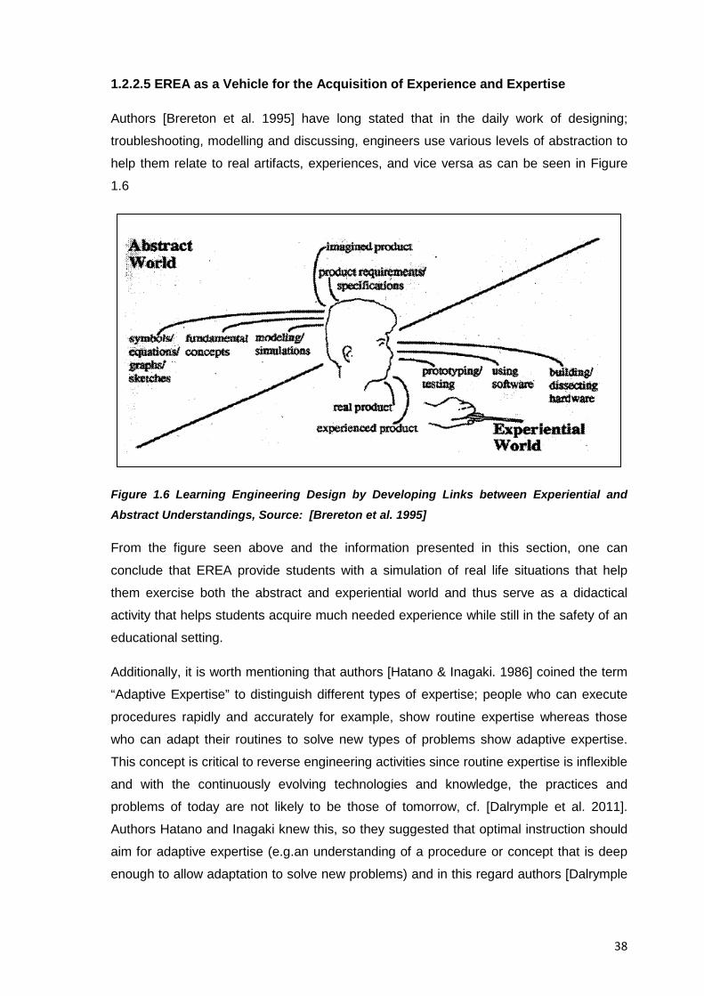
38
1.2.2.5 EREA as a Vehicle for the Acquisition of Experience and Expertise
Authors [Brereton et al. 1995] have long stated that in the daily work of designing;
troubleshooting, modelling and discussing, engineers use various levels of abstraction to
help them relate to real artifacts, experiences, and vice versa as can be seen in Figure
1.6
Figure 1.6 Learning Engineering Design by Developing Links between Experiential and Abstract Understandings, Source: [Brereton et al. 1995]
From the figure seen above and the information presented in this section, one can
conclude that EREA provide students with a simulation of real life situations that help
them exercise both the abstract and experiential world and thus serve as a didactical
activity that helps students acquire much needed experience while still in the safety of an
educational setting.
Additionally, it is worth mentioning that authors [Hatano & Inagaki. 1986] coined the term
“Adaptive Expertise” to distinguish different types of expertise; people who can execute
procedures rapidly and accurately for example, show routine expertise whereas those
who can adapt their routines to solve new types of problems show adaptive expertise.
This concept is critical to reverse engineering activities since routine expertise is inflexible
and with the continuously evolving technologies and knowledge, the practices and
problems of today are not likely to be those of tomorrow, cf. [Dalrymple et al. 2011].
Authors Hatano and Inagaki knew this, so they suggested that optimal instruction should
aim for adaptive expertise (e.g.an understanding of a procedure or concept that is deep
enough to allow adaptation to solve new problems) and in this regard authors [Dalrymple
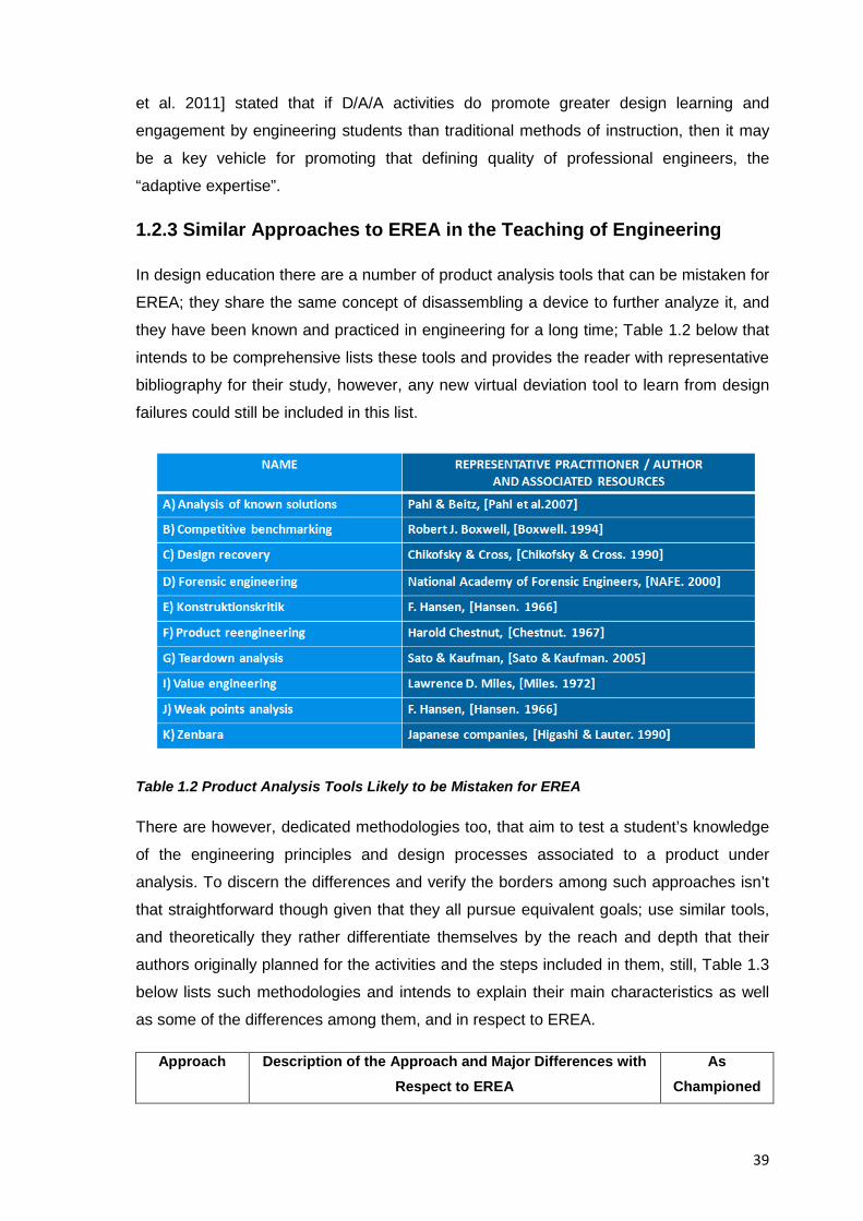
39
et al. 2011] stated that if D/A/A activities do promote greater design learning and
engagement by engineering students than traditional methods of instruction, then it may
be a key vehicle for promoting that defining quality of professional engineers, the
“adaptive expertise”.
1.2.3 Similar Approaches to EREA in the Teaching of Engineering
In design education there are a number of product analysis tools that can be mistaken for
EREA; they share the same concept of disassembling a device to further analyze it, and
they have been known and practiced in engineering for a long time; Table 1.2 below that
intends to be comprehensive lists these tools and provides the reader with representative
bibliography for their study, however, any new virtual deviation tool to learn from design
failures could still be included in this list.
Table 1.2 Product Analysis Tools Likely to be Mistaken for EREA
There are however, dedicated methodologies too, that aim to test a student’s knowledge
of the engineering principles and design processes associated to a product under
analysis. To discern the differences and verify the borders among such approaches isn’t
that straightforward though given that they all pursue equivalent goals; use similar tools,
and theoretically they rather differentiate themselves by the reach and depth that their
authors originally planned for the activities and the steps included in them, still, Table 1.3
below lists such methodologies and intends to explain their main characteristics as well
as some of the differences among them, and in respect to EREA.
Approach Description of the Approach and Major Differences with Respect to EREA
As Championed
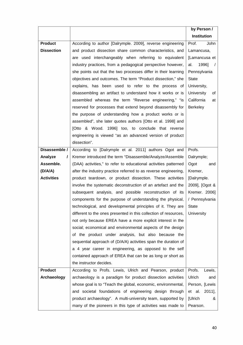
40
by Person / Institution
Product Dissection
According to author [Dalrymple. 2009], reverse engineering
and product dissection share common characteristics, and
are used interchangeably when referring to equivalent
industry practices, from a pedagogical perspective however,
she points out that the two processes differ in their learning
objectives and outcomes. The term “Product dissection,” she
explains, has been used to refer to the process of
disassembling an artifact to understand how it works or is
assembled whereas the term “Reverse engineering,” “is
reserved for processes that extend beyond disassembly for
the purpose of understanding how a product works or is
assembled”, she later quotes authors [Otto et al. 1998] and
[Otto & Wood. 1996] too, to conclude that reverse
engineering is viewed “as an advanced version of product
dissection”.
Prof. John
Lamancusa,
[Lamancusa et
al. 1996] /
Pennsylvania
State
University,
University of
California at
Berkeley
Disassemble / Analyze / Assemble. (D/A/A) Activities
According to [Dalrymple et al. 2011] authors Ogot and
Kremer introduced the term “Disassemble/Analyze/Assemble
(DAA) activities,” to refer to educational activities patterned
after the industry practice referred to as reverse engineering,
product teardown, or product dissection. These activities
involve the systematic deconstruction of an artefact and the
subsequent analysis, and possible reconstruction of its
components for the purpose of understanding the physical,
technological, and developmental principles of it. They are
different to the ones presented in this collection of resources,
not only because EREA have a more explicit interest in the
social; economical and environmental aspects of the design
of the product under analysis, but also because the
sequential approach of (D/A/A) activities span the duration of
a 4 year career in engineering, as opposed to the self
contained approach of EREA that can be as long or short as
the instructor decides.
Profs.
Dalrymple;
Ogot and
Kremer,
[Dalrymple.
2009], [Ogot &
Kremer. 2006]
/ Pennsylvania
State
University
Product Archaeology
According to Profs. Lewis, Ulrich and Pearson, product
archaeology is a paradigm for product dissection activities
whose goal is to “Teach the global, economic, environmental,
and societal foundations of engineering design through
product archaeology”. A multi-university team, supported by
many of the pioneers in this type of activities was made to
Profs. Lewis,
Ulrich and
Person, [Lewis
et al. 2011],
[Ulrich &
Pearson.
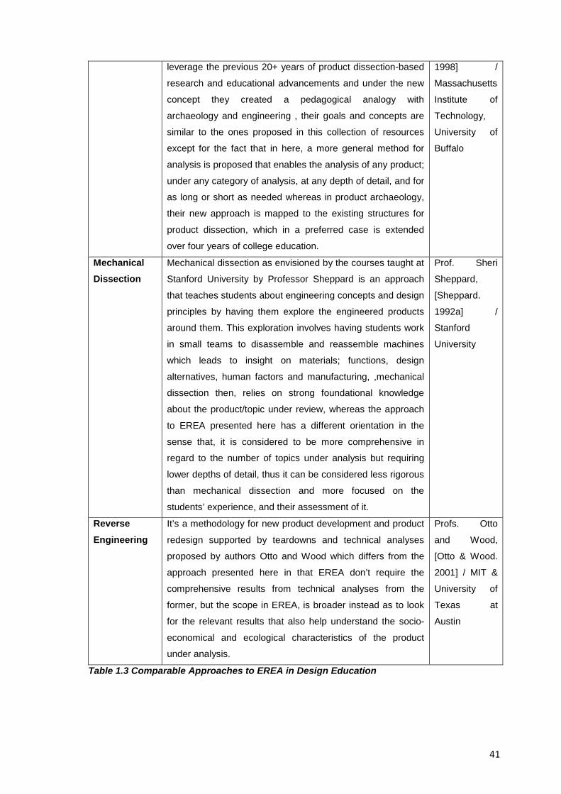
41
leverage the previous 20+ years of product dissection-based
research and educational advancements and under the new
concept they created a pedagogical analogy with
archaeology and engineering , their goals and concepts are
similar to the ones proposed in this collection of resources
except for the fact that in here, a more general method for
analysis is proposed that enables the analysis of any product;
under any category of analysis, at any depth of detail, and for
as long or short as needed whereas in product archaeology,
their new approach is mapped to the existing structures for
product dissection, which in a preferred case is extended
over four years of college education.
1998] /
Massachusetts
Institute of
Technology,
University of
Buffalo
Mechanical Dissection
Mechanical dissection as envisioned by the courses taught at
Stanford University by Professor Sheppard is an approach
that teaches students about engineering concepts and design
principles by having them explore the engineered products
around them. This exploration involves having students work
in small teams to disassemble and reassemble machines
which leads to insight on materials; functions, design
alternatives, human factors and manufacturing, ,mechanical
dissection then, relies on strong foundational knowledge
about the product/topic under review, whereas the approach
to EREA presented here has a different orientation in the
sense that, it is considered to be more comprehensive in
regard to the number of topics under analysis but requiring
lower depths of detail, thus it can be considered less rigorous
than mechanical dissection and more focused on the
students’ experience, and their assessment of it.
Prof. Sheri
Sheppard,
[Sheppard.
1992a] /
Stanford
University
Reverse Engineering
It’s a methodology for new product development and product
redesign supported by teardowns and technical analyses
proposed by authors Otto and Wood which differs from the
approach presented here in that EREA don’t require the
comprehensive results from technical analyses from the
former, but the scope in EREA, is broader instead as to look
for the relevant results that also help understand the socio-
economical and ecological characteristics of the product
under analysis.
Profs. Otto
and Wood,
[Otto & Wood.
2001] / MIT &
University of
Texas at
Austin
Table 1.3 Comparable Approaches to EREA in Design Education
42
The abovementioned methodologies place the students’ learning at the forefront and they
can be associated to the formal study of the design itself; they mostly rely on product
development methods and they are typically oriented to system analysis or immediate
industrial applications; EREA on the other hand, and as presented in this collection of
resources, are fully focused on the pedagogical value of their inherent hands-on
approach, and on the students’ learning of the non-technical aspects of the product under
analysis (e.g. The varied knowledge domains of design development seen in Figure 1.2,
or the socio-technological understanding of products as suggested by author
[Ropohl.1999]). The most important results from EREA then, are not the pieces of data or
numerical results acquired from the product under study, but rather the results that prove
the students’ acquisition and development of relevant abilities and skills that may not be
obvious or easy to measure at first sight.
However, educational reverse engineering activities as presented in this document,
cannot be considered an isolated approach independent from the abovementioned
methodologies, EREA do share the same basic tools and principles too, but also try to
combine and complement them with the new advances in multimedia and computer
assisted design technologies in an effort to improve the students’ understanding of the
broader context of engineering design in areas not usually covered by traditional
approaches, because of such shared roots and similarities between approaches then, the
extrapolation of findings from previously conducted studies benefits the own research
conducted for the creation of this collection of resources and makes possible the use of
other authors’ results in their efforts to prove the pedagogical viability of EREA
1.2.3.1 Introduction to the Terminology in use in the Area of Educational Reverse Engineering
As seen in Table 1.3 above, several terms exist in engineering education to refer to a set
of comparable, hands-on activities that revolve around the dissection of a product for its
analysis. It should be clarified then, that with only notable exceptions (cf. D/A/A activities
by [Ogot & Kremer. 2006]) such terms are, by practical means, used interchangeably. If
we take into consideration the relevant literature on educational reverse engineering
though, we could see that: the term “Mechanical Dissection” is credited with the revival of
such activities in education; the term “Product Dissection” is relevant because of the
availability of updated materials available for its study, the term “D/A/A activities” is
important because an actual study was done to come up with such name and was later
adopted by other researchers too, the term “Product Archaeology” is a recently revived
one adopted by early and new practitioners of dissection activities, and finally the term
43
“Reverse Engineering”, which is the most relevant to this document, not only because it
is the earliest recorded term in the area (author [Tilton. 2004] traces it back “at least to
1960 in connection with hardware when it meant an attempt to fathom and reconstruct
the circuitry inside a potted electronic module”), but also because it’s been used by
reputed authors such as [Otto & Wood. 2001] in their published research about the topic;
because of this, and like the early practitioners of this type of activities, this research
prefers to stick to the original term “Reverse Engineering”; to acknowledge, because of
historical reasons, its pre-eminence as an umbrella term (a supertype), to recognise that
it contains the rest of the terms mentioned in Table 1.3 (the subtypes), and ultimately, to
favour it because it better reflects the interdisciplinary, integrative nature of its activities in
engineering design.
Worthy of mention too is the term “Dissection” which has developed a special significance
in the area, to the point where it is even considered a valid term to refer to educational
reverse engineering activities in general. Indeed, that was the name given to these
activities in their resurgence in education in the 90`s, and the term is prominently featured
in the published research from the time, however, in a modern, fully fledged EREA,
dissection is preceded by information collection and followed by equally important
analysis, reassembly, synthesis and briefing stages and thus to use the term “Dissection”
as a synecdoche (a figure of speech in which a term for a part of something is used to
refer to the whole of something, or vice-versa) detracts the activities from their
methodological, integrative approach. Past researchers have also noticed this situation
by stating for example, that “Reverse engineering is sometimes called mechanical
dissection because it involves taking apart or “dissecting” a mechanical system” [Barr et
al. 2009], however, there hasn’t really been an attempt to reconcile and reach a shared
terminology in the area. Paradoxically, the last point to clarify is that the actual “Reverse
Engineering” term can be a misnomer too, “reverse” is not a type of engineering; there is
traditional “forward” engineering, but “reverse engineering” is only the name given to a
methodology whose tools help to go back from a detailed often materialized solution into
its initial conceptual foundations.
1.2.4 Historical Development of Reverse Engineering in Education
Educational reverse engineering activities have their origins in their industrial
counterparts where the analysis of varied systems for understanding and acquisition of
ideas and technologies has been a driver for development and transformation; still, the
ancient origins of reverse engineering cannot be accurately traced, there have been
however, events than can arguably count towards its historical development, for example
44
the exchange of artifacs between ancient civilizations (e.g. Trade routes of Egyptians,
Greeks and Romans); the studies by Leonardo Da Vinci and his attention to analogies
between nature and machines, the copy and modification of exchanged goods between
colonial trading companies and indigenous population, or the creativity of Thomas Alva
Edison who used to combine and modify existing inventions. The only formal reference to
reverse engineering-like activities in past times then, refers to the imitation and replication
of foreign technologies by individuals, that can be formally traced back to the early
industrial age as shown in a recent exhibit by the US Library of Congress [Library of
Congress. 2010] or the importing and analyzing of technology from the United Kingdom
into the United States in the 19th century [Nelson & Winter. 1982], concerning more
recent times though, author [Kutz. 2007] states that initially, most reverse engineering
was directed towards extending the useful life of existing products by providing the
knowledge necessary to produce replacement parts.
A properly documented story of reverse engineering however, begins not long ago when
a major state sponsored project that might well be considered the birth of modern reverse
engineering happened in 1947, when the former Soviet Union started mass producing the
TU-4 bomber just three years after three B-29 American bombers made an emergency
landing in the Vladivostok garrison in eastern Russia after experiencing problems while
raiding Japan in 1944; Author [Hardesty. 2001] for example, provides a detailed
description of how three American B-29 bombers were confiscated, and one was fully
disassembled , another one was grounded to serve as reference and a third was sent to
the air force flight test centre at Zhukovskiy to learn about it. It is said that Stalin and
Tupolev representing the highest levels of responsibility on the project personally
supervised the copying of the American bomber to come up with a Soviet clone and so
the first batch of Tu-4s rolled off the assembly line on schedule in 1947, less than two
years after the project was launched, or three years since the aircrafts made the
emergency landing. In practice, The Tu-4 became truly operational in 1948 and 1949 as
production reached full capacity and by 1950 the Soviet Long Range Aviation had
deployed nine Tu-4 regiments, each with 32 bombers, [Hardesty. 2001]. Whether the
Soviets or other nations had already embarked on similar reverse engineering projects at
that time, or if such initiatives ended up successfully anywhere else is unknown, however,
it is safe to assume due to the success and speed of the Soviet development, that some
previous experience in the reverse engineering of machinery was around already and
that the idea of reverse engineering itself had existed long before too. Indeed the success
of the Soviets caught the attention of other nations who later started reverse engineering
foreign technologies as a previous step to conducting original scientific research as has
45
been documented to occur in the transfer of German rocket technology to the USSR's
guided-missile and space programs [Neufeld. 2002]; in the Japanese innovation system
based on widespread use of reverse engineering in the 1950s and 1960s [Freeman.
1987] ], in Korea where the development of technological learning strategies started from
copying and imitation skills, [Methe. 1995], [NTRM. 2002], [Hobday et al. 2004], in “The
change from being a country of reverse engineering experts to a country that develops its
own products from ground up” as author [Mitra et al. 2006] states about India, in the
acquisition of foreign technologies and semiconductor topographies during the cold war,
and more recently in China whose mixed efforts on legitimate and illegitimate reverse
engineering of foreign products are used to acquire foreign technologies to pursue a
copy-and-develop technology development strategy [Minagawa et al. 2007]. Last but not
least, a recent example of what reverse engineering has come to be is the beginning in
2005 of the Antikythera Mechanism Research Project [AMRP. 2012], which is a
multidisciplinary investigation to figure out the meaning of what is considered the most
sophisticated mechanism known from the ancient world.
1.2.4.1 Birth and Milestones of Reverse Engineering in Education
The first full scale implementation of product dissection activities can be traced back to
Prof. Sheppard’s course “ME99 Mechanical Dissection” [Sheppard. 1992a] offered at
Stanford University in the USA in 1991, whose course’ objective was to give mechanical
engineering students an understanding of mechanical artifacts by answering the
question, “How did others solve a particular problem?” ; Such course marked the birth of
the systematic study of dissection and reverse engineering activities in engineering
education and created the basis for the subsequent development of educational
exercises. Author [Nicolai. 1995], [Nicolai. 1998] later explained that the motivation to
develop reverse engineering courses was in response to a general agreement by U.S.
industry, engineering societies, and the federal government that there had been a decline
in the quality of undergraduate engineering education over the previous two decades and
that American engineering schools were being accused of “turning out great scientists,
but mediocre engineers” and that the general feeling was that “engineering graduates
possessed very good knowledge of engineering science, math and analytical techniques;
however, they were poorly equipped to use the knowledge in the design of components,
processes or systems”.
Why reverse engineering-based activities in education seemed like a good option to
achieve the goals sought by the Synthesis Coalition (the funders of the abovementioned
ME99Course) and led to a resurgence of engineering dissection activities in U.S.
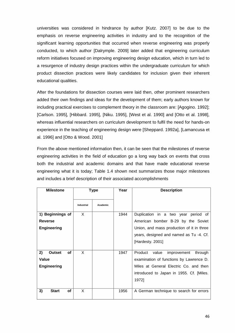
46
universities was considered in hindrance by author [Kutz. 2007] to be due to the
emphasis on reverse engineering activities in industry and to the recognition of the
significant learning opportunities that occurred when reverse engineering was properly
conducted, to which author [Dalrymple. 2009] later added that engineering curriculum
reform initiatives focused on improving engineering design education, which in turn led to
a resurgence of industry design practices within the undergraduate curriculum for which
product dissection practices were likely candidates for inclusion given their inherent
educational qualities.
After the foundations for dissection courses were laid then, other prominent researchers
added their own findings and ideas for the development of them; early authors known for
including practical exercises to complement theory in the classroom are: [Agogino. 1992];
[Carlson. 1995], [Hibbard. 1995], [Niku. 1995], [West et al. 1990] and [Otto et al. 1998],
whereas influential researchers on curriculum development to fulfil the need for hands-on
experience in the teaching of engineering design were [Sheppard. 1992a], [Lamancusa et
al. 1996] and [Otto & Wood. 2001]
From the above mentioned information then, it can be seen that the milestones of reverse
engineering activities in the field of education go a long way back on events that cross
both the industrial and academic domains and that have made educational reverse
engineering what it is today; Table 1.4 shown next summarizes those major milestones
and includes a brief description of their associated accomplishments
Milestone Type Year Description
Industrial
Academic
1) Beginnings of Reverse Engineering
X 1944 Duplication in a two year period of
American bomber B-29 by the Soviet
Union, and mass production of it in three
years, designed and named as Tu -4. Cf.
[Hardesty. 2001]
2) Outset of Value Engineering
X 1947 Product value improvement through
examination of functions by Lawrence D.
Miles at General Electric Co. and then
introduced to Japan in 1955. Cf. [Miles.
1972]
3) Start of X 1956 A German technique to search for errors
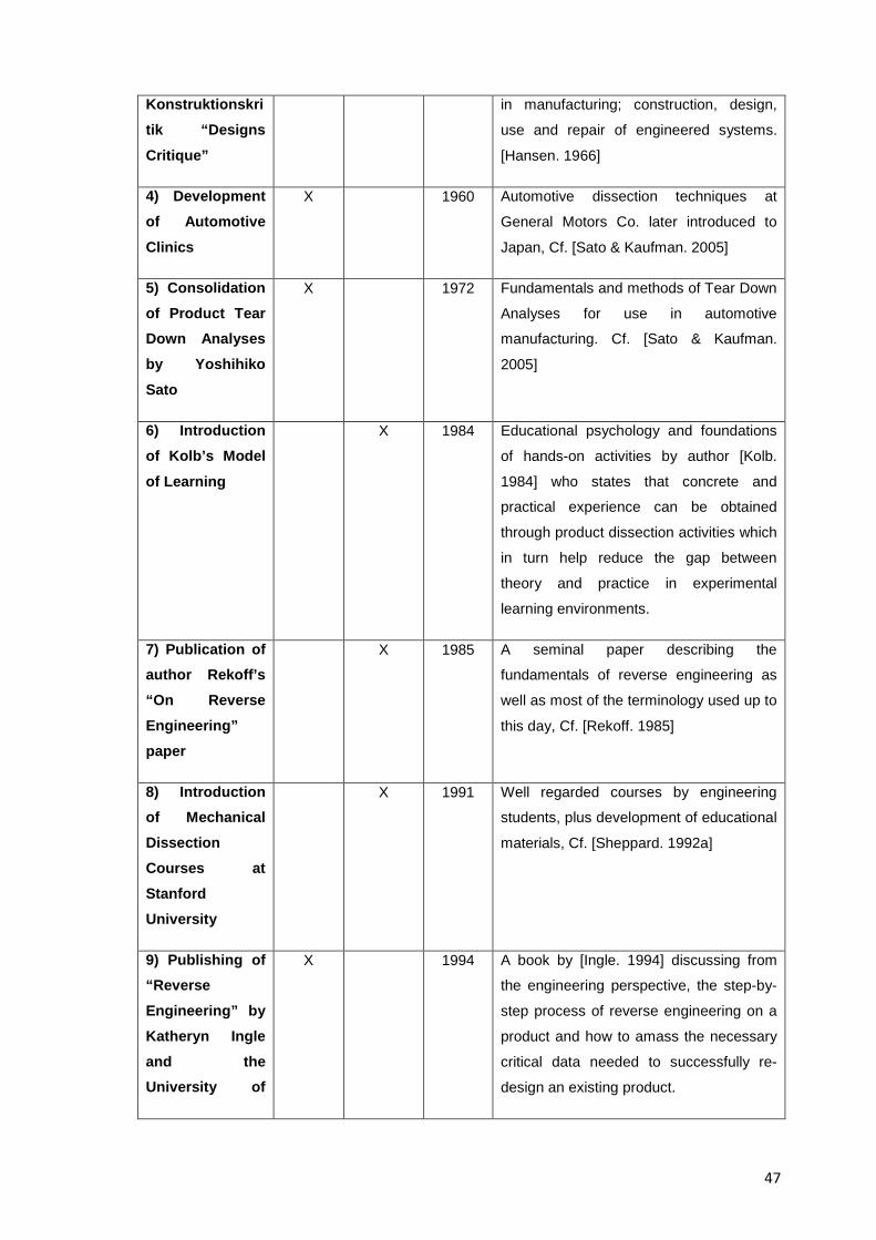
47
Konstruktionskritik “Designs Critique”
in manufacturing; construction, design,
use and repair of engineered systems.
[Hansen. 1966]
4) Development of Automotive Clinics
X 1960 Automotive dissection techniques at
General Motors Co. later introduced to
Japan, Cf. [Sato & Kaufman. 2005]
5) Consolidation of Product Tear Down Analyses by Yoshihiko Sato
X 1972 Fundamentals and methods of Tear Down
Analyses for use in automotive
manufacturing. Cf. [Sato & Kaufman.
2005]
6) Introduction of Kolb’s Model of Learning
X 1984 Educational psychology and foundations
of hands-on activities by author [Kolb.
1984] who states that concrete and
practical experience can be obtained
through product dissection activities which
in turn help reduce the gap between
theory and practice in experimental
learning environments.
7) Publication of author Rekoff’s “On Reverse Engineering” paper
X 1985 A seminal paper describing the
fundamentals of reverse engineering as
well as most of the terminology used up to
this day, Cf. [Rekoff. 1985]
8) Introduction of Mechanical Dissection Courses at Stanford University
X 1991 Well regarded courses by engineering
students, plus development of educational
materials, Cf. [Sheppard. 1992a]
9) Publishing of “Reverse Engineering” by Katheryn Ingle and the University of
X 1994 A book by [Ingle. 1994] discussing from
the engineering perspective, the step-by-
step process of reverse engineering on a
product and how to amass the necessary
critical data needed to successfully re-
design an existing product.
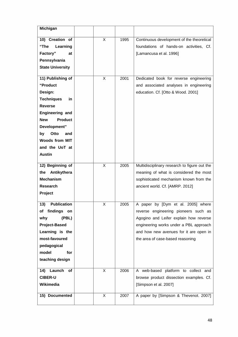
48
Michigan
10) Creation of “The Learning Factory” at Pennsylvania State University
X 1995 Continuous development of the theoretical
foundations of hands-on activities, Cf.
[Lamancusa et al. 1996]
11) Publishing of “Product Design: Techniques in Reverse Engineering and New Product Development” by Otto and Woods from MIT and the UoT at Austin
X 2001 Dedicated book for reverse engineering
and associated analyses in engineering
education. Cf. [Otto & Wood. 2001]
12) Beginning of the Antikythera Mechanism Research Project
X 2005 Multidisciplinary research to figure out the
meaning of what is considered the most
sophisticated mechanism known from the
ancient world. Cf. [AMRP. 2012]
13) Publication of findings on why (PBL) Project-Based Learning is the most-favoured pedagogical model for teaching design
X 2005 A paper by [Dym et al. 2005] where
reverse engineering pioneers such as
Agogino and Leifer explain how reverse
engineering works under a PBL approach
and how new avenues for it are open in
the area of case-based reasoning
14) Launch of CIBER-U Wikimedia
X 2006 A web-based platform to collect and
browse product dissection examples. Cf.
[Simpson et al. 2007]
15) Documented X 2007 A paper by [Simpson & Thevenot. 2007]
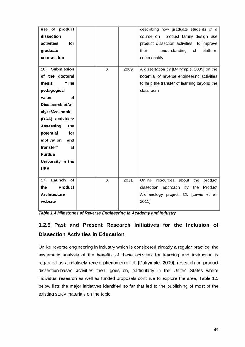
49
use of product dissection activities for graduate courses too
describing how graduate students of a
course on product family design use
product dissection activities to improve
their understanding of platform
commonality
16) Submission of the doctoral thesis “The pedagogical value of Disassemble/Analyze/Assemble (DAA) activities: Assessing the potential for motivation and transfer” at Purdue University in the USA
X 2009 A dissertation by [Dalrymple. 2009] on the
potential of reverse engineering activities
to help the transfer of learning beyond the
classroom
17) Launch of the Product Architecture website
X 2011 Online resources about the product
dissection approach by the Product
Archaeology project. Cf. [Lewis et al.
2011]
Table 1.4 Milestones of Reverse Engineering in Academy and Industry
1.2.5 Past and Present Research Initiatives for the Inclusion of Dissection Activities in Education
Unlike reverse engineering in industry which is considered already a regular practice, the
systematic analysis of the benefits of these activities for learning and instruction is
regarded as a relatively recent phenomenon cf. [Dalrymple. 2009], research on product
dissection-based activities then, goes on, particularly in the United States where
individual research as well as funded proposals continue to explore the area, Table 1.5
below lists the major initiatives identified so far that led to the publishing of most of the
existing study materials on the topic.
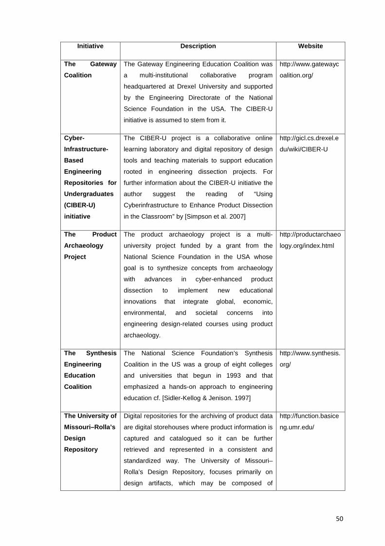
50
Initiative Description Website
The Gateway Coalition
The Gateway Engineering Education Coalition was
a multi-institutional collaborative program
headquartered at Drexel University and supported
by the Engineering Directorate of the National
Science Foundation in the USA. The CIBER-U
initiative is assumed to stem from it.
http://www.gatewayc
oalition.org/
Cyber-Infrastructure-Based Engineering Repositories for Undergraduates (CIBER-U) initiative
The CIBER-U project is a collaborative online
learning laboratory and digital repository of design
tools and teaching materials to support education
rooted in engineering dissection projects. For
further information about the CIBER-U initiative the
author suggest the reading of “Using
Cyberinfrastructure to Enhance Product Dissection
in the Classroom” by [Simpson et al. 2007]
http://gicl.cs.drexel.e
du/wiki/CIBER-U
The Product Archaeology Project
The product archaeology project is a multi-
university project funded by a grant from the
National Science Foundation in the USA whose
goal is to synthesize concepts from archaeology
with advances in cyber-enhanced product
dissection to implement new educational
innovations that integrate global, economic,
environmental, and societal concerns into
engineering design-related courses using product
archaeology.
http://productarchaeo
logy.org/index.html
The Synthesis Engineering Education Coalition
The National Science Foundation’s Synthesis
Coalition in the US was a group of eight colleges
and universities that begun in 1993 and that
emphasized a hands-on approach to engineering
education cf. [Sidler-Kellog & Jenison. 1997]
http://www.synthesis.
org/
The University of Missouri–Rolla’s Design Repository
Digital repositories for the archiving of product data
are digital storehouses where product information is
captured and catalogued so it can be further
retrieved and represented in a consistent and
standardized way. The University of Missouri–
Rolla’s Design Repository, focuses primarily on
design artifacts, which may be composed of
http://function.basice
ng.umr.edu/
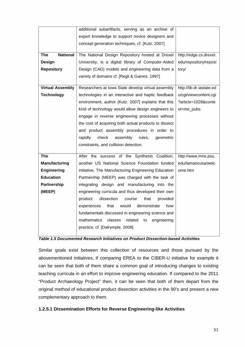
51
additional subartifacts, serving as an archive of
expert knowledge to support novice designers and
concept generation techniques, cf. [Kutz. 2007]
The National Design Repository
The National Design Repository hosted at Drexel
University, is a digital library of Computer-Aided
Design (CAD) models and engineering data from a
variety of domains cf. [Regli & Gaines. 1997]
http://edge.cs.drexel.
edu/repository/reposi
tory/
Virtual Assembly Technology
Researchers at Iowa State develop virtual assembly
technologies in an interactive and haptic feedback
environment, author [Kutz. 2007] explains that this
kind of technology would allow design engineers to
engage in reverse engineering processes without
the cost of acquiring both actual products to dissect
and product assembly procedures in order to
rapidly check assembly rules, geometric
constraints, and collision detection.
http://lib.dr.iastate.ed
u/cgi/viewcontent.cgi
?article=1028&conte
xt=me_pubs
The Manufacturing Engineering Education Partnership (MEEP)
After the success of the Synthesis Coalition,
another US National Science Foundation funded
initiative, The Manufacturing Engineering Education
Partnership (MEEP) was charged with the task of
integrating design and manufacturing into the
engineering curricula and thus developed their own
product dissection course that provided
experiences that would demonstrate how
fundamentals discussed in engineering science and
mathematics classes related to engineering
practice, cf. [Dalrymple. 2009]
http://www.mne.psu.
edu/lamancusa/welc
ome.htm
Table 1.5 Documented Research Initiatives on Product Dissection-based Activities
Similar goals exist between this collection of resources and those pursued by the
abovementioned initiatives, if comparing EREA to the CIBER-U initiative for example it
can be seen that both of them share a common goal of introducing changes to existing
teaching curricula in an effort to improve engineering education. If compared to the 2011
“Product Archaeology Project” then, it can be seen that both of them depart from the
original method of educational product dissection activities in the 90’s and present a new
complementary approach to them.
1.2.5.1 Dissemination Efforts for Reverse Engineering-like Activities
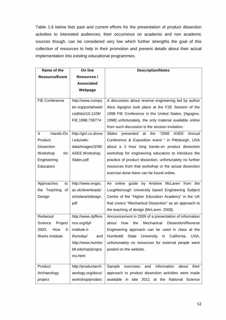
52
Table 1.6 below lists past and current efforts for the presentation of product dissection
activities to interested audiences; their occurrence on academic and non academic
sources though, can be considered very low which further strengths the goal of this
collection of resources to help in their promotion and present details about their actual
implementation into existing educational programmes.
Name of the Resource/Event
On line Resources / Associated Webpage
Description/Notes
FIE Conference http://www.compu
ter.org/portal/web/
csdl/doi/10.1109/
FIE.1998.738774
A discussion about reverse engineering led by author
Alice Agogino took place at the F2E Session of the
1998 FIE Conference in the United States, [Agogino.
1998] unfortunately, the only material available online
from such discussion is the session invitation.
A Hands-On
Product
Dissection
Workshop for
Engineering
Educators
http://gicl.cs.drexe
l.edu/wiki-
data/images/3/39/
ASEE.Workshop.
Slides.pdf
Slides presented at the “2008 ASEE Annual
Conference & Exposition event “ in Pittsburgh, USA
about a 3 hour long hands-on product dissection
workshop for engineering educators to introduce the
practice of product dissection, unfortunately no further
resources from that workshop or the actual dissection
exercise done there can be found online.
Approaches to
the Teaching of
Design
http://www.engsc.
ac.uk/downloads/
scholarart/design.
An online guide by Andrew McLaren from the
Loughborough University based Engineering Subject
Centre of the “Higher Education Academy” in the UK
that covers “Mechanical Dissection” as an approach to
the teaching of design [McLaren. 2008].
Redwood
Science Project
2003. How It
Works Institute
http://www.dyffere
nce.org/dyf-
institute-ii-
thursday/ and
http://www.humbo
ldt.edu/rsp/progra
ms.html
Announcement in 2009 of a presentation of information
about how the Mechanical Dissection/Reverse
Engineering approach can be used in class at the
Humboldt State University in California, USA,
unfortunately no resources for external people were
posted on the website.
Product
Archaeology
project
http://productarch
aeology.org/docs/
workshop/prodarc
Sample exercises and information about their
approach to product dissection activities were made
available in late 2011 at the National Science
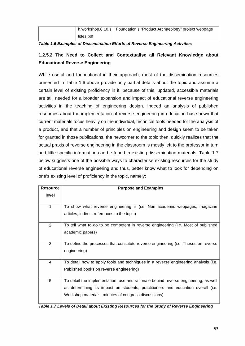
53
Table 1.6 Examples of Dissemination Efforts of Reverse Engineering Activities
1.2.5.2 The Need to Collect and Contextualise all Relevant Knowledge about Educational Reverse Engineering
While useful and foundational in their approach, most of the dissemination resources
presented in Table 1.6 above provide only partial details about the topic and assume a
certain level of existing proficiency in it, because of this, updated, accessible materials
are still needed for a broader expansion and impact of educational reverse engineering
activities in the teaching of engineering design. Indeed an analysis of published
resources about the implementation of reverse engineering in education has shown that
current materials focus heavily on the individual, technical tools needed for the analysis of
a product, and that a number of principles on engineering and design seem to be taken
for granted in those publications, the newcomer to the topic then, quickly realizes that the
actual praxis of reverse engineering in the classroom is mostly left to the professor in turn
and little specific information can be found in existing dissemination materials, Table 1.7
below suggests one of the possible ways to characterise existing resources for the study
of educational reverse engineering and thus, better know what to look for depending on
one’s existing level of proficiency in the topic, namely:
Resource level
Purpose and Examples
1 To show what reverse engineering is (i.e. Non academic webpages, magazine
articles, indirect references to the topic)
2 To tell what to do to be competent in reverse engineering (i.e. Most of published
academic papers)
3 To define the processes that constitute reverse engineering (i.e. Theses on reverse
engineering)
4 To detail how to apply tools and techniques in a reverse engineering analysis (i.e.
Published books on reverse engineering)
5 To detail the implementation, use and rationale behind reverse engineering, as well
as determining its impact on students, practitioners and education overall (i.e.
Workshop materials, minutes of congress discussions)
Table 1.7 Levels of Detail about Existing Resources for the Study of Reverse Engineering
h.workshop.8.10.s
lides.pdf
Foundation’s “Product Archaeology” project webpage
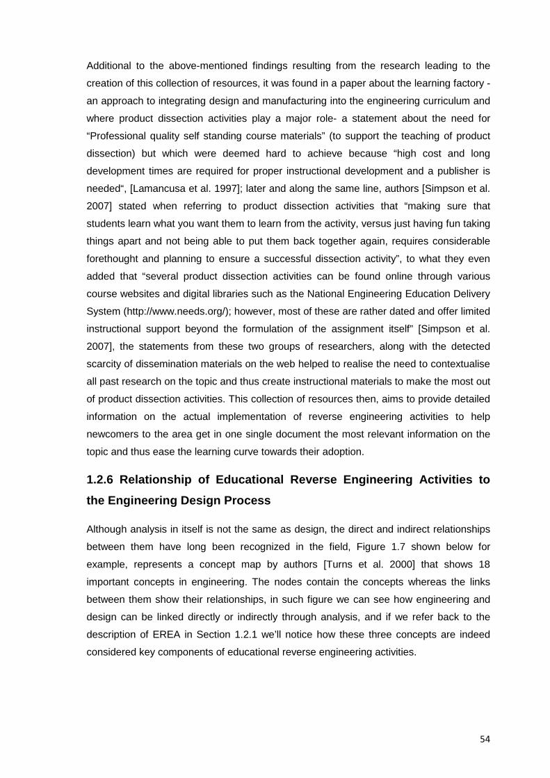
54
Additional to the above-mentioned findings resulting from the research leading to the
creation of this collection of resources, it was found in a paper about the learning factory -
an approach to integrating design and manufacturing into the engineering curriculum and
where product dissection activities play a major role- a statement about the need for
“Professional quality self standing course materials” (to support the teaching of product
dissection) but which were deemed hard to achieve because “high cost and long
development times are required for proper instructional development and a publisher is
needed“, [Lamancusa et al. 1997]; later and along the same line, authors [Simpson et al.
2007] stated when referring to product dissection activities that “making sure that
students learn what you want them to learn from the activity, versus just having fun taking
things apart and not being able to put them back together again, requires considerable
forethought and planning to ensure a successful dissection activity”, to what they even
added that “several product dissection activities can be found online through various
course websites and digital libraries such as the National Engineering Education Delivery
System (http://www.needs.org/); however, most of these are rather dated and offer limited
instructional support beyond the formulation of the assignment itself” [Simpson et al.
2007], the statements from these two groups of researchers, along with the detected
scarcity of dissemination materials on the web helped to realise the need to contextualise
all past research on the topic and thus create instructional materials to make the most out
of product dissection activities. This collection of resources then, aims to provide detailed
information on the actual implementation of reverse engineering activities to help
newcomers to the area get in one single document the most relevant information on the
topic and thus ease the learning curve towards their adoption.
1.2.6 Relationship of Educational Reverse Engineering Activities to the Engineering Design Process
Although analysis in itself is not the same as design, the direct and indirect relationships
between them have long been recognized in the field, Figure 1.7 shown below for
example, represents a concept map by authors [Turns et al. 2000] that shows 18
important concepts in engineering. The nodes contain the concepts whereas the links
between them show their relationships, in such figure we can see how engineering and
design can be linked directly or indirectly through analysis, and if we refer back to the
description of EREA in Section 1.2.1 we’ll notice how these three concepts are indeed
considered key components of educational reverse engineering activities.
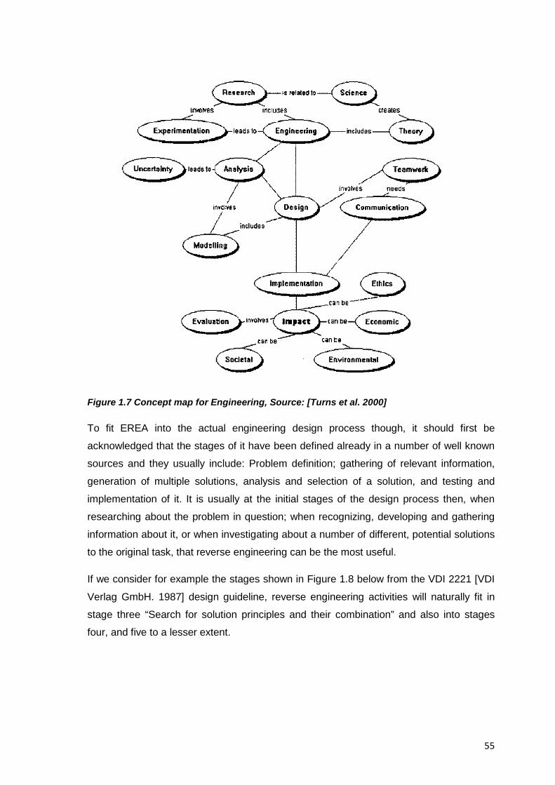
55
Figure 1.7 Concept map for Engineering, Source: [Turns et al. 2000]
To fit EREA into the actual engineering design process though, it should first be
acknowledged that the stages of it have been defined already in a number of well known
sources and they usually include: Problem definition; gathering of relevant information,
generation of multiple solutions, analysis and selection of a solution, and testing and
implementation of it. It is usually at the initial stages of the design process then, when
researching about the problem in question; when recognizing, developing and gathering
information about it, or when investigating about a number of different, potential solutions
to the original task, that reverse engineering can be the most useful.
If we consider for example the stages shown in Figure 1.8 below from the VDI 2221 [VDI
Verlag GmbH. 1987] design guideline, reverse engineering activities will naturally fit in
stage three “Search for solution principles and their combination” and also into stages
four, and five to a lesser extent.
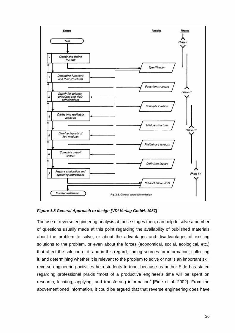
56
Figure 1.8 General Approach to design [VDI Verlag GmbH. 1987]
The use of reverse engineering analysis at these stages then, can help to solve a number
of questions usually made at this point regarding the availability of published materials
about the problem to solve; or about the advantages and disadvantages of existing
solutions to the problem, or even about the forces (economical, social, ecological, etc.)
that affect the solution of it, and in this regard, finding sources for information; collecting
it, and determining whether it is relevant to the problem to solve or not is an important skill
reverse engineering activities help students to tune, because as author Eide has stated
regarding professional praxis “most of a productive engineer’s time will be spent on
research, locating, applying, and transferring information” [Eide et al. 2002]. From the
abovementioned information, it could be argued that that reverse engineering does have
57
a rightful place in the traditional design process and thus EREA could also be considered
an exercise in design.
1.2.7 Cognitive Enablers of Educational Reverse Engineering Analysis
In a reverse engineering analysis, rediscovering the original designers’ specifications to
understand the product under study is prone to iterations of trial and error, since the path
to the final set of reverse engineered specifications is strongly based on handling
conjectured design information along the way. There are indeed pieces of information at
the highest level of abstraction such as comments, descriptions or committed design
decisions that cannot be retrieved or recreated through a reverse engineering analysis,
however, this shouldn’t be considered a bad thing by itself since in educational reverse
engineering analysis it is fine to assume, speculate and put forth educated guesses about
the ununderstood parts of a product’s design, in fact dealing with uncertainty in this kind
of educational activities can later mirror the experiences that will be had in professional
life.
Surprisingly; and in regard to the handling of uncertainty, conjectures and assumptions in
analysing other people’s designs, studies such as those conducted by [Kuffner & Ullman.
1991] uncovered that up to 90% of the design decisions made to come up with a finished
product, could be derived by unrelated designers by experience alone; and even that at
the students’ level, published results by author Kang indicated how when undergraduate
students were asked how a thermostat worked during cooking (when doing a first time,
disassembling exercise on a rice cooker) there was an 87.5% of correct responses about
its operation, [Kang. 2011], this kind of results then, support the idea that educated
assumptions and conjectures can also help identify the relationship between components
and functions during the development of a product dissection activity.
1.2.7.1 Drawbacks of the Practice of Reverse Engineering
It is the intention of this collection of resources to provide an unbiased, comprehensive
view on the topic of educational reverse engineering and thus acknowledge any of its
potential pitfalls; reverse engineering someone else’s design for example, is hard and
time consuming; it depends on the collection of information and on putting forward
educated guesses to infer the design process and design rationale of a subject system,
and as such, the analyst has to deal with information unavailability and uncertainty, and
given that to date there is no unified methodology for doing reverse engineering, it means
that the resulting analysis will be strongly dependant on the domain knowledge and
expertise of the reverse engineer in turn; because of this, reverse engineering can be a
58
long difficult process prone to cycles of trial and error where a successful end can be
hardly guaranteed. If on top of that we consider that the need for reverse engineering is
usually misunderstood, then it helps explain why it carries societal pressures and fears of
infringement on regular product customers who usually lack the competence or the desire
to reverse engineer their purchased products. Beyond all these operational drawbacks
though, there are more fundamental ones, which concern the intellectual traps in the
practice of reverse engineering, and which are explained next:
1. Attachment to Known Solutions
Authors [Pahl et al. 2007] state that “Because the only systems to be analyzed in a
reverse engineering exercise are those that have some bearing on a new problem as a
whole or on parts of it, this type of analysis could be called a way of collecting
information, and thus a systematic exploitation of proven ideas, or of experience” and
although this is helpful for finding a first solution concept and as a starting point for further
variations of a design, they also state that “This approach carries the danger of causing
designers to stick with known solutions instead of pursuing new paths.” This is at first
sight, the most obvious drawback of educational reverse engineering, it is however easily
avoided with a proper method and pedagogy for the conduction of it, for example, one
that forces students to come up with product and process improvements of their own and
in relation to the product just analysed, or one that takes extra care not to induce
negatively perceived attitudes of reverse engineering analysis to professors and students
(e.g. creative laziness). The pedagogy later suggested in Resource 6 of this collection of
resources intends to tackles those issues and challenges both, instructors and students
to make the most out of existing resources.
2. Analogies and Teleological Reasoning
It is author [Ritchey. 1991] who has provided the best explanation about how this trap
works, he claims that an initial stage before a solid knowledge about a product under
study is achieved, implies the formulation of explanations based upon something other
than the structural facts (e.g. Ad hoc internal properties) in order to remedy for the lack of
clear knowledge about a system and its inner processes. Specific conceptions familiar to
our previous experience arise then, in two possible ways (analogy and teleology) to force
the system’s internal properties to match our current level of understanding, with this
though, he states, we risk introducing arbitrary conceptions into our explanation of the
product under study, leading us to unusable final results or at least to a lack of reliable
feedback to keep us investigating on the right track.
59
Analogies as described by [Ritchey. 1991] imply comparing and likening the system’s
components under study to other mechanical components or processes from our past
experience; whereas teleology on the other hand means attributing the system’s
components under study, a purpose or utility vis à vis other components. Author Ritchey
emphasises that the use of analogies and teleology is useful and should not be rejected if
used in a proper and cautious way, and that means “emphasizing the conditions that
must be met to account for what the organ accomplishes and discarding any notions not
essential to the explanation that have arisen solely through the use of analogy or
teleology” [Ritchey. 1991]
2.1 Post hoc Rationalization
Reflection after a reverse engineering analysis might develop into post hoc rationalization
(a logical fallacy stating: "Since that event followed this one, that event must have been
caused by this one”). The memories of the reverse engineering analyst then, must be
jogged in order to reveal the real development history of a product, rather than a sanitised
version of it. A potential solution for this cognitive trap is that the reverse engineering
analysts (engineering design students in this case) try to also acquire background
knowledge about the product and processes under analysis. This type of rationalisation
then, is perhaps the clearest manifestation of teleological thinking.
3. Undetected Dead-ends
A reverse engineering analysis may not reveal the dead-ends the original designers
faced, as such, the revealed process may be incomplete. Possible solutions for this
scenario include taking extra care to identify such circumstances and explore plausible
alternatives (e.g. By studying prototypes or similar problems) across domains (e.g.
Benchmarking).
4. Idealised Design Processes
A careless reverse engineering analysis can lead to explanations that do not reflect the
actual and redundant trial and error processes of design but instead present an ‘idealized
process’ that eliminated them; and while this might be seen as something positive cf.
[Kawakami et al. 1996] the approach followed in the methodology suggested in this
collection of resources though, is to make those trials explicit, authors [Mulet & Vidal.
2008] for example, stated that “Despite the excellent results obtained by designers, most
design tasks are still carried out by trial and error or by adopting the easiest or the most
obvious solutions due to the pressure of the market and limited resources” the approach

60
followed in this collection of resources then aims to help students to realise what worked
for others, what didn’t, and why.
In the end, it is also the goal of the methodology and pedagogy for educational reverse
engineering analysis presented later in Resources 5 and 6 of this collection of resources,
to avoid or at least to minimize in students these cognitive traps and operational
drawbacks, while still acknowledging that the continuing professors ‘supervision
throughout the work sessions with the students will also play an important role in avoiding
them.
1.2.8 Validity of Reverse Engineering as an Academic Subject in Design Education
Didactical analysis of an academic subject, as suggested by Dahlgren is “the science
whose topic is the planned support of learning to acquire formation in an academic
subject” [Dahlgren. 1990], in this regard authors [Dahlgren. 1990] and [Grimheden.2006]
propose that a didactical analysis of a subject can be based on four categories or
questions, as seen in Figure 1.9 below
Figure 1.9 The Four questions of Didactical Analysis, Source: [Grimheden.2006]
The first question is concerned with the identity of the academic subject to answer the
question “What is?”, and its subsequent classification either as disciplinary or thematic. In
the case of educational reverse engineering and according to an analysis of its literature
and the findings on the area, the identity of reverse engineering as an academic subject
can be identified as “Thematic” meaning that it is a relatively newly created subject that
originates from a theme, and that as knowledge evolutes it’ll move forward in its
61
classification. In comparison, “Disciplinary” subjects are those already consolidated areas
of knowledge such as mathematics or chemistry.
The second question is that of legitimacy, that is about the questions “Why should it be
taught?” which is connected to “The relationship between the actual outcome of the
educational efforts and the nature of the demand that is put upon the student’s abilities by
society, or by industry”, [Dahlgren. 1990], in this sense reverse engineering’s legitimacy
can be considered “Functional”, meaning that the functional aspects of reverse
engineering deal with those skills that are not commonly acquired in textbooks or lectures
but are developed with hands-on exercises, laboratory experiments, and by trial and
error. The “Formal” aspect then, is the one that deals with formal knowledge such as that
found in textbooks intended to be read and understood by students.
The third question concerns the method of selection or “Which elements should be
taught?” which deals with how the content is delivered to the students, either
representatively giving a broad perspective over the entire subject with students being
taught knowledge and principles in general, or by exemplification in which the subject is
exemplified rather than represented. For educational reverse engineering then, the
content is delivered in an “Exemplified” way, meaning that only the method for
educational reverse engineering is studied but to a much greater depth, expecting that
the resulting knowledge and skills can be carried over to facilitate learning of other similar
methods.
The last question is that of communication and it relates to the question “How should it be
taught?” it could be either actively, meaning that teaching is considered an action and the
teachers always ask themselves how they should act before the subject, the students and
so on. Or it could be taught interactively meaning that the interaction teacher–student is
based on feedback from the students and insight into the learning processes of the
individual students. Reverse engineering then, is taught “Interactively” in the sense that
student’s feedback and a profound interest in the student’s cognitive processes exist
while the experiments conducted are also of paramount importance to reverse
engineering. Table 1.8 then, summarises the results to the didactical questions.
Didactical Question Result
Identity Thematic
Legitimacy Functional
62
Selection Exemplification
Communication Interactive
Table 1.8 Didactical Analysis of Reverse Engineering as an Academic Subject
In the end, the results from a didactical analysis on the subject of educational reverse
engineering are useful in positioning and validating it as a subject worth teaching and of
practical value in engineering education.
1.2.8.1 Pedagogical Viability of EREA
Author Dalrymple in [Dalrymple. 2009] and [Dalrymple et al. 2011] stated that although
D/A/A activities were utilized in the engineering curriculum at institutions around the
nation (referring to the USA), and that their value as pedagogical tools was primarily
supported by highly descriptive and favourable accounts of curricula and possible
learning outcomes by reviews from instructors and students such as: [Brereton et al.
1995]; [Hess. 2000],[Hess. 2002], [Otto et al. 1998], [Sheppard. 1992a], and [Wood et al.
2001] in order to test, and conclusively attribute the claims about the benefits of D/A/A
activities and identify what their unique contributions to pedagogical practice might be,
more formal tests were required and experimental evidence was needed since among
previous reviews and studies, relatively few had compared participants performing D/A/A
activities to a control group doing more traditional activities. A similar claim was made by
authors [Simpson et al. 2011] who stated that “the effectiveness of integrating product
archaeology into product dissection activities in engineering design education need to be
tested and further evaluated”, author Dalrymple then, felt that there were limitations in the
literature concerning the pedagogical viability of D/A/A activities given that:
• The systematic analysis of the pedagogical benefits of DAA activities was a
relatively recent phenomenon, [Dalrymple. 2009]
• In her view most of the research methods that had been employed were not
capable of providing the evidence needed to evaluate the unique allowances of
D/A/A activities with respect to motivation or learning (her research is focused on
these two attributes)
And so she set out to answer questions such as:
• What type of knowledge can students gain from engaging in D/A/A activities
compared to more traditional laboratory activities?
• Is D/A/A more motivating than traditional instruction?
63
• How does the knowledge gained from engaging in D/A/A activities support
subsequent performance on other engineering materials?
Her research thus, employed experimental designs to measure and compare the
motivation and transfer elicited by D/A/A activities by engaging students in such activities
and comparing them to a control group engaged in other traditional activities that did not
involve object disassembly, and so she conducted two quasi-experiments as part of a
first-year engineering laboratory, where a D/A/A activity that required students to
disassemble a single-use camera and analyze its components to discover how it worked
was compared to a control group doing more traditional activities on measures of
motivation and learning (a GMA, step-by-step laboratory activity in the first experiment
and a lecture method of instruction in the second experiment, that included the learning,
analysis, and suggestions for modification of a Fujifilm ™ disposable camera). She
believed the current engineering education literature revealed the potential of DAA
activities to produce good outcomes on both measures, but lacked experimental evidence
so she hypothesized that students who engaged in the D/A/A activity would be more
motivated and would demonstrate higher frequencies of transfer than the control group
(Transfer (of knowledge/learning) indeed, is the ability to extend what has been learned in
one context to new contexts, [Bransford et al. 2000], or from one product design to
another, [Sidler-Kellog & Jenison. 1997], and is considered a major goal of formal
education since the context of learning usually differs from the context of application,
[Perkins & Salomon. 1992], in this sense the ability to produce “Transfer” is one the major
added values that reverse engineering can bring to design education)
In Dalrymple’s both experiments then, over forty percent of the students that engaged in
the D/A/A activity demonstrated the ability to transfer the knowledge gained about the
functions of the camera’s components and their interconnectedness and describe an
approach for modifying the camera that involved the adaptation of an existing mechanism
to add new functionality. She reported that such exhibition of transfer was significantly
greater than the frequency of transfer yielded by the comparative traditional activities and
that further post laboratory surveys also indicated that the D/A/A activities elicited
significantly higher levels of motivation than the step-by-step laboratory (the Guided
Morphological Analysis) and the direct instructional method (the lecture), cf. [Dalrymple.
2009].
The findings in Dalrymple’s research, provided experimental support for the views of
other researchers that studied the incorporation of D/A/A activities (under this or other
similar names) in an engineering curriculum such as the previous studies done by
64
[Bedard Jr. 1999]; [Hess. 2000], [Hess. 2002], [Lamancusa et al. 1996], [Ogot. 2002],
[Ogot & Kremer. 2006], [Otto et al. 1998], [Sheppard. 1992a] or [Wood et al. 2001] her
findings also reinforced the outcomes of former studies of motivation associated with
D/A/A activities such as those by [Carlson et al. 1997] and [Okudan & Mohammed. 2008]
and in the end and although plenty of studies existed before her work, her experiments
comparing reverse engineering-like activities against traditional instruction provided
definitive proof of their benefits in education specially in the areas of transfer and
motivation, and she also published later on that ” intellectual and physical activities such
as Disassemble/Analyze/Assemble (D/A/A) activities elicit significantly higher ratings of
learning, enjoyment, and perceived helpfulness than traditional instruction”, [Dalrymple et
al. 2011] and even raised the possibility that learning general engineering design
principles and becoming a better design engineer may require the specific knowledge of
components and mechanisms that D/A/A experiences seemed well suited to offer,
[Dalrymple et al. 2011].
1.2.8.2 Teaching Approach of Educational Reverse Engineering Activities
The purpose of EREA in engineering design education is not to substitute the traditional
teaching of relevant topics with this type of activities, or even to expect students to learn
the same after using them, EREA as presented here, are a complementary tool for
existing teaching practices, and the approach to teaching through them doesn’t even
focus on the technical topics of a typical engineering design programme but rather on the
competences that students of engineering design are expected to develop during their
college years and for which EREA can serve a suitable vehicle for their acquisition.
Regarding the activities themselves, it can be said that they are geared towards an
instructor-assisted team learning rather than a self-directed learning by students, in this
way, students can benefit not only from their professor’s experience but also from a
teamwork setting where information gaps can be filled by the efforts of a pool of students
contributing towards a unified goal, this topic is further explored in Resource 6
1.2.8.3 Educational Reasons to Reverse Engineer a Consumer Product
EREA have a decidedly academic focus and are mostly performed with the purposes of
scholarship, teaching and dissemination in mind, Table 1.9 below lists such possibilities
to provide an overall view of the different uses of them documented so far in engineering
education.
Number Reason
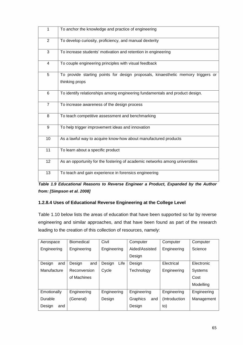
65
1 To anchor the knowledge and practice of engineering
2 To develop curiosity, proficiency, and manual dexterity
3 To increase students’ motivation and retention in engineering
4 To couple engineering principles with visual feedback
5 To provide starting points for design proposals, kinaesthetic memory triggers or
thinking props
6 To identify relationships among engineering fundamentals and product design.
7 To increase awareness of the design process
8 To teach competitive assessment and benchmarking
9 To help trigger improvement ideas and innovation
10 As a lawful way to acquire know-how about manufactured products
11 To learn about a specific product
12 As an opportunity for the fostering of academic networks among universities
13 To teach and gain experience in forensics engineering
Table 1.9 Educational Reasons to Reverse Engineer a Product, Expanded by the Author
from: [Simpson et al. 2008]
1.2.8.4 Uses of Educational Reverse Engineering at the College Level
Table 1.10 below lists the areas of education that have been supported so far by reverse
engineering and similar approaches, and that have been found as part of the research
leading to the creation of this collection of resources, namely:
Aerospace
Engineering
Biomedical
Engineering
Civil
Engineering
Computer
Aided/Assisted
Design
Computer
Engineering
Computer
Science
Design and
Manufacture
Design and
Reconversion
of Machines
Design Life
Cycle
Design
Technology
Electrical
Engineering
Electronic
Systems
Cost
Modelling
Emotionally
Durable
Design and
Engineering
(General)
Engineering
Design
Engineering
Graphics and
Design
Engineering
(Introduction
to)
Engineering
Management
66
Sustainable
Design
Engineering
Physics
Engineering
Science
Industrial
and
Systems
Engineering
Industrial
Design
Engineering
Industrial
Engineering
Industrial
Technology
Interface and
Interaction
Design
Manufacturing
/ Concurrent
Engineering
Mechanical
Design
Mechanical
Design and
Manufacturing
Mechanical
Engineering
Mechatronics
and Robotics
Engineering
Mechatronics
Design
Product
architecture,
Platforms and
Commonality
Product
Design
Rapid
Mechanical
Design
Technology &
Information
Management
Table 1.10 Areas where Reverse Engineering has been used at the College Level
1.2.8.5 Reception in the Engineering Design Community of Similar Approaches to Reverse Engineering
As seen in Table 1.2 above, educational reverse engineering shares certain goals and
concepts with professional forensic engineering but the available tools and goals of the
implied analyses are what determine the differences among them. Still, forensic
experience and its usefulness in education has been presented to the engineering design
community already, for example at the keynote speech of the 2005 International
Conference on Engineering Design by Professor Hales [Hales. 2005] who presented the
following conclusions, that are also of relevance to the practice of educational reverse
engineering, namely:
1. Since learning from our mistakes is a helpful way to improve our design skills,
learning from the mistakes of others can be almost as helpful and is a lot less
expensive
2. When mistakes occur there is a natural tendency to try to minimize their negative
effects and the extent to which the details are made public, thus limiting the
opportunity for everyone else to learn how to avoid making the same mistake in
the future
3. A way to learn from other people mistakes is for those involved in failure
investigations to describe what went wrong in such a way that a lesson can be
learned even without making all the details public
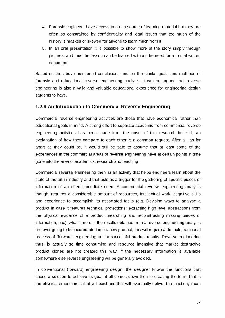
67
4. Forensic engineers have access to a rich source of learning material but they are
often so constrained by confidentiality and legal issues that too much of the
history is masked or skewed for anyone to learn much from it
5. In an oral presentation it is possible to show more of the story simply through
pictures, and thus the lesson can be learned without the need for a formal written
document
Based on the above mentioned conclusions and on the similar goals and methods of
forensic and educational reverse engineering analysis, it can be argued that reverse
engineering is also a valid and valuable educational experience for engineering design
students to have.
1.2.9 An Introduction to Commercial Reverse Engineering
Commercial reverse engineering activities are those that have economical rather than
educational goals in mind. A strong effort to separate academic from commercial reverse
engineering activities has been made from the onset of this research but still, an
explanation of how they compare to each other is a common request. After all, as far
apart as they could be, it would still be safe to assume that at least some of the
experiences in the commercial areas of reverse engineering have at certain points in time
gone into the area of academics, research and teaching.
Commercial reverse engineering then, is an activity that helps engineers learn about the
state of the art in industry and that acts as a trigger for the gathering of specific pieces of
information of an often immediate need. A commercial reverse engineering analysis
though, requires a considerable amount of resources, intellectual work, cognitive skills
and experience to accomplish its associated tasks (e.g. Devising ways to analyse a
product in case it features technical protections; extracting high level abstractions from
the physical evidence of a product, searching and reconstructing missing pieces of
information, etc.), what’s more, if the results obtained from a reverse engineering analysis
are ever going to be incorporated into a new product, this will require a de facto traditional
process of “forward” engineering until a successful product results. Reverse engineering
thus, is actually so time consuming and resource intensive that market destructive
product clones are not created this way, if the necessary information is available
somewhere else reverse engineering will be generally avoided.
In conventional (forward) engineering design, the designer knows the functions that
cause a solution to achieve its goal, it all comes down then to creating the form, that is
the physical embodiment that will exist and that will eventually deliver the function; it can
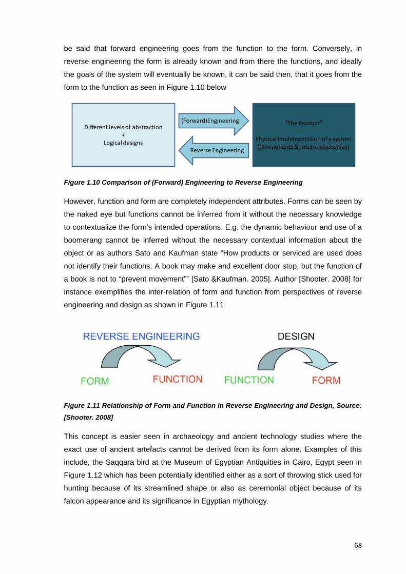
68
be said that forward engineering goes from the function to the form. Conversely, in
reverse engineering the form is already known and from there the functions, and ideally
the goals of the system will eventually be known, it can be said then, that it goes from the
form to the function as seen in Figure 1.10 below
Figure 1.10 Comparison of (Forward) Engineering to Reverse Engineering
However, function and form are completely independent attributes. Forms can be seen by
the naked eye but functions cannot be inferred from it without the necessary knowledge
to contextualize the form’s intended operations. E.g. the dynamic behaviour and use of a
boomerang cannot be inferred without the necessary contextual information about the
object or as authors Sato and Kaufman state “How products or serviced are used does
not identify their functions. A book may make and excellent door stop, but the function of
a book is not to “prevent movement”” [Sato &Kaufman. 2005]. Author [Shooter. 2008] for
instance exemplifies the inter-relation of form and function from perspectives of reverse
engineering and design as shown in Figure 1.11
Figure 1.11 Relationship of Form and Function in Reverse Engineering and Design, Source:
[Shooter. 2008]
This concept is easier seen in archaeology and ancient technology studies where the
exact use of ancient artefacts cannot be derived from its form alone. Examples of this
include, the Saqqara bird at the Museum of Egyptian Antiquities in Cairo, Egypt seen in
Figure 1.12 which has been potentially identified either as a sort of throwing stick used for
hunting because of its streamlined shape or also as ceremonial object because of its
falcon appearance and its significance in Egyptian mythology.
Different levels of abstraction+
Logical designs
(Forward)Engineering “The Product”
Physical implementation of a system(Components & Interrelationships)Reverse Engineering
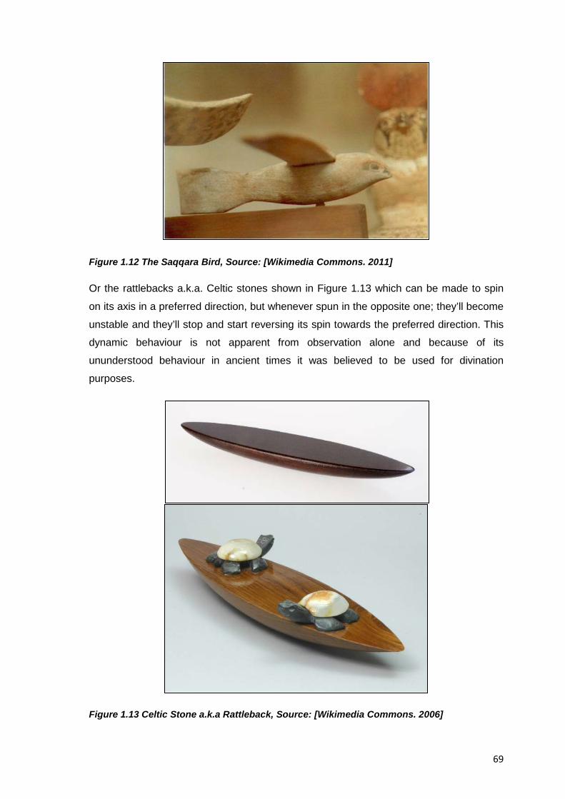
69
Figure 1.12 The Saqqara Bird, Source: [Wikimedia Commons. 2011]
Or the rattlebacks a.k.a. Celtic stones shown in Figure 1.13 which can be made to spin
on its axis in a preferred direction, but whenever spun in the opposite one; they’ll become
unstable and they’ll stop and start reversing its spin towards the preferred direction. This
dynamic behaviour is not apparent from observation alone and because of its
ununderstood behaviour in ancient times it was believed to be used for divination
purposes.
Figure 1.13 Celtic Stone a.k.a Rattleback, Source: [Wikimedia Commons. 2006]
70
Educational reverse engineering activities then, differentiate from their commercial
namesakes in their hands-on approach that allows them to test and experiment the
subject system with all senses cf. [Wood & Wood. 2000] and thus, better tackle form and
function conundrums given that design methods can later be used too to hypothesize
current functions, and help conceptualize new functions and/or solutions to the current
form.
1.2.9.1 Commercial Reverse Engineering as a Trigger for Industrial Development
Given the technological advances of countries where the practice of reverse engineering
has been acknowledged, the question whether reverse engineering or even imitation is a
necessary phase in industrial development arises; what’s more, do practices such as
imitation help to internalize the state of the art of a given field? It would seem so, since
imitation is actually still widely practiced in western companies as part of their innovation
process; but before nations or companies can even begin to innovate they must know
what the state of the art is and what the competition is doing, of course, to be able to get
this knowledge, intellectual; technical and material tools to access and process the latest
technologies have to be acquired first, before any original improvements or adaptations
can be suggested. History of modern science shows that once this innovation capability is
acquired the nations and companies’ time to apply for intellectual property protection will
come.
When speaking about the value of reverse engineering as a trigger for innovation in
industry author [Kodak. 2008] for example, stated about innovation that “The reverse
engineering process brings the essence of an innovation under an organizations finger
tips. In effect, this is a new chance to recapture a position in a lost market and this quality
makes the reverse engineering effort almost as valuable as the innovation itself. Now, the
possibility of capturing at least part of the business success of the original innovator
exists and perhaps more. The “more” part is of interest for the business savvy reverse
engineering planner.”
In modern times we have seen that patent licensing and competitive intelligence are two
controlled means to spread technology where reverse engineer has played a role in
spreading innovation and technology helping companies to stay competitive. There has
been a notorious shift in technology from Europe and North America to developing
countries, best represented by the growth of the electronics industry in Asia in countries
with a long tradition in buying western products, taking them apart and copying them, as
author [James. 2009] pointed out
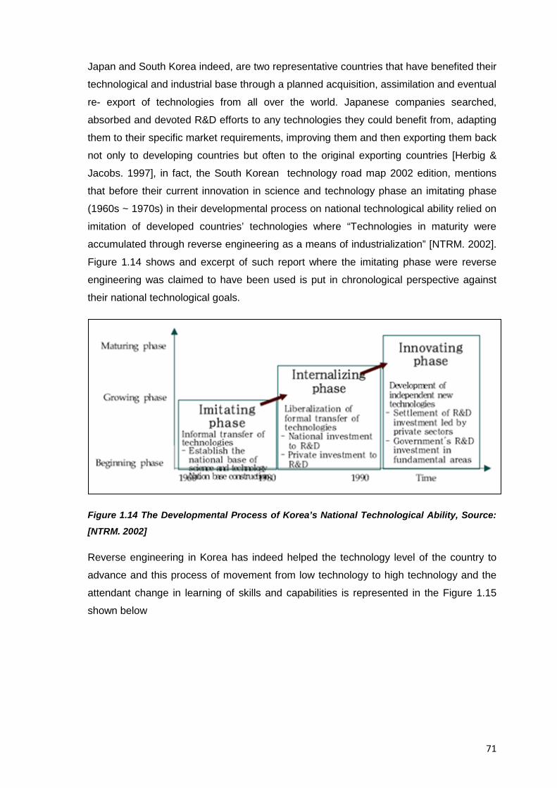
71
Japan and South Korea indeed, are two representative countries that have benefited their
technological and industrial base through a planned acquisition, assimilation and eventual
re- export of technologies from all over the world. Japanese companies searched,
absorbed and devoted R&D efforts to any technologies they could benefit from, adapting
them to their specific market requirements, improving them and then exporting them back
not only to developing countries but often to the original exporting countries [Herbig &
Jacobs. 1997], in fact, the South Korean technology road map 2002 edition, mentions
that before their current innovation in science and technology phase an imitating phase
(1960s ~ 1970s) in their developmental process on national technological ability relied on
imitation of developed countries’ technologies where “Technologies in maturity were
accumulated through reverse engineering as a means of industrialization” [NTRM. 2002].
Figure 1.14 shows and excerpt of such report where the imitating phase were reverse
engineering was claimed to have been used is put in chronological perspective against
their national technological goals.
Figure 1.14 The Developmental Process of Korea’s National Technological Ability, Source:
[NTRM. 2002]
Reverse engineering in Korea has indeed helped the technology level of the country to
advance and this process of movement from low technology to high technology and the
attendant change in learning of skills and capabilities is represented in the Figure 1.15
shown below
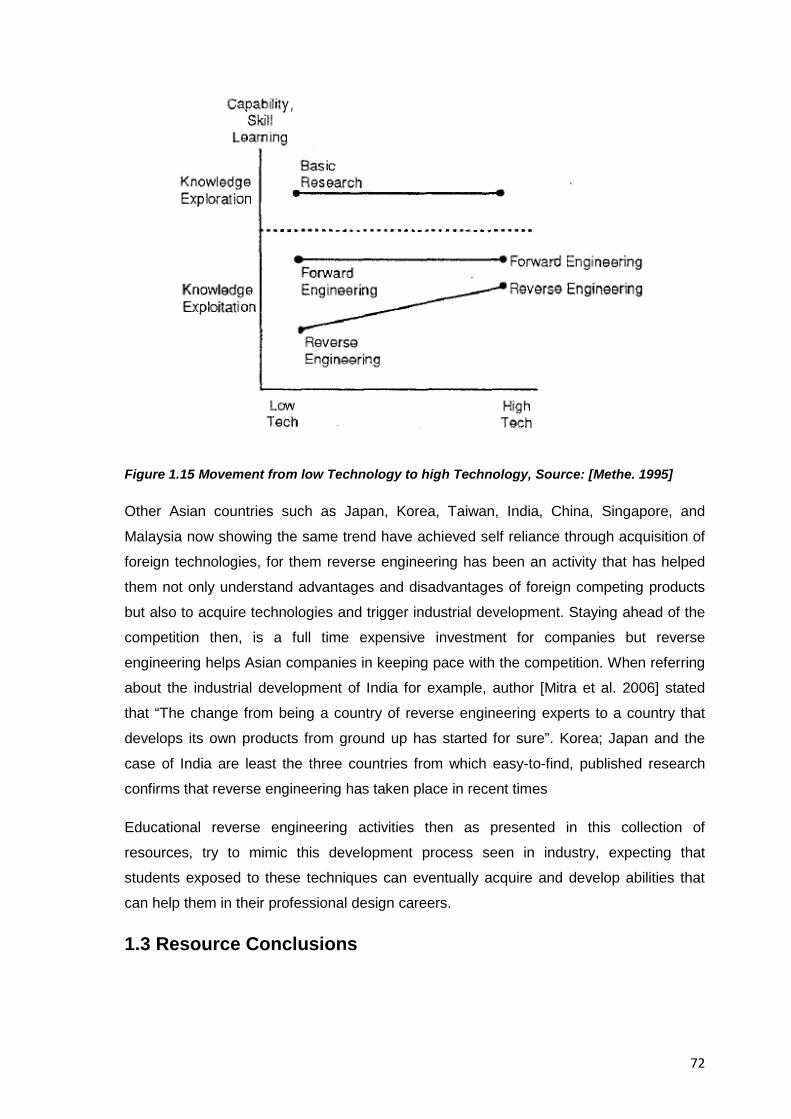
72
Figure 1.15 Movement from low Technology to high Technology, Source: [Methe. 1995]
Other Asian countries such as Japan, Korea, Taiwan, India, China, Singapore, and
Malaysia now showing the same trend have achieved self reliance through acquisition of
foreign technologies, for them reverse engineering has been an activity that has helped
them not only understand advantages and disadvantages of foreign competing products
but also to acquire technologies and trigger industrial development. Staying ahead of the
competition then, is a full time expensive investment for companies but reverse
engineering helps Asian companies in keeping pace with the competition. When referring
about the industrial development of India for example, author [Mitra et al. 2006] stated
that “The change from being a country of reverse engineering experts to a country that
develops its own products from ground up has started for sure”. Korea; Japan and the
case of India are least the three countries from which easy-to-find, published research
confirms that reverse engineering has taken place in recent times
Educational reverse engineering activities then as presented in this collection of
resources, try to mimic this development process seen in industry, expecting that
students exposed to these techniques can eventually acquire and develop abilities that
can help them in their professional design careers.
1.3 Resource Conclusions
73
Educational reverse engineering activities come from a long tradition of approaches that
intend to investigate a subject system and then with whatever analytical and technical
tools available try to come up with an understanding of it, this process though is never
straightforward and thus, a team effort and the integration of resources from multiple
sources is usually the best way to tackle a reverse engineering effort; the rewards though
are well worth it, and even authors such as [Otto & Wood. 2001] believe that reverse
engineering activities can improve engineering design education since they can offer a
better paradigm for it by allowing for a modern learning cycle of experience; hypothesis,
understanding, and new design execution.
Author Dalrymple on her side, has also stated that “there is an undeniable need to
identify and implement pedagogical practices that motivate students as well as facilitate
learning that can be applied and adapted to new contexts and support future acquisition
of related knowledge and skill” [Dalrymple. 2009], as seen from the wealth of topics
covered in this resource then, reverse engineering can be considered indeed a valid
subject of academic research in design education and thus, its study and exploration can
help fulfil the author’s recommendations.
In the end, it could be said that the available knowledge about a product under analysis
may not be absolute and not represent the final truth, however, it can be trusted to be
valid within its area of application and thus, use it as a stepping-stone for further progress
and acquisition of knowledge., indeed there is no substitute for judgement acquired
though experience and educational reverse engineering activities can help bring new
opportunities for learning to students of engineering design.

74
This page intentionally left blank
75
RESOURCE 2: REVERSE ENGINEERING AND LEARNING
2.1 Resource Introduction
This resource introduces the reader with the mechanisms and conditions that explain the
connection between the hands-on activities inherent to EREA and the associated
cognitive processes that allow the students’ acquisition of abilities related to the practice
of engineering design
2.2 Pedagogical Framework of EREA
Broadly speaking, the learning-by-doing pedagogy model falls under constructivism which
aims to facilitate learning, as opposed to traditional instructor-based teaching which falls
into objectivism, in this sense, educational reverse engineering activities require the
application of concepts and techniques from different sources in a synthesis effort that
integrates real world-like skills, and thus, the knowledge acquired from a reverse
engineering course aims to answer not only what a concept and technique is but also
how and why it is applied. On a more strict sense though, the preferred learning
environment for EREA is CBE (Competence Based Education) which is an institutional
process that moves education from focusing on what academics believe graduates need
to know (teacher-focused), to what students need to know and are able to do in varying
and complex situations (student and/or workplace focused), it is a process that is centred
on outcomes (competencies) that are linked to workforce needs as defined by employers
and the profession and for such reasons EREA are better understood and more clearly
seen in such framework, however, EREA are by no means exclusive to it, after the
consideration of simple tradeoffs (e.g. Length, depth of analysis, etc.) they can be, and
are indeed used under different educational frameworks such as Course/Objective/Topic-
based teaching curricula.
2.3 Cognitive Processes and the Construction of Knowledge in an EREA
Students use three different perception modes to learn, namely: Auditory, kinaesthetic,
and visual, the three modes can be combined but a preference for one of them is usually
developed and indeed, the preferred perception modes in students have been found to
affect the way students learn, cf.[Wankat & Oreovicz. 1992]. Kinaesthetic experiences in
education for example, include touching, smelling, feeling or testing while handling real
products in the laboratory. Visual experiences which are the preferred mode for
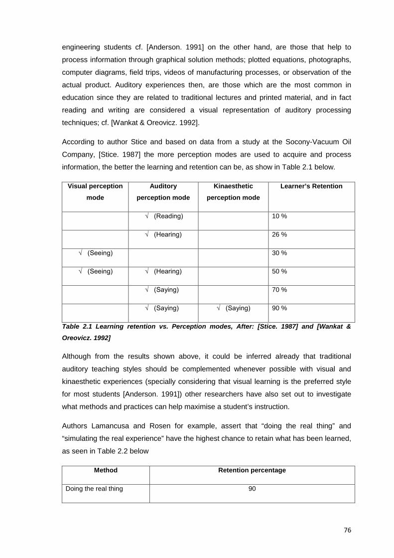
76
engineering students cf. [Anderson. 1991] on the other hand, are those that help to
process information through graphical solution methods; plotted equations, photographs,
computer diagrams, field trips, videos of manufacturing processes, or observation of the
actual product. Auditory experiences then, are those which are the most common in
education since they are related to traditional lectures and printed material, and in fact
reading and writing are considered a visual representation of auditory processing
techniques; cf. [Wankat & Oreovicz. 1992].
According to author Stice and based on data from a study at the Socony-Vacuum Oil
Company, [Stice. 1987] the more perception modes are used to acquire and process
information, the better the learning and retention can be, as show in Table 2.1 below.
Visual perception mode
Auditory perception mode
Kinaesthetic perception mode
Learner’s Retention
√ (Reading) 10 %
√ (Hearing) 26 %
√ (Seeing) 30 %
√ (Seeing) √ (Hearing) 50 %
√ (Saying) 70 %
√ (Saying) √ (Saying) 90 %
Table 2.1 Learning retention vs. Perception modes, After: [Stice. 1987] and [Wankat & Oreovicz. 1992]
Although from the results shown above, it could be inferred already that traditional
auditory teaching styles should be complemented whenever possible with visual and
kinaesthetic experiences (specially considering that visual learning is the preferred style
for most students [Anderson. 1991]) other researchers have also set out to investigate
what methods and practices can help maximise a student’s instruction.
Authors Lamancusa and Rosen for example, assert that “doing the real thing” and
“simulating the real experience” have the highest chance to retain what has been learned,
as seen in Table 2.2 below
Method Retention percentage
Doing the real thing 90
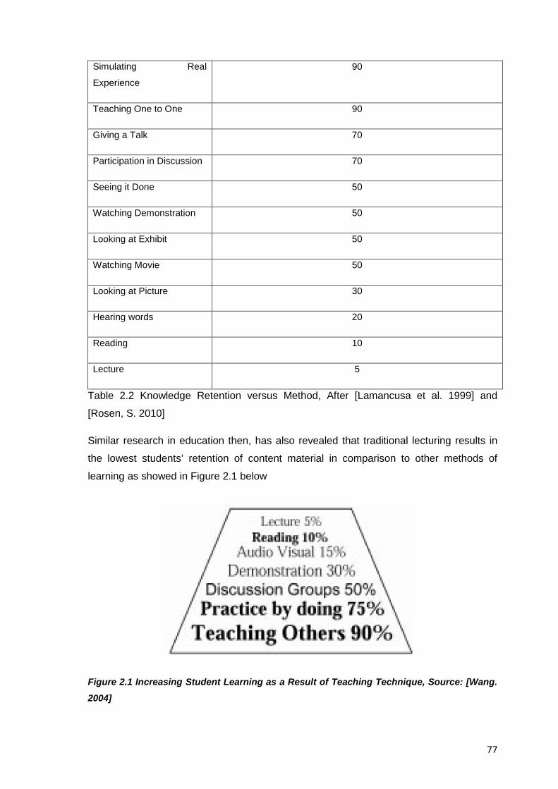
77
Simulating Real
Experience
90
Teaching One to One 90
Giving a Talk 70
Participation in Discussion 70
Seeing it Done 50
Watching Demonstration 50
Looking at Exhibit 50
Watching Movie 50
Looking at Picture 30
Hearing words 20
Reading 10
Lecture 5
Table 2.2 Knowledge Retention versus Method, After [Lamancusa et al. 1999] and
[Rosen, S. 2010]
Similar research in education then, has also revealed that traditional lecturing results in
the lowest students’ retention of content material in comparison to other methods of
learning as showed in Figure 2.1 below
Figure 2.1 Increasing Student Learning as a Result of Teaching Technique, Source: [Wang. 2004]
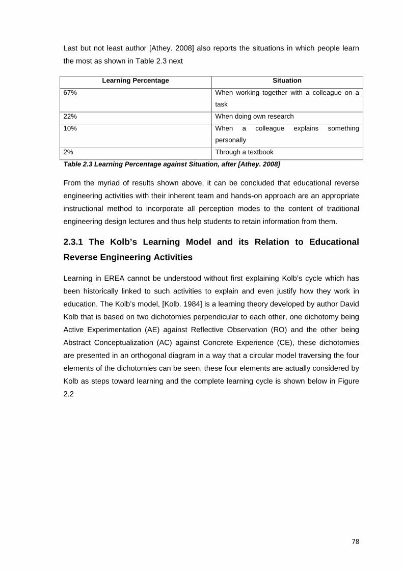
78
Last but not least author [Athey. 2008] also reports the situations in which people learn
the most as shown in Table 2.3 next
Learning Percentage Situation
67% When working together with a colleague on a
task
22% When doing own research
10% When a colleague explains something
personally
2% Through a textbook
Table 2.3 Learning Percentage against Situation, after [Athey. 2008]
From the myriad of results shown above, it can be concluded that educational reverse
engineering activities with their inherent team and hands-on approach are an appropriate
instructional method to incorporate all perception modes to the content of traditional
engineering design lectures and thus help students to retain information from them.
2.3.1 The Kolb’s Learning Model and its Relation to Educational Reverse Engineering Activities
Learning in EREA cannot be understood without first explaining Kolb’s cycle which has
been historically linked to such activities to explain and even justify how they work in
education. The Kolb’s model, [Kolb. 1984] is a learning theory developed by author David
Kolb that is based on two dichotomies perpendicular to each other, one dichotomy being
Active Experimentation (AE) against Reflective Observation (RO) and the other being
Abstract Conceptualization (AC) against Concrete Experience (CE), these dichotomies
are presented in an orthogonal diagram in a way that a circular model traversing the four
elements of the dichotomies can be seen, these four elements are actually considered by
Kolb as steps toward learning and the complete learning cycle is shown below in Figure
2.2
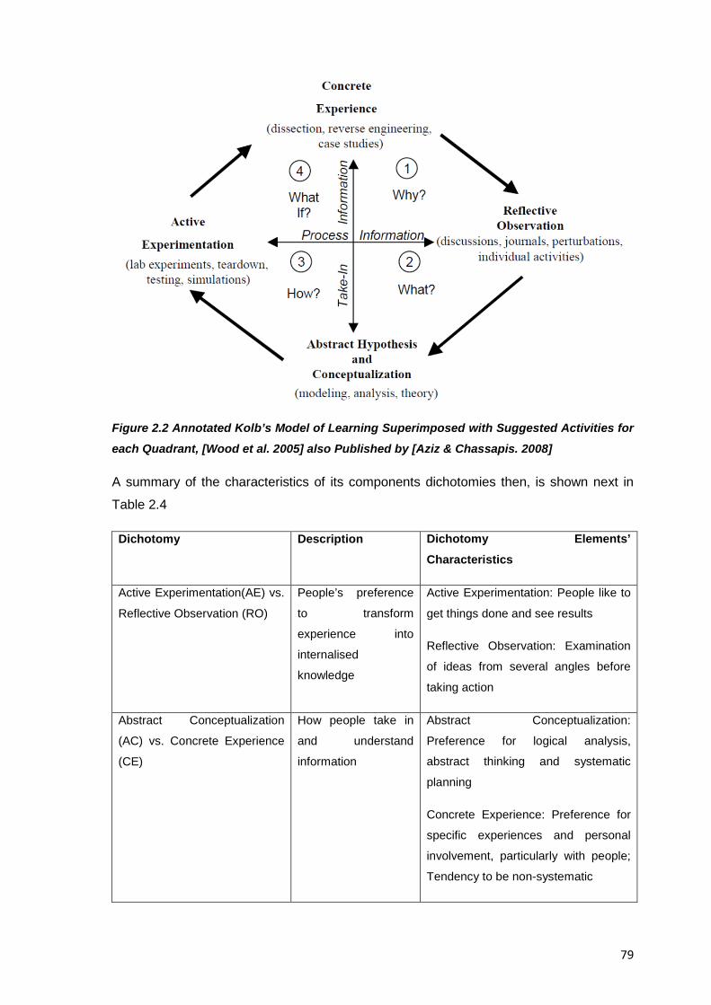
79
Figure 2.2 Annotated Kolb’s Model of Learning Superimposed with Suggested Activities for
each Quadrant, [Wood et al. 2005] also Published by [Aziz & Chassapis. 2008]
A summary of the characteristics of its components dichotomies then, is shown next in
Table 2.4
Dichotomy Description Dichotomy Elements’ Characteristics
Active Experimentation(AE) vs.
Reflective Observation (RO)
People’s preference
to transform
experience into
internalised
knowledge
Active Experimentation: People like to
get things done and see results
Reflective Observation: Examination
of ideas from several angles before
taking action
Abstract Conceptualization
(AC) vs. Concrete Experience
(CE)
How people take in
and understand
information
Abstract Conceptualization:
Preference for logical analysis,
abstract thinking and systematic
planning
Concrete Experience: Preference for
specific experiences and personal
involvement, particularly with people;
Tendency to be non-systematic
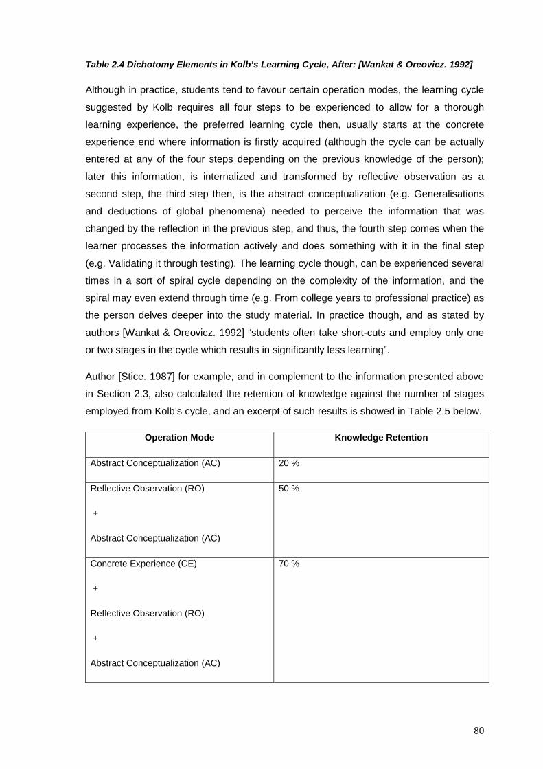
80
Table 2.4 Dichotomy Elements in Kolb’s Learning Cycle, After: [Wankat & Oreovicz. 1992]
Although in practice, students tend to favour certain operation modes, the learning cycle
suggested by Kolb requires all four steps to be experienced to allow for a thorough
learning experience, the preferred learning cycle then, usually starts at the concrete
experience end where information is firstly acquired (although the cycle can be actually
entered at any of the four steps depending on the previous knowledge of the person);
later this information, is internalized and transformed by reflective observation as a
second step, the third step then, is the abstract conceptualization (e.g. Generalisations
and deductions of global phenomena) needed to perceive the information that was
changed by the reflection in the previous step, and thus, the fourth step comes when the
learner processes the information actively and does something with it in the final step
(e.g. Validating it through testing). The learning cycle though, can be experienced several
times in a sort of spiral cycle depending on the complexity of the information, and the
spiral may even extend through time (e.g. From college years to professional practice) as
the person delves deeper into the study material. In practice though, and as stated by
authors [Wankat & Oreovicz. 1992] “students often take short-cuts and employ only one
or two stages in the cycle which results in significantly less learning”.
Author [Stice. 1987] for example, and in complement to the information presented above
in Section 2.3, also calculated the retention of knowledge against the number of stages
employed from Kolb’s cycle, and an excerpt of such results is showed in Table 2.5 below.
Operation Mode Knowledge Retention
Abstract Conceptualization (AC) 20 %
Reflective Observation (RO)
+
Abstract Conceptualization (AC)
50 %
Concrete Experience (CE)
+
Reflective Observation (RO)
+
Abstract Conceptualization (AC)
70 %
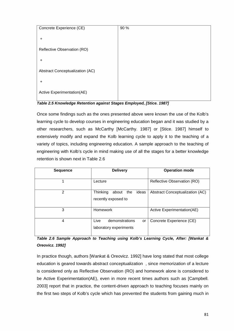
81
Concrete Experience (CE)
+
Reflective Observation (RO)
+
Abstract Conceptualization (AC)
+
Active Experimentation(AE)
90 %
Table 2.5 Knowledge Retention against Stages Employed, [Stice. 1987]
Once some findings such as the ones presented above were known the use of the Kolb’s
learning cycle to develop courses in engineering education began and it was studied by a
other researchers, such as McCarthy [McCarthy. 1987] or [Stice. 1987] himself to
extensively modify and expand the Kolb learning cycle to apply it to the teaching of a
variety of topics, including engineering education. A sample approach to the teaching of
engineering with Kolb’s cycle in mind making use of all the stages for a better knowledge
retention is shown next in Table 2.6
Sequence Delivery Operation mode
1 Lecture Reflective Observation (RO)
2 Thinking about the ideas
recently exposed to
Abstract Conceptualization (AC)
3 Homework Active Experimentation(AE)
4 Live demonstrations or
laboratory experiments
Concrete Experience (CE)
Table 2.6 Sample Approach to Teaching using Kolb’s Learning Cycle, After: [Wankat &
Oreovicz. 1992]
In practice though, authors [Wankat & Oreovicz. 1992] have long stated that most college
education is geared towards abstract conceptualization , since memorization of a lecture
is considered only as Reflective Observation (RO) and homework alone is considered to
be Active Experimentation(AE), even in more recent times authors such as [Campbell.
2003] report that in practice, the content-driven approach to teaching focuses mainly on
the first two steps of Kolb’s cycle which has prevented the students from gaining much in
82
the way of the mechanical intuition (to achieve familiarity with machines and devices), but
still as authors [Wankat & Oreovicz. 1992] originally stated, long term learning is
enhanced by planned (or even unplanned) complementary use of the other stages
throughout a number of active learning experiences during college years (i.e. Summer
jobs or team projects) that allow students to acquire much needed concrete experiences.
Findings from other researchers on the application of Kolb’s model in the teaching of
engineering have also state for example that the Kolb model “swings the pendulum of
learning engineering from an emphasis of generalization and theory to a balance with all
modes of learning”, [Stice. 1987], to what authors [Wood & Wood. 2000] contribute by
stating that since engineering becomes equally focused with hands-on activities “Without
this approach (hands-on), we have no concrete experience to ground our learning and
build a solid understanding. (and) Nowhere is this truth more pronounced than in machine
design. (since) The grounding in current machines helps nurture our interest for
understanding the way things work and for making devices work better.”
From the characteristics about EREA presented already, it can be argued that they can
help fulfil the four stages of learning, suggested by Kolb (specially the concrete
experience and active experimentation stages) and thus help improve the instruction of
students of engineering design
2.3.1.1 Students’ Roles During an EREA
For inherently hands-on projects such as those based on reverse engineering, authors
[Leek & Larsson. 2007] have advised a team approach, not only because working in
groups brings additional dimensions of experience which can be useful for future
engineers but also because projects often take place in team-form too; besides, given
that reverse engineering activities provide students with Kolb’s experiential learning
experience, the student are assumed to take the roles described by author [Lenoir. 2001],
namely “The Student as Learner”, “The Student as Observer”, “The Student as Assistant”
but most importantly “The Student as Practitioner” which means that at this level,
students are involved in an activity that helps them synthesize material together from a
wide variety of previously taken courses.
2.3.2 The Data, Information, and Knowledge Triad in EREA
Authors [Ahmed et al. 1999] provide a relationship between the data, information and
knowledge triad based on the awareness and interpretation of it as seen on Figure 2.3
below, The different stages of an educational reverse engineering analysis as will be later
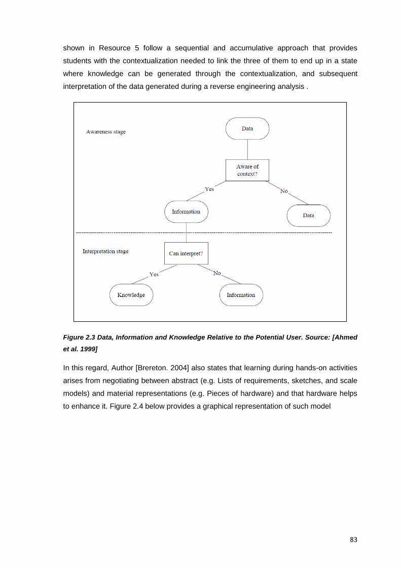
83
shown in Resource 5 follow a sequential and accumulative approach that provides
students with the contextualization needed to link the three of them to end up in a state
where knowledge can be generated through the contextualization, and subsequent
interpretation of the data generated during a reverse engineering analysis .
Figure 2.3 Data, Information and Knowledge Relative to the Potential User. Source: [Ahmed
et al. 1999]
In this regard, Author [Brereton. 2004] also states that learning during hands-on activities
arises from negotiating between abstract (e.g. Lists of requirements, sketches, and scale
models) and material representations (e.g. Pieces of hardware) and that hardware helps
to enhance it. Figure 2.4 below provides a graphical representation of such model
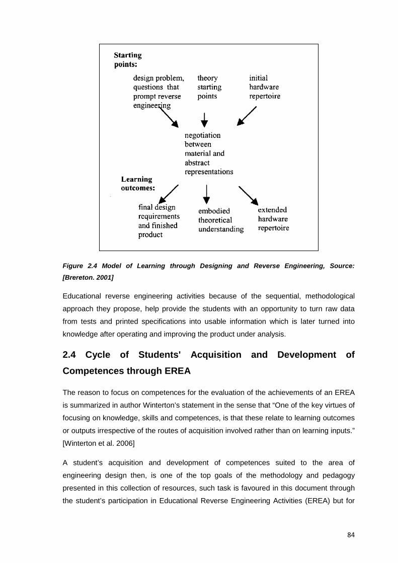
84
Figure 2.4 Model of Learning through Designing and Reverse Engineering, Source:
[Brereton. 2001]
Educational reverse engineering activities because of the sequential, methodological
approach they propose, help provide the students with an opportunity to turn raw data
from tests and printed specifications into usable information which is later turned into
knowledge after operating and improving the product under analysis.
2.4 Cycle of Students' Acquisition and Development of Competences through EREA
The reason to focus on competences for the evaluation of the achievements of an EREA
is summarized in author Winterton’s statement in the sense that “One of the key virtues of
focusing on knowledge, skills and competences, is that these relate to learning outcomes
or outputs irrespective of the routes of acquisition involved rather than on learning inputs.”
[Winterton et al. 2006]
A student’s acquisition and development of competences suited to the area of
engineering design then, is one of the top goals of the methodology and pedagogy
presented in this collection of resources, such task is favoured in this document through
the student’s participation in Educational Reverse Engineering Activities (EREA) but for
85
participant educators, a basic structure that clarifies how to go from the analysis of an
existing product to the students’ actual application of competences is required, in order to
justify the inclusion or strengthening of EREA in an existing engineering design
curriculum.
Figure 2.5 below provides an overall view of how the design rationale embedded in a
consumer product can be retrieved by students and how the required analysis of it can be
turned into a synthesis process through a methodology that combines verified information
with educated guesses. Such figure is comprised of a series of stages linked by causes
and effects that start from a common engineering process where a product designer’s
rationale is generated in order to attain a final product, which in turn becomes the starting
point of a reverse engineering analysis and ends up in a situation where students make
use of the competences acquired during the process.
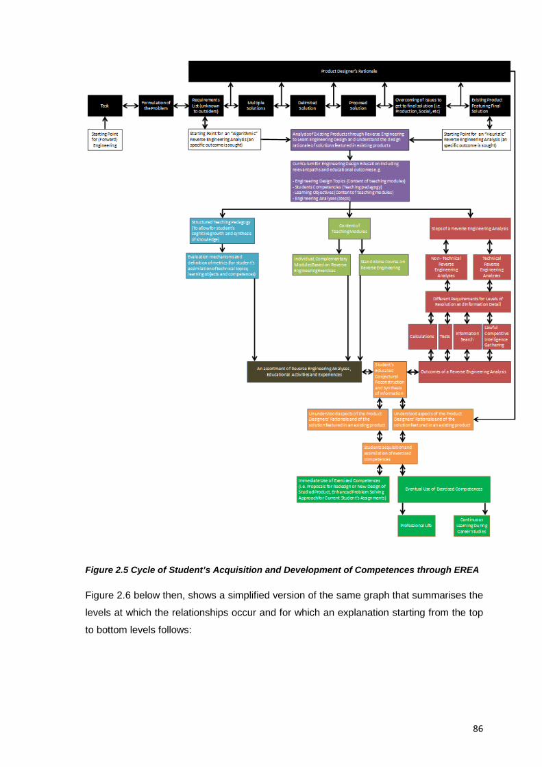
86
Figure 2.5 Cycle of Student’s Acquisition and Development of Competences through EREA
Figure 2.6 below then, shows a simplified version of the same graph that summarises the
levels at which the relationships occur and for which an explanation starting from the top
to bottom levels follows:
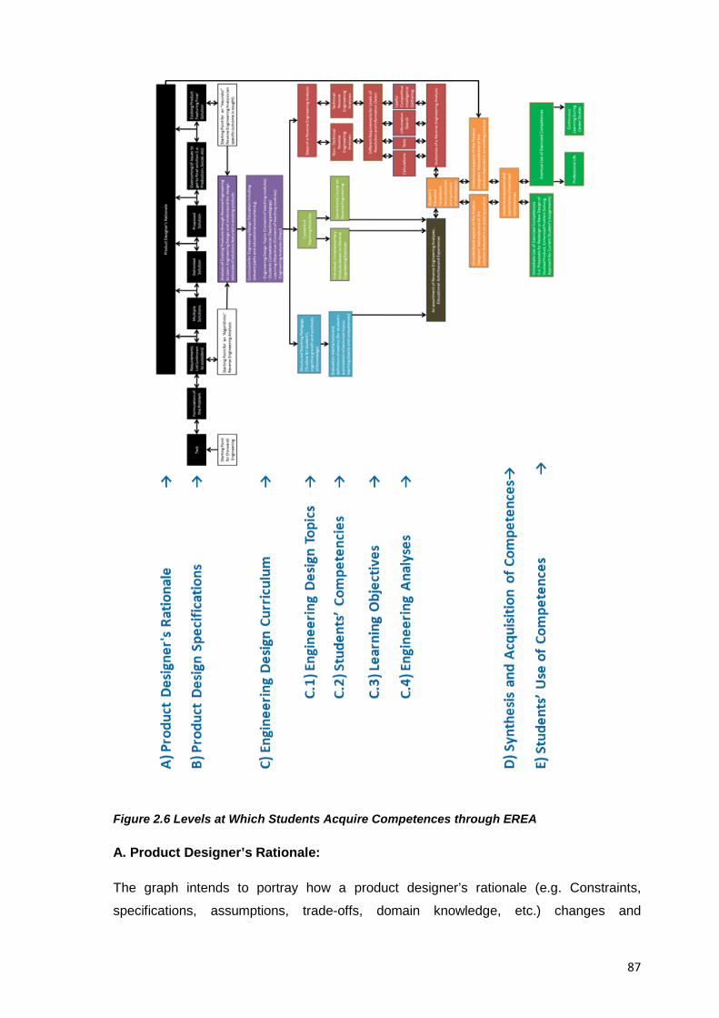
87
Figure 2.6 Levels at Which Students Acquire Competences through EREA
A. Product Designer’s Rationale:
The graph intends to portray how a product designer’s rationale (e.g. Constraints,
specifications, assumptions, trade-offs, domain knowledge, etc.) changes and
88
accumulates throughout the stages of a regular design and manufacturing process, this
experience gained by the designer which is not usually documented or available to
outsiders does complement the information about the product under analysis found in
public records (e.g. Patent documents, repair manuals) and the analyst’s own experience
in testing it to come up with a definite understanding of it. The acquisition of the original
designer’s rationale (initially unavailable to the reverse engineer) is the target of the
methodology presented in this research and the enabler that will allow the student to
contextualise simple data into information and then into usable knowledge when the
opportunity arises.
B. Product Design Specifications:
This level shows from left to right the typical design process of a consumer product which
is the test bed chosen in this collection of resources for the execution of EREA; in this
level we can also see the potential entry points to a reverse engineering analysis which
can be either at the requirements list stage or at the represented embodiment of a design
solution.
An algorithmic (or brute force) approach such as the one favoured in the guided example
presented here in Resource 7 can be considered an analysis that intends to explore all
aspects of a product and takes as a starting point all necessary categories from a typical
requirements list to start analysing each one of them, an “heuristic” approach on the other
hand has as entry point the actual physical product from which a specific aspect of it will
be explored, this approach is used in commercial reverse engineering for example or
when new information has become available that allows a previously ununderstood
feature of a product to be analysed again.
C. Engineering Design Curriculum:
This level makes explicit the resulting curriculum for engineering design education, that
will include the analysis of existing products through reverse engineering, as one of the
aids that will help students to learn about engineering design and to help them
understand the design rationale of solutions featured in existing products, such
curriculum (or methodology at the very least) will feature three relevant paths and
associated educational outcomes that will consider the technical and pedagogical
aspects of reverse engineering and that will assist in achieving its expected educational
goals, the paths are briefly mentioned below and are further explained across several
resources of this collection of resources, namely:
89
C.1 Engineering Design Topics (e.g. Contents of teaching modules (or methodology
stages) that highlight reverse engineering and related activities)
C.2 Students Competencies (e.g. A suitable teaching pedagogy that includes the use of
hands-on activities)
C.3 Learning Objectives (e.g. Chosen in accordance with the areas where reverse
engineering activities can bring an added value to engineering design education)
C.4 Engineering Analyses (e.g. Steps of the method that will increase the technical and
non technical understanding of the product under analysis)
In the same figure, an overview of the three abovementioned paths can be seen, where
in order to unify an assortment of reverse engineering analyses; educational activities
and experiences that together make up the EREA one has to consider not only an
appropriate teaching methodology and associated evaluation mechanisms, but also the
actual content of the stages of the methodology for EREA and the way they will be
delivered (e.g. A standalone course on reverse engineering as done in this collection of
resources)
Regarding the actual outcomes of a reverse engineering analysis, one will also have to
consider the different requirements for levels of resolution and information detail,
requested by the educators and depending on the proficiency of the target students.
D. Synthesis and Acquisition of Competences:
A common challenge that the reverse engineering method proposed in this collection of
resources intends to ease is that reverse engineering activities so far, have focused
heavily on a dissection stage where the product parts are analysed according to the detail
level required by the instructor in charge, however this research is focused on the area of
Engineering Design overall and so, if the results from this research project are to be used
by engineering design professors, the analysis stage of a reverse engineering activity
must be complemented with a synthesis stage that takes into account the particular
characteristics that engineering design education has, thus bringing actual benefits to the
designing abilities of the students.
In the method presented here then and when reaching this level, students will have gone
already through a sequence of orderly, accumulative tests and tasks that will have
increased their understanding of why the product under analysis is the way it is, even
then though, there will always be ununderstood elements of the system under analysis
90
which will have to be later revisited whenever new information or analysis tools become
available, once a reasonable effort has been done though, the reverse analysis has to
stop and the knowledge gained (through a permanent cycle of analysis- synthesis)
becomes an asset for the participating students.
E. Students’ Use of Competences:
Because of the way the reverse engineering methodology has been planned for this
research, there will be an immediate need for students to exercise their newly acquired
competences either through the proposals for redesign or for a new design of the studied
product, however it is also expected that such competences can be later used as they
keep progressing throughout their career studies.
Alternatively, Figures 2.7 and 2.8 below provide a complementary view on the
mechanisms in place during an EREA that make students acquire and develop
capabilities from the analysis of a consumer product. Figure 2.7 below shows all the
levels involved in the acquisition of competences through an EREA starting from the -
product life phases- level of a product at the bottom of the figure and all the way up to the
student’s learning level. The white coloured boxes shown on the right side of the figure
indicate the link between all the levels and can be thought of as the result of all the items
shown to the left of them in the same row.
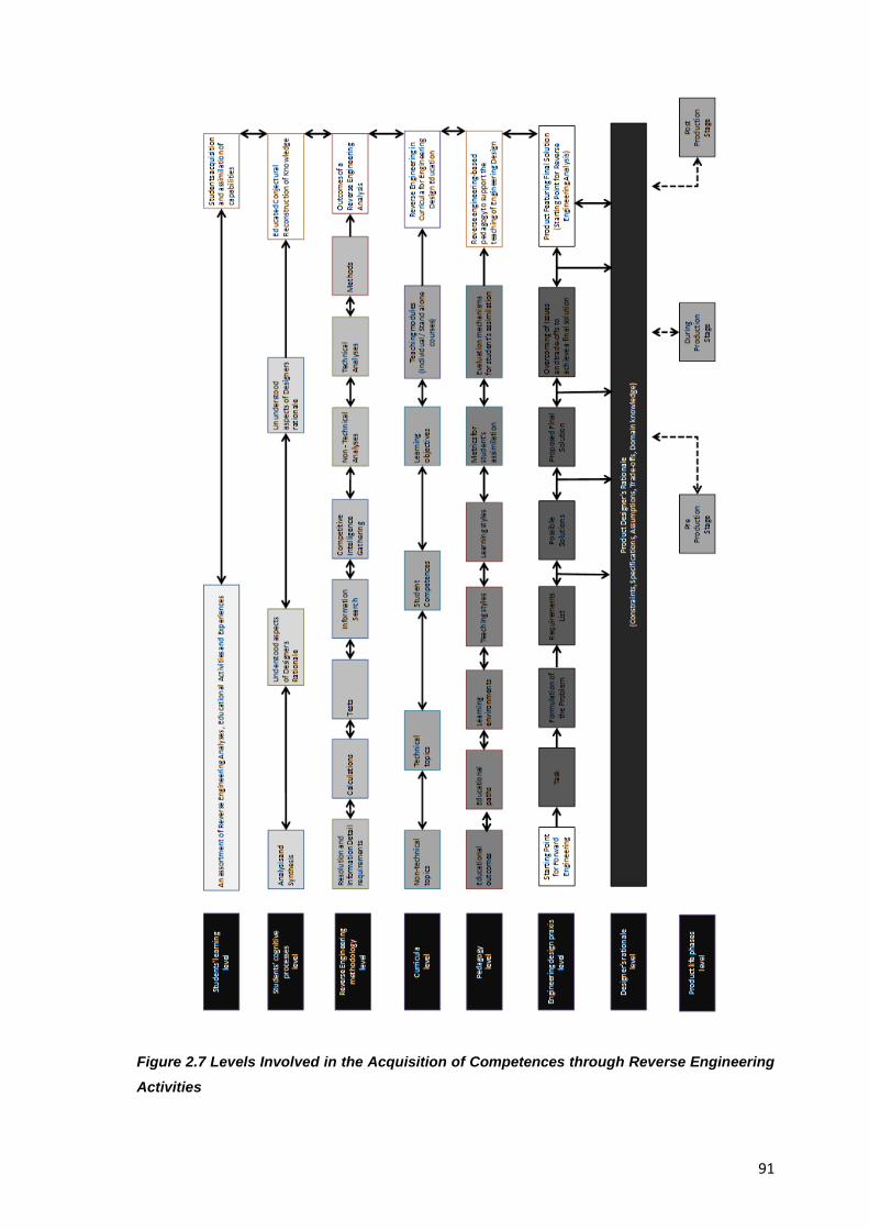
91
Figure 2.7 Levels Involved in the Acquisition of Competences through Reverse Engineering Activities
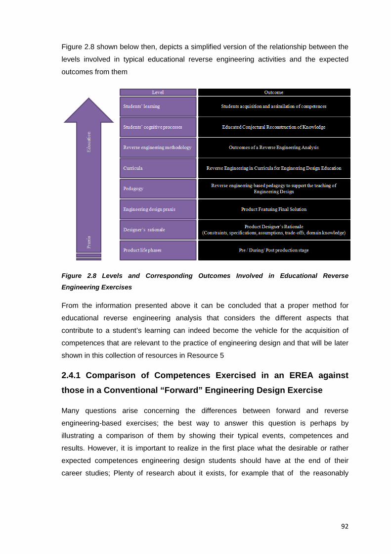
92
Figure 2.8 shown below then, depicts a simplified version of the relationship between the
levels involved in typical educational reverse engineering activities and the expected
outcomes from them
Figure 2.8 Levels and Corresponding Outcomes Involved in Educational Reverse
Engineering Exercises
From the information presented above it can be concluded that a proper method for
educational reverse engineering analysis that considers the different aspects that
contribute to a student’s learning can indeed become the vehicle for the acquisition of
competences that are relevant to the practice of engineering design and that will be later
shown in this collection of resources in Resource 5
2.4.1 Comparison of Competences Exercised in an EREA against those in a Conventional “Forward” Engineering Design Exercise
Many questions arise concerning the differences between forward and reverse
engineering-based exercises; the best way to answer this question is perhaps by
illustrating a comparison of them by showing their typical events, competences and
results. However, it is important to realize in the first place what the desirable or rather
expected competences engineering design students should have at the end of their
career studies; Plenty of research about it exists, for example that of the reasonably
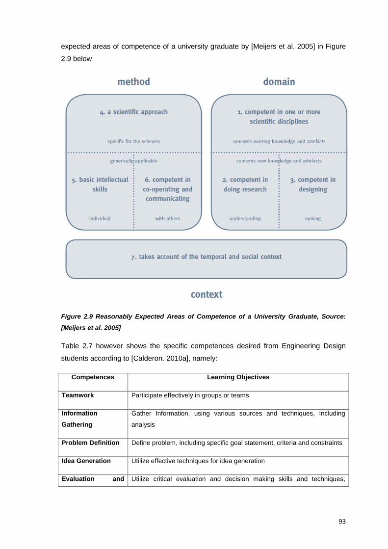
93
expected areas of competence of a university graduate by [Meijers et al. 2005] in Figure
2.9 below
Figure 2.9 Reasonably Expected Areas of Competence of a University Graduate, Source: [Meijers et al. 2005]
Table 2.7 however shows the specific competences desired from Engineering Design
students according to [Calderon. 2010a], namely:
Competences Learning Objectives
Teamwork Participate effectively in groups or teams
Information Gathering
Gather Information, using various sources and techniques, Including
analysis
Problem Definition Define problem, including specific goal statement, criteria and constraints
Idea Generation Utilize effective techniques for idea generation
Evaluation and Utilize critical evaluation and decision making skills and techniques,
94
Decision Making including testing
Synthesis Combine information together from pre-existing elements in a different
way, in a new pattern or proposing alternative solutions
Implementation Implement the design to a stage of usefulness to prospective clientele
Communication Communicate at all stages of development and implementation of design
solutions
Table 2.7 Desired Competences in an Engineering Design Student and Measurable
Learning Objectives, [Calderon. 2010a]
With the previous competences then, students can have a credible chance to succeed in
their career studies and can also serve as a baseline for further growth during their
professional careers.
Table 2.8 shown below shows an example of a typical (forward) engineering design
exercise, detailing the events common to any engineering design process, the
competences required to succeed in them, and what they lead to in terms of educational
outcomes and practical results.
Events Competences Required Leading To…
1. Define a need;
express as a goal
Problem Definition
Teamwork
Communication
Definition of the Problem, Including
Specific Goal Statements
2. Establish design
criteria and constraints
Problem Definition
Information Gathering
Teamwork
Evaluation and Decision Making
Communication
Acknowledgement and delimitation
of constraints, Understanding of the
open ended nature of problems,
Recognize importance of problem
definition
3. Evaluate alternative
designs
Evaluation and Decision Making
Idea Generation
An iterative approach that employs
evaluation of proposed solutions
repeatedly in the design process
4. Build a prototype of Implementation Achieve familiarity with the design
95
best design Teamwork
5. Test and evaluate
the prototype using the
design criteria
Evaluation and Decision Making
Teamwork
Implementation
Management of time and other
resources as required to complete
the project
6. Analyze test results,
make design changes,
and retest
Synthesis
Evaluation and Decision Making
Teamwork
Self- assessment of design
proposals and also learning to follow
instructions provided by others in
implementation
7. Communicate the
design
Communication
Teamwork
Presentation of the development and
implementation of a solution
Table 2.8 Example of Events and Practiced Competences in a (Forward) Engineering
Design Exercise
Table 2.9 below then, shows an example of a reverse engineering exercise detailing the
same aspects as those of a traditional (forward) engineering exercise (Note: The example
follows the suggested methodology for reverse engineering analysis that is later
explained in Resource 5 of this document)
Events Competences Required Leading To
1. Task Clarification Problem Definition, Idea
Generation
Goals and span of the
exercise
2. Product Procurement Problem Definition, Information
Gathering, Evaluation and
Decision Making
Selection of product to cover
expected theory principles and
effects
3. Team Selection Evaluation and Decision
Making, Communication
Assembly of people to
undergo the reverse
engineering activity
4. Data Collection Information Gathering Acknowledgement of the
positioning of the chosen
product
5. Product Performance Test I Evaluation and Decision
Making
Achieve familiarity with the
chosen product and its design
6. Product Disassembly Information Gathering, Idea
Generation, Implementation
Increase of awareness of the
product under analysis
7. Product Analysis Analysis, Information
Gathering, Idea Generation,
Understanding of inner
workings as well as external
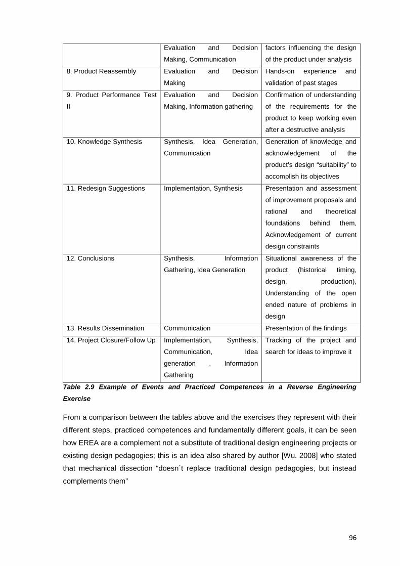
96
Evaluation and Decision
Making, Communication
factors influencing the design
of the product under analysis
8. Product Reassembly Evaluation and Decision
Making
Hands-on experience and
validation of past stages
9. Product Performance Test
II
Evaluation and Decision
Making, Information gathering
Confirmation of understanding
of the requirements for the
product to keep working even
after a destructive analysis
10. Knowledge Synthesis Synthesis, Idea Generation,
Communication
Generation of knowledge and
acknowledgement of the
product’s design “suitability” to
accomplish its objectives
11. Redesign Suggestions Implementation, Synthesis Presentation and assessment
of improvement proposals and
rational and theoretical
foundations behind them,
Acknowledgement of current
design constraints
12. Conclusions Synthesis, Information
Gathering, Idea Generation
Situational awareness of the
product (historical timing,
design, production),
Understanding of the open
ended nature of problems in
design
13. Results Dissemination Communication Presentation of the findings
14. Project Closure/Follow Up Implementation, Synthesis,
Communication, Idea
generation , Information
Gathering
Tracking of the project and
search for ideas to improve it
Table 2.9 Example of Events and Practiced Competences in a Reverse Engineering
Exercise
From a comparison between the tables above and the exercises they represent with their
different steps, practiced competences and fundamentally different goals, it can be seen
how EREA are a complement not a substitute of traditional design engineering projects or
existing design pedagogies; this is an idea also shared by author [Wu. 2008] who stated
that mechanical dissection “doesn´t replace traditional design pedagogies, but instead
complements them”
97
Part of the added value EREA can bring to engineering design education then, comes
from their suitability to reinforce engineering concepts through hands-on experiences and
help exercise most of the expected competences considered important for an engineering
design graduate, because of this, the two types of exercises should not be considered as
competing ones, but rather be chosen or even combined according to their suitability
towards the goal educational goal in mind.
2.5 Gender, Prior Experience and Motivation in EREA
With regard to the effects of gender, prior disassembly experience, and motivation in
students, the studies in the area of D/A/A Activities by Authors [Dalrymple et al. 2011]
found in their test population that men reported significantly more prior experience in
disassembling artifacts than women, also they found that males had a higher perceived
competence on D/A/A activities than females. However, no other significant relationships
was found among the variables (gender, prior disassembling experience and motivation)
and despite the abovementioned findings the actual results from their study indicated that
none of these perceptions or relationships actually accounted for any significant variability
in responses for students in a D/A/A activity, in this sense the authors reported that
women’s inexperience or lower perception did not put them at a disadvantage and
students of both genders performed equally on the measure of learning and transfer from
D/A/A activities, based on this, and on the statements by the researchers themselves,
their results “help reduce concerns about potential novelty effects related to the D/A/A
activity both because many participants had previously experienced D/A/A activities and
because prior experience with D/A/A did not show a significant relationship with transfer
or motivation”.
2.6 Resource Conclusions
Much research has gone into the study of the cognitive processes that allow for the
students’ learning and construction of knowledge with or without the aid of physical
objects ; still an indicative representation of what the most relevant findings for the area of
educational reverse engineering is presented in this resource and from it, one can see
that EREA are integrative, comprehensive activities that help students learn with all their
senses and thus have memorable educational experiences that comply with current
recommendations in the field of education, after all and as stated by author [Hoffman.
2006] when referring to hands-on activities “As much as you think you know, nothing
beats picking up the parts, feeling them, weighing them, and knowing the processes that
made them.”

98
This page intentionally left blank
99
RESOURCE 3: MISCONCEPTIONS ABOUT REVERSE ENGINEERING
3.1 Resource Introduction
Given the different goals, methods and stakeholders commercial reverse engineering
activities have in relation to their educational counterparts, a major effort has been done
during the creation of this collection of resources to focus only on the educational aspects
of reverse engineering. However, given that EREA are sometimes unfairly marred by the
misconceptions and negative perceptions their commercial counterparts have, the
information presented in this resource intends to debunk some of the myths of
commercial reverse engineering and explain at the same time how they affect the
educational aspects of it.
3.2 Negative Associations of the Term “Reverse Engineering”
The term “engineering” is positively seen as the creation of something beneficial,
whereas the term “reverse engineering” suffers a negative connotation often associated
with illegal acts, this connotation is mostly derived from the use of the term in criminal
counterfeiting or software hacking practices and thus, by sheer simplification the idea has
spread that reverse engineering is not legitimately linked to technical advance under any
circumstance. Indeed the term “reverse” rather than implying the concept of a
bidirectional data exchange between physical and conceptual domains is understood as
an opportunistic misappropriation of existing information. It’s been only in recent times
though, that in commercial environments, little by little reverse engineering starts being
associated with the positive production of new products or the variation of old ones. For
example, a publication by the Gale group states that “reverse engineering used to be
viewed as a not-so-ethical process of copying successful designs by OEMs but with less
design capability than the originators. But since then, reverse engineering has come to be
viewed in a more positive light because it speeds up and simplifies many developmental
procedures for OEMs. Today, it is in almost universal use because it enables OEMs to be
more competitive across several disciplines”, [The Gale Group, 2002].
Back to the academic domain, it should be mentioned that the idea to complement the
teaching of the engineering design process with reverse engineering activities was met
with reticence when first presenting the research proposal that led to the creation of this
collection of resources. Initial, exploratory studies showed that both, an idealized view of
the design process and a criminalisation of the term “reverse engineering” had led some
100
educators to believe that reverse engineering could have the potential to promote bad
habits in design. The following list summarizes some of the misconceptions and
misunderstanding found about educational reverse engineering and that are addressed in
this resource:
• Disassembling a product you have legally purchased is illegal
• Reverse engineering is always employed to violate copyrights
• Pursuing, sharing or obtaining knowledge through reverse engineering is
unlawful
• Reverse engineering is the same as espionage
• Reverse engineering activities promote bad habits in design
If not properly understood then, educational reverse engineering activities might be a
cause for ethical concern since they could be thought to be only one step away from
infringement of the law; this is far from truth and especially so for this collection of
resources which is decidedly focused on the educational aspects of reverse engineering.
Professor and reverse engineering author Tim Simpson for example, stated in an
interview that reverse engineering has long been upheld as a legitimate way to reveal a
product´s trade secrets and that “as long as you´re not trying to reproduce it or make it
yourself, you´re not infringing on anybody´s copyright or intellectual property”, he also
mentioned that taking something apart doesn´t provide all the information needed to
recreate it and that “we can measure a part and see what the final fabricated dimensions
are, but we don´t know what the tolerances are. We can take a guess at what the
material is, but we don´t know exactly.” [Wu. 2008], such statements add to the legitimacy
of educational reverse engineering and help debunk the misconceptions surrounding
reverse engineering in general.
3.3. Lawfulness of Reverse Engineering as an Educational Practice
Commercial and educational reverse engineering activities are of a very different nature,
their goals and purposes vary and how they are seen by intellectual property law differs
completely. The academic activities are those carried out by members of educational
institutions, and involve the disassembly, analysis and potential publication of results
obtained through the analysis of a product for educational purposes.
From the information presented already in this collection of resources it can be
understood that although certain post-reverse engineering actions in commercial
101
environments could infringe intellectual property laws at some point, as far as education
is concerned, the relationship between EREA and existing patent and copyright laws is
bond through the following principles: “First sale doctrine of patent law” as seen in
[Quanta Computer, Inc. v. LG Electronics, Inc. 2008]; “Fair use” as seen in [United States
Copyright Act. 1976], and “Fair dealing” as seen in [Copyright, Designs and Patents Act.
1988], they can be understood as the legal framework that allows EREA to be used in the
analysis and criticism of patented products for research, private study and academic
purposes and that backs ups the educational nature of the reverse engineering analysis
and the publication of its results. A short overview of them and their main characteristics
is presented next:
A. The First Sale Doctrine of Patent Law:
The first sale doctrine states that the first unrestricted sale of a patented item exhausts
the patentee's (or intellectual property owner) control over that particular item which is the
subject of intellectual property rights; in educational reverse engineering it means that
whenever a product embodying a patented invention is bought, the purchaser acquires
the right to use it and becomes generally free to experiment with his purchase without
fear of patent liability, this includes disassembling it and studying how it works as this
doesn’t not involve making or selling the invention, still, even if afterwards, the person
were to make a patented invention, it could be claimed to have been done “to satisfy
scientific curiosity” inspired by the initial product and he/she could still maintain an
“experimental use” defence against patent infringement. This concept was once,
informally called as the principle of “You bought it, you own it" by Lohmann, F. from the
Electronic frontier Foundation [EFF. 2007]
B. The Fair Use Principle of Copyright:
Fair use is a doctrine mentioned in the United States Copyright Act of 1976 regarding a
limitation and exception to the exclusive rights granted by copyright law to the author of a
creative work, that allows limited use of copyrighted material without acquiring permission
from the rights holders for purposes such as criticism; comment, news reporting, teaching
(including multiple copies for classroom use), scholarship, or research, [United States
Copyright Act. 1976]
In educational environments, the first sale doctrine of copyright law provides educational
exemptions so copyrighted works can be used in teaching environments. Section 110(1)
of the Copyright Act exempts from infringement liability “the performance or display of a
copyrighted work in the course of face-to-face teaching activities by a non-profit
102
educational institution in a classroom or similar setting.” [United States Copyright Act.
1976], it also, “exempts from liability the transmission of a performance or display of a
copyrighted work if the performance or display is a regular part of the systematic
instructional activities of the non-profit educational institution; the performance or display
is directly related and of material assistance to the teaching content of the transmission;
and the transmission is made primarily for reception in classrooms or similar places or by
persons to whom the transmission is directed because of their disabilities” [United States
Copyright Act. 1976] and [Lehman. 1995]
In cases of controversy, fair use is assessed against a four factor test for infringement of
copyright, the points included are:
The purpose and character of the use, including whether such use is of a commercial
nature or is for non-profit educational purposes
• The nature of the copyrighted work
• The amount and substantiality of the portion used in relation to the copyrighted work
as a whole
• The effect of the use upon the potential market for or value of the copyrighted work.
Of relevance to EREA is that an educational analysis of a product and further publication
of results obtained thereof would fall under the category of criticism, comment, teaching,
scholarship and research as legitimate reasons to perform reverse engineering.
C. The Fair Dealing Principle of Copyright Law:
Fair dealing is considered a set of limitations and exceptions to the exclusive rights
granted by copyright law to the author of a creative work, it is a concept found in many of
the common law jurisdictions of the members of the Commonwealth of Nations and
although different and not as flexible, it is considered a parallel concept to the United
States copyright law’s doctrine of fair use.
The copyright office of the University of Melbourne in Australia for example, states that in
certain circumstances, some works may be used if that use is considered to be 'fair
dealing'. There is no strict definition of what this means but it has been interpreted by the
courts on a number of occasions by looking at the economic impact on the copyright
owner of the use. In cases where the economic impact is not significant, the use may
count as fair dealing, [Patent Office. 2012]. A commonly agreed definition is that fair
dealing is an enumerated set of possible defences against an action for infringement of
an exclusive right of copyright that allows the limited use of copyrighted materials for
103
certain purposes without requiring the permission from the copyright owner, (where) fair
dealing is only valid for certain purposes, such as research; study, criticism, review,
parody, satire, reporting news, judicial proceedings or professional advice, after: [UCO.
2011].
For research or study purposes for example, one can copy ten percent of the total
number of pages or words (if the work is not paginated) or one chapter of the work,
whichever is greatest, one can also for example, copy one article from a journal issue,
magazine or newspaper or two or more articles from the same issue if they are for the
same research or course of study. To copy other types of materials such as artistic works;
films, sound recordings, computer programs, software, games, unpublished material
more than ten percent or one chapter of textual material, one can consider if the use is
"fair and reasonable" under the following conditions, [UCO. 2011]:
a. Why you are copying the work
b. The nature of the work
c. The possibility of obtaining a copy within a reasonable time at an ordinary
commercial price
d. The effect of the use upon the potential market for, or value of, the work
e. If only part of the work is copied, the amount and substantiality of the part in
relation to the whole work.
In such cases, the provision only applies to material being copied for your own research
and study and one does not need to be enrolled in a formal course of study, fair dealing
for research and study also applies to self-directed study and research and one must
acknowledge any material used.
In cases of criticism or review on the other hand, one can use either the whole work, if
needed, or a part of it. In the specific case of the Australian Copyright Council for
example, "criticism and review involves making a judgment of the material concerned or
of the underlying ideas" which means one is unlikely to be able to use material as an
example or to illustrate a point under fair dealing for criticism or review. The provision
then, also applies if the critique or review is being published, presented at a conference
or made available online and one must acknowledge any material used. In summary,
under fair dealing, educational analysis and other activities can be defended against
potential accusations of copyright infringement and just as the fair use principle, fair
dealing allows for the educational use of copyrighted material under certain
circumstances, c.f. [D’Agostino. 2008].
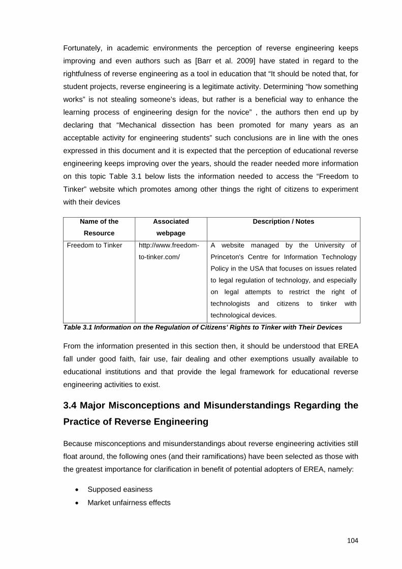
104
Fortunately, in academic environments the perception of reverse engineering keeps
improving and even authors such as [Barr et al. 2009] have stated in regard to the
rightfulness of reverse engineering as a tool in education that “It should be noted that, for
student projects, reverse engineering is a legitimate activity. Determining “how something
works” is not stealing someone’s ideas, but rather is a beneficial way to enhance the
learning process of engineering design for the novice” , the authors then end up by
declaring that “Mechanical dissection has been promoted for many years as an
acceptable activity for engineering students” such conclusions are in line with the ones
expressed in this document and it is expected that the perception of educational reverse
engineering keeps improving over the years, should the reader needed more information
on this topic Table 3.1 below lists the information needed to access the “Freedom to
Tinker” website which promotes among other things the right of citizens to experiment
with their devices
Name of the Resource
Associated webpage
Description / Notes
Freedom to Tinker http://www.freedom-
to-tinker.com/
A website managed by the University of
Princeton's Centre for Information Technology
Policy in the USA that focuses on issues related
to legal regulation of technology, and especially
on legal attempts to restrict the right of
technologists and citizens to tinker with
technological devices.
Table 3.1 Information on the Regulation of Citizens' Rights to Tinker with Their Devices
From the information presented in this section then, it should be understood that EREA
fall under good faith, fair use, fair dealing and other exemptions usually available to
educational institutions and that provide the legal framework for educational reverse
engineering activities to exist.
3.4 Major Misconceptions and Misunderstandings Regarding the Practice of Reverse Engineering
Because misconceptions and misunderstandings about reverse engineering activities still
float around, the following ones (and their ramifications) have been selected as those with
the greatest importance for clarification in benefit of potential adopters of EREA, namely:
• Supposed easiness
• Market unfairness effects
105
• Disdain for intellectual property laws
• Innovation hampering, invention weakening
A number of statements from actual results found in published literature have been
collected in an effort to provide a clearer, unbiased view about what reverse engineering
activities really are and thus, try to portray a favourable view of them that helps improve
their acceptance as a valid tool in the teaching of engineering design, and to try to reduce
their perceived association to questionable practices that contribute to the disinformation
about them.
Authors Pamela Samuelson and Suzanne Scotchmer conducted an extensive research
on the law and economics of reverse engineering where they debunked many myths
concerning not only reverse engineering as an intellectual activity itself but also about its
impact in economy and innovation. This collection of resources has gone through their
seminal publication “The Law and Economics of Reverse Engineering” [Samuelson &
Scotchmer. 2002] to collect the most significant statements mentioned there that help
debunk misconceptions and misunderstanding surrounding the reverse engineering
practice and that are also relevant to the engineering education field covered in this
collection of resources. Tables 3.2 to 3.6 shown below then, list common misconceptions
about reverse engineering and are contrasted against actual documented facts.
A. Reverse Engineering and its Perceived “Easiness”:
Reverse engineering is sometimes thought to be a careless, easy way to take what has
been done already, in a speedy, risk-free manner; this misconception is wrong since
reverse engineering is indeed a complicated process. Table 3.2 lists the perceived myths
about reverse engineering’s easiness against what has been actually published in
Samuelson & Scotchmer’s study [Samuelson & Scotchmer. 2002].
Misconception Facts, Quoted from: [Samuelson & Scotchmer. 2002]
Reverse engineering is an
easy activity
Reverse engineering can be extremely difficult and is generally
costly, time-consuming or both.
Innovation and secrets are
visible to the open eye and are
there for the taking by
freeloaders
Reverse engineering is a Second comers to a market have to go through a four stage
process before they introduce reverse engineered products for
106
speedy process sale.
The first stage involves a firm’s recognition that another firm
has introduced a product into the market that is potentially
worth the time, expense, and effort of reverse engineering. In
some markets, recognition happens very rapidly; in others, it
may take some time, during which the innovator can begin to
recoup its R&D costs by selling its product and establishing
goodwill with its customer base.
The second stage begins when a second comer obtains the
innovator’s product and starts to disassemble and analyze it to
discern and find of what and how it was made This stage may
be costly, time-consuming, and difficult.
The third stage is implementation where the know-how
obtained during the reverse engineering process is put to work
in designing and developing a product to compete in the same
market. This may involve making prototypes, experimenting
with them, retooling manufacturing facilities, and reiterating the
design and development process until it yields a satisfactory
product. It may be necessary to return to the reverse
engineering stage again if it becomes apparent in the
implementation phase that some necessary know-how eluded
the reverse engineer the first time.
Information obtained during reverse engineering may,
moreover, suggest possibilities for additional product innovation
that will be investigated in the implementation stage, for these
reasons, the second comer’s implementation stage may take
considerable time and require significant expense.
The fourth stage is the introduction of the product to the
market. How quickly the new product will erode the innovator’s
market share and force the innovator to reduce prices to be
competitive with the new entrant will depend on various market
factors.
Companies performing reverse
engineering are lousy and
careless
American industry lost a substantial share of the market for
random access memory chips to Japanese competitors whose
superior quality control made their chips very competitive.
107
Table 3.2 Misconceptions in Reverse Engineering Regarding its Perceived “Easiness”,
After: [Samuelson & Scotchmer. 2002]
B. Reverse Engineering and Market “Unfairness”:
Though at first sight reverse engineering practices might appear harming to market
health, it is actually quite the opposite since they contribute to force market innovation
and continuous competition; reverse engineering in industrial contexts serves as a way to
transfer knowledge to second comers and acquire some of the know-how embedded in
innovative competing products while still aiming to learn anything that might lead to
further innovation. Given that reverse engineering is a costly; lengthy, resource intensive
process where the acquired know-how takes time to reimplement and materialize into a
completed, fully tested product, first comers will be protected long enough from horizontal
competition to recover R&D expenses and establish a customer base. Thus, in order to
maintain their advantage, innovators are pushed to come up with a better product thereby
benefiting customers as a whole.
Reverse engineering then, is one of the forces promoting competition and constant
innovation, for example, first comers could if they wished so, license their technologies to
second comers as a means to acquire additional income and market power, or they could
even voluntarily disclose and share some information. Reverse engineering per se has
not a market destructive effect of its own as it is normally conducted behind closed doors,
post-reverse-engineering activities on the other hand have the potential to erode first
comers’ advantage and deprive society of the benefit of follow-on innovation but only if
somehow a way to expedite the reverse engineering process were ever found. In
practice, continuous innovation and changes of technology provide the leading advantage
to innovative companies and reverse engineering of old products does not seem to harm
innovative companies since they’ve had enough time to recover their R&D expenses by
then. In this context, it is very important to distinguish reverse engineering (as a driver for
follow-on innovation) from plain copying which does not lead to any kind of innovation;
does not promote the development of knowledge-based tools, or the advancement of the
state of the art at all.
Table 3.3 below lists the perceived myths about reverse engineering’s market
“unfairness”, against what has actually been published in Samuelson & Scotchmer’s
study [Samuelson & Scotchmer. 2002].
Misconception Facts, Quoted from: [Samuelson & Scotchmer. 2002]
108
Reverse engineering is a
market destructive practice
Either costliness or delays can protect the first comer
(companies , manufacturers, innovators, etc) long enough to
recoup its initial research and development (R&D) expenditures
Reverse engineering
damages innovators
Innovators are usually protected by one or all of the following
reasons, the costliness of reverse engineering, the human
resources required to perform it, and the lead time due to
difficulties of reverse engineering imposed by technology gaps
(this latter functions as a short-lived intellectual property right)
Publication of information
obtained through reverse
engineering erodes an
innovator’s ability to recoup
its R&D expenses because
the innovation will no longer
be secret.
Reverse engineers do not generally publish their discoveries,
instead maintaining the discovered information as their own
trade secret.
Reverse engineering always
erodes innovative firms’
market
For some consumers, a firm’s reputation for innovation or quality
service will make its product attractive even if second comers
eventually copy it, to the extent there are switching costs
associated with the product (e.g., owing to a steep learning curve
in how to use it), the innovator may also benefit from “lock-in” of
its initial customers and those who later value the innovator’s
product because others are using it and portray a strong brand
image.
Reverse engineering does
not yield any economic
benefit to first comers
The reverse engineer’s purchase of a competitor’s product to
reverse-engineer it, does contribute towards recoupment of the
innovator’s costs; this may be trivial for mass-market goods but
not for specialized, expensive, long lifecycle machinery
First comers can’t benefit
economically from
competitors
During both the reverse engineering and the implementation
stages, the innovator may decide to license its know-how to the
second comer. Over time, the innovator’s willingness to license
may increase, especially if it has reason to think that certain
second comers are making progress toward developing a
competing or improved product. The second comer’s willingness
to take a license may decline as its expenditures in reverse
engineering and redevelopment rise and as it perceives these
efforts to be bearing fruit; yet a license from the innovator may
become attractive if fine details of implementation elude the
109
reverse engineer.
Table 3.3 Misconceptions in Reverse Engineering Regarding its Perceived “Market unfairness”, After: [Samuelson & Scotchmer. 2002]
Additional examples of positive views about reverse engineering’s effects in the market
can also be found, for example in “The Pocket Scope” newsletter who published for
example, that “reverse engineering is a common and recognized practice, particularly in
computer software, and is extremely important to technological advancement. IEEE-USA
defines reverse engineering as the discovery by engineering techniques of the underlying
ideas and principles that govern how a machine, computer program or other
technological device works”, they also ended up stating that “ultimately, the greatest
benefits from reverse engineering are reaped by the public at large”, [McManes, 2005].
C. Reverse Engineering and its “Disdain for Intellectual Property Laws”:
Reverse engineering is wrongly equated with counterfeiting rather than with
exemplification and inspiration. Counterfeiting itself, is associated to a lack of effort and
creativity, and counterfeiters for example, have no need to understand how a product
works in order to copy it, this is especially true if all they are aiming for, is the
reproduction of geometrical features or the overall appearance of a product, and while
some superb counterfeits could exist, the trend for forgers is to provide independent
contributions to the counterfeited product to a minimum. Lawful competitors on the other
hand, come up with a new implementation of a reverse engineered specification that is at
least different enough to the original design as to avoid copyright infringements, most
likely, they’ll go even further in the development, as to consider it a new product. While
counterfeiting for commercial profits is a questionable practice, copying should not be
instantly equated to counterfeiting or any other criminal activity, the actual process of
copying a product, in all fairness, is indeed a difficult, time-consuming process whose set
of skills necessary to achieve a successful outcome are commonly overlooked or even
scorned. What’s more, legitimate copying for the purpose of self-education should not
reproduce flaws in the source design since a critical analysis to the original design should
run parallel.
Imitation and learning from competitors, products and processes in professional practice
occurs from formal and informal exchanges between colleagues, suppliers and designers
at a number of different venues (e.g. congresses) and in fact authors [Patel & Pavitt.
1995] also report that reverse engineering is indeed the main method of learning from
competitors’ product technologies. Counterfeiting and piracy on the other hand, are
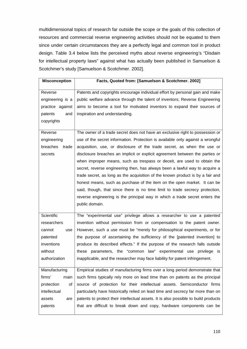
110
multidimensional topics of research far outside the scope or the goals of this collection of
resources and commercial reverse engineering activities should not be equated to them
since under certain circumstances they are a perfectly legal and common tool in product
design. Table 3.4 below lists the perceived myths about reverse engineering’s “Disdain
for intellectual property laws” against what has actually been published in Samuelson &
Scotchmer’s study [Samuelson & Scotchmer. 2002].
Misconception Facts, Quoted from: [Samuelson & Scotchmer. 2002]
Reverse
engineering is a
practice against
patents and
copyrights
Patents and copyrights encourage individual effort by personal gain and make
public welfare advance through the talent of inventors; Reverse Engineering
aims to become a tool for motivated inventors to expand their sources of
inspiration and understanding.
Reverse
engineering
breaches trade
secrets
The owner of a trade secret does not have an exclusive right to possession or
use of the secret information. Protection is available only against a wrongful
acquisition, use, or disclosure of the trade secret, as when the use or
disclosure breaches an implicit or explicit agreement between the parties or
when improper means, such as trespass or deceit, are used to obtain the
secret, reverse engineering then, has always been a lawful way to acquire a
trade secret, as long as the acquisition of the known product is by a fair and
honest means, such as purchase of the item on the open market. It can be
said, though, that since there is no time limit to trade secrecy protection,
reverse engineering is the principal way in which a trade secret enters the
public domain.
Scientific
researchers
cannot use
patented
inventions
without
authorization
The “experimental use” privilege allows a researcher to use a patented
invention without permission from or compensation to the patent owner.
However, such a use must be “merely for philosophical experiments, or for
the purpose of ascertaining the sufficiency of the [patented invention] to
produce its described effects.” If the purpose of the research falls outside
these parameters, the “common law” experimental use privilege is
inapplicable, and the researcher may face liability for patent infringement.
Manufacturing
firms’ main
protection of
intellectual
assets are
patents
Empirical studies of manufacturing firms over a long period demonstrate that
such firms typically rely more on lead time than on patents as the principal
source of protection for their intellectual assets. Semiconductor firms
particularly have historically relied on lead time and secrecy far more than on
patents to protect their intellectual assets. It is also possible to build products
that are difficult to break down and copy, hardware components can be
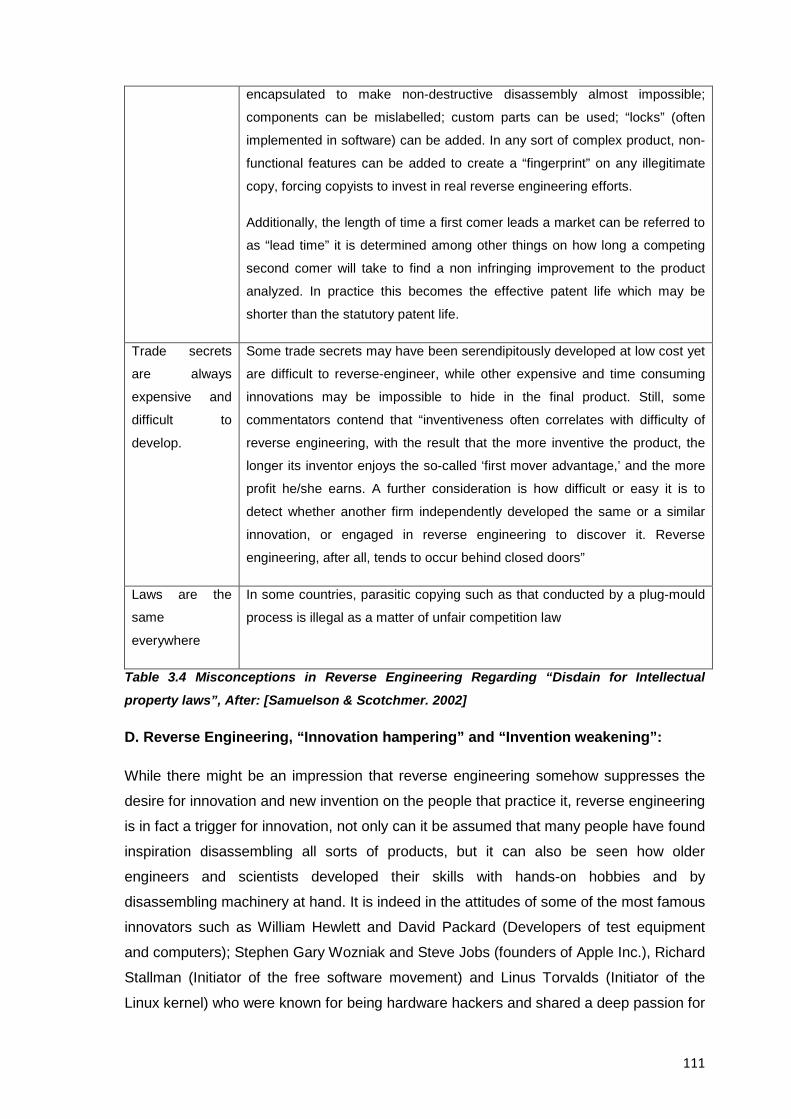
111
encapsulated to make non-destructive disassembly almost impossible;
components can be mislabelled; custom parts can be used; “locks” (often
implemented in software) can be added. In any sort of complex product, non-
functional features can be added to create a “fingerprint” on any illegitimate
copy, forcing copyists to invest in real reverse engineering efforts.
Additionally, the length of time a first comer leads a market can be referred to
as “lead time” it is determined among other things on how long a competing
second comer will take to find a non infringing improvement to the product
analyzed. In practice this becomes the effective patent life which may be
shorter than the statutory patent life.
Trade secrets
are always
expensive and
difficult to
develop.
Some trade secrets may have been serendipitously developed at low cost yet
are difficult to reverse-engineer, while other expensive and time consuming
innovations may be impossible to hide in the final product. Still, some
commentators contend that “inventiveness often correlates with difficulty of
reverse engineering, with the result that the more inventive the product, the
longer its inventor enjoys the so-called ‘first mover advantage,’ and the more
profit he/she earns. A further consideration is how difficult or easy it is to
detect whether another firm independently developed the same or a similar
innovation, or engaged in reverse engineering to discover it. Reverse
engineering, after all, tends to occur behind closed doors”
Laws are the
same
everywhere
In some countries, parasitic copying such as that conducted by a plug-mould
process is illegal as a matter of unfair competition law
Table 3.4 Misconceptions in Reverse Engineering Regarding “Disdain for Intellectual
property laws”, After: [Samuelson & Scotchmer. 2002]
D. Reverse Engineering, “Innovation hampering” and “Invention weakening”:
While there might be an impression that reverse engineering somehow suppresses the
desire for innovation and new invention on the people that practice it, reverse engineering
is in fact a trigger for innovation, not only can it be assumed that many people have found
inspiration disassembling all sorts of products, but it can also be seen how older
engineers and scientists developed their skills with hands-on hobbies and by
disassembling machinery at hand. It is indeed in the attitudes of some of the most famous
innovators such as William Hewlett and David Packard (Developers of test equipment
and computers); Stephen Gary Wozniak and Steve Jobs (founders of Apple Inc.), Richard
Stallman (Initiator of the free software movement) and Linus Torvalds (Initiator of the
Linux kernel) who were known for being hardware hackers and shared a deep passion for
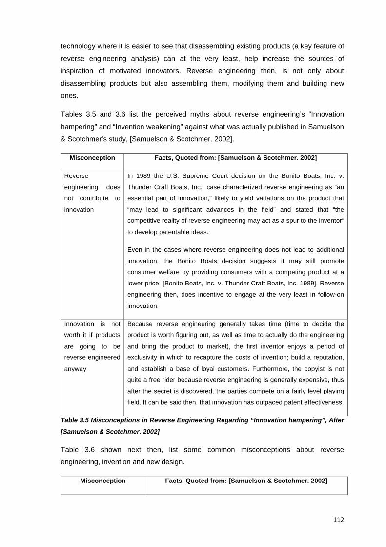
112
technology where it is easier to see that disassembling existing products (a key feature of
reverse engineering analysis) can at the very least, help increase the sources of
inspiration of motivated innovators. Reverse engineering then, is not only about
disassembling products but also assembling them, modifying them and building new
ones.
Tables 3.5 and 3.6 list the perceived myths about reverse engineering’s “Innovation
hampering” and “Invention weakening” against what was actually published in Samuelson
& Scotchmer’s study, [Samuelson & Scotchmer. 2002].
Misconception Facts, Quoted from: [Samuelson & Scotchmer. 2002]
Reverse
engineering does
not contribute to
innovation
In 1989 the U.S. Supreme Court decision on the Bonito Boats, Inc. v.
Thunder Craft Boats, Inc., case characterized reverse engineering as “an
essential part of innovation,” likely to yield variations on the product that
“may lead to significant advances in the field” and stated that “the
competitive reality of reverse engineering may act as a spur to the inventor”
to develop patentable ideas.
Even in the cases where reverse engineering does not lead to additional
innovation, the Bonito Boats decision suggests it may still promote
consumer welfare by providing consumers with a competing product at a
lower price. [Bonito Boats, Inc. v. Thunder Craft Boats, Inc. 1989]. Reverse
engineering then, does incentive to engage at the very least in follow-on
innovation.
Innovation is not
worth it if products
are going to be
reverse engineered
anyway
Because reverse engineering generally takes time (time to decide the
product is worth figuring out, as well as time to actually do the engineering
and bring the product to market), the first inventor enjoys a period of
exclusivity in which to recapture the costs of invention; build a reputation,
and establish a base of loyal customers. Furthermore, the copyist is not
quite a free rider because reverse engineering is generally expensive, thus
after the secret is discovered, the parties compete on a fairly level playing
field. It can be said then, that innovation has outpaced patent effectiveness.
Table 3.5 Misconceptions in Reverse Engineering Regarding “Innovation hampering”, After
[Samuelson & Scotchmer. 2002]
Table 3.6 shown next then, list some common misconceptions about reverse
engineering, invention and new design.
Misconception Facts, Quoted from: [Samuelson & Scotchmer. 2002]
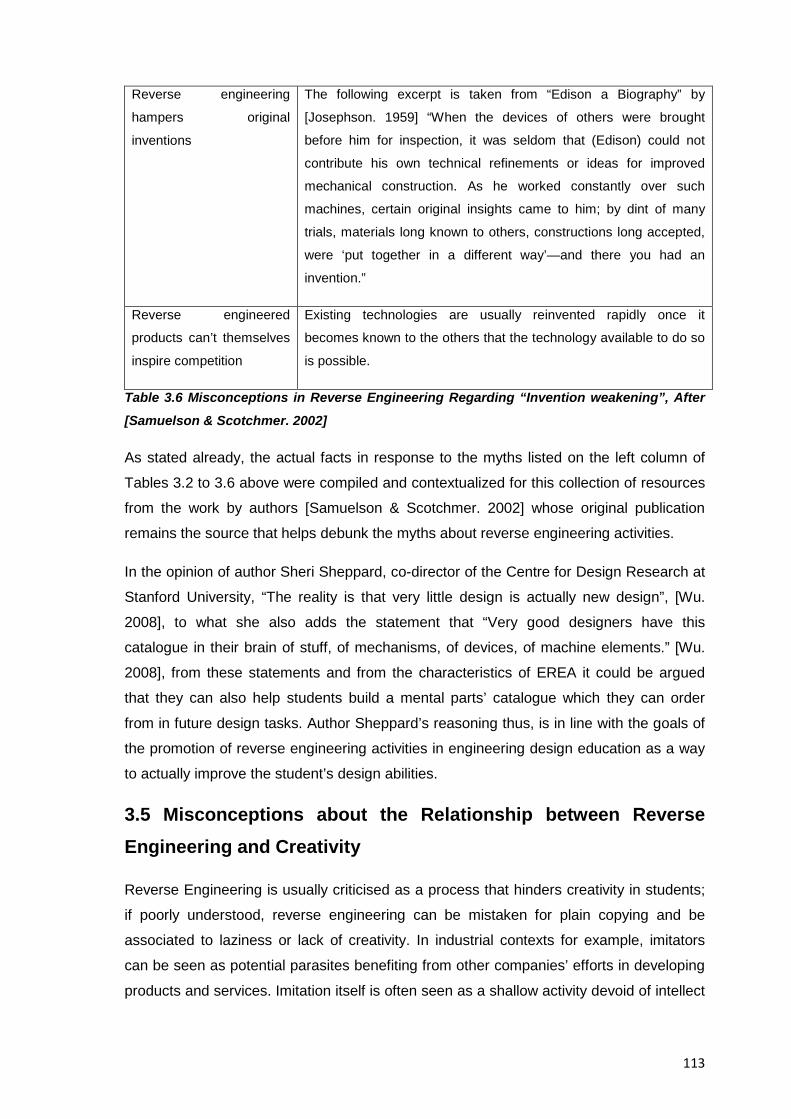
113
Reverse engineering
hampers original
inventions
The following excerpt is taken from “Edison a Biography” by
[Josephson. 1959] “When the devices of others were brought
before him for inspection, it was seldom that (Edison) could not
contribute his own technical refinements or ideas for improved
mechanical construction. As he worked constantly over such
machines, certain original insights came to him; by dint of many
trials, materials long known to others, constructions long accepted,
were ‘put together in a different way’—and there you had an
invention.”
Reverse engineered
products can’t themselves
inspire competition
Existing technologies are usually reinvented rapidly once it
becomes known to the others that the technology available to do so
is possible.
Table 3.6 Misconceptions in Reverse Engineering Regarding “Invention weakening”, After
[Samuelson & Scotchmer. 2002]
As stated already, the actual facts in response to the myths listed on the left column of
Tables 3.2 to 3.6 above were compiled and contextualized for this collection of resources
from the work by authors [Samuelson & Scotchmer. 2002] whose original publication
remains the source that helps debunk the myths about reverse engineering activities.
In the opinion of author Sheri Sheppard, co-director of the Centre for Design Research at
Stanford University, “The reality is that very little design is actually new design”, [Wu.
2008], to what she also adds the statement that “Very good designers have this
catalogue in their brain of stuff, of mechanisms, of devices, of machine elements.” [Wu.
2008], from these statements and from the characteristics of EREA it could be argued
that they can also help students build a mental parts’ catalogue which they can order
from in future design tasks. Author Sheppard’s reasoning thus, is in line with the goals of
the promotion of reverse engineering activities in engineering design education as a way
to actually improve the student’s design abilities.
3.5 Misconceptions about the Relationship between Reverse Engineering and Creativity
Reverse Engineering is usually criticised as a process that hinders creativity in students;
if poorly understood, reverse engineering can be mistaken for plain copying and be
associated to laziness or lack of creativity. In industrial contexts for example, imitators
can be seen as potential parasites benefiting from other companies’ efforts in developing
products and services. Imitation itself is often seen as a shallow activity devoid of intellect
114
and initiative that prevents the development of new knowledge; however this is a naive,
idealized vision probably stemming from models of innovation that assume a linear
relationship between basic scientific research and industrial superiority which authors
Bessant and Francis have found not always to exist, [Bessant & Francis. 1999].
Reverse engineering in fact, should be understood as discovery; contextualization, and
technical proficiency, it is indeed an exercise in synthesis which integrates not only
technical knowledge but also doses of creativity and hard work. Analyzing a product then,
is not an easy task and requires deep concentration to find out what conditions led to
given results. Reverse engineering is comprised by a number of steps and considerations
that far from hindering creativity actually expand it by allowing students to increase their
awareness of the design process as well as their sources of inspiration, and are even an
opportunity to exercise their cognitive skills, for example when analyzing other’s
successes and failures in design. The building of one’s technological capabilities from the
achievement of others thus, should at least be credited with the generation of learning;
with an effort in product development, with potential innovation, and should be
disassociated from criminal counterfeiting and intellectual infringement activities that don’t
involve creation of knowledge but rather monetary benefits.
The search for inspiration from analogies or other’s experiences then, is a surely element
of the innovation process. For example, solutions in engineering design are the product of
experimentation and integration of knowledge from different disciplines, reverse
engineering thus, tries to tear apart the rational for these solutions and has the potential
to identify weaknesses and improve existing solutions by consciously combining new
ideas and methods.
Authors [Sato & Kaufman. 2005] state for example, that in Japan “Comparative analysis
tends to stimulate creativity. Engineers are sensitive to differences. If they lag
competition, they want to overtake. If they lead, they want to maintain that lead”
comparative analysis thus, is indeed a key step in a reverse engineering analysis and
Sato and Kaufman’s statement might contribute to the explanation of why reverse
engineering was so successful in Japan and in Asian countries overall
It is true however, that resorting to known preferred solutions might somehow exclude the
most efficient ones for a given task, however, this trait is well known in designers
notwithstanding their level of experience; authors [Pahl et al. 2007] have stated in this
regard, that designers tend to minimize their work effort and favour certain solutions
115
because of their individual talents and experience. Still, the actual selection of known
solutions also has the following advantages as published by authors Pahl & Beitz too:
1. Avoidance of unfeasible solutions and waste of time
2. Quick concretization of a solution starting from a similar one
Conversely, selecting known solutions has the following disadvantages, Source: [Pahl et
al. 2007]:
1. Designers’ tendency to remain in their area of expertise
2. Fixation on solution ideas that are less suitable in principle
3. Failure to recognise other better solution principles
As authors [Pahl et al. 2007] state, these are existing traits already known in designers,
and because reverse engineering actually tries to overcome such disadvantages, it is
only unfair to conclude that reverse engineering is the actual origin of these traits, a more
comprehensive effort in teaching pedagogies though, is in fact needed to reduce the
effect of the abovementioned disadvantages.
The relationship between reverse engineering and creativity then, is often misunderstood
even at the fundamental level, on the one hand, research in brain science states that the
essence of human brain activity is not a passive processing of stimuli from the outside
world, but the active creation of contexts [Mogi. 2003]. On the other, creativity cannot be
forced to happen from one moment to the next. Thus, reverse engineering in this sense,
can arguably help students to expand their awareness and sources of information for a
better contextualization of their research and findings.
The following list by [Khandani. 2005] compiles characteristics of creative people which
can be consciously developed by committed people:
• Curiosity and tolerance of the unknown to not be afraid of what is not understood.
• Openness to new experiences.
• Willingness to take risks, knowing that they may be misunderstood and criticized by
others.
• Self-confident and not afraid to fail.
• Ability to observe details but also the whole picture
• No fear to tackle complex problems with their own abilities and experience if possible
• Ability to concentrate and focus on the problem until it's solved
116
From the findings of past researchers presented here already, and from the experience in
developing this collection of resources it can be stated that none of the above mentioned
points conflicts in any way with the skills and requirements needed to perform an
educational reverse engineering analysis and thus creativity should be understood as
much more than a systematic application of rules and theories to solve a problem. Author
Khandani for example, stated that “Psychological research has found no correlation
between intelligence and creativity”, people are creative because they make a conscious
effort to think and act creatively. Everybody has the potential to be creative. Creativity
begins with a decision to take risks”, [Khandani. 2005] and so the argument that reverse
engineering per se can hinder students’ creativity cannot be sustained.
3.5.1 EREA, Teaching and Development of Creativity
Neither reverse engineering nor another teaching tool can on its own teach everything a
student needs to know, reverse engineering isn’t a panacea that can be used to teach
everything an engineering design curriculum needs, still and in order to answer questions
about how reverse engineering can help with the teaching of creativity , this document
resorts to the paper “Teaching Creativity in Engineering” by [Liu & Schönwetter. 2004]
and to the research by authors [Treffinger et al. 1994] where creativity is said to emanate
from problems, thus making the practice of problem solving a suitable approach to gain
creativity. For such purpose, it is suggested in this collection of resources to follow the
creative process and systematic pathways of problem-solving and creative learning
model proposed by [Treffinger et al. 1994] since it is a powerful tool for an instructor to
stimulate and develop creativity in engineering students. This model then, consists of
three hierarchical levels, namely:
1. Learning and using basic thinking tools
2. Learning and practicing a systematic process of problem solving
3. Working with real problems
EREA as presented in the methodology of Resource 5 and the pedagogy of Resource 6
mostly support levels two and three, regarding level two for example, students learn from
this document a methodology for educational reverse engineering analysis that is based
on previous ones that other researchers have used to solve problems and thus, through
the explanations provided in this collection of resources students can also learn from the
work of others. The objective of level three then, is to improve the students' capability of
and effectiveness in handling real-life problems and challenges for which authors [Liu &
Schönwetter. 2004] have stated before, that students must experience first-hand through
117
hands-on unsolved problems such as those that reverse engineering exercises can
provide.
Other researchers on the topic have also documented the use of reverse engineering or
similar activities to support the teaching of creativity, among them for example, author
[Kodak. 2008] cites Prof Edward Crawley by stating that the professor “suggest a number
of approaches to stimulate creativity. The list is extensive, but he prioritizes reverse
engineering, benchmarking and patent search for creativity exercises”, other authors
such as [Dalrymple et al. 2011] quote Professor Hess from the Department of
Engineering at the College of New Jersey who described a D/A/A activity incorporated in
a manufacturing processes course, as “the instructor’s fire keg that lights the imaginations
of the engineering students,” [Hess. 2002]. In the end, it could be said that further studies
to link creativity and EREA are needed, but at least the information provided in this
resource can serve as a starting point from which to continue researching on the topic.
3.6 Reverse Engineering in Support of the Innovation Process
Although limited occurrences have been found in published research specifically linking
educational reverse engineering to support the innovation process, two of them can be
cited here; the first one by author [Kodak. 2008] who stated that “Just like the inventive
genius who determines the next innovation by testing the system to its limits, a prolific
reverse engineering will do the same to uncover the innovation”. The second one, comes
from an article by [Conti. 2006] in the “Hacking and Innovation” issue of the magazine of
the Association for Computing Machinery magazine suggesting that innovation can
arguably benefit from hardware hacking (which is a context similar to reverse
engineering) and states that computer science “should pay serious attention to the
hacking community and its passion for pushing the limits of technology and its role as a
counterbalance to its misuse”. As it will be explained in the next section though, where
reverse engineering can leave a longer lasting mark is in its ability to support the creation
of incremental innovation designs.
3.6.1 Suitability of EREA to come up with Incremental Innovation Designs
Authors [Benedicic et al. 2005] state that innovations can be divided into two larger
groups, incremental and radical. Incremental innovations are an ongoing process of
change, they are being introduced all the time within a company but they have no
revolutionary impact on the structure of the company or the market. Radical innovations
118
on the other hand, can happen on products; processes, or services, and trigger changes
that affect the current technical solutions and markets. They state that radical innovation
meets the following criteria:
1. It brings an entirely new set of performance features.
2. It causes a five times or greater improvement in the existing performance
features.
3. It causes a significant (thirty percent or greater) reduction in costs.
To come up with radical innovations such as those suggested by [Benedicic et al. 2005]
as a result from one educational reverse engineering activity done by students while still
learning engineering design may not be that realistic to expect, in fact, such kind of
innovations may well be outside the expectations of any other educational experience
had during the full length of undergraduate studies. What educational reverse
engineering activities could trigger though, are post reverse engineering design works
and incremental innovations in the form of follow-on innovation (e.g. Derivative
applications, add-ons, spare parts, attachments, etc.). Sometimes when teaching
students about innovation and creativity, educators might believe that asking students to
come up only with new ideas every single time is the right way to go, and while as an
ideal goal this might be true and commendable to teach, in industry, innovation works in a
different way, it is just as the Goldfire © innovation software homepage used to claim
“Innovation is not just reserved for the glamour of breakthrough products and disruptive
technologies. In fact, the most common innovation task that companies must do is to
improve something that already exists. There is simply no disgrace to incremental
improvement. Innovative solutions applied here, can reap enormous benefits in driving
high-quality revenue, product reliability, and process efficiency”, [IMC. 2011].
Author [Cross. 2008] for example, published Figure 3.1 seen below to show the
opportunity areas for product development considering the associated risks, from it, it can
be seen how incremental improvement of a current product has its rightful place in
product development just as much as product innovation does.
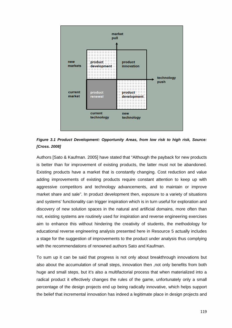
119
Figure 3.1 Product Development: Opportunity Areas, from low risk to high risk, Source:
[Cross. 2008]
Authors [Sato & Kaufman. 2005] have stated that “Although the payback for new products
is better than for improvement of existing products, the latter must not be abandoned.
Existing products have a market that is constantly changing. Cost reduction and value
adding improvements of existing products require constant attention to keep up with
aggressive competitors and technology advancements, and to maintain or improve
market share and sale”. In product development then, exposure to a variety of situations
and systems’ functionality can trigger inspiration which is in turn useful for exploration and
discovery of new solution spaces in the natural and artificial domains, more often than
not, existing systems are routinely used for inspiration and reverse engineering exercises
aim to enhance this without hindering the creativity of students, the methodology for
educational reverse engineering analysis presented here in Resource 5 actually includes
a stage for the suggestion of improvements to the product under analysis thus complying
with the recommendations of renowned authors Sato and Kaufman.
To sum up it can be said that progress is not only about breakthrough innovations but
also about the accumulation of small steps, innovation then ,not only benefits from both
huge and small steps, but it’s also a multifactorial process that when materialized into a
radical product it effectively changes the rules of the game, unfortunately only a small
percentage of the design projects end up being radically innovative, which helps support
the belief that incremental innovation has indeed a legitimate place in design projects and
120
it suits much better the goal of EREA to be a complement not a substitute for other
traditional teaching approaches in engineering design.
3.7 Benefits of Replicating Typical Commercial Reverse Engineering Activities in an Academic Exercise
Although the approach to educational reverse engineering is different to the commercial
one, the suggestion of improvements to the product under analysis is a major stage of the
educational methodology, the merits of such stage if replicating a purely commercial
approach as an academic exercise and the actual benefits stemming from it are
discussed below:
In a commercial environment or because of competitive intelligence purposes the
reasons to reverse engineer a product can range from:
a. Making a surrogate product
b. Cloning a product
c. Developing an improved derivative of the original product or
d. Creating a complete new product
In academic environments though and specially so in the approach to reverse
engineering presented in this document, the ultimate goal of an academic reverse
engineering analysis is to understand a product; its inner workings, why it exists, what it
needs to fulfil, how it does that, what technologies it might contain, what its socio-
economical impact could be and ideally to be able to predict what comes next to the
market or in a technological roadmap.
At the “Redesign Suggestions” stage of the reverse engineering method used in this
collection of resources; it is asked from students to come up with improvements to the
product just analysed to the best of their understanding or come up with ideas for an
original design fulfilling the same or similar needs that the product analysed attains.
However, asking students to replicate a commercial approach (mainly options a and b of
the ordered list shown above) as a purely academic exercise is left to the criteria of the
professors in charge and the benefits of such approach are contextualized here.
It is believed in this collection of resources that “playing catch-up” may be a valid initial
goal in academic environments too, specially until students grow in the understanding
and mastery of technologies, since the ability to create a substitute or even a cloned
product based on the one under analysis could still bring some value to their education.
121
For example, creating a surrogate product means creating a fully functional substitute
that fulfils a given set of requirements while using available, proven, known components.
Additionally, while creating this substitute, students could even attempt to produce a
cheaper, more environmentally and manufacturing friendly surrogate product profiting
from the current technologies and processes available at the time of the reverse
engineering analysis, while at the same time generating a full clear set of original
blueprints rather than trying to recover old ones.
Cloning a product or making a direct copy of the one under analysis, which is another
possibility, can still provide students with valuable experience and understanding of the
design subjects involved, for example, having detailed information about a product, such
as the schematics or the data obtained through a reverse engineering analysis, not only
satisfies the general curiosity about a product’s structure but it is also educational to be
able to see the details on how components, mechanisms or circuits have been
implemented; even in a worst case scenario the students would have to revisit the
technologies used in the product at the time of its original design and production which
might be nowadays old, obsolete or dependant on currently unavailable components ,it
would be interesting for them then, to see how solutions were implemented, because
while the theory behind the solutions might be well known , the actual implementation is
trade craft know how, where experience might trump knowledge and play a more
important role. Seeing the actual product and knowing the theory behind, can only
expand the understanding of the subject under study; besides as patents expire over a
period of time, no intellectual property conflicts could arise from copying an old product if
it ever were to be commercialized by the students.
On the other hand and as it is usually the case in an EREA, if the intention is to create an
improved derivative of the product under analysis, the new modernized specifications in
the new solution would make it an original work and the new blueprints and components
would enable students to improve the product or add additional capabilities which could
eventually end up making a complete new solution over the original product. In fact
simultaneous reverse engineering analyses and the development of new specifications
and upgrades are common in industry.
Finally, if initial the goal were to create a complete new product, an EREA would still be
useful in setting the foundations for the creation of the new product since the actual
(forward) engineering process needed to come up with a new product (real or imaginary)
that comes after the educational reverse engineering method is already well understood,
122
researched and documented and thus this doctoral research mostly considers out of its
scope.
As seen above then, taking a commercial approach to try to replicate what is done in
competitive intelligence laboratories for commercial gain but with a specific goal to learn
from the process can also bring benefits for students of engineering design.
3.7 Resource Conclusions
Although creativity and innovation are highly desired traits of a design engineer, the
mechanisms to develop them need to be properly contextualized so reasonable
expectations about the specific contributions EREA can make towards their growth can
be set.
In trying to clarify misunderstandings about creativity itself, author [Jirousek. 1995] stated
for example, that a common misunderstanding equates creativity with originality “when in
point of fact, there are very few absolutely original ideas”; she also stated that most of
what seems to be new is simply a bringing together of previously existing concepts in a
new way. Other authors such as [Pahl. 2005] stated that “It is accepted at face value that
“novelty” is the prime measure of creativity. (and) We also know that novelty in design
often occurs as a result of transfer of data, either inspired or rigorous, from outside the
field of original expert knowledge. However to date we lack both simple explanations and
appropriate tools for teaching the process of creative knowledge transfer to designers”,
[Pahl. 2005]. Concerning misconceptions about innovation itself, and in trying to
demystify economical success through innovation alone author [Kodak. 2008] stated that
“innovation alone does not guarantee business success” and that “there is more to
commercial success than an earth shattering innovation”. These past statements intend
to show that expectations from EREA and from any other teaching tool for that matter,
should always be properly contextualized so the actual added value new teaching
approaches can actually bring is properly appreciated and understood so other
researchers can also replicate it and benefit from it.
Still, and for the field of education it could be said that EREA do try to help students
enhance their innovation and creativity traits by putting them in touch with multiple
sources of inspiration from past and existing solutions relevant to the challenges they
face. This resource then, has been included in this collection of resources to help
engineering design professors form an opinion about the impact EREA could have in their
students’ traits of innovation, creativity and invention and see if they find it worthy giving
them a try under their existing teaching practices.
123
RESOURCE 4: BENEFITS OF REVERSE ENGINEERING
4.1 Resource Introduction
Despite being highly rated activities by engineering students and the fact that authors
such as [Kutz. 2007] already consider the industry-specific learning and pedagogical
benefits of reverse engineering as “obvious” it is important nevertheless to present
potential adopters with the documented benefits that make EREA a viable tool in the
teaching and learning of engineering design. The findings published by previous authors
on the topic and those new ones resulting from the research leading to the writing of this
collection of resources are highlighted, contextualized and discussed in this resource.
4.2 Documented Benefits of Educational Reverse Engineering Activities
Product dissection activities have been utilized already in a variety of engineering
learning environments and their value as a pedagogical tool has been primarily supported
by the published works of pioneering researchers in the area such as: [Sheppard. 1992a];
[Brereton et al. 1995], [Otto et al. 1998], [Hess. 2000], or [Wood et al. 2001] who have
provided already, information about their respective course objectives; instructional
approaches, outcomes, reviews, and the impressions of students and instructional staff
while using them. In order to organize all available information though, other authors such
as [Simpson et al. 2008], [Shooter. 2008] and [Dalrymple et al. 2011] have compiled lists
of their uses and benefits, and also published historical accounts of the development of
product dissection activities that have successfully engaged engineering students in their
learning.
Tables 4.1 to 4.8 below, cover and explain those major categories of findings and
benefits and present the reader with several claims that are related either to the practice
or study of EREA. In such tables, the left columns categorise the documented benefits
and claims; the central column provides a summarized explanation about the context in
which the claim is stated, and the right column lists the representative researchers
confirming the claimed results that show how EREA helped students. Namely:
A. Claimed Benefits of the Study and Practice of EREA in Relation to Industrial Practices:
Documented Benefits Context Source
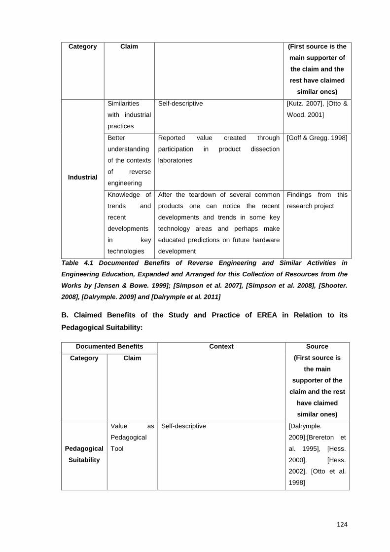
124
Category Claim (First source is the main supporter of the claim and the rest have claimed
similar ones)
Industrial
Similarities
with industrial
practices
Self-descriptive [Kutz. 2007], [Otto &
Wood. 2001]
Better
understanding
of the contexts
of reverse
engineering
Reported value created through
participation in product dissection
laboratories
[Goff & Gregg. 1998]
Knowledge of
trends and
recent
developments
in key
technologies
After the teardown of several common
products one can notice the recent
developments and trends in some key
technology areas and perhaps make
educated predictions on future hardware
development
Findings from this
research project
Table 4.1 Documented Benefits of Reverse Engineering and Similar Activities in Engineering Education, Expanded and Arranged for this Collection of Resources from the Works by [Jensen & Bowe. 1999]; [Simpson et al. 2007], [Simpson et al. 2008], [Shooter. 2008], [Dalrymple. 2009] and [Dalrymple et al. 2011]
B. Claimed Benefits of the Study and Practice of EREA in Relation to its Pedagogical Suitability:
Documented Benefits Context Source (First source is
the main supporter of the
claim and the rest have claimed similar ones)
Category Claim
Pedagogical Suitability
Value as
Pedagogical
Tool
Self-descriptive [Dalrymple.
2009];[Brereton et
al. 1995], [Hess.
2000], [Hess.
2002], [Otto et al.
1998]
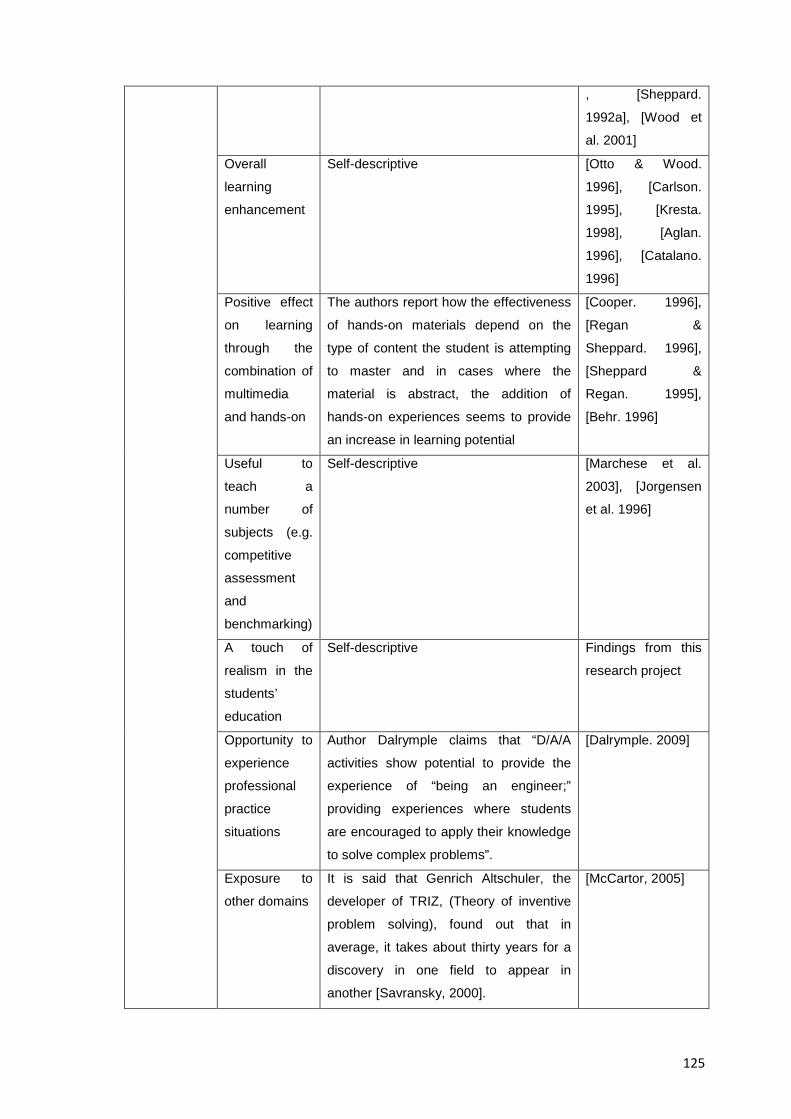
125
, [Sheppard.
1992a], [Wood et
al. 2001]
Overall
learning
enhancement
Self-descriptive [Otto & Wood.
1996], [Carlson.
1995], [Kresta.
1998], [Aglan.
1996], [Catalano.
1996]
Positive effect
on learning
through the
combination of
multimedia
and hands-on
The authors report how the effectiveness
of hands-on materials depend on the
type of content the student is attempting
to master and in cases where the
material is abstract, the addition of
hands-on experiences seems to provide
an increase in learning potential
[Cooper. 1996],
[Regan &
Sheppard. 1996],
[Sheppard &
Regan. 1995],
[Behr. 1996]
Useful to
teach a
number of
subjects (e.g.
competitive
assessment
and
benchmarking)
Self-descriptive [Marchese et al.
2003], [Jorgensen
et al. 1996]
A touch of
realism in the
students’
education
Self-descriptive Findings from this
research project
Opportunity to
experience
professional
practice
situations
Author Dalrymple claims that “D/A/A
activities show potential to provide the
experience of “being an engineer;”
providing experiences where students
are encouraged to apply their knowledge
to solve complex problems”.
[Dalrymple. 2009]
Exposure to
other domains
It is said that Genrich Altschuler, the
developer of TRIZ, (Theory of inventive
problem solving), found out that in
average, it takes about thirty years for a
discovery in one field to appear in
another [Savransky, 2000].
[McCartor, 2005]
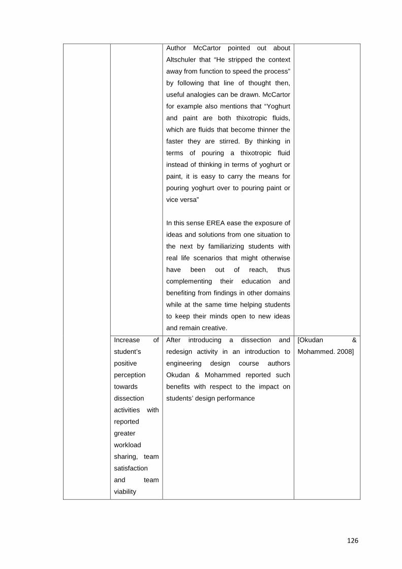
126
Author McCartor pointed out about
Altschuler that “He stripped the context
away from function to speed the process”
by following that line of thought then,
useful analogies can be drawn. McCartor
for example also mentions that “Yoghurt
and paint are both thixotropic fluids,
which are fluids that become thinner the
faster they are stirred. By thinking in
terms of pouring a thixotropic fluid
instead of thinking in terms of yoghurt or
paint, it is easy to carry the means for
pouring yoghurt over to pouring paint or
vice versa”
In this sense EREA ease the exposure of
ideas and solutions from one situation to
the next by familiarizing students with
real life scenarios that might otherwise
have been out of reach, thus
complementing their education and
benefiting from findings in other domains
while at the same time helping students
to keep their minds open to new ideas
and remain creative.
Increase of
student’s
positive
perception
towards
dissection
activities with
reported
greater
workload
sharing, team
satisfaction
and team
viability
After introducing a dissection and
redesign activity in an introduction to
engineering design course authors
Okudan & Mohammed reported such
benefits with respect to the impact on
students’ design performance
[Okudan &
Mohammed. 2008]
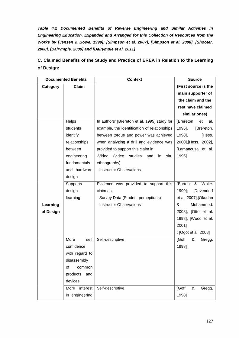
127
Table 4.2 Documented Benefits of Reverse Engineering and Similar Activities in Engineering Education, Expanded and Arranged for this Collection of Resources from the Works by [Jensen & Bowe. 1999]; [Simpson et al. 2007], [Simpson et al. 2008], [Shooter.
2008], [Dalrymple. 2009] and [Dalrymple et al. 2011]
C. Claimed Benefits of the Study and Practice of EREA in Relation to the Learning of Design:
Documented Benefits Context Source (First source is the main supporter of the claim and the rest have claimed
similar ones)
Category Claim
Learning of Design
Helps
students
identify
relationships
between
engineering
fundamentals
and hardware
design
In authors’ [Brereton et al. 1995] study for
example, the identification of relationships
between torque and power was achieved
when analyzing a drill and evidence was
provided to support this claim in:
-Video (video studies and in situ
ethnography)
- Instructor Observations
[Brereton et al.
1995], [Brereton.
1998], [Hess.
2000],[Hess. 2002],
[Lamancusa et al.
1996]
Supports
design
learning
Evidence was provided to support this
claim as:
- Survey Data (Student perceptions)
- Instructor Observations
[Burton & White.
1999]; [Devendorf
et al. 2007],[Okudan
& Mohammed.
2008], [Otto et al.
1998], [Wood et al.
2001]
; [Ogot et al. 2008]
More self
confidence
with regard to
disassembly
of common
products and
devices
Self-descriptive [Goff & Gregg.
1998]
More interest
in engineering
Self-descriptive [Goff & Gregg.
1998]
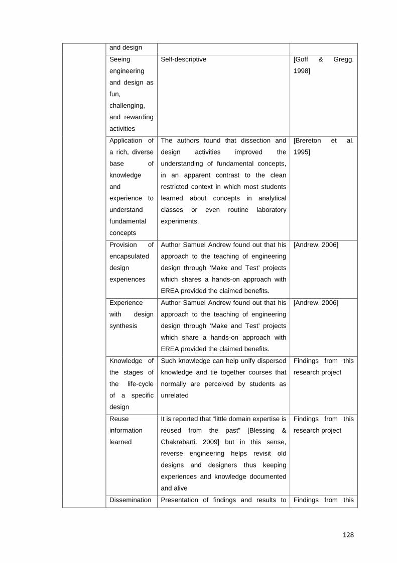
128
and design
Seeing
engineering
and design as
fun,
challenging,
and rewarding
activities
Self-descriptive [Goff & Gregg.
1998]
Application of
a rich, diverse
base of
knowledge
and
experience to
understand
fundamental
concepts
The authors found that dissection and
design activities improved the
understanding of fundamental concepts,
in an apparent contrast to the clean
restricted context in which most students
learned about concepts in analytical
classes or even routine laboratory
experiments.
[Brereton et al.
1995]
Provision of
encapsulated
design
experiences
Author Samuel Andrew found out that his
approach to the teaching of engineering
design through ‘Make and Test’ projects
which shares a hands-on approach with
EREA provided the claimed benefits.
[Andrew. 2006]
Experience
with design
synthesis
Author Samuel Andrew found out that his
approach to the teaching of engineering
design through ‘Make and Test’ projects
which share a hands-on approach with
EREA provided the claimed benefits.
[Andrew. 2006]
Knowledge of
the stages of
the life-cycle
of a specific
design
Such knowledge can help unify dispersed
knowledge and tie together courses that
normally are perceived by students as
unrelated
Findings from this
research project
Reuse
information
learned
It is reported that “little domain expertise is
reused from the past” [Blessing &
Chakrabarti. 2009] but in this sense,
reverse engineering helps revisit old
designs and designers thus keeping
experiences and knowledge documented
and alive
Findings from this
research project
Dissemination Presentation of findings and results to Findings from this
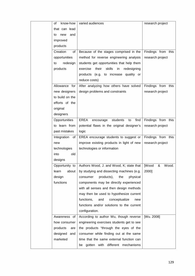
129
of know-how
that can lead
to new and
improved
products
varied audiences research project
Creation of
opportunities
to redesign
products
Because of the stages comprised in the
method for reverse engineering analysis
students get opportunities that help them
exercise their skills in redesigning
products (e.g. to increase quality or
reduce costs)
Findings from this
research project
Allowance for
new designers
to build on the
efforts of the
original
designers
After analyzing how others have solved
design problems and constraints
Findings from this
research project
Opportunities
to learn from
past mistakes
EREA encourage students to find
potential flaws in the original designer’s
logic
Findings from this
research project
Integration of
new
technologies
into old
designs
EREA encourage students to suggest or
improve existing products in light of new
technologies or information
Findings from this
research project
Opportunity to
learn about
design
functions
Authors Wood, J. and Wood, K; state that
by studying and dissecting machines (e.g.
consumer products), the physical
components may be directly experienced
with all senses and then design methods
may then be used to hypothesize current
functions, and conceptualize new
functions and/or solutions to the current
configuration.
[Wood & Wood.
2000]
Awareness of
how consumer
products are
designed and
marketed
According to author Wu, though reverse
engineering exercises students get to see
the products “through the eyes of the
consumer while finding out at the same
time that the same external function can
be gotten with different mechanisms
[Wu. 2008]
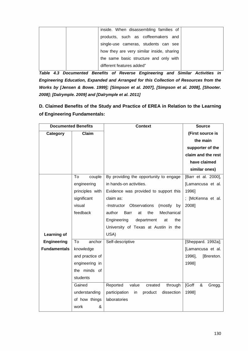
130
inside. When disassembling families of
products, such as coffeemakers and
single-use cameras, students can see
how they are very similar inside, sharing
the same basic structure and only with
different features added”
Table 4.3 Documented Benefits of Reverse Engineering and Similar Activities in Engineering Education, Expanded and Arranged for this Collection of Resources from the Works by [Jensen & Bowe. 1999]; [Simpson et al. 2007], [Simpson et al. 2008], [Shooter. 2008]; [Dalrymple. 2009] and [Dalrymple et al. 2011]
D. Claimed Benefits of the Study and Practice of EREA in Relation to the Learning of Engineering Fundamentals:
Documented Benefits Context Source (First source is
the main supporter of the
claim and the rest have claimed similar ones)
Category Claim
Learning of Engineering
Fundamentals
To couple
engineering
principles with
significant
visual
feedback
By providing the opportunity to engage
in hands-on activities.
Evidence was provided to support this
claim as:
-Instructor Observations (mostly by
author Barr at the Mechanical
Engineering department at the
University of Texas at Austin in the
USA)
[Barr et al. 2000],
[Lamancusa et al.
1996]
; [McKenna et al.
2008]
To anchor
knowledge
and practice of
engineering in
the minds of
students
Self-descriptive [Sheppard. 1992a];
[Lamancusa et al.
1996], [Brereton.
1998]
Gained
understanding
of how things
work &
Reported value created through
participation in product dissection
laboratories
[Goff & Gregg.
1998]
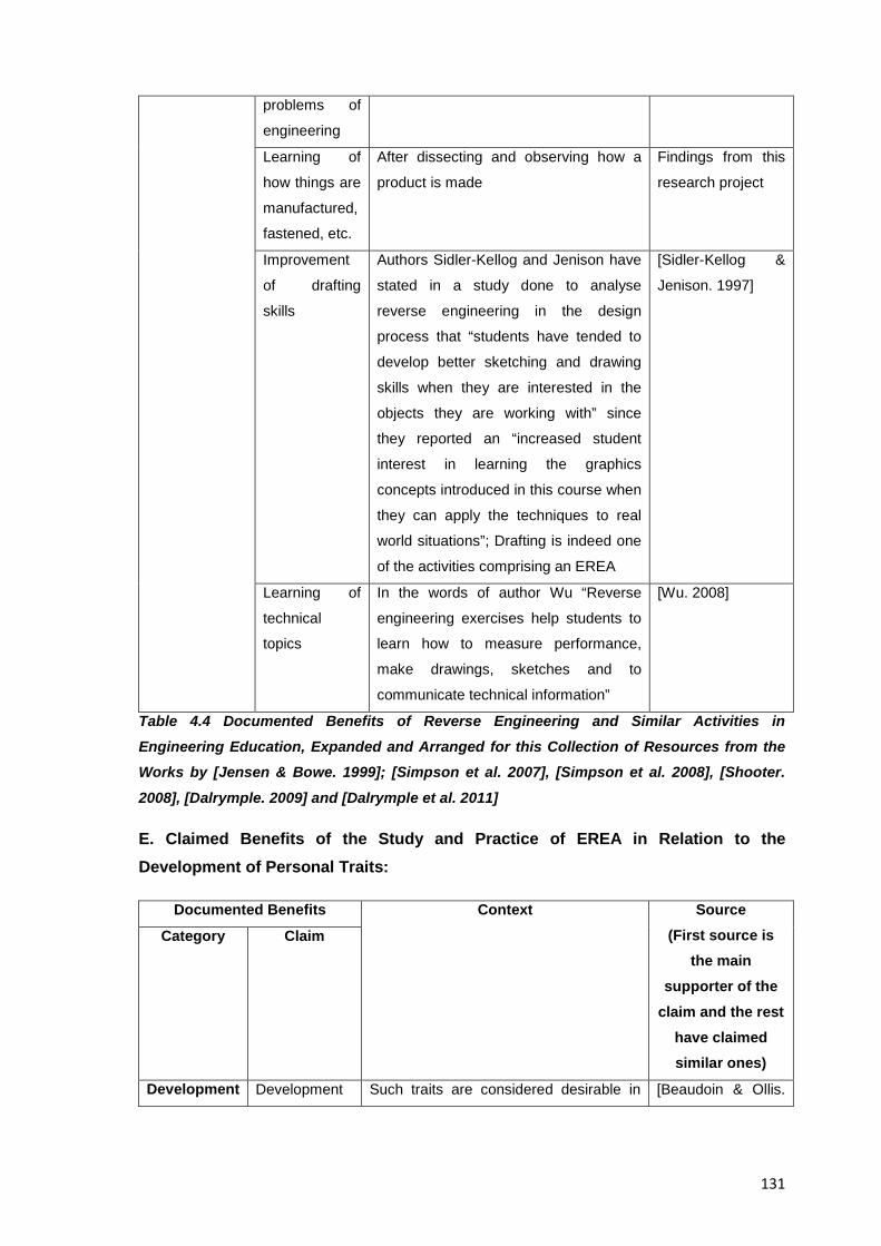
131
problems of
engineering
Learning of
how things are
manufactured,
fastened, etc.
After dissecting and observing how a
product is made
Findings from this
research project
Improvement
of drafting
skills
Authors Sidler-Kellog and Jenison have
stated in a study done to analyse
reverse engineering in the design
process that “students have tended to
develop better sketching and drawing
skills when they are interested in the
objects they are working with” since
they reported an “increased student
interest in learning the graphics
concepts introduced in this course when
they can apply the techniques to real
world situations”; Drafting is indeed one
of the activities comprising an EREA
[Sidler-Kellog &
Jenison. 1997]
Learning of
technical
topics
In the words of author Wu “Reverse
engineering exercises help students to
learn how to measure performance,
make drawings, sketches and to
communicate technical information”
[Wu. 2008]
Table 4.4 Documented Benefits of Reverse Engineering and Similar Activities in Engineering Education, Expanded and Arranged for this Collection of Resources from the Works by [Jensen & Bowe. 1999]; [Simpson et al. 2007], [Simpson et al. 2008], [Shooter.
2008], [Dalrymple. 2009] and [Dalrymple et al. 2011]
E. Claimed Benefits of the Study and Practice of EREA in Relation to the Development of Personal Traits:
Documented Benefits Context Source (First source is
the main supporter of the
claim and the rest have claimed similar ones)
Category Claim
Development Development Such traits are considered desirable in [Beaudoin & Ollis.
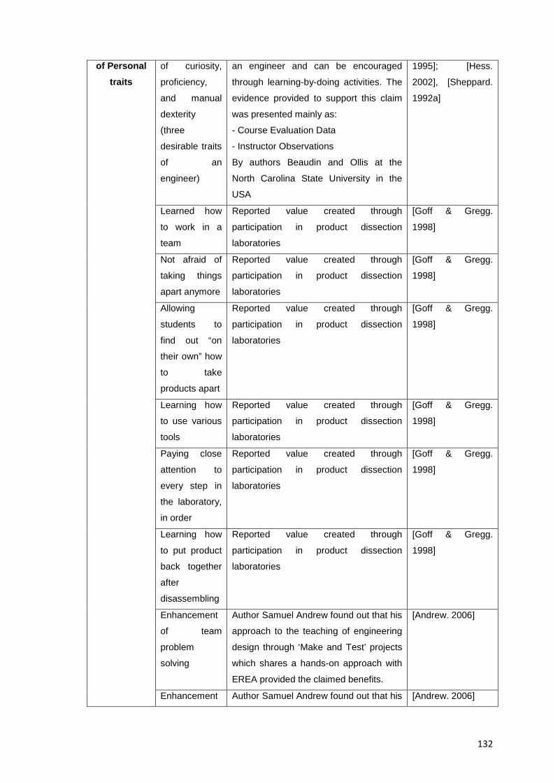
132
of Personal traits
of curiosity,
proficiency,
and manual
dexterity
(three
desirable traits
of an
engineer)
an engineer and can be encouraged
through learning-by-doing activities. The
evidence provided to support this claim
was presented mainly as:
- Course Evaluation Data
- Instructor Observations
By authors Beaudin and Ollis at the
North Carolina State University in the
USA
1995]; [Hess.
2002], [Sheppard.
1992a]
Learned how
to work in a
team
Reported value created through
participation in product dissection
laboratories
[Goff & Gregg.
1998]
Not afraid of
taking things
apart anymore
Reported value created through
participation in product dissection
laboratories
[Goff & Gregg.
1998]
Allowing
students to
find out “on
their own” how
to take
products apart
Reported value created through
participation in product dissection
laboratories
[Goff & Gregg.
1998]
Learning how
to use various
tools
Reported value created through
participation in product dissection
laboratories
[Goff & Gregg.
1998]
Paying close
attention to
every step in
the laboratory,
in order
Reported value created through
participation in product dissection
laboratories
[Goff & Gregg.
1998]
Learning how
to put product
back together
after
disassembling
Reported value created through
participation in product dissection
laboratories
[Goff & Gregg.
1998]
Enhancement
of team
problem
solving
Author Samuel Andrew found out that his
approach to the teaching of engineering
design through ‘Make and Test’ projects
which shares a hands-on approach with
EREA provided the claimed benefits.
[Andrew. 2006]
Enhancement Author Samuel Andrew found out that his [Andrew. 2006]
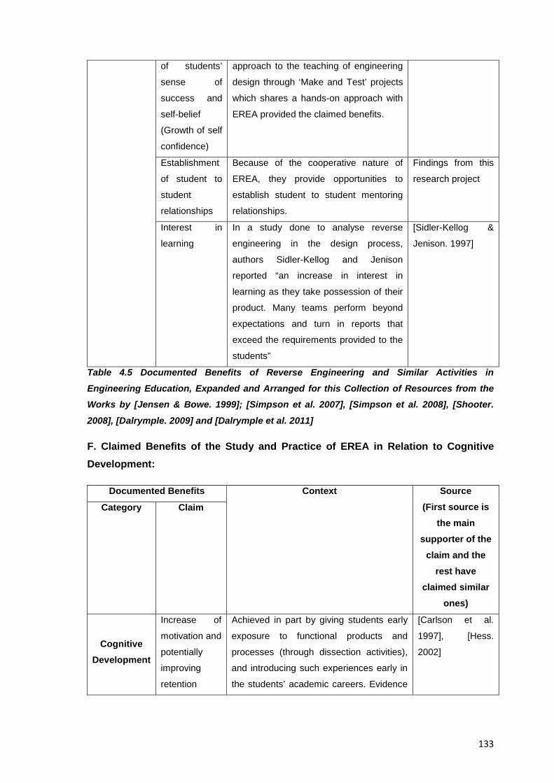
133
of students’
sense of
success and
self-belief
(Growth of self
confidence)
approach to the teaching of engineering
design through ‘Make and Test’ projects
which shares a hands-on approach with
EREA provided the claimed benefits.
Establishment
of student to
student
relationships
Because of the cooperative nature of
EREA, they provide opportunities to
establish student to student mentoring
relationships.
Findings from this
research project
Interest in
learning
In a study done to analyse reverse
engineering in the design process,
authors Sidler-Kellog and Jenison
reported “an increase in interest in
learning as they take possession of their
product. Many teams perform beyond
expectations and turn in reports that
exceed the requirements provided to the
students”
[Sidler-Kellog &
Jenison. 1997]
Table 4.5 Documented Benefits of Reverse Engineering and Similar Activities in Engineering Education, Expanded and Arranged for this Collection of Resources from the Works by [Jensen & Bowe. 1999]; [Simpson et al. 2007], [Simpson et al. 2008], [Shooter.
2008], [Dalrymple. 2009] and [Dalrymple et al. 2011]
F. Claimed Benefits of the Study and Practice of EREA in Relation to Cognitive Development:
Documented Benefits Context Source (First source is
the main supporter of the
claim and the rest have
claimed similar ones)
Category Claim
Cognitive Development
Increase of
motivation and
potentially
improving
retention
Achieved in part by giving students early
exposure to functional products and
processes (through dissection activities),
and introducing such experiences early in
the students’ academic careers. Evidence
[Carlson et al.
1997], [Hess.
2002]
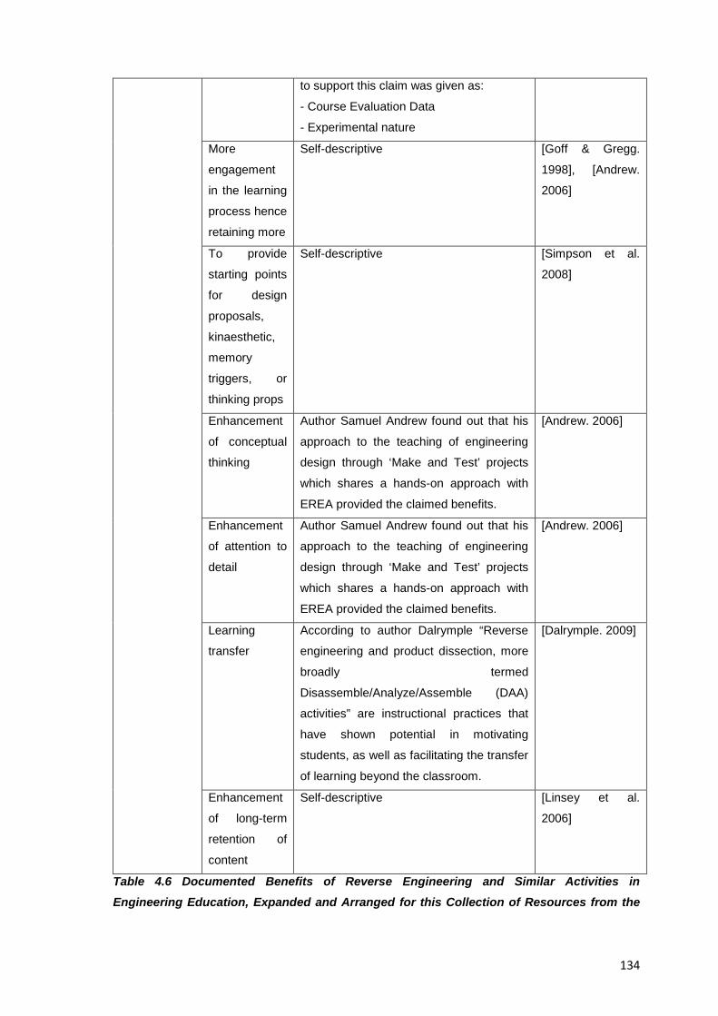
134
to support this claim was given as:
- Course Evaluation Data
- Experimental nature
More
engagement
in the learning
process hence
retaining more
Self-descriptive [Goff & Gregg.
1998], [Andrew.
2006]
To provide
starting points
for design
proposals,
kinaesthetic,
memory
triggers, or
thinking props
Self-descriptive [Simpson et al.
2008]
Enhancement
of conceptual
thinking
Author Samuel Andrew found out that his
approach to the teaching of engineering
design through ‘Make and Test’ projects
which shares a hands-on approach with
EREA provided the claimed benefits.
[Andrew. 2006]
Enhancement
of attention to
detail
Author Samuel Andrew found out that his
approach to the teaching of engineering
design through ‘Make and Test’ projects
which shares a hands-on approach with
EREA provided the claimed benefits.
[Andrew. 2006]
Learning
transfer
According to author Dalrymple “Reverse
engineering and product dissection, more
broadly termed
Disassemble/Analyze/Assemble (DAA)
activities” are instructional practices that
have shown potential in motivating
students, as well as facilitating the transfer
of learning beyond the classroom.
[Dalrymple. 2009]
Enhancement
of long-term
retention of
content
Self-descriptive [Linsey et al.
2006]
Table 4.6 Documented Benefits of Reverse Engineering and Similar Activities in Engineering Education, Expanded and Arranged for this Collection of Resources from the
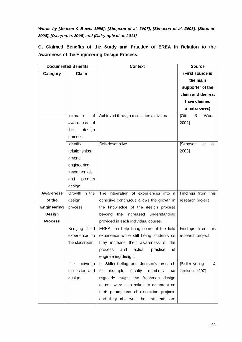
135
Works by [Jensen & Bowe. 1999]; [Simpson et al. 2007], [Simpson et al. 2008], [Shooter.
2008], [Dalrymple. 2009] and [Dalrymple et al. 2011]
G. Claimed Benefits of the Study and Practice of EREA in Relation to the Awareness of the Engineering Design Process:
Documented Benefits Context Source (First source is
the main supporter of the
claim and the rest have claimed similar ones)
Category Claim
Awareness of the
Engineering Design Process
Increase of
awareness of
the design
process
Achieved through dissection activities [Otto & Wood.
2001]
Identify
relationships
among
engineering
fundamentals
and product
design
Self-descriptive [Simpson et al.
2008]
Growth in the
design
process
The integration of experiences into a
cohesive continuous allows the growth in
the knowledge of the design process
beyond the increased understanding
provided in each individual course.
Findings from this
research project
Bringing field
experience to
the classroom
EREA can help bring some of the field
experience while still being students so
they increase their awareness of the
process and actual practice of
engineering design.
Findings from this
research project
Link between
dissection and
design
In Sidler-Kellog and Jenison’s research
for example, faculty members that
regularly taught the freshman design
course were also asked to comment on
their perceptions of dissection projects
and they observed that “students are
[Sidler-Kellog &
Jenison. 1997]
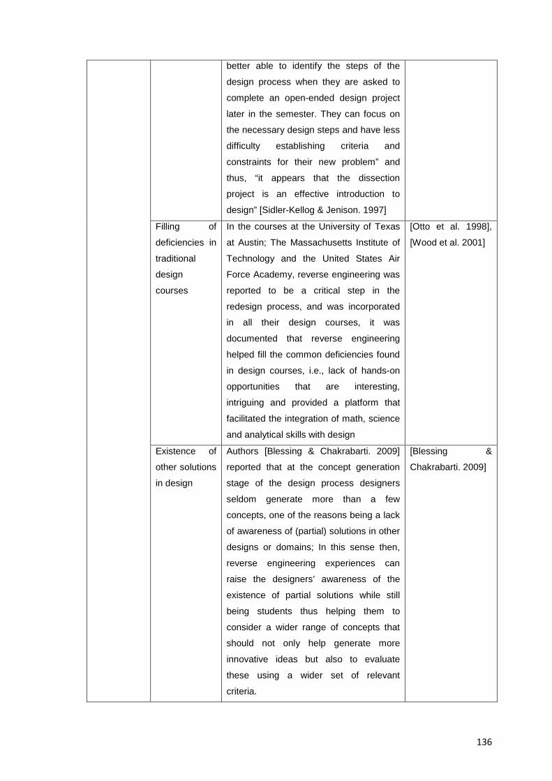
136
better able to identify the steps of the
design process when they are asked to
complete an open-ended design project
later in the semester. They can focus on
the necessary design steps and have less
difficulty establishing criteria and
constraints for their new problem” and
thus, “it appears that the dissection
project is an effective introduction to
design” [Sidler-Kellog & Jenison. 1997]
Filling of
deficiencies in
traditional
design
courses
In the courses at the University of Texas
at Austin; The Massachusetts Institute of
Technology and the United States Air
Force Academy, reverse engineering was
reported to be a critical step in the
redesign process, and was incorporated
in all their design courses, it was
documented that reverse engineering
helped fill the common deficiencies found
in design courses, i.e., lack of hands-on
opportunities that are interesting,
intriguing and provided a platform that
facilitated the integration of math, science
and analytical skills with design
[Otto et al. 1998],
[Wood et al. 2001]
Existence of
other solutions
in design
Authors [Blessing & Chakrabarti. 2009]
reported that at the concept generation
stage of the design process designers
seldom generate more than a few
concepts, one of the reasons being a lack
of awareness of (partial) solutions in other
designs or domains; In this sense then,
reverse engineering experiences can
raise the designers’ awareness of the
existence of partial solutions while still
being students thus helping them to
consider a wider range of concepts that
should not only help generate more
innovative ideas but also to evaluate
these using a wider set of relevant
criteria.
[Blessing &
Chakrabarti. 2009]
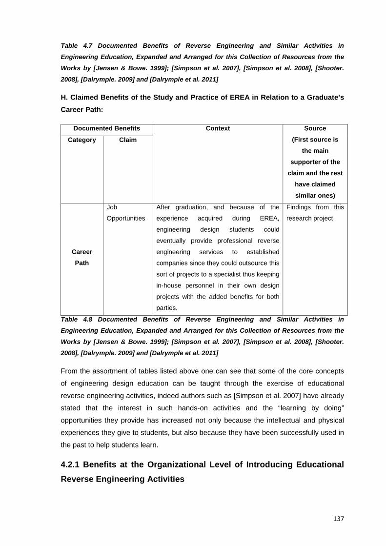
137
Table 4.7 Documented Benefits of Reverse Engineering and Similar Activities in Engineering Education, Expanded and Arranged for this Collection of Resources from the Works by [Jensen & Bowe. 1999]; [Simpson et al. 2007], [Simpson et al. 2008], [Shooter.
2008], [Dalrymple. 2009] and [Dalrymple et al. 2011]
H. Claimed Benefits of the Study and Practice of EREA in Relation to a Graduate’s Career Path:
Documented Benefits Context Source (First source is
the main supporter of the
claim and the rest have claimed similar ones)
Category Claim
Career Path
Job
Opportunities
After graduation, and because of the
experience acquired during EREA,
engineering design students could
eventually provide professional reverse
engineering services to established
companies since they could outsource this
sort of projects to a specialist thus keeping
in-house personnel in their own design
projects with the added benefits for both
parties.
Findings from this
research project
Table 4.8 Documented Benefits of Reverse Engineering and Similar Activities in Engineering Education, Expanded and Arranged for this Collection of Resources from the Works by [Jensen & Bowe. 1999]; [Simpson et al. 2007], [Simpson et al. 2008], [Shooter. 2008], [Dalrymple. 2009] and [Dalrymple et al. 2011]
From the assortment of tables listed above one can see that some of the core concepts
of engineering design education can be taught through the exercise of educational
reverse engineering activities, indeed authors such as [Simpson et al. 2007] have already
stated that the interest in such hands-on activities and the “learning by doing”
opportunities they provide has increased not only because the intellectual and physical
experiences they give to students, but also because they have been successfully used in
the past to help students learn.
4.2.1 Benefits at the Organizational Level of Introducing Educational Reverse Engineering Activities
138
Apart from the benefits shown above from Tables 4.1 to 4.8 for students participating in
EREA, their introduction can also bring benefits to educators and host universities as
explained below. Namely:
A. Benefits to Faculty:
- If a reverse engineering activity involves multidisciplinary analyses; the interaction
among students and professors from other university departments can increase, and
could lead to a greater coordination, integration and sense of community of the faculty
B. Benefits to the Department or the University:
-The prominent display in departmental hallways of successful reverse engineering
projects can help to capture the interest of students and teachers from other
departments, and also from the general public. This could increase the understanding of
reverse engineering and of engineering design, and make students consider a continuous
career in engineering.
-Positive feedback from the students’ side regarding reverse engineering activities can
increase the department and the university’s opportunity to publicly and concretely
demonstrate the value of the education the students are receiving. Authors [Jensen et al.
2003] for example, stated in their research that the reformulating of their existing design
classes to include a reverse engineering/redesign component “has led to substantial
improvements in course ratings” including “an immediate jump of 16% in student's ratings
on the `intellectual challenge and encouragement of independent thought' and a 13%
increase in the student's perception of the instructor's concern for their learning”
C. Benefits to Industrial Clients:
-Industrial sponsors or donors of equipment for dissection can gain a greatly enhanced
exposure among students and the general public.
- Students with reverse engineering experience could present their skills to recruiters from
benchmarking and competitive Intelligence companies.
-Additional to the benefits to faculty and host institutions, reverse engineering projects
can also help to foster cooperation from research groups at partner universities or local
companies. The study of the design principles materialized into existing products, and the
potential to produce improved derivative products for example, are just two of the ways
EREA can open venues for industrial collaboration and applications where existing
industrial requirements could be handed to students to find a suitable solution.
139
The results presented in this section then, intend to present the reader with those
documented benefits EREA have and that could be of relevance to the teaching of those
interested in giving EREA a try.
4.3 Strongest Elements Educational Reverse Engineering Activities can add to the Teaching of Engineering Design
EREA are not a panacea for the teaching of engineering design, and for that matter,
unfortunately no approach is; however they do bring unique learning experiences and
add value to the teaching of it by helping students acquire and develop a given set of
competence elements; abilities, skills, and attitudes to help raise their awareness of the
design process; expand their sources of inspiration, and understand the impact of the
designer’s actions within the life cycle of a product. This section presents the reader with
the compendium of those strongest elements where EREA work as a suitable vehicle to
bring engineering design students a given competence element or learning objective into
their education; such results are expected to guide professors and curriculum developers
adopting EREA or the most representative aspects of them to better plan their learning
activities and expected educational goals. In order to provide concrete evidence about
which of the learning experiences unique to reverse engineering can add value to the
teaching of engineering design and how; it is needed then, not only to acknowledge first
what the experiences associated to reverse engineering actually entail but also to know
what the desired/expected competences from engineering design students are, so the
suitability of the specific learning experiences to achieve those competences can be
evaluated; measured, analyzed and its results contextualized.
A number of studies have been conducted already to outline the competences and
elements expected from studying and practicing engineers in general (and design
engineers in particular) and that ensure a proper performance on the situations typical of
their praxis, such type of research involves the interaction with practicing engineers;
students; professors, cognitive psychologists, representatives from industry, as well as
the definition and agreement of the involved parties on a variety of concepts such as
competence, knowledge and skills. Table 4.9 below shows the lists of representative
studies of that kind that were chosen for examination on “A Comparison of Competences
Required in Reverse Engineering Exercises Versus Conventional Engineering Exercises
and its Relationship to IPMA’s Competence Baseline”, [Calderon. 2010b] which was one
on the papers written along this collection of resources and that supported the creation of
the content for the individual resource presented here. The items analyzed in those
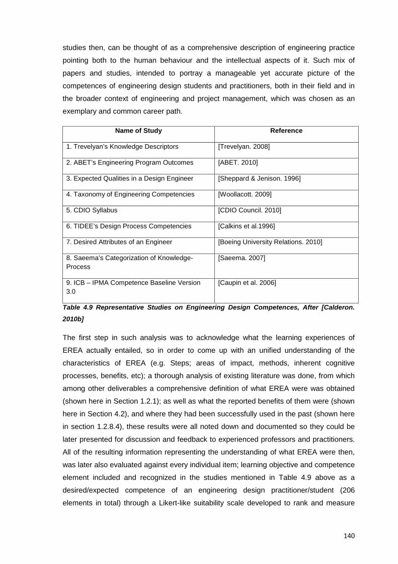
140
studies then, can be thought of as a comprehensive description of engineering practice
pointing both to the human behaviour and the intellectual aspects of it. Such mix of
papers and studies, intended to portray a manageable yet accurate picture of the
competences of engineering design students and practitioners, both in their field and in
the broader context of engineering and project management, which was chosen as an
exemplary and common career path.
Name of Study Reference
1. Trevelyan’s Knowledge Descriptors [Trevelyan. 2008]
2. ABET’s Engineering Program Outcomes [ABET. 2010]
3. Expected Qualities in a Design Engineer [Sheppard & Jenison. 1996]
4. Taxonomy of Engineering Competencies [Woollacott. 2009]
5. CDIO Syllabus [CDIO Council. 2010]
6. TIDEE’s Design Process Competencies [Calkins et al.1996]
7. Desired Attributes of an Engineer [Boeing University Relations. 2010]
8. Saeema’s Categorization of Knowledge-Process
[Saeema. 2007]
9. ICB – IPMA Competence Baseline Version 3.0
[Caupin et al. 2006]
Table 4.9 Representative Studies on Engineering Design Competences, After [Calderon.
2010b]
The first step in such analysis was to acknowledge what the learning experiences of
EREA actually entailed, so in order to come up with an unified understanding of the
characteristics of EREA (e.g. Steps; areas of impact, methods, inherent cognitive
processes, benefits, etc); a thorough analysis of existing literature was done, from which
among other deliverables a comprehensive definition of what EREA were was obtained
(shown here in Section 1.2.1); as well as what the reported benefits of them were (shown
here in Section 4.2), and where they had been successfully used in the past (shown here
in section 1.2.8.4), these results were all noted down and documented so they could be
later presented for discussion and feedback to experienced professors and practitioners.
All of the resulting information representing the understanding of what EREA were then,
was later also evaluated against every individual item; learning objective and competence
element included and recognized in the studies mentioned in Table 4.9 above as a
desired/expected competence of an engineering design practitioner/student (206
elements in total) through a Likert-like suitability scale developed to rank and measure
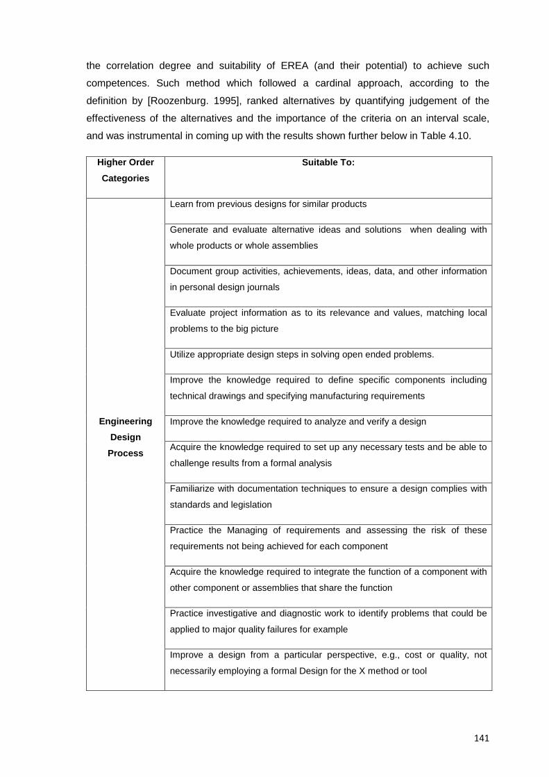
141
the correlation degree and suitability of EREA (and their potential) to achieve such
competences. Such method which followed a cardinal approach, according to the
definition by [Roozenburg. 1995], ranked alternatives by quantifying judgement of the
effectiveness of the alternatives and the importance of the criteria on an interval scale,
and was instrumental in coming up with the results shown further below in Table 4.10.
Higher Order Categories
Suitable To:
Engineering Design
Process
Learn from previous designs for similar products
Generate and evaluate alternative ideas and solutions when dealing with
whole products or whole assemblies
Document group activities, achievements, ideas, data, and other information
in personal design journals
Evaluate project information as to its relevance and values, matching local
problems to the big picture
Utilize appropriate design steps in solving open ended problems.
Improve the knowledge required to define specific components including
technical drawings and specifying manufacturing requirements
Improve the knowledge required to analyze and verify a design
Acquire the knowledge required to set up any necessary tests and be able to
challenge results from a formal analysis
Familiarize with documentation techniques to ensure a design complies with
standards and legislation
Practice the Managing of requirements and assessing the risk of these
requirements not being achieved for each component
Acquire the knowledge required to integrate the function of a component with
other component or assemblies that share the function
Practice investigative and diagnostic work to identify problems that could be
applied to major quality failures for example
Improve a design from a particular perspective, e.g., cost or quality, not
necessarily employing a formal Design for the X method or tool
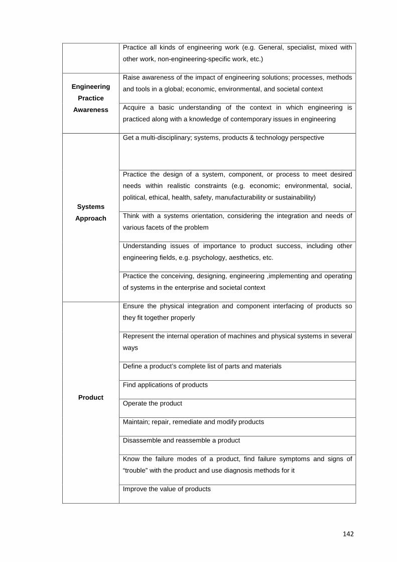
142
Practice all kinds of engineering work (e.g. General, specialist, mixed with
other work, non-engineering-specific work, etc.)
Engineering Practice
Awareness
Raise awareness of the impact of engineering solutions; processes, methods
and tools in a global; economic, environmental, and societal context
Acquire a basic understanding of the context in which engineering is
practiced along with a knowledge of contemporary issues in engineering
Systems Approach
Get a multi-disciplinary; systems, products & technology perspective
Practice the design of a system, component, or process to meet desired
needs within realistic constraints (e.g. economic; environmental, social,
political, ethical, health, safety, manufacturability or sustainability)
Think with a systems orientation, considering the integration and needs of
various facets of the problem
Understanding issues of importance to product success, including other
engineering fields, e.g. psychology, aesthetics, etc.
Practice the conceiving, designing, engineering ,implementing and operating
of systems in the enterprise and societal context
Product
Ensure the physical integration and component interfacing of products so
they fit together properly
Represent the internal operation of machines and physical systems in several
ways
Define a product’s complete list of parts and materials
Find applications of products
Operate the product
Maintain; repair, remediate and modify products
Disassemble and reassemble a product
Know the failure modes of a product, find failure symptoms and signs of
“trouble” with the product and use diagnosis methods for it
Improve the value of products
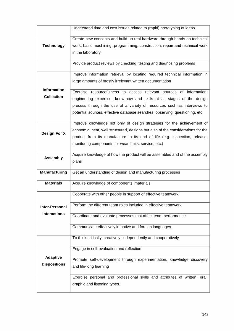
143
Technology
Understand time and cost issues related to (rapid) prototyping of ideas
Create new concepts and build up real hardware through hands-on technical
work; basic machining, programming, construction, repair and technical work
in the laboratory
Provide product reviews by checking, testing and diagnosing problems
Information Collection
Improve information retrieval by locating required technical information in
large amounts of mostly irrelevant written documentation
Exercise resourcefulness to access relevant sources of information;
engineering expertise, know-how and skills at all stages of the design
process through the use of a variety of resources such as interviews to
potential sources, effective database searches ,observing, questioning, etc.
Design For X
Improve knowledge not only of design strategies for the achievement of
economic; neat, well structured, designs but also of the considerations for the
product from its manufacture to its end of life (e.g. inspection, release,
monitoring components for wear limits, service, etc.)
Assembly Acquire knowledge of how the product will be assembled and of the assembly
plans
Manufacturing Get an understanding of design and manufacturing processes
Materials Acquire knowledge of components’ materials
Inter-Personal Interactions
Cooperate with other people in support of effective teamwork
Perform the different team roles included in effective teamwork
Coordinate and evaluate processes that affect team performance
Communicate effectively in native and foreign languages
Adaptive Dispositions
To think critically; creatively, independently and cooperatively
Engage in self-evaluation and reflection
Promote self-development through experimentation, knowledge discovery
and life-long learning
Exercise personal and professional skills and attributes of written, oral,
graphic and listening types.
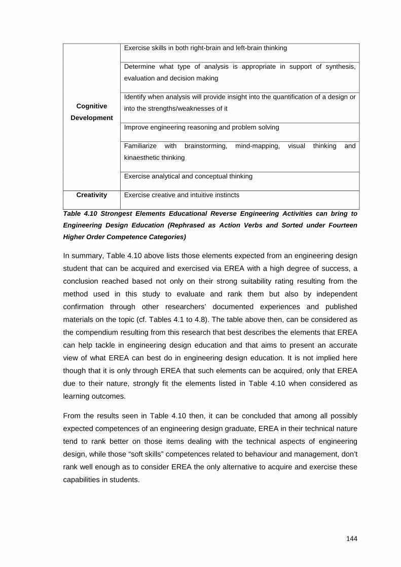
144
Cognitive Development
Exercise skills in both right-brain and left-brain thinking
Determine what type of analysis is appropriate in support of synthesis,
evaluation and decision making
Identify when analysis will provide insight into the quantification of a design or
into the strengths/weaknesses of it
Improve engineering reasoning and problem solving
Familiarize with brainstorming, mind-mapping, visual thinking and
kinaesthetic thinking
Exercise analytical and conceptual thinking
Creativity Exercise creative and intuitive instincts
Table 4.10 Strongest Elements Educational Reverse Engineering Activities can bring to Engineering Design Education (Rephrased as Action Verbs and Sorted under Fourteen
Higher Order Competence Categories)
In summary, Table 4.10 above lists those elements expected from an engineering design
student that can be acquired and exercised via EREA with a high degree of success, a
conclusion reached based not only on their strong suitability rating resulting from the
method used in this study to evaluate and rank them but also by independent
confirmation through other researchers’ documented experiences and published
materials on the topic (cf. Tables 4.1 to 4.8). The table above then, can be considered as
the compendium resulting from this research that best describes the elements that EREA
can help tackle in engineering design education and that aims to present an accurate
view of what EREA can best do in engineering design education. It is not implied here
though that it is only through EREA that such elements can be acquired, only that EREA
due to their nature, strongly fit the elements listed in Table 4.10 when considered as
learning outcomes.
From the results seen in Table 4.10 then, it can be concluded that among all possibly
expected competences of an engineering design graduate, EREA in their technical nature
tend to rank better on those items dealing with the technical aspects of engineering
design, while those “soft skills” competences related to behaviour and management, don’t
rank well enough as to consider EREA the only alternative to acquire and exercise these
capabilities in students.
145
4.4 Added Value of Reverse Engineering Activities in Design Education
EREA are comprehensive, integrative activities that can bring new experiences to those
that try them, from a students’ perspective the added value EREA can bring to
engineering design education comes from:
• The opportunity to engage in an exercise that simulates the type of practical
experiences and knowledge developed by designers in real life projects; EREA
• The potential to exercise students/instructors/practitioners interaction through the
exchange of experiences during a project and its preparation
• Getting early in career studies, the opportunity to acquire and develop, through
interesting and engaging activities, some of the abilities required to lead a
successful career in engineering design.
From the instructors’ side what constitutes the added value from EREA is:
• Their suitability to exercise most of the expected competences of an engineering
design curriculum
• Their ability to keep students interested and engaged in the activities; which can
help them acquire new knowledge and learn on their own
• Their ability to produce “Transfer”
• Their suitability to reinforce engineering concepts through hands-on experiences
The different experiences EREA can bring to the learning of engineering design can
complement the regular teaching of it and thus give students other type of experiences
that are very close to those found during the actual praxis of design.
4.5 Resource Conclusions
In general, it can be concluded that reverse engineering activities in education help
engineering design students to acquire and develop a set of abilities that raise their
awareness and proficiency of the engineering design process, and they do so by
enhancing the students’ ability to learn from their predecessors in the safety of an
educational setting that helps them understand the technologies they work with in order
to gain confidence and practice in them. Listed next though are some specific
conclusions regarding the benefits of four specific aspects of EREA, namely:
A. Educational Setting:
146
- EREA provide realistic; complex, hands-on experiences that can be safely repeated in a
classroom until a desired goal is attained. The reinforcement and repetition of key
information; as well as the free exchange of ideas, test results, and improvement
proposals by all participating students helps to level differences in status, experience and
knowledge among students.
B. Cognitive Development:
- It is clear that design engineers do not stop learning when they finish their studies, much
of their learning actually comes while practicing design in their professional careers; by
bringing that same practice to the classroom, EREA can help improve the lifelong
learning experience of students of engineering design
- Reverse engineering activities help students to reason on multiple levels and look at
problems from multiple perspectives, because of this, students can eventually have
access to the reasoning rules in design and know how and when to break them
C. Potential Ramifications of EREA:
- Comparing similar technologies and solutions from different manufacturers thus
catching up with the changing technologies relevant to an engineering design curriculum
may indeed lead to academic or even commercial opportunities when suggesting
improvements to the product under analysis
Breakthroughs may eventually come from students with good training and experience
and thus, EREA as well as other educational tools that could bring benefits to their
education should be tried and tested, in this regard the information presented in this
resource has been compiled so potential adopters of EREA can get an overview of the
latest findings in the area.
147
RESOURCE 5: A PROPOSED METHODOLOGY FOR REVERSE ENGINEERING ANALYSIS IN ENGINEERING DESIGN EDUCATION
5.1 Resource Introduction
A definite methodology for the educational reverse engineering analysis of consumer
products that unifies all relevant fields of engineering design does not exist, there are
however, tailored methodologies for the dissection of products in education such as those
proposed by authors [Sheppard. 1992a]; [Lamancusa et al. 1996], [Otto & Wood. 2001],
[Durfee. 2008] or [Lewis et al. 2011] shown here in Table 1.3. However, the varied
differences among them justify the continuous research on the topic while still being
possible to benefit from them by using them as a baseline for complementing research.
An approximation to that comprehensive, sought after methodology for the area of
engineering design is proposed in this resource and it is one that is comprised of proved
and tested analytical tools common to the subject area (e.g. Technical systems analysis,
DfX analyses, engineering tests, etc.) as well as comprised of methodological tasks
arranged in a such a way that allow for the sequential, accumulative analysis of a subject
system (e.g. A consumer product). The methodology then, provides a natural path of
progression in the analysis of consumer products for educational purposes and intends to
help students understand how a given system came to be and why, while at the same
time helping them to acquire and exercise relevant abilities to the area of engineering
design.
The sequence of analyses and specific deliverables expected from each of the individual
stages presented here, along with their contextualization and implementation of results
into the field of engineering education design stem from the author’s own experience in
reverse engineering products as well as from the findings gotten after a thorough
bibliographical analysis of other authors’ experiences; approaches, rationale and
published best practices in the area.
5.2 Conceptual Stages of a Proposed Methodology for Educational Reverse Engineering Analysis
The basic foundations of learning through reverse engineering analysis come from the
cycle of analysis and synthesis inherent to human cognition cf. [Kant. 1781] triggered by
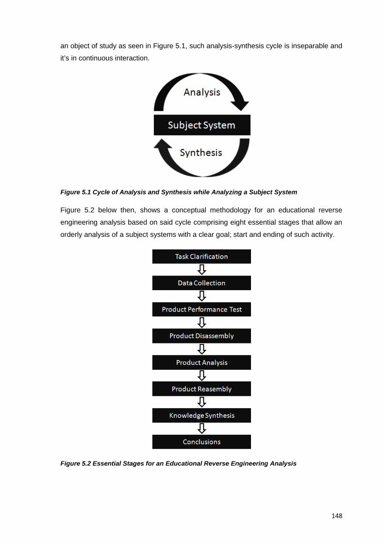
148
an object of study as seen in Figure 5.1, such analysis-synthesis cycle is inseparable and
it’s in continuous interaction.
Figure 5.1 Cycle of Analysis and Synthesis while Analyzing a Subject System
Figure 5.2 below then, shows a conceptual methodology for an educational reverse
engineering analysis based on said cycle comprising eight essential stages that allow an
orderly analysis of a subject systems with a clear goal; start and ending of such activity.
Figure 5.2 Essential Stages for an Educational Reverse Engineering Analysis
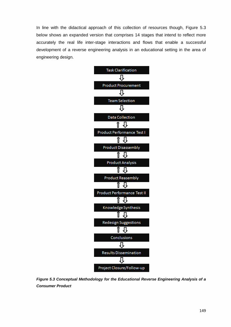
149
In line with the didactical approach of this collection of resources though, Figure 5.3
below shows an expanded version that comprises 14 stages that intend to reflect more
accurately the real life inter-stage interactions and flows that enable a successful
development of a reverse engineering analysis in an educational setting in the area of
engineering design.
Figure 5.3 Conceptual Methodology for the Educational Reverse Engineering Analysis of a Consumer Product
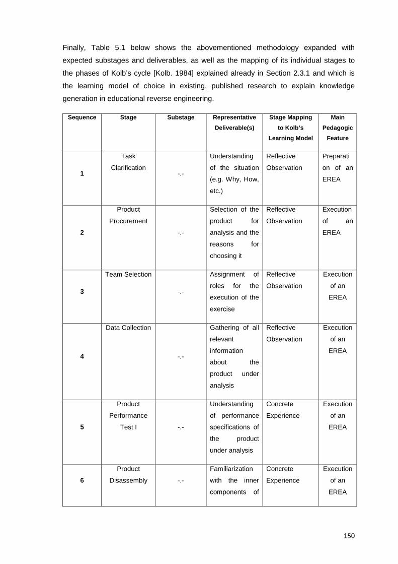
150
Finally, Table 5.1 below shows the abovementioned methodology expanded with
expected substages and deliverables, as well as the mapping of its individual stages to
the phases of Kolb’s cycle [Kolb. 1984] explained already in Section 2.3.1 and which is
the learning model of choice in existing, published research to explain knowledge
generation in educational reverse engineering.
Sequence Stage Substage Representative Deliverable(s)
Stage Mapping to Kolb’s
Learning Model
Main Pedagogic
Feature
1
Task
Clarification -.-
Understanding
of the situation
(e.g. Why, How,
etc.)
Reflective
Observation
Preparati
on of an
EREA
2
Product
Procurement
-.-
Selection of the
product for
analysis and the
reasons for
choosing it
Reflective
Observation
Execution
of an
EREA
3
Team Selection
-.-
Assignment of
roles for the
execution of the
exercise
Reflective
Observation
Execution
of an
EREA
4
Data Collection
-.-
Gathering of all
relevant
information
about the
product under
analysis
Reflective
Observation
Execution
of an
EREA
5
Product
Performance
Test I -.-
Understanding
of performance
specifications of
the product
under analysis
Concrete
Experience
Execution
of an
EREA
6 Product
Disassembly -.-
Familiarization
with the inner
components of
Concrete
Experience
Execution
of an
EREA
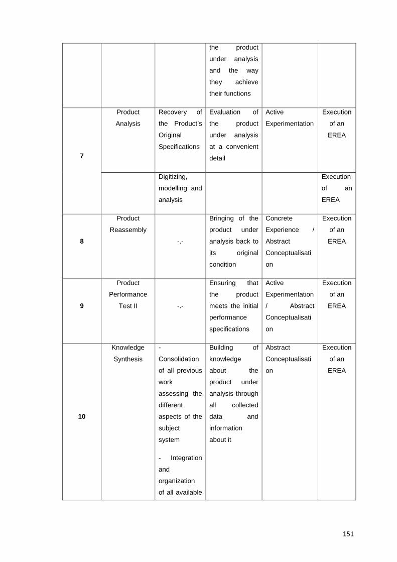
151
the product
under analysis
and the way
they achieve
their functions
7
Product
Analysis
Recovery of
the Product’s
Original
Specifications
Evaluation of
the product
under analysis
at a convenient
detail
Active
Experimentation
Execution
of an
EREA
Digitizing,
modelling and
analysis
Execution
of an
EREA
8
Product
Reassembly
-.-
Bringing of the
product under
analysis back to
its original
condition
Concrete
Experience /
Abstract
Conceptualisati
on
Execution
of an
EREA
9
Product
Performance
Test II -.-
Ensuring that
the product
meets the initial
performance
specifications
Active
Experimentation
/ Abstract
Conceptualisati
on
Execution
of an
EREA
10
Knowledge
Synthesis
-
Consolidation
of all previous
work
assessing the
different
aspects of the
subject
system
- Integration
and
organization
of all available
Building of
knowledge
about the
product under
analysis through
all collected
data and
information
about it
Abstract
Conceptualisati
on
Execution
of an
EREA
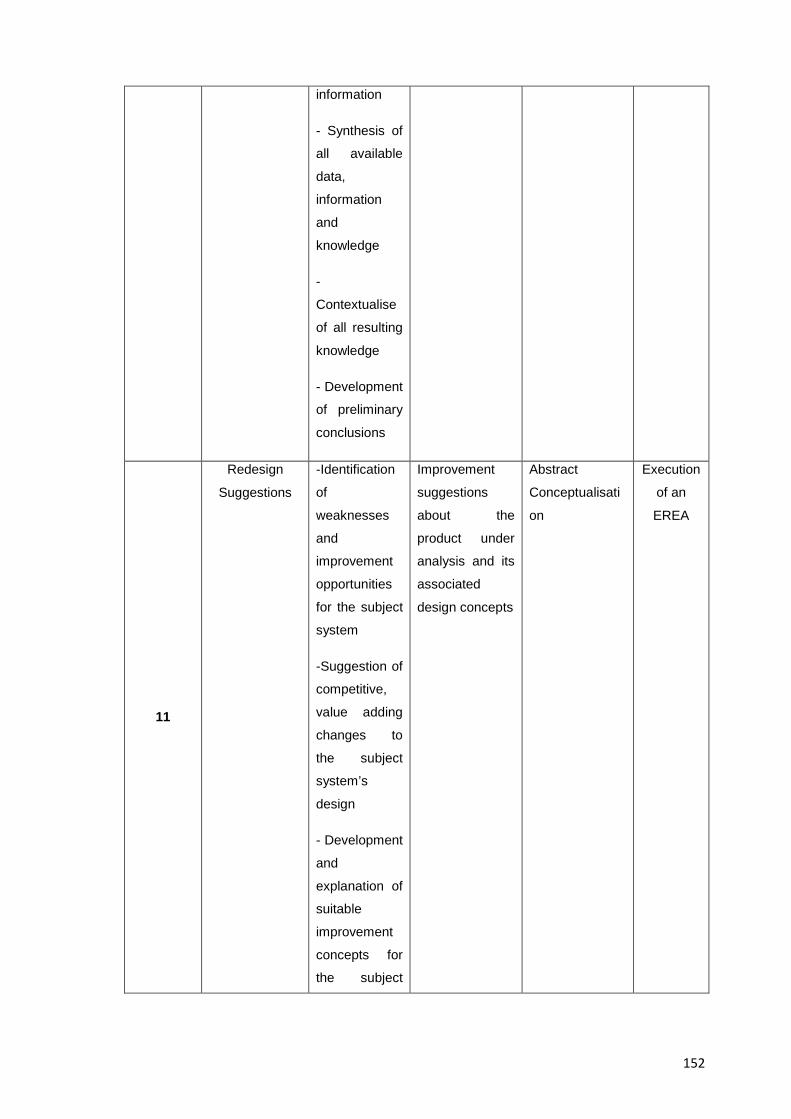
152
information
- Synthesis of
all available
data,
information
and
knowledge
-
Contextualise
of all resulting
knowledge
- Development
of preliminary
conclusions
11
Redesign
Suggestions
-Identification
of
weaknesses
and
improvement
opportunities
for the subject
system
-Suggestion of
competitive,
value adding
changes to
the subject
system’s
design
- Development
and
explanation of
suitable
improvement
concepts for
the subject
Improvement
suggestions
about the
product under
analysis and its
associated
design concepts
Abstract
Conceptualisati
on
Execution
of an
EREA
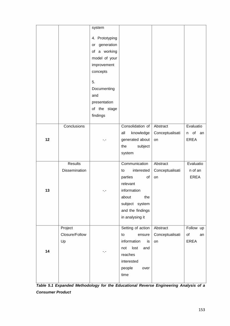
153
system
4. Prototyping
or generation
of a working
model of your
improvement
concepts
5.
Documenting
and
presentation
of the stage
findings
12
Conclusions
-.-
Consolidation of
all knowledge
generated about
the subject
system
Abstract
Conceptualisati
on
Evaluatio
n of an
EREA
13
Results
Dissemination
-.-
Communication
to interested
parties of
relevant
information
about the
subject system
and the findings
in analysing it
Abstract
Conceptualisati
on
Evaluatio
n of an
EREA
14
Project
Closure/Follow
Up
-.-
Setting of action
to ensure
information is
not lost and
reaches
interested
people over
time
Abstract
Conceptualisati
on
Follow up
of an
EREA
Table 5.1 Expanded Methodology for the Educational Reverse Engineering Analysis of a
Consumer Product
154
One of the things that can be seen in the table above with respect to Kolb’s learning cycle
and its match with the sequence of the suggested methodology, is that it makes several
passes or that it goes back and forth on certain steps of it, this is normal and it better
reflects the real life applications of the cycle. The column at the far right of the table then,
lists what the main pedagogical feature of the stage is which can be of a planning;
execution, evaluation or follow up nature as explained in Resource 6
5.3 Conceptual and Procedural Explanation of the Stages of the Proposed Methodology for Educational Reverse Engineering Analysis
In the pages below, each stage of the suggested methodology will be explained to make
clear the purpose; expectations, differences, deliverables and steps needed to
accomplish them; each stage of the methodology indeed, is comprised of its own fitting
analyses, tasks and questions and the answer to them provides a safe path to the
achievement and goals set for an EREA
The individual tasks, questions and analyses to be performed on the subject system and
shown further below then, are all considered standard ones in the area of engineering
design and are deemed suitable for the stage where they are placed; they are however,
not categorized by their specific area of knowledge (e.g. Analysis of technical systems,
DfX Analysis, etc.) but rather grouped into higher order taxonomies (e.g. Analysis of:
Materials; manufacturing processes, product architecture, etc.), this is in line with existing,
published examples of reverse engineering and is done to remove one extra layer of
complexity, so professors and students alike can more easily start a reverse engineering
analysis with a lees steep learning curve; in an educational activity of this nature though,
most of the results are expected to be narrative rather than numerical and their
interpretation to be open depending on the experience and knowledge of the target
students and the professor in turn.
The individual tasks, questions and analyses then, are placed at the stages where they
better belong and intend to be of a sequential nature to convey the highest sense of order
and clarity to the suggested methodology, in real life though, intra and inter stage
interaction is expected to happen back and forth until a satisfactory understanding of the
activity is attained, indeed even the transition between the stages themselves could be
thought of as a zone of continuous transference rather than a clear cut division; this will
mean two things, on one hand the cases where two or more of the stage tasks can be
executed in parallel will be evident to the experienced reader, and on the other hand the
155
completion of some tasks or the complete solution to certain questions will be
unattainable at the suggested stage they are originally placed, since the expected, final
result might require the tracking of flows or signals across several stages of the
methodology to determine with certainty what is being looked for and thus, they should be
left and retried further down the sequence of the methodology when complementing
information becomes available. The decision to go ahead and consider individual,
separate stages in the methodology proposed here then, was taken so students of
reverse engineering give a conscious effort and properly focus on the specifics of each of
the individual stages.
It is worth mentioning though, that just as the goals and levels of expectation from an
EREA are set by the professor in charge, each task, question or analysis comprising the
methodology here can be adapted to the specific needs of the target students, meaning
for example that, any item can be chosen, skipped, rearranged or changed in the
thoroughness of its execution in the methodology; and although the methodology is
presented here for a maximum case scenario that covers all relevant, aspects of the
reverse engineering analysis of a consumer product, professors should rest assured that
just by having their students go through the core concepts of each of the stages of the
methodology , their understanding of the subject system will still be enough to familiarize
and learn something from it and thus have a higher chance to come up eventually with a
suggested, improved version of it that isn’t that far off from and engineeringly correct and
plausible redesign
Finally, it can’t be stressed enough that educational reverse engineering activities as
envisioned in this collection of resources are not heavily, technically oriented where a
numerical result is sought at any cost, but they are rather planned as an aid that supports
the teaching of engineering design and helps students acquire and exercise design-
relevant abilities in the process.
5.4 Stages of the Proposed Methodology for Reverse Engineering Analysis in Design Education
Although this resource (and the whole collection of resources for that matter) is directed
to professors of engineering design the methodology shown below has been written in a
style to address the one(s) executing the EREA (c.f. Undergraduate students of
engineering design). Besides, the questions and tasks listed below are all of a generic
nature in order fit any product under analysis, they can be seen though, specifically
adapted to the example of an educational reverse engineering analysis of a Kodak™
156
single use camera that is later shown in Resource 7. In Resource 6 then, a suggested
pedagogy on how to deliver the methodology shown in Table 5.1 above is presented to
those professors of engineering design willing to give EREA a try.
5.4.1 Stage 1: Task Clarification:
5.4.1.1 Stage Purpose:
To plan the actions to achieve an understanding of the holistic context of a subject
system’s design by determining how it works and interrelates with humans and the
environment.
5.4.1.2 Stage Tasks, Questions and Analyses:
1. Understand what you are about to do and foresee how it will be achieved
1.1 Write down the purpose, expectations and goals of the exercise
1.1.1 Establish the activity rationale: (e.g. The understanding and adequate
representation of the subject system, from its detected need to its physical
implementation)
1.2 Determine what constitutes a successful completion of the task
1.3 Determine the activities to perform through the activity
1.3.1 Plan for the execution of global analyses that include not only the technological
aspects of your subject system but also the factors that affect its market success and
customer’s fulfilment (e.g. Technical; societal, safety, ethical, economical, environmental
analyses, etc.)
2. Determine total duration and schedule of the activity
3. Plan for the allocation of resources needed to achieve your goal
4. Document stage findings; individual/group activities, achievements, ideas, data, and
other information and explain how you performed the required steps in personal design
journals
5.4.2. Stage 2: Product Procurement:
5.4.2.1 Stage Purpose:
157
To get a physical product from which something relevant can be learnt and a true hands-
on experience can be had.
5.4.2.2 Stage Tasks, Questions and Analyses:
1. Select the subject system (c.f. A consumer product) for procurement and determine
according to the characteristics of it what information in areas relevant to the learning of
engineering design will be sought after and for what purpose
1.1 If needed and for purposes of contextualization of results also choose and procure a
competing product or exemplary product component that aids in a comparative analysis
2. Procure the subject system(s) (e.g. Purchase or donation from sponsors)
3. If the product is still packaged, unpack it with care (e.g. Remove all seals and stickers)
and record the steps and packaging materials in case you need to pack it again.
4. Inspect the product externally as a first contact with it, recognize its main function;
features and form; in subsequent stages then (e.g. Performance Test I) the product will
be fully experienced.
5. Start reflecting on the experiments and testing procedures for the product chosen
which will be later implemented at the Product Performance Test I stage (e.g. Imagine at
least two tests of a quantitative nature and another one of a qualitative one to discover
how well the product performs its tasks and to characterize how it performs at different
levels of inputs)
6. Prepare an initial assessment of the auxiliary tools needed for the disassembly, testing
and reassembly of the subject system as well as any safety devices needed (but
definitive information about this will become available at subsequent stages. Namely:
Data Collection and Product Performance Test I)
7. Document product impressions; stage findings; group activities, achievements, ideas,
data, and other information in personal design journals and explain how you performed
the required steps
5.4.3. Stage 3: Team Selection:
5.4.3.1 Stage Purpose:
To assemble a team of people to accomplish the goal of the Educational Reverse
Engineering Activity and assign roles and tasks accordingly
158
5.4.3.2 Stage Tasks, Questions and Analyses:
1. Devise the team skills needed to accomplish the activity’s goal and take actions to
acquire them
1.1 Determine the professor’s functions to guide the activities
1.2 Determine the students’ roles in performing the activities
1.3 Plan for team members’ cooperation; participation sharing of information,
communication and contribution to the project’s workload
2. Prepare a document showing division of labour and ground rules for an effective
teamwork experience
3. Document in chronological order stage findings; group activities, achievements, ideas,
data, tasks distribution ,decision making, overall progress and other information in
personal design journals and explain how you performed the required stage steps
5.4.4 Stage 4: Data Collection:
5.4.4.1 Stage Introduction:
This stage is about the collection of data that will serve as a baseline for future
investigations about the subject system; to accomplish it, the tasks and questions further
below are suggested and are expected to be answered by information collection alone.
5.4.4.2 Stage Purpose:
To collect all background and reference materials about the product under analysis to
build information out of it and answer as many questions as possible about it before
actually testing it and disassembling it.
5.4.4.3 Difference to other Stages of the Methodology:
This stage is different to the ‘Product Analysis’ one for example, in that in here the
information about the subject system is obtained by information collection or indirect
analysis alone without actually testing or disassembling the subject system whereas in
subsequent stages further information is also obtained from its thorough physical
manipulation.
5.4.4.4 Link to Other Stages of the Methodology:
159
There will be questions and tasks left only partially answered at the end of this stage, this
is normal in reverse engineering analysis but the methodology provides ways to get
further complementing information in subsequent stages (e.g. Product Performance Test
I; Product Disassembly, and Product Analysis)
5.4.4.5 Students’ Learning from this Stage:
Experience in information retrieval and interpretation
5.4.4.6 Stage Tasks, Questions and Analyses:
1. Prepare thorough analyses about the following areas of your subject system: (e.g.
Primary needs to fulfil, Product type, background theory, description, usage environment,
applications, etc.)
1.1 Assess and contextualize your subject systems’ functionality
1.2 Investigate manufacturer’s data about your subject system (e.g. Factory repair and
service manuals; technical data handouts, published specifications, blueprints, technical
journals, design catalogues, delivery instructions, design documents, design records,
technical reports, CAD drawings, user manuals, brochures, online catalogues, , bill of
materials , assembly drawings, parts list, etc.)
1.3 Prepare a market analysis of your product (e.g. Customers; stakeholders, surveys,
benchmarking data, competition, marketing, parent company, inventor, export versions,
availability, etc.)
1.4 Investigate about the Intellectual Property relevant to your subject system (e.g.
Patents, licenses, norms, legal disputes involved, etc.)
1.5 Analyse the regulations applicable to the product under analysis (e.g. Applicable
industry standards; codes and government regulations, statutory legislations, product
liability, health and safety requirements, etc.)
1.6 Prepare a packaging and distribution analysis of the subject system (e.g. Packaging
assessment; product storing, transporting, distribution and installing, visual design
elements, advertising, graphic design, etc.)
2. Prepare initial analyses about the following areas of your subject system (Which will be
later completed at subsequent stages of the methodology)
2.1 Document your initial impressions about the product under analysis
160
2.2 Prepare a technology level analysis of your subject system (e.g. State of the art in the
field)
2.3 Assess the features of industrial design relevant to your product (e.g. Aesthetics,
design influences, etc)
2.4 Prepare a social assessment about your subject system (e.g. Product’s social context
and impact on consumer habits)
2.5 Evaluate the historical timing of the product (e.g. Temporal perspective against
competitors and trends, Generational nature of it meaning it is regularly updated and
released to the market, etc.)
2.6 Investigate about the product’s design development and history (e.g. Analysis of
mock-ups, prototypes or other physical models)
2.7 Investigate about the product’s manufacturing and production process (e.g. Mass
production, made to order, etc.)
2.8 Prepare an ecological assessment on your product system (e.g. Reuse, recycling,
etc.)
2.9 Prepare a user’s safety analysis of your product
3. Study, understand and organize all background theory and gathered data about your
subject system
4. Produce preliminary conclusions about the investigations associated to this stage
(Note: The product has been neither fully operated nor disassembled at this stage)
5. Acknowledge how much available knowledge about the product exists and determine
what further information about the product will be sought through other means in
subsequent stages
6. As a last step of the stage and as an exercise in synthesis try to hypothesise and
predict the product’s work, functions, inner constructions and performance (e.g. Its main
parameters), a task which will be properly performed and confirmed at later stages of the
methodology (e.g. Product Test I)
7. Document in chronological order stage findings; group activities, achievements, ideas,
data, tasks distribution ,decision making, overall progress and other information in
personal design journals and explain how you performed the required stage steps
161
5.4.5 Stage 5: Product Performance Test I:
5.4.5.1 Stage Purpose:
To develop an understanding of the functionality of the device
5.4.5.2 Stage Characteristics:
This stage is about the kinaesthetic knowledge of the subject system through its
operation and testing
5.4.5.3 Stage Tasks, Questions and Analyses:
1. Prepare for product performance tests (e.g. Familiarize with the tools, measuring
devices and basic safety precautions for the handling of the subject system and its testing
equipment. verify if the product is safe to handle and operate, etc.)
2. Operate the product (e.g. Identify all user or product actions; determine the inputs,
processes, outputs and feedback aspects of the system, the measured main performance
parameters, and so on.)
3. Find out the boundaries of the main performance parameters of the product (e.g.
Derive user requirements and customer needs, Evaluate its performance against
competition, Attempt to discovery undocumented features of your product, Determine the
maximum and minimum design parameters of your product, etc)
4. Assess the ergonomic and aesthetic considerations of the subject system (e.g.
Appearance, feeling, simplicity, psychological aspects, etc.)
5. Assess the product’s safety
6. Assess the product’s durability
7. Develop a black box model of the subject system (e.g. Speculate about the system's
internal properties and formulate hypotheses about how the system works, the functions
of it and what you might find when disassembling it)
8. Consolidate, interpret, and contextualise all acquired data
9. Document in chronological order stage findings; group activities, achievements, ideas,
data, tasks distribution ,decision making, overall progress and other information in
personal design journals and explain how you performed the required stage steps
162
5.4.6 Stage 6: Product Disassembly:
5.4.6.1 Stage Introduction:
This is a stage where the planning and execution of the inspection of the insides of the
subject system is done in an effort to understand exactly how the product performs each
of its major functions and thus achieve a better understanding of it
5.4.6.2 Stage Purpose:
To orderly access a subject system’s inner assemblies and components in order to learn
about its design
5.4.6.3 Major Activities from this Stage:
Setting up all resources for the disassembly; documenting, testing, measuring and
controlling of the activity as well as developing hypothesis about the subject system and
deciding the analyses to be executed down to an appropriate level that helps verify them
5.4.6.4 Background Information:
Most of the existing work on educational reverse engineering has been done in the area
of product dissection, the ideas presented in the methodology; pedagogy and guided
example of this document intend to expand on that seminal research and are based on
the author’s own experiences with the several aspects of the analysis and synthesis cycle
inherent to an EREA
5.4.6.5 Link to Other Stages of the Methodology:
A varied number of tasks and analyses can be executed at this stage with the product in
a disassembled state (e.g. those of a geometrical nature and relating to the assembly of
it), however many of the analyses happening at the upcoming “Product Analysis” stage
also benefit from having the product in that state (e.g. Analysis of materials and
manufacturing processes involved), indeed no formal instructions to reassemble it are
given in the methodology until the subsequent “Product Reassembly” stage and so it
becomes necessary to keep it disassembled for several sessions/days to only
reassemble it once the tasks required by the professor in charge are completed (e.g.
Comparing the subject system to competitors) or a new stage in the methodology is
reached; the planning of provisions for a proper storage that allows the protection of the
product while still being able to pick up smoothly where you left the analysis in a previous
session / day then, is strongly suggested.
163
5.4.6.6 Stage Tasks, Questions and Analyses:
There are no fixed guidelines for the disassembly of a product other than performing a
step by step dissection that allows for a safe and traceable activity that later allows the
successful reassembly and re-test of the product under analysis, the following tasks
though, are presented in an order that has proved to be successful in attaining such goal
in the past, namely:
1. Prepare for the disassembly process of the subject system (e.g. Select and procure the
dissection tools and safety devices needed for the subject system, hypothesise about the
inner workings of the product and how the various operations of it are performed;
estimate how many parts are required to make the product, hypothesise on the materials
and manufacturing processes of the parts you will find inside, etc.)
2. Set in place controlling and recording actions for an orderly disassembly process (e.g.
Determine expected order of disassembly, access directions, orientation of product, any
expected permanent deformation that may be caused by disassembly, etc.)
3. Disassemble the subject system to the agreed level of detail (e.g. Determine down to
what level the subject system will be disassembled for analysis, in order to conduct
supporting tests that allow the hypotheses about it to be verified or modified)
4. Generate a full set of measurements of your subject system (e.g. Materials; weights,
dimensions of components, etc)
5. Prepare a full set of engineering drawings (e.g. One or two point perspective, 3rd angle
projection, point and mesh clouds, etc.)
6. Create a comprehensive Bill-of-Materials (BOM) detailing relevant data about the entire
subject system
7. Analyze your product’s architecture (e.g. By determining what constitutes an assembly
and subassembly by following flows and signals of them, etc.)
8. Analyze the inner workings of your subject system (e.g. Identify the product
components that function to allow each of the previously identified user (or product)
actions of your subject system to occur)
9. Create thorough instructions for the disassembly of the subject system (e.g. Make a
three dimensional computer animation that provides information about the sequence in
164
which the disassembly should proceed or a video providing support in disassembling the
subject system)
10. Create thorough instructions for the reassembly of the subject system (e.g. Create a
three dimensional computer animation that provides information about the sequence in
which the reassembly should proceed or a video on how to reassemble the product under
analysis)
11. Document in chronological order stage findings; group activities, achievements,
ideas, data, tasks distribution, decision making, overall progress and other information in
personal design journals and explain how you performed the required stage steps (e.g.
Report if the dissection process of your product was destructive or non-destructive,
compare what you expected to find inside the camera before and what you found during
disassembly, etc.)
5.4.7 Stage 7: Product Analysis:
5.4.7.1 Stage Introduction:
This stage is about examining the product under analysis until the workings of it are
known to a degree that allows the testing of hypotheses about it, to attain this, the
execution of a number of design and performance tests common to the teaching of
engineering design is suggested; indeed the technical analyses performed to a subject
system for the purpose of a reverse engineering analysis (educational or not) have been
previously devised by authors such as [Jounghyun. 1994]; [Musker. 1998], [Otto & Wood.
2001]; [Sato & Kaufman. 2005] and [Kutz. 2007] and in that sense this specific stage
draws heavily on the work from past researchers and due credit is given wherever
needed; however the specific mix of tasks and questions suggested below were
handpicked from the findings of the abovementioned authors by following the guidelines
detailing the competences engineering design students are expected to show during their
studies and in their careers according to [Calderon. 2010b] where a number of papers
and studies that portrayed an accurate picture of the competences of design engineers
both in their field and in the broader context of engineering and project management were
analysed. The items suggested for this stage then, provide a manageable yet accurate
picture of what is desired to analyse about a subject system from a technical point of view
while still helping students to reach their expected competence goals and professors their
teaching objectives for the activity.
5.4.7.2 Stage Purpose:
165
To understand the actual workings and rational behind the creation of the subject system
by exploring its mechanisms and component’s interactions in order to confirm or revise
the explanations of how things are put together and how they work.
5.4.7.3 Background Information:
For a long time, the sole technical analysis of a subject system as seen in this specific
stage has been considered “reverse engineering” and indeed such stage requires special
attention since it consumes most of the resources allocated for an activity of this kind.
Traditional approaches to reverse engineering analysis rely on product development
methods, however under the approach to reverse engineering presented in this document
the rest of the stages of the methodology are equally important since they provide a
comprehensive, multidisciplinary approach to what otherwise would be just a thorough
technical analysis of a product, this indeed makes it a more inclusive methodology and
one that is contextualized into the field of engineering design. In fact, the idea to engage
in a comprehensive product analysis further beyond a purely technical analysis is an idea
that has been around engineering education for a long time, author Kang, for example,
suggested to research on the “global, economic, environmental, and societal issues” of a
product under analysis [Kang. 2011] thus the methodology presented in this document
intends to amalgamate those concerns, and complement with original results the work by
previous researchers in the area.
5.4.7.4 Link to Other Stages of the Methodology:
In the previous “Product Performance Test I” stage for example, the subject system was
tested as a whole as intended to be used by the customer whereas in this stage the
individual parts/subsystems/assemblies inaccessible in previous stages can now be
analysed from a different (e.g. Technical, scientific) perspective; additionally, it is in this
stage where it is clearer that several tests are solved by a hands-on rather than
bibliographical approach and thus they actually transcend their host stage, since they
start early on the methodology but definite certainty of the results obtained can only be
gotten at the last stages of it when further information and validation becomes possible.
5.4.7.5 Students’ Learning from this Stage:
How to analyse a product from a technical point of view and to contextualize its visible
data (e.g. After it is disassembled) in order to derive actual knowledge from it
5.4.7.6 Stage Tasks, Questions and Analyses:
166
The tasks and questions listed below are tailored not only to gain insight into the
product’s design but also to help students exercise their design-related capabilities, as
they stand, they represent a valid but summarized version of what can be a fully fledged
technical analysis, however, professors should still select from them only the analyses to
be conducted by the target students, to what depth, their sequence (although a rough
sequential order is provided already), and which ones to leave out according to their
teaching needs, indeed no specific test is recommended over another since all of them
provide relevant numerical data, it should be noted though that the answer to many of
these questions and tasks by first year students might be of a narrative nature only (as
opposed to a numerical one), this is normal and expected from students at the early
stages of their careers.
1. Assume that some sort of design optimization strategies were considered in the design
of your subject system (e.g. DfX)
2. Determine what data needs to be collected about your subject system (e.g. A full
technical systems analysis of it or how the product works; its components, connections,
how functions are achieved, etc.)
3. Plan the analysis of your subject system (e.g. Determine the approach to analysis
(analytical vs. synthetic), Choose appropriate measurement techniques; tools, units of
measure for the data to be collected, etc.)
4. Execute the analysis of your subject system down to the appropriate level to verify any
hypotheses you might have about it
5. Analyse your subject system’s overall construction (e.g. Structural features); compare it
and contrast it to competing (older/newer) products (e.g. Mechanisms, structure and
composition of objects)
6. Analyse and determine your subject system’s architecture (types and examples;
product modularity, modular design, clustering and functional methods, architecture-
based development, etc.)
7. Asses your subject systems in terms of functionality (e.g. Embedded anti-counterfeiting
measures or traps/locks against refurbishing, remanufacturing, recycling or disassembly
by unauthorized entities, discuss alternative ways the product may be used or misused
by customers, etc.)
7.1 Assess and document the full range of user experiences with the subject system
167
8. Execute a functional and systems analysis of your product and its components (e.g.
System decomposition, Design Structure Matrix, Function Relation Analysis, etc.)
9. Determine the manufacturing process(es) and manufacturability of the product under
analysis and provide a basic manufacturing process plan for it and its components (e.g.
Identify your product parts’ origins and availability (standard, off the shelf vs. unique
construction))
9.1 Uncover a feasible sequence of assembly of your subject system
10. Assess and determine the materials comprising the subject system by a physical
analysis and gathering of information about them (e.g. Critically appraise the choice of
materials selected)
11. Assess your subject system’s for compliance to DfX approaches and suggested
design and usage guidelines
12. Assess your subject system in terms of quality and reliability topics (e.g. Perform a
FMEA (Failure Mode and Effects Analysis))
13. Perform a life cycle assessment of your subject system
13.1 Asses your subject system’s environmental design and ecodesign aspects (e.g.
Perform a Life Cycle Inventory analysis of the subject system such as the one suggested
by authors [Comparini & Cagan. 1998])
14. Consolidate your work analyzing the societal, technical and economical aspects of
your subject system (e.g. By following authors [Devendorf et al. 2011] recommendations
for the analysis of factors that influence the design of a product)
15. Confirm if the product’s design complies with ethics (e.g. Social responsibility),
standards and legislations of the target markets (e.g. Assess your product in terms of
safety, liability, ethics and standards of practice issues)
16. Benchmark your subject system against competing or generational designs of itself
(e.g. Determine what are the features of the product that make it competitive)
17. Obtain competitive intelligence data about your subject system (e.g. Comment on the
impact of engineering processes, methods and tools that allow a product like the one
under analysis to exist)
168
18. Execute a design critique of your subject system by assessing the degree of
refinement of its design (e.g. Determine if the subject system was designed to meet the
desired needs of the target customer within realistic constraints such as economical;
environmental, social, political, ethical, health and safety, manufacturability, and
sustainability ones))
19. Explore your subject system’s design influences (e.g. Asses your product’s main
design philosophy and criteria)
20. Analyse your product’s design and development process (e.g. Speculate about
possible alternative solutions or trial designs undergone to come up with the current
product (evaluate alternatives based on scientific/engineering principles))
21. Analyse the workers’ actions in the manufacturing of the subject system (e.g.
Speculate how you think they were trained and for what purposes)
22. Analyse the overall realization process of your subject system
23. Recover, develop and report potential PDS (Product Design/Data Specifications)
a.k.a “Requirements List” about the product under analysis (e.g. by leveraging from
author`s [Musker. 1998] research in this area and also by generating engineering
functions and specifications about your subject system (as suggested among others by
authors [Otto & Wood. 2001]))
23.1 Assess the performance requirements of the subject system (e.g. Function(s);
appearance, reliability, environment, ex-works cost, ergonomics, quality, weight, noise,
etc.)
24. Create a computer / behavioural model of your subject system (e.g. Metric ranges;
simulation, optimization, spread sheet applications, example models of cost, heat
transfer, stress, strength, life cycle, assembly and so on, as suggested by [Otto & Wood.
2001])
25. Research on potential diagnosing actions and strategies for your subject system (e.g.
Devise diagnosing and maintenance actions and strategies for your subject system such
as how to provide reparation; support, tuning, change services and so on)
26. Determine the logistics associated to the creation of the subject system (e.g.
Procuring components and materials, storage, logistics, transport, etc.)
169
27. Consolidate your work assessing the different aspects of the market and marketing of
your subject system (e.g. Assess your product’s actual market success or failure)
28 Assess the varied aspects of the installation and operation of the subject system
29. Assess the relevant electromagnetic aspects of your subject system (e.g. Its
interaction with other electronic devices without affecting them or the users)
30. Try to explain how your product fits as per the customer requirements based on
Kano’s model of customer requirements (i.e. Normal, expected or exciting requirements),
cf. [Kano et al. 1984]
31. Assess if the subject system is a generational device (e.g. Products that feature
cumulative system technologies such as hard drives)
32. Determine if the design of your product uses an existing spatial variation of a known
principle and if so, how
33. Analyse the subject system’s state of novelty/obsolescence (e.g. Think about possible
scenarios that could make the subject system obsolete)
34. Document the ununderstood features of the subject system up to this point to be
tackled at subsequent stages of the methodology (e.g. Propose hypothesis about your
subject system to be finally tested at the “Knowledge Synthesis” stage of the
methodology)
35. Validate and verify all analyses performed up to this point in preparation for the next
stage of the methodology
36. Secure a sound theoretical framework to identify and explain what the subject system
actually accomplishes and its solution principles
37. End the stage once a satisfactory specification of the subject system is created
38 Document in chronological order stage findings; group activities, achievements, ideas,
data, tasks distribution, decision making, overall progress and other information in
personal design journals and explain how you performed the required stage steps
5.4.8 Stage 8 Product Reassembly:
5.4.8.1 Stage Introduction:
170
The purpose of this stage is twofold on the one hand it is to return (as much as possible)
the subject system back to a fully functional state in preparation for the subsequent
stages of the methodology and on the other it is to help students contribute towards the
completion of their cycle of learning as suggested by Kolb’s cycle [Kolb. 1984] via the
hands-on work and visual feedback when reassembling the device.
5.4.8.2 Stage Purpose:
To return the disassembled device back to its original state in preparation for the
subsequent stages of the methodology while providing students with a chance for a
complementing hands-on experience with the device
5.4.8.3 Background:
Reassembling the product under analysis is indeed an integral part of an EREA not only
because it makes students conscious about the consequences of careless disassembly
actions but also because it is an activity that helps them learn how to keep their hands-on
activity under control.
5.4.8.4 Stage Tasks, Questions and Analyses:
1. Acknowledge if before reassembling the subject system there are unusable or missing
parts and plan for remediation actions (e.g. Jumping directly to Stage 10 “Knowledge
Synthesis” altogether)
2. Reassemble the subject system back into a functional state in preparation for the next
steps of the methodology
3. Consolidate your work on writing and refining product reassembly instructions that
others could follow (e.g. For future readers of your work)
4. Research on how the subject system was assembled and on its plausible assembly
plans and compare them to your own experience reassembling it (e.g. Determine what
features of the product make it easy or hard to assemble)
5. Keep track of the steps required for reassembling the subject system and think about
what type of machine could be (was) used to automate the assembly step.
6. Compare your disassembly and reassembly times and procedures and analyse and
report the reason for the differences
171
7. Superficially examine the proper operation of the reassembled system in preparation
for full tests of it at the “Product Performance II” stage
8. Straighten out your work space after the stage is done
9. Document in chronological order stage findings; group activities, achievements, ideas,
data, tasks distribution, decision making, overall progress and other information in
personal design journals and explain how you performed the required stage steps
5.4.9 Stage 9: Product Performance Test II:
5.4.9.1 Section Introduction:
This stage is about testing if the subject system was successfully brought back to its
original state, such action is more important than it might seem at first sight since
students get a great sense of reassurance and accomplishment when proving
themselves capable of restoring the product back to working conditions, it means to them
(among other things) that no pieces were damaged or lost during the previous stages and
it effectively confirms that the previous stages of the methodology were carried out
successfully.
5.4.9.2 Stage Purpose:
To confirm that the previous stages of the methodology were carried out successfully by
testing if the subject system is still fit for future users/uses of it while at the same time
getting a chance to complete the sequence of learning suggested by author Kolb’s cycle,
cf. [Kolb. 1984]
5.4.9.3 Background Information:
The reassembly and restart of a product helps uncover new information about it that
would be very difficult to get otherwise specially in those cases where a destructive
analysis has to be avoided or if the product counts with anti tampering and anti reverse
engineering measures, if students had to actually defeat anti tampering measures (e.g.
by not damaging the photographic film in a disposable camera by disassembling the
camera in a dark environment) not only did they understand the workings of product but
also learned to operate around it, effectively becoming expert users of the subject
system.
5.4.9.4 Link to Subsequent Stages of the Methodology:
172
In terms of complying with Kolb’s learning cycle, cf. [Kolb.1984] this stage gives students
the opportunity to experience a stage of “Abstract Conceptualisation” and “Active
Experimentation” of the published cycle (Concrete Experience -> Reflective Observation -
> Abstract Conceptualization -> Active Experimentation) effectively “closing the circle” of
learning suggested by author Kolb while at the same time getting the students ready for
the subsequent stages of the methodology
5.4.9.5 Main differences to other stages of the methodology:
The past Product Performance Test I stage for example, was about getting concrete
experience with the product whereas this Product Performance Test II stage is about
closing the Kolb’s learning cycle, thus complying with his advice for a complete learning
experience while testing at the same time the subject system for future applications of it.
5.4.9.6 Stage Tasks, Questions and Analyses:
1. Acknowledge if the subject system can be tested at all (e.g. In case the product
underwent a partially destructive analysis) and plan for remediation actions (e.g. Jumping
directly to Stage 10 “Knowledge Synthesis” altogether) or else continue with the stage
steps
2. Report if you attempted to adjust/improve/repair any part of the subject system during
its disassembly/reassembly
3. Test the performance of the reassembled product, and compare the results to those
obtained prior its disassembly
4. Describe the operational capabilities of the product after reassembly
5. Assess and report the limitations of manufacturing processes and materials chosen, in
trying to achieve a given product performance
6. Report if after operating and analyzing the subject system you’d be able to detect
failure symptoms or signs of “trouble” with it and why
7. Consolidate your work on benchmarking the performance of your subject system
against competition
8. Store the subject system and auxiliary tools needed during the stage once it is finished
173
9. Document in chronological order stage findings; group activities, achievements, ideas,
data, tasks distribution, decision making, overall progress and other information in
personal design journals and explain how you performed the required stage steps
5.4.10 Stage 10 Knowledge Synthesis:
5.4.10.1 Stage Introduction:
This is perhaps the most important stage in a reverse engineering analysis since it is here
where all past data is made sense of and contextualized in the search of an
understanding of how the subject system came to be and why; in fact every past stage of
the methodology has brought new knowledge to the intermediate stage results of it and
so it is actually at this stage when one is certain of what is actually known about the
subject system and what isn’t; the tasks to perform listed below and that aim to attain the
understanding of the subject system can be clearly differentiated as those concerning the
consolidation, organisation, synthesis, contextualization and development of preliminary
conclusions from all available results obtained so far; the steps comprising this stage
then, have been made individually explicit in this document in order to study them and
focus on their particularities, but in real life and as mentioned already they form a
continuum of actions where transitions and boundaries among them rather blur
A. Step 1 ‘Consolidate all previous work assessing the different aspects of the subject
system’. This task is self describing and it is not only about unifying all information
obtained throughout the past stages of the methodology but also revisiting any aspect of
the subject system where new relevant information had become available up to this point
and be worth taking into consideration to help fill any knowledge gap in the reverse
engineering analysis of the subject system
B. Step 2 ‘Integrate and organize all available information’. The purpose of this step is to
facilitate the development of a synthesis – contextualisation cycle and it is needed in this
stage given that an effective reverse engineering analysis calls for the consideration of
varied perspectives, domains and use of existing data from design repositories, thus
strengthening the need to integrate and organize it all in semi formal data structures or
major domain categories initially, but preferably at a later time in formal data structures,
so that a clear arrangement is made for representing the various types of design
information available so far, and where specific data can be easily found or retrieved from
a structure that allows for a modular; rational, collaborative and systematic analysis to
interpret and contextualize whatever data had been obtained during past stages of the
methodology.
174
C. Step 3 ‘X. Synthesize all available data, information and knowledge’. The purpose of
this step is self explanatory since there is an impending need to make sense of all data
and information collected throughout the analysis stages and turn it into usable
knowledge that helps uncover the history of the subject system (cf. Its design plan) and
its design rationale. In fact in the reverse engineering analysis of design information, two
aspects can be distinguished which in the end converge and turn out to be one and the
same, one is the analysis for the purpose of understanding the inner workings of the
subject system itself which includes for example, the obtaining of raw performance data;
the functional analysis of it and of the manufacturing processes undergone to achieve its
final form whereas the other aspect is the reconstruction of the product’s design history
which is expected to yield information about the design process, its tradeoffs between
design; manufacturing and production, and of course the actual rationale behind the
product (e.g. Socio-economical, technical and ecological). indeed design plans and
design rationales are both individual topics of research on their own right and yet the
method of synthesis-contextualisation presented at this stage analyses them individually
and ultimately unifies both of them and their results in an approach that is valid for the
specific context and goals of an EREA thus amalgamating existing findings in the area
and takings the best parts of them to suit the educational goals of an EREA. By following
the sequence of tasks suggested here and covering the points they mention, the students
will naturally go through a process of synthesis of all available information which is based
and supported by existing theory and past examples that have taken a similar sequence
of actions under similar reasoning grounds.
D. Step 4 ‘Contextualise all resulting knowledge’. This stage is about putting all
knowledge about the subject system in perspective either to reinforce the already known
aspects of it or to aid in the proposal of new hypotheses to solve the still ununderstood
aspects of the subject system, in this sense the main tasks to develop concern the
contextualization of all resulting knowledge about the subject system and the
demonstration of the level of understanding about it, for example, by answering a battery
of questions and tasks provided in this document and that encompass and represent the
ideal of understanding to strive for, at the end of this stage
E. Step 5 ‘Develop preliminary conclusions’. The focus of this step is twofold, on the one
hand it is about drawing conclusions about the progress in the knowledge of the subject
system and on the other about documenting and analysing your personal impressions
about the full reverse engineering process in regards to your own learning.
5.4.10.2 Stage Purpose:
175
To turn all data and information available about the subject system into usable knowledge
that helps to come up with a reasonably comprehensive and accurate picture of its design
history and rationale
5.4.10.3 Background:
Knowledge synthesis in support of analysis processes is a thriving area of research
where several theories try to explain how cognition works, for such reason coming up with
the analysis-synthesis-contextualisation sequence presented in this document involved
the thorough examination of existing methods dispersed across varied domains in an
effort to pick the findings that best suited the area of engineering design education. This
collection of resources acknowledges previous research on the topic of knowledge
acquisition such as that of authors:[Gruber & Rusell. 1992], [Jounghyun. 1994],
[Khandani. 2005]; the research on a product’s character by [Ashby. 2005]; the seminal
work on reverse engineering theory by [Chikofsky & Cross. 1990], the methods for
interpretation of information by [Blessing & Chakrabarti. 2009], the techniques for
knowledge acquisition by [Grosso et al. 1999], the uses for a design rationale by [Burge &
Brown. 1998], the research on exception handling operations in the design processes by
[Tomiyama. 1985], the contextualization of data through the reasoning framework
“Inference to the best explanation” identified by [Harman. 1965] and the studies on the
traits of successful explanations by [Fogelin. 2007], due credit is given to them as the
main source of reference for the method presented in this stage which aims to be
properly suited and contextualized to the teaching of reverse engineering in the area of
engineering design education at academic institutions all over with undergraduate
programs and higher.
To the potential surprise of the reader might be the fact that conjectures do have their
rightful place in a reverse engineering analysis. Knowledge about a subject system is
traditionally acquired through the inspection, experimentation and research about it,
however, when reaching a wall and not knowing where to go anymore in the analysis of a
product; no additional information about it can be obtained, and problem solving
heuristics have already been used, it is ok to conjecture about it. Indeed, because of the
very nature of reverse engineering there will always be knowledge gaps in the analysis of
a subject system; in cases of conflicting information in the analysis of it then, changes to
the information taken for granted or a return to a coarser level of detail in the analysis of a
subject system should help carry on with the reverse engineering analysis even if
inconsistencies show up; every step accomplished in a reverse engineering analysis
though, should be validated to the best of students’ understanding based on the available
176
information at that moment. In the end, there should be a strategy at hand to handle the
domain knowledge gaps likely to be found during a reverse engineering analysis and the
methodology presented further below presents the students with some options.
5.4.10.4 Relationship to Other Stages of the Methodology:
Up to this point, stages of a ‘technical’ and ‘hands-on’ nature have helped gather as much
data as possible about the subject system in preparation for the conduction at a later time
of a proper analysis and contextualization of it (e.g. By connecting all pieces of
information and extracting some actual knowledge from it); it is true though that at this
point in the methodology the dissection of a product, its analysis and the knowledge
synthesis from it could occur simultaneously in real life, specially so in the case of
experienced students; still and in order to guide a proper didactic experience each
process has been given its individual stage in the methodology proposed here so a
separate conscious effort for each individual stage is made by students thus targeting all
their levels of experience and depths of planned analyses. In regard to Kolb’s learning
cycle [Kolb. 1984] and continuing with the closing sequence started at the past stage, this
one is of an ‘Abstract conceptualization’ nature too and provides a culmination point to
the cycle effectively providing students with the support to come up with feasible
improvement suggestions to their subject system throughout the following stages
5.4.10.5 Difference to Other Stages of the Methodology:
Although some testing and interviewing could still be done at this point, this stage is
conceptually at least, of a purely mental nature, meaning that the development and
exercise of the students’ cognitive processes of synthesis and contextualization is of
paramount importance in the search of the knowledge (both technical and non technical)
about the subject system that will actually help understand its design history and rationale
5.4.10.6 Stage Tasks, Questions and Analyses:
The following tasks, questions and analyses intend to guide you throughout this stage in
a way that allows you to synthesise and contextualise all available data about your
subject system in a natural manner; the algorithmic approach and sequential nature of
the tasks themselves can be considered a very practical shortcut to a thorough more
complex synthesis process and it was derived as a specific application for the teaching of
reverse engineering in the area of engineering design from research previously done on
the field of knowledge engineering, the items suggested below then have been fitted to
meet the goals of an EREA and represent the kind of knowledge expected to get from it
177
1. Consolidate all previous work assessing the different aspects of the subject system:
The following areas for example are relevant to mention (but you should not limit yourself
to them only) and have all been investigated throughout the past stages of the
methodology already, however it is worth revisiting them at this point in order to add any
newly available information that helps continue with the reverse engineering analysis of
the subject system, namely: advantages, aesthetics, assembly, competition, competitive
intelligence, constraints, design and development process, diagnosing, disadvantages,
environmental design, electromagnetic, ethical issues, evolution, functional analysis,
functionality, history, industrial design/ergonomics, life cycle, logistics, maintenance,
manufacturing, marketing, materials, mechanics, modelling, operation requirements,
performance, PDS (Product Data Specifications), production, quality management,
realization, safety and liability, socio-economical issues, standards and legislations,
market success/failure, suppliers, systems, technology, usability, etc.
2. Integrate and organize all available information:
2.1 Gather all available data, information and knowledge about the subject system (e.g.
Patents; domain models, domain theories, residual evidence; performance tests, design,
manufacturing process, patents, manufacturing marks, domain specific representations to
describe behaviour, etc.)
2.2 Organise all available information so far to facilitate the analysis-synthesis process of
this step
2.2.1 Organise all data collected in Product Data Specification (PDS) categories to further
expand those categories for investigation and subdivision of tasks
2.2.1.1 Position the product’s information obtained from the analysis, according to the
design stage where it generated (e.g. By following authors’ [Buura & Myrup. 1989]
examples)
2.3 Integrate all available information to facilitate the upcoming synthesis-
contextualization process of this step
2.3.1 Integrate from several sources and disciplines all relevant data, information and
knowledge about the product under analysis in semi formal data structures or major
domain categories initially, but later in more formal structures (e.g. In a “knowledge
worksheet”)
178
3. Synthesize all available data, information and knowledge:
3.1 Devise a strategy to get a reasonably accurate and realistic reconstruction of how the
design of the subject system went and why (e.g. By following authors’ [Blessing &
Chakrabarti. 2009] advice on how to interpret all available information, or by following the
steps listed below)
3.1.1 Become familiar with the problem domain (e.g. How to turn all available data into
usable knowledge)
3.1.1.1 Identify the major domain concepts
3.1.2 Characterise the reasoning tasks necessary to solve the problem
3.1.2.1 Identify the reasoning strategies used by experts
3.1.3 Categorise the type of knowledge necessary to solve the problem
3.1.4 Define an inference structure for the resulting application that solves the detected
problem
3.1.5 Acknowledge how much available knowledge about the subject system exists up to
this point and assimilate it
3.1.5.1 Take new information from diverse sources and effectively integrate it with
previous knowledge
3.1.5.2 Assimilate the operation of the subject system in the overall scheme of things
3.1.6 Identify and understand the structural and functional relationships among the
Data/Information/Knowledge triad (e.g. Resulting from the analytic tools, cognitive
processes and measurements obtained from your subject system)
3.1.7 Identify and determine what kind of scientific study method can be appropriately
used to support the synthesis – contextualization process of this stage
3.1.8 Extract ideas from differences found from a wide range of viewpoints and various
types of analysis and evaluation
3.1.9 Derive information about the product under analysis by triangulating data;
conjectures and knowledge of the theory behind it and its real life implementation
3.1.9.1 Supplement disperse information and product production evidence with
conjectural reconstruction of your own
179
3.1.9.2 Discern or deduce design details through educated assumptions and results from
engineering analyses done on your subject system
3.1.9.3 Put forth educated assumptions regarding the subject system
3.1.10 Retrieve design information by comparing the subject system’s proposed PDS
(Product Data Specifications) against their actual implementation (e.g. By following
author’s [Tomiyama. 1985] findings)
3.1.11 Make use of simple enumeration or descriptive statistics to help interpret existing
information about the subject system
3.1.12 Select and refine probable design ideas and concepts using appropriate qualitative
and quantitative techniques (e.g. brainstorming, decision matrix, and economic analysis)
3.1.13 Prepare to perform estimations, qualitative analyses and start the synthesis-
contextualisation process of this stage
3.1.14 Whenever possible meet with qualified people who can help contribute to specific
problem resolutions and discuss the results of your synthesis-contextualization process
3.1.15 Link all findings regarding the subject system
3.1.15.1 Identify from existing information about the subject system correlations and
possible causal relationships
3.1.15.2 Find explanations and draw inferences from existing information about your
subject system
3.1.15.3 Put forth Inferences about causality (but look for evidence of time order between
concepts; covariance between concepts; and exclusion of rival factors (spurious
relationships))
3.1.16 Reduce at the earliest possible moment the huge theoretically admissible, but
practically unattainable, number of solutions and design actions leading to the final
materialization of the subject system
3.1.17 Formalise the resulting strategy from this step in a generic and reusable way
3.2 Synthesize all available data and information about the subject system (e.g. From its
mathematical modelling; metrics of DFX tests performed, etc.) in order to acquire
knowledge from it and uncover the history of the subject system (e.g. Its manufacturing,
180
distribution, etc.) and its design rationale (e.g. The design process and why it came to be
the way it is)
3.2.1 Question and interpret every aspect of the design of the subject system given the
available information
3.2.2 Assume that everything in the subject system is there or was done the way it was
for a reason
3.2.3 Assume (for later verification or refutal) that the final design of the subject system is
optimal and carefully thought
3.2.4 Make educated generalizations about products of its kind and adapt them to your
own subject system
3.2.5 Apply techniques for knowledge acquisition from the discipline of knowledge
engineering such as those suggested by [Grosso et al. 1999]
3.2.6 Apply systems thinking to synthesise all information about your subject system
3.2.7 Draw inferences from the particular representation of data obtained for your product
under analysis
3.2.8 Make use of problem solving techniques (e.g. As in open ended problems) to
synthesise all information about the product under analysis
3.2.9 Make effective use of brainstorming; mind-mapping, visual thinking, kinaesthetic
thinking and other related techniques for the generation of ideas to make sense of it all
and to aid in the synthesis process
3.2.10 Draw valid inferences about observed things (but as mentioned above, avoid
spurious relationships)
3.2.11 Conjecture and derive partial explanations and design information about the
design of your subject system based on available data (e.g. effects in functions, costs,
etc.)
3.2.12 Come up with a plausible account and explanation of the subject system’s design
history (e.g. The actual design, engineering, manufacturing and distribution actions, a.k.a
design plan/design process) by leveraging from author’s [Jounghyun. 1994] research on
the reconstruction of default design plans for product analysis by using default knowledge
or alternatively by following the steps listed below

181
3.2.12.1 Make use of all collected resources about it (e.g. Empirical tests; your own
reverse engineered data, design for assembly techniques, etc.)
3.2.12.2 Speculate on plausible project planning actions in the design of your subject
system (e.g. Use of critical path methods; scheduling, methods of work organisation,
design reviews and project management techniques)
3.2.12.3 Suggest an initial representation of the design plan of the product under analysis
3.2.12.4 Propose a possible design plan for your subject system
3.2.12.5 Suggest a sequence of probable design actions that could have happened
during the actual design process of the subject system
3.2.12.6 Identify design events in your subject system and understand how they
interrelated with each other
3.2.12.7 Associate available pieces of knowledge and reasoning processes to each listed
design action
3.2.12.8 Track back specific design problems / particularities / features of your subject
system and map them to the corresponding stages of its engineering design process
3.2.12.9 Find possible design patch-ups in you subject system
3.2.12.10 Determine if optimization strategies (such as DfA) are applied to the portions of
design of your product which exhibit minimal kinetic behaviour (as suggested by author
[Jounghyun. 1994])
3.2.12.11 Relate to the best of your understanding all available information into a
coherent, realistic, preliminary design plan
3.2.12.12 Try to reconstruct your subject system’s manufacturing and distribution history
3.2.12.13 Refine your design plan by soliciting and aggregating further design information
from specific sources or by going through problem solving heuristics (if not done already)
3.2.12.14 Try to come up with the decision history of your subject system (e.g. By
remembering that the pattern created by the previous decisions create a unique scenario
for the specific decision)
3.2.12.15 Present a final version of your design plan in a format previously agreed with
your professor in charge.
182
3.2.12.16 Try to determine how the original designer’s design plan of the subject system
was, (e.g. Of the “Record and Replay”, “Acquire and Generate”, “Create and Debug” or
any other type)
3.2.13 Acquire to the best of your understanding a plausible design rationale (e.g. The
designers’ tradeoffs) for the product under analysis based on the available information
3.2.13.1 Write a design rationale statement about your subject system that justifies the
design process and resulting insight from the original designers and that led to the
specific device structure of the product under analysis so that it helps your teammates
see what engineering practices worked for others and why, there are indeed alternate
paths for this goal, for example by following the suggestions of authors [Garcia & Howard.
1992] or by following authors’ [Gruber & Rusell. 1992] method which considers the
following categories of interest: Requirements; structure/form, behaviour/operation,
functions, hypotheticals, dependencies, constraint checking, decisions, justification and
evaluations of alternatives, justification and explanations of functions,
validation/explanations, computations on existing model, definitions, and other design
moves, or alternatively by completing the steps listed next.
3.2.13.2 Speculate about what was done in the design process of the subject system
(e.g. Values, scenarios, etc)
3.2.13.2.1 Debate (e.g. With your classmates; experts, consultants, etc.) about different
views on the potential actions that made up the design of the product under analysis
3.2.13.3 Brainstorm in team about the rationale behind the design and manufacturing of
the subject system and all relevant PDS items that provide a comprehensive view on it
3.2.13.3.1 Develop, organize and process ideas
3.2.13.4 List all your hypotheses proposed for coming up with a potential design rationale
for your subject system
3.2.13.5 List all the assumptions made for coming up with a potential design rationale for
your subject system
3.2.13.6 Come up with design cues and bearings about where the design decisions about
the subject system might come from and why
3.2.13.7 Use a basic knowledge of social sciences and humanities in the uncovery of the
design rationale of the subject system
183
3.2.13.8 Try to backtrack (retrace) the design path of the subject system
3.2.13.9 Identify design decision taken in the design of the subject system
3.2.13.9.1 Speculate why given decisions in the design process of your subject system
were made (e.g. The context in which decisions were made; issues considered, stages of
the design process were decisions were made, etc.)
3.2.13.9.2 Generate and evaluate explanations for the design decisions taken in the
design of the product under analysis.
3.2.13.9.3 List the possible solutions tested in the process
3.2.13.10 Speculate about the alternatives the original designers considered
3.2.13.11 Speculate about possible designer’s preferences, represented either as
constraints or as evaluation functions (frequently derived from experience) in the design
of your subject system
3.2.13.11.1 Determine which constraint(s) was / were the designer trying to satisfy or
violate in making given design decisions detected from your product under analysis
3.2.13.12 Try to identify addition of specifications (addition of overlooked or
misunderstood requirements) in the design of the subject system
3.2.13.13 Try to identify relaxation of specifications (giving up on unattainable goals) in
the design of the subject system
3.2.13.14 Try to find signs of conflict resolution (understood as the deviations from the
actual to the planed design path) in the design of the subject system
3.2.13.14.1 Speculate about potential creative measures taken by the original designers
3.2.13.15 Identify if design choices in your product were made which weren’t optimal but
likely a trade off against a number of different situations (keep in mind that in real design
experience, design choices and decisions can be iterated only within limited resources
and timeframes)
3.2.13.15.1 Try to find the original designer’s source of design constraints (e.g.
Specifications, preferences, etc.)
3.2.13.15.2 Try to find potential changes in parameter values in the design of your subject
system
184
3.2.13.15.3 Speculate about possible, intermediate refinements to the design
3.2.13.15.4 Speculate about potential experiences acquired by the original designers
along the process
3.2.13.15.5 List potential decisions taken by the original designers to come up with the
final version of the subject system’s design
3.2.13.16 List from the information collected so far, potential situations during the design
of the product where specifications might have been augmented; corrected, relaxed,
refined or compromised
3.2.13.16.1 Try to find out what constraints designers had to relax in order to make a
valid design decision
3.2.13.17 Speculate why not certain actions were taken or decisions were not made (e.g.
The designer’s conjectures on what should have been done or what would be the impact
on the design if instead of “X”, they would have chosen “Y”, etc.)
3.2.13.18 Speculate if the original designers considered a given issue you can think of
3.2.13.19 Speculate if the original designers considered a given alternative you can think
of
3.2.13.19.1 Speculate why the designers didn’t consider a given alternative you can think
of
3.2.13.20 Present a final version of your understanding of the original designers’ design
rational for your subject system in a format previously agreed with your professor in
charge.
3.2.14 Speculate and explain what kinds of tradeoffs you think the designers (or even the
engineers) had to make to attain the final version of the subject system
3.2.14.1 Explain how design tradeoffs can be seen throughout the life cycle of the product
3.2.14.2 Reflect on the potential solutions implemented along the process
3.2.14.3 Understand and explain to the best of your understanding why the product’s final
design configuration is the way it is
185
3.2.14.4 Document some of the requirements, specifications and constraints that
influenced the design; engineering, material selection and manufacturing of the subject
system
3.2.14.5 Make educated guesses as to why certain design decisions might have been
taken in designing and producing the subject system
3.2.14.6 Explain why the final design of the product is not manifested in some other form
3.2.14.7 Speculate how the final design configuration of your subject system was reached
3.2.15 Speculate about what kinds of specialists you think were involved in the design of
the subject system
3.2.15.1 Speculate about potential exchange of knowledge among designers
3.2.16 Reconstruct design knowledge embedded in the product under analysis based on
the findings so far
3.2.16.1 Reconstruct missing design data (e.g. From the one originally acquired)
3.2.17 Try to evaluate the functions applied in the final version of the design of your
subject system
3.2.18 Alternatively to the abovementioned tasks, leverage from the research on the
components of a design solution by [Khandani. 2005] to use it as a guide and checklist
for the synthesis of all data and information available about your subject system
3.3 Develop new hypothesis about the understood aspects of your subject system (e.g.
Its workings), based on all available resources and that you think might help you expand
your knowledge about it and its associated knowledge domains or at least reach a
satisfactory level of knowledge about your subject system
3.3.1 Test and defend (as much as existing resources allow it) to validate new
hypotheses and to uncover new information about your subject system
3.4 Stop the analysis-synthesis cycle of this stage whenever one or more of the following
conditions are met
3.4.1 You have achieved a clear empirical knowledge not only about the product’s
performance but also about the principles and natural laws relevant to that performance
186
3.4.2 The product can be considered a white box (as opposed to a black box) and all
needed information about the system is available
3.4.3 A desired level of knowledge is achieved or settled for in order to come up with
conclusions and insight about a product and its history
3.4.4 You can explain not only the product’s design goal (e.g. The primary function) along
with the structures supporting the functions and subfunctions but also the reason “why”
these functional and structural compositions of the object were selected from among
other alternative choices
3.4.5 You have achieved a full understanding of the fundamentals of the product under
study
3.4.6 You have gained an understanding of engineering tradeoffs and increased your
awareness of the design process overall
3.4.7 You are able to understand the workings of the subject system and suggest
improvement ideas about it and its manufacturing process.
3.4.8 You can track back product features to the corresponding stages of its engineering
design process
3.5 Document (derived from your findings) what you think was the most likely design
sequence and rationale of you subject system
3.5.1 Sketch a plausible description of the lifecycle of your product form its manufacturing
to its disposal
3.5.2 Report your preliminary findings and conclusions
4. Contextualise all resulting knowledge:
4.1 Affirm your level of understanding of the technical aspects of your subject system
(e.g. Its inner workings) by answering and reporting about the following items taken from
the research by [Menchu. 2007]
4.1.1 The players: the key components that make up the system.
4.1.2 The functions: the main building blocks of the system.
4.1.3 The relationships: the threads that tie the functions together.
187
4.1.4 The flow of information: the energy and the information used to carry out the system
strategy.
4.1.5 The strategies: which define what the system is supposed to do and how it will do it.
4.1.6 The Stimulus, process, and outcome: from user input to all the steps that take place
and lead to the system output
4.2 Affirm your level of understanding about your subject system in all relevant non
technical aspects of it (e.g. Socio-economical issues) by performing a design critique that
also helps contextualize all your knowledge about it and state your level of understanding
of it (e.g. By completing the set of tasks and questions suggested below as a guideline)
4.2.1 Explain what are the elements that give the product its main characteristics
4.2.2 List what you think were the major business concerns related to the design of the
subject system
4.2.2.1 Document the subject system’s business model
4.2.3 Discuss the various fields of engineering that helped materialize your subject
system
4.2.4 Document cases in the design of your subject system where various engineering
disciplines complement each other (e.g. Software engineering providing interfaces for
touchscreens in your product)
4.2.5 Explain your subject system’s design constraints; design specifications, design
history, assumptions and list them appropriately
4.2.5.1 Describe the criteria and constraints that were met by the product’s design
4.2.5.2 Analyse and list examples of how constraints vs. criteria were satisfied in the
design of your subject system
4.2.6 Explain why the main problem the subject system must solve has nothing to do with
its construction per se (or if you challenge this statement and why)
4.2.7 Report the situational characteristics of the product under analysis (e.g. Why was
the product produced, and at what historical timing, its use of transitional technologies,
materials, etc.)

188
4.2.8 Report where the subject system stands in the general history of technology and
why
4.2.9 Explain the technological level of your subject system and its implications
4.2.9.1 Explain your product’s lifecycle in terms of technological impacts
4.2.9.2 Explain how the subject system influences future technology or how you think it
will
4.2.9.3 Explain how newer technology has influenced/changed the subject system
4.2.9.4 Relate the subject system to the overall history of technology (e.g. By considering
external and internal components of it)
4.2.10 Identify the societal impact of your product’s engineering solution
4.2.10.1 Report the subject system’s impact on society
4.2.11 Understand and document the subject system’s impact on the market
4.2.12 Correlate and discuss the suitability of materials against manufacturing processes
in your subject system
4.2.13 Explain the ethical and societal constraints on your product’s design and how they
influenced its design process
4.2.13.1 List any ethical concerns regarding the design of your subject system
4.2.14 Evaluate the design of the engineering systems of the product under analysis (and
of its overall engineering) in comparison with the recovered goals and constraints of it
4.2.15 Evaluate if the design of the subject system is any better than other similar
products (e.g. By taking some time to think about it and to look at it from different points
of view)
4.2.16 List the benefits of the subject system for its consumers
4.2.17 List major design features or undesirable design aspects of the product
4.2.18 Write an initial, possible, original designer’s Product Data Specification based on
all information available so far (but the final version of it will be reported at the later
stages of the methodology)
4.2.18.1 Keep refining the potential, engineering specifications about the subject system
189
4.3 Acknowledge and reflect on the still ununderstood aspects of your subject system
4.3.1 Write hypotheses; assume, speculate, and put forth educated guesses about the
ununderstood and most relevant aspects of your subject system’s design
4.3.2 Test (as much as existing resources allow it) new hypotheses about the
ununderstood aspects of your subject system and research to arrive to the full
understanding of it
4.3.3 Provide possible explanations to the ununderstood aspects of the subject system
4.4 Infer to the best explanation in order to finish the synthesis-contextualisation process
of this stage as suggested by the research by [Harman. 1965] on reasoning frameworks
and the studies on the traits of successful explanations by [Fogelin. 2007]
4.4.1 Consolidate your work putting forth hypotheses that explain (depending on the
available knowledge) the overall design process of the product under analysis and
specific aspects of it
4.4.2 Choose the hypotheses that best account for your subject system’s operation and
construction
4.4.3 Assess if the hypotheses chosen provide simple, coherent, and causally adequate
explanations of the evidence or phenomena in question
4.4.4 Confirm the hypotheses selected, to the best of your understanding
4.4.5 Contextualize all resulting knowledge from the reverse engineering analysis of the
subject system in order to make sense of it (e.g. By using brainstorming techniques;
accessing design databases, using analogies, etc.)
5. Develop preliminary conclusions:
5.1 Communicate your team members your personal assumptions, beliefs and/or biases
regarding the subject system and its associated design history and design rationale
5.1.1 Find a compromise for a shared view of all your team members about the subject
system
5.2 Get in touch with designers or reverse engineering practitioners to get further
information and insight about the product under analysis
190
5.3 Consolidate your previous work in coming up with a definite specification of the
subject system
5.4 Report any design issues you might have found in analysing your subject system
(e.g. As suggested by authors [Otto & Wood.2001])
5.5 Determine what further information about the subject system could still be sought
5.6 Draw preliminary conclusions about the subject system that help arrive at the full
understanding of it (e.g. By deliberating about how the product works, about its
engineering work, market impact, how it came to be and why and so on) but report your
final conclusions at the upcoming “Conclusions” stage of the reverse engineering
methodology
5.7 Formulate a hypothesis (or hypotheses) that satisfactorily accounts for the product
under analysis
5.8 Consolidate your work creating a troubleshooting document intended for a general
audience about your subject system
5.9 Document in chronological order stage findings; group activities, achievements,
ideas, data, tasks distribution ,decision making, overall progress and other information in
personal design journals and explain how you performed the required stage steps
5.9.1 Write a document for future readers of your analysis that explains ways to avoid
repeating past design mistakes and issues in your subject system
5.4.11 Stage 11: Redesign Suggestions:
5.4.11.1 Introduction:
At this stage students get a chance to put all experience gained in analysing the subject
system into practical use, in here all knowledge gained about it can be used to come up
with improvement concepts which (depending on the educational needs and goals of the
professors in charge) can be further developed to a level where either a functional,
theoretical model or a full mechanical prototype is created, This stage also, goes further
from the simple proposal of redesign improvements for the product under analysis since it
also serves as a starting point for the suggestion of changes to all aspects of its
surrounding technologies and the processes needed for its actual materialization
5.4.11.2 Stage Purpose:
191
To close the analysis-synthesis-contextualisation process inherent to an educational
reverse engineering analysis by actually leveraging from all the experience gained with
the subject system and providing improvement ideas for its redesign (be it actual or
theoretical)
5.4.11.3 Background:
This stage is comprised of five different steps which naturally transition from putting forth
suggestions for the improvement of the subject system to actually materialising them,
namely:
1. Identify weaknesses and improvement opportunities for your subject system
2. Suggest competitive, value adding changes to your subject system’s design
3. Develop and explain suitable improvement concepts for your subject system
4. Prototype or generate a working model of your improvement concepts
5. Document and present the stage finding
Major attention must be given by the professor in charge to step four of this stage and
whether in it students will be required to actually prototype an improved redesign of the
subject system or just come up with a theoretical model of it (e.g. A CAD file, animation or
simulation); the author of this collection of resources argues that the mechanical
prototyping and testing of a design concept is already a typical task of any (forward)
engineering exercise for which published theory and examples already exist, thus failing
outside the scope of this collection of resources and of the doctoral dissertation from
which it originates. As mentioned already reverse engineering as envisioned in this
collection of resources is used as an opportunity for students to acquire and exercise
abilities relevant to the practice of engineering design; if students go into a prototyping
stage they effectively link a reverse engineering analysis with a typical (forward)
engineering activity in a way that is similarly done in industry, and although it is the more
known use of it, educational reverse engineering analysis is much more than that at as
will be seen in Section 8.3 where future lines of research for it are shown; still , the
opportunity for students to actually materialize their improvement ideas and get even
more practical experience from this educational exercise undoubtedly adds to their
education (although EREA entail a heavy workload already as they are), so the final
decision to actually go into a prototype building step is better left to the professors in turn
and their educational goals
5.4.11.4 Link to Subsequent Stages of the Methodology:
192
This is indeed the last stage covering the analysis-synthesis-contextualisation cycle
inherent to a educational reverse engineering analysis, where an opportunity to show
everything learnt about the subject system and its design process is given; thus from now
on, only stages dealing with the drawing of conclusions and dissemination actions for the
results of the EREA will follow in the methodology
5.4.11.5 Stage Tasks, Questions and Analyses:
1. Identify weaknesses and improvement opportunities for your subject system
1.1 Research internally on the product itself (e.g. By leveraging from your own findings
dissecting it)
1.1.1 Consolidate your work identifying and understand customer needs
1.2 Acknowledge current constraints in your subject system’s design
1.3 Discover competing products’ weaknesses and potentially exploit them to your
advantage
1.4 Consolidate your work investigating, predicting and hypothesizing about the subject
system as suggested by [Otto & Wood. 2001] in preparation for a potential, future
redesign in mind (e.g. Higher performance, lower failure possibility, etc.)
1.5 Determine if a new product is needed or only a modification to the current one (e.g. In
terms of technological projections)
2. Suggest competitive, value adding changes to your subject system’s design
2.1 Look for improvement opportunities for your subject system (e.g. By examining the
results from past analyses)
2.1.1 Research externally on similar products and companies (e.g. Patents)
2.1.2 Think of ways to unlock features or boost performance of the subject system (but
keep in mind that it will likely result in the loss of the product warranty)
2.1.3 Think of possible improvement ideas to the subject system’s design from varied
perspectives (e.g. Through an integrated product development approach but not
necessarily employing a formal design for X method or tool, or by determining possible
improvements for the product’s life cycle stage with the largest environmental impact)
193
2.2 Assess if a change of the subject system’s working principle would lead to a better
product (Given that the subject system was actually based on a specific working principle)
2.3 Propose preliminary, potential improvement ideas and concepts for the subject
system (e.g. By considering different options such as going for minor/major changes; new
designs, immediate, future improvements, short/medium/long term improvements,
fulfilling the same original needs, etc.)
2.3.1 Demonstrate your mastery of the subject system by summarizing the major features
of your subject system and explaining how it would affect a change in its key parameters
2.3.2 Come up with at least one alternate design concept based on variant design by
varying the parameters (e.g. Features, components) of certain aspects of the subject
system to achieve new functionality or to develop a new and more robust design
2.3.3 Come up with at least one improvement idea for your subject system based on
parametric redesign
2.3.4 Suggest at least one idea for an improved subject system bases on adaptive design
2.3.5 Think of at least one improved, derivative product that could be created using the
subject system as a baseline (e.g. By generating and evaluating several ideas of
conceptual design for the whole subject system or whole assemblies)
2.3.6 Suggest at least one original redesign that fulfils the same goals and improves on
the existing subject system
2.3.7 Suggest at least one follow-on innovation from your subject system
2.3.8 Suggest at least one compatible product (e.g. Accessories) with the existing subject
system
2.4 Analyse if your subject system is now obsolete or when and how it could happen, if so
suggest redesign actions against it
2.5 Think of possible actions to strengthen product features such as modularity, reliability
or ergonomics (e.g. According to feedback from long term user experiences)
2.6 Assess, based on your findings, if the risk of new product launches is lowered by
avoiding design errors that competitors might have made already
2.7 Think of a platform/hardware independent alternative to your subject system
194
2.8 Explore ways and tools that would allow you to determine beforehand the impact of
any proposed design changes to the subject system
2.9 Come up with definitive, improvement suggestions for the redesign of your subject
system by evaluating options and choosing the best overall one and suitable candidate
for further refinement
3. Develop and explain suitable improvement concepts for your subject system
3.1 Scope the reach of your redesign developments with agreement from your professor
3.2 Evaluate suitable design improvement concepts
3.3 Select the improvement concepts for further refinement that are the most efficient and
suitable for your target market and available resources (e.g. Considering among others;
product’s cost, safety, feasibility and so on)
3.4 Detail the improved redesign and write initial specifications for it
3.5 Develop the selected concepts for improvement of your subject system to a
satisfactory level of detail agreed with your professor
4. Prototype or generate a working model of your improvement concepts
4.1 Assess your understanding of time and cost issues related to prototyping and
knowledge of rapid prototyping skills
4.2 Plan a realistic implementation for your improved product design (e.g. Creation of a
working model of it, a working physical prototype, etc.)
4.3 Implement your design improvement concept for prospective clientele to a state of
usefulness agreed with your professor (e.g. Physical or theoretical implementation)
4.3.1 Build up, test and evaluate real hardware and working prototypes featuring your
chosen improvement concepts by making use of your first-hand design skills (e.g. Model
making, fitting and testing) but only if requested by your professor since this would be
considered already a traditional (forward) engineering exercise
4.3.2 Alternatively (instead of prototyping) and if requested by your professor, create a
working theoretical model of your redesigned product
4.3.2.1 Suggest the steps needed for the creation of derivative products (at least
theoretically) in case no actual building or prototyping is made before this point
195
5. Document and present the stage findings
5.1 Document your stage findings and explain how you performed the required steps
5.2 Present a case for your chosen, improved design, neatly and persuasively
5.3 Report on how your improvement suggestions would relate to the area of product/
new product development (e.g. The product and process development (IPPD) paradigm)
5.4 Explain other ways the design of your subject system could have been achieved
5.5 Report on how else the subject system itself could be improved based on your
findings
5.6 Explain how you would sell the redesigned product
5.7 Document in chronological order stage findings; group activities, achievements,
ideas, data, tasks distribution ,decision making, overall progress and other information in
personal design journals and explain how you performed the required stage steps
5.4.12 Stage 12: Conclusions:
5.4.12.1 Stage Introduction:
At this point students sum up all their findings from past stages and come to a conclusion
with the EREA and its associated learning experiences; they record everything relevant to
the study of the product under analysis and of the events surrounding the whole activity
(e.g. The rationale behind the product analysed, the knowledge acquired from the EREA
and the conclusions of a personal; technical, and methodological nature about it).
Examples of the minimum items to record in a final report include but are not limited to:
• An affirmation of the understanding of how the product under analysis works
• An evaluation of predictions about the subject system (e.g. Parts, inner workings,
manufacturing processes, etc) against actual findings
• The state of the device after reassembly (It still works/doesn’t work anymore,
warped parts, destroyed parts, etc)
• Further analyses that could still be performed to the product under analysis by the
students (e.g. Durability tests to discover how it holds up, etc.)
Additional to the abovementioned, this stage also includes a section regarding the
evaluation of the personal and academic goals set initially for the EREA as well as a
section dealing with the formatting of the final report in preparation for the next stage of
196
the methodology. It will be worth remembering then, that all relevant conclusions reached
and documented at this stage will be eventually disseminated with a general audience in
mind later on in the methodology and so the final report from the EREA is expected to
benefit current and future readers of the work
5.4.12.2 Stage Purpose:
To evaluate the attainment of the goals -both personal and academic- initially set for the
EREA and to reach the definite findings and conclusions relevant to the whole EREA in
order to write them down for the dissemination of them at the next stage of the
methodology
5.4.12.3 Background:
By following Kolb’s model of learning [Kolb. 1984] one can see how this stage is of an
abstract conceptualisation nature and so it helps close the cycle suggested by him; at the
end of this stage then, the student will have gone through an analysis-synthesis-
contextualisation sequence and is ready to conclude the major part of the EREA where
the most relevant findings and impressions from the past Knowledge Synthesis stage are
now made explicit and written down next to everything else deemed important for a
general audience eager to know about educational reverse engineering
5.4.12.4 Link to Subsequent Stages of the Methodology:
As a conclusion for the major part of an EREA this stage is different to the rest of them in
the sense that an introspection and critical self evaluations is done here about everything
that happened during the EREA whereas the previous stages have mostly followed a
methodological approach to reach a fixed goal which ultimately lead to the reverse
engineering of a given consumer product; Still, this stage manages to show how all of
them in the methodology are actually closely dependant on each other since whatever
new, available information generated at the rest of the stages has to be integrated
incrementally in a continuous cycle which ultimately leads to an updated conclusions
report which after a proper refining and formatting effectively becomes the final
deliverable from this stage and a document that will be eventually presented to the
pertinent academic evaluators and audiences
5.4.12.5 Stage Tasks, Questions and Analyses:
1. Evaluate the achievement of the educational goals set for the EREA
1.1 Self evaluate your attainment of the personal goals originally set for the EREA
197
1.2 Be evaluated externally to determine the attainment of the academic goals set for the
EREA
2. Prepare a final, written report encompassing all relevant data, findings and conclusions
about the whole EREA and submit it to your academic evaluators (The format and level of
comprehensiveness of the report is left to the instructor in turn)
2.1 Hold a wrap-up session to consolidate all findings and conclusions and to discuss
how to record them appropriately (e.g. By elaborating on the findings from previous
stages)
2.1.1 Describe the processes used to come by the assertions in your final report
2.2 Record your conclusions regarding the unfolding of the EREA itself (e.g.
Methodological, team-related, tasks performed, etc.)
2.3 Record your conclusions regarding the design (rationale and history) behind the
product under analysis itself (e.g. Technical design of it, associated engineering,
manufacturing and production processes, protocols, results’ documentation, etc.), support
and explain your findings
2.3.1 List, in chronological order what your team did during the stages of the EREA,
explain how tasks were distributed and how decisions were made.
2.3.2 Illustrate the reverse engineering process as conducted in your team
2.3.3 Describe the methods of analysis (e.g. Procedures followed, devised or avoided)
2.4 Record your personal impressions and conclusions regarding your performance and
interactions in an EREA in particular and in engineering design in general (e.g. Learned
bits; knowledge generation, findings, remarks, etc.)
2.4.1 Think of potential scenarios where the knowledge and skills learned during the
EREA can be appropriately transferred to future situations (e.g. In industry).
3. Submit your student’s journal and a final, formal report to your evaluators
3.1 Submit your student’s journal with all entries from previous stages for evaluation (e.g.
Answers to all questions, sketches of product elements, etc.)
3.2 Assemble with other class teams and give and receive constructive criticism and
suggestions on how you reverse engineered your product, and discuss findings and
impressions of the whole activity to help write down your final report
198
3.3 Consolidate your discussion on what you learned about engineering design itself and
write down your conclusions
3.4 Consolidate your discussion on what you learned about the subject system itself and
write down your conclusions
3.5 Document in chronological order stage findings; group activities, achievements,
ideas, data, tasks distribution ,decision making, overall progress and other information in
personal design journals and explain how you performed the required stage steps
5.4.13 Stage 13: Results Dissemination:
5.4.13.1 Stage Introduction:
Although at this point a final, written report has been submitted already to the evaluators
of the EREA; it is only at this stage where classmates and people in general get to know
about the conclusions and work done throughout all the stages of it, to achieve this,
appropriate documentation and dissemination formats such as written reports, oral
presentations and graphical illustrations are presented and communicated at the
appropriate level of detail, for example, internally to classmates, teaching assistants (and
professors to a lesser extent), or externally to a general audience (e.g. Sponsors;
students of different fields, etc.)
5.4.13.2 Stage Purpose:
To present internally and externally the results and conclusions from the EREA and lay
the basis for the potential expansion of the activities or the publication of its results in the
future
5.4.13.3 Background:
Because of their educational nature EREA require a explicit stage and a conscious effort
to make all results obtained from it publicly available, not only for the benefit of general
audiences but for students and evaluators alike to find themselves motivated to come up
with quality results knowing that they will be eventually communicated and inspected
5.4.13.4 Link to Subsequent Stages of the Methodology:
This stage is the natural continuation of the past one “Conclusions” in the sense that at
the previous one the results and conclusions were recorded and written down but at this
one specifically, they are presented publicly to classmates, evaluators and external
audiences
199
5.4.13.5 Stage Tasks, Questions and Analyses:
1. Communicate your results, findings and conclusions internally (e.g. Professors and
classmates)
1.1 Brief both your professors and your classmates about everything relevant to the
EREA
1.2 Critique each other’s work in class (e.g. In teams)
1.3 Acknowledge donors or supporters of the EREA if applicable
1.4 Lay the basis to produce a technical paper out of your work in an acceptable style
and format (e.g. For submission to a congress/journal opportunity)
2. Communicate your results, findings and conclusions externally (e.g. General
audiences)
2.1 Prepare a Poster / Display board / Multimedia / Oral presentation / Webpage to show
a general audience the most relevant aspect of your work
2.2 Give a demonstration in public of how your subject system works (i.e. In a non-
technical approach to it)
2.3 Display prominently the results of successful reverse engineering projects (even long
after the activity ended) at relevant venues
2.4 Organize an “open house” event where other students of your university can know
about your work
2.5 Write a short document directed to future designers/redesigners of your subject
system, summarizing your major advices to them
2.6 Collect ideas from visitors to your exhibition and screen them for future EREA
2.7 Acknowledge donors or supporters of the EREA if applicable
3. Submit the final edition, binding and presentation of your written work to classmates
and evaluators (if you haven’t done so already or if any significant change had to be
made after presenting the results publicly)
3.1 Submit a dissemination activities’ report to your evaluators (if they’re still around), and
wait for feedback
200
3.2 Consolidate your work documenting in chronological order findings from all stages;
group activities, achievements, ideas, data, tasks distribution, decision making, overall
progress and other information and explain how you performed the required steps of all
the stages
5.4.14 Stage 14: Project Closure/Follow Up:
5.4.14.1 Stage Introduction:
This stage marks the formal ending of the EREA and the start of the planning of the
actions that will ensure that every benefit obtained from it remains available over time.
This point too is ideal for students to finally reflect on two things; how their findings can be
transferable to benefit other people too, and the potential opportunities arisen as a result
from the work on the reverse engineering project (e.g. Related paid internships or job
offerings)
5.4.14.2 Stage Purpose:
To give a proper ending to the educational activity that sets up the mechanisms that allow
all knowledge gained from it to be kept and reachable in case it still proves valuable in the
future
5.4.14.3 Background:
This is a stage of a purely abstract conceptualisation nature and marks indeed the final
point in the learning cycle suggested by Kolb [Kolb. 1984]. From the experiences gained
up to this point then, students are ready to take actions not to lose any benefits gained
from the activity and can now anticipate what kind of resources are needed and what
experiences are expect for future, similar projects.
5.4.14.4 Stage Tasks, Questions and Analyses:
1. Set up any follow up tasks for the EREA
1.1 Plan actions for the tracking and following up of the results from the EREA (e.g.
Further investigations and analyses in case new analytical tools become available or if
new insider’s knowledge comes up)
1.2 Evaluate the possibility to set up a collaborative Google Doc or a Wiki, updated by a
group of enthusiasts (e.g. Your classmates)
201
2. Foster individual or institutional connections between local companies, sponsors and
the academic scene that help promote your new abilities in the search for a future
internship / job opportunity
2.1 Help your university get company donations of both physical equipment and experts
visits for the benefit of future students
3. Wrap-up the EREA
3.1 Reflect on all experiences gained that could help plan ahead future reverse
engineering projects either in academia or in industry (e.g. What experiences are
expected and what resources will be needed)
3.2 Think of future themes for reverse engineering projects
3.3 Reflect on your findings that could be potentially transferable to other
students/professors/academic institutions, etc.
4. End the EREA
4.1 End the activity whenever you consider you know the product under analysis in detail,
the methodology to analyse it and your professors agree to this based on their knowledge
and evaluations of you and your teammates
5. 5 Resource Conclusions
The methodology for educational reverse engineering analysis presented in this resource
has been devised so that it can serve as a template that provides a contextual anchor
where professors can customize their own EREA based upon the course level, course
goal or available product for analysis thus, aiming to make a methodology that is suitable
for different educational settings and that can fit varied teaching practices. The
methodology also strives to be self descriptive so experienced students and professors
alike have no problems in following it; it has been written here as short as possible to
allow for readability and space constraints in this document but in turn, it is further
complemented with the examples and accompanying pedagogy suggested in Resources
7 and 6 respectively, as well as Resource 9 “Miscellaneous Resources” of this same
document which contains additional information for the successful development of EREA.

202
This page intentionally left blank
203
RESOURCE 6: A SUGGESTED PEDAGOGY FOR THE TEACHING OF EDUCATIONAL REVERSE ENGINEERING ACTIVITIES
6.1 Resource Introduction
In the previous resource a methodology for the educational reverse engineering analysis
of consumer products was introduced, in this resource, a pedagogy for the teaching of
such methodology which considers students, professors and the existing
administrative structures that support a student’s instruction is presented to professors of
engineering design in an effort to assist an eventual integration of EREA that is as
smoothly and beneficial as possible into their existing teaching curricula
A pedagogy for the teaching of EREA as presented in this collection of resources then,
consists of a collection of tips and advices (as opposed to teaching and learning theories)
regarding the analyses, tasks and questions that have proved successful in the past in
guiding and supporting each of the individual stages of the abovementioned
methodology, whenever required though, extra content, specific to the guided example in
Resource 7 will be included in the sections below to support the eventual teaching of it
Still, the contents of this resource, as comprehensive as they could be, are meant to be
read in tandem with the rest of the resources in this collection of resources for a better
contextualization and clarity of the information presented.
6.2 The Rationale behind a Pedagogy for the Teaching of EREA
The pedagogy presented here intends to provide researchers and professors of
engineering design with the elements that will allow them to guide their students through
a methodological, educational experience that facilitates self-discovery learning, and
where students are allowed to plan their own disassembly, analysis, and reassembly
steps thus helping them to ground fundamental concepts, and reinforce their theoretical
knowledge through activities that are closely connected to the design process, and that
require the application of “core” engineering knowledge to reverse engineer a consumer
product
The advice for the teaching of EREA presented in this resource is supported not only by a
thorough bibliographical analysis of existing approaches, or the author’s own experience
in reverse engineering, but also by the input from advisors at the Design Society’s 2009
204
Summer School on Engineering Design; the staff of the Engineering Design Department
at the Technical University of Ilmenau in Germany during an author’s stay in 2010, the
advice from participants of the E&PDE 2008/2009/2010 congresses, the Design 2010
congress, and the IPMA’s 2010 congress where the fundamentals of this research were
presented.
The major challenge in coming up with the methodology and pedagogy presented in this
document then, stemmed from balancing the socio-technical issues covered by the
methodology with the didactic and experiential activities suggested by the pedagogy in a
way that still fitted within well established learning theories and strategies.
6.3 The Different Phases in the Teaching of EREA
Four clear phases can be distinguished in a pedagogy for the teaching of EREA and
whose completion can help attain the educational goals set for them, namely:
Preparation; Execution, Evaluation, and Follow up, each of the phases will be explained
and discussed in this resource which comprises several major section covering them, and
the flows of information among phases in a fully fledged EREA and as seen from an
instructor’s perspective. For each of the phases then a compendium of ordered steps with
a detailed set of actions, tips and advices that ensure the accomplishment of the
educational goals set is presented
As mentioned already, and as seen in Figure 6.1 below the pedagogy and its comprising
phases have been structured in such a way that each phase of the pedagogy supports a
corresponding stage of the methodology for the reverse engineering analysis of
consumer products previously shown in Resource 5; the sequential nature of the
pedagogy then, will allow professors to locate their actions within an overall framework
and plan from that point the steps that will help them either reinforce their current state, or
move forward into a satisfactory one that ends up with the achievement of the goals of
the EREA
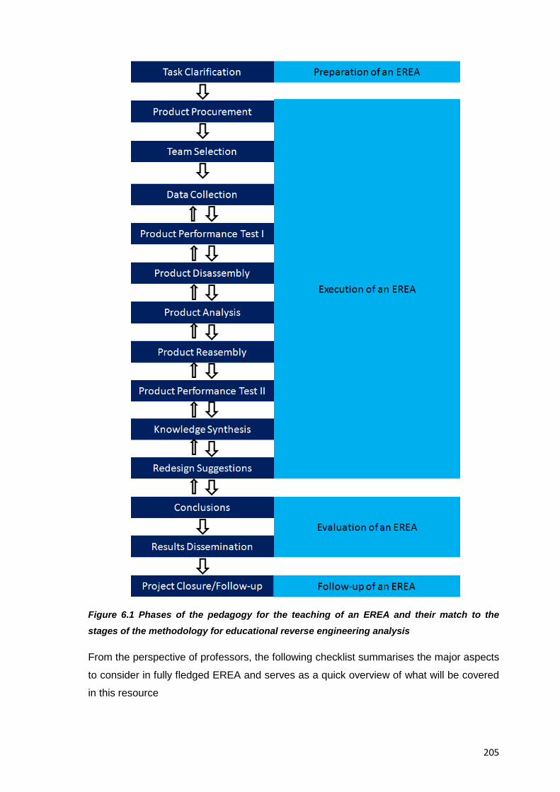
205
Figure 6.1 Phases of the pedagogy for the teaching of an EREA and their match to the stages of the methodology for educational reverse engineering analysis
From the perspective of professors, the following checklist summarises the major aspects
to consider in fully fledged EREA and serves as a quick overview of what will be covered
in this resource
206
1) Preparation of the EREA
a. Setting of educational goals and means to achieve it (e.g. Learning
outcomes in line with the university curriculum)
a) Setting of specific learning objectives
b. Setting of steps to carry out the EREA
c. Setting up of activity logistics
d. Planning of evaluation mechanisms
e. Selection/Acquisition of the product for analysis
f. Putting in place of feedback mechanisms for students
g. Budgeting
h. Setting the teaching strategy for the EREA (e.g. Presentation of
introductory lectures followed by lab work and concluding dissemination
activities)
i. Determining the total duration of the exercise
j. Setting of the teaching method: (e.g. An activity taken over eight session of
1h each where students will be evaluated on the application of the reverse
engineering methodology presented here)
2) Briefing to the Students
a. Setting of tasks, expectations and procedures to follow
3) Execution of the EREA
a. Execution of all stages of the methodology
b. Guidance during the stages of the methodology
c. Guidance during the students’ deliberation processes to help them learn
and arrive at their own conclusions
4) Evaluation of the EREA
a. Evaluation of the achievement of the overall goals of the activity
207
b. Evaluation of attainment of learning objectives
c. Grading of students and teams
5) Documenting and Dissemination
a. Documenting of knowledge obtained from the EREA
b. Dissemination of findings from the EREA
c. Opinions on knowledge generation and application
6) Follow up
a. Collection of students feedback
b. Archiving of student’s project
c. Preparation of new EREA for upcoming semesters
From the abovementioned checklist, note that every phase and individual item in it will be
further expanded in the subsequent sections of this resource.
6.4 Fundamentals of the Teaching of EREA
The information in this section applies to all cases of EREA irrespective of the depth
pursued or the product analysed, and relates to the specific educational needs of
professors, students and academic institutions involved, as such, it is presented in this
separate section to highlight its foundational nature, and after having dealt with the
information presented here, the reader can naturally move onto the next phases and
stages of the teaching of EREA (e.g. The Task Clarification stage). In this section then,
several pieces of information more akin to the areas of the teaching and pedagogy of
engineering are presented which will help contextualise the information for the specific
phases and stages shown further below
6.4.1 Setting the Goal and Learning Outcomes of an EREA
The general goal of an EREA is always dependant on the professor in charge but it is
usually in line with those already standardized in the teaching of engineering design such
as the ones from the Accreditation Board for Engineering and Technology (ABET) in the
USA (e.g. Appreciate wider design issues such as ethics, liability, safety, and product
disposal, be familiar with the product realization process and its documentation [ABET.
2010] etc.), or those similar ones from CDIO in Europe [CDIO Council. 2010], in this
208
sense, and as envisioned in this collection of resources the general goal should be one
that contributes to the students’ education and to their future professional performance
via a practical (rather than theoretical) educational experience, so the following one is
suggested as an example “To provide students with an opportunity to familiarize with a
variety of engineering design-related topics through the reverse engineering analysis of a
consumer product.” For specific implementations of EREA though, the goal is still defined
by the professor in charge but it usually describes the final point the class should achieve
after taking the EREA (e.g. To introduce students to modern product design by the
analysis and redesign of existing consumer products) and it may or may not coincide with
the general goal for all EREAs.
The general learning outcomes after the completion of an EREA on the other hand
describe what students will be able to do at the end of instruction and provide clear
reasons for teaching. A number of authors have already provided examples of achievable
examples well within the reach of academic institutions and students with minimum
resources at hand for the conduction of an EREA, the examples of learning outcomes
listed below then, have been suggested by authors such as [Sheppard. 1992b],
[Sathianathan. 1997] and others, and are presented here as an aid in setting your own
ones at the upcoming Task clarification stage, that are specific to your own case of an
EREA and dependant on the details of the curriculum of your engineering design
programme, namely:
• To develop an awareness of the design process (e.g. Through hands-on design
assignments that highlight the importance of functional specifications in design
and how they map into specific functions)
• To develop an understanding of the knowledge and skills required in contributing
effectively to product development as a design engineer.
• To introduce students to modern product design by analysing and redesigning
existing consumer products
• To introduce students to the science and art of design by evaluating the work of
practicing designers
• To empower students to determine how scientific principles; material properties,
manufacturing techniques, cost, safety requirements, environmental
considerations, intellectual property rights, and other considerations of
engineering impact the design of a product
• To incorporate the skill oriented tasks, such as analysis and interpretation of
experimental data, into team oriented design projects
209
• To understand the underlying design concepts behind the product under analysis
and its technological history
• To be able to explain materials characteristics and properties, and relate them to
performance, manufacturing process, and the environment
• To make students aware of the power of clear, concise communications (oral,
written and graphical) by having them present descriptions of mechanical artifacts
and critique each other’s work.
• To be proficient in the disassembly, inspection, performance measurement,
rebuilding, and assembly of consumer products’
• To connect the engineering knowledge to the physical realities of the subject
system
From all the above mentioned outcomes you should pick those that are more relevant to
your target students
6.4.2. Suitable Format of EREA to fit an Engineering Design Syllabus
Educational reverse engineering activities can take any of the following forms:
• A capstone project administered at the senior semester culminating what was learned
throughout all courses of the career curriculum
• A year/semester project culminating what was learned across all the courses of a
given career year/semester (e.g. Freshman, senior, etc.)
• A unit project culminating everything learned during one of the courses of the
engineering design curriculum (usually Introduction to Engineering Design 101)
• A self-contained educational experience; of limited duration and depth; running in
parallel to any of the courses comprising the whole engineering design curriculum,
intended to achieve a specific educational outcome and support the teaching of topics
in the host course (e.g. An example done at The University of Washington, [UOW.
2010] across seven 1hr sessions).
The most popular choices from the above mentioned cases can be considered the year /
semester project and the self-contained activity. The methodology of Resource 5 and the
pedagogy of Resource 6 presented here then, both support any of the abovementioned
cases where due provisions are taken to ensure the flexibility necessary to shorten or
stretch the span of the selected case and match the specific needs of a class and its
available resources
210
The guided example of an EREA of Resource 7 thus, has been designed as a self-
contained activity of limited duration (eight sessions) in the form of a side project, running
parallel to the regular schedule of any of the courses of the first year curriculum of
engineering design (e.g. Introduction to engineering design, or introduction to systems
engineering)
It was designed that way because the integration of EREA into existing teaching practices
might be a new activity for the readers of this document and so an initial example of
limited resources and expectations has been favoured in this collection of resources to
serve as first step into reverse engineering, experienced professors though can easily
expand the example presented in Resource 7 into a fully fledged activity according to the
needs of their own students
In short, the exact moment of inclusion and to what depth the results from the EREA are
asked, is a decision left entirely to the professors in charge since the methodology and
resources presented here will allow for such flexibility.
6.4.3 Setting the Depth of an EREA
The thoroughness and level of detail to go into the analysis of a consumer product will be
mostly dependant on the semester students are, and on how much they have covered
about their career’s syllabus; this means that not all potential stage questions, tests and
tasks tests are to be assigned to the same students and that there should be a clear
difference about what to expect in terms of technical proficiency from freshmen to senior
years (e.g. A fully fledged reverse engineering analysis against a superficial one).
Authors [Malmqvist et al. 2004] state when referring to the right level of difficulty in an
activity that a too difficult task may result in an impressive analysis that is teacher-
created, with student as implementers (whereas) a too simple analysis may not promote
motivation nor build confidence from having met a challenge , in this sense the
knowledge and experience of the professor in charge should help both, the student to
know what to look for when reverse engineering a product, and the professor to know
what to ask and what to expect from students,
6.4.3.1 Setting the level of disassembly for the subject system
Every product is different and has different properties which affect the type and breadth of
empirical knowledge available to the analyst, this mean that just as the depth of analysis
in an EREA has to be tailored to the knowledge and capabilities of students, the actual
disassembly of the product under analysis has an optimal level depending on the
211
complexity of it; a general level of detail is set for the overall product then, but in practice
another one is achieved for the individual parts of it , the following criteria should be taken
into account in descending order in order to suit the level of disassembly to the needs of
the professor in turn, namely:
• Try for a full disassembly down to the last individual part even if it requires the
destruction of components (e.g. Suitable when analysing out of order products of no
significant value)
• Try for a full disassembly down to the last individual part that still allows for a
satisfactory reassembly to original working conditions
• Dismantle only to the level of major subsystems, if a full understanding of a product is
already attainable (e.g. For a disposable camera: Power/battery, film advance
mechanism, lens, and flash)
• Disassemble down to the level where a classification of the major components allows
for the recognition of its materials (e.g. Metal, plastic, etc) or its plausible
manufacturing process (e.g. Machining, stamping, etc.)
• Disassemble down to the level of major subsystems even if some areas of the
product remain a black box for which further speculation about its operation will be
needed
Given that the subject system must be analysed down to the appropriate level that allows
the verification of the hypotheses about it these criteria will help professors set the
disassembly of the subject system down to a level that still allows for an educational, fluid
experience with the available resources
6.4.3.2 Advice Specific to the Guided Example in Resource 7
When analysing your subject system, do not try to reverse engineer beyond irreversible
reactions (e.g. The actual film and how it works (in terms of chemical reactions)), but bear
in mind that the purpose of the dissection and the desired level of detail will dictate the
specificity of the data collected.
6.4.4 Time of Inclusion of an EREA in an Engineering Design Curriculum
Although EREA can be administered to students at any point throughout the duration of
their career studies, two major timeframes have been favoured already in past published
research and for different reasons, namely:
212
• Inclusion at the beginning of career studies (e.g. 1st Year): Because the integrative
nature of EREA makes students quickly familiarise with the field of engineering design
and the topics that will be covered more comprehensively later in their studies, and
because an EREA at this point can be done with less resources and contained
expectations
• Inclusion at the end of career studies (e.g. 4th Year): Because at this point students
can better tackle the tasks, questions and analyses of a fully fledged EREA which can
also serve as opportunity to consolidate and make use of all previously acquired
knowledge during their studies (e.g. A “capstone project)
A notable exception from the cases presented above comes from the Stevens Institute of
Technology in the US where reverse engineering courses support the teaching of
engineering though seven continuous terms [SIT. 2012]. For the specific example in this
collection of resources, the inclusion at the first year of studies has been favoured
because the EREA itself, has been planned as a short, exploratory activity and limited
resources for its development are anticipated
6.4.5 Introductory Talks
Irrespective of the type of implementation of an EREA (e.g. Time of inclusions, length,
target students, product chosen, etc.) students must have a kick off meeting; this is
indeed common to any hands-on activity or laboratory work in educational environments
and the only difference would lie on what topics are covered in said meeting. Under a
reverse engineering approach for example it is here when students can be explained that
they’ll perform a reverse engineering analysis of a consumer product and that they’ll be
required to document and execute a variety of tasks an analyses associated to it (e.g.
Disassembling; analysis, assembling, etc). The following list of tasks and items then,
intends to exemplify the aspects that should be reviewed with target students before the
beginning of the activity, namely:
• Ask your students think about what reverse engineering is and why are products
reverse engineered, so they can better contextualize their educational experience
• Familiarise your students with shop practices, safety measures and use of tools
and equipment
• Ask students to brush up on all related theory and published resources about
reverse engineering, to level all students’ understanding about it and set the
expectations from the activity
213
• Assess your students’ knowledge of common engineering design topics, if
needed, familiarize them with the concepts of systems engineering, engineering
design and other you’d consider essential for the success of this activity
• Explain your students what disassembly, analysis and assembly activities are like
• Explain your students why the exercise exists and how it fits with the rest of the
syllabus
• Introduce your students to the methodology for educational reverse engineering
analysis suggested in this collection of resources
• Assess your student’s previous knowledge or experiences needed to go through
the EREA without major knowledge gaps and provide remedial actions if needed
• Explain the assignment and expectations for the EREA
• Suggest appropriate ways to proceed safely and efficiently during work sessions
• Talk with students about possible product to dissects
• Ask students to reflect on what they will find on the inside of consumer products
and how they will work
• Ask your students to reflect on what the ethical and societal impact considerations
in product design are
• Refresh your students understanding on varied topics such as use of design
catalogues, basic engineering materials properties and their selections for various
applications
• Refresh your students’ skills on technical writing
• Ask your students to keep a design journal throughout the duration of the EREA
where they’ll document all their impressions about it
• Determine if a field trip to industry would be needed
• As mentioned already EREA stem from the more common hands-on type of
activities which can be seen here through the similarity in the preparatory activities
common to all of them
6.4.6 Familiarising Students with Vocabulary and Terminology
EREA are a suitable way to familiarize students with the vernacular of engineering design
practice, as a professor it is easy to anticipate the kind of terms students will acquire
throughout the duration of their studies and Table 6.1 below for example summarises
those words mentioned in typical EREA, and the list can be expanded/contracted as per
the professor’s requirements
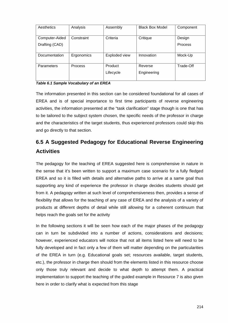
214
Aesthetics Analysis Assembly Black Box Model Component
Computer-Aided
Drafting (CAD)
Constraint Criteria Critique Design
Process
Documentation Ergonomics Exploded view Innovation Mock-Up
Parameters Process Product
Lifecycle
Reverse
Engineering
Trade-Off
Table 6.1 Sample Vocabulary of an EREA
The information presented in this section can be considered foundational for all cases of
EREA and is of special importance to first time participants of reverse engineering
activities, the information presented at the “task clarification” stage though is one that has
to be tailored to the subject system chosen, the specific needs of the professor in charge
and the characteristics of the target students, thus experienced professors could skip this
and go directly to that section.
6.5 A Suggested Pedagogy for Educational Reverse Engineering Activities
The pedagogy for the teaching of EREA suggested here is comprehensive in nature in
the sense that it’s been written to support a maximum case scenario for a fully fledged
EREA and so it is filled with details and alternative paths to arrive at a same goal thus
supporting any kind of experience the professor in charge decides students should get
from it. A pedagogy written at such level of comprehensiveness then, provides a sense of
flexibility that allows for the teaching of any case of EREA and the analysis of a variety of
products at different depths of detail while still allowing for a coherent continuum that
helps reach the goals set for the activity
In the following sections it will be seen how each of the major phases of the pedagogy
can in turn be subdivided into a number of actions, considerations and decisions;
however, experienced educators will notice that not all items listed here will need to be
fully developed and in fact only a few of them will matter depending on the particularities
of the EREA in turn (e.g. Educational goals set; resources available, target students,
etc.), the professor in charge then should from the elements listed in this resource choose
only those truly relevant and decide to what depth to attempt them. A practical
implementation to support the teaching of the guided example in Resource 7 is also given
here in order to clarify what is expected from this stage
215
It is important to keep in mind though that the pedagogy is presented in a linear,
sequential and accumulative manner, and so at any point of the methodology, you should
feel free to safely repeat any step of it to provide your students reinforcement and
repetition of key information until the desired goal is attained.
6.5.1 Phase 1 Preparation of an EREA:
This is the phase were all the planning for the development of a safe, educational activity
for the students is done, the resources listed here for that purpose cover the most
relevant aspects for the proper attainment of this stage and in that sense the information
presented here can be considered comprehensive, it is expected that first time instructors
of reverse engineering will find in this resource everything they need from the battery if
items to check before starting an EREA, experienced professors however, and as stated
before, will only pick and attempt those needed for them.
It is advised that two main aspects lead all the work in this phase for the benefit of both
professors and students and by sticking to those two points the resulting work from this
phase should contribute for the attainment of the overall goal of the EREA, one is that all
work should converge toward meeting all project milestones & deadlines (e.g. By using
time efficiently) , and the other is that all work done should stay focused on the task being
asked, by following these two directives then , this stage should be attained without any
unexpected complications
The methodology for educational reverse engineering analysis suggested in Resource 5
already contains a sequence of stages that consider all aspects of the actual analysis of a
subject system, the pedagogy of this resource though, is divided by phases and each of
them correspond to one or more of the stages of such methodology, for the “Preparation”
phase then, the corresponding match is the “Task Clarification” stage and for all intents
and purposes they pursue the same goals but they are seen from the different
perspectives of the analyst (cf. Undergraduate student of engineering design) and of the
professor in charge.
6.5.1.1 Task Clarification:
At this stage most of the work to understand the actual situation, its goals and how they
will be achieved is done, the preparation of an Educational Reverse Engineering Activity
(EREA) then, is not that different from any other laboratory activity used in the teaching of
engineering design, and as such the writing of a lesson plan that can effectively work as a
checklist for the items to consider in the process is necessary, The information listed
216
below for example, represent a possible lesson plan for the preparation of an EREA
which includes all relevant points to keep in mind; because of reasons of space though
not all items listed in it will be developed here, only those specific to the reverse
engineering nature of the activity whereas for the rest of them, just a self descriptive
explanation will be mentioned for the readers to expand at a later time
A. A General Lesson Plan for EREA in an Engineering Design Curriculum
In support of the eventual implementation (or expansion) of EREA into existing teaching
curricula, the following list inspired by researchers such as [Hannaford. 1995] and
[Eggert.1996] comprises the suggested elements to include in a lesson plan for an EREA;
the elements included therein are of a self explanatory nature and support the planning of
all cases of EREA, they can be considered standard elements from existing engineering
design courses and intend to improve the cognitive abilities of students learning under the
pedagogy suggested in this resource. For specific advice on a given application of an
EREA though, the rest of the subsections of this resource will provide further explanation
to the elements that could change depending on the nature of the EREA being done.
Earlier version of this resource included fully developed lesson plans, supporting
documents and a syllabus. Because of space constraints and readability, now only the
most relevant items are developed as a sample while the rest is given self descriptive
leads for reference, so the readers of this document can eventually develop their own
lesson plan according to their own needs, criteria and regulations of the host academic
institution. From the items listed below then, select those to assign your students and
tailor or complement them accordingly to fit your teaching needs and those of your target
students , namely:
A.1 Aspects Related to the Identification and Control of the EREA
• Activity credits: It describes the points obtained after approving the activity and how they
are distributed depending on the professor in charge and the host university
• Activity description: An account of the major elements of it, e.g. “This activity will further
develop the student’s knowledge of the engineering design process and emphasis will be
placed on accepted practices in disassembly; assembly, inspection and performance
measurement of the subject system’s parts. In their final reports, students will critically
appraise the design of it and suggest improvement alternatives for it.”
• Activity Format: How the course will be structured, this item is further discussed in
Section 6.4.2 and 6.4.3
217
• Activity title and code: A name to portray the basic idea and key features of the activity
and its control number according to the host university
• Additional notes: An optional section to emphasize any aspect of the activity that
needed to be made clear or could be useful for prospective students (e.g. The following
activity is directed to engineering students with an interest in discovering the links among
markets, materials, and manufacturing processes by analysing the design of everyday
products).
• Allocation of Resources: Assess available resources for the EREA (e.g. Workspace,
storage space, tools, potential extra help from teaching assistants, running costs,
maintenance and support, etc.) and allocate them
• Allocation of students’ resources: It refers to the expected workload students will do
over the length of the activity (e.g. On average students need to spend two hours of study
and preparation for each 50-minute session)
• Arrangement of field trips to industry: In case donors or supporters offer it or if the study
of product under analysis dictates it
• Assumptions: To communicate the professor’s assumptions; biases, principles and
beliefs regarding the activity content to set it off from other similar courses
• Class meeting times: The time allocation where the activity will be done and discussed,
as well as the suggested hours outside class dedicated to it
• Course communication: It refers to e-mail addresses, drop boxes, etc.
• Course goal: The general outcomes the course is designed to achieve and how they
contribute to the education of students, this item is discussed in Section 6.4.1
• Course prerequisites: Depending on the host university or professors’ criteria but related
to the previous knowledge or experiences needed to go through the activity without major
knowledge gaps
• Course Rationale: Why the activity exists and how it fits with the rest of the curriculum,
(e.g. In this activity students can get in one single activity the condensed experience in
the design process and associated manufacturing actions that the analysis of an existing
product can provide)
• Course reading: Required text and background readings (if any)
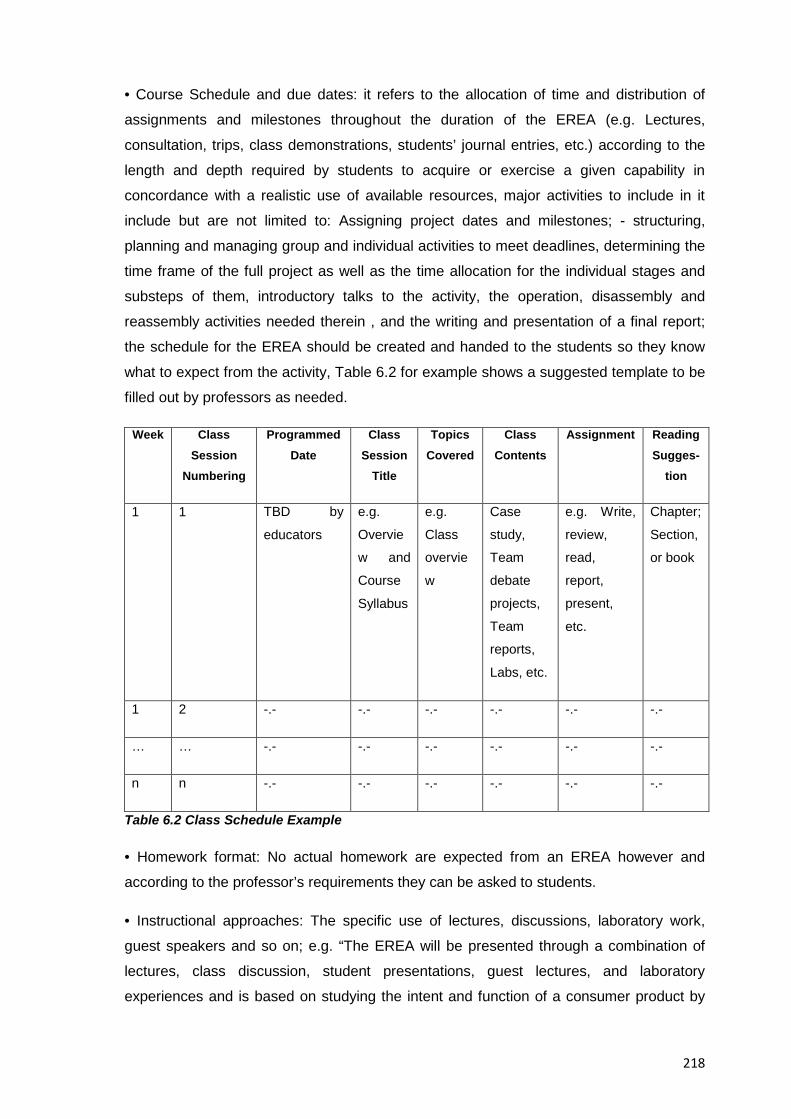
218
• Course Schedule and due dates: it refers to the allocation of time and distribution of
assignments and milestones throughout the duration of the EREA (e.g. Lectures,
consultation, trips, class demonstrations, students’ journal entries, etc.) according to the
length and depth required by students to acquire or exercise a given capability in
concordance with a realistic use of available resources, major activities to include in it
include but are not limited to: Assigning project dates and milestones; - structuring,
planning and managing group and individual activities to meet deadlines, determining the
time frame of the full project as well as the time allocation for the individual stages and
substeps of them, introductory talks to the activity, the operation, disassembly and
reassembly activities needed therein , and the writing and presentation of a final report;
the schedule for the EREA should be created and handed to the students so they know
what to expect from the activity, Table 6.2 for example shows a suggested template to be
filled out by professors as needed.
Week Class Session
Numbering
Programmed Date
Class Session
Title
Topics Covered
Class Contents
Assignment Reading Sugges-
tion
1 1 TBD by
educators
e.g.
Overvie
w and
Course
Syllabus
e.g.
Class
overvie
w
Case
study,
Team
debate
projects,
Team
reports,
Labs, etc.
e.g. Write,
review,
read,
report,
present,
etc.
Chapter;
Section,
or book
1 2 -.- -.- -.- -.- -.- -.-
… … -.- -.- -.- -.- -.- -.-
n n -.- -.- -.- -.- -.- -.-
Table 6.2 Class Schedule Example
• Homework format: No actual homework are expected from an EREA however and
according to the professor’s requirements they can be asked to students.
• Instructional approaches: The specific use of lectures, discussions, laboratory work,
guest speakers and so on; e.g. “The EREA will be presented through a combination of
lectures, class discussion, student presentations, guest lectures, and laboratory
experiences and is based on studying the intent and function of a consumer product by
219
disassembling it in order to see how its intent is realized, then reassembling it and
suggesting improvements for it
• Lab time Scheduling: For the actual analysis of the subject system students will meet
several times at the laboratory and won’t assemble the subject system again until they
have fully analysed it (If no further lab sessions were are available they can work at the
classroom or at their homes and present later their findings to the class). It can also be
understood as the number of sessions needed to cover all stages included in the
methodology, (but flexibility on different configurations and number of sessions should be
considered)
• Medium of instruction: It refers to the language used in the activity
• Name / Office location / e-mail / Phone: The main contact information for the professor
in charge and / or, teaching assistants, guest speakers and industrial partners if needed
• Office hours: The time available for counselling to the students
• Overall teaching pattern: The main parts that constitute the full activity content and how
they intend to be approached (e.g. Duration of the activity, mix of hours of lecture / tutorial
/ laboratory / other, use of class time, etc.)
• Participants’ identification: the general data about students undergoing an EREA (e.g.
Team name; team members, product under analysis, date, etc.)
• Preparer: The name of the creator of the lesson plan in case it is different from the one
teaching it
• Provisions for teaching assistants: Determine if extra support personnel will be needed
(e.g. Depending on class size)
• Request for additional equipment: It concerns the mechanisms that will allow to look for
additional equipment for the attainment of the goals of the EREA in case it becomes
necessary, e.g. tools, videocameras, etc.
• Required Activity materials and infrastructure: The resources needed (e.g. Equipment,
facilities, etc.) for undergoing an EREA, this item is further discussed in Task Clarification
at Section 6.5.2.1
• Semester/Year: The time frame where the EREA will be delivered
220
• Statement of Purpose: The focus of the activity, what the students will learn, the abilities
to exercise, etc.
• Suggested bibliography: Course text and supplemental readings suggested by the
instructor to support the teaching of the subject, e.g. Course Text: “Product Design:
Techniques in Reverse Engineering and New Product Development” by [Otto & Wood.
2001]. Reference Text (Not compulsory): “Hacking the Xbox: An Introduction to Reverse
Engineering” by [Huang. 2003]. See also Resource 9 “Miscellaneous Resources” for
support on this item
• Target student group: The details about the students undergoing an EREA
• Teaching / Learning styles: It refers to the pedagogies (e.g. Teaching styles, learning
styles, educational environment) the target students and the professors in charge may be
more acquainted with
• Venue: The physical space (e.g. Classroom and engineering laboratory) where the
activities will be conducted and the students’ safety can be guaranteed
• Version: It shows the latest valid version of the activity and when it was revised
A.2 Aspects Related to the Management of the EREA
• Abilities to be developed: It the refers to the set of abilities and skills to be acquired and
developed in this activity, this item is further discussed in Section 4.3
• Acknowledgement of advantages: State your class strengths and potential contributions
for the success of this activity
• Activity instructions: The directions on what to do for the EREA , e.g. “By following the
methodology for the reverse engineering analysis of consumer products given by your
professor attempt all questions, tasks and analyses that apply to your product” or “In this
project you will reverse engineer a typical consumer product that contains both electrical
and mechanical components, you’ll be asked to create engineering drawings for the
device analysed as well as disassembly and assembly instructions for others to follow;
you will work in teams and document everything you see and will have to do research on
how the subject system is manufactured to finally report on how to make the process
more cost effective, environmentally friendlier and how the product itself could be
improved based on your findings”
221
• Activity requirements: The tasks and assignments included in the activity and aligned to
the learning outcomes that will help students to achieve the final abilities to leave the
course with, Resource 6 with the pedagogy itself discusses this item
• Activity topics: The list of themes about what is covered each class session or
throughout the activity, Resource 5 for example, supports this item however, an
introductory lecture mentioning the topics of manufacturing principles; product cost
analysis, product architecture, concept embodiment, DfX topics (e.g. DFMA, DfE,
DfRobustness), and prototyping is suggested
•Arrangement of facilities: It refers to the selection of the workplace for the EREA; the
planning for the straightening out of the workplace after finishing the activities, the
laboratory equipment and in general an assessment of the infrastructure requirements for
the safe and smooth development of the activity
• Assessment of challenges: To anticipate potential shortcomings or challenges a
professor might face in the development of an EREA (e.g. Unplanned student needs) and
thus develop contingency plans (e.g. Corrective action based on feedback from students)
for any unexpected circumstances where common sense should prevail
• Grading Procedures: It refers to the assessment criteria, tools and techniques for the
evaluation of students again learning objectives; this item is further discussed in Section
6.5.3
• Ideal number of students / Class size: This item is further discussed in Section 6.5.2.2
and considers the number of students enrolled to the activity
• Learning outcomes: It refers to the learning objectives the EREA is intended to produce
at the end of it, they are usually worded starting with “by the end of this activity, students
will…” and they should be listed as specifically as possible based on the kind of evidence
you will need to assess the student’s learning, this item in discussed in Section 6.4.1
• Preparation of tooling: it refers to the expected equipment necessary for the attainment
of the goals of the EREA
• Provisions against disliked aspects of product dissection activities: According to authors
Sidler-Kellog and Jenison regarding the things students less like in a product dissection
activity, their answers typically reflected they dislike tasks that are detailed oriented like
counting and measuring pieces, creating drawings, and most of all writing the formal
report, [Sidler-Kellog & Jenison. 1997] and thus care should be taken to consider these
222
tasks as an integral part of all projects and enhance them (as reflected in the
methodology presented in Section 5.4.12 so students can perceive them as important
and meaningful.
• Students’ tracking and management mechanism: Students can be advised to document
team actions in a dissection journal (A detailed record kept by each student of their
dissection activities; sketches, reflections, calculations, photographs, etc) that can be
periodically collected and graded for completeness and accuracy
A.3 Codes in Practice during an EREA
• Academic integrity: The codes in place in every institution to ensure a fair learning
experience for all students and how they’ll be applied to this activity
• Affidavit: A section included in the lesson plan linking the university, the professor and
students to a common set of rules, (e.g. Through signatures of all relevant parts)
• Attendance policy: It refers to the demonstration by students of class attendance,
assignments, attitude, participation, respect for others, use of class time, inclement
weather and enthusiasm in both lecture and laboratory activities
• Provisions for students with disabilities: The consideration of appropriate academic
accommodations for students with disabilities in accordance with the specific university
policies and equal access laws in place. Examples of disability categories are AD/HD
(Attention-deficit hyperactivity disorder); specific learning disabilities, hearing, vision,
health impairment, psychological, orthopaedic, traumatic brain injury and so on
• Rules of conduct and academic policies in general: Depending on the host university
and professor in charge but usually considering points such as students’ participation,
ethical behaviour and safety, e.g. . “Students are required to maintain a professional
attitude while in classes and at the laboratory. Students must adhere to standard safety
practices at all times and will not operate any piece of equipment they have not been
given instruction on. Students may and will be removed from the premises for behaviour
that is considered "unprofessional" by the professor in charge, including but not limited to:
Constant tardiness; excessive loud talking, sleeping, not being prepared, inappropriate
attire (e.g. Safety goggles, hats, boots), bullying, inappropriate language and so on,
throughout all stages of the EREA
• Safety and emergency provisions: It refers to the practices to maintain the well being of
students at all times, e.g.: Keep telephone numbers at hand; work at least in pairs, set
223
class order and rules (e.g. No horseplay during handling of tools and testing devices,
require students to wear safety glasses every time the product or tools are being handled,
in order to prevent electrical shocks basic electrical safety measures should be followed,
always read device labels carefully before taking items apart, perform training and
enforcement of safety procedures for both students and faculty, take care when dealing
with hazardous materials; handling risky loads or pointy part profiles, if your product uses
magnets, (e.g. Single cylinder 4-cycle engines) remove and store watches since strong
magnetic fields (e.g. Around the armature of a motor) can damage watch mechanisms
• Statement of expectations: Professor’s expectations in terms of student responsibilities.
Just as in any other educational activity, an EREA requires a document to organize the
main ideas in it, its creation then, is no different to any other lesson plan previously done
by the professors in charge, and because of this, their own experiences and requirements
can be easily integrated to the sample structure shown above to come up with a lesson
plan that covers the needs and aspirations of the students in mind and in accordance with
regulations at the host academic institution. If the professor in charge deems it important
then, a copy of this could be given to the students
Finally and as mentioned already the contents presented here are of a comprehensive
nature but experienced educators will know what items to attempt, to skip, or even decide
to go straight to the task clarification stage altogether, this is specially true since only a
few of all the abovementioned items are usually developed, depending mostly on the
particularities of the EREA in turn.
6.5.1.2 Specific Phase and Stage Advise for the Guided Example in Resource 7
Setting the Depth of the Reverse Engineering Analysis: for the specific example shown
here; the film canister for example isn’t fully reversed engineered because of the non
reversible chemical reactions embedded in it, the instructor then, decides to what depth
of analysis students should go according to the educational goals previously established
6.5.1.3 Creation of Supporting Documents for Students
Additional to the information presented above, professors can come up with their own
supporting documents to give students and to help them go through the development of
an EREA, the example listed below provides support for every stage of an EREA and is
presented here so the readers can use it as baseline for the creation of their own
examples.
224
6.5.1.3.1 Activity Handout for Students ndergoing an EREA
This section intends to portray what the contents of a supporting document (e.g. An
activity handout) for students undergoing an EREA would be, it lists tips and suggestion
on what to do at every step of the methodology for EREA suggested in Resource 5. It is
directed to students of engineering design newcomers to reverse engineering activities
and its intention is to help ensure a safe, successful educational experience. The handout
itself is written in a general way so it fits any format of EREA and the selection of any
consumer product for analysis. The professors in charge then, could either withhold or
present this information to their students according to their proficiency in analyzing
systems, but its distribution is actually recommended to help equalize the knowledge of
all students about what to do and how, given that this handout would effectively be a
pedagogy for the conduction of an EREA as seen from a student’s perspective, the
readers of this document could create their own example based on their own needs using
the example provided below as a baseline
• Stage 1: Task Clarification
• Goal:
To understand the nature of the tasks you are being asked / wanting to perform
• Student Tasks:
1. If not mentioned by your professor already, state your what you would like to learn
from this first stage and your goals and expectations in participating in this whole activity,
share them with your teammates too
2. Familiarise with the concept of Educational Reverse Engineering (e.g. Read a paper
about it or consult the ‘Miscellaneous Resources’ section of the collection of resources of
your professor)
2.1 Familiarise with a methodology for the educational analysis of consumer products
(consult with your professor or look at the ‘Miscellaneous Resources’ section of your
professor’s collection of resources)
2.1.1 Familiarize with the concepts of product testing; disassembly, analysis and
reassembly
3. Present a project proposal to your professor with action plans, diagrams, charts and
timetables that track and show your progress towards the completion of the activity
225
3.1 Allocate resources and assign the tasks to perform
4. Prepare both an individual and team’s journal to record your stage findings;
observations relevant to the EREA how you performed the required steps and assign how
the team journal will be kept by who and when.
• Stage 2: Product Procurement
• Goal:
To select and procure a suitable product for educational reverse engineering analysis
• Student Tasks:
1. If your Professor / Institution hasn’t already provided one, choose a suitable product for
reverse engineering analysis
2. Get the selected sample (but also look for potential sponsors/donators)
2.1 If indicated by your professor also collect competing products or specific
product parts for areas of subsequent, detailed comparison and analysis.
3. Document in an individual and team’s journal your stage findings; observations
relevant to the EREA and how you performed the required steps.
• Tips:
-For the selection of the product for analysis:
-- If the decision to choose a subject system for educational reverse engineering analysis
rests in you, think about your school and community. Identify local examples of a natural
system, an engineered system and a social system to learn about the various kinds of
systems that there are and choose one that you find of interest for analysis
--Procure a working product that is preferably operation-safe and from which something
valuable can be learned
-- Choose one that at a minimum contains both electrical and mechanical components, a
familiar product such as any home appliance found at home, i.e. A coffee maker or a
toaster are a good starting option
-- To choose old products is good since their technologies are more transparent and easy
to see
226
--From this stage forth you will notice how every stage brings new intermediate results;
information about the subject system and about how to achieve your goals, but it will be
only at the ‘Knowledge Synthesis’ stage when one will be certain of what is actually
known about the product under analysis and what isn’t
• Suggestions:
- Comment individually to your professor if you were already familiar with the product
chosen for analysis
• Stage 3: Team Selection
• Goal:
To understand team roles and responsibilities so you and your team members’ efforts are
organized to ensure a successful completion of an Educational Reverse Engineering
Activity
• Student Tasks:
1. Set up a work team with people you feel okay working with or with those assigned to
work with
2. Assign team roles if your professor hasn’t done so already (e.g. Assign turns to
disassemble; assemble a product, keeping of notes, documenting the process, etc.)
3. Set fair labour division rules (differences in gender and cultural backgrounds can be
partially alleviated with fair labour division) so ensure an orderly distribution of workload,
fair distribution of tasks and a similar learning experience were all team members can
have the disassembling experience and take equal turns irrespective of the product
chosen.
4. Prepare a document showing division of labour and ground rules to support an
effective group communication teamwork experience after the teams have formed
5. Document your stage findings and explain how you performed the required steps
• Tips:
- Complexity and size of the product chosen for analysis can be one of the major criteria
used to assign roles and tasks
• Stage 4: Data Collection
227
• Goal:
To pose and answer at this stage as many questions about your product as possible
• Student Tasks:
1. Collect and document all possible data about the subject system under analysis
2. Expand and develop your research skills (e.g. By familiarizing with tools that retrieve
information; by using visual and oral techniques, by questioning and observing or by
bringing in information from ``outside'' sources to help make decisions)
3. Document your stage findings and explain how you performed the required steps
• Tips:
Use computer-based and library resources effectively to acquire needed information;
seek information on problem from multiple sources, understand importance of learning
what has already been done to solve a given problem, use traditional sources of
information to het key data (e.g. Operation; performance, target market, outstanding
features, technological level, market analysis, intellectual property, manufacturing
company information, patents, data from online databases, etc.))
- Understand all available information about the product under analysis and bring it to the
classroom the day of the reverse engineering activity or whenever indicated by your
professor
• Stage 5: Product Performance Test I
• Goal:
To operate the product and gain concrete experience with it in terms of functions and
forms
• Student Tasks:
1. Familiarize with the tools, measuring devices and basic safety measures for the use of
the testing equipment
2. Observe, use and experience your product to familiarize with it in a structured way in
order to understand it
3. Document your stage findings and explain how you performed the required steps
228
• Tips:
- Follow all relevant laboratory guidelines concerning safety (e.g. Testing equipment,
behaviour, etc)
- If testing the product implies the permanent change or destruction of its parts, consult
with your professor before carrying on
• Stage 6: Product Disassembly
• Goal:
To disassemble the chosen product in preparation for a thorough analysis of it
• Student Tasks:
1. Prepare for the disassembly of the subject system
2. Disassemble the subject system
3. Perform an initial analysis of the inner workings of your product
4. Document you findings
• Suggestions and Tips:
The disassembly of a product calls for a careful and methodological procedure where all
necessary resources are at hand in an environment that guarantees the safety of
participants at all times, the following tips and suggestions are presented in order to
achieve a successful educational experience, namely:
-For the Management of the Activity:
-- During the activity practice effective listening skills; exhibit appropriate non-verbal
mannerisms and give and receive constructive feedback
-For the Recording and Tracking of the Activity:
-- In order to record the information generated during the disassembly stage of an EREA
(e.g. Components; parts that make up the product, description of how the components
function to make the product work, etc.) you can use tables or pictorial function-
component maps
-- Photographs should be taken of the product before dissection begins and frequently
during dissection to aid in product reassembly
229
-- Keep a dissection notebook for recording and sketching what you see and what you do
(e.g. Disassembly steps of the product)
-For the Disassembly of the Product:
-- Follow ordered and methodical product disassembly practices, fishbone diagrams for
example, are powerful tools in organizing the disassembly of the product under analysis,
use them if needed
-- Be systematic in the disassembly, examining each part, its function, and documenting
how it interfaces with other parts and as you disassemble document in detail what you
learn about how the subject system works
-- When disassembling, remove one component at a time and put all parts in a bin /
transparent bag to help keep track of the process but whenever you remove a bolt,
instead of just throwing it in your parts bin, thread it back into the place where it came
from (after the mating part has been removed)
-- When disassembling your product be firm, but gentle, the pieces should come apart
without breaking
-- When disassembling be careful with pieces that drop out or stick to other parts (e.g.
Magnetic or sticky ones) they are very easy to lose.
-- When disassembling be careful of flying pieces
-- Organize the component parts of your subject system on their work area according to
their subsystem and continue until all major components of the system have been
dismantled
-- Be careful when disassembling mechanisms that require specific adjustments (e.g.
Timing marks on cam shafts in motors) check its repair manual to clarify any doubt or ask
your instructor
-- Take all possible precautions to impede a destructive disassembly of your product, or a
condition that doesn’t’ allow the return to its normal operation. If disassembling; testing or
analysing the product implies the permanent change or destruction of its parts, assess
the consequences in bringing the product back to working conditions before going ahead
with it and if a part needs to be / becomes broken during disassembly inform /consult with
your professor.
230
-- Be extremely careful when disassembling gaskets, they may be reused again (although
not generally a very good idea)
-- Be careful when prying parts with a screwdriver or anything from their original positions,
since prying can ruin the parts, oftentimes lifting parts out is enough when they are
correctly disengaged , a knife could also be useful in separating pieces
-- Be careful when handling springs since they are stretched very tightly causing them to
fly away easily
-- During disassembly populate a table with the following information that can be later
refined from information from other stages of the methodology (Part name; function (what
function does the part provide?), material (what is the part made of?), joining method
(what is used to join the parts?), production method (what manufacturing process was
used?))
-For the Sketching of the Product:
--Use computerized techniques such as CAD or CAM for you product parts’
measurements, parameters and 3D models
-For the Initial Analysis of Your Product:
-- When disassembling your product, just by looking at the relation between mechanisms
try to guess what purpose the might serve
-For Safety Practices:
-- Take care when dealing with hazardous materials; handling risky loads or pointy part
profiles, during disassembly beware of sharp edges.
-For Compliant Disposal Regulations:
--If during the disassembly some parts were destructed or damaged, collect the
component parts in large bins and explain to your professor that you will see to it that the
items are disposed of properly and according to local laws.
• Stage 7: Product Analysis
• Goal:
To understand your subject system’s inner workings, how it works as a whole in its
intended context and how it came to be
231
• Student Tasks:
1. Analyze the subject system on all of the required categories of knowledge down to a
depth agreed with your instructor that allows the testing of hypotheses or conjectures
proposed about it and with the available resources
• Suggestions and Tips:
-For the interaction with you professor:
Most of the work previously done on the topic of educational reverse engineering falls in
the area of the technical analysis of the product under study and as such a wealth of
information about how to execute this stage exists, it is important then to follow your
instructor’s advice in order to complete this stage in an efficient way where the desired
results from it can be realistically attained with the available resources
-For the overall execution of the technical analyses in this stage:
--When analysing your subject system, consider it a black box to avoid bias and
psychological inertia
--Use all your deliverables from previous stages to guide your reverse engineering
analysis
-- Use appropriate quality tools and methods to analyse your product
-- Try to achieve technical mastery in the use of analytic tools and measuring devices
-- Answer questions and tasks as satisfactorily as possible
-For the Mechanical Analysis of the Subject System:
-- Read simplified catalogues of components for reference and starting point for further
research about it
-For the analysis of your product’s architecture:
-- Decide what actually constitutes a "part" on your product. Although your product can be
broken down completely into elemental parts, sometimes it makes sense to leave things
as a subassembly (c.f. [Durfee. 2008])
-For completing a morphological and functional analysis of the product overall:
232
--Identifying possible means to accomplish the sub-functions of the product but don’t limit
your thinking to examples or implementations you might already know
-For determining the manufacturing process(es) of the product under analysis:
-- Use all available information in conjunction with other information sources in
understanding product components and the processes they have undergone.
-For determining the materials of the product under analysis:
--Draw on your or others’ expertise to collect all information about a product’s materials
and come up with a conclusion about them (e.g. by checking author Ashby’s research on
the topic, c.f. [Ashby. 2005] about the identification of materials and common processes
used on them)
-- Carry on a traditional search of information in published media about the product under
study or consult with an expert since they still remain a valid source of information for an
approximate rather than exhaustive identification of a product’s material
-- Be as specific as possible when determining the product parts’ functions and materials
• Student Suggestions:
Think about global engineering, why has global engineering become so widely used and
how it might have affected the design of your product
• Stage Closure:
Always Show you instructor / teaching assistant a copy of your work, document your
stage findings and explain how you performed the required steps
• Stage 8 Product Reassembly
• Goal:
To bring the product back to its original state as much as possible in preparation for the
subsequent stages of the reverse engineering analysis
• Student Tasks:
1. Before reassembling your product tell the your professor if you have any unusable or
missing parts, if so plan for remediation actions (e.g. Jumping directly to Stage 10
“Knowledge Synthesis” altogether)
233
2. Once the stage is done and although actual practices could change from institution to
institution you should take provisions for proper keeping, cleaning and maintenance of
involved tools whether there are laboratory assistants for help or not.
3. Document your stage findings and explain how you performed the required steps
• Student Suggestions and Tips:
-For reassembling the subject system:
-- Be especially careful about fragile parts and those difficult to reassemble.
-- Be careful that no product parts are left over.
-- Follow ordered and methodical product reassembly practices.
-- Install parts in the reverse order in which you disassembled them (if possible), this can
actually be considered a test on your memory, journal completeness and common sense.
Watch out for proper reassembly sequences whose failure requires redoing the process
again
-- The product’s service manual can be used for the reassembly but your own instructions
previously written should be taken into account too.
-- Try not to overtighten bolts; small bolts can be easily broken off and usually require
only "finger tight" pressure, look out though, for other types of bolts that might need tools
like a torque wrench or be tightened in a specific order.
-- If needed use special tools (e.g. Ring compressors) to put parts back into position
-- If necessary use small amounts of oil to lubricate mating parts when reassembling
-- Be careful of flying pieces
-- Be careful of small parts that easily lost and can be difficult to reassemble due to their
size
-- Be careful when handling springs since they are stretched very tightly causing them to
fly away easily and they might hurt you
-- Be careful when reassembling mechanisms that require specific adjustments (e.g.
Timing marks on cam shafts in motors) check its repair manual to clarify any doubt or ask
your instructor
234
-- Clean all needed tools, inventory them, find if there is one missing or return where they
belong and extra tools with you
-- For examining the reassembled product:
-- Once the product is completely together and you have no parts left over, operate it. If it
does not sound or feel like it did before, or if a strange smell develops, stop immediately
and figure out what is wrong.
• Stage 9: Product Performance Test II
• Goal:
To test and measure the performance of the reassembled product under analysis and
explain any change detected in it
• Student Tasks:
1. Perform as much as possible the same tests done at the Product Performance Test I
stage to the reassembled product
2. Document your stage findings and explain how you performed the required steps
• Student Tips:
-Most of the tips and suggestions from Product Performance Test I stage apply here, just
prepare for the planning of new tests in case new information about the product under
analysis becomes available.
- Consult with your professor for the best practices when using measurement and test
equipment
- Asses if your reassembled product operated smoothly, or else make whatever
adjustments are needed to convince your instructor that the product is running properly, if
the product underwent a destructive analysis then consult with your professor about the
course of actions for the next stages of the methodology.
• Stage 10: Knowledge Synthesis
• Goal:
To achieve a clear empirical knowledge not only about the history of the product under
analysis but also about its performance and the principles and natural laws relevant to it
235
• Students’ Tasks and Suggestions:
1. Question and interpret every aspect of the product under analysis under the
assumption that everything is there or was done the way it was for a reason, and that the
final design is optimal and carefully thought
2. Consolidate your work familiarizing with brainstorming, mind-mapping, visual thinking
and kinaesthetic thinking if necessary to perform smoothly this stage of the methodology
3. Exercise creative and intuitive instincts; come up with educated guesses and consult
regularly with your instructor or any other advisor for the successful attainment of this
stage
4. Apply systems thinking to synthesise all information about your subject system
5. Integrate knowledge from diverse sources to solve problems found at this stage
6. When trying to reconstruct a design plan about the product under analysis make use of
your domain knowledge or that of your instructors to help filter out unreasonable yet
possible design actions and reach only a level of detail that is suitable for the typical
goals of an educational exercise
7. For detecting design choices in the product under analysis that weren’t optimal but
likely a trade off against a number of different situations; Keep in mind that in real design
experience, design choices and decisions can be iterated only within limited resources
and timeframes
• Stage Closure:
Document your stage findings and explain how you performed the required steps
• Stage 11: Redesign Suggestions
• Goal:
To provide a closing point to the analytical processes undergone throughout the
educational experience by suggesting improvement ideas for the product under analysis
and actually materialising them either in a mechanical prototype or a theoretical manner.
• Students’ Tasks and Suggestions:
1. Be as creative as possible when coming up with suggestions for a superior product
than the one analyzed
236
2. If an invention is conceived during the EREA ask your professor for guidance on patent
application
3. When developing the ideas for the redesign of the product under analysis it is very
easy to go into a typical case of forward engineering which entails the mechanical
prototyping of ideas, consult with your professor whether that step would be needed or
just a theoretical implementation of the improvement suggestions is enough
• Stage Closure:
Document your stage findings and explain how you performed the required steps
• Stage 12: Conclusions
• Goal:
This stage has two major goals one is to evaluate and be evaluated regarding the
attainment of your performance goals set for EREA and the other one is to write down all
relevant findings from previous stages in order to draw conclusions about the actual
educational experiences the EREA and the chosen product for analysis provided you, so
they can be eventually presented and evaluated by the right people at the following stage
of the methodology
• Students’ Tasks and Suggestions:
1. Review available bibliography on how to write technical reports or ask your professor
for guidance
2. Start drafting the final report since the very beginning of the EREA
3. Submit your student’s journal with all entries from previous stages, the journal should
include among others answers to all questions; sketches of product elements and so on
4. Submit your professor / teaching assistant a hard copy of your work at the end of the
EREA
• Stage Closure:
Document your stage findings and explain how you performed the required steps
• Stage 13: Results Dissemination
• Goal:
237
To present and disseminate all results, findings and conclusions from the EREA to an
internal and external audience while laying the basis for an eventual expansion or formal
publication of results
• Students’ Tasks and Suggestions:
1. For the creation of displays / posters and written handouts properly quote all
references used throughout your investigation
2. Always consider the nature of your target audience when addressing them
• Stage Closure:
Document your stage findings and explain how you performed the required steps
• Stage 14: Project Closure/Follow Up
• Goal:
To give a proper ending to the educational activity while at the same time planning for a
strategy to benefit from all things learned throughout the EREA and make them easily
reachable in case they are still needed in the long term
• Students’ Tasks and Suggestions:
Try to increase your marketability for future professional opportunities (e.g. Internships /
job offers) by fostering relations with donors and contacts in local industries by
mentioning your abilities acquired abilities throughout the EREA
The information in this subsection then, is written in a style addressed to students and is
full of actual advice collected from previous examples of EREA both from published
research and the author’s own experience
6.5.1.4 Additional Guidelines for the Success of Hands-On and Similar Activities
Although reverse engineering activities are already perceived as interesting and
motivational [Dalrymple. 2009] experience dictates that the use of interesting subject
systems; exploring everyday uses of materials, using anecdotes and stories, using visual
animations to explain theories involved and planning industrial visits can help further
spark the interest of students in EREA; additional to the information presented in this
resource then, the advice by authors [Malmqvist et al. 2004] on the planning and
execution of hands-on activities (to which EREA belong) is presented here in Table 6.3
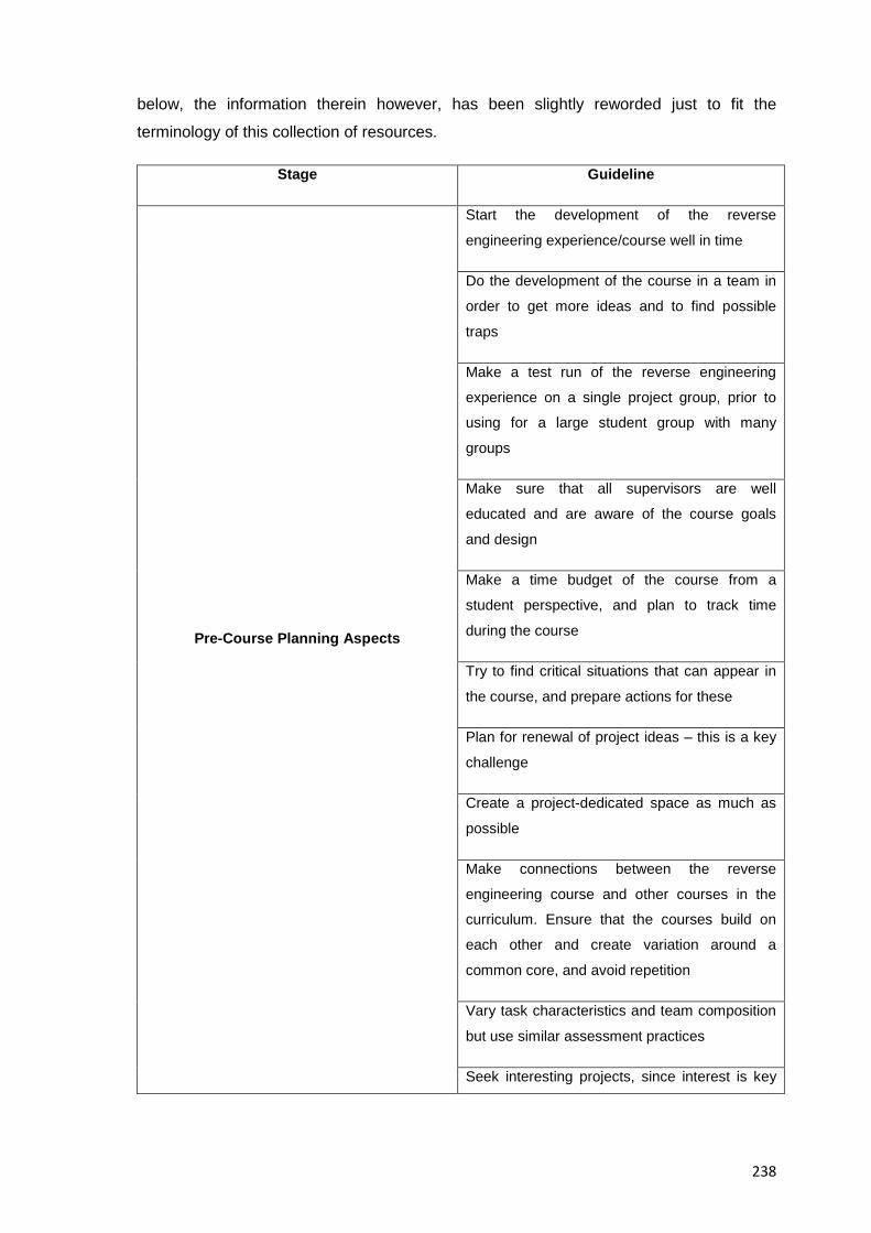
238
below, the information therein however, has been slightly reworded just to fit the
terminology of this collection of resources.
Stage Guideline
Pre-Course Planning Aspects
Start the development of the reverse
engineering experience/course well in time
Do the development of the course in a team in
order to get more ideas and to find possible
traps
Make a test run of the reverse engineering
experience on a single project group, prior to
using for a large student group with many
groups
Make sure that all supervisors are well
educated and are aware of the course goals
and design
Make a time budget of the course from a
student perspective, and plan to track time
during the course
Try to find critical situations that can appear in
the course, and prepare actions for these
Plan for renewal of project ideas – this is a key
challenge
Create a project-dedicated space as much as
possible
Make connections between the reverse
engineering course and other courses in the
curriculum. Ensure that the courses build on
each other and create variation around a
common core, and avoid repetition
Vary task characteristics and team composition
but use similar assessment practices
Seek interesting projects, since interest is key
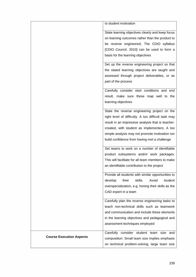
239
to student motivation
State learning objectives clearly and keep focus
on learning outcomes rather than the product to
be reverse engineered, The CDIO syllabus
[CDIO Council. 2010] can be used to form a
basis for the learning objectives
Set up the reverse engineering project so that
the stated learning objectives are taught and
assessed through project deliverables, or as
part of the process
Carefully consider start conditions and end
result, make sure these map well to the
learning objectives
State the reverse engineering project on the
right level of difficulty. A too difficult task may
result in an impressive analysis that is teacher-
created, with student as implementers. A too
simple analysis may not promote motivation nor
build confidence from having met a challenge
Set teams to work on a number of identifiable
product subsystems and/or work packages.
This will facilitate for all team members to make
an identifiable contribution to the project
Provide all students with similar opportunities to
develop their skills. Avoid student
overspecialization, e.g. honing their skills as the
CAD expert in a team
Carefully plan the reverse engineering tasks to
teach non-technical skills such as teamwork
and communication and include these elements
in the learning objectives and pedagogical and
assessment techniques employed
Course Execution Aspects Carefully consider student team size and
composition: Small team size implies emphasis
on technical problem-solving, large team size
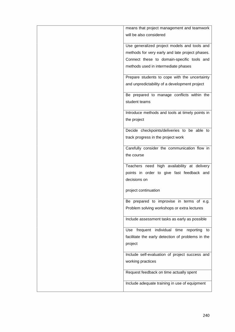
240
means that project management and teamwork
will be also considered
Use generalized project models and tools and
methods for very early and late project phases.
Connect these to domain-specific tools and
methods used in intermediate phases
Prepare students to cope with the uncertainty
and unpredictability of a development project
Be prepared to manage conflicts within the
student teams
Introduce methods and tools at timely points in
the project
Decide checkpoints/deliveries to be able to
track progress in the project work
Carefully consider the communication flow in
the course
Teachers need high availability at delivery
points in order to give fast feedback and
decisions on
project continuation
Be prepared to improvise in terms of e.g.
Problem solving workshops or extra lectures
Include assessment tasks as early as possible
Use frequent individual time reporting to
facilitate the early detection of problems in the
project
Include self-evaluation of project success and
working practices
Request feedback on time actually spent
Include adequate training in use of equipment
241
Table 6.3 Summary of guidelines for the success of hands-on and similar activities, Source:
[Malmqvist et al. 2004]
Should the reader still needed additional support on the planning of an EREA the reading
of the overall list of factors to take into account when preparing an educational activity by
author [Linsey et al. 2006] is also recommended
6.5.2 Phase 2: Execution of an EREA
The second phase in the pedagogy for the teaching of EREA concerns the actual
carrying out of it and it corresponds from the 2nd to the 11th stages of the suggested
methodology for educational reverse engineering analysis presented in Resource 5
meaning that most of a professor’s work done with students in an EREA will fall at this
phase, in this section specific details about the corresponding stages of the methodology
are presented, as well as a practical application of the teaching pedagogy of this resource
associated to the guided example of an EREA shown in Resource 7
The execution of an EREA entails the setting in place of the management; tracking and
corrective mechanisms of all relevant resources and actions leading to the completion of
the EREA in a set timeframe (e.g. Resources, milestones, deadlines, teaching times, etc.)
and that will allow students to reach the desired learning objectives throughout the stages
that involve the actual handling of the subject system; this phase is subdivided by stages
to support the actions needed therein, each of the stages mentioned in the next sections
then, contain suggestions for the safe and efficient development of the EREA but the
professors’ own experience in managing groups and academic activities should provide
valuable too.
Listed below are the individual stages that comprise the execution phase of the teaching
of EREA along with the advice on the pedagogical aspects of their teaching and in
accordance with their correspondence to the suggested methodology for EREA in
Resource 5, namely:
6.5.2.1 A Suggested Pedagogy for the Teaching of the Product Procurement Stage
The following advice is of a general nature and should help students and professor better
decide which product to choose for analysis and for what reasons. Further below in this
same section practical advice concerning the guided example of Resource 7 is also
provided, namely:
• Select a product that helps fulfil the objectives set for the activity
242
• Select a product that at minimum contains both electrical and mechanical
components
• Choose an operation-safe, working product from which something valuable can be
learned
• Old products to reverse engineer are good in that their technologies are more
transparent and easy to see
• It is positive to have similar products from different manufacturers or even
generational products from the same manufacturers so that students can see
changes from one generation to the other and how different manufacturers
approach the same needs
• If needed also collect competing products or specific product parts for areas of
subsequent, detailed comparison and analysis
• Keep in mind that some products for example have an inherent disposition to
show certain design philosophies more easily than others (e.g. Disposable
cameras emphasise design for mass production features; coffee makers
emphasise design for cost; personal multimedia device emphasise design for
functionality, etc.)
• Look for potential sponsors/donators of products
A. Effect of the Results of This Stage in the Subsequent ones Comprising the Phase
The clearest effect from the results of this stage concerns the information regarding the
tools and equipment that will be needed to test and analyse the product being chosen,
and although the final list of resources for this purpose will be only know once the product
starts being operated (e.g. Product testing, disassembly and reassembly stages) the
results from this stage will help start gathering the right resources for the fulfilment of this
teaching phase
B. Information about the Specific Example Shown in Resource 7
B.1 Suitability of Disposable Cameras to Exemplify an EREA
Single use cameras were first invented by Kodak and they are a good example of a high
volume, low cost product designed to have a high content of re-used parts and recycled
materials. A Kodak Flash and a Kodak Waterproof camera were indeed used for the
guided example of a reverse engineering exercise presented in Resource 7, because, in
fact a number of authors have independently chosen disposable cameras as a source for
product dissection exercises , reasons for this include their low cost , high availability,
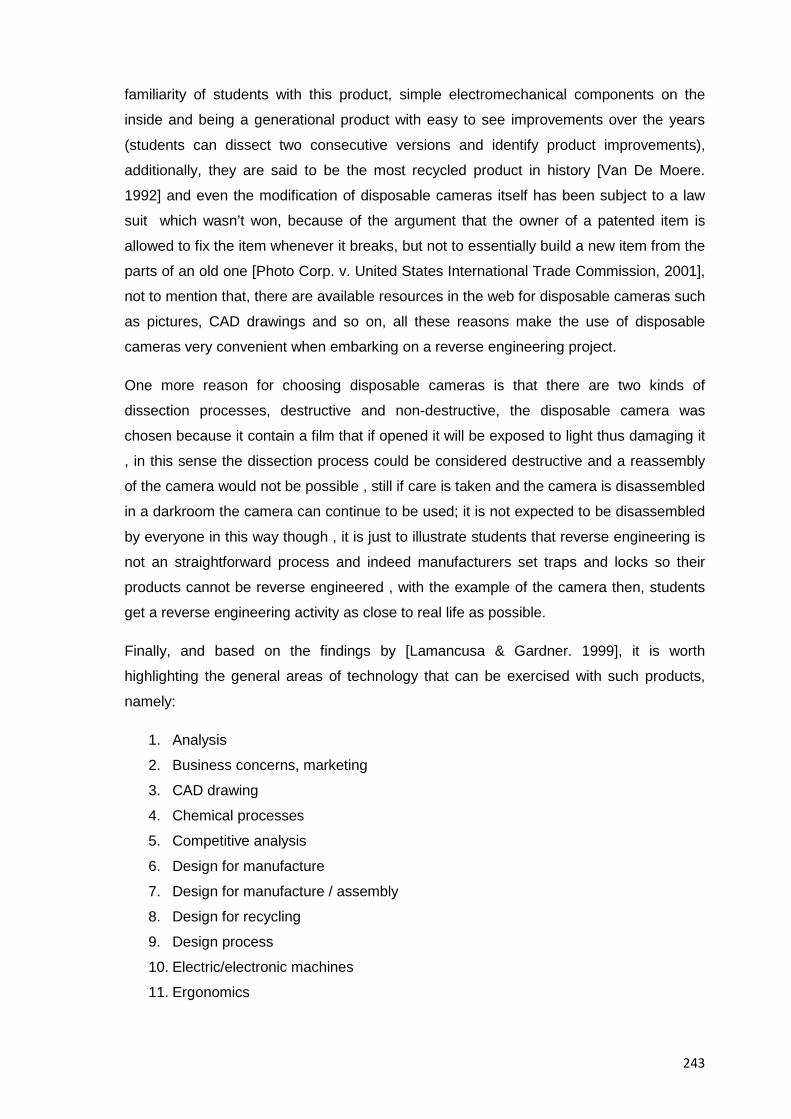
243
familiarity of students with this product, simple electromechanical components on the
inside and being a generational product with easy to see improvements over the years
(students can dissect two consecutive versions and identify product improvements),
additionally, they are said to be the most recycled product in history [Van De Moere.
1992] and even the modification of disposable cameras itself has been subject to a law
suit which wasn’t won, because of the argument that the owner of a patented item is
allowed to fix the item whenever it breaks, but not to essentially build a new item from the
parts of an old one [Photo Corp. v. United States International Trade Commission, 2001],
not to mention that, there are available resources in the web for disposable cameras such
as pictures, CAD drawings and so on, all these reasons make the use of disposable
cameras very convenient when embarking on a reverse engineering project.
One more reason for choosing disposable cameras is that there are two kinds of
dissection processes, destructive and non-destructive, the disposable camera was
chosen because it contain a film that if opened it will be exposed to light thus damaging it
, in this sense the dissection process could be considered destructive and a reassembly
of the camera would not be possible , still if care is taken and the camera is disassembled
in a darkroom the camera can continue to be used; it is not expected to be disassembled
by everyone in this way though , it is just to illustrate students that reverse engineering is
not an straightforward process and indeed manufacturers set traps and locks so their
products cannot be reverse engineered , with the example of the camera then, students
get a reverse engineering activity as close to real life as possible.
Finally, and based on the findings by [Lamancusa & Gardner. 1999], it is worth
highlighting the general areas of technology that can be exercised with such products,
namely:
1. Analysis
2. Business concerns, marketing
3. CAD drawing
4. Chemical processes
5. Competitive analysis
6. Design for manufacture
7. Design for manufacture / assembly
8. Design for recycling
9. Design process
10. Electric/electronic machines
11. Ergonomics
244
12. Green design
13. History of technology
14. Injection moulding
15. Journal record
16. Manufacturing processes
17. Materials selection
18. Mechanical hardware
19. Metrology
20. Sketching
21. Team skills
B.2 Suggested Tools and Equipment to Achieve the Goals of the EREA
A minimum list of materials needed for the analysis of a Kodak disposable camera (such
as the one in the guided example of Resource 7, is listed next:
• Laboratory space
• A workbench for every team
• Protective gear (safety glasses, smock, etc.)
• One subject system per team (ideally)
• A screwdriver set, or at least a small flat head screwdriver (small ones will
facilitate product disassembly and they can be shared with the class)
• A pair of needle nose and regular pliers
• Small storage containers, envelopes, or zip lock bags to hold smaller parts being
disassembled from the devices
• White paper to create systems diagrams (larger paper may be easier for students
to use and include more information)
• Bins or containers to collect metal, plastic, and other parts for recycling at the end
of the activity
• Black electrical tape
• A rubber mallet
• Tweezers
• Measuring Tools and instruments (Such as a micrometer)
• Cutting tools (e.g. Utility knife; razor blade, a pair of metal clippers, wire cutter,
etc.)
• Adjustable power supply
• Bright overhead lighting or desk lamp
245
• Cleaning supplies
• Glue
• Wrench
• Video recording equipment and computing resources to analyze and document
the activity
B.3 Specific notes regarding the disposable cameras used in the guided example of
Resource 7
• Emphasise you students that disposable cameras contain small gears and
components which are interesting to learn about
• Explain your students that in a reverse engineering analysis it is very normal that any
mock-ups, prototypes, and other physical models can be part of the collected data,
(e.g. To trace the development of a product) and the actual focus can be on a
particular aspect or on the product as a whole.
• Once the product for analysis had been chosen, give your students an introductory
talk about it, its principles and where they can get information about it to level all
students understanding about the subject system
6.5.2.2 A Suggested Pedagogy for the Teaching of the Team Selection Stage
In order to assemble a team of people to accomplish the goal of the EREA and assign
roles and tasks accordingly please consider the following items:
• Have a talk with all team members to exchange contact information, pick team
leaders and assess the knowledge level of all team members
• Give your students some team building advice on topics such as leadership; decision
making and group success (e.g. Team members’ cooperation; participation, sharing
of information, communication and contribution to the project’s workload)
A. How to choose team members:
They can be picked either by teacher’s criteria (existing needs) or student’s affinities
(individual talents and skills)
B. How to decide the number of members in a team:
The number of members in a team is dependent on the total number of students enrolled;
and the complexity, and availability of products so everyone participates actively in the
tasks, in crammed classes for example groups of five or six members might need to be
246
formed, this is a high number of students but with proper roles and tasks assignments
every students should get a good share of hands on and team experience, indeed
different authors suggest different numbers for team members, authors [Sidler-Kellog &
Jenison. 1997] for example suggest teams of three to five members, authors such as
Lamancusa state that 2 persons per group is best and three is all right if necessary
[Lamancusa et al. 1996], In Kang’s research, teams from two to up to six member in odd
numbers have been documented already, [Kang. 2011] but in general four is the ideal
number of team members for reason that will be explained further below
C. How to assign team roles:
Team roles are assigned in order to support the activity so all team members can have a
disassembling experience and take equal turns irrespective of the product chosen; usual
contribution roles include: Group leader; Presentation design, Parts analysis, Oral
presenter, Disassembler/Assembler; 3D Modelling/Animation, Information
collection/Research into the product under analysis, Photographer, Results disseminator
(e.g. Posters, online, etc.), and the usual tasks are assigned for the Team Recorder (the
one who writes down all the ideas and material generated during the working meeting),
Team Timer (to make sure that team stays on its time budget for the various tasks), Team
Gatekeeper (to makes sure that all members of the team are participating), Team
Advocate (to make sure that opposing ideas are brought up and discussed, Team
Encourager (to makes sure that everyone on the team is getting positive recognition for
their contribution),and the Team Resource Holder (who is the one that holds team
resources (e.g., Calculators, instructions, paper & pencils, etc.)), however all students
should be provided with similar opportunities to develop their skills and avoid student
overspecialization (e.g. Honing their skills as the CAD expert in a team)
An ideal team though, is made up of four members so each of them can work to reverse
engineer the product under analysis. The assignment of roles for the hands on parts of
the EREA (e.g. Testing, disassembling, assembling) is suggested as follows: One person
should do the physical disassembly of the product; A second one should create a
Disassembly Procedure describing the step-by-step process of disassembly, the third
member of the team should use a digital camera to record images of individual parts and
systems and the fourth member should carefully observe the disassembly process so that
he/she leads the process of re-assembling the camera. The rest of the tasks of the other
stages of the methodology should be equally distributed following the advice mentioned
above. A notable exception though, and as mentioned by [Durfee. 2008]occurs when
analysing very small products since it would be only one student actually disassembling it
247
; but still, everyone should try to be involucrate somehow, in the same way, if working in a
group and dissecting a complex object, consider splitting into groups to tackle the
dissection of subassemblies.
D. How to determine the role of the professor in an EREA
Reverse engineering projects help professors expand the type of interaction they
regularly have with students, the role of the instructor, and the skills required for these
exercises are different from the typical lecture-oriented class. Industry experience,
particularly in a design or product development capacity is highly important, and so during
an EREA the instructor serves in many non-traditional roles, for example:
• As a consultant: To guide students in their project and point them in the right
direction
• As facilitator: To provide resources to get the job done
In learning about product design then, students can “borrow” the learning curve of
professors so they can help their students go faster and learn from their experiences. In
fact educators shouldn’t fear to state the obvious during an EREA, after all authors such
as [Gick and Holyoak. 1983] have already proved that the addition or omission of
perceivably simple cues makes a significant difference in the a student’s ability to notice
correlations between two dissimilar situations.
In this regard, author Dalrymple also published how in her studies, students
demonstrated spontaneous transfer in an increase from 43% to 68% if more guidance
was provided to help them notice and abstract relevant features of their product under
analysis which fro author Dalrymple concluded that professors guidance during a D/A/A
activity was paramount, [Dalrymple.2009]
Last but not least, you should set fair labour division rules for potential differences in
gender and cultural backgrounds thus after the teams have formed, members must
prepare a document showing division of labour and ground rules for an effective
teamwork experience.
E. Information about the Specific Example Shown In Resource 7
There is no fixed guideline concerning the distribution of roles and workload other than
ensuring an orderly distribution of workload and a similar learning experience for al team
members, whenever possible though, you should allow students with a natural inclination
for tinkering lead the fairly inexperienced ones
248
6.5.2.3 A Suggested Pedagogy for the Teaching of the Data Collection Stage
The following is a list of items to keep in mind and that summarise the aspects that have
proved relevant for the proper conduction of this stage, they are directed to the
professors in charge of the activity and describe how and why support students at this
stage, namely:
A. Instructors’ Assignments
• Help your students expand and develop their research skills e.g.: By helping them
bring in information from ``outside'' sources to help make decisions; by teaching them
to use computer-based resources effectively to acquire needed information, by
helping them seek information on a problem from multiple sources, or by helping them
understand the importance of learning what has already been done to solve a given
situation
• Help your students familiarise and gain experience in information retrieval and
interpretation by giving them access and having them check the following (EKR’s)
engineering knowledge resources that provide relevant data about their product under
analysis and that are as suggested among others by [Pahl et al. 2007]:
• Traditional printed publications (e.g. Local libraries): Design catalogues, stock sheets,
trade journals
Manufacturers Data: Technical reports; CAD drawings, delivery
instructions, user manuals, service manuals, brochures, manufacturer
catalogues, bill of materials, vendor and components catalogues, original
design/designer’s documentation (but very hard to get outside the design
team and by company outsiders overall), product information
Consumer Associations: Inquiries from customers; test reports, accident
reports, trade organizations, test reports, accident reports.
Market Studies: Market analyses, trend studies, consumer focus groups,
industry sources
Intellectual Property Resources: Patents, licenses.
Academic Resources: Technical journals; research results, concrete
assignments, analyses of natural and artificial systems, calculations,
experiments, analogies, computer data, document collections, handbooks,
engineering texts, engineering databases, technical handbooks (e.g.
Electrical engineers handbook, [Warne. 2000], Mark's handbook of
mechanical engineering, [Avallone et al. 2007]), specialized societies,
empirical tests, abstracts, document collections, etc.
249
Laws and Regulations: General and in-house standards and regulations,
government documents.
Scientific encyclopaedias: e.g. McGraw-Hill encyclopaedia of science and
technology, [McGraw-Hill Editors. 2013]
Indexes: e.g. Index of applied science and technology [EBSCO Industries.
2013], the engineering index, [Elsevier Inc. 2013]
Internet Queries: e.g. Articles; patents, journals, manufacturers’ websites
and catalogues, the Google scholar search engine at
http://scholar.google.com/, etc.
Any other source of relevant data at your disposal.
• For the most elusive pieces of information or to come up with details of the
operation and design of the product under analysis have your students to try talks
and interviews with designers; reverse engineering practitioners, individual
experts; users and / or certified servicemen of the product, or even insiders’
knowledge or actual experience and accounts from the field in order to get further
information and insight about the product under analysis
Tell your students that if only limited lab time is available students can gather all
information about the product and study it at home, once all information has been
gathered, classified and understood, they can bring it to the classroom to carry on with
the methodology (e.g. The actual disassembling experience)
A.1 Information about the Specific Example Shown In Resource 7
If needed, give access to your students to published research about the subject system in
case they couldn’t find anything relevant on their own, for the specific example of this
collection of resources the following paper is suggested: “Design for Recyclability:
Kodak's Single-Use Camera” by [Van De Moere. 1992]
6.5.2.4 A Suggested Pedagogy for the Teaching of the Product Performance Test I Stage
To guide students through this stage it will become important to work on the safety and
class order aspects of laboratory work, as well as on the necessary guidance on the
technical aspects relevant to the use of laboratory equipment and their testing and data
recording practices.
Given that testing a product calls for a method of its own that ensures the thoroughness
and methodical approach in executing it the preparatory work for this stage should
250
include a talk with your students about shop practices that covers at least the following
points:
• A pre-activity briefing and explanation on how to behave and handle machinery
during the EREA, (other regular measures for laboratory behaviour will remain
valid too)
• A review of basic concepts on metrology, if needed
• Planning for straightening out actions after practices
• Explaining students how they should proceed with operating their device
After the students follow this advice and record every relevant result from this stage they
should be able to continue without any trouble with the next stages of the methodology
6.5.2.5 A Suggested Pedagogy for the Teaching of the Product Disassembly Stage
The professors’ main responsibility in this stage is to provide students with the support to
manage the dissection process of their subject system so they can access all exterior
components and those housed in the interior of it in order to lay the basis for further
analyses in the subsequent stages of the methodology, the major aspects to keep in mind
for this stage then, are summarised in the list below:
• Suggest your students to dissect the equipment into various components and then
break into groups to analyze smaller components in detail, so students first get a big
picture of how everything fits together and are later given the chance to examine
smaller parts of the system with more attention to engineering principles. Also, as
soon as students have attained a good understanding of their specific component ask
them to move forward to look at the other components/systems.
• If there is time available ask your students to pair up with another group that is
dissecting a different product and compare and explain the items they have just
analyzed to other classmates
• Faculty and teaching assistants (if needed) must be present during much of the
disassembly process to facilitate high levels of student/faculty interaction, during the
dissection process then, circulate among the teams to provide extra guidance and
answer questions
• Encourage each student to actively participate since many of them have never
experienced this type of hands-on project and are unfamiliar with using tools and
taking things apart
• Assist the students if necessary with removing or taking apart difficult pieces
251
• Ask your students to be aware of sharp parts or not lose track of small parts during
the disassembly
• Remind your students that the purpose of the dissection and the desired level of detail
will determine the specificity of the data collected
• During this stage, assign tool boxes per team or tell students to take turns and share
turns if needed
• Suggest your students to make a three dimensional computer animation that provide
information about the sequence in which the dissection of the subject system should
proceed
• Prepare a Q/A session to answer any specific questions or calculations presented
during the dissection stage
A. Information about the Specific Example Shown in Resource 7
• When asking students to generate a full set of measurements of their subject system
keep in mind what author [Kutz. 2007] stated when referring to CAD models of a
product under analysis, in the sense that such models “can often shed light on the
designer’s intent, but it is impossible to recreate the parts exactly, as there is no way
to measure or know the tolerances or exact specifications for each part”
• When asking students to prepare an equipment-breakdown hierarchy in order to
analyse their product’s architecture, ask them to remember that it can be a document
with the work-breakdown structure providing a mechanism to order the subsystems,
their assemblies (including subassemblies), and parts of a subject system to expedite
the development of specifications) this document also acts as a vehicle to guide the
reverse engineering effort and is critical to the development of functional
specifications.
• When asking students to sketch a systems diagram for the device under analysis tell
students that an initial one may be done by hand but a more refined version done
using computer software such as MS Word or PowerPoint using different shapes or
colours to enhance their explanation and illustration could be included in the final
report (e.g. at the “Results Dissemination” stage)
• When asking students to create a comprehensive BOM (Bill-of-Materials) remind
them that the BOM can be later revisited at subsequent stages of the methodology to
fill out any missing or newly relevant information about the subject system, in fact the
final BOM should only be reported at the “Results Dissemination” stage, so just ask
them to try to gather as much information as possible in this stage and complement it
in later ones
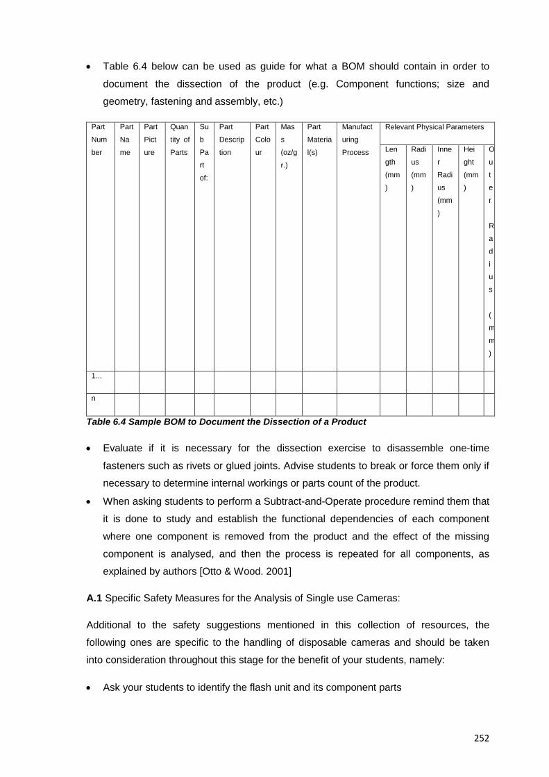
252
• Table 6.4 below can be used as guide for what a BOM should contain in order to
document the dissection of the product (e.g. Component functions; size and
geometry, fastening and assembly, etc.)
Part
Num
ber
Part
Na
me
Part
Pict
ure
Quan
tity of
Parts
Su
b
Pa
rt
of:
Part
Descrip
tion
Part
Colo
ur
Mas
s
(oz/g
r.)
Part
Materia
l(s)
Manufact
uring
Process
Relevant Physical Parameters
Len
gth
(mm
)
Radi
us
(mm
)
Inne
r
Radi
us
(mm
)
Hei
ght
(mm
)
O
u
t
e
r
R
a
d
i
u
s
(
m
m
)
1...
n
Table 6.4 Sample BOM to Document the Dissection of a Product
• Evaluate if it is necessary for the dissection exercise to disassemble one-time
fasteners such as rivets or glued joints. Advise students to break or force them only if
necessary to determine internal workings or parts count of the product.
• When asking students to perform a Subtract-and-Operate procedure remind them that
it is done to study and establish the functional dependencies of each component
where one component is removed from the product and the effect of the missing
component is analysed, and then the process is repeated for all components, as
explained by authors [Otto & Wood. 2001]
A.1 Specific Safety Measures for the Analysis of Single use Cameras:
Additional to the safety suggestions mentioned in this collection of resources, the
following ones are specific to the handling of disposable cameras and should be taken
into consideration throughout this stage for the benefit of your students, namely:
• Ask your students to identify the flash unit and its component parts
253
• In order to prevent electrical shocks, the product’s capacitors (It stores 300 volts of
electricity) should be removed and the use of the flash button avoided during its
handling (e.g. Disassembly / reassembly)
• Ask your students to not activate carelessly the flash charging circuit while all
housings are removed
• Suggest your students to remove the camera’s capacitors immediately after opening
the camera. Disposable cameras with flash contain a large capacitor that can cause
an electrical shock and so students should discharge the capacitor before
disassembling the camera by following the next instructions: Discharge the flash;
remove the battery, discharge the flash again (discharge it by placing an insulated
screw driver across both leads of the capacitor)
• Suggest your students to remove the shutter and film-advance mechanisms slowly
and carefully, noting the correct assembly order so that the camera can be easily
reassembled. These small parts are easily lost and can be difficult to reassemble due
to their size
• Ask your students to collect the batteries and film from the single use cameras for
future use
6.5.2.6 A Suggested Pedagogy for the Teaching of the Product Analysis Stage
In this section you will see a collection of tips and advice for the analysis of a consumer
product in the context of an educational reverse engineering activity; the explanations to
the technical analyses presented in this stage then, are considered standard fare for
engineering design practitioners and their inclusion into a reverse engineering exercise
doesn’t change their nature, ultimate context or expected deliverables. For reasons of
space and readability though a practical rather than a comprehensive explanation of the
tasks listed below is shown in this document given that the steps to execute such
analyses, exercises and tasks are considered standard practice in education, are well
known in the field of engineering design and plenty of information exists about them
anyway. The main items to consider for this stage then, are listed below, namely:
A. For the overall conduction of this stage:
The first task to set with your students is to determine what type of analyses are
appropriate to provide insight into the quantification of the design of your subject system
or into its strengths/weaknesses, you should ask them to consider analyses in the areas
of mechanics; electronics, software, socio-economics, ecology (materials, production
methods, cost impacts) and other related topics after this but before actually starting the
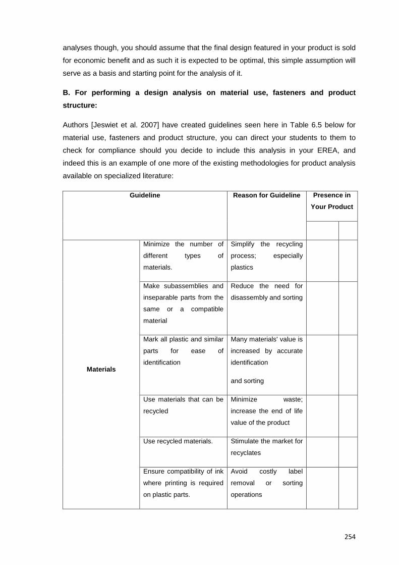
254
analyses though, you should assume that the final design featured in your product is sold
for economic benefit and as such it is expected to be optimal, this simple assumption will
serve as a basis and starting point for the analysis of it.
B. For performing a design analysis on material use, fasteners and product structure:
Authors [Jeswiet et al. 2007] have created guidelines seen here in Table 6.5 below for
material use, fasteners and product structure, you can direct your students to them to
check for compliance should you decide to include this analysis in your EREA, and
indeed this is an example of one more of the existing methodologies for product analysis
available on specialized literature:
Guideline Reason for Guideline Presence in Your Product
Materials
Minimize the number of
different types of
materials.
Simplify the recycling
process; especially
plastics
Make subassemblies and
inseparable parts from the
same or a compatible
material
Reduce the need for
disassembly and sorting
Mark all plastic and similar
parts for ease of
identification
Many materials' value is
increased by accurate
identification
and sorting
Use materials that can be
recycled
Minimize waste;
increase the end of life
value of the product
Use recycled materials. Stimulate the market for
recyclates
Ensure compatibility of ink
where printing is required
on plastic parts.
Avoid costly label
removal or sorting
operations
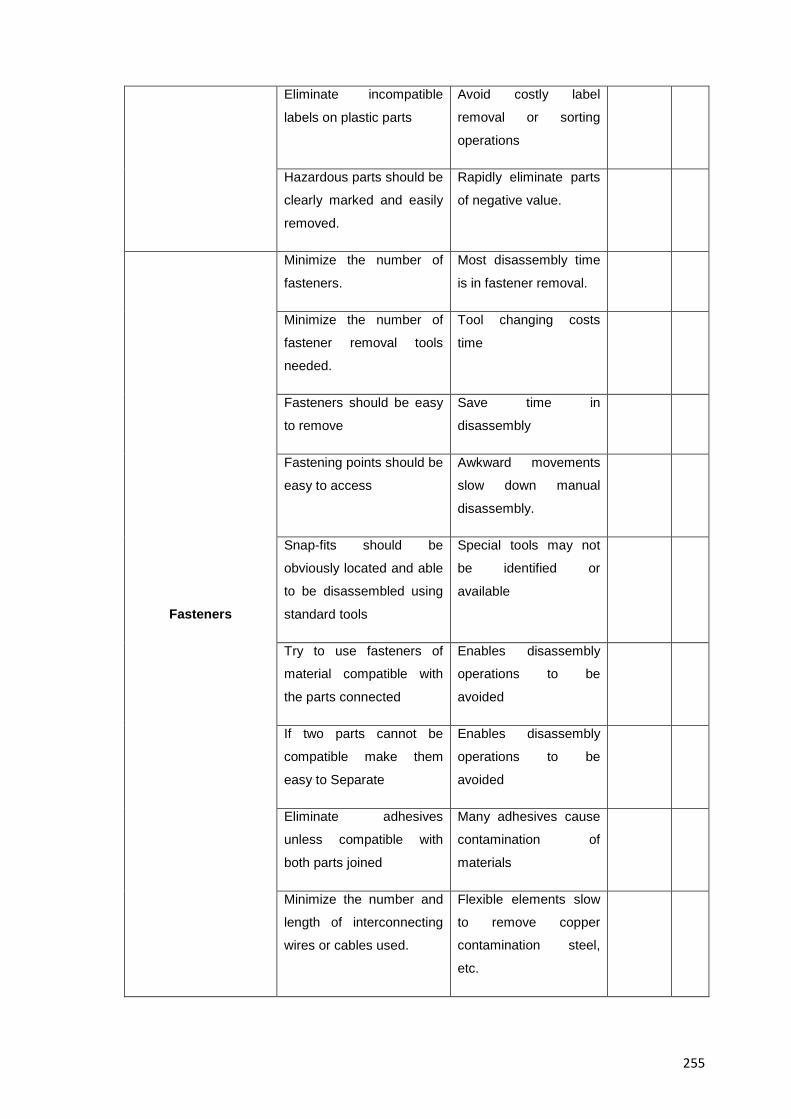
255
Eliminate incompatible
labels on plastic parts
Avoid costly label
removal or sorting
operations
Hazardous parts should be
clearly marked and easily
removed.
Rapidly eliminate parts
of negative value.
Fasteners
Minimize the number of
fasteners.
Most disassembly time
is in fastener removal.
Minimize the number of
fastener removal tools
needed.
Tool changing costs
time
Fasteners should be easy
to remove
Save time in
disassembly
Fastening points should be
easy to access
Awkward movements
slow down manual
disassembly.
Snap-fits should be
obviously located and able
to be disassembled using
standard tools
Special tools may not
be identified or
available
Try to use fasteners of
material compatible with
the parts connected
Enables disassembly
operations to be
avoided
If two parts cannot be
compatible make them
easy to Separate
Enables disassembly
operations to be
avoided
Eliminate adhesives
unless compatible with
both parts joined
Many adhesives cause
contamination of
materials
Minimize the number and
length of interconnecting
wires or cables used.
Flexible elements slow
to remove copper
contamination steel,
etc.
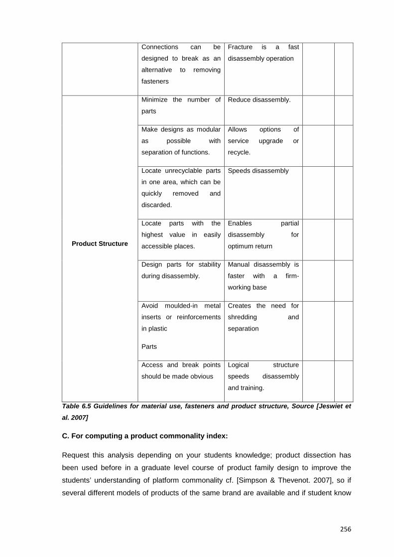
256
Connections can be
designed to break as an
alternative to removing
fasteners
Fracture is a fast
disassembly operation
Product Structure
Minimize the number of
parts
Reduce disassembly.
Make designs as modular
as possible with
separation of functions.
Allows options of
service upgrade or
recycle.
Locate unrecyclable parts
in one area, which can be
quickly removed and
discarded.
Speeds disassembly
Locate parts with the
highest value in easily
accessible places.
Enables partial
disassembly for
optimum return
Design parts for stability
during disassembly.
Manual disassembly is
faster with a firm-
working base
Avoid moulded-in metal
inserts or reinforcements
in plastic
Parts
Creates the need for
shredding and
separation
Access and break points
should be made obvious
Logical structure
speeds disassembly
and training.
Table 6.5 Guidelines for material use, fasteners and product structure, Source [Jeswiet et
al. 2007]
C. For computing a product commonality index:
Request this analysis depending on your students knowledge; product dissection has
been used before in a graduate level course of product family design to improve the
students’ understanding of platform commonality cf. [Simpson & Thevenot. 2007], so if
several different models of products of the same brand are available and if student know
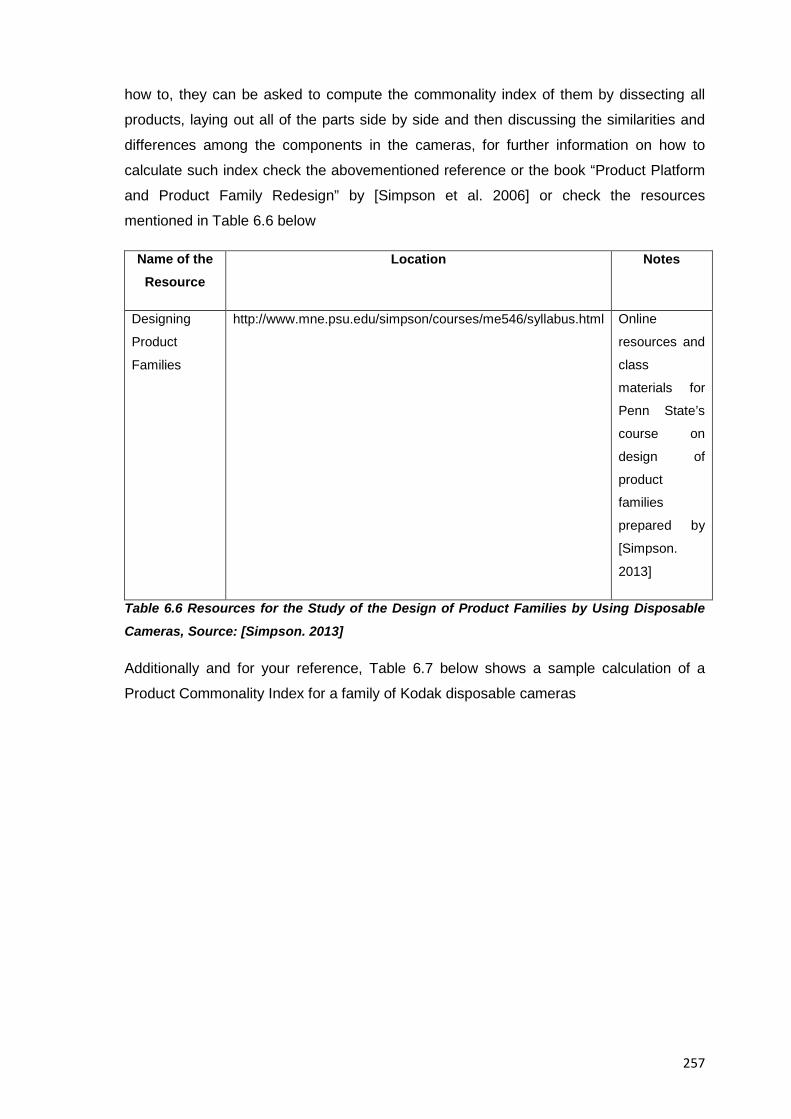
257
how to, they can be asked to compute the commonality index of them by dissecting all
products, laying out all of the parts side by side and then discussing the similarities and
differences among the components in the cameras, for further information on how to
calculate such index check the abovementioned reference or the book “Product Platform
and Product Family Redesign” by [Simpson et al. 2006] or check the resources
mentioned in Table 6.6 below
Name of the Resource
Location Notes
Designing
Product
Families
http://www.mne.psu.edu/simpson/courses/me546/syllabus.html Online
resources and
class
materials for
Penn State’s
course on
design of
product
families
prepared by
[Simpson.
2013]
Table 6.6 Resources for the Study of the Design of Product Families by Using Disposable
Cameras, Source: [Simpson. 2013]
Additionally and for your reference, Table 6.7 below shows a sample calculation of a
Product Commonality Index for a family of Kodak disposable cameras
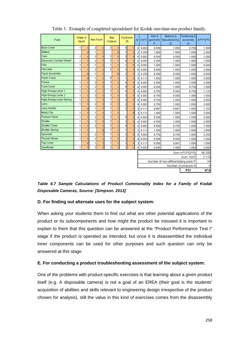
258
Table 6.7 Sample Calculations of Product Commonality Index for a Family of Kodak
Disposable Cameras, Source: [Simpson. 2013]
D. For finding out alternate uses for the subject system:
When asking your students them to find out what are other potential applications of the
product or its subcomponents and how might the product be misused it is important to
explain to them that this question can be answered at the “Product Performance Test I”
stage if the product is operated as intended, but once it is disassembled the individual
inner components can be used for other purposes and such question can only be
answered at this stage
E. For conducting a product troubleshooting assessment of the subject system:
One of the problems with product-specific exercises is that learning about a given product
itself (e.g. A disposable camera) is not a goal of an EREA (their goal is the students’
acquisition of abilities and skills relevant to engineering design irrespective of the product
chosen for analysis), still the value in this kind of exercises comes from the disassembly
259
aspect of them which at the very least will familiarise and provide hands-on experience to
the students with the use of the tools and procedures that are indeed common to all
educational reverse engineering analyses
F. For executing a technical systems analysis of your product:
Suggest your students to formulate all the product requirements in a solution-neutral way
(working principles should only be determined if really necessary from the point of view of
the overall functionality).
G. For executing an analysis on your product with a systems approach overall:
When analysing the subject system first suggest your students to distinguish different
levels of abstraction or system levels, the system functioning as a whole and the system
as a set of relationships between interacting parts, then ask them to see the system as a
whole, treat it as a black box and deduct its overall behaviour by submitting inputs and
observing the resulting outputs; finally ask them to see the system as a set of
relationships and analyse the system’s construction, internal structures and processes in
order to understand how the system’s overall behaviour is produced
H. For executing a functional analysis of your subject system and its components:
When performing the functional analysis of the subject system ask your students to
answer all important questions about the device such as which components are
responsible for providing which functions; remind your students to focus on the
fundamentals, not to restrict alternative solutions and also to identify repeated functions
and combine them or eliminate them. Also remind them that a wealth of resources such
as the “Function: Definition and Analysis” monograph by [SAVE International. 1998], the
research by [Parker. 1994], the tables by [Kaufman & Woodhead. 2006] or any other
known resource can be used for a comprehensive list of typical verbs and nouns for
defining functions.
Also, when determining the structure and role of individual components advice your
students not to assume any specific functional relationships between individual
components at least at the beginning of the analysis since the structure and role of
individual components can only be determined based on its relationship to the function of
the product as a unit. Indeed, ask your students to decide what actually constitutes a
"part" on your product since your product can be broken down completely into elemental
parts, and sometimes it makes sense to leave things as a subassembly, as stated by
author [Durfee. 2008]
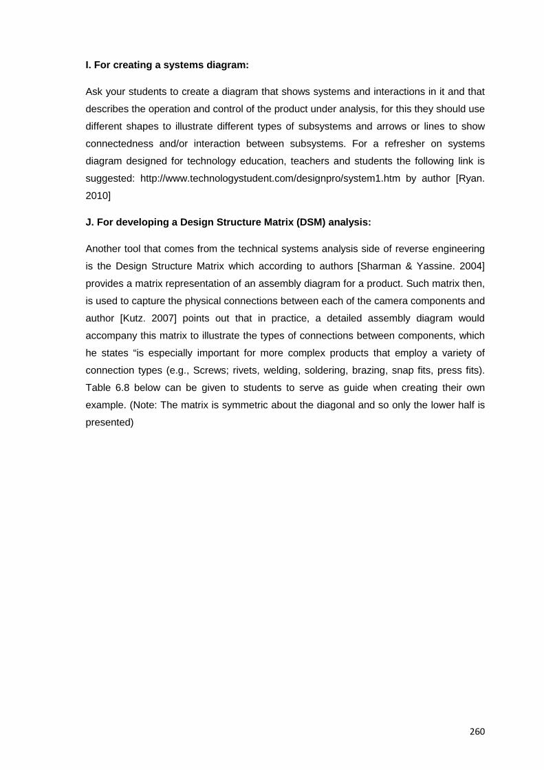
260
I. For creating a systems diagram:
Ask your students to create a diagram that shows systems and interactions in it and that
describes the operation and control of the product under analysis, for this they should use
different shapes to illustrate different types of subsystems and arrows or lines to show
connectedness and/or interaction between subsystems. For a refresher on systems
diagram designed for technology education, teachers and students the following link is
suggested: http://www.technologystudent.com/designpro/system1.htm by author [Ryan.
2010]
J. For developing a Design Structure Matrix (DSM) analysis:
Another tool that comes from the technical systems analysis side of reverse engineering
is the Design Structure Matrix which according to authors [Sharman & Yassine. 2004]
provides a matrix representation of an assembly diagram for a product. Such matrix then,
is used to capture the physical connections between each of the camera components and
author [Kutz. 2007] points out that in practice, a detailed assembly diagram would
accompany this matrix to illustrate the types of connections between components, which
he states “is especially important for more complex products that employ a variety of
connection types (e.g., Screws; rivets, welding, soldering, brazing, snap fits, press fits).
Table 6.8 below can be given to students to serve as guide when creating their own
example. (Note: The matrix is symmetric about the diagonal and so only the lower half is
presented)
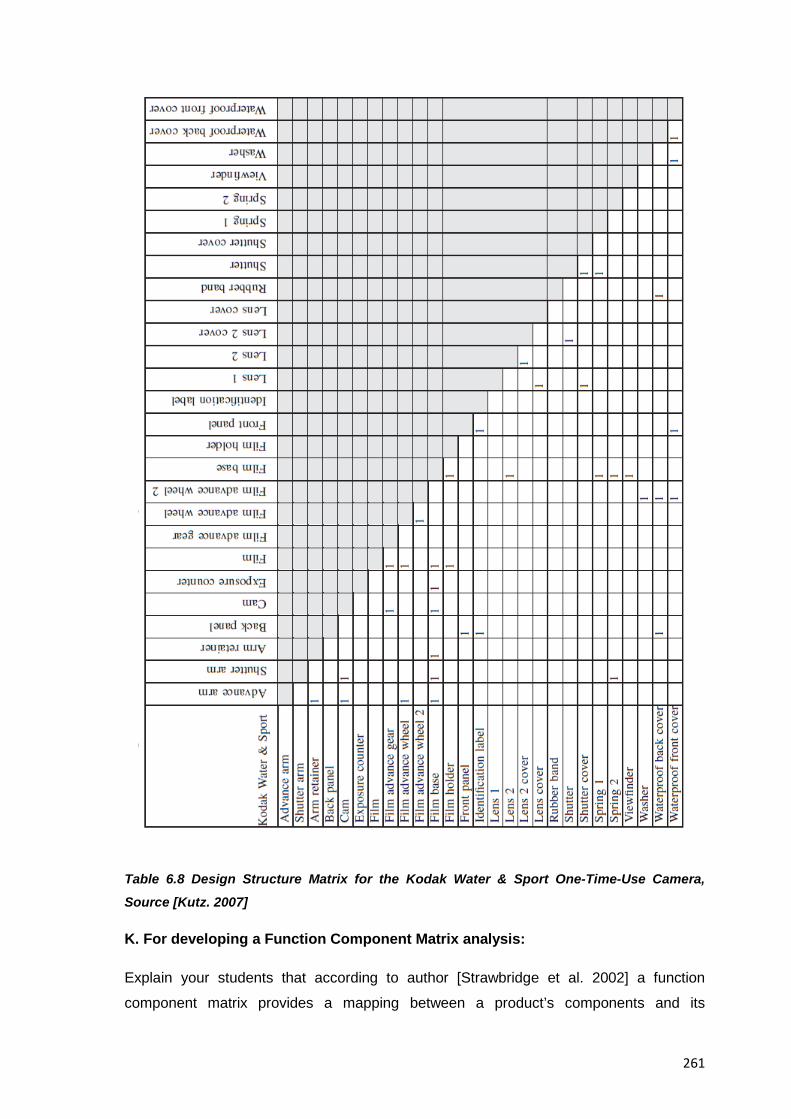
261
Table 6.8 Design Structure Matrix for the Kodak Water & Sport One-Time-Use Camera,
Source [Kutz. 2007]
K. For developing a Function Component Matrix analysis:
Explain your students that according to author [Strawbridge et al. 2002] a function
component matrix provides a mapping between a product’s components and its

262
subfunctions and is created by combining the information obtained from the function
structure analysis plus the components listed in a BOM. Author [Kutz. 2007] also adds
that this matrix represents the product architecture for the subject system as it indicates
how the different functions of it are mapped to its physical components. Table 6.9 below
shows a sample function component matrix for a Kodak Water & Sport Camera which can
be given to students as an aid in the creation of their own
Table 6.9 Function-Component Matrix for the Kodak Water & Sport One-Time-Use Camera,
Source [Kutz. 2007]
L. For performing a Function Relation analysis:
Explain your students that the function relation analysis is a design method that allows
the designer to think of a product in terms of the function and subfunctions that the
product or system has to perform and not on a particular solution. In this approach the
designer works from a function to form a hierarchy that goes from the overall function and
is distributed among multiple sub functions. The goal in a function relation analysis then,
is not only to examine the relationships between the various subfunctions, paying
attention to their logical sequence or interconnections but also to show how the main
functions serve the overall function directly and how the auxiliary functions contribute to
the overall function indirectly, both of them are supportive or complementary and are
often determined by the nature of the solution. Authors [Comparini & Cagan. 1998] have
devised a procedure to perform a function relation analysis which is used in this collection
of resources.
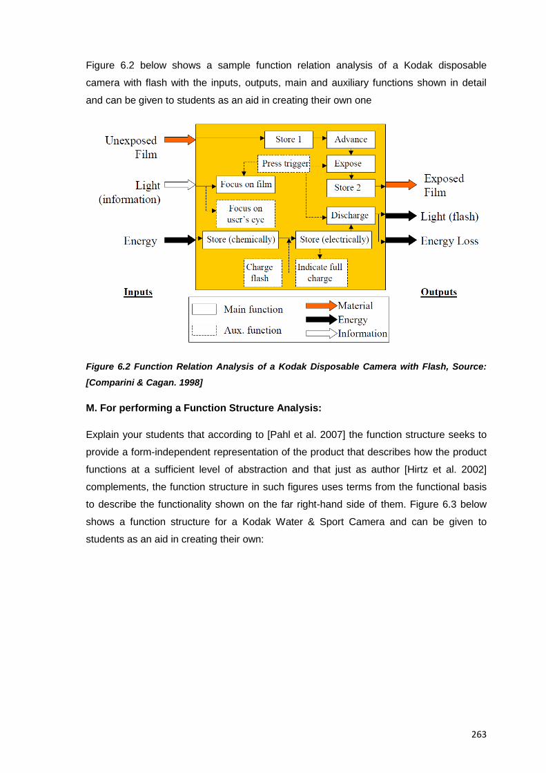
263
Figure 6.2 below shows a sample function relation analysis of a Kodak disposable
camera with flash with the inputs, outputs, main and auxiliary functions shown in detail
and can be given to students as an aid in creating their own one
Figure 6.2 Function Relation Analysis of a Kodak Disposable Camera with Flash, Source:
[Comparini & Cagan. 1998]
M. For performing a Function Structure Analysis:
Explain your students that according to [Pahl et al. 2007] the function structure seeks to
provide a form-independent representation of the product that describes how the product
functions at a sufficient level of abstraction and that just as author [Hirtz et al. 2002]
complements, the function structure in such figures uses terms from the functional basis
to describe the functionality shown on the far right-hand side of them. Figure 6.3 below
shows a function structure for a Kodak Water & Sport Camera and can be given to
students as an aid in creating their own:
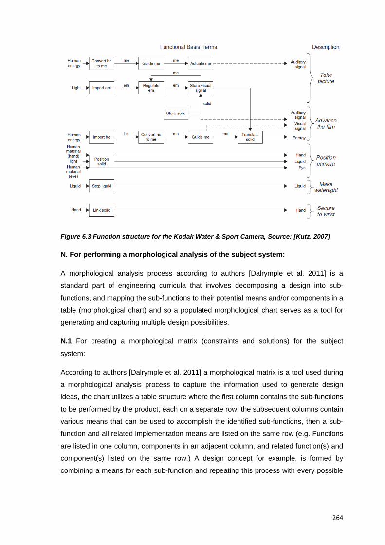
264
Figure 6.3 Function structure for the Kodak Water & Sport Camera, Source: [Kutz. 2007]
N. For performing a morphological analysis of the subject system:
A morphological analysis process according to authors [Dalrymple et al. 2011] is a
standard part of engineering curricula that involves decomposing a design into sub-
functions, and mapping the sub-functions to their potential means and/or components in a
table (morphological chart) and so a populated morphological chart serves as a tool for
generating and capturing multiple design possibilities.
N.1 For creating a morphological matrix (constraints and solutions) for the subject
system:
According to authors [Dalrymple et al. 2011] a morphological matrix is a tool used during
a morphological analysis process to capture the information used to generate design
ideas, the chart utilizes a table structure where the first column contains the sub-functions
to be performed by the product, each on a separate row, the subsequent columns contain
various means that can be used to accomplish the identified sub-functions, then a sub-
function and all related implementation means are listed on the same row (e.g. Functions
are listed in one column, components in an adjacent column, and related function(s) and
component(s) listed on the same row.) A design concept for example, is formed by
combining a means for each sub-function and repeating this process with every possible
265
combination of sub-function means that can generate an exhaustive list of design
concepts
O. For executing a subtract and operate (SOP) procedure for the subject system (as part of a functional analysis of it):
Remind your students that Otto and Wood’s Subtract-and-Operate procedure (SOP),
[Otto & Wood. 2001] is a bottom up approach to developing a function tree and it’s one of
the easiest ways to check the effects of parts in a system and better understand the
function of its components but it is not the only one, so, help them choose an appropriate
method based on resources available, their knowledge and expected learning outcomes
P. For determining the manufacturing process(es) of the product under analysis:
Ask your students to perform a physical analysis of a product’s manufacturing marks and
to look for individual characteristics that manufacturing processes and raw materials
imprint on manufactured objects (e.g. Machining and moulding leave characteristic
imprints related to the tooling and raw materials (plastic, metal, etc) used to produce a
given part), also have them look for visible manufacturing marks; traces of known
materials, characteristic odours and other visible signs that can be detected through
visual inspection alone and can help as a starting point for identifying a product’s
composition and manufacturing history. Alternatively students can try to identify simple
microscopic differences in the product’s surfaces by experience alone or try to detect
more complex ones through automated software and mathematical algorithms that can
recognize specific patterns, through these past actions then, students can extract every
possible bit of information from the physical markings of a product to help come up with a
rather plausible reconstruction of what the original engineering decisions might have
been.
Q. For hypothesizing on the subject system’s volume of production
Ask your students to consult the product’s manufacturing marks and selection of
materials to help answer this question
R. For determining the materials of the product under analysis and its components:
The identification of commonly used materials in product manufacturing is a complex
task, students can and should rely on part identification and markings indicated by the
manufacturers since they are vital in helping identify the materials themselves however,
specialized resources exist for it .Suggest your students for example to make use of the
266
published tables and research by authors [Otto and Wood. 2001] and [Ashby. 2005]
concerning the properties and identification of engineering materials found on common
consumer products to come up with a reasonable approximation to the composition of the
parts and components in your product in case no other analytical tools are at hand for the
determination of the materials in the product’s parts. Indeed you could just straightly ask
them to consult Ashby’s tables: “Names and applications of metals and alloys”,” Names
and applications of polymers and foams” and “Names and applications of composites,
ceramics, glasses, and natural materials” since they list the names and typical
applications of materials commonly found in every day consumer products. In fact, even
when trying to determine the material composition of your subject system, just by
checking author Ashby’s process-material matrixes, and in case a sound, rational,
economic and technical decision was taken in the manufacturing of your product’s parts,
then the use of his published selection charts will also provide a quick approximation to
what the actual manufacturing process applied was. Thus, author Michael Ashby’s book
“Materials Selection in Mechanical Design” provides a wealth of information on how to
correlate material properties to their identification, the reading of such book is strongly
suggested for those interested in further information about verification of materials and
manufacturing processes in reverse engineering. Additionally, students should also
consult the table “Common Elastomers and Supporting Information (Fillers)” in the
Material Identification Tools (Fillers) section on the online resources by [Otto & Wood.
2001] since this table helps reverse engineering students identify common elastomers
(fillers) found in consumer products and which manufacturers need to specify them by
combining a material and shape label into 2 letters and dashed into the base material
label to name them so students can simply compare the ISO label to the corresponding
material and shape. Also they should consult the Tables “Identifying Plastic Types”;
“Common Plastics and Supporting Information” in the Material Identification Tools section
on the online resources also presented by [Otto & Wood. 2001] since these tables serve
as a first starting point in trying to determine the material composition of a part under
study and they could become, along with an educated internet search and a visit to a
local library the easiest sources of information for determining a material’s composition.
Finally, unconventional thinking should be tried when identifying materials , in the book
“Identifying Wood: Accurate Results with Simple Tools” by [Hoadley. 1990] for example,
the identification of over 180 types of wood is done with only a loupe or microscope and
unconventional methods such testing the floatability of woods are used to identify
different types of woods. Try to identify the material used for each of the product’s parts,
and be as specific as you can, but If you can't identify it, determine at least the properties
(stiffness, hardness, clarity, and so on) of it as suggested by author [Durfee. 2008]. In any
267
case, the identification of materials is a common analysis in engineering, its
contextualisation into an EREA doesn’t change its nature and as such no new knowledge
is contributed to it from this collection of resources instead it only provides a quick way to
perform such an analysis via selected tasks and links to existing resources on the topic.
The information about materials presented in this collection of resources then serves only
as a first step in the approach to decoding materials and processes in consumer
products, and the resources presented in the “Miscellaneous resources” section of this
same document intend to provide comprehensive information about the topic.
S. For checking your subject system’s for compliance with DfX and suggested design and usage guidelines:
Ask your students to check their subject systems in the following areas to name a few:
DfAssembly; DfManufacturing, DfEcological impact, DfRecycling, DfProducibility, DfMass
production, DfCost, DfFunctionality etc, as per their relative importance given at your
syllabus so only those DfX analyses relevant to your subject system get full attention and
the rest are only performed at very basic level.
Additionally, remind them that they should start the DfX analyses assuming that many of
the parts that constitute a product are already standardized ones and they must have
followed some of the widely known DFX principles.
T. For performing a Design for Manufacturing / Assembly of your subject system:
Depending on the resources or knowledge available a fully fledged DFMA analysis can
be excessive to ask to your students so only tasks and questions that provide a good
introduction to the topic and their answer is well within the reach of students should be
attempted
U. For performing a Design for Assembly analysis of your subject system:
Ask your students to try to identify the following rules in Table 6.10 below compiled by
author [Jounghyun. 1994] and identify if some of them may conflict with each other or
with unavoidable design decisions, For example DFA (Design for Assembly) rules for
design of orienting surfaces may contradict another known DFA rule in the design of
symmetric surfaces (e.g. By inducing asymmetry); In the same way, design of stacked
products as DFA suggests, can reduce assembly costs but might as well increase the
manufacturing ones:
DFA Rule Present in the Product under Analysis Tradeoffs at
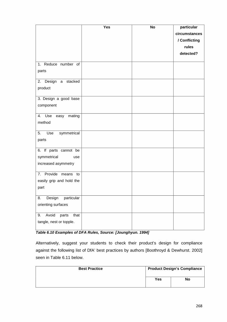
268
Yes No particular circumstances
/ Conflicting rules
detected?
1. Reduce number of
parts
2. Design a stacked
product
3. Design a good base
component
4. Use easy mating
method
5. Use symmetrical
parts
6. If parts cannot be
symmetrical use
increased asymmetry
7. Provide means to
easily grip and hold the
part
8. Design particular
orienting surfaces
9. Avoid parts that
tangle, nest or topple.
Table 6.10 Examples of DFA Rules, Source: [Jounghyun. 1994]
Alternatively, suggest your students to check their product’s design for compliance
against the following list of DfA’ best practices by authors [Boothroyd & Dewhurst. 2002]
seen in Table 6.11 below.
Best Practice Product Design’s Compliance
Yes No
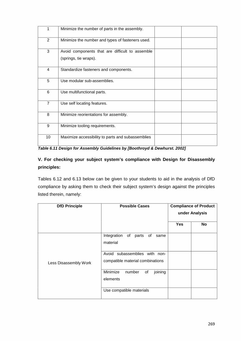
269
1 Minimize the number of parts in the assembly.
2 Minimize the number and types of fasteners used.
3 Avoid components that are difficult to assemble
(springs, tie wraps).
4 Standardize fasteners and components.
5 Use modular sub-assemblies.
6 Use multifunctional parts.
7 Use self locating features.
8 Minimize reorientations for assembly.
9 Minimize tooling requirements.
10 Maximize accessibility to parts and subassemblies
Table 6.11 Design for Assembly Guidelines by [Boothroyd & Dewhurst. 2002]
V. For checking your subject system’s compliance with Design for Disassembly principles:
Tables 6.12 and 6.13 below can be given to your students to aid in the analysis of DfD
compliance by asking them to check their subject system’s design against the principles
listed therein, namely:
DfD Principle Possible Cases Compliance of Product under Analysis
Yes No
Less Disassembly Work
Integration of parts of same
material
Avoid subassemblies with non-
compatible material combinations
Minimize number of joining
elements
Use compatible materials
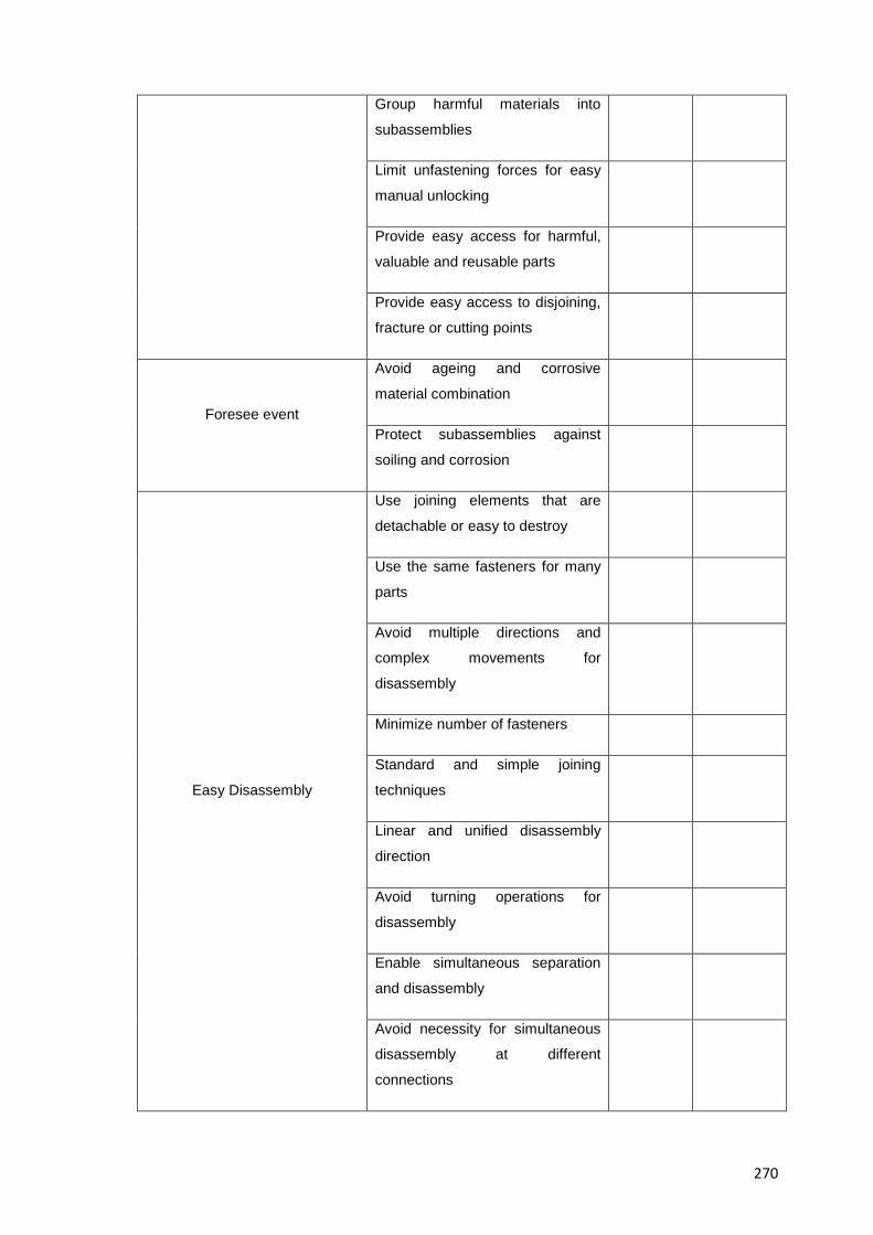
270
Group harmful materials into
subassemblies
Limit unfastening forces for easy
manual unlocking
Provide easy access for harmful,
valuable and reusable parts
Provide easy access to disjoining,
fracture or cutting points
Foresee event
Avoid ageing and corrosive
material combination
Protect subassemblies against
soiling and corrosion
Easy Disassembly
Use joining elements that are
detachable or easy to destroy
Use the same fasteners for many
parts
Avoid multiple directions and
complex movements for
disassembly
Minimize number of fasteners
Standard and simple joining
techniques
Linear and unified disassembly
direction
Avoid turning operations for
disassembly
Enable simultaneous separation
and disassembly
Avoid necessity for simultaneous
disassembly at different
connections
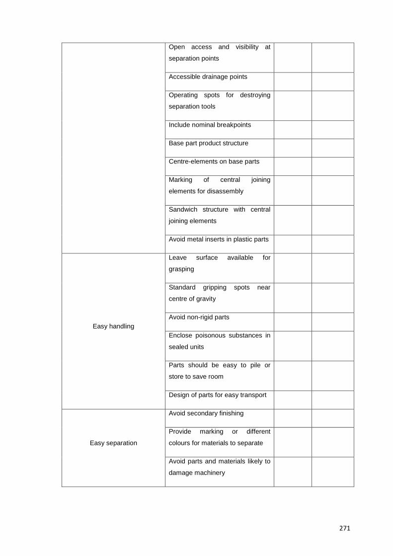
271
Open access and visibility at
separation points
Accessible drainage points
Operating spots for destroying
separation tools
Include nominal breakpoints
Base part product structure
Centre-elements on base parts
Marking of central joining
elements for disassembly
Sandwich structure with central
joining elements
Avoid metal inserts in plastic parts
Easy handling
Leave surface available for
grasping
Standard gripping spots near
centre of gravity
Avoid non-rigid parts
Enclose poisonous substances in
sealed units
Parts should be easy to pile or
store to save room
Design of parts for easy transport
Easy separation
Avoid secondary finishing
Provide marking or different
colours for materials to separate
Avoid parts and materials likely to
damage machinery
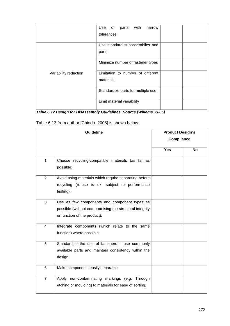
272
Use of parts with narrow
tolerances
Variability reduction
Use standard subassemblies and
parts
Minimize number of fastener types
Limitation to number of different
materials
Standardize parts for multiple use
Limit material variability
Table 6.12 Design for Disassembly Guidelines, Source [Willems. 2005]
Table 6.13 from author [Chiodo. 2005] is shown below:
Guideline Product Design’s Compliance
Yes No
1 Choose recycling-compatible materials (as far as
possible).
2 Avoid using materials which require separating before
recycling (re-use is ok, subject to performance
testing).
3 Use as few components and component types as
possible (without compromising the structural integrity
or function of the product).
4 Integrate components (which relate to the same
function) where possible.
5 Standardise the use of fasteners – use commonly
available parts and maintain consistency within the
design.
6 Make components easily separable.
7 Apply non-contaminating markings (e.g. Through
etching or moulding) to materials for ease of sorting.
273
8 Maintain good access to components and fasteners.
Consider making the plane of access to components
the same for all components.
9 Do not paint plastic parts or other coatings which may
contaminate other plastics when recycled.
Table 6.13 Design for Disassembly Guidelines, After: [Chiodo. 2005]
W. For checking your subject system’s compliance with design for end-of-life principles:
Have your students check the paper “Design practices for improving the end-of-life
disposal of telecommunications equipment” by [Low et al. 1996] as one of the available
resources to get information, guidelines and best practices on disassembly; recycling,
recovery or remanufacturing topics.
X. For trying to find design patch-ups in your subject system:
Tell your students that conventional DfX suggestions tend to provide localized design
patch-ups while most useful and cost saving redesign strategies are those that globally
redesign the product. Ask your students to try to find this kind of patch-ups as an
exercise.
Y. For performing a Life Cycle Inventory analysis:
A life cycle Inventory analysis is defined by authors [Graedel & Allenby. 2003] as “An
evaluation of the environmental effect of raw materials taken from the environment
(inputs) and the waste released back into the environment (outputs) by an industrial
system” and the execution of this analysis in a reverse engineering exercise is suggested
by authors [Comparini & Cagan. 1998] whose basic approach (Inventory: Quantification
of inputs (energy, raw material) and outputs (environmental releases) to the environment
throughout the life of the product or activity + Impact Assessment: Quantitative and/or
qualitative assessment of the effect of the environmental loads identified in the inventory
component) is easy; comprehensive and well suited to this educational activity and thus it
is shown here in Figure 6.4 below.
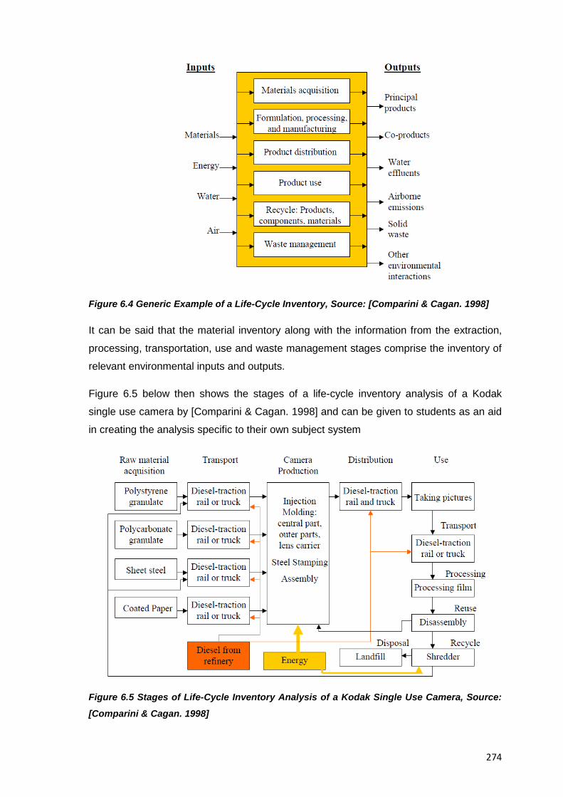
274
Figure 6.4 Generic Example of a Life-Cycle Inventory, Source: [Comparini & Cagan. 1998]
It can be said that the material inventory along with the information from the extraction,
processing, transportation, use and waste management stages comprise the inventory of
relevant environmental inputs and outputs.
Figure 6.5 below then shows the stages of a life-cycle inventory analysis of a Kodak
single use camera by [Comparini & Cagan. 1998] and can be given to students as an aid
in creating the analysis specific to their own subject system
Figure 6.5 Stages of Life-Cycle Inventory Analysis of a Kodak Single Use Camera, Source:
[Comparini & Cagan. 1998]
275
Z. For the benchmarking of the subject system:
If resources allow it, have every team analyse a competing product or have different team
analyse different products so the whole class can access the results about competing
products and compare them against their own
AA. For performing a costs analysis of the subject system:
You can ask students to determine the prices of their product’s components by using
value techniques or just simply basing it on their size, relative complexity in terms of
manufacturing, as well as the material that they are made of. Additionally, when
determining if your product can be considered cost effective based on customers and
market demand you’ll need an approximation to the real cost of the product which can be
derived by yourself or your students or obtained from product teardown webpages
available on the web or indirectly referenced in the “Miscellaneous Resources” section of
this collection of resources
BB. For recovering, developing and reporting Potential PDS (Product Design/Data Specifications) a.k.a “Requirements List” for the product under analysis:
Ask students to prepare a document to record the performance specifications for the item
by formulating a specification tree with the same structure as an equipment-breakdown
hierarchy or structure. (at all levels but the lowest (e.g. Piece components) specification-
tree entries describe the item’s functional aspects. At the piece-component level, the
entries in the performance specification are basically of the dimensional kind)
CC. For digitizing and modelling your subject system:
Ask your students to create computer models of the product under analysis given that the
rise of computer assisted tools in the area of engineering design benefits from having a
fully disassembled product to create a computerised version of it and that allows for the
simulation of its workings. Alternatively suggest your students to engage in a “big picture”
reasoning (e.g. basic reasoning + analytical tools) instead of a model based reasoning in
case the creation of models is outside of their reach or of the depth of analysis set by the
instructor
DD. For determining the major scientific, physical principles behind the full development of the subject system:
276
Ask your students to identify a library of general principles or common modules that make
the product work and that serves them as reference for the drawing of conclusions or
further analyses
EE. For identifying modifications to an initial design a.k.a “Side effects”:
Refer you students to authors’ [Chikofsky & Cross. 1990] research where it is stated that:
“Side effects or modifications to an initial design can lead to unintended ramifications and
side effects that impede a system’s performance in subtle ways” and that “some types of
information (such as the already mentioned unplanned ramifications and side effects) are
not shared between forward and reverse engineering processes, however reverse
engineering can provide observations that are unobtainable in forward engineering and
can help detect anomalies and problems before users report them as bugs.”
FF. For positioning your subject system on Kano’s model of customer requirements:
This is a task for advanced students, implement it as deemed pertinent and refer your
students to the research by author Noriaki Kano, [Kano et al. 1984] if need be.
6.5.2.6.1 Suggested Questions and Analyses Specific to the Guided Example Presented in Resource 7
Although the methodology presented in Resource 5 is already comprehensive enough, it
is written in a general style intended fit any type of product under analysis, the questions
below though intend to be a practical representation of that general approach and help
professors to come up with meaningful questions about disposable cameras. Students
undergoing an EREA with a disposable camera as subject system then, should get the
answers to the questions suggested below, namely:
• See the differences between disposable cameras (similar products) from different
manufacturers
• Discover how the camera takes a picture. Sketch the entire mechanism that controls
the shutter. Explain how this works from the instant you touch the button to the time
the film is exposed and what determines the exposure time
• Determine the type of electric components used in the flash unit
• Describe the overall construction of the camera and compare it and contrast it to
analogue cameras (or even digital ones) on the following items:
o Technology: Electronic vs. Mechanical or evolution and integration of both
o Mechanical design of body, shutter, etc.
277
o Product complexity
o Ease of assembly/servicing
o Labour content
o Features
o Ease of use
o Styling
• Determine what the main functions of the product components are, (e.g. What is the
function of the capacitor in the flash of a camera?)
• If you have access to the full product family of Kodak’s of Fujifilm’s disposable
cameras; Identify common elements or even subsystems in all of them
o If two or more different single use cameras are available (even from different
manufacturers) compare their components and answer how many parts are
the same; how many parts are different, try to explain the similarities and
differences, compare their ease of assembly and disassembly, which is easier
and why.
• Identify design deterrents that impede the user to reload the camera with a different
brand of film or that impede to reload the camera at all
• Evaluate if the fact that parts snap together instead of being welded helps the
recycling of the process, and if so, why?
• Identify colour codes in the camera parts or any other actions to make the product
easy to sort out and more recyclable
• Identify elements of a high volume production in the design of the camera
• Determine when the camera was manufactured
• Analyse what materials were used for the housing, how it was manufactured and why
the front piece has different surface finishes.
• If possible compare different generations of disposable cameras by the same
manufacturer and discuss any design change (an alternative is to compare old
drawings of them against current ones)
• Determine what the shutter blade is made of and how is it manufactured
• Determine what fastening and joining method is used for most of the camera parts.
Why you think this was used and what advantage it had?
• Discuss the question “How do Kodak’s new cameras compare to the original design?”
in case dissecting an old camera and one of the newer models is possible
• It may be that the disposable cameras’ internal pieces are already numerated, can
you guess why?
278
• Assess whether it is helpful to know how many times the camera parts have been
used and why?
6.5.2.6.2 Minimum Case Analysis of the Subject System
Presented above, practical advice for the analysis of a consumer product in the context of
an educational reverse engineering context was given , however if you’d like to try your
own approach to analyzing a consumer product, the following information based on the
findings from the doctoral research from which this collection of resources originates is
presented.
PDS (Product Design/Data Specifications) items serve as the main guiding effort in
executing the analysis part of the methodology for educational reverse engineering
analysis presented in this document because the analysis of each of such items produces
data about a product under analysis that in conjunction with technical tests and educated
assumptions of your own yield a better understanding about it. Table 6.14 below shows
the set of PDS items that if analysed will result in a level of knowledge about the subject
system minimum enough to carry on with the educational analysis of it with acceptable
results and the least consumption of resources (e.g. lab time, tools, people involved), you
can try your own combination of tests that as long as they cover the areas mentioned
therein
In Table 6.14 below to name but one example, it can be seen that by analyzing the
patents of a product, information about the product itself in the areas of (Function and
feature; context, usability, processes and materials) as well as information from the
manufacturer in the area of competitive intelligence will be obtained.
It should be kept in mind though that the methodology presented already in this collection
of resources, includes a variety of analyses beyond those recommended for a minimum
effort case and Table 6.14 below should only be considered in those information wealth
vs. effort scenarios where resources available are rather limited.
PDS ITEM Product Manufacturer Total Count
Function and
Features
Context Personality Usability
Processes Materials Competitive Intelligence
Costs x x x x 4
Geometry x x x x 4
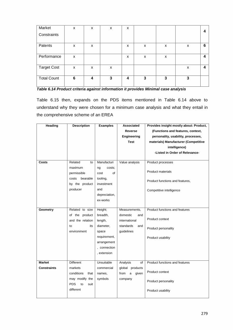
279
Market
Constraints
x x x x 4
Patents x x x x x x 6
Performance x x x x 4
Target Cost x x x x 4
Total Count 6 4 3 4 3 3 3
Table 6.14 Product criteria against information it provides Minimal case analysis
Table 6.15 then, expands on the PDS items mentioned in Table 6.14 above to
understand why they were chosen for a minimum case analysis and what they entail in
the comprehensive scheme of an EREA
Heading Description Examples Associated Reverse
Engineering Test
Provides insight mostly about: Product, (Functions and features, context, personality, usability, processes,
materials) Manufacturer (Competitive intelligence)
-Listed in Order of Relevance-
Costs Related to
maximum
permissible
costs bearable
by the product
producer
Manufacturi
ng costs;
cost of
tooling,
investment
and
depreciation,
ex-works
Value analysis Product processes
Product materials
Product functions and features,
Competitive intelligence
Geometry Related to size
of the product
and the relation
to its
environment
Height;
breadth,
length,
diameter,
space
requirement,
arrangement
, connection
, extension
Measurements,
domestic and
international
standards and
guidelines
Product functions and features
Product context
Product personality
Product usability
Market Constraints
Different
markets
conditions that
may modify the
PDS to suit
different
Unsuitable
commercial
names,
symbols
Analysis of
global products
from a given
company
Product functions and features
Product context
Product personality
Product usability
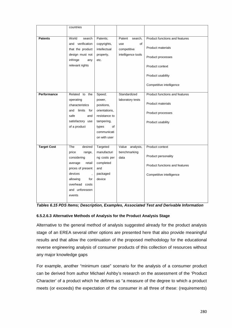
280
countries
Patents World search
and verification
that the product
design must not
infringe any
relevant rights
Patents;
copyrights,
intellectual
property,
etc.
Patent search,
use of
competitive
intelligence tools
Product functions and features
Product materials
Product processes
Product context
Product usability
Competitive intelligence
Performance Related to the
operating
characteristics
and limits for
safe and
satisfactory use
of a product
Speed;
power,
positions,
orientations,
resistance to
tampering,
types of
communicati
on with user
Standardized
laboratory tests
Product functions and features
Product materials
Product processes
Product usability
Target Cost The desired
price range,
considering
average retail
prices of present
devices ,
allowing for
overhead costs
and unforeseen
events
Targeted
manufacturi
ng costs per
completed
and
packaged
device
Value analysis,
benchmarking
data
Product context
Product personality
Product functions and features
Competitive intelligence
Tables 6.15 PDS Items; Description, Examples, Associated Test and Derivable Information
6.5.2.6.3 Alternative Methods of Analysis for the Product Analysis Stage
Alternative to the general method of analysis suggested already for the product analysis
stage of an EREA several other options are presented here that also provide meaningful
results and that allow the continuation of the proposed methodology for the educational
reverse engineering analysis of consumer products of this collection of resources without
any major knowledge gaps
For example, another “minimum case” scenario for the analysis of a consumer product
can be derived from author Michael Ashby’s research on the assessment of the ‘Product
Character’ of a product which he defines as “a measure of the degree to which a product
meets (or exceeds) the expectation of the consumer in all three of these: (requirements)
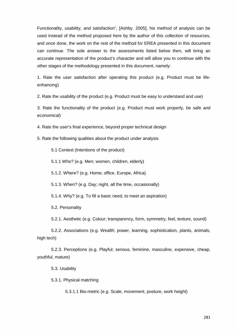
281
Functionality, usability, and satisfaction”, [Ashby. 2005], his method of analysis can be
used instead of the method proposed here by the author of this collection of resources,
and once done, the work on the rest of the method for EREA presented in this document
can continue. The sole answer to the assessments listed below then, will bring an
accurate representation of the product’s character and will allow you to continue with the
other stages of the methodology presented in this document, namely:
1. Rate the user satisfaction after operating this product (e.g. Product must be life-
enhancing)
2. Rate the usability of the product (e.g. Product must be easy to understand and use)
3. Rate the functionality of the product (e.g. Product must work properly, be safe and
economical)
4. Rate the user’s final experience, beyond proper technical design
5. Rate the following qualities about the product under analysis
5.1 Context (Intentions of the product)
5.1.1 Who? (e.g. Men; women, children, elderly)
5.1.2. Where? (e.g. Home; office, Europe, Africa)
5.1.3. When? (e.g. Day; night, all the time, occasionally)
5.1.4. Why? (e.g. To fill a basic need, to meet an aspiration)
5.2. Personality
5.2.1. Aesthetic (e.g. Colour; transparency, form, symmetry, feel, texture, sound)
5.2.2. Associations (e.g. Wealth; power, learning, sophistication, plants, animals,
high tech)
5.2.3. Perceptions (e.g. Playful; serious, feminine, masculine, expensive, cheap,
youthful, mature)
5.3. Usability
5.3.1. Physical matching
5.3.1.1 Bio-metric (e.g. Scale, movement, posture, work height)
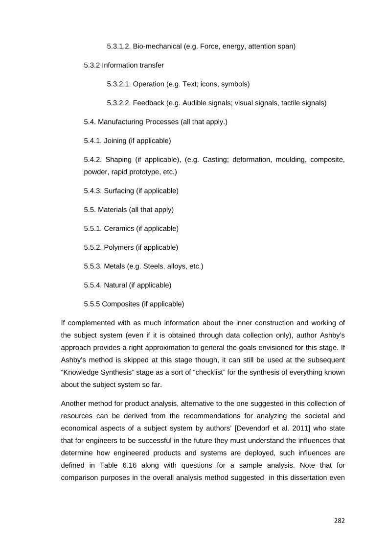
282
5.3.1.2. Bio-mechanical (e.g. Force, energy, attention span)
5.3.2 Information transfer
5.3.2.1. Operation (e.g. Text; icons, symbols)
5.3.2.2. Feedback (e.g. Audible signals; visual signals, tactile signals)
5.4. Manufacturing Processes (all that apply.)
5.4.1. Joining (if applicable)
5.4.2. Shaping (if applicable), (e.g. Casting; deformation, moulding, composite,
powder, rapid prototype, etc.)
5.4.3. Surfacing (if applicable)
5.5. Materials (all that apply)
5.5.1. Ceramics (if applicable)
5.5.2. Polymers (if applicable)
5.5.3. Metals (e.g. Steels, alloys, etc.)
5.5.4. Natural (if applicable)
5.5.5 Composites (if applicable)
If complemented with as much information about the inner construction and working of
the subject system (even if it is obtained through data collection only), author Ashby’s
approach provides a right approximation to general the goals envisioned for this stage. If
Ashby’s method is skipped at this stage though, it can still be used at the subsequent
“Knowledge Synthesis” stage as a sort of “checklist” for the synthesis of everything known
about the subject system so far.
Another method for product analysis, alternative to the one suggested in this collection of
resources can be derived from the recommendations for analyzing the societal and
economical aspects of a subject system by authors’ [Devendorf et al. 2011] who state
that for engineers to be successful in the future they must understand the influences that
determine how engineered products and systems are deployed, such influences are
defined in Table 6.16 along with questions for a sample analysis. Note that for
comparison purposes in the overall analysis method suggested in this dissertation even
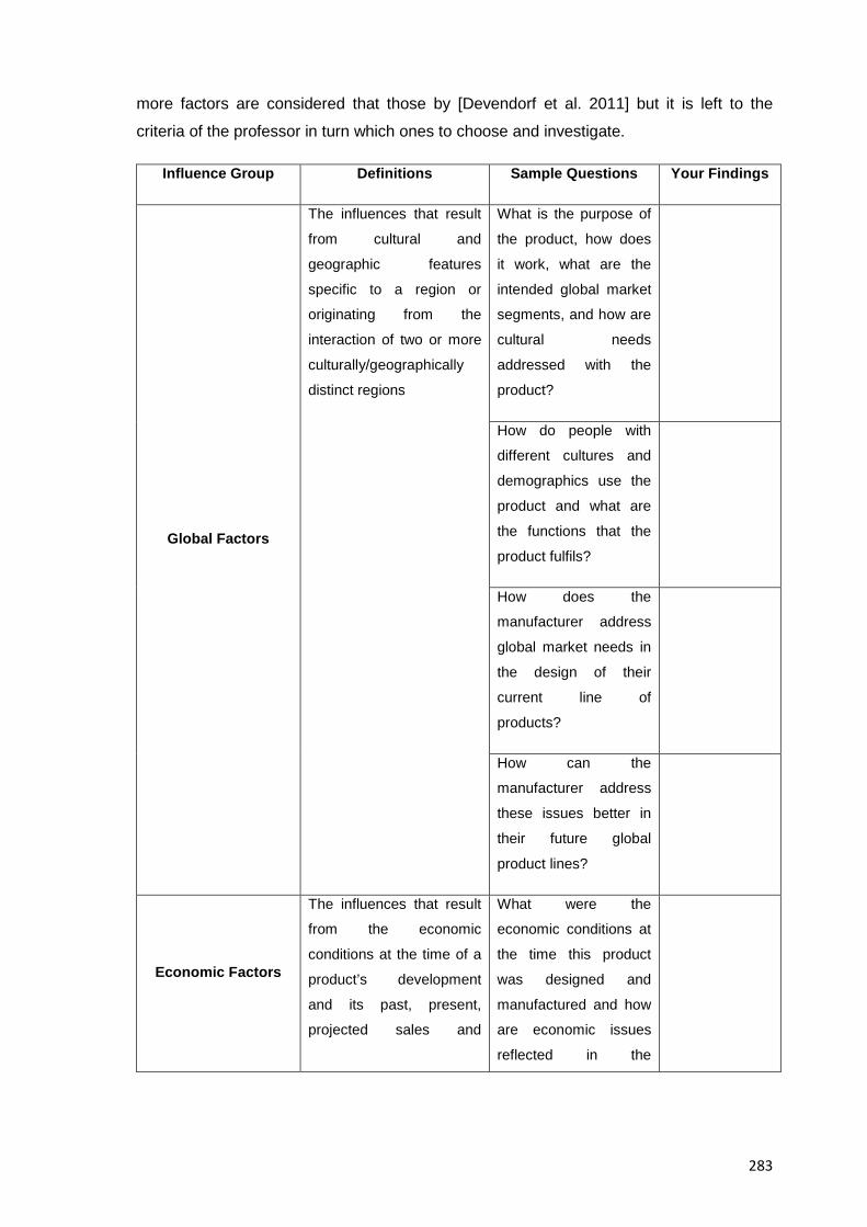
283
more factors are considered that those by [Devendorf et al. 2011] but it is left to the
criteria of the professor in turn which ones to choose and investigate.
Influence Group Definitions Sample Questions Your Findings
Global Factors
The influences that result
from cultural and
geographic features
specific to a region or
originating from the
interaction of two or more
culturally/geographically
distinct regions
What is the purpose of
the product, how does
it work, what are the
intended global market
segments, and how are
cultural needs
addressed with the
product?
How do people with
different cultures and
demographics use the
product and what are
the functions that the
product fulfils?
How does the
manufacturer address
global market needs in
the design of their
current line of
products?
How can the
manufacturer address
these issues better in
their future global
product lines?
Economic Factors
The influences that result
from the economic
conditions at the time of a
product’s development
and its past, present,
projected sales and
What were the
economic conditions at
the time this product
was designed and
manufactured and how
are economic issues
reflected in the
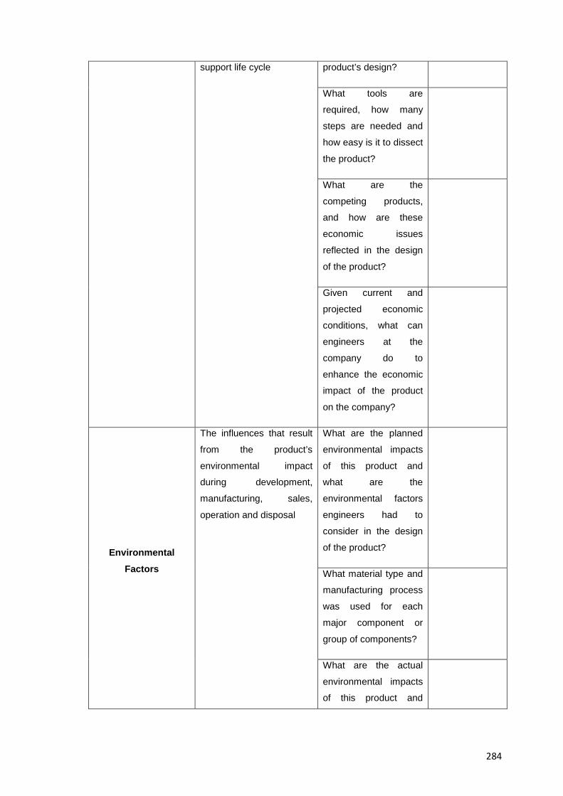
284
support life cycle product’s design?
What tools are
required, how many
steps are needed and
how easy is it to dissect
the product?
What are the
competing products,
and how are these
economic issues
reflected in the design
of the product?
Given current and
projected economic
conditions, what can
engineers at the
company do to
enhance the economic
impact of the product
on the company?
Environmental Factors
The influences that result
from the product’s
environmental impact
during development,
manufacturing, sales,
operation and disposal
What are the planned
environmental impacts
of this product and
what are the
environmental factors
engineers had to
consider in the design
of the product?
What material type and
manufacturing process
was used for each
major component or
group of components?
What are the actual
environmental impacts
of this product and
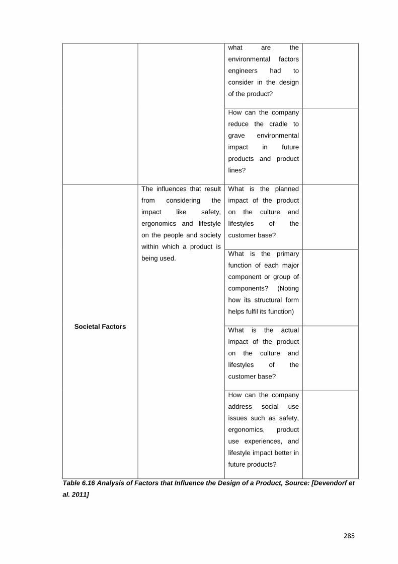
285
what are the
environmental factors
engineers had to
consider in the design
of the product?
How can the company
reduce the cradle to
grave environmental
impact in future
products and product
lines?
Societal Factors
The influences that result
from considering the
impact like safety,
ergonomics and lifestyle
on the people and society
within which a product is
being used.
What is the planned
impact of the product
on the culture and
lifestyles of the
customer base?
What is the primary
function of each major
component or group of
components? (Noting
how its structural form
helps fulfil its function)
What is the actual
impact of the product
on the culture and
lifestyles of the
customer base?
How can the company
address social use
issues such as safety,
ergonomics, product
use experiences, and
lifestyle impact better in
future products?
Table 6.16 Analysis of Factors that Influence the Design of a Product, Source: [Devendorf et al. 2011]
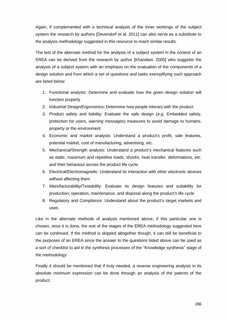
286
Again, if complemented with a technical analysis of the inner workings of the subject
system the research by authors [Devendorf et al. 2011] can also serve as a substitute to
the analysis methodology suggested in this resource to reach similar results.
The last of the alternate method for the analysis of a subject system in the context of an
EREA can be derived from the research by author [Khandani. 2005] who suggests the
analysis of a subject system with an emphasis on the evaluation of the components of a
design solution and from which a set of questions and tasks exemplifying such approach
are listed below
1. Functional analysis: Determine and evaluate how the given design solution will
function properly
2. Industrial Design/Ergonomics: Determine how people interact with the product
3. Product safety and liability: Evaluate the safe design (e.g. Embedded safety,
protection for users, warning messages) measures to avoid damage to humans,
property or the environment
4. Economic and market analysis: Understand a product’s profit, sale features,
potential market, cost of manufacturing, advertising, etc.
5. Mechanical/Strength analysis: Understand a product’s mechanical features such
as static, maximum and repetitive loads, shocks, heat transfer, deformations, etc.
and their behaviour across the product life cycle.
6. Electrical/Electromagnetic: Understand its interaction with other electronic devices
without affecting them
7. Manufacturability/Testability: Evaluate its design features and suitability for
production; operation, maintenance, and disposal along the product’s life cycle
8. Regulatory and Compliance: Understand about the product’s target markets and
uses
Like in the alternate methods of analysis mentioned above, if this particular one is
chosen, once it is done, the rest of the stages of the EREA methodology suggested here
can be continued. If the method is skipped altogether though, it can still be beneficial to
the purposes of an EREA since the answer to the questions listed above can be used as
a sort of checklist to aid in the synthesis processes of the “Knowledge synthesis” stage of
the methodology
Finally it should be mentioned that if truly needed, a reverse engineering analysis in its
absolute minimum expression can be done through an analysis of the patents of the
product.
287
6.5.2.7 A Suggested Pedagogy for the Teaching of the Product Reassembly Stage
The following advice has proved successful in the past for the attainment of the goals of
this stage and is categorized here for an easier reading by professors in charge of EREA,
namely:
A. General Advise for the stage:
• If for some reason, workload distribution at the disassembly stages was not equal ask
your student that those that didn’t have enough hands-on experience in past stages to
be the ones allowed to touch the product at this stage and take turns with each task
• If time is not an issue you could ask your students to try to assemble other teams’
devices by following their reassembly instructions, in this way students get
familiarized with a varied number of consumer products in one session.
B. For reassembling the subject system:
• Ask your students to be especially careful about fragile parts and those difficult to
reassemble.
• Ask them to be careful that no product parts are left over.
• Advise students to follow ordered and methodical product reassembly practices.
• Suggest your students to use small amounts of oil to lubricate mating parts, if
necessary
• If needed use special tools (e.g. Ring compressors) to put parts back into position
• Be sure to use the recommended tools when needed (e.g. a Torque wrench)
• If using a torque wrench ask your students the following:
o To finger tighten bolts before using the torque wrench
o To try each torque wrench on an exterior bolt before using it for real to see
how it works.
o To torque all bolts to the factory specification (e.g. Given values and pattern)
o To not over-tighten any of the bolts, some parts may be made of aluminium or
plastic and the threads can get stripped very easily.
C. For examining the reassembled device:
Once the product is completely together and students have no parts left over, ask them to
operate it, if it does not sound or feel like it did before, or if a strange smell develops tell
them to stop immediately to figure out what is wrong.
D. For straightening out once the stage is done:
288
Although actual practices change from institution to institution ask your students to take
provisions for proper keeping, cleaning and maintenance of involved tools whether there
are laboratory assistants for help or not, remind them that the necessary tools for the next
stage should be kept at hand though. the following actions are suggested once the
product has been reassembled, namely:
• Remove all products from the table or working area
• Return all tools where they belong and no empty tool slots remain
• Lock toolboxes and check everything is in order
• Wipe any oil or dirt off the table and dispose of the cleaning cloths
• Ask your students to do a tool inventory so they count and record all tools in their tool
box and compare this with the tool list they were are given, ask them to list any
shortages and overages of it if needed
6.5.2.8 A Suggested Pedagogy for the Teaching of the Product Performance Test II Stage
The following aspects to note have proved useful in the past to attain the goals of this
stage, namely:
A. For testing the performance of the reassembled Product:
Ask your students to perform as closely as possible those tests of the Product
Performance Test I stage or to prepare for additional measurement and testing in case
new information becomes available at this point
B. For storing the subject system and auxiliary tools once the stage is finished:
Suggest your students to store the devices in a place where they are able to access them
for the next class session in case more than one class period is needed to test the
device.
6.5.2.9 A Suggested Pedagogy for the Teaching of the Knowledge Synthesis Stage
The advise presented here for the proper development this stage is strongly based on a
varied of findings by researchers dispersed across several domains of knowledge, the
execution of the sequence of tasks suggested for this stage then, requires a minimal
knowledge of the reasons why they are asked and the background under which such
tasks are performed, and as such the tips and suggestions presented below intend to
provide an explanation of why the steps in the suggested methodology for educational
reverse engineering analysis were asked, how such steps should be executed and why
289
preliminary, cumulative results from previous stages (e.g. Disassembling , testing and
analysis stages) can be finally synthesized and contextualised at this point, namely:
A. For gathering and integrating all relevant data, information and knowledge about the product under analysis:
Tell your students to consult all available sources and to integrate everything, suggest
them for example, to make use of dynamic representations such as formatted templates
independent of ontology engineering tools that can provide the overall view necessary to
infer the original needs the product under analysis fulfils and make sense out of the
interrelated features of a product in terms of materials; functions, aesthetics and
interfaces.
Table 6.17 below shows an example developed specifically for this collection of
resources of what could be considered a “Knowledge worksheet” which is one of the
many possible options to help organise and contextualise all available data in support of
an EREA. Indeed such table was developed based on the previous work by [Zachman.
2002] and [Urbanic & ElMaraghy. 2008] and it consists of central columns headed by an
assortment of wh- questions that intend to uncover the rationale and history behind a
product, and left columns listing the life phases of a system/product that are used as the
guiding criteria for answering the wh- questions along the full lifecycle of the product
under analysis, the intersection in the central columns then are filled by the students with
the information obtained for group analysis and interpretation, and one table at a time can
be created and populated focusing only on one PDS aspect of the product at the time
The advantage of such structure is that it establishes definitions rather than a process
that transforms inputs to outputs, and as such, it is predictable and produces repeatable
results irrespective of the practitioner’s skills; what’s more, it allows the accumulations of
information about a product under analysis at different levels of abstraction and the
resulting data can still be further grouped at different levels of detail to associate them to
design ,manufacturing, or usage domains so that by asking questions such as what
(data); how (function), where (interconnection) and why (motivation) about a product’s
components and their features, the final design data can transform ideas into
implementations and can then be interpreted, contextualized and made useful by
common problem solving techniques of systems analysis.
Another advantage of such structure is that it also serves as a basis for a product’s
architecture since it is the representation of the fundamental structure of complex
products and can yield the total set of descriptive representations relevant for describing
290
them. The intersection between cells then, are the classifications that help describe a
product.
Finally and given that product design entails the integration of different systems in
consumer products they can be of a mechanical, electrical, electronic or computing
nature and they in turn will be integrated by further subsystems at different levels of
resolution. It makes sense then, to employ a system analysis approach to the reverse
engineering of consumer products and do so through each of the life phases of a system
in order to gain a full understanding of a product from its origins to its ends. Guideline
VDI 2221 for example [VDI Verlag GmbH. 1987], lists the life phases of a system which
proves suitable to the analysis of a consumer product, namely: Preliminary study (Market
need task, Company potential/goals, Product planning, Task clarification), System
development (Design), System production (Manufacture, Assembly, Test), System
installation (Sales, Service, Distribution), System operation (Operation, Consumption,
Maintenance), and System replacement (Recycle, further use, Environment disposal)
Table 6.17 then, shows such phases in the context of an EREA to provide a structure for
the organization and further design intelligence reconstruction of the product under
analysis
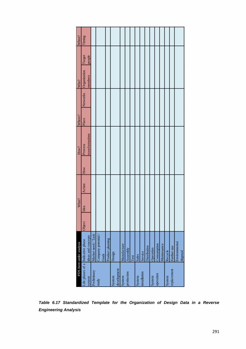
291
Table 6.17 Standardized Template for the Organization of Design Data in a Reverse
Engineering Analysis
Whe
n?Li
fe p
hase
s of
a
syst
emIn
dica
tive
phas
e id
eas
and
conc
epts
Obj
ect
Idea
Act
ion
How
Proc
ess
trans
form
atio
nsPl
ace
Net
wor
ksO
rgan
izatio
n m
embe
rsTa
rget
pe
ople
Tim
ing
Mar
ket n
eed
/ Tas
kC
ompa
ny p
oten
tial /
G
oals
Prod
uct p
lann
ing
Syst
em
deve
lopm
ent
Des
ign
Man
ufac
ture
Ass
embl
yTe
stSa
les
Serv
ice
Dist
ribut
ion
Ope
ratio
nC
onsu
mpt
ion
Mai
nten
ance
Rec
ycle
Furth
er u
seEn
viro
nmen
tal
disp
osal
PDS
Item
und
er a
naly
sis
Syst
em
repl
acem
ent
Syst
em
oper
atio
n
Syst
em
inst
alla
tion
Syst
em
prod
uctio
n
Wha
t?H
ow?
Whe
re?
Who
?
Prel
imin
ary
stud
y
292
B. For identifying what kind of scientific study method will be selected to start an analysis and synthesis process:
Tell your students that according to the type and breadth of empirical knowledge
available to the analyst, two types of methods can be selected, being them: Analytic,
whose approach draws conclusions about causes on the basis of given effects, or
synthetic whose approach infers effects from known or given causes
C. For explaining why the main problem the subject system must solve has nothing to do with its construction per se:
Explain your students that it is advisable not to assume any specific functional
relationships between individual components at least at the beginning of the analysis
process since the structure and role of individual components can only be determined
based on its relationship to the function of the product as a unit
D. For positioning all the information obtained about the product at the design stage where it generated:
Direct your students to the research by authors [Buura & Myrup. 1989] who provide
several examples for it, namely:
• Function principles and subsystems are tested in experimental laboratory setups
• Appearance and ergonomics are evaluated in design mock ups
• Product functions are evaluated in function models
• Usage, functions, reliability, marketing properties and the such are evaluated on
prototypes
• Manufacturing properties and quality indicators are tested on preproduction series
E. For finding possible design patch-ups in the subject system:
Tell your students that conventional DfX suggestions tend to provide localized design
patch-ups while most useful and cost saving redesign strategies are those that globally
redesign the product.
F. For detecting design choices in the product under analysis that weren’t optimal but likely a trade off against a number of different situations:
Explain your students that in real design experience, design choices and decisions can
be iterated only within limited resources and timeframes.
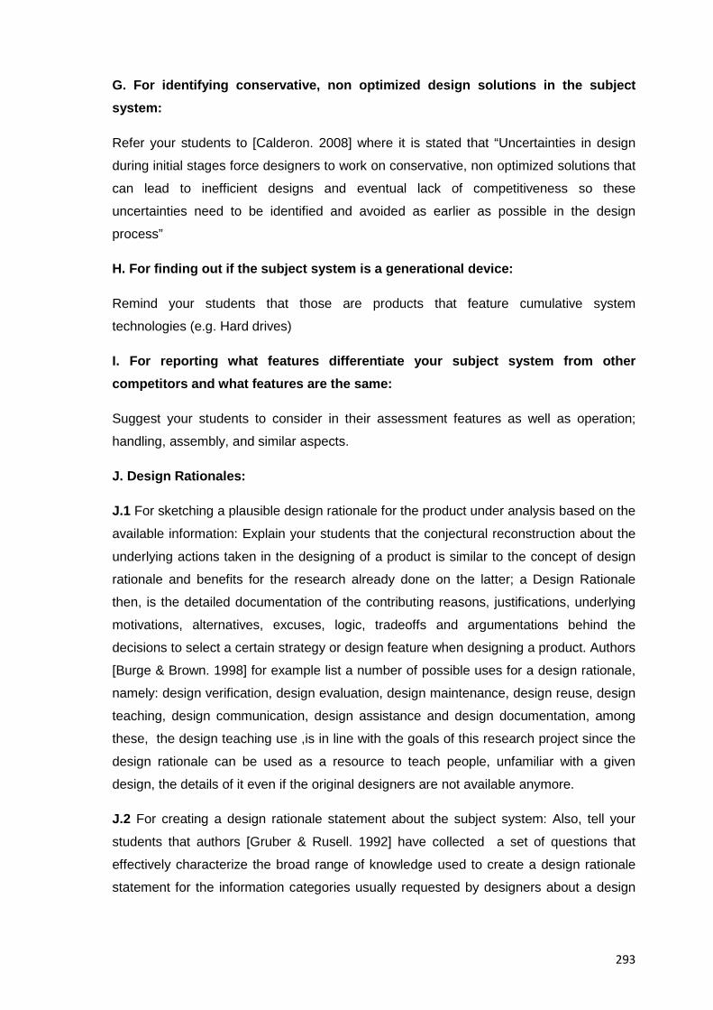
293
G. For identifying conservative, non optimized design solutions in the subject system:
Refer your students to [Calderon. 2008] where it is stated that “Uncertainties in design
during initial stages force designers to work on conservative, non optimized solutions that
can lead to inefficient designs and eventual lack of competitiveness so these
uncertainties need to be identified and avoided as earlier as possible in the design
process”
H. For finding out if the subject system is a generational device:
Remind your students that those are products that feature cumulative system
technologies (e.g. Hard drives)
I. For reporting what features differentiate your subject system from other competitors and what features are the same:
Suggest your students to consider in their assessment features as well as operation;
handling, assembly, and similar aspects.
J. Design Rationales:
J.1 For sketching a plausible design rationale for the product under analysis based on the
available information: Explain your students that the conjectural reconstruction about the
underlying actions taken in the designing of a product is similar to the concept of design
rationale and benefits for the research already done on the latter; a Design Rationale
then, is the detailed documentation of the contributing reasons, justifications, underlying
motivations, alternatives, excuses, logic, tradeoffs and argumentations behind the
decisions to select a certain strategy or design feature when designing a product. Authors
[Burge & Brown. 1998] for example list a number of possible uses for a design rationale,
namely: design verification, design evaluation, design maintenance, design reuse, design
teaching, design communication, design assistance and design documentation, among
these, the design teaching use ,is in line with the goals of this research project since the
design rationale can be used as a resource to teach people, unfamiliar with a given
design, the details of it even if the original designers are not available anymore.
J.2 For creating a design rationale statement about the subject system: Also, tell your
students that authors [Gruber & Rusell. 1992] have collected a set of questions that
effectively characterize the broad range of knowledge used to create a design rationale
statement for the information categories usually requested by designers about a design
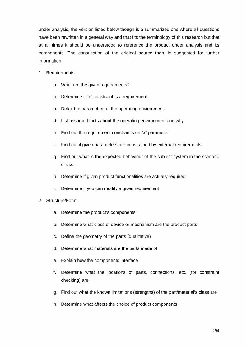
294
under analysis, the version listed below though is a summarized one where all questions
have been rewritten in a general way and that fits the terminology of this research but that
at all times it should be understood to reference the product under analysis and its
components. The consultation of the original source then, is suggested for further
information:
1. Requirements
a. What are the given requirements?
b. Determine if “x” constraint is a requirement
c. Detail the parameters of the operating environment.
d. List assumed facts about the operating environment and why
e. Find out the requirement constraints on “x” parameter
f. Find out if given parameters are constrained by external requirements
g. Find out what is the expected behaviour of the subject system in the scenario
of use
h. Determine if given product functionalities are actually required
i. Determine if you can modify a given requirement
2. Structure/Form
a. Determine the product’s components
b. Determine what class of device or mechanism are the product parts
c. Define the geometry of the parts (qualitative)
d. Determine what materials are the parts made of
e. Explain how the components interface
f. Determine what the locations of parts, connections, etc. (for constraint
checking) are
g. Find out what the known limitations (strengths) of the part/material’s class are
h. Determine what affects the choice of product components
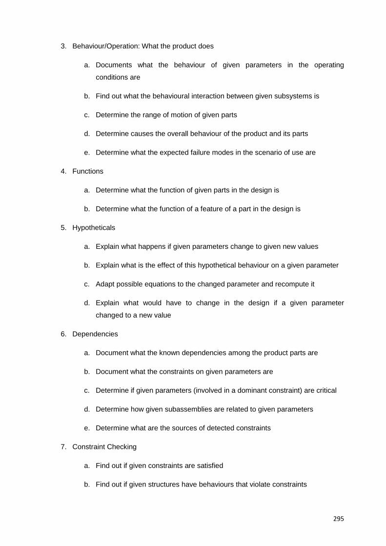
295
3. Behaviour/Operation: What the product does
a. Documents what the behaviour of given parameters in the operating
conditions are
b. Find out what the behavioural interaction between given subsystems is
c. Determine the range of motion of given parts
d. Determine causes the overall behaviour of the product and its parts
e. Determine what the expected failure modes in the scenario of use are
4. Functions
a. Determine what the function of given parts in the design is
b. Determine what the function of a feature of a part in the design is
5. Hypotheticals
a. Explain what happens if given parameters change to given new values
b. Explain what is the effect of this hypothetical behaviour on a given parameter
c. Adapt possible equations to the changed parameter and recompute it
d. Explain what would have to change in the design if a given parameter
changed to a new value
6. Dependencies
a. Document what the known dependencies among the product parts are
b. Document what the constraints on given parameters are
c. Determine if given parameters (involved in a dominant constraint) are critical
d. Determine how given subassemblies are related to given parameters
e. Determine what are the sources of detected constraints
7. Constraint Checking
a. Find out if given constraints are satisfied
b. Find out if given structures have behaviours that violate constraints
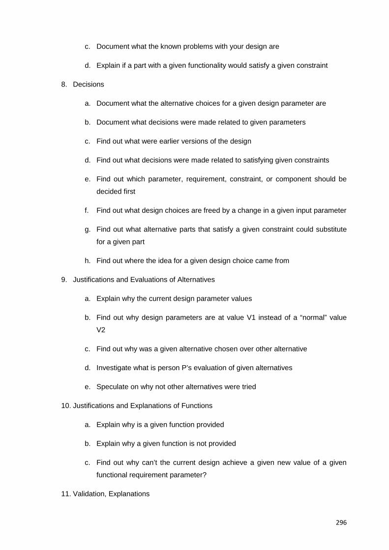
296
c. Document what the known problems with your design are
d. Explain if a part with a given functionality would satisfy a given constraint
8. Decisions
a. Document what the alternative choices for a given design parameter are
b. Document what decisions were made related to given parameters
c. Find out what were earlier versions of the design
d. Find out what decisions were made related to satisfying given constraints
e. Find out which parameter, requirement, constraint, or component should be
decided first
f. Find out what design choices are freed by a change in a given input parameter
g. Find out what alternative parts that satisfy a given constraint could substitute
for a given part
h. Find out where the idea for a given design choice came from
9. Justifications and Evaluations of Alternatives
a. Explain why the current design parameter values
b. Find out why design parameters are at value V1 instead of a “normal” value
V2
c. Find out why was a given alternative chosen over other alternative
d. Investigate what is person P’s evaluation of given alternatives
e. Speculate on why not other alternatives were tried
10. Justifications and Explanations of Functions
a. Explain why is a given function provided
b. Explain why a given function is not provided
c. Find out why can’t the current design achieve a given new value of a given
functional requirement parameter?
11. Validation, Explanations
297
a. Find out how are given requirements satisfied
b. Explain how are given functions achieved
c. Explain how are given functional requirements achieved
d. Explain how given parts will be maintained
12. Computations on Existing Model
a. Compute a parameter value given other parameters
b. Document what the trajectories of parameters are
13. Definitions
a. Explain what given terms in the documentation mean
14. Other Design Moves
a. Search for information expected to be in documentation (e.g. Equations or
diagrams)
b. Change given requirement constraints and update design.
c. Find out if all the arguments for/against a given alternative have been checked
J.3 For writing a design rationale that justifies the design process that led to the specific
device structure of the product under analysis: In complement to the abovementioned
information on design rationales, refer your students to the research by [Garcia &
Howard. 1992] who in their studies recognized patterns that represent the desire to know
what was done in the design of a product, and from them students can start asking the
right questions, namely:
• What? (The desire to know what was done, e.g. Values, scenarios, etc.)
• Why? (The context in which decisions were made, e.g. Issues considered stages of
the design process where decisions were made, etc.)
• Why not? (The designer’s conjectures on what should have been done, e.g. What
would be the impact on the design if instead of “X”, we chose “Y”?)
Additionally, the authors also suggest to include in the writing of a design rationale the
following items in order to add clarity and support to it, namely:
• Hypotheses proposed
298
• Assumptions made
• Constraints that had to be relaxed in order to make valid a decision
• Source of those constraints (such as specifications and preferences)
• Evaluation functions applied
• Changes in previous parameter values
• Designer’s preferences, represented either as constraints or as evaluation functions
(frequently derived from experience)
• Decision history (the pattern created by the previous decisions create a unique
scenario for the specific decision)
K. Design Plans:
K.1 For proposing a possible design plan for the subject system:
Tell your students that it can be done through experience, knowledge and educated
conjectures about its design and manufacturing (e.g. By making default assumptions
about the process of the design or possible redesign alternatives), the information listed
further below though, provides a good starting point for the creation of it.
K.2 For reconstructing a default design plan for the subject system by using default
knowledge:
Explain your students that design plans are defined as probable design states that lead to
the creation of a subject system (the product under analysis in this case) and given that
the design plan to arrive at a specific stage of a design is not unique and the original
design process is assumed to be unknown, a domain independent default plan using
default knowledge can be constructed at a coarse level that leaves room for changes that
will satisfy design constraints as more and more information about the product becomes
available and is added to it. A manual reconstruction like the one that will be shown below
then, requires the help of available information, inference and a strong domain knowledge
that contextualizes all possible clues. The steps listed in this regard in Section 5.4.10.6 to
reconstruct a default design plan (as opposed to a true design plan) by using default
knowledge (design information that cannot be confirmed to be true at the time it is
suggested) were devised by the author of this document by studying, expanding and
contextualizing to the domain of engineering design an original idea by author
[Jounghyun. 1994]. The algorithmic approach listed below is a knowledge-based one and
can be further enhanced and complemented by local problem solving heuristics. The
level of specificity of the design plan then, should be appropriate for the domain
299
knowledge of the product under analysis, which is usually at the middle of the spectrum in
cases of educational exercises.
K.3 For listing a sequence of probable design actions that could have happened during
the actual design of the subject system: Explain your students that such actions
commonly include potential design stages; design parameters, design objects, global
(product) vs. local (part) design decisions, and so on. Of course not all plausible design
action and their interrelationships need to be identified and students should only try until a
reasonable extent of common design actions is reached to a level of specificity previously
agreed upon, between instructors and students. In fact, some knowledge domain will help
filter out unreasonable yet possible design actions.
K.4 For mapping design problems / design particularities to a given stage of the design
plan: Remind your students that in general, problems that map to early or middle stages
of a design require global changes (function) to a design, whereas problems or
particularities in the final stages require changes of a local nature only (form)
K.5 For making use of descriptive design models, tell your students that they are domain
independent systematizations of the design process that identify sequences and patterns
of events likely to happen in most design projects, they reflect the successive abstract
refinements at each stage of design and they usually advise techniques and methods to
assist in the design process by providing guidelines, rules and procedures and that if
followed are expected to result in better designs and optimization of design resources.
Author [Jounghyun. 1994] for example provided some insight about these models and
their relevance to reverse engineering analysis, namely:
a. Prescriptive design models are domain independent or are applicable to many
domains
b. They gradually refine designs by guiding them from sketches up to detailed designs
c. They prioritize target objects by their functional importance (e.g. Main, auxiliary,
assembly, special, etc.)
d. They explicitly separate form design and layout design
e. Certain types of design actions are applied early in design, while others are applied
later.
f. Designers rarely reason about physical forms before functions
g. Features are usually added after parts are created
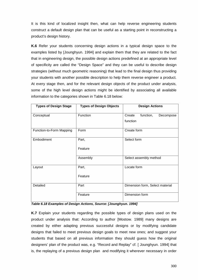
300
It is this kind of localized insight then, what can help reverse engineering students
construct a default design plan that can be useful as a starting point in reconstructing a
product’s design history.
K.6 Refer your students concerning design actions in a typical design space to the
examples listed by [Jounghyun. 1994] and explain them that they are related to the fact
that in engineering design, the possible design actions predefined at an appropriate level
of specificity are called the “Design Space” and they can be useful to describe design
strategies (without much geometric reasoning) that lead to the final design thus providing
your students with another possible description to help them reverse engineer a product.
At every stage then, and for the relevant design objects of the product under analysis,
some of the high level design actions might be identified by associating all available
information to the categories shown in Table 6.18 below:
Types of Design Stage Types of Design Objects Design Actions
Conceptual Function Create function, Decompose
function
Function-to-Form Mapping Form Create form
Embodiment Part,
Feature
Select form
Assembly Select assembly method
Layout Part,
Feature
Locate form
Detailed Part Dimension form, Select material
Feature Dimension form
Table 6.18 Examples of Design Actions, Source: [Jounghyun. 1994]
K.7 Explain your students regarding the possible types of design plans used on the
product under analysis that: According to author [Mostow. 1989] many designs are
created by either adapting previous successful designs or by modifying candidate
designs that failed to meet previous design goals to meet new ones; and suggest your
students that based on all previous information they should guess how the original
designers’ plan of the product was, e.g. “Record and Replay” cf. [ Jounghyun. 1994] that
is, the replaying of a previous design plan and modifying it wherever necessary in order
301
to meet the new specified design goals; “Acquire and Generate” cf. [Gruber & Russel.
1992] which tries to automatically infer the design rationale based on knowledge-based
inference methods such as simulation or qualitative device behaviour models and it
requires a strong domain knowledge about the task designs, or “Create and Debug” c.f. [
Jounghyun. 1994] which is the common paradigm for machine planning where a default
design plan is first generated and subsequently modified, if your students find out it was
of a different type ask them to explain how they reached their conclusions.
Finally, the following resources should be mentioned to your students as a suitable
starting point for listing probable design actions, namely:
• The standard design stages found at guidelines such as VDI2221 [VDI Verlag GmbH.
1987]
• An ordered sequence of design decisions and design actions from a previous design
process of a similar product
• Partially derived design actions from CAD screens or blueprints illustrating different
stages of design (a design plan based only on this though, would need to be
augmented with much more information and conjectures)
• Well known DfX recommendations / principles / criteria / guidelines for design
optimization
• Common sense design actions and assumptions
• Knowledge and experience from the professor at work
• Strong domain knowledge about engineering design and ideally about electro-
mechanics, manufacturing, or any other related area related to manufacturing and
production technologies
• Conjectures and educated guesses about the design rationale of the original
designers
• Descriptive design models
L. For uncovering the ununderstood aspects of the subject system’s design:
Remind your students that there are pieces of information at the highest level of
abstraction such as comments, descriptions or committed design decisions that cannot
be retrieved or recreated through a reverse engineering analysis so it is ok to assume,
speculate and put forth educated guesses about the ununderstood parts of the product
design
M. Advise for Constructing Knowledge from a Design Assessment
302
For analysing and listing examples of how constraints vs. criteria were satisfied in the
design of the subject system: Explain your students that one example is that to keep
costs low many optional features are left out of consumer product, e.g. picture dating or
automatic timers in single use cameras
N. Advice for Synthesising of Information
For synthesising all available information about the product under analysis:
Help your students exercise creative and intuitive instincts as well as coming up with
educated guesses during this stage, also advise them to consult with you; any other
instructor, experts, advisors, or consultants who can help acquire knowledge for the
subject system and uncover its history (e.g. Manufacturing, distribution, etc.) and its
design rationale (e.g. Design process and why it came to be the way it is).
Authors [Grosso et al. 1999] for example, provide additional guidance for this task by
suggesting the application of the techniques for knowledge acquisition from the discipline
of knowledge engineering which help synthesise knowledge from the product under
analysis based on the information acquired from it but always dependant on the depth of
knowledge to be constructed, the pointers listed below then, exemplify such synthesis
approach and should be attempted by your students, namely:
• By becoming familiar with the problem domain
• By characterising the reasoning tasks necessary to solve the problem
• By identifying the major domain concepts
• By categorizing the type of knowledge necessary to solve the problem
• By identifying the reasoning strategies used by experts
• By defining an inference structure for the resulting application
• By formalizing all of the above in a generic and reusable way
O. For drawing inferences from the particular representation of data obtained from the product under analysis:
Direct your students to the research by authors [Miles & Huberman. 1984] who suggest
specific tactics for drawing meaning from a particular representation of data, and who
suggest among other things:
• To see what is there
• To see what goes with what
• To integrate and differentiate data
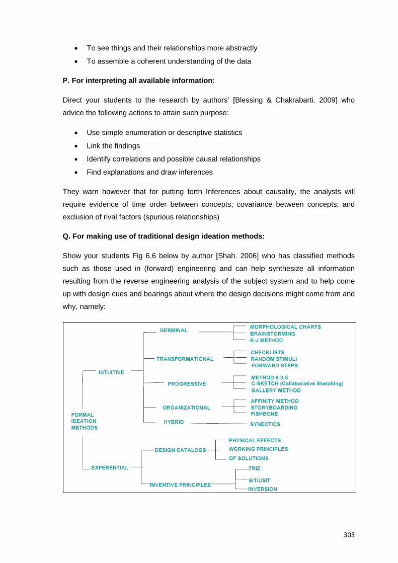
303
• To see things and their relationships more abstractly
• To assemble a coherent understanding of the data
P. For interpreting all available information:
Direct your students to the research by authors’ [Blessing & Chakrabarti. 2009] who
advice the following actions to attain such purpose:
• Use simple enumeration or descriptive statistics
• Link the findings
• Identify correlations and possible causal relationships
• Find explanations and draw inferences
They warn however that for putting forth Inferences about causality, the analysts will
require evidence of time order between concepts; covariance between concepts; and
exclusion of rival factors (spurious relationships)
Q. For making use of traditional design ideation methods:
Show your students Fig 6.6 below by author [Shah. 2006] who has classified methods
such as those used in (forward) engineering and can help synthesize all information
resulting from the reverse engineering analysis of the subject system and to help come
up with design cues and bearings about where the design decisions might come from and
why, namely:
304
Figure 6.6 Classification of Design Ideation Methods, Source: [Shah. 2006]
R. For comparing proposed PDS (Product Data Specifications) in a subject system against their actual implementation in order to retrieve design information:
Direct your students to the research by [Tomiyama. 1985] who explains that design
processes contain exception handling operations in order to achieve the desired design
goals, according to him these operations are called:
• Backtrack (retracing of the design path)
• Addition of specifications (addition of overlooked or misunderstood requirements)
• Relaxation of specifications (giving up on unattainable goals)
• Conflict resolution (understood as the deviations from the actual to the planed design
path)
They result either from identifying hidden or unclear specifications in the early stages of
the design process or from balancing requirements such as cost and performance at the
later stages. In practice It means design specifications are usually incomplete,
inconsistent and even infeasible and they’ll have to be further tested, revised and
augmented. Until the design is completed then, specifications can be considered to be
incomplete. Hence, the designers role in the design process lies in augmenting,
correcting, relaxing, refining and compromising the given specifications, the resulting
experience, knowledge and lessons learned comprise much of what is known as “Design
Rationale” and it can be partially retrieved by the reverse engineering method proposed
here by conjectural reconstruction of missing pieces of information along the design
process. In the end it is the drift of the initial product design specifications from the final
ones materialised into the finished product what stores information for reverse
engineering analysis. The same can be assumed about the manufacturing and
production processes where similar operations and compromises are likely to happen
until a final product is achieved.
S. For using the “Inference to the best explanation” reasoning framework in order to contextualize all available data:
Explain your students that once the information collection and organisation steps have
been done, an analysis and contextualization of the available data is necessary, the
reasoning framework that supports this process is called “inference to the best
explanation” and it is a method of abductive reasoning used in science, identified by
Harman c.f. [Harman. 1965] that helps scientists; so they can elect hypothesis which
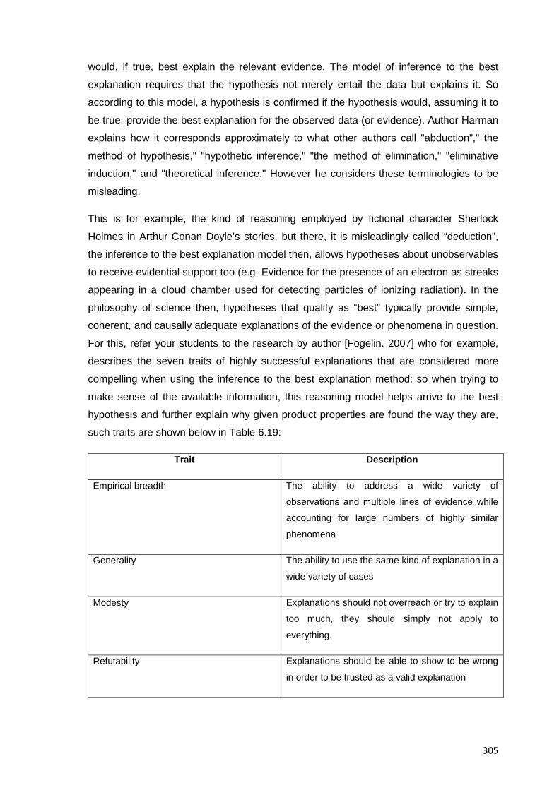
305
would, if true, best explain the relevant evidence. The model of inference to the best
explanation requires that the hypothesis not merely entail the data but explains it. So
according to this model, a hypothesis is confirmed if the hypothesis would, assuming it to
be true, provide the best explanation for the observed data (or evidence). Author Harman
explains how it corresponds approximately to what other authors call "abduction”," the
method of hypothesis," "hypothetic inference," "the method of elimination," "eliminative
induction," and "theoretical inference." However he considers these terminologies to be
misleading.
This is for example, the kind of reasoning employed by fictional character Sherlock
Holmes in Arthur Conan Doyle’s stories, but there, it is misleadingly called “deduction”,
the inference to the best explanation model then, allows hypotheses about unobservables
to receive evidential support too (e.g. Evidence for the presence of an electron as streaks
appearing in a cloud chamber used for detecting particles of ionizing radiation). In the
philosophy of science then, hypotheses that qualify as “best” typically provide simple,
coherent, and causally adequate explanations of the evidence or phenomena in question.
For this, refer your students to the research by author [Fogelin. 2007] who for example,
describes the seven traits of highly successful explanations that are considered more
compelling when using the inference to the best explanation method; so when trying to
make sense of the available information, this reasoning model helps arrive to the best
hypothesis and further explain why given product properties are found the way they are,
such traits are shown below in Table 6.19:
Trait Description
Empirical breadth The ability to address a wide variety of
observations and multiple lines of evidence while
accounting for large numbers of highly similar
phenomena
Generality The ability to use the same kind of explanation in a
wide variety of cases
Modesty Explanations should not overreach or try to explain
too much, they should simply not apply to
everything.
Refutability Explanations should be able to show to be wrong
in order to be trusted as a valid explanation
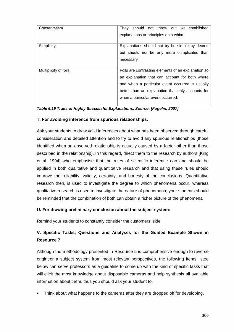
306
Conservatism They should not throw out well-established
explanations or principles on a whim
Simplicity Explanations should not try be simple by decree
but should not be any more complicated than
necessary
Multiplicity of foils Foils are contrasting elements of an explanation so
an explanation that can account for both where
and when a particular event occurred is usually
better than an explanation that only accounts for
when a particular event occurred.
Table 6.19 Traits of Highly Successful Explanations, Source: [Fogelin. 2007]
T. For avoiding inference from spurious relationships:
Ask your students to draw valid inferences about what has been observed through careful
consideration and detailed attention and to try to avoid any spurious relationships (those
identified when an observed relationship is actually caused by a factor other than those
described in the relationship). In this regard, direct them to the research by authors [King
et al. 1994] who emphasise that the rules of scientific inference can and should be
applied in both qualitative and quantitative research and that using these rules should
improve the reliability, validity, certainty, and honesty of the conclusions. Quantitative
research then, is used to investigate the degree to which phenomena occur, whereas
qualitative research is used to investigate the nature of phenomena; your students should
be reminded that the combination of both can obtain a richer picture of the phenomena
U. For drawing preliminary conclusion about the subject system:
Remind your students to constantly consider the customers’ side
V. Specific Tasks, Questions and Analyses for the Guided Example Shown in Resource 7
Although the methodology presented in Resource 5 is comprehensive enough to reverse
engineer a subject system from most relevant perspectives, the following items listed
below can serve professors as a guideline to come up with the kind of specific tasks that
will elicit the most knowledge about disposable cameras and help synthesis all available
information about them, thus you should ask your student to:
• Think about what happens to the cameras after they are dropped off for developing.
307
• Assess what are the advantages and disadvantages of single use cameras against
conventional analogue/digital ones?
• Assess how can the environmental impact of the camera be further reduced?
• Knowing that the manufacturer does not reuse the lenses and the battery, answer
how you think a faulty lens or battery would affect the consumer’s perception about
the product?
6.5.2.10 A Suggested Pedagogy for the Teaching of the Redesign Suggestions Stage
The following pieces of advice intend to remind professors in charge of EREA that the
students’ ideas about what a better subject system would be should receive a fair
judgement through the consideration of their actual knowledge and experience of the
engineering design process in relation to their suggested improvements
A. Overall considerations for this stage:
Whenever students suggest improvements to the product they have analysed it is
expected that their suggestions begin with simple imitation of what others have already
suggested, however, as confidence and proficiency in the process develops, more
creative approaches and innovative solutions can emerge as a result of triggering more
cognitive processes in them
B. For the overall attainment of this stage, suggest your students to:
• Look for inspiration from competing products (e.g. Based on preconceived product
improvement ideas) in case comparative analysis proves useful to achieve the goals
of this stage
• Add new improvement ideas, after screening, combining, modifying and expanding
existing ones to also come up with an improved redesign of the subject system
• Create innovative solutions for redesigning the subject system
• Apply creative problem solving techniques in the suggestion of design improvements
for a superior product than the one analyzed (e.g. Challenge the way things are
normally done; Improve on what has been done before; Generate many potential
solutions to a given problem, Suggest new approaches to solving problems, etc.)
• Consider different technical alternatives to the improvement suggestions while
bearing in mind cost, environmental concerns, safety, and other constraints
• Compile promissory, improvement suggestions for further culling and development
later in this stage
308
• Hold team discussions where formal ideation methods are use to come up with
plausible changes to improve the subject system
C. For identifying weaknesses and improvement opportunities for your subject system:
Suggest your students to operate under the assumption that the design under analysis
has been already streamlined and is efficient to achieve a certain goal considered by the
original designers, in this way coming up with improvement suggestions becomes a more
conscious effort and thus more thought is put into it by students
D. For conceptualizing new functions and/or solutions to the current configuration in your subject system:
Suggest your students to use design methods to hypothesize current and future
functions, for example a design concept for a redesigned product can be done benefiting
from previous work done in performing a morphological analysis of your subject system
and recording functions and subfunctions on a design concept table to finally describe
each design concept generated
E. Suggest you students to make use of typical analytical tools available in engineering design:
For example if students choose to eliminate a subject system’s part to improve its design,
ask them to explain verbally what changes would need to take place to eliminate such
part but if possible ask them to explain their answers via a morphological matrix
F. For selecting the most promissory improvement concepts for further refinement and allocation of development resources:
Suggest your students to make use of analytic tools, for example:
• House of quality: To find the most appropriate product area to address in the redesign
process as suggested by [Otto & Wood.2001], also direct your students to the
example by [Edwards et al. 2010] who have used a house of quality to evaluate the
perceived value or importance of redesign concepts in the context of a product
dissection activity and also provide examples on concept generation, screening and
scoring
• Pugh’s concept selection charts [Pugh. 1991]
• Weighted sums, etc.
309
G. For dealing with potential students’ invention:
If an invention is conceived during the EREA, provide your students with guidance on
patent application
H. For additional support to come up with a product redesign of the subject system, ask your students to:
• Consult authors’ [Otto & Wood. 2001] research on product redesign tasks and their
examples.
• Benefit from their own experiences and consult with other professors or specialists on
the field
• Consider that incremental improvements to the subject system have their place too
(i.e. Of the type that adds features without changing much the original design;
recycling process, manufacturing costs, or final price tag)
• Consider that usually the improvement aspect to consider about existing consumer
products deal with: Ergonomics; size, weight, cost, and portability.
I. If during the disassembly stage your students found product parts that were hard to disassemble:
Explain them that according to authors [Comparini & Cagan. 1998] this situation usually
indicates not only that the manufacturer is preventing the user from servicing the unit but
also that disassembly for servicing; reusing or recycling is clearly not an objective in this
design, and that in fact Design for Disassembly is not usually considered, unless
regulatory pressures come into effect (one of the reasons manufacturers contend is that
the logistics of a take-back program would be too costly), this situation in itself can serve
as a source of improvement ideas for the subject system
This is the end of the second phase of the pedagogy for the teaching of EREA dealing
with the execution of it, the next phase though, will deal with the grading aspects of it.
6.5.3 Phase 3: Evaluation of an EREA
Engineering Design is a multidisciplinary activity with varied application areas that
requires not only its teaching strategies to be diverse but its evaluation to be flexible just
like the goals and nature of design projects themselves. The third phase in the pedagogy
for the teaching of EREA then, corresponds to the stages 12th (Conclusions) and 13th
(Results Dissemination) of the methodology for educational reverse engineering analysis
suggested in Resource 5 and covers its main task which is the evaluation of the
310
achievement of the goals set at the beginning of the EREA both at the students (e.g.
Team and individual performance) and professors (e.g. Learning objectives) level.
Based on original results and on the benefits reported by previous researchers of the
topic, after performing an EREA students are expected:
1. To improve the understanding of simple information (Vocabulary; facts, equations,
quotes)
2. To improve the understanding of complex information (Differentiation; comparison,
contrasting, synthesizing of information)
3. To improve their theorizing, analyzing, and problem solving performance
4. To improve the use of tools and procedures
5. To investigate the natural and industrial world
6. To improve their communication and team work skills
The information presented here then, gives the elements to detect and evaluate the
abovementioned improvements in students and indeed, it intends to cover all relevant
cases for the evaluation of EREA and thus, proper guidance on their assessment
including the possibility of both internal and external evaluations is shown here along with
details specific to the two individual stages comprising the phase. Later in this same
section, a practical application for the evaluation of the example showed in Resource 7
will be suggested in order to support the readers’ eventual development of their own
assessment tools
6.5.3.1 Fundamentals of the Evaluation of Educational Reverse Engineering Activities
No matter how new EREA could be to some of the students they still need to be
evaluated under the regular grading mechanisms of the host institutions, some pointers
then, for the examination of the teaching and learning performance during an EREA are
presented in this section. Indeed, the advice given here could be considered to apply to
all cases of EREA irrespective of the depth pursued or the product analysed, and it
relates to the specific educational needs of professors, students and academic
institutions involved; such advise then, is presented in this section, separate from the two
individual stages comprising this phase, to highlight its foundational nature and thus the
contents listed in here should be of special importance to first time participants and
311
instructors of reverse engineering activities, however, and as usual, experienced
professors can skip this section altogether and evaluate their students according to their
specific requirements. Additionally, and later in this section , specific advise on the two
individual stages comprising this phase, and on the guided example presented in
Resource 7 will be also given, namely:
A. Instructors’ Overall Advice for the Completion of this Phase:
• Explain your students your assessment patterns, that is how learning will be
evaluated and what constitutes a passing or failing performance
• Give students detailed feedback on their performance individually, as a team and if
possible as a whole class
• Clarify task requirements and expectations as needed
• For tracking and reporting purposes to your academic institution, keep a close look on
the number of student completing the activity, withdrawing it or failing it (a.k.a Attrition
rates) although EREA are usually well perceived among students cf. [Dalrymple.
2009]
• Try to give your students the opportunity to talk to invited speakers or go into an
industry tour in order to wrap up their knowledge of the product under analysis and
support their writing of conclusions
B. Suggested Aspects to Evaluate the Students’ Learning and Performance in the Attainment of the goals of the EREA
The following list of items and recommendations summarise those aspects relevant to the
evaluation of students in an EREA, namely:
• Evaluate you students’ class participation (but the criteria for quantity, quality and
what determines both of them should be stated to students beforehand)
• Evaluate the creation of engineering graphics and documents for their subject system:
e.g. Systems diagram of the product under analysis, product schematics, disassembly
and reassembly instructions, suggestions for the improvement of the product
throughout its lifecycle (e.g. Before; creation, disposal, etc.)
• Evaluate your students’ design journal which should include answers to all questions
and tasks of the methodology for educational reverse engineering analysis suggested
in Resource 5
• Evaluate your students’ homework and other assignments
• Evaluate your students’ performance throughout the EREA by considering their
creation of derivative products and the creation of an improved product specification
312
The major categories of graded activities in an EREA then, include but are not limited to:
Session deliverables; intermediate reports, laboratory work, class discussions, public
presentations, demonstrations, and final project reports; specific examples of them worth
mentioning would be class attendance; participation in discussions, team activities,
homeworks, and so on
B.1 Alternate aspects to assess on an EREA: Depending on certain conditions of the
EREA in turn (e.g. Students’ limited, technical proficiency or lack of access to
technological equipment) an alternative way to assess the learning of students rather
focusing on the development of non technical traits might be need. The following list for
example, shows some of those criteria that can help the professor in charge evaluate
students and potential signs of their growth, namely:
• Evidence that students achieved certain learning goals
• Evidence of their most / least successful learning objective
• Effect on student’s interest, motivation, values, study habits and interpersonal
relationships from the EREA
• Evidence that students are prepared for subsequent courses on the area of
Engineering Design
• Students’ ideas and proposals on what changes should be made to EREA to
better benefit from them
C. Suggested Tools and Techniques for the Assessment of Students’ Performance on Course Objectives and Goals
It refers to the way students will be evaluated, and it is suggested to evaluate using a
mixture of student ratings (e.g. Tests, ungraded activities, interactive periods in lecture,
short writing assignments, group work, success of product’s reassembly, self evaluation,
student interviews, achievement of learning outcomes, students’ retention, examinations;
reports, oral examinations, student’s presentations, student reports, students feedback
(about what they did), etc.), the following options though, are favoured for their use in an
EREA, namely:
• Oral reports
• Team experiences
• Written reports
• Team presentation
D. Suggested Grading Policies and Standards for Evaluation to use in an EREA
313
Grading rules are set according to the requirements of the host institutions but they are
usually devised to explain how the activity will be assessed, under what criteria, and to
ensure the quality of the students’ work in aspects such as completeness; correctness,
organization, timely submission, and so on
• Suggested distribution for marks: They usually depend on the professor in charge but
for an EREA the usual grading percentages are 50% for laboratory work, 25% for the
quality of redesign suggestions and 25% for quality of the final report. In this regard it
is worth keeping in mind that the weighting for the different assignments and tasks
given to students will have a major impact on the distribution of their efforts and thus
the distribution of grades should be explained to them beforehand
• Suggested grading scales: Common options include the American A to F scales or
the European 5 to 10 scores where a minimum passing mark should be at least 70%
of the maximum possible total
• Suggested policy for extra credits: Since one of the objectives of this activity is to
introduce the profession of engineering design to the students, a possible idea for
extra points is their attendance to approved student and professional technical
meetings, congresses, presentations and so on, inside and outside their chosen
engineering discipline where in order to obtain the extra points the student must
provide proof of his attendance or of what he/she learned.
E. Perspectives to Consider in the Evaluation of an EREA
In order to get a comprehensive view of the actual learning and growth of a student
throughout an EREA, three different perspectives to evaluate should be considered and
which are briefly explained here so the professors in charge eventually develop a strategy
that covers them based on their own experience and supported by the resources
presented in this section, namely:
• Evaluation from Professors to Students
Evaluation to students must be done considering their acquisition of abilities in line with
those shown in Table 4.10; the students’ final knowledge about the subject system
though should be considered a side-benefit and consequence of an EREA but never its
main aspect to evaluate.
• Evaluation from Students to Students
Students must evaluate themselves in regard to their performance throughout the EREA
and in terms of their individual contributions to the attainment of the goals of the EREA, or
314
in accordance with the fulfilment of their assigned roles, if they seem it appropriate
though, a combination of both can also serve as a measure of their performance
• Student’s self evaluation
The student must evaluate himself/herself according to his/her appreciation of the bits
learned from the activity as well as from the individual contributions to the attainment of
the goals of the EREA.
F. Summary of Major Evaluation Criteria in Relation to Goals of a Typical Engineering Design Curriculum
The information listed below intends to summarise those aspect to be evaluated in
students undergoing an EREA and that have proved to be some of the most important
ones in relation to the learning goals of typical engineering design programmes (earlier
versions of this document included varied examples of questions to asks for the
evaluation of an EREA, however since all the relevant aspects have already been
integrated into the methodology of Resource 5 for purposes of clarity now only few
pointers and examples are included below to guide the instructors in their evaluation of
an EREA), namely:
1. About the engineering design process: e.g. To determine how scientific principles;
material properties, manufacturing techniques, cost, safety requirements,
environmental considerations, ethical, intellectual property rights and other
considerations of engineering affect the design of a system, component or process
2. About awareness of engineering practice: e.g. To acquire the knowledge required to
set up any necessary tests and be able to challenge results from a formal analysis
3. About a systems perspective: e.g. To unify dispersed knowledge and tie together
other fields that normally are perceived as unrelated, To be able to analyze the
component systems and subsystems of a device, to create a systems diagram to
describe the operation and control of a device, and to identify the purpose of
subsystems as input, process, output, or feedback.
4. About consumer products themselves: e.g. To understand the workings of the product
analyzed and suggest ideas to improve the value of it
5. About Technology: e.g. To increase the knowledge of trends and recent
developments in key technologies and to explain a product’s lifecycle in terms of
technological impacts.
6. About information collection: e.g. To exercise resourcefulness to access relevant
sources of information; engineering expertise, know-how and skills at all stages of the
315
reverse engineering analysis through the use a variety of information resources (i.e.
Interviews to potential sources, effective database searches ,observing, questioning,
and so on)
7. About Design for X: e.g. To learn about the varied Design for X approaches for the
achievement of economic; neat, well structured, designs
8. About a product’s’ assembly: e.g. To learn how products are assembled and about
their assembly plans (e.g. To classify the component parts of a device according to
varied criteria)
9. About product’s manufacturing: e.g. To recognize the basic principles of selecting
manufacturing processes for a particular component
10. About product’s materials: e.g. To learn about selection and properties of construction
materials for consumer products
11. About inter-personal interactions: To discover the advantages and disadvantages of
working with others and collaborating
12. About adaptive dispositions: e.g. To transfer the knowledge and skills learned during
the EREA to future situations or to provide a context for new learning
13. About cognitive development: e.g. To determine what type of analysis was
appropriate in support of synthesis, evaluation and decision making
14. About creativity: e.g. To exercise creative and intuitive instincts
15. About intellectual property: e.g. To realize that reverse engineering is not a
straightforward process and indeed manufacturers set traps and locks so their
products cannot be reverse engineered
All of the information presented in this section then, is of a foundational nature and is
applicable to both stages comprising this phase; individual, specific advice for each stage
comprising this phase though is given next too, followed by a practical application of the
advice presented here and in support of the guided example presented in Resource 7
6.5.3.2 A Suggested Pedagogy for the Teaching of the Conclusions Stage
Given that it is the students who’ll do all the work at this stage, the professors’ role falls in
guiding them so they can come up with a comprehensive set of conclusions that are both
meaningful and revealing about what they learned throughout the EREA, the following
tips and suggestions then are given to the professor in charge, namely:
A. General advice for writing the conclusions report:
• Suggest your students to produce a report that documents and discusses all relevant
findings and impressions from previous steps of the methodology at the appropriate
316
level of detail following their own sense of comprehensiveness and relevance of the
conclusions presented (e.g. Oral and written reports directed to classmates, peers,
and well informed yet general audiences).
• Remind your students that particular attention should be given to update the final
report with findings from early stages of the methodology (e.g. Data collection) and
with complementary information revealed at later stages (e.g. Product analysis)
• Ask your students to leverage from all findings and conclusions documented for each
previous stage of the methodology
• Suggest your students to brush up their technical writing skills and apply them on their
final report
• Suggest your students to start drafting the final report since the beginning of the
EREA itself and thus benefit from team and individual entries in their design journal(s)
from all stages
• Suggest your students to keep future classmates in mind so the essential findings and
results in their report can benefit them too (e.g. By describing in chronological order
what your team did during all phases; how tasks were distributed and how decisions
were made)
• Ask your students to organize the written materials in a logical sequence to enhance
reader's comprehension
B. For writing the final conclusions about the subject system analysed:
• Suggest your students to benefit from the umbrella categories suggested by authors
[Pahl et al. 2007] acknowledged as related knowledge domains that support design
and development, and suggest them to place all their findings under the appropriate
category, namely: Natural Science / Engineering Science; Production Science /
Technology, Materials Science, Industrial Design / Art, Information and
Communication Sciences, Experiences / Engineering Applications, Economics and
Management Science, Social Science. Additionally you could suggest your students
to comment on the following domains also mentioned by the authors, namely:
Mechanics; ergonomics, marketing and psychology; finally, you could also ask them
to state their final impressions about the subject system by answering authors’ Pahl
items on the description of a product under analysis, namely: The use of specific
materials to attain certain concept solutions; The application of possible design
methods, The use and knowledge of existing design solutions, The design history of
the product until its last incarnation, The product’s aesthetics, and Potential user
trials.
317
• Remind your students to incorporate material; mechanical, electrical, and assembly
factors into their team discussions and eventual writing of conclusions
In summary, conclusions about the EREA at this stage will vary in reach; scope, length
and detail, but at a personal level students usually report enthusiasm and motivation to
finish the EREA since they see it as a “Practical” experience, whereas as learning bits
they report a familiarization with varied aspect of the design of a consumer product which
they consider to be a “representative” experience of the engineering design process
overall
6.5.3.3 A Suggested Pedagogy for the Teaching of the Results Dissemination Stage
The dissemination of results marks the stage where classmates and the general public
get to know about the outcomes from the students’ work on the educational aspects of
reverse engineering and as such it is of paramount importance to present all results in a
proper way that includes a clear explanation of why such activities are done, how they
are done, and what benefits they bring to engineering design education overall, the
advice presented below then, intends to help clarify what the requirements for appropriate
presentation of results from an EREA are and thus help professors better publicise good
works from their students that can help increase the department’s/university status
,namely:
A. For the overall communication of conclusions:
• Suggest your students to communicate effectively their information by using all
available means (e.g. Oral presentations, written reports as well as graphical; verbal,
written and electronic tools)
• Suggest them to include in their conclusions an explanation of the items they
analyzed
• Advise your students to present relevant information in a variety of audience-friendly
formats and always keep the nature of the audience in mind when addressing them
• Remind your students to add any additional information they might consider useful to
the readers of their work
• Ask your students to provide good documented information about the about the
subject system
• Suggest your students to properly quote all references used throughout their
investigation
• Suggest your students to understand “global/general audiences” as non technical but
well informed ones
318
B. For the creation and showing of display boards in academic settings:
For creating a display board with the results of successful EREA projects suggest your
students to mount the components of their subject system and include brief explanations
of how the parts interact and work together as well as graphics of their findings to add
credibility and attract interest to those looking at their results
C. For the creation and showing of posters in academic settings:
Suggest your students to hang them at a suitable location(s) for other students to see it
D. For the creation of an oral presentation:
Suggest your students to follow the next recommendations for an effective transfer of
information and reinforcing of their presentations, namely: To plan to deliver an effective
oral presentation; to apply presentation tools effectively (e.g. By creating visuals for oral
presentations), to make the most out of their presentation skills, and to use and present
their design working files and follow-up reports in their presentation of results
E. For the writing of dissemination hand-outs:
Ask your students to try to comply with currents standards of technical writing
F. For writing a document directed to future designers / redesigners of their chosen subject system:
Suggest your students to give advice that helps the readers to avoid repeating past
mistakes; that provides them a direct means for determining the impact of proposed
design changes, and that helps them in the communication of goals, assumptions and
final system specifications.
As a professor it is important not only to support your students in disseminating the right
results from their work and to help them present the results appropriately according to
their target audience (e.g. By suggesting them to give classmates supporting handouts
before a presentation) but also to profit at this point from the opportunity to collect their
final reactions and impression about the EREA, in order to set a baseline from which you
as a professor can keep improving for future collaborations and projects on the topic of
educational reverse engineering.
6.5.3.4 Sample Students’ Evaluation Tests Specific to the Guided Example of Resource 7
319
To reach a thorough knowledge about the product under analysis is never the main goal
of an EREA but rather an effect from it and thus the success of students undergoing an
EREA cannot be evaluated on that aspect alone (although, arguably there is no better
way to know about a consumer product other than disassembling it), still and as shown
by researchers such as [Dalrymple. 2009] well planed subject system-based exercises
can actually contribute to the comprehensive evaluation of a student in an EREA and in
relation to the attainment of the actual goals of a typical engineering design programme
The four following exercises for example were devised and used by author [Dalrymple.
2009] to evaluate students and prove among other things the ability of product dissection
activities to the elicit transfer (the ability to extend what has been learned in one context
to new contexts cf. [Bransford et al. 2000]) in her students, namely:
A. Mapping functions-to-components exercise
B. Variant design (modifying the camera to achieve new functionality) exercise
C. Product troubleshooting exercise
D. System Decomposition exercise
Any of the abovementioned exercises will help students acquire and develop skills,
abilities and concepts relevant to all hands-on activities in engineering design irrespective
of the product chosen for analysis and as such the results from said exercises can
complement other aspects of their evaluation (e.g. Laboratory work, improvement
suggestions, presentations of results, etc.) thus getting a fair, comprehensive assessment
of their performance throughout the EREA
The exercises are presented here in a format addressed to the professor in charge and
represent the way they should be delivered to your students, namely:
A. Sample Mapping Functions-to-Components Exercise, Source: [Dalrymple. 2009]
During the design process, engineers may map the desired functions of a device to
specific components that will accomplish those functions; this is an educational exercise
to simulate that experience and helps exercise skills such as spatial awareness or
familiarization with mechanisms
• General instructions to students:
1. Write your name and team
2. Map the functions of a single use disposable camera of your choice to the specific
components used to accomplish those functions
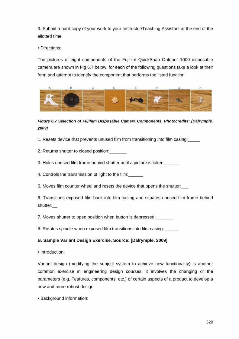
320
3. Submit a hard copy of your work to your Instructor/Teaching Assistant at the end of the
allotted time
• Directions:
The pictures of eight components of the Fujifilm QuickSnap Outdoor 1000 disposable
camera are shown in Fig 6.7 below, for each of the following questions take a look at their
form and attempt to identify the component that performs the listed function
Figure 6.7 Selection of Fujifilm Disposable Camera Components, Photocredits: [Dalrymple.
2009]
1. Resets device that prevents unused film from transitioning into film casing:_____
2. Returns shutter to closed position:_______
3. Holds unused film frame behind shutter until a picture is taken:______
4. Controls the transmission of light to the film:______
5. Moves film counter wheel and resets the device that opens the shutter:___
6. Transitions exposed film back into film casing and situates unused film frame behind
shutter:__
7. Moves shutter to open position when button is depressed:_______
8. Rotates spindle when exposed film transitions into film casing:______
B. Sample Variant Design Exercise, Source: [Dalrymple. 2009]
• Introduction:
Variant design (modifying the subject system to achieve new functionality) is another
common exercise in engineering design courses, it involves the changing of the
parameters (e.g. Features, components, etc.) of certain aspects of a product to develop a
new and more robust design.
• Background information:
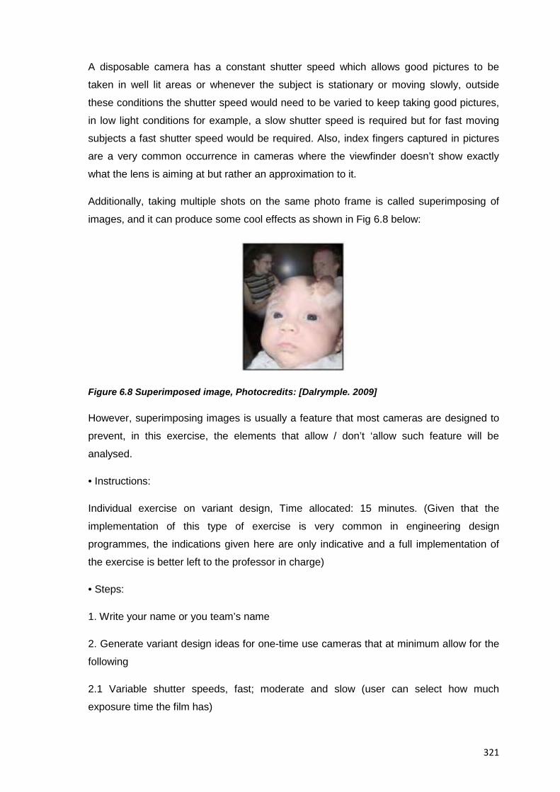
321
A disposable camera has a constant shutter speed which allows good pictures to be
taken in well lit areas or whenever the subject is stationary or moving slowly, outside
these conditions the shutter speed would need to be varied to keep taking good pictures,
in low light conditions for example, a slow shutter speed is required but for fast moving
subjects a fast shutter speed would be required. Also, index fingers captured in pictures
are a very common occurrence in cameras where the viewfinder doesn’t show exactly
what the lens is aiming at but rather an approximation to it.
Additionally, taking multiple shots on the same photo frame is called superimposing of
images, and it can produce some cool effects as shown in Fig 6.8 below:
Figure 6.8 Superimposed image, Photocredits: [Dalrymple. 2009]
However, superimposing images is usually a feature that most cameras are designed to
prevent, in this exercise, the elements that allow / don’t ‘allow such feature will be
analysed.
• Instructions:
Individual exercise on variant design, Time allocated: 15 minutes. (Given that the
implementation of this type of exercise is very common in engineering design
programmes, the indications given here are only indicative and a full implementation of
the exercise is better left to the professor in charge)
• Steps:
1. Write your name or you team’s name
2. Generate variant design ideas for one-time use cameras that at minimum allow for the
following
2.1 Variable shutter speeds, fast; moderate and slow (user can select how much
exposure time the film has)
322
2.2 Superimposing of images (user can take one picture on top of another), determine for
example what components (select all that apply) from the Bill-Of-Materials of the
disposable camera under analysis prevent multiple images from being taken on the same
film frame and how the identified components should function to allow the user the
superimposing of images
2.3 Alter the disposable camera design to allow the user to see in the viewfinder any
object blocking the lens (e.g. Fingers on corners of the picture)
3. For each scenario describe how you’d modify the original design of the camera to
achieve the new functionality
4. Show your work to your Instructor / Teaching assistant, to be collected at the end of
the allotted time.
Conditions (optional): The camera should maintain some of its original functions (you
choose)
C. Sample Product Troubleshooting Exercise, Source: [Dalrymple. 2009]
• Introduction:
Disposable camera manufacturers reuse most of the components from previously used
cameras to make new ones. To ensure that the re-used components still function
satisfactorily they undergo a thorough cleansing process to remove imperfections and
restore them to their original working condition, the reused components are only moved
to the assembly line if they pass inspection, [Dalrymple. 2009]
A re-loaded one-time-use camera is a camera that has been manufactured by a third
party company using the used camera components that were originally manufactured by
Kodak, Fujifilm and other reputable companies. After obtaining the camera shells from
the photo-developers, these third party companies re-assemble the parts, and load the
cameras with new film. Although these re-loaded cameras may look similar to those from
the original manufacturers, they are very different because the re-used components have
not undergone the same stringent cleaning and inspection processes to ensure the same
quality. Developed film often reveals the imperfections with reloaded cameras, Source:
[Dalrymple. 2009]
• Tasks:
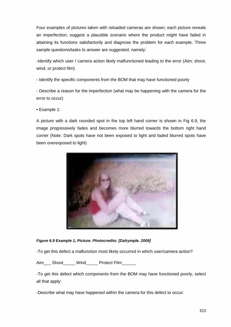
323
Four examples of pictures taken with reloaded cameras are shown; each picture reveals
an imperfection; suggest a plausible scenario where the product might have failed in
attaining its functions satisfactorily and diagnose the problem for each example. Three
sample questions/tasks to answer are suggested, namely:
-Identify which user / camera action likely malfunctioned leading to the error (Aim; shoot,
wind, or protect film)
- Identify the specific components from the BOM that may have functioned poorly
- Describe a reason for the imperfection (what may be happening with the camera for the
error to occur)
• Example 1:
A picture with a dark rounded spot in the top left hand corner is shown in Fig 6.9, the
image progressively fades and becomes more blurred towards the bottom right hand
corner (Note: Dark spots have not been exposed to light and faded blurred spots have
been overexposed to light)
Figure 6.9 Example 1, Picture. Photocredits: [Dalrymple. 2009]
-To get this defect a malfunction most likely occurred in which user/camera action?
Aim___ Shoot_____ Wind_____ Protect Film______
-To get this defect which components from the BOM may have functioned poorly, select
all that apply:
-Describe what may have happened within the camera for this defect to occur:
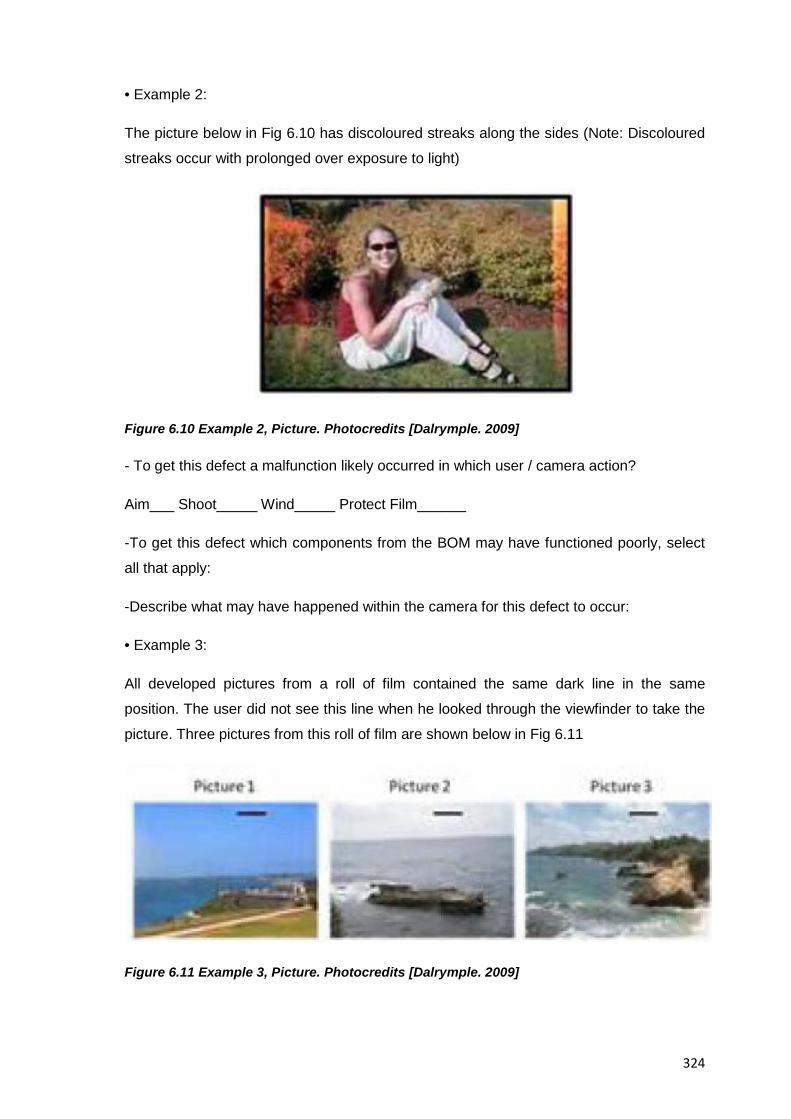
324
• Example 2:
The picture below in Fig 6.10 has discoloured streaks along the sides (Note: Discoloured
streaks occur with prolonged over exposure to light)
Figure 6.10 Example 2, Picture. Photocredits [Dalrymple. 2009]
- To get this defect a malfunction likely occurred in which user / camera action?
Aim___ Shoot_____ Wind_____ Protect Film______
-To get this defect which components from the BOM may have functioned poorly, select
all that apply:
-Describe what may have happened within the camera for this defect to occur:
• Example 3:
All developed pictures from a roll of film contained the same dark line in the same
position. The user did not see this line when he looked through the viewfinder to take the
picture. Three pictures from this roll of film are shown below in Fig 6.11
Figure 6.11 Example 3, Picture. Photocredits [Dalrymple. 2009]
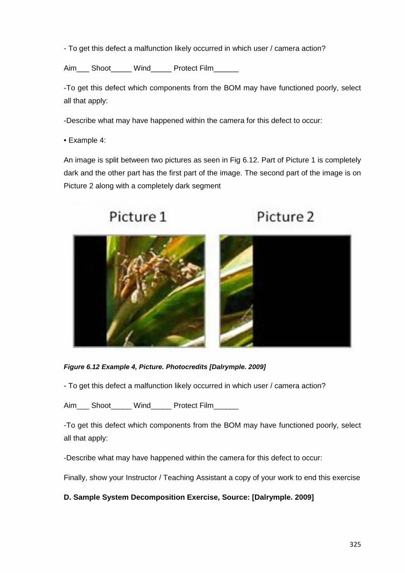
325
- To get this defect a malfunction likely occurred in which user / camera action?
Aim___ Shoot_____ Wind_____ Protect Film______
-To get this defect which components from the BOM may have functioned poorly, select
all that apply:
-Describe what may have happened within the camera for this defect to occur:
• Example 4:
An image is split between two pictures as seen in Fig 6.12. Part of Picture 1 is completely
dark and the other part has the first part of the image. The second part of the image is on
Picture 2 along with a completely dark segment
Figure 6.12 Example 4, Picture. Photocredits [Dalrymple. 2009]
- To get this defect a malfunction likely occurred in which user / camera action?
Aim___ Shoot_____ Wind_____ Protect Film______
-To get this defect which components from the BOM may have functioned poorly, select
all that apply:
-Describe what may have happened within the camera for this defect to occur:
Finally, show your Instructor / Teaching Assistant a copy of your work to end this exercise
D. Sample System Decomposition Exercise, Source: [Dalrymple. 2009]
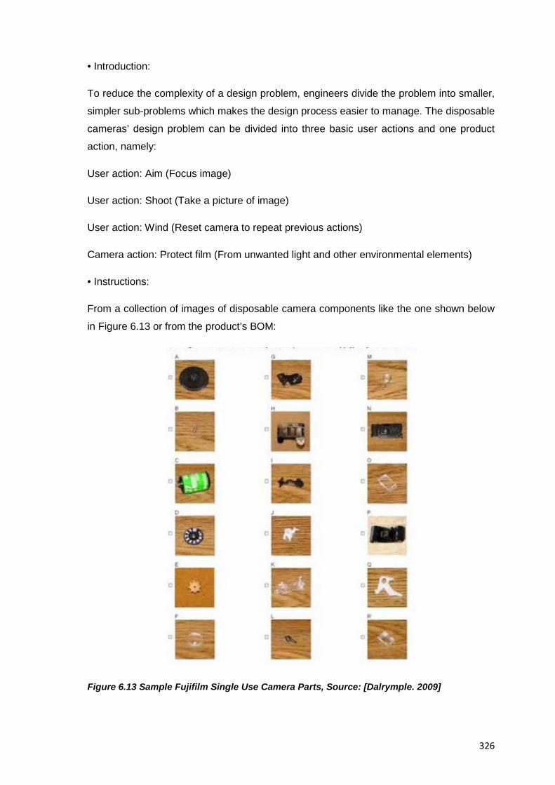
326
• Introduction:
To reduce the complexity of a design problem, engineers divide the problem into smaller,
simpler sub-problems which makes the design process easier to manage. The disposable
cameras’ design problem can be divided into three basic user actions and one product
action, namely:
User action: Aim (Focus image)
User action: Shoot (Take a picture of image)
User action: Wind (Reset camera to repeat previous actions)
Camera action: Protect film (From unwanted light and other environmental elements)
• Instructions:
From a collection of images of disposable camera components like the one shown below
in Figure 6.13 or from the product’s BOM:
Figure 6.13 Sample Fujifilm Single Use Camera Parts, Source: [Dalrymple. 2009]
327
1. Identify and select all the components that function to allow the user or the camera to:
Aim (Focus image):____________________,_______,_________,_______
Shoot (Take a picture of an image): ______, ______,______,_____
Wind (Reset camera to repeat previous actions):______,________,______,______
Protect film (From unwanted light and other environmental
elements):_______,________,_______,____
2. Note if some of the components can support multiple actions
As seen from the four different exercises above product-based tests can help students
acquire relevant skills and abilities necessary for the development of the profession of
engineering design.
This is the end of the third phase of the pedagogy for the teaching of EREA dealing with
the evaluation of it, the next phase though will cover the following up aspects of it so all
knowledge gained from an EREA can be kept reachable for whoever deems it useful in a
future situation.
6.5.4 Phase 4: Follow up of an EREA
The fourth and last phase in the pedagogy for the teaching of EREA concerns the actions
involving the ending of the students’ work in an EREA and the following up of its results
by the professors that were in charge in the sense that all relevant knowledge and
findings obtained from the EREA can remain available until they are needed again (e.g.
To improve the planning of resources for future EREA; to know what to expect from them
under given circumstances or to know how to analyse a certain family of products). This
phase then, correspond entirely with the 14th and last stage (Project Closure / Follow Up)
of the suggested methodology for educational reverse engineering analysis proposed in
Resource 5 and so it marks the end of both the methodology and the pedagogy for EREA
suggested in this collection of resources
Major categories for the actions to carry out at this stage from a professor’s perspective
and that have proved successful in the past in keeping the experience gained from an
EREA readily available include: Documenting the knowledge obtained from an EREA
both at the students and instructors level; disseminating the findings from the EREA in
academic circles, putting in place feedback mechanisms for students in order keep
improving the teaching of EREA, and the developing of guidelines for the creation of
328
Reverse Engineering-based educational activities based on the results from professors
having given them a try
6.5.4.1 Project Closure/Follow Up
The advice presented below intends to support professors in charge of EREA to set up
the mechanisms that will allow all knowledge gained from an EREA to be kept and
reachable; the specific actions for professors to do at this stage then, include:
• To analyse the feedback from your students about their overall impressions from the
EREA
• To try to foster connections between local industries and your institution by requesting
any form of support such as donated physical equipment, company tours, or experts
visits
• To think of future themes for EREA
• To consider the possibility to exchange EREA-projects with partner schools and learn
from each other’s experiences
• To consider the possibility to deliver EREA to students of the same university not only
from engineering design programmes but also from different engineering disciplines
• To incorporate changes to the teaching curriculum of EREA (if needed) after the
experiences gained from them
• To plan for renewal of project ideas
• To prepare a strategy to reuse projects from past semesters in case of need or at
least to keep them arranged as a repository of past projects for students to consult,
provided that each semester different, varied products are suggested to students to
choose as subject systems
• To prepare your findings so they are transferable to other classes/professors and
universities
• If convinced of the benefits of EREA or if you detect new uses of them, to try to
disseminate them and to always look for different applications of them
The last piece of advice to give professors reaching this point of the pedagogy then, is to
allow their students to conclude the EREA whenever they feel there is nothing left to be
taught under the available resources and the professor is ready to move on with the
assurance that everything relevant that was learned won’t be lost and will be of benefit for
future professors and students of EREA.
6.6. Resource Conclusions
329
Educational reverse engineering activities -Just like engineering design itself- are
multidisciplinary activities with varied application areas that require their teaching
strategies to be diverse and their evaluation to be flexible just like the goals and nature of
design projects themselves.
It is believed then, that a structured approach to the teaching of EREA like the one
presented in this resource (cf. Preparation; execution , evaluation, and follow up of them)
that is set in a real-life like scenario and where students can plan their own tasks and the
professors’ role mainly falls in supporting an orderly sequence of events by providing
them with technical and organizational input, not only helps ensure that the learning
experiences inherent to EREA are actually acquired and that the workload and roles
needed for them are evenly distributed among team members and professors in an
effective and safe way, but also that such structured approach can help mitigate not only
some of the attributes of poor instruction in engineering identified by authors [Seymour
and Hewitt. 1997] such as the “Predominant use of one-way lectures”, “Lack of
discussion”, and “No indicated application or implication of material” ones but also to help
lessen the deficiencies of typical lectures reported by [Bligh. 2000] with respect to
“Promotion of thought” and “Inspiring interest in a subject”.
The advice presented in this resource intends to support professors of engineering
design willing to give EREA a try by providing them with the advice and information
necessary to plan, teach, evaluate and follow up the work and results from their students
under the existing administrative and pedagogical frameworks already enforced at their
workplace.

330
This page intentionally left blank
331
RESOURCE 7: INTEGRATED EXAMPLE OF AN EDUCATIONAL REVERSE ENGINEERING ACTIVITY ON A DISPOSABLE CAMERA
7.1 Resource Introduction
This resource is presented as a self-contained example of an educational reverse
engineering activity using a disposable photographic camera as a subject system; it is
intended to show professors of engineering design in an integrated, practical way what an
EREA would look like in an educational setting (i.e. Tasks and questions suggested in the
methodology are translated into specific actions done to a disposable camera) thus each
step of the example, how it is handled and what the results from it are, should be
understood both as an indication of what an EREA would comprise and how experience
recommends to deal with. Each of the fourteen stages of the methodology for the
development of an EREA already explained in Resource 5 is presented here in an
expanded three-subsections format in order to include suggestions for its teaching, and
examples of results from it.
• The subsections showing the self-descriptive stages of the suggested methodology for
the reverse engineering analysis of the subject system are written in a style addressed to
the analysts in turn (cf. Undergraduate students of engineering design)
• The subsections showing a proposed pedagogy for the teaching of the abovementioned
methodology are written in a style addressed to professors in order to support the
development of each of the stages (e.g. By including the theory and explanation behind
them)
• The subsections showing sample results, deliverables and conclusions for each of the
stages of the methodology are presented in the same way as students would submit
them for evaluation to their professors
The information presented in this resource then, complements that previously shown in
Resources 5 and 6, and in the rest of the collection of resources overall to support the
testing and eventual implementation of EREA in existing engineering design curricula.
7.1.1 The Methodology Subsections
As mentioned already, from the battery of tasks, questions and analyses suggested in the
methodology for the development of EREA, the professor in charge must select only
332
those that provide a beneficial tradeoff between information gained and resources
invested, in this guided example one can see how experience dictates single use
cameras should be analysed in a reverse engineering activity and what sequence the
analyses would follow and to what depth they would be pursued
7.1.2 The Suggested Pedagogy Subsections
Different from Section 6.4 where the fundamentals of a pedagogy for the teaching of
EREA is presented , in this resource’s example those specific suggestions and
explanations are transformed into specific tips and suggestions on how to conduct each
of the stages of the methodology when using a disposable photographic camera as a test
subject, from the comparison of the specific actions here to the general guidelines
presented at the previous resource one can see how a theoretical approach is
transformed into a real life application.
7.1.3 The Sample Deliverables Subsections
Earlier versions of this collection of resources considered the inclusion of the solutions to
the full battery of tasks, questions and analyses suitable for the disposable camera used
as subject system in this example, however the idea was quickly discarded because of
readability and length constraints in this document, instead, a more focused approach is
considered here where only those analyses known to most professors; with a certain
degree of difficulty, and that provide the most information about the product under
analysis are attempted in this example; what’s more, and in order to benefit from the work
by past researchers on disposable cameras, now fully developed exercises are included
only whenever deemed necessary, but in the rest of cases only snippets showing the
most relevant data, and pointers for the development of a given analysis are shown;
additional to this and as much as possible, the author of this document has tried to
include relevant analyses already solved and published which can indeed serve not only
as references and inspiration for the target audience but also as leads to discover the
work of other researchers on the topic; indeed several authors have worked in the past
on disposable cameras and finally in this collection of resources can the readers
coherently link the work of all of them and complement it with the original findings from
this collection of resources.
7.1.4 Specifics of this Resource
As mentioned in Section 6.4.4, EREA can support students’ learning at any stage of their
studies, however their recommended time of inclusion falls during their first year so they
333
can use the activity as a fast track to familiarise with the topics of their educational
curriculum as well as with the analyses and approaches likely to be found later in their
careers, the level of detail and comprehensiveness of the analyses presented here then,
reflects this approach while still providing at the same time significant pointers for the
development of several advanced analyses expected from last year and graduate
students of engineering design.
It is also worth mentioning that the Kodak single use camera with flash was chosen as
the subject system for this example not only because it features electromechanical
components as well as a chemical device (the photographic film), but also because it’s
been the subject of analysis by past researchers and as such, newcomers to reverse
engineering can compare their own results to those previously published to check how
they are doing; however, it was later brought to the attention of the author that this model
was not sold in all markets, so additional examples for the Kodak single use waterproof
camera (a complementing member of the same product line available worldwide) were
also included to present an example that feels closer to professors in academic
institutions all over, indeed in an EREA with more than one team or where plenty of
resources are available this approach is actually taken where the simultaneous analysis
of similar, competing products by different teams of students provides a greater chance to
expand the sources of learning for the whole class, in the end though, it is worth keeping
in mind that learning about disposable cameras themselves (or about the chosen product
for analysis for that matter) is not a goal of an EREA (though disassembling a specific
product to learn about it is a great way), but they are rather considered a vehicle for the
acquisition of abilities and skills relevant to engineering design irrespective of the product
analysed.
Finally, all due credit should go to the past researchers who have worked on disposable
cameras as an aid in the teaching of engineering and from which this specific section of
the collection of resources draws heavily, namely: The lesson plan “Reverse Engineering
of a Common Product a CIESE collaborative project” by [CIESE. 2008]; the examples
“Kodak Waterproof One-Time-Use Camera” by [Castellani. 2006], “Single-Use Camera
Dissection” by [Simpson. 2009], “Group 32 - Kodak Funsaver Camera” by [CIBER-U.
2012] and the dissection of a Kodak Water & Sport camera by [Kutz. 2007], the
pioneering product dissection examples by [Lamancusa et al. 1996], the research on
reverse engineering for green design of products by [Comparini & Cagan. 1998], and the
findings by [Dalrymple. 2009]; their past publications along with the ideas and findings
pertaining to the doctoral research from which this collection of resources stems aim to
334
represent most of the best practices, experience and innovations available in the area of
product dissection and hands-on activities for the teaching of engineering design.
7.2 Integrated Example of an EREA
The example below explores how a single use camera works; how it came to be and its
impact in society, the main objective of the activities listed below is to provide students
with an opportunity to develop their basic abilities in engineering design and as such this
activity is planned as a complement not a substitute to their traditional instruction.
7.2.1 Stage I: Task Clarification
7.2.1.1 Methodology
From the battery of tasks, questions and analyses available for this stage it was decided
to go ahead with those that provided a general understanding of the situation and whose
results are seen in Tables 7.1 and 7.2 below.
7.2.1.2 Suggested Pedagogy
The professors’ work at this stage is mostly comprised of helping their students
understand the nature of the task they are being asked, and of helping them to plan the
actions to meet project milestones & deadlines
7.2.1.3 Sample Deliverables
A. Students’ understanding of the situation:
Understanding of the Situation
What To understand how the single use Kodak Flash Camera came to be, for what reason
and how it has impacted society
Why As a way to quickly familiarize with the topics and engineering tasks likely to find
throughout the undergraduate years and later in our careers
How By performing a reverse engineering analysis to a disposable camera and determining
among other things its components; functions, features, materials and manufacturing
processes involved and eventually suggesting improvements to it
When At the second semester of our engineering studies and for which a timetable for the
execution of the tasks is shown further below in Table 7.2
335
Where At several venues but most of the work being at the university lab and the usual
classroom itself
Which The consumer product chosen for reverse engineering analysis is a disposable Kodak
Flash camera
Who Based on the size of the class several teams were created each of them with four
members
Table 7.1 Students’ Understanding of the Situation
B. Student’s statement of goals and expectations from the EREA:
To have an educational activity in a safe environment where we can learn the trades of
our career and advance in the acquisition of abilities and knowledge related to it
C. Timetable for the completion of the activity (8 Sessions of 1h duration at least)
Stage of the Methodology
Major Activities Resources Needed
Venue
Session 1 Task
clarification,
Product
procurement,
Team selection
Introduction and
overview of the
activity; team
setting, first contact
with the product
Disposable Kodak
Flash camera
Classroom
Session 2 Data collection Collection of
information and
contact with
experts
Internet access,
published
resources
University
library,
classroom,
home
Session 3 Product
performance
test I, Product
disassembly
Testing, measuring
and dissection of
camera
Laboratory tools University
laboratory
Session 4 Product
analysis
Testing, inspecting Laboratory tools,
Internet access,
published
resources,
external advisors
University
laboratory
Session 5 Product Assembly, tuning Laboratory tools University
336
reassembly,
Product
performance
test II
and measuring of
the camera
laboratory
Session 6 Knowledge
synthesis,
Redesign
suggestions
Team discussions,
consultation with
experts
Internet access,
published
resources,
external advisors
University
library,
classroom,
home
Session 7 Conclusions Team discussions,
documenting,
drafting of report
Personal
computers;
internet access,
published
resources,
external advisors
University
library,
classroom,
home
Session 8 Results
dissemination,
Project closure /
Follow up
Team presentation Projector,
screens, personal
computers,
boards
Classroom
Table 7.2 Expected Timetable for the EREA
7.2.2 Stage II: Product Procurement
7.2.2.1 Methodology
Although students can choose the product they wish to analyse, it will be also a common
case when the professors themselves provide the subject system to their students; be it
because of personal preferences or because certain products are already provided by the
academic institution, in this case the latter case is presented.
A disposable Kodak Flash camera was given to students as subject system because they
are commonly found products and while not an overly complex one they can be used as
a vehicle for understanding some of the key concepts of systems and the engineering
design process
7.2.2.2 Suggested Pedagogy
• If students choose their own product for analysis ask them to think about their
immediate environment and identify an engineered system that at a minimum
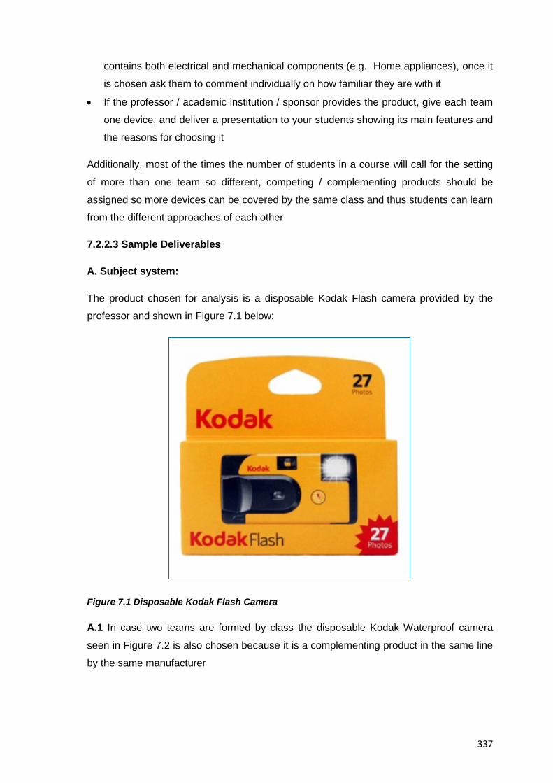
337
contains both electrical and mechanical components (e.g. Home appliances), once it
is chosen ask them to comment individually on how familiar they are with it
• If the professor / academic institution / sponsor provides the product, give each team
one device, and deliver a presentation to your students showing its main features and
the reasons for choosing it
Additionally, most of the times the number of students in a course will call for the setting
of more than one team so different, competing / complementing products should be
assigned so more devices can be covered by the same class and thus students can learn
from the different approaches of each other
7.2.2.3 Sample Deliverables
A. Subject system:
The product chosen for analysis is a disposable Kodak Flash camera provided by the
professor and shown in Figure 7.1 below:
Figure 7.1 Disposable Kodak Flash Camera
A.1 In case two teams are formed by class the disposable Kodak Waterproof camera
seen in Figure 7.2 is also chosen because it is a complementing product in the same line
by the same manufacturer
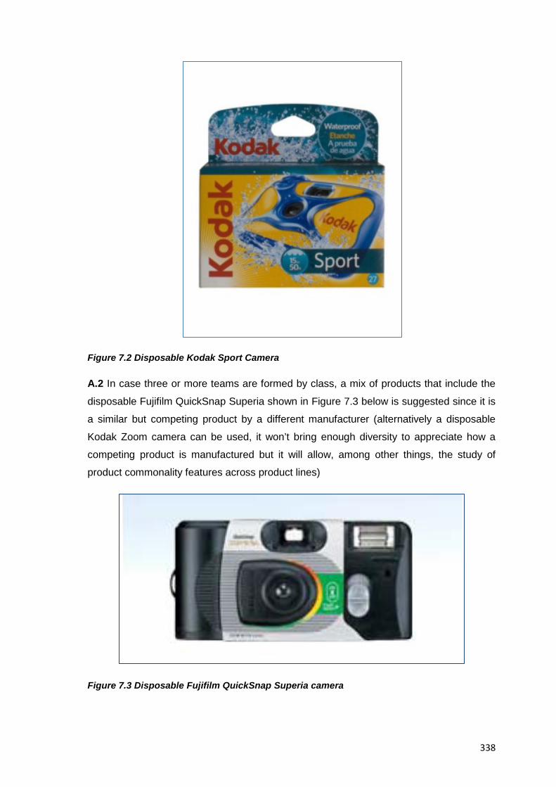
338
Figure 7.2 Disposable Kodak Sport Camera
A.2 In case three or more teams are formed by class, a mix of products that include the
disposable Fujifilm QuickSnap Superia shown in Figure 7.3 below is suggested since it is
a similar but competing product by a different manufacturer (alternatively a disposable
Kodak Zoom camera can be used, it won’t bring enough diversity to appreciate how a
competing product is manufactured but it will allow, among other things, the study of
product commonality features across product lines)
Figure 7.3 Disposable Fujifilm QuickSnap Superia camera
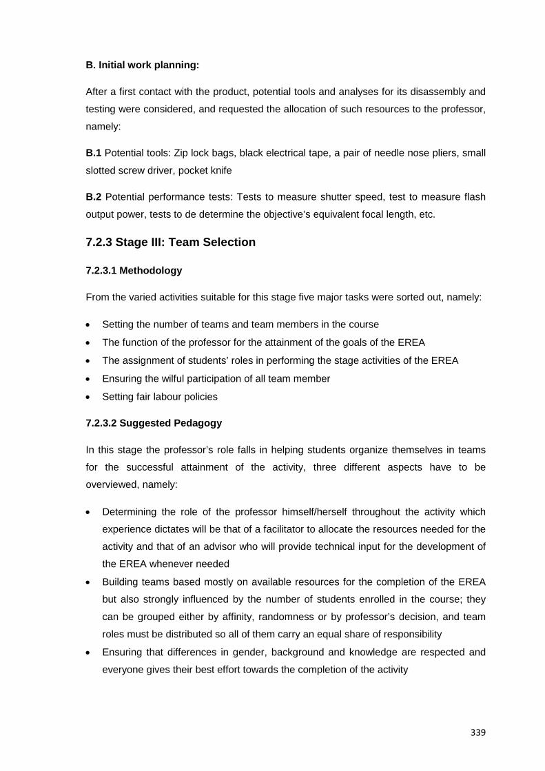
339
B. Initial work planning:
After a first contact with the product, potential tools and analyses for its disassembly and
testing were considered, and requested the allocation of such resources to the professor,
namely:
B.1 Potential tools: Zip lock bags, black electrical tape, a pair of needle nose pliers, small
slotted screw driver, pocket knife
B.2 Potential performance tests: Tests to measure shutter speed, test to measure flash
output power, tests to de determine the objective’s equivalent focal length, etc.
7.2.3 Stage III: Team Selection
7.2.3.1 Methodology
From the varied activities suitable for this stage five major tasks were sorted out, namely:
• Setting the number of teams and team members in the course
• The function of the professor for the attainment of the goals of the EREA
• The assignment of students’ roles in performing the stage activities of the EREA
• Ensuring the wilful participation of all team member
• Setting fair labour policies
7.2.3.2 Suggested Pedagogy
In this stage the professor’s role falls in helping students organize themselves in teams
for the successful attainment of the activity, three different aspects have to be
overviewed, namely:
• Determining the role of the professor himself/herself throughout the activity which
experience dictates will be that of a facilitator to allocate the resources needed for the
activity and that of an advisor who will provide technical input for the development of
the EREA whenever needed
• Building teams based mostly on available resources for the completion of the EREA
but also strongly influenced by the number of students enrolled in the course; they
can be grouped either by affinity, randomness or by professor’s decision, and team
roles must be distributed so all of them carry an equal share of responsibility
• Ensuring that differences in gender, background and knowledge are respected and
everyone gives their best effort towards the completion of the activity
340
7.2.3.3 Sample Deliverables
A. Team setting
Because resources such as tools and available laboratory time are usually limited only
two teams but with six members each were formed, the members were grouped by
affinity for this case
A.1. Team roles and functions
Overspecialization in only one role throughout the whole activity was avoided, however
each member was given a major role to fulfil and then he/she could support or be
supported by other team members whenever required, the roles and functions were:
• Disassembler / Assembler: To lead the hands-on activities of the EREA
• Photographer: To videotape and photograph every relevant event in the EREA
• Analyst: To lead the use of analytical tools and tests to understand the product
• Drafter: To lead the creation of technical drawings and computer animations of the
product
• Data collector: To lead the collection of information and interaction with external
experts
• Presenter: To lead the effort in writing the final report and delivering its presentation
B. Professor’s functions
It was decided that the role of the professor would be that of a facilitator to allocate the
necessary resources for the completion of the activity, and also that of a consultant who
would provide technical expertise and guidance in the completion of the activity.
C. Commitment to the activity
In order to ensure the wilful participation of all team members in the activity it was agreed
to sign a document stating our commitment to the activity and undergo a 360 degree
evaluation (c.f. From all team members) in case of disputes
D. Setting up of fair labour policies
After a talk with our professor about the importance of a fair distribution of workload and
potential differences in gender and cultural backgrounds among team members a team
building attitude was agreed among each other and we committed to avoid negative
practices such as bullying or discrimination
341
7.2.4 Stage IV: Data Collection
7.2.4.1 Methodology
After reflecting on the first impression caused by disposable cameras, it was decided to
pursue those activities that would yield the most information about their functionality and
current place in the consumer market, to that end a search was organized to collect all
relevant background and reference materials available at our reach; it turned out that the
sources with the most data on the topic were manufacturers’ brochures; intellectual
property resources (patents), previously published academic results, interviews, and
internet searches on engineering databases and journals; the collected information was
later studied and organised in preparation for the next stages of the methodology where it
would be better understood and integrated to the rest of information about the disposable
camera. Finally at the end of the stage, the professor provided input on what additional
information should be sought after, and how it could be acquired either through direct
means (e.g. Testing and analysis) or through indirect confirmation (e.g. Benchmarking
data from similar fields)
7.2.4.2 Suggested Pedagogy
The major work of professors at this stage deals with helping students develop their
information gathering and integration skills by teaching them on the one hand how to use
and benefit from engineering knowledge resources such as scholar internet searches or
traditional printed publications, and on the other hand how to integrate all collected
information into a coherent body of information from which preliminary results can support
further investigation
7.2.4.3 Sample Deliverables
A. Identification, understanding and description of the primary function / need addressed by the product
The primary function of the Kodak single-use camera is to take pictures in a convenient
(e.g. Portable / practical) and affordable way for both the consumer and manufacturer,
(the function was derived by students’ consensus and later confirmed via published
research by [Van De Moere. 1992] on the design philosophy of disposable cameras) (see
also Table 7.19 for complementing views on this)
A.1 Typical uses of disposable cameras
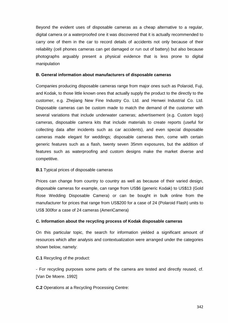
342
Beyond the evident uses of disposable cameras as a cheap alternative to a regular,
digital camera or a waterproofed one it was discovered that it is actually recommended to
carry one of them in the car to record details of accidents not only because of their
reliability (cell phones cameras can get damaged or run out of battery) but also because
photographs arguably present a physical evidence that is less prone to digital
manipulation
B. General information about manufacturers of disposable cameras
Companies producing disposable cameras range from major ones such as Polaroid, Fuji,
and Kodak, to those little known ones that actually supply the product to the directly to the
customer, e.g. Zhejiang New Fine Industry Co. Ltd. and Henwei Industrial Co. Ltd.
Disposable cameras can be custom made to match the demand of the customer with
several variations that include underwater cameras; advertisement (e.g. Custom logo)
cameras, disposable camera kits that include materials to create reports (useful for
collecting data after incidents such as car accidents), and even special disposable
cameras made elegant for weddings; disposable cameras then, come with certain
generic features such as a flash, twenty seven 35mm exposures, but the addition of
features such as waterproofing and custom designs make the market diverse and
competitive.
B.1 Typical prices of disposable cameras
Prices can change from country to country as well as because of their varied design,
disposable cameras for example, can range from US$6 (generic Kodak) to US$13 (Gold
Rose Wedding Disposable Camera) or can be bought in bulk online from the
manufacturer for prices that range from US$200 for a case of 24 (Polaroid Flash) units to
US$ 300for a case of 24 cameras (AmeriCamera)
C. Information about the recycling process of Kodak disposable cameras
On this particular topic, the search for information yielded a significant amount of
resources which after analysis and contextualization were arranged under the categories
shown below, namely:
C.1 Recycling of the product:
- For recycling purposes some parts of the camera are tested and directly reused, cf.
[Van De Moere. 1992]
C.2 Operations at a Recycling Processing Centre:
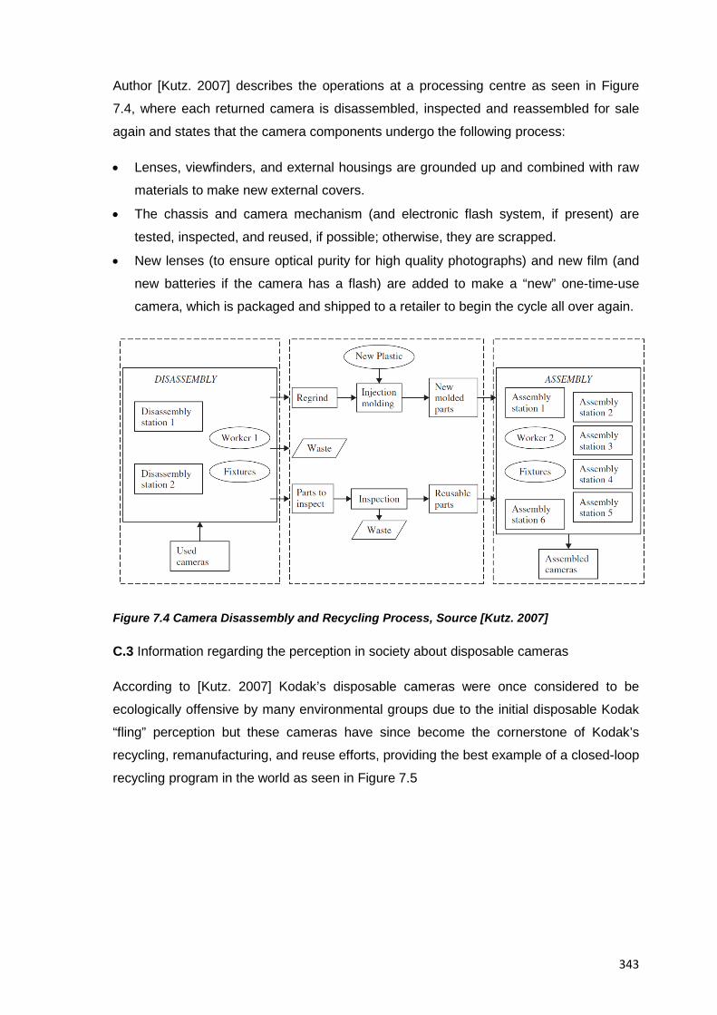
343
Author [Kutz. 2007] describes the operations at a processing centre as seen in Figure
7.4, where each returned camera is disassembled, inspected and reassembled for sale
again and states that the camera components undergo the following process:
• Lenses, viewfinders, and external housings are grounded up and combined with raw
materials to make new external covers.
• The chassis and camera mechanism (and electronic flash system, if present) are
tested, inspected, and reused, if possible; otherwise, they are scrapped.
• New lenses (to ensure optical purity for high quality photographs) and new film (and
new batteries if the camera has a flash) are added to make a “new” one-time-use
camera, which is packaged and shipped to a retailer to begin the cycle all over again.
Figure 7.4 Camera Disassembly and Recycling Process, Source [Kutz. 2007]
C.3 Information regarding the perception in society about disposable cameras
According to [Kutz. 2007] Kodak’s disposable cameras were once considered to be
ecologically offensive by many environmental groups due to the initial disposable Kodak
“fling” perception but these cameras have since become the cornerstone of Kodak’s
recycling, remanufacturing, and reuse efforts, providing the best example of a closed-loop
recycling program in the world as seen in Figure 7.5
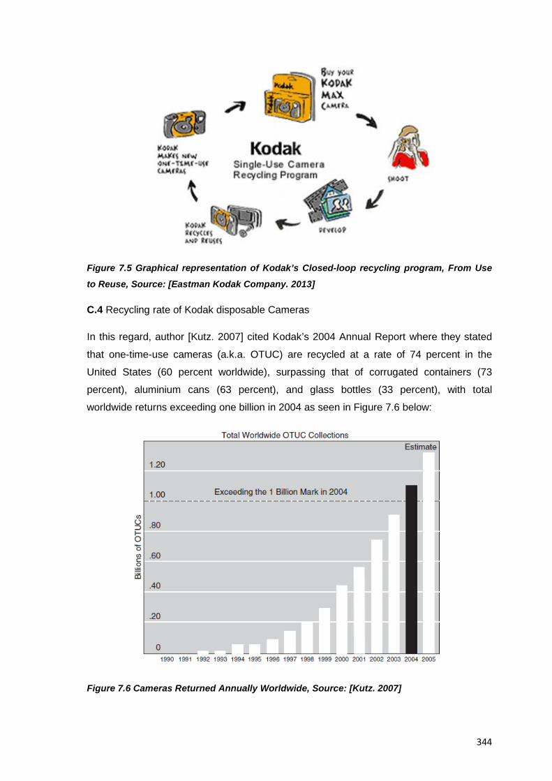
344
Figure 7.5 Graphical representation of Kodak’s Closed-loop recycling program, From Use
to Reuse, Source: [Eastman Kodak Company. 2013]
C.4 Recycling rate of Kodak disposable Cameras
In this regard, author [Kutz. 2007] cited Kodak’s 2004 Annual Report where they stated
that one-time-use cameras (a.k.a. OTUC) are recycled at a rate of 74 percent in the
United States (60 percent worldwide), surpassing that of corrugated containers (73
percent), aluminium cans (63 percent), and glass bottles (33 percent), with total
worldwide returns exceeding one billion in 2004 as seen in Figure 7.6 below:
Figure 7.6 Cameras Returned Annually Worldwide, Source: [Kutz. 2007]
345
C.5 Varied, interesting facts about disposable cameras
• A single-use camera can be returned to the shelf in 30 days after collected from a
developer (an aluminium can takes ~60 days), Source [Simpson. 2009]
• By weight, 74-90% of a Kodak single use camera can be reused, remanufactured or
recycled (because film and battery in the camera (if included) are not re-useable after a
standard usage), Source [Van De Moere. 1992] , [Kutz. 2007] & [Simpson. 2009],
however, the rest of camera materials (e.g. Polystyrene) allow them to be reground into
pellets of material and moulded again into new parts for the cycles of single use cameras,
this rate is considered high compared to similar systems across industries (e.g. Varied
aluminium components), in this regard, author [Kutz. 2007] ends up by stating that the
extent to which these cameras can be reused and recycled continues to be improved,
thanks to ongoing redesign efforts that were launched more than a decade ago by an
integrated product development team composed of design, business, manufacturing, and
environmental personnel, the analysis of different models of Kodak’s one-time-use
cameras then, provides insight into such products and how they have evolved to facilitate
disassembly and part reuse while continuing to ensure high-quality photographs.
D. Patent Analysis of Disposable Cameras
Table 7.3 below lists the patents found relevant to the study of disposable cameras
overall
Patent Number
Description Date of Patent Location
5,471,270 “Spool drive for film cartridge in
single-use camera” This apparatus
helps prevent the unauthorized
recycling of disposable cameras.
Nov. 28, 1995 Patent Searching
and Inventing
Resources at
http://www.freepatent
sonline.
com/5471270.html
5,325,366 "Photographic Film and Cartridge”
Single-use photographic film
package and cartridge that gives
disposable cameras a packaging in
which the camera cannot be reused
without replacing key components.
This also prevents the unauthorized
Aug. 10, 1993 Patent Searching
and Inventing
Resources at
http://www.freepatent
sonline.com/5192648
.html
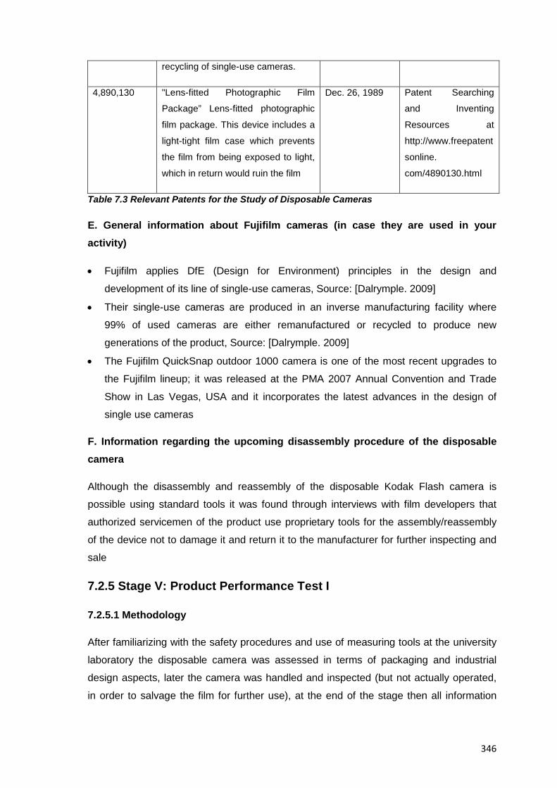
346
recycling of single-use cameras.
4,890,130 "Lens-fitted Photographic Film
Package” Lens-fitted photographic
film package. This device includes a
light-tight film case which prevents
the film from being exposed to light,
which in return would ruin the film
Dec. 26, 1989 Patent Searching
and Inventing
Resources at
http://www.freepatent
sonline.
com/4890130.html
Table 7.3 Relevant Patents for the Study of Disposable Cameras
E. General information about Fujifilm cameras (in case they are used in your activity)
• Fujifilm applies DfE (Design for Environment) principles in the design and
development of its line of single-use cameras, Source: [Dalrymple. 2009]
• Their single-use cameras are produced in an inverse manufacturing facility where
99% of used cameras are either remanufactured or recycled to produce new
generations of the product, Source: [Dalrymple. 2009]
• The Fujifilm QuickSnap outdoor 1000 camera is one of the most recent upgrades to
the Fujifilm lineup; it was released at the PMA 2007 Annual Convention and Trade
Show in Las Vegas, USA and it incorporates the latest advances in the design of
single use cameras
F. Information regarding the upcoming disassembly procedure of the disposable camera
Although the disassembly and reassembly of the disposable Kodak Flash camera is
possible using standard tools it was found through interviews with film developers that
authorized servicemen of the product use proprietary tools for the assembly/reassembly
of the device not to damage it and return it to the manufacturer for further inspecting and
sale
7.2.5 Stage V: Product Performance Test I
7.2.5.1 Methodology
After familiarizing with the safety procedures and use of measuring tools at the university
laboratory the disposable camera was assessed in terms of packaging and industrial
design aspects, later the camera was handled and inspected (but not actually operated,
in order to salvage the film for further use), at the end of the stage then all information
347
collected about the camera was interpreted and contextualized in a group session where
the professor provided technical input whenever needed
7.2.5.2 Suggested Pedagogy
This is the first stage where the professor’s role in helping ensure the safety of students
at all times becomes noticeable so his/her major task here falls in working on the safety
and class order aspects of laboratory work (e.g. Locating fire extinguishers and first-aid
kits) as well as in providing the necessary guidance on the technical aspects relevant to
the use of laboratory equipment, testing and data recording practices; additionally and
depending on the number of enrolled students and of available resources the support of
teaching assistants or laboratory technicians might be required
7.2.5.3 Sample Deliverables
A. Analysis of Customer Needs:
After the gathering of information about the camera and the actual testing of it was
possible to consolidate the analysis of the customer needs it fulfils, so it was agreed that
the typical factors about disposable cameras that are important to customers are
categorized as:
• Ergonomics
o Easy to hold
o Comfortable fit in hands
• Image quality
• Misfiring protections
o Reduce the risk to take a picture accidentally
• Image framing
o Viewfinder matching the final framing of the image
o Reduction of the risk to take a picture with the fingers over the lens
• Durability
• Flash
o Enough flash power output
o Red eye avoidance
• Camera aesthetics
o Attractive to average customers
• Control of use of Film
o Show number of exposures used/remaining
348
B. Performance parameters:
It was determined that the camera specifications are as follow:
• Equivalent focal length f=30mm; meaning it provides a field of view tending towards
the wide end to cover as much ground as possible but still close to the traditional
35mm field of view ever present during the analogue film era
• Shutter speed of 1/100s; meaning that image blurriness due to camera shake is
negligible since it exceeds by two stops the empirical suggestion of s=(1/f) and it is
suitable enough to freeze everyday scenes, and with the right technique (e.g.
Panning) even fast moving objects
• ISO film speed of 800 (Kodak Ultramax 800); to provide for latitude in the exposure
given the fixed set of exposure parameters of the camera (shutter speed, aperture
and film speed)
• Lens aperture: F10; 2 elements, 2 aspherical, moulded plastic groups, the small lens
aperture in combination with the fixed focal length means that the depth of field of the
camera ranges from three to eight feet from the lense/camera which in practical terms
it means that unless pictures are taken at extreme “macro distances” everything in the
scene will appear to be in focus
• Flash power output: The optimum range of operation of the flash output is from three
to eight feet, these values are derived not only from observing examples of
photographs taken with it enabled, but are also based on the depth of field value
given by the combination of aperture and equivalent focal length of the camera; the
output range of the flash unit was arguably planned that way in order to take the best
possible self-portraits (e.g. Selfies, by covering the length of a fully extended arm) and
group pictures (at distances where the heads and shoulders of the subjects are in
frame). It must also be mentioned that the flash power itself is generated from a
preinstalled 1.5 volt battery which can optimally produce a flash of light for the full 27
exposures of the camera film
• Usage environment: Those disposable cameras with a flash unit contain a very simple
device, only suitable for regular use as explained already, most of cameras though,
don’t feature a flash unit in them; because of this, one might think that disposable
cameras are only suitable for daylight use and although in an interview with film
developers it was estimated that 90% of all shots are taken in daylight the truth is that
thanks to the ISO speed and dynamic range of the built-in negative print film which
provides up to an estimated 4 stops of under/over exposure, the final image provided
by film developers (even if it was taken under dark conditions) will still be a usable
349
one (with only perhaps a “grainy” aspect, typical to analogue film anyway) with a
quality higher than expected from devices at this price range. For regular daylight
conditions then, the camera’s fixed exposure parameters (lens aperture , shutter
speed and ISO speed) allow for an exposure that seems to follow the “Sunny 16” rule
(an empirical rule known to educated photographers that links aperture and shutter
speed to the reciprocal of ISO film speed) which means a suitable exposure will be
obtained on daylight.
B.1 Performance parameters for Fujifilm disposable cameras
Just as for the Kodak brand, Fujifilm also publishes the disposable camera specifications
and are included here for the benefit of the reader using them as subject systems
• Number of Exposures: 27
• Lens: Plastic lens, 32mm f/10, fixed focus lens
• Shutter Speed : 1/140s.
• Subject-to-Lens Distance: From 1m to infinity
• Finder : Inverted Galilean-type plastic lens finder
• Flash: Built-in electronic flash, (Effective subject-to-flash distance: 1m - 4m)
Although the main camera specifications were published by the manufacturer, the team
had already devised tests of a qualitative and quantitative nature to determine at least the
shutter speed of the camera by photographing objects of a known speed (like
stroboscopic lights or a car in movement) and then from the exposure parameters of the
negatives of the resulting pictures derive everything else, in the end this was not
necessary and only a regular use of the camera to assess it and familiarize with it was
done, still it is worth mentioning that manufacturer’s specifications mean nothing on their
own so the team had to learn the basics of film photography in order to contextualise and
better interpret the available data.
C. Assessment of industrial design aspects:
After examining the camera’s packaging which was understood as a simple one and only
intended to protect the product until its sale, the ergonomic and aesthetic aspects of the
camera were assessed where it was agreed that the aesthetics of the product are rather
“austere” in a typical case where “form follows the function” and where the containment of
rising costs is paramount, however it was also noted when assessing the ergonomic
aspects of the camera that a great attention to detail in specific areas of it was given,
where for example different surface finishes would be found even in the same product
350
part not only to improve grip in the presence of sweat or water but also to improve the
perception of quality of the product overall.
7.2.6 Stage VI: Product Disassembly
7.2.6.1 Methodology
Most of the activities executed at this stage naturally fall on the side of documenting the
dissection process of the disposable camera, be it for example in a digital way through
drawings and video or by creating an inventory of the components as they are
disassembled; however, several aspects regarding the workings of the camera start
becoming evident through the simple observation of its inner components and so they
should be note down too; in preparation for the more thorough analyses from upcoming
stages then, some intermediate findings can still be reported here and be later
complemented to come up with a definite report at the end of the methodology. The major
categories for the results presented at this stage thus, were the identification of
user/product actions; the documenting of the disassembly process (e.g. CAD files, BOM,
disassembly instructions) and the actions taken to make this a non-destructive analysis
(e.g. Salvaging of camera film for further use)
7.2.6.2 Suggested Pedagogy
As a professor, most of the work at this stage is of a supervisory nature; first off, it is
about helping students devise a strategy to make this a non-destructive process or at
least one that allows the subject system to be brought back to its original state; then it is
about helping students go through this stage with the highest possible standards of safety
while at the same time ensuring that a fair division of work is done; one last task though is
to remind students that intermediate albeit incomplete results do have their rightful place
and that later down the methodology there will be chances to integrate all resulting
information into a final activity report
7.2.6.3 Sample Deliverables
A. System decomposition
A.1 Identified user / product actions
The major actions relevant to the camera are: Aim; shoot, wind and protect film
B. Disassembly instructions for a disposable Kodak Flash camera
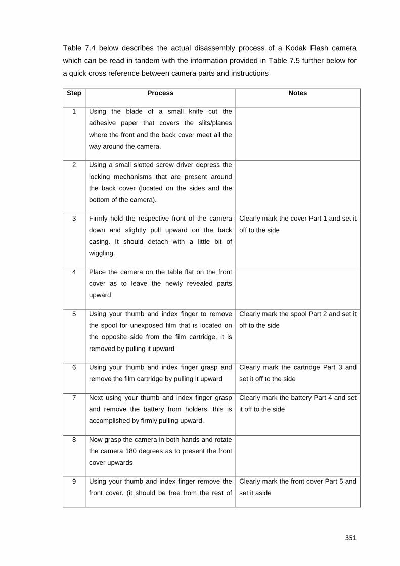
351
Table 7.4 below describes the actual disassembly process of a Kodak Flash camera
which can be read in tandem with the information provided in Table 7.5 further below for
a quick cross reference between camera parts and instructions
Step Process Notes
1 Using the blade of a small knife cut the
adhesive paper that covers the slits/planes
where the front and the back cover meet all the
way around the camera.
2 Using a small slotted screw driver depress the
locking mechanisms that are present around
the back cover (located on the sides and the
bottom of the camera).
3 Firmly hold the respective front of the camera
down and slightly pull upward on the back
casing. It should detach with a little bit of
wiggling.
Clearly mark the cover Part 1 and set it
off to the side
4 Place the camera on the table flat on the front
cover as to leave the newly revealed parts
upward
5 Using your thumb and index finger to remove
the spool for unexposed film that is located on
the opposite side from the film cartridge, it is
removed by pulling it upward
Clearly mark the spool Part 2 and set it
off to the side
6 Using your thumb and index finger grasp and
remove the film cartridge by pulling it upward
Clearly mark the cartridge Part 3 and
set it off to the side
7 Next using your thumb and index finger grasp
and remove the battery from holders, this is
accomplished by firmly pulling upward.
Clearly mark the battery Part 4 and set
it off to the side
8 Now grasp the camera in both hands and rotate
the camera 180 degrees as to present the front
cover upwards
9 Using your thumb and index finger remove the
front cover. (it should be free from the rest of
Clearly mark the front cover Part 5 and
set it aside
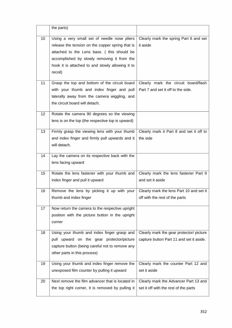
352
the parts)
10 Using a very small set of needle nose pliers
release the tension on the copper spring that is
attached to the Lens base. ( this should be
accomplished by slowly removing it from the
hook it is attached to and slowly allowing it to
recoil)
Clearly mark the spring Part 6 and set
it aside
11 Grasp the top and bottom of the circuit board
with your thumb and index finger and pull
laterally away from the camera wiggling, and
the circuit board will detach.
Clearly mark the circuit board/flash
Part 7 and set it off to the side.
12 Rotate the camera 90 degrees so the viewing
lens is on the top (the respective top is upward)
13 Firmly grasp the viewing lens with your thumb
and index finger and firmly pull upwards and it
will detach.
Clearly mark it Part 8 and set it off to
the side
14 Lay the camera on its respective back with the
lens facing upward
15 Rotate the lens fastener with your thumb and
index finger and pull it upward
Clearly mark the lens fastener Part 9
and set it aside
16 Remove the lens by picking it up with your
thumb and index finger
Clearly mark the lens Part 10 and set it
off with the rest of the parts
17 Now return the camera to the respective upright
position with the picture button in the upright
corner
18 Using your thumb and index finger grasp and
pull upward on the gear protector/picture
capture button (being careful not to remove any
other parts in this process)
Clearly mark the gear protector/ picture
capture button Part 11 and set it aside.
19 Using your thumb and index finger remove the
unexposed film counter by pulling it upward
Clearly mark the counter Part 12 and
set it aside
20 Next remove the film advancer that is located in
the top right corner, it is removed by pulling it
Clearly mark the Advancer Part 13 and
set it off with the rest of the parts
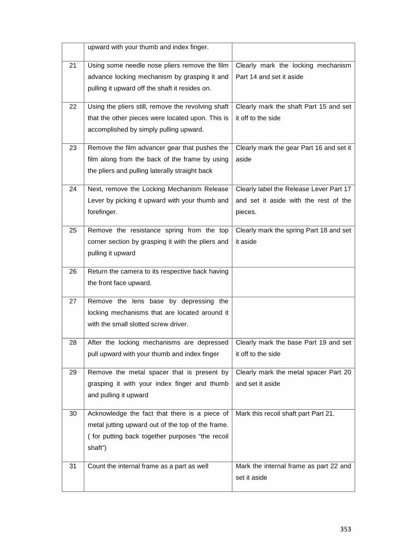
353
upward with your thumb and index finger.
21 Using some needle nose pliers remove the film
advance locking mechanism by grasping it and
pulling it upward off the shaft it resides on.
Clearly mark the locking mechanism
Part 14 and set it aside
22 Using the pliers still, remove the revolving shaft
that the other pieces were located upon. This is
accomplished by simply pulling upward.
Clearly mark the shaft Part 15 and set
it off to the side
23 Remove the film advancer gear that pushes the
film along from the back of the frame by using
the pliers and pulling laterally straight back
Clearly mark the gear Part 16 and set it
aside
24 Next, remove the Locking Mechanism Release
Lever by picking it upward with your thumb and
forefinger.
Clearly label the Release Lever Part 17
and set it aside with the rest of the
pieces.
25 Remove the resistance spring from the top
corner section by grasping it with the pliers and
pulling it upward
Clearly mark the spring Part 18 and set
it aside
26 Return the camera to its respective back having
the front face upward.
27 Remove the lens base by depressing the
locking mechanisms that are located around it
with the small slotted screw driver.
28 After the locking mechanisms are depressed
pull upward with your thumb and index finger
Clearly mark the base Part 19 and set
it off to the side
29 Remove the metal spacer that is present by
grasping it with your index finger and thumb
and pulling it upward
Clearly mark the metal spacer Part 20
and set it aside
30 Acknowledge the fact that there is a piece of
metal jutting upward out of the top of the frame.
( for putting back together purposes “the recoil
shaft”)
Mark this recoil shaft part Part 21.
31 Count the internal frame as a part as well Mark the internal frame as part 22 and
set it aside
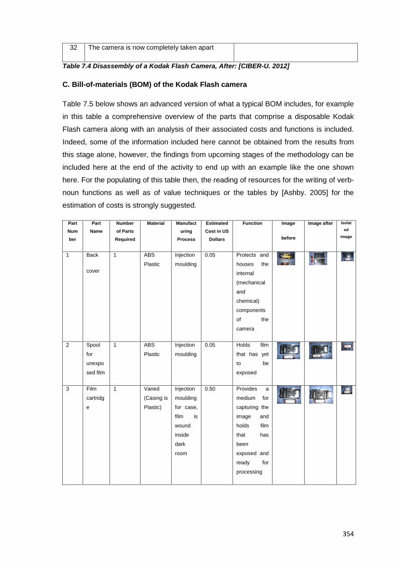
354
32 The camera is now completely taken apart
Table 7.4 Disassembly of a Kodak Flash Camera, After: [CIBER-U. 2012]
C. Bill-of-materials (BOM) of the Kodak Flash camera
Table 7.5 below shows an advanced version of what a typical BOM includes, for example
in this table a comprehensive overview of the parts that comprise a disposable Kodak
Flash camera along with an analysis of their associated costs and functions is included.
Indeed, some of the information included here cannot be obtained from the results from
this stage alone, however, the findings from upcoming stages of the methodology can be
included here at the end of the activity to end up with an example like the one shown
here. For the populating of this table then, the reading of resources for the writing of verb-
noun functions as well as of value techniques or the tables by [Ashby. 2005] for the
estimation of costs is strongly suggested.
Part Number
Part Name
Number of Parts
Required
Material Manufacturing
Process
Estimated Cost in US
Dollars
Function Image
before
Image after Isolated
image
1 Back
cover
1 ABS
Plastic
Injection
moulding
0.05 Protects and
houses the
internal
(mechanical
and
chemical)
components
of the
camera
2 Spool
for unexpo
sed film
1 ABS
Plastic
Injection
moulding
0.05 Holds film
that has yet to be
exposed
3 Film
cartridg
e
1 Varied
(Casing is
Plastic)
Injection
moulding
for case,
film is
wound
inside
dark
room
0.50 Provides a
medium for
capturing the
image and
holds film
that has
been
exposed and
ready for
processing
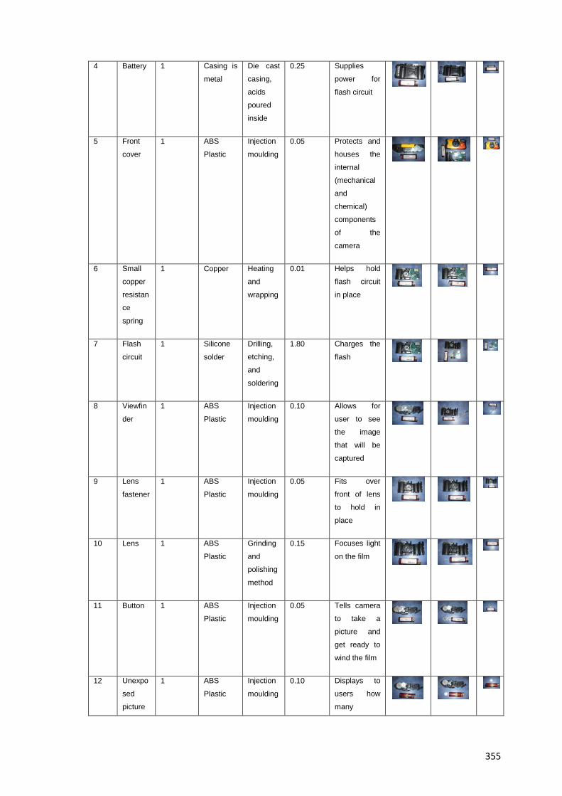
355
4 Battery 1 Casing is
metal
Die cast
casing,
acids
poured
inside
0.25 Supplies
power for
flash circuit
5 Front
cover
1 ABS
Plastic
Injection
moulding
0.05 Protects and
houses the
internal
(mechanical
and
chemical)
components
of the
camera
6 Small
copper
resistan
ce
spring
1 Copper Heating
and
wrapping
0.01 Helps hold
flash circuit
in place
7 Flash
circuit
1 Silicone
solder
Drilling,
etching,
and
soldering
1.80 Charges the
flash
8 Viewfin
der
1 ABS
Plastic
Injection
moulding
0.10 Allows for
user to see
the image
that will be
captured
9 Lens
fastener
1 ABS
Plastic
Injection
moulding
0.05 Fits over
front of lens
to hold in
place
10 Lens 1 ABS
Plastic
Grinding
and
polishing
method
0.15 Focuses light
on the film
11 Button 1 ABS
Plastic
Injection
moulding
0.05 Tells camera
to take a
picture and
get ready to
wind the film
12 Unexpo
sed
picture
1 ABS
Plastic
Injection
moulding
0.10 Displays to
users how
many
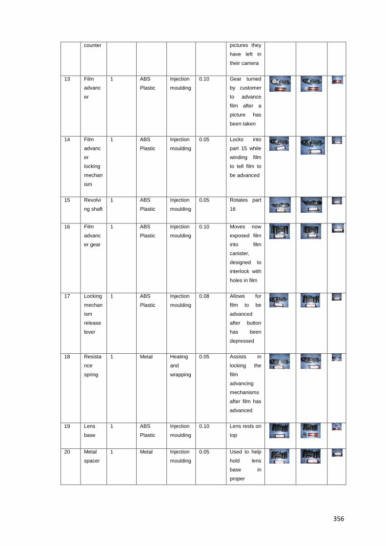
356
counter pictures they
have left in
their camera
13 Film
advanc
er
1 ABS
Plastic
Injection
moulding
0.10 Gear turned
by customer
to advance
film after a
picture has
been taken
14 Film
advanc
er
locking
mechan
ism
1 ABS
Plastic
Injection
moulding
0.05 Locks into
part 15 while
winding film
to tell film to
be advanced
15 Revolvi
ng shaft
1 ABS
Plastic
Injection
moulding
0.05 Rotates part
16
16 Film
advanc
er gear
1 ABS
Plastic
Injection
moulding
0.10 Moves now
exposed film into film
canister,
designed to
interlock with
holes in film
17 Locking
mechan
ism
release
lever
1 ABS
Plastic
Injection
moulding
0.08 Allows for
film to be
advanced
after button
has been
depressed
18 Resista
nce
spring
1 Metal Heating
and
wrapping
0.05 Assists in
locking the
film
advancing
mechanisms
after film has
advanced
19 Lens
base
1 ABS
Plastic
Injection
moulding
0.10 Lens rests on
top
20 Metal
spacer
1 Metal Injection
moulding
0.05 Used to help
hold lens
base in
proper
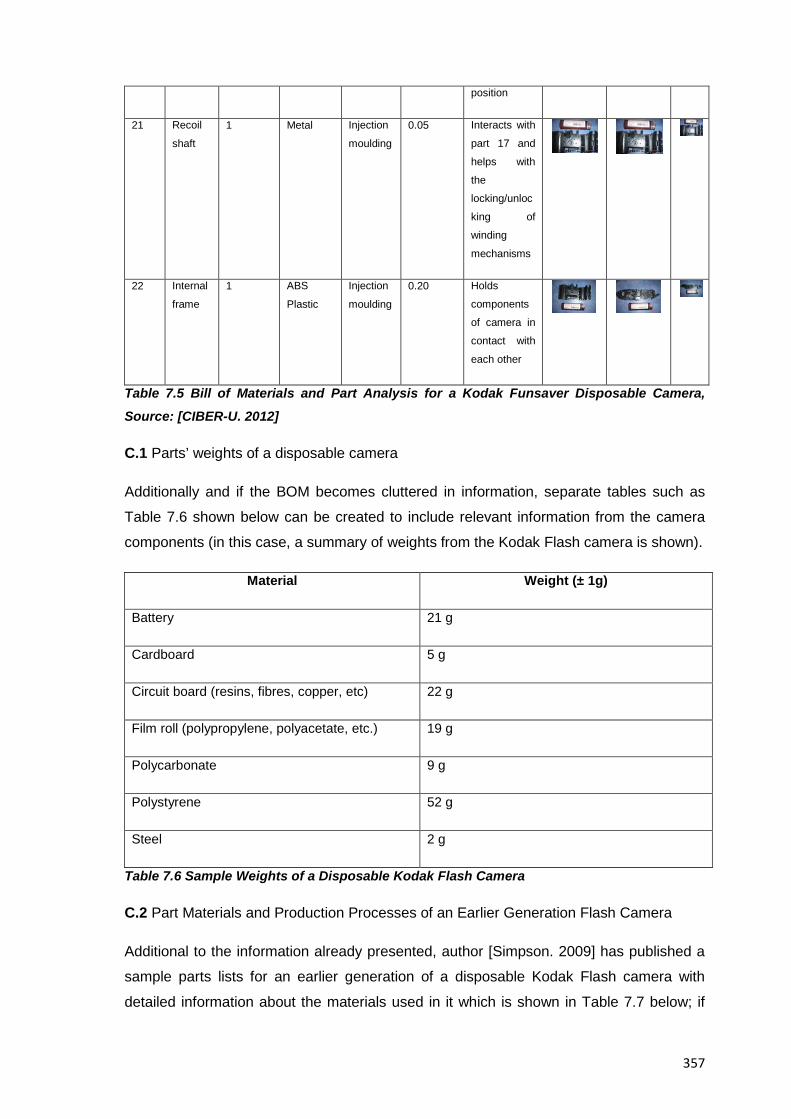
357
position
21 Recoil
shaft
1 Metal Injection
moulding
0.05 Interacts with
part 17 and
helps with
the
locking/unloc
king of
winding
mechanisms
22 Internal
frame
1 ABS
Plastic
Injection
moulding
0.20 Holds
components
of camera in
contact with
each other
Table 7.5 Bill of Materials and Part Analysis for a Kodak Funsaver Disposable Camera,
Source: [CIBER-U. 2012]
C.1 Parts’ weights of a disposable camera
Additionally and if the BOM becomes cluttered in information, separate tables such as
Table 7.6 shown below can be created to include relevant information from the camera
components (in this case, a summary of weights from the Kodak Flash camera is shown).
Material Weight (± 1g)
Battery 21 g
Cardboard 5 g
Circuit board (resins, fibres, copper, etc) 22 g
Film roll (polypropylene, polyacetate, etc.) 19 g
Polycarbonate 9 g
Polystyrene 52 g
Steel 2 g
Table 7.6 Sample Weights of a Disposable Kodak Flash Camera
C.2 Part Materials and Production Processes of an Earlier Generation Flash Camera
Additional to the information already presented, author [Simpson. 2009] has published a
sample parts lists for an earlier generation of a disposable Kodak Flash camera with
detailed information about the materials used in it which is shown in Table 7.7 below; if
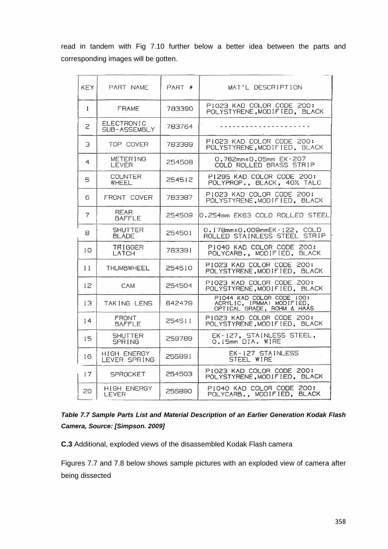
358
read in tandem with Fig 7.10 further below a better idea between the parts and
corresponding images will be gotten.
Table 7.7 Sample Parts List and Material Description of an Earlier Generation Kodak Flash Camera, Source: [Simpson. 2009]
C.3 Additional, exploded views of the disassembled Kodak Flash camera
Figures 7.7 and 7.8 below shows sample pictures with an exploded view of camera after
being dissected
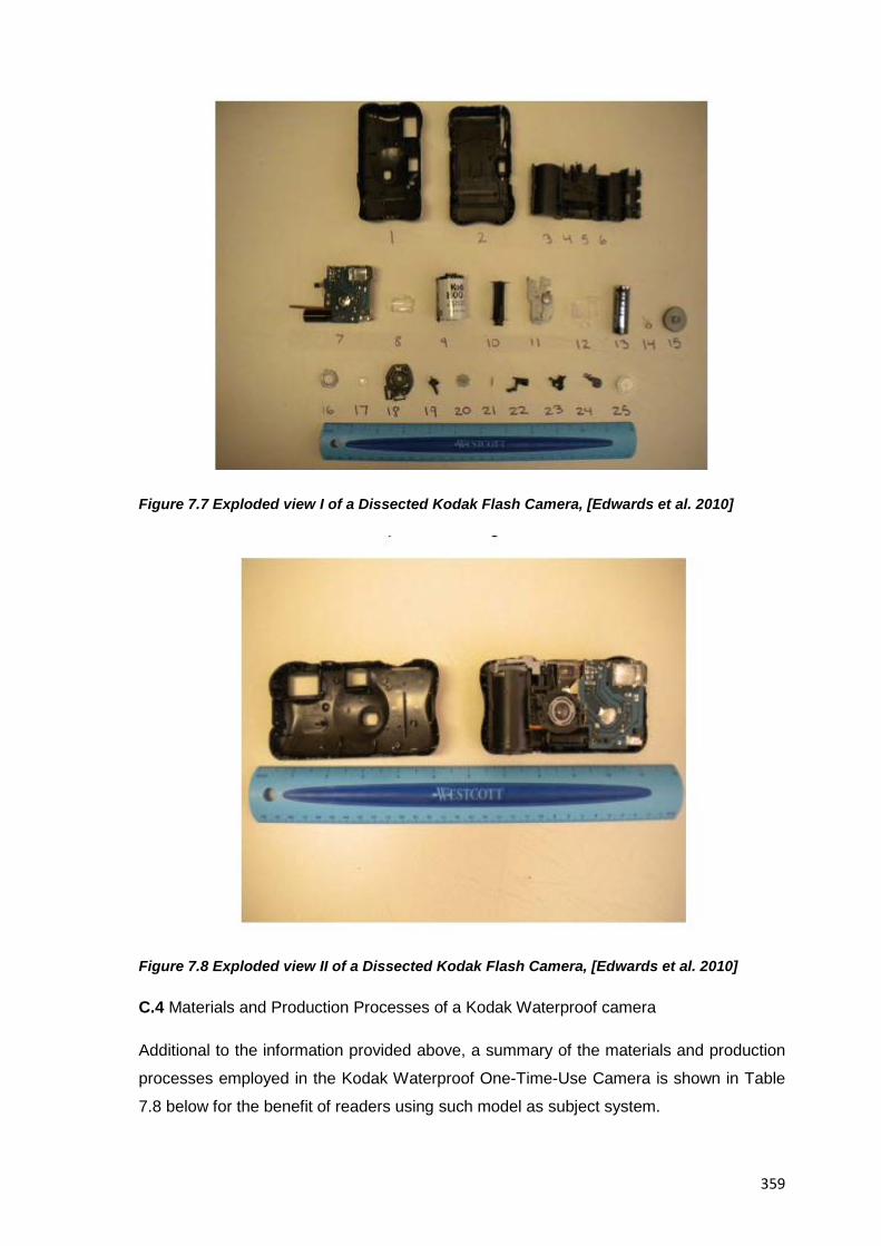
359
Figure 7.7 Exploded view I of a Dissected Kodak Flash Camera, [Edwards et al. 2010]
Figure 7.8 Exploded view II of a Dissected Kodak Flash Camera, [Edwards et al. 2010]
C.4 Materials and Production Processes of a Kodak Waterproof camera
Additional to the information provided above, a summary of the materials and production
processes employed in the Kodak Waterproof One-Time-Use Camera is shown in Table
7.8 below for the benefit of readers using such model as subject system.
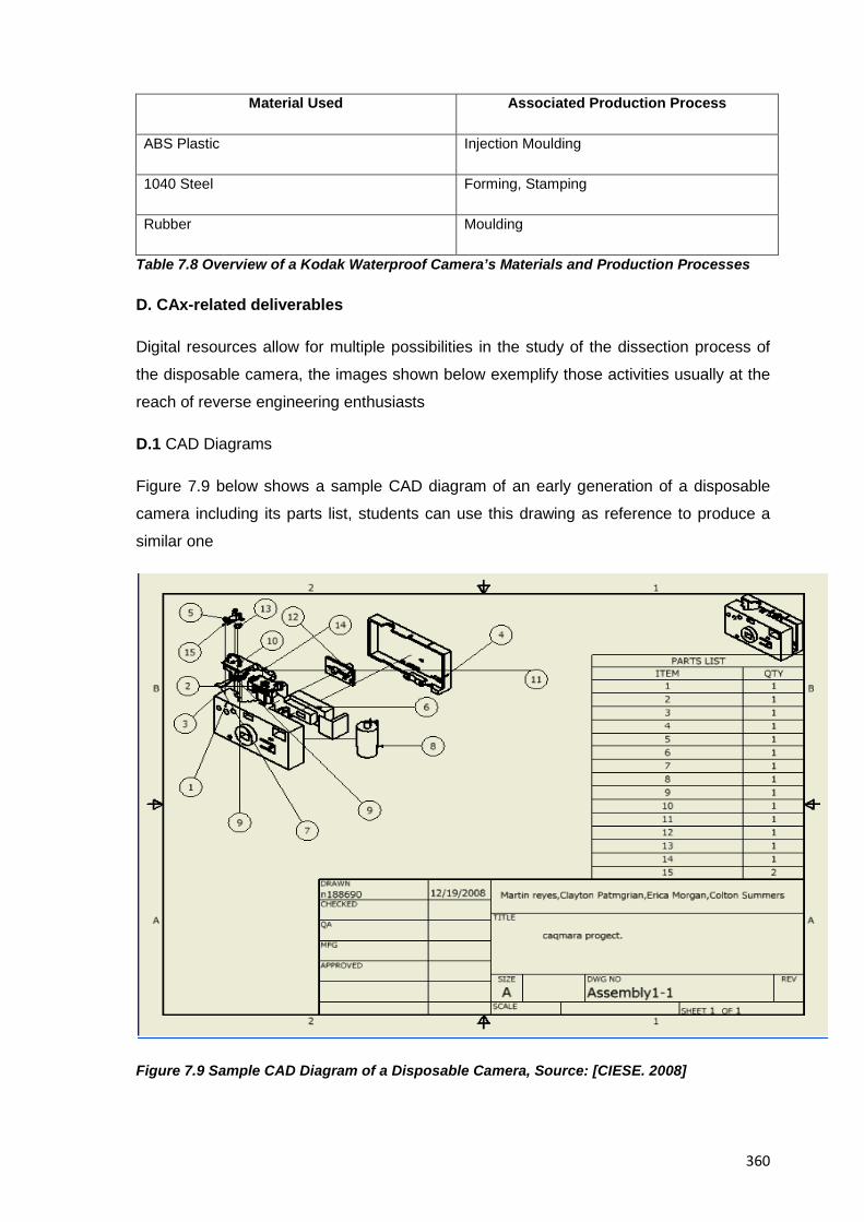
360
Material Used Associated Production Process
ABS Plastic Injection Moulding
1040 Steel Forming, Stamping
Rubber Moulding
Table 7.8 Overview of a Kodak Waterproof Camera’s Materials and Production Processes
D. CAx-related deliverables
Digital resources allow for multiple possibilities in the study of the dissection process of
the disposable camera, the images shown below exemplify those activities usually at the
reach of reverse engineering enthusiasts
D.1 CAD Diagrams
Figure 7.9 below shows a sample CAD diagram of an early generation of a disposable
camera including its parts list, students can use this drawing as reference to produce a
similar one
Figure 7.9 Sample CAD Diagram of a Disposable Camera, Source: [CIESE. 2008]
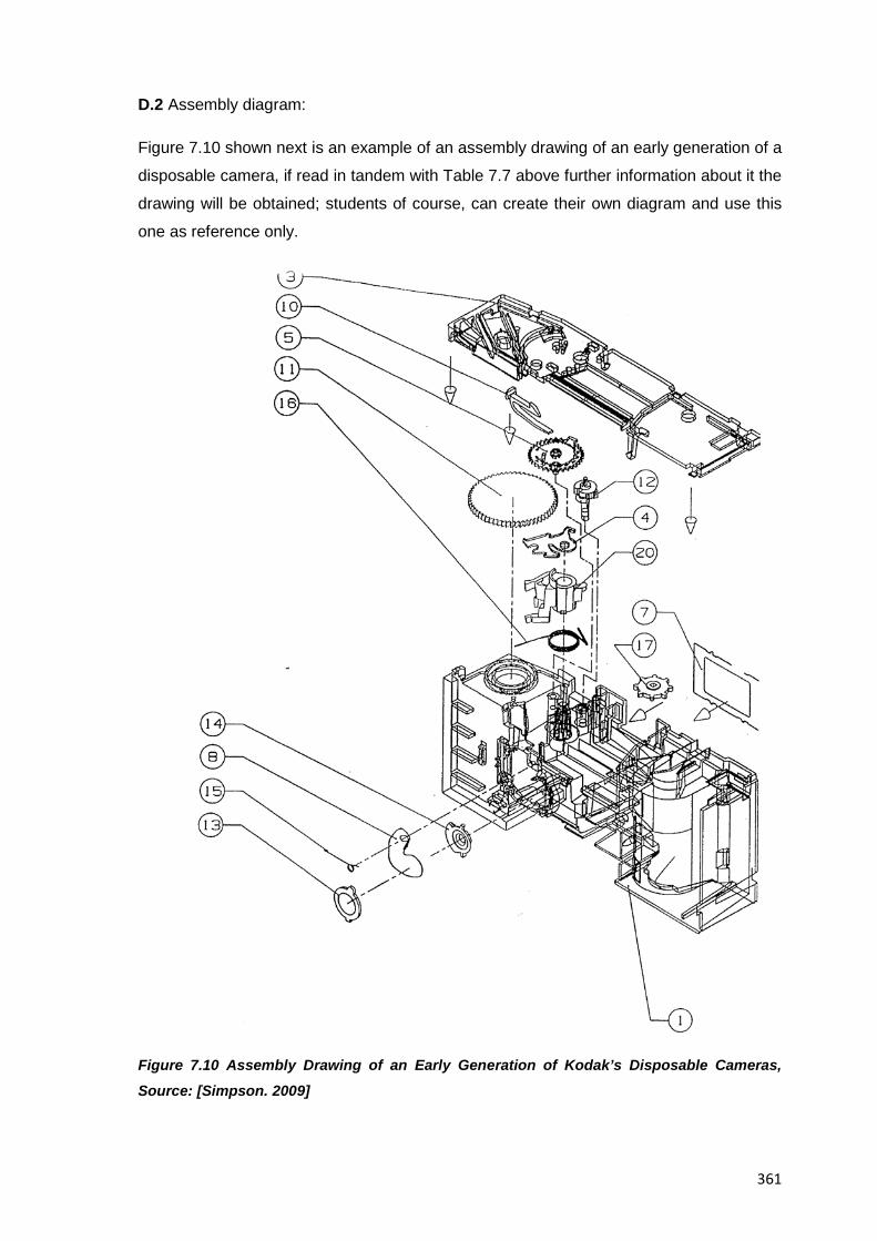
361
D.2 Assembly diagram:
Figure 7.10 shown next is an example of an assembly drawing of an early generation of a
disposable camera, if read in tandem with Table 7.7 above further information about it the
drawing will be obtained; students of course, can create their own diagram and use this
one as reference only.
Figure 7.10 Assembly Drawing of an Early Generation of Kodak’s Disposable Cameras,
Source: [Simpson. 2009]
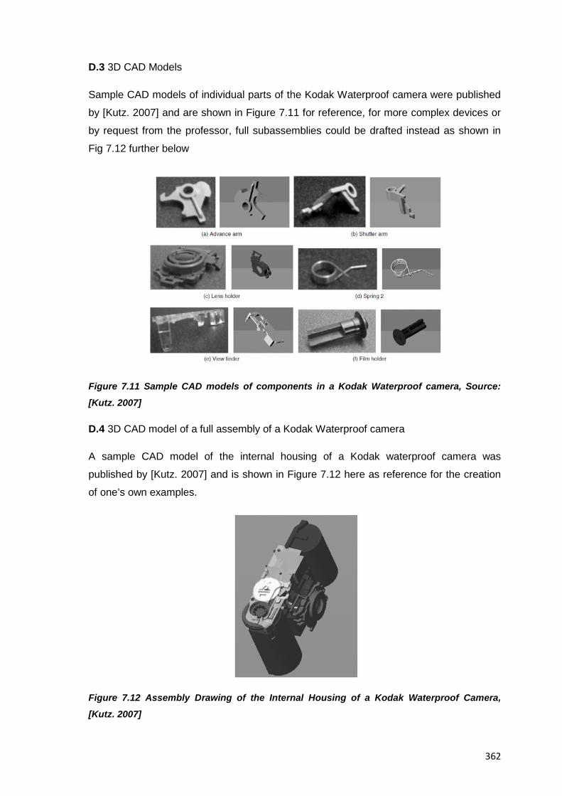
362
D.3 3D CAD Models
Sample CAD models of individual parts of the Kodak Waterproof camera were published
by [Kutz. 2007] and are shown in Figure 7.11 for reference, for more complex devices or
by request from the professor, full subassemblies could be drafted instead as shown in
Fig 7.12 further below
Figure 7.11 Sample CAD models of components in a Kodak Waterproof camera, Source:
[Kutz. 2007]
D.4 3D CAD model of a full assembly of a Kodak Waterproof camera
A sample CAD model of the internal housing of a Kodak waterproof camera was
published by [Kutz. 2007] and is shown in Figure 7.12 here as reference for the creation
of one’s own examples.
Figure 7.12 Assembly Drawing of the Internal Housing of a Kodak Waterproof Camera,
[Kutz. 2007]
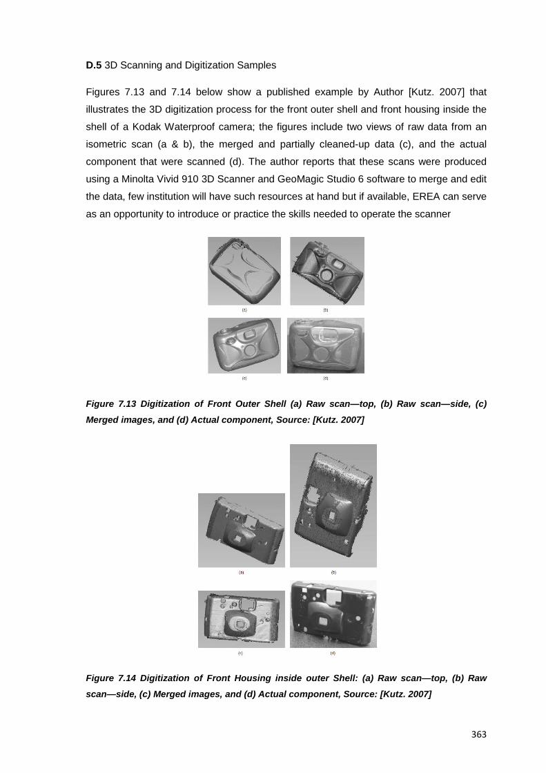
363
D.5 3D Scanning and Digitization Samples
Figures 7.13 and 7.14 below show a published example by Author [Kutz. 2007] that
illustrates the 3D digitization process for the front outer shell and front housing inside the
shell of a Kodak Waterproof camera; the figures include two views of raw data from an
isometric scan (a & b), the merged and partially cleaned-up data (c), and the actual
component that were scanned (d). The author reports that these scans were produced
using a Minolta Vivid 910 3D Scanner and GeoMagic Studio 6 software to merge and edit
the data, few institution will have such resources at hand but if available, EREA can serve
as an opportunity to introduce or practice the skills needed to operate the scanner
Figure 7.13 Digitization of Front Outer Shell (a) Raw scan—top, (b) Raw scan—side, (c)
Merged images, and (d) Actual component, Source: [Kutz. 2007]
Figure 7.14 Digitization of Front Housing inside outer Shell: (a) Raw scan—top, (b) Raw
scan—side, (c) Merged images, and (d) Actual component, Source: [Kutz. 2007]
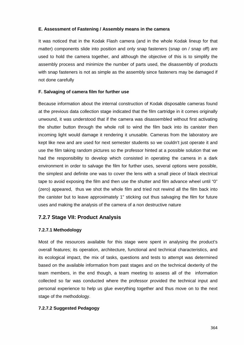
364
E. Assessment of Fastening / Assembly means in the camera
It was noticed that in the Kodak Flash camera (and in the whole Kodak lineup for that
matter) components slide into position and only snap fasteners (snap on / snap off) are
used to hold the camera together, and although the objective of this is to simplify the
assembly process and minimize the number of parts used, the disassembly of products
with snap fasteners is not as simple as the assembly since fasteners may be damaged if
not done carefully
F. Salvaging of camera film for further use
Because information about the internal construction of Kodak disposable cameras found
at the previous data collection stage indicated that the film cartridge in it comes originally
unwound, it was understood that if the camera was disassembled without first activating
the shutter button through the whole roll to wind the film back into its canister then
incoming light would damage it rendering it unusable. Cameras from the laboratory are
kept like new and are used for next semester students so we couldn’t just operate it and
use the film taking random pictures so the professor hinted at a possible solution that we
had the responsibility to develop which consisted in operating the camera in a dark
environment in order to salvage the film for further uses, several options were possible,
the simplest and definite one was to cover the lens with a small piece of black electrical
tape to avoid exposing the film and then use the shutter and film advance wheel until “0”
(zero) appeared, thus we shot the whole film and tried not rewind all the film back into
the canister but to leave approximately 1” sticking out thus salvaging the film for future
uses and making the analysis of the camera of a non destructive nature
7.2.7 Stage VII: Product Analysis
7.2.7.1 Methodology
Most of the resources available for this stage were spent in analysing the product’s
overall features; its operation, architecture, functional and technical characteristics, and
its ecological impact, the mix of tasks, questions and tests to attempt was determined
based on the available information from past stages and on the technical dexterity of the
team members, in the end though, a team meeting to assess all of the information
collected so far was conducted where the professor provided the technical input and
personal experience to help us glue everything together and thus move on to the next
stage of the methodology.
7.2.7.2 Suggested Pedagogy
365
Although a varied number of tests; questions and analyses are suitable for this stage,
only those that provide the best balance between the quality of information they provide
against the amount of resources employed should be attempted; it is the role of the
professor at this stage then, to help students select what exercises are done and to what
depth based on available resources and their technical proficiency; for the analysis of the
disposable Kodak Flash camera the areas of electromechanics (functions, architecture)
and ecodesign (materials, production methods, cost impacts) can be chosen for
investigation since they are suitable for both methodological work and self discovery;
once students are done with their work though, the professor must help glue everything
together so students end up with numerical results that support further investigation into
the subject system
7.2.7.3 Sample Deliverables
A. Product Overview
The Kodak Flash used in this example is a single use camera manufactured by Eastman
Kodak Co. It is comprised of 23 distinct parts with the majority being made of ABS Plastic
via injection moulding; it is assembled from simple parts such as a circuit board; halogen
flash, battery, a moulded plastic housing, plastic gears, and film. Table 7.9 below shows a
quick overview of its main characteristics (complementing information for the Kodak
Waterproof model for the reader using it as subject system is also included)
Item Description
Name of Artifact Kodak Flash camera
Description of Product One Time Use; Low Cost, Convenient Camera
Manufacturer Eastman Kodak Company
Built in Mexico
Assembled in Mexico
Cost 11.99 USD / 17,75 EUR
Number of Parts Camera with flash (22), Waterproof Camera
(23),Camera With Flash and Zoom (38)
Main Tool Required for Disassembly Flathead Screwdriver
Film Exposures 27
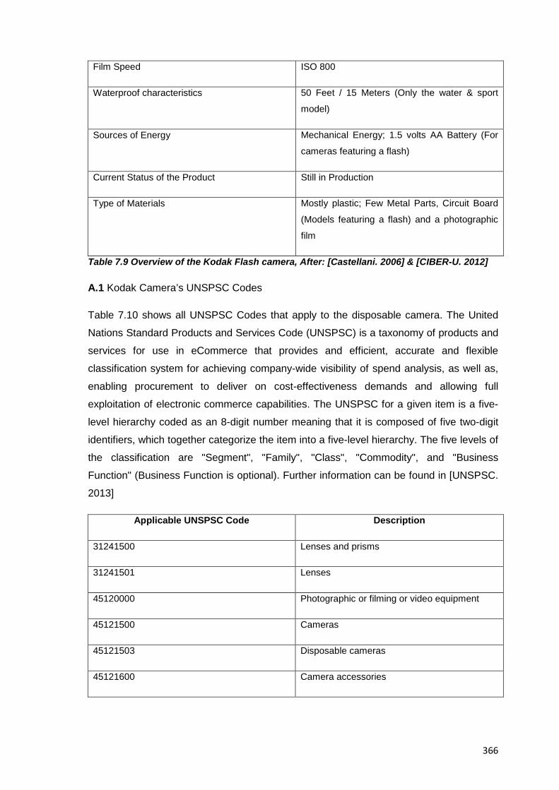
366
Film Speed ISO 800
Waterproof characteristics 50 Feet / 15 Meters (Only the water & sport
model)
Sources of Energy Mechanical Energy; 1.5 volts AA Battery (For
cameras featuring a flash)
Current Status of the Product Still in Production
Type of Materials Mostly plastic; Few Metal Parts, Circuit Board
(Models featuring a flash) and a photographic
film
Table 7.9 Overview of the Kodak Flash camera, After: [Castellani. 2006] & [CIBER-U. 2012]
A.1 Kodak Camera’s UNSPSC Codes
Table 7.10 shows all UNSPSC Codes that apply to the disposable camera. The United
Nations Standard Products and Services Code (UNSPSC) is a taxonomy of products and
services for use in eCommerce that provides and efficient, accurate and flexible
classification system for achieving company-wide visibility of spend analysis, as well as,
enabling procurement to deliver on cost-effectiveness demands and allowing full
exploitation of electronic commerce capabilities. The UNSPSC for a given item is a five-
level hierarchy coded as an 8-digit number meaning that it is composed of five two-digit
identifiers, which together categorize the item into a five-level hierarchy. The five levels of
the classification are "Segment", "Family", "Class", "Commodity", and "Business
Function" (Business Function is optional). Further information can be found in [UNSPSC.
2013]
Applicable UNSPSC Code Description
31241500 Lenses and prisms
31241501 Lenses
45120000 Photographic or filming or video equipment
45121500 Cameras
45121503 Disposable cameras
45121600 Camera accessories
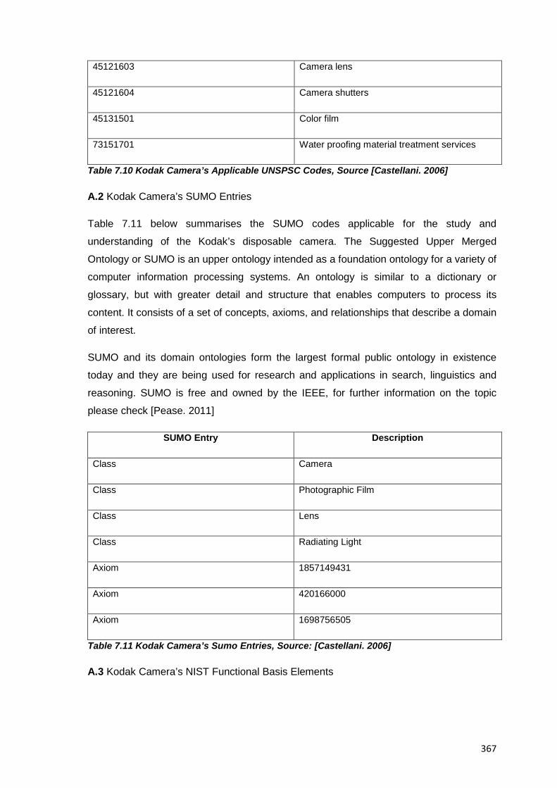
367
45121603 Camera lens
45121604 Camera shutters
45131501 Color film
73151701 Water proofing material treatment services
Table 7.10 Kodak Camera’s Applicable UNSPSC Codes, Source [Castellani. 2006]
A.2 Kodak Camera’s SUMO Entries
Table 7.11 below summarises the SUMO codes applicable for the study and
understanding of the Kodak’s disposable camera. The Suggested Upper Merged
Ontology or SUMO is an upper ontology intended as a foundation ontology for a variety of
computer information processing systems. An ontology is similar to a dictionary or
glossary, but with greater detail and structure that enables computers to process its
content. It consists of a set of concepts, axioms, and relationships that describe a domain
of interest.
SUMO and its domain ontologies form the largest formal public ontology in existence
today and they are being used for research and applications in search, linguistics and
reasoning. SUMO is free and owned by the IEEE, for further information on the topic
please check [Pease. 2011]
SUMO Entry Description
Class Camera
Class Photographic Film
Class Lens
Class Radiating Light
Axiom 1857149431
Axiom 420166000
Axiom 1698756505
Table 7.11 Kodak Camera’s Sumo Entries, Source: [Castellani. 2006]
A.3 Kodak Camera’s NIST Functional Basis Elements
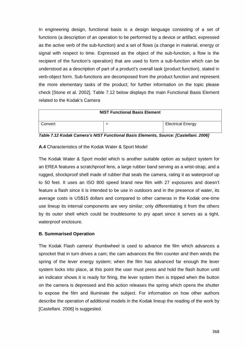
368
In engineering design, functional basis is a design language consisting of a set of
functions (a description of an operation to be performed by a device or artifact, expressed
as the active verb of the sub-function) and a set of flows (a change in material, energy or
signal with respect to time. Expressed as the object of the sub-function, a flow is the
recipient of the function’s operation) that are used to form a sub-function which can be
understood as a description of part of a product’s overall task (product function), stated in
verb-object form. Sub-functions are decomposed from the product function and represent
the more elementary tasks of the product; for further information on the topic please
check [Stone et al. 2002]. Table 7.12 below displays the main Functional Basis Element
related to the Kodak’s Camera
NIST Functional Basis Element
Convert + Electrical Energy
Table 7.12 Kodak Camera’s NIST Functional Basis Elements, Source: [Castellani. 2006]
A.4 Characteristics of the Kodak Water & Sport Model
The Kodak Water & Sport model which is another suitable option as subject system for
an EREA features a scratchproof lens, a large rubber band serving as a wrist-strap, and a
rugged, shockproof shell made of rubber that seals the camera, rating it as waterproof up
to 50 feet. It uses an ISO 800 speed brand new film with 27 exposures and doesn’t
feature a flash since it is intended to be use in outdoors and in the presence of water, its
average costs is US$15 dollars and compared to other cameras in the Kodak one-time
use lineup its internal components are very similar; only differentiating it from the others
by its outer shell which could be troublesome to pry apart since it serves as a tight,
waterproof enclosure.
B. Summarised Operation
The Kodak Flash camera’ thumbwheel is used to advance the film which advances a
sprocket that in turn drives a cam; the cam advances the film counter and then winds the
spring of the lever energy system; when the film has advanced far enough the lever
system locks into place, at this point the user must press and hold the flash button until
an indicator shows it is ready for firing, the lever system then is tripped when the button
on the camera is depressed and this action releases the spring which opens the shutter
to expose the film and illuminate the subject. For information on how other authors
describe the operation of additional models in the Kodak lineup the reading of the work by
[Castellani. 2006] is suggested.
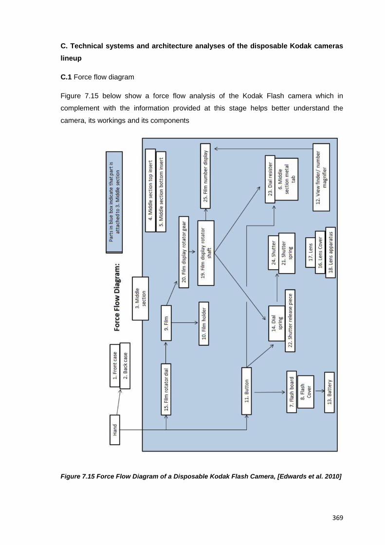
369
C. Technical systems and architecture analyses of the disposable Kodak cameras lineup
C.1 Force flow diagram
Figure 7.15 below show a force flow analysis of the Kodak Flash camera which in
complement with the information provided at this stage helps better understand the
camera, its workings and its components
Figure 7.15 Force Flow Diagram of a Disposable Kodak Flash Camera, [Edwards et al. 2010]
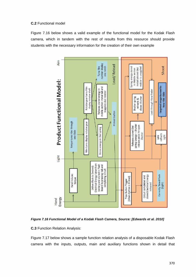
370
C.2 Functional model
Figure 7.16 below shows a valid example of the functional model for the Kodak Flash
camera, which in tandem with the rest of results from this resource should provide
students with the necessary information for the creation of their own example
Figure 7.16 Functional Model of a Kodak Flash Camera, Source: [Edwards et al. 2010]
C.3 Function Relation Analysis:
Figure 7.17 below shows a sample function relation analysis of a disposable Kodak Flash
camera with the inputs, outputs, main and auxiliary functions shown in detail that
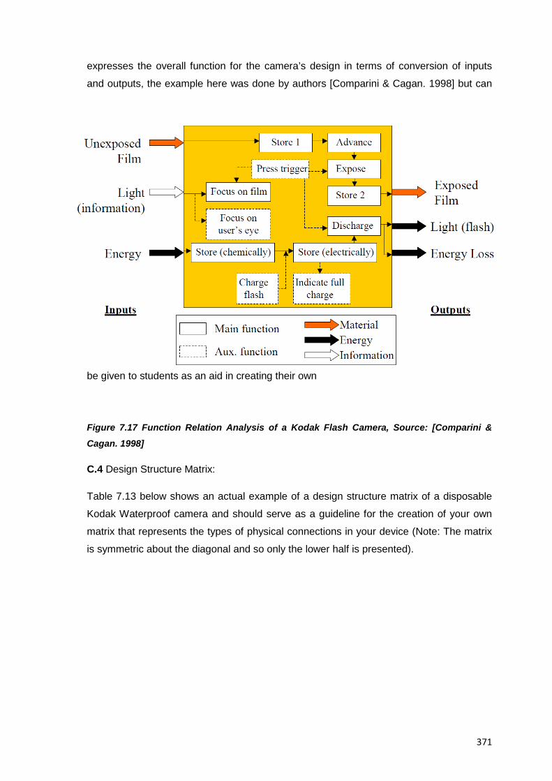
371
expresses the overall function for the camera’s design in terms of conversion of inputs
and outputs, the example here was done by authors [Comparini & Cagan. 1998] but can
be given to students as an aid in creating their own
Figure 7.17 Function Relation Analysis of a Kodak Flash Camera, Source: [Comparini & Cagan. 1998]
C.4 Design Structure Matrix:
Table 7.13 below shows an actual example of a design structure matrix of a disposable
Kodak Waterproof camera and should serve as a guideline for the creation of your own
matrix that represents the types of physical connections in your device (Note: The matrix
is symmetric about the diagonal and so only the lower half is presented).
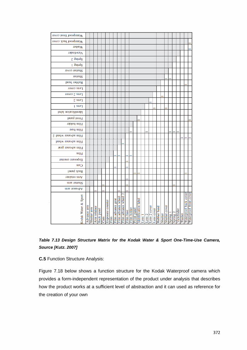
372
Table 7.13 Design Structure Matrix for the Kodak Water & Sport One-Time-Use Camera,
Source [Kutz. 2007]
C.5 Function Structure Analysis:
Figure 7.18 below shows a function structure for the Kodak Waterproof camera which
provides a form-independent representation of the product under analysis that describes
how the product works at a sufficient level of abstraction and it can used as reference for
the creation of your own
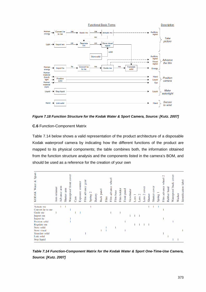
373
Figure 7.18 Function Structure for the Kodak Water & Sport Camera, Source: [Kutz. 2007]
C.6 Function-Component Matrix
Table 7.14 below shows a valid representation of the product architecture of a disposable
Kodak waterproof camera by indicating how the different functions of the product are
mapped to its physical components; the table combines both, the information obtained
from the function structure analysis and the components listed in the camera’s BOM, and
should be used as a reference for the creation of your own
Table 7.14 Function-Component Matrix for the Kodak Water & Sport One-Time-Use Camera,
Source: [Kutz. 2007]
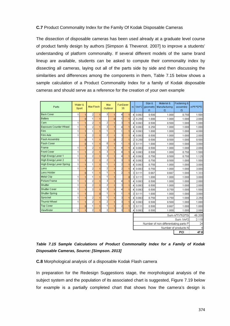
374
C.7 Product Commonality Index for the Family Of Kodak Disposable Cameras
The dissection of disposable cameras has been used already at a graduate level course
of product family design by authors [Simpson & Thevenot. 2007] to improve a students’
understanding of platform commonality. If several different models of the same brand
lineup are available, students can be asked to compute their commonality index by
dissecting all cameras, laying out all of the parts side by side and then discussing the
similarities and differences among the components in them, Table 7.15 below shows a
sample calculation of a Product Commonality Index for a family of Kodak disposable
cameras and should serve as a reference for the creation of your own example
Table 7.15 Sample Calculations of Product Commonality Index for a Family of Kodak Disposable Cameras, Source: [Simpson. 2013]
C.8 Morphological analysis of a disposable Kodak Flash camera
In preparation for the Redesign Suggestions stage, the morphological analysis of the
subject system and the population of its associated chart is suggested, Figure 7.19 below
for example is a partially completed chart that shows how the camera’s design is
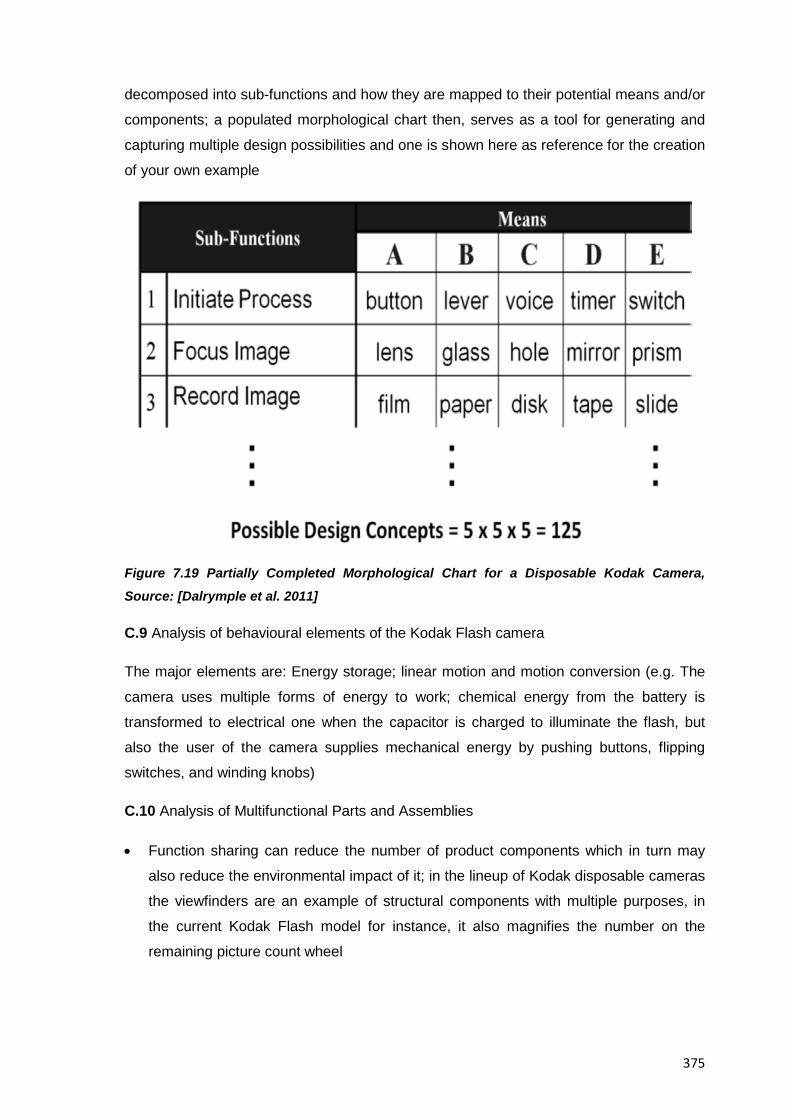
375
decomposed into sub-functions and how they are mapped to their potential means and/or
components; a populated morphological chart then, serves as a tool for generating and
capturing multiple design possibilities and one is shown here as reference for the creation
of your own example
Figure 7.19 Partially Completed Morphological Chart for a Disposable Kodak Camera,
Source: [Dalrymple et al. 2011]
C.9 Analysis of behavioural elements of the Kodak Flash camera
The major elements are: Energy storage; linear motion and motion conversion (e.g. The
camera uses multiple forms of energy to work; chemical energy from the battery is
transformed to electrical one when the capacitor is charged to illuminate the flash, but
also the user of the camera supplies mechanical energy by pushing buttons, flipping
switches, and winding knobs)
C.10 Analysis of Multifunctional Parts and Assemblies
• Function sharing can reduce the number of product components which in turn may
also reduce the environmental impact of it; in the lineup of Kodak disposable cameras
the viewfinders are an example of structural components with multiple purposes, in
the current Kodak Flash model for instance, it also magnifies the number on the
remaining picture count wheel
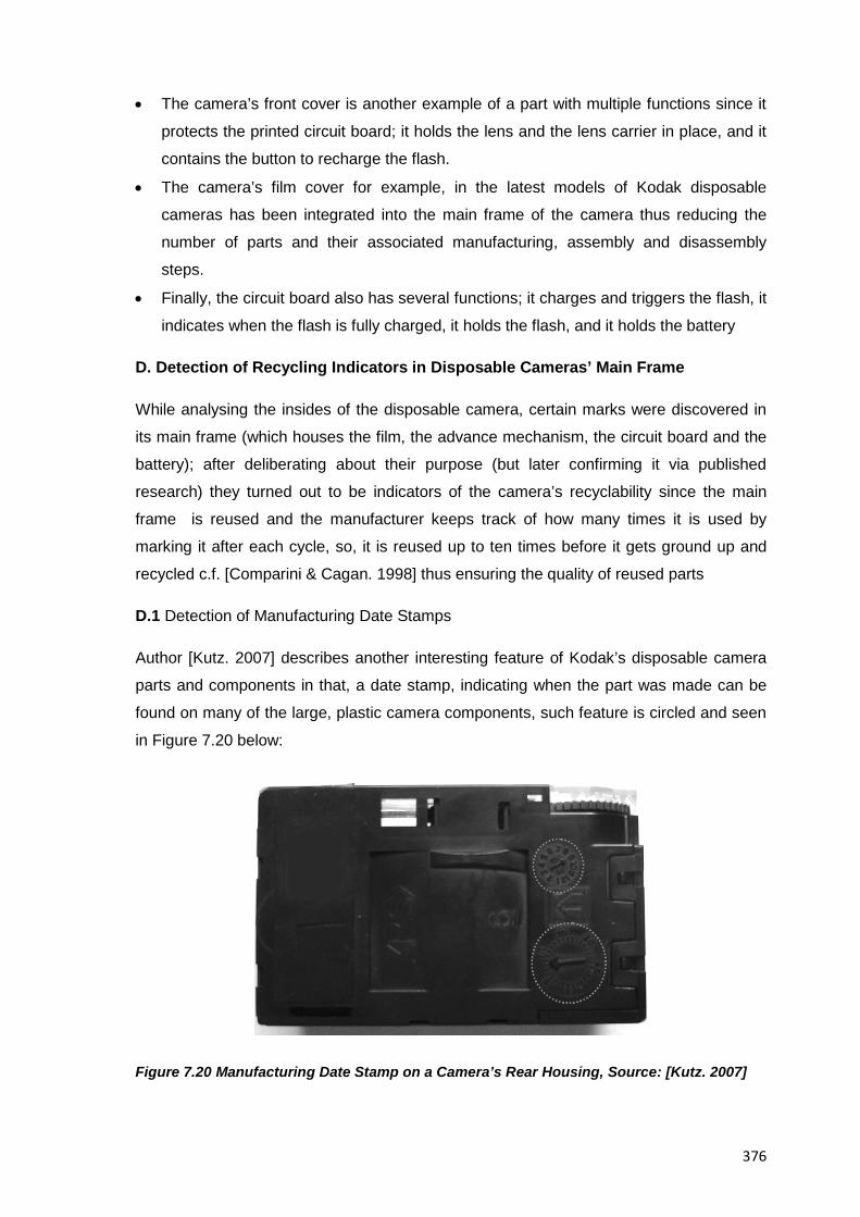
376
• The camera’s front cover is another example of a part with multiple functions since it
protects the printed circuit board; it holds the lens and the lens carrier in place, and it
contains the button to recharge the flash.
• The camera’s film cover for example, in the latest models of Kodak disposable
cameras has been integrated into the main frame of the camera thus reducing the
number of parts and their associated manufacturing, assembly and disassembly
steps.
• Finally, the circuit board also has several functions; it charges and triggers the flash, it
indicates when the flash is fully charged, it holds the flash, and it holds the battery
D. Detection of Recycling Indicators in Disposable Cameras’ Main Frame
While analysing the insides of the disposable camera, certain marks were discovered in
its main frame (which houses the film, the advance mechanism, the circuit board and the
battery); after deliberating about their purpose (but later confirming it via published
research) they turned out to be indicators of the camera’s recyclability since the main
frame is reused and the manufacturer keeps track of how many times it is used by
marking it after each cycle, so, it is reused up to ten times before it gets ground up and
recycled c.f. [Comparini & Cagan. 1998] thus ensuring the quality of reused parts
D.1 Detection of Manufacturing Date Stamps
Author [Kutz. 2007] describes another interesting feature of Kodak’s disposable camera
parts and components in that, a date stamp, indicating when the part was made can be
found on many of the large, plastic camera components, such feature is circled and seen
in Figure 7.20 below:
Figure 7.20 Manufacturing Date Stamp on a Camera’s Rear Housing, Source: [Kutz. 2007]
377
This date stamp, -as author Kutz describes-, often takes the form of a clock with an arrow
pointing to the month in one (top circle) and day of the month in the other (bottom circle ).
The author explains that this form of a date stamp is easy to change in the mould itself
before parts are made and helps Kodak keep track of when particular parts are made
(e.g. What percentage of new and recycled material was used in a given batch of plastic
on a particular day), thus providing useful information for the recycling process given that
the time between when a camera is made and when it is returned to the photo finisher is
highly variable.
D.2 Numbering of Internal Pieces of Kodak Disposable Cameras
In relation to the abovementioned marks, each major internal piece of Kodak disposable
cameras is numerated and has a standardized code stamped on it indicating the material
from which it is manufactured; this aids the assembling process of the camera at the
manufacturing line but it is actually intended to help sort the materials for an eventual
recycling
D.3 Assurance of Quality of Reused Camera Parts
According to authors [Comparini & Cagan. 1998] just as in the above mentioned cases
other camera components are reused a limited number of times too; the printed circuit
board (PCB) for example is reused up to seven times and it is tested after every cycle,
whereas the batteries which still contain more than half of their charge c.f. [Simpson.
2009] are donated to various charities (Refer also to Figure 7.4 for additional information
on this)
D.4 Safety Measures Against the Refurbishing, Remanufacturing or Recycling of
Disposable Kodak Cameras by Unapproved Entities
Author [Kutz. 2007] has reported in this regard, that initially some photo finishers were
recycling the cameras directly, without returning them to Kodak, but without the proper
inspection and testing, the quality of the photographs could degrade very quickly if the
cameras were simply reused time and again; because of this Kodak designed a special
film canister of a specific shape that they only produce for their one-time-use cameras to
prevent this unauthorized recycling since the film canister cannot be bought separately
from the camera itself and cannot be used in traditional film cameras (thus the importance
of salvaging the film in this educational activity ). Figure 7.21 below shows how a unique
saw-tooth pattern on top of the film canisters is used in all Kodak disposable cameras
and how it mates perfectly to the underside of the film advance wheel seen in the same
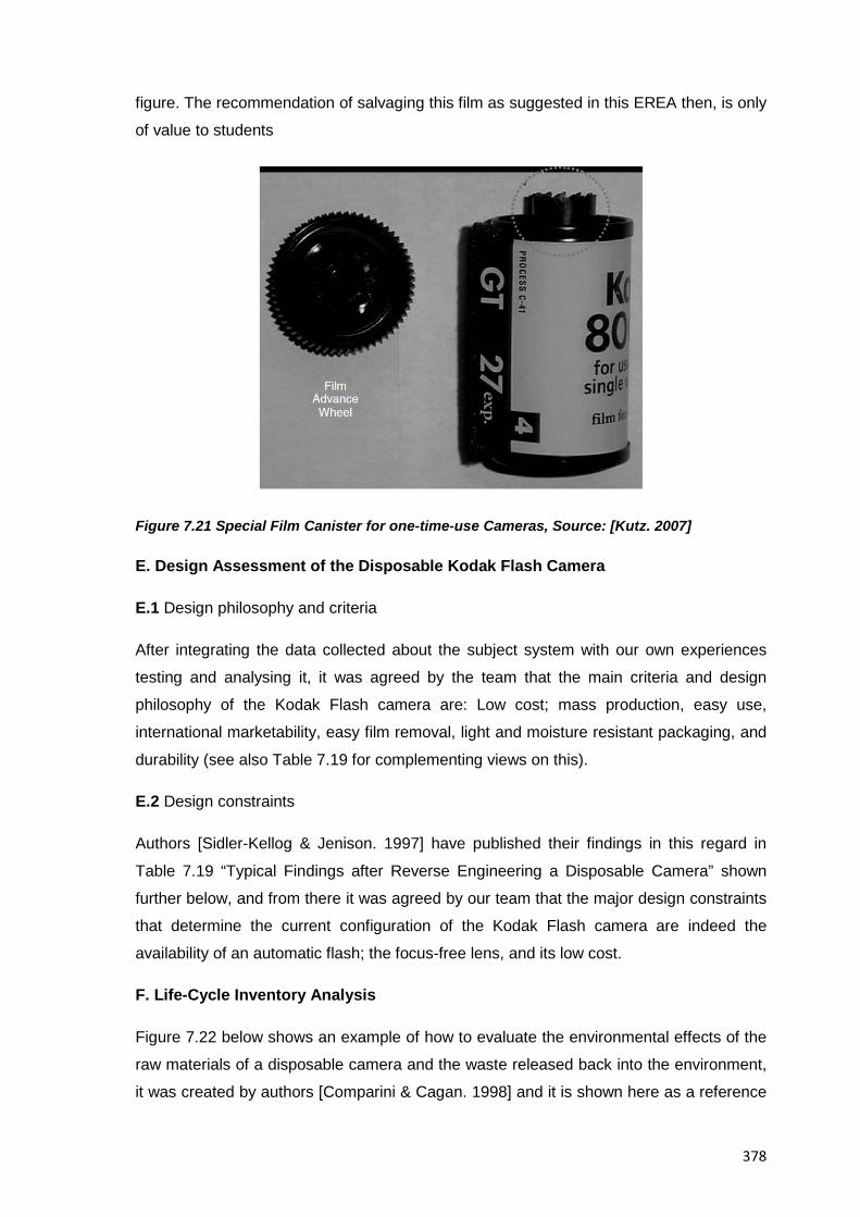
378
figure. The recommendation of salvaging this film as suggested in this EREA then, is only
of value to students
Figure 7.21 Special Film Canister for one-time-use Cameras, Source: [Kutz. 2007]
E. Design Assessment of the Disposable Kodak Flash Camera
E.1 Design philosophy and criteria
After integrating the data collected about the subject system with our own experiences
testing and analysing it, it was agreed by the team that the main criteria and design
philosophy of the Kodak Flash camera are: Low cost; mass production, easy use,
international marketability, easy film removal, light and moisture resistant packaging, and
durability (see also Table 7.19 for complementing views on this).
E.2 Design constraints
Authors [Sidler-Kellog & Jenison. 1997] have published their findings in this regard in
Table 7.19 “Typical Findings after Reverse Engineering a Disposable Camera” shown
further below, and from there it was agreed by our team that the major design constraints
that determine the current configuration of the Kodak Flash camera are indeed the
availability of an automatic flash; the focus-free lens, and its low cost.
F. Life-Cycle Inventory Analysis
Figure 7.22 below shows an example of how to evaluate the environmental effects of the
raw materials of a disposable camera and the waste released back into the environment,
it was created by authors [Comparini & Cagan. 1998] and it is shown here as a reference
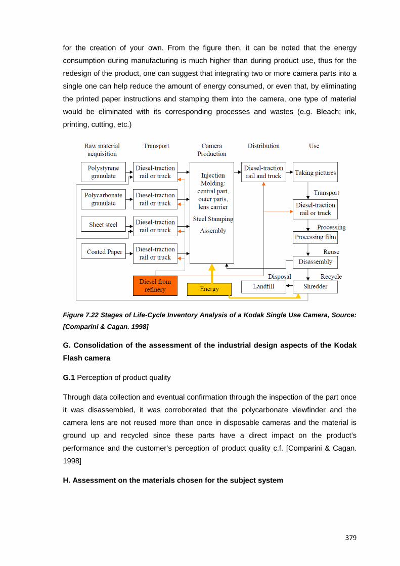
379
for the creation of your own. From the figure then, it can be noted that the energy
consumption during manufacturing is much higher than during product use, thus for the
redesign of the product, one can suggest that integrating two or more camera parts into a
single one can help reduce the amount of energy consumed, or even that, by eliminating
the printed paper instructions and stamping them into the camera, one type of material
would be eliminated with its corresponding processes and wastes (e.g. Bleach; ink,
printing, cutting, etc.)
Figure 7.22 Stages of Life-Cycle Inventory Analysis of a Kodak Single Use Camera, Source:
[Comparini & Cagan. 1998]
G. Consolidation of the assessment of the industrial design aspects of the Kodak Flash camera
G.1 Perception of product quality
Through data collection and eventual confirmation through the inspection of the part once
it was disassembled, it was corroborated that the polycarbonate viewfinder and the
camera lens are not reused more than once in disposable cameras and the material is
ground up and recycled since these parts have a direct impact on the product’s
performance and the customer’s perception of product quality c.f. [Comparini & Cagan.
1998]
H. Assessment on the materials chosen for the subject system
380
An analysis of the mix of materials selected for the Kodak Flash camera in combination
with the available information on how important the recycling programme is for the
manufacturers lead us to believe that such materials have been selected for the
properties of strength; texture, durability and producibility, and thus as mentioned already
up to 90% of the camera components can be reused or recycled
7.2.8 Stage VIII: Product Reassembly
7.2.8.1 Methodology
The two major tasks to fulfil at this stage are on the one hand; to reassemble the
disposable camera having already defeated any anti-tampering measures that could have
rendered it unusable, and on the other, to document the whole process so future readers
of this work get detailed information on the full disassembly/reassembly sequence of the
subject system. For reassembling the disposable camera then, special care was taken
not to damage its photographic film via an undesired exposure to light thus being able to
bring it back to its original state; for the documenting of the reassembly process, the
instructions and supporting diagrams previously sketched at the Product Disassembly
stage were finally completed and checked for inclusion in the final activity report.
7.2.8.2 Suggested Pedagogy
The major task of professors at this stage is to support students in the reassembly
process of their subject system, both by checking on the methodological aspects of the
task itself, and by providing the technical input required to defeat or avoid any anti
tampering measures that could impede the return of the subject system to its original
state. Other minor situations that could show up where professors would need to lend
their support include for example, dealing with remedial actions for lost or damaged
product parts, or helping students to draw at the end of the stage, meaningful conclusions
from detected differences between the disassembling and reassembling of a consumer
product.
7.2.8.3 Sample Deliverables
A. Reassembly instructions
Table 7.16 below describes a step-by-step process for reassembling the Kodak Flash
camera used as the main subject in this example; and although most of it was written at
the Product Disassembly stage, it is only during the actual reassembly where it can be
confirmed and refined for the benefit of the reader, it can be noted for example, that it is
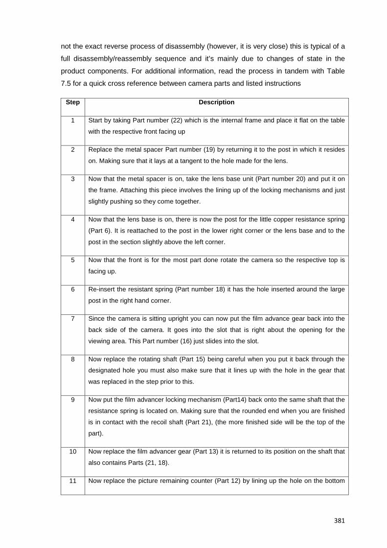
381
not the exact reverse process of disassembly (however, it is very close) this is typical of a
full disassembly/reassembly sequence and it’s mainly due to changes of state in the
product components. For additional information, read the process in tandem with Table
7.5 for a quick cross reference between camera parts and listed instructions
Step Description
1 Start by taking Part number (22) which is the internal frame and place it flat on the table
with the respective front facing up
2 Replace the metal spacer Part number (19) by returning it to the post in which it resides
on. Making sure that it lays at a tangent to the hole made for the lens.
3 Now that the metal spacer is on, take the lens base unit (Part number 20) and put it on
the frame. Attaching this piece involves the lining up of the locking mechanisms and just
slightly pushing so they come together.
4 Now that the lens base is on, there is now the post for the little copper resistance spring
(Part 6). It is reattached to the post in the lower right corner or the lens base and to the
post in the section slightly above the left corner.
5 Now that the front is for the most part done rotate the camera so the respective top is
facing up.
6 Re-insert the resistant spring (Part number 18) it has the hole inserted around the large
post in the right hand corner.
7 Since the camera is sitting upright you can now put the film advance gear back into the
back side of the camera. It goes into the slot that is right about the opening for the
viewing area. This Part number (16) just slides into the slot.
8 Now replace the rotating shaft (Part 15) being careful when you put it back through the
designated hole you must also make sure that it lines up with the hole in the gear that
was replaced in the step prior to this.
9 Now put the film advancer locking mechanism (Part14) back onto the same shaft that the
resistance spring is located on. Making sure that the rounded end when you are finished
is in contact with the recoil shaft (Part 21), (the more finished side will be the top of the
part).
10 Now replace the film advancer gear (Part 13) it is returned to its position on the shaft that
also contains Parts (21, 18).
11 Now replace the picture remaining counter (Part 12) by lining up the hole on the bottom
382
with the top of the revolving shaft and slightly pressing down.
12 Now that all of the mechanical / interface parts have been replaced that are in the upper
right hand corner, we now replace the gear protector/picture capture button (Part 11). (It
just slides over the top and when the locking mechanisms meet with the appropriate
spaces just push down a little and it will be locked back into place.)
13 With the camera still in its upright position replace the viewing lens by lining up the lens
and pushing it down in its appropriate spot, (the lens is made so that it only fits one way)
once it is fit in, it will not be held in place by friction
14 Now rotate the camera so that the respective back is once again on the table with the
lens base facing upward
15 Now replace the lens (Part 10) by lining it up with the round hole that is in the lens base
and setting it on it with the curved portion facing upward
16 Now that the lens is on the base take the lens fastener (Part 9) and line it up with the
holes around the lens with the respective fasteners that come out of the piece. Insert the
fasteners into the depressions and turn the piece slightly in the direction that it will let
you, so that you may lock the lens down to the camera
17 Now for the hard part take the circuit board / flash (Part 7) holding it in the position with
the flash facing up, insert the long metal section right below the lens holder and wiggle
the piece until it becomes flush with the lens base. You might have to insert it at a slight
angle and then when you are pushing slowly decrease that angle until it is flat with
respect to the frame. (The flash should sit in the upper right hand corner facing you when
the camera is in this position).
18 Now that the front of the camera has been reconstructed place the front cover (Part 5)
over the frame and rotate the camera so that the front cover is now facing the table and
the back unfinished portion is now facing upward
19 Now reinsert the battery (Part 4) to the two prongs that have now been replaced, now
that the circuit board/flash has been replaced the battery should set with the positive end
on the two pronged side and the negative end on the one pronged side.
20 Now replace the film cartridge (Part 3) which sets on the right hand side in its little slot.
The canister goes in with the protruding piece up and the respective bottom down, it just
sets in place there.
21 Now replace the unexposed film spool (Part 2). It goes into place with the larger end up
and the smaller end down so that it may rotate in the slot that the internal frame has
provided for it. The pieces will not fit the other way so if you put them in wrong you will
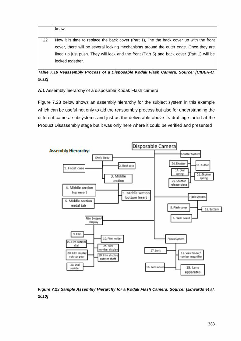
383
know
22 Now it is time to replace the back cover (Part 1), line the back cover up with the front
cover, there will be several locking mechanisms around the outer edge. Once they are
lined up just push. They will lock and the front (Part 5) and back cover (Part 1) will be
locked together.
Table 7.16 Reassembly Process of a Disposable Kodak Flash Camera, Source: [CIBER-U.
2012]
A.1 Assembly hierarchy of a disposable Kodak Flash camera
Figure 7.23 below shows an assembly hierarchy for the subject system in this example
which can be useful not only to aid the reassembly process but also for understanding the
different camera subsystems and just as the deliverable above its drafting started at the
Product Disassembly stage but it was only here where it could be verified and presented
Figure 7.23 Sample Assembly Hierarchy for a Kodak Flash Camera, Source: [Edwards et al.
2010]
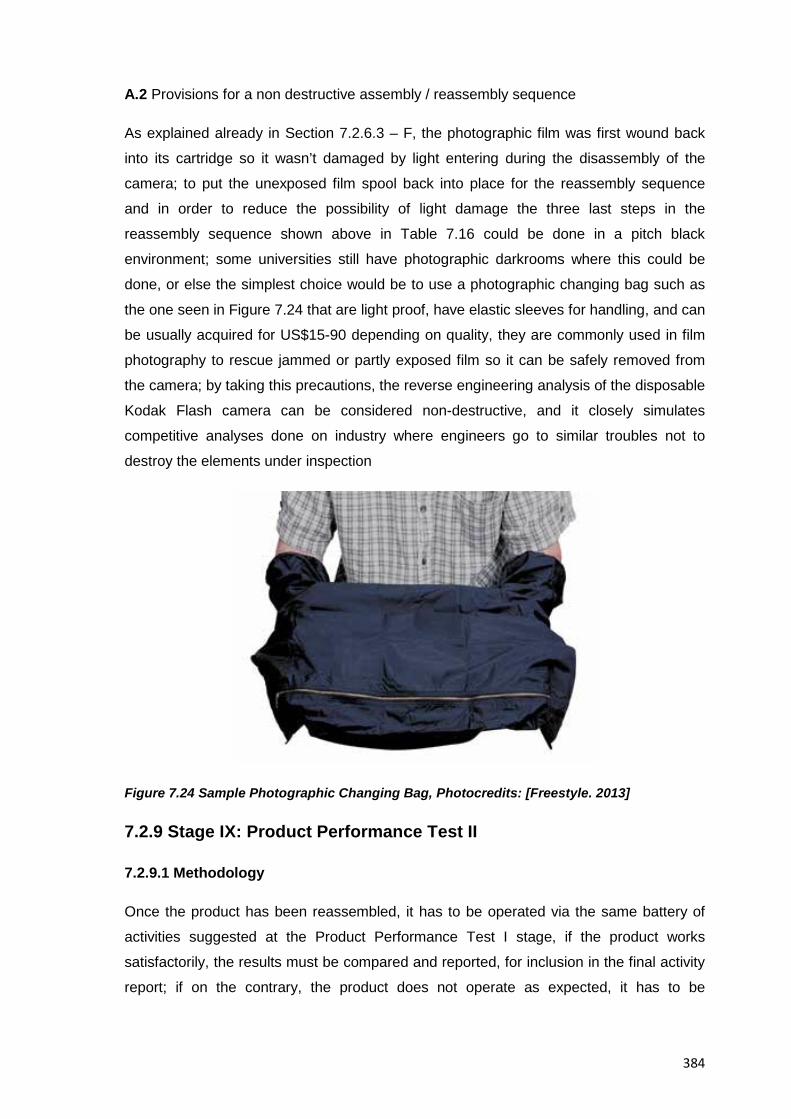
384
A.2 Provisions for a non destructive assembly / reassembly sequence
As explained already in Section 7.2.6.3 – F, the photographic film was first wound back
into its cartridge so it wasn’t damaged by light entering during the disassembly of the
camera; to put the unexposed film spool back into place for the reassembly sequence
and in order to reduce the possibility of light damage the three last steps in the
reassembly sequence shown above in Table 7.16 could be done in a pitch black
environment; some universities still have photographic darkrooms where this could be
done, or else the simplest choice would be to use a photographic changing bag such as
the one seen in Figure 7.24 that are light proof, have elastic sleeves for handling, and can
be usually acquired for US$15-90 depending on quality, they are commonly used in film
photography to rescue jammed or partly exposed film so it can be safely removed from
the camera; by taking this precautions, the reverse engineering analysis of the disposable
Kodak Flash camera can be considered non-destructive, and it closely simulates
competitive analyses done on industry where engineers go to similar troubles not to
destroy the elements under inspection
Figure 7.24 Sample Photographic Changing Bag, Photocredits: [Freestyle. 2013]
7.2.9 Stage IX: Product Performance Test II
7.2.9.1 Methodology
Once the product has been reassembled, it has to be operated via the same battery of
activities suggested at the Product Performance Test I stage, if the product works
satisfactorily, the results must be compared and reported, for inclusion in the final activity
report; if on the contrary, the product does not operate as expected, it has to be
385
examined and a solution must be sought, which usually entails the disassembly,
reparation and reassembly of the subject system until a desired result is reached. The
Kodak Flash camera for this example worked as intended at the first try and so the work
area, tools and measuring devices were cleaned and returned to the laboratory
technician to end with the work to be done at the university laboratory as agreed in the
timetable and work schedule from the Task Clarification stage
7.2.9.2 Suggested Pedagogy
Unless a new testing device becomes available; unexpected information about the
product arises, or a destructive analysis of the subject system was inevitable, the battery
of tests to conduct is the same as in the Product Testing I stage and so similar
recommendations apply. If any of the previously mentioned conditions show up though,
the analyses to the subject system will have to be adapted to warrant the continuation of
the stages of the methodology. In any case, professors should see that students report at
least the following three items at the end of this stage, namely: Any detected differences
between the results from Product Performance Test stage I and II (with potential
explanations to this); any attempt to adjust; repair or improve the performance of the
disposable camera, their understanding of the subject system to detect problems in it.
After this, the final task for the professor will be to ensure that students actually clean the
workplace and return the set of tools and measuring devices in full working order back to
the laboratory technician to continue at a different venue with the rest of the methodology
7.2.9.3. Sample Deliverables
A. Assessment of Product Operation and Capabilities
Because plenty of information about the internal construction of the camera was at our
reach during the past stage of the methodology a successful reassembling was actually
achieved; thus, during the tests required for this current stage, we could confirm that the
operation and capabilities of the product remained the same with all dials, knobs and
buttons feeling and working the same; indeed, the camera handed from last semester
students was in full working order and throughout our EREA no part was deformed,
damaged or lost so no real need for a thorough maintenance (e.g. Lubricating, cleaning,
etc.) or repairing of it was necessary either.
At the end of the stage though, it was agreed that the definite way to prove that the
reassembled camera worked as intended was to actually take pictures with it and develop
the film to see the quality of the resulting pictures, however, this was not possible
386
because the cameras belong to the university and they have to be returned to the
laboratory warehouse for use by future students, still, and because of their reduced cost
one of the teams in the course agreed to purchasing a disposable camera with their own
money and set out to disassemble, reassemble and take pictures with it to have them
later developed, their actions actually ended up satisfactorily and got crisp and clear
images from their camera.
7.2.10 Stage X: Knowledge Synthesis
7.2.10.1 Methodology
In Section 2.3 a full explanation was provided on how students build knowledge
throughout an EREA, in this section though an account is given of what was done for this
particular example where a wealth of information was available to students since the very
beginning. Indeed, much of what students usually present only until reaching this stage
(e.g. Lists, summaries, compilations, etc.) has already been shown as intermediate
results at the previous stages of the methodology, a fact due to the exemplary nature of
this specific case but with the added benefit of its comprehensiveness which makes it
suitable for use as a reference on what to expect from students undergoing an EREA.
The most relevant work done at this stage then, dealt with the integration of all past
information, the reaching of some conclusions summarizing the understanding of the
subject system, and the documenting of them in a way that provided a meaningful
explanation of the subject system to future readers of this work. Individual activities from
this stage then, that are worth highlighting include:
• Reviewing all past information about the Kodak Flash camera and complementing it
with intermediate findings from past stages not to leave any significant loose end
behind before moving on to the next stage of the methodology
• Consolidating the assessment of the design of the subject system specially in the
areas of assembly, lifecycle and generational changes
• Reflecting on the socioeconomical aspects of the camera (mostly represented by the
analysis of its ecological considerations)
• Speculating on the still ununderstood aspects of the camera
The stage itself then, ended both when no further information could be added to the
report in progress, and when the understanding of the subject system was considered
satisfactory enough as to start suggesting improvement modifications to it
7.2.10.2 Suggested Pedagogy
387
The resources for the conduction of this stage represented by the suggested stage
methodology in Section 5.4.10, the proposed pedagogy mentioned in Section 6.5.2.9,
and the actual examples shown here provide a variety of perspectives on how to help
students reach the main goal of this stage which is construct knowledge both from the
numerical data resulting from past tests of the methodology and from the actual
exchange of ideas in discussing them, the major tasks for professors at this stage then, is
to guide students in the cognitive exercises (e.g. Brainstorms) that help them turn
numerical data into information and information into knowledge that can either provide
independent confirmation to previously published results or be presented for future
confirmation by independent testers; for this specific case where a wealth of information
about the subjects system was available to students since the very beginning, the major
challenge as a professor was to help students benefit from past findings while still helping
encouraging them to come up with their own conclusions that could or could not confirm
past, published results.
7.2.10.3 Sample Deliverables
A. Consolidation of the Assessment of the Disposable Kodak Flash Camera’s Design
A.1 Design Efficiency
In a low cost product such as this one it is of paramount importance to accomplish its
function in an efficient manner, unlike regular film cameras for example in the Kodak
lineup of disposable cameras the film is unwound from the film canister and prewound
into a roll in the camera; this means that if the camera is opened without advancing
through all the pictures the film will be exposed and damaged, this design decision
however, allows the film to rewind into the canister as pictures are taken thus eliminating
the need for a separate film rewind mechanism in the camera therefore reducing costs,
complexity and materials
A.2 Ecodesign features of disposable cameras overall
By comparing information and designs from previous generations of disposable cameras
it can be seen from a design perspective how they have evolved to improve their
ecological impact (e.g. Easier disassembly; higher part reuse, better quality) , in this
regards author [Dalrymple 2009] states that as a result of DfE principles Fujifilm
disposable cameras (and Kodak ones for that matter) follow a cradle-to-cradle production
type through the use of remanufacturing and are every time lighter and more compact
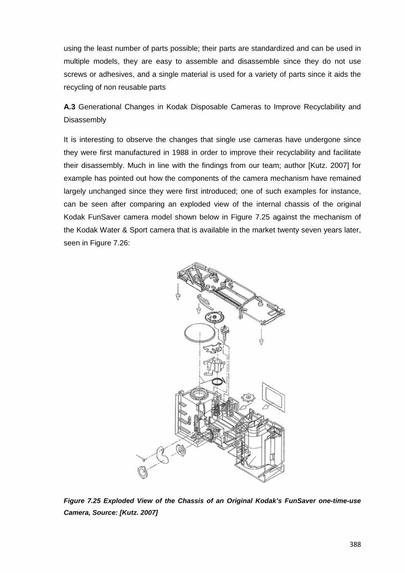
388
using the least number of parts possible; their parts are standardized and can be used in
multiple models, they are easy to assemble and disassemble since they do not use
screws or adhesives, and a single material is used for a variety of parts since it aids the
recycling of non reusable parts
A.3 Generational Changes in Kodak Disposable Cameras to Improve Recyclability and
Disassembly
It is interesting to observe the changes that single use cameras have undergone since
they were first manufactured in 1988 in order to improve their recyclability and facilitate
their disassembly. Much in line with the findings from our team; author [Kutz. 2007] for
example has pointed out how the components of the camera mechanism have remained
largely unchanged since they were first introduced; one of such examples for instance,
can be seen after comparing an exploded view of the internal chassis of the original
Kodak FunSaver camera model shown below in Figure 7.25 against the mechanism of
the Kodak Water & Sport camera that is available in the market twenty seven years later,
seen in Figure 7.26:
Figure 7.25 Exploded View of the Chassis of an Original Kodak’s FunSaver one-time-use Camera, Source: [Kutz. 2007]
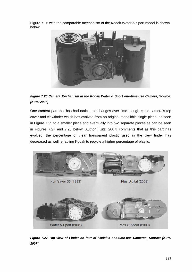
389
Figure 7.26 with the comparable mechanism of the Kodak Water & Sport model is shown below:
Figure 7.26 Camera Mechanism in the Kodak Water & Sport one-time-use Camera, Source:
[Kutz. 2007]
One camera part that has had noticeable changes over time though is the camera’s top
cover and viewfinder which has evolved from an original monolithic single piece, as seen
in Figure 7.25 to a smaller piece and eventually into two separate pieces as can be seen
in Figures 7.27 and 7.28 below. Author [Kutz. 2007] comments that as this part has
evolved, the percentage of clear transparent plastic used in the view finder has
decreased as well, enabling Kodak to recycle a higher percentage of plastic.
Figure 7.27 Top view of Finder on four of Kodak’s one-time-use Cameras, Source: [Kutz. 2007]
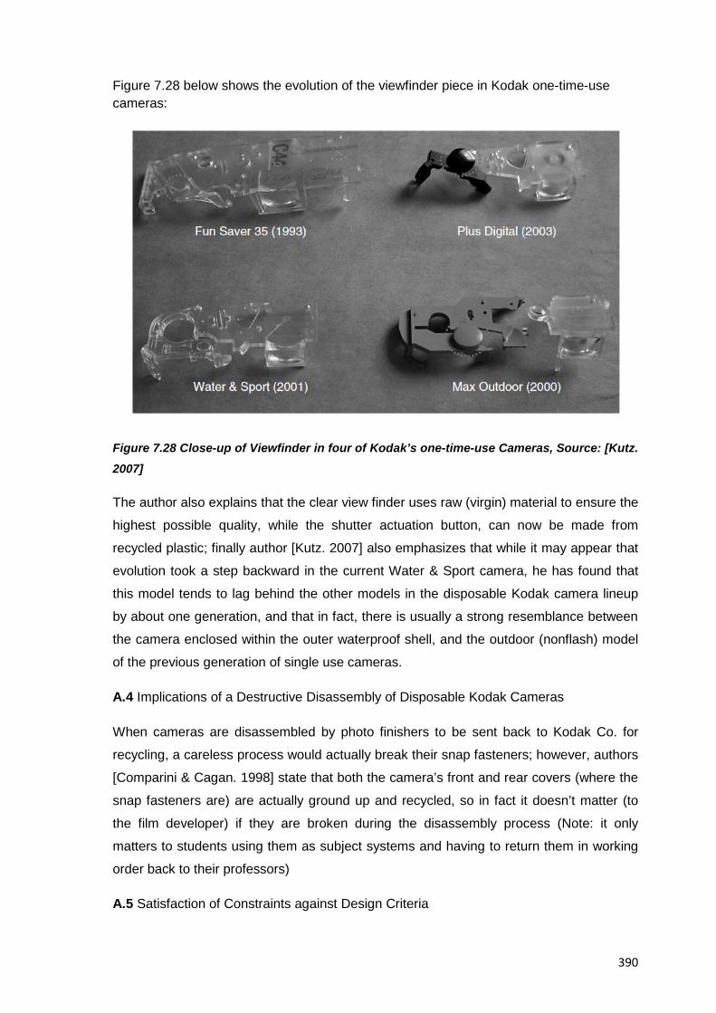
390
Figure 7.28 below shows the evolution of the viewfinder piece in Kodak one-time-use cameras:
Figure 7.28 Close-up of Viewfinder in four of Kodak’s one-time-use Cameras, Source: [Kutz. 2007]
The author also explains that the clear view finder uses raw (virgin) material to ensure the
highest possible quality, while the shutter actuation button, can now be made from
recycled plastic; finally author [Kutz. 2007] also emphasizes that while it may appear that
evolution took a step backward in the current Water & Sport camera, he has found that
this model tends to lag behind the other models in the disposable Kodak camera lineup
by about one generation, and that in fact, there is usually a strong resemblance between
the camera enclosed within the outer waterproof shell, and the outdoor (nonflash) model
of the previous generation of single use cameras.
A.4 Implications of a Destructive Disassembly of Disposable Kodak Cameras
When cameras are disassembled by photo finishers to be sent back to Kodak Co. for
recycling, a careless process would actually break their snap fasteners; however, authors
[Comparini & Cagan. 1998] state that both the camera’s front and rear covers (where the
snap fasteners are) are actually ground up and recycled, so in fact it doesn’t matter (to
the film developer) if they are broken during the disassembly process (Note: it only
matters to students using them as subject systems and having to return them in working
order back to their professors)
A.5 Satisfaction of Constraints against Design Criteria
391
Keeping costs low in a disposable camera; which is one of its main design criteria, takes
a toll on the final design of the product, one of such examples can be seen in how
optional features taken for granted in traditional, low cost, film cameras such as large
viewfinders, grip surfaces or lens protection mechanisms are missing in the lineup of
disposable cameras (see also Table 7.19 for a complementing views on this).
B. Lifecycle Stages of Kodak’s Single-Use Cameras
Table 7.17 below summarises the lifecycle stages of the Kodak lineup of disposable
cameras, it was compiled after information published by [Simpson. 2009] and helps
position and contextualize new findings and ideas in the study of disposable cameras
Stage Description
1 Camera is manufactured and loaded with
unexposed film which is pre-wound from the
cartridge into a roll in the camera.
2 Consumer purchases and uses camera,
winding film back into the cartridge one frame
at a time as photographs are taken.
3 Consumer returns entire camera to a photo-
finisher for processing
4 Photofinisher removes the battery and film
cartridge and develops the pictures
Camera body is returned to the manufacturer
(Kodak Co.) for reuse and recycling.
Manufacturer pays photofinisher a small fee for
each camera returned as incentive to recycle.
C.f. [Kutz. 2007]
Battery is reused by other industries since it still
has over half of its useful life remaining. (Refer
also to Table 7.18 for additional information on
this)
5 Manufacturer removes lenses and external
enclosures for regrind with to raw materials.
Internal camera body and mechanism
392
assembly is inspected and re-used, and new
film, a battery, lenses and outer covers are
added to make a “new” single use camera
ready for sale.
Table 7.17 Lifecycle Stages of Kodak’s Single-Use Cameras, [Simpson. 2009]
C. Recycling and Reuse Rundown of Components in Kodak Disposable Cameras
From information published by [Simpson. 2009] and derived from the rest of resources
available up to this point; Table 7.18 was created to summarize the “Closed-Loop”
recycling program by Kodak and show how every piece of the camera is reused; it should
be noted though that since no process is 100% effective, the parts of the camera that
don't pass inspection are reported to be simply ground up and fed into the raw material
stream for moulding into new cameras
Component Reuse
Covers The polystyrene covers of the Kodak cameras
(both flash and waterproof) are ground up and
recycled into covers for new cameras
The paperboard outer shell of cameras is made
of recycled material
Polycarbonate elements in the cameras are
ground up and sold to make non-photographic
products
Label The graphic label is ground up during the
recycling of the outer covers
Film After removing the film for processing, the
photofinisher has the option of returning the
camera to Kodak for recycling and reuse
Since retailers and photofinishers play a key
role in this recycling process, they are
reimbursed for each camera returned and
shipping costs
Lens To ensure optical purity, the camera receives a
new lens each time it is recycled
393
Used lenses are ground up and sold to outside
companies as raw materials for other products
Camera Mechanism The chassis, basic camera mechanism and
electronic flash systems are tested, inspected
and reused
Viewfinder The viewfinder is re-ground and recycled into
new internal camera parts
Battery (For camera models featuring a flash) When sending the camera back for recycling,
photofinishers can choose to keep the batteries
for reuse or sale to another industry; however,
authors [Comparini & Cagan. 1998] state that if
the batteries are returned to Kodak co. they are
in turn donated to various charities since (as
author [Kutz. 2007]) points out they typically
have more than half of their useful life still left
Table 7.18 Kodak’s Single-Use Cameras Component Recycling and Reuse, After: [Simpson. 2009]
7.2.11 Stage XI: Redesign Suggestions
7.2.11.1 Methodology
At this point in the methodology, students have already summed up their understanding
of the subject system; and thus based on their own experiences operating the product
and on their actual needs as potential customers of disposable cameras, a clearer point
of view to start suggesting improvement changes has been reached; for this specific
example then, an initial assessment activity to know how much was actually known about
the Kodak Flash camera in terms of opportunities for improvement was done,
immediately followed by a professor-led session of formal ideation methods (e.g.
Brainstorming , checklists, fishbone, etc.) to suggest value adding changes to the subject
systems, it will be noted from the deliverables shown further below though that no
prototypes or working models of the improvement concepts were requested by the
professor in charge mainly due to the resources available for this activity, however all
resulting findings from this stage were integrated to the report in progress in order to be
presented later in the methodology
7.2.11.2 Suggested Pedagogy
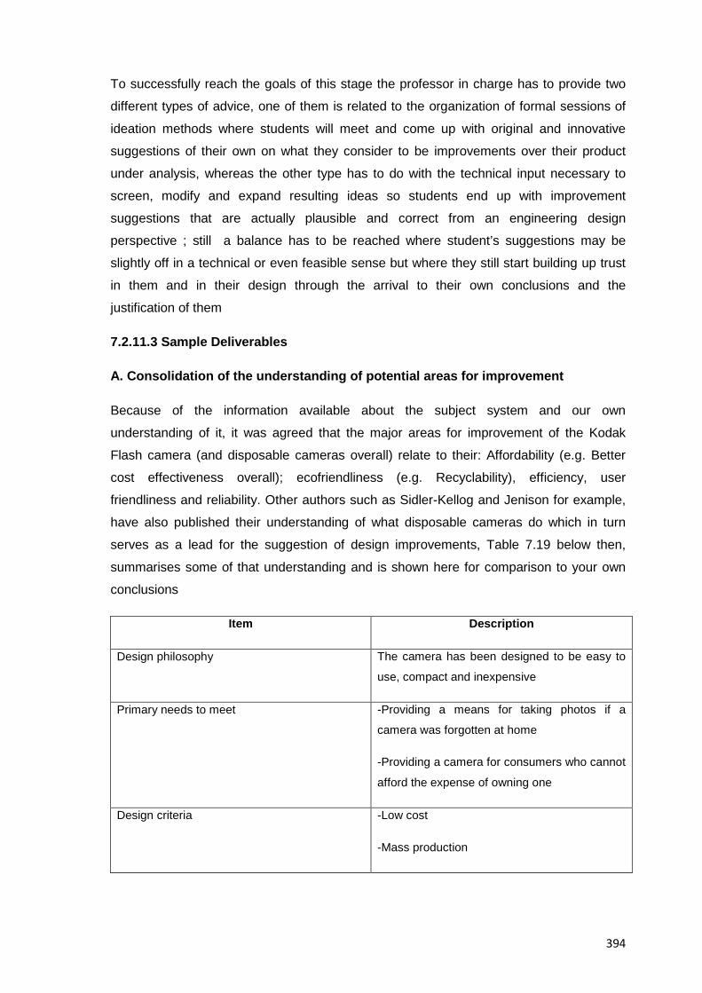
394
To successfully reach the goals of this stage the professor in charge has to provide two
different types of advice, one of them is related to the organization of formal sessions of
ideation methods where students will meet and come up with original and innovative
suggestions of their own on what they consider to be improvements over their product
under analysis, whereas the other type has to do with the technical input necessary to
screen, modify and expand resulting ideas so students end up with improvement
suggestions that are actually plausible and correct from an engineering design
perspective ; still a balance has to be reached where student’s suggestions may be
slightly off in a technical or even feasible sense but where they still start building up trust
in them and in their design through the arrival to their own conclusions and the
justification of them
7.2.11.3 Sample Deliverables
A. Consolidation of the understanding of potential areas for improvement
Because of the information available about the subject system and our own
understanding of it, it was agreed that the major areas for improvement of the Kodak
Flash camera (and disposable cameras overall) relate to their: Affordability (e.g. Better
cost effectiveness overall); ecofriendliness (e.g. Recyclability), efficiency, user
friendliness and reliability. Other authors such as Sidler-Kellog and Jenison for example,
have also published their understanding of what disposable cameras do which in turn
serves as a lead for the suggestion of design improvements, Table 7.19 below then,
summarises some of that understanding and is shown here for comparison to your own
conclusions
Item Description
Design philosophy The camera has been designed to be easy to
use, compact and inexpensive
Primary needs to meet -Providing a means for taking photos if a
camera was forgotten at home
-Providing a camera for consumers who cannot
afford the expense of owning one
Design criteria -Low cost
-Mass production
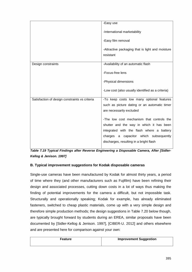
395
-Easy use
-International marketability
-Easy film removal
-Attractive packaging that is light and moisture
resistant
Design constraints -Availability of an automatic flash
-Focus-free lens
-Physical dimensions
-Low cost (also usually identified as a criteria)
Satisfaction of design constraints vs criteria -To keep costs low many optional features
such as picture dating or an automatic timer
are necessarily excluded
-The low cost mechanism that controls the
shutter and the way in which it has been
integrated with the flash where a battery
charges a capacitor which subsequently
discharges, resulting in a bright flash
Table 7.19 Typical Findings after Reverse Engineering a Disposable Camera, After [Sidler-
Kellog & Jenison. 1997]
B. Typical improvement suggestions for Kodak disposable cameras
Single-use cameras have been manufactured by Kodak for almost thirty years, a period
of time where they (and other manufacturers such as Fujifilm) have been refining their
design and associated processes, cutting down costs in a lot of ways thus making the
finding of potential improvements for the camera a difficult, but not impossible task.
Structurally and operationally speaking; Kodak for example, has already eliminated
fasteners, switched to cheap plastic materials, come up with a very simple design and
therefore simple production methods; the design suggestions in Table 7.20 below though,
are typically brought forward by students during an EREA, similar proposals have been
documented by [Sidler-Kellog & Jenison. 1997], [CIBER-U. 2012] and others elsewhere
and are presented here for comparison against your own:
Feature Improvement Suggestion
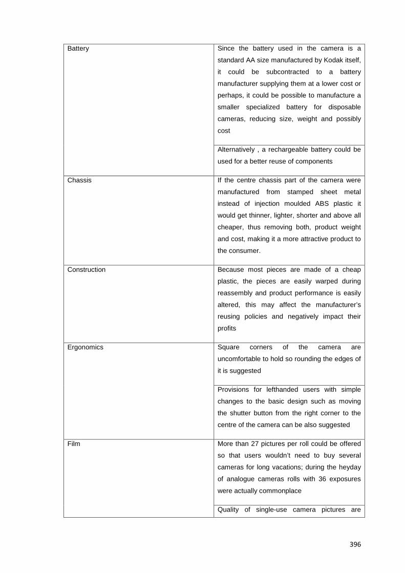
396
Battery Since the battery used in the camera is a
standard AA size manufactured by Kodak itself,
it could be subcontracted to a battery
manufacturer supplying them at a lower cost or
perhaps, it could be possible to manufacture a
smaller specialized battery for disposable
cameras, reducing size, weight and possibly
cost
Alternatively , a rechargeable battery could be
used for a better reuse of components
Chassis If the centre chassis part of the camera were
manufactured from stamped sheet metal
instead of injection moulded ABS plastic it
would get thinner, lighter, shorter and above all
cheaper, thus removing both, product weight
and cost, making it a more attractive product to
the consumer.
Construction Because most pieces are made of a cheap
plastic, the pieces are easily warped during
reassembly and product performance is easily
altered, this may affect the manufacturer’s
reusing policies and negatively impact their
profits
Ergonomics Square corners of the camera are
uncomfortable to hold so rounding the edges of
it is suggested
Provisions for lefthanded users with simple
changes to the basic design such as moving
the shutter button from the right corner to the
centre of the camera can be also suggested
Film More than 27 pictures per roll could be offered
so that users wouldn’t need to buy several
cameras for long vacations; during the heyday
of analogue cameras rolls with 36 exposures
were actually commonplace
Quality of single-use camera pictures are
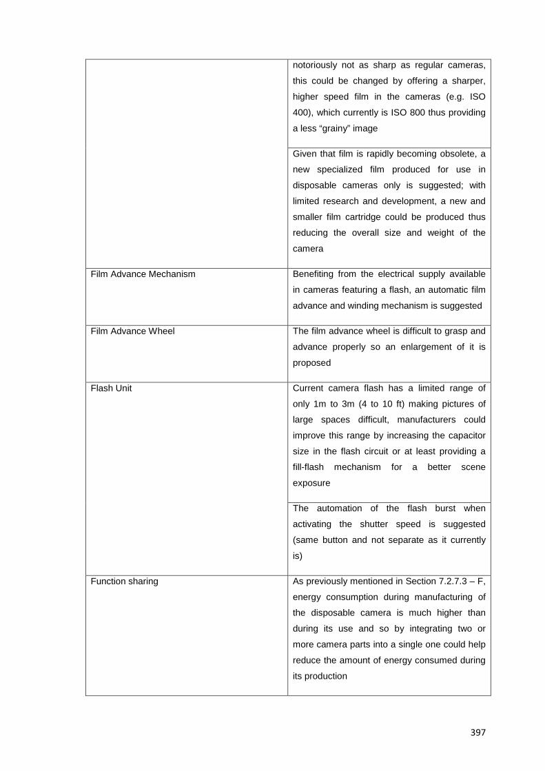
397
notoriously not as sharp as regular cameras,
this could be changed by offering a sharper,
higher speed film in the cameras (e.g. ISO
400), which currently is ISO 800 thus providing
a less “grainy” image
Given that film is rapidly becoming obsolete, a
new specialized film produced for use in
disposable cameras only is suggested; with
limited research and development, a new and
smaller film cartridge could be produced thus
reducing the overall size and weight of the
camera
Film Advance Mechanism Benefiting from the electrical supply available
in cameras featuring a flash, an automatic film
advance and winding mechanism is suggested
Film Advance Wheel The film advance wheel is difficult to grasp and
advance properly so an enlargement of it is
proposed
Flash Unit Current camera flash has a limited range of
only 1m to 3m (4 to 10 ft) making pictures of
large spaces difficult, manufacturers could
improve this range by increasing the capacitor
size in the flash circuit or at least providing a
fill-flash mechanism for a better scene
exposure
The automation of the flash burst when
activating the shutter speed is suggested
(same button and not separate as it currently
is)
Function sharing As previously mentioned in Section 7.2.7.3 – F,
energy consumption during manufacturing of
the disposable camera is much higher than
during its use and so by integrating two or
more camera parts into a single one could help
reduce the amount of energy consumed during
its production
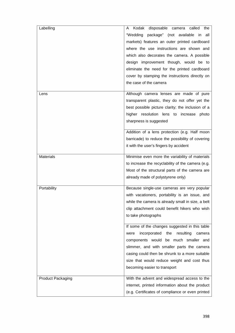
398
Labelling A Kodak disposable camera called the
“Wedding package” (not available in all
markets) features an outer printed cardboard
where the use instructions are shown and
which also decorates the camera. A possible
design improvement though, would be to
eliminate the need for the printed cardboard
cover by stamping the instructions directly on
the case of the camera
Lens Although camera lenses are made of pure
transparent plastic, they do not offer yet the
best possible picture clarity; the inclusion of a
higher resolution lens to increase photo
sharpness is suggested
Addition of a lens protection (e.g. Half moon
barricade) to reduce the possibility of covering
it with the user’s fingers by accident
Materials Minimise even more the variability of materials
to increase the recyclability of the camera (e.g.
Most of the structural parts of the camera are
already made of polystyrene only)
Portability Because single-use cameras are very popular
with vacationers, portability is an issue, and
while the camera is already small in size, a belt
clip attachment could benefit hikers who wish
to take photographs
If some of the changes suggested in this table
were incorporated the resulting camera
components would be much smaller and
slimmer, and with smaller parts the camera
casing could then be shrunk to a more suitable
size that would reduce weight and cost thus
becoming easier to transport
Product Packaging With the advent and widespread access to the
internet, printed information about the product
(e.g. Certificates of compliance or even printed
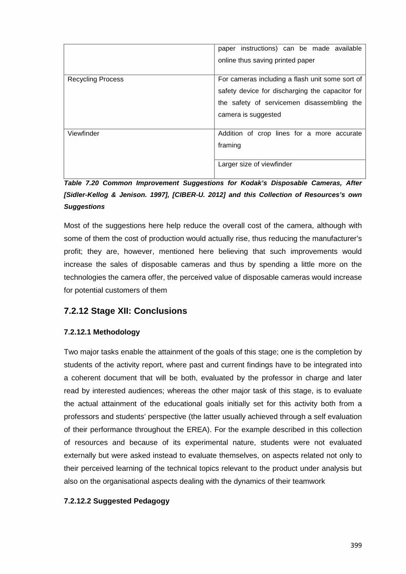
399
paper instructions) can be made available
online thus saving printed paper
Recycling Process For cameras including a flash unit some sort of
safety device for discharging the capacitor for
the safety of servicemen disassembling the
camera is suggested
Viewfinder Addition of crop lines for a more accurate
framing
Larger size of viewfinder
Table 7.20 Common Improvement Suggestions for Kodak’s Disposable Cameras, After [Sidler-Kellog & Jenison. 1997], [CIBER-U. 2012] and this Collection of Resources’s own
Suggestions
Most of the suggestions here help reduce the overall cost of the camera, although with
some of them the cost of production would actually rise, thus reducing the manufacturer’s
profit; they are, however, mentioned here believing that such improvements would
increase the sales of disposable cameras and thus by spending a little more on the
technologies the camera offer, the perceived value of disposable cameras would increase
for potential customers of them
7.2.12 Stage XII: Conclusions
7.2.12.1 Methodology
Two major tasks enable the attainment of the goals of this stage; one is the completion by
students of the activity report, where past and current findings have to be integrated into
a coherent document that will be both, evaluated by the professor in charge and later
read by interested audiences; whereas the other major task of this stage, is to evaluate
the actual attainment of the educational goals initially set for this activity both from a
professors and students’ perspective (the latter usually achieved through a self evaluation
of their performance throughout the EREA). For the example described in this collection
of resources and because of its experimental nature, students were not evaluated
externally but were asked instead to evaluate themselves, on aspects related not only to
their perceived learning of the technical topics relevant to the product under analysis but
also on the organisational aspects dealing with the dynamics of their teamwork
7.2.12.2 Suggested Pedagogy
400
As a professor, two major tasks have to be done at this stage; one is to ensure that
students finish preparing a thorough activity report, whereas the other is to evaluate from
a professors and students’ perspective the attainment of the learning objectives initially
set for the EREA; for the first task, if the professor in charge has regularly checked the
intermediate results from past stages of the methodology, students will have no problem
in submitting a document at this point that is both coherent and approved for eventual
dissemination to a variety of audiences; if on the other hand, this is the first time
professors read the students’ results they have to check that the students provide
reasonable, thorough explanations for the whole activity and specially so from a technical
and organizational perspective that describes both the workings of the subject system
and the team activities that led to that understanding. For the second major task of this
stage then; resources for the evaluation of students are provided in Section 6.5.3 of this
document, but still, it should be mentioned that for this specific example, and because of
the exploratory nature of it, students were only required to evaluate themselves
individually and then be evaluated by their teammates through a 360 degree assessment,
from both results and from the professor’s accumulated knowledge about them, students
can be evaluated and assigned a proper grade for the EREA
7.2.12.3 Sample Deliverables
A. Activity Conclusions
Throughout this activity we implemented the reverse engineering methodology proposed
in this collection of resources, while evaluating at the same time, its usefulness as an aid
in the learning and understanding of concepts of engineering design. To achieve the
goals set for the EREA then, a number of analytical tools, testing devices and
computerised resources where used throughout the activity in complementing and
accumulative ways that helped us reach a conclusive understanding about the product
under analysis.
For example, in regard to the hands-on nature of the EREA, it can be said that all stages
of the Kolb model were visited and that a different learning experience overall was had
where the learning of theory was complemented with its practical counterpart. Concerning
the technical principles behind the product though, we were told that the thorough
knowledge of the subject system is not a goal in itself but rather an excuse to go through
the proposed methodology and thus develop our design-related abilities, however, it still
should be stated that the disposable Kodak Flash camera provided an opportunity to
experience typical analyses and situations in the area of engineering design which
401
ultimately allowed us to learn not only the ins and outs of our career but also how it
interrelates with other areas of knowledge.
Respecting the actual tasks and analyses done to the subject system, it can be said that
the reverse engineering methodology made us combine not only the information obtained
from outside sources about the operation and manufacturing of the subject system (e.g.
Acquired via thorough bibliographical investigations) but also our own experiences in
testing and analysing the Kodak camera (one example of this, relates to how customer
needs about the subject system were established not only by researching and
interviewing people about them but also by self-experiencing the camera in order to
complement them and refine them). Indeed, the experiences gained thereof gave us the
confidence to suggest value adding changes to our subject system where, after analyzing
our product’s social factors; function, structure, materials, assembly and manufacturing
process, we concluded that the Kodak Flash model is a user friendly camera (at least in
comparison with previous generations of the same model) that at the same time keeps
costs low, and a very high reliability of operation, which in combination with its exemplary
recycling process makes it an ideal candidate for analysis for those willing to give reverse
engineering a try for the first time.
Last but not least, it should be highlighted that the EREA allowed us to undergo a team
experience very close to what we could find during our professional career, since we
were all allocated roles, responsibilities and resources to attain a satisfactory result in a
learning experience that was found motivating, refreshing and above all educational by
everyone in the team
7.2.13 Stage XIII: Results Dissemination
7.2.13.1 Methodology
This stage is about reaching the right people (e.g. Evaluators, classmates, sponsors) with
the right information (e.g. Tailored presentations suitable to the knowledge of the
audience) and so as a student the main task is to present to the class the results from the
EREA and from there, prepare derivative dissemination materials (e.g. Posters) to be
displayed at relevant venues and for a variety of audiences. As a professor, on the other
hand, the main responsibility for this stage falls in evaluating the students’ final report;
complementing their presentations with appropriate contextualization remarks, leading
the actions for those student works with potential for peer-reviewed publication, and
collecting the students’ reactions and impressions about the EREA for the last time.
Regarding the specific actions done for this example then, it can be highlighted that
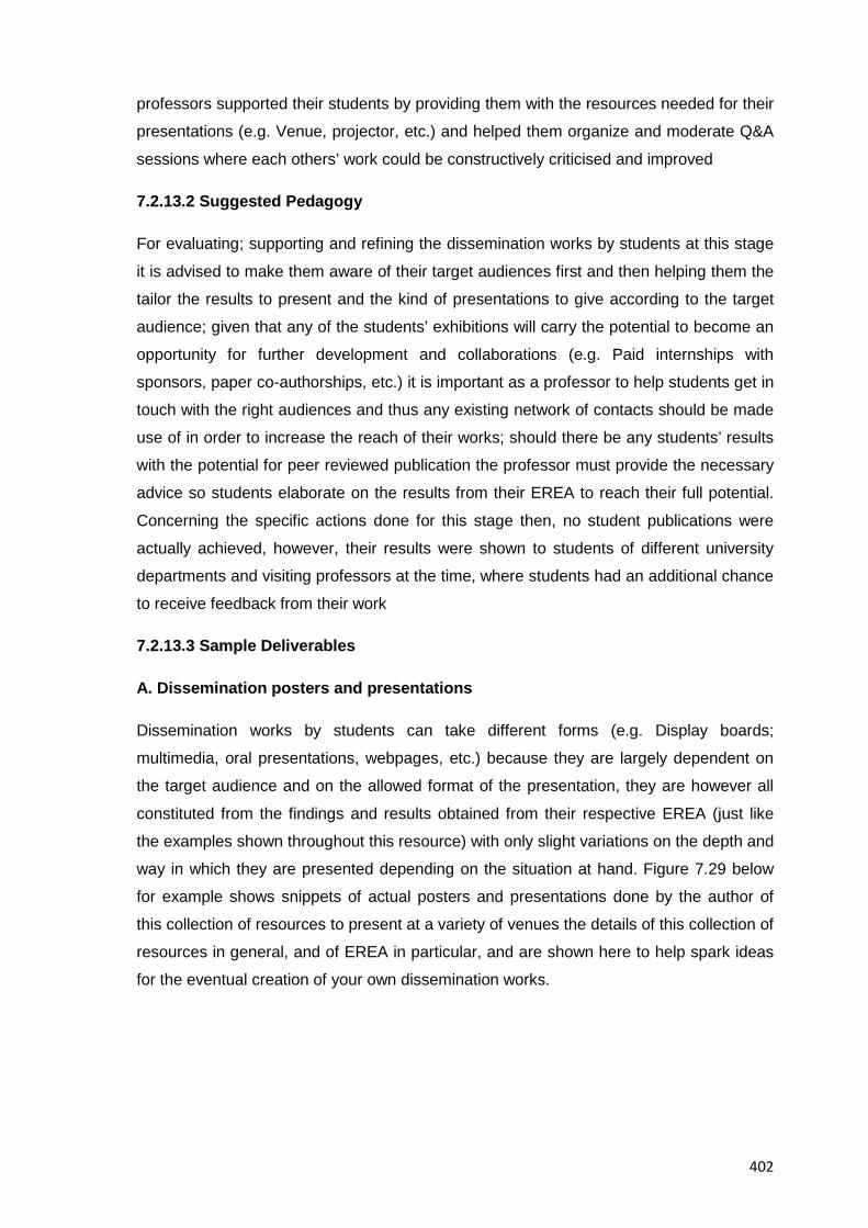
402
professors supported their students by providing them with the resources needed for their
presentations (e.g. Venue, projector, etc.) and helped them organize and moderate Q&A
sessions where each others’ work could be constructively criticised and improved
7.2.13.2 Suggested Pedagogy
For evaluating; supporting and refining the dissemination works by students at this stage
it is advised to make them aware of their target audiences first and then helping them the
tailor the results to present and the kind of presentations to give according to the target
audience; given that any of the students’ exhibitions will carry the potential to become an
opportunity for further development and collaborations (e.g. Paid internships with
sponsors, paper co-authorships, etc.) it is important as a professor to help students get in
touch with the right audiences and thus any existing network of contacts should be made
use of in order to increase the reach of their works; should there be any students’ results
with the potential for peer reviewed publication the professor must provide the necessary
advice so students elaborate on the results from their EREA to reach their full potential.
Concerning the specific actions done for this stage then, no student publications were
actually achieved, however, their results were shown to students of different university
departments and visiting professors at the time, where students had an additional chance
to receive feedback from their work
7.2.13.3 Sample Deliverables
A. Dissemination posters and presentations
Dissemination works by students can take different forms (e.g. Display boards;
multimedia, oral presentations, webpages, etc.) because they are largely dependent on
the target audience and on the allowed format of the presentation, they are however all
constituted from the findings and results obtained from their respective EREA (just like
the examples shown throughout this resource) with only slight variations on the depth and
way in which they are presented depending on the situation at hand. Figure 7.29 below
for example shows snippets of actual posters and presentations done by the author of
this collection of resources to present at a variety of venues the details of this collection of
resources in general, and of EREA in particular, and are shown here to help spark ideas
for the eventual creation of your own dissemination works.
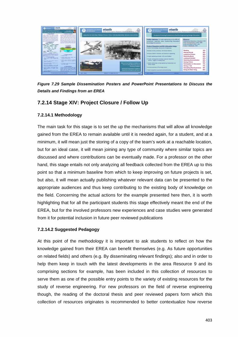
403
Figure 7.29 Sample Dissemination Posters and PowerPoint Presentations to Discuss the
Details and Findings from an EREA
7.2.14 Stage XIV: Project Closure / Follow Up
7.2.14.1 Methodology
The main task for this stage is to set the up the mechanisms that will allow all knowledge
gained from the EREA to remain available until it is needed again, for a student, and at a
minimum, it will mean just the storing of a copy of the team’s work at a reachable location,
but for an ideal case, it will mean joining any type of community where similar topics are
discussed and where contributions can be eventually made. For a professor on the other
hand, this stage entails not only analyzing all feedback collected from the EREA up to this
point so that a minimum baseline from which to keep improving on future projects is set,
but also, it will mean actually publishing whatever relevant data can be presented to the
appropriate audiences and thus keep contributing to the existing body of knowledge on
the field. Concerning the actual actions for the example presented here then, it is worth
highlighting that for all the participant students this stage effectively meant the end of the
EREA, but for the involved professors new experiences and case studies were generated
from it for potential inclusion in future peer reviewed publications
7.2.14.2 Suggested Pedagogy
At this point of the methodology it is important to ask students to reflect on how the
knowledge gained from their EREA can benefit themselves (e.g. As future opportunities
on related fields) and others (e.g. By disseminating relevant findings); also and in order to
help them keep in touch with the latest developments in the area Resource 9 and its
comprising sections for example, has been included in this collection of resources to
serve them as one of the possible entry points to the variety of existing resources for the
study of reverse engineering. For new professors on the field of reverse engineering
though, the reading of the doctoral thesis and peer reviewed papers form which this
collection of resources originates is recommended to better contextualize how reverse
404
engineering can from its industrial origins be tailored to support the teaching of
engineering design and the creation of new educational case studies on the topic
7.2.14.3 Sample Deliverables
A. Sample peer reviewed papers on EREA
One of the possible ways to preserve the findings about EREA is to publish any relevant
results from the study and testing of them, the author of this collection of resources for
example has presented at peer reviewed conferences details about EREA and about
their application in the teaching of engineering design, the list of papers shown below for
instance, are part of the dissemination efforts in progress to contribute to the existing
body of knowledge on the field, and are available for reading to anyone interested in
them, namely:
• Product Visualization Praxis and its Integration to Academic Curricula, [Calderon.
2008]
• Analysis of Existing Products as a Tool for Engineering Design Education, [Calderon.
2009]
• Application of Reverse Engineering Activities in the Teaching of Engineering Design,
[Calderon. 2010a]
• A Comparison of Competences Required in Reverse Engineering Exercises Versus
Conventional Engineering Exercises and its Relationship to IPMA’s Competence
Baseline, [Calderon. 2010b]
• The Design Research Methodology as a Framework for the Development of a Tool for
Engineering Design Education, [Calderon. 2010c]
7. 3 Resource Conclusions
In a guided example such as the one presented in this resource it can be seen how the
stages of an EREA call for the integration of varied perspectives for every single activity
included in them; indeed it is not only about placing importance on the technical
foundations for the development of a given task but also on the cognitive processes that
are set in action and that ensure a proper learning experience for the students, in this
sense the guidance and judgement of the professor in charge can determine how much
students will learn from an EREA; for example, and as seen throughout this resource, a
wealth of analytic tools exist that provide information about a product under inspection,
but it is the decision of the professor in charge to tell students only which of them to
develop and why, in a way that allows the continuation of the EREA without leaving any

405
significant knowledge gaps behind; since the information presented here, including the
methodology, pedagogy and examples, is all based on past, published research on the
topic and complemented with original findings from this research, the guided example
presented in this resource should be considered a self-explanatory backbone for the
understanding of the basic elements of EREA, and after the reader’s own
contextualization, it should help enthusiasts of reverse engineering not only to make the
most out of EREA but also to serve as a baseline for the eventual creation of further
educational materials.

406
This page intentionally left blank
407
RESOURCE 8: CONCLUSIONS AND FINAL REMARKS
8.1 Resource Introduction
Although published studies stated that hands-on activities such as educational reverse
engineering ones could become a popular pedagogy to provide students with practical
experience in the classroom [Lamancusa et al. 1996], there are still nowadays many
areas left to explore in the topic; for example, further studies on suitable pedagogies
which allow for the right balance between teachers’ guidance and students’ freedom are
still required to make the most out of these activities; and it is not only the pedagogical
aspects of them that need to be improved, other challenges in the implementation and
expansion of such activities also exist, in initial exploratory studies conducted as part of
this research project -to name but another example- some educators manifested a
reticence to complement the teaching of the design process with reverse engineering
activities and the varied reasons given for it ranged from personal to organizational ones,
the contents of this resource then, intend to present an overview of what EREA currently
are and what they could still become.
8.2 Present of Reverse Engineering Activities in Education
From the research leading to the creation of this collection of resources, which included
the analysis of all available data and the drawing of conclusions from field results and
experiences collected throughout the duration of the project, it could be concluded about
the use of EREA as an educational tool, that they:
• Are just another tool for the teaching of engineering design, they don’t try to abolish
other approaches and as such they are a complement rather that a substitute of
traditional engineering design projects, or any other existing teaching tool.
• Are fun: Because students have the opportunity to disassemble and see the insides of
everyday products, thus engaging in a novel and appealing challenge that can help
them stay motivated and interested.
• Are dynamic: Because in to order to complete a successful activity; a simultaneous
collection, integration, and contextualisation of knowledge from different areas has to
be done which demands from students an increased sense of awareness and a
display of resourcefulness.
• Provide a realistic opportunity for practice: EREA provide opportunities for repetition
and reinforcement of key information where students can make mistakes and learn
from them and also from the feedback provided by their instructor, besides, the
408
infrastructure and rules inherent to an educational environment provide students with
a safe environment to fail and try again, thus encouraging them to test new ideas and
behaviours.
• Make learning concrete: EREA are realistic, complex experiences that allow students
to link information to action, and to reinforce engineering concepts through hands-on
experiences which could later help them use concrete learning in real life situations.
• Help learning to permeate: EREA have the potential to enhance students’ learning by
providing them with an opportunity to bring whatever has been learnt theoretically,
into a practical environment where all information can be challenged; analyzed,
discussed and interpreted to come up with a realistic explanation of what has
happened during the design process of the product under analysis and during its
actual operation
• Help students work as team: EREA are a group activity where specific roles and
responsibilities are set; and as such, students can mix their abilities and ideas with
those of their team members thereby helping reinforce learning and interaction in the
team; should noticeable differences in experience; knowledge and status among team
members arise during and EREA, the opportunity to safely repeat the activity until a
desired state is attained contributes to level the knowledge about the product under
analysis of all team members.
• Let the instructors observe the learning process: Professors and teaching assistants
can observe the students while they perform the hands-on tasks and discuss about
what they see and how they relate it to theory; educators then, can provide feedback
and guidance whenever needed while team members take active responsibility for the
learning that occurs during the activity.
• Foster cooperation with industry partners: Existing industrial requirements could be
handed to students to help find a suitable solution, (e.g. By proposing and designing
improved derivative products from the one under analysis)
• Are mostly technology oriented: EREA are just another tool available to support the
teaching of engineering design and as such they will cover just a set of the total
possible, expected competences of an engineering design student, indeed and as
seen in Table 4.10, and Resource 4 overall, EREA best suit learning objectives
related to the technical aspects of engineering design and shouldn’t be considered
the main choice to teach or exercise “soft skills” with them.
• Have an added value that lies in giving students early in their studies, the opportunity
to acquire and develop, through interesting and engaging activities, some of the
abilities required to lead a successful career in engineering design.
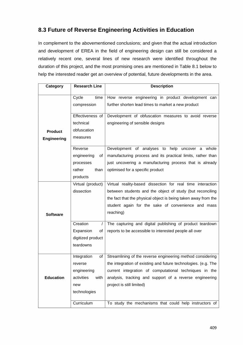
409
8.3 Future of Reverse Engineering Activities in Education
In complement to the abovementioned conclusions; and given that the actual introduction
and development of EREA in the field of engineering design can still be considered a
relatively recent one, several lines of new research were identified throughout the
duration of this project, and the most promising ones are mentioned in Table 8.1 below to
help the interested reader get an overview of potential, future developments in the area.
Category Research Line Description
Product Engineering
Cycle time
compression
How reverse engineering in product development can
further shorten lead times to market a new product
Effectiveness of
technical
obfuscation
measures
Development of obfuscation measures to avoid reverse
engineering of sensible designs
Reverse
engineering of
processes
rather than
products
Development of analyses to help uncover a whole
manufacturing process and its practical limits, rather than
just uncovering a manufacturing process that is already
optimised for a specific product
Software
Virtual (product)
dissection
Virtual reality-based dissection for real time interaction
between students and the object of study (but reconciling
the fact that the physical object is being taken away from the
student again for the sake of convenience and mass
reaching)
Creation /
Expansion of
digitized product
teardowns
The capturing and digital publishing of product teardown
reports to be accessible to interested people all over
Education
Integration of
reverse
engineering
activities with
new
technologies
Streamlining of the reverse engineering method considering
the integration of existing and future technologies. (e.g. The
current integration of computational techniques in the
analysis, tracking and support of a reverse engineering
project is still limited)
Curriculum To study the mechanisms that could help instructors of
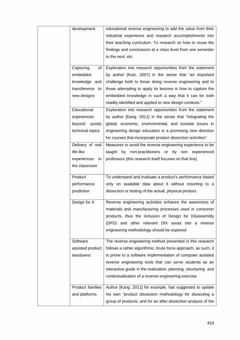
410
development educational reverse engineering to add the value from their
industrial experience and research accomplishments into
their teaching curriculum. To research on how to reuse the
findings and conclusions at a class level from one semester
to the next, etc.
Capturing of
embedded
knowledge and
transference to
new designs
Exploration into research opportunities from the statement
by author [Kutz. 2007] in the sense that “an important
challenge both to those doing reverse engineering and to
those attempting to apply its lessons is how to capture the
embedded knowledge in such a way that it can be both
readily identified and applied to new design contexts.”
Educational
experiences
beyond purely
technical topics
Exploration into research opportunities from the statement
by author [Kang. 2011] in the sense that “Integrating the
global, economic, environmental, and societal issues in
engineering design education is a promising new direction
for courses that incorporate product dissection activities”
Delivery of real
life-like
experiences in
the classroom
Measures to avoid the reverse engineering experience to be
taught by non-practitioners or by non experienced
professors (this research itself focuses on that line)
Product
performance
prediction
To understand and evaluate a product’s performance based
only on available data about it without resorting to a
dissection or testing of the actual, physical product.
Design for X Reverse engineering activities enhance the awareness of
materials and manufacturing processes used in consumer
products, thus the inclusion of Design for Disassembly
(DFD) and other relevant DfX areas into a reverse
engineering methodology should be explored
Software
assisted product
teardowns
The reverse engineering method presented in this research
follows a rather algorithmic, brute force approach, as such, it
is prone to a software implementation of computer assisted
reverse engineering tools that can serve students as an
interactive guide in the realization; planning, structuring and
contextualization of a reverse engineering exercise
Product families
and platforms
Author [Kang. 2011] for example, has suggested to update
his own “product dissection methodology for dissecting a
group of products, and for an after-dissection analysis of the
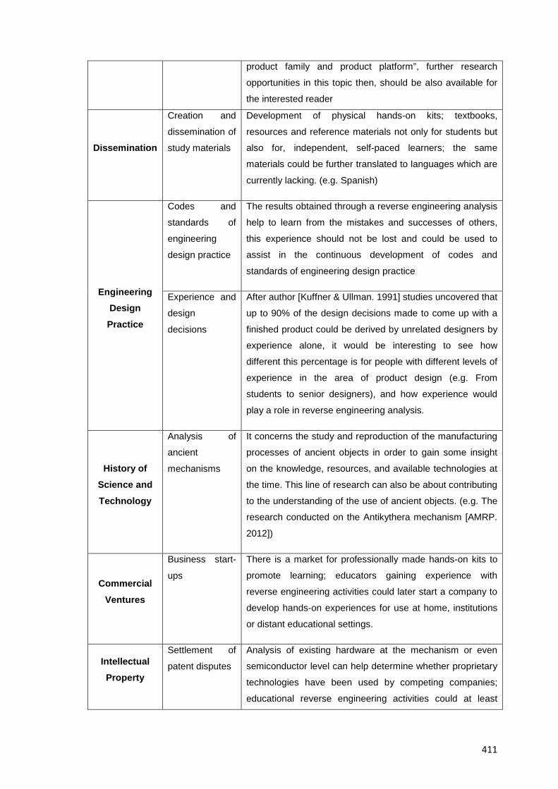
411
product family and product platform”, further research
opportunities in this topic then, should be also available for
the interested reader
Dissemination
Creation and
dissemination of
study materials
Development of physical hands-on kits; textbooks,
resources and reference materials not only for students but
also for, independent, self-paced learners; the same
materials could be further translated to languages which are
currently lacking. (e.g. Spanish)
Engineering Design Practice
Codes and
standards of
engineering
design practice
The results obtained through a reverse engineering analysis
help to learn from the mistakes and successes of others,
this experience should not be lost and could be used to
assist in the continuous development of codes and
standards of engineering design practice
Experience and
design
decisions
After author [Kuffner & Ullman. 1991] studies uncovered that
up to 90% of the design decisions made to come up with a
finished product could be derived by unrelated designers by
experience alone, it would be interesting to see how
different this percentage is for people with different levels of
experience in the area of product design (e.g. From
students to senior designers), and how experience would
play a role in reverse engineering analysis.
History of Science and Technology
Analysis of
ancient
mechanisms
It concerns the study and reproduction of the manufacturing
processes of ancient objects in order to gain some insight
on the knowledge, resources, and available technologies at
the time. This line of research can also be about contributing
to the understanding of the use of ancient objects. (e.g. The
research conducted on the Antikythera mechanism [AMRP.
2012])
Commercial Ventures
Business start-
ups
There is a market for professionally made hands-on kits to
promote learning; educators gaining experience with
reverse engineering activities could later start a company to
develop hands-on experiences for use at home, institutions
or distant educational settings.
Intellectual Property
Settlement of
patent disputes
Analysis of existing hardware at the mechanism or even
semiconductor level can help determine whether proprietary
technologies have been used by competing companies;
educational reverse engineering activities could at least
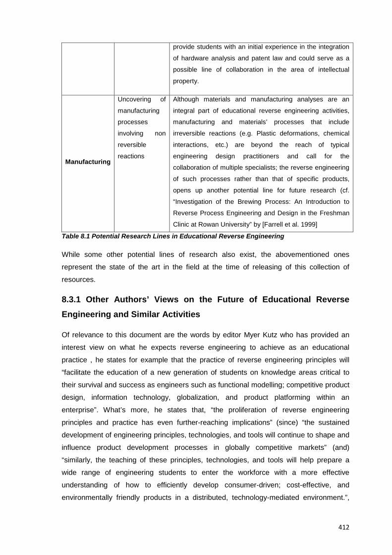
412
provide students with an initial experience in the integration
of hardware analysis and patent law and could serve as a
possible line of collaboration in the area of intellectual
property.
Manufacturing
Uncovering of
manufacturing
processes
involving non
reversible
reactions
Although materials and manufacturing analyses are an
integral part of educational reverse engineering activities,
manufacturing and materials’ processes that include
irreversible reactions (e.g. Plastic deformations, chemical
interactions, etc.) are beyond the reach of typical
engineering design practitioners and call for the
collaboration of multiple specialists; the reverse engineering
of such processes rather than that of specific products,
opens up another potential line for future research (cf.
“Investigation of the Brewing Process: An Introduction to
Reverse Process Engineering and Design in the Freshman
Clinic at Rowan University” by [Farrell et al. 1999]
Table 8.1 Potential Research Lines in Educational Reverse Engineering
While some other potential lines of research also exist, the abovementioned ones
represent the state of the art in the field at the time of releasing of this collection of
resources.
8.3.1 Other Authors’ Views on the Future of Educational Reverse Engineering and Similar Activities
Of relevance to this document are the words by editor Myer Kutz who has provided an
interest view on what he expects reverse engineering to achieve as an educational
practice , he states for example that the practice of reverse engineering principles will
“facilitate the education of a new generation of students on knowledge areas critical to
their survival and success as engineers such as functional modelling; competitive product
design, information technology, globalization, and product platforming within an
enterprise”. What’s more, he states that, “the proliferation of reverse engineering
principles and practice has even further-reaching implications” (since) “the sustained
development of engineering principles, technologies, and tools will continue to shape and
influence product development processes in globally competitive markets” (and)
“similarly, the teaching of these principles, technologies, and tools will help prepare a
wide range of engineering students to enter the workforce with a more effective
understanding of how to efficiently develop consumer-driven; cost-effective, and
environmentally friendly products in a distributed, technology-mediated environment.”,

413
[Kutz. 2007]. The information presented in this resource and in the collection of resources
overall about the documented benefits of reverse engineering activities aim indeed to
support author Kutz’s views.
8.4 Resource Conclusions
All in all, there is no better or worst approach to the teaching of engineering design;
EREA must be understood as just another tool to support its teaching and in
consequence they will only favour a limited set of the total expected, and desired
competences of an engineering design student; however, there will always be a need to
improve engineering education and thus, new approaches such as EREA will have to be
explored; tested and expanded, continuing studies about reverse engineering then, can
be reasonably expected, and considered healthy for the development of the area.
The information provided here regarding the reasonable expectations from an EREA
should help educators plan their introduction at the time and purpose that better fit their
teaching needs; reverse engineering activities indeed, can work in very different settings,
but the greater the differences in levels of technical support, training, resource materials
and facilities the greater the attention instructors need to pay in ensuring that reverse
engineering activities work at expected at their academic institutions. Conveniently, the
advice given in this collection of resources considers all realistic scenarios for their
implementation and thus the core learning effect in students and the results brought
about by them should remain valid irrespective of the amount of resources available at
the time of their implementation.
The study of the design principles materialized into existing products then, provides
students with an opportunity to expand their sources of inspiration and information; by
looking back in the history and development of consumer products, there is much to learn
from the accumulated knowledge of science and technology from earlier design
engineers. The results from this collection of resources though, are aimed and are of
relevance to academic environments only, if any inference or association were to be
made to the commercial counterparts of educational reverse engineering activities,
different considerations about individuals; groups, technologies and organizational
aspects would need to be made which were always outside the scope of this project.
Finally, it is expected that the challenges in the familiarisation, and the eventual
implementation of EREA into existing engineering design curricula are correctly
addressed in this document, in such a way that the reader can actually benefit from
previously published best practices on the area, as well as from the original results

414
presented here. Your impressions and feedback nonetheless, will be paramount in
helping revise this collection of resources until the right balance that ensures that the
learning setting; the curriculum content, the teaching method, and the evaluation
mechanisms support students in their attainment of the learning goals expected from an
EREA.
415
RESOURCE 9: MISCELLANEOUS RESOURCES FOR THE STUDY OF EDUCATIONAL REVERSE ENGINEERING
9.1 Resource Introduction
The study of EREA nowadays; benefits from the amount of relevant, yet dispersed
information available across a varied number of fields, this resource thus, aims to bring
together those relevant pieces of information that will allow the reader to understand the
background behind the theory and practice of EREA and that can support the eventual
creation of new reverse engineering-based instructional materials.
9.2 How to Look for Information about Educational Reverse Engineering
Specific information about educational reverse engineering can be tricky to get, thus it
must be searched with very clear ideas and keywords in mind; the reason for this is that
“Reverse Engineering” is a common name (cf. Table 1.1) shared among other contexts
that are somewhat unrelated to the main one in this document, and for which there is
much more information available; most of the results returned by search engines (if using
one) when introducing the terms “reverse” + “engineering” will be either from the software
engineering area or from the context of the machinery used in the extraction of
geometrical features; thus in order to get the results desired, one must provide a search
engine at least the following terms to have a high rate of relevant results, namely:
“reverse” + “engineering” + “product” + “disassembly”. With the use of the right keywords
and by looking at reputable databases such as those associated to the resources shown
in Tables 9.4; 9.6, 9.8, 9.10 and 9.12 shown below, one can retrieve useful results.
Moreover, Tables 9.4 to 9.8 themselves aim to categorize and summarize the main
sources of information currently available to the interested reader for the study of
educational reverse engineering activities.
9.3 Resources for the Understanding of EREA
9.3.1 Ideal Examples of what Educational Reverse Engineering can Become
9.3.1.1. The Study of the Antikythera Mechanism
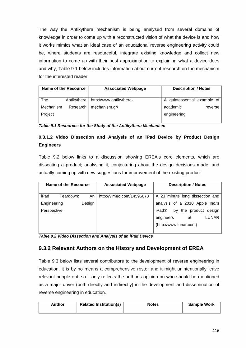
416
The way the Antikythera mechanism is being analysed from several domains of
knowledge in order to come up with a reconstructed vision of what the device is and how
it works mimics what an ideal case of an educational reverse engineering activity could
be, where students are resourceful, integrate existing knowledge and collect new
information to come up with their best approximation to explaining what a device does
and why, Table 9.1 below includes information about current research on the mechanism
for the interested reader
Name of the Resource Associated Webpage Description / Notes
The Antikythera
Mechanism Research
Project
http://www.antikythera-
mechanism.gr/
A quintessential example of
academic reverse
engineering
Table 9.1 Resources for the Study of the Antikythera Mechanism
9.3.1.2 Video Dissection and Analysis of an iPad Device by Product Design Engineers
Table 9.2 below links to a discussion showing EREA’s core elements, which are
dissecting a product; analysing it, conjecturing about the design decisions made, and
actually coming up with new suggestions for improvement of the existing product
Name of the Resource Associated Webpage Description / Notes
iPad Teardown: An
Engineering Design
Perspective
http://vimeo.com/14596673 A 23 minute long dissection and
analysis of a 2010 Apple Inc.’s
iPad® by the product design
engineers at LUNAR
(http://www.lunar.com)
Table 9.2 Video Dissection and Analysis of an iPad Device
9.3.2 Relevant Authors on the History and Development of EREA
Table 9.3 below lists several contributors to the development of reverse engineering in
education, it is by no means a comprehensive roster and it might unintentionally leave
relevant people out; so it only reflects the author’s opinion on who should be mentioned
as a major driver (both directly and indirectly) in the development and dissemination of
reverse engineering in education.
Author Related Institution(s) Notes Sample Work
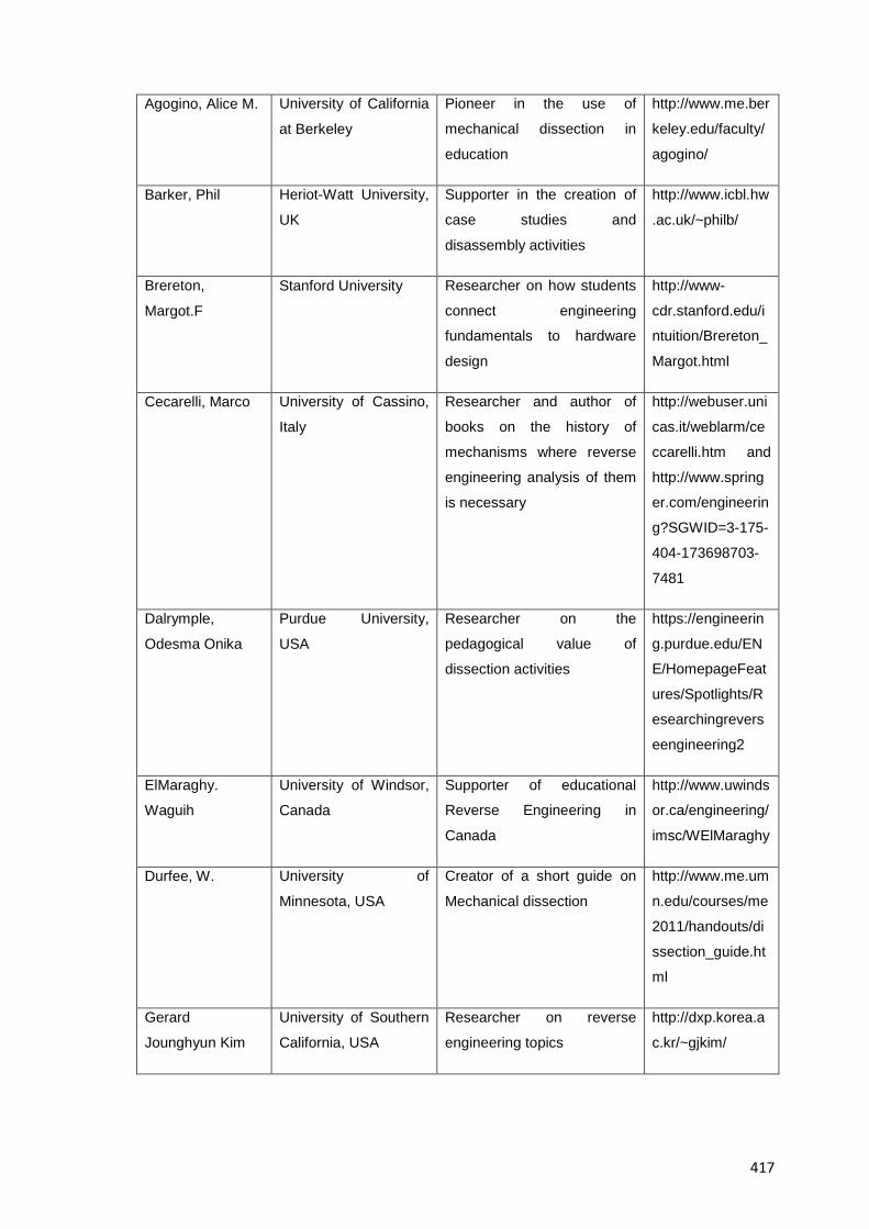
417
Agogino, Alice M. University of California
at Berkeley
Pioneer in the use of
mechanical dissection in
education
http://www.me.ber
keley.edu/faculty/
agogino/
Barker, Phil Heriot-Watt University,
UK
Supporter in the creation of
case studies and
disassembly activities
http://www.icbl.hw
.ac.uk/~philb/
Brereton,
Margot.F
Stanford University Researcher on how students
connect engineering
fundamentals to hardware
design
http://www-
cdr.stanford.edu/i
ntuition/Brereton_
Margot.html
Cecarelli, Marco University of Cassino,
Italy
Researcher and author of
books on the history of
mechanisms where reverse
engineering analysis of them
is necessary
http://webuser.uni
cas.it/weblarm/ce
ccarelli.htm and
http://www.spring
er.com/engineerin
g?SGWID=3-175-
404-173698703-
7481
Dalrymple,
Odesma Onika
Purdue University,
USA
Researcher on the
pedagogical value of
dissection activities
https://engineerin
g.purdue.edu/EN
E/HomepageFeat
ures/Spotlights/R
esearchingrevers
eengineering2
ElMaraghy.
Waguih
University of Windsor,
Canada
Supporter of educational
Reverse Engineering in
Canada
http://www.uwinds
or.ca/engineering/
imsc/WElMaraghy
Durfee, W. University of
Minnesota, USA
Creator of a short guide on
Mechanical dissection
http://www.me.um
n.edu/courses/me
2011/handouts/di
ssection_guide.ht
ml
Gerard
Jounghyun Kim
University of Southern
California, USA
Researcher on reverse
engineering topics
http://dxp.korea.a
c.kr/~gjkim/
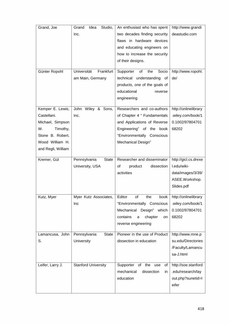
418
Grand, Joe Grand Idea Studio,
Inc.
An enthusiast who has spent
two decades finding security
flaws in hardware devices
and educating engineers on
how to increase the security
of their designs.
http://www.grandi
deastudio.com
Günter Ropohl Universität Frankfurt
am Main, Germany
Supporter of the Socio
technical understanding of
products, one of the goals of
educational reverse
engineering
http://www.ropohl.
de/
Kemper E. Lewis;
Castellani.
Michael, Simpson
W. Timothy,
Stone B. Robert,
Wood William H.
and Regli, William
John Wiley & Sons,
Inc.
Researchers and co-authors
of Chapter 4 “ Fundamentals
and Applications of Reverse
Engineering” of the book
“Environmentally Conscious
Mechanical Design”
http://onlinelibrary
.wiley.com/book/1
0.1002/97804701
68202
Kremer, Gül Pennsylvania State
University, USA
Researcher and disseminator
of product dissection
activities
http://gicl.cs.drexe
l.edu/wiki-
data/images/3/39/
ASEE.Workshop.
Slides.pdf
Kutz, Myer Myer Kutz Associates,
Inc
Editor of the book
“Environmentally Conscious
Mechanical Design” which
contains a chapter on
reverse engineering
http://onlinelibrary
.wiley.com/book/1
0.1002/97804701
68202
Lamancusa, John
S.
Pennsylvania State
University
Pioneer in the use of Product
dissection in education
http://www.mne.p
su.edu/Directories
/Faculty/Lamancu
sa-J.html
Leifer, Larry J. Stanford University Supporter of the use of
mechanical dissection in
education
http://soe.stanford
.edu/research/lay
out.php?sunetid=l
eifer
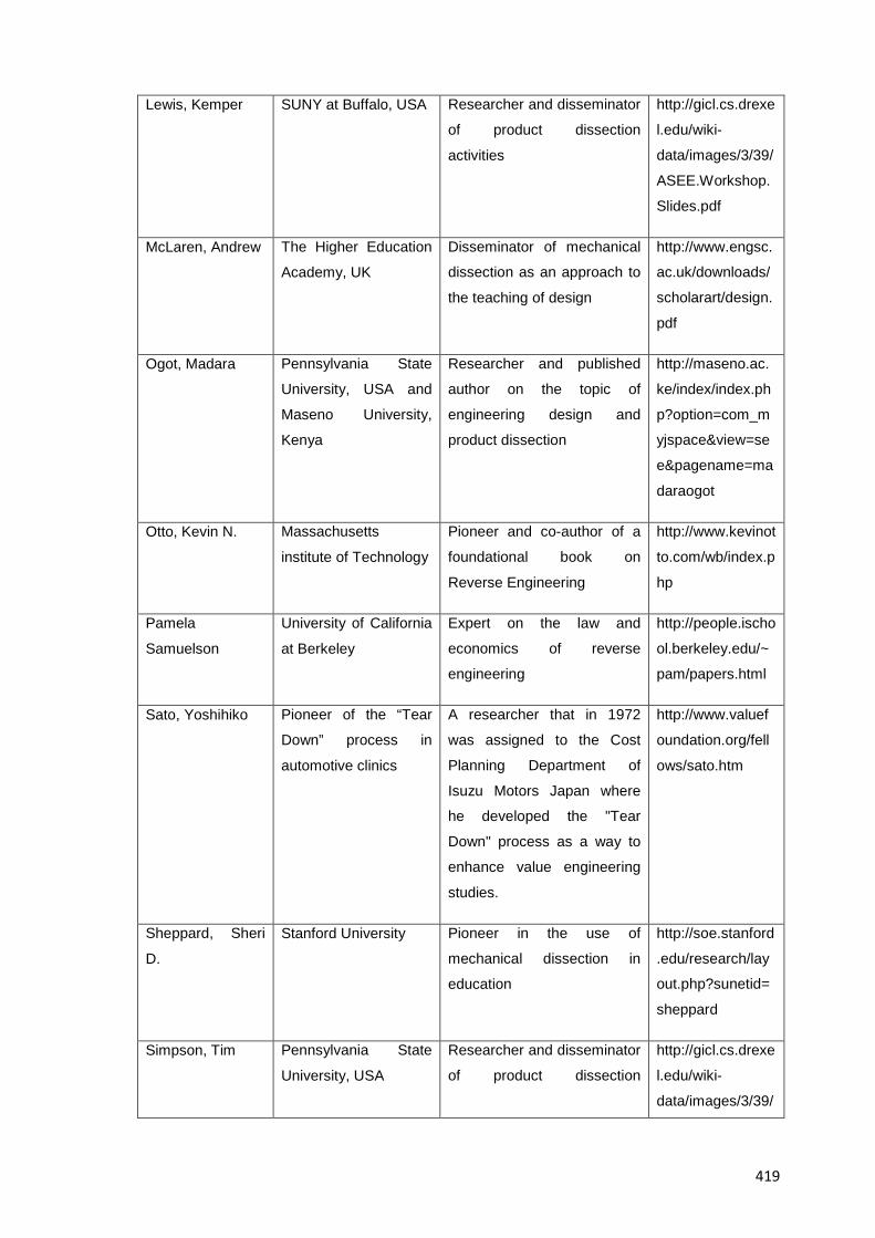
419
Lewis, Kemper SUNY at Buffalo, USA Researcher and disseminator
of product dissection
activities
http://gicl.cs.drexe
l.edu/wiki-
data/images/3/39/
ASEE.Workshop.
Slides.pdf
McLaren, Andrew The Higher Education
Academy, UK
Disseminator of mechanical
dissection as an approach to
the teaching of design
http://www.engsc.
ac.uk/downloads/
scholarart/design.
Ogot, Madara Pennsylvania State
University, USA and
Maseno University,
Kenya
Researcher and published
author on the topic of
engineering design and
product dissection
http://maseno.ac.
ke/index/index.ph
p?option=com_m
yjspace&view=se
e&pagename=ma
daraogot
Otto, Kevin N. Massachusetts
institute of Technology
Pioneer and co-author of a
foundational book on
Reverse Engineering
http://www.kevinot
to.com/wb/index.p
hp
Pamela
Samuelson
University of California
at Berkeley
Expert on the law and
economics of reverse
engineering
http://people.ischo
ol.berkeley.edu/~
pam/papers.html
Sato, Yoshihiko Pioneer of the “Tear
Down” process in
automotive clinics
A researcher that in 1972
was assigned to the Cost
Planning Department of
Isuzu Motors Japan where
he developed the "Tear
Down" process as a way to
enhance value engineering
studies.
http://www.valuef
oundation.org/fell
ows/sato.htm
Sheppard, Sheri
D.
Stanford University Pioneer in the use of
mechanical dissection in
education
http://soe.stanford
.edu/research/lay
out.php?sunetid=
sheppard
Simpson, Tim Pennsylvania State
University, USA
Researcher and disseminator
of product dissection
http://gicl.cs.drexe
l.edu/wiki-
data/images/3/39/
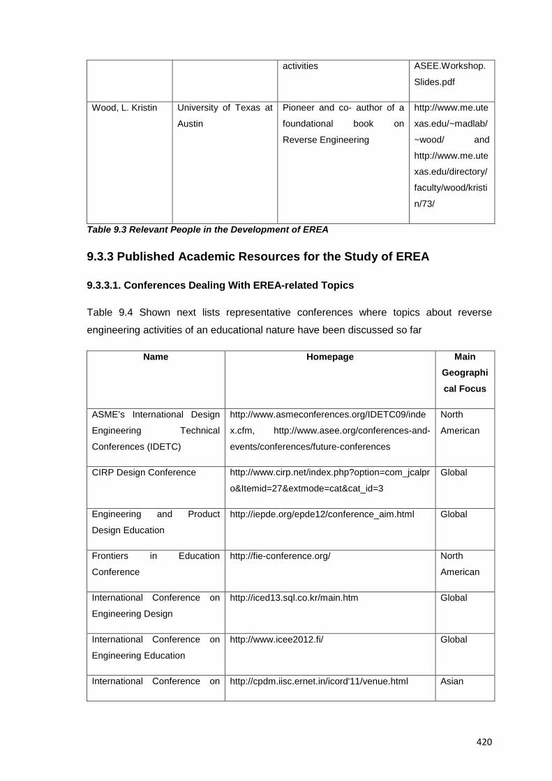
420
activities ASEE.Workshop.
Slides.pdf
Wood, L. Kristin University of Texas at
Austin
Pioneer and co- author of a
foundational book on
Reverse Engineering
http://www.me.ute
xas.edu/~madlab/
~wood/ and
http://www.me.ute
xas.edu/directory/
faculty/wood/kristi
n/73/
Table 9.3 Relevant People in the Development of EREA
9.3.3 Published Academic Resources for the Study of EREA
9.3.3.1. Conferences Dealing With EREA-related Topics
Table 9.4 Shown next lists representative conferences where topics about reverse
engineering activities of an educational nature have been discussed so far
Name Homepage Main Geographical Focus
ASME’s International Design
Engineering Technical
Conferences (IDETC)
http://www.asmeconferences.org/IDETC09/inde
x.cfm, http://www.asee.org/conferences-and-
events/conferences/future-conferences
North
American
CIRP Design Conference http://www.cirp.net/index.php?option=com_jcalpr
o&Itemid=27&extmode=cat&cat_id=3
Global
Engineering and Product
Design Education
http://iepde.org/epde12/conference_aim.html Global
Frontiers in Education
Conference
http://fie-conference.org/ North
American
International Conference on
Engineering Design
http://iced13.sql.co.kr/main.htm Global
International Conference on
Engineering Education
http://www.icee2012.fi/ Global
International Conference on http://cpdm.iisc.ernet.in/icord'11/venue.html Asian
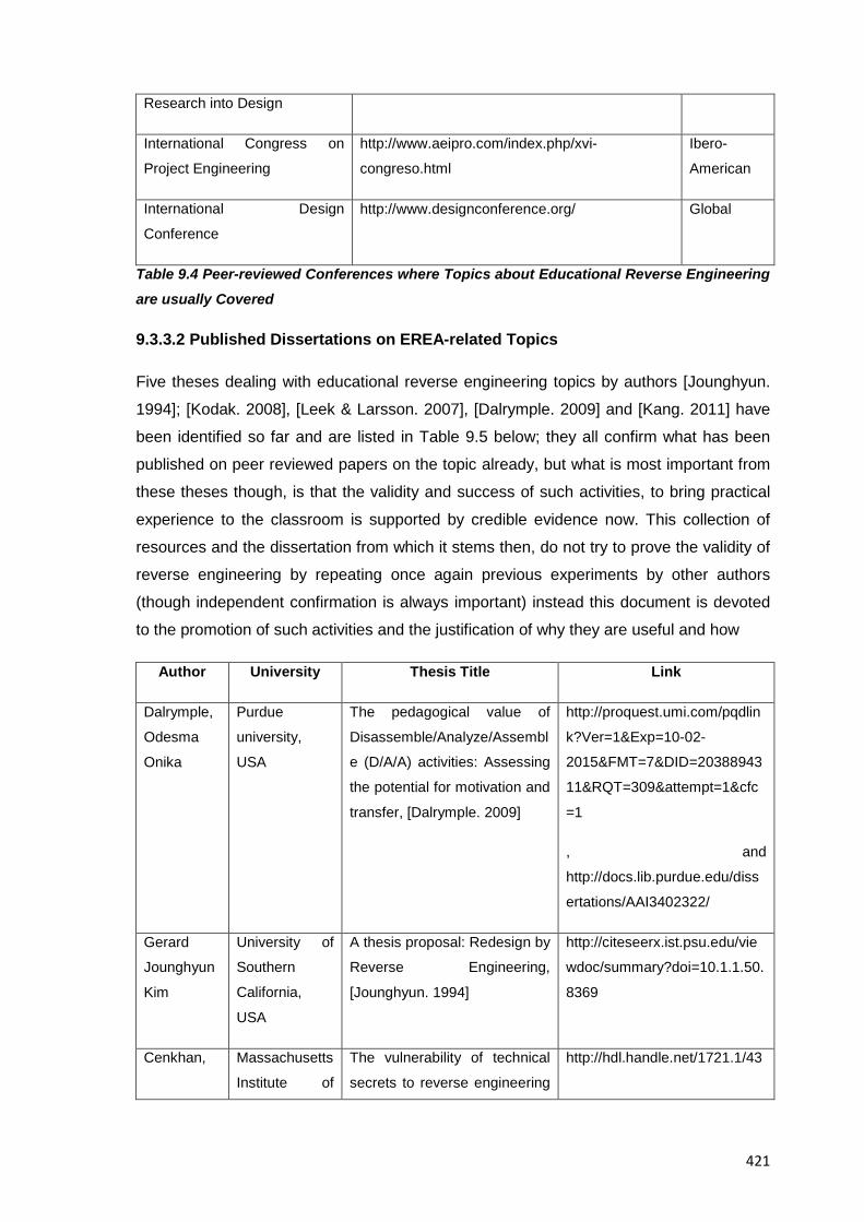
421
Research into Design
International Congress on
Project Engineering
http://www.aeipro.com/index.php/xvi-
congreso.html
Ibero-
American
International Design
Conference
http://www.designconference.org/ Global
Table 9.4 Peer-reviewed Conferences where Topics about Educational Reverse Engineering are usually Covered
9.3.3.2 Published Dissertations on EREA-related Topics
Five theses dealing with educational reverse engineering topics by authors [Jounghyun.
1994]; [Kodak. 2008], [Leek & Larsson. 2007], [Dalrymple. 2009] and [Kang. 2011] have
been identified so far and are listed in Table 9.5 below; they all confirm what has been
published on peer reviewed papers on the topic already, but what is most important from
these theses though, is that the validity and success of such activities, to bring practical
experience to the classroom is supported by credible evidence now. This collection of
resources and the dissertation from which it stems then, do not try to prove the validity of
reverse engineering by repeating once again previous experiments by other authors
(though independent confirmation is always important) instead this document is devoted
to the promotion of such activities and the justification of why they are useful and how
Author University Thesis Title Link
Dalrymple,
Odesma
Onika
Purdue
university,
USA
The pedagogical value of
Disassemble/Analyze/Assembl
e (D/A/A) activities: Assessing
the potential for motivation and
transfer, [Dalrymple. 2009]
http://proquest.umi.com/pqdlin
k?Ver=1&Exp=10-02-
2015&FMT=7&DID=20388943
11&RQT=309&attempt=1&cfc
=1
, and
http://docs.lib.purdue.edu/diss
ertations/AAI3402322/
Gerard
Jounghyun
Kim
University of
Southern
California,
USA
A thesis proposal: Redesign by
Reverse Engineering,
[Jounghyun. 1994]
http://citeseerx.ist.psu.edu/vie
wdoc/summary?doi=10.1.1.50.
8369
Cenkhan, Massachusetts
Institute of
The vulnerability of technical
secrets to reverse engineering
http://hdl.handle.net/1721.1/43
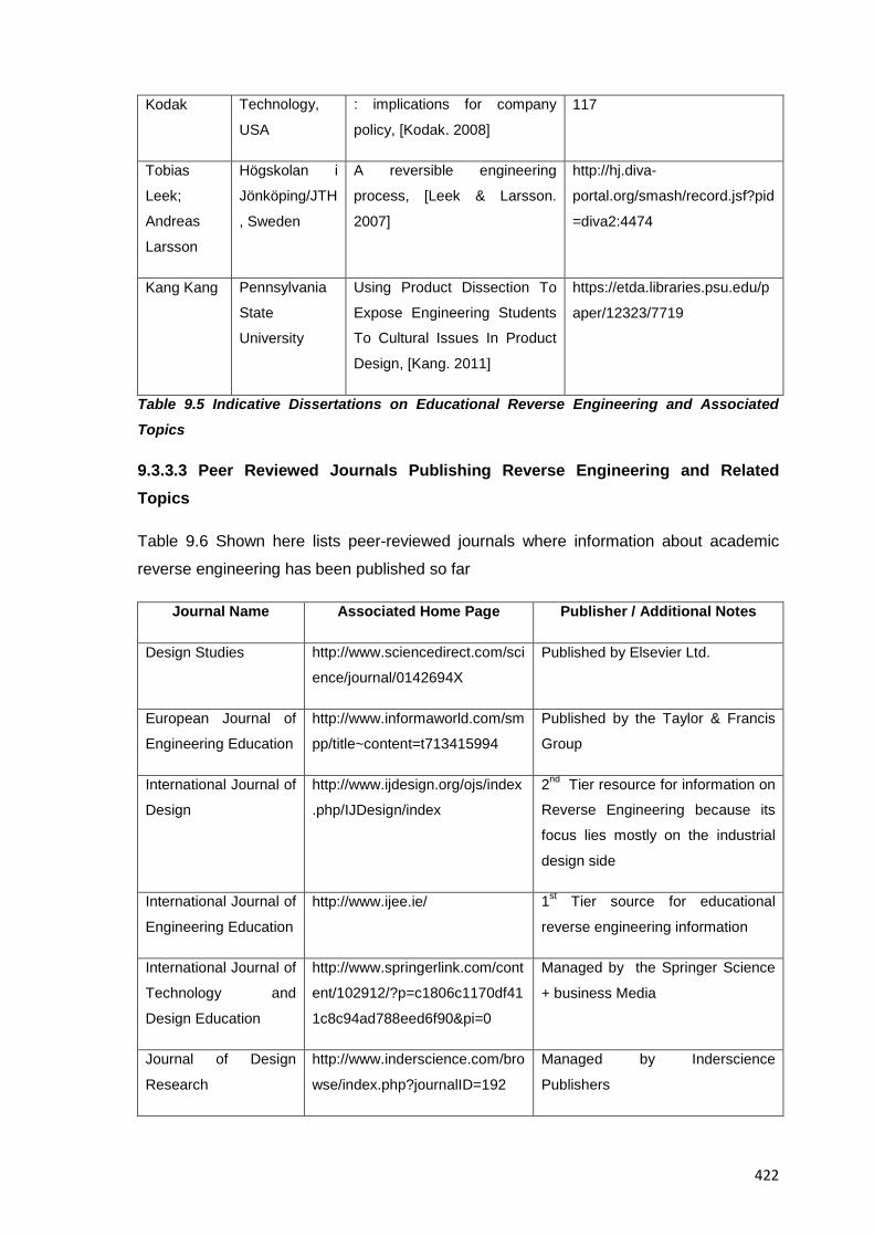
422
Kodak Technology,
USA
: implications for company
policy, [Kodak. 2008]
117
Tobias
Leek;
Andreas
Larsson
Högskolan i
Jönköping/JTH
, Sweden
A reversible engineering
process, [Leek & Larsson.
2007]
http://hj.diva-
portal.org/smash/record.jsf?pid
=diva2:4474
Kang Kang Pennsylvania
State
University
Using Product Dissection To
Expose Engineering Students
To Cultural Issues In Product
Design, [Kang. 2011]
https://etda.libraries.psu.edu/p
aper/12323/7719
Table 9.5 Indicative Dissertations on Educational Reverse Engineering and Associated
Topics
9.3.3.3 Peer Reviewed Journals Publishing Reverse Engineering and Related Topics
Table 9.6 Shown here lists peer-reviewed journals where information about academic
reverse engineering has been published so far
Journal Name Associated Home Page Publisher / Additional Notes
Design Studies http://www.sciencedirect.com/sci
ence/journal/0142694X
Published by Elsevier Ltd.
European Journal of
Engineering Education
http://www.informaworld.com/sm
pp/title~content=t713415994
Published by the Taylor & Francis
Group
International Journal of
Design
http://www.ijdesign.org/ojs/index
.php/IJDesign/index
2nd Tier resource for information on
Reverse Engineering because its
focus lies mostly on the industrial
design side
International Journal of
Engineering Education
http://www.ijee.ie/ 1st Tier source for educational
reverse engineering information
International Journal of
Technology and
Design Education
http://www.springerlink.com/cont
ent/102912/?p=c1806c1170df41
1c8c94ad788eed6f90&pi=0
Managed by the Springer Science
+ business Media
Journal of Design
Research
http://www.inderscience.com/bro
wse/index.php?journalID=192
Managed by Inderscience
Publishers
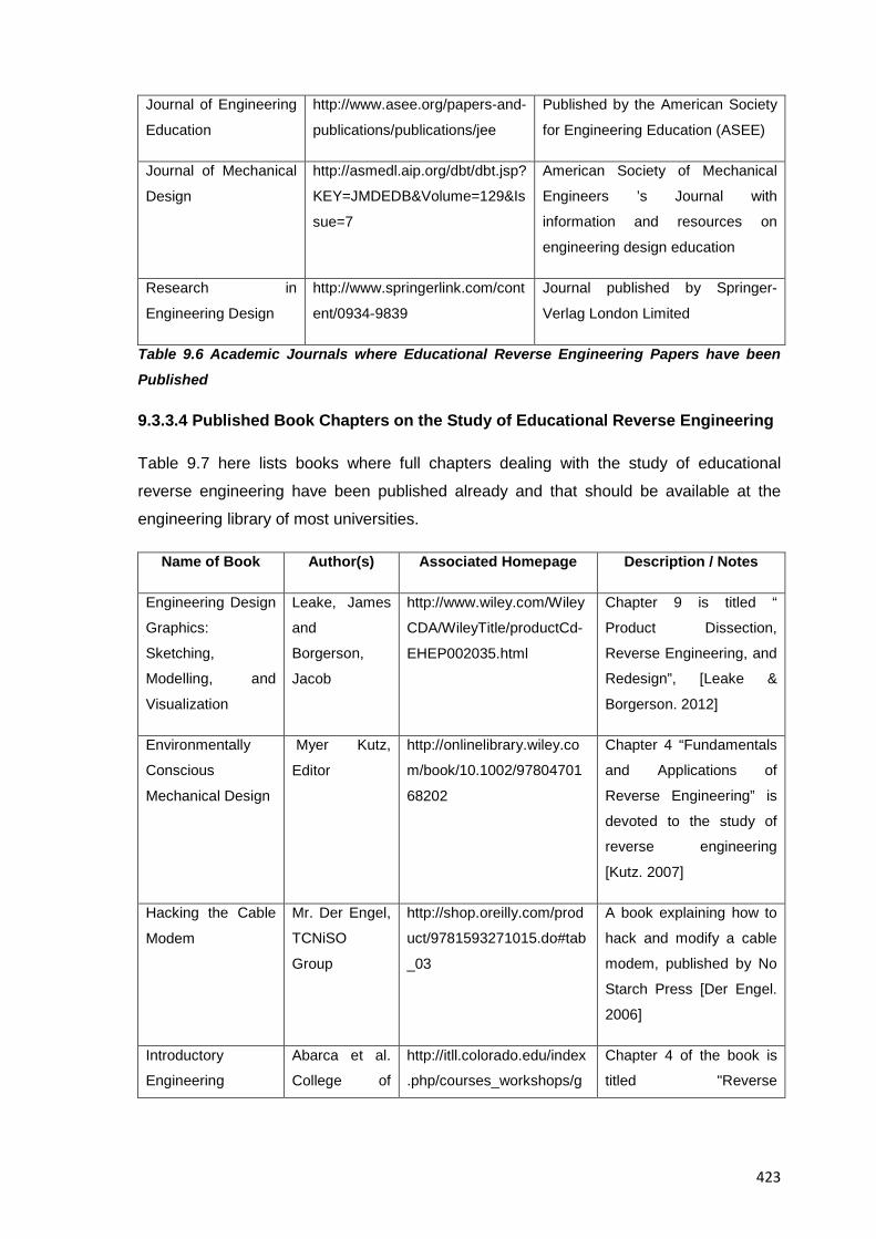
423
Journal of Engineering
Education
http://www.asee.org/papers-and-
publications/publications/jee
Published by the American Society
for Engineering Education (ASEE)
Journal of Mechanical
Design
http://asmedl.aip.org/dbt/dbt.jsp?
KEY=JMDEDB&Volume=129&Is
sue=7
American Society of Mechanical
Engineers ’s Journal with
information and resources on
engineering design education
Research in
Engineering Design
http://www.springerlink.com/cont
ent/0934-9839
Journal published by Springer-
Verlag London Limited
Table 9.6 Academic Journals where Educational Reverse Engineering Papers have been
Published
9.3.3.4 Published Book Chapters on the Study of Educational Reverse Engineering
Table 9.7 here lists books where full chapters dealing with the study of educational
reverse engineering have been published already and that should be available at the
engineering library of most universities.
Name of Book Author(s) Associated Homepage Description / Notes
Engineering Design
Graphics:
Sketching,
Modelling, and
Visualization
Leake, James
and
Borgerson,
Jacob
http://www.wiley.com/Wiley
CDA/WileyTitle/productCd-
EHEP002035.html
Chapter 9 is titled “
Product Dissection,
Reverse Engineering, and
Redesign”, [Leake &
Borgerson. 2012]
Environmentally
Conscious
Mechanical Design
Myer Kutz,
Editor
http://onlinelibrary.wiley.co
m/book/10.1002/97804701
68202
Chapter 4 “Fundamentals
and Applications of
Reverse Engineering” is
devoted to the study of
reverse engineering
[Kutz. 2007]
Hacking the Cable
Modem
Mr. Der Engel,
TCNiSO
Group
http://shop.oreilly.com/prod
uct/9781593271015.do#tab
_03
A book explaining how to
hack and modify a cable
modem, published by No
Starch Press [Der Engel.
2006]
Introductory
Engineering
Abarca et al.
College of
http://itll.colorado.edu/index
.php/courses_workshops/g
Chapter 4 of the book is
titled "Reverse
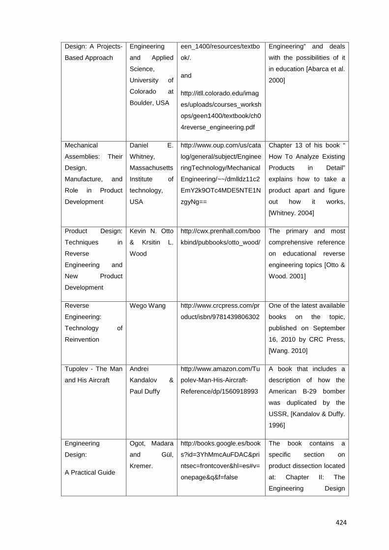
424
Design: A Projects-
Based Approach
Engineering
and Applied
Science,
University of
Colorado at
Boulder, USA
een_1400/resources/textbo
ok/.
and
http://itll.colorado.edu/imag
es/uploads/courses_worksh
ops/geen1400/textbook/ch0
4reverse_engineering.pdf
Engineering” and deals
with the possibilities of it
in education [Abarca et al.
2000]
Mechanical
Assemblies: Their
Design,
Manufacture, and
Role in Product
Development
Daniel E.
Whitney,
Massachusetts
Institute of
technology,
USA
http://www.oup.com/us/cata
log/general/subject/Enginee
ringTechnology/Mechanical
Engineering/~~/dmlldz11c2
EmY2k9OTc4MDE5NTE1N
zgyNg==
Chapter 13 of his book “
How To Analyze Existing
Products in Detail”
explains how to take a
product apart and figure
out how it works,
[Whitney. 2004]
Product Design:
Techniques in
Reverse
Engineering and
New Product
Development
Kevin N. Otto
& Krsitin L.
Wood
http://cwx.prenhall.com/boo
kbind/pubbooks/otto_wood/
The primary and most
comprehensive reference
on educational reverse
engineering topics [Otto &
Wood. 2001]
Reverse
Engineering:
Technology of
Reinvention
Wego Wang http://www.crcpress.com/pr
oduct/isbn/9781439806302
One of the latest available
books on the topic,
published on September
16, 2010 by CRC Press,
[Wang. 2010]
Tupolev - The Man
and His Aircraft
Andrei
Kandalov &
Paul Duffy
http://www.amazon.com/Tu
polev-Man-His-Aircraft-
Reference/dp/1560918993
A book that includes a
description of how the
American B-29 bomber
was duplicated by the
USSR, [Kandalov & Duffy.
1996]
Engineering
Design:
A Practical Guide
Ogot, Madara
and Gül,
Kremer.
http://books.google.es/book
s?id=3YhMmcAuFDAC&pri
ntsec=frontcover&hl=es#v=
onepage&q&f=false
The book contains a
specific section on
product dissection located
at: Chapter II: The
Engineering Design
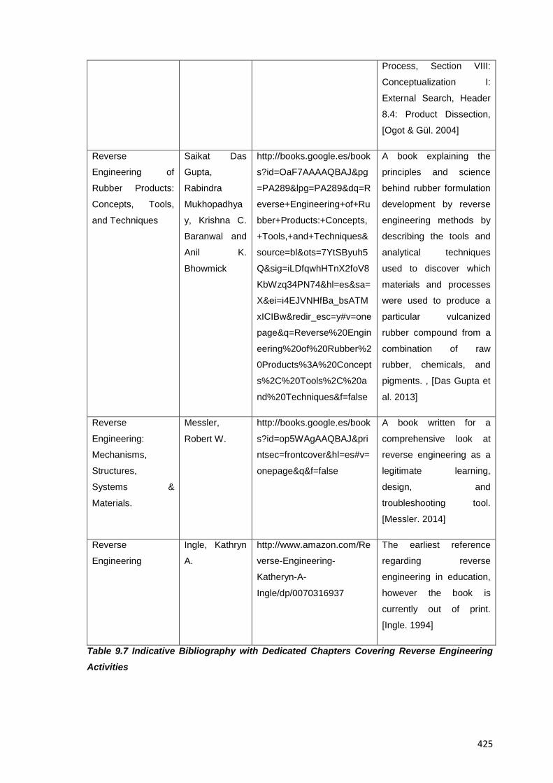
425
Process, Section VIII:
Conceptualization I:
External Search, Header
8.4: Product Dissection,
[Ogot & Gül. 2004]
Reverse
Engineering of
Rubber Products:
Concepts, Tools,
and Techniques
Saikat Das
Gupta,
Rabindra
Mukhopadhya
y, Krishna C.
Baranwal and
Anil K.
Bhowmick
http://books.google.es/book
s?id=OaF7AAAAQBAJ&pg
=PA289&lpg=PA289&dq=R
everse+Engineering+of+Ru
bber+Products:+Concepts,
+Tools,+and+Techniques&
source=bl&ots=7YtSByuh5
Q&sig=iLDfqwhHTnX2foV8
KbWzq34PN74&hl=es&sa=
X&ei=i4EJVNHfBa_bsATM
xICIBw&redir_esc=y#v=one
page&q=Reverse%20Engin
eering%20of%20Rubber%2
0Products%3A%20Concept
s%2C%20Tools%2C%20a
nd%20Techniques&f=false
A book explaining the
principles and science
behind rubber formulation
development by reverse
engineering methods by
describing the tools and
analytical techniques
used to discover which
materials and processes
were used to produce a
particular vulcanized
rubber compound from a
combination of raw
rubber, chemicals, and
pigments. , [Das Gupta et
al. 2013]
Reverse
Engineering:
Mechanisms,
Structures,
Systems &
Materials.
Messler,
Robert W.
http://books.google.es/book
s?id=op5WAgAAQBAJ&pri
ntsec=frontcover&hl=es#v=
onepage&q&f=false
A book written for a
comprehensive look at
reverse engineering as a
legitimate learning,
design, and
troubleshooting tool.
[Messler. 2014]
Reverse
Engineering
Ingle, Kathryn
A.
http://www.amazon.com/Re
verse-Engineering-
Katheryn-A-
Ingle/dp/0070316937
The earliest reference
regarding reverse
engineering in education,
however the book is
currently out of print.
[Ingle. 1994]
Table 9.7 Indicative Bibliography with Dedicated Chapters Covering Reverse Engineering Activities
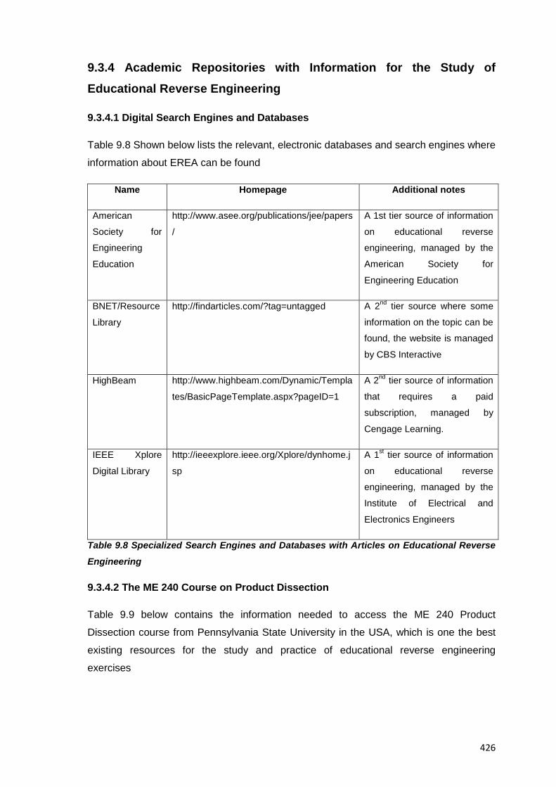
426
9.3.4 Academic Repositories with Information for the Study of Educational Reverse Engineering
9.3.4.1 Digital Search Engines and Databases
Table 9.8 Shown below lists the relevant, electronic databases and search engines where
information about EREA can be found
Name Homepage Additional notes
American
Society for
Engineering
Education
http://www.asee.org/publications/jee/papers
/
A 1st tier source of information
on educational reverse
engineering, managed by the
American Society for
Engineering Education
BNET/Resource
Library
http://findarticles.com/?tag=untagged A 2nd tier source where some
information on the topic can be
found, the website is managed
by CBS Interactive
HighBeam http://www.highbeam.com/Dynamic/Templa
tes/BasicPageTemplate.aspx?pageID=1
A 2nd tier source of information
that requires a paid
subscription, managed by
Cengage Learning.
IEEE Xplore
Digital Library
http://ieeexplore.ieee.org/Xplore/dynhome.j
sp
A 1st tier source of information
on educational reverse
engineering, managed by the
Institute of Electrical and
Electronics Engineers
Table 9.8 Specialized Search Engines and Databases with Articles on Educational Reverse
Engineering
9.3.4.2 The ME 240 Course on Product Dissection
Table 9.9 below contains the information needed to access the ME 240 Product
Dissection course from Pennsylvania State University in the USA, which is one the best
existing resources for the study and practice of educational reverse engineering
exercises
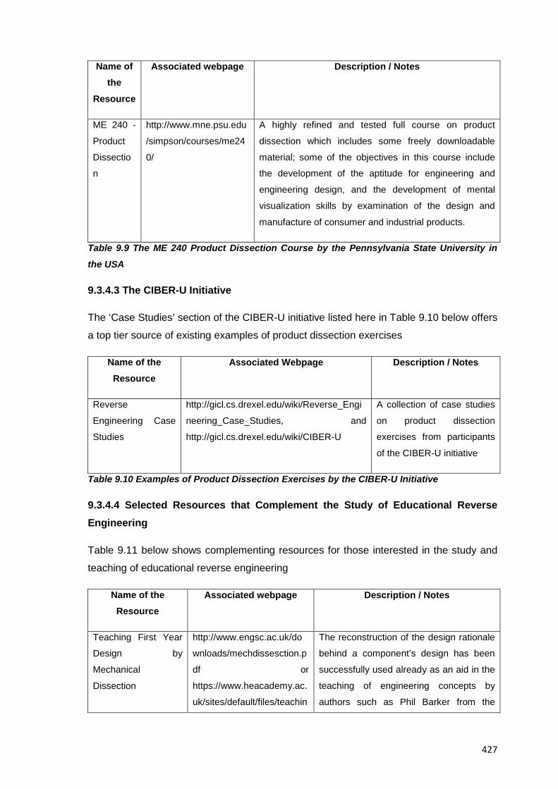
427
Name of the
Resource
Associated webpage Description / Notes
ME 240 -
Product
Dissectio
n
http://www.mne.psu.edu
/simpson/courses/me24
0/
A highly refined and tested full course on product
dissection which includes some freely downloadable
material; some of the objectives in this course include
the development of the aptitude for engineering and
engineering design, and the development of mental
visualization skills by examination of the design and
manufacture of consumer and industrial products.
Table 9.9 The ME 240 Product Dissection Course by the Pennsylvania State University in
the USA
9.3.4.3 The CIBER-U Initiative
The ‘Case Studies’ section of the CIBER-U initiative listed here in Table 9.10 below offers
a top tier source of existing examples of product dissection exercises
Name of the Resource
Associated Webpage Description / Notes
Reverse
Engineering Case
Studies
http://gicl.cs.drexel.edu/wiki/Reverse_Engi
neering_Case_Studies, and
http://gicl.cs.drexel.edu/wiki/CIBER-U
A collection of case studies
on product dissection
exercises from participants
of the CIBER-U initiative
Table 9.10 Examples of Product Dissection Exercises by the CIBER-U Initiative
9.3.4.4 Selected Resources that Complement the Study of Educational Reverse Engineering
Table 9.11 below shows complementing resources for those interested in the study and
teaching of educational reverse engineering
Name of the Resource
Associated webpage Description / Notes
Teaching First Year
Design by
Mechanical
Dissection
http://www.engsc.ac.uk/do
wnloads/mechdissesction.p
df or
https://www.heacademy.ac.
uk/sites/default/files/teachin
The reconstruction of the design rationale
behind a component’s design has been
successfully used already as an aid in the
teaching of engineering concepts by
authors such as Phil Barker from the
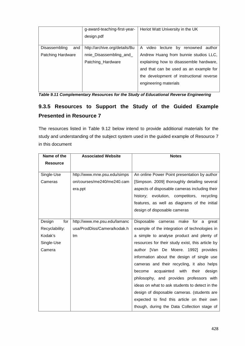
428
g-award-teaching-first-year-
design.pdf
Heriot Watt University in the UK
Disassembling and
Patching Hardware
http://archive.org/details/Bu
nnie_Disassembling_and_
Patching_Hardware
A video lecture by renowned author
Andrew Huang from bunnie studios LLC,
explaining how to disassemble hardware,
and that can be used as an example for
the development of instructional reverse
engineering materials
Table 9.11 Complementary Resources for the Study of Educational Reverse Engineering
9.3.5 Resources to Support the Study of the Guided Example Presented in Resource 7
The resources listed in Table 9.12 below intend to provide additional materials for the
study and understanding of the subject system used in the guided example of Resource 7
in this document
Name of the Resource
Associated Website Notes
Single-Use
Cameras
http://www.mne.psu.edu/simps
on/courses/me240/me240.cam
era.ppt
An online Power Point presentation by author
[Simpson. 2009] thoroughly detailing several
aspects of disposable cameras including their
history; evolution, competitors, recycling
features, as well as diagrams of the initial
design of disposable cameras
Design for
Recyclability:
Kodak's
Single-Use
Camera
http://www.me.psu.edu/lamanc
usa/ProdDiss/Camera/kodak.h
tm
Disposable cameras make for a great
example of the integration of technologies in
a simple to analyse product and plenty of
resources for their study exist, this article by
author [Van De Moere. 1992] provides
information about the design of single use
cameras and their recycling, it also helps
become acquainted with their design
philosophy, and provides professors with
ideas on what to ask students to detect in the
design of disposable cameras. (students are
expected to find this article on their own
though, during the Data Collection stage of
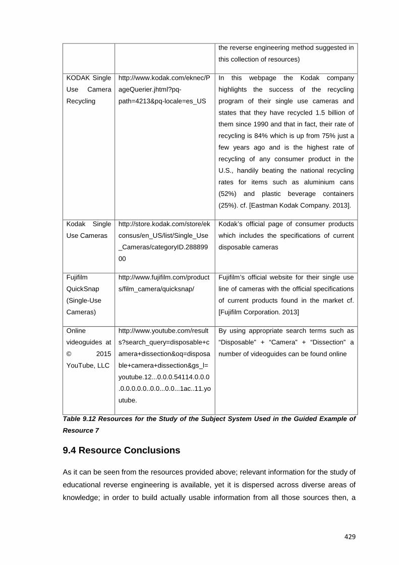
429
the reverse engineering method suggested in
this collection of resources)
KODAK Single
Use Camera
Recycling
http://www.kodak.com/eknec/P
ageQuerier.jhtml?pq-
path=4213&pq-locale=es_US
In this webpage the Kodak company
highlights the success of the recycling
program of their single use cameras and
states that they have recycled 1.5 billion of
them since 1990 and that in fact, their rate of
recycling is 84% which is up from 75% just a
few years ago and is the highest rate of
recycling of any consumer product in the
U.S., handily beating the national recycling
rates for items such as aluminium cans
(52%) and plastic beverage containers
(25%). cf. [Eastman Kodak Company. 2013].
Kodak Single
Use Cameras
http://store.kodak.com/store/ek
consus/en_US/list/Single_Use
_Cameras/categoryID.288899
00
Kodak’s official page of consumer products
which includes the specifications of current
disposable cameras
Fujifilm
QuickSnap
(Single-Use
Cameras)
http://www.fujifilm.com/product
s/film_camera/quicksnap/
Fujifilm’s official website for their single use
line of cameras with the official specifications
of current products found in the market cf.
[Fujifilm Corporation. 2013]
Online
videoguides at
© 2015
YouTube, LLC
http://www.youtube.com/result
s?search_query=disposable+c
amera+dissection&oq=disposa
ble+camera+dissection&gs_l=
youtube.12...0.0.0.54114.0.0.0
.0.0.0.0.0..0.0...0.0...1ac..11.yo
utube.
By using appropriate search terms such as
“Disposable” + “Camera” + “Dissection” a
number of videoguides can be found online
Table 9.12 Resources for the Study of the Subject System Used in the Guided Example of
Resource 7
9.4 Resource Conclusions
As it can be seen from the resources provided above; relevant information for the study of
educational reverse engineering is available, yet it is dispersed across diverse areas of
knowledge; in order to build actually usable information from all those sources then, a

430
binding effort that brings together the work from past researchers, and that sets the
bridges that allow the exchange and applicability of results from other hands-on
approaches into the reverse engineering ones must still continue.
The resources presented in this resource thus, intend to present information from varied
perspectives so a comprehensive idea of educational reverse engineering that helps
better understand the potentialities of it in education can be achieved. Along the same
lines too, it is expected that the resources here, provide the reader with the necessary
leads for the eventual creation of new instructional materials that can be better suited to
their specific teaching needs.
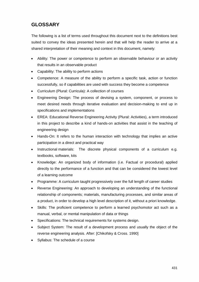
431
GLOSSARY
The following is a list of terms used throughout this document next to the definitions best
suited to convey the ideas presented herein and that will help the reader to arrive at a
shared interpretation of their meaning and context in this document, namely:
• Ability: The power or competence to perform an observable behaviour or an activity
that results in an observable product
• Capability: The ability to perform actions
• Competence: A measure of the ability to perform a specific task, action or function
successfully, so if capabilities are used with success they become a competence
• Curriculum (Plural: Curricula): A collection of courses
• Engineering Design: The process of devising a system, component, or process to
meet desired needs through iterative evaluation and decision-making to end up in
specifications and implementations
• EREA: Educational Reverse Engineering Activity (Plural: Activities), a term introduced
in this project to describe a kind of hands-on activities that assist in the teaching of
engineering design
• Hands-On: It refers to the human interaction with technology that implies an active
participation in a direct and practical way
• Instructional materials: The discrete physical components of a curriculum e.g.
textbooks, software, kits
• Knowledge: An organized body of information (i.e. Factual or procedural) applied
directly to the performance of a function and that can be considered the lowest level
of a learning outcome
• Programme: A curriculum taught progressively over the full length of career studies
• Reverse Engineering: An approach to developing an understanding of the functional
relationship of components; materials, manufacturing processes, and similar areas of
a product, in order to develop a high level description of it, without a priori knowledge.
• Skills: The proficient competence to perform a learned psychomotor act such as a
manual, verbal, or mental manipulation of data or things
• Specifications: The technical requirements for systems design.
• Subject System: The result of a development process and usually the object of the
reverse engineering analysis. After: [Chikofsky & Cross. 1990]
• Syllabus: The schedule of a course

432
This page intentionally left blank
433
ACKNOWLEDGMENTS
This collection of resources and the doctoral research from which it stems were possible
thanks to the guidance and support from my thesis supervisor Prof. Dr. Ing. Joaquim
Lloveras Macià and from the academic staff at the Technical University of Catalonia in
Barcelona.
A special acknowledgement goes to Univ.-Prof. Dr.-Ing. Christian Weber and the
academic staff of the Engineering Design Department of the Faculty of Mechanical
Engineering at the Technical University of Ilmenau in Germany for accepting me as a
visiting doctoral researcher where on-site training and support to develop the ideas
behind this collection of resources were given.
My earnest gratitude also goes to professors Lucienne Blessing; Mogens M. Andreasen
M. and Christian Weber of the 2009 edition of the European Summer School on
Engineering Design Research for the counselling given for the development of this
research.
Last but not least, my deepest gratitude goes to the reviewers of this collection of
resources and to all the participants in this project over the years for the meaningful
insight and fruitful advice for the success of this project that is now shared with the global
engineering design community.
Marco L. Calderón
Barcelona, Spain
October 2015

434
This page intentionally left blank
435
REFERENCES
All links to the resources provided below are valid at the time of issuing of this collection
of resources; should web resources go offline or change addresses because of the
temporary nature of data published online, several tools exist for the retrieval of old
versions of webpages, more information for the interested reader can be found in pages
such as “The Internet Archive” at http://archive.org/web/web.php or by selecting the
“cached” version of a webpage at the Google search engine’s webpage itself at
https://support.google.com/websearch/answer/1687222?hl=en&ref_topic=4386094:
[Abarca et al. 2000] J. Abarca, A. Bedard, D. Carlson, L. Carlson, J. Hertzberg, B. Louie,
J. Milford, R. Reitsma, T. Schwartz, J. Sullivan. Editors: J. Yowell & D. Carlson.
Introductory Engineering Design: A Projects-Based Approach, College of Engineering
and Applied Science, University of Colorado at Boulder, Third Edition, Copyright © 2000,
available at
http://itll.colorado.edu/index.php/courses_workshops/geen_1400/resources/textbook/.
[ABET. 2010] ABET, Engineering Accreditation Commission, 2009-2010, Criteria for
Accrediting Engineering Programs, available at:
http://www.abet.org/linked%20documents-update/criteria%20and%20pp/e001%2009-
10%20eac%20criteria%2012-01-08.pdf and http://www.abet.org/.
[Aglan. 1996] Aglan, H.A., Ali, S.F., “Hands-on Experiences: An Integral Part of
Engineering Curriculum Reform”, Journal of Engineering Education, pp. 327-330, Oct.,
1996.
[Agogino. 1992] Agogino, A., 1992, “Making Connections to Engineering During the First
Two Years”, Frontiers in Education toward 2000, IEEE, 563-569.
[Agogino. 1998] A. Agogino, "A hands-on discussion of "dissection": Coalitions lessons
learned", FIE, vol. 2, pp.700vol.2-xix, 28th Annual Frontiers in Education – vol. 2 (FIE'98),
1998).
[Ahmed et al. 1999] Ahmed, S., Blessing, L.T.M. and Wallace, K.M., The relationship
between data, information and knowledge based on a preliminary study of engineering
designers, in 1999 ASME Design Engineering Technical Conferences (DETC'99), Las
Vegas, Nevada, USA
[Alberg. 1999] Alberg, D. Monino Aviation. Tu-4 "Bull", 1999. Available at
http://www.moninoaviation.com/index.html.
436
[AMRP. 2012] AMRP, Antikythera Mechanism Research Project, Project Overview,
Available at http://www.antikythera-mechanism.gr/
[Anderson. 1991] Anderson, M. R., “Characterizations of the graduate career change
woman in engineering: Recruitment and retention”, Proceedings ASEE/IEEE Frontiers in
Education Conference, IEEE, New York, 248, 1991.
[Andrew. 2006] Andrew, E.S. Make and Test Projects in Engineering Design. 2006, XXVI,
278 p. 242 illus. ISBN 978-1-84628-285-0, Springer Science+Business Media, Available
at http://www.springer.com/engineering/mechanical+engineering/book/978-1-85233-915-
9.
[Ashby. 2005] Ashby, Michael F. Materials Selection in Mechanical Design, Third Edition,
ISBN 0 7506 6168 2, Copyright 1992, 1999, 2005, Michael F. Ashby, Butterworth-
Heinemann
[Athey. 2008] Athey, R. It's 2008: Do you know where your talent is? Connecting people
to what matters, Journal of Business Strategy, Vol. 29 ISS: 4, pp.4 – 14, 2008. Available
at http://www.deloitte.com/assets/Dcom-
UnitedKingdom/Local%20Assets/Documents/UK_Consulting_TalenMgtResearchReport.p
df.
[Augustine. 1983] Augustine, N. R., Augustine’s Laws: An Irreverent Guide to Traps,
Puzzles, and Quandaries of the Defense Business and other Undertakings, American
Institute Aeronautics and Astronautics, 1983, 241pp.
[Avallone et al. 2007] Avallone, E. Baumeister, T. Sadegh, A. Marks' Standard Handbook
for Mechanical Engineers. ISBN: 0071428674, Edition: 11th. Publisher: McGraw-Hill, Pp.
1800, Available at http://www.mhprofessional.com/product.php?isbn=0071428674#.
[Aziz & Chassapis. 2008] Aziz, E.-S.; Chassapis, C. "Introduction to the ME curriculum
through product engineering case studies", Frontiers in Education Conference, 2008. FIE
2008. 38th Annual, Vol., no., pp.F1F-21-F1F-26, 22-25 Oct. 2008, doi:
10.1109/FIE.2008.4720368. Available at
http://ieeexplore.ieee.org/stamp/stamp.jsp?tp=&arnumber=4720368&isnumber=4720249
[Barr et al. 2000] Barr, R., Schmidt, P., Krueger, T. And Twu, C.Y, 2000, An Introduction
to Engineering through an Integrated Reverse Engineering and Design Graphics Project,
ASEE Journal of Engineering Education, 89(4), pp. 413-418.
437
[Barr et al. 2009] Barr, R. Krueger, T. Wood, B. Aanstoos, T. Pirnia, M. “Introduction to
Mechanical Engineering Design through a Reverse Engineering Team Project”,
Proceedings of the 2009 ASEE Gulf-Southwest Annual Conference, Waco, TX, Copyright
© 2009, American Society for Engineering Education
[Beaudin & Ollis. 1995] Beaudoin, D. L. and Ollis, D. F., 1995, "A Product and Process
Engineering Laboratory for Freshmen", ASEE Journal of Engineering Education, 84(3),
pp. 279-284.
[Bedard Jr. 1999] Bedard Jr., A. J. Enhancing student creativity and respect for the
linkages between analysis and design in a first year engineering course (pp. 2893–2908).
Proceedings of the 1999 ASEE Annual Conference & Exposition, Charlotte, NC.
[Behr. 1996] Behr, Richard A., “Computer Simulations Versus Real Experiments in a
Portable Structural Mechanics Laboratory”, Computer Applications in Engineering
Education, Vol. 4 (1), pp. 9-17, 1996.)
[Benedicic et al. 2005] Benedicic, R. Zavbi, J. Duhovnik, J. A way to a radical innovation:
a case study, Proceedings of the 15th international conference on engineering design,
ICED05, Australia, August , 2005 , A. Samuel, W. Lewis, editors. full paper no.
DS35_417.386
[Bessant & Francis. 1999] Bessant, J. and Francis, D. (1999) Developing strategic
continuous improvement capability. International Journal of Operations and Production
Management, 19, 1106–1119.
[Blessing & Chakrabarti. 2009] Source: Blessing L., Chakrabarti A. DRM, A design
research methodology, 2009. © Springer-Verlag London limited. ISBN: 978-1-84882-
586-4.
[Blessing. 1994] Blessing Lucienne, A process-based approach to computer supported
engineering design, PhD thesis, University of Twente, Published Cambridge 1994.
[Bligh. 2000] Bligh, D. A. (2000). What's the use of lectures? 1st U.S. ed. of the Classic
work on lecturing. Jossey-Bass Publishers.)
[Boeing University Relations. 2010] Boeing University Relations, 2010, Desired Attributes
of an Engineer, Available at http://www.boeing.com/educationrelations/attributes.html.
438
[Bonito Boats, Inc. v. Thunder Craft Boats, Inc. 1989] Bonito Boats, Inc. v. Thunder Craft
Boats, Inc., 489 U.S. 141 (1989), Available at
http://www.law.uconn.edu/homes/swilf/ip/cases/bonito.htm
[Boothroyd & Dewhurst. 2002] Boothroyd, G. Dewhurst, P (2002) Product design for
manufacture and assembly. 2nd ed. Revised and expanded. Marcel Dekker, Inc., New
York, NY
[Boxwell. 1994] Boxwell, R. J. Benchmarking for Competitive Advantage, McGraw-Hill
Professional Publishing (March 1, 1994), ISBN-10: 0070068992, 224 pages, Available at
http://www.amazon.com/Benchmarking-Competitive-Advantage-Robert-
Boxwell/dp/0070068992.
[Bransford et al .2000] Bransford, J. D., Brown, A. L., & Cocking, R. R. (2000). How
People Learn: Brain, Mind, Experience, and School (Expanded ed.). Washington, DC:
National Academy of Sciences.
[Brereton et al. 1995] Brereton, M., Sheppard, S. & Leifer, L. (1995). Students connecting
engineering fundamentals and hardware design: Observations and implications for the
design of curriculum and assessment methods. Proceedings of the 1995 ASEE/IEEE
Frontiers in Education Conference, Atlanta, GA. available at
http://ieeexplore.ieee.org/stamp/stamp.jsp?tp=&arnumber=483238&userType=inst.
[Brereton. 1998] Brereton, M. F., 1998, "The Role of Hardware in Learning Engineering
Fundamentals: An Empirical Study of Engineering Design and Dissection Activity", Ph.D.
Dissertation, Mechanical Engineering, Stanford University, Palo Alto, CA.
[Brereton. 2001] Brereton, M. Drawing lessons in the design of tangible media from a
study of interactions with mechanical products, AUIC '01 Proceedings of the 2nd
Australasian conference on user interface, ISBN:0-7695-0969-X , Pages 124 – 131, IEEE
Computer Society Washington, DC, USA, ©2001, available at
http://dl.acm.org/citation.cfm?id=545663.
[Brereton. 2004] Brereton, M. Distributed Cognition in Engineering Design: Negotiating
between Abstract and Material Representations, Springer London, 2004. Available at
http://dx.doi.org/10.1007/978-1-85233-863-3_4.
[Burge & Brown. 1998] Burge, J.E. Brown, D.C. Design Rationale, Technical Report,
Worcester Polytechnic Institute, Computer Science Department, Fall 1998, available at:
http://web.cs.wpi.edu/Research/aidg/DR-Rpt98.html
439
[Burton & White. 1999] (Burton, J. D., & White, D. M. (1999). Selecting a model for
freshman engineering design. Journal of Engineering Education, 88(3), 327-332.
[Buura & Myrup. 1989] Buura, J. Myrup, M.A. Design models in mechatronic product
development, Design Studies, Volume 10, Issue 3, July 1989, Pages 155-162
[Calderon. 2008] Calderon M. Product Visualization Praxis and its Integration to
Academic Curricula. 10th Engineering and Product Design Education International
Conference, E&PDE'08, Vol. 1, September 2008, pp. 417-422. Artyplan Global Printers
Ltd, Barcelona. ISBN: 1-904670-04-0. Barcelona, Spain
[Calderon. 2009] Calderon M. Analysis of Existing Products as a Tool for Engineering
Design Education. 11th Engineering and Product Design Education International
Conference, E&PDE'09, Creating a Better World, September 2009, pp.65. Institution of
Engineering Designers, The Design Society. ISBN: 978-1-904670-17-9. Brighton, United
Kingdom
[Calderon. 2010a] Calderon M. Application of Reverse Engineering Activities in the
Teaching of Engineering Design, International Design Conference - Design 2010, Design
2010 Proceedings Volume 2. Pp. 1249-1258, Marjanovic et al. Editors. (Faculty of
Mechanical Engineering and Naval Architecture, University of Zagreb, The Design
Society, Glasgow), ISBN: 978-953-7738-05-1, Dubrovnik, Croatia
[Calderon. 2010b] Calderon M. A Comparison Of Competences Required In Reverse
Engineering Exercises Versus Conventional Engineering Exercises And Its Relationship
To IPMA’s Competence Baseline, Abstracts book of the XIV International Congress on
Project Engineering, Fundación General de la Universidad Politécnica de Madrid Editors,
Ibersaf Industrial Press, Pp.230 ISBN:978-84-614-2608-9 Madrid, Spain.
[Calderon. 2010c] Calderon M. The Design Research Methodology As A Framework For
The Development Of A Tool For Engineering Design Education, Proceedings of the 12th
Engineering and Product Design Education International Conference, E&PDE’10.
Norwegian University of Science and Technology, Copyright © 2010 Institution of
Engineering Designers, The Design Society, Boks et al. Editors. ISBN: 978-1-904670-19-
3, Trondheim, Norway
[Calkins et al. 1996] Calkins, D.et al. 1996, TIDEE: The First Year of a Design
Engineering Educational Partnership for Washington State, FIE '96 Proceedings, IEEE 0-
7803-3348-9
440
[Campbell. 2003] Campbell, M.J. Teaching Machine Design through Product Emulation,
Proceedings of the 2003 American Society for Engineering Education Annual Conference
and Exhibition, Session 2366, June, 2003. Available at
http://www.me.utexas.edu/proceed/docs/2003.06.Campbell.Emulation.pdf
[Carlson et al. 1997] Carlson, B., Schoch, P., Kalsher, M. and Racicot, B., 1997, "A
Motivational First-Year Electronics Lab Course", ASEE Journal of Engineering Education,
86(4), pp. 357-362.
[Carlson. 1995] Carlson, L. E., “First Year Engineering Projects: An Interdisciplinary,
Hands-on Introduction to Engineering”, Proceeding of the ASEE Annual Conference, pp.
2039-2043, 1995.
[Castellani. 2006] Castellani, M. Kodak Waterproof One-Time-Use Camera, 2006.
Available at http://gicl.cs.drexel.edu/wiki/Kodak_Waterproof_One-Time-Use_Camera.
[Catalano. 1996] Catalano, G. D., Tonso, K. L., “The Sunrayce ’95 Idea: Adding Hands-
on Design to an Engineering Curriculum”, Journal of Engineering Education, pp. 193-199,
Jul., 1996.
[Caupin et al. 2006] Gilles Caupin et al. ICB–IPMA Competence Baseline, Version 3.0.
International Project Management Association (IPMA) 2006, Available at
http://www.ipma.ch/documents/icb_v._3.0.pdf
[CDIO Council. 2010] CDIO Council, 2010, CDIO Syllabus. Worldwide CDIO Initiative,
Available at http://www.cdio.org/framework-benefits/cdio-syllabus
[Chan & Leung. 1996] Chan, L.W. Leung, T.P. Spiral design model for consumer
mechatronic products, Mechatronics, Volume 6, Issue 1, February 1996, Pages 35-51,
ISSN 0957-4158, 10.1016/0957-4158(95)00041-0. Available at
http://www.sciencedirect.com/science/article/pii/0957415895000410
[Chestnut. 1967] Chestnut, H. Systems Engineering Methods. Wiley, John Sons
(September 1967), ISBN-10: 0471154482, 404 pages, Available at
http://www.amazon.com/Systems-Engineering-Methods-Harold-
Chestnut/dp/0471154482/ref=sr_1_1?s=books&ie=UTF8&qid=1365054982&sr=1-
1&keywords=harold+chestnut
[Chikofsky & Cross. 1990] Chikofsky, E.J. Cross, J.H. Reverse engineering and design
recovery: A taxonomy. IEEE Software, 7(1):13-17, 1990. Available at http://www.weidl-
rektenwald.at/swe/chikofsky90.pdf
441
[Chiodo. 2005] Chiodo, J. Design for Disassembly Guidelines, Active Disassembly
Research, January 2005, available at
http://www.activedisassembly.com/guidelines/ADR_050202_DFD-guidelines.pdf
[CIBER-U. 2012] Cyber-Infrastructure-Based Engineering Repositories for
Undergraduates. Single-Use Cameras. Teaching Materials Header, Supporting Wiki
Pages Subsection. 2012. Available at http://gicl.cs.drexel.edu/wiki/Single-Use_Cameras
and further linked to http://gicl.cs.drexel.edu/wiki/Group_32_-_Kodak_Funsaver_Camera,
http://gicl.cs.drexel.edu/wiki/Group_7_-_Kodak_Disposable_Camera,
http://gicl.cs.drexel.edu/wiki/Group_10_-_Kodak_Flash_Camera
[CIESE. 2008] Center for Innovation in Engineering and Science Education (CIESE).
Core Concepts of Systems Engineering, A CIESE Collaborative Project, Copyright ©
2008 Stevens Institute of Technology, available at
http://www.ciese.org/curriculum/seproject/index.html
[Comparini & Cagan. 1998] Comparini, E. Cagan, J. Reverse Engineering for Green
Design of Products. Copyright © 1998, Green Design Institute, Carnegie Mellon.
Available at http://gdi.ce.cmu.edu/gd/education/coffee-maker.pdf
[Conti. 2006] Conti, G. Guest editor. Hacking and Innovation. Communications of the
ACM - Hacking and Innovation, Volume 49 Issue 6, June 2006, Pages 32 – 36, ACM
New York, NY, USA, ISSN: 0001-0782, doi: 10.1145/1132469.1132497, available at
http://dl.acm.org/citation.cfm?id=1132497&bnc=1
[Cooper. 1996] Cooper, S. C., Miller, G. R., “A Suite of Computer-Based Tools for
Teaching Mechanics of Material,”, Computer Applications in Engineering Education, pp.
41-49, 1996.
[Copyright, Designs and Patents Act. 1988] Copyright, Designs and Patents Act 1988. UK
Public General Acts. Available at http://www.legislation.gov.uk/ukpga/1988/48/
[Cross. 2008] Cross, N. Engineering Design Methods: Strategies for Product Design
(fourth edition), John Wiley and Sons Ltd., Chichester, 2008. ISBN: 978 0 470 51926 4,
available at http://eu.wiley.com/WileyCDA/WileyTitle/productCd-0470519266.html
[D’Agostino. 2008] D’Agostino, G: "Healing fair dealing? A comparative copyright analysis
of Canada’s fair dealing to U.K. fair dealing and U.S. fair use", McGill Law Journal,
53:311-363, available at http://lawjournal.mcgill.ca/documents/dAgostino.pdf
442
[Dahlgren. 1990] Dahlgren, L. (1990). Undervisningen och det meningsfulla lärandet.
Linköping University.
[Dalrymple et al. 2011] Dalrymple, O., Sears, D., Evangelou, D. The Motivational and
Transfer Potential of Disassemble/Analyze/Assemble (DAA) Activities, Journal of
Engineering Education, October 2011, Vol. 100, No. 4, pp. 741–759. Available at
http://www.jee.org/2011/October/06.pdf
[Dalrymple. 2009] Dalrymple, O. O. Ph.D. Dissertation. The pedagogical value of
disassemble/analyze/assemble (DAA) activities: assessing the potential for motivation
and transfer, Purdue University, 2009, 140 pages; AAT 3402322, ISBN: 9781109744002,
available at: http://proquest.umi.com/pqdlink?did=2038894311&fmt=7&clienti
d=40968&rqt=309&vname=pqd
[Das Gupta et al. 2013] Das Gupta, S. Mukhopadhyay, R. Baranwal, K.C. Bhowmick, A.K.
Reverse Engineering of Rubber Products: Concepts, Tools, and Techniques. CRC Press.
Taylor & Francis Group. ISBN: 0849373166, 2013, 357Pp.
[Der Engel. 2006] Engel, Der. Hacking the Cable Modem, No Starch Press, September
2006, Pages; 312, Print ISBN: 978-1-59327-101-5, ISBN 10:1-59327-101-8, available at
http://shop.oreilly.com/product/9781593271015.do#tab_03
[Devendorf et al. 2007] Devendorf, M., Lewis, K., Simpson, T. W., Stone, R. B., & Regli,
W. C. (2007). Evaluating the use of cyberinfrastructure in the classroom to enhance
product dissection. Proceedings of the 2007 ASME Design Engineering Technical
Conferences. Las Vegas, NV.
[Devendorf et al. 2011] (Devendorf, E. Cormier, P. Moore-Russo, D. Lewis, K. Using
Product Archaeology to Integrate Global, Economic, Environmental, and Societal Factors
in Introductory Design Education. Proceedings of the ASME 2011. International Design
Engineering Technical Conferences & Computers and Information in Engineering
Conference. Available at
http://does.eng.buffalo.edu/administrator/components/com_jresearch/files/publications/D
ETC2011-48438.pdf
[Durfee. 2008] Durfee, W. Guide to Mechanical Dissection, University of Minnesota, USA,
2008, available at
http://www.me.umn.edu/courses/me2011/handouts/dissection_guide.html
443
[Dym et al. 2005] Dym, C.L. Agogino, A.M. Ozgur E. Frey,D.D. Leifer,L.J. Engineering
Design Thinking, Teaching, and Learning. Journal of Engineering Education, vol. 94, No.
1, p103-120, 2005, available at
http://digitalcommons.olin.edu/cgi/viewcontent.cgi?article=1021&context=mech_eng_pub
[Eastman Kodak Company. 2013] Eastman Kodak Company. KODAK Single Use
Camera Recycling. Available at http://www.kodak.com/eknec/PageQuerier.jhtml?pq-
path=4213&pq-locale=es_US
[EBSCO Industries, 2013] EBSCO Industries, Inc. Applied Science & Technology Index,
2013. Available at http://www.ebscohost.com/academic/applied-science-technology-index
[Edwards et al. 2010] Edwards, A. Culver, B. Kahle, B. MacDonald, K. Project 1:
Disposable Camera Redesign – FunSaver+, Engineering Design 100, Section 016, Team
2, Submitted to: Professor Jeonghwan Jin, Pennsylvania State University, 2010.
Available at http://www.personal.psu.edu/users/a/n/ane5064/cameraprojectfinalreport.pdf
[EFF. 2007] Lohmann, F. Supreme Court Victory for Patent First Sale Doctrine, Electronic
Frontier Foundation, 2007, available at https://www.eff.org/deeplinks/2007/11/you-
bought-it-you-own-it-part-iv-quanta-v-lg-electronics
[Eggert. 1996] Eggert, A. Mechanical Dissection Bridging the Gap Between the
Theoretical and Physical World, Session 9b6: Merging the Theoretical and Practical
Applications in Engineering Courses, FIE ‘96 Proceedings, 1996.
[Eide et al. 2002] Eide, A. Jenison, R. Mashaw, L. Northup, L. Engineering:
Fundamentals and Problem Solving. New York City: McGraw-Hill Companies Inc., 2002
[Elsevier Inc. 2013] Elsevier Inc. Compendex, Copyright © 2013 Elsevier Inc. All Rights
Reserved. Available at http://www.ei.org/compendex
[Farrell et al. 1999] Farrell, S. Hesketh, R.P. Slater, C.S. "Investigation of the brewing
process: an introduction to reverse process engineering and design in the Freshman
Clinic at Rowan University", FIE, vol. 2, pp.12B4/14-12B4/18, vol.2, Frontiers in
Education Conference, 1999. FIE '99. 29th Annual, 1999, available at
http://www.computer.org/csdl/proceedings/fie/1999/5643/02/00841586-abs.html
[Felder & Silverman. 1988] Felder, R.M. Silverman, L. K. "Learning and Teaching Styles
in Engineering Education", Engr. Education, 78(7), 674-681 (1988). Available at
http://www4.ncsu.edu/unity/lockers/users/f/felder/public/Papers/LS-1988.pdf
444
[Fogelin. 2007] Fogelin, L. Inference to the Best Explanation: A Common and Effective
Form of Archaeological Reasoning. American Antiquity, Vol. 72, No. 4 (Oct., 2007), pp.
603-625 Published by: Society for American Archaeology, available at:
http://www.jstor.org/stable/25470436
[Freeman. 1987] Freeman, C. Technology Policy and Economic Performance; Lessons
from Japan. London: Printer Publishers, Freeman’s. 1987.
[Freestyle. 2013] Freestyle Photographic Supplies. Arista Changing Bag 27 in. x 30 in. ©
1990 - 2013 Copyright - All Rights Reserved, Available at
http://www.freestylephoto.biz/322730-Arista-Changing-Bag-27-in.-x-30-in
[Fujifilm Corporation. 2013] Fujifilm Holdings Corporation. QuickSnap (Single-Use
Cameras). Available at http://www.fujifilm.com/products/film_camera/quicksnap/
[Garcia & Howard. 1992] Bicharra Garcia, A.C. and Howard. H. C. Acquiring design
knowledge through design decision justification. Artificial Intelligence for Engineering,
Design and Manufacturing (AI EDAM), Cambridge. Vol. 6, n. 1, p. 59-71, 1992. ISSN:
0890.0604, doi:10.1017/S0890060400002948.
[Gick and Holyoak. 1983] Gick, M. L., & Holyoak, K. J. (1983). Schema induction and
analogical transfer. Cognitive Psychology, 15(1), 1-38. Available at
http://deepblue.lib.umich.edu/bitstream/handle/2027.42/25331/0000776.pdf?sequence=1
[Goff & Gregg. 1998] Goff, R. M. Gregg, M. H. Implementing a “Hands-On” Laboratory
For First Year Engineering Students. “Practical Engineering Laboratory Mechanical
Dissection and Design” a Power Point Presentation from Virginia Tech and the
Southeastern University and College Coalition for Engineering Education (SUCEED),
1998. File name: CEUT SUCCEED 1098.pptx.
[Graedel & Allenby. 2003] Graedel, T. E. Allenby, B. R. Industrial Ecology, 2nd Edition.
ISBN-10: 0130467138. © 2003. Prentice Hall, Paper, 363 pp.
[Grimheden.2006] Grimheden, M. Mechatronics Engineering Education. Doctoral Thesis
in Machine Design, School of Industrial Engineering and Management, Royal Institute of
Technology, Stockholm, Sweden. TRITA-MMK 2006:01, ISSN 1400-1179, ISBN 91-
7178-213-3. (2006). Available at
http://www.md.kth.se/~marting/papers/mech_eng_edu_phd_thesis.pdf
445
[Grosso et al. 1999] Grosso W.E, Fergerson R.W, Musen M.A (1999) Knowledge models
and axiom languages: The formal underpinnings of Protege. Stanford Medical
Informatics, Technical Report
[Gruber & Rusell. 1992] Gruber, T. R. Russell, D. M. Derivation and Use of Design
Rationale Information as Expressed by Designers (Technical Report KSL-92-64). And
“Generative Design Rationale: Beyond the Record and Replay Paradigm”, Report No.
KSL 92-59, Knowledge Systems Laboratory, Stanford University. (1992). Available at
http://ksl-web.stanford.edu/KSL_Abstracts/KSL-92-64.html
[Hales. 2005] Hales, C. (Samuel, A. Lewis, W Editors). Proceedings of the 15th
international conference on engineering design, ICED 05. Australia, August, 2005, full
paper no. ds35_a15.
[Hannaford. 1995] Hannaford, B. Master Course Syllabus for EE 498 (ABET sheet),
College of Engineering, University of Washington, available at:
http://www.ee.washington.edu/academic/undergrad/abet/courses/ee498.htm
[Hansen. 1966] Hansen, F.: Konstruktionssystematik. Berlin: VEB Verlag Technik 1966.
[Hardesty. 2001] Von Hardesty. Made in the U.S.S.R. Of course they copied it. The two
airplanes could have been twins. But was the Soviets' Tu-4 truly an exact duplicate of the
Boeing B-29? Air & Space magazine, Smithsonian Media, 2001 available at
http://www.airspacemag.com/military-aviation/USSR.html
[Harman. 1965] Harman, G.H. The Inference to the Best Explanation. The Philosophical
Review, Vol. 74, No. 1. (Jan. 1965), pp. 88-95. Available at:
http://links.jstor.org/sici?sici=0031-
8108%28196501%2974%3A1%3C88%3ATITTBE%3E2.0.CO%3B2-A
[Hatano & Inagaki. 1986] Hatano, G., & Inagaki, K. (1986). Two courses of expertise (pp.
262–272). Proceedings of the Conference on Child Development and Education, Japan.
[Herbig & Jacobs. 1997] Herbig P. Jacobs L. A historical perspective of Japanese
innovation. Management Decision, 35/10 [1997] 760–778. © MCB University Press, ISSN
0025-1747
[Hess. 2000] Hess, H. L. (2000). Teaching manufacturing using the golden key—reverse
engineering. Proceedings of the 2000 ASEE Annual Conference & Exposition:
Engineering Education Beyond the Millennium. St. Louis, MO.
446
[Hess. 2002] Hess, H. L. (2002). Solid modeling and reverse engineering: the stimulus for
teaching manufacturing. Proceedings of the 2002 ASEE Annual Conference &
Exposition: Vive L'ingenieur! Montréal, Quebec, Canada.
[Hibbard. 1995] Hibbard, W. Hibbard, R. “Generating Excitement about Mechanical
Engineering by Using Hands-on Projects”, 1995 ASEE Annual Conference Proceedings,
2:2471-2476.
[Higashi & Lauter. 1990] Higashi, C. Lauter, G.P. The internationalization of the Japanese
economy, Springer, 1990, ISBN: 0792390520, 430 pp.
[Hirtz et al. 2002] Hirtz, J. Stone, R. McAdams, D. Szykman, S. Wood, K. “A Functional
Basis for Engineering Design: Reconciling and Evolving Previous Efforts”, Research in
Engineering Design, 13(2), 65–82 (2002)
[Hoadley. 1990] Hoadley, R.B. Identifying Wood: Accurate Results with Simple Tools.
ISBN: 0-942391-04-7. The Taunton Press. 1990. Available at
http://books.google.es/books/about/Identifying_Wood.html?id=kIGxQwAACAAJ&redir_es
c=y
[Hobday et al. 2004] Hobday, M. Rush, H. Bessant, J. (2004) Approaching the innovation
frontier in Korea: The transition phase to leadership. Research Policy, 33, 10, 1433–
1457.
[Hoffman. 2006] Hoffman, C. The Teardown Artists. Wired.com © 2006 Condé Nast
Digital. 136 (5) All rights reserved, photo credits to Brian Ulrich, available at
http://www.wired.com/wired/archive/14.02/teardown.html
[Huang. 2003] Huang, A. Hacking the Xbox: An Introduction to Reverse Engineering. July
2003, 288 pp. ISBN: 978-1-59327-029-2. No Starch Press.
[Hyman. 2003] Hyman, B. Public Policy and Engineering Design Education, Int. J. Engng
Ed. Vol. 19, No. 1, pp. 110±117, 2003.
[IMC. 2011] Invention Machine Corporation, Solutions - Improve Existing Products or
Systems. Available at http://inventionmachine.com/solutions/by-task/improve-a-system/,
© 2011.
[Ingle. 1994] Ingle, K. A. Reverse Engineering. ISBN: 0070316937. McGraw-Hill
Professional Publishing, 1994. Pp. 240.
447
[James. 2009] James, D. Reverse Engineering 101, The How and Why of Reverse
Engineering for Technical Teams. Chipworks Whitepaper, available at
http://www.chipworks.com/assets/0/28/124/D041D5BF-31CF-4983-96D3-
81C35A1890F1.pdf
[Jensen & Bowe. 1999] Jensen, D.D. Bowe, M. “Hands-On Experiences to Enhance
Learning of Design: Effectiveness in a Reverse Engineering / Redesign Context When
Correlated with MBTI and VARK Types”, Proceedings of the ASEE Annual Conference
and Exposition, Charlotte, NC, June, 1999. Available at
http://www.me.utexas.edu/~alps/publications/documents/ASEE1999HandsOnexperience
s.pdf
[Jensen et al. 2003] Jensen, D. Wood, K. Wood, J. “Enhancing Mechanical Engineering
Curriculum Through the Use of Hands-on Activities, Interactive Multimedia and Tools to
Improve Team Dynamics”, International Journal of Engineering Education,” Vol. 19, No.
6, 2003. Available at
http://www.me.utexas.edu/~alps/publications/documents/IJEE2003HandsonActivites.pdf
[Jeswiet et al. 2007] Jeswiet, J. Duflou, J. Dewulf, W. Luttrop, C. Hauschild, M. Course
Content for Life Cycle Engineering and EcoDesign, Int. J. Engng Ed. Vol. 23, No. 6, pp.
1081±1089, 2007, TEMPUS Publications)
[Jirousek. 1995] Jirousek, C. Creativity and the Design Process, Copyright © 1995 by
Charlotte Jirousek. Available at http://char.txa.cornell.edu/language/creative.htm
[Jorgensen et al. 1996] Jorgensen, J.E. Fridley, J. Lamancusa, J.s. "Product Dissection -
A Tool for Benchmarking in the Process of Teaching Design", Proceedings of 1996
Frontiers in Education Conference, Salt Lake city, UT, November, 1996, available at
http://www.me.psu.edu/lamancusa/papers/fie96bm1.pdf
[Josephson. 1959] Josephson, M. “Edison a Biography”. McGraw Hill Book Company –
Copyright 1959, 1st ed. 511 Pages.
[Jounghyun. 1994] Jounghyun, G. K. A thesis proposal: Redesign by Reverse
Engineering. University of Southern California, USA, 1994 available at
http://citeseerx.ist.psu.edu/viewdoc/summary?doi=10.1.1.50.8369
[Kandalov & Duffy. 1996] Kandalov, A. Duffy, P. Tupolev - The Man and His Aircraft,
Hardcover: 236 pages, Society of Automotive Engineers Inc, December 1996, ISBN-10:
448
1560918993, ISBN-13: 978-1560918998, available at http://www.amazon.com/Tupolev-
Man-His-Aircraft-Reference/dp/1560918993
[Kang. 2011] Kang, K. Using Product Dissection to Expose Engineering Students To
Cultural Issues In Product Design. A Thesis in Industrial Engineering for the Degree of
Master of Science at the Harold and Inge Marcus Department of Industrial and
Manufacturing Engineering of the Graduate School of The Pennsylvania State University.
Available at https://etda.libraries.psu.edu/paper/12323/7719
[Kano et al. 1984] Kano, N., N. Seraku, F. Takahashi and S. Tsuji: "Attractive Quality and
Must-be Quality", Hinshitsu. The Journal of the Japanese Society for Quality Control,
(April 1984), pp. 39-48.
[Kant. 1781] (Kant, I. Meiklejohn, J. M. D. Translator, 1830-1902. The Critique of Pure
Reason, July 1st, 2003 Release date for Public Domain in the USA, Available at
http://www.gutenberg.org/ebooks/4280
[Kaufman & Woodhead. 2006] Kaufman, J.J. Woodhead, R. Stimulating Innovation in
Products and Services: Function Analysis and Function Mapping, Chapter 3: Function
Analysis, Wiley-Interscience; 1st ed. 2006, ISBN: 0471740608, Preview available at
http://books.google.es/books?id=n4zNOARZ79cC&printsec=frontcover&hl=es#v=onepag
e&q&f=false
[Kawakami et al. 1996] Kawakami, H. Katai, O. Sawaragi, T. Konishi, T. Iwai. S.
Knowledge acquisition method for conceptual design based on value engineering and
axiomatic design theory, Artificial Intelligence in Engineering, Volume 10, Issue 3, August
1996, Pages 187-202, ISSN 0954-1810, 10.1016/0954-1810(95)00028-3. Available at
http://www.sciencedirect.com/science/article/pii/0954181095000283
[Khandani. 2005] Khandani, S. Engineering Design Process, Education Transfer Plan,
2005. Industry Initiatives for Science and Math Education (IISME) / Solectron, Available
at http://iisme.org/etp/HS%20Engineering-%20Engineering.pdf
[King et al. 1994] King, G. Keohane, R.O. Verba, S. (1994) Designing social inquiry.
Scientific inference in qualitative research. Princeton University Press, Princeton NJ.
[Kodak. 2008] Kodak, C. The vulnerability of technical secrets to reverse engineering:
implications for company policy. Thesis (S.M.)--Massachusetts Institute of Technology,
System Design and Management Program, 2008. Quoting his annotations from ESD.37
Systems Architecture IAP class in 2005, Lecture 3, Notes on concepts and creativity by
449
Edward F. Crawley, a professor at Aeronautics and Astronautics Engineering Department
at MIT. Available at http://dspace.mit.edu/handle/1721.1/43117
[Kolb. 1984] Kolb, D. A. Experiential Learning: Experience as the source of learning and
development, Prentice Hall, Englewood-Cliffs, NJ, 1984. 1st ed.
[Kresta. 1998] Kresta, S. M. “Hands-on Demonstrations: An Alternative to Full Scale Lab
Experiments” Journal of Engineering Education, pp. 7-9, Jan., 1998.
[Kutz. 2007] Kutz, M. (Ed.); Kemper L.E. Catellani, M. Simpson, T.W. Stone, R. B. Wood,
W. H. Regli, W. Environmentally Conscious Mechanical Design. Wiley Series in
Environmentally Conscious Engineering (Vol. 1). Chapter 4, Fundamentals and
Applications of Reverse Engineering. © 2007 John Wiley & Sons, Inc. ISBN: 978-0-471-
72636-4), Hoboken, NJ, USA. doi: 10.1002/9780470168202.
[Lamancusa & Gardner. 1999] Lamancusa, J. S. Gardner, J. F. Product Dissection in
Academia Teaching Engineering the Way we Learned it, ICEE'99, Czech Republic, Paper
No_ 416.
[Lamancusa et al. 1996] Lamancusa, J.S. Jorgensen, J. Kumar, V. Torres, M. "Learning
Engineering by Product Dissection", Proceedings of the 1996 ASEE Annual Meeting,
Washington DC, June 1996, Available at
http://www.me.psu.edu/lamancusa/papers/asee96pd.pdf
[Lamancusa et al. 1997] Lamancusa, J.S. Jorgensen, J.E. Zayas - Castro, J.L. "The
Learning Factory -- A New Approach to Integrating Design and Manufacturing into
Engineering Curricula", ASEE, Journal of Engineering Education, Vol. 86, No. 2, pp. 103-
112, April 1997, available at http://www.me.psu.edu/lamancusa/papers/aseejour.pdf
[Lamancusa et al. 1999] Lamancusa, J.S, and staff. “intro.ppt”. Power point presentation
from Product Dissection Course Materials. Available at
http://www.mne.psu.edu/lamancusa/html/ProdDiss.htm
[Leake & Borgerson. 2012] Leake, J. Borgerson, J. Engineering Design Graphics:
Sketching, Modeling, and Visualization, 2nd Edition, ISBN 978-1-1180-7888-4, June
2012, ©2013, Paperback, 400 pages, available at
http://www.wiley.com/WileyCDA/WileyTitle/productCd-EHEP002035.html
[Leek & Larsson. 2007] Leek, T. Larsson, A. A reversible engineering process. University
essay from Högskolan i Jönköping/JTH, Maskinteknik; Högskolan i Jönköping/JTH,
Maskinteknik, 2007. Available at http://hj.diva-portal.org/smash/record.jsf?pid=diva2:4474
450
[Lehman. 1995] Lehman, B.A. Intellectual Property and the National Information
Infrastructure. The Report of the Working Group on Intellectual Property Rights. 1995,
ISBN: 0-9648716-0-1. Available at
http://www.uspto.gov/web/offices/com/doc/ipnii/ipnii.pdf
[Lenoir. 2001] Lenoir, J. The Roles of the Student in a Project-Based Engineering
Curriculum. Department of Engineering Western Kentucky University, 2001.
[Lewis et al. 2011] Lewis, K. Moore-Russo, D. Kremer, G. Simpson, T. McKenna, A.
Chen, W. CCLI Phase II: Collaborative Research - Teaching the Global, Economic,
Environmental, and Societal Foundations of Engineering Design through Product
Archaeology. Available at
http://productarchaeology.org/docs/resources/CCLI.Product.Archaeology.pdf
[Library of Congress. 2010] United States Library of Congress. John Bull and Uncle Sam,
Four Centuries of British-American Relations, Inventions and Discoveries, available at
http://www.loc.gov/exhibits/british/brit-5.html
[Linsey et al. 2006] Linsey, J. Cobb, B. Jensen, D. Wood, K. Eways, S. “Methodology and
Tools for Developing Hands-on Active Learning Activities”. Proceedings of 2006
American Society for Engineering Education Annual Conference, Chicago, IL. 2006,
available at
http://www.me.utexas.edu/~alps/publications/documents/ASEE_2006_MethodologyandT
ools.pdf
[Liu & Schönwetter. 2004] Liu, Z.E. Schönwetter, D. Teaching Creativity in Engineering,
Int. J. Engng Ed. Vol. 20, No. 5, pp. 801±808, 2004.
[Low et al. 1996] (Low, M.K. Williams, D.J. Dixon, A.C. Design practices for improving the
end of life disposal of telecommunications equipment, Engineering Science and
Education Journal, Volume: 5, Issue: 4, Page(s): 153 – 158, Aug 1996, available at
http://ieeexplore.ieee.org/xpl/login.jsp?tp=&arnumber=533741&url=http%3A%2F%2Fieee
xplore.ieee.org%2Fiel1%2F2222%2F11499%2F00533741.pdf%3Farnumber%3D533741
[Malmqvist et al. 2004] Malmqvist, J. Young, P. Y. Hallström, S. Kuttenkeuler, J.
Svensson, T. Lessons learned from design-build-test-based project courses. In Design
2004: Proceedings of the 8th International Design Conference, Vols. 1-3. 2004. p. 665-
672. Available at http://www.cdio.org/files/document/file/lessonslrnd_db.pdf
451
[Marchese et al. 2003] Marchese, A.J. Ramachandran, R.P. Hesketh, R.P. Schmalzel,
J.L. Newell, H.L. "The competitive assessment laboratory: introducing engineering design
via consumer product benchmarking". Education, IEEE Transactions on , vol.46, no.1, pp.
197- 205, Feb 2003, doi: 10.1109/TE.2002.808216, available at
http://ieeexplore.ieee.org/stamp/stamp.jsp?tp=&arnumber=1183684&isnumber=26560
[McCarthy. 1987] McCarthy, B. The 4MAT System. Teaching to Learning Styles with
Right/Left Mode Techniques, EXCEL, Barrington, IL, 1987.
[McCartor, 2005] McCartor, M. Why value methodology seems fundamental: it is!, 2005,
available at http://www.value-
eng.org/knowledge_bank/attachments/McCartor%20Mary%20%28Morgan%29%20Why
%20Value%20Methodology.pdf
[McGraw-Hill Editors. 2013] McGraw-Hill Editors. McGraw-Hill Encyclopedia of Science
and Technology Volumes 1-20 11th Edition. ISBN: 0071792732. Edition Number: 11,
Publisher: McGraw-Hill. Available at
http://www.mhprofessional.com/product.php?isbn=0071792732#
[McKenna et al. 2008] McKenna, A. F. Chen, W. Simpson, T. W. Exploring the impact of
virtual and physical dissection activities on students’ understanding of engineering design
principles. Proceedings of the 2008 ASME Annual Conference, Miami, FL, 43291, 359–
368. doi:10.1115/DETC2008-49783
[McLaren. 2008] McLaren, A. Approaches to the Teaching of Design, an Engineering
Subject Centre. Higher Education Academy - Engineering Subject Centre, ISBN 978-1-
904804-795, 2008.
[McManes, 2005] McManes, C. The Pocket Scope. Volume 55, Number 7, March 2005,
The Institute of Electrical and Electronics Engineers, Inc., IEEE Houston Section, P.O.
Box 460443, Houston, TX 77056-8014, available at http://www.ieee-
houston.org/PocketScope/2005/Pscope3_05.pdf
[Meijers et al. 2005] Meijers, A.W.M. Borghuis, V.A.J. Mutsaers, E.J.P.J. Overveld,
C.W.A.M. Van & Perrenet, J.C. Criteria for Academic Bachelor's and Master's Curricula.
Eindhoven: Technische Universiteit. 2005. Available at http://repository.tue.nl/591930,
and http://www.jointquality.nl/content/descriptors/AC_English_Gweb.pdf
452
[Menchu. 2007] Menchu, J. Think Different: Get Ahead By Putting It In Reverse, Motor.
2007.
[Messler. 2014] Messler, R. W. Reverse Engineering: Mechanisms, Structures, Systems
& Materials. McGraw-Hill Professional, ISBN-10: 0071825169, 448Pp, 2014. Available at
http://books.google.es/books?id=op5WAgAAQBAJ&printsec=frontcover&hl=es#v=onepa
ge&q&f=false
[Methe. 1995] Methe, D.T. Moving into the technological fast lane: from reverse to
forward engineering through the establishment of innovation communities in Korea.
Engineering Management Conference, 1995. 'Global Engineering Management:
Emerging Trends in the Asia Pacific'. Proceedings of 1995 IEEE Annual International,
Page(s): 44 - 49, Available at
http://ieeexplore.ieee.org/xpl/login.jsp?tp=&arnumber=523907&url=http%3A%2F%2Fieee
xplore.ieee.org%2Fiel3%2F3996%2F11506%2F00523907.pdf%3Farnumber%3D523907
[Miles & Huberman. 1984] Miles, M.B. Huberman, A.M. (1984). Qualitative data analysis:
a sourcebook of new methods. Sage, Beverly Hills.
[Miles. 1972] Miles, L. D. Techniques of Value Analysis and Engineering. Mcgraw-Hill
(Tx); 2nd Edition (June 1972), ISBN-10: 0070419264, 320 Pages. Available at
http://wendt.library.wisc.edu/miles/milesbook.html
[Minagawa et al. 2007] Minagawa, T. Trott, P. Hoecht, A. Counterfeit, imitation, reverse
engineering and learning: reflections from Chinese manufacturing firms, R&D
Management, Vol.37, No.5, pp.455-467, 2007.
[Mitra et al. 2006] Mitra, K; With additional reporting by Kumarkaushalam, Rahul
Sachitanand and Nitya Varadarajan. The India Engineering Story Long considered a job
shop, India is turning out to be an engineering centre as well. But there's a long way to
go. Business Today, 2006.
[Mogi. 2003] Mogi, K. Ishiki towa Nanika—Watashi wo Keiseisuru Nou (What Is
Consciousness: The Brain That Forms Me). 2003, Tokyo: Chikuma Shobou.
[Moore. 1965] Moore, G.E. (1965). "Cramming more components onto integrated
circuits”. Electronics Magazine. p.4. Available at
ftp://download.intel.com/museum/Moores_Law/Articles-
Press_Releases/Gordon_Moore_1965_Article.pdf
453
[Mostow. 1989] Mostow, J. “Design by Derivational analogy: Issues in the Automated
Replay of Design Plans”, Vol. 40, pp. 119-184. Artificial Intelligence, 1989.
[Mulet & Vidal. 2008] Mulet, E. Vidal, R. Heuristic guidelines to support conceptual
design. Research in Engineering Design, Volume 19, Numbers 2-3, 101-112, available at:
http://www.springerlink.com/content/36207441r33165m0/fulltext.html
[Musker. 1998] Musker, D.C. Reverse Engineering, "Protecting & Exploiting Intellectual
Property in Electronics". IBC Conferences, 10 June 1998, available at
http://www.jenkins.eu/articles-general/reverse-engineering.asp
[NAFE. 2000] NAFE. National Academy of Forensic Engineers. Website at
http://www.nafe.org.
[Nelson & Winter. 1982] Nelson, R. Winter, S. (1982). An Evolutionary Theory of
Economic Change. Cambridge, MA: HBS Press.
[Neufeld. 2002] Neufeld, M. J. Stalin's V-2: Technologietransfer der deutschen
Fernlenkwaffentechnik in die USSR und der Aufbau der sowjetischen Raketenindustrie
1945 bis 1959 (review). Technology and Culture - Volume 43, Number 4, October 2002,
pp. 820-822, E-ISSN: 1097-3729 Print ISSN: 0040-165X, doi: 10.1353/tech.2002.0165,
available at http://muse.jhu.edu/journals/technology_and_culture/v043/43.4neufeld.pdf
[Nicolai. 1995] Nicolai, L.M. “Designing a Better Engineer”. Aerospace America, AIAA,
Washington, DC, 30(4), Pp. 30–33 April (1995). Available at www.aerospaceamerica.org
[Nicolai. 1998] Nicolai, L.M. “Viewpoint: An Industry View of Engineering Design
Education.” International Journal Engineering Education Vol. 14, No. 1, p. 7-13, 1998.
Available at http://www.ijee.ie/articles/Vol14-1/ijee956.pdf
[Niku. 1995] Niku, S. 1995, “Metamorphic Mechanical Dissection and Design in Freshman
Engineering Courses”. 1995 ASEE Annual Conference Proceedings, 2:2035-2038.
[NTRM. 2002] National Technology RoadMap. Korea Institute of Science and Technology
Evaluation and Planning, Pp. 32, Part I, Section IV. 2002. Visions for Science and
Technology in 2012.
[Ogot & Gül. 2004] Ogot, M.M. Gül, K. Engineering Design: A Practical Guide. Trafford
Publishing, 2004, ISBN-10: 1412038502, available at
http://books.google.es/books?id=3YhMmcAuFDAC&printsec=frontcover&hl=es#v=onepa
ge&q&f=false
454
[Ogot & Kremer. 2006] Ogot, M. Kremer, G. Developing a framework for
disassemble/assemble/analyze (DAA) activities in engineering education. Proceedings of
the 2006 ASEE Annual Conference & Exposition: Excellence in Education Chicago, IL.
[Ogot et al. 2008] Ogot, M. Okudan, G.E. Simpson, T.S. Lamancusa, J.S. (2008). “A
framework for classifying disassemble/analyze/assemble activities in engineering design
education”. J. Design Research, Vol. 7, No. 2, pp.120–135.
[Ogot. 2002] Ogot, M. The creative design workshop: Learning and discovery through
reverse engineering. Proceedings of the 2002 ASEE Annual Conference & Exposition,
Montréal, Quebec, Canada.
[Okudan & Mohammed. 2008] Okudan, G. E. Mohammed, S. An Investigation on the
students' perception of dissection effectiveness in a redesign context. Proceedings of the
ASME 2008 International Design Engineering Technical Conferences & Computers and
Information in Engineering Conference (Vol. 50125). New York, NY.
[Otto & Wood. 1996] Otto, K.N. Wood, K.L. “A Reverse Engineering and Redesign
Methodology for Product Evolution”. ASME Design Theory and Methodology Conference,
Irvine, CA, Paper No. DETC/DTM- 1523, 1996.
[Otto & Wood. 2001] Otto, K. Wood, K. Product Design: Techniques in Reverse
Engineering and New Product Development. 1st ed. And Book’s companion website,
Design, 1/e: Book Resources, Software and Templates, © 2001, Prentice-Hall, Inc.
Available at http://cwx.prenhall.com/bookbind/pubbooks/otto_wood/chapter0/deluxe.html
[Otto et al. 1998] Otto, K. Wood, K. Bezdek, J. Murphy, M. Jensen, D. (1998). Building
better mousetrap builders: Courses to incrementally and systematically teach design.
Proceedings of the 1998 ASEE Annual Conference & Exposition: Engineering Education
Contributing to U. S. Competitiveness, Seattle, WA. Available at
http://www.sutd.edu.sg/cmsresource/idc/papers/1998-
_Building_Better_Mousetrap_Builders-
_Courses_To_Incrementally_And_Systematically_Teach_Design.pdf
[Pahl et al. 2007] Pahl, G. Wallace, K. Engineering design: a systematic approach. – 3rd
ed. 2007. Springer-Verlag London Limited
455
[Pahl. 2005] Pahl, A. K. Maximising team creativity using meditation as a template for
analogy & co-evolutionary design process – a preliminary report. Proceedings of the 15th
international conference on engineering design, ICED05, Australia, August, 2005, A.
Samuel, W. Lewis, Editors. Full paper no. DS35_107.44.
[Parker. 1994] Parker, D. Management Application of Value Engineering for Business &
Government. Lawrence D. Miles Value Foundation, ISBN: 964105209. 1994, Available at
http://www.value-eng.org/education_publications_bookstore.php
[Patel & Pavitt. 1995] Patel, P. Pavitt, K. (1995). Patterns of technological activity. In
Stoneman, P. (ed.), Handbook of the Economics of Innovation and Technological
Change. Oxford: Blackwell, pp. 14–51.
[Patent Office. 2012] Patent Office. Fair dealing; Intellectual Property Office. © Crown
copyright 2012, available at http://www.ipo.gov.uk/types/copy/c-other/c-exception/c-
exception-review/c-exception-fairdealing.htm
[Pease. 2011] Pease, A. (2011). Ontology: A Practical Guide. Articulate Software Press,
Angwin, CA. ISBN 978-1-889455-10-5.
[Perkins & Salomon. 1992] Perkins, D. N. Salomon, G. (1992). Transfer of learning.
International encyclopedia of education. Second edition. Oxford, England: Pergamon
Press.
[Photo Corp. v. United States International Trade Commission, 2001] Jazz Photo Corp. v.
United States International Trade Commission. 264 F. 3d 1094 (Fed. Cir. 2001), available
at http://www.justice.gov/osg/briefs/2001/0responses/2001-1376.resp.pdf
[Piaget. 1952] Piaget, J. The Origins of Intelligence in Children. New York: International
University Press, 1952. (La naissance de l'intelligence chez l'enfant (1936), also
translated as The Origin of Intelligence in the Child (London: Routledge and Kegan Paul,
1953).
[Pugh. 1991] Pugh, S. Total Design: Integrated Methods for Successful Product
Engineering. Addison-Wesley, 1991. ISBN: 0201416395.
[Quanta Computer, Inc. v. LG Electronics, Inc. 2008] Quanta Computer, Inc. v. LG
Electronics, Inc. 553 U.S. 617 (2008). Available at http://www.oyez.org/cases/2000-
2009/2007/2007_06_937 and https://www.eff.org/deeplinks/2008/06/supreme-court-
victory-patent-first-sale-doctrine
456
[Regan & Sheppard. 1996] Regan, M. Sheppard, S. “Interactive Multimedia Courseware
and the Hands-on Learning Experience: An Assessment”. Journal of Engineering
Education, pp. 123-131, Apr., 1996.
[Regli & Gaines. 1997] Regli, W.C. Gaines, D.M. “An Overview of the NIST Repository for
Design, Process Planning, and Assembly”. Computer Aided Design, 29(12), 895–905,
1997.
[Rekoff. 1985] Rekoff, M. G. “On Reverse Engineering”. IEEE Trans. on Systems, Man,
and Cybernetics, Vol. 15, No. 2, 1985, pp. 244–252.
[Ritchey. 1991] Ritchey, T. "Analysis and Synthesis - On Scientific Method based on a
Study by Bernhard Riemann". Systems Research 8(4), 21-41. 1991. Available at:
http://www.swemorph.com/pdf/anaeng-r.pdf
[Roozenburg. 1995] Roozenburg, N. F. M. Eekels, J. (1995). Product Design:
Fundamentals and Methods, John Wiley & Sons, Inc.
[Ropohl.1999] Ropohl, G. Philosophy of socio-technical systems. In: Society for
Philosophy and Technology. Spring 1999, Volume 4, Number 3, 1999. Available at
http://scholar.lib.vt.edu/ejournals/SPT/v4_n3html/ROPOHL.html
[Rosen, S. 2010] Rosen S. STAR Solutions That Achieve Results, Inc. Copyright © 2010.
Available at http://www.starresults.com/blog/?p=255
[Ryan. 2010] (Ryan, V. The Systems Diagram. In: www.technologystudent.com. © 2001-
10. Available at http://www.technologystudent.com/designpro/system1.htm
[Saeema. 2007] Saeema, A. An Industrial Case Study: Identification of Competencies of
Design Engineers. Contributed by the Design Education Committee of ASME for
Publication in the Journal of Mechanical Design, Vol. 129 / 709, Paper Presented at the
ICED 2005. July 2007.
[Samuelson & Scotchmer. 2002] Samuelson, P.† Scotchmer, S. ††. The Law and
Economics of Reverse Engineering. The Yale Law Journal. Vol. 111: 1575, 2002. Pp
1575-1664, May 2002, Issue Number 7. Available from:
http://yalelawjournal.org/images/pdfs/200.pdf
[Sathianathan. 1997] Sathianathan, D. First-Year Design Curriculum at 19 Campuses
The Penn State First-Year Engineering Design. International Conference on Engineering
457
Education 1997. Available at
http://www.ineer.org/events/icee1997/proceedings/paper362.htm
[Sato & Kaufman. 2005] Sato, Y. Kaufman, J. Value Analysis Tear-Down: A New Process
for Product Development and Innovation. Industrial Press Inc., 2005, ISBN
0831132035, 1st ed. Available at
http://books.google.es/books/about/Value_Analysis_Tear_Down.html?id=UTZJhEzgpXcC
&redir_esc=y
[SAVE International. 1998] SAVE International. -Monograph- Function: Definition and
Analysis. SAVE International “The Value Society”. Available at http://www.value-
eng.org/pdf_docs/monographs/funcmono.pdf
[Savransky, 2000] Savransky, S. (2000). Engineering of Creativity: Introduction to TRIZ
Methodology of Inventive Problem Solving. CRC Press, New York.
[Seymour & Hewitt. 1997] Seymour, E. Hewitt, N. M. (1997). Talking About Leaving: Why
Undergraduates Leave the Sciences. Westview Press.
[Shah. 2006] Shah, J. J. Can you study Right Brain Processes with Left Brain Tools?
NSF Innovation & Discovery Workshop, May 2006 available at
http://www.lrdc.pitt.edu/schunn/innov2006/talks/Shah.pdf
[Sharman & Yassine. 2004] Sharman. D.M. Yassine, A.A. “Characterizing Complex
Product Architectures”. Systems Engineering, 7(1), 35–60, 2004.
[Sheppard & Jenison.1996] Sheppard, S. Jenison, R. Table 1: Qualities Expected in a
Design Engineer and that Engineering Courses Should be Helping Engineering Students
to Develop. Available at http://www-adl.stanford.edu/images/frdestbl.pdf, Accessed on
28/03/10, Referred from (S. Sheppard and R. Jenison, Freshman Engineering Design
Experiences: An Organizational Framework. Int. J. Eng. Ed., 13, (1997) pp. 190±197.),
“under review” version available at http://www-adl.stanford.edu/images/freshdes.pdf.
[Sheppard & Regan. 1995] Sheppard, S. Regan, D. “Bicycle Multimedia Courseware:
Formative In-depth assessment Report”. Center for Design Research Internal Report,
Stanford University, Dec., 1995.
[Sheppard. 1992a] Sheppard, S. "Dissection as a Learning Tool". Proceedings of the
IEEE Frontiers in Education Conference, Nashville, TN, IEEE. 1992.
458
[Sheppard. 1992b] Sheppard S. “Mechanical Dissection: an Experience of How Things
Work”. Proceedings of the Engineering Education Conference: Curriculum Innovation &
Integration, Santa Barbara, CA, Jan 6-10, 1992. Available at http://www-
adl.stanford.edu/images/dissphil.pdf
[Shooter, S. 2008] Shooter, S. Bucknell hooks middle school students on engineering.
Bucknell University. Available at: http://www.bucknell.edu/x39905.xml
[Sidler-Kellog & Jenison. 1997] Sidler-Kellogg, R. Jenison, R. "Utilizing Reverse
Engineering to Explore the Design Process" Proceedings of the 1997 ASEE Annual
Conference, Milwaukee, WI, June, 1997, available at
http://search.asee.org/search/fetch?url=file%3A%2F%2Flocalhost%2FE%3A%2Fsearch
%2Fconference%2F21%2FAC%25201997Paper486.pdf&index=conference_papers&spa
ce=129746797203605791716676178&type=application%2Fpdf&charset=
[Simpson & Thevenot. 2007] Simpson, T.W. Thevenot, H.J. Using Product Dissection to
Integrate Product Family Design Research into the Classroom and Improve Students'
Understanding of Platform Commonality. Int. J. Engng Ed. Vol. 23, No. 1, pp. 120±130,
2007.
[Simpson et al. 2006] Simpson, T.W. Siddique, Z. Jianxin, J.R. (Eds.). Product Platform
and Product Family Design: Methods and Applications. 2006, XV, 548 p. ISBN: 978-0-
387-25721-1. DOI 10.1007/0-387-29197-0. Springer US, Publisher.
[Simpson et al. 2007] Simpson, T.W. Lewis, K.E. Stone, R.B. Regli, W.C. Using
Cyberinfrastructure to Enhance Product Dissection in the Classroom. Proceedings of the
2007 Industrial Engineering Research Conference G. Bayraksan, W. Lin, Y. Son, and R.
Wysk, eds. Available at http://gicl.cs.drexel.edu/images/1/1d/IERC.07.CIBER-U.pdf
[Simpson et al. 2008] Simpson, T. Kremer, G. Lewis, K. Stone, R. Shooter, S. A Hands-
On Product Dissection Workshop for Engineering Educators. ASEE Annual Conference &
Exposition, 22-25 June 2008, Pittsburgh, PA. Available at http://gicl.cs.drexel.edu/wiki-
data/images/3/39/ASEE.Workshop.Slides.pdf
[Simpson et al. 2011] Simpson, T. W. Okudan, G. E. Ashour, O. M. Lewis, K. “From
Product Dissection to Product Archaeology: Exposing Students to Global, Economic,
Environmental, and Societal Impact through Competitive and Collaborative “Digs”. ASME
Design Engineering Technical Conferences, August 28-31, ASME, Washington, D.C.,
Paper No. DETC2011-48298. 2011. Available at
459
http://does.eng.buffalo.edu/administrator/components/com_jresearch/files/publications/D
ETC2011-48298.pdf
[Simpson. 2009] Simpson, T.W. ME240,ME106S Product Dissection: Appliances. Single-
Use Camera Dissection. Penn State University. Department of Mechanical & Nuclear
Engineering. 2009, Available at http://gicl.cs.drexel.edu/wiki-
data/images/d/d0/Singlecamea.lab.activity.pdf and
http://www.mne.psu.edu/simpson/courses/me240/me240.camera.ppt
[Simpson. 2013] Simpson, T.W. Designing Product Families: ME546, IE546. Online
resources and class materials for Penn State’s course on design of product families.
Available at http://www.mne.psu.edu/simpson/courses/me546/syllabus.html
[SIT. 2012] Stevens Institute of Technology. Engineering Management Curriculum.
Available at http://sse.stevens.edu/academics/undergraduate/curriculum/#7. Copyright
2012.
[Stice. 1987] Stice, J.E. “Using Kolb’s Learning Cycle to Improve Student Learning”.
Engineering Education, Vol.77, No.7, pp. 291-296, Feb. 1987.
[Stone et al. 2002] Stone, R.B. Hirtz, J. McAdams, D.A. Szykman, S. Wood, K.L. A
Functional Basis for Engineering Design: Reconciling and Evolving Previous Efforts. NIST
(National Institute of Standards and Technology) Technical Note 1447. February 2002.
Available at http://www.mel.nist.gov/msidlibrary/doc/szykman_RED.pdf
[Strawbridge et al. 2002] Strawbridge, B. McAdams, D. Stone, R. “A Computational
Approach to Conceptual Design”. ASME Design Engineering Technical Conferences—
Design Theory & Methodology Conference, Montreal, Quebec, Canada, ASME, Paper
No. DETC2002/DTM-34001, 2002.
[The Gale Group, 2002] The Gale Group. Going in reverse: Michelangelo used the
principles of reverse engineering to create great sculptures. Today, manufacturers use it
to create images of products to speed up prototyping, manufacturing and testing
processes. Training Trends. 2002. Available at: http://goliath.ecnext.com/coms2/gi_0198-
108743/Going-in-reverse-Michelangelo-used.html
[Tilton. 2004] Tilton, H. B. Reverse engineer the universe! Smarandache Notions Journal.
2004
460
[Tomiyama. 1985] Tomiyama, T. A Design Process Model that Unifies General Design
Theory and Empirical Findings. Design Engineering Technical Conferences, ASME 1995,
Volume 2, DE-Vol. 83
[Treffinger et al. 1994] Treffinger, D. J. Isaksen, S. G. Dorval, K. B. Creative problem
solving: an overview. In M. A. Runco (ed.) Problem Finding, Problem Solving and
Creativity, 1994, Ablex Publishing Company, Norwood, NJ.
[Trevelyan. 2008] Trevelyan, J.P. A Framework for Understanding Engineering Practice.
In American Association for Engineering Education (ASEE) Annual Conference. 2008.
Pittsburgh.
[Turns et al. 2000] Turns, J. Atman, C.J. Adams, R. "Concept maps for engineering
education: a cognitively motivated tool supporting varied assessment functions".
Education, IEEE Transactions on, Vol.43, no.2, pp.164-173, May 2000, doi:
10.1109/13.848069. Available at
http://ieeexplore.ieee.org/stamp/stamp.jsp?tp=&arnumber=848069&isnumber=18450
[UCO. 2011] University Copyright Office. Fair Dealing. The University of Melbourne,
2011. Available at
http://www.unimelb.edu.au/copyright/information/fastfind/fairdealing.html
[Kuffner & Ullman. 1991] Kuffner, T.A. Ullman, D.G. The Information Requests of
Mechanical Design Engineers. Design Studies; Vol. 12, No. 1, January 1991, Butterworth
- Heinemann Ltd. Available at http://web.engr.oregonstate.edu/~ullman/kuffner1.htm
[Ulrich & Pearson. 1998] Ulrich, K. T. Pearson, S. “Assessing the Importance of Design
through Product Archaeology”. Management Science, 44(3), 352–369, 1998.
[United States Copyright Act. 1976] Copyright Law of the United States of America and
Related Laws Contained in Title 17 of the United States Code. Chapter 1 Subject Matter
and Scope of Copyright, § 107. Limitations on exclusive rights: Fair use. Available at:
http://www.copyright.gov/title17/92chap1.html#107
[UNSPSC. 2013] United Nations Standard Products and Services Code. Frequently
Asked Questions. ©2013 UNSPSC. All rights reserved. Available at
http://www.unspsc.org/faqs
[UOW. 2010] College Of Engineering; The University of Washington. Engine Dissection
Project. Available at
http://courses.washington.edu/engr100/Section_Wei/engine/engine_descript.html
461
[Urbanic & ElMaraghy. 2008] Urbanic, R.J. ElMaraghy, W.H. “Collaborative Design
Recovery Framework”. Special Issue of the International Journal of Computer Integrated
Manufacturing (IJCIM), Selected papers from the CIRP Digital Enterprise Technology
(DET) 2006. Conference, Vol. 21, No. 2, pp. 146 – 165, 2008.
[Van De Moere. 1992] Van De Moere, A. Design for Recyclability: Kodak's Single-Use
Camera. Project Manager, Single-Use Cameras. Eastman Kodak Company, Available at
http://www.mne.psu.edu/lamancusa/ProdDiss/Camera/kodak.htm
[VDI Verlag GmbH. 1987] VDI 2221. Systematic Approach to the Design of Technical
Systems and Products. Ed. VDI Verlag GmbH, 1987, Available at
http://www.beuth.de/en/technical-rule/vdi-2221/973992
[Wang. 2004] Wang G.G. Bringing Games into the Classroom in Teaching Quality
Control. Int. J. Engng Ed. Vol. 20, No. 5, pp. 678±689, 2004, TEMPUS Publications.
[Wang. 2010] Wego Wang. Reverse Engineering: Technology of Reinvention. ISBN:
9781439806302, CRC Press, 2010, Number of Pages: 357.
[Wankat & Oreovicz. 1992] Wankat, P.C. Oreovicz, F.S. Teaching Engineering, Chapter
14: Models of cognitive development: Piaget and Perry and Chapter 15: Learning
theories. Purdue University, Mcgraw-Hill College, 1992, ISBN-10: 0070681546. Available
at https://engineering.purdue.edu/ChE/AboutUs/Publications/TeachingEng/index.html
[Warne. 2000] Warne, D.F. Electrical Engineer's Handbook. Publisher: Newnes /
Butterworth-Heinemann Ltd, ISBN: 0750648791, Pp. 415, 27 Sep 2000, Available at
http://www.amazon.co.uk/Newnes-Electrical-Engineers-Handbook-
Warne/dp/0750648791#
[West et al. 1990] West, H. Flowers, W. Gilmore, D. 1990. “Hands-on Design in
Engineering Education: Learning by Doing What?” Engineering Education, July/August.
[Whitney. 2004] Whitney, D.E. Mechanical Assemblies: Their Design, Manufacture, and
Role in Product Development, ISBN13: 9780195157826, ISBN10: 0195157826
Hardcover, 544 pages, Feb 2004, Oxford University Press, available at
http://www.oup.com/us/catalog/general/subject/EngineeringTechnology/MechanicalEngin
eering/~~/dmlldz11c2EmY2k9OTc4MDE5NTE1NzgyNg==?view=usa&ci=978019515782
6#Description
462
[Wikimedia Commons. 2006] Wikimedia commons, the free media repository. Carved
wooden rattleback. Available at
http://en.wikipedia.org/wiki/File:Celt_with_weights_of_gemstone_turtles-01.jpg
[Wikimedia Commons. 2011] Wikimedia commons, the free media repository. Saqqara
Bird. Available at http://commons.wikimedia.org/wiki/File:Photo_2-
plane_side_view1.jpg#filelinks
[Willems. 2005] Willems, B. Dewulf, W. Duflou, J. "Design for active disassembly (DfAD):
an outline for future research". Electronics and the Environment. Proceedings of the 2005
IEEE International Symposium on , vol., no., pp. 129- 134, 16-19 May 2005, doi:
10.1109/ISEE.2005.143700, available at
http://ieeexplore.ieee.org/stamp/stamp.jsp?tp=&arnumber=1437007&isnumber=30950
[Winterton et al. 2006] Winterton, J. Delamare, F. Stringfellow, E. Typology of knowledge,
skills and competences: Clarification of the concept and prototype. ISBN 92-896-0427-1.
European Centre for the Development of Vocational Training, 2006. Available at:
http://www.cedefop.europa.eu/etv/Upload/Information_resources/Bookshop/434/3048_en
[Wood & Wood. 2000] Wood, J.J. Wood, K.L. “The Tinkerer’s Pendulum for Machine
System’s Education: Creating a Basic Hands-On Environment with Mechanical
Breadboards”. Proceedings of the ASEE Annual Conference and Exposition, St. Louis,
MO, June, 2000. Available at
http://www.me.utexas.edu/~alps/publications/documents/ASEE_2000TheTinkerersPendul
um.pdf
[Wood et al. 2001] Wood, K.L. Jensen, D. Bezdek, J. Otto, K.N. “Reverse engineering
and redesign: Courses to incrementally and systematically teach design”. ASEE Journal
of Engineering Education, Vol. 90, No. 3, pp.363–374, 2001.
[Wood et al. 2005] Wood, J. Jensen, D. Wood, K. Enhancing Machine Design Courses
Through Use of a Multimedia-Based Review of Mechanics of Materials. Proceedings of
the 2005 American Society for Engineering Education Annual Conference & Exposition.
Copyright © 2005, American Society for Engineering Education”, Available at
http://download.ni.com/pub/devzone/tut/enhancingmachinedesign....pdf
[Woollacott. 2009] Woollacott, L. C. Validating the CDIO Syllabus for Engineering
Education Using the Taxonomy of Engineering Competencies. European Journal of
Engineering Education, 34: 6, 545-559. 2009.

463
[Wu. 2008] Wu, C. Some Disassembly Required. In Connection newsletter by the
American Society for Engineering Education. November 2008 issue. Available at
http://www.asee.org/papers-and-publications/blogs-and-
newsletters/connections/2008Nov.htm#toolbox
[Zachman. 2002] Zachman, J. “Enterprise Architecture”. Zachman International. 2002.
Available at http://www.zachmaninternational.com/default.htm
464
BACK COVER
Educational reverse engineering activities (EREA) are a type of hands-on exercises that,
among other documented benefits, bring a suitable solution to the need to provide
undergraduate students with real life experiences in the classroom. The goal of this
document then, is to increase the university professors’ eagerness to give EREA a try, so
the engineering design community in specific and the engineering education community
in general can count with yet, one more tool to achieve their teaching goals. To attain
this, the document in your hands provides beginning and experienced educators alike,
with a collection of resources that offers relevant knowledge about educational reverse
engineering in a digested and contextualized manner, not only to help the reader
understand the benefits of EREA and thus make the most out of them, but also to guide
the integration of said activities into their existing teaching practices. Eventually,
academic institutions should benefit from exploring new approaches to engineering
design education, just as much as students should benefit, from getting access to real life
experiences in the safety of an educational environment.