Embed Size (px)
Citation preview
DOI: 10.1111/cgf.12862 COMPUTER GRAPHICS forumVolume 00 (2016), number 00 pp. 1–11
A Colour Interpolation Scheme for Topologically UnrestrictedGradient Meshes
Henrik Lieng1,2, Jirı Kosinka1,3, Jingjing Shen1 and Neil A. Dodgson1
1University of Cambridge, [email protected], {jiri.kosinka, jingjing.shen, neil.dodgson}@cl.cam.ac.uk
2Oslo and Akershus University College of Applied Sciences, Norway3Johann Bernoulli Institute, University of Groningen, The Netherlands
AbstractGradient meshes are a 2D vector graphics primitive where colour is interpolated between mesh vertices. The current implemen-tations of gradient meshes are restricted to rectangular mesh topology. Our new interpolation method relaxes this restrictionby supporting arbitrary manifold topology of the input gradient mesh. Our method is based on the Catmull-Clark subdivisionscheme, which is well-known to support arbitrary mesh topology in 3D. We adapt this scheme to support gradient mesh colourinterpolation, adding extensions to handle interpolation of colours of the control points, interpolation only inside the givencolour space and emulation of gradient constraints seen in related closed-form solutions. These extensions make subdivision aviable option for interpolating arbitrary-topology gradient meshes for 2D vector graphics.
Keywords: gradient mesh, colour interpolation, subdivision surface
ACM CCS: I.3.3 [Computer Graphics]: Picture/Image Generation—Generation, Graphics Utilities
1. Introduction
Vector graphics provides powerful tools for drawing vivid, scalable,2D imagery. In commercial products, Adobe Illustrator’s gradientmesh tool (and the equivalent mesh fill tool in Corel’s CorelDRAW)is one of the more powerful tools. It allows artists to draw colourgradients in the interior of vector objects via control meshes. Theunderlying vector primitive associated with the tool is defined by arectangular grid, where colours and colour gradients are associatedwith the mesh control points. Both colour and colour gradients canbe manipulated by the user.
The gradient mesh tool has been employed by both artists and re-searchers. In art, it allows highly skilled, experienced artists to pro-duce photorealistic imagery using vector graphics. Such imageryis unfeasible to achieve with the other tools available in a vec-tor graphic product. However, producing such high-quality vectorgraphics in this way is widely regarded as complicated and tedious,while mastering the tool is considered rewarding since compleximagery can be accomplished. In research, the gradient mesh toolhas inspired researchers to propose solutions to challenging colourinterpolation problems. In particular, multiple solutions to the prob-
lem of vectorizing an input photograph to a vector-based represen-tation have been proposed using gradient meshes (e.g. [SLWS07,LHM09]).
The technical solution, used by Adobe and Corel, to interpolatethe colours and colour gradients has not been published. As withother approaches in the literature concerned with gradient meshes(e.g. [SLWS07]), we assume that Ferguson patches [Fer64] are usedfor interpolating the interior pixels. Ferguson’s framework providesbicubic interpolatory C1 patches where gradients at each grid pointcan be edited. Ferguson patches are not suitable for 3D geometry,owing to the local ‘flatness’ at the corners of the patches [RA90],but have proven to be excellent for colour interpolation in 2D vectorgraphics, where they can be adapted to support manipulation ofcolours and colour gradients via rectangular control meshes, asdemonstrated by Sun et al. [SLWS07].
As implemented in Illustrator, gradient meshes are topologicallyrestricted to a rectangular grid, which limits the representable shapesto topological rectangles and annuli (achieved by looping the rect-angle). We propose a colour interpolation scheme that relaxes thisrectangular-grid restriction. Our solution supports gradient meshes
c© 2016 The AuthorsComputer Graphics Forum c© 2016 The Eurographics Association andJohn Wiley & Sons Ltd. Published by John Wiley & Sons Ltd.
1
2 H. Lieng et al. / Topologically Unrestricted Gradient Meshes
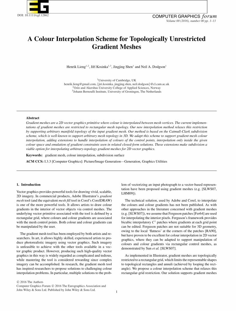
Figure 1: Illustrator’s gradient mesh tool, used for vivid colour-ings in vector graphics, is constrained to rectangular and annularcontrol meshes (annuli are achieved by looping rectangles). Thecolour images were rendered with our method, which does supportarbitrary surface topology.
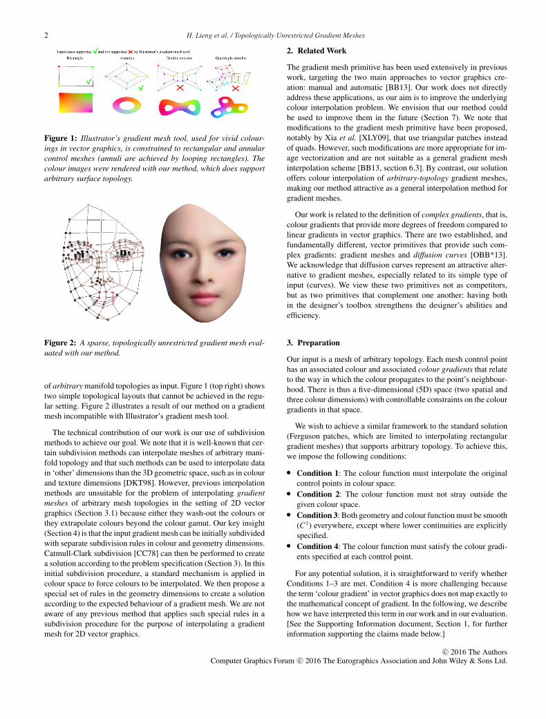
Figure 2: A sparse, topologically unrestricted gradient mesh eval-uated with our method.
of arbitrary manifold topologies as input. Figure 1 (top right) showstwo simple topological layouts that cannot be achieved in the regu-lar setting. Figure 2 illustrates a result of our method on a gradientmesh incompatible with Illustrator’s gradient mesh tool.
The technical contribution of our work is our use of subdivisionmethods to achieve our goal. We note that it is well-known that cer-tain subdivision methods can interpolate meshes of arbitrary mani-fold topology and that such methods can be used to interpolate datain ‘other’ dimensions than the 3D geometric space, such as in colourand texture dimensions [DKT98]. However, previous interpolationmethods are unsuitable for the problem of interpolating gradientmeshes of arbitrary mesh topologies in the setting of 2D vectorgraphics (Section 3.1) because either they wash-out the colours orthey extrapolate colours beyond the colour gamut. Our key insight(Section 4) is that the input gradient mesh can be initially subdividedwith separate subdivision rules in colour and geometry dimensions.Catmull-Clark subdivision [CC78] can then be performed to createa solution according to the problem specification (Section 3). In thisinitial subdivision procedure, a standard mechanism is applied incolour space to force colours to be interpolated. We then propose aspecial set of rules in the geometry dimensions to create a solutionaccording to the expected behaviour of a gradient mesh. We are notaware of any previous method that applies such special rules in asubdivision procedure for the purpose of interpolating a gradientmesh for 2D vector graphics.
2. Related Work
The gradient mesh primitive has been used extensively in previouswork, targeting the two main approaches to vector graphics cre-ation: manual and automatic [BB13]. Our work does not directlyaddress these applications, as our aim is to improve the underlyingcolour interpolation problem. We envision that our method couldbe used to improve them in the future (Section 7). We note thatmodifications to the gradient mesh primitive have been proposed,notably by Xia et al. [XLY09], that use triangular patches insteadof quads. However, such modifications are more appropriate for im-age vectorization and are not suitable as a general gradient meshinterpolation scheme [BB13, section 6.3]. By contrast, our solutionoffers colour interpolation of arbitrary-topology gradient meshes,making our method attractive as a general interpolation method forgradient meshes.
Our work is related to the definition of complex gradients, that is,colour gradients that provide more degrees of freedom compared tolinear gradients in vector graphics. There are two established, andfundamentally different, vector primitives that provide such com-plex gradients: gradient meshes and diffusion curves [OBB*13].We acknowledge that diffusion curves represent an attractive alter-native to gradient meshes, especially related to its simple type ofinput (curves). We view these two primitives not as competitors,but as two primitives that complement one another: having bothin the designer’s toolbox strengthens the designer’s abilities andefficiency.
3. Preparation
Our input is a mesh of arbitrary topology. Each mesh control pointhas an associated colour and associated colour gradients that relateto the way in which the colour propagates to the point’s neighbour-hood. There is thus a five-dimensional (5D) space (two spatial andthree colour dimensions) with controllable constraints on the colourgradients in that space.
We wish to achieve a similar framework to the standard solution(Ferguson patches, which are limited to interpolating rectangulargradient meshes) that supports arbitrary topology. To achieve this,we impose the following conditions:
� Condition 1: The colour function must interpolate the originalcontrol points in colour space.
� Condition 2: The colour function must not stray outside thegiven colour space.
� Condition 3: Both geometry and colour function must be smooth(C1) everywhere, except where lower continuities are explicitlyspecified.
� Condition 4: The colour function must satisfy the colour gradi-ents specified at each control point.
For any potential solution, it is straightforward to verify whetherConditions 1–3 are met. Condition 4 is more challenging becausethe term ‘colour gradient’ in vector graphics does not map exactly tothe mathematical concept of gradient. In the following, we describehow we have interpreted this term in our work and in our evaluation.[See the Supporting Information document, Section 1, for furtherinformation supporting the claims made below.]
c© 2016 The AuthorsComputer Graphics Forum c© 2016 The Eurographics Association and John Wiley & Sons Ltd.
H. Lieng et al. / Topologically Unrestricted Gradient Meshes 3
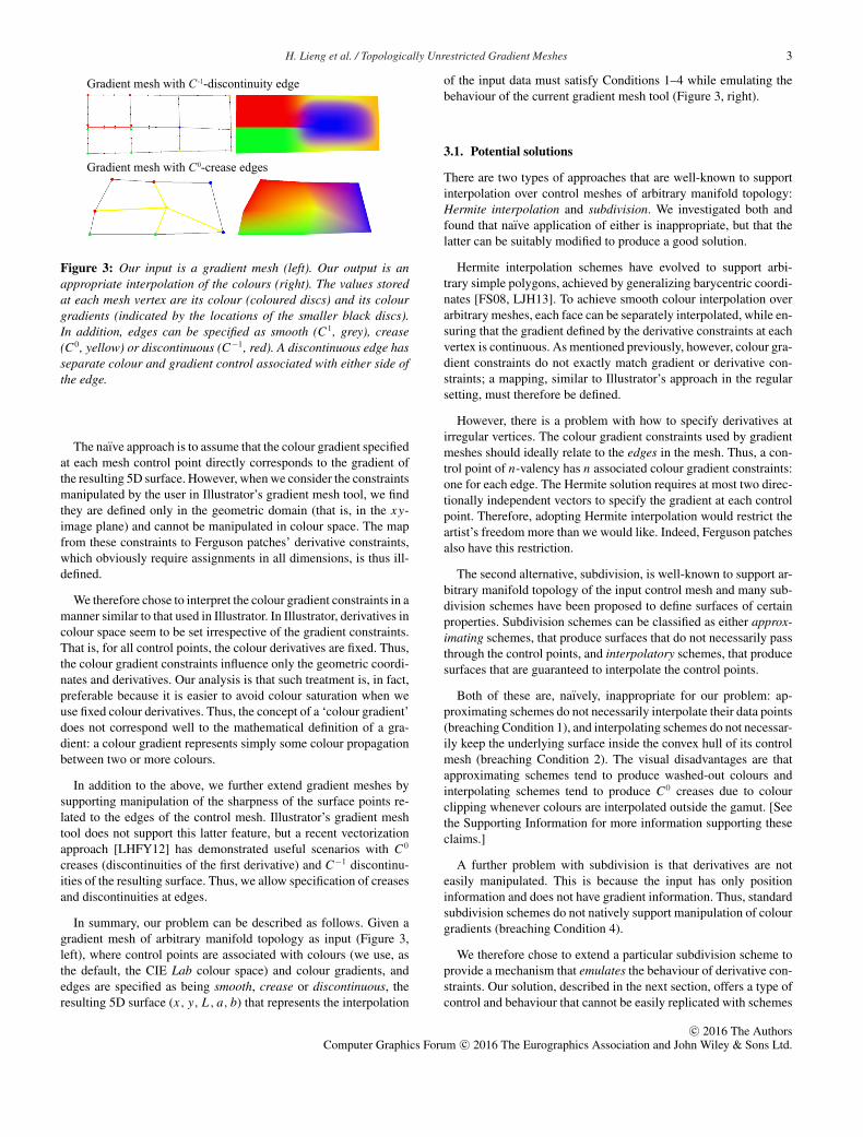
Gradient mesh with C-1-discontinuity edge
Gradient mesh with C0-crease edges
Figure 3: Our input is a gradient mesh (left). Our output is anappropriate interpolation of the colours (right). The values storedat each mesh vertex are its colour (coloured discs) and its colourgradients (indicated by the locations of the smaller black discs).In addition, edges can be specified as smooth (C1, grey), crease(C0, yellow) or discontinuous (C−1, red). A discontinuous edge hasseparate colour and gradient control associated with either side ofthe edge.
The naıve approach is to assume that the colour gradient specifiedat each mesh control point directly corresponds to the gradient ofthe resulting 5D surface. However, when we consider the constraintsmanipulated by the user in Illustrator’s gradient mesh tool, we findthey are defined only in the geometric domain (that is, in the xy-image plane) and cannot be manipulated in colour space. The mapfrom these constraints to Ferguson patches’ derivative constraints,which obviously require assignments in all dimensions, is thus ill-defined.
We therefore chose to interpret the colour gradient constraints in amanner similar to that used in Illustrator. In Illustrator, derivatives incolour space seem to be set irrespective of the gradient constraints.That is, for all control points, the colour derivatives are fixed. Thus,the colour gradient constraints influence only the geometric coordi-nates and derivatives. Our analysis is that such treatment is, in fact,preferable because it is easier to avoid colour saturation when weuse fixed colour derivatives. Thus, the concept of a ‘colour gradient’does not correspond well to the mathematical definition of a gra-dient: a colour gradient represents simply some colour propagationbetween two or more colours.
In addition to the above, we further extend gradient meshes bysupporting manipulation of the sharpness of the surface points re-lated to the edges of the control mesh. Illustrator’s gradient meshtool does not support this latter feature, but a recent vectorizationapproach [LHFY12] has demonstrated useful scenarios with C0
creases (discontinuities of the first derivative) and C−1 discontinu-ities of the resulting surface. Thus, we allow specification of creasesand discontinuities at edges.
In summary, our problem can be described as follows. Given agradient mesh of arbitrary manifold topology as input (Figure 3,left), where control points are associated with colours (we use, asthe default, the CIE Lab colour space) and colour gradients, andedges are specified as being smooth, crease or discontinuous, theresulting 5D surface (x, y, L, a, b) that represents the interpolation
of the input data must satisfy Conditions 1–4 while emulating thebehaviour of the current gradient mesh tool (Figure 3, right).
3.1. Potential solutions
There are two types of approaches that are well-known to supportinterpolation over control meshes of arbitrary manifold topology:Hermite interpolation and subdivision. We investigated both andfound that naıve application of either is inappropriate, but that thelatter can be suitably modified to produce a good solution.
Hermite interpolation schemes have evolved to support arbi-trary simple polygons, achieved by generalizing barycentric coordi-nates [FS08, LJH13]. To achieve smooth colour interpolation overarbitrary meshes, each face can be separately interpolated, while en-suring that the gradient defined by the derivative constraints at eachvertex is continuous. As mentioned previously, however, colour gra-dient constraints do not exactly match gradient or derivative con-straints; a mapping, similar to Illustrator’s approach in the regularsetting, must therefore be defined.
However, there is a problem with how to specify derivatives atirregular vertices. The colour gradient constraints used by gradientmeshes should ideally relate to the edges in the mesh. Thus, a con-trol point of n-valency has n associated colour gradient constraints:one for each edge. The Hermite solution requires at most two direc-tionally independent vectors to specify the gradient at each controlpoint. Therefore, adopting Hermite interpolation would restrict theartist’s freedom more than we would like. Indeed, Ferguson patchesalso have this restriction.
The second alternative, subdivision, is well-known to support ar-bitrary manifold topology of the input control mesh and many sub-division schemes have been proposed to define surfaces of certainproperties. Subdivision schemes can be classified as either approx-imating schemes, that produce surfaces that do not necessarily passthrough the control points, and interpolatory schemes, that producesurfaces that are guaranteed to interpolate the control points.
Both of these are, naıvely, inappropriate for our problem: ap-proximating schemes do not necessarily interpolate their data points(breaching Condition 1), and interpolating schemes do not necessar-ily keep the underlying surface inside the convex hull of its controlmesh (breaching Condition 2). The visual disadvantages are thatapproximating schemes tend to produce washed-out colours andinterpolating schemes tend to produce C0 creases due to colourclipping whenever colours are interpolated outside the gamut. [Seethe Supporting Information for more information supporting theseclaims.]
A further problem with subdivision is that derivatives are noteasily manipulated. This is because the input has only positioninformation and does not have gradient information. Thus, standardsubdivision schemes do not natively support manipulation of colourgradients (breaching Condition 4).
We therefore chose to extend a particular subdivision scheme toprovide a mechanism that emulates the behaviour of derivative con-straints. Our solution, described in the next section, offers a type ofcontrol and behaviour that cannot be easily replicated with schemes
c© 2016 The AuthorsComputer Graphics Forum c© 2016 The Eurographics Association and John Wiley & Sons Ltd.
4 H. Lieng et al. / Topologically Unrestricted Gradient Meshes
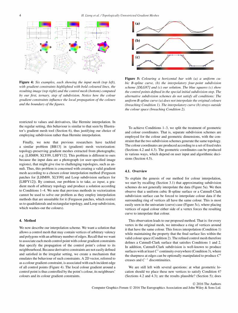
Figure 4: Six examples, each showing the input mesh (top left),with gradient constraints highlighted with bold coloured lines, theresulting image (top right) and the control mesh (bottom) computedby our first, ternary, step of subdivision. Notice how the colourgradient constraints influence the local propagation of the coloursand the boundary of the figures.
restricted to values and derivatives, like Hermite interpolation. Inthe regular setting, this behaviour is similar to that seen by Illustra-tor’s gradient mesh tool (Section 6), thus justifying our choice ofemploying subdivision rather than Hermite interpolation.
Finally, we note that previous researchers have tackleda similar problem [BB13] in (gradient) mesh vectorization:topology-preserving gradient meshes extracted from photographs;e.g. [LHM09, XLY09, LHFY12]. This problem is different to oursbecause the input data are a photograph (or user-specified imageregions), that might give rise to challenging topologies, such as an-nuli. Thus, this problem is concerned with creating a valid gradientmesh according to a chosen colour interpolation method (Fergusonpatches for [LHM09, XLY09] and Loop subdivision surfaces for[LHFY12]). By contrast, our problem is to take, as input, a gra-dient mesh of arbitrary topology and produce a solution accordingto Conditions 1–4. We note that previous methods in vectorizationcannot be used to solve our problem as they employ interpolationmethods that are unsuitable for it (Ferguson patches, which restrictus to quadrilaterals and rectangular topology, and Loop subdivision,which washes-out the colours).
4. Method
We now describe our interpolation scheme. We want a solution thatallows a control mesh that may contain vertices of arbitrary valencyand polygons with an arbitrary number of edges. Recall that we wantto associate each mesh control point with colour gradient constraintsthat specify the propagation of the control point’s colour to itsneighbourhood. Because derivative constraints are not easily definedand satisfied in the irregular setting, we create a mechanism thatemulates the behaviour of such constraints. A 2D vector, referred toas a colour gradient constraint, is associated with each incident edgeof all control points (Figure 4). The local colour gradient around acontrol point is thus controlled by the point’s colour, its neighbours’colours and its colour gradient constraints.
Figure 5: Colouring a horizontal bar with (a) a uniform cu-bic B-spline curve, (b) the interpolatory four-point subdivisionscheme [DLG87] and (c) our solution. The blue squares (c) showthe control points defined in the special initial subdivision step. Thealternative subdivision schemes do not satisfy all conditions: Theuniform B-spline curve (a) does not interpolate the original colours(breaching Condition 1). The interpolatory curve (b) strays outsidethe colour space (breaching Condition 2).
To achieve Conditions 1–3, we split the treatment of geometricand colour coordinates. That is, separate subdivision schemes areemployed for the colour and geometric dimensions, with the con-straint that the two subdivision schemes generate the same topology.The colour coordinates are produced according to a set of fixed rules(Sections 4.2 and 4.3). The geometric coordinates can be producedin various ways, which depend on user input and algorithmic deci-sions (Section 4.5).
4.1. Overview
To explain the genesis of our method for colour interpolation,we start by recalling (Section 3.1) that approximating subdivisionschemes do not generally interpolate the data (Figure 5a). We thenobserve that a uniform cubic B-spline surface or a Catmull-Clarksubdivision surface can be forced to interpolate colour data if thesurrounding ring of vertices all have the same colour. This is mosteasily seen in the univariate (curve) case (Figure 5c), where placingvertices of equal colour either side of a vertex forces the resultingcurve to interpolate that colour.
This observation leads to our proposed method. That is: for everyvertex in the original mesh, we introduce a ring of vertices aroundit that have the same colour. This forces interpolation (Condition 1)while maintaining the property that the final surface lies within thevalid colour space (Condition 2). The refined control mesh thereforedefines a Catmull-Clark surface that satisfies Conditions 1 and 2.In addition, Catmull-Clark subdivision is well-known to producesurfaces with at least C1 continuity everywhere (Condition 3), wherethe sharpness at edges can be optionally manipulated to produce C0
creases and C−1 discontinuities.
We are still left with several questions: at what geometric lo-cation should we place these new vertices to satisfy Condition 4?(Sections 4.2 and 4.3); are the results plausible? (Section 5); does
c© 2016 The AuthorsComputer Graphics Forum c© 2016 The Eurographics Association and John Wiley & Sons Ltd.
H. Lieng et al. / Topologically Unrestricted Gradient Meshes 5
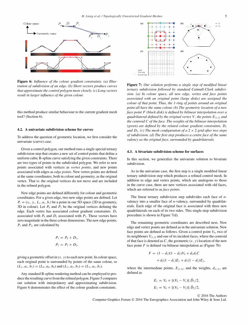
Figure 6: Influence of the colour gradient constraints. (a) Illus-tration of subdivision of an edge. (b) Short vectors produce curvesthat approximate the control polygon more closely. (c) Long vectorsresult in larger influence of the given colour.
this method produce similar behaviour to the current gradient meshtool? (Section 6).
4.2. A univariate subdivision scheme for curves
To address the question of geometric location, we first consider theunivariate (curve) case.
Given a control polygon, our method runs a single special ternarysubdivision step that creates a new set of control points that define auniform cubic B-spline curve satisfying the given constraints. Thereare two types of points in the subdivided polygon. We refer to newpoints associated with vertices as vertex points, and new pointsassociated with edges as edge points. New vertex points are definedat the same coordinates, both in colour and geometry, as the originalvertex. That is: the original vertices do not move and are includedin the refined polygon.
New edge points are defined differently for colour and geometriccoordinates. For a given edge, two new edge points are defined. LetPi = (xi, yi, Li, ai, bi) be a point in our 5D space (2D in geometry,3D in colour). Let P0 and P3 be the original vertices defining theedge. Each vertex has associated colour gradient constraints: D1
associated with P0 and D2 associated with P3. These vectors havezero magnitude in the three colour dimensions. The new edge points,P1 and P2, are calculated by
P1 = P0 + D1,
P2 = P3 + D2,
giving a geometric offset in (x, y) to each new point. In colour space,each original point is surrounded by points of the same colour, so(L1, a1, b1) = (L0, a0, b0) and (L2, a2, b2) = (L3, a3, b3).
Any standard B-spline rendering method can be employed to pro-duce the resulting curve from the refined polygon. Figure 5 comparesour solution with interpolatory and approximating subdivision.Figure 6 demonstrates the effect of the colour gradient constraints.
d1d2
(1-d1)(1-d2)d2(1-d1) d1(1-d2)
D2
D1(a) (b)
(c) (d)
F
InputFirst step Second step
E1
V0
E2
C
V2V1
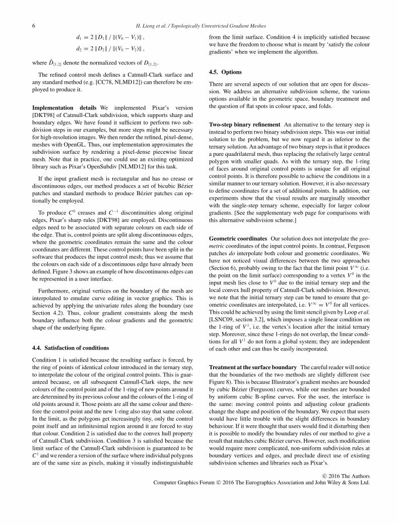
Figure 7: Our solution performs a single step of modified linearternary subdivision followed by standard Catmull-Clark subdivi-sion. (a) In colour space, all new edge, vertex and face pointsassociated with an original point (large disks) are assigned thecolour of that point. Thus, the 1-ring of points around an originalpoint all have the same colour. (b) The geometric location of a newface point F (black disk) is defined by bilinear interpolation over aquadrilateral defined by the original vertex V , the points E{1,2} andthe centroid C of the face. The weights of the bilinear interpolation(green) are defined by the related colour gradient constraints, D1
and D2. (c) The mesh configuration of a 2 × 2 grid after two stepsof subdivision. (d) The first step produces a centre face of the samevalency as the original face, surrounded by quadrilaterals.
4.3. A bivariate subdivision scheme for surfaces
In this section, we generalize the univariate solution to bivariatesubdivision.
As in the univariate case, the first step is a single modified linearternary subdivision step which produces a refined control mesh. Inaddition to edge and vertex points, which are analogous to thosein the curve case, there are new vertices associated with old faces,which are referred to as face points.
The linear ternary subdivision step subdivides each face of n-valency into a smaller face of n-valency, surrounded by quadrilat-erals. Each edge of the original face is associated with three newquadrilaterals on each of its two sides. This single-step subdivisionprocedure is shown in Figure 7(d).
The remaining geometric coordinates are described next. Newedge and vertex points are defined as in the univariate solution. Newface points are defined as follows. Given a control point V0, two ofits neighbours V{1,2} and one of its incident faces, where the centroidof that face is denoted as C, the geometric (x, y) location of the newface point F is defined via bilinear interpolation as (Figure 7b)
F = (1 − d1)(1 − d2)V0 + d1d2C
+ d2(1 − d1)E1 + d1(1 − d2)E2,
where the intermediate points, E{1,2}, and the weights, d{1,2}, aredefined as
E1 = V0 + ‖(V0 − V1)‖ D1/2,
E2 = V0 + ‖(V0 − V2)‖ D2/2,
c© 2016 The AuthorsComputer Graphics Forum c© 2016 The Eurographics Association and John Wiley & Sons Ltd.
6 H. Lieng et al. / Topologically Unrestricted Gradient Meshes
d1 = 2 ‖D1‖ / ‖(V0 − V1)‖ ,
d2 = 2 ‖D2‖ / ‖(V0 − V2)‖ ,
where D{1,2} denote the normalized vectors of D{1,2}.
The refined control mesh defines a Catmull-Clark surface andany standard method (e.g. [CC78, NLMD12]) can therefore be em-ployed to produce it.
Implementation details We implemented Pixar’s version[DKT98] of Catmull-Clark subdivision, which supports sharp andboundary edges. We have found it sufficient to perform two sub-division steps in our examples, but more steps might be necessaryfor high-resolution images. We then render the refined, pixel-dense,meshes with OpenGL. Thus, our implementation approximates thesubdivision surface by rendering a pixel-dense piecewise linearmesh. Note that in practice, one could use an existing optimizedlibrary such as Pixar’s OpenSubdiv [NLMD12] for this task.
If the input gradient mesh is rectangular and has no crease ordiscontinuous edges, our method produces a set of bicubic Bezierpatches and standard methods to produce Bezier patches can op-tionally be employed.
To produce C0 creases and C−1 discontinuities along originaledges, Pixar’s sharp rules [DKT98] are employed. Discontinuousedges need to be associated with separate colours on each side ofthe edge. That is, control points are split along discontinuous edges,where the geometric coordinates remain the same and the colourcoordinates are different. These control points have been split in thesoftware that produces the input control mesh; thus we assume thatthe colours on each side of a discontinuous edge have already beendefined. Figure 3 shows an example of how discontinuous edges canbe represented in a user interface.
Furthermore, original vertices on the boundary of the mesh areinterpolated to emulate curve editing in vector graphics. This isachieved by applying the univariate rules along the boundary (seeSection 4.2). Thus, colour gradient constraints along the meshboundary influence both the colour gradients and the geometricshape of the underlying figure.
4.4. Satisfaction of conditions
Condition 1 is satisfied because the resulting surface is forced, bythe ring of points of identical colour introduced in the ternary step,to interpolate the colour of the original control points. This is guar-anteed because, on all subsequent Catmull-Clark steps, the newcolours of the control point and of the 1-ring of new points around itare determined by its previous colour and the colours of the 1-ring ofold points around it. Those points are all the same colour and there-fore the control point and the new 1-ring also stay that same colour.In the limit, as the polygons get increasingly tiny, only the controlpoint itself and an infinitesimal region around it are forced to staythat colour. Condition 2 is satisfied due to the convex hull propertyof Catmull-Clark subdivision. Condition 3 is satisfied because thelimit surface of the Catmull-Clark subdivision is guaranteed to beC1 and we render a version of the surface where individual polygonsare of the same size as pixels, making it visually indistinguishable
from the limit surface. Condition 4 is implicitly satisfied becausewe have the freedom to choose what is meant by ‘satisfy the colourgradients’ when we implement the algorithm.
4.5. Options
There are several aspects of our solution that are open for discus-sion. We address an alternative subdivision scheme, the variousoptions available in the geometric space, boundary treatment andthe question of flat spots in colour space, and folds.
Two-step binary refinement An alternative to the ternary step isinstead to perform two binary subdivision steps. This was our initialsolution to the problem, but we now regard it as inferior to theternary solution. An advantage of two binary steps is that it producesa pure quadrilateral mesh, thus replacing the relatively large centralpolygon with smaller quads. As with the ternary step, the 1-ringof faces around original control points is unique for all originalcontrol points. It is therefore possible to achieve the conditions in asimilar manner to our ternary solution. However, it is also necessaryto define coordinates for a set of additional points. In addition, ourexperiments show that the visual results are marginally smootherwith the single-step ternary scheme, especially for larger colourgradients. [See the supplementary web page for comparisons withthis alternative subdivision scheme.]
Geometric coordinates Our solution does not interpolate the geo-metric coordinates of the input control points. In contrast, Fergusonpatches do interpolate both colour and geometric coordinates. Wehave not noticed visual differences between the two approaches(Section 6), probably owing to the fact that the limit point V ∞ (i.e.the point on the limit surface) corresponding to a vertex V 0 in theinput mesh lies close to V 0 due to the initial ternary step and thelocal convex hull property of Catmull-Clark subdivision. However,we note that the initial ternary step can be tuned to ensure that ge-ometric coordinates are interpolated, i.e. V ∞ = V 0 for all vertices.This could be achieved by using the limit stencil given by Loop et al.[LSNC09, section 3.2], which imposes a single linear condition onthe 1-ring of V 1, i.e. the vertex’s location after the initial ternarystep. Moreover, since these 1-rings do not overlap, the linear condi-tions for all V 1 do not form a global system; they are independentof each other and can thus be easily incorporated.
Treatment at the surface boundary The careful reader will noticethat the boundaries of the two methods are slightly different (seeFigure 8). This is because Illustrator’s gradient meshes are boundedby cubic Bezier (Ferguson) curves, while our meshes are boundedby uniform cubic B-spline curves. For the user, the interface isthe same: moving control points and adjusting colour gradientschange the shape and position of the boundary. We expect that userswould have little trouble with the slight differences in boundarybehaviour. If it were thought that users would find it disturbing thenit is possible to modify the boundary rules of our method to give aresult that matches cubic Bezier curves. However, such modificationwould require more complicated, non-uniform subdivision rules atboundary vertices and edges, and preclude direct use of existingsubdivision schemes and libraries such as Pixar’s.
c© 2016 The AuthorsComputer Graphics Forum c© 2016 The Eurographics Association and John Wiley & Sons Ltd.
H. Lieng et al. / Topologically Unrestricted Gradient Meshes 7
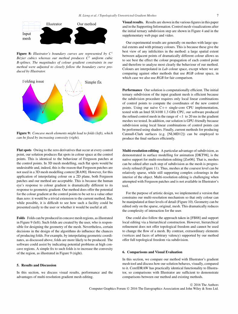
Figure 8: Illustrator’s boundary curves are represented by C1
Bezier cubics whereas our method produces C2 uniform cubicB-splines. The magnitudes of colour gradient constraints in ourmethod were adjusted to closely follow the boundary curve pro-duced by Illustrator.
Figure 9: Concave mesh elements might lead to folds (left), whichcan be fixed by increasing convexity (right).
Flat spots Owing to the zero derivatives that occur at every controlpoint, our solution produces flat spots in colour space at the controlpoints. This is identical to the behaviour of Ferguson patches atthe control points. In 3D mesh modelling, such flat spots would beundesirable and, indeed, this is the reason that Ferguson patches arenot used in a 3D mesh modelling context [RA90]. However, for thisapplication of interpolating colour on a 2D plane, both Fergusonpatches and our method are acceptable. This is because the humaneye’s response to colour gradient is dramatically different to itsresponse to geometric gradient. Our method does offer the potentialfor the colour gradient at the control points to be set to a value otherthan zero: it would be a trivial extension to the current method. But,while possible, it is difficult to see how such a facility could bepresented easily to the user or whether it would be useful at all.
Folds Folds can be produced in concave mesh regions, as illustratedin Figure 9 (left). Such folds are created by the user, who is respon-sible for designing the geometry of the mesh. Nevertheless, certaindecisions in the design of the algorithms do influence the chancesof producing folds. For example, by interpolating geometric coordi-nates, as discussed above, folds are more likely to be produced. Thesoftware could assist by indicating potential problems at high con-cave regions. A simple fix to such folds is to increase the convexityof the region, as illustrated in Figure 9 (right).
5. Results and Discussion
In this section, we discuss visual results, performance and theadvantages of multi-resolution gradient mesh editing.
Visual results. Results are shown in the various figures in this paperand in the Supporting Information. Control mesh visualizations afterthe initial ternary subdivision step are shown in Figure 4 and in thesupplementary web page and video.
Our experimental results are generally on meshes with large spa-tial extents and with primary colours. This is because these give thebest view of any infelicities in the method: a large spatial extentbetween adjacent points of dramatically different colour allows usto see best the effect the colour propagation of each control pointand therefore to analyse most clearly the behaviour of our method.Colours are interpolated in Lab colour space, except where we arecomparing against other methods that use RGB colour space, inwhich case we also use RGB for fair comparison.
Performance Our solution is computationally efficient. The initialternary subdivision of the input gradient mesh is efficient becausethe subdivision procedure requires only local linear combinationsof control points to compute the coordinates of the new controlpoints. Using our naıve C++ single-core CPU implementation,tested with an Intel SU4100 1.3 GHz CPU, our software producedthe refined control mesh in the range of <1 to 20 ms in the gradientmeshes we tested. In addition, our solution is GPU-friendly becausesubdivision using local linear combinations of control points canbe performed using shaders. Finally, current methods for producingCatmull-Clark surfaces (e.g. [NLMD12]) can be employed toproduce the final surfaces efficiently.
Multi-resolution editing A particular advantage of subdivision, asdemonstrated in surface modelling for animation [DKT98], is thenative support for multi-resolution editing [Zor06]. That is, meshescan be edited after each step of subdivision as the mesh is progres-sively refined (Figure 11). Thus, meshes at the coarsest level can berelatively sparse, while still supporting complex colourings in theinterior of the object. Multi-resolution editing is challenging whenattempted with Ferguson patches and is not available in Illustrator’stool.
For the purpose of artistic design, we implemented a version thatconstrains our multi-resolution mechanism so that only colour canbe manipulated at finer levels of detail (Figure 10). Geometry can beedited only on the sparse, original, mesh. This dramatically reducesthe complexity of interaction for the user.
One could also follow the approach taken in [FB88] and supportlocal editing via a hierarchical construction. However, hierarchicalrefinement does not offer topological freedom and cannot be usedto change the flow of a mesh. By contrast, extraordinary elements(vertices and faces of arbitrary valency) supported by our methodoffer full topological freedom via subdivision.
6. Comparisons and Visual Evaluation
In this section, we compare our method with Illustrator’s gradientmesh tool and discuss how our solution behaves, visually, comparedto it. CorelDRAW has practically identical functionality to Illustra-tor, so comparisons with Illustrator are sufficient to demonstratecomparisons between our method and existing methods.
c© 2016 The AuthorsComputer Graphics Forum c© 2016 The Eurographics Association and John Wiley & Sons Ltd.
8 H. Lieng et al. / Topologically Unrestricted Gradient Meshes
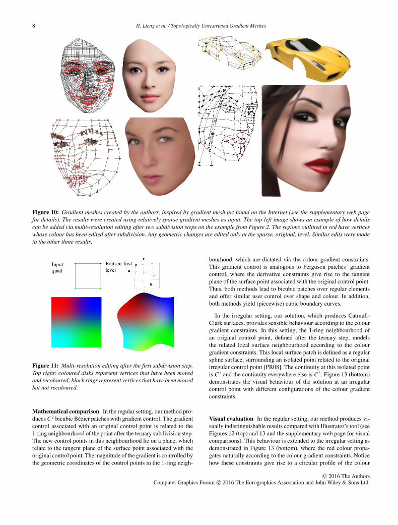
Figure 10: Gradient meshes created by the authors, inspired by gradient mesh art found on the Internet (see the supplementary web pagefor details). The results were created using relatively sparse gradient meshes as input. The top-left image shows an example of how detailscan be added via multi-resolution editing after two subdivision steps on the example from Figure 2. The regions outlined in red have verticeswhose colour has been edited after subdivision. Any geometric changes are edited only at the sparse, original, level. Similar edits were madeto the other three results.
Figure 11: Multi-resolution editing after the first subdivision step.Top right: coloured disks represent vertices that have been movedand recoloured; black rings represent vertices that have been movedbut not recoloured.
Mathematical comparison In the regular setting, our method pro-duces C2 bicubic Bezier patches with gradient control. The gradientcontrol associated with an original control point is related to the1-ring neighbourhood of the point after the ternary subdivision step.The new control points in this neighbourhood lie on a plane, whichrelate to the tangent plane of the surface point associated with theoriginal control point. The magnitude of the gradient is controlled bythe geometric coordinates of the control points in the 1-ring neigh-
bourhood, which are dictated via the colour gradient constraints.This gradient control is analogous to Ferguson patches’ gradientcontrol, where the derivative constraints give rise to the tangentplane of the surface point associated with the original control point.Thus, both methods lead to bicubic patches over regular elementsand offer similar user control over shape and colour. In addition,both methods yield (piecewise) cubic boundary curves.
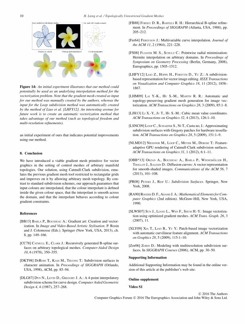
In the irregular setting, our solution, which produces Catmull-Clark surfaces, provides sensible behaviour according to the colourgradient constraints. In this setting, the 1-ring neighbourhood ofan original control point, defined after the ternary step, modelsthe related local surface neighbourhood according to the colourgradient constraints. This local surface patch is defined as a regularspline surface, surrounding an isolated point related to the originalirregular control point [PR08]. The continuity at this isolated pointis C1 and the continuity everywhere else is C2. Figure 13 (bottom)demonstrates the visual behaviour of the solution at an irregularcontrol point with different configurations of the colour gradientconstraints.
Visual evaluation In the regular setting, our method produces vi-sually indistinguishable results compared with Illustrator’s tool (seeFigures 12 (top) and 13 and the supplementary web page for visualcomparisons). This behaviour is extended to the irregular setting asdemonstrated in Figure 13 (bottom), where the red colour propa-gates naturally according to the colour gradient constraints. Noticehow these constraints give rise to a circular profile of the colour
c© 2016 The AuthorsComputer Graphics Forum c© 2016 The Eurographics Association and John Wiley & Sons Ltd.
H. Lieng et al. / Topologically Unrestricted Gradient Meshes 9
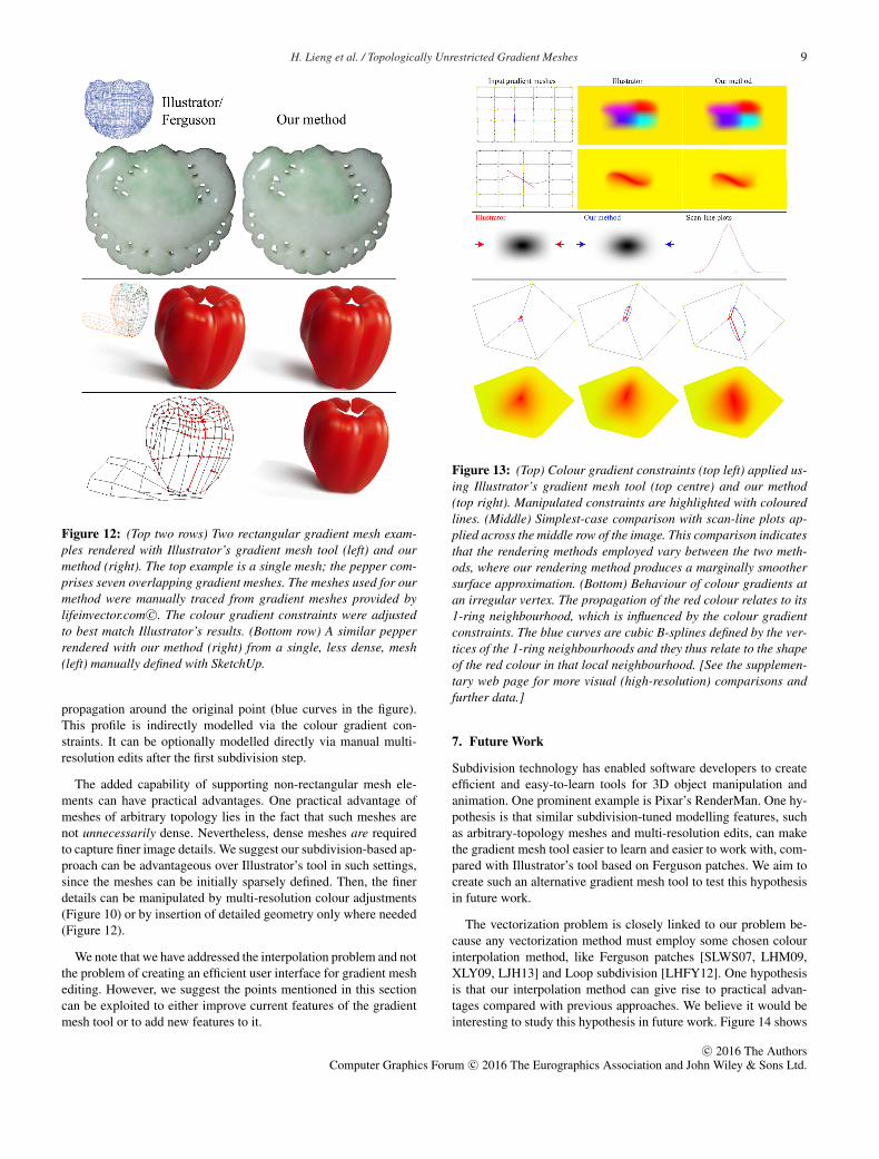
Figure 12: (Top two rows) Two rectangular gradient mesh exam-ples rendered with Illustrator’s gradient mesh tool (left) and ourmethod (right). The top example is a single mesh; the pepper com-prises seven overlapping gradient meshes. The meshes used for ourmethod were manually traced from gradient meshes provided bylifeinvector.com c©. The colour gradient constraints were adjustedto best match Illustrator’s results. (Bottom row) A similar pepperrendered with our method (right) from a single, less dense, mesh(left) manually defined with SketchUp.
propagation around the original point (blue curves in the figure).This profile is indirectly modelled via the colour gradient con-straints. It can be optionally modelled directly via manual multi-resolution edits after the first subdivision step.
The added capability of supporting non-rectangular mesh ele-ments can have practical advantages. One practical advantage ofmeshes of arbitrary topology lies in the fact that such meshes arenot unnecessarily dense. Nevertheless, dense meshes are requiredto capture finer image details. We suggest our subdivision-based ap-proach can be advantageous over Illustrator’s tool in such settings,since the meshes can be initially sparsely defined. Then, the finerdetails can be manipulated by multi-resolution colour adjustments(Figure 10) or by insertion of detailed geometry only where needed(Figure 12).
We note that we have addressed the interpolation problem and notthe problem of creating an efficient user interface for gradient meshediting. However, we suggest the points mentioned in this sectioncan be exploited to either improve current features of the gradientmesh tool or to add new features to it.
Figure 13: (Top) Colour gradient constraints (top left) applied us-ing Illustrator’s gradient mesh tool (top centre) and our method(top right). Manipulated constraints are highlighted with colouredlines. (Middle) Simplest-case comparison with scan-line plots ap-plied across the middle row of the image. This comparison indicatesthat the rendering methods employed vary between the two meth-ods, where our rendering method produces a marginally smoothersurface approximation. (Bottom) Behaviour of colour gradients atan irregular vertex. The propagation of the red colour relates to its1-ring neighbourhood, which is influenced by the colour gradientconstraints. The blue curves are cubic B-splines defined by the ver-tices of the 1-ring neighbourhoods and they thus relate to the shapeof the red colour in that local neighbourhood. [See the supplemen-tary web page for more visual (high-resolution) comparisons andfurther data.]
7. Future Work
Subdivision technology has enabled software developers to createefficient and easy-to-learn tools for 3D object manipulation andanimation. One prominent example is Pixar’s RenderMan. One hy-pothesis is that similar subdivision-tuned modelling features, suchas arbitrary-topology meshes and multi-resolution edits, can makethe gradient mesh tool easier to learn and easier to work with, com-pared with Illustrator’s tool based on Ferguson patches. We aim tocreate such an alternative gradient mesh tool to test this hypothesisin future work.
The vectorization problem is closely linked to our problem be-cause any vectorization method must employ some chosen colourinterpolation method, like Ferguson patches [SLWS07, LHM09,XLY09, LJH13] and Loop subdivision [LHFY12]. One hypothesisis that our interpolation method can give rise to practical advan-tages compared with previous approaches. We believe it would beinteresting to study this hypothesis in future work. Figure 14 shows
c© 2016 The AuthorsComputer Graphics Forum c© 2016 The Eurographics Association and John Wiley & Sons Ltd.
10 H. Lieng et al. / Topologically Unrestricted Gradient Meshes
Figure 14: An initial experiment illustrates that our method couldpotentially be used as an underlying interpolation method for thevectorization problem. Note that the gradient mesh created as inputfor our method was manually created by the authors, whereas theinput for the Loop subdivision method was automatically createdby the method of Liao et al. [LHFY12]. An interesting avenue forfuture work is to create an automatic vectorization method thattakes advantage of our method (such as topological freedom andmulti-resolution refinements).
an initial experiment of ours that indicates potential improvementsusing our method.
8. Conclusion
We have introduced a viable gradient mesh primitive for vectorgraphics in the setting of control meshes of arbitrary manifoldtopologies. Our solution, using Catmull-Clark subdivision, emu-lates the previous gradient mesh tool restricted to rectangular gridsand improves on it by allowing arbitrary mesh topology. By con-trast to standard subdivision schemes, our approach guarantees thatinput colours are interpolated, that the colour interpolant is definedinside the given colour space, that the interpolant is smooth acrossthe domain, and that the interpolant behaves according to colourgradient constraints.
References
[BB13] BARLA P., BOUSSEAU A.: Gradient art: Creation and vector-ization. In Image and Video-Based Artistic Stylisation. P. Rosinand J. Colomosse (Eds.). Springer (New York, USA, 2013), ch.8, pp. 149–166.
[CC78] CATMULL E., CLARK J.: Recursively generated B-spline sur-faces on arbitrary topological meshes. Computer-Aided Design10, 6 (1978), 350–355.
[DKT98] DEROSE T., KASS M., TRUONG T.: Subdivision surfaces incharacter animation. In Proceedings of SIGGRAPH (Orlando,USA, 1998), ACM, pp. 85–94.
[DLG87] DYN N., LEVIN D., GREGORY J. A.: A 4-point interpolatorysubdivision scheme for curve design. Computer Aided GeometricDesign 4, 4 (1987), 257–268.
[FB88] FORSEY D. R., BARTELS R. H.: Hierarchical B-spline refine-ment. In Proceedings of SIGGRAPH (Atlanta, USA, 1988), pp.205–212.
[Fer64] FERGUSON J.: Multivariable curve interpolation. Journal ofthe ACM 11, 2 (1964), 221–228.
[FS08] FLOATER M. S., SCHULZ C.: Pointwise radial minimization:Hermite interpolation on arbitrary domains. In Proceedings ofSymposium on Geometry Processing (Berlin, Germany, 2008),Eurographics, pp. 1505–1512.
[LHFY12] LIAO Z., HOPPE H., FORSYTH D., YU Z.: A subdivision-based representation for vector image editing. IEEE Transactionson Visualization and Computer Graphics 18, 11 (2012), 1858–1867.
[LHM09] LAI Y.-K., HU S.-M., MARTIN R. R.: Automatic andtopology-preserving gradient mesh generation for image vec-torization. ACM Transactions on Graphics 28, 3 (2009), 85:1–8.
[LJH13] LI X.-Y., JU T., HU S.-M.: Cubic mean value coordinates.ACM Transactions on Graphics 32, 4 (2013), 126:1–10.
[LSNC09] LOOP C., SCHAEFER S., NI T., Casta no, I.: Approximatingsubdivision surfaces with Gregory patches for hardware tessella-tion. ACM Transactions on Graphics 28, 5 (2009), 151:1–9.
[NLMD12] NIESSNER M., LOOP C., MEYER M., DEROSE T.: Feature-adaptive GPU rendering of Catmull-Clark subdivision surfaces.ACM Transactions on Graphics 31, 1 (2012), 6:1–11.
[OBB*13] ORZAN A., BOUSSEAU A., BARLA P., WINNEMOLLER H.,THOLLOT J., SALESIN D.: Diffusion curves: A vector representationfor smooth-shaded images. Communications of the ACM 56, 7(2013), 101–108.
[PR08] PETERS J., REIF U.: Subdivision Surfaces. Springer, NewYork, 2008.
[RA90] ROGERS D. F., ADAMS J. A.: Mathematical Elements for Com-puter Graphics (2nd edition). McGraw-Hill, New York, USA,1990.
[SLWS07] SUN J., LIANG L., WEN F., SHUM H.-Y.: Image vectoriza-tion using optimized gradient meshes. ACM Trans. Graph. 26, 3(2007), 11.
[XLY09] XIA T., LIAO B., YU Y.: Patch-based image vectorizationwith automatic curvilinear feature alignment. ACM Transactionson Graphics 28, 5 (2009), 115:1–10.
[Zor06] ZORIN D.: Modeling with multiresolution subdivision sur-faces. In SIGGRAPH Courses (2006), ACM, pp. 30–50.
Supporting Information
Additional Supporting Information may be found in the online ver-sion of this article at the publisher’s web site:
Online supplement
Video S1
c© 2016 The AuthorsComputer Graphics Forum c© 2016 The Eurographics Association and John Wiley & Sons Ltd.


![New Iterative Methods for Interpolation, Numerical ... · and Aitken’s iterated interpolation formulas[11,12] are the most popular interpolation formulas for polynomial interpolation](https://img.pdfslide.net/doc/110x75/5ebfad147f604608c01bd287/new-iterative-methods-for-interpolation-numerical-and-aitkenas-iterated-interpolation.jpg)