Embed Size (px)
Citation preview
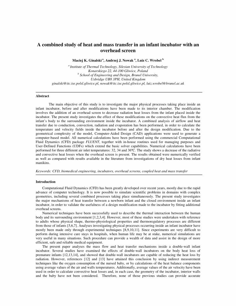
A combined study of heat and mass transfer in an infant incubator with an
overhead screen
Maciej K. Ginalski a, Andrzej J. Nowak a, Luiz C. Wrobel b a Institute of Thermal Technology, Silesian University of Technology
Konarskiego 22, 44-100 Gliwice, Poland b School of Engineering and Design, Brunel University,
Uxbridge UB8 3PH, United Kingdom [email protected], [email protected], [email protected]
Abstract
The main objective of this study is to investigate the major physical processes taking place inside an infant incubator, before and after modifications have been made to its interior chamber. The modification involves the addition of an overhead screen to decrease radiation heat losses from the infant placed inside the incubator. The present study investigates the effect of these modifications on the convective heat flux from the infant’s body to the surrounding environment inside the incubator. A combined analysis of airflow and heat transfer due to conduction, convection, radiation and evaporation has been performed, in order to calculate the temperature and velocity fields inside the incubator before and after the design modification. Due to the geometrical complexity of the model, Computer-Aided Design (CAD) applications were used to generate a computer-based model. All numerical calculations have been performed using the commercial Computational Fluid Dynamics (CFD) package FLUENT, together with in-house routines used for managing purposes and User-Defined Functions (UDFs) which extend the basic solver capabilities. Numerical calculations have been performed for three different air inlet temperatures: 32, 34 and 36ºC. The study shows a decrease of the radiative and convective heat losses when the overhead screen is present. The results obtained were numerically verified as well as compared with results available in the literature from investigations of dry heat losses from infant manikins.
Keywords: CFD, biomedical engineering, incubators, overhead screens, coupled heat and mass transfer
Introduction
Computational Fluid Dynamics (CFD) has been greatly developed over recent years, mostly due to the rapid advance of computer technology. It is now possible to simulate scientific problems in domains with complex geometries, including several combined processes taking place simultaneously. The present study investigates the major mechanisms of heat transfer between a newborn infant and the closed environment inside an infant incubator, in order to validate the usefulness of a design modification made to the incubator by fitting additional overhead screens.
Numerical techniques have been successfully used to describe the thermal interaction between the human body and its surrounding environment [1,2,3,4]. However, most of these studies were undertaken with reference to adults whose physical shape, thermo-physiological properties and thermoregulatory processes are different from those of infants [5,6,7]. Analyses investigating physical processes occurring inside an infant incubator have mostly been made only through experimental techniques [8,9,10,11]. Since experiments are very difficult to perform during intensive care stays in hospitals, when human life may be at stake, numerical simulations are very useful in many situations. Such procedure can provide a wealth of data and assist in the design of more efficient, safe and reliable medical equipment.
The present paper analyses the mass flow and heat transfer mechanisms inside a double-wall infant incubator. Several studies have examined the effects of double-wall incubators on the body heat loss of premature infants [12,13,14], and showed that double-wall incubators are capable of reducing the heat loss by radiation. However, references [12] and [13] have attained this conclusion by using indirect measurement techniques like the oxygen consumption of the nursed baby, or by calculations of the heat balance components using average values of the air and walls temperatures. Additionally, average values of the air velocity have been used in order to calculate convective heat losses and, in each case, the geometry of the incubator, interior walls and the baby have not been considered. Therefore, none of those previous studies can provide accurate

2
information on the values of the radiative and convective heat fluxes exchanged between the baby and the surrounding environment. This is probably the reason why the shape and position of the interior walls vary, depending of the manufacturer and specific incubator model. The study presented in this paper describes a procedure that can be used to calculate more accurate values of the above-mentioned parameters and to analyse the impact of the interior screens on the heat transfer processes and, therefore, the total heat balance of the baby.
The Caleo™ infant incubator, manufactured by the German company Dräger, has been used as a research unit in the presented study. In order to establish the influence of the interior walls on the heat balance of the baby, calculations for three different internal environment conditions have been performed for the incubator model, with and without the double walls in place. Velocity and temperature fields have been calculated in order to investigate the impact of the double walls on the thermal comfort of the baby. Therefore, convective and radiative heat losses from the baby to the surrounding environment, which are essential terms in a global energy balance of the infant, were obtained using CFD and compared in both cases. Heat losses due to evaporation of moisture from the newborn skin and during the respiration process also play a very important role in the total heat loss. However, since these processes are strongly dependent on the humidity of the air, rather than the air temperature and velocity in the analyzed range, their impact have only been included based on empirical data and equations provided in the literature [8,9,15].
CFD results are also compared with those presented by Elabbassi et al. [16] for the heat losses measured for thermal manikins. Since different incubators were used in the above experiments, the comparison is more qualitative than quantitative.
Methodology
In order to make the calculation process fully automatic, a managing program was created to deal with all the essential stages of the numerical simulation, step by step. A detailed scheme of the algorithm is presented in Figure 1. At the beginning, the program reads information on parameters required to build the geometric model. In the next step, the GAMBIT pre-processor software is launched and the geometric modelling and mesh generation processes are performed. The geometry of the interior and exterior incubator domains are generated based on the pre-defined model created earlier in the CAD application, to increase accuracy and save time. After generating a mesh file, a journal file for the numerical calculation is prepared based on the data provided in the input file. Information considering the material properties, boundary conditions and initial settings are included and the main analysis solver FLUENT is launched. In the initial run of the solver, the thermal boundary condition on the external wall of the incubator is set with a constant temperature value. As a result of this setting, the surface heat flux profile is determined. The profile obtained is further used as a heat flux boundary condition for the second exterior model used to calculate flow and thermal processes outside the incubator. After performing the calculations for the exterior model, the managing program reads the new temperature field on the external wall of the incubator and returns this information as a temperature boundary condition to the first, interior model. This iterative process between the two models continues until the convergence criteria are satisfied. The iterative method between the two separated domains proved to be very useful for specifying accurate temperature boundary conditions for the interior model. Moreover, it decreased the computational time and storage requirements for the calculations. The managing program was used to perform calculations for the incubator before the design modifications were undertaken, and later with the inclusion of the overhead screen.
Model Geometry
In previous studies, a simplified infant physical shape was often adopted, usually represented by geometric primitives such as spheres or cylinders. With the assistance of the CAD application CATIA, the geometric representation of the infant child, incubator and incubator’s interior and exterior domains were generated with high accuracy. It is believed that the position and the physical shape of the infant would have an important influence on its thermal condition. Therefore, parametric capabilities of the CAD application can be utilised for adjusting the geometry of the model to the specific case examined.
Dimensions required to build the representation of the infant incubator were obtained from the technical documentation provided by the manufacturer. The model was based on the Caleo™ Infant Incubator manufactured by the German company Dräger [17]. Some additional measurements were also taken in a collaborating hospital in Katowice, Poland. The complete model can be seen in Figure 2.
All the required information related to the geometry of the baby was taken from the measurements of a natural size baby doll and confirmed with basic data provided by the medical literature. Based on that information, a parametric model of the infant child was created. Several parameters, such as length and periphery of the head, chest, arms and legs were set in order to adjust the physical representation of the child placed inside the incubator. The final model can be seen in Figure 3.

3
Figure 1. Detailed scheme of the algorithm

4
Figure 2. Three-dimensional model of the infant and the incubator generated in CATIA: 1 – Stand, 2- Air inlets, 3- Wire access ports, 4- Infant child, 5- Internal thermometer, 6- External wall, 7- Incubator access
ports, 8- Internal screens, 9- Air outlets.
Figure 3. Three-dimensional parametric model of the infant generated in CATIA: 1 – Air inlets, 2 – Mattress, 3 – Air outlets, P1 – P8 geometric constraints.
Mathematical Model
Basic assumptions
• The combined heat and mass transfer processes are in steady state.
• The airflow through the incubator is turbulent and viscous. The Shear-Stress Transport (SST) k – � turbulence model has been used in all simulations, with a correction for flows characterized by a low Reynolds number.
• The skin temperature is the same for all cases considered.

5
• All calculations were performed for a representative baby whose basic geometrical and physiological data are provided in Table 1.
Table 1 – Geometrical and physiological data
Newborn’s weight m = 1.5 [kg] Newborn’s height l = 0.43 [m] Skin surface area Ask = 0.043 [m2] Age p = 1 [day] Gestation age Ga = 32 [weeks] Evaporation rate NWL50 = 3 [ml kg-1 h-1]
Energy balance of the newborn baby
• The metabolic heat generated by the baby is either stored or dissipated to the surrounding environment due to conduction, radiation, convection, and evaporation of water from the skin and respiratory track. However, since the heat transport processes calculated in this study are considered to be in a steady state, accumulation terms have not been considered. An energy balance equation can therefore be written as [15]:
EvpCovRadConM QQQQQ ����� +++= (1)
where MQ� is the metabolic heat generated by the body (W),
ConQ� ,RadQ� ,
CovQ� EvpQ� ,represent heat dissipation to
the environment due to conduction, radiation, convection, evaporation of moisture from the newborn skin (W).
• The total metabolic heat transfer generated by the baby (W) was calculated based on the following equation [18]:
64.10522.0 +××= pmQM� (2)
where m is the baby weight (kg) and p is the baby’s age (days).
• The temperature on the surface of the mattress on which the baby is placed inside the incubator is set to be equal to the baby skin temperature. Therefore, no conduction heat loss between infant and mattress was considered in this study. This is a reasonable assumption following Wheldon [19], who states that the rate of heat transfer by conduction is small for a baby lying on a foam mattress.
• Heat exchange by conduction and convection between the baby and the surrounding environment inside the incubator is calculated by the FLUENT solver. Those quantities are determined through the solution of the mass, momentum and energy conservation equations. Radiation heat exchange is also calculated by the main FLUENT solver using the discrete ordinates radiation model. Detailed information is provided in [20].
• The impact of the water evaporation process from the newborn’s body on the thermal balance of the baby has also been included. The following formula [15] has been used in order to calculate the value of the heat flux lost due to evaporation, EvpQ� (W),
fgvEvp hmQ ×= �� (3)
where vm� is the rate of evaporation from the body (kg/s) and
fgh is the enthalpy of vaporisation of water (kJ/kg).
Mathematical model components
The heat transfer analysis is based on the energy equation [21]
tT
cTkDD
)( ρ=∇∇ (4)
where T is the temperature (K), k is the thermal conductivity (W/mK), � is the density (kg/m3), c is the specific heat (W/kgK), and t is time (s). The derivative on the right-hand side of equation (4) is the total derivative:
6
TtT
zT
yT
xT
tT
tT
zyx ∇⋅+∂∂=
∂∂+
∂∂+
∂∂+
∂∂= uuuu
DD (5)
where ux, uy, uz, are the velocity components of vector u in the x-, y-, z-direction, respectively (m/s). Since only steady-state problems are studied in this work, the first term on the right-hand side of equation (6) vanishes.
The above equations are complemented by the continuity and momentum equations [21], namely
0=⋅∇ u (6)
uFu 2
DD ∇+∇−= µρ p
t (7)
where p is the pressure (N/m2), F represents the body force term which in the present case has only a vertical component Fz = �g in the z-direction (N/m2), g is gravity acceleration (m/s2) and � is the dynamic viscosity (Ns/m2).
The Boussinesq approximation was adopted for the buoyancy term in equation (17). Thus, density takes the usual form
))(1( 00 TT −−= βρρ (8)
where � is the thermal expansion coefficient (1/K), T0 and �0 represent the operating parameters.
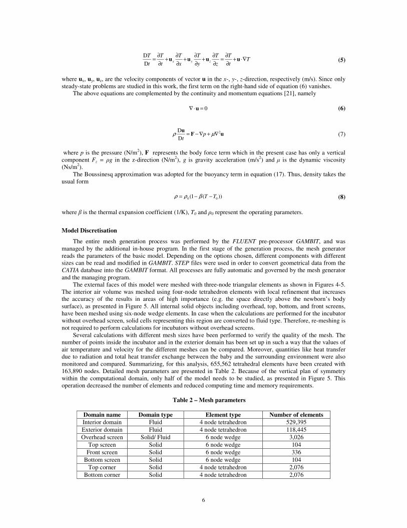
Model Discretisation
The entire mesh generation process was performed by the FLUENT pre-processor GAMBIT, and was managed by the additional in-house program. In the first stage of the generation process, the mesh generator reads the parameters of the basic model. Depending on the options chosen, different components with different sizes can be read and modified in GAMBIT. STEP files were used in order to convert geometrical data from the CATIA database into the GAMBIT format. All processes are fully automatic and governed by the mesh generator and the managing program.
The external faces of this model were meshed with three-node triangular elements as shown in Figures 4-5. The interior air volume was meshed using four-node tetrahedron elements with local refinement that increases the accuracy of the results in areas of high importance (e.g. the space directly above the newborn’s body surface), as presented in Figure 5. All internal solid objects including overhead, top, bottom, and front screens, have been meshed using six-node wedge elements. In case when the calculations are performed for the incubator without overhead screen, solid cells representing this region are converted to fluid type. Therefore, re-meshing is not required to perform calculations for incubators without overhead screens.
Several calculations with different mesh sizes have been performed to verify the quality of the mesh. The number of points inside the incubator and in the exterior domain has been set up in such a way that the values of air temperature and velocity for the different meshes can be compared. Moreover, quantities like heat transfer due to radiation and total heat transfer exchange between the baby and the surrounding environment were also monitored and compared. Summarizing, for this analysis, 655,562 tetrahedral elements have been created with 163,890 nodes. Detailed mesh parameters are presented in Table 2. Because of the vertical plan of symmetry within the computational domain, only half of the model needs to be studied, as presented in Figure 5. This operation decreased the number of elements and reduced computing time and memory requirements.
Table 2 – Mesh parameters
Domain name Domain type Element type Number of elements Interior domain Fluid 4 node tetrahedron 529,395 Exterior domain Fluid 4 node tetrahedron 118,445 Overhead screen Solid/ Fluid 6 node wedge 3,026
Top screen Solid 6 node wedge 104 Front screen Solid 6 node wedge 336
Bottom screen Solid 6 node wedge 104 Top corner Solid 4 node tetrahedron 2,076
Bottom corner Solid 4 node tetrahedron 2,076

7
Figure 4. Surface of the infant’s body meshed with triangular elements.
Figure 5. Model of the imprinted air-solid region meshed with tetrahedral elements: 1– Internal front screen, 2– Internal top screen, 3– Top corner, 4– Internal thermometer, 5– Overhead screen, 6- Exterior
domain, 7- Interior domain.
Boundary conditions
Airflow and exits
Velocity inlet boundary conditions were used to define the velocity and scalar properties of the flow and the four inlet boundaries. Pressure outlet boundary conditions were used to model air outflow from the domain. All material properties are based on the existing literature [15,17]. The initial velocity and temperature of the air are based on [15]. All relevant parameters are presented in Table 3.
Newborn’s body boundary wall
The material properties are based on the existing literature [15,17]. In addition, information on the temperature profile on the newborn’s skin and the water mass flux can be found in [7,18]. All the relevant parameters are presented in Table 4.
External wall of the incubator
The material properties of the incubator walls are based on the existing literature [15,17]. Two different materials were used to model the semi-transparent and opaque walls of the incubator. Properties of those materials are presented in Tables 5 and 6. As mentioned in the previous sections, in order to obtain heat transfer and temperature distribution fields for the external wall of the incubator, iterative procedures between the interior and exterior domains have been introduced. The results obtained have been later used in the final

8
calculations as a temperature profile on the external wall of the incubator. The temperature distribution on the external walls of the incubator, with and without the overhead screens, can be seen in Figures 18-19.
Table 3 – Air boundary conditions
Table 4 – Newborn boundary conditions
Table 5 – External wall boundary conditions (opaque material)
Table 6 – External wall boundary conditions (semi-transparent material)
Solution procedure
After the creation of the grid, the managing program reads all the necessary information regarding the boundary conditions, material properties and initial parameters and writes them in the journal file. In the following step, the FLUENT main solver is launched and calculations are performed. Once a grid has been read into FLUENT, all remaining operations are performed within the solver. The solution algorithm is the segregated solver. Using this approach, the governing equations are solved sequentially, i.e. segregated from one another.
Total inlets surface area Av = 0.0224 [m2] Total outlets surface area Ao = 0.0044 [m2] Inlet air temperature (Three initial settings have been considered in order to calculate heat transfer components for different internal temperature conditions)
TaI = 32 TaII = 34 TaIII = 36
[˚C]
Initial axial velocity of the air uz = 0.41 [m/s] Air density (Boussinesq model) ρa = 1.225 [kg/m3] Heat capacity of the air cp,a = 1,006 [J/kgK] Thermal conductivity of the air ka = 0.0268 [W/mK] Viscosity of the air µa = 1.90×10⁻⁵ [kg/ms] Thermal expansion coefficient of the air β = 0.003326 [1/K]
Skin temperature
Temperature Profile
Tsk max = 35.6 Tsk min = 34.7
[ºC]
Newborn’s skin emissivity εsk = 0.95
Material name (opaque material) Plastic (PVC) Total internal surface area 1.10 [m2] Total external surface area 1.10 [m2] Density 1700 [kg/m3] Heat capacity 1.000 [J/kgK] Thermal conductivity 0.14 [W/mK] Absorption coefficient 0 [1/m] Internal emissivity 0.90
Material name (semi-transparent material) Glass fibre Total internal surface area 0.264 [m2] Total external surface area 0.266 [m2] Density 1.450 [kg/m3] Heat capacity 0.96 [J/kgK] Thermal conductivity 0.036 [W/mK] Absorption coefficient 220 [1/m] Internal emissivity 0.92

9
Results and discussion Simulations have been performed for three different cases, with two separate analyses each, with and
without the overhead screen. The inlet air temperature for each case has been set at 32˚C, 34˚C and 36˚C, respectively. Figures 6-19 show calculation results for the case when the inlet air temperature is 34ºC. The heat transfer from the newborn child to the surrounding environment, especially the radiation and convection rates, is directly related to the temperature and air velocity within the incubator. Therefore, fields of these two quantities (with and without the overhead screen) are presented in Figures 6-9. Moreover, based on this information, FLUENT calculates the heat losses from the infant’s body, shown in Figures 10-13. Additionally, estimated metabolic heat and evaporation heat loss values have been also provided in order to compare different components of the infant’s heat balance. The relevant numerical values for all the analysed cases are also presented in Tables 7-9.
The analysis confirms the air movement conforms to the basic working principles of the Caleo™ Infant Incubator [17]. Figures 6-9 show clear differences in flow and temperature fields before and after the modification. In the incubator with the internal screen, the main air stream from the inlets separates into two. One of these streams starts circulating and warms up the baby. The second stream warms up only the internal screen and after mixing with the stream from the inlets located on the opposite side of the incubator, it moves directly to the outlets. The analysis also shows that the circulating air creates a zone around the baby where the air velocity is almost zero. Due to this fact, convection heat losses from the child to the surrounding air in this region are greatly reduced in cases when the temperature of the surrounding air is lower than the baby’s skin temperature. This process can be seen in Figures 10-11, which show the distribution of the convective heat flux on the infant’s body. The infant’s chest and head are in direct contact with the circulating air. Therefore, the convection heat exchange is larger in those areas, although air velocities are very low (less than 1 cm/s).
The distribution of the radiative heat flux on the newborn’s skin is presented in Figures 12-13. A reduction of the heat loss due to radiation can be seen in Figure 13. This fact indicates that incubators with internal overhead screens significantly decrease the radiative heat losses from the infant’s body.
In extremely low birth weight infants, evaporation of moisture from the infant skin is the major source of heat loss. Using a high ambient humidity in the incubator reduces the loss of heat by evaporation. In this study, this process was examined for air with ambient humidity of 60%. Moisture evaporation from the skin and lungs is highly dependent on the water vapour partial pressure of the air. However, this quantity is not influenced by the additional internal screens. Therefore, in order to reduce calculation time and the complexity of the mathematical model, equation (3) has been used in order to estimate the value of the heat loss due to evaporation of moisture from the baby’s skin.
To validate the numerical results in Tables 7-9, a comparison was attempted with the experimental results of Elabbassi et al. [16], who measured the dry heat loss in two anthropomorphic thermal manikins representing premature newborns of 900g and 1,800g. The two manikins were exposed to environmental temperatures ranging from 29 to 35˚C in a single-walled incubator. Elabbassi et al. [16] provided equations, obtained from linear regression, to estimate the dry heat loss (by conduction, convection and radiation) for each of the manikins.
The equations provided by Elabbassi et al. [16] were interpolated for the newborn considered in the present work, with a weight of 1,500g, for temperature values of 32, 34 and 36˚C. A comparison between CFD and experimental results in shown in Figure 20. The comparison is qualitative rather than quantitative since different incubators were used in both analyses, but similar trends are observed in both cases. The results appear to confirm the efficiency of the Caleo™ incubator.

10
Figure 6. Temperature distribution within an infant incubator without overhead screen (ºC)
Figure 7. Temperature distribution within an infant incubator with overhead screen (ºC)
Figure 8. Velocity vectors coloured by velocity magnitude plotted inside the infant incubator without overhead screen (m/s)

11
Figure 9. Velocity vectors coloured by velocity magnitude plotted inside the infant incubator with overhead screen (m/s)
Figure 10. Contours of the convective heat flux plotted on the newborn’s skin nursed inside the incubator without overhead screen (W/m2)
Figure 11. Contours of the convective heat flux plotted on the newborn’s skin nursed inside the incubator with overhead screen (W/m2)

12
Figure 12. Contours of the radiative heat flux plotted on the newborn’s skin nursed inside the incubator without overhead screen (W/m2)
Figure 13. Contours of the radiative heat flux plotted on the newborn’s skin nursed inside the incubator with overhead screen (W/m2)
Figure 14. Path lines coloured by velocity magnitude inside the incubator without overhead screen (m/s)

13
Figure 15. Path lines coloured by velocity magnitude inside the incubator with overhead screen (m/s)
Figure 16. Path lines coloured by total temperature inside the incubator without overhead screen (ºC)
Figure 17. Path lines coloured by total temperature inside the incubator with overhead screen (ºC)

14
Figure 18. Contours of the temperature plotted on the external surface of the incubator without overhead screen (ºC)
Figure 19. Contours of the temperature plotted on the external surface of the incubator with overhead screen (ºC)
Table 7 –Results for air inlet temperature of 32ºC
Metabolic heat
generation
Heat flux exchanged
by radiation
Heat flux exchanged
by convection
Average temperature
around neonate
Average air
velocity around neonate
Heat loss by
evaporation
Imbalance of the energy
equation
Air inlet temperature TqI = 32ºC
[W] [W] [W] [ºC] [m/s] [W] [W] Incubator with overhead screen
1.36 1.08 32.4 0.09 2.95 -3.68
Incubator without overhead screen
1.71
1.66 1.28 32.2 0.09 2.95 -4.21

15
Table 8 – Results for air inlet temperature of 34ºC
Metabolic heat
generation
Heat flux exchanged
by radiation
Heat flux exchanged
by convection
Average temperature
around neonate
Average air
velocity around neonate
Heat loss by
evaporation
Imbalance of the energy
equation
Air inlet temperature TqII = 34ºC
[W] [W] [W] [ºC] [m/s] [W] [W] Incubator with overhead screen
0.97 0.52 34.3 0.09 2.95 -2.73
Incubator without overhead screen
1.71
1.35 0.72 34.1 0.10 2.95 -3.31
Table 9 – Results for air inlet temperature of 36 ºC
Metabolic heat
generation
Heat flux exchanged
by radiation
Heat flux exchanged
by convection
Average temperature
around neonate
Average air
velocity around neonate
Heat loss due to
evaporation
Imbalance of the energy
equation
Air inlet temperature TqIII = 36ºC
[W] [W] [W] [ºC] [m/s] [W] [W] Incubator with overhead screen
0.56 -0.11 35.4 0.09 2.95 -1.96
Incubator without overhead screen
1.71
1.05 0.07 35.2 0.09 2.95 -2.36

16
95.0
73.5
53.5
73.5
48.2
25.9
0.0
10.0
20.0
30.0
40.0
50.0
60.0
70.0
80.0
90.0
100.0
31 32 33 34 35 36 37
Experiment
CFD
Figure 20. Comparison between the present CFD results and experimental results extrapolated from
Elabbassi et al. [16]
Conclusions
From the thermal point of view, the Caleo™ infant incubator is a well-designed neonatal unit. The temperature and velocity fields show that the characteristic geometry and the specific way the air flows within the incubator are unique and very efficient. An additional overhead screen reduces radiative heat flux and also changes the airflow inside the incubator in such a way that the heat losses due to convection are smaller in a colder environment (when the average air temperature surrounding the baby is lower than the baby’s temperature) and greater in situations when an additional amount of heat needs to be provided to the baby. From the medical point of view, a high level of humidity inside the incubator can be dangerous due to possible bacteria colonisation in the water traps of the incubator. Therefore, in this type of incubator, convection is the only possible means of providing an additional amount of heat to the child that can be useful for reducing total heat losses to the environment, or to increase the temperature of the newborn’s body, if necessary. Additional internal screens not only proved to be efficient in reducing the radiative heat flux, especially for lower inlet air temperatures, but also improved convection heat exchange to satisfy the thermal comfort of the baby.
The results obtained in this study are in good agreement with previous calculations based on simpler methods [9]. Previous mathematical models used to calculate the energy balance of a neonate inside an incubator are based on the incubator geometry and ambient values of the air velocity and temperature, and can provide reasonable estimates of the energy balance components. However, Figures 10-13 show that the distribution of the radiative and convective heat fluxes on the neonate’s skin is not even. Moreover, they are strongly dependent on the neonate’s position inside the incubator. Figures 10-11 present distributions of the convective heat flux, which can have positive values (heat is lost from the child) or negative values (heat is provided to the child) on different parts of the body. This information is crucial not only for incubator designers but also for medical staff, who can select the optimal position of the child or settings of the incubator.
It can be assumed that the algorithm presented here is efficient and possesses the necessary capabilities for calculating the thermal factors present during neonatal care within an infant incubator. By using a numerical method, we can save time and money during the design process of new infant incubators, while maintaining levels of accuracy that are at least equivalent to those achieved in previous studies using simplified models. However, the CFD technique presented in this study can provide much more detailed information on the thermal state of the nursed baby. Additional measurements in real hospital conditions are currently being undertaken to further validate the models.

17
The possibility of interfacing two different types of software, such as CAD and CFD, was also examined in this paper. In order to generate the complex incubator and human body geometries, a powerful CAD application (CATIA) was employed. A STEP file was then used to transfer the geometry created by the CAD application to the CFD software. Models transferred from CAD applications are much more accurate than models created directly in CFD packages. Therefore, a heat transfer analysis, which is strongly dependent on the model geometry, can be performed with higher accuracy. Unlike previous studies, using the procedures presented in this paper, individual cases can be examined. This includes identical twin infants placed in the same incubator or some extremely ill premature newborns.
As shown in this work, modern numerical methods can successfully be used in biomedical engineering to solve complex heat and mass flow problems with high accuracy. The algorithm described in this study is very efficient and flexible. New designs, materials and technologies can be examined first by using numerical models, which will save time and money in the complete design cycle of new products. References
[1]. S. Murakami, S. Kato, J. Zeng, Combined simulation of airflow, radiation and moisture transport for heat release from a human body. Building and Environment, 35, 489-500, 2000.
[2]. S. Murakami, J. Zeng, T. Hayashi, CFD analysis of wind environment around a human body. Journal of Wind Engineering and Industrial Aerodynamics, 83, 393-408, 1999.
[3]. T.T. Makinen, D. Gavhed, I. Holmer, H. Rintamaki, Effect of metabolic rate on thermal responses at different air velocities in -10°C. Comparative Biochemistry and Physiology A – Molecular and Integrative Physiology, 128, 759-768, 2001.
[4]. D.N. Sorensen, L.K. Voigt, Modelling flow and heat transfer around a seated human body by computational fluid dynamics. Building and Environment 38, 753-762, 2003.
[5]. Fleur L. Strand, Physiology - A Regulatory System Approach. Collier Macmillan Publishers, London, 1980.
[6]. Arthur C. Guyton, Textbook of Medical Physiology. W. B. Saunders Company, London, 1986. [7]. V. Bach, F. Telliez, G. Krim, J.P. Libert, Body temperature regulation in the newborn infant:
Interaction with sleep and clinical implications. Neurophysiologie Clinique, 26, 379-402, 1996. [8]. J. Wasner, Heat Balance of Premature Infants. Dragwerk AG, Lubeck, Germany, 1994. [9]. D.P.G Bolton, E.A.S. Nelson, B.J. Taylor, I.L. Weatherall, Thermal balance in infants. Journal of
Applied Physiology, 80, 2234-2242, 1996. [10]. A.E. Wheldon, N. Rutter, The heat balance of small babies nursed in incubators and under radiant
warmers. Early Human Development, 6, 131-143, 1982. [11]. J.M. Rennie, N.R.C. Robertom, A Manual of Neonatal Intensive Care. Arnold Hodder, London, 2002. [12]. E.F. Bell, G.R. Rios, A double-walled incubator alters the partition of the body heat loss of premature
infants. Pediatric Research, 17, 135-140, 1983. [13]. K.H Marks, C.A. Lee, C.D. Bolan, M.J. Maisels, Oxygen consumption and temperature control of
premature infants in a double-wall incubator. Paediatrics, 68, 93-98, 1981. [14]. T.F. Yeh, S.Voora, L.D. Lilien, J. Matwynshyn, G. Srinivasan, R.S. Pildes, Oxygen consumption and
insensible water loss in premature infants in single- versus double-walled incubators. Journal of Pediatrics, 97, 967-971, 1980.
[15]. Y.A. Cengel, Heat Transfer – A Practical Approach. McGraw-Hill, NY, 1998. [16]. E.B. Elabbassi, K. Belghazi, S. Delanaud, J.P. Libert, Dry heat loss in incubator: comparison of two
premature newborn sized manikins. European Journal of Applied Physiology, 92, 679-682, 2004. [17]. Commercial information provided by Dräger Polska, 2002. [18]. K. Brück, Temperature regulation in the newborn. Biology of the Neonate, 3, 65-119, 1961. [19]. A.E. Wheldon, Energy balance in the newborn baby: use of a manikin to estimate radiant and
convective heat loss. Physical & Medical Biology, 27, 285-296, 1982. [20]. Fluent 6.0 User Guide, Fluent Inc., Lebanon, NH, USA, 2003. [21]. H.K. Versteeg, W. Malalasekera, Computational Fluid Dynamics. The Finite Volume Method.
Longman, NY, 1995.