Embed Size (px)
Citation preview
A Communication Assisted Solution for a 138kV
Distance Relay Misoperation
Christopher L. Turner, Prakash Ranganathan
Department of Electrical Engineering,
University of North Dakota
Abstract— This paper discuss a 138kV miss operation due to a
zone 1 overreach of a microprocessor relay. A communication
assisted solution to the overreach without compromising the
security of the line has been presented that will also increase the
dependability of the line.
Keywords: Current Transformers, Fault, Breakers
I. INTRODUCTION
On a clear day in July, a 145kV class wire wound oil
insulated CT (current transformer) failed in a transmission and
distribution substation. The entire substation went dark due to
an overreach of the neighboring substations distance relay, and
one transmission line being taken out of service for
maintenance. There are multiple challenges with this
transmission line including multiple parallel sections with other
138KV transmission lines in a 3.8 mile line. Many challenges
were presented with setting the relays to have the appropriate
balance between security and dependability, with the advent of
North American Electric Reliability Corporation NERC
compliance which sprung from the northeast blackout of 2003
[1]. The need for secure but dependable relay settings is
becoming mandatory and making the older methods of
protection no longer acceptable. According to the NERC
misoperations report approximately 94% of misoperations in
the study period resulted in unnecessary trips. Only 6% or less
resulted in a failure to trip or slow trip [2]. The reclosing of
transmission breakers has not been adopted by this utility on
the transmission system.
II. BACKGROUND INFORMATION
The substation that lost power is a 138kV ring bus
substation with two 138/13.2 kV 25MVA distribution
transformers, a 138/12.47 kV 15MVA transformer and also a
radial 69kV transmission feed through an autotransformer to a
distribution substation. The total number of customers affected
is about 8300 customers. The relying protecting the section of
bus that faulted seems to have worked correctly. Both breakers
protecting the transmission line were found to be open upon
arrival at the substation. A subsystem network with print of the
section of bus where the fault was located is shown in Figure 1.
The substation in question is a shared substation between two
municipally owned electric utilities. There had not been a
recent coordination between the two utilities so at the time of
the event the relay schemes were unknown because of recent
construction and upgrades.
Figure 1. Fault Location in a Substation Network
III. FAULT IDENTIFICATION
The exact cause of the CT failure is unknown although
recent oil DGAs (dissolved gas analysis) have shown in other
instrument transformers that moisture content is unacceptable.
Also dielectric test of the insulating oil are not passing the test.
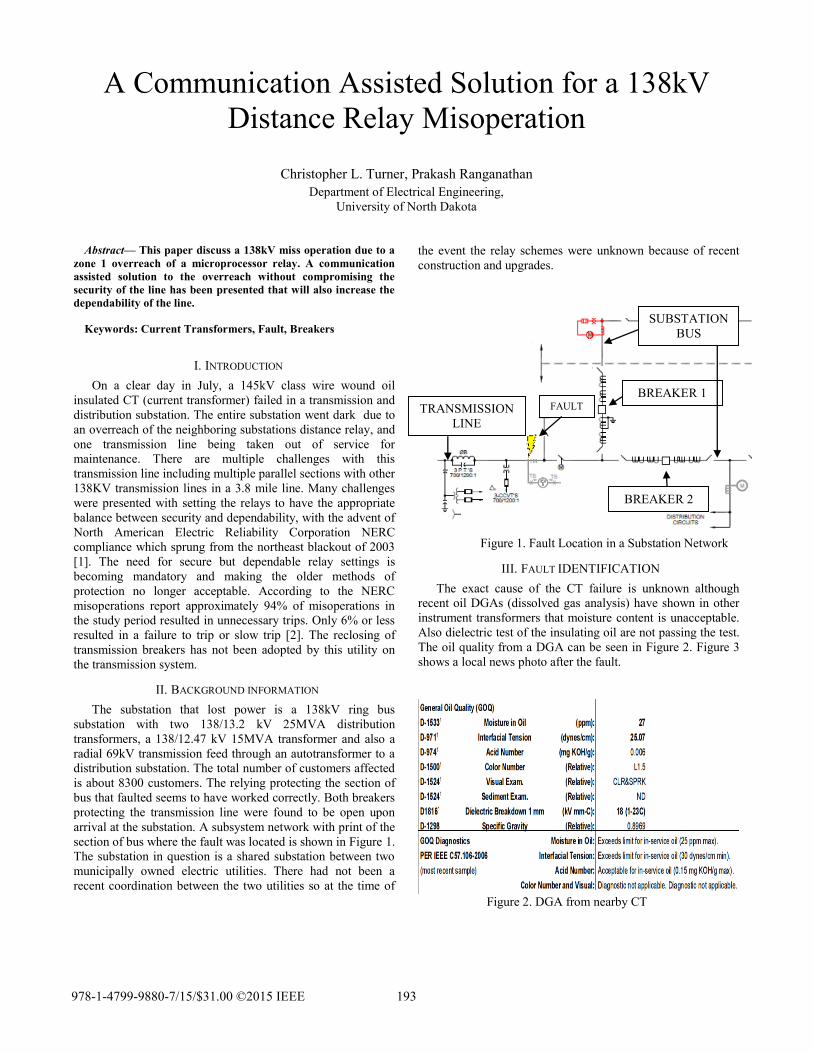
The oil quality from a DGA can be seen in Figure 2. Figure 3
shows a local news photo after the fault.
Figure 2. DGA from nearby CT
BREAKER 1
BREAKER 2
FAULT TRANSMISSION
LINE
SUBSTATION
BUS
978-1-4799-9880-7/15/$31.00 ©2015 IEEE 193
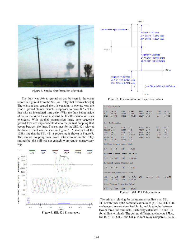
Figure 3. Smoke ring formation after fault
The fault was Aᴓ to ground as can be seen in the event
report in Figure 4 from the SEL 421 relay that overreached.[3]
The element that caused the trip equation to operate was the
zone 1 ground element which is supposed to cover 80% of the
line with no intentional time delay. With the fault being inside
of the substation at the other end of the line this was an obvious
overreach. With parallel transmission lines, zero sequence
ground trips are unpredictable due to the mutual coupling that
occurs between the lines. The settings for the SEL 421 relay at
the time of fault can be seen in Figure 6. A snapshot of the
138kv line that the SEL 421 is protecting is shown in Figure 5.
The mutual coupling was taken into account in the relay
settings but this still was not enough to prevent an unnecessary
trip.
Figure 4. SEL 421 Event report
Figure 5. Transmission line impedance values
Figure 6. SEL 421 Relay Settings
The primary relaying for the transmission line is an SEL
311L with fiber optic communication lines [4]. The SEL 311L
exchanges time-synchronized IA, IB, and IC samples between
two or three line terminals. Each relay calculates 3I2 and 3I0
for all line terminals. The current differential elements 87LA,
87LB, 87LC, 87L2, and 87LG in each relay compare IA, IB, IC,
194
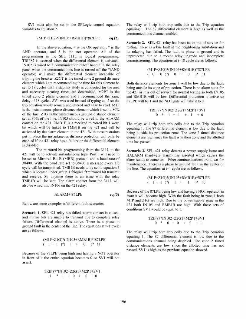
3I2, and 3I0 (IG) from each line terminal [4]. If the 311L
picks up a difference between any of these elements it will trip
the breakers protecting the line. The event was seen by the
311L which can be seen in the event report in Figure 6. The
differential element operated perfectly on the 311L. All
currents stayed in the restraint coil and did not pass into the
operating coil. The 311L can also do phase distance and
ground distance protection. These elements did not assert due
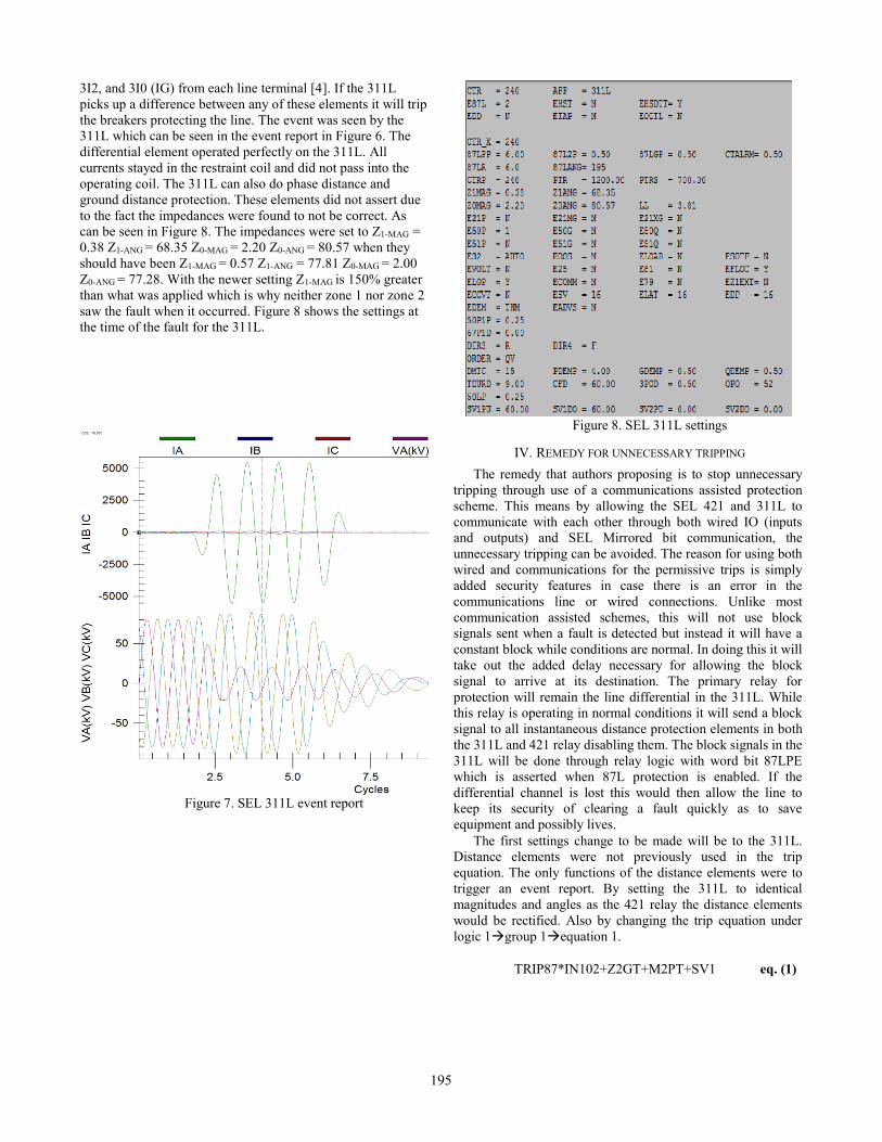
to the fact the impedances were found to not be correct. As
can be seen in Figure 8. The impedances were set to Z1-MAG =
0.38 Z1-ANG = 68.35 Z0-MAG = 2.20 Z0-ANG = 80.57 when they
should have been Z1-MAG = 0.57 Z1-ANG = 77.81 Z0-MAG = 2.00
Z0-ANG = 77.28. With the newer setting Z1-MAG is 150% greater
than what was applied which is why neither zone 1 nor zone 2
saw the fault when it occurred. Figure 8 shows the settings at
the time of the fault for the 311L.
Figure 7. SEL 311L event report
Figure 8. SEL 311L settings
IV. REMEDY FOR UNNECESSARY TRIPPING
The remedy that authors proposing is to stop unnecessary
tripping through use of a communications assisted protection
scheme. This means by allowing the SEL 421 and 311L to
communicate with each other through both wired IO (inputs
and outputs) and SEL Mirrored bit communication, the
unnecessary tripping can be avoided. The reason for using both
wired and communications for the permissive trips is simply
added security features in case there is an error in the
communications line or wired connections. Unlike most
communication assisted schemes, this will not use block
signals sent when a fault is detected but instead it will have a
constant block while conditions are normal. In doing this it will
take out the added delay necessary for allowing the block
signal to arrive at its destination. The primary relay for
protection will remain the line differential in the 311L. While
this relay is operating in normal conditions it will send a block
signal to all instantaneous distance protection elements in both
the 311L and 421 relay disabling them. The block signals in the
311L will be done through relay logic with word bit 87LPE
which is asserted when 87L protection is enabled. If the
differential channel is lost this would then allow the line to
keep its security of clearing a fault quickly as to save
equipment and possibly lives.
The first settings change to be made will be to the 311L.
Distance elements were not previously used in the trip
equation. The only functions of the distance elements were to
trigger an event report. By setting the 311L to identical
magnitudes and angles as the 421 relay the distance elements
would be rectified. Also by changing the trip equation under
logic 1group 1equation 1.
TRIP87*IN102+Z2GT+M2PT+SV1 eq. (1)
195
SV1 must also be set in the SELogic control equation
variables to equation 2.
(M1P+Z1G)*(IN105+RMB1B)*!87LPE eq.(2)
In the above equation, + is the OR operator, * is the
AND operator, and ! is the not operator. All of the
programming in the SEL 311L is logical programming.
TRIP87 is asserted when the differential element is activated.
IN102 is wired to a communication cutoff handle in the relay
panel when the communications line is turned off the *(AND
operator) will make the differential element incapable of
tripping the breaker. Z2GT is the timed zone 2 ground distance
element which I am recommending the time for this element be
set to 18 cycles until a stability study is conducted for the area
and necessary clearing times are determined. M2PT is the
timed zone 2 phase element and I recommended the same
delay of 18 cycles. SV1 was used instead of typing eq. 2 so the
trip equation would remain uncluttered and easy to read. M1P
is the instantaneous phase distance element which is set to 80%
of the line. Z1G is the instantaneous ground distance element
set at 80% of the line. IN105 should be wired to the ALARM
contact on the 421. RMB1B is a received mirrored bit 1 word
bit which will be linked to TMB1B on the 421 and will be
activated by the alarm element in the 421. With these restraints
put in place the instantaneous distance protection will only be
enabled if the 421 relay has a failure or the differential element
is disabled.
The mirrored bit programming from the 311L to the
421 will be to activate instantaneous trips. Port 3 will need to
be set to Mirrored Bit B (MBB) protocol and a baud rate of
38400. With the baud rate set to 38400 a message every 1/8
cycle will be transmitted. TMB1B needs to be set to equation 3
which is located under group 1logic1mirrored bit transmit
and receive. So anytime there is an issue with the relay
TMB1B will be sent. The alarm contact from the 311L will
also be wired into IN106 on the 421 relay.
ALARM+!87LPE eq.(3)
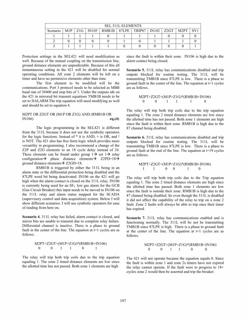
Below are some examples of different fault scenarios.
Scenario 1. SEL 421 relay has failed, alarm contact is closed,
and mirror bits are unable to transmit due to complete relay
failure. Differential channel is active. There is a phase to
ground fault in the center of the line. The equations at t=1 cycle
are as follows.
(M1P+Z1G)*(IN105+RMB1B)*!87LPE
( 1 + 1 )*( 1 + 0 )* !1
Because of the 87LPE being high and having a NOT operator
in front of it the entire equation becomes 0 so SV1 will not
assert.
TRIP87*IN102+Z2GT+M2PT+SV1
1 * 1 + 0 + 0 + 0
The relay will trip both trip coils due to the Trip equation
equaling 1. The 87 differential element is high as well as the
communications channel enabled.
Scenario 2. SEL 421 relay has been taken out of service for
testing. There is a bus fault in the neighboring substation and
its relaying has failed. The fault is phase to ground and is
unprotected due to a recent relay upgrade and incomplete
commissioning. The equations at t=18 cycle are as follows.
(M1P+Z1G)*(IN105+RMB1B)*!87LPE
( 0 + 0 )*( 0 + 0 )* !1
Both distance elements for zone 1 will be low due to the fault
being outside its zone of protection. There is no alarm state for
the 421 as it is out of service for normal testing so both IN105
and RMB1B will be low. Differential protection is active so
87LPE will be 1 and the NOT gate will take it to 0.
TRIP87*IN102+Z2GT+M2PT+SV1
0 * 1 + 1 + 1 + 0
The relay will trip both trip coils due to the Trip equation
equaling 1. The 87 differential element is low due to the fault
being outside its protection zone. The zone 2 timed distance
elements are high since the fault is in their zone and the allotted
time has passed.
Scenario 3. SEL 421 relay detects a power supply issue and
HALARM (hardware alarm) has asserted which causes the
alarm status to come on. Fiber communications are down for
maintenance. There is a phase to ground fault in the center of
the line. The equations at t=1 cycle are as follows.
(M1P+Z1G)*(IN105+RMB1B)*!87LPE
( 1 + 1 )*( 1 + 1 )* !0
Because of the 87LPE being low and having a NOT operator in
front it will become high. With the fault being in zone 1 both
M1P and Z1G are high. Due to the power supply issue in the
421 both IN105 and RMB1B are high. With these sets of
conditions SV1 would be equal to 1.
TRIP87*IN102+Z2GT+M2PT+SV1
0 * 0 + 0 + 0 + 1
The relay will trip both trip coils due to the Trip equation
equaling 1. The 87 differential element is low due to the
communications channel being disabled. The zone 2 timed
distance elements are low since the allotted time has not
passed. SV1 is high as the previous equation showed.
196
Protection settings in the SEL421 will need modification as
well. Because of the mutual coupling on the transmission line,
ground distance elements are unpredictable. Because of this all
instantaneous setting in the 421 will be disabled for normal
operating conditions. All zone 2 elements will be left on a
timer and have no permissive elements other than time.
The first element to be modified will be the
communications. Port 3 protocol needs to be selected as MBB
baud rate of 38400 and stop bits of 1. Under the outputs tab on
the 421 in mirrored bit transmit equations TMB1B needs to be
set to HALARM.The trip equation will need modifying as well
and should be set to equation 4.
M2PT OR Z2GT OR (M1P OR Z1G) AND (RMB1B OR
IN106) eq.(4)
The logic programming in the SEL421 is different
from the 311L because it does not use the symbolic operators
for the logic functions. Instead of * it is AND, + is OR, and !
is NOT. The 421 also has free form logic which provides more
versatility in programming. I also recommend a change of the
Z2P and Z2G elements to an 18 cycle delay instead of 24.
These elements can be found under group 1 set 1 relay
configuration phase distance elements Z2PD=18
ground distance elements Z2GD=18.
RMB1B is triggered by either the 311L being in an
alarm state or the differential protection being disabled and the
87LPE word bit being deactivated. IN106 on the 421 will go
high when the alarm contact is closed on the 311L relay. IN106
is currently being used for an SF6 low gas alarm for the GCB
(Gas Circuit Breaker) this input needs to be moved to IN106 on
the 311L relay and alarm status mapped for the SCADA
(supervisory control and data acquisition) system. Below I will
show different scenarios. I will use symbolic operators for ease
of reading from here on.
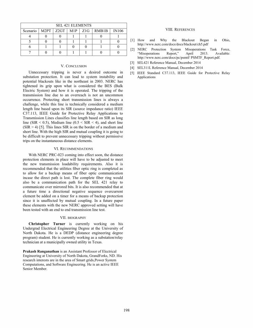
Scenario 4. 311L relay has failed, alarm contact is closed, and
mirror bits are unable to transmit due to complete relay failure.
Differential channel is inactive. There is a phase to ground
fault in the center of the line. The equation at t=1 cycles are as
follows.
M2PT+Z2GT+(M1P+Z1G)*(RMB1B+IN106)
0 0 1 1 0 1
The relay will trip both trip coils due to the trip equation
equaling 1. The zone 2 timed distance elements are low since
the allotted time has not passed. Both zone 1 elements are high
since the fault is within their zone. IN106 is high due to the
alarm contact being closed.
Scenario 5. 311L relay has communications disabled and trip
outputs blocked for routine testing. The 311L will be
transmitting TMB1B since 87LPE is low. There is a phase to
ground fault in the center of the line. The equation at t=1 cycles
are as follows.
M2PT+Z2GT+(M1P+Z1G)*(RMB1B+IN106)
0 0 1 1 1 0
The relay will trip both trip coils due to the trip equation
equaling 1. The zone 2 timed distance elements are low since
the allotted time has not passed. Both zone 1 elements are high
since the fault is within their zone. RMB1B is high due to the
87 channel being disabled.
Scenario 6. 311L relay has communications disabled and trip
outputs blocked for routine testing. The 311L will be
transmitting TMB1B since 87LPE is low. There is a phase to
ground fault at the end of the line. The equation at t=19 cycles
are as follows.
M2PT+Z2GT+(M1P+Z1G)*(RMB1B+IN106)
1 1 0 0 1 0
The relay will trip both trip coils due to the Trip equation
equaling 1. The zone 2 timed distance elements are high since
the allotted time has passed. Both zone 1 elements are low
since the fault is outside their zone. RMB1B is high due to the
87 channel being disabled. So even though the 311L is disabled
it did not affect the capability of the relay to trip on a zone 2
fault. Zone 2 faults will always be able to trip once their timer
has expired.
Scenario 7. 311L relay has communications enabled and is
functioning normally. The 311L will be not be transmitting
TMB1B since 87LPE is high. There is a phase to ground fault
at the center of the line. The equation at t=1 cycles are as
follows.
M2PT+Z2GT+(M1P+Z1G)*(RMB1B+IN106)
0 0 1 1 0 0
The 421 will not operate because the equation equals 0. Since
the fault is within zone 1 and zone 2s timers have not expired
the relay cannot operate. If the fault were to progress to 18+
cycles zone 2 would then be asserted and trip the breaker.
SEL 311L ELEMENTS
Scenario M1P Z1G IN105 RMB1B 87LPE TRIP87 IN102 Z2GT M2PT SV1
1 1 1 1 0 1 1 1 0 0 0
2 0 0 0 0 1 0 1 1 1 0
3 1 1 1 1 0 0 0 0 0 1
197
V. CONCLUSION
Unnecessary tripping is never a desired outcome in
substation protection. It can lead to system instability and
potential blackouts like in the northeast in 2003. NERC has
tightened its grip upon what is considered the BES (Bulk
Electric System) and how it is operated. The tripping of the
transmission line due to an overreach is not an uncommon
occurrence. Protecting short transmission lines is always a
challenge, while this line is technically considered a medium
length line based upon its SIR (source impedance ratio) IEEE
C37.113, IEEE Guide for Protective Relay Applications to
Transmission Lines classifies line length based on SIR as long
line (SIR < 0.5), Medium line (0.5 < SIR < 4), and short line
(SIR > 4) [5]. This lines SIR is on the border of a medium and
short line. With the high SIR and mutual coupling it is going to
be difficult to prevent unnecessary tripping without permissive
trips on the instantaneous distance elements.
VI. RECOMMENDATIONS
With NERC PRC-023 coming into effect soon, the distance
protection elements in place will have to be adjusted to meet
the new transmission loadability requirements. Also it is
recommended that the utilities fiber optic ring is completed as
to allow for a backup means of fiber optic communication
incase the direct path is lost. The complete fiber ring would
also be a communication path for the SEL 421 relay to
communicate over mirrored bits. It is also recommended that at
a future time a directional negative sequence overcurrent
element be added on a timer for a means of backup protection
since it is unaffected by mutual coupling. In a future paper
these elements with the new NERC approved setting will have
been tested with an end to end transmission line test.
VII. BIOGRAPHY
Christopher Turner is currently working on his
Undergrad Electrical Engineering Degree at the University of
North Dakota. He is a DEDP (distance engineering degree
program) student. He is currently working as a substation/relay
technician at a municipally owned utility in Texas.
Prakash Ranganathan is an Assistant Professor of Electrical
Engineering at University of North Dakota, GrandForks, ND. His
research interests are in the area of Smart grids,Power System
Computations, and Software Engineering. He is an active IEEE
Senior Member.
VIII. REFERENCES
[1] How and Why the Blackout Began in Ohio,
http://www.nerc.com/docs/docs/blackout/ch5.pdf
[2] NERC Protection System Misoperations Task Force,
“Misoperations Report,” April 2013. Available:
http://www.nerc.com/docs/pc/psmtf/ PSMTF_Report.pdf.
[3] SEL421 Reference Manual, December 2014
[4] SEL311L Reference Manual, December 2014
[5] IEEE Standard C37.113, IEEE Guide for Protective Relay
Applications
SEL 421 ELEMENTS
Scenario M2PT Z2GT M1P Z1G RMB1B IN106
4 0 0 1 1 0 1
5 0 0 1 1 1 0
6 1 1 0 0 1 0
7 0 0 1 1 0 0
198