Embed Size (px)
Citation preview

RADIOENGINEERING, VOL. 26, NO. 3, SEPTEMBER 2017 655
DOI: 10.13164/re.2017.0655 ELECTROMAGNETICS
A Compact Flexible and Frequency Reconfigurable Antenna for Quintuple Applications
Mubashir Ul HASSAN 1, Farzana ARSHAD 1, Syeda Iffat NAQVI 1, Yasar AMIN1, 2
Hannu TENHUNEN2, 3
1ACTSENA Research Group, University of Engineering and Technology (UET), Taxila, 47050, Pakistan 2 iPack VINN Excellence Center, Royal Institute of Technology (KTH), SE-16440, Stockholm, Sweden
3TUCS, University of Turku, Turku-20520, Finland
[email protected], [email protected]
Submitted March 10, 2017 / Accepted June 11, 2017
Abstract. A novel, compact coplanar waveguide-fed flexi-ble antenna is presented. The proposed design uses flexible Rogers RT/duroid 5880 (0.508 mm thickness) as a sub-strate with small size of 30 × 28.4 mm2. Two switches are integrated on the antenna surface to change the current distribution which consequently changes the resonance frequency under different conditions of switches, thereby making it a frequency reconfigurable antenna. The antenna design is simulated on CST®MWS®. The proposed antenna exhibits VSWR < 2 and appreciable radiation patterns with positive gain over desired frequency bands. Good agree-ment exists between simulated and measured results. On the basis of results, the proposed antenna is envisioned to be deployed for the following applications; aeronautical radio navigation [4.3 GHz], AMT fixed services [4.5 GHz], WLAN [5.2 GHz], Unlicensed WiMAX [5.8 GHz] and X-band [7.5 GHz].
Keywords Flexible antennas, reconfigurable antenna, coplanar waveguide-fed, switches
1. Introduction An antenna operating on multiple frequency bands
has gained a lot of attention due to the proliferation of modern wireless technology and customer demand for multiple services in a single device. Conventionally, a fre-quency band is associated with a particular wireless ser-vice; therefore multi-band antenna is required to support multiple services in a single wireless device. Multi-band antennas can operate over different frequency bands exhi-biting good gain and stable radiation pattern. Albeit, multi-band antennas transmit electromagnetic waves simultane-ously at all the supported frequencies in addition to the desired frequency. Also, electromagnetic radiations from the wireless device have an adverse effect on human health.
The reconfigurable antennas mitigate the above-men-tioned problems associated with the multi-band antennas. Such type of antennas can be reconfigured at the desired frequency band, radiation pattern and polarization. Recon-figuration can be achieved by deploying switches within the radiating element of the antenna [1]. A reconfigurable antenna reduces interference from adjacent unused bands and minimizes the filter requirements of the front end cir-cuits, thus making the design compact [2]. Frequency re-configurable antenna with wide bandwidth is generally chosen because of its miniaturization, cost effectiveness and better tuning ability between different frequency bands without affecting the gain and stability of radiation pattern.
Frequency agility can be realized using different types of switches like varactor diodes [3], pin diodes [4], RF MEMS [5] and FET switches [6]. In [3], varactor diodes are used for reconfiguration, but varactor diodes are non-linear and their continuous tuning range is narrow in nature [4]. Switching between multiple bands requires a large number of pin diodes that increases the insertion loss and complicates the biasing circuitry [7]. RF MEMS has a low loss, but its deployment is expensive [8]. In [9], three pin diodes are employed in U-shaped and L-shaped slots for LTE, AMT Fixed Services, and WLAN applications. However, it uses antenna element on both sides of the substrate. Microstrip based frequency and pattern reconfig-urable antenna is reported in [10] that utilizes five pin diodes. It has three operating modes; omnidirectional at 2.4 GHz, unidirectional at 5.4 GHz and both omnidirec-tional and unidirectional operating concurrently. In [11], frequency reconfigurable antenna using a thick substrate (3.3 mm thickness) is presented in which resonance is controlled by shorting strips; moreover, the conical radia-tion pattern is maintained even at higher frequencies. A compact frequency reconfigurable antenna proposed in [12] utilizes a simple square shaped radiating patch for Bluetooth, WLAN, and WiMAX applications. Three pin diodes are inserted in ground plane that controls switching bands. A novel frequency reconfigurable antenna using the FR4 substrate that switches between an ultra wide band, narrow band, and dual band mode is proposed in [13].
656 M. U. HASSAN , F. ARSHAD, S. I. NAQVI, ET AL., A COMPACT FLEXIBLE AND FREQUENCY RECONFIGURABLE ANTENNA…
Switching is achieved by four pin diodes along with the slotted structure that is created on the ground. Microstrip based frequency reconfigurable antenna is proposed in [14]. Using five pin diodes it achieves six switchable bands from 2.2 GHz to 4.75 GHz. However, the above-mentioned designs suffer from three main drawbacks; the first is their larger dimension, the second is limited impedance band-width, the third is design complexity in terms of numerous switches and intricate structure.
Nowadays, flexible antennas have gained much im-portance because of their low profile, light weight, and robustness [15]. Different flexible substrates have been reported in [15–18]. In [15], the crescent-shaped antenna is presented using flexible RO4003 Rogers with the imped-ance bandwidth of 7.1 GHz. Kapton® polyamide- based multi-band antenna is proposed in [16]. Paper-based an-tenna for 2.4 GHz WLAN application is introduced in [17]. Dual frequency rejection at 5.25 GHz and 5.775 GHz is successfully achieved in [18] using flexible Liquid Crystal Polymer. Above-mentioned flexible antennas have non-reconfigurable functions. Various feeding techniques have been used in flexible antennas, but coplanar waveguide feeding is preferable as it reduces complication by placing an antenna element and a patch on the same side of the substrate. One pin diode is employed in the T-shaped an-tenna for WLAN and WiMAX applications. However, its gain is comparatively low and its fabrication is expensive [19].
In this paper, a novel compact, flexible and frequency reconfigurable antenna is proposed. Both features; flexibil-ity, and reconfiguration are added in this design which makes it attractive for conformal and many other applica-tions. Switches are employed to change the electrical length of the radiator which subsequently changes the resonant frequency. Thus, by applying switches at an ap-propriate location in the proposed design, frequency recon-figuration is possible for five different applications.
The main contributions of this paper are as follows:
A novel, compact, flexible and frequency reconfigu-rable antenna is proposed for Aeronautical Radio Navigation (ARN), AMT fixed Services, WLAN, WiMAX and X-band applications.
Useful frequency bands are achieved for every On/ Off state of the switches.
Gain and bandwidth enhancement using the flexible substrate.
2. Antenna Design and Reconfigura-tion The proposed design is shown in Fig. 1. The proposed
antenna uses Flexible Rogers RT/Duroid 5880 as a sub-strate. The dielectric constant of the substrate is 2.2 and loss tangent is 0.0009 with the thickness of 0.508 mm. The
Fig. 1. Antenna configuration (top view).
Parameter Value (mm) Parameter Value (mm) L 30 Lm 7.3 W 28.4 Lr 3 Lg 14.642 Wt 5.2 Wg 13.45 Wr 11 F 1 R1 1.5 G 0.358 R2 2.5
Tab. 1. Optimized parameters of the proposed design.
proposed antenna has a compact size of 30 mm × 28.4 mm. The antenna is fed by a 50 Ω microstrip line.
The CPW feed line having the width of 1 mm is con-nected to the main radiator. The inner and outer radiator is connected to the main radiator via switch S1 and S2. First of all, CPW fed rectangular antenna which has a single band at 5.8 GHz is designed. The rectangle is introduced inside and outside the main radiator to acquire more reso-nance frequencies. The arc-shaped slots are introduced in appropriate locations in the inner and outer rectangle to obtain the desired band. The width of slot controls the current intensity and minimizes the return loss. The lumped element boundary condition is used to implement the switches in CST® MWS®
. With the four states of switches five resonance modes at 4.2 GHz, 4.3 GHz, 5.1 GHz, 5.8 GHz and 7.5 GHz are excited with good impedance matching. Different parameters are described in Tab. 1.
3. Results and Discussion The prototype of the proposed antenna is fabricated
and tested to validate the performance of the design. Meas-urements are taken using the Vector Network Analyzer (VNA) R&S ZVL13.
The description of states (1 to 4) in terms of the posi-tion of the two switches is described in Tab. 2. The status of the switch, i.e. whether the switch is On/off actually defines the electrical length of the antenna structure that contributes for radiating a particular frequency band. S1 and S2 are the switches that are implemented using con-
RADIOENGINEERING, VOL. 26, NO. 3, SEPTEMBER 2017 657
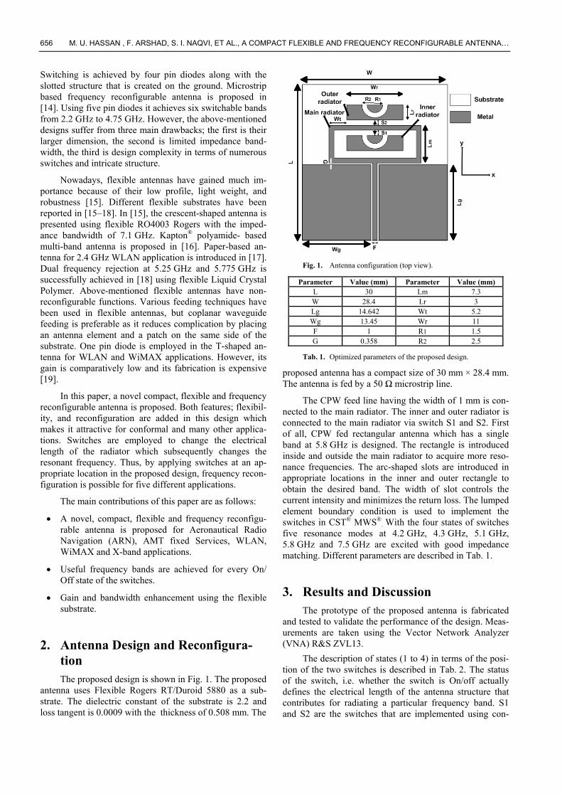
ductor/conducting wires between two conductors to pro-vide the path. Although diodes can be used to provide the path, but this conductor is used because of limitations. When both S1 & S2 are shorted simultaneously, the current circulates in the main radiator as well as in the inner and outer radiator. When both S1 and S2 are open, the current circulates only in the main radiator.
The simulated surface current distribution of the pro-posed antenna at various frequencies under different states of switches is shown in Fig. 2 (a-e). Figure 2(a) suggests that inner radiator radiates due to coupling with surround-ing walls of the main radiator. The main radiator and the outer radiator also radiate. In this case, the current follows the longer path, hence antenna resonates at a low frequency of 4.2 GHz with an impedance bandwidth of 630 MHz (3.9–4.53 GHz) that covers 4.3 GHz Aeronautical Radio Navigation. Figure 2(b) indicates that due to strong current intensity around S1 and S2 another frequency band from 7.2 GHz to 7.8 GHz with an impedance bandwidth of 600 MHz is also observed in state 1. It is noticed that in state 2 the antenna covers the frequency range of (4.7–5.4 GHz) with an impedance bandwidth of 700 MHz that covers 5.2 GHz WLAN. The impedance bandwidth in state 3 is 700 MHz (3.9–4.6 GHz) that is sufficient for the standard of 4.5 GHz AMT Fixed Services. In state 4, the only main radiator is contributing to the radiation, hence, current follows the shortest path so, resonance at 5.5 GHz with a very wide bandwidth of 1 GHz (5–6 GHz) is achieved. It covers 5.5 GHz WLAN and 5.8 GHz unli-censed WiMAX. As mentioned earlier that single rectan-gular antenna operates at 5.8 GHz. Therefore, the shift in frequency from 5.8 GHz to 5.5 GHz is due to the presence of strong coupling that exists in the gap between the main radiator, arc-shaped radiators as well as around the switches.
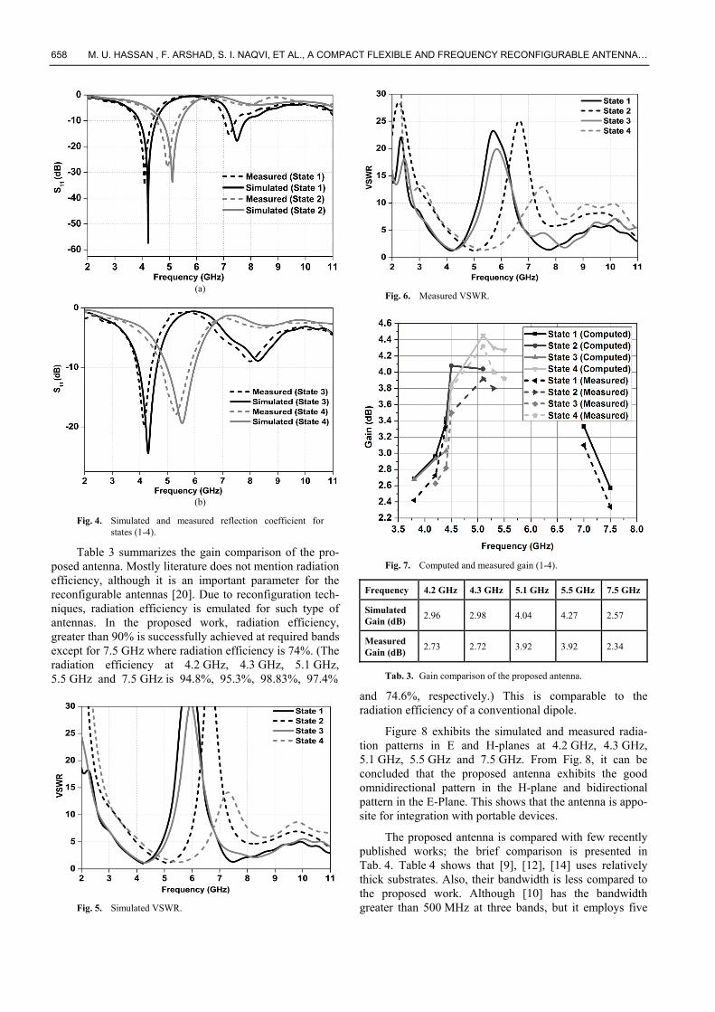
The prototype of the proposed antenna is illustrated in Fig. 3. Input reflection coefficient, VSWR, gain and radia-tion patterns are discussed in this section. Figure 4 shows the simulated and measured reflection coefficient of the proposed antenna for different states of switches. The measured S11 response is in accordance with the simulated results. However, the slight shift between simulated and measured frequencies is due to fabrication inaccuracy, but it still covers the desired frequency bands. It has been ob-served that bandwidth for 4.2 GHz, 7.5 GHz, 4.3 GHz, 5.1 GHz and 5.5 GHz band is 18%, 8%, 16.2%, 13.7% and 18.18%, respectively. Figures 5 and 6 show that VSWR < 2 has been successfully achieved at required resonance bands.
States S1 S2 Frequency (GHz)
Bandwidth (MHz)
State 1 ON ON 4.2 & 7.5 630 & 600 State 2 ON OFF 5.1 700 State 3 OFF ON 4.3 700 State 4 OFF OFF 5.5 1000
Tab. 2. Configuration of switches.
Fig. 2. Current distribution: (a) 4.2 GHz at state 1,
(b) 7.5 GHz at state 1, (c) 5.1 GHz at state 2, (d) 4.3 GHz at state 3, (e) 5.5 GHz at state 4.
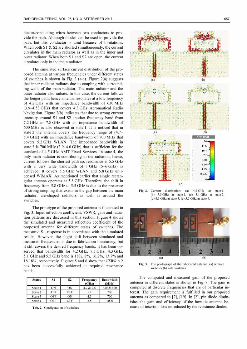
(a) (b)
Fig. 3. The photograph of the fabricated antenna: (a) without switches (b) with switches.
The computed and measured gain of the proposed antenna in different states is shown in Fig. 7. The gain is computed at discrete frequencies that are of particular in-terest. The gain requirement is fulfilled in our proposed antenna as compared to [2], [19]. In [2], pin diode dimin-ishes the gain and efficiency of the bow-tie antenna be-cause of insertion loss introduced by the resistance diodes.
658 M. U. HASSAN , F. ARSHAD, S. I. NAQVI, ET AL., A COMPACT FLEXIBLE AND FREQUENCY RECONFIGURABLE ANTENNA…
(a)
(b)
Fig. 4. Simulated and measured reflection coefficient for states (1-4).
Table 3 summarizes the gain comparison of the pro-posed antenna. Mostly literature does not mention radiation efficiency, although it is an important parameter for the reconfigurable antennas [20]. Due to reconfiguration tech-niques, radiation efficiency is emulated for such type of antennas. In the proposed work, radiation efficiency, greater than 90% is successfully achieved at required bands except for 7.5 GHz where radiation efficiency is 74%. (The radiation efficiency at 4.2 GHz, 4.3 GHz, 5.1 GHz, 5.5 GHz and 7.5 GHz is 94.8%, 95.3%, 98.83%, 97.4%
Fig. 5. Simulated VSWR.
Fig. 6. Measured VSWR.
Fig. 7. Computed and measured gain (1-4).
Frequency 4.2 GHz 4.3 GHz 5.1 GHz 5.5 GHz 7.5 GHz
Simulated Gain (dB)
2.96 2.98 4.04 4.27 2.57
Measured Gain (dB)
2.73 2.72 3.92 3.92 2.34
Tab. 3. Gain comparison of the proposed antenna.
and 74.6%, respectively.) This is comparable to the radiation efficiency of a conventional dipole.
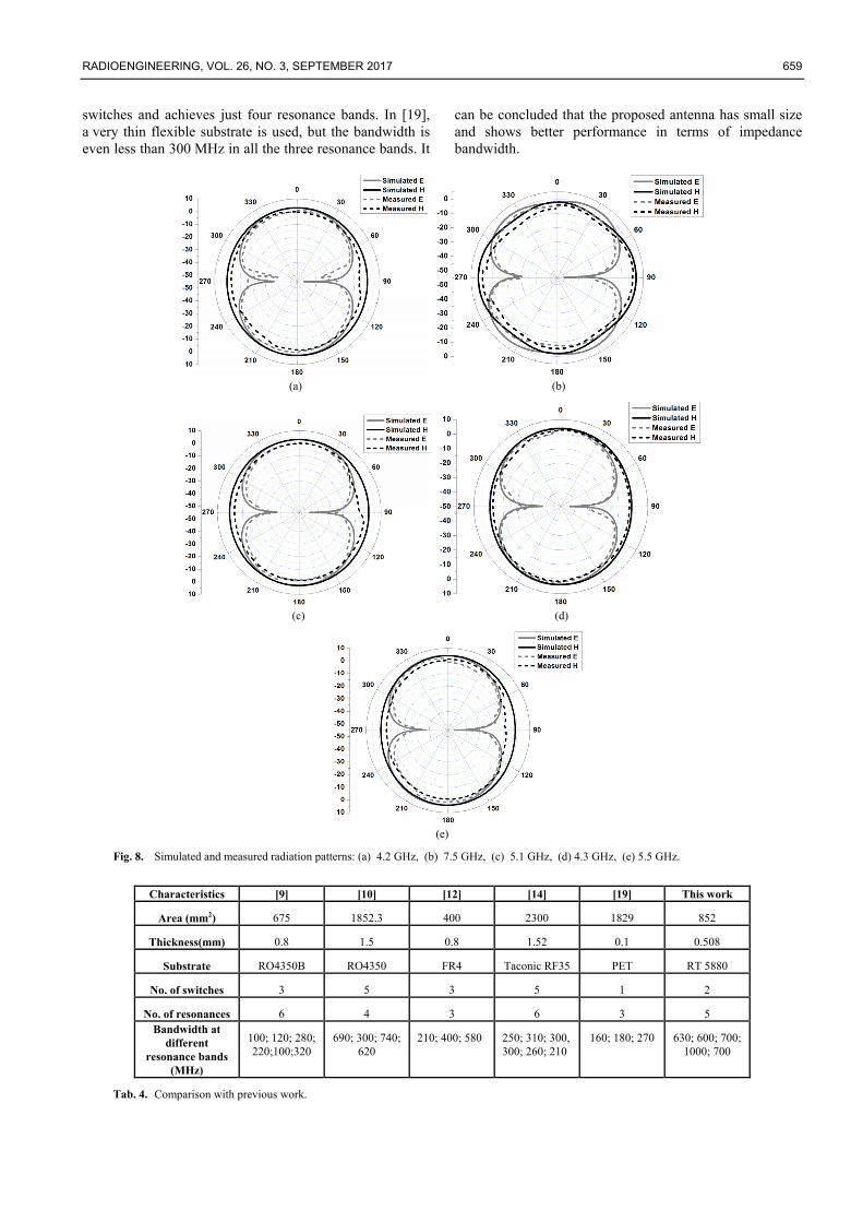
Figure 8 exhibits the simulated and measured radia-tion patterns in E and H-planes at 4.2 GHz, 4.3 GHz, 5.1 GHz, 5.5 GHz and 7.5 GHz. From Fig. 8, it can be concluded that the proposed antenna exhibits the good omnidirectional pattern in the H-plane and bidirectional pattern in the E-Plane. This shows that the antenna is appo-site for integration with portable devices.
The proposed antenna is compared with few recently published works; the brief comparison is presented in Tab. 4. Table 4 shows that [9], [12], [14] uses relatively thick substrates. Also, their bandwidth is less compared to the proposed work. Although [10] has the bandwidth greater than 500 MHz at three bands, but it employs five
RADIOENGINEERING, VOL. 26, NO. 3, SEPTEMBER 2017 659
switches and achieves just four resonance bands. In [19], a very thin flexible substrate is used, but the bandwidth is even less than 300 MHz in all the three resonance bands. It
can be concluded that the proposed antenna has small size and shows better performance in terms of impedance bandwidth.
(a) (b)
(c) (d)
(e)
Fig. 8. Simulated and measured radiation patterns: (a) 4.2 GHz, (b) 7.5 GHz, (c) 5.1 GHz, (d) 4.3 GHz, (e) 5.5 GHz.
Characteristics [9] [10] [12] [14] [19] This work
Area (mm2) 675 1852.3 400 2300 1829 852
Thickness(mm) 0.8 1.5 0.8 1.52 0.1 0.508
Substrate RO4350B RO4350 FR4 Taconic RF35 PET RT 5880
No. of switches 3 5 3 5 1 2
No. of resonances 6 4 3 6 3 5 Bandwidth at
different resonance bands
(MHz)
100; 120; 280; 220;100;320
690; 300; 740; 620
210; 400; 580 250; 310; 300, 300; 260; 210
160; 180; 270 630; 600; 700; 1000; 700
Tab. 4. Comparison with previous work.
660 M. U. HASSAN , F. ARSHAD, S. I. NAQVI, ET AL., A COMPACT FLEXIBLE AND FREQUENCY RECONFIGURABLE ANTENNA…
4. Conclusion A frequency reconfigurable antenna for Aeronautical
Radio Navigation, AMT Fixed services, WLAN, unli-censed WiMAX and X-band applications is proposed. The effective electrical length of the antenna is changed by employing switches that provide the wide tunability of the operating bands. The simulated and measured results are in good agreement. The antenna operates efficaciously at desired bands and has good radiation patterns. Simplicity, compactness, reconfigurability and flexibility are some features that make it a promising candidate for wireless applications.
Acknowledgments This work was financially supported by Vinnova (The
Swedish Governmental Agency for Innovation Systems) and University of Engineering and Technology Taxila, Pakistan through the Vinn Excellence Centers program and ACTSENA research group funding, respectively.
References
[1] SHAH, S. S. A., KHAN, M. F., ULLAH, S., et al. Design and measurement of planar monopole antenna for multi-band wireless applications. IETE Journal of Research, 2017, vol. 63, no. 2, p. 194–204. DOI: 10.1080/03772063.2016.1261049
[2] LI, T., ZHAI, H., WANG, X., et al. Frequency-reconfigurable bow-tie antenna for Bluetooth, WiMAX, and WLAN applications. IEEE Antennas and Wireless Propagation Letters, 2015, vol. 14, p. 171–174. DOI: 10.1109/LAWP.2014.2359199
[3] GE, L., LUK, K. M. Frequency-reconfigurable low-profile circular monopolar patch antenna. IEEE Transactions on Antennas and Propagation, 2014, vol. 62, no. 7, p. 3443–3449. DOI: 10.1109/TAP.2014.2318077
[4] LI, T., ZHAI, H., LI, L. Frequency-reconfigurable bow-tie antenna with a wide tuning range. IEEE Antennas and Wireless Propagation Letters, 2014, vol. 13, p. 1549–1552. DOI: 10.1109/LAWP.2014.2344676
[5] CETINER, B. A., CRUSATS, G. R., JOFRE, L., et al. RF MEMS integrated frequency reconfigurable annular slot antenna. IEEE Transactions on Antennas and Propagation, 2010, vol. 58, no. 3, p. 626–632. DOI: 10.1109/TAP.2009.2039300
[6] YANG, X. L., LIN, J. C., CHEN, G., et al. Frequency reconfigurable antenna for wireless communications using GaAs FET switch. IEEE Antennas and Wireless Propagation Letters, 2015, vol. 14, p. 807–810. DOI: 10.1109/LAWP.2014.2380436
[7] BHELLAR, B., TAHIR, F. A. Frequency reconfigurable antenna for handheld wireless devices. IET Microwaves, Antennas & Propagation, 2015, vol. 9, no. 13, p. 1412–1417. DOI: 10.1049/iet-map.2015.0199
[8] CHEN, G., YANG, X. L., WANG, Y. Dual-band frequency-reconfigurable folded slot antenna for wireless communications. IEEE Antennas and Wireless Propagation Letters, 2012, vol. 11, p. 1386–1389. DOI: 10.1109/LAWP.2012.2227293
[9] HAN, L., WANG, C., CHEN, X., et al. Compact frequency-reconfigurable slot antenna for wireless applications. IEEE
Antennas and Wireless Propagation Letters, 2016, vol. 15, p. 1795–1798. DOI: 10.1109/LAWP.2016.2536778
[10] LI, P. K., SHAO, Z. H., WANG, Q., et al. Frequency- and pattern-reconfigurable antenna for multi standard wireless applications. IEEE Antennas and Wireless Propagation Letters, 2015, vol. 14, p. 333–336. DOI: 10.1109/LAWP.2014.2359196
[11] ROW, J. S., LIN, T. Y. Frequency-reconfigurable coplanar patch antenna with conical radiation. IEEE Antennas and Wireless Propagation Letters, 2010, vol. 9, p. 1088–1091. DOI: 10.1109/LAWP.2010.2093118
[12] BORHANI, M., REZAEI, P., VALIZADE, A. Design of a reconfigurable miniaturized microstrip antenna for switchable multiband systems. IEEE Antennas and Wireless Propagation Letters, 2016, vol. 15, p. 822–825. DOI: 10.1109/LAWP.2015.2476363
[13] BOUDAGHI, H., AZARMANESH, M., MEHRANPOUR, M. A frequency-reconfigurable monopole antenna using switchable slotted ground structure. IEEE Antennas and Wireless Propagation Letters, 2012, vol. 11, p. 655–658. DOI: 10.1109/LAWP.2012.2204030
[14] MAJID, H. A., RAHIM, M. K. A., HAMID, M. R., et al. A compact frequency-reconfigurable narrowband microstrip slot antenna. IEEE Antennas and Wireless Propagation Letters, 2012, vol. 11, p. 616–619. DOI: 10.1109/LAWP.2012.2202869
[15] SALLAM, M. O., KANDIL, S. M., VOLSKI, V., et al. 2.4/5 GHz WLAN crescent antenna on flexible substrate. In 10th European Conference on Antennas and Propagation (EuCAP). Davos (Switzerland), 2016, p. 1-3. DOI: 10.1109/EuCAP.2016.7481498
[16] AHMED, S., TAHIR, F. A., SHAMIM, A., et al. A compact Kapton-based inkjet-printed multiband antenna for flexible wireless devices. IEEE Antennas and Wireless Propagation Letters, 2015, vol. 14, p. 1802–1805. DOI: 10.1109/LAWP.2015.2424681
[17] ANAGNOSTOU, D. E., GHEETHAN, A. A., AMERT., et al. A direct-write printed antenna on paper-based organic substrate for flexible displays and WLAN applications. Journal of Display Technology, 2010, vol. 6, no. 11, p. 558–564. DOI: 10.1109/JDT.2010.2045474
[18] GHEETHAN, A. A., ANAGNOSTOU, D. E. Dual band-reject UWB antenna with sharp rejection of narrow and closely-spaced bands. IEEE Transactions on Antennas and Propagation, 2012, vol. 60, no. 4, p. 2071–2076. DOI: 10.1109/TAP.2012.2186221
[19] SAEED, S. M., BALANIS, C. A., BIRTCHER, C. R. Inkjet-printed flexible reconfigurable antenna for conformal WLAN/WiMAX wireless devices. IEEE Antennas and Wireless Propagation Letters, 2016, vol. 15, p. 1979–1982. DOI: 10.1109/LAWP.2016.2547338
[20] DEL BARRIO, S. C., FOROOZANFARD, E., MORRIS, A., et al. Tunable handset antenna: Enhancing efficiency on TV white spaces. IEEE Transactions on Antennas and Propagation, 2017, vol. 65, no. 4, p. 2106–2111. DOI: 10.1109/TAP.2017.2662221
About the Authors... Mubashir UL HASSAN received his Bachelor’s degree in Telecommunication Engineering from University of Engi-neering and Technology, Taxila in 2014. Currently, in the same University, he is enrolled as an MS Full time scholar. His research interests include planar antennas, multi-band and reconfigurable antennas.
Farzana ARSHAD has received her M.Sc. degree in Tele-communication Engineering from University of Engineer-
RADIOENGINEERING, VOL. 26, NO. 3, SEPTEMBER 2017 661
ing and Technology, Taxila in 2010. Currently, she is an Assistant Professor at the Telecommunication Engi-neering Department and part time Ph.D. researcher of ACTSENA group, UET Taxila. Her research focuses on low profile multi-band and reconfigurable antenna design.
Syeda Iffat NAQVI received her M.Sc. degree in Tele-communication Engineering from University of Engineer-ing and Technology Taxila, in 2011. Currently, she is an Assistant Professor at the Telecommunication Engi-neering Department and part time Ph.D. researcher of ACTSENA group, UET Taxila. Her research focuses on RF and microwave antenna designing for cutting edge wireless technologies.
Yasar AMIN is Chairman and Associate Professor of the Telecommunication Engineering Department, University of Engineering and Technology Taxila, Pakistan. He is founder of the ACTSENA Research Group at UET Taxila, Pakistan. He has done his B.Sc. in Electrical Engineering in 2001 with specialization in Telecommunication, and M.Sc. in Electrical Engineering in 2003 with specialization in System-on Chip Design from Royal Institute of Tech-nology (KTH), Sweden. His Ph.D. is in Electronic and Computer Systems from Royal Institute of Technology (KTH), Sweden, with research focus on printable green RFID antennas for embedded sensors, while having an MBA in Innovation and Growth from Turku School of Economics, University of Turku, Finland. He has done several specialized courses from Stanford University, Cali-fornia, USA and Massachusetts Institute of Technology (MIT), USA. He has supervised over 15 M.Sc. thesis, and presently supervising 8 doctoral thesis. He is presently serving as leading Guest Editor at two international jour-nals and an active reviewer of more than a dozen well reputed international journals. He has contributed to over 20 journal papers, over 30 reviewed international confer-ence papers. Dr. Yasar is a member of IEEE, IET, ACM and ACES.
Hannu TENHUNEN is Chair Professor of Electronic Systems at Royal Institute of Technology (KTH), Stock-
holm, Sweden. Prof. Tenhunen has held professor position as full professor, invited professor or visiting honorary professor in Finland (TUT, UTU), Sweden (KTH), USA (Cornel U), France (INPG), China (Fudan and Beijing Jiatong Universities), and Hong Kong (Chinese University of Hong Kong), and has an honorary doctorate from Tal-linn Technical University. He has been director of multiple national large scale research programs or being an initiator and director of national or European graduate schools. He has actively contributed in VLSI and SoC design in Fin-land and Sweden via creating new educational programs and research directions, most lately at European level as being the EU-level Education Director of the new Euro-pean flagship initiative European Institute of Technology and Innovations (EIT), and its Knowledge and Innovation Community EIT ICT Labs. Prof. Tenhunen has been active in promoting the innovation system and innovation support mechanism in research and education both at national and European level. Prof. Tenhunen has been a board member in science parks, startup companies, and has served as advisor or expert for high technology companies and ven-ture capitalists, as well as evaluator for EU and national programs and research institutes. He has supervised over 70 M.Sc. thesis, 39 doctoral theses, and 8 post-doc. From his doctoral students and post-docs, as of today, 21 are currently professors and associate professors. Prof. Tenhu-nen has served on the Technical Program Committees of all major conferences in his area, have been general Chairman or vice-chairman or member of Steering Com-mittee of multiple conferences in his core competence areas. He has been one of the founding editorial board members of 3 scientific journals, has been questing editor for multiple special issues of scientific journals or books, and has contributed numerous invited papers to journals. He has contributed to over 110 journal papers, over 625 reviewed international conference papers, over 170 non- reviewed papers, local conference papers, or other publica-tions, and 9 international patents granted in multiple coun-tries. Prof. Tenhunen is a member of the Academy of En-gineering Science of Finland.