Embed Size (px)
Citation preview
HAL Id: hal-02931776https://hal.archives-ouvertes.fr/hal-02931776
Submitted on 10 Sep 2020
HAL is a multi-disciplinary open accessarchive for the deposit and dissemination of sci-entific research documents, whether they are pub-lished or not. The documents may come fromteaching and research institutions in France orabroad, or from public or private research centers.
L’archive ouverte pluridisciplinaire HAL, estdestinée au dépôt et à la diffusion de documentsscientifiques de niveau recherche, publiés ou non,émanant des établissements d’enseignement et derecherche français ou étrangers, des laboratoirespublics ou privés.
A compact lowpass filter for satellite communicationsystems based on transfer function analysis
Ali Lalbakhsh, M. (behdad) Jamshidi, H. Siahkamari, A Ghaderi, A.Golestanifar, R. Linhart, J Talla, R.B.V.B. Simorangkir, K Mandal
To cite this version:Ali Lalbakhsh, M. (behdad) Jamshidi, H. Siahkamari, A Ghaderi, A. Golestanifar, et al.. A compactlowpass filter for satellite communication systems based on transfer function analysis. AEÜ - Interna-tional Journal of Electronics and Communications / Archiv für Elektronik und Übertragungstechnik,Elsevier, 2020, 124, pp.153318. �10.1016/j.aeue.2020.153318�. �hal-02931776�
1
A Compact Lowpass Filter for Satellite Communication Systems Based on Transfer
Function Analysis
Ali Lalbakhsh, Mohammad (Behdad) Jamshidi, Hesam Siahkamari, Amirhossein Ghaderi,
Alireza Golestanifar, Richard Linhart, Jakub Talla, Roy B. V. B. Simorangkir, and Kaushik
Mandal
Dr. Ali Lalbakhsh (PhD in Electronics Engineering) is with the School of Engineering, Macquarie
University, NSW, Australia, Email: [email protected] (Corresponding author)
Mr. Mohammad (Behdad) Jamshidi is a PhD student in the Department of Electromechanical
Engineering and Power Electronics (KEV), Faculty of Electrical Engineering of the University of
West Bohemia, Email: [email protected]
Mr. Hesam Siahkamari is a PhD student in in the Department of Applied Electronics and
Telecommunications (KAE), Faculty of Electrical Engineering of the University of West Bohemia,
Email: [email protected]
Mr. Amirhossein Ghaderi (Master in Electronics Engineering) is a senior researcher at Young
Researchers and Elite Club, Kermanshah Branch, Islamic Azad University, Kermanshah, Iran,
Email: [email protected]
Alireza Golestanifar (Master in Electronics Engineering) is a senior researcher at Young
Researchers and Elite Club, Kermanshah Branch, Islamic Azad University, Hamedan, Iran, Master
of Electronics Engineering, Email: [email protected]
Dr. Richard Linhart (PhD in Electronics Engineering) is an Assistant Professor in the Department
of Applied Electronics and Telecommunications (KAE), Faculty of Electrical Engineering of the
University of West Bohemia, Email: [email protected]
Dr. Jakub Talla (PhD in Electrical Engineering) is an Assistant Professor in the Department of
Electromechanical Engineering and Power Electronics (KEV), Faculty of Electrical Engineering
of the University of West Bohemia, Email: [email protected]
Dr. Roy B. V. B. Simorangkir (PhD in Electronics Engineering) is a research associate at University
of Rennes 1, CNRS, Institut d’Electronique et de Tel´ ecommunications of Rennes (IETR)-UMR
6164, F35000 Rennes, France. Email: [email protected]
Kaushik Mandal is an Assistant Professor in the Institute of Radio Physics and Electronics,
University of Calcutta, West Bengal, India, [email protected]
2
Abstract: This paper presents a very efficient design procedure for a high-
performance microstrip lowpass filter (LPF). Unlike many other sophisticated
design methodologies of microstrip LPFs, which contain complicated
configurations or even over-engineering in some cases, this paper presents a
straightforward design procedure to achieve some of the best performance of this
class of microstrip filters. The proposed filter is composed of three different
polygonal-shaped resonators, two of which are responsible for stopband
improvement, and the third resonator is designed to enhance the selectivity of the
filter. A holistic performance assessment of the proposed filter is presented using
a Figure of Merit (FOM) and compared with some of the best filters from the same
class, highlighting the superiority of the proposed design. A prototype of the
proposed filter was fabricated and tested, showing a 3-dB cut-off frequency (fc) at
1.27 GHz, having an ultrawide stopband with a suppression level of 25 dB,
extending from 1.6 to 25 GHz. The return loss and the insertion loss of the
passband are better than 20 dB and 0.25 dB, respectively. The fabricated filter has
a high FOM of 76331, and its lateral size is 22.07 mm × 7.57 mm.
Introduction: Microstrip technology has been extensively used for implementation of
microwave passive and active components, due to its low-cost fabrication process and its
versatile characteristics [1-6]. Microstrip filters (LPFs) play a critical role in modern
communication systems for suppressing unwanted harmonics, as they are easily integrated with
other microwave components. Therefore, passive LPFs with a small size, wide stopband, and
low cost are highly in demand [7]. Such high-performance filters will play a significant role in
the upcoming new generation of the low-cost satellite communications technology, where the
size and the cost of the Earth receiver stations are critical. This is even more important for the
3
communication-one-the-move, where in addition to all strict satellite communication
requirements, there is a strong motivation to employ passive, affordable microwave and
electromagnetic components in the portable satellite receivers [8-11]. Thus, various techniques
have been studied to achieve LPFs with the mentioned features [12-27]. A modified version of
T-shaped resonators in conjunction with multiple open-stubs was proposed in [12] to realize a
compact LPF with a large stopband. In a different approach, a new E-type feeding structure
was proposed to feed a cross-shaped patch reonator to minimize the passband insertion loss
[13]. Coupled rhombic stubs were proposed in [14] to improve both stopband and out-of-band
rejection. While the design procedures in [12], [14] have been successful in some factors of
merit, their roll-offs were reported to be around 50 dB/GHz. To achieve high selectivity,
tapered sectorial resonators and large radial stubs were proposed in [15] and [16], respectively.
Despite the very sharp responses realized in these two works, both procedures resulted in a
relatively large circuit size. Other methods, such as stepped-impedance [13-17], pendulum-
shaped resonator [18] and spiral lines [19], have been proposed for wide-stopband applications.
Similar out-of-band performance along with a strong harmonic attenuation can be achieved
using defected ground structures [20, 21]; however, the implementation complexity is
considered as the associated challenge with this technique.
In [22], a high-impedance transmission-line is loaded by multiple compact microstrip resonant
cells to provide both high selectivity and wide stopband, while the circuit size is not equally
weighted, resulting in a relatively large filter. In [23-27], numerical-based approaches were
used to predict the transfer function of a lowpass filter and to extract its resonant frequencies.
With the development of nature-based optimization algorithms, such as ant colony
optimization [28-29], neural networks [30-34] and particle swarm optimization [35-36], a new
avenue of research in the microwave and electromagnetic community has been established,
4
where several customized optimization algorithms in conjunction with electromagnetic (EM)
simulators have been used to design and optimize a wide range of microwave and EM
components, such as filters, power dividers, frequency selective surfaces [37-44]. Apart from
the above-mentioned applications, microstrip LPFs are integrated with other microwave
components, such as power-dividers with harmonic suppression capability [45-46]. In [47], a
symmetric LPF composed of several square resonators was used to attenuate the reflected
signals throughout the passband up to 15 dB, whereas the transition band is relatively large.
Defected ground structure (DGS) has been reported as another technique for harmonic
suppression in LPFs, considerably extending the stopband range [48],[49]. However, the
attenuation level in the stopband of these filters are less than 18 dB, and the return loss in the
passband is around only 10 dB. Also, radial-shaped and semi-circle patch resonators were
applied in [50], even though it suffers from a narrow stopband. Reviewing related literature
reveals that most approaches mainly focus on improving one or some of the critical properties
of the LPFs, while other aspects, particularly design complications, are sacrificed or neglected.
Hence, we propose a very simple, yet systematic design methodology, to reasonably satisfy all
factors of merit and achieve a significantly greater FOM than many recently published LPFs.
The presented filter is compact with total area of only 0.0048 λg2, where λg is the guided
wavelength at the cut-off frequency. The measured transition band extends from 1.27 GHz to
1.67 GHz with attenuation levels of -3 and -40 dB, respectively. The spurious signals are
significantly suppressed from 1.6 GHz up to 25 GHz, which is about 19fc. The proposed LPF
operating at 1.27 GHz with wide stopband and miniaturized dimensions is a good candidate
for the satellite communication technology. All simulations are carried out by ADS Momentum
on an RT-5880 substrate with a thickness of 0.381 mm.
5
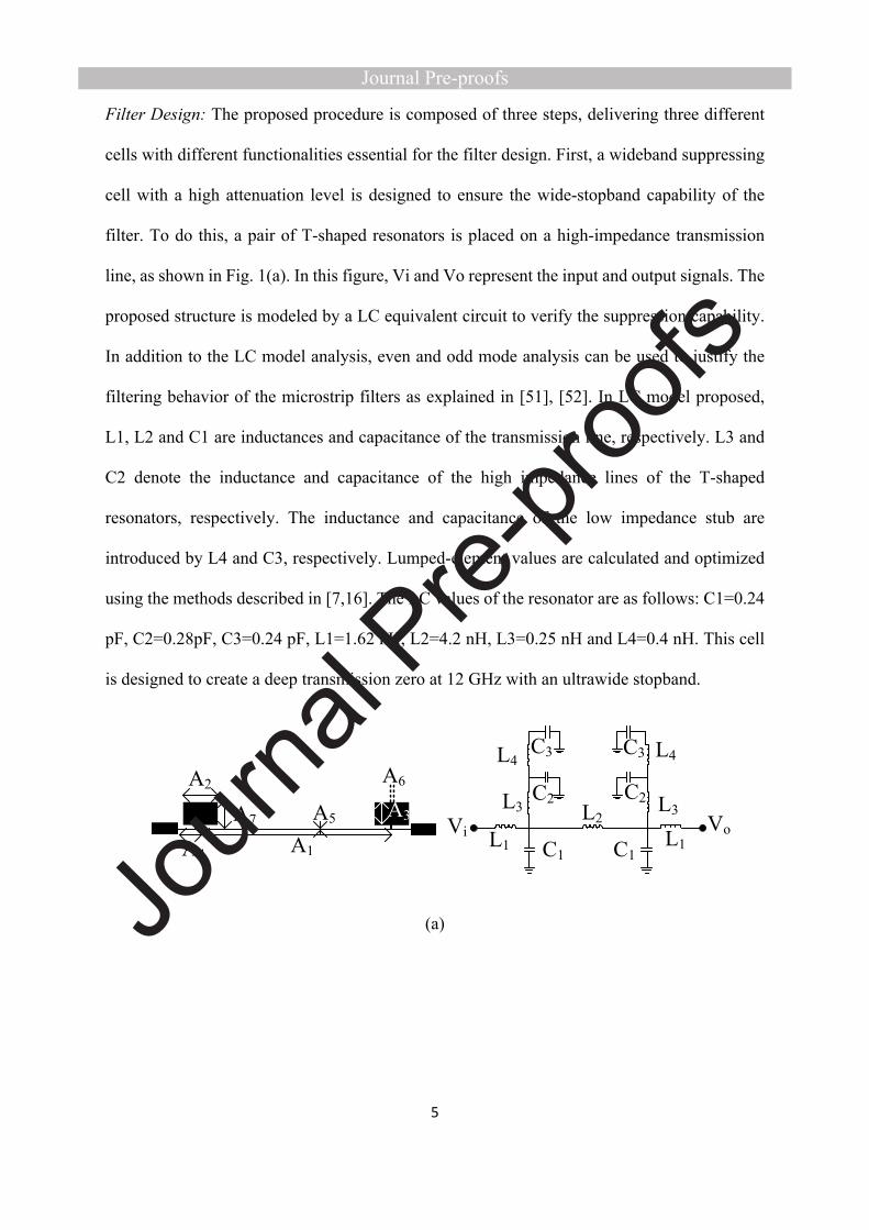
Filter Design: The proposed procedure is composed of three steps, delivering three different
cells with different functionalities essential for the filter design. First, a wideband suppressing
cell with a high attenuation level is designed to ensure the wide-stopband capability of the
filter. To do this, a pair of T-shaped resonators is placed on a high-impedance transmission
line, as shown in Fig. 1(a). In this figure, Vi and Vo represent the input and output signals. The
proposed structure is modeled by a LC equivalent circuit to verify the suppression capability.
In addition to the LC model analysis, even and odd mode analysis can be used to justify the
filtering behavior of the microstrip filters as explained in [51], [52]. In LC model proposed,
L1, L2 and C1 are inductances and capacitance of the transmission line, respectively. L3 and
C2 denote the inductance and capacitance of the high impedance lines of the T-shaped
resonators, respectively. The inductance and capacitance of the low impedance stub are
introduced by L4 and C3, respectively. Lumped-element values are calculated and optimized
using the methods described in [7,16]. The LC values of the resonator are as follows: C1=0.24
pF, C2=0.28pF, C3=0.24 pF, L1=1.62 nH, L2=4.2 nH, L3=0.25 nH and L4=0.4 nH. This cell
is designed to create a deep transmission zero at 12 GHz with an ultrawide stopband.
ViA1
A2
A3
A4
A5
A6
A7
C1 C1
C3
C2 C2
C3
L1
L3
L4 L4
L3
L1
L2 Vo
(a)

6
S11-LayoutS11-LCS21-LayoutS21-LC TZ1
Frequency (GHz)
Mag
nitu
de (d
B)
(b)
Fig. 1 The proposed wideband suppressing cell. (a)Layout and LC equivalent circuit. (b) EM
and LC simulation results.
Fig. 1 (b) shows the EM and LC responses. To analyze and verify the operation of the LC
model, transfer function of the T-shaped resonators is computed as (1). The formula of the first
transmission zero (Tz1) is attained by equating the transfer function to zero as (2). Notice, r is
the matching impedance of input and output ports (r = 50Ω). As seen, the equation of Tz1 is
relared to LC parameters, so that its location can be easily relocated by varying LC values.
(1),22)()(
2
2112
12111 rdsrcLsrcLrsadrLadrdscLsLdbscLsLsdLrd
vv
i
o
where
,22
22
dsLccda

7
,1121 c
dscLsLsLb
,3213
4324313313215
43321 sCCCsLCCLCCLCCLCCsLLCCCc
.12433332
44332 sLCLCLCsLLCCd
(2).2
24)(
4332
43322
433332433332
1 LLCC
LLCCLCLCLCLCLCLC
TZ
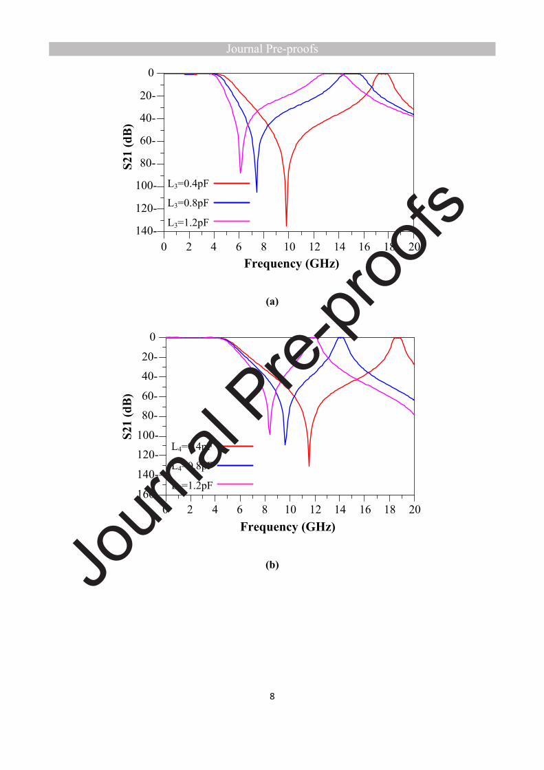
Location of Tz1 is related to the LC values, particularly the values of L3, L4 and C3 which
represent the T-shaped resonators equivalent model. Fig 2 shows the effects of varying L4, L3
and C3. The sweep range of L3 and L4 is 0 to 1 nH and the sweep range of C3 is between 0 to
1 pF. As can be seen, by decresing the vlaues of L4 and L3, Tz1 shifts to higher frequencies,
extending the stopband, while the cut off frequency is less affected by variation of L4
cpompared to L3. The next parameter which is effective to alter stopband range is C3.
According to Fig 2, it is seen that decreasing the value of C3 increaes the stopband and cut off
frequency. It should be noticed that for swept values of L4, L3 and C3 only the one parameter
is swepted and the others are fixed
8
2 4 6 8 10 12 14 16 180 20
-120
-100
-80
-60
-40
-20
-140
0
L3=1.2pF
L3=0.8pF
L3=0.4pF
)GHz(Frequency
S21
(dB
)
(a)
2 4 6 8 10 12 14 16 180 20
-140
-120-100
-80-60
-40-20
-160
0
L4=1.2pF
L4=0.8pF
L4=0.4pF
)GHz(Frequency
S21
(dB
)
(b)
9
2 4 6 8 10 12 14 16 180 20
-120
-100
-80
-60
-40
-20
-140
0
C3=1.2pF
C3=0.8pF
C3=0.4pF
)GHz(Frequency
S21
(dB
)
(c)
Fig. 2. Variation of Tz1 and its effects on the frequency reponse of the filter versus the
different values of L4,L3 and C3.
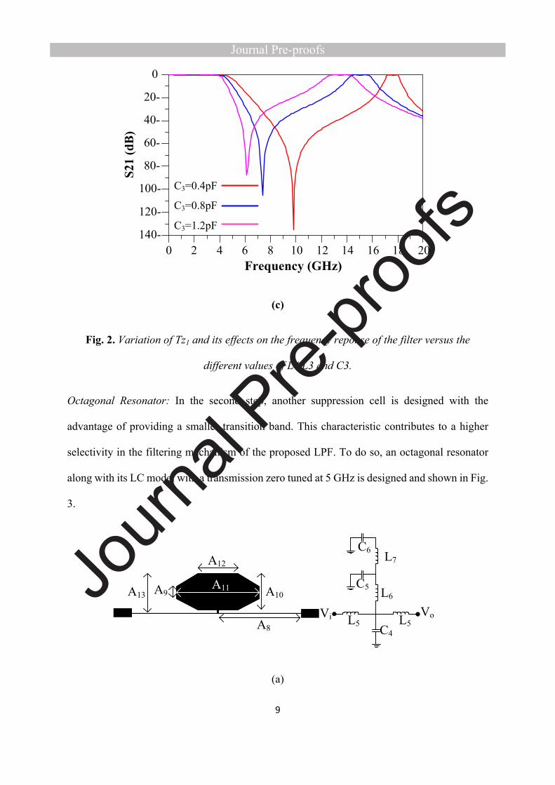
Octagonal Resonator: In the second step, another suppression cell is designed with the
advantage of providing a smaller transition band. This characteristic contributes to a higher
selectivity in the filtering mechanism of the proposed LPF. To do so, an octagonal resonator
along with its LC model with a transmission zero tuned at 5 GHz is designed and shown in Fig.
3.
Vi VoA8
A10A9A11A13
C4
C6
C5
L7
L6
L5 L5
A12
(a)
10
S11-LayoutS11-LCS21-LayoutS21-LC TZ2
Frequency (GHz)
Mag
nitu
de (d
B)
(b)
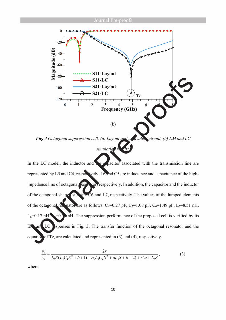
Fig. 3 Octagonal suppression cell. (a) Layout and equivalent circuit. (b) EM and LC
simulation results.
In the LC model, the inductor and the capacitor associated with the transmission line are
represented by L5 and C4, respectively. L6 and C5 are inductance and capacitance of the high-
impedance line of octagonal resonator, respectively. In addition, the capacitor and the inductor
of the octagonal-shaped stub are C6 and L7, respectively. The values of the lumped elements
of the octagonal resonator are as follows: C4=0.27 pF, C5=1.08 pF, C6=1.49 pF, L5=8.51 nH,
L6=0.17 nH, L7=0.50 nH. The suppression performance of the proposed cell is verified by its
EM and LC responses in Fig. 3. The transfer function of the octagonal resonator and the
equation of Tz2 are calculated and represented in (3) and (4), respectively.
(3),)2()1(
2
52
52
452
455 SLarbSaLSCLrbSCLSLr
vv
i
o
where
11
,1)(
)(42
7666654
6765
653
765
SCSLCLCLCSLLCC
SCCSLCCa
.1)(
))((2
7666654
765
653
7655
SLCLCLCSLCCSCCSLCCSLb
(4).2
24)(
7665
76652
766665766665
2 LLCC
LLCCLCLCLCLCLCLC
TZ
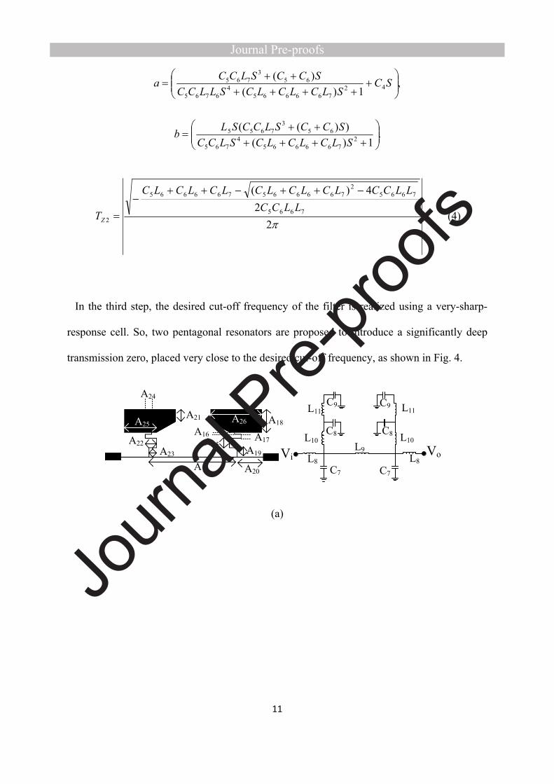
In the third step, the desired cut-off frequency of the filter is realized using a very-sharp-
response cell. So, two pentagonal resonators are proposed to introduce a significantly deep
transmission zero, placed very close to the desired cut-off frequency, as shown in Fig. 4.
L8
L10
L11
C7
L8A14
A15
A16 A17
A18
A19
A20
A21
A22A23
A24
A25 A26C8
C9
C8
C9
L9L10
L11
C7
Vi Vo
(a)
12
S11-LayoutS11-LCS21-LayoutS21-LC
TZ3
Frequency (GHz)
Mag
nitu
de (d
B)
(b)
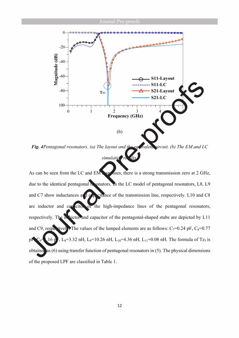
Fig. 4Pentagonal resonators. (a) The layout and the equivalent circuit. (b) The EM and LC
simulation results.
As can be seen from the LC and EM responses, there is a strong transmission zero at 2 GHz,
due to the identical pentagonal resonators. In the LC model of pentagonal resonators, L8, L9
and C7 show inductances and capacitance of the transmission line, respectively. L10 and C8
are inductor and capacitor of the high-impedance lines of the pentagonal resonators,
respectively. The inductor and capacitor of the pentagonal-shaped stubs are depicted by L11
and C9, respectively. The values of the lumped elements are as follows: C7=0.24 pF, C8=0.77
pF, C9=1.16 pF, L8=3.32 nH, L9=10.26 nH, L10=4.36 nH, L11=0.08 nH. The formula of Tz3 is
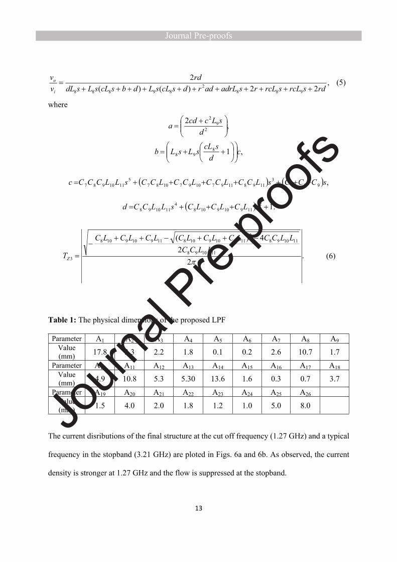
obtained as (6) using transfer function of pentagonal resonators in (5). The physical dimensions
of the proposed LPF are classified in Table 1.
13
(5),22)()(
2
9882
89888 rdsrcLsrcLrsadrLadrdscLsLdbscLsLsdLrd
vv
i
o
where
,22
92
dsLccda
,1898 c
dscLsLsLb
,9873
11981197109710875
1110987 sCCCsLCCLCCLCCLCCsLLCCCc
.12119109108
4111098 sLCLCLCsLLCCd
(6).2
24)(
111098
1110982
119109108119109108
3 LLCC
LLCCLCLCLCLCLCLC
TZ
Table 1: The physical dimensions of the proposed LPF
Parameter A1 A2 A3 A4 A5 A6 A7 A8 A9Value (mm) 17.8 3.3 2.2 1.8 0.1 0.2 2.6 10.7 1.7
Parameter A10 A11 A12 A13 A14 A15 A16 A17 A18Value (mm) 4.9 10.8 5.3 5.30 13.6 1.6 0.3 0.7 3.7
Parameter A19 A20 A21 A22 A23 A24 A25 A26Value (mm) 1.5 4.0 2.0 1.8 1.2 1.0 5.0 8.0
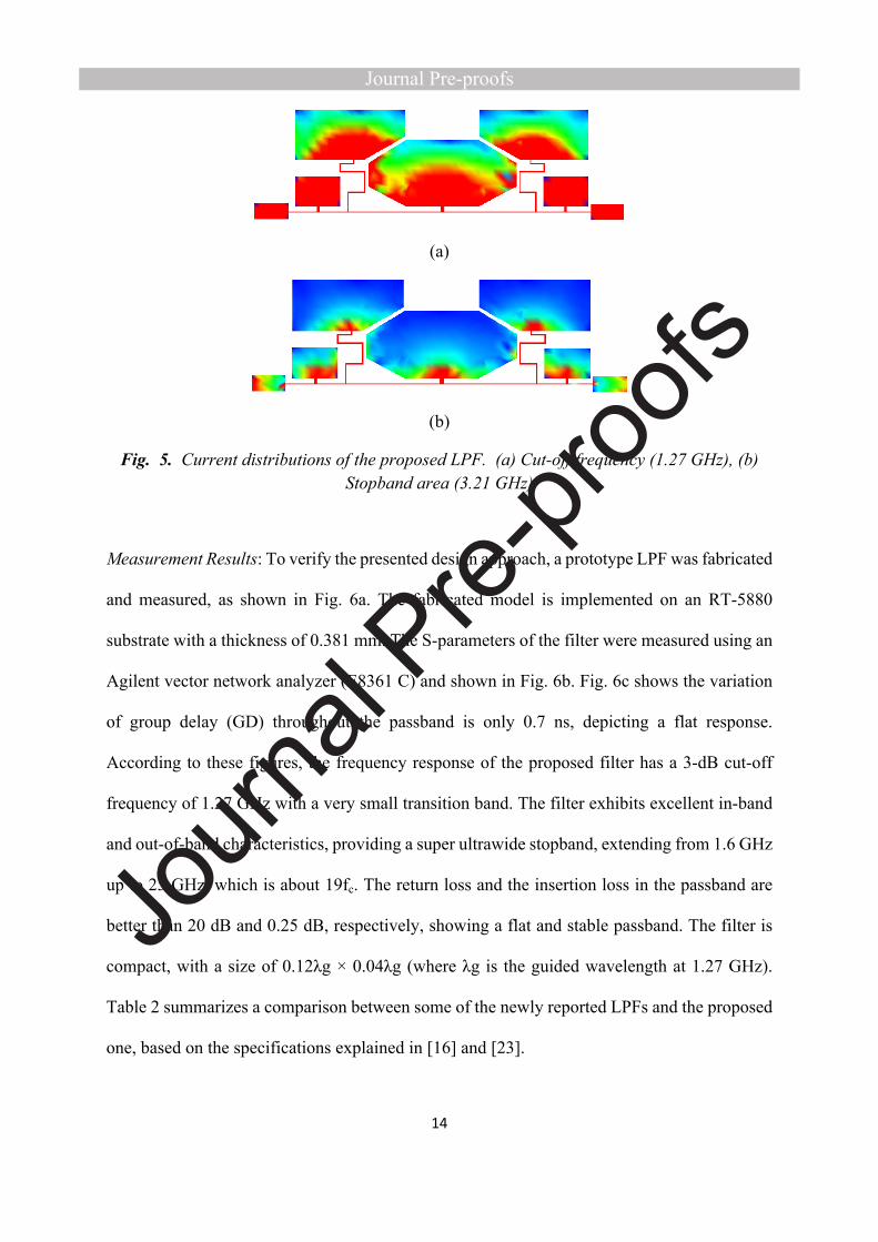
The current disributions of the final structure at the cut off frequency (1.27 GHz) and a typical
frequency in the stopband (3.21 GHz) are ploted in Figs. 6a and 6b. As observed, the current
density is stronger at 1.27 GHz and the flow is suppressed at the stopband.
14
(a)
(b)
Fig. 5. Current distributions of the proposed LPF. (a) Cut-off frequency (1.27 GHz), (b) Stopband area (3.21 GHz)
Measurement Results: To verify the presented design approach, a prototype LPF was fabricated
and measured, as shown in Fig. 6a. The fabricated model is implemented on an RT-5880
substrate with a thickness of 0.381 mm. The S-parameters of the filter were measured using an
Agilent vector network analyzer (E8361 C) and shown in Fig. 6b. Fig. 6c shows the variation
of group delay (GD) throughout the passband is only 0.7 ns, depicting a flat response.
According to these figures, the frequency response of the proposed filter has a 3-dB cut-off
frequency of 1.27 GHz with a very small transition band. The filter exhibits excellent in-band
and out-of-band characteristics, providing a super ultrawide stopband, extending from 1.6 GHz
up to 25 GHz, which is about 19fc. The return loss and the insertion loss in the passband are
better than 20 dB and 0.25 dB, respectively, showing a flat and stable passband. The filter is
compact, with a size of 0.12λg × 0.04λg (where λg is the guided wavelength at 1.27 GHz).
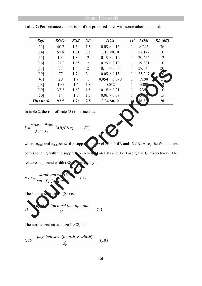
Table 2 summarizes a comparison between some of the newly reported LPFs and the proposed
one, based on the specifications explained in [16] and [23].

15
(a)
(b)
0 0.2 0.4 0.6 0.8 1 1.2Frequency (GHz)
0
1
2
3
GD
(ns)
Sim.Meas.
(c)
Fig. 6. The proposed LPF. (a) Fabricated prototype, (b) Simulated and measured results,
(c) Group delay
16
Table 2: Performance comparison of the proposed filter with some other published.
Ref. RO(ξ) RSB SF NCS AF FOM RL (dB)[13][14][15][16]
40.257.8104217
1.601.611.801.65
1.53.522
0.09 × 0.130.12 ×0.100.19 × 0.120.29 × 0.12
1111
8,24627,14220,46419,931
36101210
[17] 75 1.66 2 0.11 × 0.08 1 28,040 20[19] 77 1.74 2.4 0.09 × 0.13 1 25,247 20[47] 20 1.7 1 0.054 × 0.070 1 9190 15[48] 100 1.6 1.8 0.032 1 9000 12[49] 37.2 1.62 1.5 0.18 × 0.21 1 2391 10[50] 14 1.5 1.5 0.06 × 0.08 1 6468 15
This work 92.5 1.76 2.5 0.04 ×0.12 1 76,331 20
In table 2, the roll-off rate (𝞷) is defined as:
𝜉 =𝛼𝑚𝑎𝑥 ― 𝛼𝑚𝑖𝑛
𝑓𝑠 ― 𝑓𝑐 (𝑑𝐵/𝐺𝐻𝑧) (7)
where αmax and αmin show the suppression level of -40 dB and -3 dB. Also, the frequencies
corresponding with the suppression levels of -40 dB and 3 dB are fs and fc, respectively. The
relative stop-band width (RSB) is given by :
𝑅𝑆𝐵 =𝑠𝑡𝑜𝑝𝑏𝑎𝑛𝑑 𝑤𝑖𝑑𝑡ℎ
𝑐𝑢𝑡 𝑜𝑓𝑓 𝑓𝑟𝑒𝑞𝑢𝑒𝑛𝑐𝑦 (8)
The suppression factor (SF) is:
𝑆𝐹 =𝑠𝑢𝑝𝑝𝑟𝑒𝑠𝑠𝑖𝑜𝑛 𝑙𝑒𝑣𝑒𝑙 𝑖𝑛 𝑠𝑡𝑜𝑝𝑏𝑎𝑛𝑑
10 (9)
The normalized circuit size (NCS) is:
𝑁𝐶𝑆 =𝑝ℎ𝑦𝑠𝑖𝑐𝑎𝑙 𝑠𝑖𝑧𝑒 (𝑙𝑒𝑛𝑔𝑡ℎ × 𝑤𝑖𝑑𝑡ℎ)
𝜆2𝑔
(10)
17
where λg is the guided wavelength at 1.27 GHz and for 2 dimensional structure the architecture
factor (AF) is defined 1. Finally, the FOM is defined as:
𝐹𝑂𝑀 =𝑅𝑆𝐵 × 𝜉 × 𝑆𝐹
𝐴𝐹 × 𝑁𝐶𝑆 (11)
Conclusion: A highly selective, compact LPF with an ultrawide stopband is designed through
a systematic approach. In this approach, three polygonal resonators are designed, where two
resonators are collectively responsible for providing an ultrawide stopband, and the third
resonator independently controls the cut-off frequency of the filter with a sharp roll-off. The
filter suppresses all spurious bands up to the 19th harmonic, with a very good attenuation of 25
dB, exhibiting an excellent out-of-band characteristic. The fabricated LPF has a high return
loss (20 dB) and negligible insertion loss (0.25 dB) in the passband. The filter is compact with
a very high FOM of 76,331.
Acknowledgement
This research has been supported by the Ministry of Education, Youth and Sports of the Czech
Republic under the project OP VVV Electrical Engineering Technologies with High Level of
Embedded Intelligence CZ.02.1.01/0.0/0.0/18_069/0009855.
18
References
[1] P Rostami, S Roshani, “A miniaturized dual band Wilkinson power divider using capacitor loaded transmission lines,” AEU-International Journal of Electronics and Communications, 90, pp. 63-68, 2018.[2] G Karimi, M Amirian, A Lalbakhsh, M Ranjbar, “A new microstrip coupling system for realization of a differential dual-band bandpass filter,” AEU-International Journal of Electronics and Communication, Vol. 99, pp. 186-192, 2019.[3] A. Lalbakhsh, Muhammad U. Afzal, Karu P. Esselle, Stepanie L. Smith, Basit A. Zeb, “Single-dielectric Wideband Partially Reflecting Surface with Variable Reflection Components for Realization of a Compact High-gain Resonant Cavity Antenna,” IEEE Trans. Antennas Propag.,Vo. 67, no. 3, pp.1916–1921, 2019[4] P. Gooran, A. Lalbakhsh, H. Moradi, and M. Jamshidi “Compact and wideband printed log-periodic dipole array antenna using multi-sigma and multi-Tau techniques,” Journal of Electromagnetic Waves and Applications, 2019[5] A Ahmadi, SV Makki, A Lalbakhsh, S Majidifar, “A novel dual-mode wideband band pass filter,” Applied Computational Electromagnetics Society Journal (ACES). Vol. 29, Issue 9, pp.735-742, Sep. 2014[6] G. Karimi, H. pourasad, A. Lalbakhsh, H. Siahkamari, “Design of a compact ultra-narrow band dual band filter for WiMAX application,” AEU-International Journal of Electronics and Communication, Vol. 110, 2019[7] H. Jia-Sheng, and M. Lancaster, “Microstrip filters for RF/microwave applications,” Microwave Magazine, vol. 3, no. 3, pp. 62-65, 2001.[8] M. U. Afzal, A. Lalbakhsh and K. P. Esselle, “A Low-Profile Beam-Tilted Antenna Array for Receiving Direct-Broadcast Satellite Services,” 2018 IEEE Asia-Pacific Conference on Antennas and Propagation (APCAP), Auckland, 2018, pp. 147-148.[9] A. Lalbakhsh, M. U. Afzal, K.P. Esselle, S. L. Smith, “Low-Cost Non-Uniform Metallic Lattice for Rectifying Aperture Near-Field of Electromagnetic Bandgap Resonator Antennas,” IEEE Trans. Antennas Propag. In press, 2020.[10] J.E. Eng, and S.Y. Frank, Boeing Co, 2019. Low cost millimeter wave receiver and method for operating same. U.S. Patent 10,263,648.[11] Muhammad U. Afzal, A. Lalbakhsh, Karu P. Esselle, “Electromagnetic-wave beam-scanning antenna using near-field rotatable graded-dielectric plates,” Journal of Applied Physics, Vol. 124, no. 23 pp. 912–915, 2018.[12] A. Sheikhi, A. Alipour, and H. Hemesi, “Design of microstrip wide stopband lowpass filter with lumped equivalent circuit,” Electronics Letters, vol. 53, no. 21, pp. 1416-1418, 2017.[13] Y. Jiang, B. Wei, Y. Heng, X. Guo, B. Cao, and L. Jiang, “Compact superconducting lowpass filter with wide stopband,” Electronics Letters, vol. 53, no. 14, pp. 931-933, 2017.[14] B. Zhang, S. Li, and J. Huang, “Compact lowpass filter with wide stopband using coupled rhombic stubs,” Electronics Letters, vol. 51, no. 3, pp. 264-266, 2015.[15] S. Jiang, and J. Xu, “Sharp roll-off planar lowpass filter with ultra-wide stopband up to 40 GHz,” Electronics Letters, vol. 53, no. 11, pp. 734-735, 2017.
19
[16] G. Karimi, A. Lalbakhsh, and H. Siahkamari, “Design of sharp roll-off lowpass filter with ultra wide stopband,” IEEE Microwave and Wireless Components Letters, vol. 23, no. 6, pp. 303-305, 2013.[17] J. Xu, Y.-X. Ji, W. Wu, and C. Miao, “Design of miniaturized microstrip LPF and wideband BPF with ultra-wide stopband,” IEEE Microwave and wireless components letters, vol. 23, no. 8, pp. 397-399, 2013.[18] K. Dehghani, G. Karimi, A. Lalbakhsh and S.V. Maki, “Design of lowpass filter using novel stepped impedance resonator,” Electronics Letters, vol. 50, no. 1, pp. 37-39, 2014.[19] C.-J. Chen, C.-H. Sung, and Y.-D. Su, “A multi-stub lowpass filter,” IEEE Microwave and Wireless Components Letters, vol. 25, no. 8, pp. 532-534, 2015.[20] F.-C. Chen, H.-T. Hu, J.-M. Qiu, and Q.-X. Chu, “High-selectivity low-pass filters with ultrawide stopband based on defected ground structures,” IEEE Transactions on components, packaging and manufacturing Technology, vol. 5, no. 9, pp. 1313-1319, 2015.[21] S. Jiang, and J. Xu, “Compact microstrip lowpass filter with ultra-wide stopband based on dual-plane structure,” Electronics Letters, vol. 53, no. 9, pp. 607-609, 2017.[22] S. Roshani, “A compact microstrip low-pass filter with ultra wide stopband using compact microstrip resonant cells,” International Journal of Microwave and Wireless Technologies, vol. 9, no. 5, pp. 1023-1027, 2017.[23] G Karimi, A Lalbakhsh, K Dehghani, H Siahkamari, “Analysis of Novel Approach to Design of Ultra‐wide Stopband Microstrip Low‐Pass Filter Using Modified U‐Shaped Resonator,” ETRI Journal, vol. 37, no. 5, pp. 945-950, 2015.[24] G Karimi, H Siahkamari, FK Hamedani, A Lalbakhsh, “Design of modified Z-shaped and T-shaped microstrip filter based on transfer function analysis,” Wireless Personal Communications, vol. 82, no. 4, pp. 2005-2016, 2015.[25] H. Sariri, Z. Rahmani, A. Lalbakhsh and S. Majidifar, “Compact LPF Using T-shaped Resonator,” Frequenz, vol. 67, no. 1-2, pp. 17-20, 2013.[26] S. Roshani, K. Dehghani, and S. Roshani, “A Lowpass Filter Design Using Curved and Fountain Shaped Resonators,” Frequenz, vol. 73, no. 7-8, pp. 267-272, 2019.[27] A. Ghaderi, and S. Roshani, “L-Band Microstrip Lowpass Filter with Small Size and Excellent Harmonic Suppression,” Microwave Journal, vol. 61, no. 10, 2018.[28] Pooia Lalbakhsh, Bahram Zaeri, A. Lalbakhsh, Mehdi N. Fesharaki, “AntNet with Reward-Penalty Reinforcement Learning,”Second International Conference on Computational Intelligence, Communication Systems and Networks (CICSYN2010), Liverpool, UK, pp. 17-21, 2010.[29] Pooia Lalbakhsh, Bahram Zaeri and A. Lalbakhsh, “An Improved Model of Ant Colony Optimization using a Novel Pheromone Update Strategy,” IEICE Trans. Inf. & Syst. Vol. E96-D, No.11, pp. 2309-2318, Nov. 2013.[30] M. B. Jamshidi, N. Alibeigi, A. Lalbakhsh, “Artificial Neural Networks: A Powerful Tool for Cognitive Science,” 2018 IEEE 9th Annual Information Technology, Electronics and Mobile Communication Conference (IEMCON), Vancouver, BC, 2018, pp. 674-679.[31] Wang, G., Xu, Y., Ge, M., Lu, L. and Jia, Y., 2020. Mode transition and energy dependence of FitzHugh-Nagumo neural model driven by high-low frequency electromagnetic radiation. AEU-International Journal of Electronics and Communications, p.153209.

20
[32] M. B. Jamshidi, A. Lalbakhsh, N. Alibeigi, M. R. Soheyli, B. Oryani and N. Rabbani, “Socialization of Industrial Robots: An Innovative Solution to improve Productivity,” 2018 IEEE 9th Annual Information Technology, Electronics and Mobile Communication Conference (IEMCON), Vancouver, BC, 2018, pp. 832-837. [33] M Hayati, F Shama, S Roshani, A Abdipour,"Linearization design method in class-F power amplifier using artificial neural network," Journal of Computational Electronics 13 (4), 943-949[34] M. B. Jamshidi, A. Lalbakhsh et al, “Artificial Intelligence and COVID-19: Deep Learning Approaches for Diagnosis and Treatment,” IEEE ACCESS, 2020. DOI:10.1109/ACCESS.2020.3001973.[35] A. Lalbakhsh, Muhammad U. Afzal, Karu P. Esselle, Stephanie Smith, “Design of an artificial magnetic conductor surface using an evolutionary algorithm,” in Proc. 19th IEEE international Conference on Electromagnetics in Advanced Applications (ICEAA), Verona, Italy, Sep., 2017[36] A. Lalbakhsh, Muhammad U. Afzal, B. A. Zeb and Karu P. Esselle, “Design of a dielectric phase-correcting structure for an EBG resonator antenna using particle swarm optimization,” in Proc. IEEE. Int Symp. Antennas Propag. (ISAP), Hobart, Australia, Nov., 2015, pp. 408-410[37] Z. Yang, Y. Yao, Y. Jin, M. Li, Z. Geng, Z. Yu, and Z. Li, “Synthesizing and Optimizing of Wide Stopband Low-Pass Filter with Improved Infinite Attenuation Unit Based on Stubs,” Frequenz, vol. 72, no. 11-12, pp. 523-531, 2018.[38] A Karami, GH Roshani, E Nazemi, S Roshani, "Enhancing the performance of a dual-energy gamma ray based three-phase flow meter with the help of grey wolf optimization algorithm,'' Flow Measurement and Instrumentation 64, 164-172, 2018.[39] A. Lalbakhsh, M. U. Afzal, and K. P. Esselle, “Multiobjective particle swarm optimization to design a time-delay equalizer metasurface for an electromagnetic band-gap resonator antenna,” IEEE Antennas and Wireless Propagation Letters, vol. 16, pp. 912-915, 2017.[40] M. B. Jamshidi, A. Lalbakhsh, S. Lotfi, H. Siahkamari, B. Mohamadzade, and J. Jalilian, “A Neuro-based Approach to Designing a Wilkinson Power Divider,” International Journal of RF and Microwave Computer Aided Engineering, e22091. 2019.[41] S. Koziel, and A. Bekasiewicz, “On deterministic procedures for low-cost multi-objective design optimization of miniaturized impedance matching transformers,” Engineering Computations, vol. 34, no. 2, pp. 403-419, 2017.[42] A. Lalbakhsh, M. U. Afzal, K. P. Esselle, and S. L. Smith, “Wideband Near-Field Correction of a Fabry–Perot Resonator Antenna,” IEEE Transactions on Antennas and Propagation, vol. 67, no. 3, pp. 1975-1980, 2019.[43] MB Jamshidi, A Lalbakhsh, B Mohamadzade, H Siahkamari, “A Novel Neural-Based Approach for Design of Microstrip Filters,” AEU-International Journal of Electronics and Communications, pp. 152847, 2019.[44] A. Lalbakhsh, M. Afzal, and K. Esselle, "Simulation-driven particle swarm optimization of spatial phase shifters," in Proc. 18th IEEE international Conference on Electromagnetics in Advanced Applications (ICEAA), Australia, Cairns, Australia, Sep., 2016, pp 428-430

21
[45] S. Roshani, S. Roshani, and A. Zarinitabar, “A modified Wilkinson power divider with ultra harmonic suppression using open stubs and lowpass filters,” Analog Integrated Circuits and Signal Processing, vol. 98, no. 2, pp. 395-399, 2019.[46] S. Roshani, M. Hayati, S. Setayeshi, S. Roshani, and G. Mohamadpour, “A miniaturized harmonic suppressed power amplifier integrated with lowpass filter for long term evolution application,” Analog Integrated Circuits and Signal Processing, vol. 89, no. 1, pp. 197-204, 2016.[47] Li, Z. and Ho, S.J., Compact Microstrip Lowpass Filter with Ultra-Wide Stopband Characteristic Using Square Ring Loaded Resonators. Progress In Electromagnetics Research, vol. 90, pp.1-5, 2020.[48] Rekha, T.K., Abdulla, P., Jasmine, P.M. and Anu, A.R., Compact microstrip lowpass filter with high harmonics suppression using defected structures. AEU-International Journal of Electronics and Communications, vol. 115, p.153032, 2020.[49] Shi, L.F., Fan, Z.Y. and Xin, D.J., Miniaturized low‐pass filter based on defected ground structure and compensated microstrip line. Microwave and Optical Technology Letters, vol. 62, no. 3, pp.1093-1097, 2020.[50] Zhang, H. and Zhao, J., “Compact microstrip lowpass filter with ultra-wide stopband performance using radial stub loaded resonators”, Progress In Electromagnetics Research, vol. 71, pp.199-203, 2018.[51] A. Lalbakhsh, G. Karimi, F. Sabaghi, “Triple mode spiral wideband bandpass filter using symmetric dual-line coupling,” Electronics Letters, Vol. 53, No. 12, pp. 795-797, 2017[52] Wang, J., He, S., You, F., Shi, W., Peng, J. and Li, C., 2018. Codesign of high-efficiency power amplifier and ring-resonator filter based on a series of continuous modes and even–odd-mode analysis. IEEE Transactions on Microwave Theory and Techniques, 66(6), pp.2867-2878.