Embed Size (px)
Citation preview

© 2019 IJRAR May 2019, Volume 6, Issue 2 www.ijrar.org (E-ISSN 2348-1269, P- ISSN 2349-5138)
IJRAR19K1101 International Journal of Research and Analytical Reviews (IJRAR) www.ijrar.org 738
A Compact UWB Fractal Antenna For Wireless Communication Applications
1Ch.Manohar Kumar, 2 M.V.N Sai Pavan ,3 N.sowmya , 4 P.Ajith, 5 Bh.S.G.Vijay Kumar 1,3 Assistant Professor ,Department of ECE, GVP College for Degree and PG Courses(A), Rushikonda, Visakhapatnam.
ABSTRACT: The literature is devoted to the development and investigation of an ultra-wideband micro strip patch antenna with an extended frequency range constructed on the basis of a Koch inspired fractal technique which allows significant reduction of the dimensions of the structure. The results regarding the changes in the characteristics of radiation depending on the level of iteration are presented. Optimization of the scaling depth of each side for compliance with the collision of one side with the adjacent was carried out. The dimensions of the proposed antenna after optimization are 51 × 54mm2 and the operating frequency range is 3.7 to 20 GHz. Simulations are done using CST Microwave Studio Suite 2015.
Index terms: Multi Band, fractal, Gain, Directivity.
INTRODUCTION
Microtechnology involves miniaturization of all parts that are encapsulated in a device. The rapid development of telecommunication technology over the past decade has led to a significant tightening of requirements presented to the weight and size characteristics of radiators with high throughputs at microwave frequencies. There is also demand for compatibility with the printed circuit board of the wireless device. Micro strip Patch antenna suits well for such requirements and was so promising about two decades but it is confined to work at a particular frequency and its performance is good only at that frequency and poor outside that frequency .To make a normal patch multi-band in nature, the structure needs to be pruned or increased. Narrow bandwidth, unsatisfactory gain and large ohmic losses made the traditional patch antenna inefficient. It is necessary for the antenna to resonate at more than one frequency with improved performance parameters. One way to reduce the size of the antenna and make it multiband in nature without significantly degrading the radiation efficiency and altering the frequency band, is the use of fractal structures in the antenna design.
The word “Fractal” has its seeds rooted by Benoit Mandelbrot in 1975. Fractalisation means self-repetition of an available shape. Fractalisation in the field of antennas was put forth by Nathan Cohen in 1988 .The known properties of fractals viz. self-similarity(effects multi-band nature),space filling property of fractals helps in miniaturization. Of the four prominent fractalising techniques, we opted Koch geometry and developed an unprecedented shape and applied it for a square-shaped patch antenna .A Fractal antenna consists of different antennas (LC circuits) embedded inside it each having a unique resonant frequency .This is the reason behind multi-band nature of fractal antenna. The proposed antenna uses square-shaped patch antenna as the base shape and underwent two iterations. As the iteration count goes up by one, drastic fall in the values of s- parameters and improvement of VSWR was noticed.
The Koch curve:
It is a mathematical curve and one of the earliest fractals that were discovered so far. It involves division of a line
segment into three segments of equal length. An equilateral triangle that has the middle segment of the three as its base
and points outward is constructed and the base is then removed. It is shown below.

© 2019 IJRAR May 2019, Volume 6, Issue 2 www.ijrar.org (E-ISSN 2348-1269, P- ISSN 2349-5138)
IJRAR19K1101 International Journal of Research and Analytical Reviews (IJRAR) www.ijrar.org 739
Fig.No. 1
The figure above shows a Koch curve iterated up to 2 iterations. Let’s have a look on the proposed style of fractalisation, which is shown below. The proposed style differs from the normal Koch curve in that it is evolved by dividing a line into six equal segments (assumed before design) and has its second side BC making 750 anticlockwise with the horizontal and, similarly does the fifth with the sixth where as that of Koch curve is evolved by dividing the line segment into 3 equal parts and also its second side makes 600 clockwise with the horizontal. A small problem in the design of second iteration led us to scale the sides which is discussed in a later part of this paper and is shown below.
The proposed way of fractalisation when applied to a square-shaped patch of side 12 units resulted in size which is lesser than that which is fractalized using Koch technique. Figure 3 shows it in detail. The whiter parts on the periphery of the proposed design (red in colour) are the extraneous parts that are removed using the proposed design. (Both are centered at origin)
© 2019 IJRAR May 2019, Volume 6, Issue 2 www.ijrar.org (E-ISSN 2348-1269, P- ISSN 2349-5138)
IJRAR19K1101 International Journal of Research and Analytical Reviews (IJRAR) www.ijrar.org 740
Fig.No.3
Design:
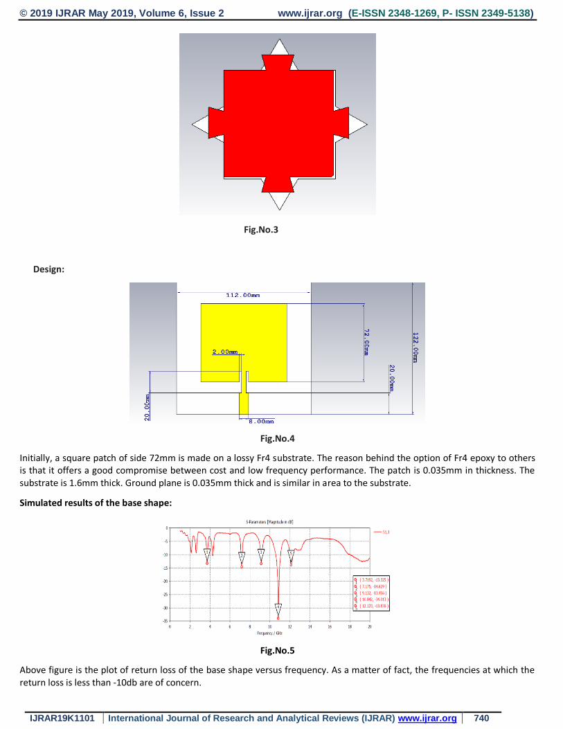
Fig.No.4
Initially, a square patch of side 72mm is made on a lossy Fr4 substrate. The reason behind the option of Fr4 epoxy to others is that it offers a good compromise between cost and low frequency performance. The patch is 0.035mm in thickness. The substrate is 1.6mm thick. Ground plane is 0.035mm thick and is similar in area to the substrate.
Simulated results of the base shape:
Fig.No.5
Above figure is the plot of return loss of the base shape versus frequency. As a matter of fact, the frequencies at which the return loss is less than -10db are of concern.

© 2019 IJRAR May 2019, Volume 6, Issue 2 www.ijrar.org (E-ISSN 2348-1269, P- ISSN 2349-5138)
IJRAR19K1101 International Journal of Research and Analytical Reviews (IJRAR) www.ijrar.org 741
Standing waves exist even for an antenna that is matched to the best of its designer because matching cent percent is hypothetical and cannot be done in practice. Following figure (Fig.No.6) is the plot of Voltage Standing Wave Ratio versus frequency of the base shape. VSWR can hypothetically be unity, but in practice, VSWR in the range (1, 2) can be accepted.
Fig.No.6
First Iteration:
The base shape when iterated using the technique mentioned above results in the first iteration and is shown below.
Fig.No.7
The antenna shown above is designed assuming each side is one-sixth of the total length of its base shape. But the problem
we encountered by using this technique is that when it is used for the second iteration, the adjacent sides collide with each
other. So, we optimized the scaling depth of each side and finally reached to the below mentioned values.
AB=EF= 𝑳
𝟑.𝟓
CD=2BC=2DE= 𝑳
𝟗.𝟐𝟑
The following figure shows the modified first iteration

© 2019 IJRAR May 2019, Volume 6, Issue 2 www.ijrar.org (E-ISSN 2348-1269, P- ISSN 2349-5138)
IJRAR19K1101 International Journal of Research and Analytical Reviews (IJRAR) www.ijrar.org 742
Fig.No.8
We can observe from the above figure that the area of the singly iterated patch is less compared to the base shape.The
following figure shows the magnified view of the first iteration.
Fig.No.9
Simulated results of the first iteration:
Return Loss :
Fig No.10
Above is the plot of reflection coefficients versus frequency of the singly iterated shape.

© 2019 IJRAR May 2019, Volume 6, Issue 2 www.ijrar.org (E-ISSN 2348-1269, P- ISSN 2349-5138)
IJRAR19K1101 International Journal of Research and Analytical Reviews (IJRAR) www.ijrar.org 743
Fig No.11
VSWR plot of the singly iterated shape is shown above.
Proposed Antenna:
Fig No.12a
Above shape is doubly iterated design after applying the same technique to the singly iterated shape.
Fig.No.12b
Dimensions of the second iteration are shown in the above figures .We can observe how area decreased from the singly iterated one thereby the space occupied by the proposed design is very less compared to the base shape.
Simulated results of the proposed antenna:
© 2019 IJRAR May 2019, Volume 6, Issue 2 www.ijrar.org (E-ISSN 2348-1269, P- ISSN 2349-5138)
IJRAR19K1101 International Journal of Research and Analytical Reviews (IJRAR) www.ijrar.org 744
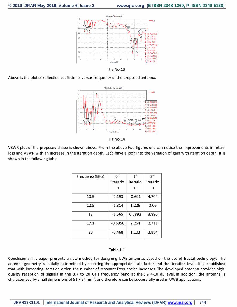
Fig No.13
Above is the plot of reflection coefficients versus frequency of the proposed antenna.
Fig No.14
VSWR plot of the proposed shape is shown above. From the above two figures one can notice the improvements in return
loss and VSWR with an increase in the iteration depth. Let’s have a look into the variation of gain with iteration depth. It is
shown in the following table.
Frequency(GHz) 0th
iteratio
n
1st
iteratio
n
2nd
iteratio
n
10.5 -2.193 -0.691 4.704
12.5 -1.314 1.226 3.06
13 -1.565 0.7892 3.890
17.1 -0.6356 2.264 2.711
20 -0.468 1.103 3.884
Table 1.1
Conclusion: This paper presents a new method for designing UWB antennas based on the use of fractal technology. The antenna geometry is initially determined by selecting the appropriate scale factor and the iteration level. It is established that with increasing iteration order, the number of resonant frequencies increases. The developed antenna provides high-quality reception of signals in the 3.7 to 20 GHz frequency band at the S 11 <-10 dB level. In addition, the antenna is characterized by small dimensions of 51 × 54 mm2, and therefore can be successfully used in UWB applications.

© 2019 IJRAR May 2019, Volume 6, Issue 2 www.ijrar.org (E-ISSN 2348-1269, P- ISSN 2349-5138)
IJRAR19K1101 International Journal of Research and Analytical Reviews (IJRAR) www.ijrar.org 745
References:
1. Jalali and T. Sedghi, “Very compact UWB CPW-fed fractal antenna using modified ground plane and unit cells”,
Microw. Opt. Technol. Lett., Vol. 56, No. 4, April 2014, pp. 851 – 854.
2. Oraizi, and S. Hedayati, “Miniaturization of microstrip antennas by the novel application of the Giuseppe Peano
fractal
geometries”, IEEE Trans. Antennas Propag., Vol. 60, No. 8, August 2012, pp. 3559 – 3567.
3. Y. Huang and D. Y. Lin, “CPW-fed bow-tie slot antenna for ultra-wideband communications,” Electronics Letters,
vol. 42, no. 19, pp. 1073–1074, 2006.
4. V.Reddy and N.V.S.N.Sarma, “Compact Circularly Polarized AsymmetricalFractal Boundary Microstrip Antenna for
Wireless Applications,” IEEE Antennas And Wireless Propagation Letters, Vol. 13, 2014.
5. Dual band notched fractal UWB antenna by Anirban Karmakar, RowdraGhatak and D R Poddar.
6. Sanjay V. Khobragade, Prashant More, 2012 “Hexagonal-Shaped Fractal Antenna Array for Multiband
Applications” Emerging Trends in Computer Science and Information Technology.
7. Effect of Metamaterial on a triangle shaped Multi Band Patch Antenna: Ch.Manohar Kumar (JETIR) 2019

![A New CPW-fed Patch Antenna for UWB Applications · The hexagonal-shaped microstrip fractal antenna pow-ered through CPW-fed structure for UWB applications has been reported in [11]](https://img.pdfslide.net/doc/110x75/5ec163104ddd725ea750c6e7/a-new-cpw-fed-patch-antenna-for-uwb-applications-the-hexagonal-shaped-microstrip.jpg)


![A TWO-PORT ANTENNA FOR WIRELESS-POWERED UWB-RFID … · 2.1. Circularly-Polarized UWB Quasi-Spiral Antenna Spiral antennas [16{18] are widely investigated for UWB antenna designs](https://img.pdfslide.net/doc/110x75/60cd00d2fbca443dcb07fa71/a-two-port-antenna-for-wireless-powered-uwb-rfid-21-circularly-polarized-uwb-quasi-spiral.jpg)
![On the Design of Circular Fractal Antenna with U-Shape ...UWB fractal antennas with notch have been reported for UWB applications [5-8]. In [5], Crown - Sierpinski mi-crostrip antenna](https://img.pdfslide.net/doc/110x75/5e76b4eb61be4e0a053e7188/on-the-design-of-circular-fractal-antenna-with-u-shape-uwb-fractal-antennas.jpg)