Embed Size (px)
Citation preview

International Journal of Aviation, International Journal of Aviation,
Aeronautics, and Aerospace Aeronautics, and Aerospace
Volume 6 Issue 4 Article 10
2019
A Comparative Aerodynamic study of Nonplanar Wings A Comparative Aerodynamic study of Nonplanar Wings
Mondher Yahyaoui LASMAP Laboratory at Tunisia Polytechnic School & Ecole d'aviation de Borj El Amri, Tunisia., [email protected]
Follow this and additional works at: https://commons.erau.edu/ijaaa
Part of the Aerodynamics and Fluid Mechanics Commons
Scholarly Commons Citation Scholarly Commons Citation Yahyaoui, M. (2019). A Comparative Aerodynamic study of Nonplanar Wings. International Journal of Aviation, Aeronautics, and Aerospace, 6(4). https://doi.org/10.15394/ijaaa.2019.1383
This Article is brought to you for free and open access by the Journals at Scholarly Commons. It has been accepted for inclusion in International Journal of Aviation, Aeronautics, and Aerospace by an authorized administrator of Scholarly Commons. For more information, please contact [email protected].

Introduction
Vortex drag accounts for about 40% of commercial jet transport at cruise
conditions and for 80-90% at low speed (Kroo, 2005). The induced drag of plain
monoplanes can only be optimized to the extent of having a unit span efficiency
factor by achieving an elliptic lift distribution in the spanwise direction.
Therefore, in recent years, nonplanar wing configurations have received renewed
research interest in view of their potential for attaining much higher values of
span efficiency factor and providing major reduction in induced drag.
The idea of nonplanar wings goes back to almost a century ago (Prandtl,
1924) when it was shown that a box wing, which is basically a biplane connected
by end plates, generates less induced drag than other configurations at given lift
and span. This configuration was referred to as the best wing system (BWS).
According to Prandtl’s study, for a height-to-span ratio of 0.2, box wings generate
only 68% of the induced drag of a monoplane of equal lift and span. This is
equivalent to an overall 12.8% drag reduction in cruise flight (32% of 40%) of a
typical jet transport aircraft, and a reduction of 25.6-28.8% at low speeds. These
reductions will increase to 16% at cruise speed and 32-36% at low speeds if the
fence height-to-span ration in increased to 0.3. Adding surface extensions to basic
wings to obtain nonplanar wing configurations such as box wings, C-wings or
wing-winglets adds profile drag by increasing wetted area. In addition, for the
case of box wings, maintaining equal span and planform area reduces the average
chord by half and lowers the wings’ Reynolds number, which in turn increases
local skin friction. But this is by no means the only drawback associated with box
wings.
An early investigation into the possibility of integrating box wings into
transonic transport (Lange et al., 1974) revealed a number of issues that needed to
be resolved, in particular the problem of aeroelastic instabilities at a relatively low
flutter speed known to be associated with forward swept wings. Kroo (2005)
presented an interesting discussion of the potential for overall aircraft
performance improvement associated with nonplanar wing configurations. The
main point made was that nonplanar concepts should not be evaluated from an
induced drag reduction perspective alone. Other aspects such as the wings
structural features may improve overall performance by reducing structural
weight.
In spite of the many unsolved issues relating to stability, aeroelastic
behavior, and structural efficiency, nonplanar wing configurations have been the
subject of numerous aerodynamic studies. Most of these studies are based in the
Treftz plane and use a discrete vortex lattice method to determine the optimal
spanwise lift distribution which yields minimum induced drag (Blackwell, 1976;
Lamar, 1976; Kroo, 2004; Kuhlman & Ku, 1982). As shown in Figure 1, the
1
Yahyaoui: Non planar wings
Published by Scholarly Commons, 2019

spanwise distribution of wing and fin twist for minimum induced drag is in
general highly varying which makes it of limited practical interest in aircraft
construction.
Figure 1. Example of optimal twist distribution for a box wing. Adapted from
“Aerodynamic Optimization Trade Study of a Box-Wing Aircraft Configuration,”
by H. Gagnon and D. W. Zingg, 2016, AIAA.
The objective of the present work is to show that it is possible to achieve
the same higher values of span efficiency published in various research papers
using only the more practical linear twist for the upper and lower wings and the
tip fin. Four nonplanar wing configurations were considered (Figure 2) and the
effect of other geometric parameters such as angle of attack, fin height-to-span
ratio, sweep, aspect ratio, stagger, and the ratio of the winglet/fin bottom chord to
wing tip chord were also studied.
Figure 2. The four nonplanar wings considered.
It is also the purpose of this study to make a comparison between the
different configurations based on the lowest induced drag criteria. Establishing
empirical equations for the induced drag ratio as a function of fin height-to-span
Biplane Wing-winglet
C-wing Box wings
2
International Journal of Aviation, Aeronautics, and Aerospace, Vol. 6 [2019], Iss. 4, Art. 10
https://commons.erau.edu/ijaaa/vol6/iss4/10DOI: https://doi.org/10.15394/ijaaa.2019.1383

ratio is another objective. The investigation is conducted using a cambered VLM
program developed by the author (Yahyaoui, 2014/2019). The main results are
given in the form of graphical representation of the span efficiency factor of the
different configurations as functions of the various geometric parameters
considered.
Numerical Method and Validation
The vortex-lattice method used in this investigation is a singularity method
which has been around for many decades and is well documented in the literature
(Bertin & Smith, 2009). Our VLM MATLAB code accommodates the four
configurations subject of this investigation but can also be easily adjusted to
include other non planer configurations. While the induced drag coefficient is
directly provided by the VLM code, the profile drag coefficient is computed using
the equation (Figure 3):
𝐶𝐷𝑝
=2
𝑆∫ 𝐶𝑑(𝑠)𝑐(𝑠)𝑑𝑠
𝑠𝐵
0
(1)
where S is the wing reference area, 𝑠 is the curvilinear coordinate following the
wing span, and Cd is the section profile drag coefficient which depends on the
local angle of attack α(𝑠) and the Reynolds number based on the local chord c(s).
Numerical values for the local profile drag coefficient are estimated through
interpolation using experimental data curves (Abbott & Von Doenhoff, 1959).
Figure 3. The setup for computing the profile drag of a typical nonplanar wing.
The key geometric parameters that can be specified for a non planar wing
configuration are given in Figure 4. These are:
- The angle of attack at the root of the lower wing (𝛼𝑟𝑙).
- The angle of attack at the inner end of the upper wing (𝛼𝑟𝑢). When a box
wing is considered, this angle is the angle at the root of the upper wing.
- The twist angle for lower and upper wings (𝜃𝑙 , 𝜃𝑢).
- The twist angle for the winglet/fin (𝜃𝑤, 𝜃𝑓).
- The winglet/fin cant angle (𝛿𝑐).
- The height-to-span ratio (ℎ𝑏).
𝑧
𝑦
𝑠 α(s), c(s) B
3
Yahyaoui: Non planar wings
Published by Scholarly Commons, 2019

- The ratio of the upper-wing span to lower wing span (𝐾𝑏 = 𝑏𝑢 𝑏𝑙⁄ ).
- The ratio of the winglet/fin bottom chord to the lower-wing tip chord (𝐾𝑐 =𝑐𝑏𝑤
𝑐𝑡𝑙⁄ ).
- Other classical parameters such as aspect ratio (A), sweep (Λ), and taper ratio
(𝜆).
An example of wing configuration treated by our code is shown in Figure 5.
Figure 4. Key geometric parameters defining nonplanar wings.
Figure 5. A swept and tapered C-wing as modeled by our VLM code.
�⃗� ∞
𝑥
𝑧
𝑦
𝛼𝑟
𝜃𝑙
𝜃𝑓 > 0
𝜃 > 0
𝑏𝑢
ℎ
Λ
𝑏2⁄
𝑐𝑏𝑓
𝑐𝑡𝑙
∥ to x-axis
Λ
4
International Journal of Aviation, Aeronautics, and Aerospace, Vol. 6 [2019], Iss. 4, Art. 10
https://commons.erau.edu/ijaaa/vol6/iss4/10DOI: https://doi.org/10.15394/ijaaa.2019.1383

Computations using our code will be validated by comparison to reference
numerical values. The lattice resolution used is 3 rows of panels in the chordwise
direction and 25 rows per half span in the spanwise direction. Such a spanwise
resolution was sufficient for accuracy to the second decimal place.
A first comparison case consists of a biplane with wings of equal span, an
aspect ratio of eight and a gap-to-span ratio of 0.5. The value of the span
efficiency factor given in Blackwell (1976) is 1.6307. The numerical method used
in that work was a vortex-lattice representation of the non-planar wing in the
Treftz plane with an optimum lift distribution in the spanwise direction. The
equivalent biplane we considered is of the same geometry except that a linear
twist of -3° was applied to both wings. The value given by our code is 1.6392.
The relative difference is about 0.5%.
A second case given in the same reference is that of a wing-winglet
configuration with an aspect ratio of eight and a height-to-span ratio of 0.1. The
value of the span efficiency factor given in Blackwell (1976) is 1.224. The wing-
winglet combination we considered is of the same geometry (Kc=1) except that a
linear twist of -2° was applied to the wing. The value given by our code is 1.226.
The relative difference is about 0.2%.
A third and final comparison is made with values of the span efficiency
factor given by Kroo (2005). The wings have an aspect ratio of 8, a height-to-span
ratio of 0.2, and no sweep. Wing twist is equal to -3° for the biplane wings and -
2° for the wings of the other three configurations. The lift coefficient is equal to
0.5 and the parameter Kc is equal to unity for the wing-winglet and C-wing. As
shown in Table 1, the agreement is good. The relative difference is less than 1%
for three of the configurations and is equal to 2% for the C-wing.
Table 1
Comparison of the VLM span efficiency values with those from Kroo (2005)
Wing configuration Box wing C-wing Wing-winglet Biplane
Kroo (2005) 1.46 1.45 1.41 1.36
Present work 1.47 1.42 1.41 1.37
Difference +0.7% -2% 0 +0.7
The winglet or fin twist angle 𝜃𝑤/𝑓 was optimized to give the highest value
of the span efficiency factor instead of the overall lift-to-drag ratio. Such a choice
emanates from the fact that the induced drag of the wings represents a higher
percentage of an airplane drag than does profile drag. Finding the optimal value
was done manually by running the code for different values of 𝜃𝑤/𝑓. An example
of finding the “optimal” fin twist angle is shown in Figure 6 for the C-wing. The
effect is similar for the wing-winglet and box wings configurations.
5
Yahyaoui: Non planar wings
Published by Scholarly Commons, 2019

Figure 6. An example of finding fin twist angle (𝜃𝑓) of a C-wing with A=8, 𝜆=1,
Λ=0, Kh=0.2, Kc=1, Kb=0.1, CL=0.5.
The span of the upper part of a C-wing was limited to 10% of the main
wing span. Beyond this value (Figure 7), the span efficiency factor remains
constant while the lift-to-drag ratio keeps on decreasing since the induced drag
has reached stagnation while parasite drag continues to increase due to a greater
wetted area. Since the span of the upper part of a C-wing is small, no twist was
applied to it.
6
International Journal of Aviation, Aeronautics, and Aerospace, Vol. 6 [2019], Iss. 4, Art. 10
https://commons.erau.edu/ijaaa/vol6/iss4/10DOI: https://doi.org/10.15394/ijaaa.2019.1383

Figure 7. Variation of e with the ratio of the upper wing span to overall wing span
for a C-wing with A=8, 𝜆=1, Λ=0, Kh=0.2, Kc=1, and CL=0.5.
Another precaution taken was that the lift of the upper part of the C-wing
has to be of a given ratio to the lift of the lower wing. Our computations show that
the upper portion’s lift has to be negative and, for Kb = 0.1, the ratio Lu/Ll needs
to be around -0.6% to obtain higher values of e. This is shown on Figure 8 below.
7
Yahyaoui: Non planar wings
Published by Scholarly Commons, 2019

Figure 8. Effect of the ratio of upper wing lift to that of the lower wing for a C-
wing with A=8, 𝜃=-2°, 𝜆=1, Λ=0, Kh=0.2, Kc=1, Kb=0.1 at CL=0.5.
For the box wing configuration, we followed the well-established fact that
the lower and upper wings have to have equal positive lift while the circulation of
the end fins has to equal zero at their mid points (Kroo, 2005). Similarly the
wings of the biplane have to carry equal lift.
Finally, as indicated by Figure 9, compressibility had very little effect of
the span efficiency factor and all computations were conducted in the
incompressible régime. Compressibility effects were accounted for by applying
the Prandtl-Glauert rule to the vortices circulation.
8
International Journal of Aviation, Aeronautics, and Aerospace, Vol. 6 [2019], Iss. 4, Art. 10
https://commons.erau.edu/ijaaa/vol6/iss4/10DOI: https://doi.org/10.15394/ijaaa.2019.1383

Figure 9. Effect of Mach number on the span efficiency factor: wing-winglet with
A=8, 𝜃=-2°, 𝜆=1, Λ=0, Kh=0.2, Kc=1, and CL=0.5.
Results and Discussion
Unless otherwise specified, the aspect ratio of the different wing
configurations is equal to 8 and the lift coefficient is equal to 0.5. Such a value is
representative of cruise flight. The equivalent planar wing used for comparison is
a assumed to have the same aspect ratio, operate at the same lift coefficient and
have an elliptic lift distribution in the spanwise direction so that its span
efficiency factor is equal to unity. The induced drag coefficient is given by the
equation:
𝐶𝐷𝑖=
𝐶𝐿2
𝜋𝑒𝜆 (2)
Therefore the ratio of the induced drag coefficient of any configuration to that of
the reference planar wing is:
𝑟 =𝐶𝐷𝑖
𝐶𝐷𝑖𝑟
=𝑒𝑟
𝑒
If we assume that the reference planar wing has an elliptic spanwise lift
distribution at the given CL then 𝑒𝑟 = 1 and:
𝑟 =1
𝑒 (3)
9
Yahyaoui: Non planar wings
Published by Scholarly Commons, 2019

Since airfoil camber has basically no influence on the results, the
symmetrical NACA 0012 was used for the main wing, vertical extension and
upper wing. The twist of the upper wing of the box wing configuration was set
equal to that of the lower wing. But no twist was given to the upper portion of the
C-wing.
Effect of Twist
The effect of wing twist on the span efficiency factor is shown in Figure
10. From an aerodynamic efficiency perspective, this parameter will be chosen as
to maximize the value of 𝑒. In practice, higher washout values may be chosen in
order to obtain a better wing stall onset characteristics for instance. One should
note however that, when the twist angle is varied between -4 and 0°, the
difference between the maximum value of e and its minimum is around 3% for
the biplane and less than 2% for the other three configurations.
Throughout this study, unless otherwise specified, the following values for
wing twist are retained:
- 𝜃= -2° for the wing of the wing-winglet system, the C-wing and both wings
of the box wing.
- 𝜃 = -3° for both wings of the biplane and for the planar wing.
Figure 10. Effect of wing washout on e for A=8, 𝜆=1, Λ=0, Kh=0.2, Kc=1, and
CL=0.5.
10
International Journal of Aviation, Aeronautics, and Aerospace, Vol. 6 [2019], Iss. 4, Art. 10
https://commons.erau.edu/ijaaa/vol6/iss4/10DOI: https://doi.org/10.15394/ijaaa.2019.1383

Effect of Taper
Increasing wing taper reduces the value of the span efficiency factor. The
decrease is 3.4% for the box wing, 3.7% for the biplane and 5.6% for both the C-
wing, and wing-winglet configuration when going from a rectangular
configuration to one with 0.5 taper ratio.
Figure 11. Effect of taper on e for A=8, K, Λ=0, Kh=0.2, Kc=1, and CL=0.5.
Effect of Aspect Ratio
As for planar wings, the span efficiency factor of nonplanar configurations
decreases with aspect ratio (Figure 12). However, the effective aspect ratio (𝑒𝐴)
increases linearly for all four configurations (Figure 13). Since the induced drag
coefficient is inversely proportional to this parameter, it decreases with aspect
ratio. It follows that, for a given lift coefficient, the L/D ratio of the configuration
increases. When A is increased from 6 to 10, the increase in L/D is around 24%
for the C-wing, 25% for the wing-winglet, and 28% for the box wing and the
biplane.
If we compare the L/D values at A=8 to those at A=6, then the increase is
still important. It is of the order of 14% for the wing-winglet and C-wing, 16% for
the box wing, and 17% for the biplane. The corresponding increase in the product
eA is about 32% for the wing-winglet and 33% for the other three configurations.
This amounts to about 25% decrease in the induced drag coefficient.
11
Yahyaoui: Non planar wings
Published by Scholarly Commons, 2019

Figure 12. Variation of e with aspect ratio for 𝜆=1, Λ=0, Kh=0.2, Kc=1, and
CL=0.5.
12
International Journal of Aviation, Aeronautics, and Aerospace, Vol. 6 [2019], Iss. 4, Art. 10
https://commons.erau.edu/ijaaa/vol6/iss4/10DOI: https://doi.org/10.15394/ijaaa.2019.1383
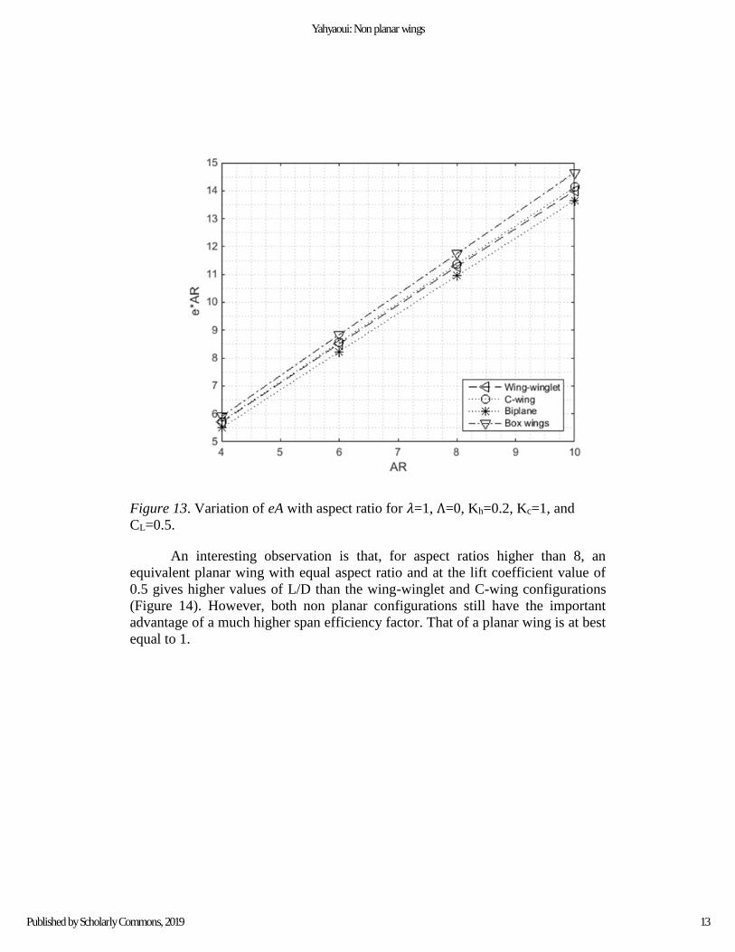
Figure 13. Variation of eA with aspect ratio for 𝜆=1, Λ=0, Kh=0.2, Kc=1, and
CL=0.5.
An interesting observation is that, for aspect ratios higher than 8, an
equivalent planar wing with equal aspect ratio and at the lift coefficient value of
0.5 gives higher values of L/D than the wing-winglet and C-wing configurations
(Figure 14). However, both non planar configurations still have the important
advantage of a much higher span efficiency factor. That of a planar wing is at best
equal to 1.
13
Yahyaoui: Non planar wings
Published by Scholarly Commons, 2019

Figure 14. Variation of L/D with aspect ratio for 𝜆=1, Λ=0, Kh=0.2, Kc=1, and
CL=0.5.
Effect of Sweep
Moderate sweep improves the span efficiency factor. When a 20° sweep at
the quarter chord is applied to wings and end fins alike, the span efficiency factor
𝑒 increases from (Figure 15):
• 1.41 to 1.44 for a wing-winglet, a 2.1% increase.
• 1.42 to 1.46 for a C-wing, a 2.8% increase
• 1.37 to 1.40 for a biplane, a 2.2% increase
The 𝑒 value for the box wing increases from 1.47 to 1.48 for a sweep of 15°.
14
International Journal of Aviation, Aeronautics, and Aerospace, Vol. 6 [2019], Iss. 4, Art. 10
https://commons.erau.edu/ijaaa/vol6/iss4/10DOI: https://doi.org/10.15394/ijaaa.2019.1383

Figure 15. Effect of sweep on e for A=8, 𝜆=1, Λ=0, Kh=0.2, Kc=1, and CL=0.5.
Effect of Chord Ratio
This parameter is the ratio of the winglet/fin bottom chord to the tip chord
of the lower wing. It concerns only the C-wing and wing-winglet configurations.
As shown on Figure 16, reducing this parameter from 1 to around 0.85 will
slightly increase the span efficiency factor by a moderate 0.5%. If it is reduced to
0.5, there will be a decrease of about 1.3%. So generally speaking this parameter
has rather limited effect on the span efficiency factor.
15
Yahyaoui: Non planar wings
Published by Scholarly Commons, 2019

Figure 16. Effect of Kc on e for the C-wing and wing-winglet for A=8, 𝜆=1, Λ=0,
Kh=0.2, and CL=0.5.
Effect of Stagger
For a biplane or a box wing stagger is defined as streamwise shift in
position of the lower wing relative to the upper wing. It is considered positive
when the former is located aft of the latter. While the stagger for the biplane is
achieved directly by longitudinally shifting one of the wings with respect to the
other, for the box wing configuration with straight rectangular upper and lower
wings it was achieved by sweeping the fin (Figure 17).
Figure 17. Definition of positive stagger for a box wing.
Based on the previous figure, the stagger normalized with respect to the
average geometric chord is given by:
𝑥
𝑦
𝑧
�⃗� ∞
fin
Positive stagger
Λ𝑓
16
International Journal of Aviation, Aeronautics, and Aerospace, Vol. 6 [2019], Iss. 4, Art. 10
https://commons.erau.edu/ijaaa/vol6/iss4/10DOI: https://doi.org/10.15394/ijaaa.2019.1383

𝑆�̅� = 𝑆𝑡 𝑐̅⁄= −𝐾ℎ𝐴 𝑡𝑎𝑛 𝛬𝑓 (4)
where the fin sweep angle shown on this figure is considered negative.
As indicated by Figure 18, a positive stagger of an unswept rectangular
biplane with an aspect ratio of 8 will moderately increase the span efficiency
factor. The increase is 0.6% for a stagger of two chord lengths and about 0.9% for
a stagger of three chord lengths. Negative stagger will on the other hand decrease
the span efficiency factor. The decrease is about 1.4% for a negative stagger of
three chord lengths.
Figure 18. Effect of stagger on e for the box wing and the biplane for A = 8, 𝜆=1,
Λ=0, Kh=0.2, Kc=1, and CL=0.5.
The effect of stagger, positive or negative, on the box-wing system is to
decrease the span efficiency factor but the change will not surpass the 1.3% for a
negative stagger of three chord lengths and 0.6% for a positive stagger of equal
amplitude.
Staggering the end fin for the wing-winglet or the C-wing consisted in
shifting backwards its leading edge along the main wing tip chord. Sample results
for the case where the fin chord is equal to the main wing’s chord are shown on
Figure 19. These results show that such a measure will increase the span
efficiency factor up to a relative stagger (𝑆𝑡 𝑐⁄ ) of about 0.6 to 2/3. For the
unswept wing-winglet configuration, the increase is 2.7% and it occurs for a
relative stagger of 2/3. Whereas, for the same configuration with a 20° sweep, e
goes from 1.44 at zero stagger up to 1.49 for a relative stagger of 0.6. The
17
Yahyaoui: Non planar wings
Published by Scholarly Commons, 2019

increase is about 3.5%. For the C-wing with a 20° sweep e goes up 1.46 to 1.51
with an increase of 3.4%.
It seems that the combination of a positive sweep of 20° and a relative
stagger of about 0.6 make both the C-wing and wing-winglet configurations
surpass the box wing in terms of the highest value of e.
A summary of the main results for an aspect ratio of 8 and h/b=0.2 is
given in Table 2 where the lift-to-drag ratio was also included, along with the
percent increase in the L/D ratio with respect the reference planar wing. The latter
has the same aspect ratio of 8 and 3° washout. It has a lift to drag ratio of 28.82 at
the same CL value of 0.5 and a Reynolds number of 6x10⁶. The same Reynolds
number was retained for the four nonplanar configurations.
Figure 19. Wing-winglet and C-wing: effect of end fin stagger on e for A=8, 𝜆=1,
Kh=0.2, Kc=1, and CL=0.5.
The results also show that the biplane and box wing have the higher values
of L/D while the C-wing configuration does not improve the lift-to-drag ratio, at
least for this value of aspect ratio. Reduction in vortex drag can be viewed as
more important than reducing the overall lift-to-drag ratio of the wing
configuration since vortex drag takes a much higher percentage of the overall drag
of an airplane than does the profile drag of the wings alone.
𝑆𝑡
Λ
Λ
18
International Journal of Aviation, Aeronautics, and Aerospace, Vol. 6 [2019], Iss. 4, Art. 10
https://commons.erau.edu/ijaaa/vol6/iss4/10DOI: https://doi.org/10.15394/ijaaa.2019.1383

Table 2
Summary of the higher values of e for A=8, Kh=0.2, Kc = 1, 𝜆 = 1 and CL=0.5
Wing geometry e L/D % increase in L/D
C-wing: Λ = 20°, St = 0.6c 1.51 28.78 ≈0%
Wing-winglet: Λ = 20°, St =
0.6c
1.49 30.00 4%
Box wings: Λ = 15° 1.48 33.63 16.6%
Biplane: St = 2c, Λ = 20° 1.41 34.37 19.3%
Figure 20. Higher values of e for A=8, 𝜆=1, h/b=0.2, Kh=0.2, Kc=1, and CL=0.5
The positive effect associated with stagger, particularly for the C-wing and
wing-winglet configurations, is not predicted by Trefftz plane analysis, frequently
used in prior studies of non planar wings. This may indicate a limitation of the
Trefftz plane approach as well as Munk’s stagger theorem (Munk, 1921) in regard
to this particular point.
Effect of Cant Angle
The cant angle is defined on Figure 21 and its effect is shown on the same
figure. A negative cant angle will negatively affect the span efficiency factor for
all three configurations. As for positive cant angles, our main finding is that any
increase in the span efficiency factor with positive cant angles for the wing-
winglet configuration (Heyson, Riebe, & Fulton, 1977) or for the C-wing can only
be claimed if the reference span is taken as that of the main wing which is lower
than that the overall tip-to-tip span of the configuration. If the latter is taken as a
reference, the span efficiency factor will systematically be lower since:
𝑒 =𝐿2
𝜋𝐷𝑖𝑏2�̅�∞
Therefore, for any given wing configuration at a given relative wind speed and
angle of attack, the lift and induced drag will also have well defined values, and
the choice of the value of the span will definitely define the final value of the span
efficiency factor.
Wing-winglet: e = 1.49 C-wing: e = 1.51
Box wing: e = 1.48 Biplane: e = 1.41
19
Yahyaoui: Non planar wings
Published by Scholarly Commons, 2019

For the box wing configuration, since it is generally the convention to take
the higher of the upper and lower wings spans as a reference, both positive and
negative angles will decrease the span efficiency factor.
Figure 21. Effect of cant angle on e for A=8, 𝜆=1, Λ=0, Kh=0.2, Kc=1, and
CL=0.5.
Effect of Height Ratio
The effect of the ratio of winglet/fin height to wing span is presented in
terms of the ratio of the induced drag of the nonplanar configuration to that of the
reference planar wing given by equation (3). The results shown on Figure 22
show that, for values of height-to-span ratio of practical interest (0.2 or less), our
results for the box wing identically duplicate what is known as the Prandtl’s
BWS.
b1
𝛿𝑐 > 0
b2
20
International Journal of Aviation, Aeronautics, and Aerospace, Vol. 6 [2019], Iss. 4, Art. 10
https://commons.erau.edu/ijaaa/vol6/iss4/10DOI: https://doi.org/10.15394/ijaaa.2019.1383

Figure 22. Effect of height-to-span ratio on 𝐶𝐷𝑖𝐶𝐷𝑖𝑟
⁄ for A=8, Λ=0, 𝜆=1, Kc=1,
and CL=0.5.
For Kh=0.1, compared to the box wing, the C-wing has 3.3% higher drag
ratio, the wing-winglet 4.1%, and the biplane 7.2%. These differences increase
with Kh.
Empirical Laws for the Induced Drag Ratios
The empirical law for the induced drag ratio is assumed to be in the form
(Prandtl, 1924):
𝑟 =1 + 𝑟𝑐1ℎ̅
𝑐2 + 𝑐3ℎ̅ (5)
where ℎ̅ is the height-to-span ratio and 𝑟 is the induced drag ratio, defined
previously. The three unknown constants are determined by solving a linear
system of three equations in these constants, obtained by requiring that the curve
representing the induced drag ratio go through three points whose choice is
somewhat arbitrary. It was found that choosing ℎ̅1 = 0, ℎ̅1 = 0.2, and ℎ̅3 = 0.5
as abscissa of these points yields curve fits which fairly accurately match the
discrete data (Figure 25). The three unknown constants are thereby solutions to
the following system:
21
Yahyaoui: Non planar wings
Published by Scholarly Commons, 2019

(
ℎ̅1 −𝑟1 −ℎ̅1𝑟1ℎ̅2 −𝑟2 −ℎ̅2𝑟2ℎ̅3 −𝑟3 −ℎ̅3𝑟3
)[
𝑐1
𝑐2
𝑐3
] = [−1−1−1
] (6)
Applying this approach to the different configurations considered we get:
• Wing-winglet:
𝑟 =1 + 2.6ℎ̅
0.935 + 6.1ℎ̅ , 𝑙𝑖𝑚
ℎ̅→∞𝑟 = 0.426 (7)
• C-wing:
𝑟 =1 + 2.847ℎ̅
0.933 + 6.55ℎ̅ , 𝑙𝑖𝑚
ℎ̅→∞𝑟 = 0.434 (8)
• Biplane:
Present work:
𝑟 =1 + 1.548ℎ̅
1.05 + 3.713ℎ̅ , 𝑙𝑖𝑚
ℎ̅→∞𝑟 = 0.417 (9)
Prandtl’s equation is:
𝑟 = 0.5 +1 − 0.66ℎ̅
2.1 + 7.4ℎ̅, 𝑙𝑖𝑚
ℎ̅→∞𝑟 = 0.411 (10)
The curves corresponding to equations (9) and (10) are shown on Figure 23 and
the agreement between the two approaches is quite remarkable. This is further
proof of the accuracy of or VLM computations.
22
International Journal of Aviation, Aeronautics, and Aerospace, Vol. 6 [2019], Iss. 4, Art. 10
https://commons.erau.edu/ijaaa/vol6/iss4/10DOI: https://doi.org/10.15394/ijaaa.2019.1383

Figure 23. Comparison of the results given in the present work with those from
Prandtl (1924) for the biplane configuration.
• Box Wing:
Present work:
𝑟 =1 + 1.03ℎ̅
1.02 + 3.76ℎ̅, 𝑙𝑖𝑚
ℎ̅→∞𝑟 = 0.274 (11)
Prandtl’s result:
𝑟 =1 + 0.45ℎ̅
1.04 + 2.81ℎ̅, 𝑙𝑖𝑚
ℎ̅→∞𝑟 = 0.16 (12)
While a more recent study (Rizzo, 2007) gave the following equation:
𝑟 =1 + 2.18ℎ̅
1 + 5.04ℎ̅, 𝑙𝑖𝑚
ℎ̅→∞𝑟 = 0.43 (13)
The curves corresponding to equations (11)-(13) are shown on Figure 24. It is
clear that in the region of practical interest, i.e. for a height-to-span ratio between
5 and 20%, our results very closely agree with what is known as Prandtl’s best
wing system. Also, our limit value for the induced drag ratio r is equal to 0.274.
This places it practically midway between the ideal value of 0.16 predicted by
Prandtl’s analysis (Prandtl, 1924) and that given by equation (13).
23
Yahyaoui: Non planar wings
Published by Scholarly Commons, 2019

Figure 24. Comparison of the present work results and those from Rizzo (2007)
for the box wing to Prandtl’s best work system.
Figure 25 shows how the newly established empirical laws, given by
equations (7)-(9) and (11), thoroughly agree with the numerical values of the
induced drag ratio for all four configurations.
24
International Journal of Aviation, Aeronautics, and Aerospace, Vol. 6 [2019], Iss. 4, Art. 10
https://commons.erau.edu/ijaaa/vol6/iss4/10DOI: https://doi.org/10.15394/ijaaa.2019.1383

Figure 25. Agreement between the empirical laws and the numerical values of the
induced drag ratio: A=8, Λ=0, 𝜆=1, Kc=1, and CL=0.5.
Conclusions
In this work four nonplanar wing configurations were studied using the
vortex-lattice method: the wing-winglet, the C-wing, the biplane, and the box
wing. It has been shown that linear twist, which is more practical in aeronautical
construction, is more than adequate when it comes to achieving the higher values
of span efficiency factor obtained by a completely optimized twist distribution
along the span camber, the latter being in general highly varying and thus not very
practical.
It has also been shown that moderate sweep can slightly increase the span
efficiency factor and further reduce vortex drag. The increase is more important
for the C-wing, the wing-winglet, and the biplane than it is for the box wing.
Similarly, it was found that staggering the vertical extension longitudinally
backwards to around 60% of wing tip chord for the C-wing and wing-winglet
configurations had a non negligible positive effect on the span efficiency factor. It
was also shown that combining such a stagger and a moderate sweep gave the C-
wing and the wing-winglet configurations a slight edge over the box wing
configuration in terms of the value of the span efficiency factor. The latter
25
Yahyaoui: Non planar wings
Published by Scholarly Commons, 2019

configuration is known to have the higher value of this important aerodynamic
parameter, but only when no sweep and stagger are applied.
When assessed from the perspective of the overall lift-to-drag ratio, the
biplane and then the box wing configuration have the highest values, at least for
the cruise flight lift coefficient considered. Reduction in vortex drag can be
viewed as more important than increasing the lift-to-drag ratio of the wing
configuration since vortex drag takes a much higher percentage of the overall drag
of an airplane than does the profile drag of the wings alone. As mentioned at the
beginning of this article, the vortex drag represents as much as 90% of the total
drag at low speed flight and as much as 40% in cruise flight, for jet transports at
least.
26
International Journal of Aviation, Aeronautics, and Aerospace, Vol. 6 [2019], Iss. 4, Art. 10
https://commons.erau.edu/ijaaa/vol6/iss4/10DOI: https://doi.org/10.15394/ijaaa.2019.1383

References
Abbott, I. H., & Von Doenhoff, A. E. (1959). Theory of wing sections. New York,
NY: Dover.
Blackwell, J. A. (1976). Numerical method to calculate the induced drag or
optimum loading for arbitrary non-planar aircraft. Retrieved from
https://ntrs.nasa.gov/search.jsp?R=19760021079
Bertin, J. J., & Smith, M. L. (2009). Aerodynamics for engineers (5th ed.). New
York, NY: Pearson Prentice Hall.
Frediani A., & Montanari G. (2009). Best wing system: An exact solution of the
Prandtl’s problem. In Variational Analysis and Aerospace Engineering.
Springer Optimization and Its Applications, 33, 183-211.
Frediani, A. (2005). The Prandtl wing: Innovative configurations and advanced
concepts for future civil transport aircraft. Van Karmon Institute for Fluid
Dynamics, VKI Lecture series. Retrieved from
http://www.engbrasil.eng.br/artigos/art95.pdf
Gagnon, H., & Zingg, D. W. (2016). Aerodynamic optimization trade study of a
box-wing aircraft configuration. AIAA. https://doi.org/10.2514/1.C033592
Heyson, H. H., Riebe, G. D., & Fulton, C. L. (1977). Theoretical parametric
study of the relative advantages of winglets and wing-tip extensions.
Retrieved from https://ntrs.nasa.gov/search.jsp?R=19770026168
Kroo, I. (2004). A general approach to multiple lifting surface design and
analysis. AIAA. https://doi.org/10.2514/6.1984-2507
Kroo, I. (2005). Nonplanar wing concepts for increased aircraft efficiency.
Retrieved from http://citeseerx.ist.psu.edu/viewdoc/summary?
doi=10.1.1.139.9694
Kuhlman, J., & Ku, T. (1982). Numerical optimization techniques for bound
circulation distribution for minimum induced drag of nonplanar wings:
Computer program documentation. Retrieved from https://ntrs.nasa.gov/
search.jsp?R=19830022114
Lange, R. H., Cahill J. F., Bradley, E. S., Eudaily, R. R., Jenness, C. M., &
MacWilkinson, D. G. (1974). Feasibility study of the transonic biplane
concept for transport aircraft application. Retrieved from
https://ntrs.nasa.gov/search.jsp?R=19740026364
Lamar, J. E. (1976). A vortex-lattice method for the mean camber shapes of
trimmed non coplanar planforms with minimum induced drag. Retrieved
from https://ntrs.nasa.gov/archive/nasa/casi.ntrs.nasa.gov/
19760019073.pdf
Munk, M. M. (1921). The minimum induced drag of airfoils. Retrieved from
https://ntrs.nasa.gov/search.jsp?R=19930091456
27
Yahyaoui: Non planar wings
Published by Scholarly Commons, 2019

Prandtl, L. (1924). Induced drag of multi planes. Retrieved from
https://ntrs.nasa.gov/search.jsp?R=19930080964
Rizzo, E. (2007). Optimization methods applied to the preliminary design of
innovative, non conventional aircraft configurations. Pisa, IT: Edizioni.
Yahyaoui, M. (2014). Generalized vortex lattice method for predicting
characteristics of wings with flap and aileron deflection. International
Journal of Mechanical, Aerospace, Industrial, and Mechatronics
Engineering, 8(10), 1690-1698.
Yahyaoui, M. (2019). A new method for the prediction of the downwash angle
gradient. International Journal of Aviation, Aeronautics, and Aerospace,
6(3). Retrieved from https://commons.erau.edu/ijaaa/vol6/iss3/9
28
International Journal of Aviation, Aeronautics, and Aerospace, Vol. 6 [2019], Iss. 4, Art. 10
https://commons.erau.edu/ijaaa/vol6/iss4/10DOI: https://doi.org/10.15394/ijaaa.2019.1383